
Air conditioner
Installation manual
AJ***TXJ*KH
• Thank you for purchasing this Samsung air conditioner.
• Before operating this unit, please read this manual carefully and retain it for future reference.
DB68-09261A-05
DB68-09261A-05_IM_FJM HP Outdoor_EA_EN_.indd 1DB68-09261A-05_IM_FJM HP Outdoor_EA_EN_.indd 1 2024-02-07 오전 8:18:552024-02-07 오전 8:18:55
2
English
Contents
Safety Information 3
General information 4
Installing the unit 5
Power supply line, fuse or circuit breaker 5
Installation Procedure 6
Step 1 Choosing the installation location 6
Step 2 Checking and preparing accessories and tools 8
Step 3 Fixing the outdoor unit in place 8
Step 4 Connecting the power cables, communication cable, and controllers 9
Step 5 Optional: Extending the power cable 14
Step 6 Connecting the refrigerant pipe 16
Step 7 Optional: Cutting and flaring the pipes 16
Step 8 Connecting refrigerant pipes and vacuuming 17
Step 9 Performing the gas leak test 18
Step 10 Adding refrigerant (R-410A) 19
Step 11 Connecting the drain hose to the outdoor unit 20
Step 12 Checking the earthing 20
Step 13 Setting an indoor unit address and installation option 21
Step 14 Cool and Heat modes operation test 31
Step 15 Optional: Setting to Cool or Heat only mode 31
Step 16 Optional: Power improvement mode 31
Extra procedures 32
Pumping down refrigerant 32
Relocating the indoor and outdoor units 32
Using the stop valve 32
Appendix 34
Troubleshooting 34
Correct Disposal of This Product
(Waste Electrical & Electronic Equipment)
(Applicable in countries with separate collection systems)
This marking on the product, accessories or literature indicates that the product and its electronic accessories (e.g.
charger, headset, USB cable) should not be disposed of with other household waste at the end of their working life. To
prevent possible harm to the environment or human health from uncontrolled waste disposal, please separate these
items from other types of waste and recycle them responsibly to promote the sustainable reuse of material resources.
Household users should contact either the retailer where they purchased this product, or their local government office, for
details of where and how they can take these items for environmentally safe recycling.
Business users should contact their supplier and check the terms and conditions of the purchase contract. This product
and its electronic accessories should not be mixed with other commercial wastes for disposal.
DB68-09261A-05_IM_FJM HP Outdoor_EA_EN_.indd 2DB68-09261A-05_IM_FJM HP Outdoor_EA_EN_.indd 2 2024-02-07 오전 8:18:552024-02-07 오전 8:18:55
3
English
Safety Information
WARNING: Read This Manual
• Read and follow all safety information and instructions before installation, use, or maintenance of this appliance.
Incorrect installation, use, or maintenance of this appliance can result in death, serious injury, or property damage.
Keep these instructions with this appliance. This manual is subject to change. For the latest version,
visit www.samsung.com.
Notices and notes
To make you aware of safety messages and highlighted information, we use the following notices and notes throughout
this manual:
WARNING
Hazards or unsafe practices that may result in severe personal injury or death.
CAUTION
Hazards or unsafe practices that may result in minor personal injury or property damage.
IMPORTANT
• Information of special interest
NOTE
• Supplementary information that may be useful
WARNING
The installation and testing of this appliance must be performed by a qualified technician.
• The instructions in this manual are not intended as a substitute for proper training or adequate experience in the safe
installation of the appliance.
Always install the air conditioner in compliance with current local, state, and federal safety standards.
Safety Information
Safety Information
DB68-09261A-05_IM_FJM HP Outdoor_EA_EN_.indd 3DB68-09261A-05_IM_FJM HP Outdoor_EA_EN_.indd 3 2024-02-07 오전 8:18:552024-02-07 오전 8:18:55

4
English
Safety Information
Safety Information
General information
WARNING
• Carefully read the content of this manual before
installing the air conditioner and store the manual in
a safe place in order to be able to use it as reference
after installation.
• For maximum safety, installers should always carefully
read the following warnings.
• Store the operation and installation manual in a safe
location and remember to hand it over to the new
owner if the air conditioner is sold or transferred.
• This manual explains how to install an indoor unit with
a split system with two SAMSUNG units. The use of
other types of units with different control systems may
damage the units and invalidate the warranty. The
manufacturer shall not be responsible for damages
arising from the use of non compliant units.
• The manufacturer shall not be responsible for damage
originating from unauthorized changes or the
improper connection of electric and requirements set
forth in the "Operating limits" table, included in the
manual, shall immediately invalidate the warranty.
• The air conditioner should be used only for the
applications for which it has been designed: the indoor
unit is not suitable to be installed in areas used for
laundry.
• Do not use the units if damaged. If problems occur,
switch the unit off and disconnect it from the power
supply.
• In order to prevent electric shocks, fires or injuries,
always stop the unit, disable the protection switch
and contact SAMSUNG’s technical support if the unit
produces smoke, if the power cable is hot or damaged
or if the unit is very noisy.
• Always remember to inspect the unit, electric
connections, refrigerant tubes and protections
regularly. These operations should be performed by
qualified personnel only.
• The unit contains moving parts, which should always
be kept out of the reach of children.
• Do not attempt to repair, move, alter or reinstall the
unit. If performed by unauthorized personnel, these
operations may cause electric shocks or fires.
• Do not place containers with liquids or other objects
on the unit.
• All the materials used for the manufacture and
packaging of the air conditioner are recyclable.
• The packing material and exhaust batteries of the
remote controller(optional) must be disposed of in
accordance with current laws.
• The air conditioner contains a refrigerant that has
to be disposed of as special waste. At the end of its
life cycle, the air conditioner must be disposed of in
authorized centers or returned to the retailer so that it
can be disposed of correctly and safely.
• Wear protective equipment (such as safety gloves,
goggles, and headgear) during installation and
maintenance works. Installation/repair technicians
may be injured if protective equipment is not properly
equipped.
• This appliance is not intended for use by persons
(including children) with reduced physical, sensory
or mental capabilities, or lack of experience and
knowledge, unless they have been given supervision
or instruction concerning use of the appliance by a
person responsible for their safety. Children should be
supervised to ensure that they do not play with the
appliance.
DB68-09261A-05_IM_FJM HP Outdoor_EA_EN_.indd 4DB68-09261A-05_IM_FJM HP Outdoor_EA_EN_.indd 4 2024-02-07 오전 8:18:552024-02-07 오전 8:18:55

5
English
Safety Information
Installing the unit
WARNING
IMPORTANT: When installing the unit, always remember
to connect first the refrigerant tubes, then the electrical
lines.
• Upon receipt, inspect the product to verify that
it has not been damaged during transport. If the
product appears damaged, DO NOT INSTALL it and
immediately report the damage to the carrier or
retailer (if the installer or the authorized technician has
collected the material from the retailer.)
• After completing the installation, always carry out a
functional test and provide the instructions on how to
operate the air conditioner to the user.
• Do not use the air conditioner in environments with
hazardous substances or close to equipment that
release free flames to avoid the occurrence of fires,
explosions or injuries.
• Our units should be installed in compliance with the
spaces shown in the installation manual, to ensure
accessibility from both sides and allow repairs or
maintenance operations to be carried out. The
unit’s components should be accessible and easy to
disassemble without endangering people and objects.
• For this reason, when provisions of the installation
manual are not complied with, the cost required to
access and repair the units (in SAFETY CONDITIONS,
as set out in prevailing regulations) with harnesses,
ladders, scaffolding or any other elevation system will
NOT be considered part of the warranty and will be
charged to the end customer.
Power supply line, fuse or circuit
breaker
WARNING
• Always make sure that the power supply is compliant
with current safety standards. Always install the air
conditioner in compliance with current local safety
standards.
• Always verify that a suitable earthing connection is
available.
• Verify that the voltage and frequency of the power
supply comply with the specifications and that the
installed power is sufficient to ensure the operation of
any other domestic appliance connected to the same
electric lines.
• Always verify that the cut-off and protection switches
are suitably dimensioned.
• Verify that the air conditioner is connected to the
power supply in accordance with the instructions
provided in the wiring diagram included in the manual.
• Always verify that electric connections (cable entry,
section of leads, protections…) are compliant with
the electric specifications and with the instructions
provided in the wiring scheme. Always verify that all
connections comply with the standards applicable to
the installation of air conditioners.
• Devices disconnected from the power supply should
be completely disconnected in the condition of
overvoltage category.
• Be sure not to perform power cable modification,
extension wiring, and multiple wire connection.
– It may cause electric shock or fire due to poor
connection, poor insulation, or current limit
override.
– When extension wiring is required due to power
line damage, refer to "Step 5 Optional: Extending
the power cable" in the installation manual.
DB68-09261A-05_IM_FJM HP Outdoor_EA_EN_.indd 5DB68-09261A-05_IM_FJM HP Outdoor_EA_EN_.indd 5 2024-02-07 오전 8:18:552024-02-07 오전 8:18:55
6
English
Installation Procedure
Installation Procedure
Installation Procedure
Step 1 Choosing the installation
location
Installation location requirements
• Do not place the outdoor unit on its side or upside
down. Failing to do so may cause the compressor
lubrication oil to run into the cooling circuit and lead
to serious damage to the unit.
• Install the unit in a well-ventilated location away from
direct sunlight or strong winds.
• Install the unit in a location that would not obstruct
any passageways or thoroughfares.
• Install the unit in a location that would not
inconvenience or disturb your neighbors, as they could
be affected by the noise or the airflow coming from
the unit.
• Install the unit in a location where the pipes and the
cables can be easily connected to the indoor unit.
• Install the unit on a flat, stable surface that can
withstand the weight of the unit. Otherwise, the unit
can generate noise and vibration during operation.
• Install the unit so that the air flow is directed towards
the open area.
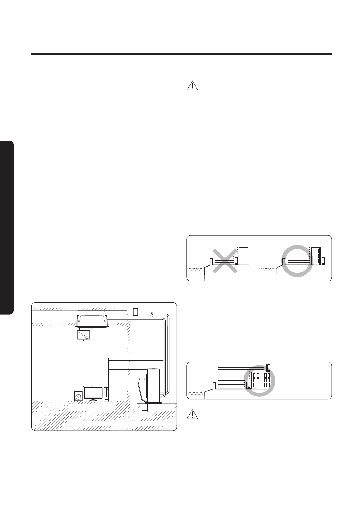
• Maintain sufficient clearance around the outdoor unit,
especially from a radio, computer, stereo system, etc.
Indoor Unit
1 m or more
1.5 m or more
1.5 m or more
Stereo Computer etc
Air Guide Duct (This product is not provided by Samsung)
300 mm
200 mm
Outdoor Unit
1 m or more
Control
Fuse
• Install the unit at a height where its base can be firmly
fixed in place.
• Make sure that the water dripping from the drain hose
runs away correctly and safely.
CAUTION
• You have just purchased a system air conditioner
and it has been installed by your installation
specialist.
• This device must be installed according to the
national electrical rules.
• If your outdoor unit exceeds a net weight of 60 kg,
do not install it on a suspended wall, but stand it
on a floor.
• When installing the outdoor unit at the seaside, make
sure that it is not directly exposed to sea breeze. If
you cannot find an adequate place free from direct
sea breeze, construct a protection wall or a protective
fence.
– Install the outdoor unit in a place (such as near
buildings etc.) where it can be prevented from sea
breeze. Failure to do so may cause a damage to the
outdoor unit.
Sea breeze Sea breeze
Outdoor Unit
Outdoor Unit
Sea Sea
• If you cannot avoid installing the outdoor unit at the
seaside, construct a protection wall around to block
the sea breeze.
• Construct a protection wall with a solid material such
as concrete to block the sea breeze. Make sure that the
height and the width of the wall are 1.5 times larger
than the size of the outdoor unit. Also, secure a space
larger than 700 mm between the protection wall and
the outdoor unit for exhausted air to ventilate.
Outdoor Unit
Protection wall
Sea breeze
Sea
CAUTION
• Depending on the condition of the power supply,
unstable power or voltage may cause malfunction of
parts or control system (example: on a boat or places
using power supplied from electric generator, etc.).
• Install the unit in a place where water can drain
smoothly.
DB68-09261A-05_IM_FJM HP Outdoor_EA_EN_.indd 6DB68-09261A-05_IM_FJM HP Outdoor_EA_EN_.indd 6 2024-02-07 오전 8:18:562024-02-07 오전 8:18:56
7
English
Installation Procedure
• If you have any difficulty finding installation location as
prescribed above, contact your manufacturer for details.
• Consider that the salinity particles clinging to the
external panels should be sufficiently washed out. Be
sure to clean sea water and dust from the outdoor unit
heat exchanger and apply a corrosion inhibitor on it at
least once a year.
• Because the residual water at the bottom of the outdoor
unit significantly promotes corrosion, make sure that
the slope does not disturb drainage.
– Keep the floor level so that rain does not accumulate.
– Be careful not to block the drain hole due to foreign
substance.
• Check the condition of the product periodically
– Check the installation site every 3 months and
perform anti-corrosion treatment such as R-Pro
supplied by SAMSUNG (Code : MOK-220SA) or
commercial water repellent grease and wax, etc.,
based on the product condition.
– When the product is to be shut down for a long
period of time, such as off-peak hours, take
appropriate measures like covering the product.
• If the product installed within 500m of seashore, special
anti-corrosion treatment is required.
※
Please contact your local SAMSUNG representative
for further details.
Minimum clearances for the outdoor unit
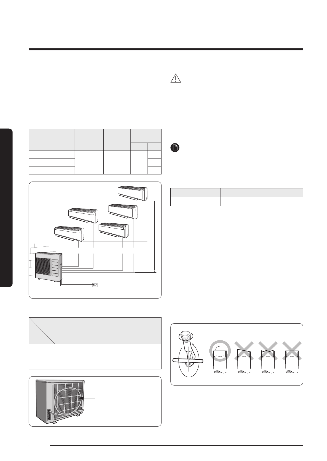
When installing 1 outdoor unit
(Unit : mm)
300 or more
1500 or more
300 or
more
600 or
more
300 or
more
2000 or
more
1500 or
more
600 or more
300
or more
1500
or more
300 or
mor
e
When installing more than 1 outdoor unit
(Unit : mm)
1500
or more
600
or
more
3000
or more
3000
or more
3000
or more
600
or more
600
or
more
1500
or more
300
or more
600
or more
600
or
more
1500 or more
600
or more
600
or
more
600
or more
300
or
more
300
or more
300 or more
300 or more
500 or more
500 or more
CAUTION
• The outdoor unit must be installed according to the
specified distances in order to permit accessibility
from each side, to guarantee correct operation,
maintenance, and repair of the unit.
The components of the outdoor unit must be
re
achable and removable under safe conditions for
people and the unit.
DB68-09261A-05_IM_FJM HP Outdoor_EA_EN_.indd 7DB68-09261A-05_IM_FJM HP Outdoor_EA_EN_.indd 7 2024-02-07 오전 8:18:562024-02-07 오전 8:18:56
8
Installation Procedure
English
Installation Procedure
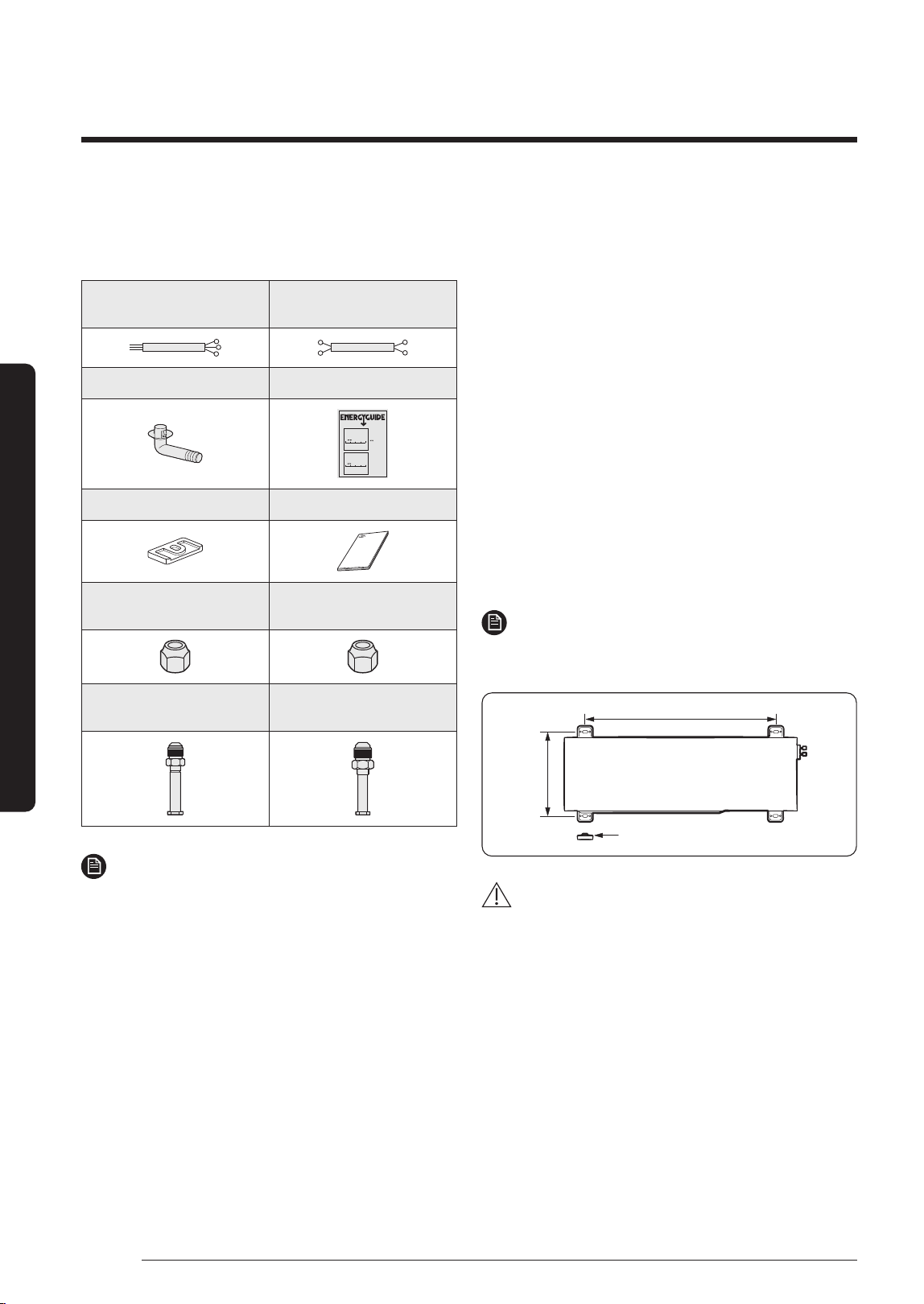
Step 2 Checking and preparing
accessories and tools
3-wire
Power Cable (option)
2-wire
Assembly Cable (option)
Drain Plug Energy Label
Federal law prohibits removal of this label before consumer purchase.U.S. Government
Heat Pump
Cooling and Heating
Split System
Samsung Electronics Co., Ltd.
Model AJ036JCJ5CH
Heating Capacity 40,000 Btu/h
Cooling Capacity 36,000 Btu/h
13.5
Most Efficient
Range of Similar Models
* Heating Seasonal Performance Factor
Least Efficient
8.2
9.0-9.5
Heating
Efficiency Rating
(HSPF)*
30.5
Most Efficient
Range of Similar Models
* Seasonal Energy Efficiency Ratio
Least Efficient
14.0
16.5-18.5
Cooling
Efficiency Rating
(SEER)*
For energy cost info, visit
productinfo.energy.gov
This system’s
efficiency ratings depend
on the coil your contractor
installs with this unit. The
heating efficiency rating
varies slightly in different
geographic regions. Ask
your contractor for details.
Rubber Leg Installation Manual
Flare Nuts, 15.88 mm
outer pipe diameter
Flare Nuts, 9.52 mm
outer pipe diameter
Tube connector
(Pipe 12.70 mm, Bolt 9.52 mm)
Tube connector
(Pipe 12.70 mm, Bolt 15.88 mm)
NOTE
• Attach Energy Label to the outdoor unit properly when
installing.
• Wire assembly cables are optional. If they are not
supplied, use standard cables.
• The drain plug and the rubber legs are included only
when the air conditioner is supplied without assembly
pipes.
• If these accessories are supplied, they are in the
accessory package or outdoor unit package.
Step 3 Fixing the outdoor unit in
place
Install the outdoor unit on a rigid and stable base to
prevent disturbance from any noise caused by vibration.
When installing the unit on tall stands or in a location
exposed to strong winds, fix the unit securely to the
ground or structure.
1 Position the outdoor unit so that the air flow is directed
towards the outside, as indicated by the arrows on the
top of the unit.
2 Attach the outdoor unit to the appropriate support
using anchor bolts.
• The ground wire for the telephone line cannot be
used to ground the air conditioner.
3 DIf the outdoor unit is exposed to strong winds, install
shield plates around the outdoor unit, so that the fan
can operate correctly.
NOTE
• Install provided rubber legs to prevent vibration and
noise.
620 mm
Rubber leg
360 mm
CAUTION
• Install a drain outlet at the lowest end around the base
for outdoor unit drainage
• When installing the outdoor unit on the roof,
waterproof the unit and check the ceiling strength.
DB68-09261A-05_IM_FJM HP Outdoor_EA_EN_.indd 8DB68-09261A-05_IM_FJM HP Outdoor_EA_EN_.indd 8 2024-02-07 오전 8:18:562024-02-07 오전 8:18:56
9
English
Installation Procedure
Optional: Fixing the outdoor unit to a wall with a rack
Designed to cut off residual vibration from outdoor
unit to rack. (not supplied with product)
Soft rubber designed to cut off vibration from rack
to wall. (not supplied with product)
Anchor bolt
20 mm
Base surface
• Install a proper grommet in order to reduce noise
and residual vibration transferred by the outdoor unit
towards the wall.
CAUTION
• When installing an air guide duct, be sure to check the
following:
– The screws do not damage the copper pipe.
– The air guide duct is fixed firmly on the guard fan.
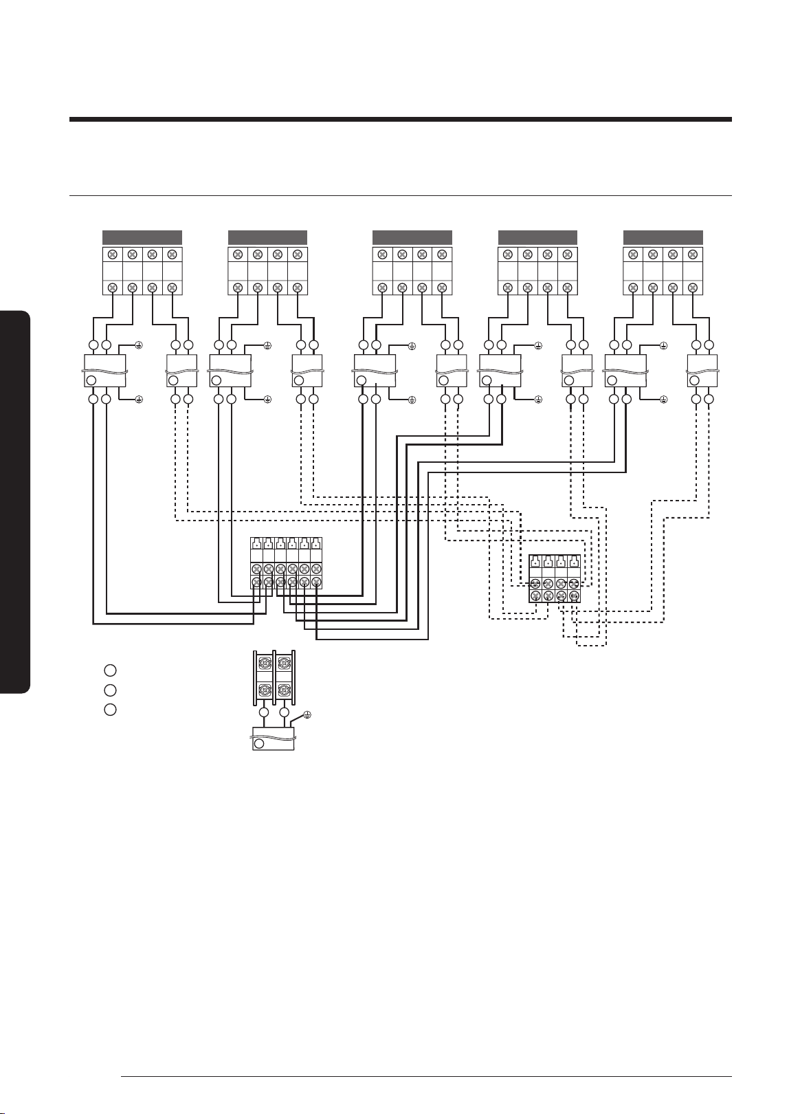
Step 4 Connecting the power cables,
communication cable, and controllers
You must connect the following three electrical cables to
the outdoor unit:
• The main power cable between the auxiliary circuit
breaker and the outdoor unit.
• The outdoor-to-indoor power cable between the
outdoor unit and the indoor unit.
• The communication cable between the outdoor unit
and the indoor unit.
CAUTION
• During installation, make first the refrigerant
connections and then the electrical connections. If the
unit is being removed, first disconnect the electrical
cables and then the refrigerant connections.
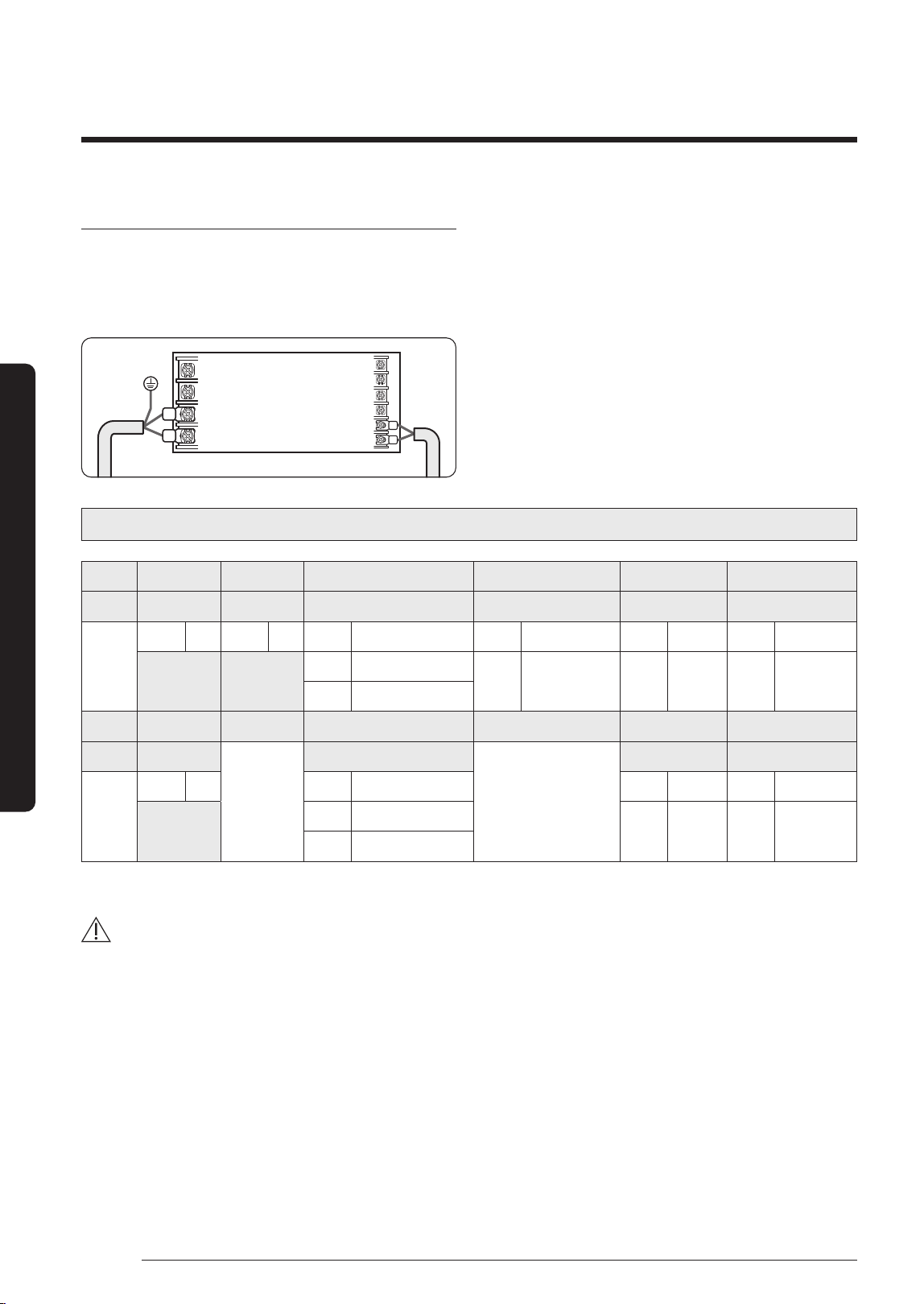
• Connect the air conditioner to the earthing system
before making the electrical connections.
NOTE
• Especially, if your outdoor unit is the one designed for
Russian and European markets, consult the supply
authority, if necessary, to estimate and reduce the
supply system impedance before installation.
Connecting wire conduits
For AJ125TXJ5KH / AJ140TXJ5KH models only
When connecting cables between the indoor unit and the
outdoor unit, use conduits to protect the cables.
1 Remove the conduit plate from the product.
2 Remove conduit knock-outs for the required number
of connections.
Power supply
(19.05 mm)
Out
door-Indoor
(12.70 mm)
3 Insert the cables through the conduits, and then fix the
conduits to the conduit plate with the lock nuts.
4 Apply silicone to the end of the hose to prevent rain
from entering the hose.
Conduit inserted into the outdoor unit
Silicone
5 Connect the cables to the outdoor units.
For how to connect the cables, refer to the next page.
6
Attach the conduit plate to the product.
DB68-09261A-05_IM_FJM HP Outdoor_EA_EN_.indd 9DB68-09261A-05_IM_FJM HP Outdoor_EA_EN_.indd 9 2024-02-07 오전 8:18:572024-02-07 오전 8:18:57
10
Installation Procedure
English
Installation Procedure
Connecting the cables to the outdoor unit
L N 1(L) 2(N)
1(L) 2(N)
1(L) 2(N) F1 F2 1(L) 2(N) F1 1(L) 2(N) F1 1(L)
2(N)
F1F2
1
2
F1 F2 F1 F2
1
2
21
F2
1
2
F1 F2
F1 F2
F2
F1 F2
F1 F2
1
2
1
2
B
C B CB C B C
A
1(L)
2(N) F1 F2
F1 F2
F1 F2
1
2
B C
F1 F2 F1 F2
F1 F2 F1 F2
L N
1 2
21
1 2
21
A-unit B-unit C-unit D-unit E-unit
Indoor unit
Assembly cable
Earth
terminal
Earth
t
erminal
Earth
terminal
Earth
terminal
Earth
terminal
Earth
terminal
Ear
th
t
erminal
Earth
terminal
Earth
terminal
Earth
terminal
Outdoor unit
Main Power supply cable
Power cable to indoor units
Communication cable
to indoor units
Cable Type : A
Cable Type : B
Cable Type : C
Earth
terminal
A
B
C
DB68-09261A-05_IM_FJM HP Outdoor_EA_EN_.indd 10DB68-09261A-05_IM_FJM HP Outdoor_EA_EN_.indd 10 2024-02-07 오전 8:18:572024-02-07 오전 8:18:57
11
English
Installation Procedure
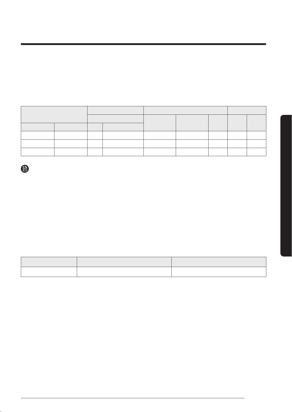
Specification for circuit breaker and power supply cord
• Power supply cord is not supplied with air conditioner.
• Select the power supply cord in accordance with relevant local and national regulations.
• Wire size must comply with the applicable local and national code.
• Specifications for local wiring power supply cord and branch wiring are in compliance with local cord.
Model
Outdoor Unit Maximum Input Current [A] Power Supply
Rated
Outdoor Indoor (Max.) Total MCA MFA
Outdoor Unit Indoor Unit Hz Volts
AJ100TXJ5KH 5 Room 50/60 1phase, 220-240 23.0 2.0 25.0 25.00 28.75
AJ125TXJ5KH 5 Room 50/60 1phase, 220-240 32.0 2.0 34.0 34.00 40.00
AJ140TXJ5KH 5 Room 50/60 1phase, 220-240 32.0 2.0 34.0 34.00 40.00
NOTE
1 Power Supply cords of parts of appliances for outdoor use shall not be lighter than polychloroprene sheathed flexible
cord. (Code designation IEC:60245 IEC 57 / CENELEC: H05RN-F, IEC:60245 IEC 66 / CENELEC: H07RN-F )
2 Select power supply cord based on MCA.
3 MFA is used to select the circuit breaker and the ground fault circuit interrupter (earth leakage circuit breaker).
4 MCA represents maximum input current.
5 MFA represents capacity which may accept MCA.
Abbreviations
• MCA : Min. Circuit Amps. (A)
• MFA : Max. Fuse Amps. (A)
Screw Tighten Torque(kgf.cm) Position
M4 12.0 ~ 18.0 1(L), 2(L), L, N, F1, F2
Tightening power terminal
• Connect the cables to the terminal board using the compressed ring terminal.
• Use rated cables only.
• Connect the cables with driver and wrench that can apply the rated torque to the screws.
• Make sure that appropriate tightening torque is applied for cable connection. If the terminal is loose, arc heat may
occur and cause fire and if the terminal is connected too firmly, terminal may get damaged.
DB68-09261A-05_IM_FJM HP Outdoor_EA_EN_.indd 11DB68-09261A-05_IM_FJM HP Outdoor_EA_EN_.indd 11 2024-02-07 오전 8:18:572024-02-07 오전 8:18:57
12
Installation Procedure
English
Installation Procedure
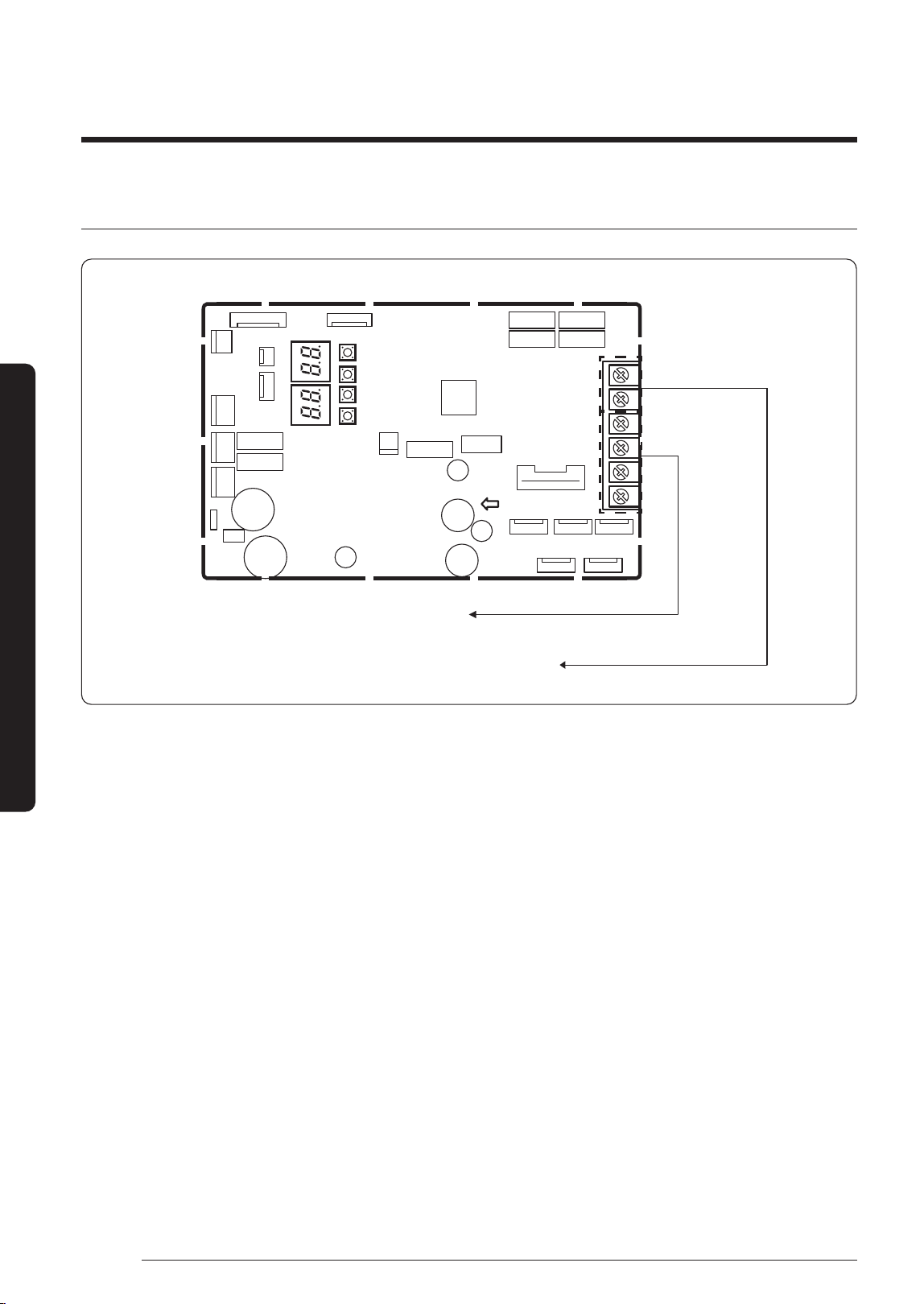
Central control connection (optional)
PCB MAIN - OUT
Do not connect the power and communication
wires to these terminal blocks
Terminal blocks(R1,R2) for connection with the Upper Controller
(DMS, Touch, On/Off Controller, etc.)
1 Turn the power off and take off the cover of the outdoor units.
2 Connect R1/R2 lines which are upper controller communication cables referring to upper figure.
(Upper controller power should be off.)
3
Assemble a cover of the outdoor unit and turn the power on.
4 Check the communication status.
5 If you install a upper controller to the outdoor unit, every indoor unit which is connected to the outdoor unit can be
controlled simultaneously.
DB68-09261A-05_IM_FJM HP Outdoor_EA_EN_.indd 12DB68-09261A-05_IM_FJM HP Outdoor_EA_EN_.indd 12 2024-02-07 오전 8:18:572024-02-07 오전 8:18:57
13
English
Installation Procedure
Outdoor-to-indoor power terminal
specifications
• Connect the cables to the terminal board using the
compressed ring terminal.
• Cover a solderless ring terminal and a connector part
of the power cable and then connect it.
B
L
EF
d1
D
t
d2
Norminal
dimensions
for cable
(mm²)
Norminal
dimensions
for screw
(mm)
B D d1 E F L d2 t
Standard
dimension
(mm)
Allowance
(mm)
Standard
dimension
(mm)
Allowance
(mm)
Standard
dimension
(mm)
Allowance
(mm)
Min.
(mm)
Min.
(mm)
Max.
(mm)
Standard
dimension
(mm)
Allowance
(mm)
Min.
(mm)
1.5
4 6.6
±0.2 3.4
+0.3
-0.2
1.
7 ±0.2 4.1 6 16 4.3
+0.2
0
0.7
4 8
2.5
4 6.6
±0.2 4.2
+0.3
-0.2
2.3 ±
0.2 6 6 17.5 4.3
+0.2
0
0.8
4 8.5
4 4 9.5 ±0.2 5.6
+0.3
-0.2
3.4 ±0.2 6 5 20 4.3
+ 0.2
0
0.9
• Connect the rated cables only.
• Connect using a driver which is able to apply the rated
torque to the screws.
• If the terminal is loose, fire may occur caused by arc. If
the terminal is connected too firmly, the terminal may
be damaged.
Tightening torque (kgf • cm)
M4 12.0 to 18.0
M5 20.0 to 30.0
(1N • m = 10 kgf • cm)
CAUTION
• When connecting cables, you can connect the cables to
the electrical part or connect them through the holes
below depending on the spot.
• Connect the communication cable between the indoor
and outdoor units through a conduit to protect against
external forces, and feed the conduit through the wall
together with refrigerant piping.
• Remove all burrs at the edge of the knock-out hole
and secure the cable to the outdoor knock-out using
lining and bushing with an electrical insulation such as
rubber and so on.
• Must keep the cable in a protection tube.
• Keep distances of 50mm or more between power cable
and communication cable.
• When the cables are connected through the hole,
remove the Plate bottom.
DB68-09261A-05_IM_FJM HP Outdoor_EA_EN_.indd 13DB68-09261A-05_IM_FJM HP Outdoor_EA_EN_.indd 13 2024-02-07 오전 8:18:572024-02-07 오전 8:18:57
14
Installation Procedure
English
Installation Procedure
Outdoor-to-indoor power and communication
cables specifications
Indoor power supply
Power supply Max/Min (V) Indoor power cable
1Φ, 220-240V, 50/60 Hz
±10%
1.5 mm²
↑
,
3 wires
C
ommunic
ation cable
0.75 to 1.5 mm², 2 wires
• Power supply cords of parts of appliances for outdoor
use shall not be lighter than polychloroprene sheathed
flexible cord. (Code designation IEC:60245 IEC 57 /
CENELEC: H05RN-F or IEC:60245 IEC 66 / CENELEC:
H07RN-F)
• When installing the indoor unit in a computer room or
net work room, server room or in the presence of risk
of disturbance to the communication cable, use the
double shielded (tape aluminium / polyester braid +
copper ) cable of FROHH2R type.
Step 5 Optional: Extending the
power cable
1 Prepare the following tools.
Tools Spec Shape
Crimping pliers MH-14
Connection sleeve
(mm)
20xØ6.5
(HxOD)
Insulation tape Width 19 mm
Contraction tube
(mm)
70xØ8.0
(LxOD)
2 As shown in the figure, peel off the shields from the
rubber and wire of the power cable.
• Peel off 20 mm of cable shields from the pre-
installed tube.
Power cable
(Unit: mm)
20 20
20
60
120
180
180
120
60
20 20 20
Pre-installed
tube for the
power cable
CAUTION
• For information about the power cable specifications
for indoor and outdoor units, refer to the installation
manual.
• After peeling off cable wires from the pre-installed
tube, insert a contraction tube.
3 Insert both sides of core wire of the power cable into
the connection sleeve.
• Method 1: Push the core wire into the sleeve from
both sides.
• Method 2: Twist the wire cores together and push it
into the sleeve.
Method 1
Connection sleeve Connection sleeve
Method 2
CAUTION
• If cable wires are connected without using connecting
sleeves, their contact area becomes reduced, or
corrosion develops on the outer surfaces of the wires
(copper wires) over a long time. This may cause an
increase of resistance (reduction of passing current)
and consequently may result in a fire.
DB68-09261A-05_IM_FJM HP Outdoor_EA_EN_.indd 14DB68-09261A-05_IM_FJM HP Outdoor_EA_EN_.indd 14 2024-02-07 오전 8:18:582024-02-07 오전 8:18:58
15
English
Installation Procedure
4 Using a crimping tool, compress the two points and
flip it over and compress another two points in the
same location.
• The compression dimension should be 8.0.
Compression
dimension
• After compressing it, pull both sides of the wire to
make sure it is firmly pressed.
Method 1 Method 2
5 mm
Compress it 4 times. Compress it 4 times.
5 mm
5 Apply heat to the contraction tube to contract it.
Method 1
Contraction tube Contraction tube
Method 2
6 Wrap it with the insulation tape twice or more and
position your contraction tube in the middle of the
insulation tape.
Method 1 Method 2
40 mm
Insulation tape Insulation tape
35 mm
7 After tube contraction work is completed, wrap it with
the insulation tape to finish.
Three or more layers of insulation are required.
Method 1
IInsulation tape
IInsulation tape
Method 2
CAUTION
• Make sure that the connection parts are not exposed
to outside.
• Be sure to use insulation tape and a contraction tube
made of approved reinforced insulating materials
that have the same level of withstand voltage with
the power cable. (Comply with the local regulations on
extensions.)
WARNING
• In case of extending the electric wire, please DO NOT
use a round-shaped Pressing socket.
– Incomplete wire connections can cause electric
shock or a fire.
DB68-09261A-05_IM_FJM HP Outdoor_EA_EN_.indd 15DB68-09261A-05_IM_FJM HP Outdoor_EA_EN_.indd 15 2024-02-07 오전 8:18:582024-02-07 오전 8:18:58
16
Installation Procedure
English
Installation Procedure
Step 6 Connecting the refrigerant
pipe
AJ100TXJ5KH/AJ125TXJ5KH/AJ140TXJ5KH
1 Piping outside diameter
Indoor unit Out unit
Power supply
Ø, V, Hz
Outside
diameter
Liquid Gas
**020/025/026/035**
AJ100TXJ5KH
AJ125TXJ5KH
AJ140TXJ5KH
1,
220-240,
50/60
1/4"
3/8"
**050/052** 1/2"
**068/071** 5/8"
Main power switch
A B C D E
(h)
(H)
2 Piping length and the height.
1 Room max
length
5 Room total
max length
Max height
between
indoor unit &
outdoor unit
Max height
between
indoor units
Dimension 25 m 70 m 15 m 7. 5 m
Composition A, B, C, D, E
A + B + C +
D + E
(H) (h)
Make at least one round:
It will reduce noise and vibration
CAUTION
• Minimum pipe length is 3 m to reduce noise and
vibration.
• Tighten the nuts to the specified torques.
If overtightened, the nuts could be broken so
r
e
frigerant may leak.
• Protect or enclose refrigerant tubing to avoid
mechanical damage.
NOTE
• The appearance of the unit may be different from the
diagram depending on the model.
• You can use the Cool and Heat modes in the following
conditions :
Mode Cool Heat
Outdoor temperature -10 ℃ to 46 ℃ -15 ℃ to 24 ℃
• It could take maximum 60 minutes to operate for
the protection of the compressor, if the outdoor
temperature is below -5 ℃.
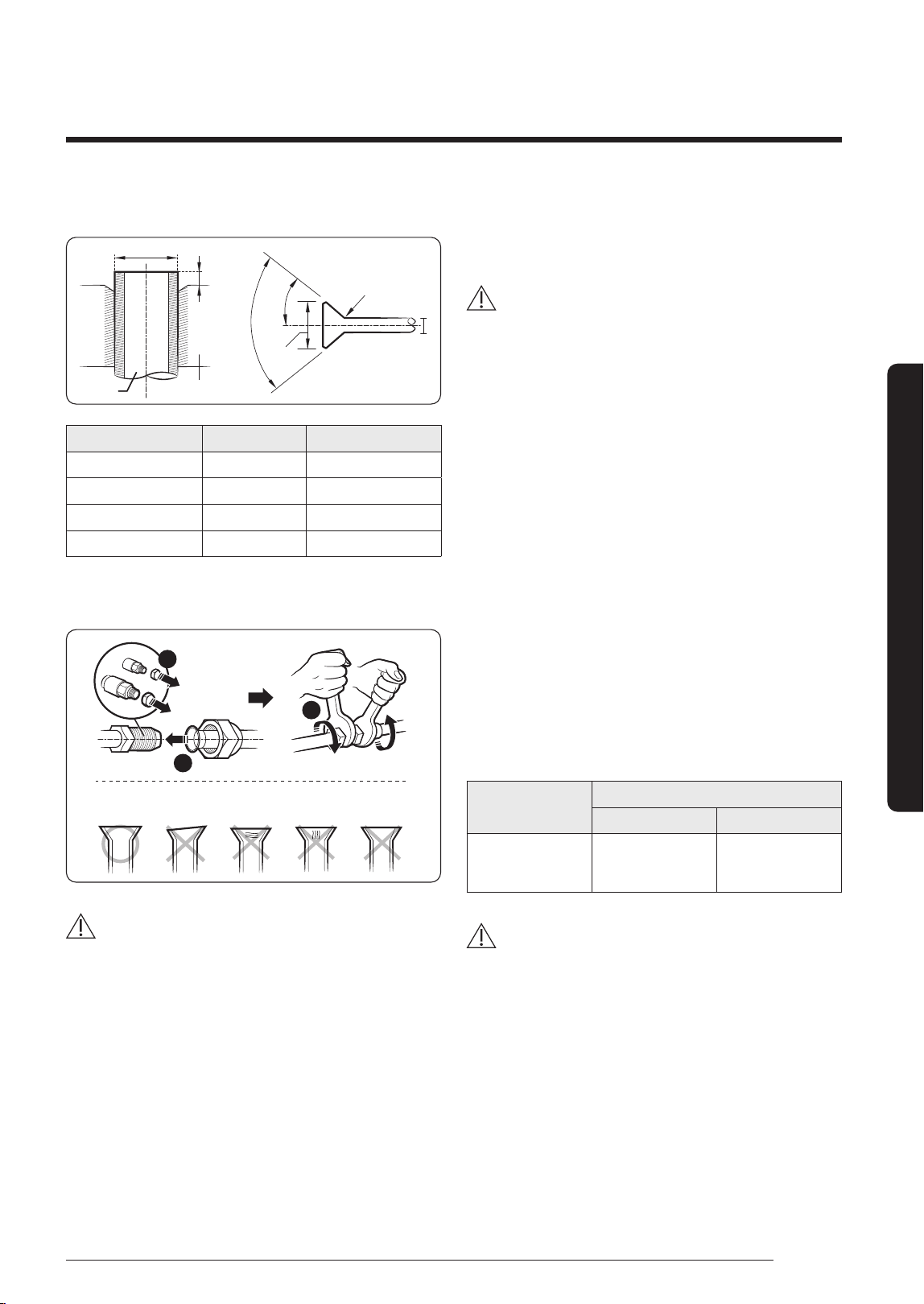
Step 7 Optional: Cutting and flaring
the pipes
1 Make sure that you have the required tools available.
(pipe cutter, reamer, flaring tool, and pipe holder)
2 If you wish to shorten the pipes, cut it with a pipe
cutter, taking care to ensure that the cut edge remains
at a 90° angle with the side of the pipe. Refer to the
illustrations below for examples of edges cut correctly
and incorrectly.
Oblique Rough Burr
90°
3 To prevent any gas from leaking out, remove all burrs
at the cut edge of the pipe, using a reamer.
DB68-09261A-05_IM_FJM HP Outdoor_EA_EN_.indd 16DB68-09261A-05_IM_FJM HP Outdoor_EA_EN_.indd 16 2024-02-07 오전 8:18:592024-02-07 오전 8:18:59
17
English
Installation Procedure
4 Slide a flare nut on to the pipe and flare the pipe.
D
D
L
A
90° ± 2°
Pipe
Flare
45° ± 2°
R 0.4 to 0.8 mm
Flare
Outer diameter (D) Depth (A) Flare dimension (L)
ø6.35 mm 14 to 18 mm 8.7 to 9.1 mm
ø9.52 mm 34 to 42 mm 12.8 to 13.2 mm
ø12.70 mm 49 to 61 mm 16.2 to 16.6 mm
ø15.88 mm 68 to 82 mm 19.3 to 19.7 mm
5 Check that the flaring is correct, referring to the
illustrations below for examples of incorrect flaring.
Correct Inclined
Damaged
Surface
Uneven
Thickness
Cracked
1
2
3
CAUTION
• If the pipes require brazing ensure that OFN (Oxygen
Free Nitrogen) is flowing through the system.
• Nitrogen blowing pressure range is 0.02 to 0.05 MPa.
Step 8 Connecting refrigerant pipes
and vacuuming
WARNING
• When installing, make sure there is no leakage. When
recovering the refrigerant, ground the compressor first
before removing the connection pipe. If the refrigerant
pipe is not properly connected and the compressor
works with the service valve open, the pipe inhales the
air and it makes the pressure inside of the refrigerant
cycle abnormally high. It may cause explosion and
injury.
The outdoor unit is loaded with sufficient R-410A
refrigerant. Do not vent R-410A into atmosphere: it is a
fluorinated greenhouse gas, covered by Kyoto Protocol,
with a Global Warming Potential (GWP) = 2088.
You should purge the air in the indoor unit and in the
pipe. If air remains in the refrigerant pipes, it affects the
compressor. It may cause reduction of cooling capacity
and malfunction. Refrigerant for air purging is not
charged in the outdoor unit. Use Vacuum Pump as seen in
the picture.
1 Check the piping connections.
2 Connect the charging hose of low pressure side of
manifold gauge to the stop valve having a service port.
Model Name
Valve
3/8'' 1/2''
AJ100TXJ5KH
AJ125TXJ5KH
AJ140TXJ5KH
2 3
CAUTION
• Make the electrical connection and leave the system
into "stand by mode". Do not turn on the system! This
is necessary for better vacuum operation (full OPEN
position of Electronic Expansion Valve - EEV -).
DB68-09261A-05_IM_FJM HP Outdoor_EA_EN_.indd 17DB68-09261A-05_IM_FJM HP Outdoor_EA_EN_.indd 17 2024-02-07 오전 8:18:592024-02-07 오전 8:18:59
18
Installation Procedure
English
Installation Procedure
Tightening torque for body cap
(Refer to the table)
Spindle
Char
ging core
Charging port cap
R-410A: Diameter of the
screw-1/2-20UNF
Vacuum
Pump
3 Open the valve of the low pressure side of manifold
gauge counter clockwise.
4 Purge the air from the system using vacuum pump for
about 30 minutes.
• Close the valve of the low pressure side of manifold
gauge clockwise.
• Make sure that pressure gauge show -0.1MPa
(-76 cmHg) after about 1 hour. This procedure is very
important in
order to avoid gas leak.
• Turn off the vacuum pump.
• Remove the hose of the low pressure side of
manifold gauge.
5 Set spindle of both liquid side and gas side of stop
valve to the open position.
6 Mount the valve stem nuts and the service port cap to
the valve, and tighten them with a torque wrench.
Outer diameter
(mm)
Tightening torque
Body cap
(N•m)
Charging por
t cap
(N•m)
ø 6.35 20 to 25
10 to 12
ø 9.52 20 to 25
ø 12.70 25 to 30
ø 15.88 30 to 35
※
The designs and shape are subject to change according
to the model.
Step 9 Performing the gas leak test
Before completing the installation (insulation of the
cables, hose and piping and fixing of the indoor unit to the
installation plate), you must check that there are no gas
leaks.
To check for gas
leaks on the...
Then, using a leak detector, check the...
Outdoor unit Valves on sections A and B.
Indoor unit Flare nuts at the end of sections C and D.
Outdoor unit Indoor unit
C D
B (Gas)
A (Liquid)
• The designs and shape are subject to change
according to the model.
DB68-09261A-05_IM_FJM HP Outdoor_EA_EN_.indd 18DB68-09261A-05_IM_FJM HP Outdoor_EA_EN_.indd 18 2024-02-07 오전 8:19:002024-02-07 오전 8:19:00
19
English
Installation Procedure
LEAK TEST WITH NITROGEN (before opening valves)
Pressure check the refrigerant system using high
pressure nitrogen in order to detect basic refrigerant
leaks Before performing the vacuum process and
releasing the factory R-410A charge into the refrigerant
pipes, it is the responsibility of the installer to pressurize
the whole system with nitrogen (using a cylinder with
pressure reducer) at a pressure above 4 MPa (gauge).
LEAK TEST WITH R-410A (after opening valves)
Before opening valves, discharge all the nitrogen into the
system and create vacuum. After opening valves check
leaks using a leak detector for refrigerant R-410A.
Once you have completed all the connections, check for
possible leaks using leak detector specifically designed
for HFC refrigerants.
Step 10 Adding refrigerant (R-410A)
Important information regulation regarding the
refrigerant used
This product contains fluorinated greenhouse gases. Do
not vent gases into the atmosphere.
CAUTION
• Inform user if system contains 5 tCO₂e or more of
fluorinated greenhouse gases. In this case, it has to
be checked for leakage at least once every 12 months,
according to regulation n°517/2014. This activity has to
be covered by qualified personnel only.
• In case situation above (5 tCO₂e or more of R-410A),
installer (or recognized person which has responsibility
for final check) has to provide a maintenance book,
with all the information recorded according to
REGULATION (EU) No 517/2014 OF THE EUROPEAN
PARLIAMENT AND OF THE COUNCIL of 16 April 2014
on fluorinated greenhouse gases.
Please fill in the following with indelible ink on the
refrigerant charge label supplied with this product and
on this manual.
• ①: The factory refrigerant charge of the product.
• ②: The additional refrigerant amount charged in the
field.
• ① + ②: The total refrigerant charge.
Indoor Unit
Outdoor Unit
①
②
d
Unit kg tCO₂e
①, a
②, b
① + ②, c
Refrigerant type GWP value
R-410A 2088
• GWP: Global Warming Potential
• Calculating tCO₂e : kg x GWP / 1000
NOTE
a Factory refrigerant charge of the product: see unit
name plate
b Additional refrigerant amount charged in the
field(Refer to the above information for the
quantity of refrigerant replenishment.)
c Total refrigerant charge
d Refrigerant cylinder and manifold for charging
DB68-09261A-05_IM_FJM HP Outdoor_EA_EN_.indd 19DB68-09261A-05_IM_FJM HP Outdoor_EA_EN_.indd 19 2024-02-07 오전 8:19:002024-02-07 오전 8:19:00
20
Installation Procedure
English
Installation Procedure
Calculating the quantity of refrigerant to add
The quantity of additional refrigerant is variable according
to the installation situation. Thus, make sure the outdoor
unit situation before adding refrigerant.
If you install the excessive length of pipe, add additional
refrigerant as 10 g or 20 g per unit meter; refer to the
table below.
Refer to the Service Manual for more details on this
operation.
Model Name
Total connecting
pipe length (LT)
Adding refrigerant
AJ100TXJ5KH
LT ≤ 40 m Chargeless
LT > 40 m (LT - 40 m) x 20 g
AJ125TXJ5KH
AJ140TXJ5KH
LT ≤ 50 m Chargeless
LT > 50 m (LT - 50 m) x 10 g
Charging the system with liquid refrigerant
R-410A is a mixed type of refrigerant. It is necessary for
recharging under conditions of liquid. When recharging
refrigerant from the refrigerant cylinder to the
equipment, follow the instructions below.
• Before recharging, check whether the cylinder has
a siphon or not. There are two ways to recharge the
refrigerant.
Cylinder with siphon
Charge the refrigerant standing
the cylinder upright.
Charge the refrigerant turning
the cylinder upside down.
Cylinder without siphon
siphon
NOTE
• If R-410A refrigerant is charged with gas, the
composition of the charged refrigerant changes and
the characteristics of the equipment vary.
• While adding refrigerant use an electronic scale to
measure the volume added. If the refrigerant cylinder
doesn’t have a siphon, turn it upside-down.
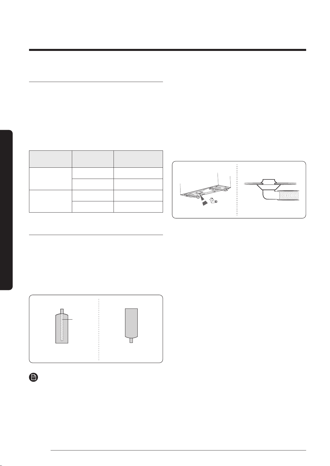
Step 11 Connecting the drain hose to
the outdoor unit
When heating, ice may accumulate. During the process of
defrosting, check if condensation draining is adequate.
For adequate draining, do the following :
1 Insert the drain plug into the drain hole on the
underside of the outdoor unit.
2 Connect the drain hose to the drain plug.
3 Ensure that condensation draining is adequate.
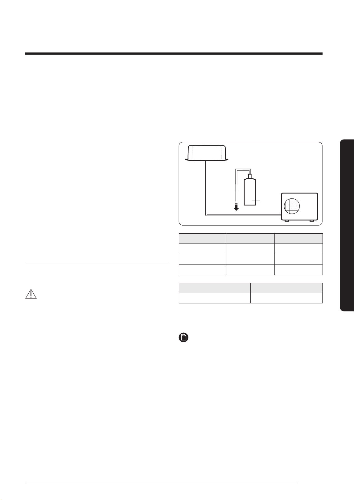
Step 12 Checking the earthing
If the power distribution circuit does not have a earthing
or the earthing does not comply with specifications, an
earthing electrode must be installed. The corresponding
accessories are not supplied with the air conditioner.
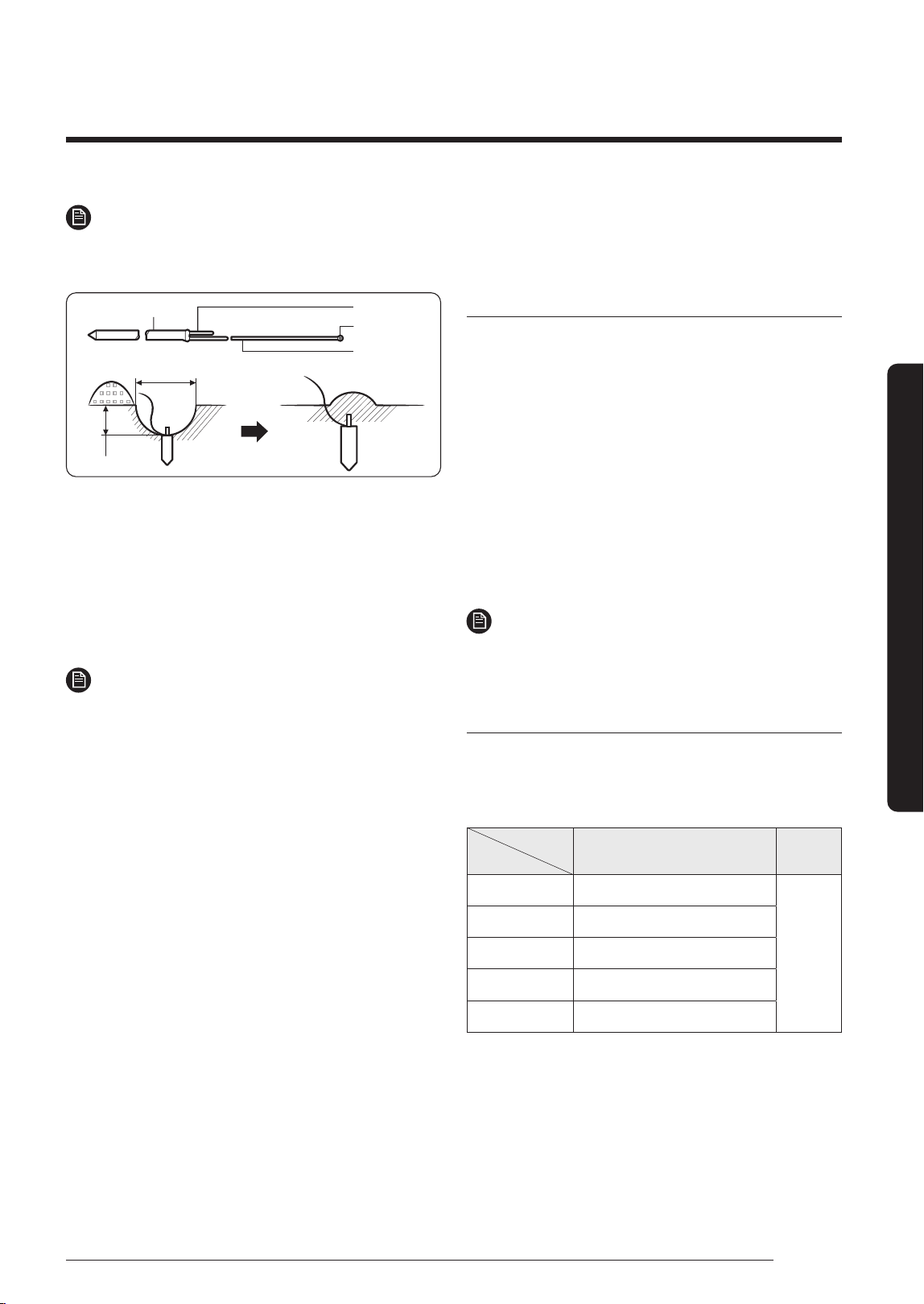
1 Select an earthing electrode that complies with the
specifications given in the illustration.
2 Connect the flexible hose to the flexible hose port.
• In damp hard soil rather than loose sandy or gravel
soil that has a higher earthing resistance.
• Away from underground structures or facilities,
such as gas pipes, water pipes, telephone lines and
underground cables.
• At least two meters away from a lightening
conductor earthing electrode and its cable.
DB68-09261A-05_IM_FJM HP Outdoor_EA_EN_.indd 20DB68-09261A-05_IM_FJM HP Outdoor_EA_EN_.indd 20 2024-02-07 오전 8:19:002024-02-07 오전 8:19:00
21
English
Installation Procedure
NOTE
• The earthing wire for the telephone line cannot be
used to ground the air conditioner.
Carbon plastic
To grounding screw
50 cm
30 cm
Steel core
Terminal M4
PVC-insulated
green/yellow
wire
3 Finish wrapping insulating tape around the rest of the
pipes leading to the outdoor unit.
4 Install a green/yellow colored earthing wire:
• If the earthing wire is too short, connect an
extension lead in a mechanical way and wrap it with
insulating tape (do not bury the connection).
• Secure the earthing wire in position with staples.
NOTE
• If the earthing electrode is installed in an area with
heavy traffic, its wire must be connected securely.
5 Carefully check the installation by measuring the
earthing resistance with a earth resistance tester. If
the resistance is above the required level, drive the
electrode deeper into the ground or increase the
number of earthing electrodes.
6 Connect the earthing wire to the electrical component
box inside of the outdoor unit.
Step 13 Setting an indoor unit
address and installation option
Setting the indoor unit addresses manually
1 Review all the following elements in the installation:
• Installation site strength
• Piping connection tightness to detect any gas
leakage
• Connection wiring
• Heat-resistant insulation of the piping
• Drainage
• Earthing wire connection
2 Manually set options in each room’s the indoor unit by
referring to page 25~31.
3 Press the K3 button once or reset the outdoor unit.
NOTE
• The Display 1/2 indications are the same as in the
automatic address setting mode.
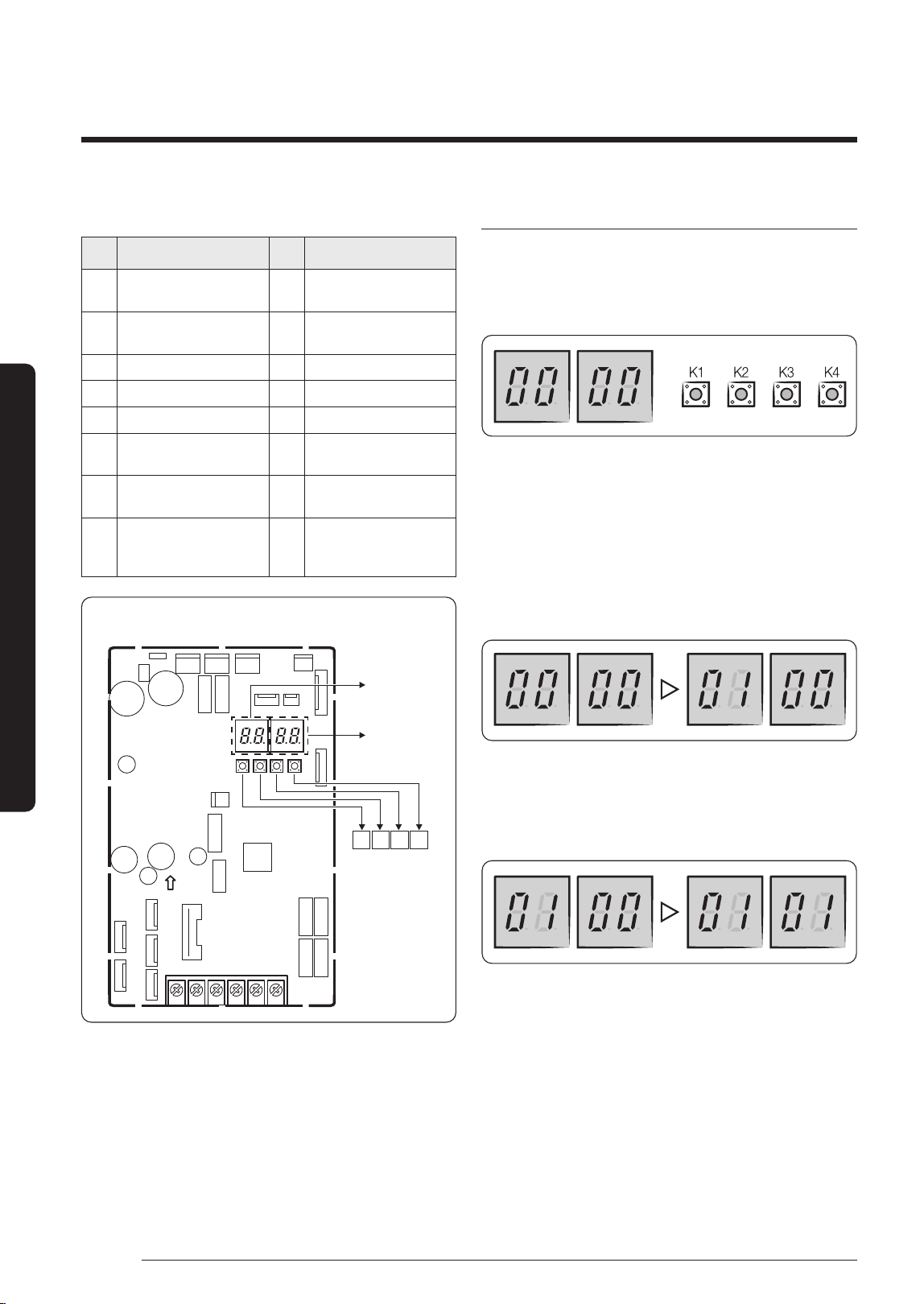
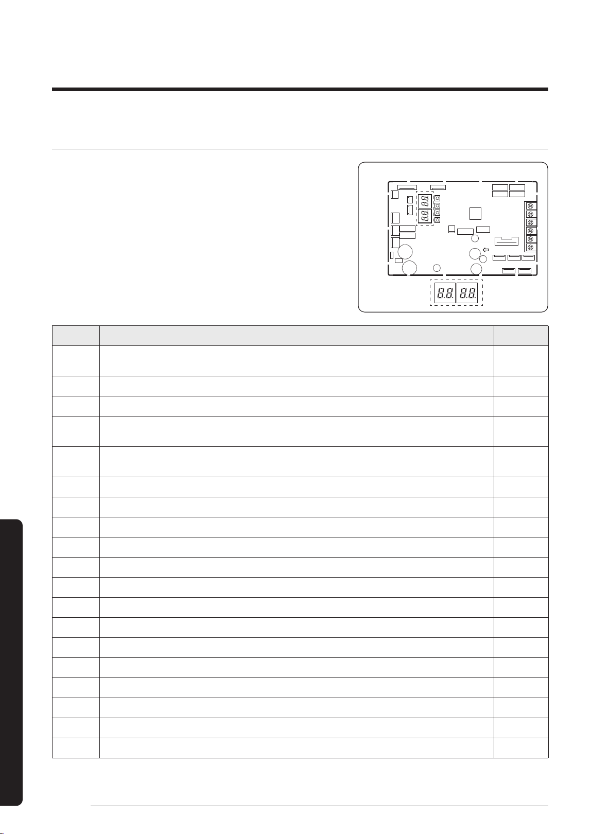
Setting Key and Display of the outdoor unit
• Key option of the outdoor unit
– K1: Function button
– K3: Reset button
Key
Push
K1 K3
1 Pipe Checking Operation
Reset
2 Cool Mode Try run
3 Heat Mode Try run
4 Pump Down
5 Finish Key Operation
※
For more information of the Cool or Heat Try run test,
refer to page 31.
DB68-09261A-05_IM_FJM HP Outdoor_EA_EN_.indd 21DB68-09261A-05_IM_FJM HP Outdoor_EA_EN_.indd 21 2024-02-07 오전 8:19:002024-02-07 오전 8:19:00
22
Installation Procedure
English
Installation Procedure
• K4 View mode Display changes
Push Display Explanation Push Display Explanation
1
Present Compressor
Frequency
9 Discharge temperature
2
Target Compressor
Frequency
10 OLP temperature
3 EEV0 current step 11 Condenser temperature
4 EEV1 current step 12 Outdoor temperature
5 EEV2 current step 13 Running current
6 EEV3 current step 14
Target Discharge
temperature
7 EEV4 current step 15
Total capacity of the indoor
units
8
Fan RPM
(H: high, L: low, Blank: off )
16
Safety
Control
(just For Service
T
ech
nician)
K1 K2
K3 K4
PCB MAIN - OUT
DISPLAY 1
DISPLAY 2
Setting the outdoor option
• Press and hold K2 to enter the option setting.
(Only available when the operation is stopped)
– If you enter the option setting, display will show the
following.
– Seg1 and Seg2 will display the number for selected
option.
– Seg3 and Seg4 will display the number for set value
of the selected option.
• If you have selected desired option, you can shortly
press the K1 switch to adjust the value of the Seg1,
Seg2 and change the function for the selected option.
Example)
• If you have selected desired option, you can shortly
press the K2 switch to adjust the value of the Seg3,
Seg4 and change the function for the selected option.
Example)
• After selecting the function for options, press and
hold the K2 switch for 2 seconds. Edited value of the
option will be saved when entire segments blinks and
tracking mode begins.
DB68-09261A-05_IM_FJM HP Outdoor_EA_EN_.indd 22DB68-09261A-05_IM_FJM HP Outdoor_EA_EN_.indd 22 2024-02-07 오전 8:19:012024-02-07 오전 8:19:01
23
English
Installation Procedure
Option item Input unit SEG1 SEG2 SEG3 SEG4 Function
Setting to Cool or Heat only
mode
Main 0 0
0 0 Cooling and Heating (Factory default)
0 1 Only Cooling
0 2 Only Heating
Power improvement mode Main 0 1
0 0 Disabled (Factory default)
0 1 Enabled
Mixed mode indoor input Main 0 2
0 0 Disabled (Factory default)
0 1 Enabled
Auto Change Over Main 0 3
0 0 Disabled
0 1 Enabled (Factory default)
Channel address Main 0 4
A U Automatic setting (Factory default)
00 ~ 15 Manual setting
CAUTION
• Edited option will not be saved if you do not end the option setting as explained in above instruction.
※
While you are setting the option, you may press and hold the K1 button to reset the value to previous setting.
※
If you want to restore the setting to factory default, press and hold the K4 button while you are in the option setting
mode.
– If you press and hold the K4 button, setting will be restored to factory default but it doesn't mean that restored
setting is saved. Press and hold the K2 button. When the segments shows that tracking mode is in progress,
setting will be saved.
DB68-09261A-05_IM_FJM HP Outdoor_EA_EN_.indd 23DB68-09261A-05_IM_FJM HP Outdoor_EA_EN_.indd 23 2024-02-07 오전 8:19:012024-02-07 오전 8:19:01
24
Installation Procedure
English
Installation Procedure
Setting Option
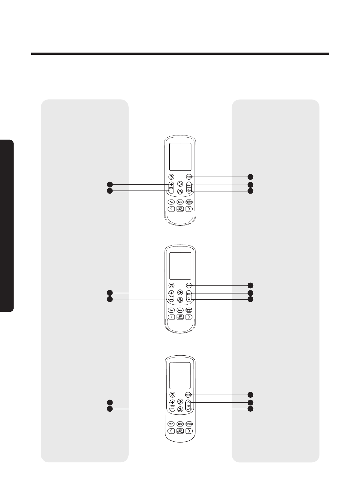
<AJ***TNAPKH>
<AJ***TNTDKH>
<AJ***TN*DKH>
Entering mode for setting option Option setting mode
2
1
1
1
4
4
4
5
5
5
2
2
3
3
3
High Temp button
Mode button
Mode button
Mode button
Fast button
Fast button
High Fan button
WindFree button
Eco button
Low Fan button
High Temp button
High Temp button
Low Temp button
Low Temp button
Low Temp button
DB68-09261A-05_IM_FJM HP Outdoor_EA_EN_.indd 24DB68-09261A-05_IM_FJM HP Outdoor_EA_EN_.indd 24 2024-02-07 오전 8:19:012024-02-07 오전 8:19:01
25
English
Installation Procedure
Setting Option
1 Remove batteries from the remote controller
2 Insert batteries and enter the option setting mode while pressing
2
button and
3
button.
3 Each time you press
5
button, 7-seg on left side is increased by "1" and each time you press
4
button, 7-seg on
right side is increased by "1"
4 You press
1
button to move to the next setting page.
5 After setting option, press
1
button to check whether the option code you input is correct or not.
→ → → →
→ → → →
6 Press operation button
with the direction of remote control for set.
CAUTION
• SEG1, SEG7, SEG13, SEG19 are not set as page option.
• Set the SEG1, SEG7 as ON status and SEG13, SEG19 as OFF status.
– Set the each option separately since you cannot set the ADDRESS setting and indoor unit installation setting
option at the same time.
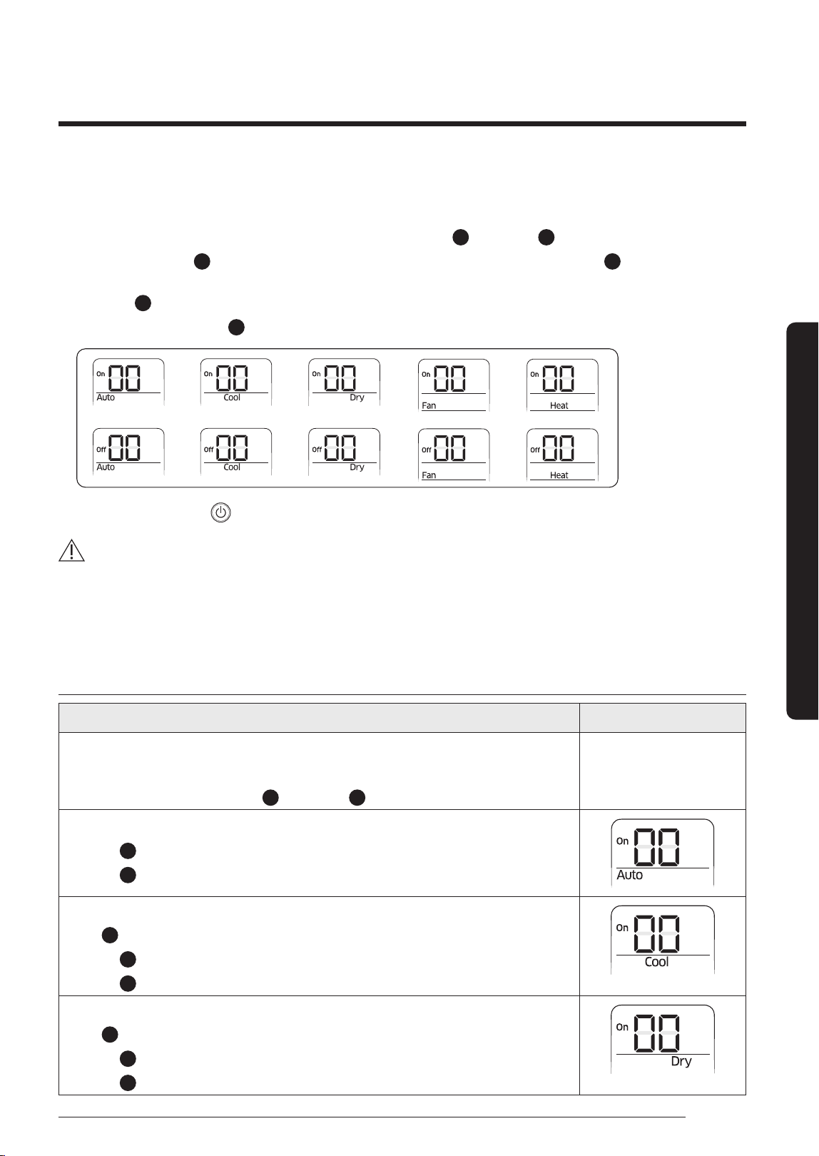
The procedure of setting option
Operation Indication
Step 1
1 Remove the batteries from the remote controller.
2 Insert batteries while pressing
2
Button and
3
Button.
Step 2
1 Press
5
button to enter SEG2 value.
2 Press
4
button to enter SEG3 value.
Step 3
Press
1
button to be change to Cool mode in the ON status.
1 Press
5
button to enter SEG4 value.
2 Press
4
button to enter SEG5 value.
Step 4
Press
1
button to be changed to DRY mode in the ON status.
1 Press
5
button to enter SEG6.
2 Press
4
button to enter SEG8.
DB68-09261A-05_IM_FJM HP Outdoor_EA_EN_.indd 25DB68-09261A-05_IM_FJM HP Outdoor_EA_EN_.indd 25 2024-02-07 오전 8:19:022024-02-07 오전 8:19:02
26
Installation Procedure
English
Installation Procedure
Operation Indication
Step 5
Press
1
button to be changed to FAN mode in the ON status.
1 Press
5
button to enter SEG9 value.
2 Press
4
button to enter SEG10 value.
Step 6
Press
1
button to be changed to HEAT mode in the ON status.
1 Press
5
button to enter SEG11 value.
2 Press
4
button to enter SEG12 value
Step 7
Press
1
button to be changed to AUTO mode in the OFF status.
1 Press
5
button to enter SEG14 value.
2 Press
4
button to enter SEG15 value.
Step 8
Press
1
button to be changed to Cool mode in the OFF status.
1 Press
5
button to enter SEG16 value.
2 Press
4
button to enter SEG17 value.
Step 9
Press
1
button to be changed to DRY mode in the OFF status.
1 Press
5
button to enter SEG18 value.
2 Press
4
button to enter SEG20 value.
Step 10
Press
1
button to be changed to FAN mode in OFF status
1 Press
5
button to enter SEG21 value.
2 Press
4
button to enter SEG22 value.
Step 11
Press
1
button to be changed to HEAT mode in the OFF status
1 Press
5
button to enter SEG23 value.
2 Press
4
button to enter SEG24 value.
Step 12
Press
1
button to check whether the option code you entered is correct or not.
Press operation button
to enter option.
DB68-09261A-05_IM_FJM HP Outdoor_EA_EN_.indd 26DB68-09261A-05_IM_FJM HP Outdoor_EA_EN_.indd 26 2024-02-07 오전 8:19:022024-02-07 오전 8:19:02
27
English
Installation Procedure
Setting the indoor unit addresses automatically
NOTE
• For the best results, make sure that electrical wiring is
done properly.
• For the best results, the outdoor temperature should be
between 5 to 40 ℃ and the indoor temperature 16℃ or
higher (*).
※ (*) Auto addressing may fail when the temperature is out
of the range above. In this case, set the address manually.
CAUTION
• Connecting one indoor unit to this product is
prohibited. Don't use pipe checking operation and
auto addressing mode when only one indoor unit is
installed.
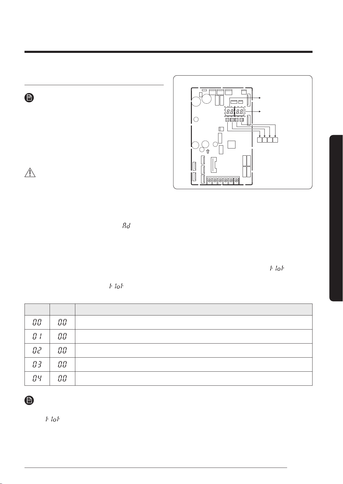
K1 K2
K3 K4
DISPLAY 1
DISPLAY 2
PCB MAIN - OUT
1 Turn on the outdoor unit, and then check whether the display 1/2 indications are displayed "E199" code.
※
During
the initial, display 1 shows "
" and display 2 shows the connected indoor number.
• If different display code is shown, see Troubleshooting on page 34 and take corrective actions.
2 Push once the K1 button.
3 After the operations described above have been performed, the system starts in Cooling or Heating mode,
depending on the external ambient temperature. After a few minutes (from a minimum of 3 to 5 minutes for the
internal unit), the system stops automatically, completing the self-test and addressing procedure. "
" appears
on the display of the outdoor unit.
4 20 seconds after the display of "
" (that confirms the correct execution of the procedure), the following codes
(if four internal units are connected) display in sequence on the display of the outdoor unit:
Display1 Display2 Description
The outdoor unit is communicating correctly with the indoor unit connected to refrigerant pipe A.
The outdoor unit is communicating correctly with the indoor unit connected to refrigerant pipe B.
The outdoor unit is communicating correctly with the indoor unit connected to refrigerant pipe C.
The outdoor unit is communicating correctly with the indoor unit connected to refrigerant pipe D.
The outdoor unit is communicating correctly with the indoor unit connected to refrigerant pipe E.
NOTE
• At this point it is possible to start the internal units in the desired mode.
※
If "
"doesn’t display, the procedure has failed and it is therefore necessary to read ALL the operator’s manual
before repeating the operating described in steps 1-2-3-4.
DB68-09261A-05_IM_FJM HP Outdoor_EA_EN_.indd 27DB68-09261A-05_IM_FJM HP Outdoor_EA_EN_.indd 27 2024-02-07 오전 8:19:032024-02-07 오전 8:19:03
28
Installation Procedure
English
Installation Procedure
Setting an indoor unit address (MAIN/RMC)
1 Check whether power is supplied or not.
– When the indoor unit is not plugged in, there
should be additional power supply in the indoor
unit.
Indoor Unit
1(L)
2(N)
F1
F2
2 The panel (display) should be connected to an indoor
unit to receive option.
3 Before installing the indoor unit, assign an address
to the indoor unit according to the air conditioning
system plan.
4 Assign an indoor unit address by wireless remote
controller.
– The initial setting status of indoor unit
ADDRESS(MAIN/RMC) is "0A0000-100000-
200000-300000"
– There is no need to assign extra ADDRESS for 1:1
installation between indoor unit and outdoor unit.
Option No. : 0AXXXX-1XXXXX-2XXXXX-3XXXXX
Option SEG1 SEG2 SEG3 SEG4 SEG5 SEG6
Explanation Page Mode Setting main address 100-digit of indoor unit address 10-digit of indoor unit A single digit of indoor unit
Indication
and details
Indication Details Indication Details Indication Details Indication Details Indication Details Indication Details
0 A
0 No Main address
0~9 100-digit 0~9 10-digit 0~9 A single digit
1 Main address setting mode
Option SEG7 SEG8 SEG9 SEG10 SEG11 SEG12
Explanation PAGE
-
Setting RMC address
-
Group channel (*16) Group address
Indication
and Details
Indication Details Indication Details Indication Details Indication Details
1
0 No RMC address
RMC1 1~F RMC2 1~F
1 RMC address setting mode
※
You must set RMC address setting mode when using the centralized Control.
CAUTION
• When "A"~"F" is entered to SEG4~6, the indoor unit MAIN ADDRESS is not changed.
• If you set the SEG3 as 0, the indoor unit will maintain the previous MAIN ADDRESS even if you input the option value
of SEG4~6.
• If you set the SEG9 as 0, the indoor unit will maintain previous RMC ADDRESS even if you input the option value of
SEG11~12.
5 The MAIN address is for commnication between the indoor unit and the outdoor unit. Therefore, you must set it to
operate the air conditioner properly.
DB68-09261A-05_IM_FJM HP Outdoor_EA_EN_.indd 28DB68-09261A-05_IM_FJM HP Outdoor_EA_EN_.indd 28 2024-02-07 오전 8:19:032024-02-07 오전 8:19:03
29
English
Installation Procedure
Setting an indoor unit installation option (suitable
for the condition of each installation location)
The following explains how to set the options for the RAC
models. For other models, refer to the installation manual
included with each product.
1 Check whether power is supplied or not.
– When the indoor unit is not plugged in, there should
be additional power supply in the indoor unit.
Indoor Unit
1(L)
2(N)
F1
F2
2 The panel (display) should be connected to an indoor
unit to receive option.
3 Before installing the indoor unit, assign an option to the
indoor unit according to the air conditioning system plan.
• The default settings for installation of the indoor unit
are as follows:
– AJ020/025/035TNAPKH: 020010-100000-200101-
300346
– AJ050/068TNAPKH, AJ050/068TNTDKH: 020010-
100000-200101-300357
– AJ020/025/035TNTDKH: 020010-100000-200101-
300335
• Individual control of a remote controller(SEG20) is the
function that controls an indoor unit individually when
there is more than one indoor unit.
4 Set the indoor unit option by wireless remote controller.
– When entering Address option, connect remote
controller receiver.
Option SEG1 SEG2 SEG3 SEG4 SEG5 SEG6
Explanation Page Mode
Reserved
Use of external temperature sensor Use of central control
Reserved
Indication
and Details
Indication Details Indication Details Indication Details Indication Details
0 2
0 Use 0 Disuse
1 Disuse 1 Use
Option SEG7 SEG8 SEG9 SEG10 SEG11 SEG12
Explanation Page Use of drain pump
(*1)
Reserved Reserved Reserved Reserved
Indication
and Details
Indication Details Indication Details
1
0 Disuse
8 External drain pump signal use
DB68-09261A-05_IM_FJM HP Outdoor_EA_EN_.indd 29DB68-09261A-05_IM_FJM HP Outdoor_EA_EN_.indd 29 2024-02-07 오전 8:19:032024-02-07 오전 8:19:03
30
Installation Procedure
English
Installation Procedure
Option SEG13 SEG14 SEG15 SEG16 SEG17 SEG18
Explanation Page Use of external control
(*1)
Setting the output of external control
Reserved
Buzzer control
Reserved
Indication
and Details
Indication Details Indication Details Indication Details Indication Details
2
0 Disuse
0 Thermo ON 0 Use of buzzer
1 ON or OFF control
2 OFF control
1 Operation ON 1 Disuse of buzzer
3 Window ON or OFF control
Option SEG19 SEG20 SEG21 SEG22 SEG23 SEG24
Explanation Page Individual control with remote control
(*2)
Reserved Reserved Reserved Reserved
Indication
and Details
Indication Details Indication Details
3
0 Indoor 1
1 Indoor 1
2 Indoor 2
3 Indoor 3
4 Indoor 4
(*1)
If external drain pump signal is used, external control (SEG14) can't be used.
(*2)
If you input a number other than 0~4 of the individual control of the indoor unit(SEG20), the indoor is set as "indoor 1".
DB68-09261A-05_IM_FJM HP Outdoor_EA_EN_.indd 30DB68-09261A-05_IM_FJM HP Outdoor_EA_EN_.indd 30 2024-02-07 오전 8:19:032024-02-07 오전 8:19:03
31
English
Installation Procedure
Step 14 Cool and Heat modes
operation test
After installing the outdoor and indoor units, test the Cool
and Heat modes.
• When you test the Cool mode, set the set temperature
of the indoor unit to the lowest one. And when you test
the Heat mode, set the set temperature of the indoor
unit to the highest one.
• Check if each indoor unit operates normally and
then also check if all indoor units operate normally
together.
– Check both of the Cool and Heat modes.
• About 20 minutes after the air conditioner is started,
check the temperature difference between the air
inlet and outlet of the indoor unit. If the temperature
difference is larger than the value given in the
following table, the operation is normal.
Mode Temperature
Cool Approximately 8 ℃
Heat Approximately 12 ℃
CAUTION
• If the outdoor unit is turned off and then immediately
turned on again, the compressor does not operate for
about 3 minutes.
• During the Cool mode, frost may temporarily develop
on valves and other parts.
NOTE
• You can also test the Cool or Heat Try run using K1
button.
– Cool mode try-run : Push the [K1] button twice.
– Heat mode try-run : Push the [K1] button three
times.
Step 15 Optional: Setting to Cool or
Heat only mode
This function enables the indoor units connected to the
outdoor unit to operate in a specific mode.
You can set each mode with Keys on the Main PCB in the
outdoor unit.
Set mode SEG1 SEG2 SEG3 SEG4
Cooling and Heating
0
0
0 0
Only Cooling 0 1
Only Heating 0 2
• Default value: Cooling and Heating mode
Step 16 Optional: Power
improvement mode
The power improvement mode has the following power
reduction effects.
• Reduced power at Thermo off
– When the air conditioner operates in Cool, Dry and
Auto mode, if Thermo off is reached during cooling,
the fan and display of the indoor unit are turned off
after 5 minutes.
– When you operates the remote control, the indoor
unit display turns on again.
• Standby mode operation
– When all indoor units are turned off, the air
conditioner recognizes it and enters the standby
mode.
– The product power consumption in the standby
mode is 3.5 W or less.
Setting the power improvement mode
Enable or disable the power improvement mode with
Keys on the Main PCB in the outdoor unit.
Power improvement
mode
SEG1 SEG2 SEG3 SEG4
Disabled
0 1
0
0
Enabled
0
1
• Default value: Disabled
DB68-09261A-05_IM_FJM HP Outdoor_EA_EN_.indd 31DB68-09261A-05_IM_FJM HP Outdoor_EA_EN_.indd 31 2024-02-07 오전 8:19:032024-02-07 오전 8:19:03
32
Extra Procedures
English
Extra procedures
Extra Procedures
Extra procedures
Pumping down refrigerant
WARNING
• After installing the product, be sure to perform leak
tests on the piping connections. After pumping down
refrigerant to inspect or relocate the outdoor unit,
be sure to stop the compressor and then remove the
connected pipes.
– Do not operate the compressor while a valve is
open due to refrigerant leakage from a pipe or an
unconnected or incorrectly connected pipe. Failure
to do so may cause air to flow into the compressor
and too a high pressure to develop inside the
refrigerant circuit, leading to an explosion or
product malfunction.
Pump-down is an operation intended to collect all the
system refrigerant in the outdoor unit.
This operation must be carried out before disconnecting
the refrigerant pipe in order to avoid refrigerant loss to
the atmosphere.
1 Turn the system on in cooling with fan operating at
high velocity and then let the compressor run for more
than 5 minutes. (Compressor will immediately start,
provided 3 minutes have elapsed since the last stop.)
2 Release the valve caps on High and Low pressure side.
3 Use L-wrench to close the valve on the high pressure
side.
4 After approximately 2 minute, close the valve on the
low pressure side.
5 Stop operation of the air conditioner by pressing the
(Power) button on the indoor unit or remote control.
6 Disconnect the pipes.
B (Gas)
A (Liquid)
• The designs and shape are subject to change
according to the model.
Relocating the indoor and outdoor
units
1 Pump down refrigerant. See Pumping down
refrigerant on page 32.
2 Remove the power cord.
3 Disconnect the assembly cable from the indoor and
outdoor units.
4 Remove the flare nuts connecting the indoor units and
the pipes. At this time, cover the pipes of the indoor
unit and the other pipes using a cap or vinyl plug to
avoid foreign material entering.
5 Disconnect the pipes connected to the outdoor units.
At this time, cover the valve of the outdoor units and
the other pipes using a cap or vinyl plug to avoid
foreign material entering.
Note: Make sure you do not bend the connection
pipes in the middle and store together with the
cables.
6 Move the indoor and outdoor units to a new location.
7 Remove the mounting plate for the indoor unit and
move it to a new location.
Using the stop valve
Opening the stop valve
1 Open the cap and turn the stop valve anticlockwise by
using a hexagonal wrench.
2 Turn it until the axis is stopped.
Tightening torque for body cap
(Refer to the table)
Chargin
g core
Charging port cap
R-410A: Diameter of the
screw-1/2-20UNF
Spindle
DB68-09261A-05_IM_FJM HP Outdoor_EA_EN_.indd 32DB68-09261A-05_IM_FJM HP Outdoor_EA_EN_.indd 32 2024-02-07 오전 8:19:032024-02-07 오전 8:19:03
33
English
Extra procedures
3 Tighten the cap securely.
Outer Diameter
(mm)
Tightening torque
Body cap (N•m) Charging port cap (N•m)
Ø 6.35 20 to 25
10 to 12
Ø 9.52 20 to 25
Ø 12.70 25 to 30
Ø 15.88 30 to 35
(1N • m = 10 kgf • cm)
NOTE
• Do not apply excessive force to the stop valve and
always use special instruments. Otherwise, the
stopping box can be damaged and the back sheet can
leaks.
• If the watertight sheet leaks, turn the axis back by
half, tighten the stopping box, then check the leakage
again. If there is no leakage any more, tighten the axis
entirely.
Closing the stop valve
1 Remove the cap.
2 Turn the stop valve clockwise by using a hexagonal
wrench.
3 Tighten the axis until the valve reached the sealing
point.
4 Tighten the cap securely.
CAUTION
• When you use the service port, always use a charging
hose, too.
• Check the leakage of refrigerant gas after tightening
the cap.
• Must use a spanner and wrench when you open/
tighten the stop valve.
DB68-09261A-05_IM_FJM HP Outdoor_EA_EN_.indd 33DB68-09261A-05_IM_FJM HP Outdoor_EA_EN_.indd 33 2024-02-07 오전 8:19:032024-02-07 오전 8:19:03
34
Appendix
English
Appendix
Appendix
Appendix
Troubleshooting
• The table below list the self-diagnostic routines. For some of error,
you must contact an authorized service center.
• If an error occurs during the operation, it is displayed on the
outdoor unit PCB MAIN-OUT.
PCB MAIN - OUT
88 SEG DISPLAY
Error Code Explanation Remark
E108
ERROR DUE TO REPEATED ADDRESS SETTING(WHEN 2 OR MORE DEVICES HAS THE SAME ADDRESS
WITHIN THE NETWORK)
E190 PIPE CHECK ERROR
E199 PIPE CHECK OPERATION HAS NOT BEEN COMPLETED
E201
COMMUNICATION ERROR BETWEEN INDOOR AND OUTDOOR UNIT(INSTALLATION NUMBER SETTING
ERROR, REPEATED INDOOR UNIT ADDRESS, INDOOR UNIT COMM
E202
COMMUNICATION ERROR BETWEEN INDOOR AND OUTDOOR UNIT(COMMUNICATION ERROR ON ALL
INDOOR UNITS, OUTDOOR UNIT COMMUNICATION CABLE ERROR)
E203 COMMUNICATION ERROR BETWEEN INVERTER PBA AND MAIN PBA
E221 ERROR ON AMBIENT TEMPERATURE SENSOR (SHORT OR OPEN)
E237 ERROR ON CONDENSOR TEMPERATURE SENSOR(SHORT OR OPEN)
E251 ERROR ON DISCHARGE TEMPERATURE SENSOR(SHORT OR OPEN)
E320 ERROR ON COMPRESSOR OLP TEMPERATURE SENSOR(SHORT OR OPEN)
E330 ERROR ON PIPE IN-A TEMPERATURE SENSOR(SHORT OR OPEN)
E331 ERROR ON PIPE IN-B TEMPERATURE SENSOR(SHORT OR OPEN)
E332 ERROR ON PIPE IN-C TEMPERATURE SENSOR(SHORT OR OPEN)
E333 ERROR ON PIPE IN-D TEMPERATURE SENSOR(SHORT OR OPEN)
E334 ERROR ON PIPE IN-E TEMPERATURE SENSOR(SHORT OR OPEN)
E335 ERROR ON PIPE OUT-A TEMPERATURE SENSOR(SHORT OR OPEN)
E336 ERROR ON PIPE OUT-B TEMPERATURE SENSOR(SHORT OR OPEN)
E337 ERROR ON PIPE OUT-C TEMPERATURE SENSOR(SHORT OR OPEN)
E338 ERROR ON PIPE OUT-D TEMPERATURE SENSOR(SHORT OR OPEN)
DB68-09261A-05_IM_FJM HP Outdoor_EA_EN_.indd 34DB68-09261A-05_IM_FJM HP Outdoor_EA_EN_.indd 34 2024-02-07 오전 8:19:042024-02-07 오전 8:19:04
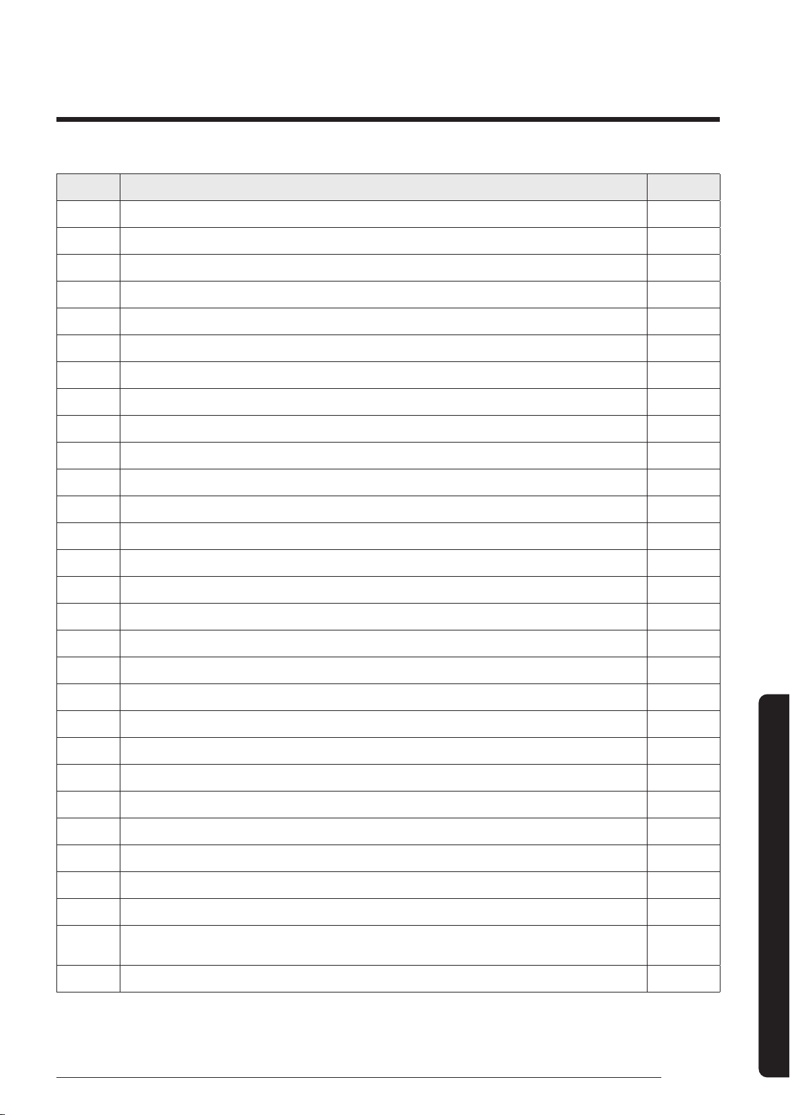
35
English
Appendix
Error Code Explanation Remark
E339 ERROR ON PIPE OUT-E TEMPERATURE SENSOR(SHORT OR OPEN)
E401 OUTDOOR UNIT FREEZING-SAFETY CONTROL(COMPRESSOR STOP)
E404 OUTDOOR UNIT OVERLOAD-SAFETY CONTROL(COMPRESSOR STOP)
E416 COMPRESSOR OPERATION STOP DUE TO DISCHARGE TEMPERATURE PROTECTION CONTROL
E422 HIGH PRESSURE BLOCKAGE CONTROL
E440 HEATING MODE RESTRICTION DUE TO HIGH AIR TEMPERATURE
E441 COOLING MODE RESTRICTION DUE TO LOW AIR TEMPERATURE
E458 FAN MOTOR ERROR
E461 OPERATION FAILURE OF COMPRESSOR
E462 COMPRESSOR OPERATION STOP DUE TO FULL LOAD CURRENT CONTROL
E463 COMPRESSOR OPERATION STOP DUE TO OLP TEMPERATURE CONTROL
E464 ERROR DUE TO OVER-CURRENT OF COMPRESSOR
E465 VOLTAGE-LIMIT ERROR OF COMPRESSOR
E466 ERROR DUE TO LOW/OVER VOLTAGE OF DC LINK IN INVERTER PBA
E467 ABNORMAL RPM IN COMPRESSOR OR WIRE FOR COMPRESSOR HAS NOT BEEN CONNECTED
E468 ERROR DUE TO OUTPUT CURRENT SENSOR OF INVERTER PBA(SHORT/OPEN)
E469 ERROR DUE TO DC LINK VOLTAGE SENSOR OF INVERTER PBA(SHORT/OPEN)
E470 OUTDOOR UNIT EEPROM READ/WRITE ERROR
E471 OUTDOOR UNIT EEPROM READ/WRITE ERROR(OTP)
E474 ERROR ON IPM/PFCM TEMPERATURE SENSOR OF INVERTER PBA(SHORT OR OPEN)
E475 FAN2 MOTOR ERROR
E483 OVERVOLTAGE OF H/W DETECT DC LINK
E484 PFC OVERLOAD(OVER CURRENT) ERROR
E485 ERROR DUE TO INPUT CURRENT SENSOR OF INVERTER PBA(SHORT/OPEN)
E488 INCOMING VOLTAGE SENSOR ERROR
E500 IPM/PFCM OVERHEAT ERROR
E554 THE REFRIGERANT LEAKS COMPLETELY FROM THE OUTDOOR UNIT
E563
ERROR DUE TO INDOOR UNIT SOFTWARE VERSION COMBINATION(INCOMPATIBLE INDOOR UNIT
SOFTWARE ON A SYSTEM
E590 INVERTER EEPROM CHECKSUM ERROR
DB68-09261A-05_IM_FJM HP Outdoor_EA_EN_.indd 35DB68-09261A-05_IM_FJM HP Outdoor_EA_EN_.indd 35 2024-02-07 오전 8:19:042024-02-07 오전 8:19:04

DB68-09261A-05_IM_FJM HP Outdoor_EA_EN_.indd 36DB68-09261A-05_IM_FJM HP Outdoor_EA_EN_.indd 36 2024-02-07 오전 8:19:042024-02-07 오전 8:19:04