Loading ...
Loading ...
Loading ...

20 Ice Manager Diverter Valve System Operation and Service Manual
Service
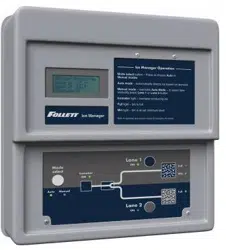
System components
Follett’s Ice Manager diverter valve system consists of following major components:
• Diverter valve module
• Control panel module
• Ice transport tube lane 1 with a dedicated sensor cable 1
• Ice transport tube lane 2 with a dedicated sensor cable 2
• Ice level sensor / ice distribution module for lane 1
• Ice level sensor / ice distribution module for lane 2
System operation
The Ice Manager diverter valve system is designed to control the feeding of ice from one Horizon ice machine to two
ice storage units. There are different ice level set-points for ice storage units.
The ice storage unit for lane 1 has two ice level set points, MIN and FULL, while the ice storage unit for lane 2 has
only one - FULL. There is also a DIF (Differential) setting for each lane that initiates rell of ice.
Note: Ice Manager diverter valve system comes with factory pre-set values for MIN, FULL and DIF (differential)
parameters. If required the pre-set values can be eld modied. (See the ice level set point on page 25.)
Control logic
Ultrasonic sensors for lane 1 and lane 2 detect ice level and send an analog signal between 0.5vdc to 4.5vdc back to
diverter valve control board. This signal is converted into distance (in inches) from the sensor face to the ice surface.
An appropriate light on the control panel comes on indicating the ice level reached either MIN or FULL levels for
lane 1 or FULL level for a lane 2 units.
Auto mode
AUTO is the standard operating mode for the Ice Manager diverter valve system. In AUTO mode, the system will
automatically direct the ice according to the sensor set point levels.
On start up, when AUTO mode is selected the diverter valve directs ice through lane 1 to the ice storage unit until the
MIN level is satised.
The diverter valve will then switch and direct ice through lane 2 until its ice storage unit FULL level is satised.
If during this time the ice level in lane 1 ice storage unit drops below the MIN level, then the diverter valve will
re-direct ice ow back to lane 1 and continue feeding ice through the lane 1 until the ice storage unit MIN level is
satised again. The cycle will continue until FULL level for both ice storage units are reached.
When the ice level in both ice storage units is at the FULL level the diverter valve shuts off the signal to the ice
machine which goes into a 15 min delay. When the delay period expires, the control logic will allow the ice machine to
restart when either sensor detects ice level drop below the FULL set-point.
Note: There is a 30 second time delay function programmed into the control logic. This function requires
30 seconds of a steady ice level reading exceeding a set-point before the control logic initiates any action.
Therefore, a momentary ice level change measured by the ice level sensors will not trigger a shut-down
or divert.
Manual mode
For Ice Manager diverter valve system cleaning and sanitizing, and some special situations (see a troubleshooting
guide on page 26), a MANUAL mode is available. MANUAL mode overrides AUTO mode and allows the operator to
select the lane.
In order to switch between AUTO and MANUAL modes push the MODE SELECT button located on the control panel.
While in MANUAL mode, pressing either lane 1 or lane 2 buttons will divert ice ow accordingly.
Note: When in manual mode ice level sensors will not control the divert action, however the ice sensors will
continue to control the ice machine. When the FULL ice level in designated ice storage unit is satised the
ice machine will be shut off.
Loading ...
Loading ...
Loading ...