
Ice Manager
™
Diverter Valve System
IMDV-2CM
01113349R05
801 Church Lane • Easton, PA 18040, USA
Toll free (877) 612-5086 • +1 (610) 252-7301
www.follettice.com
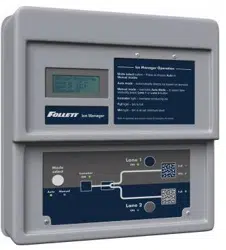
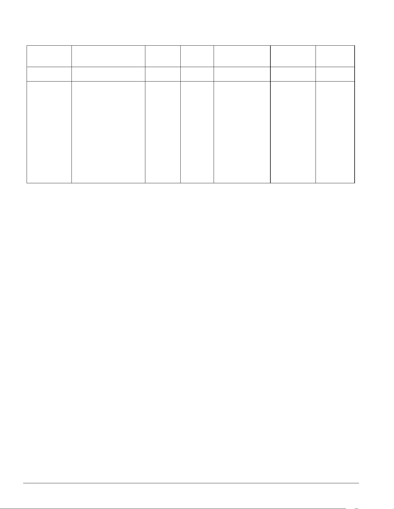
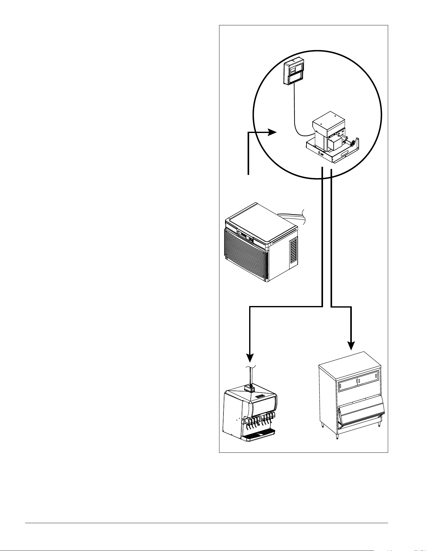
Ice Manager
Diverter Valve
(1) Horizon Elite
™
Chewblet
®
Ice Machine
(purchased separately)
(2) ice storage units
(purchased separately)
Any combination of bins or dispensers
Ice Manager
Control Panel
Lane 2
Lane 1
Installation, Operation and
Service Manual
2 Ice Manager Diverter Valve System IMDV-2CM
Special tools required
3.50" (88.9 mm) hole saw: Required for ice and beverage dispensers manufactured by others or existing bins
2.50" (63.5 mm) hole saw: Required for drop-in dispensers
1.75" (44.5 mm) hole saw: Required for drop-in dispensers
ConfigurationApplication
S RIDE
®
(RIDE remote
ice delivery
equipment)
T To p -mount
7 700 lb
(318 kg)
10 1000 lb
(454 kg)
14 1400 lb
(635 kg)
18 1800 lb
(817 kg)
21 2100 lb
(953 kg)
10 R404a
12 R449a
V Vision™
H Harmony™
B Ice storage bin
J Drop-in
M Ice Manager
diverter valve
system
Condenser
Refrigerant
Type
Ice Production
(approx.)
Voltage
Ice Type
C 208-230/60/1 (icemaking head)
Self-contained only.
D 115/60/1 (icemaking head)
Self-contained and remote. If
remote unit, high side is
208-230/60/1.
E 230/50/1 (icemaking head)
Self-contained only.
F 115/60/1 (icemaking head)
Remote only. High side is
208-230/60/3.
HC Horizon Elite
Chewblet
HM Horizon Elite
Micro Chewblet
A Air-cooled,
self-contained
W Water-cooled,
self-contained
R Air-cooled, remote
condensing unit
included with ice
machine
N No condensing unit for
connection to parallel
rack system
K Evaporator unit only,
must be paired with
Follett remote
condensing unit,
sold separately
Horizon Elite Model Number Configuration
Example: HCD1810AVS
HC
D
18
10
A V S
Ice Manager Diverter Valve System IMDV-2CM 3
Lane 1
ice transport tube & sensor cable
3
Control panel
2
Diverter valve
1
Vision
™
VU300
ice & beverage dispenser
300
7
Vision
™
VU155
ice & beverage dispenser
155
6
Read and complete installation sections 1 through 4.
Read and complete installation
sections below that apply to your specic application.
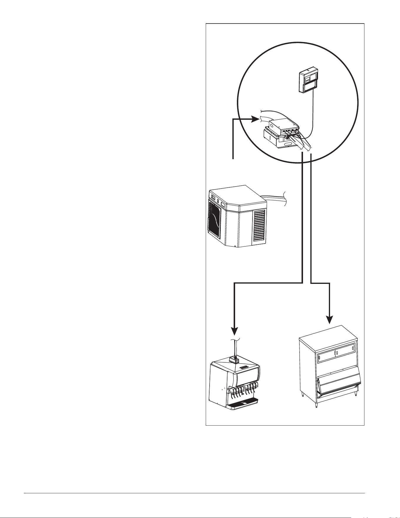
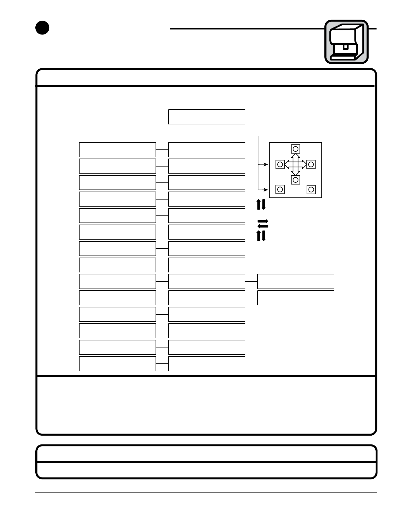
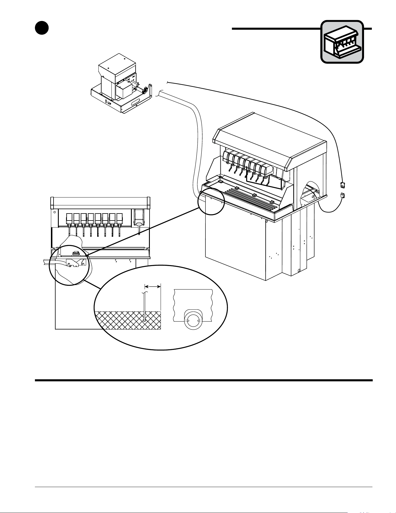
Ice Manager diverter valve system
The Ice Manager diverter valve system delivers ice to two ice storage units enabling a single ice
machine to meet demand for ice at two locations. The system’s sensors monitor ice levels in each
storage unit and automatically switch ice delivery to the appropriate location.
Lane 2
ice transport tube & sensor cable
4
Carefully review system overview (pages 4 & 5) and be sure that you have a copy
of the Follett approved site survey before proceeding with installation steps.
After thorough review of the site survey, install Horizon ice machine and
dispenser/bin(s) using the installation guide provided with each unit.
Ice & beverage dispenser/bin
5
Ice level
set points
8
4 Ice Manager Diverter Valve System IMDV-2CM
Electrical - ice machine ➊
• 1010 (A/W) 208-230/60/1, 11A, max. ice machine fuse 15A
• 1410 (A/W) 208-230/60/1, -5%/+10% under peak load. 16A, max.
ice machine fuse 20A
• 1010/1410/1810/2110 (R/N)
Evap. 115/60/1, 6A; max. fuse 15A
• 1650 (R/N)
Evap. 115/60/1, 6A; max. fuse 15A
Condenser (R models only)
1010R 1410R 1412R 1810R 2110R
Single 3-Phase Single 3-Phase 3-Phase Single 3-Phase Single 3-Phase
Electrical 208-230V, 60 Hz
Max
Circuit
HVACR
Breaker
Size
15A 15A 30A 25A 20A 45A 25A 45A 30A
Min
Circuit
Ampacity
10.7A 9.9A 19.3A 14.2A 12A 26.2A 15.7A 27.1A 19.9A
Electrical - Ice Manager ➋
• 115/60/1, 1.5 amps; max. fuse 15 amps
Drains
• Ice machine - 3/4" MPT - 3/4" FPT X
SOC, elbow provided, no vent required
• Ice Manager - 3/8" (9.5mm) barb - 15 ft.
(4.6m) 3/8"(9.5mm) I.D. tubing provided
Potable water supply - ice machine
➌
• 10 - 70 psi (69 - 483kpa)
• 45 F to 90 F (7 C to 32 C)
• Follett recommends the use of an in-line
water lter (item# 00130286)
Condenser water supply for water-
cooled systems
➍
• 10 psi min.; 150 psi max. (69kpa min.;
1034kpa max.)
• 45 F to 90 F (7 C to 32 C)
• 1.5 gallons per minute (5.68 liters per
minute)
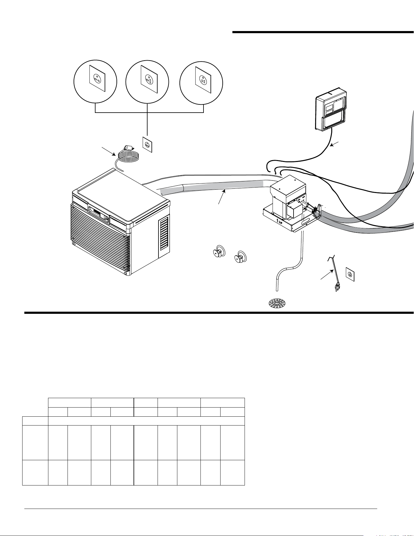
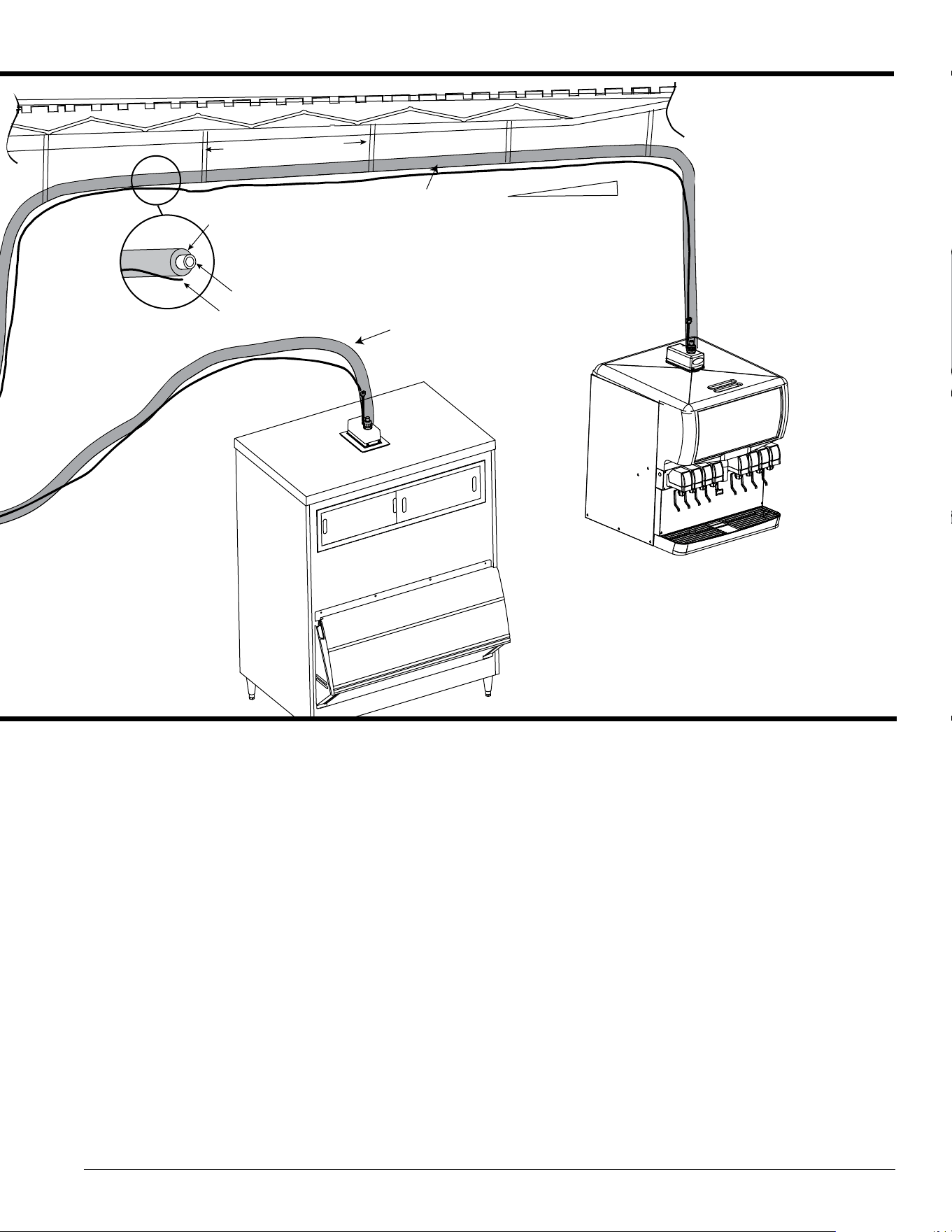
Ice Manager - Site preparation and system overview
➏
➎
1/4˝
1'
➌
➍
➊
1410A/W
1010A/W
NEMA
6-20
NEMA
5-15
NEMA
5-15
NEMA
6-15
➋
max. length of 30' (9 m)
of cable between
diverter valve
and operator
control panel
8' (2.4 m)
cord
6' (1.8 m)
cord
max. length of 75' (23 m)
of cable and transport tube between
diverter valve and ice storage unit
ice transport tube
sensor cable
max. length of 75' (23 m)
of cable and transport tube between
diverter valve and ice storage unit
ICE MACHINE
IMDV-2CM
insulation
max. length of 2' (.6m)
between supports
CONTROL
PANEL
1010N/R 1412N/R
1410N/R 1810N/R
1650N/R 2110N/R
MININUM length of 10' (3 m) of
cable and transport tube
between ice machine and
diverter valve
Ice Manager Diverter Valve System IMDV-2CM 5
Temperature and humidity requirements
• All components, including ice transport tube, must be
operated in ambient temperatures between 40 F and
120 F (5 C and 49 C)
• Relative humidity not to exceed 55%
Ice transport tube requirements
• Maximum vertical rise of 10' (3m) from ice machine to
highest elevation of tube
• Use one continuous piece of ice transport tube. Do not
splice.
• Horizontal run should be pitched so that melt water
drains back to ice machine. Ice transport tube run must
have at least 1/4" per foot pitch (6.4mm/0.3m)
➎
• Secure ice transport tube as needed to eliminate dips
and traps
• Insulate all ice transport tube runs, making sure that
sensor cable runs outside of the insulation
➏
Ice transport tube and cable distance
requirements
• Ice machine to diverter valve - minimum run of
10' (3m)
• Diverter valve cable to operator control panel -
maximum run of 30' (9 m)
• Diverter valve to ice receptacle - maximum run of
75' (23 m)
• Distance between ice transport tube supports -
maximum of 2' (0.6m)
Operating temperature requirements
• Ice Manager diverter valve system components,
including ice transport tube must be operated in
ambient temperatures between 40 F and 120 F
(4.5 C and 49 C)
➏
➎
1/4˝
1'
➌
➍
➊
1410A/W
1010A/W
NEMA
6-20
NEMA
5-15
NEMA
5-15
NEMA
6-15
➋
max. length of 30' (9 m)
of cable between
diverter valve
and operator
control panel
8' (2.4 m)
cord
6' (1.8 m)
cord
max. length of 75' (23 m)
of cable and transport tube between
diverter valve and ice storage unit
ice transport tube
sensor cable
max. length of 75' (23 m)
of cable and transport tube between
diverter valve and ice storage unit
ICE MACHINE
IMDV-2CM
insulation
max. length of 2' (.6m)
between supports
CONTROL
PANEL
1010N/R 1412N/R
1410N/R 1810N/R
1650N/R 2110N/R
MININUM length of 10' (3 m) of
cable and transport tube
between ice machine and
diverter valve
6 Ice Manager Diverter Valve System IMDV-2CM
drain
➊
12" clearance
6"
clearance
6"
clearance
6"
clearance
Diverter Valve Dimensions
Diverter Valve Required Clearances
floor mount
(2 screws)
ice "in"
from ice machine
UP
UP
ice "out"
Lane 2
ice "out"
Lane 1
➋
➌
wall mount
(4 screws)
➍
➍
➎
14.5"
(368 mm)
16"
(407 mm)
14.15"
(359mm)
19.822"
(503.47mm)
Mount diverter valve
• Minimum side clearances of 6" (153mm) required
➊
• Minimum top clearance of 12" (305mm) required
➊
• Diverter valve bracket may be mounted on the oor
➋
or on the wall
➌
using (4) anchors capable of
supporting min. 40 lb (18kg)
• Diverter valve unit MUST face up
➍
• Drain tube connects to tting on underside of
diverter valve
➎
1
Diverter valve
Ice Manager Diverter Valve System IMDV-2CM 7
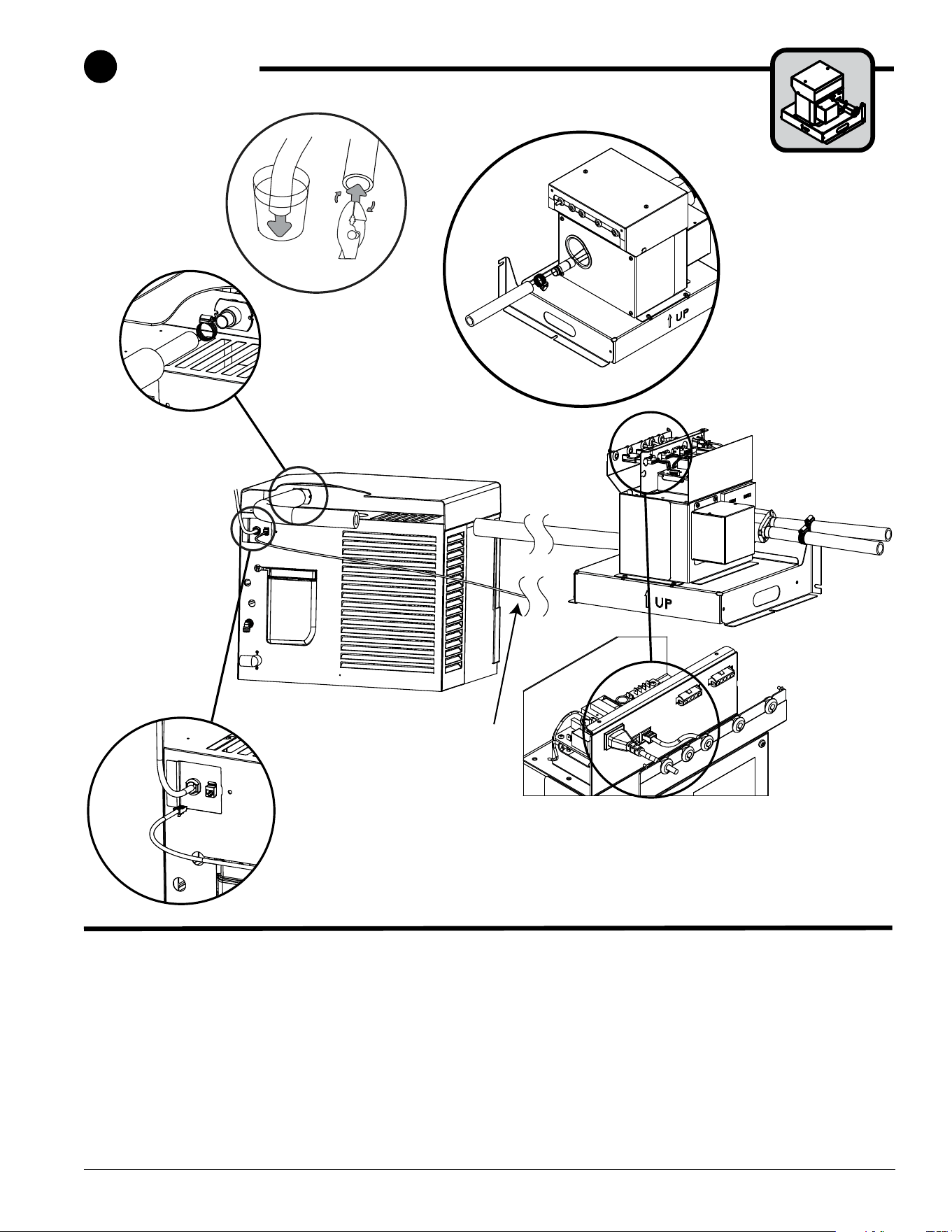
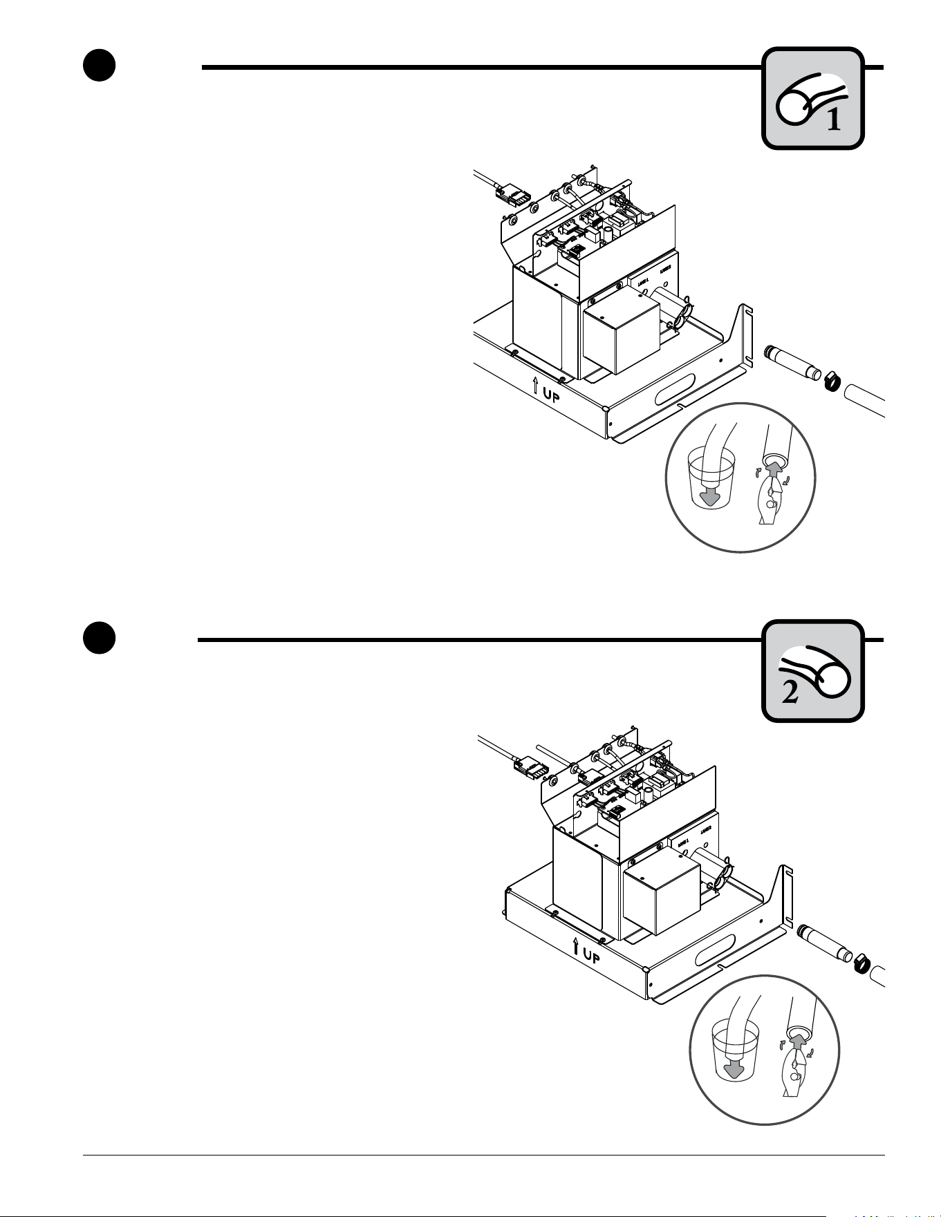
Connect diverter valve to ice machine
†
• Remove connection cover from diverter valve
➊
• Connect blue ice machine cable to diverter valve ➋
Note: Control cable run not to exceed 10' (3m).
• Connect blue ice machine control cable to ice
machine
➌
• Connect power cord to diverter valve
➍
• Run insulated ice transport tube to diverter valve
➎
using guidelines in “Site Preparation - Overview” on
➌
➍
➋
➎
➎
MININUM length of 10' (3 m) of cable
and transport tube between ice
machine and diverter valve
➋
➏
Hot Water
160 F (71 C)
10' (3 m) ice machine
cable (blue)
➊
pages 4 & 5. Heat end of transport tube in cup of 160F
(71 C) hot water to soften and spread with pliers
➏
before making connection to ease assembly and prevent
stainless coupler edge from cutting inner wall oftube.
Note: MININUM length of 10’ (3 m) of transport tube
between ice machine and diverter valve.
† If Horizon ice machine is an existing unit, install
applicable retrot kit before completing this portion of
installation (retrot instructions are included with retrot
kit).
1
Diverter valve
8 Ice Manager Diverter Valve System IMDV-2CM
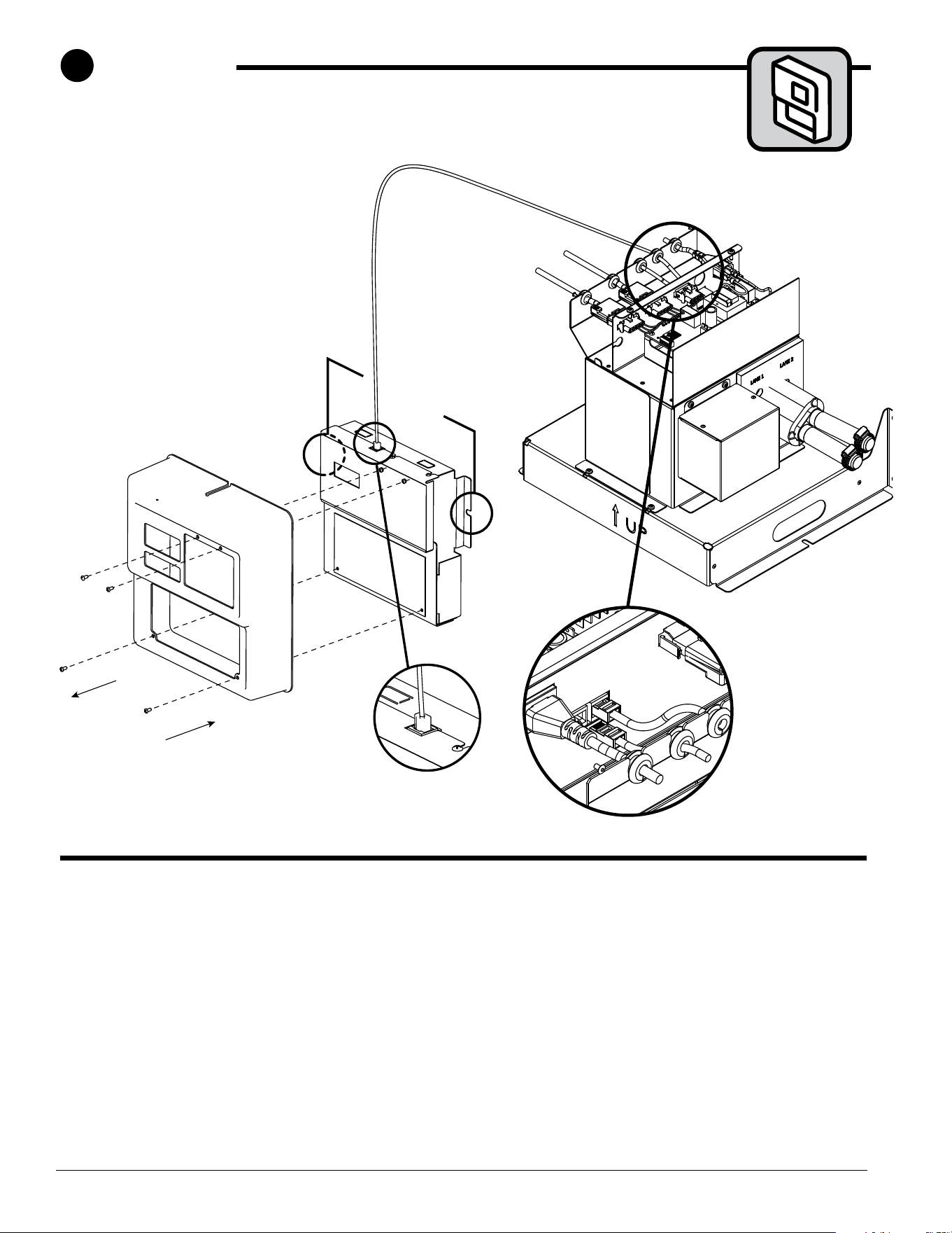
Mount control panel
• Remove cover from control panel
➊
• Mount panel to wall
➋
using wall anchors if needed
➌
➋
➊
30' (9m)
control
panel
cable
(gray)
wall mount
(2 screws)
➎
➍
Connect control panel to diverter valve
• Connect gray control panel cable to control panel
➌
• Connect gray control panel cable to diverter valve
➍
Note: Control panel cable run not to exceed 30' (9m).
• Replace control panel cover
➎
2
Control panel
Ice Manager Diverter Valve System IMDV-2CM 9
➊
➋
LANE 1
Hot Water
160 F (71 C)
➌
Hot Water
160 F (71 C)
➌
➊
➋
LANE 2
➊
➋
LANE 1
Hot Water
160 F (71 C)
➌
Hot Water
160 F (71 C)
➌
➊
➋
LANE 2
Ice transport tube and sensor cable
• Use the site survey to identify lane 2 dispenser
or bin
• Measure ice transport tube run and sensor cable run
from lane 2 dispenser/bin to diverter valve
• Verify that run lengths comply with requirements on
pages 4 & 5
• Insulate ice transport tube
• Secure insulated ice transport tube and sensor cable
as needed from dispenser/bin to diverter valve, being
certain to prevent dips and traps from forming
• Pitch tube at least 1/4" per foot (6.4mm/0.3m). Tube
must drain away from bin.
• Connect lane 2 sensor cable
➊
and insulated ice
transport tube
➋
to diverter valve
• Heat end of transport tube in cup of 160F (71 C)
hot water to soften and spread with pliers
➌
before
making connection to ease assembly
• Visually inspect inside of plastic coupling for burrs
and remove as needed
• Tighten hose clamp
3
Lane 1
4
Lane 2
Ice transport tube and sensor cable
• Use the site survey to identify lane 1 dispenser
or bin
• Measure ice transport tube run and sensor cable run
from lane 1 dispenser/bin to diverter valve
• Verify that run lengths comply with requirements on
pages 4 & 5
• Insulate ice transport tube
• Secure insulated ice transport tube and sensor cable
as needed from dispenser/bin to diverter valve, being
certain to prevent dips and traps from forming.
See guidelines on pages 4 & 5.
• Pitch tube at least 1/4" per foot (6.4mm/0.3m). Tube
must drain away from bin.
• Connect lane 1 sensor cable
➊
and insulated ice
transport tube
➋
to diverter valve
• Heat end of transport tube in cup of 160F (71 C)
hot water to soften and spread with pliers
➌
before
making connection to ease assembly
• Visually inspect inside of plastic coupling for burrs
and remove as needed
• Tighten hose clamp
10 Ice Manager Diverter Valve System IMDV-2CM
➍
front of
dispenser
or bin top
➊
C
L
C
L
front of dispenser or bin top
3-1/2"
(88.9mm) dia.
template
All other dispensers
➎ ➎
➌
➍
➌
front of
dispenser
or bin top
back of
dispenser
or bin top
➋
ED300 dispenser only
4"
(102mm)
4"
(102mm)
4"
(102mm)
R1 3/4"
(19mm)
110CM Symphony Plus w/IMDV
R1.750
5"
(127 mm)
5" (127 mm)
4"
(102 mm)
30” Lancer Sensation and Touchpoint w/IMDV
10.00"
9.00"
4"
ø3.5"
hole saw
C
L
C
L
4
"
(102 mm)
ø3.5"
hole saw
REAR OF
DISPENSER LID
(UNDERSIDE)
Freestyle 9000
FRONT OF
DISPENSER LID
(UNDERSIDE)
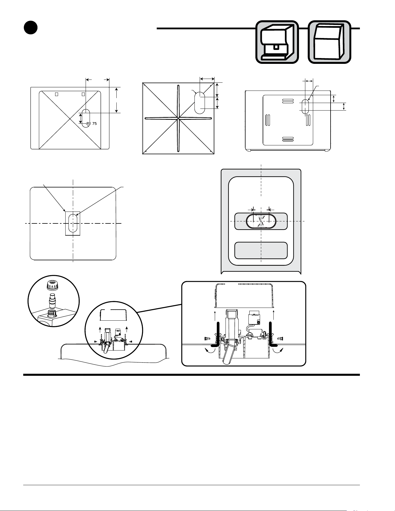
Prepare ice & beverage dispenser/bin top
• Using drawing above for your application, locate the
proper location of ice & beverage dispenser (IBD) to
place the supplied template
➊
• Using supplied template and 3.5" dia. hole saw, cut
holes per template
Note: Use a hand saw or similar tool to complete the
cut out.
Mount sensor distribution unit
• Unscrew cap nut and remove center assembly
➋
• Loosen screws and remove cover
➌
• Turn short arm of angle rods so unit can be lowered
into hole of IBD top
• Position unit into IBD top with tube at the front
➍
• Turn angle rods to face outward
➎
• Tighten wing nuts until arms of both rods press rmly
against underside of IBD top securing body of sensor
distribution unit
5
Ice & beverage dispenser/bin
Ice Manager Diverter Valve System IMDV-2CM 11
➊
➋
➌
➎
➍
Hot Water
160 F (71 C)
5
Ice & beverage dispenser/bin
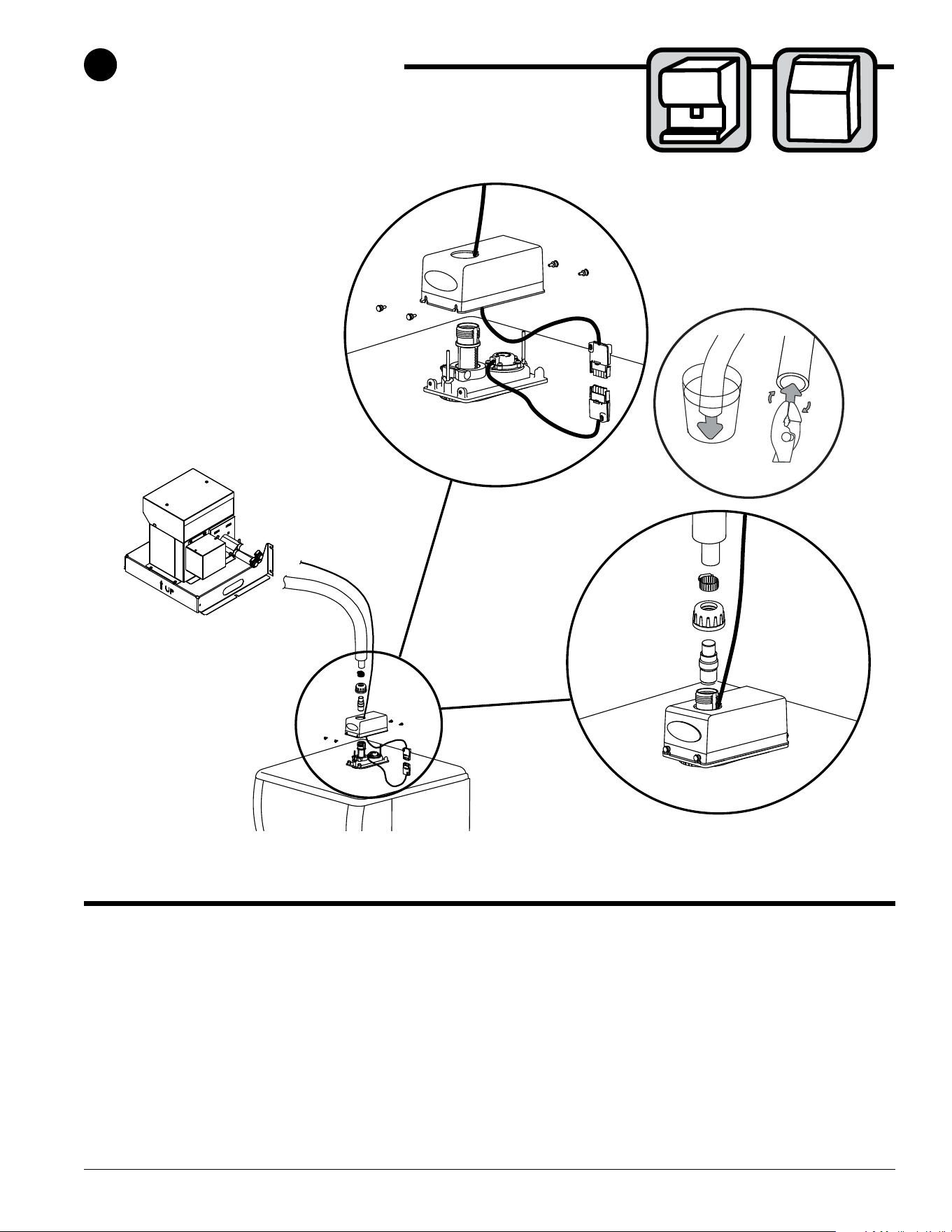
Connect ice transport tube & sensor cable
• Thread sensor cable through top of sensor
distribution unit
➊
• Connect sensor pigtail to sensor cable
➋
• Tuck cable inside sensor unit replace top and tighten
screws
➌
• Heat end of transport tube in cup of 160F (71 C)
hot water to soften and spread with pliers
➍
before
making connection to ease assembly and prevent
stainless coupler edge from cutting inner wall oftube.
• Connect insulated ice transport tube
➎
12 Ice Manager Diverter Valve System IMDV-2CM
5
Ice & beverage dispenser/bin
54.543.5
3
2.5
2 1. 5
1
.5
3
HRS
2.5
HRS
2
HRS
1. 5
HRS
1
HR
30
MIN
MOTOR ON TIME:
SET TO 1 SECOND
MOTOR OFF TIME:
SET TO 1 HOUR
10
MIN
ON
TIME
OFF
TIME
E-BOARD AGITATOR TIMER
Cornelius models ED, DB, DF, IDC and FLAVOR FUSION
Adjust the agitation timer located on the Cornelius PC board to 1 second on, 1 hour off. Note: See
Cornelius manual or call Cornelius Technical Service at 1-800-238-3600 for more information.
Agitation adjustments – CORNELIUS
PRESS IN ON
THIS SIDE TO
TURN SWITCH
ON.
PRESS IN ON
THIS SIDE TO
TURN SWITCH
OFF.
ROCKER
SWITCHES
(VIEW LOOKING
DOWN)
SWITCH
NUMBER
5
6
7
8
SWITCH
NUMBER
1 SECOND
3
4
OFF
OFF
150 MINS
ON
ON
ON
ON
AGITATION TIME
AGITATION FREQUENCY
OFF OFF OFF OFF OFF OFF OFF
SWITCH
OFF
SIDE VIEW
SWITCH
ON
SIDE VIEW
OFF
Lancer 4500 series only
Adjust the agitation time to 1 second, and the agitation frequency to 150 minutes. See Lancer
manual or call Lancer Customer Service at 1-888-846-6729 for more information.
Agitation adjustments – LANCER 4500 SERIES
Agitation adjustments – LANCER Sensation and Touchpoint, Ser/vebd
No agitation adjustment required
Ice Manager Diverter Valve System IMDV-2CM 13
5
Ice & beverage dispenser/bin
Major/Minor
FS-16 Setup
Config Bonus Key
Soda/Plain Water
Config Dispense Only
PC Mode
PC Time
Ice Stir Off
Ice Stir On
Sold Out
Carb Sensors
Ice Bin Sensors
Valve Code Version
Number Of Valves
Reset Defaults No Ye s
Reload Defaults?
1 2 3 4
12 0.104 0.104
1000
Ice Bin Optic
Upper Lower
Sold Out #1
Selection Sold Out
05000
On Time (MSEC)
Off On
Set PC Mode Menu
V:1 B1 DLY1
Dispense Delay
V:2 1:S 2:W 3:S 4:W
V:1 T:F M:S B:W
Bonus Key Setup
Brands Per Side
V:1 L:2 R:1
FS-16 Setup
FS-16 Setup
FS-16 Setup
FS-16 Setup
FS-16 Setup
FS-16 Setup
FS-16 Setup
FS-16 Setup
FS-16 Setup
FS-16 Setup
FS-16 Setup
FS-16 Setup
FS-16 Setup
Soda/Plain Water
OFF Time (MIN)
00150
On Time (MSEC)
01000
1000 500
34 0.104 0.104
On On On On
V:1 B:1
Sold Out #1
Off
Sold Out #1
Ver. 0.200
Lancer FS-16
Sub-CatagoryMain Menu
Initialization Screen
2nd Sub-Catagory
(Boot Up Only)
Cancel
Enter
Scrolls through Main Menu
Press "Enter" to enter sub-catagory
Moves curser to right or left
Changes value (number/letter)
Press "Enter" to enter save changes
Press "Cancel" to exit menu
➊
Agitation adjustments – LANCER FS SERIES
Lancer FS series only
• Hold down “cancel” and “left button” to get to hidden menu
➊
• Type in code 6655
• Type in 150 minutes “off time” and 1010 milliseconds (1 second of time) as the preferred setting
Note: See Lancer manual or call Lancer Customer Service at 1-888-846-6729 for more information.
Agitation adjustments – Coke Freestyle 9000
Call Coca-Cola at 800-241-COKE (2653) and request a Freestyle Senior Tech.
14 Ice Manager Diverter Valve System IMDV-2CM
Single Agitator
Dual Agitator
P/N 307277 — Diverter plate
(single agitator Cornelius
dispensers and left-hand
dispense chute on dual-agitator
Cornelius dispensers)
P/N 307277 — Diverter plate
(single agitator Cornelius
dispensers and left-hand
dispense chute on dual-agitator
Cornelius dispensers)
P/N 00996207 — Diverter plate
(right-hand dispense chute on
dual-agitator dispensers)
5
Ice & beverage dispenser/bin
Cornelius ED, DF and DB series only
These dispensers require the installation of an ice diverter at the dispenser opening.
• Disassemble chute assembly
• Discard factory restrictor plate
➊
• Replace with alternate diverter plate
➋
(supplied)
Dispenser diverter plate overview – CORNELIUS, ED, DF AND DB SERIES
Ice Manager Diverter Valve System IMDV-2CM 15
5
Ice & beverage dispenser/bin
ICE CHUTE
GATE MOUNTING PLATE
GASKET
STORAGE HOPPER
ICE DIVERTER
10-32 WASHER
10-32 NUT
FLANGE EXTENDS INTO
STORAGE HOPPER
THROUGH GATE
OPENING
APPLY RTV TO THIS
SURFACE TO SEAL
TO HOPPER GATE
MOUNTING PLATE
ICE CHUTE
COVER
Cornelius ED, DF and DB series only
These dispensers require the installation of an ice diverter at the dispenser opening.
• Disassemble chute assembly
• Discard factory restrictor plate
• Replace with alternate diverter plate (supplied)
Dispenser diverter plate installation – CORNELIUS ED, DF and DB SERIES
Agitation adjustments – Cornelius IDC and Flavor Fusion
These dispensers require modications for compatibility with Chewblet ice. Agitation
times must be set to 1 second ON, 1 hour OFF and the ice restrictor plate must
be adjusted to the fully open position. See your beverage supplier for these
modications.
16 Ice Manager Diverter Valve System IMDV-2CM
6
Follett Vision VU155 ice & beverage dispenser
155
Vision VU155 dispenser
ice transport tube and sensor cable
†
• Heat end of transport tube in cup of 160F (71 C)
hot water to soften and spread with pliers
➊
before
making connection to ease assembly and prevent
stainless coupler edge from cutting inner wall oftube
• Install ice transport tube tting in one of four pre-
drilled rear holes in VU155 dispenser
➋
Note: If threaded end extends into dispenser it must
be cut ush to inner nut.
➌
➊
➍
➋
➋
➌
➎
Hot Water
160 F (71 C)
• Attach ice transport tube to tting
➍.
Cut transport
tube to proper length and support the tube at least
every 2 ft. (.6m) to avoid dips or traps that will
result in standing water.
• Connect sensor pigtail to sensor cable
➎
† If VU155 is an existing unit install retrot kit part#
00185165 before completing this portion
of installation (retrot instructions included with
retrot kit).
Ice Manager Diverter Valve System IMDV-2CM 17
➎
➊
➋
1" (26mm)
➌
➍
7
Follett Vision VU300 ice & beverage dispenser
300
Vision VU300 dispenser
ice transport tube and sensor cable
†
• Insert ice transport tube through one of the four
pre-drilled holes in the VU300 dispenser.
➊
Be
sure to cut transport tube to proper length to avoid
dips or traps.
• Locate mounting tabs
➋
• Using a 3/16" bit, drill through the ice tube 1"
(26mm) from end of ice transport tube creating
two holes
➌
• Slightly compress end of tube to engage holes in
mounting tabs
➍
• Connect sensor cable
➎
† If VU300 is an existing unit install retrot kit part#
00185173 before completing this portion
of installation (retrot instructions included with
retrot kit).
18 Ice Manager Diverter Valve System IMDV-2CM
8
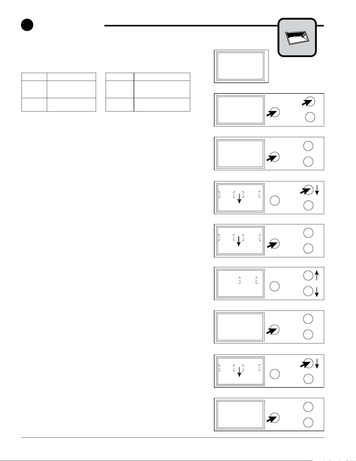
Ice level set points
Ice level set points are set at the factory and normally do not need to
be changed. Setting recommendations are shown in the table below.
Please contact Follett Technical Services toll free at (877)612-5086 or
+1 (610) 252-7301 prior to changing ice level set points.
Factory settings ID50 Factory settings
LANE
1
Full 10"
LANE
1
Full 8"
Min 14" Min 8"
Dif 3" Dif 2"
LANE
2
Full 10"
LANE
2
Full 10"
Dif 3" Dif 3"
To view ice levels
1. Locate LCD screen on Ice Manager control panel. Initial screen
will show ice levels for lane 1 and lane 2 and diverter valve status
(Fig. 1).
To view set points
1. Press and hold both MODE SELECT and LANE 1 buttons until
LANE 1 SETUP appears on the display (Fig. 2).
Note: Default/factory-set ice level sensor settings are shown.
2. To view Lane 2, press MODE SELECT to navigate to lane 2 setup
(Fig. 3).
To change set points
1. Press and hold both MODE SELECT and LANE 1 buttons until
LANE 1 SETUP appears on the display (Fig. 2).
Note: Default/factory-set ice level sensor settings are shown.
2. Press LANE 1 button to move through FULL, MIN and DIF ice
level sensor settings. When selected, choice will ash (Fig. 4).
3. Press MODE SELECT button to change ice level sensor set point
(Fig. 5).
4. Press LANE 1 button to increase ice level sensor set point
and LANE 2 to decrease ice level sensor set point, (Fig. 6) to
correspond to the drop-in dispenser ice level sensor settings listed
in table above.
5. Press MODE SELECT to save new ice level sensor setting (Fig.
7).
6. Press LANE 1 to continue to navigate through and set the Full,
Min, and Dif ice level sensor settings for lane 1 (Fig. 8).
7. Press MODE SELECT to navigate to lane 2 setup (Fig. 9).
8. Repeat steps 2 through 6 to complete changes to lane 2 ice level
sensor settings.
Sensor Reading:
Lane 1: ___"
Lane 2: ___"
Status : OK
Fig. 1
Mode
select
Lane 1
Lane 2
Lane 1 Setup:
Full: 10.0"
Min: 14.0"
Dif: 3.0"
Fig. 2
Mode
select
Lane 1
Lane 2
Lane 1 Setup:
Full: 10.0"
Min: 14.0"
Dif: 3.0"
Fig. 4
Lane 1 Setup:
Full: 10.0"
Min: 10.0"
Dif: 9.0"
Mode
select
Lane 1
Lane 2
Fig. 5
Lane 2 Setup:
Full: 10.0"
Dif: 3.0"
Mode
select
Lane 1
Lane 2
Fig. 3
Lane 1 Setup:
Full: 10.0"
Lane 1/2: Scroll
Mode: Save Value
Mode
select
Lane 1
Lane 2
Fig. 6
Lane 1 Setup:
Full: 10.0"
Min: 10.0"
Dif: 9.0"
Mode
select
Lane 1
Lane 2
Fig. 7
Mode
select
Lane 1
Lane 2
Lane 1 Setup:
Full: 10.0"
Min: 14.0"
Dif: 3.0"
Fig. 8
Lane 2 Setup:
Full: 10.0"
Dif: 3.0"
Mode
select
Lane 1
Lane 2
Fig. 9
Ice Manager Diverter Valve System IMDV-2CM 19
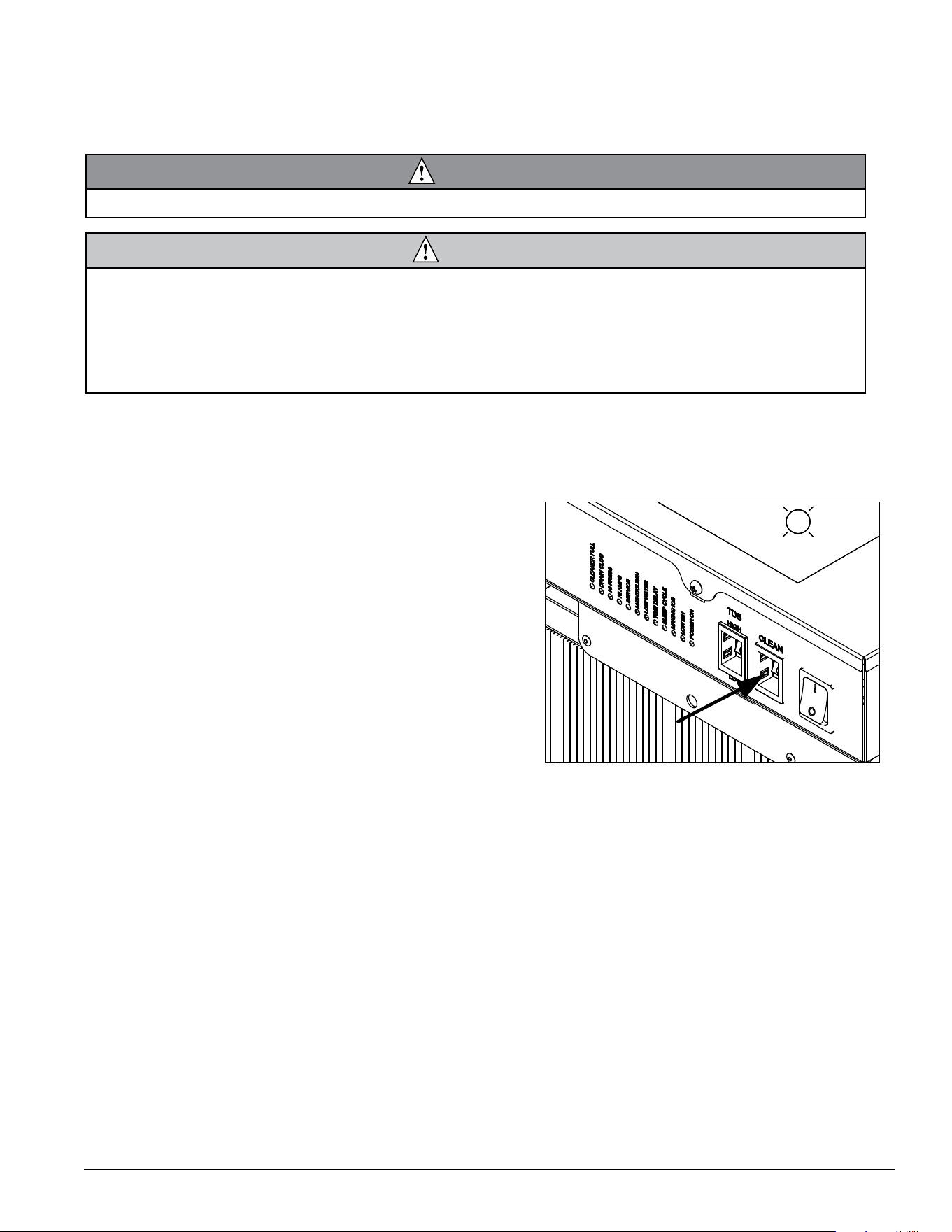
Before Operating Equipment
Ice Manager Diverter Valve System must be cleaned and sanitized.
Note: Do not use bleach to sanitize or clean the ice machine or diverter valve.
WARNING
• Wear rubber gloves and safety goggles (and/or face shield) when handling ice machine cleaner or sanitizer.
CAUTION
• Use only Follett approved SafeCLEAN Plus™
• Do not mix SafeCLEAN Plus™
• DO NOT USE BLEACH
• It is a violation of Federal law to use these solutions in a manner inconsistent with their labeling
• Read and understand all labels printed on packaging before use
Note: Complete procedure for cleaning and sanitizing MUST be followed. Ice must be collected for 10 minutes
from each lane before putting ice machine and Ice Manager system back into service.
Fig. 1
1. Press the CLEAN button. The machine will drain. The
auger will run for a short time and then stop. Wait for
the LOW WATER light to come on.
LO WATER

20 Ice Manager Diverter Valve System IMDV-2CM
Fig. 2
2. Follow the directions on the SafeCLEAN Plus
packaging to mix 1 gal. (3.8 L) of Follett SafeCLEAN
Plus solution. Use 100 F (38 C) water.
3. Using a 1 quart (1 L) container, slowly ll cleaning
cup until CLEANER FULL light comes on. Do not
overll.
4. Place one SaniSponge™ cleaning sponge in
remaining sanitizing and cleaning solution and retain
for Step 23.
Note: Do not use bleach to sanitize or clean the icemaker.
CLEANER FULL
Fig. 3
5. Replace cover on cleaner cup. Machine will clean,
then ush 3 times in approximately 15 minutes. Wait
until machine restarts.
15
Fig. 4
Follow the directions on the SafeCLEAN Plus packaging to mix
1 gal. (3.8 L) of Follett SafeCLEAN Plus solution. Use 100F
(38 C) water.
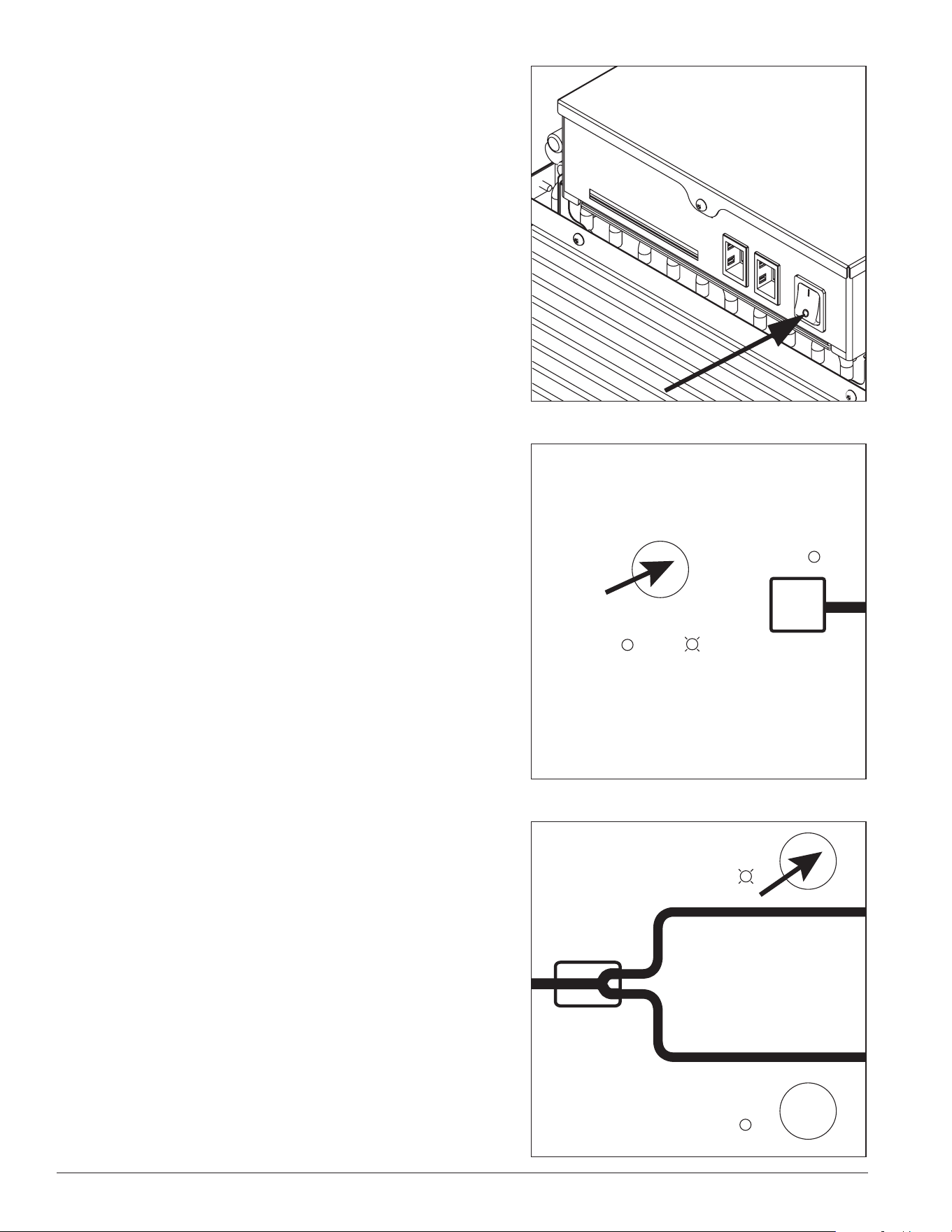
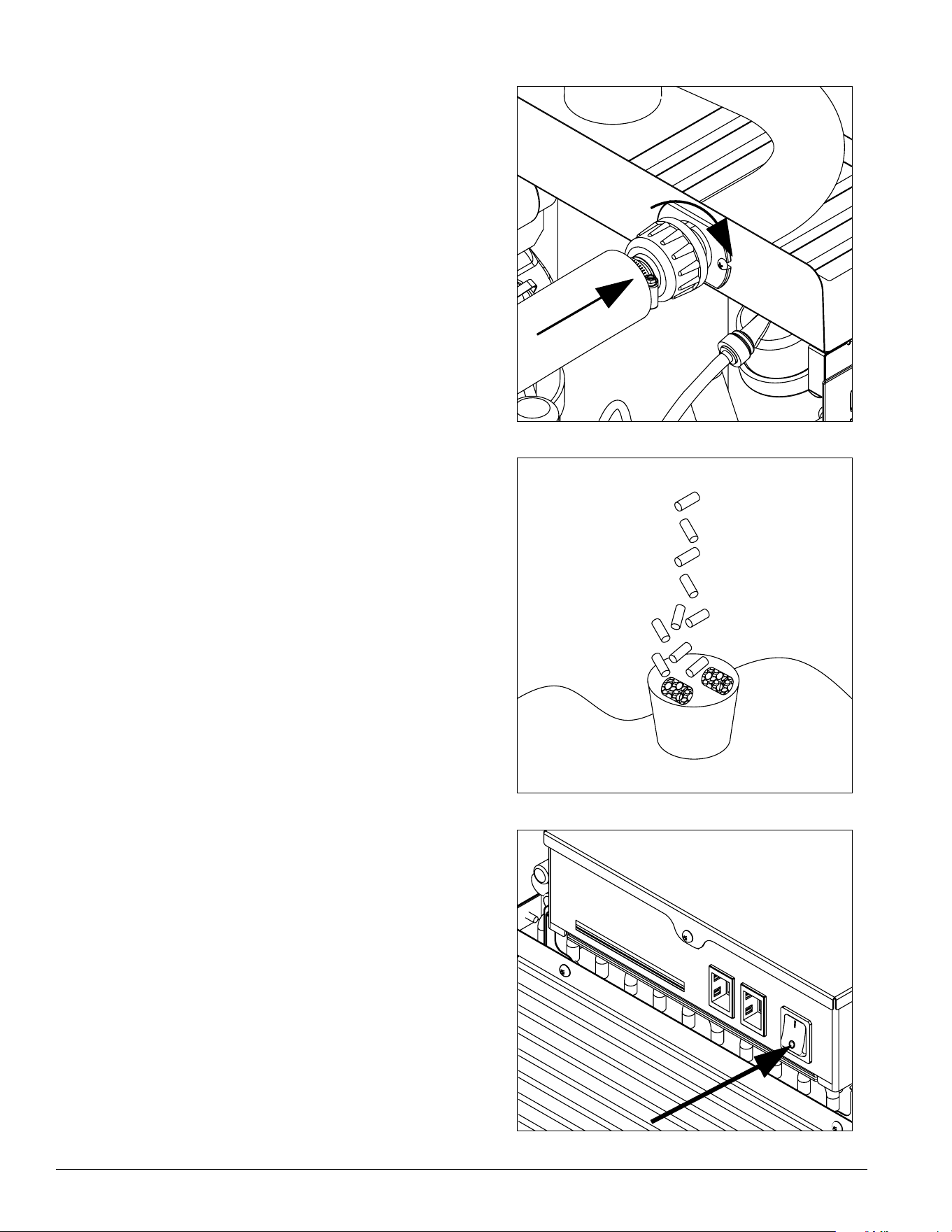
6. To clean/sanitize ice transport tube – Press power
switch OFF
Ice Manager Diverter Valve System IMDV-2CM 21
Fig. 5
7. Locate Ice Manager
control panel.
Mode
select
Auto
ON
ON
Full
Full
Lane 1
Lane 2
Min
Icemaker
Manual
ON
Fig. 6
8. To clean and sanitize Lanes 1 and 2, diverter valve
must be in manual mode. Press the MODE SELECT
button on the Ice Manager control panel. Manual light
will come on. If auto light comes on, press MODE
SELECT button again.
Mode
select
Auto
ON
ON
Full
Full
Lane 1
Lane 2
Min
Icemaker
Manual
ON
Fig. 7
9. To clean and sanitize Lane 1 – Press LANE 1
button. Lane 1 light will come on.
Mode
select
Auto
ON
ON
Full
Full
Lane 1
Lane 2
Min
Icemaker
Manual
ON
22 Ice Manager Diverter Valve System IMDV-2CM
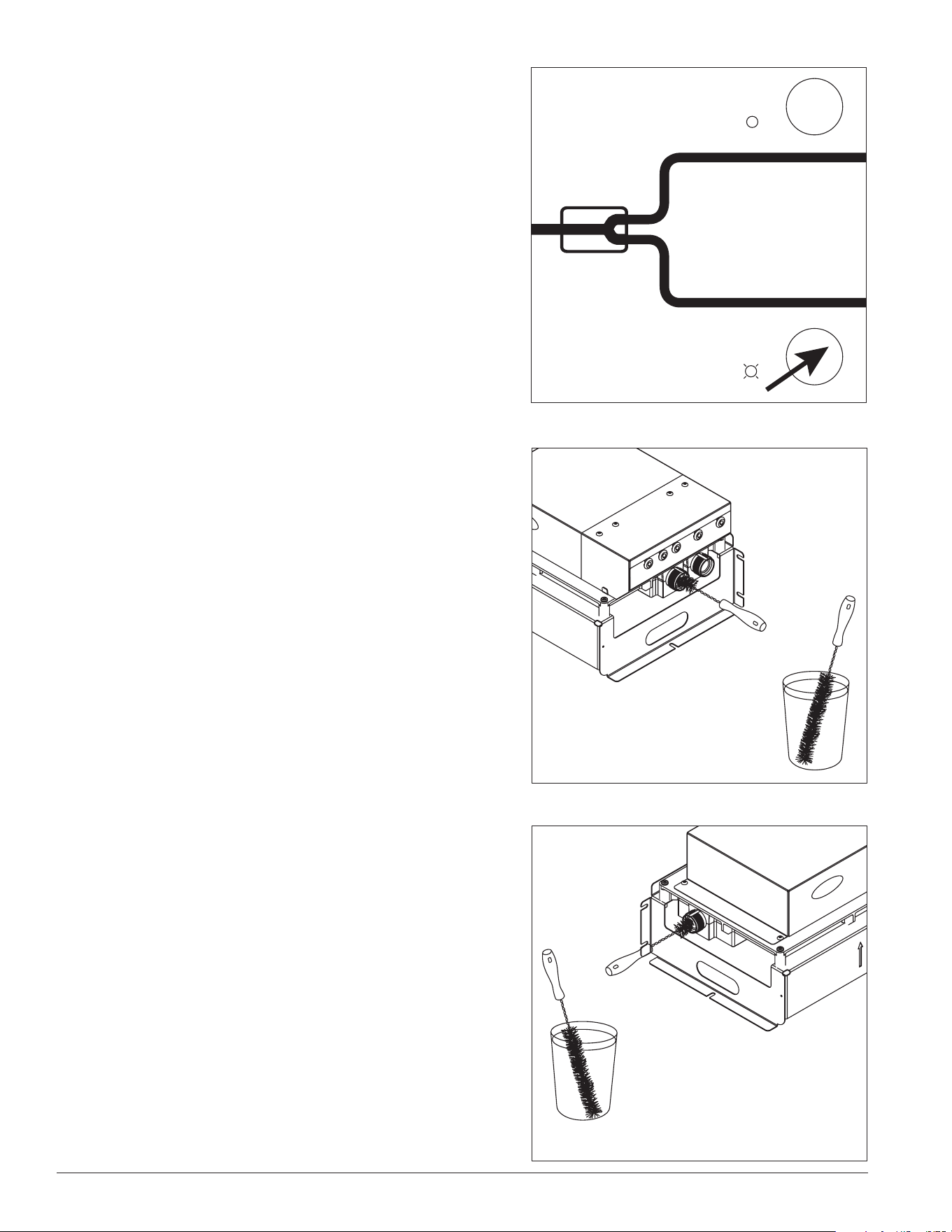
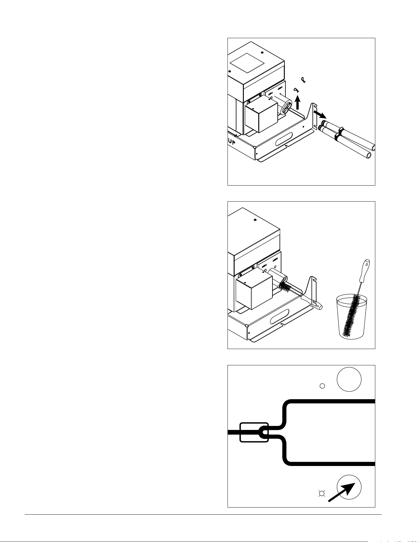
Fig. 8
10. Disconnect ice transport tubes from diverter valve
unit by removing the cotter pins (Fig. 8.1). Be sure
to note Lane 1 and Lane 2 connections to avoid
confusion when reattaching.
1
LANE 2
LANE 1
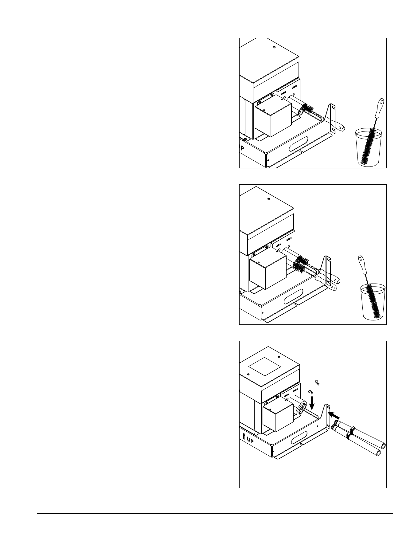
Fig. 9
11. Soak supplied brush in cleaning/sanitizing solution
and scrub inside of the diverter valve Lane 1 for at
least 60 s, re-wetting the brush as needed.
Fig. 10
12. To clean and sanitize Lane 2 – Press LANE 2
button. Lane 2 light will come on.
Mode
select
Auto
ON
ON
Full
Full
Lane 1
Lane 2
Min
Icemaker
Manual
ON
Ice Manager Diverter Valve System IMDV-2CM 23
Fig. 11
13. Soak supplied brush in cleaning/sanitizing solution
and scrub inside of the diverter valve Lane 2 for at
least 60 s, re-wetting the brush as needed.
Fig. 12
14. Rinse brush in potable, 100 F (38 C) water. Rinse
Lane 1 (Fig. 12.1), Lane 2 (Fig. 12.2), and inlet
(Fig. 12.3) with clean potable water for at least 60 s to
be sure each lane is rinsed thoroughly.
1
2
H
2
O
Fig. 13
15. Re-connect ice transport tube to Lane 1 and Lane 2
and secure with cotter pins..
LANE 2
LANE 1
24 Ice Manager Diverter Valve System IMDV-2CM
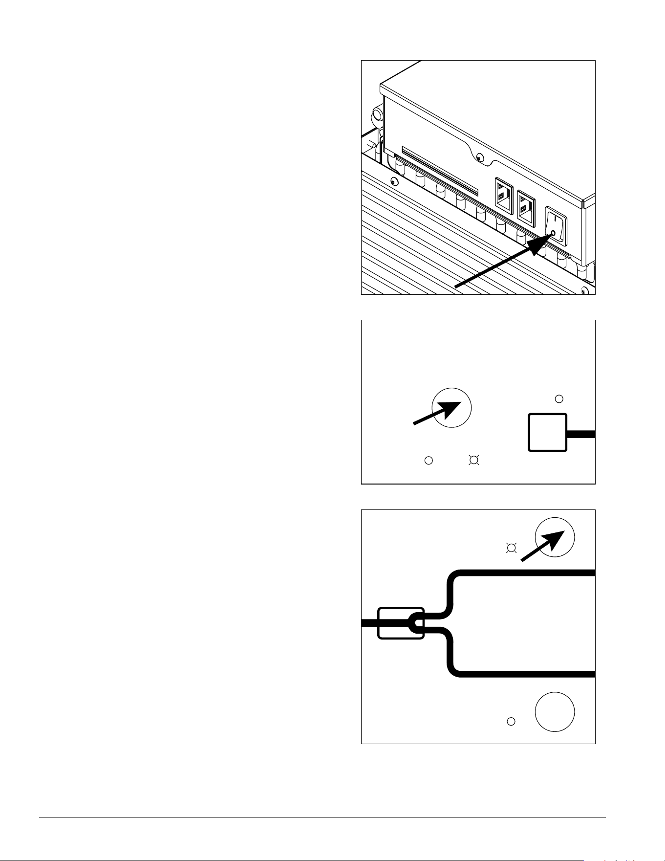
Fig. 14
16. To clean and sanitize Lane 1 ice transport tube –
Press ice machine power switch OFF.
Fig. 15
1 7. Verify that Ice Manager is in manual mode. Manual
light should be on. If auto light is on, press MODE
SELECT button to switch to manual mode.
Mode
select
Auto
ON
ON
Full
Full
Lane 1
Lane 2
Min
Icemaker
Manual
ON
Fig. 16
18. Press LANE 1 button. Lane 1 light will come on.
Mode
select
Auto
ON
ON
Full
Full
Lane 1
Lane 2
Min
Icemaker
Manual
ON
Fig. 17
Ice Manager Diverter Valve System IMDV-2CM 25
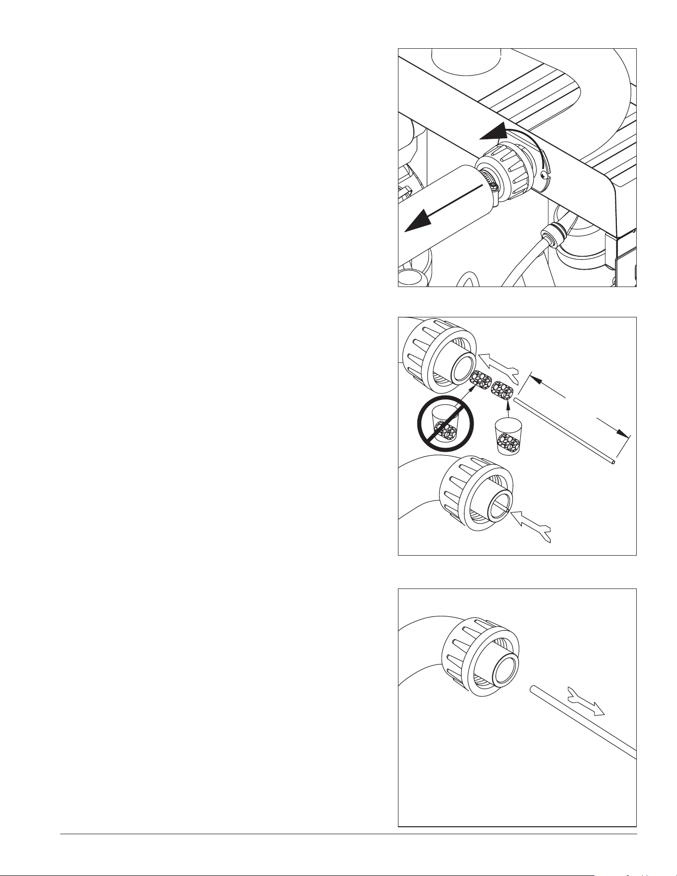
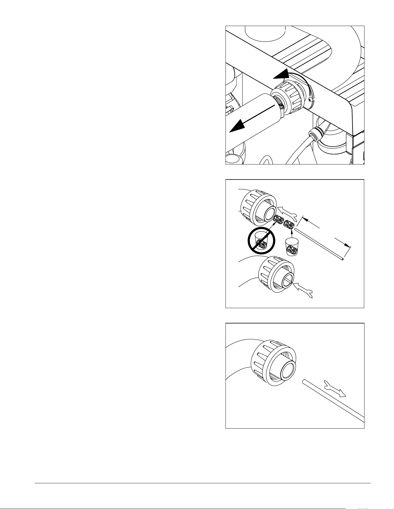
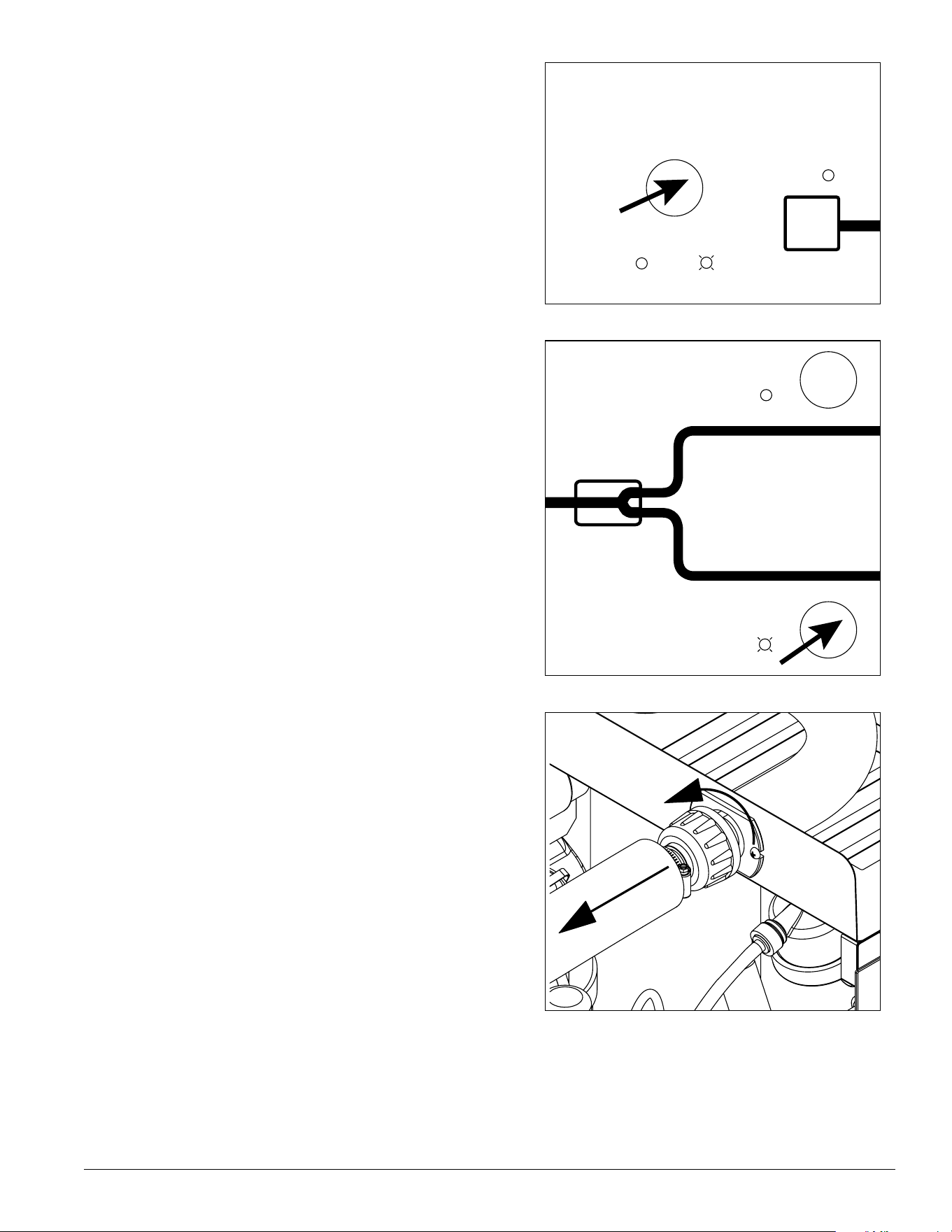
19. Disconnect coupling from ice machine as shown.
Fig. 18
20. Using disposable food service grade gloves, insert
dry Sani-Sponge.
2 1. Insert Sani-Sponge soaked in SafeClean Plus (from
Step 4).
22. Push both Sani-Sponges down ice transport tube
with supplied pusher tube.
1
2
3
16"
(407 mm)
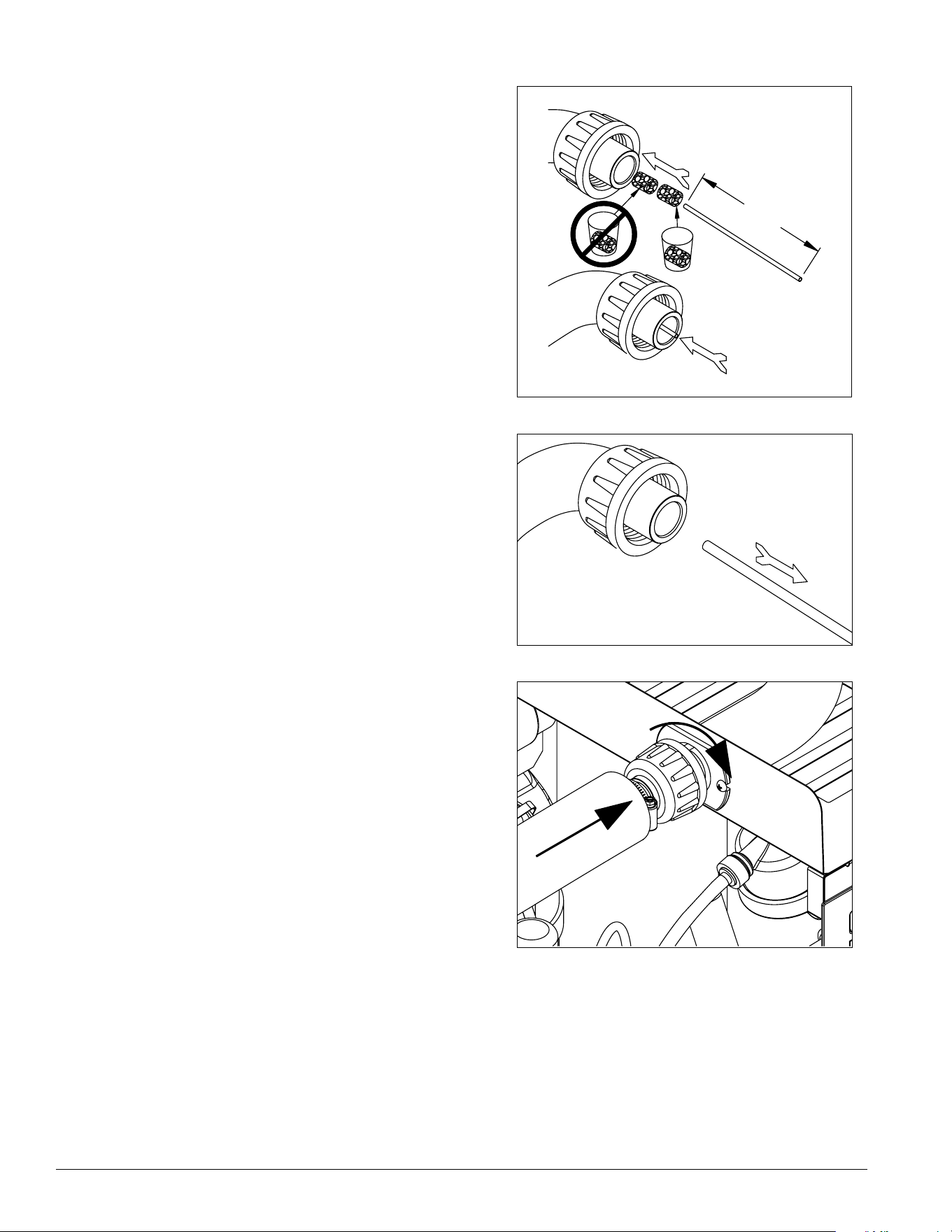
Fig. 19
23. Remove 16” (407 mm) pusher tube.
26 Ice Manager Diverter Valve System IMDV-2CM
Fig. 20
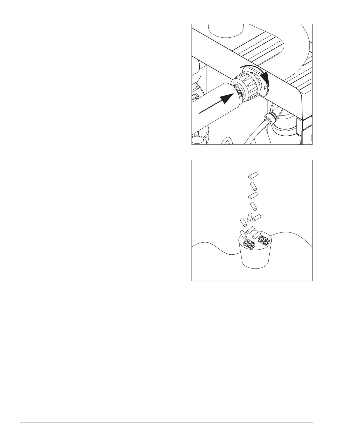
24. Reconnect coupling. Press ice machine power switch
ON. Ice pushes Sani-Sponges through tube.
Fig. 21
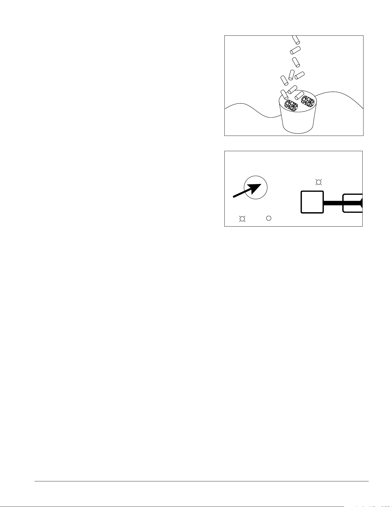
25. Place a sanitary (2 gallon or larger) container in bin
or dispenser to collect Sani-Sponges and ice for
10 minutes. Collect 5.5 lbs (3 kg) of ice from unit.
Discard ice and Sani-Sponge.
Fig. 22
26. To clean and sanitize Lane 2 ice transport tube –
Press ice machine power switch OFF.
Fig. 23
Ice Manager Diverter Valve System IMDV-2CM 27
2 7. Verify that Ice Manager is in manual mode. Manual
light should be on. If auto light is on, press MODE
SELECT button to switch to manual mode.
Mode
select
Auto
ON
ON
Full
Full
Lane 1
Lane 2
Min
Icemaker
Manual
ON
Fig. 24
28. Press LANE 2 button. Lane 2 light will come on.
Mode
select
Auto
ON
ON
Full
Full
Lane 1
Lane 2
Min
Icemaker
Manual
ON
Fig. 25
29. Disconnect coupling from ice machine as shown.
28 Ice Manager Diverter Valve System IMDV-2CM
Fig. 26
30. Using disposable food service grade gloves, insert
dry Sani-Sponge.
3 1. Insert Sani-Sponge soaked in SafeClean Plus (from
Step 4).
32. Push both Sani-Sponges down ice transport tube
with supplied pusher tube.
1
2
3
16"
(407 mm)
Fig. 27
33. Remove and discard 16” (407 mm) pusher tube.
Fig. 28
34. Reconnect coupling. Press ice machine power switch
ON. Ice pushes Sani-Sponges through tube.
Ice Manager Diverter Valve System IMDV-2CM 29
Fig. 29
35. Place a sanitary (2 gallon or larger) container in bin
or dispenser to collect Sani-Sponges and ice for
10 minutes. Collect 5.5 lbs (3 kg) of ice from unit.
Discard ice and Sani-Sponges.
Fig. 30
36. Press MODE SELECT button on Ice Manager control
panel to switch to auto mode. Auto light will come on.
Mode
select
Auto
ON
ON
Full
Full
Lane 1
Lane 2
Min
Icemaker
Manual
ON
30 Ice Manager Diverter Valve System IMDV-2CM
Operation
General information
The Ice Manger diverter valve system is designed to
direct ice from one Horizon ice machine to two ice
storage units. AUTO is the standard operating mode.
When selected, ice is directed to the lane 1 storage
unit until it reaches the MIN (minimum) set-point.
Ice is then directed to the lane 2 storage unit and
will continue to ll this lane until the FULL level is
achieved. If at any time the ice level in lane 1 storage
unit goes below the MIN set-point, ice will be directed
back to lane 1 until the MIN level is satised. When
lane 2 reaches its FULL level, ice will be directed back
to lane 1. When both lanes reach their FULL level, the
Horizon ice machine will shut off. The ice machine will
be ready to start as soon as the ice level in either of
the storage units drops below the FULL set-point.
Audible alarm
In the event a system error occurs that could cause
ice shortages, the audible alarm will be turned ON
accompanied by an appropriate error message on the
LED screen. To silence the alarm, press any of the
push buttons on the control panel. This will silence
the alarm for 4 hours, however the error message
displayed on the LED screen will remain until the
problem is addressed. After 4 hrs, if the error has not
been addressed, the audible alarm will resume.
Placing the system in MANUAL MODE will also
prevent the alarm from sounding. The error message
on the LED screen will still ash, but the alarm will not
resume.
See troubleshooting guide on page 26 for causes.
Ice Manager
Diverter Valve
(1) Horizon
™
Chewblet
®
Icemaker
(purchased separately)
(2) ice storage units
(purchased separately)
Any combination of bins or dispensers
Ice Manager
Control Panel
ICE MANAGER SYSTEM
Lane 1
Lane 2

Ice Manager Diverter Valve System IMDV-2CM 31
Service
System components
Follett’s Ice Manager diverter valve system consists of following major components:
• Diverter valve module
• Control panel module
• Ice transport tube lane 1 with a dedicated sensor cable 1
• Ice transport tube lane 2 with a dedicated sensor cable 2
• Ice level sensor / ice distribution module for lane 1
• Ice level sensor / ice distribution module for lane 2
System operation
The Ice Manager diverter valve system is designed to control the feeding of ice from one Horizon ice machine to two
ice storage units. There are different ice level set-points for ice storage units.
The ice storage unit for lane 1 has two ice level set points, MIN and FULL, while the ice storage unit for lane 2 has
only one - FULL. There is also a DIF (Differential) setting for each lane that initiates rell of ice.
Note: Ice Manager diverter valve system comes with factory pre-set values for MIN, FULL and DIF (differential)
parameters. If required the pre-set values can be eld modied. (See the ice level set point on page 25.)
Control logic
Ultrasonic sensors for lane 1 and lane 2 detect ice level and send an analog signal between 0.5vdc to 4.5vdc back to
diverter valve control board. This signal is converted into distance (in inches) from the sensor face to the ice surface.
An appropriate light on the control panel comes on indicating the ice level reached either MIN or FULL levels for
lane 1 or FULL level for a lane 2 units.
Auto mode
AUTO is the standard operating mode for the Ice Manager diverter valve system. In AUTO mode, the system will
automatically direct the ice according to the sensor set point levels.
On start up, when AUTO mode is selected the diverter valve directs ice through lane 1 to the ice storage unit until the
MIN level is satised.
The diverter valve will then switch and direct ice through lane 2 until its ice storage unit FULL level is satised.
If during this time the ice level in lane 1 ice storage unit drops below the MIN level, then the diverter valve will
re-direct ice ow back to lane 1 and continue feeding ice through the lane 1 until the ice storage unit MIN level is
satised again. The cycle will continue until FULL level for both ice storage units are reached.
When the ice level in both ice storage units is at the FULL level, the diverter valve shuts off the signal to the ice
machine. When the delay period expires, the control logic will allow the ice machine to restart when either sensor
detects ice level drop below the FULL set-point.
Note: There is a 30 second time delay function programmed into the control logic. This function requires
30 seconds of a steady ice level reading exceeding a set-point before the control logic initiates any action.
Therefore, a momentary ice level change measured by the ice level sensors will not trigger a shut-down
or divert.
Manual mode
For Ice Manager diverter valve system cleaning and sanitizing, and some special situations (see a troubleshooting
guide on page 26), a MANUAL mode is available. MANUAL mode overrides AUTO mode and allows the operator to
select the lane.
In order to switch between AUTO and MANUAL modes push the MODE SELECT button located on the control panel.
While in MANUAL mode, pressing either lane 1 or lane 2 buttons will divert ice ow accordingly.
Note: When in manual mode ice level sensors will not control the divert action, however the ice sensors will
continue to control the ice machine. When the FULL ice level in designated ice storage unit is satised the
ice machine will be shut off.
32 Ice Manager Diverter Valve System IMDV-2CM
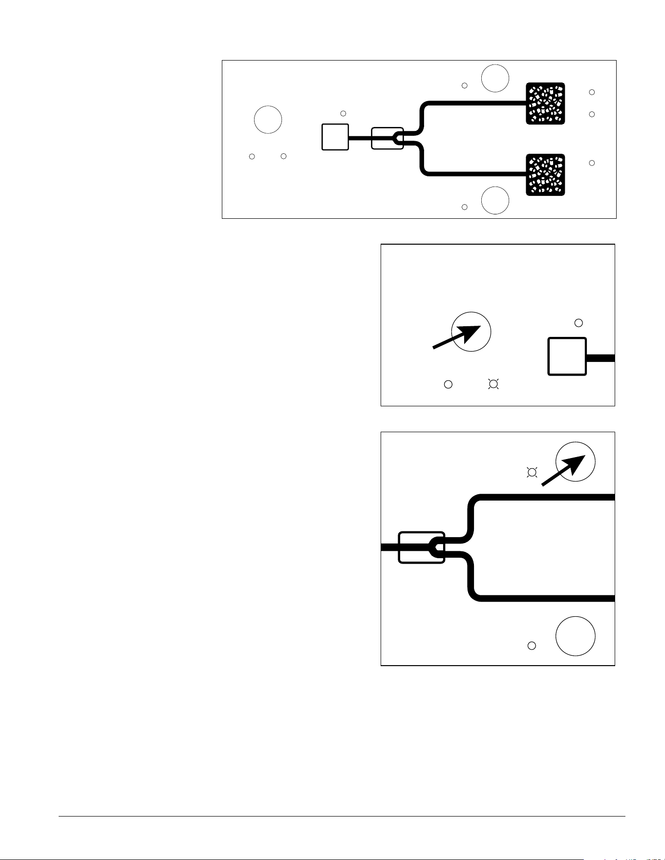
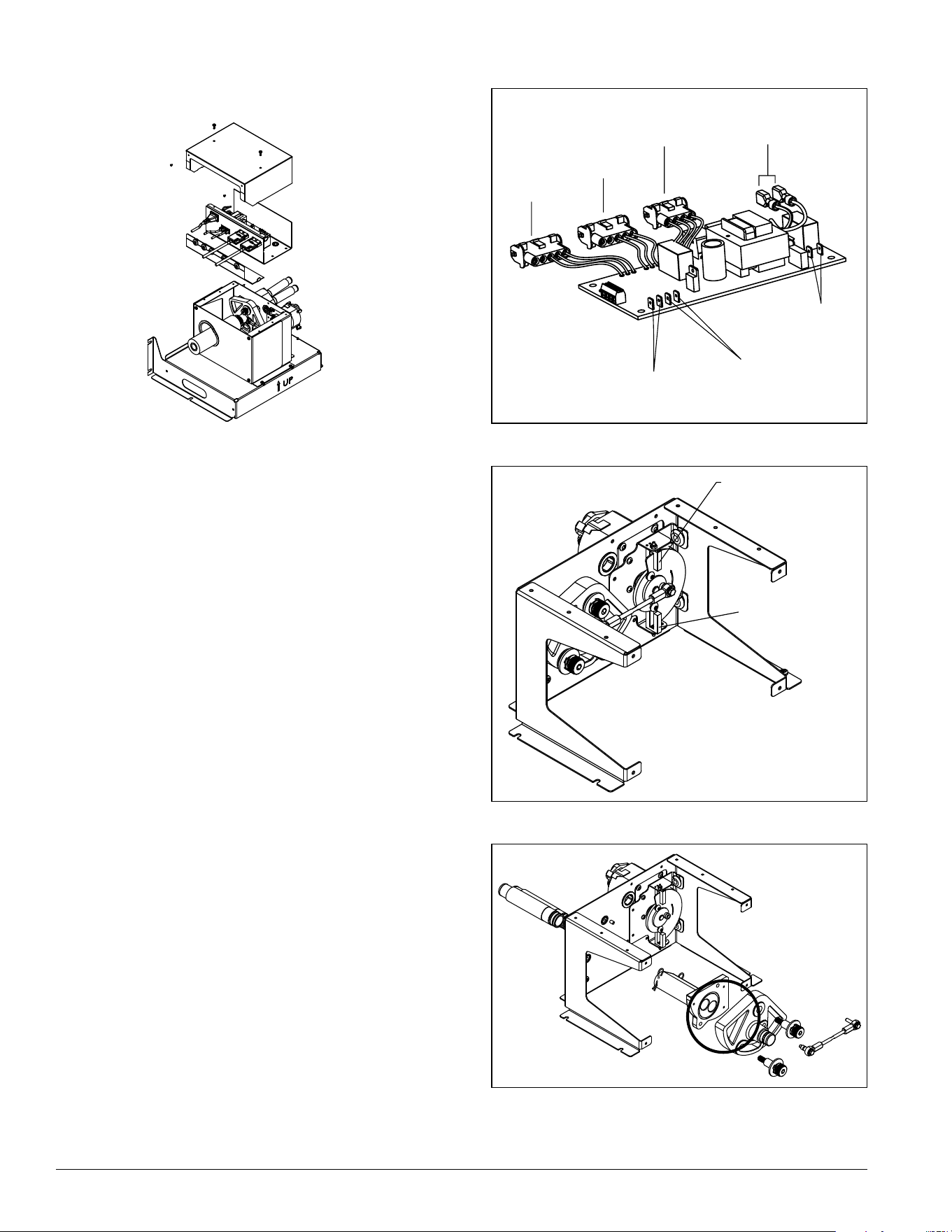
Diverter valve module
There are three major functional components within the
diverter valve.
Control board
The control board manages all functions of the Ice
Manager diverter valve system based on signals
received from lane 1 and lane 2 ice level sensors. It
diverts ice ow from one lane to another, while ice
storage units are lled and shuts off ice machine when
both dispensers are at the FULL level.
The control board communicates with the Horizon ice
machine and the sensors for the lane 1 and lane 2 via
appropriate signal cables. It supplies 120/60/1 electrical
power to the divert gearmotor assembly and monitors
the divert gearmotor position status based on inputs
from two magnetic switches mounted to the gearmotor
bracket. It also provides 12vdc power to the control
panel via the gray control cable.
Divert gearmotor
The divert gearmotor assembly is linked to the divert
paddle assembly and manages ice ow direction.
Divert paddle
Located inside of the body of the diverter valve module,
the divert paddle is driven by the gearmotor and
switches ice ow from one internal channel to another.
lane 1
magnetic switch
lane 2
magnetic switch
Fig. 31
Fig. 32
lane 1
lane 2
no connection
power
gearmotor
lane 2
switch
lane 1
switch
Fig. 33
Ice Manager Diverter Valve System IMDV-2CM 33
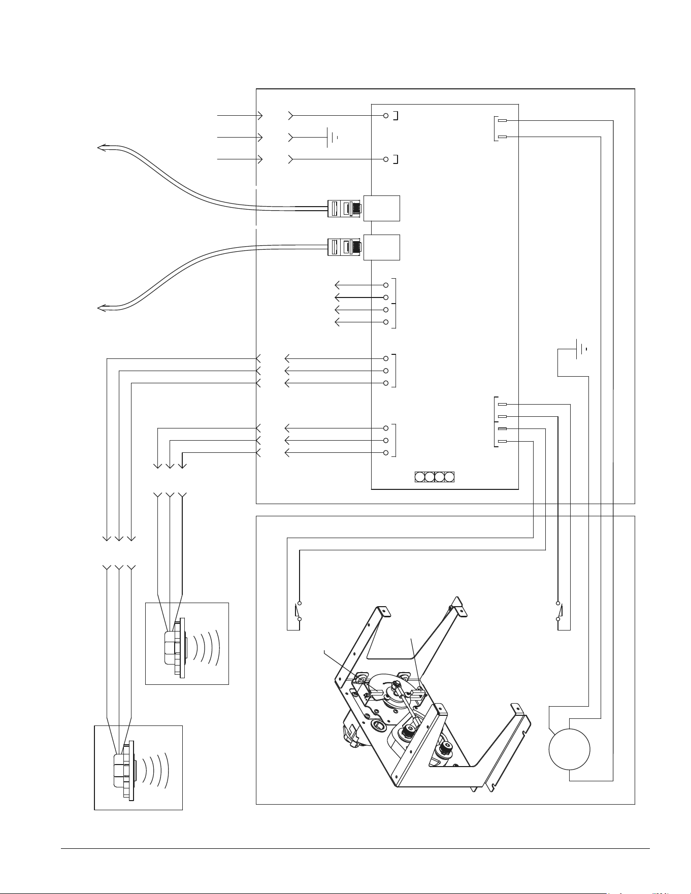
Ice Manager diverter valve wiring diagram
115Vac/60HZ
DIVERT
MOTOR
HN G
LANE 2 LEVEL SENSOR
HN
LANE 2
MOTOR
DIVERT
POS SW
LANE 2
POS SW
LANE 1
SENSORSENSOR
LANE 1
BLACK
WHITE
GREEN
BLUE
BLUE
WHITE
WHITE
123
RED (+12 VDC)
BLACK (Grnd)
YELLOW (.5-4.5 VDC)
WHITE
GREEN
BLACK
BLACK
BLACK
BLACK
MAIN CONTROL BOX
LANE 1 LEVEL SENSOR
RED (+12 VDC)
BLACK (Grnd)
YELLOW (.5-4.5 VDC)
(115Vac)
(12vdc)(12vdc)
LANE 1
TOP SWITCH
LANE 2
BOTTOM SWITCH
MOTOR COMPARTMENT
5 PIN PLUG
123
5 PIN PLUG
1234
POWER INLET
CONNECTOR
123
5 PIN PLUG
123
5 PIN PLUG
PANEL
CONTROL
TO
BLACK
ICE MACHINE
HORIZON
TO
BLUE
GRAY
4 PIN PLUG
(NOT USED)
HORIZON CONTROL
PANEL
lane 1
magnetic switch
lane 2
magnetic switch

34 Ice Manager Diverter Valve System IMDV-2CM
Control panel
(Fig. 39)
The control panel is powered with
12vdc coming from the diverter valve
control board via the gray control
cable. It contains a membrane switch
and an LCD screen.
Note: The diverter valve control
board receives power
directly from the outlet. The
system will be running even
if the control panel is not
operational.
Membrane switch
The membrane switch contains LED indicators offering
a quick system status.
ICE MACHINE ON light - a steady LED indicates the
ice machine is running.
LANE 1 ON light - a steady LED indicates ice is
directed through lane 1
LANE 2 ON light - a steady LED indicates ice is
directed through lane 2
FULL light – a steady LED indicates the ice has
reached the FULL level set-point
MIN light – a steady LED indicates the ice has
reached the minimum level set-point
LCD screen
The LCD screen shows ice level readings in both ice
storage units and overall Ice Manager diverter valve
system status. In case of System errors the LCD
screen displays the nature of the failure and provides
necessary details.
(See troubleshooting on page 26 for details.)
Audible alarm
In the event a system error occurs that could cause
ice shortages, the audible alarm will be turned ON
accompanied by an appropriate error message on the
LCD screen. To silence the alarm, press any of the
push buttons on the control panel. This will silence
the alarm for 4 hours, however the error message
displayed on the LCD screen will remain until the
problem is addressed. After 4 hrs, if the error has not
been addressed, the audible alarm will resume.
Placing the system in MANUAL MODE will also
prevent the alarm from sounding. The error message
on the LCD screen will still ash, but the alarm will not
resume.
See troubleshooting guide for causes.
Mode
select
Auto
ON
ON
Full
Full
Lane 1
Lane 2
Min
Icemaker
Manual
ON
Sensor Reading:
Lane 1: ___"
Lane 2: ___"
Status : OK
Fig. 34
Fig. 35
Ice Manager Diverter Valve System IMDV-2CM 35
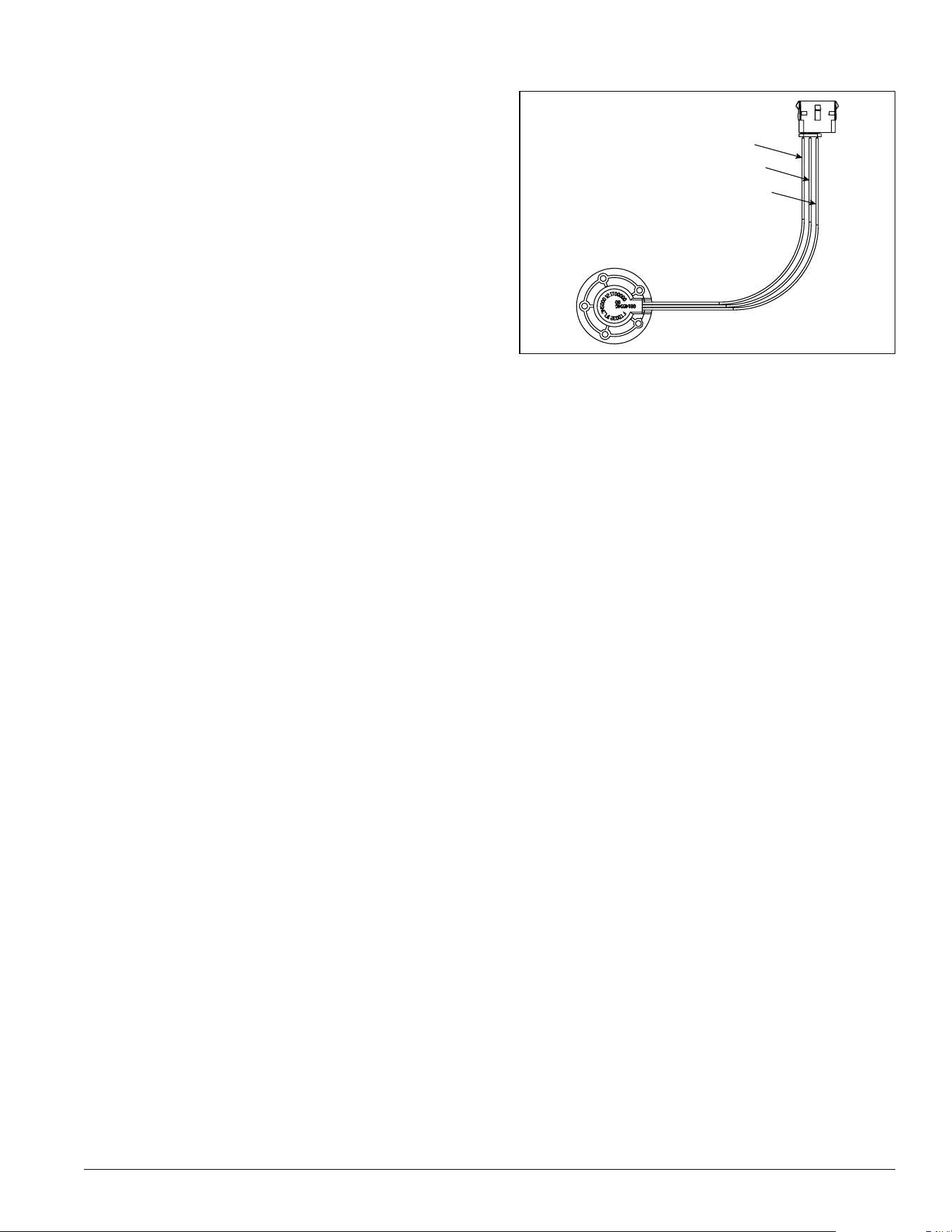
red
black
yellow
Ultrasonic sensor
The ultrasonic sensor measures ice level in each ice
storage unit. The sensor outputs an analog voltage
between 0.5 Vdc and 4.5 vVdc corresponding the ice
level distance from the face of the sensor.
Fig. 36
36 Ice Manager Diverter Valve System IMDV-2CM
Troubleshooting
Ice shortage with audible alarm
To silence audible alarm press any push buttons on the face of the control panel. Use the chart below to diagnose
the cause.
Control Panel Error Message Indicator or Possible Cause Corrective Action
Ice machine LED is ashing and
ICEMAKER ERROR message is
displayed
• Signal cable between Horizon ice
machine and diverter valve module
is not properly engaged
• Check the signal cable connections
• Horizon ice machine has shut off
on a SERVICE error
• Troubleshoot Horizon ice machine
Lane 1 or lane 2 LED is ashing
and SENSOR ERROR message is
displayed
• Malfunctioning sensor • Check supply and return dc voltage
at sensor connections. Supply
should read 12vdc between red
and black wires. Return should
read between .5 - 4.5 vdc between
yellow and black wires.
• Recycle power to sensor and see if
error clears.
Lane 1 or lane 2 LED is ashing
and SENSOR CONNECT ERROR
message is displayed
• Sensor is disconnected from a
signal cable
• Check sensor connections to cable
• Signal cable is disconnected from
diverter valve
• Check signal cable connection to
diverter valve
Both lane 1 and lane 2 LEDs are
alternately ashing and DIVERT
ERROR message is displayed
• Both upper (lane 1) and lower
(lane 2) magnetic positioning
switches mounted to the gearmotor
bracket inside the diverter valve are
in closed or open position at the
same time.
• Check both magnetic positioning
sensors. One should be closed
when it is engaged by the
positioning disc, while the other
should be open.
Note: To manually rotate the disc
depress the gearmotor brake.
DIVERT TO L1 or DIVERT TO L2
message is displayed
• Divert valve fails to switch to
another lane due to lane magnetic
positioning switch not closing
• Check to be sure magnetic
positioning switch is properly
connected to the control board
• Check the positioning switch for
continuity while it is engaged by
the positioning disc
• Diverter valve fails to switch to
another lane due to mechanical
jamming inside the diverter valve
• Manually switch between lane 1
and lane 2 to free divert paddle
• Mechanical linkage between the
gearmotor and divert paddle is
disconnected
• Check the linkage between the
gearmotor and divert paddle

Ice Manager Diverter Valve System IMDV-2CM 37
Ice shortage without audible alarm
Use the chart below to diagnose the cause.
Control Panel Error Message Indicator or Possible Cause Corrective Action
No error message • Signal cables and ice transport
tubes are not connected to correct
ice storage/ice dispenser (lane)
• Check to be sure that signal
cables and ice transport tubes are
connected to correct lane
No error message • Ice level reading as displayed
on control panel is signicantly
different from the actual distance
between the ice and the sensor
face
• Recycle power to the diverter valve.
Make sure to re-start the Horizon
ice machine which will go into
TIME DELAY mode
No error message • Horizon ice machine goes into
TIME DELAY mode within a few
minutes of start up of lane change
• Manually switch ice to another lane
and restart Horizon ice machine.
Let ice machine produce ice for 5
to 8 minutes and manually switch
ice back to the “troublesome” lane.
See if “start-up” ice clears through
• If the above procedure does not
work, investigate a potential ice
lane restriction issue (i.e. transport
tube, bulkhead ttings, sensor
distribution unit, diverter valve)
• Check ice level set-points. Be sure
they match factory settings or
drop-in requirements shown in the
Ice level set point section of this
manual on page 24
• ITT from IM to IMDV too short (not
10 foot minimum required length)
38 Ice Manager Diverter Valve System IMDV-2CM
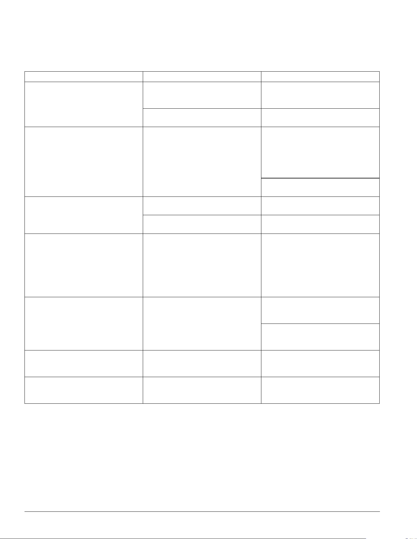
Service Parts
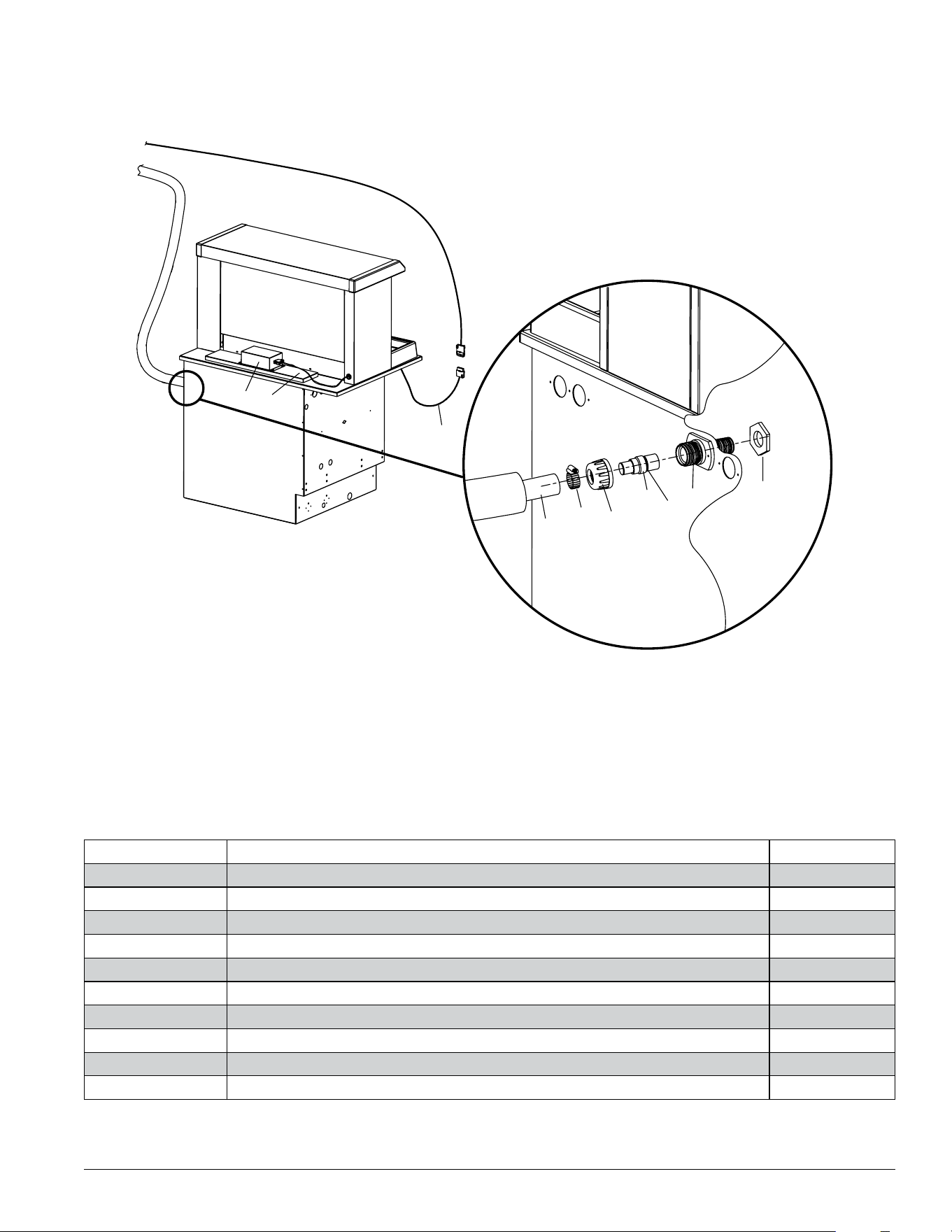
Diverter valve module
1
2
3
4
5
Reference # Description Part #
1 Clamp 500378
2 Pin, coupling, retainer 01550037
3 Gearmotor assembly 00175166
4 Grommet 01555606
5 Main control board 00173955
6 Switch, magnetic (1) 00168096
Not shown Pan, diverter drain 01550029
Not shown O-ring kit 01550045
Not shown Coupling, ice tube 01550052
Not shown Insulation, coupling 01550060
Not shown Insulation, diverter tube 01550078
Not shown Cable, communication, IMDV-2CM 01551365
Not shown O-ring, ice tube 01555655
Not shown Power cord 01555622
Not shown Elbow, drain 01555630
Not shown Hose, drain (sold per foot) 501965
Ice Manager Diverter Valve System IMDV-2CM 39
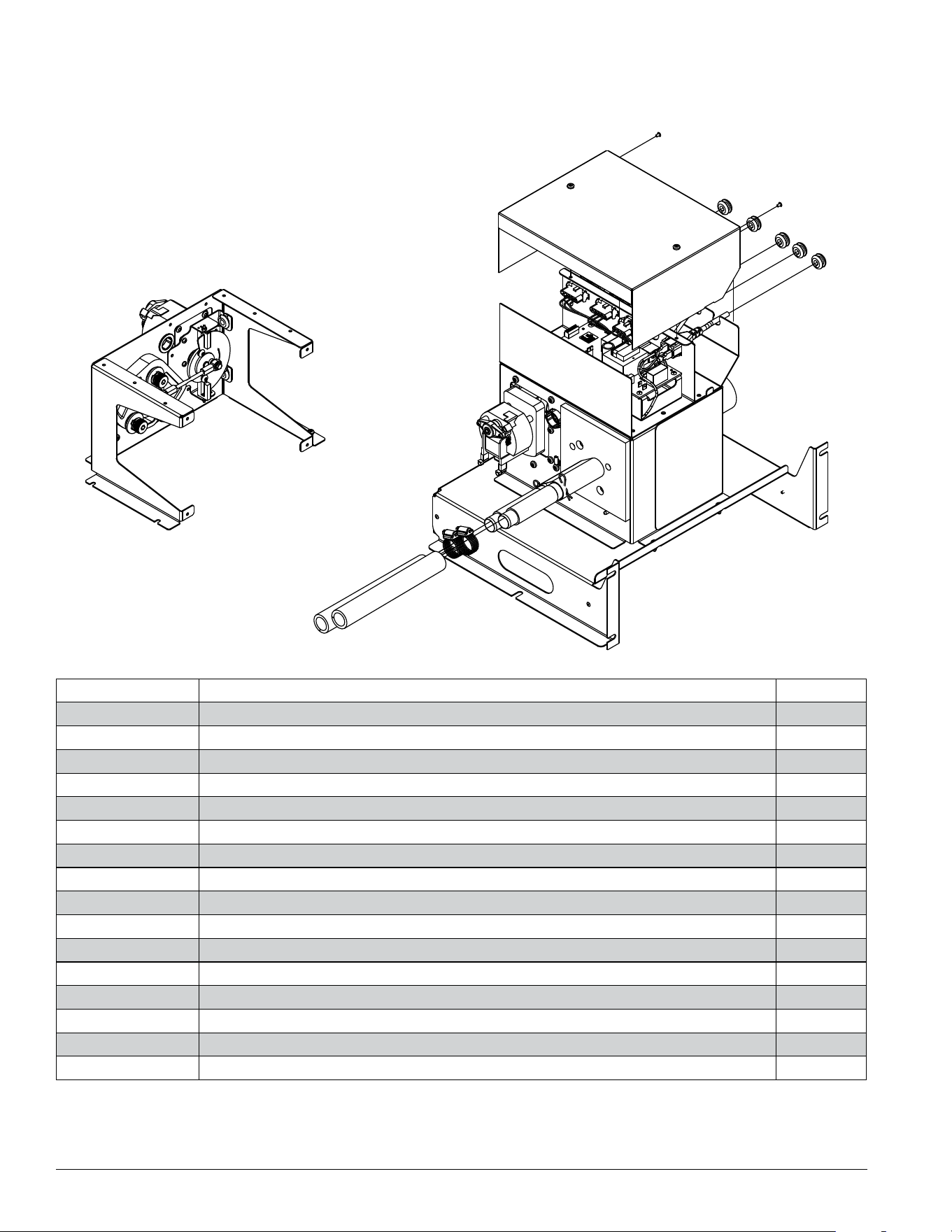
Control panel
Reference # Description Part #
1 Control module (includes gray control cable) 00159350
2 Membrane switch 00172627
3 Control panel board 00172684
4 Control panel cover 00175133
1
2
3
4
40 Ice Manager Diverter Valve System IMDV-2CM
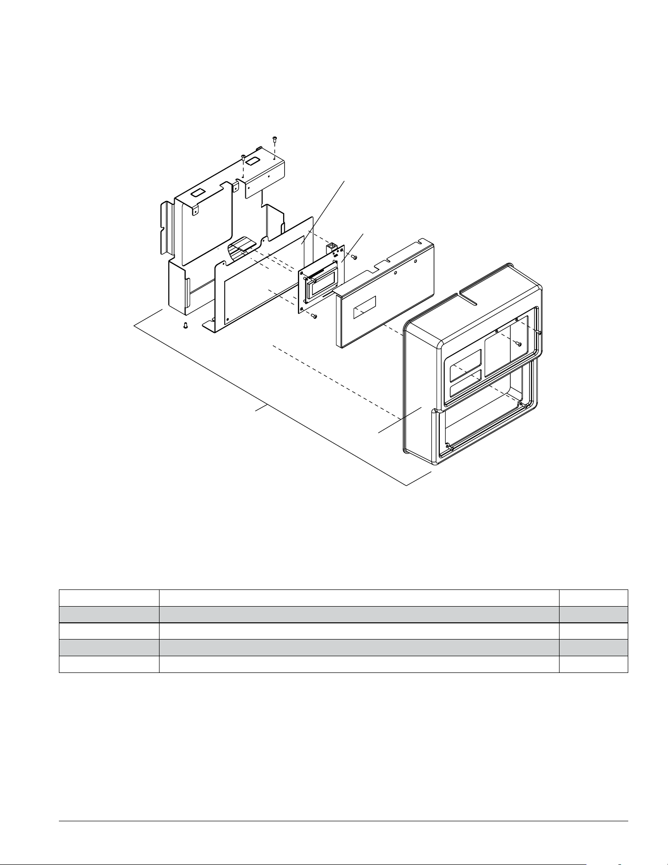
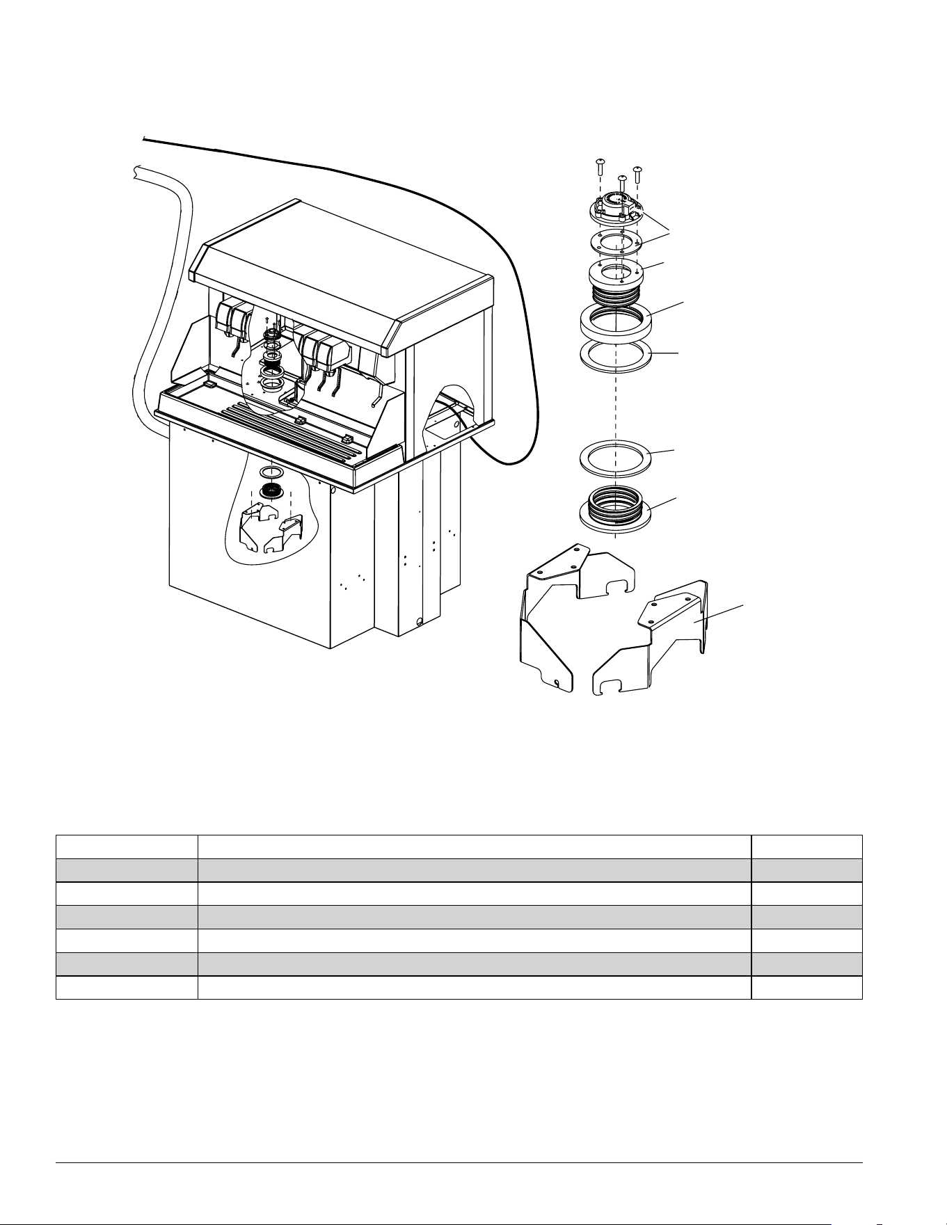
Sensor distribution unit
Reference # Description Part #
1 Cover 01555648
2 Clamp 500378
3 Nut 01303189
4 Coupling 00175141
5 O-ring 01555655
6 Clamp, positioning (includes nut and bolt) 00182451
7 Nut, wing and rod 00182469
8 Distribution unit 00146803
9 Nut, hex stainless steel 1/4-20 01555663
10 Carriage screw, 1/4-20 2/5” long 01555671
11 Sensor, ultrasonic 00175174
12 Insert 01555689
13 Thumb screw 01555697
14 Sensor distribution assembly 00149377
1
2
3
14
4
5
6
7
8
10
11
9
13
12
Ice Manager Diverter Valve System IMDV-2CM 41
Follett Vision™ VU155 Ice Manager kit
Reference # Description Part #
1 Cover, 155 sensor 01555705
2 Lid, rear, 155 sensor 01555713
3 Vision sensor cable 01555721
4 Polywire tube, insulated see page 35
5 Clamp, hose 500378
6 Nut 01303189
7 Coupling (includes 00145300) 00175141
8 O-ring 01555655
9 Bulkhead tting 01555747
10 Nut, bulkhead tting 01555754
4
12
5
3
7
9
6
8
10
42 Ice Manager Diverter Valve System IMDV-2CM
Follett Vision™ VU300 Ice Manager kit
Reference # Description Part #
1 Sensor, ultrasonic, service 00175174
2 Tube, sensor mount 01555762
3 Locking ring, coupling 00171371
4 Gasket, coupling 01303080
5 Coupling, sensor mount 01555770
6 Bracket, ice tube 00175208
3
5
6
1
2
4
4
Ice Manager Diverter Valve System IMDV-2CM 43
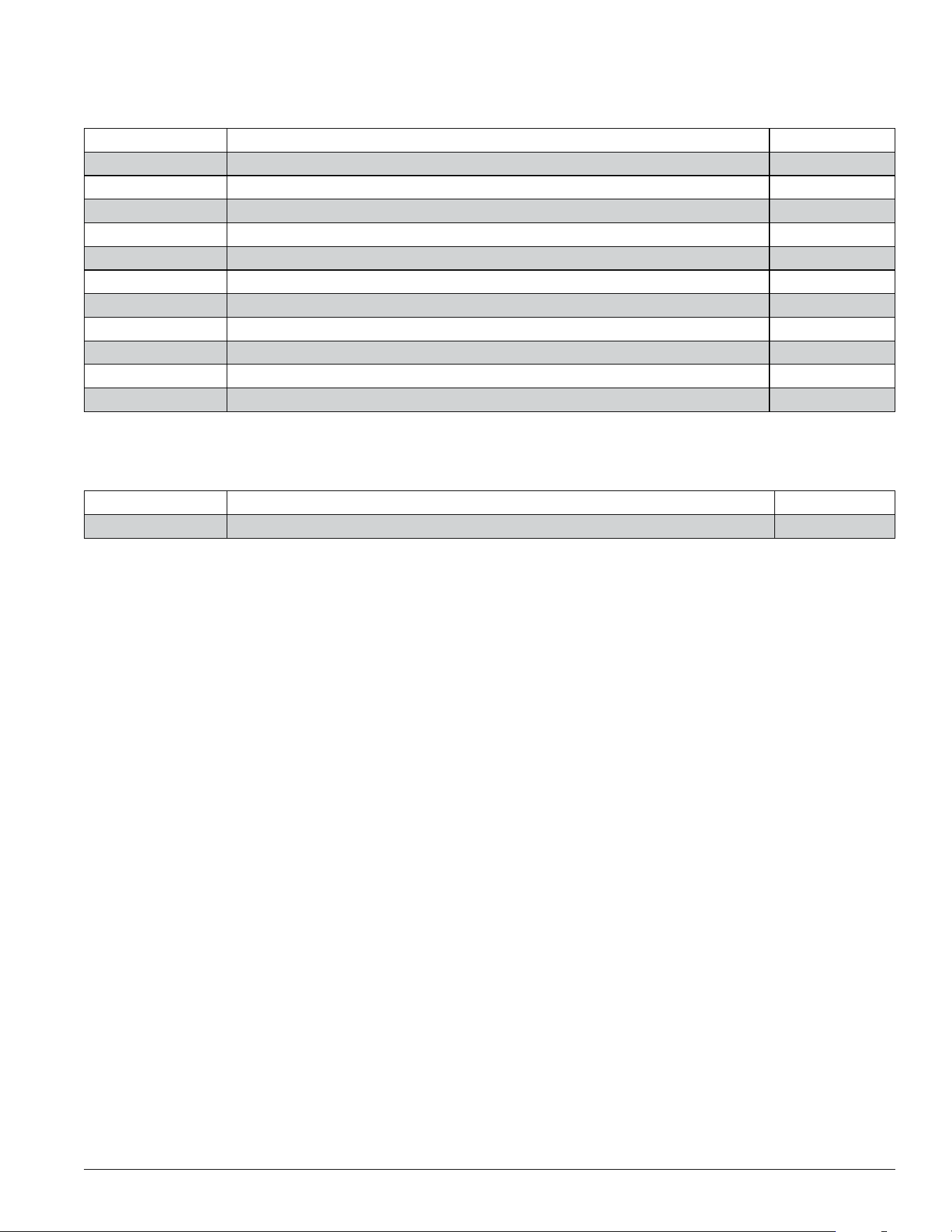
Cables
Reference # Description Part #
Not shown Cable, control panel to diverter valve, 30' (9m) 01555788
Not shown Cable, diverter valve lane sensor, 10' (3m) 01555796
Not shown Cable, diverter valve lane sensor, 25' (7.6m) 01555804
Not shown Cable, diverter valve lane sensor, 50' (15.2m) 01555812
Not shown Cable, diverter valve lane sensor, 75' (22.9m) 01555820
Not shown Cable, Horizon to diverter valve, 20' (6m) 01555838
Not shown Cable, Horizon board interface 01555846
Not shown Cable, Comm, IMDV2 01551365
Not shown Ice transport tube, 10'* 00171280
Not shown Ice transport tube, 20'* 00171298
Not shown Ice transport tube, by the foot* 00174896
* All ice transport tube includes insulation, shipped loose.
Ice Machine Retrot Kits
Reference # Description Part #
Not shown All Model 01551365

01113349R05
© Follett Products, LLC 1/24
801 Church Lane • Easton, PA 18040, USA
Toll free (877) 612-5086 • +1 (610) 252-7301
www.follettice.com
Horizon, Horizon Elite, Ice Manager, SafeCLEAN, Sani-Sponge, RIDE and Vision are trademarks of Follett Products, LLC.
Follett and Chewblet are registered trademarks of Follett Products, LLC, registered in the US.