
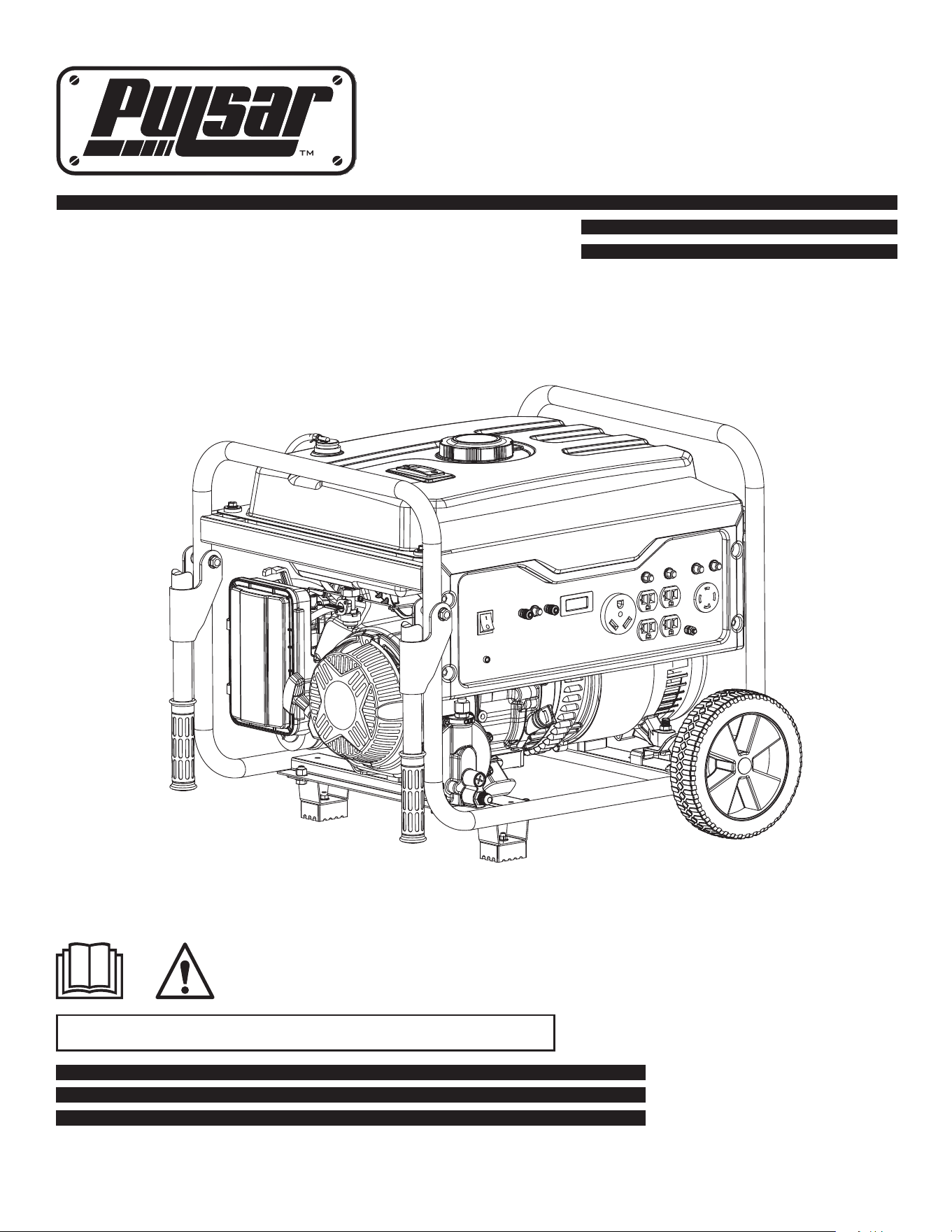
Generator
www.pulsar-products.com
OPERATOR’S MANUAL
Warning: The Engine Exhaust from this product contains chemicals known to
the State of California to cause cancer, birth defects or other reproductive harm.
Model: G65BN

Introduction. ............................................................................................................................................................................3
Parts Ordering / Customer Service. .............................................................................................................................3
Product Specifications. ................................................................................................................................................3
Safety Rules. ...........................................................................................................................................................................4
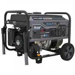
Safety Symbols. ...........................................................................................................................................................4
Safety Instructions ......................................................................................................................................................4
Features....................................................................................................................................................................................7
Assembly ................................................................................................................................................................................8
Unpacking .................................................................................................................................................................... 8
Packing List . ............................................................................................................................................................... 8
Attaching Wheels ....................................................................................................................................................... 9
Adding Oil/Checking engine oil ...................................................................................................................................10
Adding Fuel. ...............................................................................................................................................................11
Connecting Generator to a building Electrical System. ............................................................................................11
Operation ..............................................................................................................................................................................12
How to Stop Engine. ..................................................................................................................................................13
Grounding the Generator .
How to Start Engine.
............................................................................................................................................12
Receptacles and Extension Cords..............................................................................................................................13
Don’t Overload Generator...........................................................................................................................................14
Wattage Reference Guide. .........................................................................................................................................15
Cold Weather Operation. ...........................................................................................................................................16
Maintenance . ..........................................................................................................................................................................17
Maintenance Schedule . .............................................................................................................................................17
Engine Maintenance ..................................................................................................................................................19
Changing Oil . ............................................................................................................................................................18
How to Store . ...........................................................................................................................................................21
Troubleshooting . ..................................................................................................................................................................22
Diagrams.................................................................................................................................................................................23
TABLE OF CONTENTS
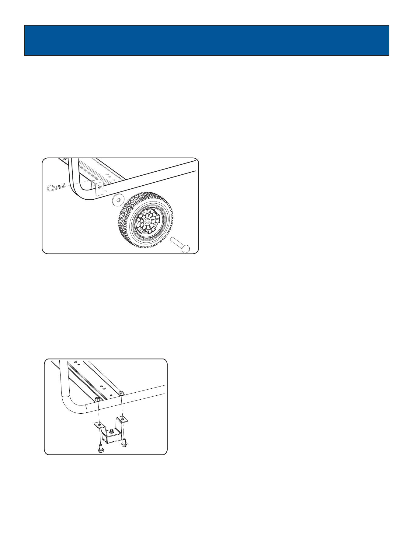
Installing support leg ................................................................................................................................................... 9
Installing the handles...................................................................................................................................................10
..................................................................................................................................................12
3
INTRODUCTION
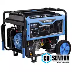
Date of Purchase:
Model Number:
Serial Number:
AC Output
Rated Wattage 5500W (5.5kW)
Rated Voltage 120V/240V
Rated Frequency 60Hz
Rated Ampere 45.8A / 22.9A
Maximum Output 6.58kVA
SAVE THIS MANUAL FOR FUTURE REFERENCE
This manual contains important information regarding safety, operation, and maintenance.
Engine 274cc OHV, 4 Stroke, Air Cooled
Engine Oil
10W30 - 23oz (0.7L)
Fuel Tank 5.2 Gal (20L) Unleaded Gasoline
GAS LPG
4900W (4.9kW)
120V/240V
60Hz
58.3A / 29.1A
5.922kVA
PULSAR PRODUCTS, INC
5721 E. SANTA ANA ST.
ONTARIO, CA 91761
866-591-8921
The emissions control system for this generator is compliant with all standards set by the U.S. Agency. (EPA)
How to contact us:
To order parts, receive warranty assistance, or other services inquiries, you can contact us via our website at
www.pulsar-products.com or write to us at:
Save your original sales receipt and record the following information below for service or warranty assistance.
Thank you for purchasing this superior quality portable generator from Pulsar Products Inc. When operating and
maintaining this product as instructed in this manual, your generator will give you many years of reliable service.as
Product Specifications:
This generator is an engine-driven, revolving field, alternating current (AC) portable generator. It is designed to
supply electrical power to operate tools, appliances, camping equipment, lighting, or serve as a backup power source
during power outages.
4
SAFETY RULES
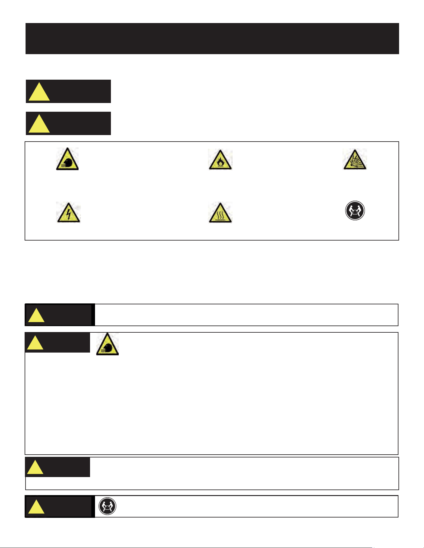
Toxic Fumes Risk of fire Risk of explosion
Lifting hazard
Risk of electric shock Hot surface
WARNING!
CAUTION!
Indicates a potentially hazardous
situation which could result in
serious injury or death if not avoided.
Indicates a potentially hazardous
situation which could result in
damage to equipment or property.
Safety Symbols
Read and understand this manual in its entirety before operating this generator. Improper
use of this generator could result in serious injury or death.
WARNING!
To reduce the risk of serious injury, avoid attempting to lift the generator alone.
WARNING!
Safety Instructions
The manufacturer cannot anticipate every possible hazardous circumstance that the user may encounter. Therefore, the
warnings in this manual, on tags, and on affixed decals are not all-inclusive. To avoid accidents, the user must understand
and follow all manual instructions and use good common sense.
•
•
•
•
• Using a generator indoors CAN KILL YOU IN MINUTES!
• Carbon monoxide gas is a poisonous, odorless gas that can cause headache, confusion, fatigue, nausea, fainting,
sickness, seizures, or death. If you start to experience any of these symptoms, IMMEDIATELY get fresh air and seek
medical attention.
Never use indoors, in a covered area, or in a confined space, even if doors and windows are open.
Install a battery-operated carbon monoxide alarm near bedrooms.
Keep exhaust from this unit from entering a confined area through windows, doors, vents, or other openings.
When working in areas where vapors could be inhaled, use a respirator rated
WARNING!
Do not operate indoors or in a confined space that prevent dangerous
carbon monoxide gas from dissipating.
•
Always wash hands after handling generator.
WARNING!
Engine exhaust contains chemicals that lead to cause cancer and birth defects.
5
SAFETY RULES
• Do not wear loose clothing or gloves.
• Remove jewelry or anything else that could be caught in moving parts.
• Tie back or wear protective head covering to contain long hair.
WARNING!
Starter recoil and other moving parts can catch on clothing, jewelry, and hair.
Keep engine away from flammable objects and other hazardous materials.
•
•
•
The fuel and its vapors used to power this unit are highly flammable and could explode resulting in serious injury or
death.
Never fill or drain fuel tank indoors.
Never overfill fuel tank. If fuel spills, move the unit at least 30 feet away from the spill and wipe up any remaining fuel
on the unit before starting the engine.
•
•
•
•
• Never smoke while operating or fueling this unit.
Never operate or store this unit near an open flame, heat, or any other ignition source.
Generator should be far away from buildings or other equipment during operation.
Keep engine free of grass, leaves, or grease and other flammable debris..
When adding or draining fuel, unit should be turned off for at least 2 minutes to cool before removing fuel cap. If unit
has been running. then the fuel cap may be under pressure, remove slowly.
• To keep fuel from spilling, secure unit so it cannot tip while operating or transporting.
• When transporting unit, disconnect the spark plug wire and make sure the fuel tank is empty with the fuel shutoff valve
turned to the off position.
WARNING!
Never exceed generator’s wattage / amperage capacity. This could damage the generator
and / or connected electrical devices.
WARNING!
•Check operating voltage and frequency requirements of all electrical devices prior to plugging them into the generator.
• To avoid recoil, pull starter cord slowly until resistance is felt, then pull rapidly.
WARNING!
Pull cord recoils rapidly and pulls arm towards engine faster than you can let go which
could result in injury.
• Always start the engine and let it stabilize before connecting any electrical devices.
• Disconnect all electronic devices before stopping the engine.
WARNING!
Never start or stop engine with electrical devices plugged in to the receptacles. Failure to do
so could damage the generator and / or connected electrical devices.
•
•
Use caution around the muffler, cylinder, and other engine parts as they can be extremely hot.
Allow hot components to cool before touching.
WARNING!
Avoid contacting hot areas of this unit.
6
SAFETY RULES
• Improper treatment of generator can damage the unit and shorten its life.
•
Always repair this unit as specified in this manual. If you have any questions, contact your dealer or consult a
qualified service center.
•
Shut generator off if electrical output is missing, unit vibrates excessively or begins to smoke, spark or emit flames.
WARNING!
• Do not bypass any safety device. Moving parts are covered with guards. Make sure all protective covers are in place.
• Never transport or make adjust this unit while it is running.
• Never insert objects through cooling slots.
WARNING!
Never operate this unit if there are any broken or missing parts and only use Pulsar
replacement parts specifically designed for this unit.
PROP 65 WARNING: This product contains chemicals known to the state of California to cause cancer and birth defects or
other reproductive harm.
Only use this unit as intended or serious injury or death could result.
• Increasing governed speed is dangerous which can result in personal injury and / or damaged equipment.
• Decreasing governed speed adds an excessive load and can damage equipment.
• Only when operating at the preset governed speed will this generator will supply the correct rated frequency and
voltage.
WARNING!
Never modify this unit in any way or modify governed speed.
• Only operate generator on a level surface.
• Always connect the nut and ground terminal on the frame to an appropriate ground source.
WARNING!
Generator must be properly grounded to prevent electrocution.
• Never handle the generator, electronic devices, or any cord while standing in water, while barefoot, or when hands
or feet are wet.
• Always keep the generator dry. Never operate generator in rain or under wet conditions.
• Use a ground fault circuit interrupter (GFCI) in a damp or highly conductive area, such as metal decking
or steel work.
•
•
Never plug electronic devices into generator having frayed, worn, or bare wires. Never touch bare wires or make
contact receptacles.
Never permit a child or unqualified person to operate generator. timesAlways keep children a minimum of 10 feet
away from the .generator.
• If using the generator for backup power, notify the utility company.
If connecting generator to a building’s electrical system for standby power, you must use a qualified electrician to
install a transfer switch. Failure to isolate the generator from the power utility could result in serious injury or death to
electric utility workers.
•
WARNING!
This generator produces high voltage which could result in burns or
electrocution causing serious injury or death.
7
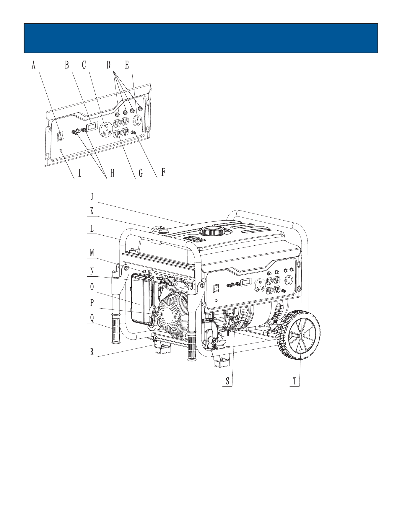
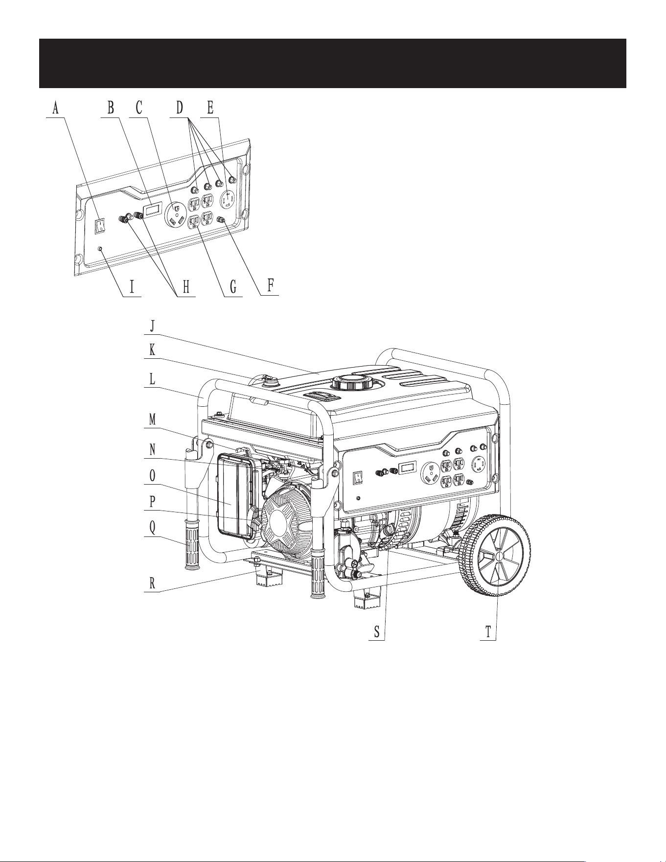
FEATURES
A - ON/OFF Start Switch
B - 3 in 1 Hour Meter
C -120 Volt 30 Amp RV Receptacle(TT-30)
D - Circuit Breaker
E - 120V / 240V 30 Amp Twist Lock (L14-30)
F - Grounding Connection
G - 120V NEMA-5 Receptacle
H - 12V DC Output (For Charging Batteries Only)
I - Low Oil Alert Lamp
J - Fuel Tank
K - Tank Vapor Valve
L - Frame
M- Choke Lever
N - Fuel Valve (ON/OFF)
O - Air Filter Housing
P - Recoil Starter
Q - Handle
R - Support Leg
S - Oil Fill and Dipstick
T - No Flat Tires
8
ASSEMB
L
Y
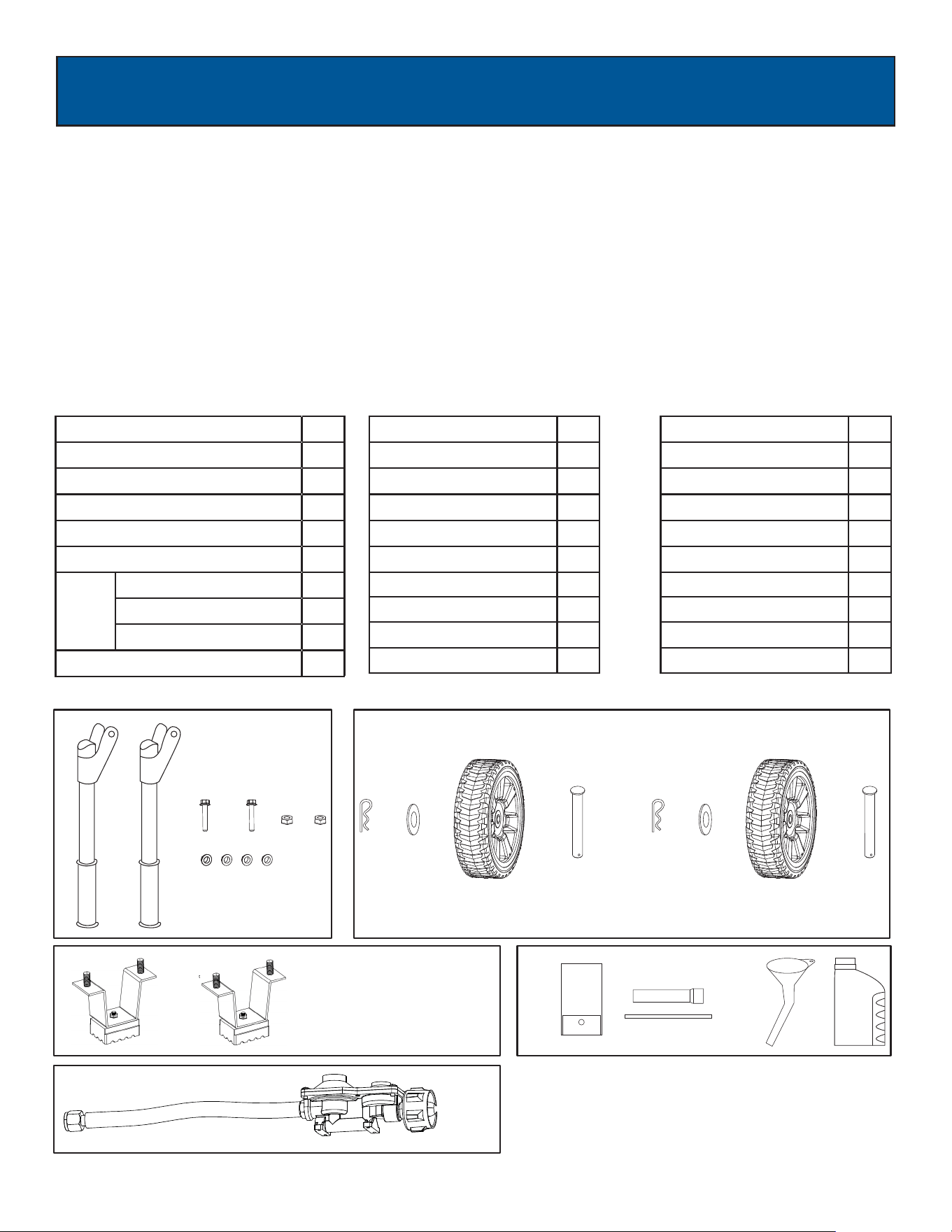
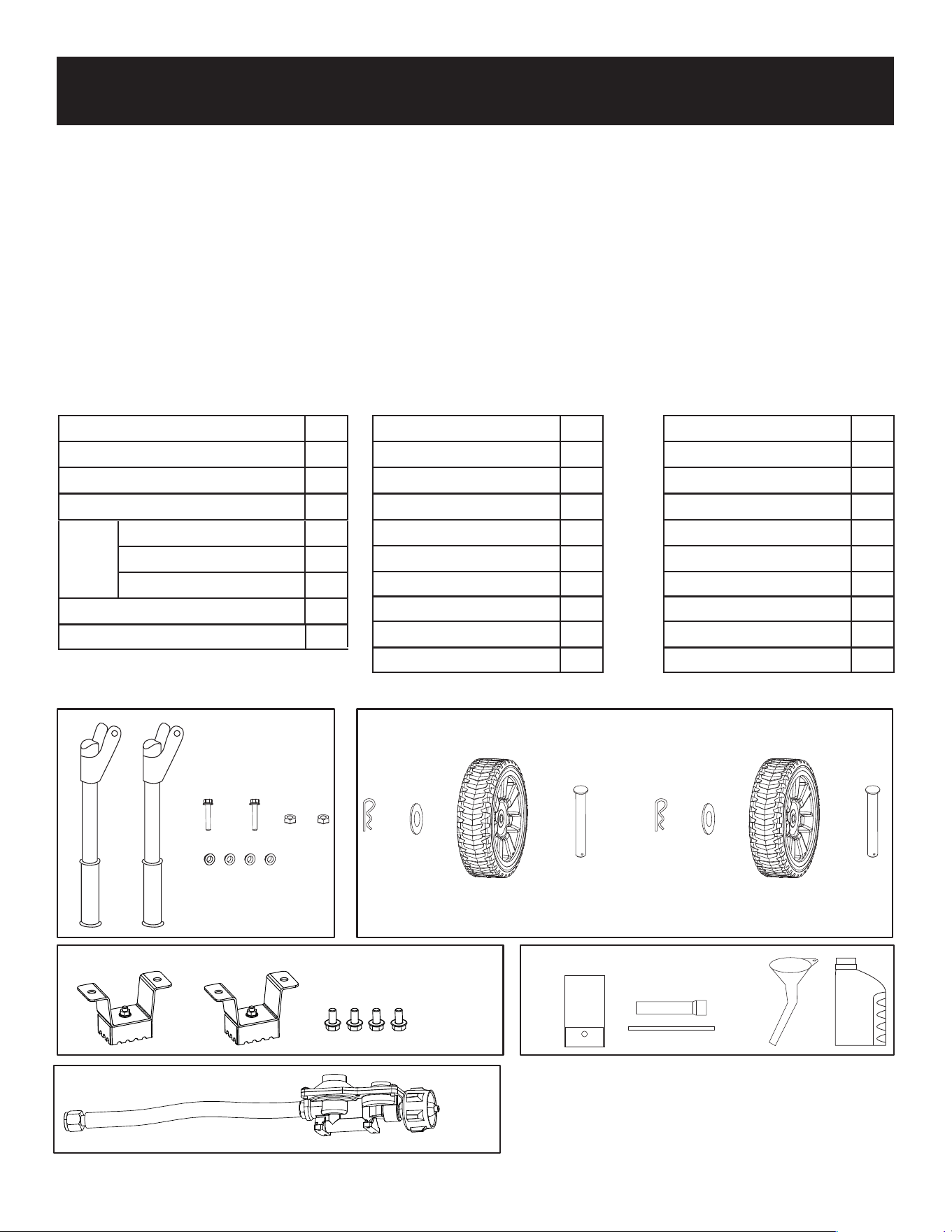
Unpacking
Packing List
Check all loose parts to the following list. Contact your dealer if any loose parts are not included.
Description Qty
Handle Assembly
Bolt
Nut
2
2
4
Wheel Assembly
2
Hair pin
2
Axles
2
Description Qty
Generator
1
Operator’s manual
1
Product registration card
1
Toolkit
Spark Plug Wrench
1
1
Washer
2
Description Qty
Foot Assembly
Bolt
2
4
Funnel
++ + + + +
+ ++ +
( )
++ +
Handle Assembly Wheel Assembly
+
Foot Assembly
2
Bushings (Flanged)
+
Engine oil
1
Two stage regulator
1
OIL
1. Place box on a level surface.
2. Remove all items from box except the generator. Make sure all items listed on the packing list are included and
undamaged
3. Cut-down the sides of the box being careful to avoid touching the generator.
4. Leave generator on box to install wheel assemblies.
9
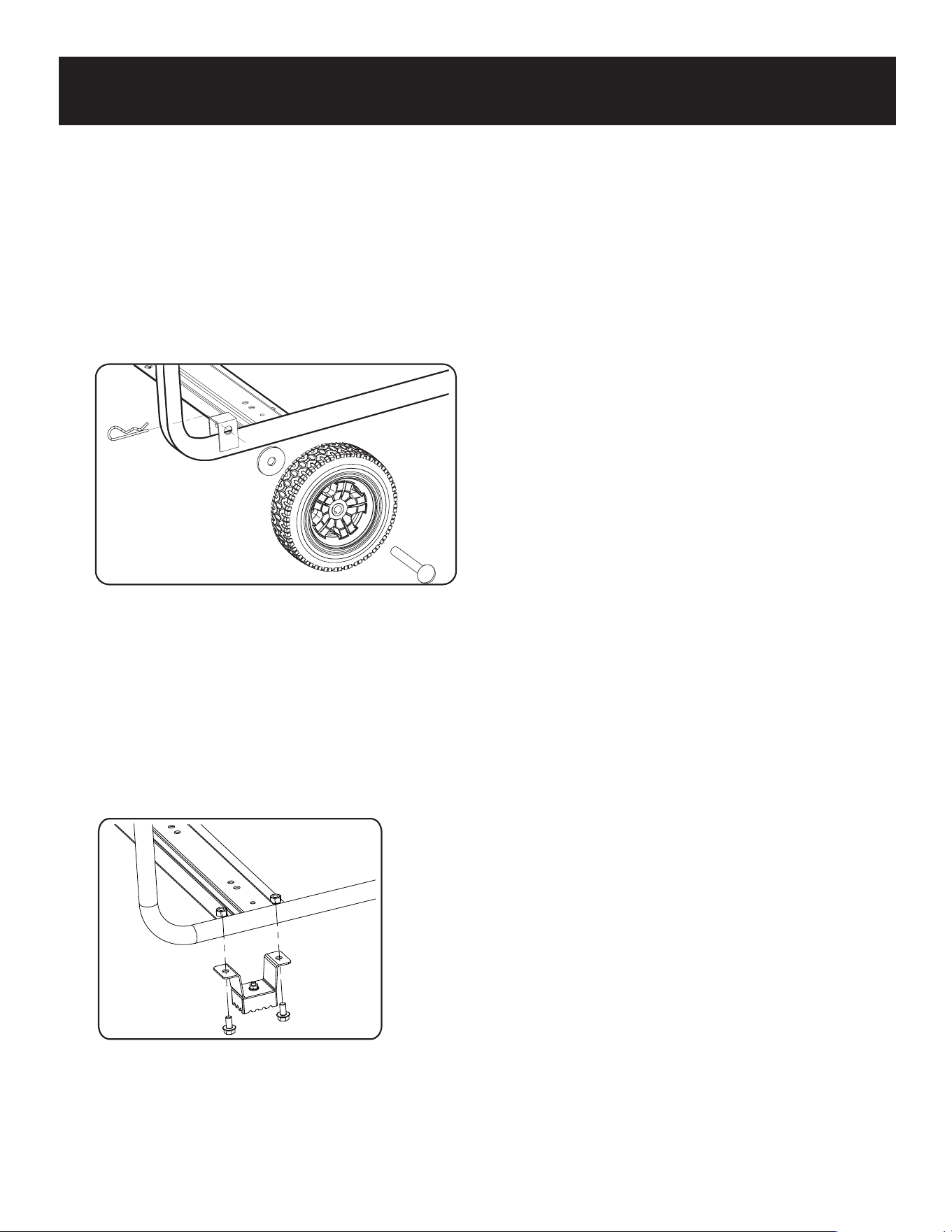
ASSEMBLY
• Attach the support leg using M8 screws (2) and nuts.
Installing Support Leg (See fig 2)
• Parts needed - 2 wheels, 2 axles, 2 hair pins, and 2 washers.
• Raise or tilt generator so you can slide the wheel axle pin into the wheel, the washer, the wheel mounting hole located
on the side of the frame.
• Secure the wheel assembly by inserting a hair pin through hole at the end of the wheel axle clevis pin and pressing until
it locks into place.
• Repeat process on the other side of the generator to install the second wheel.
Attaching Wheels (See fig 1)
Fig 1
Fig 2
• Parts needed - Support Leg(2) & M8 screw (2) and 2 nuts.
•
•
Raise the front end of the generator high enough to gain access to the bottom of the frame. Securely position
props
underneath to support.
Line up holes on the support leg bracket to the holes on the front of the generator frame.

10
ASSEMB
L
Y
Fig 4
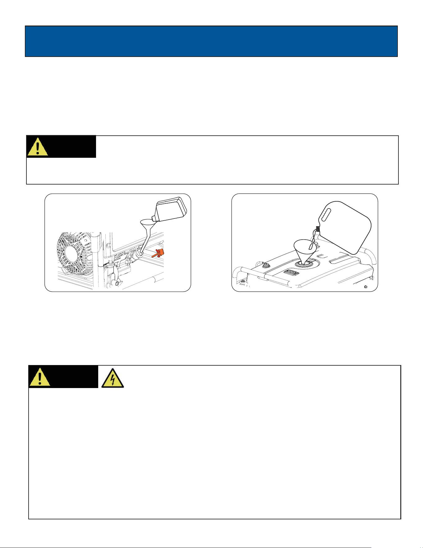
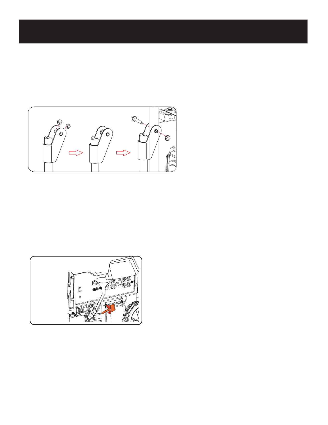
Adding / Checking Engine Oil (See fig 5)
•
• Place 2 bushings on handle and slide handle in place with the pre-drilled hole on the generator frame.
Insert bolt through the handle and frame and tighten with nut.
•
Repeat on opposite side.
Installing The Handles (See fig 4)
•Place generator on a level surface.
•Clean area around oil fill.
•Remove oil fill cap and wipe dipstick clean.
•Screw dipstick into filler neck. Remove dipstick and verify oil level is within safe operating range.
•Add recommended engine oil as necessary. (See Add Engine Oil.)
•Install oil fill cap/dipstick and hand-tighten.
11
ASSEMBLY
Fig 6Fig 5
CAUTION!
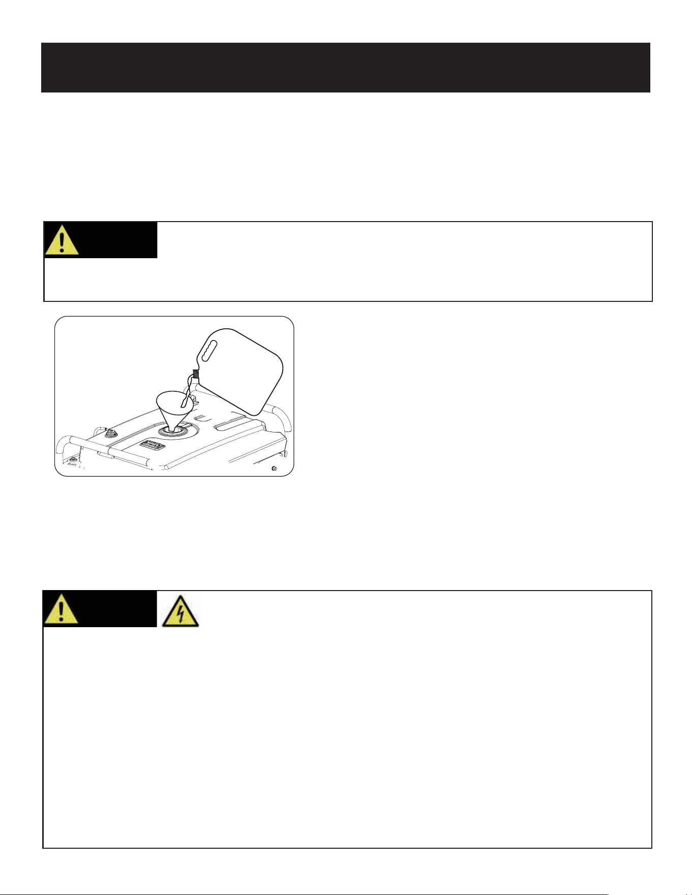
Adding Fuel (See fig 6)
10W30 OIL
Gasoline
Unleaded
• Set generator outdoors in a well-ventilated area, away from structures and people.
• Slowly remove fuel cap.
• Insert a funnel into the fuel tank and carefully pour gasoline into the tank until fuel level reaches 1 ½ inches below the
top of the neck. Be careful not to overfill the tank to allow space for fuel expansion.
You must add oil before first operating this generator. Always check oil level before each
operation.
DO NOT USE E15 OR E85 FUEL IN THIS UNIT. IT IS A VIOLATION OF FEDERAL LAW AND
WILL DAMAGE THE UNIT AND VOID YOUR WARRANTY.
• Never handle the generator, electrical devices, or any cord while standing in water, while barefoot, or when hands or
feet are wet.
• Always keep the generator dry. Never store or operate generator in rain or under wet conditions.
• Use a ground fault circuit interrupter (GFCI) in a damp or highly conductive area, such as metal decking or steel work.
•
•
Never plug electronic devices into generator having frayed, worn, or bare wires. Never touch bare wires or contact
receptacles.
Never permit a child or unqualified person to operate generator. Always keep children a minimum of 10 feet away
from the generator.
• If using the generator for backup power, notify the utility company.
• If connecting generator to a building’s electrical system for standby power, you must use a qualified electrician to
install a transfer switch. Failure to isolate the generator from the power utility could result in serious injury or death to
electric utility workers.
W
ARNING!
This generator produces high voltage which could result in burn or
electrocution causing serious injury or death.
Connecting Generator to a Building Electrical System
• If connecting generator to a building electrical system for standby power, you must use a qualified electrician to install a
transfer switch. The power from the generator must be isolated from the utility power source. The connection must
comply with all electrical codes and applicable laws.
OPERATION
12
Fig 9
Fig 12
CHOKE RUN
CHOKE LEVER
CHOKE RUN
CHOKE LEVER
W
AIT
5sec
Fig 10
SKIP THIS IF THE ENGINE IS
WARM OR HOT.
Fig 7
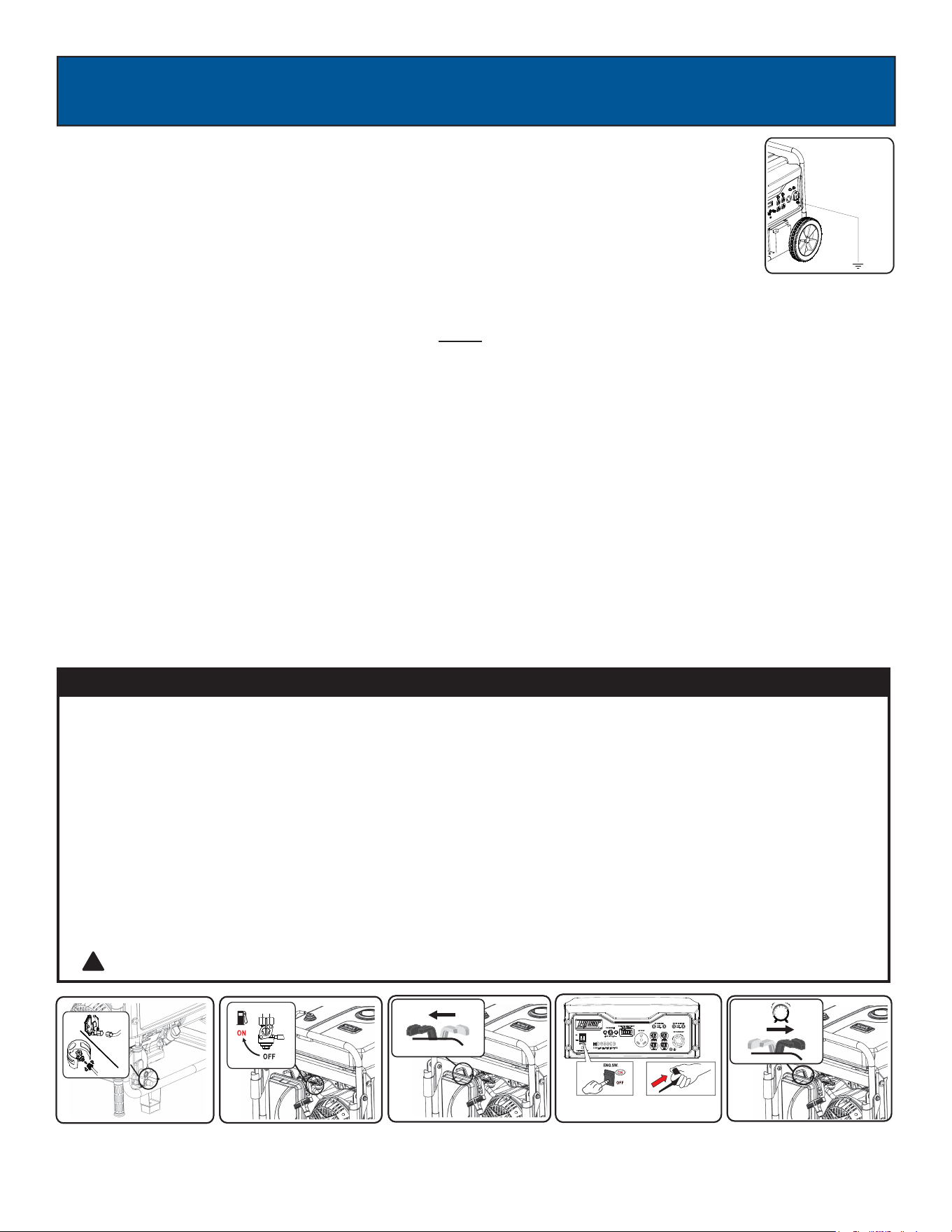
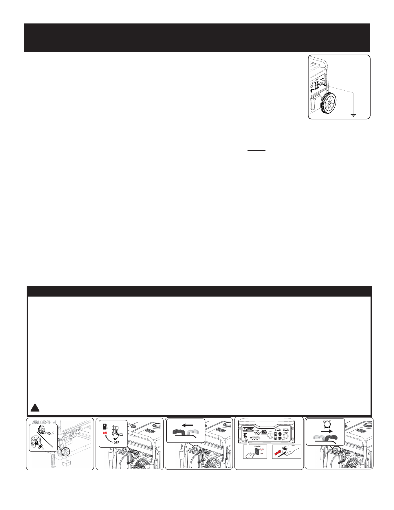
Grounding the Generator (See fig 7)
The portable generator is equipped with a terminal for the connection of a ground electrode conductor
where a grounding electrode system is required by NEC Article 250.34(A). The equipment grounding
conductor terminals of the generator receptacles are bonded to the generator frame. Where the
generator supplies power to cord and plug connected equipment, like power tools, the frame of the
generator is not required by the NEC to be connected to an earthen ground electrode. The generator
neutral conductor is bonded to the generator frame in accordance with NEC Article 250.34(C)
How to Start Engine (See fig 8-12)
Fig 11 Recoil Start
• Place generator on a level surface. All electrical loads MUST be disconnected from generator.
• Turn fuel valve to the “ON” position. (See fig 9)
• Slide the choke lever to the “Choke” position. (See fig 10) SKIP THIS IF THE ENGINE IS WARM OR HOT.
• Push the ON/OFF switch to the “ON” position. Pull the recoil starter grip slowly until resistance is felt, return, then pull
rapidly. (See fig 11)
• Let engine run for several seconds and then gradually, as engine warms up, slide the choke lever towards the “RUN”
position until the choke is fully at the “RUN” position. (See fig 12)
• Connect the propane hose to the intake nozzle of regulator; Open the valve on the LPG tank (See fig 8)
• Slide the choke lever to the “Choke” position. (See fig 10)
• Push the ON/OFF switch to the “ON” position. Pull the recoil starter grip slowly until resistance is felt, return, then pull
rapidly. (See fig 11)
• Let engine run for several seconds and then gradually, as engine warms up, slide the choke lever towards the “RUN”
position until the choke is fully at the “RUN” position. (See fig 12)
When Using Gasoline
When Using LPG
Fig 8
1
2
CAUTION! Failure to follow this process may cause rough operation which could lead to engine damage
CAUTION
It is very important to SHUT OFF the fuel supply and wait for the generator to stop running before switching fuel source.
Gasoline to Propane:
1. With the generator running, turn the gasoline supply valve 90 degrees to shut off flow; then wait (up to 2 minutes) for
the machine to stop on its own.
2. With the generator and gasoline supply now OFF and propane hose properly connected, open the propane supply by
turning the supply valve fully left, wait 30 seconds, then start the generator.
Propane to Gasoline:
1. With the generator running, turn the propane supply valve fully right to shut off flow; then wait (up to 30 seconds) for
the machine to stop on its own.
2. With the generator and propane supply now OFF, turn gasoline supply valve 90 degrees, (straight up and down) wait
2 minutes, then start the generator.
IMPORTANT NOTICE FOR SWITCHING FUEL SOURCES
!
OPERA
TION
13
Receptacles and Extension Cords
Only use high quality, well-insulated, grounded extension cords in good condition with generator receptacles. Follow each
load manufacturer’s power rating recommendation when selecting receptacle and extension cord.
This generator is equipped with the following receptacles:
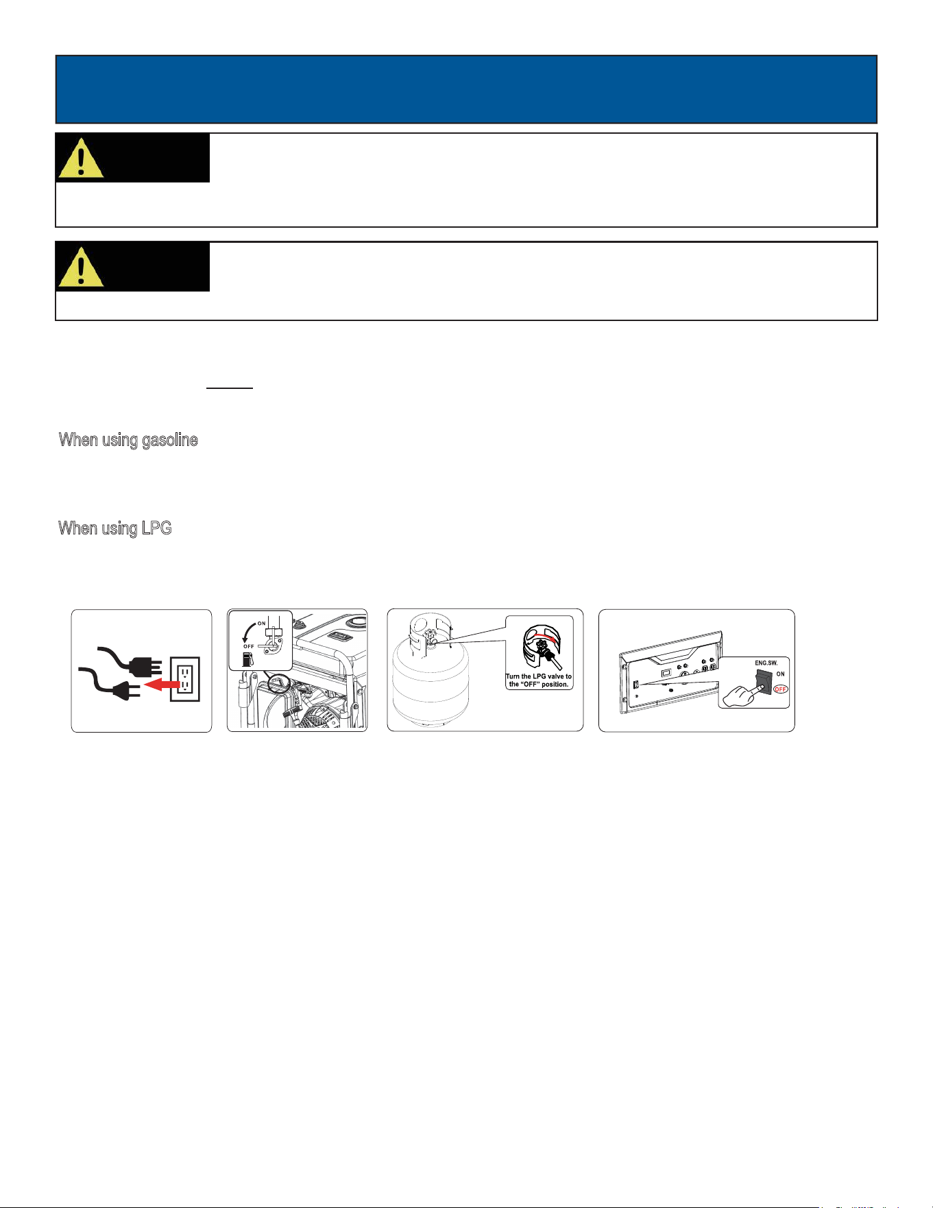
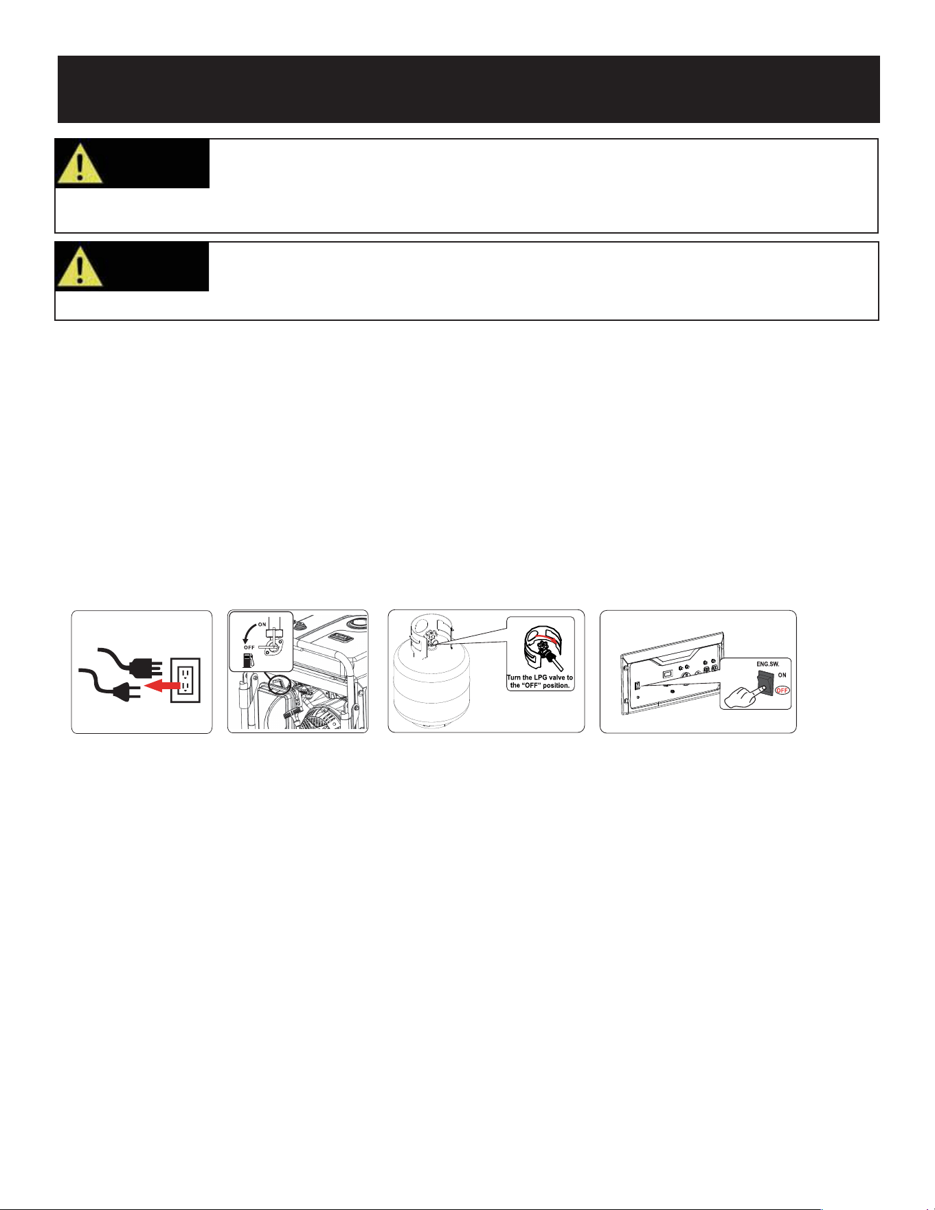
How to Stop Engine (See fig 13-16))
• All electrical loads MUST be disconnected from the generator. Never start or stop the engine with electrical devices
plugged in to the receptacles. (See fig 13)
W
hen using gasoline
1.Turn the engine ON/OFF switch to the “OFF” position. (See fig 16)
2.Turn the fuel valve lever back to the OFF position.(See fig 14)
When using LPG
1.Turn the engine ON/OFF switch to the “OFF” position. (See fig 16)
2.Turn off LPG bottle. (See fig 15)
Fig 13 Fig 14 Fig 15
Fig 16
• Four 120 Volt AC, 20 Amp receptacles.
• 120 Volt AC, 30 Amp receptacle (TT-30R).
• 120 / 240 Volt AC, 30 Amp twist lock receptacle (NEMA L14-30R).
• 12 Volt 8.3 Amp Output (For charging batteries only)
120 Volt AC, 20 Amp receptacle
• This receptacle has a 20 Amp push-to reset circuit breaker to protect against overload.
• Each socket is rated to operate 120 Volt, AC, single phase, 60Hz loads requiring up to 2400 watts (2.4 kW) at 20 Amps.
• Use extension cords having a minimum rating of 125 Volts AC, 20 Amps.
• To avoid recoil, pull starter cord slowly until resistance is felt, then.
W
ARNING!
Pull cord recoils rapidly and pulls arm towards engine faster than you can let go which
could result in injury.
• Always start the engine and let it stabilize before connecting any electrical devices.
• Disconnect all electronic devices before stopping the engine.
WARNING!
Never start or stop engine with electrical devices plugged in to the receptacles. Failure to
heed this warning could damage the generator and / or connected electrical devices.
OPERA
TION
14
Do not connect 3-phase loads to generator.
CAUTION!
120 / 240 Volt AC, 30 Amp locking receptacle
• This receptacle has a 30 Amp push-to reset circuit breaker to protect against overload.
• This receptacle is rated to operate 120 Volt, AC, single phase, 60Hz loads requiring up to 3600 watts (3.6 kW) at 30
Amps. It is also rated to operate 240 Volt AC, single phase, 60Hz loads requiring up to 7,200 watts (7.2 kW).
• Use a NEMA L14-30 plug with this receptacle.
• Use a 4-wire cord rated for 240 Volts AC, 30 Amps to the plug. You can use the same 4-wire cord to operate a 120
Volt load.
(Amps)
Extension Cord Selection
Refer to the below table to ensure the extension cord used has the capacity to carry the required load. If the size of the
cable is inadequate it can cause a voltage drop and heat buildup, which can damage the electrical device and cord.
Current
Load (Watts) Maximum Cord Length
120V 240V #8 Wire #10 Wire #12 Wire #14 Wire #16 Wire
2.5 300 600 X 1000 ft. 600 ft. 375 ft. 250 ft.
5 600 1200 X 500 ft. 300 ft. 200 ft. 125 ft.
7.5 900 1800 X 350 ft. 200 ft. 125 ft. 100 ft.
10 1200 2400 X 250 ft. 150 ft. 100 ft. 50 ft.
15 1800 3800 X 150 ft. 100 ft. 65 ft. X
20 2400 4800 175 ft. 125 ft. 75 ft. X X
25 3000 6000 150 ft. 100 ft. X X X
30 3600 7200 125 ft. 65 ft. X X X
Moving the Generator
• Disconnect any electrical devices from generator then switch the generator off.
• urn fuel valve to the “OFF” position, then switch OFF the engine On/Off Switch.
• Use the handle to tilt generator until it balances on wheels. Roll machine to desired location.
• If the generator must be carried, fold handle to the down position. Never lift or carry generator by
its handle.
CAUTION!
This product is heavy and requires several people to lift. Lift and lower with your legs by bending
at the knees, not your back, to avoid injury.
Don’t Overload Generator
Make sure you can supply enough rated watts and surge watts for all electrical loads connected to the generator. Rated
watts refer to the power a generator must supply to keep a device running. Surge watts refer to the power a generator
must supply to start an electrical device. This power surge for starting a device usually lasts between 2-3 seconds but
this additional output must be considered when selecting the electrical devices, you plan to attach to the generator. To
prevent overloading the generator, take the following steps:
1. Add the total rated wattage of all electrical devices that will be connected to the generator simultaneously.
2. Estimate surge watts by adding the item(s) with the highest output (it is unnecessary to calculate the surge output for
all devices as they should be connected one at a time).
3. Add the Surge Watts to the total Rated Watts in step 1. Keep total load within generator’s power capacity.

OPERATION
15
Never exceed generator’s wattage / amperage capacity. This could damage the generator
and / or connected electrical devices.
WARNING!
•Check operating voltage and frequency requirements of all electrical devices prior to plugging them into the generator.
Bathroom Rated Watts Surge Watts
Hair Dryer 1250 1250
Curling Iron 1000 1000
Family Room
Home Office
X-Box or Play Station 40 40
AM/FM Radio 100 100
VCR 100 100
Color TV (27”) 500 500
Fax Machine 65 65
Personal Computer (17” Monitor) 800 800
Laser Printer 250 950
Copy Machine 700 800
Power Tools
1000W Quartz Halogen Work Light 1000 1000
Airless Sprayer (⅓ HP) 600 800
Reciprocating Saw 6000 950
Circular Saw (7 ¼”) 1400 2300
Miter Saw (10”) 800 1800
Table/Radial Arm Saw 1000 2000
Electric Drill (½ HP, 5.4 Amps) 600 900
Hammer Drill 700 1000
Air Compressor 1600 4500
Other
Home Security System 500 500
Garage Door Opener (⅓ HP) 750 750
Essentials Rated Watts Surge Watts
75W Light Bulbs 75 each 75 each
18 CU Ft Refrigerator / Freezer 800 2200
Furnace Fan (⅓ HP) 800 2350
Sump Pump (⅓ HP) 1000 2000
Water Pump (⅓ HP) 1000 3000
Heating/Cooling
650 800
Table Fan
Dehumidifier
800 2000
Window AC (10k BTU) 1200 3600
Central Air (10k BTU) 1500 6000
Electric Blanket 400 400
Space Heater 1800 1800
Kitchen
Blender 300 900
Toaster (2 slice) 1000 1000
Coffee Maker 1500 1500
Electric Range (1 element) 1500 1500
Dishwasher 1500 2000
Electric Oven 3410 3500
Electric Water Heater 4000 4000
Laundry Room
Iron 1200 1200
Washing Machine 1150 2400
Gas Clothes Dryer 700 1500
Electric Clothes Dryer 5400 6750
Operating voltage and frequency requirement of all electrical equipment should be checked prior to plugging them into this
generator. Damage may result if the equipment is not designed to operate within a +/- 10% voltage variation, and +/- 3 Hz
frequency variation from the generator name plate ratings. To reduce the risk of damage, always have an additional load
plugged into the generator if solid-state equipment (such as television set) is used. A power line conditioner is
recommended for some solid state applications.
Wattage Reference Guide
(Wattages listed are just approximations. Check electronic device for actual wattage)
OPERATION
16
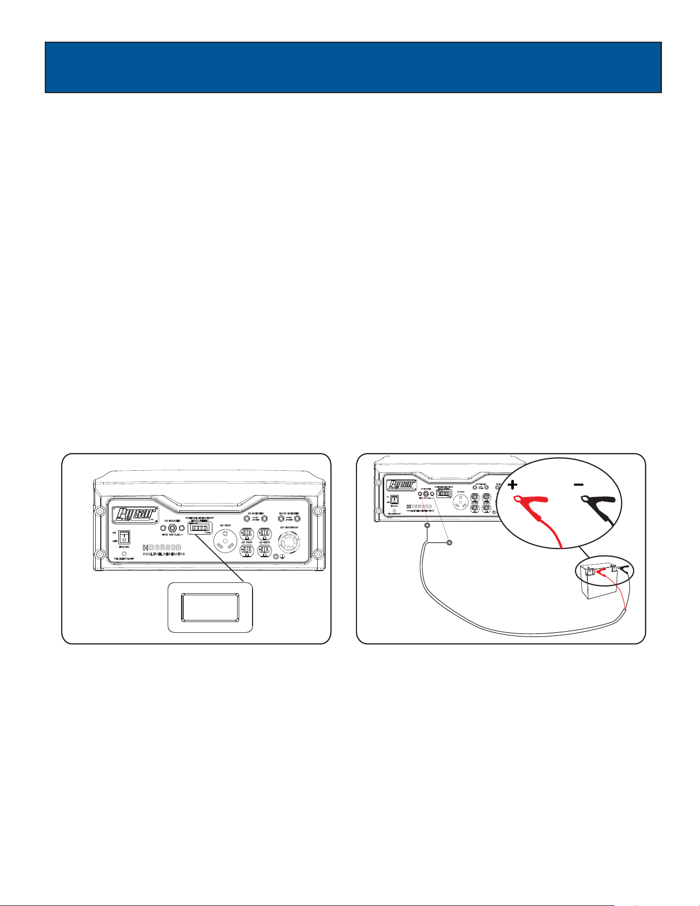
Hour Meter (See Fig 17)
Use this meter along with the manual to determine when and what type of service on the unit is needed. The display will
show the word “P25” at the first 25 hours of operation and again at every 100 hours of operation after.
Power Management
Charging a 12 Volt Battery (See Fig 18)
This generator can be used to charge a 12 volt automotive or storage battery by taking the following steps:
Inspect fluid level of the battery cells.
Add ONLY distilled water to any cell where fluid level is low. Never add tap water.
Use a wire brush to clean battery terminals if corroded.
Connect the Battery Charging Cable Connection Plug to the 12 Volt D.C. Receptacle.
Connect the red cable clamp to the positive (+) battery terminal.
Connect the black cable clamp to the negative (-) battery terminal.
Start generator engine. Let engine run while battery charges.
Battery is considered fully charged when the gravity of its fluid is 1.260 or higher when measured by a hydrometer. It is
strongly recommended to use a hydrometer to test for battery charge and condition. Be careful to follow the hydrometer
manufacturer’s instruction.
Fig 18Fig 17
•
•
•
•
•
•
•
•
Start engine without anything connected to generator.
When engine has stabilized, plug in and turn on first load. It is strongly recommended to plug in devices with the largest
output first and the smallest output last to help prevent overloading the generator.
•
•
•
Allow generator output to stabilize (engine and attached devices run evenly) before plugging in the next load.
Cold Weather Operation
Under humid conditions where temperatures drop to 40ºF (4ºC) the carburetor and/or crankcase breather system may
begin to freeze. To prevent cold weather performance issues, take the following steps:
1. Replace any old fuel with clean, fresh fuel.
2. Use SAE30 or SAE 5W-30 engine oil. Check oil daily or after every 8 hours of use.
3. Turn fuel valve to the ON position.
4. Ensure generator is serviced according to the maintenance schedule under “Maintenance” section of the manual.
5. Shelter unit from elements.
MAINTENANCE
17
Regular maintenance will extend the life of this generator and improve its performance. The warranty does not cover items
that result from operator negligence, misuse, or abuse. To receive full value from the warranty, operator must maintain the
generator as instructed in this manual, including proper storage.
Before inspecting or servicing this machine, make sure the engine is off and no parts are
moving. Disconnect the spark plug wire and move it away from the spark plug.
WARNING!
Pre-Operation Steps
Before starting the engine, perform the following pre-operation steps:
•
•
• Check the level of the engine oil and the fuel tank level.
Make sure the air filter is clean.
Remove any debris that has collected on the generator and around the muffler and controls. Use a vacuum cleaner to
pick up loose debris. If dirt is caked on, use a soft bristle brush.
• Inspect the work area for hazards.
After Each Use
Follow the following procedure after each use:
After First 5 Hours Change Oil
After 8 Hours or Daily Clean Debris from Generator and Air Filter area
Check Engine Oil Level
Annually (25 hr Use) Check and Clean Air Cleaner
Change Engine Oil (Service more often under dirty or dusty conditions)
Check Muffler and Spark Arrester
Annually (100 hr Use) Service Spark Plug (Replace with NGK BP6ES, Champion N9YC or equivalent)
Inspect Fuel Valve and Fuel Lines for leaks or damage
Inspect Muffler and Spark Arrester
Check and Clean Air Cleaner Assembly, Replace Air Filter
Clean Cooling System Cylinder Head Fins and Flywheel Fan
• Close the Fuel Valve
• witch OFF the engine
• Wait for the generator to become cool to the touch
• Store unit in a clean and dry area.
Maintenance Schedule
MAINTENANCE
18
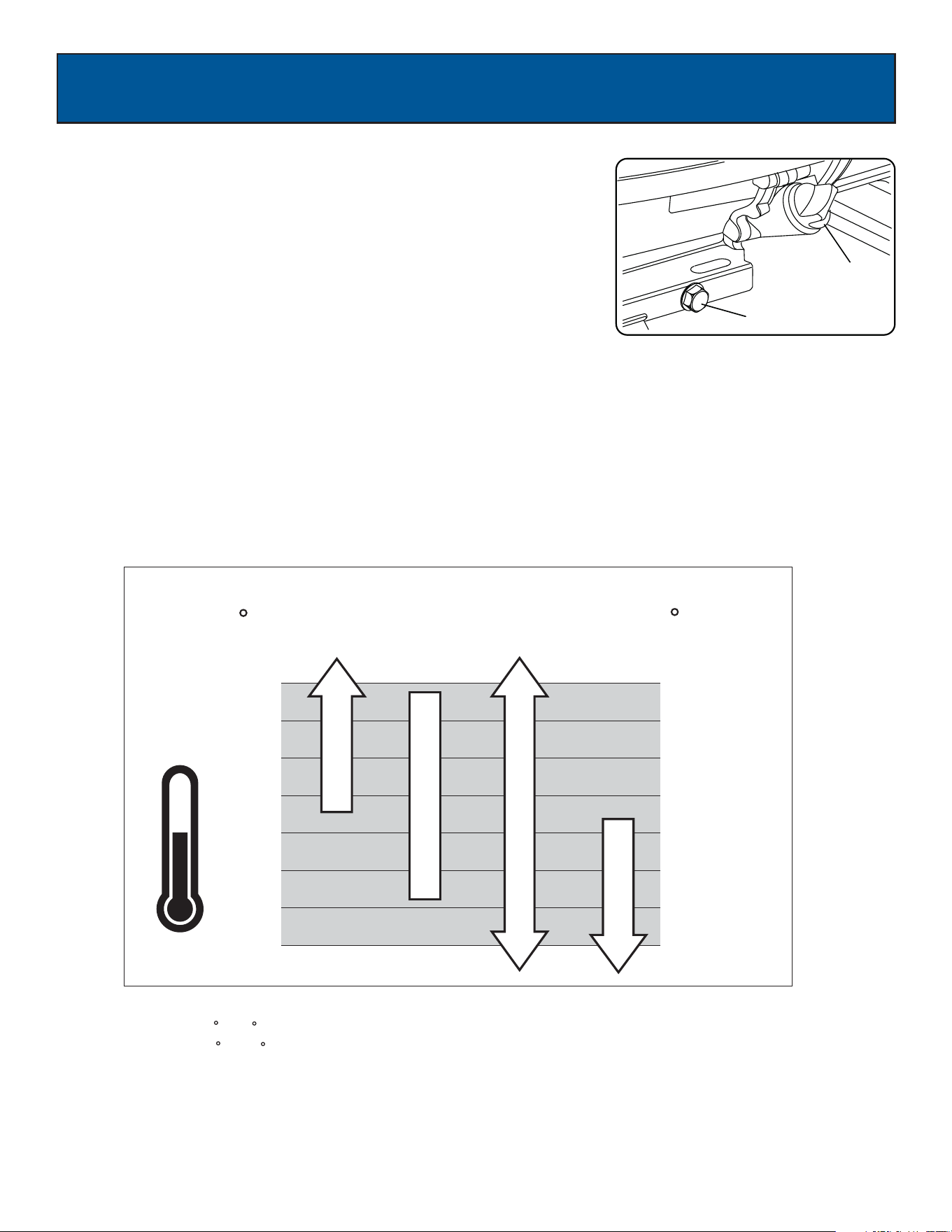
Changing Oil (See Fig 19)
Oil drainage plug
Fig 19
Oil Fill & Dipstick
-22
-4
14
32
50
68
86
104
-30
-20
-10
0
10
20
30
40
SAE 30
10W-30
Synthetic 5W-30
5W-30
Above 80 F the use of 10W -30 may cause increased oil consumption.
Check oil level more frequently .
Note:
*
*
*
*
*
(4 C) the use of SAE 30 will result in hard starting.
C
F
(27 C)
Below 40 F
*
• Run the Generator until the Engine is warm, then shut OFF.
• Place generator on a level surface.
• Remove the crankcase dipstick.
• Place an oil pan underneath the oil drain hole to collect used oil.
• Remove the oil drain plug and allow oil to drain completely.
• Reinstall oil drain plug, tighten securely.
• Carefully add SAE 30 or 10W-30 to empty reservoir until the oil reaches the
threads of the oil fill hole (Crankcase Dipstick hole).
• Replace crankcase dipstick.
Oil Recommendations
• Do not use special additives.
• Outdoor temperatures
can affect proper oil viscosity for the engine.
• Use the chart to select the best viscosity for the outdoor temperature range
expected.
Used oil should be disposed of at an approved disposal site.
CAUTION!
MAINTENANCE
19
Fig 21
0.7-0.8mm
Fig 20
•
•
•
•
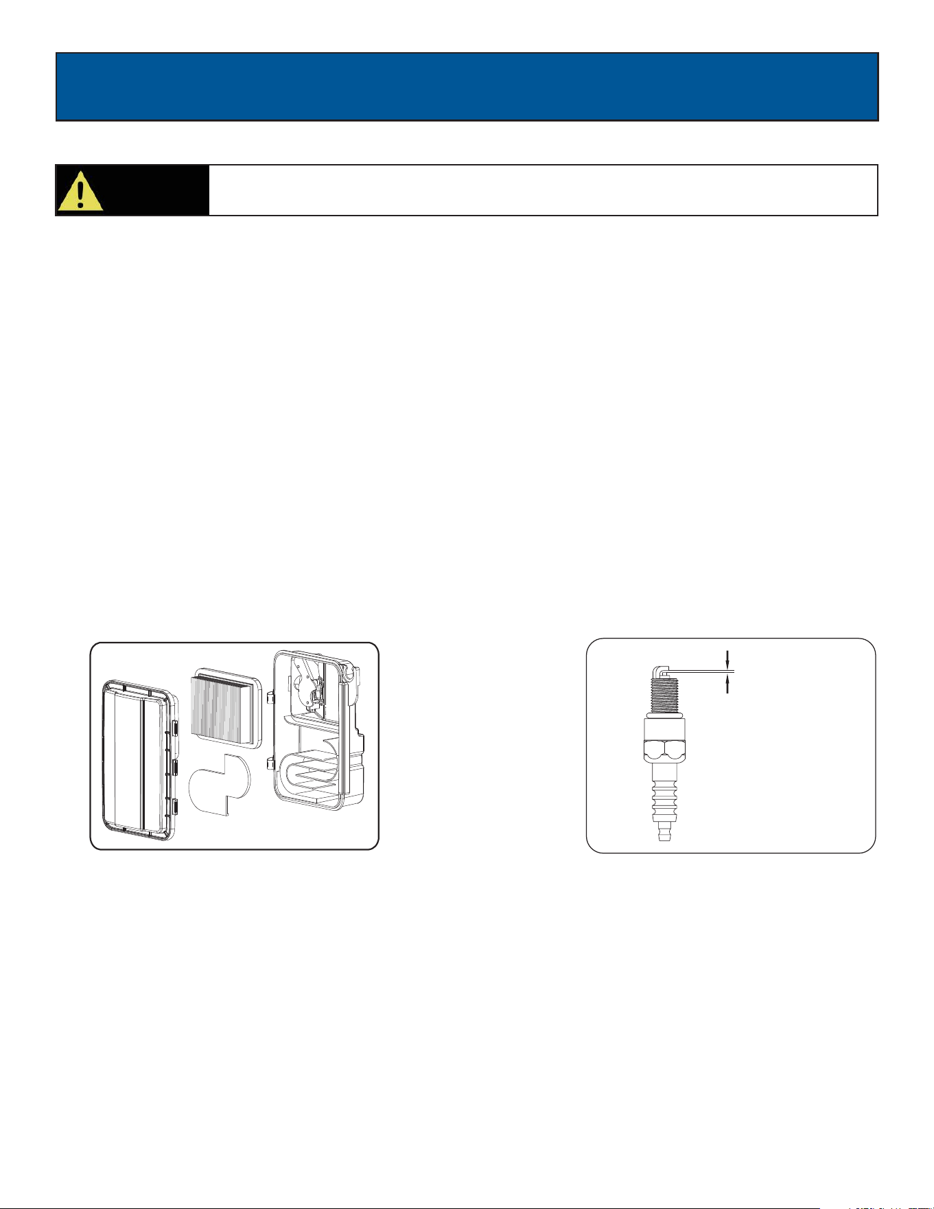
Checking Spark Plug (See Fig
21)
• Disconnect the spark plug wire from the spark plug.
• Before removing the spark plug, clean the area around its base to prevent debris from entering the engine.
• Clean carbon deposits off the electrode with a wire brush.
• Check the electrode gap and gently adjust gap to 0.762 mm -0 .80 mm (.030 - .031") if necessary.
• Reinstall spark plug and tighten to Torque 22.0 – 26.9 Nm (16-20 ft-lb).
• Reconnect spark plug wire.
• If spark plug is worn replace only with an equivalent replacement part. Spark plug should be replaced
annually. (BOSCH F7TC, NGK BP6ES, CHAMPION N9YC or equivalent)
To clean, remove the air filter cover.
Carefully pull the air filter out by lifting along the edges.
Remove dirt from filter by tapping on it or having it blown out. Replace with new filter annually.
Reinstall air filter so that it seals and replace air filter cover.
Air Filter (See Fig 20)
A dirty air filter will reduce the life span of the engine, make it difficult to start the engine, and reduce the unit’s performance.

MAINTENANCE
20
HHiigh Altitude Operation
At high altitude, the standard carburetor air/fuel mixture will be too rich. Performance will decrease, and fuel consumption
will increase. A very rich mixture will also foul the spark plug and cause hard starting. Operation at an altitude that differs
from that at which this engine was certified, for extended periods of time, may increase emissions. High altitude
performance can be improved by specific
modifications to the carburetor. If you always operate your generator at altitudes above 5,000 feet
(1,500 meters), have your dealer perform this carburetor modification. This engine, when operated at high altitude with
the carburetor modifications for high altitude use, will meet each emission standard throughout its useful life. Even with
carburetor modification, engine horsepower will decrease about 3.5% for each 1,000-foot (300-meter) increase in altitude.
The effect of altitude on horsepower will be greater than this if no carburetor modification is made.
Draining Fuel Tank and Carburetor
To help prevent varnish deposits in the fuel system, drain the fuel from the tank and carburetor before storing the unit for
long periods of time. This will help prevent starting problems in the future. If the unit is stored with fuel and the fuel
becomes stale or turns gummy or to varnish the warranty does not cover this repair or service.
Draining the fuel tank
• Turn the fuel valve to the OFF position.
• Turn the engine OFF
• Push the fuel valve knob through the valve holder bracket allowing you to access the petcock.
• Remove the fuel line that leads from the carburetor to the petcock by squeezing the ends of the hose clamps and
sliding the fuel line off.
• If needed, install a fuel hose that will extend to a suitable fuel container large enough to catch the fuel being drained
from the tank.
• Turn the fuel valve to the ON position and open the fuel tank cap slightly to equalize pressure.
• When the fuel has drained from the tank, close the fuel valve and reinstall fuel line securely on petcock.
• Reinstall the fuel valve knob in the valve bracket. Push forward until knob snaps securely into position.
Draining the carburetor
• Turn the fuel valve to the OFF position.
• Turn the engine OFF.
• Position a suitable container under the carburetor drain screw to catch fuel; loosen and remove the screw.
• Allow fuel to drain completely into container, be sure to wipe up any spilled fuel right away.
• Retighten drain screw, taking care that the gasket seal is in place.
MAINTENANCE
21
Consult your local hazardous waste management in your area for the proper way to dispose
of used fuel.
CAUTION!
Fig 21
Engine Long Term Storage:
•
Remove the spark plug and pour about 1 teaspoon of 10W30 Engine oil into the spark plug hole. Reinstall the spark plug.
With the ON/OFF switch in the OFF position pull the recoil starter cord several time to coat the cylinder walls with oil.
•
Slowly pull the recoil Starter until you feel the engine build compression (When you feel resistance). Leave the Engine in
this state as this will prevent any corrosion on the cylinder walls if stored for a long period of time.
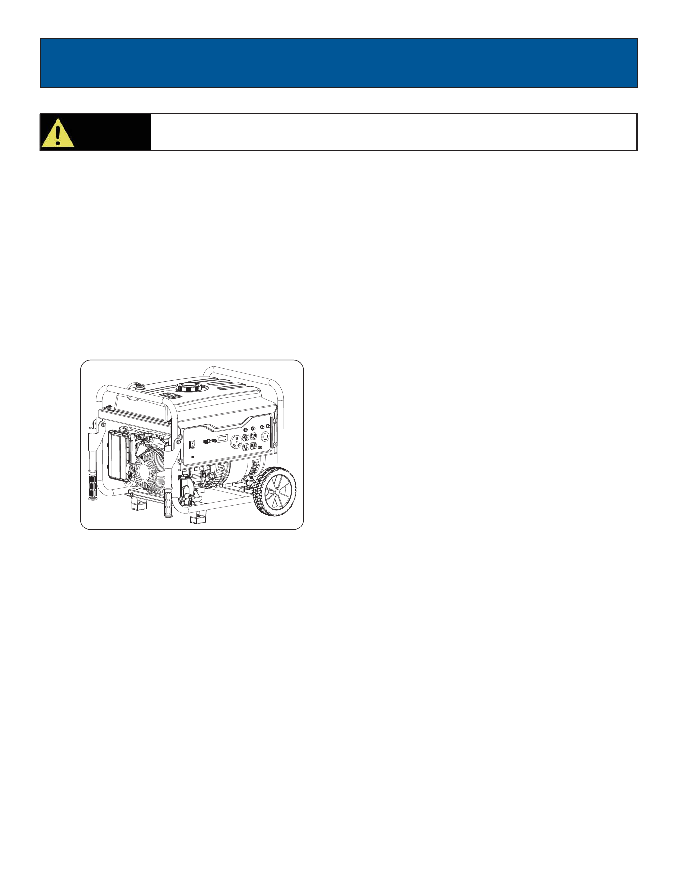
Storage and Transportation of the Generator: (See Fig 21)
• Remove any debris that has collected on the generator and around the muffler and controls. Use a vacuum cleaner to
pick up loose debris. If dirt is caked on, use a soft bristle brush.
• Inspect air cooling cylinder fins and flywheel fan. Remove any debris if obstructed.
• For short-term storage, start generator once every 7 days.
• For long-term storage, add fuel stabilizer to prevent stale fuel from causing acid and gum deposits in the fuel system
and carburetor.
• Store ina sheltered location and use a protective cover to suitable from dust.

TROUBLESHOOTING
22
Problem Cause Solution
Engine is running, but AC output is not
available
1. Open circuit breaker
2. Poor connection
3. Defective cord set
4. Connected device is faulty
5. Fault in generator
1. Reset circuit breaker
2. Check and repair
3. Check and repair
4. Connect a device that is working
properly
5. Contact service department
Engine runs well without load but bogs
down when loads are connected
1. Short circuit in connected device
2. Generator is overloaded
3. Clogged fuel filter
4. Engine speed is too slow
5. Short circuit in generator
1. Disconnect device
2. See pg 17 “Don’t overload
generator”
3. Clean or replace fuel filter
4. Contact service department
5. Contact service department
Engine will not start, shuts down during
operation, or starts and runs rough.
1. ON/OFF switch set to “OFF”
2. Dirty Air filter
3. Clogged fuel filter
4. Stale fuel
5. Spark plug wire disconnected from
spark plug
6. Bad spark plug
7. Water in fuel
8. Fuel valve is in “OFF” position
9. Over choking
10. Low oil level
11. Rich fuel mixture
12. Intake valve stuck open or
closed
13. Loss of engine compression
14. Engine has flooded
1. Turn switch to “ON”
2. Replace Air filter
3. Clean or replace fuel filter
4. Replace fuel
5. Reconnect spark plug wire
6. Replace spark plug
7. Drain fuel tank and replace fuel
8. Turn fuel valve to “ON” position
9. Turn off choke
10. Fill crankcase to proper oil level &
place generator on a level surface
11. Contact service department
12. Contact service department
13. Contact service department
14. Wait 5 minutes and crank engine
Engine lacks power 1. Generator is overloaded
2. Clogged fuel filter
3. Dirty Air filter
4. Engine needs servicing
1. See pg. 17 “Don’t overload
generator”
2. Clean or replace fuel filter
3. Replace Air filter
4. Contact service department
Engine “hunts” or falters 1. Move choke to middle position until
engine runs smoothly
2. Clean or replace fuel filter
3. Contact service department
1. Choke was opened too soon
2. Clogged fuel filter
3. Carburetor is running too rich or too
lean
DIAGRAMS
23
G65BN
Generador
www.pulsar-products.com
MANUAL DEL USUARIO
Advertencia: El escape del motor de este producto contiene productos químicos que el estado de California
reconoce que causan cáncer, defectos de nacimiento y otros daños reproductivos.

CONTENIDO
Introducción............................................................................................................................................................................3
Pedido de Piezas / Servicio al Cliente ........................................................................................................................3
Especificaciones del Producto ....................................................................................................................................3
Reglas de Seguridad ........................................................................................................................................................... 4
Símbolos de Seguridad ................................................................................................................................................ 4
Instrucciones de Seguridad . .........................................................................................................................................4
Características......................................................................................................................................................................... 7
Montaje ............................................................................................................................................................................... 8
Desempacar ............................................................................................................................................................... 8
Lista de empaque . ..................................................................................................................................................... 8
................................................................................................................................................ 9
Agregar Aceite ...........................................................................................................................................................10
Agregar Combustible ................................................................................................................................................ 11
Conectando el Generador a un Sistema Eléctrico ......................................................................................................11
Funcionamiento .................................................................................................................................................................. 12
Apagando ele Motor...................................................................................................................................................13
Toma de tierra el Generador .
Cómo Encienda el Motor
............................................................................................................................................12
Receptáculos y Cables de Extensión.......................................................................................................................... 13
No Sobrecargar el Generador..................................................................................................................................... 14
Referencia a Guía de Potencia .................................................................................................................................... 15
Tiempo de Frío Funcionamiento ................................................................................................................................. 16
Mantenimiento ........................................................................................................................................................................17
Programación de Mantenimiento . ............................................................................................................................... 17
Mantenimiento del Motor . ............................................................................................................................................ 19
Cambio de Aceite . ...................................................................................................................................................... 18
Cómo Guardar ........................................................................................................................................................... 21
.................................................................................................................................................... 22
Diagramas.............................................................................................................................................................................. 23
Montaje del soporte ..................................................................................................................................................... 9
Monataje de las Manijas ..........................................................................................................................................10
.........................................................................................................................................12
Montaje de las Llantas
Resolución de Problemas
3
INTRODUCTION
Potencia nominal 5500W (5.5kW)
120V/240V
60Hz
45.8A / 22.9A
6.58kVA
274cc 4 tiempos, OHV, refrigerado por aire
10W30 - 23oz (0.7L)
5.2 Gal (2 0L) Gasolina sin plomo
GAS LPG
4900W (4.9kW)
120V/240V
60Hz
58.3A / 29.1A
5.922kVA
PULSAR PRODUCTS, INC
5721 E. SANTA ANA ST.
ONTARIO, CA 91761
866-591-8921
GUARDE ESTE MANUAL PARA FUTURAS REFERENCIAS
Gracias por comprar este generador portátil de calidad superior de Pulsar Products Inc. Al usar y mantener este producto
como se indica en este manual, el generador le ofrecerá muchos años de servicio confiable.
Fecha de la compra:
Número de modelo:
Número de serie:
El sistema de control de emisiones de este generador cumple con todas las normas establecidas por la Agencia de
Protección Ambiental.
Tome nota de la información siguiente al ponerse en contacto con nosotros para recibir servicio o asistencia bajo
garantía.
Este generador es un generador portátil impulsado por motor. Está diseñado para suministrar energía eléctrica para
operar herramientas, electrodomésticos, equipos de acampada y sistemas de iluminación, o para servir como fuente
de energía de respaldo durante cortes del suministro eléctrico.
Para ponerse en contacto con nosotros:
Puede ponerse en contacto con nosotros por teléfono al 1.866.591.8921 o por correo electrónico en
Especificaciones del producto
Este manual contiene información importante sobre seguridad, operación y mantenimiento.
Salida de CA
Voltaje nominal de CA
Frecuencia nominal
Corriente de CA
Potencia máxima
Motor
Aceite del motor
Capacidad del
depósito de
combustible
4
Indica una situación potencialmente peligrosa que, si no se evita, podría causar lesiones
graves o la muerte.
Emanaciones tóxicas Riesgo de incendio Riesgo de explosión
Riesgo de descarga eléctrica Superficie caliente
¡ADVERTENCIA!
Indica una situación potencialmente peligrosa que, si no se evita, podría causar daños al
equipo o daños materiales de otro tipo.
Símbolos de seguridad
Lea y comprenda este manual en su totalidad antes de usar el generador. El uso incorrecto del
generador puede causar lesiones graves o la muerte.
Instrucciones de seguridad
• Usar un generador en interiores PROVOCARÁ SU MUERTE EN MINUTOS.!
• El monóxido de carbono es un gas venenoso e inodoro que puede causar dolor de cabeza, confusión, fatiga, náuseas,
desmayos, malestar, convulsiones o la muerte. Si comienza a experimentar alguno de estos síntomas, respire aire
fresco INMEDIATAMENTE y reciba atención médica.
Mantener los gases de escape de la unidad de entrar en un área confinada a través de ventanas, puertas, rejillas de
ventilación y otras aberturas.
•
• Instale una alarma de monóxido de carbono a pilas cerca de los dormitorios.
•
• Cuando trabaje en áreas donde los vapores puedan ser inhalados, use una mascarilla de respiración de acuerdo con
todas sus instrucciones.
WARNING!
No lo utilice en interiores o en lugares confinados que impidan que el monóxido
de carbono peligroso se disipe.
REGLAS DE SEGURIDAD
• Lávese siempre las manos después de manejar el generador.
Los gases de escape del motor contienen sustancias químicas que pueden causar cáncer y
defectos congénitos.
El fabricante no puede anticipar todas las situaciones peligrosas que podrían presentarse.
Por lo tanto, las advertencias que se recogen en este manual, así como en las etiquetas y las placas adheridas al
generador, no son exhaustivas. Para evitar accidentes, el usuario debe entender y seguir las instrucciones del manual y
tener sentido común.
!
¡ADVERTENCIA!
!
Para reducir el riesgo de lesiones graves, evite intentar levantar el generador solo.
¡ADVERTENCIA!
!
¡ADVERTENCIA!
!
¡ADVERTENCIA!
!
¡PRECAUCIÓN!
!
Nunca use en interiores, en un área cubierta, o en un espacio confinado, incluso si las puertas y ventanas están abiertas.
Levante con 2 personas
5
REGLAS DE SEGURIDAD
• No se ponga ropa suelta o guantes.
• Quítese las joyas o cualquier otra cosa que pueda engancharse en las partes móviles.
• Ate el pelo largo o cúbrase el cabello con algo que lo proteja.
El sistema de arranque y otras partes móviles pueden engancharse en la ropa, joyas o
cabello.
•
El combustible que se utiliza con esta unidad y los vapores que emite son altamente inflamables y puede explotar y
causar lesiones graves o la muerte.
•
•
No llene excesivamente el depósito. Si se derrama combustible, aleje la unidad a una distancia mínima de 30 pies
(9 m) y limpie con un paño el combustible que se haya salpicado sobre esta antes de encender el motor.
• No fume nunca mientras usa o llena con combustible esta unidad.
•
• El generador debe situarse a una distancia mínima de 5 pies (1.5 m) de edificios u otros equipos durante el uso.
Mantener el motor libre de césped, hojas o grasa que son inflamables.
•
• Al echar o vaciar combustible, la unidad debe apagarse por lo menos 2 minutos antes de abrir la tapa del depósito de
combustible. Si la unidad ha estado encendida, la tapa del depósito de combustible habrá acumulado presión; ábrala
con cuidado.
• Para evitar que se derrame combustible, asegure la unidad para que no pueda volcarse al usarla o transportarla.
• Al transportar el generador, desconecte el cable de la bujía y asegúrese de que el depósito de combustible esté
vacío y el interruptor 3 en 1 se encuentre en la posición “Off ” (Apagado).
No supere nunca la potencia/amperaje nominales del generador. Esto podría dañar el
generador y/o los dispositivos eléctricos conectados.
• Compruebe el voltaje de funcionamiento y los requisitos de frecuencia de todos los dispositivos eléctricos antes de
enchufarlos al generador.
•
Para evitar el retroceso, tire de la correa de arranque lentamente hasta que sienta resistencia; entonces, tire rápidamente.
La correa de arranque retrocede rápidamente y tira del brazo hacia el motor más rápido de
lo que es posible soltarla, lo que puede causar lesiones.
• Siempre que arranque el motor, deje que se estabilice antes de conectar dispositivos eléctricos.
• Desconecte todos los dispositivos electrónicos antes de detener el motor.
No arranque o detenga nunca el motor con dispositivos eléctricos conectados en las tomas.
Hacerlo podría dañar el generador y/o los dispositivos eléctricos conectados.
•
• Deje que los componentes calientes se enfríen antes de tocarlos.
Evite el contacto con las partes calientes de esta unidad.
¡ADVERTENCIA!
!
¡ADVERTENCIA!
!
¡ADVERTENCIA!
!
¡ADVERTENCIA!
!
¡ADVERTENCIA!
!
¡ADVERTENCIA!
!
No llene o vacíe nunca el depósito de combustible en interiores.
Nunca utilice ni almacene esta unidad cerca de una llama abierta, calor o cualquier otra fuente de ignición.
Tenga cuidado alrededor del silenciador, del cilindro y de otras partes del motor, ya que pueden estar muy calientes.
Mantenga el motor alejado de objetos inflamables y otros materiales
peligrosos.
6
• El tratamiento inadecuado del generador puede dañarlo y acortar su vida útil.
•
Esta unidad siempre debe repararse de acuerdo con las instrucciones recogidas en este manual. Si tiene alguna
pregunta, póngase en contacto con su distribuidor o hable con un taller calificado.
•
• No evite ninguno de los dispositivos de seguridad. Las partes móviles están cubiertas con protecciones. Asegúrese
de que no falte ninguna cubierta de protección.
• Nunca transporte o haga ajustes a esta unidad mientras está en funcionamiento.
• No inserte ningún objeto en las ranuras de refrigeración.
No utilice nunca esta unidad si faltan piezas o si tiene piezas rotas, y utilice solo repuestos
diseñados específicamente para esta unidad.
Use esta unidad solo para uso previsto; de lo contrario, podrían producirse lesiones graves
o la muerte.
REGLAS DE SEGURIDAD
• Aumentar la velocidad regulada es peligroso y puede causar lesiones y/o daños al equipo.
• Reducir la velocidad regulada provoca una carga excesiva y puede dañar el equipo.
• Este generador solo proporcionará corriente del voltaje y frecuencia correctos al funcionar a la velocidad regulada
preconfigurada.
Nunca modifique esta unidad de ninguna manera ni cambie la velocidad regulada.
• Nunca manipule el generador, dispositivos electrónicos o cables si está parado sobre agua, descalzo o con las
manos o pies húmedos.
•
Mantenga el generador seco en todo momento. No utilice nunca el generador bajo la lluvia o en condiciones húmedas.
• Use un interruptor de circuito de falla a tierra (GFCI) en las áreas húmedas o altamente conductoras, tal como
cubiertas metálicas o estructuras de acero.
• No enchufe nunca en el generador dispositivos electrónicos con cables deshilachados, desgastados o expuestos.
No toque nunca cables expuestos ni los tomacorrientes.
•
• Si utiliza este generador como suministro eléctrico de respaldo, informe a la compañía eléctrica.
•
}Este generador produce un voltaje muy alto, lo cual puede provocar quemaduras
o electrocución y causar lesiones graves o la muerte.
• El generador solo debe utilizarse sobre una superficie nivelada.
¡ADVERTENCIA!
!
¡ADVERTENCIA!
!
¡ADVERTENCIA!
!
¡ADVERTENCIA!
!
¡ADVERTENCIA!
!
No permita nunca que un niño o una persona no calificada usen el generador. Mantenga a los niños a una distancia
mínima de 10 pies (3 m) del generador.
Si va a conectar el generador al sistema eléctrico de un edificio para disponer de energía eléctrica de respaldo, un
electricista calificado debe instalar un desconectador de transferencia. No aislar el generador del cableado de
suministro de la red eléctrica puede provocar lesiones graves o la muerte a los trabajadores de la compañía eléctrica.
ADVERTENCIA DE LA PROPOSICIÓN 65: Este producto contiene sustancias químicas reconocidas por el Estado de
California como causantes de cáncer, defectos congénitos y otros daños reproductivos.
Apague el generador si falta un puesto de avanzada eléctrico, la unidad vibra excesivamente o comienza a ahumar,
chispa o emite llamas.
7
CARACTERÍSTICAS
A - Interruptor de arranque
B - 3 en 1 Medidor de (Voltajes, Frequencia, Horas)
C -120 voltios 30 amperios RV Enchufe
D - Protectores de circuito
E - 120V / 240V 30 amperios twist lock (L14-30)
F - Terminal de tierra
G - 4-120V Enchufes
H - Salida de 12V DC
I - Alerta de aceite
J - Depósito de combustible
K - Respiradero
L - Marco
M- Palanca del estrangulador
N - Válvula de gasolina (ON/OFF)
O - Filtro de Aire
P - Sistema de arranque
Q - Asa
R - Pie de apoyo
S - Llenado de aceite y varilla medidora
T - Llantas
8
MONTAJE
Descripción Cant.
Montaje de manijas
Tornillo
Tuerca
2
2
4
Llantas
2
Pin
2
Ejes
2
Desempacar
1. Coloque la caja sobre una superficie plana.
2. Saque todos los artículos de la caja excepto el generador. Asegúrese de que todos los artículos que figuran en la lista
de empaque están incluidos y no dañados.
3. Corte los lados de la caja con cuidado para evitar golpear el generador.
4. Mantenga el generador en la caja para el montaje de las llantas.
Lista de Embalaje
Porfavor revise todas las partes en la lista. Comuníquese con su vendedor si faltan partes.
Descripción Cant.
Generador
1
Manual del Operador
1
Tarjeta de registro del producto
1
Kit de
Herram-
ientas
Llave de bujías
1
1
Arandela
2
Descripción Cant.
Montaje del pie
Tornillo
2
4
Embudo
+ ++ + + +
+ ++ +
( )
++ +
Montaje de manijas Montaje de las llantas
Montaje del pie
2
Bujes (bridados)
+
Kit de herramienta
OIL
1
Aceite para motor de 4 tiempos
9
MONTAJE
Fig 2
Instalación de el Pie de Soporte (See fig 2)
• Piezas necesarias: 2 ruedas, 2 ejes, 2 horquillas y 2 arandelas.
•
Eleve o incline el generador para que pueda deslizar el pasador del eje de la rueda en la rueda, la arandela y el orificio
de montaje de la rueda ubicado en el costado del marco.
• Asegure el conjunto de la rueda insertando una horquilla a través de un orificio en el extremo del eje de la rueda y
presionando hasta que “HAGA CLIC”.
• Repetir el proceso en el otro lado del generador para instalar la segunda rueda.
Colocación de las Ruedas (See fig 1)
Fig 1
• Piezas necesarias - Pie de apoyo y tornillo M8 (2) y (2) tuercas
• Elevar el extremo frontal del generador lo suficientemente alto para obtener acceso a la parte inferior del marco.
Firmemente posición utilería debajo para apoyo.
• Alinee los agujeros en la pierna de apoyo en la parte delantera del marco del generador.
• Conecte el pie de apoyo utilizando los tornillos M8 (2) y (2) tuercas
10
Fig 4
•
• Coloque 2 bujes en la manija y deslice la manija en su lugar con el orificio pretaladrado en el marco del generador.
Inserte el perno a través del mango y el marco y apriete con la tuerca.
•
Repita en el lado opuesto.
Instalación de las manijas (Ver figura 4)
• Coloque el generador sobre una superficie nivelada.
• Retire la varilla del cárter para asegurarse de que no desborde el motor.
• Insertar un embudo en el orificio de la varilla del cárter y llenarlo con aceite de motor de 4 tiempos (SEA10W-30) al
depósito vacío o hasta que el aceite llegue al borde exterior del orificio de aceite (orificio de la varilla del cárter).
• Asegúrese de reemplazar la varilla de medición antes de intentar arrancar el motor.
• Para revisar el aceite ponga el generador en una superficie plana, Limpie la varilla y vuelva sin volver a enhebrar.
Agregando/Chequeado el aceite del motor (vea fig. 5)
Fig 5
10W30 OIL
MONTAJE
11
Fig 6
Gasoline
Unleaded
Debe añadir aceite a el generador antes de trabajarlo por primera vez. Siempre revise el
nivel de aceite antes de cada uso.
NO USE COMBUSTIBLE E85 EN ESTA UNIDAD. ES UNA VIOLACIÓN DE LA LEY FEDERAL
Y DAÑARÁ LA UNIDAD Y ANULARÁ SU GARANTÍA.
PRECAUCIÓN
MONTAJE
• Ajuste el generador en una superficie limpia y nivelada en una área bien ventilada.
• Retire la tapa de la gasolina.
• Insertar un embudo en el depósito de gasolina y llene el tanque de gasolina con cuidado hasta que los niveles de
gasolina alcanza 1 1/2 pulgadas por debajo de la parte superior del cuello. Tenga cuidado de no llenar demasiado el
tanque paraproporcionar espacio para la expansión del combustible.
Poniendo Gasolina (See fig 6)
• Nunca utilice el generador, los dispositivos electrónicos, o cualquier cable mientras esté parado en agua, descalzo o
cuando las manos o los pies estan mojados.
• Siempre mantenga el generador seco. Nunca opere el generador bajo la lluvia o en condiciones húmedas.
• Use un interruptor (GFCI) de circuito de falla a tierra en una zona húmeda o en una área muy conductividad, como
terrazas de metal o trabajo de acero.
• Nunca conecte los dispositivos electrónicos en el generador habiendo deshilachados, desgastados o con cables
pelados. Nunca toque los alambres pelados o hacer contacto con los recipientes.
• Nunca permita que un niño o una persona no calificada utilizan el generador. Mantenga a los niños un mínimo de
10 pies de distancia del generador en todo momento.
• Si se utiliza el generador de energía de reserva, notifique a la compañía de servicios públicos.
• Si se conecta el generador al sistema eléctrico de un edificio para energía de reserva, debe utilizar un electricista
calificado para que instale un interruptor de transferencia. Si no aísla el generador de la utilidad de energía puede
resultar en lesiones graves o la muerte a los trabajadores de electricidad.
ADVERTENCIA
Este generador produce un voltaje muy alto que podría resultar en quemaduras o
electrocución causando lesiones graves o la muerte.
Conectando el Generador a un Sistema Eléctrico
• Si se conecta el generador al sistema eléctrico de un edificio para energía de reserva, debe utilizar un electricista
calificado para instalar un interruptor de transferencia. La energía de el generador debe ser aislado de la interruptor de
circuito o fuente de energía alternativa. La conexión debe cumplir con todos los códigos eléctricos y las leyes aplicables.
12
Cómo arrancar el motor ( fig 8-12)
Fig 9
Fig 12
CHOKE RUN
CHOKE LEVER
CHOKE RUN
CHOKE LEVER
W
AIT
5sec
Fig 10
OMITA ESTO SI EL MOTOR
ESTÁ CALIENTE O CALIENTE.
Fig 7
Fig 11 Recoil Start
Cuando use gasolina
Cuando use Propano
Fig 8
2
FUNCIONAMIENTO
Puesta a tierra del Generador
(See fig 7)
El terminal de tierra situado en la parte posterior del marco de l generador siempre debe ser utilizado
para conectar el generador a una varilla de tierra impulsado. El terminal de tierra situado en la parte
posterior del bastidor del generador siempre debe ser utilizado para conectar el generador a una varilla
de tierra impulsado. Conecte el terminal de tierra a la varilla de tierra es arrastrada con No 8 AWG
(American Wire Gauge) un hilo de cobre. El cable se conecta a la terminal entre la arandela de
seguridad y tuerca. Apretar la tuerca segura para garantizar una conexión correcta. Puesta a tierra
del generador le protege de una descarga eléctrica que resulta de la acumulación de electricidad
estática o fallas a tierra no detectados.
PRECAUCIÓN! Al no aser este proceso puede causar un funcionamiento brusco que podría causar daños en el motor.
CAUTION
Es muy importante APAGAR el suministro de combustible y esperar a que el generador deje de funcionar antes de cambiar el
suministro de combustible.
Gasolina a Propano:
1. Con el generador en funcionamiento, gire la válvula de suministro de gasolina 90 grados para cerrar el flujo; luego espere (hasta 2
minutos) a que la máquina se detenga por sí sola.
2. Con el generador y el suministro de gasolina ahora APAGADOS y la manguera de propano correctamente conectada, abra el
suministro de propano girando la válvula de suministro completamente a la izquierda, espere 30 segundos y luego arranque el
generador.
Propano a Gasolina:
1. Con el generador en funcionamiento, gire la válvula de suministro de propano completamente a la derecha para cerrar el flujo;
luego espere (hasta 30 segundos) a que la máquina se detenga por sí sola.
2. Con el generador y el suministro de propano ahora APAGADOS, gire la válvula de suministro de gasolina 90 grados, (hacia arriba y
hacia abajo) espere 2 minutos, luego arranque el generador.
AVISO IMPORTANTE PARA CAMBIAR DE PROPANO A GASOLINA
!
• Coloque el generador en una superficie nivelada. Todas las cargas eléctricas deben estar desconectados del generador.
• Gire la válvula de combustible a la posición ON.
(fig 9)
• Deslice la palanca del estrangulador a la posición "Choke". (fig 10) OMITA ESTO SI EL MOTOR ESTÁ CALIENTE O CALIENTE.
• Empuje el interruptor ON / OFF a la posición "ON". Jale el mango de retroceso (cable de arranque) lentamente hasta sentir
resistencia, regrese y luego jale rápidamente. (fig 11)
• Deje que el motor funcione durante varios segundos y luego, gradualmente, a medida que el motor se calienta, deslice la palanca
del estrangulador hacia la posición "MARCHA" hasta que el estrangulador esté completamente enganchado a la
posición "MARCHA". (fig 12)
• Conecte la manguera de propano a la boquilla de admisión del regulador; Abra la válvula en el tanque de Propano (fig 8)
• Deslice la palanca del estrangulador a la posición "Choke". (fig 10) OMITA ESTO SI EL MOTOR ESTÁ CALIENTE O CALIENTE.
• Empuje el interruptor ON / OFF a la posición "ON". Jale el mango de retroceso (cable de arranque) lentamente hasta sentir
resistencia, regrese y luego jale rápidamente. (fig 11)
• Deje que el motor funcione durante varios segundos y luego, gradualmente, a medida que el motor se calienta, deslice la palanca
del estrangulador hacia la posición "MARCHA" hasta que el estrangulador esté completamente enganchado a la
posición "MARCHA". (fig 12)
1
13
Receptacles and Extension Cords
Utilice únicamente cables de extensión de alta calidad, bien aislados y conectados a tierra en buenas condiciones con
receptáculos del generador. Siga la recomendación de potencia nominal del fabricante al seleccionar el
receptáculo y el cable de extensión.
Este generador está equipado con los siguientes enchufes:
Cómo Parar el motor (fig 13-16)
Fig 13 Fig 14 Fig 15
Fig 16
FUNCIONAMIENTO
• Para evitar el retroceso, jale la cuerda de de arranque del motor lentamente hasta sentir resistencia, luego jale rápidamente
El cable de tracción retrocede rápidamente y jala el brazo hacia el motor más rápido de lo
que usted puede soltarlo, que podría resultar en lesions.
• Siempre arranque el motor y dejar que se estabilice antes de conectar cualquier dispositivo electrónico.
• Desconecte todos los dispositivos electrónicos antes de parar el motor.
Nunca arranque o detenga el motor con los dispositivos eléctricos conectados a los
receptáculos. No hacerlo, podría dañar el generador y los dispositivos eléctricos conectados.
ADVERTENCIA
ADVERTENCIA
1. Gire el botón del motor ON/OFF a la posición "OFF". (fig 16)
1. Gire el botón del motor ON/OFF a la posición "OFF". (fig 16)
1. Apague el tanque de propano (fig 15)
2. Gire la válvula del gasolina a la posición "OFF". (fig 14)
• Todas las cargas deben ser desconectadas del generador. Nunca arranque o detenga el motor con los
dispositivoseléctricos enchufados en los receptáculos.
Cuando use gasolina
Cuando use propano
• (4) Enchufes de CA 120 V, I, 20 A
• Enchufe de CA 120 V, de 30 A (TT-30R)
• Enchufe de CA 120V / 240 V, de 30 A twist lock (L14-30R)
• Enchufe de 12 V DC 8.3 A
Enchufe de 120 voltios CA, de 20 amperios
• Este receptáculo tiene un empuje de 20 amperios para restablecer el disyuntor de protección contra sobrecarga.
• Cada conector está clasificado para funcionar 120 voltios AC, 60Hz cargas monofásicas que requieran hasta 2,400vatios
(2.4 kW) a 20 Amperios.

14
FUNCIONAMIENTO
• Este enchufe tiene un empuje de 30 amperios para restablecer el disyuntor de protección contra sobrecarga.
• Este enchufe está clasificado para operar 240 voltios CA, monofásico, cargas de 60Hz que requieren hasta
7200 vatios (7.2 kW).
• Use un enchufe NEMA L14-30 con este receptáculo.
Enchufe de bloqueo de 240 voltios CA, 30 amperios
No conecte cargas trifásicas al generador.
¡PRECAUCIÓN!
Selección del cable de extension
Consulte la tabla siguiente para asegurar el cable de extensión utilizada tiene la capacidad de soportar la carga requerida.
Si el tamaño del cable es inadecuada puede causar una caída de tensión, que puede dañar el dispositivo eléctrico y el cable.
Corriente
(Amperios)
Carga (Vatios) Longitud Máxima del Cable
120V 240V Alambre #8 Alambre #10
2.5 300 600 X 1000 ft. 600 ft. 375 ft. 250 ft.
5 600 1200 X 500 ft. 300 ft. 200 ft. 125 ft.
7.5 900 1800 X 350 ft. 200 ft. 125 ft. 100 ft.
10 1200 2400 X 250 ft. 150 ft. 100 ft. 50 ft.
15 1800 3800 X 150 ft. 100 ft. 65 ft. X
20 2400 4800 175 ft. 125 ft. 75 ft. X X
25 3000 6000 150 ft. 100 ft. X X X
30 3600 7200 125 ft. 65 ft. X X X
Alambre #12 Alambre #14 Alambre #16
Moviendo el Generador
• Desconecte todos los dispositivos electrónicos de generador y luego apague el generador.
• Gire la válvula del gasolina a la posición "OFF".
• Incline el generador hasta que se balancea sobre ruedas. Lleve la máquina para lugar deseado.
• Si el generador tiene que ser levantado, doble la palanca a la posición hacia abajo. Nunca levante ni transporte el
generador por su palanca.
PRECAUCIÓN
Este producto es pesado y requiere de varias personas para levantarla. Levante y baje las
piernas, doblando las rodillas, no la espalda, para evitar lesiones.
No Sobrecargue el Generador
Asegúrese de que puede suministrar suficiente potencia nominal y sobretensiones vatios para todos los dispositivos
electrónicos conectados al generador. Vatios nominales se refieren al generador de energía que debe suministrar para
mantener un dispositivo que ejecuta. Vatios de carga se refieren a la potencia de un generador debe suministrar para
comenzar un dispositivos eléctricos. Este aumento de potencia para arrancar un dispositivo por lo general dura entre 2 a 3
segundos, pero esta salida adicional se debe tomar en cuenta al seleccionar los dispositivos electrónicos que planea
conectar al generador. Para evitar la sobrecarga del generador siga los siguientes pasos.

15
FUNCIONAMIENTO
Voltaje de operación y frecuencia exigencia de todos los equipos electrónicos debe comprobarse antes de enchufarlos a
este generador. Pueden ocurrir daños si el equipo no está diseñado para operar dentro de un + / - 10% arriation voltaje,
y + / - 3 Hz variación de frecuencia a partir de los valores nominales que aparecen generador de placas. Para reducir el
riesgo de daños, siempre tenga una carga adicional enchufada al generador de equipos de estado sólido (como el televisor)
se utiliza. Se recomienda utilizar un acondicionador de línea eléctrica para algunas aplicaciones de estado sólido.
Guía de Referencia de Voltaje
(Potencias figuran son sólo aproximaciones. Compruebe Dispositivo electrónico para la potencia real)
Baño
Secador del Pelo 1250 1250
Hierro que se encrespa 1000 1000
Habitación Familiar
Oficina en el Hogar
XBox o Playstation 40 40
Radio AM / FM 100 100
VCR 100 100
Television de Color (27”) 500 500
Máquina de Fax 65 65
Computadora personal (monitor de17”) 800 800
Impresora Láser 250 950
Máquina de Copia 700 800
Herramientas Eléctricas
1000W de Halógeno para la Luz del Trabajo
Rociador Sin Aire ( ⅓ HP) 600
800
Serrucho
6000 950
Serrucho Circular (7 ¼”) 1400 2300
Serrucho mitra (10”) 800 1800
Serrucho Tabla/Radial de Brazo
1000
2000
Destornillador Eléctrico (½ HP, 5.4 Amps)
Martillo Taladro 700 1000
Compresor de Aire 1600 4500
Otro
Sistema de Seguridad 500 500
Puerta de Cochera (⅓ HP) 750 750
Artículos básicos nominales de Pico nominales de Pico
Focos de 75W 75 each 75 each
800 2200
Calenton ( ⅓ HP) 800 2350
Bomba de sumidero ( ⅓ HP) 1000 2000
Bomba de agua ( ⅓ HP) 1000 3000
Calefacción / Refrigeración
650 800
Ventilador de Mesa
Deshumidificadores
800 2000
Aire Acondicionado de Ventana (10k BTU)
Aire Acondicionado (10k BTU
Colcha Eléctrica 400 400
Calentador 1800 1800
Cocina
Licuadora 300 900
Tostadora (2 rebanadas) 1000 1000
Cafetera 1500 1500
Estufa Electrica(1 elemento) 1500 1500
Lavavajillas 1500 2000
Horno Eléctrico 3410 3500
Calentador de Agua Eléctrico 4000 4000
Cuarto de Lavar
Plancha 1200 1200
Lavadora 1150 2400
Secador de Gas 700 1500
Secadora Eléctrica 5400 6750
18 CU FT Refrigerador/congelador
1200 3600
1500 6000
1000 1000
600 900
Nunca exceda vatiaje / amperaje del generador. Esto podría dañar el generador y / o
dispositivos eléctricos conectados.
ADVERTENCIA
• Compruebe la tensión de funcionamiento y los requisitos de frecuencia de todos los aparatos eléctricos antes de
conectarlos al generador.
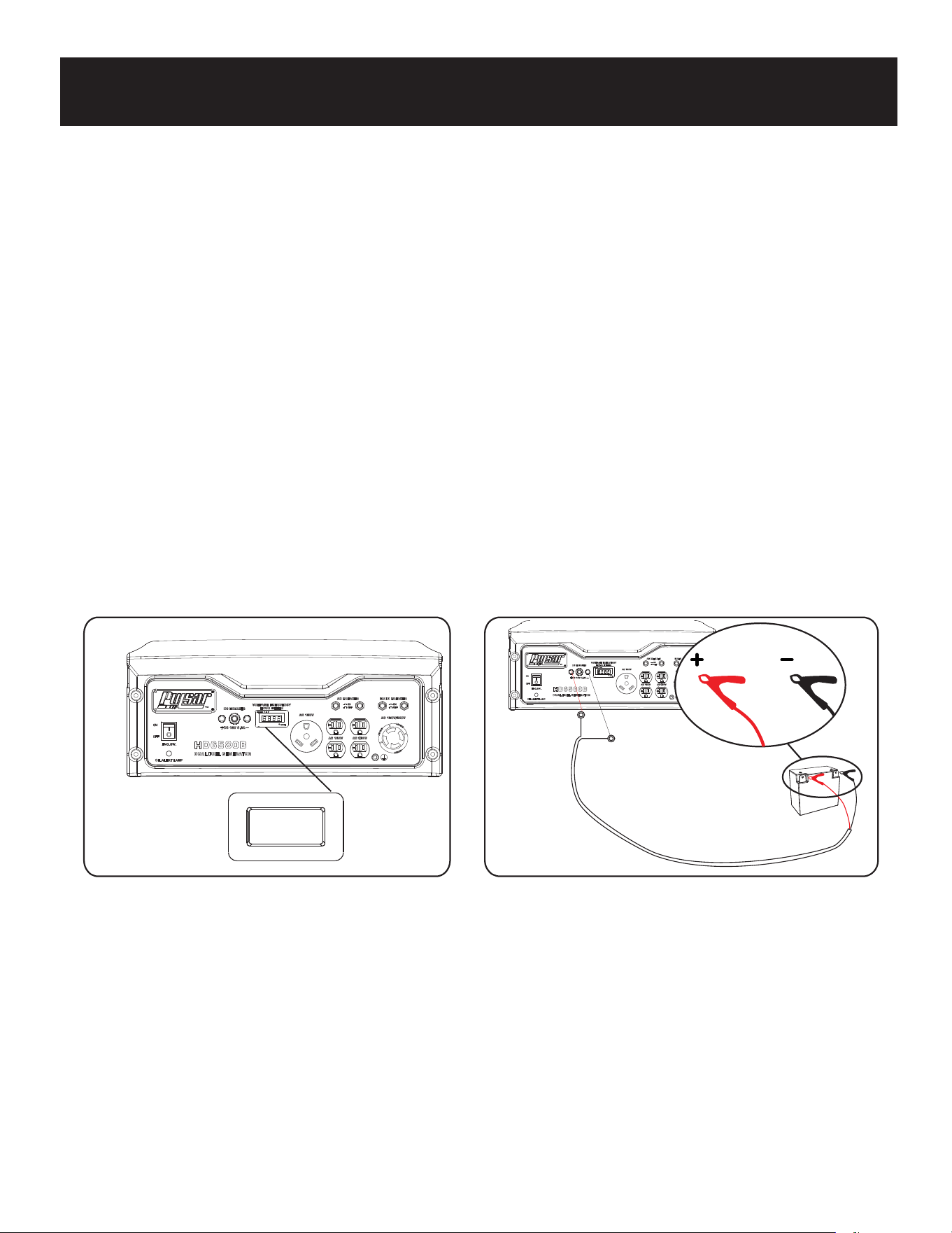
16
Fig 18Fig 17
FUNCIONAMIENTO
Carga de una batería de 12 voltios (ver Fig. 18)
Este generador se puede utilizar para cargar una batería automotriz o de almacenamiento de 12 voltios siguiendo estos
pasos:
Use un cepillo de alambre para limpiar los terminales de la batería si está corroído.
Conecte la abrazadera roja del cable al terminal positivo (+) de la batería.
Arranque el motor. Deje que el motor funcione mientras la batería se carga.
La batería se considera completamente cargada cuando el voltaje de CC estático lee 12.7 o mas.
•
•
•
•
•
•
Medidor de Hora (vea fig. 17)
El contador de horas digital opera cada vez que el motor está en funcionamiento y mantiene la cuenta de cuántas horas se
ha utilizado la unidad. Utilice este medidor, junto con el manual para determinar cuándo y qué tipo de servicio necesita la
unidad. la pantalla mostrará la palabra "LUBE" en las primeras 25 horas de funcionamiento y de nuevo a cada 100 horas
de funcionamiento después.
Administración de potencia
• Arrancar el motor sin nada conectado al generador.
• Cuando el motor se haya estabilizado, enchufe y encienda la primera carga. Se recomienda conectar los dispositivos con
la salida más grande primero y la salida más pequeña después Permita que la salida del generador se estabilice (el motor
y los dispositivos conectados funcionan de manera uniforme) antes de enchufar la próxima carga. para ayudar a prevenir la
sobrecarga del generador.
Conecte el enchufe de conexión del cable de carga de la batería al receptáculo DC de 12 voltios.
Conecte la abrazadera del cable negro al terminal negativo (-) de la batería.
Funcionamiento en Clima Fría
En condiciones húmedas, donde las temperaturas caen a 40ºF (4ºC) el carburador y / o el sistema de ventilación del
cárter pueden comenzar a congelarse. Para evitar la formación de hielo siga los siguientes pasos:
1. Reemplace cualquier vieja gasolina con gasolina limpia y fresca.
2. Utilice aceite de motor sintético 5W-30 o SAE 5W-30. Revise el aceite diariamente o después de cada 8 horas de uso.
3. Asegúrese de que el generador cuenta con los servicios de acuerdo con el programa de mantenimiento en la sección
"Mantenimiento" de este manual.
4. Proteja la unidad de elementos
17
MANTENIMIENTO
Mantenimiento regular extendera la vida del generador y mejorara el rendimiento. La garantia no cubre partes que
resultan por negligencia, mal uso, o abuso del operador. Para recibir el valor complete de la garantia el operador tendra
que mantener el generador como indique este manual incluyendo almacenamiento adecuado.
Antes de la inspeccion y mantenimiento de esta maquina asegurese que el motor este
apagado y no se muevan partes. Desconecte el alambre de la bujia y muevalo lejos de la bujia.
ADVERTENCIA
Pasos de Pre-Operacion
Antes de comenzar el motor, lleve a cabo los siguientes pasos de la pre- operacion:
• Revise de aceite el motor y el nivel de gasoline en el tanque.
• Asegurese que el filtro de aire este limpio.
• Remueva algun desecho colectado en el generador y alrededor del mofle y controles. Use una aspiradora para recoger
desechos sueltos. Si hay tierra pegada use un cepillo de cerdas.
• Inspeccionar el area de trabajo de los peligros.
Despues de cada uso
Siga los siguientes procedimientos despues de cada uso.
• Apague el motor.
• Almacenar la unidad en un lugar limpio y seco.
Despues de primer 5 horas
cambiar el aceite
Despues de 8 horas o diario
Limpiar desechos
Revise el nivel de aceite del motor
Anualmente (uso 25 hrs)
Revise y limpie el limpiador de aire
Cambie aceite de motor (Servicio con mayor frecuencia en condiciones sucias y polvorientas)
Revise el mofle y parachispas
Anualmente (Uso 100 hrs)
Servicio de bujias (Reemplace con NGK BP6ES, Champion N9YC o equivalente)
Servicio a valvula de combustible
Inspeccionar mofle y parachispas
Revise y limpie el limpiador de aire, re-emplace el filtro de aire
Limpie systema de enfriamiento
Programa de Mantenimiento
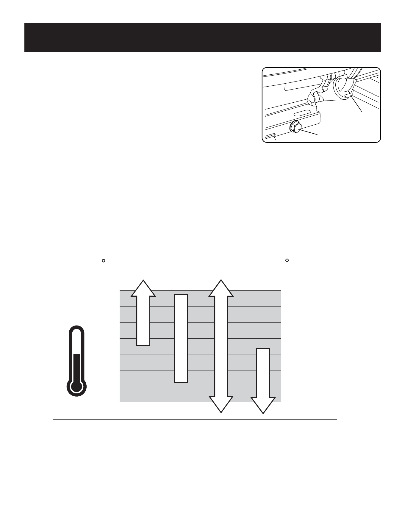
MANTENIMIENTO
18
Oil drainage plug
Fig 19
Oil Fill & Dipstick
-22
-4
14
32
50
68
86
104
-30
-20
-10
0
10
20
30
40
SAE 30
10W-30
Synthetic 5W-30
5W-30
*
*
*
C
F
Cambiar el aceite (fig. 19)
• Corra el generador hasta que el motor este caliente.
• Colocar el generador en una superficie plana.
• Saque la barilla del cárter.
• Ponga un recipinte de aceite de bajo del perno del drenaje de aceite.
• Quite el tapón de drenaje de aceite y deje que el aceite drene completamente
• Reinstalar el tapón del drenaje, apriete firmemente.
• Pongale SAE 10W-30 al depósito vacio hasta que el aceite llegue al borde
exterior del orificio (orificio de la varilla del cárter).
• Reemplase la varilla de medición del cárter.
Recomendaciones de aceite
• No use aditivos especiales.
• Determinar la temperatura de viscosidad exterior adecuada del aceite para
el motor. Use el gráfico para seleccionar la mejor viscosidad de la temperatura
exterior.
Nota: Debajo de 40°F (4°C) el uso de SAE 30, tendra dificultad en el arranque.
Mass de 80°F (27°C) el uso de 10W-30 puede provocar un aumento del consumo
de petróleo. Comprobar el nivel de aceite con mayor frecuencia.
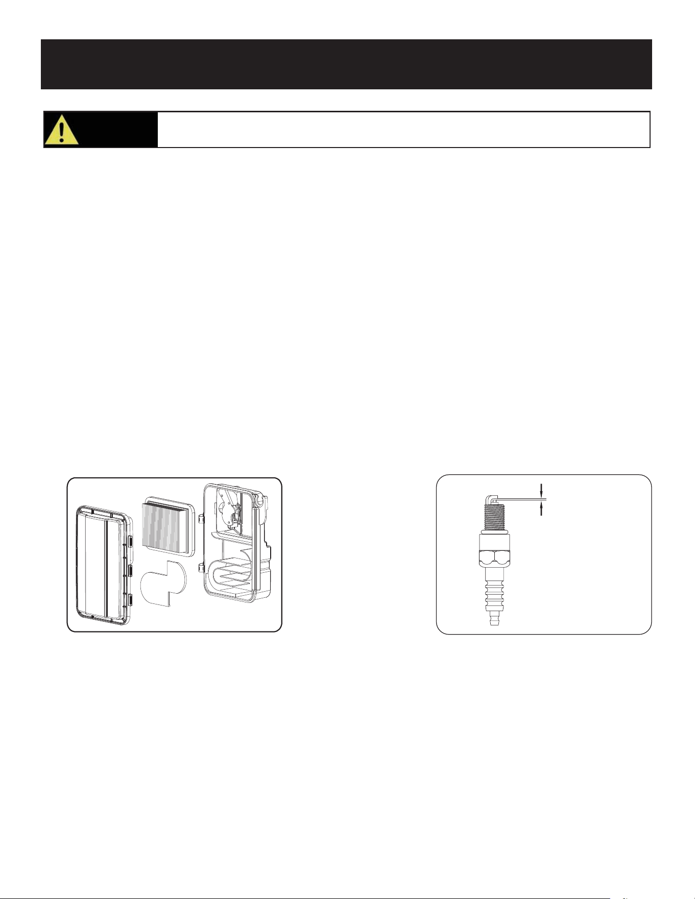
19
Fig 21
0.7-0.8mm
Fig 20
MANTENIMIENTO
El aceite usado debe eliminarse en un sitio de eliminación aprobado. Consulte a su distribuidor local
de petróleo para obtener más información.
¡PRECAUCIÓN!
Filtro de Aire (vea fig. 20)
Un filtro de aire sucio puede reducir la vida del motor, haciendo dificultosamente el prender el motor y reduce el
funcionamiento de la unidad.
• Para limpiar, remoeva el covertor del filtro de aire.
• Cuidadosamente saque el filtro de aire levantandolo por las orillas.
• Remueva la tierra del filtro pulsandolo o soplandolo. Reemplace con un nuevo filtro anualmente.
• Reinstale el filtro de aire para sellar y reemplace el covertor del filtro de aire.
Examinar bujias (vea fig. 29)
• Desconectar el alambre de bujia de la bujia.
• Antes de remover la bujia limpe el área alrededor de su base para prevenir desechos que entren al motor.
• Limpiar depósitos de carbono fuera del electrode con un cepillo de alambre.
• Verificar la reparación del electrodo y ajustelo lentamente a 0.7mm-0.8mm (0.028-0.031”) si es necesario.
• Reinstale la bujia y apriete el torque a 22.0-26.9 Nm (16-20ft-lb).
• Vuelva a conectar el alambre de la bujia.
• Si la bujia está desgastada reemplace con una parte de recambio equivalente. La bujia deber reemplazarce anualmente
(BOSCH F7TC, NGK BP6ES, CHAMPION N9YC o equivalente).

20
Drenando el tanque de gasolina
• Apague el motor.
• Dele vuelta a la valvula de gasolina a la posición “OFF”.
• Cuando el combustible se haya drenado del tanque, cierre la válvula de combustible y vuelva a instalar la línea de
combustible de forma segura en la llave de paso.
• Retire la línea de combustible que conduce al carburador de la llave de purga apretando los extremos de las abrazaderas
de la manguera y deslizando la línea de combustible hacia afuera.
• Si es necesario, instale una manguera de combustible que se extienda a un recipiente de combustible adecuado lo
suficientemente grande como para atrapar el combustible que se drena del tanque.
•
Voltear la valvula de gasolina a la posición ON.
A gran altitud, la mezcla estándar de combustible / aire del carburador será demasiado alta. El rendimiento disminuirá y el
consumo de combustible incrementará. Una mezcla muy alta también ensuciará la bujía y provocará un arranque difícil.
Operación a una altitud que difiere a partir de la cual se certificó este motor, por largos períodos de tiempo, puede aumentar
las emisiones. Rendimiento a gran altitud puede mejorarse mediante modificaciones específicas al carburador.
Si siempre opera su generador a altitudes superiores a 5,000 pies (1,500 metros), haga que su distribuidor realice esta
modificación del carburador. Este motor, cuando se opera a gran altitud con las modificaciones del carburador para uso a
gran altitud cumplirán con cada estándar de emisión a lo largo de su vida útil. Incluso con modificación del carburador, la
potencia del motor disminuirá aproximadamente 3.5% por cada 1,000 pies (300 metros) de aumento de altitud.
El efecto de la altitud sobre los caballos de fuerza será mayor que esto si no se realiza ninguna modificación del carburador.
Drenando el carburador
• Apague el motor.
• Dele vuelta a la valvula de gasolina a la posición “OFF”.
• Coloque un recipiente adecuado debajo del tornillo de drenaje del carburador para recoger combustible; Aflojar el tornillo.
• Permita que el combustible se drene completamente en el contenedor.
• Vuelva a apretar el tornillo de drenaje.
Drenando el tanque de gasoline y el carburador
Operación a gran altitud
Para prevenir depósitos de goma en el systema de gasoline drene la gasolina del tanque y el carburador antes de guardar la
unidad por periodos largos. Esto ayudara a prevenir problemas de comienzo en el future. Si la unidad es guardada con
gasolina y la gasolina se hace rancia o gomosa para varnizar la garantia no cubre este reparo o servicio.
MANTENIMIENTO

21
Fig 21
MANTENIMIENTO
Consulte con su manejo de residuas peligrosos local en su area para desaserce de la
gasolina correctamente.
PRECAUCIÓN
Almacenamiento (vea fig. 21)
• Remueva algun desecho que haya colectado el generador y al rededor del mofel y controles. Use una aspiradora para
recoger desechos sueltos. Si hay tierra pegada, use un cepillo de alambre.
• Inspeccione las ranuras del enfriamiento. Remueva desechos que obstrullen.
• Deconectar cable de la bateria negative de la bateria.
• Para almacenamiento de corto tiempo prenda el generador cada 7 dias.
• Para almacenamiento de largo tiempo pongale estabilizador de gasolina para prevenir que se entiece la gasolina y para
prevenir que haiga acido y depósitos de gomas en el systema de gasolina y carburador.
• Almacenamiento interior y usar cobertura protectora para proteger de la tierra.
• El generador tiene que ser enviado, corridor y almacenado en la posición vertical como demostrado en esta imagen.
•
•
Quite la bujía y vierta aproximadamente 1 cucharadita de aceite de motor 10W30, dentro del orificio de la bujía. Vuelva a
instalar la bujía. Con el interruptor ON/OFF en la posición OFF (APAGADO) saque el retroceso el cordón de arranque varias’
veces para recubrir las paredes del cilindro con aceite.
Slowly pull the recoil Starter until you feel the engine build compression (When you feel resistance). Leave the Engine in this
state as this will prevent any corrosion on the cylinder walls if stored for a long period of time.
Almacenamiento a largo plazo:

22
SOLUCIÓN DE PROBLEMAS
Problema Causa Solución
Engine will not start, shuts down during
operation, or starts and runs rough.
No tiene fuerza el motor
1. El generado esta sobre cargado
2. El filtro de gasolina esta tapado
3. El filtro de aire esta sucio
4. El motor necesita servicio
1. Vea pagina 17 Sobre carga al
generador
2. Limpie y reemplace el filtro de gasolina
3. Reemplace el filtro de aire
4. Contacte el departamendo de servicio
El motor tambalea 1. Estrangulador se retiro demasiado
2. Filtro de gasolina tapado
3. El carburador corre muy rica o muy
pobremente
1. Mueva el cebador a la posición
intermedia hasta que el motor corra bien.
2. Limpie o reemplace el filtro de gasolina
3. Contacte el departamendo de servicio
El motor esta corriendo
pero la salida del aire
condicionado no esta
disponible
1. Abre el cortacircuitos 1. Reajustar el cortacircuitos
2. Conexión pobre 2. Examine y Reparar
3. Juego de cables defectuosos 3. Examine y Reparar
4. Depositivo Conectado está defectuoso 4. Conectar el dipositivo
5. Falta en el generador 5. Contacte el departamento de servicio
El motor corer bien
sin carga pero se
atasca cuando se
conecta.
1. Corto en el circuito de dipositivo 1. Desconecte el dipositivo conectado
2. El Generado esta sobre cargado 2. Vea pagina 17 No Sobre Cargue
3. El tanque de gasolina esta tapado 3. Limpe o cambie el filtro de gasolina
4. La rapides del motor es muy lenta 4. Contacte el departamendo de servicio
5. Corto el generador 5. Contacte el departamendo de servicio
1. La perilla de ON/OFF moverse a OFF 1.Voltear perilla a “ON”
2. Filtro de aire sucio 2. Reemplace el filtro de aire
3. Filtro de gasolina tapado 3. Limpie y reemplace el filtro de gasolina
4. Gasolina tiesa 4. Reemplace la gasolina aspire.
5. Alambre de la bujia esta desconectado 5. Reconectar alambre de la bujia
6. Bujia mala 6. Reemplace la bujia
7. Agua en la gasolina 7. Drene el tanque de gasolina y
reemplace
8. Valvula esta en la posición “OFF” 8. Voltear la valvula de gasolina a la
posición “ON”
9. Sobre atragantamiento 9. Desactive el estrangulador
10. Nivel de aceite bajo 10. Llene el cárter con aceite hasta el
nivel apropiado
11. Gasolina mezclada enriquecida 11. Contacte el departamendo de servicio
12. Valvual de entrada esta trabada 12. Contacte el departamendo de servicio
13. Perdida de compression 13. Contacte el departamendo de servicio
14. Bateria muerta 14. Recarge o reemplace la bateria
15. Motor inundado 15. Espere 5 minutos y arranque el motor
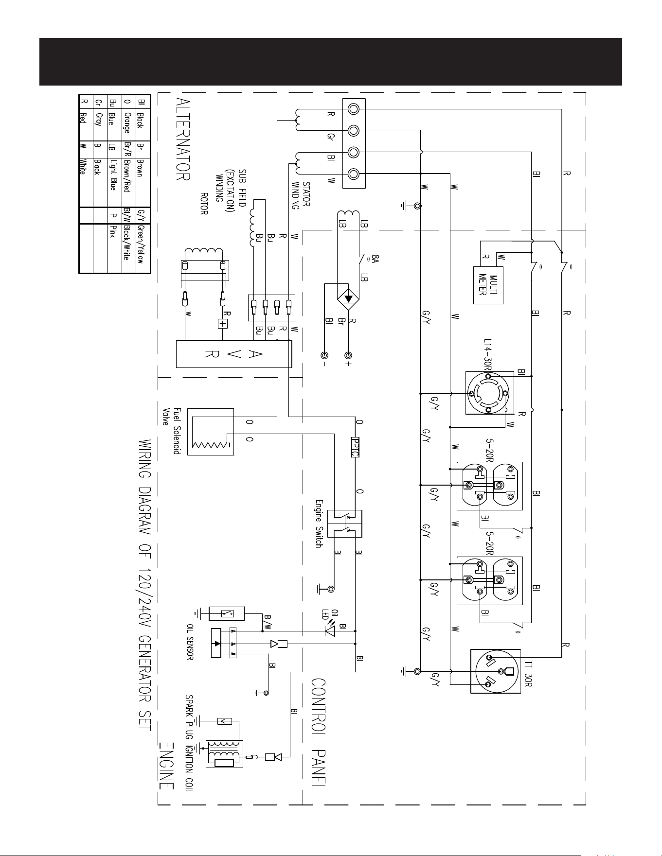
DIAGRAMA
23
G65BN