Ed :
Re :
Cod :
INSTRUCTION
09/24 GRLDEVETFK495S00
3
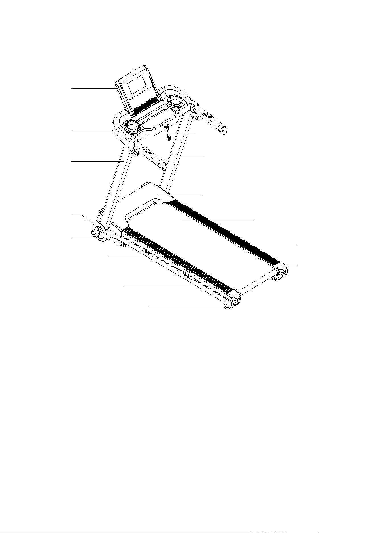
PRODUCT DESCRIPTION
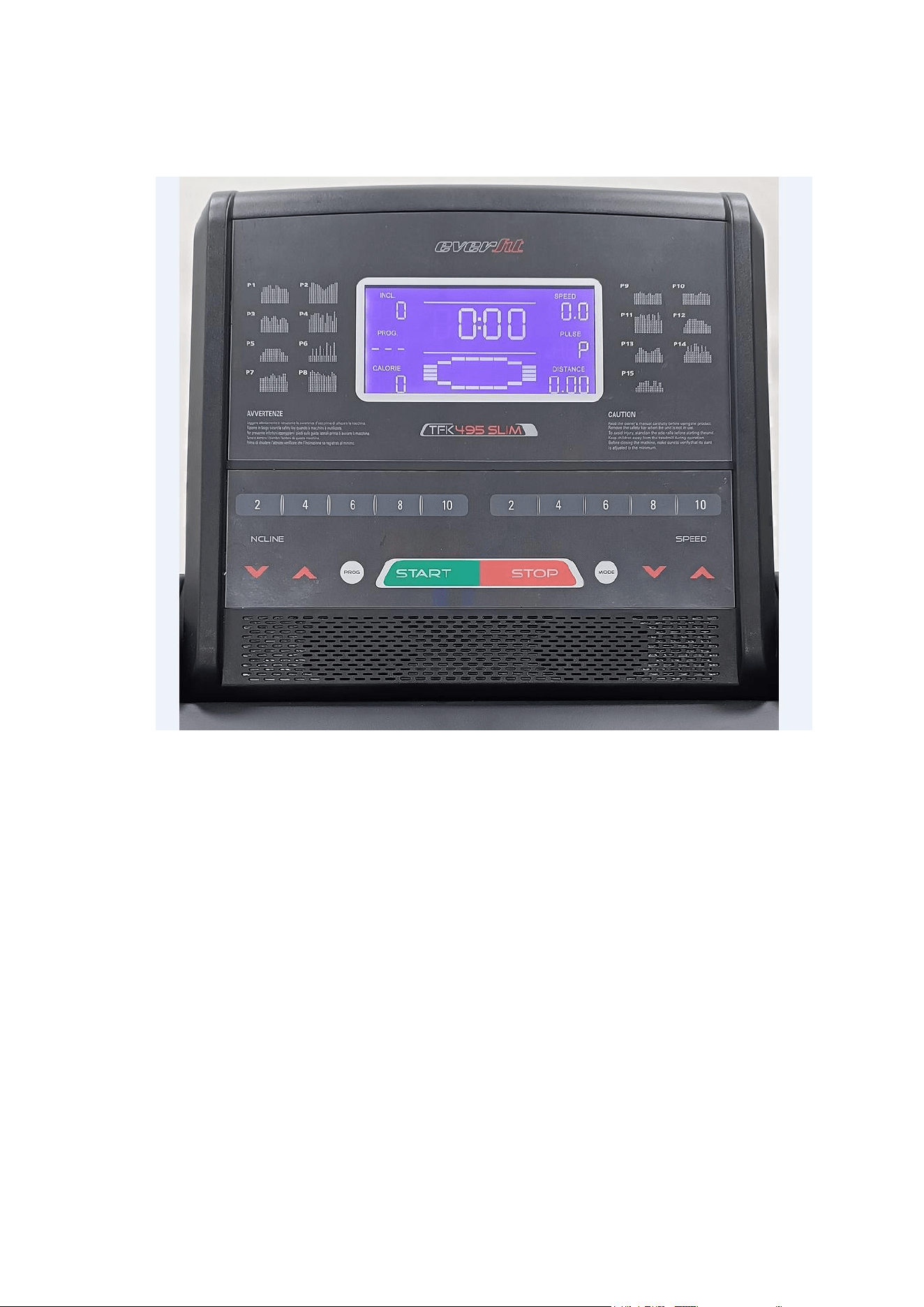
Console
Console Cover
Side Cover
Folding Lever
Cushion
Safety
Key
Left Upright
Motor Upper Cover
Side Rail
Running Belt
End Cap
Right Upright
Main Frame
Rear Stabilizer Foot
4
ASSEMBLY INSTRUCTIONS
ATTENTION: Do the following operations after checking all screws are tightened and everything is OK.
Before you use the treadmill, please read the instructions carefully.
ST
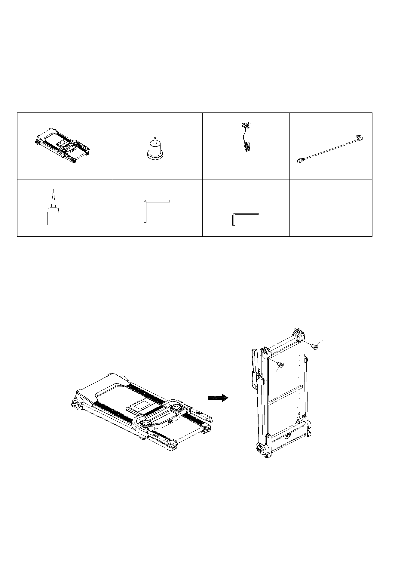
EP 1:Open the carton, and move out all the parts listed in below chart.
Treadmill Frame: 1 SET
B8 Rear Stabilizer
Foot: 2 PCs
C13 Safety Key: 1 PC
C15 Power Cable: 1
PC
B18 Silicon Oil: 1 PC
D3 Allen Wrench T5: 1
PC
D92 Allen Wrench T8:
1 PC
STEP 2:Move out the Treadmill Frame from the carton, and lift the treadmill in standing
position as illustrated. Tighten Rear Stabilizer Foot (B8) onto treadmill frame.
Updated Drawing
B8
B8
5
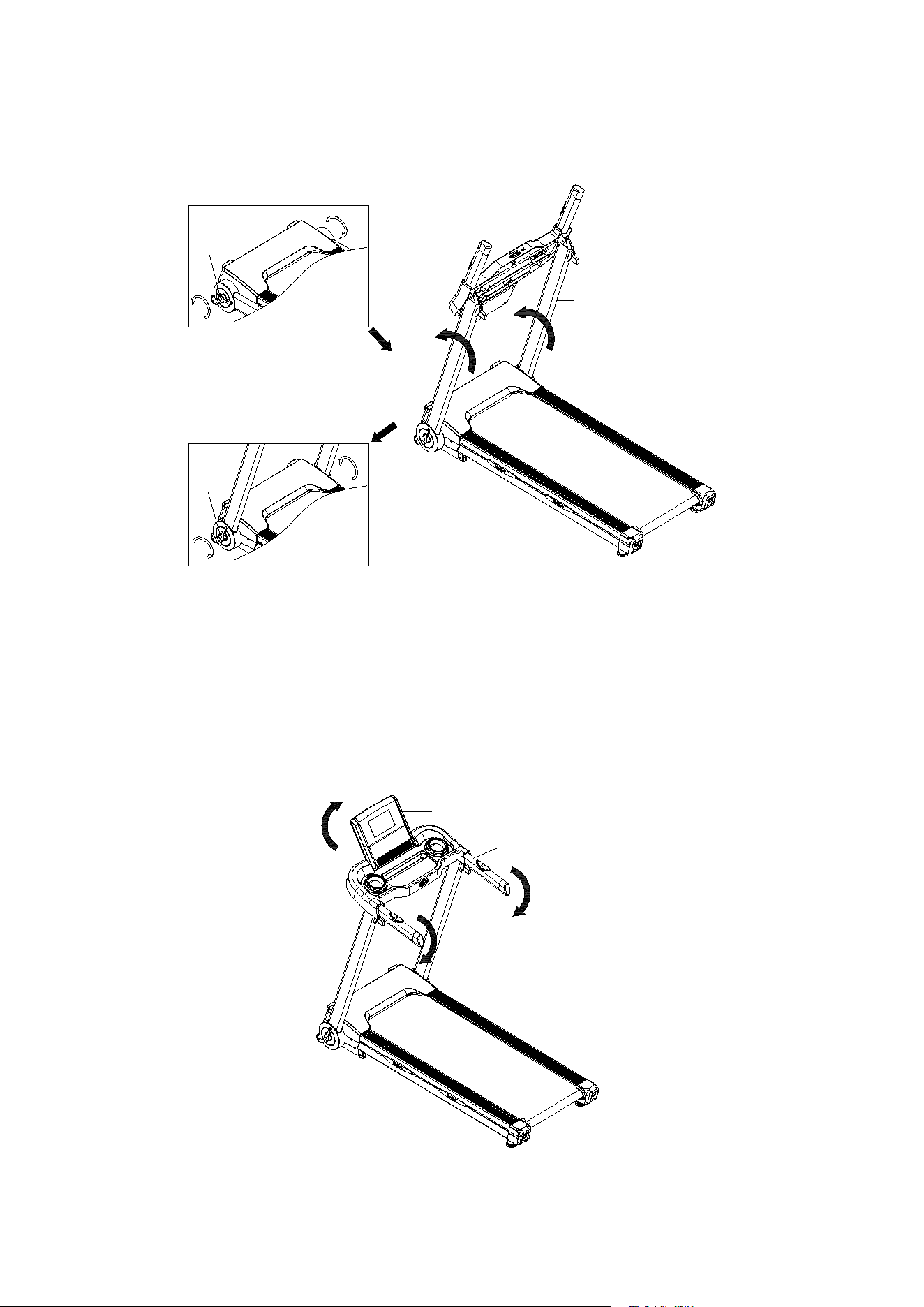
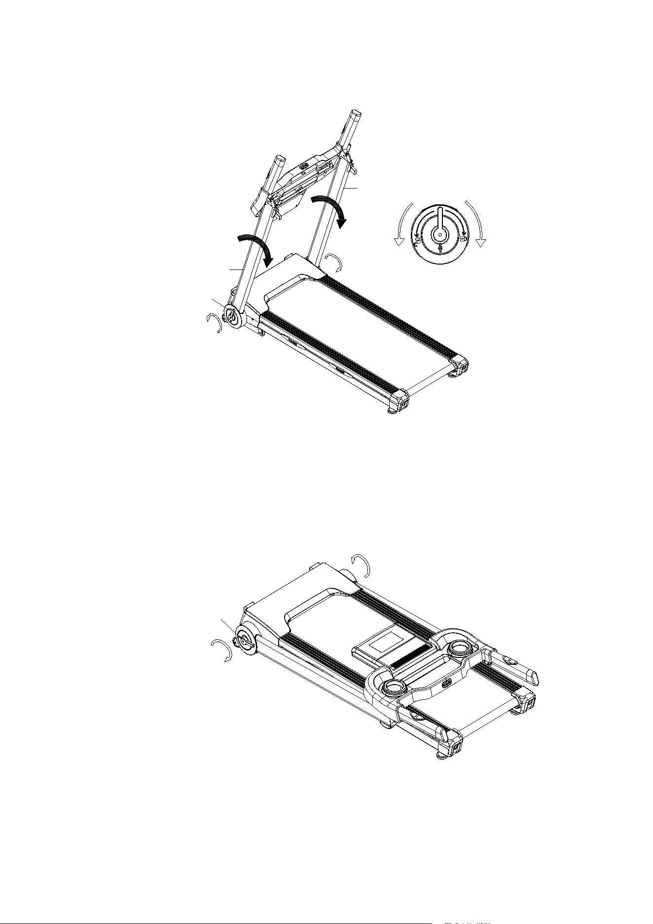
STEP 3:Turn both Folding Levers (B157) on Left/ Right Uprights (A3L/ A3R) counter-
clockwise. Hold and lift Left/ Right Uprights (A3L/ A3R), and rotate both Folding Levers
(B157) clockwise to lock both Uprights.
ST
EP 4: Hold left and right Handlebar (A4) and push it down until hearing a “clock”
sound for lock it into position. Rotate the Console (B1) to the appropriate reading angle.
A3R
A3L
B157
B157
A4
B1
6
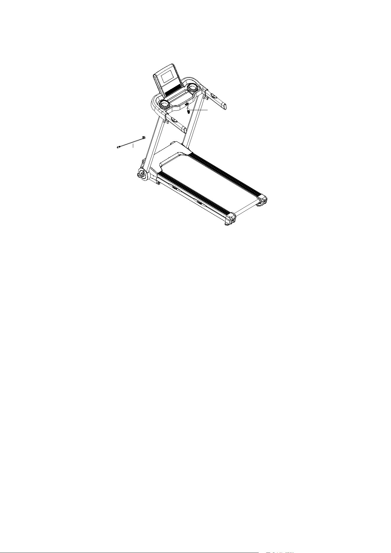
STEP 5: Place on Power Cable (C15), and Safety Key (C13).
STEP 6: After installation, press start button, adjust speed level under 3km/h. Then
check the running belt to see if it runs smoothly or not. The tightness level is decided
based on the situation of slippery and deviation. After checking is completed, move
treadmill to appropriate location for exercising use.
C13
C15
7
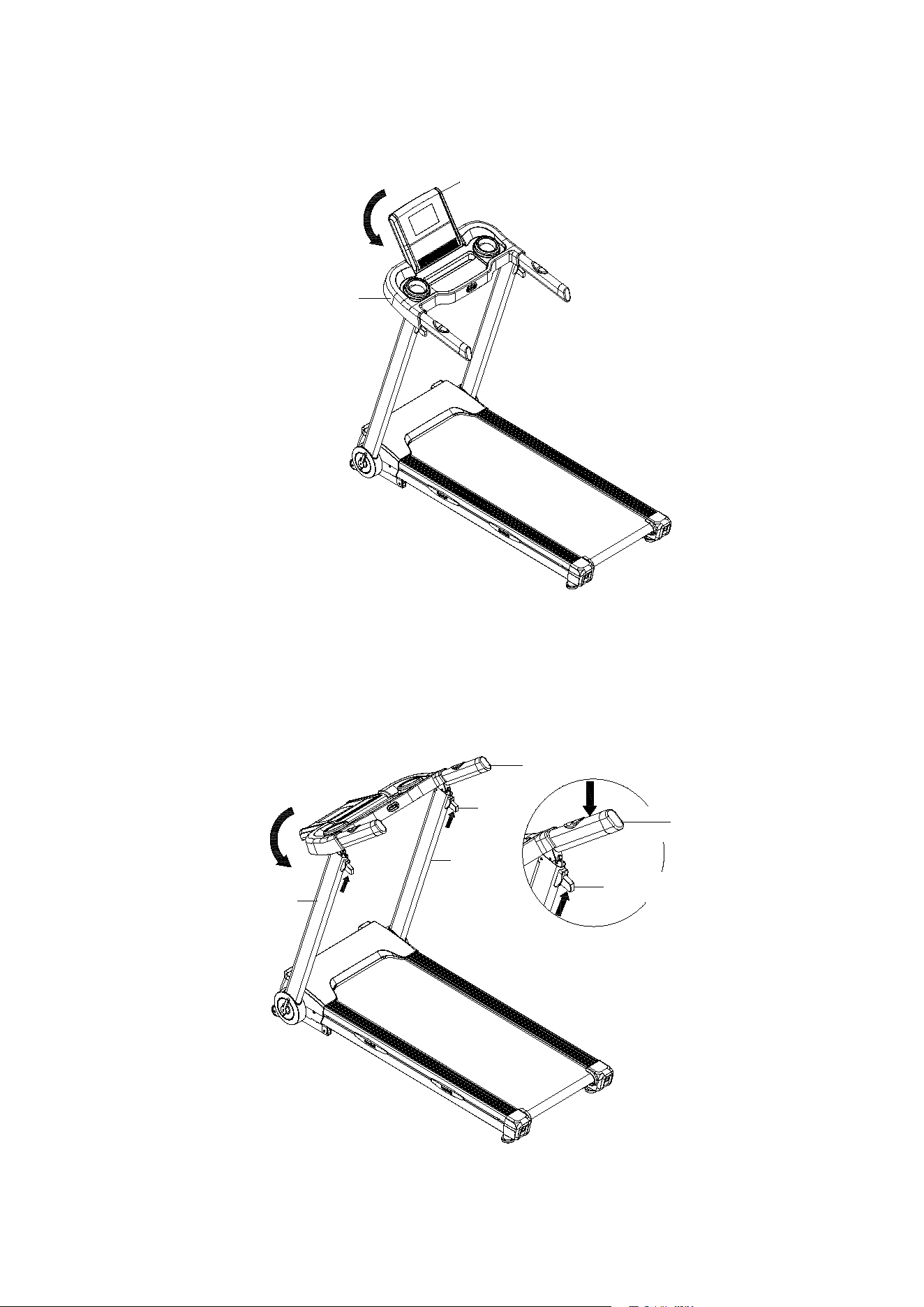
FOLDING INSTRUCTION
ST
EP 1: Rotate Console (B1) backward to be horizontal with Handlebar (A4).
ST
EP 2: Slightly push down the Handlebar (A4) and press Folding Button (B156) on left/
right sides at the same time. Once the Handlebar (A4) is un-locked, rotate it back to
attach Left/ Right Uprights (A3L/ A3R).
B1
A4
A3L
B156
A3R
A4
B156
A4
8
STEP 3: Rotate Folding Lever (B157) counter-clockwise for 1 turn in order to loosen Left/
Right Uprights (A3L/ A3R) and push them down to attach the Treadmill Frame.
STEP 4: Rotate Folding Lever (B157) clockwise for 1 turn in order to tighten the Left/
Right Uprights (A3L/ A3R).
A3R
A3L
B157
Loosen
Tighten
B157
9
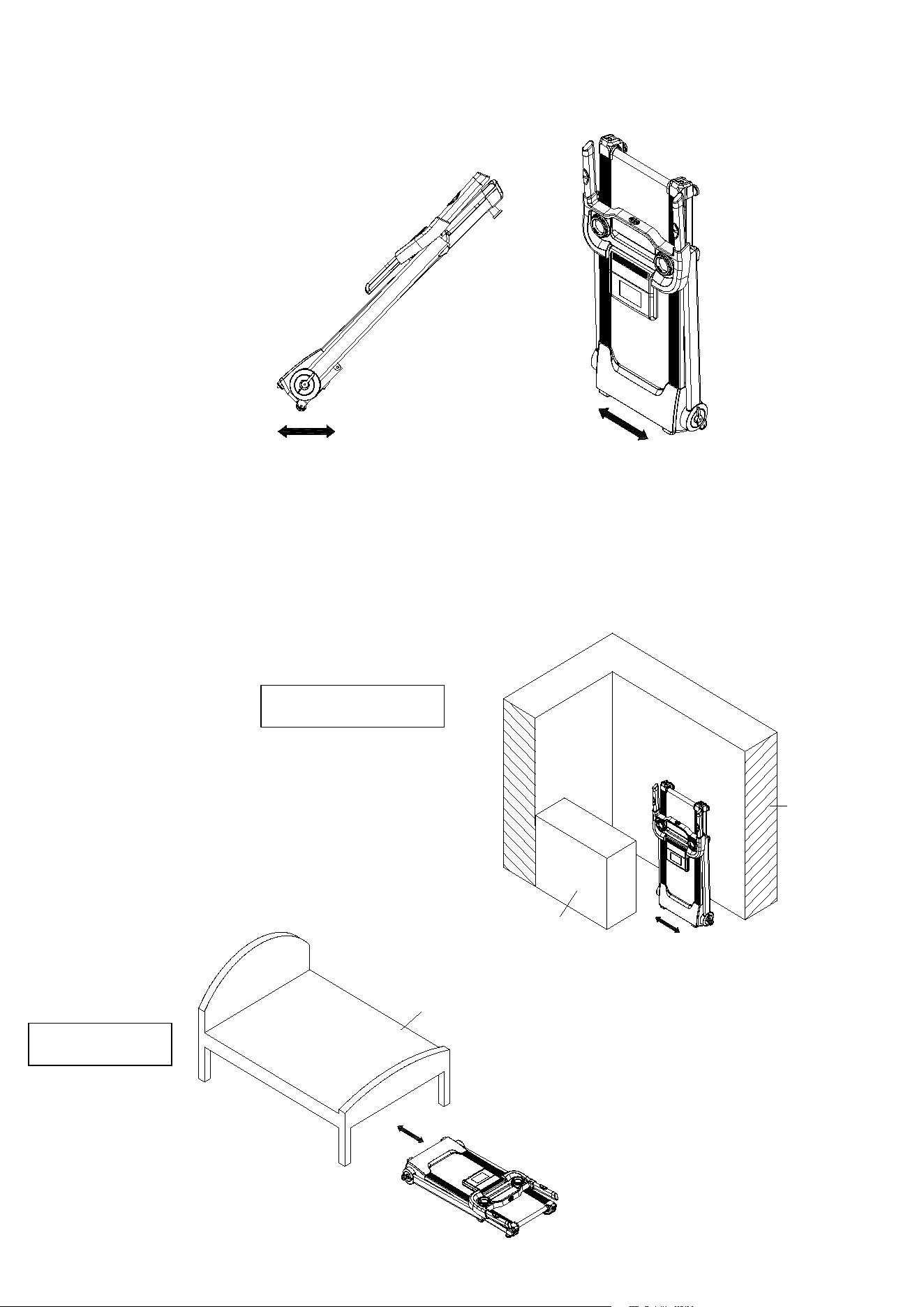
STEP 5: To move the treadmill forward and backward, lift the end of treadmill frame and
have transport wheels touch on the ground/ floor. To move the treadmill to the left and
right, have the treadmill stand with motor cover end closer to the ground / floor.
STEP 6 (for storage): Place treadmill at standing position against wall for storage, or
place it under the bed for space saving. The height of treadmill is 26cm (needs to be
measured on actual sample again). If the space is less than 26cm under your bed,
please keep it somewhere else for storage.
Storage Against Wall
Place Under Bed
Bed
Wall
Cabinet

10
GROUNDING METHODS
This product must be grounded. If it should malfunction or breakdown, grounding provides a path of
least resistance for electric current to reduce the risk of electric shock. This product is equipped with a
cord having an equipment-grounding conductor and a grounding plug. The plug must be plugged into
an appropriate outlet that is properly installed and grounded in accordance with all local codes and
ordinances.
DANGER – Improper connection of the equipment-grounding conductor can result in a risk of electric
shock. Check with a qualified electrician or serviceman if you are in doubt as to whether the product
is properly grounded. Do not modify the plug provided with the product – if it will not fit the outlet, please
find a proper outlet installed by a qualified electrician.
. This product is for use on a nominal 110V circuit and has a grounding plug. Make that the product is
connected to an outlet having the same configuration as the plug. No adapter should be used with this
product.

14
MAINTENANCE INSTRUCTION
WARNING:Please make sure pull out the treadmill's power plug before cleaning or maintaining the
product.
CLEANSING:General cleaning or the unit will greatly prolong the treadmill's life.
Keep treadmill clean by dusting regularly. Be sure to clean the exposed part of the deck on either side
of the walking belt and also the side rails. This reduces the build up of foreign material underneath
the walking belt. Make sure the shoes are clean. The top of the belt may be cleaned with a wet soapy
cloth. Be careful to keep liquid away from inside the motorized treadmill frame or from underneath the
belt.
WARN
ING:Always unplug the treadmill from the electrical outlet before removing the motor
cover. At least once a year remove the motor cover and vacuum under the motor cover.
This treadmill's walking belt and deck are equipped with a pre-lubricated, low maintenance deck
system. Do not require adding lubrication.
15
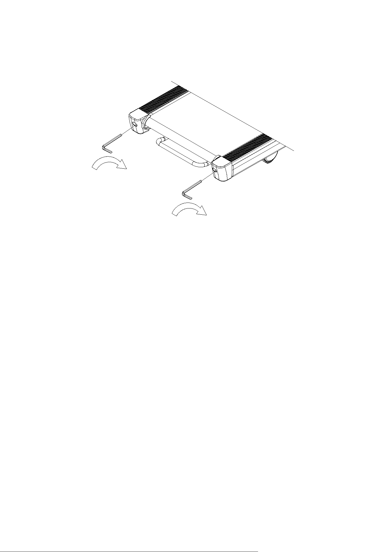
BELT ADJUSTMENT
Place treadmill on a level surface. Make treadmill run at approximately 6-8 km/h, observe the running
belt deviate condition.
If the belt has drifted to the right, unplug the safety lock and power switch, and turn the right
adjusting bolt 1/4 turn clockwise, then insert the power switch and safety lock, make the treadmill
running, observe the running belt deviate condition.
Repeat above steps until the running belt be placed in the middle.
O
nce the treadmill belt swerving to the left, unplug the safety lock, turn off the power, then with the
left adjusting bolt clockwise rotation 1 / 4 laps, and turn on the safety lock and power to make treadmill
running, checking the deviation of the treadmill belt. Repeat the above
Steps until belt is centered.
The
treadmill belt will gradually relax after above steps or after a period of time using, unplug the safety
lock, and turn off the power, with the two adjusting bolt clockwise rotation 1 / 4 laps, and turn on the
safety lock and power to make treadmill running, then standing on the belt to confirm the tightness.
Repeat the above steps until the belt moderate tightness.
16
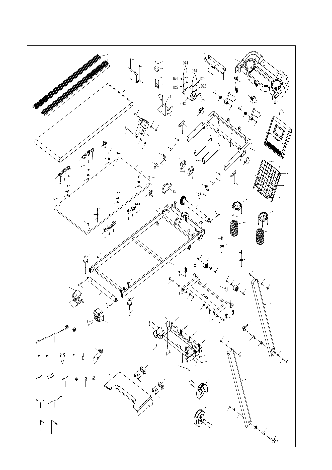
EXPLOSTION DRAWING
A1
A3L
A3R
A4
A57
A5
A75
A75
A47
B104
B104
D131
D131
A48
A48
D52
A13
A13
D52
C12
D200
D21
D18
D21
D18
D7
C8
D3
C34
C15
D58
B1
C9
D42
D42
C4
D30
D30
D29
C2
C5
C3
B116
B116
B2
B5
B45
B3
B4
B152
B152
B51
B51
B97
B97
B155
B156
B155
B156
B13
B14
B101
D136
D136
B11L
B11R
B157
B157
B8
B8
B7
B7
B28
B28
B28
B32
B32
D52
D52
B19B20
B21
B21
B158
B158
B16R
B16L
B15
D186
D186
D20
D121
D204
A57
D20
D121
D204
D99
D123
D99
D123
D10
D21
D18
D10
D21
D18
D23
D15
D15
D23
D20
D20
D87
D23
D20
D23
D20
D87
D206
D206
D112
D112
D112
D112
D130
D130
D198
D52
D52
D52
D151
D151
C10
C11
D23
D26
D52
D23
D26
D52
D23
D26
D52
D23
D26
D52
D23
D26
D52
D23
D26
D52
A47
D52
D52
D214
D214
D145
D145
D145
D145
D145
D145
D169
D169
D169
D169
D91
D91
D44
B4
D58
D58
D45
D45
D24
D208
D207
D208
D207
A77
A77
C14
C27
C33
C20
C20
C50
C17
C16
B18
B101
D169
D169
D92
B32
D52
B32
D52
C22
C21
D42
D42
A80
D152
D152
A34
C13
B87
D134

17
PARTS LIST
A.
Welding Parts
N
O.
D
ESCRIPTION
Q
TY
A
1
M
ain Frame
1
A
3L
L
eft Upright
1
A
3R
R
ight Upright
1
A
4
H
andlebar
1
A
5
I
ncline Bracket
1
A
13
B
elt Fixation Bracket
2
A34
Safety Key Pin
2
A
47
S
topper Pin
2
A
48
P
U Roller Spacer
2
A
57
Upright Folding Bracket
2
A
75
F
olding Lever Sleeve
2
A
76
R
esistance Plate
2
A79
Safety Key Pin Holder
(delete this part) 1
A80
Inductor & Filter Bracket
1
B.
Plastic Parts
N
O.
D
ESCRIPTION
Q
TY
B
1
C
onsole Set
1
B
1-1
O
verlay
1
B
2
C
onsole Cover
1
B
3
H
andlebar Foam
2
B
4
H
andlebar End Cap
2
B
5
C
onsole Small Back Cover
1
B
7
T
ransport Wheel
2
B
8
R
ear Stabilizer Foot
2
B
11L
Left
Side Cover
1
B
11R
R
ight Side Cover
1

18
B
13
M
otor Upper Cover
1
B
14
M
otor Bottom Cover
1
B
15
S
ide Rail
2
B
16L
L
eft End Cap
1
B
16R
R
ight End Cap
1
B
18
S
ilicon Lubrication
1
B
19
C
able Clip
1
B
20
W
ire Protection Plug
1
B
21
S
quared-shaped Tube Plug
4
B
28
S
quared-shaped Cushion
4
B
32
O
val-Shaped Cushion
4
B
45
C
onsole Large Back Cover
1
B
51
W
ater Bottle Holder Ring
2
B87
Safety Key Holder
1
B
97
W
ater Bottle Holder
2
B
101
T
ransportation Wheel Cover
2
B
104
Second
ary Transportation Wheel
2
B
116
S
mall Incline Bushing
4
B
152
U
pright Joint Cover
2
B
155
F
olding Button Base
2
B
156
F
olding Button
2
B
157
F
olding Lever
2
B
158
C
ushion with Screw
2
C.
Electronic Parts
N
O.
D
ESCRIPTION
Q
TY
C
2
R
unning Belt
1
C
3
R
ear Roller
1
C
4
F
ront Roller
1
C
5
R
unning Deck
1

19
C
7
D
rive Belt
1
C
8
P
ower Switch
1
C
9
C
ontroller
1
C
10
Pulse Sensor
on Left Handlebar
1
C
11
Pulse Sensor
on Right Handlebar
1
C
12
I
ncline Motor
1
C
13
S
afety Key
1
C
14
S
ingle Cable (Brown)
1
C
15
P
ower Cord
1
C
16
U
pper Section Cable
1
C
17
L
ower Section Cable
1
C
20
M
agnetic Ring
2
C21
Inductor
1
C22
Filter
1
C
27
S
ingle Cable (Blue)
1
C
33
G
round Wire
1
C
34
P
ower Plug
1
C
42
B
rushless Motor
1
C
50
L
arge Magnetic Ring
1
C
56
R
ectangle Shaped Magnet (delete this part) 1
C59
Rectangle Shaped Sensor
(delete this part) 1
D.
Hardware Parts
N
O.
D
ESCRIPTION
Q
TY
D
3
A
llen Wrench T5
1
D
7
B
utton Head Cap Screw, M10x60mm
1
D
10
B
utton Head Cap Screw, M10x45mm
2
D
15
B
utton Head Cap Screw. M8x40mm
2
D
18
N
ylon Nut, M10
4
D
20
N
ylon Nut, M8
6

20
D
21
F
lat Washer, M10
4
D
22
F
lat Washer, M6
4
D
23
Fl
at Washer, M8
1
0
D
24
S
pring Washer, M5
1
D
26
Bowl
Washer
6
D
29
S
ocket Head Cap Screw, M6x45mm
1
D
30
S
ocket Head Cap Screw, M6x60mm
2
D42
Phillips Rounded Washer Head Screw, M
4x10mm
6
D
44
Phillips Rounded Washer Head Screw,
M5x12mm
2
D
45
Phillips Rounded Washer Head Screw, M5x15mm
4
D
52
Phillips
Pan Head Self-Tapping Screw, ST4.2x16mm
3
4
D
58
Phillips Flat Head Self
-Drilling Screw, ST3.5x16mm
4
D
74
Socket Head Cap Screw, M
6x25mm
6
D
79
S
pring Washer, M6
4
D
87
Button
Head Cap Screw, M8x80mm
2
D
91
Phillips Pan Head Self
-Drilling Screw, ST4.2x19mm
4
D92
Allen Wrench T8
1
D
99
Comp
ression Spring
2
D
112
Hex Head Cap Screw
, M6x35mm
4
D
121
C
onsole Pression Spring
2
D
123
C
Ring
∮
5
2
D
130
Phillips Flat Head
Self-Tapping Screw, ST4.2x19mm
4
D
131
Flat Socket Head Cap Screw, M8x22mm
2
D134
Phillips Pan Head Self
-Tapping Screw, ST3.0x8mm 6
D
136
Phillips Pan Head Self
-Tapping Screw, ST4.2x10mm
8
D
145
Phillips Pan Head Screw
, M5x16mm
6
D151
Phillips Pan
Head Self-Tapping Screw, ST4.2x10mm
8
D
152
Phillips Flat Head Self
-Tapping Screw, ST4.2x10mm
4
D
169
Phillips Pan Head Self
-Drilling Screw, ST4.2x16mm
8
D
186
Pression
Spring
2
D
198
Phillips Pan Head Self
-Tapping Screw, ST3.0x12mm
9

21
D
200
Button Head
Cap Screw, M10x40mm
1
D
204
D
Shaped Screw Lock, M8x40mm
2
D
206
Socket Head Cap Screw
, M10x75mm
2
D
207
Socket Head Cap Screw
, M6x35mm (Reverse Thread)
2
D
208
F
lat Washer, M6
2
D214
Phillips Flat Head Self
-Tapping Screw, ST4.0x6mm 2
2
Operation Guide
1. DISPLAY DEFINITION
(1) SPEED
- Show current running speed of the exercise.
(2) CALORIE
- Show total consumed calories during the exercise.
(3) INCL. (INCLINE)
- Show the incline level set for the exercise.
- Incline unit = 0 – 12 levels
(4) PROG. (PROGRAM)
- Show selected training program, including P01 – P05, U01 – U03, HP1 – HP3, H-1, H-2, H-
3, and FAT.
(5) Time

3
- Show duration of the exercise.
(6) Distance
- Show accumulated distance of the exercise.
(7) Pulse
- Once heart rate signal detected, display shows pulse data. Please noted pulse data is only
for reference, not for medical purpose.
(8) ODO
- Show total accumulated distance of this treadmill by pressing PROG and MODE buttons
together for at least 3 seconds.
2. CONTROL BUTTON DEFINITION
(1) PROG
- Select training program file
- 15 pre-set programs: P01 to P15
- 3 user programs: U01 to U03
- 3 HRC programs: HP1 to HP3
- 1 body fat program: FAT
- Manual
(2) MODE
- Select countdown program file
- Time Countdown: H-1
- Distance Countdown: H-2
- Calories Countdown: H-3
(3) START
- Press “Start” button for begin of exercise after 3 seconds countdown. Treadmill starts from
lowest speed at 0.8 km/h or first speed under certain program.
(4) STOP
- Press “Stop” button for 1st time to temporarily stop the exercise (Pause Status). Speed goes
to zero and incline stops at current incline level.
- When it’s in “Pause Status”, press “Stop” button to end the exercise.
- When it’s in “Pause Status”, press “Start” to begin the exercise. Adjust the speed and incline

4
to appropriate setting.
(5) QUICK SPEED
- Quick speed has 5 buttons for 2 km/h, 4 km/h, 6 km/h, 8 km/h, and 10 km/h (when it’s in
imperial setting).
(6) QUICK INCLINE
- Quick incline has 5 buttons for level 2, level 4, level 6, level 8, and level 10.
(7) SPEED CONTROL BUTTONS
- Press “Increase” or “Decrease” buttons to adjust up or down the speed.
- Each press adjusts up/ down speed by 0.1 km/h.
- Min. speed: 0.8 km/h
- Max. speed: 14 km/h (Console shows 15 km/h)
(8) INCLINE CONTROL BUTTONS
- Press “Increase” or “Decrease” buttons to adjust up or down the incline level.
- Each press adjusts up/ down incline by 1 level.
- Min. incline level: level 0
- Max. incline level: level 12
3. FEATURES (MANUAL / COUNTDOWN / PRE-SET PROGRAMS)
(1) When power is on, display lights up for 2 seconds on all windows and enter standby mode.
(2) To start “Manual Mode”, insert safety key firmly into correct position and press “Start” button.
Console starts countdown for 3 seconds and belt starts to run at lowest speed of 0.8 km/h.
To adjust “Speed” or “Incline”, press “Speed Control Buttons”, “Incline Control Buttons”, “Quick
Speed”, and “Quick Incline” for appropriate setting. To end the session, press “Stop” or fully
remove safety key.
(3) To start “Countdown Program”, press “Mode” button to choose countdown mode in sequence:
Time Countdown (H-1), Distance Countdown (H-2), and Calories Countdown (H-3).
To adjust the default time/ distance/ calories setting, press “Speed Control Buttons” or “Incline
Control Buttons” to adjust up or down the value only when the Time, Distance, or Calorie
window displays flashing data. After the setting is completed, press “Start” button to begin the
exercise. During the session, adjust the speed or incline based on your personal condition.
When Countdown Program is completed, there’s beep sound alarms and window display

5
flashes.
(4) To start pre-set programs, press “Program” buttons to choose any of the 15 programs, and the
corresponding program number will be displayed on “PROG.” display window. To adjust the
default time setting, press “Speed Control Buttons” or “Incline Control Buttons” to set the total
time duration.
Each pre-set program has 16 segments and the time duration of each segment is the 1/16 of
setting time.
Press “Start” button to begin the training after setting is completed.
When one segment is completed, console automatically runs the setting speed and incline
based on the next segment. User can adjust the speed and incline to fit one’s personal
condition.
When Pre-set Program is completed, there’s beep sound alarms and window display flashes.
Programs
\ Sections
1
2
3
4
5
6
7
8
9
10
11
12
13
14
15
16
P01
Speed
5
8
8
8
10
10
7
7
10
10
8
7
7
7
7
5
Incline
0
0
2
2
4
4
6
4
6
4
4
2
2
2
2
0
P02
Speed
6
10
10
8
8
7
6
5
3
5
6
7
8
8
10
10
Incline
0
0
0
0
0
0
0
0
0
0
0
0
0
0
0
0
P03
Speed
8
9
10
10
9
7
9
10
10
8
5
8
9
9
8
6
Incline
0
2
4
4
2
0
3
5
5
3
0
4
6
6
4
0
P04
Speed
8
10
10
10
10
10
9
10
10
6
10
10
10
7
10
9
Incline
0
2
2
0
0
0
5
4
4
7
1
3
3
6
0
0
P05
Speed
4
6
6
8
8
8
8
8
8
8
8
8
6
6
4
4
Incline
0
2
4
6
6
8
8
6
8
8
6
4
4
4
2
0
P06
Speed
4
4
8
4
8
4
10
4
8
4
10
4
10
4
10
4
Incline
0
2
4
2
4
2
6
2
4
2
6
2
4
2
6
0
P07
Speed
6
6
6
7
7
6
8
10
8
6
8
8
7
10
10
3
Incline
0
2
4
2
2
4
2
0
2
4
2
2
4
2
2
0
P08
Speed
6
8
10
8
7
8
7
6
7
6
5
6
5
8
7
6
Incline
0
0
0
0
4
4
4
6
6
6
8
8
8
0
0
0
P09
Speed
7
7
7
8
7
7
6
6
7
7
6
6
7
7
7
7
Incline
0
0
2
0
2
2
4
4
2
0
4
4
2
0
2
0
P10
Speed
7
7
7
7
7
7
7
6
6
7
8
7
7
7
7
6
Incline
0
3
4
7
8
9
10
11
12
5
3
5
7
9
10
0
P11
Speed
6
6
6
8
7
7
6
7
8
3
8
7
3
10
7
3
Incline
0
2
2
0
2
2
0
2
2
0
2
2
0
2
2
0

6
P12
Speed
4
6
8
9
9
9
9
9
8
8
8
8
6
6
5
5
Incline
3
3
4
4
5
6
6
7
8
9
10
10
5
5
0
0
P13
Speed
5
6
9
9
8
7
7
6
6
7
7
8
9
9
6
5
Incline
0
4
5
6
7
8
9
10
10
9
8
7
6
5
4
0
P14
Speed
5
7
10
7
10
7
10
10
10
6
10
7
10
7
7
5
Incline
0
0
4
2
4
2
3
2
2
0
4
2
4
2
1
0
P15
Speed
3
4
6
6
6
7
7
7
4
4
7
7
4
6
6
3
Incline
0
0
2
2
0
0
2
2
0
0
2
2
0
2
0
0
4. PULSE
To detect a pulse, both hands hold the heart rate sensor pads on left/ right handlebars for over 5
seconds. Pulse window displays the spotted pulse value.
To have more accurate pulse data on the display, it’s recommend to hold heart rate sensor pads for
30 seconds or above.
The detected pulse value is not for medical purpose.
5. SLEEP MODE
Console goes into “Sleep Mode” when there’s no function for 10 minutes or above. Pressing any
buttons can awake the console to begin the exercise. During Sleep Model, data on all windows will
disappear.
6. SAFETY KEY
All data clears after removing the safety key and all windows display “---“.
All functions can only be operated when safety key is firmly inserted into correct position.
7. EXERCISE DATA RANGE
Display Range
Default Setting Value
Setting Range
Speed
0.8 km/h – 16 km/h
0.8 km/h
0.8 km/h – 16 km/h
Incline
Level 0 – Level 12
Level 0
Level 0 – Level 12
Time
0:00 – 99:59
30:00
5:00 – 99:59
Distance
0 km – 99.99 km
1 km
1.0 km – 99.0 km
Calories
0 Kcal – 999 Kcal
50 Kcal
10 Kcal – 999 Kcal
8. FAT MEASUREMENT

7
Under “Standby Mode”, press “Program” button and choose “FAT” program.
Press “MODE” button to enter basic data, including Gender / Age / Height / Weight. The
corresponding codes displayed on console for these 4 categories are M or F / WEIGHT / HEIGHT /
AGE.
To adjust the numbers under each category, press “Speed Control Buttons” or “Incline Control
Buttons” to adjust up or down the value. Then press “MODE” to complete the setting of each
category.
When display shows “---”, place both hands firmly on the heart rate sensor pads for 5 seconds and
display shows the calculated “FAT” numbers.
Category
Default Value
Input Range
Note
F or M
(Gender)
0
0 - 1
0 = Male
1 = Female
AGE
25
10 - 99
HEIGHT
170 cm
100 – 240 cm
WEIGHT
70 kg
20 – 160 kg
FAT Data Chart
BMI
Level of Body Condition
<19
Skinny
19 - 26
Normal
27 - 30
Over-weight
>30
Highly Over-weight
9. USER PROGRAM
Under “Standby Mode”, press “Program” button and choose any of the 3 USER PROGRAMS (U01
to U03), and the corresponding program number will be displayed on “PROG.” display window. To
adjust the default time setting, press “Speed Control Buttons” or “Incline Control Buttons” to set the
total time duration.
Press “Mode” button to confirm the setting under each segment, and continue to adjust the setting
for next segment. Each user program has 16 segments and the time duration of each segment is
the 1/16 of setting time.
Press “Start” button to begin the training after setting is completed.

When one segment is completed, console automatically runs the setting speed and incline based
on the next segment. User can adjust the speed and incline to fit one’s personal condition after
training starts.
When User Program is completed, there’s beep sound alarms and window display flashes.
Default speed under U01 is 1 km/h. Default speed under U01 is 2 km/h. Default speed under U03 is
3 km/h.
10. HRC PROGRAM
Under “Standby Mode”, press “Program” button and choose any of the 3 HRC PROGRAMS (HP1
to HP3), and the corresponding program number will be displayed on “PROG.” display window. To
adjust the default time setting, press “Speed Control Buttons” or “Incline Control Buttons” to set the
total time duration.
Default age is 30 years-old, and to adjust age by pressing “Speed Control Buttons” or “Incline
Control Buttons”, and press “Mode” button to confirm the setting. Then “Pulse” window displays
corresponding data based on your age. To adjust displayed Pulse data on window, press “Mode”
button and use “Speed Control Buttons” or “Incline Control Buttons” to adjust pulse. After the
setting is completed, press “Mode” button.
User can adjust the speed and incline to fit one’s personal condition after training starts, but
treadmill still adjusts speed or incline to help user bring Pulse data closer to setting target value.
In the beginning 1 minute of training, treadmill doesn’t automatically adjust speed and incline.
When current pulse is below target pulse value, treadmill increases speed by 0.5 km/h every 10
seconds until reaching max. speed of the program. If current pulse is still below target pulse value,
treadmill increases incline by 1 level every 10 seconds until reaching max incline level.
When current pulse is above target pulse value, treadmill decreases incline by 1 level every 10
seconds until reaching min. incline level. If current pulse is still above target pulse value, treadmill
decreases speed by 0.5 km/h every 10 seconds until reaching min. speed.
When treadmill cannot detect heart rate for over 1 minute, treadmill stops.
Calculation of target pulse is (220 – age) x training force.
Training force under HP1 is 75% and max. speed is 8.0 km/h.
Training force under HP2 is 85% and max. speed is 9.0 km/h.
Training force under HP3 is 95% and max. speed is 10.0 km/h.
8

9
11. BLUETOOTH APP & BLUTOOTH HEART RATE
This treadmill provides Bluetooth app connectivity, including KINOMAP and ZWIFT.
This treadmill provides Bluetooth heart rate connectivity. Wear a chest belt, which is equipped with
Bluetooth function, and start to exercise on the treadmill, and then treadmill would pair with your
chest belt automatically and display defected heart rate data on the console window.
Please pair and connect the Bluetooth chest belt before connecting the treadmill to an app. If not
follow this instruction, the heart rate will not be detected by the treadmill.

GARLANDO SPA
Via Regione Piemonte, 32 - Zona Industriale D1
15068 - Pozzolo Formigaro (AL) - Italy
www.evert.it - info@evert.it