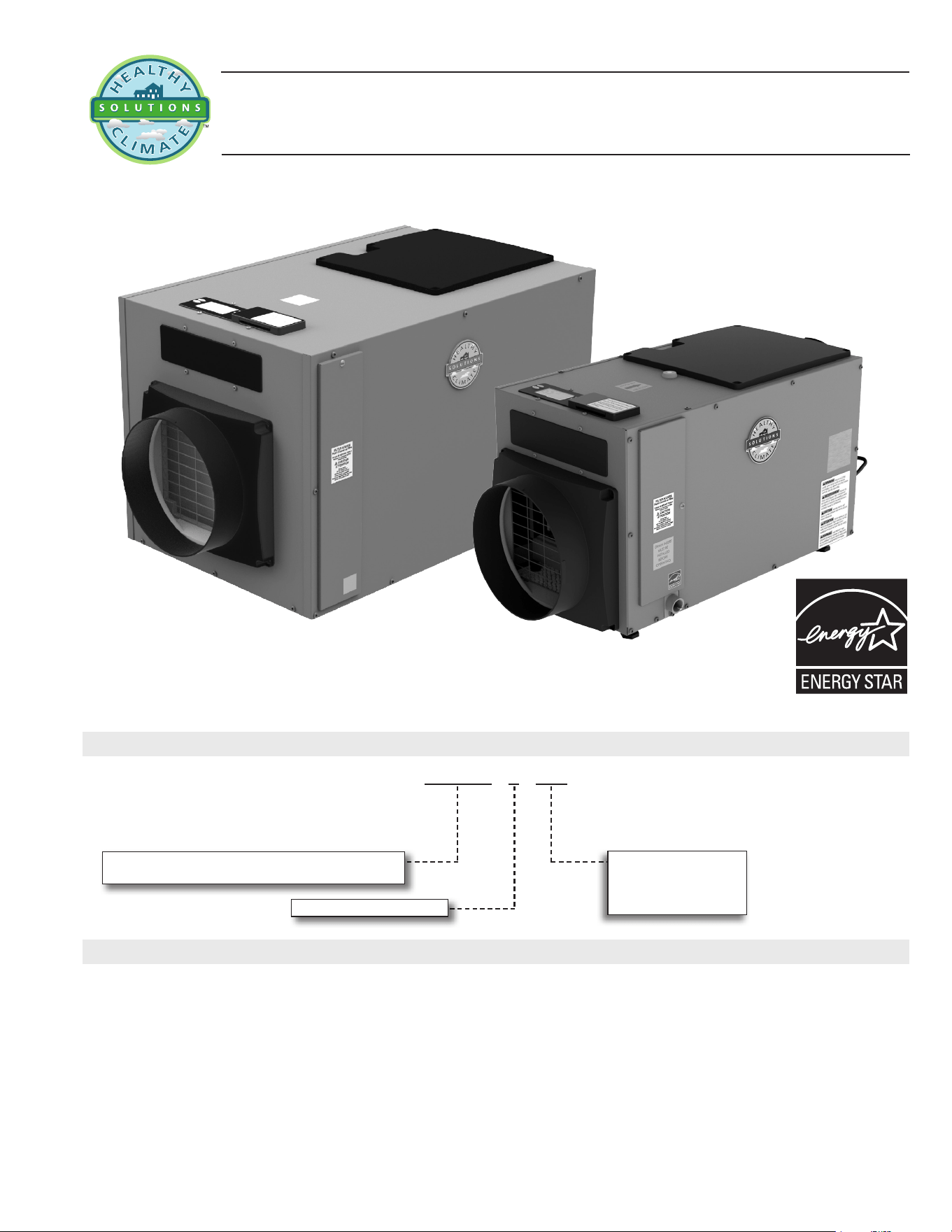
HCWHD4
Healthy Climate
®
Whole-Home Dehumidier
Bulletin No. 210956
July 2021
Nominal Capacity - 80 to 130 pints per day
HCWHD - 4 - 100
Unit Type
HCWHD = Healthy Climate
®
Whole Home Dehumidier
Nominal Capacity
080 = 80 pints per day
100 = 100 pints per day
130 = 130 pints per day
Major Design Sequence = 4
HCWHD HEALTHY CLIMATE
®
WHOLE-HOME DEHUMIDIFIER
MODEL NUMBER IDENTIFICATION
CONTENTS
Approvals and Warranty . . . . . . . . . . . . . . . . . . . . . . . . . . . . . . . . . . . . . . . . . . . . . . . . . . 2
Dimensions . . . . . . . . . . . . . . . . . . . . . . . . . . . . . . . . . . . . . . . . . . . . . . . . . . . . . . . . 13
Electrical Data . . . . . . . . . . . . . . . . . . . . . . . . . . . . . . . . . . . . . . . . . . . . . . . . . . . . . . . .6
Features . . . . . . . . . . . . . . . . . . . . . . . . . . . . . . . . . . . . . . . . . . . . . . . . . . . . . . . . . . . 2
Installation Clearances . . . . . . . . . . . . . . . . . . . . . . . . . . . . . . . . . . . . . . . . . . . . . . . . . .13
Optional Accessories . . . . . . . . . . . . . . . . . . . . . . . . . . . . . . . . . . . . . . . . . . . . . . . . . . . .7
Performance. . . . . . . . . . . . . . . . . . . . . . . . . . . . . . . . . . . . . . . . . . . . . . . . . . . . . . . . .8
Sizing Guidelines . . . . . . . . . . . . . . . . . . . . . . . . . . . . . . . . . . . . . . . . . . . . . . . . . . . . . 12
Specications . . . . . . . . . . . . . . . . . . . . . . . . . . . . . . . . . . . . . . . . . . . . . . . . . . . . . . . . 6
Typical Applications . . . . . . . . . . . . . . . . . . . . . . . . . . . . . . . . . . . . . . . . . . . . . . . . . . . 14
INDOOR AIR QUALITY
RESIDENTIAL
PRODUCT SPECIFICATIONS
HCWHD4-130
HCWHD4-080-100
HCWHD4 Whole-Home Dehumidier / Page 2
APPLICATIONS
• Healthy Climate Whole Home Dehumidier is designed
to control humidity throughout the home or in specic
locations such as an attic, crawlspace or basement
• Also used for zoned dehumidication and ventilation
control
• Humidity sensor automatically and continually
measures the relative humidity
• Based on sensor measurement, the unit will operate to
control the humidity based on the set point
• Zoning option dehumidies a “Primary” zone space
(example: living space) or a “Secondary” zone space
(example: basement) to control humidity levels in
different areas as needed
• Patented, built-in ventilation feature allows fresh air to be
brought into the home from the outside
• Dehumidier will condition the incoming air if needed
FILTER
• Washable, MERV 8 (Minimum Efciency Reporting
Value) lter furnished
BLOWER ASSEMBLY
• UL approved impeller type with backward curved
centrifugal fan equipped with maintenance free ball
bearings
EVAPORATOR COIL
• Aluminum coil for superior corrosion resistance
COMPRESSOR
• R-410A, rotary-type compressor
CABINET
• Constructed of 22 gauge, post-painted steel
• Interior is lined with 1/2 in., foil-faced, expanded
polystyrene to eliminate noise, condensation and air loss
• The supply outlet is equipped with a built-in backow
damper
• Duct start collars (10 inch diameter) are included
• Supply collar can be relocated from the end of the
cabinet to the top if space is restricted
• Adjustable feet (up to 2 in.) to level unit
NOTE - If the dehumidier is installed in an attic or
location requiring leak protection, the unit should
be placed in a secondary condensate drain pan
with a normally closed condensate overow
safety switch (oat switch)
DIGITAL ONBOARD CONTROL
• Factory installed on the top of the unit
• Depending on dehumidier location the control can
be moved to the duct inlet end of the unit for easier
accessibility
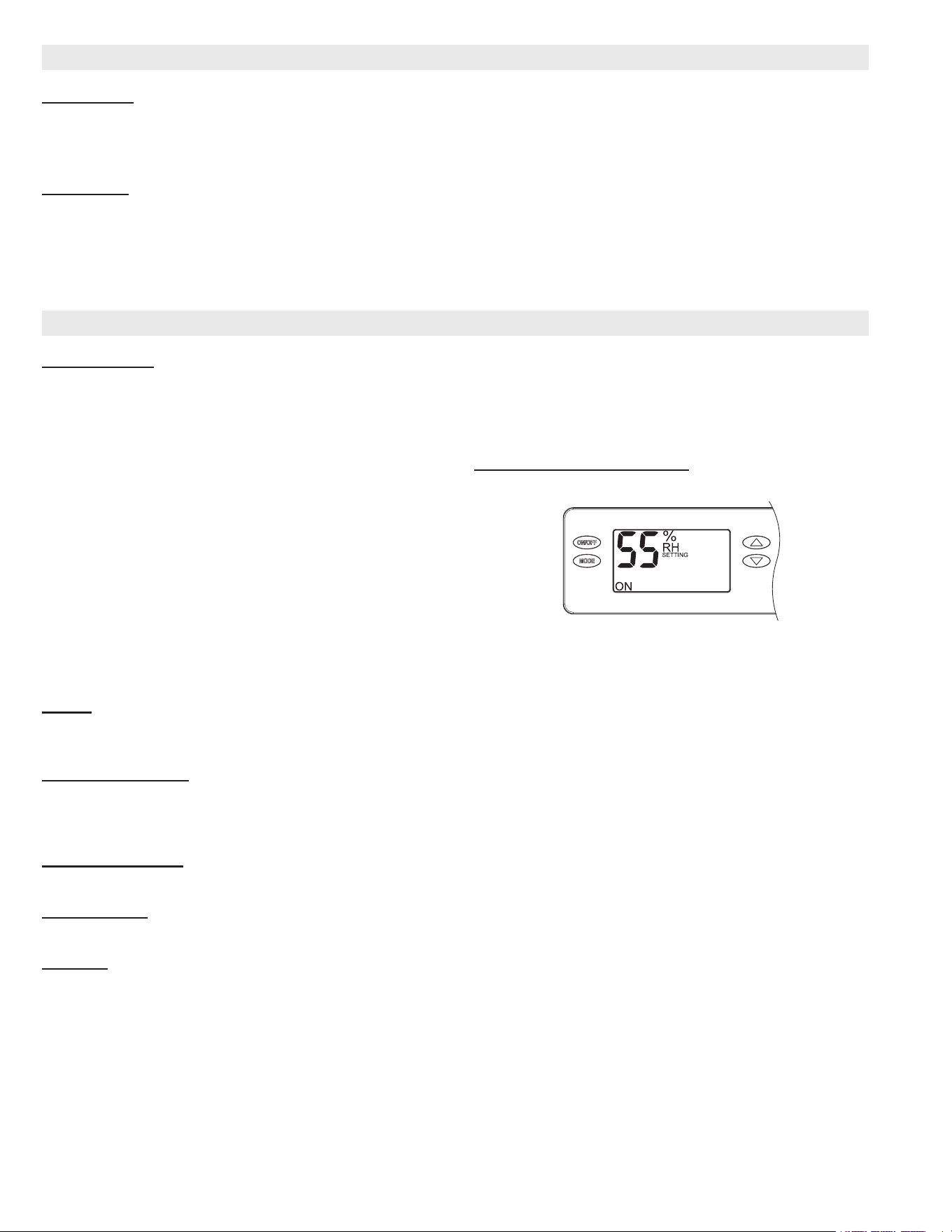
• Simple, backlit, menu-driven control allows complete
operation of dehumidication and ventilation features
• Control will display the humidity setting when unit is
not running, and display the measured humidity when
running
• UP and DOWN arrow buttons allow the humidity level to
be set from 40% to 80% relative humidity
• ON/OFF button turns the dehumidier on or off
• MODE button allows access to optional ventilation
(timed and auto) and zoning features and installer setup
menu (hold for 3 seconds)
• Filter Reminder displays CLEAN FILTER every six months
(press Up/Down Arrow buttons simultaneously for 3
seconds to clear)
External Control Operation
• The control can be set to operate using an external wired
control
• See Optional Accessories section for available controls
Dehumidication Operation Options
• Unit can be set to operate during HVAC air-conditioning
operation or only when HVAC air conditioning is off
FEATURES
APPROVALS AND WARRANTY
APPROVALS
• CSA Listed
• ENERGY STAR
®
certied units are designed to use less energy, help save money on utility bills, and help protect the
environment
WARRANTY
• All Covered Components
• Limited ve year warranty in residential applications
• Limited one year in non-residential applications
NOTE - Refer to Lennox Equipment Limited Warranty certicate included with unit for specic details.
HCWHD4 Whole-Home Dehumidier / Page 3
ZONING
Zone Mode
• Zone control can be enabled and disabled from the
Digital Onboard Control
• When zone control is enabled two zones are available
1. Primary Zone - Zone dampers are energized
2. Secondary Zone - Zone dampers are de-energized
VENTILATION
• The built-in ventilation feature is designed to be meet
ASHRAE 62.2 Standard for Ventilation
• Utilizes the dehumidier and furnace/air handler blower
to make-up any remaining ventilation required based on
chosen set point
• In hot, humid climates, supplemental dehumidication
of fresh air is recommended
• Automatically monitors and controls the humidity of the
incoming air
• The dehumidier can also operate an optional ventilation
damper to bring air in from outside
• To keep it from using outdoor air above 100°F or below
0°F, an optional Outdoor Temperature Sensor must be
eld installed
AIR CYCLING
• An integrated air cycling feature can activate the
furnace/air handler blower to cycle air through the house
to balance the indoor air conditions
• Monitors furnace/air handler blower run-time to
efciently ventilate the whole home
• Air cycling will cycle furnace/air handler blower to the
values set on the control
REQUIRED COMPONENTS
Drain Pan
• Required if unit is installed in an attic or a location
requiring leak protection
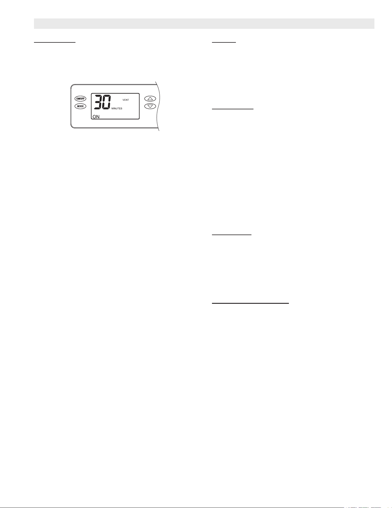
VENTILATION
• The dehumidier can activate a normally closed damper
to bring in outdoor air through a fresh air intake duct
• Settings are available at the Digital Onboard Control
Timed Ventilation Features (Vent Timed Mode)
Press the UP or DOWN arrows to adjust the ventilation
time per hour from 0 to 60 minutes.
Automatic Ventilation Features (Auto Mode)
• Three different settings based on outdoor temperature
are available:
1. Vent-Auto-B - Ventilation is disabled when outdoor
temperature is below 0°F and above 100°F
Between 0°F and 20°F ventilation is only allowed
during an HVAC heating demand
2. Vent-Auto-C - Ventilation is disabled when outdoor
temperature is below 0°F and above 100°F
3. Vent-Auto-D - Ventilation is disabled when outdoor
temperature is below 0°F and above 100°F
Between 0°F – 40°F ventilation is only allowed
during an HVAC heating demand
NOTE - Outdoor temperature sensor is required for
ventilation options above. Sensor must be ordered
extra.
FEATURES
HCWHD4 Whole-Home Dehumidier / Page 4
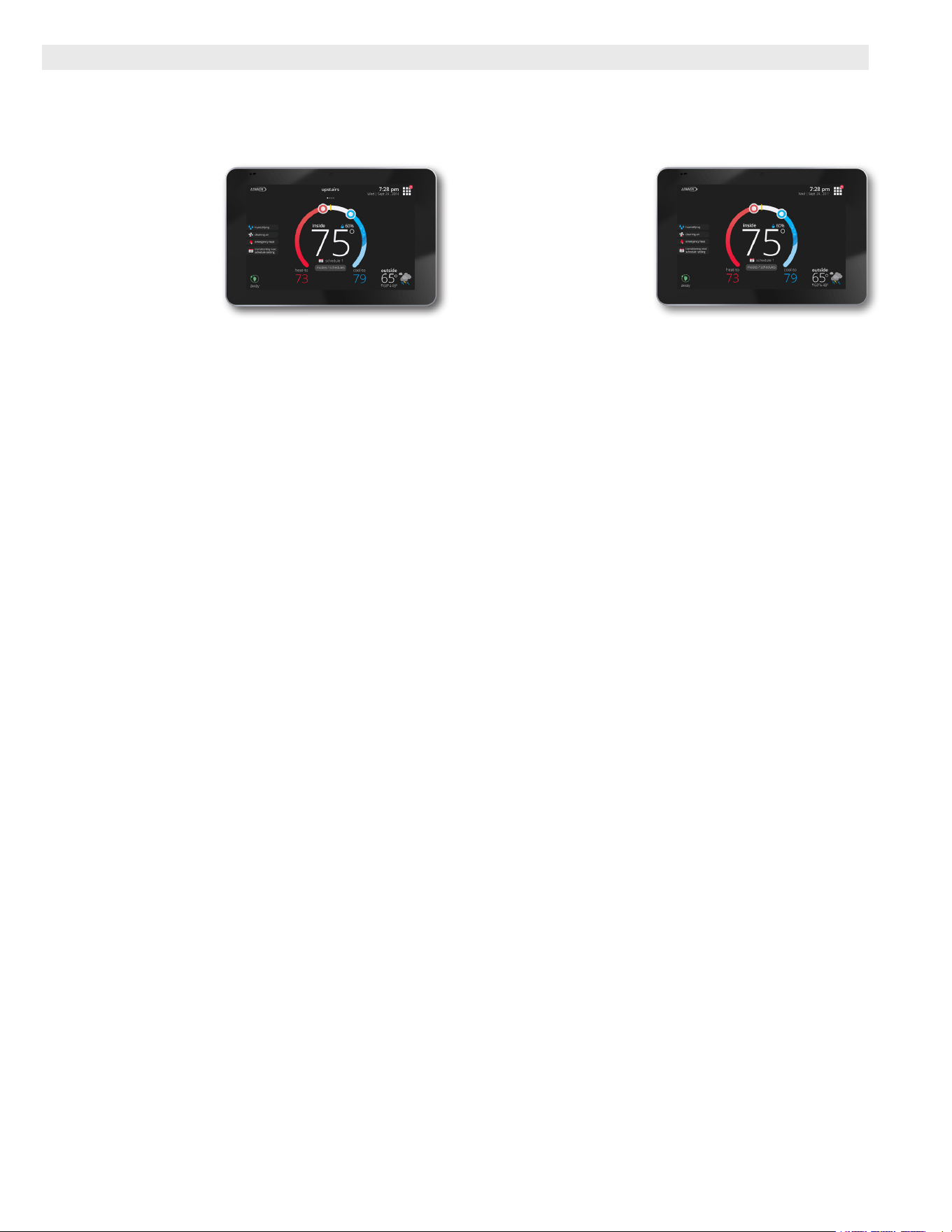
iComfort
®
S30 Ultra-Smart Wi-Fi Thermostat (part of the
iComfort
®
Residential Communicating Control System)
• Recognizes and connects to all iComfort
®
Communicating products to automatically congure
and control the heating/
cooling system (based
on user-specied
settings) for the highest
level of comfort,
performance and
efciency
• Recognizes model
and serial number
information for iComfort
®
Communicating products to
simplify system setup
• Wi-Fi remote temperature monitoring and adjustment
through a home wireless network for desktop PCs,
laptops and apps for smartphones or tablets
• Service alerts and reminders sent via text message or
e-mail
• Smart home automation compatible with Apple
HomeKit™, Amazon Alexa
®
, Google Assistant and IFTTT
• Service Dashboard features online real-time monitoring
of installed iComfort
®
Communicating systems
• Simple easy-to-use touchscreen allows complete
system conguration
• Scheduled maintenance alerts, system warnings and
troubleshooting are also displayed on thermostat screen
• Easy to read 7 inch high denition color display
(measured diagonally)
• Conventional outdoor units (not iComfort
®
Communicating) can easily be added and controlled by
the iComfort
®
S30 Thermostat
• Installer setup screens allow quick and simple system
conguration without a manual, Installer can also run
tests on complete system or individual components for
easy maintenance and troubleshooting
• Serial communications bus (RSBus), with less wiring
than a conventional heating/cooling system, allows
system communication
• Uses 4-wire, 18-gauge standard thermostat wiring
• High Denition Color Display with Subbase, Smart Hub
Controller, wallplate (for retrot installations) furnished
for easy installation
• See the iComfort
®
S30 Thermostat Product
Specications bulletin for more information
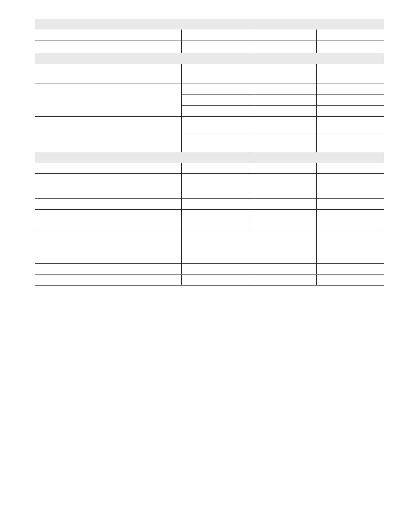
iComfort
®
E30 Smart Wi-Fi Thermostat
• Wi-Fi enabled, electronic 7-day, universal, multi-stage,
programmable, touchscreen thermostat
• 3 Heat/2 Cool
• Auto-changeover
• Controls
dehumidication during
cooling mode and
humidication during
heating mode
• Offers enhanced
capabilities including
humidication / dehumidication / dewpoint
measurement and control, Humiditrol
®
control, and
equipment maintenance reminders
• Easy to read 7 in. color touchscreen (measured diagonally)
• LCD display with backlight shows the current and set
temperature, time, inside relative humidity, system
status (operating mode and schedules) and outside
temperature (optional outdoor sensor required)
• Smooth Setback Recovery starts system early to
achieve setpoint at start of program period
• Compressor short-cycle protection (5 minutes)
• Up to four separate schedules are available plus
Schedule IQ™
• One-Touch Away Mode - A quick and easy way to set the
cooling and heating setpoints while away
• Smart Away™ - Uses geo-fencing technology
to determine when the homeowner is within a
predetermined distance from the home to operate the
system when leaving, away and arriving
• Wi-Fi remote monitoring and adjustment through a
home wireless network for desktop PCs, laptops and
apps for smartphones or tablets
• Smart home automation compatible with Apple
HomeKit™, Amazon Alexa
®
, Google Assistant and IFTTT
• High Denition Color Display with Subbase, Smart Hub
Controller, wallplate (for retrot installations) furnished
for easy installation
• See the iComfort
®
E30 Smart Wi-Fi Thermostat Product
Specications bulletin for more information
OPTIONAL CONTROLS
HCWHD4 Whole-Home Dehumidier / Page 5
OPTIONAL CONTROLS (continued)
Remote Outdoor Temperature Sensor
• Used with iComfort
®
Communicating thermostats
• When installed outdoors, sensor
allows thermostat to display
outdoor temperature
NOTE - Sensor is required
for Enhanced
Dehumidication Control
(EDA) applications.
NOTE - The outdoor sensor is furnished as standard with
iComfort
®
Communicating outdoor units, optional
for conventional units.
NOTE - HCWHD4 Whole-Home Dehumidiers are not
iComfort
®
Communicating. The iComfort
®
humidity sensor can control the dehumidication
features in the dehumidier; however, it can not
control zoning or ventilation.
NOTE - An iComfort
®
Communicating indoor unit (furnace
or air handler) is required for proper operation with
a conventional outdoor unit.
ComfortSense
®
7500 Touchscreen Thermostat
• Electronic 7-day, universal, multi-stage, programmable,
touchscreen thermostat
• 4 Heat/2 Cool
• Auto-changeover
• Dual-fuel control with
optional outdoor sensor
• Controls dehumidication
during cooling mode and
humidication during
heating mode
• Offers enhanced capabilities including humidication /
dehumidication / dewpoint measurement and control,
Humiditrol
®
control, and equipment maintenance
reminders
• Easy-to-use, menu driven thermostat with a back-lit, LCD
touchscreen
• See the ComfortSense
®
7500 Product Specications
bulletin in the Controls section for more information
OPTIONAL ACCESSORIES
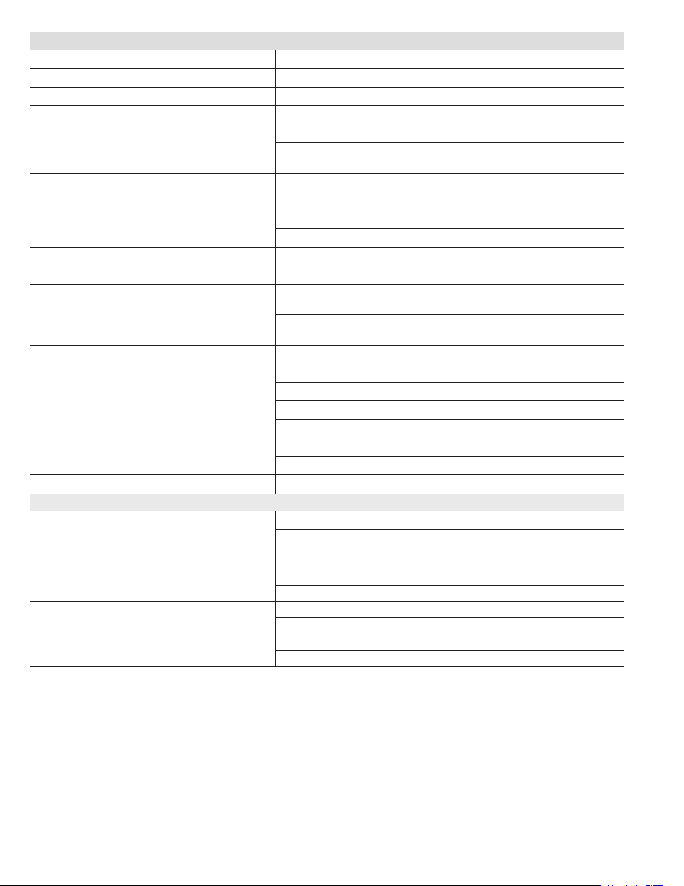
Whole-Home Dehumidistat
• Whole-Home
Dehumidistat is used when
access to the onboard control is
unavailable (unit installation in
an attic, crawlspace, etc.).
• LCD screen displays
current relative humidity (%) and
operation mode (On/Off).
• Up/Down arrow buttons allow setting dryness levels
(1 to 7; 1 is least dry, 7 is most dry) in remote mode & %
RH setting in external mode.
• Two modes of operation are available:
• 1 - External - Measures humidity levels with an internal
sensor on the control.
• 2 - Remote - Measures humidity levels with the sensor
on the dehumidier.
Basement Kit
• Includes components typically needed for two-zone
dehumidication.
• Includes two 10-in. normally open dampers, two 10-in.
normally closed dampers and one 24V, 40VA transformer.
Ventilation and Zone Dampers
• Constructed of rolled galvanized steel with stiffening
ribs to maintain rigidity. A single steel offset blade is
attached to a one piece aluminum shaft connected with
nylon bearings for smooth operation. Spring return with
a normally closed or normally open congurations are
available. Requires 24V transformer ordered separately.
Transformer
• 120V primary, 24V secondary, 40VA transformer for
powering dampers.
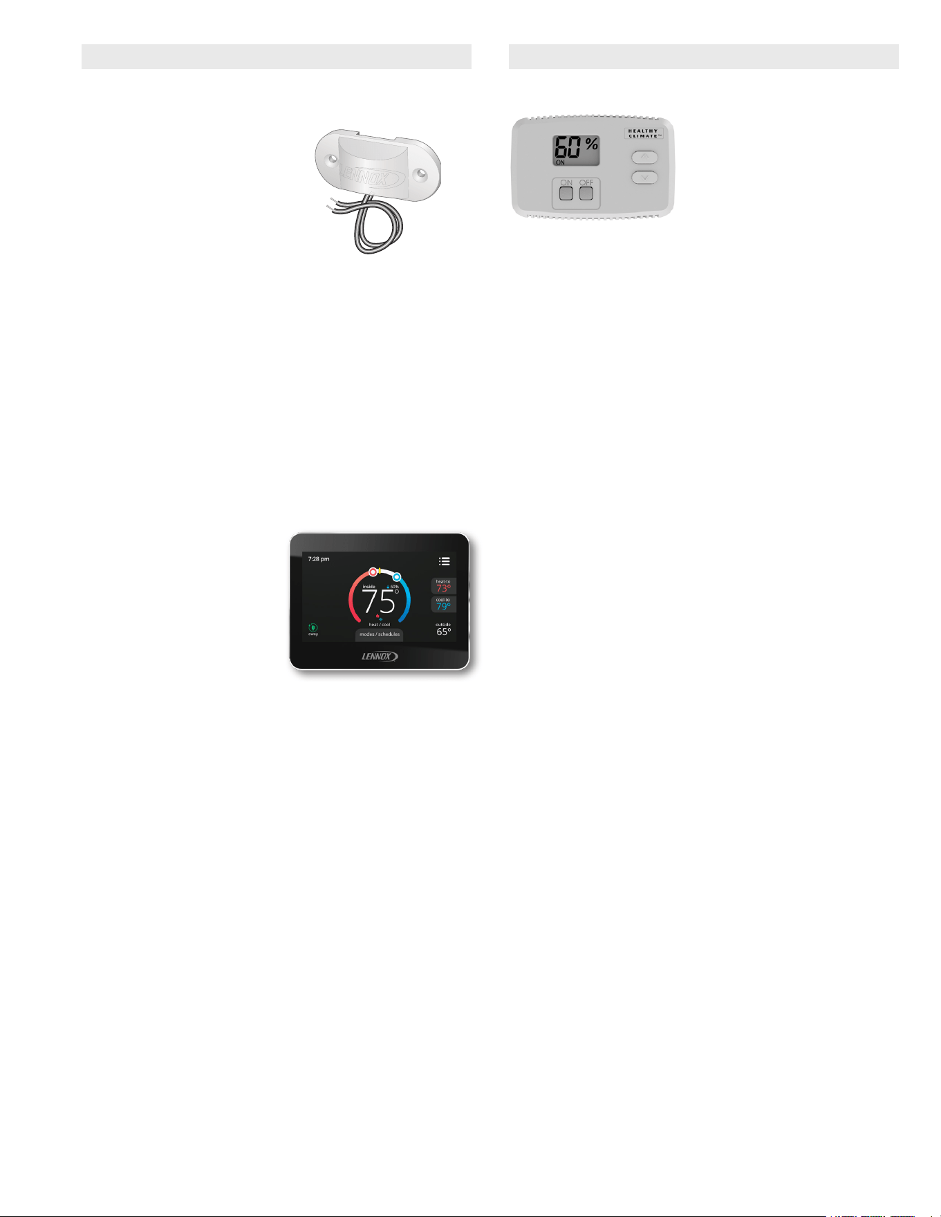
Outdoor Air Temperature Sensor
• Prevents the HCWHD from using outside air for ventilation
if the outdoor temperature is above 100°F or below 0°F.
Connects directly to dehumidier.
HCWHD4 Whole-Home Dehumidier / Page 6
SPECIFICATIONS
Model No. HCWHD4-080 HCWHD4-100 HCWHD4-130
Energy Star Qualied Yes Yes Yes
Capacity
1
80 pints per day
2
100 pints per day
3
130 pints per day
Energy Factor
1
2.81 L/kW-h
2
2.61 L/kW-h
3
2.9L/kW-h
Capacity in Non-Rating Conditions 70°F / 60% RH = 62 ppd 70°F / 60% RH = 76 ppd 70°F / 60% RH = 99 ppd
60°F / 60% RH = 44 ppd
@ 185 cfm
60°F / 60% RH = 53 ppd
@ 280 cfm
60°F / 60% RH = 72 ppd
@310 cfm
Discharge Air Temperature Rise (°F) 10 - 30 10 - 30 10 - 30
Refrigerant R-410A R-410A R-410A
Sound Level (dBA) Ducted 45 55 50
Unducted 49 59 54
Connections - in. Drain diameter (PVC)
4
3/4
4
3/4
4
3/4
Duct diameter 10 10 10
Operating Conditions
(temperature, RH)
Inlet Air 50°F - 104°F,
40°F dewpoint minimum
50 - 104°F,
40° dewpoint minimum
50 - 104°F,
40°F dewpoint minimum
Installation (ambient) 40°F - 140°F, 0 - 99%
(non-condensing)
40 - 140°F, 0 - 99% RH
(non-condensing)
40 - 140°F, 0-99% RH
(non-condensing)
Blower Data Air Flow
(external static pressure - dry coil)
185 cfm @ 0.0 in. w.c. 280 cfm @ 0.0 in. w.c. 310 cfm @ 0.0 in. w.c.
135 cfm @ 0.2 in. w.c. 245 cfm @ 0.2 in. w.c. 270 cfm @ 0.2 in. w.c.
85 cfm @
5
0.4 in. w.c. 210 cfm @ 0.4 in. w.c. 225 cfm @ 0.4 in. w.c.
- - - 175 cfm @
5
0.6 in. w.c. 175 cfm @ 0.6 in. w.c.
- - - - - - 160 cfm @
5
0.7 in. w.c.
Filter Type Washable, MERV 8 Washable, MERV 8 Washable, MERV 8
Size - in. 12 x 14 x 1 12 x 14 x 1 14 x 19 x 1
Shipping Weight - lbs. 81 82 113
ELECTRICAL DATA
Line voltage data - 60 hz - 1ph 110/120V 110/120V 110/120V
⁵ Maximum overcurrent protection (amps) 15 15 15
⁵ Minimum Circuit Ampacity 8.42 11.23 11.51
Rated amperage (amps)
1
5.1
2
6.9
3
8.3
Maximum normal operation amps 6.03 9.9 10.4
Compressor Compressor rated load (amps) 6.45 8 9.4
Compressor locked rotor (amps) 34 37 54
Blower rated power (watts) 60 135 124
Power connection 8 ft., 3-prong power cord
1
Rated capacity, Energy Factor test and current draw measured in accordance with AHAM DH-1 2008 at 80°F/60% RH inlet air at 185 cfm.
2
Rated capacity, Energy Factor test and current draw measured in accordance with AHAM DH-1 2008 at 80°F/60% RH inlet air at 280 cfm.
3
Rated capacity, Energy Factor test and current draw measured in accordance with AHAM DH-1 2008 at 80°F/60% RH inlet air at 310 cfm.
4
Adaptor for threaded connection or plastic hose is furnished.
5
Refer to National or Canadian Electrical Code manual to determine wire, fuse and disconnect size requirements.
HCWHD4 Whole-Home Dehumidier / Page 7
REQUIRED COMPONENTS
Model No. HCWHD4-080 HCWHD4-100 HCWHD4-130
Drain Pan - 36 x 36 in. (required for attic installations)
25P64 25P64 25P64
OPTIONAL ACCESSORIES
Basement Kit - includes 2-10 in. NO dampers, 2-10 in.
NC dampers, one 24V, 40VA transformer.
Y6451 Y6451 Y6451
Dampers Ventilation - 6 in. Normally Closed (NC) X4152 X4152 X4152
Ventilation - 10 in Normally Closed (NC) Y6483 Y6483 Y6483
Zone - 10 in. Normally Open (NO) X4211 X4211 X4211
Damper
Transformers
Damper Transformer 24V, 40VA
(hardwired, operates 1 damper only)
22N03 22N03 22N03
Damper Transformer 24V, 40VA
(plug in, operates up to 4 dampers)
Y7128 Y7128 Y7128
OPTIONAL CONTROLS
iComfort
®
S30 Ultra-Smart Wi-Fi Thermostat 19V30 19V30 19V30
Equipment Interface Module (EIM) - Required with
iComfort
®
S30 Ultra-Smart Wi-Fi Thermostat
(Dual-Fuel capable non-communicating heat pumps)
10T50 10T50 10T50
iComfort
®
E30 Smart Wi-Fi Thermostat 20A65 20A65 20A65
¹ Discharge Air Temperature Sensor 88K38 88K38 88K38
ComfortSense
®
7500 Thermostat 13H14 13H14 13H14
² Remote Outdoor Air Temperature Sensor X2658 X2658 X2658
¹ Discharge Air Temperature Sensor 88K38 88K38 88K38
ComfortSense
®
7500 Thermostat 13H14 13H14 13H14
Whole-Home Dehumidistat Y6456 Y6456 Y6456
3
Outdoor Air Temperature Sensor 58N66 58N66 58N66
1
Optional for service diagnostics for communicating outdoor and indoor units (E30/S30 thermostats).
2
Remote Outdoor Air Temperature Sensor allows the thermostat to display outdoor temperature.
3
Required for Automatic Ventilation Modes. Connects directly to dehumidier.
HCWHD4 Whole-Home Dehumidier / Page 8
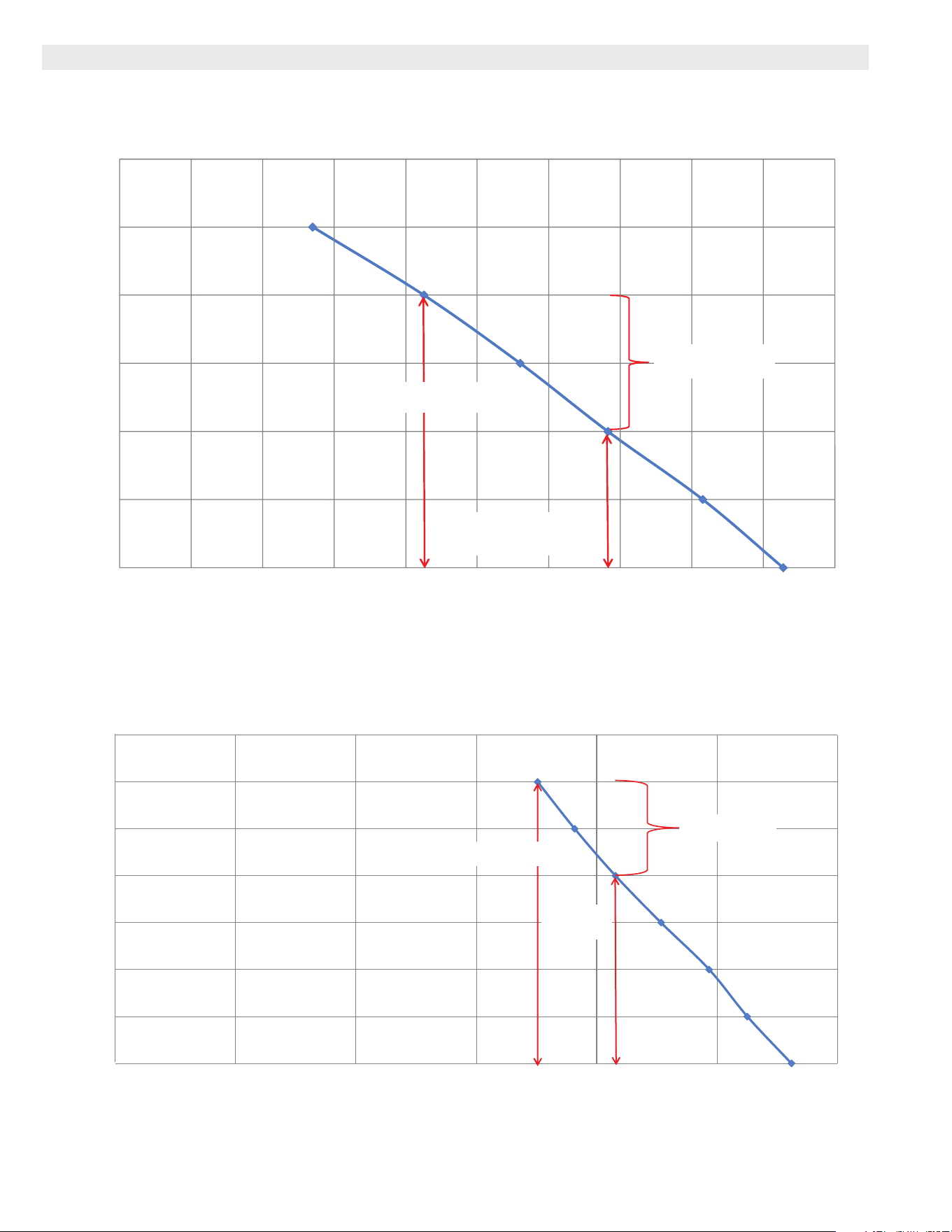
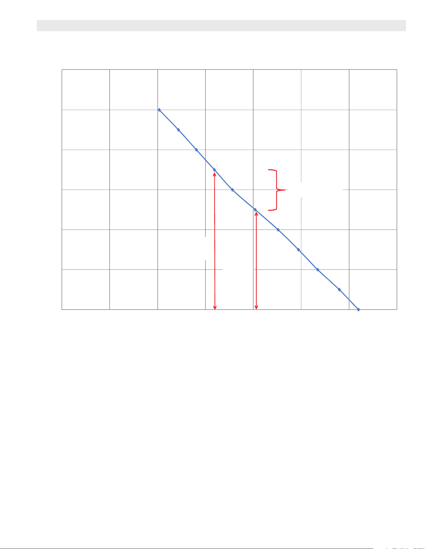
PERFORMANCE
0
0.1
0.2
0.3
0.4
0.5
0.6
Minimum Recommended
Airflow = 85 CFM
HCWHD4-080 Dehumidifier Pressure/Airflow Curve
Coil Dry, Air Filter Clean
External Static Pressure (in. w.c.)
Airflow (CFM)
Filter Pressure Increase
= 0.2" w.c.
Design System for
0.2 in. w.c. Max. External
Pressure Drop
020 160100 140120806040 180
200
0
0.1
0.2
0.3
0.4
0.5
0.6
0.7
003052002051001050
HCWHD4-100 Dehumidifier Pressure/Airflow Curve
Coil Dry, Air Filter Clean
External Static Pressure (in. w.c.)
Airflow (CFM)
Filter Pressure Increase
= 0.2" w.c.
Design System
for 0.4 in. w.c.
Max. External
Pressure Drop
Minimum Recommended
Airflow = 175 CFM
HCWHD4 Whole-Home Dehumidier / Page 9
PERFORMANCE
HCWHD4-130 Dehumidifier Pressure/Airflow Curve
Coil Dry, Air Filter Clean
050 100 150 200 250 300
350
Airflow (CFM)
0
0.2
0.4
0.6
0.8
1
1.2
External Static Pressure (in. w.c.)
Filter Pressure Increase
= 0.2" w.c.
Minimum
Recommended Airflow
= 160 CFM
Design
System for
0.4" w.c.
Max. External
Pressure
Drop
HCWHD4 Whole-Home Dehumidier / Page 10
HCWHD4-080 - CAPACITY - PINTS PER DAY
Relative
Humidity
Temperature °F
60 70 80
60 44 62 80
HCWHD4-080 - ENERGY USE - PINTS PER KW/HR
Relative
Humidity
Temperature °F
60 70 80
60 4.4 5.3 6.0
HCWHD4-080 - LEAVING AIR TEMPERATURE
Relative
Humidity
Temperature °F
60 70 80
60 75 90 106
HCWHD4-080 - LEAVING AIR % RELATIVE HUMIDITY
Relative
Humidity
Temperature °F
60 70 80
60 24 20 18
HCWHD4-080 - CAPACITY AND ENERGY USAGE VS. STATIC PRESSURE
Static Pressure - in. w.g. 0.0 0.3 0.4
Capacity - Pints Per Day 80 71 62
Energy Usage - Pints per kW/Hr 5.94 4.57 3.83
NOTE - Tested at 80°F/60% relative humidity.
HCWHD4-100 - CAPACITY - PINTS PER DAY
Relative
Humidity
Temperature °F
60 70 80
60 53 76 100
HCWHD4-100 - ENERGY USE - PINTS PER KW/HR
Relative
Humidity
Temperature °F
60 70 80
60 3.8 4.8 5.6
HCWHD4-100 - LEAVING AIR TEMPERATURE
Relative
Humidity
Temperature °F
60 70 80
60 72 86 101
HCWHD4-100 - LEAVING AIR % RELATIVE HUMIDITY
Relative
Humidity
Temperature °F
60 70 80
60 29 25 23
HCWHD4-100 CAPACITY AND ENERGY USAGE VS. STATIC PRESSURE
Static Pressure - in. w.g. 0 0.3 0.5 0.7
Capacity - Pints Per Day 100 94 91 85
Energy Usage - Pints per kW/Hr 5.52 4.95 4.59 4.11
NOTE - Tested at 80°F/60% relative humidity.
PERFORMANCE
HCWHD4 Whole-Home Dehumidier / Page 11
HCWHD4-130 - CAPACITY - PINTS PER DAY
Relative
Humidity
Temperature °F
60 70 80
60 72 99 130
HCWHD4-130 - ENERGY USE - PINTS PER KW/HR
Relative
Humidity
Temperature °F
60 70 80
60 4.3 5.3 6.13
HCWHD4-130 - LEAVING AIR TEMPERATURE
Relative
Humidity
Temperature °F
60 70 80
60 80 94 107
HCWHD4-130 - LEAVING AIR % RELATIVE HUMIDITY
Relative
Humidity
Temperature °F
60 70 80
60 18 17 18
HCWHD4-130 CAPACITY AND ENERGY USAGE VS. STATIC PRESSURE
Static Pressure - in. w.g. 0 0.3 0.5 0.7
Capacity - Pints Per Day 130 121 103 83
Energy Usage - Pints per kW/Hr 6.13 5.30 4.12 3.05
NOTE - Tested at 80°F/60% relative humidity.
PERFORMANCE
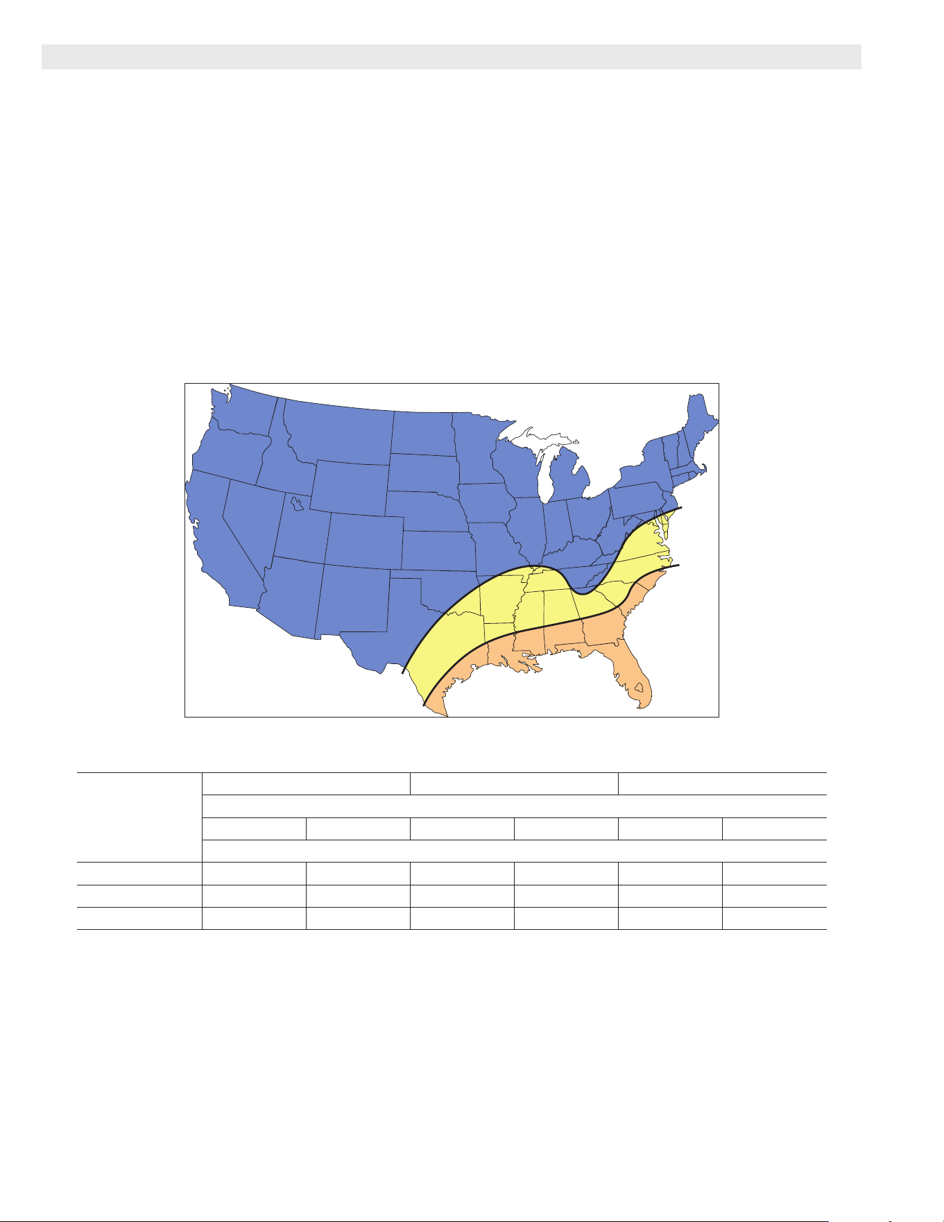
HCWHD4 Whole-Home Dehumidier / Page 12
HCWHD4-080 HCWHD4-100 HCWHD4-130
Air Change Per Hour (ACH)
1.00 0.50 1.00 0.50 1.00 0.50
Maximum Recommended Home Size (sq. ft.)
Region A 2800 3800 3800 5200 5200 7200
Region B 2200 3400 3000 4700 3900 6500
Region C 1400 2000 1900 2800 2300 3600
NOTES:
- Based on a single-story, slab construction home with four occupants.
- Dehumidistats set to less dry; thermostat set to auto-fan.
- Air conditioner with thermostat cooling set to at least 79°F.
- TMY 2 (Typical Meteorological Year) weather data; 1.00 lb./hr. internal moisture gain due to occupants.
A
B
C
1. Find the home location (and corresponding region) in the map below
2. Estimate the air change rate of the home:
a. 1.00 air change per hour is an older home, that is not particularly tight.
b. 0.50 air change per hour is a reasonably tight home.
3. Determine how many dehumidifiers are required by comparing the actual home size and
corresponding air change rate, to the “Maximum Recommended Home Size” in the table.
4. This is a general guideline. Consider any special circumstances that may require more water
removal capacity and, if necessary, adjust your dehumidifier choice(s) accordingly.
SIZING GUIDELINES
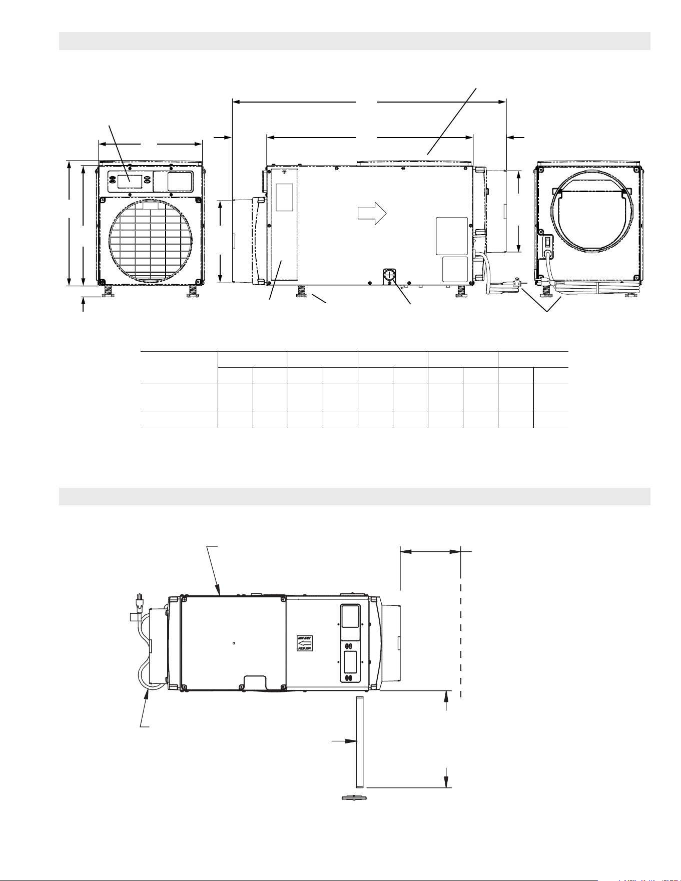
HCWHD4 Whole-Home Dehumidier / Page 13
Adjustable Legs (4)
Power Cord
Filter Access
(Front and Back)
INLET AIR END BACK VIEW OUTLET AIR END
Onboard User Interface Control
(shown on Inlet End of Unit)
Adjustable 3/8 to 2 (9.5 to 51)
4 (102) 4 (102)
10
(254)
Dia.
10
(254)
Dia.
Drain (3/4 in. dia.)
Air Flow
Backdraft
Damper
Optional Top Outlet Air Location
(End Outlet must be Field Relocated)
A
B
C
D
E
Model No.
A B C D E
in. mm in. mm in. mm in. mm in. mm
HCWHD4-080
HCWHD4-100
34 762 26 660 15-5/8 397 15 381 14 356
HCWHD4-130 38 965 30 762 18-3/4 476 17-1/8 435 19-1/2 495
TOP VIEW
Filter
Power Cord
Electrical Service
Access This Side
6 in. (152 mm)
Minimum Clearance
For Proper Airflow
13 in. (330 mm) 080-100 models
20 in. (508 mm) 130 model
Minimum Clearance
For Filter Access (Either Side)
DIMENSIONS
INSTALLATION CLEARANCES
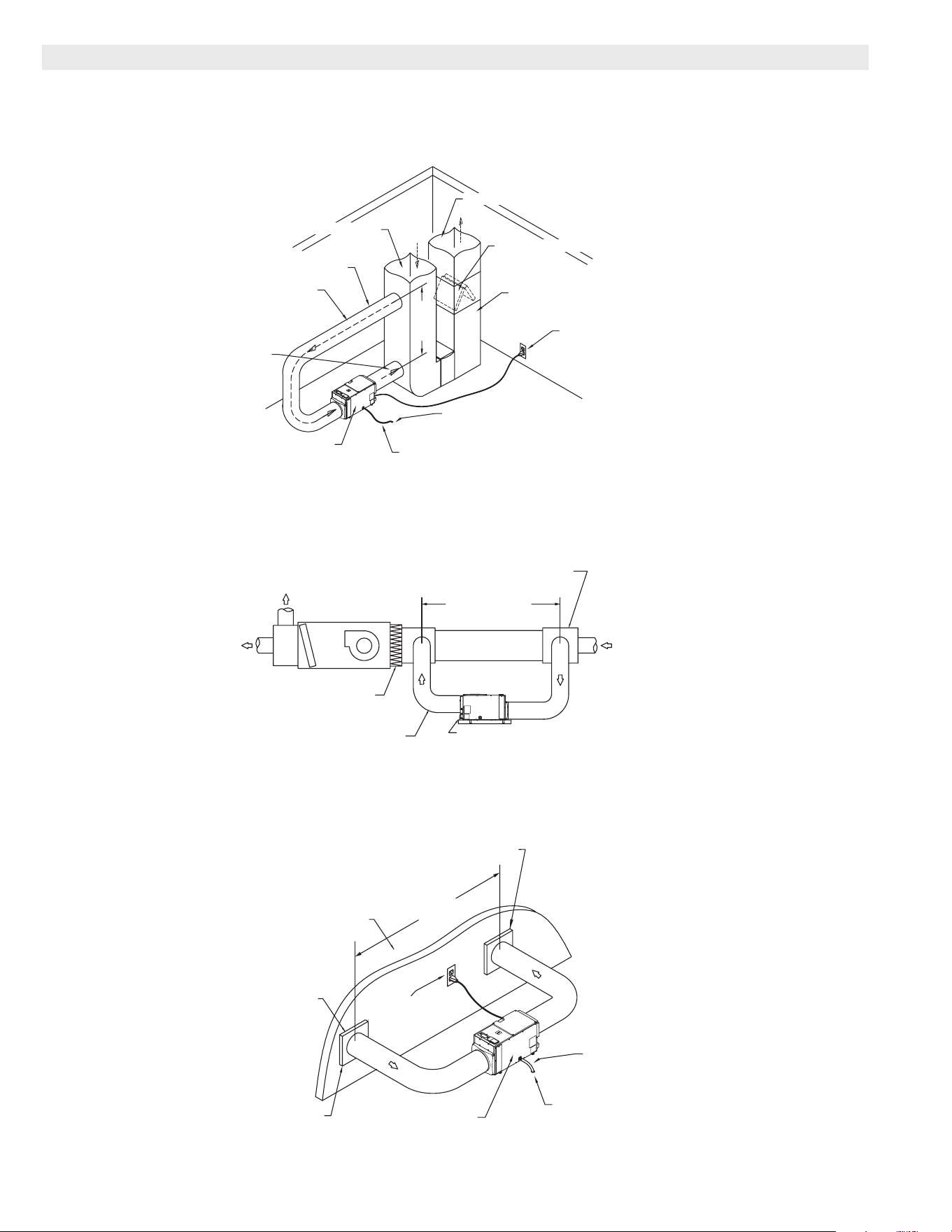
HCWHD4 Whole-Home Dehumidier / Page 14
HVAC/FURNACE
AIR IS PULLED
FROM AND
SUPPLIED TO THE
RETURN DUCT
10 in. (254 mm)
DIAMETER DUCT
DEHUMIDIFIER
6 ft.
(1.8 m)
MIN.
115 VAC
CIRCUIT
FLOOR DRAIN
SUPPLY DUCT
RETURN DUCT
EVAPORATIVE COIL
BASEMENT DUCTING AND WIRING
Whole-Home Preferred Basement Installation
CONDENSATE HOSE
(TO COMMON DRAIN OR OUTSIDE)
DEHUMIDIFIED
AIR IS SUPPLIED
UPSTREAM OF
EVAPORATIVE COIL
PLENUM BOX OR Y-FITTING
6 FT. (1.8 M) MIN.
HVAC UNIT
FILTER
10 in. (254 mm) DIAMETER
INSULATED DUCT
BOTH SIDES
CONDENSATE PAN
ATTIC DUCTING
Whole-Home Preferred Attic Installation
DEHUMIDIFIER
DEHUMIDIFIED AIR IS SUPPLIED
TO DUCTED SPACE
AIR IS PULLED
FROM DUCTED
SPACE
10 ft. (3 m) MIN.
(2) GRILLES WITH
10 in. (254 mm)
DUCT COLLARS
(INLET AND OUTLET)
DEHUMIDIFIED SPACE
115 VAC
CIRCUIT
CONDENSATE HOSE
(TO COMMON DRAIN OR OUTSIDE)
FLOOR DRAIN
STANDALONE DUCTING AND WIRING
TYPICAL APPLICATIONS
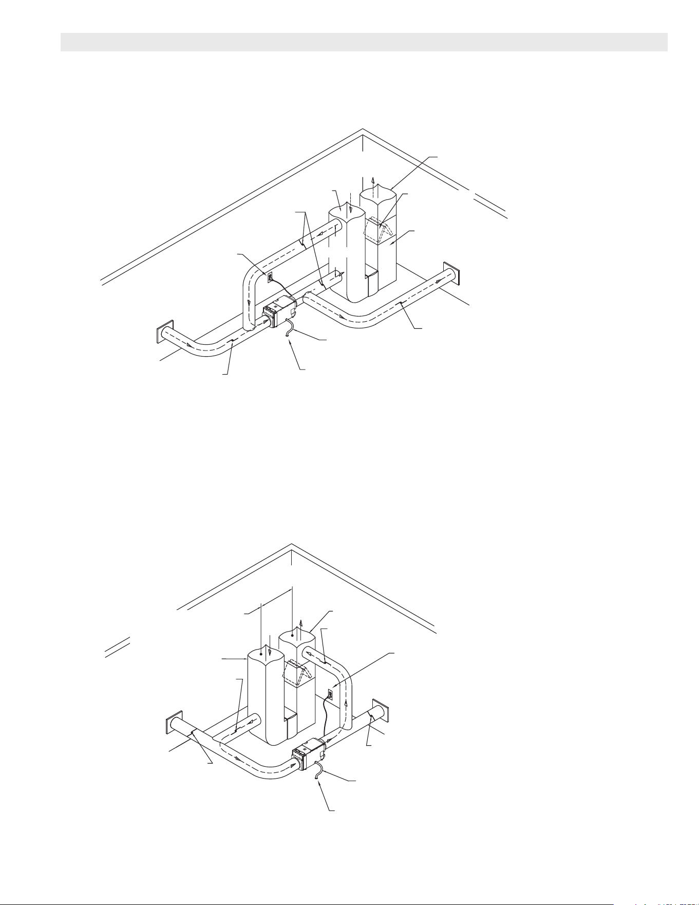
HCWHD4 Whole-Home Dehumidier / Page 15
SUPPLY AIR
TO PRIMARY ZONE
SUPPLY DUCT
RETURN
DUCT
NORMALLY OPEN DAMPER
NORMALLY OPEN DAMPER
SUPPLY TO
SECONDARY ZONE
RETURN FROM
SECONDARY ZONE
NORMALLY
CLOSED
DAMPERS
6 ft.
(1.8 m)
MIN.
SECONDARY ZONING AND WIRING
Whole-Home Primary Zone Installation
115 VAC
CIRCUIT
FLOOR DRAIN
CONDENSATE HOSE
(TO COMMON DRAIN OR OUTSIDE)
EVAPORATIVE COIL
HVAC/FURNACE
IMPORTANT
- Normally Closed dampers must be installed in the ducts serving the Primary Zone
and Normally Open dampers installed in the ducts serving the Secondary Zone.
TO/FROM
SECONDARY ZONE
SUPPLY DUCT
RETURN DUCT
NORMALLY CLOSED DAMPER
NORMALLY CLOSED DAMPER
SUPPLY TO
PRIMARY ZONE
RETURN FROM
PRIMARY ZONE
NORMALLY
OPEN
DAMPER
NORMALLY
OPEN
DAMPER
*HCWHD4-080 - 0.4 in. w.c. MAX
HCWHD4-100 - 0.6 in. w.c. MAX
HCWHD4-130 - 0.7 in. w.c. MAX
* NOTE - When the Whole-Home
is the Secondary Zone, the
ducting must be returned to
supply. Make sure the external
static pressure does not
exceed the maximums shown
and disable dehumidification
during air conditioning operation.
PRIMARY ZONING AND WIRING
Whole-Home Secondary Zone Installation
FLOOR DRAIN
CONDENSATE HOSE
(TO COMMON DRAIN OR OUTSIDE)
115 VAC
CIRCUIT
IMPORTANT - Normally Closed dampers must be installed in the ducts serving the Primary Zone
and Normally Open dampers installed in the ducts serving the Secondary Zone.
TYPICAL APPLICATIONS - PRIMARY AND SECONDARY ZONING

REVISIONS
US
C
NOTE - Due to Lennox’ ongoing commitment to quality, Specications, Ratings and Dimensions subject to change without notice and without incurring liability.
Improper installation, adjustment, alteration, service or maintenance can cause property damage or personal injury.
Installation and service must be performed by a qualied installer and servicing agency. ©2021 Lennox Industries, Inc.
Visit us at www.Lennox.com
For the latest technical information, www.LennoxPros.com
Contact us at 1-800-4-LENNOX