

Legal Informaon
About this Document
●
This Document includes instrucons for using and managing the Product. Pictures, charts,
images and all other
informaon hereinaer are for descripon and explanaon only.
●
The
informaon contained in the Document is subject to change, without noce, due to
rmware updates or other reasons. Please nd the latest version of the Document at the
Hikvision website ( hps://www.hikvision.com ). Unless otherwise agreed, Hangzhou Hikvision
Digital Technology Co., Ltd. or its aliates (hereinaer referred to as "Hikvision") makes no
warranes, express or implied.
●
Please use the Document with the guidance and assistance of professionals trained in
supporng the Product.
About this Product
This product can only enjoy the aer-sales service support in the country or region where the
purchase is made.
Acknowledgment of Intellectual Property Rights
●
Hikvision owns the copyrights and/or patents related to the technology embodied in the
Products described in this Document, which may include licenses obtained from third pares.
●
Any part of the Document, including text, pictures, graphics, etc., belongs to Hikvision. No part
of this Document may be excerpted, copied, translated, or modied in whole or in part by any
means without
wrien permission.
●
and other Hikvision's trademarks and logos are the properes of Hikvision in
various
jurisdicons.
●
Other trademarks and logos menoned are the properes of their respecve owners.
LEGAL DISCLAIMER
●
TO THE MAXIMUM EXTENT PERMITTED BY APPLICABLE LAW, THIS DOCUMENT AND THE
PRODUCT DESCRIBED, WITH ITS HARDWARE, SOFTWARE AND FIRMWARE, ARE PROVIDED "AS
IS" AND "WITH ALL FAULTS AND ERRORS". HIKVISION MAKES NO WARRANTIES, EXPRESS OR
IMPLIED, INCLUDING WITHOUT LIMITATION, MERCHANTABILITY, SATISFACTORY QUALITY, OR
FITNESS FOR A PARTICULAR PURPOSE. THE USE OF THE PRODUCT BY YOU IS AT YOUR OWN RISK.
IN NO EVENT WILL HIKVISION BE LIABLE TO YOU FOR ANY SPECIAL, CONSEQUENTIAL,
INCIDENTAL, OR INDIRECT DAMAGES, INCLUDING, AMONG OTHERS, DAMAGES FOR LOSS OF
BUSINESS PROFITS, BUSINESS INTERRUPTION, OR LOSS OF DATA, CORRUPTION OF SYSTEMS, OR
LOSS OF DOCUMENTATION, WHETHER BASED ON BREACH OF CONTRACT, TORT (INCLUDING
NEGLIGENCE), PRODUCT LIABILITY, OR OTHERWISE, IN CONNECTION WITH THE USE OF THE
Nametag Module User Manual
i

PRODUCT, EVEN IF HIKVISION HAS BEEN ADVISED OF THE POSSIBILITY OF SUCH DAMAGES OR
LOSS.
●
YOU ACKNOWLEDGE THAT THE NATURE OF THE INTERNET PROVIDES FOR INHERENT SECURITY
RISKS, AND HIKVISION SHALL NOT TAKE ANY RESPONSIBILITIES FOR ABNORMAL OPERATION,
PRIVACY LEAKAGE OR OTHER DAMAGES RESULTING FROM CYBER-ATTACK, HACKER ATTACK,
VIRUS INFECTION, OR OTHER INTERNET SECURITY RISKS; HOWEVER, HIKVISION WILL PROVIDE
TIMELY TECHNICAL SUPPORT IF REQUIRED.
●
YOU AGREE TO USE THIS PRODUCT IN COMPLIANCE WITH ALL APPLICABLE LAWS, AND YOU ARE
SOLELY RESPONSIBLE FOR ENSURING THAT YOUR USE CONFORMS TO THE APPLICABLE LAW.
ESPECIALLY, YOU ARE RESPONSIBLE, FOR USING THIS PRODUCT IN A MANNER THAT DOES NOT
INFRINGE ON THE RIGHTS OF THIRD PARTIES, INCLUDING WITHOUT LIMITATION, RIGHTS OF
PUBLICITY, INTELLECTUAL PROPERTY RIGHTS, OR DATA PROTECTION AND OTHER PRIVACY
RIGHTS. YOU SHALL NOT USE THIS PRODUCT FOR ANY PROHIBITED END-USES, INCLUDING THE
DEVELOPMENT OR PRODUCTION OF WEAPONS OF MASS DESTRUCTION, THE DEVELOPMENT OR
PRODUCTION OF CHEMICAL OR BIOLOGICAL WEAPONS, ANY ACTIVITIES IN THE CONTEXT
RELATED TO ANY NUCLEAR EXPLOSIVE OR UNSAFE NUCLEAR FUEL-CYCLE, OR IN SUPPORT OF
HUMAN RIGHTS ABUSES.
●
IN THE EVENT OF ANY CONFLICTS BETWEEN THIS DOCUMENT AND THE APPLICABLE LAW, THE
LATTER PREVAILS.
© Hangzhou Hikvision Digital Technology Co., Ltd. All rights reserved.
Nametag Module User Manual
ii
Symbol Convenons
The symbols that may be found in this document are dened as follows.
Symbol Descripon
Danger
Indicates a hazardous situaon which, if not avoided, will or could
result in death or serious injury.
Cauon
Indicates a potenally hazardous situaon which, if not avoided, could
result in equipment damage, data loss, performance degradaon, or
unexpected results.
Note
Provides addional informaon to emphasize or supplement
important points of the main text.
Nametag Module User Manual
iii

Safety Instrucon
Warning
●
All the electronic operaon should be strictly compliance with the electrical safety regulaons,
re prevenon regulaons and other related regulaons in your local region.
●
Please use the power adapter, which is provided by normal company. The power consumpon
cannot be less than the required value.
●
Do not connect several devices to one power adapter as adapter overload may cause over-heat
or re hazard.
●
Please make sure that the power has been disconnected before you wire, install or dismantle the
device.
●
When the product is installed on wall or ceiling, the device shall be
rmly xed.
●
If smoke, odors or noise rise from the device, turn
o the power at once and unplug the power
cable, and then please contact the service center.
●
If the product does not work properly, please contact your dealer or the nearest service center.
Never aempt to disassemble the device yourself. (We shall not assume any responsibility for
problems caused by unauthorized repair or maintenance.)
Cauon
●
Do not drop the device or subject it to physical shock, and do not expose it to high
electromagnesm radiaon. Avoid the equipment installaon on vibraons surface or places
subject to shock (ignorance can cause equipment damage).
●
Do not place the device in extremely hot (refer to the
specicaon of the device for the detailed
operang temperature), cold, dusty or damp locaons, and do not expose it to high
electromagnec radiaon.
●
The device cover for indoor use shall be kept from rain and moisture.
●
Exposing the equipment to direct sun light, low
venlaon or heat source such as heater or
radiator is forbidden (ignorance can cause
re danger).
●
Do not aim the device at the sun or extra bright places. A blooming or smear may occur
otherwise (which is not a malfuncon however), and aecng the endurance of sensor at the
same me.
●
Please use the provided glove when open up the device cover, avoid direct contact with the
device cover, because the acidic sweat of the ngers may erode the surface coang of the device
cover.
●
Please use a so and dry cloth when clean inside and outside surfaces of the device cover, do
not use alkaline detergents.
●
Please keep all wrappers
aer unpack them for future use. In case of any failure occurred, you
need to return the device to the factory with the original wrapper. Transportaon without the
original wrapper may result in damage on the device and lead to
addional costs.
Nametag Module User Manual
iv

●
Improper use or replacement of the baery may result in hazard of explosion. Replace with the
same or equivalent type only. Dispose of used baeries according to the instrucons provided by
the baery manufacturer.
●
Improper replacement of the
baery with an incorrect type may defeat a safeguard (for
example, in case of some lithium
baery types).
●
Do not dispose of the baery into re or a hot oven, or mechanically crush or cut the baery,
which may result in an explosion.
●
Do not leave the
baery in an extremely high temperature surrounding environment, which may
result in an explosion or leakage of
ammable liquid or gas.
●
Do not subject the
baery to extremely low air pressure, which may result in an explosion or the
leakage of
ammable liquid or gas.
●
CAUTION: Risk of explosion if the
baery is replaced by an incorrect type. If a power adapter is
provided in the device package, use the provided adapter only.
●
If no power adapter is provided, ensure the power adapter or other power supply complies with
Limited Power Source. Refer to the product label for the power supply output parameters.
Nametag Module User Manual
v

Regulatory Informaon
EU Conformity Statement
This product and - if applicable - the supplied accessories too are marked with "CE"
and comply therefore with the applicable harmonized European standards listed
under the EMC Direcve 2014/30/EU, the RoHS Direcve 2011/65/EU
2012/19/EU (WEEE direcve): Products marked with this symbol cannot be disposed
of as unsorted municipal waste in the European Union. For proper recycling, return
this product to your local supplier upon the purchase of equivalent new equipment,
or dispose of it at designated
collecon points. For more informaon see:
www.recyclethis.info
2006/66/EC (baery direcve): This product contains a baery that cannot be
disposed of as unsorted municipal waste in the European Union. See the product
documentaon for specic baery informaon. The baery is marked with this
symbol, which may include
leering to indicate cadmium (Cd), lead (Pb), or mercury
(Hg). For proper recycling, return the
baery to your supplier or to a designated
collecon point. For more informaon see:www.recyclethis.info
Industry Canada ICES-003 Compliance
This device meets the CAN ICES-3 (B)/NMB-3(B) standards requirements.
This device complies with Industry Canada licence-exempt RSS standard(s). Operaon is subject to
the following two
condions:
1. this device may not cause interference, and
2. this device must accept any interference, including interference that may cause undesired
operaon of the device.
Le présent appareil est conforme aux CNR d'Industrie Canada applicables aux appareils
radioexempts de licence.
L'exploitaon est autorisée aux deux condions suivantes :
1. l'appareil ne doit pas produire de brouillage, et
2.
l'ulisateur de l'appareil doit accepter tout brouillage radioélectrique subi, même si le brouillage
est suscepble d'en compromere le fonconnement.
Under Industry Canada regulaons, this radio transmier may only operate using an antenna of a
type and maximum (or lesser) gain approved for the transmier by Industry Canada. To reduce
potenal radio interference to other users, the antenna type and its gain should be so chosen that
the equivalent isotropically radiated power (e.i.r.p.) is not more than that necessary for successful
communicaon.
Nametag Module User Manual
vi

Conformément à la réglementaon d'Industrie Canada, le présent émeeur radio peut fonconner
avec une antenne d'un type et d'un gain maximal (ou inférieur) approuvé pour l'émeeur par
Industrie Canada. Dans le but de réduire les risques de brouillage radioélectrique à l'intenon des
autres
ulisateurs, il faut choisir le type d'antenne et son gain de sorte que la puissance isotrope
rayonnée équivalente (p.i.r.e.) ne dépasse pas l'intensité nécessaire à l'établissement d'une
communicaon sasfaisante.
This equipment should be installed and operated with a minimum distance 20cm between the
radiator and your body.
Cet équipement doit être installé et
ulisé à une distance minimale de 20 cm entre le radiateur et
votre corps.
Nametag Module User Manual
vii

About this Manual
Get the manual and related soware from or the ocial website (hp://w ww.hikvision.com).
Product Model
Module Door Staon (Sub Module) DS-KD-K12
Module Door Staon (Sub Module) DS-KD-K12/S
Nametag Module User Manual
viii

Contents
Chapter 1 Appearance ................................................................................................................ 1
Chapter 2 Conguraon Flow of the Nametag Module ............................................................... 2
Chapter 3 Congure Sub Module Address ................................................................................... 3
Chapter 4 Terminal and Wiring ................................................................................................... 5
4.1 Terminals ................................................................................................................................ 5
4.2 Module Door Staon Wiring .................................................................................................. 5
4.2.1 Wiring with the Main Unit ............................................................................................ 5
Chapter 5 Installaon ................................................................................................................. 8
5.1 Two-Module
Installaon ........................................................................................................ 9
5.1.1 Two-Module Surface Mounng .................................................................................... 9
5.1.2 Two-Module Flush Mounng ...................................................................................... 15
5.2 Three-Module
Installaon ................................................................................................... 20
5.2.1 Three-Module Surface Mounng ................................................................................ 20
5.2.2 Three-Module Flush Mounng ................................................................................... 27
Chapter 6
Conguraon and Operaon .................................................................................... 32
6.1 Conguraon via Web Client of the Main Unit .................................................................... 32
6.1.1 Conguraon via Web 4.0 ........................................................................................... 32
6.1.2
Conguraon via PC Web 5.0 or Mobile Web ............................................................. 36
6.2 Conguraon via Client Soware of the Main Unit ............................................................. 41
6.2.1 Device Management ................................................................................................... 41
6.2.2 Remote
Conguraon ................................................................................................. 43
6.3 Call Resident ........................................................................................................................ 43
Nametag Module User Manual
ix

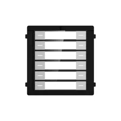
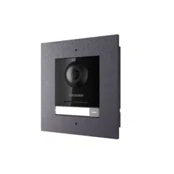
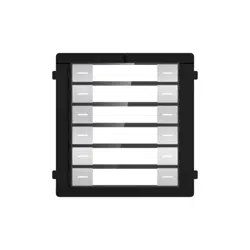
Chapter 1 Appearance
Nametag Module
Figure 1-1 Nametag Module Appearance
Note
●
The pictures here are for reference only.
●
The nametag can be replaced.
●
RS-485 interfaces are for module-connecng.
●
The debugging port is for debugging use only.
●
The device can be used for cascading. To avoid the risk of overload in the preceding power
supply, it is necessary to use it in
combinaon according to the output limit of the main unit.
Nametag Module User Manual
1
Chapter 2 Conguraon Flow of the Nametag
Module
You can
congure the nametag module through the following ow.
Table 2-1 Conguraon Flow of the Nametag Module
Conguraon Steps Details
1. Set sub module address of K12 module Please refer to: Congure Sub Module Address
2. Wiring and Installaon of the K12 Module Please refer to:
●
Terminal and Wiring
●
Installaon
3. Congure the K12 Module via the Web Client
of the Main Unit or iVMS-4200 Client Soware
●
Congure the K12 Module via the Web Client
of 8003 Series Module Door Staon:
Conguraon via Web 4.0
●
Congure the K12 Module via the PC and
Mobile Web Client of 7003 Series Module
Door Staon: Conguraon via PC Web 5.0
or Mobile Web
●
Congure the K12 Module via the iVMS-4200
Client
Soware: Conguraon via Client
Soware of the Main Unit
4. Call residents via the K12 Module Please refer to: Call Resident
Nametag Module User Manual
2
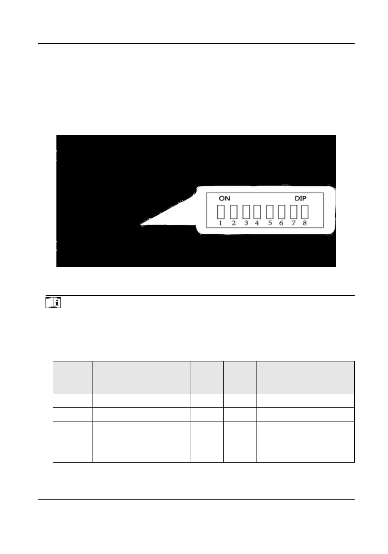
Chapter 3 Congure Sub Module Address
You need to set the sub module address via DIP switch before installaon.
Steps
1.
Remove the rubber cover on the rear panel of the sub module to expose the DIP switch.
Figure 3-1 DIP Switch
2.
Set the sub module address according to the DIP rules, and install the rubber cover back.
Note
●
DIP 1, 2, 3, 4 are used to coding the sub module address. DIP 5, 6, 7, 8 are reserved.
●
Valid sub module address is from 1 to 8. The address should be unique for connecng to the
main unit.
The sub module address and its corresponding switch status are displayed as below.
Sub
Module
Address
DIP 1 DIP 2 DIP 3 DIP 4 DIP 5 DIP 6 DIP 7 DIP 8
Module 1 ON OFF OFF OFF OFF OFF OFF OFF
Module 2 OFF ON OFF OFF OFF OFF OFF OFF
Module 3 ON ON OFF OFF OFF OFF OFF OFF
Module 4 OFF OFF ON OFF OFF OFF OFF OFF
Module 5 ON OFF ON OFF OFF OFF OFF OFF
Nametag Module User Manual
3

Sub
Module
Address
DIP 1 DIP 2 DIP 3 DIP 4 DIP 5 DIP 6 DIP 7 DIP 8
Module 6 OFF ON ON OFF OFF OFF OFF OFF
Module 7 ON ON ON OFF OFF OFF OFF OFF
Module 8 OFF OFF OFF ON OFF OFF OFF OFF
Nametag Module User Manual
4
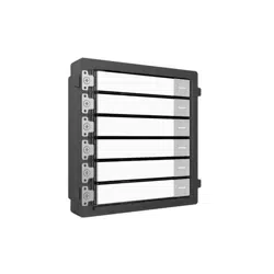
Chapter 4 Terminal and Wiring
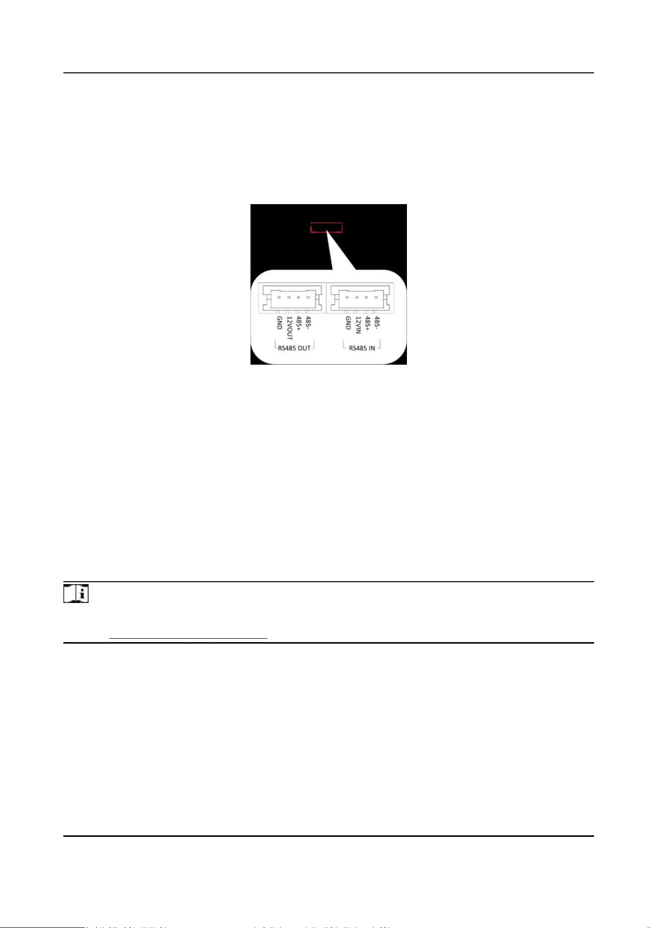
4.1 Terminals
Figure 4-1 RS-485 Module-Connecng Interfaces
4.2 Module Door
Staon Wiring
4.2.1 Wiring with the Main Unit
The nametag module can connect to Two-Wire module door staon and IP module door staon via
RS-485
module-connecng interfaces. Aer connecng with the door staon and seng the call
buon of the module, you can press the call buon of the sub module to call linked indoor staon.
For more informaon about seng call buons, please refer to Conguraon and Operaons
chapter.
Note
For more informaon about seng call buons, please refer to Conguraon and Operaons
chapter. Conguraon and Operaon
Nametag Module User Manual
5

Wiring with IP Module Door Staon
Figure 4-2 Wiring with IP Module Door Staon
Nametag Module User Manual
6

Wiring with Two-Wire Module Door Staon
Figure 4-3 Wiring with Two-Wire Module Door Staon
Nametag Module User Manual
7

Chapter 5 Installaon
Note
●
Sub module must work along with the main unit.
●
Sub modules share the same approach of the installaon. The sub modules in installaon images
are for reference only.
●
Make sure the device in the package is in good
condion and all the assembly parts are included.
●
Set the sub module address before start the
installaon steps.
●
Make sure the place for surface mounng is at.
●
Make sure all the related equipment is power-o during the installaon.
●
Tools that you need to prepare for
installaon:
Drill (ø6), cross screwdriver (PH1*150 mm), and gradienter.
Nametag Module User Manual
8

5.1 Two-Module Installaon
5.1.1 Two-Module Surface Mounng
Before You Start
Figure 5-1 Mounng Frame
Note
●
The suggested depth of the installaon hole is 33 mm.
●
The dimensions above are for reference only. The actual size can be slightly dierent from the
theorecal dimension.
Steps
1.
Sck the mounng scker to the wall. The suggested length of cables le outside is 270 mm.
Nametag Module User Manual
9
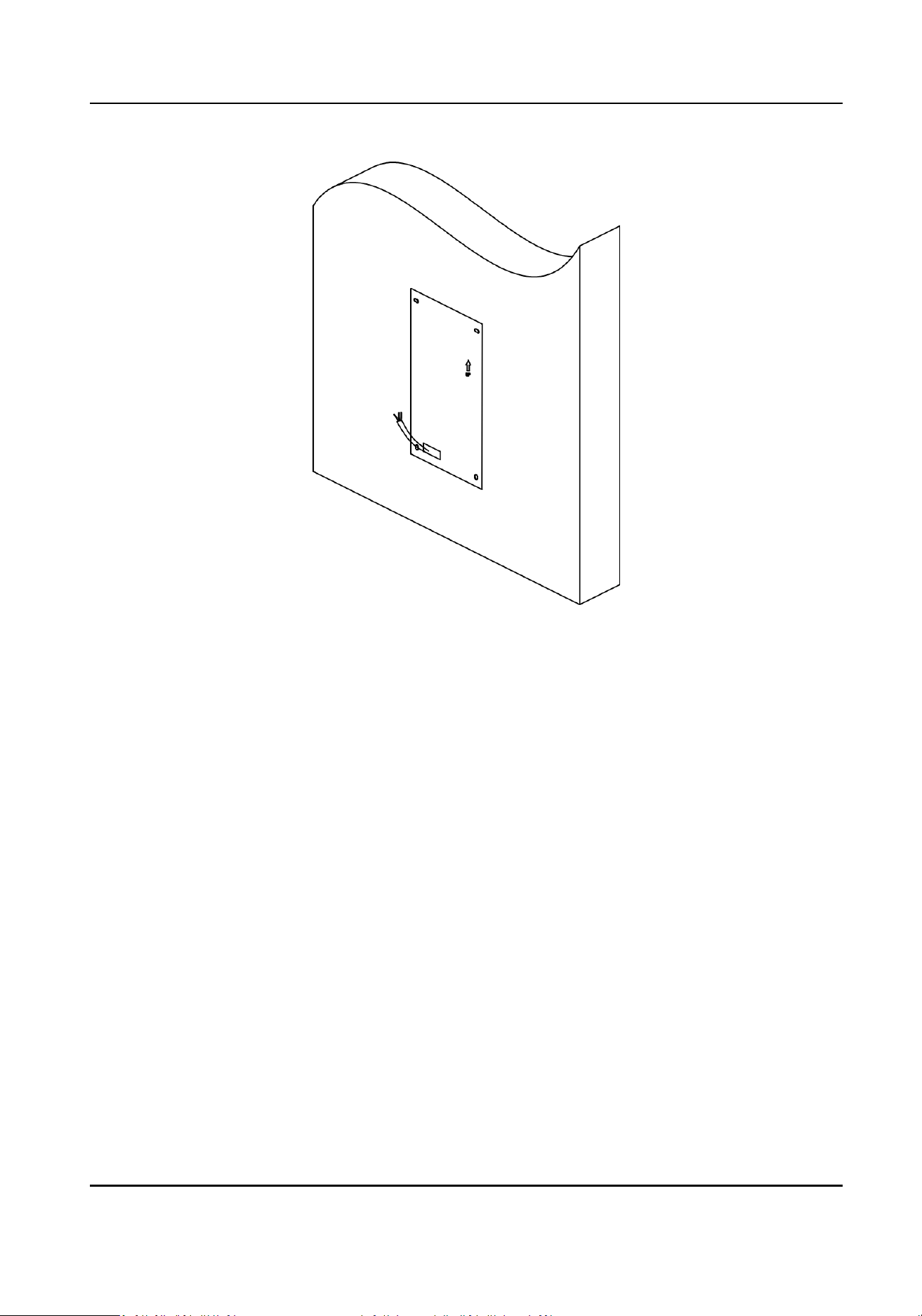
Figure 5-2 Sck the Scker
2.
Drill 4 holes of 25 mm deep according to the marks on the scker and insert the expansion
sleeves into the screw holes. Remove the
mounng scker and x the mounng frame to the
wall with 4 expansion bolts.
Nametag Module User Manual
10

Figure 5-3 Fix the Mounng Frame
3.
Thread the module-connecng line across the thread holes of the frame. Pass the main unit
connecng line across the thread hole to the top grid and connect the cables. Insert the
modules into the frame aer wiring. The main unit must be placed in the top grid.
Nametag Module User Manual
11
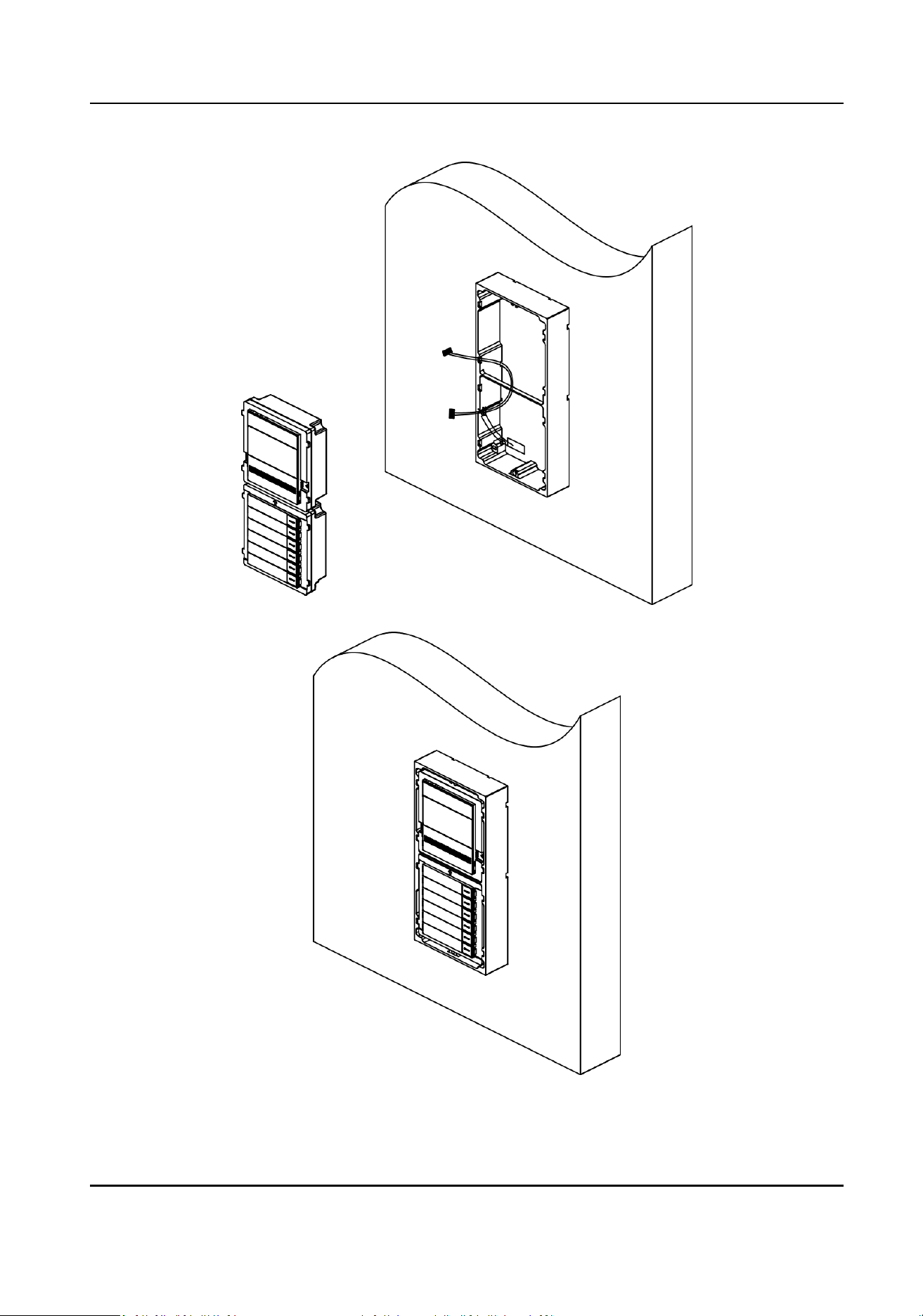
Figure 5-4 Fix Modules to the Frame
Nametag Module User Manual
12
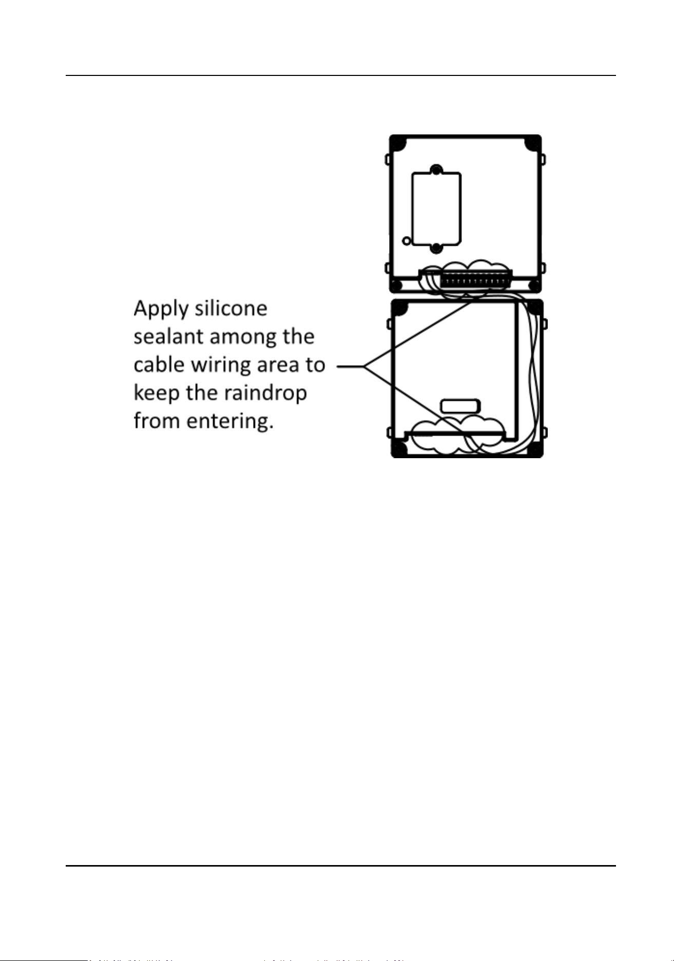
4.
Apply silicone sealant among the cable wiring area to keep the raindrop from entering.
Figure 5-5 Apply Silicone Sealant
5.
Use the hexagon wrench in the package to x the cover onto the frame.
Nametag Module User Manual
13
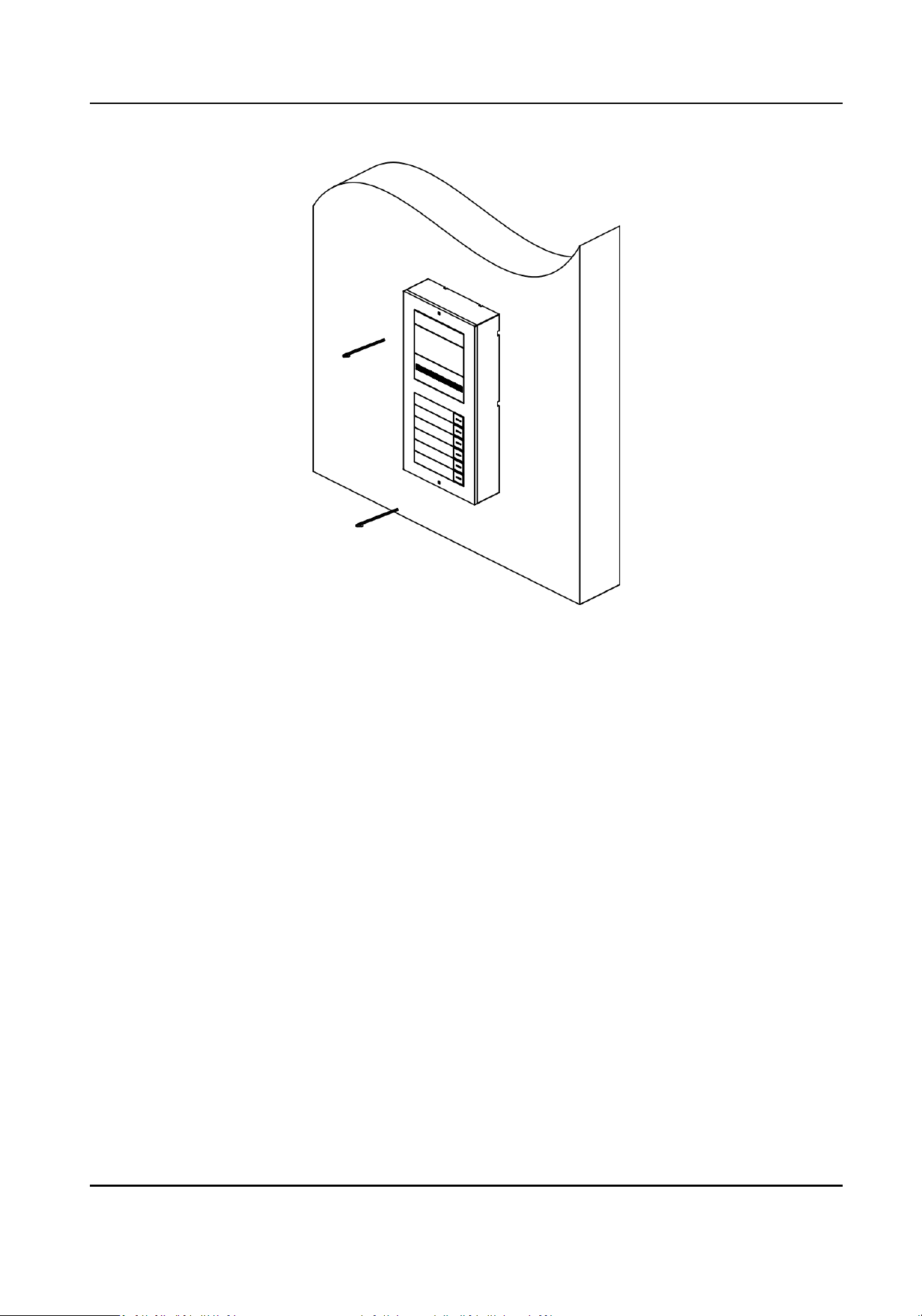
Figure 5-6 Fix the Cover
Nametag Module User Manual
14

5.1.2 Two-Module Flush Mounng
Before You Start
Figure 5-7 Mounng Box
Note
The dimensions above are for reference only. The actual size can be slightly dierent from the
theorecal dimension.
Steps
1.
Sck the mounng scker to the wall and cave the installaon hole according to the scker. Pull
the cable out. Sck the mounng scker to the installaon hole and drill 4 holes of 25 mm deep
according to the marks on the scker and insert the expansion sleeves into the screw holes.
Note
●
The suggested depth of the hole is 44.5 mm.
●
The suggested length of cables le outside is 270 mm.
Nametag Module User Manual
15
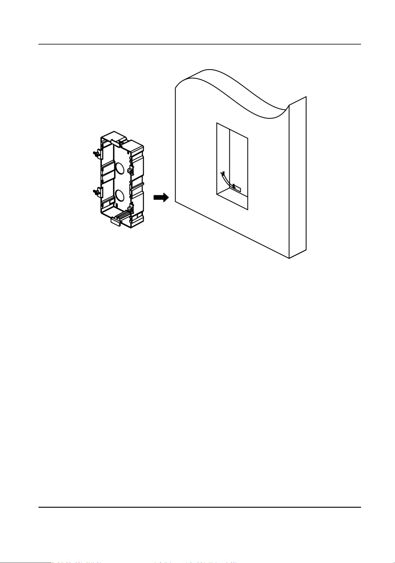
Figure 5-8 Drill the Installaon Hole
2.
Fix the mounng box to the installaon with 4 expansion bolts. Remove the posioning piece of
the
mounng box.
Nametag Module User Manual
16
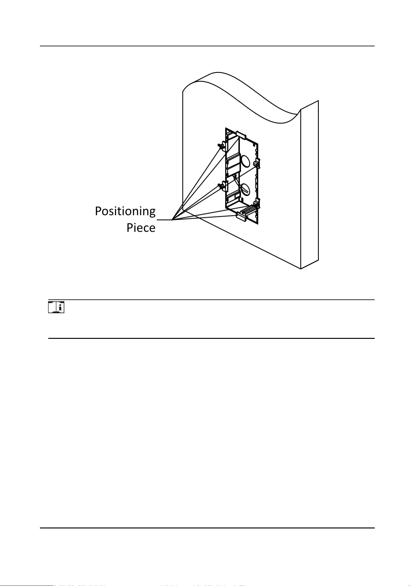
Figure 5-9 Fix the Mounng Box
3.
Connect cables of the main unit and other modules and insert the modules to the mounng box.
Note
Apply silicone sealant on the top and sides of the mounng box. Do not apply silicone sealant on
the boom of the box.
Nametag Module User Manual
17
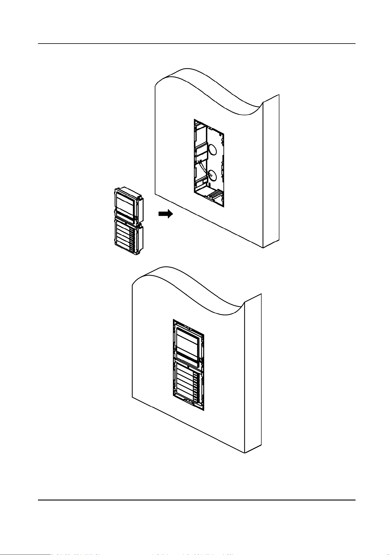
Figure 5-10 Fix Modules to the Mounng Box
Nametag Module User Manual
18
4.
Fix the cover with 2 socket head cap screws by using a hexagon wrench.
Figure 5-11 Fix the Cover
Nametag Module User Manual
19

5.2 Three-Module Installaon
5.2.1 Three-Module Surface Mounng
Before You Start
Figure 5-12 Mounng Frame
Note
●
The suggested depth of the installaon hole is 33 mm.
●
The dimensions above are for reference only. The actual size can be slightly dierent from the
theorecal dimension.
Steps
1.
Sck the mounng scker to the wall. The suggested length of cables le outside is 270 mm.
Nametag Module User Manual
20

Figure 5-13 Sck the Scker
2.
Drill 4 holes of 25 mm deep according to the marks on the scker and insert the expansion
sleeves into the screw holes. Remove the
mounng scker and x the mounng frame to the
wall with 4 expansion bolts.
Nametag Module User Manual
21

Figure 5-14 Fix the Mounng Frame
3.
Thread the module-connecng line across the thread holes of the frame.
Nametag Module User Manual
22

Figure 5-15 Thread the Module-Connecng Line
4.
Pass the main unit connecng line across the thread hole to the top grid and connect the cables.
Insert the modules into the frame
aer wiring. The main unit must be placed in the top grid.
Nametag Module User Manual
23

Figure 5-16 Fix Modules to the Frame
5.
Apply silicone sealant among the cable wiring area to keep the raindrop from entering.
Nametag Module User Manual
24
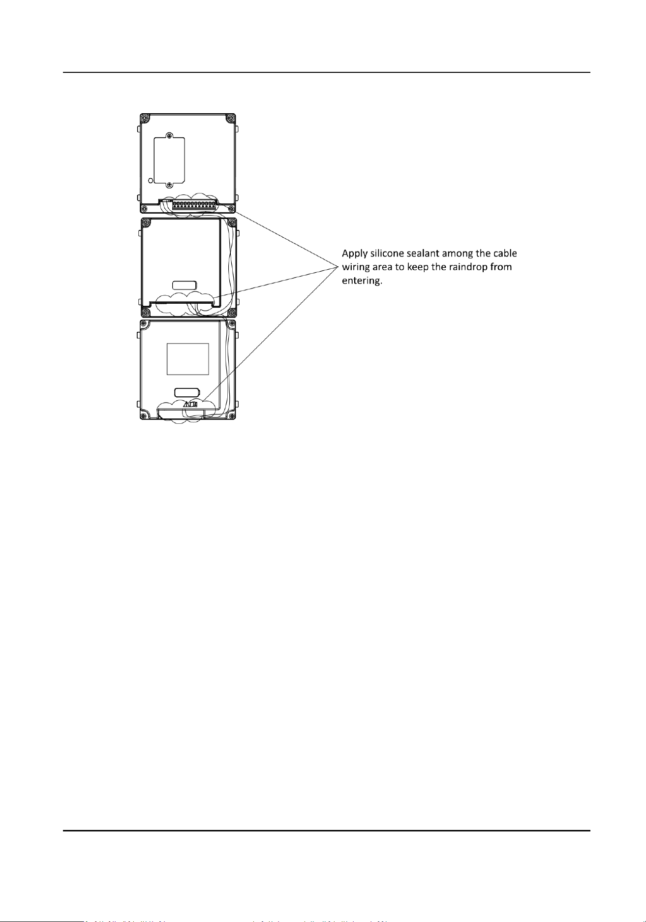
Figure 5-17 Apply Silicone Sealant
6.
Use the hexagon wrench in the package to x the cover onto the frame.
Nametag Module User Manual
25

Figure 5-18 Fix the Cover
Nametag Module User Manual
26

5.2.2 Three-Module Flush Mounng
Before You Start
Figure 5-19 Mounng Box
Note
The dimensions above are for reference only. The actual size can be slightly dierent from the
theorecal dimension.
Steps
1.
Sck the mounng scker to the wall and cave the installaon hole according to the scker. Pull
the cable out. Sck the mounng scker to the installaon hole and drill 4 holes of 25 mm deep
according to the marks on the scker and insert the expansion sleeves into the screw holes.
Note
●
The suggested depth of the hole is 44.5 mm.
●
The suggested length of cables le outside is 270 mm.
Nametag Module User Manual
27

Figure 5-20 Drill the Installaon Hole
2.
Fix the mounng box to the installaon with 4 expansion bolts. Remove the posioning piece of
the
mounng box.
Nametag Module User Manual
28
Figure 5-21 Fix the Mounng Box
3.
Connect cables of the main unit and other modules and insert the modules to the mounng box.
Note
Apply silicone sealant on the top and sides of the mounng box. Do not apply silicone sealant on
the boom of the box.
Nametag Module User Manual
29

Figure 5-22 Fix Modules to the Mounng Box
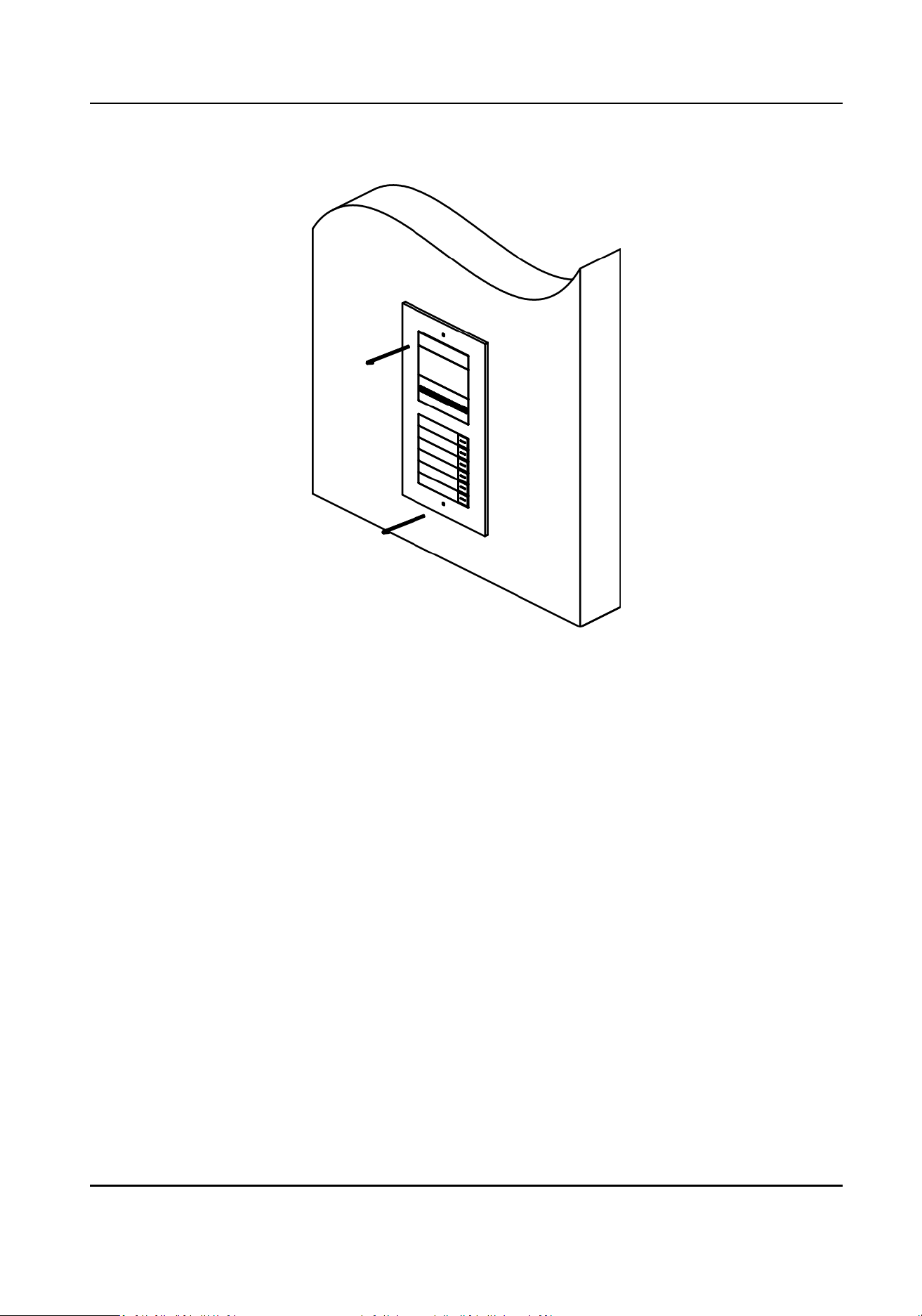
4.
Fix the cover with 2 socket head cap screws by using a hexagon wrench.
Nametag Module User Manual
30

Figure 5-23 Fix the Cover
Nametag Module User Manual
31

Chapter 6 Conguraon and Operaon
You can congure the nametag module via the Web Client and Client Soware of the main unit.
6.1 Conguraon via Web Client of the Main Unit
6.1.1 Conguraon via Web 4.0
Login Web Browser
You can log into the Web browser for device conguraon.
Before You Start
The sub module needs to be connected with the main unit before you can set the sub module via
the web client of the main unit. For more details, please refer to Wiring with the Main Unit
Steps
1.
Enter the device IP address in the address bar of the web browser and press Enter to enter the
login page.
2.
Enter the device user name and the password. Click Login to login to the page.
View
Buon Image of Connected Sub Modules
You can view image of all connected sub modules and the No. of each buon.
Steps
1.
Click
Conguraon → Intercom → Press Buon to Call to enter the page.
2.
Click View Buon Image, and you can check all connected sub modules and the No. of each
buon. The following image is shown as an example.
Nametag Module User Manual
32
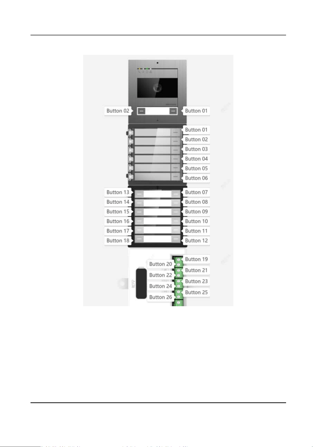
Figure 6-1 View Buon Image
Schedule
Sengs
You can create call schedules for the nametag module. By default, you can call indoor staons via
the nametag module at any me of the day.
Steps
1.
Click Conguraon → Schedule → Video Intercom → Call Schedule to enter the page.
Nametag Module User Manual
33
2.
Click the next row below Enable Indoor Staon All Day by Default.
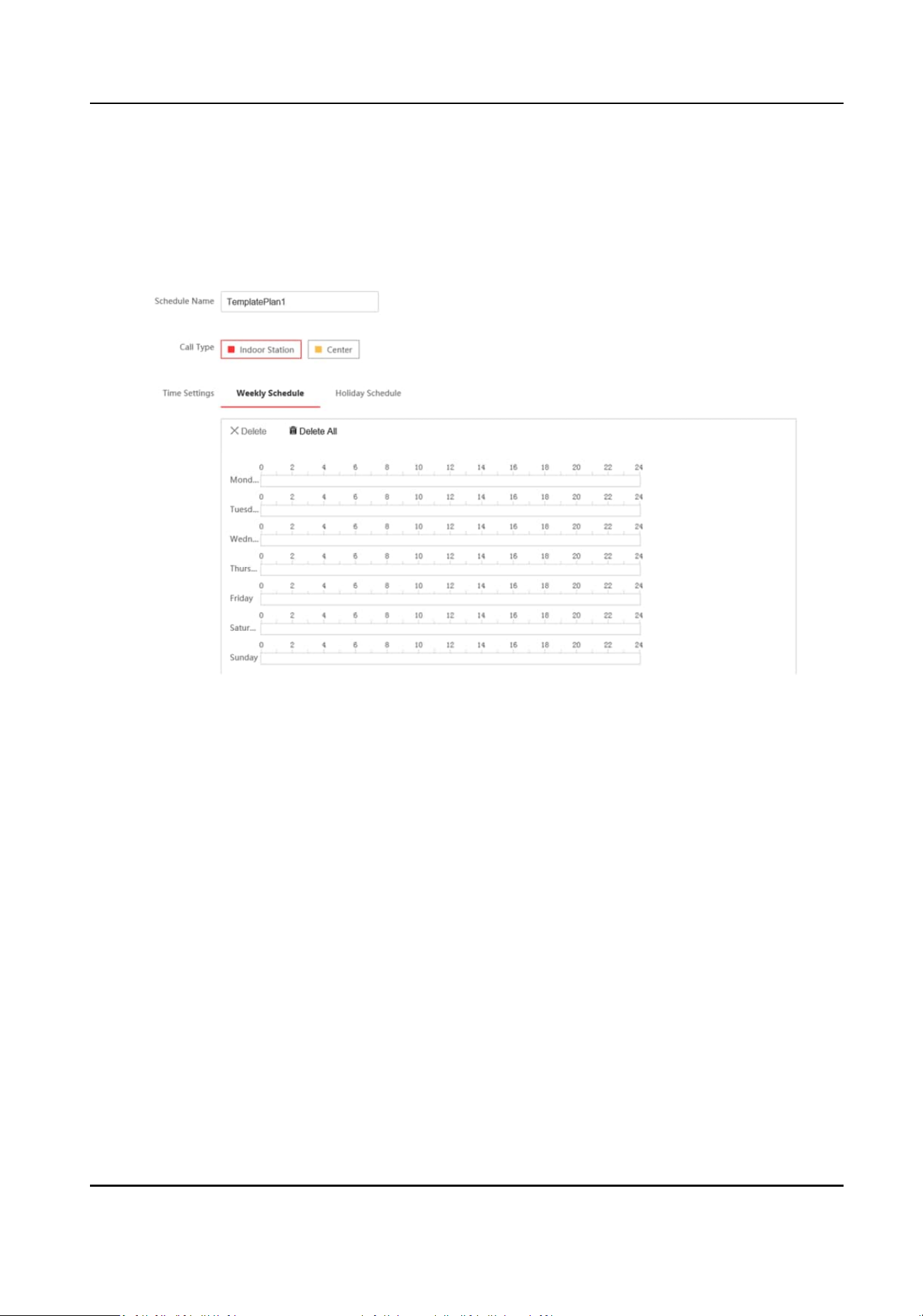
3.
Enter Schedule Name.
4.
Select Call Type.
5.
Set Weekly Schedule.
1) Click Weekly Schedule.
Figure 6-2 Weekly Schedule
2) Drag mouse to set the schedule according to the actual needs.
3) Oponal: Click the copy icon to copy the schedule to other days according to the actual
needs.
4) Click Save to save the
sengs.
6.
Set Holiday Schedule.
1) Click Holiday Schedule.
Nametag Module User Manual
34
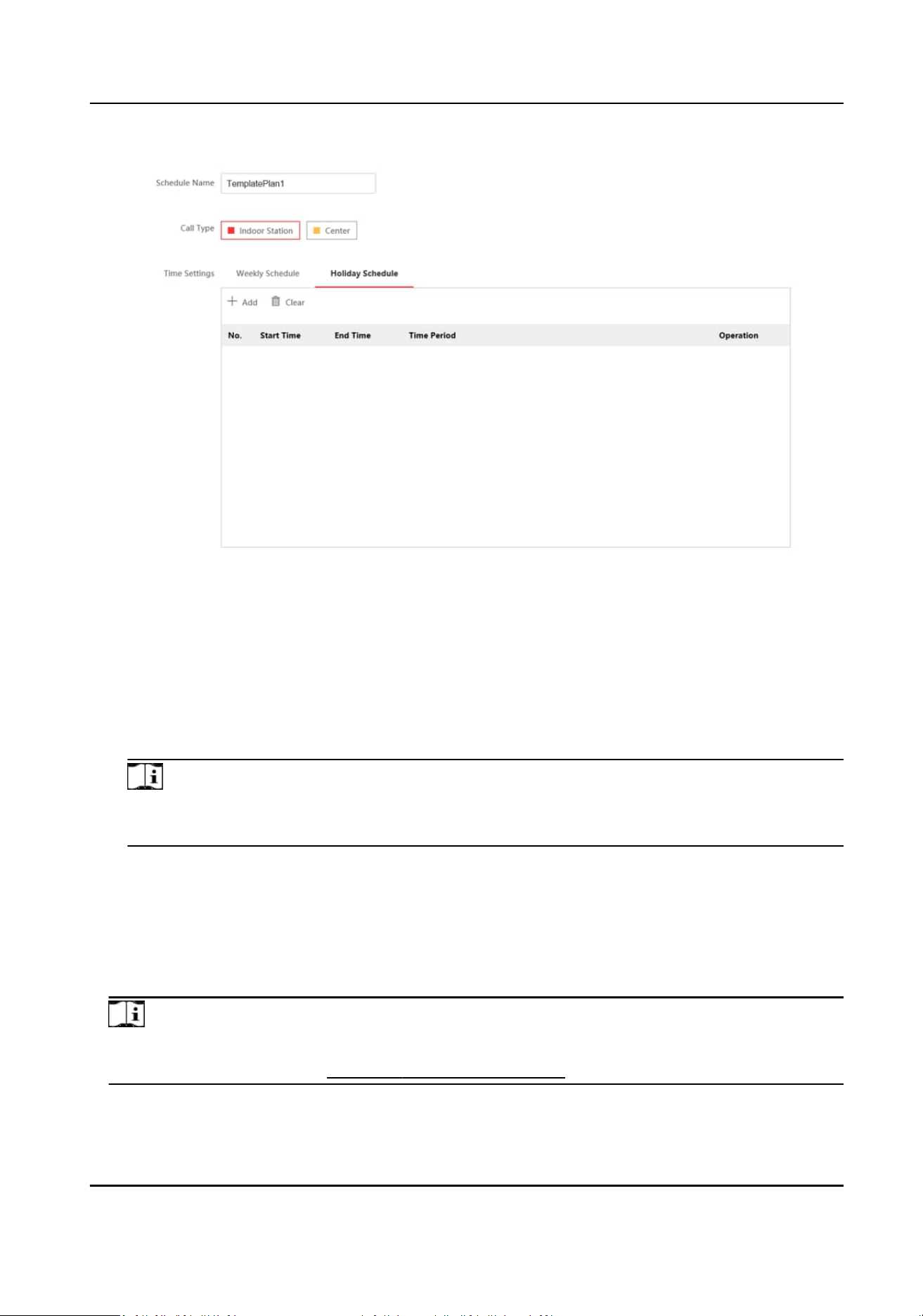
Figure 6-3 Holiday Schedule
2) Click +Add.
3) Set Start Time and End Time.
4) Select Call Type.
5) Drag mouse to set the schedule according to the actual needs.
6) Click OK.
7)
Oponal: You can edit or delete the schedule according to the actual needs.
8) Click Save to save the sengs.
Note
The holiday schedule has higher priority than weekly schedule when you set the two schedule
at the same me.
Set Room No. and Call Schedule for Nametag Module
Steps
1.
Click Conguraon → Intercom → Press Buon to Call to enter the page.
2.
Select Sub Module from the drop-down list.
Note
You can set No. of the nametag module via the DIP switch on the back of the module. For more
informaon, please refer to: Congure Sub Module Address
3.
Fill in the room No. of the indoor staon in the blank of the Buon Seng column.
Nametag Module User Manual
35
4.
Link Time Schedule: Select me schedule plan from the drop-down list. For more informaon
about the me schedule plan, please refer to Schedule Sengs .
5.
Click Save to enable the sengs.
Aer
conguraon, you can press the buon on the nametag module to call relave indoor
staon.
View Informaon of Nametag Module
You can view the sub module address, module type, status, and version of the nametag module.
Steps
1.
Click
Conguraon → Intercom → Sub Module Conguraon to enter the page.
2.
View the sub module informaon, including No. (sub module address), module type, status, and
version.
Note
●
The module address is used to dierenate the sub modules.
●
K12 module belongs to nametag modules.
●
The room No. for the main unit's call buon is 1 by default; and the room No. for other call
buons will start with 2. The number will increase connuously. For example, the room No. of
the
rst nametag module range from 2~7, the room No. of next nametag module will range
from 8~13.
6.1.2 Conguraon via PC Web 5.0 or Mobile Web
Login Web Browser
You can log into the Web browser for device conguraon.
Before You Start
The sub module needs to be connected with the main unit before you can set the sub module via
the web client of the main unit. For more details, please refer to
Wiring with the Main Unit
Steps
1.
Connect your mobile devices or PCs to the main unit's hotspot.
2.
Enter the user name and the
acvaon password. Click Login.
Note
The main unit will be acvated automacally aer powered on. You can check the acvaon
password via the label on the surface of the main unit.
Nametag Module User Manual
36

3.
For the rst-me login, you need to change the acvaon password: Click admin → Modify
Password on the upper right of the Web browser page. Enter the old and new password and
conrm the new password. Click Save to save the seng.
Note
The hotspot password will be changed simultaneously aer the acvaon password is changed.
View Buon Image of Connected Sub Modules on Mobile Devices
You can view image of all connected sub modules and the No. of each buon.
Steps
1.
Tap
→ Intercom → Press Buon to Call to enter the page.
2.
Tap ... → View Buon Image and you can check all connected sub modules and the No. of each
buon. The following image is shown as an example.
Nametag Module User Manual
37
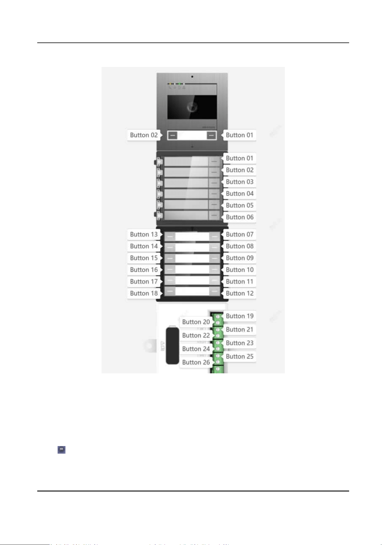
Figure 6-4 View Buon Image
Set Room No. for Nametag Module via Mobile Web
You can set room No. for call buons of nametag module via mobile Web Client of the main unit.
Steps
1.
Tap → Intercom → Press Buon to Call to enter the page.
2.
Tap to select a buon to congure.
Nametag Module User Manual
38

3.
Enable the funcon of Press Buon to Call and set Room No. for this buon.
4.
Tap Save to save the seng.
Result
Aer the seng, you can then press the correspondent call buon on the nametag module to call
the
specic indoor staon.
View Nametag Module Informaon via Mobile Web
You can view informaon of the nametag module on mobile Web of the main unit.
Steps
1.
Tap → Intercom → Sub Module Conguraon to enter the page.
2.
View the version and online status of connected nametag modules.
View
Buon Image of Connected Sub Modules on PC
You can view image of all connected sub modules and the No. of each buon.
Steps
1.
Click
Conguraon → Intercom → Press Buon to Call to enter the page.
2.
Click View Buon Image, and you can check all connected sub modules and the No. of each
buon. The following image is shown as an example.
Nametag Module User Manual
39

Figure 6-5 View Buon Image
Set Room No. for Nametag Module via PC Web
You can set room No. for call buons of nametag module via PC Web Client of the main unit.
Steps
1.
Click Conguraon → Intercom → Press Buon to Call to enter the page.
2.
Fill in the blank with room No. for each buon and click to enable Press Buon to Call.
Nametag Module User Manual
40

Note
The room No. refers to the mapping room No. which you can custom the No. on your own.
3.
Click Save.
Result
Aer the seng, you can then press the correspondent call buon on the nametag module to call
the specic indoor staon.
View Nametag Module Informaon via PC Web
You can view the informaon of the nametag module via PC Web Client of the main unit.
Steps
1.
Click
Conguraon → Intercom → Sub Module Conguraon to enter the page.
2.
View the sub module informaon, including No. (sub module address), module type, online
status, and version.
6.2
Conguraon via Client Soware of the Main Unit
6.2.1 Device Management
Device management includes device acvaon, adding device, eding device, and deleng device,
and so on.
Aer running the iVMS-4200, video intercom devices should be added to the client soware for
remote
conguraon and management.
Add Online Device
Before You Start
Make sure the device to be added is in the same subnet with your computer. Otherwise, please
edit network parameters
rst.
Steps
1.
Click Online Device to select an acve online device.
2.
Click Add.
3.
Enter corresponding
informaon, and click Add.
Nametag Module User Manual
41
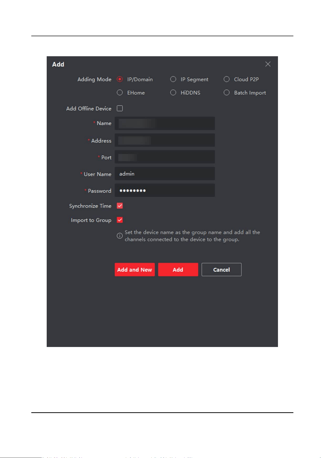
Figure 6-6 Add to the Client
Nametag Module User Manual
42
Add Device by IP Address
Steps
1.
Click +Add to pop up the adding devices dialog box.
2.
Select IP/Domain as Adding Mode.
3.
Enter corresponding
informaon.
4.
Click Add.
Add Device by IP Segment
You can add many devices at once whose IP addresses are among the IP segment.
Steps
1.
Click +Add to pop up the dialog box.
2.
Select IP Segment as Adding Mode.
3.
Enter corresponding
informaon, and click Add.
6.2.2 Remote
Conguraon
Aer login to the Client Soware and add main units to the Client, you can click to set the
parameters of the device.
Note
It will automacally jump to the Web conguraon page of the main unit. For more informaon of
Web conguraon, please refer to Conguraon via Web Client of the Main Unit .
Run the browser, click → Internet Opons → Security to disable the Protected Mode.
6.3 Call Resident
Press the call buon on the nametag module to call residents.
Note
●
Make sure you have congured the room No. of the device. For more informaon, please refer
to
○
Set Room No. and Call Schedule for Nametag Module
○
Set Room No. for Nametag Module via PC Web
○
Set Room No. for Nametag Module via Mobile Web
●
Make sure you have add contacts to the device via iVMS-4200 Client Soware or Web Client of
the main unit.
Nametag Module User Manual
43

UD35734B