1
800.533.7533 | Santa-Fe-Products.com Santa Fe ULTRA98/120 Installation & Operation Instructions
Serial Number
Install Date
Sold By
Installation Instructions
Patent: thermastor.com/patents
ULTRA SERIES | ULTRA98/120
TS-2058 03/24 Rev A
Santa-Fe-Products.com | 800.533.7533
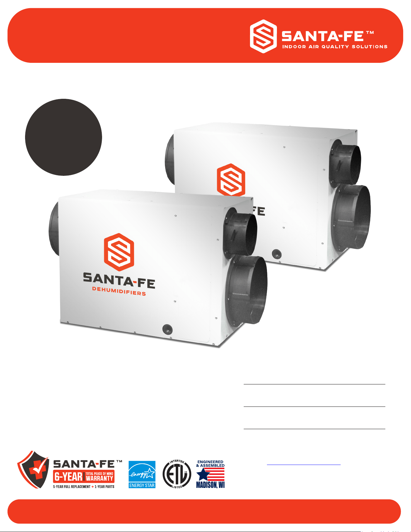
The Santa Fe Ultra98/120 are ventilating dehumidiers
that integrate into the heating and cooling system to
provide the ultimate in comfort, health and property
protection through:
+ Dehumidication
+ Optional Outdoor Air Ventilation
+ Air Filtration
* Previously the Ultra Aire 98H/120H.
Español
Versión
La Página
27
Ultra98 Only
2
Santa Fe ULTRA98/120 Installation & Operation Instructions Santa-Fe-Products.com | 800.533.7533
Safety Instructions ........................................................................................3
Assembly & Installation ................................................................................4
Dehumidier Set Up ..................................................................................5-6
Attaching Duct Collars ..................................................................................7
Electrical Requirements ........................................................................... 8 -9
Drain Installation .........................................................................................10
Ducting to HVAC Systems ..........................................................................11
Recommended HVAC System Installation ...............................12-13
Alternative HVAC System Installation.......................................14-15
Ducting to HVAC Systems (Closet Installations)
Recommended Closet Installation ..................................................16
Alternative Closet Installation .........................................................17
Outdoor Air Ventilation ...............................................................................18
Determine Ventilation Requirements ..............................................19
Controls .................................................................................................20-21
Air Filtration .................................................................................................22
MERV Rating Chart ..........................................................................23
Service ...................................................................................................24-25
Warranty ......................................................................................................26
Spanish Version ..........................................................................................27
Santa Fe is committed to manufacturing quality products. To maintain
our standards, product specications may change without notice.
4201 Lien Road, Madison, WI 53704
(800) 533-7533
Thermastor.com | Santa-Fe-Products.com
© 2019 Therma-Stor LLC
FOR REPAIR & TECH SUPPORT: 1-800-533-7533 (follow prompts)
or CONTACT US AT: [email protected]
TABLE OF CONTENTS
1
3
800.533.7533 | Santa-Fe-Products.com Santa Fe ULTRA98/120 Installation & Operation Instructions
WARNING!
THIS SYMBOL MEANS IMPORTANT INSTRUCTIONS. FAILURE TO HEED THEM CAN
RESULT IN SERIOUS INJURY OR DEATH.
Read the installation, operation and maintenance instructions carefully before installing and
operating this device. Proper adherence to these instructions is essential to obtain maximum
benet from the Santa Fe Whole House Ventilating Dehumidier.
CAUTION!
THIS SYMBOL MEANS IMPORTANT INSTRUCTIONS. FAILURE TO HEED THEM CAN
RESULT IN INJURY OR MATERIAL PROPERTY DAMAGE.
REGISTRATIONS
THE SANTA FE ULTRA98/120 CONFORMS TO UNIFIED STANDARD UL 60335-2-40
AND CSA STANDARD C22.2.60335-2-40.
CAUTION!
READ ALL INSTRUCTIONS BEFORE BEGINNING INSTALLATION.
ALWAYS USE CAUTION AND WEAR CUT RESISTANT GLOVES WHEN HANDLING SHEET METAL.
IMPROPER INSTALLATION MAY CAUSE PROPERTY DAMAGE OR INJURY. INSTALLATION, SERVICE,
AND MAINTENANCE MUST BE PERFORMED BY A QUALIFIED SERVICE TECHNICIAN.
THE DEHUMIDIFIER IS HEAVY. HANDLE WITH CARE AND FOLLOW INSTALLATION INSTRUCTIONS.
NEVER OPERATE A UNIT WITH A DAMAGED POWER CORD. IF THE POWER CORD IS DAMAGED, IT MUST
BE REPLACED BY THE MANUFACTURER, ITS SERVICE AGENT, OR A SIMILARLY QUALIFIED PERSON IN
ORDER TO AVOID A HAZARD.
THIS APPLIANCE IS NOT INTENDED FOR USE BY PERSONS (INCLUDING CHILDREN) WITH REDUCED
PHYSICAL, SENSORY OR MENTAL CAPABILITIES, OR LACK OF EXPERIENCE OR KNOWLEDGE, UNLESS
THEY HAVE BEEN GIVEN SUPERVISION OR INSTRUCTION CONCERNING THE USE OF THE APPLIANCE
BY A PERSON RESPONSIBLE FOR THEIR SAFETY. CHILDREN SHOULD BE SUPERVISED TO ENSURE
THAT THEY DO NOT PLAY WITH THE APPLIANCE.
WARNING!
120 VOLTS MAY CAUSE SERIOUS INJURY FROM ELECTRIC SHOCK. DISCONNECT
ELECTRICAL POWER BEFORE STARTING INSTALLATION OR SERVICING, AND LEAVE
POWER DISCONNECTED UNTIL INSTALLATION OR SERVICE IS COMPLETED.
SAFETY INSTRUCTIONS
2
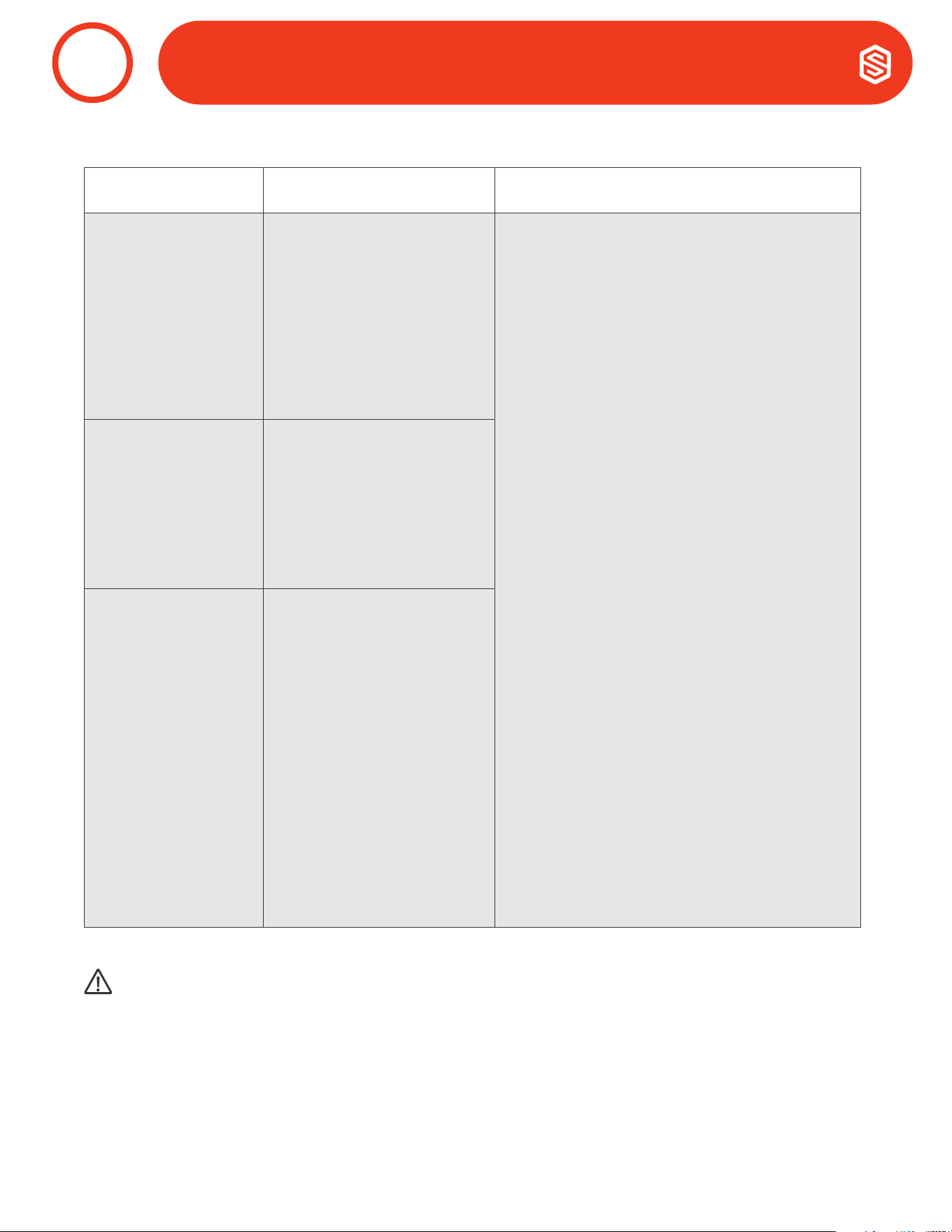
Brand Name Individual
Model Number
Basic Model
Number
Rating
Conditions
Integrated Energy
Factor (L/kWh)
Capacity
(Pint/Day)
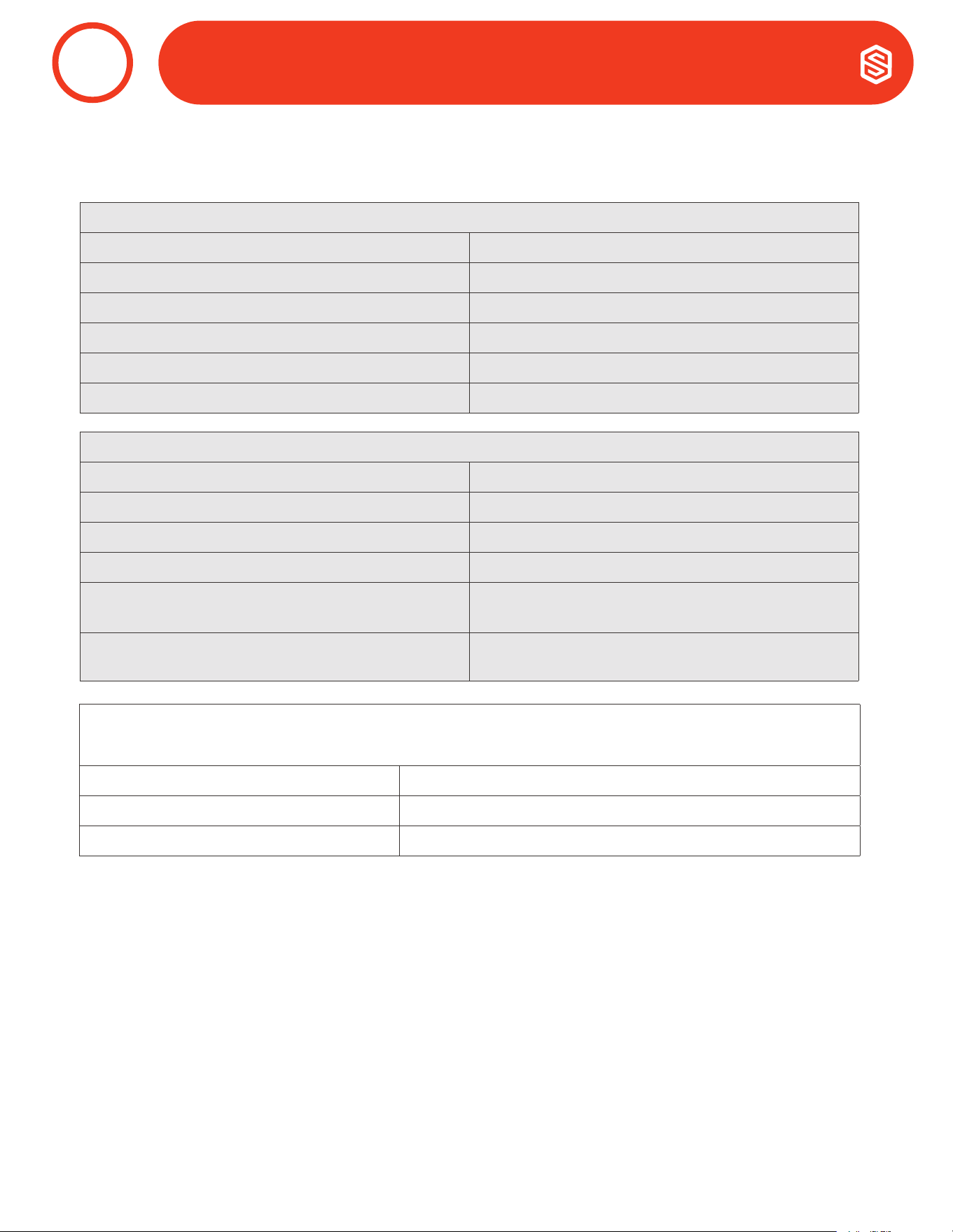
Santa Fe Ultra98 98-W 73F/60% 2.31 72.43
Brand Name Individual
Model Number
Basic Model
Number
Rating
Conditions
Integrated Energy
Factor (L/kWh)
Capacity
(Pint/Day)
Santa Fe Ultra120 120-W 73F/60% 1.93 79.41
4
Santa Fe ULTRA98/120 Installation & Operation Instructions Santa-Fe-Products.com | 800.533.7533
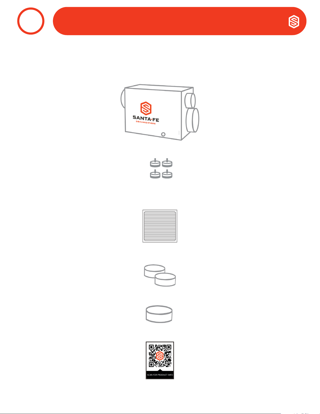
1. Unpack Box.
2. Check that you have all parts:
3. Register warranty at santa-fe-products.com
Read all remaining steps and warnings before continuing.
a. Dehumidifier (1)
b. Leveling feet (4)
c. Filter - 1.75”x14”x17.5” MERV 13 (1)
d. 10” Round Duct Collars (2)
e. 6” Round Duct Collar (1)
I
I
I
I
I
I
I
I
I
I
I
I
I
I
I
H
U
M
I
D
N
O
R
M
A
L
D
R
I
E
R
OFFON
BEFORE TURNING ON UNIT:
1. CUT AND REMOVE ZIP TIE
2. PLUG HOLES USING
INCLUDED PLUGS
COM
FAN
24V
DEHU
*
DMPR
COM
FAN
24V
DEHU
*
DMPR
24V AC
COMP FAN
HONEYWELL REMOTE HUMIDISTAT
WIRING DIAGRAM
QUEST DEH 3000R CONTROL
WIRING DIAGRAM
ASSEMBLY & INSTALLATION
3

5
800.533.7533 | Santa-Fe-Products.com Santa Fe ULTRA98/120 Installation & Operation Instructions
1. Important Precautions
• The device is designed to be installed indoors in a space that is protected from rain and flooding.
• Install the unit with enough space to access all sides for maintenance and service. The entire shell needs to
be removed in order to do repairs.
• Avoid directing the discharge air at people. The dehumidier should be used in the upright position.
• If used near a water source; be certain there is no chance the unit could fall into the water or get splashed
and that it is plugged into a dedicated circuit and Ground Fault Circuit Interrupter (GFCI) protected outlet.
• DO NOT use the dehumidier as a bench or table.
• Do not place the dehumidier directly on structural building members without vibration absorbers or
unwanted noise may result. Place the Santa Fe Ultra98/120 on supports to raise the base of the unit.
• A drain pan with a float switch must be placed under the dehumidier if installed above a living area or above
an area where water leakage could cause damage.
DEHUMIDIFIER SET UP
4
6
Santa Fe ULTRA98/120 Installation & Operation Instructions Santa-Fe-Products.com | 800.533.7533
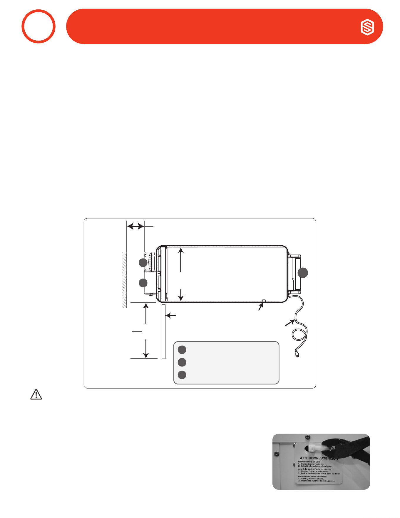
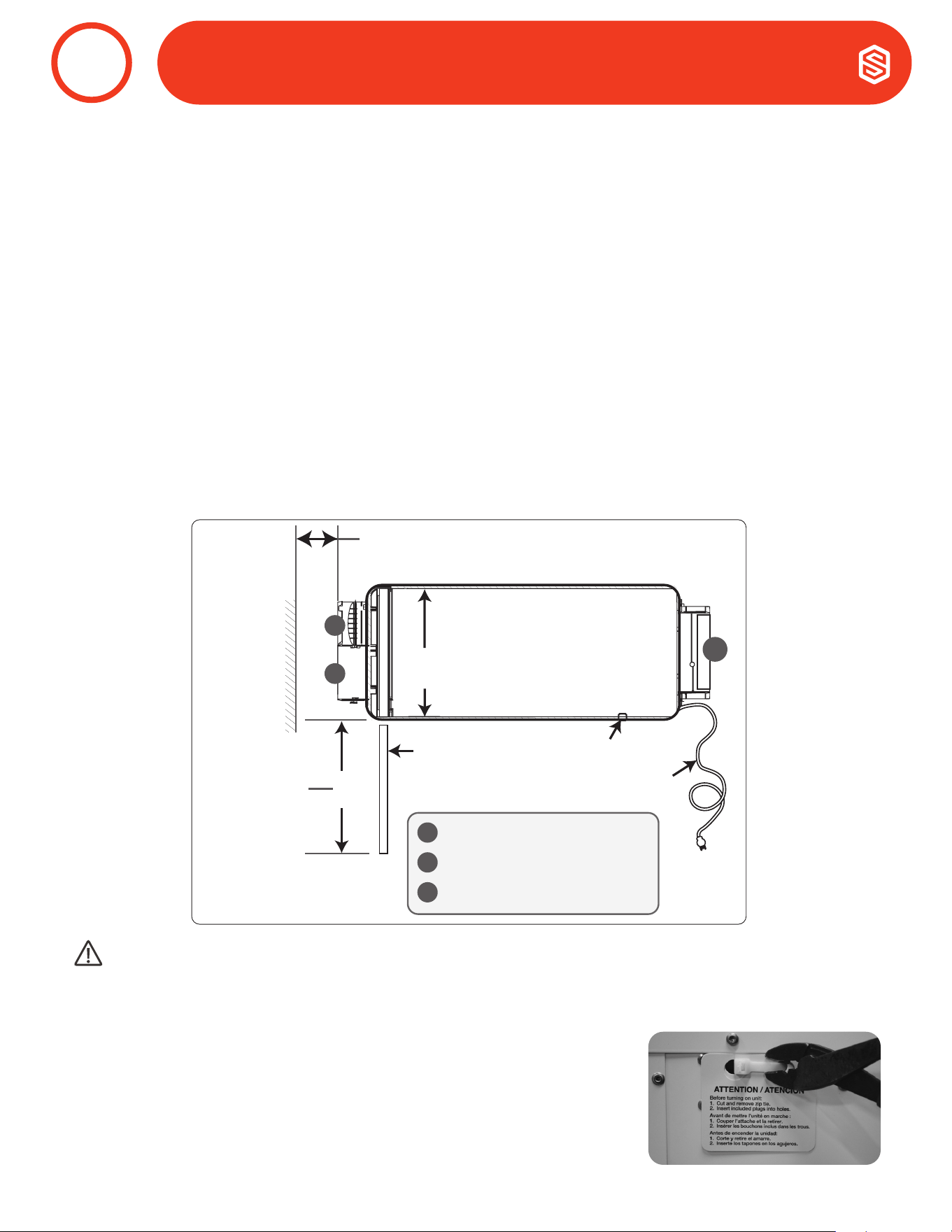
Electrical Service Access
(Either Side)
Filter
9' Power Cord
Top View
Minimum
Clearance
For Filter
(Either Side)
15"
6" Optional Outdoor Air Intake
10" Return Air Duct
10" Supply Air Duct
A
B
C
B
C
Drain Port
A
6" Minimum Clearance
For Proper Airflow
2. Location Considerations
• Allow sufcient clearance to handle the unit’s overall dimensions as well as the necessary return and
supply ductwork to the unit.
• Allow sufcient clearance for lter removal and to prevent airflow obstruction.
• Electrical service access will require the removal of the outside shell. Allow sufcient clearance around the
unit.
• Locate the dehumidier in an area where the unit’s 9 ft. cord can easily reach electrical outlet.
• Locate the dehumidier in an area where eld wiring the control (low voltage) to the unit will be possible.
• A back draft damper is required in the supply duct of the Santa Fe Ultra98/120, especially when connecting
to the supply ducting system. The backdraft damper prevents supply air from counter flowing through
the Santa Fe Ultra98/120 when it is not operating. The dehumidier’s location should be chosen to allow
installation of this accessory if necessary.
• The Santa Fe Ultra98/120 may be suspended with the hang kit or a suitable alternative from structural
members, ensuring the assembly supports the dehumidier’s base in its entirety. Do not hang the Santa Fe
Ultra98/120 from its’ cabinet.
• Allow for proper drainage and routing of needed drain pipes.
DEHUMIDIFIER SET UP
4
CAUTION!
REMOVE COMPRESSOR SHIPPING TIE FROM THE UNIT. FAILURE TO REMOVE THE SHIPPING TIE WILL CAUSE
EXCESS VIBRATION TO BE TRANSMITTED TO THE FRAME.
3. Removal of Compressor Shipping Support
• The Santa Fe Ultra98/120 uses a compressor to power the refrigeration
system. To protect the compressor and refrigeration system during
shipping, a plastic tie wrap secures it to the unit’s frame. Remove the tie
wrap by cutting the tie wrap and pulling from the unit as shown. After
removing tie wrap, insert plastic plugs provided into the holes.

7
800.533.7533 | Santa-Fe-Products.com Santa Fe ULTRA98/120 Installation & Operation Instructions
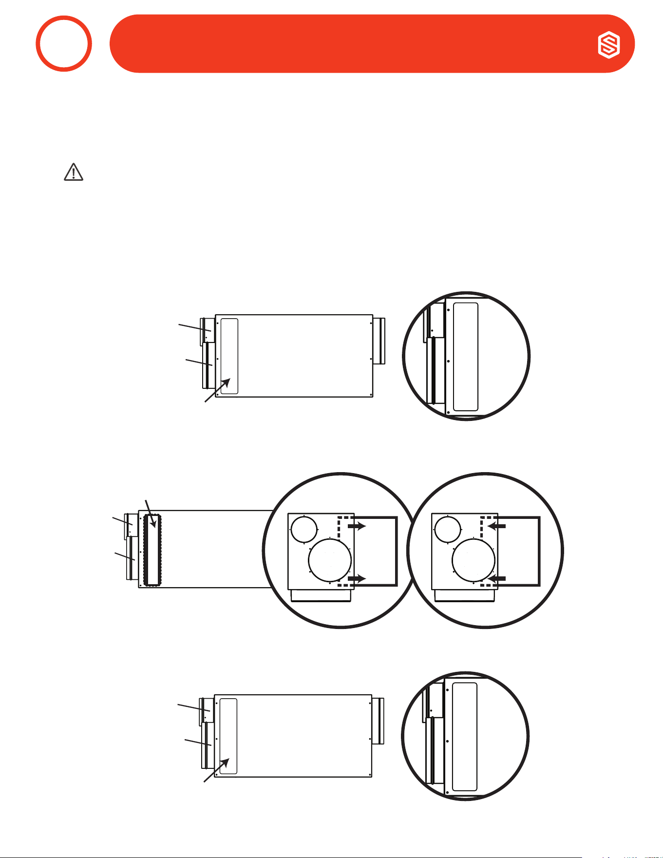
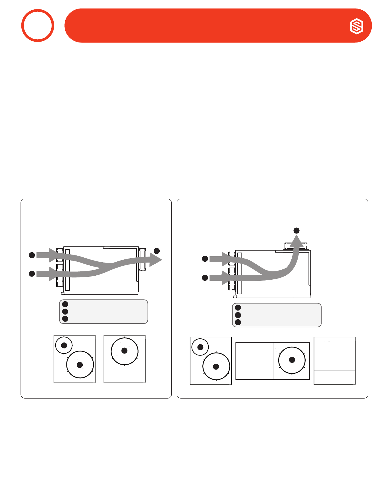
1. Outdoor Air Ventilation Duct
Outdoor air ventilation is optional. If setting up the unit to provide outdoor air ventilation, see page 18.
2. Return Air Inlet
A 10” diameter duct collar is attached to the unit.
3. Supply Air Outlet
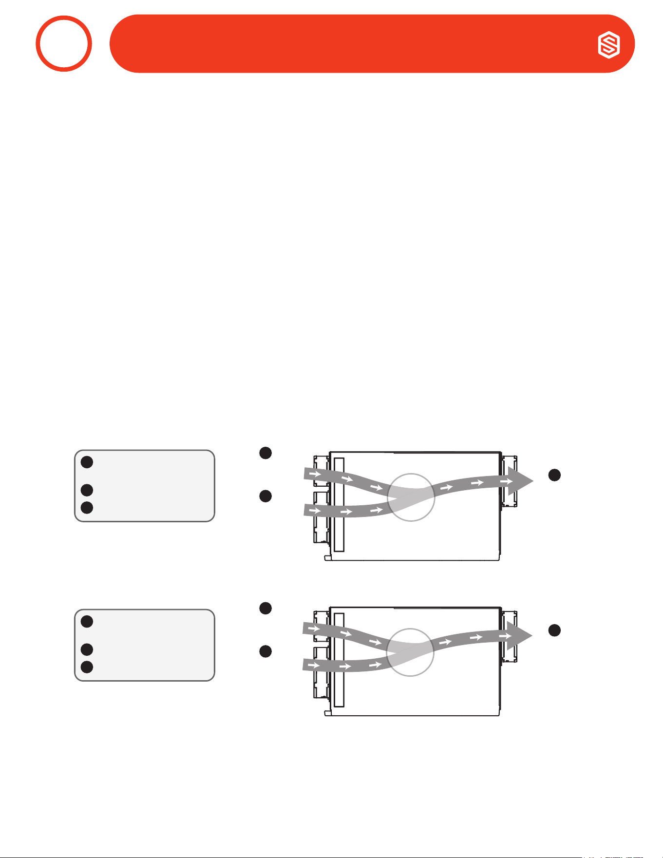
The back panel of the dehumidier can be rotated to allow for horizontal flow through or vertical flow through of
the supply air.
a. Horizontal Flow Through
The unit ships congured for a horizontal flow through. A 10” diameter duct collar is attached to the unit.
b. Vertical Flow Through
Remove the exhaust panel using a T25 torx bit. Rotate the panel so the exhaust collar is located on the top
of the unit. Align screw holes and snap the panel onto the base. Secure the exhaust panel to the base by
replacing the six screws.
ATTACHING DUCT COLLARS
5
OUTLET DUCT
COLLAR WITH
BACK DRAFT
DAMPER
RETURN AIR
INLET DUCT
COLLAR
FRESH AIR
INLET DUCT
COLLAR
RETURN AIR
INLET DUCT
COLLAR
FRESH AIR
INLET DUCT
COLLAR
Front View
Horizontal Flow Through
(End Discharge)
AIR FLOW
Air
Flow
Rear View
Vertical Flow Through
(Top Discharge)
6" Optional Outdoor Air Intake
10" Return Air Inlet
10" Supply Air Outlet
A
B
C
A
B
C
A
B
C
Top View
C
6" Optional Outdoor Air Intake
10" Return Air Inlet
10" Supply Air Outlet
A
B
C
A
B
C
Air
Flow
Rear ViewFront View
A
B
8
Santa Fe ULTRA98/120 Installation & Operation Instructions Santa-Fe-Products.com | 800.533.7533
The Santa Fe Ultra98/120 plugs into a common grounded 115VAC outlet. Locate the dehumidier in an area
where the unit’s 9 ft. cord can easily reach a 115 VAC electrical outlet with a minimum of 15 Amp circuit capacity.
If used in an area that may become wet, a GFCI protected circuit is recommended. Consult local electrical codes
for any further information.
Santa Fe offers a variety of control devices for use with the Santa Fe Ultra98/120. The controls are to be located
remotely from the dehumidier and placed in the space to be conditioned. Low voltage (24 Volt) controls can be used
with the Santa Fe Ultra98/120 and MUST be connected with low voltage (18-22 gauge) thermostat wire.
CAUTION!
DO NOT ALLOW THE 24V TERMINAL TO CONTACT THE COM/DMPR TERMINALS ON THE
SANTA FE ULTRA98/120 OR DAMAGE TO THE TRANSFORMER WILL RESULT.
1. Electrical Precautions
• Do not install the control where it may not accurately sense the relative humidity such as near HVAC
supply registers, near exterior doors, on an outside wall, near a window, or near a water source.
• The screw terminals on the Santa Fe Ultra98/120 and the control are labeled to prevent confusion.
• Be sure to consult the electrical schematic in the CONTROLS Section (pages 20-21) of this manual or
inside the access panel of the Santa Fe Ultra98/120 before making control connections.
WARNING!
THE REMOTE CONTROLS OF THE SANTA FE ULTRA98/120 ARE POWERED BY A LOW VOLTAGE CIRCUIT (24VAC)
AND MUST NEVER CONTACT OR BE CONNECTED TO A HIGH VOLTAGE CIRCUIT.
CAUTION!
SOME OF THE SCREWS TERMINALS ON THE SANTA FE ULTRA98/120 MAY NOT BE USED WITH
CERTAIN CONTROLS AND SHOULD BE LEFT UNCONNECTED.
ELECTRICAL REQUIREMENTS
6
9
800.533.7533 | Santa-Fe-Products.com Santa Fe ULTRA98/120 Installation & Operation Instructions
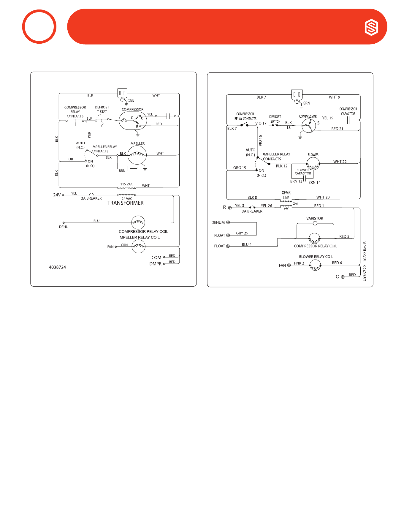
2. Wiring Schematics
Santa Fe ULTRA98H Wiring Diagram
Santa Fe ULTRA120H Wiring Diagram
ELECTRICAL REQUIREMENTS
6
10
Santa Fe ULTRA98/120 Installation & Operation Instructions Santa-Fe-Products.com | 800.533.7533
The Santa Fe Ultra98/120 generate condensate.
Place a secondary drain pan with a float switch under the dehumidier if it is suspended above a nished area or
in an area where water leakage could cause damage.
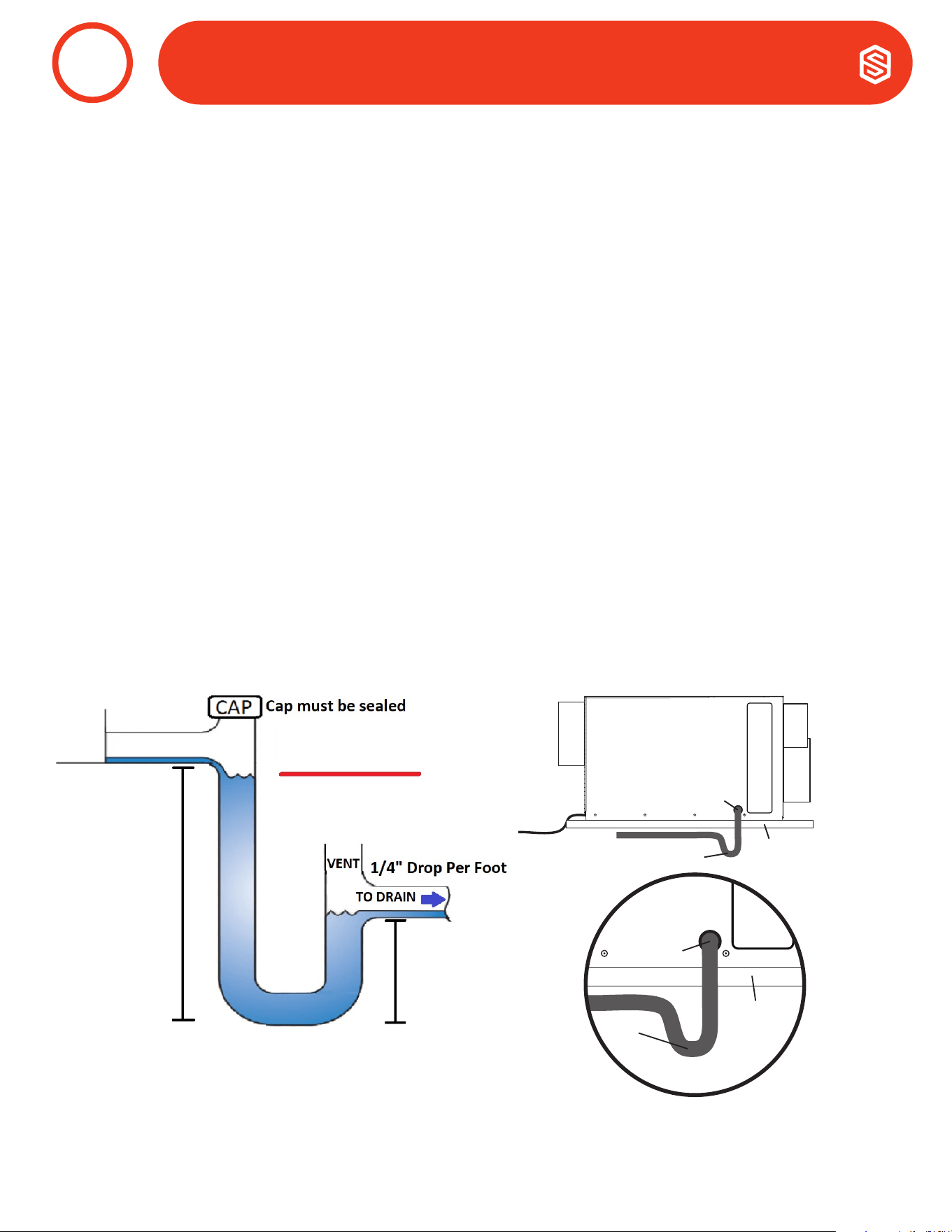
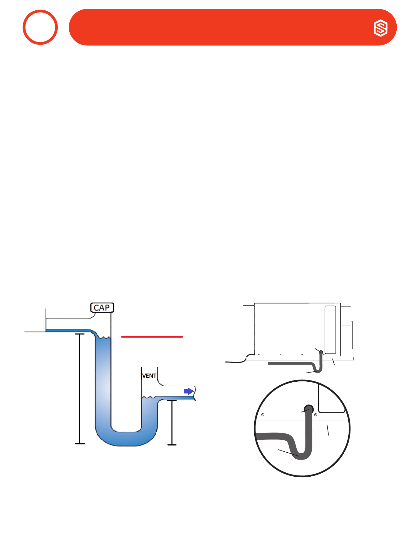
A drain trap is required for the dehumidier to run properly (see diagram below). Install a 3/4" threaded male
NPT adapter to the drain pan. Install a drain pipe assembly utilizing 3/4" PVC pipe to transport the condensate
to a drain. Pitch of drain should be 1" per 10'.
An optional condensate pump kit is available for use with the Santa Fe Ultra98/120 and may be installed if lift is
required to dispose of condensate. Condensate is automatically pumped to a remote location when the water
level in the pump’s reservoir rises to close the float switch.
The pump also contains a safety float switch. The white leads from this switch extend from beneath the pump
cover. This switch should be installed in series with the eld wire that connects to the common lead from the
Santa Fe Ultra98/120 to the control panel. If the pump fails, this switch opens the common control circuit and
stops water production before the reservoir overflows. Contact a qualied electrician to install the safety float
switch to the Santa Fe Ultra98/120 dehumidier.
Drain Installation
DRAIN INSTALLATION
7
Dehumidiers commonly use a negative air pressure drain pan. This causes air to flow backwards thru the drain
system which can cause water to pool inside the dehumidier and leak. A drain trap prevents this issue by trapping
water in the pipe to stop air from flowing backwards.
Please see the trap diagram below. This assembly can be made with common ¾” PVC pipe ttings. The pipe
measurements and placement of the cap and vent are critical to the function of the trap. Once trap is assembled, be
sure to ll with water.
4”
1.5”
Drain
Trap
Secondary
Drain Pan
Drain
Port
Drain Trap
Secondary Drain Pan
Drain Port
Side View
Drain
Trap
Secondary
Drain Pan
Drain
Port
Drain Trap
Secondary Drain Pan
Drain Port
VENT HEIGHT MUST
BE BELOW THE LINE
11
800.533.7533 | Santa-Fe-Products.com Santa Fe ULTRA98/120 Installation & Operation Instructions
DRAIN INSTALLATION
CAUTION!
DO NOT CONNECT WITH A STATIC PRESSURE GREATER THAN OR EQUAL TO +0.5 WG.
CONTACT TECHNICAL SUPPORT AT (800) 533-7533 FOR ADDITIONAL DETAILS.
Ducting Considerations:
• All flexible ducting connected to the Santa Fe Ultra98/120 should be UL listed.
• A short piece of flexible ducting on all Santa Fe Ultra98/120 duct connections is recommended to reduce
noise and vibration transmitted to rigid ductwork in the structure.
• Use a minimum 10" diameter round or equivalent rectangular duct for total duct lengths of up to 25'. Use
a minimum 12" diameter or equivalent for longer lengths.
• Grills or diffusers on the duct ends must not excessively restrict airflow.
• A length of 8" or more of insulated flex duct or any other vibration isolating material on the outlet of the
Santa Fe Ultra98/120 will reduce air noise from the blower.
• Effective dehumidication may require that ducting be branched to isolated, stagnant air flow areas.
When ducting to two or three areas, use 8" or larger diameter branch ducting. When ducting to four or
more areas, use 6" or larger diameter branch ducting. Provisions must be made to provide airflow from
supply locations to the central return location. Proper air distribution is important to ensure even humid-
ity control and heat distribution throughout the structure.
• DO NOT locate the return in a bathroom or a kitchen.
Decide Where To Place The Unit.
CAUTION! ALLOW FOR ENOUGH SPACING TO PROPERLY ROUTE THE RETURN AND SUP-
PLY CONNECTION
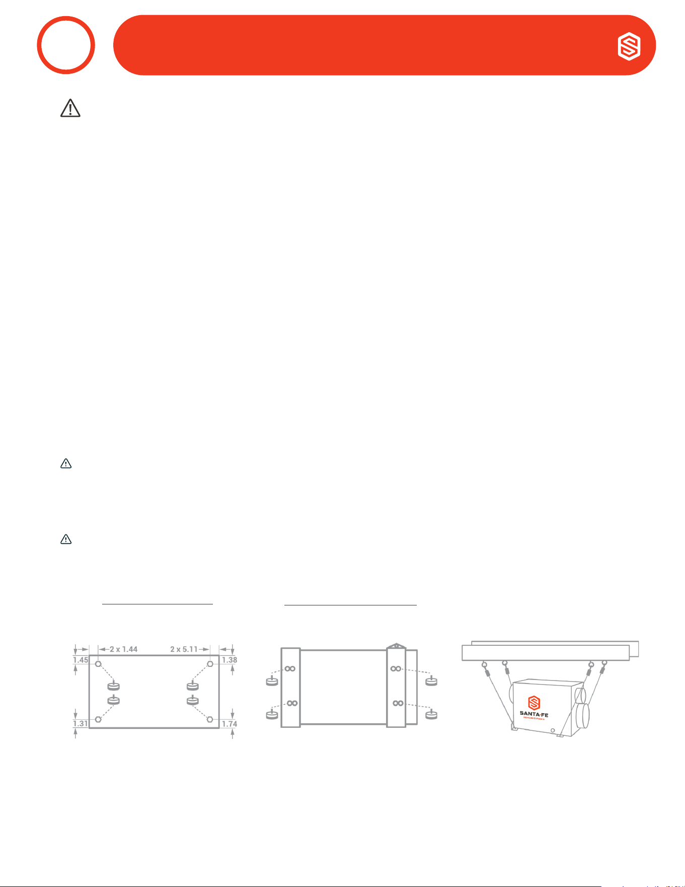
a. If You Place On Floor
Attach leveling feet and use
vibration pads and/or risers.
b. If You Hang Dehumidifier
Use 2 Brackets
*
Per Unit.
*
Brackets sold separately.
Choose Weather To Place On Floor Or Hang Dehumidifier.
CAUTION! INTERNAL STOPS LIMIT FEET HEIGHT. DO NOT TIGHTEN FEET BEYOND THE
RESISTANCE PROVIDED BY STOPS.
Example Of Hanging Option:
*
NOTE: LEVELING FEET HOLD
BRACKET IN PLACE
DUCTING TO HVAC SYSTEMS
8

12
Santa Fe ULTRA98/120 Installation & Operation Instructions Santa-Fe-Products.com | 800.533.7533
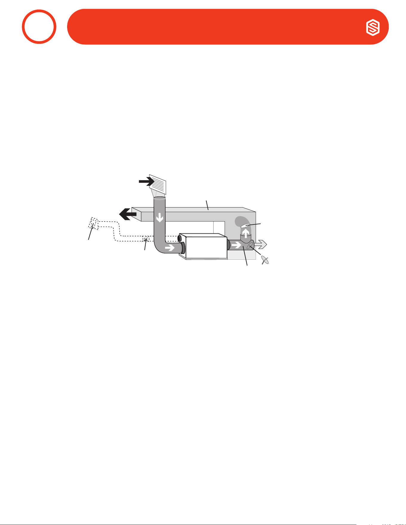
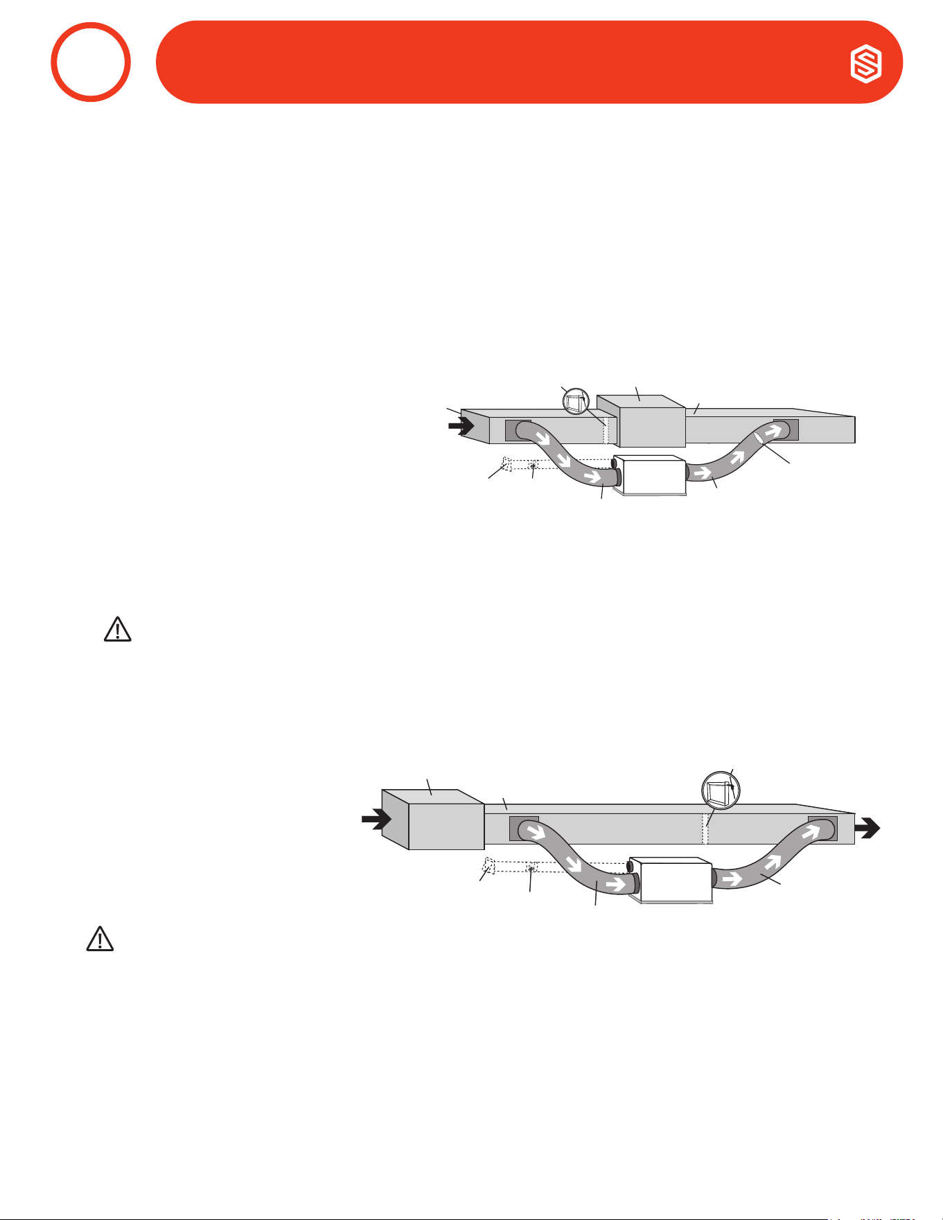
1. Recommended HVAC System Installations
a. Attic
The recommended installation draws air from a central location through a dedicated return to the
dehumidier and ducts the supply of the dehumidier to the air supply of the HVAC system. Utilize the
optional outdoor air ventilation duct to provide outdoor air.
• Install a dedicated 10" air return for the Santa Fe Ultra98/120 from a central area of the structure.
• Duct the supply of the Santa Fe Ultra98/120 to the supply of the HVAC system with a backdraft
damper.
• If the existing system has multiple returns, instead of installing a dedicated return to the Santa Fe
Ultra98/120, it is possible to select one to disconnect from the existing HVAC system and use it for
the dedicated Santa Fe Ultra98/120 return. Select a return from a central location in the house that
is always open to the rest of the structure. DO NOT use a return from a room where doors are kept
closed.
• DO NOT locate return in a bathroom or kitchen.
• Control should be located remotely from the dehumidier and placed in a central location.
Dedicated Santa Fe Return to HVAC Supply
DUCTING TO HVAC SYSTEMS
8
Air Handler
HVAC
Return
HVAC Supply
Ultra Series
Indoor
Air Return
Motorized
Damper
Optional
Outdoor
Air Intake
Ultra Series
Supply
Backdraft
Damper
13
800.533.7533 | Santa-Fe-Products.com Santa Fe ULTRA98/120 Installation & Operation Instructions
DUCTING TO HVAC SYSTEMS DUCTING TO HVAC SYSTEMS
8
Optional
Duct Tee
& Gravity
Damper
Ultra Series
Indoor Air
Return
Motorized
Damper
Optional
Outdoor
Air Intake
Dry Air to Basement
Backdraft
Damper
Air Handler Supply
Ultra Series
Supply
b. Installation in a Basement or Crawlspace
Install a separate 10" return for the Ultra98/120 in a central area of the structure. Duct the supply of the
dehumidier to the air supply of the HVAC system with a backdraft damper.
Optional: Duct the supply of the Ultra98/120 to a 8" x 8" x 8" tee/damper with a gravity draft damper,
adjusted to 20% open to the basement. CAUTION: Air takes the path of least resistance. If the upper levels
of the living space are not receiving the appropriate amount of dry air, this damper may need to be adjusted.
When the dehumidier is not running, there is a chance that air from the basement or crawlspace will make
its way back through the gravity damper and into the living space.
14
Santa Fe ULTRA98/120 Installation & Operation Instructions Santa-Fe-Products.com | 800.533.7533
If the Recommended Dedicated Ultra Series Return to HVAC Supply Installation is not possible, there are several
alternative installation options available.
• DO NOT locate return in a bathroom or kitchen.
• Control should be located remotely from the dehumidier and placed in a central location.
• For basement and crawl space installations, an optional tee can be installed on the Ultra Series Supply.
a. HVAC Return to HVAC Supply
Check Damper should be in place
between the Return and Supply
connections of the dehumidier.
If Check Damper is not in place, the
HVAC fan must turn on when the
dehumidier is in operation.
If the system has greater than 0.5” WG
the ducting must be recongured.
Air Handler
HVAC Supply
Motorized
Damper
Optional
Outdoor
Air Intake
Optional Check Damper
(no HVAC fan needed)
HVAC Return
Ultra Series
Supply
Ultra Series
Return
Backdraft
Damper
2. Alternative HVAC System Installation
DUCTING TO HVAC SYSTEMS
8
WARNING
DUE TO PRESSURE RESISTANCE IT IS NOT RECOMMENDED TO USE THE OPTIONAL OUTDOOR AIR INTAKE
WHEN INSTALLING THE DEHUMIDIFIER SUPPLY TO SUPPLY.
b. HVAC Supply to HVAC Supply
If Check Damper is not in place, the
HVAC fan must turn on when the
dehumidier is in operation.
Air Handler
HVAC Supply
Motorized
Damper
Optional
Outdoor
Air Intake
Optional Check Damper
(no HVAC fan needed)
Ultra Series
Supply
Ultra Series
Return
CAUTION!
TO AVOID THE DEHUMIDIFIER CYCLING IN AND OUT OF DEFROST, IT IS RECOMMENDED THAT THE LEAVING
AIR TEMPERATURE OF THE A/C COIL IS NOT BELOW 55°F. ALSO, THIS INSTALL IS NOT RECOMMENDED FOR
CLIMATES WERE THE HEATING SYSTEM WILL RUN DURING THE SPRING AND FALL TIMES OF THE YEAR, AS
THIS COULD DIMINISH THE WATER REMOVAL CAPABILITY OF THE DEHUMIDIFIER.

15
800.533.7533 | Santa-Fe-Products.com Santa Fe ULTRA98/120 Installation & Operation Instructions
d. HVAC Return to HVAC Return
If Check Damper is not in place, the
HVAC fan must turn on when the
dehumidier is in operation.
Air Handler
HVAC
Supply
HVAC Return
Motorized
Damper
Optional
Outdoor
Air Intake
Optional Check Damper
(no HVAC fan needed)
Ultra Series
Supply
Ultra Series
Return
c. Dedicated Ultra Series Return to HVAC Return
Create a separate return for the Ultra
Series Dehumidier in a central area of
the building.
Installing the supply air from the Ultra
Series Dehumidier to the return of the
HVAC system requires the HVAC fan to
run when the Ultra Series Dehumidier
is operating.
Air Handler
HVAC
Return
HVAC Supply
Ultra Series
Supply
Ultra Series
Indoor
Air Return
Motorized
Damper
Optional
Outdoor
Air Intake
Motorized
Damper
Ultra Series
Supply
Ultra Series
Indoor Air
Return
Optional
Outdoor
Air Intake
e. No Existing Ductwork Installation
When installing the Ultra Series Dehumidier in a structure that does not have a forced-air HVAC system, a
single return for the dehumidier should be installed in a central location.
Install an insulated duct from outside to the 6” collar of the Ultra Series Dehumidier to provide outdoor air
ventilation (optional).
The supply of the Ultra Series Dehumidier should be ducted to the rooms in the home that have the ductless
mini-split heads and as close to the heads as possible. Be sure to utilize multiple rooms to allow air inside the
structure to properly circulate. Proper air distribution is important to ensure even humidity control and heat
distribution throughout the structure.
A 6” diameter duct is recommended for branches to bedrooms. An 8” diameter duct is recommended for
branches to larger areas.
• DO NOT locate return in a bathroom or
kitchen.
• DO NOT locate the supply in rooms
where doors may be closed.
• Control should be located remotely
from the dehumidier and placed in a
central location.
CAUTION!
PLEASE NOTE: RETURN TO RETURN INSTALLS ARE TO BE CONSIDERED LAST RESORT OPTIONS AND
ARE NOT RECOMMENDED. THE DEHUMIDIFIER WILL HEAT THE AC COOLING COILS WHICH DIMINISHES
THE AMOUNT OF WATER THE AC SYSTEM WILL REMOVE WHEN OPERATING. IF THIS INSTALLATION IS
CHOSEN, THE DEHUMIDIFIER MUST ACTIVATE THE HVAC BLOWER AND AC CALLS NEED TO LOCK OUT THE
DEHUMIDIFIER FROM RUNNING. PLEASE CHECK YOUR LOCAL CODES PRIOR TO INSTALLING.
DUCTING TO HVAC SYSTEMS
8

16
Santa Fe ULTRA98/120 Installation & Operation Instructions Santa-Fe-Products.com | 800.533.7533
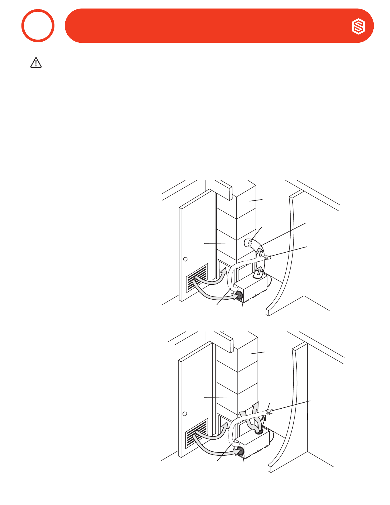
Due to space limitations, a closet installation may require additional considerations. Locate the dehumidier under
or next to the HVAC system as space allows. A passive vent or louver door is required to allow air to be pulled in
from the living space.
• No inlet duct is required. Air is pulled through the passive vent or louver door from the living space.
• Install an insulated duct from outside to the 6” collar of the Ultra Series Dehumidier to provide outdoor air
ventilation (optional).
• Control should be located remotely from the dehumidier and placed in a central location.
• Where outlet space is restricted, the outlet duct collar is optional or vertical flow through may be preferred.
WHEN INSTALLING THE DEHUMIDIFIER AS PART OF A COMBUSTION TYPE HVAC SYSTEM (GAS, OIL, PROPANE,
ETC.), FOLLOW ALL LOCAL AND NATIONAL BUILDING AND SAFETY CODES.
WARNING!
Central Return to HVAC Supply
Duct the supply of the Ultra Series
Dehumidier to the supply of the
existing HVAC system with a backdraft
damper.
Backdraft
Damper
HVAC
Supply
Ultra Series
Supply
HVAC
Return
Ultra Series
Return
Optional Outdoor
Air Intake
Motorized
Damper
1. Recommended Closet Installation
DUCTING TO HVAC SYSTEMS (Closet Installations)
9
17
800.533.7533 | Santa-Fe-Products.com Santa Fe ULTRA98/120 Installation & Operation Instructions
2. Alternative Closet Installation
If the Recommended Closet Installation is not possible, there are several alternative installation options available.
• No inlet duct is required. Air is pulled through the passive vent or louver door from the living space.
• Install an insulated duct from outside to the 6” collar of the Ultra Series Dehumidier to provide outdoor air
ventilation (optional).
• Control should be located remotely from the dehumidier and placed in a central location.
a. Central Return to HVAC Return
Duct the supply of the Ultra Series
Dehumidier to the return side of the
existing HVAC system.
In a central return system, the HVAC
fan must run when the dehumidier is
running.
Backdraft
Damper
HVAC
Supply
Ultra Series
Supply
HVAC
Return
Ultra Series
Return
Optional Outdoor
Air Intake
Motorized
Damper
b. No Duct - Central Return to HVAC Return
Attach outlet duct with a vertical flow
through so air is not discharged into
wall or other obstruction. The HVAC
system will naturally pull dehumidied
air from the closet and distribute it
throughout the structure.
HVAC
Supply
Ultra Series
Supply
HVAC
Return
Ultra Series
Return
Optional Outdoor
Air Intake
Motorized
Damper
DUCTING TO HVAC SYSTEMS (Closet Installations)
9
CAUTION!
PLEASE NOTE: RETURN TO RETURN INSTALLS ARE TO BE CONSIDERED LAST RESORT OPTIONS AND ARE
NOT RECOMMENDED. THE DEHUMIDIFIER WILL HEAT THE AC COOLING COILS WHICH DIMINISHES THE
AMOUNT OF WATER THE AC SYSTEM WILL REMOVE WHEN OPERATING. PLEASE CHECK YOUR LOCAL
CODES PRIOR TO INSTALLING.
18
Santa Fe ULTRA98/120 Installation & Operation Instructions Santa-Fe-Products.com | 800.533.7533
Outdoor air ventilation is optional.
Outdoor air may be brought into the structure by connecting an insulated duct from outside the structure to the
6” inlet of the Santa Fe Ultra98/120. A ventilation control is needed to program the time and frequency that the
unit introduces outside air. The time and frequency of ventilation should be based on the size and occupancy of
the residence.
• The outdoor air ventilation duct should be connected to the 6” round collar on the front of the Santa Fe
Ultra98/120.
• An insulated 6” diameter duct can provide up to 75 CFM of outside air.
• If a motorized damper is not being used, outdoor air is controlled by the manual damper in the 6” collar
of the Santa Fe Ultra98/120.
• Performance of the Santa Fe Ultra98/120 can be impacted by inside and outside air conditions.
• When a 6” motorized damper is used, a digital control is required.
• It may be necessary to use 8” duct work if additional outdoor air is required.
• In cold climates or at times when the dew point is low, ventilation can be used to dehumidify the
structure, making the Santa Fe Ultra98/120 capable of year-round drying.
OUTLET DUCT
COLLAR WITH
BACK DRAFT
DAMPER
RETURN AIR
INLET DUCT
COLLAR
FRESH AIR
INLET DUCT
COLLAR
RETURN AIR
INLET DUCT
COLLAR
FRESH AIR
INLET DUCT
COLLAR
AIR FLOW
Air
Flow
Outdoor Air
90°F, 65%RH
Indoor Air
70°F, 50%RH
Mixed Air
Mixed Air
75°F
75°F
65%RH
65%RH
Mixed Air
75°F
65%RH
Outlet Air
75°F, 65%RH
Hot Climate
6" Optional Outdoor
Air Intake
10" Return Air Inlet
10" Supply Air Outlet
A
B
C
A
B
C
Outdoor Air
30°F, 65%RH
Indoor Air
70°F, 50%RH
Outlet Air
59°F, 51%RH
Cold Climate
A
B
C
6" Optional Outdoor
Air Intake
10" Return Air Inlet
10" Supply Air Outlet
A
B
C
Mixed Air
Mixed Air
59°F
59°F
51%RH
51%RH
Mixed Air
59°F
51%RH
1. Outdoor Air Ventilation With Dehumidier Off and Fan Only Operation
Outside air mixes with return air prior to beginning the dehumidication process. Outside
and inside temperature and relative humidity will impact the combined outlet air conditions.
OUTDOOR AIR VENTILATION
10

19
800.533.7533 | Santa-Fe-Products.com Santa Fe ULTRA98/120 Installation & Operation Instructions
Option 1: Calculating Airflow Requirement Using ASHRAE 62.2-2016 Airflow Equation
ASHRAE Airflow in CFM = [House Area in Sq.Ft. x 0.03] + [(Number of Bedrooms +1) x 7.5]
NOTE: Use ‘Number of Bedrooms + 1’ or ‘Number of Occupants’, whichever is larger.
Example 1: Number of Bedrooms + 1
1800 square foot house with 3 bedrooms, 4 occupants = [1800 X 0.03] + [(3+1) X 7.5] = 84 CFM
Example 2: Number of Occupants
1800 square foot house with 3 bedrooms, 5 occupants = [1800 X 0.03] + [5 X 7.5] = 91.5 CFM
Record the required CFM ____________
1. Determine Ventilation Requirements
The MINIMUM ventilation requirement is calculated using ASHRAE 62.2-2016. Use one or both of the options below
to determine your ventilation requirement. Follow all local and national building and safety codes.
Option 2: Calculating Airflow Requirement Using Table 4.1 from ASHRAE 62.2-2019
Ventilation Air Requirements, CFM
Record the required CFM ____________
Table 4.1 from ASHRAE 62.2-2019
Floor Area
(ft
2
)
Number of Bedrooms
1 2 3 4 5
<500 30 38 45 53 60
501-1000 45 56 60 68 75
1001-1500 60 68 75 83 90
1501-2000 75 83 90 98 105
2001-2500 90 98 105 113 120
2501-3000 105 113 120 128 135
3001-3500 120 128 135 143 150
3501-4000 135 143 150 158 165
4001-4500 150 158 165 173 180
4501-5000 165 173 180 188 195
OUTDOOR AIR VENTILATION
11
20
Santa Fe ULTRA98/120 Installation & Operation Instructions Santa-Fe-Products.com | 800.533.7533
A control must be used with the Santa Fe Ultra98/120. Santa Fe offers the DEH 3000 proprietary control. The DEH
3000 allows homeowners to monitor and control relative humidity and proper ventilation levels in their home. This
control is also available with a remote sensing option.
NOTE: The DEH 3000 is sold separately. Other thermostats are compatible with the Santa Fe Ultra98/120.
CAUTION!
DO NOT ALLOW THE 24V TERMINAL FROM THE SANTA FE ULTRA98/120 TO CONTACT THE COM
TERMINAL ON THE SANTA FE ULTRA98/120 OR DAMAGE TO THE TRANSFORMERS WILL RESULT.
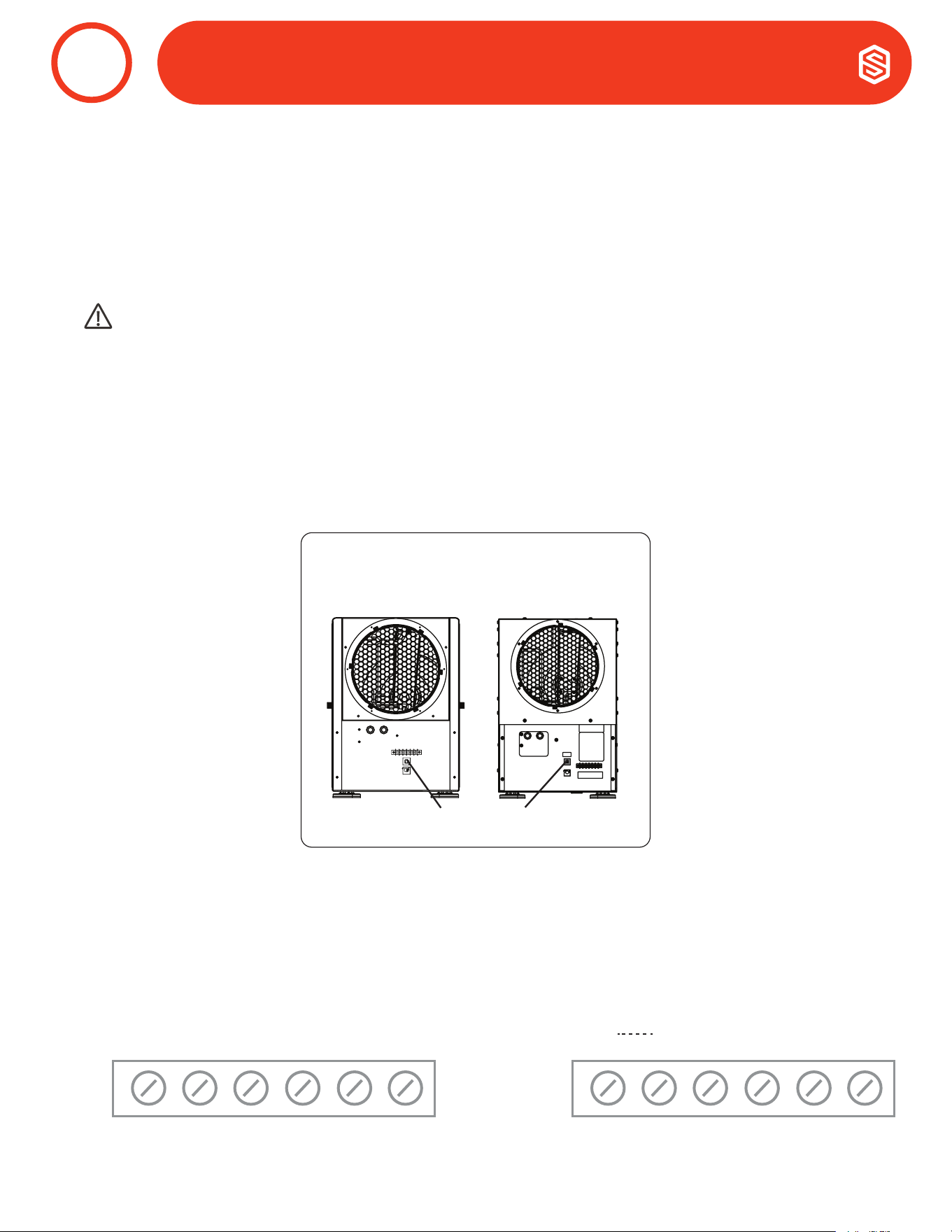
a. Circuit Breaker
To prevent damage to the 24 volt control transformer, the Santa Fe Ultra98/120 comes with a resettable
circuit breaker. Check wiring for any electrical short and repair before resetting breaker. Resetting the circuit
breaker without correcting the electrical short may result in transformer damage. Be sure to check the
electrical schematic in this manual or inside the access panel of the Santa Fe Ultra98/120 before making any
control connections. The reset button for the circuit breaker can be found on the back of the unit.
b. Control Connections
The control and the Santa Fe Ultra98/120 are labeled to prevent confusion. Depending on the control, some of
the screw terminals on the Santa Fe Ultra98/120 may not be used. Be sure to consult the electrical schematic
in this manual or inside the access panel of the Santa Fe Ultra98/120 before making control connections.
1. Wiring Controls
CONTROLS
12
Rear View
Santa Fe ULTRA120
Circuit Breaker Reset Button
Santa Fe ULTRA98
COM
FAN
24V
DEHU
*
DMPR
COM
FAN
24V
DEHU
FLOAT
FLOAT
Ultra98 Ultra120
21
800.533.7533 | Santa-Fe-Products.com Santa Fe ULTRA98/120 Installation & Operation Instructions
A low voltage control must be used with the Santa Fe Ultra98/120.
NOTE: 18 gauge wire needed between the Santa Fe Ultra98/120 dehumidier and the external control.
Ultra98
COM 24VAC Power Transformer Neutral Side
FAN Fan Control
24V Transformer High Side
DEHU Dehumidication (Fan and Compressor) Control
DMPR 24VAC Power Transformer Neutral Side
* Spare Terminal (Open)
Ultra120
COM 24VAC Power Transformer Neutral Side
FAN Fan Control
24V Transformer High Side
DEHU Dehumidication (Fan and Compressor) Control
Float
External Low Voltage Float Switch or Water Sensor
(Use Normally Closed Switch)
Float
External Low Voltage Float Switch or Water Sensor
(Use Normally Closed Switch)
Between the COM lead and the 24V TERMINAL is a 40VA transformer. This low voltage power source powers
the relay coils which control the fan and compressors. This 24VAC transformer can also be used to power
HVAC accessories external to the dehumidier.
Compressor ON/Fan On Make contact between 24V and DEHU terminals
Compressor OFF/Fan On Make contact between 24V and FAN terminals
Power HVAC Accessory Connect the accessory to the DMPR and 24V terminals
CONTROLS
12
2. Terminal Block Control Operation
22
Santa Fe ULTRA98/120 Installation & Operation Instructions Santa-Fe-Products.com | 800.533.7533
The Santa Fe Ultra98/120 is equipped with a MERV-13 (Dimensions: 1.75”x14”x17.5”) air lter. The lter should be
checked and replaced every three to six months. Operating the unit with a dirty lter will reduce dehumidier capacity
and efciency.
DO NOT operate the unit without the recommended lter. Filter non-compliance voids the product warranty.
Changing the Filter
For greatest ltration and efciency of the Santa Fe Ultra98/120, it is recommended the air lter be replaced
every three to six months with a MERV 13 rated lter.
Step 1: Remove the magnetized lter door by pulling it off of the dehumidier. You can remove it on either side
to gain access to the lter.
Step 2: Remove the lter by gently pulling straight out of the unit. Insert new lter by gently pushing it
straight into the unit. Make sure the AIR FLOW arrow on the lter is pointing into the unit.
Step 3: Attach the magnetized lter door back into place, ensuring it covers the lter compartment completely.
CAUTION!
MAKE SURE UNIT IS OFF BEFORE CHANGING THE FILTER.
AIR FILTRATION
13
Side View
Filter Door
Optional
Outdoor
Air Intake
Return
Filter
Optional
Outdoor
Air Intake
Return
Side View
Filter
Top View
Side View
Magnetic Strip
Optional Fresh
Air Intake
Return
Supply
Top View
Supply
Top View
Filter
Fresh Air
Intake
(Optional)
Return
Filter
Return
Filter
To Remove,
pull out straight.
Filter
Top View
Side View
Magnetic Strip
Optional Fresh
Air Intake
Return
Supply
Top View
Supply
Top View
Filter
Fresh Air
Intake
(Optional)
Return
Filter
Return
Filter
To Replace,
push in straight.
Front View Front View
Side View
Filter Door
Optional
Outdoor
Air Intake
Return
23
800.533.7533 | Santa-Fe-Products.com Santa Fe ULTRA98/120 Installation & Operation Instructions
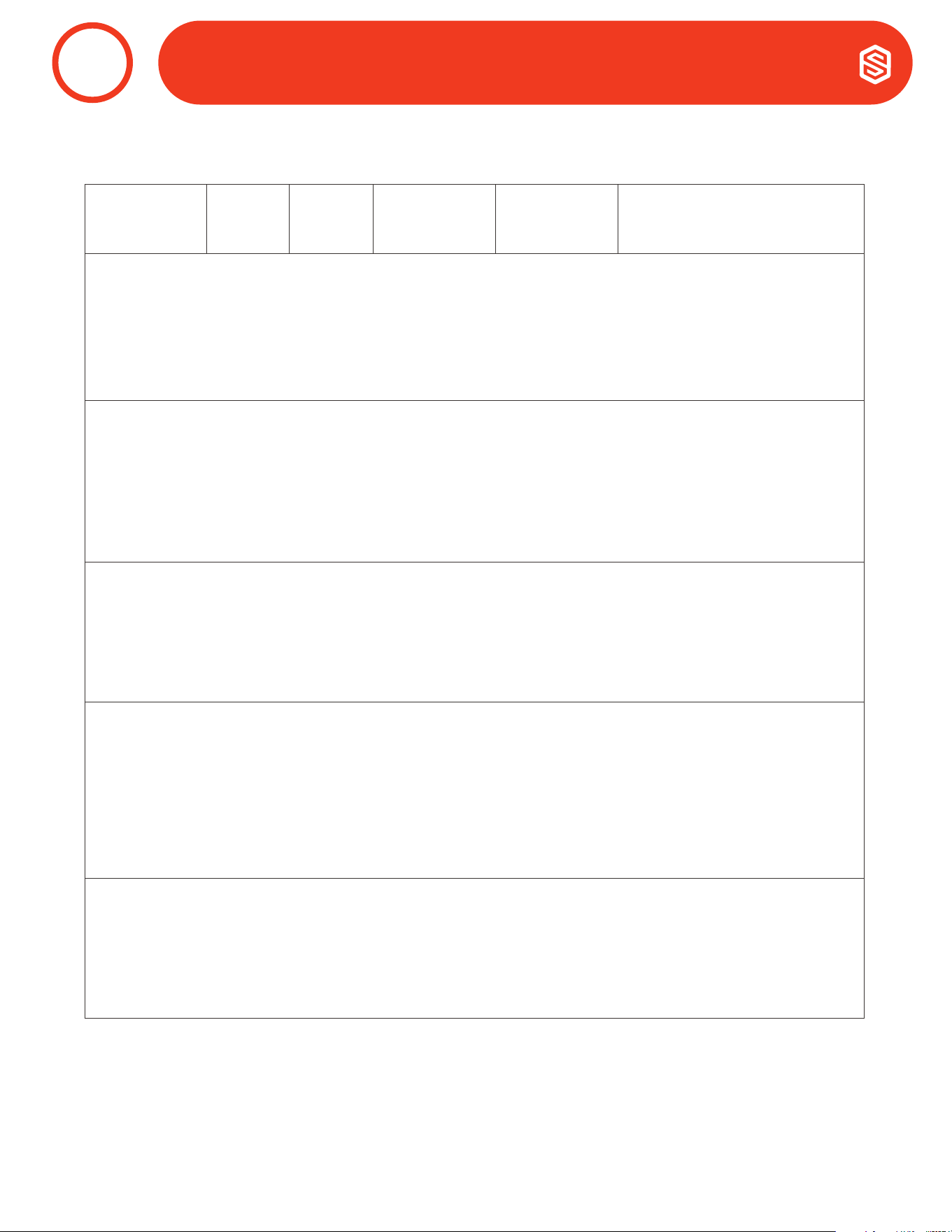
Standard 52.5
Minimum Efciency
Reporting Value
Dust Spot
Efciency
Arrestance
Typical Controlled
Contaminant
Typical
Applications and
Limitations
Typical Ail Filter/Cleaner Type
20 n/a n/a
< 0.30 pm Particle
Size
Cleanrooms
≥99.999% eff. On 10-20 pm Particles
19 n/a n/a Virus (unattached)
Radioactive
Materials
Particles
18 n/a n/a Carbon Dust
Pharmaceutical
Man.
Particulates
17 n/a n/a
All Combustion
Smoke
Carcinogenic
Materials
≥99.97% eff. On 30 pm Particles
16 n/a n/a
0.30-1.0 pm
Particle Size
General Surgery Bag Filter - Nonsupported
15 >95% n/a All Bacteria
Hospital Inpatient
Care
Micro Fine Fiberglass or Synthetic media,
12-36 in. Deep, 6-12 Pockets
14 90-95% >98%
Most Tobacco
Smoke
Smoking Lounges Box Filter - Rigid Style Cartridge
13 89-90% >98%
Proplet Nuceli
(Sneeze)
Superior
Commercial
Buildings
Filters 6 to 12 in. Deep, May Use Lofted or
Paper Media
12 70-75% >95%
1.0-3.0 pm Particle
Size Legionella
Superior
Residential
Bag Filter - Nonsupported
11 60-65% >95%
Humidier Dust
Lead Dust
Better Commercial
Buildings
Micro Fine Fiberglass or Synthetic media,
12-36 in. Deep, 6-12 Pockets
10 50-55% >95% Milled Flour Box Filter - Rigid Style Cartridge
9 40-45% >90% Welding Fumes
Hospital
Laboratories
Filters 6 to 12 in. Deep, May Use Lofted or
Paper Media
8 30-35% >90%
3.0-10.0 pm
Particle Size
Commercial
Buildings
Pleated Filters - Disposable, Extended
Surface Area, Thick with Cotton-Polyester
Blend Media, Cardboard Frame
7 25-30% >90%
Mold Spores
Hair Spray
Better Residential
Cartridge Filters - Graded Density Viscous
Coated Cube or Pocket Filters, Synthetic
Media
6 <20% 85-90%
Fabric Protector
Dusting Aids
Throwaway - Disposable Synthetic Panel
Filter
5 <20% 80-85%
Cement Dust
Pudding Mix
Paint Booth Inlet
4 <20% 75-80%
>10.0 pm Particle
Size Pollen
Minimal Filtration
Throwaway - Disposable Synthetic Panel
Filter
3 <20% 70-75%
Dust Mites
Standing Dust
Residential Washable - Aluminum Mesh
2 <20% 65-70% Spray Paint Dust
1 <20% <65%
Textile Fibers
Carpet Fibers
Window A/C Units
Electrostatic - Self Charging Woven Panel
Filter
Table Data Source: United States Environmental Protection Agency
AIR FILTRATION
13
2. MERV Rating Chart
24
Santa Fe ULTRA98/120 Installation & Operation Instructions Santa-Fe-Products.com | 800.533.7533
CAUTION!
TROUBLESHOOTING SHOULD BE PERFORMED BY A QUALIFIED HVAC TECHNICIAN.
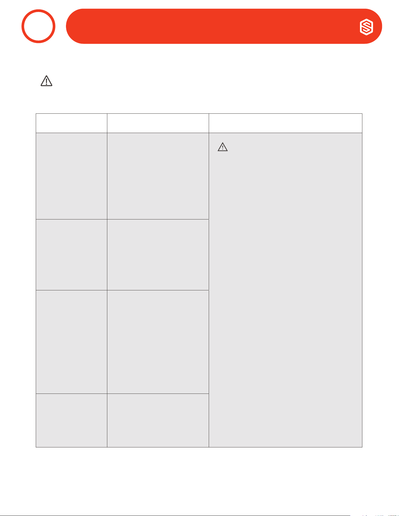
1. Troubleshooting
Symptom Possible Reason Troubleshooting Procedure
Neither fan nor
compressor
running.
Dehumidication
is being called for.
1. Dehumidier unplugged or
no power to outlet.
2. Humidity control set too
high.
3. Loose connection in
internal or control wiring.
4. Defective compressor
relay.
5. Defective control
transformer.
WARNING!
ELECTRICAL SHOCK HAZARD:
Electrical power must be present to perform
some tests. These tests should be performed by
a qualied service person.
Troubleshooting Procedure for Control Related
Issues
This method of diagnosis will test the 3 main
components of the control circuit individually
to indicate any potential problems. This is to be
used when the control will not activate the main
unit.
1. Detach eld control wiring connections from
the terminals on the main unit.
2. Connect the 24V and FAN terminals
together; only the fan should run.
Disconnect the terminals.
3. Connect the 24V and DEHU terminals
together; fan and compressor should run.
Disconnect the terminals.
4. If this test works, the main unit is working
correctly from a control standpoint.
5. Reconnect eld control wiring to the
terminals on the main unit.
6. Remove the control panel cover and
detach the eld wiring from the control
connections.
7. Connect the 24V and FAN terminals
together; only the fan should run.
Disconnect the terminals.
8. Connect the 24V and DEHU terminals
together; fan and compressor should run.
Disconnect the terminals.
9. If this test works, then the eld control
wiring is ok.
10. If the problem persists, then the control is
most likely faulty.
Compressor
is not running.
Dehumidication is
being called for. Fan
is running.
1. Defective compressor run
capacitor.
2. Loose connection in
compressor circuit.
3. Defective compressor
overload.
4. Defective compressor.
5. Defrost thermostat open.
Compressor
cycles on and off.
Dehumidication is
being called for.
1. Low ambient temperature
and/or humidity causing
unit to cycle through
defrost mode.
2. Defective compressor
overload.
3. Defective compressor.
4. Defrost thermostat
defective.
5. Dirty air lter(s) or air flow
restricted.
6. Defective fan or relay.
Fan is not running.
Dehumidication or
fan is being called
for.
1. Loose connection in fan
circuit.
2. Obstruction prevents fan
impeller rotation.
3. Defective fan.
4. Defective fan relay.
SERVICE
14
25
800.533.7533 | Santa-Fe-Products.com Santa Fe ULTRA98/120 Installation & Operation Instructions
Troubleshooting (Continued)
WARNING!
SERVICING THE SANTA FE ULTRA98/120 WITH ITS HIGH PRESSURE REFRIGERANT SYSTEM AND
HIGH VOLTAGE CIRCUITRY PRESENTS A HEALTH HAZARD WHICH COULD RESULT IN DEATH, SERIOUS
BODILY INJURY, AND/OR PROPERTY DAMAGE. SERVICE MUST BE PERFORMED BY
A QUALIFIED SERVICE TECHNICIAN.
If the refrigerant charge is lost due to service or a leak, the leak should be repaired and a new charge must be
accurately weighed in. If any of the old charge is left in the system, it must be recovered before weighing in the
new charge. Refer to the unit nameplate for the correct charge weight and refrigerant type.
2. Refrigerant Charging
Symptom Possible Reason Troubleshooting Procedure
Low dehumidication
capacity (evaporator
is frosted
continuously).
Dehumidication is
being called for.
1. Defrost thermostat loose
or defective.
2. Low refrigerant charge.
3. Dirty air lter(s) or air
flow restricted.
4. Excessively restrictive
ducting connected to
unit.
WARNING!
ELECTRICAL SHOCK HAZARD:
Electrical power must be present to perform
some tests. These tests should be performed by
a qualied service person.
Troubleshooting Procedure for Control Related
Issues
This method of diagnosis is used to
function check the internal components in
the dehumidier. This is to be used when a
performance issue is suspected.
1. Set the humidity controller all the way to the
most humid setting or off position – Did the
unit shut off?
2. If yes, turn the fan setting to the ON position
– does the fan start?
3. If fan starts, leave in the fan ON position
and set the humidity all the way to driest
setting. May have to wait 5 minutes for the
compressor to start.
4. Listen for a distinct buzzing/humming
sound of a compressor starting up – do you
hear this noise?
5. If compressor is running and continues to
run, after about 15 minutes you should feel
a slight increase in air temperature being
discharged out of the discharge air side of
the unit.
6. If so, depending on your environmental
conditions (temp/Rh%), you should see
some water production out of the hose
within 30 minutes or so. (Note: If the room
temperature is 55 degrees or below and/
or in area of low relative humidity, the
dehumidier will produce little to no water.)
7. Collecting the water removed in a 24
hour period will give a measurement of
performance.
No ventilation.
Ventilation is being
called for.
1. Loose connection in
ventilation control
circuit.
2. Loose connection in
damper power circuit.
3. Defective outdoor air
damper.
Dehumidier
removes some water,
but not as much as
expected.
1. Air temperature and/or
humidity have dropped.
2. Humidity meter and or
thermometer used are
out of calibration.
3. Unit has entered defrost
cycle.
4. Dirty air lter(s) or air
flow is restricted.
5. Defective defrost
thermostat.
6. Low refrigerant charge.
7. Air leak such as loose
cover or ducting leaks.
8. Defective compressor.
9. Restrictive ducting.
SERVICE
14

26
Santa Fe ULTRA98/120 Installation & Operation Instructions Santa-Fe-Products.com | 800.533.7533
WARRANTY
15
Effective January 1, 2024
Limited Warranty. Therma-Stor, LLC (“Therma-Stor”) warrants as follows: (i) Santa Fe dehumidifiers (“Product”) will be free of material
defects in workmanship or materials for a period of 5 years (“Five-Year Warranty”) following the date of initial purchase of such Product
by an original customer purchasing from Therma-Stor or an authorized reseller (“Customer”); and (ii) the Product’s components will be
free of material defects in workmanship or materials for a period of six (6) years following the date of initial purchase of such Product by
a Customer.
Limitation of Remedies. CUSTOMER’S SOLE AND EXCLUSIVE REMEDY UNDER THE ABOVE LIMITED WARRANTY AND THERMA-
STOR’S ENTIRE LIABILITY THEREUNDER, SHALL BE, AT THE SOLE OPTION OF THERMA-STOR, REPLACEMENT OR REPAIR OF SUCH
PRODUCT OR ITS COMPONENTS (“COMPONENTS”) BY THERMA-STOR OR THERMA-STOR’S AGENTS ONLY. REFRIGERANT, PIPING,
SUPPLIES, TRANSPORTATION COSTS, LABOR COSTS INCURRED IN REPAIR OR REPLACEMENT OF SUCH COMPONENTS ARE NOT
INCLUDED. THIS DISCLAIMER AND EXCLUSION SHALL APPLY EVEN IF THE EXPRESS WARRANTY AND LIMITED REMEDY SET FORTH
HEREIN FAILS OF ITS ESSENTIAL PURPOSE. CUSTOMER ACKNOWLEDGES THAT NO REPRESENTATIVE OF THERMA-STOR OR OF ITS
AFFILIATES OR RESELLERS IS AUTHORIZED TO MAKE ANY REPRESENTATION OR WARRANTY ON BEHALF OF THERMA-STOR OR ANY
OF ITS AFFILIATES OR RESELLERS THAT IS NOT IN THIS AGREEMENT.
Disclaimer of Warranties. EXCEPT FOR ABOVE LIMITED WARRANTY, WHICH IS THE SOLE AND EXCLUSIVE WARRANTY PROVIDED WITH
RESPECT TO THE PRODUCT AND ITS COMPONENTS, THERMA-STOR HEREBY DISCLAIMS ALL EXPRESS AND IMPLIED WARRANTIES,
INCLUDING, WITHOUT LIMITATION, THE IMPLIED WARRANTIES OF MERCHANTABILITY AND FITNESS FOR A PARTICULAR PURPOSE.
Warranty Limitations. The foregoing limited warranty extends only to a Customer and shall be null and void upon attempted assignment
or transfer. A “defect” under the terms of the limited warranty shall not include problems resulting from Customer’s or Customer’s
employees’, agents’, invitees’ or a third party’s misuse, improper installation, improper design of any system in which the Product is
included, abuse, lack of normal care, failure to follow written instructions, tampering, improper repair, or freezing, corrosion, acts of
nature or other causes not arising out of defects in Therma-Stor’s workmanship or material. If a Product or Component is replaced
while under warranty, the applicable limited warranty period shall not be extended beyond the original warranty time period. The
limited warranty does not cover any costs related to changes to a Product or Component that may be required by any codes, laws, or
regulations that may become effective after initial purchase of the Product by Customer.
Customer Responsibilities. As a further condition to obtaining warranty coverage hereunder, the Customer must send a valid warranty
claim to Therma-Stor such that Therma-Stor receives such claim prior to the end of the applicable warranty period. Therma-Stor shall
have no obligation hereunder with respect to any claim received by Therma-Stor after the expiration of the applicable warranty period.
As a further condition to obtaining warranty coverage hereunder, the Customer must present forms of invoices evidencing proof of
purchase of a Product. If such invoices do not clearly indicate the date of initial purchase by a Customer, the applicable Product’s date
of manufacture will be used instead of the date of initial purchase for the purpose of calculating the commencement of the applicable
warranty period. Warranty service must be performed by Therma-Stor or a servicer authorized by Therma-Stor. In order to obtain
warranty service, the Customer should call Therma-Stor at 1-800-533-7533 and ask for the Therma-Stor Products Service Department,
which will then arrange for applicable warranty service. Warranty service will be performed during customary, daytime working hours. If
the Product must be shipped for service, Customer shall be solely responsible for properly packaging the Product, for all freight charges,
and for all risk of loss associated with shipment.
Limitation of Liability. IN NO EVENT SHALL THERMA-STOR, IN CONNECTION WITH THE DESIGN, SALE, INSTALLATION, USE, REPAIR,
REPLACEMENT OR PERFORMANCE OF ANY PRODUCT, COMPONENT, PART THEREOF OR WRITTEN MATERIAL PROVIDED THEREWITH,
BE LIABLE, TO THE EXTENT ALLOWED UNDER APPLICABLE LAW, UNDER ANY LEGAL THEORY FOR ANY SPECIAL, DIRECT, INDIRECT,
COLLATERAL OR CONSEQUENTIAL DAMAGES OF ANY KIND. NOTWITHSTANDING THE ABOVE LIMITATIONS AND WARRANTIES, THE
SOLE AND EXCLUSIVE LIABILITY OF THERMA-STOR, REGARDLESS OF THE NATURE OR THEORY OF THE CLAIM, SHALL UNDER NO
CIRCUMSTANCES EXCEED THE PURCHASE PRICE OF THE PRODUCT, COMPONENT OR PART UPON WHICH THE CLAIM IS PREMISED.
Applicable Law and Venue. ANY ARBITRATION, ENFORCEMENT OF AN ARBITRATION OR LITIGATION RELATED TO THE PRODUCT WILL
BE BROUGHT EXCLUSIVELY IN DANE COUNTY, WISCONSIN, AND CUSTOMER CONSENTS TO THE JURISDICTION OF THE FEDERAL
AND STATE COURTS LOCATED THEREIN, SUBMITS TO THE JURISDICTION THEREOF AND WAIVES THE RIGHT TO CHANGE VENUE.
CUSTOMER FURTHER CONSENTS TO THE EXERCISE OF PERSONAL JURISDICTION BY ANY SUCH COURT WITH RESPECT TO ANY
SUCH PROCEEDING.
Miscellaneous. If any term or condition of this Limited Warranty is found by a court of competent jurisdiction to be invalid, illegal or
otherwise unenforceable, the same shall not affect the other terms or conditions hereof or thereof or the whole of this Limited Warranty.
Any delay or failure by Therma-Stor to exercise any right or remedy will not constitute a waiver of Therma-Stor to thereafter enforce
such rights.
27
800.533.7533 | Santa-Fe-Products.com Santa Fe ULTRA98/120 Installation & Operation Instructions
Número de Serie:
Fecha de Instalación:
Vendido Por:
Instrucciones de Instalación
Patent: thermastor.com/patents
SERIES ULTRA | ULTRA98/120
The Santa Fe Ultra98/120 es un dehumidicador con
ventilación que integra los sistemas de ventilacion y
calefacción para proveer lo último en comodidad, salud
y protección de la propiedad mediante:
+ Dehumidicación
+ Ventilación de Aire Exterior Opcional
+ Filtración de Aire
* Previamente Ultra Aire 98H/120H.
Ultra98 Only

28
Santa Fe ULTRA98/120 Installation & Operation Instructions Santa-Fe-Products.com | 800.533.7533
REGISTROS
SANTA FE ULTRA120V CUMPLE CON EL ESTÁNDAR UNIFICADO UL 60335-2-
40 Y CSA STANDARD C22.2.60335-2-40..
Instrucciones de Seguridad ........................................................................29
Ensamble e Instalación ...............................................................................30
Conguración del Dehumidicador ......................................................31-32
Conexión de Collares de Conducto ............................................................33
Requirementos Eléctricos .................................................................... 34 -35
Installación de Drenaje ...............................................................................36
Ductos a Sistemas HVAC............................................................................37
Instalación Recommendada del Sistema HVAC ......................38-39
Instalación Alternativa del Sistema HVAC ................................40-41
Ductos a Sistemas HVAC Systems (Instalaciónes cerradas)
Instalación Cerrada Recomendada ................................................. 42
Instalación Cerrada Alternativa .......................................................43
Ventilación de Aire Exterior .........................................................................44
Determinar los Requerimientos de Ventilación ..............................45
Controles ...............................................................................................46-47
Filtración de Aire .........................................................................................48
MERV Gráco de Calicación ..........................................................49
Servicio ..................................................................................................50-51
Garantía .......................................................................................................52
Santa Fe está comprometido a la fabricación de productos de calidad. A mantener
nuestros estandares, las especicaciones de los productos pueden cambiar sin aviso
4201 Lien Road, Madison, WI 53704
(800) 533-7533
Thermastor.com | Santa-Fe-Products.com
© 2019 Therma-Stor LLC
PARA REPARACIONES Y APOYO TÉCNICO: 1-800-533-7533
o CONTACTENOS A: [email protected]
TABLA DE CONTENIDO
1

29
800.533.7533 | Santa-Fe-Products.com Santa Fe ULTRA98/120 Installation & Operation Instructions
ADVERTENCIA!
ESTE SIMBOLO SIGNIFICA INSTRUCCIONES IMPORTANTES. FALTA DE ATENCIÓN DE
ESTA PUEDE RESULTAR EN SERIAS LESIONES O LA MUERTE.
Lea las intrucciones de instalación, operación y mantenimiento cuidadosamente antes de instalar
y operar este equipo. EL cumplimiento adecuado de estas intrucciones es esencial para optener el
máximo benecio del Dehumidicador de Ventilación de la Casa Completa de Santa Fe Ultra.
PRECAUCIÓN!
ESTE SIMBOLO SIGNIFICA INSTRUCCIONES IMPORTANTES. FALTA DE ATENCIÓN DE
ESTA PUEDE RESULTAR EN SERIAS LESIONES O DAŇOS A LA PROPIEDAD.
PRECAUCIÓN!
LEA LAS INSTRUCCIONES ANTES DE EMPEZAR LA INSTALACION.
SIEMPRE TENGA PRECAUCION Y USE GUANTES ANTICORTE CUANDO ESTA MANIPULANDO
PLANCHAS DE METAL.
LA INSTALACIÓN INADECUADA PUEDE OCASIONAR DAŇOS A LA PROPIEDAD O LESIONES.
LA INSTALACIÓN, EL SERVICIO Y EL MANTENIMIENTO DEBE SER HECHO POR UN TÉCNICO
CALIFICADO SE SERVICIO.
EL DEHUMIDIFICADOR ES PESADO. MANIPULAR CON CUIDADO Y SEGUIR LAS INSTRUCCIONES DE
INSTALACION.
NUNCA OPERE LA UNIDAD CON UN CABLE DE ALIMENTACIÓN DAŇADO. SI EL CABLE DE
ALIMENTACIÓN ESTA DAŇADO, DEBE SER REEMPLAZADO POR EL FABRICANTE, EL AGENTE DE
SERVICIO O UNA PERSONA CALIFICADA SIMILAR PARA EVITAR PELIGRO.
ESTE APARATO NO ESTA DISEŇADO PARA SER UTILIZADO POR PERSONAS (INCLUYEN NIŇOS)
QUE TIENEN CAPACIDADES FISICAS, SENSORIALES Y MENTALES REDUCIDAS O PERSONAS SIN
EXPERIENCIA NI CONOCIMIENTO, A NO SER QUE LA PERSONA ENCARGADA SE LE HAYA DADO
INSTRUCCIONES Y SUPERVISION DEL USO DEL EQUIPO POR UNA PERSONA RESPONSABLE DE LA
SEGURIDAD. LOS NIŇOS DEBEN SER SUPERVISADOS PARA ASEGURARSE QUE NO JUEGUEN CON
ESTE APARATO.
ADVERTENCIA!
UN SHOCK ELECTRICO DE 120 VOLTIOS PUEDE OCASIONAR SERIAS LESIONES Y
HERIDAS GRAVES. DESCONECTE EL CABLE DE ALIMENTACIÓN ELECTRICO ANTES DE
EMPEZAR LA INSTALACIÓN O EL SERVICIO Y DEJE DESCONECTADO HASTA QUE LA
INSTALACION Y EL SERVICIO SEA TERMINADO..
INSTRUCCIONES DE SEGURIDAD
2

30
Santa Fe ULTRA98/120 Installation & Operation Instructions Santa-Fe-Products.com | 800.533.7533
1. Desenpacar.
2. Verique que se tenga todas las partes:
3. Inscripción de garantía en santa-fe-products.com
Lea todos los pasos restantes y garantías antes de continuar.
a. Dehumidificador (1)
b. Nivelador de pies (4)
c. Filtro - 1.75”x14”x17.5” MERV 13 (1)
d. 10” Collares de Conductos Circulares (2)
e. 6” Collares de Conductos Circulares (1)
I
I
I
I
I
I
I
I
I
I
I
I
I
I
I
H
U
M
I
D
N
O
R
M
A
L
D
R
I
E
R
OFFON
BEFORE TURNING ON UNIT:
1. CUT AND REMOVE ZIP TIE
2. PLUG HOLES USING
INCLUDED PLUGS
COM
FAN
24V
DEHU
*
DMPR
COM
FAN
24V
DEHU
*
DMPR
24V AC
COMP FAN
HONEYWELL REMOTE HUMIDISTAT
WIRING DIAGRAM
QUEST DEH 3000R CONTROL
WIRING DIAGRAM
ENSAMBLE E INSTALACIÓN
3

31
800.533.7533 | Santa-Fe-Products.com Santa Fe ULTRA98/120 Installation & Operation Instructions
1. Precauciones Importantes
• El dispositivo está diseñado para instalarse en interiores, en un espacio protegido de la lluvia e inundaciones.
• Instalea unidad con acceso necesario por todos los lados para mantenimiento y servicio. La tapa completa
necesita ser removida para hacer reparaciones.
• Evite dirigir el aire de descarga a los ocupantes. El dehumidcador sebe estae en posición vertical.
• Si se usa cerca de una fuente de agua, asegúrese que no haya ninguna posibilidad que la unidad sea
salpicada. Conectar la unidad dedicada a un circuito con protección de circuitos con interruptor de falla a
tierra (Ground Fault Circuit Protection (GFCI) es recomendado
• NO use el dehumidifador como mesa o mesa de trabajo.
• NO coloque los lados y parte superior e inferior de la caja en contacto directo con los elementos de
construcción estructurales de lo contrario ocacionará ruidos no deseados. Coloque Santa Fe Ultra98/120
sobre soportes para elevar la base del mueble
• Se debe colocar una bandeja de drenaje con un interruptor de flotador debajo del deshumidicador si se
instala sobre una sala de estar o sobre un área donde la fuga de agua podría causar daños.
CONFIGURACIÓN DEL DEHUMIDIFICADOR
4
32
Santa Fe ULTRA98/120 Installation & Operation Instructions Santa-Fe-Products.com | 800.533.7533
Electrical Service Access
(Either Side)
Filter
9' Power Cord
Top View
Minimum
Clearance
For Filter
(Either Side)
15"
6" Optional Outdoor Air Intake
10" Return Air Duct
10" Supply Air Duct
A
B
C
B
C
Drain Port
A
6" Minimum Clearance
For Proper Airflow
2. Consideraciones de Ubicación
• Deje espacio suciente para manejar las dimensiones generales de la unidad, así como los conductos
necesarios de retorno y suministro a la unidad.
• Deje espacio suciente para retirar el ltro y evitar la obstrucción del flujo de aire.
• El acceso al servicio eléctrico requerirá remover la cubierta exterior. Deje suciente espacio libre alrededor de la
unidad.
• Ubique el deshumidicador en un área donde el cable de 9 pies de la unidad pueda alcanzar fácilmente el
tomacorriente .
• Ubique el dehumidicador en una área donde el control de cable de campo (bajo voltaje) a la unidad sea posible.
• Se recomienda una válvula de contracorriente para ser usada como descarda del ducto de Santa Fe Ultra
98/120, especialmente cuando se conecta al suministro del sistema de ducto. La válvula de contracorriente
evita que el suministro de aire fluya en sentido contrario a través del Santa Fe Ultra98/120 cuando no está en
funcionamiento. La ubicación del deshumidicador debe elegirse para permitir la instalación de este accesorio
si es necesario.
• Santa Fe Ultra98/120 may be suspended with the hang kit or a suitable alternative from structural members,
ensuring the assembly supports the dehumidier’s base in its entirety.
• No cuelgue Santa Fe Ultra98/120 de su gabinete.
• Permita un apropiado drenaje y enrutamiento de los tubos de drenaje.
CONFIGURACIÓN DEL DEHUMIDIFICADOR
4
PRECAUCIÓN!
RETIRE EL AMARRE DE ENVÍO DEL COMPRESOR DE LA UNIDAD. SI NO SE QUITA EL AMARRE DE ENVÍO, SE
TRANSMITIRÁ UN EXCESO DE VIBRACIÓN AL MARCO.
3. Retiro del Soporte de Envío de Compresores
• El Santa Fe Ultra98/120 utiliza un compresor para alimentar el sistema
de refrigeración. Para proteger el compresor y el sistema de refrigeración
durante el envío, una brida de plástico lo sujeta al marco de la unidad.
Quite el amarre cortándolo y tirando de la unidad como se muestra.
Después de quitar la cinta de amarre, inserte los tapones de plástico
proporcionados en los oricios.
• .
6” espacio mínimo para un ujo
de aire apropiado
Espacio
Mínimo para
Filtro (cualquier
lado)
Puerto de Drenaje
9’ cable de
alimentacion
Vista Superior
^Acceso para
Servicio Electrico
(cualquier lado) v
33
800.533.7533 | Santa-Fe-Products.com Santa Fe ULTRA98/120 Installation & Operation Instructions
1. Conducto de Ventilación de Aire Exterior
La ventilación de aire exterior es opcional. Si la conguración de la unidad provee ventilación de aire exterior,
ver pagina 18.
2. Entrada de Aire de Retorno
Un conducto de collar de 10” de diámetro esta adjuntado a la unidad.
3. Salida de Suministro de Aire
The back panel of the dehumidier can be rotated to allow for horizontal flow through or vertical flow through of
the supply air.
a. Mediante Flujo Horizontal
La unidad se envía congurada mediante un flujo horizontal. Un collar de conducto de diámetro de 10” está
adjuntada a la unidad.
b. Mediante Flujo Vertical
Retire el panel de escape con una broca torx T25. Gire el panel para que el collar de escape quede ubicado
en la parte superior de la unidad. Alinee los oricios de los tornillos y encaje el panel en la base. Asegure el
panel de escape a la base reemplazando los seis tornillos.
CONEXIÓN DE COLLARES DE CONDUCTO
5
OUTLET DUCT
COLLAR WITH
BACK DRAFT
DAMPER
RETURN AIR
INLET DUCT
COLLAR
FRESH AIR
INLET DUCT
COLLAR
RETURN AIR
INLET DUCT
COLLAR
FRESH AIR
INLET DUCT
COLLAR
Front View
Horizontal Flow Through
(End Discharge)
AIR FLOW
Air
Flow
Rear View
Vertical Flow Through
(Top Discharge)
6" Optional Outdoor Air Intake
10" Return Air Inlet
10" Supply Air Outlet
A
B
C
A
B
C
A
B
C
Top View
C
6" Optional Outdoor Air Intake
10" Return Air Inlet
10" Supply Air Outlet
A
B
C
A
B
C
Air
Flow
Rear ViewFront View
A
B
OUTLET DUCT
COLLAR WITH
BACK DRAFT
DAMPER
RETURN AIR
INLET DUCT
COLLAR
FRESH AIR
INLET DUCT
COLLAR
RETURN AIR
INLET DUCT
COLLAR
FRESH AIR
INLET DUCT
COLLAR
Front View
Horizontal Flow Through
(End Discharge)
AIR FLOW
Air
Flow
Rear View
Vertical Flow Through
(Top Discharge)
6" Optional Outdoor Air Intake
10" Return Air Inlet
10" Supply Air Outlet
A
B
C
A
B
C
A
B
C
Top View
C
6" Optional Outdoor Air Intake
10" Return Air Inlet
10" Supply Air Outlet
A
B
C
A
B
C
Air
Flow
Rear ViewFront View
A
B

34
Santa Fe ULTRA98/120 Installation & Operation Instructions Santa-Fe-Products.com | 800.533.7533
Santa Fe Ultra98/120 se enchufa a un enchufe comun a tierra de 115VAC. Ubique el dehumidicador en una area
donde la longitud del cordon (9”) alcance facilmente el enchufe de 115 VAC con un mínimo de 15 Amp de circuito
de capacidad. Si se usa en una área que se pueda humedecer, un circuito protegido de GFCI es recomendado.
Consulte con los códigos electrico locales para mas información.
Santa Fe ofrece una variedad de dispositivos de control para usar con Santa Fe Ultra98/120. TEl control debe
ubicarse a distancia del deshumidicador y colocarse en el espacio a acondiciona. Los controles de bajo voltahe
(24 Volt) pueden ser usados con Santa Fe Ultra98/120 y DEBEN ser conentados con un cable de termostato de bajo
voltaje (18-22 calibre)
PRECAUCIÓN!
NO PERMITA QUE EL TERMINAL DE 24V ENTRE EN CONTACTO CON LOS TERMINALES DE COM/DMPR DE SANTA FE
ULTRA98/120 O EL TRANSFOMADOR SE DAŇARA COMO RESULTADO.
1. Precauciones Eléctricas
• No instale el control donde no pueda detectar con precisión la humedad relativa, como por ejemplo
cerca de HVAC registros de suministro, cerca de puertas exteriores, en una pared exterior, cerca de una
ventana o cerca de una fuente de agua.
• Los terminales de tornillo en el Santa Fe Ultra120V y el control están etiquetados para evitar confusio-
nes.
• Asegúrese de consultar el esquema eléctrico en la Sección de CONTROLES (página 20-21) de este manual o
dentro del panel de acceso del Santa Fe Ultra98/120 antes de hacer las conexiones de control..
ADVERTENCIA!
LOS CONTROLES REMOTOS DE SANTA FE ULTRA98/120 SON ALIMENTADOS POR UN CIRCUITO DE BAJO
VOLTAJE (24VAC) Y NUNCA DEBEN TENER CONTACTO O SER CONECTADOS A UN CIRCUITO DE ALTO VOLTA-
JE.
PRECAUCIÓN!
ALGUNOS DE LOS TORNILLOS DE LOS TERMINALES DE SANTA FE ULTRA98/120 NO SE PUEDEN USAR CON
CIERTOS CONTROLES Y DEBEN DEJARSE DESCONECTADOS.
REQUERIMIENTOS ELÉCTRICOS
6

35
800.533.7533 | Santa-Fe-Products.com Santa Fe ULTRA98/120 Installation & Operation Instructions
2. Esquema de Cableado
Santa Fe ULTRA98H Diagrama de Cableado
Santa Fe ULTRA120H Diagrama de Cableado
REQUERIMIENTOS ELÉCTRICOS
6
36
Santa Fe ULTRA98/120 Installation & Operation Instructions Santa-Fe-Products.com | 800.533.7533
Santa Fe Ultra98/120 genera condensado.
Coloque una bandeja de drenaje secundaria con un interruptor de flotador debajo del deshumidicador si está sus-
pendido sobre un área terminada o en un área donde la fuga de agua podría causar daños.
Se requiere una trampa de drenaje para que el deshumidicador funcione correctamente (vea el diagrama a continu-
ación). Instale un adaptador NPT macho roscado de 3/4” en la bandeja de drenaje. Instale un conjunto de tubería de
drenaje utilizando una tubería de PVC de 3/4” para transportar el condensado a un drenaje. La inclinación del desa-
gue debe ser de 1” por 10’.
Un juego de bomba de condensado opcional está disponible para usar con el Santa Fe Ultra98/120 y se puede insta-
lar si elevación es necesaria para eliminar el condensado. El condensado se bombea automáticamente a una ubi-
cación remota cuando el nivel del agua en el depósito de la bomba sube para cerrar el interruptor de flotador.
La bomba también contiene un interruptor de flotador de seguridad. Los conductores blancos de este interruptor se
extienden desde debajo de la cubierta de la bomba. Este interruptor debe instalarse en serie con el cable de campo
que se conecta al cable común del Santa Fe Ultra98/120 al panel de control. Si la bomba falla, este interruptor abre
el circuito de control común y detiene la producción de agua antes de que se desborde el depósito. Comuníquese
con un electricista calicado para instalar el interruptor de flotador de seguridad en el deshumidicador Santa Fe
Ultra98/120.
Installación de Drenaje
INSTALACIÓN DEL DRENAJE
7
Los deshumidicadores suelen utilizar una bandeja de drenaje de presión de aire negativa. Esto hace que el
aire fluya hacia atrás a través del sistema de drenaje, lo que puede provocar que el agua se acumule dentro del
deshumidicador y se produzca una fuga. Una trampa de drenaje evita este problema al atrapar agua en la tubería
para evitar que el aire fluya hacia atrás.
Por favor, vea el diagrama de la trampa a continuación. Este montaje se puede realizar con accesorios comunes de
tubería de PVC de ¾”. Las medidas de la tubería y la ubicación de la tapa y el respiradero son fundamentales para el
funcionamiento de la trampa. Una vez que la trampa esté ensamblada, asegúrese de llenarla con agua
4”
1.5”
Drain
Trap
Secondary
Drain Pan
Drain
Port
Drain Trap
Secondary Drain Pan
Drain Port
Vista Lateral
Drain
Trap
Secondary
Drain Pan
Drain
Port
Drain Trap
Secondary Drain Pan
Drain Port
VENT HEIGHT MUST
BE BELOW THE LINE
1/4” Caida por Pie
A drenar
LA ALTURA DE RESPIRADERO
DEBE SER DEBAJO DE ESTA LINEA
Tapa debe ser sellada
Trampa de
drenaje

37
800.533.7533 | Santa-Fe-Products.com Santa Fe ULTRA98/120 Installation & Operation Instructions
INSTALACIÓN DEL DRENAJE
PRECAUCIÓN!
NO CONECTAR CON UNA PRESIÓN ESTÁTICA SUPERIOR O IGUAL A +0,5 WG.
COMUNÍQUESE CON EL SOPORTE TÉCNICO AL (800) 533-7533 PARA OBTENER DETALLES ADICIONALES
Consideraciones de Conductos:
• Todos los conductos flexibles conectados al Santa Fe Ultra98/120 deben estar listados por UL
• Se recomienda una pieza corta de ducto flexible en todas las conexiones de ductos Santa Fe Ultra98/120 para
reducir el ruido y la vibración transmitidos a los ductos rígidos en la estructura.
• Use un ducto redondo de 10” de diámetro mínimo o un ducto rectangular equivalente para longitudes totales de
ductos de hasta 25’. Use diámetro mínimo de 12” para longitudes mas largas.
• Las parrillas o difusores en los extremos de los conductos no deben restringir excesivamente el flujo de aire.
• Una longitud de 8” o más de conducto flexible aislado o cualquier otro material aislante de vibraciones en
la salida del Santa Fe Ultra98/120 reducirá el ruido del aire del soplador
• La deshumidicación efectiva puede requerir que los conductos se ramiquen a áreas aisladas de flujo de
aire estancado. Cuando se hace el conducto a dos o tres áreas, use ductos de ramal de 8” o más de diá-
metro. Cuando ducto a cuatro o más áreas, use ductos de ramal de 6” o más de diámetro. Se deben tomar
medidas para proporcionar flujo de aire desde las ubicaciones de suministro hasta la ubicación central de
retorno. La distribución adecuada del aire es importante para garantizar un control uniforme de la humedad
y la distribución del calor en toda la estructura.
Decida Donde Colocar La Unidad.
PRECAUCIÓN! PERMITIR SUFICIENTE ESPACIO PARA ENCAMINAR PROPIAMENTE LA
CONECCIÓN DE RETORNO Y SUMINISTRO
a. Si coloca en el Piso
Conecte el nivelador de pies y use las
almohadillas de vibracion y/o elevadores
b. Si Cuelga el Dehumidificador
c. Use 2 soportes
*
Por Unidad .
*
Los soportes se venden por separado.
Escoja el Clima para Ubicacion en el suelo o Colgar el Dehumidificador.
PRECAUCIÓN! LAS PARADAS INTERNAS LIMITAN LA ALTURA DE LOS PIES. NO APRIETE LOS
PIES MÁS ALLÁ DE LA RESISTENCIA PROPORCIONADA POR LOS TOPES.
Ejemplo de la Opción de
Colgado:
*
NOTA: LOS NIVELADORES DE PIES
LO MANTIENEN EN SU LUGAR
CONDUCTOS A SISTEMAS HVAC
8
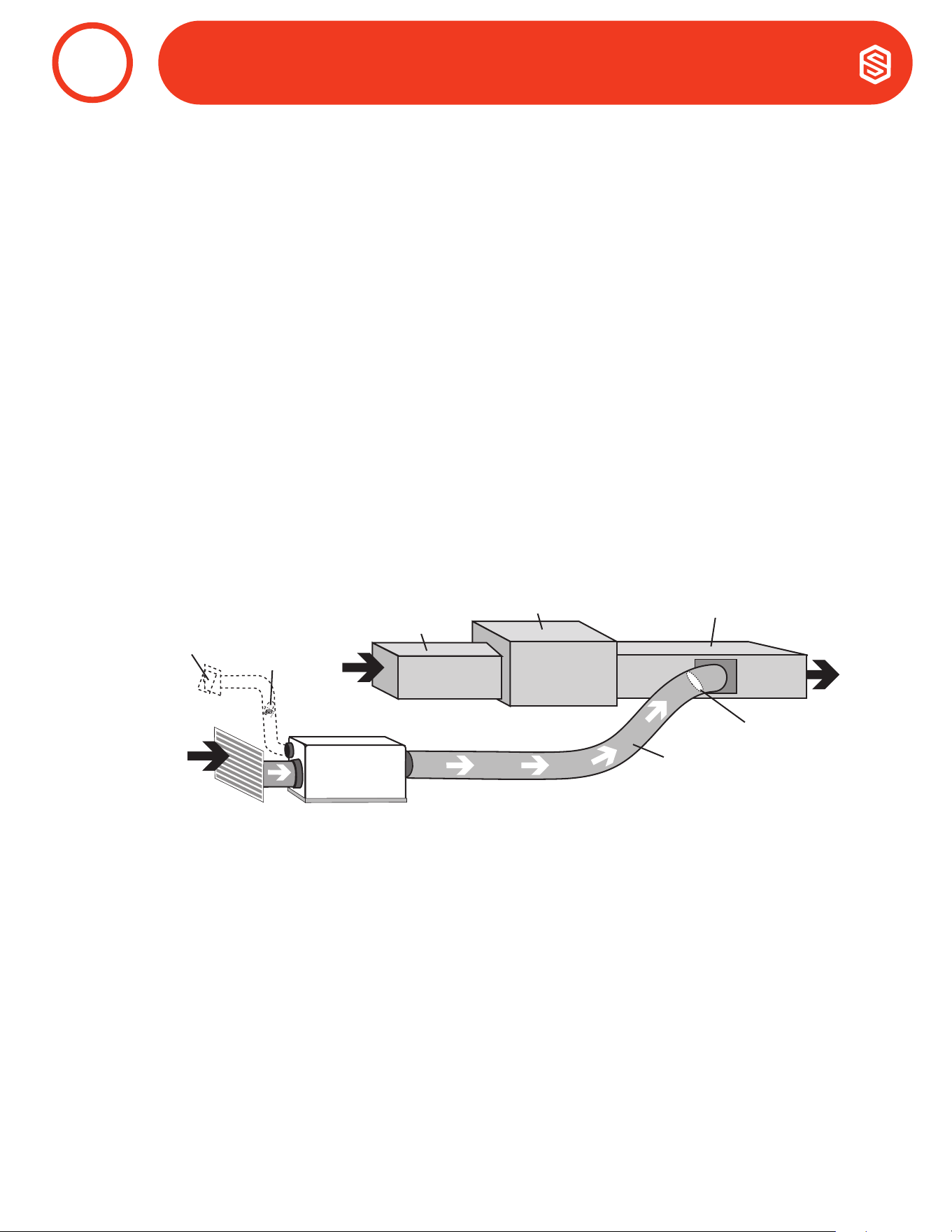
38
Santa Fe ULTRA98/120 Installation & Operation Instructions Santa-Fe-Products.com | 800.533.7533
a. Instalaciones de Sistemas HVAC Recomendadas
a. Atico
La instalación recomendada extrae aire de una ubicación central a través de un retorno dedicado al
deshumidicador y canaliza el suministro del deshumidicador al suministro de aire del sistema HVAC.
Utilice el conducto de ventilación de aire exterior opcional para proporcionar aire exterior.
• Instalar el aire de retorno de 10” dedicado a Santa Fe Ultra98/120 desde una área central de la
estructura.
• Canalizar la alimentación de la Santa Fe Ultra98/120 a la alimentación del sistema HVAC con una
válvula de retorno .
• Si el sistema existente tiene múltiples retornos, en lugar de instalar un retorno dedicado al Santa
Fe Ultra98/120, es posible seleccionar uno para desconectarlo del sistema HVAC existente y usarlo
para el retorno dedicado del Santa Fe Ultra98/120. Seleccione un retorno desde una ubicación
central en la casa que siempre esté abierta al resto de la estructura. No utilice un retorno desde una
habitación donde las puertas se mantienen cerradas
• NO ubique el retorno en el baño o cocina.
• El control debe estar ubicado en un lugar remoto del dehumidicador y en un lugar central.
Dedicated Santa Fe Return to HVAC Supply
CONDUCTOS A SISTEMAS HVAC
8
Air Handler
HVAC
Return
HVAC Supply
Ultra Series
Indoor
Air Return
Motorized
Damper
Optional
Outdoor
Air Intake
Ultra Series
Supply
Backdraft
Damper
Entrada de
Aire Exterior
Opcional
Válvula
Motorizada
Retorno
HVAC
Manipulador de Aire
Suministro HVAC
Válvula
Contracorriente
Suministro
Series Ultra
Retorno de
Aire Interior
Series Ultra

39
800.533.7533 | Santa-Fe-Products.com Santa Fe ULTRA98/120 Installation & Operation Instructions
CONDUCTOS A SISTEMAS HVAC CONDUCTOS A SISTEMAS HVAC HVA\\\\\\\\\\\?\\\\\
8
Optional
Duct Tee
& Gravity
Damper
Ultra Series
Indoor Air
Return
Motorized
Damper
Optional
Outdoor
Air Intake
Dry Air to Basement
Backdraft
Damper
Air Handler Supply
Ultra Series
Supply
b. Instalación en un Sótano o en un Espacio Reducido
Instale un retorno separado de 8” para el Ultra98/120 en una zona central de la estructura. Canalice el
suministro del deshumidicador hacia el suministro de aire del sistema HVAC con una válvula de retorno.
Opcional: : Canalice el suministro del Ultra98/120 a una T/válvula de 8” x 8” x 8” con una válvula de con-
tracorriente por gravedad, ajustada al 20% de apertura hacia el sótano. PRECAUCIÓN: El aire toma el camino
de menor resistencia. Si los niveles superiores de la vivienda no reciben la cantidad adecuada de aire seco,
puede ser necesario ajustar esta compuerta. Cuando el deshumidicador no está funcionando, existe la po-
sibilidad de que el aire del sótano o del espacio reducido regrese por la válvula de gravedad y en el espacio
habitable.
Aire de Retorno
Interior Series Ultra
Suministro de Manipulacion de Aire
Válvula de
Contracorriente
Aire Seco hacia el Sótano
Ducto T
Opcional y
Válvula de
gravedad
Suministro de
Series Ultra
Válvula
Motorizada
Entrada de
Aire Exterior
Opcional

40
Santa Fe ULTRA98/120 Installation & Operation Instructions Santa-Fe-Products.com | 800.533.7533
Si no es posible realizar la instalación recomendada de retorno al suministro de HVAC de la serie Ultra dedicada,
hay varias opciones de instalación alternativas disponibles.
• NO ubique el retono en el baño o cocina..
• El control debe estar situado a distancia del deshumidicador y colocado en un lugar central.
• Para instalaciones en sótanos y espacios reducidos, se puede instalar una T opcional en el Suministro de la
Series Ultra.
a. Retorno HVAC al Suminitro HVAC
La Compuerta de Chequeo debe estar
colocada entre las conexiones de retorno y
suministro del deshumidicador.
Si la Válvula de Chequeo no está en su lugar,
el ventilador de la HVAC debe prenderse
cuando el deshumidicador está en
funcionamiento.
Si el sistema es mayor que 0.5” WG el ducto
debe se recongurado.
Air Handler
HVAC Supply
Motorized
Damper
Optional
Outdoor
Air Intake
Optional Check Damper
(no HVAC fan needed)
HVAC Return
Ultra Series
Supply
Ultra Series
Return
Backdraft
Damper
2. Alternativas de la Instalación del Sistema HVAC
CONDUCTOS A SISTEMAS HVAC
8
ADVERTENCIA!
DEBIDO A LA RESISTENCIA A LA PRESIÓN NO SE RECOMIENDA UTILIZAR LA ENTRADA DE AIRE EXTERIOR
OPCIONAL CUANDO SE INSTALA EL DESHUMIDIFICADOR DE SUMINISTRO A SUMINISTRO.
b. Suministro de HVAC al Suministro de HVAC
If Check Damper is not in place, the
HVAC fan must turn on when the
dehumidier is in operation.
Air Handler
HVAC Supply
Motorized
Damper
Optional
Outdoor
Air Intake
Optional Check Damper
(no HVAC fan needed)
Ultra Series
Supply
Ultra Series
Return
PRECAUCIÓN!
PARA EVITAR QUE EL DESHUMIDIFICADOR ENTRE EN UN CICLO DE DESCONGELACIÓN Y CONGELACIÓN,
SE RECOMIENDA QUE LA TEMPERATURA DEL AIRE DE SALIDA DEL SERPENTÍN DEL A/C NO SEA INFERIOR
A 55 °F. ADEMÁS, ESTA INSTALACIÓN NO SE RECOMIENDA EN CLIMAS EN LOS QUE EL SISTEMA DE
CALEFACCIÓN FUNCIONE DURANTE LA PRIMAVERA Y EL OTOÑO, YA QUE ESTO PODRÍA DISMINUIR LA
CAPACIDAD DE ELIMINACIÓN DE AGUA DEL DESHUMIDIFICADOR..
Suministro HVAC
Manipulador de Aire
Entrada de
Aire Exterior
Opcional
Válvula
Motorizada
Retorno de
Series Ultra
Suministro
de Series
Ulra
Válvula de
Contracorriente
Manipulador de Aire
Válvula
Motorizada
Retorno de
Series Ultra
Suministro de
Series Ultra
Válvula de Chequeo Opcional
(No necesita ventilador HVAC)
Válvula de Cheuqueo
Opcional (No necesita
ventilador HVAC)
Retorno
HVAC
Suministro de Aire
Entrada de Aire
Exterior Opcional
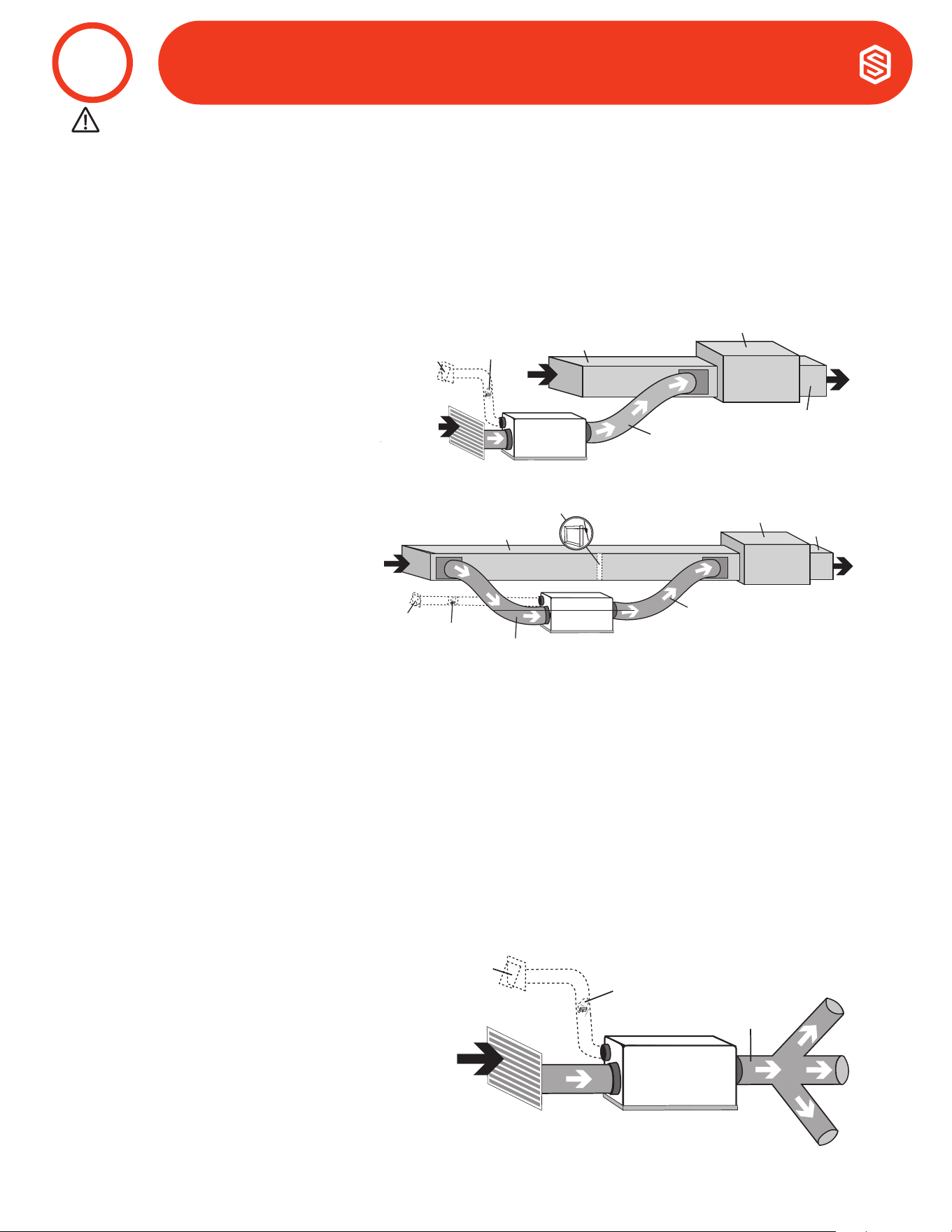
41
800.533.7533 | Santa-Fe-Products.com Santa Fe ULTRA98/120 Installation & Operation Instructions
d. Retorno HVAC a Retorno HVAC
Si verica que la válvula que no está
en su lugar, el ventilador HVAC debe
encenderse cuando el deshumidicador
esté en funcionamiento.
Air Handler
HVAC
Supply
HVAC Return
Motorized
Damper
Optional
Outdoor
Air Intake
Optional Check Damper
(no HVAC fan needed)
Ultra Series
Supply
Ultra Series
Return
c. Retorno Dedicado de Series Ultra a Retorno HVAC
Cree un retorno separado para el
deshumidicador de la serie Ultra en un
área central del edicio.
Instalar el suministro de aire desde
el deshumidicador Ultra Series al
retorno del sistema HVAC requiere que
el ventilador HVAC funcione cuando
el deshumidicador Ultra Series está
funcionando.
Air Handler
HVAC
Return
HVAC Supply
Ultra Series
Supply
Ultra Series
Indoor
Air Return
Motorized
Damper
Optional
Outdoor
Air Intake
Motorized
Damper
Ultra Series
Supply
Ultra Series
Indoor Air
Return
Optional
Outdoor
Air Intake
e. Sin instalación de Conductos Existentes
Al instalar el deshumidicador de la Serie Ultra en una estructura que no tiene un sistema HVAC de aire
forzado, se debe instalar un solo retorno para el deshumidicador en una ubicación central.
Instale un conducto aislado desde el exterior hasta el collar de 6” del deshumidicador de la serie Ultra para
proporcionar ventilación de aire exterior (opcional).
El suministro del deshumidicador de la serie Ultra debe canalizarse a las habitaciones de la casa que tienen
los cabezales mini-split sin conductos y lo más cerca posible de los cabezales. Asegúrese de utilizar varias
habitaciones para permitir que el aire dentro de la estructura circule correctamente. La distribución adecuada
del aire es importante para garantizar un control uniforme de la humedad y la distribución del calor en toda la
estructura.
Se recomienda un ducto de 6” de diámetro para derivaciones a dormitorios. Se recomienda un conducto de 8”
de diámetro para derivaciones a áreas más grandes.
• NO ubique el retono en el baño o cocina.
• NOT ubique el suministro en
cuartos donde las puertas
puedan estar cerradas.
• El control debe ubicarse en
remoto del dehumidicador
y en un lugar central.
PRECAUCIÓN!
TOME EN CUENTA: LAS INSTALACION DE RETORNO A RETORNO SON CONSIDERADOS COMO ULTIMO
RECURSO Y NO SON RECOMENDADOS. EL DEHUMIDIFICADOR CALENTARA EL SERPENTIN DE
ENFRIAMIENTO DEL AC LO CUAL DISMINUIRA LA CANTIDAD DE AGUA QUE EL SISTEMA DE AC PUDIERA
REMOVER CUANDO ESTE EN OPERACIONT. SI ESTA INSTACION ES ESCOGIDA, EL DEHUMIDIFICADOR
DEBE ACTIVAR EL SOPLADOR DE HVAC Y LAS LLAMADAS DE AC NECESITARAN BLOQUEAR EL
FUNCIONNAMIENTO DEL DEHUMIDIFICADOR. POR FAVOR VERIFIQUE LOS CODIGOS LOCALES ANTES DE LA
INSTALACION.
CONDUCTOS A SISTEMAS HVAC
8
Entrada de
Aire Exterior
Opcional
Válvula
Motorizada
Retorno
HVAC
Manipulador de Aire
Suminitro de HVAC
Suministro de
Series Ultra
Retorno
de Aire
Interior
Series
Ultra
Retorno HVAC
Entrada de Aire
Exterior opcional
Válvula
Motorizada
Retorno de Series Ultra
Suminitro de Series Ultra
Manipulador de Aire
Suministro
de HVAC
Válvula Motorizada
Suministro de
Series Ultra
Válvula de Chequeo Opcional
(No necesita ventilador HVAC)
Entrada
de Aire
Exterior
Opcional
Retorno de
Aire Inteior
Series Ultra
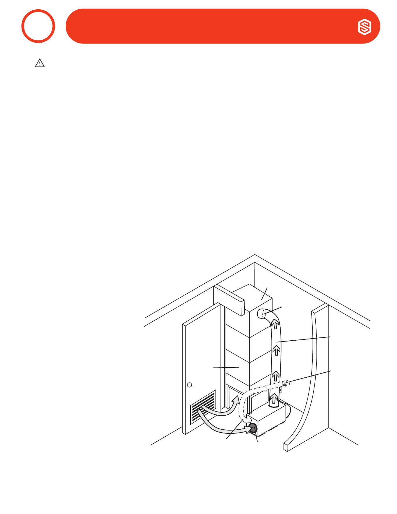
42
Santa Fe ULTRA98/120 Installation & Operation Instructions Santa-Fe-Products.com | 800.533.7533
Debido a las limitaciones de espacio, la instalación de un armario puede requerir consideraciones adicionales.
Ubique el deshumidicador debajo o al lado del sistema HVAC según lo permita el espacio. Se requiere una
ventilación pasiva o una puerta con persianas para permitir que el aire ingrese desde el espacio habitable.
• No se requiere conducto de entrada. El aire se extrae a través de la rejilla de ventilación pasiva o la puerta
de persiana desde el espacio habitable.
• Instale un conducto aislado desde el exterior hasta el collar de 6” del deshumidicador de la serie Ultra
para proporcionar ventilación de aire exterior (opcional).
• El control debe ubicarse de manera remota desde el deshumidicador y colocarse en una ubicación
central.
• Cuando el espacio de salida está restringido, el collar del conducto de salida es opcional o se puede preferir
el flujo vertical.
CUANDO INSTALE EL DESHUMIDIFICADOR COMO PARTE DE UN SISTEMA HVAC DE TIPO DE COMBUSTIÓN (GAS,
ACEITE, PROPANO, ETC.), SIGA TODOS LOS CÓDIGOS DE SEGURIDAD Y CONSTRUCCIÓN LOCALES Y NACIONALES.
ADVERTENCIA!
Retorno Central al Suministro HVAC
Conecte el suministro del
deshumidicador de la Series Ultra al
suministro del sistema HVAC existente
con una válvula de contracorriente.
Backdraft
Damper
HVAC
Supply
Ultra Series
Supply
HVAC
Return
Ultra Series
Return
Optional Outdoor
Air Intake
Motorized
Damper
1. Instalación de Armario Recomendada
CONDUCTOS A SISTEMAS HVAC (Instalaciones Cerradas)
9
Retorno
HVAC
Suministro de
Series Ultra
Válvula
Motorizada
Retorno de
Series Ultra
Suministro
HVAC
Válvula
Contracorriente
Entrada de Aire
Exterior Opcional

43
800.533.7533 | Santa-Fe-Products.com Santa Fe ULTRA98/120 Installation & Operation Instructions
2. Instalaciones Alternativas de Armario
Si la instalación de armario recomendada no es posible, hay varias opciones de instalación alternativas
disponibles.
• No se requiere conducto de entrada. El aire se extrae a través de la rejilla de ventilación pasiva o la puerta
de persiana desde el espacio habitable.
• Instale un conducto aislado desde el exterior hasta el collar de 6” del deshumidicador de la serie Ultra
para proporcionar ventilación de aire exterior (opcional).
• El control debe ubicarse de manera remota desde el deshumidicador y colocarse en una ubicación
central.
a. Retorno Central a Retorno HVAC
Conduzca el suministro del
deshumidicador de la serie Ultra
al lado de retorno del sistema HVAC
existente.
En un sistema de retorno central, el
ventilador HVAC debe funcionar cuando
el deshumidicador está funcionando.
Backdraft
Damper
HVAC
Supply
Ultra Series
Supply
HVAC
Return
Ultra Series
Return
Optional Outdoor
Air Intake
Motorized
Damper
b. No Conducto - Retorno Central
a Retorno HVAC
Fije el conducto de salida con un
flujo vertical para que el aire no
se descargue en la pared u otra
obstrucción. El sistema HVAC extraerá
naturalmente el aire deshumidicado
del armario y lo distribuirá por toda la
estructura.
HVAC
Supply
Ultra Series
Supply
HVAC
Return
Ultra Series
Return
Optional Outdoor
Air Intake
Motorized
Damper
DUCTING TO HVAC SYSTEMS (Closet Installations)
9
PRECAUCIÓN!
TENGA EN CUENTA: LAS INSTALACIONES DE DEVOLUCIÓN DEBEN CONSIDERARSE OPCIONES DE
ÚLTIMO RECURSO Y NO SE RECOMIENDAN. EL DESHUMIDIFICADOR CALENTARÁ LAS SERPENTINES DE
ENFRIAMIENTO DE AC, LO QUE DISMINUYE LA CANTIDAD DE AGUA QUE EL SISTEMA DE AC ELIMINARÁ
CUANDO ESTÉ EN FUNCIONAMIENTO. COMPRUEBE SUS CÓDIGOS LOCALES ANTES DE LA INSTALACIÓN.
Retorno
HVAC
Suministro
HVAC
Suministro de
Series Ultra
Válvula
Motorizada
Suministro
HVAC
Válvula
Motorizada
Suministro de
Series Ultra
Retorno
HVAC
Retorno de
Series Ultra
Válvula
Contracorriente
Entrada de Aire
Exterior Opcional
Retorno de
Series Ultra
Entrada de Aire
Exterior Opcional
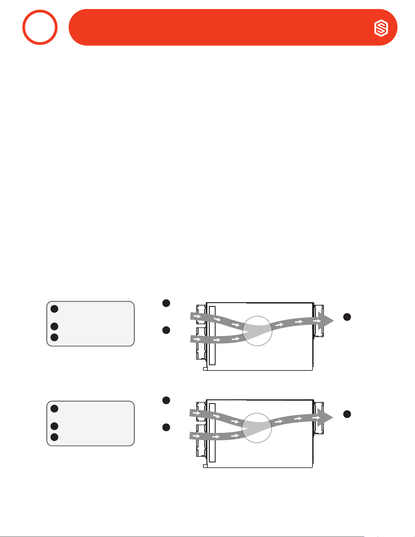
44
Santa Fe ULTRA98/120 Installation & Operation Instructions Santa-Fe-Products.com | 800.533.7533
Ventilación de Aire Exterior es Opcional.
Se puede introducir aire exterior en la estructura conectando un conducto aislado desde el exterior de la
estructura a la entrada de 6” del Santa Fe Ultra98/120. Se necesita un control de ventilación para programar
el tiempo y la frecuencia con la que la unidad introduce aire exterior. El tiempo y la frecuencia de la ventilación
deben basarse en el tamaño y la ocupación de la residencia..
• El conducto de ventilación de aire exterior debe conectarse al collarín redondo de 6” en la parte
delantera del Santa Fe Ultra98/120.
• Un conducto aislado de 6” de diámetro puede proporcionar hasta 75 CFM de aire exterior.
• Si no se utiliza una compuerta motorizada, el aire exterior se controla mediante la compuerta manual en
el collar de 6” del Santa Fe Ultra98/120.
• El rendimiento del Santa Fe Ultra98/120 puede verse afectado por las condiciones del aire interior y
exterior.
• Cuando se utiliza un amortiguador motorizado de 6”, se requiere un control digital.
• Puede que sea necesario usar conductos de 8” si se requiere aire exterior adicional.
• En climas fríos o en momentos en que el punto de rocío es bajo, se puede utilizar la ventilación para
deshumidicar la estructura, lo que hace que Santa Fe Ultra98/120 pueda secarse durante todo el año.
OUTLET DUCT
COLLAR WITH
BACK DRAFT
DAMPER
RETURN AIR
INLET DUCT
COLLAR
FRESH AIR
INLET DUCT
COLLAR
RETURN AIR
INLET DUCT
COLLAR
FRESH AIR
INLET DUCT
COLLAR
AIR FLOW
Air
Flow
Outdoor Air
90°F, 65%RH
Indoor Air
70°F, 50%RH
Mixed Air
Mixed Air
75°F
75°F
65%RH
65%RH
Mixed Air
75°F
65%RH
Outlet Air
75°F, 65%RH
Hot Climate
6" Optional Outdoor
Air Intake
10" Return Air Inlet
10" Supply Air Outlet
A
B
C
A
B
C
Outdoor Air
30°F, 65%RH
Indoor Air
70°F, 50%RH
Outlet Air
59°F, 51%RH
Cold Climate
A
B
C
6" Optional Outdoor
Air Intake
10" Return Air Inlet
10" Supply Air Outlet
A
B
C
Mixed Air
Mixed Air
59°F
59°F
51%RH
51%RH
Mixed Air
59°F
51%RH
1. Ventilación de aire exterior con deshumidicador apagado y funcionamiento solo con
ventilador
El aire exterior se mezcla con el aire de retorno antes de comenzar el proceso de deshumidicación. La tem-
peratura interior y exterior y la humedad relativa afectarán las condiciones combinadas del aire de salida.
VENTILACIÓN AIRE EXTERIOR
10
Clima Calinete
Clima Frio
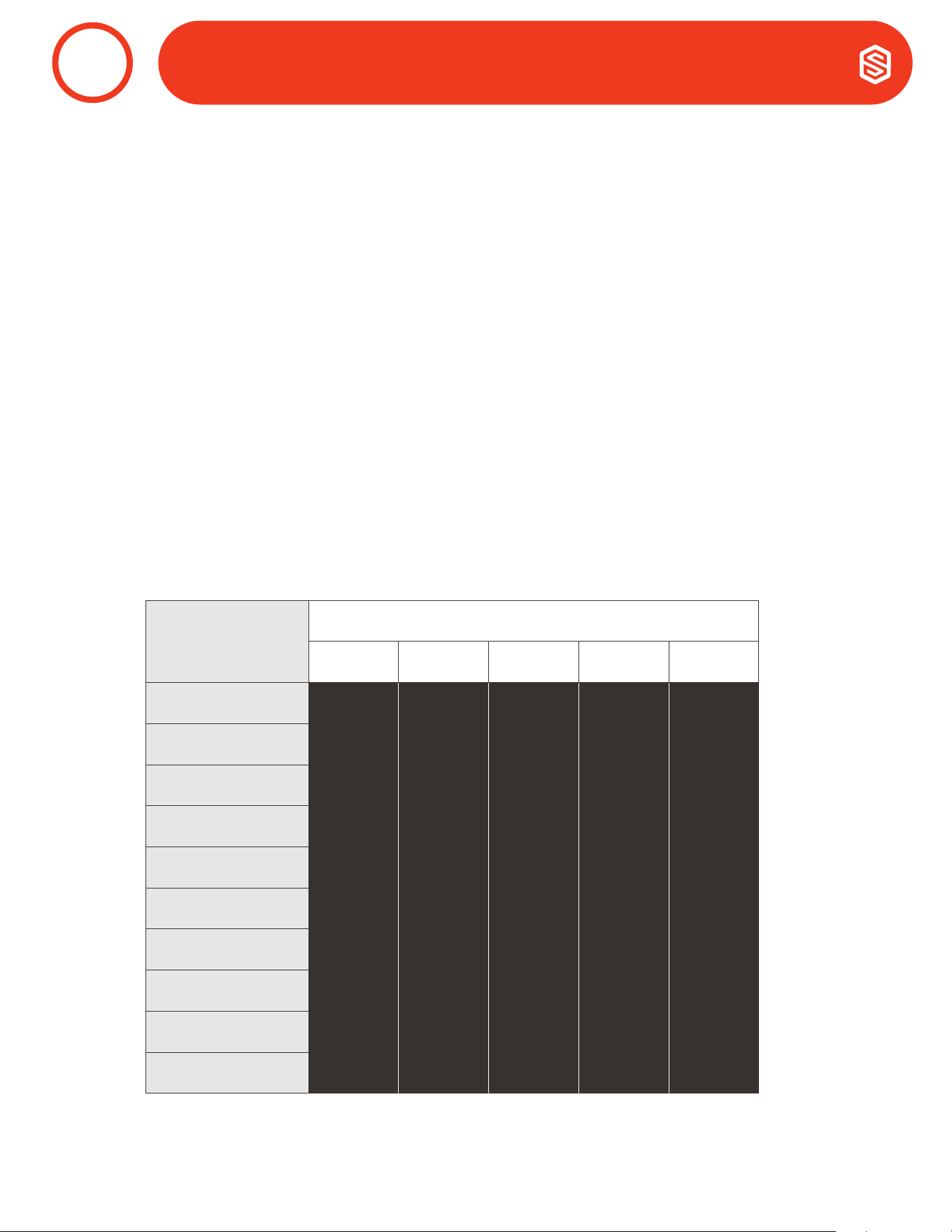
45
800.533.7533 | Santa-Fe-Products.com Santa Fe ULTRA98/120 Installation & Operation Instructions
Opción 1: Cálculo del Requisito de Flujo de Aire Usando ASHRAE 62.2-2016 Ecuación de Aire de
Flujo
ASHRAE Flujo de Aire CFM = [Area de la casa en Sq.Ft. x 0.03] + [(Número de habitaciones +1) x 7.5]
NOTA: Use ‘Número de habitaciones + 1’ o ‘Número de Ocupantes’, cualquiera que sea mayor.
Ejemplo 1: Número de habitaciones + 1
Casa de 1800 pies cuadrados con 3 habitaciones, 4 ocupantes = [1800 X 0.03] + [(3+1) X 7.5] = 84 CFM
Ejemplo 2: Número de Ocupantes
Casa de 1800 pies cuadrados con 3 habitaciones, 5 ocupantes = [1800 X 0.03] + [5 X 7.5] = 91.5 CFM
Registrar el Requerido CFM ____________
1. Determinar los Requisitos de Ventilación
El requisito de ventilación MÍNIMO se calcula utilizando ASHRAE 62.2-2016. Use una o ambas opciones a continu-
ación para determinar su requerimiento de ventilación. Siga todos los códigos de construcción y seguridad locales y
nacionales.
Option 2: Cálculo de los Requisitos de Flujo de Aire usando la Tabla 4.1 de ASHRAE 62.2-2019
Requisitos de Ventilación de Aire, CFM
Registrar el Requerido CFM ____________
Tabla 4.1 de ASHRAE 62.2-2019
Area del Piso
(ft
2
)
Número de Habitaciones
1 2 3 4 5
<500 30 38 45 53 60
501-1000 45 56 60 68 75
1001-1500 60 68 75 83 90
1501-2000 75 83 90 98 105
2001-2500 90 98 105 113 120
2501-3000 105 113 120 128 135
3001-3500 120 128 135 143 150
3501-4000 135 143 150 158 165
4001-4500 150 158 165 173 180
4501-5000 165 173 180 188 195
VENTILACIÓN AIRE EXTERIOR
11
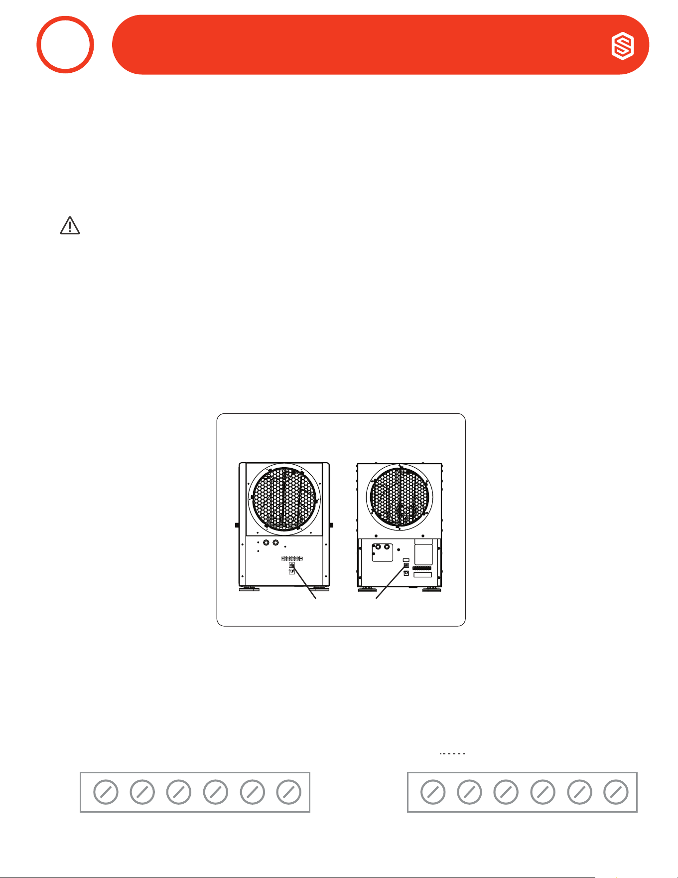
46
Santa Fe ULTRA98/120 Installation & Operation Instructions Santa-Fe-Products.com | 800.533.7533
Se debe utilizar un control con el Santa Fe Ultra98/120. Santa Fe ofrece el control propietario DEH 3000. El DEH 3000
permite a los propietarios monitorear y controlar la humedad relativa y los niveles de ventilación adecuados en su
hogar. Este control también está disponible con una opción de detección remota.
NOTA: El DEH 3000 es vendido por separado. Otras termostatos son compatibles con Santa Fe Ultra98/120.
PRECAUCIÓN!
NO PERMITA QUE EL TERMINAL 24V DEL SANTA FE ULTRA98/120 SE COMUNIQUE CON EL TERMINAL COM EN
EL SANTA FE ULTRA98/120 O SE DAÑARÁN LOS TRANSFORMADORES.
a. Disyuntor
Para evitar daños al transformador de control de 24 voltios, el Santa Fe Ultra98/120 viene con un
disyuntor reiniciable. Verique el cableado en busca de cualquier cortocircuito eléctrico y repárelo antes
de restablecer el disyuntor. Restablecer el disyuntor sin corregir el cortocircuito eléctrico puede provocar
daños en el transformador. Asegúrese de revisar el esquema eléctrico en este manual o dentro del panel de
acceso del Santa Fe Ultra98/120 antes de realizar cualquier conexión de control. El botón de reinicio para el
disyuntor se puede encontrar en la parte posterior de la unidad.
1. Controles de Cableado
CONTROLES
12
Rear View
Santa Fe ULTRA120
Circuit Breaker Reset Button
Santa Fe ULTRA98
COM
FAN
24V
DEHU
*
DMPR
COM
FAN
24V
DEHU
FLOAT
FLOAT
Ultra98 Ultra120
b. Connecciones de Control
deThe control and the Santa Fe Ultra98/120 are labeled to prevent confusion. Depending on the control,
some of the screw terminals on the Santa Fe Ultra98/120 may not be used. Be sure to consult the electrical
schematic in this manual or inside the access panel of the Santa Fe Ultra98/120 before making control
connections.

47
800.533.7533 | Santa-Fe-Products.com Santa Fe ULTRA98/120 Installation & Operation Instructions
Un control de bajo voltaje debe utilizarse con the Santa Fe Ultra98/120.
NOTE: 18 cable de calibre es necesario entre el dehumidicador Santa Fe Ultra98/120 y el control externo.
aUltra98
COM 24VAC Lado neutro del transformador de potencia
FAN Control de Ventilador
24V Lado Alto del Transformador
DEHU Control de deshumidicación (Ventilador y Com-
DMPR 24VAC Lado neutro del transformador de potencia
* Terminal de repuesto (abierto)
Ultra120
COM 24VAC Lado neutro del transformador de potencia
FAN Control de Ventilador
24V Lado Alto del Transformador
DEHU Control de Dehumidicación (Ventilación y Compresor)
Float
Interruptor de flotador externo de bajo voltaje o sensor de agua.
(Utilice un interruptor normalmente cerrado)
Float
Interruptor de flotador externo de bajo voltaje o sensor de agua.
(Utilice un interruptor normalmente cerrado)
Entre el cable COM y el TERMINAL 24V TERMINAL hay un transformador de 40VA. Esta fuente de energía de
bajo voltaje alimenta las bobinas de relé que controlan el ventilador y los compresores. Este transformador
de 24VAC también puede ser utilizado para alimentar accesorios HVAC externos al dehumidicador.
Compresor ON/Ventilador On Hacer contacto entre 24V y DEHU terminales
Compressor OFF/Ventilador On Hacer contacto entre 24V y terminales de Ventilador
Power HVAC Accessory Conecte los accesorios al DMPR y 24V terminales
CONTROLES
12
2. Operación de Control del Bloque de Terminales
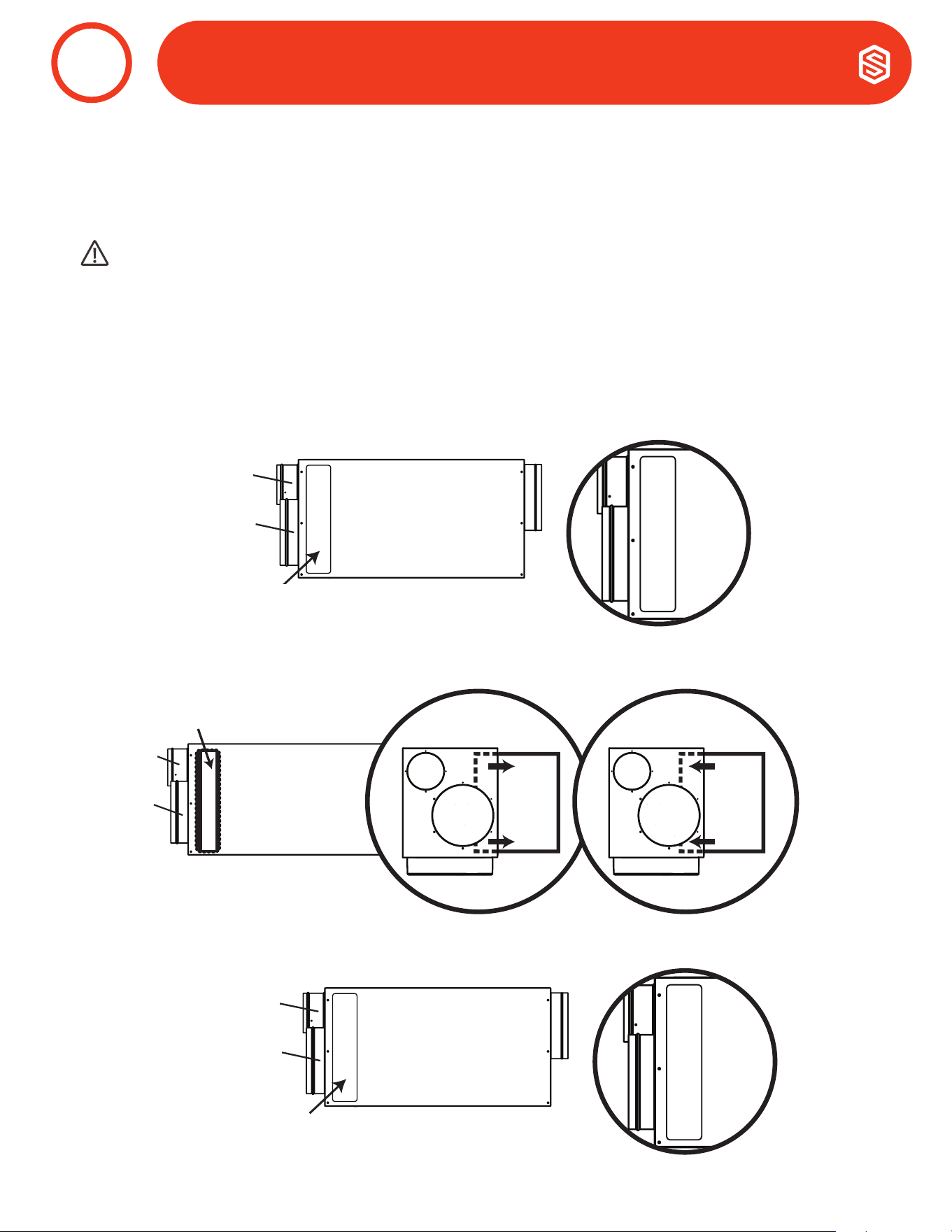
48
Santa Fe ULTRA98/120 Installation & Operation Instructions Santa-Fe-Products.com | 800.533.7533
Santa Fe Ultra98/120 es equipado con un ltro de aire MERV 13 (Dimensiones: 1.75”x14”x17.5”). El ltro debe ser
vericado y reemplazado cada tres a seis meses. Operar la unidad con ltros sucios reducirá la capacidad y eciencia
del dehumidicador.
NO opere la unidad sin el ltro recomendado. Filtros que no tienen conformidad anulan la garantía del producto.
Changing the Filter
Para mayor ltración y eciencia del Santa Fe Ultra98/120, se recomienda reemplazar el ltro de aire cada tres a
seis meses con un ltro clasicado MERV-13.
Paso 2: Retire el ltro tirando suavemente hacia afuera de la unidad. Inserte el ltro nuevo empuján-
dolo suavemente hacia el interior de la unidad. Asegúrese de que la flecha de FLUJO DE AIRE en el ltro
apunte hacia la unidad.
PRECAUCIÓN!
ASEGURESE QUE LA UNIDAD ESTA APAGADA ANTES DE CAMBIAR EL FILTRO.
VENTILACIÓN DE AIRE
13
Side View
Filter Door
Optional
Outdoor
Air Intake
Return
Filter
Optional
Outdoor
Air Intake
Return
Side View
Filter
Top View
Side View
Magnetic Strip
Optional Fresh
Air Intake
Return
Supply
Top View
Supply
Top View
Filter
Fresh Air
Intake
(Optional)
Return
Filter
Return
Filter
To Remove,
pull out straight.
Filter
Top View
Side View
Magnetic Strip
Optional Fresh
Air Intake
Return
Supply
Top View
Supply
Top View
Filter
Fresh Air
Intake
(Optional)
Return
Filter
Return
Filter
To Replace,
push in straight.
Front View Front View
Entrada de Aire
Exterior Opcional
Retorno
Puerta de Filtro
Vista Lateral
Entrada de
Aire Exterior
Opcional
Retorno
Vista Lateral
Paso 1: Retire la puerta del ltro magnetizado tirando de ella para sacarla del deshumidicador. Puede quitarlo
de cualquier lado para acceder al ltro.
Paso 3: Vuelva a colocar la puerta del ltro magnetizado en su lugar, asegurándose de que cubra
completamente el compartimiento del ltro.
Side View
Filter Door
Optional
Outdoor
Air Intake
Return
Entrada de Aire
Exterior Opcional
Retorno
49
800.533.7533 | Santa-Fe-Products.com Santa Fe ULTRA98/120 Installation & Operation Instructions
Standard 52.5
Valor mínimo
de informe de
eciencia
Eciencia de
Mancha de
Polvo
Arrestance
Típico
Contaminante
Controlado
Típicas
Aplicaciones y
Limitaciones
Tipos Típicos de Filtro de Aire/Limpiador
20 n/a n/a
< 0.30 pm Porte de
Partícula
Cuartos limpios
≥99.999% eff. Prendido 10-20 pm
Particulas
19 n/a n/a Virus (sin adjuntar)
Materiales
Radioactivos
Particulas
18 n/a n/a Polvo de Carbón
Pharmaceutical
Man.
Particulates
17 n/a n/a
Todo humo de
combustión
Materiales
Carcinogénico
≥99.97% eff. On 30 pm Particulas
16 n/a n/a
0.30-1.0 pm Porte
de Partículas
Cirugia General Filtro de Bolsa - No compatible
15 >95% n/a Todas las Bacterias
Atención hospitaria
para pacientes
hospitalizados
Fibra de vidrio microna o medios
sinteticos, 12-36 in. de profundidad, 6-12
Bolsillos
14 90-95% >98%
La mayoría del
Humo del Tabaco
Salones para
fumadores
Caja de Filtro - Cartucho de Estilo Rígido
13 89-90% >98%
Núcleos Problet
(Estornudo)
Edicios
Comerciales
Superiores
Filtros 6 to 12 in. de profundidad, Puede
usar soportes de papel o elevadores
12 70-75% >95%
1.0-3.0 pm
Partículas
tamaño Legionella
Superior
Residencial
Bolsa de Filtro - Nonsupported
11 60-65% >95%
Polvo de
Humidicador
Polvo de Plomo
Mejores Edicios
Comercialed
Fibra de Vidrio Microna o Medios
sintética, 12-36 in. de profundidad, 6-12
Pockets
10 50-55% >95% Harina Molida Filtro de caja - Cartucho de estilo rígido
9 40-45% >90%
Humos de
Soldadura
Laboratorios de
Hospitales
Filtross 6 to 12 in. de profundidad, Puede
usar soportes de papel o loft
8 30-35% >90%
3.0-10.0 pm
tamaño de
partículas
Edicio
Comerciales
Filtros plisados - Desechables, área de
superficie extendida, gruesos con medio
de mezcla de algodón y poliéster, marco
de cartón
7 25-30% >90%
Esporas de moho
Laca para el
cabello
Residencial
Mejorada
Filtros de cartucho - Cubo con
Revestimiento Viscoso de Densidad
Graduada o Filtros de Bolsillo, media
sintética
6 <20% 85-90%
Protector de tela
Ayudas para quitar
el polvo
Tirar a la basura - Filtro de Panel sintético
Desechable
5 <20% 80-85%
polvo de cemento
Mezcla de pudín
Entrada de Cabina
de Pintura
4 <20% 75-80%
>10.0 pm Polen
de tamaño de
partícula
Mínima Filtración
Tirar a la basura - Filtro de Panel
Sintético Desechabter
3 <20% 70-75%
Ácaros del polvo
Polvo de pie
Residencial Labable - Rejilla de Aluminum
2 <20% 65-70%
Polvo de pintura en
aerosol
1 <20% <65%
Textile Fibers
Carpet Fibers
Window A/C Units
Electrostatic - Self Charging Woven Panel
Filter
Table Data Source: United States Environmental Protection Agency
VENTILACIÓN DE AIRE
13
2. MERV Gráco de Calicación
50
Santa Fe ULTRA98/120 Installation & Operation Instructions Santa-Fe-Products.com | 800.533.7533
PRECAUCIÓN!
LA SOLUCIÓN DE PROBLEMAS DEBE SER REALIZADA POR UN TÉCNICO CALIFICADO EN HVAC.
SoluciÓn de Problemas
Síntoma Posible Razón Procedimiento de Solución de Problemas
No funciona ni el
ventilador ni el
compresor.
Deshumidicación
hace un llamando.
1. Dehumidicador
desenchufado o sin corriente
en el tomacorriente.
2. El control de humidad está
demasiado alto.
3. Conexión suelta en el
cableado interno o de control
4. Relé del compreso
defectuoso.
5. Transformador de control
defectuoso
ADVERTENCIA!
PELIGRO DE DESCARGA ELÉCTRICA:
La energía eléctrica debe estar presente para
realizar algunas pruebas. Estas pruebas deben ser
realizadas por una persona de servicio calicada.
Procedimiento de resolución de problemas
relacionados con el control
Este método de diagnóstico probará los 3
componentes principales del circuito de control
individualmente para indicar cualquier problema
potencial. Esto se debe usar cuando el control no
activará la unidad principal.
1. Desconecte las conexiones del cableado
de control de campo de los terminales de la
unidad principal.
2. Conecte los terminales 24V y FAN juntos; solo
debe funcionar el ventilador. Desconecte los
terminales.
3. Conecte los terminales 24V y DEHU juntos;
el ventilador y el compresor deben funcionar.
Desconecte los terminales.
4. Si esta prueba funciona, la unidad principal
funciona correctamente desde el punto de vista
del control.
5. Vuelva a conectar el cableado de control de
campo a los terminales de la unidad principal.
6. Retire la cubierta del panel de control y
desconecte el cableado de campo de las
conexiones de control.
7. Conecte los terminales 24V y FAN juntos; solo
debe funcionar el ventilador. Desconecte los
terminales.
8. Conecte los terminales 24V y DEHU juntos;
el ventilador y el compresor deben funcionar.
Desconecte los terminales
9. Si esta prueba funciona, entonces el cableado
de control de campo está bien.
10. Si el problema persiste, lo más probable es que
el control esté defectuoso.
El compresor no
está funcionando.
Se requiere
deshumidicación.
El ventilador está
funcionando.
1. Condensador de
funcionamiento del
compresor defectuoso.
2. Conexión suelta en el circuito
del compresor
3. Sobrecarga del compresor
defectuoso
4. Compresor Defectuoso.
5. Termostato de congelación
abierto
El compresor se
enciende y se
apaga. Se requiere
deshumidicación..
1. Temperatura ambiente y/o
humedad baja que hacen
que la unidad pase por modo
de desongelación.
2. Sobrecarga del compresor
defectuoso.
3. Compresor Defectuoso.
4. Termostato de
descongelación defectuoso.
5. Filtros de aire sucios o flujo
de aire restringido.
6. Ventilador o relé defectuoso.
El ventilador no
está funcionando.
Se requiere
deshumidicación o
ventilador.
1. Conexión suelta en el circuito
del ventilador.
2. La obstrucción impide la
rotación del impulsor del
ventilador.
3. Ventilador defectuoso.
4. Ventilador de Relé
defectuoso.
SERVICIO
14
51
800.533.7533 | Santa-Fe-Products.com Santa Fe ULTRA98/120 Installation & Operation Instructions
SoluciÓn de Problemas (ContinuaciÓN)
ADVERTENCIA!
MANTENIMIENTO DE LA SANTA FE ULTRA98/120 CON SU SISTEMA DE REFRIGERANTE DE ALTA PRESIÓN Y
LOS CIRCUITOS DE ALTO VOLTAJE PRESENTAN UN PELIGRO PARA LA SALUD QUE PODRÍA PROVOCAR LA
MUERTE, LESIONES CORPORALES GRAVES Y/O DAÑOS A LA PROPIEDAD. EL SERVICIO DEBE SER REALIZADO
POR UN TÉCNICO DE SERVICIO CALIFICADO.
Si la carga de refrigerante se pierde debido al servicio o a una fuga, se debe reparar la fuga y se debe pesar
con precisión una nueva carga. Si queda parte de la carga anterior en el sistema, se debe recuperar antes de
pesar la nueva carga. Consulte la placa de identicación de la unidad para conocer el peso de carga y el tipo de
refrigerante correctos.
2. Carga Refrigerante
Síntoma Posible Razón Procedimiento de Solución de Problemas
Baja capacidad de
deshumidicación
(el evaporador
se escarcha
continuamente).
Se requiere
deshumidicación.
1. Termostato de
descongelación suelto o
defectuoso.
2. Baja carga de refrigerante.
3. Filtros de aire sucios o flujo
de aire restringido.
4. Ductos excesivamente
restrictivos conectados a la
unidad.
ADVERTENCIA!
PELIGRO DE DESCARGA ELÉCTRICA:
La energía eléctrica debe estar presente para realizar
algunas pruebas. Estas pruebas deben ser realizadas
por una persona de servicio calicada.
Procedimiento de resolución de problemas
relacionados con el control
Este método de diagnóstico se utiliza para comprobar
el funcionamiento de los componentes internos del
deshumidicador. Esto se utilizará cuando se sospeche
de un problema de rendimiento.
1. Congure el controlador de humedad hasta el
ajuste más húmedo o en la posición de apagado.
¿Se apagó la unidad?
2. En caso armativo, gire la conguración del
ventilador a la posición ON: ¿arranca el ventilador?
3. Si el ventilador arranca, déjelo en la posición de
ventilador ENCENDIDO y congure la humedad
hasta el nivel más seco. Puede que tenga que
esperar 5 minutos para que arranque el compresor
4. Escuche un zumbido distintivo/zumbido de un
compresor que se inicia: ¿escucha este ruido?
5. Si el compresor está funcionando y sigue
funcionando, después de unos 15 minutos debería
sentir un ligero aumento en la temperatura del aire
que sale del lado de descarga de aire de la unidad.
6. Si es así, dependiendo de sus condiciones
ambientales (temperatura/HR), debería ver algo
de producción de agua fuera de la manguera
dentro de los 30 minutos más o menos. (Nota:
si la temperatura ambiente es de 55 grados o
menos y/o en un área de baja humedad relativa, el
deshumidicador producirá poca o nada de agua).
7. La recolección del agua eliminada en un período de
24 horas dará una medida del rendimiento
No ventilation.
Ventilation is being
called for.
1. Conexión suelta en el
circuito de control de
ventilación.
2. Conexión floja en el
circuito de alimentación del
amortiguador.
3. Compuerta de aire exterior
defectuosa.
El
deshumidicador
elimina algo de
agua, pero no tanta
como se esperaba.
1. La temperatura del aire y/o
la humedad han bajado..
2. El medidor de humedad o
el termómetro utilizados
están descalibrados.
3. La unidad ha entrado en el
ciclo de descongelación.
4. Los ltros de aire están
sucios o el flujo de aire
está restringido.
5. Termostato de
descongelación
defectuoso.
6. Baja carga de refrigerante.
7. Fuga de aire, como una
cubierta suelta o fugas en
los conductos.
8. Compresor defectuoso.
9. Conductos restrictivos.
SERVICIO
14

52
Santa Fe ULTRA98/120 Installation & Operation Instructions Santa-Fe-Products.com | 800.533.7533
15

53
800.533.7533 | Santa-Fe-Products.com Santa Fe ULTRA98/120 Installation & Operation Instructions

54
Santa Fe ULTRA98/120 Installation & Operation Instructions Santa-Fe-Products.com | 800.533.7533

55
800.533.7533 | Santa-Fe-Products.com Santa Fe ULTRA98/120 Installation & Operation Instructions
WARRANTY REGISTRATION CARD / TARJETA DE REGISTRO DE GARANTIA
Santa-Fe-Products.com
1.800.533.7533
WARRANTY
WARRANTY
REGISTER YOUR PRODUCT.
IMPORTANT WARRANTY INFORMATION - DO NOT DISCARD
www.thermastor.com/registration
SERIAL
NUMBER
PART
NUMBER
Register your product
using the serial number
and part number above at
www.thermastor.com/registration
This is important
Warranty Information.
Please DO NOT DISCARD!