
© 2017 GeoVision, Inc. All rights reserved.
Under the copyright laws, this manual may not be copied, in whole or in
part, without the written consent of GeoVision.
Every effort has been made to ensure that the information in this manual is
accurate. GeoVision, Inc. makes no expressed or implied warranty of any
kind and assumes no responsibility for errors or omissions. No liability is
assumed for incidental or consequential damages arising from the use of
the information or products contained herein. Features and specifications
are subject to change without notice. Note: no memory card slot or local
storage function for Argentina.
GeoVision, Inc.
9F, No. 246, Sec. 1, Neihu Rd.,
Neihu District, Taipei, Taiwan
Tel: +886-2-8797-8377
Fax: +886-2-8797-8335
http://www.geovision.com.tw
Trademarks used in this manual: GeoVision, the GeoVision logo and GV
series products are trademarks of GeoVision, Inc. Windows is the
registered trademark of Microsoft Corporation.
September 2017

Contents
Contents ..............................................................................i
Caution...............................................................................iii
Safety Notice .....................................................................iii
Options ............................................................................. iv
Note for Adjusting Focus and Zoom............................... v
Chapter 1 Fixed IP Dome .................................................1
1.1 Packing List ..............................................................................3
1.1.1 Packing List for Hard-Ceiling Mount .............................3
1.1.2 Packing List for In-Ceiling Mount..................................4
1.2 Overview ..................................................................................5
1.3 Installation................................................................................7
1.3.1 Hard-Ceiling Mount ......................................................7
1.3.2 In-Ceiling Mount.........................................................11
1.3.3 Wall-Surface Mount ...................................................15
1.4 Connecting the Camera..........................................................17
1.5 I/O Terminal Block..................................................................18
1.5.1 Pin Assignment..........................................................18
1.5.2 Voltage Load Expansion (Optional)............................19
1.6 Loading Factory Default..........................................................20
1.6.1 Using the Web Interface.............................................20
i

1.6.2 Directly on the Camera ..............................................21
Chapter 2 Target Fixed Dome.........................................22
2.1 Packing List ............................................................................23
2.2 Overview ................................................................................24
2.3 Installation..............................................................................26
2.4 Connecting the Camera..........................................................29
2.5 Loading Factory Default..........................................................30
2.5.1 Using the Web Interface.............................................30
2.5.2 Directly on the Camera ..............................................31
Chapter 3 Accessing the Camera..................................32
3.1 System Requirement...............................................................32
3.2 Accessing the Live View..........................................................33
3.2.1 Checking the Dynamic IP Address.............................34
3.2.2 Configuring the IP Address ........................................36
3.3 Adjusting Image Clarity ...........................................................38
Chapter 4 The Web Interface .........................................41
Chapter 5 Upgrading System Firmware ........................44
ii

Caution
Risk of explosion if battery is replaced by an incorrect type.
Dispose of used batteries according to the instructions.
Safety Notice
The GV-IPCAM uses a Lithium battery as the power supply for its internal
real-time clock (RTC). The battery should not be replaced unless required!
If the battery does need replacing, please observe the following:
Danger of Explosion if battery is incorrectly replaced
Replace only with the same or equivalent battery, as recommended by
the manufacturer
Dispose of used batteries according to the manufacturer's instructions
iii
Options
Optional devices can expand your camera’s capabilities and versatility.
Contact your dealer for more information.
Device Description
Power Adapter
The power adapter is available for all Fixed IP Dome
Camera. Contact your sales representative for the
countries and areas supported.
GV-PA191 PoE
Adapter
The GV-PA191 PoE adapter is designed to provide
power and network connection to the cameras over
a single Ethernet cable.
GV-POE Switch
The GV-POE Switch is designed to provide power
along with network connection for IP devices. The
GV-POE Switch is available in various models with
different numbers and types of ports.
GV-Mount
Accessories
The GV-Mount Accessories provide a
comprehensive lineup of accessories for installation
on ceiling, wall corner and pole. For details, see GV-
Mount Accessories Installation Guide on the
Software DVD.
GV-Relay V2
The GV-Relay V2 is designed to expand the voltage
load of GV IP devices. It provides 4 relay outputs,
and each can be set as normally open (NO) or
normally closed (NC) independently as per your
requirement.
GV-Relay V2 does not support GV-EFD2101 / 3101
/ 5101.
Smoked Cover
The smoked cover is an IK7, tinted camera cover
designed for GV-Fixed IP Dome to conceal the
direction of the camera lens.
iv
v
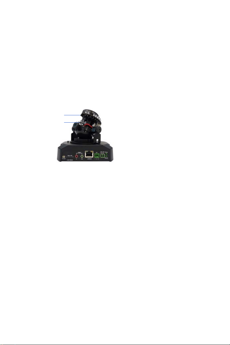
Note for Adjusting Focus and Zoom
When adjusting the Focus and Zoom Screws, do not over tighten the
Focus and Zoom screws. The screws only need to be as tight as your
finger can do it. It is not necessary to use any tools to get them tighter.
Doing so can damage the structure of lens.
For example,
Focus Screw
Zoom Screw
Fixed IP Camera
The maximum torque value for all the zoom and focus screws is 0.049 N.m
Fixed IP Dome
1
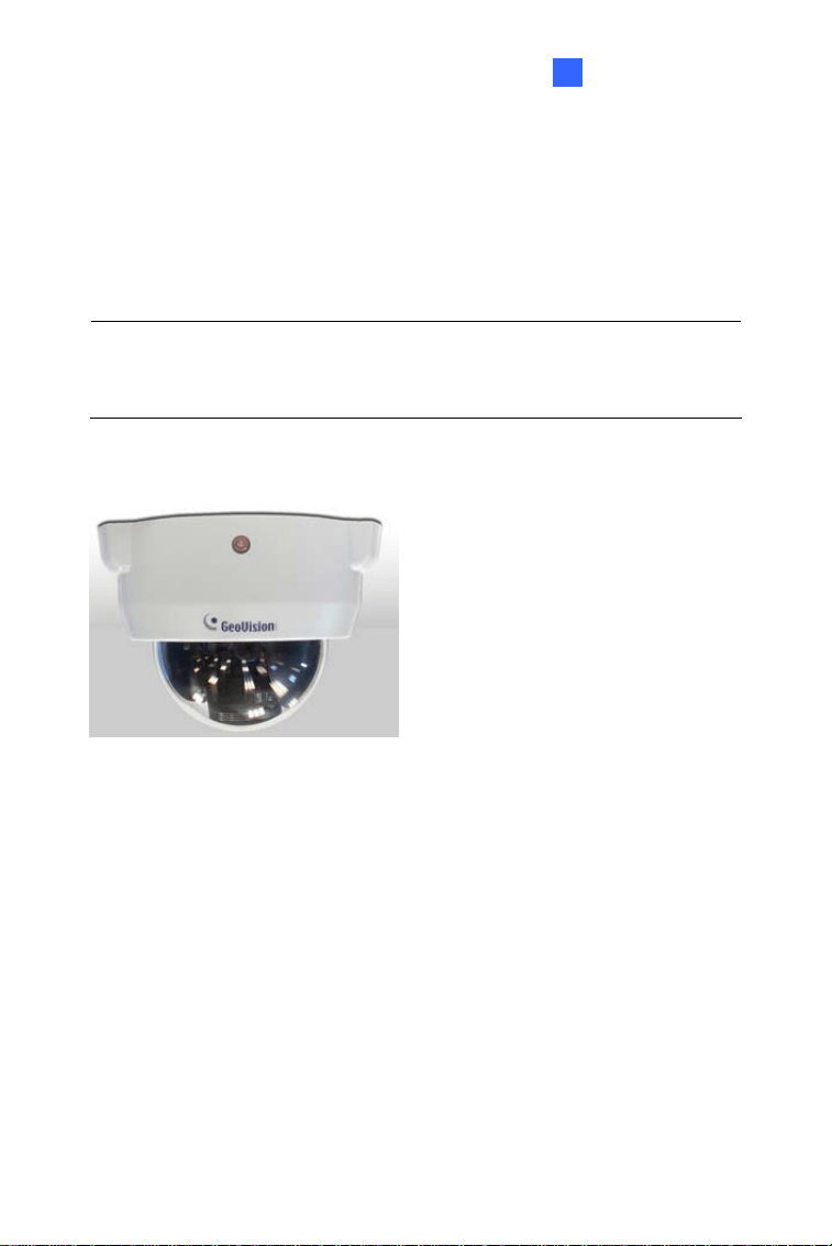
Chapter 1 Fixed IP Dome
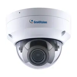
The Fixed IP Dome is a series of indoor camera designed with 3-axis
mechanism for easy and flexible installation. The Fixed IP Dome features
IR LED for infrared illumination for night surveillance. The WDR Pro
models can produce clear image for scenes containing contrasting intensity
of lights. The motorized varifocal lens models allow the user to remotely
adjust the zoom and focus through the Web interface. The super low lux
models are able to display color live view in near darkness. The models are
detailed below:
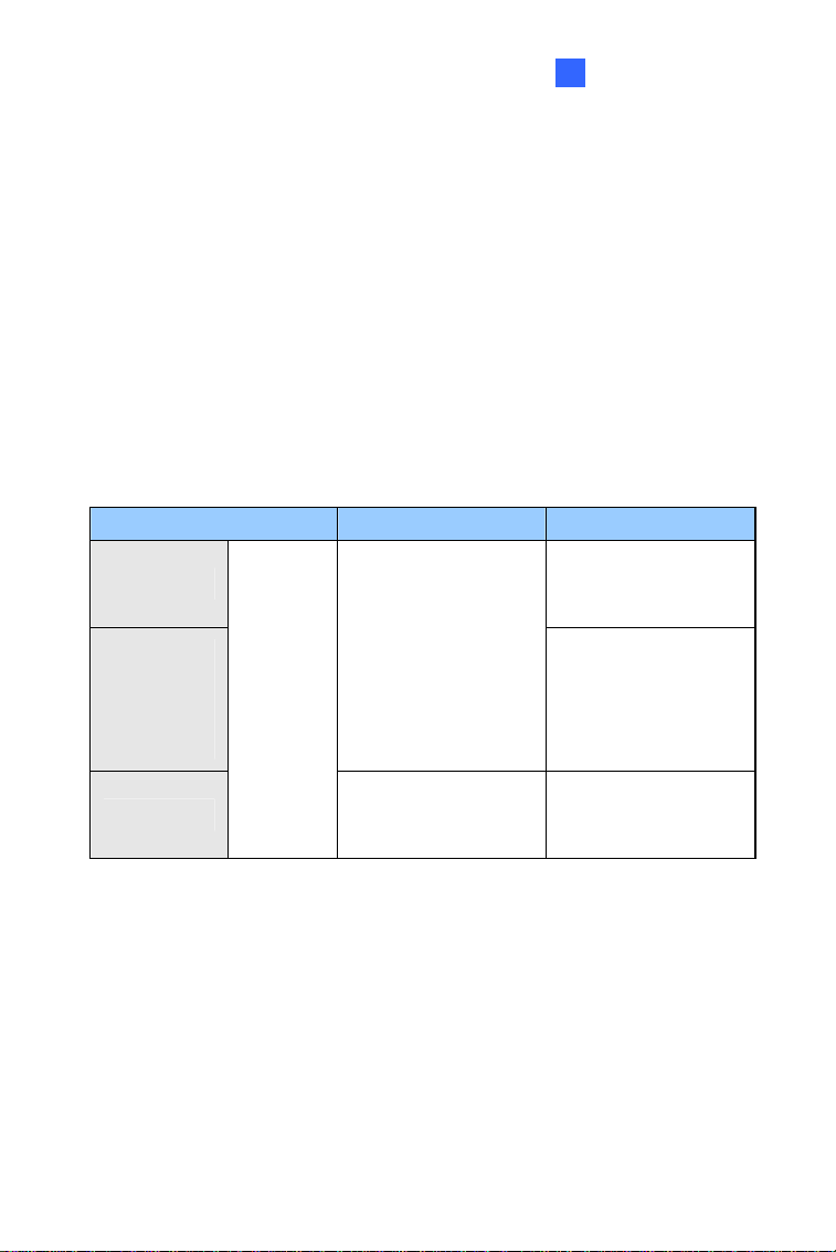
Model No. Specification Description
GV-FD1200
1.3 MP Low Lux,
H.264, D/N, Fixed IP
Dome
GV-FD1500
GV-FD2400
GV-FD2500
GV-FD3400
Auto Iris, f: 3 ~ 9
mm, F/1.2, 1/2.7’’
ø 14 mm Mount
1.3 MP Super Low
Lux / 2 MP WDR Pro
/ 2 MP Super Low
Lux / 3 MP WDR
Pro, H.264, D/N
GV-FD5300
Varifocal
Lens
f: 4.5 ~ 10 mm,
F/1.6, 1/2.5” CS
Mount
5 MP, H.264, D/N,
Fixed IP Dome
1
Model No. Specification Description
GV-FD1210
1.3 MP Low Lux,
H.264, D/N, 3x
Optical Zoom, Fixed
IP Dome
GV-FD1510
GV-FD2510
1.3 MP / 2 MP Super
Low Lux, H.264,
D/N, 3x Optical
Zoom, Fixed IP
Dome
GV-FD2410
GV-FD3410
Motorized
varifocal
Lens
Auto Iris, f: 3 ~ 9
mm, F/1.2, 1/2.7’’
ø 14 mm Mount
2 MP / 3 MP, H.264,
D/N, WDR Pro, 3x
Optical Zoom, Fixed
IP Dome
Models with P-Iris
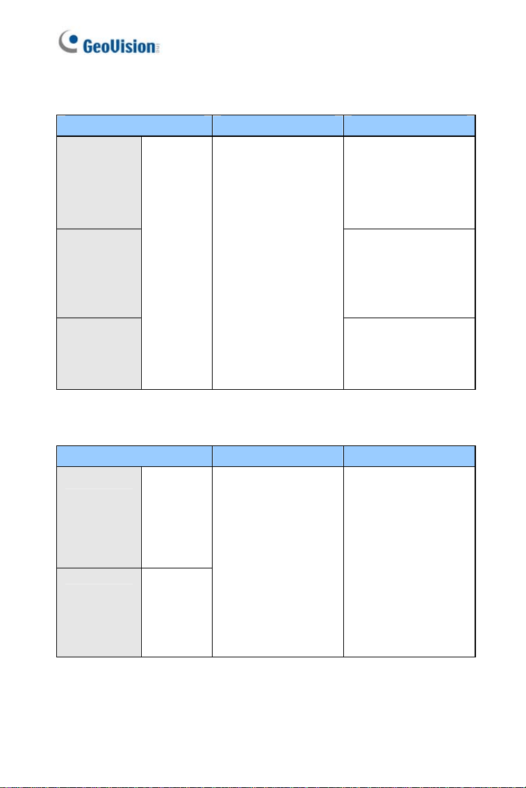
Model No. Specification Description
GV-FD1500
GV-FD2500
GV-FD3400
Varifocal
Lens
GV-FD1510
GV-FD2510
GV-FD3410
Motorized
varifocal
Lens
P-Iris, f: 3 ~ 9 mm,
F/1.2, 1/2.7’’
ø 14 mm Mount
1.3 MP Super Low
Lux / 2 MP Super
Low Lux / 3 MP
WDR Pro, H.264,
D/N, Fixed IP Dome
2
Fixed IP Dome
1
1.1 Packing List
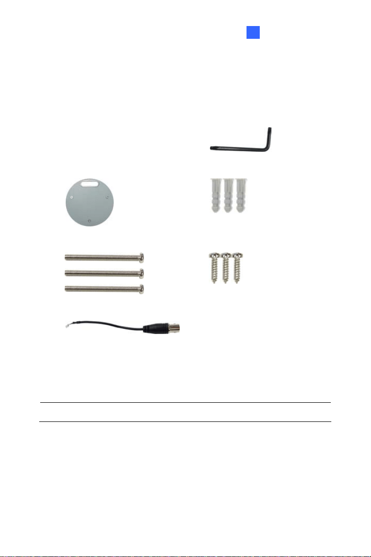
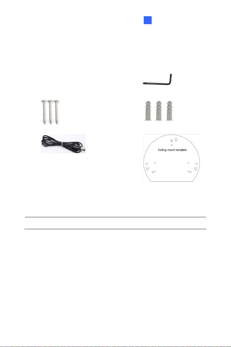
1.1.1 Packing List for Hard-Ceiling Mount
Fixed IP Dome
Torx Wrench
Mounting Plate
Short Screw Anchor x 3
Ceiling Screw x 3
Plate Screw x 3
TV-out Wire
Sticker
Power Adapter GV-IPCAM Software DVD
GV-Software DVD Warranty Card
Note: The power adapter can be excluded upon request.
3
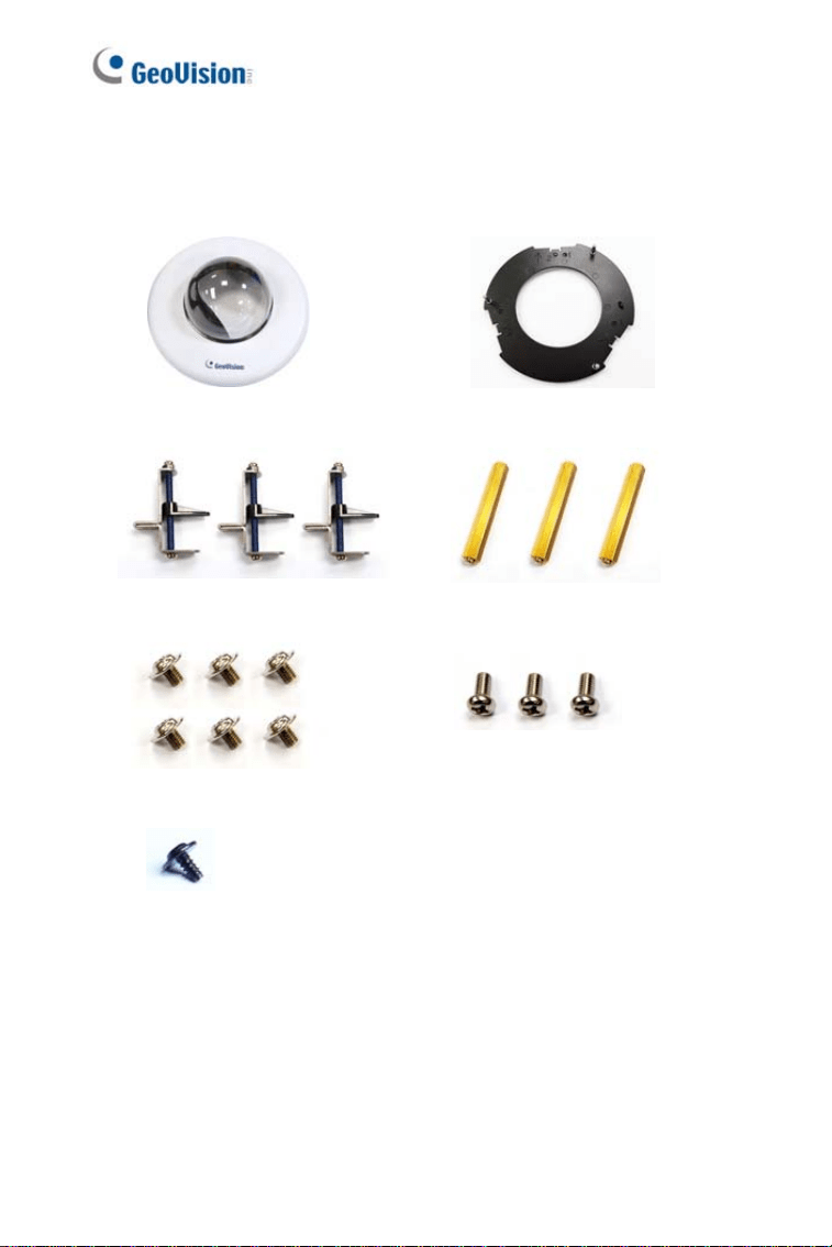
1.1.2 Packing List for In-Ceiling Mount
In-Ceiling Housing Cover
Mounting Plate
Mounting Bracket x 3
Copper Pillar x 3
Copper Pillar Screw x 6
Bracket Screw x 3
Thread Lock Screw
Housing Cover Thread
Sticker (In-Ceiling Mount)
4
Fixed IP Dome
1
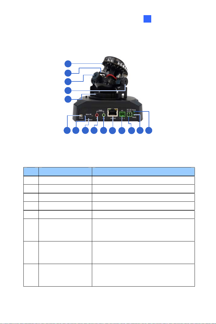
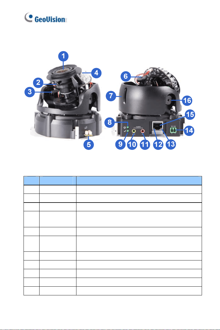
1.2 Overview
1
2
3
4
5
6 7 8 9
10
11 12 13
14 15
Figure 1-1
No. Name Description
1 Focus Screw Adjusts the focus of the camera.
2 Zoom Screw Adjusts the zoom of the camera.
3 Rotational Screw Loosens to adjust the camera angle.
4 Tilt Screw Loosens the screw to tilt the camera.
5 Pan Disc Loosens to pan the camera.
6 Video Out
Connects to a portable monitor for setting
the focus and angle of Fixed IP Dome
during initial installation.
7 Memory Card Slot
Inserts a micro SD card (SD/SDHC,
version 2.0, Class 10) to store recording
data.
8 Default Button
Restores the camera to factory default.
For details, see 1.6 Loading Factory
Default.
5
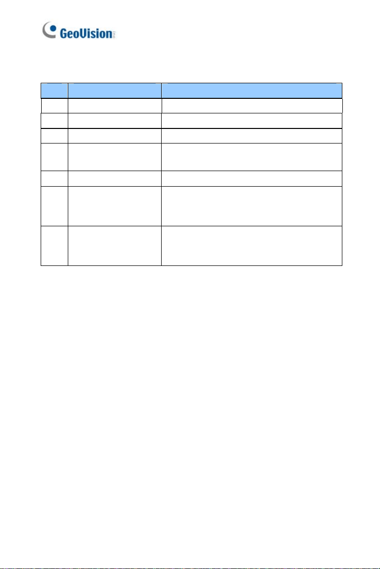
No. Name Description
9 Audio In Connects a microphone for audio input.
10 Audio Out Connects a speaker for audio output.
11 LAN / PoE Connects to a 10/100 Ethernet or PoE.
12 I/O Terminal Block
Connects to I/O devices. For details, see
1.5 I/O Terminal Block.
13 DC 12V Port Connects to power.
14 Status LED
Turns on (green) when the system
operates normally and turns off when
system error occurs.
15 Power LED
Turns on (green) when the power is on
and turns off when there is no power
supply.
6
Fixed IP Dome
1
1.3 Installation
The Fixed IP Dome is designed for indoors. With the standard packing,
there are three ways to install the Fixed IP Dome: hard-ceiling mount, in-
ceiling mount and wall-surface mount.
Note: You may also install the camera to ceilings, wall corners
(concave or convex), and poles with optional mounting kits. For details,
see GV-Mount Accessories Installation Guide on the Software CD.
1.3.1 Hard-Ceiling Mount
Figure 1-2
1. Paste the supplied sticker onto a desired location on the ceiling. Drill
the three red dots and the ellipse mark only if you wish to run the
wires into the ceiling.
7

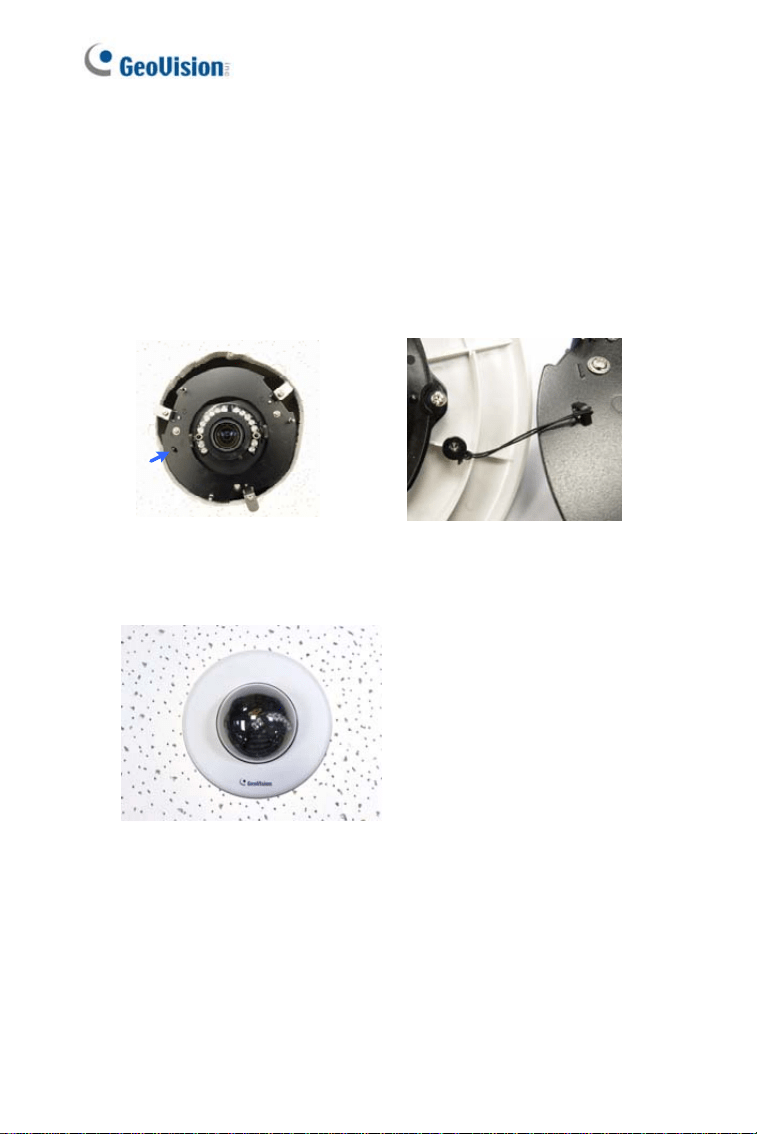
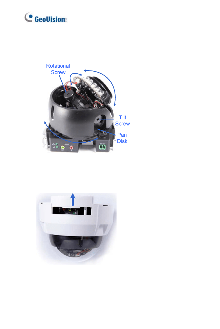
2. Unpack the camera package and take out the camera body.
A. Use the torx wrench to loosen the housing cover at the front and
the back.
Figure 1-3
B. Take out the camera body
Figure 1-4
3. Secure the camera body to the mounting plate with three ceiling
screws.
Figure 1-5
8
Fixed IP Dome
1
4.
Connect the network, power and other cables to the camera. See 1.4
Connecting the Camera.
5. Access the live view. See 3.2 Accessing the Live View.
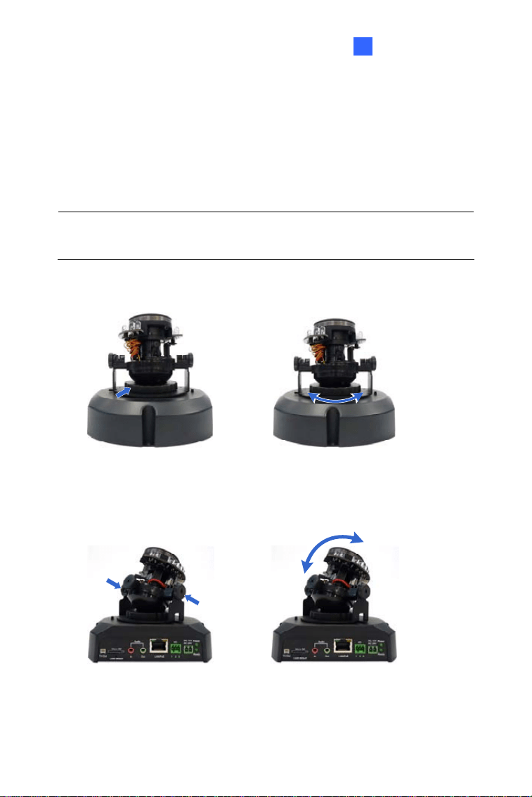
6. Based on the live view, adjust the camera to a desired angle as
illustrated below.
Tip: The 3-axis mechanism offers flexible and easy ceiling / wall
installation.
Pan Adjustment
Figure 1-6
Tilt Adjustment
Figure 1-7
9
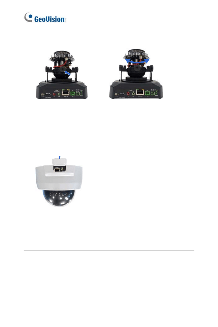
Rotational Adjustment
Figure 1-8
7. Adjust image clarity using the GV-IP Device Utility program. For
details, see 3.3 Adjusting Image Clarity.
8. Secure the housing cover as shown in step 2. Remove the indicated
part when necessary.
Figure 1-9
Note: Adjust the black mask inside the housing cover to make sure the
camera view is not obscured.
10

Fixed IP Dome
1
1.3.2 In-Ceiling Mount
Figure 1-10
1. Follow step 2 in the 1.3.1 Hard-Ceiling Mount to remove the housing
cover and take out the camera body.
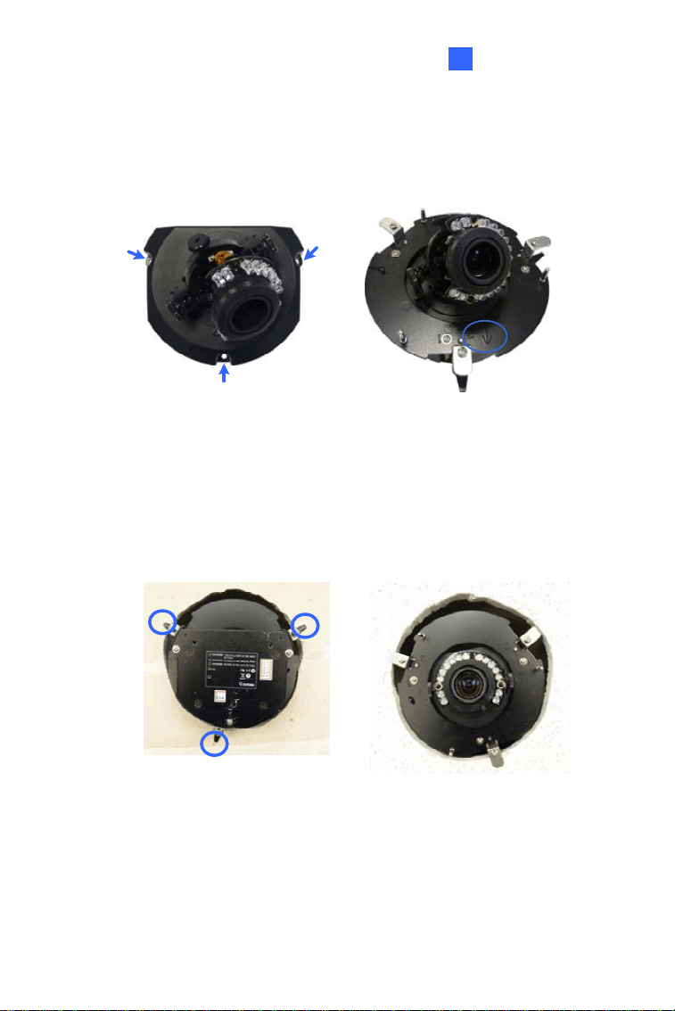
2. Paste the supplied sticker onto a desired location on the ceiling and
cut a circle on the ceiling along the edge of the sticker.
3. On the mounting plate, locate the 3 holes labeled as 1 and insert the
3 copper pillars from the back side.
Figure 1-11
11

4. From the side with the numbering, secure the copper pillars with 3
copper pillar screws.
Figure 1-12
5. Place the 3 mounting brackets at the indent next to the copper pillars
(labeled as 2 on the mounting plate) and secure them using the 3
bracket screws.
Figure 1-13
12
Fixed IP Dome
1
6.
Place the mounting plate on the camera body with the copper pillars
inserted in the locations indicated below. The arrow on the mounting
plate should be pointing toward the front of the camera.
Figure 1-14
7. From the bottom of the camera, secure the copper pillars using the 3
copper pillars screws.
8. Place the camera into the ceiling opening.
9. On the back side, make sure the black plastic clips are slightly above
the ceiling board and pointing outward.
Back Side Front Side
Figure 1-15
10. Tighten the bracket screws from the front side of the camera.
13
11. Connect the network, power and other cables to the camera. See 1.4
Connecting the Camera.
12. Access the live view. See 3.2 Accessing the Live View.
13. Follow steps 6 and 7 in 1.3.1 Hard-Ceiling Mount section to adjust the
angle, focus and zoom of the camera.
14. Use the housing cover thread and the thread lock screw to attach the
housing cover to the camera body.
Figure 1-16
15. Place the housing cover on the camera body with the GeoVision logo
pointing toward the front of the camera.
Figure 1-17
14

Fixed IP Dome
1
1.3.3 Wall-Surface Mount
Figure 1-18
1. Follow step 2 in 1.3.1 Hard-Ceiling Mount section to remove the
housing cover and take out the camera body.
2. Paste the supplied sticker onto a desired location on the wall. Drill the
three red dots, and the ellipse mark only if you wish to run the wires
into the wall.
3. Insert the short screw anchors and secure the camera and the
mounting plate with three plate screws.
Figure 1-19
4. Connect the network, power and other cables to the camera. See 1.4
Connecting the Camera.
15

5. Access the live view. See 3.2 Accessing the Live View.
6. Follow steps 6 and 7 in 1.3.1 Hard-Ceiling Mount section to adjust the
angle, focus and zoom of the camera.
7. Follow step 8 in 1.3.1 Hard-Ceiling Mount section to secure the
housing cover.
16

Fixed IP Dome
1
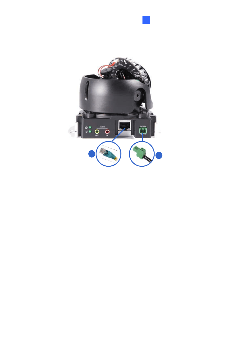
1.4 Connecting the Camera
Figure 1-20
1. Use a standard network cable to connect the camera to your network.
2. Optionally connect a speaker and an external microphone.
3. Optionally connect a monitor using a Video Out wire. Enable this
function by selecting your signal format at the TV Out field on the
Web interface. See 4.1.1 Video Settings, GV-IPCam Firmware
Manual.
4. Optionally connect to input / output devices. For details, see 1.5 I/O
Terminal Block.
5. Connect power using one of the following methods:
plugging the power adapter to power port.
using the Power over Ethernet (PoE) function and the power will
be provided over the network cable.
6. The status LED of the camera will be on.
17

1.5 I/O Terminal Block
The terminal block, located on the back panel of the Fixed IP Dome,
provides the interface to one input and one output devices. The I/O
terminal block can be used for applications such as motion detection, event
alerts via E-Mail and FTP, and center monitoring through Center V2 and
VSM.
1.5.1 Pin Assignment
The Fixed IP Dome supports one digital input and one digital output of dry
contact.
Pin Function
1 Digital Output
2 GND
I/O
123
Figure 1-21
3 Digital Input
18
Fixed IP Dome
1
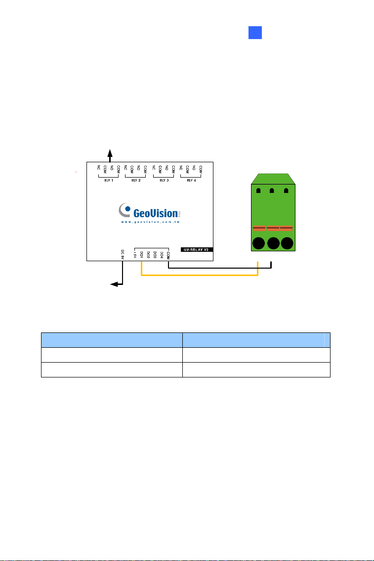
1.5.2 Voltage Load Expansion (Optional)
The camera on its own can only drive a maximum load of 200mA 5V DC.
To expand the maximum voltage load to 10A 250V AC / 10A 125V AC /
5A 100V DC), connect the camera to a GV-Relay V2 module (optional
product). Refer to the figure and table below:
Connect to Power
3
Output Device
I/O
2
1
Figure 1-22
GV-Relay V2 Bullet Camera
COM Pin 2 (GND)
DO1 Pin 1 (Digital Output)
19
1.6 Loading Factory Default
You can restore factory default settings through the Web interface or
directly on the camera.
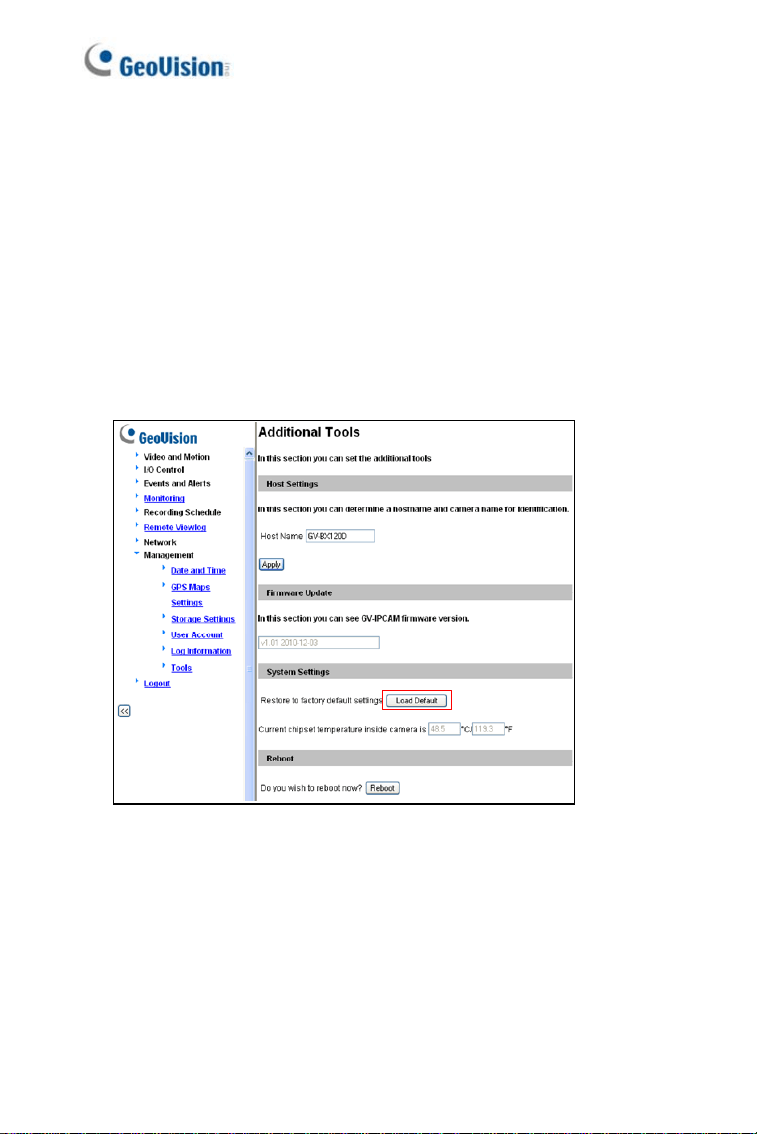
1.6.1 Using the Web Interface
1. On the left menu of Web interface, select Management and select
Tools. The Additional Tools dialog box appears.
2. Click the Load Default button in the System Settings section.
Figure 1-23
20
Fixed IP Dome
21
1
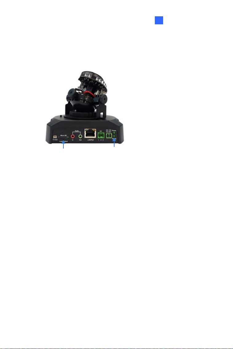
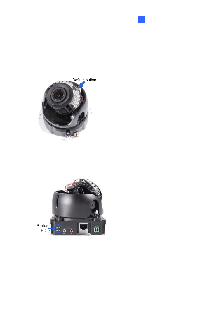
1.6.2 Directly on the Camera
3. Keep the power and network cables (or PoE) connected to the camera.
4. Use a pin to press and hold the default button on the panel.
Default button
Status LED
Figure 1-24
5. Release the default button when the status LED blinks. This shall
take about 8 seconds.
6. When the status LED fades, the process of loading default settings is
completed and the camera reboots automatically.

Chapter 2 Target Fixed Dome
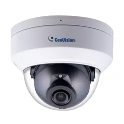
The Target Fixed Dome (GV-EFD) is an indoor, fixed network camera
equipped with an automatic IR-cut filter and IR LEDs for day and night
surveillance. Adjustable in 3 axis (pan, tilt and rotate), it offers an entry-
level surveillance solution with all the essential features and excellent
image quality.
Model No. Specifications Description
GV-EFD2101
Varifocal
Lens
P-Iris, f: 3 ~ 9 mm,
F/1.7, 1/2.8” Ø14
mm Mount
2 MP, H.264,
Super Low
Lux, WDR
GV-EFD3101
Varifocal
Lens
P-Iris, f: 3 ~ 9 mm,
F/1.7, 1/2.8” Ø14
mm Mount
3 MP, H.264,
Super Low
Lux, WDR Pro
GV-EFD5101
Varifocal
Lens
P-Iris, f: 3 ~ 9 mm,
F/1.7, 1/2.7” Ø14
mm Mount
5 MP, H.264,
Low Lux, WDR
22
Target Fixed Dome
2
2.1 Packing List
Target Fixed IP Dome
Torx Wrench
Screw x 3
Screw Anchor x 3
TV-Out Wire
Installation sticker
GV-IPCam Software DVD Warranty Card
GV-Software DVD
Note: Power adapter can be purchased upon request.
23
2.2 Overview
Figure 2-1
No. Name Description
1 Lens Receives image inputs.
2 Focus Screw Adjusts the focus of the camera.
3 Zoom Screw Adjusts the zoom of the camera.
4
Default
Button
Resets the camera to factory default. For details,
see 2.5 Loading Factory Default.
5 TV-Out Provides video inputs (D1 resolution).
6
Rotational
Screw
Loosens to adjust the camera angle.
7 Pan Disc Loosens to pan the camera.
8 Power Turns on (green) when power is on.
9 Status Turns on (green) when the system is ready.
10 Audio Out Connects a speaker for audio output.
11 Audio In Connects a microphone for audio input.
24

Target Fixed Dome
2
No. Name Description
12 Link Turns on (green) when the network is connected.
13 ACT Turns on (orange) when data are being transmitted.
14 DC 12V Port Connects to power.
15 LAN / PoE Connects to a 10/100 Ethernet or PoE.
16 Tilt Screw Loosens the screw to adjust tilt angle.
Note: The TV-out function can only be used during installation to adjust
the focus of the camera. To use the TV out function, connect the
supplied black BNC connector to a monitor and select your signal format
(NTSC or PAL) at the TV Out field on the Web interface. The default
signal format is NTSC. For details, see 4.1.1 Video Settings, GV-IPCam
Firmware Manual. The TV-out wire must be removed before you secure
the housing cover.
25

2.3 Installation
The Target Fixed Dome can be installed on the wall or the ceiling. Before
installing the camera, make sure the installing site is shielded from rain and
moisture.
1. Use the supplied torx wrench to loosen three screws on the housing
cover, and take out the camera body.
Figure 2-2
26

Target Fixed Dome
2
2.
Place the installation sticker where you want to install it, and make 3
marks on the ceiling or the wall for screw anchors.
Figure 2-3
3. Drill the marks and insert the screw anchors.
4. Connect the camera to network and power. For details, see 2.4
Connecting the Camera.
5. Secure the camera to the ceiling or the wall with the supplied screws.
6. Access the live view. For details, see 3.2 Accessing the Live View.
Note: The TV-out function can only be used during installation to adjust
the focus of the camera. To use the TV out function, connect the
supplied black BNC connector to a monitor and select your signal format
(NTSC or PAL) at the TV Out field on the Web interface. The default
signal format is NTSC. For details, see 4.1.1 Video Settings, GV-IPCam
Firmware Manual. The TV-out wire must be removed before you secure
the housing cover.
7. Adjust image clarity using the GV-IP Device Utility program. For
details, see 3.3 Adjusting Image Clarity.
27
8. Loosen the tile screw, pan screw or rotational screw. Adjust the
angles based on the live view as needed, and tighten the screws
again.
Figure 2-4
9. Place the housing cover back and tighten the three screws to secure
it. Remove the indicated part when necessary.
Figure 2-5
28
Target Fixed Dome
2
2.4 Connecting the Camera
1
2
Figure 2-6
1. Connect power using one of the following methods:
Plug the power adapter to the 12V terminal block. The power
adapter is an optional device. For detail, see Options in the
manual.
Use the Power over Ethernet (PoE) function and the power will be
provided over the network cable.
The power and status LEDs shall turn on (green).
2. Use a standard network cable to connect the camera to your network.
3. You are ready to access the live view, adjust the image clarity and
configure the basics. See Getting Started, Chapter 2, GV-IPCam
Firmware Manual.
29

2.5 Loading Factory Default
2.5.1 Using the Web Interface
You can restore default settings through the Web Interface. For details, see
1.6.1 Using the Web Interface.
30
Target Fixed Dome
31
2
2.5.2 Directly on the Camera
1. Keep the power and network cables (or PoE) connected to the
camera.
2. Press and hold the default button for about 8 seconds.
Figure 2-7
3. Release the default button when the status LED blinks.
Figure 2-8
When the status LED fades, the process of loading default settings is
completed and the camera reboots automatically
Chapter 3 Accessing the Camera
3.1 System Requirement
To access the GV-IP Camera through the Web browser, ensure your PC
connects to the network properly and meets this system requirement:
Microsoft Internet Explorer 8.0 or later
Note: For the users of Internet Explorer 8, additional settings are
required. For details, see Appendix A in GV-IPCAM Firmware Manual
on the Software DVD.
32

Accessing the Camera
3
3.2 Accessing the Live View
When the camera is connected to a network with a DHCP server, it will be
automatically assigned with a dynamic IP address. See 3.2.1 Checking the
Dynamic IP Address to look up this IP address.
However, if you do not have a DHCP server on your network, access the
camera by its default IP address 192.168.0.10 and see 3.2.2 Configuring
the IP Address for more detail.
Note: The default ID and Password of the GV-IP Camera is admin.
33
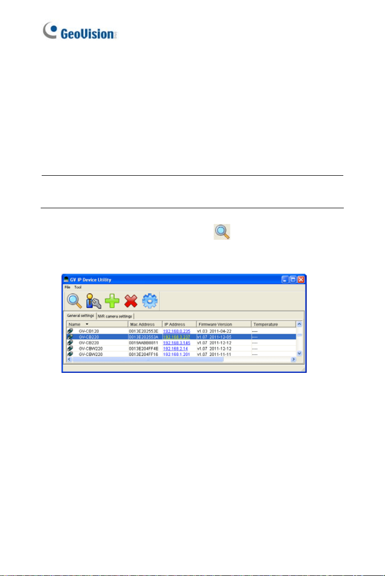
3.2.1 Checking the Dynamic IP Address
Follow the steps below to look up the IP address and access the Web
interface.
1. Install the GV-IP Device Utility program included on the GV-IPCAM
software DVD.
Note: The PC installed with GV-IP Device Utility must be under the
same LAN with the GV-IPCAM you wish to configure.
2. On the GV-IP Utility window, click the
button to search for the IP
devices connected in the same LAN. Click the Name or Mac Address
column to sort.
Figure 3-1
34
Accessing the Camera
3
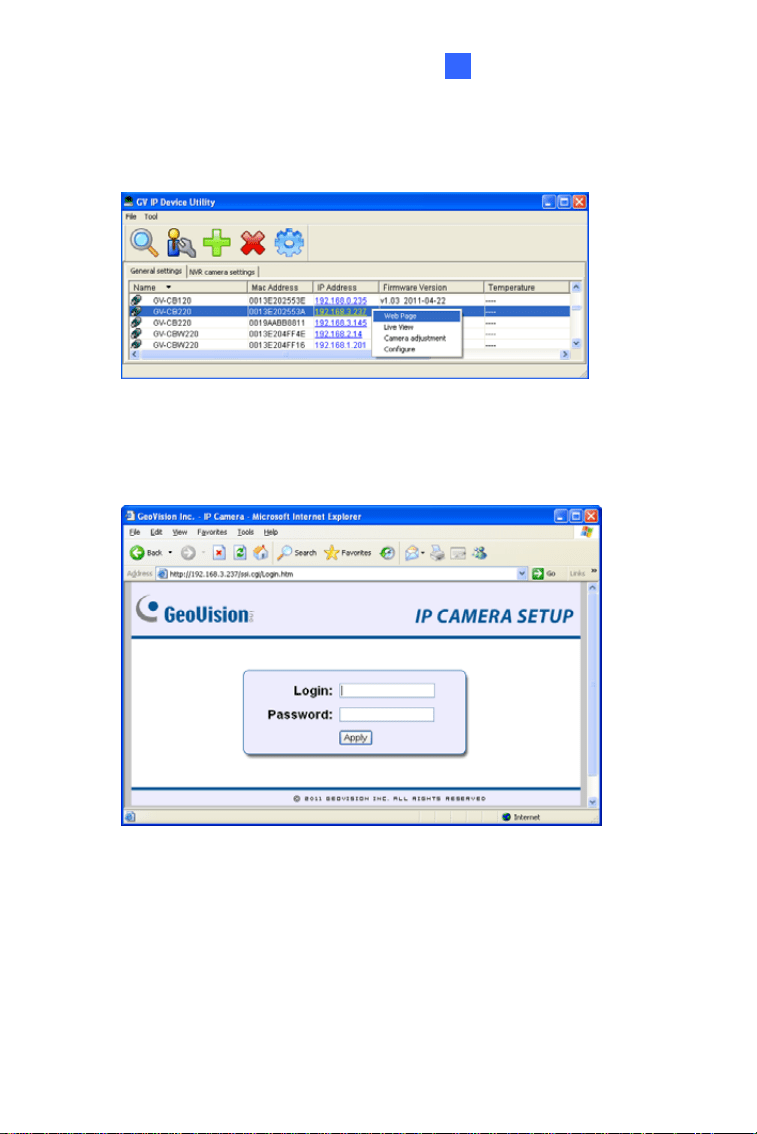
3.
Find the camera with its Mac Address, click on its IP address and
select Web Page.
Figure 3-2
4. The login page appears.
Figure 3-3
5. Type the default ID and password admin and click Apply to log in.
35

3.2.2 Configuring the IP Address
Follow the steps below to configure the IP address.
1. Open your Web browser, and type the default IP address
http://192.168.0.10
.
2. In both Login and Password fields, type the default value admin. Click
Apply.
3. In the left menu, select Network and then LAN to begin the network
settings.
Figure 3-4
4. Select Static IP address, Dynamic IP address or PPPoE and type the
required network information.
5. Click Apply. The camera is now accessible by entering the assigned
IP address on the Web browser.
6. To enable the updating of images in Microsoft Internet Explorer, you
must set your browser to allow ActiveX Controls and perform a one-
time installation of GeoVision’s ActiveX component onto your
computer.
36

Accessing the Camera
3
Important:
1. If Dynamic IP Address or PPPoE is enabled, you need to know
which IP address the camera will get from DHCP server or ISP to
log in. If your camera is installed in the LAN, use the GV-IP Device
Utility to look up its current dynamic IP address. See 3.2.1 Checking
the Dynamic IP Address. If your camera uses a public dynamic IP
address via PPPoE, use the dynamic DNS Service to obtain a
domain name that is linked to the camera’s changing IP address
first. For details, see LAN Configuration and Advanced TCP/IP
sections, Administrator Mode Chapter in the GV-IPCAM Firmware
Manual on the Software DVD.
2. If Dynamic IP Address or PPPoE is enabled and you cannot
access the camera, you may have to reset the camera to its factory
default and then perform the network settings again. To restore
factory settings, see 1.6, 2.5 Loading Factory Default.
37

3.3 Adjusting Image Clarity
You can adjust the image clarity using the GV-IP Device Utility. Make sure
that you have connected your GV-IPCAM to the network and install the
GV-IP Device Utility program under the same LAN.
Note: This feature only applies to the cameras that allow manual focus
adjustment.
1. Make sure you have installed the GV-IP Device Utility program
included on the GV-IPCAM software DVD.
2. On the GV-IP Utility window, click the
button to search for the IP
devices connected in the same LAN. Click the IP Address of the
camera you desire. A drop-down list appears.
Figure 3-5
38

Accessing the Camera
3
3.
Select Focus Value. The Login dialog box appears.
Figure 3-6
4. Type the user name and password of the camera selected. The
default is admin for both user name and password. This window
appears.
Figure 3-7
5. Adjust the Zoom Screw and the Focus Screw of the camera slowly
until the focus value reaches the maximum.
39

40
Note:
1. For locations of adjustment screws and rings in each model, see
Locations of Adjustment Screws, section, Getting Started Chapter,
GV-IPCAM Firmware Manual on the Software DVD.
2. Do not over tighten the screws. The screws only need to be as tight
as your fingers can get them to be. Do not bother using any tool to
get them tighter. Doing so can damage the structure of lens.
3. The maximum focus value may vary when the environment
changes.
The Web Interface
4
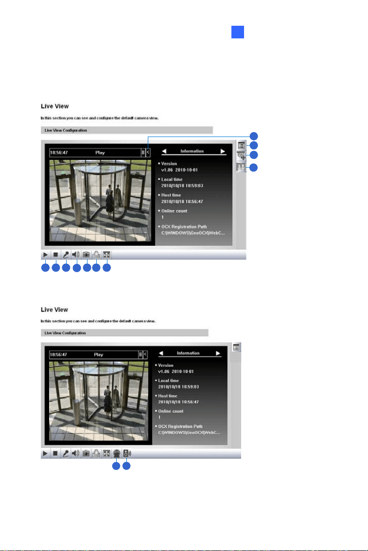
Chapter 4 The Web Interface
1 2 3
4
5 6 7
8
9
10
11
Figure 4-1
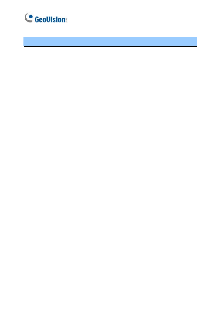
12
13
Figure 4-2
41
No. Name Function
1 Play Plays live video.
2 Stop Stops playing video.
3 Microphone
Broadcasts to the surveillance site from a remote
PC. Note this function is not available for Ultra
Bullet Camera and Target Series. For Cube
Camera and Advanced Cube Camera, click the
Push to talk button (from the pop-up menu) for the
camera to switch between audio transmission and
reception, where only one party can speak at a
time.
4 Speaker
Transfers sounds of the surveillance site to a
remote PC. Note this function is not available for,
Mini Fixed Rugged Dome, Ultra Bullet Camera,
Target Bullet Camera, and Target Mini Fixed
Rugged Dome.
5 Snapshot Takes a snapshot of live video.
6 File Save Records live video to the local computer.
7 Full Screen
Switches to full screen view. Right-click the image
to see additional options.
8 Control Panel
Displays the camera information, video settings,
audio data rate, I/O device status, images captured
upon alarm, and GPS location of the camera. Also
allows you to adjust image quality and install the
program from the hard drive.
9
Show System
Menu
Brings up these functions: Alarm Notify, Video and
Audio Configuration, Remote Config, Show
Camera Name and Image Enhance.
42

The Web Interface
43
4
No. Name Function
10
PTZ Control
Panel
Enables the PTZ Control Panel or the Visual PTZ.
Note this function is supported by PTZ Camera
and PT Camera, and only partially supported by
GV-IP Cameras with motorized varifocal lens.
11 I/O Control
Enables the I/O Control Panel and Visual
Automation. Note this function is not available in
Mini Fixed Dome, Mini Fixed Rugged Dome,
Cube Camera, Advanced Cube Camera and
Target Series.
12 LED Control
Click to turn the Alarm LED on and/or adjust the
brightness sensitivity. Note this function is only
available for Advanced Cube Camera.
13
Alarm
Speaker
Click to sound the alarm and/or adjust its volume.
To sound the alarm upon motion or tampering
events, see Speaker section, Administrator Mode
Chapter, GV-IPCAM Firmware Manual on the
Software DVD. Note this function is only available
for Advanced Cube Camera.
Chapter 5 Upgrading System
Firmware
GeoVision periodically releases updated firmware on the website. The new
firmware can be simply loaded into the GV-IPCAM by using the Web
interface or IP Device Utility included in the software DVD.
Important:
1. To update the camera firmware from versions earlier than V2.07 to
the latest version, back up the files in the storage device to
another device before the upgrade.
2. While the firmware is being updated,
A) the power supply must not be interrupted, and
B) do not unplug the Ethernet cable if the cable is the source of
power supply (Power over Ethernet or PoE supported).
3. Do not turn the power off within 10 minutes after the firmware is
updated.
4. If you use the IP Device Utility for firmware upgrade, the computer
used to upgrade firmware must be under the same network of the
camera.
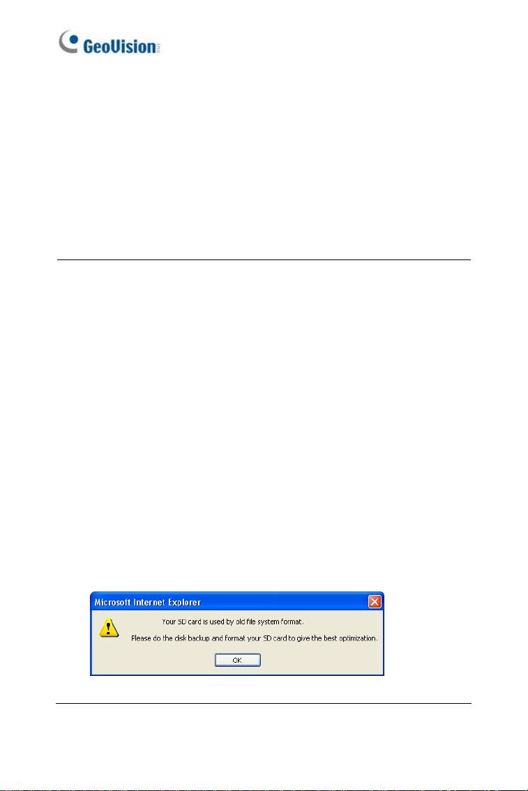
5. Since the firmware adopts different storage format from V2.07
onward, be sure to re-format the storage device after firmware
upgrade. If you have not done so, this warning message appears
when you view the Monitoring or Storage Settings’ Web interface:
Figure 5-1
44
Upgrading System Firmware
45
5
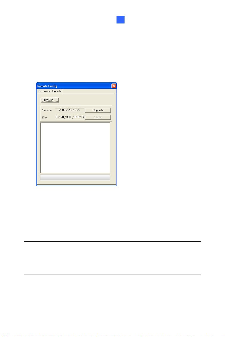
1. Stop these operations: monitoring of the camera, connection to GV-
DVR / NVR / VMS and remote connections to Center V2, Vital Sign
Monitor, ViewLog Server and 3GPP/RTSP.
2. In the Live View window, click the Show System Menu button and
select Remote Config. This dialog box appears.
Figure 5-2
3. Click the Browse button to locate the firmware file (.img) saved at
your local computer.
4. Click the Upgrade button to start the upgrade.
WARNING: The interruption of power supply during updating causes
not only update failures but also damages to the camera. In this case,
please contact your sales representative and send your device back to
GeoVision for repair.