Air Conditioner
user manual
imagine the possibilities
Thank you for purchasing this Samsung product.
Duct Type Series
Global Duct :
AM✴✴✴HNMP✴✴✴
AM✴✴✴HNHP✴✴✴
2
Correct Disposal of This Product
(Waste Electrical & Electronic Equipment)
(Applicable in the countries with separate collection systems)
This marking on the product, accessories or literature indicates that the product and its electronic accessories (e.g. charger, headset, USB
cable) should not be disposed of with other household waste at the end of their working life. To prevent possible harm to the environment
or human health from uncontrolled waste disposal, please separate these items from other types of waste and recycle them responsibly to
promote the sustainable reuse of material resources.
Household users should contact either the retailer where they purchased this product, or their local government office, for details of where
and how they can take these items for environmentally safe recycling.
Business users should contact their supplier and check the terms and conditions of the purchase contract. This product and its electronic
accessories should not be mixed with other commercial wastes for disposal.
Safety precautions ................................................................................................................................................................................................................. 3
Checking before use .......................................................................................................................................................................................................... 10
Viewing the parts ................................................................................................................................................................................................................ 12
Cleaning and maintaining the air conditioner ...................................................................................................................................................... 13
Appendix ................................................................................................................................................................................................................................ 16
Installation parts .................................................................................................................................................................................................................. 20
Contents
For information on Samsung’s environmental commitments and product-specific regulatory obligations, e.g. REACH, visit: www.samsung.
com/uk/aboutsamsung/sustainability/environment/our-commitment/data/
3
ENGLISH
Safety precautions
Before using your new air conditioner, please read this manual thoroughly to ensure that
you know how to safely and eciently operate the extensive features and functions of your
new appliance.
Because the following operating instructions cover various models, the characteristics of
your air conditioner may dier slightly from those described in this manual. If you have any
questions, call your nearest contact center or nd help and information online at www.
samsung.com.
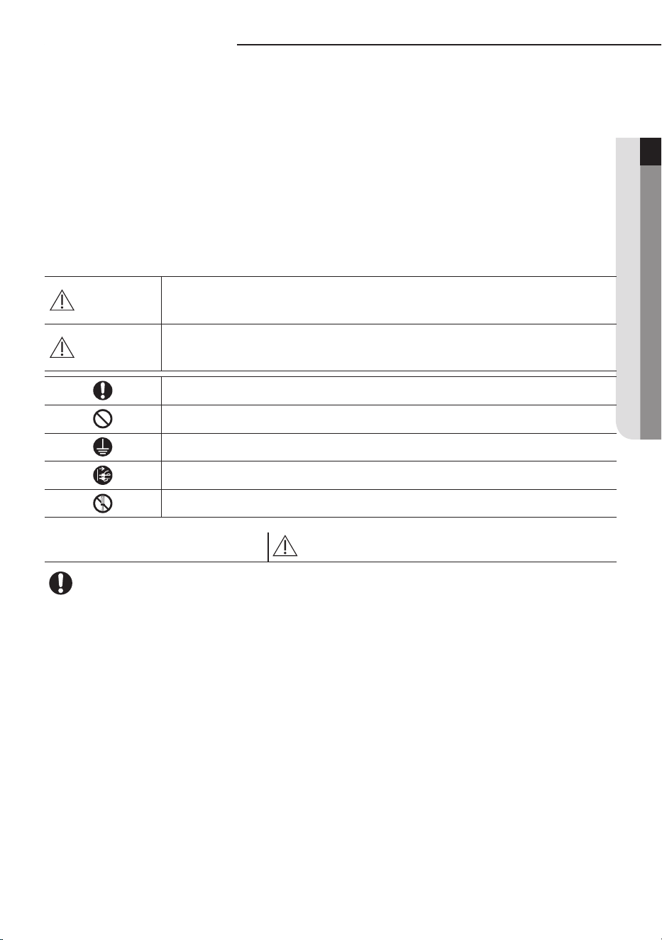
Important safety symbols and precautions:
WARNING
Hazards or unsafe practices that may result in severe personal injury
or death.
CAUTION
Hazards or unsafe practices that may result in minor personal injury
or property damage.
Follow directions.
Do NOT attempt.
Make sure the machine is grounded to prevent electric shock.
Unplug the power plug from the wall socket.
Do NOT disassemble.
FOR INSTALLATION
WARNING
Use the power line with the power specications of the product or higher and use
the power line for this appliance only. In addition, do not use an extension line.
Extending the power line may result in electric shock or re.
Do not use an electric transformer. It may result in electric shock or re.
If the voltage/frequency/rated current condition is dierent, it may cause re.
The installation of this appliance must be performed by a qualied technician or
service company.
Failing to do so may result in electric shock, re, explosion, problems with the
product, or injury.
Install a switch and circuit breaker dedicated to the air conditioner.
Failing to do so may result in electric shock or re.
Fix the outdoor unit rmly so that the electric part of the outdoor unit is not exposed.
Failing to do so may result in electric shock or re.
4
Safety precautions
FOR INSTALLATION
WARNING
Do not install this appliance near a heater, inammable material. Do not install
this appliance in a humid, oily or dusty location, in a location exposed to direct
sunlight and water (rain drops). Do not install this appliance in a location where
gas may leak.
This may result in electric shock or re.
Never install the outdoor unit in a location such as on a high external wall where it
could fall.
If the outdoor unit falls, it may result in injury, death or property damage.
This appliance must be properly grounded. Do not ground the appliance to a gas
pipe, plastic water pipe, or telephone line.
Failure to do so may result in electric shock, re, an explosion, or other problems with
the product.
Never plug the power cord into a socket that is not grounded correctly and make
sure that it is in accordance with local and national codes.
FOR INSTALLATION
CAUTION
Install your appliance on a level and hard oor that can support its weight.
Failing to do so may result in abnormal vibrations, noise, or problems with the
product.
Install the draining hose properly so that water is drained correctly.
Failing to do so may result in water overowing and property damage.
When installing the outdoor unit, make sure to connect the draining hose so that
draining is performed correctly.
The water generated during the heating operation by the outdoor unit may overow
and result in property damage.
In particular, in winter, if a block of ice falls, it may result in injury, death or property
damage.
5
ENGLISH
FOR POWER SUPPLY
WARNING
When the circuit breaker is damaged, contact your nearest service center.
Do not pull or excessively bend the power line. Do not twist or tie the power line.
Do not hook the power line over a metal object, place a heavy object on the power
line, insert the power line between objects, or push the power line into the space
behind the appliance.
This may result in electric shock or re.
FOR POWER SUPPLY
CAUTION
When not using the air conditioner for a long period of time or during a thunder/
lightning storm, cut the power at the circuit breaker.
Failing to do so may result in electric shock or re.
FOR USING
WARNING
If the appliance is ooded, please contact your nearest service center.
Failing to do so may result in electric shock or re.
If the appliance generates a strange noise, a burning smell or smoke, unplug the
power plug immediately and contact your nearest service center.
Failing to do so may result in electric shock or re.
In the event of a gas leak (such as propane gas, LP gas, etc.), ventilate immediately
without touching the power line.
Do not touch the appliance or power line.
Do not use a ventilating fan.
A spark may result in an explosion or re.
To reinstall the air conditioner, please contact your nearest service center.
Failing to do so may result in problems with the product, water leakage, electric
shock, or re.
A delivery service for the product is not provided. If you reinstall the product in
another location, additional construction expenses and an installation fee will be
charged.
Especially, when you wish to install the product in an unusual location such as in
an industrial area or near the seaside where it is exposed to the salt in the air, please
contact your nearest service center.
6
Safety precautions
FOR USING
WARNING
Do not touch the circuit breaker with wet hands.
This may result in electric shock.
Do not strike or pull the air conditioner with excessive force.
This may result in re, injury, or problems with the product.
Do not place an object near the outdoor unit that allows children to climb onto
the machine.
This may result in children seriously injuring themselves.
Do not turn the air conditioner o with the circuit breaker while it is operating.
Turning the air conditioner o and then on again with the circuit breaker may cause a
spark and result in electric shock or re.
After unpacking the air conditioner, keep all packaging materials well out of the
reach of children, as packaging materials can be dangerous to children.
If a child places a bag over its head, it may result in suocation.
Do not insert your ngers or foreign substances into the outlet when the air
conditioner is operating or the front panel is closing.
Take special care that children do not injure themselves by inserting their ngers into
the product.
Do not touch the front panel with your hands or ngers during the heating
operation.
This may result in electric shock or burns.
Do not insert your ngers or foreign substances into the air inlet/outlet of the air
conditioner.
Take special care that children do not injure themselves by inserting their ngers into
the product.
Do not use this air conditioner for long periods of time in badly ventilated
locations or near inrm people.
Since this may be dangerous due to a lack of oxygen, open a window at least once an
hour.
7
ENGLISH
FOR USING
WARNING
If any foreign substance such as water has entered the appliance, cut the power by
unplugging the power plug and turning the circuit breaker o and then contact
your nearest service center.
Failing to do so may result in electric shock or re.
Do not attempt to repair, disassemble, or modify the appliance yourself.
Do not use any fuse (such as cooper, steel wire, etc.)other than the standard fuse.
Failing to do so may result in electric shock, re, problems with the product, or injury.
FOR USING
CAUTION
Do not place objects or devices under the indoor unit.
Water dripping from the indoor unit may result in re or property damage.
Check that the installation frame of the outdoor unit is not broken at least once a
year.
Failing to do so may result in injury, death or property damage.
Max current is measured according to IEC standard for safety and current is
measured according to ISO standard for energy eciency.
Do not stand on top of the appliance or place objects (such as laundry, lighted
candles, lighted cigarettes, dishes, chemicals, metal objects, etc.) on the appliance.
This may result in electric shock, re, problems with the product, or injury.
Do not operate the appliance with wet hands.
This may result in electric shock.
Do not spray volatile material such as insecticide onto the surface of the appliance.
As well as being harmful to humans, it may also result in electric shock, re or
problems with the product.
Do not drink the water from the air conditioner.
The water may be harmful to humans.
Do not apply a strong impact to the remote controller and do not disassemble the
remote controller.
Do not touch the pipes connected with the product.
This may result in burns or injury.
8
Safety precautions
FOR USING
CAUTION
Do not use this air conditioner to preserve precision equipment, food, animals,
plants or cosmetics, or for any other unusual purposes.
This may result in property damage.
Avoid directly exposing humans, animals or plants from the air ow from the air
conditioner for long periods of time.
This may result in harm to humans, animals or plants.
This appliance is not intended for use by persons (including children) with
reduced physical, sensory or mental capabilities, or lack of experience and
knowledge, unless they have been given supervision or instruction concerning
use of the appliance by a person responsible for their safety. Children should be
supervised to ensure that they do not play with the appliance.
For use in Europe :
This appliance can be used by children aged from 8 years and above and persons
with reduced physical,sensory or mental capabilities or lack of experience and
knowledge if they have been given supervision or instruction concerning use of the
appliance in a safe way and understand the hazards involved. Children shall not play
with the appliance. Cleaning and user maintenance shall not be made by children
without supervision.
FOR CLEANING
WARNING
Do not clean the appliance by spraying water directly onto it. Do not use benzene,
thinner or alcohol to clean the appliance.
This may result in discoloration, deformation, damage, electric shock or re.
Before cleaning or performing maintenance, unplug the air conditioner from the
wall socket and wait until the fan stops.
Failing to do so may result in electric shock or re.
9
ENGLISH
FOR CLEANING
CAUTION
Take care when cleaning the surface of the heat exchanger of the outdoor unit
since it has sharp edges.
To avoid cutting your ngers, wear thick cotton gloves when cleaning it.
Do not clean the inside of the air conditioner by yourself.
For cleaning inside the appliance, contact your nearest service center.
When cleaning the internal lter, refer to the descriptions in the ‘Cleaning and
maintaining the air conditioner’ section.
Failure to do may result in damage, electric shock or re.
10
Checking before use
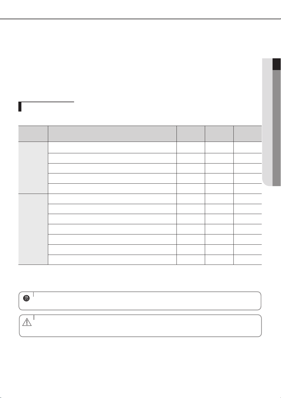
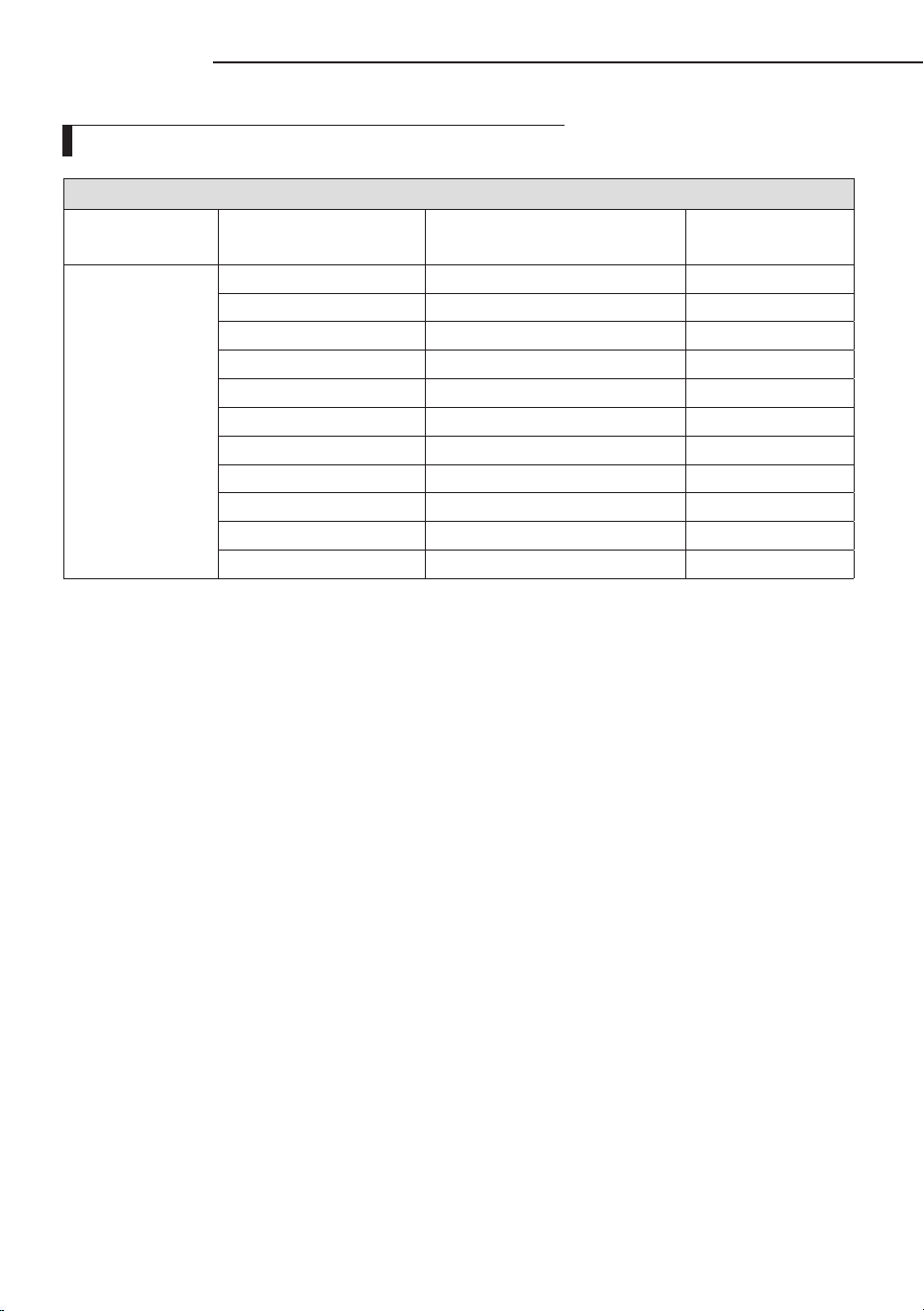
Operation ranges
The table below indicates the temperature and humidity ranges the air conditioner can
be operated within.
Refer to the table for ecient use.
• The standardized temperature for heating is 7˚C/45˚F. If the outdoor temperature drops to 0˚C/32˚F or below, the
heating capacity can be reduced depending on the temperature condition.
If the cooling operation is used at over 32˚C/90˚F (indoor temperature), it does not cool at its full capacity.
NOTE
•
The use of the air conditioner at a relative humidity above the expected one (80%) may
cause the formation of condensate and the leakage of water drops on the oor.
CAUTION
MODE OUTDOOR TEMPERATURE INDOOR TEMPERATURE INDOOR HUMIDITY
COOLING -15°C/5°F to 50°C/122°F 18°C/64°F to 32°C/90°F
80% or lessHEATING -20°C/-4°F to 24°C/75°F 27°C/81°F to less
DRYING -15°C/5°F to 50°C/122°F 18°C/64°F to 32°C/90°F
Maintaining your air conditioner
Internal protections via the unit control system
This internal protection operates if an internal fault occurs in the air conditioner.
Type Description
Against cold air The internal fan will be o to against cold air when the heat pump is heating.
De-ice cycle
(Defrost cycle)
The internal fan will be o to against cold air when the heat pump is heating.
Anti-protection of
internal battery
The compressor will be o to protect internal battery when the air conditioner operates
in Cool mode.
Protect compressor
The air conditioner does not start operating immediately to protect the compressor of
the outdoor unit after it has been started.
• If the heat pump is operating in Heat mode, De-ice cycle is actuated to remove frost from an outdoor unit that may
have deposited at low temperatures.
The internal fan is switched o automatically and restarted only after the de-ice cycle is completed.
NOTE
11
ENGLISH
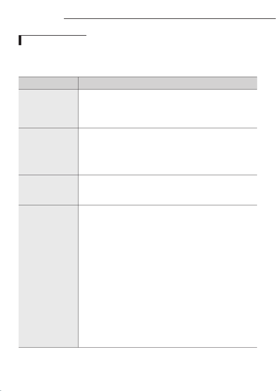
Tips on using air conditioner
Here are some tips that you would follow when using your air conditioner.
TOPIC RECOMMENDATION
Cooling • If current outside temperatures are much higher than the selected
indoor temperature, it may take time to bring the inner temperature
to the desired coolness.
• Avoid drastically turning down the temperature. Energy is wasted and
the room does not cool faster.
Heating • Since the air conditioner heats the room by taking heat energy
from outdoor air, the heating capacity may decrease when outdoor
temperatures are extremely low. If you feel the air conditioner
insuciently heats, using an additional heating appliance in
combination with the air conditioner is recommended.
Frost & De-ice • When the air conditioner runs in Heat mode, due to temperature
dierence between the unit and the outside air, frost will form.
If this happens:
- The air conditioner stops heating.
-
The air conditioner will operate automatically in De-ice mode for 10 minutes.
- The steam produced on the outdoor unit in De-ice mode is safe.
No intervention is required; after about 10 minutes, the air conditioner
operates again normally.
❈ The unit will not operate when it starts to de-ice.
Fan • Fan may not operate for about 3~5 minutes at the beginning to
prevent any cold blasts while the air conditioner is warming up.
High indoor/
outdoor
temperatures
• If both indoor and outdoor temperatures are high and the air
conditioner is running in Heat mode, the outdoor unit’s fan and
compressor may stop at times. This is normal; wait until the air
conditioner turns on again.
Power failure • If a power failure occurs during the operation of the air conditioner,
the operating immediately stops and unit will be o. When power
returns, the air conditioner will run automatically.
Protection
mechanism
• If the air conditioner has just been turned on after operation stops or
being plugged in, cool/warm air does not come out for 3 minutes to
protect the compressor of the outdoor unit.
12
Viewing the parts
• Your air conditioner and display may look slightly dierent from the illustration shown above depending on your
model.
NOTE
Congratulations on the purchase of the air conditioner. We hope you enjoy the features of your air conditioner and stay cool or
warm with optimal eciency.
Please read the user manual to get started and to make the best use of the air conditioner.
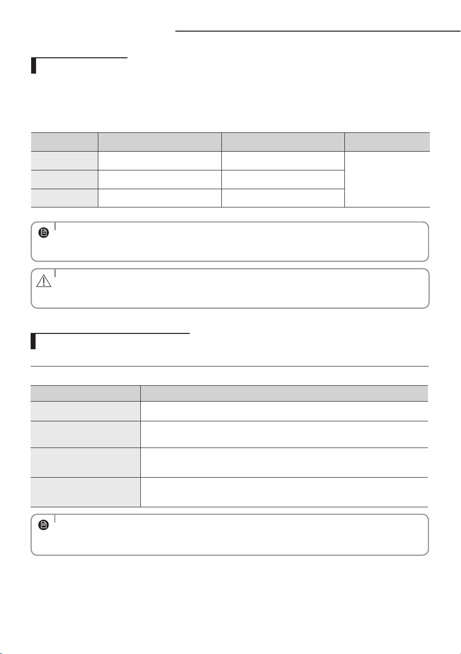
GLOBAL DUCT Type
Air intake
Air outlet
Ceiling
Air lter (the return air side)
13
ENGLISH
Cleaning and maintaining the air conditioner
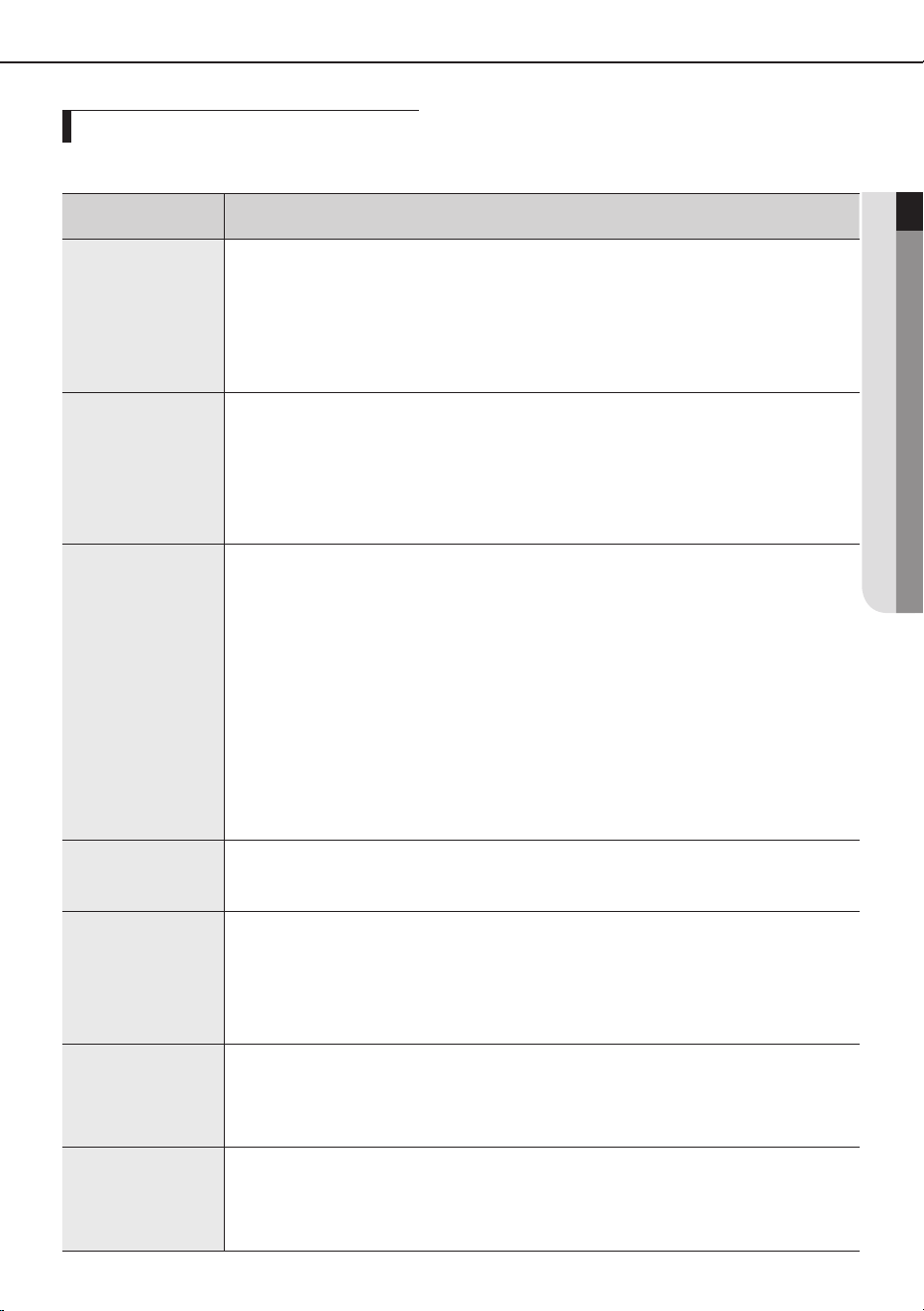
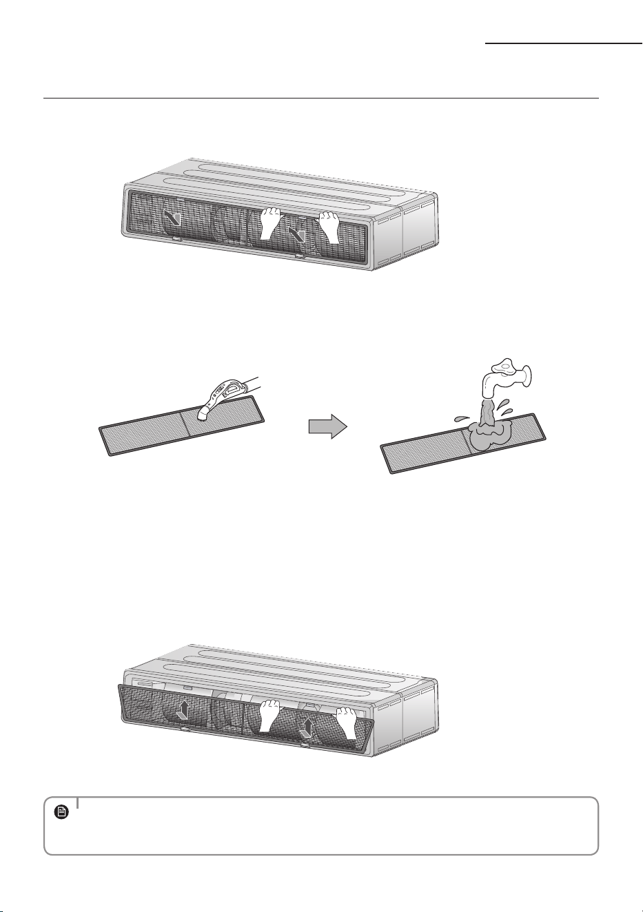
GLOBAL DUCT (Plastic Type)
1. Press both hooks and take the lter downward.
2. Clean the Air lter with a vacuum cleaner or soft brush. If dust is too heavy, then rinse it with running water and dry it
in a ventilated area.
• For best conditions, repeat every two weeks.
• If the Air lter dries in a conned (or humid) area, odors may generate. If it occurs,
re-clean and dry it in a ventilated area.
3. Insert the Air lter back in its original position.
• The illustration shown above may dier from yours depending on your model.
• After cleaning the lter, press the Filter Reset button on the remote control for 2 seconds to reset the lter
schedule. Filter sign indicator will be on for cleaning time.
NOTE
14
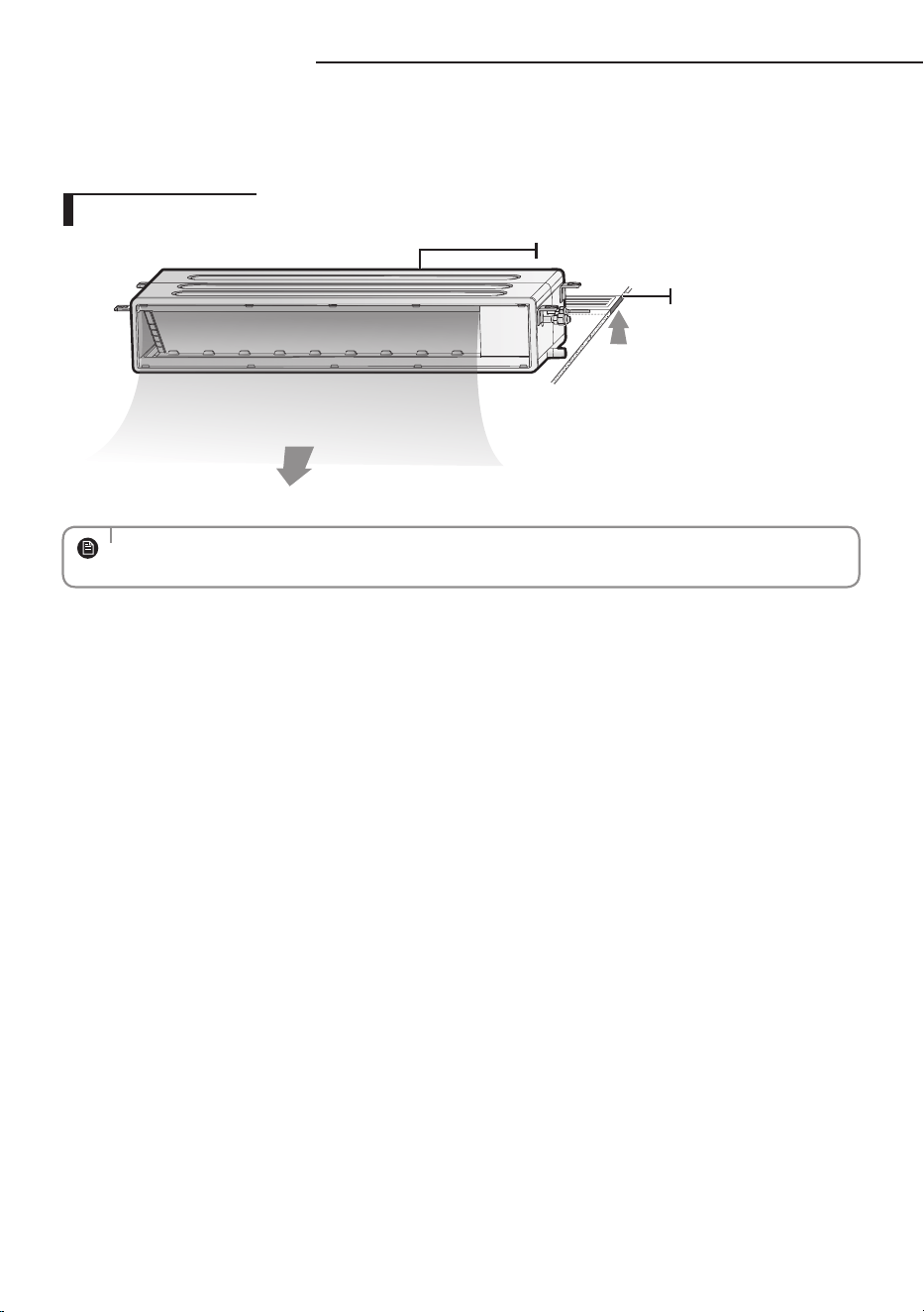
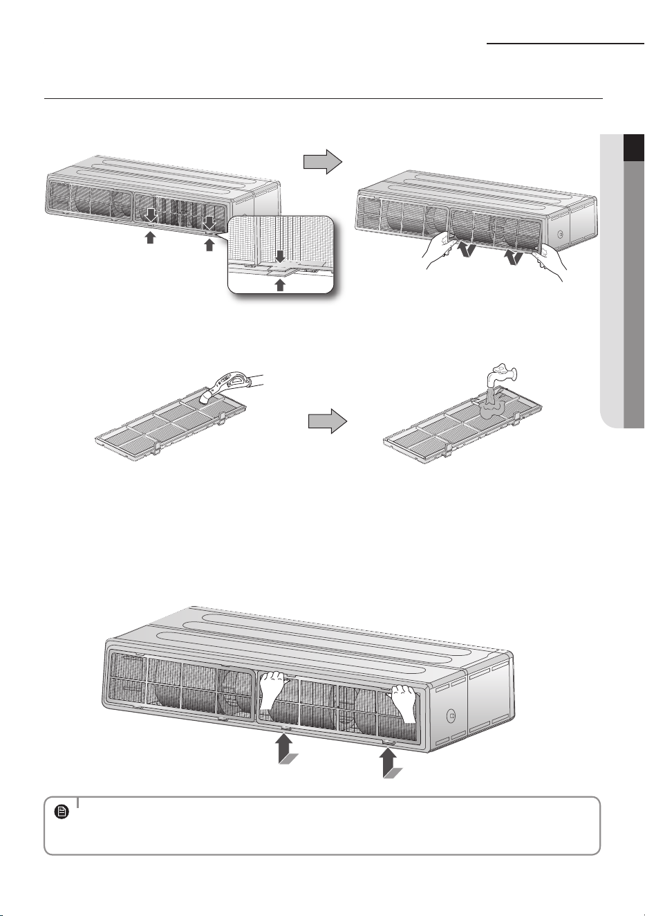
GLOBAL DUCT (Steel wire Type)
1. Pull out the Air lter from the frame .
2. Clean the Air lter with a vacuum cleaner or soft brush. If dust is too heavy, then rinse it with running water and dry it
in a ventilated area.
• For best conditions, repeat every two weeks.
• If the Air lter dries in a conned (or humid) area, odors may generate. If it occurs,
re-clean and dry it in a ventilated area.
3. Insert the Air lter back in its original position.
• The illustration shown above may dier from yours depending on your model.
• After cleaning the lter, press the Filter Reset button on the remote control for 2 seconds to reset the lter
schedule. Filter sign indicator will be on for cleaning time.
NOTE
Cleaning and maintaining the air conditioner
15
ENGLISH
If the air conditioner will not be used for an extended period of time, dry the air conditioner to maintain it in best condition.
Dry the air conditioner thoroughly by operating in Fan mode for 3 to 4 hours and
disconnect the power plug.
There may be internal damage if moisture is left in components.
Before using the air conditioner again, dry the inner components of the air conditioner
again by running in Fan mode for 3 to 4 hours. This helps remove odors which may have
generated from dampness.
• The described operations should be performed more frequently if the area of installation is very dusty.
NOTE
• These operations must always be performed by qualied personnel. For more
detailed information, see the installation part in the manual.
CAUTION
Periodical checks
Refer to the following chart to maintain the air conditioner properly.
Type Description Monthly
Every 4
months
Once a year
Indoor unit
Clean the air lter (1)
●
Clean the condensate drain pan (2)
●
Thoroughly clean the heat exchanger (2)
●
Clean the condensate drain pipe (2)
●
Replace the remote control batteries (1)
●
Outdoor unit
Clean the heat exchanger on the outside of the unit (2)
●
Clean the heat exchanger on the inside of the unit (2)
●
Clean the electric components with jets of air (2)
●
Verify that all the electric components are rmly tightened (2)
●
Clean the fan (2)
●
Verify that all the fan assembly is rmly tightened (2)
●
Clean the condensate drain pan (2)
●
●: This check mark requires checking the indoor/outdoor unit periodically, following to the description to maintain the air
conditioner properly.
16
Appendix
Troubleshooting
Refer to the following chart if the air conditioner operates abnormally. This may
save time and unnecessary expenses.
PROBLEM SOLUTION
The air conditioner
does not operate
immediately after it
has been restarted.
• Because of the protective mechanism, the appliance does not start
operating immediately to keep the unit from overloading.
The air conditioner will start in 3 minutes.
The air conditioner
does not work at all.
• Check that the power plug is properly connected. Insert the power
plug into the wall socket correctly.
• Check if the circuit breaker is switched o.
• Check if there is a power failure.
• Check your fuse. Make sure it is not blown out.
The temperature
does not change.
• Check if you selected Fan mode.
Press the Mode button on the remote control to select another
mode.
The cool (warm)
air does not come
out of the air
conditioner.
• Check if the set temperature is higher (lower) than the current
temperature. Press the Temperature button on the remote control
to change the set temperature. Press the Temperature button to
decrease or increase the temperature.
• Check if the air lter is blocked by dirt. Clean the air lter every two
weeks.
• Check if the air conditioner has just been turned on. If so, wait 3
minutes. Cool air does not come out to protect the compressor of
the outdoor unit.
• Check if the air conditioner is installed in a place with a direct
exposure to sunlight. Hang curtains on windows to boost cooling
eciency.
• Check if the cover or any obstacle is not near the outdoor unit.
• Check if the refrigerant pipe is too long.
• Check if the air conditioner is only available in Cool mode.
• Check if the remote control is only available for cooling model.
17
ENGLISH
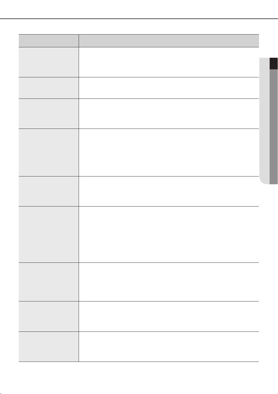
PROBLEM SOLUTION
The fan speed does
not change.
• Check if you selected Auto or Dry mode.
The air conditioner automatically adjusts the fan speed to Auto in
Auto/Dry mode.
Timer function does
not set.
• Check if you press the Power button on the remote control after
you have set the time.
Odors permeate in
the room during
operation.
• Check if the appliance is running in a smoky area or if there is a smell
entering from outside. Operate the air conditioner in Fan mode or
open the windows to air out the room.
The air conditioner
makes a bubbling
sound.
• A bubbling sound may be heard when the refrigerant is circulating
through the compressor. Let the air conditioner operate in a
selected mode.
• When you press the Power button on the remote control, noise may
be heard from the drain pump inside the air conditioner.
Water is dripping
from the air ow
blades.
• Check if the air conditioner has been cooling for an extended period
of time with the air ow blades pointed downwards. Condensation
may generate due to the dierence in temperature.
Remote control is
not working.
• Check if your batteries are depleted.
• Make sure batteries are correctly installed.
• Make sure nothing is blocking your remote control sensor.
• Check that there are strong lighting apparatus near the air
conditioner. Strong light which comes from uorescent bulbs or
neon signs may interrupt the electric waves.
The air conditioner
does not turn on or
o with the wired
remote control.
• Check if you set the wired remote control for group control.
The wired remote
control does not
operate.
• Check if TEST indicator is displayed on the wired remote control.
If so, turn o the unit and switch o the circuit breaker. Call your
nearest contact center.
The indicators of
the digital display
ashes.
• Press the Power button on the remote control to turn the unit o
and switch the circuit breaker o. Then, switch it on again.
18
Model specication (
Dimension and weight)
Dimension and weight
Type Model
Net dimension (WxDxH)
(mm)
Net weight
(kg)
Indoor unit
AM036HNMPKH 850*700*250 25.5
AM045HNMPKH 850*700*250 25.5
AM056HNMPKH 850*700*250 25.5
AM071HNMPKH 850*700*250 25.5
AM090HNMPKH 1200*700*250 32.5
AM112HNMPKH 1300*700*300 36.5
AM128HNMPKH 1300*700*300 36.5
AM140HNMPKH 1300*700*300 36.5
AM112HNHPKH 1300*700*300 46
AM128HNHPKH 1300*700*300 46
AM140HNHPKH 1300*700*300 46
Appendix

19
ENGLISH
20
INSTALLATION PARTS
Indoor unit installation
When deciding on the location of the air conditioner with the owner, the following restrictions must be taken into account.
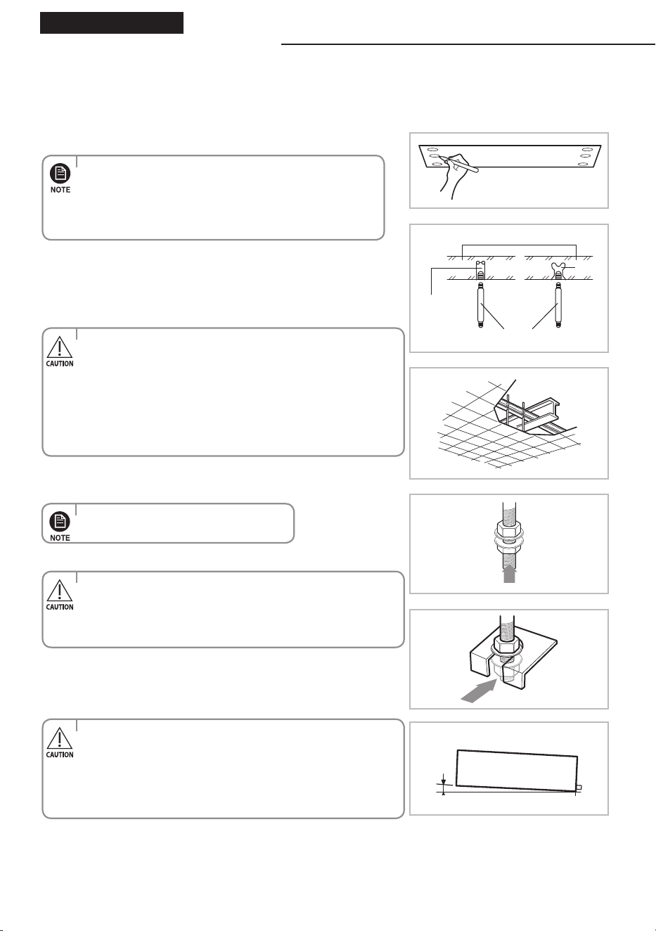
1
Place the pattern sheet on the ceiling at the spot where you want
to install the indoor unit.
2
Insert bolt anchors. Use existing ceiling supports or construct a suit-
able support as shown in figure.
3
Install the suspension bolts depending on the ceiling type.
4
Screw eight nuts to the suspension bolts making space for hanging
the indoor unit.
5
Hang the indoor unit to the suspension bolts between two nuts.
6
Screw the nuts to suspend the unit.
7
Adjust level of the unit by using measurement plate for all 4 sides.
Concrete
Suspension bolt(M8)-field supply
Hole in anchor
hole in plug
Ceiling support
When the drain hose is installed to the right.
Drain hose port
3mm
Insert
•
Since the diagram is made of paper, it may shrink or
stretch slightly due to temperature or humidity. For this
reason, before drilling the holes maintain the correct
dimensions between the markings.
•
Pattern sheet is supplied depending on the model type.
•Ensure that the ceiling is strong enough to support the weight
of the indoor unit. Before hanging the unit, test the strength of
each attached suspension bolt.
• If the length of suspension bolt is more than 1.5m,
it is required to prevent vibration.
• If this is not possible, create an opening on the false ceiling in
order to be able to use it to perform the required operations on
the indoor unit.
• Piping must be laid and connected inside the ceiling when
suspending the unit. If the ceiling is already constructed, lay the
piping into position for connection to the unit before
placing the unit inside the ceiling.
• For proper drainage of condensate, give a 3mm slant to the
left or right side of the unit which will be connected with the
drain hose, as shown in the gure. Make a tilt when you wish to
install the drain pump, too.
• When installing the indoor unit, make sure it is not tilted toward
front or back side.
•
You must install all the suspension rods.
21
ENGLISH
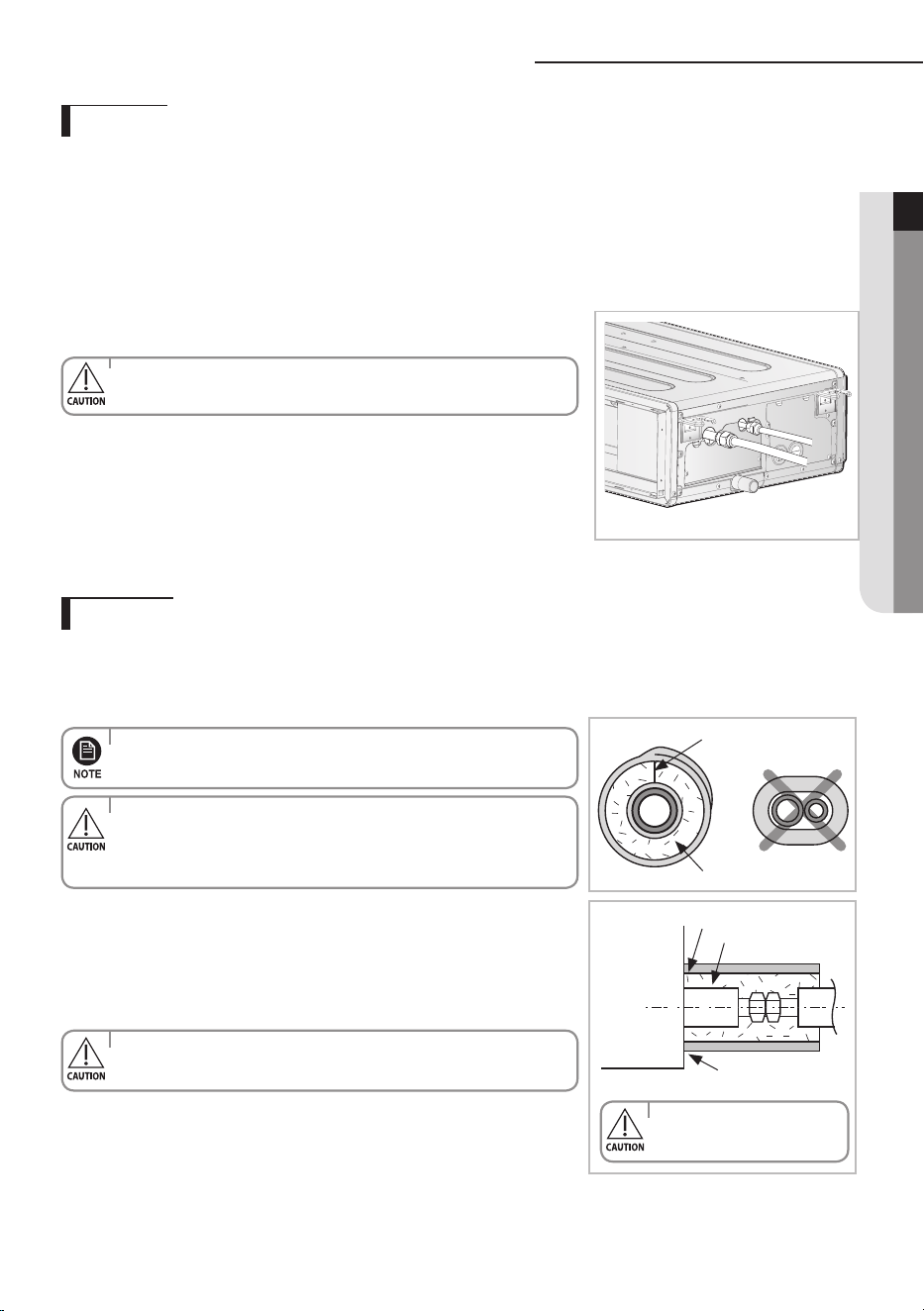
Performing leak test & insulation
Once you have checked that there are no leaks in the system, you can insulate the piping and hose.
1
To avoid condensation problems, place T13.0 or thicker Acrylonitrile Butadien Rubber separately around each refrigerant
pipe.
2 Wind insulating tape around the pipes and drain hose avoiding to compress
the insulation too much.
3
Finish wrapping insulating tape around the rest of the pipes leading to the outdoor
unit.
4 The pipes and electrical cables connecting the indoor unit with the outdoor
unit must be xed to the wall with suitable ducts.
5 Select the insulation of the refrigerant pipe.
◆ Insulate the gas side and liquid side pipe referring to the thickness
according to the pipe size.
◆
Indoor temperature of 30°C and humidity of 85% is the stan dard condition.
If installing in a high humidity condition, use one grade thicker insulator by referring to the table below.
If installing in an unfavorable conditions, use thicker one.
◆ Insulator’s heat-resistance temperature should be more than 120°C.
Leak test
Insulation
No gap
NBR(T13.0 or thicker)
Insulation cover pipe
Indoor unit
Be sure to overlap
the insulation
Insulation pipe
• Must t tightly against
body without any gap.
• Always make the seam of pipes face upwards.
• All refrigerant connection must be accessible, in order to permit
either unit maintenance or removing it completely.
• The insulation has to be produced in full compliance of European
regulation reg. EEC / EU 2037/ 2000 that
requires the use of sheaths insulation form without using CFC and
HCFC gases for health and the environment.
◆
LEAK TEST WITH NITROGEN (before opening valves)
In order to detect basic refrigerant leaks, before recreating the vacuum and recirculating the R410A, it’s responsable
of installer to pressurize the whole system with nitrogen (using a cylinder with pressure reducer)
at a pressure above 40 bar (gauge).
◆
LEAK TEST WITH R410A (after opening valves)
Before opening valves, discharge all the nitrogen into the system and create vacuum. After opening valves check
leaks using a leak detector for refrigerant R410A.
• Discharge all the nitrogen to create a vacuum and charge the system.
The designs and shape are subject to
change according to the model.
22
Pipe
Pipe size
Insulation Type (Heating/Cooling)
RemarksStandard [30°C, 85%] High humidity [30°C, over 85%]
EPDM,NBR
Liquid
pipe
Ø6.35 ~ Ø9.52 9t 9t
Internal temperature is
higher than 120°C
Ø12.7 ~ Ø19.05 13t 13t
Gas
pipe
Ø6.35 13t 19t
Ø9.52
19t 25t
Ø12.70
Ø15.88
Ø19.05
◆
When installing insulation in places and conditions below, use the same insulation that is used for high humidity conditions.
<Geological condition>
- High humidity places such as shoreline, hot spring, near lake or river, and ridge (when the part of the building is covered by
earth and sand.)
<Operation purpose condition>
- Restaurant ceiling, sauna, swimming pool etc.
<Building construction condition>
- The ceiling frequently exposed to moisture and cooling is not covered.
e.g. The pipe installed at a corridor of a dormitory and studio or near an exit that opens and closes frequently.
- The place where the pipe is installed is highly humid due to the lack of ventilation system.
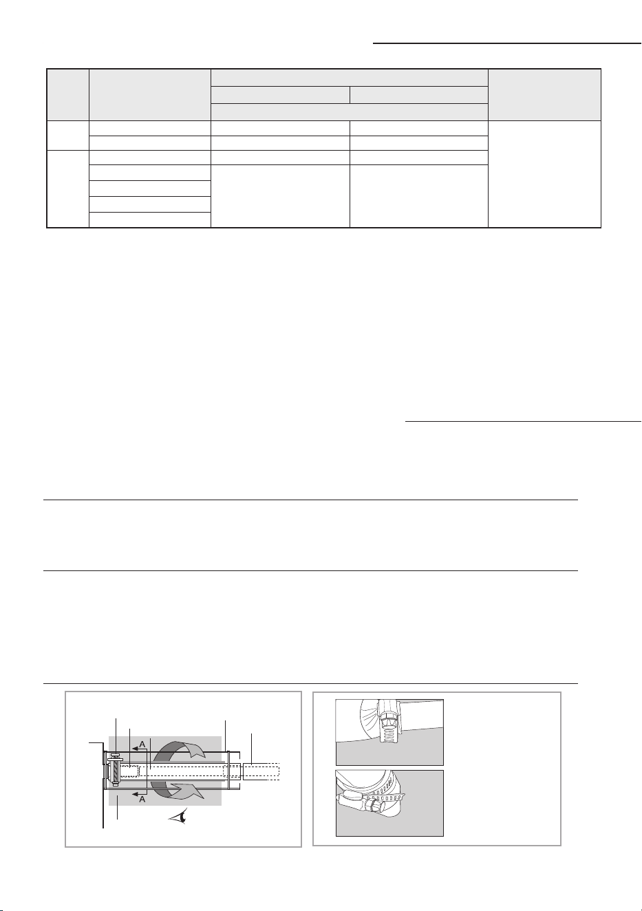
Drainpipe and drain hose installation
Care must be taken when installing the drain hose for the indoor unit to ensure that any condensate
water is correctly drained outside.
The drain hose can be installed to the right of the base pan.
1
Installing the drain hose should be the shorter, the better.
◆ In order to discharge condensation water, the drain hose should keep tilted.
◆ Fix the drain hose with Cable-Tie, so that it will not separate from the machine.
◆ While using draining pump, connect the end with draining pump.
2
Insulate and fix the drain hose according to the figure.
◆ Insert the drain hose to bottom of the outfall of water basin.
◆ Lock steel ring of the drain hose according to the figure.
◆ Wind and wrap steel ring and drain hose fully with thermal insulation sponge; fix both ends of exter-
nal layer with ribbon for thermal insulation.
◆ After being installed, drain hose must be insulated fully by heat insulating material. (To be provided
at site.)
A-A’
Steel ring of drain hose
Joint of drain hose
Drain hose
Drain hose
Fix with Cable-Tie
Wrap thermal sleeve hose
Indoor unit
As shown in the figure,
tighten steel ring of the
drain hose.
Performing leak test & insulation
23
ENGLISH
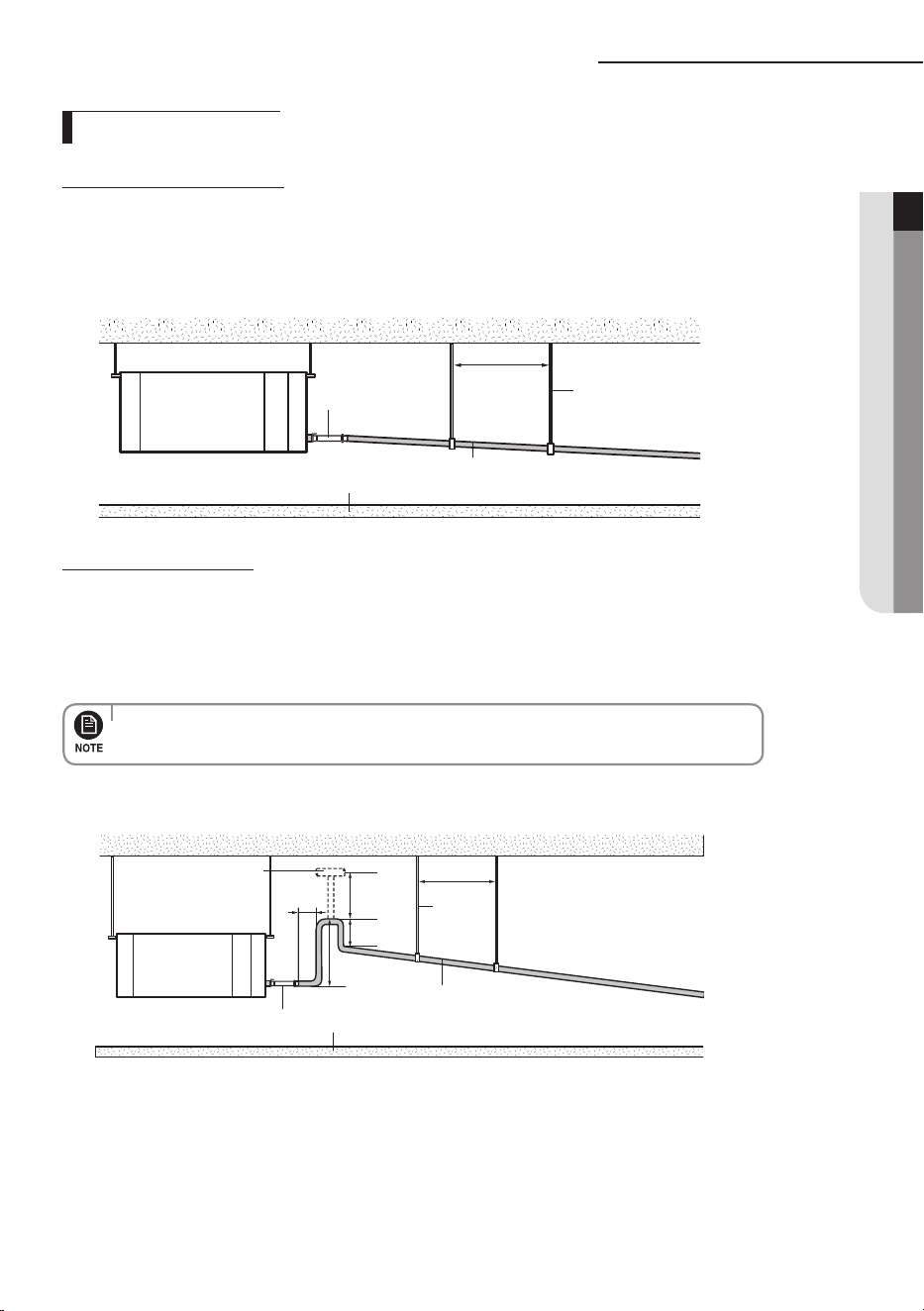
Drainpipe and drain hose installation
1. Install horizontal drainpipe with a slope of 1/100 or more and fix it by hanger space of 1.0~1.5m.
2. Install U-trap at the end of the drainpipe to prevent a nasty smell to reach the indoor unit.
3. Do not install the drainpipe to upward position. It may cause water flow back to the unit.
Without the drain pump
1~1.5m
Horizontal drainpipe
more than 1/100 slope
Ceiling
Hanger
Flexible hose
Drainpipe Connection
With the drain pump
1~1.5m
20mm
or more
200mm
or more
Hanger
Within
300~550mm
Air vent
300mm or less
Flexible hose
Horizontal drainpipe
more than 1/100 slope
Ceiling
1. The drain pipe should be installed within 300mm to 550mm from the flexible hose and then lift down 20mm
or more.
2. Install horizontal drainpipe with a slope of 1/100 or more and fix it by hanger space of 1.0~1.5m.
3 Install the air vent in the horizontal drainpipe to prevent water flow back to the indoor unit.
4 The flexible hose should not be installed upward position,
it may cause water flow back to the indoor unit.
•
You may not need to install it if there were proper slope in the horizontal drainpipe.
24
Drainpipe and drain hose installation
Prepare a little water about 2 liter.
1
Pour water into the base pan in the indoor unit as shown in figure.
2
Confirm that the water flows out through the drain hose.
Testing the drainage
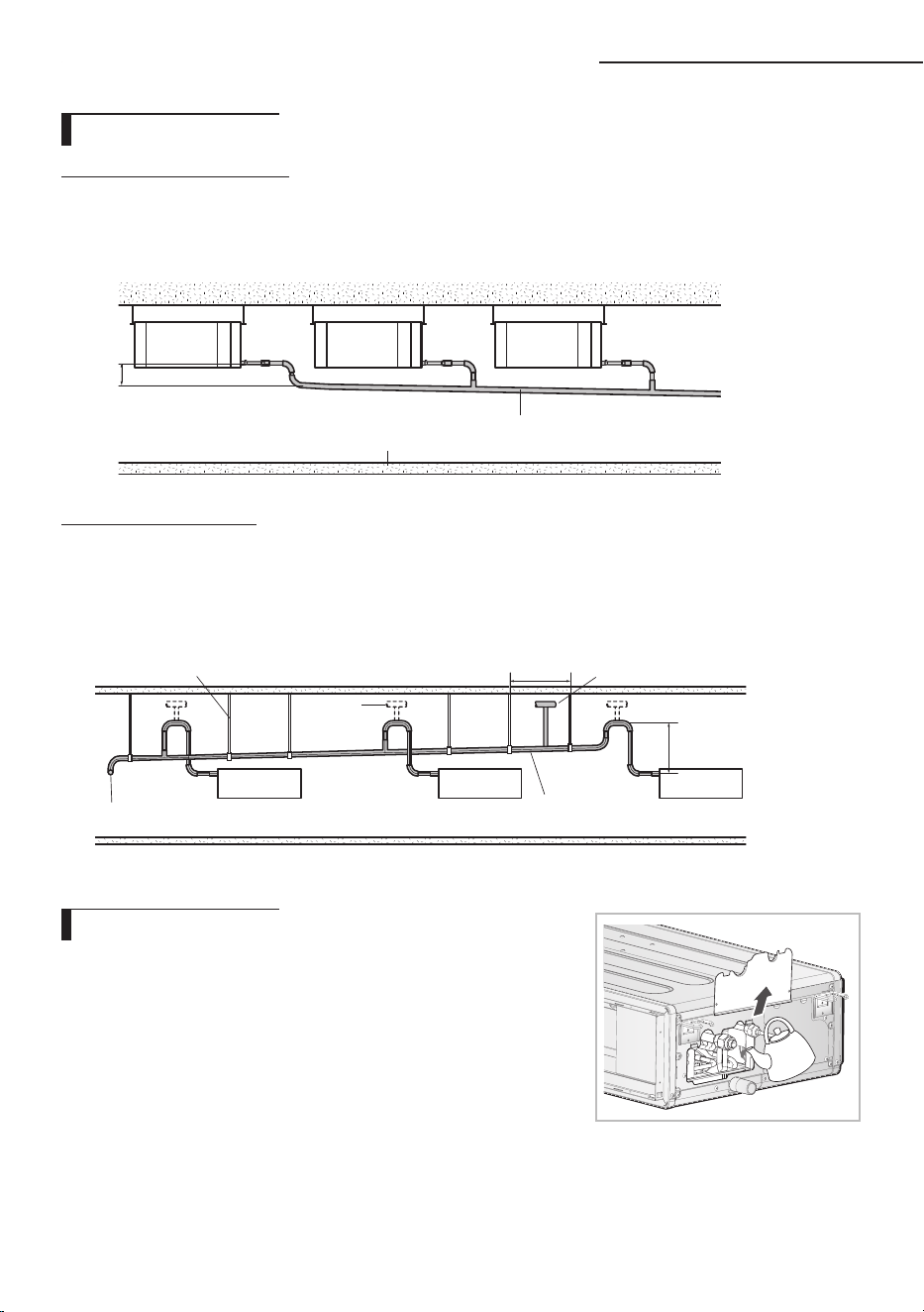
1
Install horizontal drainpipe with a slope of 1/100 or more and fix it by hanger space of 1.0~1.5m.
2
Install U-trap at the end of the drainpipe to prevent a nasty smell to reach the indoor unit.
Without the drain pump
1 Install main air vent at the front of the farthest indoor unit from the main drain when installed
indoor units are more than 3.
2 You may need to install individual air vent to prevent water flow back at the top of each indoor unit
drainpipe.
With the drain pump
Hanger
Main drainpipe
Individual
air vent
Main air vent
Centralized horizontal drainpipe
(more than 1/100 slope)
550mm or
less
1~1.5m
100mm or more
Ceiling
Horizontal drainpipe
more than 1/100 slope
Centralized Drainage
25
ENGLISH
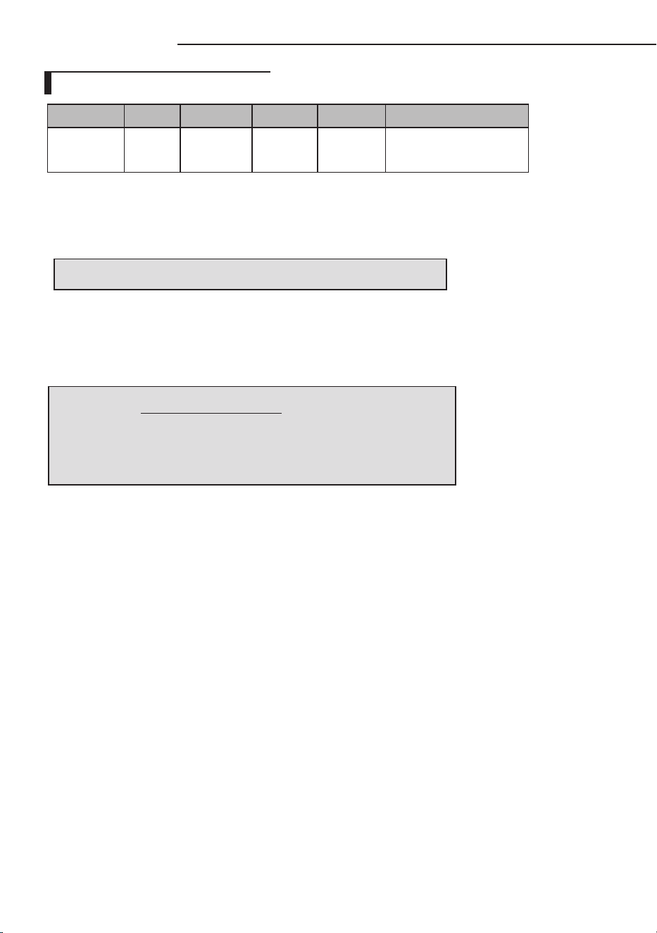
Wiring work
Silver solder
Norminal
dimensions
for cable
(mm
2
)
Norminal
dimensions
for screw
(mm)
B D d1 E F L d2 t
Standard
dimension
(mm)
Allowance
(mm)
Standard
dimension
(mm)
Allowance
(mm)
Standard
dimension
(mm)
Allowance
(mm)
Min. Min. Max.
Standard
dimension
(mm)
Allowance
(mm)
Min.
1.5
4 6.6
±0.2 3.4
+0.3
-0.2
1.7 ±0.2 4.1 6 16 4.3
+0.2
0
0.7
4 8
2.5
4 6.6
±0.2 4.2
+0.3
-0.2
2.3 ±0.2 6 6 17.5 4.3
+0.2
0
0.8
4 8.5
4 4 9.5 ±0.2 5.6
+0.3
-0.2
3.4 ±0.2 6 5 20 4.3
+0.2
0
0.9
N L
N L N L N L
ELCB
MCCB+
ELB
V1 V2
Indoor Unit 1 Indoor Unit 2 Indoor Unit 3
Indoor Unit 4 Indoor Unit 5 Indoor Unit 6
Outdoor Unit
Wired Remote
Control
EEV kit
h
Ceiling, wall-mounted indoor unit.
220-240V~
or
h
ELCB : Essential Installation
WARNING :
Power off before connecting any wires;
Indoor PBA will be damaged while V1,V2,F3,F4 short each
other.
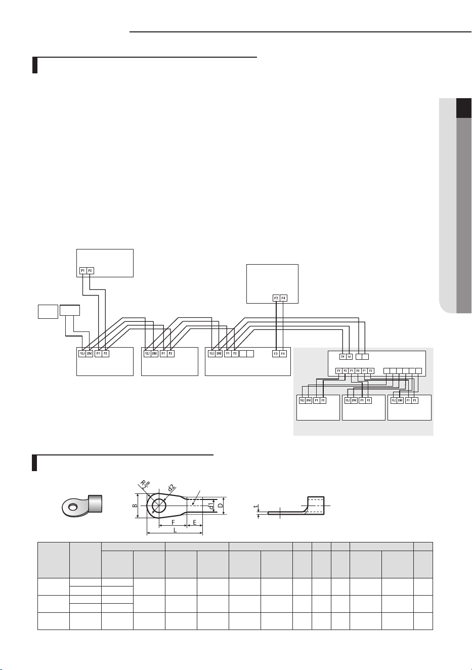
Power and communication cable connection
Selecting compressed ring terminal
1. Before wiring work, you must turn off all power source.
2. Indoor unit power should be supplied through the breaker( ELCB or MCCB+ELB ) separated by the
outdoor power.
ELCB:Earth Leakage Circuit Breaker
MCCB:Molded Case Circuit Breaker
ELB:Earth Leakage Breaker
3. The power cable should be used only copper wires.
4. Connect the power cable{1(L), 2(N)} among the units within maximum length and communication
cable(F1, F2) each.
5. Connect F3, F4(for communication) when installing the wired remote control.
26
Power supply MCCB ELB or ELCB Power cable Earth cable Communication cable
Max : 242V
Min : 198V
X A
X A, 30mmA
0.1 s
2.5mm
2
2.5mm
2
0.75~1.5mm
2
Decide the capacity of ELCB(or MCCB+ELB) by below formula.
Power supply cords of parts of appliances for outdoor use shall not be lighter than polychloroprene
sheathed flexible cord.
(Code designation IEC:60245 IEC 57 / CENELEC:H05RN-F ; IEC:60245 IEC 66 / CENELEC:H07RN-F)
The capacity of ELCB(or MCCB+ELB) X [A] = 1.25 X 1.1 X ∑Ai
T X
: The capacity of ELCB(or MCCB+ELB).
T
∑
Ai : Sum of Rating currents of each indoor unit.
T
Refer to each installation manual about the rating current of indoor unit.
Decide the power cable specification and maximum length within 10% power drop among indoor units.
T
coef: 1.55
T
Lk: Distance among each indoor unit[m], Ak: Power cable specification[mm
2
]
ik: Running current of each unit[A]
∑ (
Coef×35.6×Lk×ik
) <
10% of input voltage[V]
1000×Ak
n
k=1
Specification of electronic wire
Wiring work
27
ENGLISH
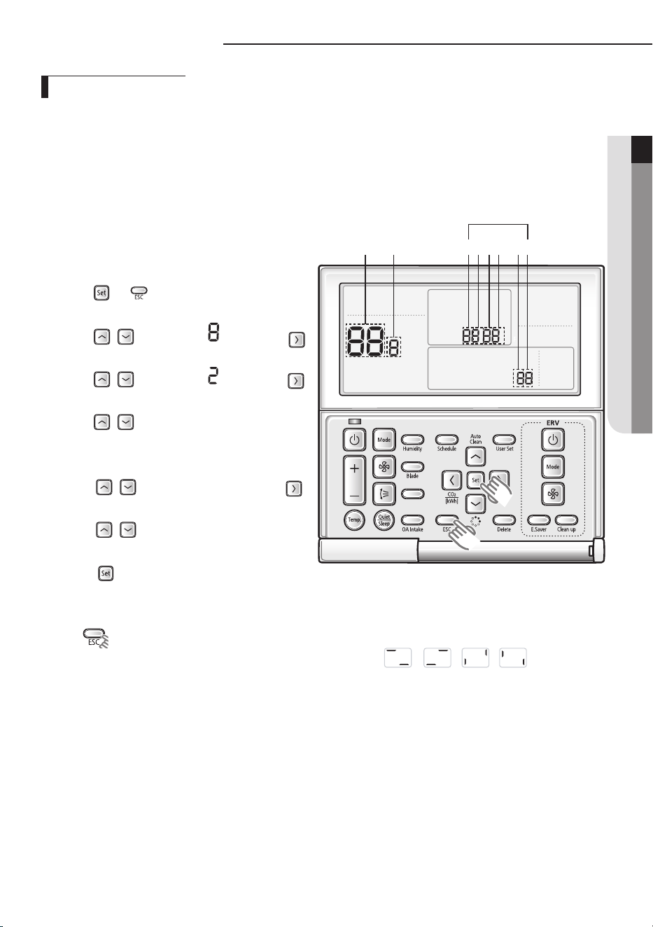
Adjusting air ow
Automatic Air-Volume
1).Press the and buttons at the same time for more
than 3 seconds and then a Main menu will be displayed.
2).Press the / button to select and then press
button to enter a Sub-menu setting screen.
3).Press the / button to select and then press
button to enter a automatic air-volume setting screen.
4).Press the / button to select 1 to enable automatic
air-volume operation.
5). Select mode No. 8.2 , and set to “1”.
6). Press the / button to select 3 and then press
button to enter input voltage.
7). Press the / button to select 1~3 to set voltage.
(1 : 220V, 2 : 230V, 3 : 240V)
8). Press the button, then the air conditioning unit will
start the fan operation for Automatic Air-Volume adjustment.
Away/MDS
Main Menu
Sub-menu
1 2 3 54 6
SEG Used
❈ Do not adjust the dampers during fan operation for Automatic Air-Volume adjustment.
9). Press button to escape setting mode.
(During the automatic air-volume adjustment,[Main Menu] will be displayed
repetitively)
10). After 1 to 8 minutes, the air conditioning unit stops operating automatically when Automatic Air-Volume adjustment has
been carried out (fan operation icon will be o.)
11). When the air conditioning unit has stopped, check the Mode No. 8.1 is "1” for completion of Automatic Air-Volume.
If the Mode No. 8.1 is “0”, Automatic Air-Volume adjustment is fail. Then adjust the fan speed by referring the E. S. P(External
Static Pressure) setting table.
When DPM is installed, Automatic Air-Volume function cannot be performed simultaneously for all indoor units.
Automatic Air-Volume function must be performed for each indoor unit with the wired remote control attached.
With its BLDC motor, you can use smart adjust the indoor unit fan speed depending on the installation condition.
If the external static pressure is high so that the duct becomes longer or if the external static pressure is low so that the
duct becomes shorter, Using the Automatic Air-Volume function,the volume of exhaust air has been adjusted to the
rated volume flow rate automatically.
Performing the Automatic Air-Volume function.
- Check the air conditioning unit stop.
Press the Power button to stop the air conditioner
- Go to Service setting mode with remote controller.
28
Note
Main menu Sub menu Functions SEG used Default Range
8
1
Automatic Air-Volume State
Return
1 0
0 - OFF (Fail or Disable)
1 - Completion.
2 - Running Automatic Air-Volume.
2
Automatic Air-Volume
Operation
1 0
0 - Disable
1 - Enable
3
Automatic Air-Volume
Voltage Setting
1 2
1- 220V
2- 230V (Default)
3- 240V
Adjusting air ow
•
If the coil is not dry, run the unit for 2 hours with fan only to dry the coil.
•
The air filter is properly attached into the air passage on the air suction side of the air conditioning unit.
• Adjust the dampers so that each air inlet and outlet exhusts the designed airow rate.
• If using booster fans(an outdoor air processing unit or ERV via duct), do not use Automatic Air-Volume function.
• If the duct congurations have been changed, automatic air-volume function perform again.
• The product can be used within the range of rated voltage 220 V/230 V/240 V ± 5 V. If the product needs to be
installed in the condition that is out of the rated voltage stated above, additional setting with installation option is
required.
29
ENGLISH
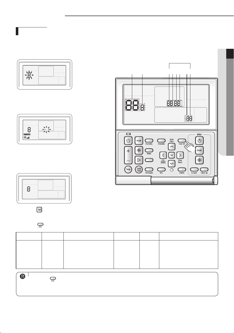
Easy Tuning
EASY Tuning
If the more cooling and heating airflow rate which set up when installing is wanted, or if the more Silent operation
which sets up when installing is wanted, air conditioner is tuned for comfort.
Indoor unit airflow rate for high, mid, low mode increases or decreases for +2 ~ -2 Steps with wired remocon.
• Press the
button anytime during setup to exit without setting.
• According to airflow changed from the Easy Tuning,Air conditioning performance reducing is
possible.
NOTE
Away/MDS
Main Menu
Sub-menu
1 2 3 54 6
SEG Used
1. Press the User Set button.
(Main Menu) will be displayed, and you can press the [Λ]/
[V] buttons to select No. 8, which will set the Easy Tuning.
2. Press the [>] button to select airow step.
Press the [Λ]/[V] buttons to select airow step(-2,-1,0,1,2)
tuning (During the Easy Tuning setting, AC Fan Speed icon
will be displayed)
3) Press the button to complete the Easy Tuning.
(When the Easy Tuning setting complete, AC Fan Speed icon will be o)
4) Press the
button to to exit to normal mode.
Main menu Sub menu Functions SEG used Default Range
8 - Easy Tuning 1,2 0
-2 : -2 Step
-1 : -1 Step
0 : No Use
1 : +1 Step
2 : +2 Step
30
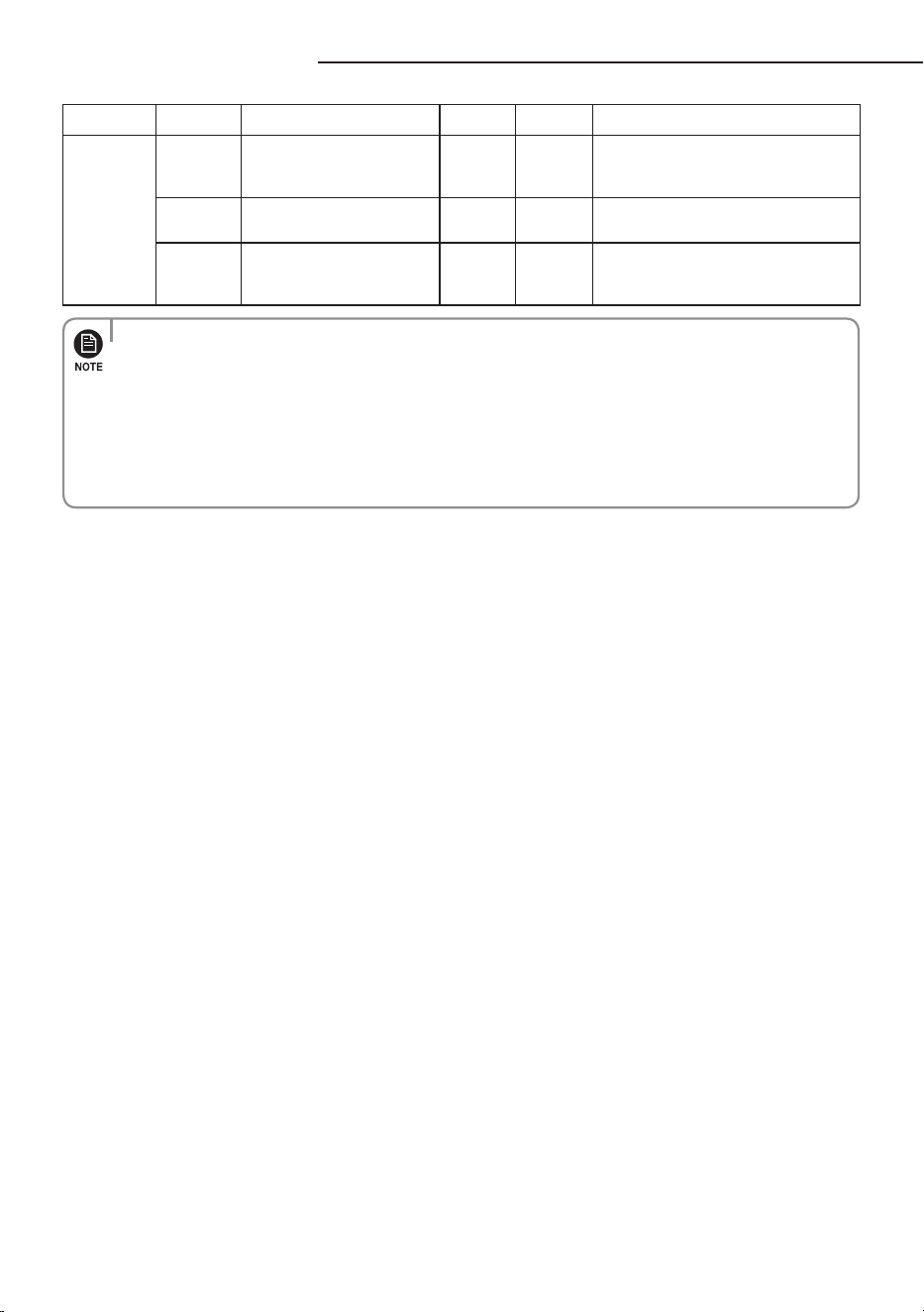
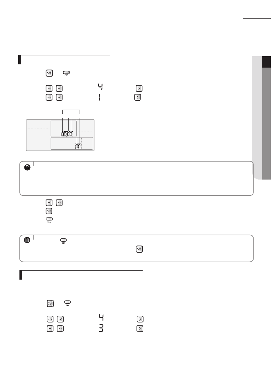
Setting the indoor unit option code
In order to set the indoor unit option code use the wired remote controller and follow the directions below.
1) Press the and buttons at the same time for more than 3 seconds and then a Main menu will be
displayed.
2) Press the
/ button to select and then press button to enter a Sub-menu setting screen.
3) Press the / button to select and then press button to enter a Indoor unit option code setting
screen.
4) Press the
/ button to set the option code in order. Press button to go to the next page.
5) Press the button to save and complete the option setting.
6) Press the button to exit to normal mode.
• Option code will not be applied if you don’t press the
• Setting indoor unit option code is only possible in Master wired remote controller.
You can only check the indoor unit option code in Slave wired remote controller.
• Setting indoor unit option code is possible when one indoor unit is connected. If more than 2
indoor units are connected, you can only check the Master indoor unit option code.
• Press the
button anytime during setup to exit without setting.
NOTE
NOTE
• The first digit represents the page number and the remaining five digits are option codes.
• The option code which is currently setting will icker.
Away/MDS
Main Menu
Sub-menu
1 2 3 54 6
Data bit
1 2 3 4 5 6
Option CodePage number
SEG1 SEG2 SEG3 SEG4 SEG5 SEG6
0
✴ ✴ ✴ ✴ ✴
Page number
SEG7 SEG8 SEG9 SEG10 SEG11 SEG12
1
✴ ✴ ✴ ✴ ✴
Page number
SEG13 SEG14 SEG15 SEG16 SEG17 SEG18
2
✴ ✴ ✴ ✴ ✴
Page number
SEG19 SEG20 SEG21 SEG22 SEG23 SEG24
3
✴ ✴ ✴ ✴ ✴
Page number
31
ENGLISH
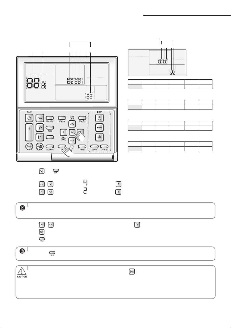
Set the indoor unit address and installation option with remote controller option. Set the each option
separately since you cannot set the ADDRESS setting and indoor unit installation setting option at the same
time. You need to set twice when setting indoor unit address and installation option.
Setting an indoor unit address
1) Press the and buttons at the same time for more than 3 seconds and then a Main menu will be
displayed.
2) Press the
/ button to select and then press button to enter a Sub-menu setting screen.
3) Press the / button to select and then press button to enter a Indoor Address setting screen.
1 2 3 4 5 6
Data bit
4) Press the
/ button to set the Indoor unit Main/RMC Address.
5) Press the button to save and complete the option setting.
6) Press the button to exit to normal mode.
Setting an indoor unit address and installation option
• Press the button anytime during setup to exit without setting.
• Address will not be applied if you don't press button.
• Setting Main/RMC Address of an Indoor unit is available only with a master wired remote controller.
NOTE
NOTE
• The Main/RMC Address which is currently setting will flicker.
• Data bit 1 and 2 present Indoor unit main address checking
• Data bit 3 and 4 present Indoor unit main address setting(outdoor unit reset is needed to set).
• Data bit 5 and 6 present Indoor unit RMC address setting/checking.
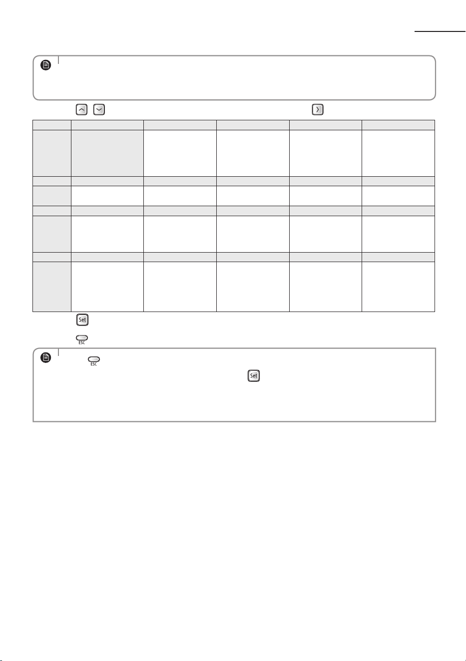
Setting an indoor unit installation option
In order to check and set the indoor unit installation option code use the wired remote controller and follow
the directions below.
1) Press the and buttons at the same time for more than 3 seconds and then a Main menu will be
displayed.
2) Press the / button to select and then press button to enter a Sub-menu setting screen.
3) Press the / button to select and then press button to enter a Indoor unit installation option
code setting screen.
32
• The rst digit represents the page number and the remaining ve digits are installation option.
• The total option codes are 24 digits. You can set six digits at a time and it is distinguished by page
number (0, 1, 2, 3).
NOTE
4) Press the / button to set the installation option code in order. Press button to go to the next page.
SEG1 SEG2 SEG3 SEG4 SEG5 SEG6
0 2 --
External room
temperature sensor
/ Minimizing fan
operation when
thermostat is o
Central control
FAN RPM
compensation
SEG7 SEG8 SEG9 SEG10 SEG11 SEG12
1 Drain pump Hot water heater --
EEV Step when
heating stops
--
SEG13 SEG14 SEG15 SEG16 SEG17 SEG18
2 External control
External control
output / External
heater On or O
signal
S-Plasma ion Buzzer
Number of hours
using lter
SEG19 SEG20 SEG21 SEG22 SEG23 SEG24
3
Individual control of a
remote controller
Heating setting
compensation
/ Removing
condensated water in
heating mode
EEV Step of stopped
unit during oil return/
defrost mode
Motion detect sensor --
5) Press the button to save and complete the option setting.
6) Press the button to exit to normal mode.
• Press button anytime during setup to exit without setting.
• Option code will not be applied if you don't press button.
• Setting Installation option code is available only with a master wired remote controller.
• Setting Installation option code is available when there is one on one connection between a wired
remote controller and an indoor unit.
NOTE
Setting an indoor unit address and installation option
33
ENGLISH
Set the indoor unit address and installation option with remote controller option.
Set the each option separately since you cannot set the ADDRESS setting and indoor unit installation setting
option at the same time. You need to set twice when setting indoor unit address and installation option.
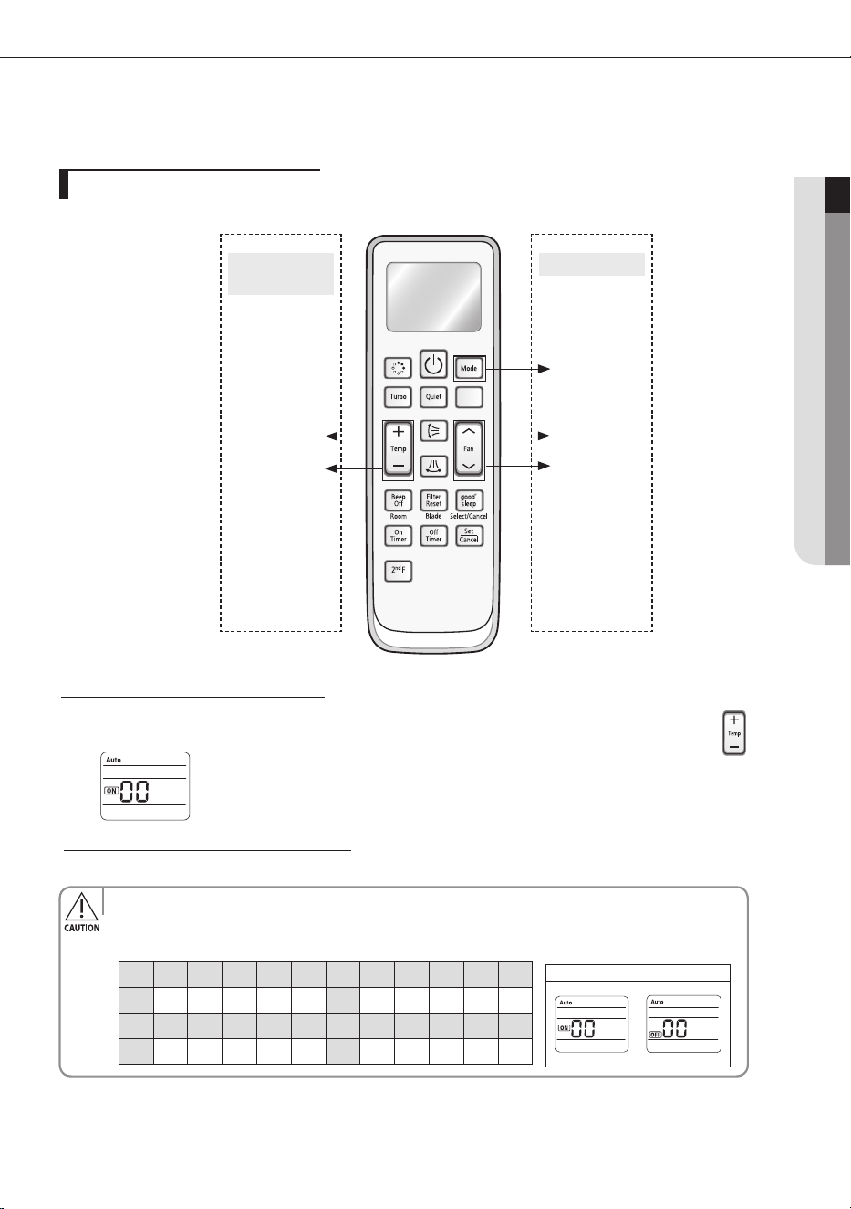
Step 1. Entering mode to set option
1. Remove batteries from the remote controller.
2. Insert batteries and enter the option setting mode while pressing High Temp button and Low Temp button.
3. Check if you have entered the option setting status.
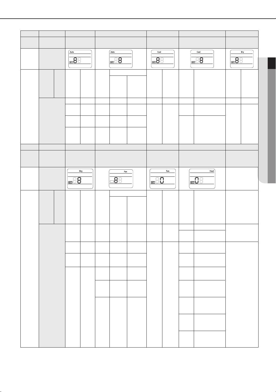
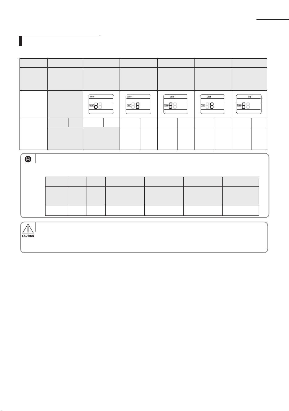
Step 2. The procedure of option setting
After entering the option setting status, select the option as listed below.
High Temp Button
High Fan Button
Mode change
Low Temp Button
Low Fan Button
Entering mode for
option setting
Option setting mode
SEG1 SEG2 SEG3 SEG4 SEG5 SEG6 SEG7 SEG8 SEG9 SEG10 SEG11 SEG12
0 X X X X X 1 X X X X X
SEG13 SEG14 SEG15 SEG16 SEG17 SEG18 SEG19 SEG20 SEG21 SEG22 SEG23 SEG24
2 X X X X X 3 X X X X X
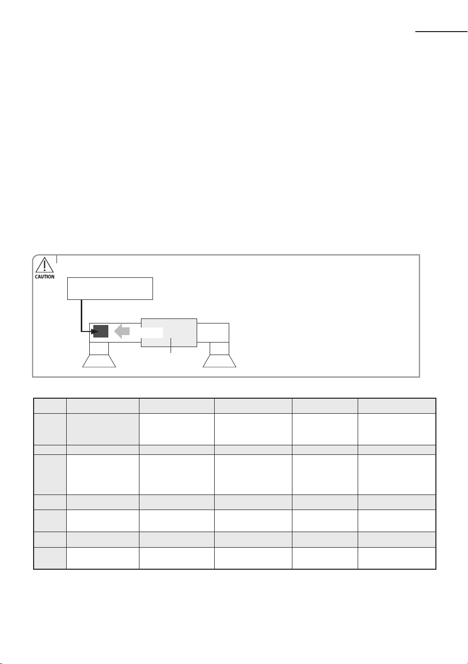
On(SEG1~12) O(SEG13~24)
The procedure of option setting
• Option setting is available from SEG1 to SEG 24
• SEG1, SEG7, SEG13, SEG19 are not set as page option.
• Set the SEG2~SEG6, SEG8~SEG12 as ON status and SEG14~18, SEG20~24 as OFF status.
34
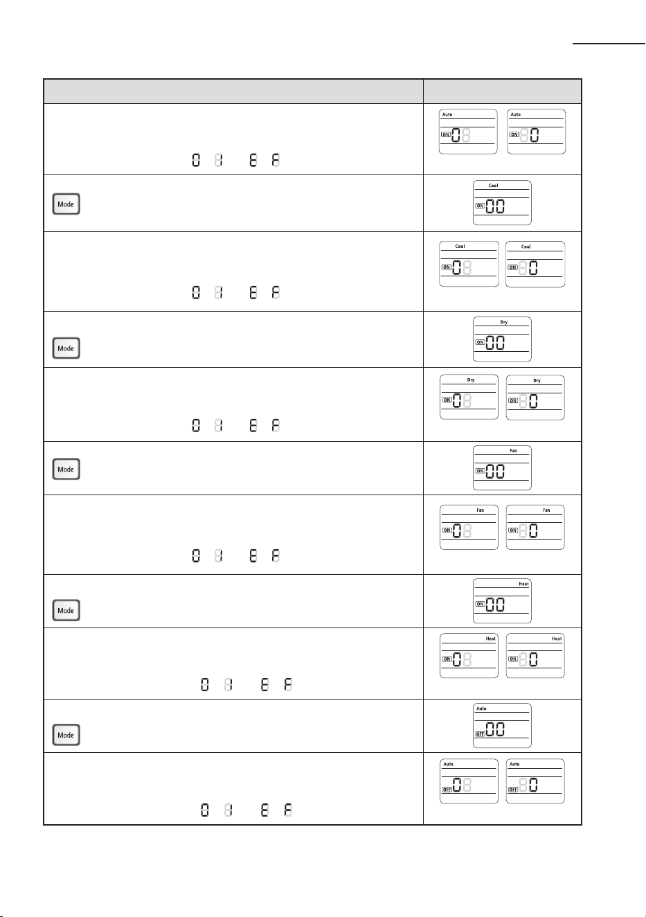
Option setting Status
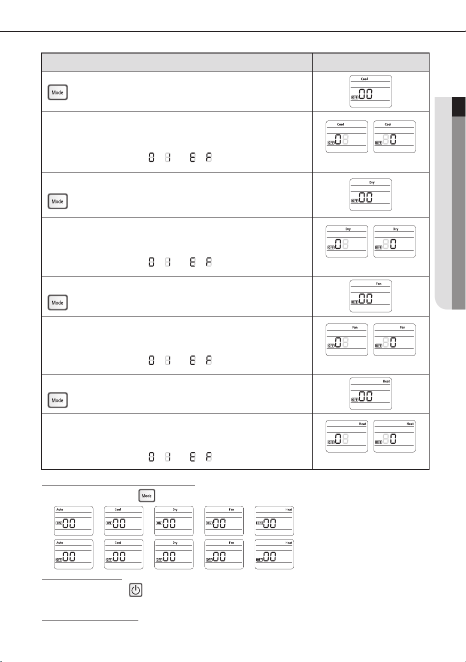
1. Setting SEG2, SEG3 option
Press Low Fan button(
∨
) to enter SEG2 value.
Press High Fan button(
∧
) to enter SEG3 value.
Each time you press the button,
…
will be selected in rotation.
2. Setting Cool mode
Press Mode button to be changed to Cool mode in the ON status.
3. Setting SEG4, SEG5 option
Press Low Fan button(
∨
) to enter SEG4 value.
Press High Fan button(
∧
) to enter SEG5 value.
Each time you press the button,
…
will be selected in rotation.
4. Setting Dry mode
Press Mode button to be changed to DRY mode in the ON status.
5. Setting SEG6, SEG8 option
Press Low Fan button(
∨
) to enter SEG6 value.
Press High Fan button(
∧
) to enter SEG8 value.
Each time you press the button,
…
will be selected in rotation.
6. Setting Fan mode
Press Mode button to be changed to FAN mode in the ON status.
7. Setting SEG9, SEG10 option
Press Low Fan button(
∨
) to enter SEG9 value.
Press High Fan button(
∧
) to enter SEG10 value.
Each time you press the button,
…
will be selected in rotation.
8. Setting Heat mode
Press Mode button to be changed to HEAT mode in the ON status.
9. Setting SEG11, SEG12 option
Press Low Fan button(
∨
) to enter SEG11 value.
Press High Fan button(
∧
) to enter SEG12 value.
Each time you press the button,
…
will be selected in rotation.
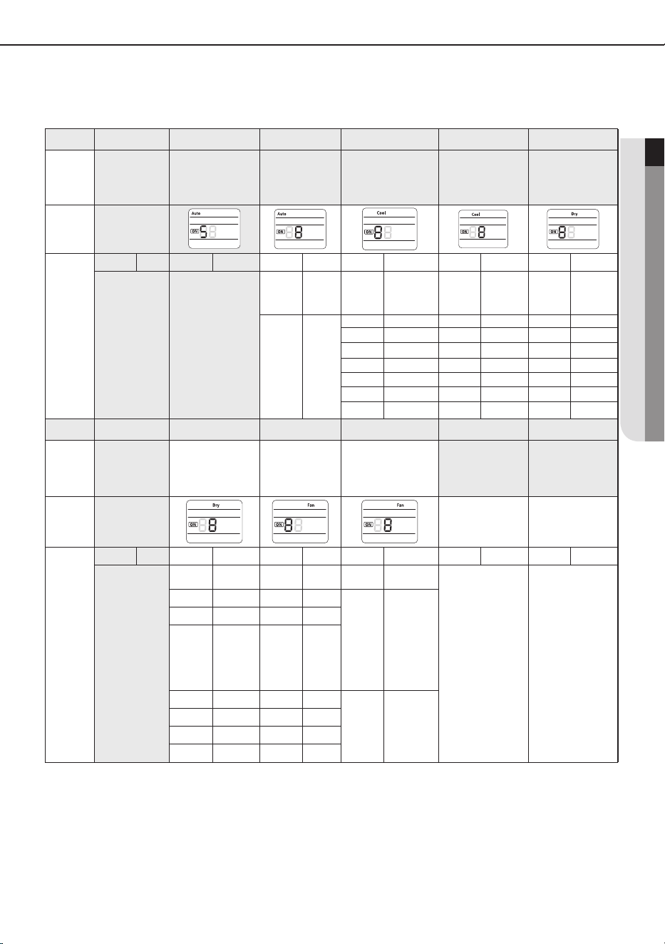
10. Setting Auto mode
Press Mode button to be changed to AUTO mode in the OFF status.
11. Setting SEG14, SEG15 option
Press Low Fan button(
∨
) to enter SEG14 value.
Press High Fan button(
∧
) to enter SEG15 value.
Each time you press the button,
…
will be selected in rotation.
SEG2 SEG3
SEG4
SEG6
SEG9
SEG11
SEG14
SEG5
SEG8
SEG10
SEG12
SEG15
Setting an indoor unit address and installation option
35
ENGLISH
SEG16
SEG18
SEG21
SEG23
SEG17
SEG20
SEG22
SEG24
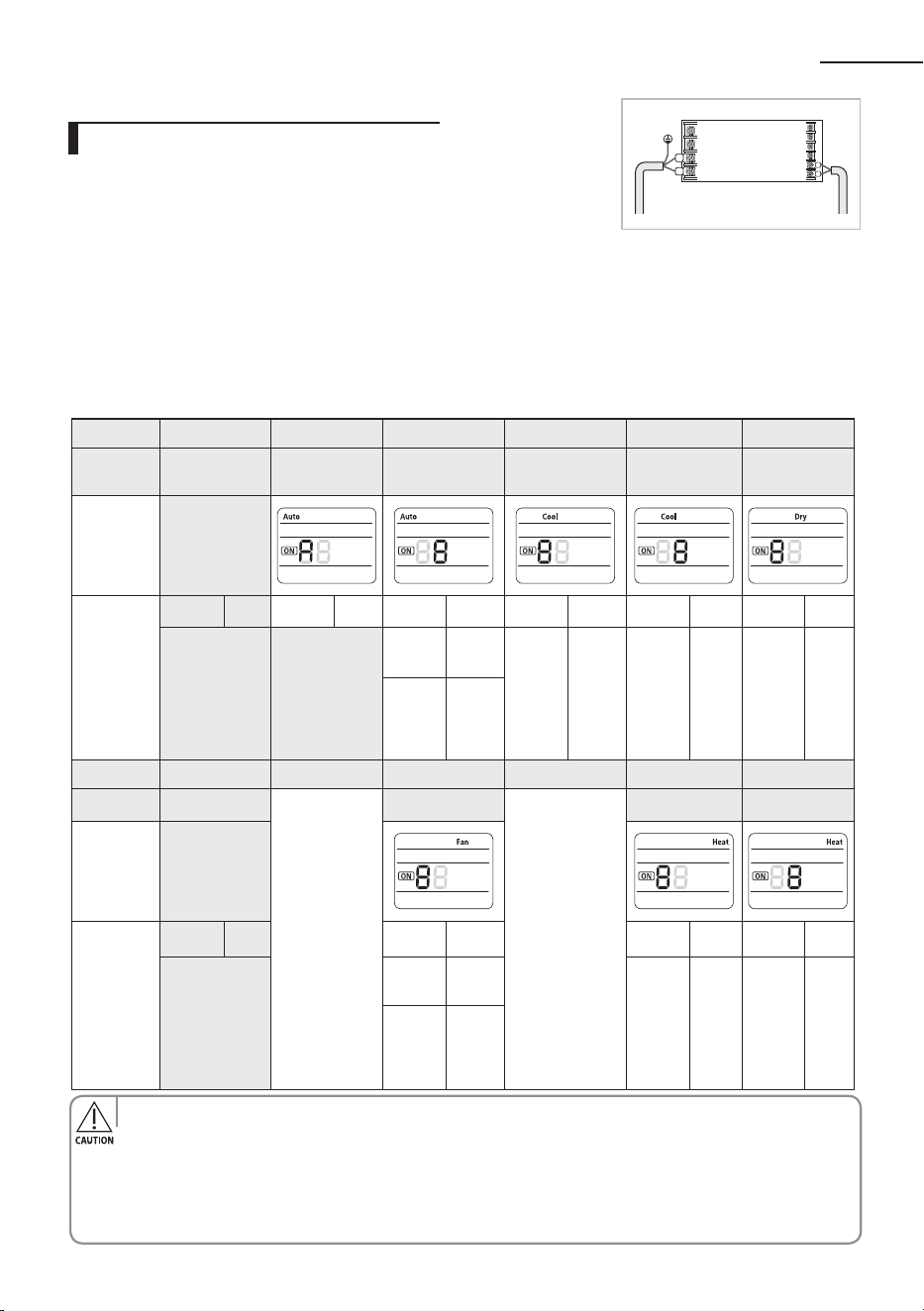
Step 4. Input option
Press operation button with the direction of remote control for set.
For the correct option setting, you must input the option twice.
Step 5. Check operation
1. Reset the indoor unit by pressing the RESET button of indoor unit or outdoor unit.
2. Take the batteries out of the remote controller and insert them again and then press the operation button.
Option setting Status
12. Setting Cool mode
Press Mode button to be change to Cool mode in the OFF status.
13. Setting SEG16, SEG17 option
Press Low Fan button(
∨
) to enter SEG16 value.
Press High Fan button(
∧
) to enter SEG17 value.
Each time you press the button,
…
will be selected in rotation.
14. Setting Dry mode
Press Mode button to be change to Dry mode in the OFF status.
15. Setting SEG18, SEG20 option
Press Low Fan button(
∨
) to enter SEG18 value.
Press High Fan button(
∧
) to enter SEG20 value.
Each time you press the button,
…
will be selected in rotation.
16. Setting Fan mode
Press Mode button to be change to Fan mode in the OFF status.
17. Setting SEG21, SEG22 option
Press Low Fan button(
∨
) to enter SEG21 value.
Press High Fan button(
∧
) to enter SEG22 value.
Each time you press the button,
…
will be selected in rotation.
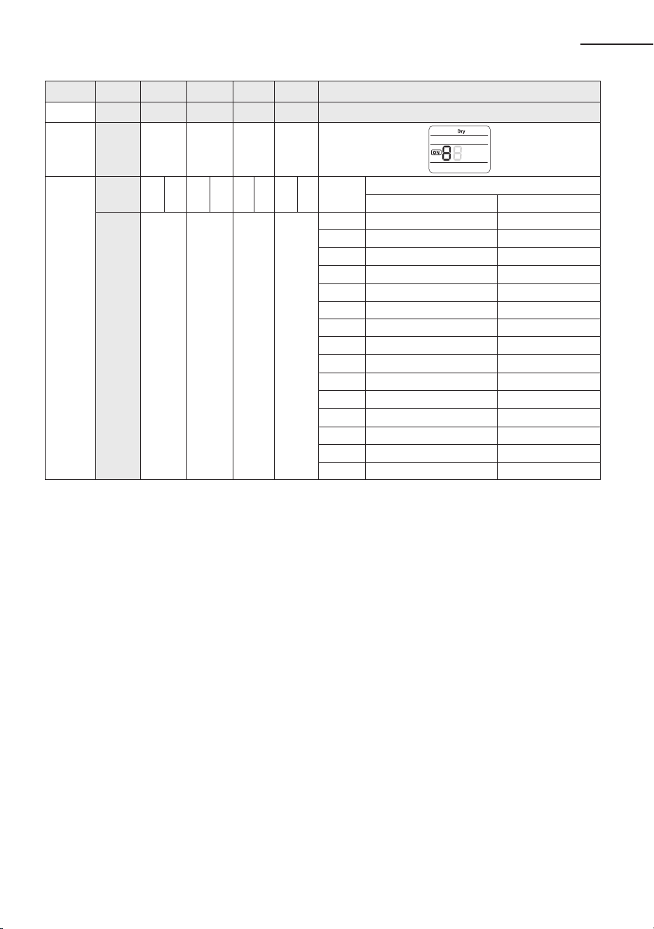
18. Setting Heat mode
Press Mode button to be change to HEAT mode in the OFF status.
19. Setting SEG23, SEG24 mode
Press Low Fan button(
∨
) to enter SEG23 value.
Press High Fan button(
∧
) to enter SEG24 value.
Each time you press the button,
…
will be selected in rotation.
Step 3. Check the option you have set
After setting option, press button to check whether the option code you input is correct or not.
36
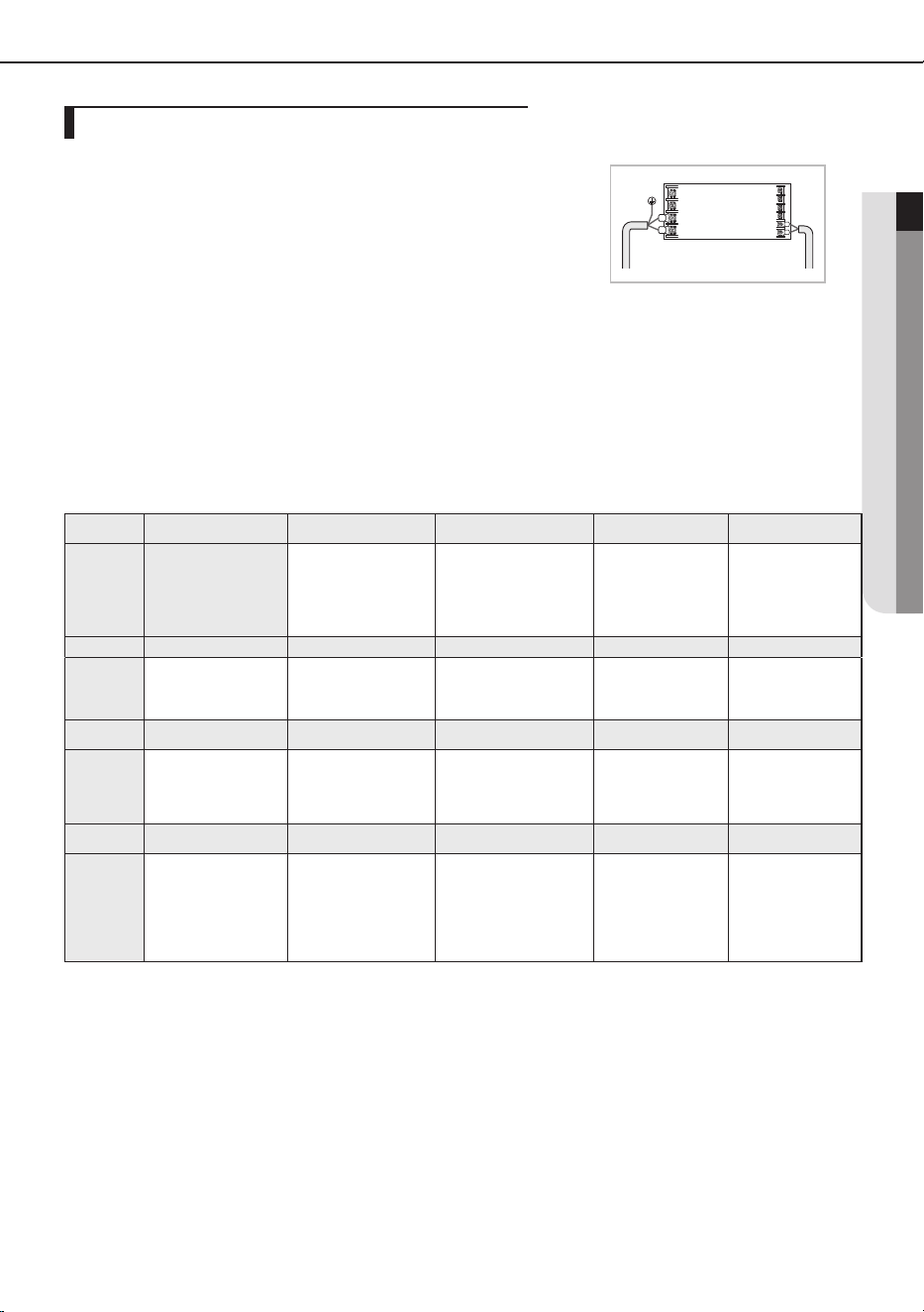
1.
Check whether power is supplied or not.
- When the indoor unit is not plugged in, there should be additional
power supply in the indoor unit.
2.
The panel(display) should be connected to an indoor unit to receive option.
3.
Before installing the indoor unit, assign an address to the indoor unit according to the air
conditioning system plan.
4.
Assign an indoor unit address by wireless remote controller.
- The initial setting status of indoor unit ADDRESS(MAIN/RMC) is “0A0000-100000-200000-300000”.
Option
SEG1 SEG2 SEG3 SEG4 SEG5 SEG6
Explanation
PAGE Mode Setting Main address
100-digit of indoor
unit address
10-digit of indoor
unit
The unit digit of
an indoor unit
Remote
Controller
Display
Indication
and Details
Indication Details Indication Details Indication Details Indication Details Indication Details Indication Details
0 A
0
No Main
address
0~9 100-digit 0~9 10-digit 0~9
A unit
digit
1
Main
address
setting
mode
Option
SEG7 SEG8 SEG9 SEG10 SEG11 SEG12
Explanation
PAGE
__
Setting RMC address
__
Group channel(*16) Group address
Remote
Controller
Display
Indication
and Details
Indication Details Indication Details Indication Details Indication Details
1
0
No RMC
address
RMC1 0~F RMC2 0~F
1
RMC
address
setting
mode
Indoor Unit
1(L)
F2
F1
2(N)
Setting an indoor unit address (MAIN/RMC)
• When “A”~”F” is entered to SEG5~6, the indoor unit MAIN ADDRESS is not changed.
• If you set the SEG 3 as 0, the indoor unit will maintain the previous MAIN ADDRESS even if you
input the option value of SEG5~6.
• If you set the SEG 9 as 0, the indoor unit will maintain previous RMC ADDRESS even if you input
the option value of SEG11~12.
• You cannot set SEG11 and SEG12 as F value at the same time.
Option No. : 0AXXXX-1XXXXX-2XXXXX-3XXXXX
Setting an indoor unit address and installation option
37
ENGLISH
1.
Check whether power is supplied or not.
- When the indoor unit is not plugged in, there should be additional
power supply in the indoor unit.
2.
The panel(display) should be connected to an indoor unit to receive
option.
3.
Set the installation option according to the installation condition of an air
conditioner.
- The default setting of an indoor unit installation option is
“020010-100000- 200000-300000”.
- Individual control of a remote controller(SEG20) is the function that controls an
indoor unit individually when there is more than one indoor unit.
4.
Set the indoor unit option by wireless remote controller.
SEG1 SEG2 SEG3 SEG4 SEG5 SEG6
0 2 --
External room
temperature sensor
/ Minimizing fan
operation when
thermostat is o
Central control
FAN RPM
compensation
SEG7 SEG8 SEG9 SEG10 SEG11 SEG12
1 Drain pump Hot water heater --
EEV Step when
heating stops
--
SEG13 SEG14 SEG15 SEG16 SEG17 SEG18
2 External control
External control
output / External
heater On or O
signal
S-Plasma ion Buzzer
Number of hours
using lter
SEG19 SEG20 SEG21 SEG22 SEG23 SEG24
3
Individual control of
a remote controller
Heating setting
compensation
/ Removing
condensated water in
heating mode
EEV Step of stopped
unit during oil return/
defrost mode
Motion detect
sensor
--
1WAY/2WAY/4WAY MODEL : Drain pump(SEG8) will be set to ‘USE + 3minute delay’ even if the drain
pump is set to 0.
1 WAY/2WAY/4WAY,DUCT MODEL : Number of hours using filter(SEG18) will be set to ‘1000hour’ even
if the SEG18 is set to exept for 2 or 6.
When setting the option other than above SEG values, the option will be set as “0”.
SEG5 central control option is basically set as 1 (Use), so you don’t need to set the central control
option additionally.
However, if the central control is not connected but it doesn’t indicate an error message, you need to
set the central control option as 0 (Disuse) to exclude the indoor unit from the central control.
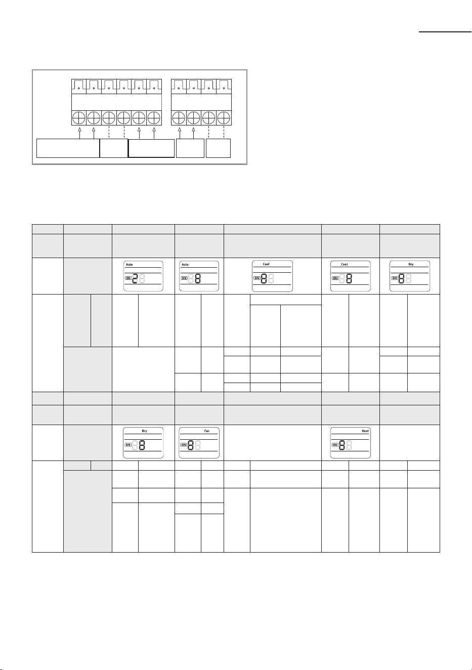
Indoor Unit
1(L)
F2
F1
2(N)
02 series installation option
Setting an indoor unit installation option
(suitable for the condition of each installation location)
38
02 series installation option(Detailed)
F4
F3
F1 F2
V2
V1
1(L) 2(N)
2
1
HOT
COIL
AC
POWER
OUTDOOR
COMMUNICATION
Wire Remote
Controller
DC 12V
* The output of hot coil terminal is AC 220 V / 230 V
(The same as Indoor Unit’s input Power)
COM1 COM2
(+) L N (-)
The external output of SEG15 is generated by MIM-B14 connection. (Refer to the manual of MIM-B14.)
Option SEG1 SEG2 SEG3 SEG4 SEG5 SEG6
Explanation PAGE MODE
Use of robot
cleaning
Use of external room temperature
sensor / Minimizing fan operation when
thermostat is o
Use of central control FAN RPM compensation
Remote
Controller
Display
Indication
and Details
Indication Details Indication Details Indication Details Indication
Details
Indication Details Indication Details
Use of
External
room
temperature
sensor
Minimizing fan
operation when
thermostat is o
0 2
0 Disuse
0 Disuse Disuse
0 Disuse
0 Disuse
1 Use Disuse 1
RPM
compensation
1 Use
2 Disuse Use
(
*1
)
1 Use 2
High ceiling
KIT
3 Use Use
(
*1
)
Option SEG7 SEG8 SEG9 SEG10 SEG11 SEG12
Explanation PAGE Use of drain pump
Use of hot water
heater
EEV Step when heating
stops
Remote
Controller
Display
Indication
and Details
Indication Details Indication Details Indication Details Indication Details Indication Details Indication Details
1
0 Disuse 0 Disuse 0
Default
value
1 Use 1 Use
(
*2
)
1
Noise
decreasing
setting
2
When an indoor
unit stops, drain
pump will operate
for 3min
2 --
3 Use
(
*2
)
The output of hot water heater in SEG9 is generated from the hot coil part of the terminal board in duct models.
Option No. : 02XXXX-1XXXXX-2XXXXX-3XXXXX
Setting an indoor unit address and installation option
39
ENGLISH
Option SEG13 SEG14 SEG15 SEG16 SEG17 SEG18
Explanation PAGE Use of external control
Setting the output of external control /
External heater On/O signal
S-Plasma ion Buzzer control Hours of lter usage
Remote
Controller
Display
Indication
and Details
Indication Details Indication Details Indication
Details
Indication Details Indication Details Indication Details
Setting the
output of
external
control
External
heater On/O
signal
2
0 Disuse 0 Thermo on - 0 Disuse 0 Use buzzer 2 1000 Hour
1
ON/OFF
control
1
Operation
on
-
1 Use
1 Disuse buzzer
6 2000 Hour
2
OFF
control
2 - Use
(*3)
3
Window
ON/OFF
control
3 - Use
(*3)
Option SEG19 SEG20 SEG21 SEG22 SEG23 SEG24
Explanation PAGE
Individual control of a
remote controller
Heating setting compensation / Removing
condensated water in heating mode
EEV Step of stopped
unit during oil return/
defrost mode
Motion detect sensor -
Remote
Controller
Display
OFF
Indication
and Details
Indication Details Indication Details Indication
Details
Indication Details Indication Details
Heating Setting
Compensation
Removing
Condensated
Water in
Heating
Mode
3
0 or 1 channel 1 0 Default
(*4)
Disuse 0
Default
value
0 Disuse
1
Turn out in 30min.
without motion
2 channel 2 1 2 °C Disuse
1
Oil return
or Noise
decreasing
in defrost
mode
2
Turn out in 60min.
without motion
3 channel 3 2 5 °C Disuse 3
Turn out in 120min.
without motion
4 channel 4
3 Default
(*4)
Use
(*5)
4
Turn out in 180min.
without motion
4 2 °C Use
(*5)
5
Turn out in 30min.
without motion or
*advanced function
5
5 °C Use
(*5)
6
Turn out in 60min.
without motion or
*advanced function
7
Turn out in 120min.
without motion or
*advanced function
8
Turn out in 180min.
without motion or
*advanced function
40
SEG1 SEG2 SEG3 SEG4 SEG5 SEG6
0 5
Use of Auto Change Over for
HR only in Auto mode
(When setting SEG3)
Standard heating temp.
Oset
(When setting SEG3)
Standard cooling temp.
Oset
(When setting SEG3)
Standard for mode change
Heating → Cooling
SEG7 SEG8 SEG9 SEG10 SEG11 SEG12
1
(When setting SEG3)
Standard for mode change
Cooling → Heating
(When setting SEG3)
Time required for mode
change
Compensation option for
Long pipe or height
dierence between indoor
units
- -
SEG13 SEG14 SEG15 SEG16 SEG17 SEG18
2 - - - -
Control variables when using
hot water / external heater
SEG19 SEG20 SEG21 SEG22 SEG23 SEG24
3 - - - - -
05 series installation option
*
Advanced function: Controlling cooling/heating current or power saving with motion detect.
(*1) Minimizing fan operation when thermostat is o
- Fan operates for 20 seconds at an interval of 5 minutes in heat mode.
(*2) 1: Fan is turned on continually when the hot water heater is turned on,
3: Fan is turned o when the hot water heater is turned on with cooling only indoor unit
Cooling only indoor unit: To use this option,install the Mode Select switch(MCM-C200) on the outdoor unit and x it as cool mode.
(*3) When the following 2 or 3 is used as external heater On/O signal, the signal for monitoring external contact control will not be output.
2: Fan is turned on continually when the external heater is turned on,
3: Fan is turned o when the external heater is turned on with cooling only indoor unit
Cooling only indoor unit: To use this option,install the Mode Select switch(MCM-C200) on the outdoor unit and x it as cool mode.
· If Fan is set to o for cooling only indoor unit by setting the SEG9=3 or SEG15=3, you need to use an external sensor or wired remote
controller sensor to detect indoor temperature exactly.
(*4) Default setting value
- 4Way Cassette, Mini 4Way Cassette: 5 °C
- Other indoor units: 2 °C
(*5) This function can be applied to 4 Way Cassette and Mini 4 Way Cassette only. If the air conditioner operates the heating mode
immediately after nishing the cooling mode, the condensated water in the drain pan becomes water vapor by the heat of the indoor
unit heat exchanger. Since the water vapor might be condensed on the indoor unit, which may fall into a living space, use this function to
get rid of the water vapor out of the indoor unit by operating the fan (for maximum 20 minutes) even when the indoor unit is turned o
after cooling mode is turned to heating mode .
Air Flow
Suction side Discharge side
Electronic heater should
not be installed.
• Do not install the electronic heater in the ow channel of the indoor unit fan.
Duct Indoor unit
Setting an indoor unit address and installation option
41
ENGLISH
Option SEG1 SEG2 SEG3 SEG4 SEG5 SEG6
Explanation
PAGE
MODE
Use of Auto Change
Over for HR only in
Auto mode
(When setting SEG3)
Standard heating
temp. Oset
(When setting SEG3)
Standard cooling temp.
Oset
(When setting SEG3)
Standard for mode
change
Heating
→
Cooling
Remote
Controller
Display
Indication
and Details
Indication Details Indication Details Indication Details Indication Details Indication Details Indication Details
0 5
0
Follow
product
option
0 0°C 0 0°C 0 1°C
1
Use Auto
Change
Over for
HR only
1 0.5°C 1 0.5°C 1 1.5°C
2 1°C 2 1°C 2 2°C
3 1.5°C 3 1.5°C 3 2.5°C
4 2°C 4 2°C 4 3°C
5 2.5°C 5 2.5°C 5 3.5°C
6 3°C 6 3°C 6 4°C
7 3.5°C 7 3.5°C 7 4.5°C
Option SEG7 SEG8 SEG9 SEG10 SEG11 SEG12
Explanation
PAGE
(When setting SEG3)
Standard for mode
changing Cooling
→
Heating mode
(When setting SEG3)
Time required for
mode change
Compensation option
for Long pipe or height
diference between
indoor units
Remote
Controller
Display
Indication
and Details
Indication Details Indication Details Indication Details Indication Details
1
0 1°C 0 5 min. 0
Use default
value
1 1.5°C 1 7 min.
1
1) Height
difference
1)
is more than
30m or
2) Distance
2)
is longer than
110m
2 2°C 2 9 min.
3 2.5°C 3 11 min.
4 3°C 4 13 min.
2
1) Height
difference
1)
is
15~30m or
2) Distance
2)
is
50~110m
5 3.5°C 5 15 min.
6 4°C 6 20 min.
7 4.5°C 7 30 min.
05 series installation option(Detailed)
Option No. : 05XXXX-1XXXXX-2XXXXX-3XXXXX
42
(*1)
Height dierence : The dierence of the height between the corresponding indoor uint and the indoor unit installed at the lowest place.
For example, When the indoor unit is installed 40m higher than the indoor unit installed at the lowest place, select the
option "1".
(*2)
Distance : The dierence between the pipe length of the indoor unit istalled at farthest place from an outdoor unit and the pipe length of the
corresponding indoor unit from an outdoor unit.
For example, when the farthest pipe length is 100m(328 ft) and the corresponding indoor unit is 40m away from an outdoor unit,
select the option "2".
(100 - 40 = 60m)
(*3) Heater operation when the SEG9 of 02 series installation option is set to using hot water heater or when SEG15 is set to using external heater
e.g. 1) Setting 02 series SEG9 =”1” / Setting 05 series SEG18 = “0”: Hot water heater is turned on at the same time as the heating thermostat
is on, and turned o when the heating thermostat is o.
e.g. 2) Setting 02 series SEG15 =”2” / Setting 05 series SEG18 =”A”:
Room temp. ≤ set temp. + f(heating compensation temp.)
- External heater is turned on when the temperature is maintained as 4.5 °C for 10 minutes.
Room temp. > set temp. + f(heating compensation temp.)
- External heater is turned o when the temperature is maintained as 4.5 °C + 1 °C (1 °C is the Hysteresis for On/O selection.)
Option SEG13 SEG14 SEG15 SEG16 SEG17
SEG18
(*3)
Explanation
Control variables when using hot water / external heater
Remote
Controller
Display
Indication
and Details
Indication
Details
Set temp. for heater On/O
Delay time for heater On
2
0 At the same time as thermo on No delay
1
At the same time as thermo on
10 minutes
2 At the same time as thermo on 20 minutes
3 1.5 °C No delay
4 1.5 °C 10 minutes
5 1.5 °C 20 minutes
6 3.0 °C No delay
7 3.0 °C 10 minutes
8 3.0 °C 20 minutes
9 4.5 °C No delay
A 4.5 °C 10 minutes
B 4.5 °C 20 minutes
C 6.0 °C No delay
D 6.0 °C 10 minutes
E 6.0 °C 20 minutes
Setting an indoor unit address and installation option
43
ENGLISH
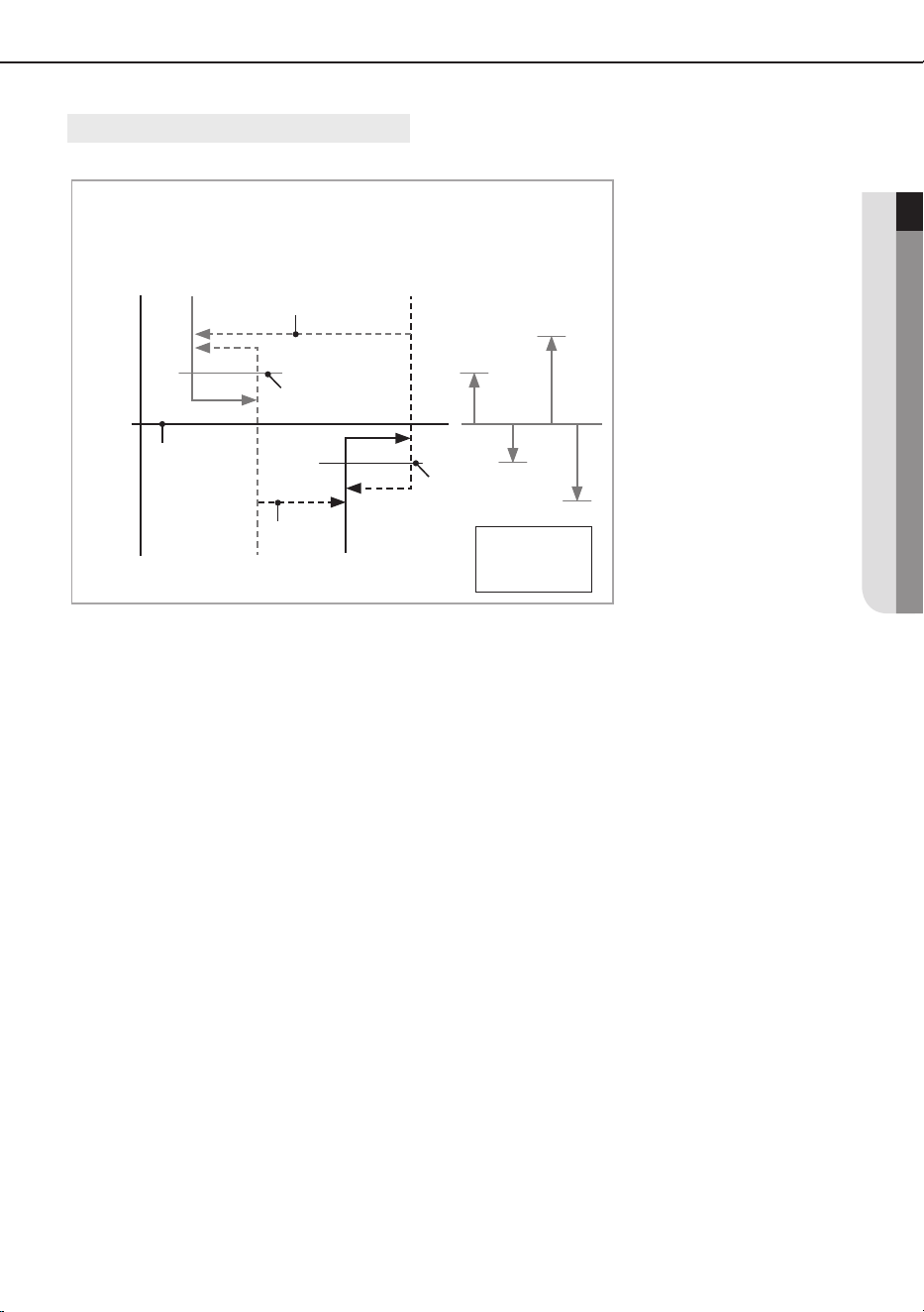
SEG 3, 4, 5, 6, 8, 9 additional information
When the SEG 3 is set as "1" and follow Auto Change Over for HR only operation, it will operate as follows.
Cooling/Heating mode can be changed when Thermo O status is maintained during the time with SEG9.
A : Set with SEG4
B : Set with SEG5
C : Set with SEG6
D : Set with SEG8
Cooling Thermo O
Heating Thermo O
Cooling Thermo On
Heating Thermo On
B C
D
Ts
A
c
a
Temp.
d
b
Standard temp.
for Heating
Standard temp.
for Cooling
Standard temp. for
Heating
→
Cooling
Standard temp.
for Cooling
→
Heating
Set temp.
for Auto mode
44
Option SEG1 SEG2 SEG3 SEG4 SEG5 SEG6
Explanation PAGE MODE
The option mode
you want to change
The tens’ digit of an
option SEG you will
change
The unit digit of an
option SEG you will
change
Changed value
Remote
Controller
Display
Indication and
Details
Indication Details Indication Details Indication Details Indication Details Indication Details Indication Details
0 D
Option
mode
1~6
Tens’ digit
of SEG
0~9
Unit digit
of SEG
0~9
The
changed
value
0~F
You can change each digit of set option.
NOTE
Option SEG1 SEG2 SEG3 SEG4 SEG5 SEG6
Explanation PAGE MODE
The option mode you
want to change
The tens’ digit of an
option SEG you will
change
The unit digit of an
option SEG you will
change
Changed value
Indication 0 D 2 1 7 1
• When changing a digit of an indoor unit address setting option, set the SEG3 as ‘A’.
• When changing a digit of indoor unit installation option, set the SEG3 as ‘2’.
Ex) When setting the ‘buzzer control’ into disuse status.
• If you are using heat pump model, mixed operation mode (two or more indoor units operating
in dierent operation mode simultaneously) is not available when the indoor units are
connected to same outdoor unit. If you set the master indoor unit with a remote controller,
outdoor unit will operate in the mode which was set in the master indoor unit.
Changing a particular option
Setting an indoor unit address and installation option

45
ENGLISH
Note
QUESTIONS OR COMMENTS?
DB68-04861A-05
Samsung, PO Box 12987, Blackrock, Co. Dublin. IE
or Euro QA Lab. Saxony Way, Yateley, Hampshire GU46 6GG, UK
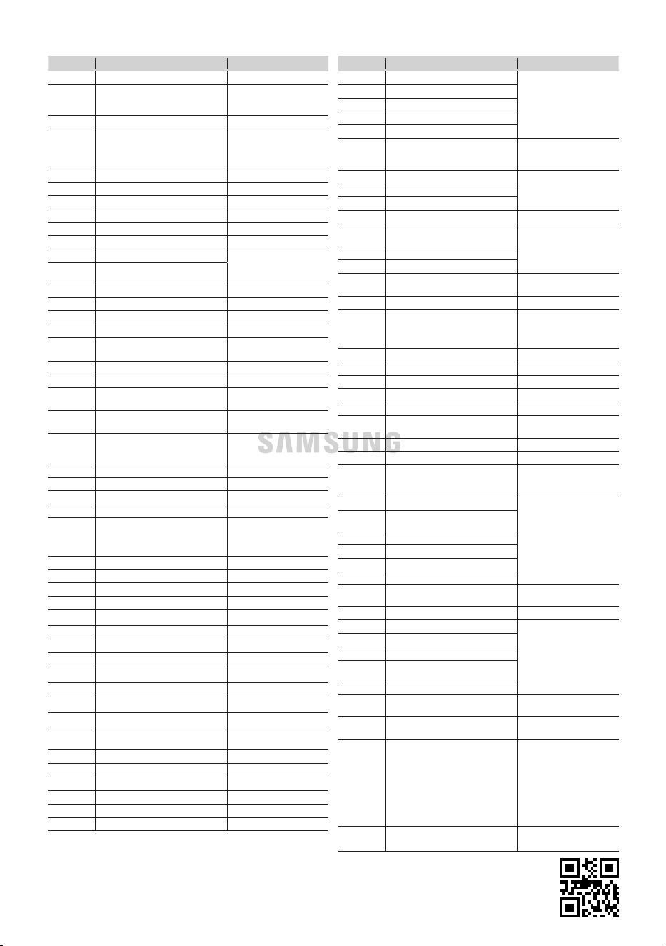
COUNTRY CALL
OR VISIT US ONLINE AT
AUSTRIA 0800 72 67 864 (0800-SAMSUNG)
www.samsung.com/at/support
BELGIUM 02-201-24-18
www.samsung.com/be/support (Dutch)
www.samsung.com/be_fr/support
(French)
BOSNIA 055 233 999
www.samsung.com/ba/support
BULGARIA
0800 111 31 - Безплатен за всички оператори
*3000 - Цена на един градски разговор или
според тарифата на мобилният оператор
09:00 до 18:00 - Понеделник до Петък
www.samsung.com/bg/support
CROATIA 072 726 786
www.samsung.com/hr/support
CZECH 800 - SAMSUNG (800-726786)
www.samsung.com/cz/support
DENMARK 707 019 70
www.samsung.com/dk/support
FINLAND 030-6227 515
www.samsung.com//support
FRANCE 01 48 63 00 00
www.samsung.com/fr/support
GERMANY 06196 77 555 77
www.samsung.com/de/support
CYPRUS 8009 4000 only from landline, toll free
www.samsung.com/gr/support
GREECE
80111-SAMSUNG (80111 726 7864) only from land line
(+30) 210 6897691 from mobile and land line
HUNGARY 0680SAMSUNG (0680-726-7864)
www.samsung.com/hu/support
ITALIA 800-SAMSUNG (800.7267864)
www.samsung.com/it/support
LUXEMBURG 261 03 710
www.samsung.com/be_fr/support
MONTENEGRO 020 405 888
www.samsung.com/support
SLOVENIA 080 697 267 (brezplačna številka)
www.samsung.com/si/support
NETHERLANDS 088 90 90 100
www.samsung.com/nl/support
NORWAY 21629099
www.samsung.com/no/support
POLAND
801-172-678* lub +48 22 607-93-33*
* (opłata według taryfy operatora)
www.samsung.com/pl/support
PORTUGAL
0800872678 - Apel gratuit
*8000 - Apel tarifat în reţea
www.samsung.com/pt/support
ROMANIA
*8000 (apel in retea)
08008-726-78-64 (08008-SAMSUNG) Apel
GRATUIT
www.samsung.com/ro/support
SERBIA 011 321 6899
www.samsung.com/rs/support
SLOVAKIA 0800 - SAMSUNG(0800-726 786)
www.samsung.com/sk/support
SPAIN 91 175 00 15
www.samsung.com/es/support
SWEDEN 0771-400 300
www.samsung.com/se/support
SWITZERLAND
0800 726 786
www.samsung.com/ch/support
(German)
www.samsung.com/ch_fr/support
(French)
U.K 0333 000 0333
www.samsung.com/uk/support
IRELAND (EIRE) 0818 717100
www.samsung.com/ie/support
LITHUANIA 8-800-77777
www.samsung.com/lt/support
LATVIA 8000-7267
www.samsung.com/lv/support
ESTONIA 800-7267
www.samsung.com/ee/support
Kosovo 038 40 30 90
www.samsung.com/support
ALBANIA 045 620 202
www.samsung.com/al/support
RUSSIA 8-800-555-55-55
www.samsung.com/ru/support
GEORGIA 0-800-555-555
www.samsung.com/support
ARMENIA 0-800-05-555
www.samsung.com/support
AZERBAIJAN 0-88-555-55-55
www.samsung.com/support
KAZAKHSTAN 8-10-800-500-55-500 (GSM: 7799)
www.samsung.com/kz_ru/support
UZBEKISTAN
00-800-500-55-500
(GSM: 7799, 0799 (Uztelecom))
www.samsung.com/uz_ru/support
KYRGYZSTAN 00-800-500-55-500 (GSM: 9977)
www.samsung.com/kz_ru/support
TAJIKISTAN 8-10-800-500-55-500 (GSM: 8888)
www.samsung.com/support
MONGOLIA 1800-25-55
www.samsung.com/support
BELARUS 810-800-500-55-500
www.samsung.com/support
UKRAINE 0-800-502-000
www.samsung.com/ua/support
MOLDOVA +373-22-667-400
www.samsung.com/support
COUNTRY CALL
OR VISIT US ONLINE AT
U.A.E 800-SAMSUNG (800 - 726 7864)
www.samsung.com/ae/support (English)
www.samsung.com/ae_ar/support (Arabic)
OMAN 800-SAM CS (800-72627)
KUWAIT 183-CALL (183-2255)
BAHRAIN 8000-GSAM (8000-4726)
QATAR 800-CALL (800-2255)
EGYPT
08000-7267864
16580
WhatsApp 010 000 16580
www.samsung.com/eg/support
ALGERIA 3004
www.samsung.com/n_africa/support
TUNISIA 80 1000 12
MOROCCO 080 100 2255
PAKISTAN 0800-Samsung (72678)
www.samsung.com/pk/support
JORDAN
0800-22273
06 5777444
www.samsung.com/Levant/support
Lebanon 1598
Iraq 80010080
IRAN
021-8255 [CE]
021-42132 [HHP]
www.samsung.com/iran/support
Palestine 1800-792447
www.samsung.com/ps/support/
SAUDI ARABIA
8002474357 (800 24/7 HELP) From Inside
Saudi Arabia
+966112614718 From outside Saudi Arabia (May
Call Charges will be applied)
www.samsung.com/sa_en/support(English)
www.samsung.com/sa/support(Arabic)
TURKEY 444 77 11
www.samsung.com/tr/support
Israel *6963
www.samsung.com/il/support/
ARGENTINA 0800-555-SAMSUNG(7267)
www.samsung.com/ar
URUGUAY 0800-SAMS(7267)
www.samsung.com/uy
PARAGUAY 0800-11-SAMS(7267)
www.samsung.com/py
BRAZIL
0800 555 0000 (Demais cidades e regiões)
4004-0000 (Capitais e grandes centros)
www.samsung.com/br/support
CHILE 800 726 786 www.samsung.com/cl/support
BOLIVIA 800 107 260 www.samsung.com/cl/support
COLOMBIA
Bogotá en el 600 12 72
Sin costo en todo el pais 01 8000 112 112
Y desde tu celular #726
www.samsung.com/co/support
COSTA RICA 00-800-1-SAMSUNG (726-7864)
www.samsung.com/latin/support (Spanish)
www.samsung.com/latin_en/support
(English)
DOMINICAN
REPUBLIC
1-800-751-2676
ECUADOR 1-800-SAMSUNG (72-6786)
EL SALVADOR 8000-SAMSUNG (726-7864)
GUATEMALA 1-800-299-0033
HONDURAS 800-2791-9111
JAMAICA 1-800-SAMSUNG (726-7864)
www.samsung.com/latin_en/support
(English)
MEXICO
800-SAMSUNG www.samsung.com/mx/support
NICARAGUA 001-800-5077267
www.samsung.com/latin/support (Spanish)
www.samsung.com/latin_en/support
(English)
PANAMA 800-0101
PUERTO RICO 1-800-682-3180
TRINIDAD &
TOBAGO
1-800-SAMSUNG(726-7864)
VENEZUELA 0-800-100-5303
PERU
080077708 Desde teléfonos jos, públicos
o celulares
www.samsung.com/pe/support
AUSTRALIA
1300 362 603 (Other)
1300 425 299 (HHP)
www.samsung.com/au/support
PHILIPPINES
Only for HHP PRODUCT :
#GALAXY (just dial #425-299) [ PLDT / Globe /
Smart / Sun Toll Free ]
02-8-422-2177 [ Standard Landline ]
OTH PRODUCT :
1-800-10-726-7864 [ PLDT Toll Free ]
1-800-8-726-7864 [ Globe Landline and Mobile ]
02-8-422-2111 [ Standard Landline ]
www.samsung.com/ph/support
SINGAPORE
1800 7267864 | 1800-SAMSUNG (Other)
1800 4252997 | 1800-GALAXYS (HHP)
www.samsung.com/sg/support