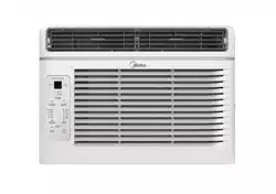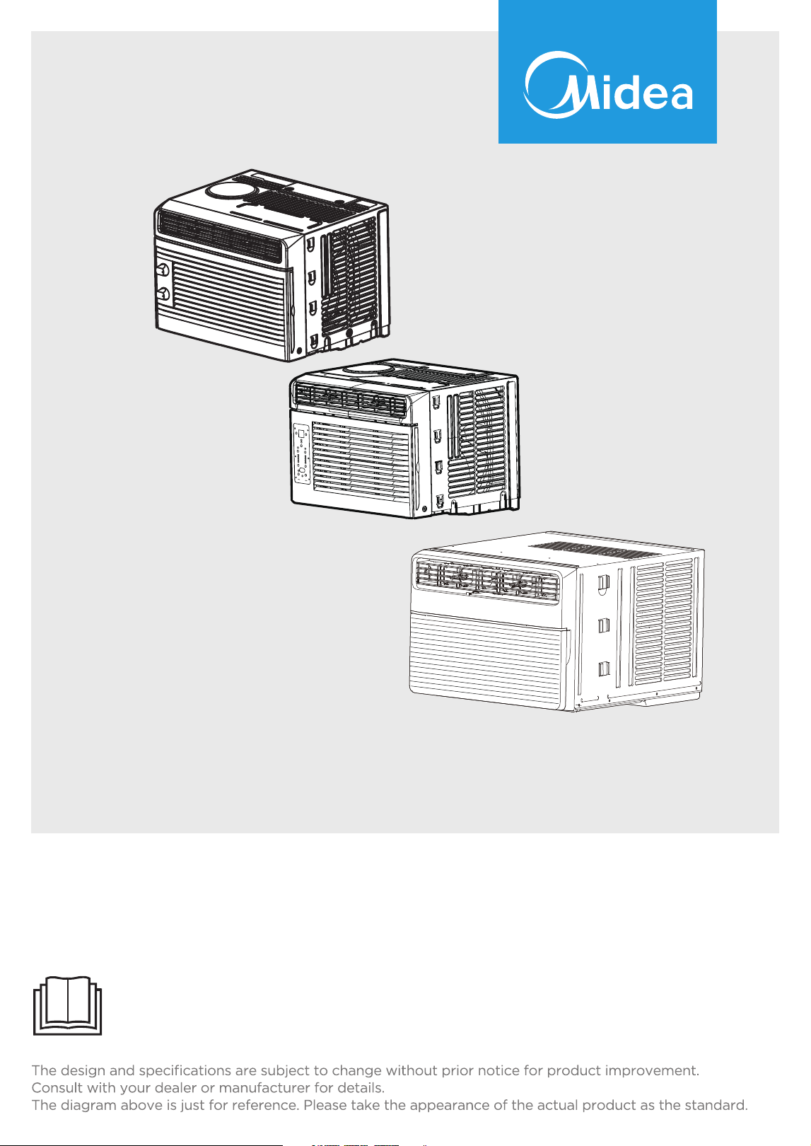
W indow Air Condit ioner
MAW
MAW 0 5M1YW T/ MAW 0 6R1YW T-S/
MAW 0 8S1YW T/ MAW 10 S1YW T
USER MANUAL
Warning notices: Before using this product, please read this manual carefully and keep it for future reference.

2
CONTENTS
THANK YOU LETTER
Thank you for choosing Midea! Before using your new Midea product, please read this manual
thoroughly to ensure that you know how to operate the features and functions that your new air
conditioner offers in a safe way.
THANK YO U LETTER ...............................................................................................................2
SAFETY PRECAUTIONS ........................................................................................................3
PRODUCT INSTALLATION ...................................................................................................12
OPERA TIO N INSTRUCTIONS ..............................................................................................19
REMOTE CO N TROL A ND A PP INSTRUCTIO N S .........................................................25
CLEANING AND MAINTENANCE......................................................................................41
TROUBLESHOOTIN G TIPS ..................................................................................................42
W ARRANTY ...............................................................................................................................44
SAFETY PRECAUTIONS
Read Safety Precautions Before Operation and Installation
To prevent death or injury to the user or other people and property damage, the
following instructions must be followed. Incorrect operation due to ignoring of
instructions may cause death, harm or damage.
Your air conditioner should be used in such a way that it is protected from moisture.
e.g. condensation, splashed water, etc. Do not place or store your air conditioner
where it can fall or be pulled into water or any other liquid. Unplug immediately if it
occurs.
Installation must be performed according to the installation instructions. Improper
installation can cause water leakage, electrical shock, or fire.
Use only the included accessories and parts, and specified tools for the installation.
Using non- standard parts can cause water leakage, electrical shock, fire, and injury
or property damage.
Make sure that the outlet you are using is grounded and has the appropriate voltage.
The power cord is equipped with a three-prong grounding plug to protect against
shock. Voltage information can be found on the nameplate of the unit.
Your unit must be used in a properly grounded wall receptacle. If the wall receptacle
you intend to use is not adequately grounded or protected by a time delay fuse or
circuit breaker (the fuse or circuit breaker needed is determined by the maximum
current of the unit. The maximum current is indicated on the nameplate located on
unit), have a qualified electrician install the proper receptacle.
Install the unit on a flat, sturdy surface. Failure to do so could result in damage or
excessive noise and vibration.
The unit must be kept free from obstruction to ensure proper function and to
mitigate safety hazards.
Do not modify the length of the power cord or use an extension cord to power the
unit.
Do not share a single outlet with other electrical appliances. Improper power supply
can cause fire or electrical shock.
Do not install your air conditioner in a wet room such as a bathroom or laundry room.
Too much exposure to water can cause electrical components to short circuit.
Do not install the unit in a location that may be exposed to combustible gas, as this
could cause fire.
The unit has wheels to facilitate moving. Make sure not to use the wheels on thick
carpet or to roll over objects, as these could cause tipping.
Do not operate a unit that it has been dropped or damaged.
The appliance with electric heater shall have at least 1 meter space to the combustible
materials.
Do not touch the unit with wet or damp hands or when barefoot.
If the air conditioner is knocked over during use, turn off the unit and unplug it from
the main power supply immediately. Visually inspect the unit to ensure there is no
damage. If you suspect the unit has been damaged, contact a technician or customer
service for assistance.
In a thunderstorm, the power must be cut off to avoid damage to the machine due to
lightning.
WARNING
WARNING
CAUTION
This symbol indicates the possibility of
property damage or serious consequences.
This symbol indicates the possibility
of personnel injury or loss of life.
3

All wiring must be performed strictly in accordance with the wiring diagram located
inside of the unit.
The unit's circuit board(PCB) is designed with a fuse to provide overcurrent
protection. The specifications of the fuse are printed on the circuit board, such as:
T 3.15A/250V, etc.
When the water drainage function is not in use, keep the upper and the lower drain
plug firmly to the unit to get rid of choking. When the drain plug is not in use, keep
it carefully to prevent children from choking.
This appliance is not intended for use by persons (including children) with reduced
physical, sensory or mental capabilities or lack of experience and knowledge, unless
they have been given supervision or instruction concerning use of the appliance by
a person responsible for their safety. Children should be supervised to ensure that
they do not play with the appliance.
Children must be supervised around the unit at all times.(be applicable for other
countries except the European Countries )
If the supply cord is damaged, it must be replaced by the manufacturer,its service
agent or similarly qualified persons in order to avoid a hazard.
Prior to cleaning or other maintenance, the appliance must be disconnected from
the supply mains.
Do not remove any fixed covers. Never use this appliance if it is not working
properly, or if it has been dropped or damaged.
Do not run cord under carpeting. Do not cover cord with throw rugs, runners, or
similar coverings. Do not route cord under furniture or appliances. Arrange cord
away from traffic area and where it will not be tripped over.
Do not operate unit with a damaged cord, plug, power fuse or circuit breaker.
Discard unit or return to an authorized service facility for examination and/or repair.
To reduce the risk of fire or electric shock, do not use this fan with any solid-state
speed control device.
The appliance shall be installed in accordance with national wiring regulations.
Contact the authorised service technician for repair or maintenance of this unit.
Contact the authorised installer for installation of this unit.
Do not cover or obstruct the inlet or outlet grilles.
Do not use this product for functions other than those described in this instruction
manual.
Before cleaning, turn off the power and unplug the unit.
Disconnect the power if strange sounds, smell, or smoke comes from it.
Do not press the buttons on the control panel with anything other than your fingers.
Do not remove any fixed covers. Never use this appliance if it is not working properly,
or if it has been dropped or damaged.
Do not operate or stop the unit by inserting or pulling out the power cord plug.
Do not use hazardous chemicals to clean or come into contact with the unit. Do not
use the unit in the presence of inflammable substances or vapour such as alcohol,
insecticides, petrol,etc.
Always transport your air conditioner in a vertical position and stand on a stable,
level surface during use.
Always contact a qualified person to carry out repairs. If the damaged power supply
cord must be replaced with a new power supply cord obtained from the product
manufacturer and not repaired.
Hold the plug by the head of the power plug when taking it out.
Turn off the product when not in use.
CAUTION
4
5
WARNING for Using R32 Refrigerant
Electronic Work
WARNING:
Do not use means to accelerate the defrosting process or to clean, other than those
recommended by the manufacturer.
The appliance shall be stored in a room without continuously operating ignition
sources (for example: open flames, an operating gas appliance or an operating
electric heater).
Do not pierce or burn.
Be aware that the refrigerants may not contain an odour.
Appliance should be installed, operated and stored in a room with a floor area
according to the amount of refrigerant to be charged. For specific information on
the type of gas and the amount, please refer to the relevant label on the unit itself.
When there are differences between the lable and the manual on the Min. room
area description, the description on label shall prevail.
Appliance shall be installed, operated and stored in a room with a floor area larger
than 4 m
2
.
Appliance shall not be installed in an unvertilated space, if that space is smaller than
4 m
2
.
No any open fire or device like switch which may generate spark/arcing shall be
around appliance to avoid causing ignition of the flammable refrigerant used.
Please follow the instructions carefully when storing or maintaining the appliance to
prevent mechanical damage from occurring.
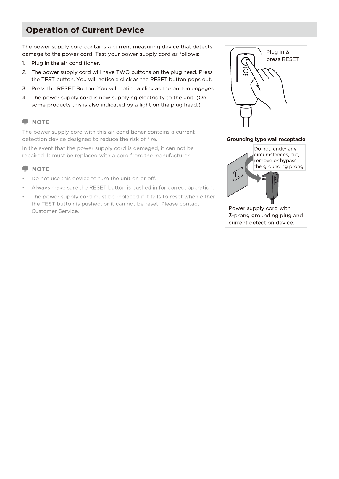
DISPLAY
BEFORE PERFORMING ANY ELECTRICAL OR WIRING WORK, TURN OFF THE
MAIN POWER TO THE SYSTEM.
MAIN
CONTROL
POWER
NOTE: The cographs are for
explanation purpose only. Your
machine may be slightly different.
The actual shape shall prevail.
SUPPLY
CORD
WARNING
- Servicing shall only be performed as recommended by the equipment manufacturer.
Maintenance and repair requiring the assistance of other skilled personnel shall be
carried out under the supervision of the person competent in the use of flammable
refrigerants.
- DO NOT modify the length of the power cord or use an extension cord to power the unit.
- DO NOT share a single outlet with other electrical appliances. Improper power supply
can cause fire or electrical shock.
- Please follow the instruction carefully to handle, install, clear, service the appliance to
avoid any damage or hazard.
- When maintaining or disposing the appliance, the refrigerant shall be recovered
properly, shall not discharge to air directly.
- Compliance with national gas regulations shall be observed.
- Keep ventilation openings clear of obstruction.
- The appliance shall be stored so as to prevent mechanical damage from occurring.
- A warning that the appliance shall be stored in a well-ventilated area where the room
size corresponds to the room area as specified for operation.
- Any person who is involved with working on or breaking into a refrigerant circuit
should hold a current valid certificate from an industry-accredited assessment
authority, which authorises their competence to handle refrigerants safely in
accordance with an industry recognised assessment specification. All
training shall follow the ANNEX HH requirements of UL 60335-2-40.
Examples for such working procedures are:
• breaking into the refrigerating circuit;
• opening of sealed components;
• opening of ventilated enclosures.
CAUTION:
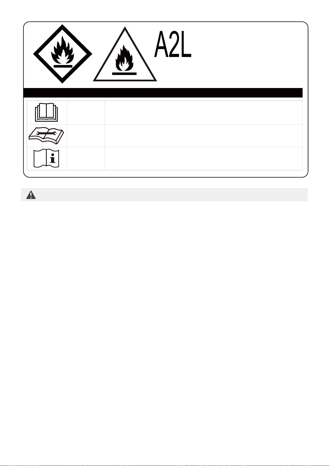
Risk of fire
flammable materials
Explanation of symbols displayed on the unit
CAUTION
CAUTION
CAUTION
This symbol shows that the operation manual should be
read carefully.
This symbol shows that a service personnel should be
handling this equipment with reference to the installation
manual.
This symbol shows that information is available such as
the operating manual or installation manual.
6

See transport regulations.
1.Transport of equipment containing flammable refrigerants
See local regulations.
2.Marking of equipment using signs
See national regulations.
3.Disposal of equipment using flammable refrigerants
The storage of equipment should be in accordance with the manufacturer's
instructions.
4.Storage of equipment/appliances
Storage package protection should be constructed such that mechanical damage
to the equipment inside the package will not cause a leak of the refrigerant charge.
The maximum number of pieces of equipment permitted to be stored together will
be determined by local regulations.
Prior to beginning work on systems containing flammable refrigerants, safety
checks are necessary to ensure that the risk of ignition is minimised. For repair to
the refrigerating system, the following precautions shall be complied with prior to
conducting work on the system.
5.Storage of packed (unsold) equipment
1)Checks to the area
Work shall be undertaken under a controlled procedure so as to minimise the risk of
a flammable gas or vapour being present while the work is being performed.
2)Work procedure
All maintenance staff and others working in the local area shall be instructed on the
nature of work being carried out. Work in confined spaces shall be avoided. The
area around the workspace shall be sectioned off. Ensure that the conditions within
the area have been made safe by control of flammable material.
3)General work area
The area shall be checked with an appropriate refrigerating detector prior to and
during work, to ensure the technician is aware of potentially flammable atmospheres.
Ensure that the leak detection equipment being used is suitable for use with
flammable refrigerants, i.e. non-sparking, adequately sealed or intrinsically safe.
4)Checking for presence of refrigerant
If any hot work is to be conducted on the refrigeration equipment or any
associated parts, appropriate fire extinguishing equipment shall be available to
hand. Have a dry powder or CO2 fire extinguisher adjacent to the charging area.
5)Presence of fire extinguisher
No person carrying out work in relation to a refrigerating system which involves
exposing any pipe work that contains or has contained flammable refrigerant shall
use any sources of ignition in such a manner that it may lead to the risk of fire or
explosion. All possible ignition sources, including cigarette smoking, should be kept
sufficiently far away from the site of installation, repairing, removing and disposal,
during which flammable refrigerant can possibly be released to the surrounding
space. Prior to work taking place, the area around the equipment is to be surveyed
to make sure that there are no flammable hazards or ignition risks. No Smoking
signs shall be displayed.
6)No ignition sources
Ensure that the area is in the open or that it is adequately ventilated before
breaking into the system or conducting any hot work. A degree of ventilation shall
continue during the period that the work is carried out. The ventilation should safely
disperse any released refrigerant and preferably expel it externally into the
atmosphere.
7)ventilated area
6.Information on servicing
7

1)During repairs to sealed components, all electrical supplies shall be disconnected
from the equipment being worked upon prior to any removal of sealed covers, etc.
If it is absolutely necessary to have an electrical supply to equipment during
servicing, then a permanently operating form of leak detection shall be located at
the most critical point to warn of a potentially hazardous situation.
2)Particular attention shall be paid to the following to ensure that by working on
electrical components, the casing is not altered in such a way that the level of
protection is affected. Check for damage to cables, excessive number of
connections, terminals not made to original specification, damage to seals, incorrect
fitting of glands, etc. Ensure that apparatus is mounted securely. Ensure that seals or
sealing materials have not degraded such that they no longer serve the purpose of
preventing the ingress of flammable atmospheres. Replacement parts shall be in
accordance with the manufacturer's specifications.
NOTE: The use of silicon sealant may inhibit the effectiveness of some types of leak
detection equipment. Intrinsically safe components do not have to be isolated prior
to working on them.
7.Sealed electrical components shall be replaced.
Do not apply any permanent inductive or capacitance loads to the circuit without
ensuring that this will not exceed the permissible voltage and current permitted for
the equipment in use. Intrinsically safe components are the only types that can be
worked on while live in the presence of a flammable atmosphere. The test apparatus
shall be at the correct rating. Replace components only with parts specified by the
manufacturer. Other parts may result in the ignition of refrigerant in the atmosphere
from a leak.
8. Intrinsically safe components must be replaced.
Where electrical components are being changed, they shall be fit for the purpose
and to the correct specifications. At all times the manufacturer's maintenance and
service guidelines shall be followed. If in doubt consult the manufacturer's technical
department for assistance. The following checks shall be applied to installations
using flammable refrigerants: the actual refrigerant charge is in accordance with the
room size within which the refrigerant containing parts are installed; the ventilation
machinery and outlets are operating adequately and are not obstructed; if an
indirect refrigerating circuit is being used, the secondary circuit shall be checked
for the presence of refrigerant; marking to the equipment continues to be visible
and legible.
Markings and signs that are illegible shall be corrected; and refrigerating pipe or
components are installed in a position where they are unlikely to be exposed to any
substance which may corrode refrigerant containing components, unless the
components are constructed of materials which are inherently resistant to being
corroded or are suitably protected against being so corroded.
8)Checks to the refrigerating equipment
Repair and maintenance to electrical components shall include initial safety checks
and component inspection procedures. If a fault exists that could compromise
safety, then no electrical supply shall be connected to the circuit until it is
satisfactorily dealt with. If the fault cannot be corrected immediately but it is
necessary to continue operation, an adequate temporary solution shall be used.
This shall be reported to the owner of the equipment so all parties are advised.
Initial safety checks shall include: That capacitors are discharged: this shall be done
in a safe manner to avoid possibility of sparking; that there no live electrical
components and wiring are exposed while charging, recovering or purging the
system; that there is continuity of earth bonding.
9)Checks to electrical devices
8

9
Check that cabling will not be subject to wear, corrosion, excessive pressure,
vibration, sharp edges or any other adverse environmental effects. The check
shall also take into account the effects of aging or continual vibration from
sources such as compressors or fans.
9. Cabling
Under no circumstances shall potential sources of ignition be used in the searching
for or detection of refrigerant leaks. A halide torch (or any other detector using a
naked flame) shall not be used.
The following leak detection methods are deemed acceptable for systems
containing flammable refrigerants. Electronic leak detectors shall be used to detect
flammable refrigerants, but the sensitivity may not be adequate, or may need
re-calibration. (Detection equipment shall be calibrated in a refrigerant-free area.)
Ensure that the detector is not a potential source of ignition and is suitable for
the refrigerant used. Leak detection equipment shall be set at a percentage of the
LFL of the refrigerant and shall be calibrated to the refrigerant employed and the
appropriate percentage of gas (25 % maximum) is confirmed. Leak detection fluids
are suitable for use with most refrigerants but the use of detergents containing
chlorine shall be avoided as the chlorine may react with the refrigerant and
corrode the copper pipe-work. If a leak is suspected, all naked flames shall be
removed/ extinguished. If a leakage of refrigerant is found which requires brazing,
all of the refrigerant shall be recovered from the system, or isolated (by means of
shut off valves) in a part of the system remote from the leak.
Removal of refrigerant shall be according to Removal and evacuation.
10.Detection of flammable refrigerants
When breaking into the refrigerant circuit to make repairs—or for any other purpose
- conventional procedures shall be used. However, for flammable refrigerants it is
important that best practice be followed, since flammability is a consideration.
The following procedure shall be adhered to:
-Safely remove refrigerant following local and national regulations;
-Evacuate;
-Purge the circuit with inert gas (optional for A2L);
-Evacuate (optional for A2L);
-continuously flush or purge with inert gas when using flame to open circuit; and
-open the circuit.
The refrigerant charge shall be recovered into the correct recovery cylinders if
venting is not allowed by local and national codes. For appliances containing
flammable refrigerants, the system shall be purged with oxygen-free n flammable
refrigerants. This process might compressed air or oxygen shall not be used for
purging refrigerant systems.
For appliances containing flammable refrigerants, refrigerants purging shall be
achieved by breaking the vacuum in the system with oxygen-free nitrogen and
continuing to fill until the working pressure is achieved, then venting to atmosphere,
and finally pulling down to a vacuum (optional for A2L). This process shall be
repeated until no refrigerant is within the system (optional for A2L). When the final
oxygen-free nitrogen charge is used. the system shall be vented down to
atmospheric pressure to enable work to take place. The outlet for the vacuum
pump shall not be close to any potential ignition sources, and ventilation shall
be available.
11.Removal and evacuation
In addition to conventional charging procedures, the following requirements shall be
followed. Ensure that contamination of different refrigerants does not occur when
using charging equipment. Hoses or lines shall be as short as possible to minimise
the amount of refrigerant contained in them. Cylinders shall be kept in an appropriate
position according to the instructions. Ensure that the refrigeration system is earthed
prior to charging the system with refrigerant. Label the system when charging is
complete (if not already). Extreme care shall be taken not to overfill the refrigeration
system. Prior to recharging the system it shall be pressure tested with OFN. The
system shall be leak tested on completion of charging but prior to commissioning.
A follow up leak test shall be carried out prior to leaving the site.
12.Charging procedures

Before carrying out this procedure, it is essential that the technician is completely
familiar with the equipment and all its detail. It is recommended good practice that
all refrigerants are recovered safely.
Prior to the task being carried out, an oil and refrigerant sample shall be taken in
case analysis is required prior to re-use of reclaimed refrigerant. It is essential that
electrical power is available before the task is commenced.
a) Become familiar with the equipment and its operation.
b) Isolate system electrically.
c) Before attempting the procedure ensure that: Mechanical handling equipment is
available, if required, for handling refrigerant cylinders;all personal protective
equipment is available and being used correctly; the recovery process is
supervised at all times by a competent person; recovery equipment and cylinders
conform to the appropriate standards.
d) Pump down refrigerant system, if possible.
e) If a vacuum is not possible, make a manifold so that refrigerant can be removed
from various parts of the system.
f) Make sure that cylinder is situated on the scales before recovery takes place.
g) Start the recovery machine and operate in accordance with manufacturer's
instructions.
h) Do not overfill cylinders. (No more than 80 % volume liquid charge).
i) Do not exceed the maximum working pressure of the cylinder, even temporarily.
j) When the cylinders have been filled correctly and the process completed, make
sure that the cylinders and the equipment are removed from site promptly and
all isolation valves on the equipment are closed off.
k) Recovered refrigerant shall not be charged into another refrigeration system
unless it has been cleaned and checked.
13.Decommissioning
Equipment shall be labelled stating that it has been de-commissioned and
emptied of refrigerant. The label shall be dated and signed. Ensure that there are
labels on the equipment stating the equipment contains flammable refrigerant.
14.Labelling
When removing refrigerant from a system, either for servicing or decommissioning,
it is recommended good practice that all refrigerants are removed safely. When
transferring refrigerant into cylinders, ensure that only appropriate refrigerant
recovery cylinders are employed. Ensure that the correct number of cylinders for
holding the total system charge is available. All cylinders to be used are designated
for the recovered refrigerant and labelled for that refrigerant (i.e. special cylinders
for the recovery of refrigerant). Cylinders shall be complete with pressure relief
valve and associated shut-off valves in good working order. Empty recovery
cylinders are evacuated and, if possible, cooled before recovery occurs. The
recovery equipment shall be in good working order with a set of instructions
concerning the equipment that is at hand and shall be suitable for the recovery of
the flammable refrigerant. If in doubt, the manufacturer should be consulted. In
addition, a set of calibrated weighing scales shall be available and in good working
order. Hoses shall be complete with leak-free disconnect couplings and in good
condition.
The recovered refrigerant shall be processed according to local legislation in the
correct recovery cylinder, and the relevant waste transfer note arranged. Do not
mix refrigerants in recovery units and especially not in cylinders. If compressors or
compressor oils are to be removed, ensure that they have been evacuated to an
acceptable level to make certain that flammable refrigerant does not remain within
the lubricant. The compressor body shall not be heated by an open flame or other
ignition sources to accelerate this process. When oil is drained from a system, it shall
be carried out safely.
15.Recovery
10
11
PRODUCT INSTALLATION
Window Requirements
WARNING - Before You Begin
Read these instructions completely and carefully.
• IMPORTANT - Save these instructions.
• IMPORTANT - Observe all governing codes and ordinances.
We recommend that two people install this product.
Proper installation is the responsibility of the installer.
Product failure due to improper installation is not covered under the Limited Warranty.
You MUST use all supplied parts and use proper installation procedures as described in these instructions when
installing this air conditioner.
Do not, under any circumstances, cut or remove the third (ground) prong from the power cord.
Do not change the plug on the power cord of the air conditioner.
Aluminum house wiring may present special problems - consult a qualifi ed electrician.
When handling the air conditioner, be careful to avoid cuts from sharp metal edges and aluminum fi ns on front
and rear coils. Please wear cut-resistant gloves.
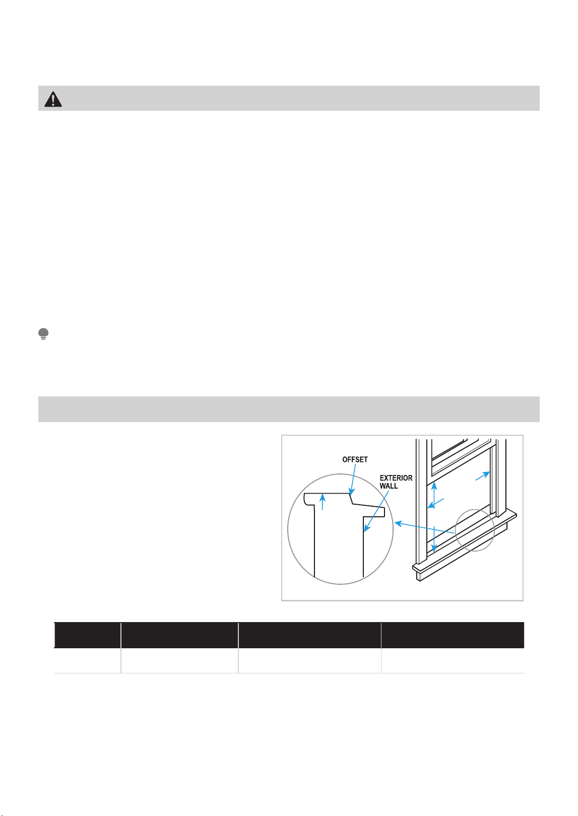
Your air conditioner is designed to install in
standard double hung windows with opening
widths of 23 to 36 inches (584mm to 914mm).
Save carton and these Installation Instructions for future reference. The carton is the best way to store unit
during winter, or when not in use.
NOTE
Table 1
Model 10000 BTU/h
H 13 in (330 mm) 14 in (356 mm) 15-1/2 in (394 mm)
Wooden Windows
INNER
WINDOW
SILL
INTERIOR
WALL
13.75" min
(349 mm)
23" to 36"
(584 mm
to 914mm)
H
5000 BTU/h ~ 8000 BTU/h6000
12
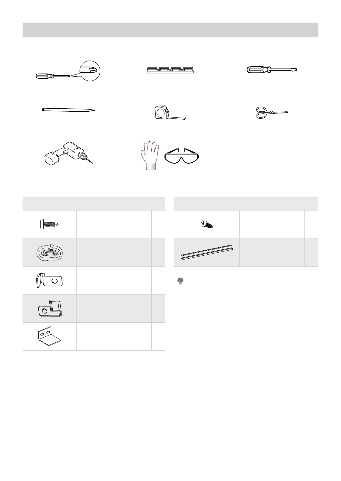
Tools You Will Need
Mounting Hardware
3/4” (1/2”) Screws 7
Window Sash Seal Foam 1
Lock Frame
(For Wooden Windows)
2
Lock Frame
(For Vinyl-Clad Windows)
2
Sash Lock 1
Top Rail Hardware
3/8” Screws 4
Top Rail 1
Drill and 1/8” drill bit Proper PPE
Phillips Screwdriver Level Flathead Screwdriver
Pencil Ruler or tape measure Scissors or knife
Installation Hardware
The MAW10 comes with its own top rail, so there
is no additional top rail.
NOTE
13
1. Prepare the Window
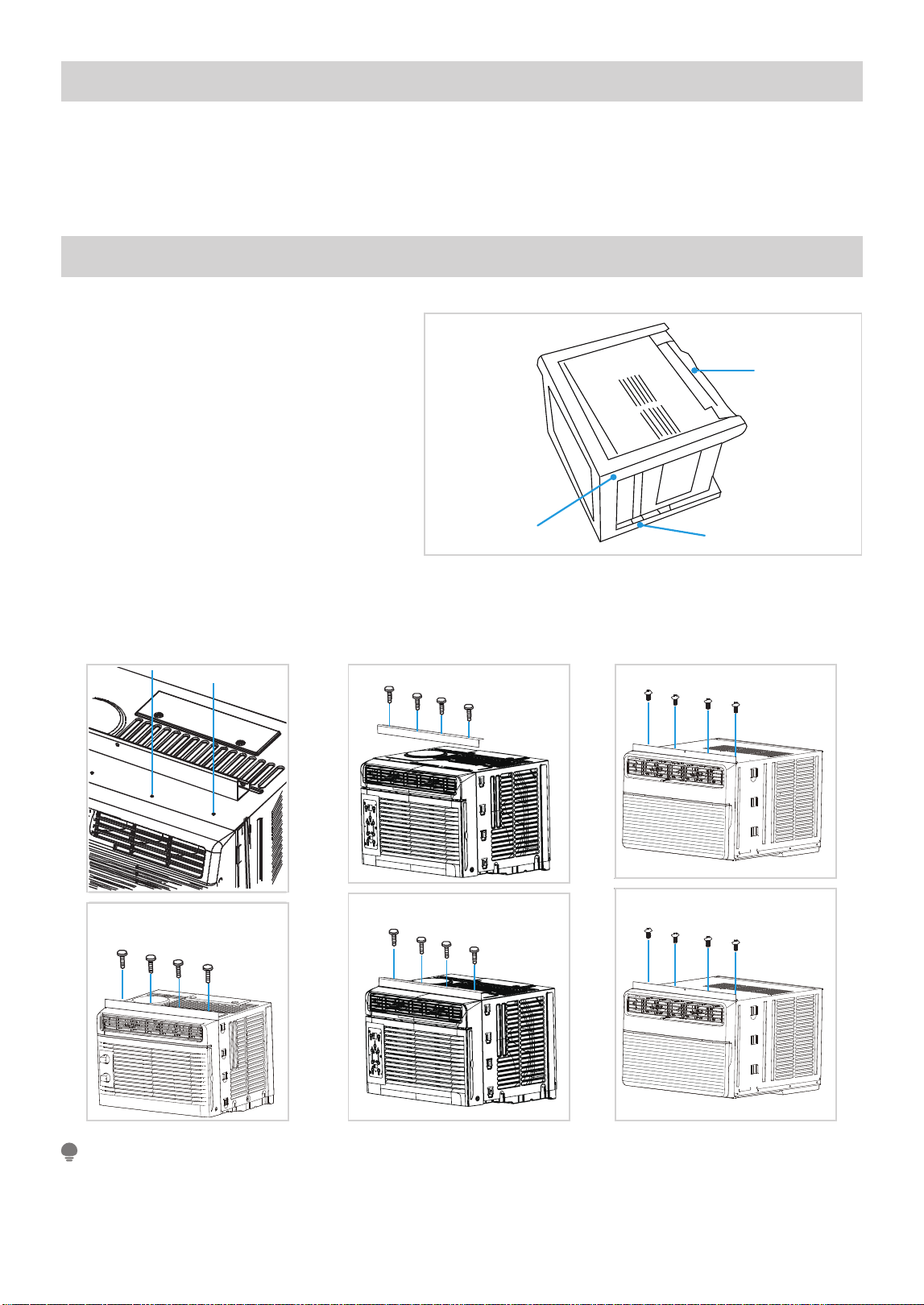
2. Prepare the Air Conditioner
• For safety reasons, all four (4) screws MUST be securely fastened.
• Before installing unit, the top rail must be assembled on the unit.
NOTE
Lower sash must open suf ciently to allow a clear vertical opening (see dimension H in Table 1). Side louvers
and the rear of the AC must have clear air space to allow enough air ow through the condenser for heat
removal. The rear of the unit must be outdoors, not inside a building or garage.
Before installing the unit, the top rail must be
assembled on the unit for some models with
a capacity of less than 10,000Btu/h.
A. Remove the air conditioner from the
carton and place on a at surface.
B. Remove top rail from the packaging
material as shown in Fig. A.
C. Align the hole in the top rail with those in the top of the unit as shown in Fig. B.
D. Secure the top rail to the unit with the 3/8” Screws as shown in Fig. C.
Top Rail
Top Rail
Packaging
Fig. A
14
MAW05 Model MAW06 Model
Fig.B
Fig.C
Fig. C
Fig. B
MAW08 Model
Fig. C
Fig. B
Fig. B
Fig. C
15
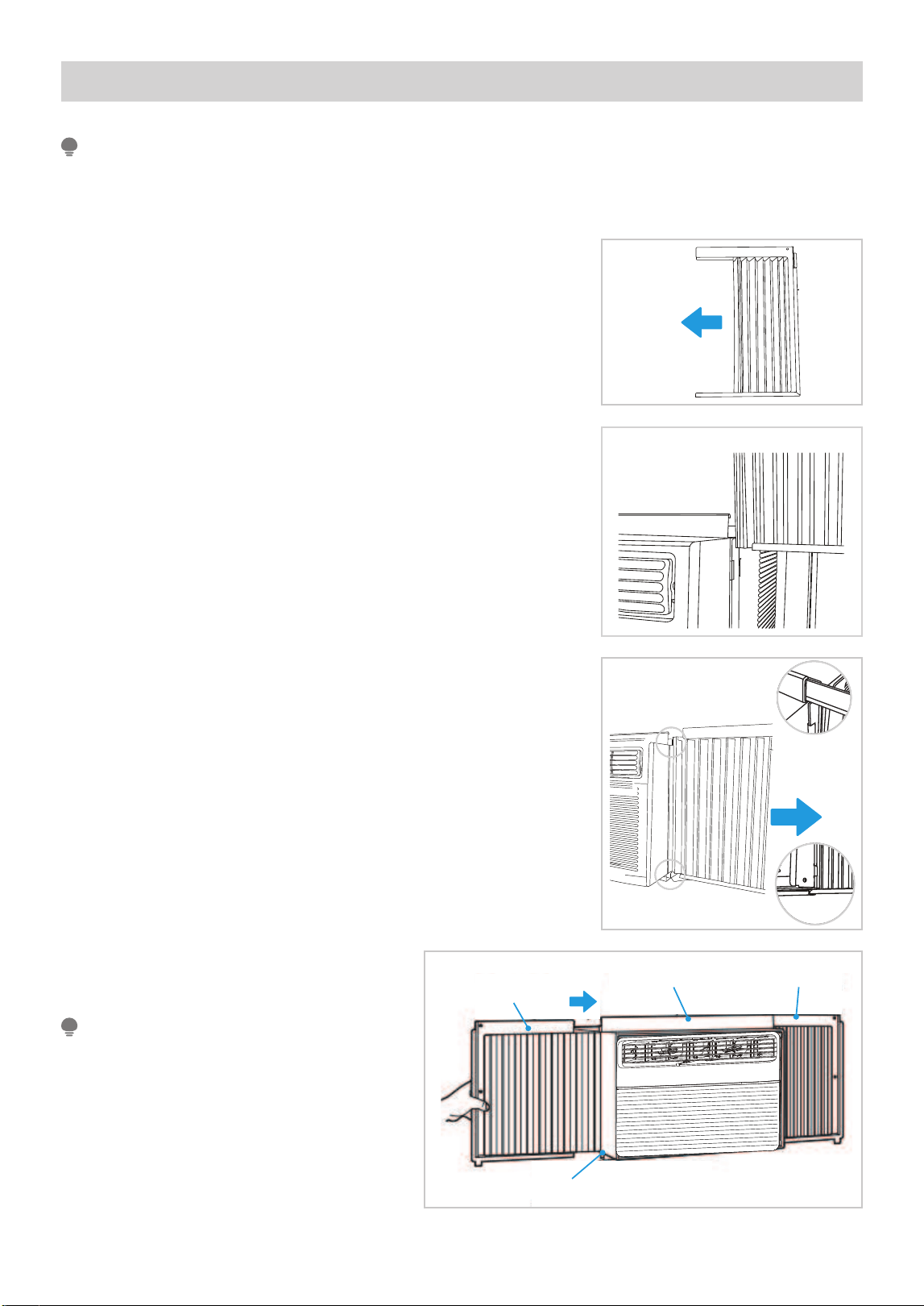
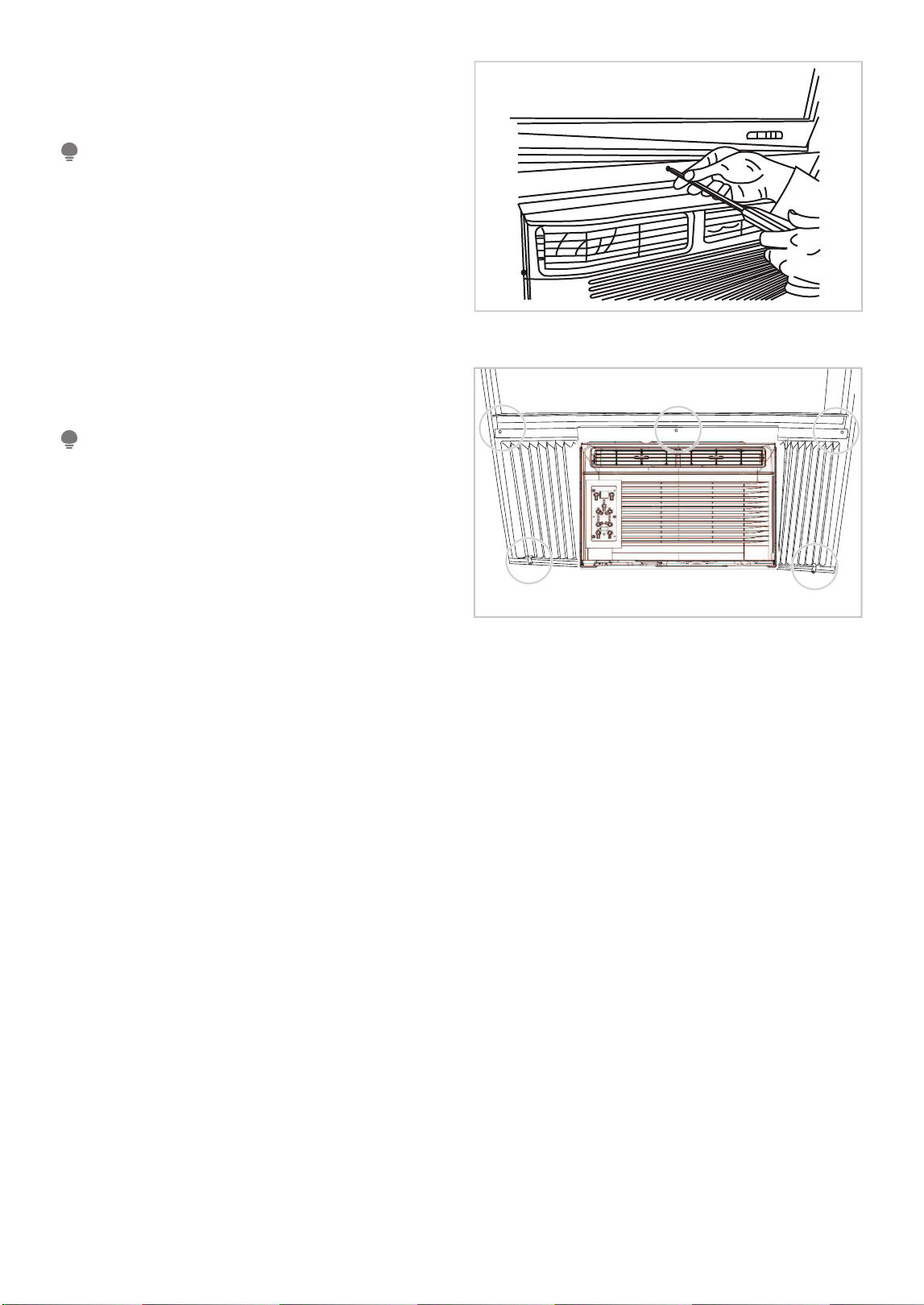
3. Install Accordion Panels on Air Conditioner
The Top rail and Sliding Panels on each side are offset to provide the proper pitch to the rear of the unit (5/16”).
This is necessary for proper condensate management and drainage. If you are not using the Side Panels for any
reason, this pitch to the rear must be maintained.
NOTE
A. Place unit on the fl oor, a bench or a table. Hold the Accordion Panel
in one hand and gently pull back the center to free the open end.
See Fig. 1.
Fig. 2
“
I
“ section
If storm window blocks AC, see Fig. 12.
NOTE
B. Slide the free end “
I
“ section of the panel directly into the cabinet as
shown in Fig. 2. Slide the panel down. Be sure to leave enough space
to slip the top and bottom of the frame into the rails on the cabinet.
C. Once the panel has been installed on the side of the cabinet, make
sure it sits securely inside the frame channel by making slight
adjustments.
Slide the top and bottom ends of the frame into the top and
bottom rails of the cabinet. Fig. 3.
D. Slide the panel all the way in and repeat on
the other side.
Fig. 1
Fig. 3
Top Rail
Bottom Rail
Top Rail
Bottom Rail
Fig. 4
Bottom Rail
Top RightTop Rail
Top Left
16
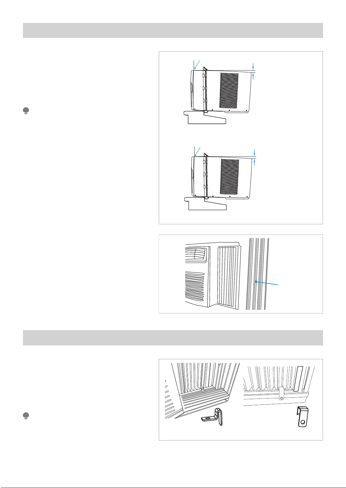
Fig. 6
Fig. 5
Check that air conditioner is tilted back per
dimension H (Fig. 5) (tilted about 3° to 4°
downward to the outside). After proper
installation, condensate should not drain
from the overfl ow drain hole during normal
use. Adjust the slope if otherwise.
NOTE
4. Install Air Conditioner
A. Keep a fi rm grip on the air conditioner,
carefully place the unit into the window
opening so the bottom of the air
conditioner frame is against the window
sill (Fig. 5). Carefully close the window
behind the top rail of the unit.
B. Extend the side panels out against the
window frame (Fig. 6).
Wooden Windows
INSIDE
OUTSIDE
H:About 3/4” to 1”
(for 5K to 8K)
Measure from the cabinet edge
3
H:About 1” to 1
/
(for 10K)
8”
H
Vinyl-Clad Windows
INSIDE
OUTSIDE
H:About 3/4” to 1”
(for 5K to 8K)
Measure from the cabinet edge
3
H:About 1” to 1
/
(for 10K)
8”
H
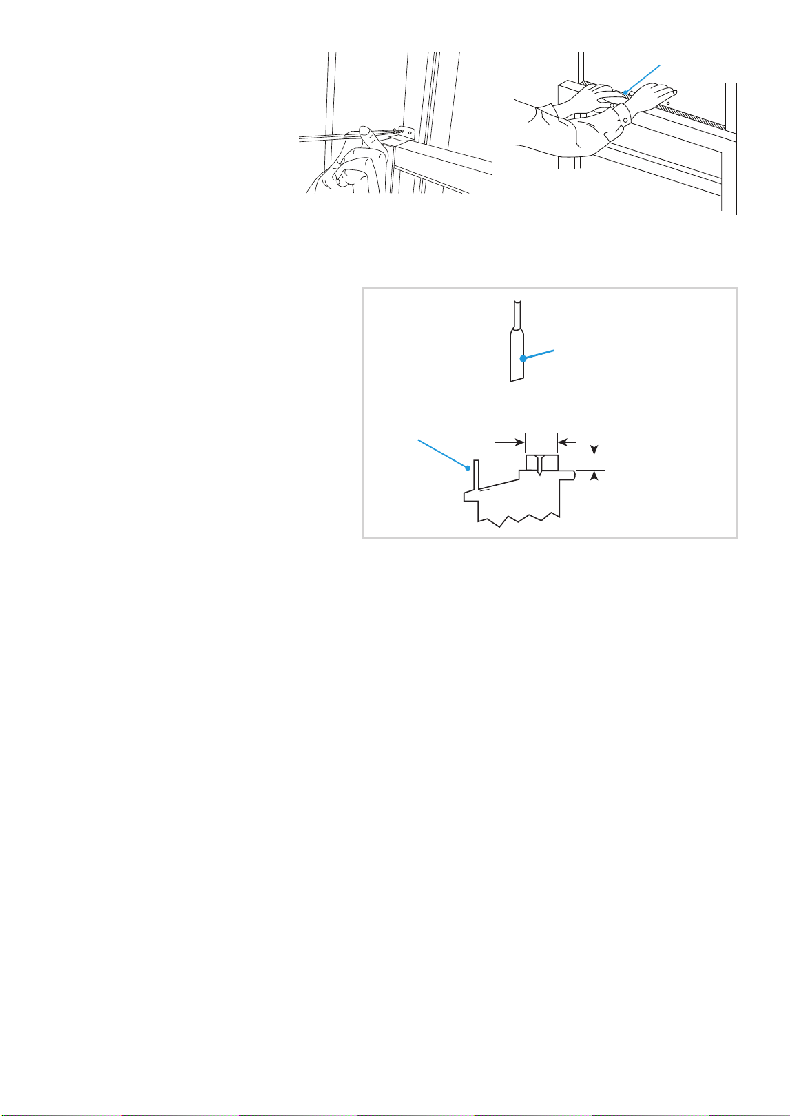
5. Secure Air Conditioner
Fig. 7A Fig. 7B
To prevent window sill from splitting, drill 1/8”
(3 mm) pilot holes before driving screws.
NOTE
A. Place the frame lock between the frame
extensions and the window sill as shown
(Fig. 7A for Wooden windows), (Fig. 7B
for Vinyl-Clad windows). Drive 3/4” (19
mm) or 1/2” (12.7 mm) locking screws
through the frame lock and into the sill.
Window
frame
Window
frame
17
Fig. 8A
B1: For wooden windows:
Drive 1/2” (12.7 mm) locking screws through the
top rail and into the window sash (Fig. 8A).
To prevent window sill from splitting, drill 1/8” (3mm)
pilot holes before driving screws. Drive 1/2” (12.7mm)
locking screws through frame holes into window sash
(Fig. 8B/8C).
NOTE
Before driving the screws, drill 5 holes into the
window through the holes of the top rail and side
panel frames as shown (Fig. 8B).
NOTE
B2: For Vinyl-Clad windows:
Drive 1/2” (12.7 mm) locking screws through the
top rail and into the window sash (Fig. 8B).
Fig. 8B
18
REMOVING AC FROM WINDOW
Fig. 9
Fig. 10
FOAM SEA
L
FOAM SEAL
C. Secure lower sash in place by
attaching the sash lock with the
3/4” (19 mm) or 1/2” (12.7 mm)
screw as shown (Fig. 9).
D. Cut Window sash seal foam and
insert it in the space between
the upper and lower sashes
(Fig. 10).
Add wood as shown in Fig. 12, or remove storm
window before air conditioner is installed.
If storm window frame must remain, be sure
the drain holes or slots are not caulked or
painted shut. Accumulated rain water or
condensation must be allowed to drain out.
• Turn AC off, and disconnect power cord.
• Remove sash seal from between windows, and unscrew sash lock.
• Remove screws installed through top rail and side panel frames.
• Slide the accordion panels into the rails to close.
• Keeping a fi rm grip on the air conditioner, raise the sash and carefully remove.
• Be careful not to spill any condensate while lifting unit from window. Store parts WITH air conditioner.
IF AC IS BLOCKED BY STORM WINDOW
SASH
OUTSIDE INSIDE
1-1/2" min
(38 mm)
B
o
r
e
pi
e
n
w
Storm window
frame or other
obstruction.
Storm window
frame or other
obstruction.
Board thickness
as required, for
proper pitch to
rear, along entire
sill. Fasten with
nails or screws.
1-1/2” min
(38 mm)
INSIDE
SASH
OUTSIDE
Fig. 12
19
OPERATION INSTRUCTIONS
Normal Sounds
Gurgle/Hiss
Gurgling or hissing noises may be heard
due to refrigerant fl owing through
evaporator during normal operation.
Sound of Rushing Air
In front of the unit, you may
hear the sound of rushing
air being moved by the fan.
High Pitched Chatter
High effi ciency compressors may have a
high pitched sound during cooling cycle.
Vibration
Unit may vibrate and make
noise because of poor wall
or window construction or
incorrect installation.
Trickling Sound
Droplets of water
hitting condenser
during normal
operation may cause
a trickling sound.
MAW05 Models
MAW06 Models
Sound of Rushing Air
In front of the unit, you may
hear the sound of rushing
air being moved by the fan.
High Pitched Chatter
High effi ciency compressors may have a
high pitched sound during cooling cycle.
Trickling Sound
Droplets of water
hitting condenser
during normal
operation may cause
a trickling sound.
Gurgle/Hiss
Gurgling or hissing noises may be heard
due to refrigerant fl owing through
evaporator during normal operation.
Vibration
Unit may vibrate and make
noise because of poor wall
or window construction or
incorrect installation.
All the illustrations in this manual are for explanation purpose only. The actual installation may vary.
NOTE
MAW08/10 Models
Gurgle/Hiss
Gurgling or hissing noises may be heard
due to refrigerant fl owing through
evaporator during normal operation.
Sound of Rushing Air
In front of the unit, you may
hear the sound of rushing
air being moved by the fan.
High Pitched Chatter
High effi ciency compressors may have a
high pitched sound during cooling cycle.
Vibration
Unit may vibrate and
make noise because of
poor wall or window
construction or
incorrect installation.
Trickling Sound
Droplets of water
hitting condenser
during normal
operation may cause
a trickling sound.
20
This air conditioner is designed to be operated under the following conditions:
Air Conditioner Features (general)
WARNING
To reduce the risk of fi re, electrical shock, or injury to people or property, read the SAFETY PRECAUTIONS
before operating this appliance.
Cooling Operation
Outdoor temperature: 64°F ~ 109°F / 18°C ~ 43°C
Indoor temperature: 62°F ~ 90°F / 17°C ~ 32°C
• The relative humidity of the room should be less than 80%. If the unit is used in a condition with a relative
humidity over 80%, there will be condensed water on the surface of the unit.
• Performance may be reduced outside of these operating temperatures.
NOTE
Air Conditioner Features (MAW05M1YWT only)
Air Directional Louvers
Always wait 3 minutes when turning the unit off and then on again, or when changing from cool to fan and back
to cool. This prevents damage from occurring to the compressor.
NOTE
To begin operating the air conditioner, follow these steps:
1. Plug in the air conditioner (be sure to follow the power cord instructions).
2. Turn the power on to the air conditioner, using the ON/OFF button.
3. Set the thermostat to the coldest temperature setting.
4. Select the Cool mode setting.
5. Adjust the louver for comfortable air fl ow (see Air Directional Louvers).
6. Once the room has cooled, adjust the thermostat to the setting you fi nd most comfortable.
7. Make sure the air fl ow inside and outside is not obstructed by anything.
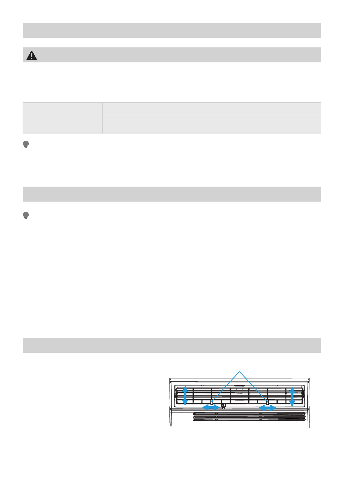
The louvers will allow you to direct the air fl ow
Left or Right, or Up and Down (optional on some
models) throughout the room as needed.
Move the Levers from side to side until the
desired Left/Right direction is obtained.
You can also move the LEFT lever to adjust air
fl ow up/down as needed.
Levers
Air Direction
21
Air Conditioner Features (MAW05M1YWT only)
Air Conditioner Features (MAW06R1YWT-S only)
The controls featured in this manual are representative of many available models. Your model may offer slightly
different features.
NOTE
When selecting a low fan or high fan, the compressor will not run.
NOTE
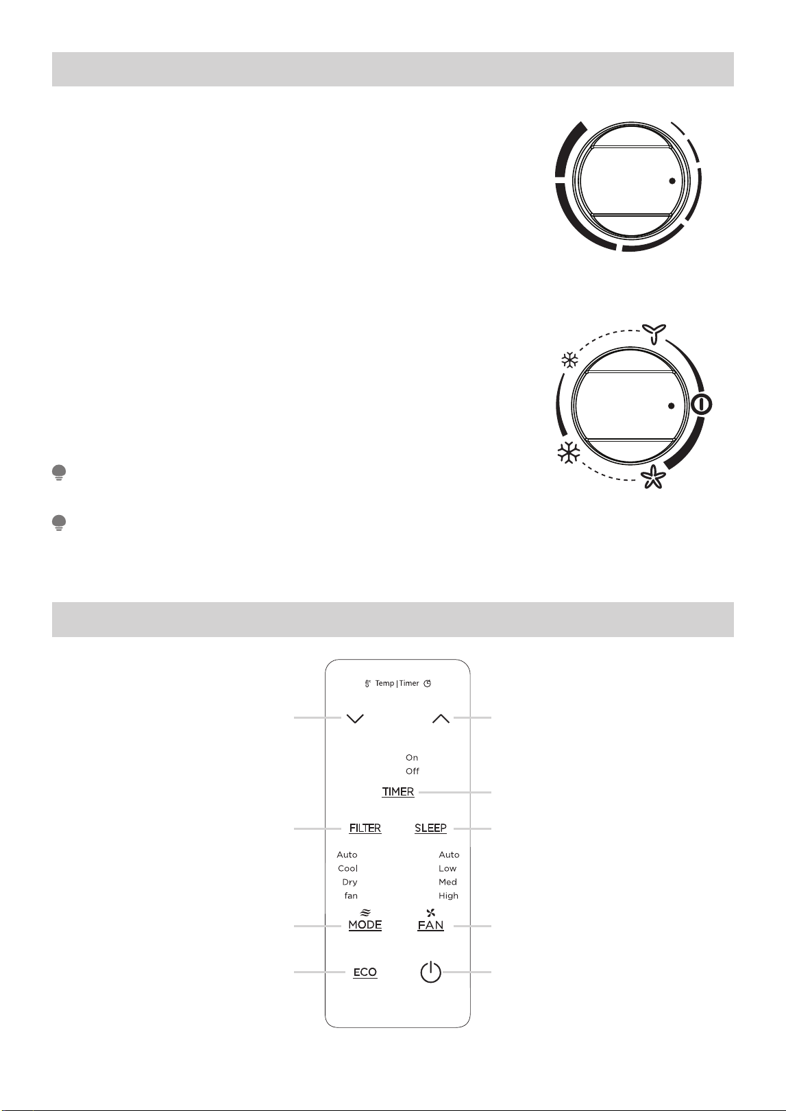
THERMOSTAT
The thermostat is used to set the desired room temperature when the unit
is being operated in the COOL MODE.
To set the desired room temperature, rotate the thermostat switch to the
desired setting. After the set temperature is achieved the thermostat will
automatically start and stop the compressor in order to maintain the desired
set temperature.
• Rotate the thermostat selector clockwise for higher cool settings.
Higher cool settings will provide lower room temperature.
• Rotate the thermostat selector counter clockwise for lower cool settings.
Lower cool settings will provide higher room temperature.
COOL MODE
The desired cool setting is selected by rotating the knob clockwise to the
desired position.
HIGH COOL has maximum cooling effect and airfl ow.
LOW COOL has minimum cooling effect and airfl ow.
FAN MODE
Rotate the knob counter clockwise to select your choice of fan speeds for
air circulation.
TEMP
MODE
MINMAX
9
1
2 2
4
38
5
7
(Refer to the next page
for specic functions)
22
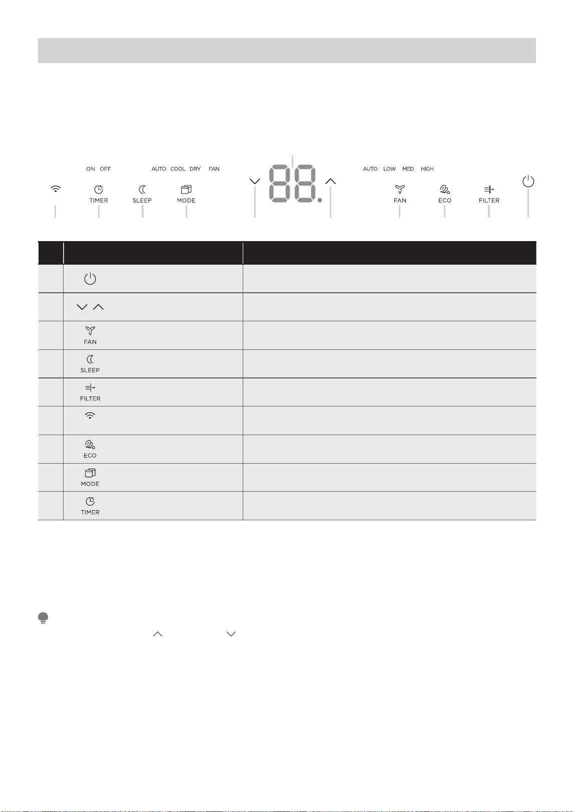
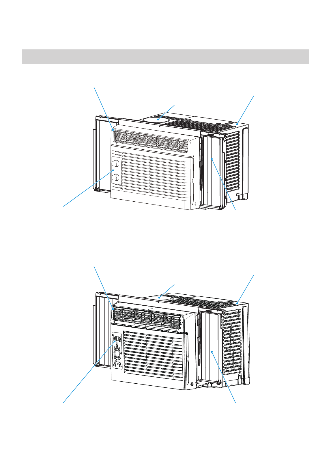
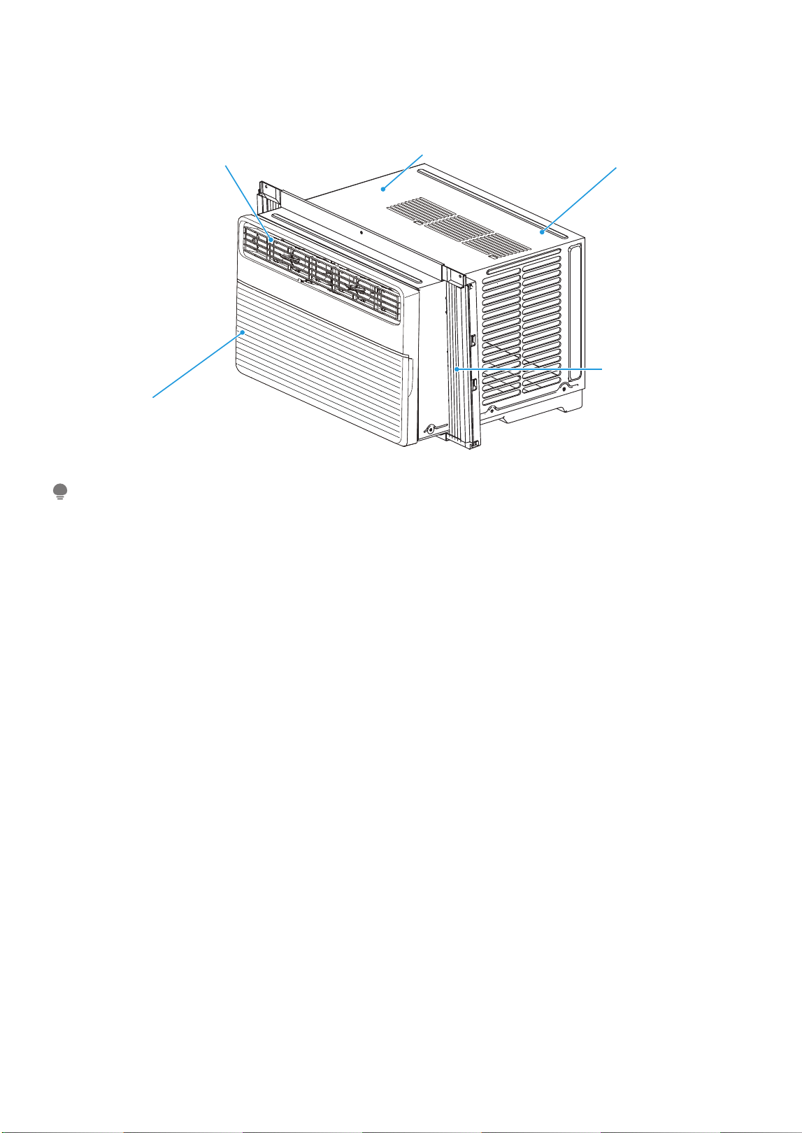
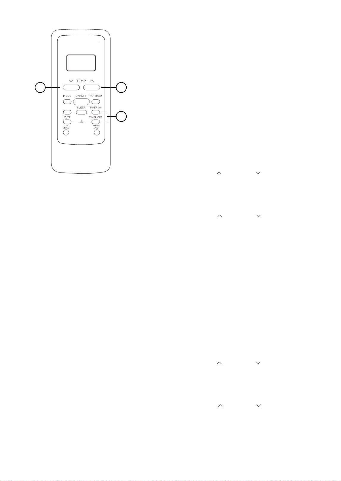
Air Conditioner Features (MAW08S1YWT/MAW10S1YWT)
ELECTRONIC CONTROL OPERATING INSTRUCTIONS
Before you begin, thoroughly familiarize yourself with the control panel as shown below and all its functions,
then follow the symbol for the functions you desire. The unit can be controlled by the unit control alone or
with the remote.
2. TO CHANGE TEMPERATURE SETTING:
Press UP/DOWN button to change temperature
setting.
1. TO TURN UNIT ON OR OFF:
Press Power button to turn unit on or off.
Press or hold either UP ( ) or DOWN ( )
button until the desired temperature is seen on
the display.
NOTE
Description
1 ON / OFF • Press to turn unit on or off.
2
UP / DOWN
Button • Press to change temperature setting.
3
Fan Speed
• Press to select the Fan Speed in four steps - Auto, Low, Med
or High.
4
Sleep Function • Press to initiate the sleep mode.
5
Check Filter Feature • Press to turn off the cleaning fi lter reminder.
6
CONNECT
Connect Function • Press to initiate smart connection mode. (Smart models only)
7
Energy Saver Feature
• Press to initiate this feature, which will maintain comfort and
save energy.
8
Mode Fuctions
• Press to choose operating mode in a sequence that goes
from Auto, Cool, Dry and Fan.
9
Timer Feature • Press to turn unit Auto Start/Stop.
This temperature will be automatically
maintained anywhere between 62°F (17°C) and
86°F (30°C). If you want to display the actual
room temperature, see To Operate on Fan Only
section.
3. TO ADJUST FAN SPEEDS:
Press to select the Fan Speed in four steps - Auto, Low,
Med or High. Each time the button is pressed, the fan
speed mode is changed. On Dry mode, the fan operates
on Low speed automatically and cannot be changed.
On Auto mode, the fan operates on Auto fan speed
automatically and cannot be changed.
4. SLEEP FEATURE:
Press Sleep button to initiate the sleep mode. In this
mode the selected temperature will increase by 2°F
(1°C) 30 minutes after the mode is selected. The
temperature will then increase by another 2°F (1°C)
after an additional 30 minutes.
This new temperature will be maintained for 7 hours
before it returns to the originally mode and the unit will
continue to operate as originally programmed.
The Sleep mode program can be canceled at any time
during operation by pressing the Sleep button again.
6 9 4 8 3 7 5 12 2
CONNECT
LED Display
23
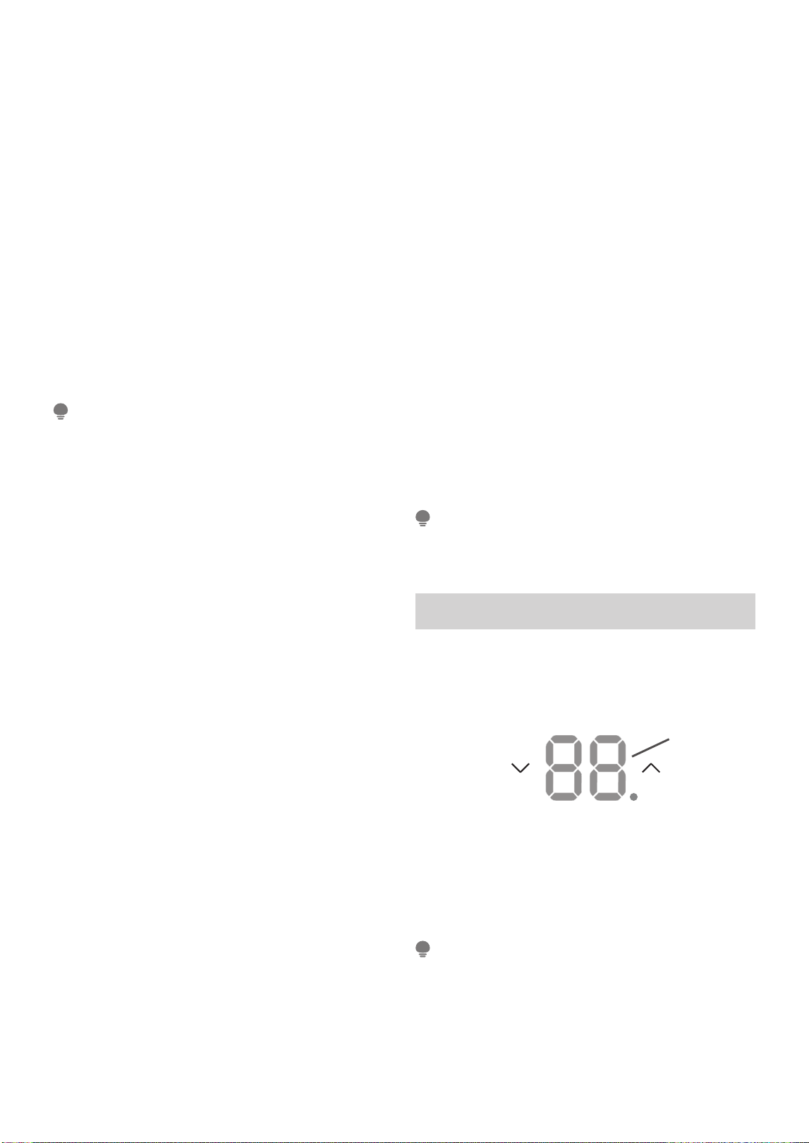
Displays
LED Display:
Shows the set temperature in “°C” or “°F” and the
Auto-timer settings. While on Fan Only mode, it
shows the room temperature. If the room temperature
is too high or low, it will display “HI” or “LO”.
Error codes:
AS - Room temperature sensor error - Unplug the
unit and plug it back in.
If error repeats, call for service.
ES - Evaporator temperature sensor error - Unplug
the unit and plug it back in.
If error repeats, call for service.
• To change the AC between Celsius and Fahrenheit
scales, press the temperature control arrows at
the same time for 5 seconds.
• If the unit shuts o unexpectedly due to the power
outage, it will restart with the previous function
setting automatically when the power resumes.
NOTE
The unit will automatically initiate the Energy Saver
function under Cool, Dry, Auto modes.
NOTE
To cancel timer operation, press and hold the timer
button for 2 seconds until the beep/buzzer is heard.
NOTE
5. CHECK FILTER FEATURE:
The Clean Filter indicator light is a reminder to clean
the air fi lter for more effi cient operation. The light
will illuminate after 250 hours of operation. After
cleaning the air fi lter, reset by pressing the Clean
Filter button. After resetting, the light will go off.
6. CONNECT FEATURE:
Press CONNECT button for 3 seconds to turn off the
unit and initiate smart connection mode.
For detailed instruction on how to connect your
device, see page 25
7. ENERGY SAVER FEATURE (ECO):
Press Energy Saver button to initiate this function.
This function is available on COOL, DRY, AUTO (only
AUTO-COOLING and AUTO-FAN) modes. The fan will
continue to run for 3 minutes after the compressor
shuts off. The fan then cycles on for 2 minutes at 10
minute intervals until the room temperature is above
the set temperature, at which time the compressor
turns back on and Cooling resumes.
8. TO SELECT THE OPERATING MODE:
To choose operating mode, press Mode button.
Each time you press the button, a mode is selected
in a sequence that goes from Auto, Cool, Dry and
Fan. The indicator light adjacent will be illuminated
and remain on once the mode is selected.
When the unit is turned off and back on via the power
button, the unit will automatically switch on the Energy
Saver function for the following modes: Cool, Dry, Auto.
To operate on AUTO feature:
• When you set the air conditioner to AUTO mode,
it will automatically select cooling or fan only
operation depending on what temperature you
have selected and the current room temperature.
• The air conditioner will control room temperature
automatically according to temperature you’ve set.
• In this mode, the fan speed cannot be adjusted
as it’s automatically controlled according to
temperature setting and room temperature.
To operate on Fan Only:
• Use this function only when cooling is not desired,
such as for room air circulation or to exhaust stale
air (on some models). (Remember to open the
vent during this function, but keep it closed during
cooling for maximum cooling effi ciency.) You can
choose any fan speed you prefer.
• During this function, the display will show the
actual room temperature, not the set temperature
as in the cooling mode.
• In Fan Only mode, the temperature is not adjusted.
To operate on DRY mode:
• In this mode, the air conditioner will generally
function as a dehumidifi er. Since the conditioned
space is a closed or sealed area, some degree of
cooling will occur.
9. TIMER: AUTO START/STOP FEATURE:
• When the unit is on, press the Timer button. The
“Timer off ” LED indicator light will illuminate
indicating the Auto stop feature has been activated.
- When the unit is off, press the Timer button.
The “Timer on” LED indicator light will illuminate
indicating the Auto start feature has been activated.
• When the time of TIMER ON is displayed, press
the Timer button again. The TIMER OFF indicator
light illuminates. It indicates the Auto Stop
program has initiated.
• Press or hold the UP or DOWN button to change the
Auto time by 0.5 hour increments, up to 10 hours,
then at 1 hour increments up to 24 hours. The control
will count down the time remaining until start.
• The selected time will register in 5 seconds, and
the system will automatically revert back to
display the previous temperature setting or room
temperature when the unit is on. (when the unit is
off, there is no display.)
• The selected time indicates the amount of time
after the current time which you want the unit to
turn on or off. If you select Timer On and adjust
the time to 2.0h, the unit will turn on 2 hours after
the current time.
• Turning the unit ON or OFF at any time or
adjusting the timer setting to 0.0 will cancel the
Auto Start/Stop timed program.
Display
24
25
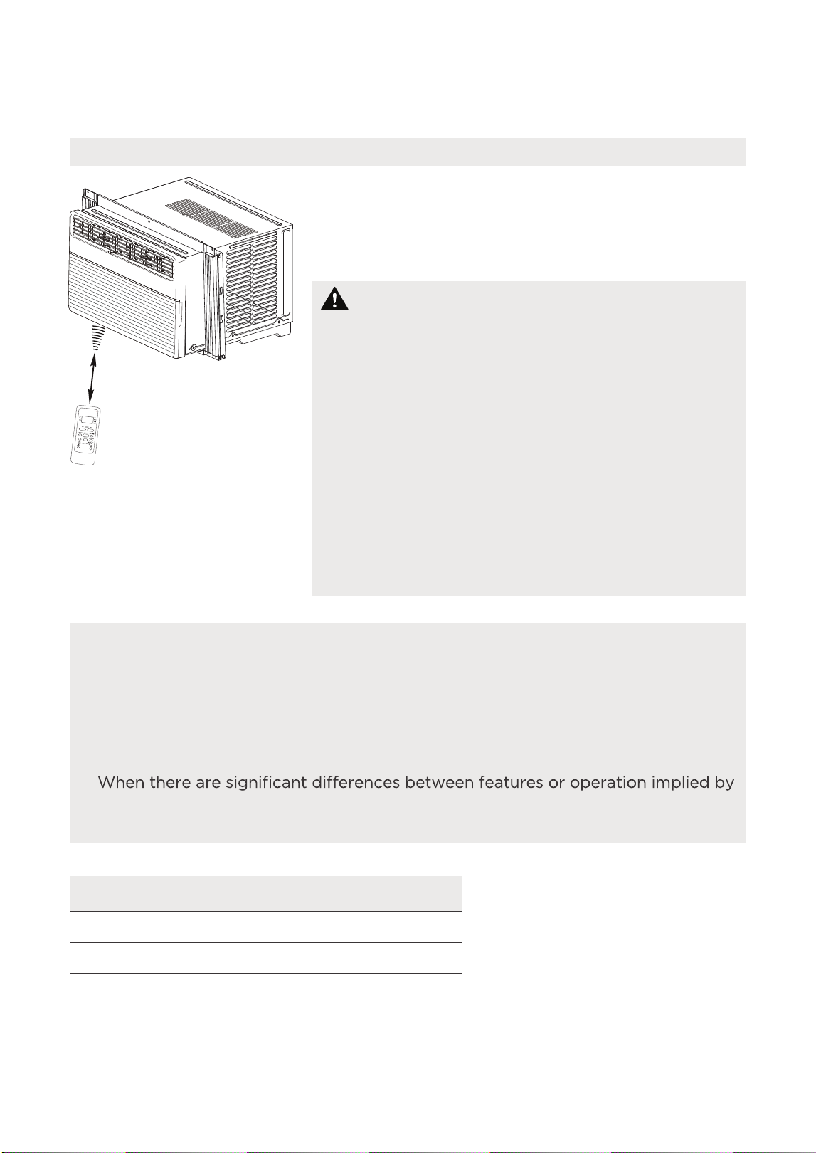
Location of the remote control
Use the remote controller within a distance of 26.2 ft
(8 meters) from the air conditioner, pointing it towards
the receiver. Reception is confirmed by a beep.
Handling the Remote Control
•
The air conditioner will not operate if curtains,
doors or other materials block the signals from the
remote control to the unit.
•
Prevent any liquid from spilling onto the remote
control. Do not expose the remote control to
direct sunlight or heat.
•
If the infrared signal receiver on the indoor unit is
exposed to direct sunlight, the air conditioner may
not function properly. Use curtains to prevent the
sunlight from falling on the receiver.
•
If other electrical appliances react to the remote
control, either move these appliances or consult
your local dealer.
CAUTION
26.2 ft (8 meters)
C-SE
N
S
E
NOTICE
Remote Controller Specifications
•
Button design is based on typical model and may vary slightly from the actual
one you purchased.
•
All the functions described are accomplished by the unit. If the unit is without a
feature, the unit will not respond if the corresponding button on the remote is
pressed.
•
the remote control illustration and the actual functions described in the USER’S
MANUAL, the descriptions in the USER’S MANUAL shall prevail.
Rated Voltage: 3.0V (Dry batteries R03/LR03x2)
Environment: 23°F ~140°F (-5°~60°)
REMOTE CONTROL AND APP INSTRUCTIONS
26
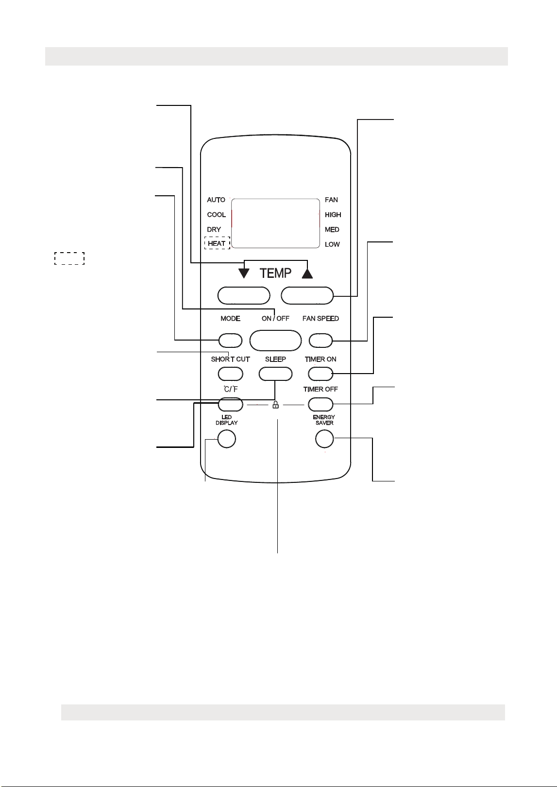
Function Buttons
RG51G5(1)/CEU1
AUTO COOL DRY
HEAT
FAN
NOTE:
Model RG51G5(1)/CEU1 does not have HEAT feature.
NOTE: Please do not
select HEAT mode if the
machine you purchased
is cooling only type.
Heat mode is not
supported by the
cooling only appliance.
SLEEP
Saves energy during
sleeping hours.
°C/°F
ON/OFF
Turns the unit on or
off.
MODE
Scrolls through
operation modes
as follows:
The temperature display
between the °C & °F.
TEMP
Decreases temperate
in1°F (1°C) increments.
Min. temperature is
62°F(17°C).
LOW MED HIGH
FAN SPEED
Selects fan speeds in
the following order:
TEMP
Increases temperate
in1°F (1°C) increments.
Max. temperature is
86°F(30°C).
TIMER ON
Sets timer to turn unit
on (see How to Use
Basic Functions for
instructions).
TIMER OFF
Sets timer to turn unit
off (see How to Use
Basic Functions for
instructions).
Press together °C/°F & TIMER OFF buttons
simultaneously for 5 seconds to lock the
keyboard. Press together the two buttons for
2 seconds to unlock the keyboard.
LOCK
ENERGY SAVER
Press this button to
activate the Energy
saving mode. Press it
again to stop the
funtion.
LED DISPLAY
Turns indoor unit’s LED display and
air conditioner buzzer on and off
(model dependent), which create a
comfortable and quiet environment.
SHORTCUT
Used to restore the
current settings or
resume previous settings.
27
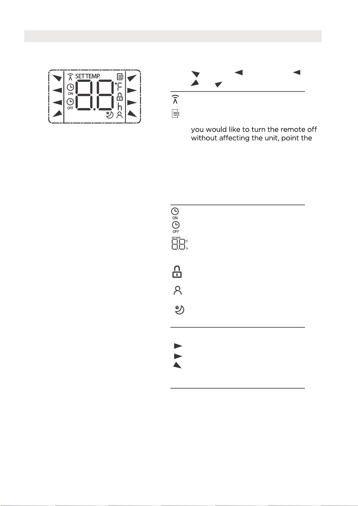
Information are displayed when the remote controller is power up.
All indicators shown in the figure are for the purpose of clear presentation.
But during the actaul operation, only the relative function signs are shown
on the display window.
Remote Screen Indicators
Displayed when data transmitted.
Appears when the remote is enabled
and can send a signal to the unit. If
remote away from the unit and press
the ON/OFF button.
To turn the remote on, point the
remote away from the unit and press
the ON/OFF button. The unit will not
receive commands from the remote
if this indicator is not illuminated.
AUTO
COOL
DRY
HEAT
AUTO
HEAT
COOL
FAN
DRY
Mode display
FAN
HIGH
MED
LOW
Low speed
NO display
Medium speed
High speed
Auto fan speed
Displayed when TIMER ON time is set
Displayed when TIMER OFF time is set
Indicated all the current settings are
locked
Shows set temperature or room
temperature, or time under TIMER
setting
HIGH
MED
LOW
Fan speed indication
Displayed when ComfortSense feature
is activated(some units)
Displayed when SLEEP feature is
activated
Note:
28
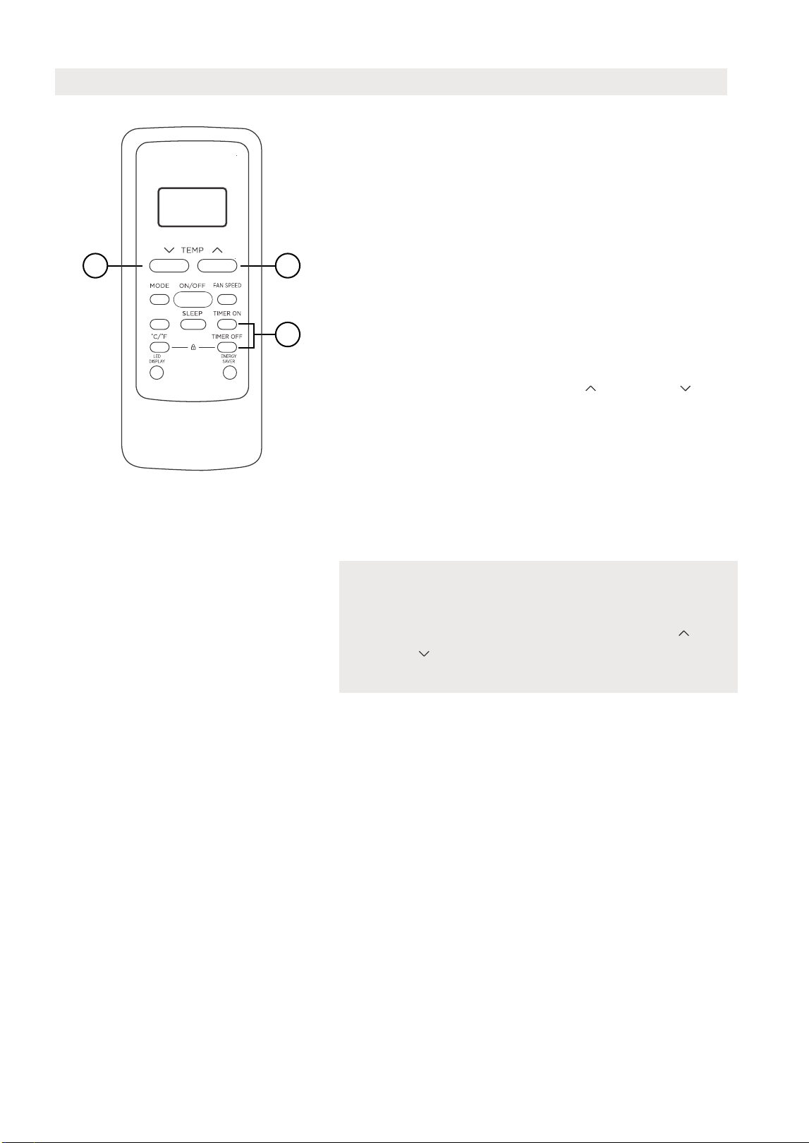
How to Use the Buttons
TIMER OPERATION
Press the TIMER button to initiate the Auto-start
and Auto-stop setting program of the unit.
To set the Auto-start/stop time.
1. Press the TIMER button, when the TIMER ON
indicator is displayed on the LED window of
the air conditioner, it indicates the Auto Start
setting program is initiated. When the TIMER
OFF indicator is displayed on the LED window
of the air conditioner, it indicates the Auto
Stop setting program is initiated.
2. Press or hold the TEMP UP ( )/DOWN ( ) to
change the Auto time. The control will count
down the time remaining until start/stop.
3. The selected time will register in 5 seconds and
the air conditioner will automatically revert back
to display the previous temperature setting.
4. Turning the unit ON or OFF at any time will
cancel the Auto Start/stop function.
NOTES
To cancel the TIMER setting, push the TIMER
button and press or hold the TEMP UP ( )/
DOWN ( ) until 0 hour is displayed on the LCD
window of the air conditioner.
1
22
SHORT CUT
FAN
AUTO
COOL
DRY
HIGH
MED
LOW
FAN
AUTO
COOL
DRY
HIGH
MED
LOW
COMBINED TIMER
(Setting both ON and OFF timers simultaneously)
AUTO STOP >AUTO START
(On > Stop > Start operation)
This feature is useful when you want to stop the
air conditioner after you go to bed, and start it
again in the morning when you wake up or when
you return home.
Example:
To stop the air conditioner 2 hours after setting
and start it again 10 hours after setting.
AUTO START > AUTO STOP
(Off > Start > Stop operation)
This feature is useful when you want to start the
air conditioner before you wake up and stop it
after you leave the house.
Example:
To start the air conditioner 5 hours after setting,
and stop it 8 hours after setting.
1
22
SHORT CUT
1. Press the TIMER button until the TIMER OFF
indicator is displayed on the LED display of
the air conditioner.
2. Use the TEMP UP ( )/DOWN ( ) button to
display “2.0” on the LED display of the air
conditioner.
3. Press the TIMER button again to display the
TIMER OFF on the LED display of the unit.
4. Use the TEMP UP ( )/DOWN ( ) button to
display “10” on the LED display of the unit.
5. Wait for 5 seconds until the previous display
appears in LED window.
1. Press the TIMER button until the TIMER ON
indicator is displayed on the LED display of
the air conditioner.
2. Use the TEMP UP ( )/DOWN ( ) button to
display “5.0” on the LED display of the air
conditioner.
3. Press the TIMER button again to display the
TIMER OFF on the LED display of the unit.
4. Use the TEMP UP ( )/DOWN ( ) button to
display “8.0” on the LED display of the unit.
5. Wait for 5 seconds until the previous display
appears in LED window.
29
30
NOTES
• Button design is based on a typical model and may slightly vary from the actual
one you purchased.
• This device complies with part 15 of the FCC Rules. Operation is subject to the
following two conditions: (1) This device may not cause harmful interference,
and (2) this device must accept any interference received, including interference
that may cause undesired operation.
• This equipment has been tested and found to comply with the limits for a Class
B digital device, pursuant to part 15 of the FCC Rules. These limits are designed
to provide reasonable protection against harmful interference in a residential
installation. This equipment generates, uses and can radiate radio frequency
energy and, if not installed and used in accordance with the instructions, may cause
harmful interference to radio communications. However, there is no guarantee that
interference will not occur in a particular installation. If this equipment does cause
harmful interference to radio or television reception, which can be determined by
interference by one or more of the following measures:
- Reorient or relocate the receiving antenna.
- Increase the separation between the equipment and receiver.
receiver is connected.
- Consult the dealer or an experienced radio/TV technician for help.
- Changes or modifications not approved by the party responsible for compliance
could void users authority to operate the equipment.
Battery Warning:
Do not mix old and new batteries and Do not mix alkaline, standard (carbon-zinc)
or rechargeable (ni-cad, ni-mh, etc.) batteries
Unique Identifier: Midea brand,RG51G5(1)/CEU1
Responsible Party U.S. Contact Information
Midea America Corporation
300 Kimball Dr
Parsippany NJ
07054
This device complies with Part 15 of the FCC Rules. Operation is subject to the
following two conditions: (1) This device may not cause harmful interference, and
(2) this device must accept any interference received, including interference that
may cause undesired operation.
Telephone number or internet contact information: Midea.com/us
FCC Compliance Statement ( products subject to Part 15)
Supplier's Declaration of Conformity
47 CFR § 2.1077 Compliance Information

Declaration of Conformity
We hereby declare that this AC is in compliance with the essential requirements and other relevant provisions of
Directive 1999/5/EC.
Specification of Wireless Module
Model: US-SK109 Dimensions: 41 x 24 x 5 (mm)
Operation Temperature: 0°C ~ 45°C / 32°F ~ 113°F
Antenna Type: Printed PCB Antenna
Operation Humidity: 10% ~ 85%
Frequency: WLAN 2400-2483.5 MHz
Power Input: DC 5V/500 mA
Maximum Transmitted Power: <20 dBm Max
1. Supports operating systems: Please refer to page 34.
2.
In the event of a OS update, there may be a delay between the update of the OS
and a related software update during which your OS may or may not be supported
until a new version is released. Your specific mobile phone or problems in your
network may prevent the system from working and Midea will not be responsible
for any problems that could be caused by incompatibility or network issues.
3.
This Smart AC only supports WPA-PSK/WPA2-PSK (recommended) encryption.
4.
To ensure proper scanning of the QR code, your smart phone must have at least a
5-megapixel camera.
5.
Due to unstable network connectivity, requests may time out. If this happens, rerun
the network configuration.
6. Due to unstable network connectivity, commands may time out. If this happens,
the smartphone app and the actual product may display conflicting information.
The information displayed on the actual product is always the most accurate
available. Refresh the app to re-sync.
Midea will not be responsible for any problems that could be caused by
incompatibility or network issues, your wireless router and mobile phone.
NOTICE
PRECAUTIONS
31
1
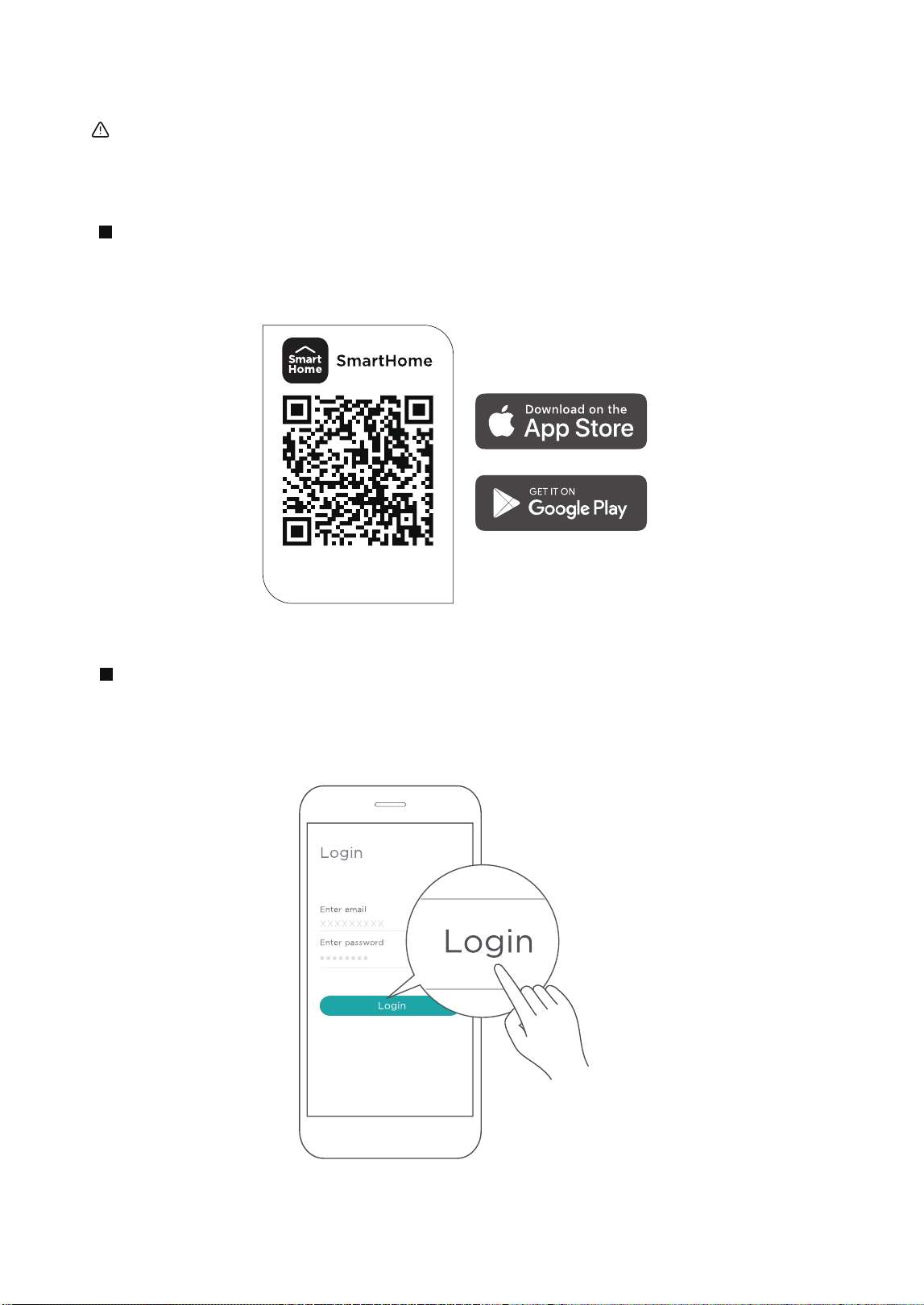
How to use SmartHome App (MAW08S1YWT and MAW10S1YWT only)
Ensure that your mobile phone is connected to the wireless network. Bluetooth must be turned on.
The device must also be powered up.
Scan the QR code below to download the SmartHome app from app store or search for it directly
on the Google Play Store or Apple's App Store.
Step 1: Download the SmartHome app
Open the SmartHome app. Log in directly if you have an existing SmartHome account or create a
new account. Alternatively, you can also use a 3rd party login platform.
Step 2: Log in
Download the app
& activate product
32
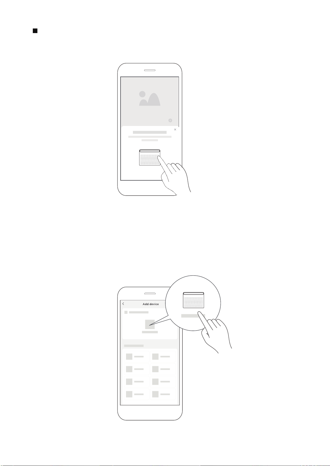
1) When you log in, you may see the message "Smart devices discovered nearby".
Tap to add your device.
2) If no such message appears, proceed as follows: Tap on "+" and select your device in the list of
nearby available devices.
If your device is not listed, please add your device manually, first selecting the device category e.g.
Window AC.
Step 3: Connecting the device
33
34
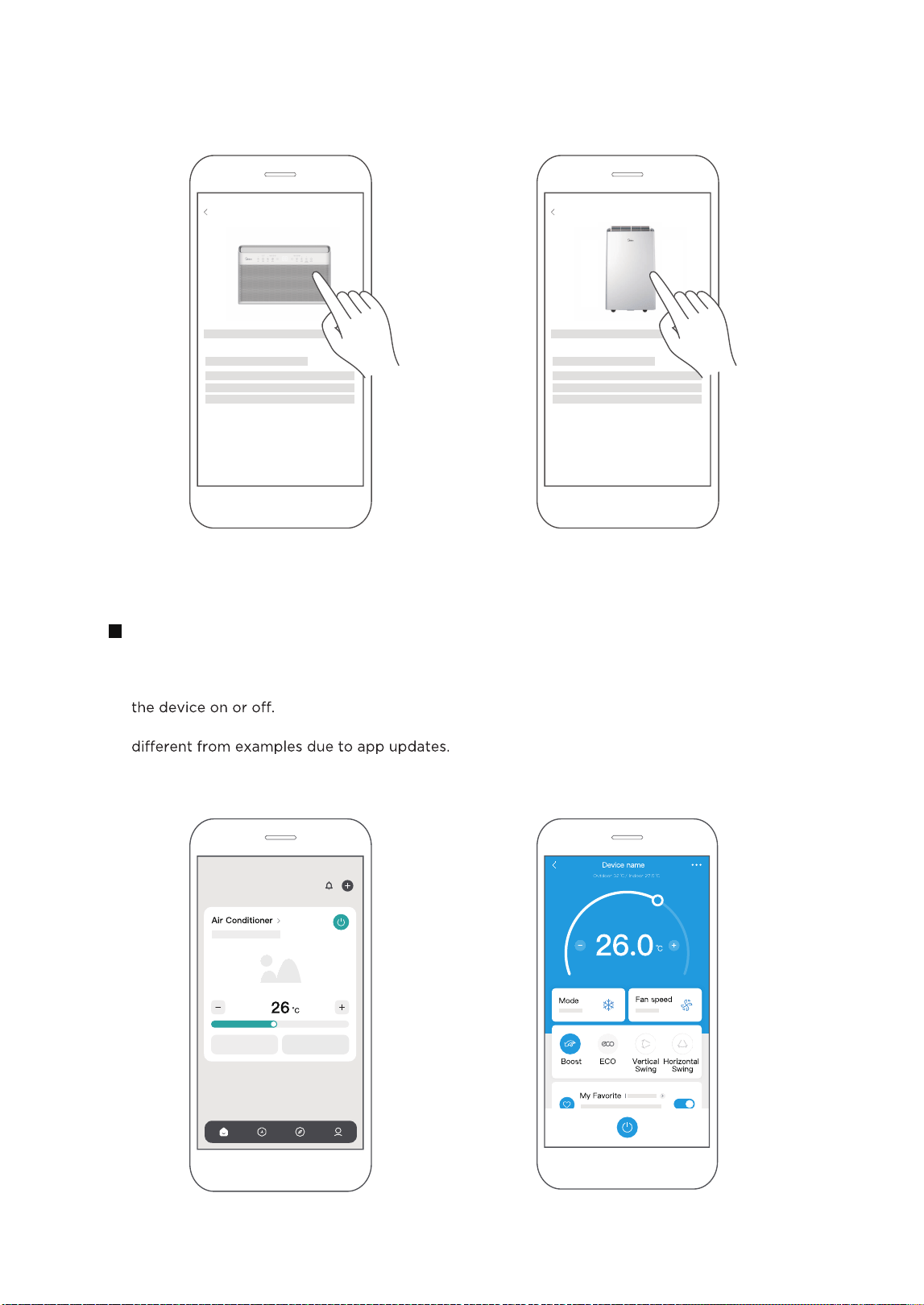
After pairing successfully, a card will be created for the device in the SmartHome app.
Shortcuts for basic functions will appear on the card such as changing the temperature or switching
Tapping on the card, will reveal additional features and settings. The actual UI design may look
Step 4: Controlling the device
SmartHome
3) Follow the steps in the app to connect your device to the wireless network. If your device fails to
connect, follow the additional instructions in the app.
Add device
For Window AC For Portable
AC
Add device
35
2
How to use Matter (MAW08S1YWT and MAW10S1YWT only)
Connect YourAir Conditioner through Matter
Make sure your mobile device is connected to your wireless router.
Wireless router should support and turn on IPv6. Please make sure your smartphone connect to 2.4G
but not 5G network.
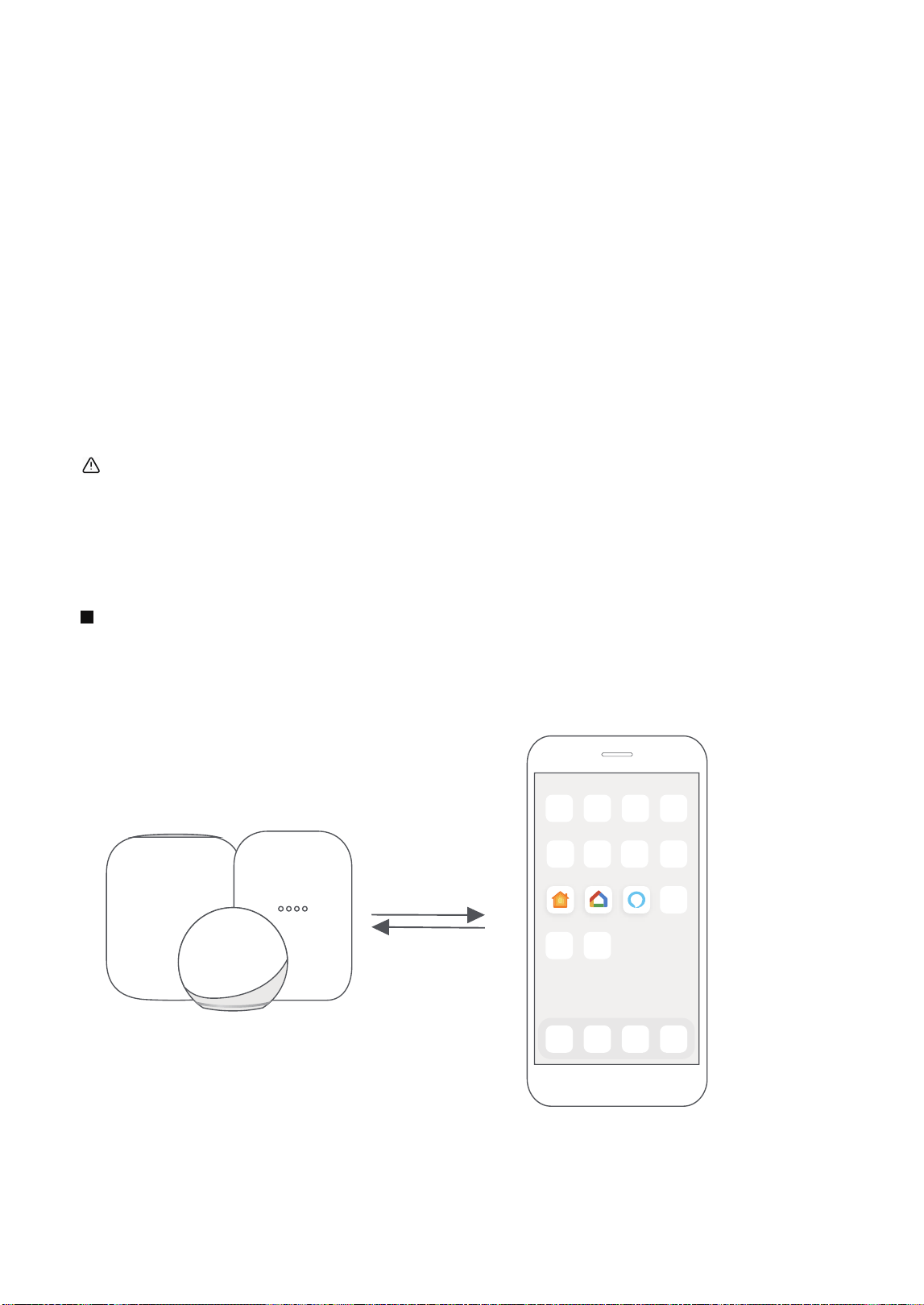
Matter is a connectivity technology that unifies the smart home by allowing devices and ecosystems
(such as Alexa, Google Home and Apple Home) to speak the same language thus creating exciting new
features and use cases.
To use Matter, you will need at least one Matter enabled smart speaker from Amazon, Google or Apple,
and it's respective app.
-- If you have a Matter enabled smart speaker, please proceed to the "How to use
Matter" instructions on the following pages.
-- If you don't have a Matter enabled smart speaker, you won't be able to use
Matter right now. However, you can still achieve full functionality of the product by
using our SmartHome app. To do this, proceed to the "How to use SmartHome app" section back on
page 1.
Step 1: Connect to smart speaker
Select your preferred ecosystem (Alexa, Google Home or Apple Home) and make sure you’ve got one
of their Matter enabled products (such as their smart speakers) connected to your wireless router.
Apple Home Google Home Alexa
For best Matter compatibility, connect the AC to the Alexa, Google Home or Apple Home ecosystems along
with at least one of their respective Matter enabled smart speakers.
36
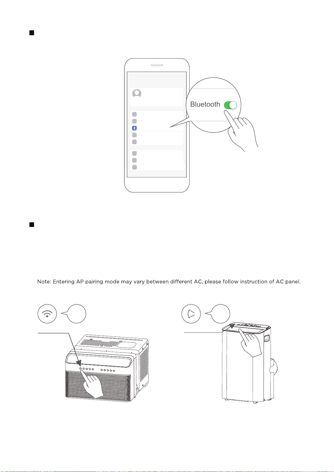
Turn on Bluetooth on your mobile device.
Step 2: Turn on Bluetooth
Settings
Bluetooth
Bluetooth
Window AC: Hold down the CONNECT / Power button for 3 seconds to begin the pairing process
(“AP” will appear on the AC’s display).
Portable AC: Hold down the SWING / Power button for 3 seconds to begin the pairing process (“AP”
will appear on the AC’s display).
Step 3: Enter AP mode
AP
CONNECT
AP
SWING
Window AC Portable AC
37
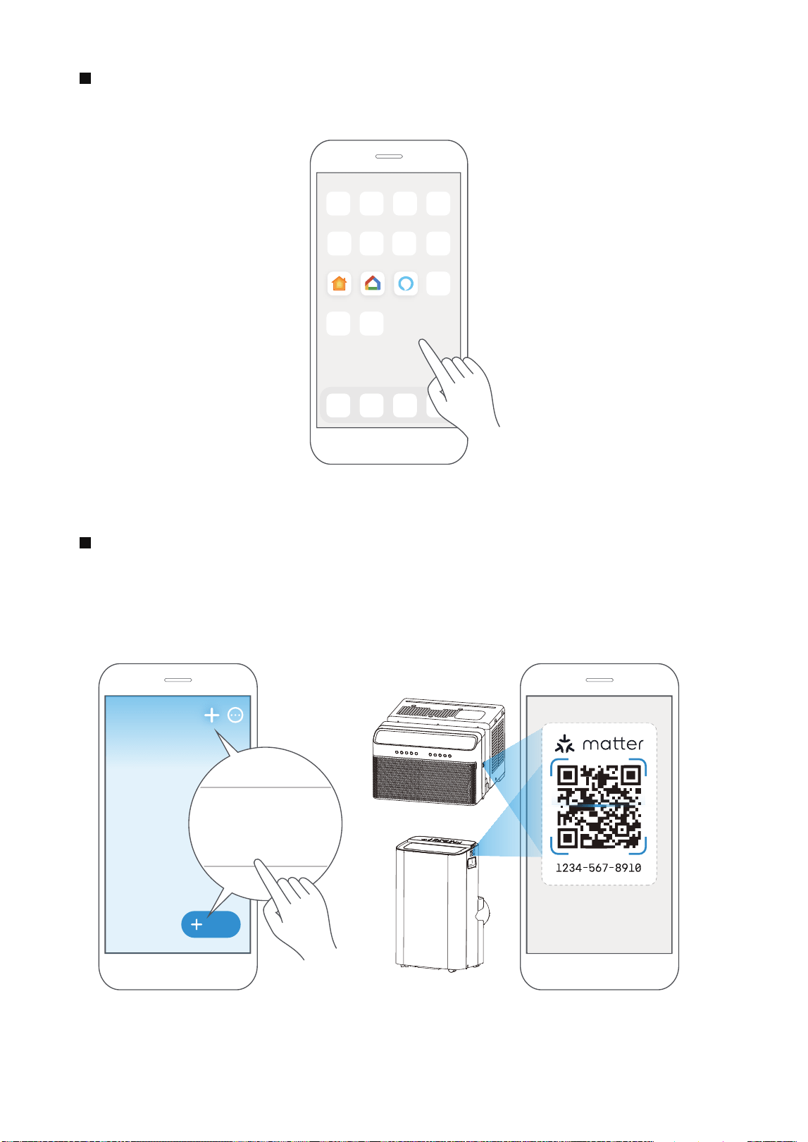
Open the Alexa, Google Home, Apple Home app on your mobile device.
Step 4: Open app
Apple Home Google Home Alexa
Tap the “+” and “Add Device/Accessory” or tap "+Add" in your app and then select Matter device
and scan the Matter QR code found on the side of the AC device. Follow the respective instructions
in the Alexa, Google Home or Apple Home app to complete the pairing process.
Step 5: Scan matter QR code
Add
Add Device/Accessory
scan
Matter QR code
38
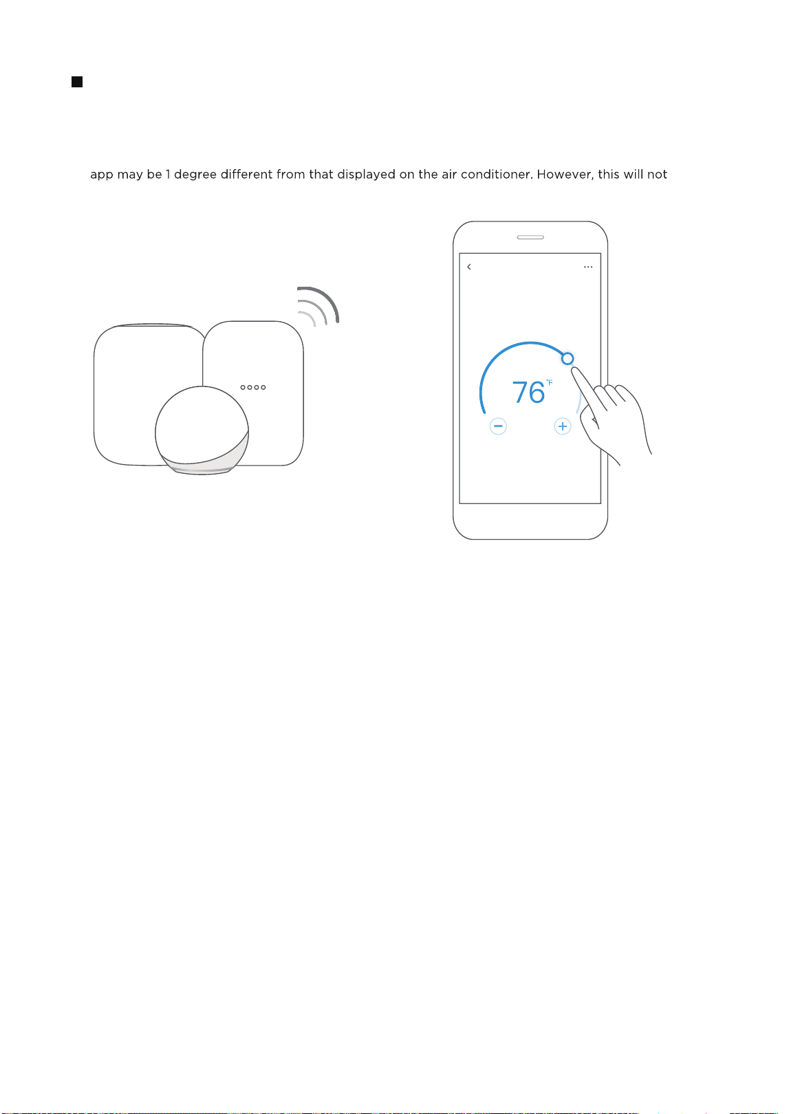
After pairing is successful, you can control your AC’s temperature and mode settings, etc. through
the respective ecosystem app and smart speaker.
Due to a compatibility issue, the temperature value shown in the Alexa, Google Home or Apple Home
impact the device's ability to cool the room.
Step 6: Control device
Air conditioner
39
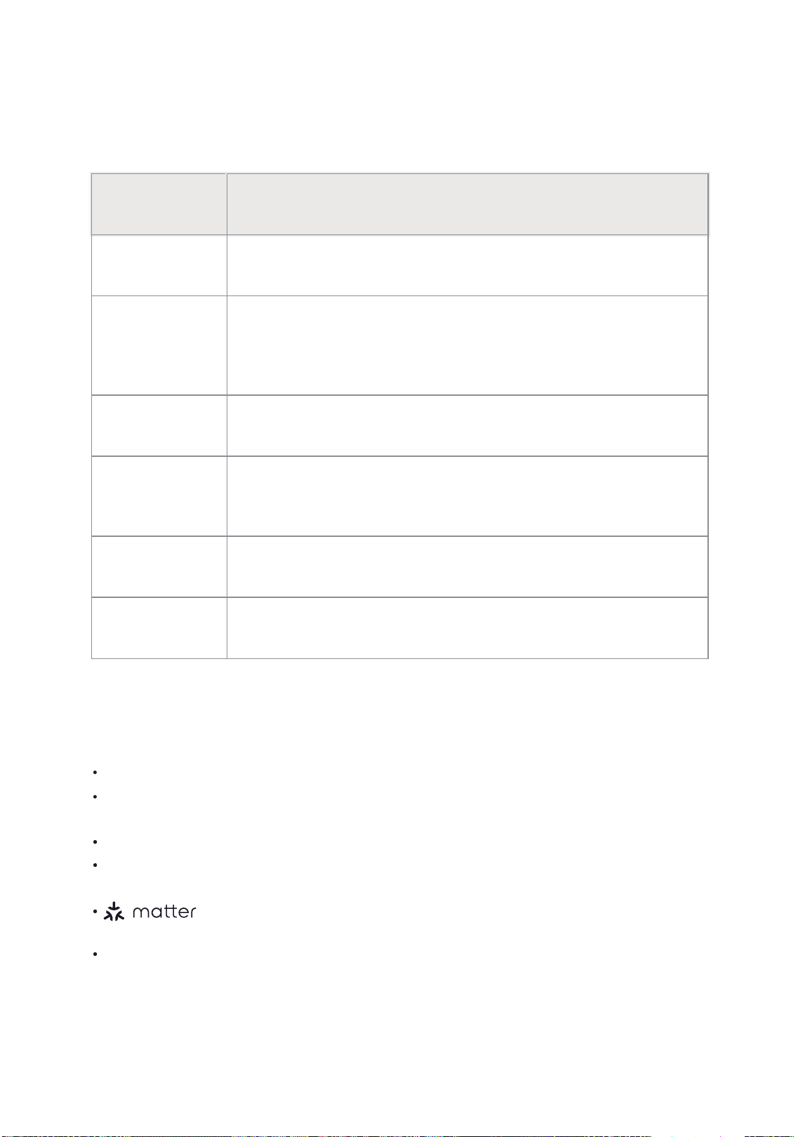
NOTE:
The functions shown in the Alexa, Google Home or Apple Home apps may change with updates to
their products or apps.
Setup processes and features may vary between ecosystems.
Make sure the Matter enabled app is up to date to ensure the best experience.
Periodically, we will update the device’s software to improve the experience.
Device software updates can be accomplished through the SmartHome app.
is developed by the Connectivity Standards Alliance TM. This
brand, related logos,
and marks are trademarks of the Alliance, all rights reserved.
App & Smart Speakers can support Matter only when using these
versions or above.
9094439556
Google Play services min version: 22.36.15
Google Home app (GHA) min version: 2.58.24.1-dogfood
Google Hub firmware min version: 1.56.324896
(appears on hub as Chromecast firmware version)
2.2.536317
16.5
Device Version
iOS 16.5iPhone
Apple Home
Pod
Alexa Echo
Device
Android
Google
Home Hub
Alexa App
Use of the Works with Apple badge means that an accessory has been designed to work specifically
with the technology identified in the badge and has been certified by the developer to meet Apple’s
performance standards.
Apple is not responsible for the operation of this device or its compliance with safety and regulatory
standards.
This device complies with Part 15 of the FCC Rules and Industry Canada’s licenceexempt
RSSs.
Operation is subject to the following two conditions:
This equipment has been tested and found to comply with the limits for a Class B digital
device, pursuant to part 15 of the FCC Rules. These limits are designed to provide
reasonable protection against harmful interference in a residential installation. This
equipment generates, uses and can radiate radio frequency energy and, if not installed
and used in accordance with the instructions, may cause harmful interference to radio
communications. However, there is no guarantee that interference will not occur in a
particular installation. If this equipment does cause harmful interference to radio or
television reception, which can be determined by turning the equipment off and on, the
user is encouraged to try to correct the interference by one or more of the following
measures:
--Reorient or relocate the receiving antenna.
--Increase the separation between the equipment and receiver.
--Connect the equipment into an outlet on a circuit different from that to which the
receiver is connected.
--Consult the dealer or an experienced radio/TV technician for help.
Hereby, we declare that this AC is in compliance with the essential requirements and
other relevant provisions of RE Directive 2014/53/EU. A copy of the full DoC is attached
(European Union products only).
Only operate the device in accordance with the instructions supplied. Changes or
could void the user's authority to operate the equipment.This device complies with FCC
radiation exposure limits set forth for an uncontrolled environment. In order to avoid the
possibility of exceeding the FCC radio frequency exposure limits, human proximity to the
antenna shall not be less than 20cm (8 inches) during normal operation.
(1) This device may not cause interference;and
(2) This device must acceptany interference,including interference that may cause
undesired operation of the device.
Declaration of conformity
FCC ID: 2ADQOMDNA23
IC: 12575A-MDNA23
NOTE:
40
CLEANING AND MAINTENANCE
Air Filter Cleaning
Cabinet Cleaning
Winter Storage
The air lter should be checked at least once every two
weeks to see if cleaning is necessary. Trapped particles in
the lter can build up and cause an accumulation of frost
on the cooling coils and reduce performance.
• Grasp the lter by the center and pull up and out.
• Wash the lter using warm water. Rinse lter thoroughly.
• Gently shake excess water from the lter. Be sure the
lter is thoroughly dry before replacing.
• Instead of washing, you may also vacuum the lter clean
rather than washing.
• Be sure to unplug the air conditioner to prevent shock or re hazard. The cabinet and front may be
dusted with an oil-free cloth or washed with a cloth dampened in a solution of warm water and mild liquid
dishwashing detergent. Rinse thoroughly and wipe dry.
• Never use harsh cleansers, wax, or polish on the cabinet front.
• Be sure to wring excess water from the cloth before wiping around the controls. Excess water in or around
the controls will cause damage to the air conditioner.
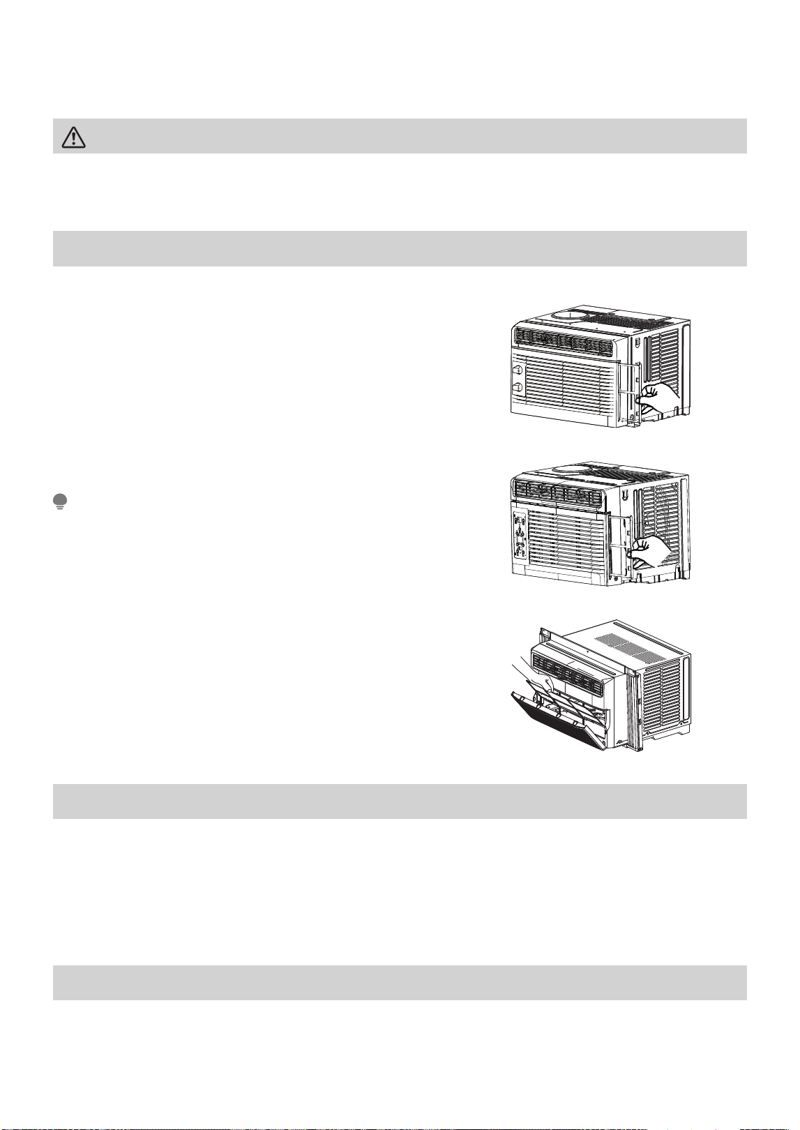
If you plan to store the air conditioner during the winter, remove it carefully from the window according to the
installation instructions. Cover the unit with plastic or return it to the original carton.
CAUTION
Clean your air conditioner occasionally to keep it looking new. Be sure to unplug the unit before cleaning to
prevent shock or re hazards.
Never use hot water over 104°F (40°C) to clean the air lter.
Never attempt to operate the unit without the air lter.
NOTE
41
MAW05 Models Only
MAW08/10 Models
MAW06 Models Only
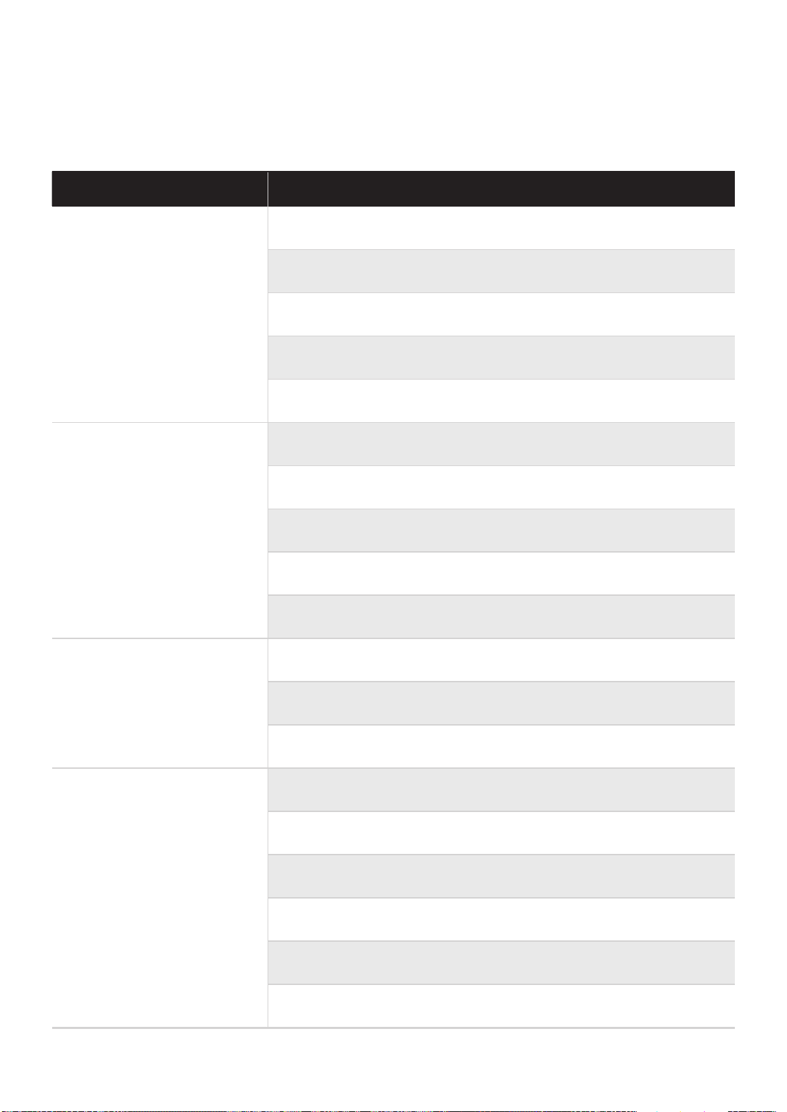
TROUBLESHOOTING TIPS
Problem Solution
Air conditioner does not start.
Wall plug disconnected. Push plug rmly into wall outlet.
Circuit breaker tripped. Reset circuit breaker.
Check if the light on the plug is on. If it is off, press the RESET button.
Power is OFF. Turn power ON.
Unit turned off and then on quickly. Turn unit off and wait 3 minutes
before restarting.
Air from unit does not feel cold
enough.
Room temperature below 62°F (17°C). Cooling may not occur until room
temperature rises above 62°F (17°C).
Temperature sensor behind the air lter is touching the cold coil. Try to
move it so it does not contact the cold coil.
Reset to a lower temperature.
Compressor shut-off by changing modes. Wait approximately 3 minutes
and listen for compressor to restart when set in the COOL mode.
Check for potential obstructions blocking the outdoor intake/exhaust.
Clear any obstructions.
Air conditioner cooling, but room
is too warm - ice forming on
cooling coil behind air lter.
Outdoor temperature below 64°F (18°C). To defrost the coil, set to FAN
ONLY mode.
Air lter may be dirty. Clean lter. Refer to Cleaning and Maintenance
section. To defrost, set to FAN ONLY mode.
Thermostat set too cold for night-time cooling. To defrost the coil, set to
FAN ONLY mode. Then, set temperature to a higher setting.
Air conditioner cooling, but room
is too warm - NO ice forming on
cooling coil behind air lter.
Dirty or restricted air lter. Clean lter. Refer to Cleaning and Maintenance
section. To defrost, set to FAN ONLY mode.
Temperature is set too high, set temperature to a lower setting.
Air directional louvers positioned improperly. Position louvers for better
air distribution.
Front of unit is blocked by drapes, blinds, furniture, etc. - restricts air
distribution. Clear obstruction in front of unit.
Any open doors, windows, or registers may allow cold air to escape. Close
any doors, windows, or registers.
The room may be too warm. Allow additional time to remove “stored
heat” from walls, ceiling, oor and furniture.
Before calling for service, review this list. It may save you time and expense. This list includes common
occurrences that are not the result of defective workmanship or materials in this appliance.
42
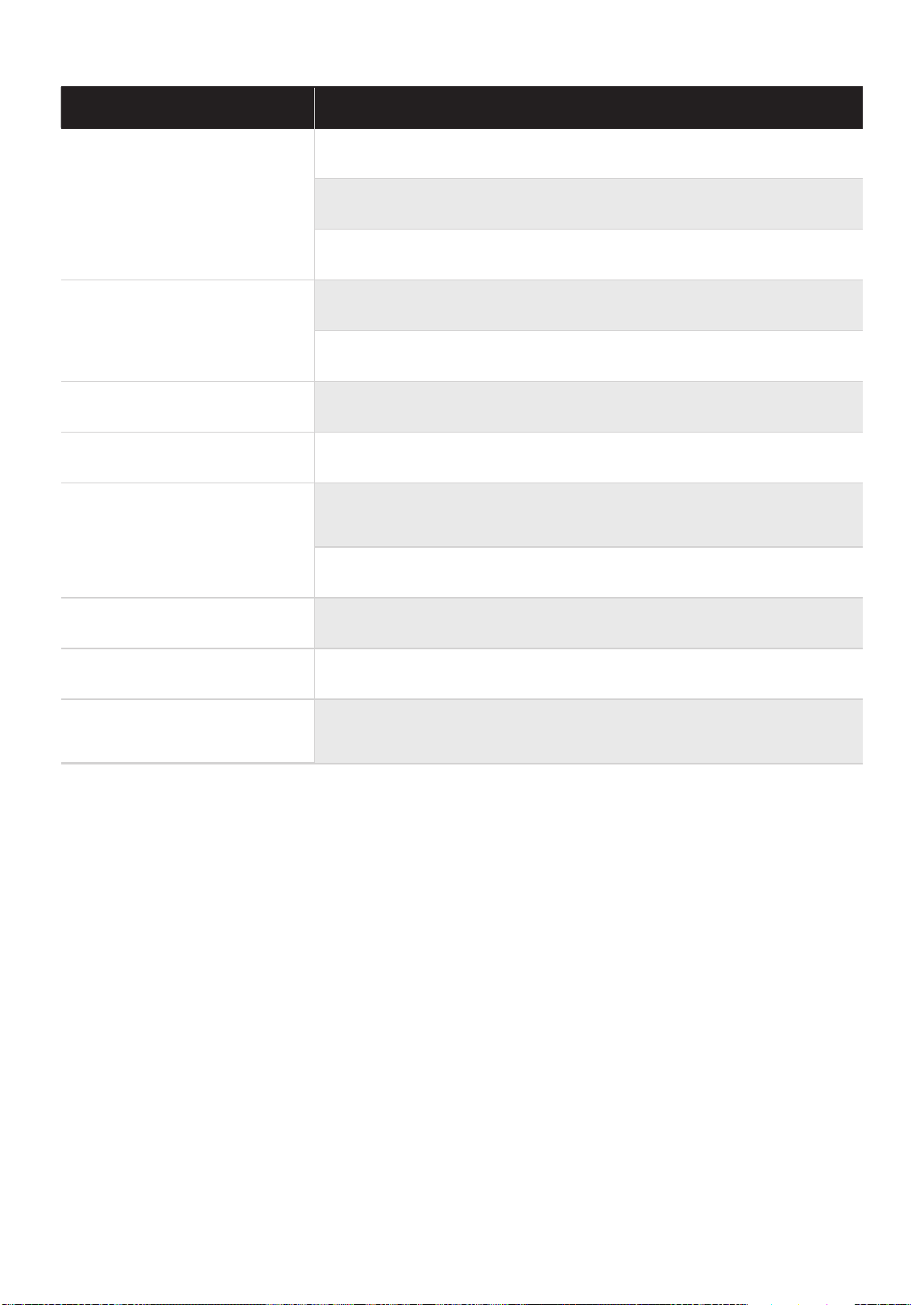
Problem Solution
Air conditioner turns on and off
rapidly.
Dirty air lter - air restricted. Clean air lter.
Outside temperature extremely hot. Set FAN speed to a higher setting to
bring air past cooling coils more frequently.
Check for potential obstructions blocking the outdoor intake/exhaust.
Clear any obstructions.
Noise when unit is cooling.
Air movement sound. This is normal. If too loud, set to a slower FAN
setting.
Window vibration - poor installation. Refer to installation instructions or
check with installer.
Water dripping INSIDE when unit
is cooling.
Improper installation. Tilt air conditioner slightly to the outside to allow water
drainage. Refer to installation instructions - check with installer.
Water dripping OUTSIDE when
unit is cooling.
Unit removing large quantity of moisture from humid room. This is normal
during excessively humid days.
Remote sensing deactivating
prematurely (some models).
Remote control not located within range. Place remote control within
16.4 feet & 180°, radius of the front of the unit, and pointed in the general
direction of the air conditioner unit.
Remote control signal obstructed. Remove obstruction.
Room too cold. Temperature setting too low. Increase temperature setting.
Noise when unit starts.
A “da-da” sound may occur for thirty seconds when the unit is turned on
due to the compressor starting. It is normal.
Unit will not connect to WiFi
or App does not work (some
models).
For additional support and troubleshooting tips, visit the “Help” tab
within the SmartHome app.
43


CWS002IU-TYN8(GF)
16120300A31764
20231221