Loading ...
Loading ...
Loading ...
4
Other items that are needed (not included)
• Mounting screws
Installation method Recommended screw*
1
Minimum
pull-out
strength*
2
Directly mount the camera onto the installation
surface.
M4 × 16 mm {5/8 inches}
4 pcs. or 2 pcs.*
3
196 N {44 lbf}
*1 Select screws according to the material of the location that the camera will be mounted
to. In this case, wood screws and nails should not be used.
*2 This value indicates the minimum pull-out strength required value per screw.
For information about the minimum pull-out strength, refer to our technical information
website <Control No.: C0120>.
*3 The screw length is an example when installing the camera on a robust ceiling or wall
with a thickness of 20 mm {25/32 inches} or more.
• 5 mm (distance between two parallel sides of a hexagon) hex wrench
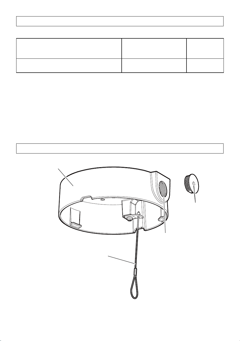
Parts and functions
This product
Installed auxiliary wire
Female thread
cap for conduit
Conduit cable access hole
Compliant with ANSI NPSM
(parallel pipe threads) 3/4 or
ISO 228-1 (parallel pipe threads) G3/4
Loading ...
Loading ...
Loading ...