
Portable Radar Speed Detector
User Manual

Legal Informaon
©2021 Hangzhou Hikvision Digital Technology Co., Ltd. All rights reserved.
About this Manual
The Manual includes instrucons for using and managing the Product. Pictures, charts, images and
all other informaon hereinaer are for descripon and explanaon only. The informaon
contained in the Manual is subject to change, without noce, due to rmware updates or other
reasons. Please nd the latest version of this Manual at the Hikvision website ( hps://
www.hikvision.com/ ).
Please use this Manual with the guidance and assistance of professionals trained in supporng the
Product.
Trademarks
and other Hikvision's trademarks and logos are the properes of
Hikvision in various jurisdicons.
Other trademarks and logos menoned are the properes of their respecve owners.
Disclaimer
TO THE MAXIMUM EXTENT PERMITTED BY APPLICABLE LAW, THIS MANUAL AND THE PRODUCT
DESCRIBED, WITH ITS HARDWARE, SOFTWARE AND FIRMWARE, ARE PROVIDED "AS IS" AND "WITH
ALL FAULTS AND ERRORS". HIKVISION MAKES NO WARRANTIES, EXPRESS OR IMPLIED, INCLUDING
WITHOUT LIMITATION, MERCHANTABILITY, SATISFACTORY QUALITY, OR FITNESS FOR A PARTICULAR
PURPOSE. THE USE OF THE PRODUCT BY YOU IS AT YOUR OWN RISK. IN NO EVENT WILL HIKVISION
BE LIABLE TO YOU FOR ANY SPECIAL, CONSEQUENTIAL, INCIDENTAL, OR INDIRECT DAMAGES,
INCLUDING, AMONG OTHERS, DAMAGES FOR LOSS OF BUSINESS PROFITS, BUSINESS
INTERRUPTION, OR LOSS OF DATA, CORRUPTION OF SYSTEMS, OR LOSS OF DOCUMENTATION,
WHETHER BASED ON BREACH OF CONTRACT, TORT (INCLUDING NEGLIGENCE), PRODUCT LIABILITY,
OR OTHERWISE, IN CONNECTION WITH THE USE OF THE PRODUCT, EVEN IF HIKVISION HAS BEEN
ADVISED OF THE POSSIBILITY OF SUCH DAMAGES OR LOSS.
YOU ACKNOWLEDGE THAT THE NATURE OF THE INTERNET PROVIDES FOR INHERENT SECURITY
RISKS, AND HIKVISION SHALL NOT TAKE ANY RESPONSIBILITIES FOR ABNORMAL OPERATION,
PRIVACY LEAKAGE OR OTHER DAMAGES RESULTING FROM CYBER-ATTACK, HACKER ATTACK, VIRUS
INFECTION, OR OTHER INTERNET SECURITY RISKS; HOWEVER, HIKVISION WILL PROVIDE TIMELY
TECHNICAL SUPPORT IF REQUIRED.
YOU AGREE TO USE THIS PRODUCT IN COMPLIANCE WITH ALL APPLICABLE LAWS, AND YOU ARE
SOLELY RESPONSIBLE FOR ENSURING THAT YOUR USE CONFORMS TO THE APPLICABLE LAW.
ESPECIALLY, YOU ARE RESPONSIBLE, FOR USING THIS PRODUCT IN A MANNER THAT DOES NOT
INFRINGE ON THE RIGHTS OF THIRD PARTIES, INCLUDING WITHOUT LIMITATION, RIGHTS OF
PUBLICITY, INTELLECTUAL PROPERTY RIGHTS, OR DATA PROTECTION AND OTHER PRIVACY RIGHTS.
YOU SHALL NOT USE THIS PRODUCT FOR ANY PROHIBITED END-USES, INCLUDING THE
DEVELOPMENT OR PRODUCTION OF WEAPONS OF MASS DESTRUCTION, THE DEVELOPMENT OR
Portable Radar Speed Detector User Manual
i

PRODUCTION OF CHEMICAL OR BIOLOGICAL WEAPONS, ANY ACTIVITIES IN THE CONTEXT RELATED
TO ANY NUCLEAR EXPLOSIVE OR UNSAFE NUCLEAR FUEL-CYCLE, OR IN SUPPORT OF HUMAN
RIGHTS ABUSES.
IN THE EVENT OF ANY CONFLICTS BETWEEN THIS MANUAL AND THE APPLICABLE LAW, THE LATER
PREVAILS.
Portable Radar Speed Detector User Manual
ii

Regulatory Informaon
FCC Informaon
Please take aenon that changes or modicaon not expressly approved by the party responsible
for compliance could void the user's authority to operate the equipment.
FCC compliance: This equipment has been tested and found to comply with the limits for a Class A
digital device, pursuant to part 15 of the FCC Rules. These limits are designed to provide
reasonable protecon against harmful interference when the equipment is operated in a
commercial environment. This equipment generates, uses, and can radiate radio frequency energy
and, if not installed and used in accordance with the instrucon manual, may cause harmful
interference to radio communicaons. Operaon of this equipment in a residenal area is likely to
cause harmful interference in which case the user will be required to correct the interference at his
own expense.
FCC Condions
This device complies with part 15 of the FCC Rules. Operaon is subject to the following two
condions:
1. This device may not cause harmful interference.
2. This device must accept any interference received, including interference that may cause
undesired operaon.
EU Conformity Statement
This product and - if applicable - the supplied accessories too are marked with "CE"
and comply therefore with the applicable harmonized European standards listed
under the EMC Direcve 2014/30/EU, the LVD Direcve 2014/35/EU, the RoHS
Direcve 2011/65/EU.
2012/19/EU (WEEE direcve): Products marked with this symbol cannot be
disposed of as unsorted municipal waste in the European Union. For proper
recycling, return this product to your local supplier upon the purchase of
equivalent new equipment, or dispose of it at designated collecon points. For
more informaon see: www.recyclethis.info
2006/66/EC (baery direcve): This product contains a baery that cannot be
disposed of as unsorted municipal waste in the European Union. See the product
documentaon for specic baery informaon. The baery is marked with this
symbol, which may include leering to indicate cadmium (Cd), lead (Pb), or
mercury (Hg). For proper recycling, return the baery to your supplier or to a
designated collecon point. For more informaon see: www.recyclethis.info
Industry Canada ICES-003 Compliance
This device meets the CAN ICES-3 (A)/NMB-3(A) standards requirements.
Portable Radar Speed Detector User Manual
iii
Symbol Convenons
The symbols that may be found in this document are dened as follows.
Symbol Descripon
Danger
Indicates a hazardous situaon which, if not avoided, will or could
result in death or serious injury.
Cauon
Indicates a potenally hazardous situaon which, if not avoided, could
result in equipment damage, data loss, performance degradaon, or
unexpected results.
Note
Provides addional informaon to emphasize or supplement
important points of the main text.
Portable Radar Speed Detector User Manual
iv

Safety Instrucon
Regulatory Informaon
This is a class A product and may cause radio interference in which case the user may be required
to take adequate measures.
Laws and Regulaons
Use of the product must be in strict compliance with the local laws and regulaons. Please shut
down the device in prohibited area.
Power Supply
• Use of the product must be in strict compliance with the local electrical safety regulaons.
• Use the power adapter provided by qualied manufacturer. Refer to the product specicaon for
detailed power requirements.
• It is recommended to provide independent power adapter for each device as adapter overload
may cause over-heang or a re hazard.
• Make sure that the power has been disconnected before you wire, install, or disassemble the
device in the authorized way according to the descripon in the manual.
• To avoid electric shock, DO NOT directly touch exposed contacts and components once the
device is powered up.
• DO NOT use damaged power supply devices (e.g., cable, power adapter, etc.) to avoid electric
shock, re hazard, and explosion.
• DO NOT directly cut the power supply to shut down the device. Please shut down the device
normally and then unplug the power cord to avoid data loss.
• The socket-outlet shall be installed near the equipment and shall be easily accessible.
• Make sure the power supply has been disconnected if the power adapter is idle.
• Connect to earth before connecng to the power supply.
Transportaon, Use, and Storage
• To avoid heat accumulaon, good venlaon is required for a proper operang environment.
• Store the device in dry, well-venlated, corrosive-gas-free, no direct sunlight, and no heang
source environment.
• Avoid re, water, and explosive environment when using the device.
• Install the device in such a way that lightning strikes can be avoided. Provide a surge suppressor
at the inlet opening of the equipment under special condions such as the mountain top, iron
tower, and forest.
• Keep the device away from magnec interference.
• Avoid device installaon on vibratory surfaces or places. Failure to comply with this may cause
device damage.
• DO NOT touch the heat dissipaon component to avoid burns.
Portable Radar Speed Detector User Manual
v

• DO NOT expose the device to extremely hot, cold, or humidity environments. For temperature
and humidity requirements, see device specicaon.
• No naked ame sources, such as lighted candles, should be placed on the equipment.
• DO NOT touch the sharp edges or corners.
• To prevent possible hearing damage, DO NOT listen at high volume levels for long periods.
Maintenance
• If smoke, odor, or noise arises from the device, immediately turn o the power, unplug the
power cable, and contact the service center.
• If the device cannot work properly, contact the store you purchased it or the nearest service
center. DO NOT disassemble or modify the device in the unauthorized way (For the problems
caused by unauthorized modicaon or maintenance, the company shall not take any
responsibility).
• Keep all packaging aer unpacking them for future use. In case of any failure occurred, you need
to return the device to the factory with the original packaging. Transportaon without the
original packaging may result in damage to the device and the company shall not take any
responsibility.
Network
• Please enforce the protecon for the personal informaon and the data security as the device
may be confronted with the network security problems when it is connected to the Internet.
Contact us if network security risks occur.
• Please understand that you have the responsibility to congure all the passwords and other
security sengs about the device, and keep your user name and password.
Lens
• DO NOT touch the lens with ngers directly in case the acidic sweat of the ngers erodes the
surface coang of the lens.
• DO NOT aim the lens at the strong light such as sun or incandescent lamp. The strong light can
cause fatal damage to the device.
Screen
Clean the screen with so and dry cloth or other substutes to wipe the interior and exterior
surface. DO NOT use alkaline detergents. Protect the screen from scratches.
Data
DO NOT disconnect the power during formang, uploading, and downloading. Or les may be
damaged.
Portable Radar Speed Detector User Manual
vi

Contents
Chapter 1 Introducon ............................................................................................................... 1
1.1 Product Introducon .............................................................................................................. 1
1.2 Key Feature ............................................................................................................................ 1
Chapter 2 Acvaon ................................................................................................................... 2
2.1 Default Informaon ............................................................................................................... 2
2.2 Acvate via SADP ................................................................................................................... 2
2.3 Acvate via Web Browser ...................................................................................................... 3
Chapter 3 Local Conguraon ..................................................................................................... 4
3.1 Login ...................................................................................................................................... 4
3.2 Set Radar Detecon Parameters ............................................................................................ 4
3.3 Vehicle Capture ...................................................................................................................... 7
3.3.1 Set Speed Parameters ................................................................................................... 7
3.3.2 Set Lane Line ................................................................................................................. 8
3.3.3 Set Measurement Mode ............................................................................................... 9
3.3.4 Set Capture Parameters ................................................................................................ 9
3.3.5 View Real-Time Picture ............................................................................................... 14
3.3.6 Search Picture ............................................................................................................. 14
3.3.7 Search Trac Stascs ................................................................................................ 15
3.4 Live View .............................................................................................................................. 16
3.5 Playback ............................................................................................................................... 17
3.6 Record and Capture ............................................................................................................. 18
3.6.1 Set Storage Path .......................................................................................................... 18
3.6.2 Set Quota .................................................................................................................... 21
3.6.3 Set Record Schedule ................................................................................................... 21
3.7 Encoding and Display ........................................................................................................... 22
3.7.1 Set Image Parameters ................................................................................................. 22
Portable Radar Speed Detector User Manual
vii

3.7.2 Set ICR ......................................................................................................................... 23
3.8 Network Conguraon ........................................................................................................ 23
3.8.1 Set IP Address ............................................................................................................. 23
3.8.2 Dial .............................................................................................................................. 24
3.8.3 Connect to Wi-Fi ......................................................................................................... 25
3.8.4 Set Wi-Fi Hotspot ........................................................................................................ 26
3.9 An-The Conguraon ...................................................................................................... 27
3.10 Maintenance ...................................................................................................................... 28
3.10.1 Manage User ............................................................................................................. 28
3.10.2 View Device Informaon ........................................................................................... 28
3.10.3 Search Log ................................................................................................................. 29
3.10.4 Upgrade Radar .......................................................................................................... 29
3.10.5 Upgrade System ........................................................................................................ 29
3.10.6 Reboot ...................................................................................................................... 30
3.10.7 Restore Parameters ................................................................................................... 30
3.10.8 Set NTP Synchronizaon ........................................................................................... 30
3.10.9 Debug Screen Display ................................................................................................ 31
3.10.10 Shutdown ................................................................................................................ 31
Chapter 4 Operaon via Web Browser ...................................................................................... 32
4.1 Login .................................................................................................................................... 32
4.2 Set Radar Detecon Parameters .......................................................................................... 32
4.3 Vehicle Capture .................................................................................................................... 34
4.3.1 Set Side-Mounted Speed Detecon ............................................................................ 34
4.3.2 Set Capture Parameters .............................................................................................. 36
4.3.3 View Real-Time Picture ............................................................................................... 45
4.3.4 Search Picture ............................................................................................................. 47
4.4 Live View and Local Conguraon ....................................................................................... 47
4.4.1 Live View ..................................................................................................................... 47
Portable Radar Speed Detector User Manual
viii

4.4.2 Local Conguraon ..................................................................................................... 49
4.5 Record and Capture ............................................................................................................. 50
4.5.1 Set Storage Path .......................................................................................................... 50
4.5.2 Set Quota .................................................................................................................... 54
4.5.3 Set Record Schedule ................................................................................................... 54
4.6 Encoding and Display ........................................................................................................... 55
4.6.1 Set Video Encoding Parameters .................................................................................. 55
4.6.2 Set Image Parameters ................................................................................................. 57
4.6.3 Set ICR ......................................................................................................................... 59
4.6.4 Set ROI ........................................................................................................................ 59
4.6.5 Set OSD ....................................................................................................................... 61
4.7 Network Conguraon ........................................................................................................ 62
4.7.1 Set IP Address ............................................................................................................. 62
4.7.2 Dial .............................................................................................................................. 63
4.7.3 Connect to Wi-Fi ......................................................................................................... 64
4.7.4 Set Wi-Fi Hotspot ........................................................................................................ 65
4.7.5 Connect to EHome Plaorm ....................................................................................... 66
4.7.6 Set DDNS ..................................................................................................................... 67
4.7.7 Set Port ....................................................................................................................... 67
4.8 Serial Port Conguraon ...................................................................................................... 68
4.8.1 Set RS-485 ................................................................................................................... 68
4.8.2 Set RS-232 ................................................................................................................... 69
4.9 Alarm ................................................................................................................................... 70
4.9.1 Set Excepon Alarm .................................................................................................... 70
4.9.2 Set An-The .............................................................................................................. 70
4.10 Safety Management ........................................................................................................... 71
4.10.1 Manage User ............................................................................................................. 71
4.10.2 Enable User Lock ....................................................................................................... 72
Portable Radar Speed Detector User Manual
ix

4.10.3 Set HTTPS .................................................................................................................. 72
4.10.4 Set SSH ...................................................................................................................... 73
4.11 Maintenance ...................................................................................................................... 73
4.11.1 View Device Informaon ........................................................................................... 73
4.11.2 Search Log ................................................................................................................. 73
4.11.3 Upgrade .................................................................................................................... 74
4.11.4 Reboot ...................................................................................................................... 74
4.11.5 Restore Parameters ................................................................................................... 74
4.11.6 Synchronize Time ...................................................................................................... 75
4.11.7 Export Parameters .................................................................................................... 75
4.11.8 Import Conguraon File .......................................................................................... 76
4.11.9 Export Violaon Type File ......................................................................................... 76
4.11.10 Export Debug File .................................................................................................... 76
Appendix A. Communicaon Matrix and Device Command ...................................................... 78
Portable Radar Speed Detector User Manual
x

Chapter 1 Introducon
1.1 Product Introducon
Portable radar speed detector (hereinaer referred to as the "device") is a speed detecon device
that integrates speed detecon, image processing, intelligent analysis, license plate recognion,
storage, and display. It supports automac speed detecon of vehicles in a specic direcon and
violaon capture.
1.2 Key Feature
• License plate recognion.
• Radar-triggered capture.
• Wide-range speed detecon.
• High vehicle capture rate.
• Connuous violaon capture.
• Picture composion.
• Built-in lithium baery for power supply.
• Adjustable lens angle.
Portable Radar Speed Detector User Manual
1
Chapter 2 Acvaon
For the rst-me access, you need to acvate the device by seng an admin password. No
operaon is allowed before acvaon. The device supports mulple acvaon methods, such as
acvaon via SADP soware, web browser, and client soware.
Note
Refer to the user manual of client soware for the acvaon via client soware.
2.1 Default Informaon
The device default informaon is shown as below.
• Default IP address: 192.168.1.64
• Default user name: admin
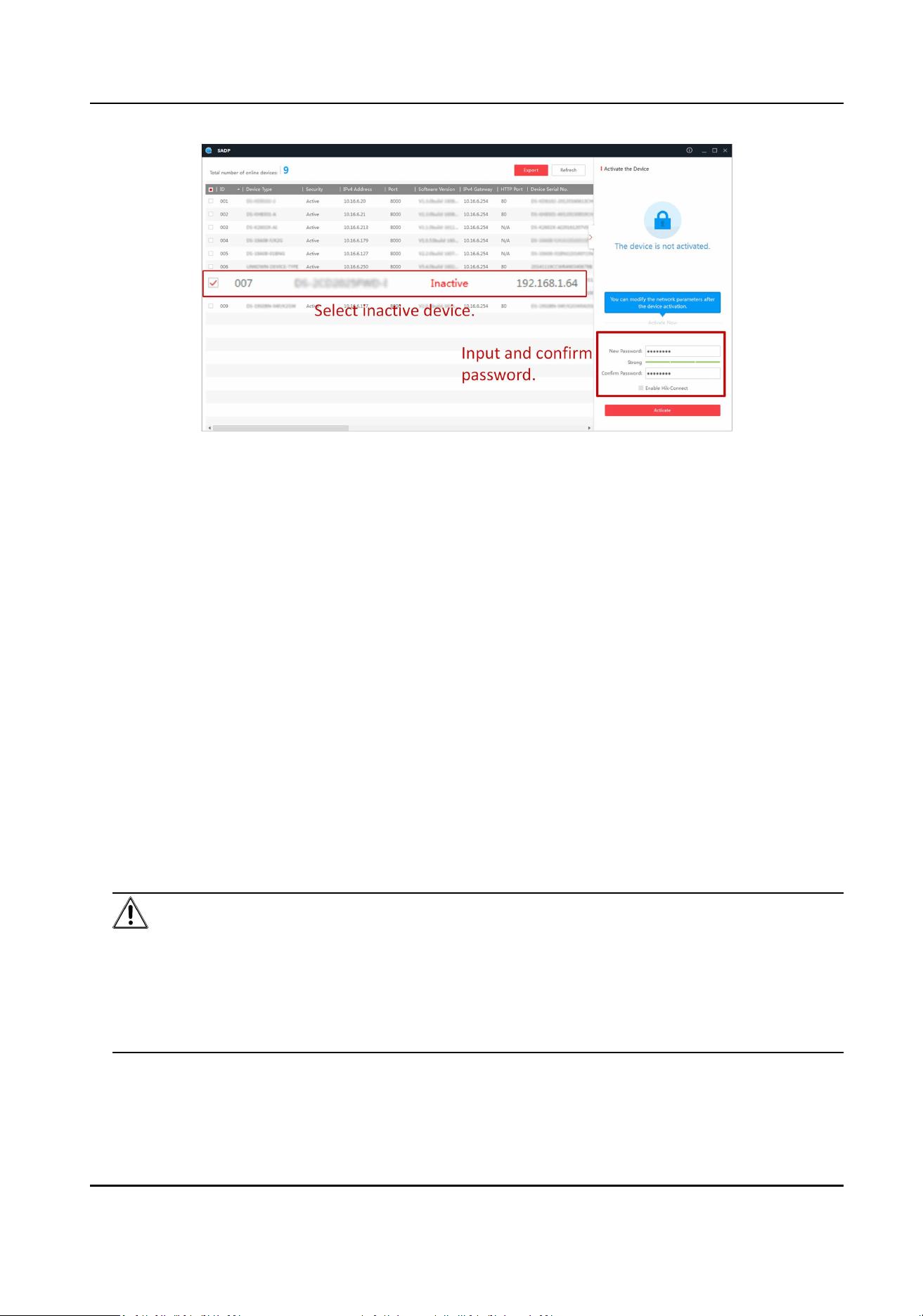
2.2 Acvate via SADP
SADP is a tool to detect, acvate, and modify the IP address of the device over the LAN.
Before You Start
• Get the SADP soware from the supplied disk or the ocial website ( hp://
www.hikvision.com/ ), and install it according to the prompts.
• The device and the computer that runs the SADP tool should belong to the same network
segment.
The following steps show how to acvate one device and modify its IP address. For batch acvaon
and IP address modicaon, refer to User Manual of SADP for details.
Steps
1. Run the SADP soware and search the online devices.
2. Find and select your device in online device list.
3. Enter a new password (admin password) and conrm the password.
Cauon
STRONG PASSWORD RECOMMENDED-We highly recommend you create a strong password of
your own choosing (using a minimum of 8 characters, including upper case leers, lower case
leers, numbers, and special characters) in order to increase the security of your product. And
we recommend you reset your password regularly, especially in the high security system,
reseng the password monthly or weekly can beer protect your product.
4. Click Acvate to start acvaon.
Portable Radar Speed Detector User Manual
2
Status of the device becomes Acve aer successful acvaon.
5. Modify IP address of the device.
1) Select the device.
2) Change the device IP address to the same network segment as your computer by either
modifying the IP address manually or checking Enable DHCP.
3) Enter the admin password and click Modify to acvate your IP address modicaon.
2.3 Acvate via Web Browser
Use web browser to acvate the device. For the device with the DHCP enabled by default, use
SADP soware or client soware to acvate the device.
Before You Start
Ensure the device and the computer connect to the same LAN.
Steps
1. Change the IP address of your computer to the same network segment as the device.
2. Open the web browser, and enter the default IP address of the device to enter the acvaon
interface.
3. Create and conrm the admin password.
Cauon
STRONG PASSWORD RECOMMENDED-We highly recommend you create a strong password of
your own choosing (using a minimum of 8 characters, including upper case leers, lower case
leers, numbers, and special characters) in order to increase the security of your product. And
we recommend you reset your password regularly, especially in the high security system,
reseng the password monthly or weekly can beer protect your product.
4. Click OK to complete acvaon.
5. Go to the network sengs interface to modify IP address of the device.
Portable Radar Speed Detector User Manual
3
Chapter 3 Local Conguraon
The device supports local conguraon on the screen.
3.1 Login
You can log in to the device locally.
Before You Start
Power on the device.
Steps
1. Enter the user name and password.
2. Tap Login.
3. Oponal: If you want to log out, go to Sengs → User Management and tap Logout to log out.
Result
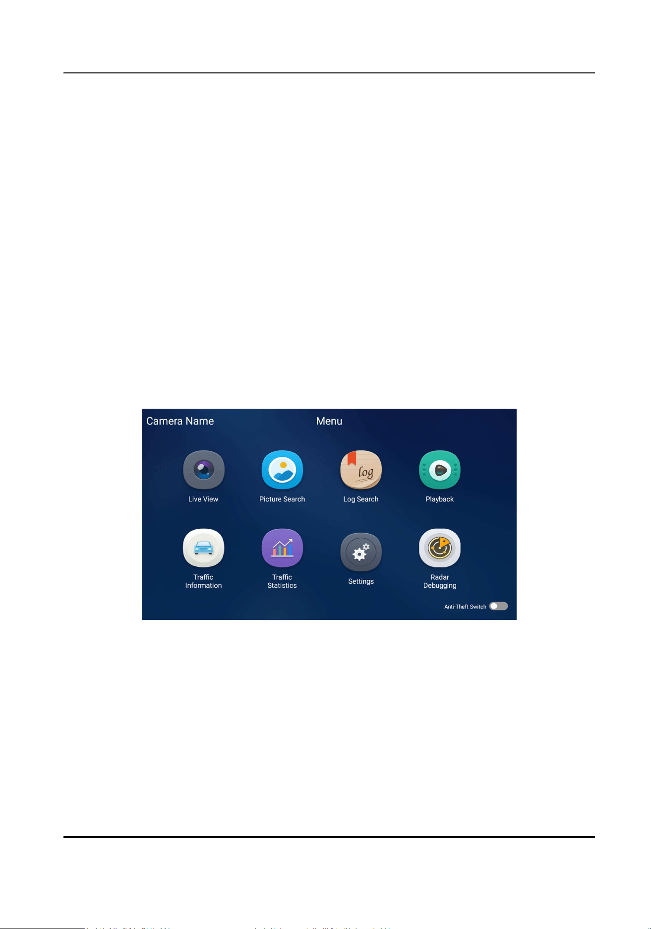
You will enter the main menu aer login.
Figure 3-1 Main Menu
3.2 Set Radar Detecon Parameters
Set radar detecon parameters to detect the vehicle speed via radar.
Steps
1. Tap Radar Debugging.
2. Set construcon parameters.
1) Tap Construcon Parameters.
Portable Radar Speed Detector User Manual
4

2) Set the parameters below.
Construcon Height
The construcon height of the radar. 1.5 m is recommended.
Construcon Angle
The angle between the radar and the road. 25° is recommended.
Lane Distance
Enter the distance between two lanes according to the actual condion.
Trigger Speed
If the vehicle speed exceeds the set value, capture will be triggered.
Trigger Mode
Head
Capture is triggered by the vehicle head. The vehicles from the approaching direcon
will be detected.
Tail
Capture is triggered by the vehicle tail. The vehicles from the leaving direcon will be
detected.
Head and Tail
Capture can be triggered by the vehicle head or tail. The vehicles from both the
approaching and leaving direcons will be detected.
Advanced Lane Sengs
Width of Lane X
Enter the lane width according to the actual condion.
Triggered X at
Capture will be triggered at the set distance of the lane if the speed exceeds the trigger
speed.
3) Tap Save.
Portable Radar Speed Detector User Manual
5
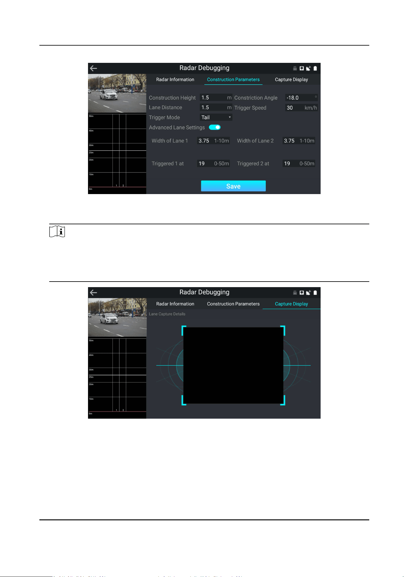
Figure 3-2 Set Construcon Parameters
3. Tap Capture Display to view the radar detecon eect.
Note
The live view and lanes on the le of the interface show if the radar tracks match with the
vehicles. The vehicle capture picture on the right of the interface shows the vehicle posion in
the captured picture. Adjust the construcon parameters unl the radar detecon eect
sases the requirement.
Figure 3-3 Capture Display
4. Oponal: Tap Radar Informaon to view the radar status.
Portable Radar Speed Detector User Manual
6
3.3 Vehicle Capture
3.3.1 Set Speed Parameters
Set the speed parameters to capture the violaon vehicle and check if the radar detecon is
normal.
Steps
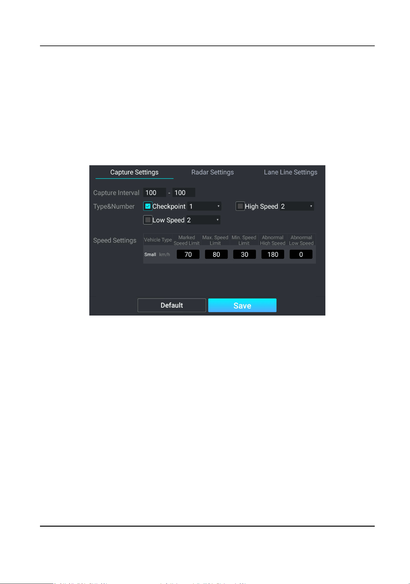
1. Go to Sengs → Applicaon Mode → Capture Sengs .
Figure 3-4 Set Speed Parameters
2. Set the parameters below.
Capture Interval
Pictures will be captured every set interval.
Type & Number
Check the capture type and select the number of captured pictures of this type.
Speed Sengs
Marked Speed Limit
The speed limit marked on the sign.
Max. Speed Limit
The allowable max. speed. If you have enabled high speed detecon, when the vehicle
speed exceeds the max. speed limit, capture will be triggered.
Min. Speed Limit
Portable Radar Speed Detector User Manual
7
The allowable min. speed. If you have enabled low speed detecon, when the vehicle
speed is lower than the min. speed limit, capture will be triggered.
Abnormal High Speed
When the radar detected speed exceeds the abnormal high speed, the radar detecon
will be regarded as excepon, and the soware will provide a normal speed randomly.
Abnormal Low Speed
When the radar detected speed is lower than the abnormal low speed, the radar
detecon will be regarded as excepon, and the soware will provide a normal speed
randomly.
3. Oponal: Tap Default to restore the parameters to the default sengs.
4. Tap Save.
3.3.2 Set Lane Line
You can draw the lane lines to detect trac status on the lanes.
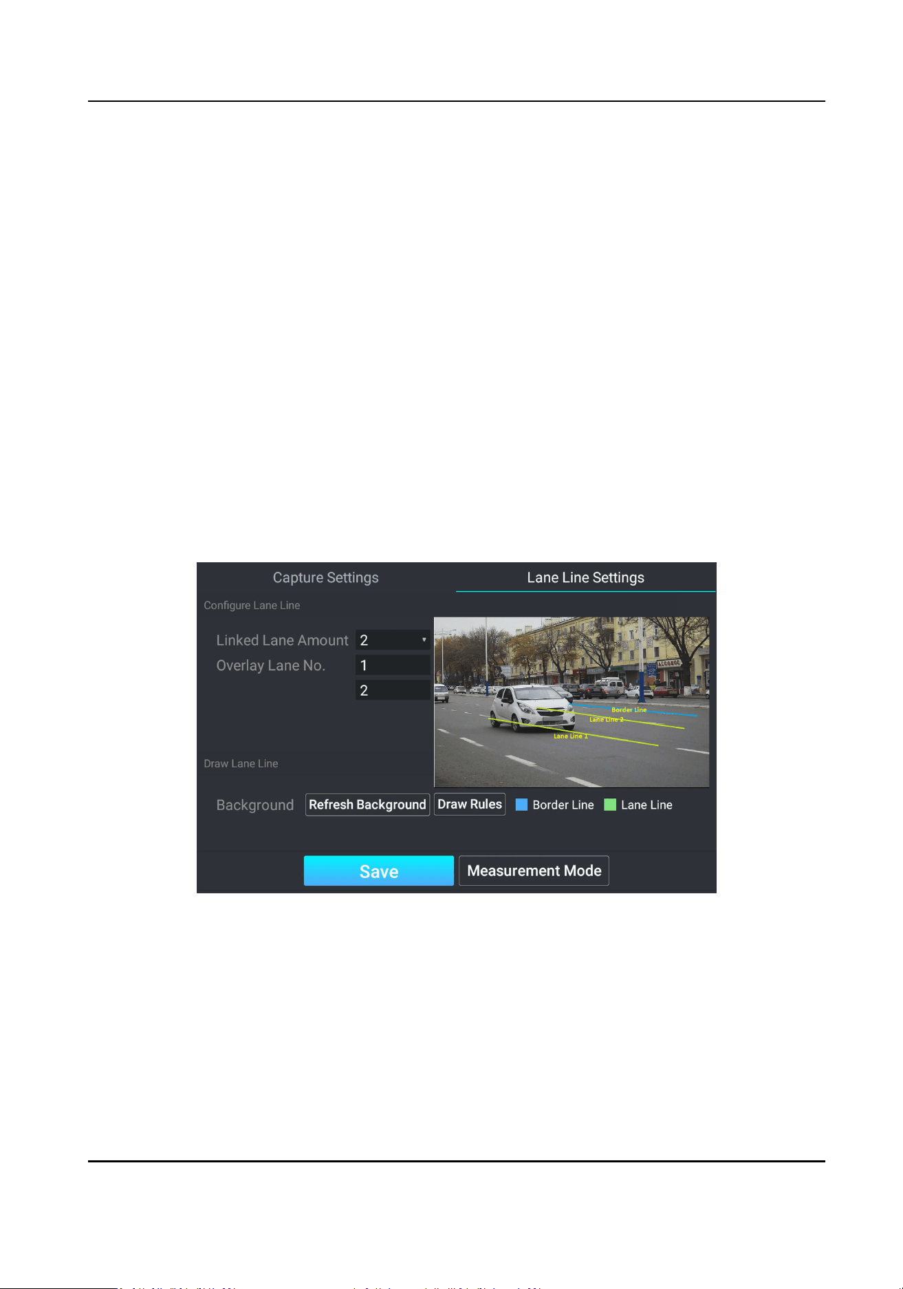
Steps
1. Go to Sengs → Applicaon Mode → Lane Line Sengs .
Figure 3-5 Set Lane Line
2. Set Linked Lane Amount and Overlay Lane No.
3. Tap Draw Rules to adjust the posions of the lane line(s) and border line, and tap Finish to
nish the drawing.
4. Oponal: If you have changed the scene, tap Refresh Background to refresh the background.
5. Click Save.
Portable Radar Speed Detector User Manual
8
3.3.3 Set Measurement Mode
You can measure the radar speed detecon accuracy.
Steps
1. Go to Sengs → Applicaon Mode → Lane Line Sengs .
2. Tap Measurement Mode.
3. Tap Click to detect speed.
Result
The detected speed will be shown on the interface.
3.3.4 Set Capture Parameters
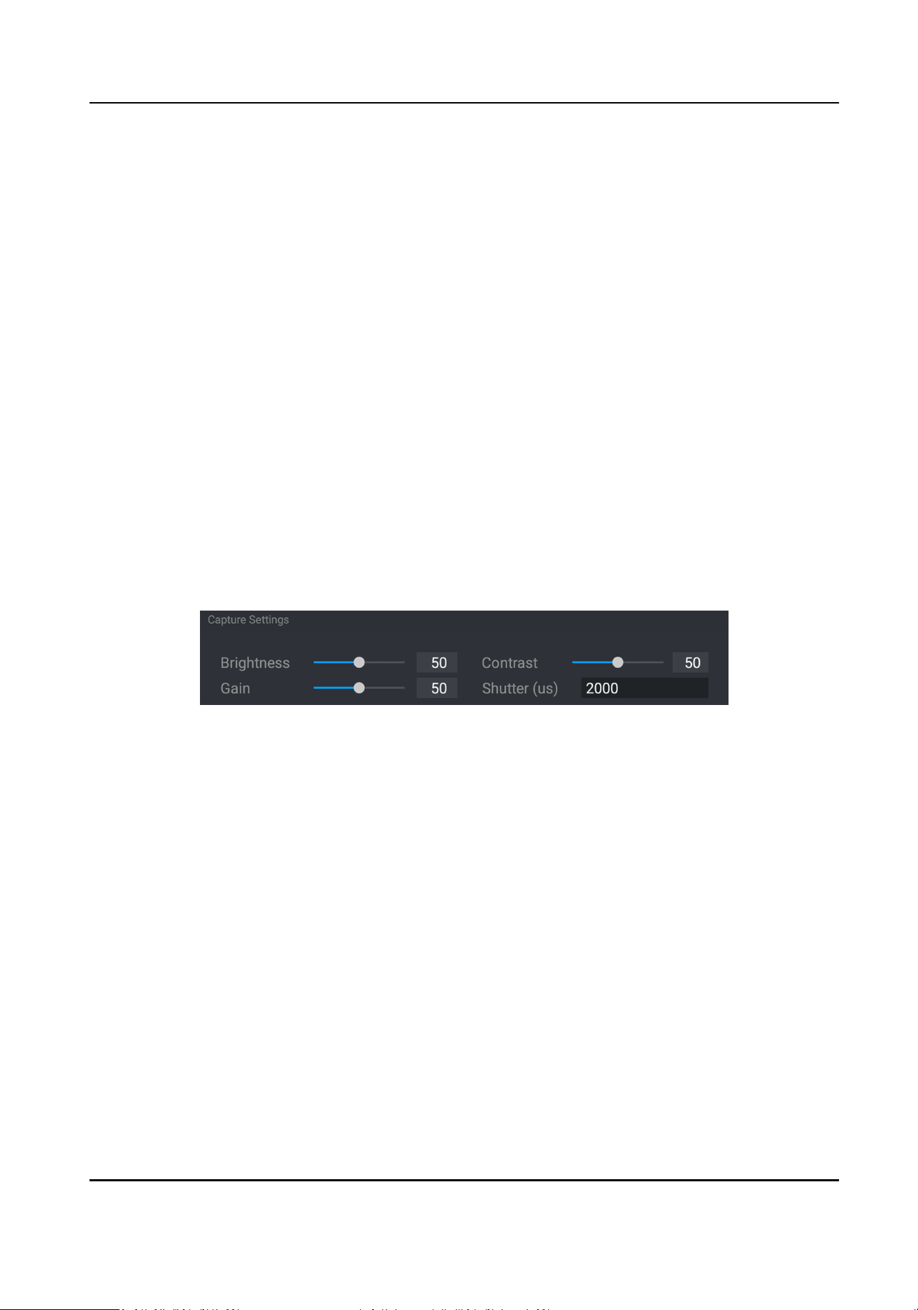
Set Captured Image Parameters
Set the parameters of captured images to raise the image quality.
Steps
1. Go to Sengs → Image Parameters → Capture Sengs .
Figure 3-6 Set Captured Image Parameters
2. Set the captured image parameters.
Brightness
The max. brightness of the image.
Contrast
The color contrast between the brightest part and darkest part of the image. Set it to adjust
the levels and permeability of the image.
Gain
The upper limit value of liming image signal amplicaon. It is recommended to set a high
gain if the illuminaon is not enough, and set a low gain if the illuminaon is enough.
Shuer
If the shuer speed is quick, the details of the moving objects can be displayed beer. If the
shuer speed is slow, the outline of the moving objects will be fuzzy and trailing will appear.
3. Tap Save.
Portable Radar Speed Detector User Manual
9
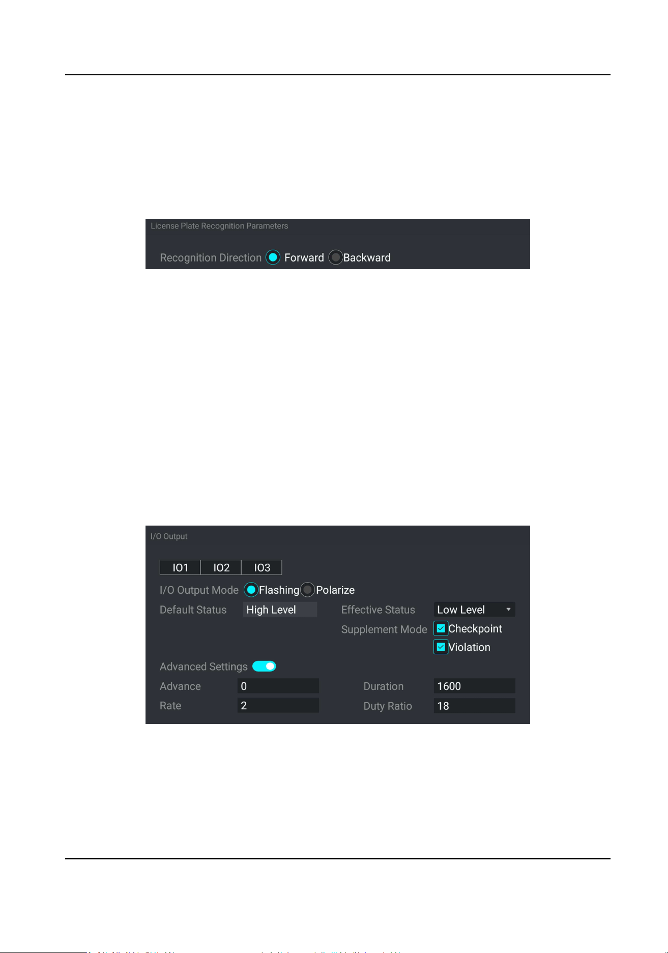
Set License Plate Recognion Parameters
When there are vehicles of dierent types passing from dierent direcons, set the license plate
recognion parameters.
Steps
1. Go to Sengs → Capture Parameters → License Plate Recognion Parameters .
Figure 3-7 Set License Plate Recognion Parameters
2. Select Recognion Direcon.
-
Select Forward when license plates of vehicles from the approaching direcon need to be
recognized.
-
Select Backward when license plates of vehicles from the leaving direcon need to be
recognized.
3. Tap Save.
Set Flash Light Parameters
Flash light can enhance the image stabilizaon and adjust the brightness and color temperature.
You can use ash light to supplement light at night or when the light is dim.
Steps
1. Go to Sengs → Capture Parameters → I/O Output .
Figure 3-8 Set Flash Light Parameters
2. Select the I/O output.
3. Select I/O Output Mode.
4. Select Eecve Status.
Portable Radar Speed Detector User Manual
10

High Level/Low Level
The eecve status should stay dierent with the default status for I/O to take eect. And
the default status changes according to the selecon of the eecve status. If you set the
eecve status as high level, the default level goes to low level. The selecon of high/low
level is applicable to burst light.
Pulse
If you set the eecve status as pulse, you can select the default status as high level or low
level. The selecon of pulse is applicable to strobe light.
5. Select Supplement Mode.
Checkpoint
The light compensaon works on every vehicle.
Violaon
The light compensaon works when there are violaons.
6. Enable Advanced Sengs and set the parameters.
Advance
It is the preact me [0 to 1000 μs] of the ash light, to ensure that the ash light is on when
capture is triggered.
Duraon
It is the dwell me [0 to 10000 μs] aer the ash light responds. The actual ash light
supplement me is the result of the dwell me minus advanced me.
Rate
It is the frequency mulplicaon of 25 of output pulse by strobe light, to keep the ash light
as constant. You can set it as default value.
Duty Rao
It is the me occupaon of the high level in a certain period. The higher the duty rao, the
brighter the ash light. High duty rao will cut life span of the ash light, and duty rao
under 25 is recommended. Set it when you select Eecve Status as Pulse.
7. Tap Save.
Set Image Composion
You can enable the image composion to composite several pictures into one to make it
convenient to view the violaon captured pictures.
Steps
1. Go to Sengs → Capture Parameters → Picture Composion .
Portable Radar Speed Detector User Manual
11
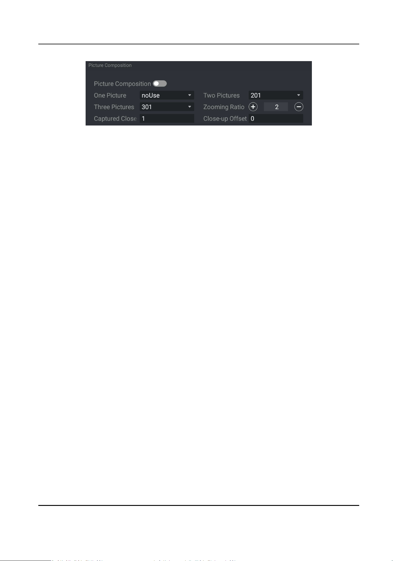
Figure 3-9 Set Image Composion
2. Enable Picture Composion.
3. Set composion types for dierent picture quanes.
4. Set other composion parameters.
Zooming Rao
The higher the value is, the larger the close-up is.
Captured Close-up Picture
The number of captured close-up pictures.
Close-up Oset
The device can capture close-up pictures according to the set oset when no license plate is
recognized.
5. Tap Save.
Set Capture Overlay
If you want to overlay informaon on the captured pictures, set capture overlay.
Steps
1. Go to Sengs → Text Overlay .
2. Select Overlay Mode as Captured Picture.
Portable Radar Speed Detector User Manual
12
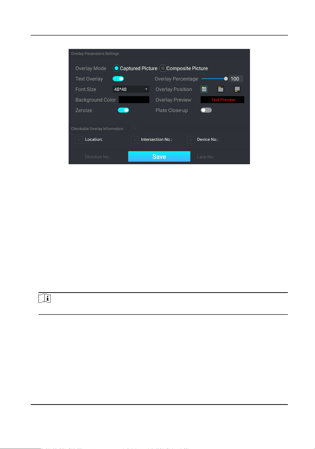
Figure 3-10 Set Capture Overlay
3. Enable Text Overlay.
4. Set the percentage, front size, color, overlay posion, etc.
Overlay Percentage
It is the percentage that the overlaid informaon occupies on the picture. For example, if you
set the percentage to 50, the overlaid informaon in a row will occupy up to half of the
image width, and the excess content will be overlaid from a new line.
Zeroize
When the overlaid number digits are smaller than the xed digits, 0 will be overlaid before
the overlaid number. E.g., the xed digits for lane No. is 2. If the lane No. is 1, 01 will be
overlaid on the picture.
Plate Close-up
Enable it to overlay the license plate close-up pictures on the captured pictures.
5. Check Checkable Overlay Informaon, and select the overlay informaon from the list.
Note
The overlay informaon varies with dierent models. The actual device prevails.
6. Tap Save.
Set Composite Picture Overlay
If you want to overlay informaon on the composite pictures, set composite picture overlay.
Steps
1. Go to Sengs → Text Overlay .
Portable Radar Speed Detector User Manual
13
2. Select Overlay Mode as Composite Picture.
3. Enable Text Overlay.
4. Set the font size, color, overlay posion, etc.
Overlay Percentage
It is the percentage that the overlaid informaon occupies on the picture. For example, if you
set the percentage to 50, the overlaid informaon in a row will occupy up to half of the
image width, and the excess content will be overlaid from a new line.
5. Check Checkable Overlay Informaon, and select the overlay informaon from the list.
Note
The overlay informaon varies with dierent models. The actual device prevails.
6. Tap Save.
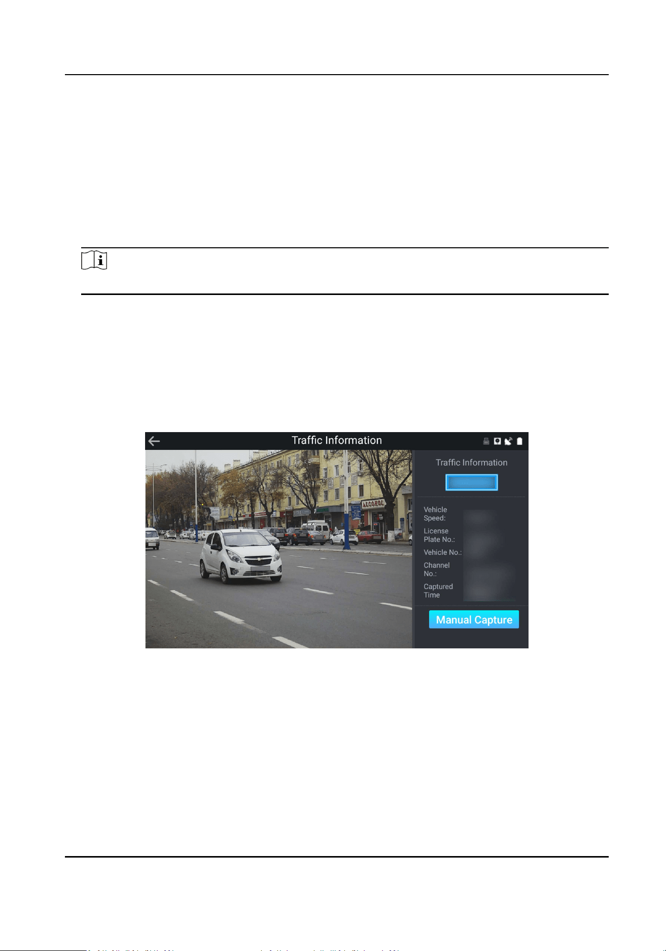
3.3.5 View Real-Time Picture
You can view the real-me captured pictures and license plate informaon.
Steps
1. Tap Trac Informaon.
Figure 3-11 View Real-Time Picture
2. View the captured scene picture and license plate picture.
3. View other informaon such as vehicle speed, license plate number, captured me, etc.
4. Oponal: Tap Manual Capture to capture a picture manually.
3.3.6 Search Picture
You can search the captured violaon pictures and export them to the USB ash drive.
Portable Radar Speed Detector User Manual
14
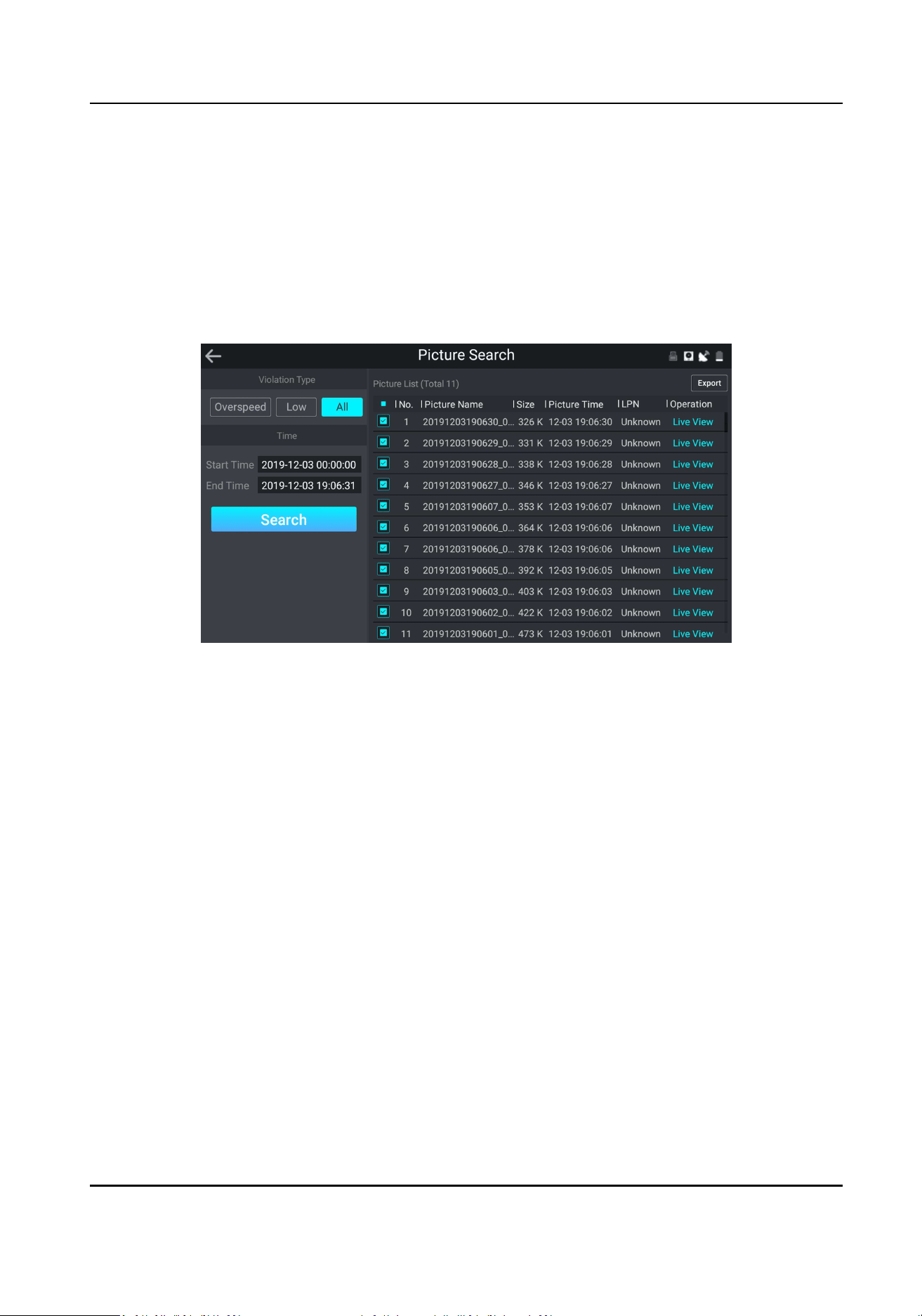
Before You Start
Connect a USB ash drive to the device.
Steps
1. Tap Picture Search.
2. Select the violaon type.
3. Set the start me and end me.
4. Tap Search.
The searched pictures informaon will be displayed in the picture list.
Figure 3-12 Search Picture
5. Oponal: Tap Live View to preview the selected picture.
6. Oponal: Check a picture or several pictures and tap Export to export it/them to the USB ash
drive.
3.3.7 Search Trac Stascs
You can search the daily/weekly/monthly number of passing vehicles of dierent violaon types,
speeds, and vehicle types.
Steps
1. Tap Trac Stascs.
2. Set the search condions.
3. Tap Search.
Result
The daily/weekly/monthly number of passing vehicles of dierent violaon types, speeds, and
vehicle types will be displayed on the right.
Portable Radar Speed Detector User Manual
15
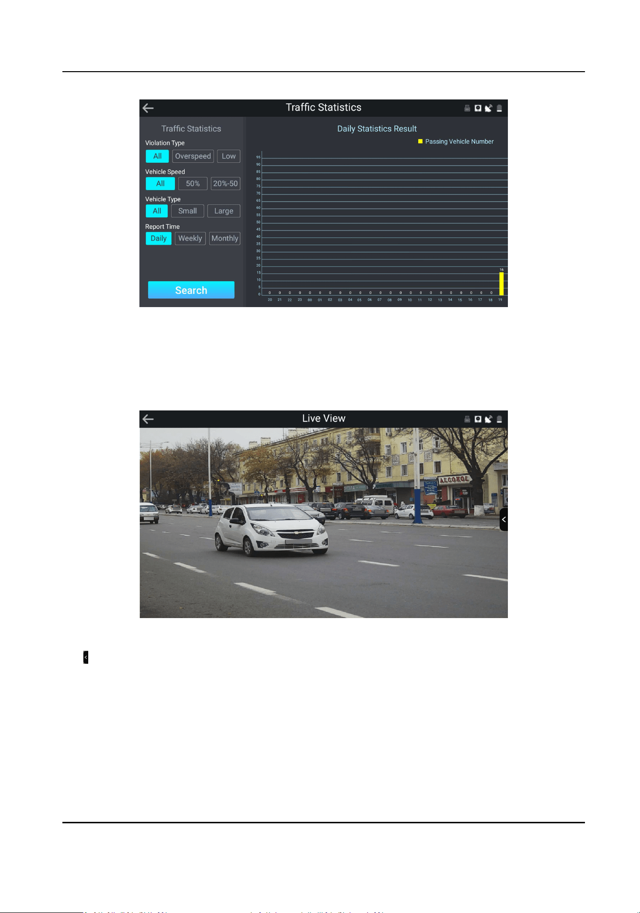
Figure 3-13 Search Trac Stascs
3.4 Live View
Tap Live View to view the real-me video.
Figure 3-14 Live View
Tap to adjust the live view image parameters.
Brightness
It refers to the max. brightness of the image.
Contrast
It refers to the contrast of the image. Set it to adjust the levels and permeability of the image.
Shuer
Portable Radar Speed Detector User Manual
16

If the shuer speed is quick, the details of the moving objects can be displayed beer. If the
shuer speed is slow, the outline of the moving objects will be fuzzy and trailing will appear.
Gain
It refers to the upper limit value of liming image signal amplicaon. It is recommended to set
a high gain if the illuminaon is not enough, and set a low gain if the illuminaon is enough.
2D DNR
The higher the DNR Level is, the stronger the noise will be reduced. But if it is too high, the
image may become fuzzy.
Angle Baseline
Select Le or Right to adjust the device construcon angle.
3D DNR
Digital Noise Reducon (DNR) reduces the noise in the video stream.
In Normal mode, the higher the DNR Level is, the stronger the noise will be reduced. But if it is
too high, the image may become fuzzy.
In Expert mode, set Space Domain and Time Domain. If the space domain intensity is too high,
the outline of the image may become fuzzy and the details may lose. If the me domain
intensity is too high, trailing may appear.
3.5 Playback
You can play back and export the recorded videos.
Before You Start
Connect the USB ash drive to the device if you want to export the videos.
Steps
1. Tap Playback.
2. Set the start me and end me.
3. Tap Search.
The searched videos will be listed on the video list.
Portable Radar Speed Detector User Manual
17
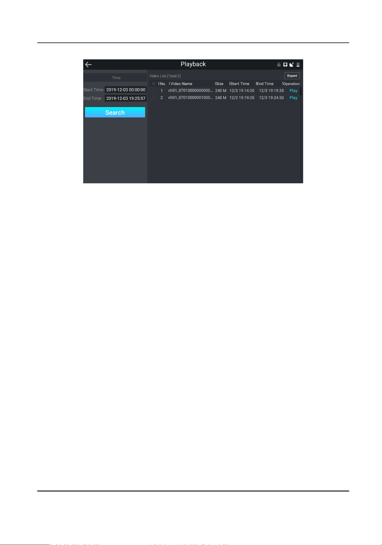
Figure 3-15 Playback
4. Tap Play to play back the selected video.
5. Oponal: Check a video or several videos and tap Export to export it/them.
3.6 Record and Capture
3.6.1 Set Storage Path
Format Storage Media
Format the storage media before saving videos and pictures.
Steps
1. Go to Sengs → Maintenance → Storage Informaon .
Portable Radar Speed Detector User Manual
18
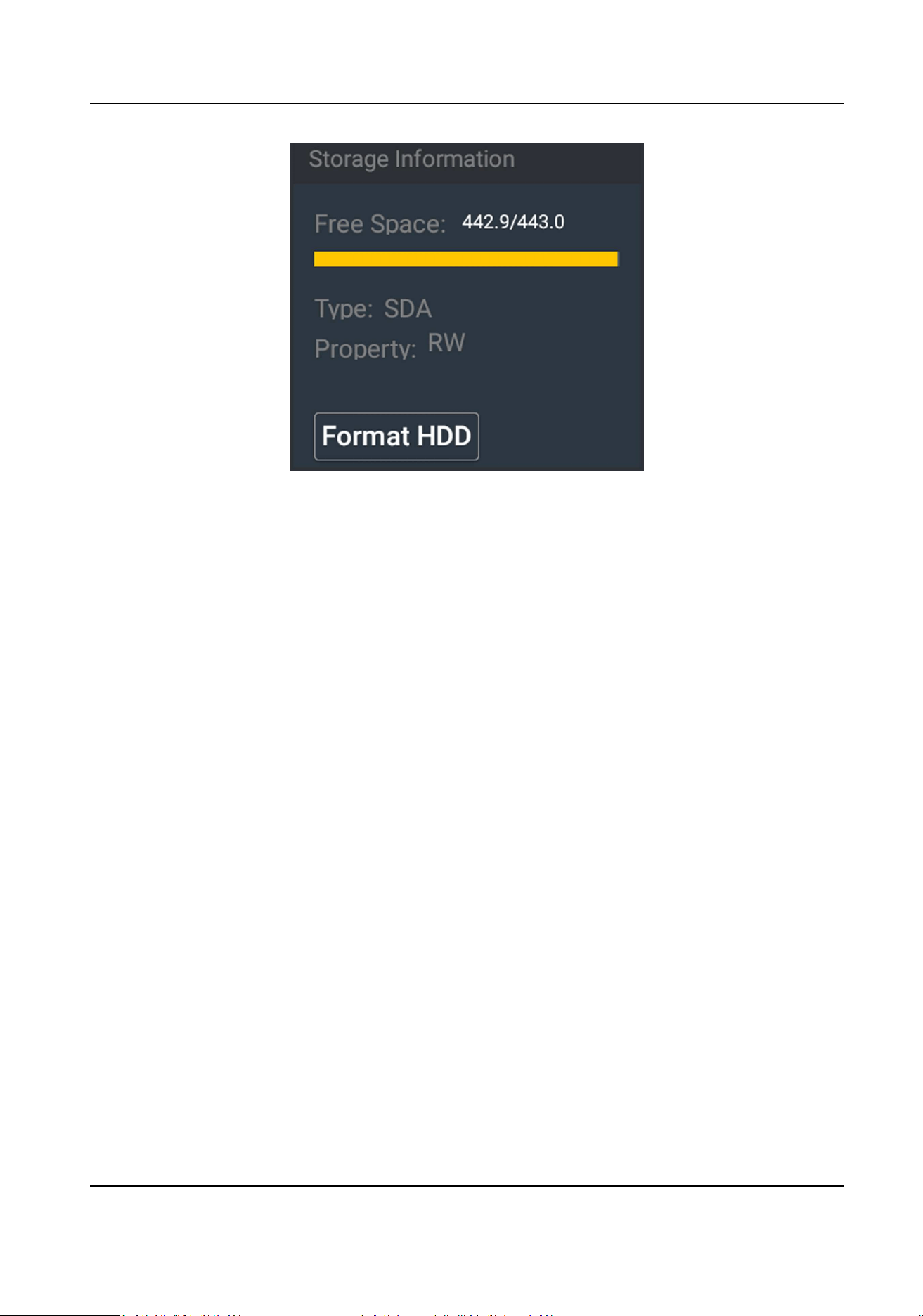
Figure 3-16 Format Storage Media
2. Tap Format HDD.
3. Tap OK to the popup window.
Set FTP
Set FTP parameters if you want to upload the captured pictures to the FTP server.
Before You Start
Set the FTP server, and ensure the device can communicate normally with the server.
Steps
1. Go to Sengs → Network Sengs → FTP .
2. Enable FTP.
Portable Radar Speed Detector User Manual
19
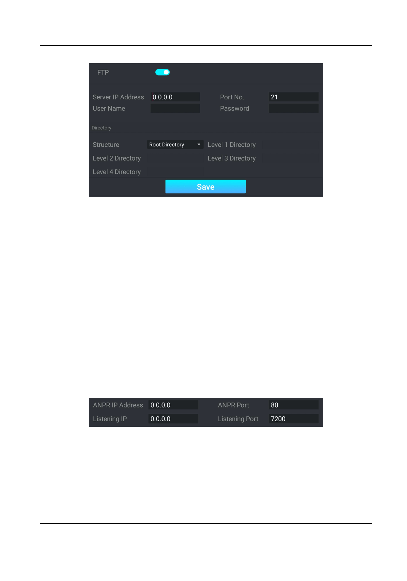
Figure 3-17 Set FTP
3. Set FTP server parameters.
1) Enter Server IP Address and Port No.
2) Enter User Name and Password.
4. Set directory.
1) Select Structure.
2) Oponal: Select the directory name if mulple structures are needed.
5. Tap Save.
Set Listening Host
The listening host can be used to receive the uploaded informaon and pictures of the device
arming alarm.
Before You Start
The listening service has been enabled for the listening host, and the network communicaon with
the device is normal.
Steps
1. Go to Sengs → Network Sengs → Interface .
Figure 3-18 Set Listening Host
2. Set ANPR IP Address and ANPR Port to upload the alarm informaon and pictures.
3. Set Listening IP and Listening Port to upload the alarm informaon and pictures.
Portable Radar Speed Detector User Manual
20
Note
ANPR and listening conict with each other. When you enable listening host, pictures will be
uploaded via listening host in priority. When you disable listening and have set ANPR IP address
and port, pictures will be uploaded via ANPR protocol.
4. Tap Save.
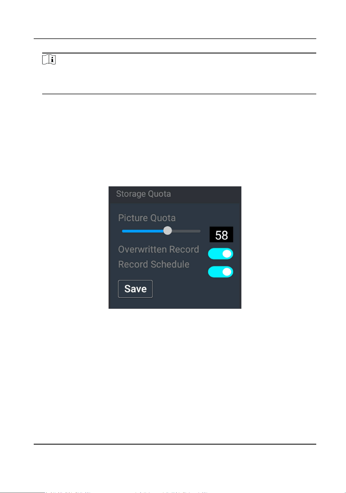
3.6.2 Set Quota
Set the picture rao in the storage.
Before You Start
Ensure the storage status is normal.
Steps
1. Go to Sengs → Maintenance → Storage Quota .
Figure 3-19 Set Quota
2. Set Picture Quota.
3. Tap Save.
3.6.3 Set Record Schedule
Set record schedule to record video automacally during congured me periods.
Before You Start
Ensure the storage status is normal. You are recommended to set the video quota rao as not 0.
Steps
1. Go to Sengs → Maintenance → Storage Quota .
Portable Radar Speed Detector User Manual
21
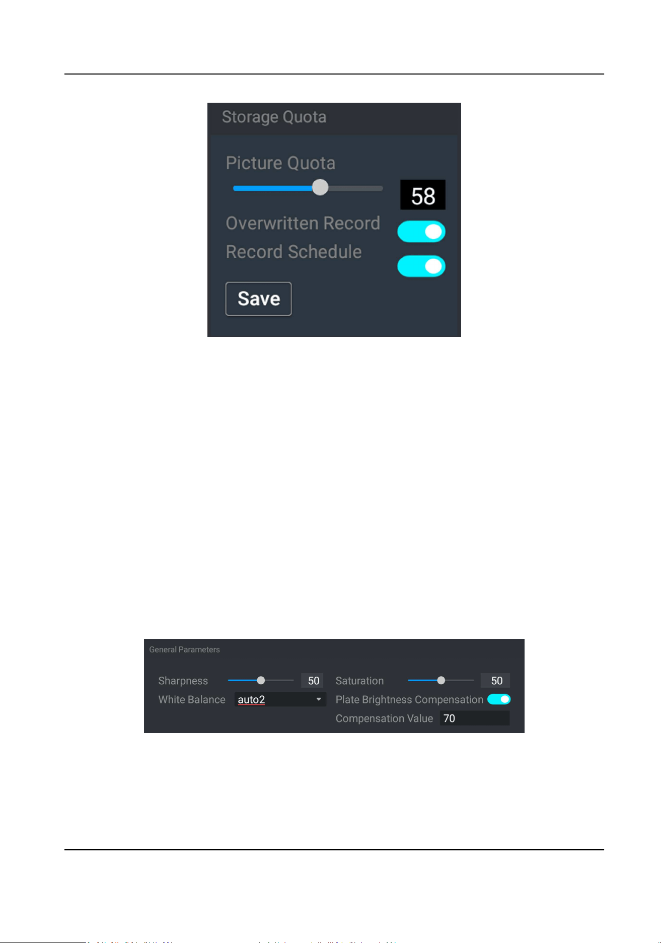
Figure 3-20 Set Record Schedule
2. Oponal: Enable Overwrien Record.
When the storage is full, the earliest videos will be overwrien.
3. Enable Record Schedule.
4. Tap Save.
What to do next
Set the record schedule via the web browser.
3.7 Encoding and Display
3.7.1 Set Image Parameters
You can adjust the image parameters to get clear image.
Steps
1. Go to Sengs → Image Parameters → General Parameters .
Figure 3-21 Set General Parameters
2. Adjust the parameters.
Sharpness
Portable Radar Speed Detector User Manual
22
It refers to the edge contrast of the image.
Saturaon
It refers to the colorfulness of the image color.
White Balance
It is the white rendion funcon of the device used to adjust the color temperature
according to the environment.
Plate Brightness Compensaon
Check it. The plate brightness compensaon can be realized, and various light supplement
condions can be adapted via seng license plate expectant brightness and supplement
light correcon coecient. The higher the Compensaon Value is, the easier this funcon
can be enabled.
3. Tap Save.
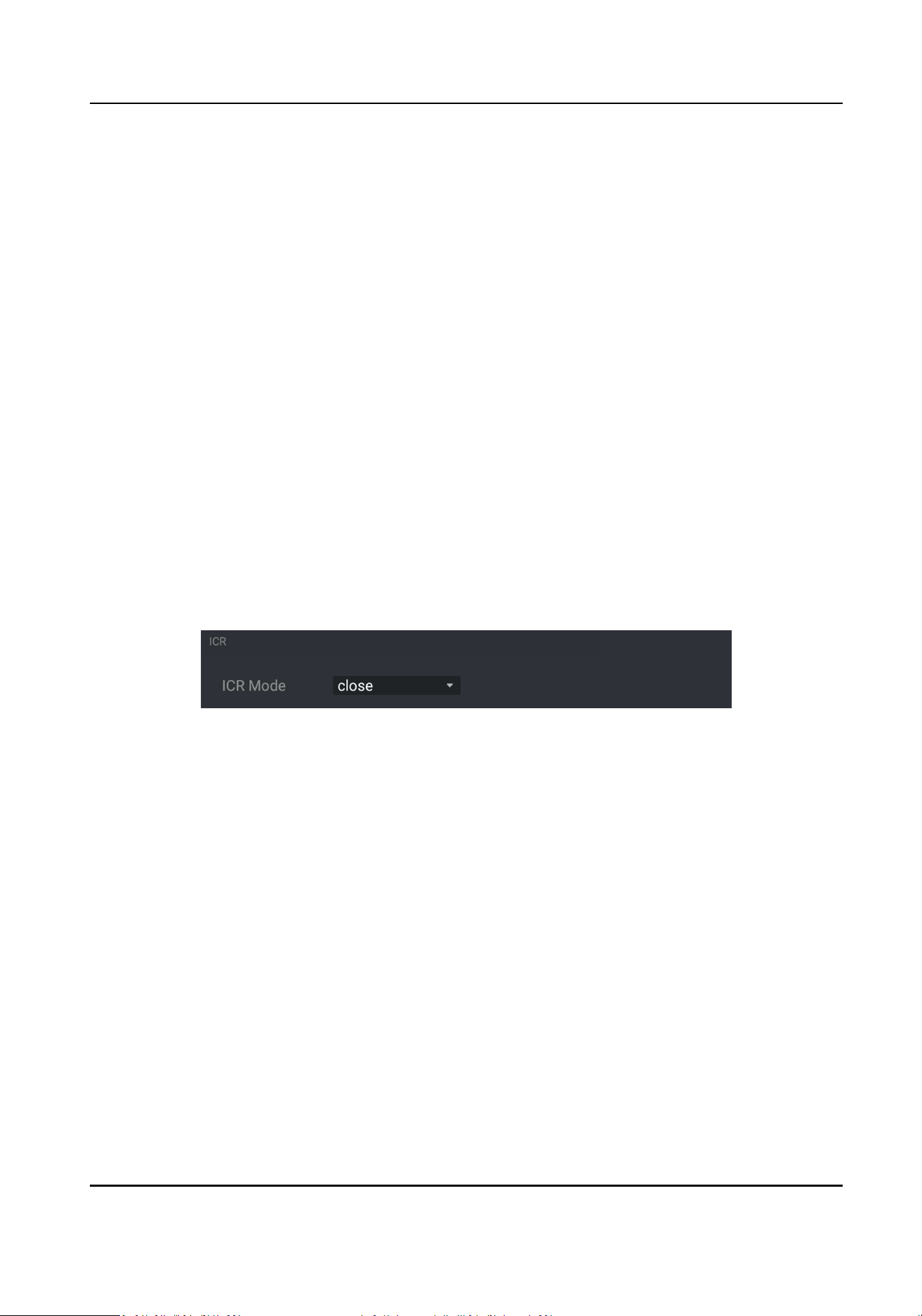
3.7.2 Set ICR
ICR adopts mechanical IR lter to lter IR in the day to guarantee the image eect, and to remove
the IR lter at night to guarantee full-spectrum rays can get through the device.
Steps
1. Go to Sengs → Image Parameters → ICR .
Figure 3-22 Set ICR
2. Select ICR Mode.
auto Switches to ICR mode automacally at night or in dark light condions.
manual Select Day/Night Mode to switch to the day or night manually.
me Set day/night mode, start me, and end me to switch to ICR mode only during
the set me period.
close Disable the ICR mode.
3. Tap Save.
3.8 Network Conguraon
3.8.1 Set IP Address
IP address must be properly congured before you operate the device over network.
Portable Radar Speed Detector User Manual
23
Go to Sengs → Network Sengs → Interface .
Figure 3-23 Set IP Address
IP Address
You can set the device IP parameters manually. Enter Host IP, Subnet Mask, and Gateway.
DNS Server
It stands for domain name server. It is required if you need to visit the device with domain
name. And it is also required for some applicaons (e.g., sending email). Set the server IP
address properly if needed.
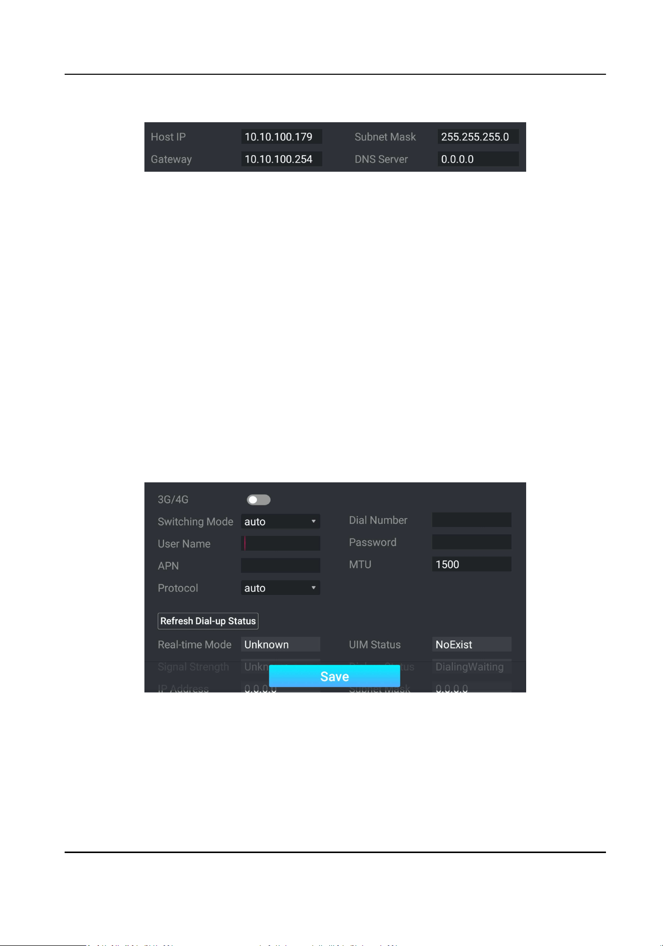
3.8.2 Dial
Set the dialing parameters if you want to connect the device to the network via SIM card.
Before You Start
Install SIM card.
Steps
1. Go to Sengs → Network Sengs → 3G/4G .
2. Enable 3G/4G.
Figure 3-24 Set Dial-up Parameters
3. Select Switching Mode.
manualto4G
Select it to x to 4G network.
manualto3G
Portable Radar Speed Detector User Manual
24
Select it when 4G network is not steady.
manualto2G
Select it when 3G network is not steady.
4. Set the APN informaon, such as Dial Number, User Name, Password, APN, etc.
Note
• Consult the operator about the dial-up parameters.
• When you have enabled 2G/3G/4G and Wi-Fi simultaneously, the device will use 2G/3G/4G
network in priority.
5. Tap Save.
6. Oponal: Tap Refresh Dial-up Status to view the dial-up status.
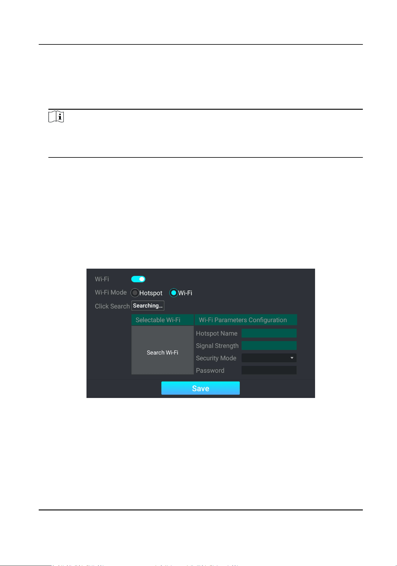
3.8.3 Connect to Wi-Fi
Set Wi-Fi parameters if you want to connect the device to the network via Wi-Fi.
Steps
1. Go to Sengs → Network Sengs → Wi-Fi .
2. Enable Wi-Fi.
3. Select Wi-Fi Mode as Wi-Fi.
Figure 3-25 Connect to Wi-Fi
4. Tap Searching... to search the Wi-Fi.
5. Select a Wi-Fi, and enter Password.
6. Tap Save.
Portable Radar Speed Detector User Manual
25
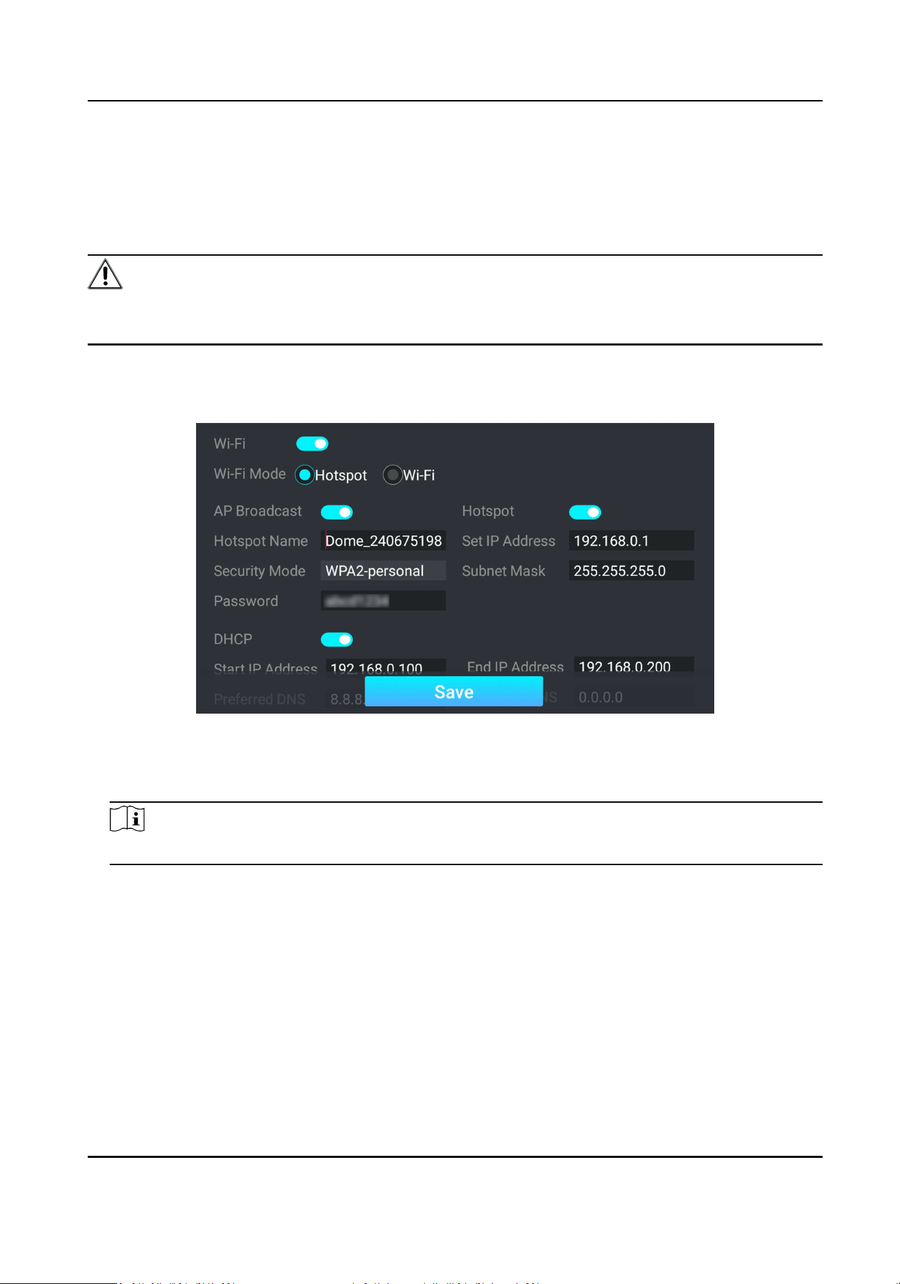
3.8.4 Set Wi-Fi Hotspot
Set Wi-Fi AP to use the device as a hotspot to share network to another terminal device.
Steps
Cauon
Wi-Fi AP and Wi-Fi funcon cannot be enabled at the same me. Once one of them is enabled, the
other will be disabled automacally.
1. Go to Sengs → Network Sengs → Wi-Fi .
2. Enable Wi-Fi.
3. Select Wi-Fi Mode as Hotspot.
Figure 3-26 Set Wi-Fi Hotspot
4. Enable AP Broadcast and Hotspot.
5. Set Hotspot Name, IP Address, Security Mode, etc.
Note
The IP address should be dierent from the one that set in the network parameters.
6. Oponal: Enable DHCP and enter the start/end IP address.
7. Tap Save.
Result
When the device connects to the network via dialing, the connected peripheral device can get
access to the network either.
Portable Radar Speed Detector User Manual
26
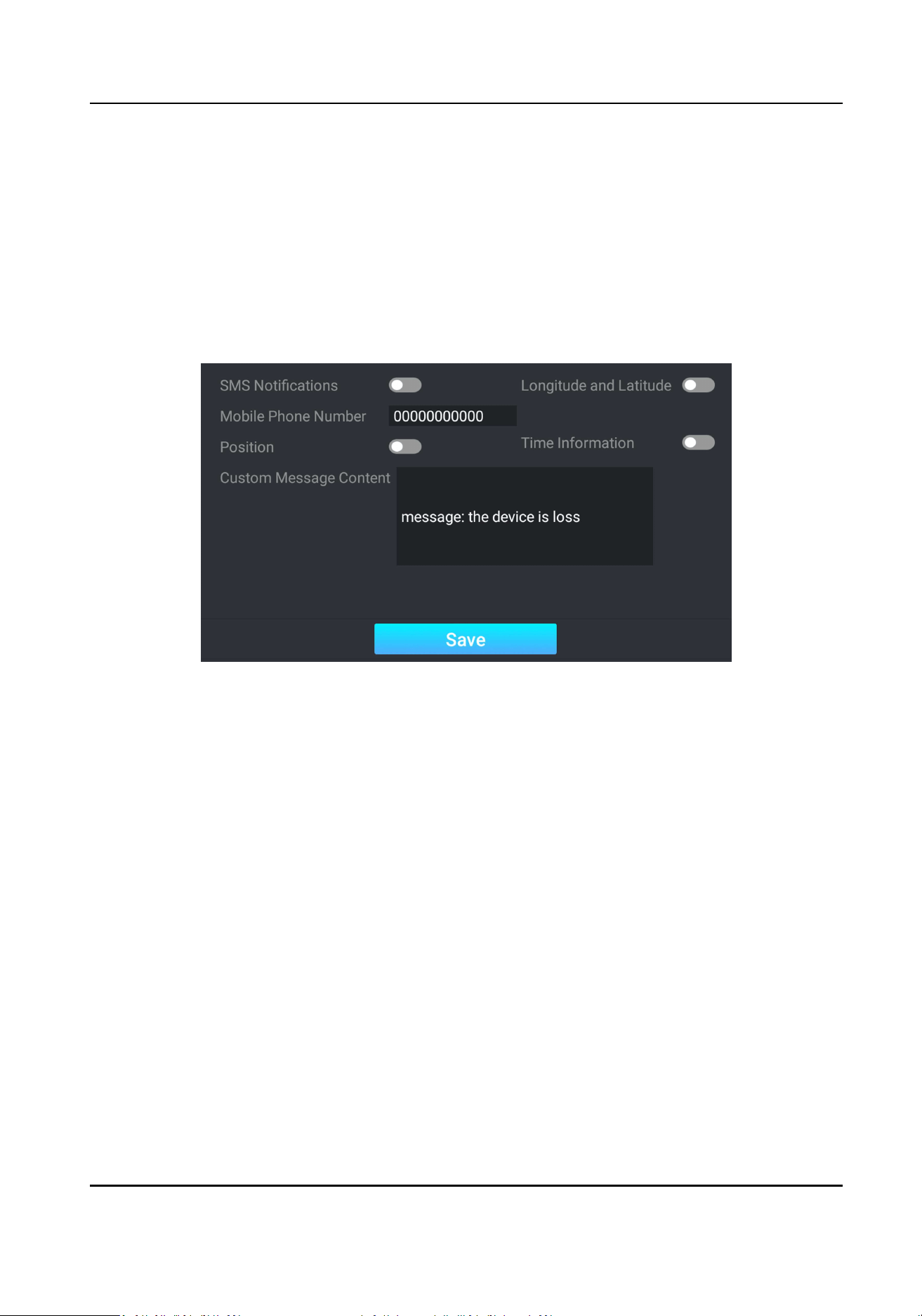
3.9 An-The Conguraon
Set an-the to prompt alarm informaon when the baery of the device is being pulled out or
inserted, or the power is o.
Before You Start
Ensure the dial module is normal.
Steps
1. Go to Sengs → Network Sengs → An-The .
Figure 3-27 Set An-The
2. Enable an-the SMS nocaon.
1) Enable SMS Nocaons.
2) Enter Mobile Phone Number.
3) Edit Custom Message Content.
When the baery of the device is being pulled out or inserted, or the power is o, the SMS
content will be sent to the specic mobile phone.
3. Oponal: Enable Longitude and Latude, Posion, or Time Informaon according to your
needs.
4. Tap Save.
What to do next
Go to the main menu to enable An-The Switch on the lower right corner of the interface.
Portable Radar Speed Detector User Manual
27
3.10 Maintenance
3.10.1 Manage User
The administrator can add, modify, or delete other accounts, and grant dierent permissions to
dierent user levels.
Steps
1. Go to Sengs → User Management .
2. Add a user.
1) Tap Add.
2) Enter User Name and select User Type.
3) Enter Password, and conrm the password.
Cauon
To increase security of using the device on the network, please change the password of your
account regularly. Changing the password every 3 months is recommended. If the device is
used in high-risk environment, it is recommended that the password should be changed
every month or week.
4) Assign remote permission to users based on needs.
User
Users can be assigned permission of viewing live video and changing their own passwords,
but no permission for other operaons.
Operator
Operators can be assigned all permission except for operaons on the administrator and
creang accounts.
5) Tap Save.
Note
The administrator can add up to 31 user accounts.
3. You can do the following operaons.
-
Select a user and tap View to change the password and permission.
-
Select a user and tap Delete to delete the user.
3.10.2 View Device Informaon
Basic Informaon
Go to Sengs → Maintenance → Device Informaon to view the basic informaon such as device
name, device model, rmware version, etc. of the device.
Portable Radar Speed Detector User Manual
28

Running Status
Go to Sengs → Maintenance → Running Status to view the running status of the device.
3.10.3 Search Log
Log helps to locate and troubleshoot problems.
Steps
1. Tap Log Search.
2. Set search condions.
3. Tap Search.
Result
The matched log les will be displayed on the log list.
3.10.4 Upgrade Radar
You can upgrade radar via USB ash drive.
Before You Start
Save the radar upgrade le to the root directory of the USB ash drive, and connect the drive to
the device.
Steps
1. Go to Sengs → Maintenance .
2. Tap Radar Upgrade via USB.
3. Select the radar upgrade le, and tap OK to start upgrade.
What to do next
Reboot the device to take the upgrade into eect.
3.10.5 Upgrade System
You can upgrade the system via USB ash drive when you need to update the device version.
Before You Start
Save the system upgrade le to the root directory of the USB ash drive, and connect the drive to
the device.
Steps
1. Go to Sengs → Maintenance .
2. Tap System Upgrade via USB.
3. Select the system upgrade le, and tap OK to start upgrade.
Portable Radar Speed Detector User Manual
29

Note
The upgrade process will take 1 to 10 minutes. Do not cut o the power supply.
Result
The device will reboot automacally aer upgrade.
3.10.6 Reboot
When the device needs to be rebooted, you can reboot it via the screen operaon instead of
cung o the power directly.
Steps
1. Go to Sengs → Maintenance .
2. Tap Reboot.
3. Tap OK on the popup window to reboot the device.
3.10.7 Restore Parameters
When the device is abnormal caused by the incorrect set parameters, you can restore the
parameters.
Steps
1. Go to Sengs → Maintenance .
2. Select the restoraon mode.
-
Tap Restore Default to restore the parameters except the IP parameters and user parameters
to the default sengs.
-
Tap Restore Factory to restore all the parameters to the factory sengs.
3. Tap OK on the popup window to start the restoraon.
3.10.8 Set NTP Synchronizaon
You can set NTP synchronizaon to synchronize device me with NTP server me.
Before You Start
Ensure the device communicates normally with the NTP server.
Steps
1. Go to Sengs → Network Sengs → NTP .
2. Enable NTP.
3. Set Server Address, Server Port No., and Sync. Interval.
4. Tap Save.
Portable Radar Speed Detector User Manual
30

3.10.9 Debug Screen Display
You can set the screen brightness and screen o threshold, and export the screen log.
Steps
1. Go to Sengs → Display Debugging .
2. Adjust Screen Brightness, or check Auto.
If you check Auto, the screen brightness will change according to the environment brightness.
3. Adjust Screen O Threshold.
4. Oponal: Tap Export to export the screen log.
5. Tap Save.
3.10.10 Shutdown
When the device needs to be shut down, you can shut it down via the screen operaon instead of
cung o the power directly.
Steps
1. Go to Sengs → Maintenance .
2. Tap Shutdown.
3. Tap OK on the popup window to shut down the device.
Portable Radar Speed Detector User Manual
31

Chapter 4 Operaon via Web Browser
4.1 Login
You can log in to the device via web browser for further operaons such as live view and local
conguraon.
Before You Start
Connect the device to the network directly, or via a switch or a router.
Steps
1. Open the web browser, and enter the IP address of the device to enter the login interface.
2. Enter User Name and Password.
3. Click Login.
4. Download and install appropriate plug-in for your web browser. Follow the installaon prompts
to install the plug-in.
5. Reopen the web browser aer the installaon of the plug-in and repeat steps 1 to 3 to login.
6. Oponal: Click Logout on the upper right corner of the interface to log out of the device.
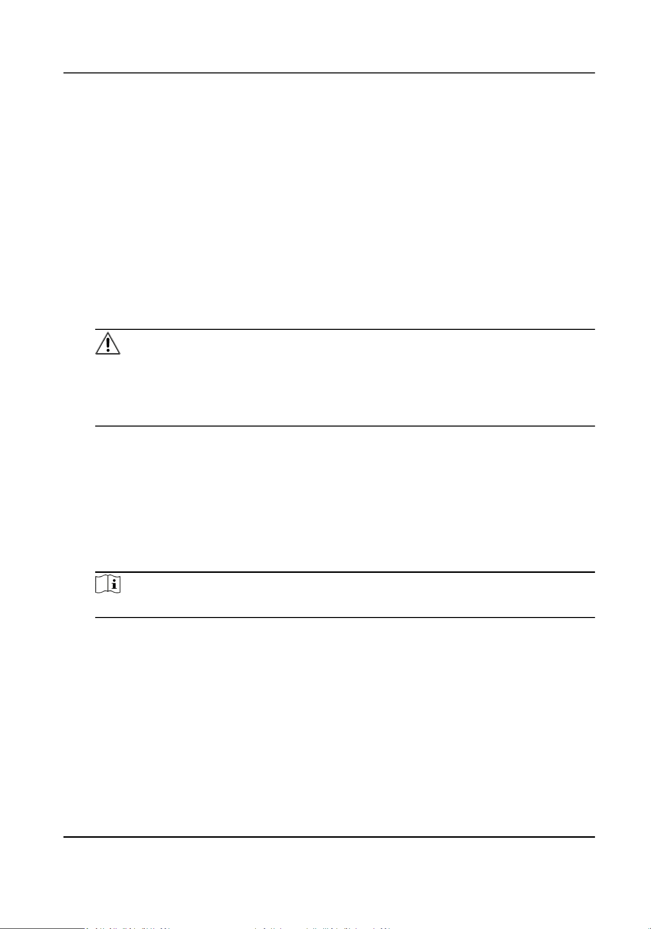
4.2 Set Radar Detecon Parameters
Radar is used to detect the target and link the capture. Set radar detecon parameters before
capturing vehicle pictures.
Steps
1. Click Radar.
Portable Radar Speed Detector User Manual
32
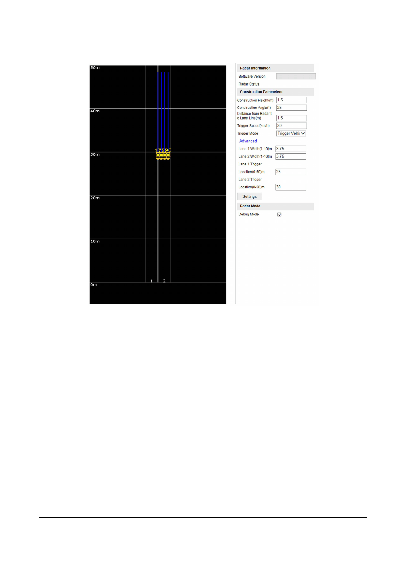
Figure 4-1 Set Radar Detecon Parameters
2. View the radar informaon.
Soware Version
The soware version of the radar.
Radar Status
The current radar status. The radar can be normally used in normal status. If the radar is in
upgrading status, do not reboot the device. Refresh the interface every one minute, and the
status can be restored to normal.
3. Set the construcon parameters below, and click Sengs to save the sengs.
Construcon Height
The construcon height of the radar. 1.5 m is recommended.
Construcon Angle
The angle between the radar and the road. 25° is recommended.
Distance from Radar to Lane Line
The distance from the radar to the lane line.
Portable Radar Speed Detector User Manual
33

Trigger Speed
If the vehicle speed exceeds the set value, capture will be triggered.
Trigger Mode
Trigger Vehicle Head
Capture is triggered by the vehicle head. The vehicles from the approaching direcon will
be detected.
Trigger Vehicle Tail
Capture is triggered by the vehicle tail. The vehicles from the leaving direcon will be
detected.
Trigger Vehicle Head and Tail
Capture can be triggered by the vehicle head or tail. The vehicles from both the
approaching and leaving direcons will be detected.
Advanced
Lane X Width
Enter the lane width according to the actual condion.
Lane X Trigger Locaon
Capture will be triggered at the set locaon if the speed exceeds the trigger speed.
4. Check Debug Mode to enable the radar debug mode.
In this mode, the vehicles outside the detecon area will be displayed, to make it convenient to
debug the radar.
4.3 Vehicle Capture
4.3.1 Set Side-Mounted Speed Detecon
The device supports side-mounted speed detecon.
Steps
1. Go to Conguraon → Device Conguraon → Applicaon Mode .
Portable Radar Speed Detector User Manual
34
Figure 4-2 Set Side-Mounted Speed Detecon
2. Set violaon detecon parameters.
1) Select Burst Interval Type.
2) Set Burst Interval.
3) Check the violaon detecon type(s), and select the number of captured picture(s).
When the selected violaon type is detected, burst will be triggered every set interval.
3. Set the lane parameters.
1) Select Number of Linked Lane.
2) Select the lane.
3) Set the parameters below.
Overlay Lane No.
The No. of the lane overlaid on OSD.
Marked Speed Limit for Small-Sized Vehicle
The speed limit for small-sized vehicles marked on the sign. It will be overlaid on the
captured pictures.
Max. Speed Limit for Small-Sized Vehicle
The allowable max. speed for small-sized vehicles. When the vehicle speed exceeds the
max. speed limit, capture will be triggered.
Min. Speed Limit for Small-Sized Vehicle
The allowable min. speed for small-sized vehicles. When the vehicle speed is lower than
the min. speed limit, capture will be triggered.
Portable Radar Speed Detector User Manual
35
Abnormal Overspeed of Small-Sized Vehicle
When the radar detected speed exceeds the abnormal overspeed of small-sized vehicles,
the radar detecon will be regarded as excepon, and the soware will provide a normal
speed randomly.
Abnormal Low Speed of Small-Sized Vehicle
When the radar detected speed is lower than the abnormal low speed of small-sized
vehicles, the radar detecon will be regarded as excepon, and the soware will provide a
normal speed randomly.
4) Check the supplement light No. to link it to the lane.
5) Oponal: Check the other lane(s) to copy the same sengs.
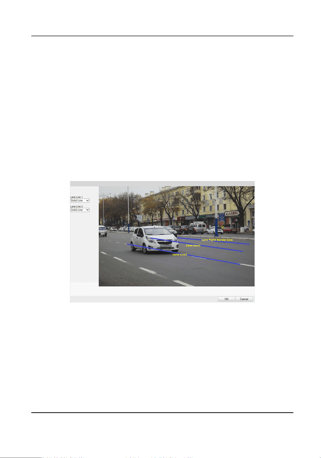
4. Draw lane lines.
1) Click Draw Rules.
2) Select the lane type.
3) Select the default lane lines and right border line, and drag the two end points of the line or
drag the whole line to adjust its posion according to the actual scene.
4) Click OK.
Figure 4-3 Draw Lane Line
5. Click Save.
4.3.2 Set Capture Parameters
Set Captured Image Parameters
Set the parameters of captured images to raise the image quality.
Portable Radar Speed Detector User Manual
36
Steps
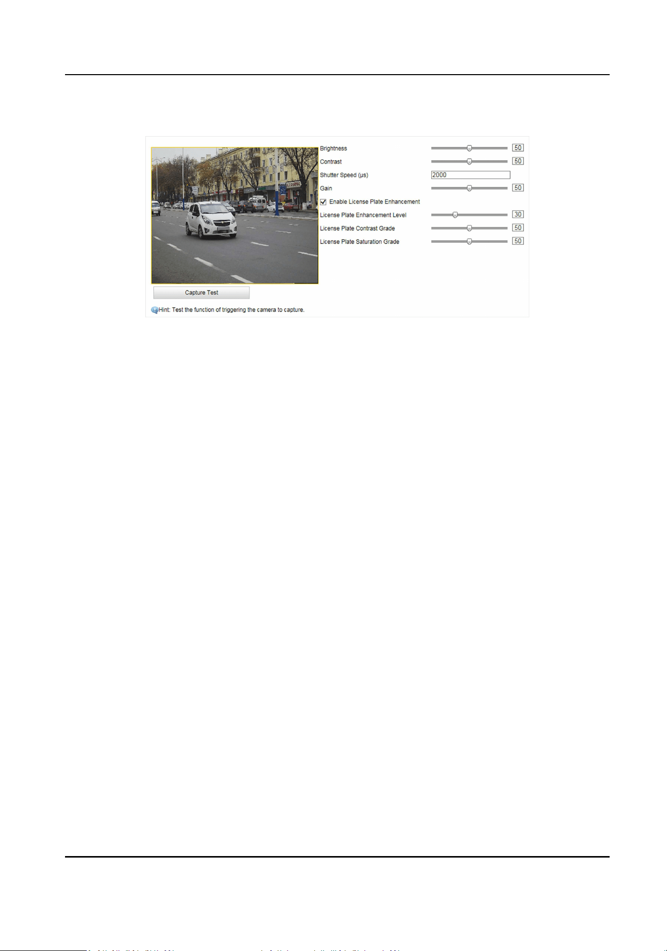
1. Go to Conguraon → Device Conguraon → Image Parameters → Picture .
Figure 4-4 Set Captured Image Parameters
2. Set the captured image parameters.
Brightness
The max. brightness of the image.
Contrast
The color contrast between the brightest part and darkest part of the image. Set it to adjust
the levels and permeability of the image.
Shuer Speed
If the shuer speed is quick, the details of the moving objects can be displayed beer. If the
shuer speed is slow, the outline of the moving objects will be fuzzy and trailing will appear.
Gain
The upper limit value of liming image signal amplicaon. It is recommended to set a high
gain if the illuminaon is not enough, and set a low gain if the illuminaon is enough.
Enable License Plate Enhancement
Check Enable License Plate Enhancement to capture clearer license plate images. The higher
the License Plate Enhancement Level, License Plate Contrast Grade, and License Plate
Saturaon Grade are, the clearer the captured license plate images are. But if the level is too
high, the captured images may be overexposed. It is recommended to keep the default level.
Set License Plate Recognion Parameters
When there are vehicles of dierent types passing from dierent direcons, set the license plate
recognion parameters.
Steps
1. Go to Conguraon → Device Conguraon → Capture Parameters → License Parameters .
Portable Radar Speed Detector User Manual
37

Figure 4-5 Set License Plate Recognion Parameters
2. Select License Plate Recognion.
-
Select Front Plate when license plates of vehicles from the approaching direcon need to be
recognized.
-
Select Back Plate when license plates of vehicles from the leaving direcon need to be
recognized.
3. Select License Plate Type according to the actual needs.
-
Select Small-Size Plate Recognion when the license plate pixel ranges from 80 to 120.
-
Select Large-Size Plate Recognion when the license plate pixel ranges from 120 to 180.
4. Click Save.
Set Flash Light Parameters
Flash light can enhance the image stabilizaon and adjust the brightness and color temperature.
You can use ash light to supplement light at night or when the light is dim.
Steps
1. Go to Conguraon → Device Conguraon → Capture Parameters → Flash Light Parameters .
2. Select an IO.
3. Select IO Output Mode.
-
Select Strobe Light Mode. Refer to Set Strobe Light Mode for details.
-
Select Polarizer Mode. Refer to Set Polarizer Mode for details.
Set Strobe Light Mode
Steps
1. Select IO Output Mode as Strobe Light Mode.
Portable Radar Speed Detector User Manual
38
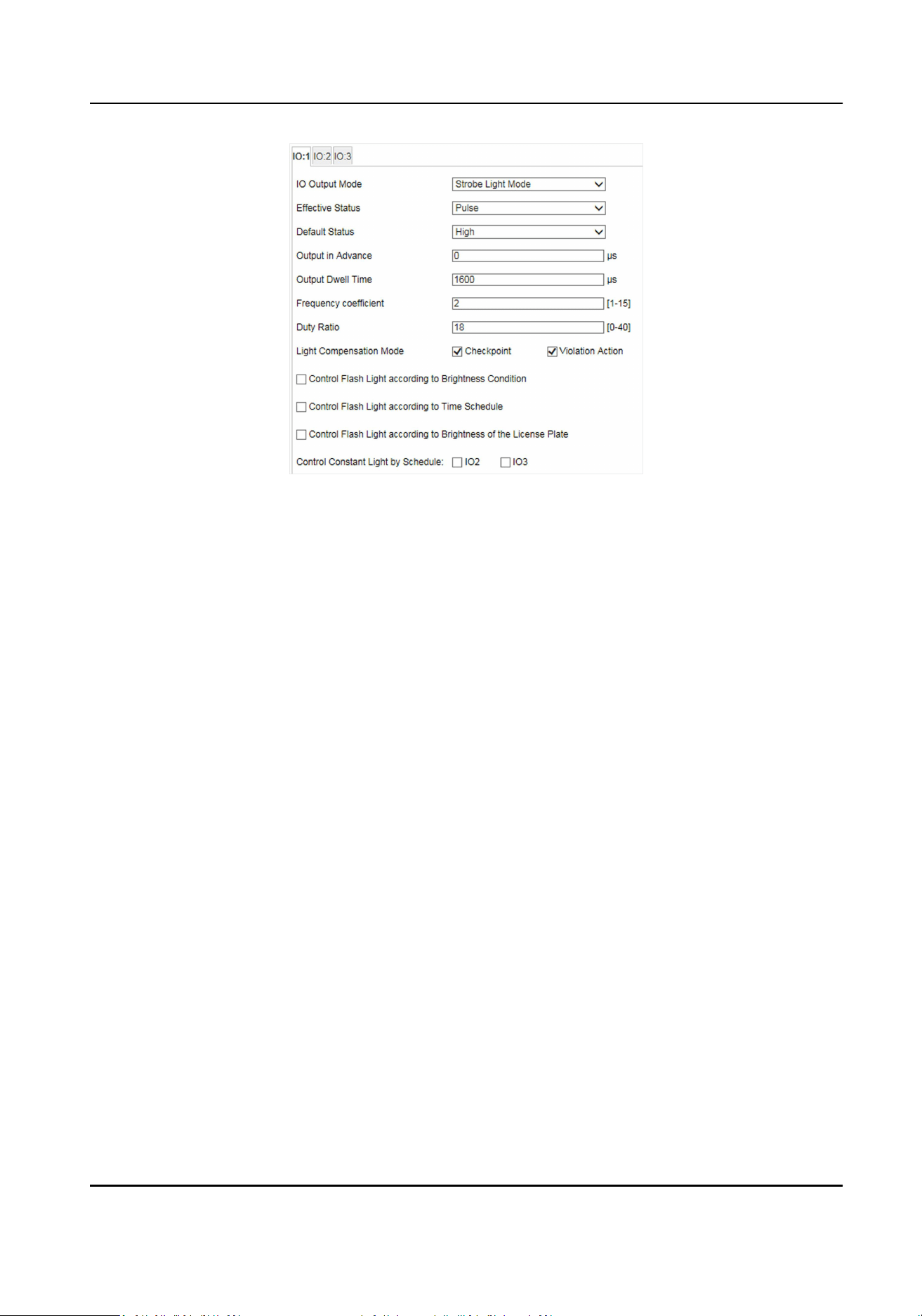
Figure 4-6 Set Strobe Light Mode
2. Select Eecve Status.
High/Low
The light will ash when the high/low level signal is output to the ash light. The eecve
status should stay dierent with the default status for IO to take eect. And the default
status changes according to the selecon of the eecve status. If you set the eecve status
as high level, the default level goes to low level. The selecon of high/low level is applicable
to burst light.
Pulse
The light will ash when the pulse signal is output to the ash light. If you set the eecve
status as pulse, you can select the default status as high level or low level. The selecon of
pulse is applicable to strobe light.
3. Set other parameters.
Output in Advance
It is the preact me [0 to 1000 μs] of the ash light, to ensure that the ash light is on when
capture is triggered.
Output Dwell Time
It is the dwell me [0 to 10000 μs] aer the ash light responds. The actual ash light
supplement me is the result of the dwell me minus advanced me.
Frequency coecient
It is the frequency mulplicaon of 25 of output pulse by strobe light, to keep the ash light
as constant. You can set it as default value. Set it when you select Eecve Status as Pulse.
Duty Rao
Portable Radar Speed Detector User Manual
39
It is the me occupaon of the high level in a certain period. The higher the duty rao, the
brighter the ash light. High duty rao will cut life span of the ash light, and duty rao
under 25 is recommended. Set it when you select Eecve Status as Pulse.
Light Compensaon Mode
Checkpoint
The light compensaon works on every vehicle.
Violaon Acon
The light compensaon works when there are violaons.
4. Set the ash light control mode.
-
Check Control Flash Light according to Brightness Condion when you want the ash light to
be controlled by detecng the surroundings brightness automacally. Set the brightness
threshold. The higher the threshold is, the harder the ash light can be enabled.
-
Check Control Flash Light according to Time Schedule when you want the ash light to be
enabled during a xed me period. Set the start me and end me.
-
Check Control Flash Light according to Brightness of the License Plate when you select
Eecve Status as Pulse. The ash light takes into eect according to the brightness of the
license plate.
5. Oponal: Select other IO(s) to copy the same sengs.
6. Click Save.
Set Polarizer Mode
Steps
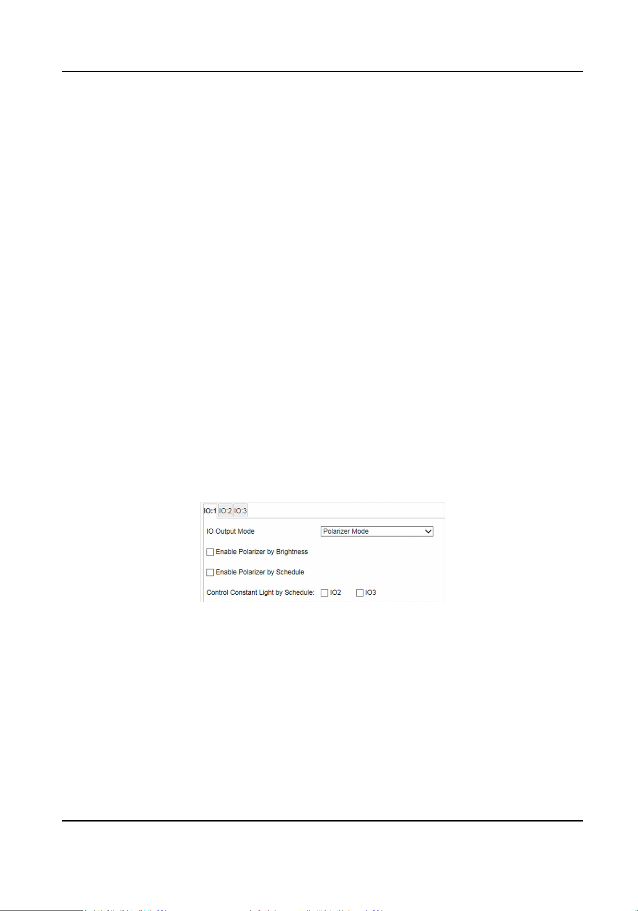
1. Select IO Output Mode as Polarizer Mode.
Figure 4-7 Set Polarizer Mode
2. Set the polarizer control mode.
-
Check Enable Polarizer by Brightness when you want the polarizer to be controlled by
detecng the surroundings brightness automacally. Set the brightness threshold. The higher
the threshold is, the harder the polarizer can be enabled.
-
Check Enable Polarizer by Schedule when you want the polarizer to be enabled during a
xed me period. Set the start me and end me.
3. Oponal: Select other IO(s) to copy the same sengs.
4. Click Save.
Portable Radar Speed Detector User Manual
40
Set Image Composion
You can enable the image composion to composite several pictures into one to make it
convenient to view the violaon captured pictures.
Steps
1. Go to Conguraon → Device Conguraon → Capture Parameters → Image Composion .
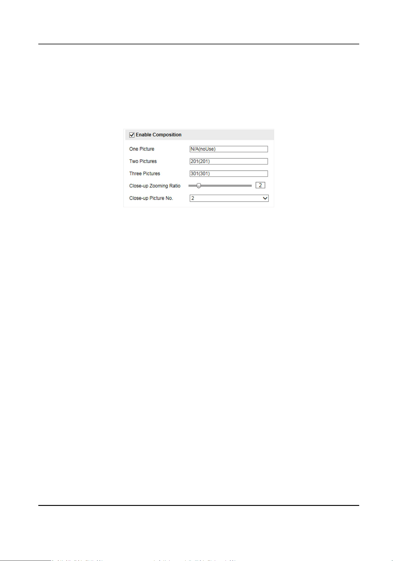
Figure 4-8 Set Image Composion
2. Check Enable Composion.
3. Set other parameters.
Close-up Zooming Rao
The higher the value is, the larger the close-up is.
Close-up Picture No.
It is the picture where the close-up comes from.
4. Click Save.
Set Capture Overlay
If you want to overlay informaon on the captured pictures, set capture overlay.
Steps
1. Go to Conguraon → Device Conguraon → Text Overlay → Capture Overlay
Conguraon .
2. Check Capture Picture Overlay.
Portable Radar Speed Detector User Manual
41
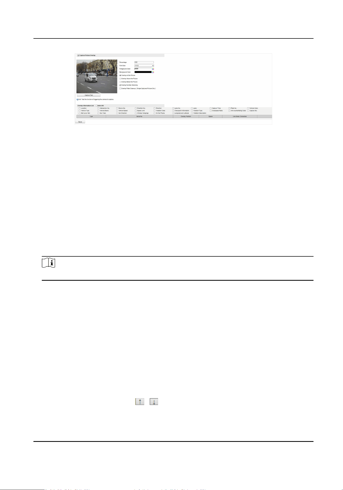
Figure 4-9 Set Capture Overlay
3. Set the percentage, front size, color, overlay posion, etc.
Percentage
It is the percentage that the overlaid informaon occupies on the picture. For example, if you
set the percentage to 50, the overlaid informaon in a row will occupy up to half of the
image width, and the excess content will be overlaid from a new line.
Overlay Number Zeroizing
When the overlaid number digits are smaller than the xed digits, 0 will be overlaid before
the overlaid number. E.g., the xed digits for lane No. is 2. If the lane No. is 1, 01 will be
overlaid on the picture.
Overlay Plate Close-up
Overlay the license plate close-up pictures on the captured pictures.
4. Select the overlay informaon from the list.
Note
The overlay informaon varies with dierent models. The actual device prevails.
5. Set the overlay informaon.
Set Type You can edit the type.
Set Overlay
Informaon
For some informaon types, you can edit the detailed informaon.
Set Overlay Posion If you select Overlay on the Picture, you can check it. Then the
current informaon will be displayed from a new line.
Set Space Edit the number of space between the current informaon and the
next one from 0 to 255. 0 means there is no space.
Set Line Break
Characters
Edit the number of characters from 0 to 100 between the current
informaon line and the previous informaon line. 0 means no line
break.
Adjust overlay
sequence
Click
/ to adjust the display sequence of the overlay
informaon.
Portable Radar Speed Detector User Manual
42
6. Click Save.
Set Composite Picture Overlay
If you want to overlay informaon on the composite pictures, set composite picture overlay.
Steps
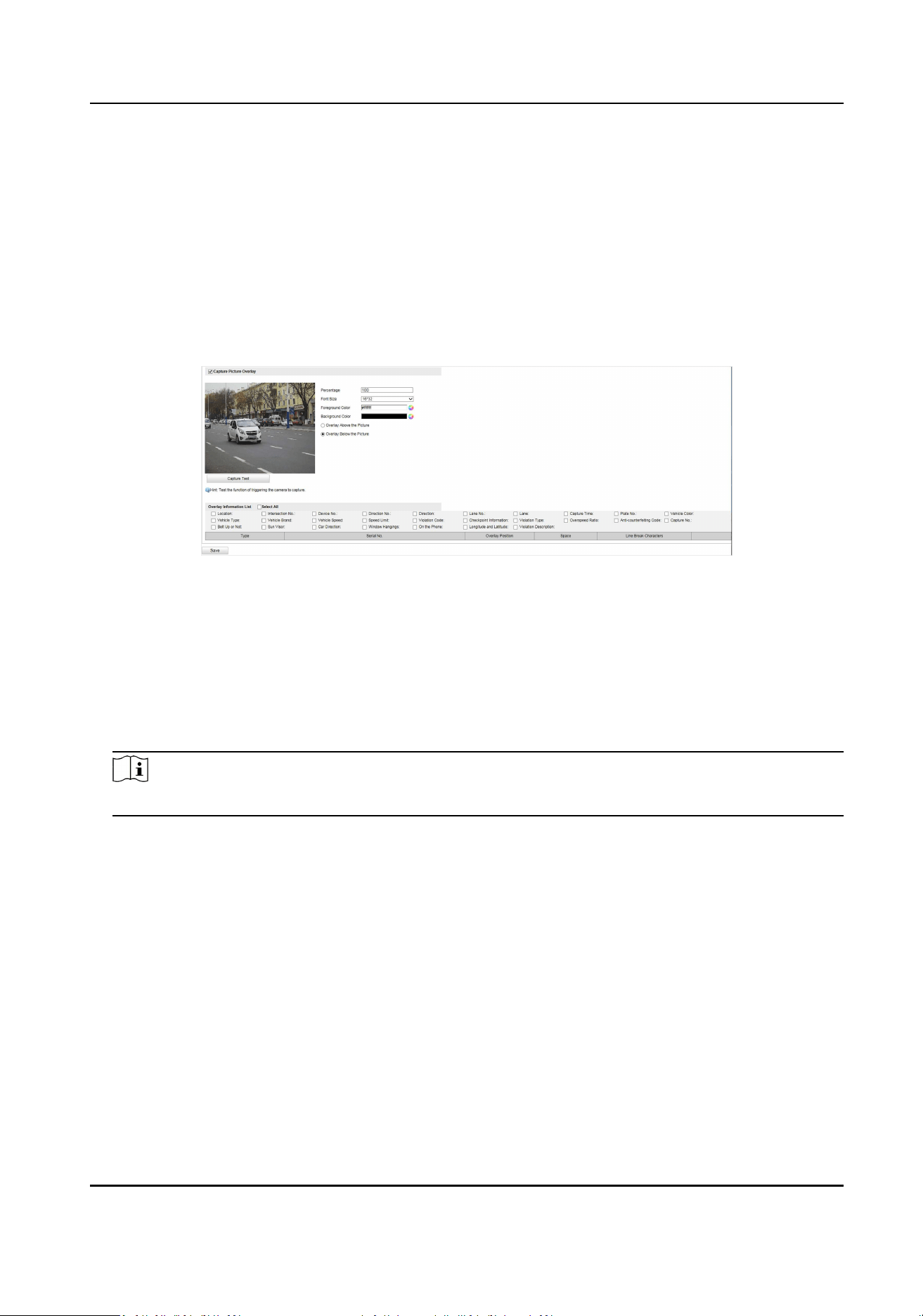
1. Go to Conguraon → Device Conguraon → Text Overlay → Composite Picture Overlay
Conguraon .
2. Check Capture Picture Overlay.
Figure 4-10 Set Composite Picture Overlay
3. Set the font size, color, overlay posion, etc.
Percentage
It is the percentage that the overlaid informaon occupies on the picture. For example, if you
set the percentage to 50, the overlaid informaon in a row will occupy up to half of the
image width, and the excess content will be overlaid from a new line.
4. Select the overlay informaon from the list.
Note
The overlay informaon varies with dierent models. The actual device prevails.
5. Set the overlay informaon.
Set Type You can edit the type.
Set Overlay
Informaon
For some informaon types, you can edit the detailed informaon.
Set Overlay Posion If you check it, the current informaon will be displayed from a
new line.
Set Space Edit the number of space between the current informaon and the
next one from 0 to 255. 0 means there is no space.
Set Line Break
Characters
Edit the number of characters from 0 to 100 between the current
informaon line and the previous informaon line. 0 means no line
break.
Portable Radar Speed Detector User Manual
43
Adjust overlay
sequence
Click / to adjust the display sequence of the overlay
informaon.
6. Click Save.
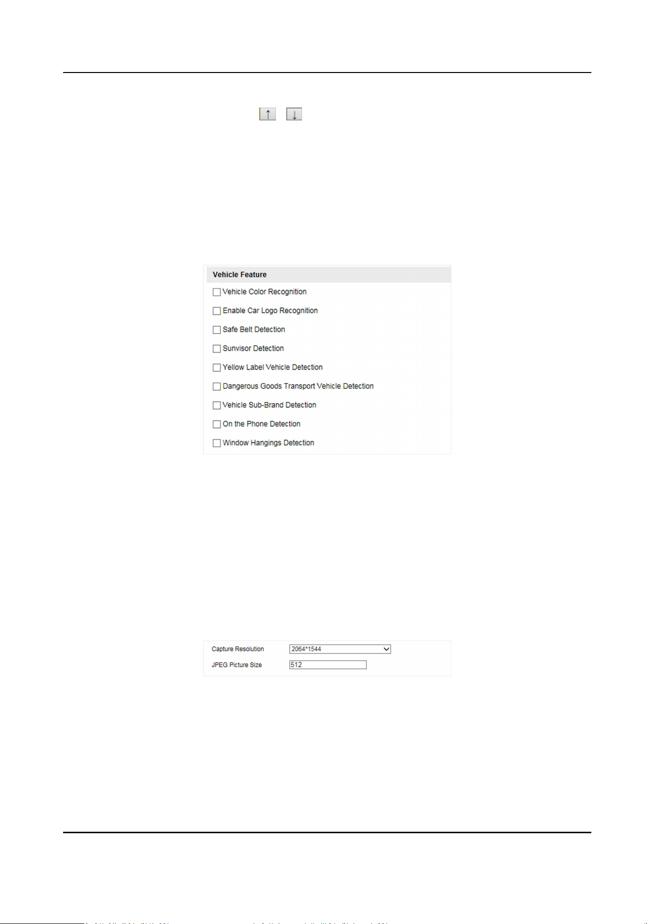
Set Vehicle Feature Parameters
Set vehicle feature parameters if you need to detect the vehicle features of the passing vehicle.
Steps
1. Go to Conguraon → Device Conguraon → Capture Parameters → Vehicle Feature .
Figure 4-11 Set Vehicle Feature Parameters
2. Check the vehicle features that needed to be detected.
3. Click Save.
Set Image Encoding Parameters
If the captured pictures are not clear, set the resoluon of the captured pictures and the picture
size.
Steps
1. Go to Conguraon → Device Conguraon → Encoding and Storage → Image Encoding .
Figure 4-12 Set Image Encoding Parameters
2. Select Capture Resoluon.
3. Enter the picture size.
JPEG Picture Size
The size of the captured picture.
Portable Radar Speed Detector User Manual
44

4. Click Save.
Set Violaon Diconary
Violaon diconary denes corresponding codes of violaon types. You can set the violaon code,
violaon type, and violaon descripon in this secon. The default parameters are recommended.
Steps
Note
Funcons and parameters vary with dierent models. The actual device prevails.
1. Go to Conguraon → Device Conguraon → System Conguraon → Violaon Diconary .
2. Set Violaon Code, Violaon Type, and Violaon Descripon according to the actual needs.
3. Click Save.
Result
The violaon code and descripon will be displayed on the captured picture when the
corresponding violaon happens.
4.3.3 View Real-Time Picture
You can view the real-me captured pictures and license plate informaon.
Steps
1. Go to Live View → Real-Time Status and Trac Flow Stascs .
2. Select an item from the list, and you can view the capture scene picture and license plate
picture.
Portable Radar Speed Detector User Manual
45
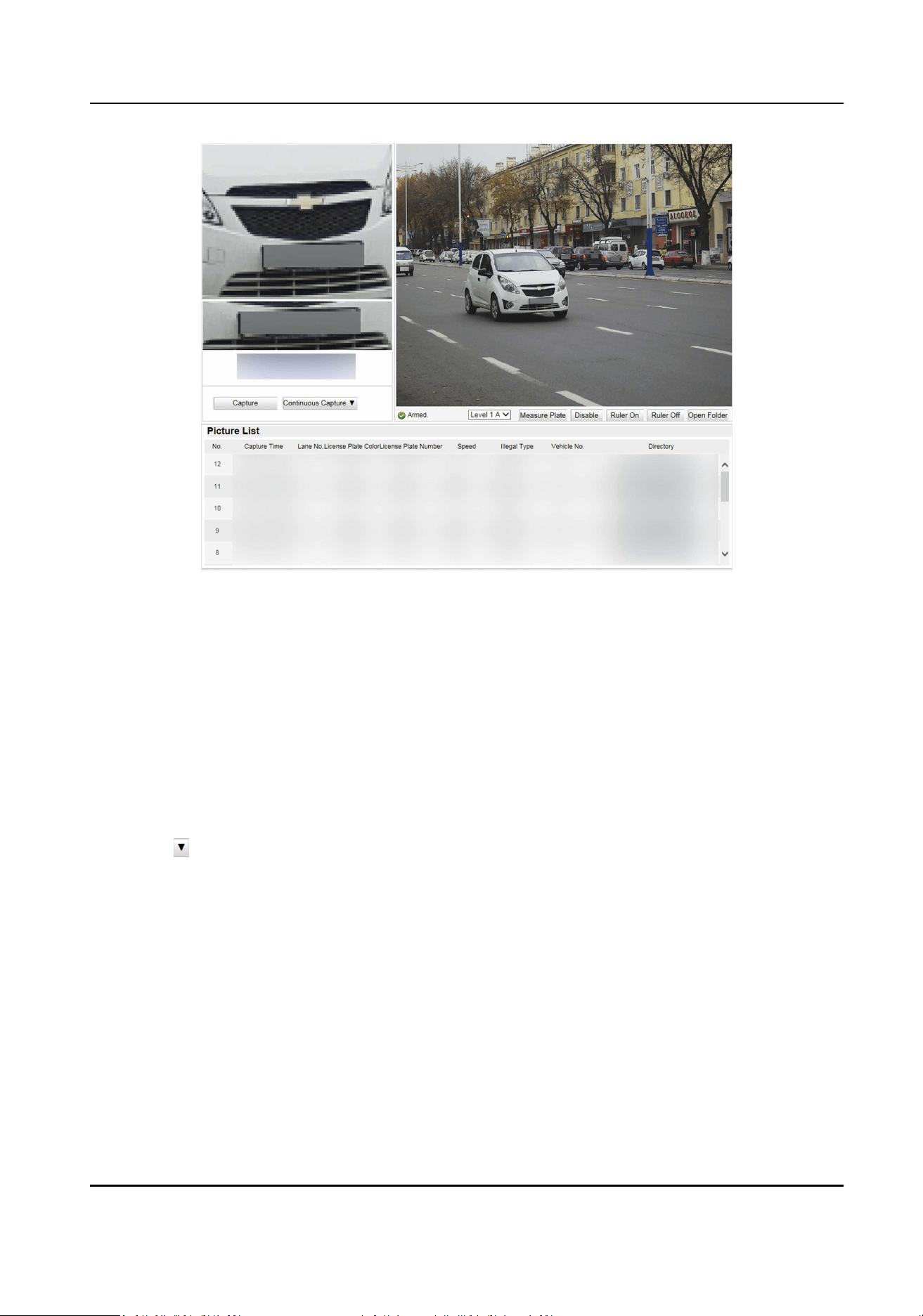
Figure 4-13 Real-Time Picture
3. You can do the following operaons on this interface.
-
Select the arming mode. Level 1 Arming can only connect one client or web. The uploaded
pictures will not be stored in the storage media. The pictures in the storage media will be
uploaded to the level 1 arming. Level 2 Arming can connect three clients or webs. The
pictures will be uploaded to the client/web, and stored in the storage media. Disarming is to
cancel the alarm status or real-me picture.
-
Click Capture to enable manual capture. The captured pictures will be saved in the set local
path. Or you can click Open Folder to view the pictures.
-
Click Measure Plate/Ruler On to measure the license plate pixel. Aer the measurement,
click Disable/Ruler O.
-
Click
aer Connuous Capture to set the burst parameters.
Capture Times
Up to ve pictures can be captured per burst.
Connuous Capture Intervals
Up to four intervals can be set, and the default interval is 100 s.
Click Connuous Capture, and the device will capture pictures according to the set intervals.
Portable Radar Speed Detector User Manual
46
4.3.4 Search Picture
You can search the captured pictures stored in the storage media and export the pictures you
need.
Before You Start
Ensure the storage status is normal.
Steps
1. Click Picture.
2. Set the search condions such as Lane No., Vehicle Type, etc.
3. Click Search.
The searched pictures informaon will be displayed in the picture list.
Note
If you have set level 1 arming for the device, the captured pictures will not be saved in the
storage media. Go to the saving path of scene pictures to view them. You can go to
Conguraon → Local Conguraon to get the saving path.
4. Oponal: Click to preview the selected picture.
You can view the captured picture and the related informaon such as the capture me, lane
No., license plate number, etc.
5. Oponal: Check a picture or several pictures and click Export Picture to export it/them to the
saving path you have set.
The downloaded picture(s) will be marked as "Downloaded". You can go to Conguraon →
Local Conguraon to get the saving path of downloaded pictures.
4.4 Live View and Local Conguraon
4.4.1 Live View
Start/Stop Live View
Click
to start live view. Click to stop live view.
Select Image Display Mode
Click to display the image in 4:3/16:9/self-adapve display mode.
Portable Radar Speed Detector User Manual
47

Select Stream Type
Click / / to select the stream type. It is recommended to select the main
stream to get the high-quality image when the network condion is good, and select the sub-
stream to get the uent image when the network condion is not good enough. The third stream is
custom.
Capture Picture Manually
You can capture pictures manually on the live view image and save them to the computer.
Steps
1. Click to start live view.
2. Click to capture a picture.
3. Oponal: Click Conguraon → Local Conguraon to view the saving path of snapshots in live
view.
Record Manually
You can record videos manually on the live view image and save them to the computer.
Steps
1. Click to start live view.
2. Click to start recording.
3. Click to stop recording.
4. Oponal: Click Conguraon → Local Conguraon to view the saving path of record les.
Enable Digital Zoom
You can enable digital zoom to zoom in a certain part of the live view image.
Steps
1. Click to start live view.
2. Click to enable digital zoom.
3. Place the cursor on the live view image posion which needs to be zoomed in. Drag the mouse
rightwards and downwards to draw an area.
The area will be zoomed in.
4. Click any posion of the image to restore to normal image.
5. Click
to disable digital zoom.
Portable Radar Speed Detector User Manual
48
Enable Wiper
is a reserved funcon.
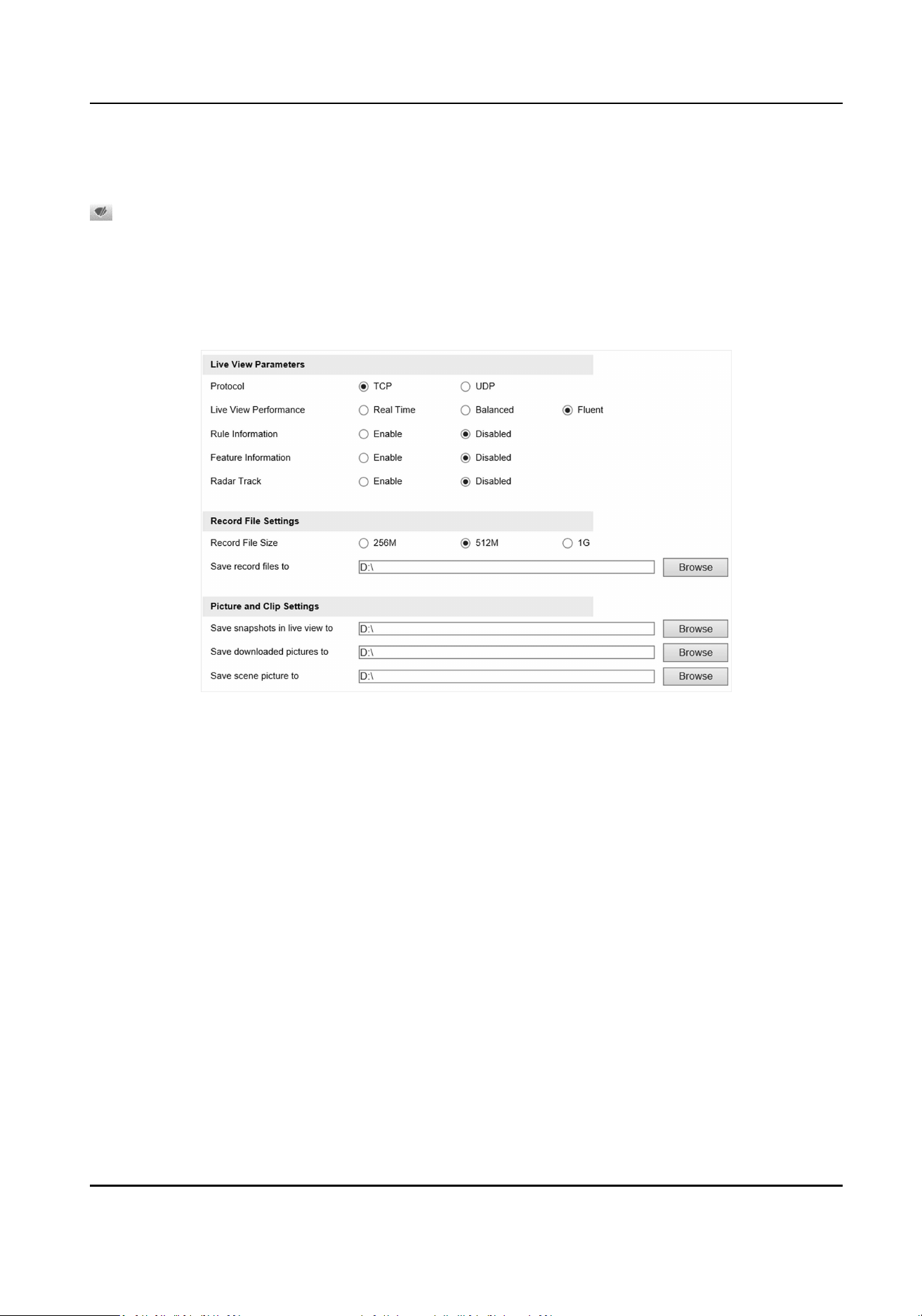
4.4.2 Local Conguraon
Go to Conguraon → Local Conguraon to set the live view parameters and change the saving
paths of videos, captured pictures, scene pictures, etc.
Figure 4-14 Local Conguraon
Protocol
Select the network transmission protocol according to the actual needs.
TCP
Ensures complete delivery of streaming data and beer video quality, yet the real-me
transmission will be aected.
UDP
Provides real-me audio and video streams.
Live View Performance
Real Time
The video is real-me, but the video uency may be aected.
Balanced
Balanced mode considers both the real me and uency of the video.
Fluent
When the network condion is good, the video is uent.
Portable Radar Speed Detector User Manual
49
Rule Informaon
If you enable the rule informaon, tracking frames will be displayed on the live view interface
when there are vehicles passing.
Feature Informaon
If you enable the feature informaon, informaon of the lane, trac ow, speed, etc. will be
displayed on the live view interface.
Record File Size
Select the packed size of the manually recorded video les. Aer the selecon, the max. record
le size is the value you selected.
Save record les to
Set the saving path for the manually recorded video les.
Save snapshots in live view to
Set the saving path of the manually captured pictures in live view mode.
Save downloaded pictures to
Set the saving path for the downloaded pictures.
Save scene picture to
Set the saving path of the captured pictures in the Real-Time Status and Trac Flow Stascs
interface.
Note
The parameters vary with dierent models. The actual device prevails.
4.5 Record and Capture
4.5.1 Set Storage Path
Set Storage Media
If you want to store the les to the storage media, make sure you format the storage media in
advance.
Steps
1. Go to Conguraon → Device Conguraon → Encoding and Storage → Storage
Management .
Portable Radar Speed Detector User Manual
50
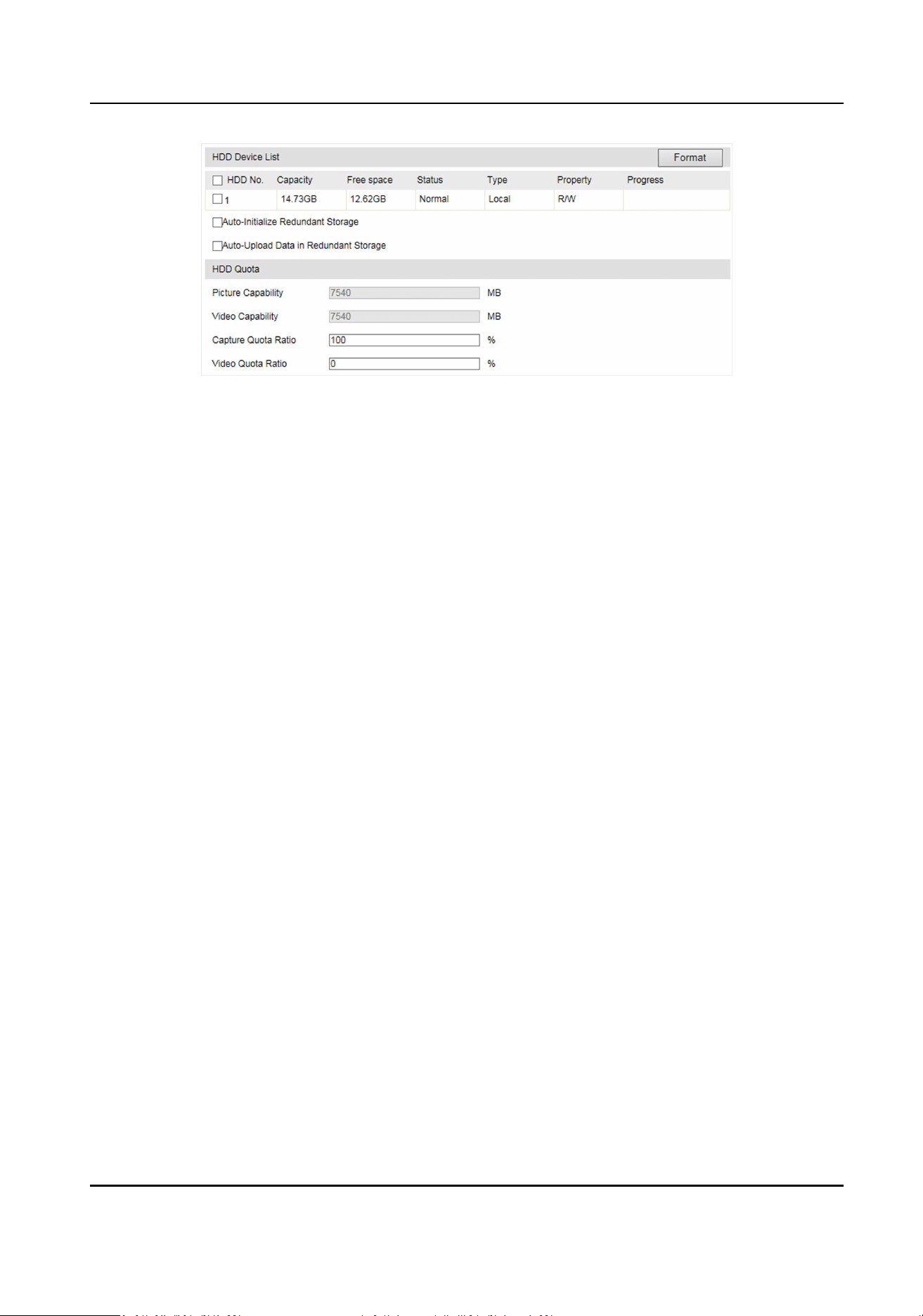
Figure 4-15 Set Storage Media
2. Format the storage media in two ways.
-
Check the storage media, and click Format to format it manually.
-
If you want to format the storage media automacally when the it is abnormal, check Auto-
Inialize Redundant Storage.
3. Oponal: If the device has been connected to the plaorm, and you want to upload the storage
media informaon automacally, check Auto-Upload Data in Redundant Storage.
4. Click Save.
Set FTP
Set FTP parameters if you want to upload the captured pictures to the FTP server.
Before You Start
Set the FTP server, and ensure the device can communicate normally with the server.
Steps
1. Go to Conguraon → Device Conguraon → Encoding and Storage → FTP .
Portable Radar Speed Detector User Manual
51
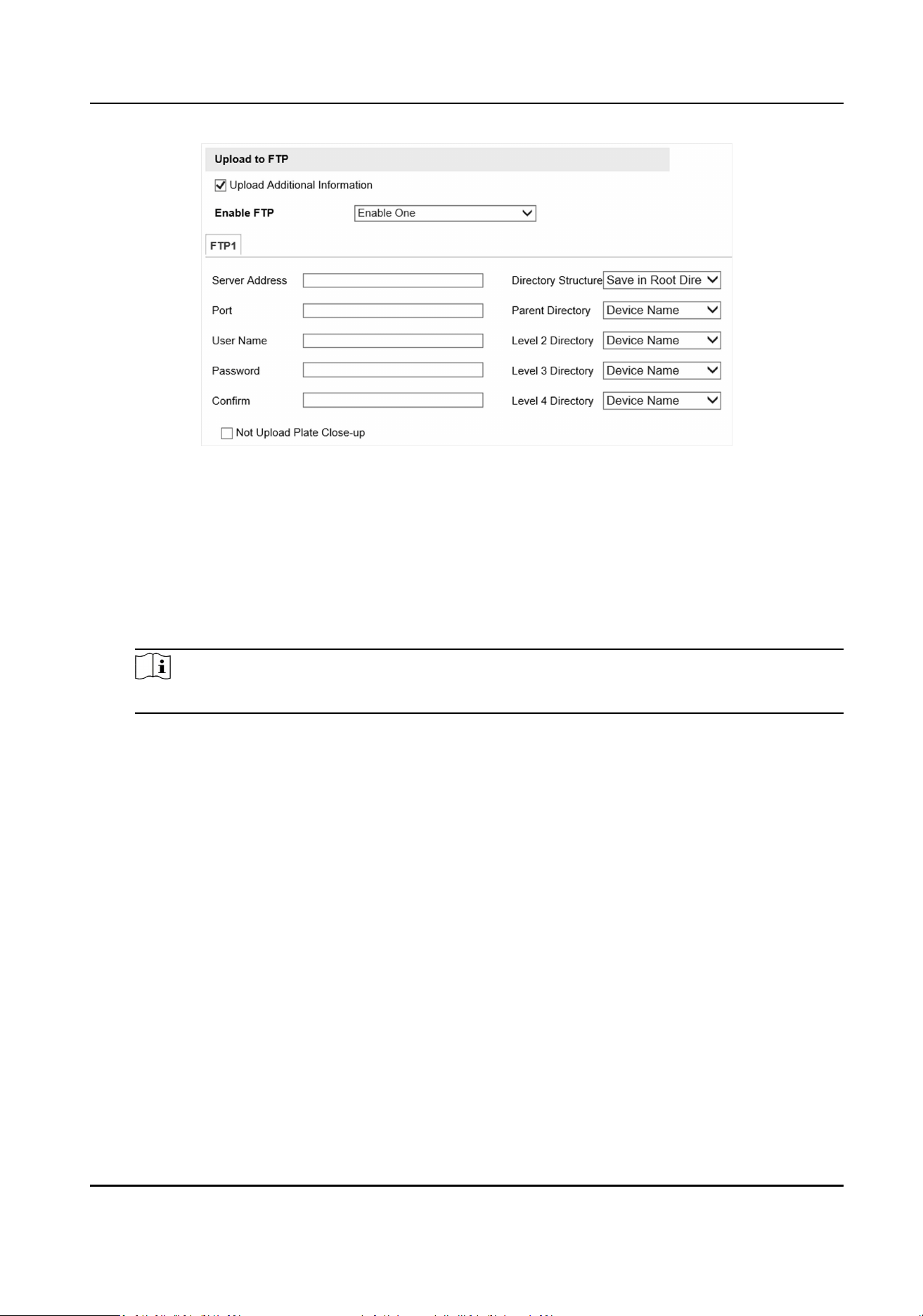
Figure 4-16 Set FTP
2. Oponal: Check Upload Addional Informaon, and then the related informaon can be
aached when uploading.
3. Enable the FTP server.
4. Set FTP parameters.
1) Enter Server Address and Port.
2) Enter User Name and Password, and conrm the password.
3) Select Directory Structure.
Note
If mulple directories are needed, you can customize the directory name.
5. Oponal: Check Not Upload Plate Close-up if the license plate close-up pictures are not needed
to upload.
6. Set the name rule and separator according to the actual needs.
7. Oponal: Edit OSD informaon which can be uploaded to the FTP server with the pictures to
make it convenient to view and disnguish the data.
8. Click Save.
Set Listening Host
The listening host can be used to receive the uploaded informaon and pictures of the device
arming alarm.
Before You Start
The listening service has been enabled for the listening host, and the network communicaon with
the device is normal.
Steps
1. Go to Conguraon → Device Conguraon → System Conguraon → Network Parameters .
Portable Radar Speed Detector User Manual
52
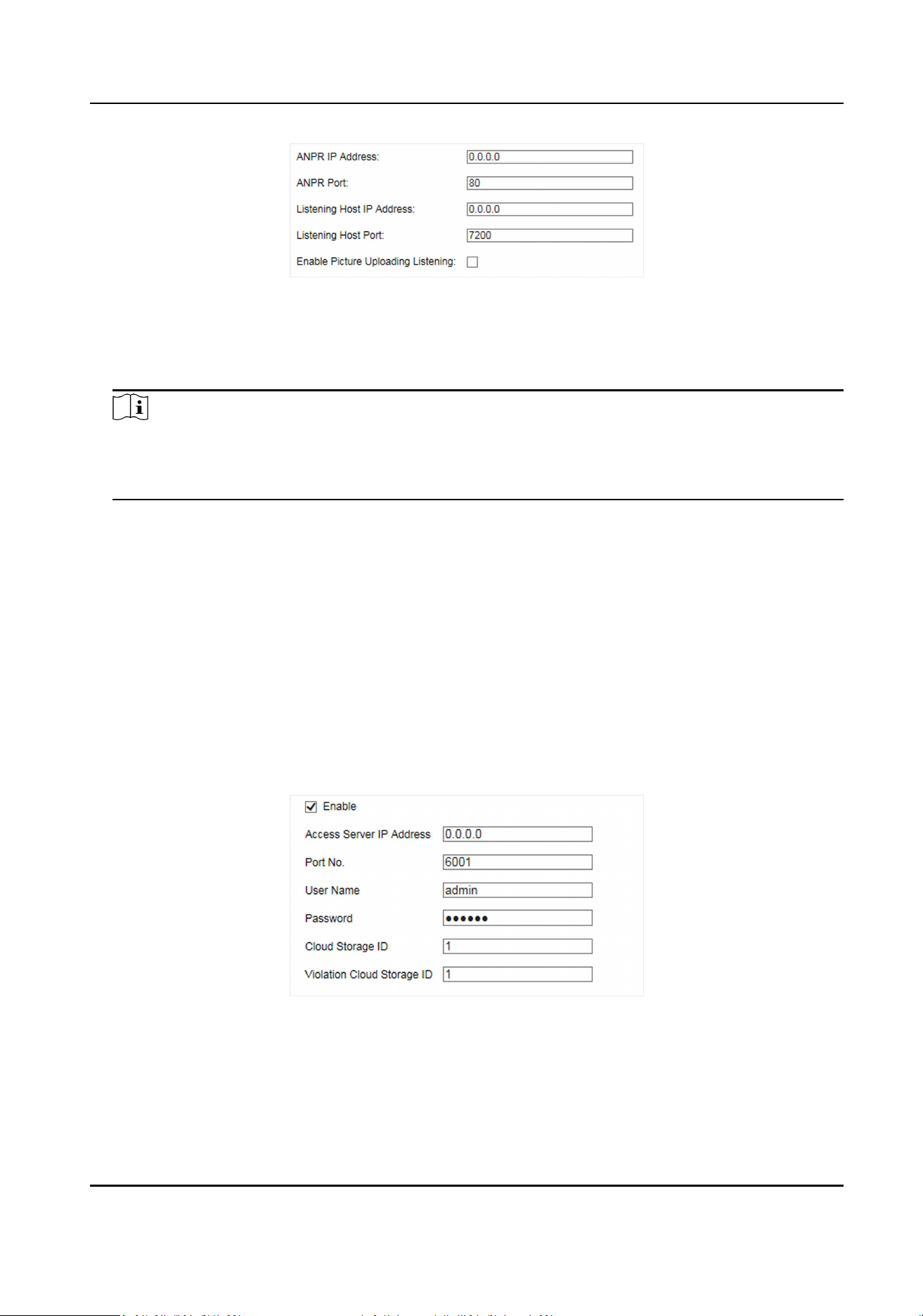
Figure 4-17 Set Listening Host
2. Set ANPR IP Address and ANPR Port to upload the alarm informaon and pictures.
3. Set Listening Host IP Address and Listening Host Port, and check Enable Picture Uploading
Listening if you need to upload pictures.
Note
ANPR and listening conict with each other. When you enable listening host, pictures will be
uploaded via listening host in priority. When you disable listening and have set ANPR IP address
and port, pictures will be uploaded via ANPR protocol.
4. Click Save.
Set Cloud Storage
Cloud storage is a kind of network storage. It can be used as the extended storage to save the
captured pictures.
Before You Start
• Arrange the cloud storage server.
• You have enabled level 1 arm in Real-Time Status and Trac Flow Stascs.
Steps
1. Go to Conguraon → Device Conguraon → Encoding and Storage → Cloud Storage .
Figure 4-18 Set Cloud Storage
2. Check Enable.
3. Set the server parameters.
1) Enter Access Server IP Address and Port No.
2) Enter User Name and Password.
Portable Radar Speed Detector User Manual
53
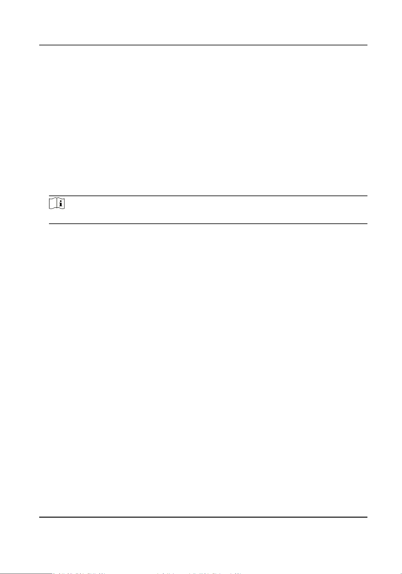
3) Enter the ID according to the storage area No. of the server.
4. Click Save.
4.5.2 Set Quota
Set the video and picture rao in the storage.
Before You Start
Ensure the storage status is normal.
Steps
1. Go to Conguraon → Device Conguraon → Encoding and Storage → Storage
Management .
2. Set Capture Quota Rao and Video Quota Rao according to the actual needs.
Note
The percentage sum of the capture and video quota rao should be 100%.
3. Click Save.
What to do next
Format the storage media aer the sengs.
4.5.3 Set Record Schedule
Set record schedule to record video automacally during congured me periods.
Before You Start
Ensure the storage status is normal. You are recommended to set the video quota rao as not 0.
Steps
1. Go to Conguraon → Device Conguraon → Encoding and Storage → Record Schedule .
Portable Radar Speed Detector User Manual
54
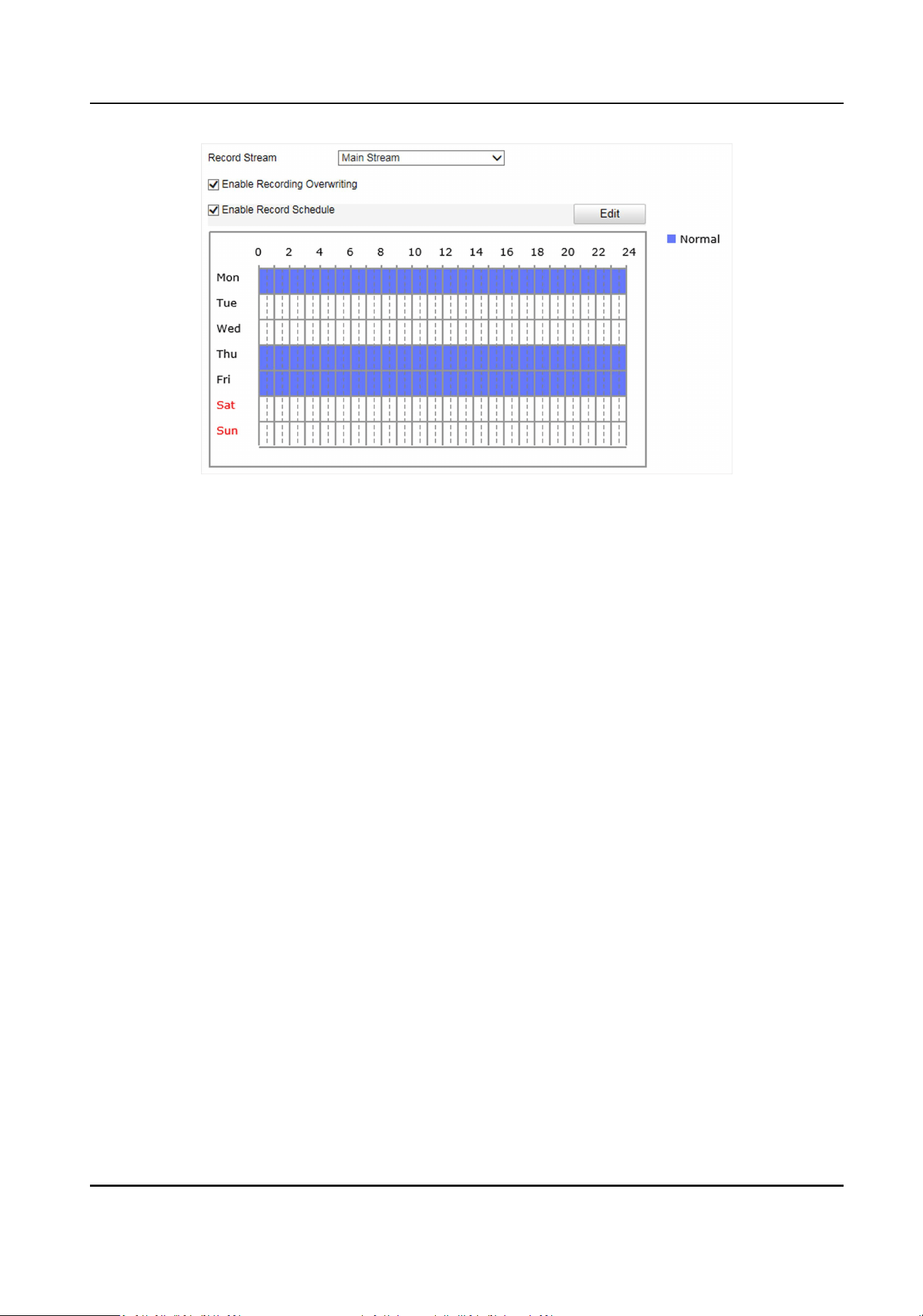
Figure 4-19 Set Record Schedule
2. Oponal: Check Enable Recording Overwring.
When the storage is full, the earliest videos will be overwrien.
3. Check Enable Record Schedule.
4. Click Edit to edit the record schedule.
1) Select Customize.
2) Set the start me and end me.
3) Oponal: Select the other days and click Copy to copy the sengs to other days.
4) Click OK.
5. Click Save.
4.6 Encoding and Display
4.6.1 Set Video Encoding Parameters
Set video encoding parameters to adjust the live view and recording eect.
• When the network signal is good and the speed is fast, you can set high resoluon and bitrate to
raise the image quality.
• When the network signal is bad and the speed is slow, you can set low resoluon, bitrate, and
frame rate to guarantee the image uency.
• When the network signal is bad, but the resoluon should be guaranteed, you can set low
bitrate and frame rate to guarantee the image uency.
• Main stream stands for the best stream performance the device supports. It usually oers the
best resoluon and frame rate the device can do. But high resoluon and frame rate usually
means larger storage space and higher bandwidth requirements in transmission. Sub-stream
Portable Radar Speed Detector User Manual
55

usually oers comparavely low resoluon opons, which consumes less bandwidth and storage
space.
Steps
1. Go to Conguraon → Device Conguraon → Encoding and Storage → Video Encoding .
2. Set the parameters for dierent streams.
Stream Type
Video stream and video & audio stream are selectable.
Bitrate
Select relavely large bitrate if you need good image quality and eect, but more storage
spaces will be consumed. Select relavely small bitrate if storage requirement is in priority.
Frame Rate
It is to describe the frequency at which the video stream is updated and it is measured by
frames per second (fps). A higher frame rate is advantageous when there is movement in the
video stream, as it maintains image quality throughout.
Resoluon
The higher the resoluon is, the clearer the image will be. Meanwhile, the network
bandwidth requirement is higher.
SVC
Scalable Video Coding (SVC) is an extension of the H.264/AVC and H.265 standard. Enable the
funcon and the device will automacally extract frames from the original video when the
network bandwidth is insucient.
Bitrate Type
Select the bitrate type to constant, variable, MVBR, or SVBR.
Video Quality
When bitrate type is not constant, 6 levels of video quality are selectable. The higher the
video quality is, the higher requirements of the network bandwidth.
Prole
Selectable proles vary according to device models.
I Frame Interval
It refers to the number of frames between two key frames. The larger the I frame interval is,
the smaller the stream uctuaon is, but the image quality is not that good.
Video Encoding
The device supports mulple video encoding types, such as H.264, H.265, and MJPEG.
Supported encoding types for dierent stream types may dier. H.265 is a new encoding
technology. Compared with H.264, it reduces the transmission bitrate under the same
resoluon, frame rate, and image quality.
3. Click Save.
Portable Radar Speed Detector User Manual
56
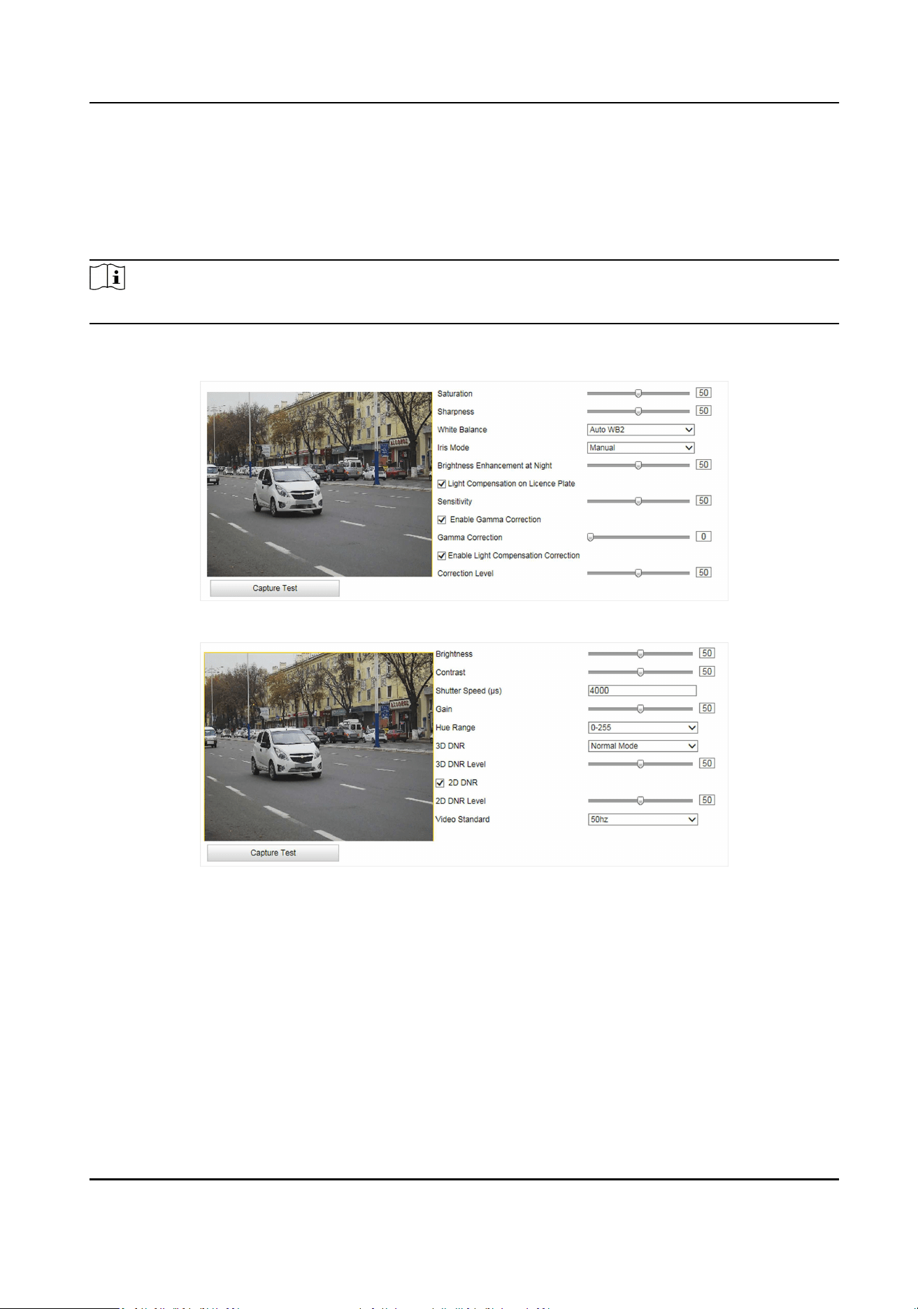
4.6.2 Set Image Parameters
You can adjust the image parameters to get clear image.
Steps
Note
The supported parameters may vary with dierent models. The actual device prevails.
1. Go to Conguraon → Device Conguraon → Image Parameters → General Parameters /
Conguraon → Device Conguraon → Image Parameters → Video .
Figure 4-20 Set General Parameters
Figure 4-21 Set Video Image Parameters
2. Adjust the parameters.
Saturaon
It refers to the colorfulness of the image color.
Sharpness
It refers to the edge contrast of the image.
White Balance
It is the white rendion funcon of the device used to adjust the color temperature
according to the environment.
Portable Radar Speed Detector User Manual
57

Iris Mode
Select the iris mode as manual or auto.
Brightness Enhancement at Night
The scene brightness will be enhanced at night automacally.
Light Compensaon on License Plate
Check it. The plate brightness compensaon can be realized, and various light supplement
condions can be adapted via seng license plate expectant brightness and supplement
light correcon coecient. The higher the sensivity is, the easier this funcon can be
enabled.
Enable Gamma Correcon
The higher the gamma correcon value is, the stronger the correcon strength is.
Enable Light Compensaon Correcon
Check it and set the correcon level to adjust the license plate brightness automacally if the
license plate or scene brightness cannot be adjusted via supplement light.
Brightness
It refers to the max. brightness of the image.
Contrast
It refers to the contrast of the image. Set it to adjust the levels and permeability of the
image.
Shuer Speed
If the shuer speed is quick, the details of the moving objects can be displayed beer. If the
shuer speed is slow, the outline of the moving objects will be fuzzy and trailing will appear.
Gain
It refers to the upper limit value of liming image signal amplicaon. It is recommended to
set a high gain if the illuminaon is not enough, and set a low gain if the illuminaon is
enough.
Hue Range
Select the range to adapt to the display.
3D DNR
Digital Noise Reducon (DNR) reduces the noise in the video stream.
In Normal Mode, the higher the 3D DNR Level is, the stronger the noise will be reduced. But
if it is too high, the image may become fuzzy.
In Expert Mode, set Spaal Intensity and Time Intensity. If the space domain intensity is too
high, the outline of the image may become fuzzy and the details may lose. If the me domain
intensity is too high, trailing may appear.
2D DNR
Portable Radar Speed Detector User Manual
58

The higher the 2D DNR Level is, the stronger the noise will be reduced. But if it is too high,
the image may become fuzzy.
Video Standard
Select the video standard according to the actual power supply frequency.
4.6.3 Set ICR
ICR adopts mechanical IR lter to lter IR in the day to guarantee the image eect, and to remove
the IR lter at night to guarantee full-spectrum rays can get through the device.
Steps
1. Go to Conguraon → Device Conguraon → Image Parameters → ICR .
2. Select ICR Mode.
Auto-switch Switches to ICR mode automacally at night or in dark light condions.
Manual Switch Select Day/Night Mode to switch to the day or night manually.
Scheduled Switch Set day/night mode, start me, and end me to switch to ICR mode
only during the set me period.
Do not switch Disable the ICR mode.
3. Click Save.
4.6.4 Set ROI
ROI (Region of Interest) encoding helps to assign more encoding resources to the region of
interest, thus to increase the quality of the ROI whereas the background informaon is less
focused.
Before You Start
Please check the video encoding type. ROI is supported when the video encoding type is H.264 or
H.265.
Steps
1. Go to Conguraon → Device Conguraon → Encoding and Storage → ROI .
Portable Radar Speed Detector User Manual
59
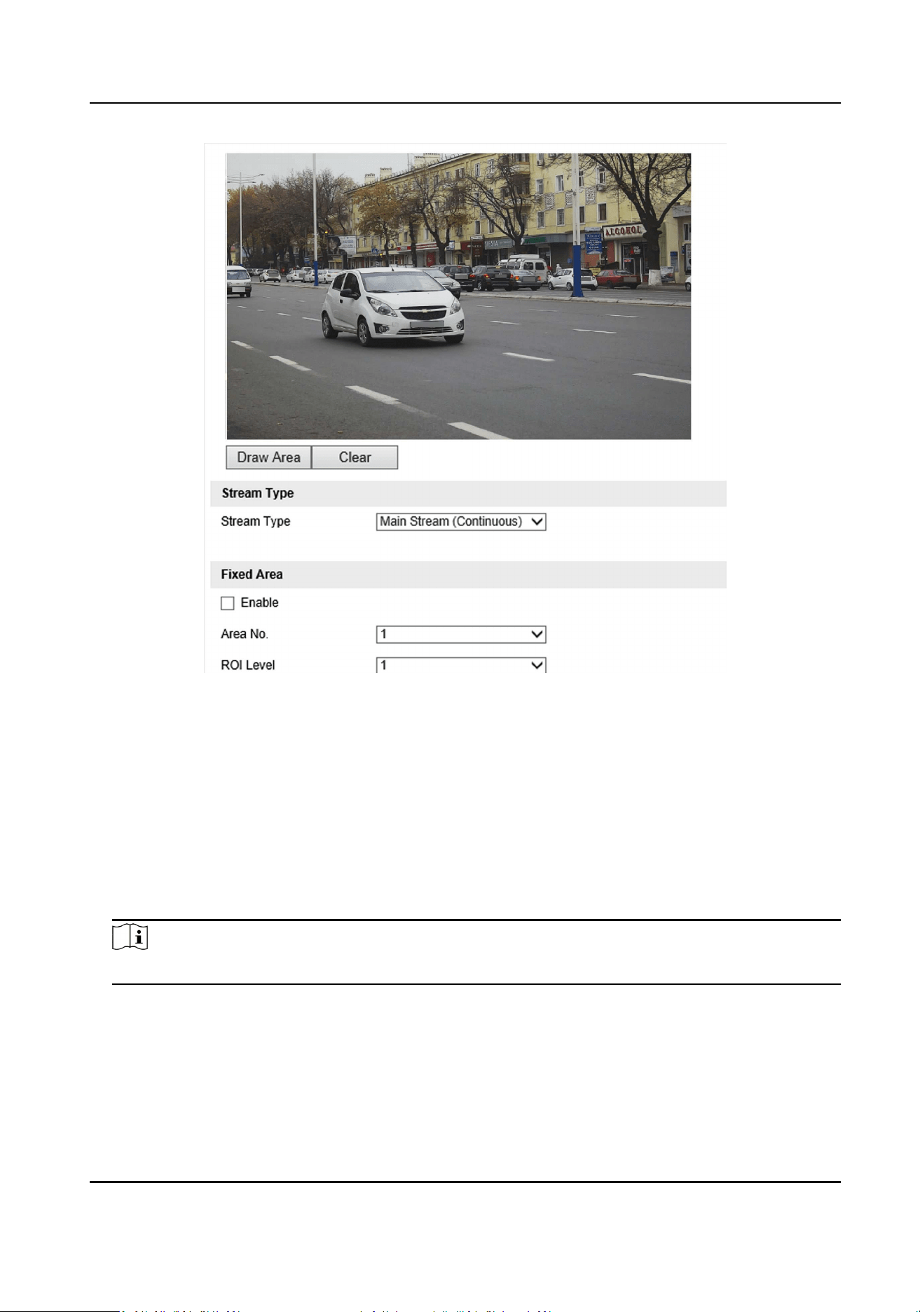
Figure 4-22 Set ROI
2. Select Stream Type.
3. Set ROI region.
1) Check Enable.
2) Select Area No.
3) Click Draw Area.
4) Drag the mouse on the live view image to draw a xed area.
5) Select the xed area that needs to be adjusted and drag the mouse to adjust its posion.
6) Click Stop Drawing.
4. Select Area No. and ROI Level and enter Area Name.
Note
The higher the ROI level is, the clearer the image of the detected area is.
5. Click Save.
6. Oponal: Select other area codes and repeat the steps above if you need to draw mulple xed
areas.
Portable Radar Speed Detector User Manual
60
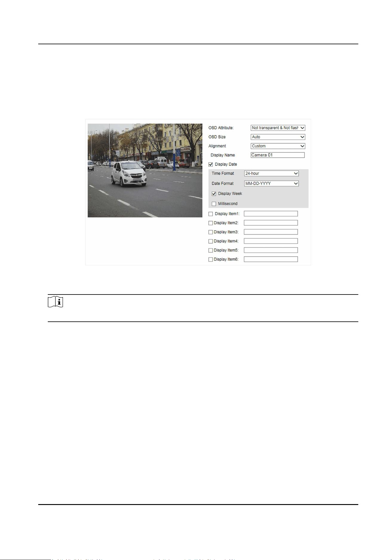
4.6.5 Set OSD
You can customize OSD informaon on the live view.
Steps
1. Go to Conguraon → Device Conguraon → Text Overlay → OSD Sengs .
Figure 4-23 Set OSD
2. Set OSD aribute, size, alignment, etc.
Note
The supported funcons vary with dierent models. The actual device prevails.
3. Set the display content.
1) Enter Display Name.
2) Check Display Date, and set the me and date format.
3) Check Display Week or Millisecond according to your needs.
4. Oponal: Check the display item(s) and enter the informaon in the text eld(s).
5. Drag the red frames on the live view image to adjust the OSD posions.
6. Click Save.
Result
The set OSD will be displayed in live view image and recorded videos.
Portable Radar Speed Detector User Manual
61
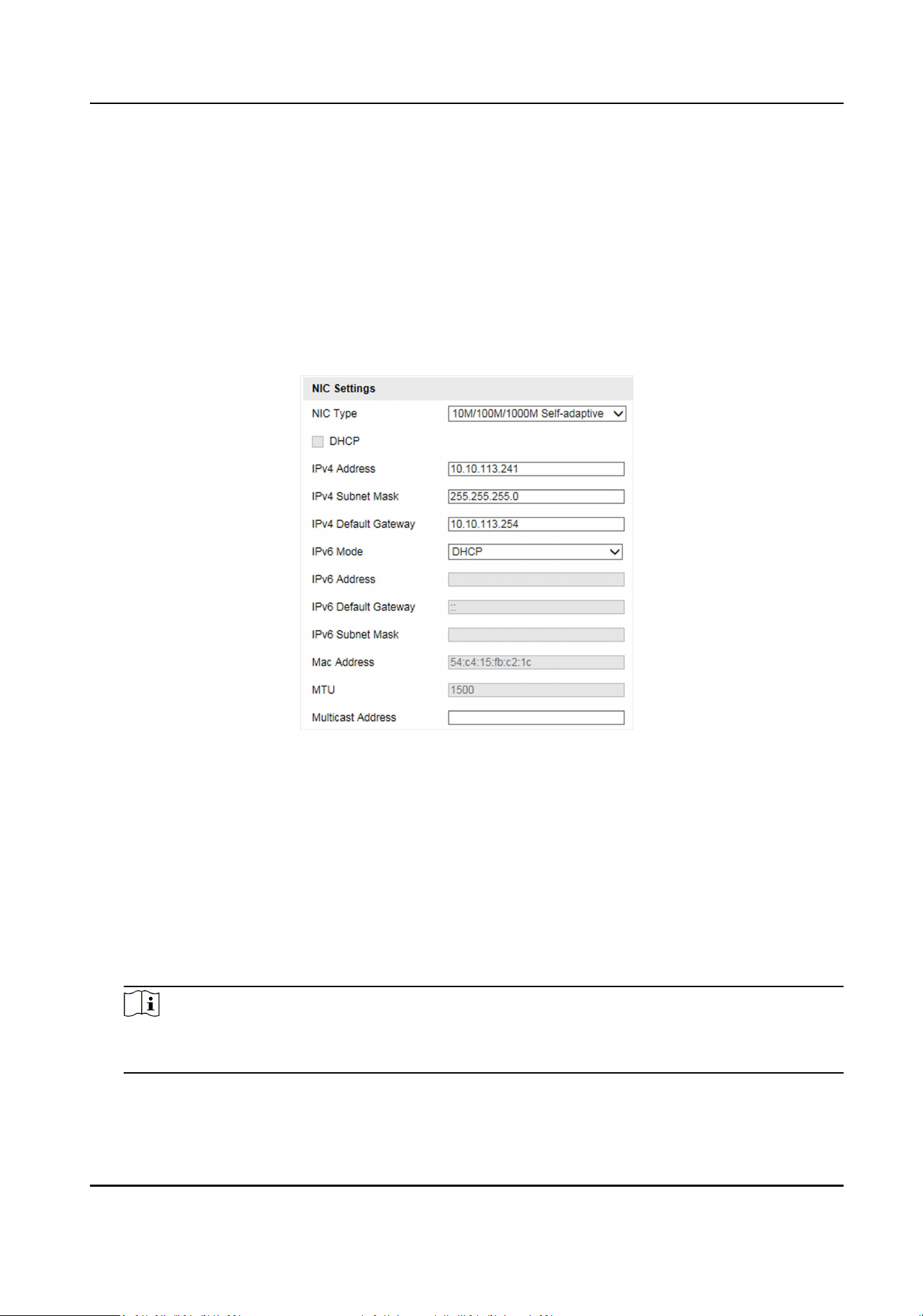
4.7 Network Conguraon
4.7.1 Set IP Address
IP address must be properly congured before you operate the device over network. IPv4 and IPv6
are both supported. Both versions can be congured simultaneously without conicng to each
other.
Go to Conguraon → Device Conguraon → System Conguraon → Network Parameters .
Figure 4-24 Set IP Address
NIC Type
Select a NIC (Network Interface Card) type according to your network condion.
IPv4
Two IPv4 modes are available.
DHCP
The device automacally gets the IPv4 parameters from the network if you check DHCP. The
device IP address is changed aer enabling the funcon. You can use SADP to get the device IP
address.
Note
The network that the device is connected to should support DHCP (Dynamic Host
Conguraon Protocol).
Manual
Portable Radar Speed Detector User Manual
62

You can set the device IPv4 parameters manually. Enter IPv4 Address, IPv4 Subnet Mask, and
IPv4 Default Gateway.
IPv6
Three IPv6 modes are available.
Route Adversement
The IPv6 address is generated by combining the route adversement and the device Mac
address.
Note
Route adversement mode requires the support from the router that the device is connected
to.
DHCP
The IPv6 address is assigned by the server, router, or gateway.
Manual
Enter IPv6 Address, IPv6 Subnet Mask, and IPv6 Default Gateway. Consult the network
administrator for required informaon.
MTU
It stands for maximum transmission unit. It is the size of the largest protocol data unit that can
be communicated in a single network layer transacon.
The valid value range of MTU is 1280 to 1500.
Mulcast
Mulcast is group communicaon where data transmission is addressed to a group of
desnaon devices simultaneously. Aer seng the IP address of the mulcast host, you can
send the source data eciently to mulple receivers.
DNS
It stands for domain name server. It is required if you need to visit the device with domain
name. And it is also required for some applicaons (e.g., sending email). Set Preferred DNS
Server properly if needed.
4.7.2 Dial
Set the dialing parameters if you want to connect the device to the network via SIM card.
Before You Start
Install SIM card.
Steps
1. Go to Conguraon → Device Conguraon → System Conguraon → Dial-up
Conguraon .
Portable Radar Speed Detector User Manual
63
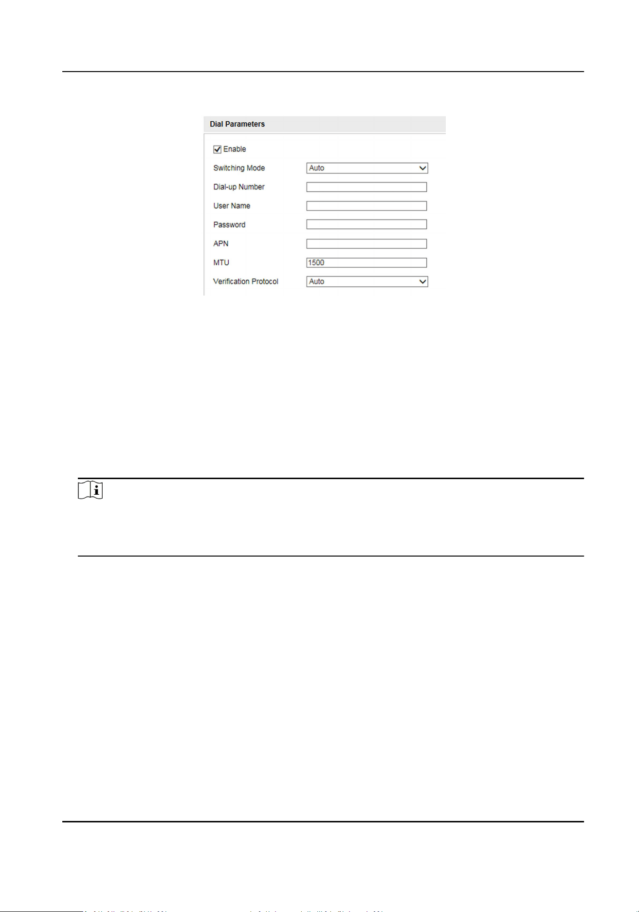
2. Check Enable.
Figure 4-25 Set Dial-up Parameters
3. Select Switching Mode.
Force Switch to 4G
Select it to x to 4G network.
Force Switch to 3G
Select it when 4G network is not steady.
Force Switch to 2G
Select it when 3G network is not steady.
4. Set the APN informaon, such as the user name, APN, etc.
Note
• Consult the operator about the dial-up parameters.
• When you have enabled 2G/3G/4G and Wi-Fi simultaneously, the device will use 2G/3G/4G
network in priority.
5. Click Save.
6. Oponal: Click Refresh to view the dial-up status.
4.7.3 Connect to Wi-Fi
Set Wi-Fi parameters if you want to connect the device to the network via Wi-Fi.
Steps
1. Go to Conguraon → Device Conguraon → System Conguraon → Wi-Fi .
2. Select Wi-Fi Mode as Wi-Fi.
3. Click Search to search the Wi-Fi.
4. Select a Wi-Fi from the wireless network list, and enter Key.
5. Click Save.
Portable Radar Speed Detector User Manual
64
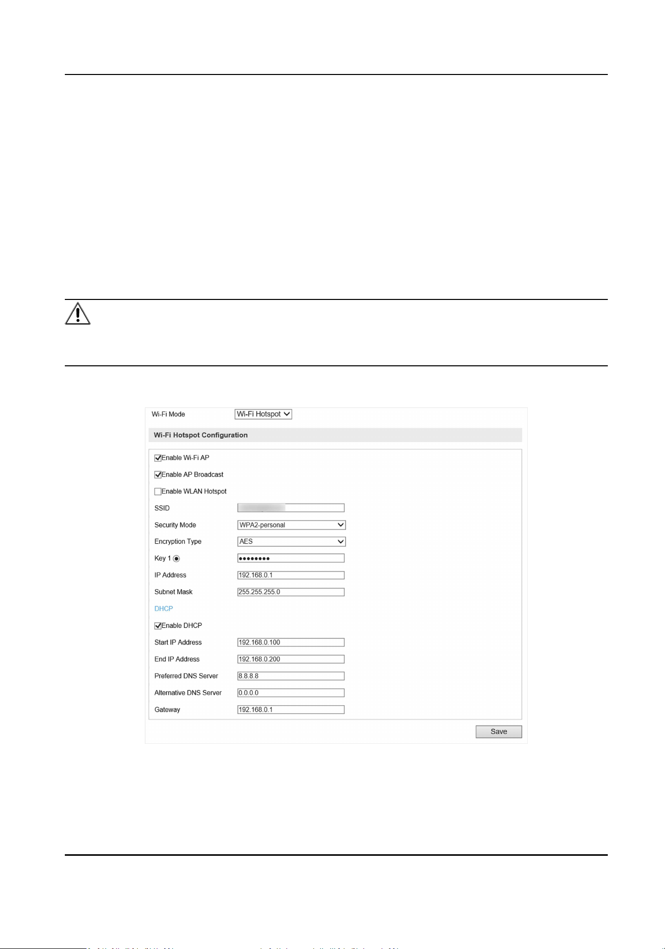
6. Oponal: If you want to edit the IP address connected to the Wi-Fi to make it convenient to
access to the device via the IP address of WLAN, set the IP address of WLAN.
1) Select IP Address Type as Stac IP.
2) Enter parameters such as IP address, subnet mask, etc.
3) Click Conguraon to save the sengs.
7. Oponal: Go to Conguraon → Device Status to view the connecon status of Wi-Fi.
4.7.4 Set Wi-Fi Hotspot
Set Wi-Fi AP to use the device as a hotspot to share network to another terminal device.
Steps
Cauon
Wi-Fi AP and Wi-Fi funcon cannot be enabled at the same me. Once one of them is enabled, the
other will be disabled automacally.
1. Go to Conguraon → Device Conguraon → System Conguraon → Wi-Fi .
2. Select Wi-Fi Mode as Wi-Fi Hotspot.
Figure 4-26 Set Wi-Fi Hotspot
3. Check Enable Wi-Fi AP, Enable AP Broadcast, and Enable WLAN Hotspot.
4. Set hotspot informaon.
Portable Radar Speed Detector User Manual
65
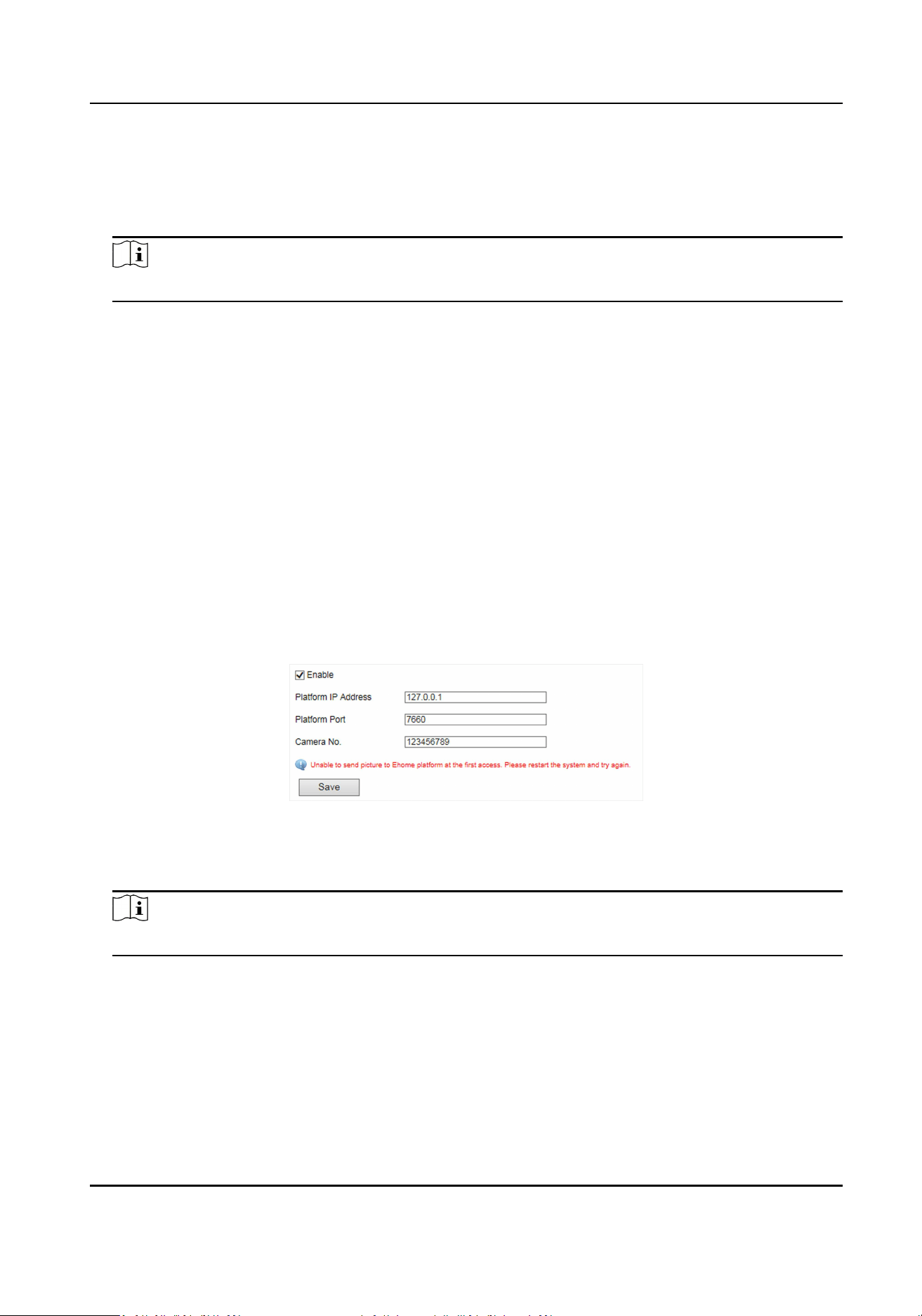
1) Enter SSID (hotspot name).
2) Select Security Mode.
3) Select Encrypon Type.
4) Enter Key, IP Address, and Subnet Mask.
Note
The IP address should be dierent from the one that set in the network parameters.
5. Oponal: Check Enable DHCP and enter the start/end IP address.
Result
When the device connects to the network via dialing, the connected peripheral device can get
access to the network either.
4.7.5 Connect to EHome Plaorm
EHome is a plaorm access protocol. The device can be remotely accessed via this plaorm.
Before You Start
• Create the device ID on EHome plaorm.
• Ensure the device can communicate with the plaorm normally.
Steps
1. Go to Conguraon → Device Conguraon → System Conguraon → EHome .
Figure 4-27 Connect to EHome Plaorm
2. Check Enable.
3. Enter Plaorm IP Address, Plaorm Port, and Camera No.
Note
The camera No. should be the same with the added one on the EHome plaorm.
4. Click Save.
Result
Aer connecng to the EHome plaorm, you can add or manage the device via the plaorm
soware. Refer to the corresponding user manual for details.
Portable Radar Speed Detector User Manual
66
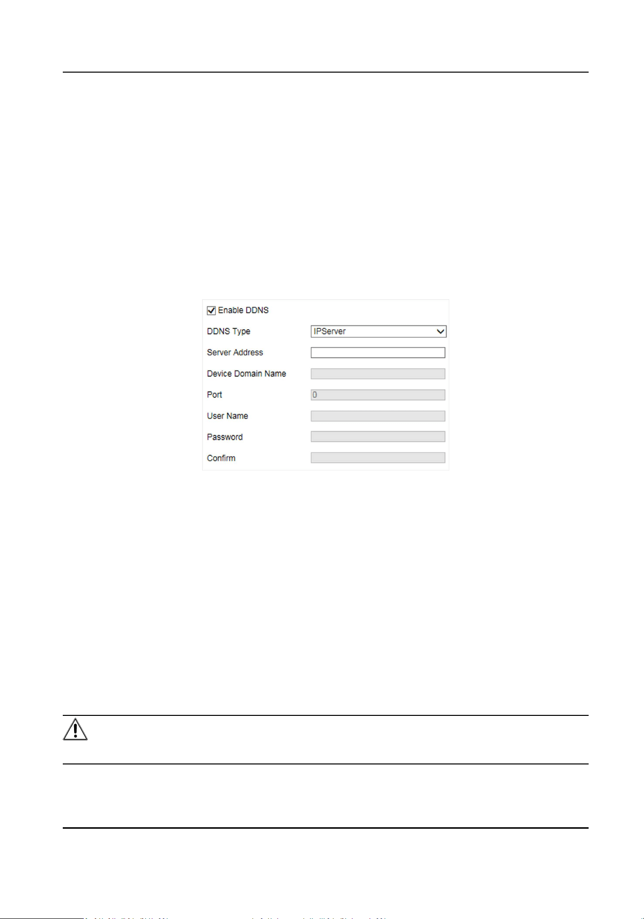
4.7.6 Set DDNS
You can use the Dynamic DNS (DDNS) for network access. The dynamic IP address of the device can
be mapped to a domain name resoluon server to realize the network access via domain name.
Before You Start
• Register the domain name on the DDNS server.
• Set the LAN IP address, subnet mask, gateway, and DNS server parameters. Refer to "Set IP
Address" for details.
• Complete port mapping. The default port is 80, 8000, and 554.
Steps
1. Go to Conguraon → Device Conguraon → System Conguraon → DDNS .
Figure 4-28 Set DDNS
2. Check Enable DDNS.
3. Enter the server address and other informaon.
4. Click Save.
5. Access the device.
By Browsers Enter the domain name in the browser address bar to access the
device.
By Client Soware Add domain name to the client soware. Refer to the client soware
manual for specic adding methods.
4.7.7 Set Port
The device port can be modied when the device cannot access the network due to port conicts.
Cauon
Do not modify the default port parameters at will, otherwise the device may be inaccessible.
Portable Radar Speed Detector User Manual
67
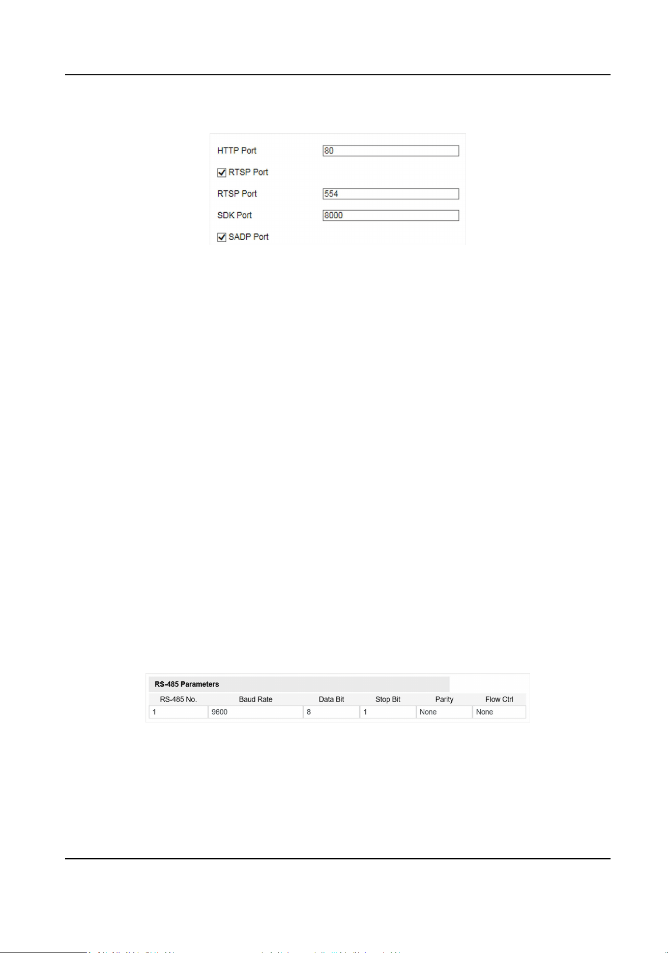
Go to Conguraon → Device Conguraon → System Conguraon → Port .
Figure 4-29 Set Port
HTTP Port
It refers to the port through which the browser accesses the device. For example, when the
HTTP Port is modied to 81, you need to enter hp://192.168.1.64:81 in the browser for login.
RTSP Port
It refers to the port of real-me streaming protocol.
SDK Port
It refers to the port through which the client adds the device.
SADP Port
It refers to the port through which the SADP soware searches the device.
4.8 Serial Port Conguraon
4.8.1 Set RS-485
Set RS-485 parameters if the device needs to be connected to other peripheral devices controlled
by RS-485 serial port.
Before You Start
The corresponding device has been connected via the RS-485 serial port.
Steps
1. Go to Conguraon → Device Conguraon → System Conguraon → Serial Ports .
Figure 4-30 Set RS-485
2. Set Baud Rate, Data Bit, Stop Bit, etc.
Portable Radar Speed Detector User Manual
68
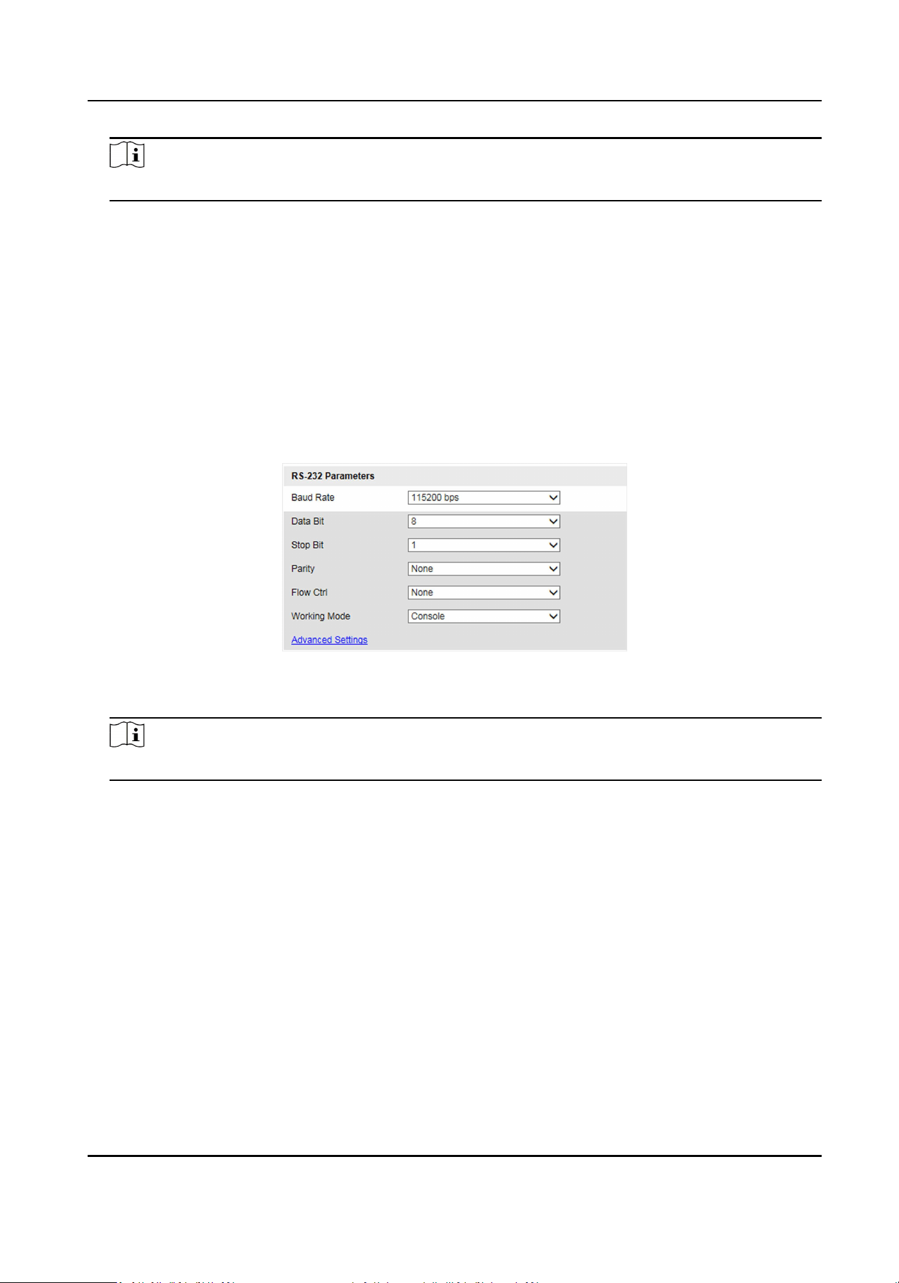
Note
The parameters should be same with those of the connected device.
3. Click Save.
4.8.2 Set RS-232
Set RS-232 parameters if you need to debug the device via RS-232 serial port.
Before You Start
The debugging device has been connected via the RS-232 serial port.
Steps
1. Go to Conguraon → Device Conguraon → System Conguraon → Serial Ports .
2. Click Advanced Sengs.
Figure 4-31 Set RS-232
3. Set Baud Rate, Data Bit, Stop Bit, etc.
Note
The parameters should be same with those of the connected device.
4. Select Working Mode.
Console
Select it when you need to debug the device via RS-232 serial port.
Transparent Channel
Select it, and the network command can be transmied to RS-232 control command via the
RS-232 serial port.
Narrowband
Reserved.
5. Click Save.
Portable Radar Speed Detector User Manual
69
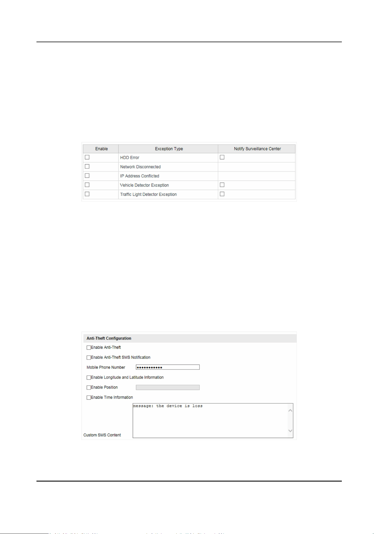
4.9 Alarm
4.9.1 Set Excepon Alarm
Set excepon alarm when the network is disconnected, the IP address is conicted, etc.
Steps
1. Go to Conguraon → Device Conguraon → Events → Excepon Event .
Figure 4-32 Set Excepon Alarm
2. Select the excepon type(s) and the linkage method.
3. Click Save.
4.9.2 Set An-The
Set an-the to prompt alarm informaon when the baery of the device is being pulled out or
inserted, or the power is o.
Before You Start
Ensure the dial module is normal.
Steps
1. Go to Conguraon → Device Conguraon → System Conguraon → An-The .
Figure 4-33 Set An-The
Portable Radar Speed Detector User Manual
70
2. Check Enable An-The.
3. Enable an-the SMS nocaon.
1) Check Enable An-The SMS Nocaon.
2) Enter Mobile Phone Number.
3) Edit Custom SMS Content.
When the baery of the device is being pulled out or inserted, or the power is o, the SMS
content will be sent to the specic mobile phone.
4. Oponal: Check Enable Longitude and Latude Informaon, Enable Posion, or Enable Time
Informaon according to your needs.
5. Click Save.
4.10 Safety Management
4.10.1 Manage User
The administrator can add, modify, or delete other accounts, and grant dierent permissions to
dierent user levels.
Steps
1. Go to Conguraon → Device Conguraon → User Management .
2. Add a user.
1) Click Add.
2) Enter User Name and select Level.
3) Enter Password, and conrm the password.
Cauon
To increase security of using the device on the network, please change the password of your
account regularly. Changing the password every 3 months is recommended. If the device is
used in high-risk environment, it is recommended that the password should be changed
every month or week.
4) Assign remote permission to users based on needs.
User
Users can be assigned permission of viewing live video and changing their own passwords,
but no permission for other operaons.
Operator
Operators can be assigned all permission except for operaons on the administrator and
creang accounts.
5) Click OK.
Portable Radar Speed Detector User Manual
71

Note
The administrator can add up to 31 user accounts.
3. You can do the following operaons.
-
Select a user and click Modify to change the password and permission.
-
Select a user and click Delete to delete the user.
4.10.2 Enable User Lock
To raise the data security, you are recommended to lock the current IP address.
Steps
1. Go to Conguraon → Device Conguraon → System Conguraon → Service .
2. Check Enable User Lock.
3. Click Save.
Result
When the mes you entered incorrect passwords have reached the limit, the current IP address
will be locked automacally.
4.10.3 Set HTTPS
Create and Install Self-signed Cercate
HTTPS is a network protocol that enables encrypted transmission and identy authencaon,
which improves the security of remote access.
Steps
1. Go to Conguraon → Device Conguraon → System Conguraon → HTTPS .
2. Select Create Self-signed Cercate.
3. Click Create.
4. Follow the prompt to enter Country, Hostname/IP, Validity, and other parameters.
5. Click OK.
Result
The device will install the self-signed cercate by default.
Install Authorized Cercate
If the demand for external access security is high, you can create and install authorized cercate
via HTTPS protocol to ensure the data transmission security.
Portable Radar Speed Detector User Manual
72

Steps
1. Go to Conguraon → Device Conguraon → System Conguraon → HTTPS .
2. Select Create cercate request rst and connue the installaon.
3. Click Create.
4. Follow the prompt to enter Country, Hostname/IP, Validity, and other parameters.
5. Click Download to download the cercate request and submit it to the trusted authority for
signature.
6. Import cercate to the device.
-
Select Signed cercate is available, start the installaon directly. Click Browse and Install
to import the cercate to the device.
-
Select Create the cercate request rst and connue the installaon. Click Browse and
Install to import the cercate to the device.
7. Click Save.
4.10.4 Set SSH
To raise network security, disable SSH service. The conguraon is only used to debug the device
for the professionals.
Steps
1. Go to Conguraon → Device Conguraon → System Conguraon → Service .
2. Uncheck Enable SSH Service.
3. Click Save.
4.11 Maintenance
4.11.1 View Device Informaon
Basic Informaon and Algorithms Library Version
Go to Conguraon → Device Conguraon → System Conguraon → Device Informaon to
view the basic informaon and algorithms library version of the device.
You can edit Device Name and Device No. The device No. is used to control the device. It is
recommended to reserve the default value.
Device Status
Go to Conguraon → Device Status to view the device status, Wi-Fi status, Wi-Fi AP status, etc.
4.11.2 Search Log
Log helps to locate and troubleshoot problems.
Portable Radar Speed Detector User Manual
73
Steps
1. Click Log.
2. Set search condions.
3. Click Search.
The matched log les will be displayed on the log list.
4. Oponal: Click Save Log to save the log les to your computer.
4.11.3 Upgrade
Upgrade the system when you need to update the device version.
Before You Start
Prepare the upgrade le.
Steps
1. Go to Conguraon → Device Conguraon → System Maintenance → Upgrade .
2. Click Browse to select the upgrade le.
3. Click Upgrade.
4. Click OK in the popup window.
Note
The upgrade process will take 1 to 10 minutes. Do not cut o the power supply.
Result
The device will reboot automacally aer upgrade.
4.11.4 Reboot
When the device needs to be rebooted, reboot it via the soware instead of cung o the power
directly.
Steps
1. Go to Conguraon → Device Conguraon → System Maintenance → Reboot .
2. Click Reboot.
3. Click OK to reboot the device.
4.11.5 Restore Parameters
When the device is abnormal caused by the incorrect set parameters, you can restore the
parameters.
Steps
1. Go to Conguraon → Device Conguraon → System Maintenance → Default .
Portable Radar Speed Detector User Manual
74
2. Select the restoraon mode.
-
Click Restore to restore the parameters except the IP parameters and user parameters to the
default sengs.
-
Click Restore Factory Sengs to restore all the parameters to the factory sengs.
3. Click OK.
4.11.6 Synchronize Time
Synchronize the device me when it is inconsistent with the actual me.
Steps
1. Go to Conguraon → Device Conguraon → System Conguraon → Time Sengs .
2. Select Synchronizaon Mode.
NTP Synchronizaon
Select it to synchronize the device me with that of the NTP server. Set Server Address, NTP
Port, and Interval. Click NTP Test to test if the connecon between the device and the server
is normal.
Manual Synchronizaon
Select it to synchronize the device me with that of the computer. Set me manually, or
check Sync. with computer me.
Note
The me synchronizaon modes vary with dierent models. The actual device prevails.
3. Click Save.
4.11.7 Export Parameters
You can export the parameters of one device, and import them to another device to set the two
devices with the same parameters.
Steps
1. Go to Conguraon → Device Conguraon → System Maintenance → Export Parameters .
2. Click Export Parameters.
3. Set a password, and click OK.
Note
The password is used for imporng the conguraon le of the current device to other devices.
4. Select the saving path, and enter the le name.
5. Click Save.
Portable Radar Speed Detector User Manual
75
4.11.8 Import Conguraon File
Import the conguraon le of another device to the current device to set the same parameters.
Before You Start
Save the conguraon le to the computer.
Steps
Cauon
Imporng conguraon le is only available to the devices of the same model and same version.
1. Go to Conguraon → Device Conguraon → System Maintenance → Import Cong. File .
2. Select Imporng Method.
Note
If you select Import Part, check the parameters to be imported.
3. Click Browse to select the conguraon le.
4. Enter the password which is set when the conguraon le is exported, and click OK.
5. Click Import.
6. Click OK on the popup window..
Result
The parameters will be imported, and the device will reboot.
4.11.9 Export Violaon Type File
You can export the violaon type le to check whether the vehicle has illegal types, etc.
Steps
Note
Export violaon type le funcon vary with dierent models, please refer to the actual product.
1. Go to Conguraon → Device Conguraon → System Maintenance .
2. Click Export Violaon Type File.
3. Select the saving path and enter the le name.
4. Click Save.
4.11.10 Export Debug File
The technicians can export the debug le to troubleshoot and maintain the device.
Portable Radar Speed Detector User Manual
76

Steps
1. Go to Conguraon → Device Conguraon → System Maintenance → Export Debug File .
2. Click Export Debug.
3. Select the saving path, and enter the le name.
4. Click Save.
Portable Radar Speed Detector User Manual
77
Appendix A. Communicaon Matrix and Device
Command
Scan the QR code below to get the communicaon matrix of the device.
Scan the QR code below to get the device command.
Portable Radar Speed Detector User Manual
78

UD22731B