Loading ...
Loading ...
Loading ...
EN
22
4-wire connection
Part of metal ground strap must be removed.
1) Use Phillips screwdriver to remove the ground-link screw
from the back of the range. Save the ground-link screw and
the end of the ground link under the screw.
2) Feed the power supply cord through the strain relief in the
cord/conduit plate on bottom of range. Allow enough slack
to easily attach the wiring to the terminal block.
3) Use Phillips screwdriver to connect the green ground wire
from the power supply cord to the range with the ground-
link screw. The ground wire must be attached rst.
4) Use 3/8” nut driver to connect the neutral (white) wire to the
enter terminal block post with one of the 10-32 hex nuts.
(Refer to the “Electric Connection Options” table to see
the appropriate connection type)
5) Connect line 1 (black) and line 2 (red) wires to the outer
terminal block posts with 10-32 hex nuts.
6) Securely tighten hex nuts.
7) Replace terminal block access cover.
4-WIRE CONNECTION
A
B
C
D
E
F
A. Terminal block
B. Bare or Green wire
C. L1 Black wire
D. L2 Red wire
E. Neutral White wire
F. Ground Link screw
3-wire connection
Use this method only if local codes permit connecting chassis
ground conductor to neutral wire of power supply cord:
1) Feed the power supply cord through the strain relief in the
cord/conduit plate on bottom of range. Allow enough slack
to easily attach the wiring to the terminal block.
2) Use 3/8 nut driver to connect the neutral (white) wire to the
center terminal block post with one of the 10-32 hex nuts.
(Refer to the “Electric Connection Options” table to see
the appropriate connection type)
3) Connect line 1 (black) and line 2 (red) wires to the outer
terminal block posts with 10-32 hex nuts.
4) Securely tighten hex nuts.
5) Replace terminal block access cover.
3-WIRE CONNECTION
B
A
C
E
D
F
A. Terminal block
B. Ground strap
C. L1 Black wire
D. L2 Red wire
E. Neutral White wire
F. Ground Link screw
8 - Electrical connections
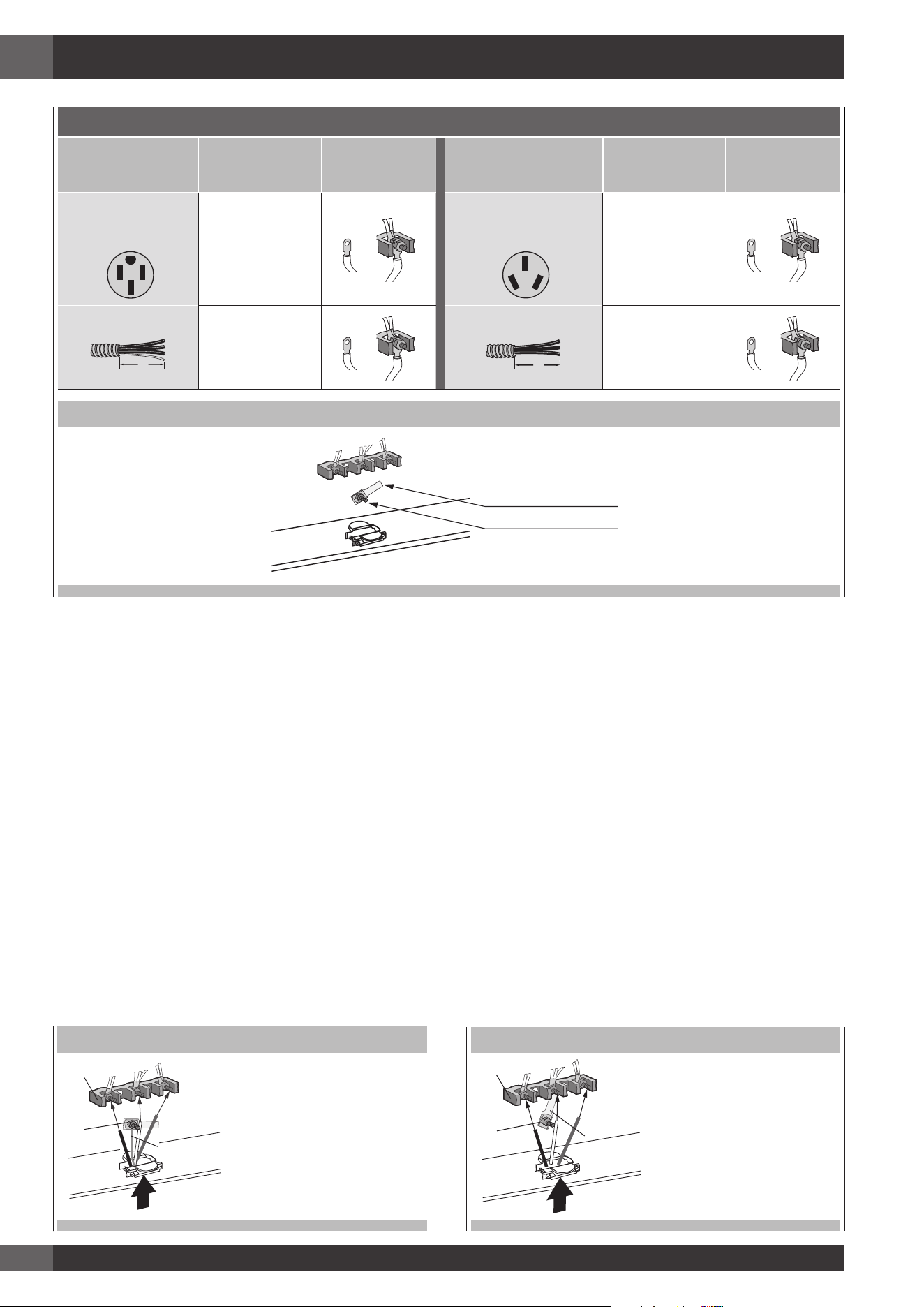
ELECTRICAL CONNECTION OPTIONS
IF YOUR HOME
HAS
AND YOU
WILL BE CON-
NECTING TO:
CONNECTION
TYPE:
IF YOUR HOME HAS AND YOU
WILL BE CON-
NECTING TO:
CONNECTION
TYPE:
4-wire receptacle
(NEMA type 14-50R)
A UL listed, 250-
volt minimum,
30-amp, range
power supply
cord
3-wire receptacle
(NEMA type 10-50R)
A UL listed, 250-
volt minimum,
30-amp, range
power supply
cord
4-wire direct
A fused discon-
nect or circuit
breaker box
3-wire direct
A fused discon-
nect or circuit
breaker box
(12.7 cm)
5"
(12.7 cm)
5"
TERMINAL BLOCK - GROUND STRAP
A. Metal ground strap
B. Ground-link screw
Loading ...
Loading ...
Loading ...