Loading ...
Loading ...
Loading ...
EN
14
6 - Conversion for LP or NG Gas
Converting Appliance for Use with LP Gas
WARNING
Conversion is to be performed by an AUTHORIZED
SERVICER (or other qualied agency) in accordance with the
manufacturer’s instructions and all codes and requirements of
the authority having jurisdiction. Failure to follow instructions
could result in serious injury or property damage.
The qualied agency performing this work assumes
responsibility for this conversion.
CAUTION
Before proceeding with the conversion, shut off the
gas supply to the appliance prior to disconnecting the
electrical power.
If this appliance is to converted for use with gas LP (propane
or butane), each of the following modications must be
performed:
Gas conversion label (aluminium) to be placed on the back of
the appliance, near the data plate, after conversion has been
carried out;
Replace Injectors (two ring flame burner)
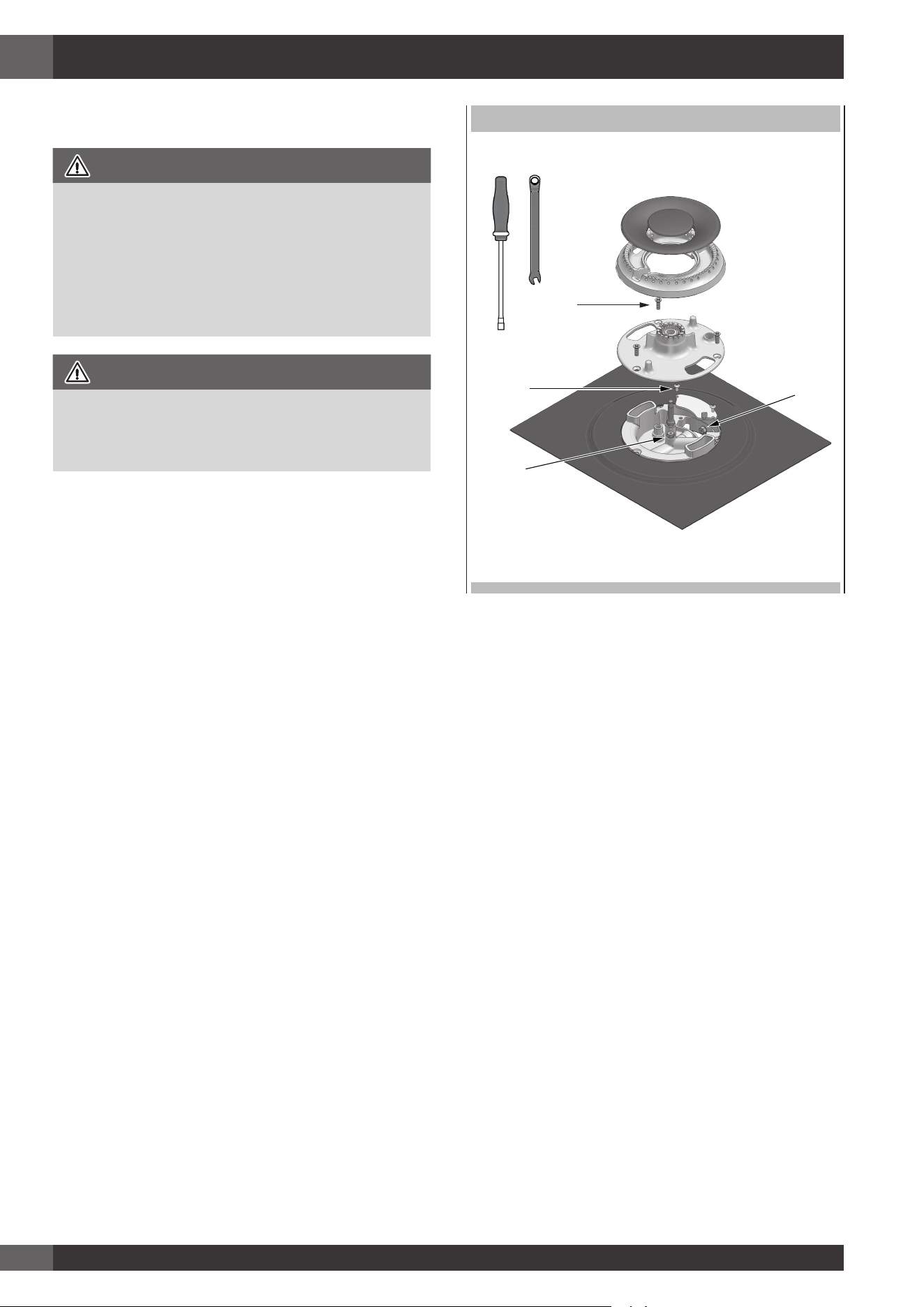
1. Remove the grates and burner caps.
2. Remove aluminium gas spreader.
3. Remove the three screws from the simmer gas spreader
(1).
4. Remove the two screws of the injector cover (2).
5. Remove injector (A) by using a 9-32” (7mm) nut driver
counter clockwise.
6. Remove injector (B) by using a 9-32” (7mm) box wrench
counter clockwise.
7. Install the injectors supplied with this appliance in the
appropriate burner. The injectors have small numbers
stamped on the side, this number corresponds with the
orice diameter and its correct burner location (refer to
illustrations in the section: “Injectors Position”).
8. Turn clockwise to tighten (tighten to a torque of 15 to 20
inch-lbs).
9. Replace all parts following the reverse order.
10. Save the injectors removed from the appliances for
future use.
EXPLODED VIEW OF BURNER
1
2
B
A
Replace Injector (griddle)
1. Remove griddle plate.
2. Remove the burner xing screw (1).
3. Remove the springs (2) from thermocouple and ignitor to
shift the burner.
4. Remove injector (A) by using a 9-32” (7mm) nut driver
counter clockwise.
5. Install the injector supplied with this appliance. The injector
has small numbers stamped on the side, this number
corresponds with the orice diameter.
6. Turn clockwise to tighten (tighten to a torque of 15 to 20
inch-lbs.)
7. Replace all parts following the reverse order.
8. Save the injectors removed from the appliances for future
use.
Loading ...
Loading ...
Loading ...