EN
Original Instructions
Version 1 – December 2023
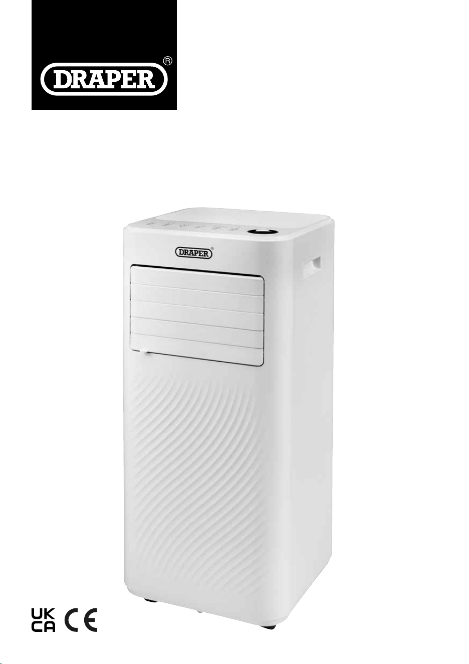
3-IN-1 PORTABLE
23828, 23830
3-IN-1 PORTABLE
AIR CONDITIONER
WITH REMOTE CONTROL
1.1 Product Reference
User Manual for: 3-in -1 Portable Air Conditioner with
Remote Control
Stock No: 23828, 23830
Part No: PAC5, PAC9
1.2 Revisions
Version 1: December 2023
First release
As our manuals are continually updated, always ensure
that the latest version is used.
Please visit drapertools.com/manuals for the latest
version of this manual and the associated parts list, if
applicable.
1.3 Understanding the Safety Content of
This Manual
WARNING!
– Situations or actions that may result
in personal injury or death.
CAUTION! – Situations or actions that may result
in damage to the product or surroundings.
Important: – Information or instructions of particular
importance.
1.4 Copyright © Notice
Copyright © Draper Tools Limited.
Permission is granted to reproduce this manual for
personal and educational use ONLY. Commercial
copying, redistribution, hiring or lending is strictly
prohibited.
No part of this manual may be stored in a retrieval system
or transmitted in any other form or means without written
permission from Draper Tools Limited.
In all cases, this copyright notice must remain intact.
1. Preface
– 2 –
These are the original product instructions. This
document is part of the product; retain it for the life
of the product, passing it on to subsequent holders.
Read this manual in full before attempting to
assemble, operate or maintain this product.
This Draper Tools manual describes the purpose
of the product and contains all the necessary
information to ensure its correct and safe use.
Following all the instructions and guidance in
this manual will ensure the safety of both the
product and the operator and increase the
lifespan of the product.
All photographs and drawings within this manual are
supplied by Draper Tools to help illustrate correct
operation of the product.
Every eort has been made to ensure the
information contained in this manual is accurate.
However, Draper Tools reserves the right to amend
this document without prior warning. Always use the
latest version of the product manual.
2. Contents
– 3 –
EN
1. Preface 2
1.1 Product Reference 2
1.2 Revisions 2
1.3 Understanding the Safety Content of
This Manual 2
1.4 Copyright © Notice 2
2. Contents 3
3. Product Introduction 4
3.1 Intended Use 4
3.2 Specication 4
4. Explanation of Symbols 5
5. Health and Safety Information 6
5.1 General Health and Safety Precautions 6
5.2 Connection to the Power Supply 7
5.3 Residual Risk 7
6. Identication and Unpacking 8
6.1 Product Overview 8
6.2 What’s in the Box? 9
6.3 Packaging 9
7. Before Operation 10
7.1 Attach the Exhaust Hose 10
7.2 Control Panel/ Display 11
7.3 Remote Control 11
8. Operation 12
8.1 Start Up/Shutdown 12
8.2 Operation Modes (2) 12
8.2.1 Cooling Mode (3a)
12
8.2.2 Dehumidier/Dry Mode (3b)
12
8.2.3 Ventilation/Fan Only Mode (3c)
12
8.2.4 Sleep Mode 12
8.2.5 Timer Setting – 1hour – 24hours (8) 12
8.2.6 Automatic Defrost 12
8.2.7 Overload Protection 12
9. Maintenance and Troubleshooting 13
9.1 Manual Drainage 13
9.2 Continuous Drainage 13
9.3 General Cleaning 13
9.4 Cleaning the Air Filter (4) 13
9.5 Troubleshooting 14
9.6 Storage 14
10. Spares, Returns and Disposal 15
11. Warranty 15

3. Product Introduction
– 4 –
3.1 Intended Use
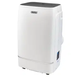
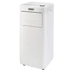
This product has been designed as a portable air
conditioner for cooling single rooms. It also has a
ventilation function for circulating air and a
dehumidifying function for the removal of moisture.
Any other application beyond the conditions established
for use will be considered misuse. Draper Tools accepts
no responsibility for improper use of this product.
Read this manual in full before attempting to assemble,
operate or maintain the product, and retain it for later
use.
3.2 Specication
Stock No. 23828 23830
Part No. PAC5 PAC9
Cooling Capacity 1.5Kw (5000btu) 2.6Kw (9000btu)
Rated Input (Cooling) 560W 1005W
Circulation 260m
3
/hr 300m
3
/hr
Rated Voltage/Frequency 220 -240V/AC – 50Hz 220 -240V/AC – 50Hz
Noise Level ≤ 54dbBA ≤ 54dbBA
Net weight 19kg 22.5kg
Unit Dimensions 315 × 310 × 698mm 315 × 310 × 698mm
Remote Control batteries 2 × AAA (not supplied) 2 × AAA (not supplied)
Extraction Rate 15 litres per 24 hours 21.8 litres per 24 hours
Exhaust Hose Size 1.5m 1.5m
Suggested Room Size 8 – 12m
2
12 –18m
2
Temperature Range 16 – 32°C 16 – 32°C
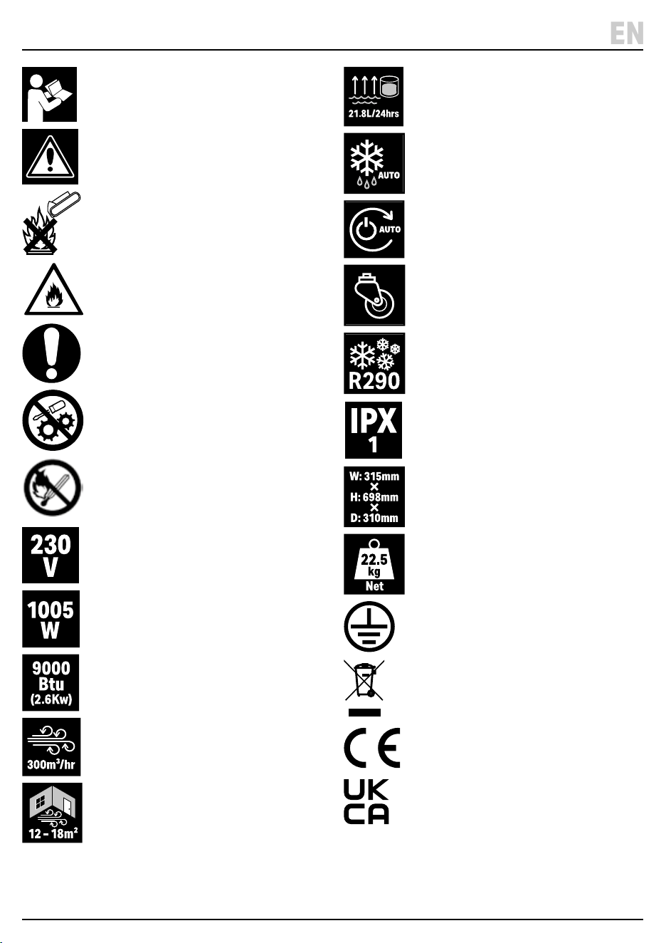
4. Explanation of Symbols
Read the instruction manual
Warning!
Do not incinerate or throw onto re
Warning! Flammable gas.
Risk of explosion
Mandatory action required
DO NOT Adjust factory settings or
attempt to modify product
Keep appliance away from naked
ames or sources of ignition.
Supply voltage
Input power (stock No.23830 shown)
Cooling rating – British Thermal Units/
Kilowatts (stock No.23830 shown)
Air movement volume
(stock No.23830 shown)
Suggested operational
space parameters
(stock No.23830 shown)
Dehumidier moisture
collection capacity
(stock No.23830 shown)
Auto defrost
Auto restart
Manoeuvrable product
Refrigerant
Ingress protection rating
Product dimensions
(stock No.23830 shown)
Net product weight
(stock No.23830 shown)
Earthed
WEEE –
Waste Electrical & Electronic Equipment
Do not dispose of Waste Electrical & Electronic Equipment
in with domestic rubbish
European conformity
UK Conformity Assessed
– 5 –
EN
5. Health and Safety Information
WARNING!: Read all the Health and Safety
instructions before operating, maintaining or
repairing this product. Non-compliance with
these instructions may result in injury or
damage to the user or the product.
5.1 General Health and Safety
Precautions
• This appliance can be used by children aged from 8
years and above and persons with reduced physical,
sensory or mental capabilities or lack of experience
and knowledge if they have been given supervision or
instruction concerning use of the appliance in a safe
way and understand the hazards involved. Children
shall not play with the appliance. Cleaning and user
maintenance shall not be made by children without
supervision.
• The unit is designed only for use with R290 (propane)
gas.
• The refrigerant loop is sealed. Only a qualied
technician should service it.
• NEVER discharge the refrigerant into the atmosphere.
• R290 (propane) is ammable and heavier than air. It
collects rst in low areas but can be circulated by the
fans.
• If propane gas is present or even suspected, only
trained personnel should attempt to nd the cause.
R290 gas used in the unit has no odour. The lack of
smell does not indicate a lack of escaped gas.
• If a leak is detected, immediately evacuate all persons
from the area, ventilate the room and contact the
local re department to advise them that a propane
leak has occurred. Do not let any persons back into
the room until the qualied service technician has
arrived and advises that it is safe to return to the room.
• No open ames, cigarettes or other possible sources
of ignition should be used inside or in the vicinity of
the unit.
• Component parts must only be replaced with identical
repair parts.
• DO NOT operate with wet hands. Keep the unit away
from sources or water, moisture, or any other liquids.
• DO NOT unplug or tilt the unit while it is in operation.
• DO NOT unplug by pulling on the power cord.
• DO NOT put objects on the unit, climb or sit on the
unit.
• DO NOT touch or insert ngers or other objects into
the air outlet.
• DO NOT operate the unit if it is dropped, damaged or
showing signs of product malfunction.
• DO NOT clean the appliance with any chemicals.
• DO NOT use any means to accelerate the defrosting
process or to clean, other than those recommended
by the manufacture.
• The appliance shall be stored so as to prevent
mechanical damage from occurring.
• DO NOT place in direct sunlight or near objects that
may cause mechanical vibration or shock.
• DO NOT pierce or burn, even after use.
• Compliance with national gas regulations shall be
observed.
• Keep the air inlet and exhaust outlet clear of any
obstructions.
• Place the unit on a rm, level surface in an area with at
least 50cm of free space around it to allow for proper
air circulation.
• The appliance shall be stored in a well-ventilated area
where the room size corresponds to the room area as
specied for operation.
WARNING! Install the unit in rooms which
exceed 12m². Do not install the unit in a
place where inammable gas may leak.
• DO NOT leave the unit running unattended.
WARNING! Any person who is involved with
working on refrigerant circuits should hold a
current valid certicate from an industry-
accredited assessment authority, which
authorises their competence to handle
refrigerants safely in accordance with an
industry, recognised assessment specication.
WARNING! Servicing shall only be performed as
recommended by the equipment manufacturer.
Maintenance and repair requiring the
assistance of other skilled personnel shall be
carried out under the supervision of the person
competent in the use of ammable refrigerants.
– 6 –

5. Health and Safety Information
5.2 Connection to the Power Supply
WARNING! Risk of electric shock. DO NOT open
this product.
• This appliance is supplied with an approved plug and
cable for your safety. The product must be installed
according to national wiring regulations.
• If the power supply cord is damaged, it must be
replaced by Draper Tools, an authorised service agent
or similarly qualied personnel in order to avoid a
hazard.
• The damaged or incomplete plug, when cut from the
cable, must be disabled to prevent connection to a
live electrical outlet.
• This product is Class I* and is designed for connection
ONLY to a power supply matching that detailed on the
rating label and compatible with the plug tted. The
value of the fuse tted is marked on the pin face of the
plug. Should the fuse need replacing, ensure the
substitute is of the correct rating, approved to BS
1363/A and ASTA or BS Kite marked. This should only
be performed by suitably qualied personnel. ASTA
BSI The fuse can be replaced by removing the cover
using a small plain slot screwdriver and removing the
broken fuse from its holder. This should only be
performed by suitably qualied personnel.
• DO NOT use with an extension lead or adaptor plug.
*Earthed: This product requires an earth connection to
protect against electric shock from accessible
conductive parts in the event of a failure of the basic
insulation.
5.3 Residual Risk
The safety instructions in this manual cannot account for
all possible conditions and situations that may occur.
Exercise common sense and caution when using this
product and protect against any additional conceivable
risks.
– 7 –
EN
– 8 –
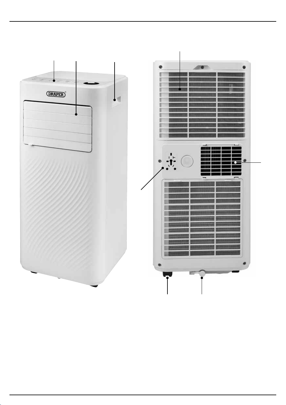
6. Identication and Unpacking
6.1 Product Overview
(1) Control panel
(2) Air outlet with adjustable louvres
(3) Recessed handle
(4) Air inlet with air lter
(5) Castors
(6) Drain valve
(7) Air exhaust outlet
(8) Plug storage
(1)
(5) (6)
(7)
(8)
(3)
(4)
(2)
– 9 –
6. Identication and Unpacking
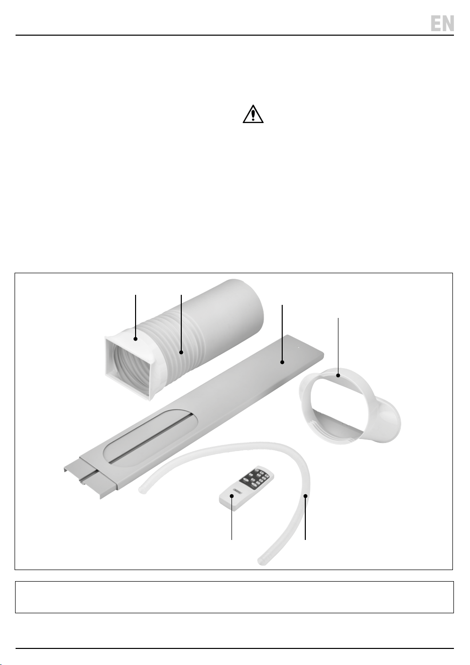
6.2 What’s in the Box?
Carefully remove the product from the packaging and
examine it for signs of damage that may have occurred
during shipment.
Before assembling the product, lay the contents out and
check them against the parts shown below. If any part is
damaged or missing, do not attempt to use the product.
Please contact the Draper Helpline; contact details can
be found at the back of this manual.
(A) 1 × Exhaust hose
(B) 1 × Exhaust hose connector
(C) Window kit hose adaptor
(D) Window seal kit
(E) Drainage hose
(F) Remote control
6.3 Packaging
Keep the product packaging for the duration of the
warranty period for reference should the product need to
be returned for repair.
WARNING! Keep packaging materials out of
reach of children. Dispose of packaging
correctly and responsibly and in accordance
with local regulations.
Please visit drapertools.com for our full range of accessories and consumables.
EN
(B) (A)
(C)
(D)
(F) (E)
7. Before Operation
– 10 –
Important: Before using this product, read and
understand all the safety instructions listed in this
manual.
• Allow the unit to stand upright for at least 24 hours
before setting up.
• Place the unit on a rm, level surface in an area with at
least 50cm of free space around it to allow for proper
air circulation.
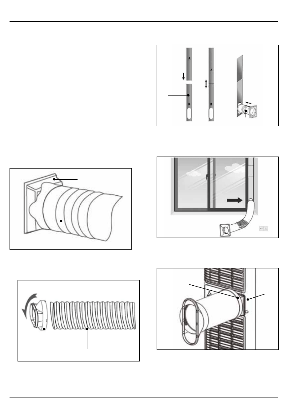
7.1 Attach the Exhaust Hose
The air conditioner requires venting outside so that the
exhaust heat and moisture coming from the unit can
escape the room.
Do not replace or extend the exhaust hose as this will
result in decreased eciency or cause the unit to shut
down.
1. Connect the hose connector (B) to one end of the
exhaust hose (A). Fig.1
1 Fig.
(A)
(B)
2. Connect the window kit adapter (C ) to the other end.
Fig.2
2 Fig.
(C) (A)
3. Extend the window kit (D) to the length of your
window and connect to the exhaust hose. Fig.3
3 Fig.
(D)
(A)
4. Close your window to secure the kit rmly in place.
Fig. 4
4 Fig.
5. Attach the hose connector (B) to the exhaust air outlet
(7). Fig. 5
5 Fig.
(7)
(B)
6. Adjust the length of the exhaust hose - take care not
to bend the hose.
7. Before Operation
– 11 –
EN
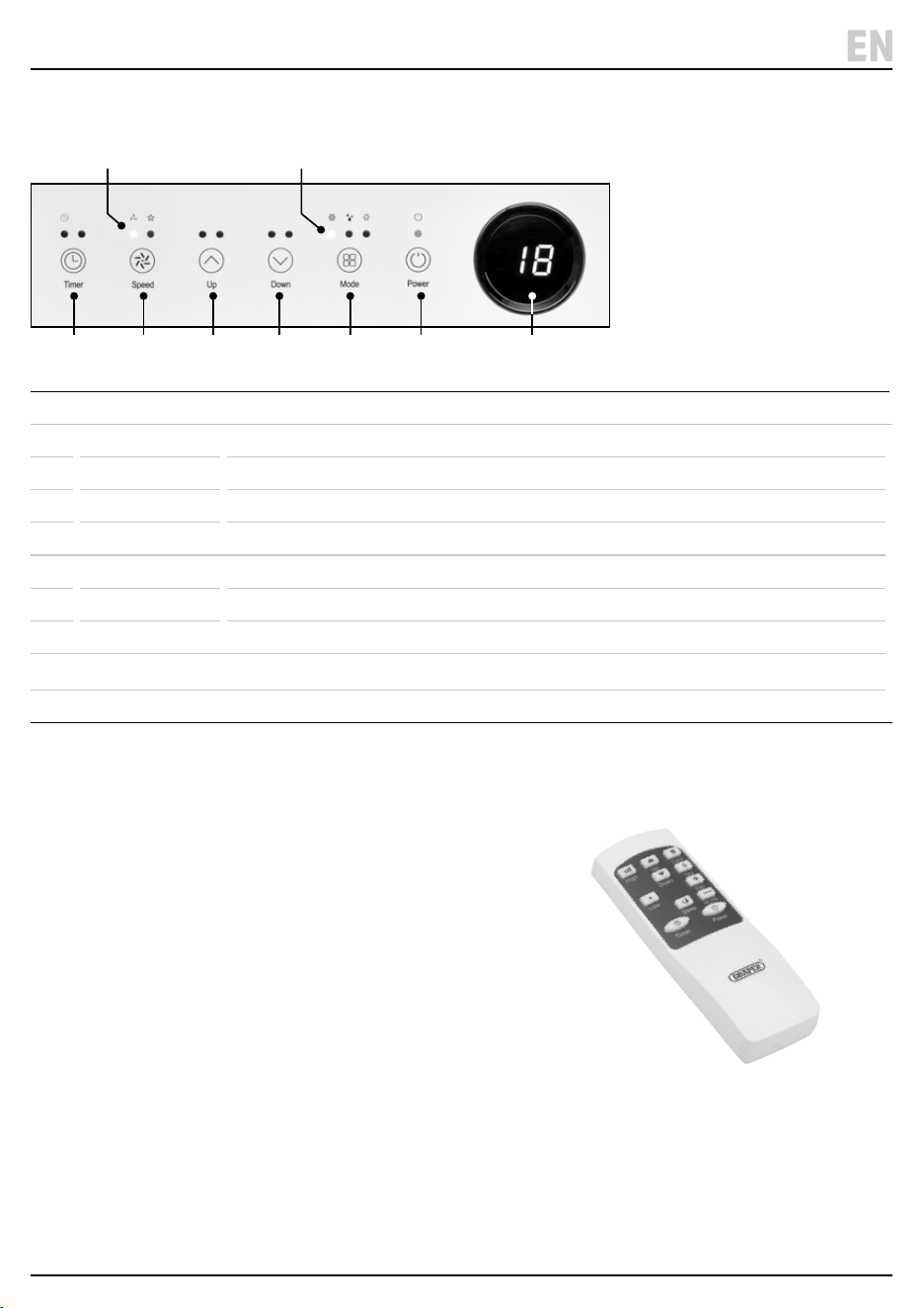
7.2 Control Panel/ Display
1 Power Switch on or o.
2 Mode Switch between cool, dehumidier or fan.
3 Mode Indicator Shows mode setting selected – (a) cool, (b) dehumidier or (c) fan.
4 Down Decrease the temperature or time set.
5 Up Increase temperature from 16°C – 32°C or time set.
6 Fan Speed Switch fan speed from low/high.
7 Fan Indicator Shows fan speed selected (a) low or (b) high.
8 Timer 1 hour – 24hrs – Set time for unit to automatically start or stop.
9 Digital Display Shows time or temperature selected.
Manually move the louvres to adjust the air ow direction.
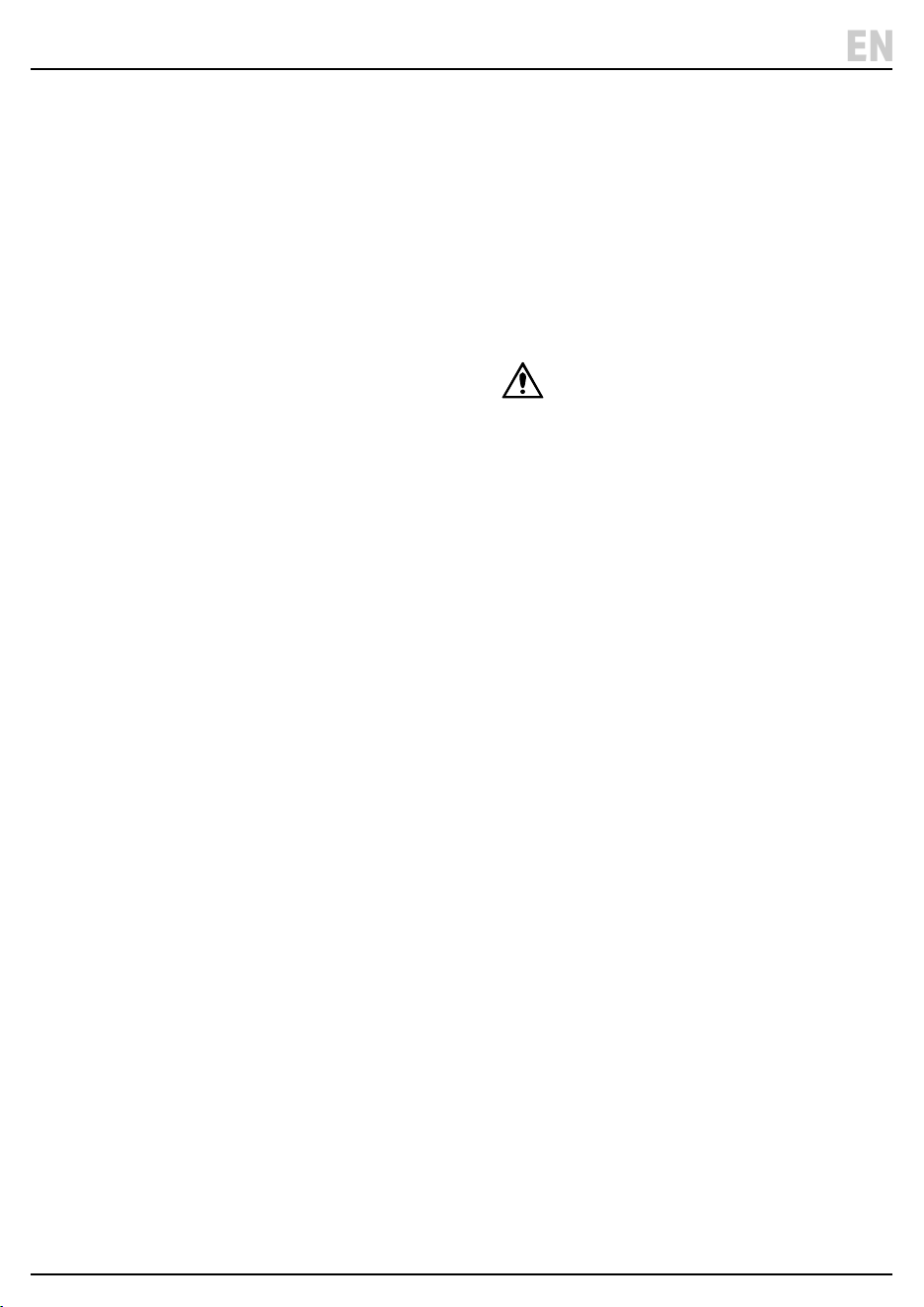
7.3 Remote Control
The unit can be operated using the remote control instead of using the control panel buttons.
Insert 2 × AAA batteries (not supplied) into the back of the remote control.
Ensure the batteries are tted in the correct +/- orientation.
(7) (3)
(8) (6) (5) (4) (2) (1) (9)
(a) (a)(b)(c)(b)
8. Operation
8.1 Start Up/Shutdown
1. Plug in and the display screen will come on. The
indicator lights will ash and the red light above the
POWER button will come on.
2. To select an operating mode press the POWER
button (1) or use the remote control. Note: The unit
will default to FAN mode.
3. To stop the operation press the POWER button again.
4. Allow the unit to completely stop before unplugging.
8.2 Operation Modes (2)
• The unit has three operation modes: COOL,
DEHUMIDIFIER (DRY), or FAN.
• To change from °C Centigrade to °F Fahrenheit either
hold the MODE button down for 2-3 seconds or press
the °C /°F button on the remote control to switch.
8.2.1 Cooling Mode (3a)
1. Press the MODE button until the COOL indicator
lights up.
2. Press the UP and DOWN buttons to adjust the
required temperature. The temperature can be set
between 16°C and 32°C.
3. Press the SPEED button until the desired fan speed
indicator light comes on.
− Manually open the louvres to adjust the air ow
direction.
Note: The air conditioner will stop if the room
temperature is lower than the selected temperature.
8.2.2 Dehumidier/Dry Mode (3b)
1. Press the MODE button on the control panel until the
dehumidier indicator lights up. Remove the drain
valve plug and connect the drainage hose (E ) to the
drain outlet (6) at the bottom of the unit.
Note: In this mode, the fan speed is on low and a
temperature cannot be selected.
2. Refer to section 9.1 Manual Drainage and 9.2
Continuous Drainage for more information on using
the drainage hose.
8.2.3 Ventilation/Fan Only Mode (3c)
1. Press the MODE button until the FAN indicator lights
up.
Note: In ventilation mode the room air is circulated,
but not cooled.
2. Press the SPEED button to select the desired fan
speed.
8.2.4 Sleep Mode
1. The SLEEP mode can be activated in COOL mode
using the remote control.
2. In SLEEP mode: the display screen light will dim and
the fan will operate at low speed.
8.2.5 Timer Setting – 1hour – 24hours (8)
The timer operates in two ways:
a. To Turn O (when power on) – Press the TIMER
button to select the timer function. Then press the UP
and DOWN arrows until the delay o time required is
set.
b. To Turn ON (when power o) - Press the TIMER
button to select the timer function. Then press the UP
and DOWN arrows until the delay on time required is
set.
To cancel the timer – Press UP/DOWN until ‘00’ is
displayed or press the POWER button.
8.2.6 Automatic Defrost
At low room temperatures, frost may build up at the
evaporator during operation. If this occurs the unit will
start defrosting and the power light will blink.
The unit will automatically start defrosting and the
POWER light will blink.
The defrost operates as follows:
a. When the unit operates in the COOL or
DEHUMIDIFIER/DRY mode, the temperature sensor
will sense the evaporator coil temperature is below
-1°C. The compressor will then stop operating for 10
minutes or until the temperature reaches 7°C, the unit
will then restart in COOL mode.
b. When the unit operates in the dehumidifying mode,
once the coil temperature sensor senses the
temperature of the evaporator is below 40°C and the
dierence between the coil temperature and room
temperature is below 19°C, the compressor will
operate for 20minutes. The unit will then start
defrosting for 5 minutes and the POWER indicator
will blink.
8.2.7 Overload Protection
In the event of a power loss, to protect the compressor
there is a 3 minute delay until the compressor will restart.
– 12 –
9. Maintenance and Troubleshooting
9.1 Manual Drainage
1. The unit will automatically stop when the tank is full.
Unplug before emptying the unit.
2. Move the unit carefully to avoid spilling the water.
3. Place a container for the water below the drain.
4. Remove the drain valve to allow the water to ow out
into the container.
Notes:
− During drainage, tilt the body back slightly.
− When the water has emptied, ret the drain valve.
− Always ensure the drain valve is tted correctly
before restarting the unit.
9.2 Continuous Drainage
The self-evaporating system uses the collected water to
cool the condenser coils for more ecient performance.
There is no need to empty the drainage tank in cooling
mode as any condensation will evaporate and exit
through the exhaust outlet.
For continuous operation in dehumidifying mode,
connect the drain hose to the unit so that the water can
automatically ow into a bucket or drain.
1. Switch o the unit and remove the drain valve. Retain
in a safe place.
2. Securely connect the drainage hose (E), making sure
it is not kinked and clear of any obstructions.
3. Place the end of the hose over a drain or bucket so
the water ows freely out of the unit.
4. To prevent any air locks, do not submerge the end of
the hose completely in the water.
9.3 General Cleaning
• Always switch o and plug the unit before cleaning.
• Clean the outer surface of the unit with a soft damp
cloth and mild detergent. Wipe dry.
• Clean the air inlet and lter regularly to stop a build of
dust which can have a detrimental eect on the
performance of the unit.
9.4 Cleaning the Air Filter (4)
Dust collects on the lter can restricting the airow and
reduces the eciency of the system. If it becomes
blocked it can cause damage to the unit.
Remove and clean the air lter regularly.
DO NOT operate the unit without the air inlet cover tted.
1. Switch o and unplug the unit.
2. Lift o the air inlet cover (4) with the mesh lter from
the unit.
WARNING! To avoid injury to your ngers,
DO NOT touch the evaporator surface when
removing the lter.
3. Use a vacuum cleaner to suck dust from the
mesh lter.
4. Ret the air inlet cover.
– 13 –
EN

– 14 –
9. Maintenance and Troubleshooting
9.5 Troubleshooting
Problem Possible cause Remedy
The unit does not operate. Not plugged in. Plug into power socket.
Auto shut o operated due to water
level at maximum or 'Ft' shown on
screen.
Drain the water – see 9.1 drainage.
Room temperature too cold or hot Operating temperature is 5 - 35°C.
Operating with reduced eciency Air lter dirty. Clean the air lter – see 9.4
Recommend cleaning every 2 weeks.
Air duct is blocked. Clear the obstruction.
Door or window opened. Keep doors and window closed
during operation.
Exhaust hose not tted. Securely attach the hose.
Water leakage Overowed while moving unit. Empty the water before moving.
Drain hose is kinked or bent. Straighten the drain hose.
Excessive Noise Unit not positioned on a at level
surface.
Place the appliance on a at level
surface.
Noise sounds like owing water. Normal operation – noise coming
from owing refrigerant.
Fan continues to operation after
powered o
Normal operation.
The compressor fan will continue to
operate to blow out any remaining
condensed water.
Wait a few minutes until the unit has
completely stopped before
unplugging.
Error Codes
E0, E1, E2 Fault with unit. Contact Draper helpline for advice.
Ft Condensation high level alarm. Empty the water – see 9.1
9.6 Storage
When the appliance is not in use for an extended period, it is recommended to follow these steps:
1. Unplug and remove the exhaust hose and window kit. Store both with the main unit.
2. Drain the water and clean the lter. Allow the lter to dry before retting.
3. Keep the appliance upright when storing. Store in a dry and well-ventilated area.
Important: The evaporator inside the appliance must be dried out before it is packed to avoid component damage and
mould growth. Either place in a dry open area until dried out or turn on to FAN mode until the exhaust hose is dry.
For spare parts, servicing, and repair and replacement
options, please contact the Draper Tools Product
Helpline for details of your nearest authorised agent.
Draper Tools will endeavour to hold any spare parts, if
applicable, for seven years from the date that it sells the
nal matching stock item.
Any servicing or repairs carried out by unauthorised
personnel or installation of spare parts not supplied by
Draper Tools will invalidate your warranty.
At the end of its working life, dispose of the product
responsibly and in line with local regulations. Recycle
where possible.
• DO NOT dispose of this product with domestic waste;
most local authorities provide appropriate recycling
facilities.
WARNING! Releasing refrigerant into
atmosphere is strictly forbidden!
• DO NOT burn or mutilate batteries; this may release
toxic or corrosive substances.
• Dispose of the battery in accordance with local
regulations or return it to your warranty agent or
stockist for recycling.
10. Spares, Returns and Disposal
– 15 –
11. Warranty
Draper Tools products are carefully tested and inspected
before shipment and are guaranteed to be free from
defective materials and workmanship.
Should the tool develop a fault, return the complete tool
to your nearest distributor or contact Draper Tools
directly. Contact information can be found at the back of
this manual.
Proof of purchase must be provided.
If, upon inspection, it is found that the fault occurring is
due to defective materials or workmanship, repairs will
be carried out free of charge. This warranty period covers
parts and labour for 24 months from the date of
purchase. Where tools have been hired out, the warranty
period covers 90 days from the date of purchase.
This warranty does not apply to any consumable parts,
batteries or normal wear and tear, nor does it cover any
damage caused by misuse, careless or unsafe handling,
alterations, accidents, or repairs attempted or made by
any personnel other than the authorised Draper Tools
repair agent.
In all cases, to make a claim for faulty workmanship or
materials within the standard warranty period, please
contact or return the product to the place of purchase.
Proof of purchase may be required.
If the place of purchase is no longer trading or if you
experience any diculties with your warranty, please
contact Customer Services with the product details and
your proof of purchase. Contact details can be found at
the back of this manual.
If the tool is not covered by the terms of this warranty,
repairs and carriage charges will be quoted and charged
accordingly.
This warranty supersedes any other guarantees
expressed or implied and variations of its terms are not
authorised.
Your Draper Tools guarantee is not eective until you can
produce, upon request, a dated receipt or invoice to
verify your purchase within the guarantee period.
Please note that this warranty is an additional benet
and does not aect your statutory rights.
Draper Tools Limited
EN

© Published by Draper Tools Limited© Published by Draper Tools Limited
Delta International
Delta International BV
Oude Graaf 8
6002 NL
Weert
Netherlands
Contact Details
Draper Tools
Draper Tools Limited
Hursley Road
Chandler’s Ford
Eastleigh
Hampshire
SO53 1YF
UK
Website: drapertools.com
Email: [email protected]
Product Helpline: +44 (0) 23 8049 4344
Telephone Sales Desk: +44 (0) 23 8049 4333
General Enquiries: +44 (0) 23 8026 6355
General Fax: +44 (0) 23 8026 0784
Please contact the Draper Tools Product Helpline for repair and servicing enquiries.