
9938 MET/TEMP II
Automated Calibration Software
User’ s Guide
Rev. 582401
Hart Scientific
1.888.610.7664 sales@GlobalTestSupply.com
Fluke-Direct.com

Rev. 582401
Fluke Corporation, Hart Scientific Division (Hart) warrants this product to be free
from defects in material and workmanship under normal use and service for a pe-
riod as stated in our current product catalog from the date of shipment. This war-
ranty extends only to the original purchaser and shall not apply to any product
which, in Hart’s sole opinion, has been subject to misuse, alteration, abuse or abnor-
mal conditions of operation or handling.
Software is warranted to operate in accordance with its programmed instructions on
appropriate Hart products. It is not warranted to be error free.
Hart’s obligation under this warranty is limited to repair or replacement of a product
which is returned to Hart within the warranty period and is determined, upon exam-
ination by Hart, to be defective. If Hart determines that the defect or malfunction
has been caused by misuse, alteration, abuse or abnormal conditions or operation or
handling, Hart will repair the product and bill the purchaser for the reasonable cost
of repair.
To exercise this warranty, the purchaser must forward the product after calling or
writing Hart for authorization. Hart assumes NO risk for in-transit damage.
For service or assistance, please contact the manufacturer.
THE FOREGOING WARRANTY IS PURCHASER’S SOLE AND EXCLUSIVE
REMEDY AND IS IN LIEU OF ALL OTHER WARRANTIES, EXPRESS OR IM-
PLIED, INCLUDING BUT NOT LIMITED TO ANY IMPLIED WARRANTY OR
MECHANTABILITY, OR FITNESS FOR ANY PARTICULAR PURPOSE OR
USE. HART SHALL NOT BE LIABLE FOR ANY SPECIAL, INDIRECT, INCI-
DENTAL, OR CONSEQUENTIAL DAMAGES OR LOSS WHETHER IN CON-
TRACT, TORT, OR OTHERWISE.
Microsoft, MS-DOS, Windows, Window for Workgroups, and Windows 95, 98,
ME, NT, 2000, and XP are either registered trademarks or trademarks of Microsoft
Corporation.
1.888.610.7664 sales@GlobalTestSupply.com
Fluke-Direct.com

Table of Contents
1 Introduction . . . . . . . . . . . . . . . . . . . . . . . . . . . . 1
1.1 What is MET/TEMP II? . . . . . . . . . . . . . . . . . . . . . . . 1
1.2 Features New to Version 4 . . . . . . . . . . . . . . . . . . . . . . 1
1.2.1 Version 4.3 . . . . . . . . . . . . . . . . . . . . . . . . . . . . . . . . . . . . 1
1.2.2 Version 4.2 . . . . . . . . . . . . . . . . . . . . . . . . . . . . . . . . . . . . 1
1.2.3 Version 4.1 . . . . . . . . . . . . . . . . . . . . . . . . . . . . . . . . . . . . 2
1.2.4 Version 4.0 . . . . . . . . . . . . . . . . . . . . . . . . . . . . . . . . . . . . 4
1.3 Requirements . . . . . . . . . . . . . . . . . . . . . . . . . . . . . 6
1.3.1 Communications Requirements . . . . . . . . . . . . . . . . . . . . . . . . . 6
1.3.2 Computer Hardware Requirements . . . . . . . . . . . . . . . . . . . . . . . 7
1.3.3 Computer Software Requirements . . . . . . . . . . . . . . . . . . . . . . . . 8
1.3.4 Firmware Requirements . . . . . . . . . . . . . . . . . . . . . . . . . . . . . 8
1.4 Installation . . . . . . . . . . . . . . . . . . . . . . . . . . . . . . 8
1.5 Running MET/TEMP II . . . . . . . . . . . . . . . . . . . . . . . 10
1.6 Using MET/TEMP II with MET/TRACK. . . . . . . . . . . . . . 12
1.7 Required .DLL and .VBX Files . . . . . . . . . . . . . . . . . . . 15
1.8 Connection of Instruments . . . . . . . . . . . . . . . . . . . . . 15
1.8.1 Computer to SmartSwitch. . . . . . . . . . . . . . . . . . . . . . . . . . . . 15
1.8.2 Reference Readout to SmartSwitch. . . . . . . . . . . . . . . . . . . . . . . 16
1.8.3 Scanner to SmartSwitch. . . . . . . . . . . . . . . . . . . . . . . . . . . . . 17
1.8.4 Heat Sources to SmartSwitch . . . . . . . . . . . . . . . . . . . . . . . . . . 17
1.8.5 Model 1620/5020A ‘DewK’ Thermohygrometer to SmartSwitch . . . . . . . 17
1.9 MET/TEMP II Main Display . . . . . . . . . . . . . . . . . . . . 18
1.10 Toolbar . . . . . . . . . . . . . . . . . . . . . . . . . . . . . . . 19
1.11 MET/TEMP II Introduction Dialog . . . . . . . . . . . . . . . . . 20
1.12 MET/TEMP II Test Display . . . . . . . . . . . . . . . . . . . . . 21
2 Configuring a Test . . . . . . . . . . . . . . . . . . . . . . . . 25
2.1 Comparison, Fixed-Point and Mixed Calibrations . . . . . . . . . 26
2.2 Heat Source Calibrations . . . . . . . . . . . . . . . . . . . . . . 27
3 File Menu . . . . . . . . . . . . . . . . . . . . . . . . . . . . . 31
3.1 New . . . . . . . . . . . . . . . . . . . . . . . . . . . . . . . . . 31
3.2 Open . . . . . . . . . . . . . . . . . . . . . . . . . . . . . . . . . 31
3.3 Save As . . . . . . . . . . . . . . . . . . . . . . . . . . . . . . . 32
3.4 Defaults . . . . . . . . . . . . . . . . . . . . . . . . . . . . . . . 32
3.4.1 General Tab . . . . . . . . . . . . . . . . . . . . . . . . . . . . . . . . . . . 33
i
1.888.610.7664 sales@GlobalTestSupply.com
Fluke-Direct.com

3.4.2 Set-points Tab . . . . . . . . . . . . . . . . . . . . . . . . . . . . . . . . . . 35
3.4.2.1 Fixed-Points Dialog. . . . . . . . . . . . . . . . . . . . . . . . . . . . . . . . . . .36
3.4.2.1.1 Edit Fixed-Point Dialog . . . . . . . . . . . . . . . . . . . . . . . . . . . . . . . . . . . 37
3.4.2.1.2 New Fixed-Point Dialog . . . . . . . . . . . . . . . . . . . . . . . . . . . . . . . . . . 39
3.4.3 Setup Tab . . . . . . . . . . . . . . . . . . . . . . . . . . . . . . . . . . . . 41
3.4.4 Graph Tab . . . . . . . . . . . . . . . . . . . . . . . . . . . . . . . . . . . . 42
3.4.5 Reports Tab . . . . . . . . . . . . . . . . . . . . . . . . . . . . . . . . . . . 44
3.4.5.1 Text Editor Dialog . . . . . . . . . . . . . . . . . . . . . . . . . . . . . . . . . . .46
3.4.6 User Tab . . . . . . . . . . . . . . . . . . . . . . . . . . . . . . . . . . . . . 46
3.4.7 Test Tab . . . . . . . . . . . . . . . . . . . . . . . . . . . . . . . . . . . . . 48
3.4.8 Fonts & Sizes Tab . . . . . . . . . . . . . . . . . . . . . . . . . . . . . . . . 50
3.4.9 MET/TRACK Tab . . . . . . . . . . . . . . . . . . . . . . . . . . . . . . . 52
3.4.10 SmartSwitch Tab . . . . . . . . . . . . . . . . . . . . . . . . . . . . . . . . 55
3.5 Setup Printer. . . . . . . . . . . . . . . . . . . . . . . . . . . . . 55
3.6 Print Report . . . . . . . . . . . . . . . . . . . . . . . . . . . . . 56
3.7 Recall Saved Report . . . . . . . . . . . . . . . . . . . . . . . . . 58
3.8 Close Test . . . . . . . . . . . . . . . . . . . . . . . . . . . . . . 58
3.9 Exit . . . . . . . . . . . . . . . . . . . . . . . . . . . . . . . . . 58
4 Configuration Menu . . . . . . . . . . . . . . . . . . . . . . . 59
4.1 Install Drivers . . . . . . . . . . . . . . . . . . . . . . . . . . . . 59
4.1.1 Adding Drivers . . . . . . . . . . . . . . . . . . . . . . . . . . . . . . . . . 60
4.1.2 Removing Drivers. . . . . . . . . . . . . . . . . . . . . . . . . . . . . . . . 60
4.2 COM Port . . . . . . . . . . . . . . . . . . . . . . . . . . . . . . 60
4.2.1 Communications Port Configuration Dialog . . . . . . . . . . . . . . . . . . 61
4.2.2 Check SmartSwitch Dialog . . . . . . . . . . . . . . . . . . . . . . . . . . . 62
4.3 Reference . . . . . . . . . . . . . . . . . . . . . . . . . . . . . . 63
4.3.1 Reference Readout Configuration Dialog . . . . . . . . . . . . . . . . . . . 63
4.3.2 Reference Module Configuration Dialog . . . . . . . . . . . . . . . . . . . . 66
4.3.3 Reference Probe Configuration Dialog . . . . . . . . . . . . . . . . . . . . . 68
4.4 Scanner . . . . . . . . . . . . . . . . . . . . . . . . . . . . . . . 71
4.4.1 Scanner Configuration Dialog . . . . . . . . . . . . . . . . . . . . . . . . . 71
4.4.2 Scanner Module Configuration Dialog . . . . . . . . . . . . . . . . . . . . . 74
4.5 Heat Sources. . . . . . . . . . . . . . . . . . . . . . . . . . . . . 76
4.5.1 Heat Source Configuration Dialog . . . . . . . . . . . . . . . . . . . . . . . 77
4.5.2 Temperature Range Configuration Dialog . . . . . . . . . . . . . . . . . . . 80
4.6 Equipment Info . . . . . . . . . . . . . . . . . . . . . . . . . . . 82
4.6.1 Equipment Info Dialog . . . . . . . . . . . . . . . . . . . . . . . . . . . . . 82
5 Calibration Menu. . . . . . . . . . . . . . . . . . . . . . . . . 85
5.1 Set-points . . . . . . . . . . . . . . . . . . . . . . . . . . . . . . 85
5.1.1 Set-point Configuration Dialog . . . . . . . . . . . . . . . . . . . . . . . . . 86
5.1.1.1 Auto-Generating Comparison Set-points. . . . . . . . . . . . . . . . . . . . . . . . 89
5.1.1.2 Inserting Comparison Set-points . . . . . . . . . . . . . . . . . . . . . . . . . . . . 91
5.1.1.3 Inserting Fixed-Point Set-points . . . . . . . . . . . . . . . . . . . . . . . . . . . . 91
5.1.1.4 Removing Set-points . . . . . . . . . . . . . . . . . . . . . . . . . . . . . . . . . . 92
5.1.1.5 Editing Set-points . . . . . . . . . . . . . . . . . . . . . . . . . . . . . . . . . . . . 92
ii
1.888.610.7664 sales@GlobalTestSupply.com
Fluke-Direct.com

5.1.1.6 Moving Set-points . . . . . . . . . . . . . . . . . . . . . . . . . . . . . . . . . . . 93
5.2 View Set-points . . . . . . . . . . . . . . . . . . . . . . . . . . . 93
5.2.1 Set-point Status Dialog . . . . . . . . . . . . . . . . . . . . . . . . . . . . . 93
5.3 Adjust Uncertainties. . . . . . . . . . . . . . . . . . . . . . . . . 94
5.3.1 Adjust Uncertainties Dialog . . . . . . . . . . . . . . . . . . . . . . . . . . 94
5.4 Test Probes . . . . . . . . . . . . . . . . . . . . . . . . . . . . . 95
5.4.1 Test Probe Configuration Dialog . . . . . . . . . . . . . . . . . . . . . . . . 95
5.4.1.1 Customer Information Dialog . . . . . . . . . . . . . . . . . . . . . . . . . . . . . 101
5.5 Start Test . . . . . . . . . . . . . . . . . . . . . . . . . . . . . . 102
5.5.1 Enter Data Dialog . . . . . . . . . . . . . . . . . . . . . . . . . . . . . . . 106
5.5.2 Test Information Dialog . . . . . . . . . . . . . . . . . . . . . . . . . . . . 107
5.6 Stop Test . . . . . . . . . . . . . . . . . . . . . . . . . . . . . . 109
5.7 Pause Test . . . . . . . . . . . . . . . . . . . . . . . . . . . . . 109
5.8 Resume Test . . . . . . . . . . . . . . . . . . . . . . . . . . . . 110
5.9 Stability Override . . . . . . . . . . . . . . . . . . . . . . . . . 110
5.9.1 Stability Override Dialog . . . . . . . . . . . . . . . . . . . . . . . . . . . 110
6 Scale Menu. . . . . . . . . . . . . . . . . . . . . . . . . . . . 113
6.1 Set to C. . . . . . . . . . . . . . . . . . . . . . . . . . . . . . . 113
6.2 Set to F . . . . . . . . . . . . . . . . . . . . . . . . . . . . . . . 113
7 Graph Menu . . . . . . . . . . . . . . . . . . . . . . . . . . . 115
7.1 Graph Settings . . . . . . . . . . . . . . . . . . . . . . . . . . . 115
7.1.1 Graph Settings Dialog . . . . . . . . . . . . . . . . . . . . . . . . . . . . . 115
7.2 Print Graph . . . . . . . . . . . . . . . . . . . . . . . . . . . . . 117
7.3 Start Display . . . . . . . . . . . . . . . . . . . . . . . . . . . . 117
7.4 Stop Display . . . . . . . . . . . . . . . . . . . . . . . . . . . . 117
8 Utilities Menu . . . . . . . . . . . . . . . . . . . . . . . . . . 119
8.1 Compact Database . . . . . . . . . . . . . . . . . . . . . . . . . 119
8.2 Repair Database . . . . . . . . . . . . . . . . . . . . . . . . . . 119
8.3 Maintain Equipment . . . . . . . . . . . . . . . . . . . . . . . . 120
8.3.1 Maintain Test Equipment Dialog . . . . . . . . . . . . . . . . . . . . . . . 120
8.4 Maintain Test Results . . . . . . . . . . . . . . . . . . . . . . . 121
8.4.1 Maintain Test Results Dialog . . . . . . . . . . . . . . . . . . . . . . . . . 121
8.4.1.1 Invalid Test Dialog . . . . . . . . . . . . . . . . . . . . . . . . . . . . . . . . . . 122
8.5 Edit Test Information . . . . . . . . . . . . . . . . . . . . . . . 123
8.5.1 Edit Test Information Dialog . . . . . . . . . . . . . . . . . . . . . . . . . 124
8.6 Coefficients and Tables . . . . . . . . . . . . . . . . . . . . . . 125
8.7 Export Calibration Data to MET/TRACK . . . . . . . . . . . . . 125
8.7.1 Export Calibration Data to MET/TRACK Dialog. . . . . . . . . . . . . . . 125
iii
1.888.610.7664 sales@GlobalTestSupply.com
Fluke-Direct.com

9 Help Menu . . . . . . . . . . . . . . . . . . . . . . . . . . . . 127
9.1 Contents . . . . . . . . . . . . . . . . . . . . . . . . . . . . . . 127
9.2 Search for Help On. . . . . . . . . . . . . . . . . . . . . . . . . 127
9.3 Getting Started . . . . . . . . . . . . . . . . . . . . . . . . . . . 127
9.4 Technical Support . . . . . . . . . . . . . . . . . . . . . . . . . 127
9.5 About MET/TEMP II . . . . . . . . . . . . . . . . . . . . . . . 128
10 Configuration Files . . . . . . . . . . . . . . . . . . . . . . . 129
10.1 Instrument Configuration File . . . . . . . . . . . . . . . . . . . 129
10.2 Set-point Configuration File . . . . . . . . . . . . . . . . . . . . 130
10.2.1 Set-point Options Dialog . . . . . . . . . . . . . . . . . . . . . . . . . . . 131
10.3 Test Probe Configuration File . . . . . . . . . . . . . . . . . . . 131
10.3.1 Enter Order ID Dialog . . . . . . . . . . . . . . . . . . . . . . . . . . . . . 133
11 Reports of Calibration . . . . . . . . . . . . . . . . . . . . . 135
11.1 Default Report of Calibration . . . . . . . . . . . . . . . . . . . 135
11.2 Custom Reports of Calibration. . . . . . . . . . . . . . . . . . . 139
11.2.1 Pass/Fail Report of Calibration . . . . . . . . . . . . . . . . . . . . . . . . 139
11.2.1.1 Tolerance Dialog. . . . . . . . . . . . . . . . . . . . . . . . . . . . . . . . . . . . 143
11.2.1.2 Changing Tolerance Values . . . . . . . . . . . . . . . . . . . . . . . . . . . . . . 143
11.2.2 Heat Source Report of Calibration . . . . . . . . . . . . . . . . . . . . . . 145
12 Performing Calibrations Using Fixed-Points . . . . . . . . . 151
12.1 Configuring Fixed-Point Cells . . . . . . . . . . . . . . . . . . . 151
12.2 Configuring MET/TEMP II to Perform Fixed-Point Only Calibrations
153
12.2.1 Fixed-Point Reference Readout Configuration . . . . . . . . . . . . . . . . 153
12.2.2 Fixed-Point Heat Source Configuration . . . . . . . . . . . . . . . . . . . . 154
12.2.3 Fixed-Point Set-point Configuration . . . . . . . . . . . . . . . . . . . . . 155
12.3 Fixed-Point Calibration Process . . . . . . . . . . . . . . . . . . 157
13 Performing Heat Source Calibrations . . . . . . . . . . . . . 159
13.1 Heat Source Calibration Process . . . . . . . . . . . . . . . . . . 159
13.2 Configuring MET/TEMP II to Perform Heat Source Calibrations 159
13.2.1 Default Settings . . . . . . . . . . . . . . . . . . . . . . . . . . . . . . . . 160
13.2.1.1 Writing New Coefficients To Heat Source . . . . . . . . . . . . . . . . . . . . . . 160
13.2.1.2 Report of Calibration . . . . . . . . . . . . . . . . . . . . . . . . . . . . . . . . . 162
13.2.2 Configure Communications Port . . . . . . . . . . . . . . . . . . . . . . . 162
13.2.3 Configure Reference Readout . . . . . . . . . . . . . . . . . . . . . . . . . 163
13.2.4 Configure Scanner . . . . . . . . . . . . . . . . . . . . . . . . . . . . . . . 164
13.2.5 Configure Test Probes . . . . . . . . . . . . . . . . . . . . . . . . . . . . . 164
13.2.6 Configure Heat Source. . . . . . . . . . . . . . . . . . . . . . . . . . . . . 165
13.2.7 Configure Set-points. . . . . . . . . . . . . . . . . . . . . . . . . . . . . . 167
13.2.8 Start Heat Source Calibration . . . . . . . . . . . . . . . . . . . . . . . . . 170
iv
1.888.610.7664 sales@GlobalTestSupply.com
Fluke-Direct.com

13.3 Performing Heat Source Calibrations . . . . . . . . . . . . . . . 171
13.4 Printing Heat Source Reports of Calibration. . . . . . . . . . . . 171
14 MET/TRACK Export Process . . . . . . . . . . . . . . . . . 173
14.1 Tolerances . . . . . . . . . . . . . . . . . . . . . . . . . . . . . 177
14.2 Changing Coefficients Export Field . . . . . . . . . . . . . . . . 179
15 Coefficients and Tables Application . . . . . . . . . . . . . . 181
15.1 What is the Coefficients and Tables Application? . . . . . . . . . 181
15.2 New Features. . . . . . . . . . . . . . . . . . . . . . . . . . . . 181
15.2.1 Version 4.1 . . . . . . . . . . . . . . . . . . . . . . . . . . . . . . . . . . . 181
15.2.2 Version 4.0 . . . . . . . . . . . . . . . . . . . . . . . . . . . . . . . . . . . 182
15.3 Main Display. . . . . . . . . . . . . . . . . . . . . . . . . . . . 183
15.4 Toolbar . . . . . . . . . . . . . . . . . . . . . . . . . . . . . . . 183
15.5 Calculating Characterization Coefficients . . . . . . . . . . . . . 184
15.5.1 Calculating Coefficients . . . . . . . . . . . . . . . . . . . . . . . . . . . . 184
15.5.1.1 Calculating PRT/RTD Coefficients . . . . . . . . . . . . . . . . . . . . . . . . . . 185
15.5.1.2 Calculating Thermistor Coefficients . . . . . . . . . . . . . . . . . . . . . . . . . 187
15.5.1.3 Calculating Thermocouple Coefficients. . . . . . . . . . . . . . . . . . . . . . . . 188
15.5.1.4 Calculate Coefficients Dialog . . . . . . . . . . . . . . . . . . . . . . . . . . . . . 190
15.5.1.5 Select Set-points Dialog . . . . . . . . . . . . . . . . . . . . . . . . . . . . . . . . 192
15.5.1.6 Coefficients and Residuals Dialog . . . . . . . . . . . . . . . . . . . . . . . . . . 194
15.5.1.7 Print Reports of Calibration and Tables . . . . . . . . . . . . . . . . . . . . . . . . 195
15.5.1.8 Report Options Dialog. . . . . . . . . . . . . . . . . . . . . . . . . . . . . . . . . 198
15.5.1.8.1 Report Sections Tab . . . . . . . . . . . . . . . . . . . . . . . . . . . . . . . . . . . . 199
15.5.1.8.2 Template Settings Tab . . . . . . . . . . . . . . . . . . . . . . . . . . . . . . . . . . . 200
15.5.1.8.3 Fonts & Sizes Tab . . . . . . . . . . . . . . . . . . . . . . . . . . . . . . . . . . . . . 201
15.5.1.9 Table Options Dialog . . . . . . . . . . . . . . . . . . . . . . . . . . . . . . . . . 202
15.5.1.9.1 Type and Range Tab . . . . . . . . . . . . . . . . . . . . . . . . . . . . . . . . . . . . 203
15.5.1.9.2 Resolutions Tab . . . . . . . . . . . . . . . . . . . . . . . . . . . . . . . . . . . . . . 204
15.5.1.9.3 Other Settings Tab . . . . . . . . . . . . . . . . . . . . . . . . . . . . . . . . . . . . . 205
15.5.1.9.4 Template Settings Tab . . . . . . . . . . . . . . . . . . . . . . . . . . . . . . . . . . . 206
15.5.1.9.5 Export Settings Tab . . . . . . . . . . . . . . . . . . . . . . . . . . . . . . . . . . . . 207
15.6 Exporting Data and Coefficients . . . . . . . . . . . . . . . . . . 208
15.6.1 Export Data . . . . . . . . . . . . . . . . . . . . . . . . . . . . . . . . . . 208
15.6.2 Customizing Export Data . . . . . . . . . . . . . . . . . . . . . . . . . . . 211
15.6.3 Export Coefficients . . . . . . . . . . . . . . . . . . . . . . . . . . . . . . 213
15.7 File Menu . . . . . . . . . . . . . . . . . . . . . . . . . . . . . 216
15.7.1 Export Data . . . . . . . . . . . . . . . . . . . . . . . . . . . . . . . . . . 216
15.7.2 Export Coefficients . . . . . . . . . . . . . . . . . . . . . . . . . . . . . . 216
15.7.3 Defaults . . . . . . . . . . . . . . . . . . . . . . . . . . . . . . . . . . . . 216
15.7.3.1 General Tab . . . . . . . . . . . . . . . . . . . . . . . . . . . . . . . . . . . . . . 217
15.7.3.2 Coefficients Tab . . . . . . . . . . . . . . . . . . . . . . . . . . . . . . . . . . . . 218
15.7.3.3 Reports Tab . . . . . . . . . . . . . . . . . . . . . . . . . . . . . . . . . . . . . . 219
15.7.3.4 Tables Tab . . . . . . . . . . . . . . . . . . . . . . . . . . . . . . . . . . . . . . . 220
15.7.3.5 Directories Tab . . . . . . . . . . . . . . . . . . . . . . . . . . . . . . . . . . . . 221
15.7.4 Setup Printer . . . . . . . . . . . . . . . . . . . . . . . . . . . . . . . . . . 221
15.7.5 Print Reports and Tables . . . . . . . . . . . . . . . . . . . . . . . . . . . . 221
15.7.6 Exit. . . . . . . . . . . . . . . . . . . . . . . . . . . . . . . . . . . . . . . 221
15.8 Coefficients Menu . . . . . . . . . . . . . . . . . . . . . . . . . 222
15.8.1 Platinum Probe. . . . . . . . . . . . . . . . . . . . . . . . . . . . . . . . . 222
v
1.888.610.7664 sales@GlobalTestSupply.com
Fluke-Direct.com

15.8.2 Thermistor Probe . . . . . . . . . . . . . . . . . . . . . . . . . . . . . . . 222
15.8.3 Thermocouple Probe. . . . . . . . . . . . . . . . . . . . . . . . . . . . . . 222
15.9 Utilities Menu . . . . . . . . . . . . . . . . . . . . . . . . . . . 223
15.9.1 Compact Database . . . . . . . . . . . . . . . . . . . . . . . . . . . . . . . 223
15.9.2 Repair Database . . . . . . . . . . . . . . . . . . . . . . . . . . . . . . . . 223
15.9.3 Maintain Test Results . . . . . . . . . . . . . . . . . . . . . . . . . . . . . 223
15.9.3.1 Maintain Test Results Dialog . . . . . . . . . . . . . . . . . . . . . . . . . . . . . 224
15.9.3.2 Test Probe Validation . . . . . . . . . . . . . . . . . . . . . . . . . . . . . . . . . 224
15.10 Help Menu . . . . . . . . . . . . . . . . . . . . . . . . . . . . . 226
15.10.1 Contents . . . . . . . . . . . . . . . . . . . . . . . . . . . . . . . . . . . . 226
15.10.2 Search for Help On . . . . . . . . . . . . . . . . . . . . . . . . . . . . . . 226
15.10.3 Getting Started . . . . . . . . . . . . . . . . . . . . . . . . . . . . . . . . . 226
15.10.4 Technical Support . . . . . . . . . . . . . . . . . . . . . . . . . . . . . . . 226
15.10.5 About . . . . . . . . . . . . . . . . . . . . . . . . . . . . . . . . . . . . . 227
15.11 Reports of Calibration and Tables . . . . . . . . . . . . . . . . . 227
15.11.1 Default Report of Calibration . . . . . . . . . . . . . . . . . . . . . . . . . 227
15.11.2 Default Table. . . . . . . . . . . . . . . . . . . . . . . . . . . . . . . . . . 228
15.12 Requirements and Methods . . . . . . . . . . . . . . . . . . . . 229
15.12.1 ITS-90 Requirements . . . . . . . . . . . . . . . . . . . . . . . . . . . . . 229
15.12.2 IPTS-68 Requirements. . . . . . . . . . . . . . . . . . . . . . . . . . . . . 230
15.12.3 Callendar-Van Dusen Requirements. . . . . . . . . . . . . . . . . . . . . . 233
15.12.4 Polynomial Requirements . . . . . . . . . . . . . . . . . . . . . . . . . . . 233
15.12.5 Thermocouple Requirements . . . . . . . . . . . . . . . . . . . . . . . . . 234
15.12.6 Methods Used for Calculating Coefficients . . . . . . . . . . . . . . . . . . 236
15.12.6.1 General. . . . . . . . . . . . . . . . . . . . . . . . . . . . . . . . . . . . . . . . . 236
15.12.6.2 ITS-90 . . . . . . . . . . . . . . . . . . . . . . . . . . . . . . . . . . . . . . . . . 236
15.12.6.3 IPTS-68 . . . . . . . . . . . . . . . . . . . . . . . . . . . . . . . . . . . . . . . . 237
15.12.6.4 Callendar-Van Dusen . . . . . . . . . . . . . . . . . . . . . . . . . . . . . . . . . 237
15.12.6.5 Polynomial and Thermocouple . . . . . . . . . . . . . . . . . . . . . . . . . . . . 237
15.12.7 Table Temperature Range Chart . . . . . . . . . . . . . . . . . . . . . . . . 237
16 Print Preview Window . . . . . . . . . . . . . . . . . . . . . 239
17 Report Viewer Utility . . . . . . . . . . . . . . . . . . . . . . 241
17.1 Limitations . . . . . . . . . . . . . . . . . . . . . . . . . . . . . 242
17.2 Report Files . . . . . . . . . . . . . . . . . . . . . . . . . . . . 242
17.3 Making a Report Viewer Utility Setup Diskette . . . . . . . . . . 243
18 Troubleshooting . . . . . . . . . . . . . . . . . . . . . . . . . 245
18.1 Hart Authorized Service Centers. . . . . . . . . . . . . . . . . . 245
18.2 Communication Error . . . . . . . . . . . . . . . . . . . . . . . 247
18.3 Troubleshooting Common Problems. . . . . . . . . . . . . . . . 247
vi
1.888.610.7664 sales@GlobalTestSupply.com
Fluke-Direct.com

vii
Figures
Figure 1 Shared Files Conflict Dialog . . . . . . . . . . . . . . . . . . . . . . . 11
Figure 2 MET/TRACK Database Login Dialog . . . . . . . . . . . . . . . . . . 13
Figure 3 Prompt to Synchronize Technician Name with MET/TRACK
User Name . . . . . . . . . . . . . . . . . . . . . . . . . . . . . . . . 14
Figure 4 Example Computer and Instrument Cable Connections . . . . . . . . . 16
Figure 5 MET/TEMP II Main Display . . . . . . . . . . . . . . . . . . . . . . 18
Figure 6 MET/TEMP II Introduction Dialog . . . . . . . . . . . . . . . . . . . 21
Figure 7 MET/TEMP II Test Display . . . . . . . . . . . . . . . . . . . . . . . 22
Figure 8 Equipment Info Dialog. . . . . . . . . . . . . . . . . . . . . . . . . . 25
Figure 9 File Menu . . . . . . . . . . . . . . . . . . . . . . . . . . . . . . . . 31
Figure 10 General Tab . . . . . . . . . . . . . . . . . . . . . . . . . . . . . . . 33
Figure 11 Set-points Tab . . . . . . . . . . . . . . . . . . . . . . . . . . . . . . 35
Figure 12 Fixed-Points Dialog . . . . . . . . . . . . . . . . . . . . . . . . . . . 36
Figure 13 Edit Fixed-Point Dialog . . . . . . . . . . . . . . . . . . . . . . . . . 37
Figure 14 New Fixed-Point Dialog . . . . . . . . . . . . . . . . . . . . . . . . . 39
Figure 15 Setup Tab. . . . . . . . . . . . . . . . . . . . . . . . . . . . . . . . . 41
Figure 16 Graph Tab . . . . . . . . . . . . . . . . . . . . . . . . . . . . . . . . 42
Figure 17 Reports Tab. . . . . . . . . . . . . . . . . . . . . . . . . . . . . . . . 44
Figure 18 Text Editor Dialog . . . . . . . . . . . . . . . . . . . . . . . . . . . . 46
Figure 19 User Tab . . . . . . . . . . . . . . . . . . . . . . . . . . . . . . . . . 47
Figure 20 Test Tab . . . . . . . . . . . . . . . . . . . . . . . . . . . . . . . . . 48
Figure 21 Fonts & Sizes Tab . . . . . . . . . . . . . . . . . . . . . . . . . . . . 51
Figure 22 MET/TRACK Tab . . . . . . . . . . . . . . . . . . . . . . . . . . . . 52
Figure 23 SmartSwitch Tab . . . . . . . . . . . . . . . . . . . . . . . . . . . . . 55
Figure 24 Print Test Report Dialog . . . . . . . . . . . . . . . . . . . . . . . . . 56
Figure 25 Configuration Menu . . . . . . . . . . . . . . . . . . . . . . . . . . . 59
Figure 26 Install Drivers Dialog . . . . . . . . . . . . . . . . . . . . . . . . . . 59
Figure 27 Communications Port Configuration Dialog. . . . . . . . . . . . . . . 61
Figure 28 Check SmartSwitch Dialog - 6-port SmartSwitch Selected . . . . . . . 62
Figure 29 Check SmartSwitch Dialog - 8-Port SmartSwitch Selected . . . . . . . 63
Figure 30 Reference Readout Configuration Dialog . . . . . . . . . . . . . . . . 64
Figure 31 Reference Module Configuration Dialog . . . . . . . . . . . . . . . . 67
Figure 32 Reference Probe Configuration Dialog . . . . . . . . . . . . . . . . . 69
Figure 33 Scanner Configuration Dialog . . . . . . . . . . . . . . . . . . . . . . 71
Figure 34 Scanner Module Configuration Dialog . . . . . . . . . . . . . . . . . 74
Figure 35 Heat Source Configuration Dialog . . . . . . . . . . . . . . . . . . . . 77
Figure 36 External Heat Source Model dialog . . . . . . . . . . . . . . . . . . . 78
Figure 37 Temperature Range Configuration Dialog . . . . . . . . . . . . . . . . 81
Figure 38 Equipment Info Dialog. . . . . . . . . . . . . . . . . . . . . . . . . . 82
Figure 39 Calibration Menu. . . . . . . . . . . . . . . . . . . . . . . . . . . . . 85
1.888.610.7664 sales@GlobalTestSupply.com
Fluke-Direct.com

viii
Figure 40 Set-point Configuration Dialog . . . . . . . . . . . . . . . . . . . . . 86
Figure 41 Example of Duration, Tolerance, and Window Settings . . . . . . . . . 87
Figure 42 Auto-Generate Set-points Dialog . . . . . . . . . . . . . . . . . . . . 90
Figure 43 Set-point Status Dialog. . . . . . . . . . . . . . . . . . . . . . . . . . 93
Figure 44 Adjust Uncertainties Dialog . . . . . . . . . . . . . . . . . . . . . . . 94
Figure 45 Test Probe Configuration Dialog. . . . . . . . . . . . . . . . . . . . . 96
Figure 46 Incomplete Setup– Test Probe Information Dialog . . . . . . . . . . . 100
Figure 47 Customer Information Dialog . . . . . . . . . . . . . . . . . . . . . 101
Figure 48 SmartSwitch Port Conflict Dialog . . . . . . . . . . . . . . . . . . . 103
Figure 49 Incomplete Setup- Setup Information Dialog. . . . . . . . . . . . . . 103
Figure 50 Communication Error Dialog . . . . . . . . . . . . . . . . . . . . . . 104
Figure 51 Enter Data Dialog. . . . . . . . . . . . . . . . . . . . . . . . . . . . 106
Figure 52 Test Information Dialog . . . . . . . . . . . . . . . . . . . . . . . . 107
Figure 53 Stability Override Dialog . . . . . . . . . . . . . . . . . . . . . . . . 110
Figure 54 Scale Menu . . . . . . . . . . . . . . . . . . . . . . . . . . . . . . . 113
Figure 55 Graph Menu. . . . . . . . . . . . . . . . . . . . . . . . . . . . . . . 115
Figure 56 Graph Settings Dialog . . . . . . . . . . . . . . . . . . . . . . . . . 116
Figure 57 Utilities Menu. . . . . . . . . . . . . . . . . . . . . . . . . . . . . . 119
Figure 58 Maintain Equipment Dialog . . . . . . . . . . . . . . . . . . . . . . 120
Figure 59 Maintain Test Results Dialog . . . . . . . . . . . . . . . . . . . . . . 121
Figure 60 Invalid Test Dialog . . . . . . . . . . . . . . . . . . . . . . . . . . . 123
Figure 61 Edit Test Information Dialog . . . . . . . . . . . . . . . . . . . . . . 124
Figure 62 Export Calibration Data to MET/TRACK Dialog . . . . . . . . . . . 126
Figure 63 Help Menu . . . . . . . . . . . . . . . . . . . . . . . . . . . . . . . 127
Figure 64 About MET/TEMP II Dialog . . . . . . . . . . . . . . . . . . . . . . 128
Figure 65 Set-point Options Dialog . . . . . . . . . . . . . . . . . . . . . . . . 131
Figure 66 Enter Order ID Dialog . . . . . . . . . . . . . . . . . . . . . . . . . 133
Figure 67 Example Default Report of Calibration -
Temperature vs. Resistance Data . . . . . . . . . . . . . . . . . . . . 137
Figure 68 Example Default Report of Calibration -
Temperature vs. Temperature Data . . . . . . . . . . . . . . . . . . . 138
Figure 69 Print Custom Report of Calibration Dialog. . . . . . . . . . . . . . . 139
Figure 70 Example of Custom Pass/Fail Report of Calibration . . . . . . . . . . 142
Figure 71 Tolerance Dialog . . . . . . . . . . . . . . . . . . . . . . . . . . . . 143
Figure 72 Print Heat Source Report of Calibration . . . . . . . . . . . . . . . . 145
Figure 73 Example Heat Source Report of Calibration Page 1 . . . . . . . . . . 149
Figure 74 Example Heat Source Report of Calibration Page 2 . . . . . . . . . . 150
Figure 75 Set-points Tab. . . . . . . . . . . . . . . . . . . . . . . . . . . . . . 152
Figure 76 Fixed-Points Dialog. . . . . . . . . . . . . . . . . . . . . . . . . . . 153
Figure 77 Heat Source Configuration Dialog . . . . . . . . . . . . . . . . . . . 154
Figure 78 Set-point Configuration Dialog . . . . . . . . . . . . . . . . . . . . . 155
Figure 79 Fixed-Points Dialog. . . . . . . . . . . . . . . . . . . . . . . . . . . 156
Figure 80 Example Configuration for Performing a Heat Source Calibration . . 160
Figure 81 Test Tab . . . . . . . . . . . . . . . . . . . . . . . . . . . . . . . . . 161
Figure 82 Reports Tab . . . . . . . . . . . . . . . . . . . . . . . . . . . . . . . 162
1.888.610.7664 sales@GlobalTestSupply.com
Fluke-Direct.com

ix
Figure 83 Reference Readout Configuration Dialog . . . . . . . . . . . . . . . 163
Figure 84 Test Probes Configuration Dialog . . . . . . . . . . . . . . . . . . . 164
Figure 85 Heat Source Configuration Dialog . . . . . . . . . . . . . . . . . . . 166
Figure 86 Set-point Configuration Dialog . . . . . . . . . . . . . . . . . . . . . 168
Figure 87 Equipment Info Dialog . . . . . . . . . . . . . . . . . . . . . . . . . 170
Figure 88 Print Test Report Dialog . . . . . . . . . . . . . . . . . . . . . . . . 172
Figure 89 Locate MET/TRACK Asset Dialog. . . . . . . . . . . . . . . . . . . 174
Figure 90 MET/TRACK 7 Edit a Calibration Record Dialog . . . . . . . . . . . 176
Figure 91 MET/TRACK 7 Full Results Dialog . . . . . . . . . . . . . . . . . . 177
Figure 92 MET/TRACK Export Tolerances Dialog . . . . . . . . . . . . . . . . 178
Figure 93 Coefficients and Tables Main Display . . . . . . . . . . . . . . . . . 183
Figure 94 Platinum Probe Coefficients Dialog (ITS-90) . . . . . . . . . . . . . 185
Figure 95 Platinum Probe Coefficients Dialog (Polynomial) . . . . . . . . . . . 186
Figure 96 Thermistor Probe Coefficients Dialog . . . . . . . . . . . . . . . . . 187
Figure 97 Thermocouple Probe Coefficients Dialog (Type K) . . . . . . . . . . 188
Figure 98 Calculate Coefficients Dialog. . . . . . . . . . . . . . . . . . . . . . 190
Figure 99 Insufficient Data Dialog . . . . . . . . . . . . . . . . . . . . . . . . 191
Figure 100 Select Set-points Dialog . . . . . . . . . . . . . . . . . . . . . . . . 192
Figure 101 Select Calculation Scale Dialog . . . . . . . . . . . . . . . . . . . . 193
Figure 102 Coefficients and Residuals Dialog . . . . . . . . . . . . . . . . . . . 194
Figure 103 Print Reports and Tables Dialog . . . . . . . . . . . . . . . . . . . . 196
Figure 104 Report Options Dialog . . . . . . . . . . . . . . . . . . . . . . . . . 198
Figure 105 Report Sections Tab. . . . . . . . . . . . . . . . . . . . . . . . . . . 199
Figure 106 Template Settings Tab . . . . . . . . . . . . . . . . . . . . . . . . . 200
Figure 107 Fonts & Sizes Tab. . . . . . . . . . . . . . . . . . . . . . . . . . . . 201
Figure 108 Table Options Dialog . . . . . . . . . . . . . . . . . . . . . . . . . . 202
Figure 109 Type and Range Tab . . . . . . . . . . . . . . . . . . . . . . . . . . 203
Figure 110 Resolutions Tab . . . . . . . . . . . . . . . . . . . . . . . . . . . . . 204
Figure 111 Other Settings Tab . . . . . . . . . . . . . . . . . . . . . . . . . . . 205
Figure 112 Template Settings Tab . . . . . . . . . . . . . . . . . . . . . . . . . 206
Figure 113 Export Settings Tab . . . . . . . . . . . . . . . . . . . . . . . . . . . 207
Figure 114 Export Data Dialog . . . . . . . . . . . . . . . . . . . . . . . . . . . 208
Figure 115 Export Probe Data Dialog . . . . . . . . . . . . . . . . . . . . . . . 210
Figure 116 Configure Export Fields Dialog . . . . . . . . . . . . . . . . . . . . 211
Figure 117 Example Export Data File . . . . . . . . . . . . . . . . . . . . . . . 212
Figure 118 Export Coefficients Dialog . . . . . . . . . . . . . . . . . . . . . . . 214
Figure 119 Example Coefficients Export Files . . . . . . . . . . . . . . . . . . . 215
Figure 120 File Menu . . . . . . . . . . . . . . . . . . . . . . . . . . . . . . . . 216
Figure 121 General Tab . . . . . . . . . . . . . . . . . . . . . . . . . . . . . . . 217
Figure 122 Coefficients Tab. . . . . . . . . . . . . . . . . . . . . . . . . . . . . 218
Figure 123 Reports Tab . . . . . . . . . . . . . . . . . . . . . . . . . . . . . . . 219
Figure 124 Tables Tab. . . . . . . . . . . . . . . . . . . . . . . . . . . . . . . . 220
Figure 125 Directories Tab . . . . . . . . . . . . . . . . . . . . . . . . . . . . . 221
Figure 126 Coefficients Menu . . . . . . . . . . . . . . . . . . . . . . . . . . . 222
Figure 127 Utilities Menu. . . . . . . . . . . . . . . . . . . . . . . . . . . . . . 223
1.888.610.7664 sales@GlobalTestSupply.com
Fluke-Direct.com

x
Figure 128 Maintain Test Results Dialog . . . . . . . . . . . . . . . . . . . . . . 224
Figure 129 Invalid Test Probe Dialog . . . . . . . . . . . . . . . . . . . . . . . . 225
Figure 130 Help Menu . . . . . . . . . . . . . . . . . . . . . . . . . . . . . . . 226
Figure 131 About MET/TEMP II Coefficients and Tables Application Dialog . . 227
Figure 132 Example Default Report of Calibration - ITS-90 Coefficients . . . . . 231
Figure 133 Example Default Table - Temperature vs. Resistance . . . . . . . . . 232
Figure 134 Print Preview Window . . . . . . . . . . . . . . . . . . . . . . . . . 239
Figure 135 Report Viewer Utility . . . . . . . . . . . . . . . . . . . . . . . . . . 241
1.888.610.7664 sales@GlobalTestSupply.com
Fluke-Direct.com

xi
Tables
Table 1 Instrument Connections . . . . . . . . . . . . . . . . . . . . . . . . . 15
Table 2 Temperature Range of Thermocouple Types. . . . . . . . . . . . . . 235
Table 3 Temperature Range Recommendations . . . . . . . . . . . . . . . . . 237
1.888.610.7664 sales@GlobalTestSupply.com
Fluke-Direct.com

1 Introduction
1.1 What is MET/TEMP II?
MET/TEMP II (formerly Calibrate-it and Generate-it) is temperature sensor
calibration software that interfaces reference thermometers, scanners, and heat
sources to perform typical comparison calibrations of RTDs, thermistors,
thermocouples, and other types of probes and thermometers. The software au-
tomates testing of multiple sensors simultaneously and supports multiple test
instrument configurations.
MET/TEMP II uses thermometer readouts, scanners, dry-wells, baths, and fur-
naces. These instruments can combine to calibrate up to 100 test probes at up to
40 temperature set-points.
MET/TEMP II is available through the Fluke Corporation, Hart Scientific Divi-
sion (Hart). A free demo version of this software is available on our
As we develop new instruments, support for
these instruments will be added to all of our existing software (as applicable)
by way of an upgrade or a Service Release. These upgrades or Service Releases
will typically be available for download from our
frequently for free demo software, Service Releases, updates, and information
on new products and services.
1.2 Features New to Version 4
1.2.1 Version 4.3
A list of features and enhancements in version 4.3 of MET/TEMP II follows:
Support for using 917x Metrology Wells as Heat Sources
Support has been added to MET/TEMP II for using the following instruments
as heat sources:
• 9170 Metrology Well
• 9171 Metrology Well
• 9172 Metrology Well
• 9173 Metrology Well
Branding/Logo change
The logos and graphics displayed in MET/TEMP II have been updated.
1.2.2 Version 4.2
A list of new features and enhancements in version 4.2 of MET/TEMP II
follows:
1
1
Introduction
1.888.610.7664 sales@GlobalTestSupply.com
Fluke-Direct.com

Support for Chinese Reports Add-on for MET/TEMP II
Features have been added to MET/TEMP II to support the Chinese Reports
add-on. These features include:
• A new option has been added to the Test tab of the MET/TEMP II De-
faults dialog to allow Reference Probe readings to be taken in raw units
(ohms or volts) as well as in temperature. This feature should be left dis-
abled unless you are using the Chinese Reports add-on.
• A new table has been added to the database for the raw measurement data.
This table is currently not accessible to users through the MET/TEMP II
application.
• Additional command-line arguments are now passed to custom report ap-
plications when using the Custom Reports feature of MET/TEMP II.
1.2.3 Version 4.1
A list of new features and enhancements in version 4.1 of MET/TEMP II
follows:
Support for Model 1620/5020A ‘DewK’ Thermohygrometer
Support has been added to allow the ambient temperature and humidity to be
monitored throughout the testing period using a Model 1620/5020A ‘DewK’
Thermohygrometer. This feature can be enabled on the General tab of the
MET/TEMP II Defaults dialog.
Adjustable Margins and Table Column Widths
The top, bottom, left, and right margins on the Report of Calibration are now
adjustable. To set the margins, select the Defaults option in the File menu in
MET/TEMP II, and click on the Reports tab. This tab also allows the column
widths of the Test Equipment table to be adjusted.
Print Custom Logo on Report of Calibration
A custom logo can now be added to the Report of Calibration. The logo ap-
pears in the upper left corner of the Report of Calibration. To set the logo to
use, select the Defaults option in the File menu in MET/TEMP II, and click on
the Reports tab.
Drivers for New Instruments Added
Drivers have been added to the database for the following new instruments:
• 9132 and 9133 IR Calibrators
• 6331, 7321, 7341, and 7381 Deep Well Compact Baths
Heat Source Calibration Configuration Files
Default heat source calibration configuration files (.STC files) for the 9132 and
9133 IR Calibrators have been created.
Get Model for External Heat Sources
9938 MET/TEMP II
User’s Guide
2
1.888.610.7664 sales@GlobalTestSupply.com
Fluke-Direct.com

When configuring an External heat source, a prompt is displayed to enter the
model number of the heat source. This allows the correct model number to ap-
pear on the Report of Calibration. It also allows the asset records in
MET/TRACK to be located properly (if enabled).
New Excitation Currents Added
The following excitation current settings have been added to the Test Probe
Configuration dialog when using 1575, 1575A, or 1590 SuperThermometers as
the scanner:
• 30µA
• 0.05mA
• 0.1mA
• 0.2mA
• 0.5mA
Auto-Generate Test Number Option
An option has been added to the Setup tab of the MET/TEMP II Defaults dia-
log to automatically generate test numbers by default.
Bug Fixes
In addition to the new features listed above, the following known bugs and
other issues have been fixed:
Printing to network printers: When attempting to print to a network printer,
an error would sometimes occur stating the printer was not available. This issue
has been resolved. (KB0013)
General Protection Fault error: When using Windows® 2000/XP, a GPF er-
ror in module DWVSTAMP.VBX would occur when launching the application
for the first time. This issue has been resolved.
MET/TRACK Asset Number: When using the 1575, 1575A, or 1590 as both
the Reference and Scanner, the MET/TRACK asset number would not automat-
ically be filled in (KB0015). Also, when using External heat sources, the
MET/TRACK asset number would also not be filled in (KB0007). These issues
have been resolved.
SmartSwitch Port Conflict: A SmartSwitch port conflict error message would
appear when attempting to use a dual-well dry-well. This issue has been
resolved.
Type Mismatch Error When Starting Test: An "Error 13 - Type Mismatch"
error would sometimes occur when attempting to start a test. This issue has
been resolved. (KB0011)
CJC Incompatibilities: There were some issues regarding CJC readings when
using the 1560 "Black Stack" and 1529 "Chub-E4". These issues have been re-
solved. (KB0002 and KB0019)
3
1
Introduction
1.888.610.7664 sales@GlobalTestSupply.com
Fluke-Direct.com

Using Period as Date Separator: MET/TEMP II would previously not allow
the period "." to be used as the date separator. This issue has been resolved.
(KB0001)
Exporting "No Reading" Data to MET/TRACK: There was an issue regard-
ing exporting data to MET/TRACK when a reading could not be taken during a
test. This issue has been resolved.
Aborting a Test: An "Error 9 - Index out of bounds" error would occur if a test
was aborted prior to initialization of the test was complete. This issue has been
resolved.
Equipment Information Incomplete: The Equipment Info dialog sometimes
incorrectly reported whether the test configuration was complete. This issue has
been resolved.
CAL9141.STC File: The Uncertainty parameter for the sixth set-point in the
CAL9141.STC file was not being read in properly. This issue has been
resolved.
Unable to Compact or Repair Database: An "Error 53 - File not found" error
would occur when attempting to compact or repair the database. This issue has
been resolved.
1.2.4 Version 4.0
A list of new features and enhancements in version 4.0 of MET/TEMP II
follows.
Name Change
MET/TEMP II was previously known as Calibrate-it and Generate-it. All of the
features and capabilities of both Calibrate-it and Generate-it can now be found
in one software package.
Interface with Fluke's MET/TRACK Software
MET/TEMP II has the ability to interface with Fluke's MET/TRACK software
version 7 or later. The added features include associating test equipment and
test probes with MET/TRACK assets and exporting calibration data to the
MET/TRACK database. For more details on using this feature, refer to Section
1.6, Using MET/TEMP II with MET/TRACK.
Fixed-Point Calibrations
MET/TEMP II now includes the capability of performing calibrations using
fixed-point cells. MET/TEMP II can perform calibrations using fixed-point
cells only, or fixed-point set-points can be mixed in with comparison set-points.
For more details on using this feature, refer to Section 12, Performing Calibra-
tions Using Fixed-Points.
9938 MET/TEMP II
User’s Guide
4
1.888.610.7664 sales@GlobalTestSupply.com
Fluke-Direct.com

Important: MET/TEMP II allows calibrations to be performed using
fixed-point cells only or by mixing fixed-point set-points with comparison
set-points as a convenience to the user. It is assumed that, if you are using
these features, you are familiar with the process and theory of performing
calibrations using fixed-point cells. This User’s Guide does not provide
any detailed information as to how to perform fixed-point calibrations and
shall not be used as a substitute for proper training and source of infor-
mation on such topics. For more information on performing calibrations
using fixed-point cells, please refer to the currently available literature.
Hart periodically offers training seminars on using fixed-point cells. NIST
is also a good source of information on this topic.
Heat Source Calibrations
A new feature has been added to allow some of the heat sources that are sup-
ported by MET/TEMP II to be calibrated. This feature includes reading heat
source calibration coefficients, taking As Found data, calculating new calibra-
tion coefficients, writing new coefficients to the heat source, and taking As Left
data. A new custom Report of Calibration has also been created to print heat
source calibration reports. For more details on using this feature, refer to Sec-
tion 13, Performing Heat Source Calibrations.
Support for New Instruments
New drivers have been added to MET/TEMP II for the following instruments:
Reference Readouts-
• Fluke 2620A Hydra Data Bucket
• Fluke 2625A Hydra Data Bucket
• Fluke 2635A Hydra Data Bucket
Scanners-
• Fluke 2620A Hydra Data Bucket
• Fluke 2625A Hydra Data Bucket
• Fluke 2635A Hydra Data Bucket
Heat Sources-
• Fluke 514 Low Temperature Dry-well
• Fluke 515 High Temperature Dry-well
• Fluke 517 Low Temperature Dry-well
• Fluke 518 Dual-well Dry-well
• Hart 7340 Compact Bath
• Hart 9011 Dual-well Dry-well
• Hart 9100S Handheld Dry-well
5
1
Introduction
1.888.610.7664 sales@GlobalTestSupply.com
Fluke-Direct.com

• Hart 9102S Handheld Dry-well
• Hart 9114 Metrology Furnace
• Hart 9122A High Capacity Dry-well
Fixed-Points-
• Hart 590x Fixed-Point Cells
• Hart 591x Fixed-Point Cells
• Hart 592x Fixed-Point Cells
• Hart 593x Fixed-Point Cells
• Hart 594x Fixed-Point Cells
Utility to Edit Test Information
MET/TEMP II now includes a utility that allows some information for tests that
have already been performed to be edited including the technician name, ambi-
ent conditions, calibration range setting, the paragraph and test notes, test pro-
cedure, company name and address, manufacturer and description information,
order ID, received condition, check standard setting, MET/TRACK asset num-
ber, uncertainty, method of realization setting, and heat source calibration coef-
ficient labels. For more details on using this feature, refer to Section 8.5, Edit
Test Information.
Other Changes
Many other small changes have been made to MET/TEMP II, including storing
test start time, end date, elpased time, reference and UUT standard deviation in-
formation, raw values, and more. For a complete list of these changes, refer to
the README.TXT file.
1.3 Requirements
MET/TEMP II is designed to work with a variety of thermometer readouts,
scanners and heat sources. In order to ensure that MET/TEMP II functions
properly, verify that the following requirements are met.
1.3.1 Communications Requirements
MET/TEMP II requires the use of one RS-232 (COM) port to interface with the
test equipment. The SmartSwitch box that is included with MET/TEMP II
needs to be connected to the computer’s COM port using the cable provided.
Additionally, every piece of interfaced test equipment needs to be connected to
the SmartSwitch using a null modem cable (not included with software). Refer
to Section 1.8, Connection of Instruments, for more details.
MET/TEMP II performs all communications at a set baud rate of 2400 baud.
All test equipment must be configured to use this baud rate. The SmartSwitch
included with MET/TEMP II has been configured at the factory to use these
settings and should not be changed.
9938 MET/TEMP II
User’s Guide
6
1.888.610.7664 sales@GlobalTestSupply.com
Fluke-Direct.com

MET/TEMP II always sends commands to the test equipment, when applicable,
to configure the test equipment as needed for performing calibrations. How-
ever, you should ensure that the following settings, features and functions of
your test equipment are properly configured prior to starting a calibration:
Reference Readouts and Scanners
• Averaging should be disabled
• Filtering should be configured as desired
• System units and temperature scale should be configured properly
• Probe conversion setting and calibration coefficients should be entered
and verified
• Readout calibration constants should be verified
Hydra Series Dataloggers
• All channels with probes connected must be configured manually
• The Hydra must be configured to operate in Scan mode, scanning all
channels with probes connected
Heat Sources
• Scan function should be OFF
• Hold Mode should be OFF
• Program Control should be OFF
• Cutout setting should be verified
• Approach, proportional band and calibration constants should be verified
• Heater, refrigeration, and other switches must be set properly to allow the
software to control them
Refer to the User’s Guide of your test equipment for more information on these
settings.
1.3.2 Computer Hardware Requirements
The following minimum computer configuration is required to use MET/TEMP
II:
• IBM Compatible 486 PC or better with 8MB RAM (Pentium® class pro-
cessor with 16MB RAM or more recommended)
• VGA monitor or better
• CD-ROM drive for installation
• RS-232 serial (COM) port
• Minimum of about 12MB of disk space for installation (additional space
is required as calibrations are performed)
The following equipment is required to use MET/TEMP II:
7
1
Introduction
1.888.610.7664 sales@GlobalTestSupply.com
Fluke-Direct.com

• SmartSwitch box (included) (Supports both 8 port and 6 port models.)
• 9-pin extender cable (included, to connect SmartSwitch MASTER PORT
to computer’s COM port)
• Up to 6 null modem cables to connect test equipment to SmartSwitch
ports (not included with software)
Refer to Section 1.8, Connection of Instruments, for more information on con-
necting the test equipment.
1.3.3 Computer Software Requirements
MET/TEMP II requires one of the following operating systems:
• Windows® 95
†
/98/ME
• Windows® NT with Service Pack 4 or later installed
• Windows® 2000
• Windows® XP
†
If you are planning to use MET/TEMP II with MET/TRACK, you must be
running Windows® 98 or later. MET/TRACK version 7 will not run on Win-
dows® 95.
Note: To use MET/TEMP II, Windows login accounts must be granted full
access to the folder to which the software is installed and all subfolders. If
the folders have read-only access, errors will occur when MET/TEMP II
attempts to access its database and/or configuration files. Contact your
system administrator for assistance in setting up Windows login accounts
with full access to these folders.
1.3.4 Firmware Requirements
The reference readouts, scanners, modules and heat sources supported by
MET/TEMP II all require firmware to operate. MET/TEMP II will not always
operate properly with instruments that have old versions of firmware installed
in them. MET/TEMP II always checks the version of firmware installed in each
instrument prior to performing calibrations to ensure that the firmware installed
in the instrument is sufficient for MET/TEMP II to utilize the instrument prop-
erly. If the firmware installed in an instrument needs to be updated, a warning
message is displayed indicating the currently installed firmware version and the
minimum required firmware version. If this message is displayed, contact an
Authorized Service Center as indicated in Section 18.1, Technical Support for
information on updating the firmware in the instrument.
1.4 Installation
A backup should always be made of your hard disk drive and registry before in-
stalling any software, and all running applications should be closed.
9938 MET/TEMP II
User’s Guide
8
1.888.610.7664 sales@GlobalTestSupply.com
Fluke-Direct.com

Note: To successfully install MET/TEMP II, you must be logged into Win-
dows as an Administrator.
When installing MET/TEMP II, setup attempts to locate a previous version of
this software (Calibrate-it) on the computer. MET/TEMP II should be installed
to a different folder than Calibrate-it! During the setup process, any existing
test data is copied to the MET/TEMP II database. Also, any existing configura-
tion files (*.CFG, *.TPC, *.STF, *.STC) from the \CONFIG folder and all re-
port files (*.RPT, *.PGH, *.TXT) from the \REPORTS folder are copied to the
MET/TEMP II \CONFIG and \REPORTS folders respectively.
Important: Before installing MET/TEMP II, make sure the date, time, and
number formats are set according to how you want the dates, times, and
numbers to appear. If test data is being copied from a previous version da-
tabase, all data is formatted according to the current settings when the
data is copied.
Installing MET/TEMP II
1 Insert the MET/TEMP II CD-ROM into your CD-ROM drive. The Setup
program should run automatically.
2 Follow the on-screen instructions to install MET/TEMP II.
3 When prompted, enter the product serial number. The serial number is
provided on a sticker typically located on the CD pouch on the inside
back cover of the MET/TEMP II User’s Guide.
4 After all files have been installed, a program group is created with icons
for the software, the Help file, the README.TXT file, and an icon to
uninstall the software. The installation process is complete.
5 The README.TXT file can be displayed by checking the appropriate
check box before the setup program finishes. Read this file for important
information that was not available when the User Guide was printed.
6 If you are upgrading from Calibrate-it to MET/TEMP II, run
MET/TEMP II to verify all existing test data was successfully copied
from the Calibrate-it database to the MET/TEMP II database. Calibrate-it
(and Generate-it) can now be uninstalled from your computer. You will
have to manually delete the \HART9932 folder and all subfolders from
your hard drive using Windows® Explorer.
Uninstalling MET/TEMP II
To uninstall the software, use the Windows® Add/Remove Programs icon in
the Control Panel. Follow the instructions given. The program files are removed
from your system, with the following exceptions:
• USERDRVR.MDB database in the \DATABASE folder (contains test
data)
9
1
Introduction
1.888.610.7664 sales@GlobalTestSupply.com
Fluke-Direct.com

• DRIVERS.MDB database in the \DATABASE folder
• Any configuration files (*.CFG, *.TPC, *.STC, *.STF, etc.) in the
\CONFIG folder
• Any Report files (*.RPT) in the \REPORTS folder
• Any Paragraph or Notes files (*.PGH, *.TXT) in the \REPORTS folder
• Any other files created by the software since it was installed
The files mentioned above, along with the folders that these files are in, must
be manually deleted using Windows® Explorer to remove them from your
system.
Important: Before deleting the USERDRVR.MDB file, make sure that you
do not need to keep any of the data from tests that have been performed.
Once this file is deleted, all test data is lost!
1.5 Running MET/TEMP II
Important: To use MET/TEMP II, Windows login accounts must be
granted full access to the folder to which the software is installed
(C:\METTEMP2 by default) and all subfolders. If the folders have
read-only access, errors will occur when MET/TEMP II attempts to access
its database and/or configuration files.
Contact your system administrator for assistance in setting up Windows
login accounts with full access to these folders.
Every time this software is run, it checks to make sure that all of the required
.DLL and .VBX files are found on your computer. If the software detects that
9938 MET/TEMP II
User’s Guide
10
1.888.610.7664 sales@GlobalTestSupply.com
Fluke-Direct.com
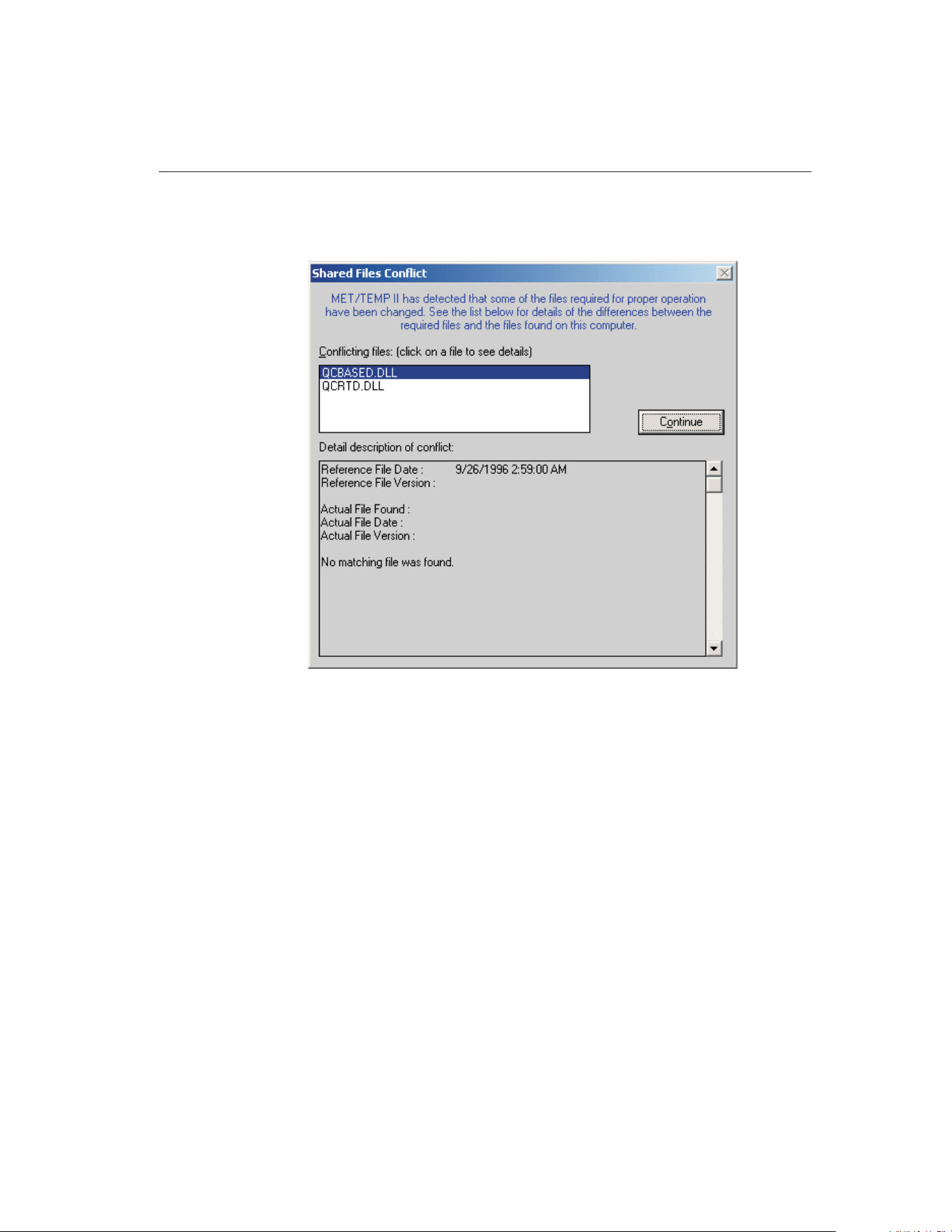
an older file has replaced one or more of these files or that the file is not found,
the Shared Files Conflict dialog is displayed detailing the problems found.
Every time you install any software on your computer, it is a good idea to make
a backup of your important files, including all files in the \WINDOWS (or
\WINNT) and \WINDOWS\SYSTEM (or WINNT\SYSTEM) folders. Some-
times during the installation process, a file may be replaced with an older ver-
sion that is not 100% compatible with the first. This may cause the software to
perform unexpectedly or fail to run at all. Replacing a .DLL or .VBX file with a
newer version does not usually cause any problems because these files are typi-
cally backward-compatible. There are, however, exceptions to this rule.
If the Shared Files Conflict dialog is displayed when you run MET/TEMP II, a
list of the files is shown in the Conflicting Files list. Select each of the files, one
at a time, and read the information that appears in the bottom half of the dialog.
Depending on the information given, you must decide what to do. The software
may continue to run without problems, however there is no guarantee of this.
The .DLL and .VBX files are typically located in the \WINDOWS\SYSTEM
(or \WINNT\SYSTEM) folder. If you find it necessary to avoid conflicts, these
files can be copied to the folder where MET/TEMP II was installed. Be sure to
11
1
Introduction
Figure 1 Shared Files Conflict Dialog
1.888.610.7664 sales@GlobalTestSupply.com
Fluke-Direct.com

compare the files on your computer with the list of required .DLL and .VBX
files.
If the link to the MET/TRACK database is enabled and MET/TEMP II deter-
mines that a compatible version of MET/TRACK is installed on the computer,
the user is prompted to login to the MET/TRACK database. For more details on
configuring MET/TEMP II to link to the MET/TRACK database, refer to Sec-
tion 3.4.9, MET/TRACK Tab.
1.6 Using MET/TEMP II with MET/TRACK
MET/TEMP II is designed to operate as either a “stand-alone” system or it can
be configured to interface with the MET/TRACK database.
When configured to operate as a “stand-alone” system, MET/TEMP II keeps
track of all test equipment and calibration test results in its own database, just
like prior versions (formerly Calibrate-it and Generate-it).
When configured to interface with the MET/TRACK database, MET/TEMP II
still keeps track of all test equipment and calibration test results in its own data-
base, but additionally requires that all instruments being used to perform a cali-
bration as well as all instruments being calibrated have corresponding inventory
records in the MET/TRACK database. For instruments that require calibration,
the MET/TRACK database must also contain up-to-date calibration records.
Also, all calibration test results can be exported to the MET/TRACK database
including probe characterization coefficients and heat source calibration
coefficients.
To configure the operating mode for MET/TEMP II, refer to Section 3.4.9,
MET/TRACK Tab.
Important: Before configuring MET/TEMP II to interface with the
MET/TRACK database, a MET/TEMP II license must be applied to the
MET/TRACK database. A MET/TEMP II license diskette is sold separately
from MET/TEMP II. To apply the license, refer to the MET/TRACK docu-
mentation.
Important: In order to interface with the MET/TRACK database,
MET/TRACK v7.01 or later must be installed! MET/TEMP II does not in-
terface with previous versions of MET/TRACK. Make sure the latest Ser-
vice Pack has been installed. MET/TEMP II will display prompts if it
determines that the installed version of MET/TRACK needs to be up-
graded.
If the link to the MET/TRACK database is enabled, every time MET/TEMP II
starts, the MET/TRACK database login prompt is displayed.
9938 MET/TEMP II
User’s Guide
12
1.888.610.7664 sales@GlobalTestSupply.com
Fluke-Direct.com
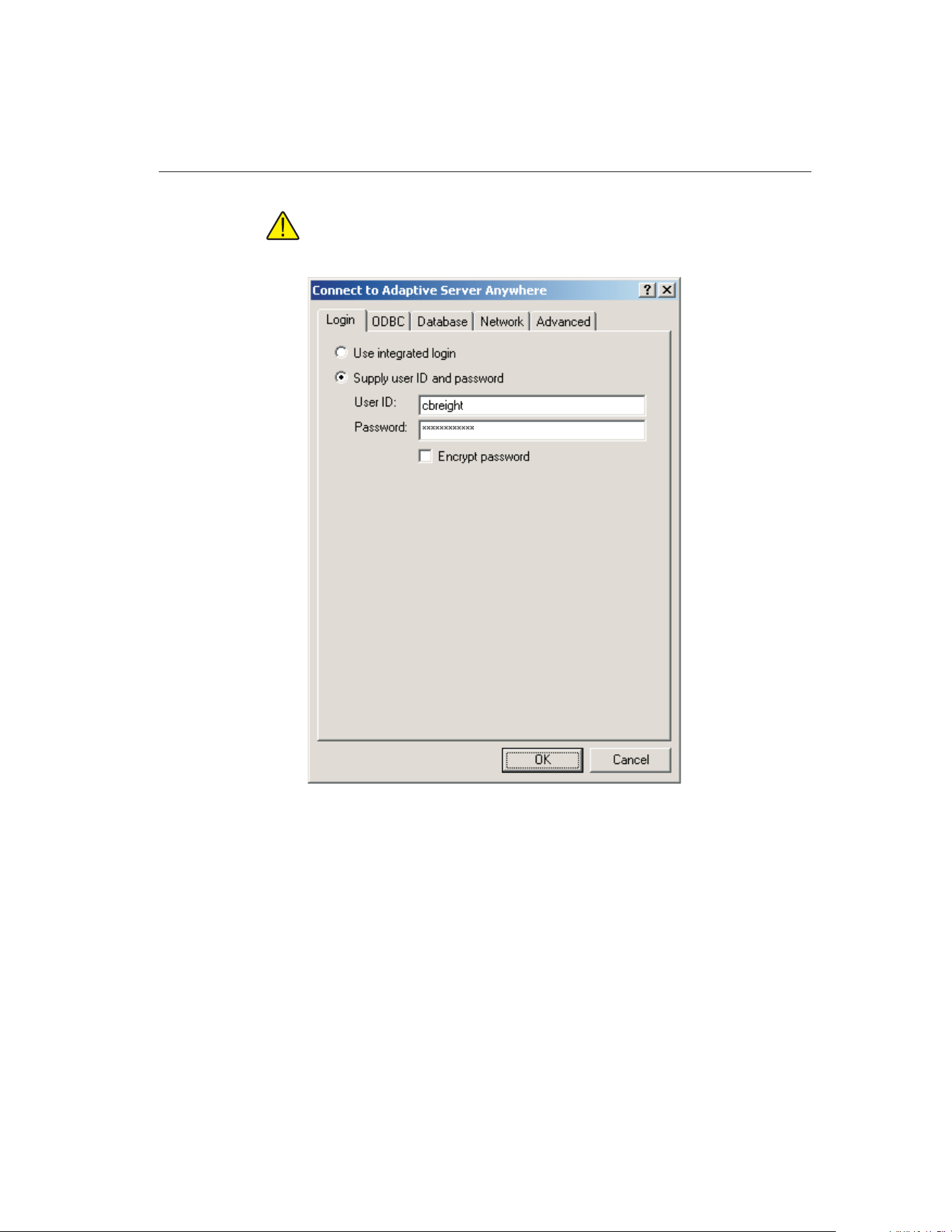
Important: MET/TEMP II requires a MET/TRACK access level of 1 or
higher.
Enter the MET/TRACK user ID and password. If login is successful, a prompt
is displayed indicating the name and access level of the user currently logged
in. If the name of the user does not match the current technician name,
MET/TEMP II asks if you want to update the default technician name. Click
13
1
Introduction
Figure 2 MET/TRACK Database Login Dialog
1.888.610.7664 sales@GlobalTestSupply.com
Fluke-Direct.com
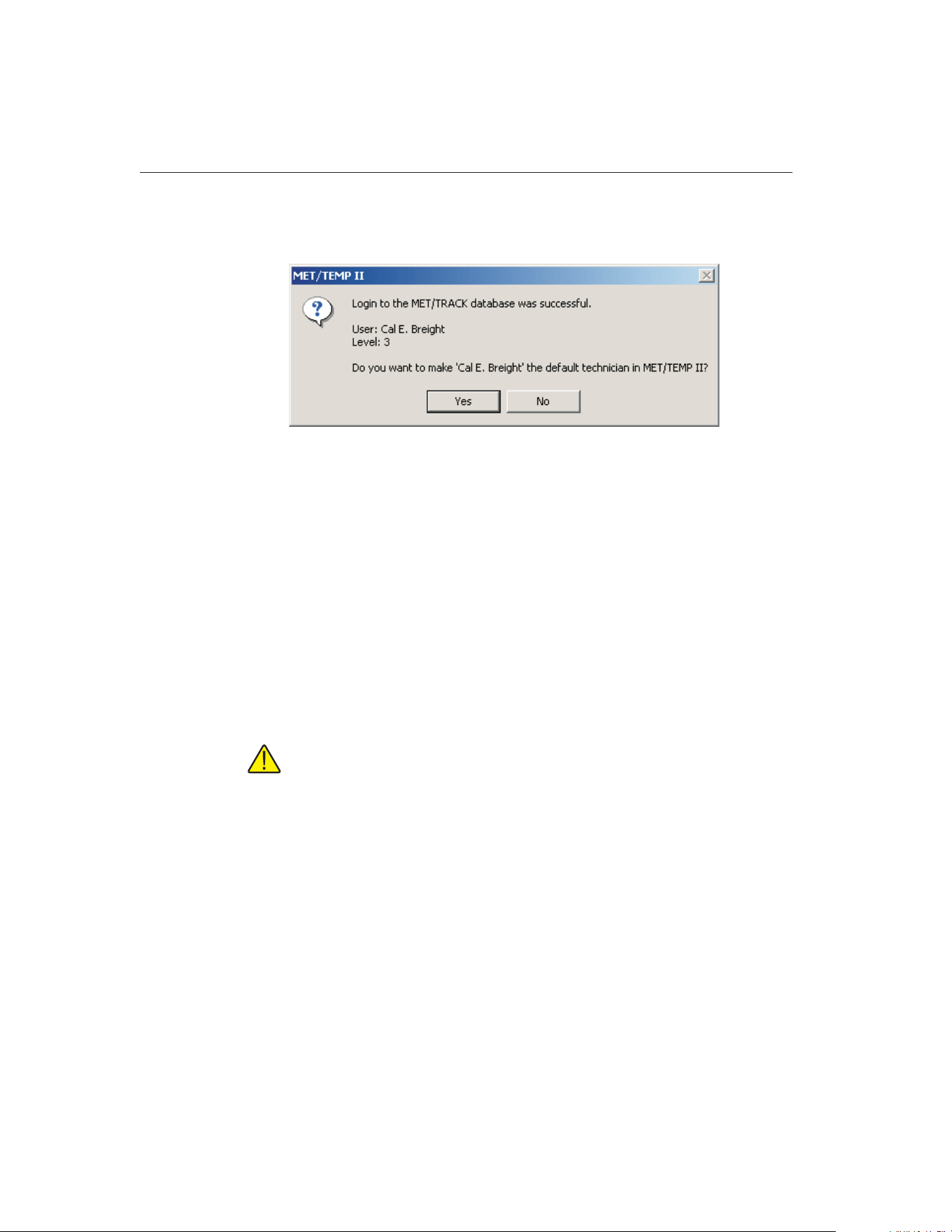
Yes to update the default technician name in MET/TEMP II or click No to pre-
serve the current default technician name.
Once successfully logged into the MET/TRACK database, the MET/TRACK
features are enabled. The MT Asset number box appears on all appropriate
configuration dialogs and all MET/TRACK menu options are enabled.
When configuring a test or opening a configuration file, MET/TEMP II at-
tempts to locate an inventory record in the MET/TRACK database for each
piece of test equipment or probe based on the model, serial number and manu-
facturer. If a match is found, the asset number is read in and displayed in the
MT Asset number box. Otherwise, a prompt is displayed indicating no match-
ing asset record was found. If no asset record exists for this instrument yet,
launch MET/TRACK by clicking Yes and add an inventory record for this in-
strument. If this instrument requires calibration, add a calibration record for
this instrument also. Refer to the MET/TRACK documentation for help on
adding records to the database.
Important: When MET/TEMP II attempts to locate an asset in the
MET/TRACK database, the model, serial number and manufacturer must
match EXACTLY! If an asset record exists but MET/TEMP II is unable to
locate it, you may need to modify the manufacturer information in the
MET/TRACK database.
Depending on the settings on the MET/TRACK tab of the Defaults dialog, the
manufacturer, description, calibration and recalibration dates in MET/TEMP II
can be automatically synchronized with the information in the MET/TRACK
database.
After performing a calibration, the calibration test data can be exported to the
MET/TRACK database. If characterization coefficients need to be calculated
for a probe, this must be done prior to exporting the calibration test data to
MET/TRACK. Calculate the coefficients, then select the Export Calibration
Data to MET/TRACK option in the Utilities menu.
9938 MET/TEMP II
User’s Guide
14
Figure 3 Prompt to Synchronize Technician Name with MET/TRACK User
Name
1.888.610.7664 sales@GlobalTestSupply.com
Fluke-Direct.com

1.7 Required .DLL and .VBX Files
MET/TEMP II requires certain .DLL and .VBX files to function properly. All
required files are shipped on the installation CD. A list of these files and their
required date stamp can be found in the README.TXT file in the folder where
MET/TEMP II is installed.
1.8 Connection of Instruments
Before configuring MET/TEMP II for a test, the test equipment (instruments to
be used) should be connected. MET/TEMP II can be configured to use many
combinations of instruments. The instruments that you use should be deter-
mined by the requirements of the test probes being calibrated and the desired
results. The following is a brief description of the test equipment required by
MET/TEMP II:
Instrument Status Comments
SmartSwitch Required The SmartSwitch is used to connect multiple instruments to a single
COM port on the computer. Use the cable provided.
Reference
Readout
Optional The Reference Readout is typically a thermometer readout with a ref-
erence probe attached. Use a null modem cable (not included).
MET/TEMP II will allow the heat source(s) to be used as the reference.
Scanner Optional The Scanner is the instrument to which all test probes (UUTs) are con-
nected. The Scanner can be the same instrument as the Reference
Readout if it has multiple inputs. Use a null modem cable (not in-
cluded). MET/TEMP II can be configured to not use a scanner if data
needs to be entered manually.
Heat Source(s) Required Up to 4 Heat Sources can be configured. All test probes and the refer-
ence probe must be placed in the same heat source at the same time.
Use a null modem cable (not included). MET/TEMP II can use non-in-
terfaced heat sources. MET/TEMP II also now supports using any
number of Fixed-Point cells as heat sources.
Ambient Condi-
tions Monitoring
Optional MET/TEMP II supports querying ambient temperature and humidity
readings from a Model 1620/5020A ‘DewK’ Thermohygrometer
throughout the testing period.
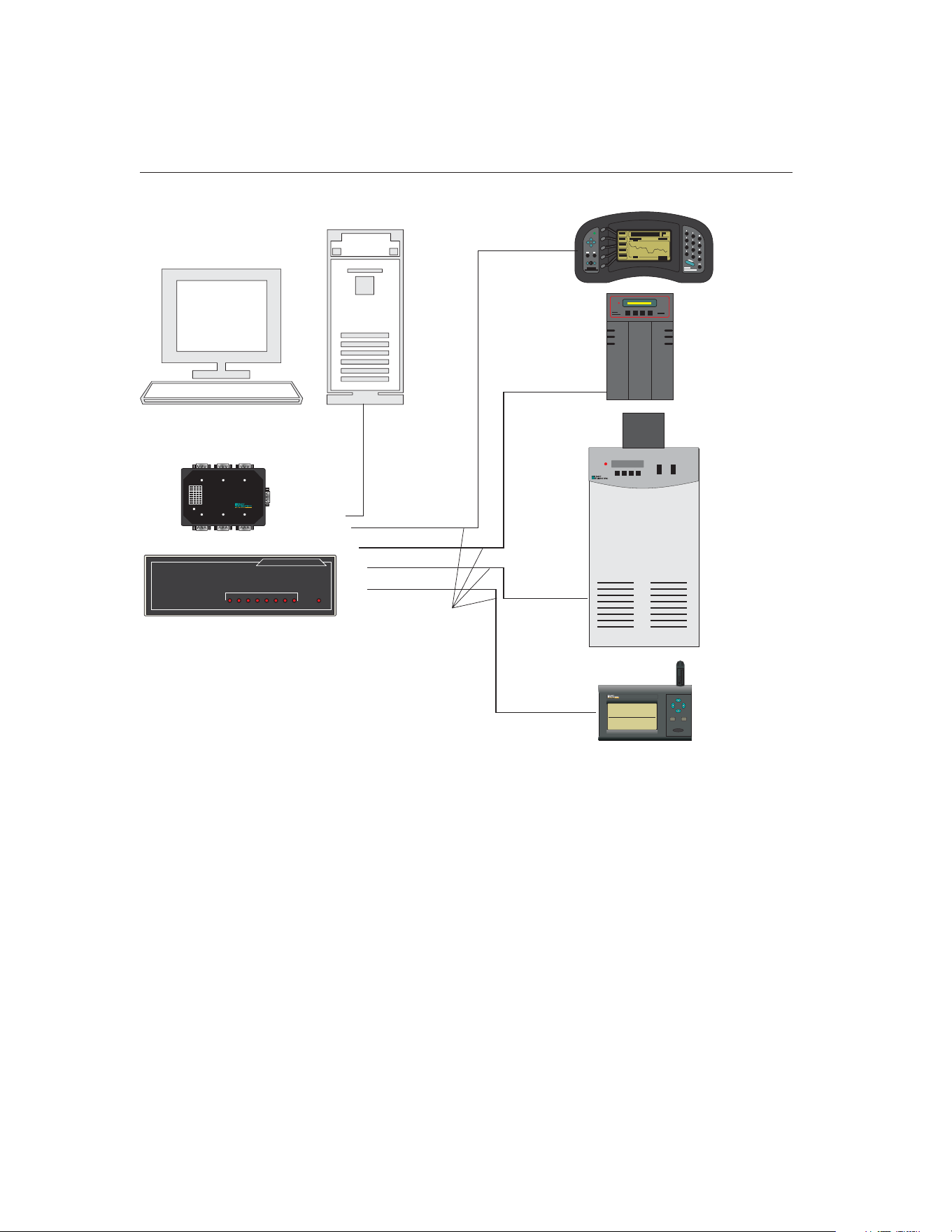
The example shown in Figure 4 is only for demonstration purposes.
1.8.1 Computer to SmartSwitch
Locate a COM port on your computer. Connect the female end of the 9-pin ex-
tender cable provided to the COM port. Connect the male end of the extender
cable to the port labeled MASTER PORT on the SmartSwitch.
If there is no COM port available on the computer but the computer has a USB
port, you may be able to use a USB to RS-232 adapter such as the IOGEAR
15
1
Introduction
Table 1 Instrument Connections
1.888.610.7664 sales@GlobalTestSupply.com
Fluke-Direct.com
Model G-UC232A USB PDA/Serial Adapter. Not all USB to RS-232 adapters
may work in conjunction with the SmartSwitch box. The adapter mentioned
above has been tested by Hart and determined to work properly.
1.8.2 Reference Readout to SmartSwitch
Connect the serial port of the instrument to one of the SmartSwitch ports (typi-
cally port A) using a null modem cable. When configuring the reference read-
out, select the SmartSwitch port to which the instrument is connected.
9938 MET/TEMP II
User’s Guide
16
Bath
Heat Source
SET DOWN
UP
EXIT
COOLING POWER
HEATER
MODE
7380
Thermometer
Readout/Scanner
Dry-Well
Heat Source
Computer
Straight
Through
Cable
Null Modem
Cables
To PORT A
To PORT C
To PORT D
To Serial Port
To Serial Port
To Serial Port
To Serial Port
EXPANDABLE SMART SWITCH
ABCDEFGH
POWER
MODEL 232XSS
PORT SELECT
or
To MASTER PORT
ABC
FED
MASTER PORT
1
2
3
4
5
6
7
8
+12VDC
SmartSwitch
DIPSwitch Settings
BaudRate
1200
2400*
4800
9600
19.2k
38.4k
57.6k
115.2k
1
0
1
0
1
0
1
0
1
2
0
0
1
1
0
0
1
1
3
0
0
0
0
1
1
1
1
*DefaultSettings
Power
Smart Switch
ENTER
MENU
EXIT
1620
the DewK
A Fluke Company
23.67°C
RELATIVE HUMIDITY
1: LAB SOUTH 1
TIME DATE
33.9%
08:43:05 09-04-03
TEMPERATURE
ToPORTF,G,orH
To Serial Port
"DewK"
Thermohygrometer
Figure 4 Example Computer and Instrument Cable Connections
1.888.610.7664 sales@GlobalTestSupply.com
Fluke-Direct.com

1.8.3 Scanner to SmartSwitch
If the same instrument is being used as both the reference readout and the scan-
ner, or if all UUT readings are to be entered manually, skip this section. No
scanner connections are required.
Connect the serial port of the instrument to one of the SmartSwitch ports (typi-
cally port B) using a null modem cable. When configuring the scanner, select
the SmartSwitch port to which the instrument is connected.
1.8.4 Heat Sources to SmartSwitch
If you are using Hart baths, dry-wells or furnaces supported by MET/TEMP II
as heat sources, connect the serial port of each instrument to one of the
SmartSwitch ports (typically ports C-H) using a null modem cable. When con-
figuring the heat sources, select the SmartSwitch port to which each of the in-
struments are connected.
If you are using other heat sources, such as fixed-points or non-supported heat
sources (which are referred to as “External” heat sources), no connection is
required.
Important: If using one or more “External” heat sources, MET/TEMP II
cannot be configured to use the heat sources as the reference.
1.8.5 Model 1620/5020A ‘DewK’ Thermohygrometer to
SmartSwitch
If you are using a 1620/5020A ‘DewK’ Thermohygrometer to monitor ambient
conditions, connect the serial port of the ‘DewK’ to one of the SmartSwitch
ports (typically port F or H) using the serial cable provided with the ‘DewK’.
On the General tab of the MET/TEMP II Defaults dialog, select the
SmartSwitch port that the ‘DewK’ is connected to.
17
1
Introduction
1.888.610.7664 sales@GlobalTestSupply.com
Fluke-Direct.com

1.9 MET/TEMP II Main Display
The MET/TEMP II Main Display consists of the menu bar, toolbar, and a
workspace area.
The menu bar allows access to the various features of the software. A general
description of the options in each menu is given below:
File - Open and Save configuration files, change default settings, printing op-
tions, exit the software.
Configuration - Configure COM port, reference, scanner, and heat sources.
Calibration - Configure set-points and test probes, view current set-points, ad-
just uncertainties, start, stop, pause and resume a test, and override current
set-point’s parameters.
Scale - Change temperature scale.
Graph - Change graph settings, print graph, and graph reference probe.
Utilities - Compact and repair databases, maintain databases, calculate coeffi-
cients and tables, and export test data to MET/TRACK software.
Help - Display help topics and About dialog.
The MET/TEMP II Main Display is the main window for the software. Once a
reference readout and reference probe have been configured, the reference
9938 MET/TEMP II
User’s Guide
18
Figure 5 MET/TEMP II Main Display
1.888.610.7664 sales@GlobalTestSupply.com
Fluke-Direct.com

probe readings can be displayed and plotted on the graph by selecting the Start
Display option from the Graph menu.
1.10 Toolbar
The toolbar provides quick access to many of the most common functions such
as instrument configuration, installing drivers, opening and saving configura-
tion files and starting/stopping a test.
The function of each toolbar button can be found by placing the mouse pointer
over the button and waiting for approximately 1/2 second. A help balloon ap-
pears indicating the function of the button. If a help balloon does not appear,
make sure the Show help balloons check box on the General tab of the Defaults
dialog is selected.
The following buttons are available on the toolbar:
New - Create a new configuration
Open - Open a configuration file
Save As - Save the current configuration to a file
Defaults - Setup default settings
Print Report - Print a Report of Calibration
Close Test - Close the current test
Install Drivers - Install drivers required to use instruments
Communications Port - Setup the computer’s COM port
Reference - Configure the Reference Readout, Reference Module, and
Reference Probe
Scanner - Configure the Scanner and Scanner Module
Heat Sources - Configure the Heat Sources
Equipment Info - View the current configuration
Set-points - Setup temperature set-points for the test
View Set-points - View the status of the set-points
19
1
Introduction
1.888.610.7664 sales@GlobalTestSupply.com
Fluke-Direct.com
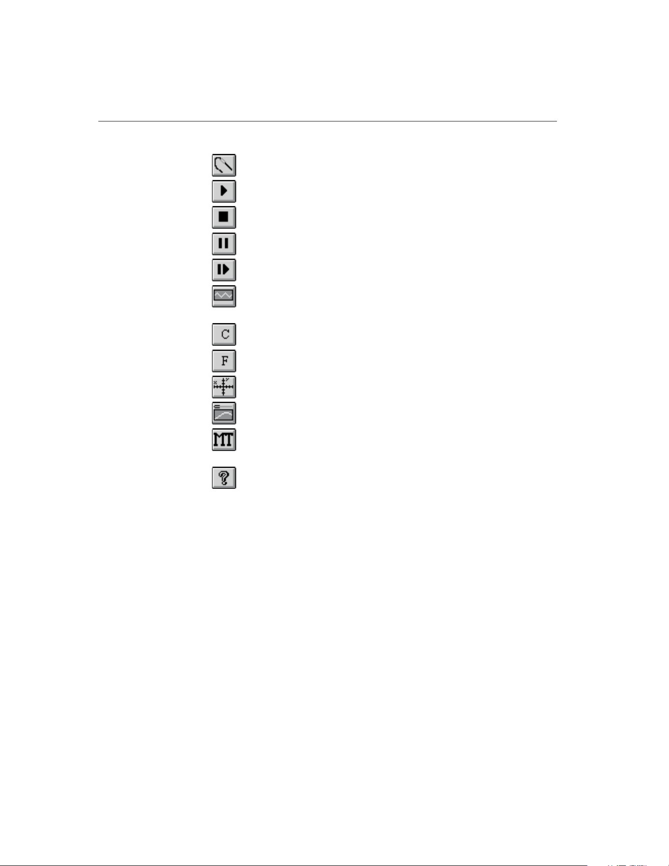
Test Probes - Configure the Test Probes
Start Test - Start a calibration test
Stop Test - Stop the current calibration test
Pause Test - Pause the current calibration test
Resume Test - Resume the current calibration test
Stability Override - Override the stability settings for the current
set-point
C - Change the temperature scale to degrees C
F - Change the temperature scale to degrees F
Graph Settings - Setup the X-axis and Y-axis on the graph
Start Display - Graph the reference probe
Export Calibration Data to MET/TRACK - Export calibration data
to the MET/TRACK database
Help - Open the help file
1.11 MET/TEMP II Introduction Dialog
The MET/TEMP II Introduction dialog is displayed when the software is exe-
cuted for the first time. This dialog is also displayed on subsequent executions
9938 MET/TEMP II
User’s Guide
20
1.888.610.7664 sales@GlobalTestSupply.com
Fluke-Direct.com
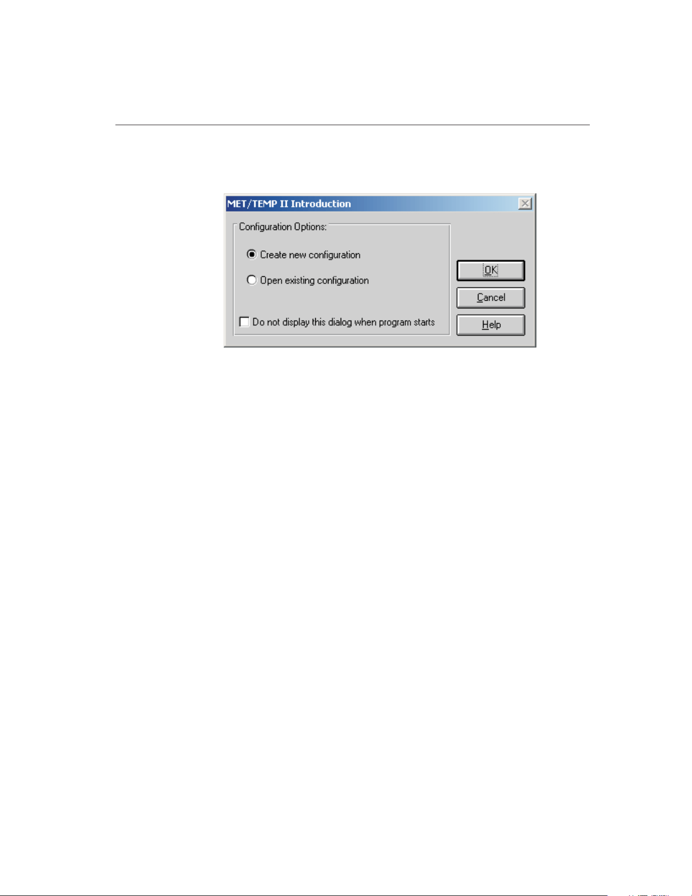
if the Show introduction dialog on startup check box is selected on the General
tab of the Defaults dialog.
The MET/TEMP II Introduction dialog provides a starting place for the user to
configure a test. From this dialog an existing configuration file can be opened
or a new configuration can be created.
To create a new configuration, select the Create new configuration option and
click the OK button. This option should be selected when executing the soft-
ware for the first time. The Equipment Info dialog is displayed and a new con-
figuration can be created. Refer to Section 2, Configuring a Test, for additional
information on creating a new configuration.
To open a configuration file that was previously created and saved to a .CFG
file, select the Open existing configuration option and click the OK button. The
Windows® Open dialog is displayed. Select the configuration file to open and
click the OK button. Refer to Section 3.2, Open, for more information on open-
ing a configuration file.
To disable the display of the MET/TEMP II Introduction dialog when the soft-
ware is executed, check the Do not display this dialog when program starts
check box before clicking the OK button. This option can be enabled again on
the General tab of the Defaults dialog.
Clicking the Cancel button closes this dialog and displays the MET/TEMP II
Main Display.
1.12 MET/TEMP II Test Display
When a test is running, the MET/TEMP II Test Display window displays infor-
mation pertaining to the calibration test that is being performed.
21
1
Introduction
Figure 6 MET/TEMP II Introduction Dialog
1.888.610.7664 sales@GlobalTestSupply.com
Fluke-Direct.com
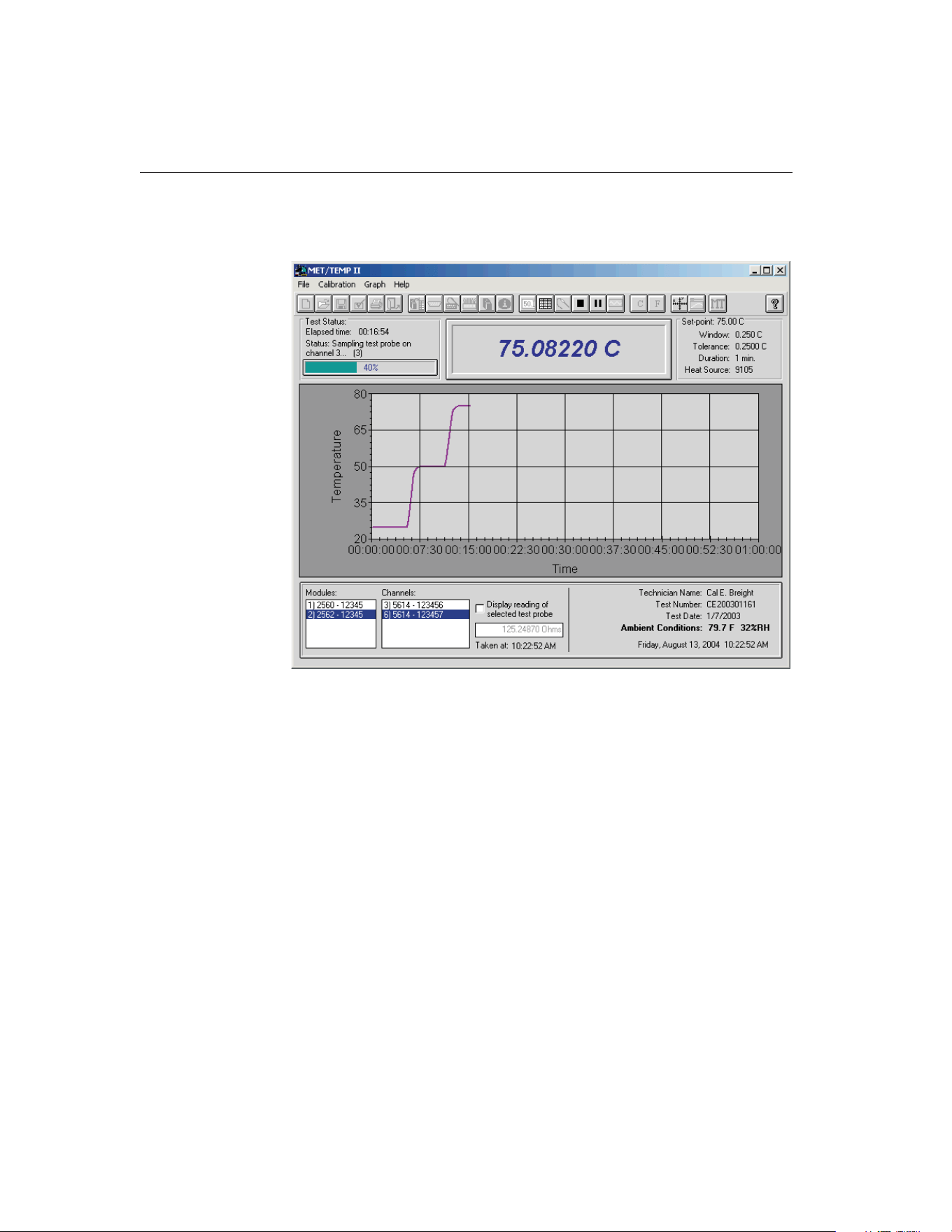
Once a calibration test is started, the MET/TEMP II Main Display changes into
the MET/TEMP II Test Display.
The Test Status box in the upper left corner displays the elapsed time, current
test status, and a progress bar indicating the percentage of the test set-points
completed.
The Set-point box in the upper right corner displays the current set-point, win-
dow, tolerance, duration, and the model of the heat source being used.
The bottom portion of the window displays a list of the scanner modules or
multiplexers (if applicable) and a list of test probes on the left side. The right
side displays the name of the technician performing the test, the test date, test
number, current date and time, and ambient conditions.
When using a Model 1620/5020A 'DewK' Thermohygrometer to monitor the
ambient temperature and humidity, the ambient conditions information indi-
cates the most recently measured values. New measurements are taken roughly
every 2 minutes during the testing period by default. Otherwise, the ambient
conditions information indicates the ambient temperature and humidity values
entered on the Test Information dialog before the test was started.
9938 MET/TEMP II
User’s Guide
22
Figure 7 MET/TEMP II Test Display
1.888.610.7664 sales@GlobalTestSupply.com
Fluke-Direct.com
Note: To configure MET/TEMP II to monitor ambient conditions through-
out the testing period using a ‘DewK’, refer to the settings on the General
tab of the MET/TEMP II Defaults dialog.
The current reading of the selected test probe can be displayed by selecting the
Display reading of selected test probe check box. Checking the Display reading
of selected test probe check box tells the software to take one measurement
from the selected test probe and display the reading in the box provided. The
time at which the measurement was taken appears below the box. This check
box is automatically unchecked after the measurement is taken to prevent this
feature from slowing down the test process. Selecting a different scanner mod-
ule, multiplexer, or test probe clears the reading box.
Note: These controls are all disabled if a scanner is not being used for the
current test.
A test may be paused at any time. To pause a test, select the Pause Test option
in the Calibration menu. The test should be paused anytime the computer needs
to be used to perform another function while a calibration test is running.
Pausing the test does not impact the outcome of the test, however, to ensure the
integrity of the test, the test should not be paused for long periods of time. To
resume the test, select the Resume Test option in the Calibration menu.
Note: The Pause Test option is disabled while the test probe and reference
probe readings are being taken to ensure that all measurements are taken
consecutively, without interruption.
The test may also be stopped (aborted) at any time by selecting the Stop Test
option in the Calibration menu. The user will be required to confirm stopping
the test.
Once a test has finished successfully or has been stopped, the reference probe
readings continue to be graphed until the test is closed. To close a test, select
the Close Test option from the File menu.
Test reports may be printed once the test has been stopped or finished success-
fully. To print a test report, select the Print Report option from the File menu.
When printing reports from the MET/TEMP II Test Display, the graph of the
reference probe readings should be paused first.
23
1 Introduction
MET/TEMP II Test Display
1.888.610.7664 sales@GlobalTestSupply.com
Fluke-Direct.com
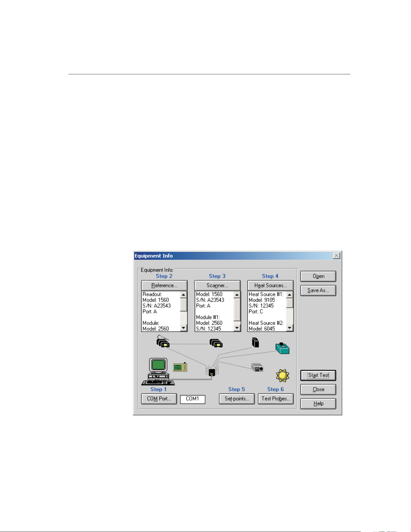
2 Configuring a Test
MET/TEMP II was designed to be very flexible. The user may select from a va-
riety of test equipment and has control over most aspects of a test. Before
MET/TEMP II can perform a test, the software must know the following
information:
• What test equipment is being used?
• How is the test equipment connected?
• What is being calibrated?
• What temperature set-points should be used?
• What scale the readings should be taken in?
The easiest way to create a new configuration is to use the Equipment Info dia-
log. This dialog visually displays the current configuration information and al-
lows access to all of the dialogs necessary to create a configuration. The
Equipment Info dialog is displayed when the Create new configuration option
is selected on the MET/TEMP II Introduction dialog, or by selecting the Equip-
ment Info option in the Configuration menu.
25
2
Configuring a Test
Figure 8 Equipment Info Dialog
1.888.610.7664 sales@GlobalTestSupply.com
Fluke-Direct.com

The Equipment Info dialog also indicates which configuration items still need
to be completed before a test can be started. All incomplete steps are high-
lighted in red text. When the configuration of a step is complete, the text turns
black.
MET/TEMP II now includes the ability to perform calibrations using
fixed-point cells and also supports calibrating certain heat sources. The follow-
ing sections outline the general configuration process for each of the types of
calibrations that MET/TEMP II supports.
2.1 Comparison, Fixed-Point and Mixed Calibrations
The following section outlines the steps necessary to configure a test to cali-
brate probes using comparison and fixed-point realization.
1. Define the communication settings for the instruments. The communica-
tion settings consist of the COM port to which the SmartSwitch is con-
nected. The SmartSwitch must be connected to an available COM port
on the computer and the baud rate for all instruments must be set to 2400
baud. Refer to Section 4.2.1, Communications Port Configuration, for
details on configuring the communication settings.
2. Define the test equipment to use as the reference. MET/TEMP II requires
a reference. For comparison calibrations, the reference is the standard
against which the test probes are compared. The software must be able to
communicate with the reference readout instrument. The software can
use either a reference readout (thermometer readout) with a reference
probe or it can use the heat source(s) as the reference. Refer to Section
4.3, Reference, for details on configuring the reference readout instru-
ment and the reference probe.
3. Define the test equipment to use as the scanner. The scanner is the instru-
ment to which all of the test probes are connected. To calibrate LIG,
bi-metallic, and other thermometers that cannot be interfaced with a
readout device, or for test probes that are attached to a readout device
that is not supported by MET/TEMP II, the software can be configured
to not use a scanner instrument (the user is prompted to manually enter
all readings at the appropriate times during a test). Refer to Section 4.4,
Scanner, for details on configuring the scanner instrument.
4. Define the instrument(s) to use as heat source(s) for the test. The heat
source(s) are the instruments into which the reference probe and all test
probes are inserted. The software can also be configured to use the heat
source(s) as the reference if desired. Heat sources are used to hold the
temperature of the reference probe and test probes at a constant tempera-
ture so that comparison measurements can be taken. When performing a
calibration using only fixed-points, a special heat source driver needs to
be configured. Refer to Section 4.5, Heat Sources, for details on config-
uring the heat source instrument(s).
9938 MET/TEMP II
User’s Guide
26
1.888.610.7664 sales@GlobalTestSupply.com
Fluke-Direct.com

5.
Optional - Save the current instrument configuration. Once the above in-
formation has been entered, the current configuration can be saved. The
configuration does not need to be saved to start a test. However, if the
same equipment is going to be used to perform future tests, saving the
configuration provides a quick method to setup the equipment.
6. Define the set-points for the test. The set-points are the temperatures at
which comparison measurements are taken. The software must know the
value and other specifications of each set-point. When using
fixed-points, this is where the fixed-point cell(s) to use are selected. Re-
fer to Section 5.1, Set-points, for details on configuring the set-points.
7.
Optional - Save the current set-point configuration. Once the set-point
information has been entered, the current set-point configuration can be
saved. The set-point configuration does not need to be saved to start a
test. However, if the same set-points are going to be used to perform fu-
ture tests, saving the set-point configuration provides a quick method to
setup the set-points.
8. Define the test probes (UUTs) to calibrate. The software must know the
type of probes, the scale of the readings to take, the channel of the scan-
ner instrument to which each test probe is connected and other informa-
tion. Refer to Section 5.4, Test Probes, for details on configuring the test
probes.
9.
Optional - Save the current test probe configuration. Once the test probe
information has been entered, the current test probe configuration can be
saved. The test probe configuration does not need to be saved to start a
test. However, if the same test probes are going to be calibrated together
in the future, saving the test probe configuration provides a quick
method to setup the test probes.
10. Start the test. The current configuration is checked for missing informa-
tion and/or conflicts and the Test Information dialog is displayed. Fill in
the remaining information for this test and click the OK button to begin.
Refer to Section 5.5, Start Test, for details on the test process.
11. Close the test. When a test is complete it must be closed. Select the Close
Test option in the File menu to close the test.
12. Print the Report of Calibration. To print the Report of Calibration for
each of the test probes, select the Print Report option in the File menu.
Refer to Section 3.6, Print Report, for details on printing a Report of
Calibration.
2.2 Heat Source Calibrations
The following section outlines the steps necessary to configure MET/TEMP II
to calibrate a heat source.
1. Define the communication settings for the instruments. The communica-
tion settings consist of the COM port to which the SmartSwitch is con-
27
2
Configuring a Test
1.888.610.7664 sales@GlobalTestSupply.com
Fluke-Direct.com

nected. The SmartSwitch must be connected to an available COM port
on the computer and the baud rate for all instruments must be set to 2400
baud.
2. Configure MET/TEMP II to use the heat source as the reference. When
prompted if you are calibrating a heat source, click Yes. No further con-
figuration is needed for the reference.
3. Define the test equipment to use as the scanner. When performing heat
source calibrations, the scanner will actually act as the reference instru-
ment, with the test probe (UUT) acting as the reference probe.
4. Define the heat source to calibrate. Make sure the Calibrate heat source
check box on the Heat Source Configuration dialog is checked. Fill in
the calibration interval and click the Customer button to indicate the sta-
tus and owner of the heat source. Click the Test Calibration Compatibil-
ity button to make sure MET/TEMP II can calibrate the heat source.
5.
Optional - Save the current instrument configuration. Once the above in-
formation has been entered, the current configuration can be saved. The
configuration does not need to be saved to start a test. However, if the
same equipment is going to be used to perform future tests, saving the
configuration provides a quick method to setup the equipment.
6. Define the set-points for the test. The set-points are the temperatures at
which the heat source will be calibrated (As Found) and the set-points at
which As Left data will be taken. When calibrating a heat source, a
set-point configuration file MUST be opened to define the set-points to
use. Default configuration files are supplied (in degrees C) for all sup-
ported heat sources. Customized configuration files can be created by
opening a default configuration file, changing the settings, and saving the
file under a different name.
7.
Optional - Save the current set-point configuration. Once the set-point
information has been entered, the current set-point configuration can be
saved. The set-point configuration does not need to be saved to start a
test. However, if the same set-points are going to be used to perform fu-
ture tests, saving the set-point configuration provides a quick method to
setup the set-points.
8. Define the test probe to use. MET/TEMP II will actually use the probe
configured as the test probe as a reference probe. The test probe MUST
be configured to read temperature! Fill in the test probe’s calibration and
recalibration dates.
Note: When calibrating a heat source, make sure that the test probe (reference
probe) is calibrated and that the scanner has been configured with the probe’s
calibration coefficients so that the temperature read by the test probe is
accurate!
9.
Optional - Save the current test probe configuration. Once the test probe
information has been entered, the current test probe configuration can be
9938 MET/TEMP II
User’s Guide
28
1.888.610.7664 sales@GlobalTestSupply.com
Fluke-Direct.com

saved. The test probe configuration does not need to be saved to start a
test.
10. Start the test. The current configuration is checked for missing informa-
tion and/or conflicts and the Test Information dialog is displayed. Fill in
the remaining information for this test and click the OK button to begin.
11. Close the test. When a test is complete it must be closed. Select the Close
Test option in the File menu to close the test.
12. Print the Report of Calibration. To print a Report of Calibration for a
heat source, select the Print Report option in the File menu. Select the
Use custom report template option and choose the custom report for heat
source calibration.
29
2
Configuring a Test
1.888.610.7664 sales@GlobalTestSupply.com
Fluke-Direct.com
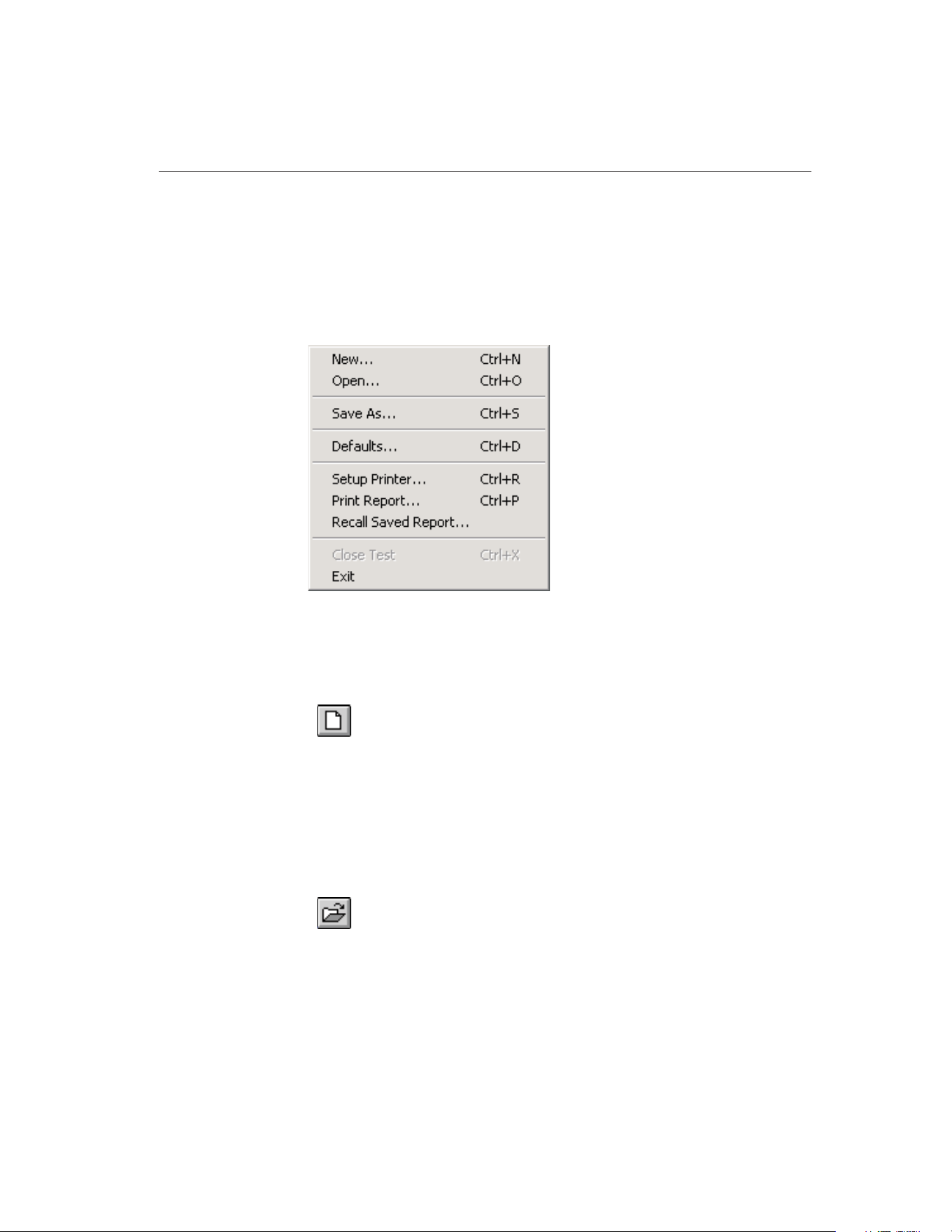
3 File Menu
The File menu provides options for creating a new instrument configuration,
opening an existing instrument configuration, saving a configuration file, set-
ting up program defaults, setting up the printer, printing a test report, closing a
test, and exiting the program.
The following sections describe each of these options.
3.1
New
Selecting the New option discards the current configuration settings and dis-
plays the Equipment Info dialog for starting a new test equipment
configuration.
The New option should be selected whenever a test equipment configuration
that is different from the current configuration is to be used to perform the next
test. Follow the outline described in Section 2, Configuring a Test, to configure
the next test.
3.2
Open
Selecting the Open option displays the Windows® Open dialog for selecting an
instrument configuration file to open.
MET/TEMP II allows the current instrument, set-point, and test probe configu-
rations to be saved to configuration files. This feature is useful when the same
set of instruments, set-points, and/or test probes are used repeatedly to perform
many calibrations.
31
3
File Menu
Figure 9 File Menu
1.888.610.7664 sales@GlobalTestSupply.com
Fluke-Direct.com
To allow for maximum flexibility, the instrument, set-point, and test probe con-
figurations are saved separately and independently from each other. Each of
these configuration files is explained in Section 10, Configuration Files.
Selecting the Open option opens instrument configuration files only.
3.3
Save As
Selecting the Save As option displays the Windows® Save As dialog for saving
an instrument configuration file.
MET/TEMP II allows the current instrument, set-point, and test probe configu-
rations to be saved to configuration files. This feature is useful when the same
set of instruments, set-points, and/or test probes are used repeatedly to perform
many calibrations.
To allow for maximum flexibility, the instrument, set-point, and test probe con-
figurations are saved separately and independent from each other. Each of these
configuration files is explained in Section 10, Configuration Files.
3.4
Defaults
Selecting the Defaults option displays the Defaults dialog for selecting or modi-
fying default settings. Default values or parameters can be set by selecting one
of eight tabs; General, Set-points, Setup, Graph, Reports, User, Test, or Fonts &
Sizes. These defaults are used each time MET/TEMP II is started. Each of the
settings on these tabs is described in detail in the following sections.
9938 MET/TEMP II
User’s Guide
32
1.888.610.7664 sales@GlobalTestSupply.com
Fluke-Direct.com
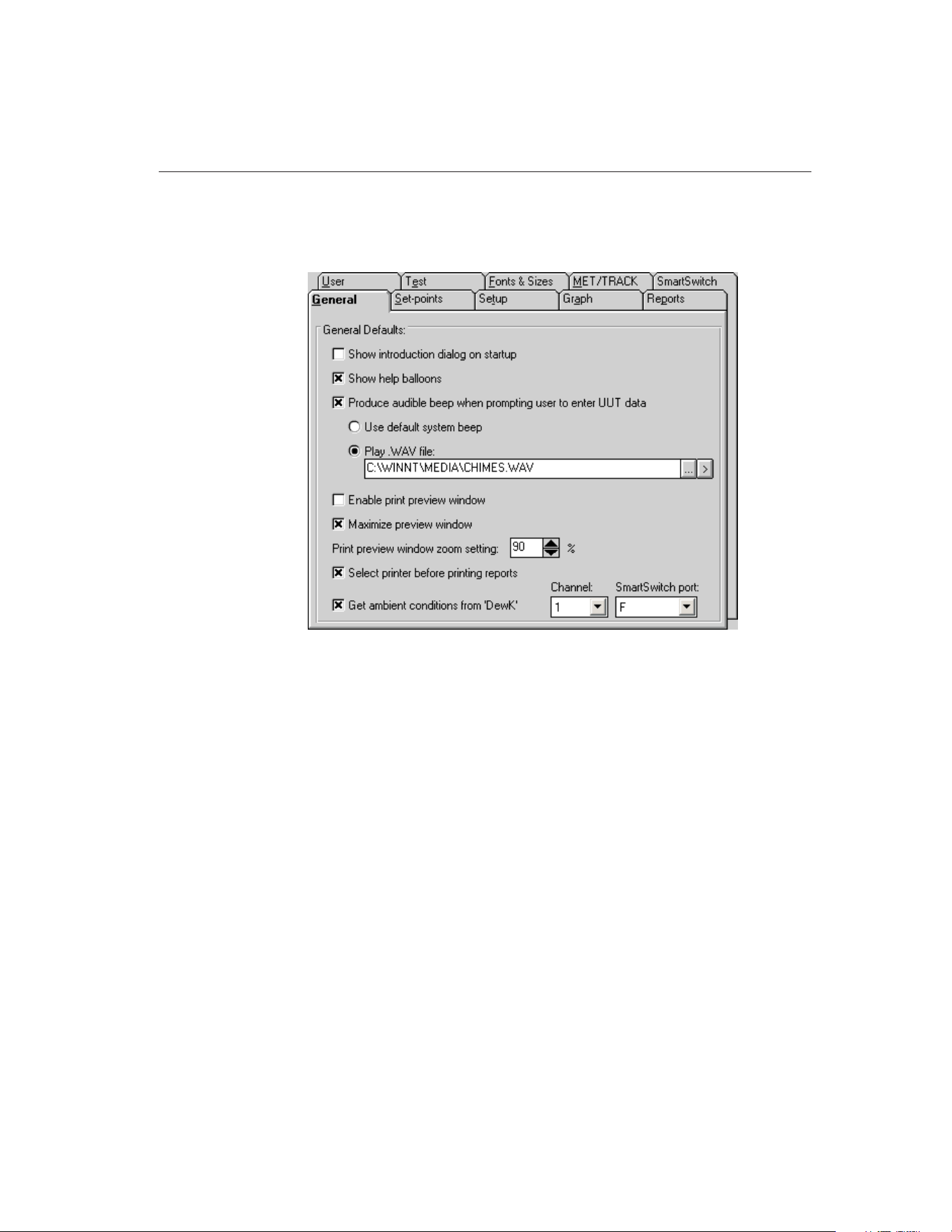
3.4.1 General Tab
The General tab is for selecting general software defaults or preferences.
If the Show introduction dialog on startup check box is selected, the
MET/TEMP II Introduction dialog is displayed each time the software runs.
The Show help balloons check box turns on and off the help balloons. Help bal-
loons are displayed when the mouse pointer is placed over a button on the
toolbar.
The Produce audible beep when prompting user to enter UUT data check box
determines whether the computer continually beeps or plays a .WAV file when
the dialog for entering UUT readings is displayed. This dialog is only displayed
when the scanner instrument is not being used (i.e. for calibrating LIG or
bi-metallic thermometers). If this check box is selected, the following options
are available:
• Use default system beep - If this option is selected, the computer contin-
ually beeps using the system speaker when the dialog for entering UUT
readings is displayed.
• Play .WAV file - If this option is selected, the computer plays the selected
.WAV file when the dialog for entering UUT readings is displayed. Select
the .WAV file to be played by clicking the ... (Browse) button. To test the
.WAV file, click the (Play) button.
33
3
File Menu
Figure 10 General Tab
1.888.610.7664 sales@GlobalTestSupply.com
Fluke-Direct.com

Note: The computer must have a sound card or other sound driver installed to
play a .WAV file. If no drivers are installed, the selected .WAV file cannot and
will not be played.
The Enable print preview window check box forces the reports to be displayed
in a preview window on-screen when printing. If this check box is not selected,
reports are printed directly to the printer when the print button is clicked.
The Maximize print preview window check box determines whether the Print
Preview window is maximized when displayed. If this check box is selected,
the Print Preview window is maximized when it is displayed.
The Print preview window zoom setting determines the default size of the re-
port within the Print Preview window. The zoom setting is limited to 40% to
190%. The zoom setting can also be changed from the Print Preview window
once it is displayed.
The Select printer before printing reports check box forces the software to dis-
play the Select Printer dialog when printing. The user can then select the printer
to which reports are printed. If this check box is not selected, reports are
printed on the default printer. To change the default printer, use the Setup
Printer option in the File menu.
The Get ambient conditions from ‘DewK’ check box indicates whether
MET/TEMP II should take the ambient temperature and humidity readings
from a Model 1620/5020A ‘DewK’ Thermohygrometer. If this check box is not
checked, the ambient conditions must be entered manually on the Test Informa-
tion dialog before starting each test. If this check box is checked, MET/TEMP
II queries readings from the connected ‘DewK’ throughout the test process and
writes the average ambient temperature and humidity readings to the database
when the test is complete.
The Channel drop-down list indicates the channel (or input) of the ‘DewK’ that
readings should be taken from. Select the appropriate channel.
The SmartSwitch port drop-down list indicates the SmartSwitch port to which
the ‘DewK’ is connected. In order for MET/TEMP II to query readings from
the ‘DewK’, it must be connected to one of the available SmartSwitch ports.
9938 MET/TEMP II
User’s Guide
34
1.888.610.7664 sales@GlobalTestSupply.com
Fluke-Direct.com
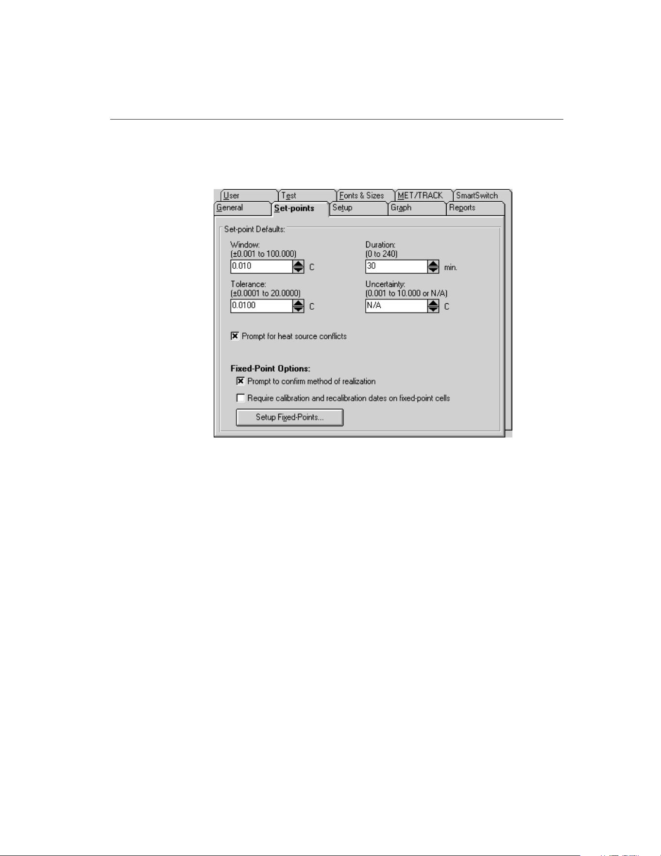
3.4.2 Set-points Tab
The Set-points tab is for selecting defaults specific to the set-points.
The default settings for the set-point window, tolerance, duration, and uncer-
tainty can be set on this tab. The set-point window, tolerance, duration, and un-
certainty values are used when automatically or manually generating set-points.
Use the spin buttons to change the values of each setting or type the new value
into the box provided. To set the uncertainty to N/A, clear the contents of the
box and then click on another box or use the spin down button.
If the Prompt for heat source conflicts check box is selected, the user is
prompted when opening a set-point configuration file, when generating
set-points automatically, or when displaying the Set-point Configuration dialog
after the heat source configuration has changed. Also, if this option is selected,
the user is prompted to enter a proportional band value for each set-point if the
heat source is a bath.
The Fixed-Point Options settings are used to indicate how MET/TEMP II
works with fixed-point cells.
The Prompt to confirm method of realization check box determines whether
MET/TEMP II displays a message to confirm the currently selected method of
realization every time a fixed-point set-point is added on the Set-point Configu-
ration dialog. If this check box is not selected, the currently configured method
of realization is used.
35
3
File Menu
Figure 11 Set-points Tab
1.888.610.7664 sales@GlobalTestSupply.com
Fluke-Direct.com
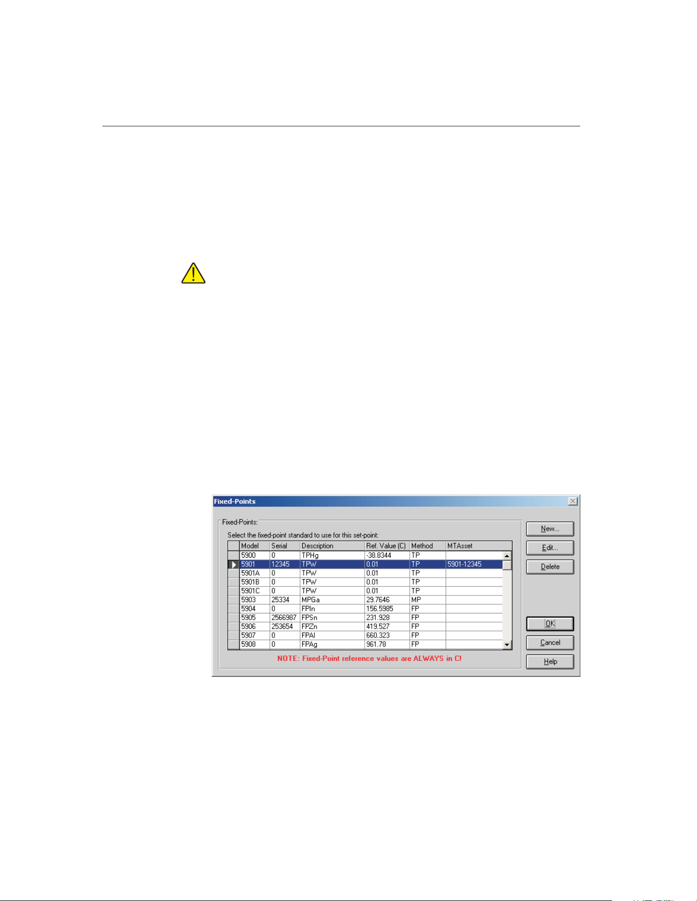
The Require calibration and recalibration dates on fixed-point cells determines
whether MET/TEMP II requires a fixed-point cell’s calibration and
recalibration dates to be entered before it can be used to perform calibrations. If
this check box is not checked, the dates are not required.
To manage the fixed-point cells supported by MET/TEMP II, click the Setup
Fixed-Points button. The Fixed-Points dialog is displayed. Refer to Section
3.4.2.1, Fixed-Points, for more information on setting up fixed-points.
Important: MET/TEMP II allows calibrations to be performed using
fixed-point cells only or by mixing fixed-point set-points with comparison
set-points as a convenience to the user. It is assumed that, if you are using
these features, you are familiar with the process and theory of performing
calibrations using fixed-point cells. This User’s Guide does not provide
any detailed information as to how to perform fixed-point calibrations and
shall not be used as a substitute for proper training and source of infor-
mation on such topics. For more information on performing calibrations
using fixed-point cells, please refer to the currently available literature.
Hart periodically offers training seminars on using fixed-point cells. NIST
is also a good source of information on this topic.
3.4.2.1 Fixed-Points Dialog
The Fixed-Points dialog is displayed when the Setup Fixed-Points button on the
Set-points tab of the Defaults dialog is clicked or when the Insert Fixed-Point
button on the Set-point Configuration dialog is clicked.
This dialog allows the fixed-points supported by MET/TEMP II to be managed.
By default, MET/TEMP II ships with support for fixed-point cells manufac-
tured by Hart. However, the serial number for each of the cells defaults to 0.
9938 MET/TEMP II
User’s Guide
36
Figure 12 Fixed-Points Dialog
1.888.610.7664 sales@GlobalTestSupply.com
Fluke-Direct.com
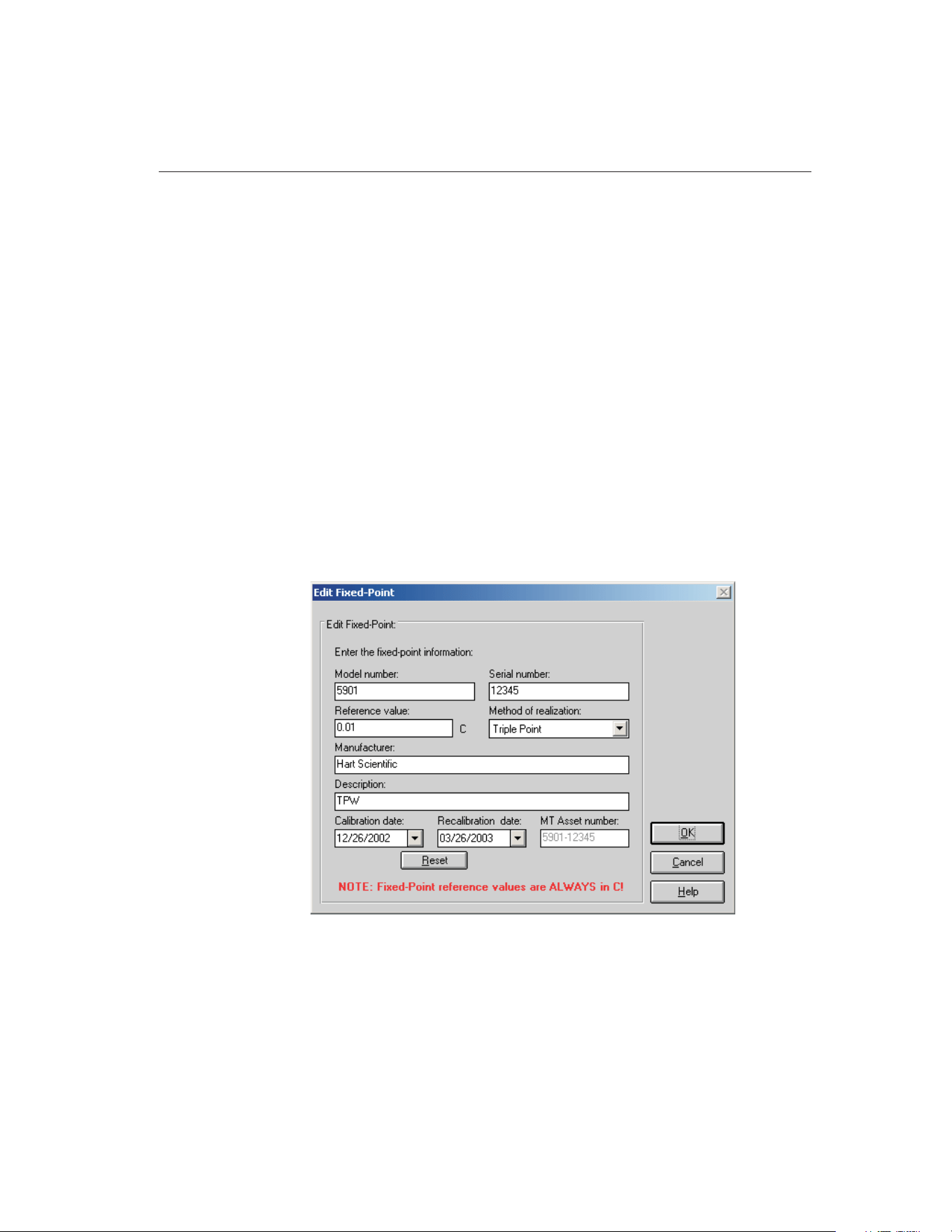
Before a fixed-point cell can be used, its serial number, reference value, method
of realization and, optionally, calibration and recalibration dates must be set.
Select the fixed-point cell to edit and click the Edit button. The Edit
Fixed-Point dialog is displayed. Refer to Section 3.4.2.1.1, Edit Fixed-Point,
for more information.
MET/TEMP II can support any fixed-point cell, not only those manufactured
by Hart. If you want to add a new fixed-point cell to MET/TEMP II, click the
New button. The New Fixed-Point dialog is displayed. Refer to Section
3.4.2.1.2, New Fixed-Point, for more information.
To remove support for a fixed-point cell, select the fixed-point cell to remove
and click the Delete button. A prompt is displayed to confirm removing the
fixed-point cell. Click Yes to remove the fixed-point or click No to abort.
Click the OK button to close this dialog.
3.4.2.1.1 Edit Fixed-Point Dialog
The Edit Fixed-Point dialog is displayed when the Edit button is clicked on the
Fixed-Points dialog. This dialog allows the settings for a fixed-point cell to be
changed.
The fixed-point model number, serial number, reference value, method of real-
ization, manufacturer, description, and calibration and recalibration dates can
be edited.
37
3
File Menu
Figure 13 Edit Fixed-Point Dialog
1.888.610.7664 sales@GlobalTestSupply.com
Fluke-Direct.com

The serial number for all fixed-point cells defaults to 0. Before a fixed-point
cell can be used by MET/TEMP II, its serial number must be set. Enter the se-
rial number for the fixed-point cell in the Serial number box.
Enter the reference value for this fixed-point cell in the Reference value box.
By default, this value is set to the nominal value for each fixed-point cell.
Note: The reference value must ALWAYS be entered in degrees C regardless of
the scale being used for the test! MET/TEMP II will convert the reference value
to degrees F as needed.
Select the method of realization for this fixed-point cell using the Method of re-
alization drop-down list. Many fixed-point cells can be used at either the melt-
ing point (MP), freezing point (FP) or triple point (TP). This setting is printed
on the Report of Calibration.
Enter the manufacturer and description information for this fixed-point cell in
the boxes provided.
The Calibration and Recalibration dates are optional and can be selected using
the drop-down calendars provided. If the Calibration and Recalibration dates
are not entered, NCR appears on the Report of Calibration in the Recall Date
column. Click the Reset button to clear dates from these boxes.
When the MET/TRACK link is active, the MT Asset number box is displayed.
This box indicates the asset number that is assigned to this fixed-point cell. An
inventory record must exist in the MET/TRACK database for this
fixed-point cell before MET/TEMP II can use it to perform calibrations! If
the calibration and recalibration dates are required, a current calibration
record must also exist in the MET/TRACK database. MET/TEMP II will
automatically attempt to locate the records in the MET/TRACK database when
the model, serial number, and manufacturer information have been entered. If
the asset number is found, MET/TEMP II displays the asset number in the MT
Asset number box. Depending on the settings on the MET/TRACK tab of the
Defaults dialog, the manufacturer, description, and calibration and recalibration
dates may be synchronized with the information in the MET/TRACK database.
If the asset cannot be found in the MET/TRACK database, a message is dis-
played. Click Yes to launch MET/TRACK to create or modify asset records or
clickNotoedittheinformationinMET/TEMPII.
Important: When MET/TEMP II attempts to locate an asset in the
MET/TRACK database, the model, serial number and manufacturer infor-
mation must be an EXACT (case-insensitive) match! If the manufacturer
information in MET/TEMP II does not match the manufacturer informa-
tion in MET/TRACK, you may need to modify the manufacturer informa-
tion in the MET/TRACK inventory record in order for MET/TEMP II to
locate it. Where applicable, you may be able to modify the manufacturer
information in MET/TEMP II.
9938 MET/TEMP II
User’s Guide
38
1.888.610.7664 sales@GlobalTestSupply.com
Fluke-Direct.com
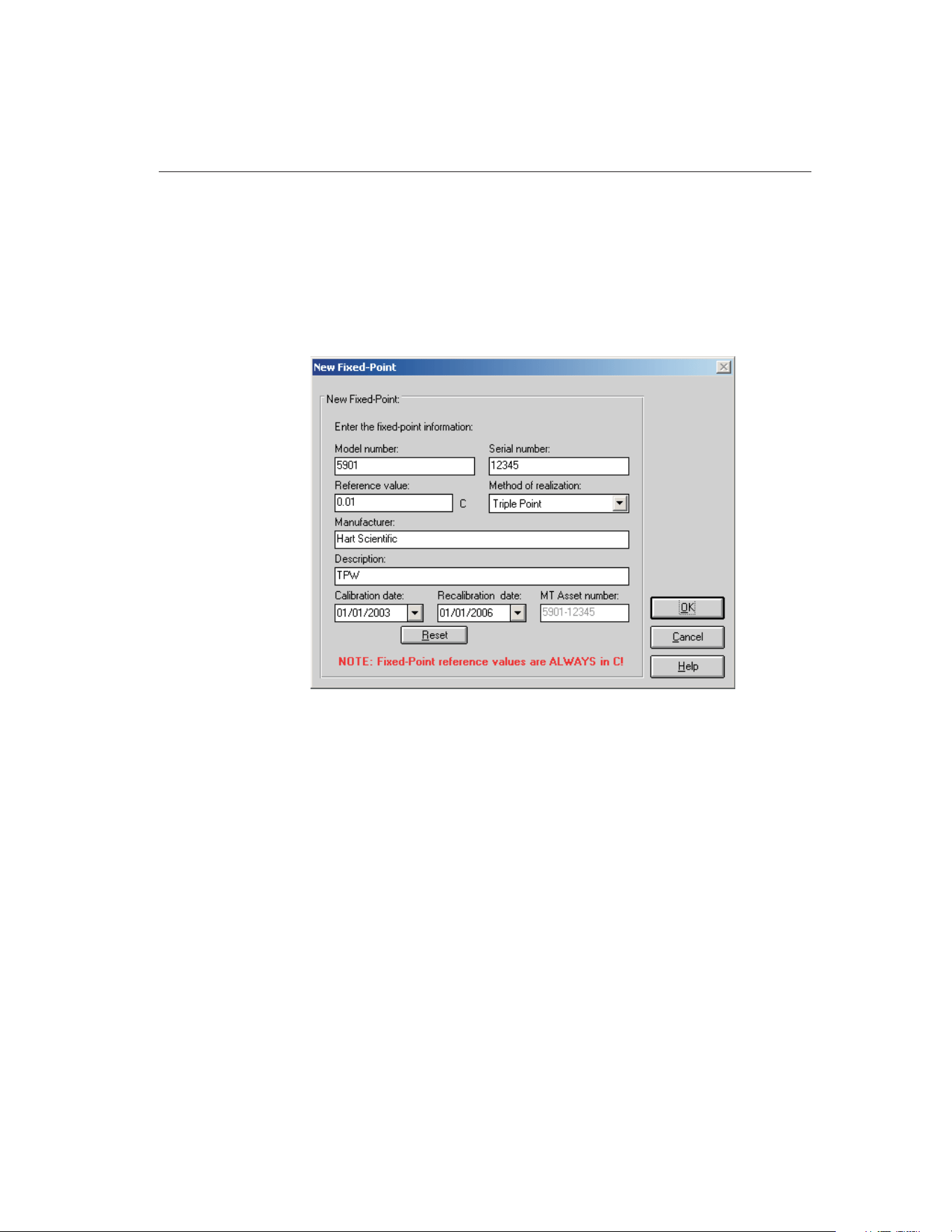
Click the OK button to accept the new settings and close this dialog or click the
Cancel button to abort making changes to this fixed-point cell.
3.4.2.1.2 New Fixed-Point Dialog
The New Fixed-Point dialog is displayed when the New button is clicked on the
Fixed-Points dialog. This dialog allows the settings for a new fixed-point cell to
be entered.
The fixed-point model number, serial number, reference value, method of real-
ization, manufacturer, description, and calibration and recalibration dates must
be entered.
Enter the model and serial numbers for this fixed-point cell in the Model num-
ber and Serial number boxes provided.
Enter the reference value for this fixed-point cell in the Reference value box.
Note: The reference value must ALWAYS be entered in degrees C regardless of
the scale being used for the test! MET/TEMP II will convert the reference value
to degrees F as needed.
Select the method of realization for this fixed-point cell using the Method of re-
alization drop-down list. Many fixed-point cells can be used at either the melt-
ing point (MP), freezing point (FP) or triple point (TP). This setting is printed
on the Report of Calibration.
39
3
File Menu
Figure 14 New Fixed-Point Dialog
1.888.610.7664 sales@GlobalTestSupply.com
Fluke-Direct.com

Enter the manufacturer and description information for this fixed-point cell in
the boxes provided.
The Calibration and Recalibration dates are optional and can be selected using
the drop-down calendars provided. If the Calibration and Recalibration dates
are not entered, NCR appears on the Report of Calibration in the Recall Date
column. Click the Reset button to clear dates from these boxes.
When the MET/TRACK link is active, the MT Asset number box is displayed.
This box indicates the asset number that is assigned to this fixed-point cell. An
inventory record must exist in the MET/TRACK database for this
fixed-point cell before MET/TEMP II can use it to perform calibrations! If
the calibration and recalibration dates are required, a current calibration
record must also exist in the MET/TRACK database. MET/TEMP II will
automatically attempt to locate the records in the MET/TRACK database when
the model, serial number and manufacturer information have been entered. If
the asset number is found, MET/TEMP II displays the asset number in the MT
Asset number box. Depending on the settings on the MET/TRACK tab of the
Defaults dialog, the manufacturer, description, and calibration and
recalibration dates may be synchronized with the information in the
MET/TRACK database. If the asset cannot be found in the MET/TRACK data-
base, a message is displayed. Click Yes to launch MET/TRACK to create or
modify asset records or click No to edit the information in MET/TEMP II.
Important: When MET/TEMP II attempts to locate an asset in the
MET/TRACK database, the model, serial number and manufacturer infor-
mation must be an EXACT (case-insensitive) match! If the manufacturer
information in MET/TEMP II does not match the manufacturer informa-
tion in MET/TRACK, you may need to modify the manufacturer informa-
tion in the MET/TRACK inventory record in order for MET/TEMP II to
locate it. Where applicable, you may be able to modify the manufacturer
information in MET/TEMP II.
Click the OK button to accept the settings for the new fixed-point cell and close
this dialog or click the Cancel button to abort creating a new fixed-point cell.
9938 MET/TEMP II
User’s Guide
40
1.888.610.7664 sales@GlobalTestSupply.com
Fluke-Direct.com
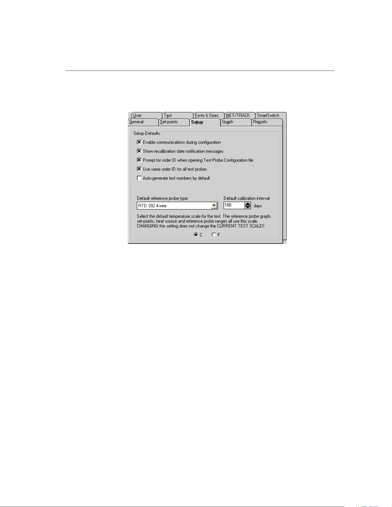
3.4.3 Setup Tab
The Setup tab is for selecting defaults specific to configuring a test.
If the Enable communications during configuration check box is selected, then
the similar check box on the Communications Port Configuration, Reference
Readout Configuration, Scanner Configuration, and Heat Source Configuration
dialogs is selected. If selected, the assumption is made that the instruments are
connected and powered on. Communication is initiated to the instruments dur-
ing the configuration process.
If the Show recalibration date notification messages check box is selected, the
user is prompted when configuring the test equipment if the recalibration date
has passed.
The Prompt for order ID when opening Test Probe Configuration file check
box determines whether or not the user is prompted for an order ID number
when opening a test probe configuration file. The order ID number is required
to begin a test and can be entered manually from the Customer Information
dialog.
The Use same order ID for all test probes check box determines whether the
software should automatically fill in the Customer order ID box on the Cus-
tomer Information dialog when configuring a new test probe.
The Auto-generate test numbers by default check box determines whether test
numbers will be automatically generated by default when the Test Information
dialog is displayed.
41
3
File Menu
Figure 15 Setup Tab
1.888.610.7664 sales@GlobalTestSupply.com
Fluke-Direct.com
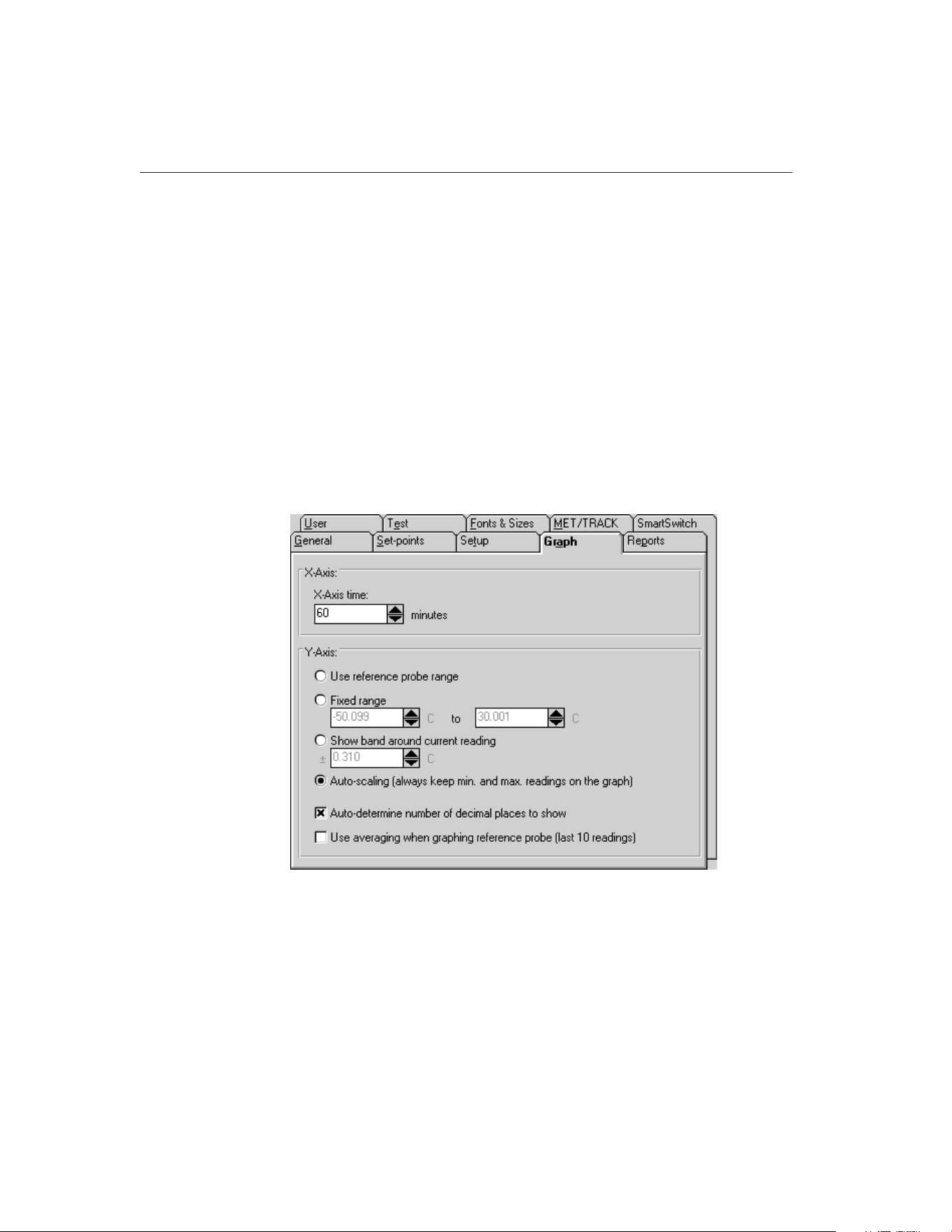
The Default reference probe type is used on the Reference Probe Configuration
dialog for selecting the default type of reference probe. If the selected default
reference probe type cannot be used with the configured reference readout, the
user must select the reference probe type on the Reference Probe Configuration
dialog.
The Default calibration interval setting allows the user to specify the calibration
interval that is automatically filled in on the Test Probe Configuration dialog
when configuring a new test probe.
The selection of C or F determines the scale of the reference probe reading dis-
play and graph as well as the default scale for the set-points, heat source range,
and reference probe when the software runs. The Scale menu allows the current
temperature scale to be changed.
3.4.4 Graph Tab
The Graph tab is for selecting the X-Axis and Y-Axis defaults.
The X-Axis of the graph in MET/TEMP II is displayed as time. Select the
amount of time the X-Axis should display. The X-Axis can be set to display
from 1 to 480 minutes (8 hours).
The Y-Axis is always displayed in degrees C or degrees F. There are four op-
tions for setting the Y-Axis values.
9938 MET/TEMP II
User’s Guide
42
Figure 16 Graph Tab
1.888.610.7664 sales@GlobalTestSupply.com
Fluke-Direct.com

• Use reference probe range - Sets the Y-Axis minimum and maximum
values to the minimum and maximum temperature values entered on the
Reference Probe Configuration dialog.
• Fixed range - Sets the Y-Axis to the minimum and maximum values en-
tered by the user in the boxes provided.
• Show band around current reading - Allows the user to enter a value of
a band to show around the most recent reference probe reading.
• Auto-scaling (always keep min. and max. readings on the graph) -
Maintains the minimum and maximum values of the visible plot on the
graph during the time shown.
The Auto-determine number of decimal places to show option determines
whether MET/TEMP II should automatically determine the resolution of the
Y-axis values. If this check box is not checked, the resolution of the values on
the Y-axis is fixed at 4 decimal places.
If the Use averaging when graphing reference probe (last 10 readings) check
box is selected, the last ten reference probe readings are averaged to produce
the current point on the graph. Averaging provides a smoother looking graph. If
not selected, each point read from the reference probe is graphed.
43
3
File Menu
1.888.610.7664 sales@GlobalTestSupply.com
Fluke-Direct.com
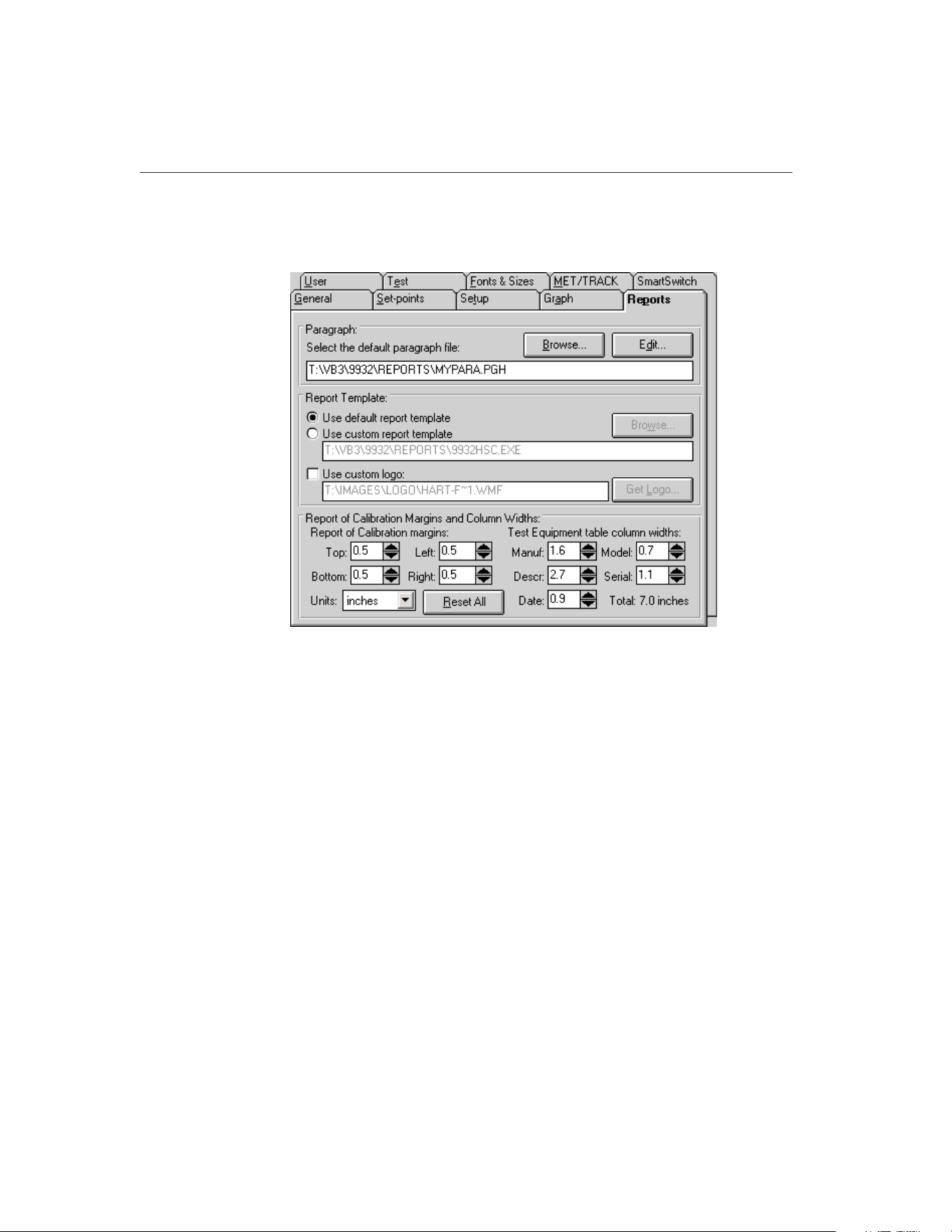
3.4.5 Reports Tab
The Reports tab is for selecting the default report settings.
The Paragraph section of this tab specifies the default text file that contains the
text to appear on the report as the Paragraph.
Clicking the Edit button opens the file specified in the Filename box in the Text
Editor so that it may be viewed or edited. If there is no file specified in the File-
name box the Text Editor is displayed blank and ready for editing.
Clicking the Browse button displays the Windows® Open dialog. The user may
select the file that contains the paragraph text.
The Report Template section of this tab determines the default report template
that will be used when printing a Report of Calibration. If the Use default re-
port template option is selected, MET/TEMP II uses the built-in Report of Cali-
bration template. The Custom report template box and Browse button are
disabled.
MET/TEMP II also allows custom report templates to be used when printing
reports. If the default report template isn’t exactly the type of report required
for your application, contact Hart application specialists for information on ob-
taining custom report templates designed to your specifications. If a custom re-
port template has been purchased from Hart, the Use custom report template
option allows the user to specify the file that contains the custom report tem-
9938 MET/TEMP II
User’s Guide
44
Figure 17 Reports Tab
1.888.610.7664 sales@GlobalTestSupply.com
Fluke-Direct.com

plate. The Custom report template box and Browse button are enabled. Click
the Browse button to select the custom report template to use.
MET/TEMP II now comes with two custom Reports of Calibration which are
installed automatically when MET/TEMP II is installed. The custom report
files are installed in the \REPORTS folder and are named PASSFAIL.EXE and
HEATSRC.EXE. For more details on using these custom reports, see Section
11.2, Custom Reports of Calibration.
Note: Custom report template files MUST be located in the \REPORTS
subfolder of the C:\METTEMP2 folder (or the folder where MET/TEMP II was
installed) in order to operate properly.
The Use custom logo check box can be used to specify a custom logo to print
in the upper left corner of the Report of Calibration. This feature supports using
either a BMP of WMF type file to display a company logo or any other graphic
to print on the Report of Calibration. Click the Get Logo button to specify the
file containing the graphic to use.
Note: The default Report of Calibration, the Pass/Fail Report of Calibration,
and the Heat Source Report of Calibration have all been modified to print the
specified logo or graphic in the upper left corner. The Report of Calibration
created by the Coefficients and Tables application has also been modified to
print the specified logo or graphic in the upper left corner. Other custom reports
may not support this feature.
The Report of Calibration Margins and Column Widths section can be used to
customize the margins and the column widths of the Test Equipment table on
the Report of Calibration.
Enter the margins to use for the Top, Bottom, Left, and Right sides of the report
in the appropriate boxes.
Enter the width of each column of the Test Equipment table in the in the appro-
priate boxes. The total width of the table is calculated and displayed in the
lower right corner.
Select the units of measure to use using the Units drop-down list.
Click the Reset All button to reset all margins and column widths to the default
values.
Note: The default Report of Calibration, the Pass/Fail Report of Calibra-
tion, and the Heat Source Report of Calibration have all been modified to
use the margins and column widths specified. The Report of Calibration
created by the Coefficients and Tables application has also been modified
to use the margins and column widths specified. Other custom reports may
not support this feature.
45
3
File Menu
1.888.610.7664 sales@GlobalTestSupply.com
Fluke-Direct.com
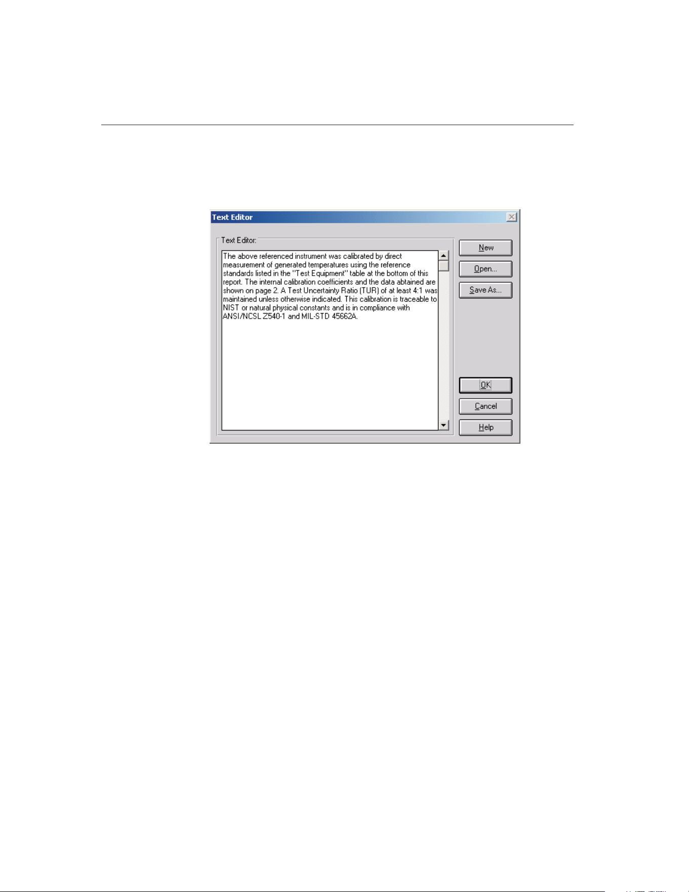
3.4.5.1 Text Editor Dialog
The Text Editor dialog allows the user to edit the paragraph or notes to appear
on the Report of Calibration.
To open an existing file, click the Open button.
Paragraph and note text files must be saved to a file in order to appear on the
Report of Calibration. To save the text displayed in the text editor to a file, click
the Save As button. To create a new text file, click the New button.
Clicking the OK button closes the Text Editor dialog. You will be prompted to
save any changes made. Clicking the Cancel button closes the Text Editor dia-
log and aborts any changes made to the text.
3.4.6 User Tab
The User tab is for configuring the default name, company name, and address
9938 MET/TEMP II
User’s Guide
46
Figure 18 Text Editor Dialog
1.888.610.7664 sales@GlobalTestSupply.com
Fluke-Direct.com
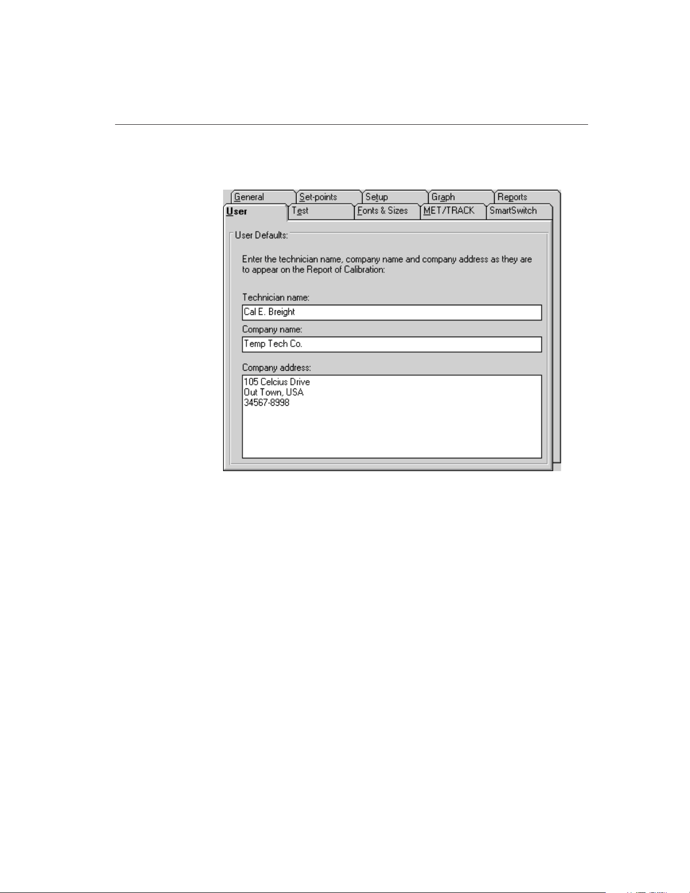
of the technician performing the test. This information prints on the Report of
Calibration.
The information on this tab pertains to the technician performing the test and
the technician’s company name and address. This information was entered
when the software was installed but may be changed at any time.
Changing this information only affects calibrations that are performed from
that point on. Calibrations that were performed previously will retain the tech-
nician, company name, and address information that was configured at the time
each test started.
47
3
File Menu
Figure 19 User Tab
1.888.610.7664 sales@GlobalTestSupply.com
Fluke-Direct.com
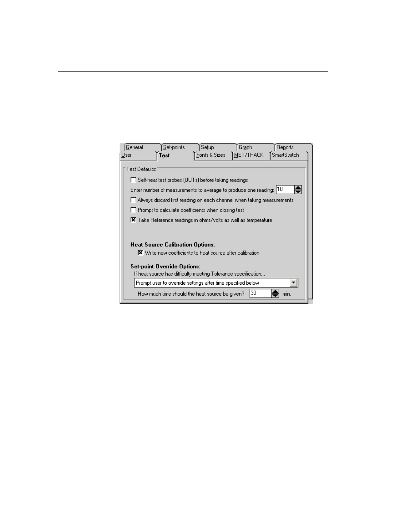
If the link to the MET/TRACK database is active, the Technician name can be
synchronized to the MET/TRACK user name when logging into the database.
For more information, refer to Section 3.4.9, MET/TRACK Tab.
3.4.7 Test Tab
The Test tab is for selecting defaults specific to the test process.
If the Self-heat test probes (UUTs) before taking readings check box is se-
lected, MET/TEMP II allows the excitation current to run through the test
probe for a period of one minute prior to taking readings. If not selected,
MET/TEMP II bypasses the self-heat step of the test process.
The user is allowed to select the number of measurements to be averaged for
each reading of a test. Once stability is reached at a set-point and the process of
reading each test probe begins, the test probe and the reference probe are sam-
pled the number of times specified here. The test probe readings and reference
probe readings are then averaged to determine the value to be used for the
set-point.
Note: MET/TEMP II uses oversampling, which means that more than the se-
lected number of readings are actually taken. MET/TEMP II then discards the
extra readings and the selected number of readings are averaged to produce the
9938 MET/TEMP II
User’s Guide
48
Figure 20 Test Tab
1.888.610.7664 sales@GlobalTestSupply.com
Fluke-Direct.com

values printed on the Report of Calibration. This technique is used to eliminate
potentially bad readings.
The Prompt to calculate coefficients when closing test option determines
whether MET/TEMP II should display a prompt when closing a test to launch
the Coefficients and Tables application to calculate characterization coeffi-
cients. This prompt is never displayed after performing heat source
calibrations.
The Take Reference readings in ohms/volts as well as temperature option deter-
mines whether MET/TEMP II should take measurements from the reference
probe in raw units (ohms or volts) in addition to temperature at each set-point
for each UUT. This feature was added for custom reporting purposes and
should usually be left unchecked.
Note: The Take Reference readings in ohms/volts as well as temperature
option may not apply to all reference instruments. Also, this feature does
not apply when using the heat source(s) as the reference. Warning mes-
sages will appear when starting a test if this feature conflicts with the cur-
rent test configuration and/or instruments being used.
The Heat Source Calibration Options settings indicate how MET/TEMP II
should operate when calibrating a heat source.
The Write new coefficients to heat source after calibration indicates whether
the new calculated calibration coefficients for the heat source should be written
to the heat source prior to taking readings at the configured As Left set-points
when performing a heat source calibration. If selected, MET/TEMP II writes
and verifies the new coefficients prior to taking As Left data.
The Set-point Override Options settings indicate what MET/TEMP II should do
if the heat source is unable to achieve the Tolerance setting at a particular
set-point. The user may select between the following options:
• Continue trying until specification is met
• Abort test after time specified below
• Prompt user to override settings after time specified below
• Override settings and continue test after time specified below
The Continue trying until specification is met option is the default. When this
option is selected, MET/TEMP II continually monitors the reference probe
readings until the tolerance specification is met, regardless of how long it takes.
MET/TEMP II does not take readings from the reference probe and UUTs until
this specification is met. Prior to version 3.1 of Calibrate-it, the software be-
haved this way. This option may be recommended when test requirements are
very strict.
The Abort test after time specified below option allows the user to automati-
cally abort a test if the tolerance specification is not met within a specific time
frame. This time frame can be specified using the How much time should the
49
3
File Menu
1.888.610.7664 sales@GlobalTestSupply.com
Fluke-Direct.com

heat source be given? box. The software begins to count down this time ap-
proximately one minute after the heat source set-point is changed. This option
may be recommended when the user is attempting to determine the best set-
tings to use for specific set-points.
The Prompt user to override settings after time specified below option causes
MET/TEMP II to display a message box (which pauses the test until the user
clicks the OK button) prompting the user to override the settings for the current
set-point if the tolerance specification is not met within a specific time frame.
This time frame can be specified using the How much time should the heat
source be given? box. MET/TEMP II begins to count down this time approxi-
mately one minute after the heat source set-point is changed. The user can
override the current set-point settings by selecting the Stability Override option
from the Calibration menu. This option may be recommended when tests are
not left unattended for long periods of time.
The Override settings and continue test after time specified below option causes
MET/TEMP II to ignore the tolerance specification for the current set-point if
not met within a specific time frame and start taking measurements. This time
frame can be specified using the How much time should the heat source be
given? box. MET/TEMP II begins to count down this time approximately one
minute after the heat source set-point is changed. This option may be recom-
mended when tests are left unattended for long periods of time.
The How much time should the heat source be given? box allows the user to
specify the amount of time that must elapse before the action selected above
occurs. The allowable range is from 1 minute to 120 minutes.
Note: This time does not apply if the first option is selected.
3.4.8 Fonts & Sizes Tab
The Fonts & Sizes tab is used for selecting the default font names, sizes and
9938 MET/TEMP II
User’s Guide
50
1.888.610.7664 sales@GlobalTestSupply.com
Fluke-Direct.com
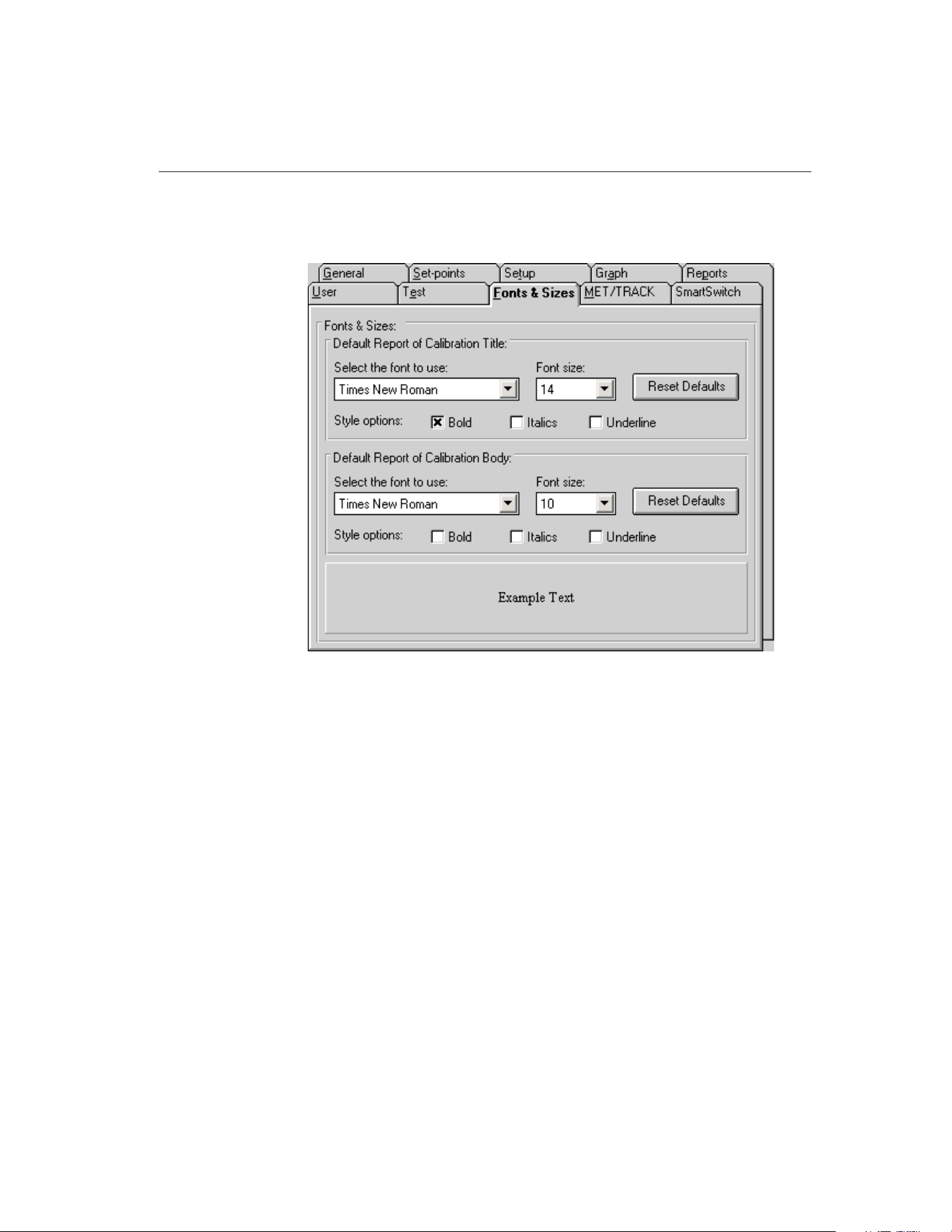
styles to be used when printing the default Report of Calibration and the cus-
tom Reports of Calibration that ship with MET/TEMP II.
To set the font that is used when printing the title on the default Report of Cali-
bration and the included custom Reports of Calibration, change the settings in
the Default Report of Calibration Title section. To set the font that is used when
printing the rest of the text (main body) on the default Report of Calibration
and the included custom Reports of Calibration, change the settings in the De-
fault Report of Calibration Body section.
• Select the name of the font to use from the Select the font to use
drop-down list.
• Increase or decrease the size of the font by selecting a setting from the
Font Size drop-down list.
• Change the font style options by checking or unchecking the Bold, Italics
and/or Underline boxes.
• The current settings are displayed in the Example Text box at the bottom
of this tab.
Click the Reset Defaults button to restore the default settings. The default set-
tings are as follows:
51
3
File Menu
Figure 21 Fonts & Sizes Tab
1.888.610.7664 sales@GlobalTestSupply.com
Fluke-Direct.com
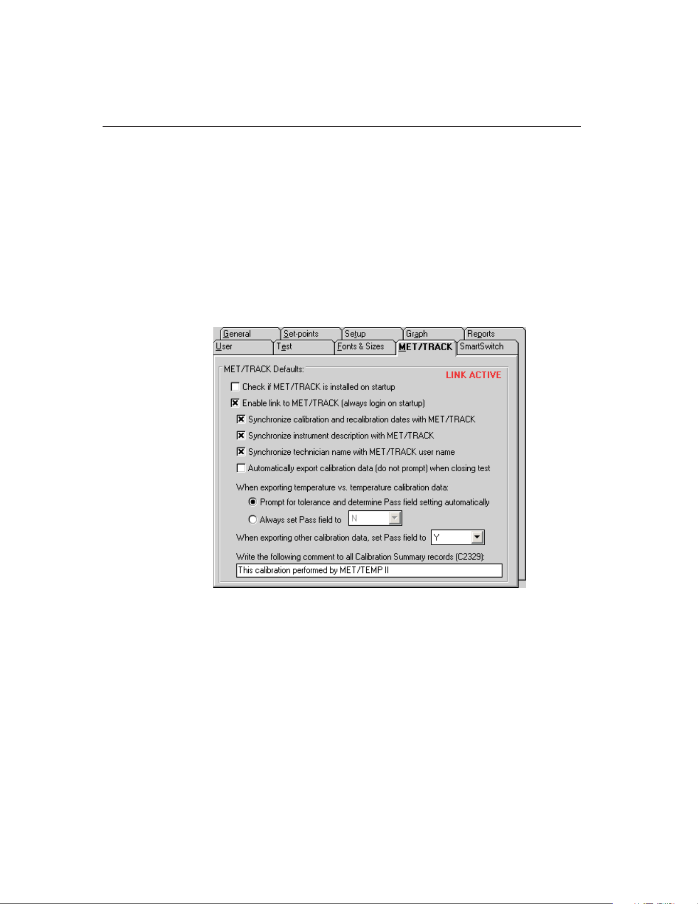
• Title font settings - Times New Roman, 14 point, Bold
• Body font settings - Times New Roman, 10 point
Note: Changing these settings does not change the font settings used on custom
Reports of Calibration that are not included with MET/TEMP II. The changes
are applied only to the default Report of Calibration which is built into
MET/TEMP II and to the custom Reports of Calibration that ship with
MET/TEMP II.
3.4.9 MET/TRACK Tab
The MET/TRACK tab is used for selecting the default settings for linking to
the MET/TRACK database.
The upper right corner of this tab indicates the current link status. If the link to
the MET/TRACK database is currently active, the status indicates LINK AC-
TIVE. If the link is not active, the status indicates LINK INACTIVE.
If the Check if MET/TRACK is installed on startup check box is checked, ev-
ery time MET/TEMP II is launched, it checks to see if MET/TRACK is in-
stalled on the local computer. If so, it makes sure that the version of
MET/TRACK is sufficient for MET/TEMP II to establish the link. If an older
version of MET/TRACK is detected (prior to version 7.0), a message is dis-
played on startup indicating MET/TRACK must be updated to a later version
before the link can be established. This check box should only be checked to
9938 MET/TEMP II
User’s Guide
52
Figure 22 MET/TRACK Tab
1.888.610.7664 sales@GlobalTestSupply.com
Fluke-Direct.com

allow MET/TEMP II to locate a newly installed version of MET/TRACK. Once
MET/TEMP II has determined that MET/TRACK is or is not installed, this
check box should be unchecked.
If the Enable link to MET/TRACK (always login on startup) check box is
checked, MET/TEMP II will attempt to login to the MET/TRACK database ev-
ery time MET/TEMP II is launched. If not checked, MET/TEMP II operates as
a stand-alone system.
The following settings only apply when the link to the MET/TRACK database
is active:
If the Synchronize calibration and recalibration dates with MET/TRACK check
box is checked, MET/TEMP II will read in the calibration and recalibration
dates (where applicable) for each instrument from the MET/TRACK database
and update the MET/TEMP II database.
If the Synchronize instrument description with MET/TRACK check box is
checked, MET/TEMP II will also read in the description for each instrument
from the MET/TRACK database and update the MET/TEMP II database.
If the Synchronize technician name with MET/TRACK user name check box is
checked, every time a user logs into the MET/TRACK database from
MET/TEMP II, the current MET/TEMP II technician name (as found on the
User tab) is checked against the full name of the MET/TRACK user. If the
names do not match, the Technician name in MET/TEMP II is updated auto-
matically. If this check box is not checked, a prompt is displayed to allow the
user to choose whether or not to synchronize the names.
If the Automatically export calibration data (do not prompt) when closing test
check box is checked, calibration data is automatically exported to the
MET/TRACK database when the Close Test option in the File menu is selected.
If this check box is not checked, a prompt will be displayed to confirm export-
ing calibration data to the MET/TRACK database.
Note: If the user chooses to launch the Coefficients and Tables application to
calculate characterization coefficients when prompted, the calibration data will
NOT be automatically exported to the MET/TRACK database when the test is
closed. Select the Export Calibration Data to MET/TRACK option from the
Utilities menu after all coefficients are calculated to export the calibration data
with the coefficients.
The next few options are used to indicate the setting for the Pass field in the
calibration summary record when calibration data is exported to the
MET/TRACK database.
For temperature vs. temperature data, there are two options:
• Prompt for tolerance and determine Pass field setting automatically
• Always set Pass field to
If the first option is selected, the first time a set of calibration data is exported,
the Tolerances dialog is displayed for each UUT. The user is allowed to enter
53
3
File Menu
1.888.610.7664 sales@GlobalTestSupply.com
Fluke-Direct.com

the tolerance at each set-point for that UUT. The tolerance is then recorded in
the MET/TEMP II database and the Pass field setting is determined based on
whether the calculated error at each set-point falls within the entered tolerance.
If the error at each set-point for a UUT is less than the entered tolerance at that
set-point for that UUT, the Pass field for that UUT is set to “Y”. If the error at
any set-point exceeds the tolerance, the Pass field is set to “N” for that UUT.
If the Always set Pass field to option is selected, the Pass field will always be
set to the selected setting. Use the drop-down list to choose the Pass field
setting.
For temperature vs. resistance or temperature vs. voltage calibration data, use
the When exporting other calibration data, set Pass field to option. The Pass
field will always be set to the selected setting. Use the drop-down list to choose
the Pass field setting.
The Write the following comment to all Calibration Summary records (C2329)
box allows the user to enter any note, comment or remark that should be writ-
ten to the C2329 field of the calibration summary record when calibration data
is exported to MET/TRACK. This field is limited to 44 characters. Leave this
box blank if you do not wish to write anything to the C2329 field.
9938 MET/TEMP II
User’s Guide
54
1.888.610.7664 sales@GlobalTestSupply.com
Fluke-Direct.com
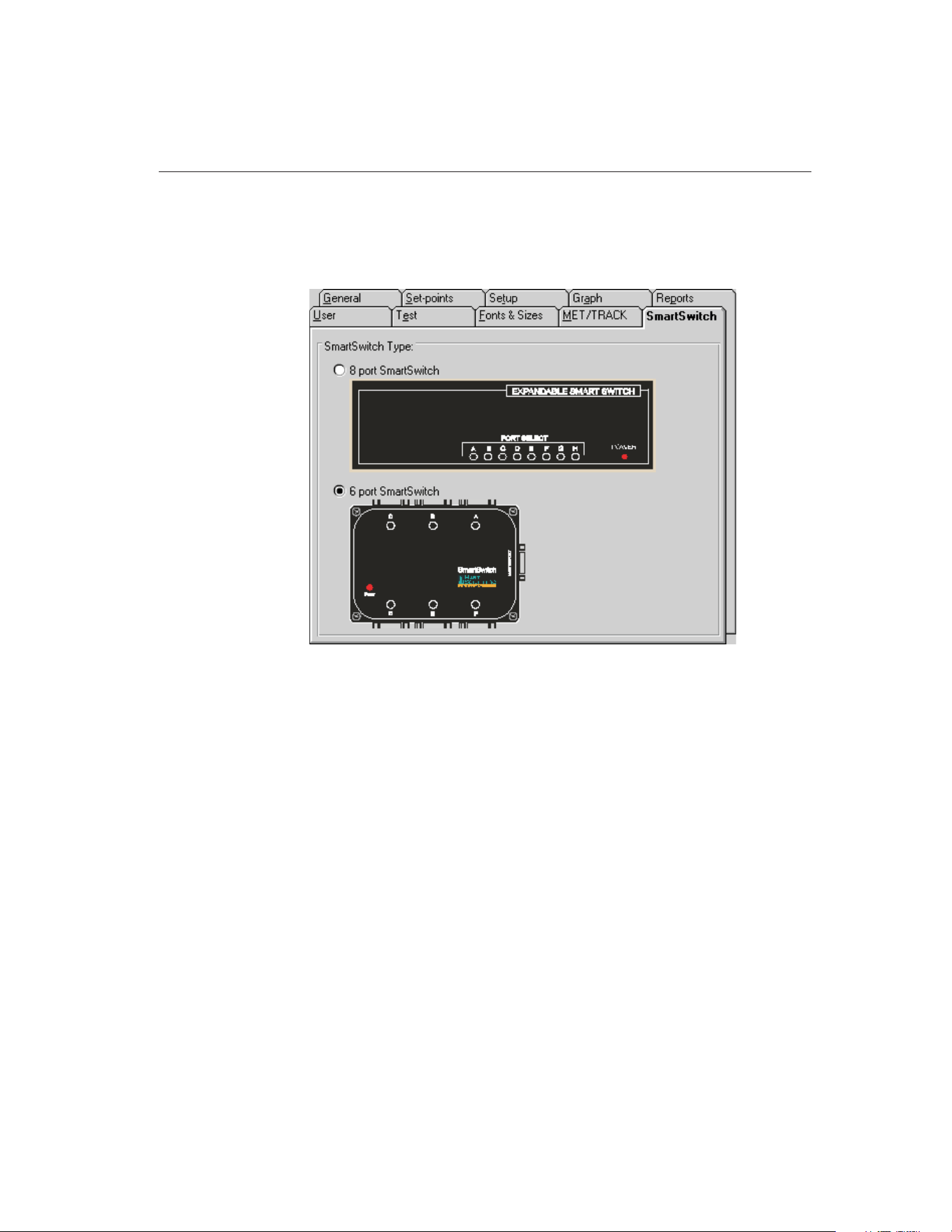
3.4.10 SmartSwitch Tab
The SmartSwitch tab is used for selecting the type of SmartSwitch being used
with MET/TEMP II.
Select the 8 port SmartSwitch option if the SmartSwitch being used has 8
25-pin ports and looks like the switch indicated in the diagram.
Select the 6 port SmartSwitch option if the SmartSwitch being used has six
9-pin ports and looks like the switch indicated in the diagram.
Note: The selection of the SmartSwitch type determines how many
SmartSwitch ports are listed in the SmartSwitch port drop-down lists on the
configuration dialogs. It also determines the diagram displayed when the Check
Port button is clicked on the Communications Port Configuration dialog. The 8
port and 6 port SmartSwitches are compatible with each other and either should
work regardless of the selection on this tab.
3.5 Setup Printer
Selecting the Setup Printer option displays the Print Setup dialog that allows
the user to select the default printer to which Reports of Calibration should be
printed. If you are using the default report template, the Orientation must be set
to Portrait. The Paper Size should be set to Letter 8 1/2 x 11 in.
55
3
File Menu
Figure 23 SmartSwitch Tab
1.888.610.7664 sales@GlobalTestSupply.com
Fluke-Direct.com
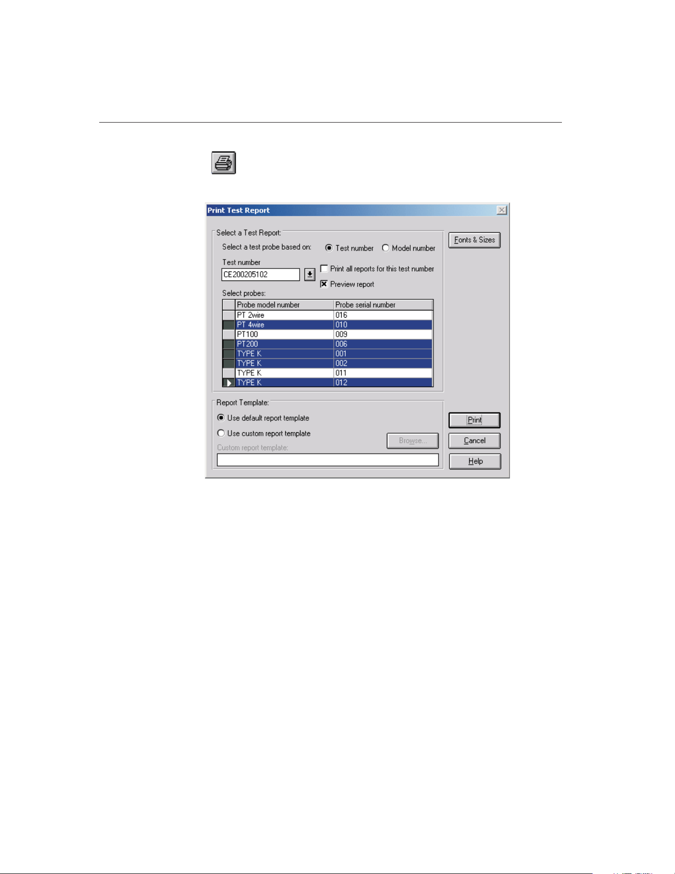
3.6
Print Report
Selecting the Print Report option displays the Print Test Report dialog.
To print a report for a test probe, you must select either a test number or a
model number on which to base the test probe selection.
If the test number option is selected, a list of test numbers becomes available.
Once a test number is selected, the probe model numbers and serial numbers
appear below. From the list entitled Select probes, select the probe model num-
ber and serial number.
If the model number option is selected, a list of probe model numbers becomes
available. Once a model number is selected, probe serial numbers and test num-
bers appear below. From the list entitled Select probes, select the probe test
number and serial number.
Select the test probes in the Select probes list. A probe may be deselected in the
same manner.
If the Print all reports for this test number check box is selected, a Report of
Calibration is printed for each of the test probes listed. If not selected, reports
are printed only for the highlighted test probes in the Select probes list.
9938 MET/TEMP II
User’s Guide
56
Figure 24 Print Test Report Dialog
1.888.610.7664 sales@GlobalTestSupply.com
Fluke-Direct.com

If the Preview report check box is selected, the report is displayed in the Print
Preview window. If the Preview report check box is not selected, the report is
sent directly to the printer.
If a test is invalid, meaning all of the required data to create a Report of Cali-
bration does not exist in the database, a message is displayed and the report
cannot be printed. Selecting the Maintain Test Results option in the Utilities
menu provides information for validating tests.
Figure 67 on page 137 shows an example of the Default Report of Calibration
produced by MET/TEMP II. The exact layout of this report depends on how
the test was performed and the type of data collected. If there is more informa-
tion than will fit on one page, additional pages are automatically generated.
The lower portion of this dialog determines the report template that will be
used when printing a Report or Calibration. If the Use default report template
option is selected, MET/TEMP II uses the built-in Report of Calibration tem-
plate. The Custom report template box and Browse button are disabled.
MET/TEMP II also allows custom report templates to be used when printing
reports. If the default report template isn’t exactly the type of report required
for your application, contact Hart application specialists for information on ob-
taining custom report templates designed to your specifications. If a custom re-
port template has been purchased from Hart, the Use custom report template
option allows the user to specify the file that contains the custom report tem-
plate. The Custom report template box and Browse button are enabled. Click
the Browse button to select the custom report template to use, then click the
Print button to launch the custom report template.
MET/TEMP II now comes with two custom Reports of Calibration which are
installed automatically when MET/TEMP II is installed. The custom report
files are installed in the \REPORTS folder and are named PASSFAIL.EXE and
HEATSRC.EXE. For more details on using these custom reports, see Section
11.2, Custom Reports of Calibration.
Note: Custom report template files MUST be located in the \REPORTS
subfolder of the C:\METTEMP2 folder (or the folder where MET/TEMP II was
installed) in order to operate properly.
Click the Fonts & Sizes button to specify the names, sizes and styles of the
fonts to be used when printing the default Report of Calibration and the custom
Reports of Calibration that ship with MET/TEMP II. Clicking the Fonts &
Sizes button displays the Defaults dialog with the Fonts & Sizes tab selected.
The font settings can be changed to produce a more customized look to the Re-
port of Calibration or to keep the Report of Calibration from printing on more
than a single page.
Note: The Fonts & Sizes options only apply to the default Report of Calibra-
tion and to the custom Reports of Calibration that are included with
MET/TEMP II.
The Browse button allows a custom report template file to be selected. Custom
report templates can be designed to meet your specific needs. Contact Hart ap-
57
3
File Menu
1.888.610.7664 sales@GlobalTestSupply.com
Fluke-Direct.com

plication specialists for more information on ordering a custom report for
MET/TEMP II.
Click the Print button to print the Report of Calibration for the selected probes
if the Use default report template option is selected, or to run the custom report
template if the Use custom report template option is selected.
Click the Cancel button to close this dialog.
3.7 Recall Saved Report
Selecting the Recall Saved Report option allows previously saved report files to
be opened, viewed, and printed from the Print Preview window.
For more information on the Print Preview window and report files, see Section
16, Print Preview Window.
3.8
Close Test
Selecting the Close Test option closes the current calibration test. This option is
enabled only after a test has completed or been aborted.
3.9
Exit
Selecting the Exit option exits MET/TEMP II. If any changes were made to the
configuration, the user is prompted to save the current configuration. The cur-
rent configuration is always saved upon exit to the file 9938LAST.CFG.
9938 MET/TEMP II
User’s Guide
58
1.888.610.7664 sales@GlobalTestSupply.com
Fluke-Direct.com
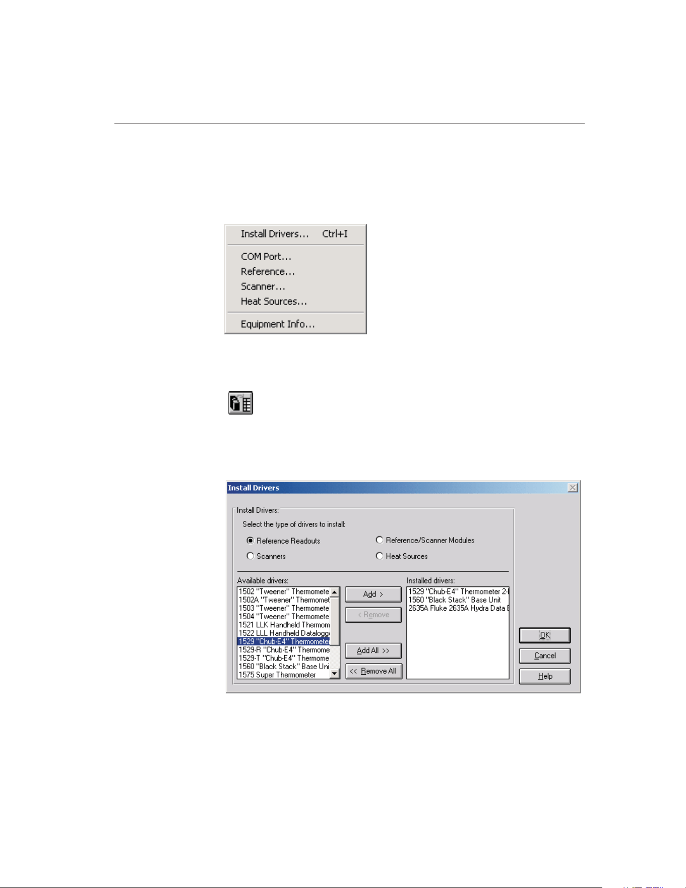
4 Configuration Menu
The Configuration menu provides options for installation of instrument drivers,
setting up test equipment, and displaying current configuration information.
4.1
Install Drivers
Selecting the Install Drivers option displays the Install Drivers dialog. This dia-
log can also be displayed by clicking the Drivers button on the Reference Read-
out Configuration, Reference Module Configuration, Scanner Configuration,
Scanner Modules Configuration or Heat Source configuration dialogs.
59
4
Configuration Menu
Figure 25 Configuration Menu
Figure 26 Install Drivers Dialog
1.888.610.7664 sales@GlobalTestSupply.com
Fluke-Direct.com

The Install Drivers dialog allows the communications drivers to be installed for
the reference readout, reference module, scanner, scanner modules, and heat
sources.
Installing a driver for an instrument allows the software to display that instru-
ment as a choice in the Model number drop-down list on the Reference Read-
out, Reference Module, Scanner, Scanner Modules, and Heat Source
Configuration dialogs. By the same token, uninstalling a driver removes that in-
strument from the Model number drop-down list. To keep the Model number
drop-down list short, only install drivers for the instruments that are to be used.
The Available drivers list shows all drivers available for the type of driver se-
lected. The Installed drivers list shows all drivers currently installed.
4.1.1 Adding Drivers
To install (add) drivers, follow the instructions below:
1. Select the type of drivers to install.
2. To install all drivers, click the Add All > button.
or
To install selected drivers, select the drivers in the Available drivers list.
Click the Add button. Multiple drivers can be selected by holding down
the <CTRL> key while selecting drivers to install.
3. If a driver for an instrument is already installed, a message is displayed
asking for confirmation to replace the currently installed driver.
4.1.2 Removing Drivers
To uninstall (remove) drivers, follow the instructions below:
1. Select the type of drivers to uninstall.
2. To uninstall all drivers, click the < Remove All button.
or
To uninstall selected drivers, select the drivers in the Installed drivers list.
Click the Remove button. Multiple drivers can be selected by holding
down the <CTRL> key while selecting drivers to uninstall.
Clicking the OK button closes the Install Drivers dialog. Clicking the Cancel
button will ignore any changes made and close the Install Drivers dialog.
4.2
COM Port
Selecting the COM Port option displays the Communications Port Configura-
tion dialog. This dialog can also be displayed by clicking the COM Port button
on the Equipment Info dialog.
9938 MET/TEMP II
User’s Guide
60
1.888.610.7664 sales@GlobalTestSupply.com
Fluke-Direct.com
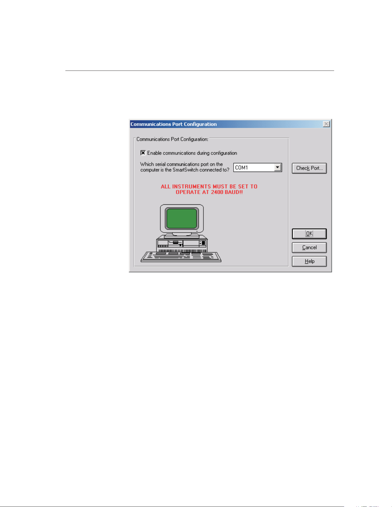
4.2.1 Communications Port Configuration Dialog
The Communications Port Configuration dialog allows the COM port to be se-
lected.
The Enable communications during configuration check box is provided to en-
able verifying communications with test equipment during the configuration
process. The default state of this check box is determined by the state of the
Enable communications during configuration check box on the Setup tab of the
Defaults dialog.
The drop-down list contains a list of all of the available COM ports. If a port is
being used by another device, the port will not appear in the drop-down list. If
there are no ports available, a message will be displayed and this software will
not be able to perform a test.
After selecting the COM port, click the Check Port button to verify communi-
cations. The Check SmartSwitch dialog is displayed. Refer to Section 4.2.2,
Check SmartSwitch Dialog, for more details.
Clicking the OK button accepts the selected settings and closes this dialog.
Clicking the Cancel button ignores any changes made and closes this dialog.
61
4
Configuration Menu
Figure 27 Communications Port Configuration Dialog
1.888.610.7664 sales@GlobalTestSupply.com
Fluke-Direct.com
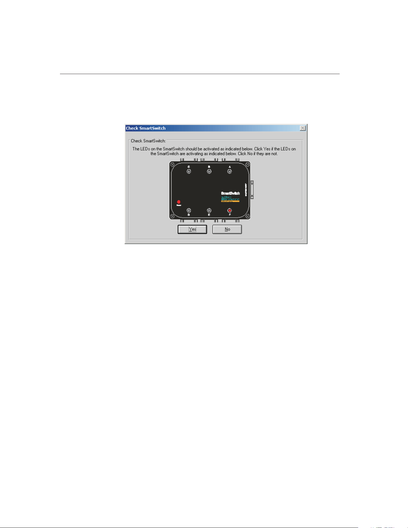
4.2.2 Check SmartSwitch Dialog
The Check SmartSwitch dialog is displayed when the Check Port button is se-
lected on the Communications Port Configuration dialog.
This dialog displays a graphic representing the SmartSwitch box. The graphic
displayed depends on the currently selected SmartSwitch type. To change the
SmartSwitch type, refer to Section 3.4.10, SmartSwitch Tab.
This dialog displays a graphic representing the SmartSwitch box. While this di-
alog is displayed, commands are sent to the SmartSwitch box to change the ac-
tive port (A to H). Make sure the LEDs on the SmartSwitch are activating as
9938 MET/TEMP II
User’s Guide
62
Figure 28 Check SmartSwitch Dialog - 6-port SmartSwitch Selected
1.888.610.7664 sales@GlobalTestSupply.com
Fluke-Direct.com
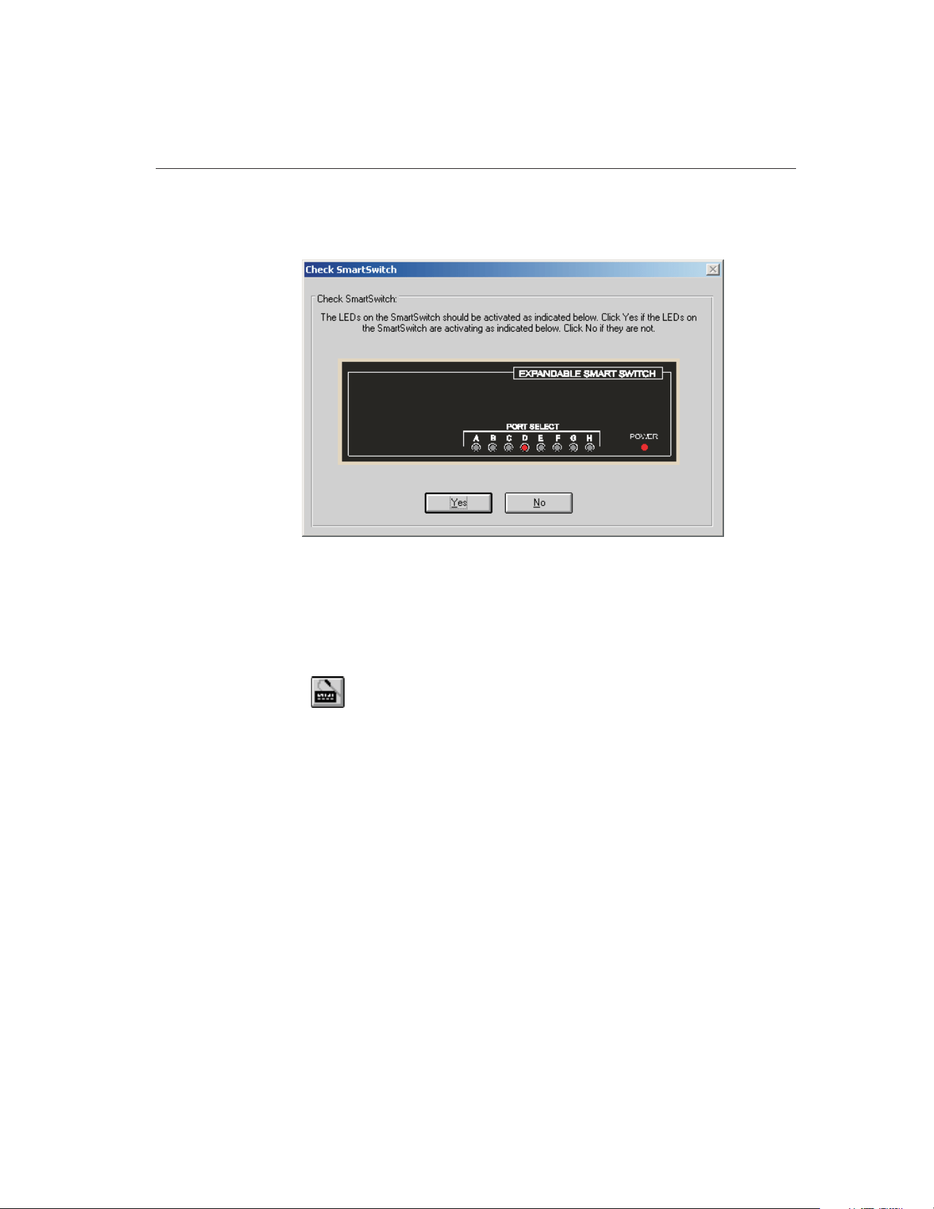
indicated on the dialog. If the LEDs on the SmartSwitch are not activating as
indicated, click No. Otherwise, click Yes.
When checking the communications, make sure the SmartSwitch and any ap-
plicable instruments are connected using the appropriate cables. Refer to Sec-
tion 1.8, Connection of Instruments, for more information.
4.3
Reference
Selecting the Reference option displays the Reference Readout Configuration
dialog. This dialog can also be displayed by clicking the Reference button on
the Equipment Info dialog.
4.3.1 Reference Readout Configuration Dialog
The Reference Readout Configuration dialog is used to select the instrument
63
4
Configuration Menu
Figure 29 Check SmartSwitch Dialog - 8-Port SmartSwitch Selected
1.888.610.7664 sales@GlobalTestSupply.com
Fluke-Direct.com
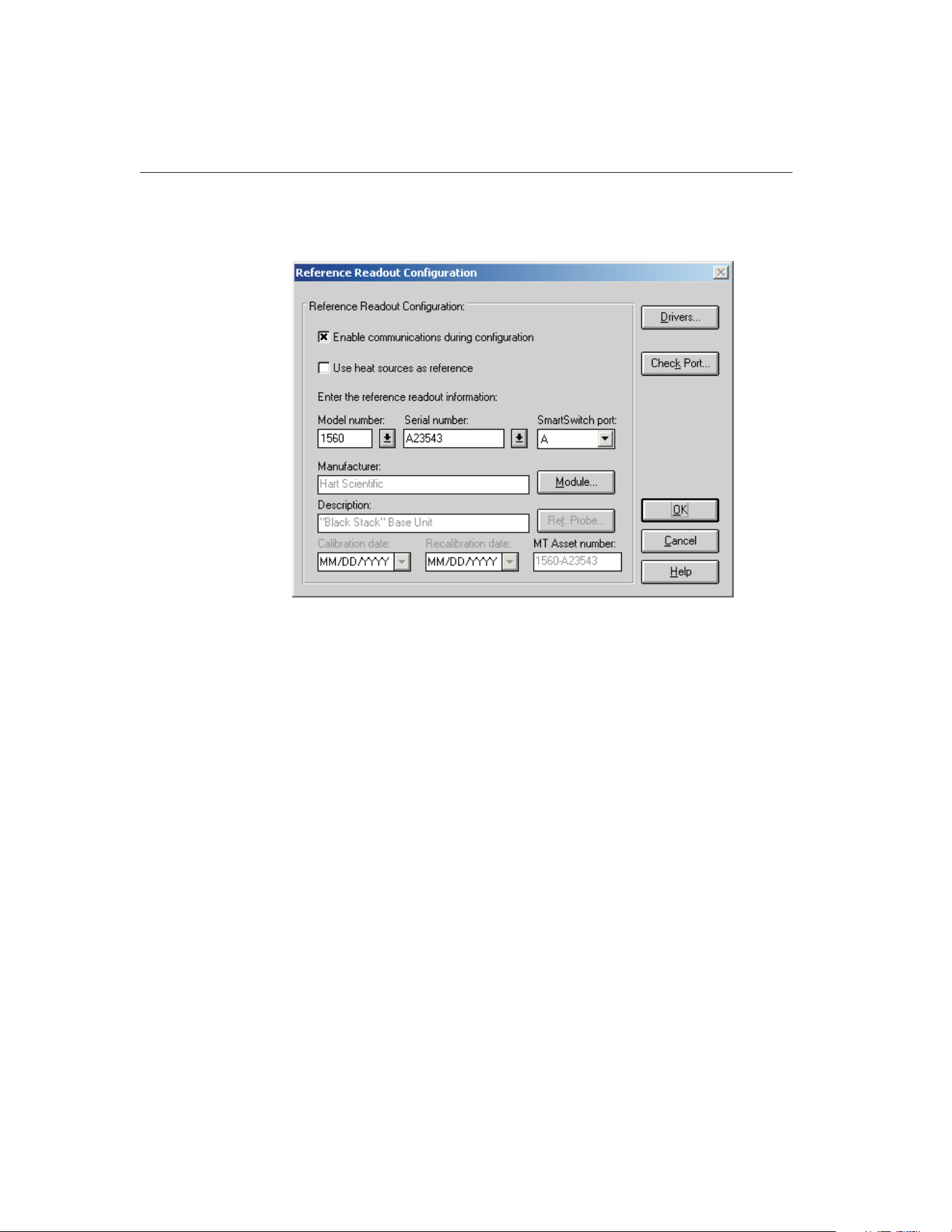
used as the reference readout instrument, or the instrument to which the refer-
ence probe is connected.
The Enable communications during configuration check box is provided to en-
able verifying communications with test equipment during the configuration
process. The default state of this check box is determined by the state of the
Enable communications during configuration check box on the Setup tab of the
Defaults dialog.
The Use Heat Sources as reference check box is provided for specifying that a
reference readout and reference probe are not needed because the sensor(s) in
the heat source(s) will be used as the reference probe. When this check box is
selected, no further reference configuration is required on this dialog and all
other controls are disabled. Click the OK button to close this dialog.
Note: When using MET/TEMP II to calibrate a heat source, this check box
must be checked! Click Yes when asked if a heat source is to be calibrated.
Select the reference readout model number using the drop-down list. If the ap-
propriate model number does not appear on the list, click the Drivers button to
install the driver for the reference readout instrument. Refer to Section 4.1, In-
stall Drivers, for more information on installing drivers. The manufacturer and
description information is filled in automatically when a model is selected.
For certain reference readouts such as the Models 1575 and 1590 Super Ther-
mometers, MET/TEMP II allows the reference probe to be connected either to
a main channel or to a multiplexer channel. If one of these instruments is se-
9938 MET/TEMP II
User’s Guide
64
Figure 30 Reference Readout Configuration Dialog
1.888.610.7664 sales@GlobalTestSupply.com
Fluke-Direct.com

lected as the reference readout, a prompt is displayed asking if the channel to
which the reference probe is connected is a main channel or a multiplexer chan-
nel. Select the appropriate response based on the configuration of your refer-
ence instrument. If the reference probe is connected to a multiplexer channel,
the Module button is enabled and the multiplexer must be configured. Other-
wise, the Ref. Probe button is enabled.
Next, select the serial number from the Serial number drop-down list or enter
the serial number in the Serial number box if it has not been entered previously.
MET/TEMP II records serial numbers, calibration dates and recalibration dates
to avoid having the user reenter the same data over and over.
If the serial number was not selected from the drop-down list, the Calibration
date and Recalibration date must be entered. These boxes are disabled if the se-
lected instrument does not require calibration.
If the recalibration date has passed and the Show recalibration date notification
messages check box on the Setup tab of the Defaults dialog is selected, the user
is warned and must change the calibration and recalibration dates before the in-
strument can be used.
Select the SmartSwitch port to which the instrument is connected using the
SmartSwitch port drop-down list. If the instrument is connected and powered
up at this time, make sure the Enable communications during configuration
check box is selected and click the Check Port button. MET/TEMP II will at-
tempt to establish communications with the instrument. If MET/TEMP II is not
able to communicate with the instrument, an error message is displayed. Other-
wise, a message is displayed stating communication was established with the
instrument.
When the MET/TRACK link is active, the MT Asset number box is displayed.
This box indicates the asset number that is assigned to this instrument. An in-
ventory record must exist in the MET/TRACK database for this instru-
ment before MET/TEMP II can use it to perform calibrations! If the
calibration and recalibration dates are required, a current calibration re-
cord must also exist in the MET/TRACK database. MET/TEMP II will au-
tomatically attempt to locate the records in the MET/TRACK database when
the model, serial number, and manufacturer information have been entered. If
the asset number is found, MET/TEMP II displays the asset number in the MT
Asset number box. Depending on the settings on the MET/TRACK tab of the
Defaults dialog, the description, and calibration and recalibration dates may be
synchronized with the information in the MET/TRACK database. If the asset
cannot be found in the MET/TRACK database, a message is displayed. Click
YestolaunchMET/TRACKtocreateormodifyassetrecordsorclickNoto
edit the information in MET/TEMP II.
65
4
Configuration Menu
1.888.610.7664 sales@GlobalTestSupply.com
Fluke-Direct.com

Important: When MET/TEMP II attempts to locate an asset in the
MET/TRACK database, the model, serial number and manufacturer infor-
mation must be an EXACT (case-insensitive) match! If the manufacturer
information in MET/TEMP II does not match the manufacturer informa-
tion in MET/TRACK, you may need to modify the manufacturer informa-
tion in the MET/TRACK inventory record in order for MET/TEMP II to
locate it. Where applicable, you may be able to modify the manufacturer
information in MET/TEMP II.
If enabled, click the Module button to configure the module or multiplexer to
which the reference probe is connected. The Reference Module Configuration
dialog is displayed. Refer to Section 4.3.2, Reference Module Configuration
Dialog, for more details.
Otherwise, click the Ref. Probe button to configure the reference probe infor-
mation. The Reference Probe Configuration dialog is displayed. Refer to Sec-
tion 4.3.3, Reference Probe Configuration Dialog, for more details.
The Drivers button allows the user to install instrument drivers. If there are no
models available in the Model number drop-down list, you must install drivers
by clicking the Drivers button.
Clicking the OK button accepts the selected settings and closes this dialog.
Clicking the Cancel button ignores any changes made and closes this dialog.
Note: The reference readout, reference module (if applicable), and reference
probe must be configured to start a calibration test.
4.3.2 Reference Module Configuration Dialog
The Reference Module Configuration dialog is displayed when the Module but-
ton on the Reference Readout Configuration dialog is clicked. This dialog is
9938 MET/TEMP II
User’s Guide
66
1.888.610.7664 sales@GlobalTestSupply.com
Fluke-Direct.com
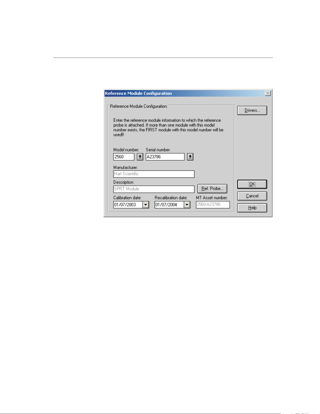
only applicable when the selected reference readout instrument requires the use
of modules or a multiplexer.
When the Module button is clicked on the Reference Readout Configuration di-
alog and the Enable communications during configuration check box is se-
lected, MET/TEMP II attempts to query the selected reference readout
instrument, when possible, to determine what modules are attached. If success-
ful, MET/TEMP II ensures that the proper drivers are installed for the modules
or multiplexer.
Select the reference module model number using the Model number drop-down
list. If the model number needed does not appear in the list, click the Drivers
button to install the driver for the module or multiplexer. The manufacturer and
description information is filled in automatically when a model is selected.
Note: If the reference readout is a model 1560 and there is more than one mod-
ule with the same model number as the module to which the reference probe is
connected, MET/TEMP II always assumes that the first module (closest to the
base unit) with that model number is being used as the reference module.
Next, select the serial number from the Serial number drop-down list or enter
the serial number in the Serial number box if it has not been entered previously.
MET/TEMP II records serial numbers, calibration dates and recalibration dates
to avoid having the user reenter the same data over and over.
67
4
Configuration Menu
Figure 31 Reference Module Configuration Dialog
1.888.610.7664 sales@GlobalTestSupply.com
Fluke-Direct.com

If the serial number was not selected from the drop-down list, the Calibration
date and Recalibration date must be entered. These boxes are disabled if the se-
lected module or multiplexer does not require calibration.
If the recalibration date has passed and the Show recalibration date notification
messages check box on the Setup tab of the Defaults dialog is selected, the user
is warned and must change the calibration and recalibration dates before the in-
strument can be used.
When the MET/TRACK link is active, the MT Asset number box is displayed.
This box indicates the asset number that is assigned to this instrument. An in-
ventory record must exist in the MET/TRACK database for this instru-
ment before MET/TEMP II can use it to perform calibrations! If the
calibration and recalibration dates are required, a current calibration re-
cord must also exist in the MET/TRACK database. MET/TEMP II will au-
tomatically attempt to locate the records in the MET/TRACK database when
the model, serial number and manufacturer information have been entered. If
the asset number is found, MET/TEMP II displays the asset number in the MT
Asset number box. Depending on the settings on the MET/TRACK tab of the
Defaults dialog, the description, calibration and recalibration dates may be syn-
chronized with the information in the MET/TRACK database. If the asset can-
not be found in the MET/TRACK database, a message is displayed. Click Yes
tolaunchMET/TRACKtocreateormodifyassetrecordsorclickNotoeditthe
information in MET/TEMP II.
Important: When MET/TEMP II attempts to locate an asset in the
MET/TRACK database, the model, serial number, and manufacturer infor-
mation must be an EXACT (case-insensitive) match! If the manufacturer
information in MET/TEMP II does not match the manufacturer informa-
tion in MET/TRACK, you may need to modify the manufacturer informa-
tion in the MET/TRACK inventory record in order for MET/TEMP II to
locate it. Where applicable, you may be able to modify the manufacturer
information in MET/TEMP II.
Click the Ref. Probe button to configure the reference probe information. The
Reference Probe Configuration dialog is displayed. Refer to Section 4.3.3, Ref-
erence Probe Configuration Dialog, for more details.
The Drivers button allows the user to install instrument drivers. If there are no
models available in the Model number drop-down list, you must install drivers
by clicking the Drivers button.
Clicking the OK button accepts the selected settings and closes this dialog.
Clicking the Cancel button ignores any changes made and closes this dialog.
4.3.3 Reference Probe Configuration Dialog
The Reference Probe Configuration dialog is displayed when the Ref. Probe
9938 MET/TEMP II
User’s Guide
68
1.888.610.7664 sales@GlobalTestSupply.com
Fluke-Direct.com
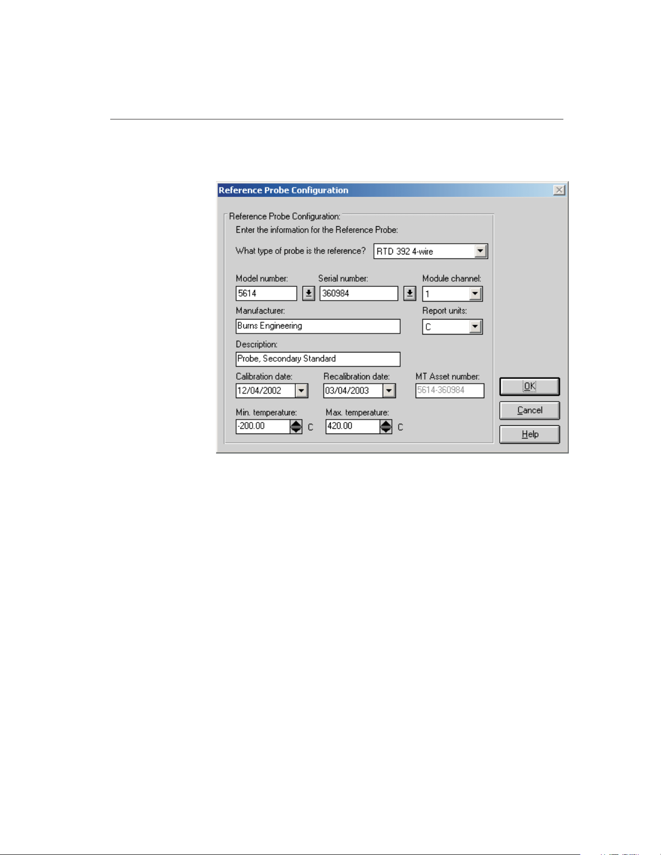
button on the Reference Readout Configuration dialog or on the Reference
Module Configuration dialog is clicked.
The reference probe type must be selected before any other information can be
entered. The reference probe type defaults to the probe type selected on the
Setup tab of the Defaults dialog. If the default probe type is not one of the
available probe types for the selected reference readout (or reference module),
then this box is left blank and must be selected from the available choices.
Select the reference probe model number using the Model number drop-down
list. The manufacturer and description information is filled in automatically
when a model is selected. If the appropriate model number does not appear on
the list, enter the model number in the Model number box. Enter the manufac-
turer and description for the reference probe in the Manufacturer and Descrip-
tion boxes. MET/TEMP II records model numbers, manufacturer, and
description information to avoid having the user reenter the same data over and
over.
Next, select the serial number from the Serial number drop-down list or enter
the serial number in the Serial number box if it has not been entered previously.
MET/TEMP II records serial numbers, calibration dates and recalibration dates
to avoid having the user reenter the same data over and over.
69
4
Configuration Menu
Figure 32 Reference Probe Configuration Dialog
1.888.610.7664 sales@GlobalTestSupply.com
Fluke-Direct.com

If the serial number was not selected from the drop-down list, the Calibration
date and Recalibration date must be entered.
If the recalibration date has passed and the Show recalibration date notification
messages check box is selected on the Setup tab of the Defaults dialog, the user
is warned and must change the calibration and recalibration dates before this
reference probe can be used.
Select the channel of the reference readout instrument or reference module (or
multiplexer) to which the reference probe is connected using the Channel
drop-down list. For reference modules or multiplexers, the channel selection is
with respect to that module or multiplexer.
Important: When using the Hydra series dataloggers with a 4-wire probe,
select the first channel that the probe is connected to. For example, if the
probe is connected to channels 1 and 11, select channel 1 in the channel
drop-down list.
Select the report units for the reference probe using the Report units drop-down
list. The possible choices are:
• C
• F
• K
Enter the minimum and maximum range of the reference probe in the Min.
temperature and Max. temperature boxes. The minimum temperature defaults
to -330 and the maximum temperature defaults to 2650 when entering a new
probe.
When the MET/TRACK link is active, the MT Asset number box is displayed.
This box indicates the asset number that is assigned to this probe. An inven-
tory record must exist in the MET/TRACK database for this probe before
MET/TEMP II can use it to perform calibrations! A current calibration
record must also exist in the MET/TRACK database. MET/TEMP II will
automatically attempt to locate the records in the MET/TRACK database when
the model, serial number, and manufacturer information have been entered. If
the asset number is found, MET/TEMP II displays the asset number in the MT
Asset number box. Depending on the settings on the MET/TRACK tab of the
Defaults dialog, the description and calibration and recalibration dates may be
synchronized with the information in the MET/TRACK database. If the asset
cannot be found in the MET/TRACK database, a message is displayed. Click
YestolaunchMET/TRACKtocreateormodifyassetrecordsorclickNoto
edit the information in MET/TEMP II.
9938 MET/TEMP II
User’s Guide
70
1.888.610.7664 sales@GlobalTestSupply.com
Fluke-Direct.com
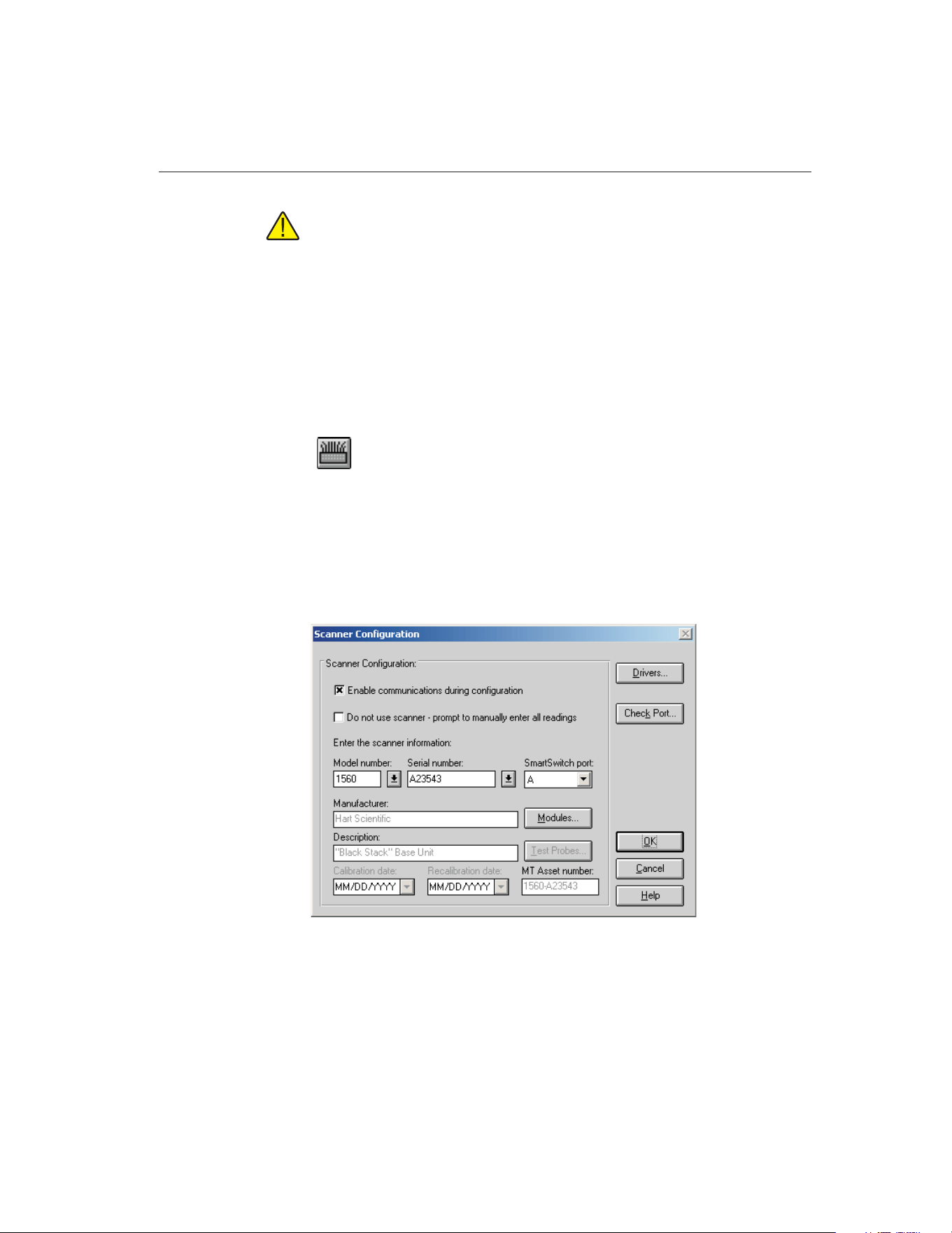
Important: When MET/TEMP II attempts to locate an asset in the
MET/TRACK database, the model, serial number, and manufacturer infor-
mation must be an EXACT (case-insensitive) match! If the manufacturer
information in MET/TEMP II does not match the manufacturer informa-
tion in MET/TRACK, you may need to modify the manufacturer informa-
tion in the MET/TRACK inventory record in order for MET/TEMP II to
locate it. Where applicable, you may be able to modify the manufacturer
information in MET/TEMP II.
Clicking the OK button accepts the selected settings and closes this dialog.
Clicking the Cancel button ignores any changes made and closes this dialog.
4.4
Scanner
Selecting the Scanner option displays the Scanner Configuration dialog. This
dialog can also be displayed by clicking the Scanner button on the Equipment
Info dialog.
4.4.1 Scanner Configuration Dialog
The Scanner Configuration dialog is used to select the instrument to which the
test probes are connected.
The Enable communications during configuration check box is provided to en-
able verifying communications with test equipment during the configuration
process. The default state of this check box is determined by the state of the
71
4
Configuration Menu
Figure 33 Scanner Configuration Dialog
1.888.610.7664 sales@GlobalTestSupply.com
Fluke-Direct.com

Enable communications during configuration check box on the Setup tab of the
Defaults dialog.
When calibrating test probes that cannot be connected to a scanner (such as
Liquid in Glass thermometers) or probes that cannot be detached from a pro-
cess control system, or if a scanner instrument that MET/TEMP II does not
support is to be used, select the Do not use scanner – prompt to manually enter
all readings check box. This feature disables the use of the scanner instrument
to automate the collection of readings from the test probes. The user will be
prompted to manually enter all test probe readings at the appropriate times dur-
ing a test.
For certain scanner instruments supported by MET/TEMP II such as the
Models 1575 and 1590 Super Thermometers, MET/TEMP II allows the test
probe(s) to be connected either to a main channel or to a multiplexer channel. If
one of these instruments is selected as the reference readout, a prompt is dis-
played asking if the test probes are connected to main channels or multiplexer
channels. Select the appropriate response based on the configuration of your
scanner instrument. If the test probes are connected to multiplexer channels, the
Modules button is enabled and the multiplexer(s) must be configured. Other-
wise, the Test Probes button is enabled.
MET/TEMP II also supports using single-channel thermometer readouts such
as the Models 1502, 1503 and 1504 “Tweener” thermometer readouts and the
Models 1521 and 1522 handheld thermometer readouts to be used as the scan-
ner instrument to calibrate a single test probe.
Note: When using MET/TEMP II to calibrate a heat source, the scanner instru-
ment acts as the reference instrument and the test probe acts as the reference
probe. Refer to Section 13, Performing Heat Source Calibrations, for more in-
formation on configuring MET/TEMP II to perform heat source calibrations.
Select the scanner model number using the Model number drop-down list. If
the model number needed does not appear on the list, click the Drivers button
to install the driver for the scanner instrument. Refer to Section 4.1, Install
Drivers, for more information on installing drivers. The manufacturer and de-
scription information is filled in automatically when a model is selected.
Next, select the serial number from the Serial number drop-down list or enter
the serial number in the Serial number box if it has not been entered previously.
MET/TEMP II records serial numbers, calibration dates, and recalibration dates
to avoid having the user reenter the same data over and over.
If the serial number was not selected from the drop-down list, the Calibration
date and Recalibration date must be entered. These boxes will be disabled if the
selected instrument does not require calibration.
If the recalibration date has passed and the Show recalibration date notification
messages check box is selected on the Setup tab of the Defaults dialog, the user
is warned and must change the calibration and recalibration dates before the in-
strument can be used.
9938 MET/TEMP II
User’s Guide
72
1.888.610.7664 sales@GlobalTestSupply.com
Fluke-Direct.com

Select the SmartSwitch port to which the instrument is connected using the
SmartSwitch port drop-down list. If the instrument is connected and powered
up at this time, make sure the Enable communications during configuration
check box is selected and click the Check Port button. MET/TEMP II will at-
tempt to establish communications with the instrument. If MET/TEMP II is not
able to communicate with the instrument, an error message is displayed. Other-
wise, a message is displayed stating communication was established with the
instrument.
When the MET/TRACK link is active, the MT Asset number box is displayed.
This box indicates the asset number that is assigned to this instrument. An in-
ventory record must exist in the MET/TRACK database for this instru-
ment before MET/TEMP II can use it to perform calibrations! If the
calibration and recalibration dates are required, a current calibration re-
cord must also exist in the MET/TRACK database. MET/TEMP II will au-
tomatically attempt to locate the records in the MET/TRACK database when
the model, serial number, and manufacturer information have been entered. If
the asset number is found, MET/TEMP II displays the asset number in the MT
Asset number box. Depending on the settings on the MET/TRACK tab of the
Defaults dialog, the description, and calibration and recalibration dates may be
synchronized with the information in the MET/TRACK database. If the asset
cannot be found in the MET/TRACK database, a message is displayed. Click
YestolaunchMET/TRACKtocreateormodifyassetrecordsorclickNoto
edit the information in MET/TEMP II.
Important: When MET/TEMP II attempts to locate an asset in the
MET/TRACK database, the model, serial number, and manufacturer infor-
mation must be an EXACT (case-insensitive) match! If the manufacturer
information in MET/TEMP II does not match the manufacturer informa-
tion in MET/TRACK, you may need to modify the manufacturer informa-
tion in the MET/TRACK inventory record in order for MET/TEMP II to
locate it. Where applicable, you may be able to modify the manufacturer
information in MET/TEMP II.
If enabled, click the Modules button to configure the modules or multiplexers
to which the test probes are connected. The Scanner Module Configuration dia-
log is displayed. Refer to Section 4.4.2, Scanner Module Configuration Dialog,
for more details.
Otherwise, click the Test Probes button to configure the test probe information.
The Test Probe Configuration dialog is displayed. Refer to Section 5.4.1, Test
Probe Configuration Dialog, for more details.
Note: The Test Probes button is not shown on this dialog when MET/TEMP II
is being configured to calibrate a heat source.
The Drivers button allows the user to install instrument drivers. If there are no
models available in the Model number drop-down list, you must install drivers
by clicking the Drivers button.
73
4
Configuration Menu
1.888.610.7664 sales@GlobalTestSupply.com
Fluke-Direct.com
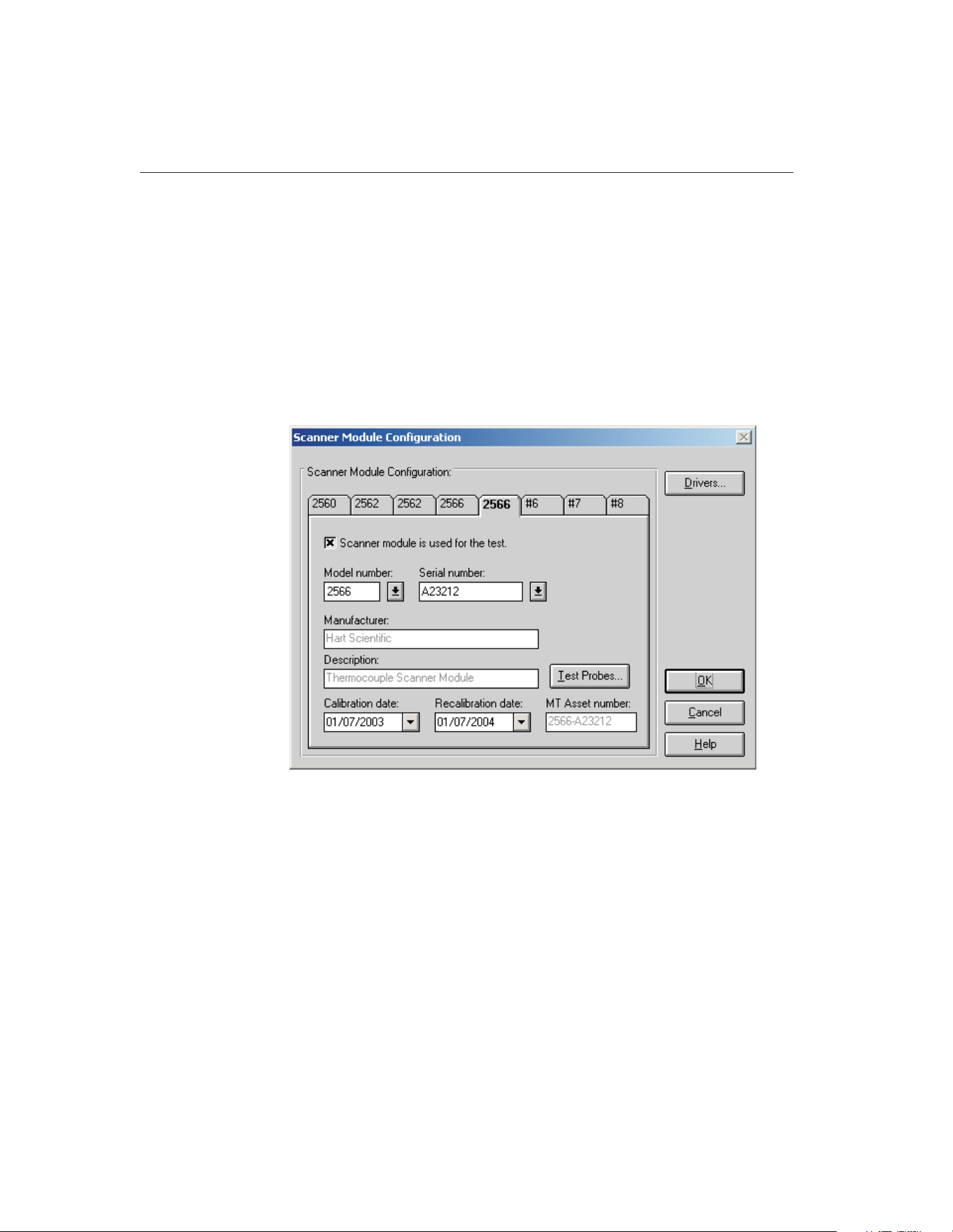
Clicking the OK button accepts the selected settings and closes this dialog.
Clicking the Cancel button ignores any changes made and closes this dialog.
Note: The scanner and scanner module (if applicable) must be configured to
start a calibration test.
4.4.2 Scanner Module Configuration Dialog
The Scanner Module Configuration dialog is displayed when the Modules but-
ton on the Scanner Configuration dialog is clicked. This dialog is only applica-
ble when the selected scanner instrument requires the use of modules or
multiplexers.
The Scanner Module Configuration dialog is displayed when the Modules but-
ton is clicked on the Scanner Configuration dialog.
If the Enable communications during configuration check box is selected when
the Modules button is clicked on the Scanner Configuration dialog,
MET/TEMP II attempts to query the selected scanner instrument (when possi-
ble) to determine what scanner modules are attached. If successful,
MET/TEMP II ensures that the proper drivers are installed for the modules or
multiplexer and the tabs on the Scanner Module Configuration dialog are auto-
matically configured accordingly. Otherwise, Defaults each of the tabs to #1,
#2, etc. and the module model numbers must be configured manually.
9938 MET/TEMP II
User’s Guide
74
Figure 34 Scanner Module Configuration Dialog
1.888.610.7664 sales@GlobalTestSupply.com
Fluke-Direct.com

All scanner modules are initially disabled by default. To use a module, it must
be enabled. To enable a scanner module, select the tab of the module to enable,
then select the Scanner module is used for the test check box. Once a scanner
module is enabled, the Model number box is enabled.
Select the scanner module model number using the Model number drop-down
list. If the required model number does not appear on the list, click the Drivers
button to install the driver for the scanner module or multiplexer. Refer to Sec-
tion 4.1, Install Drivers, for more information on installing drivers. The manu-
facturer and description information is filled in automatically when a model is
selected. The model number is also displayed on the tab.
Note: The scanner modules must be entered in the same order as they are at-
tached to the scanner instrument. If a particular scanner module is not to be
used, it still needs to be configured to act as a place holder. This is done by se-
lecting the Scanner module is used for the test check box, selecting the model
number, then unchecking the check box.
Next, select the serial number from the Serial number drop-down list or enter
the serial number in the Serial number box if it has not been entered previously.
MET/TEMP II records serial numbers, calibration dates, and recalibration dates
to avoid having the user reenter the same data over and over.
If the recalibration date has passed and the Show recalibration date notification
messages check box on the Setup tab of the Defaults dialog is selected, the user
is warned and must change the calibration and recalibration dates before the in-
strument can be used.
When the MET/TRACK link is active, the MT Asset number box is displayed.
This box indicates the asset number that is assigned to this instrument. An in-
ventory record must exist in the MET/TRACK database for this instru-
ment before MET/TEMP II can use it to perform calibrations! If the
calibration and recalibration dates are required, a current calibration re-
cord must also exist in the MET/TRACK database. MET/TEMP II will au-
tomatically attempt to locate the records in the MET/TRACK database when
the model, serial number and manufacturer information have been entered. If
the asset number is found, MET/TEMP II displays the asset number in the MT
Asset number box. Depending on the settings on the MET/TRACK tab of the
Defaults dialog, the description, calibration and recalibration dates may be syn-
chronized with the information in the MET/TRACK database. If the asset can-
not be found in the MET/TRACK database, a message is displayed. Click Yes
tolaunchMET/TRACKtocreateormodifyassetrecordsorclickNotoeditthe
information in MET/TEMP II.
75
4
Configuration Menu
1.888.610.7664 sales@GlobalTestSupply.com
Fluke-Direct.com

Important: When MET/TEMP II attempts to locate an asset in the
MET/TRACK database, the model, serial number, and manufacturer infor-
mation must be an EXACT (case-insensitive) match! If the manufacturer
information in MET/TEMP II does not match the manufacturer informa-
tion in MET/TRACK, you may need to modify the manufacturer informa-
tion in the MET/TRACK inventory record in order for MET/TEMP II to
locate it. Where applicable, you may be able to modify the manufacturer
information in MET/TEMP II.
Click the Test Probes button to configure the test probes. The Test Probe Con-
figuration dialog is displayed. Refer to Section 5.4.1, Test Probe Configuration
Dialog, for more details.
Note: The Test Probes button is not shown on this dialog when MET/TEMP II
is being configured to calibrate a heat source.
The Drivers button allows the user to install instrument drivers. If there are no
models available in the Model number drop-down list, you must install drivers
by clicking the Drivers button.
Clicking the OK button accepts the selected settings and closes this dialog.
Clicking the Cancel button ignores any changes made and closes this dialog.
4.5
Heat Sources
Selecting the Heat Sources option displays the Heat Source Configuration dia-
log. This dialog can also be displayed by clicking the Heat Sources button on
the Equipment Info dialog.
9938 MET/TEMP II
User’s Guide
76
1.888.610.7664 sales@GlobalTestSupply.com
Fluke-Direct.com
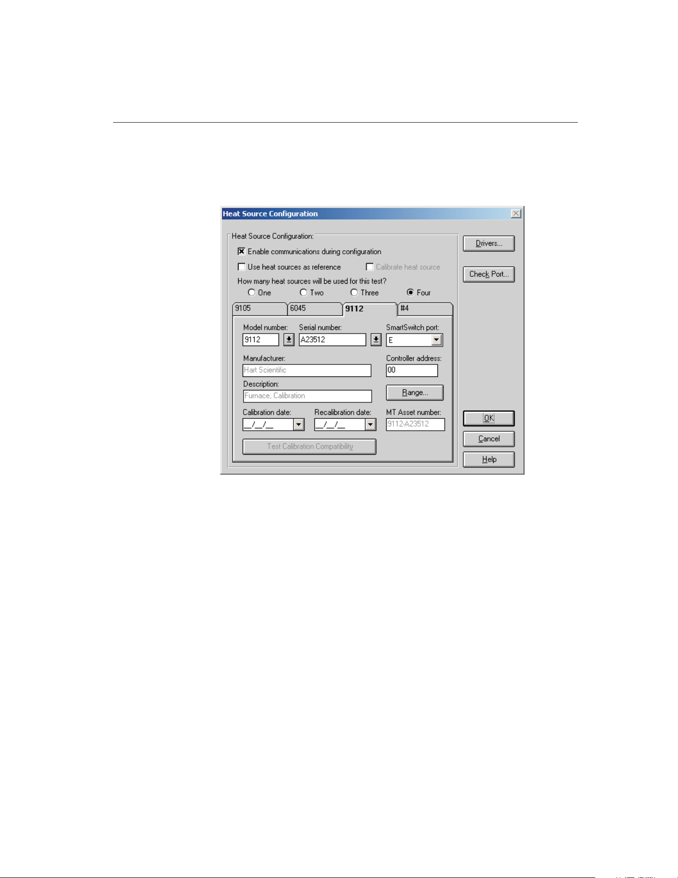
4.5.1 Heat Source Configuration Dialog
The Heat Source Configuration dialog is used to select the instrument(s) to use
as heat sources.
MET/TEMP II can use up to four heat sources to perform a calibration.
MET/TEMP II expects the reference probe and all test probes to be placed in
one heat source at a time. MET/TEMP II only supports a single reference
probe, therefore only one heat source can be used at a time. Multiple heat
sources can be used to increase the possible temperature range of a calibration.
When configuring the set-points for the calibration, each set-point must be as-
signed to a heat source. When using more than one heat source, the software
prompts the user throughout the calibration process to move the reference
probe and the test probes to the appropriate heat source.
Note: When using MET/TEMP II to calibrate a heat source, only one heat
source can be configured. Refer to Section 13, Performing Heat Source Cali-
brations, for more information on configuring MET/TEMP II to perform heat
source calibrations.
The Enable communications during configuration check box is provided to en-
able verifying communications with test equipment during the configuration
process. The default state of this check box is determined by the state of the
77
4
Configuration Menu
Figure 35 Heat Source Configuration Dialog
1.888.610.7664 sales@GlobalTestSupply.com
Fluke-Direct.com
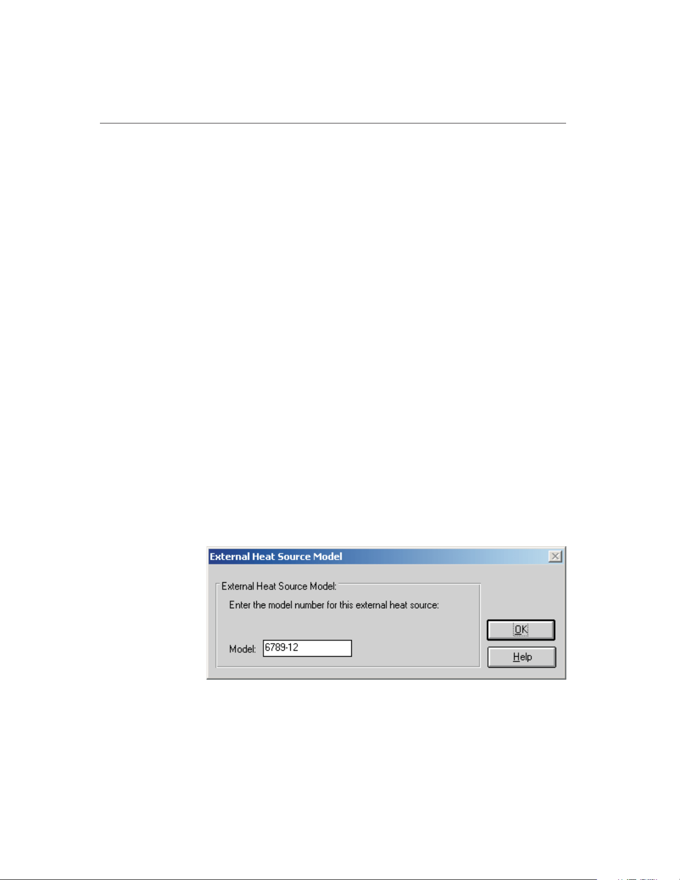
Enable communications during configuration check box on the Setup tab of the
Defaults dialog.
The Use heat sources as reference check box specifies that the heat source(s)
entered are to be used as the reference (the sensor(s) in the heat source(s) act as
the reference probe). When using the heat source(s) as the reference, the cali-
bration and recalibration dates are required.
When using MET/TEMP II to calibrate a heat source, the Use heat sources as
reference check box must be checked. This enables the Calibrate heat source
check box. To calibrate a heat source, select the Calibrate heat source check
box. When this feature is enabled, only one heat source can be configured. Re-
fer to Section 13, Performing Heat Source Calibrations, for more information
on configuring MET/TEMP II to perform heat source calibrations. When con-
figuring MET/TEMP II to calibrate a heat source, the calibration interval box
and Customer button are displayed and the calibration and recalibration date
boxes are hidden.
If not calibrating a heat source, select the number of heat sources to be used.
The maximum number of heat sources is four. The number of tabs displayed
corresponds to the number of heat sources selected.
Select the tab for the first heat source.
Heat source model numbers must be selected from the Model number
drop-down list. The manufacturer and description information is filled in auto-
matically when a model is selected. The model number is also displayed on the
tab. If the selected model is a Hart 9112 or 9113 furnace, the controller address
box is displayed.
If the heat source is external (which means MET/TEMP II does not communi-
cate with the heat source), select External from the Model number drop-down
list. The External Heat Source Model dialog is displayed. Enter the model num-
ber of the external heat source and click OK.
9938 MET/TEMP II
User’s Guide
78
Figure 36 External Heat Source Model dialog
1.888.610.7664 sales@GlobalTestSupply.com
Fluke-Direct.com

When using MET/TEMP II to perform a calibration using only fixed-point
cells, the Fixed-Point heat source driver must be setup as a heat source. No
other heat source drivers need to be setup. When mixing fixed-points with com-
parison points, the Fixed-Point heat source driver may optionally be setup, but
is not required.
Next, select the serial number from the Serial number drop-down list or enter
the serial number in the Serial number box if it has not been entered previously.
MET/TEMP II records serial numbers, calibration dates and recalibration dates
to avoid having the user reenter the same data over and over.
The Calibration and Recalibration date information is only required if the Use
Heat Sources as reference check box is selected. Otherwise, this information is
optional.
If the recalibration date has passed and the Show recalibration date notification
messages check box on the Setup tab of the Defaults dialog is selected, the user
is warned and must change the calibration and recalibration dates before the in-
strument can be used.
Select the SmartSwitch port to which the instrument is connected using the
SmartSwitch port drop-down list. If the instrument is connected and powered
up at this time, make sure the Enable communications during configuration
check box is selected and click the Check Port button. MET/TEMP II will at-
tempt to establish communications with the instrument. If MET/TEMP II is not
able to communicate with the instrument, an error message is displayed. Other-
wise, a message is displayed stating communication was established with the
instrument. The SmartSwitch port box is disabled if the selected model number
is External or Fixed-Point.
Note: For dual-well heat sources such as the Model 9009 dry-well, each well
must be configured as a separate heat source (Model 9009C and Model 9009H)
with both heat sources assigned to the same SmartSwitch port. MET/TEMP II
allows the same SmartSwitch port to be assigned to more than one instrument
for dual well heat sources.
The Controller address is used only when the selected heat source is a Hart
9112 or 9113 furnace. The controller used in these instruments requires a
2-digit address when communicating through the serial port. Enter the control-
ler address in the Controller address box. For more details, see the Model 9112
or 9113 User’s Guide.
When the MET/TRACK link is active, the MT Asset number box is displayed.
This box indicates the asset number that is assigned to this instrument. An in-
ventory record must exist in the MET/TRACK database for this instru-
ment before MET/TEMP II can use it to perform calibrations! If the
calibration and recalibration dates are required, a current calibration re-
cord must also exist in the MET/TRACK database. MET/TEMP II will au-
tomatically attempt to locate the records in the MET/TRACK database when
the model, serial number, and manufacturer information have been entered. If
the asset number is found, MET/TEMP II displays the asset number in the MT
Asset number box. Depending on the settings on the MET/TRACK tab of the
79
4
Configuration Menu
1.888.610.7664 sales@GlobalTestSupply.com
Fluke-Direct.com

Defaults dialog, the description and calibration and recalibration dates may be
synchronized with the information in the MET/TRACK database. If the asset
cannot be found in the MET/TRACK database, a message is displayed. Click
YestolaunchMET/TRACKtocreateormodifyassetrecordsorclickNoto
edit the information in MET/TEMP II.
Important: When MET/TEMP II attempts to locate an asset in the
MET/TRACK database, the model, serial number and manufacturer infor-
mation must be an EXACT (case-insensitive) match! If the manufacturer
information in MET/TEMP II does not match the manufacturer informa-
tion in MET/TRACK, you may need to modify the manufacturer informa-
tion in the MET/TRACK inventory record in order for MET/TEMP II to
locate it. Where applicable, you may be able to modify the manufacturer
information in MET/TEMP II.
Click the Range button to change the useable temperature range and to set a
cool-down temperature for the selected heat source. The Temperature Range
Configuration dialog is displayed. Refer to Section 4.5.2, Temperature Range
Configuration, for more details.
When using MET/TEMP II to calibrate a heat source, the Test Calibration
Compatibility button is enabled. Clicking this button tests the selected heat
source to make sure it can be calibrated by MET/TEMP II. Some older models
of heat sources do not support the commands necessary for MET/TEMP II to
perform the calibration successfully. The heat source must be connected and
powered up to perform the compatibility test. If the test is successful, a success
message will be displayed. If a communication error message is displayed, the
connected heat source cannot be calibrated by MET/TEMP II.
If calibrating the heat source, enter the calibration interval in the box provided.
If the link to MET/TRACK is active, the calibration interval should be filled in
automatically when the asset number is located.
If calibrating the heat source, click the Customer button to configure the cus-
tomer information for this heat source.
Clicking the OK button accepts the selected settings and closes this dialog.
Clicking the Cancel button ignores any changes made and closes this dialog.
Note: The heat source information is required and must be entered to start a
calibration test. If you are using a Hart instrument as a heat source, set the
scan, hold mode, and program control to OFF (where applicable) and set the
cut-out value to a temperature higher than the maximum set-point for the heat
source before starting a test. Also, the user should be aware of the approach set-
ting. See the instrument’s User’s Guide for details on setting these functions.
4.5.2 Temperature Range Configuration Dialog
The Temperature Range Configuration dialog is displayed when the Range but-
ton on the Heat Source Configuration dialog is clicked. This dialog is used to
9938 MET/TEMP II
User’s Guide
80
1.888.610.7664 sales@GlobalTestSupply.com
Fluke-Direct.com
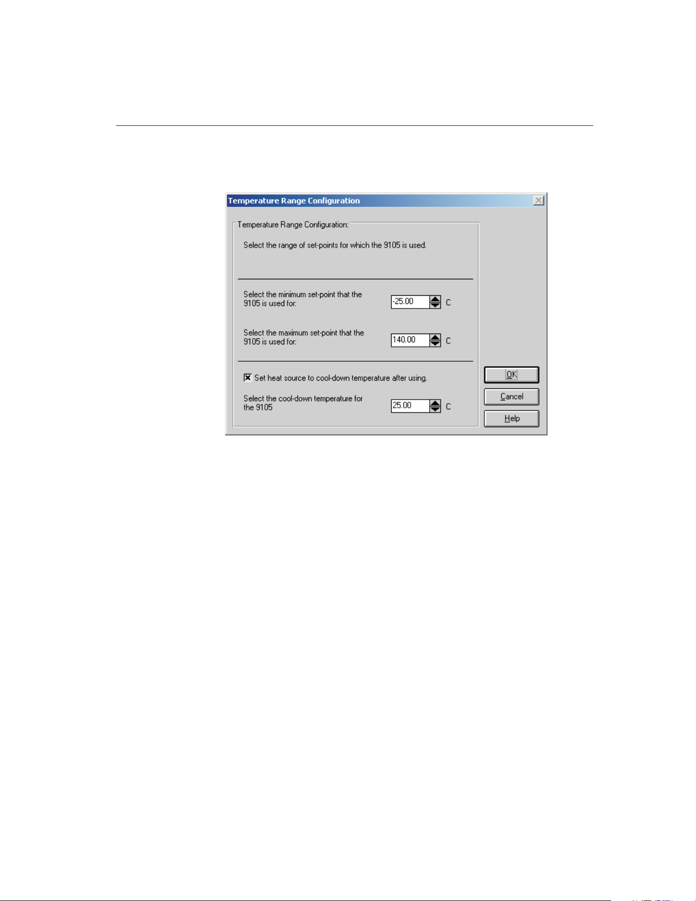
specify the useable temperature range and to specify a cool-down temperature
for the selected heat source.
The minimum and maximum temperatures for the selected heat source default
to the minimum and maximum temperatures that the heat source is capable of
reaching. These values can be changed to extend or limit the range that this
heat source is to be used for during the calibration process. When configuring
set-points, each set-point must be assigned to a heat source. The temperature
range settings on this dialog can be used to restrict which set-points can be as-
signed to the selected heat source.
Note: Although MET/TEMP II allows the temperature range for any heat
source to be extended beyond its default temperature range, be aware that many
heat sources will not accept set-points that are outside the default temperature
range. This feature should only be used to restrict the temperature range for a
heat source.
When the External or Fixed-Point heat source drivers are selected, the tempera-
ture range defaults to –330 to 2650 degrees. These values can be changed if
desired.
To change the minimum or maximum temperature for the selected heat source,
enter the new value in the appropriate box or use the up/down buttons to
change the value.
The cool-down temperature setting allows the user to specify a temperature to
set the selected heat source to when MET/TEMP II no longer requires that heat
81
4
Configuration Menu
Figure 37 Temperature Range Configuration Dialog
1.888.610.7664 sales@GlobalTestSupply.com
Fluke-Direct.com
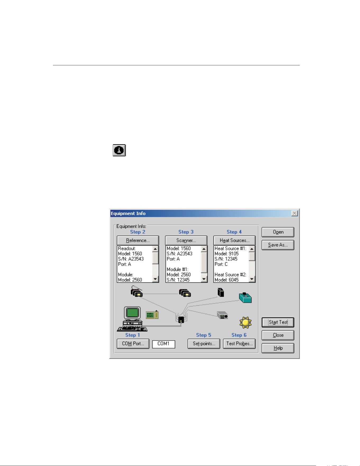
source during the calibration process. This feature can be used to prevent a heat
source from running overnight at high temperatures or to save time by setting
the heat source to the first set-point that this heat source uses for the calibration
following the current calibration. To enable this feature, select the Set heat
source to cool-down temperature after using check box and enter the cool-down
temperature into the box provided.
Clicking the OK button accepts the selected settings and closes this dialog.
Clicking the Cancel button ignores any changes made and closes this dialog.
4.6
Equipment Info
Selecting the Equipment Info option displays the Equipment Info dialog.
4.6.1 Equipment Info Dialog
The Equipment Info dialog shows a graphical representation of the current in-
strument configuration and provides access to the various configuration
dialogs.
9938 MET/TEMP II
User’s Guide
82
Figure 38 Equipment Info Dialog
1.888.610.7664 sales@GlobalTestSupply.com
Fluke-Direct.com

The Equipment Info dialog indicates which configuration steps still need to be
completed before a test can be started. All incomplete steps are indicated in red
text. When the configuration of a step is complete, the text turns black.
The test equipment, set-points, and test probes can all be configured through
this dialog. To configure the test equipment, set-points, and test probes follow
the steps indicated by the Step n labels.
1. The communications port can be configured by clicking the COM Port
button. Refer to Section 4.2, COM Port, for more details. The box on the
right side of the COM Port button displays the currently selected COM
Port.
2. The reference readout, reference module (if applicable) and reference
probe can be configured by clicking the Reference button. Refer to Sec-
tion 4.3, Reference, for more details. The box below the Reference but-
ton displays the current reference readout, reference module (if
applicable) and reference probe configuration information.
3. The scanner and scanner modules (if applicable) can be configured by
clicking the Scanner button. Refer to Section 4.4, Scanner, for more de-
tails. The box below the Scanner button displays the current scanner and
scanner module (if applicable) configuration information.
4. The heat sources can be configured by clicking the Heat Sources button.
Refer to Section 4.5, Heat Sources, for more details. The box below the
Heat Sources button displays the current heat source configuration
information.
5. The Set-points button can be used to configure the set-points for the cali-
bration test. Refer to Section 5.1, Set-points, for more details.
6. The Test Probes button can be used to configure the test probes to cali-
brate. Refer to Section 5.4, Test Probes, for more details.
Double-clicking on an instrument icon also displays the appropriate dialog for
configuring the instruments.
If the ambient conditions logger icon appears next to the PC icon, this indicates
the ambient conditions are configured to be queried from a Model 1620/5020A
‘DewK’ Thermohygrometer throughout the testing period. These settings are
configured on the General tab of the MET/TEMP II Defaults dialog. If this icon
is not displayed, the ambient conditions are entered manually on the Test Infor-
mation dialog before the test starts.
An existing instrument configuration file (.CFG) can be opened from this dia-
log by clicking the Open button.
The current instrument configuration can be saved by clicking the Save As but-
ton. All current selections pertaining to the communications port, reference,
scanner, and heat sources are saved to the instrument configuration file (.CFG).
The set-points and the test probe configuration information are not saved in this
configuration file, but can be saved into their own configuration files by click-
83
4
Configuration Menu
1.888.610.7664 sales@GlobalTestSupply.com
Fluke-Direct.com

ing the Save As buttons from the Set-point Configuration dialog and Test Probe
Configuration dialog respectively.
Clicking the Start Test button closes this dialog and causes MET/TEMP II to
validate the current configuration information. If the current configuration is
complete, the calibration process will start immediately. Otherwise, a message
is displayed indicating that some configuration information is missing and the
calibration process cannot be started yet. Clicking the Close button closes this
dialog.
Note: Closing this dialog does not discard the current configuration.
9938 MET/TEMP II
User’s Guide
84
1.888.610.7664 sales@GlobalTestSupply.com
Fluke-Direct.com
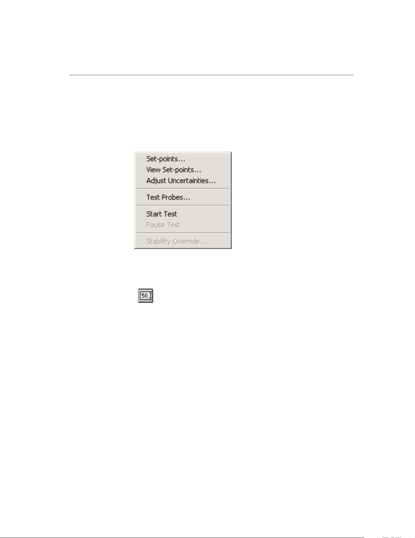
5 Calibration Menu
The Calibration menu provides options for setting up the calibration set-points,
viewing the status of the set-points, adjusting the uncertainties, setting up the
test probes, starting and stopping the calibration test, pausing and resuming the
calibration test, and overriding the stability settings for the current set-point.
5.1
Set-points
Selecting the Set-points option displays the Set-point Configuration dialog.
This dialog can also be displayed by clicking the Set-points button on the
Equipment Info dialog.
85
5
Calibration Menu
Figure 39 Calibration Menu
1.888.610.7664 sales@GlobalTestSupply.com
Fluke-Direct.com
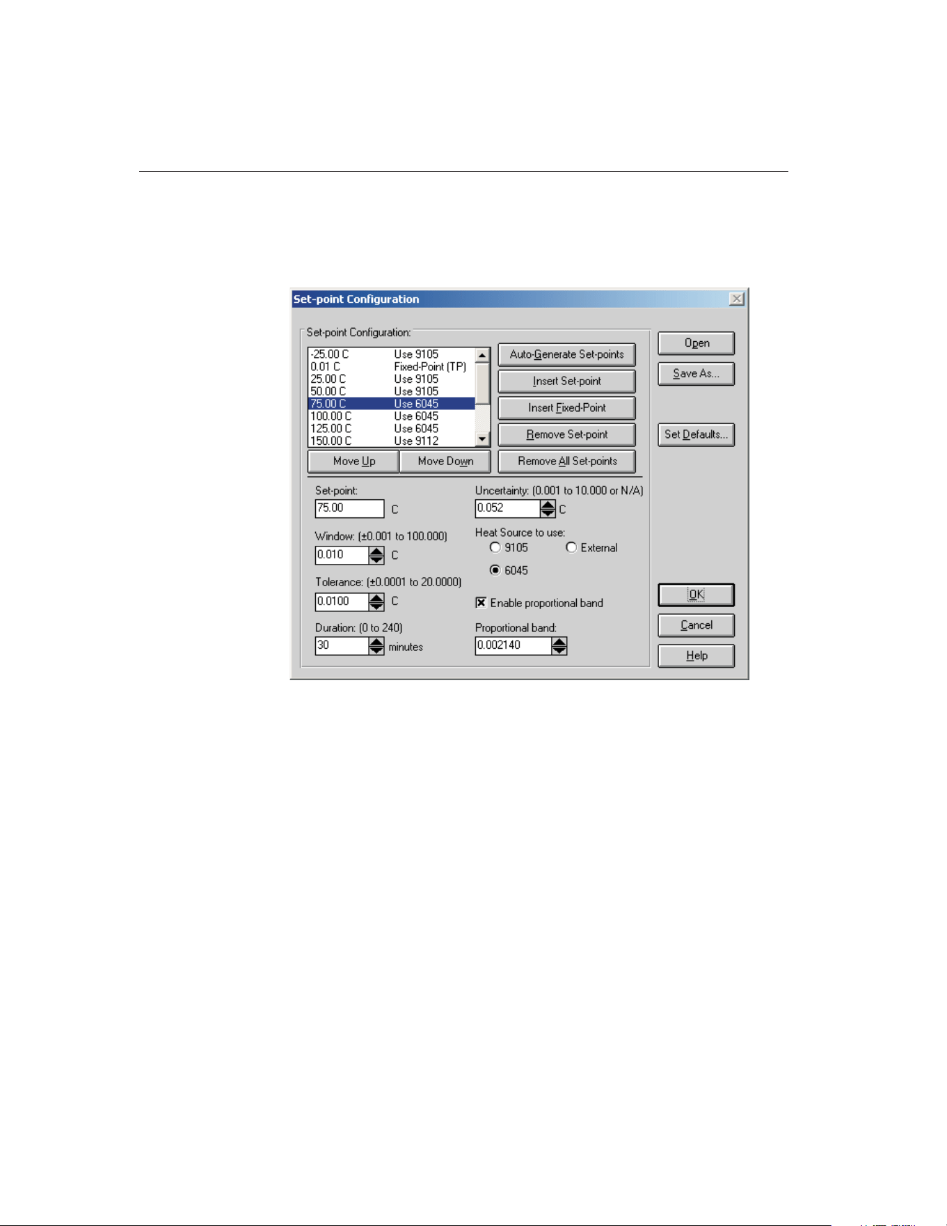
5.1.1 Set-point Configuration Dialog
The Set-point Configuration dialog is used to configure the set-points to use for
the calibration.
Up to 40 set-points can be configured. MET/TEMP II allows set-points to be
set to 2 decimal places of precision. Most Hart heat sources can handle 2 deci-
mal places. Some heat sources, however, cannot. The set-points for the Model
9112 and 9113 furnaces are always rounded to the nearest degree.
Set-points are entered in the same temperature scale (C or F) as the heat
sources and reference scale. To change this scale, refer to Section 6, Scale
Menu. The default value for this scale can be changed on the Setup tab of the
Defaults dialog.
Set-points appear in the list in the order in which they will be used during the
test.
By selecting a set-point in the set-point list, the set-point value, window, toler-
ance, duration, and uncertainty associated with that set-point appear in the ap-
propriate boxes. If more than one heat source can be used for the set-point, all
heat sources that the set-point could be assigned to are displayed. If the selected
heat source is a bath, the Enable proportional band check box is displayed. If
9938 MET/TEMP II
User’s Guide
86
Figure 40 Set-point Configuration Dialog
1.888.610.7664 sales@GlobalTestSupply.com
Fluke-Direct.com

this check box is selected, the Proportional band box is enabled. If not selected,
the Proportional band box is disabled.
A set-point is defined as the temperature that the reference probe should be
reading before MET/TEMP II begins taking measurements from the reference
probe and the test probes. Every comparison set-point must be assigned to one
of the configured heat sources. When the test processes a set-point, the refer-
ence probe and all test probes must be placed in the selected heat source for
that set-point. MET/TEMP II prompts the user at the appropriate time to place
all probes in the required heat source.
Fixed-point set-points are not assigned to a heat source.
Set-points can be generated automatically by clicking the Auto-Generate
Set-points button or inserted into the set-point list manually by clicking the In-
sert Set-Point or Insert Fixed-Point buttons. Set-points can be removed from the
set-points list by clicking the Remove Set-point or Remove All Set-points but-
tons. Each of these processes is explained in detail in the following sections.
Each set-point has its own window, tolerance, duration, uncertainty, and pro-
portional band settings that can be set independent from the other set-points.
The window and tolerance settings are not applicable to fixed-point set-points.
MET/TEMP II uses some of these parameters to determine when measurements
can begin. Refer to Figure 41, Example of Duration, Tolerance and Window
Settings.
The window parameter defines the desired accuracy to the set-point value (al-
lowable difference between the set-point and the reference probe reading). The
reference probe must be within the value of the window parameter of the
set-point value before MET/TEMP II will begin taking measurements. The ac-
tual set-point of the heat source may be adjusted automatically in order to bring
the reference probe readings within this window. For External heat sources,
MET/TEMP II prompts the user to adjust the heat source set-point manually, if
87
5
Calibration Menu
Figure 41 Example of Duration, Tolerance, and Window Settings
1.888.610.7664 sales@GlobalTestSupply.com
Fluke-Direct.com

necessary. Because fixed-point set-points do not use a heat source, the window
parameter does not apply to fixed-point set-points.
The tolerance and duration parameters define the desired stability of the refer-
ence probe readings. These parameters are used by MET/TEMP II to determine
when the reference probe has stabilized at the current temperature. The toler-
ance parameter defines how much the reference probe readings may vary and
still be considered stable. The duration parameter is the length of time that the
reference probe readings must be stable before any measurements are taken.
Fixed-point set-points do not use the tolerance parameter. The duration parame-
ter is used to determine how long each test probe should be allowed to soak in
the fixed-point cell before MET/TEMP II begins taking measurements.
The uncertainty parameter is not used by MET/TEMP II to determine when
measurements are taken. In order for the Report of Calibration produced by
MET/TEMP II to meet the ANSI/NCSL Z540-1 specification, the uncertainty
at each set-point must appear on the report. The value entered in the uncertainty
box for each set-point appears on the Report of Calibration when printed. To
determine the uncertainty at a set-point, the uncertainty of each piece of equip-
ment used to take measurements at the set-point (i.e. reference readout, refer-
ence probe, scanner, heat source, etc.) must be known. The overall uncertainty
is generally the sum of these individual uncertainties.
Note: When using MET/TEMP II to calibrate a heat source, the value entered
in the Uncertainty box for each set-point appears on the custom Heat Source
Report of Calibration as the Tolerance and is used to determine the pass/fail
status at each set-point. Refer to Section 13, Performing Heat Source Calibra-
tions, and Section 11.2.2, Heat Source Report of Calibration, for more details.
The proportional band parameter can be used only when the selected heat
source for a set-point is a Hart bath. The controller for a bath can be fine tuned
for optimal performance at a specific set-point by adjusting the proportional
band parameter. By selecting the Enable proportional band check box,
MET/TEMP II will set the proportional band parameter of the bath to the speci-
fied value when the test begins to process the set-point. If the Enable propor-
tional band check box is not checked, the proportional band parameter of the
bath will not be changed.
Every time this dialog is displayed, each set-point is checked to make sure it
falls within the range of the heat source that was previously selected for the
set-point. If any of the heat source configuration information has changed, the
user may be required to reselect the heat source to which each set-point is
assigned.
To open a set-point configuration file, click the Open button. The Windows®
Open dialog is displayed. A previously saved set-point configuration file (.STC
or .STF) can be opened. When opening a set-point configuration file, all cur-
rent set-points will be overwritten. Refer to Section 10.2, Set-point Configura-
tion File, for additional information on opening a set-point configuration file.
Note: When calibrating a heat source, a set-point configuration file that con-
tains the set-points to use to calibrate the heat source must be opened before
9938 MET/TEMP II
User’s Guide
88
1.888.610.7664 sales@GlobalTestSupply.com
Fluke-Direct.com

any set-points can be inserted. Default set-point configuration files for all sup-
ported heat sources are provided. Refer to Section 13, Performing Heat Source
Calibrations, for more information. Also, the Auto-Generate Set-points and In-
sert Fixed-Point buttons are disabled and cannot be used to insert set-points.
To save set-points to a set-point configuration file, click the Save As button.
The Windows® Save As dialog is displayed. The current set-points and all as-
sociated information (window, tolerance, duration, uncertainty, etc.) are saved
to the configuration file. The extension of the set-point configuration file is
.STC for set-points saved in degrees C and .STF for set-points saved in degrees
F. Refer to Section 10.2, Set-point Configuration File, for additional informa-
tiononsavingset-points.
Clicking the Set Defaults button displays the Set-points tab on the Defaults dia-
log. This allows the default values for the window, tolerance, duration and un-
certainty parameters to be configured. The default values of these parameters
are automatically used when new set-points are generated or inserted.
When all set-points have been configured, click the OK button. A check is per-
formed to ensure all comparison set-points have been assigned to a heat source
before closing the dialog. If any information is missing, a prompt is displayed
and the dialog is not closed. Clicking the Cancel button discards any changes
made and closes this dialog.
5.1.1.1 Auto-Generating Comparison Set-points
Comparison set-points can be generated automatically by clicking the
Auto-Generate Set-points button. All set-points generated using this process are
considered comparison set-points. Clicking the Auto-Generate Set-points but-
ton displays the Auto-Generate Set-points dialog.
89
5
Calibration Menu
1.888.610.7664 sales@GlobalTestSupply.com
Fluke-Direct.com
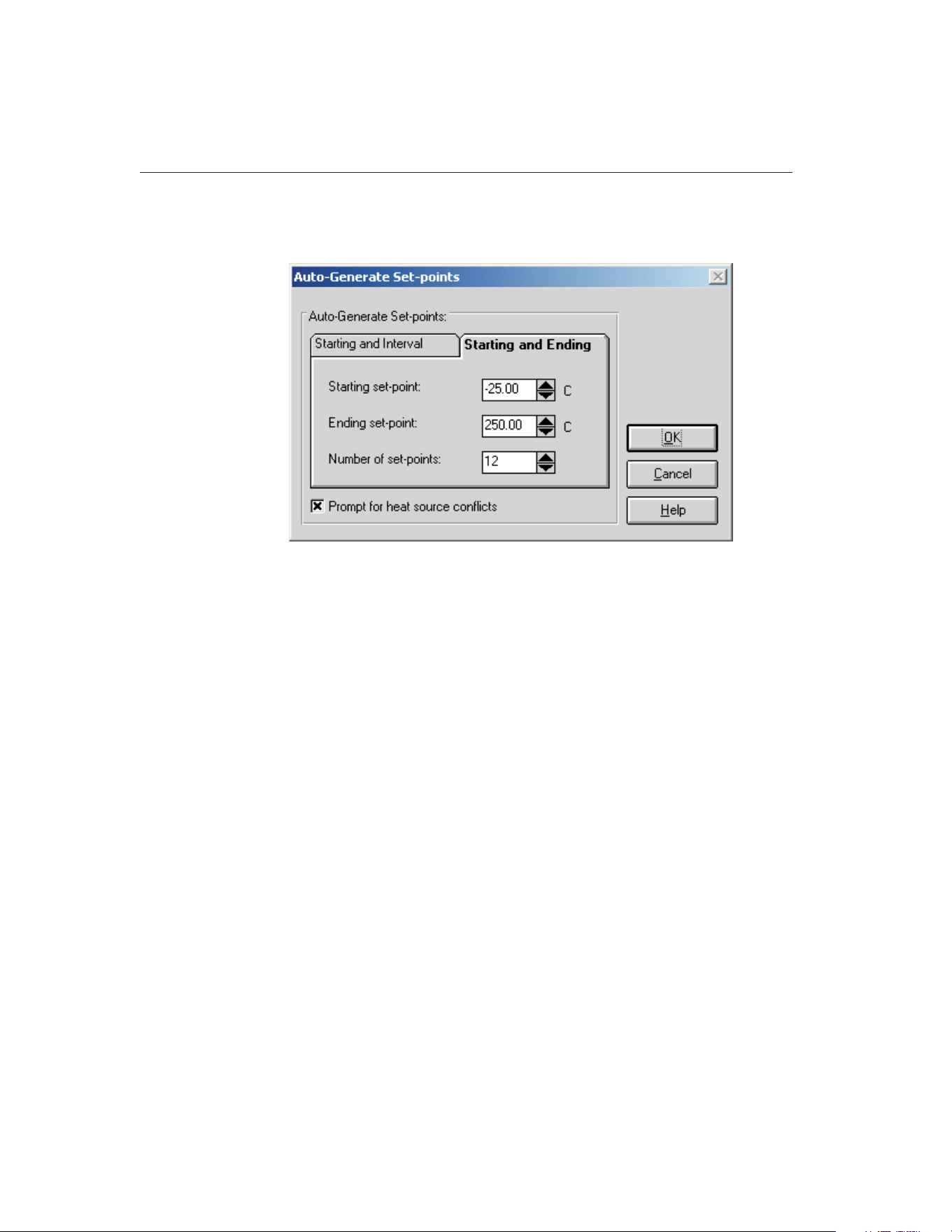
Note: When calibrating a heat source, the auto-generate feature cannot be used.
The Auto-Generate Set-points button is disabled.
The Auto-Generate Set-points dialog provides two methods for automatically
generating set-points. The two methods are: 1) Starting and Interval or 2) Start-
ing and Ending. The user may also select whether to be prompted for heat
source conflicts (in the case that a set-point can be used by more than one heat
source).
The Prompt for heat source conflicts check box allows the user to select the
heat source to which a given set-point is assigned in the case that the ranges of
two or more heat sources overlap. This check box defaults to the state of the
same check box on the Set-points tab of the Defaults dialog.
The Starting and Interval tab allows set-points to be generated based on a start-
ing set-point, an interval between set-points, and the number of set-points. En-
ter the starting set-point in the Starting set-point box. Enter the interval
between set-points in the Interval between set-points box. Enter the total num-
ber of set-points to auto-generate in the Number of set-points box.
The Starting and Ending tab allows set-points to be generated based on a start-
ing set-point, an ending set-point, and the number of set-points. Enter the start-
ing set-point in the Starting set-point box. Enter the ending set-points in the
Ending set-point box. Enter the total number of set-points to auto-generate in
the Number of set-points box.
Clicking the OK button auto-generates the set-points. If the Prompt for heat
source conflicts check box is selected, each set-point is compared to the heat
source ranges as it is generated. If the set-point could be assigned to more than
one heat source, the Set-point Options dialog is displayed and a heat source
9938 MET/TEMP II
User’s Guide
90
Figure 42 Auto-Generate Set-points Dialog
1.888.610.7664 sales@GlobalTestSupply.com
Fluke-Direct.com

must be chosen. Refer to Section 10.2.1, Set-point Options Dialog, for more in-
formation on using this dialog. If a bath is selected as the heat source to use,
the proportional band check box and value are shown. If the set-point can only
be achieved by one heat source, the set-point is automatically assigned to that
heat source. If none of the heat sources can achieve the set-point, a message is
displayed and the current set-point is not added to the list. Auto-generation
continues with the next set-point value.
Clicking the Cancel button aborts auto-generating set-points and closes this
dialog.
5.1.1.2 Inserting Comparison Set-points
Comparison set-points can be manually inserted into the set-point list by click-
ing the Insert Set-point button. All set-points generated using this process are
considered comparison set-points.
Note: When calibrating a heat source, a set-point configuration file must be
opened before set-points can be manually inserted.
To insert a set-point to the set-point list manually, first select the set-point in the
set-point list that the new set-point should come before. To add a set-point to
the top of the set-point list, select the first set-point in the list. To add a
set-point to the end of the list, select the <new set-point> item in the list.
Click the Insert Set-point button. The cursor is placed in the set-point box. En-
ter the value of the new set-point and press <Enter>. The new set-point is in-
serted into the set-point list. The window, tolerance, duration, and uncertainty
parameters are automatically set to their default settings as defined on the
Set-points tab of the Defaults dialog. To abort inserting a new set-point, press
<Esc>.
If the new set-point falls outside the defined temperature range of the config-
ured heat sources, a message appears and the set-point is not inserted into the
list. If two or more heat sources can be used for the new set-point, the set-point
is inserted into the list and the user must select the heat source for the set-point
to use. If only one heat source can be used, the heat source is automatically se-
lected and appears in the set-point list with the set-point.
If the window, tolerance, duration, uncertainty, or heat source settings need to
be changed, follow the instructions in Section 5.1.1.5, Editing Set-points.
5.1.1.3 Inserting Fixed-Point Set-points
MET/TEMP II was originally designed to do comparison calibrations only, but
support has been added for fixed-points also.
To insert a fixed-point set-point to the set-point list manually, first select the
set-point in the set-point list that the new fixed-point set-point should come be-
fore. To add a fixed-point set-point to the top of the set-point list, select the first
set-point in the list. To add a fixed-point set-point to the end of the list, select
the <new set-point> item in the list.
91
5
Calibration Menu
1.888.610.7664 sales@GlobalTestSupply.com
Fluke-Direct.com

Fixed-point set-points can be manually inserted into the set-point list by click-
ing the Insert Fixed-Point button. The Fixed-Points dialog is displayed. Select
the fixed-point cell to use and click the OK button to close this dialog. Clicking
the Cancel button closes this dialog and aborts inserting the fixed-point
set-point. Refer to Section 3.4.2.1, Fixed-Points, for more information on con-
figuring fixed-point information.
When inserting a fixed-point set-point, the set-point value defaults to the refer-
ence value for the selected fixed-point cell and the Set-point box is disabled.
The duration and uncertainty parameters are automatically set to their default
settings as defined on the Set-points tab of the Defaults dialog. The window
and tolerance parameters are disabled and do not apply to fixed-point
set-points.
If the duration or uncertainty settings need to be changed, follow the instruc-
tions in Section 5.1.1.5, Editing Set-points.
Note: When calibrating a heat source, fixed-point set-points cannot be used.
The Insert Fixed-point button is disabled.
5.1.1.4 Removing Set-points
Set-points can be removed from the set-point list by selecting the set-point to
remove and clicking the Remove Set-point button. A message always appears
to confirm removing the set-point. Click Yes to remove the selected set-point or
click No to abort removing the set-point.
To remove all set-points from the set-point list, click the Remove All Set-points
button. A message appears to confirm removing the set-points. Click Yes to re-
move all set-points or click No to abort removing the set-points.
Note: When calibrating a heat source, the set-points used to calibrate the heat
source (As Found) cannot be removed. The Remove Set-point button is dis-
abled when one of these set-points is selected. The Remove All Set-points but-
ton is always disabled when calibrating a heat source.
5.1.1.5 Editing Set-points
The parameters associated with each set-point can be edited as needed. To edit
the parameters associated with a set-point, select the set-point in the list. Make
the necessary changes to the set-point, window, tolerance, duration, uncertainty,
heat source assignment and proportional band parameters as needed.
To edit the parameters for multiple set-points simultaneously, hold down the
<CTRL> key while clicking on set-points in the list. Make the necessary
changes to the window, tolerance, duration and uncertainty parameters as
needed. The set-point, heat source assignment and proportional band settings
cannot be edited when multiple set-points are selected.
9938 MET/TEMP II
User’s Guide
92
1.888.610.7664 sales@GlobalTestSupply.com
Fluke-Direct.com
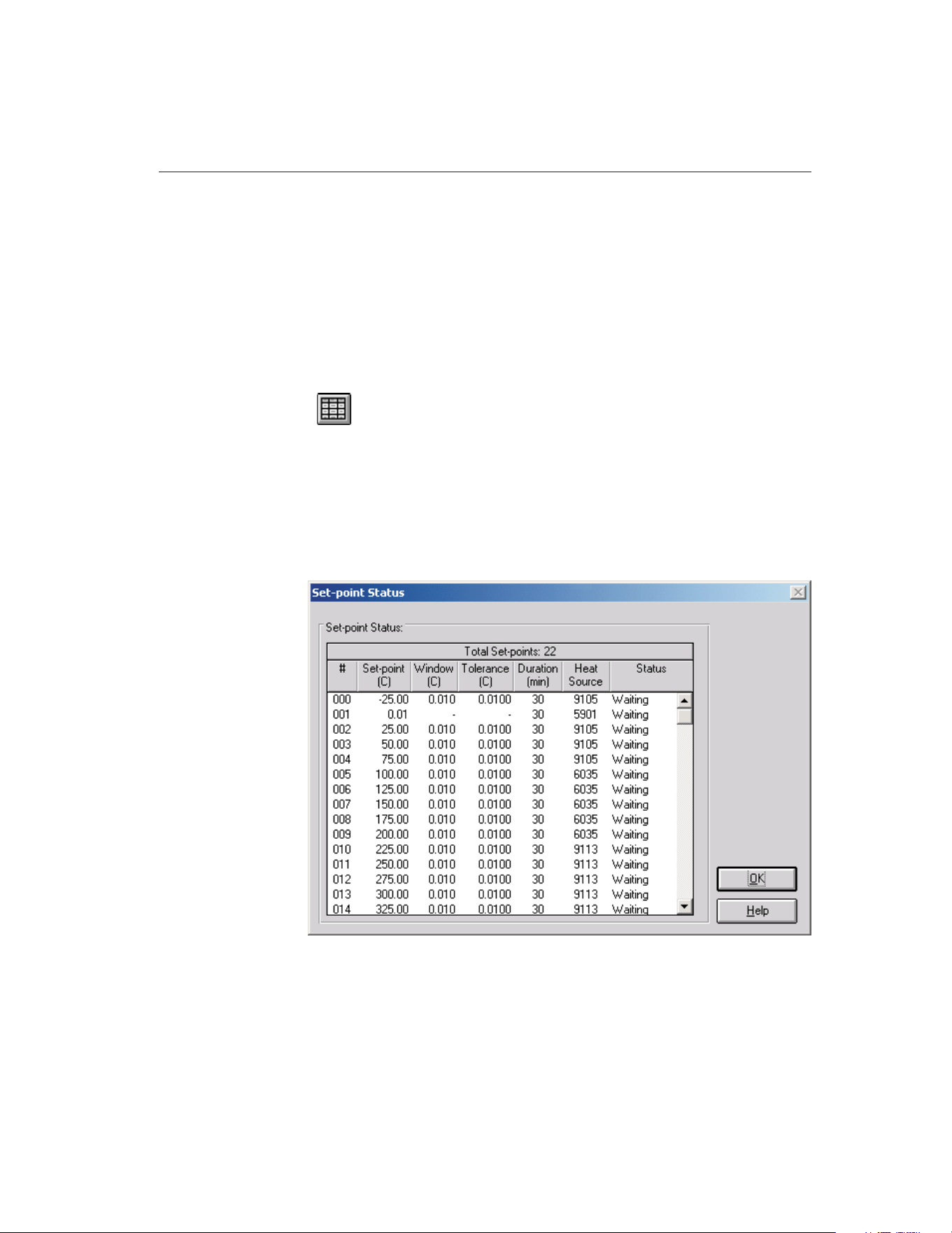
5.1.1.6 Moving Set-points
Set-points can be moved and reordered in the set-point list by selecting the
set-point to move and clicking either the Move Up or Move Down button. Only
one set-point can be moved at a time. If multiple set-points are selected, the
Move Up and Move Down buttons are disabled.
Note: When calibrating a heat source, set-points used to calibrate the heat
source cannot be moved. The Move Up and Move Down buttons are disabled
when any of these set-points are selected.
5.2
View Set-points
Selecting the View Set-points option displays the Set-point Status dialog for
monitoring the status of the set-points during a test.
5.2.1 Set-point Status Dialog
The Set-point Status dialog displays a list of the currently configured set-points
with the associated window, tolerance, duration, heat source assignment and
status.
The Set-point Status dialog displays the current status of each set-point. The
set-points appear in the order that they are used during a test. The set-point
93
5
Calibration Menu
Figure 43 Set-point Status Dialog
1.888.610.7664 sales@GlobalTestSupply.com
Fluke-Direct.com
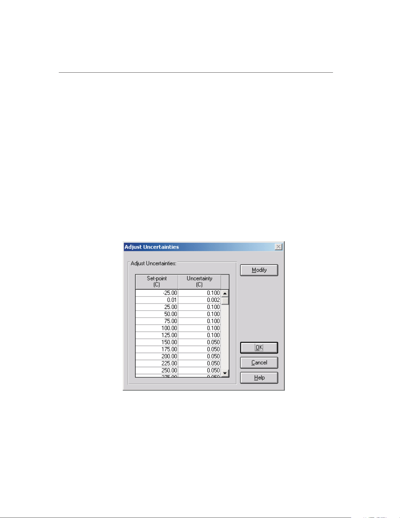
number, value, window, tolerance, duration, the heat source used, and the cur-
rent status of the set-point are displayed.
If, during the process of a test, a set-point is overridden by clicking the Take
reading now check box on the Stability Override dialog, the value in the Toler-
ance and Duration columns for that set-point contain the word OVERRIDE and
a footnote will appear on the Report of Calibration stating that the stability pa-
rameters were overridden for the indicated set-point(s).
Click the OK button to close this dialog.
5.3 Adjust Uncertainties
Selecting the Adjust Uncertainties option displays the Adjust Uncertainties dia-
log for conveniently viewing and/or changing the uncertainties associated with
each set-point.
5.3.1 Adjust Uncertainties Dialog
The Adjust Uncertainties dialog displays a list of the currently configured
set-points and the associated uncertainties.
When this dialog is displayed, the uncertainties can be viewed and changed. To
change the uncertainties, click the Modify button. The Modify button changes
to a Save button. The uncertainties can then be changed. Select the cell for the
9938 MET/TEMP II
User’s Guide
94
Figure 44 Adjust Uncertainties Dialog
1.888.610.7664 sales@GlobalTestSupply.com
Fluke-Direct.com

uncertainty to change and enter the new uncertainty value. To set an uncertainty
to N/A, clear the contents of the cell, then use the arrow keys or click to move
to another cell.
Click the Save button to save the new uncertainty settings, then click the OK
button to close this dialog. Clicking the Cancel button discards any changes and
closes this dialog.
Note: The uncertainty parameter is not used by MET/TEMP II to determine
when measurements are taken. In order for the Report of Calibration produced
by MET/TEMP II to meet the ANSI/NCSL Z540-1 specification, the uncer-
tainty at each set-point must appear on the report. To determine the uncertainty
at a set-point, the uncertainty of each piece of equipment used to take measure-
ments at the set-point (i.e. reference readout, reference probe, scanner, heat
source, etc.) must be known. The overall uncertainty is generally the sum of
these individual uncertainties.
Note: When using MET/TEMP II to calibrate a heat source, the value entered
as the uncertainty for each set-point appears on the custom Heat Source Report
of Calibration as the Tolerance and is used to determine the pass/fail status at
each set-point. Refer to Section 13, Performing Heat Source Calibrations, and
Section 11.2.2, Heat Source Report of Calibration, for more details.
5.4
Test Probes
Selecting the Test Probes option displays the Test Probe Configuration dialog
for entering information about the test probes to be calibrated. This dialog can
also be displayed by clicking the Test Probes button on the Equipment Info dia-
log, the Scanner Configuration dialog or the Scanner Modules Configuration
dialog.
5.4.1 Test Probe Configuration Dialog
95
5
Calibration Menu
1.888.610.7664 sales@GlobalTestSupply.com
Fluke-Direct.com
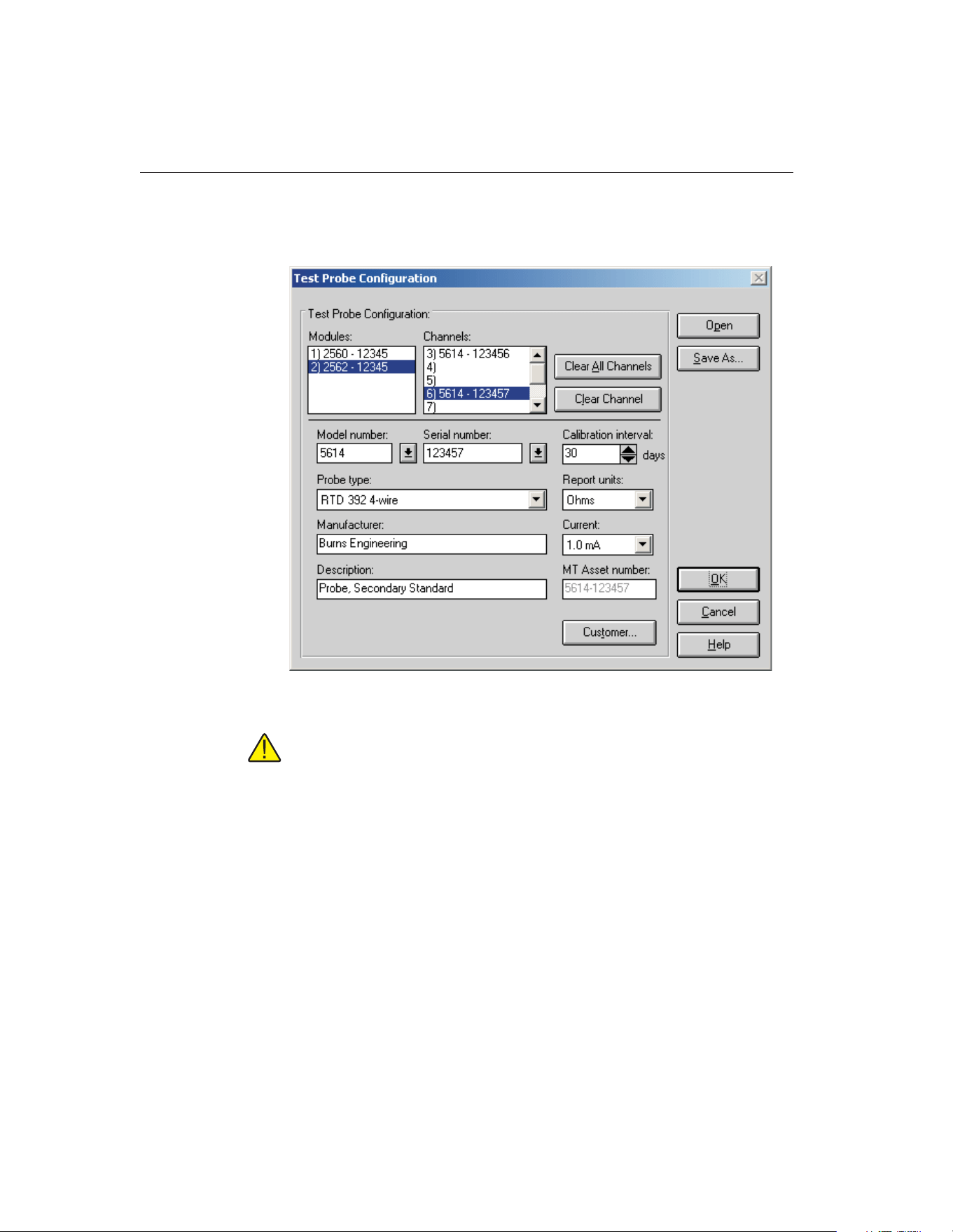
The Test Probe Configuration dialog is used to configure the test probes
(UUTs) to be calibrated.
Important: When using MET/TEMP II to calibrate a heat source, the
scanner instrument acts as the reference instrument and the test probe acts
as the reference probe. The calibration and recalibration date boxes are
only displayed when calibrating a heat source. The calibration interval
and Customer button are hidden when calibrating a heat source.
The Scanner or Modules list in the upper left corner of this dialog displays a
list of the currently configured scanner or scanner modules. The Channels list
displays a list of the channels on the scanner or scanner module that is cur-
rently selected in the Scanner or Modules list.
Note: If the Do not use scanner – prompt to manually enter all readings option
on the Scanner Configuration dialog is selected, the Scanner list is empty and
the Probes list allows up to 100 test probes to be configured. All readings for
these probes must be entered manually. MET/TEMP II displays a prompt for
the data to be entered at the appropriate times during the calibration process.
9938 MET/TEMP II
User’s Guide
96
Figure 45 Test Probe Configuration Dialog
1.888.610.7664 sales@GlobalTestSupply.com
Fluke-Direct.com

If the same instrument is being used as both the reference readout and the scan-
ner, the channel that is currently configured with the reference probe appears in
the Channel list with the <Reference> marker. A test probe cannot be config-
ured on this channel. When this channel is selected, the Clear Channel button,
Model number, Serial number, and other controls on this dialog are disabled.
Clicking the Clear All Channels button removes all test probe configuration in-
formation from all channels, regardless of the scanner or scanner module that is
currently selected. This button may be clicked to make sure all channels are
cleared before beginning to configure test probes.
Clicking the Clear Channel button removes test probe configuration informa-
tion from the currently selected channel only.
To configure a test probe, select the appropriate scanner or scanner module
from the Scanner or Modules list, as applicable. Then select the channel to
which the test probe is connected in the Channels list. If MET/TEMP II is con-
figured to not use a scanner, simply click any entry in the Probes list. The order
of the test probes is not important, but MET/TEMP II will prompt for the data
for each test probe to be manually entered in the order in which the test probes
are configured in this list.
Important: When using the Hydra series dataloggers with 4-wire probes,
configure the probes on the first channel that the probe is connected to.
For example, if a 4-wire probe is connected to channels 4 and 14, config-
ure the probe in MET/TEMP II on channel 4 and DO NOT ATTEMPT TO
CONFIGURE A PROBE ON CHANNEL 14! Leave that channel blank.
Next, select the test probe model number using the Model number drop-down
list. The probe type, manufacturer and description information is filled in auto-
matically when a model number is selected. If the model number does not ap-
pear in the list, enter the model number in the Model number box. MET/TEMP
II only displays probes of the type that can be used on the selected scanner or
scanner module. If a scanner is not being used, the user can select from all pos-
sible probe types. Select the probe type and enter the manufacturer and descrip-
tion for the test probe in the Manufacturer and Description boxes. MET/TEMP
II records model numbers, probe type, manufacturer and description informa-
tion to avoid having the user reenter the same data over and over.
The probe type must be selected from the Probe type list. Available probe types
depend on the type of scanner or scanner module selected. Possible probe types
are:
• SPRT
• RTD 385 3-wire or 4-wire
• RTD 392 3-wire or 4-wire
• RTD 2-wire, 3-wire or 4-wire
• Other PRT/RTD
97
5
Calibration Menu
1.888.610.7664 sales@GlobalTestSupply.com
Fluke-Direct.com

• Thermistor 3-wire or 4-wire
• Other Thermistor
• Thermocouple Types B, E, J, K, N, R, S, T, or AuPt
• Other Thermocouple
• Liquid in Glass (only if no Scanner is being used)
• Bi-metallic (only if no Scanner is being used)
• Other
Next, select the serial number from the Serial number drop-down list or enter
the serial number in the Serial number box if it has not been entered previously.
Select the calibration interval, report units and excitation current or CJC read-
ings settings for the test probe as applicable in the boxes provided. MET/TEMP
II records serial numbers, calibration intervals, report units, and excitation cur-
rent/CJC readings settings to avoid having the user reenter the same data over
and over.
The calibration interval is the number of days, from the date the calibration is
performed, until the next calibration is due. The calibration interval can be in-
cremented in steps of 30 days using the up/down buttons or entered manually.
The allowable range is 0 to 730 days (2 years). If the calibration interval is set
to 0, the recall date does not print on the Report of Calibration.
The report units are the scale of the test probe readings. The possible choices
are:
• C
• F
• K
• Ohms (except thermocouple, LIG, and Bi-metallic probes)
• mV (except resistance, LIG, and Bi-metallic probes)
During a calibration test, MET/TEMP II attempts to verify that the test probe
and reference probe readings are in the correct scale. For this reason, it is im-
portant to manually set each scanner channel to read in the appropriate scale
before starting a calibration test.
Note: In order to calculate characterization coefficients and generate ta-
bles, the test probe report units must be in one of the non-temperature
scales (Ohms or mV).
The excitation current setting is shown if the test probe is a resistance type
probe and the scanner instrument or module supports setting the excitation cur-
rent. Make sure the setting for the excitation current in the scanner instrument
or module matches the setting in MET/TEMP II for each channel before start-
ing a test. The excitation current must be selected from the Current drop-down
9938 MET/TEMP II
User’s Guide
98
1.888.610.7664 sales@GlobalTestSupply.com
Fluke-Direct.com
list. Available excitation current settings depend on the type of scanner or mod-
ule selected. Possible currents are:
• 2µA, 10µA, 30µA
• 0.05 mA, 0.1mA, 0.2mA, 0.5mA, 1mA, 1.4mA, 3mA, 5mA
• Auto or N/A
Note: The excitation current should be set manually in the scanner instru-
ment before starting the calibration test because not all scanner instru-
ments support setting the excitation current via serial communication
commands.
The CJC reading setting is available if the test probe is a voltage type probe.
This is the Cold Junction Compensation setting. This setting is used to tell
MET/TEMP II whether or not to take CJC readings at each temperature. Select
Enabled if CJC readings should be taken, or select N/A if CJC readings are not
required or compensation is handled internally within the Scanner instrument
for this test probe.
Generally, the CJC option should be set to N/A when the report units for a
given test probe are in temperature and Enabled when the report units are in
voltage. Hart instruments automatically account for CJC when configured to
display measurements in temperature, but do not account for CJC when config-
ured to display measurements in voltage.
Note: For the Hart Model 1560 “Black Stack” and Model 1529
“Chub-E4”, CJC readings are ALWAYS taken in degrees C. See the instru-
ment’s User’s Guide for more information about the CJC settings.
When calibrating a heat source, the Calibration date and Recalibration date
boxes are displayed. Enter the calibration and recalibration dates for this probe.
Clicking the Customer button displays the Customer Information dialog for en-
tering more information about the selected test probe. Refer to Section 5.4.1.1,
Customer Information Dialog, for more information.
Continue configuring the other channels or test probes, one by one, in this same
manner.
99
5
Calibration Menu
1.888.610.7664 sales@GlobalTestSupply.com
Fluke-Direct.com
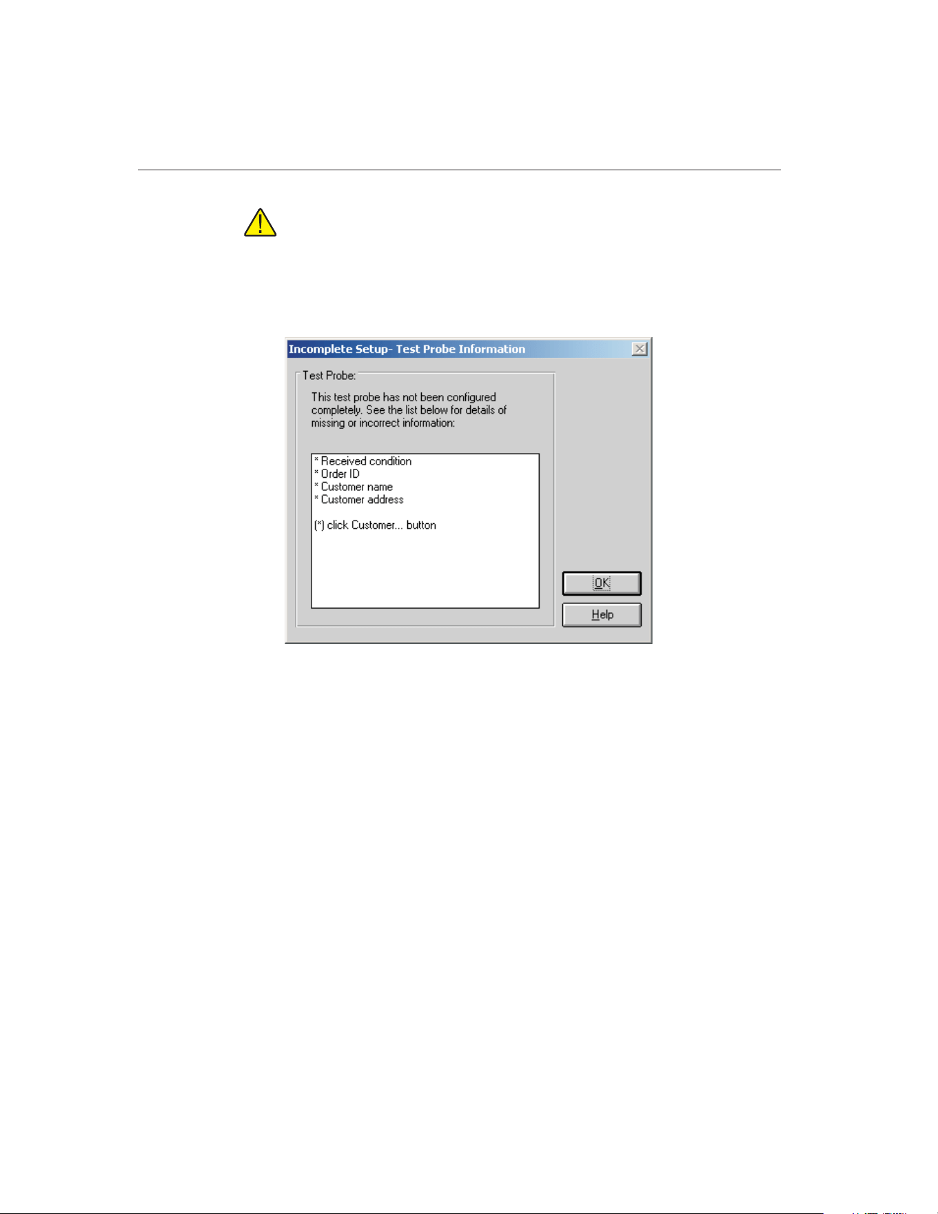
Note: If the user attempts to select a new channel in the Channels or
Probes list before completing the configuration for the current channel or
probe, the Incomplete Setup- Test Probe Information dialog is displayed.
Check the list to determine what information still needs to be filled in.
Then click the OK button and proceed to complete the test probe configu-
ration for the current channel.
To open a test probe configuration file, click the Open button. The Windows®
Open dialog is displayed. A previously saved test probe configuration file
(.TPC) can be opened. When opening a test probe configuration file, the cur-
rent test probe configuration settings will be overwritten. Refer to Section 10.3,
Test Probe Configuration File, for additional information on opening a test
probe configuration file.
To save the current test probe configuration to a test probe configuration file,
click the Save As button. The Windows® Save As dialog is displayed. The cur-
rent test probe configuration is saved to the configuration file. The extension of
the test probe configuration file is .TPC. Refer to Section 10.3, Test Probe Con-
figuration File, for additional information on saving a test probe configuration.
When all test probes have been configured, click the OK button. A check is
performed to ensure all required information has been entered. If any informa-
tion is missing, the Incomplete Setup- Test Probe Information dialog is dis-
played and the Test Probe Configuration dialog is not closed. Clicking the
Cancel button discards any changes made and closes this dialog.
9938 MET/TEMP II
User’s Guide
100
Figure 46 Incomplete Setup– Test Probe Information Dialog
1.888.610.7664 sales@GlobalTestSupply.com
Fluke-Direct.com
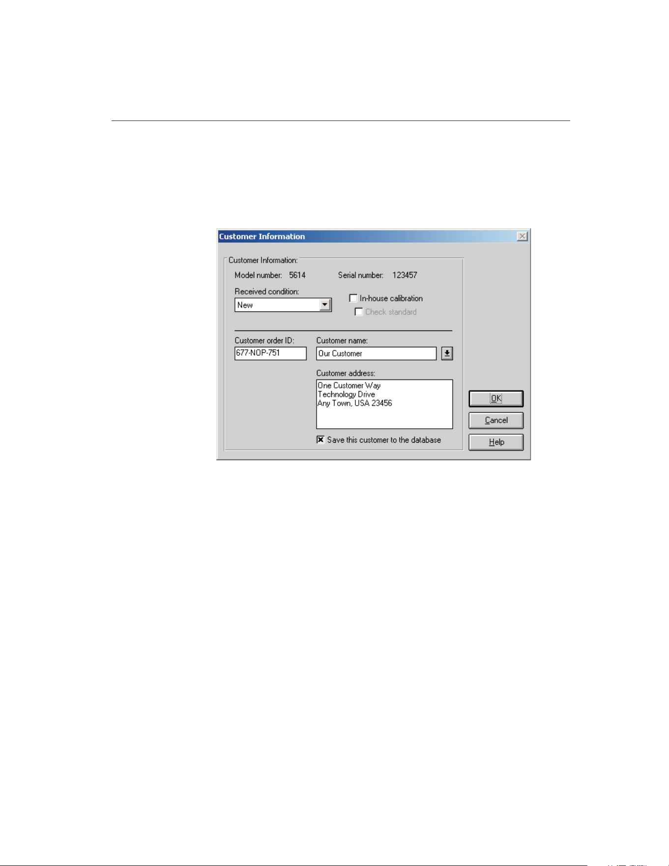
5.4.1.1 Customer Information Dialog
The Customer Information dialog is used to enter additional test probe informa-
tion and can only be displayed by clicking the Customer button on the Test
Probe Configuration dialog or the Heat Source Configuration dialog when cali-
brating a heat source.
The Customer Information dialog displays the UUT (test probe or heat source)
model and serial number, the received condition, in-house and check standard
settings, and customer order ID, name and address information. This informa-
tion is printed on the Report of Calibration for this test probe.
The information on this dialog is required and must be entered before a calibra-
tion test can be started.
The Received condition is the condition of the UUT prior to this calibration.
The choices are:
• In Tolerance
• Out of Tolerance
• New
• Recalibration
The In-house calibration check box is for designating the UUT as belonging to
the company performing the calibration. The customer name and address are
automatically filled in if this option is selected.
101
5
Calibration Menu
Figure 47 Customer Information Dialog
1.888.610.7664 sales@GlobalTestSupply.com
Fluke-Direct.com

The Check standard check box is used to indicate that this UUT is a statistical
check standard. By selecting this option, this UUT is simply flagged as a check
standard. The Coefficients and Tables application has some features that can be
used to export test data for check standard test probes only.
The Customer order ID provides a place for entering a purchase order, sales or-
der, work order or other such number.
The Customer name is the name of the company for which the calibration is be-
ing performed, or the company that owns this UUT.
The Customer address is the address of the company for which the calibration
is being performed, or the company that owns this UUT.
If the In-house calibration check box is selected, the Customer name and Cus-
tomer address boxes are filled in automatically. This information comes from
the User tab of the Defaults dialog.
Select the Save this customer to the database check box to save this customer
name and address. Saved customer names and addresses can be selected using
the Customer name drop-down list.
When all settings have been entered, click the OK button. A check is performed
to ensure all required information has been entered. If any information is miss-
ing, the Incomplete Setup- Test Probe Information dialog is displayed and the
dialog is not closed. Clicking the Cancel button discards any changes made and
closes this dialog.
5.5
Start Test
The Start Test option starts a calibration test. This option is only enabled if all
required information has been entered for the reference readout, reference mod-
ule (if applicable), reference probe, scanner, scanner module(s) (if applicable),
heat source(s), set-points and test probe(s). If any piece of the configuration is
incomplete, a calibration cannot be started. Once a test is running, this option
does not appear in the menu.
When starting a calibration test, MET/TEMP II checks for conflicts and miss-
ing information in the current configuration and attempts to establish communi-
cations with all connected instruments. All instruments must be connected and
powered on at this time. Also, make sure the SmartSwitch is connected to the
selected COM port and powered on.
If MET/TEMP II determines that some required information is missing, the In-
complete Setup- Setup Information dialog is displayed. Scroll through the list
to determine what information is missing. The items listed need to be resolved
9938 MET/TEMP II
User’s Guide
102
1.888.610.7664 sales@GlobalTestSupply.com
Fluke-Direct.com
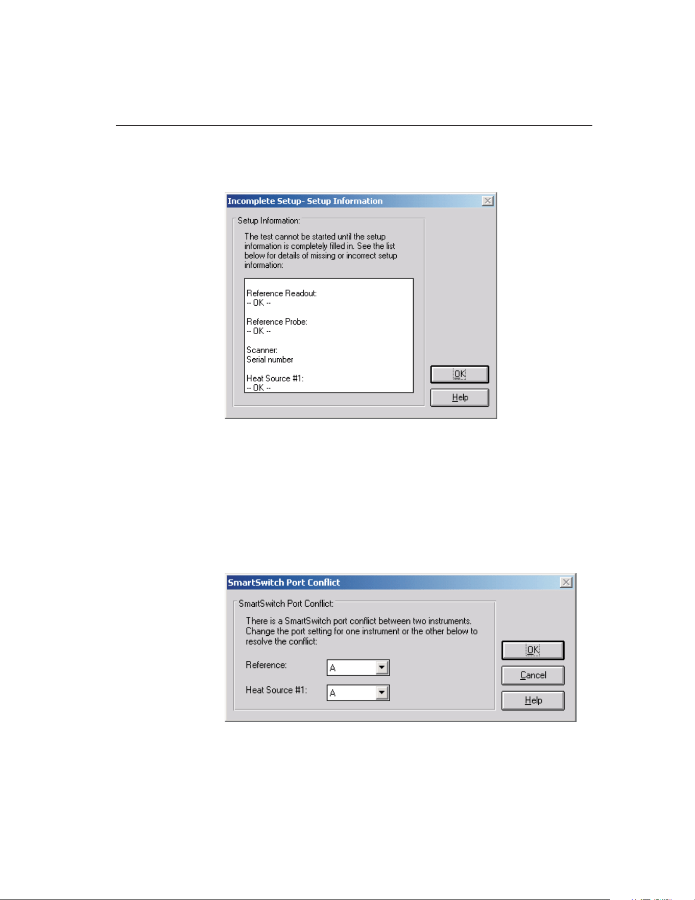
before a calibration test can start. Click the OK button to close this dialog then
go to the appropriate dialog to enter the missing information.
If MET/TEMP II finds that more than one instrument has been assigned to the
same SmartSwitch port, the SmartSwitch Port Conflict dialog is displayed. The
instruments with the conflict are indicated. To resolve this issue, simply select
the correct SmartSwitch port for each instrument using the drop-down lists.
Check the cable connections to ensure correct SmartSwitch port assignments.
Click the OK button to accept the new settings and continue. Clicking the Can-
cel button aborts starting the calibration test.
103
5
Calibration Menu
Figure 48 SmartSwitch Port Conflict Dialog
Figure 49 Incomplete Setup- Setup Information Dialog
1.888.610.7664 sales@GlobalTestSupply.com
Fluke-Direct.com

Note: The only situation where MET/TEMP II allows two instruments to
be assigned the same SmartSwitch port is when using a dual-well heat
source that has two separate controllers but a single communication port.
After checking the configuration information, MET/TEMP II attempts to com-
municate with each instrument. If communication with any instrument fails, a
communication error dialog is displayed. MET/TEMP II will automatically re-
try the communication every 5 seconds or when the Retry button is clicked.
Read this dialog and check the indicated items to determine why MET/TEMP
II cannot communicate with the instrument. Clicking the Cancel button aborts
starting the calibration test.
Note: MET/TEMP II will not attempt to communicate with External heat
sources, fixed-point cells or non-interfaced scanner or other readout in-
struments.
If communication failure is persistent, click the Cancel button and go to the ap-
propriate configuration dialog for the instrument that is not communicating.
Click the Check Port button to attempt to establish communications with the in-
strument. Make sure the LED on the SmartSwitch for the selected SmartSwitch
port is on or try another SmartSwitch port. If failure persists, try connecting the
instrument directly to the computer’s COM port and use a terminal program to
send commands to the instrument. Refer to the instrument’s User’s Guide for
communication commands and settings.
If the current instrument configuration has not been saved, MET/TEMP II
prompts to save this configuration. Clicking Yes displays the Windows® Save
As dialog. Enter the filename and click the OK button. If this configuration
does not need to be saved, Click No.
9938 MET/TEMP II
User’s Guide
104
Figure 50 Communication Error Dialog
1.888.610.7664 sales@GlobalTestSupply.com
Fluke-Direct.com

Note: The current configuration is always saved at this point to a file
named 9938LAST.CFG. Opening this configuration file will always restore
the configuration settings most recently used to run a calibration test.
The Test Information dialog is then displayed. Refer to Section 5.5.2, Test In-
formation Dialog, for more information.
Once all of the information on the Test Information dialog has been entered and
the test is running, MET/TEMP II prompts to make sure that all of the refer-
ence readout and scanner channels are configured to read the correct scales and
to insert the reference probe and all test probes into the heat source for the first
set-point.
MET/TEMP II then waits for the heat source to reach the set-point and stabilize
according to the tolerance and duration parameters for the current set-point. Be-
fore taking measurements from the reference and test probes, MET/TEMP II
checks to ensure that the difference between the desired set-point temperature
and the current reference reading does not exceed the window parameter for the
current set-point. If it does, the heat source set-point is recalculated to compen-
sate for the error and the stabilization process repeats.
MET/TEMP II then begins to take measurements from the first test probe and
the reference. The number of readings that are taken is defined on the Test tab
of the Defaults dialog. Then this process is repeated for the second test probe,
etc. When readings have been taken from all test probes, MET/TEMP II ad-
vances to the next set-point. A prompt is displayed if the reference and test
probes need to be moved to a different heat source at this time.
When MET/TEMP II has repeated this process for all set-points, the test pro-
cess ends. Select the Close Test option in the File menu to close the test.
If the calibration test was configured to not use a scanner instrument, the Enter
Data dialog is displayed at the appropriate times to allow the readings for the
indicated test probe to be manually entered. Refer to Section 5.5.1, Enter Data
Dialog, for more information on using this dialog.
If MET/TEMP II was configured to use an External heat source or one or more
fixed-point set-points, MET/TEMP II displays a prompt at the appropriate
times to manually set the heat source temperature or to place the test probes
one at a time into the fixed-point cell. Refer to Section 12, Performing Calibra-
tions Using Fixed-Points for more information.
If MET/TEMP II was configured to take ambient temperature and humidity
readings from a Model 1620/5020A ‘DewK’ Thermohygrometer, the ‘DewK’ is
queried at regular intervals throughout the entire test. When the test is complete
or aborted, the average of the ambient temperature and humidity readings over
the entire test period are calculated and written to the database.
105
5
Calibration Menu
1.888.610.7664 sales@GlobalTestSupply.com
Fluke-Direct.com
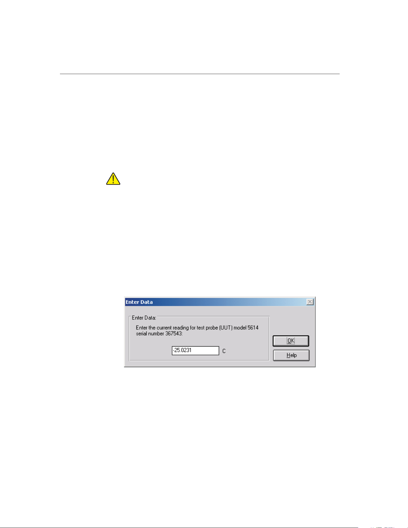
Closing a Test
When testing is complete, a message is displayed indicating the test completed
successfully. The test controls remain on-screen until the test is closed using
the Close Test option in the File menu.
When closing a test, a prompt may be displayed asking if the Coefficients and
Tables application should be launched to calculate characterization coefficients,
depending on the appropriate settings on the Test tab of the Defaults dialog.
Click Yes to launch the Coefficients and Tables application or click No to
continue.
Note: This prompt is never displayed when closing a heat source calibra-
tion.
Next, a prompt may also be displayed to export the calibration data to the
MET/TRACK database. This prompt is only displayed if the Coefficients and
Tables application was not launched, the appropriate option on the
MET/TRACK tab of the Defaults dialog is checked and the link to the
MET/TRACK database is active. Click Yes to export the calibration data now
orclickNotoabort.
All test controls are hidden and a new calibration test can be configured.
5.5.1 Enter Data Dialog
The Enter Data dialog allows the readings for non-interfaced test probes, such
as Liquid in Glass or bi-metallic probes, to be manually entered.
The test probe model and serial number are indicated. Enter the current reading
for the test probe in the indicated scale. For thermocouple probes, when
prompted to enter the CJC reading, readings may be entered in any scale (C, F,
K, mV, etc.), but all CJC readings should be entered in the same scale. If calcu-
lating characterization coefficients for a test probe using this data, all CJC read-
ings must be entered in the same scale.
Click the OK button to accept the entered reading and continue.
9938 MET/TEMP II
User’s Guide
106
Figure 51 Enter Data Dialog
1.888.610.7664 sales@GlobalTestSupply.com
Fluke-Direct.com
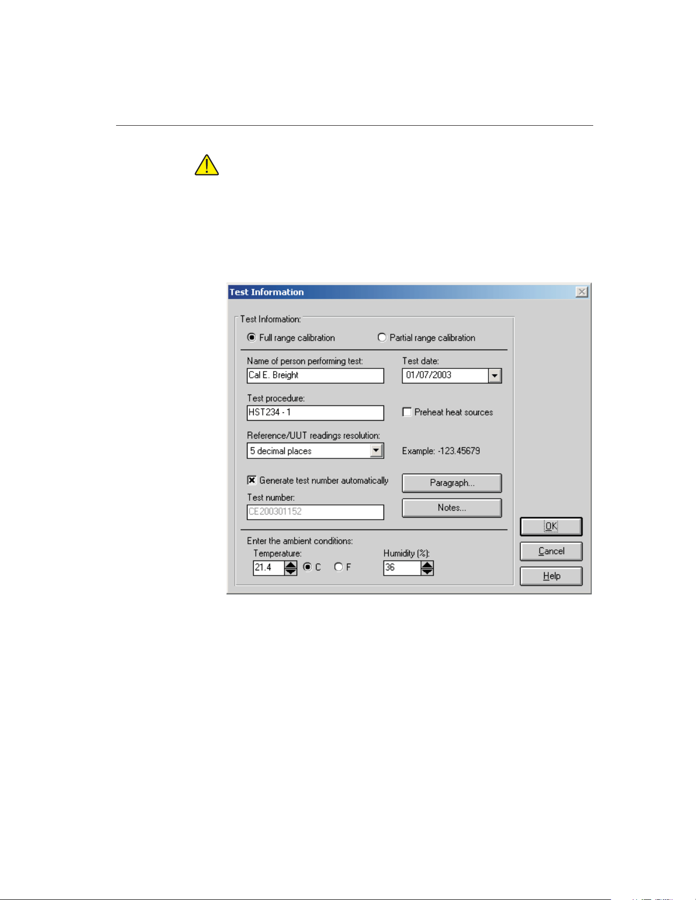
Note: This dialog will appear for each test probe the number of times in-
dicated on the Test tab of the Defaults dialog! When manually entering
data, you may wish to set this value to 1 reading!
5.5.2 Test Information Dialog
The Test Information dialog displays some general settings that apply to all test
probes for this test. Most of the settings on this dialog are remembered from the
settings that were used for the previous test.
The Full range calibration and Partial range calibration options are used to
specify whether the test probes are being calibrated over their full range or over
a partial range. Select the appropriate option.
Enter the name of the technician performing this test in the box provided. This
name is automatically filled in using the name from the User tab on the De-
faults dialog. This name appears on the Report of Calibration below one of the
signature lines.
107
5
Calibration Menu
Figure 52 Test Information Dialog
1.888.610.7664 sales@GlobalTestSupply.com
Fluke-Direct.com

The Test date is the date the test begins and defaults to today’s date. If the date
is incorrect, check the clock on the computer. To change the test date, use the
drop-down calendar and click on the appropriate date.
In the Test procedure box, enter the name or document control number of the
in-house document that describes the method or procedure followed when per-
forming this test.
Select the Preheat heat sources check box if you want MET/TEMP II to preheat
each heat source prior to being used in the test process. If this option is se-
lected, MET/TEMP II always looks ahead one set-point to determine if that
set-point is assigned to a different heat source than the current set-point. If so,
the heat source is set to its first set-point. If an External heat source is being
used, the user is prompted to manually set the set-point of the heat source. This
feature can save time in performing calibrations. If only one heat source is be-
ing used, selecting this option has no effect.
The Reference/UUT reading resolution drop-down list is used to specify the
resolution that MET/TEMP II should use to format all reference and test probe
readings. This setting applies to temperature, resistance and voltage readings.
All reference and test probe readings taken by MET/TEMP II for the current
test will be formatted to the selected number of decimal places. This setting
should be set appropriately according to the configured resolution of the read-
ings for each instrument as well as the calibration test requirements. An exam-
ple reading is displayed next to the drop-down list.
If the Generate test number automatically check box is selected, the test num-
ber is automatically generated by using the initials of the technician performing
the test, the four digits of the current year, two digits of the current month, and
a three digit sequence number. The test number box is disabled.
If the Generate test number automatically check box is not selected, the test
number box is enabled and the user must enter a test number. The test number
must be unique. MET/TEMP II will make sure the entered test number is
unique when the OK button is clicked.
The default state of the Generate test number automatically check box is deter-
mined by the setting on the Setup tab of the MET/TEMP II Defaults dialog.
Clicking on the Paragraph and Notes buttons allow text files that contain text to
appear on the Report of Calibration to be selected. When clicking either of
these buttons, the Text Editor dialog is displayed. Refer to Section 3.4.5.1, Text
Editor Dialog, for more details on using this dialog.
Note: The text for the paragraph and notes must be saved to a file in order
to appear on the Report of Calibration. A default paragraph file can be
defined on the Reports tab of the Defaults dialog. The notes must be speci-
fied for every test.
If the Get ambient conditions from ‘DewK’ check box on the General tab of the
MET/TEMP II Defaults dialog is checked, MET/TEMP II will attempt to query
9938 MET/TEMP II
User’s Guide
108
1.888.610.7664 sales@GlobalTestSupply.com
Fluke-Direct.com
the ambient temperature and humidity readings from a Model 1620/5020A
‘DewK’ Thermohygrometer using the settings defined on the General tab.
MET/TEMP II queries readings from the connected ‘DewK’ throughout the test
process and writes the average ambient temperature and humidity readings to
the database when the test is complete. If this check box is not checked, manu-
ally enter the ambient temperature, temperature scale, and humidity in the
boxes provided. This information is printed on the Report of Calibration.
Clicking the OK button checks to make sure the test number is unique and then
begins the test process.
Note: If the test number is not unique (a test already exists with that test
number), the user is prompted to overwrite the existing test or to enter a
new test number. Selecting to overwrite the existing test must be confirmed
because overwriting a test is permanent; all data from the existing test is
deleted!
Clicking the Cancel button returns to the MET/TEMP II Main Display without
starting a test.
5.6
Stop Test
The Stop Test option aborts the current calibration test. This option does not
appear in the menu unless a test is currently running. When aborting a test, a
prompt is displayed to confirm aborting the test.
Once a test has been aborted, it cannot be resumed. Select the Pause Test option
to pause a test temporarily. MET/TEMP II continues to take readings from and
graph the reference after a test has been aborted until the Close Test option in
the File menu is selected.
5.7
Pause Test
The Pause Test option suspends the test process. This option does not appear in
the menu while a test is paused. This feature can be used to temporarily pause
the test for any reason.
Important: A calibration test should not be paused for long periods of
time, such as overnight!
Note: A calibration test cannot be paused when readings are being taken from
the reference and test probes. This option is disabled until all readings have
been taken at the current set-point.
109
5
Calibration Menu
1.888.610.7664 sales@GlobalTestSupply.com
Fluke-Direct.com
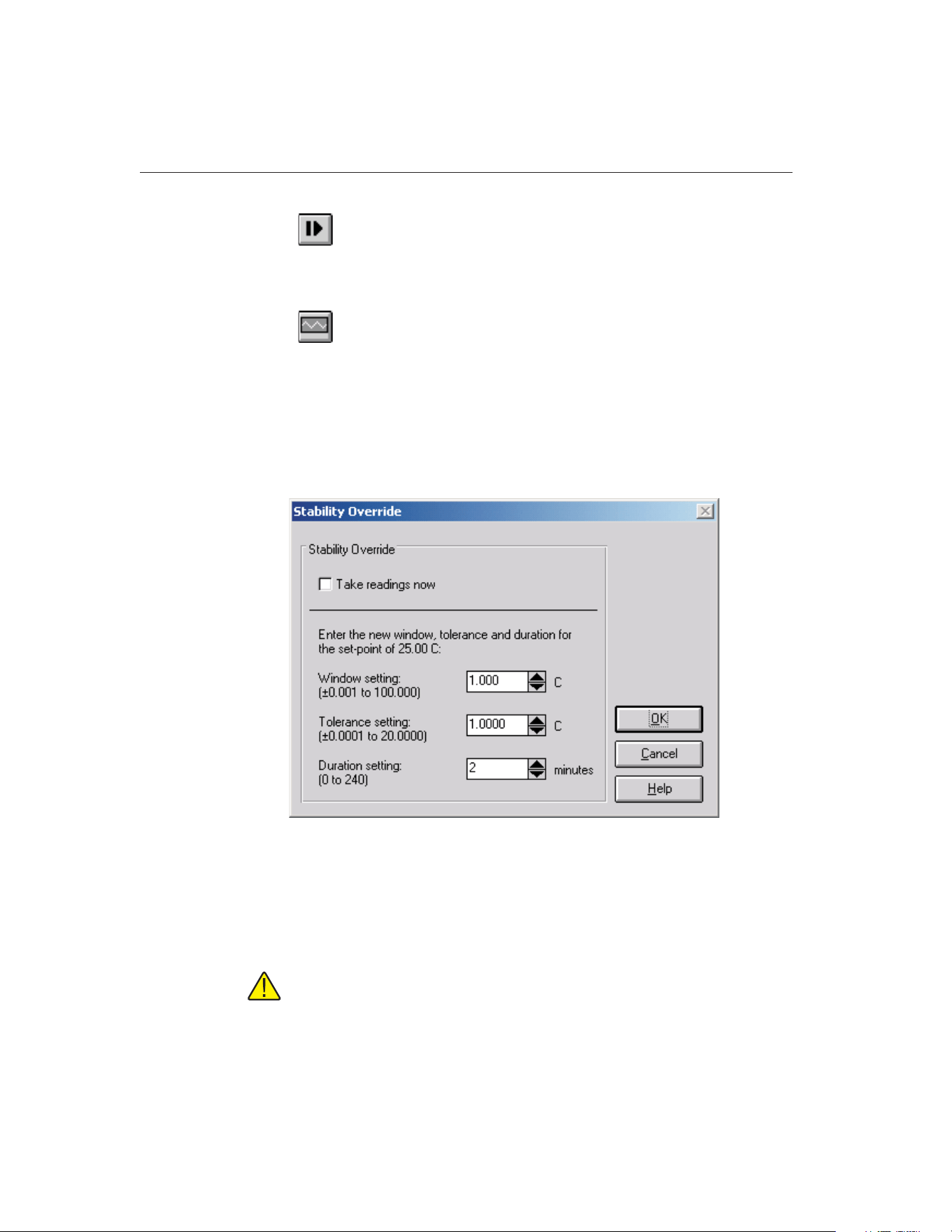
5.8
Resume Test
The Resume Test option resumes the test process after being paused. This op-
tion does not appear in the menu unless a test is currently paused.
5.9
Stability Override
The Stability Override option allows the parameters associated with the current
set-point to be changed or overridden. Selecting this option displays the Stabil-
ity Override dialog.
5.9.1 Stability Override Dialog
The Stability Override dialog displays the settings associated with the current
set-point. These parameters can be modified or overridden using this dialog.
To override the current set-point parameters, select the Take readings now op-
tion. When the OK button is clicked, the test process will automatically start
taking readings from the reference and test probes, regardless of whether the
heat source has reached and stabilized at the current set-point.
Note: MET/TEMP II can be configured to automatically override the
set-point parameters after a certain period of time on the Test tab of the
Defaults dialog.
9938 MET/TEMP II
User’s Guide
110
Figure 53 Stability Override Dialog
1.888.610.7664 sales@GlobalTestSupply.com
Fluke-Direct.com

When overriding set-point parameters, the current set-point is marked as over-
ridden. Set-points that have been overridden appear on the Report of Calibra-
tion with a special marker and a note indicating that the set-point parameters
were overridden for that set-point.
To change the window parameter for the current set-point, enter the new value
in the Window box. The window parameter is used to determine if a new
set-point needs to be calculated for the heat source. If MET/TEMP II gets stuck
in a loop recalculating the heat source set-point, this parameter can be changed
to widen the acceptable window. Typically, however, when MET/TEMP II gets
stuck in such a loop, the tolerance and duration parameters need to be changed.
To change the tolerance parameter for the current set-point, enter the new value
in the Tolerance box. The tolerance parameter is used with the duration param-
eter to determine when the heat source has stabilized at the current set-point.
Setting the tolerance parameter too large may cause MET/TEMP II to prema-
turely determine that the heat source has stabilized at the set-point and may
proceed to check the window parameter and calculate a new set-point for the
heat source. Setting the tolerance parameter too small may cause MET/TEMP
II to determine that the heat source will never stabilize and, therefore, never
proceed to taking measurements.
To change the duration parameter for the current set-point, enter the new value
in the Duration box. The duration parameter is used with the tolerance parame-
ter to determine when the heat source has stabilized at the current set-point.
Setting the duration parameter too short may cause MET/TEMP II to prema-
turely determine that the heat source has stabilized at the set-point and may
proceed to check the window parameter and calculate a new set-point for the
heat source. Setting the duration parameter too long may cause MET/TEMP II
to determine that the heat source will never stabilize and, therefore, never pro-
ceed to taking measurements.
Click the OK button to accept the new parameter settings, close the dialog and
return to performing the test. Clicking the Cancel button aborts changing the
parameter values and closes the dialog.
111
5
Calibration Menu
1.888.610.7664 sales@GlobalTestSupply.com
Fluke-Direct.com
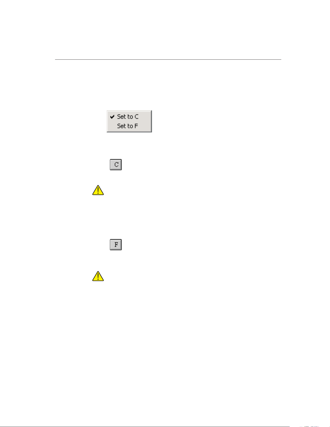
6 Scale Menu
The Scale menu provides options for changing the scale to use for the current
calibration test.
6.1
Set to C
Selecting the Set to C option converts the current test scale to degrees Celsius.
Note: Although this option can be selected after the instruments and
set-points have been configured, the scale should be selected before con-
figuring a test.
To change the scale that is selected by default when MET/TEMP II runs, see
the Setup tab on the Defaults dialog. Selecting this option does not change the
default scale.
6.2
Set to F
Selecting the Set to F option converts the current test scale to degrees
Fahrenheit.
Note: Although this option can be selected after the instruments and
set-points have been configured, the scale should be selected before con-
figuring a test.
To change the scale that is selected by default when MET/TEMP II runs, see
the Setup tab on the Defaults dialog. Selecting this option does not change the
default scale.
113
6
Scale Menu
Figure 54 Scale Menu
1.888.610.7664 sales@GlobalTestSupply.com
Fluke-Direct.com
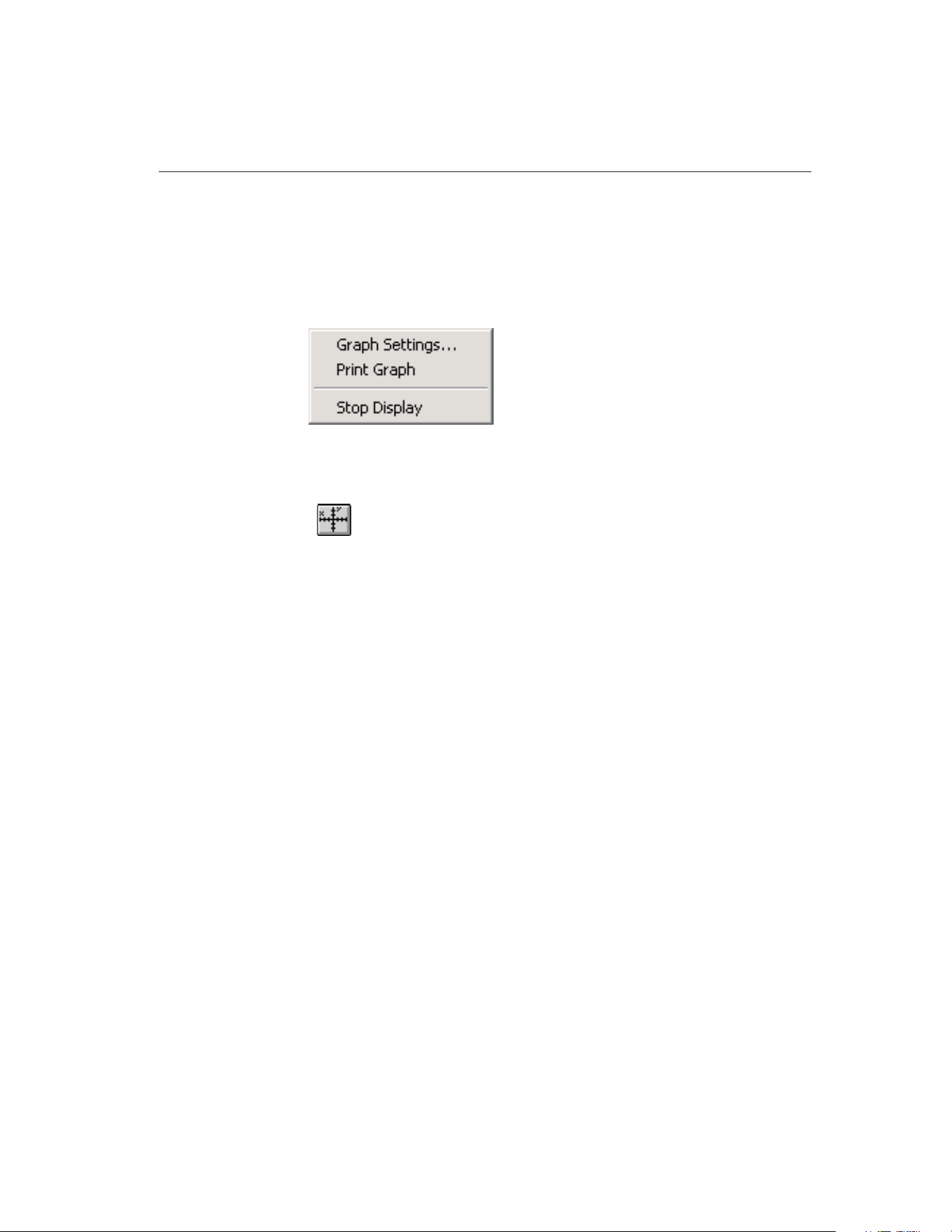
7 Graph Menu
The Graph menu provides options for changing the scale of the graph’s X-axis
and Y-axis, printing the graph, and for starting the display and graph of the ref-
erence probe.
7.1
Graph Settings
Selecting the Graph Settings option displays the Graph Settings dialog. This
option is only enabled when the graph is displayed.
7.1.1 Graph Settings Dialog
The Graph Settings dialog displays the current graph X-axis and Y-axis set-
115
7
Graph Menu
Figure 55 Graph Menu
1.888.610.7664 sales@GlobalTestSupply.com
Fluke-Direct.com
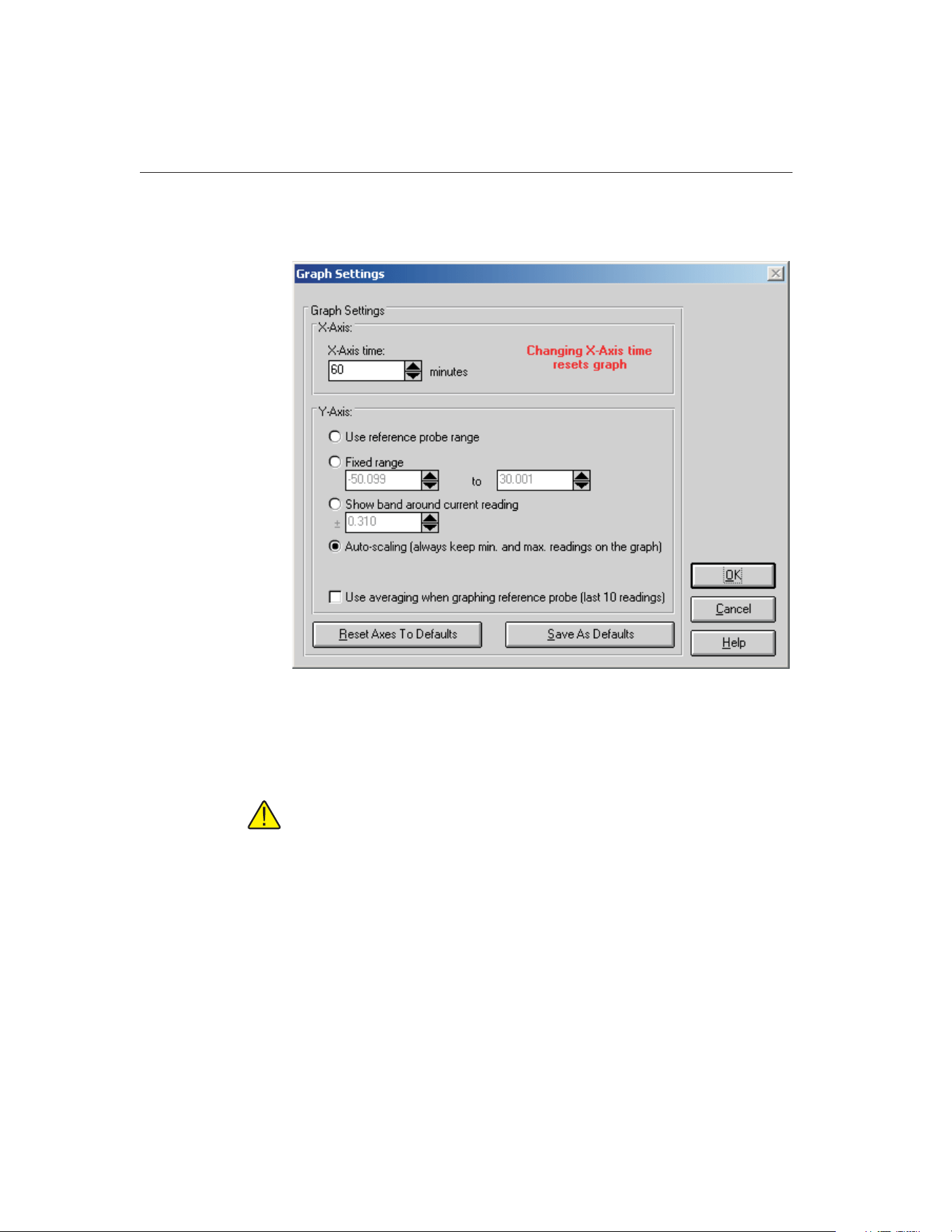
tings. These settings default to the graph settings configured on the Graph tab
on the Defaults dialog.
The X-axis of the graph is always displayed in time. The graph’s X-axis time
range can be changed using the X-axis time box. The graph can be set to show
from 1 minute to 480 minutes (8 hours) on the X-axis.
Note: Changing the X-axis time setting causes the graph to be cleared and
reset!
The Y-axis of the graph is always displayed in the current test temperature scale
(C or F). There are four options for setting the range of the Y-axis.
• Use reference probe range - Sets the Y-axis minimum and maximum
values to the minimum and maximum temperature values entered on the
Reference Probe Configuration dialog.
• Fixed range - Sets the Y-axis to the minimum and maximum values en-
tered by the user in the boxes provided. These boxes are enabled when
this option is selected.
9938 MET/TEMP II
User’s Guide
116
Figure 56 Graph Settings Dialog
1.888.610.7664 sales@GlobalTestSupply.com
Fluke-Direct.com

• Show band around current reading - Allows the user to enter a value of
a band to show around the most recent reference reading. This box is en-
abled when this option is selected.
• Auto-scaling (always keep min. and max. readings on the graph) -
Maintains the minimum and maximum values of the visible plot on the
graph during the time shown.
If the Use averaging when graphing reference probe (last 10 readings) check
box is selected, the last ten reference probe readings are averaged to produce
the current point on the graph. Averaging provides a smoother looking graph. If
not selected, each point read from the reference probe is graphed.
Clicking the Reset Axes To Defaults button resets the X-axis and Y-axis values
to their default values as defined on the Graph tab on the Defaults dialog.
Clicking the Save As Defaults button saves the current X-axis and Y-axis val-
ues as the default values.
Click the OK button to accept the new settings and close this dialog. Clicking
the Cancel button discards any changes and closes this dialog.
7.2 Print Graph
Selecting the Print Graph option sends the current graph to the default printer.
The Setup Printer dialog is displayed for selecting printer settings.
7.3
Start Display
Selecting the Start Display option begins displaying and graphing the reference
probe reading. The reference probe is displayed and graphed in degrees C or
degrees F only.
The Start Display option is only enabled after the COM port, reference readout,
reference module (if applicable) and reference probe are configured. The Start
Display option does not appear in the menu after the display has been started.
7.4
Stop Display
Selecting the Stop Display option causes the reference to stop being displayed
and graphed. The Stop Display option does not appear in the menu until the
display has been started.
117
7
Graph Menu
1.888.610.7664 sales@GlobalTestSupply.com
Fluke-Direct.com
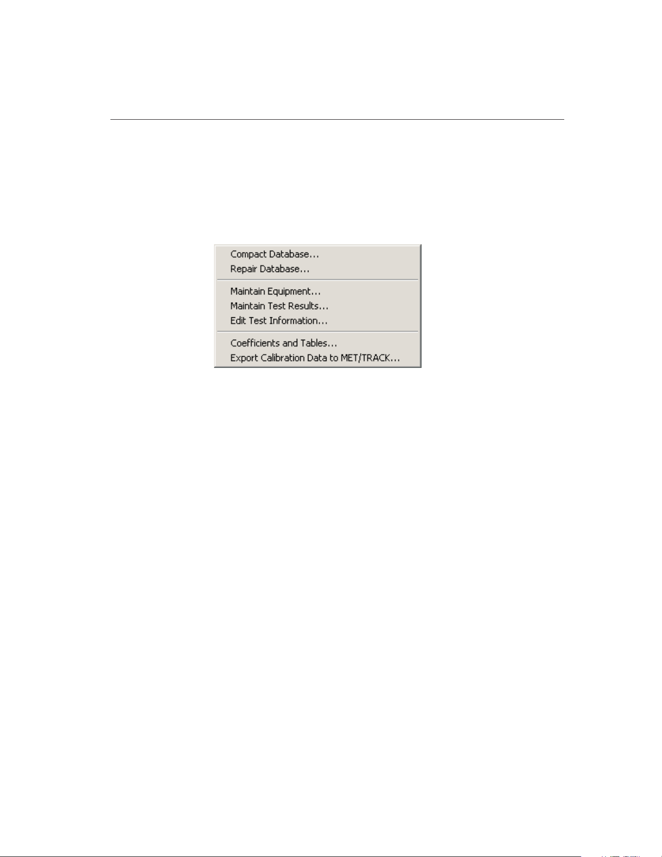
8 Utilities Menu
The Utilities menu allows the user to compact and repair the MET/TEMP II da-
tabases, to maintain the tables used for storing the test equipment and test re-
sults, to run the Coefficients and Tables application, and to export test data to
Fluke’s MET/TRACK software.
8.1 Compact Database
Selecting the Compact Database option allows any deleted records in the
MET/TEMP II databases to be purged from the database. Using this option
from time to time can typically reduce the size of the database and make ac-
cessing the database faster.
Selecting the Compact Database option displays the Windows® Open dialog.
Select the database file to compact and click the OK button. Clicking the Can-
cel button aborts compacting a database.
When MET/TEMP II compacts a database, a copy of the database is made and
given a .BAK extension. If a .BAK file with the same name already exists, it is
deleted and replaced by the new .BAK file.
8.2 Repair Database
Selecting the Repair Database option allows a corrupted MET/TEMP II data-
base to be repaired. A database can become corrupted if there is a power failure
or if the software terminates abnormally or crashes. Typically, if a database is
corrupt, MET/TEMP II will display a warning message. Use this option to re-
pair the corrupt database. After the database is repaired, the database is then
compacted following the same process outlined in the previous section.
119
8
Utilities Menu
Figure 57 Utilities Menu
1.888.610.7664 sales@GlobalTestSupply.com
Fluke-Direct.com
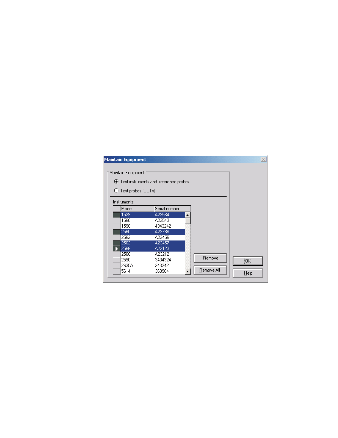
8.3 Maintain Equipment
Selecting the Maintain Equipment option displays the Maintain Equipment dia-
log. This option can be used to remove unused test equipment, reference probe
and test probe information from the database.
8.3.1 Maintain Test Equipment Dialog
The Maintain Test Equipment dialog can be used to remove unused test equip-
ment, reference probe and test probe information from the database. Removing
an item from the database prevents that item from appearing in drop-down lists
when configuring a test.
Select the Test equipment and reference probes option to view a list of the ref-
erence readout, reference module, reference probe, scanner, scanner module
and heat source instruments that have been used by MET/TEMP II. Select the
Test probes (UUTs) option to view a list of the test probes that have been cali-
brated by MET/TEMP II.
To remove one or more instruments from the MET/TEMP II database, select
the item or items in the Instruments or Test probes list and click the Remove
button. A prompt is displayed to confirm removing the selected items. Confirm
removing the selected items by clicking Yes or click No to abort.
9938 MET/TEMP II
User’s Guide
120
Figure 58 Maintain Equipment Dialog
1.888.610.7664 sales@GlobalTestSupply.com
Fluke-Direct.com
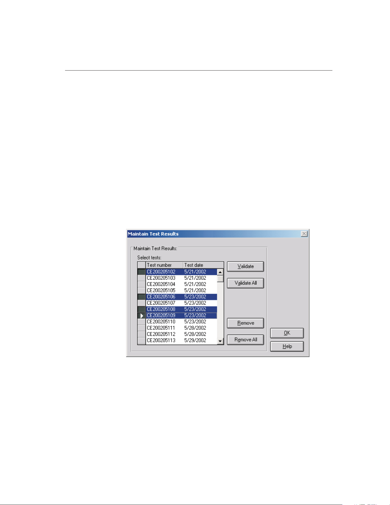
Note: Once an instrument or probe is removed, that instrument or probe will no
longer appear in the appropriate drop-down list(s). To use that instrument or
probe again, the information for that instrument or probe must be entered man-
ually again.
To remove all instruments or probes listed, click the Remove All button.
Click the OK button to close this dialog.
8.4 Maintain Test Results
Selecting the Maintain Test Results option displays the Maintain Test Results
dialog. This option can be used to validate tests and remove unnecessary test
data from the database.
8.4.1 Maintain Test Results Dialog
The Maintain Test Results dialog can be used to validate tests and remove un-
necessary test data from the database. Removing test data from the database is
permanent and cannot be undone.
This dialog allows the user to determine the validity of tests and to remove test
data from the database. To validate or remove a test from the database, select
the tests from the Select tests list and click the Validate or Remove button. To
validate or remove all tests, click the Validate All or Remove All button respec-
tively. Test validation is explained below.
121
8
Utilities Menu
Figure 59 Maintain Test Results Dialog
1.888.610.7664 sales@GlobalTestSupply.com
Fluke-Direct.com

Important: Use caution when removing tests. Once a test has been re-
moved it no longer exists! All data is deleted permanently. For this reason
the user is asked to confirm the removing of tests from the database!
MET/TEMP II stores test data in separate tables within the database. If a test is
stopped before any readings are taken, the table containing the readings has no
records for that test. If the database becomes corrupt, some of the data for a
particular test may be lost. These are a couple of the reasons why the user may
need to validate the test.
The validation feature of MET/TEMP II can be used to determine if there are
records for every test in every table.
Clicking the Validate or Validate All buttons performs a check on the selected
tests to see if there are records in each of the database tables for the test. If
MET/TEMP II determines that a test is invalid, the Invalid Test dialog is dis-
played. Otherwise, a message appears stating the validity of the tests.
Note: This feature does not determine the validity of readings taken by
MET/TEMP II. It determines only if a test valid based on the presence or
absence of information for the test in the database.
8.4.1.1 Invalid Test Dialog
The Invalid Test dialog displays information about the test that is being vali-
dated. The Test is invalid for the following reasons list shows the reasons why
the test is considered to be invalid. If no readings were found for one or more
9938 MET/TEMP II
User’s Guide
122
1.888.610.7664 sales@GlobalTestSupply.com
Fluke-Direct.com
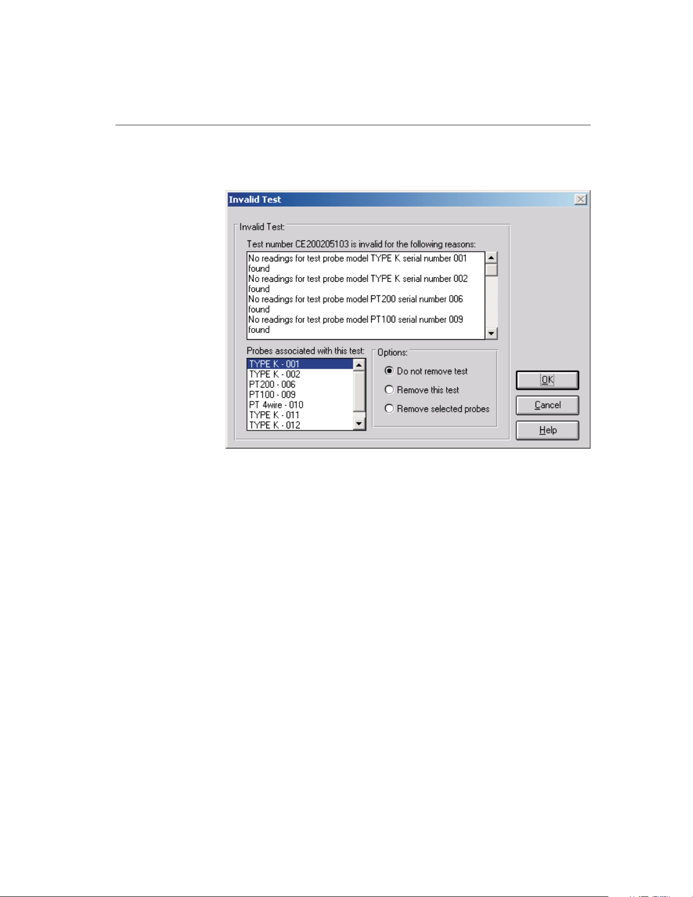
test probes, the Probes associated with this test list shows all test probes
(UUTs) associated with the test.
Based on the information provided, the user must decide what to do with the
test. The options available to the user are to not remove the test, remove the
test, or remove selected probes. Selecting the Do not remove test option leaves
the test as is. Selecting the Remove this test option permanently removes the
entire test from the database. Selecting the Remove selected probes option al-
lows the user to remove information specific to one or more test probes from a
test while leaving the other test probes and the test itself intact. To use this op-
tion, select the test probe(s) that should be removed from the list on the lower
left.
Clicking the OK button performs the selected option and continues on to the
next test or returns to the Maintain Test Results dialog. Clicking the Cancel but-
ton closes this dialog and ignores the selected option.
8.5 Edit Test Information
Selecting the Edit Test Information option displays the Edit Test Information
dialog. This dialog allows some information for tests that have already been
performed to be edited including the technician name, ambient conditions, cali-
bration range setting, the paragraph and test notes, test procedure, company
name and address, manufacturer and description information, order ID, re-
ceived condition, check standard setting, MET/TRACK asset number, uncer-
123
8
Utilities Menu
Figure 60 Invalid Test Dialog
1.888.610.7664 sales@GlobalTestSupply.com
Fluke-Direct.com
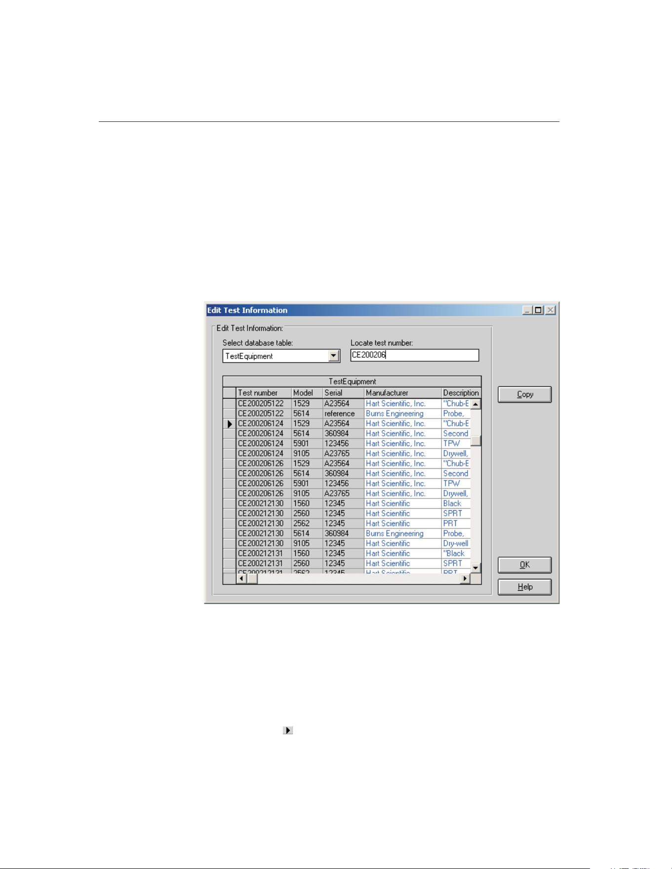
tainty, method of realization setting, and heat source calibration coefficient
labels.
8.5.1 Edit Test Information Dialog
The Edit Test Information dialog allows some information for tests that have al-
ready been performed to be edited including the technician name, ambient con-
ditions, calibration range setting, the paragraph and test notes, test procedure,
company name and address, manufacturer and description information, order
ID, received condition, check standard setting, MET/TRACK asset number, un-
certainty, method of realization setting, and heat source calibration coefficient
labels.
Select the database table that contains the information that needs to be edited
using the Select database table drop-down list. Once a table is selected, the grid
below displays the information stored in the table. The information is sorted by
test number.
To rapidly locate a specific test number, enter the test number into the Locate
test number box. The record is searched for as you type. The current record is
9938 MET/TEMP II
User’s Guide
124
Figure 61 Edit Test Information Dialog
1.888.610.7664 sales@GlobalTestSupply.com
Fluke-Direct.com
indicated by the indicator in the far left column of the grid. If no match is
found, the first record in the table is the current record.
Columns that appear in black text with a light gray background cannot be ed-
ited. Columns that appear in blue text with a white background can be edited.
All columns can be resized as needed. However, when switching between ta-
bles, the default column widths are restored.
To change the information in a certain field, position the cursor on the field to
edit and type in the new value. Copying and pasting are also enabled to facili-
tate entering a large amount of data into a field such as the paragraph or test
notes fields.
Some fields, such as the company address, paragraph and test notes, allow the
<Enter> key to be used to create multi-line entries.
When entering new values in certain fields, a message may appear stating that
the entered data is invalid for the current field. For example, this message will
be displayed if you attempt to enter a number into a field that expects a True or
False value. Correct the new value to continue.
Some fields allow NULL values (empty field) while others require some value.
A message is displayed if you attempt to leave a field empty that requires some
value.
Important: Once the value in a field has been changed or deleted it is per-
manently gone! Be very careful to not change any values accidentally
Click the OK button to close the Edit Test Information dialog.
8.6 Coefficients and Tables
The Coefficients and Tables option is used to run the Coefficients and Tables
application (formerly Generate-it) for calculating coefficients and for generat-
ing Temperature vs. Resistance, Temperature vs. Ratio, or Temperature vs.
EMF tables on the test readings taken from a calibration test.
8.7
Export Calibration Data to MET/TRACK
Selecting the Export Calibration Data to MET/TRACK option displays the Ex-
port Calibration Data to MET/TRACK dialog and allows test data to be ex-
ported to Fluke’s MET/TRACK software database. This option is only enabled
if the link to the MET/TRACK database has been configured on the General tab
of the Defaults dialog.
8.7.1 Export Calibration Data to MET/TRACK Dialog
125
8
Utilities Menu
1.888.610.7664 sales@GlobalTestSupply.com
Fluke-Direct.com
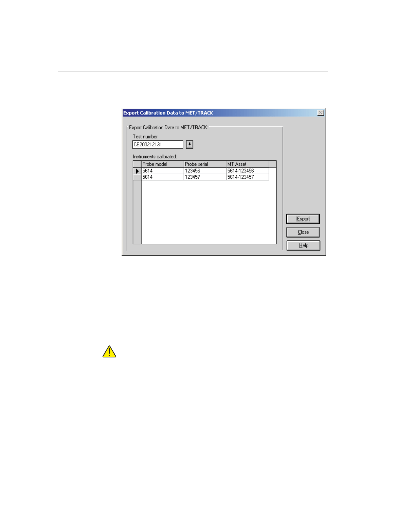
The Export Calibration Data to MET/TRACK dialog allows test data to be ex-
ported to the MET/TRACK database.
To export calibration data, select the test containing the data to export using the
Test number drop-down list. The Instruments calibrated list displays the model,
serial number and MET/TRACK asset number for each test probe or heat
source that was calibrated for the selected test. If no MET/TRACK asset num-
ber has been assigned to an instrument, the MT Asset column indicates <not as-
signed>. This will be the case for all instruments that were calibrated using
prior versions of MET/TEMP II (Calibrate-it) as well as for all tests that were
performed when the link to the MET/TRACK database was not active.
Important: If you want characterization coefficients to be exported along
with the calibration data, you must calculate the coefficients using the Co-
efficients and Tables utility prior to exporting the calibration data!
To begin the export process, click the Export button. Calibration data for all
UUTs are exported to the MET/TRACK database. Refer to Section 14,
MET/TRACK Export Process, for more information on the export process.
After exporting the calibration data, click the Close button to close this dialog.
9938 MET/TEMP II
User’s Guide
126
Figure 62 Export Calibration Data to MET/TRACK Dialog
1.888.610.7664 sales@GlobalTestSupply.com
Fluke-Direct.com
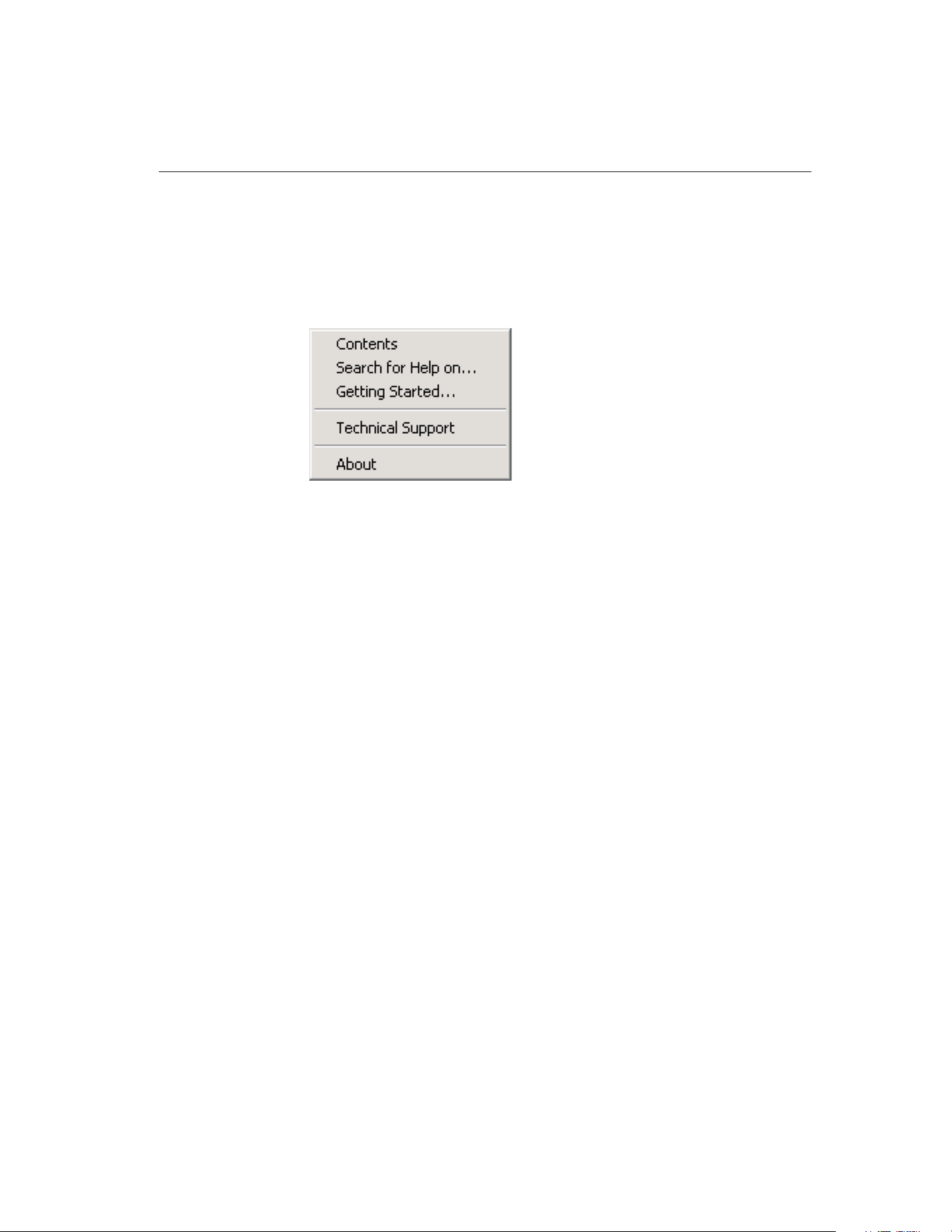
9 Help Menu
The Help menu provides access to the MET/TEMP II help file. The Technical
Support contact information and About MET/TEMP II dialog are also available
from the Help menu.
9.1 Contents
Selecting the Contents option opens the MET/TEMP II help file and displays
the contents topic.
9.2 Search for Help On
Selecting the Search for Help on option opens the MET/TEMP II help file with
the Windows® Search dialog open. Select or enter a keyword to search for a
topic or click Cancel to go to the help file.
9.3 Getting Started
Selecting the Getting Started option opens the MET/TEMP II Help file to the
Getting Started topic.
9.4 Technical Support
Selecting the Technical Support option displays the Technical Support help
topic. For technical support information, please refer to Section 18.1, Technical
Support.
127
9
Help Menu
Figure 63 Help Menu
1.888.610.7664 sales@GlobalTestSupply.com
Fluke-Direct.com

9.5 About MET/TEMP II
Selecting the About option displays the About MET/TEMP II dialog. This dia-
log states the software version number, copyright and other information.
9938 MET/TEMP II
User’s Guide
128
Figure 64 About MET/TEMP II Dialog
1.888.610.7664 sales@GlobalTestSupply.com
Fluke-Direct.com
10 Configuration Files
MET/TEMP II supports writing current configuration information to configura-
tion files to make the test instrument, set-point and test probe configuration
process much easier. Instrument, set-point and test probe configuration files can
be saved independent of each other to provide maximum flexibility. Each of the
sections below describes the configuration files supported by MET/TEMP II.
10.1 Instrument Configuration File
An instrument configuration file contains information concerning the commu-
nications settings, reference readout, scanner, and heat source instruments in-
cluding model numbers, serial numbers, and other information required by the
software. The default extension for an instrument configuration file is .CFG.
These files are usually saved in the \CONFIG subfolder.
Instrument configuration files can be opened by selecting the Open option in
the File menu or by clicking the Open button on the Equipment Info dialog.
Important: Opening an instrument configuration file completely replaces
the current instrument configuration information.
When an instrument configuration file is opened, MET/TEMP II attempts to re-
trieve the driver and calibration information for each instrument. If any con-
flicts or errors are detected while opening an instrument configuration file,
messages are displayed providing some information as to the problems found.
The user must follow the instructions given by the messages to correct the
problems before a test can begin.
Instrument configuration files can be saved at any point during the configura-
tion process by selecting the Save As option in the File menu or by clicking the
Save As button on the Equipment Info dialog. The user is prompted to enter a
filename for the configuration file. All instrument configuration files should be
saved in the \CONFIG subfolder with a .CFG extension
The default instrument configuration file, 9938LAST.CFG, is automatically
saved every time a test starts and when the software terminates regardless of
whether or not the user explicitly saves the configuration.
Important: The format of the instrument configuration file has changed
slightly in this version of MET/TEMP II from previous versions (formerly
Calibrate-it) due to enhancements and newly supported instruments. For
this reason, MET/TEMP II may not be able to successfully read in instru-
ment configuration files from previous versions. Therefore, any instrument
configuration file from a previous version of this software should be saved
in this version using the same filename.
129
10
Configuration Files
1.888.610.7664 sales@GlobalTestSupply.com
Fluke-Direct.com

10.2 Set-point Configuration File
A set-point configuration file contains a set of set-points that can be used for a
test. The default extension for a set-point configuration file is either .STC or
.STF. Set-point configuration files with a .STC extension are for set-points in C
and .STF files are for set-points in F. These files are usually saved in the
\CONFIG subfolder.
When calibrating a heat source, a set-point configuration file MUST be opened.
When MET/TEMP II was installed, the default heat source calibration set-point
configuration files were written to the \CALFILES subfolder in the \CONFIG
subfolder.
Set-point configuration files can be opened by clicking the Open button on the
Set-point Configuration dialog.
Important: Opening a set-point configuration file completely replaces the
current set-point configuration.
Set-point configuration files contain the set-point values, window, tolerance,
duration, uncertainty, fixed-point cell and proportional band information as ap-
plicable for each set-point. Information regarding the heat source assignment is
not saved in this file. If the configuration file being opened is not of the same
temperature scale as the heat sources, a message is displayed. Click Yes to con-
vert the heat sources to the same scale as the set-points or click No to abort
opening the set-point configuration file.
When a set-point configuration file is opened, MET/TEMP II automatically at-
tempts to assign each set-point to a heat source if the Prompt for heat source
conflicts check box on the Set-points tab of the Defaults dialog is selected. If a
set-point does not fall within the temperature range of any of the configured
heat sources, a message is displayed and the set-point is excluded from the test.
If the Prompt for heat source conflicts check box is not selected, set-points are
not automatically assigned to heat sources. Each set-point must be assigned to a
heat source manually using the Set-point Configuration dialog.
Important: A test cannot begin until all set-points have been assigned to a
heat source.
If more than one heat source can be used for that set-point, the Set-point Op-
tions dialog is displayed. The user is asked to choose the heat source to use
and/or the proportional band setting. Refer to Section 10.2.1, Set-point Options
Dialog, for more information on using this dialog.
Set-point configuration files can be saved by clicking the Save As button on the
Set-point Configuration dialog. The user is prompted to enter a filename for the
configuration file.
9938 MET/TEMP II
User’s Guide
130
1.888.610.7664 sales@GlobalTestSupply.com
Fluke-Direct.com
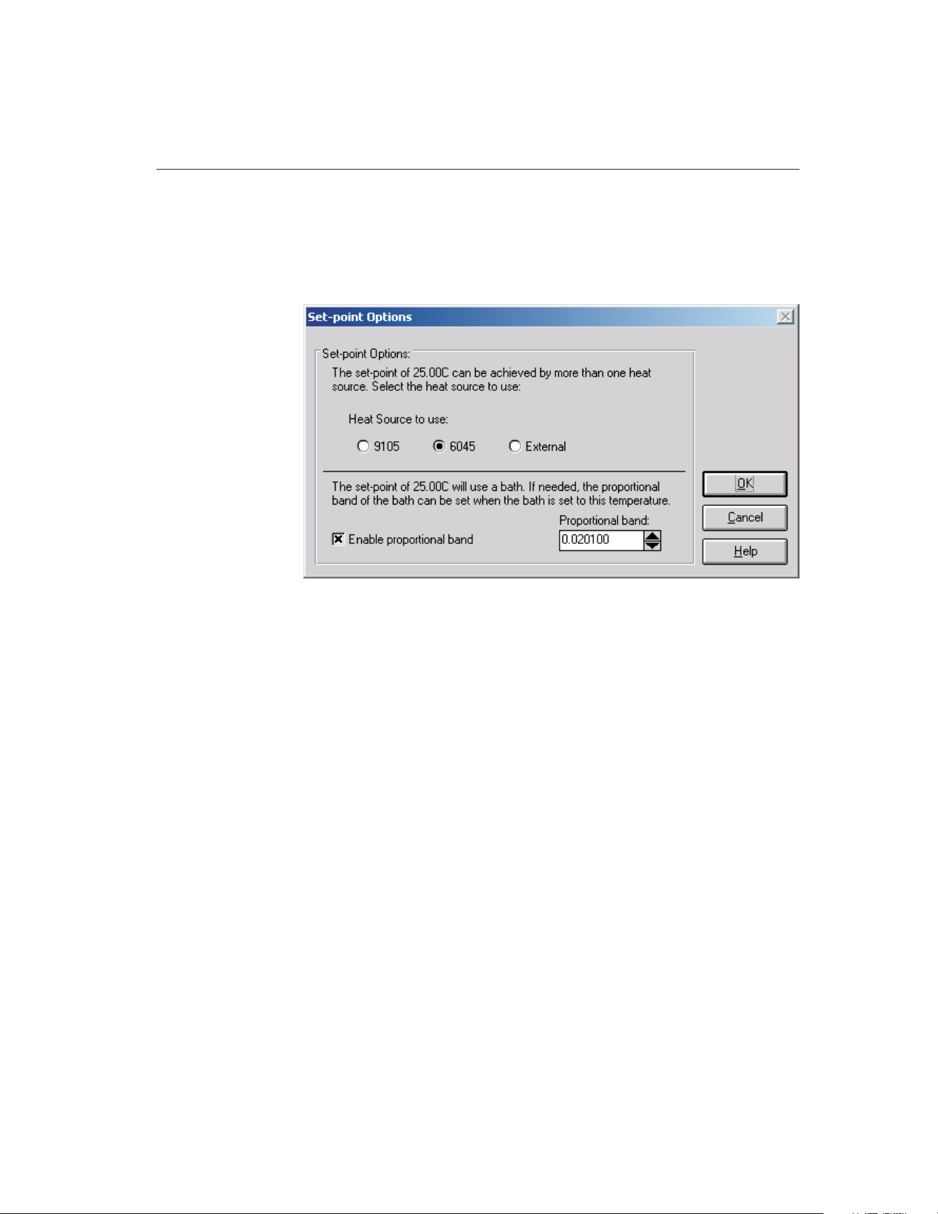
10.2.1 Set-point Options Dialog
The Set-point Options dialog is used when auto-generating set-points or when
opening a set-point configuration file to resolve heat source conflicts when
more than one heat source can be used for a set-point.
This dialog displays the heat sources that can be used for the indicated
set-point. Select which heat source the indicated set-point should use by click-
ing the appropriate option button. Selecting a heat source other than a bath will
cause this dialog to immediately close. This is done to speed up the process of
selecting heat sources to use. If the selected heat source is a bath, the propor-
tional band information is displayed and the user is allowed to setup the pro-
portional band settings at this time. In this case, the OK button must be clicked
to accept the settings and continue.
The Enable proportional band check box is visible only when the indicated
set-point is assigned to a bath. If this check box is selected, a proportional band
value is expected to be entered. The proportional band value is sent to the bath
during the test process when the bath is set to the indicated set-point.
Click the OK button to accept the current settings and close this dialog. Click-
ing the Cancel button leaves the indicated set-point unassigned.
10.3 Test Probe Configuration File
A test probe configuration file contains information concerning the set of test
probes to be calibrated including scanner channel information, probe model
numbers, serial numbers and customer information. The default extension for a
131
10
Configuration Files
Figure 65 Set-point Options Dialog
1.888.610.7664 sales@GlobalTestSupply.com
Fluke-Direct.com

test probe configuration file is .TPC. These files are usually saved in the
\CONFIG subfolder.
Test probe configuration files can be opened by clicking the Open button on the
Test Probe Configuration dialog.
Important: Opening a test probe configuration file completely replaces
the current test probe configuration.
Test probe configuration files are partially dependent on the scanner instrument
configuration. Because some scanner information is saved in the test probe con-
figuration file for compatibility reasons, attempting to open a test probe config-
uration file will most likely fail when the currently configured scanner differs
from the information in the configuration file. Warning and/or error messages
may appear in this situation. When MET/TEMP II opens a test probe configu-
ration file, it attempts to retrieve scale, current/CJC, customer name, and cus-
tomer address information for each probe. If any conflicts or errors are detected
while opening an instrument configuration file, messages are displayed provid-
ing some information as to the problems found.
The user must enter the order ID number for each test probe when a configura-
tion file is opened. If the Prompt for order ID when opening Test Probe Config-
uration file check box on the Setup tab of the Defaults dialog is selected, the
Enter Order ID dialog appears. If the Prompt for Order ID when opening Test
Probe Configuration file check box is not selected, the user must manually en-
ter this information on the Customer Information dialog by clicking the Other
Info button on the Test Probe Configuration dialog. Refer to Section 10.3.1,
Enter Order ID Dialog, for more information on using this dialog.
Test probe configuration files can be saved by clicking the Save As button on
the Test Probe Configuration dialog. The user is prompted to enter a filename
for the configuration file.
9938 MET/TEMP II
User’s Guide
132
1.888.610.7664 sales@GlobalTestSupply.com
Fluke-Direct.com
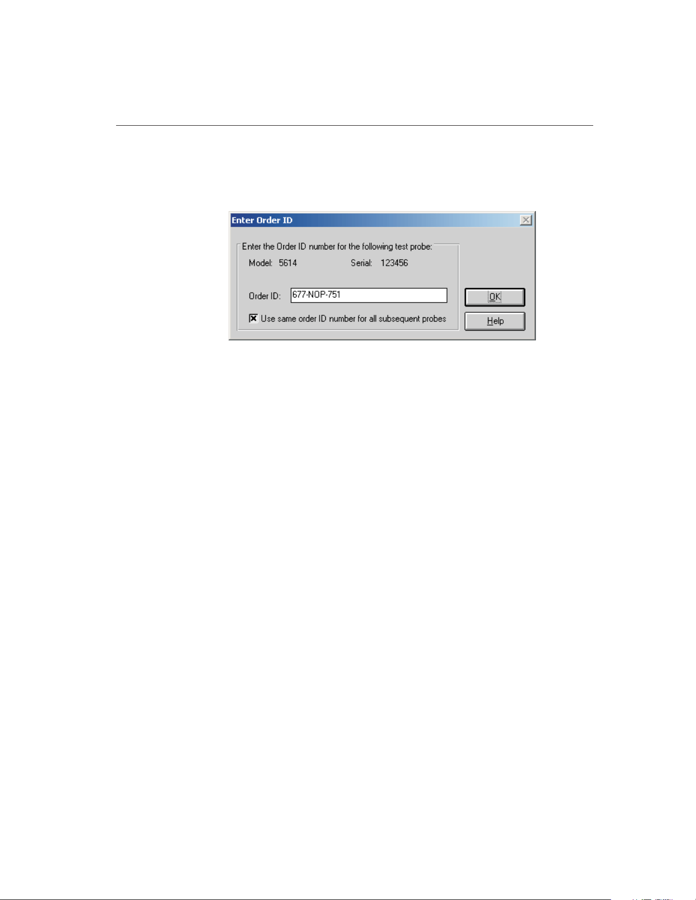
10.3.1 Enter Order ID Dialog
The Enter Order ID dialog is used when opening a test probe configuration file
to associate an order ID number with each test probe.
This dialog displays the model and serial numbers of the test probe and allows
the order ID number to be entered. This number can be a purchase order, work
order, sales order or any other such number.
This dialog is only displayed if the Prompt for order ID when opening Test
Probe Configuration file option on the Setup tab on the Defaults dialog is se-
lected. If this option is not selected, no order ID number is associated with the
test probes. The order ID number for each test probe must be manually entered
on the Customer Information dialog. Refer to Section 5.4.1.1, Customer Infor-
mation Dialog, for more information.
Selecting the Use same order ID number for all subsequent probes option
causes the same order ID number to be associated with the remainder of the test
probes. This dialog will not be displayed again. If not selected, this dialog will
be displayed once for every test probe to allow a different number to be
entered.
After entering the order ID number, click the OK button to accept it and close
this dialog.
133
10
Configuration Files
Figure 66 Enter Order ID Dialog
1.888.610.7664 sales@GlobalTestSupply.com
Fluke-Direct.com

11 Reports of Calibration
This section describes in detail the default Report of Calibration that is built
into MET/TEMP II and the custom Reports of Calibration that ship with
MET/TEMP II.
Custom report template files are installed in the \REPORTS subfolder of the
C:\METTEMP2 folder (or the folder where MET/TEMP II was installed).
11.1 Default Report of Calibration
The default Report of Calibration in MET/TEMP II was designed to meet the
ANSI/NCSL Z540-1 specification (refer to Figure 67 on page 137).
The default Report of Calibration contains: the report number, the test probe in-
formation, calibration range, received condition, excitation current used (if ap-
plicable), test procedure, customer name and address, calibration test paragraph
and notes, the actual data collected, a list of the test equipment, calibration
date, recall date, ambient temperature and humidity, customer order ID, techni-
cian name, and a place for technician and approval signatures. The actual data
collected consists of the nominal values (set-points), actual values (reference
readings), UUT values (test probe readings), error (if applicable), uncertainty,
CJC readings (if applicable), and method of realization.
The fonts, sizes, and styles used on the default Report of Calibration can be
changed on the Fonts & Sizes tab of the Defaults dialog.
The top, bottom, left, and right margins and the column widths for the Test
Equipment table on the Report of Calibration can be set using the appropriate
controls on the Reports tab of the MET/TEMP II Defaults dialog. A custom
logo can also be added to the upper left corner of the Report of Calibration us-
ing the settings on this tab.
Reports of Calibration can be saved to a report file from the Print Preview win-
dow and opened, viewed and printed by selecting the Recall Saved Report op-
tion from the File menu or by running the Report Viewer utility. Refer to
Section 17, Report Viewer Utility, for more details.
The report number is printed on each page of the Report of Calibration. The re-
port number is a unique number consisting of the test number and the scanner
channel to which the test probe was connected. These two pieces of informa-
tion are concatenated together with a dash.
The test probe information consists of the test probe model number, serial num-
ber and description. This information is printed at the top of the first page along
with the calibration range, received condition, excitation current used, and test
procedure number.
The paragraph text is the text entered as the paragraph on the Test Information
dialog. The default paragraph to use can be defined on the Report tab on the
Defaults dialog.
135
11
Reports of Calibration
1.888.610.7664 sales@GlobalTestSupply.com
Fluke-Direct.com

The raw data section contains the readings taken by the software. If the Stabil-
ity Override menu option was used on any set-point during the test, the
set-point will be marked and a footnote will appear at the bottom of the raw
data section stating that the stability parameters were overridden for the
set-points indicated. The raw data section may be different depending on the
type of test probe being calibrated, the units of the readings taken, and the in-
struments used to take the readings.
• The Nominal Value, Actual Value, UUT, and Measurement Uncertainty
columns always print.
• The Error column prints only if the units for the Actual Value and UUT
columns are in temperature and are the same scale.
• The CJC column prints only if the test probe is a thermocouple type probe
and CJC readings were taken.
• The Method of Realization column prints only if the test was performed
using MET/TEMP II v4.0 or later.
The Test Equipment section lists each of the instruments that were used to per-
form the calibration. Each instrument’s manufacturer, model, description, serial
number and recall date is indicated. For instruments that do not require calibra-
tion, NCR is printed in the Recall Date column.
The notes text is the text entered as the notes on the Test Information dialog.
The calibration date is the date the test started. This date is entered on the Test
Information dialog.
The recall date is the date the test probe or test equipment is due for
recalibration. For the test probe, this date is calculated by adding the calibration
interval entered on the Test Probe Configuration dialog to the calibration date.
For the test equipment, the user enters this date on the configuration dialogs.
Recall date is synonymous with recalibration date.
Note: If the calibration interval is set to 0 on the Test Probe Configuration
dialog, the recall date is omitted from the Report of Calibration for that
test probe.
The technician is the name of the person who performed the test. This informa-
tion is entered on the Test Information dialog.
Examples of default Reports of Calibration can be seen in Figures 67 and 68,
on pages 137 and 138.
9938 MET/TEMP II
User’s Guide
136
1.888.610.7664 sales@GlobalTestSupply.com
Fluke-Direct.com

137
11
Reports of Calibration
Report of Cal
i
brat
i
on
Report No: CE200206126-002
Page1of1
Temp Tech Co.
105 Celcius Drive
Out Town, USA
34567-8998
Model: 5614
Serial: 365232
Description: Probe, Secondary Standard
Calibration Range: Full
Received Condition: New
Current: 1.0 mA
Procedure: HST000 - 0
Customer: Our Customer
One Customer Way
Technology Drive
Any Town, USA 23456
Calibration Date: 6/3/2002
Recall Date: 6/3/2003
Temperature: 21 C
Humidity: 25%
Customer Order: 54543-544S
Technician: ________________________
Cal E. Breight
Approved By: ________________________
The above referenced instrument was calibrated by direct measurement of generated temperatures using the reference standards
listed in the "Test Equipment" table at the bottom of this report. The internal calibration coefficients and the data abtained are shown
on page 2. A Test Uncertainty Ratio (TUR) of at least 4:1 was maintained unless otherwise indicated. This calibration is traceable to
NIST or natural physical constants and is in compliance with ANSI/NCSL Z540-1 and MIL-STD 45662A.
Nominal
(Set-point)
(C)
Actual Value
(Reference)
(C)
UUT
(Test Sensor)
(Ohms)
Measurement
Uncertainty
(C)
Method of
Realization
-25.00 -24.9697 89.2564 0.050 COMP
0.01 0.0100 100.0235 0.010 TP
25.00 25.0155 110.2354 0.050 COMP
50.00 49.9895 123.5642 0.050 COMP
75.00 75.0045 132.2514 0.050 COMP
100.00 99.9692 138.2563 0.050 COMP
125.00 124.9835 145.0251 0.050 COMP
Test Equipment
Manufacturer Model Description Serial Number Recall Date
Hart Scientific, Inc. 1529 "Chub-E4" Thermometer 2-RTD/2-TC A23564 6/30/2002
Hart Scientific, Inc. 5614 Secondary Reference Temperature Std., 1/4"
x 12"
360984 1/17/2003
Hart Scientific, Inc. 5901 TPW 123456 2/1/2003
Hart Scientific, Inc. 9105 Drywell, Low-Temperature A23765 NCR
Notes: This test was performed in accordance with the test procedure indicated above.
This report shall not be reproduced except in
f
ull without written approval o
f
Temp Tech Co..
Figure 67 Example Default Report of Calibration - Temperature vs. Resistance Data
1.888.610.7664 sales@GlobalTestSupply.com
Fluke-Direct.com

9938 MET/TEMP II
User’s Guide
138
Report of Cal
i
brat
i
on
Report No: CE200206126-001
Page1of1
Temp Tech Co.
105 Celcius Drive
Out Town, USA
34567-8998
Model: 5614
Serial: 367543
Description: Probe, Secondary Standard
Calibration Range: Full
Received Condition: New
Current: 1.0 mA
Procedure: HST000 - 0
Customer: Our Customer
One Customer Way
Technology Drive
Any Town, USA 23456
Calibration Date: 6/3/2002
Recall Date: 6/3/2003
Temperature: 21 C
Humidity: 25%
Customer Order: 54543-544S
Technician: ________________________
Cal E. Breight
Approved By: ________________________
The above referenced instrument was calibrated by direct measurement of generated temperatures using the reference standards
listed in the "Test Equipment" table at the bottom of this report. The internal calibration coefficients and the data abtained are shown
on page 2. A Test Uncertainty Ratio (TUR) of at least 4:1 was maintained unless otherwise indicated. This calibration is traceable to
NIST or natural physical constants and is in compliance with ANSI/NCSL Z540-1 and MIL-STD 45662A.
Nominal
(Set-point)
(C)
Actual Value
(Reference)
(C)
UUT
(Test Sensor)
(C)
Error
(C)
Measurement
Uncertainty
(C)
Method of
Realization
-25.00 -24.9713 -25.0231 -0.0518 0.050 COMP
0.01 0.0100 0.0102 0.0002 0.010 TP
25.00 25.0119 25.0231 0.0112 0.050 COMP
50.00 49.9907 50.0212 0.0305 0.050 COMP
75.00 75.0049 75.0021 -0.0028 0.050 COMP
100.00 99.9709 99.9985 0.0276 0.050 COMP
125.00 124.9844 125.0321 0.0477 0.050 COMP
Test Equipment
Manufacturer Model Description Serial Number Recall Date
Hart Scientific, Inc. 1529 "Chub-E4" Thermometer 2-RTD/2-TC A23564 6/30/2002
Hart Scientific, Inc. 5614 Secondary Reference Temperature Std., 1/4"
x 12"
360984 1/17/2003
Hart Scientific, Inc. 5901 TPW 123456 2/1/2003
Hart Scientific, Inc. 9105 Drywell, Low-Temperature A23765 NCR
Notes: This test was performed in accordance with the test procedure indicated above.
This report shall not be reproduced except in
f
ull without written approval o
f
Temp Tech Co..
Figure 68 Example Default Report of Calibration - Temperature vs. Temperature Data
1.888.610.7664 sales@GlobalTestSupply.com
Fluke-Direct.com
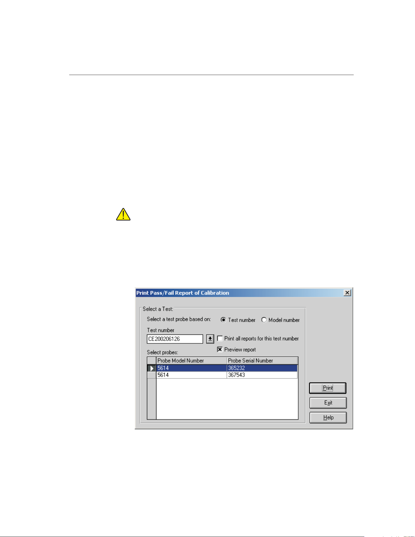
11.2 Custom Reports of Calibration
MET/TEMP II supports using custom reports of calibration. If the default re-
port template isn’t exactly the type of report required for your application, con-
tact Hart sales representatives for information on obtaining custom report
templates designed to your specifications.
MET/TEMP II ships with two custom reports of calibration. These reports are
described in the following sections.
11.2.1 Pass/Fail Report of Calibration
MET/TEMP II comes with a custom Report of Calibration that is designed to
print a tolerance and a pass/fail status associated with each set-point on the
report.
Note: The tolerance that prints on this report is not the same as the toler-
ance specified on the Set-point Configuration dialog when the test was
configured. This report prompts for the tolerance to be entered the first
time the report is printed for each test probe.
To print the Pass/Fail Report of Calibration, select the Use custom report tem-
plate option on the Print Test Report dialog and select the PASSFAIL.EXE re-
port template. Click the Print button. The Print Custom Report of Calibration
dialog is displayed.
139
11
Reports of Calibration
Figure 69 Print Custom Report of Calibration Dialog
1.888.610.7664 sales@GlobalTestSupply.com
Fluke-Direct.com

To use this custom report, you must select either a test number or a model num-
ber on which to base the test probe selection.
If the test number option is selected, a list of test numbers becomes available.
Once a test number is selected, the probe model numbers and serial numbers
appear below. From the list entitled Select probes, select the probe model num-
ber and serial number.
If the model number option is selected, a list of probe model numbers becomes
available. Once a model number is selected, the probe serial numbers and test
numbers appear below. From the list entitled Select probes, select the probe test
number and serial number.
Select the test probes in the Select probes list.
If the Print all reports for this test number check box is selected, a Report of
Calibration is printed for the selected test probes. If not selected, reports are
printed only for the highlighted test probes in the Select probes list.
If the Preview report checkbox is selected, the report is displayed in the Print
Preview window. If the Preview report check box is not selected, the report is
sent directly to the printer.
Clicking the Print button prints the Pass/Fail Report of Calibration for the se-
lected probes. If this is the first time this report is being printed using this cus-
tom report, the Tolerance dialog is displayed.
Clicking the Exit button closes the Print Custom Report of Calibration dialog.
The Pass/Fail Report of Calibration contains: the report number, the test probe
information, calibration range, received condition, excitation current used (if
applicable), test procedure, customer name and address, calibration test para-
graph and notes, the actual data collected, a list of the test equipment, calibra-
tion date, recall date, ambient temperature and humidity, customer order ID,
technician name, and a place for technician and approval signatures. The actual
data collected consists of the actual values (reference readings), UUT values
(test probe readings), error, tolerance, uncertainty, result (pass/fail), and CJC
readings (if applicable).
The fonts, sizes and styles used on the Pass/Fail Report of Calibration can be
changed on the Fonts & Sizes tab of the Defaults dialog.
The top, bottom, left, and right margins and the column widths for the Test
Equipment table on the Pass/Fail Report of Calibration can be set using the ap-
propriate controls on the Reports tab of the MET/TEMP II Defaults dialog. A
custom logo can also be added to the upper left corner of the Pass/Fail Report
of Calibration using the settings on this tab.
To use this custom report, select the Use custom report template option on the
Print Test Report dialog. Click the Browse button and select the
PASSFAIL.EXE file in the \REPORTS subfolder. Clicking the Print button on
the Print Test Report dialog launches this custom report.
9938 MET/TEMP II
User’s Guide
140
1.888.610.7664 sales@GlobalTestSupply.com
Fluke-Direct.com

Reports of Calibration can be saved to a report file from the Print Preview win-
dow and opened, viewed and printed by selecting the Recall Saved Report op-
tion from the File menu, or by running the Report Viewer Utility. Refer to
Section 17, Report Viewer Utility, for more details.
The layout of this custom report is nearly identical to the default report ex-
plained in section 11.1, Default Report of Calibration. Notable differences are
indicated below:
• This custom report requires the test probe readings to be taken in the same
scale as the reference probe readings (C or F). If the test probe readings
are taken in resistance or voltage, this report cannot be printed.
• The Tolerance column in the raw data section of this report displays the
values entered by the user on the Tolerance dialog. The scale of the values
in this column is based on the scale of the values in the UUT column (C
or F). Each set-point on the report has its own associated tolerance value.
• The Result column in the raw data section of this report displays the
pass/fail status of the test probe at each set-point. This column displays ei-
ther the word Pass if the value in the Error column is less than or equal to
the value in the Tolerance column. Otherwise, the word Fail is displayed
in this column.
An example of a custom report calibration can be seen in Figure 70 on page
142
141
11
Reports of Calibration
1.888.610.7664 sales@GlobalTestSupply.com
Fluke-Direct.com

9938 MET/TEMP II
User’s Guide
142
Report of Cal
i
brat
i
on
Report No: CE200206126-001
Page1of1
Temp Tech Co.
105 Celcius Drive
Out Town, USA
34567-8998
Model: 5614
Serial: 367543
Description: Probe, Secondary Standard
Calibration Range: Full
Received Condition: New
Current: 1.0 mA
Procedure: HST000 - 0
Customer: Our Customer
One Customer Way
Technology Drive
Any Town, USA 23456
Calibration Date: 6/3/2002
Recall Date: 6/3/2003
Temperature: 21C
Humidity: 25%
Customer Order: 54543-544S
Technician: ________________________
Cal E. Breight
Approved By: ________________________
The above referenced instrument was calibrated by direct measurement of generated temperatures using the reference standards
listed in the "Test Equipment" table at the bottom of this report. The internal calibration coefficients and the data abtained are shown
on page 2. A Test Uncertainty Ratio (TUR) of at least 4:1 was maintained unless otherwise indicated. This calibration is traceable to
NIST or natural physical constants and is in compliance with ANSI/NCSL Z540-1 and MIL-STD 45662A.
Actual Value
(Reference)
(C)
UUT
(Test Sensor)
(C)
Error
(C)
Tolerance
(C)
Result
(Pass/Fail)
Uncertainty
(C)
Method of
Realization
-24.9713 -25.0231 -0.0518 ±0.050 Fail ±0.050 COMP
0.0100 0.0102 0.0002 ±0.050 Pass ±0.010 TP
25.0119 25.0231 0.0112 ±0.050 Pass ±0.050 COMP
49.9907 50.0212 0.0305 ±0.050 Pass ±0.050 COMP
75.0049 75.0021 -0.0028 ±0.050 Pass ±0.050 COMP
99.9709 99.9985 0.0276 ±0.050 Pass ±0.050 COMP
124.9844 125.0321 0.0477 ±0.050 Pass ±0.050 COMP
Test Equipment
Manufacturer Model Description Serial Number Recall Date
Hart Scientific, Inc. 1529 "Chub-E4" Thermometer 2-RTD/2-TC A23564 6/30/2002
Hart Scientific, Inc. 5614 Secondary Reference Temperature Std., 1/4"
x 12"
360984 1/17/2003
Hart Scientific, Inc. 5901 TPW 123456 2/1/2003
Hart Scientific, Inc. 9105 Drywell, Low-Temperature A23765 NCR
Notes: This test was performed in accordance with the test procedure indicated above.
This report shall not be reproduced except in
f
ull without written approval o
f
Temp Tech Co..
Figure 70 Example of Custom Pass/Fail Report of Calibration
1.888.610.7664 sales@GlobalTestSupply.com
Fluke-Direct.com
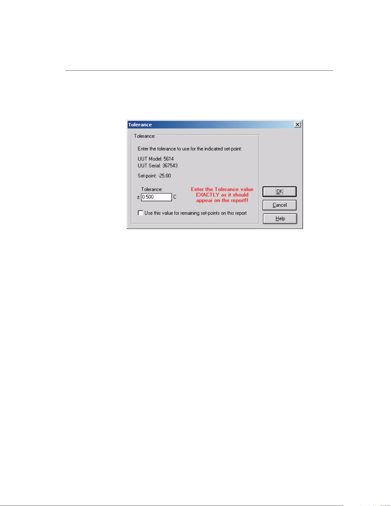
11.2.1.1 Tolerance Dialog
The Tolerance dialog allows the tolerance value for each set-point on the
Pass/Fail Report of Calibration to be entered.
The tolerance value must be entered exactly as it should be printed on the
Pass/Fail Report of Calibration. The allowable range for the tolerance value is
0.0 to 1000.0. If all remaining set-points on the current report require the same
tolerance value, check the Use this value for remaining set-points on this report
checkbox. Otherwise, this dialog is displayed once for each set-point on the
report.
Click the OK button to save the tolerance value. Once the tolerance value is ac-
cepted, it is permanently associated with that set-point. If a value is entered in-
correctly, refer to Section 11.2.1.2, Changing Tolerance Values, for information
on changing the tolerance values.
Click the Cancel button to close the dialog without changing the current toler-
ance value.
11.2.1.2 Changing Tolerance Values
On the Pass/Fail Report of Calibration included with MET/TEMP II, the toler-
ance values that appear on the report are manually entered by the user the first
time the report is printed. Once entered, these tolerance values are saved and
permanently associated with the respective set-points.
In case a tolerance value is entered incorrectly, MET/TEMP II provides two
methods to fix the value.
143
11
Reports of Calibration
Figure 71 Tolerance Dialog
1.888.610.7664 sales@GlobalTestSupply.com
Fluke-Direct.com

The first method forces the Tolerance dialog to be displayed every time a report
is printed and allows the tolerance values to be changed. This procedure re-
quires some basic computer knowledge. If you are unfamiliar with Windows®
INI files, you may want to find someone who is to assist with this procedure.
To force the Tolerance dialog to appear when printing a Pass/Fail Report of
Calibration:
1 Run Windows Explorer.
2 Locate and select the local hard drive and folder where MET/TEMP II
was installed (typically C:\METTEMP2).
3 In this folder, locate the METTEMP2.INI file. This file contains many
settings that dictate how MET/TEMP II operates. Double-click this file
to open it in a text editor.
4 Locate the ForceTolerance entry in the [General] section. This
entry should currently be set to False.
5 Change the word False to True as shown below, then close and save
the INI file.
6 If this entry does not exist in the [General] section, enter it now as
shown below.
Example:
[General]
ForceTolerance=True
Now, every time a Pass/Fail Report of Calibration is printed, the Tolerance dia-
log will be displayed.
Note: It is recommended that this procedure only be followed in case of a data
entry error. After correcting the error, the ForceTolerance entry should be
set back to False.
The second method is to use the Edit Test Information option in the Utilities
menu. Selecting this option displays the Edit Test Information dialog and al-
lows certain values in the MET/TEMP II database tables to be edited. It is rec-
ommended that this method be used to correct data entry errors when possible.
To use the Edit Test Information utility:
1 Select the Edit Test information option in the Utilities menu. The Edit
Test Information dialog is displayed.
2 Select the TestReadings table using the Select database table drop-down
list.
3 Locate the test number that contains the tolerance values to change. Use
the scroll bar on the right side of the grid to scroll through the records or
enter the test number in the Locate test number box.
9938 MET/TEMP II
User’s Guide
144
1.888.610.7664 sales@GlobalTestSupply.com
Fluke-Direct.com
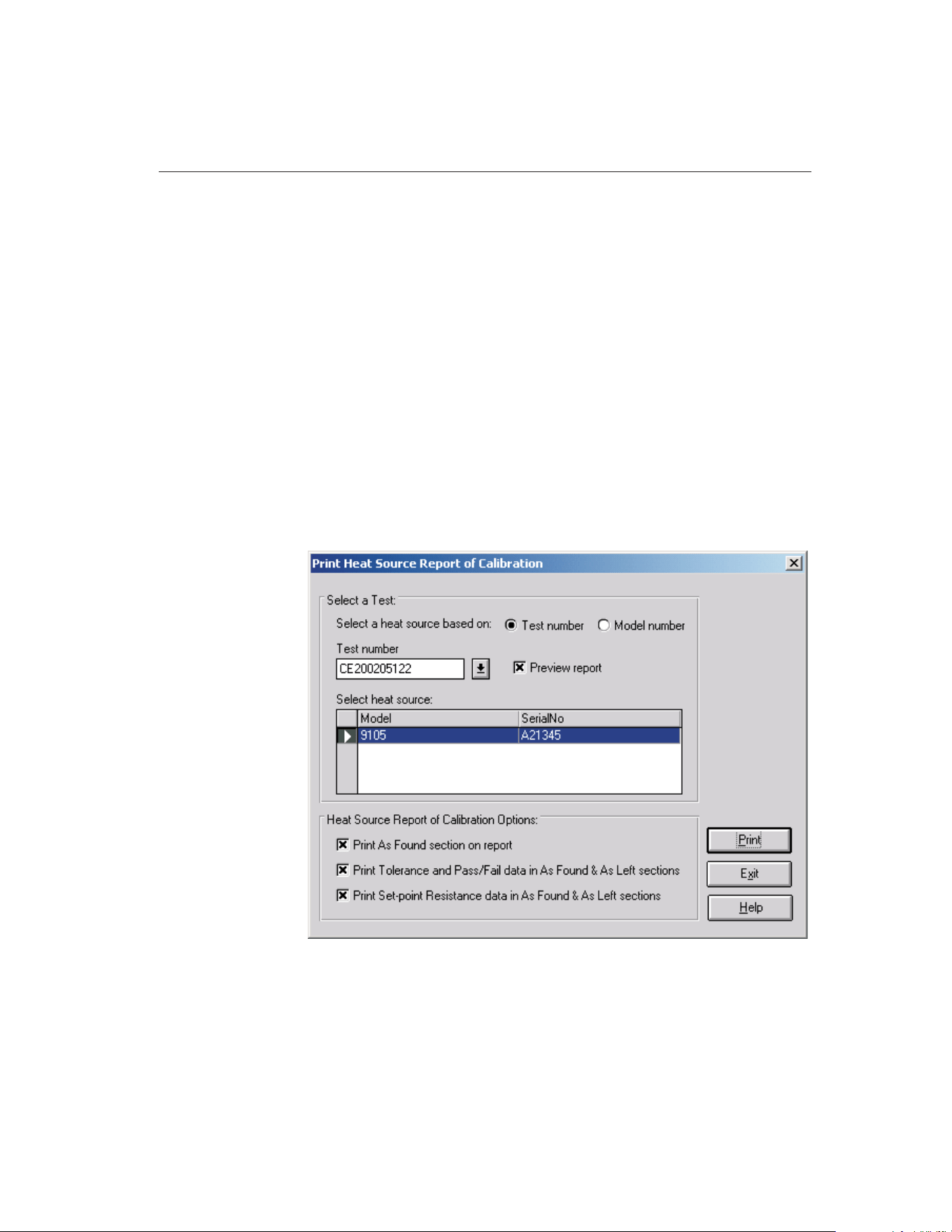
4 Use the scroll bar at the bottom of the grid to scroll to the right until the
Misc. data column is visible. This column contains the values printed in
the Tolerance column of the Pass/Fail Report of Calibration.
5 Enter the tolerance for each set-point EXACLTY AS IT SHOULD AP-
PEAR ON THE REPORT in the Misc. data field.
6 Click the OK button to close the Edit Test Information dialog.
After the tolerance values have been changed, the Pass/Fail Report of Calibra-
tion can be printed again.
11.2.2 Heat Source Report of Calibration
MET/TEMP II comes with a custom Report of Calibration that is designed to
print a Report of Calibration for heat source calibrations.
To print the Heat Source Report of Calibration, select the Use custom report
template option on the Print Test Report dialog and select the HEATSRC.EXE
report template. Click the Print button. The Print Heat Source Report of Cali-
bration dialog is displayed.
To use this custom report, you must select either a test number or a model num-
ber on which to base the heat source selection.
145
11
Reports of Calibration
Figure 72 Print Heat Source Report of Calibration
1.888.610.7664 sales@GlobalTestSupply.com
Fluke-Direct.com

If the test number option is selected, a list of test numbers becomes available.
Once a test number is selected, the heat source model number and serial num-
ber appear below. From the list entitled Select heat source, select the heat
source model number and serial number.
If the model number option is selected, a list of heat source model numbers be-
comes available. Once a model number is selected, the heat source serial num-
bers and test numbers appear below. From the list entitled Select heat source,
select the heat source test number and serial number.
Select the heat source in the Select heat source list.
If the Preview report checkbox is selected, the report is displayed in the Print
Preview window. If the Preview report check box is not selected, the report is
sent directly to the printer.
Selecting the Print As Found section on report option indicates that the As
Found section on the second page of the report should be printed. If this option
is not selected, the As Found section is not printed.
Selecting the Print Tolerance and Pass/Fail data in As Found & As Left sections
option indicates that the Tolerance and Pass/Fail columns in both the As Found
and As Left sections on the second page of the report should be printed. If this
option is not selected, the Tolerance and Pass/Fail columns are not printed.
Selecting the Print Set-point Resistance data in As Found & As Left sections
option indicates that the Set-point Resistance column in both the As Found and
As Left sections on the second page of the report should be printed. If this op-
tion is not selected, the Set-point Resistance column is not printed.
Clicking the Print button prints the Heat Source Report of Calibration for the
selected heat source.
Clicking the Exit button closes the Print Heat Source Report of Calibration
dialog.
The Heat Source Report of Calibration is designed in a two page layout. The
first page consists of: the report number, the heat source information, calibra-
tion range, received condition, test procedure, As Left condition customer name
and address, calibration test paragraph and remarks, a list of the test equipment,
calibration date, recall date, ambient temperature and humidity, customer order
ID, technician name, and a place for technician and approval signatures. The
second page consists of: As Found calibration coefficients and data and As Left
calibration coefficients and data. The As Found and As Left data consist of the
set-points, actual values, error, tolerance, pass/fail status and set-point
resistance.
The entire As Found section of the report and the Tolerance, Pass/Fail and
Set-point Resistance columns in the As Found and As Left sections of the re-
port are optional and can be printed or not by selecting the appropriate options
on the Print Heat Source Report of Calibration dialog before printing the re-
port. If all test data does not fit on the second page, a third page may be
created.
9938 MET/TEMP II
User’s Guide
146
1.888.610.7664 sales@GlobalTestSupply.com
Fluke-Direct.com

The fonts, sizes and styles used on the Heat Source Report of Calibration can
be changed on the Fonts & Sizes tab of the Defaults dialog.
The top, bottom, left, and right margins and the column widths for the Test
Equipment table on the Heat Source Report of Calibration can be set using the
appropriate controls on the Reports tab of the MET/TEMP II Defaults dialog. A
custom logo can also be added to the upper left corner of the Heat Source Re-
port of Calibration using the settings on this tab.
To use this custom report, select the Use custom report template option on the
Print Test Report dialog. Click the Browse button and select the
HEATSRC.EXE file in the \REPORTS subfolder. Clicking the Print button on
the Print Test Report dialog launches this custom report.
Reports of Calibration can be saved to a report file from the Print Preview win-
dow and opened, viewed and printed by selecting the Recall Saved Report op-
tion from the File menu, or by running the Report Viewer Utility. Refer to
Section 17, Report Viewer Utility, for more details.
The layout of this custom report is somewhat different from the default Report
of Calibration. This custom report is designed in multi-page format. A descrip-
tion of the layout of this custom report is indicated below:
First Page
• The report number and pagination information appears in the upper right
corner.
• The report title and company information appear in the top center of the
report.
• The heat source model, serial number, description, calibration range, re-
ceived condition, procedure and as left condition are printed on the left
side of the report at the top.
• The customer information is printed on the right side of the report at the
top.
• The paragraph appears immediately below the heat source and customer
information.
• The notes appear below the paragraph and are entitled Remarks.
• The test equipment information appears below the remarks and includes
the instrument configured as the scanner and the test probe (reference).
• The calibration and calibration due dates, ambient conditions and order
ID are printed on the left side at the bottom of the first page.
• The technician name and signature lines are printed on the right side at
the bottom of the first page.
Second Page
• The report number and pagination information appears in the upper right
corner.
147
11
Reports of Calibration
1.888.610.7664 sales@GlobalTestSupply.com
Fluke-Direct.com

• The heat source model and serial number appear in the upper left corner.
• The As Found section is printed at the top of the second page. The As
Found section consists of the As Found calibration coefficients and the As
Found data. The As Found data is used to calculate the new calibration
coefficients. The As Found section is optional and can be excluded from
the report by selecting the appropriate option on the Print Heat Source
Report of Calibration dialog.
• The As Found calibration coefficients vary depending on the heat source
that was calibrated.
• The As Found data consists of the set-points, actual (reference) readings,
error, tolerance, pass/fail status and set-point resistance columns.
• The tolerance, pass/fail and set-point resistance columns are optional and
can be excluded from the As Found data by selecting the appropriate op-
tions on the Print Heat Source Report of Calibration dialog.
• If the Stability Override menu option was used on any As Found set-point
during the test, the set-point will be marked and a footnote appears at the
bottom of the As Found data section stating that the stability parameters
were overridden for the set-points indicated.
• The As Left section is printed immediately below the As Found section.
The As Left section consists of the As Left calibration coefficients and the
As Left data. The As Left data is taken after the new calibration coeffi-
cients are written to the heat source. The As Left calibration coefficients
are always printed. The As Left data is only printed if As Left data was
taken. If the As Left data does not all fit on the second page, a third page
may be created.
• The As Left calibration coefficients vary depending on the heat source
that was calibrated.
• If MET/TEMP II could not successfully write one or more of the calcu-
lated coefficient values to the heat source during the calibration, the coef-
ficient(s) will be marked and a footnote appears at the bottom of the As
Left calibration coefficients section stating that the indicated coefficients
could not be successfully written to the heat source.
• The As Left data consists of the set-points, actual (reference) readings, er-
ror, tolerance, pass/fail status and set-point resistance columns.
• The tolerance, pass/fail and set-point resistance columns are optional and
can be excluded from the As Left data by selecting the appropriate op-
tions on the Print Heat Source Report of Calibration dialog.
• If the Stability Override menu option was used on any As Left set-point
during the test, the set-point will be marked and a footnote will appear at
the bottom of the As Left data section stating that the stability parameters
were overridden for the set-points indicated.
9938 MET/TEMP II
User’s Guide
148
1.888.610.7664 sales@GlobalTestSupply.com
Fluke-Direct.com

149
11 Reports of Calibration
Custom Reports of Calibration
Report of Cal
i
brat
i
on
Report No: CE200205119-004
Page1of2
Temp Tech Co.
105 Celcius Drive
Out Town, USA
34567-8998
Model: 9105
Serial: A21345
Description: Drywell, Low-Temperature
Calibration Range: Limited
Received Condition: New
Procedure: HST000 - 0
As Left Condition: Out of Tolerance
Customer: Hart Scientific
799 East Utah Valley Drive
American Fork, Utah 84003
USA
Calibration Date: 5/29/2002
Calibration Due: 5/29/2003
Temperature: 24 C
Humidity: 56%
Order #: MyOrderID
Technician: ________________________
Cal E. Breight
Approved By: ________________________
The above referenced instrument was calibrated by direct measurement of generated temperatures using the reference standards
listed in the "Test Equipment" table at the bottom of this report. The internal calibration coefficients and the data abtained are shown
on page 2. A Test Uncertainty Ratio (TUR) of at least 4:1 was maintained unless otherwise indicated. This calibration is traceable to
NIST or natural physical constants and is in compliance with ANSI/NCSL Z540-1 and MIL-STD 45662A.
Remarks: This test was performed in accordance with the test procedure indicated above.
Test Equipment
Manufacturer Model Description Serial Number Recall Date
Fluke Corporation 2635A Fluke 2635A Hydra Data Bucket 343242 5/31/2002
Burns Engineering 5614 Probe, Secondary Standard 5453 12/31/2002
This report shall not be reproduced except in
f
ull without written approval o
f
Temp Tech Co..
Figure 73 Example Heat Source Report of Calibration Page 1
1.888.610.7664 sales@GlobalTestSupply.com
Fluke-Direct.com

9938 MET/TEMP II
User’s Guide
150
Report of Cal
i
brat
i
on
Report No: CE200205119-004
Page2of2
Model: 9105
Serial: A21345
As Found Data
Calibration Coefficients
R0: 100.398
ALPHA: 0.00381830
DELTA: 1.5229
BETA: -2.0705
Test Data
Set-point
(C)
Actual
(C)
Error
(C)
Tolerance
(C) Pass/Fail
Set-point
Resistance
-25.00 -24.940 0.060 ±0.010 F 90.646
0.00 0.070 0.070 ±0.010 F 100.397
75.00 74.990 -0.010 ±0.010 P 129.259
140.00 139.830 -0.170 ±0.010 F 153.738
As Left Data
Calibration Coefficients
R0: 100.370
ALPHA: 0.00382448
DELTA: 1.4368
BETA: -2.9080
Test Data
Set-point
(C)
Actual
(C)
Error
(C)
Tolerance
(C) Pass/Fail
Set-point
Resistance
140.00 140.000 0.000 ±0.010 P 153.800
125.00 124.990 -0.010 ±0.010 P 148.178
100.00 99.990 -0.010 ±0.010 P 138.756
75.00 74.990 -0.010 ±0.010 P 129.265
50.00 49.990 -0.010 ±0.010 P 119.700
25.00 25.010 0.010 ±0.010 P 110.067
0.00 0.010 0.010 ±0.010 P 100.372
-25.00 -25.020 -0.020 ±0.010 F 90.621
0.00 0.000 0.000 ±0.010 P 100.372
25.00 25.020 0.020 ±0.010 F 110.067
50.00 50.000 0.000 ±0.010 P 119.700
75.00 74.990 -0.010 ±0.010 P 129.265
100.00 99.990 -0.010 ±0.010 P 138.756
125.00 124.990 -0.010 ±0.010 P 148.178
140.00 139.990 -0.010 ±0.010 P 153.800
This report shall not be reproduced except in
f
ull without written approval o
f
Temp Tech Co..
Figure 74 Example Heat Source Report of Calibration Page 2
1.888.610.7664 sales@GlobalTestSupply.com
Fluke-Direct.com

12 Performing Calibrations Using
Fixed-Points
MET/TEMP II now includes the capability of performing calibrations using
fixed-point cells. MET/TEMP II can perform calibrations using fixed-point
cells only, or fixed-point set-points can be mixed in with comparison set-points.
Important: MET/TEMP II allows calibrations to be performed using
fixed-point cells only or by mixing fixed-point set-points with comparison
set-points as a convenience to the user. It is assumed that, if you are using
these features, you are familiar with the process and theory of performing
calibrations using fixed-point cells. This User’s Guide does not provide
any detailed information as to how to perform fixed-point calibrations and
shall not be used as a substitute for proper training and source of infor-
mation on such topics. For more information on performing calibrations
using fixed-point cells, please refer to the currently available literature.
Hart periodically offers training seminars on using fixed-point cells. NIST
is also a good source of information on this topic.
12.1 Configuring Fixed-Point Cells
Before MET/TEMP II can perform calibration tests using fixed-point cells, the
fixed-point cells to use must be configured. MET/TEMP II ships with built-in
support for many fixed-point cells. Support for any fixed-point cell can be
added to MET/TEMP II at any time.
151
12
Performing Calibrations Using Fixed-Points
1.888.610.7664 sales@GlobalTestSupply.com
Fluke-Direct.com
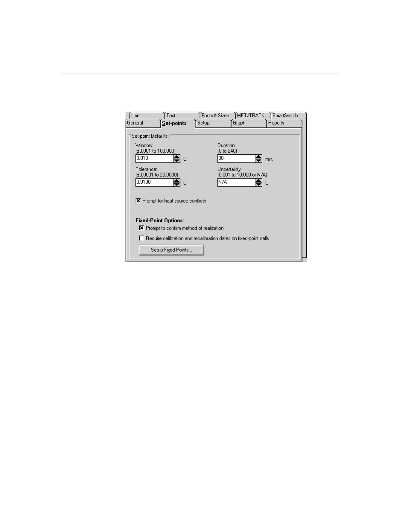
To configure fixed-point cells, select the Defaults option in the File menu. The
Defaults dialog is displayed. Select the Set-points tab.
The Prompt to confirm method of realization check box indicates whether
MET/TEMP II will show a message every time a fixed-point set-point is added
to a calibration configuration indicating the current method of realization for
the selected fixed-point cell. If this check box is not selected, no prompt is
displayed.
9938 MET/TEMP II
User’s Guide
152
Figure 75 Set-points Tab
1.888.610.7664 sales@GlobalTestSupply.com
Fluke-Direct.com
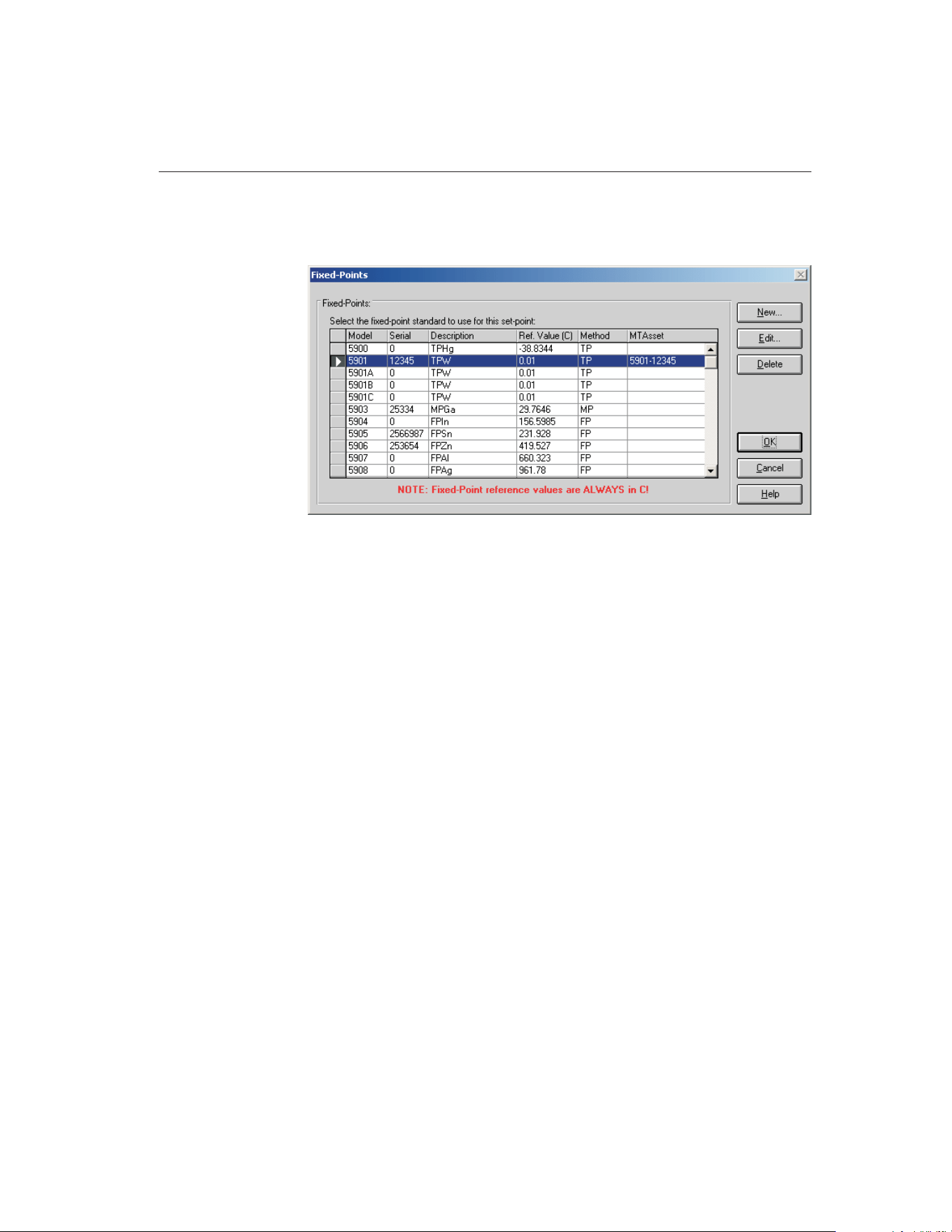
To configure fixed-point cells, click the Setup Fixed-Points button. The
Fixed-Points dialog is displayed.
To edit the current settings for a fixed-point cell, select the fixed-point cell from
the list and click the Edit button. The Edit Fixed-Point dialog is displayed. To
add a new fixed-point cell to MET/TEMP II, click the New button. The New
Fixed-Point dialog is displayed. To delete a fixed-point cell, select the
fixed-point cell to delete from the list and click the Delete button.
Refer to Section 3.4.2.1, Fixed-Points, for more detailed information on config-
uring fixed-point cells.
12.2 Configuring MET/TEMP II to Perform Fixed-Point
Only Calibrations
MET/TEMP II can be configured to perform calibrations using fixed-point cells
only. The only differences between configuring MET/TEMP II to perform
fixed-point only calibrations and performing comparison calibrations are in the
heat source and set-point configurations.
12.2.1 Fixed-Point Reference Readout Configuration
Even though MET/TEMP II does not actually store readings taken from a refer-
ence probe when configured for fixed-point set-points only, a reference readout
and reference probe must still be configured as if performing comparison cali-
brations. This is because Calibrate-it continuously takes readings from and
graphs the reference probe. Configure the reference readout and reference
probe as indicated in Section 4.3, Reference.
153
12
Performing Calibrations Using Fixed-Points
Figure 76 Fixed-Points Dialog
1.888.610.7664 sales@GlobalTestSupply.com
Fluke-Direct.com
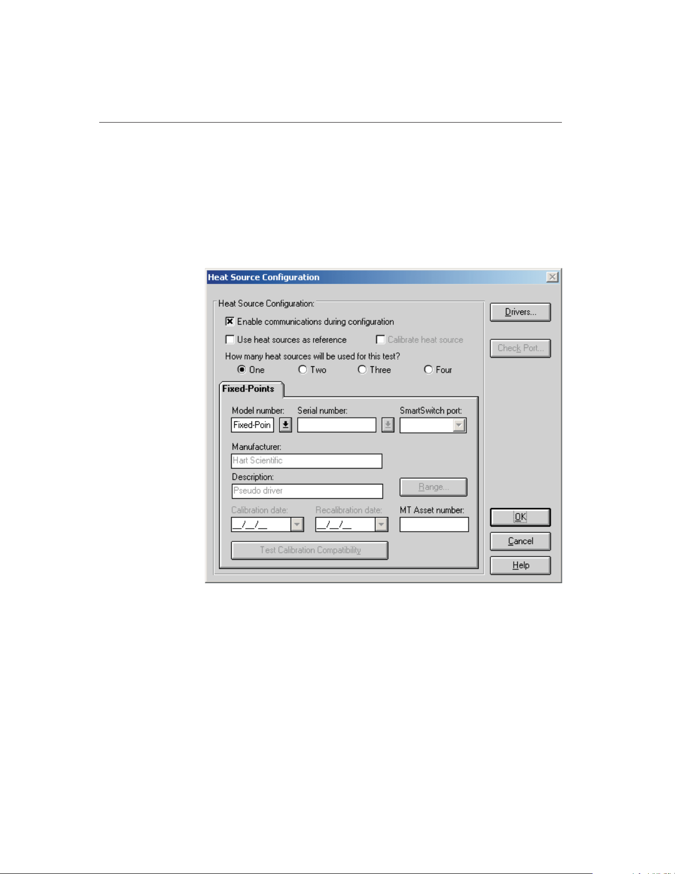
Because MET/TEMP II must always be able to take readings from the refer-
ence, MET/TEMP II cannot be configured to use the heat sources as the
reference.
12.2.2 Fixed-Point Heat Source Configuration
To configure MET/TEMP II to perform fixed-point only calibrations, a single
heat source must be configured. Select the Heat Sources option in the Configu-
ration menu to display the Heat Source Configuration dialog.
Select the One option to indicate that a single heat source is to be used.
Select the Fixed-Points pseudo driver using the Model number drop-down list.
If the Fixed-Points option does not appear in the Model number drop-down list,
click the Drivers button to display the Install Drivers dialog and install the
Fixed-Points Pseudo driver. Click the OK button to close the Install Drivers
dialog.
When the Fixed-Points driver is selected in the Model number box, all other
controls on this dialog are disabled.
9938 MET/TEMP II
User’s Guide
154
Figure 77 Heat Source Configuration Dialog
1.888.610.7664 sales@GlobalTestSupply.com
Fluke-Direct.com
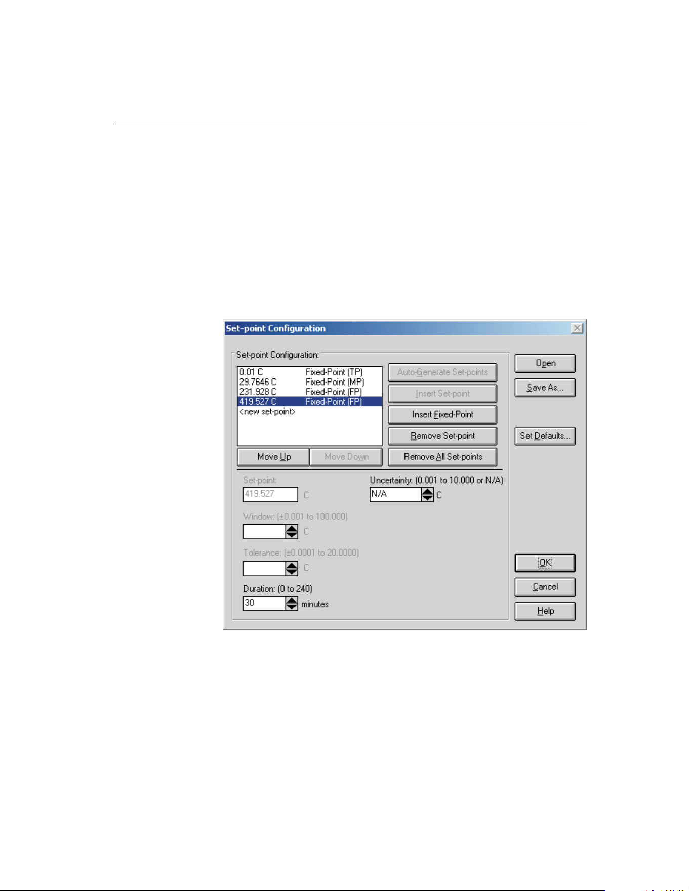
Note: The Fixed-Points Pseudo driver only needs to be configured if a calibra-
tion test does not include any comparison set-points. If a calibration test uses
one or more comparison set-points, at least one heat source must be configured
and the Fixed-Points Pseudo driver does not need to be configured.
Click the OK button to close the Heat Source Configuration dialog.
12.2.3 Fixed-Point Set-point Configuration
When MET/TEMP II has been configured with only the Fixed-Points heat
source pseudo driver as indicated in the previous section, only fixed-point
set-points can be added to the set-point configuration. Select the Set-points op-
tion in the Calibration menu to display the Set-point Configuration dialog.
The Auto-Generate Set-points and Insert Set-point buttons are always disabled.
155
12
Performing Calibrations Using Fixed-Points
Figure 78 Set-point Configuration Dialog
1.888.610.7664 sales@GlobalTestSupply.com
Fluke-Direct.com
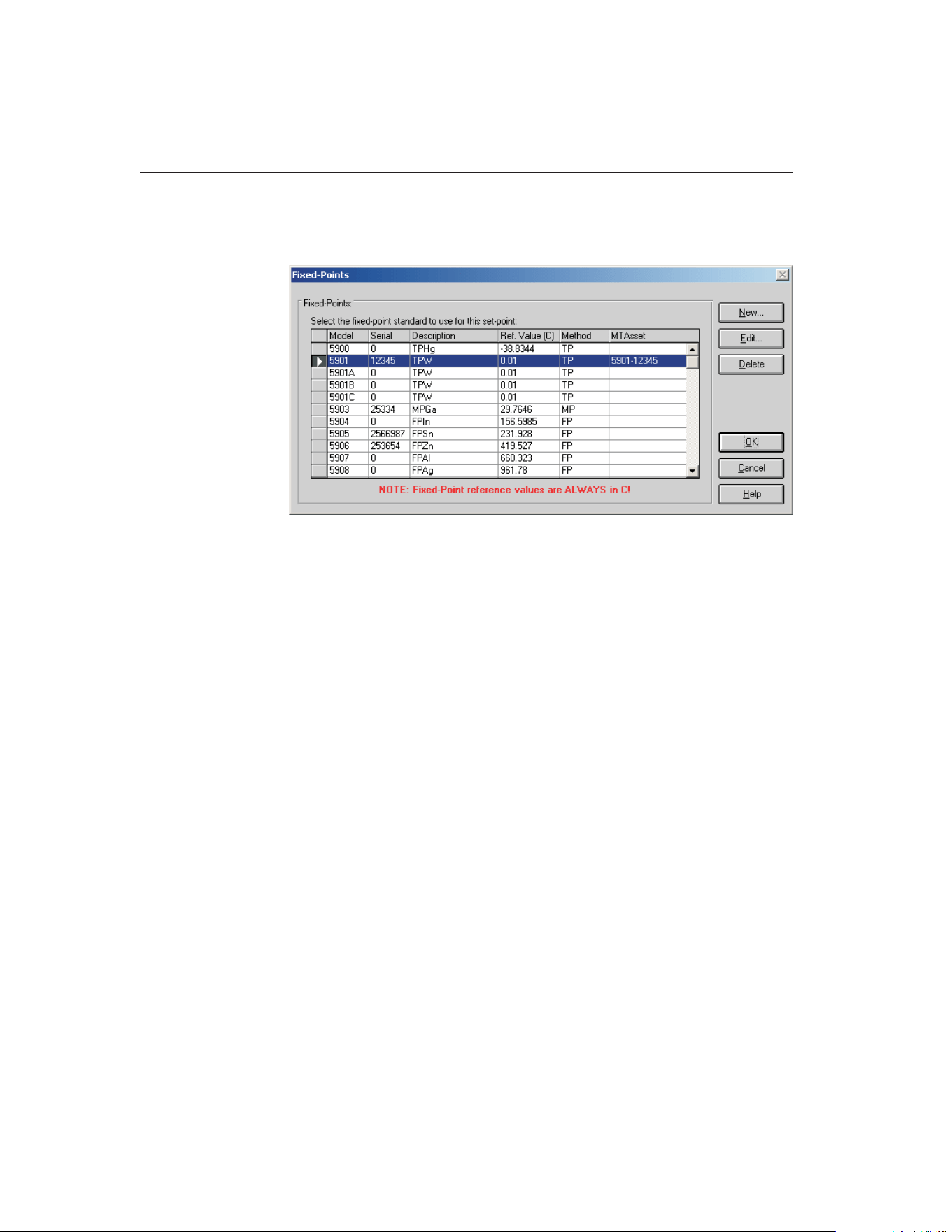
Click the Insert Fixed-Point button to add a new fixed-point set-point to the
set-point configuration. The Fixed-Points dialog is displayed.
Select the fixed-point cell to use and click the OK button. If the fixed-point cell
has not been configured yet, a message is displayed indicating the cell must be
configured before it can be used. Refer to Section 12.1, Configuring
Fixed-Point Cells, for more details.
If the Prompt to confirm method of realization check box on the Defaults dia-
log is checked, another message is displayed to confirm the currently selected
method of realization for the selected fixed-point cell. Make sure this method is
correct before continuing.
The fixed-point set-point is added to the set-points list indicating the reference
value and the current method of realization.
The Set-point, Window and Tolerance boxes on the Set-point Configuration di-
alog are disabled when a fixed-point set-point is selected. These settings cannot
be changed or do not apply for fixed-point set-points.
The Duration setting indicates the amount of soak time that MET/TEMP II
should allow once a test probe has been inserted into a fixed-point cell until
readings are taken.
Insert other fixed-point set-points by repeating this process.
Click the OK button to close the Set-point Configuration dialog.
9938 MET/TEMP II
User’s Guide
156
Figure 79 Fixed-Points Dialog
1.888.610.7664 sales@GlobalTestSupply.com
Fluke-Direct.com

12.3 Fixed-Point Calibration Process
When MET/TEMP II is configured with one or more fixed-point set-points, the
test process is slightly different than when all set-points are comparison
set-points.
For fixed-point set-points, only one test probe at a time can be inserted into the
fixed-point cell. MET/TEMP II displays a prompt to insert the first test probe
into the fixed-point cell. When the OK button on this prompt is clicked,
MET/TEMP II begins to count down the duration time for this set-point. When
the duration time has elapsed, MET/TEMP II begins to take readings from the
first test probe. The value that was entered as the Reference value for the se-
lected fixed-point cell when the cell was configured is stored as the reference
reading at that set-point. Then, MET/TEMP II prompts to insert the next test
probe into the fixed-point cell. This process is repeated for all test probes at the
current fixed-point, then for all other fixed-point set-points.
All fixed-point cells used during the calibration process are listed on the Report
of Calibration in the Test Equipment section.
157
12
Performing Calibrations Using Fixed-Points
1.888.610.7664 sales@GlobalTestSupply.com
Fluke-Direct.com

13 Performing Heat Source Calibrations
MET/TEMP II was originally designed to perform comparison calibrations for
PRT, thermistor and thermocouple probes. However, MET/TEMP II has been
modified to calibrate Liquid in Glass and bi-metallic thermometers, perform
fixed-point calibrations and to calibrate some heat sources.
Since the process of calibrating a heat source is somewhat different than that of
calibrating a probe, MET/TEMP II must be setup slightly differently. This sec-
tion explains in detail the steps necessary to configure MET/TEMP II to suc-
cessfully calibrate a heat source.
13.1 Heat Source Calibration Process
MET/TEMP II can be configured to calibrate a single heat source using only a
readout device, probe and the heat source to be calibrated.
The process of calibrating a heat source is somewhat similar to calibrating a
PRT probe. The heat source is set to various set-points one at a time, allowed to
stabilize, and then readings are taken. The readings are then fed into a set of
equations to calculate new values for the calibration coefficients for the heat
source. If desired, MET/TEMP II can then write the new calibration coeffi-
cients to the heat source and take readings at additional set-points to verify the
calibration. A custom report for heat source calibrations is included with
MET/TEMP II and can be used to print the results of the calibration.
The readings that MET/TEMP II takes consist of temperature readings from the
reference probe and set-point resistance readings from the heat source. The
set-point resistance readings are not actually resistance measurements, but re-
sistance values that are calculated by the heat source based on the current
set-point temperature and the heat source’s current calibration coefficients.
Note: Because not all heat sources supported by MET/TEMP II have a com-
mand to read set-point resistance values, not all heat sources can be calibrated
by MET/TEMP II. By the same token, even heat source models that can be cal-
ibrated by MET/TEMP II may require a firmware upgrade to support the
set-point resistance command.
13.2 Configuring MET/TEMP II to Perform Heat
Source Calibrations
The following sections describe in detail the steps that must be followed to con-
figure MET/TEMP II to perform a heat source calibration. Because
MET/TEMP II was originally intended to calibrate probes, not all of the config-
uration steps are obvious or intuitive. Please read the following sections care-
fully and be sure you understand this process before attempting to calibrate a
heat source.
159
13
Performing Heat Source Calibrations
1.888.610.7664 sales@GlobalTestSupply.com
Fluke-Direct.com
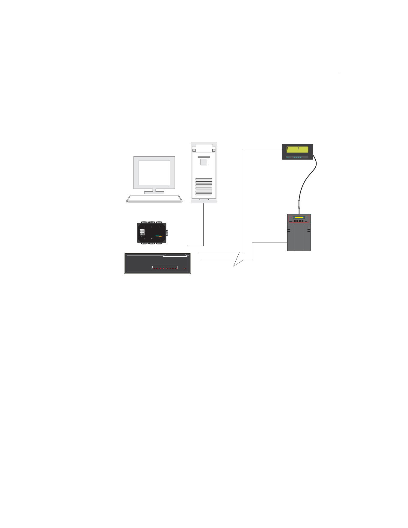
Figure 80 shows one possible instrument configuration for performing a heat
source calibration. When configuring a heat source calibration, you may use
the Equipment Info dialog to gain quick access to the various configuration
dialogs or you may select the appropriate options from the Configuration and
Calibration menus. Before beginning, select the New option from the File menu
to clear any current configuration information.
13.2.1 Default Settings
Before configuring MET/TEMP II to calibrate a heat source, there are some
settings that need to be checked that will affect the calibration process. The fol-
lowing sections describe these settings.
13.2.1.1 Writing New Coefficients To Heat Source
MET/TEMP II has a default setting that determines whether the new calculated
values of the calibration coefficients should be written to the heat source. This
setting must be configured prior to starting the heat source calibration test. Se-
9938 MET/TEMP II
User’s Guide
160
UUT (being used
as reference probe)
Heat Source
Being Calibrated
Computer
Straight
Through
Cable
Null Modem
Cables
To PORT A
To PORT C
To Serial Port
To Serial Port
To Serial Port
1
24.159C
3
24.142C
2
24.634C
4
24.015C
1 TYP: CVD
1 SER: 145-560
1 –T1: 0.0000 C
ALOG: OFF 0%
1 AVE: 24.1530 C
1 STD: 0.0038 C
1 SPR: 0.0219 C
TIME: 14:58:43
Enter Exit
Menu Unit Contrast
1529
Chub-E4
Scanner
EXPANDABLE SMART SWITCH
ABCDEFGH
POWER
MODEL 232XSS
PORT SELECT
or
To MASTER PORT
ABC
FED
MASTERPORT
1
2
3
4
5
6
7
8
+12VDC
SmartSwitch
DIPSwitch Settings
BaudRate
1200
2400*
4800
9600
19.2k
38.4k
57.6k
115.2k
1
0
1
0
1
0
1
0
1
2
0
0
1
1
0
0
1
1
3
0
0
0
0
1
1
1
1
*DefaultSettings
Power
Smart Switch
Figure 80 Example Configuration for Performing a Heat Source Calibration
1.888.610.7664 sales@GlobalTestSupply.com
Fluke-Direct.com
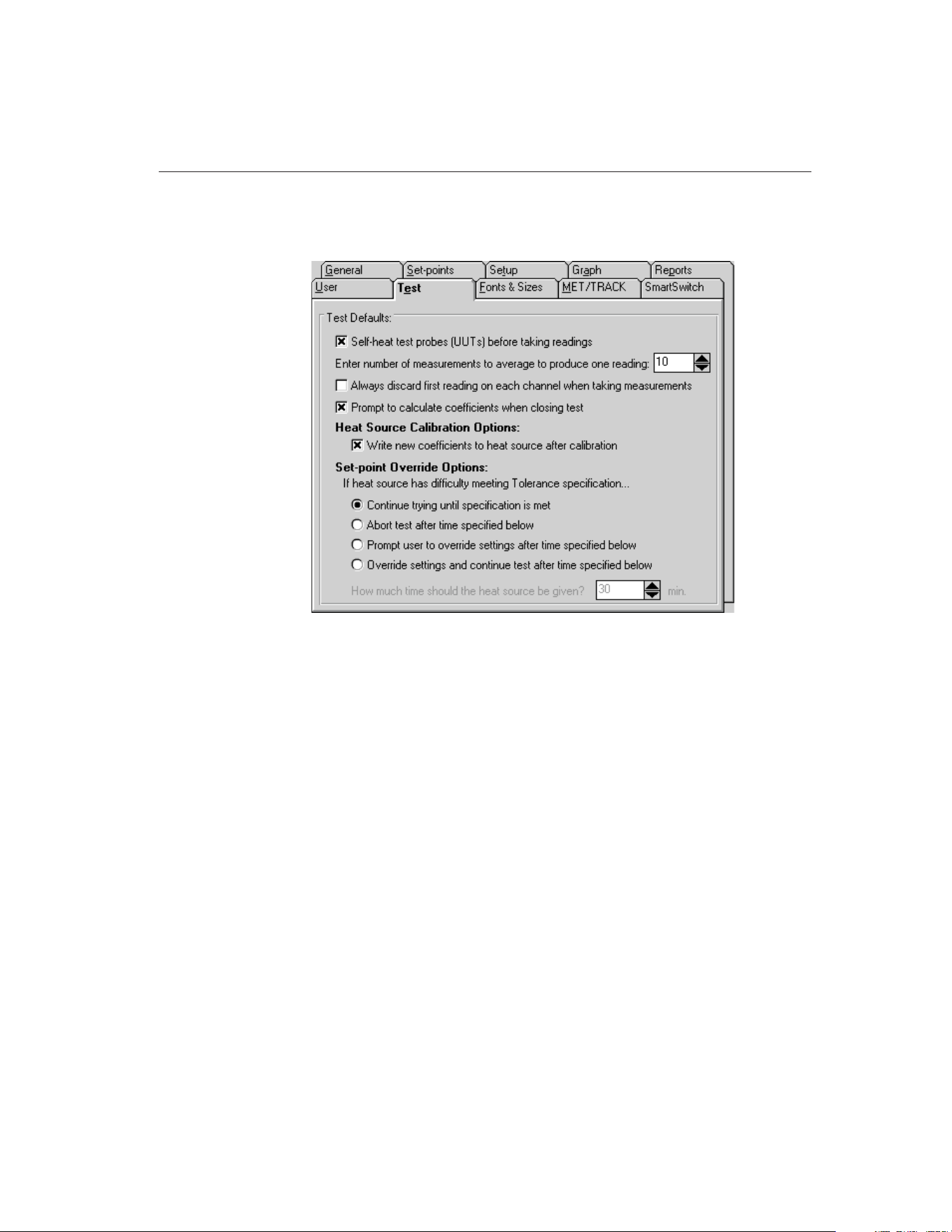
lect the Defaults option from the File menu to display the Defaults dialog. Se-
lect the Test tab.
The Write new coefficients to heat source after calibration check box deter-
mines whether MET/TEMP II will attempt to write the new calculated values
for the calibration coefficients to the heat source prior to taking readings at the
As Left set-points.
If this option is selected, MET/TEMP II attempts to write the new coefficient
values to the heat source and verify that the heat source accepted the new val-
ues before proceeding to take readings at the As Left set-points.
If this option is not selected, MET/TEMP II will not attempt to write the new
coefficient values to the heat source. If there are any As Left set-points config-
ured, readings will be taken at these set-points using the same calibration coef-
ficients that were in the heat source when the As Found readings were taken.
It is recommended that this option always be selected if As Left set-points are
configured.
Click the OK button to close the Defaults dialog.
161
13
Performing Heat Source Calibrations
Figure 81 Test Tab
1.888.610.7664 sales@GlobalTestSupply.com
Fluke-Direct.com
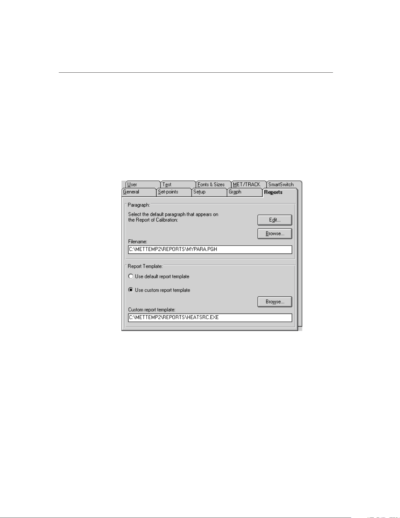
13.2.1.2 Report of Calibration
MET/TEMP II ships with a custom Report of Calibration that was designed
specifically to print the test results for heat source calibrations. This custom re-
port can be defined as the default custom report.
Note: This custom report does not have to be defined as the default custom re-
port to use. The custom report can be selected manually every time a report is
printed.
To define the custom heat source Report of Calibration as the default custom
report, select the Defaults option from the File menu to display the Defaults di-
alog. Select the Reports tab.
In the Report Template section, select the Use custom report template option.
The Custom report template box and the Browse button are enabled. Click the
Browse button and select the file HEATSRC.EXE file in the \REPORTS folder.
Click the OK button to close the Defaults dialog.
13.2.2 Configure Communications Port
The first step to configuring MET/TEMP II to perform a heat source calibration
is to select the COM port that the SmartSwitch box is connected to. Click the
COM Port button on the Equipment Info dialog or select the COM Port option
9938 MET/TEMP II
User’s Guide
162
Figure 82 Reports Tab
1.888.610.7664 sales@GlobalTestSupply.com
Fluke-Direct.com
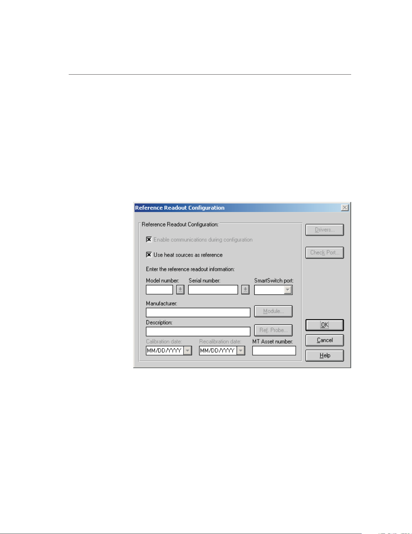
from the Configuration menu. The Communications Port Configuration dialog
is displayed.
Select the COM port that the SmartSwitch box is connected to. Refer to Section
4.2.1, Communications Port Dialog, for more information on configuring the
COM port.
Click the OK button to close the Communications Port Configuration dialog.
13.2.3 Configure Reference Readout
The second step to configuring MET/TEMP II to perform a heat source calibra-
tion is to configure the reference readout. Click the Reference button on the
Equipment Info dialog or select the Reference option from the Configuration
menu. The Reference Readout Configuration dialog is displayed.
When calibrating a heat source, MET/TEMP II must be configured to use the
heat source as the reference. Select the Use heat sources as reference check
box. All other controls on this dialog are disabled. A prompt is displayed ask-
ing if a heat source is being calibrated. Click Yes. All other controls on this dia-
log are disabled.
Click the OK button to close the Reference Readout Configuration dialog.
163
13
Performing Heat Source Calibrations
Figure 83 Reference Readout Configuration Dialog
1.888.610.7664 sales@GlobalTestSupply.com
Fluke-Direct.com
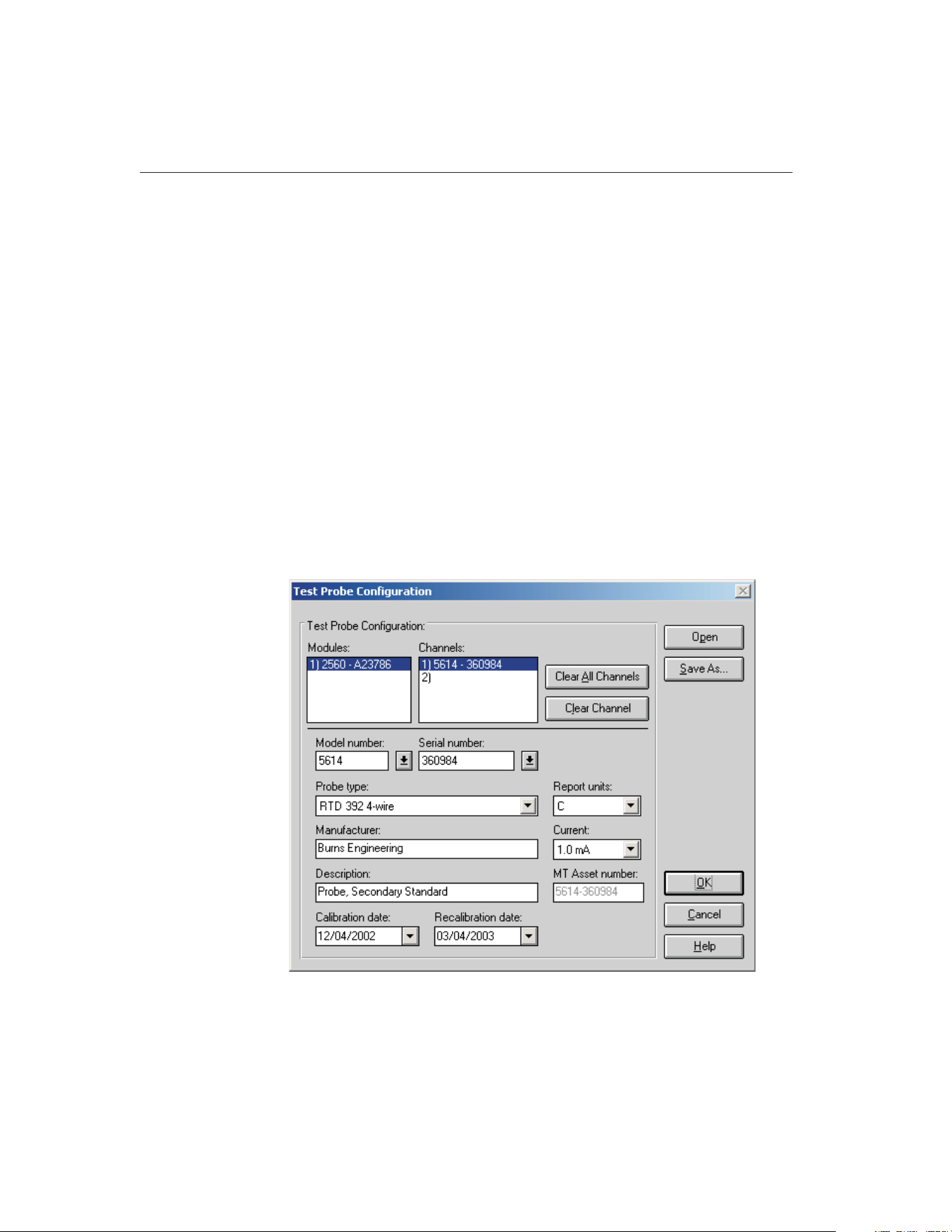
13.2.4 Configure Scanner
The third step to configuring MET/TEMP II to perform a heat source calibra-
tion is to configure the scanner. Click the Scanner button on the Equipment
Info dialog or select the Scanner option from the Configuration menu. The
Scanner Configuration dialog is displayed.
When calibrating a heat source, MET/TEMP II actually uses the scanner as if it
was the reference readout and the test probe is if it was the reference probe. Se-
lect the instrument to use as the scanner. If the selected instrument requires the
use of modules or a multiplexer, click the Modules button to configure the
modules or multiplexer. Refer to Section 4.4.1, Scanner Configuration Dialog,
for more information on configuring the scanner.
Click the OK button to close the Scanner Configuration dialog.
13.2.5 Configure Test Probes
The fourth step to configuring MET/TEMP II to perform a heat source calibra-
tion is to configure the test probe. Click the Test Probes button on the Equip-
ment Info dialog or select the Test Probes option from the Calibration menu.
The Test Probes Configuration dialog is displayed.
9938 MET/TEMP II
User’s Guide
164
Figure 84 Test Probes Configuration Dialog
1.888.610.7664 sales@GlobalTestSupply.com
Fluke-Direct.com

When calibrating a heat source, MET/TEMP II actually uses the test probe as if
it was the reference probe. MET/TEMP II only allows a single test probe to be
configured. If more than one test probe is configured, MET/TEMP II will not
allow a heat source calibration test to start!
Select the model of the test probe (reference probe) to use to calibrate the heat
source. Fill in the serial number, probe type, report units, manufacturer, de-
scription and current/CJC boxes. Note that the report units are limited to C and
F.
Next, select the calibration and recalibration dates for the test probe (reference
probe).
When the MET/TRACK link is active, the MT Asset number box is displayed.
This box indicates the asset number that is assigned to this probe. An inven-
tory record must exist in the MET/TRACK database for this probe before
MET/TEMP II can use it to perform calibrations! A current calibration
record must also exist in the MET/TRACK database. MET/TEMP II will
automatically attempt to locate the records in the MET/TRACK database when
the model, serial number and manufacturer information have been entered. If
the asset number is found, MET/TEMP II displays the asset number in the MT
Asset number box. Depending on the settings on the MET/TRACK tab of the
Defaults dialog, the description, calibration and recalibration dates may be syn-
chronized with the information in the MET/TRACK database. If the asset can-
not be found in the MET/TRACK database, a message is displayed. Click Yes
tolaunchMET/TRACKtocreateormodifyassetrecordsorclickNotoeditthe
information in MET/TEMP II.
Important: When MET/TEMP II attempts to locate an asset in the
MET/TRACK database, the model, serial number and manufacturer infor-
mation must be an EXACT (case-insensitive) match! If the manufacturer
information in MET/TEMP II does not match the manufacturer informa-
tion in MET/TRACK, you may need to modify the manufacturer informa-
tion in the MET/TRACK inventory record in order for MET/TEMP II to
locate it. Where applicable, you may be able to modify the manufacturer
information in MET/TEMP II.
Note: Since the test probe is being used as if it was the reference, make sure
the calibration coefficients for the test probe have been entered into the ther-
mometer readout and the temperature readings are accurate before starting the
heat source calibration test.
Click the OK button to close the Test Probe Configuration dialog.
13.2.6 Configure Heat Source
The fifth step to configuring MET/TEMP II to perform a heat source calibra-
tion is to configure the heat source to calibrate. Click the Heat Sources button
165
13
Performing Heat Source Calibrations
1.888.610.7664 sales@GlobalTestSupply.com
Fluke-Direct.com
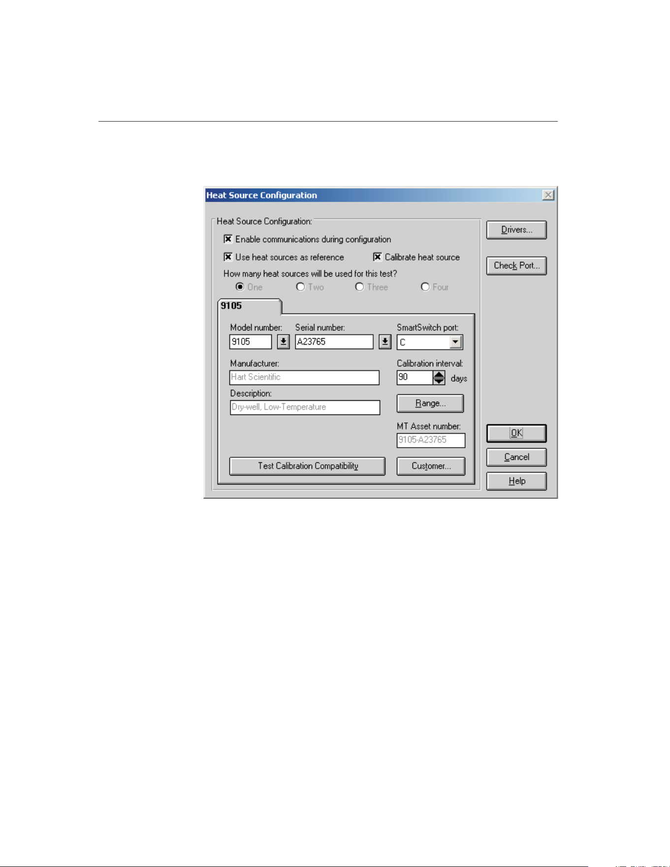
on the Equipment Info dialog or select the Heat Sources option from the Con-
figuration menu. The Heat Source Configuration dialog is displayed.
When calibrating a heat source, MET/TEMP II must be configured to use the
heat source as the reference. The Use heat sources as reference check box
should already be selected. If not, select it now. The Calibrate heat source
check box is enabled. If not already selected, select it now. Selecting this option
automatically sets the number of heat sources to One since MET/TEMP II can
only calibrate a single heat source at a time.
Select the heat source model to calibrate using the Model number drop-down
list. Fill in the serial number and calibration interval. Click the Customer button
to fill in information regarding the status and owner of this heat source.
Click the Range button to make sure the temperature range for this heat source
is configured to cover the range of temperatures to use for the calibration. The
heat source can also be configured to cool down to a specific temperature after
the calibration is complete. Click the OK button to close the Temperature
Range Configuration dialog.
9938 MET/TEMP II
User’s Guide
166
Figure 85 Heat Source Configuration Dialog
1.888.610.7664 sales@GlobalTestSupply.com
Fluke-Direct.com

When the MET/TRACK link is active, the MT Asset number box is displayed.
This box indicates the asset number that is assigned to this heat source. An in-
ventory record must exist in the MET/TRACK database for this heat
source before MET/TEMP II can calibrate it! MET/TEMP II will automati-
cally attempt to locate the records in the MET/TRACK database when the
model, serial number and manufacturer information have been entered. If the
asset number is found, MET/TEMP II displays the asset number in the MT As-
set number box. Depending on the settings on the MET/TRACK tab of the De-
faults dialog, the description may be synchronized with the information in the
MET/TRACK database. If the asset cannot be found in the MET/TRACK data-
base, a message is displayed. Click Yes to launch MET/TRACK to create or
modify asset records or click No to edit the information in MET/TEMP II.
Note: When MET/TEMP II attempts to locate an asset in the MET/TRACK da-
tabase, the model, serial number and manufacturer information must be an EX-
ACT (case-insensitive) match! If the manufacturer information in MET/TEMP
II does not match the manufacturer information in MET/TRACK, you may
need to modify the manufacturer information in the MET/TRACK inventory re-
cord in order for MET/TEMP II to locate it. Where applicable, you may be able
to modify the manufacturer information in MET/TEMP II.
Note: MET/TEMP II cannot calibrate all of the heat source models.
MET/TEMP II performs a check when the OK button is clicked to ensure that
MET/TEMP II supports calibrating the selected heat source model. If the se-
lected heat source model cannot be calibrated, a message is displayed at this
time.
To determine if a particular heat source can be calibrated, click the Test Cali-
bration Compatibility button. MET/TEMP II will attempt to determine if the
connected heat source responds to the commands that are required to success-
fully calibrate the heat source. If the heat source does not respond to the com-
mands, an error message is displayed. Otherwise, a message is displayed
indicating the heat source responded successfully to the commands.
Clicking the Customer button displays the Customer Information dialog for en-
tering more information about the heat source being calibrated.
Click the OK button to close the Heat Source Configuration dialog.
13.2.7 Configure Set-points
The last step to configuring MET/TEMP II to perform a heat source calibration
is to configure the set-points to use to calibrate the heat source. Click the
167
13
Performing Heat Source Calibrations
1.888.610.7664 sales@GlobalTestSupply.com
Fluke-Direct.com
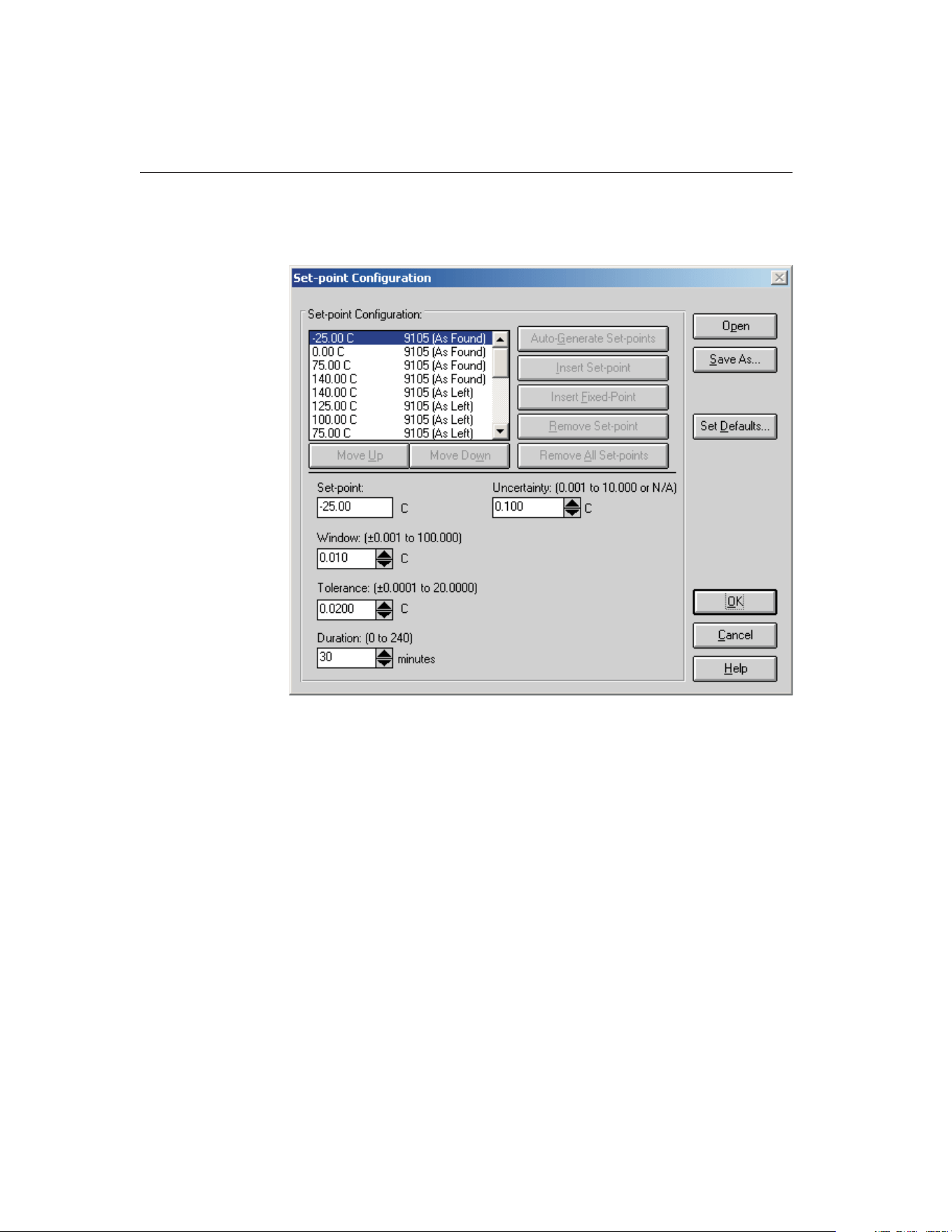
Set-points button on the Equipment Info dialog or select the Set-points option
from the Calibration menu. The Set-point Configuration dialog is displayed.
When calibrating a heat source, all of the controls on this dialog are initially
disabled. A heat source set-point configuration file must be opened to configure
the initial set-points to use to perform the heat source calibration.
Note: Fixed-point set-points cannot be used when calibrating a heat source.
The Insert Fixed-Point button is always disabled. Also, set-points cannot be
auto-generated. The Auto-Generate Set-Points button is also disabled. The Re-
move All Set-points button is always disabled.
Click the Open button to open a set-point configuration file. MET/TEMP II
ships with one default set-point configuration file (in degrees C) for each heat
source model that MET/TEMP II can calibrate. These set-point configuration
files are installed to the \METTEMP2\CONFIG\CALFILES folder. Select the
appropriate set-point configuration file. Click the OK button to open the se-
lected file. The default set-points are read in and listed in the set-points list.
9938 MET/TEMP II
User’s Guide
168
Figure 86 Set-point Configuration Dialog
1.888.610.7664 sales@GlobalTestSupply.com
Fluke-Direct.com

Important: The default set-point configuration files are installed as
Read-Only files. If you wish to modify the set-points used to calibrate a
heat source, open the default set-point configuration file for that heat
source model, make the necessary changes and save the configuration to a
new configuration file using a different name.
Once the set-point configuration file has been opened, each set-point in the
set-point list is labeled as either an As Found or As Left set-point.
As Found set-points are the set-points at which readings will be taken to calcu-
late the new calibration coefficients for the heat source. Depending on the se-
lected heat source, up to four As Found set-points will be required. As Found
set-points cannot be moved or removed from the set-point list. The Insert
Set-point and Remove Set-point buttons are always disabled when an As Found
set-point is selected. The value of each As Found set-point, however, can be
changed to a new value.
As Left set-points are optional can be moved and/or removed as desired. To in-
sert a new As Left set-point, click the Insert Set-point button. To remove the
currently selected As Left set-point, click the Remove Set-point button.
The Set-point, Window, Tolerance, Duration and Uncertainty settings for any
set-point can be changed as desired.
The Window, Tolerance and Duration settings are used in the same manner as
when performing comparison calibrations. Refer to Section 5.1.1, Set-point
Configuration Dialog, for more details.
When setting the Window and Tolerance, keep in mind the resolution of the
readings on the display of the heat source (i.e. do not attempt to set the Window
or Tolerance to 0.010 if the resolution on the display of the heat source being
calibrated is only 0.1).
When setting the Duration, be sure to allow plenty of time for the heat source
to soak at the set-point temperature. A minimum of 20 to 30 minutes is sug-
gested for most heat sources.
When performing a heat source calibration, the Uncertainty is used to deter-
mine the pass/fail status. This value should be set to the heat source’s accuracy
specification at each set-point. This value will print in the Tolerance column on
the Heat Source Report of Calibration.
Note: The values for the Window, Tolerance and Duration in the default
set-point configuration files are suggested settings only! There is no guar-
antee that these default settings will work perfectly in every case. You may
need to modify these settings and create your own set-point configuration
files to meet the specific needs of your heat sources.
169
13
Performing Heat Source Calibrations
1.888.610.7664 sales@GlobalTestSupply.com
Fluke-Direct.com
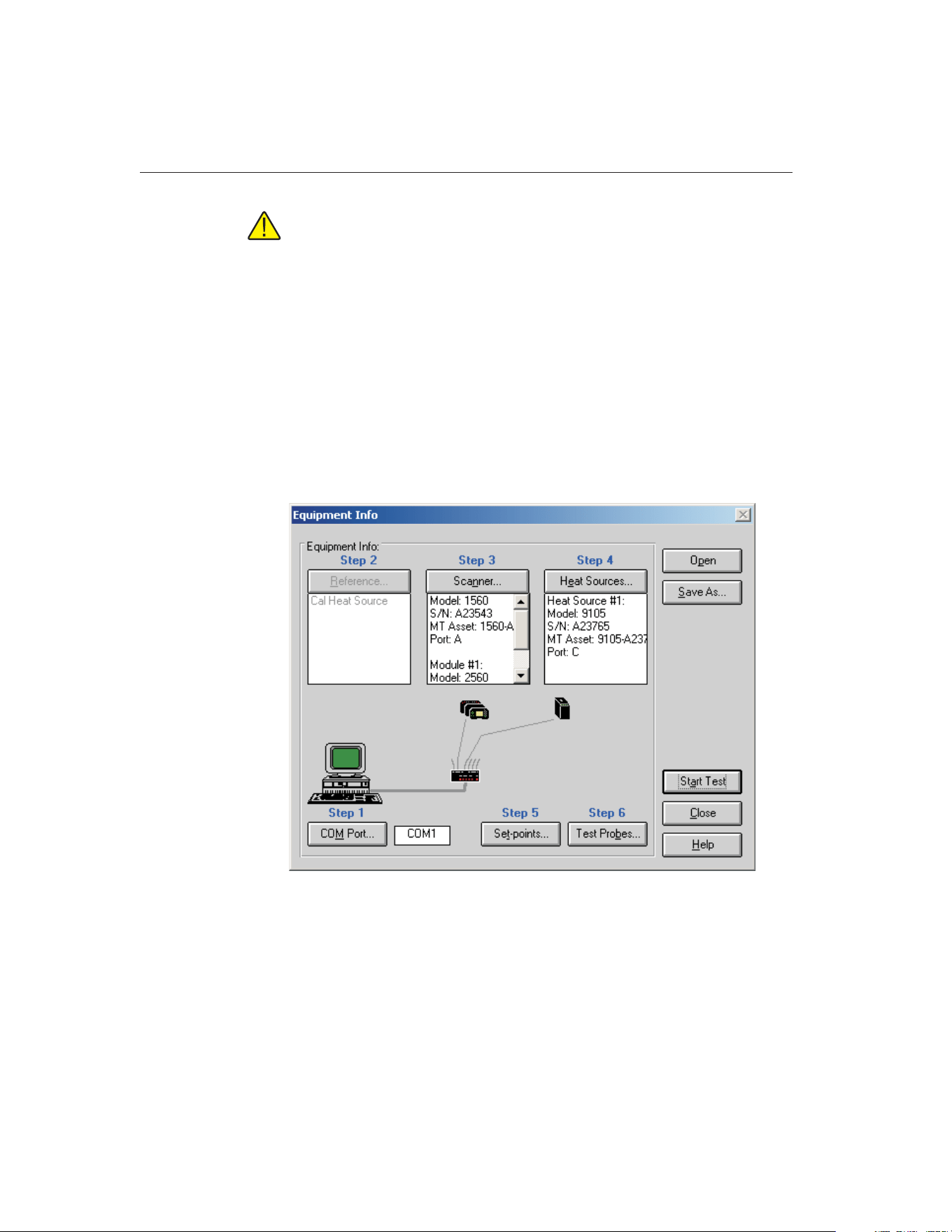
Note: When calibrating a micro-bath, you also need to be aware of the
temperature range of the calibration and the fluid being used in the mi-
cro-bath. Be sure to use a fluid that covers the entire range of the calibra-
tion or limit the calibration to the range of the fluid being used!
If you changed any of the set-point configuration settings and you wish to use
the current settings again, click the Save As button to save the current set-point
configuration to a new configuration file.
Click the OK button to close the Set-point Configuration dialog.
13.2.8 Start Heat Source Calibration
Once the COM port, scanner, heat source, test probe and set-point configura-
tions are complete, the heat source calibration test can be started. The Equip-
ment Info dialog displays the current instrument configuration.
Click the Start Test button on the Equipment Info dialog or select the Start Test
option from the Calibration menu to start the heat source calibration test.
After checking the configuration information and verifying communications
with the test equipment, the Test Information dialog is displayed.
9938 MET/TEMP II
User’s Guide
170
Figure 87 Equipment Info Dialog
1.888.610.7664 sales@GlobalTestSupply.com
Fluke-Direct.com

Finish configuring the test information on this dialog for the heat source cali-
bration. Refer to Section 5.5.2, Test Information Dialog for more details.
Note: When selecting the resolution setting for the readings, it is recommended
that a setting of 3 decimal places or more be used. The set-point resistance
readings from the heat source are typically formatted to 3 decimal places.
Using less resolution will most likely decrease the quality of the calibration.
Click the OK button to close this dialog and start the calibration test.
13.3 Performing Heat Source Calibrations
Heat source calibrations are performed in a similar manner to comparison cali-
brations. MET/TEMP II sets the heat source to the first set-point, waits until the
display of the heat source reaches the set-point and stabilizes, counts down the
duration time and takes readings. This process is repeated for all configured As
Found set-points.
Since MET/TEMP II must be configured to use the heat source as the reference
to perform heat source calibrations, the graph and display show the current heat
source temperature as indicated on the heat source’s display.
When MET/TEMP II takes the readings, the readings that are taken from the
test probe (in temperature) are stored in the database as the reference readings.
MET/TEMP II then takes set-point resistance readings from the heat source and
stores them in the database as the UUT readings.
After MET/TEMP II has taken readings at all As Found set-points, new calibra-
tion coefficients are calculated and stored in a database. If the Write new coeffi-
cients to heat source after calibration check box on the General tab on the
Defaults dialog is selected, MET/TEMP II attempts to write the new coefficient
values to the heat source. These coefficients are then verified to make sure the
heat source accepted the new values. If the value read from the heat source for
a coefficient does not match the calculated value, a message is displayed indi-
cating the calculated value and the value read from the heat source. Typically,
this message indicates that the calculated value of the coefficient exceeded the
acceptable range of values for that coefficient.
If one or more As Left set-points were configured, MET/TEMP II then pro-
ceeds to take readings at each of the As Left set-points in the same manner out-
lined above until readings have been taken at all set-points.
13.4 Printing Heat Source Reports of Calibration
When the calibration test is complete, select the Close Test option in the File
menu to close the test.
171
13
Performing Heat Source Calibrations
1.888.610.7664 sales@GlobalTestSupply.com
Fluke-Direct.com
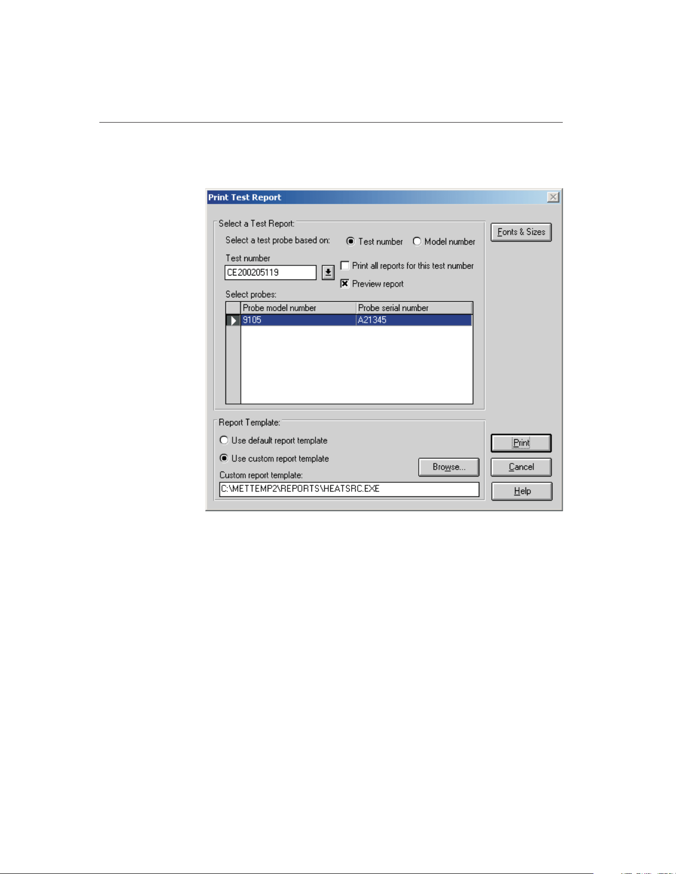
The Report of Calibration can be printed by selecting the Print Report option in
the File menu. The Print Test Report dialog is displayed.
When this dialog is displayed, the test number for the last calibration test
should already be selected. If not, select the appropriate test number using the
Test number drop-down list. The heat source that was calibrated should be dis-
played in the Select probes list.
In the Report Template section, select the Use custom report template option.
The Custom report template box and the Browse button are enabled. Click the
Browse button and select the file HEATSRC.EXE file in the \REPORTS folder.
Click the Print button to launch the custom heat source Report of Calibration
template. Refer to Section 11.2.2, Heat Source Report of Calibration, for more
details on the options available for printing heat source Reports of Calibration.
Click the Exit button to close the Print Heat Source Report of Calibration
dialog.
Click the Cancel button to close the Print Test Report dialog.
9938 MET/TEMP II
User’s Guide
172
Figure 88 Print Test Report Dialog
1.888.610.7664 sales@GlobalTestSupply.com
Fluke-Direct.com

14 MET/TRACK Export Process
MET/TEMP II can export calibration data to the MET/TRACK database when
the link to MET/TRACK is active. For more details on activating the link to
MET/TRACK, refer to Section 3.4.9, MET/TRACK Tab.
The first step to exporting calibration data to MET/TRACK is to identify the
data to export. Click the Export Calibration Data to MET/TRACK option in the
Utilities menu. Select the test containing the data to export and click the Export
button. The calibration data for ALL instruments calibrated are exported to
MET/TRACK.
When a calibration test is closed, MET/TEMP II can be configured to either au-
tomatically export calibration data or to prompt to export the calibration data. If
characterization coefficients need to be calculated for a probe, the coefficients
must be calculated before exporting the calibration data to MET/TRACK.
MET/TEMP II creates a calibration record for each UUT and exports the fol-
lowing information to the MET/TRACK database:
MET/TEMP II Data Calibration Field
Calibration date 2301
Calibration time 2333
Technician name 2307
Ambient temperature 2311
Ambient humidity 2312
Order ID 2314
Test procedure 2320
User defined comments
†
2329
Procedure end date 2342
Procedure end time 2343
Aborted flag 2363
Pass flag
‡
2323
Characterization coefficients or
heat source calibration coefficients
2341
§
†
The user defined comment can be entered on the MET/TRACK tab of
the Defaults dialog.
‡
The Pass flag (field 2323) setting is determined by the options on the
MET/TRACK tab of the Defaults dialog.
§
By default, coefficients are exported to field 2341. Refer to Section
14.2, Changing Coefficients Export Field, for information on changing
this field.
The assets (test equipment) that were used to perform the calibration are also
attached to the calibration record.
173
14
MET/TRACK Export Process
1.888.610.7664 sales@GlobalTestSupply.com
Fluke-Direct.com
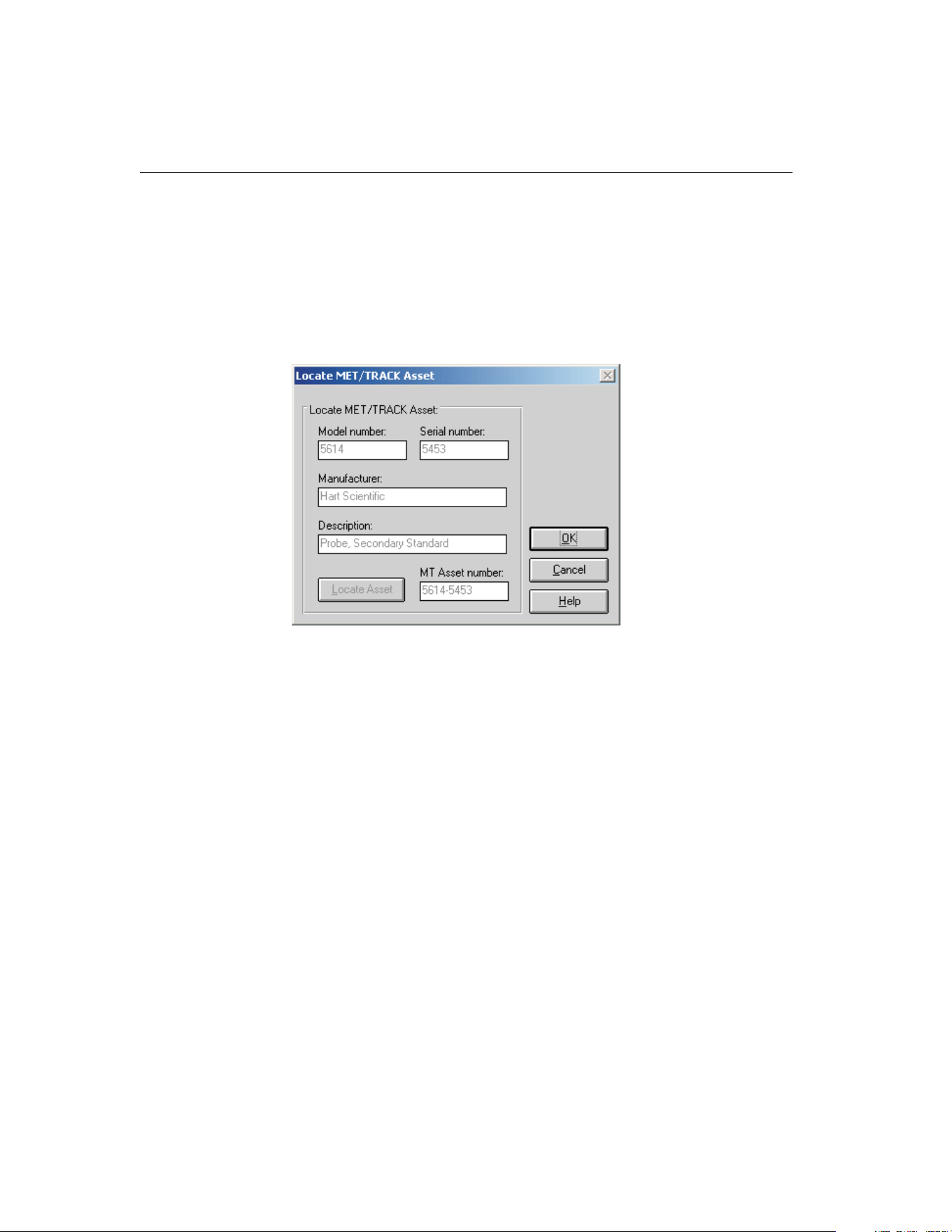
During the export process, if no asset number was previously assigned to the
UUT or test equipment, the Locate MET/TRACK Asset dialog is displayed.
This dialog allows the user to view the model, serial number and manufacturer
of the instrument. If a matching record cannot be located in the MET/TRACK
database, this gives the user the opportunity to add a record for the instrument
in MET/TRACK or to modify the information in either MET/TRACK or
MET/TEMP II so that the asset number can be found and assigned to the in-
strument.
This dialog will typically appear for any of the following reasons:
• The calibration was performed with a previous version of MET/TEMP II
(Calibrate-it)
• The link to MET/TRACK was not active when the calibration was per-
formed
• The asset record for the UUT or test equipment cannot be located in the
MET/TRACK database
♦
The record has not been created yet
♦
The record existed at one time, but has been deleted
♦
The model, serial number and manufacturer do not match EXACLTY
(case insensitive)
If MET/TEMP II successfully locates the asset record, the asset number is dis-
played in the MT Asset number box. Click OK to close this dialog and
continue.
If the MT Asset number box is empty, a matching asset record was not found in
the MET/TRACK database and a prompt to launch MET/TRACK is displayed.
9938 MET/TEMP II
User’s Guide
174
Figure 89 Locate MET/TRACK Asset Dialog
1.888.610.7664 sales@GlobalTestSupply.com
Fluke-Direct.com

The manufacturer information may be edited on this dialog if necessary to
match EXACTLY the manufacturer information in MET/TRACK. Click the
Locate Asset button to have MET/TEMP II search the MET/TRACK database
for a matching asset record again. When a match is found, click the OK button
to continue.
Click the Cancel button to abort exporting the calibration data to
MET/TRACK.
Important: When MET/TEMP II attempts to locate an asset in the
MET/TRACK database, the model, serial number and manufacturer must
match EXACTLY! If an asset record exists but MET/TEMP II is unable to
locate it, you may need to modify the manufacturer information in the
MET/TRACK database.
When exporting temperature vs. temperature calibration data, the Tolerances
dialog is displayed if this data is being exported for the first time and the appro-
priate option on the MET/TRACK tab of the Defaults dialog is selected. Enter
the tolerances for each set-point for each UUT to allow MET/TEMP II to auto-
matically determine the setting for the Pass field in the calibration summary
record.
When the export process is complete, a success message is displayed. If any er-
rors occurred during the export process, one or more error messages may be
displayed. To assist Technical Support in determining the cause of the error,
please write down the exact wording of any error message you receive. Refer to
the Troubleshooting section for more details on resolving export errors.
175
14
MET/TRACK Export Process
1.888.610.7664 sales@GlobalTestSupply.com
Fluke-Direct.com
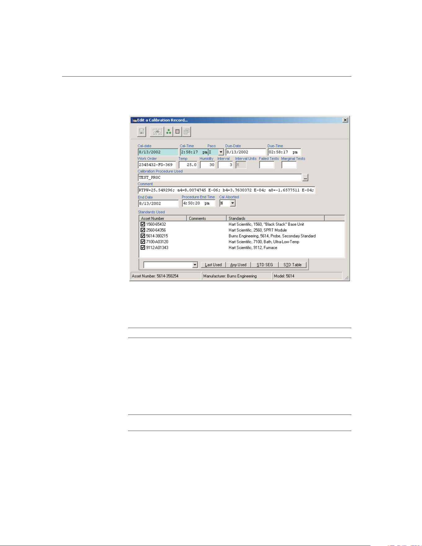
The calibration record can be viewed or edited in MET/TRACK using the Edit
a Calibration Record dialog as show below or by using the search engine.
MET/TEMP II also utilizes the FullResults table (new in MET/TRACK version
7) to export the test readings:
MET/TEMP II Data FullResults Fields
Number of measurements num_meas
Temperature set-point and scale expv, expv_p and expv_u
Reference reading and scale sys_actual, sys_actual_p and sys_actual_u
UUT reading and scale uut_ind, uut_ind_p and uut_ind_u
Error and scale (as applicable) error, error_p and error_u
Uncertainty and scale exp_uncert, exp_uncert_p and exp_uncert_u
Tolerance and scale
‡
tol, tol_p , and tol_u
User defined comments
†
remark
†
The user defined comment can be entered on the MET/TRACK tab of the Defaults dialog.
‡
The tolerance values only apply to temperature vs. temperature calibration data.
9938 MET/TEMP II
User’s Guide
176
Figure 90 MET/TRACK 7 Edit a Calibration Record Dialog
1.888.610.7664 sales@GlobalTestSupply.com
Fluke-Direct.com
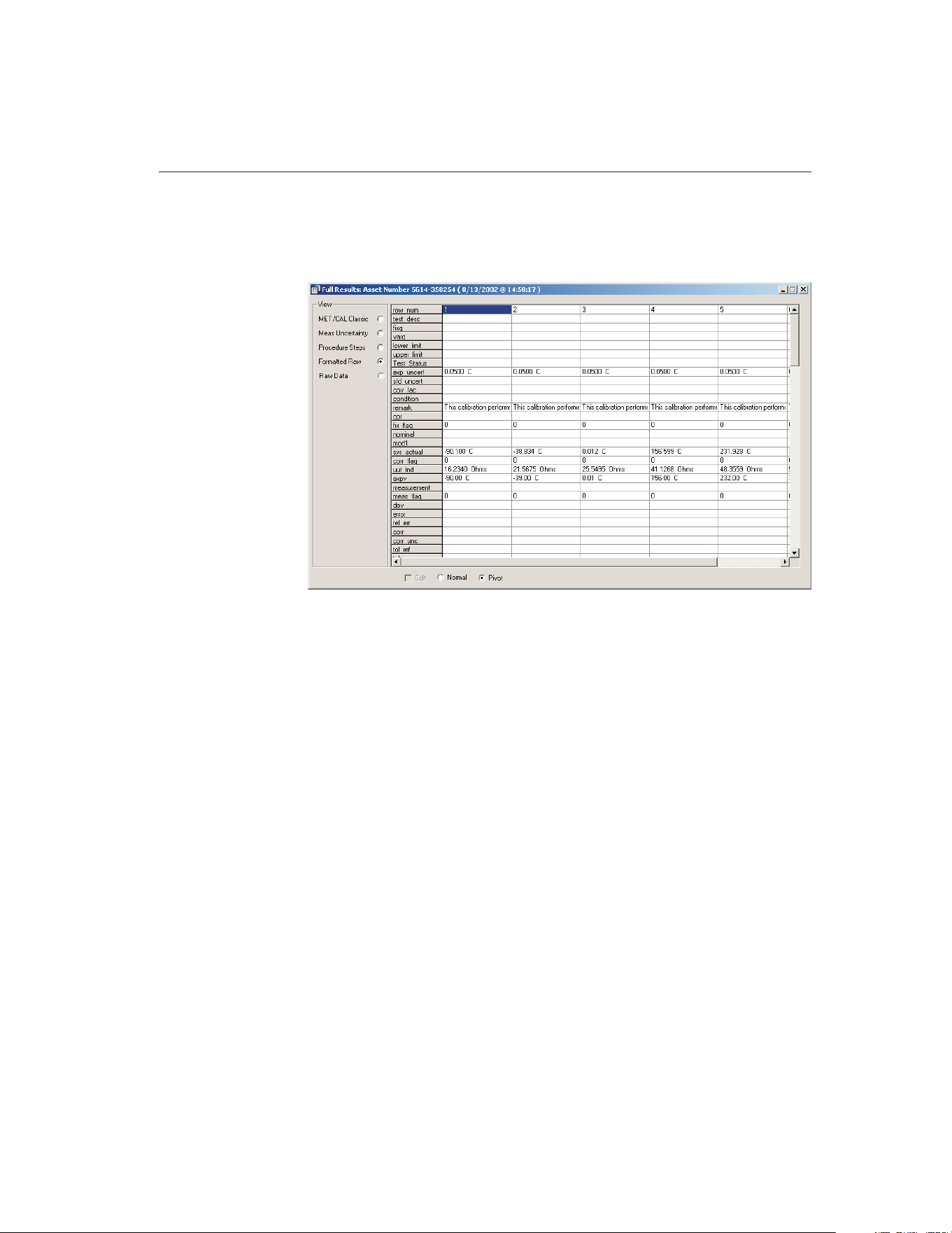
The FullResults record can be viewed in MET/TRACK using the search engine
to locate the asset record and calibration record, and clicking on the FullResults
button on the Calibration tab of the Instrument Browser dialog as show below:
14.1 Tolerances
The Tolerances dialog allows the user to enter a tolerance value for each
set-point for a UUT. This dialog is displayed when exporting temperature vs.
temperature calibration data to the MET/TRACK database if the Prompt for tol-
177
14
MET/TRACK Export Process
Figure 91 MET/TRACK 7 Full Results Dialog
1.888.610.7664 sales@GlobalTestSupply.com
Fluke-Direct.com
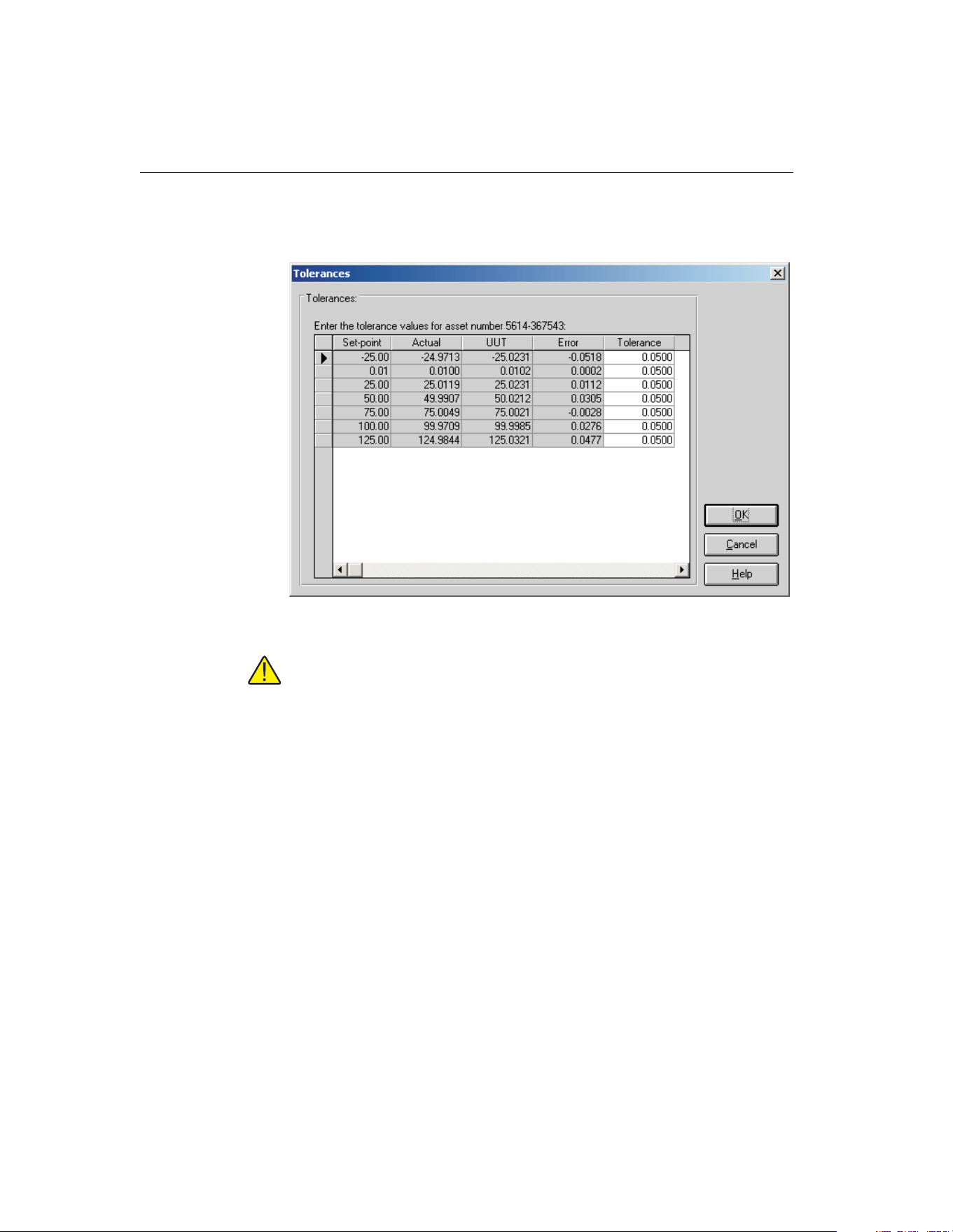
erance and determine Pass field setting automatically option on the
MET/TRACK tab of the Defaults dialog is selected.
Note: This dialog is only displayed the first time the calibration data for a
UUT is exported. The entered tolerance values are stored in the
MET/TEMP II database and used automatically if the same data is ex-
ported again.
Enter the tolerance value at each set-point for the indicated asset. The tolerance
values are formatted automatically to the same number of decimal places as the
values in the UUT column when the cursor leaves each cell.
When the calibration data is exported, MET/TEMP II compares the absolute
value of the Error to the absolute value of the Tolerance. If the value of the Er-
ror is greater than the value of the Tolerance, at any set-point, the Pass field in
the calibration summary record is set to “N”. If the Error is less than or equal to
the Tolerance for all set-points, the Pass field is set to “Y”.
Click the OK button to export the calibration data for this asset to the
MET/TRACK database. To abort exporting this calibration data to
MET/TRACK, click the Cancel button.
9938 MET/TEMP II
User’s Guide
178
Figure 92 MET/TRACK Export Tolerances Dialog
1.888.610.7664 sales@GlobalTestSupply.com
Fluke-Direct.com

14.2 Changing Coefficients Export Field
By default, the characterization coefficients for a probe and the heat source cal-
ibration constants are exported to the 2341 field of the calibration summary re-
cord when exported to MET/TRACK. However, this field can be changed by
following the process outlined below.
1 Using a text editor, locate and open the MT32MTII.INI file. This file is
located in the C:\WINDOWS (for Windows® 9x/ME/XP) or C:\WINNT
(for Windows® 2000/NT) folder.
2 Locate the [Mapping] section. There should be one entry in this
section:
[Mapping]
CoefficientsField=2341
3 Change the field referenced by the CoefficientsField entry to the
field the coefficients should be written to.
[Mapping]
CoefficientsField=2354
4 Save and close the file.
The next time coefficients are exported to the MET/TRACK database, any
probe coefficients or heat source constants should be written to the referenced
field.
Important: MET/TEMP II does not attempt to validate the field type or
length! Be sure to map the coefficients to a field of type SPVAL with
enough characters to hold the type of coefficients or constants being writ-
ten to it or the export process may fail!
179
14
MET/TRACK Export Process
1.888.610.7664 sales@GlobalTestSupply.com
Fluke-Direct.com

15 Coefficients and Tables Application
15.1 What is the Coefficients and Tables Application?
The Coefficients and Tables application (formerly known as Generate-it)isan
add-on for MET/TEMP II (formerly Calibrate-it). MET/TEMP II is designed to
acquire and store data from reference probes and test probes (UUTs). This data
is used by this software to calculate characterization coefficients, print Reports
of Calibration, and generate tables.
This software calculates characterization coefficients for platinum, thermistor,
and thermocouple probes. The types of coefficients that can be calculated are:
ITS-90 for platinum probes; IPTS-68 for platinum probes; Callendar-Van
Dusen for platinum probes; Polynomial for platinum and thermistor probes;
and coefficients for thermocouple probes types B, E, J, K, N, R, S, T, and AuPt.
This software also generates temperature vs. resistance, temperature vs. ratio,
and temperature vs. EMF tables.
This software also allows data that was acquired during a test as well as calcu-
lated coefficients to be exported to an ASCII text file. This data can then be
easily imported into a spreadsheet or other application.
15.2 New Features
15.2.1 Version 4.1
A list of new features and enhancements in version 4.1 of the Coefficients and
Tables application follows:
Adjustable Margins and Table Column Widths
The top, bottom, left, and right margins on the Report of Calibration are now
adjustable. To set the margins, select the Defaults option in the File menu in
MET/TEMP II, and click on the Reports tab. This tab also allows the column
widths of the Test Equipment table to be adjusted.
Print Custom Logo on Report of Calibration
A custom logo can now be added to the Report of Calibration. The logo ap-
pears in the upper left corner of the Report of Calibration. To set the logo to
use, select the Defaults option in the File menu in MET/TEMP II, and click on
the Reports tab.
Bug Fixes
In addition to the new features listed above, the following known bugs and
other issues have been fixed:
181
15
Coefficients and Tables Application
1.888.610.7664 sales@GlobalTestSupply.com
Fluke-Direct.com

Printing to network printers: When attempting to print to a network printer,
an error would sometimes occur stating the printer was not available. This issue
has been resolved. (KB0013)
General Protection Fault error: When using Windows® 2000/XP, a GPF er-
ror in module DWVSTAMP.VBX would occur when launching the application
for the first time. This issue has been resolved.
Error attempting to write coefficients to database: The following error
would sometimes occur when attempting to save coefficients to the database:
"Error 3163 - Couldn’t insert or paste; data too long for field". This issue has
been resolved. (KB0023)
ITS-90- Range 5 Tables: An issue regarding table generation using ITS-90
Range 5 coefficients was resolved.
15.2.2 Version 4.0
A list of new features and enhancements in version 4.0 of the Coefficients and
Tables application follows:
Matching Temperature Scales
This software now displays set-point requirements in the same temperature
scale as the set-points being selected. Prior to this version, set-point require-
ments were always displayed in degrees C.
Customizable Export Fields
This software now includes a feature that allows the test data to export to be
customized. In addition, the export file can now be divided into three sections:
header section, test equipment section and readings section. The data to export
to each of these sections can be easily customized.
Other Changes
Many other small changes have been made to this software, including addition
of a0 and a1 coefficients on Type K Thermocouple Reports of Calibration and
more. For a complete list of these changes, refer to the README.TXT file.
9938 MET/TEMP II
User’s Guide
182
1.888.610.7664 sales@GlobalTestSupply.com
Fluke-Direct.com

15.3 Main Display
The MET/TEMP II Coefficients and Tables main display consists of the menu,
toolbar, and a workspace area.
The menu bar allows access to the various features of the software. A general
description of the options in each menu is given below:
File - Export test data and coefficients, change default settings, access printing
options, exit the software.
Coefficients - Calculate coefficients from test data.
Utilities - Compact, repair and maintain databases.
Help - Display help topics and About dialog.
15.4 Toolbar
The toolbar provides quick access to many of the most common functions such
as exporting test data to a text file, printing reports and tables, viewing and edit-
ing default settings, and calculating the different types of probe coefficients.
The function of each toolbar button can be found by placing the mouse pointer
over the button and waiting for approximately 1/2 second. A help balloon ap-
pears indicating the function of the button. If a help balloon does not appear,
make sure the Show help balloons check box on the General tab of the Defaults
dialog is selected.
The following buttons are available on the toolbar:
183
15
Coefficients and Tables Application
Figure 93 Coefficients and Tables Main Display
1.888.610.7664 sales@GlobalTestSupply.com
Fluke-Direct.com
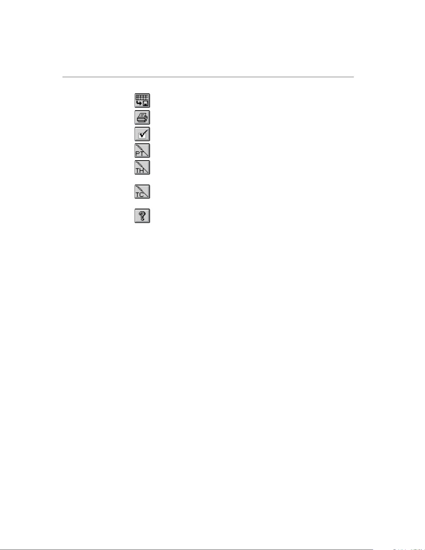
Export - Export data to a text file
Print Reports and Tables - Print a Report of Calibration and/or Table
Defaults - Setup default settings
Platinum Probe Coefficients - Calculate Platinum probe coefficients
Thermistor Probe Coefficients - Calculate Thermistor probe
coefficients
Thermocouple Probe Coefficients - Calculate Thermocouple probe
coefficients
Help - Open the help file
15.5 Calculating Characterization Coefficients
This software was designed to take the test data acquired by MET/TEMP II and
calculate characterization coefficients. The software can then use these coeffi-
cients to generate temperature vs. resistance, temperature vs. ratio or tempera-
ture vs. EMF tables.
Before the Coefficients and Tables application can be used, you must first per-
form a calibration test using MET/TEMP II. When performing a calibration
test, keep in mind the following:
• The readings for the reference probe MUST be in a temperature scale (C,
F or K)
• The readings for the test probes (UUTs) MUST be in either resistance
(Ohms or kOhms) or voltage (mV or µV)
• MET/TEMP II MUST acquire readings at a sufficient number of
set-points, depending on the type of coefficients that are to be calculated
(refer to Section 15.12, Requirements and Methods, for more details)
The following sections describe in detail how to calculate characterization coef-
ficients and print Reports of Calibration and tables.
15.5.1 Calculating Coefficients
Prior to calibrating the UUT using MET/TEMP II, you should decide what type
of characterization coefficients you want to calculate. The set-points you select
depend on the type of characterization you choose.
After a test probe (UUT) has been calibrated using MET/TEMP II, this soft-
ware can be used to calculate characterization coefficients. Launch the applica-
tion from the Utilities menu in MET/TEMP II.
9938 MET/TEMP II
User’s Guide
184
1.888.610.7664 sales@GlobalTestSupply.com
Fluke-Direct.com
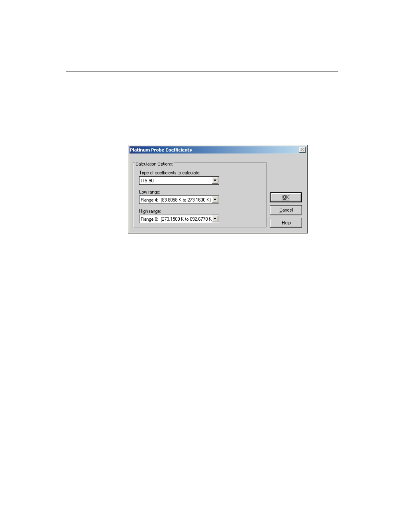
The following sections describe how to calculate coefficients for PRT/RTD,
Thermistor and Thermocouple probes.
15.5.1.1 Calculating PRT/RTD Coefficients
To calculate coefficients for PRT/RTD probes, select the Platinum Probe option
in the Coefficients menu. The Platinum Probe Coefficients dialog is displayed.
Select the type of coefficients to calculate using the Type of coefficients to cal-
culate drop-down list. For PRT/RTD probes, the choices are:
• ITS-90
• IPTS-68
• Callendar-Van Dusen
• Polynomial
Depending on the type of coefficients selected, additional information may or
may not be required.
If ITS-90 is selected, the low range and high range options must be chosen us-
ing the Low range and High range drop-down lists. ITS-90 coefficients can be
calculated for the following subranges:
Low Range
• None
• Range 4 (83.8058 K to 273.1600 K)
• Range 5 (234.3156 K to 302.9146 K)
High Range
• None
• Range 6 (273.1500 K to 1234.9300 K)
185
15
Coefficients and Tables Application
Figure 94 Platinum Probe Coefficients Dialog (ITS-90)
1.888.610.7664 sales@GlobalTestSupply.com
Fluke-Direct.com
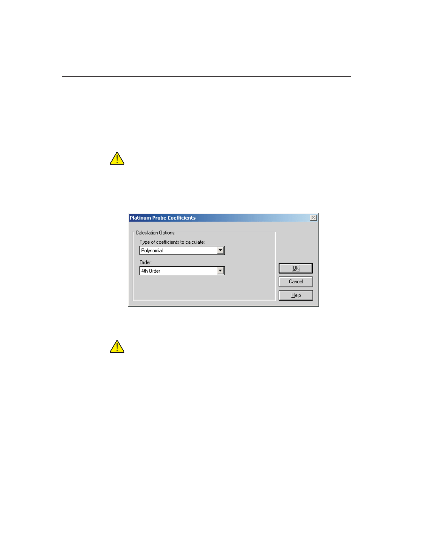
• Range 7 (273.1500 K to 933.4730 K)
• Range 8 (273.1500 K to 692.6770 K)
• Range 9 (273.1500 K to 505.0780 K)
• Range 10 (273.1500 K to 429.7485 K)
• Range 11 (273.1500 K to 302.9146 K)
Note: The temperature ranges indicated are displayed in Kelvin and are
intended for convenience only.
If Polynomial is selected, the order of the polynomial must be selected using
the Order drop-down list. This application can calculate from 3rd to 9th order
polynomials for PRT/RTD probes.
Note: The number of coefficients calculated is always one more than the
order of the polynomial (i.e. for a 4th order polynomial, 5 coefficients are
calculated). The minimum number of set-points required must exceed the
order of the polynomial by at least 1.
If IPTS-68 or Callendar-Van Dusen is selected, no additional settings are
required.
Click the OK button to continue and display the Calculate Coefficients dialog
(refer to Section 15.5.1.4, Calculate Coefficients Dialog).
Click the Cancel button to abort calculating coefficients and return to the Main
Display.
9938 MET/TEMP II
User’s Guide
186
Figure 95 Platinum Probe Coefficients Dialog (Polynomial)
1.888.610.7664 sales@GlobalTestSupply.com
Fluke-Direct.com
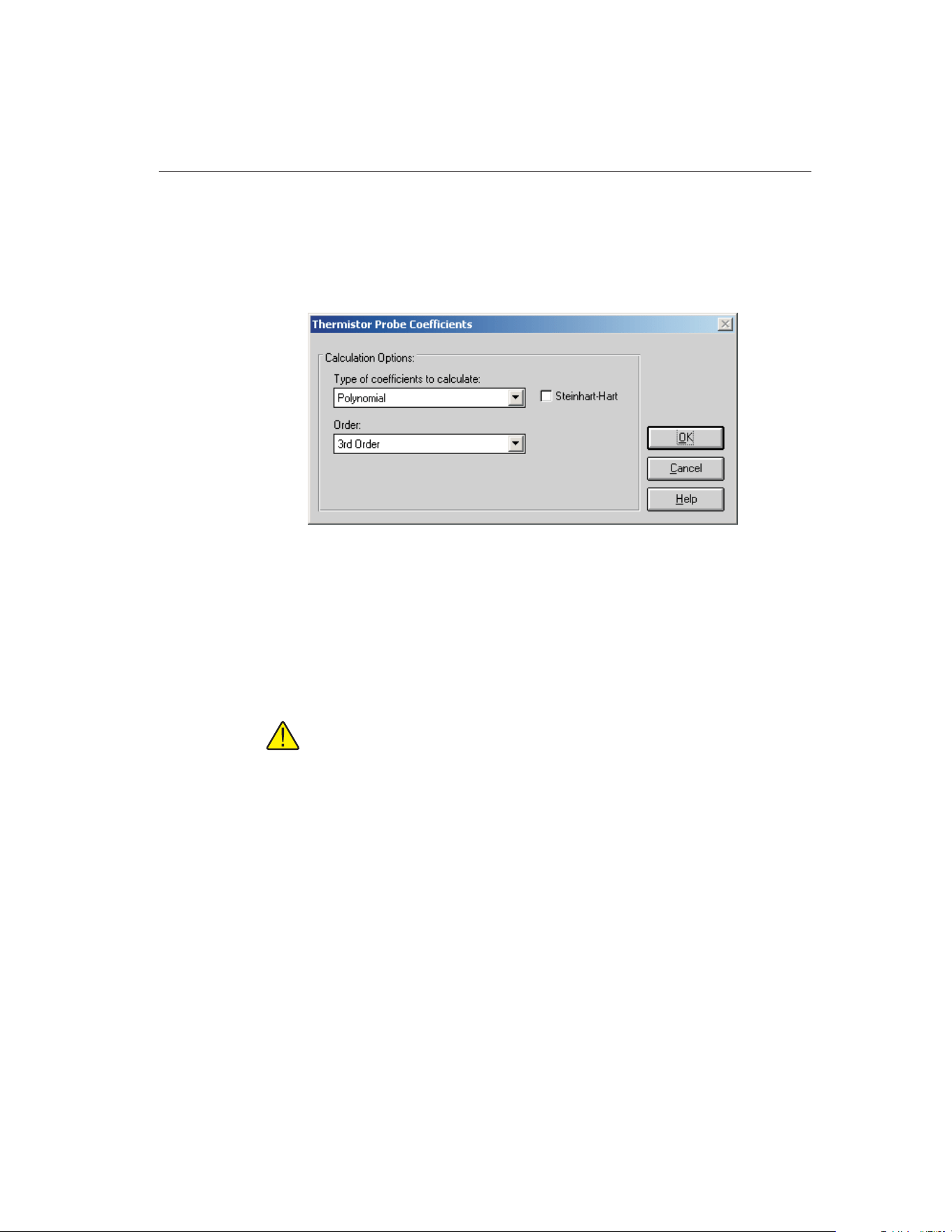
15.5.1.2 Calculating Thermistor Coefficients
To calculate coefficients for Thermistor probes, select the Thermistor Probe op-
tion in the Coefficients menu. The Thermistor Probe Coefficients dialog is dis-
played.
Select the type of coefficients to calculate using the Type of coefficients to cal-
culate drop-down list. For Thermistor probes, the only choice is Polynomial.
Both T(R) and R(T) polynomial coefficients are calculated.
The order of the polynomial must be selected using the Order drop-down list.
The application can calculate from 3rd to 6th order polynomials for Thermistor
probes.
Note: The number of coefficients calculated is always one more than the
order of the polynomial (i.e. for a 3rd order polynomial, 4 coefficients are
calculated). The minimum number of set-points required must exceed the
order of the polynomial by at least 1.
Select whether or not the Steinhart-Hart method should be used. The coeffi-
cients are calculated by checking or unchecking the Steinhart-Hart check box.
When this option is selected, the third coefficient (squared term) is set to 0.0.
Refer to Section 15.12.4, Polynomial Requirements, for more information
about the Steinhart-Hart method.
187
15
Coefficients and Tables Application
Figure 96 Thermistor Probe Coefficients Dialog
1.888.610.7664 sales@GlobalTestSupply.com
Fluke-Direct.com
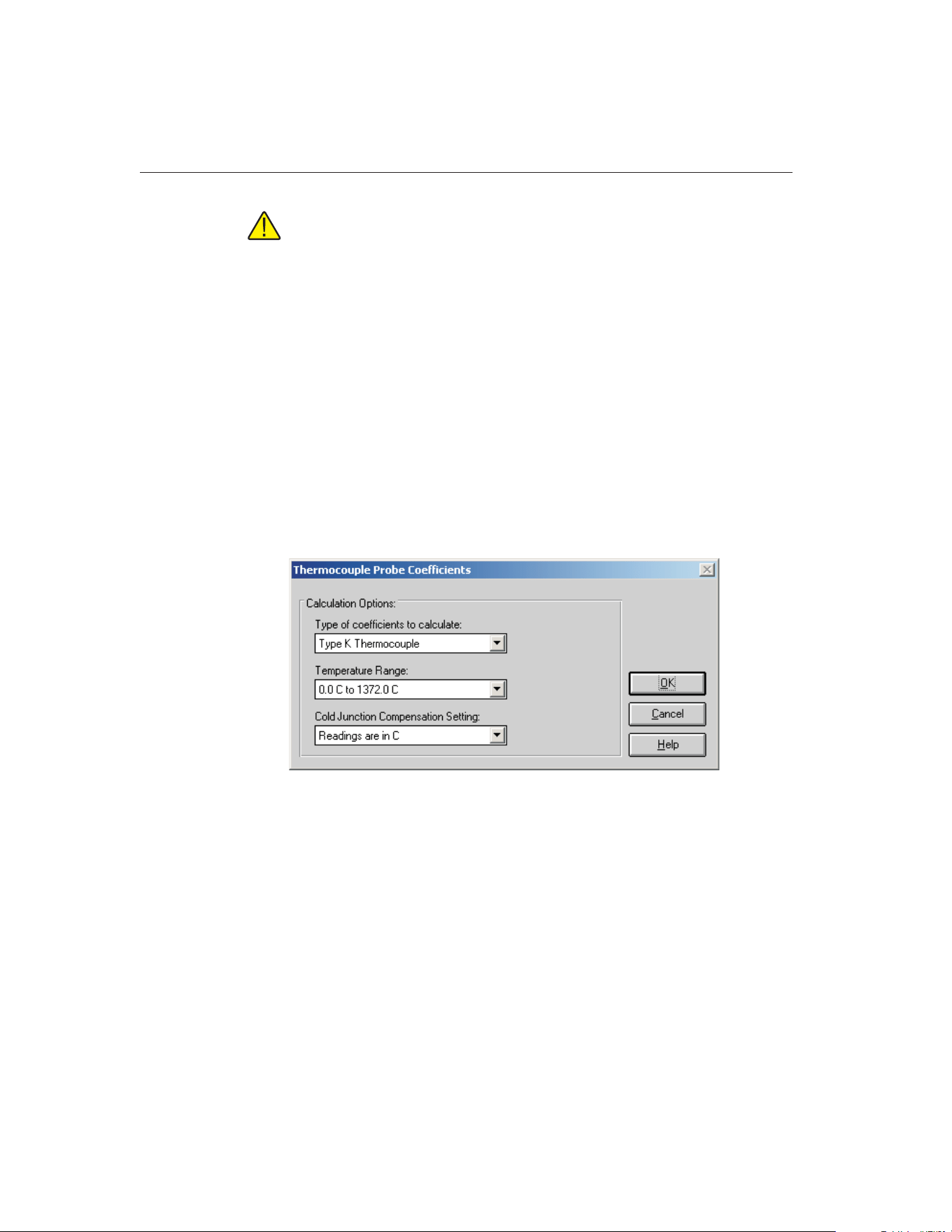
Important: The accepted thermistor model is based upon the logarithmic
resistance-temperature characteristic in terms of absolute temperature
(Kelvin). The accuracy of a model based upon degrees F or degrees C has
not been tested. Therefore, this application always calculates polynomial
coefficients for thermistor probes using Kelvin. If reference readings are in
degrees F or degrees C, the readings are automatically converted to Kel-
vin values before the fit is computed.
Click the OK button to continue and display the Calculate Coefficients dialog
(refer to Section 15.5.1.4, Calculate Coefficients Dialog).
Click the Cancel button to abort calculating coefficients and return to the Main
Display.
15.5.1.3 Calculating Thermocouple Coefficients
To calculate coefficients for Thermocouple probes, select the Thermocouple
Probe option in the Coefficients menu. The Thermocouple Probe Coefficients
dialog is displayed.
Select the type of coefficients to calculate using the Type of coefficients to cal-
culate drop-down list. For Thermocouple probes, the following options are
available:
• Type B Thermocouple
• Type E Thermocouple
• Type J Thermocouple
• Type K Thermocouple
• Type N Thermocouple
• Type R Thermocouple
9938 MET/TEMP II
User’s Guide
188
Figure 97 Thermocouple Probe Coefficients Dialog (Type K)
1.888.610.7664 sales@GlobalTestSupply.com
Fluke-Direct.com
• Type S Thermocouple
• Type T Thermocouple
• Type AuPt Thermocouple
Next, select the temperature range that your UUT was calibrated over using the
Temperature range drop-down list. The available choices depends on the type
of thermocouple selected above.
Note: The temperature ranges for thermocouple probes are always dis-
played here in degrees C and are intended for convenience only.
Select the appropriate option for cold junction readings using the Cold junction
compensation setting drop-down list. MET/TEMP II can be configured to take
CJC readings for thermocouple probes. This application needs to know the
scale of those readings. If CJC readings are not required or were not taken, se-
lect the Do not use CJC in calculations option. The CJC readings are ignored. If
you select any other option, the test probe readings are compensated according
to the CJC readings for each set-point before calculating the coefficients.
Note: For all Hart thermometer readouts, cold junction readings are AL-
WAYS in degrees C! If cold junction readings were entered manually for
your UUT, select the appropriate option.
Click the OK button to continue and display the Calculate Coefficients dialog
(refer to Section 15.5.1.4, Calculate Coefficients Dialog).
Click the Cancel button to abort calculating coefficients and return to the Main
Display.
189
15
Coefficients and Tables Application
1.888.610.7664 sales@GlobalTestSupply.com
Fluke-Direct.com
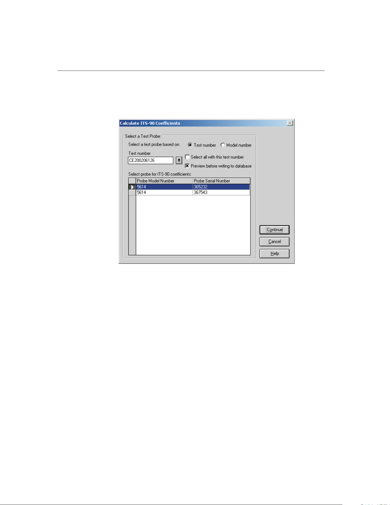
15.5.1.4 Calculate Coefficients Dialog
The Calculate Coefficients dialog is displayed when the OK button is clicked
on the Coefficient Calculation dialog.
To calculate coefficients for a test probe, you must select either a test number
or a model number on which to base the test probe selection.
If the test number option is selected, a list of test numbers becomes available.
Select a test number. Once the test number is selected, the probe model num-
bers and serial numbers appear in the Select probe... list.
If the model number option is selected, a list of probe model numbers becomes
available. Select a model number. Once the model number is selected, the
probe serial numbers and test numbers for this model appear in the Select
probe... list.
Select the test probes from the Select probe... list. If the Select all with this test
number check box is selected, coefficients are calculated for all probes associ-
ated with this test number. If not selected, coefficients are calculated only for
the highlighted test probe(s) in the Select probe... list.
If the Preview before writing to database check box is selected, the coefficients
and residuals are displayed on the Coefficients and Residuals dialog after being
calculated. The user is asked whether to save the coefficients. Otherwise, the
coefficients are automatically saved in the database after being calculated.
9938 MET/TEMP II
User’s Guide
190
Figure 98 Calculate Coefficients Dialog
1.888.610.7664 sales@GlobalTestSupply.com
Fluke-Direct.com
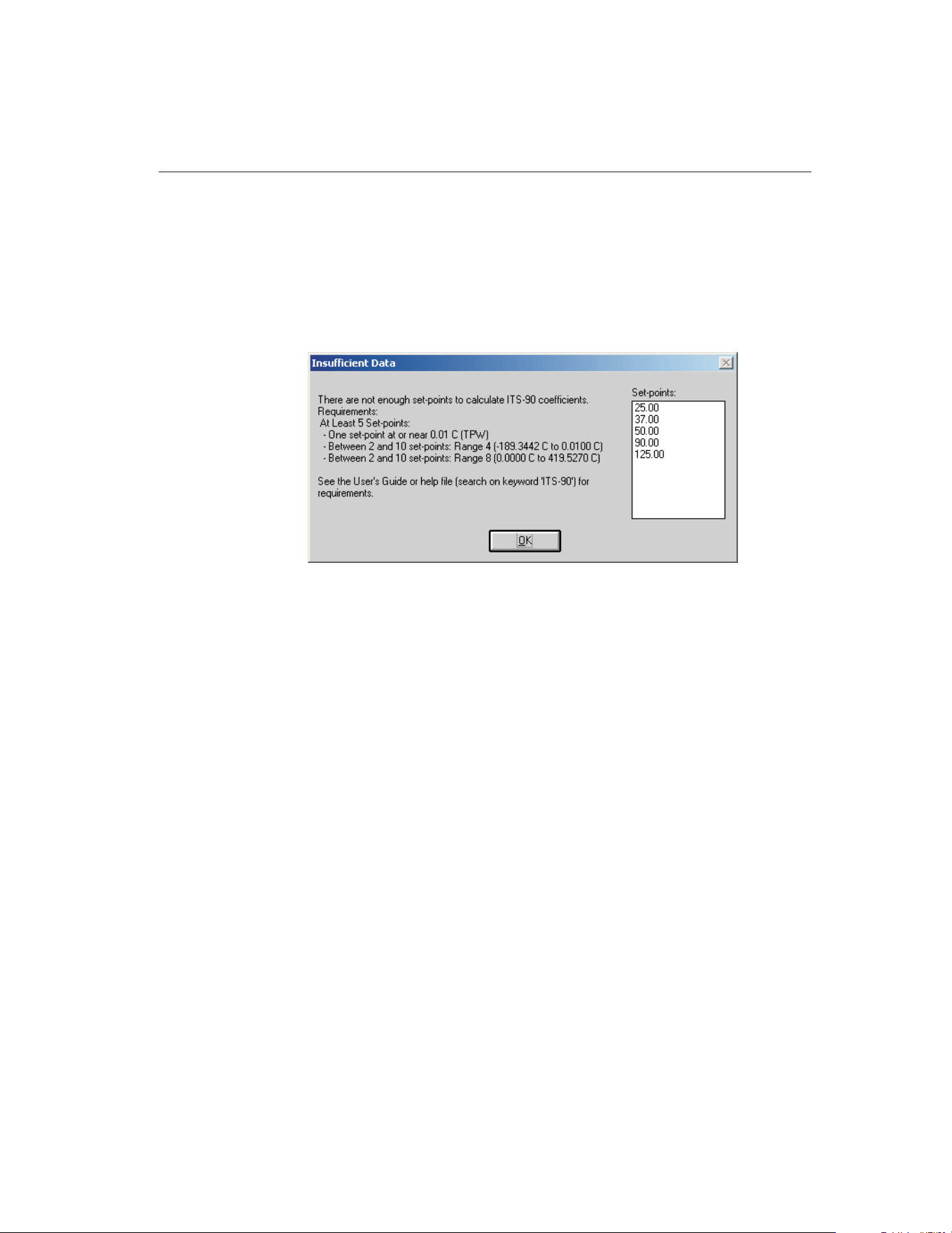
Click the Continue button to proceed. The application will verify that the read-
ings for the selected test probe meet the requirements for the selected type of
coefficients. If all requirements are met, the Select Set-points dialog is dis-
played. If the requirements are not met, the Insufficient Data dialog is dis-
played indicating that the selected type of coefficients cannot be calculated
using the available data for the selected test probe. Click the OK button to close
the Insufficient Data dialog and return to the Calculate Coefficients dialog.
Click the Cancel button to close the Calculate Coefficients dialog and return to
the Main Display.
191
15
Coefficients and Tables Application
Figure 99 Insufficient Data Dialog
1.888.610.7664 sales@GlobalTestSupply.com
Fluke-Direct.com
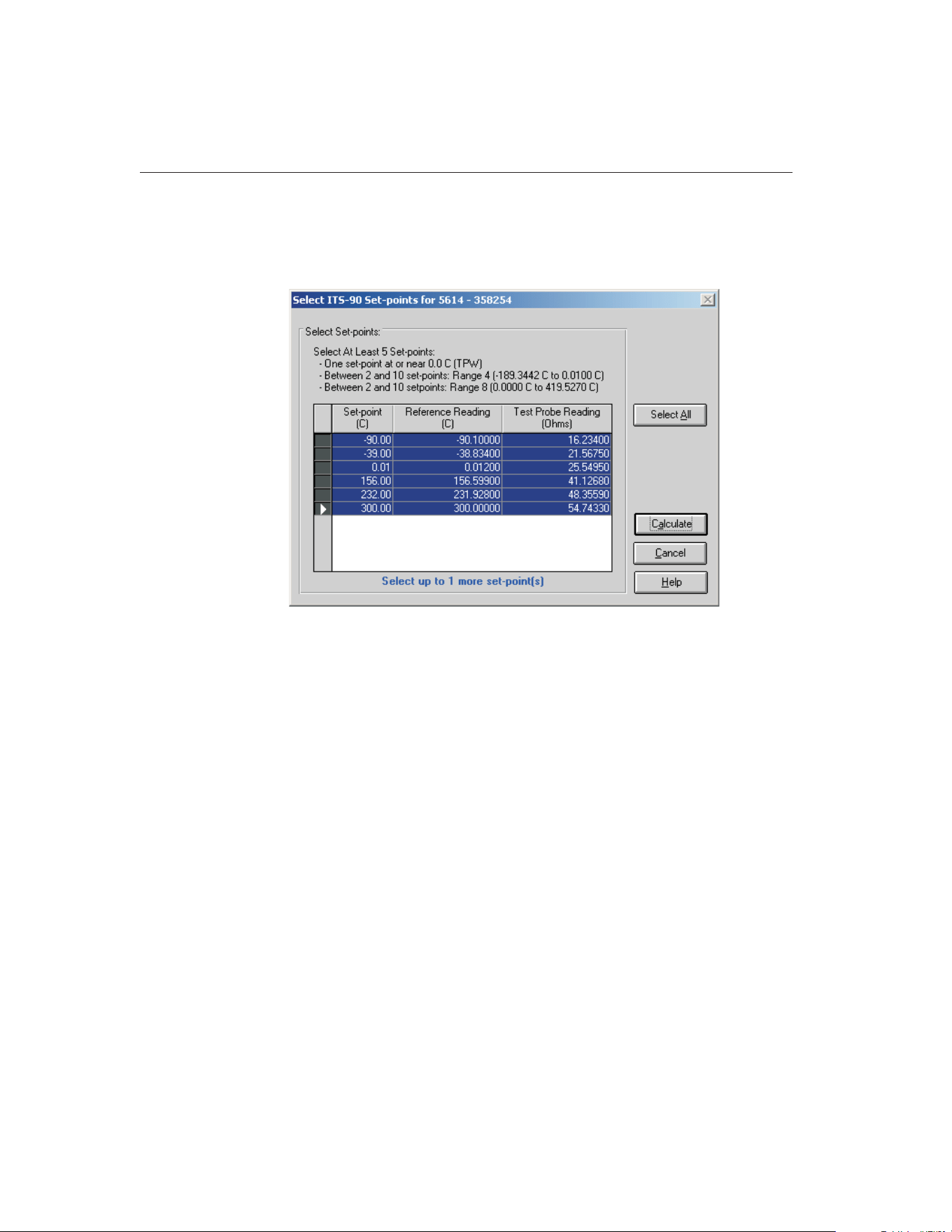
15.5.1.5 Select Set-points Dialog
The Select Set-points dialog is displayed when the Continue button is clicked
on the Calculate Coefficients dialog.
The Select Set-points dialog displays all of the test data that was acquired by
MET/TEMP II for the test probe model and serial number indicated in the title
bar. Select the set-points to use to calculate the selected type of characterization
coefficients for this test probe. Instructions pertaining to the requirements are
displayed at the top of this dialog. For more information on these requirements
see the following sections:
• Section 15.12.1, ITS-90 Requirements
• Section 15.12.2, IPTS-68 Requirements
• Section 15.12.3, Callendar-Van Dusen Requirements
• Section 15.12.4, Polynomial Requirements
• Section 15.12.5, Thermocouple Requirements
Information about the number of set-points that can be selected also appears at
the bottom of the dialog.
To select a set-point, click on the appropriate row in the grid. The row will be
highlighted and the information at the bottom of this dialog is updated. To
unselect a set-point, simply click the appropriate row in the grid again and the
row will be unhighlighted.
9938 MET/TEMP II
User’s Guide
192
Figure 100 Select Set-points Dialog
1.888.610.7664 sales@GlobalTestSupply.com
Fluke-Direct.com
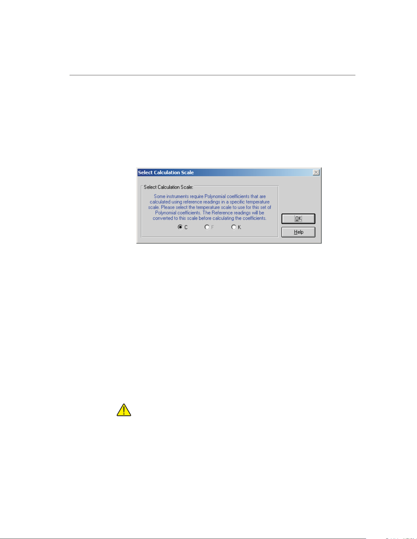
To use all of the set-points to calculate the coefficients, click the Select All
button.
When the set-points have been selected, click the Calculate button to proceed.
The software will compare the selected set-points against the requirements. If a
problem or error is detected, a message is displayed indicating the problem
found.
When calculating Polynomial coefficients for Platinum probes, the Select Cal-
culation Scale dialog is displayed.
Some instruments that use Polynomial coefficients require the coefficients to be
calculated using a specific temperature scale. The software allows the user to
select the temperature scale to use:
• If the reference readings are in degrees C, the user may select between C
and K.
• If the reference readings are in degrees F, the user may select between F
and K.
• If the reference readings are in K, coefficients will automatically be calcu-
lated using K.
Many readout instruments that accept Polynomial coefficients require that the
coefficients be calculated using reference readings in a particular temperature
scale. This feature allows reference readings to be used as acquired by
MET/TEMP II (with no conversion) or to be converted automatically to K by
the application.
Note: This application does not provide the option of converting reference
readings from degrees F to degrees C nor vice-versa. Also, if reference
readings were acquired in K, the Select Calculation Scale dialog will not
be displayed and Polynomial coefficients will automatically be calculated
using K.
193
15
Coefficients and Tables Application
Figure 101 Select Calculation Scale Dialog
1.888.610.7664 sales@GlobalTestSupply.com
Fluke-Direct.com
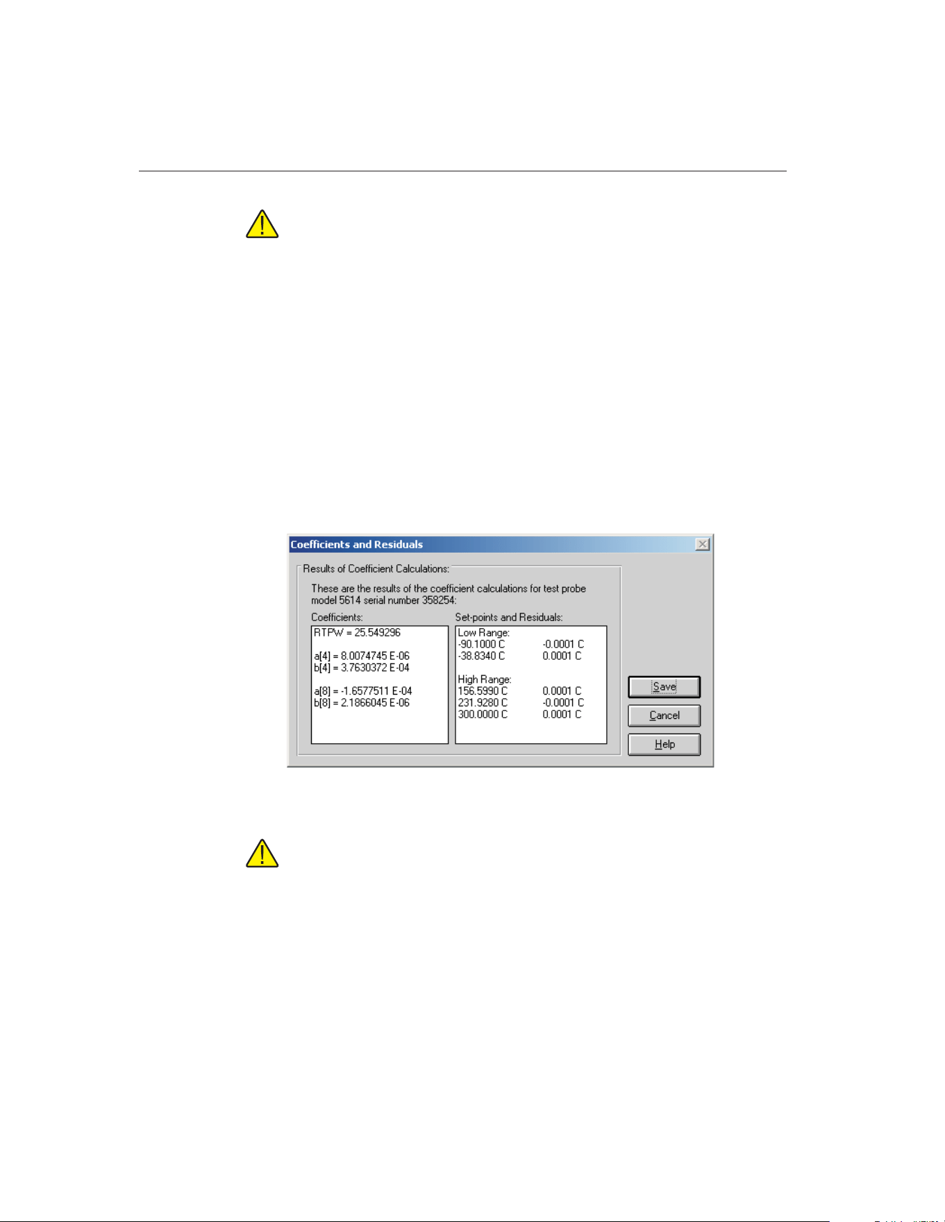
Note: The accepted thermistor model is based upon the logarithmic resis-
tance-temperature characteristic in terms of absolute temperature (K). The
accuracy of a model based upon degrees F or degrees C has not been
tested. Therefore, this software always calculates polynomial coefficients
for thermistor probes using K. If reference readings are entered in degrees
F or degrees C, the software converts the readings to their K equivalent
values before the fit is computed.
Click the OK button on the Select Calculation Scale dialog after selecting the
appropriate option to continue.
Click the Cancel button on the Select Set-points dialog to abort calculating co-
efficients and return to the Calculate Coefficients dialog.
15.5.1.6 Coefficients and Residuals Dialog
The Coefficients and Residuals dialog is displayed when the Calculate button is
clicked on the Select Set-points dialog.
Note: If the Preview before writing to database check box on the Calcu-
late Coefficients dialog was not selected, this dialog does not appear and
the calculated coefficients and residuals are automatically written to the
database.
The calculated coefficients are displayed in the Coefficients list. The set-points
used to calculate the coefficients and the resulting residuals are displayed in the
Set-points and Residuals list.
If ITS-90 coefficients were calculated, the set-points used for the low and the
high ranges (as applicable) are displayed in separate sections. The Triple-Point
9938 MET/TEMP II
User’s Guide
194
Figure 102 Coefficients and Residuals Dialog
1.888.610.7664 sales@GlobalTestSupply.com
Fluke-Direct.com

of Water set-point does not appear in the Set-points and Residuals list because
the residual at the Triple-Point of Water is always 0.0.
The residuals are always displayed in the same scale as the reference readings
(for resistance based probes) or UUT readings (for voltage based probes). For
thermistor probes, residuals are always displayed in millidegrees.
To save the coefficients and residuals to the database, click the Save button.
This information must be saved in order to print a Report of Calibration and/or
table. If coefficients have been previously calculated using this test data for this
test probe, a prompt is displayed to confirm overwriting the existing
coefficients.
Note: To disable this prompt from appearing, uncheck the Prompt before
overwriting existing coefficients in database check box on the Coefficients
tab of the Defaults dialog. Refer to Section 15.7.3, Defaults, for more in-
formation.
Click the Cancel button to close this dialog without saving the coefficients and
residuals to the database.
If multiple test probes were selected on the Calculate Coefficients dialog, the
Select Set-points dialog for the next test probe is displayed. Otherwise, you are
returned to the Calculate Coefficients dialog.
15.5.1.7 Print Reports of Calibration and Tables
After coefficients have been calculated and saved to the database, a Report of
Calibration and/or tables can be printed. To print a Report of Calibration and/or
195
15
Coefficients and Tables Application
1.888.610.7664 sales@GlobalTestSupply.com
Fluke-Direct.com
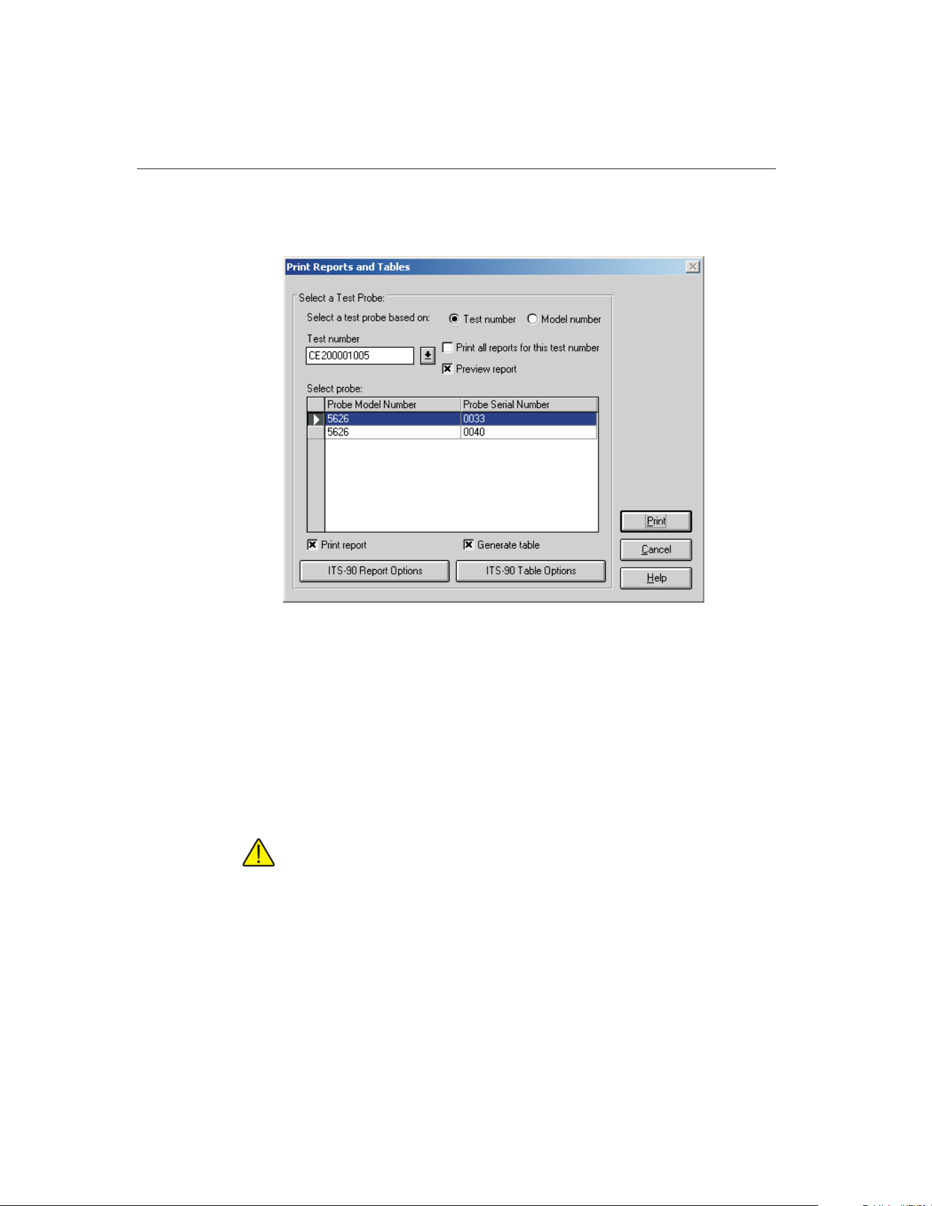
table, select the Print Reports and Tables option in the File menu. The Print Re-
ports and Tables dialog is displayed.
To print a report and/or table for a test probe, you must select either a test num-
ber or a model number on which to base the test probe selection.
If the Test number option is selected, a list of test numbers becomes available.
Once a test number is selected, probe model numbers and serial numbers ap-
pear in the Select probe list.
If the Model number option is selected, a list of test probe model numbers be-
comes available. Once a model number is selected, probe serial numbers and
test numbers appear in the Select probe list.
Note: This dialog only displays test probes for which coefficients have
been calculated and saved in the database.
Select the test probes from the Select probe... list. If the Print all reports for this
test number check box is selected, all test probes in the Select probes list are
selected.
To display the Reports of Calibration and/or tables in the Print Preview win-
dow, select the Preview report check box.
9938 MET/TEMP II
User’s Guide
196
Figure 103 Print Reports and Tables Dialog
1.888.610.7664 sales@GlobalTestSupply.com
Fluke-Direct.com

To print a Report of Calibration for the selected test probe(s), select the Print
report check box. To print a table for the selected test probe(s), select the Gen-
erate table check box. Selecting these check boxes enables the Report Options
and Table Options buttons respectively. This software has many settings regard-
ing the Report of Calibration and tables including using a custom report tem-
plate, customizable resolutions, fonts, exporting to a file and more. Refer to
Section 15.5.1.8, Report Options Dialog, and Section 15.5.1.9, Table Options
Dialog, for more information on the various report and table options.
Note: When a test probe is selected, the Report Options and Table Options
button captions change to reflect the type of coefficients stored in the data-
base for that test probe. The last settings used are remembered for each
type of coefficients independent of other types of coefficients. When select-
ing multiple test probes, the Report Options and Table Options buttons are
based on the selected test probe closest to the top of the Select probe list.
Modifying the Report Options or Table Options settings only affect reports
and tables for the test probes that have the same type of coefficients as the
first test probe. Test probes that have other coefficients will use the remem-
bered settings for that type of coefficients. If you wish to customize the set-
tings for each individual Report of Calibration and/or table, you may want
to only print the Report of Calibration and/or table for one test probe at a
time.
After the test probe has been selected and the Report Options and Table Op-
tions have been set, click the Print button to print the Report(s) of Calibration
and/or table(s). Refer to Section 15.11.1, Default Report of Calibration and
Section 15.11.2, Default Table, for more information on the default Report of
Calibration and table that ship with this software.
Click the Cancel button to close this dialog.
197
15
Coefficients and Tables Application
1.888.610.7664 sales@GlobalTestSupply.com
Fluke-Direct.com

15.5.1.8 Report Options Dialog
The Report Options dialog is displayed when the Report Options button is
clicked on the Print Reports and Tables dialog.
The Report Options dialog allows the user to specify options for the Report of
Calibration for each type of coefficients by selecting either of the three tabs:
Report Sections, Template Settings, and Fonts & Sizes.
The last settings used for each type of coefficients are remembered. When this
dialog is displayed, the last settings for the indicated type of coefficients are
shown.
Change the settings as desired, then click the OK button to save the settings and
close this dialog. Click the Cancel button to discard any changes made and
close this dialog.
9938 MET/TEMP II
User’s Guide
198
Figure 104 Report Options Dialog
1.888.610.7664 sales@GlobalTestSupply.com
Fluke-Direct.com
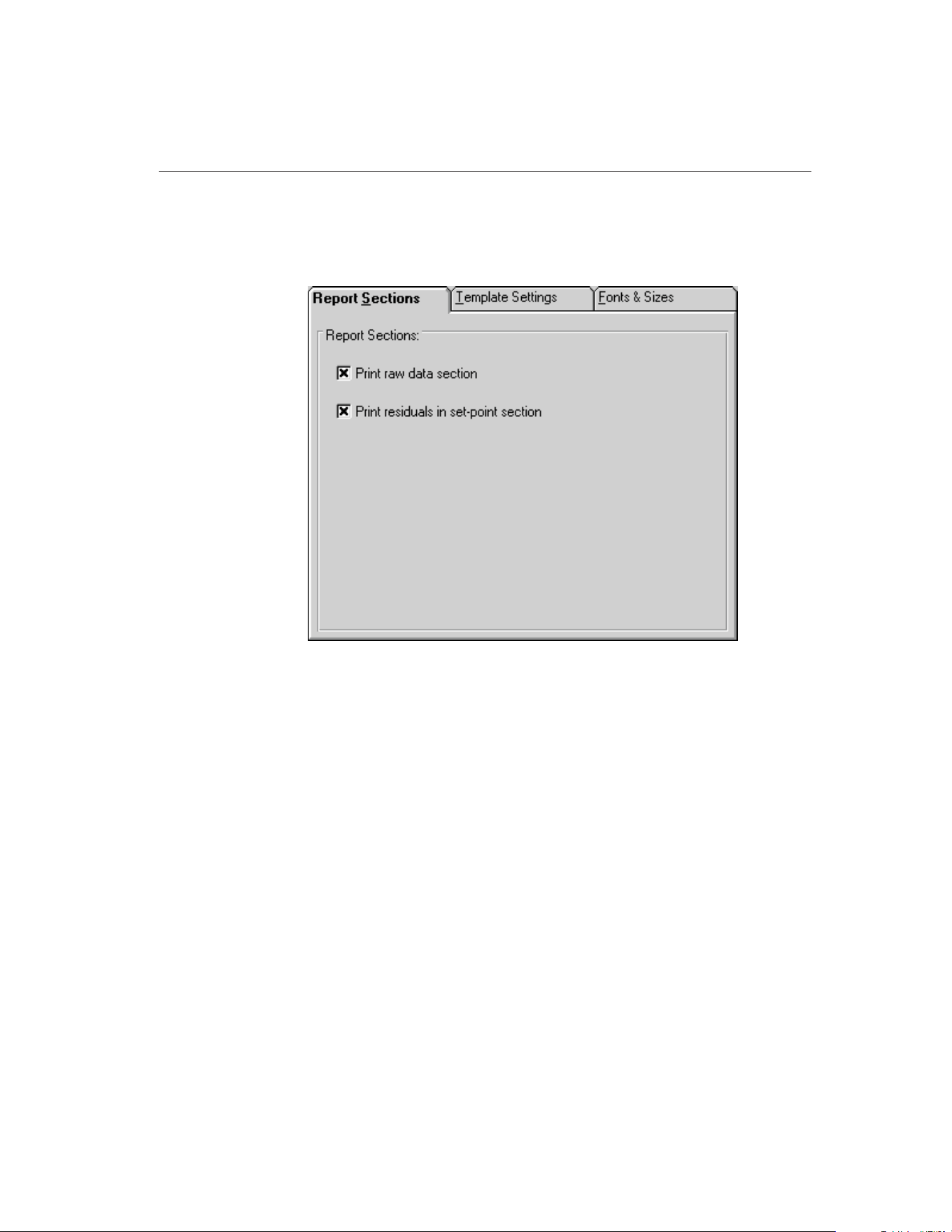
15.5.1.8.1 Report Sections Tab
The Report Sections tab allows various settings regarding the sections of the
Report of calibration to be configured.
The Report Sections tab allows the user to specify whether or not the raw data
section is printed on the Report of Calibration.
If the Print raw data check box is selected, the raw data is printed on the Report
of Calibration.
If the Print residuals in set-point section check box is selected, the raw data
section of the report displays a column for the set-point residuals. This check
box is only enabled if the Print raw data check box is selected.
199
15
Coefficients and Tables Application
Figure 105 Report Sections Tab
1.888.610.7664 sales@GlobalTestSupply.com
Fluke-Direct.com
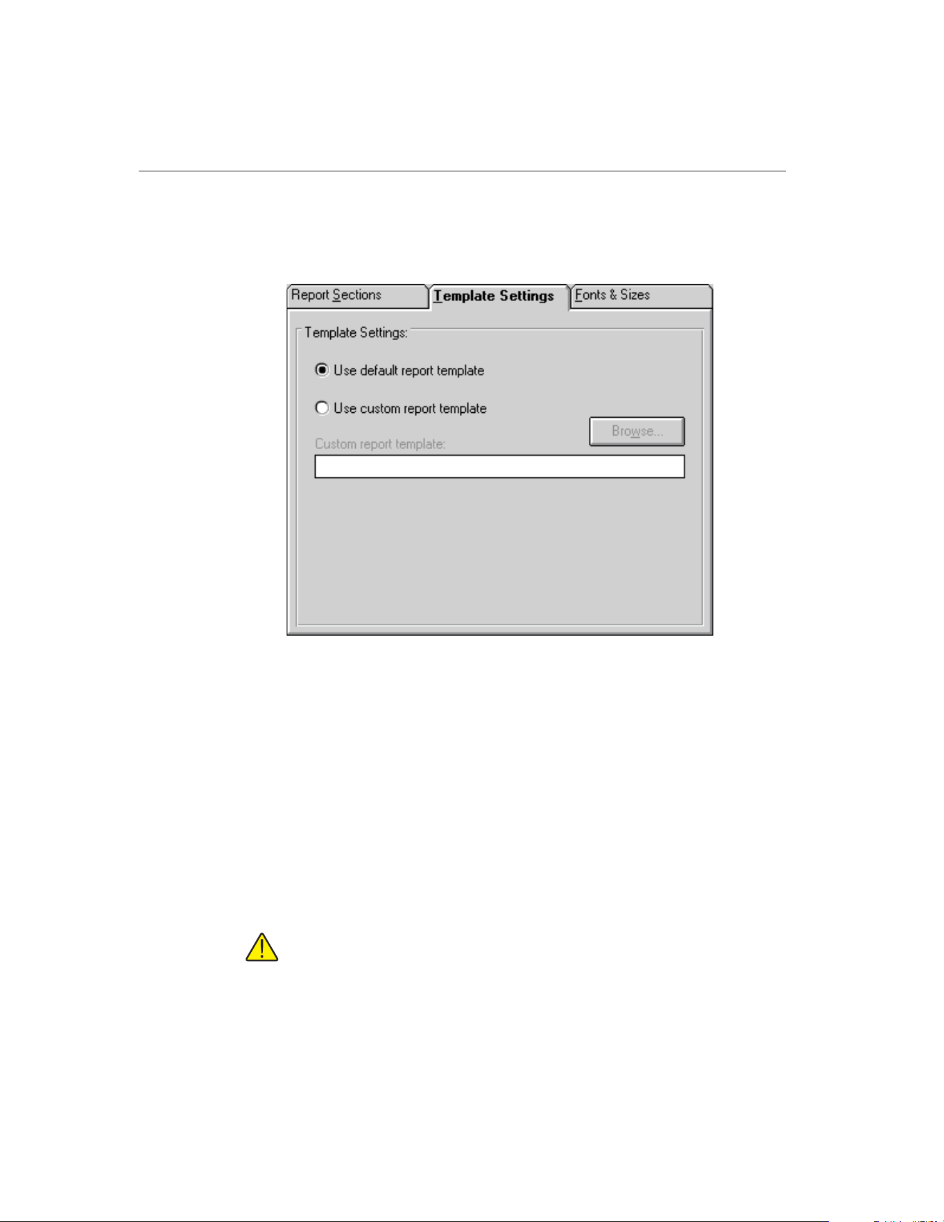
15.5.1.8.2 Template Settings Tab
The Template Settings tab allows the user to specify a custom report template
to use when printing the Report of Calibration.
If the Use default report template option is selected, the built-in Report of Cali-
bration template is used. The Custom report template box and Browse button
are disabled.
This software also allows custom report templates to be used when printing re-
ports. If the default report template isn’t exactly the type of report required for
your application, contact Hart application specialists for information on obtain-
ing custom report templates designed to your specifications. If a custom report
template has been purchased from Hart, the Use custom report template option
allows the user to specify the file that contains the custom report template. The
Custom report template box and Browse button are enabled. Click the Browse
button to select the custom report template to use.
Note: Custom report template files MUST be located in the \REPORTS
subfolder of the C:\METTEMP2 folder (or the folder where MET/TEMP II
was installed) in order to operate properly.
9938 MET/TEMP II
User’s Guide
200
Figure 106 Template Settings Tab
1.888.610.7664 sales@GlobalTestSupply.com
Fluke-Direct.com
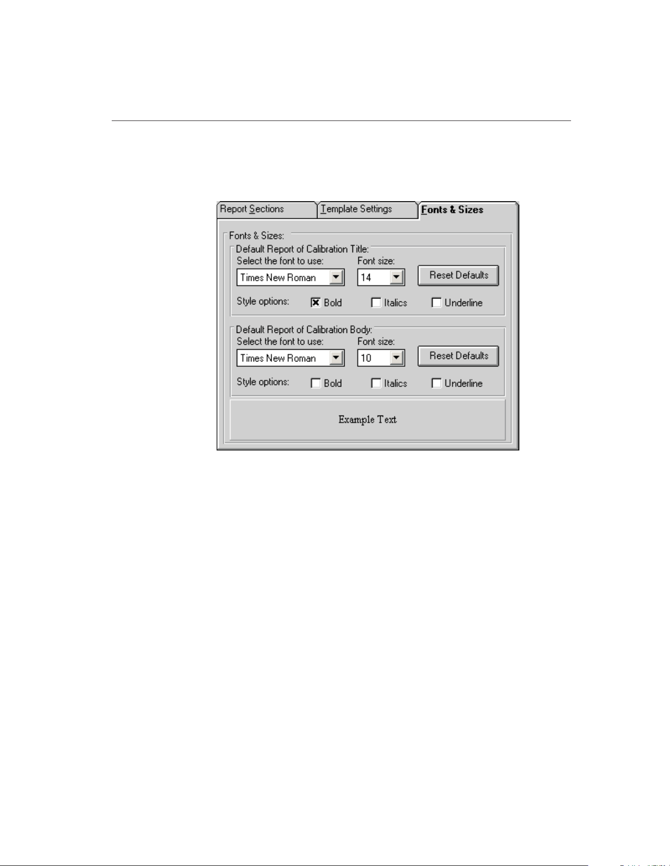
15.5.1.8.3 Fonts & Sizes Tab
The Fonts & Sizes tab is used for selecting the default font names, sizes and
styles to be used when printing the default Report of Calibration.
To set the font that is used when printing the title on the default Report of Cali-
bration, change the settings in the Default Report of Calibration Title section.
To set the font that is used when printing the rest of the text (main body) on the
default Report of Calibration, change the settings in the Default Report of Cali-
bration Body section.
• Select the name of the font to use from the Select the font to use
drop-down list.
• Increase or decrease the size of the font by selecting a setting from the
Font Size drop-down list.
• Change the font style options by checking or unchecking the Bold, Italics
and/or Underline boxes.
• The current settings are displayed in the Example Text box at the bottom
of this tab.
Click the Reset Defaults button to restore the default settings. The default set-
tings are as follows:
• Title font settings - Times New Roman, 14 point, Bold
201
15
Coefficients and Tables Application
Figure 107 Fonts & Sizes Tab
1.888.610.7664 sales@GlobalTestSupply.com
Fluke-Direct.com
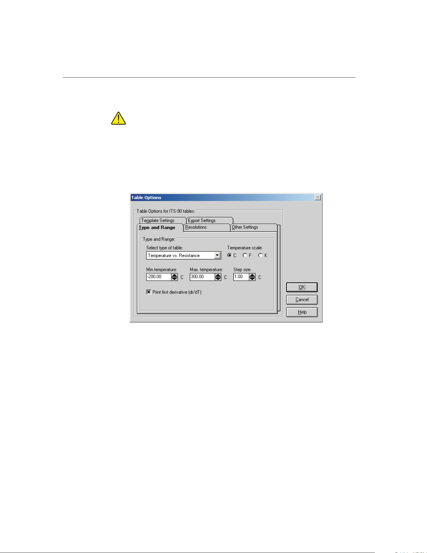
• Body font settings - Times New Roman, 10 point
Note: Changing these settings does not change the font settings used on
custom Reports of Calibration that are not included with this application.
The changes are applied only to the default Report of Calibration which is
built into the software.
15.5.1.9 Table Options Dialog
The Table Options dialog is displayed when the Table Options button is clicked
on the Print Reports and Tables dialog.
The Table Options dialog allows the user to specify options for the table for
each type of coefficients by selecting either of the five tabs: Type and Range,
Resolutions, Other Settings, Template Settings, and Export Settings.
This software remembers the last settings used for each type of coefficients.
When this dialog is displayed, the last settings for the indicated type of coeffi-
cients are shown.
Change the settings as desired, then click the OK button to save the settings and
close this dialog. Click the Cancel button to discard any changes made and
close this dialog.
9938 MET/TEMP II
User’s Guide
202
Figure 108 Table Options Dialog
1.888.610.7664 sales@GlobalTestSupply.com
Fluke-Direct.com
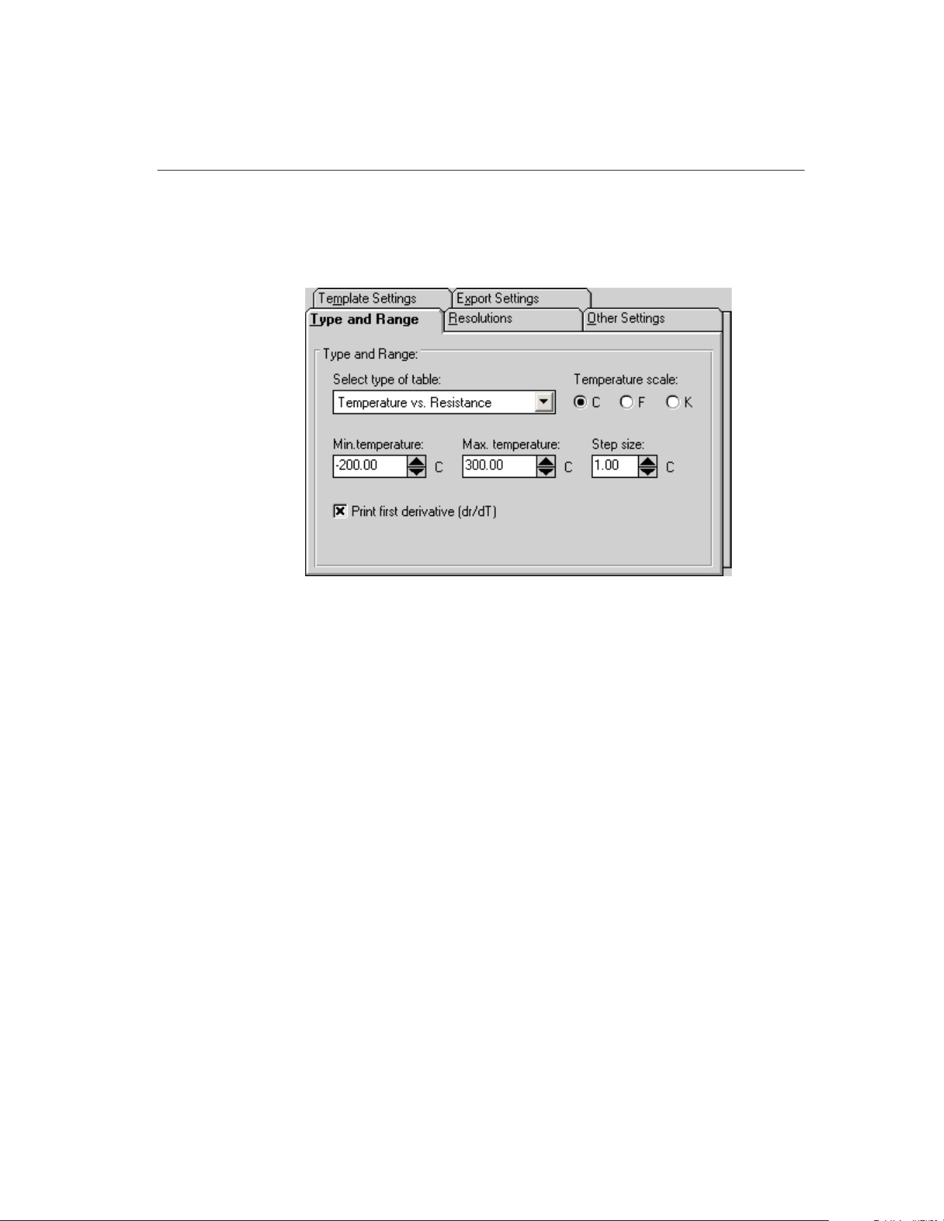
15.5.1.9.1 Type and Range Tab
The Type and Range tab allows the type of table, temperature scale, range and
step size settings to be selected.
Select the type of table to generate using the Select type of table drop-down
list. The following types of tables can be generated:
• Temperature vs. Resistance - For ITS-90, IPTS-68, Callendar-Van Dusen,
and Polynomial coefficients
• Temperature vs. Ratio - For ITS-90 and IPTS-68 coefficients only
• Temperature vs. EMF (µV) - For Thermocouple coefficients only
• Temperature vs. EMF (mV) - For Thermocouple coefficients only
Select the temperature scale for the table. The software allows tables to be gen-
erated in any of the following temperature scales:
• C
• F
• K
The Min. temperature and Max. temperature boxes indicate the temperature
range for the table in the selected temperature scale. Change these settings as
desired. The minimum temperature and maximum temperature values are lim-
ited to –273C and 2650C (–459F and 4802F) respectively. However, the equa-
tions used to generate table values may not be able to calculate values over the
full range. If a message is displayed during calculations stating that a calcula-
tion error occurred, you may need to increase the minimum temperature or de-
203
15
Coefficients and Tables Application
Figure 109 Type and Range Tab
1.888.610.7664 sales@GlobalTestSupply.com
Fluke-Direct.com
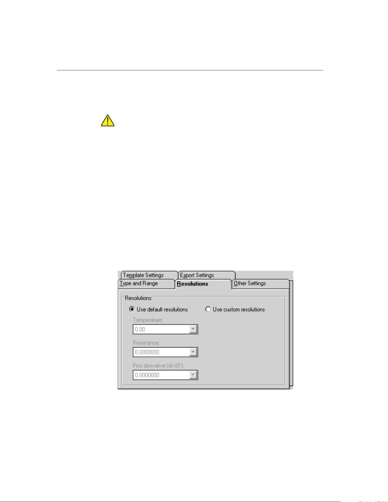
crease the maximum temperature. Refer to Section 15.12.7, Table Temperature
Range Chart, for the recommended ranges for generating tables for different
types of coefficients.
Note: Changing the selected temperature scale converts the minimum and
maximum temperature values to that scale automatically.
Enter the step size to use when generating the table in the Step size box. The
step size is the increment between each temperature value on the table and must
be between 0.01 and 100.00
Below the temperature settings are various options for the selected type of
table.
• For Temperature vs. Resistance tables, the first derivative column can be
printed by selecting the Print first derivative (dr/dT) option
• For Temperature vs. Ratio tables, the inverse difference column can be
printed by selecting the Print inverse difference (dT/dW) option
• For Temperature vs. EMF (µV or mV) tables, the error column can be
printed by selecting the Print Error (µV or mV) option
15.5.1.9.2 Resolutions Tab
The Resolutions tab allows the resolutions of the data in each column of the ta-
bletobeset.
9938 MET/TEMP II
User’s Guide
204
Figure 110 Resolutions Tab
1.888.610.7664 sales@GlobalTestSupply.com
Fluke-Direct.com
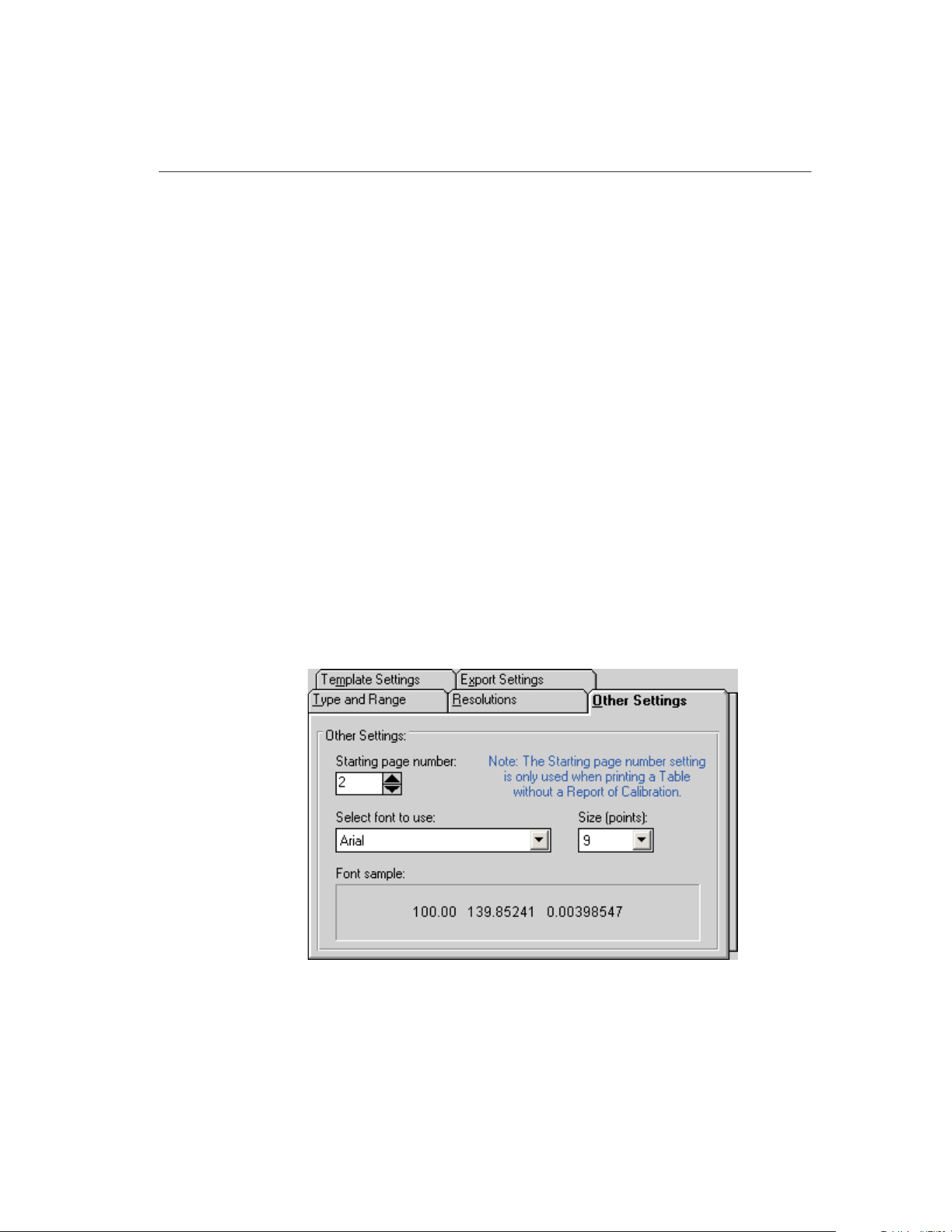
If you want to use the default resolution settings when printing the table, select
the Use default resolutions option. The drop-down lists are disabled.
When the Use default resolutions option is selected, the values on the table are
printed using the default method: temperature values are always 2 decimal
places and all other values depend upon the magnitude of the value:
• For values between -10 and 10: seven decimal places
• For values between -100 and 100: six decimal places
• For values between -1,000 and 1,000: five decimal places
• For values between -10,000 and 10,000: four decimal places
• For values between -100,000 and 100,000: three decimal places
• All other values: two decimal places
If you want to specify the resolution for the data in each column on the table,
select the Use custom resolutions option. The drop-down lists are enabled.
Select the format for temperature readings with the Temperature drop-down
list. Select the format for resistance, ratio or voltage readings with the appropri-
ate drop-down list. Select the format for the first derivative, inverse difference
or error readings with the appropriate drop-down list.
15.5.1.9.3 Other Settings Tab
The Other Settings tab allows the starting page number and font to use to be se-
lected.
205
15
Coefficients and Tables Application
Figure 111 Other Settings Tab
1.888.610.7664 sales@GlobalTestSupply.com
Fluke-Direct.com
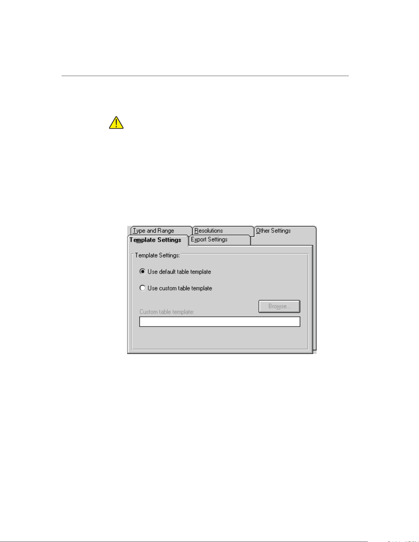
The Starting page number box allows the user to enter the page number of the
first page of the table. The starting page number must be between 1 and 100.
Note: This setting is only used when printing a table by itself and is ig-
nored when printing a table and a Report of Calibration at the same time!
The Select font to use drop-down list allows the user to select the font to use
when printing the table. The list of fonts consists of all fonts supported by the
default printer. The Size (points) drop-down list allows the user to select the
font size. Allowable font sizes are from 6 point to 14 point. A sample of the se-
lected font is displayed below the font selection.
15.5.1.9.4 Template Settings Tab
The Template Settings tab allows the user to specify the template to use when
generating tables.
If the Use default report template option is selected, the built-in table template
is used. The Custom report template box and Browse button are disabled.
The software also allows custom report templates to be used when generating
tables. If the default report template isn’t exactly the type of table required for
your application, contact Hart application specialists for information on obtain-
ing custom report templates designed to your specifications. If a custom report
template has been purchased from Hart, the Use custom report template option
allows the user to specify the file that contains the custom report template. The
9938 MET/TEMP II
User’s Guide
206
Figure 112 Template Settings Tab
1.888.610.7664 sales@GlobalTestSupply.com
Fluke-Direct.com
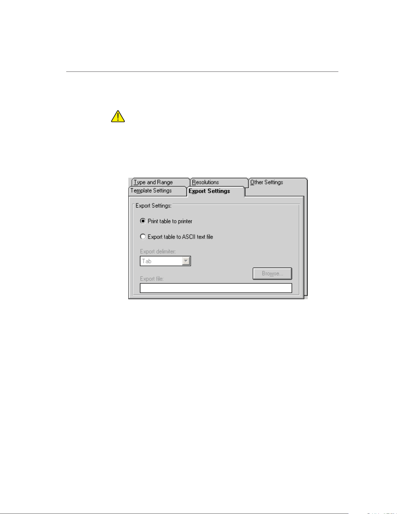
Custom report template box and Browse button are enabled. Click the Browse
button to select the custom report template to use.
Note: Custom report template files MUST be located in the \REPORTS
subfolder of the C:\METTEMP2 folder (or the folder where MET/TEMP II
was installed) in order to operate properly.
15.5.1.9.5 Export Settings Tab
The Export Settings tab allows the user to specify export options to use when
generating tables.
By default, the application sends tables to the printer. The Print table to printer
option is selected. However, the software can export the table to a text file by
selecting the Export table to ASCII text file option.
Select the delimiter to use when exporting the table using the Export delimiter
drop-down list. Either a Tab or Comma (,) are supported as the delimiter.
Enter the default path and filename for the export file in the Export file box, or
click the Browse button. When the table is exported, the user is prompted to
specify the path and filename of the file and the table exported to that file. The
path and filename default to the values entered in the Export file box.
207
15
Coefficients and Tables Application
Figure 113 Export Settings Tab
1.888.610.7664 sales@GlobalTestSupply.com
Fluke-Direct.com
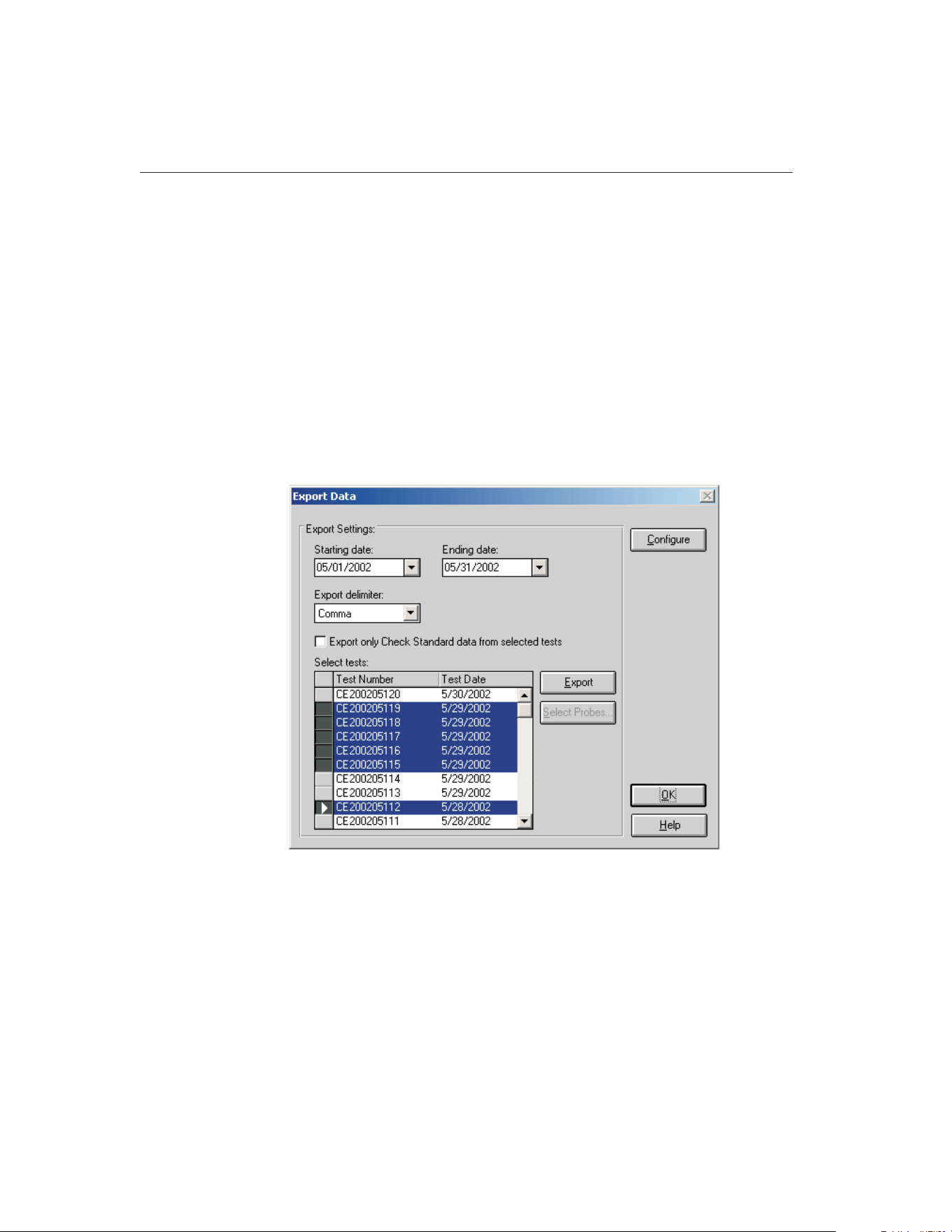
15.6 Exporting Data and Coefficients
The software has a feature that allows the test data acquired by MET/TEMP II
to be exported to a text file. Also, the characterization coefficients can be ex-
ported to a text file.
The following sections describe in detail how to export data.
15.6.1 Export Data
The software has a feature that allows the test data acquired by MET/TEMP II
to be exported to a text file. This can be useful if you have analysis software
that you want to use to analyze, graph, or manipulate the acquired test data.
To export test data, select the Export Data option in the File menu or click the
Export Data button on the toolbar. The Export Data dialog is displayed.
The Export Data dialog allows the user to specify a date range using the Start-
ing date and Ending date drop-down calendars. These dates are used to filter
the list of tests displayed in the Select tests list. The last used ending date is re-
membered every time data is exported and becomes the starting date the next
time this dialog is displayed. The ending date defaults to the current date.
Therefore, the list of tests in the Select tests list should default to all tests since
the last export was performed.
9938 MET/TEMP II
User’s Guide
208
Figure 114 Export Data Dialog
1.888.610.7664 sales@GlobalTestSupply.com
Fluke-Direct.com

To change the starting and/or ending dates, use the drop-down calendars to se-
lect new dates. The tests listed will update automatically.
Select the delimiter to use when exporting the data using the Export delimiter
drop-down list. The software supports using either a Tab or Comma (,) as the
delimiter.
Note: The software recognizes and uses the International/Regional settings
such as the date, time, and number formats as set in the Windows® Control
Panel’s Regional Settings or International icon. If a comma (,) is being used as
the decimal separator, the Tab option must be selected as the export delimiter in
order for the data to be properly imported into other software. A warning mes-
sage is displayed when the Export button is clicked.
If you wish to export only data for test probes that were marked as check stan-
dards in MET/TEMP II, select the Export only Check Standard data from se-
lected tests check box.
Select the test to export by clicking on the appropriate row in the Select tests
list.
To export the test data for the selected test(s), click the Export button. A
prompt is displayed for entering the path and filename for the export file. The
default path and filename can be changed on the Directories tab of the Defaults
dialog. A message is displayed stating the export operation was successful if no
errors occurred.
To export test data for select test probes from a particular test, select the test in
the Select tests list. Then click the Select Probes button. The Export Probe Data
dialog is displayed.
Note: The Select Probes button is disabled if more than one test is se-
lected in the Select tests list!
The software allows the user to customize the data to be exported. To custom-
ize the data to be exported, click the Configure button. The Configure Export
Fields dialog is displayed. Refer to Section 15.6.2, Customizing Export Data,
for more details on how to customize the data to export.
Click the OK button to close the Export Data dialog.
The Export Probe Data dialog allows the test data for select test probes to be
209
15
Coefficients and Tables Application
1.888.610.7664 sales@GlobalTestSupply.com
Fluke-Direct.com

exported. The Select probes from test number... list displays the mode and se-
rial number for all test probes that were calibrated for the indicated test.
Select the test probes to export by clicking on the appropriate row(s) in the Se-
lect probes from test number... list.
To export the test data for the selected test probe(s), click the Export button. A
prompt is displayed for entering the path and filename for the export file. The
default path and filename can be changed on the Directories tab of the Defaults
dialog. A message is displayed stating the export operation was successful if no
errors occurred.
Click the OK button to close this dialog and return to the Export Data dialog.
9938 MET/TEMP II
User’s Guide
210
Figure 115 Export Probe Data Dialog
1.888.610.7664 sales@GlobalTestSupply.com
Fluke-Direct.com
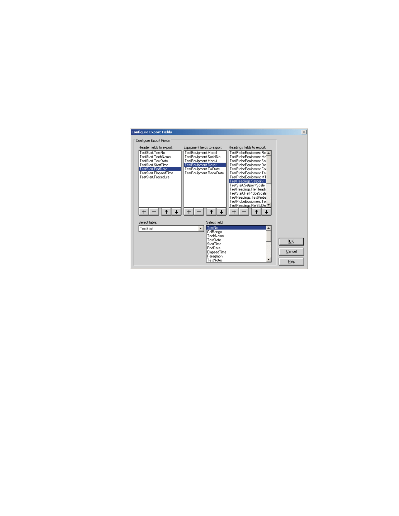
15.6.2 Customizing Export Data
The software has a feature that allows the user to define the data to be exported.
This feature is accessible by clicking the Configure button on the Export Data
dialog. Clicking this button displays the Configure Export Fields dialog.
The export file created can be divided up into three sections: header, test equip-
ment and test readings. These three sections are represented on this dialog by
the three list boxes entitled: Header fields to export, Equipment fields to export
and Readings fields to export.
The first section of the export file is called the header section. The header sec-
tion generally consists of general test information that applies to all test probes
(UUTs) and all readings taken for that test. When the export file is created, a
one line header section is written to the file for each of the selected tests to
export.
The next section is called the equipment section. The equipment section gener-
ally consists of one record for every piece of test equipment used to perform
the calibration test. When the export file is created, a one line entry is written to
the file for each piece of test equipment used to perform the calibration test.
The last section is called the readings section. The readings section generally
consists of the test probe (UUT) information and the actual readings taken.
When the export file is created, a one line entry is written to the file for each
reading for each test probe (UUT). If the data to be exported contains multiple
211
15
Coefficients and Tables Application
Figure 116 Configure Export Fields Dialog
1.888.610.7664 sales@GlobalTestSupply.com
Fluke-Direct.com
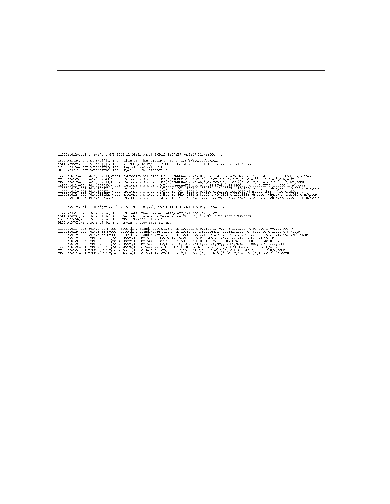
UUTs, the first UUT’s data is written followed immediately by the second
UUT’s readings, etc.
Each of the sections is separated by a blank line. If multiple tests are being ex-
ported to the same export file, each test’s data is separated by two blank lines.
If no fields have been defined to export to a section of the export file, that sec-
tion is simply skipped.
An example of an export data file is shown below:
When MET/TEMP II is installed, the header and test equipment sections are
blank, and the readings section is configured so that the exported data is com-
patible with previous versions of this software.
To customize the data to be exported in each section, select the table containing
the data to be exported using the Select table drop-down list. Available tables
are:
• TestStart - Contains general test data that applies to all UUTs such as test
number, ambient conditions, paragraph, test procedure, technician name,
etc.
• TestEquipment - Contains information about the test equipment used to
perform the calibration test such as model and serial numbers, calibration
& recall dates, etc.
• TestProbeEquipment - Contains information about each of the test
probes (UUTs) that were calibrated such as model and serial numbers,
scale of readings, etc.
9938 MET/TEMP II
User’s Guide
212
Figure 117 Example Export Data File
1.888.610.7664 sales@GlobalTestSupply.com
Fluke-Direct.com

• TestReadings - Contains all of the readings for all test probes (UUTs) in-
cluding set-points, reference readings, test probe readings, CJC readings,
uncertainty values, method of realization, etc.
Next, select the field to be exported in the Select field list. Then click the
button below the section list to which the field should be added. The field is
added to the end of the list.
The order in which the fields appear in the lists is the order that the fields will
be exported. To move a field up or down in a list, select the field to move, then
click the or button accordingly.
To remove a field from a list, select the field and click the button.
Any field may be added to any of the sections. Also, any field can be added to a
single list as many times as needed. However, use caution when adding fields.
Be aware that:
• There is only one record in the TestStart table for each test. Adding a
field to a section from the TestStart table causes the same value to be
written every time.
• There are multiple records in the TestEquipment, TestProbeEquipment
and TestReadings records for each test. Adding a TestEquipment field
to the header section, for example, will only export that field’s value for
the first record in the TestEquipment table for this test.
The information about the fields to export to each section of the export file is
saved in the EXPORT.INI file which is located in the C:\METTEMP2 folder
(or the folder where MET/TEMP II was installed). A second file containing an
alternate export definition was installed when MET/TEMP II was installed.
This file is named EXPORT.INX and is also installed in the folder where
MET/TEMP II was installed. This file can be used as a starting point for creat-
ing your own export definition. To use this file, simply rename the current EX-
PORT.INI file to something else, and rename the EXPORT.INX file to
EXPORT.INI. The next time the Configure Export Fields dialog is displayed,
this file’s definition is read in and displayed.
Important: Never attempt to manually edit the EXPORT.INI file! This file
needs to be accurate for the export feature to function properly. Always
use the Configure Export Fields dialog to make changes to the export data
configuration.
Click the OK button to save the new export data configuration and close this di-
alog. Clicking the Cancel button closes this dialog without saving changes.
15.6.3 Export Coefficients
This software has a feature that allows the calculated coefficients for a test
probe to be exported to a text file.
213
15
Coefficients and Tables Application
1.888.610.7664 sales@GlobalTestSupply.com
Fluke-Direct.com
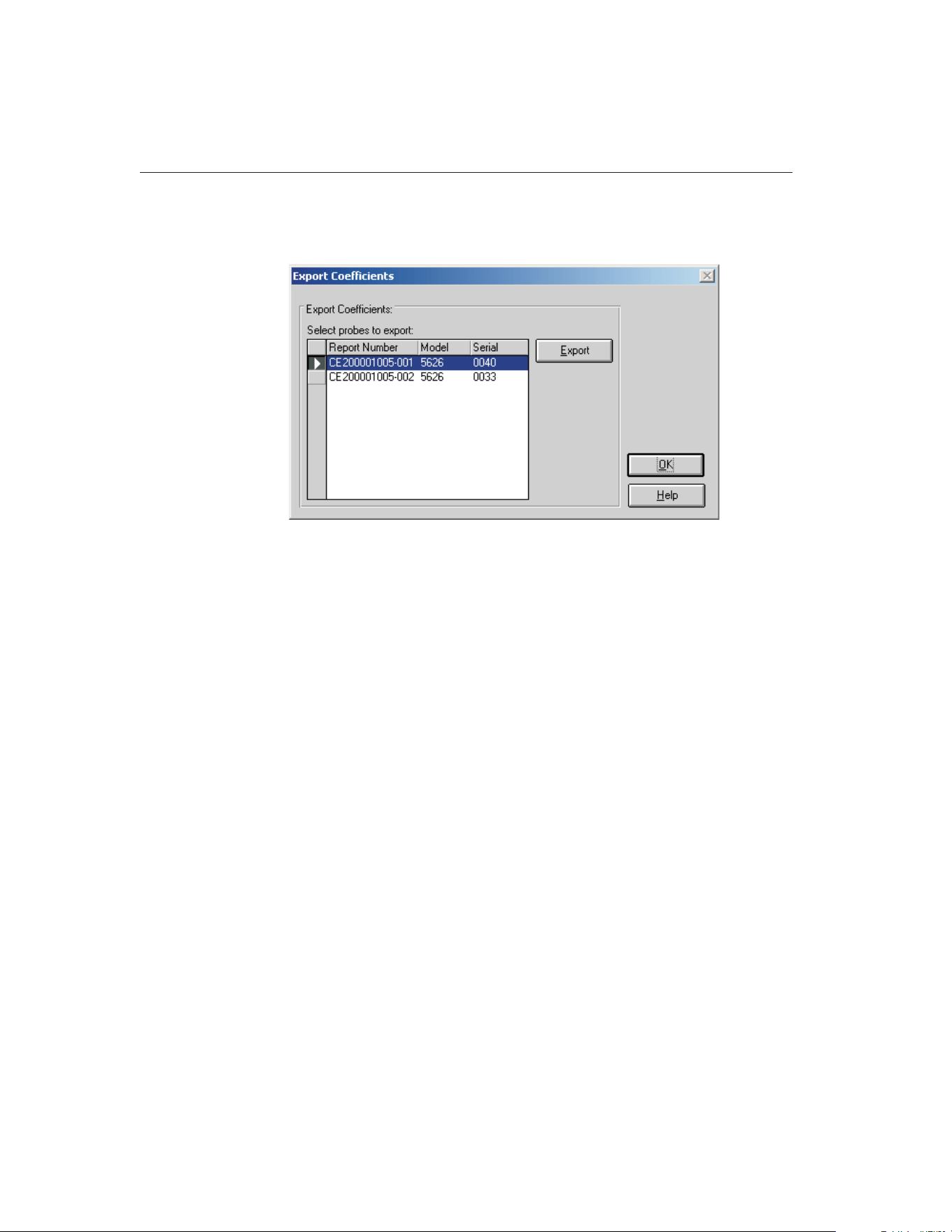
To export coefficients, select the Export Coefficients option in the File menu.
The Export Coefficients dialog is displayed.
The Export Coefficients dialog displays a list of all test probes for which coeffi-
cients have been calculated in the Select probes to export list.
Select the test probes to export by clicking on the appropriate row(s) in the Se-
lect probes to export list.
To export the coefficients for the selected test probe(s), click the Export button.
A prompt is displayed for entering the path and filename for the export file.
The default path and filename can be changed on the Directories tab of the De-
faults dialog. A message is displayed stating the export operation was success-
ful if no errors occurred.
9938 MET/TEMP II
User’s Guide
214
Figure 118 Export Coefficients Dialog
1.888.610.7664 sales@GlobalTestSupply.com
Fluke-Direct.com
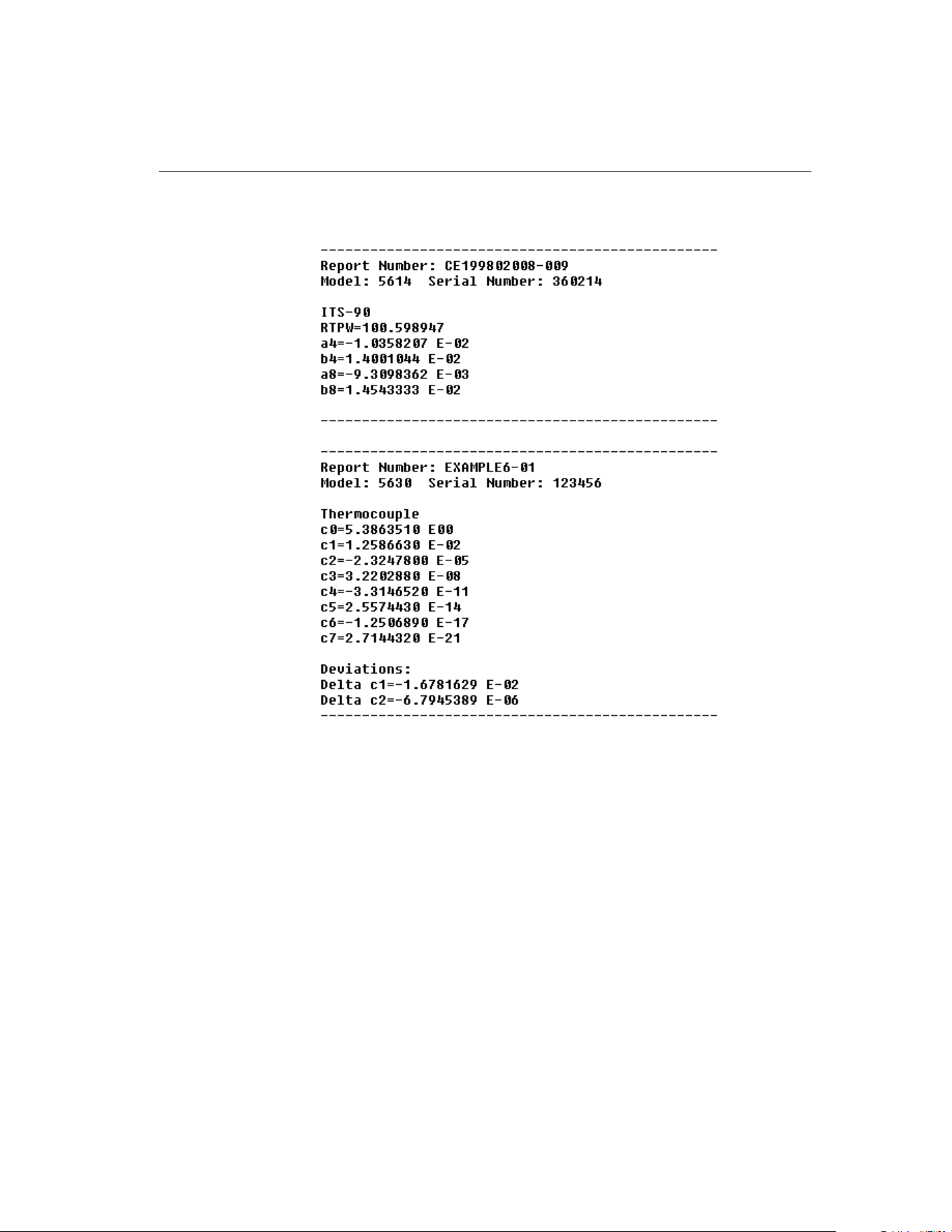
The following are examples of coefficients export files:
Click the OK button to close this dialog.
215
15
Coefficients and Tables Application
Figure 119 Example Coefficients Export Files
1.888.610.7664 sales@GlobalTestSupply.com
Fluke-Direct.com
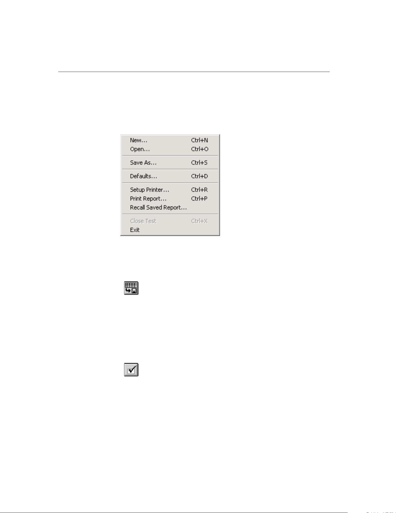
15.7 File Menu
The File menu provides options for exporting data and coefficients, setting up
program defaults, setting up the printer, printing a report and table and exiting
the program.
The following sections describe each of these options.
15.7.1 Export Data
Selecting the Export Data option displays the Export Data dialog for exporting
test data acquired by MET/TEMP II to text files. The process of exporting test
data is explained in Section 15.6.1, Export Data.
15.7.2 Export Coefficients
Selecting the Export Coefficients option displays the Export Coefficients dialog
for exporting coefficients calculated to text files. The process of exporting coef-
ficients is explained in Section 15.6.3, Export Coefficients.
15.7.3 Defaults
Selecting the Defaults option displays the Defaults dialog for selecting or modi-
fying default settings. Default values or parameters can be set by selecting one
of five tabs; General, Coefficients, Reports, Tables or Directories. These de-
faults are used each time the application is started. Each of the settings on these
tabs is described in detail in the following sections.
9938 MET/TEMP II
User’s Guide
216
Figure 120 File Menu
1.888.610.7664 sales@GlobalTestSupply.com
Fluke-Direct.com

15.7.3.1 General Tab
The General tab is for selecting general software defaults or preferences.
The Show help balloons check box turns on and off the help balloons. Help bal-
loons are displayed when the mouse pointer is placed over a button on the
toolbar.
The Enable print preview window check box forces the reports and tables to be
displayed in a preview window on-screen when printing. If this check box is
not selected, reports and tables are printed directly to the printer when the print
button is clicked.
The Select printer before printing reports and tables check box forces the soft-
ware to display the Select Printer dialog when printing. The user can then select
the printer to which reports and tables are printed. If this check box is not se-
lected, reports and tables are printed on the default printer. To change the de-
fault printer, use the Setup Printer option in the File menu.
The Maximize print preview window check box determines whether the Print
Preview window is maximized when displayed. If this check box is selected,
the Print Preview window is maximized when it is displayed.
The Print preview window zoom setting determines the default size of the re-
port or table within the Print Preview window. The zoom setting is limited to
40% to 190%. The zoom setting can also be changed from the Print Preview
window once it is displayed.
217
15
Coefficients and Tables Application
Figure 121 General Tab
1.888.610.7664 sales@GlobalTestSupply.com
Fluke-Direct.com

15.7.3.2 Coefficients Tab
The Coefficients tab is for selecting default preferences pertaining to the calcu-
lation of coefficients.
The Preview coefficients and residuals before writing to database check box de-
termines whether the user is prompted before the coefficients are written to the
database. If this check box is selected, the coefficients and residuals are dis-
played on the Coefficients and Residuals dialog before being written to the da-
tabase. The user may choose to save the coefficients to the database or to cancel
without saving. If this check box is not selected, the coefficients and residuals
are automatically written to the database without being displayed.
The Prompt before overwriting existing coefficients in database check box de-
termines whether the newly calculated coefficients automatically overwrite ex-
isting coefficients for the same report number. If this check box is selected and
a set of coefficients with the same report number already exists in the database,
the user is prompted whether to overwrite the existing coefficients. If this check
box is not selected, the new coefficients automatically overwrite the existing
coefficients. Only one set of coefficients are allowed to be stored in the data-
base for each report number.
9938 MET/TEMP II
User’s Guide
218
Figure 122 Coefficients Tab
1.888.610.7664 sales@GlobalTestSupply.com
Fluke-Direct.com
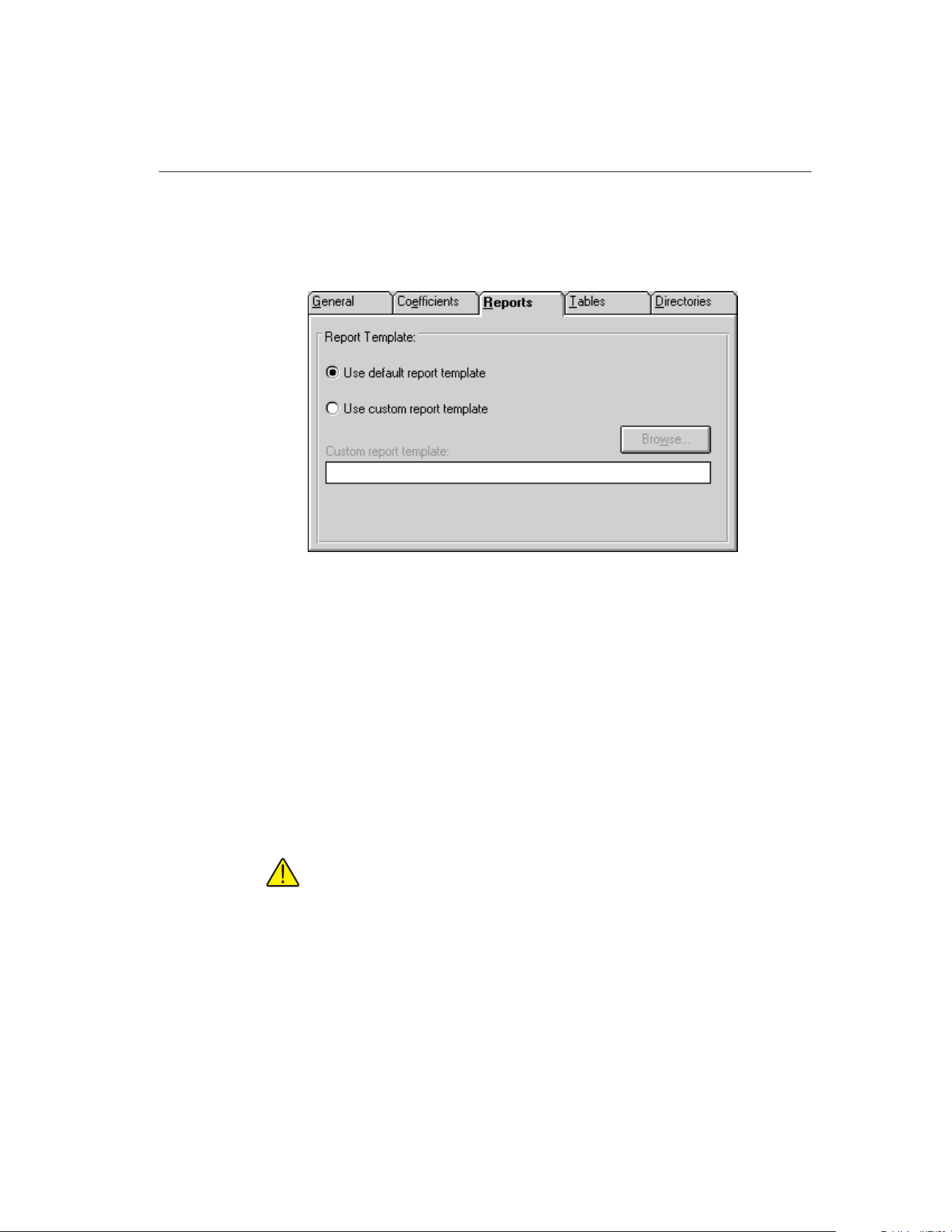
15.7.3.3 Reports Tab
The Reports tab is for selecting default preferences pertaining to Reports of
Calibration.
The options selected on this tab determine the default report template used
when printing a Report of Calibration. If the Use default report template option
is selected, the software uses the Report of Calibration template that is built
into the application. This option is selected by default.
The software also allows custom report templates to be used when printing re-
ports. If the default report template isn’t exactly the type of report required for
your application, contact Hart sales representatives for information on obtain-
ing custom report templates designed to your specifications. If a custom report
template has been purchased from Hart, the Use custom report template option
allows the user to specify the file that contains the custom report template. The
Custom report template box and Browse button are enabled. Click the Browse
button to select the custom report template to use.
Note: Custom report template files MUST be located in the \REPORTS
subfolder of the C:\METTEMP2 folder (or the folder where MET/TEMP II
was installed) in order to operate properly.
219
15
Coefficients and Tables Application
Figure 123 Reports Tab
1.888.610.7664 sales@GlobalTestSupply.com
Fluke-Direct.com
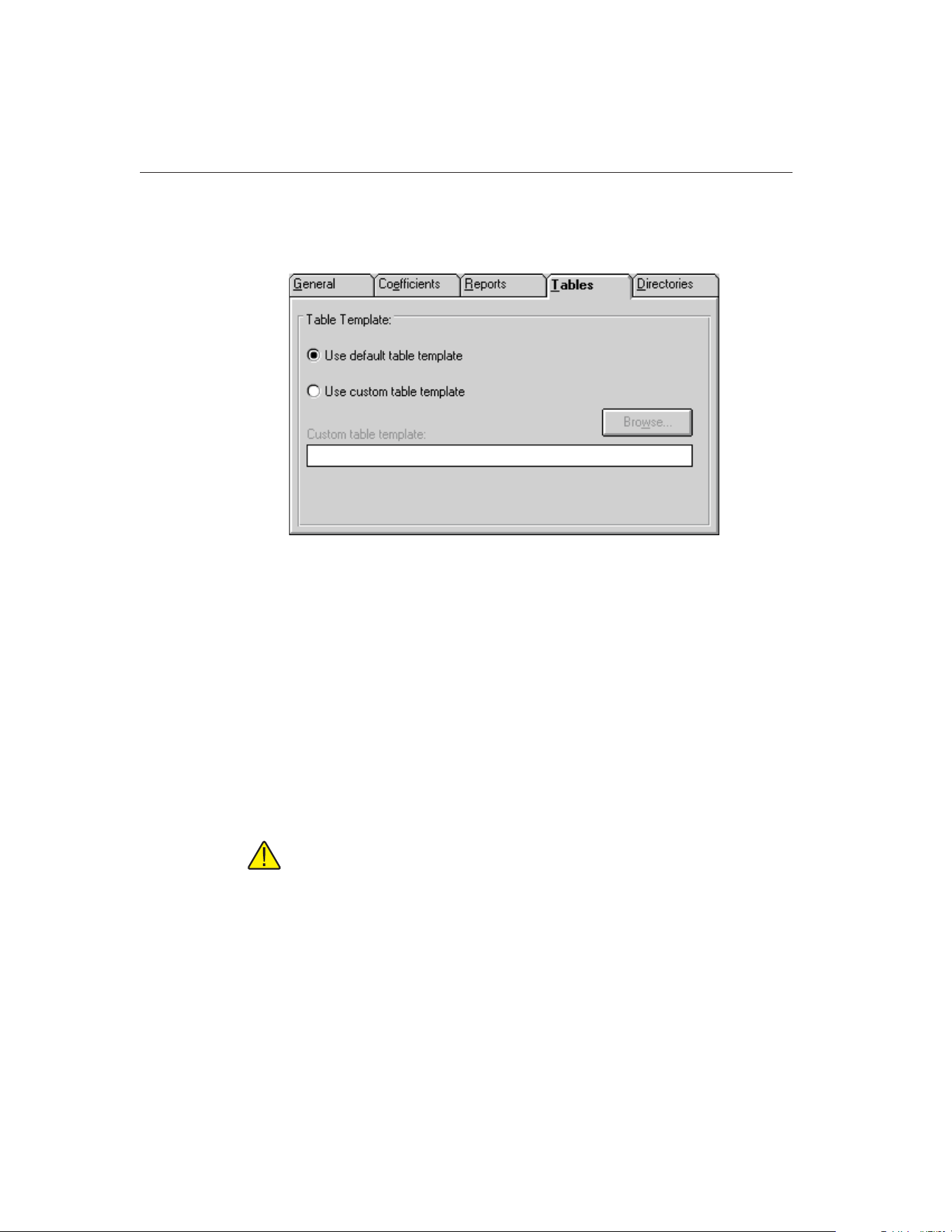
15.7.3.4 Tables Tab
The Tables tab is for selecting default preferences pertaining to tables.
The options selected on this tab determine the default table template used when
printing a table. If the Use default table template option is selected, the soft-
ware uses the table template that is built into the application. This option is se-
lected by default.
This software also allows custom table templates to be used when printing ta-
bles. If the default table template isn’t exactly the type of table required for
your application, contact Hart application specialists for information on obtain-
ing custom table templates designed to your specifications. If a custom table
template has been purchased from Hart, the Use custom table template option
allows the user to specify the file that contains the custom table template. The
Custom table template box and Browse button are enabled. Click the Browse
button to select the custom table template to use.
Note: Custom table template files MUST be located in the \REPORTS
subfolder of the C:\METTEMP2 folder (or the folder where MET/TEMP II
was installed) in order to operate properly.
9938 MET/TEMP II
User’s Guide
220
Figure 124 Tables Tab
1.888.610.7664 sales@GlobalTestSupply.com
Fluke-Direct.com
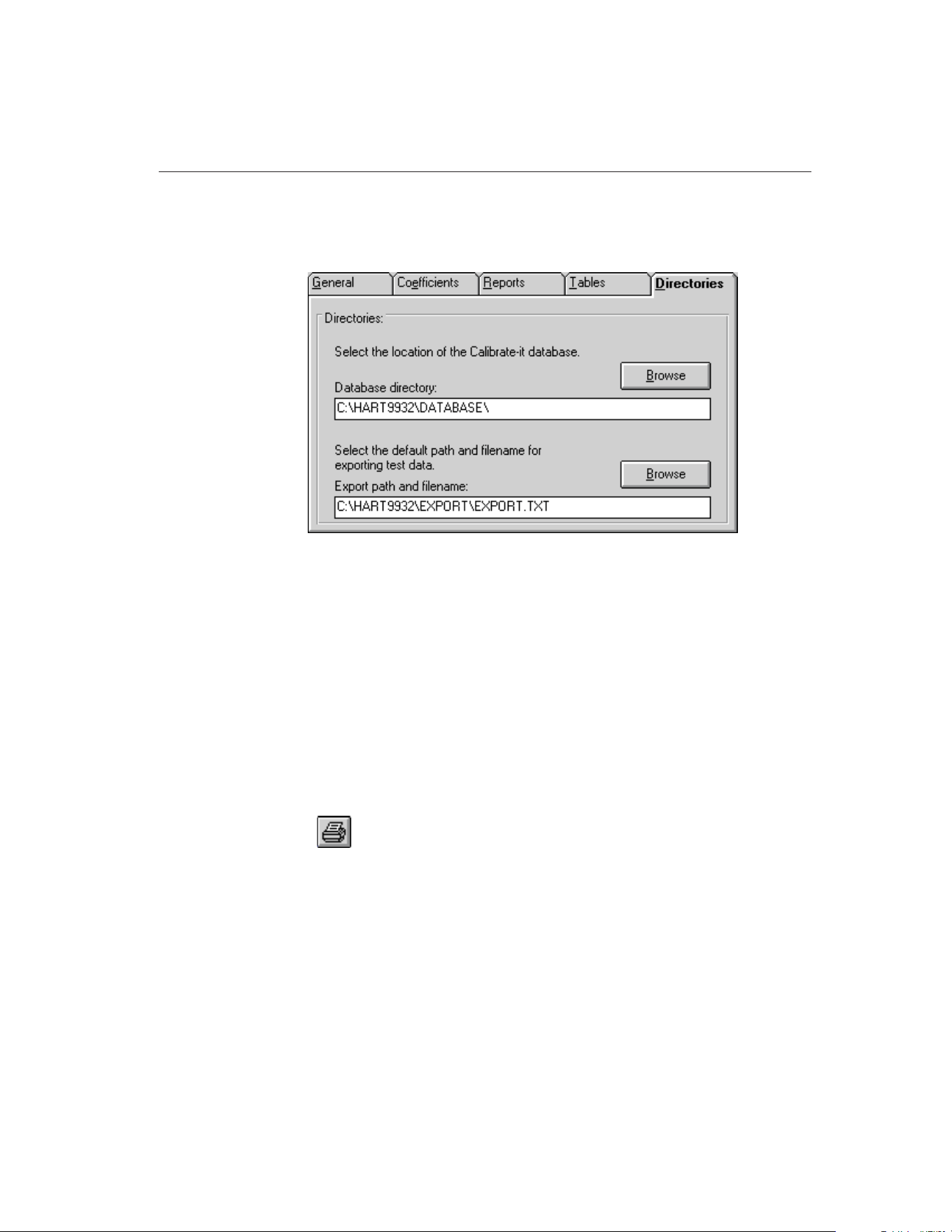
15.7.3.5 Directories Tab
The Directories tab is for setting default directory locations.
The Export path and filename specifies the path and filename to use when ex-
porting test data to a text file. By default, this path and filename are set to the
\EXPORT directory and to EXPORT.TXT respectively. To change the default
export path or filename, enter the new path and filename in the Export path and
filename box or use the Browse button.
15.7.4 Setup Printer
Selecting the Setup Printer option displays the Print Setup dialog that allows
the user to select the default printer to which Reports of Calibration and tables
should be printed. If you are using the default report template, the Orientation
must be set to Portrait. The Paper Size should be set to Letter 8 1/2 x 11 in.
15.7.5 Print Reports and Tables
Selecting the Print Reports and Tables option displays the Print Reports and Ta-
bles dialog. Refer to Section 15.5.1.7, Print Reports of Calibration and Tables
for more details on printing Reports of Calibration and tables.
For more information on the Print Preview window and report files, see Section
16, Print Preview Window.
15.7.6 Exit
Selecting the Exit option exits the Coefficients and Tables application.
221
15
Coefficients and Tables Application
Figure 125 Directories Tab
1.888.610.7664 sales@GlobalTestSupply.com
Fluke-Direct.com
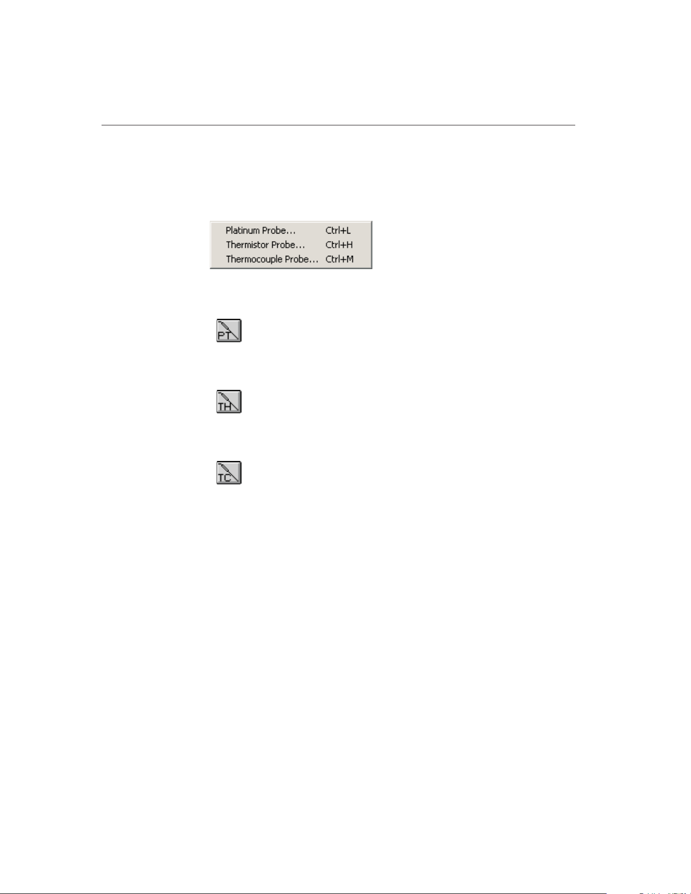
15.8 Coefficients Menu
The Coefficients menu provides options for calculating coefficients for plati-
num, thermistor and thermocouple probes.
15.8.1 Platinum Probe
Selecting the Platinum Probe option displays the Platinum Probe Coefficients
dialog. Refer to Section 15.5.1.1, Calculating PRT/RTD Coefficients, for more
information on calculating coefficients for platinum probes.
15.8.2 Thermistor Probe
Selecting the Thermistor Probe option displays the Thermistor Probe Coeffi-
cients dialog. Refer to Section 15.5.1.2, Calculating Thermistor Coefficients,
for more information on calculating coefficients for thermistor probes.
15.8.3 Thermocouple Probe
Selecting the Thermocouple Probe option displays the Thermocouple Probe
Coefficients dialog. Refer to Section 15.5.1.3, Calculating Thermocouple Coef-
ficients, for more information on calculating coefficients for thermocouple
probes.
9938 MET/TEMP II
User’s Guide
222
Figure 126 Coefficients Menu
1.888.610.7664 sales@GlobalTestSupply.com
Fluke-Direct.com
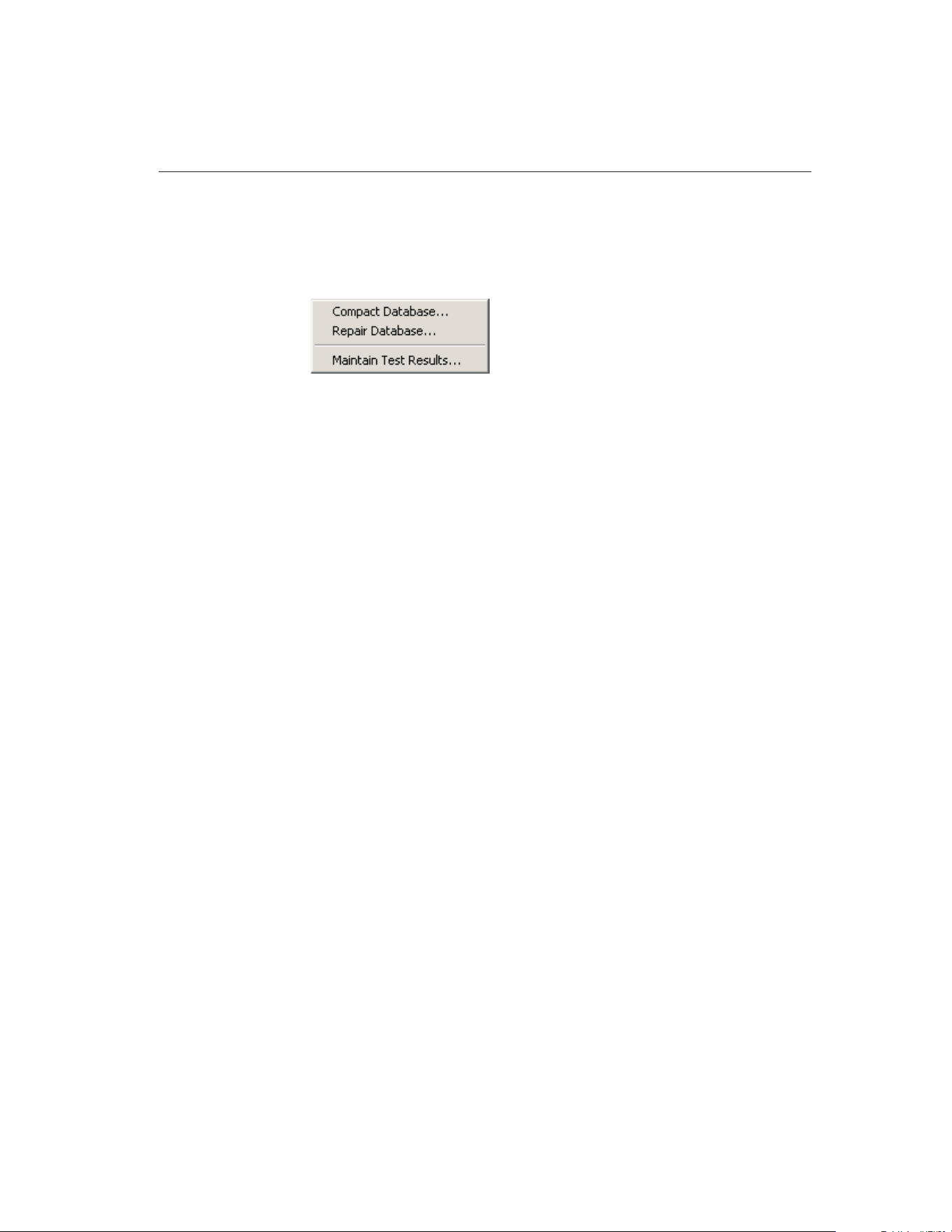
15.9 Utilities Menu
The Utilities menu allows the user to compact and repair the database and to
maintain the tables used for storing the raw data and coefficients.
15.9.1 Compact Database
Selecting the Compact Database option allows any deleted records in the data-
base to be purged from the database. Using this option from time to time can
typically reduce the size of the database and make accessing the database faster.
Selecting the Compact Database option displays the Windows® Open dialog.
Select the database file to compact and click the OK button. Clicking the Can-
cel button aborts compacting a database.
When a database is compacted, a copy of the database is made and given a
.BAK extension. If a .BAK file with the same name already exists, it is deleted
and replaced by the new .BAK file.
15.9.2 Repair Database
Selecting the Repair Database option allows a corrupted database to be re-
paired. A database can become corrupted if there is a power failure or if the
software terminates abnormally or crashes. Typically, if a database is corrupt, a
warning message is displayed. Use this option to repair the corrupt database.
After the database is repaired, the database is then compacted following the
same process outlined in the previous section.
15.9.3 Maintain Test Results
Selecting the Maintain Test Results option displays the Maintain Test Results
dialog. This dialog can be used to validate and/or remove information from the
database.
223
15
Coefficients and Tables Application
Figure 127 Utilities Menu
1.888.610.7664 sales@GlobalTestSupply.com
Fluke-Direct.com
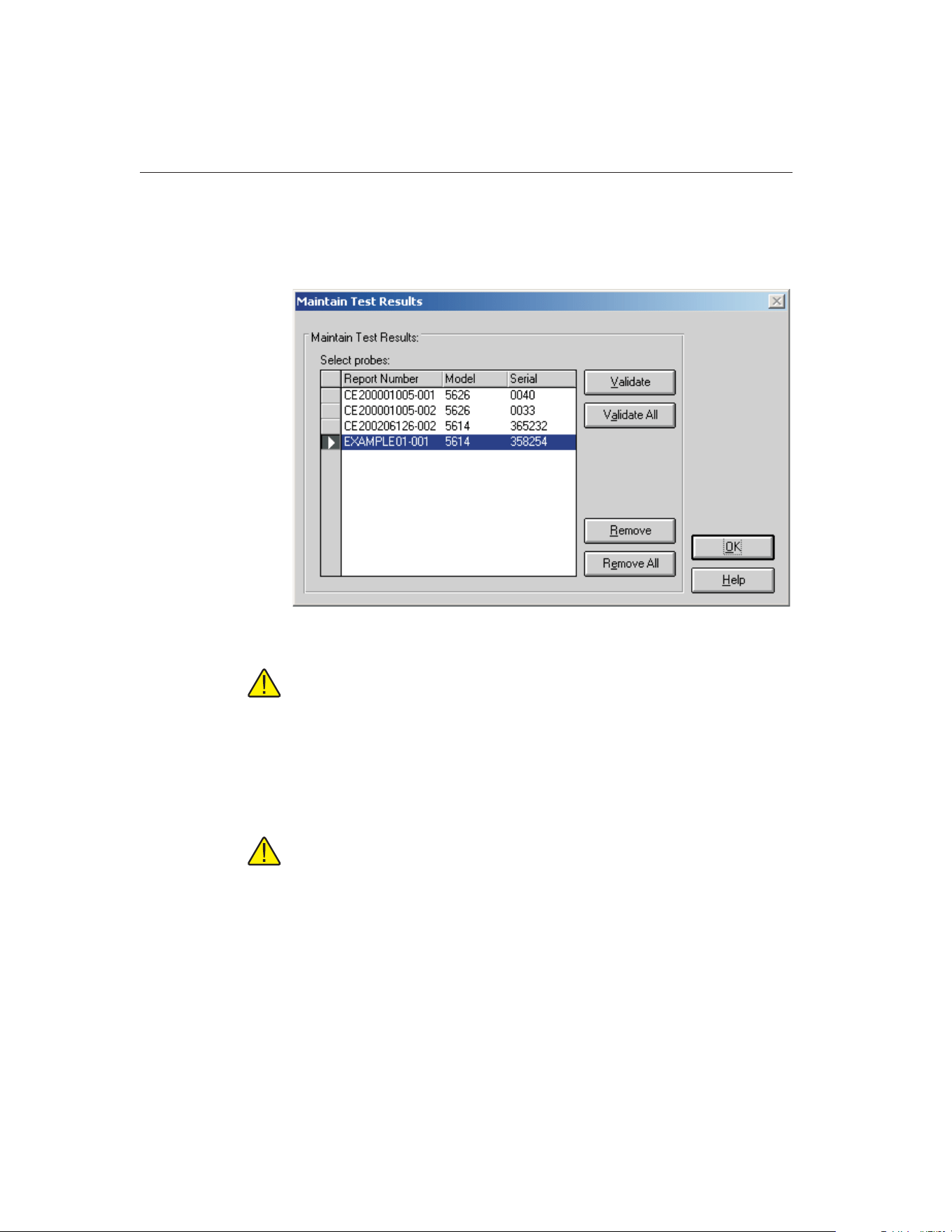
15.9.3.1 Maintain Test Results Dialog
The Maintain Test Results dialog can be used to determine the validity of test
probe data and to remove data from the database.
Note: This feature does NOT determine the validity of coefficients calcu-
lated by the software. It determines only if a test probe is valid based on
the presence or absence of information for the test in the database.
To validate or remove test probes from the database, select the test probes from
the Select probes list and click the Validate or Remove button. To validate or
remove all test probes, click the Validate All or Remove All button respectively.
Test probe validation is explained in the following section.
Important: Use caution when removing test probes. Once a test probe has
been removed, the software will not be able to print Reports of Calibration
or tables for that test probe! All coefficient data is deleted permanently.
For this reason, the user must confirm removing records from the data-
base.
15.9.3.2 Test Probe Validation
Results of coefficient calculations are stored in a table in the database. Other in-
formation required to print a Report of Calibration for the test probes is stored
in many separate tables within MET/TEMP II’s database in a relational manner.
If a test has been removed from MET/TEMP II, it may no longer be possible to
9938 MET/TEMP II
User’s Guide
224
Figure 128 Maintain Test Results Dialog
1.888.610.7664 sales@GlobalTestSupply.com
Fluke-Direct.com

print a Report of Calibration for a test probe using this application. If the data-
base became corrupt, some of the data for a particular test probe may have been
lost. These are a couple of the reasons why test probe data may not be valid.
The validation feature can be used to determine if there are records for every
test in every required table.
Clicking the Validate or Validate All buttons on the Maintain Test Results dia-
log performs a check on the selected test probes to see if the required informa-
tion to print a Report of Calibration exists in each of the database tables for the
test probe. If the software determines that required records are missing (a test
probe is invalid), the Invalid Test Probe dialog is displayed. Otherwise, a mes-
sage appears stating the validity of the test probes.
The Invalid Test Probe dialog displays information about the test probe that is
being validated. The Report number is invalid for the following reasons list at
the top of the dialog shows the reasons why the test probe is considered to be
invalid.
Based on the information provided, the user must decide what to do with the
test. The options available to the user are to not remove or to remove the se-
lected test probes. Selecting the Do not remove report option leaves the test
probe as is. Selecting the Remove this report option permanently removes the
test probe coefficients data from the database. Information about the test, test
equipment, and test readings cannot be removed.
225
15
Coefficients and Tables Application
Figure 129 Invalid Test Probe Dialog
1.888.610.7664 sales@GlobalTestSupply.com
Fluke-Direct.com
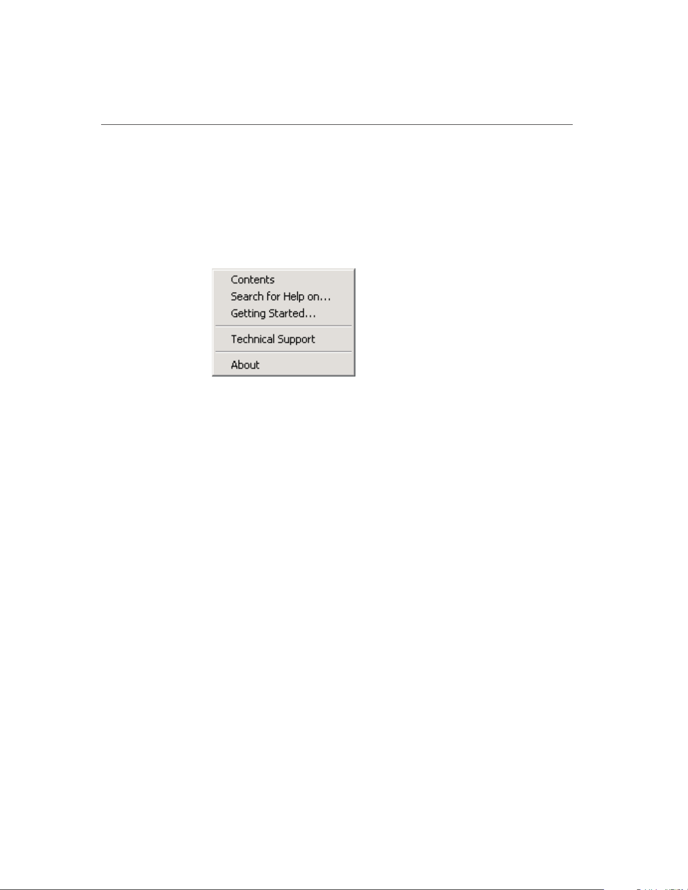
Select the appropriate options and click the OK button to continue. Click the
Cancel button to close this dialog without making any changes.
15.10 Help Menu
The Help menu provides access to the on-line help file. The Technical Support
contact information and About MET/TEMP II dialog are also available from
the Help menu.
15.10.1 Contents
Selecting the Contents option opens the on-line help file and displays the con-
tents topic.
15.10.2 Search for Help On
Selecting the Search for Help on option opens the on-line help file with the
Windows® Search dialog open. Select or enter a keyword to search for a topic
or click Cancel to go to the help file.
15.10.3 Getting Started
Selecting the Getting Started option opens the on-line help file to the Getting
Started topic.
15.10.4 Technical Support
Selecting the Technical Support option displays the Technical Support help
topic. For technical support information, please refer to Section 18.1, Technical
Support.
9938 MET/TEMP II
User’s Guide
226
Figure 130 Help Menu
1.888.610.7664 sales@GlobalTestSupply.com
Fluke-Direct.com

15.10.5 About
Selecting the About option displays the About MET/TEMP II dialog. This dia-
log states the software version number, copyright and other information.
15.11 Reports of Calibration and Tables
This section describes in detail the default Report of Calibration and table that
are built into this application.
15.11.1 Default Report of Calibration
The default Report of Calibration was designed to meet the ANSI/NCSL
Z540-1 specification.
The default Report of Calibration contains: the report number, the test probe in-
formation, calibration range, received condition, excitation current used (if ap-
plicable), test procedure, customer name and address, calibration test paragraph
and notes, the actual data used to calculate coefficients, the characterization co-
efficients, a list of the test equipment, calibration date, recall date, ambient tem-
perature and humidity, customer order ID, technician name, and a place for
technician and approval signatures. The actual data consists of the actual values
(reference readings), UUT values (test probe readings), the calculated residuals
and method of realization.
The fonts, sizes, and styles used on the default Report of Calibration can be
changed on the Fonts & Sizes tab of the Defaults dialog.
The top, bottom, left, and right margins and the column widths for the Test
Equipment table on the Report of Calibration can be set using the appropriate
227
15
Coefficients and Tables Application
Figure 131 About MET/TEMP II Coefficients and Tables Application Dialog
1.888.610.7664 sales@GlobalTestSupply.com
Fluke-Direct.com

controls on the Reports tab of the MET/TEMP II Defaults dialog. A custom
logo can also be added to the upper left corner of the Report of Calibration us-
ing the settings on this tab.
Reports of Calibration can be saved to a report file from the Print Preview win-
dow and opened, viewed and printed by selecting the Recall Saved Report/Ta-
ble option from the File menu or by running the Report Viewer utility. See
Section 17, Report Viewer Utility, for more details.
The report number is printed on each page of the Report of Calibration. The re-
port number is a unique number consisting of the test number and the scanner
channel to which the test probe was connected. These two pieces of informa-
tion are concatenated together with a dash.
The test probe information consists of the test probe model number, serial num-
ber and description. This information is printed at the top of the first page along
with the calibration range, received condition, excitation current used, and test
procedure number.
The paragraph text follows the test probe information.
The raw data section contains the readings taken by MET/TEMP II that were
used to calculate the coefficients and the resulting residuals.
Note: The Method of Realization column prints only if the test was performed
using MET/TEMP II v4.0 or later.
The coefficients print immediately below the raw data section.
The Test Equipment section lists each of the instruments that was used to per-
form the calibration. Each instrument’s manufacturer, model, description, serial
number and recall date is indicated. For instruments that do not require calibra-
tion, NCR is printed in the Recall Date column.
The notes text follows the coefficients.
The recall date is the date the test probe or test equipment is due for
recalibration. Recall date is synonymous with recalibration date.
Note: If the calibration interval was set to 0, the recall date is omitted from the
Report of Calibration for that test probe.
The technician is the name of the person who performed the test.
To see an example of the default Report of Calibration, see Figure 132.
15.11.2 Default Table
The default table includes: the date, table title, report number and pagination
information on the top of every page. Pages of the table are automatically num-
bered. If a Report of Calibration is being generated and printed with the table,
the page numbering is continuous (i.e. the Report of Calibration pages are num-
bered1toi where i is the number of pages in the Report of Calibration and the
table pages are numbered i + 1 to n where n is the sum of the number of pages
in the Report of Calibration and the table).
9938 MET/TEMP II
User’s Guide
228
1.888.610.7664 sales@GlobalTestSupply.com
Fluke-Direct.com

If the table is being printed by itself, the pages are numbered starting with the
starting page number specified on the Other Settings tab of the Table Options
dialog.
The table is formatted into three columns. Each row in each column consists of
up to 3 sets of data, depending on the selected options. The first set of data is
the temperature value. The second set is the resistance, ratio or EMF value, de-
pending on the type of table being generated. The third column is the first de-
rivative, inverse difference or error value, depending on the type of table being
generated.
The table’s minimum and maximum temperatures, temperature scale and the
increment (step) between each temperature value is set on the Type and Range
tab of the Table Options dialog.
To see an example of the default table, refer to Figure 133.
15.12 Requirements and Methods
The following sections describe in detail the requirements for calculating char-
acterization coefficients and the methods used to perform the calculations.
15.12.1 ITS-90 Requirements
The following requirements must be met when ITS-90 is selected as the type of
coefficients to calculate for platinum probes. For more information concerning
the method used to calculate the ITS-90 coefficients, refer to Section 15.12.6,
Methods Used for Calculating Coefficients.
1. The reference probe readings must be in temperature (C, F or K).
2. The UUT (test probe) readings must be in resistance (Ohms or kOhms).
3. At least 2 set-points must be used, but no more than 21 set-points can be
used. The actual minimum and maximum number of set-points that can
be used depends on the selected low range and high range.
4. There must be one set-point within a few degrees of the Triple-Point of
Water (TPW = 0.01C) (preferably as close to it as possible).
5. Low range criteria:
a. The following low ranges can be selected
i. None
ii. Range 4 (83.8058 K to 273.16 K)
iii. Range 5 (234.3156 K to 302.9146 K)
b. Both ranges 4 and 5 require the Triple-Point of Water (TPW) set-point
and at least 2 and no more than 10 additional set-points.
c. All set-points should fall within the temperature range of the selected
low range.
229
15
Coefficients and Tables Application
1.888.610.7664 sales@GlobalTestSupply.com
Fluke-Direct.com

6. High range criteria:
a. The following high ranges can be selected
i. None
ii. Range 6 (273.15 K to 1234.93 K)
iii. Range 7 (273.15 K to 933.473 K)
iv. Range 8 (273.15 K to 4692.677 K)
v. Range 9 (273.15 K to 505.078 K)
vi. Range 10 (273.15 K to 429.7485 K)
vii. Range 11 (273.15 K to 302.9146 K)
b All Ranges require the Triple-Point of Water (TPW) set-point and the
following:
i. Range 6 requires at least 4 and no more than 10 set-points.
ii. Range 7 requires at least 3 and no more than 10 set-points.
iii. Ranges 8 and 9 require at least, 2 but no more than 10 set-points.
iv. Ranges 10 and 11 require at least 1 but no more than 10 set-points.
c. All set-points should fall within the temperature range of the selected
high range.
7. Selecting None for both the low range and the high range is not
permitted.
8. The residuals are calculated for each set-point used in calculating the co-
efficients with the exception of the Triple-Point of Water (TPW)
set-point. Residuals are always in the same scale as the reference probe
readings.
15.12.2 IPTS-68 Requirements
The following requirements must be met when IPTS-68 is selected as the type
of coefficients to calculate for platinum probes. For more information concern-
ing the method used to calculate the IPTS-68 coefficients, refer to Section
15.12.6, Methods Used for Calculating Coefficients.
1. The reference probe readings must be in temperature (C, F or K).
2. The UUT (test probe) readings must be in resistance (Ohms or kOhms).
3. Exactly 4 set-points must be used:
a. One set-point must be within a few degrees of 0C (32F or 273.15 K)
(preferably as close to 0C as possible).
b. One set-point must be below 0C.
c. Two set-points must be above 0C.
9938 MET/TEMP II
User’s Guide
230
1.888.610.7664 sales@GlobalTestSupply.com
Fluke-Direct.com

231
15
Coefficients and Tables Application
Report of Cal
i
brat
i
on
Report No: EXAMPLE01-001
Page1of1
Our Company
12 Our Street
Our Town, USA
09876
Model: 5614
Serial: 358254
Description: Secondary Standard RTD Probe
Calibration Range: FULL
Received Condition: New
Current: 1.0 mA
Procedure: TEST_PROC
Customer: Our Customer
One Customer Way
This Town, USA
12345
Calibration Date: 8/1/2002
Recall Date: 8/1/2003
Temperature: 25C
Humidity: 30%
Customer Order: 2345432-FG-369
Technician: ________________________
Cal E. Breight
Approved By: ________________________
This is the paragraph. The paragraph may contain any text that needs to be displayed in this section of the Report of Calibration. The
paragraph text must be saved in an ASCII text file with a .PGH extension. The file to be used as the paragraph text can be specified
on the File | Defaults Reports tab and on the Test Information dialog.
Actual Value
(Reference)
(C)
UUT
(Test Sensor)
(Ohms)
Residuals
(C)
Method of
Realization
-90.10000 16.23400 -0.0001 COMP
-38.83400 21.56750 0.0001 COMP
0.01200 25.54950 N/A COMP
156.59900 41.12680 0.0001 COMP
231.92800 48.35590 -0.0001 COMP
300.00000 54.74330 0.0001 COMP
ITS-90 Coefficients:
RTPW = 25.549296 Ohms
a4 = 8.0074745 E-06 a8 = -1.6577511 E-04
b4 = 3.7630372 E-04 b8 = 2.1866045 E-06
Test Equipment
Manufacturer Model Description Serial Number Recall Date
Hart Scientific, Inc 1560 'Black Stack' Base Unit 65432 NCR
Hart Scientific, Inc 2560 SPRT Module 64356 8/1/2003
Burns Engineering 5614 Secondary Standard RTD Probe 380215 8/1/2003
Hart Scientific, Inc 7100 Bath, Ultra Low-Temp A03120 8/1/2003
Hart Scientific, Inc 9112 Furnace, Calibration A01343 8/1/2003
Notes: This is the text that is referred to as the Notes text. The notes may contain any text that needs to be displayed in this section
of the Report of Calibration. The notes text must be saved in an ASCII text file with a .TXT extension. The file to be used as the
notes text is specified on the Test Information dialog.
This report shall not be reproduced except in
f
ull without written approval o
f
Our Compan
y
.
Figure 132 Example Default Report of Calibration - ITS-90 Coefficients
1.888.610.7664 sales@GlobalTestSupply.com
Fluke-Direct.com

9938 MET/TEMP II
User’s Guide
232
C Resistance dr/dT
0.00
25.548277 0.1018719
1.00
25.650149 0.1018408
2.00
25.751990 0.1018096
3.00
25.853799 0.1017785
4.00
25.955578 0.1017474
5.00
26.057325 0.1017163
6.00
26.159042 0.1016852
7.00
26.260727 0.1016541
8.00
26.362381 0.1016230
9.00
26.464004 0.1015920
10.00
26.565596 0.1015609
11.00
26.667157 0.1015299
12.00
26.768687 0.1014989
13.00
26.870186 0.1014678
14.00
26.971653 0.1014368
15.00
27.073090 0.1014058
16.00
27.174496 0.1013748
17.00
27.275871 0.1013439
18.00
27.377215 0.1013129
19.00
27.478528 0.1012819
20.00
27.579810 0.1012510
21.00
27.681061 0.1012200
22.00
27.782281 0.1011891
23.00
27.883470 0.1011582
24.00
27.984628 0.1011273
25.00
28.085755 0.1010964
26.00
28.186852 0.1010655
27.00
28.287917 0.1010346
28.00
28.388952 0.1010037
29.00
28.489955 0.1009728
30.00
28.590928 0.1009420
31.00
28.691870 0.1009111
32.00
28.792781 0.1008803
33.00
28.893662 0.1008494
34.00
28.994511 0.1008186
35.00
29.095330 0.1007878
36.00
29.196117 0.1007569
37.00
29.296874 0.1007261
38.00
29.397600 0.1006953
39.00
29.498296 0.1006645
40.00
29.598960 0.1006337
41.00
29.699594 0.1006030
42.00
29.800197 0.1005722
43.00
29.900769 0.1005414
44.00
30.001311 0.1005107
45.00
30.101821 0.1004799
46.00
30.202301 0.1004491
47.00
30.302750 0.1004184
48.00
30.403169 0.1003877
49.00
30.503556 0.1003569
50.00
30.603913
0.1003262
51.00
30.704240 0.1002955
52.00
30.804535 0.1002648
53.00
30.904800 0.1002341
54.00
31.005034 0.1002034
55.00
31.105237 0.1001727
56.00
31.205410 0.1001420
57.00
31.305552 0.1001113
58.00
31.405663 0.1000807
59.00
31.505744 0.1000500
60.00
31.605794 0.1000193
C Resistance dr/dT
61.00
31.705813 0.0999887
62.00
31.805802 0.0999580
63.00
31.905760 0.0999274
64.00
32.005687 0.0998967
65.00
32.105584 0.0998661
66.00
32.205450 0.0998355
67.00
32.305286 0.0998049
68.00
32.405091 0.0997742
69.00
32.504865 0.0997436
70.00
32.604608 0.0997130
71.00
32.704322 0.0996824
72.00
32.804004 0.0996518
73.00
32.903656 0.0996212
74.00
33.003277 0.0995907
75.00
33.102868 0.0995601
76.00
33.202428 0.0995295
77.00
33.301957 0.0994989
78.00
33.401456 0.0994684
79.00
33.500925 0.0994378
80.00
33.600362 0.0994073
81.00
33.699770 0.0993767
82.00
33.799146 0.0993462
83.00
33.898493 0.0993157
84.00
33.997808 0.0992851
85.00
34.097093 0.0992546
86.00
34.196348 0.0992241
87.00
34.295572 0.0991936
88.00
34.394766 0.0991631
89.00
34.493929 0.0991325
90.00
34.593061 0.0991021
91.00
34.692163 0.0990716
92.00
34.791235 0.0990411
93.00
34.890276 0.0990106
94.00
34.989287 0.0989801
95.00
35.088267 0.0989496
96.00
35.187216 0.0989192
97.00
35.286135 0.0988887
98.00
35.385024 0.0988582
99.00
35.483882 0.0988278
100.00
35.582710
0.0987973
101.00
35.681508 0.0987669
102.00
35.780274 0.0987365
103.00
35.879011 0.0987060
104.00
35.977717 0.0986756
105.00
36.076393 0.0986452
106.00
36.175038 0.0986148
107.00
36.273652 0.0985844
108.00
36.372237 0.0985539
109.00
36.470791 0.0985235
110.00
36.569314 0.0984932
111.00
36.667807 0.0984628
112.00
36.766270 0.0984324
113.00
36.864703 0.0984020
114.00
36.963105 0.0983716
115.00
37.061476 0.0983412
116.00
37.159817 0.0983109
117.00
37.258128 0.0982805
118.00
37.356409 0.0982502
119.00
37.454659 0.0982198
120.00
37.552879 0.0981895
121.00
37.651068 0.0981591
C Resistance dr/dT
122.00
37.749227 0.0981288
123.00
37.847356 0.0980985
124.00
37.945455 0.0980681
125.00
38.043523 0.0980378
126.00
38.141561 0.0980075
127.00
38.239568 0.0979772
128.00
38.337545 0.0979469
129.00
38.435492 0.0979166
130.00
38.533409 0.0978863
131.00
38.631295 0.0978560
132.00
38.729151 0.0978258
133.00
38.826977 0.0977955
134.00
38.924773 0.0977652
135.00
39.022538 0.0977349
136.00
39.120273 0.0977047
137.00
39.217977 0.0976744
138.00
39.315652 0.0976442
139.00
39.413296 0.0976139
140.00
39.510910 0.0975837
141.00
39.608494 0.0975535
142.00
39.706047 0.0975232
143.00
39.803570 0.0974930
144.00
39.901063 0.0974628
145.00
39.998526 0.0974326
146.00
40.095959 0.0974024
147.00
40.193361 0.0973722
148.00
40.290733 0.0973420
149.00
40.388075 0.0973118
150.00
40.485387
0.0972816
151.00
40.582669 0.0972514
152.00
40.679920 0.0972213
153.00
40.777141 0.0971911
154.00
40.874332 0.0971609
155.00
40.971493 0.0971308
156.00
41.068624 0.0971006
157.00
41.165725 0.0970705
158.00
41.262795 0.0970403
159.00
41.359835 0.0970102
160.00
41.456846 0.0969801
161.00
41.553826 0.0969499
162.00
41.650776 0.0969198
163.00
41.747695 0.0968897
164.00
41.844585 0.0968596
165.00
41.941445 0.0968295
166.00
42.038274 0.0967994
167.00
42.135074 0.0967693
168.00
42.231843 0.0967392
169.00
42.328582 0.0967091
170.00
42.425291 0.0966791
171.00
42.521970 0.0966490
172.00
42.618619 0.0966189
173.00
42.715238 0.0965889
174.00
42.811827 0.0965588
175.00
42.908386 0.0965288
176.00
43.004915 0.0964987
177.00
43.101414 0.0964687
178.00
43.197882 0.0964387
179.00
43.294321 0.0964087
180.00
43.390730 0.0963786
181.00
43.487108 0.0963486
1
8
2.00
43.583457 0.0963186
8/20/2002 Temperature vs. Resistance Table Report No: EXAMPLE01-001 Page 2 of 2
Figure 133 Example Default Table - Temperature vs. Resistance
1.888.610.7664 sales@GlobalTestSupply.com
Fluke-Direct.com

4. The residuals are not calculated when calculating IPTS-68 coefficients.
15.12.3 Callendar-Van Dusen Requirements
The following requirements must be met when Callendar-Van Dusen is selected
as the type of coefficients to calculate for platinum probes. For more informa-
tion concerning the method used to calculate the Callendar-Van Dusen coeffi-
cients, refer to Section 15.12.6, Methods Used for Calculating Coefficients.
1. The reference probe readings must be in temperature (C, F or K).
2. The UUT (test probe) readings must be in resistance (Ohms or kOhms).
3. At least 3 set-points must be used but no more than 10 set-points can be
used. If any one of the set-points is more than 5 degrees below 0C (9 de-
grees below 32F or 5 degrees below 273.15 K), at least 4 set-points must
be used.
Note: This software automatically determines if the BETA coefficients
need to be calculated based on the following criteria:
• The reference reading closest to 0C is not used to determine whether
BETA is calculated.
• If any other reference reading is below 0C, BETA will be calculated.
• Otherwise, BETA will not be calculated.
4. One of the set-points used should be close to 0C. This is not a require-
ment, however, results of the calculations become less reliable when no
reading is near 0C because the software must extrapolate this reading.
5. The residuals are calculated for each set-point used in calculating the co-
efficients. Residuals are always in the same scale as the reference probe
readings.
15.12.4 Polynomial Requirements
The following requirements must be met when Polynomial is selected as the
type of coefficients to calculate for platinum or thermistor probes. For more in-
formation concerning the method used to calculate the Polynomial coefficients,
refer to Section 15.12.6, Methods Used for Calculating Coefficients.
1. The reference probe readings must be in temperature (C, F or K).
Note: The accepted thermistor model is based upon the logarithmic resis-
tance-temperature characteristic in terms of absolute temperature (K). The
accuracy of a model based upon degrees F or degrees C has net been
tested. Therefore, polynomial coefficients for thermistor probes are always
calculated using K. If reference readings are entered in degrees F or de-
grees C, the readings are converted to their K equivalent values before the
fit is computed.
2. The UUT (test probe) readings must be in resistance (Ohms or kOhms).
233
15
Coefficients and Tables Application
1.888.610.7664 sales@GlobalTestSupply.com
Fluke-Direct.com

3. The order of the polynomial must be selected. Allowable choices are
from 3rd order to 9th order for platinum probes and from 3rd order to
6th order for thermistor probes.
4. For thermistor probes, the Steinhart-Hart method may be selected. Stud-
ies have indicated no significant loss in accuracy when using the
Steinhart-Hart method (eliminating the squared term) over the range of
–2C to 70C (28F to 158F). The formula used when the Steinhart-Hart
method is selected is:
1
T
a bln R dln R
TT
=+ +() ()
For more information on this topic, refer to “Worldwide Capability in
Thermistors”, Thermometrics, Inc., 1993, pages 14-15.
5. For normal calculations, at least 4 set-points must be used but no more
than 10 set-points can be used.
6. For Steinhart-Hart calculations, only 3 set-points should be used.
7. The minimum number of set-points used must exceed the order of the
polynomial by at least 1 (i.e. for a 5th order polynomial, at least 6
set-points must be used).
8. The residuals are calculated for each set-point used in calculating the co-
efficients. Residuals are always in the same scale as the reference probe
readings. For platinum probes, the residuals are in degrees. For thermis-
tor probes, residuals are in millidegree.
15.12.5 Thermocouple Requirements
The following requirements must be met when calculating coefficients for
Thermocouple probes. For more information concerning the method used to
calculate the Thermocouple coefficients, refer to Section 15.12.6, Methods
Used for Calculating Coefficients.
1. The reference probe readings must be in temperature (C, F or K).
Note: The algorithm used to calculate thermocouple coefficients forces the
EMF at 0C to 0.0µV. Therefore, using a set-point at or near 0C when calcu-
lating thermocouple coefficients may cause erroneous results. For best re-
sults, use at least two set-points that are not near 0C (more than ±5C).
2. The UUT (test probe) readings must be in voltage (mV or µV). At least 2
set-points must be used but no more than 10 set-points can be used.
3. The CJC readings, if used, can be in either temperature (C or F) or volt-
age (mV or µV). If no CJC readings are needed, a scale does not need to
be selected.
4. The thermocouple type must be selected. The following types can be
selected:
9938 MET/TEMP II
User’s Guide
234
1.888.610.7664 sales@GlobalTestSupply.com
Fluke-Direct.com

a. Type B
b. Type E
c. Type J
d. Type K
e. Type N
f. Type R
g. Type S
h. Type T
i. Type AuPt (Gold-Platinum)
5. The temperature range for the thermocouple type must be selected. The
following ranges can be selected:
Type Range 1 Range 2 Range 3 Other
Type B 0 to 630.615C 630.615 to 1820C N/A N/A
Type E –270 to 0C 0 to 1000C N/A N/A
Type J –210 to 760C 760 to 1200C N/A N/A
Type K –270 to 0C 0 to 1372C N/A N/A
Type N –270 to 0C 0 to 1300C N/A N/A
Type R –50 to 1064.18C 1064.18 to 1664.5C 1664.5 to 1768.1C –50C to 1768.1C
(using extrapolation)*
Type S –50 to 1064.18C 1064.18 to 1664.5C 1664.5 to 1768.1C –50C to 1768.1C
(using extrapolation)*
Type T –270 to 0C 0 to 400C N/A N/A
Type AuPt 0 to 1000C
(8th order Canadian
Polynomial)
0 to 1000C
(9th order American
Polynomial)
N/A N/A
*Selecting this range allows the software to automatically select the appropriate reference function to use to calculate the EMF at each tem-
perature. Selecting one of the other ranges forces the reference function for the selected range to calculate the EMF for ALL temperatures
to be used.
6. Each set-point for thermocouple probes can have an associated Cold
Junction Compensation (CJC) reading. The UUT reading at each
set-point is adjusted according to the CJC value for that set-point prior to
calculating coefficients. The UUT readings are not adjusted prior to cal-
culating coefficients if the Do not use CJC in calculations option is
selected.
7. The residuals are calculated for each set-point used in calculating the co-
efficients. For thermocouple probes, the residuals are in the same scale as
the UUT readings (mV or µV).
235
15
Coefficients and Tables Application
Table 2 Temperature Range of Thermocouple Types
1.888.610.7664 sales@GlobalTestSupply.com
Fluke-Direct.com

15.12.6 Methods Used for Calculating Coefficients
The following sections describe the methods used to calculate coefficients.
15.12.6.1 General
The thermometric expressions used by this software are well known expres-
sions and as such are described in detail elsewhere. This section touches on
some specifics as they relate to the methods used to arrive at solutions.
The coefficients for all solutions with the exception of the IPTS-68 platinum
probe are calculated using matrix methods. The IPTS-68 platinum probe solu-
tion is calculated using iteration. The solutions are either exact solutions or
over-determined solutions depending on the number of test points used in rela-
tion to the number of test points required. Exact solutions result when the exact
number of test points required for simultaneous solution of sets of equations
are used (i.e., two coefficients from two test points). Over-determined solutions
result when more test points are used than the unknowns require (i.e., two coef-
ficients from three or more test points).
15.12.6.2 ITS-90
The ITS-90 is expressed in terms of resistance ratio (W) vs. temperature (K)
rather than resistance (R) vs. temperature. The resistance ratio is defined as the
resistance at a temperature R(t) divided by the resistance at the Triple-Point of
Water R(TPW), or:
W = R(t)/R(TPW)
Because ratios are used in the ITS-90, the RTPW is required in addition to the
resistance values at the test temperatures, thus, three test points are required to
solve for two coefficients. The example below shows a set of four equations
representing data at five temperatures (RTPW and resistance at four test tem-
peratures) along with the matrix method used to solve the over-determined set.
A
Δ
Δ
WaW bW
WaW bW
TT T
TT T
11 1
2
22 2
2
11
11
=−+−
=−+−
[( ) ( )]
[( ) ( )]
Δ
Δ
WaW bW
WaW bW
TT T
TT T
33 3
2
44 4
2
11
11
=−+−
=−+−
[( ) ( )]
[( ) ( )]
B
Matrix
W
W
W
W
T
T
T
T
1
1
2
3
4
=
⎡
⎣
⎢
⎢
⎢
⎢
⎤
⎦
⎥
⎥
⎥
⎥
Δ
Δ
Δ
Δ
Matrix
WbW
WbW
W
TT
TT
T
2
11
2
22
2
3
11
11
1
=
−+ −
−+ −
−+
()()
()()
()bW
WbW
T
TT
()
()()
3
2
44
2
1
11
−
−+ −
⎡
⎣
⎢
⎢
⎢
⎢
⎤
⎦
⎥
⎥
⎥
⎥
C
Solution Matrix Matrix Matrix Matrix
TT
=• ••
−
()
22
1
21
An exact solution (i.e., two unknowns in two equations) would be arrived at
with the following operation:
9938 MET/TEMP II
User’s Guide
236
1.888.610.7664 sales@GlobalTestSupply.com
Fluke-Direct.com

C′
Solution Matrix Matrix=•
−
2
1
1
15.12.6.3 IPTS-68
Like the ITS-90, the IPTS-68 is expressed in terms of resistance ratios. The de-
nominator, however, is the resistance at the ice point (0.0C) rather than the re-
sistance at the Triple-Point of Water (0.01C). This software allows only exact
solutions for the IPTS-68 and uses iteration or simple algebra for the solutions.
15.12.6.4 Callendar-Van Dusen
The Callendar-Van Dusen expression is basically a third order polynomial with
the third coefficient (β) set to zero above 0C. The polynomial is expressed in
terms of resistance vs. temperature in degrees C. It is solved by matrix methods
in a similar manner as the ITS-90 expression shown above with temperature on
the left of the equal sign and the polynomial on the right. The software allows
for over-determined solutions. Only data above 0C is used for solution of the
first two coefficients (α and δ), data both above and below 0C is used for solu-
tion of β.
15.12.6.5 Polynomial and Thermocouple
Polynomial solutions are arrived at using matrix methods as with the ITS-90
and the Callendar-Van Dusen. Platinum probes require polynomials expressed
in terms of resistance vs. temperature. Thermistor probes exhibit exponential
resistance vs. temperature relationships and the polynomials used are exponen-
tial expressions in terms of resistance vs. temperature. The polynomials can be
of any order up to 9th for platinum probes and up to 6th for thermistor probes.
The software allows for over-determined solutions. Thermocouple probes re-
quire polynomials expressed in terms of mV vs. temperature.
15.12.7 Table Temperature Range Chart
Due to the nature of the equations used to generate tables, the temperature
range that can or should be used to generate a table depends on the type of co-
efficients used. Table 3 provides details on the temperature range for specific
coefficients.
ITS-90 C F K
Range Min Temp Max Temp Min Temp Max Temp Min Temp Max Temp
4 –189.0 0.0 –308.2 32.0 84.2 273.2
5 –39.0 30.0 –38.2 86.0 234.2 303.2
6 0.0 962.0 32.0 1763.6 273.2 1235.2
7 0.0 660.0 32.0 1220.0 273.2 933.2
8 0.0 420.0 32.0 788.0 273.2 693.2
9 0.0 232.0 32.0 449.6 273.2 505.2
237
15
Coefficients and Tables Application
Table 3 Temperature Range Recommendations
1.888.610.7664 sales@GlobalTestSupply.com
Fluke-Direct.com
10 0.0 157.0 32.0 314.0 273.2 430.2
11 0.0 30.0 32.0 86.0 273.2 303.2
IPTS-68 C F K
Min Temp Max Temp Min Temp Max Temp Min Temp Max Temp
–230.0 2650.0 –382.0 4802.0 43.2 2923.2
CVD C F K
BETA Min Temp Max Temp Min Temp Max Temp Min Temp Max Temp
No 0.0 2650.0 32.0 4802.0 273.2 2923.2
Yes –260.0 2650.0 –436.0 4802.0 13.2 2923.2
POLYNOMIAL C F K
Probe Type Min Temp Max Temp Min Temp Max Temp Min Temp Max Temp
Platinum –260.0 1480.0 –436.0 2696.0 13.2 1753.2
Thermistor –10.0 200.0 –14.0 392.0 263.2 473.2
THERMOCOUPLE C F K
Type Range Min Temp Max Temp Min Temp Max Temp Min Temp Max Temp
B 1 0.0 631.0 32.0 1167.8 273.2 904.2
B 2 631.0 1820.0 1167.8 3308.0 904.2 2093.2
E 1 –270.0 0.0 –454.0 32.0 3.1 273.2
E 2 0.0 1000.0 32.0 1832.0 273.2 1273.2
J 1 –210.0 760.0 –346.0 1400.0 63.2 1033.2
J 2 760.0 1200.0 1400.0 2192.0 1033.2 1473.2
K 1 –270.0 0.0 –454.0 32.0 3.1 273.2
K 2 0.0 1372.0 32.0 2501.6 273.2 1645.2
N 1 –270.0 0.0 –454.0 32.0 3.1 273.2
N 2 0.0 1300.0 32.0 2372.0 273.2 1573.2
R 1 –50.0 1064.0 –58.0 1947.2 223.2 1337.2
R 2 1064.0 1664.0 1947.2 3027.2 1337.2 1937.2
R 3 1664.0 1768.0 3027.2 3214.4 1937.2 2041.2
R N/A* –50.0 1768.0 –58.0 3214.4 223.2 2041.2
S 1 –50.0 1064.0 –58.0 1947.2 223.2 1337.2
S 2 1064.0 1664.0 1947.2 3027.2 1337.2 1937.2
S 3 1664.0 1768.0 3027.2 3214.4 1937.2 2041.2
S N/A* –50.0 1768.0 –58.0 3214.4 223.2 2041.2
T 1 –270.0 0.0 –454.0 32.0 3.1 273.2
T 2 0.0 400.0 32.0 752.0 273.2 673.2
AuPt 8th Order 0.0 1000.0 32.0 1832.0 273.2 1273.2
AuPt 9th Order 0.0 1000.0 32.0 1832.0 273.2 1273.2
*This range can be selected by choosing the “–50.0C to 1768.1C (using extrapolation)” option.
9938 MET/TEMP II
User’s Guide
238
1.888.610.7664 sales@GlobalTestSupply.com
Fluke-Direct.com
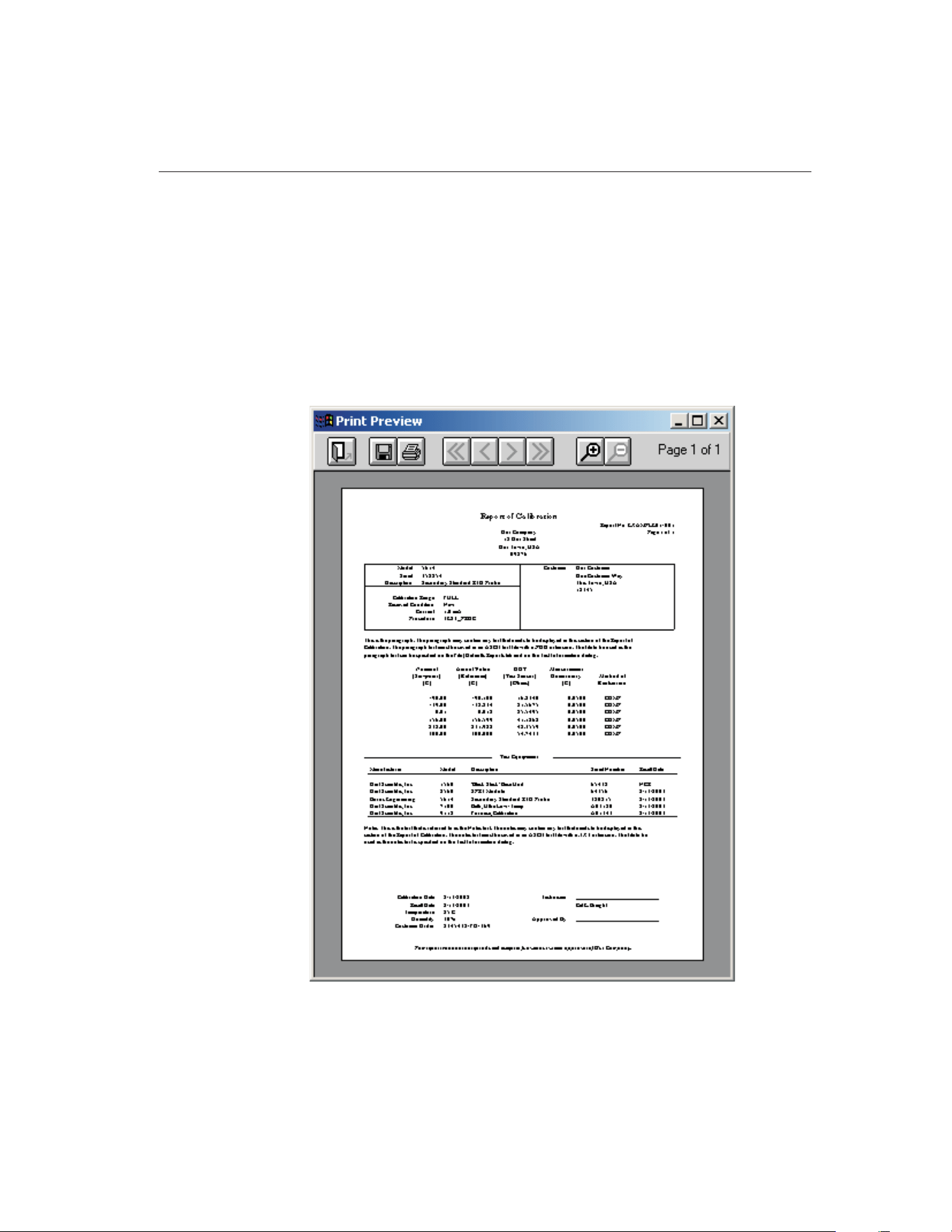
16 Print Preview Window
The Print Preview window is used to view reports on-screen without having to
print a hard copy. The Print Preview window is activated by selecting the En-
able print preview check box on the General tab of the Defaults dialog. Other
settings on the General tab can be changed to manipulate the default behavior
of the Print Preview window.
The Print Preview window is displayed when printing reports if the Enable
print preview check box is selected.
239
16
Print Preview Window
Figure 134 Print Preview Window
1.888.610.7664 sales@GlobalTestSupply.com
Fluke-Direct.com
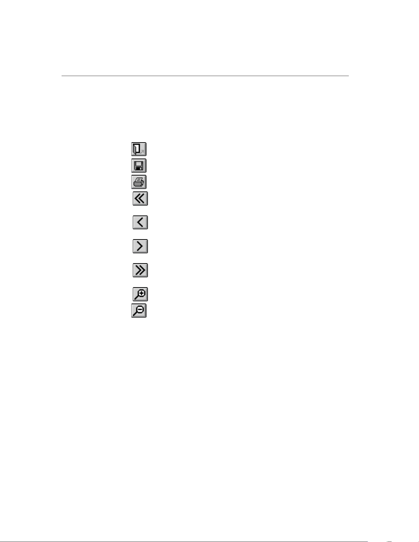
The toolbar buttons in the Print Preview window allow the user to print the re-
port, save the report to a file, navigate through all of the pages of the report (as
applicable), zoom in and out, and close the window. The current page and total
number of pages are displayed on the right side of the toolbar.
The function of each toolbar button is explained below.
Close - Closes the Print Preview window
Save As - Saves the current Report of Calibration to a report file
Print - Prints all pages of the report in the Print Preview window
First Page - Navigates to first page of the report (if more than one
page)
Previous Page - Navigates to previous page of the report (if more than
one page)
Next Page - Navigates to next page of the report (if more than one
page)
Last Page - Navigates to last page of the report (if more than one
page)
Zoom In - Zooms in to (enlarge) the report
Zoom Out - Zooms out from (reduce) the report
The toolbar also indicates the current page and the number of pages in the cur-
rent report.
9938 MET/TEMP II
User’s Guide
240
1.888.610.7664 sales@GlobalTestSupply.com
Fluke-Direct.com
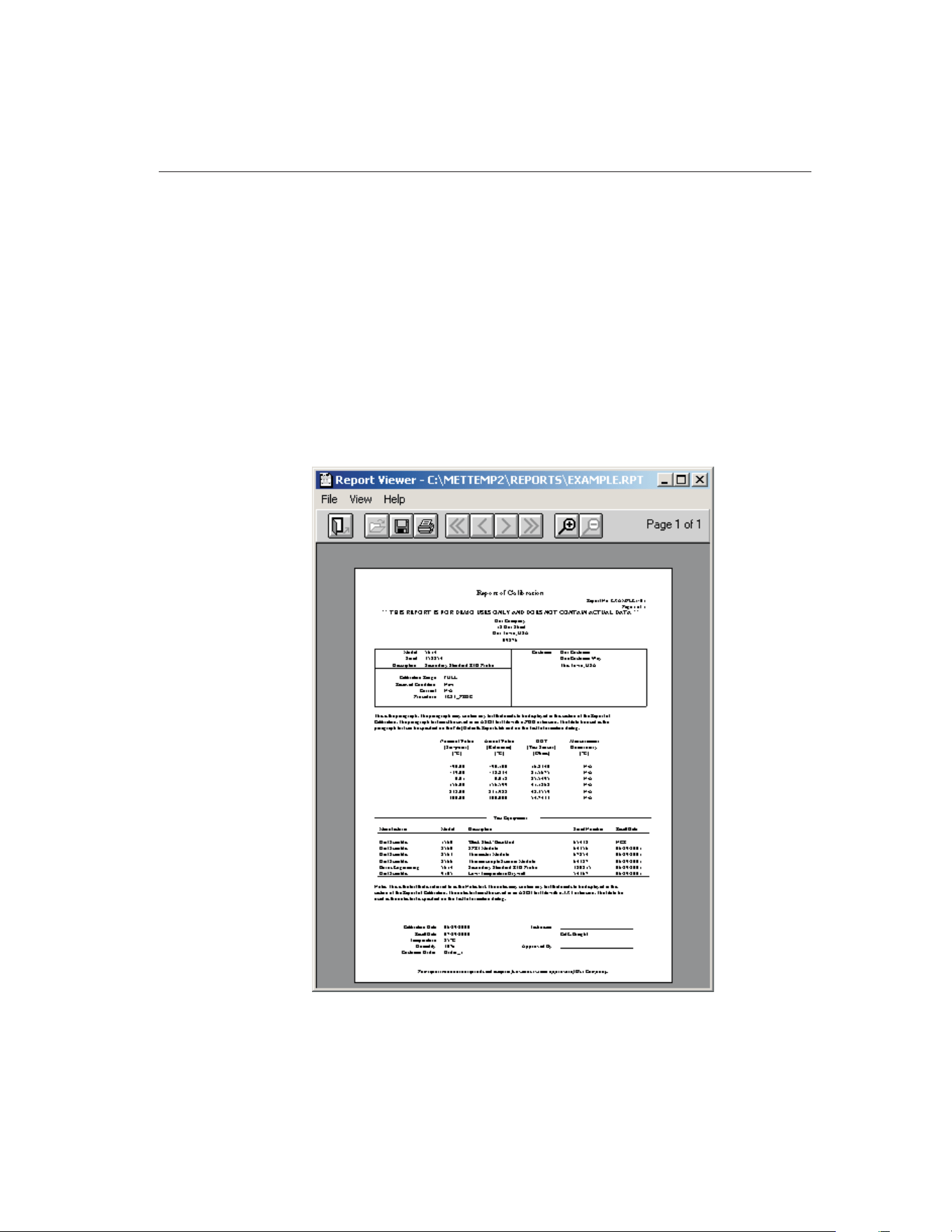
17 Report Viewer Utility
MET/TEMP II has a feature that allows a Report of Calibration to be saved to a
report file which can then be stored on diskette, CD-ROM or e-mailed to some-
one else.
The report viewer utility allows report files to be opened, viewed, and printed.
This utility can be installed on any computer where report files need to be
accessed.
The report viewer utility is very similar to the Print Preview window with a few
enhancements. This utility allows a single report file to be opened and viewed
at a time. The currently open report file must be closed before another file can
be opened.
241
17
Report Viewer Utility
Figure 135 Report Viewer Utility
1.888.610.7664 sales@GlobalTestSupply.com
Fluke-Direct.com

Report files can be saved only from the Print Preview window and have an ex-
tension of .RPT.
The report viewer utility has three menus: File, View, and Help. A brief de-
scription of the options in each menu follows.
• File menu - The File menu provides options for opening, saving, closing,
and printing report files.
• View menu - The View menu provides options for navigating multi-page
report files and zooming.
• Help menu - The Help menu provides an option to view the About Re-
port Viewer dialog.
17.1 Limitations
There are a few known limitations to using the report viewer utility. Please read
the following information to avoid potential problems:
• Report files are dependent on the currently selected Windows® printer
driver. For this reason, select the driver for the printer that is used to print
the report prior to saving the report to a file. For example, if the report file
is being e-mailed to a person who prints the report on a Hewlett-Packard
LaserJet 4MP printer, select this same print driver prior to previewing and
saving the report to a file. Otherwise, reports may appear fine in the pre-
view window but print incorrectly.
• Report files use a proprietary format and are not viewable by any other
software such as Adobe® Acrobat Reader, word processors, or graphics
applications. The report viewer utility can be distributed freely to anyone
who needs to view or print a report file. To create a distribution diskette
for the report viewer utility, refer to Section 17.3, Making a Report
Viewer Utility Setup Diskette.
• Report files which contain a table (from Coefficients and Tables applica-
tion) may contain one or more blank pages before the actual table data
starts. This is done to preserve the correct page numbering as selected
when the table was generated. To avoid blank pages, start the page num-
bering for the table at page 1. Otherwise, simply discard the blank pages
after printing the table.
17.2 Report Files
MET/TEMP II has a feature that allows a Report of Calibration to be saved to a
report file which can then be stored on diskette, CD-ROM or e-mailed to some-
one who may need to view or print the Report of Calibration.
The Recall Saved Report option in the File menu allows report files to be
opened, viewed and printed from within MET/TEMP II.
9938 MET/TEMP II
User’s Guide
242
1.888.610.7664 sales@GlobalTestSupply.com
Fluke-Direct.com

Report files are stored in a proprietary file format. Report files cannot be
viewed using Adobe® Acrobat Reader, word processors, or other graphics ap-
plications. For this reason, a special report viewer utility is included with
MET/TEMP II. For more information on installing and distributing this utility,
refer to Section 17.3, Making a Report Viewer Utility Setup Diskette.
Report files can only be saved from the Print Preview window. To save a Report
of Calibration to a report file, follow the steps below:
1 Select the Print Report option from the File menu.
2 On the Print Test Report dialog, select the appropriate test and probe.
3 Make sure the Preview report check box is selected.
4 Make sure the Use default report template option is selected.
5 Click the Print button to display the Report of Calibration in the Print
Preview window.
6 When prompted, select the printer to which the Report of Calibration
will be printed.
Note: Selecting the appropriate printer before saving the report file is very im-
portant. Read Section 17.1, Limitations before continuing!
7
When the Print Preview window is displayed, click the button on
the toolbar.
8 Select the destination folder and enter the name for the report file. Report
files should always be saved with a .RPT extension. Click the OK button
to save the file.
9
Close the Print Preview window by clicking the button.
17.3 Making a Report Viewer Utility Setup Diskette
MET/TEMP II has a feature that allows a Report of Calibration to be saved to a
report file which can then be stored on diskette, CD-ROM or e-mailed to some-
one who may need to view or print the Report of Calibration.
The report file requires a special utility to open, view, and print the Report of
Calibration. Report files cannot be viewed using Adobe® Acrobat Reader,
word processors or other graphics applications.
For this reason, a special report viewer utility is included with MET/TEMP II.
This utility is automatically installed when MET/TEMP II is installed.
This utility may be freely distributed to anyone who may need to open, view,
and print a Report of Calibration from a report file. To distribute this utility, a
setup diskette needs to be created. To create a setup diskette, follow the instruc-
tions below:
1 Insert the MET/TEMP II CD-ROM into your CD-ROM drive.
243
17
Report Viewer Utility
1.888.610.7664 sales@GlobalTestSupply.com
Fluke-Direct.com

2 Using Windows® Explorer, locate the \9938\VIEWER folder.
3 Copy all of the files from this folder to a blank floppy diskette. Label the
diskette: Hart Report Viewer Utility Setup Diskette 1 of 1.
4 From the floppy diskette, run the SETUP.EXE program to install the
utility.
Optionally, you may create a ZIP file which includes all of the files from the
\9938\VIEWER folder to facilitate attaching the utility to an e-mail.
Note: MET/TEMP II may NOT be freely distributed!
9938 MET/TEMP II
User’s Guide
244
1.888.610.7664 sales@GlobalTestSupply.com
Fluke-Direct.com

18 Troubleshooting
The following sections describe in detail some troubleshooting topics, possible
causes, and solutions.
18.1 Hart Authorized Service Centers
Please contact one of the following authorized Service Centers to coordinate
service on your Hart product:
245
18 Troubleshooting
Hart Authorized Service Centers
1.888.610.7664 sales@GlobalTestSupply.com
Fluke-Direct.com

When
calling or sending a fax, please send or have the following information
ready:
• Name of the software (MET/TEMP II)
• Software version and build (as found on the About MET/TEMP II dialog)
• Detailed description of what you were doing when the problem arose
• The exact wording and/or number of any error message received
• Any other information that may help to solve the problem
Check our website on the Internet regularly for answers to Frequently Asked
Questions, software updates, and Service Releases.
Before contacting Technical Support, check the items listed below to see if the
problem you are having can be resolved by information contained in these
topics:
• Troubleshooting
• Requirements
• Installation
• Running MET/TEMP II
When calling or sending a fax, please send or have the following information
ready:
• Name of the software (MET/TEMP II)
• Software version and build (as found on the About MET/TEMP II dialog)
• Detailed description doing when the problem arose
• The exact wording and/or number of any error message received
• Any other information that may help to solve the problem
9938 MET/TEMP II
User’s Guide
246
1.888.610.7664 sales@GlobalTestSupply.com
Fluke-Direct.com

18.2 Communication Error
If MET/TEMP II is unable to communicate with an instrument for any reason,
a communication error occurs.
To resolve the communication error, please check the following:
• Is the COM port in use? – Make sure that the COM port is not currently
being used by another application. If there is a hot sync adapter for a PDA
connected to your computer, make sure the software that uses the adapter
is closed or that it is not trying to use the same COM port.
• Is the correct COM port selected? – Make sure that the communication
cable is connected to the selected COM port on the computer.
• Is the instrument set to the right baud rate? – Make sure that the in-
strument’s baud rate is set to 2400 baud. Refer to the instrument’s User’s
Guide for more details on how to set the baud rate.
• Is the right type of cable being used? – MET/TEMP II requires that a
“null modem” cable be used to connect instruments to the SmartSwitch
box and a “straight through” (parallel) cable to connect the SmartSwitch
to the computer’s COM port.
• Is the instrument turned on? – Make sure that the instrument is turned
on. Use the buttons on the front panel of the instrument to exit from any
open menu.
• Is the correct model selected? – Make sure that the selected instrument
model matches the model of the instrument being used.
18.3 Troubleshooting Common Problems
The following table outlines some possible problems that may arise when using
MET/TEMP II and some possible solutions to those problems:
Problem Possible Cause Solution
Communication Problems
Cannot select correct COM port Another application is using the
COM port
Close all other applications that use COM ports (including Hot Sync
manager, modem software, etc.)
COM port is not enabled or con-
figured correctly
Use Windows® Device Manager to check COM port settings; Check
computer’s BIOS Setup to ensure COM port is enabled
Unable to communicate with
SmartSwitch; SmartSwitch LEDs
do not indicate correct port
Wrong COM port selected Make sure the cable is connected to the correct COM port; Do not
connect cable to computer’s 25-pin parallel (printer) port
Wrong type of RS-232 cable be-
ing used
Make sure the cable is a “straight through” cable
Cable not connected to MASTER
PORT
Make sure the cable from the computer’s COM port is connected to
the SmartSwitch MASTER PORT
SmartSwitch not plugged in Make sure SmartSwitch is plugged in and the POWER light is on
SmartSwitch may need to be
replaced
Power surges can destroy the SmartSwitch; Contact technical sup
-
port for replacement
247
18 Troubleshooting
Communication Error
1.888.610.7664 sales@GlobalTestSupply.com
Fluke-Direct.com

Problem Possible Cause Solution
Able to communicate with
SmartSwitch, but unable to com
-
municate with instruments
Wrong type of RS-232 cable be
-
ing used
Make sure the RS-232 cable is “null modem” type cable
Instrument baud rate setting
incorrect
All instruments MUST be configured to operate at 2400 baud; Check
baud rate setting of instrument
Wrong SmartSwitch port selected Select the SmartSwitch port that the RS-232 cable is connected to
on the appropriate configuration dialog; Make sure LED on
SmartSwitch for selected port is on
Bad RS-232 cable Try using a known good “null modem” cable
Instrument not turned on or cable
not connected
Make sure the instrument is powered up and the RS-232 cable is
connected; Reset the instrument by turning power off and on again
SmartSwitch port defective Try using another SmartSwitch port
Configuration Problems
Unable to successfully open con-
figuration files from previous ver-
sions of MET/TEMP II (formerly
known as Calibrate-it)
Configuration files need to be
updated
Manually create the configuration again and save it to a new configu-
ration file
Correct model does not appear in
drop-down list for instrument or
probe
Instrument driver has not been
installed
Install the driver for the instrument using the Install Drivers option in
the Configuration menu
Correct reference probe type not
selected
For reference probes, select the probe type from the Probe type
drop-down list
Instrument model has not been
previously entered
For reference and test probes, manually enter the model number in
the Model number box
Set-point parameters default to
values that always need to be
changed
Default values for set-point pa-
rameters not set yet
Use Defaults dialog to set the default values for the set-point
parameters
Temperature scale defaults to
Celsius, but I want to perform
tests in Fahrenheit
Default temperature scale not set
appropriately
Use Defaults dialog to set the default temperature scale to use
Technician name or company
name and/or address are
incorrect
User information was not entered
correctly when MET/TEMP II was
installed
Use Defaults dialog to set the default technician name and company
information to use
Unable to auto-generate
set-points
Performing heat source
calibration
MET/TEMP II does not allow set-points to be auto-generated when
performing heat source calibrations
Unable to insert or remove
set-points manually
Performing heat source
calibration
MET/TEMP II requires a set-point configuration file to be opened be-
fore allowing set-points to be inserted or removed when performing
heat source calibrations; The required (As Found) set-points cannot
be removed
Multiple set-points selected Select a single set-point in the set-point list
Maximum number of set-points
reached
Delete one or more set-points
Unable to insert fixed-point
set-point
Performing heat source
calibration
MET/TEMP II does not allow fixed-point set-points to be used when
performing heat source calibrations
Unable to move (reorder)
set-points
Performing heat source
calibration
MET/TEMP II does not allow the required (As Found) set-points to
be moved
Multiple set-points selected Select a single set-point in the set-point list
9938 MET/TEMP II
User’s Guide
248
1.888.610.7664 sales@GlobalTestSupply.com
Fluke-Direct.com

Problem Possible Cause Solution
Unable to set Uncertainty param
-
eter to N/A
Uncertainty box must be empty Clear the contents of the Uncertainty box, then press <TAB> or
<ENTER>
Unable to assign set-point to de-
sired heat source
Heat source has not been added
to configuration
Make sure the heat source has been configured on the Heat Source
Configuration dialog
Heat source range does not in-
clude set-point
Check the temperature range for the heat source by clicking the
Range button on the Heat Source Configuration dialog
Test number is not unique Test number was used previously Enter a new test number on the Test Information dialog
Use the Generate test number automatically option to generate
unique test number
Unable to locate MET/TRACK
asset number for an instrument
See MET/TRACK Link Problems section below.
Calibration Test Problems
Continuously recalculating heat
source set-point
Reference and/or heat source not
capable of meeting Window
parameter
Increase the Window parameter to allow for larger error between
set-point value and reference reading
Tolerance and Duration parame-
ters set too tight for heat source
being used
MET/TEMP II thinks heat source has stabilized at set-point based on
Tolerance and Duration settings for current set-point; Decrease Tol-
erance and/or increase Duration to allow changes in heat source
temperature to be recognized by MET/TEMP II
Taking readings before heat
source reaches or stabilizes at
set-point
Tolerance and Duration parame-
ters set too loose for heat source
being used
MET/TEMP II thinks heat source has stabilized at set-point based on
Tolerance and Duration settings for current set-point; Decrease Tol-
erance and/or increase Duration to allow changes in heat source
temperature to be recognized by MET/TEMP II
Heat source never stabilizes; test
does not continue
Tolerance and Duration parame-
ters set too tight for heat source
being used
Increase Duration and/or decrease Tolerance parameters for current
set-point
Incorrect scale message appears Reference readout and/or scan-
ner channels not properly
configured
Configure all reference readout and scanner channels to read the
proper scales; MET/TEMP II is not always able to completely config-
ure reference readout and scanner channels automatically
Too many or not enough mea-
surements being taken from ref-
erence and UUT at each
set-point
Default number of measurements
not properly set
Use Defaults dialog to set the default number of measurements to
take and average at each set-point
No reading message appears Test probe not connected to cor-
rect scanner channel
Make sure the test probe is connected to the correct scanner chan-
nel according to the current test probe configuration
Test probe bad or scanner chan-
nel not working properly
Try connecting test probe to another channel or readout device to
verify if probe is good
Scanner channel not properly
configured
Make sure scanner channel is configured properly, including excita-
tion current, CJC settings, conversion type, coefficients, etc.
Heat Source Calibration Test Problems
Message appears stating could
not successfully write calibration
coefficient(s) to heat source
Coefficient value exceeds ac-
ceptable range of values of coef-
ficient(s)
Typically, this message indicates that some of the As Found data
that was used to calculate the coefficient(s) is bad; Make sure Dura-
tion time is long enough (20 minutes or more is suggested)
Printing Problems
Report prints at ¼ original size or
4 times original size
Saved report is being printed us
-
ing a different printer driver than
was used to save the report
Save the report using the same printer driver that will be used to
print the report
249
18 Troubleshooting
Troubleshooting Common Problems
1.888.610.7664 sales@GlobalTestSupply.com
Fluke-Direct.com

Problem Possible Cause Solution
Report appears too large or too
small when displayed in preview
window
Default print preview zoom set
-
ting needs to be adjusted
Use Defaults dialog to change default print preview zoom setting
Fonts on report too large or too
small
Default fonts to use not set
properly
Use Defaults dialog to setup the default fonts to use on the report
Database Problems
Message states database is
corrupt
Software crashed or power out-
age occurred leaving database in
corrupt state
Use the options in the Utilities menu to repair and compact the
database
MET/TRACK Link Problems
Unable to establish link to
MET/TRACK database
MET/TRACK not installed or ver-
sion is prior to v7.0
Install MET/TRACK as stand-alone or client on computer; Make sure
link is enabled on MET/TRACK tab of Defaults dialog
Incompatible version of
MET/TRACK detected
MET/TRACK v7.0 or later is required; Make sure latest available
Service Pack has also been installed (Service Pack 3 or later)
Interface application could not be
launched
Check the Check if MET/TRACK is installed on startup option on the
MET/TRACK tab of the Defaults dialog; Uncheck this option after
successful login
Unable to login to MET/TRACK
database
Incorrect user ID or password Check user ID and password
No licenses available Use the license diskette included with MET/TEMP II to add a license
to MET/TRACK; Refer to MET/TRACK documentation on adding
licenses
Insufficient access level Login using user ID and password with access level of 1 or higher
Calibration Data Engine not
running
Make sure the Calibration Data Engine is running locally
(stand-alone installations only) or on the server (client installations
only)
Insufficient access rights on net-
work or drive not mapped
Refer to MET/TRACK documentation on installing and configuring
stand-alone and client-server topographies
MET/TRACK asset number
boxes do not appear on configu-
ration dialogs; Menu option to ex-
port calibration data to
MET/TRACK is not enabled
MET/TRACK link is inactive MET/TRACK link is not enabled; Check status and settings on
MET/TRACK tab of Defaults dialog
Login to MET/TRACK database failed (see above)
Unable to locate MET/TRACK as-
set number for an instrument
Model, serial number and manu-
facturer not EXACT match
Compare the model, serial number and manufacturer information
with values in MET/TRACK database; All three must match exactly!
Make changes in MET/TRACK or MET/TEMP II as applicable
No asset record exists in
MET/TRACK database
Use MET/TRACK to add an asset (inventory) record
MET/TRACK asset number is lo-
cated, but instrument is not cur-
rently in calibration
No current calibration record ex-
ists in MET/TRACK database
Use MET/TRACK to add or update a calibration record for the asset
Exporting calibration data to
MET/TRACK database fails
Could not locate asset record Make sure the asset exists in MET/TRACK
Calibration data was already ex
-
ported to MET/TRACK
Do not need to export calibration data again
If calibration data was exported in error previously, use MET/TRACK
to delete the existing calibration record and try again
9938 MET/TEMP II
User’s Guide
250
1.888.610.7664 sales@GlobalTestSupply.com
Fluke-Direct.com

Problem Possible Cause Solution
Hydra Series Datalogger Issues
When starting a test, nothing
happens. No readings are being
displayed.
Hydra channels not configured. Make sure all channels with probes connected are configured to
read the proper scale.
Hydra not scanning channels. Make sure the Hydra is operating in scan mode.
MET/TEMP II is not able to take
readings from a Hydra channel;
Actual and UUT columns on Re-
port of Calibration indicate “No
Reading” at one or more
set-points.
Hydra channel not properly con-
figured prior to starting calibration
test.
Make sure all Hydra channels have been configured prior to starting
a calibration test.
MET/TEMP II does not take cor-
rect readings for 4-wire probes
Incorrect channel configuration For 4-wire probes, MET/TEMP II should be configured to use the
lower of the two channels being used by the probe (i.e. if the 4-wire
probe is connected to channels 3 and 13, configure MET/TEMP II as
if the probe was connected only to channel 3 and leave channel 13
blank).
Problems Exporting Test Data or Coefficients
Cannot create export file Export path does not exist Use Windows
®
Explorer to create the folder or use the Browse button
on the Directories tab of the Defaults dialog to select the default ex-
port path and filename.
Insufficient access rights to ex-
port path
Login to Windows
®
with sufficient rights to create files in the speci-
fied path or export to a different folder.
Incorrect data being exported Export data not properly
configured
Use Configure Export Fields dialog to define data to be exported
Data cannot be exported MET/TEMP II calibration test did
not complete or records deleted
Use Maintain Test Results option in Utilities menu of MET/TEMP II to
validate test
Export data not properly
configured
Use Configure Export Fields dialog to define data to be exported
Problems Calculating Coefficients
Insufficient data to calculate
coefficients
The minimum requirements for
data to calculate the selected co-
efficients could not be met
Select another type of coefficients to calculate
Recalibrate test probe to acquire sufficient data to calculate
coefficients
Error occurs calculating
coefficients
Data at one or more points is
invalid
Recalibrate test probe to acquire new data
Select other points to use to calculate coefficients
Unable to calculate coefficients
using acquired data
Reference data must be in tem-
perature and UUT data must be
in resistance or voltage
Recalibrate test probe and acquire data in proper units
Selected data does not meet
requirements
Refer to Section 15.12, Requirements and Methods, for
requirements
Residuals are much larger than
expected
Data at one or more points is
invalid
Recalibrate test probe to acquire new data
Select other points to use to calculate coefficients
251
18 Troubleshooting
Troubleshooting Common Problems
1.888.610.7664 sales@GlobalTestSupply.com
Fluke-Direct.com

Index
!
.BAK file 119
.BMP file 45
.CFG file 21, 83, 129
.DLL files 10, 15
.RPT file 242 - 243
.STC file 88, 130
.STF file 88, 130
.TPC file 100, 132
.VBX files 10, 15
.WAV file 33
.WMF file 45
1620/5020A 2, 15, 17, 22, 34, 83, 105, 109
9938LAST.CFG file 58, 105, 129
A
Abort 49, 109
About 128, 227
Add drivers 60
Adjust Uncertainties 94
ambient humidity 2, 15, 17, 22, 34, 83, 105, 109
ambient temperature 2, 15, 17, 22, 34, 83, 105,
109
As found 146, 169, 171
As left 146, 161, 169, 171
ASCII text file 207
Asset number 6
Auto-Generate Set-points 87, 89
Auto-generate test numbers 41
Auto-scale 43, 117
Averaging 43, 48, 117
B
Band 43
Baud rate 6, 26, 247
Bi-metallic 98, 106, 159
Bold 51, 201
Build 128, 227
C
Calculating coefficients 184, 190
Calculation scale 193
CALFILES folder 168
Calibrate-it 193, 208, 216, 228
Calibration 1, 22, 26 - 27, 85, 145
Calibration date 38, 40, 65, 68 - 69, 72, 75, 79
Calibration interval 42, 98, 136, 228
Callendar-Van Dusen 185, 203, 237
Callendar-Van Dusen requirements 233
Channels 70, 96
Characterization 184, 192
Check standard 102, 208
CJC readings 189, 234 - 235
CJC settings 98 - 99
Close test 58
Coefficients 159 - 160, 171, 179, 183 - 184, 190,
192, 194, 214, 218, 229, 236
Coefficients menu 222
Coefficients tab 218
CoefficientsField 179
Cold junction 189
column widths 45, 135, 140, 147, 227
COM port 6 - 7, 18, 26, 60, 83, 102, 104, 162, 247
Communication error 104, 247
253
Index
1.888.610.7664 sales@GlobalTestSupply.com
Fluke-Direct.com

Communications 6, 41, 61 - 62, 64, 71, 73 - 74,
77, 79, 102, 162
Compact database 119, 223
Company address 47
Company name 47
Comparison 26
Comparison calibration 26
Comparison set-points 89, 91
CONFIG folder 129, 132
Configuration 21, 25, 31 - 32, 58 - 59, 63, 66, 68,
71, 74, 77, 82, 86, 96, 102, 151, 159, 216
Configuration file 27, 31 - 32, 41, 83, 88, 91, 100,
129 - 131, 133
Configure 211
Configure export fields 211
Conflict 11, 35, 90, 103
Connections 15
Contents 127, 226
Control panel 209
Controller address 79
Current 98 - 99
custom logo 45, 135, 140, 147, 228
Custom report template 44, 57, 139, 200, 219
Custom table template 206, 220
Customer address 102
Customer information 99, 101
Customer name 102
Customer service 127, 226, 245
Customizing export data 211
D
Database 119, 124, 223
Defaults 32, 160, 216
Delimiter 207 - 208
Demo version 1
Description 38, 40, 64, 67, 69, 72, 75, 97
DewK 2, 15, 17, 22, 34, 83, 105, 108
Directories tab 221
dr/dT 204
Drivers 59 - 60, 64, 68, 73, 76, 154
dT/dW 204
Dual-well heat sources 79, 104
Duration 35, 86, 92 - 93, 111, 169
E
Edit 37, 44
Edit test information 123
Editing Set-points 92
EMF 203
Ending date 208
Ending set-point 90
Enter data 105 - 106
Enter Order ID 133
Equipment info 82
Error 204
Exact solution 236
Excitation current 98 - 99
Exit 58, 221
Export 54, 126, 177, 179, 207 - 208, 214, 216
Export coefficients 208, 214, 216
Export data 208, 216
Export fields 211
Export file 207
EXPORT folder 221
Export probe data 209 - 210
Export Settings tab 207
Export table 207
Export test data 125, 208
EXPORT.INI file 213
EXPORT.INX file 213
EXPORT.TXT file 221
254
9938 MET/TEMP II
User’s Guide
1.888.610.7664 sales@GlobalTestSupply.com
Fluke-Direct.com

External heat source 17, 81, 104 - 105, 108
External Heat Source Model 78
F
File menu 31, 216
Firmware 8
First derivative 204
Fixed-point calibration 4, 26, 153, 157
Fixed-Point Set-point 91
Fixed-point set-points 155
Fixed-points 4, 6, 26, 36 - 37, 39, 79, 81, 87, 105,
151 - 154, 156
Folders 221
Fonts & Sizes tab 50, 201
Freezing point 38 - 39
Full range 107
Furnace 79, 86
G
General tab 33, 217
Generate table 197
Graph 115
Graph settings 115
Graph tab 42
H
Hardware 7
Header 211
Heat source calibration 5, 27, 72, 77, 88, 91 - 93,
95, 145, 159, 161, 163, 165, 167, 169, 171
Heat Source Report of Calibration 145, 162, 169,
171
Heat sources 17, 26 - 27, 60, 64, 76, 83, 86, 131,
154, 165
Help 127
Help balloons 33, 217
Help menu 226
High range 185, 194, 230
I
Incomplete setup 100, 102
Increment 204
In-house calibration 101
Insert fixed-point 91
Insert set-point 91
Install Drivers 59
Installation 8
Instruments 5
Insufficient Data 191
International settings 209
Internet 1
Interval 42, 90
Introduction 1, 3, 5, 7, 9, 11, 13, 15, 17, 19 - 21,
23, 33
Invalid test 122
Invalid test probe 225
Inverse difference 204
IPTS-68 185, 203, 236 - 237
IPTS-68 requirements 230
Italics 51, 201
ITS-90 185, 194, 203, 236
ITS-90 requirements 229
ITS-90 subranges 185, 229
L
license diskette 12
Limitations 242
Liquid in Glass 72, 98, 106, 159
Locate test number 124
logo 45, 135, 140, 147, 228
255
Index
1.888.610.7664 sales@GlobalTestSupply.com
Fluke-Direct.com

Low range 185, 194, 229
M
Maintain equipment 120
Maintain test results 121, 223
Manufacturer 38, 40, 64, 67, 69, 72, 75, 97
Mapping 179
margins 45, 135, 140, 147, 227
MASTER PORT 8
Maximum temperature 203
Maximum value 70, 81
Measurements 48
Melting point 38 - 39
Menu 18, 183
MET/TRACK 18, 33, 119, 125 - 126
Method of realization 38 - 39, 136, 152, 228
Methods 229, 236
Minimum temperature 203
Minimum value 70, 81
Model number 37, 39, 56, 64, 67, 69, 72, 75, 97,
190, 196
Moving Set-points 93
N
New 31, 39, 46
New features 4
New set-point 91
Notes 46, 108
Null modem cable 8, 247
O
Open 21, 31, 46, 58, 83, 88, 100
Options 32, 216
Order 186 - 187, 213, 234
Order ID 41, 102, 132 - 133
Other Settings tab 205
Over-determined solution 236
Override 94, 110
Oversampling 48
Overwrite 218
P
Page number 206, 228
Paragraph 44, 46, 108
Partial range 107
Pass field 54
Pass/Fail Report of Calibration 139
Pause test 109
Platinum probe 185, 193, 222, 229 - 230, 233
Polynomial 185 - 187, 193, 203, 237
Polynomial requirements 233
Preheat heat sources 108
Preview 33 - 34, 57, 190, 194, 196, 217 - 218, 239
Print graph 117
Print preview 33 - 34, 196, 217, 239, 241, 243
Print report 56, 197
Print reports and tables 221
Print Reports of Calibration 195
Print Tables 195
Printer 33, 55, 117, 207, 217, 221, 242
Probe type 42, 69, 97
Proportional band 86, 88, 91 - 92, 130 - 131
PRT/RTD probe 185, 222, 229 - 230, 233
R
R(T) coefficients 187
R(TPW) 236
Range 43, 70, 77, 80, 107, 116, 185, 189, 203,
229, 235, 237
256
9938 MET/TEMP II
User’s Guide
1.888.610.7664 sales@GlobalTestSupply.com
Fluke-Direct.com

Ratio 203
Raw data 199, 228
Readings 48, 211
README.TXT file 6, 15
Recalibration date 38, 40 - 41, 65, 68 - 69, 72, 75,
79
Recall saved report 58
Received condition 101
Reference 16, 26, 63, 78, 97, 163
Reference module 60, 66, 83
Reference probe 42, 64, 68, 77, 83, 117, 120, 153,
229 - 230, 233 - 234
Reference readout 60, 63, 72, 83
Reference value 38 - 39
Regional settings 209
Remove drivers 60
Remove report 225
Remove test 121, 123, 224
Removing Set-points 92
Repair database 119, 223
Report files 58, 241 - 243
Report of Calibration 51, 57, 88, 108, 135, 139,
145, 195, 201, 227
Report options 197 - 198
Report Sections tab 199
Report template 44, 57, 200, 219
Report units 70, 98
Report viewer utility 241, 243
REPORTS folder 45, 57, 135, 140, 162, 172, 200,
207, 219 - 220
Reports tab 44, 162, 219
Requirements 6 - 8, 11, 15, 191 - 192, 229 - 230,
233 - 234
Reset 38, 40, 51, 117, 201
Residuals 194, 199, 218, 230, 233 - 235
Resistance 184, 203, 229 - 230, 233
Resistance ratio 236
Resolution 108
Resolutions 205
Resolutions tab 204
Resume test 110
S
Samples 48
Save As 32, 46, 83, 89, 100
Scale 42, 70, 86, 98, 113, 184, 193, 195, 203, 229
- 230, 233 - 234
Scanner 17, 26, 60, 71, 83, 164
Scanner modules 60, 74, 83
Select set-points 192
Self-heat 48
Serial adapter 16
Serial number 37, 39, 65, 67, 69, 72, 75, 79, 98
Service Releases 1
Set-point options 90, 130 - 131
Set-point resistance 146, 159
Set-point Status 93
Set-point value 86
Set-points 27, 83, 85, 94, 111, 167, 192, 194 -
195, 229 - 230, 233 - 234
Set-points tab 35, 152
Settings 32, 216
Setup tab 41
SmartSwitch 6, 8, 15 - 17, 26, 62, 102, 162
SmartSwitch port 65, 73, 79, 103 - 104
Software 8
Stability 88
Stability override 110
Start display 117
Start test 84, 102, 170
Starting date 208
Starting page number 206
Starting set-point 90
257
Index
1.888.610.7664 sales@GlobalTestSupply.com
Fluke-Direct.com

Status 93
Steinhart-Hart 187, 234
Stop display 117
Stop test 109
System beep 33
T
T(R) coefficients 187
Table 184, 195, 212, 228, 237
Table font 206
Table font size 206
Table options 197, 202
Table template 206, 220
Table type 203
Tables 124
Tables tab 220
Technical support 127, 226, 245
Technician 47, 107
Temperature range 80, 237
Temperature scale 203
Temperature vs. EMF table 203
Temperature vs. ratio table 203
Temperature vs. resistance table 203
Template 44, 57, 200, 206, 219 - 220
Template Settings tab 200, 206
Test 21
Test data 121, 224
Test date 108
Test equipment 6, 8, 15, 25 - 26, 31 - 32, 60, 82,
120, 129, 211
Test information 107
Test number 56, 108, 190, 196
Test probes 27, 48, 56, 71, 73, 76 - 77, 83, 95,
106, 120, 123, 164, 184, 190, 196, 214, 229, 233 -
234
Test procedure 108
Test process 48, 105, 157, 171
Test scale 113
Test tab 48, 161
TestEquipment table 212
TestProbeEquipment table 212
TestReadings table 213
TestStart table 212
Text editor 46
Thermistor probe 187, 222, 233
Thermocouple probe 188, 222
Thermocouple requirements 234
Thermocouple types 188, 234
Thermohygrometer 2, 15, 17, 22, 34, 83, 105, 109
Tolerance 35, 86, 88, 92 - 93, 111, 139, 143, 169,
177
Toolbar 18 - 19, 183, 240
TPW 229
Triple point 38 - 39
Triple-Point of Water 194, 229, 236 - 237
Troubleshooting 245, 247, 249, 251
Type and Range tab 203
U
Uncertainty 35, 86, 92, 94, 136, 169
Underline 51, 201
Units 45
Updates 1
USB 16
User tab 46
Utilities 119
Utilities menu 223
UUT 27, 48, 96, 120, 123, 184, 229 - 230, 233 -
234
258
9938 MET/TEMP II
User’s Guide
1.888.610.7664 sales@GlobalTestSupply.com
Fluke-Direct.com

V
Validate test 121, 224
Version 128, 227
View Set-points 93
Voltage 184, 234
W
W 236
Window 35, 86, 92 - 93, 111, 169
X
X-axis 42, 115
Y
Y-axis 42, 115
Z
Zoom 33 - 34, 217, 240
259
Index
1.888.610.7664 sales@GlobalTestSupply.com
Fluke-Direct.com
