1
MODEL NO: BG2294BZH-W
MAIN BBQ GRILL
VSN.: BH16-101-09903G
SINK MODULAR
VSN.: BH16-101-09903S
DRAWER MODULAR
VSN.: BH16-101-09903D
Call Customer Service Hotline
1-855-242-6887
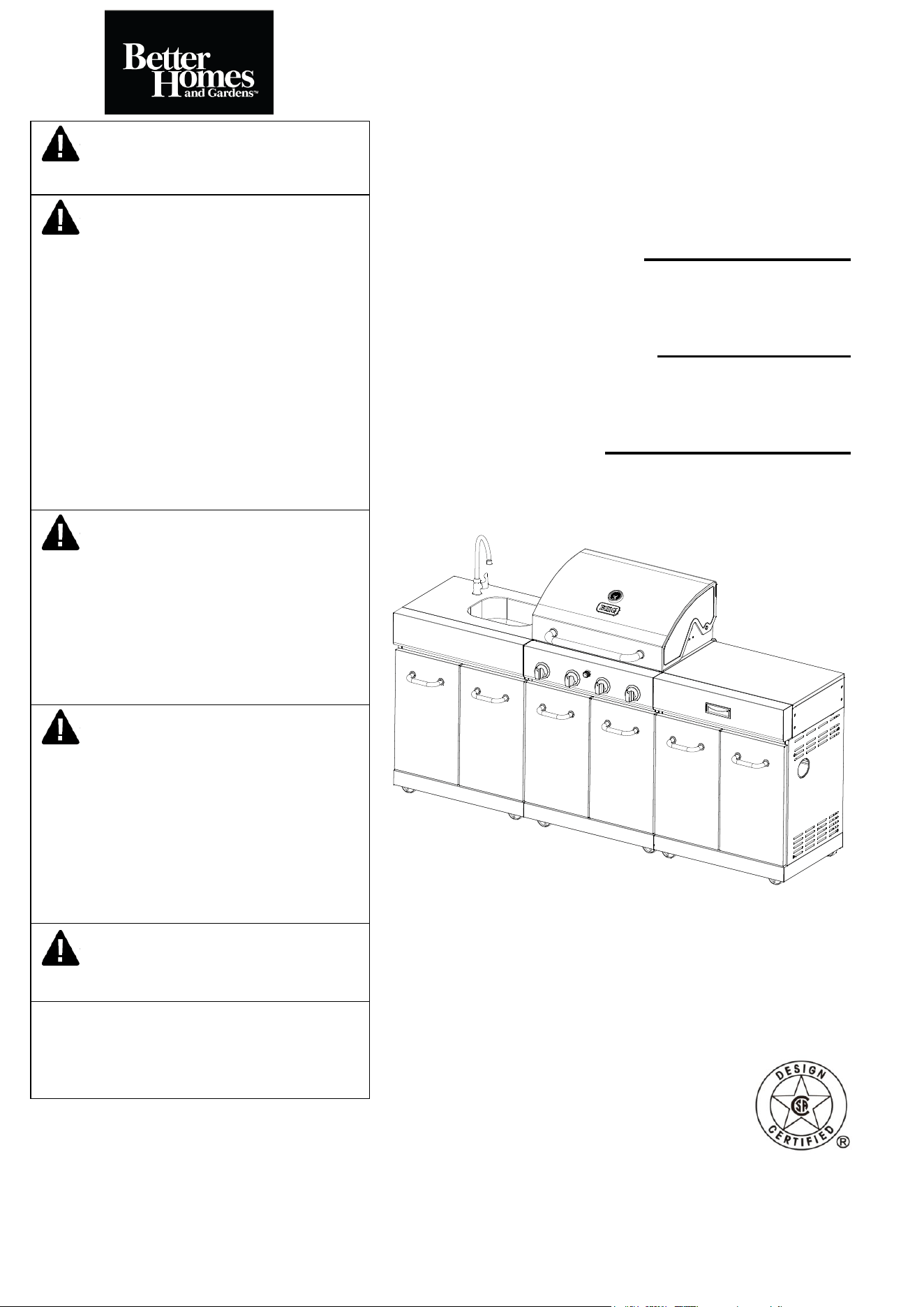
WARNING
For Outdoor Use Only (outside any enclosure)
WARNING
1. Improper installation, adjustment, alteration,
service or maintenance can cause injury or
property damage.
2. Read this instruction manual thoroughly
before installing or servicing this equipment.
3. Failure to follow these instructions could
result in fire or explosion, which could cause
property damage, personal injury or death.
4. This instruction manual contains important
information necessary for proper assembly and
safe use this appliance.
WARNING
1. Do not store or use gasoline or other
flammable vapors and liquids in the vicinity of
this or any other appliance.
2. An LP tank not connected for use should not
be stored in the vicinity of this or any other
appliance.
DANGER
If you smell gas:
1. Shut off gas to the appliance.
2. Extinguish any open flames.
3. Open the lid.
4. If the odor continues, keep away from the
appliance and immediately call your gas
supplier or fire department.
DANGER
Never operate this appliance unattended.
Save these instructions for future reference.
If you are assembling this unit for someone else,
give this manual to him or her to read save for
future reference.
DO NOT RETURN YOUR GRILL TO THE STORE
Question, problems, missing parts? Don’t return the grill to stores, please call our customer service
department at 1-855-CHANT-US (1-855-242-6887) from 8:00am to 5:00pm Eastern time, Monday
through Friday for assistance.
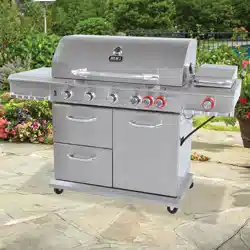
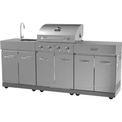
OUTDOOR 4-BURNER
STAINLESS STEEL ISLAND GRILL
2
Always read and understand the WARNINGS and INSTRUCTIONS that are contained in this
manual before attempting to use this gas barbecue grill to prevent possible bodily injury or
property damage.
Always keep this manual for convenient future reference.
WARNING
1. Do not store or use gasoline or other
flammable liquids or vapors in the
vicinity of this or any other appliance.
2. An LP cylinder not connected for use
should not be stored in the vicinity of
this or any other appliance.
DANGER
If you smell gas:
1. Shut off gas to the appliance
2. Extinguish any open flame
3. Open lid
4. If odor continues, keep away from the
appliance and immediately call your gas
supplier or your fire department.

3
TABLE OF CONTENTS
Cover …………….…………………………………….………...….………….………….….………..1
Table of Contents……………………………………….………...….………….…………………….3
Safety Information…………………………………….………...….………….….…………………..4
Main BBQ Grill Exploded View………….……………………………………………….............7
Main BBQ Grill Parts List…..…..….…................……………....………...…….............8
Main BBQ Grill Hardware Contents…………………………………………………….…………10
Main BBQ Grill Assembly Instructions………….……….……………………………………….11
Sink Modular Exploded View……………….……………………………………………............19
Sink Modular Parts List….…………..…..….…................……………....………...……...........20
Sink Modular Hardware Contents……………………………………………………….…20
Sink Modular Assembly Instructions…………….…….……………………………………….21
Drawer Modular Exploded View……………….…………………………………………............27
Drawer Modular Parts List….……………..…..….…................……………....……….............28
Drawer Modular Hardware Contents……………………………………………………….…28
Drawer Modular Assembly Instructions…………….……….………………………………….29
Island Grill Combination Assembly Instructions…………………………………….34
Natural Gas Conversion..........................…………….……….…………………………………. 35
Liquid Propane Gas Instructions…………………………….……...……....................41
Operation Instructions…………………………….……...………………………….....................44
Lighting Instructions…………………………….……...………………………….....................47
Care and Maintenance……………………………….………………………………………………49
Troubleshooting …………………………………………………………………..….……………...51
Warranty………………………………………………………………………………………………..53
4
SAFETY INFORMATION
Please read and understand this entire manual before attempting to assemble, operate
or install the product. If you have any questions regarding the product, please call our
customer service at 1-855-CHANT-US(1-855-242-6887) from 8:00am to 5:00pm Eastern
time, Monday through Friday for assistance.
The installation and repairs of this appliance must conform with local codes or, in the absence of local
odes, with either the National Fuel Gas Code, ANSI Z223.1/NFPA 54, or Natural Gas and Propane
Installation Code, CSA/CGA-B149.1.
All pipe sealants must be an approved type and resistant to the actions of L.P. gases. Never use pipe
sealant on flare fittings. All gas connections should be made by a competent qualified service technician
and in accordance with local codes and ordinances. In the absence of local codes, the installation must
comply with the National Fuel Gas Code, NFPA 54-2002/ANSI Z223.1-2002.
This grill must be isolated from the gas supply piping system by closing its individual manual shut-off valve
during any pressure testing of the gas supply piping system at test pressures equal to or less than 1/2 PSI
(3.5 kPa.).
This grill is intended for use outdoors and should not be used in a building, garage or any other enclosed
or covered area.
A minimum clearance of 36 inches from combustible constructions to the sides of the grill and 36 inches
from the back of the grill to combustible constructions must be maintained. This outdoor cooking gas
appliance must not be placed under overhead combustible construction.
Natural Gas (NG) Characteristics:
a. NG is flammable and hazardous if handled improperly. Become aware of the characteristics before
using any NG products.
b. NG is explosive under pressure, heavier than air and settles and pools in low areas.
c. NG in its natural state has no odor. For your safety, an odorant is added than smells like rotten cabbage.
d. Contact with NG can cause freeze burns to skin.
Do not block holes in sides or back of the grill.
A fire causing, serious bodily injury or damage to property may occur if above is not followed exactly.
The use of alcohol, prescription or non- prescription drugs may impair the consumers’ ability to properly
assemble or safely operate the appliance.
Never use charcoal, lighter fluid, lava rocks, gasoline, kerosene or alcohol with this product.
Check for leaks even if your unit was assembled for you by someone else.
Do not operate if gas leak is present. Gas leaks may cause a fire or explosion.
You must follow all leak-checking procedures before operating. To prevent fire or explosion hazard when
testing for a leak:
a. Always perform leak test before lighting the grill and each time the tank is connected for us.
b. No smoking. Do not use or permit sources of ignition in the area while conducting a leak test.
c. Conduct the leak test outdoors in a well-ventilated area.
d. Do not use matches, lighters, or a flame to check for leaks.
e. Do not use grill until any and all leaks are corrected.
If you can unable to stop a leak, turn off the main valve on the NG supply line. Call a gas appliance
serviceman or your local NG supplier.
Never attach an unregulated gas line to the appliance. Connection to an unregulated gas line can cause
excessive heat or fire.
The appliance and its individual shutoff valve must be disconnected from the gas supply piping system
during any pressure testing of that system at pressures in excess of 1/2 psig (3.5kpa).
The appliance must be isolated form the gas supply piping system by closing its individual manual shutoff
valve during any pressure testing of the gas supply piping system at test pressures equal to or less than
1/2 psig (3.5kpa).
Do not store or use gasoline or other flammable liquids or vapors within 25 feet (7.62 m) of this appliance.
Do not use in an explosive atmosphere. Keep grill area clear and free from combustible materials,
gasoline and other flammable vapors and liquids.
It is essential to keep the grill’s valve compartment, burners and circulating air passages clean.
Use only the gas pressure regulator supplied with this appliance. This regulator is set for an outlet
pressure of 11.0 wc.
The cylinder used must include a collar to protect the cylinder valve.
Do not store a spare LP-gas cylinder under or near this appliance.
Do not alter grill in any manner. Any alteration will void your warranty.
Do not use grill in high winds.
5
SAFETY INFORMATION
Do not use the grill unless it is COMPLETELY assembled and all parts are securely fastened and
tightened.
Do not build this model of grill in any built-in or slide in construction. Ignoring this warning could cause a
fire or an explosion that can damage properly and cause serious bodily injury or death
This grill should be thoroughly cleaned and inspected on a regular basis.
Clean and inspect the hose before each use of the appliance. If there is evidence of abrasion, wear, cuts
or leaks, hose must be replaced prior to the appliance being put into operation.
Use only the regulator and hose assembly provided. The replacement regulator and hose assembly shall
be that specified by the manufacturer.
Use only Chant Kitchen Equipment (H.K.) Ltd. company authorized
parts. The use of any part that is not company authorized can be
dangerous. Doing so will also void your warranty.
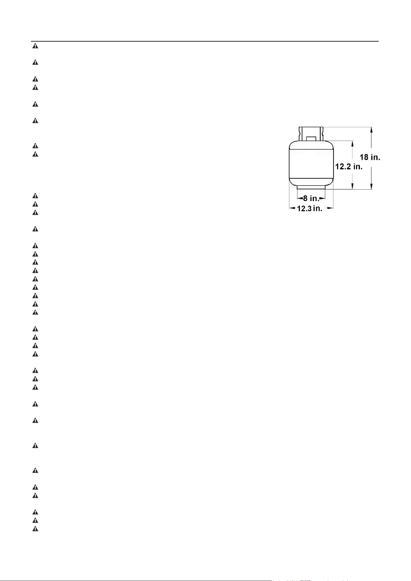
Never fill the cylinder beyond 80 percent full.
Only a 20 lb. LP-gas cylinder is allowed. The cylinder must be
constructed and marked in accordance with the Specifications for LP
Gas Cylinders of the U.S. Department of Transportation (D.O.T.) or the
National Standard of Canada, CAN/CSA-B339, Cylinders, Spheres and
Tubes for Transportation of Dangerous Goods; and Commission.
A 20 lb. LP-Gas cylinder’s dimensions are:
Inspect grill before each use.
Do not operate this appliance without reading “Operating Instructions”
in this manual.
This grill is designed with to operate at an inlet pressure of: LP gas: 11 inches water column; NG 7inches
water column.
Never operate grill without heat plates installed.
Do not leave a lit grill unattended, especially keep children and pets away from grill at all times.
Always use a meat thermometer to ensure food is cooked to a safe temperature.
Use protective gloves when assembling this product.
Do not force parts together as this can result in personal injury or damage to the product.
Never lean over the grill when lighting.
Do not place empty cooking vessels on the appliance while in operation.
Use caution when placing anything on the grill while the appliance is in operation.
Do not touch metal parts of grill until it has completely cooled (about 45 minutes) to avoid burns, unless
you are wearing protective gear (pot holders, gloves, BBQ mittens, etc…).
Do not attempt to move grill when in use. Allow the grill to cool before moving or storing.
Always open grill led carefully and slowly as heat and steam trapped within grill can severely burn you.
Do not attempt to disconnect the gas regulator from the tank or any gas fitting while the grill is in us.
Always place your grill on a hard, on-combustible, level surface. An asphalt or blacktop surface may not be
acceptable for this purpose.
Move gas hoses as far away as possible from hot surfaces and dripping hot grease.
Keep all electrical cords away from a hot grill
After a period of storage and/or nonuse, check for leaks, burner obstructions and inspect for any abrasion,
wear or cuts to the hose.
Failure to open lid while igniting the grill’s burners, or not waiting 5 minutes to allow the gas to clear if the
grill does not light, may result in an explosive flam-up.
All electrical accessories (such as rotisserie) must be electrically grounded in accordance with local codes,
or National Electrical Code, ANSI / NFPA 70 or Canadian Electrical Code, CSA C22.1. Keep any electrical
cords and/or fuel supply hoses away from any hot surfaces.
When cooking, fire extinguishing materials shall be readily accessible. In the event of an oil/grease fire, do
not attempt to extinguish with water. Use type BC dry chemical fire extinguisher or smother with dirt, sand
or baking soda.
Do not leave grill unattended while preheating or burning off food residue on high if grill has not been
cleaned, a grease fire can occur that may damage the product.
To protect against electric shock, do not immerse cord or plugs in water or other liquid.
Unplug from the outlet when not in use and before cleaning. Allow to cool before putting on or taking off
parts.
Do not let the cod hang over the edge of a table or touch hot surface.
Do not use an outdoor cooking gas appliance for purposes other than intended.
When connecting, first connect plug to the outdoor cooking gas appliance then plug appliance into the
outlet.
6
SAFETY INFORMATION
Use only a ground Fault Interrupter (GFI) protected circuit with this outdoor cooking gas appliance.
Never remove the grounding plug or use with an adapter of 2 prongs; and use only extension cords with
a 3 prong grounding plug, rated for the power of the equipment, and approved for outdoor use with a W-A
marking.
OUTDOOR USE ONLY. DO NOT EXPOSE TO RAIN.
CAUTION: Risk of Electric Shock. Keep extension cord connection dry and off the ground.
Use only on properly grounded outlet.
Deaths, serious injury or damage to properly may occur if the above is not followed exactly.
Never cover entire cooking area with aluminum foil.
CALIFORNIA PROPOSITION 65 WARNING:
(a)The burning of gas cooking fuel generates some byproducts which are on the list of substances known
by the State of California to cause cancer, reproductive harm, or other birth defects. To reduce exposure to
these substances, always operate this unit according to the use and care manual, ensuring you provide
good ventilation when cooking with gas.
(b)Handling the brass material on this product exposes you to lead, a chemical known to the State of
California to cause cancer and birth defects or other reproductive harm. Wash hands after handling.
(c)This product contains chemicals, including lead and lead compounds, known by the State of California
to cause cancer, reproductive harm, or other birth defects.
(d) Wash your hands after using this product.
IMPORTANT: We urge you to read this manual carefully and follow the recommendations
enclosed. This will ensure you receive the most enjoyable and trouble-free operation of
your new gas grill. We also advise you retain this manual for future reference.
WARNING: Your grill has been designed to operate using only the gas specified by
the manufacturer on the rating plate. Do not attempt to operate your grill on other gases.
Failure to follow this warning could lead to a fire hazard and bodily harm and will void
your warranty.
WARNING: Make certain your LP (propane) tank is filled by a reputable propane
dealer. An incorrectly filled or an overfilled LP tank can be dangerous. The overfilled
condition combined with the warming of the LP tank (a hot summer day, tank left in the
sun, etc.) can cause LP gas to be released by the pressure relief valve on the tank since
the temperature increase causes the propane to expand. LP gas released from the tank
is flammable and can be explosive. Refer to your Owner’s Manual for more information
concerning filling your LP tank.
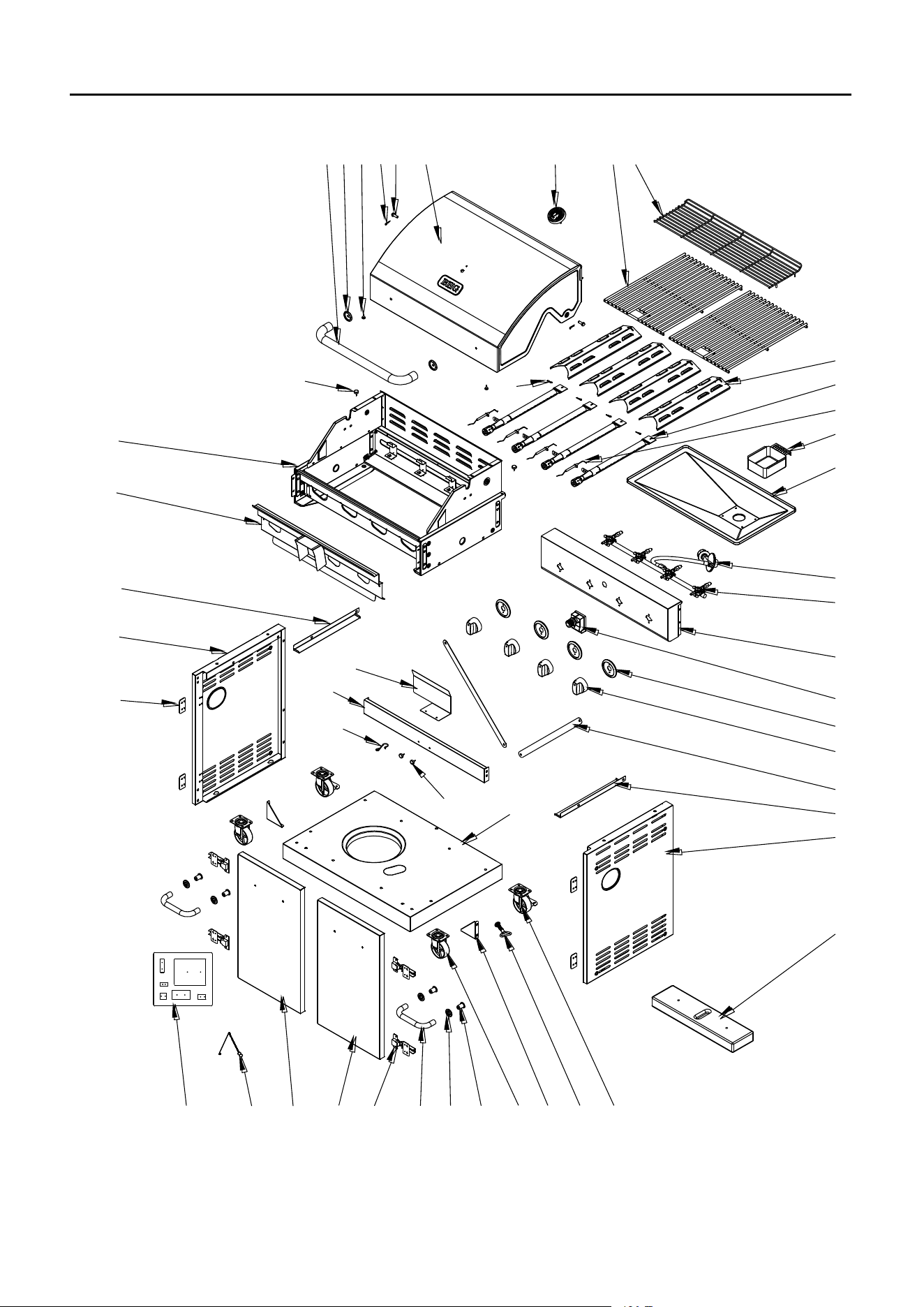
7
MAIN BBQ GRILL EXPLODED VIEW
H1
4043
28
20
21
15
18
19
17
16
32
46 45 44 42 41
31
39 383736
35
34
33
30
29
27
26
25
24
23
22
14
13
12
11
10
98
7
6
54
321
F1
G1 B1
A1
C1+D1+E1
4
3
8
MAIN BBQ GRILL PARTS LIST
※ :NO ASSEMBLY REQUIRED
PART
DESCRIPTION
PART NO
QTY
1
※Lid Handle
2307563
1
2
※Lid Handle Bezel
5201177
2
3
※Lid Spacer
2100158
4
4
※ R-Pin
2307001
6
5
※Lid Axis
2406690
2
6
※Lid Assembly
229G001
1
7
※Temperature Gauge
2406912
1
8
Cooking Grate
2409489
2
9
Warming Rack
2310685
1
10
Heat Tent
5207190
4
11
※Tube Burner
2409257
4
12
※Tube Burner Ignition Pin
2409259
4
13
Grease Cup
5201953
1
14
Drip Tray
229G002
1
15
※Regulator & Hose Assembly
5204132
1
16
※Manifold & Gas Valve Assembly
5207314
1
17
※ Control Panel
5207194
1
18
※ Electric Igniter
2409468
1
19
※Knob Bezel
2409209
4
20
Knob
2409208
4
21
※Firebox Assembly
229G003
1
22
※Heat Shield
229G004
1
23
Left Drip Tray Support
5201882
1
24
Left Side Panel
5207196
1
25
Hinge Spacer
5207205
4
26
Hose Heat Shield
5207204
1
27
Front Beam
5207199
1
28
※Hose Clip Hook
2405337
1
29
※Cushion Rubber
2404055
2
30
Bottom Panel
5207195
1
31
Cabinet Reinforcing Bar
5207198
2
9
MAIN BBQ GRILL PARTS LIST
※ :NO ASSEMBLY REQUIRED
PART
DESCRIPTION
PART NO
QTY
32
Right Drip Tray Support
5201883
1
33
Right Side Panel
5207197
1
34
※Weight Plate
2406712
1
35
Lockable Castor
2100470
2
36
※Retention Screw
229G005
1
37
Triangle reinforcing Plate
5201879
2
38
Unlockable Castor
2100471
2
39
Door Screw Socket
2100481
4
40
Door Handle Bezel
5201175
4
41
Door Handle
5204382
2
42
Door Hinge
2307764
4
43
Right Door
229G006
1
44
Left Door
229G007
1
45
※Match-Light Extension
2307247
1
46
Hardware Pack
5207206
1
47
NG Conversion Kit
5207207
1
10
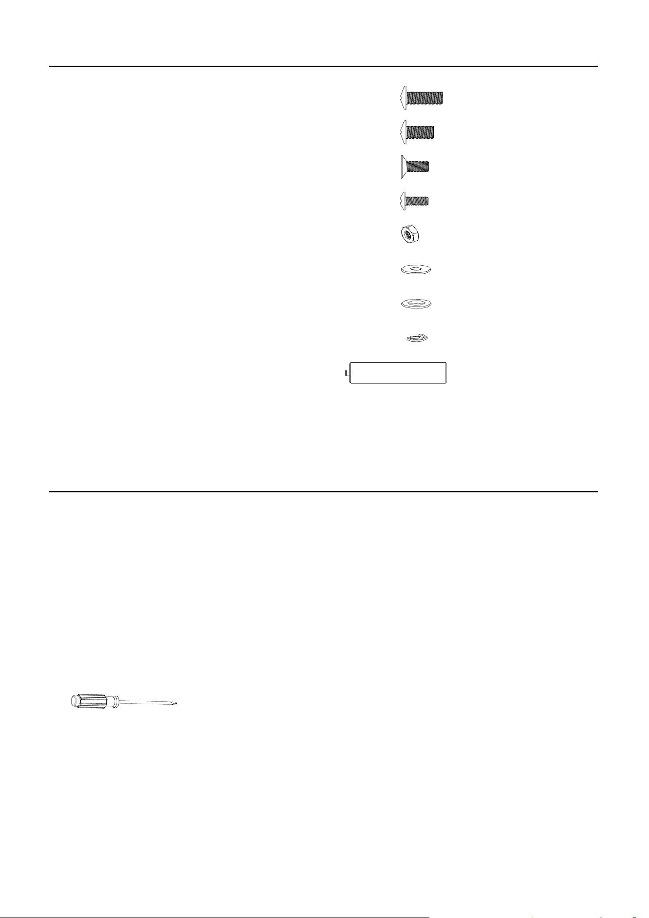
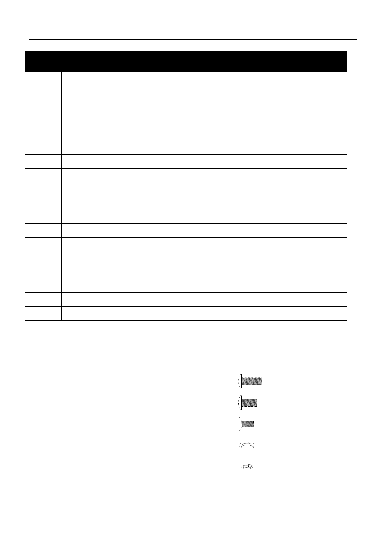
MAIN BBQ GRILL HARDWARE CONTENTS
X 20A1 M6X16mm Silver Screw
I1 AA Battery
X 1
H1 M6 Spring Washer
G1 M6 Flat Washer
F1 M4 Plastic Washer
E1 M4 Nut
D1 M4X10mm Screw
C1 M4X12mm Screw
B1 M6X12mm Silver Screw
X 20
X 20
X 23
X 3
X 24
X 1
X 1
ASSEMBLY PREPARATION
Before beginning assembly of product, make sure all parts are present. Compare parts with
package contents list and hardware contents list. If any part is missing or damaged, do not
attempt to assemble the product.
NOTE: Some parts come with screws pre-installed. Loosen and tighten for final assembly.
Estimated Assembly Time: 1 hour by two people
Tools required for assembly:
* Phillips Head Screwdriver 1pc (not included)
11
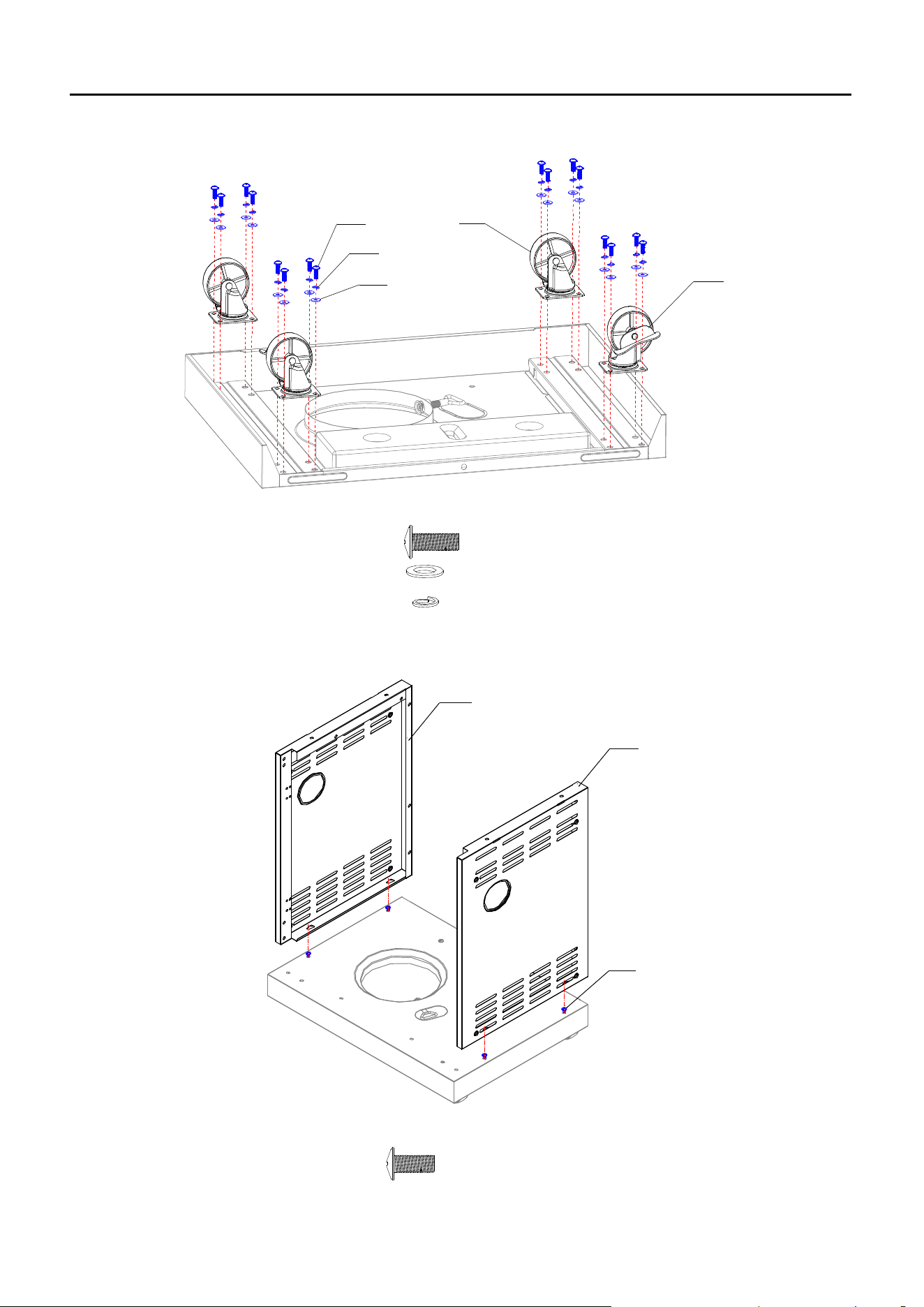
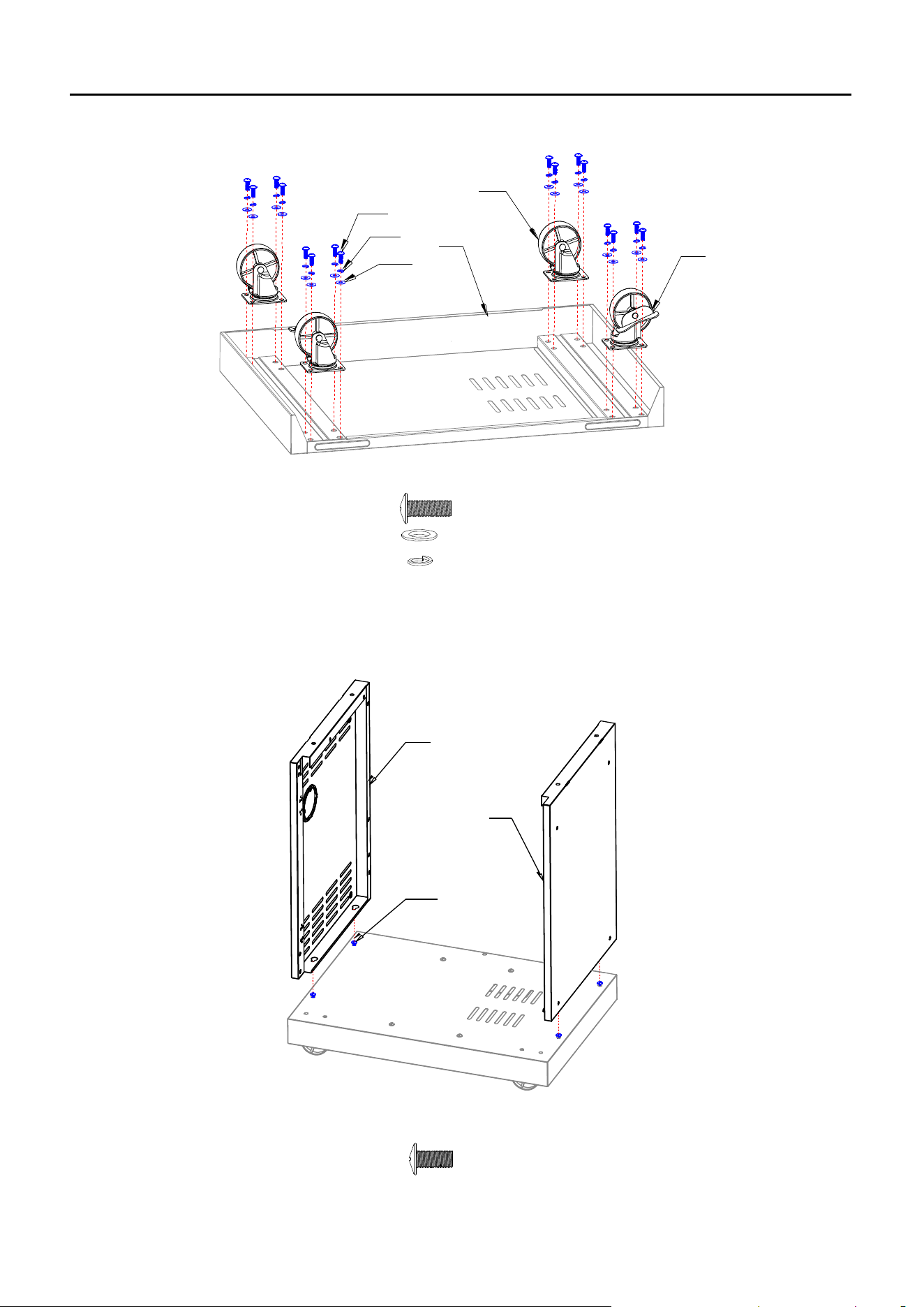
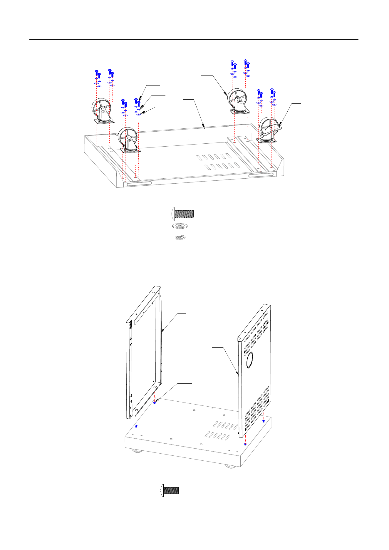
MAIN BBQ GRILL ASSEMBLY INSTRUCTIONS
IMPORTANT: ASSEMBLE ON FLAT AND SOFT SURFACE TO AVOID SCRATCHING.
1. Attach Unlockable Castors (38) in the front and Lockable Castors (35) in the back as shown.
38
A1
H1
G1
35
A1 M6X16mm Silver Screw
G1 M6 Flat Washer
H1 M6 Spring Washer
X 16
X 16
X 16
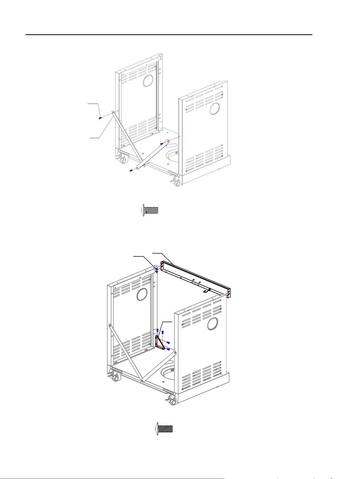
2. Attach Left Side Panel (24) and Right Side Panel (33) on Bottom Panel.
24
33
B1
B1 M6X12mm Silver Screw
X 4
12
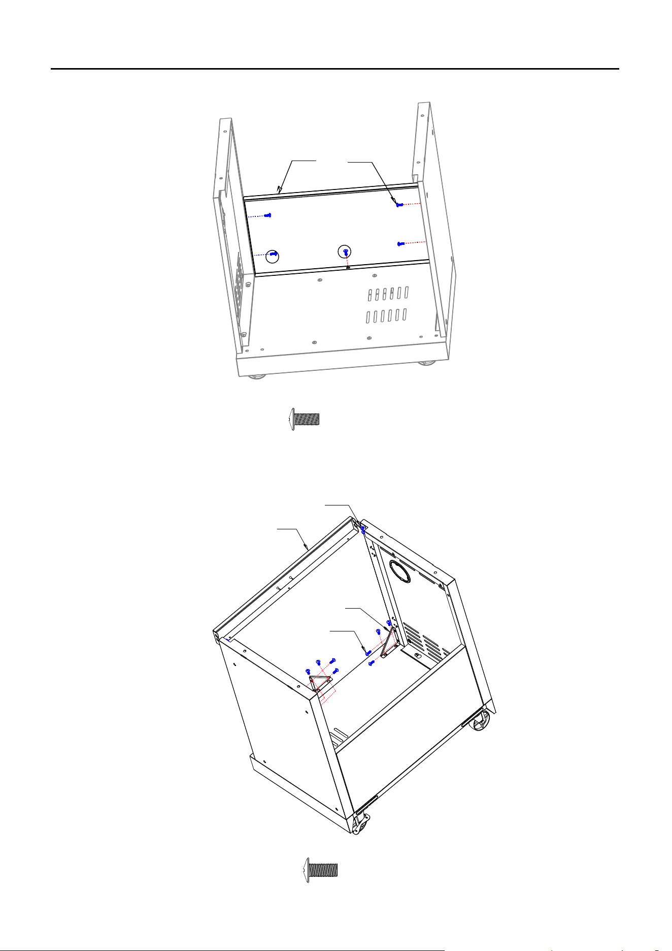
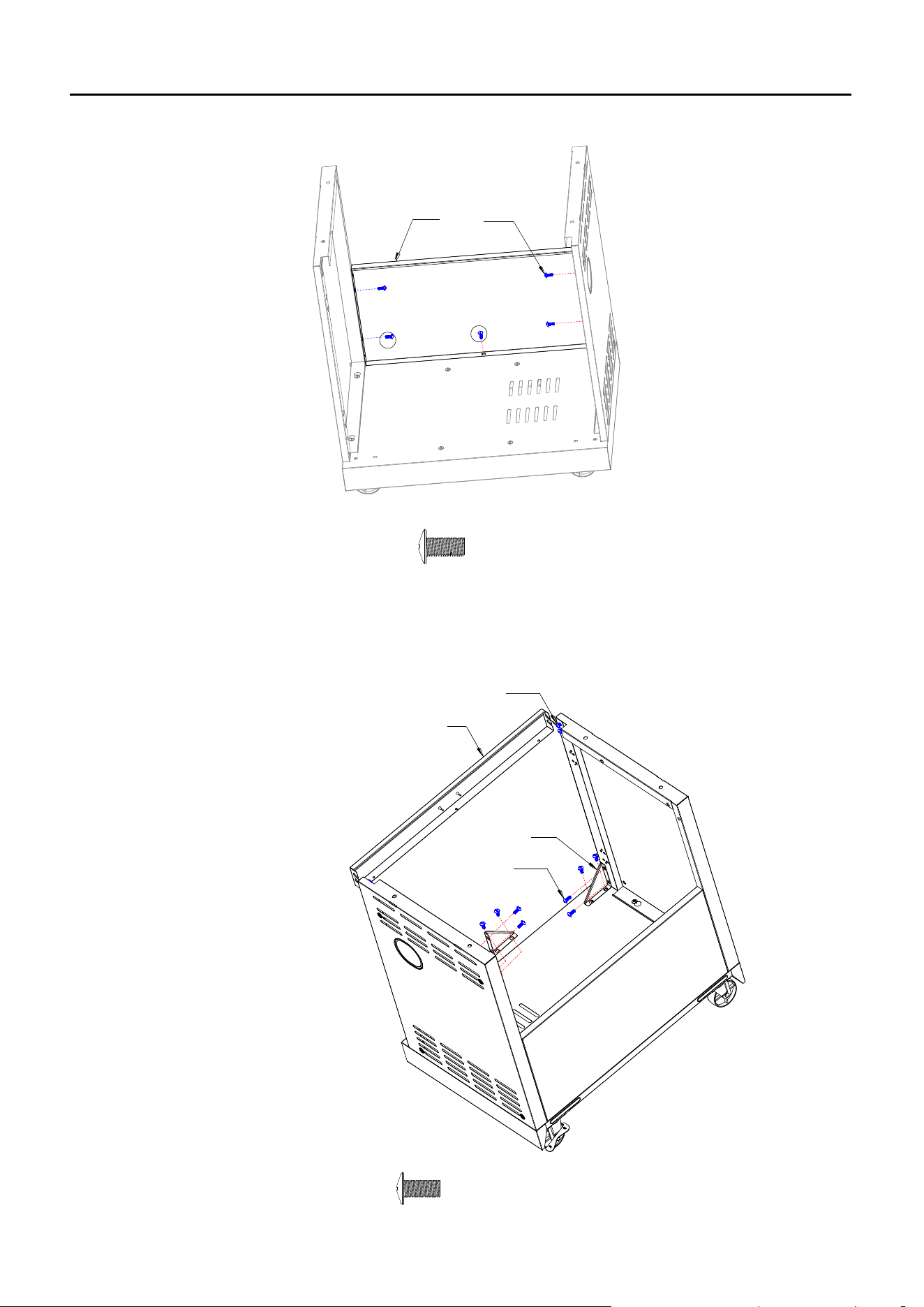
MAIN BBQ GRILL ASSEMBLY INSTRUCTIONS
3. Attach Cabinet Reinforcing Bars (31) as shown.
B1
31
4. Attach Front Beam (27) and Triangle reinforcing plates (37).
37
B1
27
X 3
B1 M6X12mm Silver Screw
X 12
B1 M6X12mm Silver Screw
13
MAIN BBQ GRILL ASSEMBLY INSTRUCTIONS
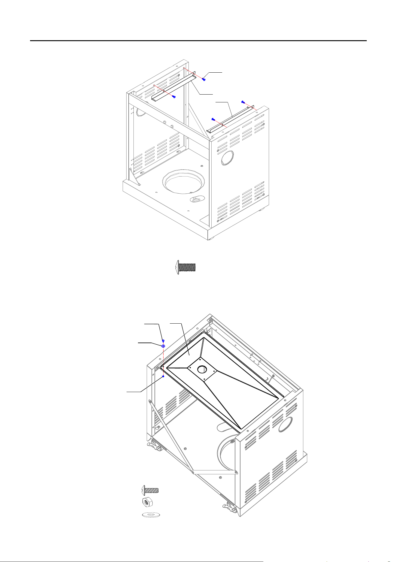
5. Attach Left Drip Tray Support (23) and Right Drip Tray Support (32) to the side panels.
B1
23
32
B1 M6X12mm Silver Screw
X 4
6. Put Drip tray (14) onto the Drip Tray Supports.
E1
F1
D1
14
F1 M4 Plastic Washer
E1 M4 Nut
D1 M4X10mm Screw
X 1
X 1
X 1
14
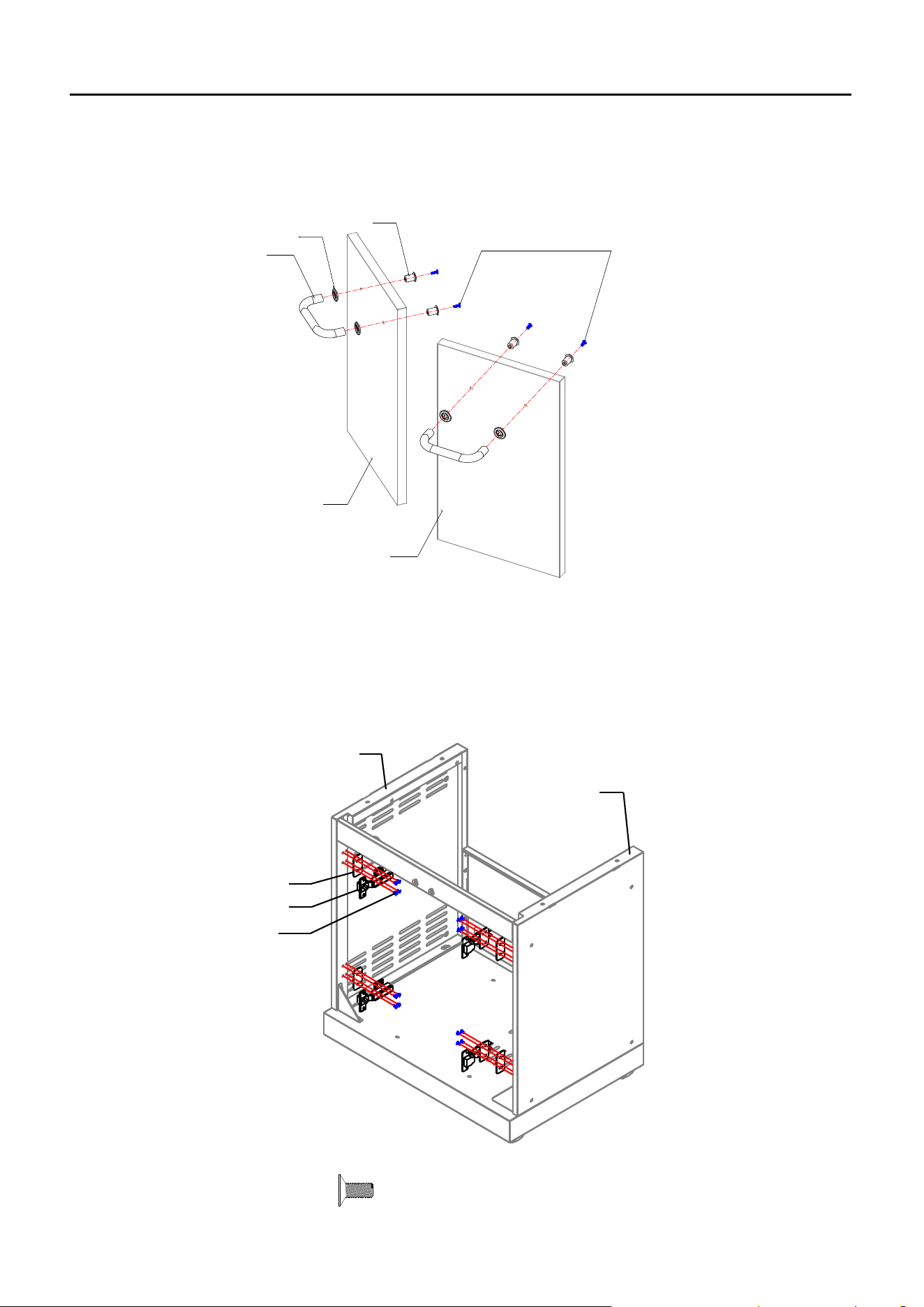
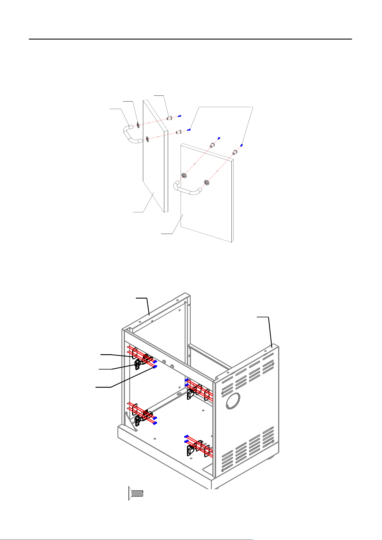
MAIN BBQ GRILL ASSEMBLY INSTRUCTIONS
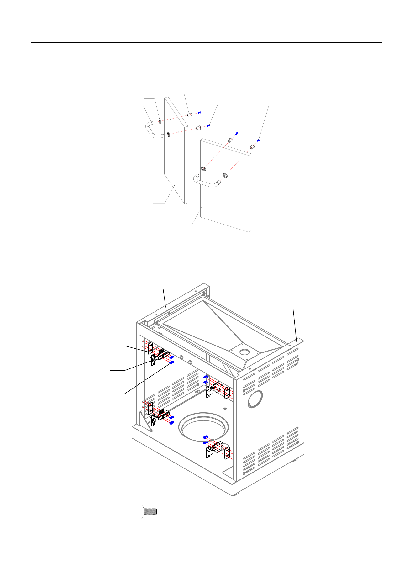
7. Loosen the pre-assembled M5 x15 screws from Door Handles (41), attach Door Handles
(41), Door Handle Bezel (40) and Door Screw Sockets (39) to the Left & Right Door (43/44),
and then fasten the screws.
43
44
M5x15 Screw
41
40
39
8. Attach Door Hinges (42) and Hinge Spacers (25) to Left & Right Side Panel (24/33) as
shown.
Note: DO NOT tighten the screws of this step now.
24
33
C1
42
25
C1 M4X12mm Screw
X 16
15
MAIN BBQ GRILL ASSEMBLY INSTRUCTIONS
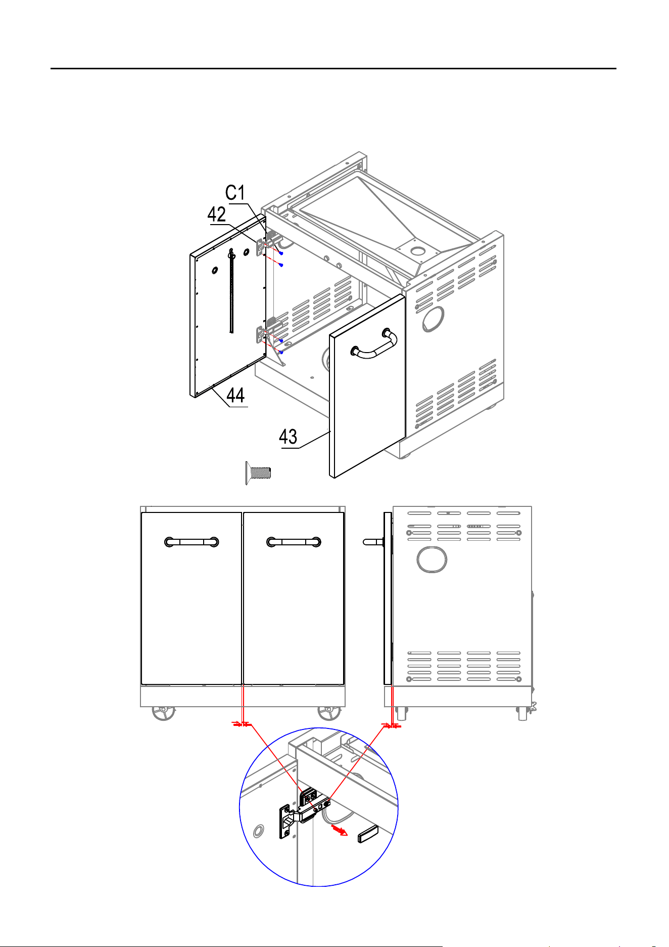
9. Attach Left door (44) and Right door (43) to Door Hinges (42), and then tighten all of the
screws, including the screws in last step.
Note: Two adjusting screws inside the door hinge, which can be used to adjust the distance
as shown.
C1 M4X12mm Screw
X 8
16
MAIN BBQ GRILL ASSEMBLY INSTRUCTIONS
10. The Regulator & Hose Assembly is located inside of the control panel. Please untie it and
hang it as the picture shown. Attach Firebox Assembly (21) on the top of the cabinet and
fasten the screws and washers as shown.
21
G1
H1
A1
11. Insert Heat Tents (10), Cooking Grates (8) and Warming Racks (9).
8
10
9
A1 M6X16mm Silver Screw
G1 M6 Flat Washer
H1 M6 Spring Washer
X 4
X 4
X 4
17
MAIN BBQ GRILL ASSEMBLY INSTRUCTIONS
12. Open the door, pull out the Hose Clip Hook (28) and secure the hose into the hook.
Then attach Grease Cup (13) as shown.
13
15
28
13. Attach Hose Heat shield (26) to Front Beam (27).
D1
26
27
D1 M4X10mm Screw
X 2
18
MAIN BBQ GRILL ASSEMBLY INSTRUCTIONS
14. Place AA battery (I1) into the Electronic Igniter with the positive (+) end facing out, and then
attach Knobs (20) to bezels.
20
I1
15. Your Main BBQ Grill is now assembled.
I1 AA Battery
X 1
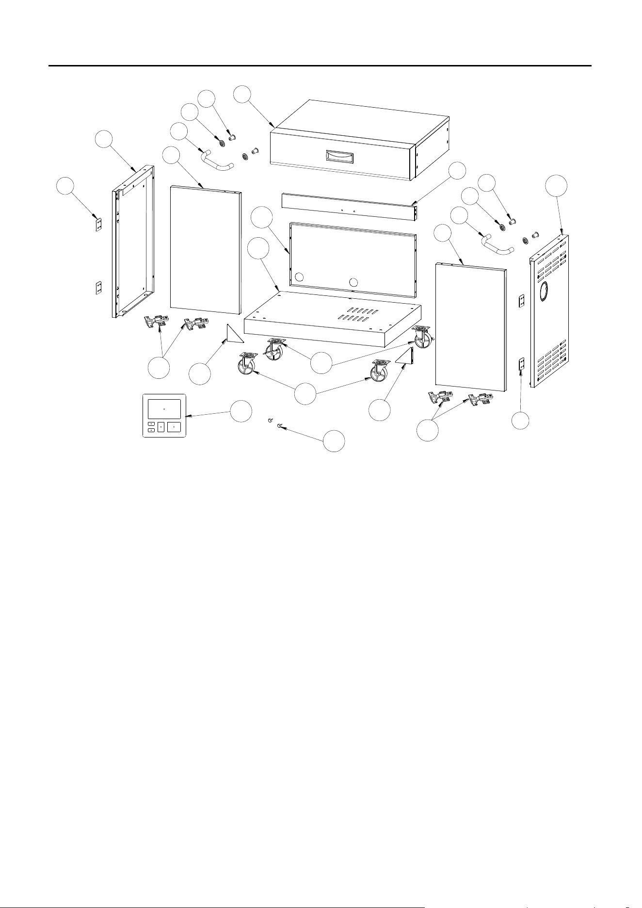
19
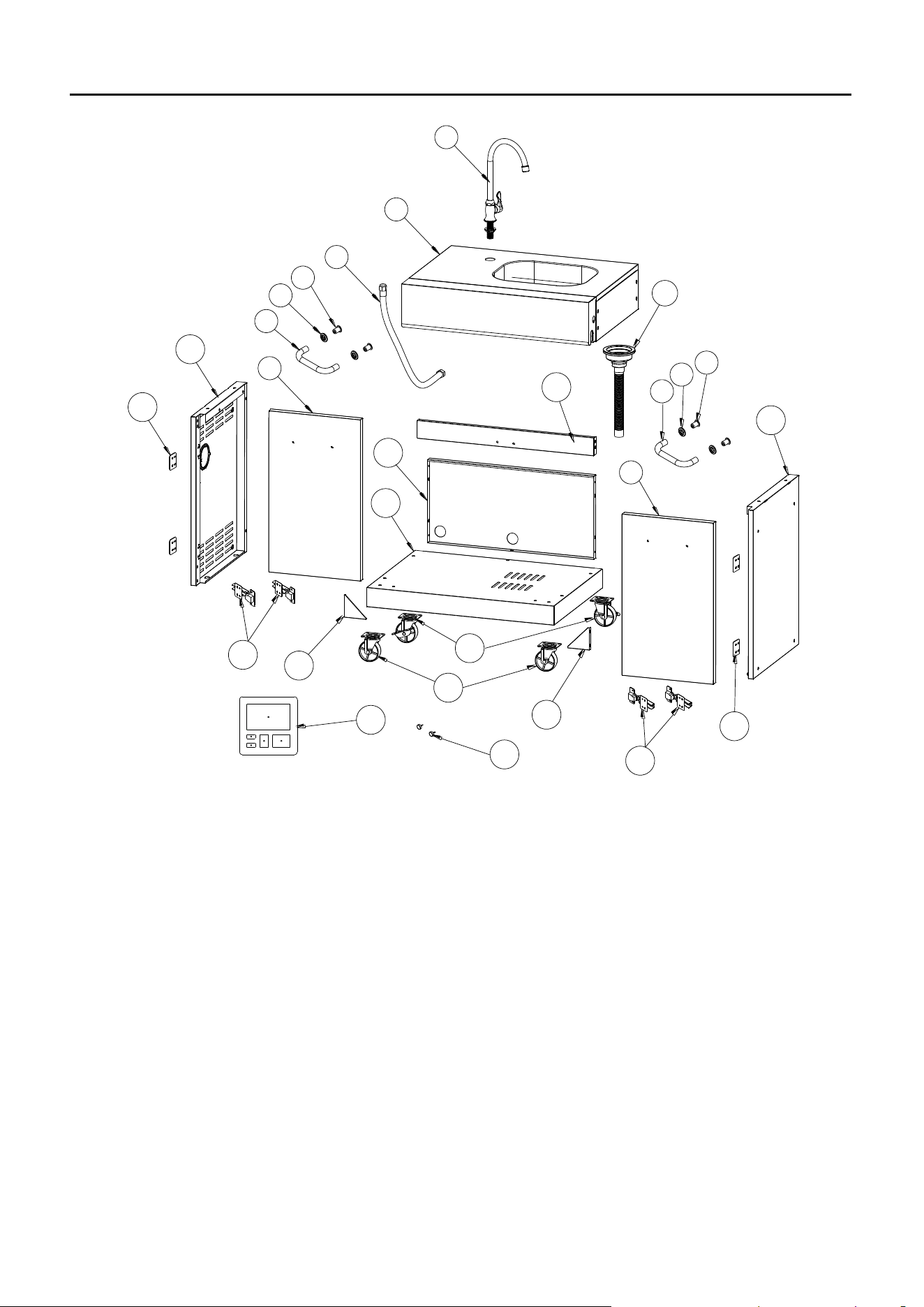
SINK MODULAR EXPLODED VIEW
5
6
7
5
6
7
11
10
11
13
12
A
C
D E B
21
20
2
4
8
14
18
15
17
17
9
16
16
1
3
19
20
SINK MODULAR PARTS LIST
※ :NO ASSEMBLY REQUIRED
SINK MODULAR HARDWARE CONTENTS:
A2 M6X16mm Silver Screw
X 24
X 24
X 21
X 20
X 20
B2 M6X12mm Silver Screw
C2 M4X12mm Screw
D2 M6 Flat Washer
E2 M6 Spring Washer
PART
DESCRIPTION
PART NO
QTY
1
Tap
2307729
1
2
※Sink Assembly
229S001
1
3
Water Inlet Hose
229S002
1
4
Launching Device Assembly
229S003
1
5
Door Screw Socket
2100481
4
6
Door Handle Bezel
5201175
4
7
Door Handle
5204382
2
8
Right Door
229S004
1
9
Left Door
229S005
1
10
Left Side Panel
5207196
1
11
Hinge Spacer
5207205
4
12
Front Beam
5207199
1
13
Back Panel
5207253
1
14
Bottom Panel
5207251
1
15
Right Side Panel
5207252
1
16
Door Hinge
2307764
4
17
Triangle reinforcing Plate
5201879
2
18
Lockable Castor
2100470
2
19
Unlockable Castor
2100471
2
20
※Cushion Rubber
2404055
2
21
Hardware Pack
5207254
1
21
SINK MODULE ASSEMBLY INSTRUCTIONS
1. Attach Unlockable Castors (19) and Lockable Castors (18) as shown.
A2
E2
D2
18
19
14
2. Attach Left Side Panel (10) and Right Side Panel (15) onto Bottom Panel.
B2
10
15
X 16
X 16
X 16
E2 M6 Spring Washer
D2 M6 Flat Washer
A2 M6X16mm Silver Screw
X 4
B2 M6X12mm Silver Screw
22
SINK MODULAR ASSEMBLY INSTRUCTIONS
3. Attach Back Panel (13).
B2
13
4. Attach Front Beam (12) and Triangle Reinforcing Plates (17) as shown
17
B2
12
B2
X 5
B2 M6X12mm Silver Screw
B2 M6X12mm Silver Screw
X 12
23
SINK MODULAR ASSEMBLY INSTRUCTIONS
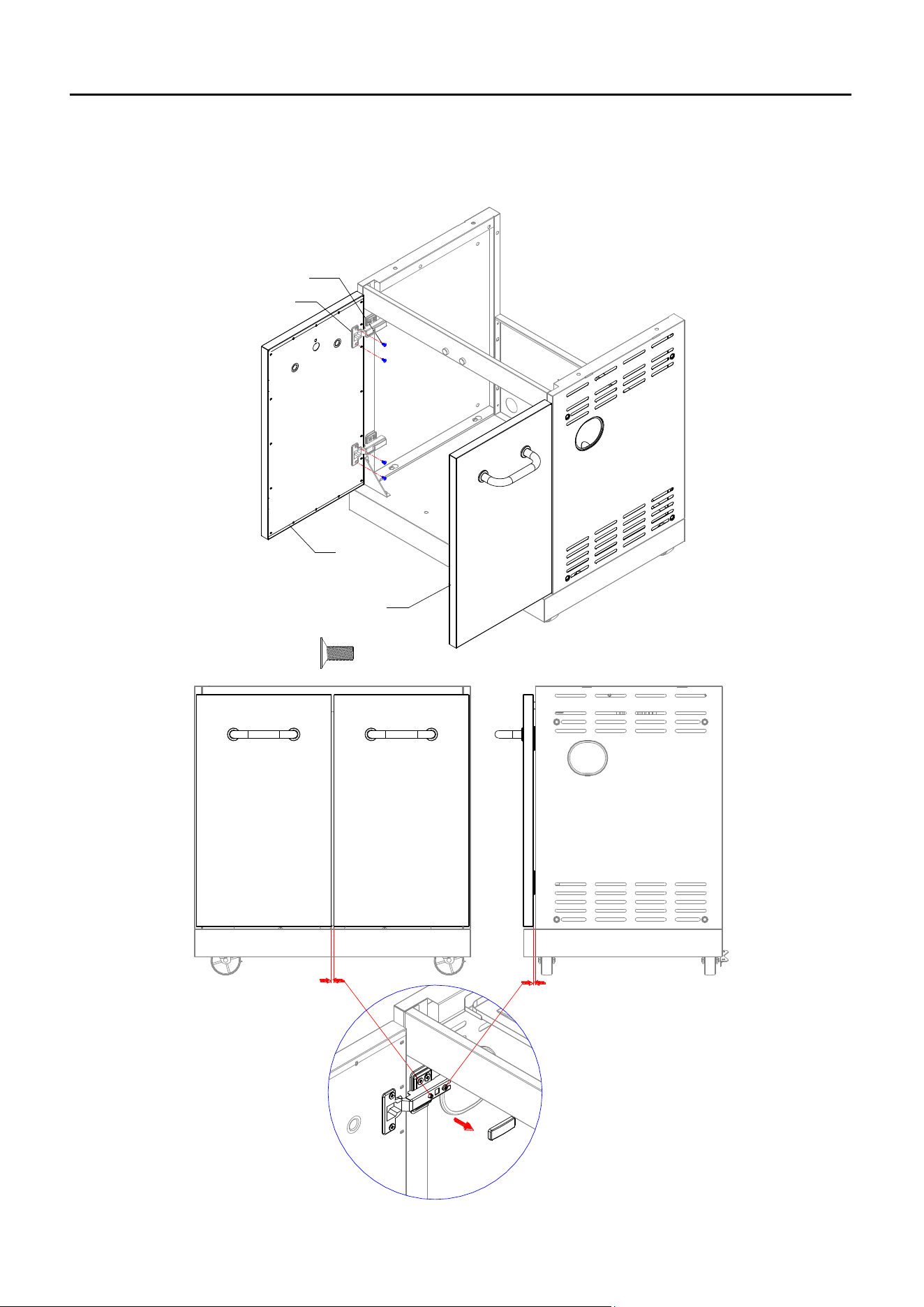
5. Loosen the pre-assembled M5 x15 screws from Door Handles (7), attach Door Handles (7),
Door Handle Bezel (6) and Door Screw Sockets (5) to Left & Right door (8/9), and then
fasten the screws.
5
6
7
M5x15 Screw
8
9
6. Attach Door Hinges (16) and Hinge Spacers (11) to Left & Right Side Panel (10/15) as
shown.
Note: DO NOT tighten the screws in this step.
C2
16
11
10
15
C2 M4X12mm Screw X 16
24
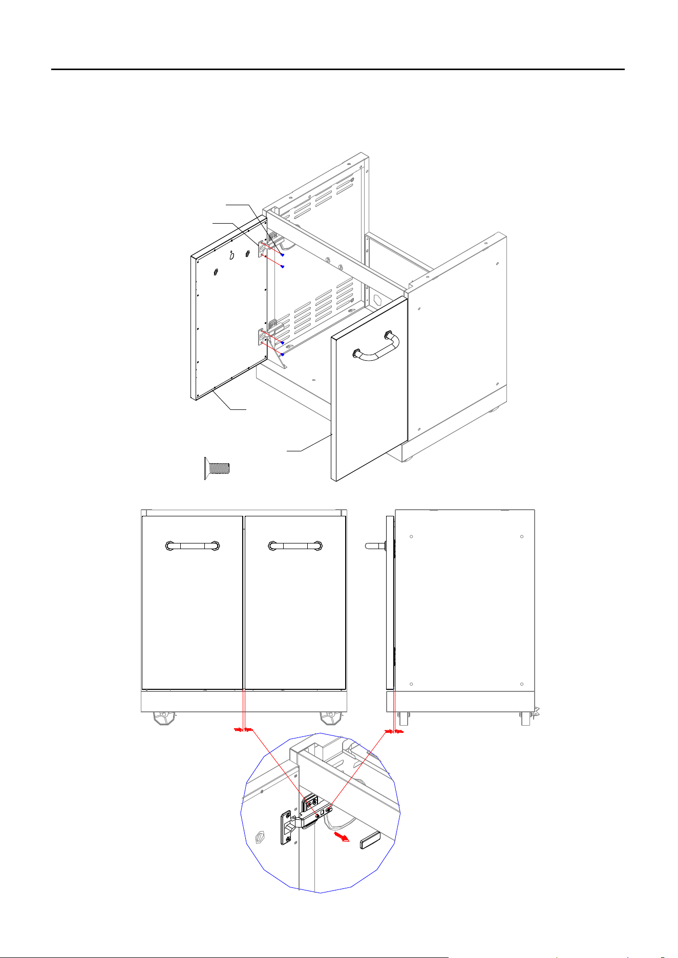
SINK MODULAR ASSEMBLY INSTRUCTIONS
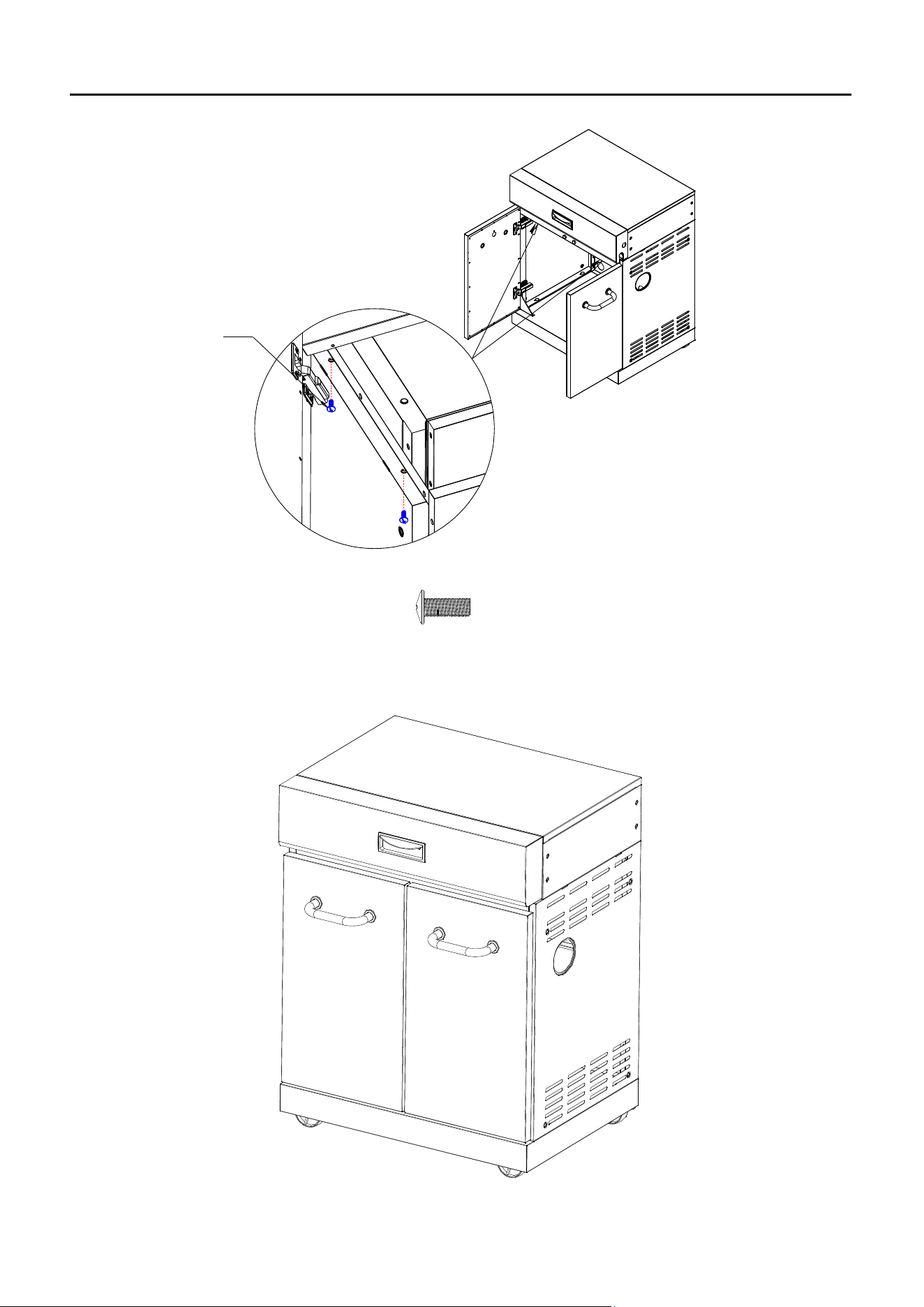
7. Attach Left door (8) and Right door (9) to Door Hinges (16), and then tighten all of the screws,
including the screws in last step.
Note: Two adjusting screws inside the door hinge, which can be used to adjust the distance
as shown.
16
C2
8
9
C2 M4X12mm Screw
X 8
25
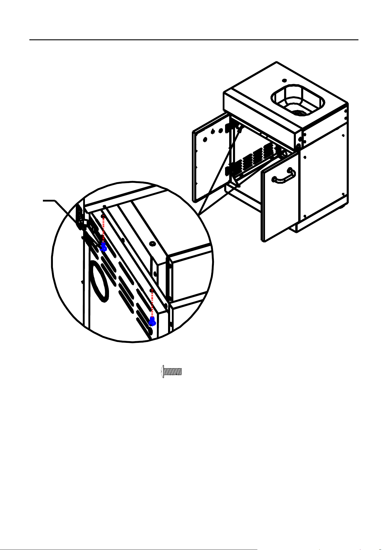
SINK MODULAR ASSEMBLY INSTRUCTIONS
8. Assemble Sink assembly (2) onto the cabinet as shown.
A2
X 4
A2 M6X16mm Silver Screw
26
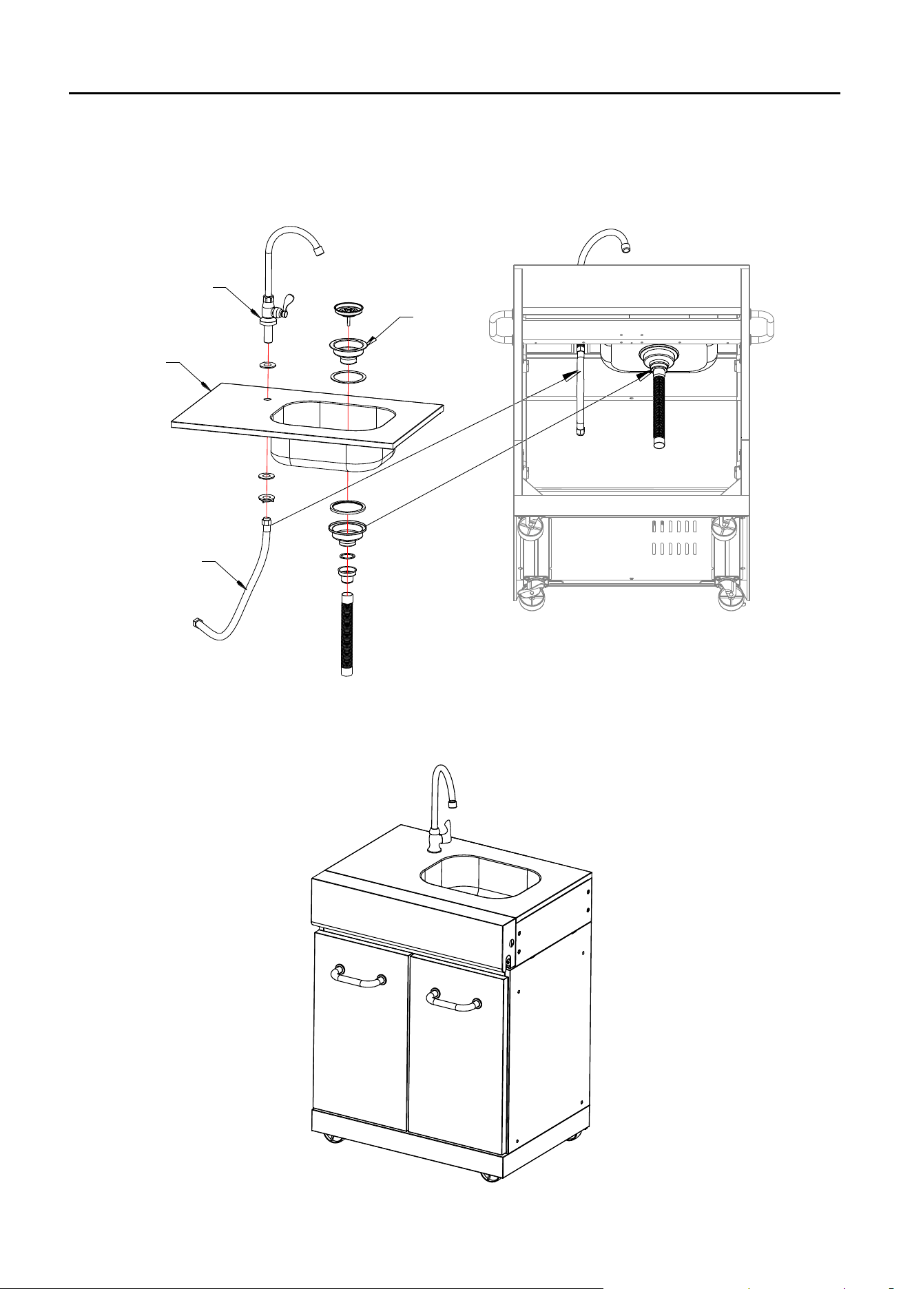
SINK MODULAR ASSEMBLY INSTRUCTIONS
9. Install Tap (1) and Launching Device Assembly (4) onto the Sink Assembly (2) as shows.
Put Water Inlet Hose (3) and Outlet Hose respectively through the holes on the back panel.
Warning: Water is only for outdoor cleaning needs, not directly for drinking. Please pay
attention that the collection and treatment of wastewater must comply with local laws and
regulations
3
2
4
1
10. Your Sink Modular is now assembled.
27
DRAWER MODULAR EXPLODED VIEW
13
2
3
4
2
3
4
11
12
9
10
14
14
A
C
D E B
1
5
8
15
16
7
6
13
9
17
18
28
DRAWER MODULAR PARTS LIST
※ :NO ASSEMBLY REQUIRED
DRAWER MODULAR HARDWARE CONTENTS:
A2 M6X16mm Silver Screw
B2 M6X12mm Silver Screw
C2 M4X12mm Screw
D2 M6 Flat Washer
E2 M6 Spring Washer
X 24
X 21
X 24
X 20
X 20
PART
DESCRIPTION
PART NO
QTY
1
※Drawer Assembly
229D001
1
2
Door Screw Socket
2100481
4
3
Door Handle Bezel
5201175
4
4
Door Handle
5204382
2
5
Right Door
229D002
1
6
Left Door
229D003
1
7
Front Beam
5207199
1
8
Left Side Panel
5207270
1
9
Hinge Spacer
5207205
4
10
Back Panel
5203721
1
11
Bottom Panel
5207251
1
12
Right Side Panel
5207197
1
13
Door Hinge
2307764
4
14
Triangle
5201879
2
15
Lockable Castor
2100470
2
16
Unlockable Castor
2100471
2
17
※Cushion Rubber
2404055
2
18
Hardware Pack
5207254
1
29
DRAWER MODULAR ASSEMBLY INSTRUCTIONS
1. Attach Unlockable Castors (16) and Lockable Castors (15) as shown.
A2
E2
D2
15
16
11
2. Attach Left Side Panel (8) and Right Side Panel (12) on Bottom Panel.
8
12
B2
A2 M6X16mm Silver Screw
D2 M6 Flat Washer
E2 M6 Spring Washer
X 16
X 16
X 16
X 4
B2 M6X12mm Silver Screw
30
DRAWER MODULE ASSEMBLY INSTRUCTIONS
3. Attach Back Panel (10) as shown.
10
B2
4. Attach Front Beam (7) and Triangles (14) as shown.
7
B2
14
B2
B2 M6X12mm Silver Screw
X 5
X 12
B2 M6X12mm Silver Screw
31
DRAWER MODULE ASSEMBLY INSTRUCTIONS
5. Loosen the pre-assembled M5 x15 screws from Door Handles (4), attach Door Handles (4),
Door Handle Bezel (3) and Door Screw Sockets (2) to Left & Right Door (5/6), and then
fasten the screws.
2
3
4
M5x15 Screw
5
6
6. Attach Door Hinges (13) and Hinge Spacers (9) to Left & Right Side Panel (8/12) as shown..
Note: DO NOT tighten the screws of this step now.
9
13
C2
12
8
X 16C2 M4X12mm Screw
32
DRAWER MODULAR ASSEMBLY INSTRUCTIONS
7. Attach Left door (5) and Right door (6) to Door Hinges (13), and then tighten all of the
screws, including the screws in last step.
Note: Two adjusting screws inside the door hinge, which can be used to adjust the distance
as shown
C2
5
6
13
X 8C2 M4X12mm Screw
33
DRAWER MODULAR ASSEMBLY INSTRUCTIONS
8. Attach Drawer Assembly (1) onto the cabinet as shown.
A2
9. Your Drawer Modular is now assembled.
A2 M6X16mm Silver Screw
X 4
34
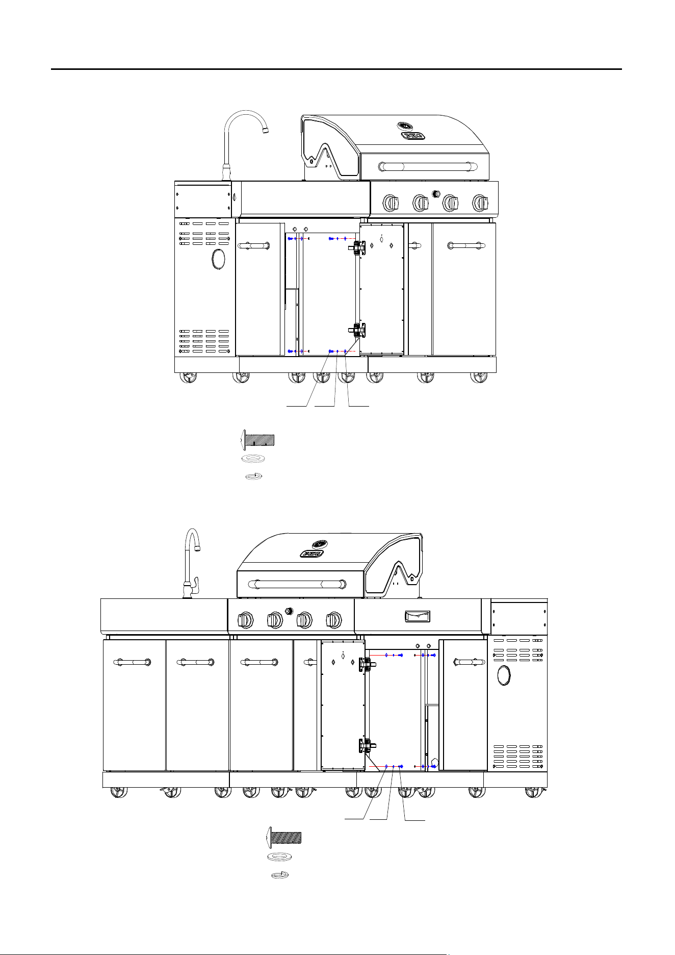
ISLAND GRILL COMBINATION ASSEMBLY INSTRUCTIONS
1. Combine Sink Module to BBQ grill as shown.
E2 D2A2
2. Combine Drawer Modular to Main BBQ grill as shown.
D2
E2
A2
A2 M6X16mm Silver Screw
D2 M6 Flat Washer
E2 M6 Spring Washer
X 4
X 4
X 4
A2 M6X16mm Silver Screw
D2 M6 Flat Washer
E2 M6 Spring Washer
X 4
X 4
X 4

35
NATURAL GAS CONVERSION
PREPARATION:
Before beginning conversion, make sure all parts are present. Compare parts with package
contents. If any part is missing or damaged, do not attempt to convert. Please have your
owner’s manual and part number available for reference, and contact customer service
1-855-242-6887 for replacement parts.
1. Turn off gas supply and then remove cap on gas supply side.
2. Recommended: Install a shut-off valve on gas supply side before installing the socket.
3. Socket should be installed by an authorized technician in accordance with the national fuel
gas code (NFPA 54/ANSI223.1).
4. Before inserting plug, turn on gas supply and leak test all connections including the stem of
the shut-off valve and the opening of the socket. For best results, use an ammonia-free
soap and water solution.
Leak Check
When checking for gas leaks, do not use an open flame. Use a soapy water solution and apply
it to the pipe joints and fittings with a brush and check for bubbles. Check flexible hoses for cuts
and wear that may affect the safe operation of the grill. Only use original equipment
replacement hoses. Use only replacement hose assemblies specified by manufacturer.
Before operating your grill, after refueling, check carefully to be certain that all connections
are tight and there are no gas leaks.
1. Make 2-3 ounces of leak solution by mixing liquid dishwashing soap with water.
2. Make certain all control knobs are in the “OFF” position.
3. Brush small amounts of the leak solution on all the fittings and turn the gas on.
4. If bubbles appear, there is a leak. Proceed to step 5.
5. Turn the gas off and tighten all connections.
6. Go back to step 1 to retest the fittings.
7. If bubbles continue to appear, turn the gas off. Contact customer service.
WARNING: Never use a match or open flame for leak detection. Use of an open flame could
result in a fire, explosion and bodily harm.
IMPORTANT: When connecting or replacing any gas pipe or fittings, all joints must be sealed
with approved leak-proof sealing compound or plumber's tape.
IMPORTANT: When connecting or replacing gas pipe or fittings, all joints must be sealed with
approved leak-proof sealing compound or plumber's tape. After making connections, check all
joints for leaks using a soapy water solution and a brush.
WARNING: Never use an open flame to test for gas leaks. Use of an open flame could
result in a fire, explosion and bodily harm.
36
NATURAL GAS CONVERSION
IMPORTANT:
After your grill is converted to natural gas, the working pressure for natural gas is 7 in. water
column (WC). Gas pressure is affected by gas line size and the length of gas line run from
house. Follow the recommendations in the chart below.
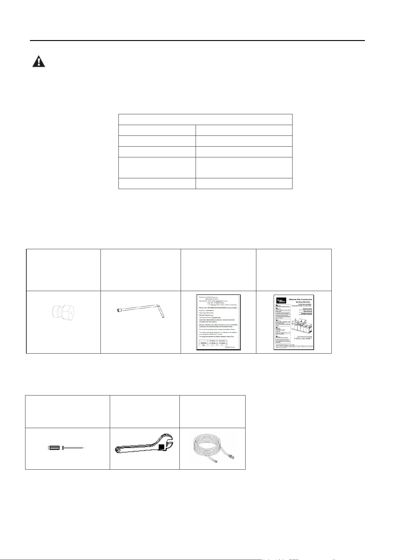
NG Conversion Kit ( Part No.5207207) Package Content:
Orifice 1.26mm
QTY: 4pcs
Orifice removal tool
QTY:1pc
NG Rating Label
QTY: 1 pc
NG Conversion
Instruction
QTY: 1 pc
※ The Natural Gas Conversion kit is located inside of the drawer.
Tools required for assembly (Not Included):
Slotted Screwdriver
QTY: 1pc
M19 Wrench
QTY:1pc
NG Hose
QTY: 1 pc
From House to Grill
Distance
Tubing Size
Up to 25 ft.
3/8 in. DIA
26 – 50 ft.
1/2 in. DIA
51 – 100 ft.
2/3 in. of run 3/4 in.
1/3 in. of run 1/2 in.
More than 101 ft.
3/4 in. DIA
37
NATURAL GAS CONVERSION
WARNING:
Place the grill on a flat, level surface.
Before the conversion, make sure all control knobs are in the OFF position, LP tank valve is
closed, and tank is disconnected from regulator and removed from grill.
Find the part number in Main BBQ Grill Parts List on page 8 to 9.
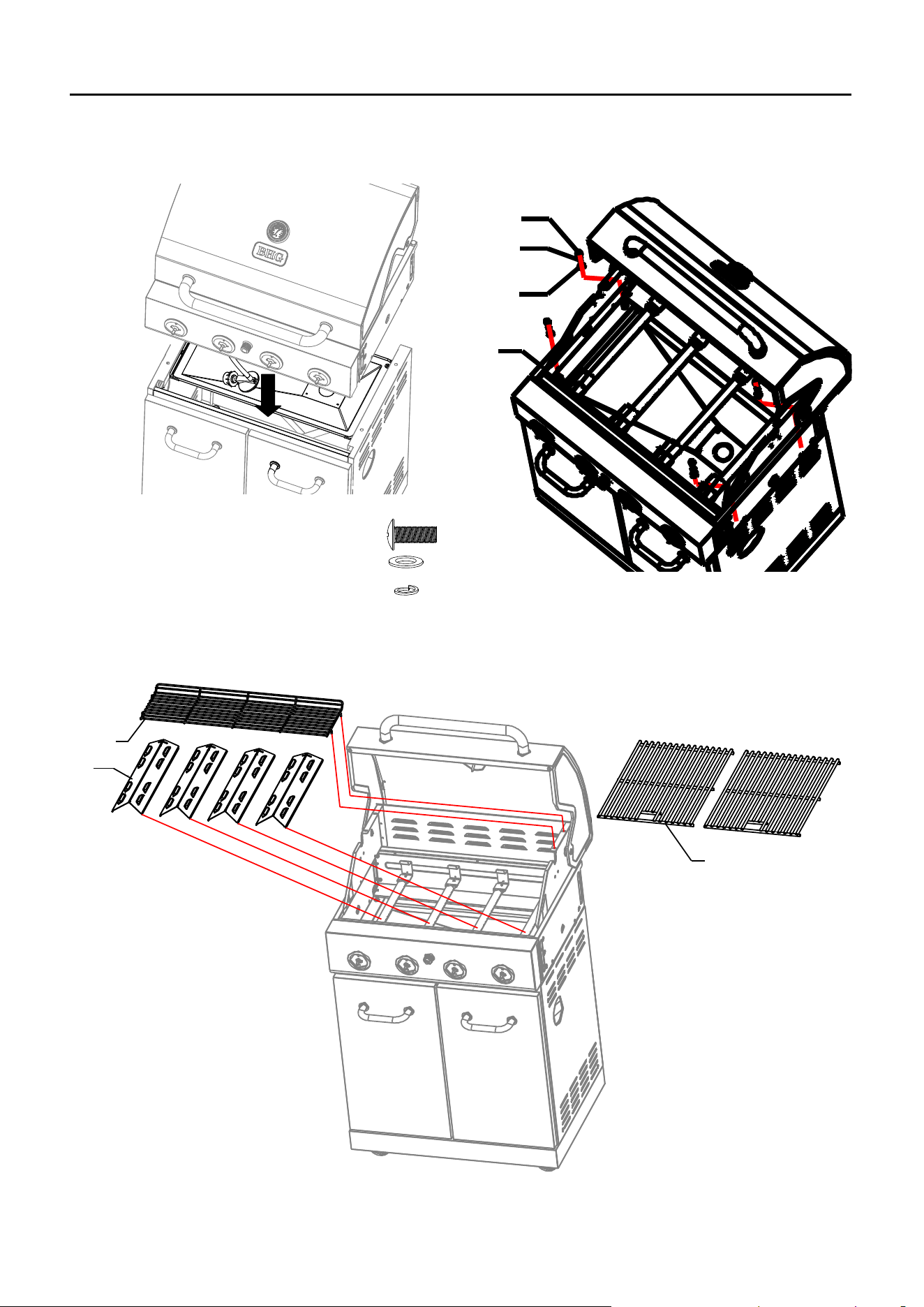
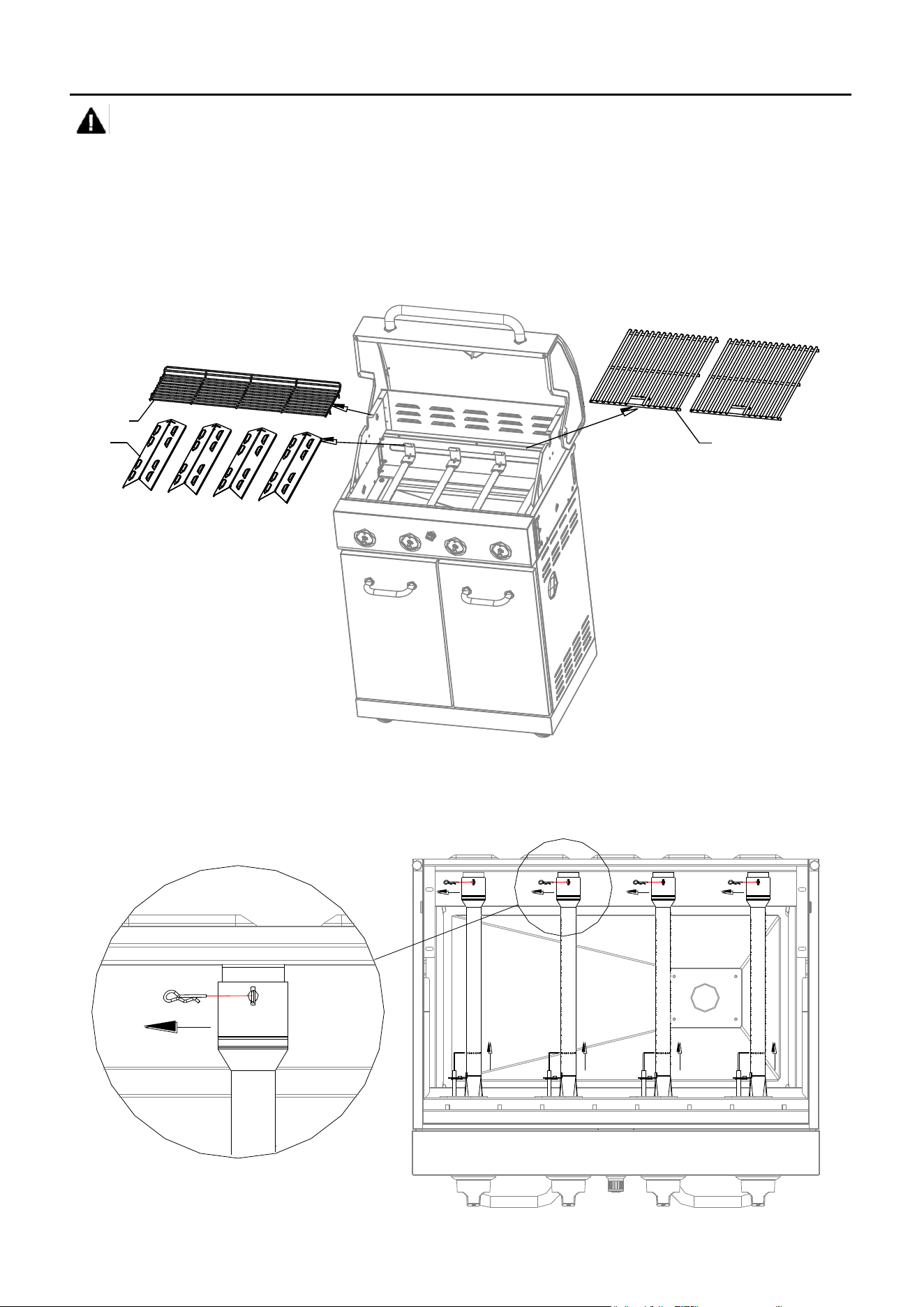
1. Open the lid and remove warming rack, cooking grates and heat tents.
9
8
10
2. Removed the R- pins at the back of main burners to detach burners from bracket. Lift back
of burners while sliding burners out of firebox, disengaging burners from gas valves as
shown.
1
1
2
38
NATURAL GAS CONVERSION
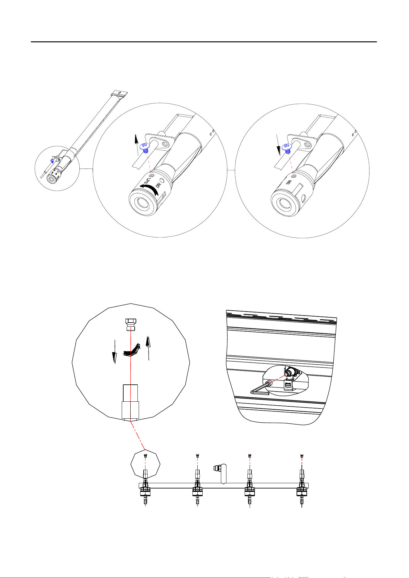
3. Loosen the screw from LPG setting, rotate the shutter opening counterclockwise, adjusting it
from LP setting to NG setting. Re-tighten the screw into NG setting for securing the air
shutter opening.
1
2
3
4. Unscrew the old LP orifice from each gas valve with the orifice removal tool. Put a new NG
orifice into the valves and tighten with tool. Repeat this step for all four main burners.
2
1
39
NATURAL GAS CONVERSION
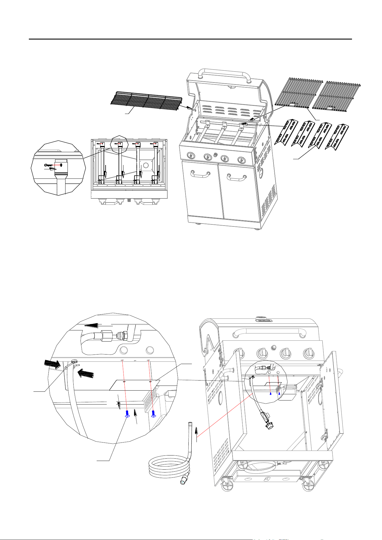
5. Reinstall the main burner and R pin. Make sure to engage the burner valves.
Then Put the heat tents, cooking grates back to grill.
1
2
9
8
10
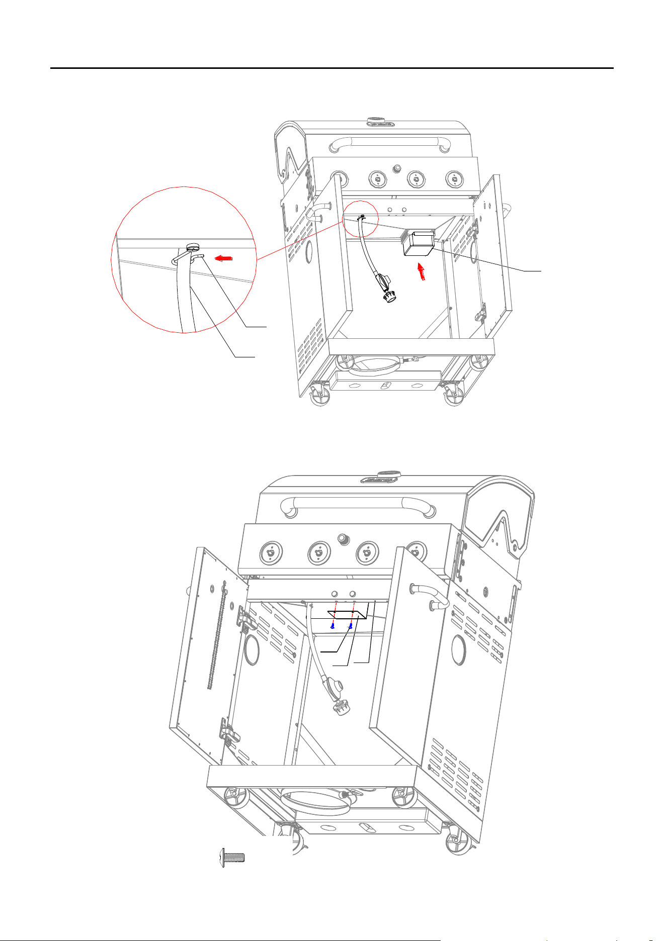
6. Step 1, Loosen the screw to remove the Hose Heat Shield (26) from Front Beam first.
Step 2, Use a wrench to detach the LP regulator and hose from fitting as shown.
Step 3, Replace with the NG hose.
Step 4, Pull out the hose clip hook (28) to secure the hose into the hook again.
Step 5, Re-attach Hose Heat Shield (26) to Front Beam.
1
3
5
C1
26
4
28
2
①
②
③
④
⑤
40
NATURAL GAS CONVERSION
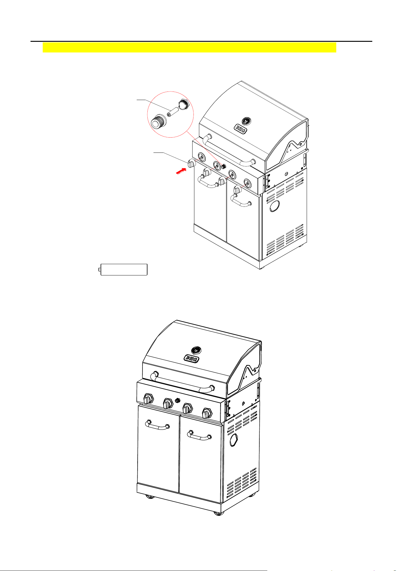
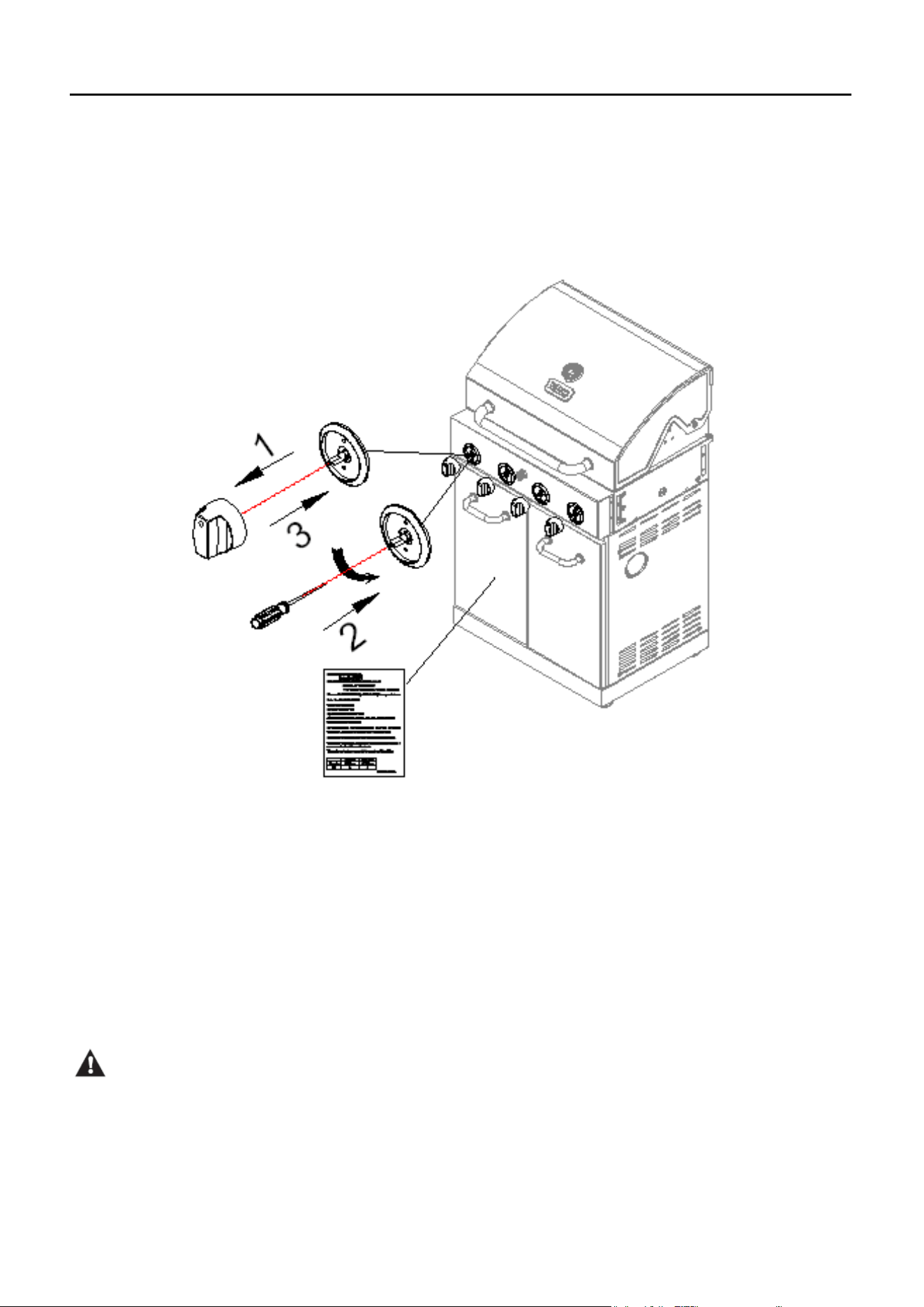
7. Remove the 4 main burner control knobs by grasping and pulling out.
Insert the slotted screwdriver (Not Included) into the hole of each main burner control valve
shaft as shown. Rotate the shaft counterclockwise (to the left) as far as it will go (about 2
complete turns) until it stops. The shaft will now be set in the NG position.
Re-attach the control knobs. Paste the new rating label for NG under the original LP rating
label on the cart door inner panel.
NG Conversion is now completed.
!CAUTION:
If low flames or burner problems are observed after converting from LPG to NG, the natural gas
lines may not be large enough. Refer to the “From House to Grill” chart on page 36 for natural
gas supply line specifications. Please contact a plumber to assure proper pressure at 7 in.
water column.
41
DO NOT RETURN YOUR GRILL TO THE STORE.
LIQUID PROPANE GAS INSTALLATION
Gas grills that are set to operate with Liquid Propane Gas come with a high capacity hose and regulator
assembly. (Note: Only use the pressure regulator and hose assembly supplied with the
grill or a replacement pressure regulator and hose assembly specified by the
manufacturer). This assembly is designed to connect directly to a standard 20 lb. L.P. Tank. L.P.
tanks are not included with the grill. L.P. tanks can be purchased separately at an independent dealer.
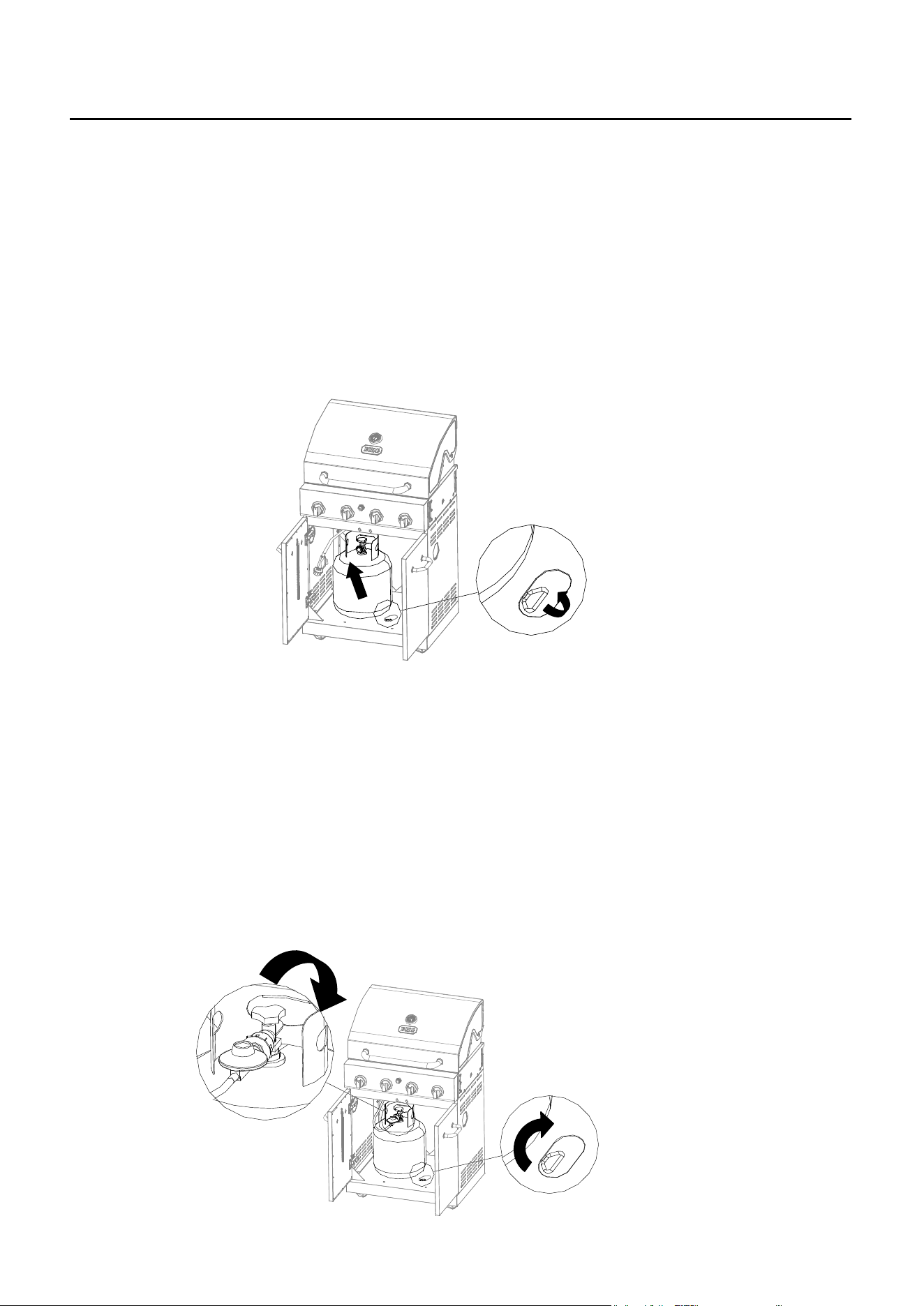
Connecting a Liquid Propane Gas Tank to the Grill:
1. Open the doors of the cabinet. Turn the stopper of the tank tray (counter-clockwise).
Place a 20 Ib. tank with foot ring into the tank tray. See Fig. 1.
Make sure the tank valve is in the OFF position.
2. Check the tank valve to ensure it has proper external mating threads to fit the hose and
regulator assembly provided (Type 1 connection per ANSI Z21.58b-2012).
3. Inspect the valve connection port of the regulator assembly. Look for damage or debris.
Remove any debris. Inspect hose for damage. Never use damaged or plugged equipment.
4. Make sure all burner knobs are in the OFF position.
5. Connect the hose and regulator assembly to the tank valve(See Fig. 2)Hand tighten the
quick coupling nut clockwise to a full stop. DO NOT use a wrench to tighten because it could
damage the quick coupling nut and result in a hazardous condition.
Fig. 2
Fig. 1
42
LIQUID PROPANE GAS INSTALLATION
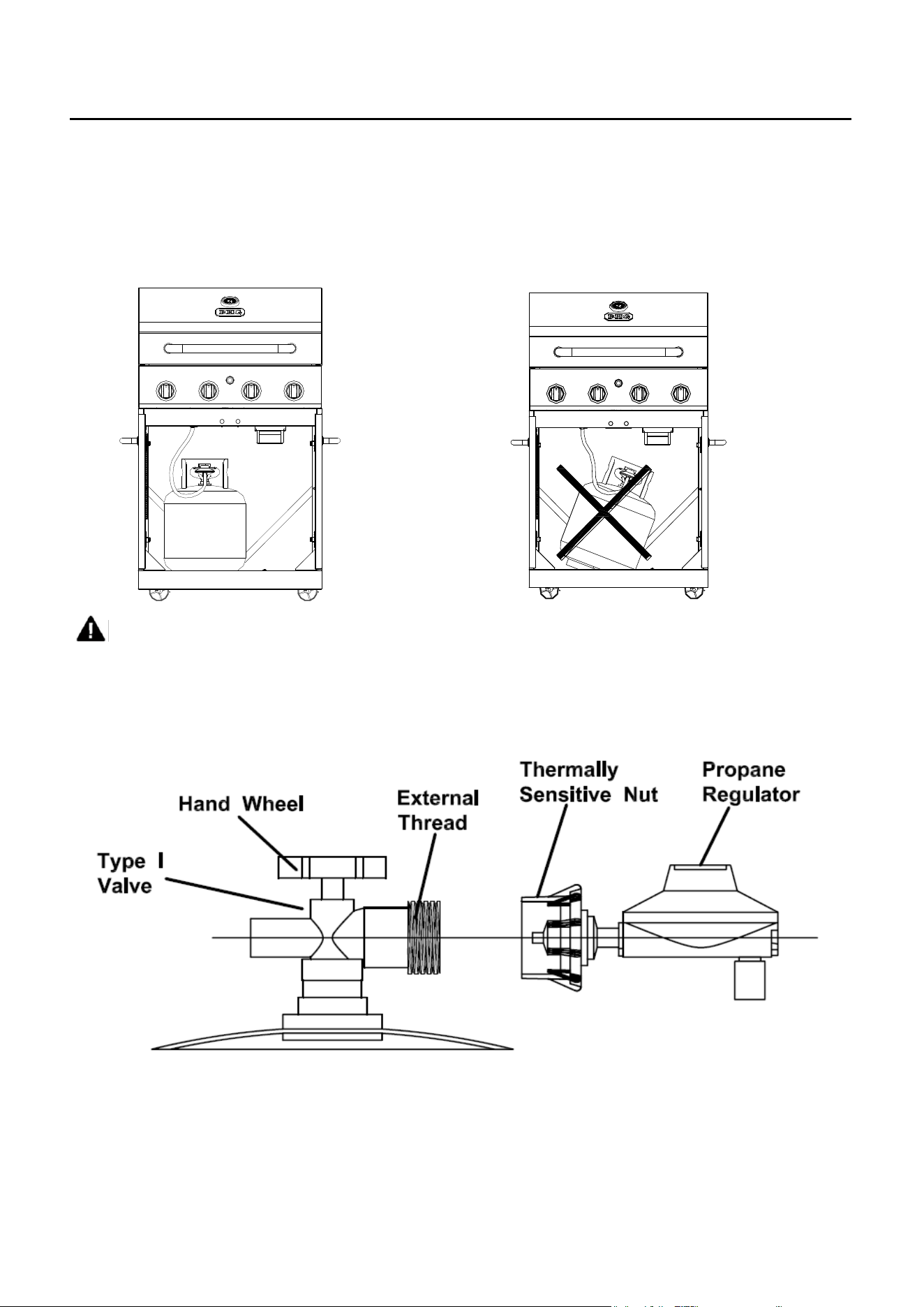
6. Open the tank valve fully (counterclockwise). Use a soapy water solution to check all
connections for leaks before attempting to light your grill. See “Leakage Testing" on page 44. If
a leak is found, turn the Tank Valve off and do not use your grill until the leak is repaired.
Gas tank must be placed into the tank tray vertically (see Fig.3a). Do not operate the grill if the
gas tank is lean (see Fig. 3b)
WARNING: The Type I connective coupling (see Fig. 4) supplied with your grill must
not be replaced with a different type of grill/tank connection system. Removal will result
in loss of warranty, gas leakage, fire and severe bodily harm.
Fig. 4
Fig. 3a
Fig. 3b
43
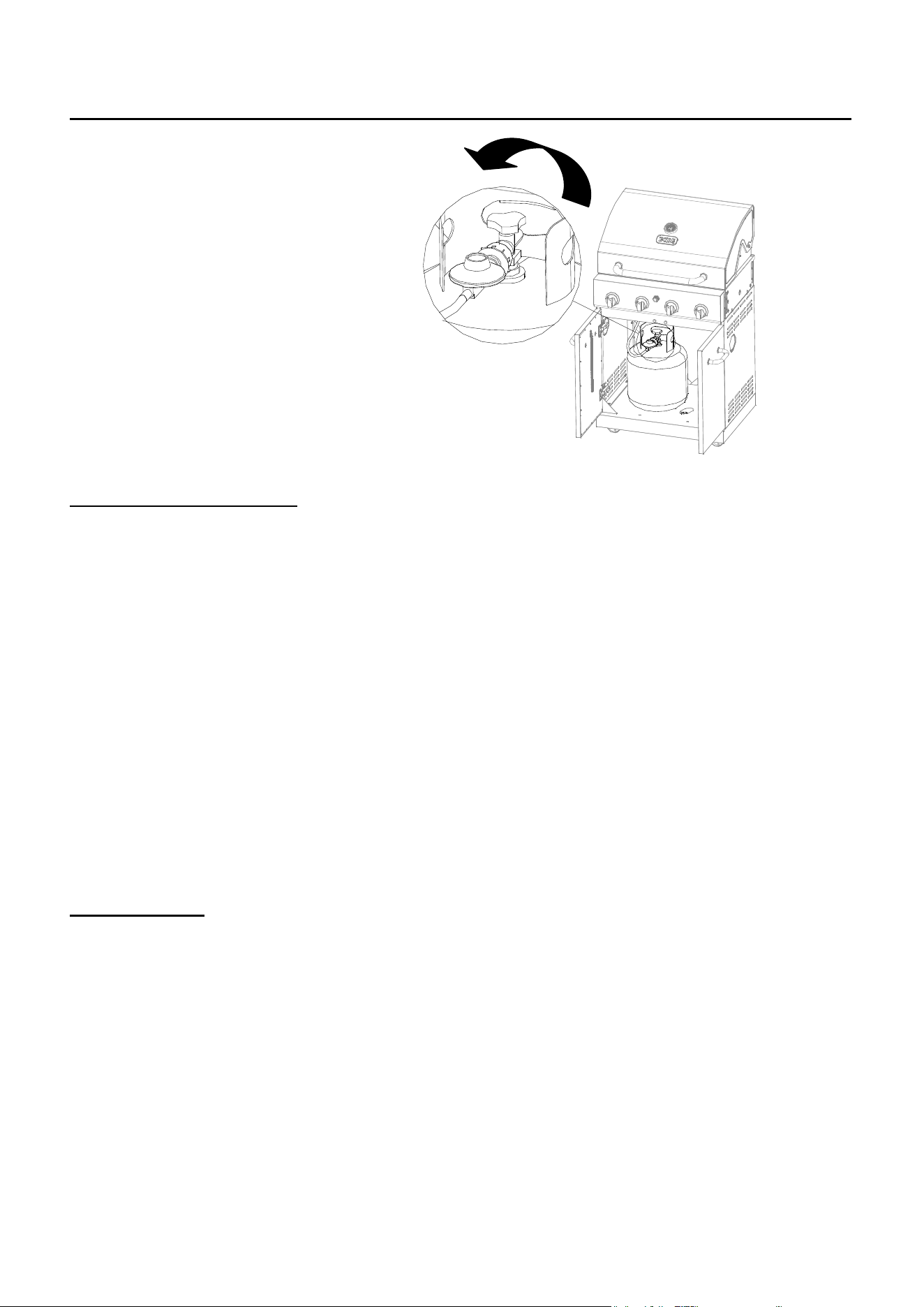
LIQUID PROPANE GAS INSTALLATION
Disconnecting A Liquid Propane
Gas (LP Gas) Tank From Your Grill:
1. Turn the burner knobs and LP gas
tank valve to the full OFF position.
(Turn clockwise to close.)
2. Detach the hose and regulator
assembly from the LP gas tank valve
by turning the quick coupling nut
counterclockwise. See Fig. 5.
CAUTION: When the appliance is
not in use, the gas must be turned
off at the supply tank.
L.P. TANK INFORMATION
Never use a dented or rusted L.P. tank or cylinder with a damaged valve.
L.P. cylinders are equipped with an O.P.D. (Overfilling Prevention Device). The device shuts off
the flow of gas to a cylinder after 80% capacity is reached. This limits the potential for release of
gas when the cylinder is heated, averting a fire or possible injury.
The L.P. cylinder must have a shut-off valve terminating in an L.P. gas supply cylinder outlet
specified, as applicable, for connection No. 510 in the standard for compressed gas cylinder
valve outlet and inlet connection ANSI/CGA-V-1. Cylinders must not be stored in a building,
garage, or any other enclosed area. (The L.P. cylinder must have an overfill protection device
and a collar to protect the cylinder valve.)
The L.P. gas supply cylinder must be constructed and marked in accordance with the
specifications for L.P. gas cylinders of the U.S. Department of Transportation (DOT) or the
National Standard of Canada, CAN/CAS-B339, “Cylinders, Spheres and Tubes for the
Transportation of Dangerous Goods and Commission.”
L.P. TANK USE
• When turning the L.P. tank on, make sure to open the valve SLOWLY two (2) complete
turns to ensure proper gas flow. Most gas tanks now come equipped with a leak
detector mechanism internal to the tank. When gas is allowed to escape rapidly it shuts
off the gas supply. Opening the valve rapidly may simulate a gas leak, causing the
safety device to activate, and restricting gas flow causing low flames. Opening the
valve slowly will ensure this safety feature is not falsely triggered.
• When not in use, gas supply cylinder valve is to be in the “OFF” position.
• The tank supply system must be stored upright to allow for vapor withdrawal.
• The regulator and hose assembly must be inspected before each use of the grill. If there is
excessive abrasion or wear or if the hose is cut, it must be replaced prior to the grill being used
again.
Fig. 5
44
OPERATING INSTRUCTIONS
• Cylinders must be stored outdoors out of the reach of children and must not be stored in a
building, garage or any other enclosed
area.
• Only a qualified gas supplier should refill
the L.P. tank.
• Place dust cap on cylinder valve outlet
whenever the cylinder is not in use.
Only install the type of dust cap on the
cylinder valve outlet that is provided
with the cylinder valve. Other types of
caps or plugs may result in leakage of
propane.
LEAKAGE CHECK
Although all gas connections on the grill are leak tested prior to shipment, a complete gas
tightness check must be performed at the installation site due to possible shifting during
shipment, installation or excessive pressure unknowingly being applied to the unit. Periodically
check the whole system for leaks and immediately check the system if the smell of gas is
detected.
1. Do not smoke while leak testing.
2. Extinguish all open flames.
3. Never leak test with an open flame.
4. Mix a solution of equal parts mild detergent
or liquid soap and water.
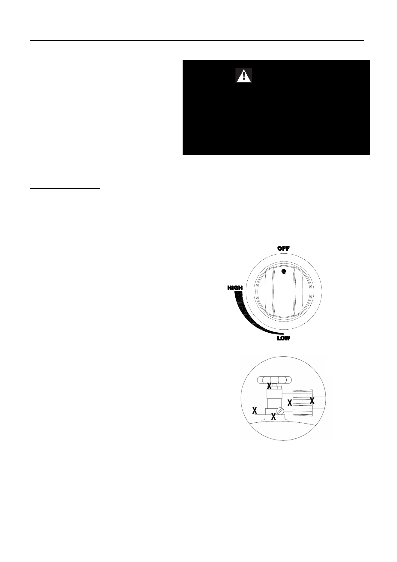
5. Turn off the burner control knobs. (see Fig. 6)
6. Turn the top knob of the fuel supply cylinder
counterclockwise two (2) rotations to open.
7. Apply the soap solution to connections of the
fuel supply assembly. Spoon leak check
solution at all: ”X” locations (see Fig. 7).
If no soap bubbles appear, there is no gas
leak. If bubbles form at the connections, a leak
is detected. If a leak is detected, immediately
turn off the gas supply, tighten any leaking
fittings, turn gas on, and repeat steps 5-6.
8. Turn off the knob on the fuel supply cylinder.
9. Turn on the burner control knobs for a moment
to release the pressure in the hose, then turn the control knobs back off.
10. Wash off soapy solution with cold water and towel dry.
Check all gas supply fittings before each use and each time, make sure the gas supply
cylinder is connected to the regulator. Have a qualified service technician to replace the grill
leak parts if any time need.
Also it is recommended to perform a leak test at least once a year whether or not the L.P.
gas supply cylinder has been disconnected.
WARNING
DO NOT store a spare L.P. gas cylinder under
or near the grill. Never fill the cylinder beyond
80% full.
If this information is not followed exactly, a fire
causing death or serious injury may occur.
Fig. 7
Fig. 6
45
OPERATING INSTRUCTIONS
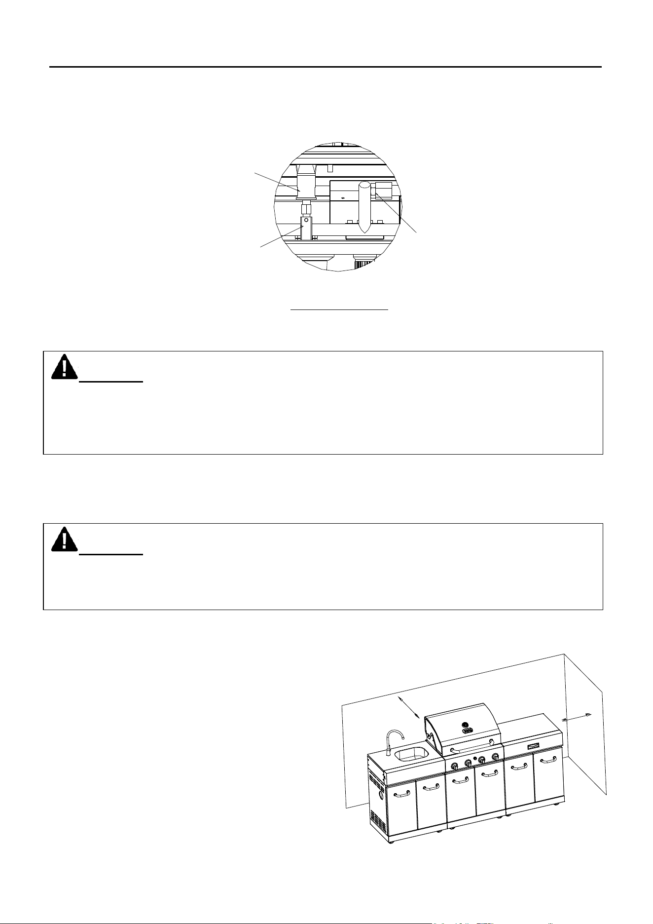
Please refer to diagram for proper installation (see Fig. 8). Visually check the connection
between the burner venture pipe and orifice. Make sure the burner venture pipe fits over the
orifice.
If you cannot stop a gas leak, turn off the gas supply and call your local gas company. If
necessary, replace the faulty part with the manufacturer’s recommended replacement part. A
slight leak could cause a fire.
NOTE: The grill will operate best if it is not facing directly into the wind.
Clearance to combustible construction:
A minimum of 36 in. from the sides and
back must be maintained from the gas
grill above and below the cooking surface
to adjacent vertical combustible construction.
Clearance to non-combustible construction:
A minimum of 36 in. clearance from the back
of the grill to non-combustible construction
is required for the lid to fully open.
WARNING When leak testing this appliance, make sure to test and tighten all loose
connections. A slight leak in the system can result in a low flame or hazardous condition. Most
L.P. gas tanks now come equipped with a leak detector mechanism internal to the tank. When
gas is allowed to escape rapidly, it shuts off the gas supply. A leak may significantly reduce the
gas flow, making the grill difficult to light or causing low flames.
WARNING Do not use the grill in garages, breezeways, sheds or any enclosed area.
Never operate the grill in enclosed areas as this could lead to a carbon monoxide buildup,
which could result in injury or death. Place the grill on a level surface. Avoid moving the grill
while it is in operation.
36"(914mm)
36"(914mm)
Burner
venturi pipe
LP Gas Valve
with Orifice
Main Burners
Valve Soft Pipe
Connection
Fig. 8
46
OPERATING INSTRUCTIONS
Storage of an outdoor gas cooking appliance indoor is permissible only if the cylinder is
disconnected and removed from the appliance.
GENERAL RULES
Do not leave the grill unattended while cooking!
1. Make sure the grill has been leak tested and is properly located.
2. Light the grill burners using the instructions
provided in this manual.
3. Turn the control knobs to desired temperature
- High or Low - and preheat the grill for 10 minutes
before cooking.
4. Adjust heat settings to meet your cooking needs for
desired results.
5. Allow grill to cool down, wipe off any splatters or
grease and clean the drip tray as needed.
6. Do not put a cover on the grill while it is still hot as it
could start a fire.
BEFORE AND AFTER LIGHTING
1. Ensure your grill is located on a level surface.
2. Keep the gas grill area clean and free from combustible materials, gasoline, and other
flammable vapors and liquids.
3. Ensure nothing is obstructing the flow of combustion and ventilation air.
4. Ensure the ventilation of the cylinder enclosure is free and clear of debris.
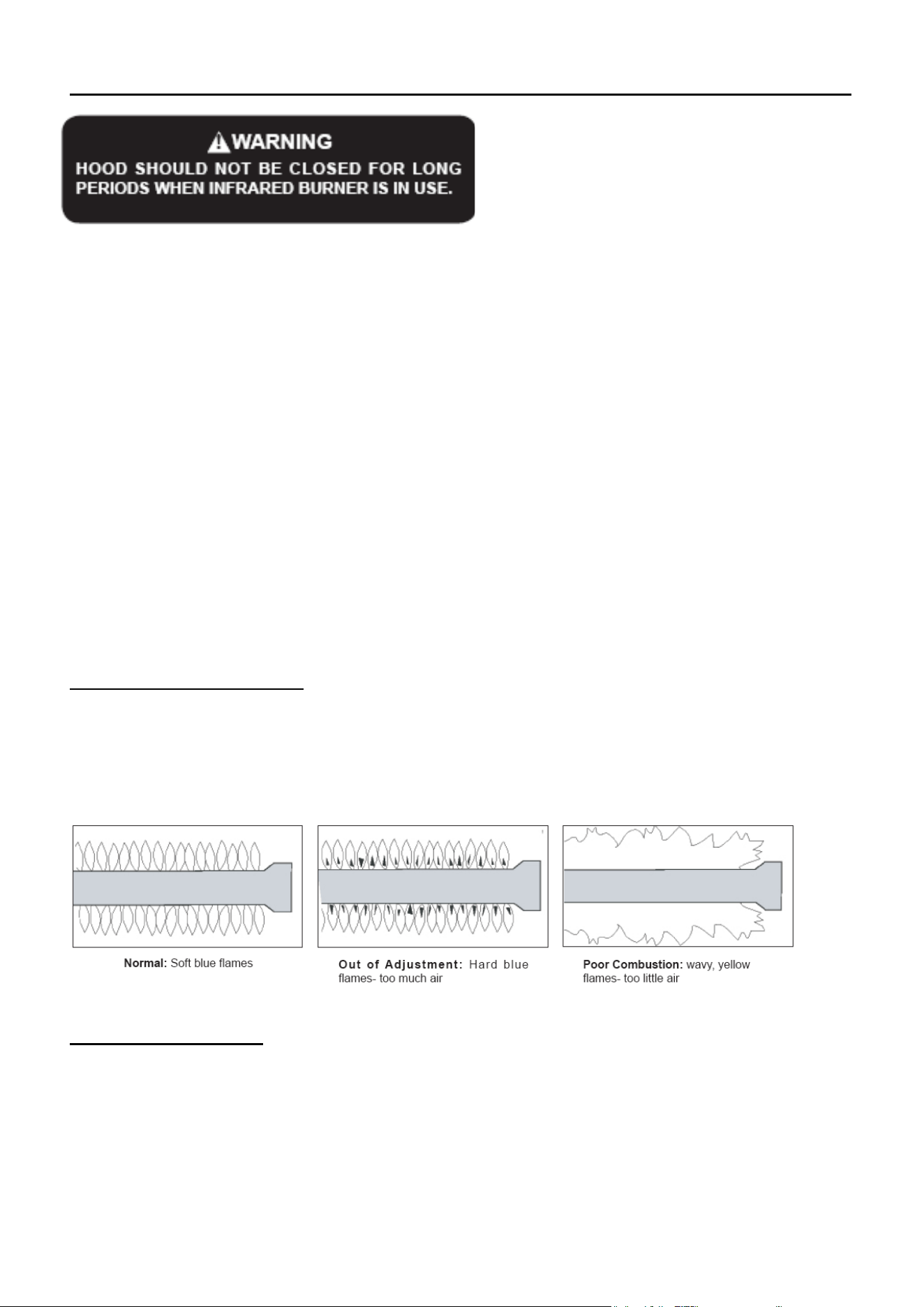
5. Visually check burner flames.
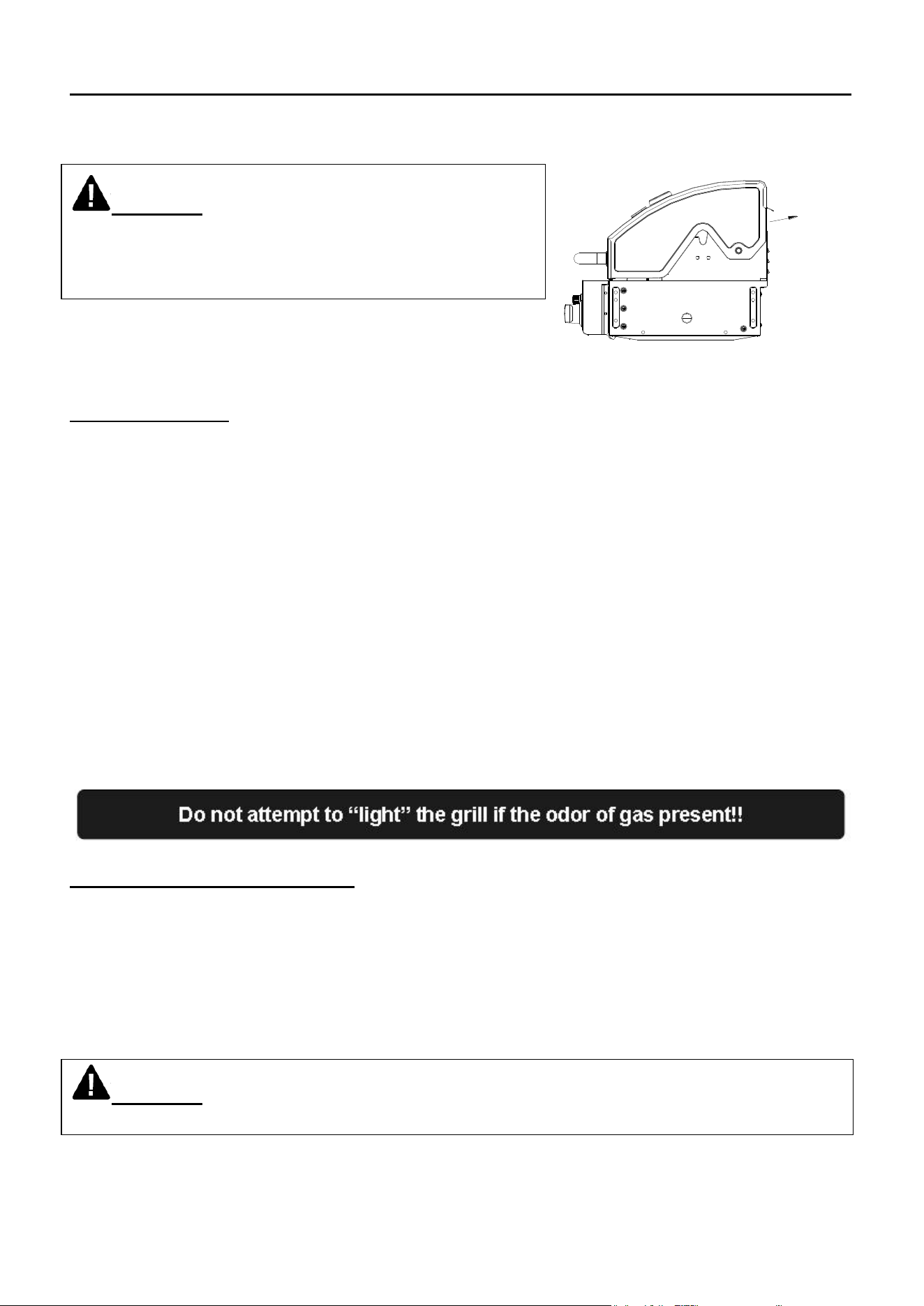
WARNING Heat and smoke exhaust out of the
back of the grill hood opening. Make sure not to have the
grill back facing your home or anything that could be
damaged by heat or smoke.
WARNING Check the gas supply line for cuts, wear or abrasion.
Always keep your face and body as far away from the grill as possible when lighting.
Heat&
Smoke
Exhaust
47
LIGHTING INSTRUCTIONS
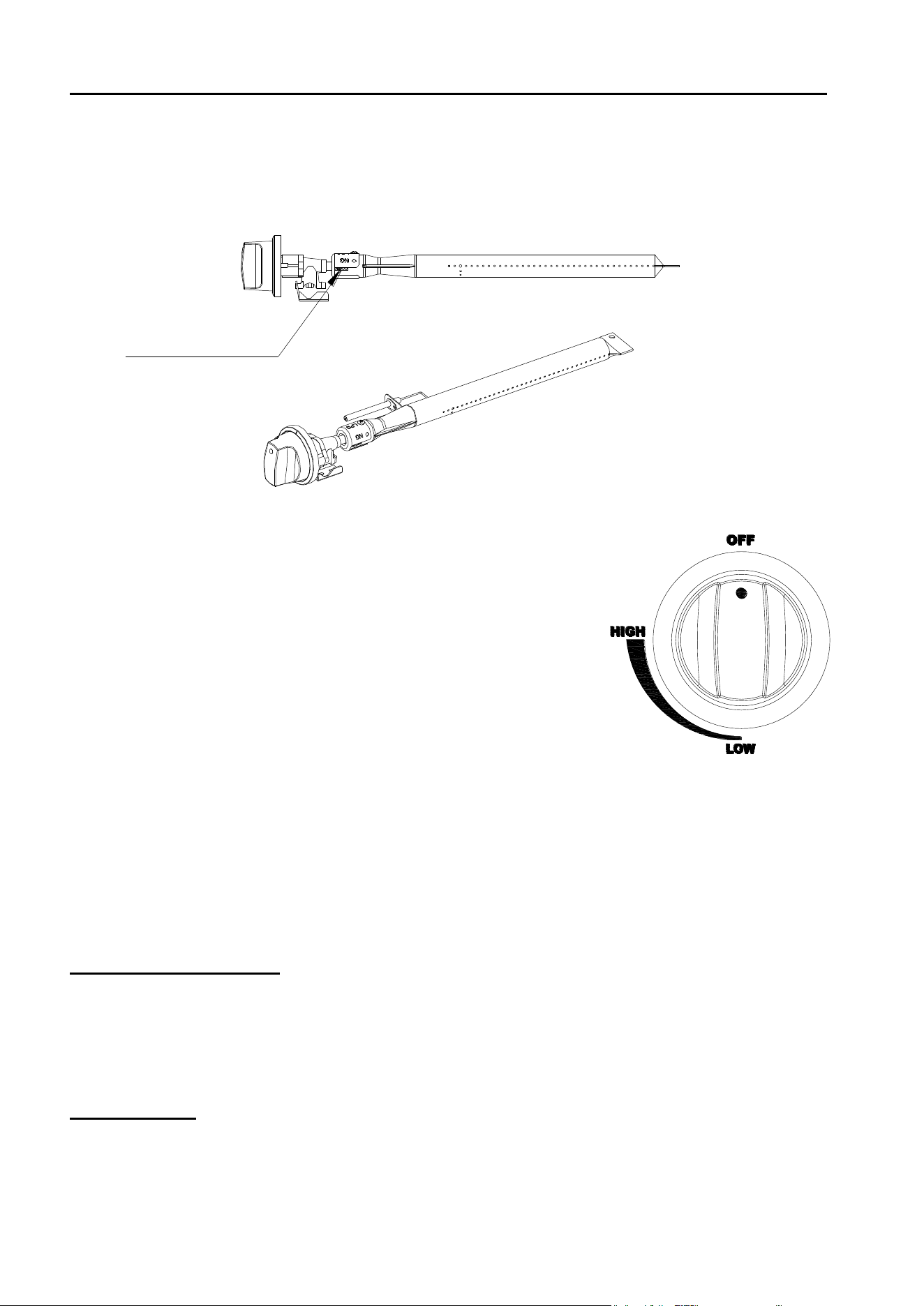
Checking orifices alignment with burners
Orifices may shift during assembly and movement. Check the orifices alignment with the
burners according to the following illustrations before lighting.
Main Burner and Orifice Relationship
LIGHTING INSTRUCTIONS:
Warning: Do not lean over grill when lighting.
1. Check that the control knobs are in the OFF position.
2. Open valve at tank fully by turning counterclockwise.
3. Open lid during lighting.
4. Press the Electronic Igniter 3 to 4 seconds while turning
the control knob to the HIGH position. The burner should ignite.
5. If the burner fails to ignite, turn the knob to OFF, and wait for 5 minutes before attempting to
re-ignite.
The first time you light the grill you may have to turn the control knob to the HIGH position for up
to 30 seconds to purge the gas lines of any air.
For complete shutdown
1. Turn the knob to “HIGH” position first, then push in and turn to “OFF” position for complete
shut off.
2. Turn the LP gas tank valve OFF before remove the LP gas tank.
Match lighting
Warning: Do not lean over grill when lighting.
If ignitor does not light the burner, the burner may be lit with a match attached to the match
extender, located on side of the cart.
Orifice stud inside
the air shutter
48
LIGHTING INSTRUCTIONS
Remove the main cooking grate and flame tamers. Keep your face as far away from the grill
surface as possible and pass the match extender to the ports of the main burner tubes. Position
the match near the burner ports and push and turn the control knob counter-clockwise to the
“HIGH” position. After the burner has lit, turn the knob to the "LP LOW" position and carefully
place the flame tamers and grates back in position. Then turn the control knob to the desired
setting.
NOTE: If the grill will not light after several attempts see the Troubleshooting section of
this manual. Turn the control knobs to the OFF position when not in use.
49
CARE AND MAINTENANCE
However, there are steps you must take to prevent cracking of the burner's ceramic surfaces,
which will cause the burners to malfunction. The following are the most common causes of
cracks and the steps you must take to avoid them. Damage caused by failure to follow these
steps is not covered by your grill warranty.
IMPACT WITH HARD OBJECTS - Never allow hard objects to strike the ceramic. You should
take particular care when inserting or removing cooking grids and accessories into or from the
grill. If objects such as these fall onto ceramic, it is likely to crack the ceramic.
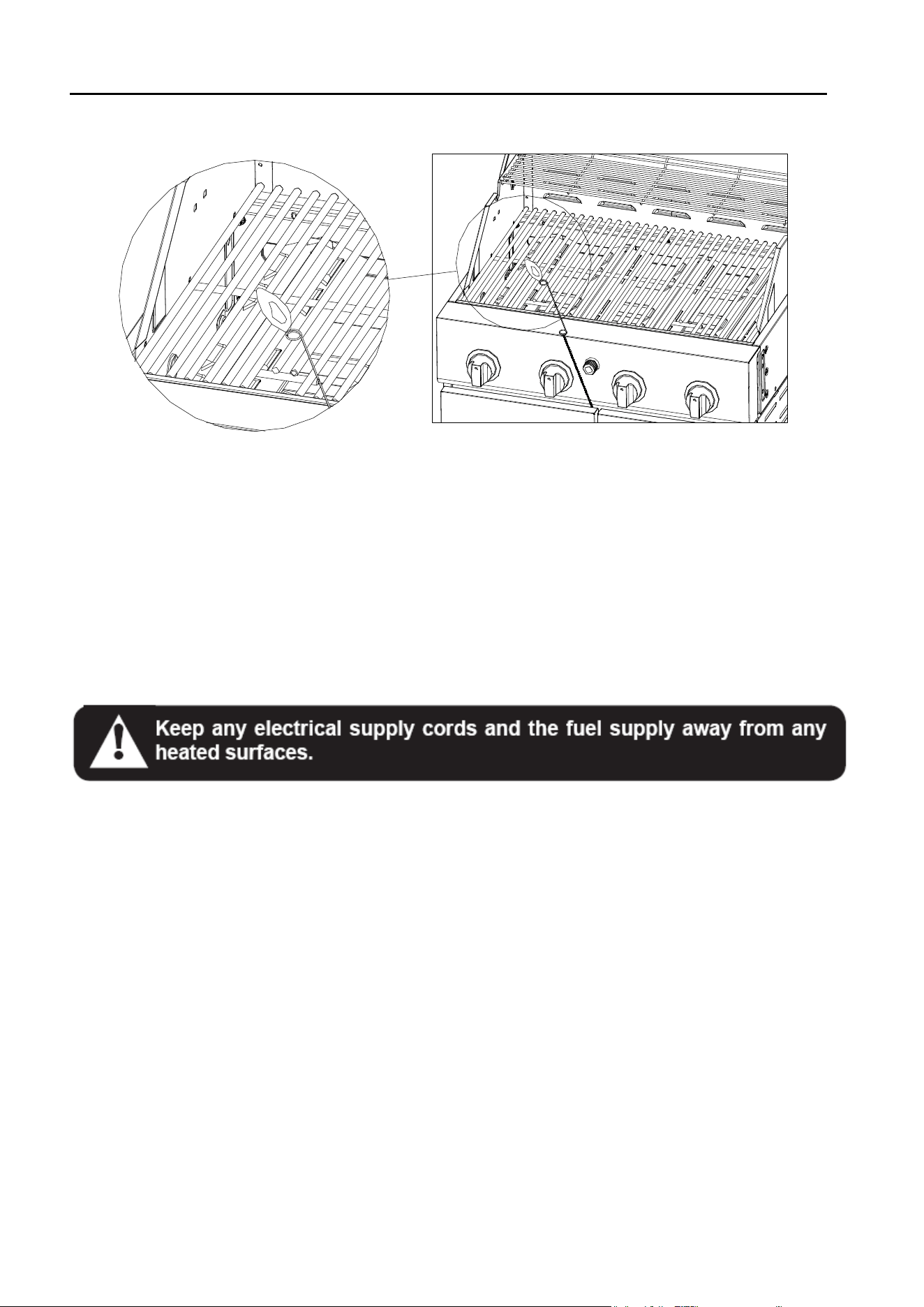
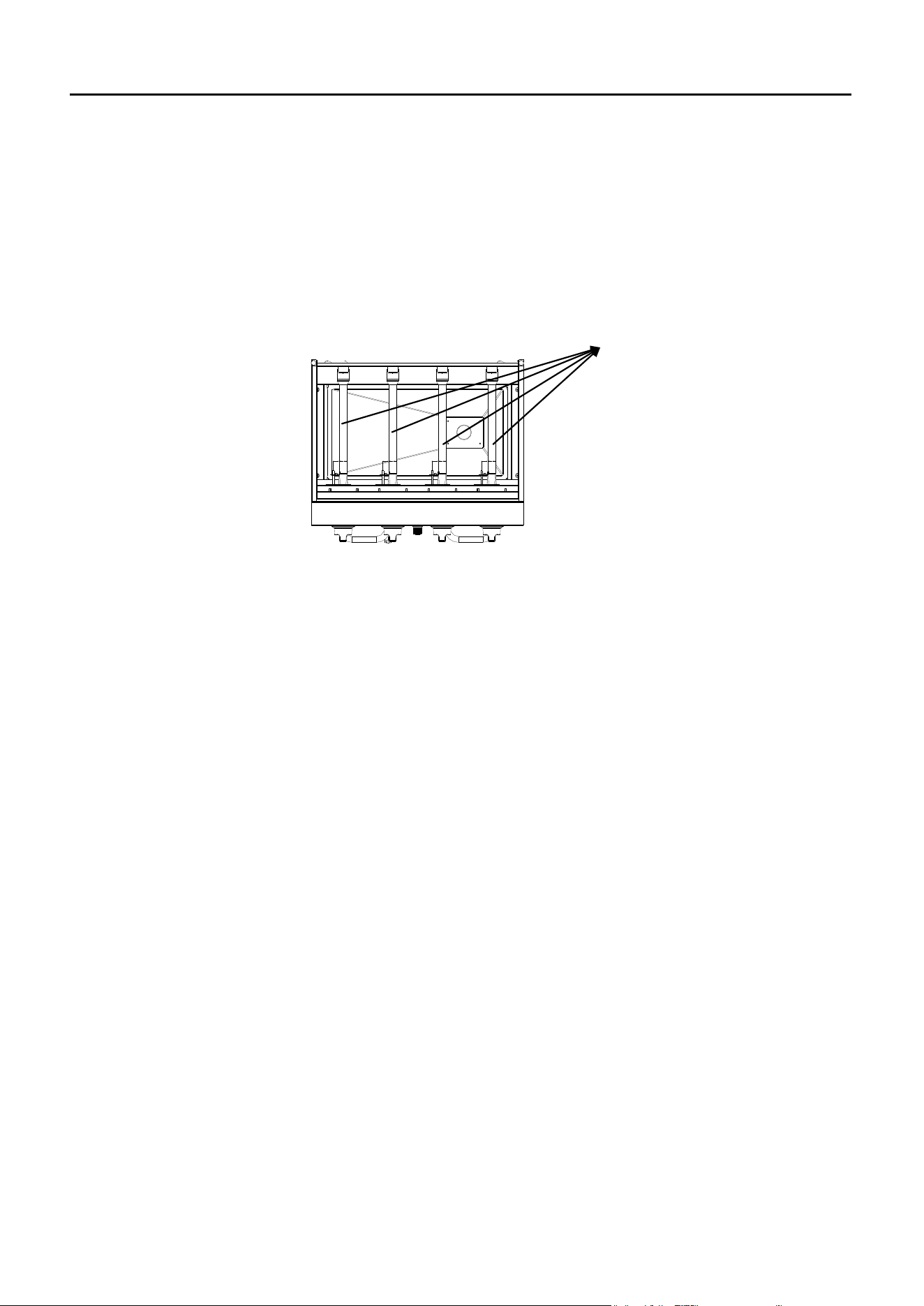
IMPAIRED VENTILATION OF HOT AIR FROM GRILL - In order for the burners to function
properly, hot air created by the burners must have a way to escape. The burners may become
deprived of oxygen, causing them to backfire, especially if the burner output is set at HIGH. If
this occurs repeatedly, the burners may crack. This is the reason your grill was designed with
ventilation louvers. These design features give the hot air an escape route. Accordingly, never
operate your grill with very little or no open space at the cooking surface (the cooking grids
provide sufficient space). Also, never cover the ventilation louvers with foil or other materials
that prevent air flow. Specifically, do not cover the entire surface with foil, a large pan, etc.
GENERAL MAINTENANCE
- Keep outdoor cooking gas appliance area clear and free from combustible materials, gasoline
and other flammable vapors and liquids.
- Do not obstruct the flow of combustion and ventilation air.
- Keep the ventilation openings of the cylinder enclosure free and clear from debris.
- Visually check the burners.
GENERAL CLEANING
GENERAL CLEANING
IMPORTANT: Before cleaning, make sure all controls are off and the grill is cool. Always follow
label instructions on cleaning products.
For routine cleaning, wash with soap and water using a soft cloth or sponge. Rinse with clean
water and dry at once with a soft, lint-free cloth to avoid spots and streaks.
To avoid scratching the surface, do not use steel wool to clean the grill.
Use a vinyl grill cover to protect finish from weather.

50
CARE AND MAINTENANCE
DRIP TRAY
The drip tray should be cleaned periodically to prevent heavy buildup of debris.
NOTE: Allow the drip tray to cool before attempting to clean.
Important: Do not leave the grill outside during inclement weather unless it is covered. Rain
water can collect inside of the grill, the grill cart or the drip tray if left uncovered. If the drip tray is
not cleaned after use and the grill is left uncovered, the drip tray will fill with water causing
grease and water to spill into the grill cart. We recommend cleaning and storing the drip tray
after every use.
COOKING GRATES
The cooking grates can be cleaned immediately after cooking is completed and after turning off
the grill. Wear a barbecue mitt and scrub the cooking grates with a damp cloth. If the grill is
allowed to cool down, cleaning the grates will be easier if removed from the grill and cleaned
with a mild detergent.
STAINLESS STEEL
After initial usage, areas of the grill may discolor from the intense heat given off by the burners.
This is normal.
Purchase a mild stainless steel cleaner and rub in the direction of the grain of the metal. Specks
of grease can gather on the surface of the stainless steel and bake on to the surface and give a
worn appearance. For removal, use a non-abrasive oven cleaner in conjunction with a stainless
cleaner.
NOTE: Always scrub in the direction of the grain.
PORCELAIN PARTS
Certain parts of your grill have a porcelain coating. Porcelain is a glass-based product and is
highly durable to standard wear and tear. However, porcelain is sensitive to concussive blows,
which can create interlaced micro-fractures or “spider-webs.” Please take care not to strike any
porcelain covered parts with solid objects, drop them, or create any other concussive blows.
These interlaced micro-fractures are common and may lead to minor chipping. Neither the
chipping nor the interlaced micro-fractures will adversely affect the performance of your grill and
are not covered under the warranty for porcelain parts.

51
TROUBLESHOOTING
Many solutions given here can make your grilling experience safer and more enjoyable. You
can also call customer service department at 1-855-CHANT-US(1-855-242-6887) from 8:00am
to 5:00pm Eastern time, Monday through Friday for assistance.
PROBLEM
POSSIBLE CAUSE
CORRECTIVE ACTION
Grill will not
light.
1. The ignition wire came off the
igniter/valve.
2. The distance between the ignition
pin and the burner is greater than
5/32 in. - 3/16 in.
3. The ignition wire is broken.
6. The electrode tip does not
produce sparks at the burner port.
7. No gas supplied.
8. Air shutter opening is too big.
1. Reconnect the ignition wire to the
electrical igniter/valve.
2. Loosen the ignition pin and adjust the
distance, then fasten it again.
3. Call customer service for a
replacement ignition wire.
6. Reinstall the electrode.
7. Turn on the regulator valve.
8. Loosen the air shutter and adjust the
opening to a smaller size.
Burner flame
is yellow and
gas odor can
be smelled.
1. The air shutter opening is not
properly set.
2. Spiders or insects block the air
shutter.
3. Possible gas leaks.
1. Loosen the air shutter and adjust the
opening to have blue flames.
1/4 in. opening for LPG.
2. Clean blockages.
3. Check for the source of gas leaks.
Excessive
flare-up.
1. Grilling fatty meats.
2. Knobs on “HIGH”.
3. Spray water on gas flames.
4. Hood closed when grilling.
1. Move the meats to the warming rack if
flare up continues until flame settles
down.
2. Grill fatty meats when the grids are
cold while the knobs are on the “LP
LOW” (when using LP Gas)
3. Never spray water on gas flames.
4. Hood up when grilling.
Burner blows
out.
1. LP tank is empty.
2. Burner is not aligned with the
control valve.
3. Gas supply is not sufficient.
1. Refill the LP Tank.
2. Install the burner correctly.
3. Check the gas supply hose and make
sure there are no leaks and no knots.
52
TROUBLESHOOTING
PROBLEM
POSSIBLE CAUSE
CORRECTIVE ACTION
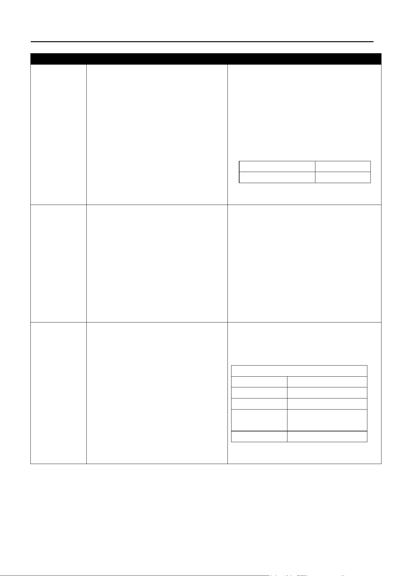
Low heat
with the knob
in “HIGH”
position.
1. Low heat is found in natural
gas models.
2. Ports are blocked.
3. LP tank has run out.
1. This model is set for 7 in. natural gas
usage. Please check your natural gas
supply system to have correct gas
pressure. Regulator is not needed for
NG model.
Check the orifice if you installed NG
nozzles. Conversion kit provides the
following nozzles:
Burner
Orifice Size
Main Burner
Φ1.26mm
2. Clear ports of any obstructions.
3. Refill the LP tank.
Low heat,
LP gas.
The propane regulator assembly
incorporates an excess flow device
designed to supply the grill with
sufficient gas flow. Rapid changes in
pressure can trigger the excess flow
device, providing a low flame and
low temperature.
Please follow these instructions:
1. Make sure all burners are “OFF”.
2. Open the tank valve and wait 5
minutes.
3. Light the burner one at a time
following the lighting instructions listed
on the door liner and Page 27.
Low heat,
natural gas.
Gas pressure is significantly affected
by gas line and length of gas line
from house gas line.
Check your gas line and make
corrections by following the chart below:
From House to Grill
Distance
Tubing Size
Up to 25 ft.
3/8 in. DIA
26 – 50 ft.
1/2 in. DIA
51 – 100 ft.
2/3 in. of run 3/4 in.
1/3 in. of run 1/2 in.
Over 101 ft.
3/4 in. DIA
53
WARRANTY
Proof of purchase is required to access this warranty program, which is in effect from the date
of purchase. Customers will be subject to parts, shipping, and handling fees if unable to provide
proof of the purchase or after the warranty has expired.
If you have any questions or problems, you can call our customer service department at
1-855-CHANT-US (1-855-242-6887) from 8:00am to 5:00pm Eastern time, Monday through
Friday for assistance.
Limited Warranty
Manufacturer warrants this product for the Stainless Steel Main Burner for 5 years and all
other replacement parts for 1 year from the date of purchase.
Warranty Provisions:
This warranty is non-transferable and does not cover failures due to misuse of improper
installation or maintenance.
This warranty is for replacement of defective parts only. We are not responsible for incidental or
consequential damages or labor costs.
This warranty does not cover corrosion or discoloration after the grill is used, or lack of
maintenance, hostile environment, accidents, alterations, abuse or neglect.
This warranty does not cover damage caused by heat, abrasive and chemical cleaners, or any
damage to other components used in the installation or operation of the gas grill.
Paint is not warranted and may require touch-up. Items considered to be consumable such as
batteries are not covered under this warranty.
Some states do not allow the limitation or exclusion of incidental or consequential damages, so
the above limitations or exclusions may not apply to you. This warranty gives you specific legal
rights, and you may also have other rights that vary from state to state.
For replacement parts, call our customer service department at 1-855-CHANT-US
(1-855-242-6887) from 8:00am to 5:00pm Eastern time, Monday through Friday for assistance.
Stainless Steel Main
Burner