
Installation Guide
FC-GMSUV101-MC
Integrated Safety System

Illustrations are typical and may not match exact vehicle details
email - [email protected] (US)
tel - 1-800-477-2267 (East Coast) - 1-888-883-2790 (West Coast)
email - [email protected] (Europe)
2
Illustrations are typical and may not match exact vehicle details
email - [email protected] (US)
tel - 1-800-477-2267 (East Coast) - 1-888-883-2790 (West Coast)
email - [email protected] (Europe)
Cover all surfaces with tape or plastic protection lm to protect against
scratching and damage. EchoMaster is in no way responsible for any damage
that may incur during installation.
This product has been validated in the vehicles listed on the application guide only.
Care must be taken when installing this accessory to ensure damage does not occur
to the vehicle. The installation of this accessory should follow approved guidelines to
ensure proper installation. Read entire instructions thoroughly before starting.
This document covers such items as:
- Vehicle Protection (use of covers and blankets, cleaning chemicals, etc).
- Vehicle Disassembly / Reassembly (panel removal, part storage, etc).
- Electrical Component Disassembly / Reassembly (battery disconnection,
connector removal, etc).
NOTES:
Removed Parts: Inspect the vehicle and parts for any damage.
Place all removed parts on a protected surface in an area where they will not get
damaged.
Connectors: When disconnecting connectors, do not pull on the wires; pull by
holding the connectors.
Retains the factory reverse camera if equipped.
Prior to Installation
FC-GMSUV101-MC
Integrated Safety System
3
Illustrations are typical and may not match exact vehicle details
email - [email protected] (US)
tel - 1-800-477-2267 (East Coast) - 1-888-883-2790 (West Coast)
email - [email protected] (Europe)
Illustrations are typical and may not match exact vehicle details
email - [email protected] (US)
tel - 1-800-477-2267 (East Coast) - 1-888-883-2790 (West Coast)
email - [email protected] (Europe)
CAUTION
Consult your vehicle owner’s manual to disconnect the battery. Do not disconnect
ANY airbag connectors or indicators. Doing so may result in activating a diagnostic
code. These codes will require the dealer to perform the reset procedure which may
incur a reset fee. If you are unsure of any vehicle trim removal process consult the
OEM service manual.
Removing vehicle trim panels in extreme hot and/or cold climate could result in
damage. Use care when removing all vehicle trims.
Using painter’s blue tape on the vehicle trim panels can help limit any scratches
and/or marring. Use a nylon trim panel removal tool whenever possible.
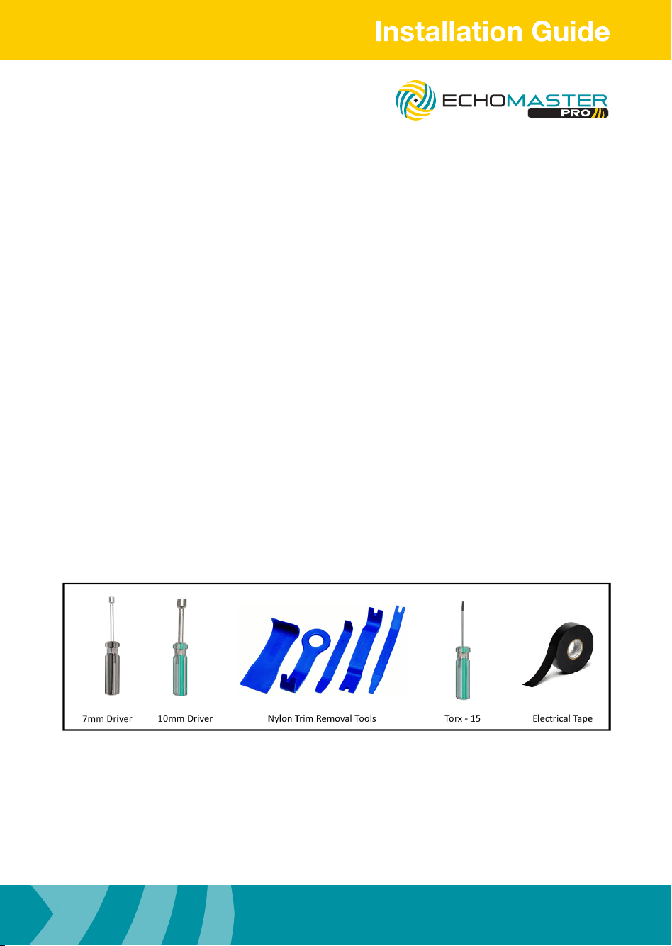
Vehicle Preparation & Protection
Required Tools
FC-GMSUV101-MC
Integrated Safety System
Illustrations are typical and may not match exact vehicle details
email - [email protected] (US)
tel - 1-800-477-2267 (East Coast) - 1-888-883-2790 (West Coast)
email - [email protected] (Europe)
4
Illustrations are typical and may not match exact vehicle details
email - [email protected] (US)
tel - 1-800-477-2267 (East Coast) - 1-888-883-2790 (West Coast)
email - [email protected] (Europe)
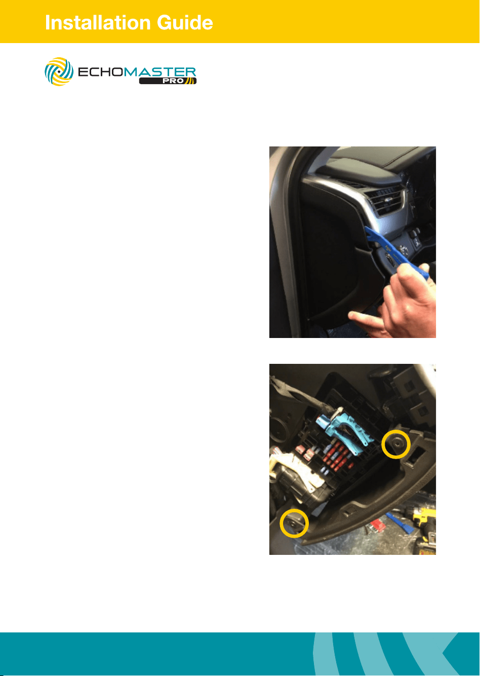
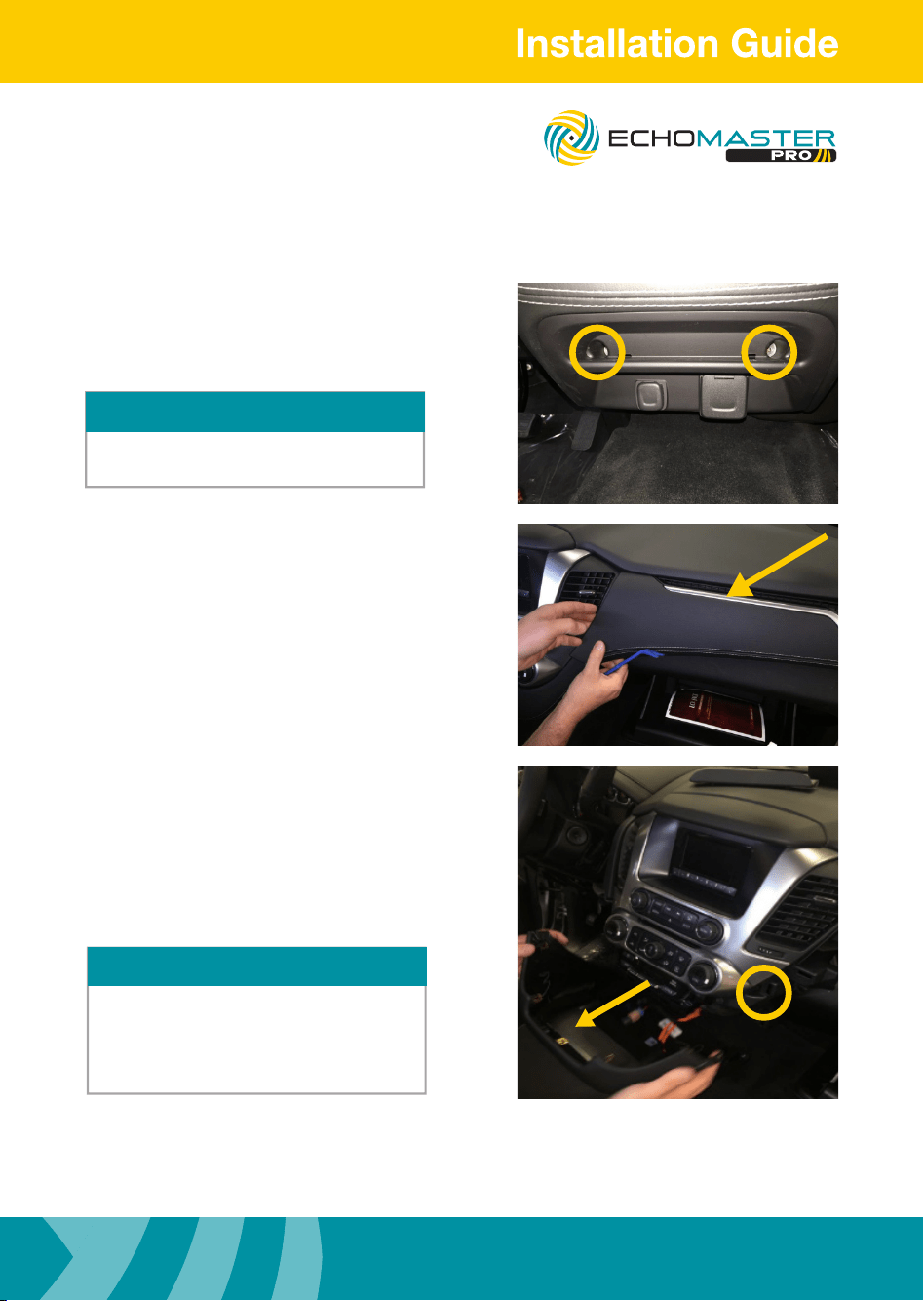
Removing the Dash
Step 1
Using a plastic dash removal tool,
remove driver side dash trim.
Step 2
Remove the 2 x T15 Torx screws.
FC-GMSUV101-MC
Integrated Safety System
5
Illustrations are typical and may not match exact vehicle details
email - [email protected] (US)
tel - 1-800-477-2267 (East Coast) - 1-888-883-2790 (West Coast)
email - [email protected] (Europe)
Illustrations are typical and may not match exact vehicle details
email - [email protected] (US)
tel - 1-800-477-2267 (East Coast) - 1-888-883-2790 (West Coast)
email - [email protected] (Europe)
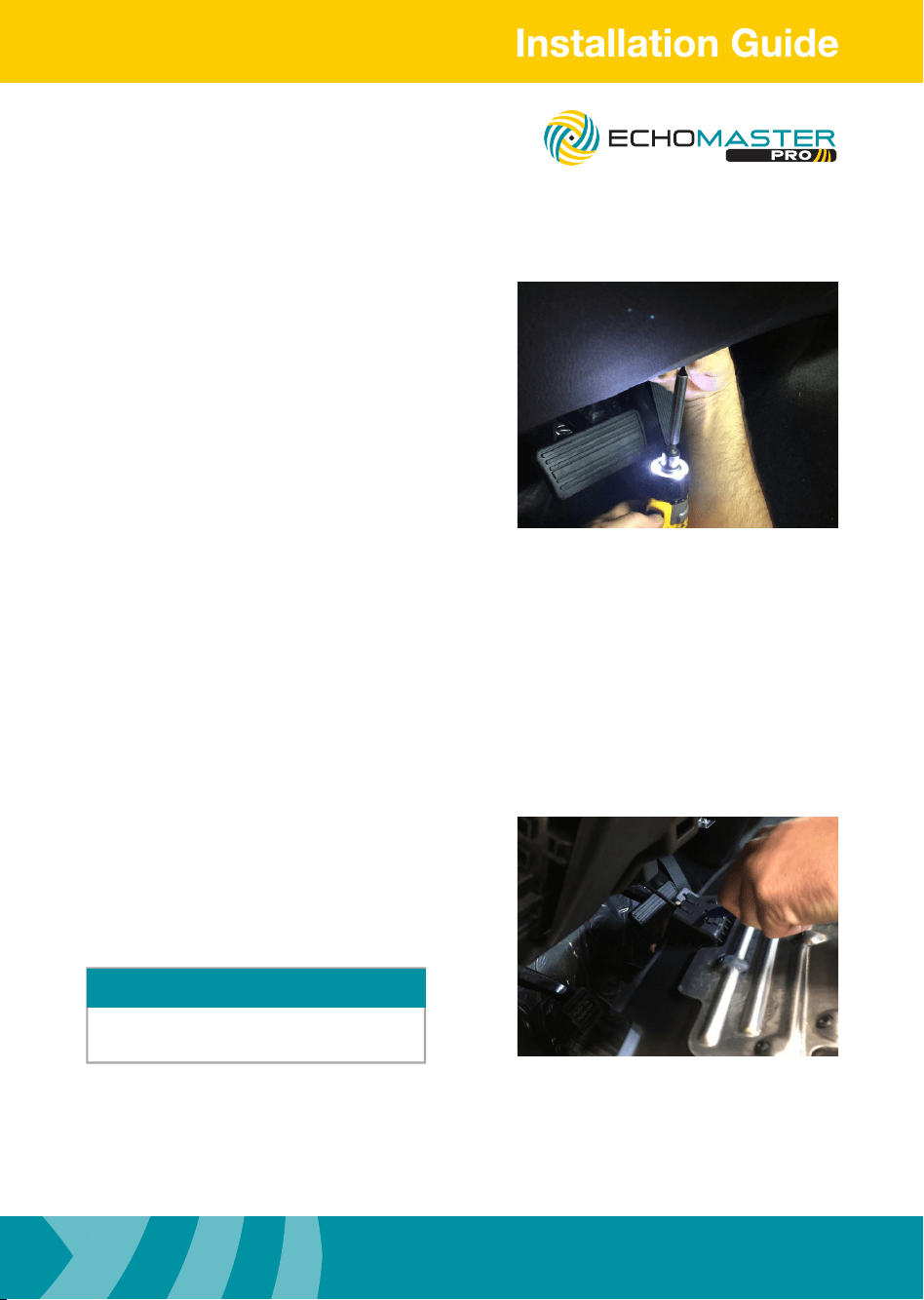
Removing the Dash
Step 3
Remove the T15 Torx screw under dash.
Step 4
Unhook the hood release lever.
Once lower dash piece is removed set aside
to avoid damage.
NOTE
FC-GMSUV101-MC
Integrated Safety System
Illustrations are typical and may not match exact vehicle details
email - [email protected] (US)
tel - 1-800-477-2267 (East Coast) - 1-888-883-2790 (West Coast)
email - [email protected] (Europe)
6
Illustrations are typical and may not match exact vehicle details
email - [email protected] (US)
tel - 1-800-477-2267 (East Coast) - 1-888-883-2790 (West Coast)
email - [email protected] (Europe)
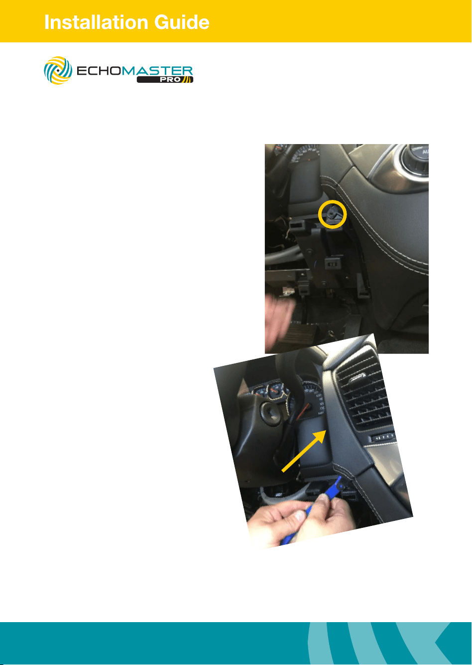
Removing the Dash
Steps 6 & 7
Remove the 7mm bolt.
Using a plastic dash removal tool, carefully
remove upper radio dash trim.
FC-GMSUV101-MC
Integrated Safety System
7
Illustrations are typical and may not match exact vehicle details
email - [email protected] (US)
tel - 1-800-477-2267 (East Coast) - 1-888-883-2790 (West Coast)
email - [email protected] (Europe)
Illustrations are typical and may not match exact vehicle details
email - [email protected] (US)
tel - 1-800-477-2267 (East Coast) - 1-888-883-2790 (West Coast)
email - [email protected] (Europe)
Step 10
Remove the 7mm bolt.
Remove lower dash underneath the A/C
controls by pulling away from dash.
Removing the Dash
Step 8
Locate and remove 2 x 7mm bolts from
lower pocket beneath radio.
This step is only for vehicles not equipped
with the center console.
NOTE
Step 9
Carefully remove upper passenger side
dash pad.
NOTE
If the vehicle is equipped with a center console
this step is not necessary.
Unclipping and removing the center console
cup holder trim is.
FC-GMSUV101-MC
Integrated Safety System
Illustrations are typical and may not match exact vehicle details
email - [email protected] (US)
tel - 1-800-477-2267 (East Coast) - 1-888-883-2790 (West Coast)
email - [email protected] (Europe)
8
Illustrations are typical and may not match exact vehicle details
email - [email protected] (US)
tel - 1-800-477-2267 (East Coast) - 1-888-883-2790 (West Coast)
email - [email protected] (Europe)
Removing the Dash
Step 11
Carefully disconnect the 12V & 110V harness.
Step 12
Carefully remove the upper radio dash pad,
pulling upward.
FC-GMSUV101-MC
Integrated Safety System
9
Illustrations are typical and may not match exact vehicle details
email - [email protected] (US)
tel - 1-800-477-2267 (East Coast) - 1-888-883-2790 (West Coast)
email - [email protected] (Europe)
Illustrations are typical and may not match exact vehicle details
email - [email protected] (US)
tel - 1-800-477-2267 (East Coast) - 1-888-883-2790 (West Coast)
email - [email protected] (Europe)
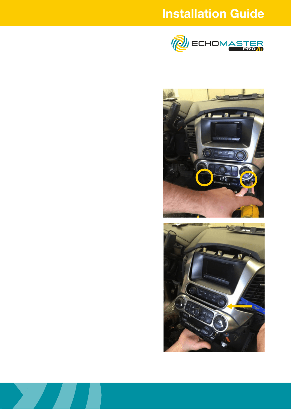
Removing the Dash
Step 13
Carefully remove 2 x 7mm bolts from
below the AC controls.
Step 14
Carefully release the radio/AC control bezel
from around the factory display screen, using
a nylon pry tool around the perimeter and
releasing away from the dash.
FC-GMSUV101-MC
Integrated Safety System
Illustrations are typical and may not match exact vehicle details
email - [email protected] (US)
tel - 1-800-477-2267 (East Coast) - 1-888-883-2790 (West Coast)
email - [email protected] (Europe)
10
Illustrations are typical and may not match exact vehicle details
email - [email protected] (US)
tel - 1-800-477-2267 (East Coast) - 1-888-883-2790 (West Coast)
email - [email protected] (Europe)
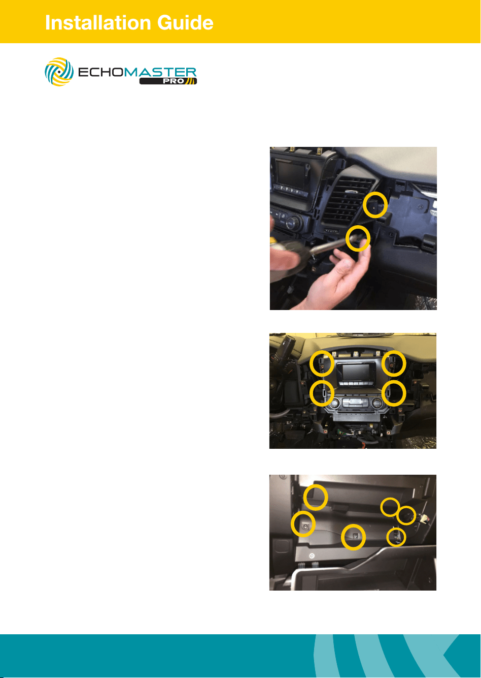
Removing the Dash
Step 15
With the radio bezel removed now remove
the 2 x 7mm bolts to release both driver &
passenger side vent ducts
Step 16
Remove 4 x 7mm bolts to release the factory
display.
Disconnect the factory display and set aside.
Step 17
Lower the glove box tray to expose the 6 x
Torx screws that secure the access panel.
Remove Torx screws and access panel.
FC-GMSUV101-MC
Integrated Safety System
11
Illustrations are typical and may not match exact vehicle details
email - [email protected] (US)
tel - 1-800-477-2267 (East Coast) - 1-888-883-2790 (West Coast)
email - [email protected] (Europe)
Illustrations are typical and may not match exact vehicle details
email - [email protected] (US)
tel - 1-800-477-2267 (East Coast) - 1-888-883-2790 (West Coast)
email - [email protected] (Europe)
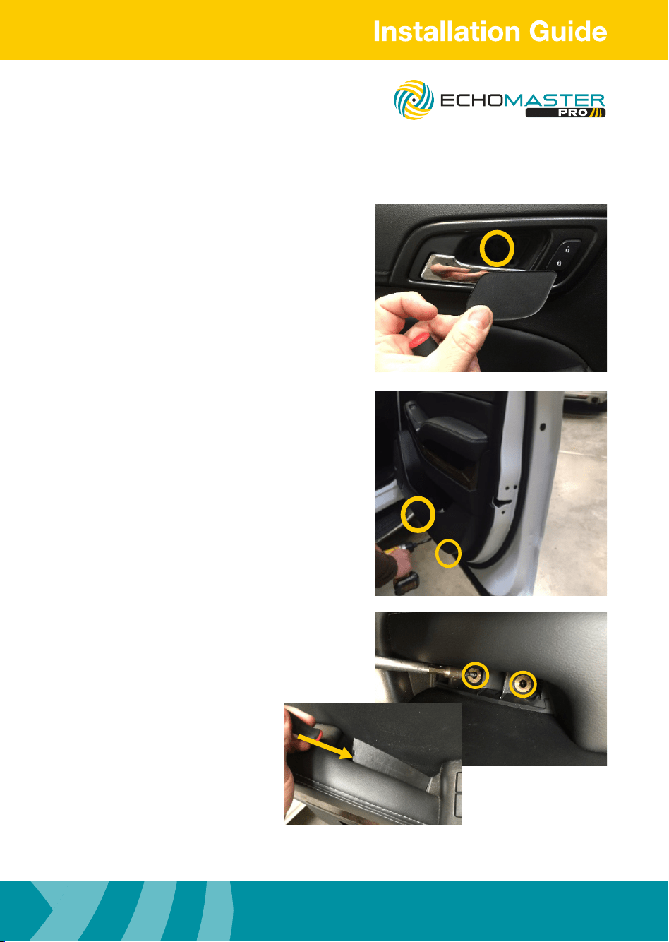
Removing the Door Panel(s)
Step 1
Remove the plastic cover from the door
release handle and remove the 1 x 7mm
bolt underneath.
Step 2
Remove the 2 x 7mm bolts from the bottom
of the door panel.
Step 3
Using a plastic trim removal tool, remove the
plastic cover from the armrest and set aside.
Once the trim is removed, remove the
2 x 7mm bolts found underneath
the trim.
FC-GMSUV101-MC
Integrated Safety System
Illustrations are typical and may not match exact vehicle details
email - [email protected] (US)
tel - 1-800-477-2267 (East Coast) - 1-888-883-2790 (West Coast)
email - [email protected] (Europe)
12
Illustrations are typical and may not match exact vehicle details
email - [email protected] (US)
tel - 1-800-477-2267 (East Coast) - 1-888-883-2790 (West Coast)
email - [email protected] (Europe)
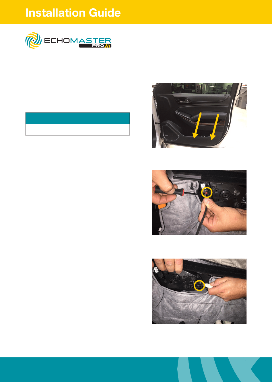
Removing the Door Panel(s)
Step 4
Pull straight towards you releasing all the clips.
Step 5
Release red lock tab from door wiring harness
and disconnect the harness.
Step 6
Unclip door handle release assembly by
pressing on top and removing cable from
handle assembly. Set the door panel aside.
Repeat these steps above for the opposite
door panel.
Top clips along the window are very tight
WARNING
FC-GMSUV101-MC
Integrated Safety System
13
Illustrations are typical and may not match exact vehicle details
email - [email protected] (US)
tel - 1-800-477-2267 (East Coast) - 1-888-883-2790 (West Coast)
email - [email protected] (Europe)
Illustrations are typical and may not match exact vehicle details
email - [email protected] (US)
tel - 1-800-477-2267 (East Coast) - 1-888-883-2790 (West Coast)
email - [email protected] (Europe)
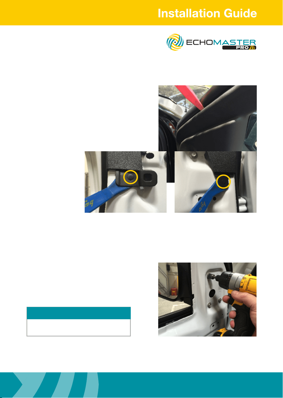
Removing the Door Panel(s)
Step 7
Remove plastic window bezel by removing
two plastic push pins and one clip located
in sail panel. Set plastic window bezel aside.
Repeat steps for opposite side door.
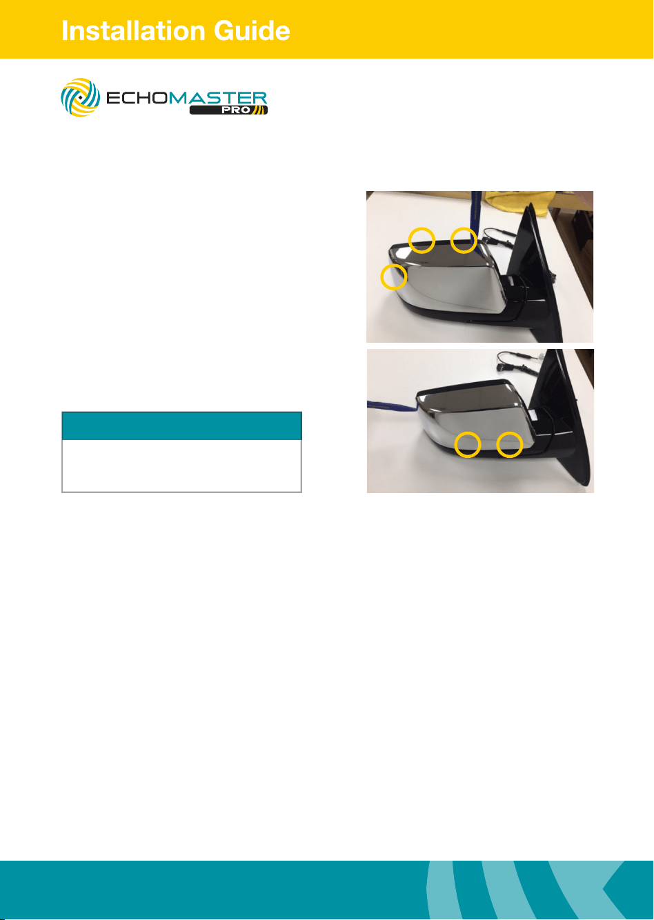
Step 8
Remove 3 x 10mm bolts from mirror assembly
(some models have 3 x 10mm bolts).
Remove mirror from door and set aside.
Disconnect the power mirror connector
before removing the mirror.
NOTE
FC-GMSUV101-MC
Integrated Safety System
Illustrations are typical and may not match exact vehicle details
email - [email protected] (US)
tel - 1-800-477-2267 (East Coast) - 1-888-883-2790 (West Coast)
email - [email protected] (Europe)
14
Illustrations are typical and may not match exact vehicle details
email - [email protected] (US)
tel - 1-800-477-2267 (East Coast) - 1-888-883-2790 (West Coast)
email - [email protected] (Europe)
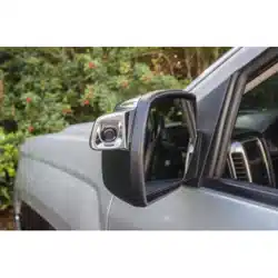
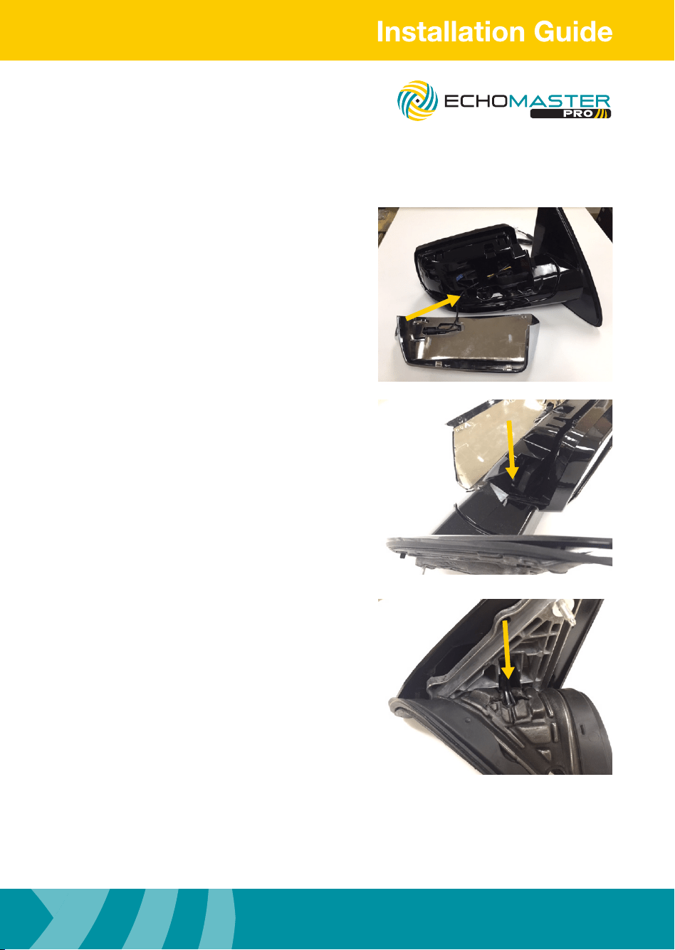
Removing the Mirror
NOTE
Using two plastic tools to work the cover off
is recommended. Be sure not to scar plastic
from mirror assembly.
Step 1
Using a plastic trim removal tool remove the
mirror cap from the mirror assembly.
There are 5 tabs holding the mirror cap on
to the mirror.
Press the pry tool in between the rear
cover and the front trim. Pry the two pieces
apart releasing the locking tabs.
FC-GMSUV101-MC
Integrated Safety System
15
Illustrations are typical and may not match exact vehicle details
email - [email protected] (US)
tel - 1-800-477-2267 (East Coast) - 1-888-883-2790 (West Coast)
email - [email protected] (Europe)
Illustrations are typical and may not match exact vehicle details
email - [email protected] (US)
tel - 1-800-477-2267 (East Coast) - 1-888-883-2790 (West Coast)
email - [email protected] (Europe)
Routing the Camera Harness
Step 1
Route the camera harness into the small
opening on the mirror towards the large
opening.
Route the camera harness into the channel
towards the hinge where the mirror mounts.
Using a zip tie taped to the camera harness
route the wire down through the hole in the
hinge.
Route the camera harness alongside the
factory wiring harness and secure with zip
ties
FC-GMSUV101-MC
Integrated Safety System
Illustrations are typical and may not match exact vehicle details
email - [email protected] (US)
tel - 1-800-477-2267 (East Coast) - 1-888-883-2790 (West Coast)
email - [email protected] (Europe)
16
Illustrations are typical and may not match exact vehicle details
email - [email protected] (US)
tel - 1-800-477-2267 (East Coast) - 1-888-883-2790 (West Coast)
email - [email protected] (Europe)
Routing the Camera Harness
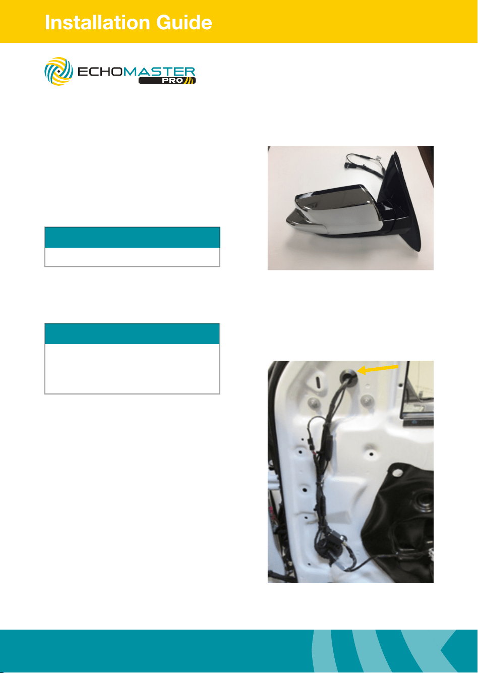
Step 4
Snap the EchoMaster mirror cap onto the
mirror assembly. Be sure all the cables are
safely tucked inside the mirror housing so
they do not get pinched.
NOTE
Be sure ALL the locking tabs have engaged
Routing the Camera Extension Harness
Step 1
Cut the rubber grommet to allow room for the
camera cable not to be pinched.
Route the camera cable along the factory wire
loom down towards the large round grommet.
Use zip ties to secure the camera cable in
place, looping it so the power supply and the
4 pin connector are along the factory wire
loom. Remove the speaker from the door
(1 x 7mm bolt secures the speaker at the top).
Disconnect the speaker harness from the
speaker and set it aside.
NOTE
The left side extension harness is longer than the
right side extension harness.
Left side extension harness part no: BSM3-SCEHL
Right side extension harness part no: BSM3-SCEHR
FC-GMSUV101-MC
Integrated Safety System
17
Illustrations are typical and may not match exact vehicle details
email - [email protected] (US)
tel - 1-800-477-2267 (East Coast) - 1-888-883-2790 (West Coast)
email - [email protected] (Europe)
Illustrations are typical and may not match exact vehicle details
email - [email protected] (US)
tel - 1-800-477-2267 (East Coast) - 1-888-883-2790 (West Coast)
email - [email protected] (Europe)
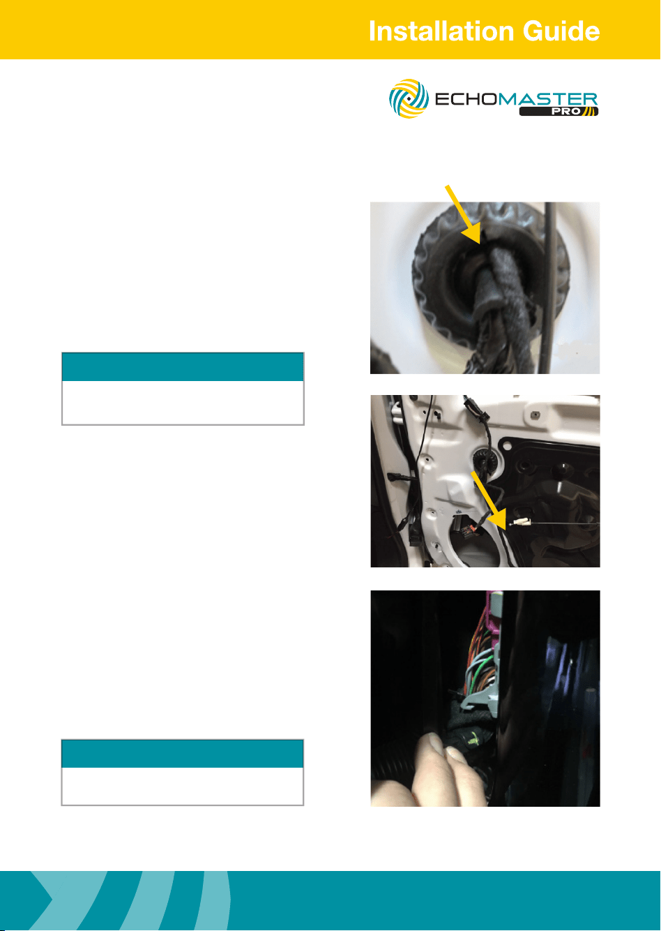
Routing the Camera Extension Harness
Step 2
Starting from inside door, route the four pin
connector of the cable through the round
factory grommet (must cut hole). Once the
cable is through connect it to the camera
connector from the mirror. Make sure to cut the
rubber grommet in a X fashion to allow room
for the 4 pin connector to t through.
Step 3
Route the cable along the factory wire loom
inside the door, using zip ties to secure to the
factory harness.
Be sure to avoid all moving parts.
Step 4
Route the cable through the rubber door
boot (easily done using a long zip tie taped
to harness). The wire should pass into the car
below the factory door connector.
Route the cable under the dash to the
appropriate connector on the main harness
extension. Use zip ties to secure wiring.
CAUTION
Use caution when feeding the 4 pin connector through
the boot. Be sure not to damage the connector or pull
pins from the plug.
TIP
Pull down on release lever to disengage connector,
this makes it easier to sh wire.
FC-GMSUV101-MC
Integrated Safety System
Illustrations are typical and may not match exact vehicle details
email - [email protected] (US)
tel - 1-800-477-2267 (East Coast) - 1-888-883-2790 (West Coast)
email - [email protected] (Europe)
18
Illustrations are typical and may not match exact vehicle details
email - [email protected] (US)
tel - 1-800-477-2267 (East Coast) - 1-888-883-2790 (West Coast)
email - [email protected] (Europe)
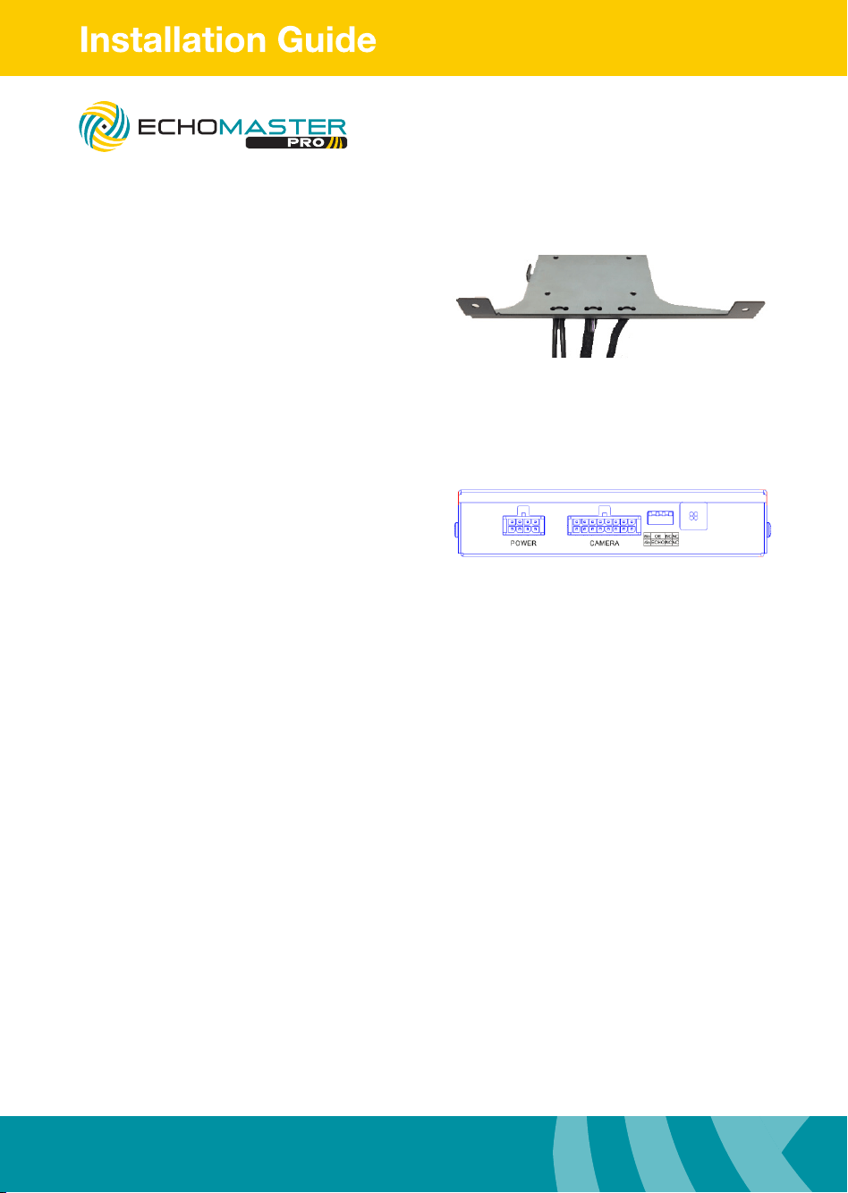
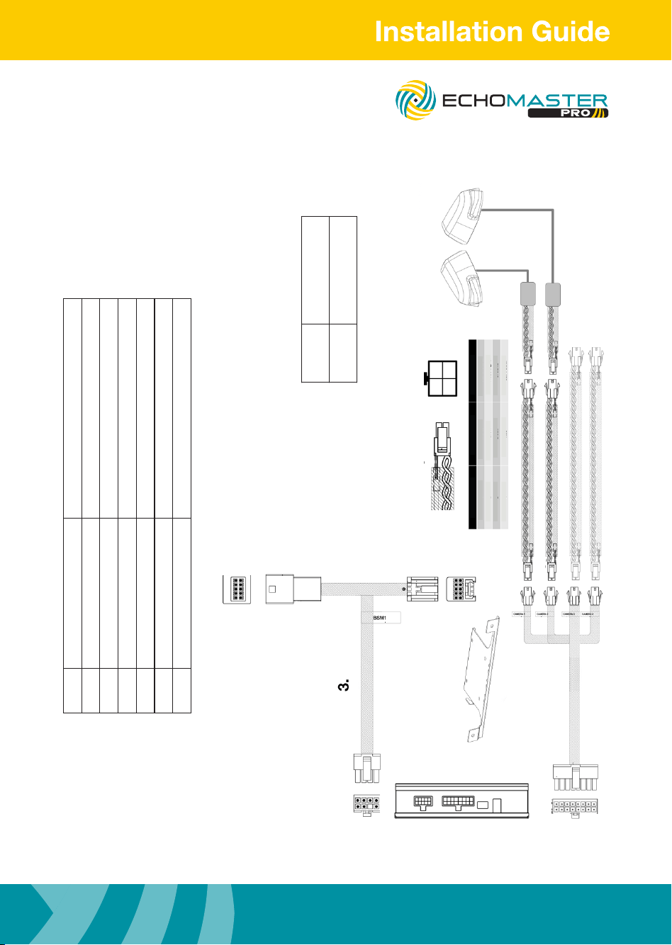
Mount Module to Bracket
Mount module to bracket using the
four provided M3 screws
Module Connections
Connect 8-pin power T-harness to module. Connect 16-pin main camera
extension cable to module. Fasten harnesses to the bracket using zip
ties through the holes provided.
Please select the size of the monitor
using dip switch 1
u Up for 8”
u Down for 4”
Please select the reverse camera input
option using dip switch 2
u Up for OEM installed tailgate camera
u Down for EchoMaster/aftermarket
camera.
When dip switch 2 is switched to ECHO
camera input 3 is automatically activated
when vehicle is switched into reverse gear.
Please select vehicle year using dip switch 3
u UP for 2015-2016 models
u Down for 2017
Dip switch 4 not used
u Up for normal operation
u Down for diagnostic mode
FC-GMSUV101-MC
Integrated Safety System
19
Illustrations are typical and may not match exact vehicle details
email - [email protected] (US)
tel - 1-800-477-2267 (East Coast) - 1-888-883-2790 (West Coast)
email - [email protected] (Europe)
Illustrations are typical and may not match exact vehicle details
email - [email protected] (US)
tel - 1-800-477-2267 (East Coast) - 1-888-883-2790 (West Coast)
email - [email protected] (Europe)
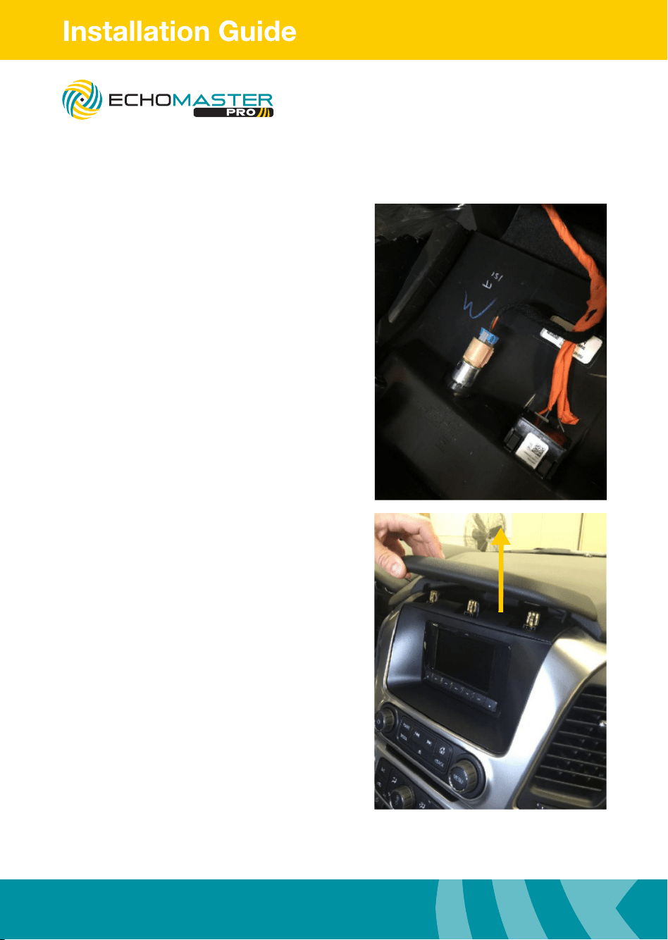
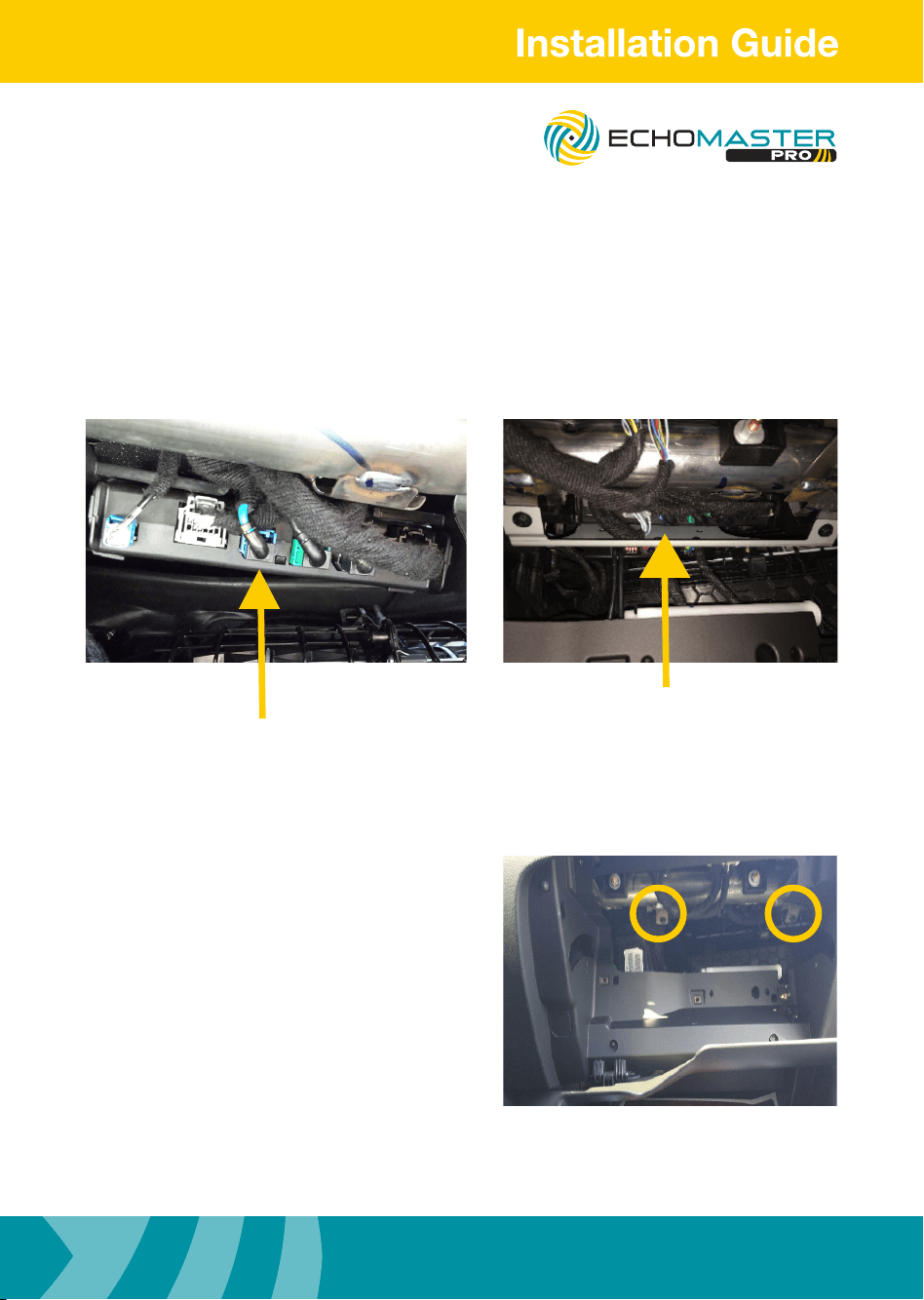
LVDS Connection
Locate HMI module in the upper portion of the glove box opening.
Disconnect the BLUE LVDS connector.
Connect the loose male LVDS connector into female EchoMaster connector.
Connect the male EchoMaster LVDS connector into HMI module.
Secure loose wiring with zipties.
Mounting Module
Step 1
Mount the module/bracket assembly
into place up behind the glove box using
2 x 7mm bolts to secure it.
FC-GMSUV101-MC
Integrated Safety System
Illustrations are typical and may not match exact vehicle details
email - [email protected] (US)
tel - 1-800-477-2267 (East Coast) - 1-888-883-2790 (West Coast)
email - [email protected] (Europe)
20
Illustrations are typical and may not match exact vehicle details
email - [email protected] (US)
tel - 1-800-477-2267 (East Coast) - 1-888-883-2790 (West Coast)
email - [email protected] (Europe)
Module Connections
Connect the 10 pin T-Harness behind the
radio display and route the 8 pin connecter
down to the module and connect it.
Route 16-pin main camera extension cable
below the dash closer to the center console
and connect the cameras.
Camera 1 = Drivers Door
Camera 2 = Passengers Door
Camera 3 = Optional Camera.
When dip switch 2 is switched to ECHO
camera input 3 is automatically activated
when vehicle is switched into reverse gear.
Camera 4 = Optional Camera
Re-install
Reinstall all removed panels and test
system.
8” version
Press and hold the “BACK” button for
three seconds to enter the user interface.
Use the touch screen to select the desired
view. Press the “BACK” button to return to
the previous screen.
4” version
Press and hold the “HOME” button for
three seconds to enter the camera view.
Press the “HOME” button for one
second to cycle through the views.
Press the “BACK” button to return to
the factory screen.
The camera is accessible after 7 seonds
while in reverse. Press and hold the
"BACK" button on the 8" and the
“HOME” button on the 4" to access.
PLEASE NOTE
FC-GMSUV101-MC
Integrated Safety System
21
Illustrations are typical and may not match exact vehicle details
email - [email protected] (US)
tel - 1-800-477-2267 (East Coast) - 1-888-883-2790 (West Coast)
email - [email protected] (Europe)
Illustrations are typical and may not match exact vehicle details
email - [email protected] (US)
tel - 1-800-477-2267 (East Coast) - 1-888-883-2790 (West Coast)
email - [email protected] (Europe)
Transmitter (TX) code pair key
Connect to +12V parking lamp
GND
(Factory ground point in the vehicle)
Camera
Receiver
Connect to extension cable
This EchoMaster system is designed for use with EchoMaster
cameras. When installing non-EchoMaster cameras it is possible
that the video image may not display correctly. If connecting a
non-EchoMaster camera to the system please use the diagram below
for wiring connection information.
2
3 4
1
Color Notes
1
2
3
4
Shield
Yellow
Black
Red
Video Signal
Video Signal
Ground
12v Power
***All connectors are viewed from wire side***
PIN
B1
B6
B5
B10
TO OEM CONNECTOR
C1 C5
C4 C8
A10
A5
A6
A1
OPTIONAL CAMERA
1
2
TO OEM MONITOR
4
5
6
D9 D1
D16 D8
PART 2
OPTIONAL CAMERA
Wiring Diagram
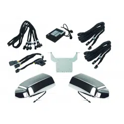
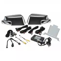
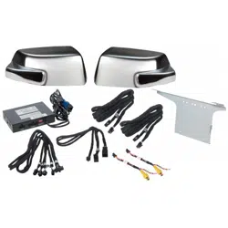
Part Number Description
1 FC-GMS-HD Main Interface Module
2 GMSWRBRKT-2 Main Interface Bracket
3 BSM3-PTH Power T-Harness
4 BSM1-CEH Camera Harness
5 BSM3-SCEHL SUV Left Side Camera Extension Harness
6 BSM3-WCEHR SUV Right Side Camera Extension Harness
Part
Number
Description
GMSUV SUV Mirror caps with
camera and power supply
FC-GMSUV101-MC
Integrated Safety System

Illustrations are typical and may not match exact vehicle details
email - [email protected] (US)
tel - 1-800-477-2267 (East Coast) - 1-888-883-2790 (West Coast)
email - [email protected] (Europe)
22
Illustrations are typical and may not match exact vehicle details
email - [email protected] (US)
tel - 1-800-477-2267 (East Coast) - 1-888-883-2790 (West Coast)
email - [email protected] (Europe)
NOTES:
FC-GMSUV101-MC
Integrated Safety System

23
Illustrations are typical and may not match exact vehicle details
email - [email protected] (US)
tel - 1-800-477-2267 (East Coast) - 1-888-883-2790 (West Coast)
email - [email protected] (Europe)
Illustrations are typical and may not match exact vehicle details
email - [email protected] (US)
tel - 1-800-477-2267 (East Coast) - 1-888-883-2790 (West Coast)
email - [email protected] (Europe)
NOTES:
FC-GMSUV101-MC
Integrated Safety System

AGREEMENT: End user agrees to use this product in compliance with the instructions and terms
of use above and with all State and Federal laws. EchoMaster provides instructions and safety
warnings with respect to this product and disclaims all liability for any use not in conformity with
those instructions or other misuse of its product. If you do not agree, please discontinue use
immediately and contact EchoMaster. This product is intended for off-road use and passenger
use only.
REV. 031617
15500 Lightwave Drive, Suite 202, Clearwater, Florida 33760
Unit 25B, Woolmer Way, Bordon, Hampshire, United Kingdom, GU35 9QE
email - [email protected] (US)
tel - 1-800-477-2267 (East Coast) - 1-888-883-2790 (West Coast)
email - [email protected] (Europe)
tel - +44(0)1420 487110 (sales) - +44(0)1420 470618 (technical)
EchoMaster is a Power Brand of AAMP Global.
EchoMaster.com