Read this manual carefully before operation
INSTRUCT ON MANUALI
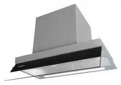
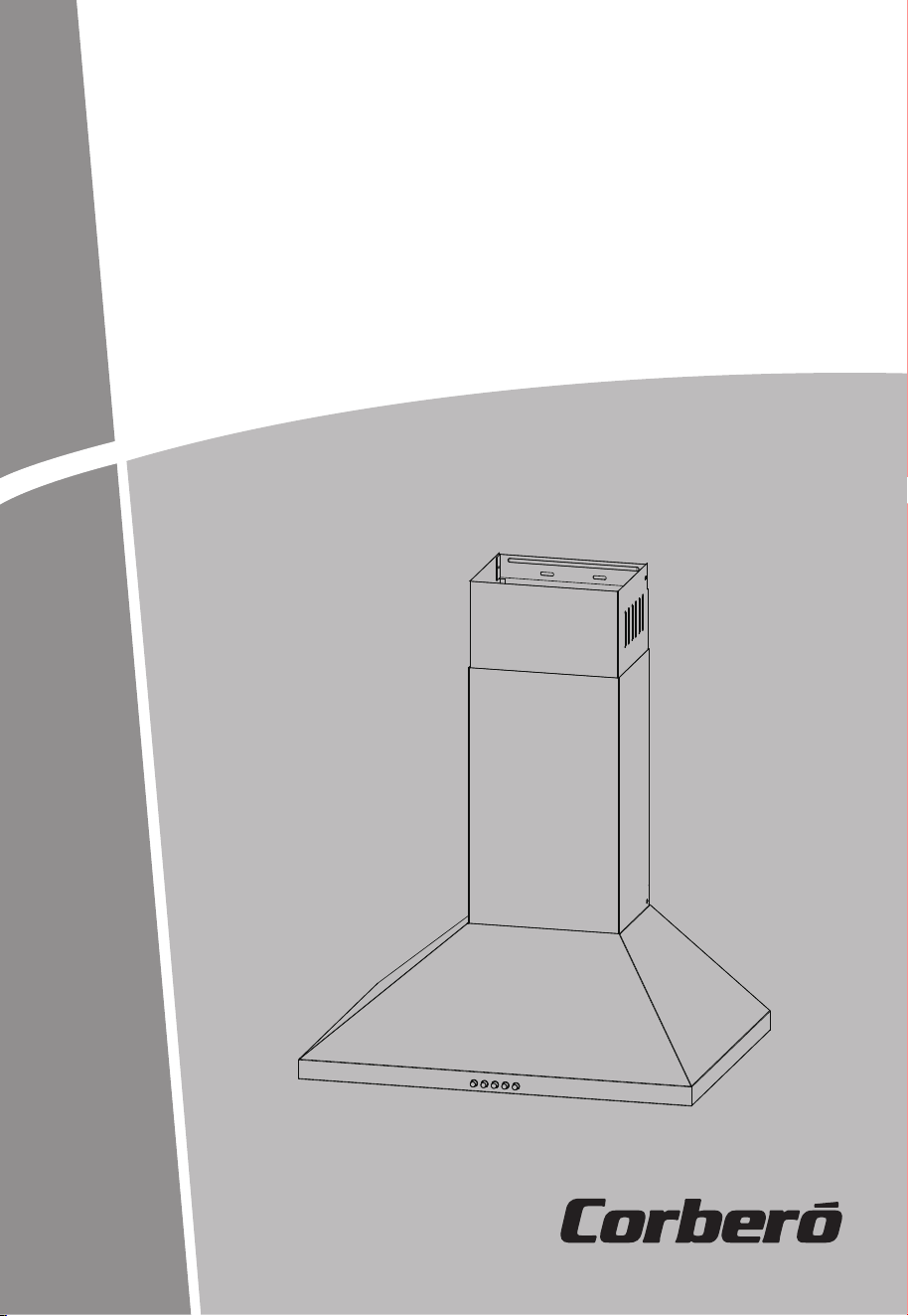
COOKER HOOD
Pictures in this manual are for reference only, the product in kind prevail.
CCMD60320PD
RECOMMENDATIONS AND SUGGESTIONS
The instructions for Use apply to several versions of this appliance. Accordingly, you
may find descriptions of individual features that do not apply to your specific appliance.
INSTALLATION
The manufacturer will not be held liable for any damages resulting from incorrect or
improper installation.
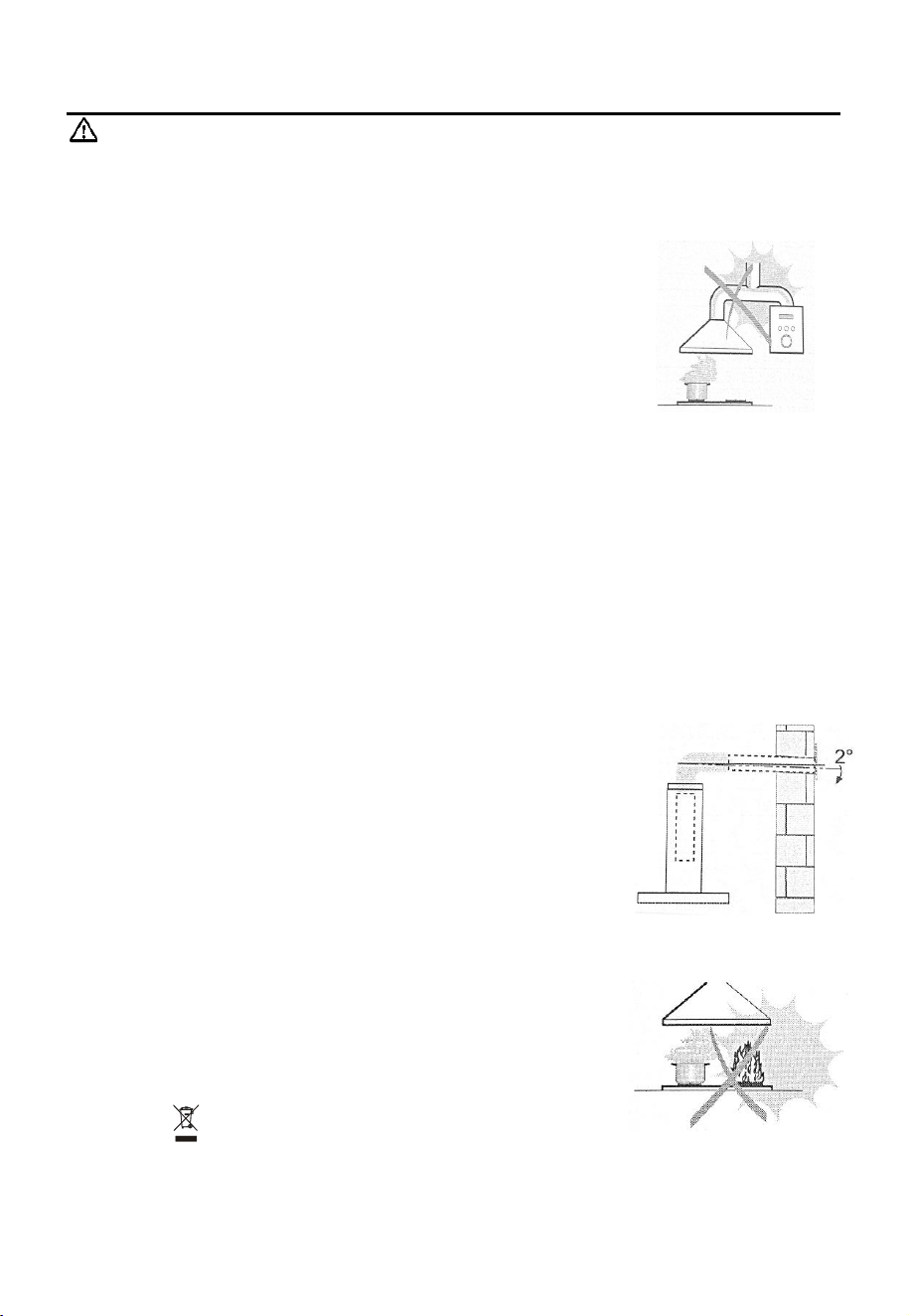
The minimum distance between the supporting surface for the cooking vessels on the
hob and the lowest part of the range hood. ( When the range hood is located above a
gas appliance, this distance shall be at least 65 cm. If the instructions for installation for
the gas hob specify a greater distance, this has to be taken into account. The distance of
65 cm can be reduced for:non-combustible parts of range hoods, and
parts operating at
safety extra low voltage,Provided these parts do not give access to live parts if deformed ;)
Che
ck t
h
at the mains voltage corresponds to that indicated on the rating plate fixed to
the hood.
For Class I appliances, check that the domestic power supply guarantees adequate
earthing.
Connect the extractor to the exhaust flue through a pipe of minimum diameter 120mm.
The route of the flue must be as short as possible.
The air must not be discharged into a flue that is used for exhausting fumes from
appliances burning gas or other fuels.
If the extractor is used in conjunction with non-electrical appliances (e.g. gas burning
appliances),a sufficient degree of aeration must be guaranteed in the room in order to
prevent the backflow of exhaust gas. The kitchen must have an opening
communicating directly with the open air in order to guarantee the entry of clean air.
When the cooker hood is used in conjunction with appliances supplied with energy
other than electric, the negative pressure in the room must not exceed 0,04 mbar to
prevent fumes being drawn back into the room by the cooker hood.
z
If the supply cord is damaged, it must be replaced by the manufacturer, its service agent
or similarly qualified persons in order to avoid a hazard.
Regulations concerning the discharge of air have to be fulfilled.
USE
z The cooker hood is only for home use, not suitable for barbecue, roast shop and other commercial purposes.
Never use the hood for purposes other than for which it has been designed.
Never leave high naked flames under the hood when it is in operation.
Adjust the flame intensity to direct it onto the bottom of the pan only, making sure that
it does not engulf the sides.
Deep fat fryers must be continuously monitored during use: overheated oil can burst
into flames.
Do not flame under the range hood; risk of fire.
This appliance can be used by children aged from 8 years and above and persons
with reduced physical, sensory or mental capabilities or lack of experience and
knowledge if they have been given supervision or instruction concerning use of the
appliance in a safe way and understand the hazards involved.
Children should be supervised to ensure that they do not play with the appliance.
Cleaning and user maintenance shall not be made by children without supervision.
“CAUTION: Accessible parts may becom
e hot when used with cooking appliance
s”.
MAINTENANCE
Switch off or unplug the appliance from the mains supply before carrying out any
maintenance work.
Clean and/or replace the Filters after the specified period (Fire hazard).
Clean the hood using a damp cloth and a neutral liquid detergent.
The appliance uses 4 hob elements at most.
The cooker hood and its filter should be cleaned regularly according to the instruction.
The symbol is packaging indicates that this product may not be treated as household
waste. Instead it shall be handed over to the applicable collection point for the recycling of
electrical and electronic equipment. By ensuring this product is disposed of correctly, you
will help prevent potential negative consequences for the environment and human health,
which could otherwise be caused by inappropriate waste handling of this product. For more
detailed information about recycling of this product, please contact your local city office,
your household waste disposal service or the shop where you purchased the product.
EN-2
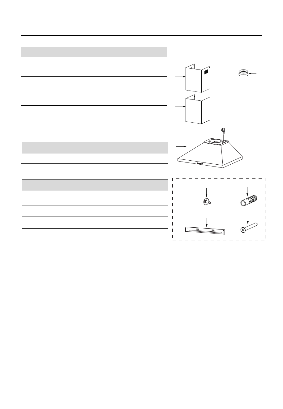
COMPONENTS
Ref.
Qty.
Product Components
1
1
Hood Body, complete with: Controls, Light,
Blower, Filter.
2.1
1
Lower Decorative Chimney
2.2
1
Upper Decorative Chimney ( optional )
3
1
Flange ( optional )
Ref.
Qty
.
Installation Components
10 7 Screws 5 x 50
11 7
Wall Plugs
12 6
Screws 4,2 x 9,5 / Screws 4 x8
21 1
Chimney fixing bracket ( optional )
Qty.
Documentation
1 Instruction Manual
2.2
3
2.1
1
12
11
10
21
EN-3
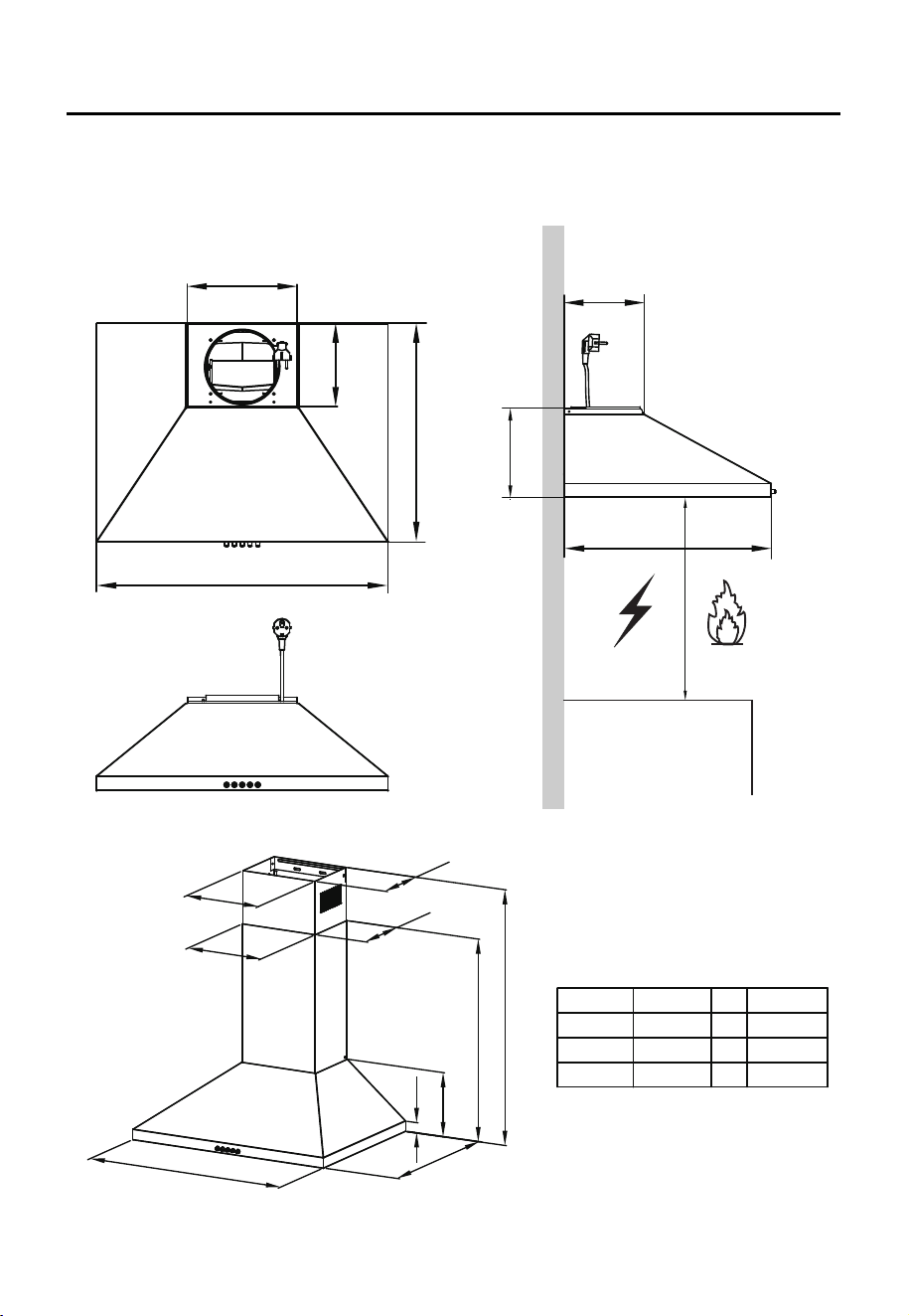
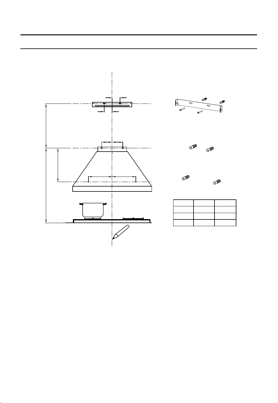
DIMENSIONS
225
171
448
598
Option Chimney A B
1
400+0
569
/
2
400+300
569
610-850
3
400+390
569
610-940
Min.
650mm
Min.
650mm
171
30
448
179
A
B
179
226
229
598
170
172
448
unit:mm
EN-4

INSTALLATION
WALL DRILLING AND BRACKET FIXING
As a first step, proceed with the following drawings:
A vertical line up to the ceiling or up to the upper limit, at the center of the area in which the
hood is to be fitted.
A horizontal line A at 835-935 mm above the cooker top.
A horizontal line B at a X mm above the horizontal line A.
A horizontal line C at a 116mm below the horizontal line A.
Mark Points:
Mark a point (1) on the horizontal line A, 80 mm to the vertical reference line.
Repeat this operation on the other side , checking that the two marks are leveled.
Mark a point (2) on the horizontal line B, 40 mm to the vertical reference line.
Repeat this operation on the other side , checking that the two marks are leveled.
80
80
40
40
835-935
A
B
(1)
(2)
X
C
155
155
(3)
116
Option Chimney X
1
400+0
/
2
400+300
410-650
3
400+390
410-740
Mark a point (3) on the horizontal line C, 155 mm to the vertical reference line.
Repeat this operation on the other side , checking that the two marks are leveled.
Vertical reference line
EN-5

Fix the brackets (Optional):
Right
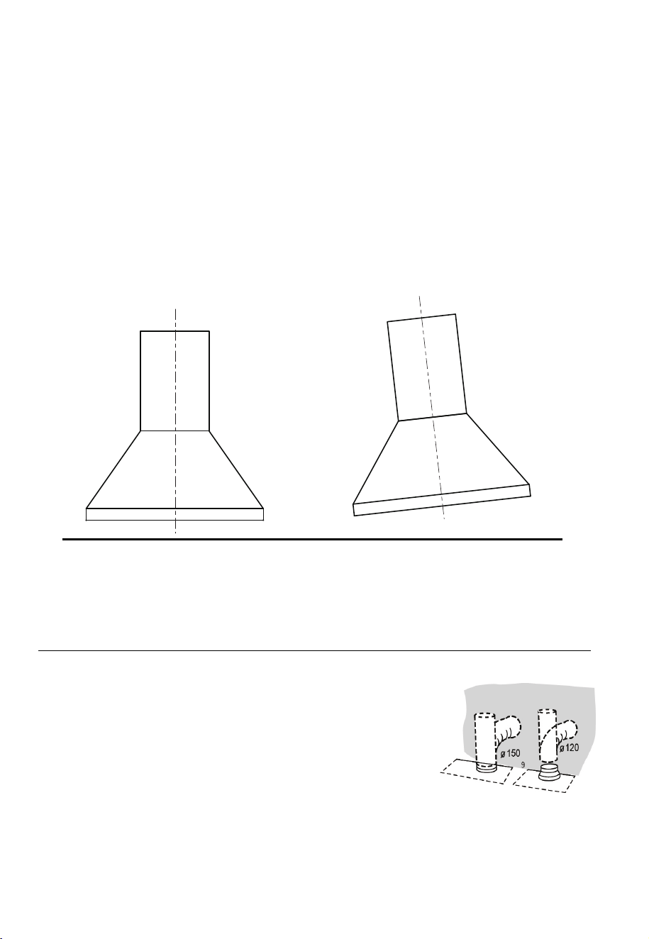
DUCTED VERSION AIR EXHAUST SYSTEM
When installing the ducted version, connect the hood to the chimney
using either a flexible or rigid pipe ɸ
150 or ɸ 120 mm, the choice of
w
hich is left to the installer.
If to install a ɸ 120 mm air exhaust connection, insert the reducer
fl
ange 3
on the h
ood bod
y
outl
et.
Fix the pi
pe
4
i
n
pos
i
ti
on us
i
ng s
u
fficient pipe clamps (not
supplied).
Remov
e pos
s
i
bl
e c
harcoa
l
fi
l
ters.
Wrong
Drill holes at the marked points with a ɸ10 mm drill bit.
Insert the Wall Plugs 11 into the holes.
Fix a Chimney fixing bracket 21 with 2 screws 10 (5 x 50) at the horizontal line B.
Hook the hood body
Hook the hood body to the 2 screws 10 (5 x 50) at the horizontal line A.
Level the hood body itself.
Remove the filter from the inside of the hood body, fix the screws 10 to Wall Plugs 11 at the
points (3).
CONNECTIONS
Screw 2 screws 10 (5 x 50) to Wall Plugs 11 at the horizontal line A; approximately the four fifth
length of the screws 10 (5 x 50) was screwed into the Wall Plugs 11, used for hook the hood.
EN-6
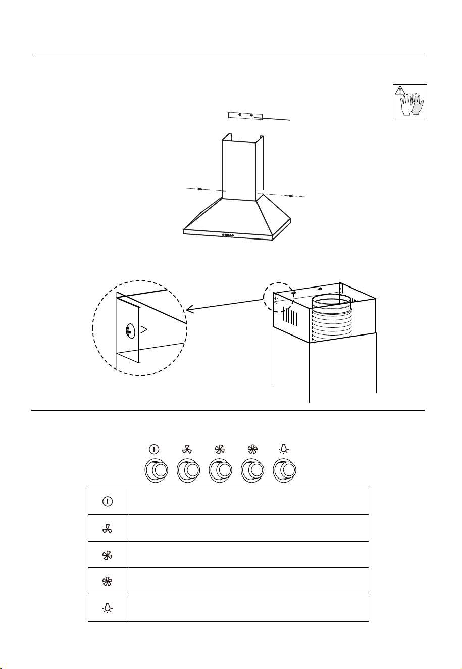
CHIMNEY ASSEMBLY
The chimney can only be installed with exhausting hood.
Lower Decorative Chimney
Fix the Lower Decorative Chimney to the hood body with 2 screws 12 (4.2 x 9.5)
supplied with the hood.
Upper Decorative Chimney
Fix the upper chimney onto the bracket 21 with 2 screws 12 (4.2 x 9.5) supplied with the hood.
B
USE
ON/OFF LIGHTING SWITCH: Press on this switch to turn on the
lights, and press again to turn them off.
OFF MOTOR SWITCH: Press on this switch to stop the motor
operation.
SPEED SWITCH: Press on this switch, the motor runs at LOW
speed.
SPEED SWITCH: Press on this switch, the motor runs at
MEDIUM speed.
SPEED SWITCH: Press on this switch, the motor runs at HIGH
speed.
Speed adjustment.
EN-7
MAINTENANCE
GREASE FILTERS
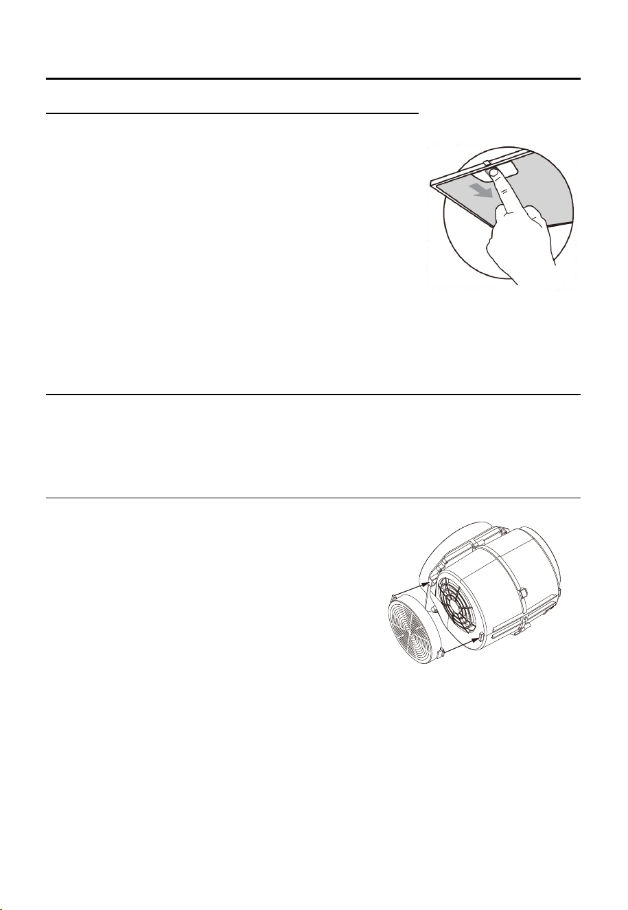
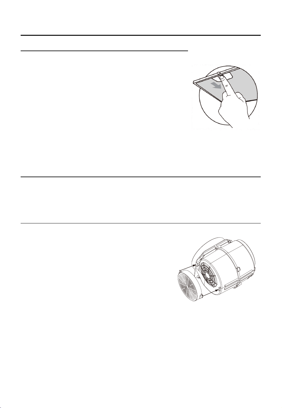
CLEANING METAL SELF-SUPPORTING GREASE FILTERS
The filters must be cleaned every 2 months of operation, or
more frequently for particularly heavy usage, and can be
washed in a dishwasher.
Remove the filters one by one pushing them towards the back
side of the hood unit and simultaneously pulling downwards.
Any kind of bending of the filters has to be avoided when
washing them. Before fitting them again into the hood make sure
that they are completely dry. (The color of the filter surface may
change throughout the time but this has no influence to the filter
efficiency).
When fitting the filters into the hood pay attention that they are
mounted in correct position , the handle facing outwards.
ACTIVATED CHARCOAL FILTER (RECIRCULATION VERSION)
These filters are not washable and cannot be regenerated, and must be replaced approximately
every 4 months of operation, or more frequently with heavy usage.
REPLACING THE ACTIVATED CHARCOAL FILTER
Remove the metal grease filters
Remove the saturated activated charcoal filter.
Fit the new filters.
Replace the metal grease filters.
EN-8
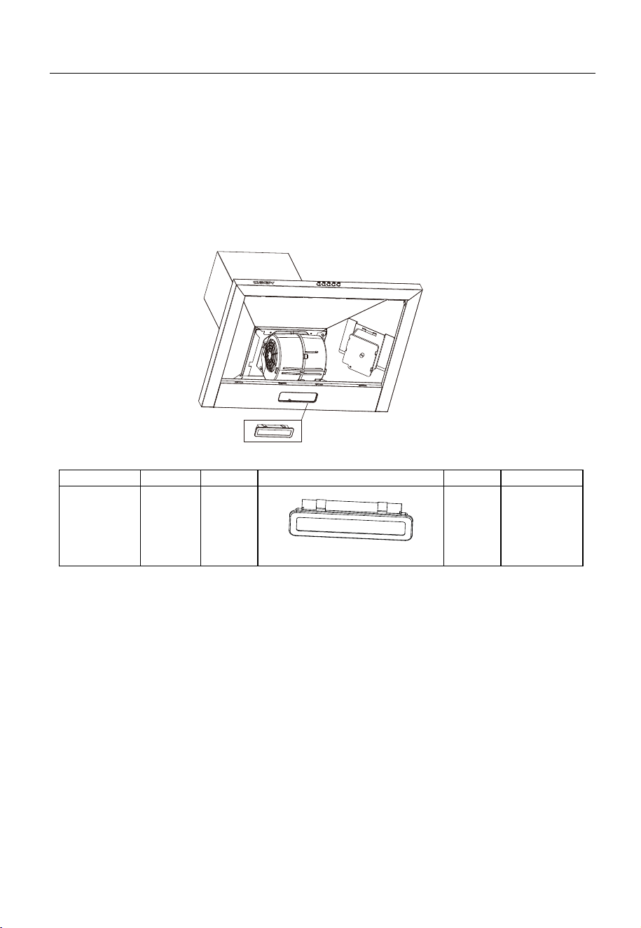
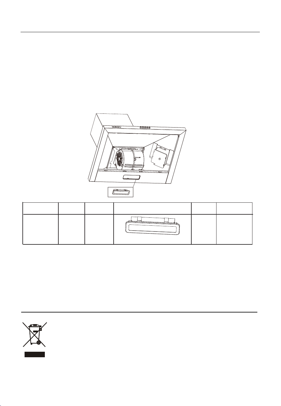
Remove the grease filter.
Remove the light by levering its fitting from the hood body (this may require pressure or force to be
applied).
Disconnect the connector of the light.
Replace the light with a new one of the same type,making sure that you connect the light with the
light cable correctly.
Reconnect the power by inserting the mains plug or by switching on the fuse.
For rectangular LED :
Max power Voltage Picture Lamp Cap ILCOS D code
1.5W 220V-240V
Square/Diameter:33.2mmx120mm
Self-ballasted
LED modules
DBS-1.5-
H-33.2/120
LIGHTING
LIGHT REPLACEMENT
EN-9
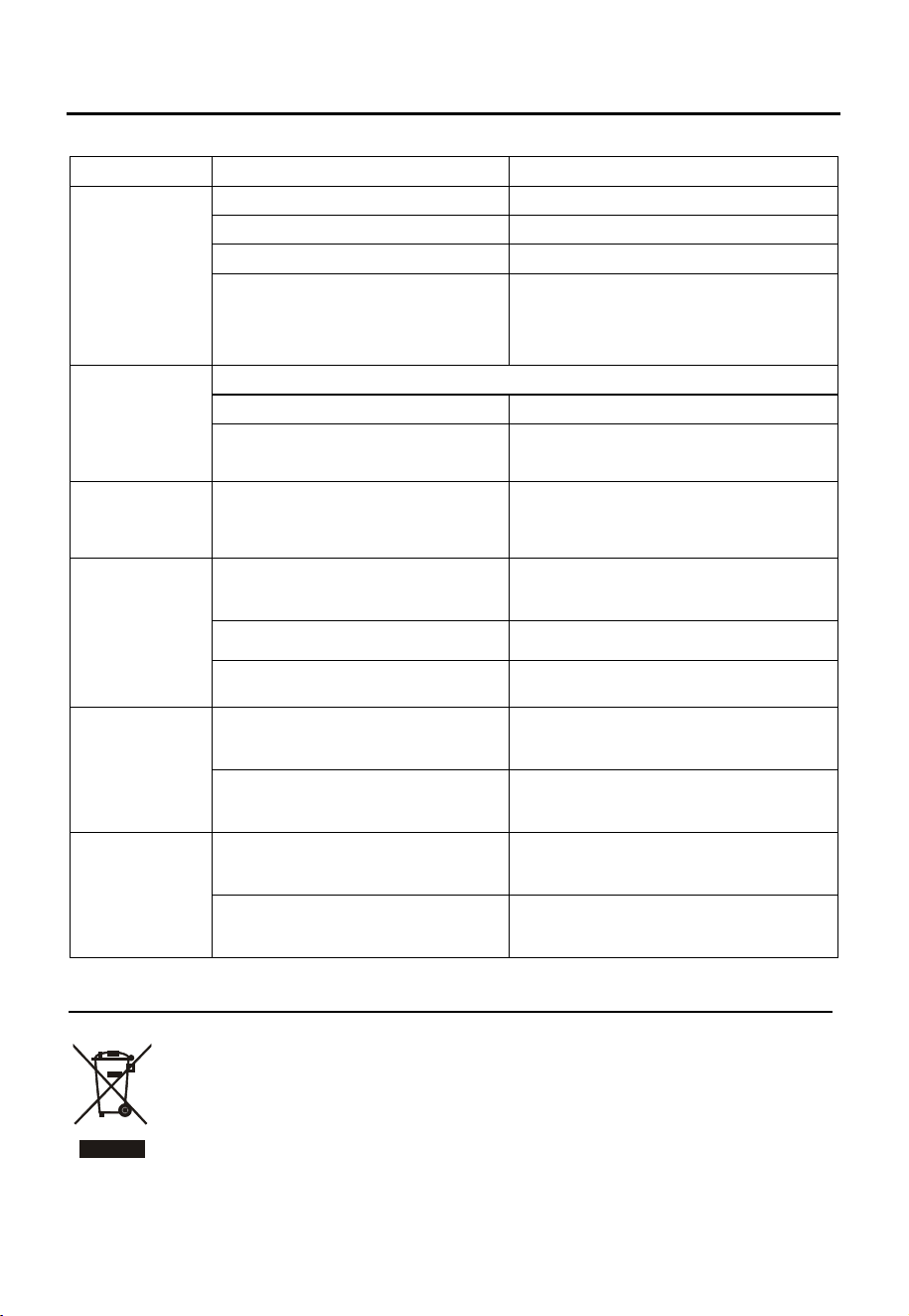
TROUBLE SHOOTING
Fault Cause Solution
Light on, but
motor does not
work
The blades are blocked.
The capacitor is damaged. Replace capacitor.
The motor is damaged. Replace motor.
The internal wiring of motor is cut off/
disconnected. An unpleasant smell
may be produced.
Replace motor.
Both light and
motor do not
work
Apart from the above mentioned, check the following:
Light damaged. Replace lights.
Power cord loose.
Connect the wires as the electric
diagram.
Oil leakage
Outlet and the air ventilation entrance
are not tightly sealed.
Take down the outlet and seal with glue.
Vibration
The blade, if damaged, can cause
vibrating.
Replace the blade.
The motor is not tightly fastened. Fasten the motor tightly.
The cooker hood is not tightly fixed. Fixed the cooker hood tightly.
Insufficient
suction
The distance between the cooker
hood and the cooker top is too large.
Readjust the distance.
Too much ventilation from open doors
or windows.
Choose a new place to install the
appliance or close some doors / windows.
The
machine
inclines
The fixing screws are not tight
enough.
Tighten the fixing screw and make it
horizontal.
The hanging screws are not tight
enough
Tighten the hanging screw and make it
horizontal.
Check the blades.
DISPOSAL OF OLD ELECTRICAL APPLIANCES
The European directive 2012/19/EU on Waste Electrical and Electronic Equipment (WEEE), requires that old
household electrical appliances must not be disposed of in the normal unsorted municipal waste stream. Old
appliances must be collected separately in order to optimize the recovery and recycling of the materials they contain,
and reduce the impact on human health and the environment.
The crossed out “wheeled bin” symbol on the product reminds you of your obligation, that when you dispose of the
appliance, it must be separately collected.
Consumers should contact their local authority or retailer for information concerning the correct disposal of their old
appliance.
EN-10

RECOMENDACIONES Y SUGERENCIAS
Las instrucciones de uso se aplican a varias versiones de este dispositivo. En consecuencia, puede
encontrar descripciones de características individuales que no se aplican a su dispositivo específico.
INSTALACIÓN
•El fabricante no será responsable por los daños que resulten de una instalación
incorrecta o inapropiada.
• La distancia mínima entre la superficie de apoyo para los recipientes de cocción en la
encimera y la parte más baja de la campana. (Cuando la campana extractora se
encuentra sobre un artefacto a gas, esta distancia debe ser de al menos 65 cm. Si las
instrucciones de instalación de la placa de gas especifican una distancia mayor, esto
debe tenerse en cuenta. La distancia de 65 cm puede ser reducido por: piezas no
combustibles de campanas extractoras, y piezas que funcionan a un voltaje extra bajo de
seguridad, siempre que estas piezas no den acceso a las partes activas si están
deformadas)
• Compruebe que la tensión de red corresponda a la indicada en la placa de
características fijada a la campana.
• Para aparatos Clase I, verifique que la fuente de alimentación doméstica garantice
una conexión a tierra adecuada.
• Conecte el extractor al tubo de escape a través de un tubo de 120 mm de diámetro
mínimo. La ruta de la chimenea debe ser lo más corta posible.
• El aire no debe descargarse en una chimenea que se utiliza para extraer los humos de
los aparatos que queman gas u otros combustibles.
• Si el extractor se utiliza junto con aparatos no eléctricos (por ejemplo, aparatos que
queman gas), se debe garantizar un grado suficiente de aireación en la habitación para
evitar el reflujo de los gases de escape. La cocina debe tener una abertura que
comunique directamente con el aire libre para garantizar la entrada de aire limpio. Cuando
la campana de cocina se usa junto con otros aparatos que reciben energía que no sea
eléctrica, la presión negativa en la habitación no debe exceder los 0,04 mbar para evitar
que la campana de la cocina arrastre los vapores hacia la habitación.
• Si el cable de alimentación está dañado, debe ser reemplazado por el fabricante, su
agente de servicio o personas con cualificaciones similares para evitar un peligro.
• Se deben cumplir las normas relativas a la descarga de aire.
USO
La campana extractora es solo para uso doméstico, no adecuada para asados y otros fines comerciales.
•Nunca use la campana extractora para otros fines que no sean para los que fue diseñada.
•Nunca deje llamas altas debajo de la campana cuando está en funcionamiento.
•Ajuste la intensidad de la llama para dirigirla solo a la parte inferior de la sartén,
asegurándose de que no sobresale de los lados.
•Las freidoras de grasa deben controlarse continuamente durante el uso: el aceite
sobre-calentado puede incendiarse.
•No flamear debajo de la campana extractora; riesgo de fuego.
•Este dispositivo puede ser utilizado por niños a partir de 8 años y personas con capacidades físicas,
sensoriales o mentales reducidas o por falta de experiencia y conocimiento, si se les
ha dado supervisión o instrucciones sobre el uso del dispositivo de manera segura y
entienden el peligro involucrado
•Los niños deben ser supervisados para asegurarse de que no jueguen con el aparato.
•Las tareas de limpieza y el mantenimiento no deben ser realizadas por niños sin supervisión.
“PRECAUCIÓN: las partes accesibles pueden calentarse cuando se usan con aparatos de
cocina”.
MANTENIMIENTO
•La campana de cocina y su filtro deben limpiarse regularmente de acuerdo con las
instrucciones.
•Apague o desenchufe el aparato de la red eléctrica antes de realizar cualquier trabajo de
mantenimiento.
•Limpie y / o reemplace los filtros después del período especificado (riesgo de incendio).
•Limpie la campana con un paño húmedo y un detergente líquido neutro.
•El aparato utiliza 4 elementos de encimera como máximo.
El símbolo en el embalaje indica que este producto no puede ser tratado como basura doméstica. En su lugar, se
entregará al punto de recolección correspondiente para el reciclaje de equipos eléctricos y electrónicos. Al asegurarse de que
este producto se elimine correctamente, ayudará a evitar posibles consecuencias negativas para el medio ambiente y la salud
humana, que de otro modo podrían ser causadas por el manejo inadecuado de los desechos de este producto. Para obtener
información más detallada sobre el reciclaje de este producto, comuníquese con la oficina local de su ciudad, con el servicio
de eliminación de desechos domésticos o con la tienda donde adquirió el producto.
ES-2

COMPONENTES
Ref.
Qty.
Componentes del producto
1
1
Cuerpo de la campana, completo con:
Controles, Luz, motor, Filtro.
2.1
1
Chimenea decorativa inferior
2.2
1
Chimenea decorativa superior (opcional)
3
1
Adaptador de tubo de extracción (opcional)
Ref.
Qty
.
Componentes de instalación
10 7 Tornillos 5 x 50
11 7
Tacos de pared
12 6
Tornillos 4,2 x 9,5 / Tornillos 4 x8
21 1
Soporte de fijación para chimenea (opcional)
Qty.
Documentación
1 Manual de instrucciones
2.2
3
2.1
1
12
11
10
21
ES-3

DIMENSIONES
225
171
448
Opción Chimenea
A B
1
400+0
569
/
2
400+300
569
610-850
3
400+390
569
610-940
Min.
650mm
Min.
650mm
171
30
448
179
A
B
179
226
229
170
172
448
unidad:mm
ES-4
598
598
INSTALACIÓN
PERFORACIÓN DE PAREDES Y FIJACIÓN DE SOPORTE
Como primer paso, proceda con los siguientes dibujos:
•Una línea vertical hasta el techo o hasta el límite superior, en el centro del área en la que
se instalará la campana.
•Una línea horizontal A a 835-935 mm por encima de la parte superior de la cocina.
•Una línea horizontal B a X mm por encima de la línea horizontal A.
•Una línea horizontal C a 116 mm por debajo de la línea horizontal A.
Puntos de marca:
80
80
40
40
835-935
A
B
(1)
(2)
X
C
155
155
(3)
116
Opción Chimenea
X
1
400+0
/
2
400+300
410-650
3
400+390
410-740
•Marque un punto (1) en la línea horizontal A, 80 mm a la línea de referencia vertical.
•Repita esta operación en el otro lado, verificando que las tres marcas estén niveladas.
•Marque un punto (2) en la línea horizontal B, 40 mm a la línea de referencia vertical.
•Repita esta operación en el otro lado, verificando que las dos marcas estén niveladas.
•Marque un punto (3) en la línea horizontal C, 155 mm a la línea de referencia vertical.
•Repita esta operación en el otro lado, verificando que las dos marcas estén niveladas.
Línea de referencia vertical
ES-5
Fijar los soportes (opcional):
Correcto
SISTEMA DE ESCAPE DE AIRE
Al instalar los conductos de ventilación, conecte la campana a la
chimenea utilizando un tubo flexible o rígido de ɸ 150 o ɸ 120 mm,
cuya elección se deja al instalador.
•Si desea instalar una conexión de escape de aire de ɸ 120
mm, inserte la brida reductora 3 en la salida del cuerpo de la
campana.
•Fije el tubo 4 en su posición utilizando suficientes abrazaderas
de tubo (no suministradas).
•Eliminar posibles filtros de carbón.
Incorrecto
•Perfore orificios en los puntos marcados con una broca de ɸ10 mm.
•Inserte los Tacos de Pared 11 en los orificios.
•Atornille 2 tornillos 10 (5 x 50) a los Tacos de Pared 11 en la línea horizontal A; los cuatro
quintos de longitud de los tornillos 10 (5 x 50) se atornillaron en los Tacos de Pared 11.
•Fije un soporte de fijación para chimenea 21 con 2 tornillos 10 (5 x 50) en la línea horizontal B.
Enganchar el cuerpo de la campana extractora.
•Enganche el cuerpo de la campana extractora a los 2 tornillos 10 (5 x 50) en la línea horizontal A.
•Nivelar el cuerpo de la campana extractora.
•Retire el filtro del interior del cuerpo de la campana extractora, fije los tornillos 10 a los Tacos de
Pared 11 en los puntos (3).
CONEXIONES
ES-6

MONTAJE DE LA CHIMENEA
La chimenea solo se puede instalar con campana extractora.
Chimenea decorativa inferior
Fije la chimenea decorativa inferior al cuerpo de la campana con 2 tornillos 12
(4.2 x 9.5) suministrados con la campana.
Chimenea decorativa superior
Fije la chimenea superior en el soporte 21 con 2 tornillos 12 (4.2 x 9.5) suministrados con la
campana.
B
USO
INTERRUPTOR DE ILUMINACIÓN DE ENCENDIDO / APAGADO: Presione
este interruptor para encender las luces, y presione de nuevo para apagarlas.
APAGUE EL INTERRUPTOR DEL MOTOR: Presione este
interruptor para detener la operación del motor.
INTERRUPTOR DE VELOCIDAD: Presionando este
interruptor, el motor funciona a velocidad BAJA.
INTERRUPTOR DE VELOCIDAD: Presionando este interruptor, el
motor funciona a velocidad MEDIA.
INTERRUPTOR DE VELOCIDAD: Presionando este interruptor, el
motor funciona a ALTA velocidad.
Ajuste de la velocidad de succión
ES-7
MANTENIMIENTO
FILTROS DE GRASA
LIMPIEZA DE LOS FILTROS DE GRASA DE METAL
•Los filtros deben limpiarse cada 2 meses de funcionamiento, o
con mayor frecuencia para un uso particularmente intenso, y
pueden lavarse en un lavaplatos.
•Retire los filtros uno por uno, empujándolos hacia la parte
posterior de la unidad de la cubierta y simultáneamente tirando
hacia abajo.
•Debe evitarse cualquier tipo de doblado de los filtros al lavarlos.
Antes de volver a colocarlos, asegúrese de que estén
completamente secos. (El color de la superficie del filtro puede
cambiar a lo largo del tiempo, pero esto no influye en la
eficiencia del filtro).
•Cuando instale los filtros, preste atención a que estén
montados en la posición correcta, con el mango mirando hacia
afuera.
FILTRO DE CARBÓN ACTIVO (VERSIÓN DE RECIRCULACIÓN)
Estos filtros no son lavables y no pueden regenerarse, y deben reemplazarse aproximadamente
cada 4 meses de funcionamiento, o más frecuentemente con un uso intensivo.
SUSTITUCIÓN DEL FILTRO DE CARBÓN ACTIVO
•Retirar los filtros de grasa metálicos.
•Retire el filtro de carbón activo.
•Montar los nuevos filtros.
•Reemplace los filtros de grasa metálicos.
ES-8
LUCES
ES-9
Retire el filtro de grasa.
Retire la luz haciendo palanca en el cuerpo de la campana (esto puede requerir presión o fuerza
para aplicarse).
Desconecte el conector de la luz.
Reemplace la luz por una nueva del mismo tipo, asegurándose de conectar la luz con el cable de
luz correctamente.
Vuelva a conectar la alimentación insertando el enchufe de red o conectando el fusible.
SUSTITUCIÓN DE LA LUZ
LEDs rectangulares :
Max
potencia
Voltaje
Imagen
Casquillo
lámpara
Código ILCOS D
1.5W 220V-240V
——
Cuadrado/Diámetro:33.2mmx120mm
ELIMINACIÓN DE APARATOS ELÉCTRICOS ANTIGUOS
La directiva europea 2012/19 / UE sobre residuos de equipos eléctricos y electrónicos (WEEE) exige que los
aparatos eléctricos domésticos viejos no se desechen en la corriente normal de residuos municipales sin clasificar.
Los aparatos viejos deben recolectarse por separado para optimizar la recuperación y el reciclaje de los materiales
que contienen y reducir el impacto en la salud humana y el medio ambiente.
El símbolo del "contenedor con ruedas" tachado en el producto le recuerda su obligación, que cuando deseche el
aparato, debe ser recolectado por separado.
Los consumidores deben comunicarse con su autoridad local o minorista para obtener información sobre la
eliminación correcta de su antiguo aparato.
DBS-1.5-
H-33.2/120
Lámpara LED
2 3 4
5 6 7 8
9 10
Causa Razón Solución
La luz se
enciende, pero
el motor no
funciona
Las aspas estan bloqueadas.
El condensador está dañado. Reemplazar el condensador.
El motor está dañado. Cambie el motor.
El cableado interno del motor está
cortado / desconectado. Se puede
producir un olor desagradable.
Cambie el motor.
Tanto la luz
como el
motor no
funcionan
Aparte de lo anterior mencionado, compruebe lo siguiente:
Lampara Dañada
Reemplazar las bombillas
Cable de alimentación suelto.
Conectar los cables según el
diagrama eléctrico.
Fuga de aceite
La entrada o salida de aire de
ventilación no están cerrado
herméticamente.
Baje la salida y selle con pegamento.
Fugas de la conexión de la
sección y la cubierta en forma
de U.
Tome la cubierta en forma de U y
proceda a sellar con jabón o pintura.
Vibración
Si el aspa del motor está
dañada, puede causar vibración.
Reemplazar el aspa del motor
El motor no está bien apretado. Fije el motor con fuerza.
La campana no está fijada
firmemente.
Fije la campana firmemente de la manera
correcta
La distancia entre la campana y la
parte superior cocina es demasiado
grande.
Volver a ajustar la distancia.
Demasiada ventilación con las
puertas o ventanas abiertas.
Elegir un nuevo lugar para instalar el
aparato o cerrar algunas puertas /
ventanas.
El aparato
se inclina
Los tornillos de fijación no
están lo suficientemente
apretados.
Apretar el tornillo de fijación hasta que
tome posición horizontal.
Los tornillos colgantes no están
lo suficientemente apretado
s
Apretar el tornillo colgante hasta que
tome posición horizontal.
Insuficient e
Succión
SOLUCIÓN DE PROBLEMAS
ES-10
2 3 4
5 6 7 8
9 10
ES-11
Voltaje
220-240 V ~ 50 Hz
Potencia nominal:
Potencia de las bombillas
1.5 W
Potencia del motor
Diámetro de la tubería de
ventilación
150 mm
Flujo de aire
Ruido
≤ 67 dB
Parámetros principales
65 W
66.5 W
340 m /h
3

CERTIFICADO DE GARANTÍA
Imprescindible la presentación de la factura de compra acompañada del presente certificado de garantía.
Riesgos cubiertos.
Este aparato está garantizado contra cualquier defecto de funcionamiento, siempre que se destine a uso doméstico,
procediéndose a su reparación dentro del plazo de garantía y sólo por la red de SAT autorizados.
Nuestros electrodomésticos Corberó cuentan con la garantía legal del fabricante que cubre cualquier avería o defecto durante36
meses, desde su fecha factura de 1 de enero del 2022. En caso de que fuera necesario, nosotros nos ocupamos de cualquier posible
incidencia siempre que se deba a un componente defectuoso o fallo de fabricación.
Excepciones de garantía.
• Que la fecha del certificado no coincida con la fecha de venta de la factura original.
• Averías producidas por golpe, por caída o cualquier otra causa de fuerza mayor.
• Si el apa
rato ha sido manipulado por personal no autorizado.
• Las averías producidas o derivadas como consecuencia de un uso inadecuado, por defectos de instalación,
por introducir modificaciones en el aparato que alteren su funcionamiento.
• Puestas en marcha, mantenimiento, limpiezas, componentes sujetos a desgaste, lámparas, piezas estéticas,
oxidaciones, plásticos, gomas, carcasas y cristales.
“ESTAS EXCEPCIONES ANULAN LA GARANTÍA, SIENDO LA REPARACIÓN CON CARGO AL CLIENTE”
Periodo amparado en aparatos según ley de garantias en la venta de bienes de consumo Ley vigente es “RD 7/2021”
Horario de atención Lunes a Viernes de 9h00 a 19h00. Teléfono de contacto_ 911 08 08 08 Mail de contacto_ [email protected] web_ www.corbero.es
Dirección de Servicio técnico oficial_Vidal i Ribes 8-10 08950 Esplugues de Llobregat Barcelona
Sevicio Técnico Oficial: 911 08 08 08
Los hornos microondas (a excepción de los integrables) y los hornos sobremesa en el caso de cualquier incidencia de
funcionamiento, deben de llevarse al servicio técnico más próximo por parte del cliente. No se recojen ni reparan en el
domicilio.
•
Garantía termos eléctricos. Garantía de 3 años incluyendo los costes de desplazamiento y mano de obra que
correspondan de la reparación del producto, teniendo que tener un mantenimiento una vez cada 12 meses.
Especialmente si Ud. ha instalado un aparato a gas, tenga presente como titular de la instalación, la obligatoriedad de
realizar una revisión completa de los equipos, (según Real Decreto 238 / 2013, del 5 Abril. RITE. IT3, M. Lo termos
eléctricos y calderas que incluyen depósitos acumuladores de agua caliente, para que se aplique la prestación de la
Garantía, es obligatorio que el ánodo de magnesio esté operativo y que realice la función de protección
adecuadamente. Para ello es recomendable que el ánodo se revise bianualmente por el Servicio Oficial y sea renovado
cuando fuera necesario. Periodicidad que deberá ser anual en aquellas zonas con aguas críticas (contenido de CaCO3
superiores a 200mg/L, es decir a partir de 20ºfH de dureza). Depósitos sin el correcto estado del ánodo de protección, no
tienen la cobertura de la garantía. Independientemente del tipo de depósito o producto, todas las válvulas de
sobrepresión de calefacción o a.c.s., deberán ser canalizadas para evitar daños en Ia vivienda por descargas de agua. La
garantía del producto no asume los daños causados por Ia no canalización del agua derramada por esta válvula.
•
CERTIFICATE OF GUARANTEE
The presentation of the purchase invoice accompanied by this guarantee certificate is essential.
Covered Risks.
This appliance is guaranteed against any malfunction, provided that it is intended for domestic use, proceeding to its repair within
the warranty period and only by the authorized SAT network.
Our Corberó appliances have the manufacturer's legal warranty that covers any breakdown or defect for 36 months, from the
invoice date of January 1, 2022. If necessary, we take care of any possible incident whenever it is due to a defective component or
manufacturing fault. Warranty Exceptions
Warranty Exceptions
•
That the date of the certificate does not coincide with the date of sale of the original invoice.
•
Faults produced by blow, by fall or any other cause of force majeure.
•
If the device has been manipulated by unauthorized personnel.
•
Faults produced or derived as a consequence of improper use, installation defects, or modifications to the device that
alter its operation.
•
Start-up, maintenance, cleaning, components subject to wear, lamps, aesthetic parts,
oxidation, plastics, rubbers, housings and crystals.
“THESE EXCEPTIONS VOID THE WARRANTY, THE REPAIR BEING CHARGED TO THE CUSTOMER”
Period covered in devices according to the law of guarantees in the sale of consumer goods Current law is “RD 7/2021”
Hours of operation Monday to Friday from9h00 a 19h00. Telephone contact_ 911 08 08 08 Contact email_ [email protected] web_ www.corbero.es
Official Technical Service Address_Vidal i Ribes 8-10 08950 Esplugues de Llobregat Barcelona
Official Technical Service: 911 08 08 08
Microwave ovens (with the exception of built-in ones) and tabletop ovens in the event of any incident of
operation, they must be taken to the nearest technical service by the customer. They are not collected or repaired at
home.
•
Electric thermos guarantee. 3-year warranty including travel and labor costs that correspond to the repair of the
product, having to have maintenance once every 12 months. Especially if you have installed a gas appliance, keep in
mind as the owner of the installation, the obligation to carry out a complete review of the equipment, (according to
Royal Decree 238 / 2013, of April 5. RITE. IT3, M. Lo thermos electrical and boilers that include hot water storage tanks,
for the benefit of the Guarantee to apply, it is mandatory that the magnesium anode is operational and that it performs
the protection function adequately.For this, it is recommended that the anode be checked biannually by the Official
Service and is renewed when necessary Periodicity that must be annual in those areas with critical waters (CaCO3
content greater than 200mg/L, that is, from 20ºfH of hardness) Deposits without the correct state of the protection
anode are not covered by the warranty Regardless of the type of tank or product, all heating or DHW overpressure
valves must be channeled to avoid damage and n the house due to water discharges. The product warranty does not
cover damages caused by not channeling the water spilled by this valve.
•