®
1744/1743
Power Quality Logger
Users Manual
PN 2560353
April 2006 Rev.1, 6/06
© 2006 Fluke Corporation, All rights reserved. Printed in USA
All product names are trademarks of their respective companies.
1.888.610.7664 sales@GlobalTestSupply.com
Fluke-Direct.com

LIMITED WARRANTY AND LIMITATION OF LIABILITY
Each Fluke product is warranted to be free from defects in material and workmanship
under normal use and service. The warranty period is two years and begins on the date of
shipment. Parts, product repairs, and services are warranted for 90 days. This warranty
extends only to the original buyer or end-user customer of a Fluke authorized reseller,
and does not apply to fuses, disposable batteries, or to any product which, in Fluke's
opinion, has been misused, altered, neglected, contaminated, or damaged by accident or
abnormal conditions of operation or handling. Fluke warrants that software will operate
substantially in accordance with its functional specifications for 90 days and that it has
been properly recorded on non-defective media. Fluke does not warrant that software will
be error free or operate without interruption.
Fluke authorized resellers shall extend this warranty on new and unused products to end-
user customers only but have no authority to extend a greater or different warranty on
behalf of Fluke. Warranty support is available only if product is purchased through a Fluke
authorized sales outlet or Buyer has paid the applicable international price. Fluke re-
serves the right to invoice Buyer for importation costs of repair/replacement parts when
product purchased in one country is submitted for repair in another country.
Fluke's warranty obligation is limited, at Fluke's option, to refund of the purchase price,
free of charge repair, or replacement of a defective product which is returned to a Fluke
authorized service center within the warranty period.
To obtain warranty service, contact your nearest Fluke authorized service center to obtain
return authorization information, then send the product to that service center, with a de-
scription of the difficulty, postage and insurance prepaid (FOB Destination). Fluke as-
sumes no risk for damage in transit. Following warranty repair, the product will be re-
turned to Buyer, transportation prepaid (FOB Destination). If Fluke determines that failure
was caused by neglect, misuse, contamination, alteration, accident, or abnormal condition
of operation or handling, including overvoltage failures caused by use outside the prod-
uct’s specified rating, or normal wear and tear of mechanical components, Fluke will pro-
vide an estimate of repair costs and obtain authorization before commencing the work.
Following repair, the product will be returned to the Buyer transportation prepaid and the
Buyer will be billed for the repair and return transportation charges (FOB Shipping Point).
THIS WARRANTY IS BUYER'S SOLE AND EXCLUSIVE REMEDY AND IS IN LIEU OF
ALL OTHER WARRANTIES, EXPRESS OR IMPLIED, INCLUDING BUT NOT LIMITED
TO ANY IMPLIED WARRANTY OF MERCHANTABILITY OR FITNESS FOR A PAR-
TICULAR PURPOSE. FLUKE SHALL NOT BE LIABLE FOR ANY SPECIAL, INDIRECT,
INCIDENTAL OR CONSEQUENTIAL DAMAGES OR LOSSES, INCLUDING LOSS OF
DATA, ARISING FROM ANY CAUSE OR THEORY.
Since some countries or states do not allow limitation of the term of an implied warranty,
or exclusion or limitation of incidental or consequential damages, the limitations and ex-
clusions of this warranty may not apply to every buyer. If any provision of this Warranty is
held invalid or unenforceable by a court or other decision-maker of competent jurisdiction,
such holding will not affect the validity or enforceability of any other provision.
Fluke Corporation
P.O. Box 9090
Everett, WA 98206-9090
U.S.A.
Fluke Europe B.V.
P.O. Box 1186
5602 BD Eindhoven
The Netherlands
11/99
1.888.610.7664 sales@GlobalTestSupply.com
Fluke-Direct.com

LIMITES DE GARANTIE ET DE RESPONSABILITE
La société Fluke garantit l’absence de vices de matériaux et de fabrication de ses
produits dans des conditions normales d’utilisation et d’entretien. La période de garantie
est de deux ans et prend effet à la date d’expédition. Les pièces, les réparations de
produit et les services sont garantis pendant une période de 90 jours. Cette garantie ne
s’applique qu’à l’acheteur d’origine ou à l’utilisateur final s’il est client d’un distributeur
agréé par Fluke, et ne s’applique pas aux fusibles, aux batteries/piles interchangeables
ni à aucun produit qui, de l’avis de Fluke, a été malmené, modifié, négligé, contaminé ou
endommagé par accident ou soumis à des conditions anormales d’utilisation et de mani-
pulation. Fluke garantit que le logiciel fonctionnera en grande partie conformément à ses
spécifications fonctionnelles pendant une période de 90 jours et qu’il a été correctement
enregistré sur des supports non défectueux. Fluke ne garantit pas que le logiciel est
exempt d’erreurs ou qu’il fonctionnera sans interruption.
Les distributeurs agréés par Fluke appliqueront cette garantie à des produits vendus
neufs et qui n’ont pas servi, mais ne sont pas autorisés à offrir une garantie plus étendue
ou différente au nom de Fluke. Le support de garantie est offert uniquement si le produit a
été acquis par l’intermédiaire d’un point de vente agréé par Fluke ou bien si l’acheteur a
payé le prix international applicable. Fluke se réserve le droit de facturer à l’acheteur les
frais d’importation des pièces de réparation ou de remplacement si le produit acheté dans
un pays a été expédié dans un autre pays pour y être réparé.
L’obligation de garantie de Fluke est limitée, au choix de Fluke, au remboursement du
prix d’achat, ou à la réparation/remplacement gratuit d’un produit défectueux retourné
dans le délai de garantie à un centre de service agréé par Fluke.
Pour avoir recours au service de la garantie, mettez-vous en rapport avec le centre de
service agréé Fluke le plus proche pour recevoir les références d’autorisation de renvoi,
ou envoyez le produit, accompagné d’une description du problème, port et assurance
payés (franco lieu de destination), à ce centre de service. Fluke décline toute responsabi-
lité en cas de dégradations survenues au cours du transport. Après la réparation sous
garantie, le produit est renvoyé à l’acheteur, frais de port payés d’avance (franco lieu
de destination). Si Fluke estime que le problème est le résultat d’une négligence, d’un
traitement abusif, d’une contamination, d’une modification, d’un accident ou de conditions
de fonctionnement ou de manipulation anormales, notamment de surtensions liées à
une utilisation du produit en dehors des spécifications nominales, ou de l’usure normale
des composants mécaniques, Fluke fournira un devis des frais de réparation et ne
commencera la réparation qu’après en avoir reçu l’autorisation. Après la réparation, le
produit est renvoyé à l’acheteur, en port payé (franco point d’expédition) et les frais de
réparation et de transport lui sont facturés.
LA PRESENTE GARANTIE EST EXCLUSIVE ET TIENT LIEU DE TOUTES AUTRES
GARANTIES, EXPRESSES OU IMPLICITES, Y COMPRIS, MAIS NON EXCLUSIVE-
MENT, TOUTE GARANTIE IMPLICITE DE VALEUR MARCHANDE OU D’ADEQUATION
A UN USAGE PARTICULIER. FLUKE NE POURRA ETRE TENU RESPONSABLE
D’AUCUN DOMMAGE PARTICULIER, INDIRECT, ACCIDENTEL OU CONSECUTIF, NI
D’AUCUN DEGAT OU PERTE, DE DONNEES NOTAMMENT, SUR UNE BASE
CONTRACTUELLE, EXTRA-CONTRACTUELLE OU AUTRE.
Etant donné que certaines juridictions n’admettent pas les limitations d’une condition
de garantie implicite, ni l’exclusion ou la limitation des dommages directs ou indirects, il
se peut que les limitations et les exclusions de cette garantie ne s’appliquent pas à
chaque acheteur. Si une disposition quelconque de cette garantie est jugée non valide ou
inapplicable par un tribunal ou un autre pouvoir décisionnel compétent, une telle décision
n’affectera en rien la validité ou le caractère exécutoire de toute autre disposition.
Fluke Corporation
P.O. Box 9090
Everett, WA 98206-0777
États-Unis
Fluke Europe B.V.
P.O. Box 1186
5602, boul. Eindhoven
Pays-Bas
1.888.610.7664 sales@GlobalTestSupply.com
Fluke-Direct.com

BESCHRÄNKTE GARANTIE UND HAFTUNGSBEGRENZUNG
Fluke gewährleistet, dass jedes Fluke-Produkt unter normalem Gebrauch und Service frei von
Material- und Fertigungsdefekten ist. Die Garantiedauer beträgt zwei Jahre ab Versanddatum.
Ersatzteile, Produktreparaturen und Servicearbeiten haben eine Garantie von 90 Tagen. Diese
Garantie wird ausschließlich dem Ersterwerber bzw. dem Endverbraucher, der das betreffende
Produkt von einer von Fluke autorisierten Verkaufsstelle erworben hat, geleistet und erstreckt sich
nicht auf Sicherungen, Einwegbatterien oder irgendwelche anderen Produkte, die nach dem
Ermessen von Fluke unsachgemäß verwendet, verändert, vernachlässigt, verunreinigt, durch
Unfälle beschädigt oder abnormalen Betriebsbedingungen oder einer unsachgemäßen
Handhabung ausgesetzt wurden. Fluke garantiert für einen Zeitraum von 90 Tagen, dass die
Software im Wesentlichen in Übereinstimmung mit den einschlägigen Funktionsbeschreibungen
funktioniert und dass diese Software auf fehlerfreien Datenträgern gespeichert wurde. Fluke
übernimmt jedoch keine Garantie dafür, dass die Software fehlerfrei ist und störungsfrei arbeitet.
Von Fluke autorisierte Verkaufsstellen dürfen diese Garantie ausschließlich für neue und nicht
benutzte, an Endverbraucher verkaufte Produkte leisten. Die Verkaufsstellen sind jedoch nicht dazu
berechtigt, diese Garantie im Namen von Fluke zu verlängern, auszudehnen oder in irgendeiner
anderen Weise abzuändern. Der Käufer hat nur dann das Recht, aus der Garantie abgeleitete
Unterstützungsleistungen in Anspruch zu nehmen, wenn das Produkt bei einer von Fluke
autorisierten Vertriebsstelle erworben oder der jeweils geltende internationale Preis gezahlt wurde.
Fluke behält sich das Recht vor, dem Käufer Einfuhrgebühren für Ersatzteile in Rechnung zu
stellen, falls der Käufer das Produkt nicht in dem Land zur Reparatur einsendet, in dem er das
Produkt ursprünglich erworben hat.
Die Garantieverpflichtung von Fluke beschränkt sich darauf, dass Fluke nach eigenem Ermessen
den Kaufpreis ersetzt oder aber das defekte Produkt unentgeltlich repariert oder austauscht, wenn
dieses Produkt innerhalb der Garantiefrist einem von Fluke autorisierten Servicezentrum zur
Reparatur übergeben wird.
Um die Garantieleistung in Anspruch zu nehmen, wenden Sie sich bitte an das nächstgelegene von
Fluke autorisierte Servicezentrum, um Rücknahmeinformationen zu erhalten, und senden Sie dann
das Produkt mit einer Beschreibung des Problems und unter Vorauszahlung von Fracht- und
Versicherungskosten (FOB-Bestimmungsort) an das nächstgelegene von Fluke autorisierte
Servicezentrum. Fluke übernimmt keine Haftung für Transportschäden. Im Anschluss an die
Reparatur wird das Produkt unter Vorauszahlung der Frachtkosten (Frachtfrei-Bestimmungsort) an
den Käufer zurückgesandt. Wenn Fluke feststellt, dass der Defekt auf Vernachlässigung,
unsachgemäße Handhabung, Verunreinigung, Veränderungen am Gerät, einen Unfall oder auf
anormale Betriebsbedingungen, einschließlich durch außerhalb der für das Produkt spezifizierten
Belastbarkeit verursachter Überspannungsfehler oder normaler Abnutzung mechanischer
Komponenten, zurückzuführen ist, wird Fluke dem Erwerber einen Voranschlag der
Reparaturkosten zukommen lassen und erst die Zustimmung des Erwerbers einholen, bevor die
Arbeiten in Angriff genommen werden. Nach der Reparatur wird das Produkt unter Vorauszahlung
der Frachtkosten an den Käufer zurückgeschickt, und es werden dem Käufer die Reparaturkosten
und die Versandkosten (Frachtfrei-Versandort) in Rechnung gestellt.
DIE VORSTEHENDEN GARANTIEBESTIMMUNGEN STELLEN DEN EINZIGEN UND
ALLEINIGEN RECHTSANSPRUCH AUF SCHADENERSATZ DES KÄUFERS DAR UND GELTEN
AUSSCHLIESSLICH UND AN STELLE ALLER ANDEREN VERTRAGLICHEN ODER
GESETZLICHEN GEWÄHRLEISTUNGSPFLICHTEN, EINSCHLIESSLICH - JEDOCH NICHT
DARAUF BESCHRÄNKT - DER GESETZLICHEN GEWÄHRLEISTUNG DER MARKTFÄHIGKEIT
UND DER EIGNUNG FÜR EINEN BESTIMMTEN ZWECK. FLUKE HAFTET NICHT FÜR
SPEZIELLE, UNMITTELBARE, MITTELBARE, BEGLEIT- ODER FOLGESCHÄDEN ODER
VERLUSTE, EINSCHLIESSLICH VERLUST VON DATEN, UNABHÄNGIG VON DER URSACHE
ODER THEORIE.
In einigen Ländern ist die Begrenzung einer gesetzlichen Gewährleistung und der Ausschluss oder
die Begrenzung von Begleit- oder Folgeschäden nicht zulässig, sodass die oben genannten
Einschränkungen und Ausschlüsse möglicherweise nicht für jeden Käufer gelten. Sollte eine Klausel
dieser Garantiebestimmungen von einem zuständigen Gericht oder einer anderen
Entscheidungsinstanz für unwirksam oder nicht durchsetzbar befunden werden, so bleiben die
Wirksamkeit oder Durchsetzbarkeit anderer Klauseln dieser Garantiebestimmungen von einem
solchen Spruch unberührt.
Fluke Corporation
P.O. Box 9090
Everett, WA 98206-9090
USA
Fluke Europe B.V.
P.O. Box 1186
5602 BD Eindhoven
Niederlande
1.888.610.7664 sales@GlobalTestSupply.com
Fluke-Direct.com

GARANZIA LIMITATA E LIMITAZIONE DI RESPONSABILITÀ
Si garantisce che ogni prodotto Fluke è esente da difetti nei materiali e nella manodopera
per normali situazioni di uso. II periodo di garanzia è di due anni a decorrere dalla data di
spedizione. La garanzia sulle parti sostituite, sulle riparazioni e sugli interventi di
assistenza è di 90 giorni. La garanzia è valida solo per l’acquirente originale o l’utente
finale che abbia acquistato il prodotto presso un rivenditore Fluke autorizzato. Sono
esclusi i fusibili, le pile monouso e i prodotti che, a parere della Fluke, siano stati
adoperati in modo improprio, alterati, trascurati, contaminati o danneggiati in seguito a
incidente o condizioni anomale d’uso e maneggiamento. La Fluke garantisce che il
software funzionerà sostanzialmente secondo le specifiche per un periodo di 90 giorni e
che è stato registrato su supporti non difettosi. Non garantisce che il software sarà esente
da errori o che funzionerà senza interruzioni.
I rivenditori autorizzati Fluke estenderanno la garanzia sui prodotti nuovi o non usati
esclusivamente ai clienti finali, ma non potranno emettere una garanzia differente o più
completa a nome della Fluke. La garanzia è valida solo se il prodotto è stato acquistato
attraverso la rete commerciale Fluke o se I’acquirente ha pagato il prezzo internazionale
pertinente. La Fluke si riserva il diritto di fatturare all’acquirente i costi di importazione per
la riparazione/sostituzione delle parti nel caso in cui il prodotto acquistato in un Paese sia
sottoposto a riparazione in un altro.
L’obbligo di garanzia è limitato, a scelta della Fluke, al rimborso del prezzo d’acquisto,
alla riparazione gratuita o alla sostituzione di un prodotto difettoso che sia inviato ad un
centro di assistenza autorizzato Fluke entro il periodo di garanzia.
Per usufruire dell’assistenza in garanzia, rivolgersi al più vicino centro di assistenza
autorizzato Fluke per ottenere informazioni sull’autorizzazione alla restituzione, quindi
spedire il prodotto al centro di assistenza, allegando una descrizione del difetto, franco
destinatario e assicurato. La Fluke declina ogni responsabilità di danni durante il
trasporto. Una volta eseguite le riparazioni in garanzia, il prodotto sarà restituito
all’acquirente, franco destinatario. Se la Fluke stabilisce che il guasto è stato causato da
negligenza, uso improprio, contaminazione, alterazione, incidente o condizioni anomale di
uso o maneggiamento (comprese le sovratensioni causate dall’uso dello strumento oltre
la portata nominale e l’usura dei componenti meccanici dovuta all’uso normale dello
strumento), la Fluke darà una stima dei costi di riparazione e attenderà l’autorizzazione
dell’utente prima di procedere con la riparazione. A seguito della riparazione, il prodotto
sarà restituito all’acquirente con addebito delle spese di riparazione e di spedizione.
LA PRESENTE GARANZIA È L’UNICO ED ESCLUSIVO RICORSO DISPONIBILE
ALL’ACQUIRENTE ED È EMESSA IN SOSTITUZIONE DI OGNI ALTRA GARANZIA,
ESPRESSA O IMPLICITA, COMPRESA , MA NON LIMITATA A ESSA, QUALSIASI
GARANZIA IMPLICITA DI COMMERCIABILITÀ O DI IDONEITÀ PER SCOPI
PARTICOLARI. LA FLUKE NON SARÀ RESPONSABILE DI NESSUN DANNO O
PERDITA SPECIALI, INDIRETTI O ACCIDENTALI, DERIVANTI DA QUALUNQUE
CAUSA O TEORIA.
Poiché alcuni Paesi non consentono di limitare i termini di una garanzia implicita né
l’esclusione o la limitazione di danni accidentali o indiretti, le limitazioni e le esclusioni
della presente garanzia possono non valere per tutti gli acquirenti. Se una clausola
qualsiasi della presente garanzia non è ritenuta valida o attuabile dal tribunale o altro foro
competente, tale giudizio non avrà effetto sulla validità delle altre clausole.
Fluke Corporation
P.O. Box 9090
Everett, WA 98206-9090
USA
Fluke Europe B.V.
P.O. Box 1186
5602 BD Eindhoven
Paesi Bassi
1.888.610.7664 sales@GlobalTestSupply.com
Fluke-Direct.com

GARANTIA LIMITADA E LIMITAÇÃO DE RESPONSABILIDADE
Todos os produtos da Fluke são garantidos contra defeitos de material e de mão-de-obra,
sob condições de uso e serviço normal. O período de garantia é de dois anos, a partir da
data de remessa do produto. As peças, reparos do produto, e serviços são garantidos por
90 dias. Esta garantia aplica-se apenas ao comprador original, ou ao cliente usuário-final de
um revendedor autorizado da Fluke, e não cobre fusíveis, baterias descartáveis, nem
qualquer produto que, na opinião da Fluke, tenha sido usado de forma inadequada,
alterado, contaminado, ou tenha sido danificado por acidente ou condições anormais de
operação ou manuseio. A Fluke garante que o software funcionará de acordo com as suas
especificações técnicas pelo período de 90 dias, e que foi gravado de forma adequada em
meio físico sem defeitos. A Fluke não garante que o software não apresentará erros nem
que funcionará ininterruptamente.
Os revendedores Fluke autorizados devem conceder esta garantia somente para produtos
novos e não-usados, mas não estão autorizados a ampliá-la ou modificá-la de qualquer
forma em nome da Fluke. A assistência técnica coberta pela garantia está disponível se o
produto houver sido adquirido de uma loja autorizada da Fluke, ou se o Comprador tiver
pago o preço internacional aplicável. A Fluke reserva-se o direito de cobrar do Comprador
os custos de importação das peças de reposição/reparo nos casos em que o produto tenha
sido comprado em um país e remetido para reparos em outro país.
A obrigação da Fluke no tocante a esta garantia é limitada, a critério da Fluke, à
devolução da importância correspondente ao preço pago pelo produto, a consertos
gratuitos, ou à substituição de produto defeituoso que seja devolvido a um centro de
assistência técnica autorizado Fluke dentro do período coberto pela garantia.
Para obter serviços cobertos pela garantia, entre em contato com o centro de assistência
técnica autorizado Fluke mais próximo, ou remeta o produto, com uma descrição do
problema encontrado e com frete e seguro pagos (FOB no destino), ao centro de
assistência técnica mais próximo. A Fluke não se responsabiliza por nenhum dano que
possa ocorrer durante o transporte. Após serem efetuados os serviços cobertos pela
garantia, o produto será remetido de volta ao Comprador, com frete pago (FOB no destino).
Se a Fluke constatar que a falha do produto foi causada por negligência, uso inadequado,
contaminação, alterações, acidente, ou condições anormais de operação ou manuseio,
inclusive falhas devidas a sobrevoltagem causadas pelo uso do produto fora das faixas e
classificações especificadas, ou pelo desgaste normal de componentes mecânicos, a Fluke
dará uma estimativa dos custos de reparo, e obterá autorização do Comprador antes de
efetuar tais reparos. Após a realização dos reparos, o produto será remetido de volta ao
Comprador com frete pago, e este reembolsará a Fluke pelos custos do reparo e da
remessa (FOB no local de remessa).
ESTA GARANTIA É O ÚNICO E EXCLUSIVO RECURSO JURÍDICO DO COMPRADOR,
E SUBSTITUI TODAS AS OUTRAS GARANTIAS, EXPRESSAS OU IMPLÍCITAS,
INCLUINDO, MAS NÃO SE LIMITANDO A, QUALQUER GARANTIA IMPLÍCITA DE
COMERCIABILIDADE OU ADEQUAÇÃO PARA UM DETERMINADO FIM. A FLUKE NÃO
SE RESPONSABILIZA POR NENHUM DANO OU PERDA, INCIDENTAL OU
CONSEQÜENTE, QUE POSSA OCORRER POR QUALQUER MOTIVO OU QUE SEJA
DECORRENTE DE QUALQUER CAUSA OU TEORIA JURÍDICA.
Como alguns estados ou países não permitem a exclusão ou limitação dos termos de
garantias implícitas, nem de danos incidentais ou conseqüentes, esta limitação de
responsabilidade poderá não se aplicar ao seu caso. Se alguma provisão desta Garantia for
considerada inválida ou inexeqüível por algum tribunal ou outro órgão de jurisdição
competente, tal decisão judicial não afetará a validade ou exeqüibilidade de nenhuma
outra provisão.
Fluke Corporation
P.O. Box 9090
Everett, WA 98206-9090,
EUA
Fluke Europe B.V.
P.O. Box 1186
5602 BD Eindhoven
Holanda
1.888.610.7664 sales@GlobalTestSupply.com
Fluke-Direct.com

GARANTÍA LIMITADA Y LIMITACIÓN DE RESPONSABILIDAD
Todo producto de Fluke está garantizado contra defectos en los materiales y en la mano
de obra en condiciones normales de utilización y mantenimiento. El periodo de garantía es de tres
años y comienza en la fecha de despacho. Las piezas de repuesto, reparaciones y servicios están
garantizados por 90 días. Esta garantía se extiende sólo al comprador
original o al cliente usuario final de un revendedor autorizado por Fluke y no es válida para
fusibles, baterías desechables ni para ningún producto que, en opinión de Fluke, haya sido
utilizado incorrectamente, modificado, maltratado, contaminado, o sufrido daño accidental
o por condiciones anormales de funcionamiento o manipulación. Fluke garantiza que el
software funcionará substancialmente de acuerdo con sus especificaciones funcionales
durante 90 días y que ha sido grabado correctamente en un medio magnético sin defectos. Fluke
no garantiza que el software no contenga errores ni que operará permanentemente.
Los revendedores autorizados por Fluke podrán extender esta garantía solamente a los Comprado-
res finales de productos nuevos y sin uso previo, pero carecen de autoridad para extender una
garantía mayor o diferente en nombre de Fluke. El soporte técnico en garantía está disponible sólo
si el producto se compró a través de un centro de distribución autorizado por Fluke o si el compra-
dor pagó el precio internacional correspondiente. Cuando un producto comprado en un país sea
enviado a otro país para su reparación, Fluke se reserva el derecho de facturar al Comprador los
gastos de importación de las reparaciones/repuestos.
La obligación de Fluke de acuerdo con la garantía está limitada, a elección de Fluke, al
reembolso del precio de compra, la reparación gratuita o el reemplazo de un producto
defectuoso que sea devuelto a un centro de servicio autorizado de Fluke dentro del
período de garantía.
Para obtener servicio de garantía, póngase en contacto con el centro de servicio autorizado por
Fluke más cercano para obtener la información correspondiente a la autorización de la devolución,
después envíe el producto a ese centro de servicio, con una descripción del fallo, con los portes y
seguro prepagados (FOB destino). Fluke no se hace responsable de los daños ocurridos durante el
transporte. Después de la reparación de garantía, el producto se devolverá al Comprador con los
fletes ya pagados (FOB destino). Si Fluke determina que el problema fue debido a negligencia,
mala utilización, contaminación, modificación, accidente
o una condición anormal de funcionamiento o manipulación, incluidas las fallas por sobretensión
causadas por el uso fuera de los valores nominales especificados para el producto, o al desgaste
normal de los componentes mecánicos, Fluke preparará una estimación de los costes de repara-
ción y obtendrá la debida autorización antes de comenzar el trabajo. Al concluir la reparación, el
producto se devolverá al Comprador con los fletes ya pagados, facturándosele la reparación y los
gastos de transporte (FOB en el sitio de despacho).
ESTA GARANTÍA ES EL ÚNICO Y EXCLUSIVO RECURSO DEL COMPRADOR Y SUBSTITUYE
A TODAS LAS OTRAS GARANTÍAS, EXPRESAS O IMPLÍCITAS, INCLUYENDO, PERO SIN
LIMITARSE A, TODA GARANTÍA IMPLÍCITA DE COMERCIABILIDAD O IDONEIDAD PARA UN
PROPÓSITO DETERMINADO. FLUKE NO SE RESPONSABILIZA DE PÉRDIDAS NI DAÑOS
ESPECIALES, INDIRECTOS, IMPREVISTOS O CONTINGENTES, INCLUIDA LA PÉRDIDA DE
DATOS, QUE SURJAN POR CUALQUIER TIPO DE CAUSA
O TEORÍA.
Como algunos países o estados no permiten la limitación de la duración de una garantía implícita ni
la exclusión ni limitación de los daños contingentes o resultantes, las limitaciones y exclusiones de
esta garantía pueden no regir para todos los Compradores. Si una cláusula de esta Garantía es
conceptuada no válida o inaplicable por un tribunal u otra instancia de jurisdicción competente, tal
concepto no afectará la validez o aplicabilidad de cualquier otra cláusula.
Fluke Corporation
P.O. Box 9090
Everett, WA 98206-9090
EE.UU.
Fluke Europe B.V.
P.O. Box 1186
5602 BD Eindhoven
Holanda
1.888.610.7664 sales@GlobalTestSupply.com
Fluke-Direct.com

有限担保和有限责任
Fluke 担保在正常使用和保养的情况下,其产品没有材料和工艺上的缺陷。
两年的担保期间由产品发货之日算起。部件、产品修理和服务的担保期限为
90 天。 本担保仅限于 Fluke 授权零售商的原购买人或最终用户,并且不适用
于一次性电池、电缆接头、电缆绝缘转换接头或 Fluke 认为由于误用、改装、
疏忽、污染及意外或异常操作或处理引起的任何产品损坏。Fluke 担保软件能
依照功能规格正常运行 90 天,并且软件是记录在无缺陷的媒介上。Fluke 并不
担保软件毫无错误或在运行中不会中断。
Fluke 授权的零售商应仅对最终用户就新的和未使用的产品提供本担保,但
无权代表Fluke 公司提供额外或不同的担保。 只有通过 Fluke 授权的销售店购
买的产品或者买方已经按适用的国际价格付款才能享受 Fluke 的担保支持。
在一国购买的产品需在他国修理时,Fluke 有权向买方要求负担重大修理/零
件更换费用。
Fluke 的担保为有限责任,由 Fluke 决定是否退还购买金额、免费修理或更换
在担保期间退还 Fluke 授权服务中心的故障产品。
如需要保修服务,请与您就近的 Fluke 授权服务中心联系,获得退还授权信息;
然后将产品寄至服务中心,并附上产品问题描述,同时预付运费和保险费(目的
地离岸价格)。Fluke 不承担运送途中发生的损坏。在保修之后,产品将被寄
回给买方并提前支付运输费(目的地交货)。 如果Fluke 认定产品故障是由于疏
忽、误用、污染、修改、意外或不当操作或处理状况而产生,包括未在产品规定
的额定值下使用引起的过压故障;或是由于机件日常使用损耗,则 Fluke 会估算
修理费用,在获得买方同意后再进行修理。在修理之后,产品将被寄回给买方并
预付运输费;买方将收到修理和返程运输费用(寄发地交货)的帐单。
本担保为买方唯一能获得的全部补偿内容,并且取代所有其它明示或隐含的担
保,包括但不限于适销性或满足特殊目的任何隐含担保。FLUKE 对任何特殊、
间接、偶发或后续的损坏或损失概不负责,包括由于任何原因或推理引起的数据
丢失。
由于某些国家或州不允许对隐含担保的期限加以限制、或者排除和限制意外或后
续损坏,本担保的限制和排除责任条款可能并不对每一个买方都适用。如果本担
保的某些条款被法院或其它具有适当管辖权的裁决机构判定为无效或不可执行,
则此类判决将不影响任何其它条款的有效性或可执行性。
Fluke Corporation
P.O. Box 9090
Everett, WA 98206-9090
U.S.A.
Fluke Europe B.V.
P.O. Box 1186
5602 BD Eindhoven
The Netherlands
1.888.610.7664 sales@GlobalTestSupply.com
Fluke-Direct.com

i
Table of Contents
Title Page
Introduction .......................................................................................... 1
Information and PC Software CD..................................................... 1
Logger Power Supply ....................................................................... 2
Power Interruptions........................................................................... 2
Introduction to the Logging Functions.................................................. 2
Symbols ............................................................................................ 4
Safety Instructions ................................................................................ 4
Qualified Personnel........................................................................... 6
Standard Equipment and Optional Accessories ................................ 6
Features............................................................................................. 8
Power Network Configurations ........................................................ 10
Working with Logged Data............................................................... 10
Using the Logger .................................................................................. 11
Logging Jobs..................................................................................... 11
Preparing the Logger for Use............................................................ 12
Test Leads – Markings.................................................................. 14
Connecting Current Probes ........................................................... 14
Logging with Voltage Converters................................................. 15
Connecting the Logger...................................................................... 15
Connections in 3-Phase 4-Wire (Wye) Systems ........................... 18
Connections in 3-Phase 3-Wire (Delta) Systems .......................... 19
Connections for Single-Phase Logging......................................... 20
Connections for Medium-Voltage Networks ................................ 21
Phase-Phase Delta Logging .......................................................... 22
Phase-Ground, Wye-Logging ....................................................... 23
Logging with Two Voltage Converters and
Two Current Transformers............................................................ 24
Logging............................................................................................. 25
Completing the Logging Job......................................................... 26
Evaluating the Logged Data.............................................................. 27
Methods of Logging.............................................................................. 27
Measuring Ranges............................................................................. 27
Signal Sampling............................................................................ 28
Resolution Accuracy......................................................................... 28
Voltage Variations ............................................................................ 29
1.888.610.7664 sales@GlobalTestSupply.com
Fluke-Direct.com

1744/1743
Users Manual
ii
Min/Max Values........................................................................... 30
Voltage Interruptions.................................................................... 31
Voltage Dips and Swells .............................................................. 32
Voltage Harmonics........................................................................... 32
Current Harmonics ........................................................................... 33
Mains Signaling............................................................................ 33
THDV – In Function A................................................................. 34
Calculation of THD in Measuring Function P.............................. 35
Flicker .......................................................................................... 35
Unbalance..................................................................................... 36
Frequency..................................................................................... 36
Current Logging ........................................................................... 37
Logging Function A ..................................................................... 37
Crest Factor (CF).......................................................................... 37
Power ............................................................................................... 37
Logger Parameters with Function P ..................................................... 38
Logger Parameters with Function A..................................................... 41
Maintenance ......................................................................................... 45
Lithium Battery ................................................................................ 45
Disposal............................................................................................ 45
Technical Specifications....................................................................... 46
Logging Parameters – Overview ...................................................... 46
Maximum Number of Intervals for Logging Function P.............. 47
General Information ..................................................................... 47
Environmental Specifications....................................................... 48
EMC ............................................................................................. 48
Power Supply ............................................................................... 49
Measurement ................................................................................ 49
Input Voltage................................................................................ 50
Current Input with Flexi Set ......................................................... 50
Current Input for Clamp ............................................................... 51
General Specifications...................................................................... 52
RMS Logging Slow Voltage Variations....................................... 52
Current Logging Values ............................................................... 52
Events Dips, Swells, Interruptions................................................ 52
Flicker .......................................................................................... 52
Power (Logging Functions A, P only) P, S, |P|............................. 53
Harmonics .................................................................................... 53
Statistics ....................................................................................... 53
Logging Function P.......................................................................... 54
Logging Values ............................................................................ 54
Application................................................................................... 54
Logging Function A – “All” parameters........................................... 55
Logging Values ............................................................................ 55
Applications ................................................................................. 56
PQ Log PC Application Software ........................................................ 57
Online Test ................................................................................... 58
ASCII Export................................................................................ 59
1.888.610.7664 sales@GlobalTestSupply.com
Fluke-Direct.com

Contents
(continued)
iii
Timeplot diagram.......................................................................... 60
UNIPEDE DISDIP Table.............................................................. 61
Cumulative Frequency – Harmonics............................................. 62
Index
1.888.610.7664 sales@GlobalTestSupply.com
Fluke-Direct.com

1744/1743
Users Manual
iv
1.888.610.7664 sales@GlobalTestSupply.com
Fluke-Direct.com

v
List of Tables
Table Title Page
1. Symbols.............................................................................................. 4
2. Standard Equipment........................................................................... 7
3. Optional Accessories.......................................................................... 7
4. 1744/1743 Power Quality Logger -
Controls and Indicators ...................................................................... 9
5 Test Lead Markings............................................................................ 14
6. Measuring Ranges.............................................................................. 27
7. Logging Parameters - Overview......................................................... 46
1.888.610.7664 sales@GlobalTestSupply.com
Fluke-Direct.com

1744/1743
Users Manual
vi
1.888.610.7664 sales@GlobalTestSupply.com
Fluke-Direct.com

vii
List of Figures
Figure Title Page
1. 1743 and 1744 Power Quality Loggers .............................................. 3
2. 1744/1743 Power Quality Logger - Front View................................. 8
3. Supplying Operating Power to the Logger......................................... 13
4. Logging in a 3-Phase 4-Wire (Wye) System...................................... 18
5. Logging in a 3-Phase 3-Wire (Delta) System..................................... 19
6. Single Phase Logging......................................................................... 20
7. Measuring 3-Phase Voltages in a 3-Wire (Delta)
System with Three Voltage Converters.............................................. 21
8. PQ Log Settings for a 16 kV Network ............................................... 22
9. PQ Log Settings for a 16 kV Network ............................................... 23
10. Measuring 3-Phase Voltages in a 3-Wire System
with Potential Transformers (Aron Measuring Circuit)...................... 24
11. PQ Log Settings for a 16 kV Network ............................................... 25
12. Selecting Voltage Input Ranges During Job Processing..................... 28
13. Measuring Voltage Variations............................................................ 29
14. Logging Min and Max Values............................................................ 30
15. Voltage Interruption........................................................................... 31
16. Voltage Dips and Swells .................................................................... 32
17. Measuring Flicker Values .................................................................. 36
18. Online Test......................................................................................... 58
19. ASCII Export ..................................................................................... 59
20. Timeplot Diagram .............................................................................. 60
21. UNIPEDE DISDIP Table................................................................... 61
22. Cumulative Frequency – For Voltage and
Current Harmonics............................................................................. 62
1.888.610.7664 sales@GlobalTestSupply.com
Fluke-Direct.com

1744/1743
Users Manual
viii
1.888.610.7664 sales@GlobalTestSupply.com
Fluke-Direct.com

1
1744/1743
Power Quality Logger
Introduction
The Fluke 1744 and 1743 Power Quality Loggers are sophisticated, robust,
easy-to-use electrical power-recording devices for the electrician or power-
quality specialist.
Note
This manual also refers to the 1744 or 1743 Power Quality Logger
simply as “the Logger.”
You’ll prepare the Logger for use with the included PQ Log software CD. You
can then connect the Logger to an electrical power-distribution network to log
a variety of power parameters, recorded as sequential averaged values over an
averaging period you can define. The Logger can measure up to three voltages
and four currents simultaneously.
The Logger enables you to conduct a load study over a specified period, or
monitor power quality to discover and report disturbances in low- and
medium-voltage networks.
The Logger has a light, compact design. Its case is sealed to IP 65
specifications, so it can be used outdoors in any weather.
Information and PC Software CD
The CD included with the Logger contains the PQ Log application software for
Windows
®
, along with users manuals in multiple languages, and the 1735
Upgrade Utility for installing firmware upgrades.
The PQ Log software prepares the Logger for use, and downloads data from
the Logger to a connected PC. You can then view the logged data in graphical
and tabular form, export it to a spreadsheet, or create reports for printing. For
details and instructions, see the PQ Log Users Manual on the CD.
1.888.610.7664 sales@GlobalTestSupply.com
Fluke-Direct.com

1744/1743
Users Manual
2
Logger Power Supply
The Logger does not include a power switch, but turns on automatically
whenever its power supply leads are connected to a voltage in its allowed
range. You can plug the Logger’s power supply leads into a standard wall
outlet (using the included adapter cord), or you can connect them directly to
the power network under test (in parallel with the test leads) if there is no
convenient wall outlet.
Power Interruptions
The Logger can sustain operation through power interruptions of up to
three seconds, long enough for most common interruptions. In longer
interruptions, the Logger shuts down, then resumes logging when power
returns.
Introduction to the Logging Functions
The Logger monitors power quality and locates disturbances in low and
medium voltage distribution networks. It measures up to three voltages and
four currents. Logged values are saved in your choice of sequential averaging
periods. You graphically or numerically evaluated measured values with PQ
Log.
The Model 1744 has two types of logging functions: logging function A
(Advanced) and logging function P (Power). Function A is the full set of
parameters, and function P provides logging capability optimized for load
studies and basic power logging. Function P contains every parameter in
Function A except voltage and current harmonics and interharmonics. Model
1743 provides only logging function P.
Measured values are saved as averaged values over user-selected averaging
periods. You can evaluate measured values graphically or in tabular form with
PQ Log software.
Logging function parameters:
• RMS Voltage of each phase (average, min, max)
• RMS Current of each phase and neutral (average, min, max)
• Voltage events (dips, swells, interruptions)
• Power (kW, kVA, kVAR, Power PF, Power tangent)
1.888.610.7664 sales@GlobalTestSupply.com
Fluke-Direct.com
Power Quality Logger
Introduction to the Logging Functions
3
• Energy, total energy
• Flicker (Pst, Plt)
• Voltage THD
• Current THD
• Current CF
• Voltage harmonics to the 50
th
(not in P function)
• Voltage interharmonics (not in P function)
• Mains signaling voltage
• Unbalance
• Frequency
POWER LOGGER
1743
START
STOP
POWER
232SR
I
N
I
3
I
2
I
1
V
3
V
2
V
1
CURRENT INPUT
10V
RMS
MAX
L
1
/A
L
2
/B
L
3
/C
N
5VA
45- 65Hz
MEASUREMENT INPUT
SUPPLY INPUT
830V
RMS
MAX CAT
600V CAT
300V CAT
100-350 V
660V MAX
88-660 V
egb002.eps
Figure 1. Model 1744/1743 Power Quality Loggers
1.888.610.7664 sales@GlobalTestSupply.com
Fluke-Direct.com
1744/1743
Users Manual
4
Symbols
Table 1 lists the symbols used on the instrument and in this manual.
Table 1. Symbols
Symbol Description
W
Important information. See the manual.
X
Hazardous voltage.
J
Earth ground.
T
Double insulation.
F
Direct current (DC).
P
Conforms to European Union requirements.
)
Canadian Standards Association is the certified body used
for testing compliance to safety standards.
~
Do not dispose of this product as unsorted municipal waste.
Contact Fluke or a qualified recycler for disposal.
;
Conforms to relevant Australian Standards.
Safety Instructions
Please read this section carefully. It will make you familiar with the most
important safety instructions for using the Logger.
Warnings identify conditions and actions that pose safety hazards to the
user, and Cautions identify conditions and actions that can damage the
Logger.
1.888.610.7664 sales@GlobalTestSupply.com
Fluke-Direct.com

Power Quality Logger
Safety Instructions
5
W X Warnings
• To avoid electrical shock, do not connect any part of
the Logger to systems that have higher voltages to
ground (earth) than are marked on the Logger.
• Areas between the power company meter and the
source of the distribution system are characterized as
CAT IV areas. To avoid electrical shock or equipment
damage, never connect the Logger to power in CAT IV
areas if the voltage-to-earth ground is greater than
300 V.
• To avoid damaging the Logger, never connect its
voltage measuring inputs to phase-to-phase voltages
higher than 830 V.
• To avoid damaging the Logger, never connect the
power supply leads to voltages higher than 660 V RMS
ac.
• The Logger is to be used and handled only by qualified
personnel (see page 6).
• Maintenance work on the Logger must be done only by
qualified service personnel.
• Use only the current probes specified in this manual. If
you use flexible current probes, wear suitable
protective gloves or work on de-energized conductors.
• Do not expose the Logger to moisture or humidity.
• To prevent electrical shock, always connect power
supply and voltage test leads to the Logger before
connecting to the load.
• All accessories must be approved for 600 V CAT III or
higher.
• Use the Logger only with its original standard
equipment or with approved optional accessories, as
listed in Table 2 and Table 3 in this manual.
1.888.610.7664 sales@GlobalTestSupply.com
Fluke-Direct.com

1744/1743
Users Manual
6
• Connect clip-on current transformers and/or Flexi Set
to insulated live conductors only.
• If measuring sensors are to be connected to non-
insulated live conductors, additional personal
protective measures must be taken as required by local
government agencies.
W Caution
To avoid damage, use the 1744/1743 Power Quality Logger,
only with the following nominal voltages:
• Single-/3-phase, 4-wire (Wye) systems (P-N): 69 V
to 480 V
• 3-phase 3-wire(Delta) systems (P-P): 120 V to 830 V
WX Warning
To avoid electrical shock, or damaging the Logger’s
internal protective circuitry or weatherproof seal, do not
open the Logger.
Qualified Personnel
The following qualifications are required for using the Logger safely:
• Trained and authorized to switch on/off, ground (earth), and mark
power distribution circuits and devices in accordance with electrical
engineering safety standards.
• Trained or instructed in safety engineering standards for maintaining
and using appropriate safety equipment.
• Trained in first aid.
Standard Equipment and Optional Accessories
Table 2 lists the standard equipment for the 1744/1743 Power Quality Logger,
and Table 3 lists optional accessories.
1.888.610.7664 sales@GlobalTestSupply.com
Fluke-Direct.com
Power Quality Logger
Safety Instructions
7
Table 2. Standard Equipment
Equipment Model/Part
Number
Power Quality Logger 1744/1743
International IEC Power Plug Adapter Set 2441372
RS232 Cable, Red, Null-Modem 2625531
Shielded 4-Phase Flexi Set (15 A/150 A/1500 A/3000 A) FS17XX
Dolphin Clip, Black (4x) 2540726
Color Coding Wire Clips WC17XX
Soft Case 1642656
English Users Manual 2560353
CD with Users Manual (English, German, French, Spanish,
Portuguese, Simplified Chinese, Italian), and PQ Log
software (same languages as the manual)
2583487
Power Cord 2561702
USB Adapter
Note
Power supply and voltage measuring leads are built into the
1744/1743 Power Quality Logger.
Table 3. Optional Accessories
Description Accessory
3-Phase Flexi Set MBX 3FLEX
3-Phase 1 A/10 A micro CT EPO405A
Pole Mounting Kit 1743/4 Pole Kit
Permlink Software for Modem Permlink
Magnetic Hanging Kit 1281997
1.888.610.7664 sales@GlobalTestSupply.com
Fluke-Direct.com
1744/1743
Users Manual
8
Inspect the contents of the shipping box for completeness and damage. Report
any damage to the shipper.
Features
This section introduces the Logger’s controls, indicators, and other features.
Refer to Figure 2 and Table 4.
POWER LOGGER
1743
START
STOP
POWER
232SR
I
N
I
3
I
2
I
1
V
3
V
2
V
1
CURRENT INPUT
10V
RMS
MAX
L
1
/A
L
2
/B
L
3
/C
N
5VA
45- 65Hz
MEASUREMENT INPUT
SUPPLY INPUT
830V
RMS
MAX CAT
600V CAT
300V CAT
100-350 V
660V MAX
88-660 V
6
3
7
2
1
5
4
egb021.eps
Figure 2. 1744/1743 Power Quality Logger - Front View
1.888.610.7664 sales@GlobalTestSupply.com
Fluke-Direct.com

Power Quality Logger
Safety Instructions
9
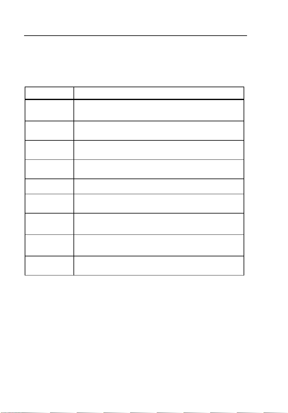
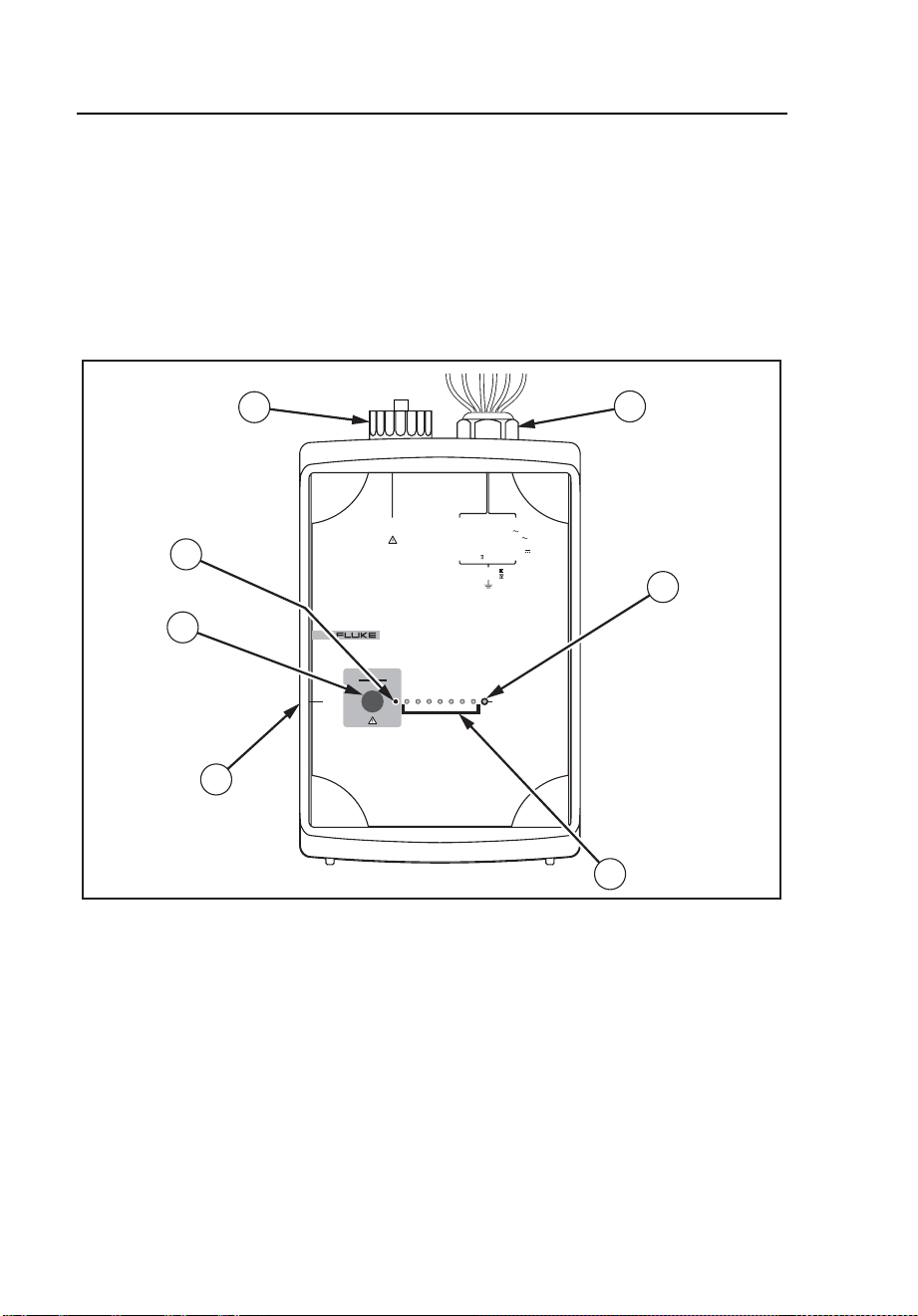
Table 4. 1744/1743 Power Quality Logger - Controls and Indicators
Item Name Description
A
Power supply
leads and
3-phase plus
neutral voltage
test leads
Power supply voltage range: 88-660 V ac or
100-350 VDC, 50 Hz / 60 Hz, 600 V CAT III.
Fixed installed voltage input cables for L1 or A,
L2 or B, L3 or C, N.
The highest permissible nominal voltage for power
supply input is 660 V.
The highest permissible nominal voltage for signal
input is 830 V in a 3-wire network with Delta
connection.
In a 4-wire network with Wye connection, the
highest permissible nominal voltage is 480 V.
When using PTs and CTs for measuring voltage
and current in a medium-voltage network, refer to
the IEC 60044 international standard for
guidelines.
B
RS232
interface port
The serial RS232 interface is used to communicate
with a PC. The Logger is connected to the PC’s
serial port (or a modem for remote communication)
using the interface cable. Use a USB adapter if
necessary.
C
START/STOP
The START/STOP button is used to start or end
switch-operated logging sessions.
D
Channel LEDs
The logging channel LEDs indicate whether the
applied voltages and currents are within the
nominal range set using the PQ Log software.
Continuously on = Logging signal in nominal range
Short blinks = No or low-level signal
Long blinks = Overload
E
Power status
LED
Continuously on = Power supply voltage in
permissible range
Off = No power
F
Connector for
Flexi Set or
current clamps
Flexi sets or current clamps are detected
automatically at power-up. If you change the current
probe type, be sure to remove and restore power so
the Logger will detect the new current probe.
Nominal ranges for the Flexi Set are 15 A, 150 A,
1500 A, and 3000 A ac. Nominal input for current
clamps is 0.5 V.
G
Logging status
LED
Continuously on = Logging in progress
Blinking = Logging stopped or not started
1.888.610.7664 sales@GlobalTestSupply.com
Fluke-Direct.com

1744/1743
Users Manual
10
Power Network Configurations
You can set up the Logger to work with several power network configurations:
• Single-phase voltage
• Single-phase voltage, current, power
• 3-phase voltage
• 3-phase voltage, 3-phase current, power
• 3-phase voltage, 3-phase current, neutral current, power
Note
3-phase logging with no neutral current can be done with appropriate
optional accessories (available separately).
Working with Logged Data
Logged data can be evaluated using the PQ Log software to provide the
following:
• Amount, date/time, and duration of quick and slow voltage variations
• Half-cycle 10 ms-extreme values for 50 Hz (8.3 ms at 60 Hz) MIN
and MAX for each measuring interval
• Depth and duration of voltage dips
• Correlation between peak current and voltage dips
• 95%-flicker values according to EN 50160
• Number and duration of interruptions
• Compliance of harmonic levels with defined limits
• Mean and peak values of phase currents
• Value of neutral conductor current
• Current total harmonic distortion (THD) of phase and neutral
conductor currents
• Profile of active, reactive, and apparent power versus time
• Monitoring of power factor (PF), and information about effectiveness
of compensation systems
• Graphical representations of logging data and statistics
1.888.610.7664 sales@GlobalTestSupply.com
Fluke-Direct.com

Power Quality Logger
Using the Logger
11
Using the Logger
This section explains how to operate the 1744/1743 Power Quality Logger.
A typical logging session includes four steps:
1. Preparing the Logger for use with the PQ Log software.
2. Installing the Logger at the logging site.
3. Leaving the Logger to collect data for a period.
4. Downloading and evaluating the logged data.
These steps are described in the following pages.
Logging Jobs
Logging jobs are defined using the PQ Log software, and transferred to the
Logger over the RS232 cable. Each job contains the following information:
• Logging function (P for Model 1743, and P or A for Model 1744)
• Measuring period, defined by start and end times
• Time activated, switch or immediate job
• Input range
• Nominal voltage, primary and secondary voltage for logging with
voltage converters
• Logging of phase-neutral wire or phase-phase
• Memory model
• Averaging period length
• Logging time periods
• Interharmonics and signaling voltages
• Limit values for events
• Memory model for events: circular (first-in/first-out, continuous), or
linear (quit logging when logging period is finished)
• Logging of current-neutral wire
• Converter ratios for current and voltage if using potential transformers
(PTs) and current transformers (CTs) at a medium-voltage network
site
1.888.610.7664 sales@GlobalTestSupply.com
Fluke-Direct.com

1744/1743
Users Manual
12
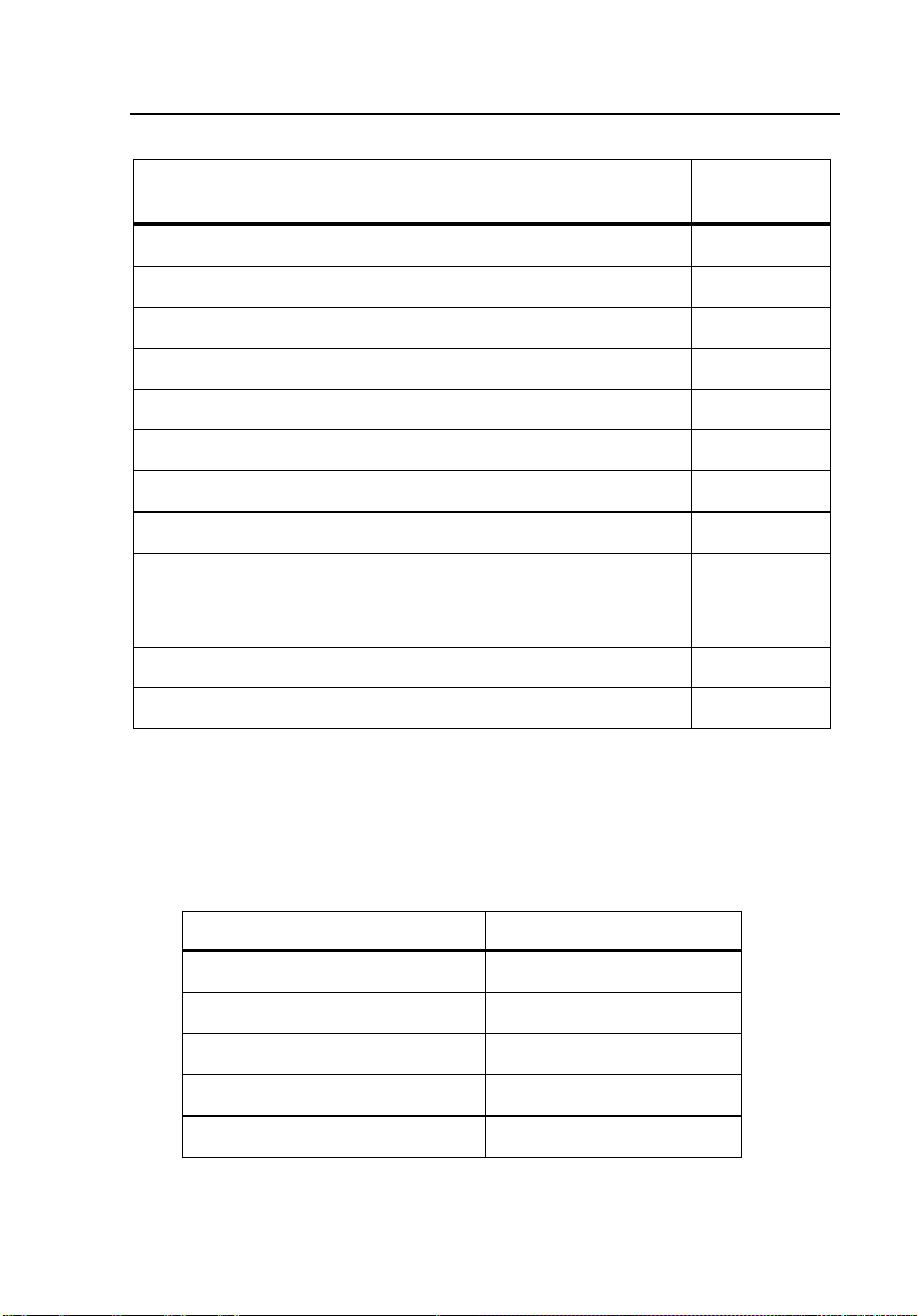
Preparing the Logger for Use
Prepare the 1744/1743 Logger for use with the PQ Log software as follows
(see Figure 3):
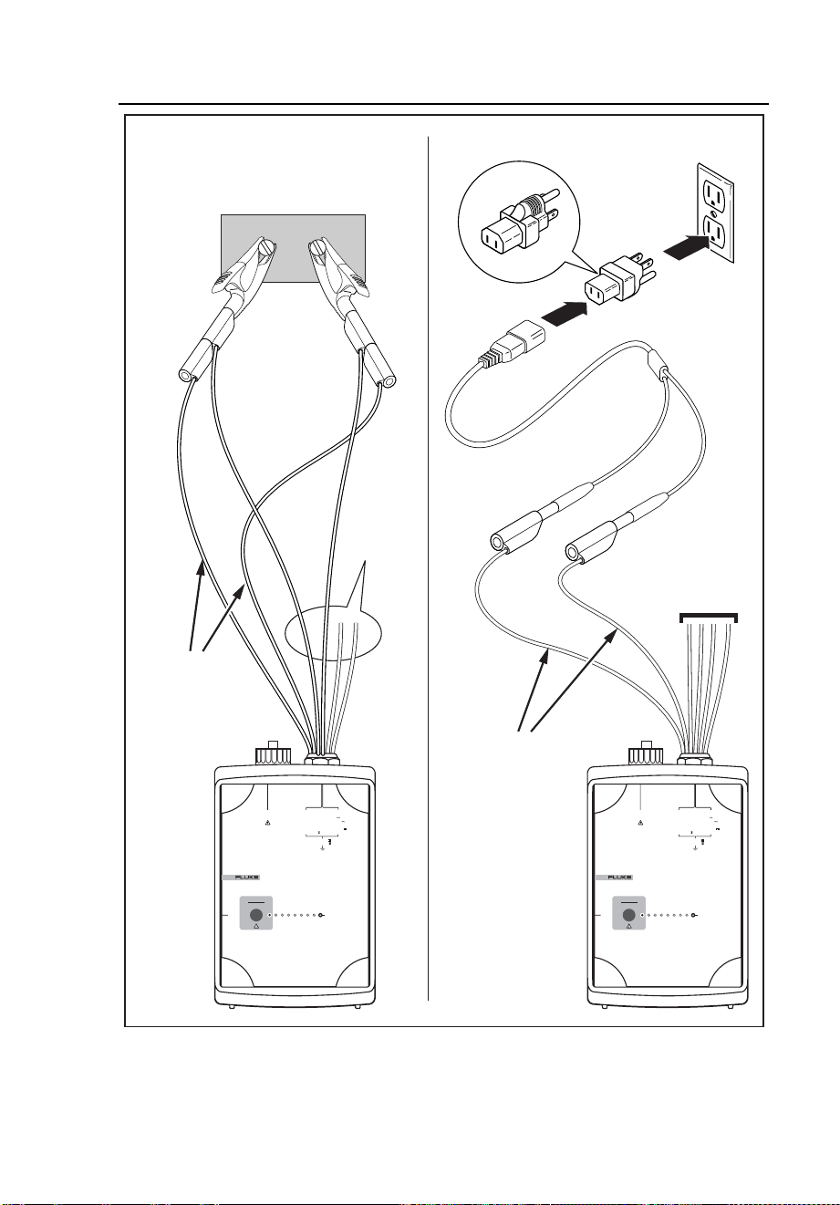
1. Connect the Logger to line power. Use the power supply cables to
connect to an outlet, or to the test leads phase and neutral for Wye
configurations, or any two-phase leads for delta.
W Caution
If you are powering the Logger in parallel with the test
leads, and the voltage under test at the Logger power
supply connections could be greater than 660 V RMS ac,
plug the power supply leads into an outlet instead.
Otherwise, you could damage the Logger.
1.888.610.7664 sales@GlobalTestSupply.com
Fluke-Direct.com
Power Quality Logger
Using the Logger
13
Voltage
Test Leads
POWER LOGGER
1743
START
STOP
POWER
232SR
I
N
I
3
I
2
I
1
V
3
V
2
V
1
CURRENT INPUT
10V
RMS
MAX
L
1
/A
L
2
/B
L
3
/C
N
5VA
45- 65Hz
MEASUREMENT INPUT
SUPPLY INPUT
830V
RMS
MAX CAT
600V CAT
300V CAT
100- 350V
660V MAX
88- 660V
POWER LOGGER
1743
START
STOP
POWER
232SR
I
N
I
3
I
2
I
1
V
3
V
2
V
1
CURRENT INPUT
10V
RMS
MAX
L
1
/A
L
2
/B
L
3
/C
N
5VA
45- 65Hz
MEASUREMENT INPUT
SUPPLY INPUT
830V
RMS
MAX CAT
600V CAT
300V CAT
100- 350V
660V MAX
88- 660V
Voltage
Test Leads
Power from Wall OutletPower in Parallel
with
Max 660 V
Test Leads
Power Supply
Leads
Power Supply
Leads
egb031.eps
Figure 3. Supplying Operating Power to the Logger
2. Connect the RS232 interface cable to the serial port of your PC.
1.888.610.7664 sales@GlobalTestSupply.com
Fluke-Direct.com
1744/1743
Users Manual
14
3. Run the PQ Log software as described in the PQ Log Users Manual.
4. Set up the Logging job and transfer the settings to the Logger.
Test Leads – Markings
The 1744/1743 Logger includes built-in, labeled test leads for voltage
terminals L1 or A, L2 or B, L3 or C, and N, as well as two for the internal
power supply. The Flexi Set or current clamp sets are connected by a seven-pin
plug to the Logger. Color coding clips are provided for your convenience.
Table 5. Test Lead Markings
Test Leads Markings
Phase L1 or A L1 / A
Phase L2 or B L2 / B
Phase L3 or C L3 / C
Neutral wire N N
Supply “Supply”
Supply “Supply”
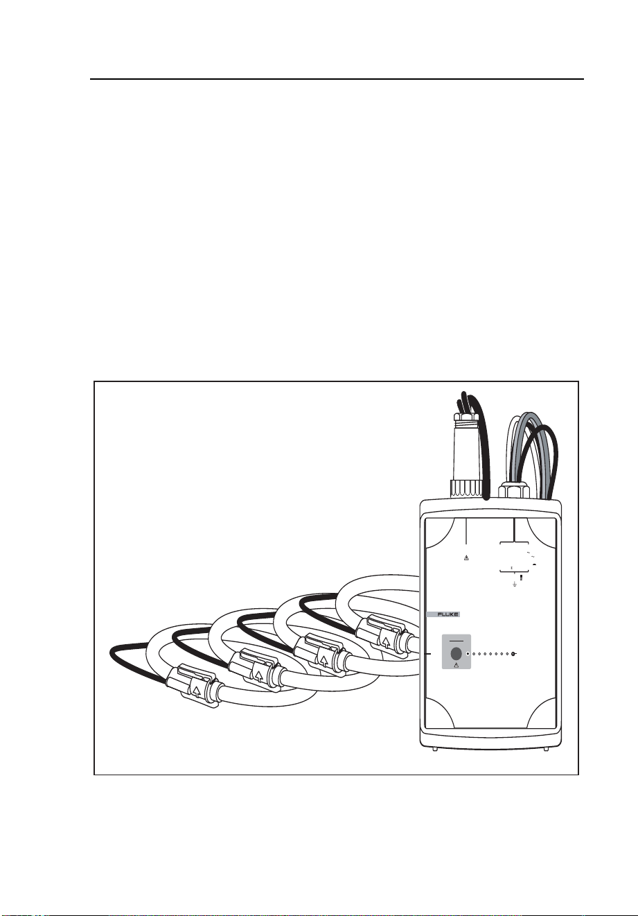
Connecting Current Probes
Connect current clamps and Flexi Set probes so that current will flow in the
direction marked by arrows on the probes. Current must flow from the energy
generator to the energy consumer (the load) in order to maintain a positive
active power. (The polarization of the test lead for neutral conductor current is
not significant, because the phase angle of the neutral conductor current is not
evaluated.)
Note
Make sure the clip-on probes are connected to the appropriate phase:
V
L1
with I
L1
for a P-N measurement or V
L12
with I
L1
for a P-P
measurement.
1.888.610.7664 sales@GlobalTestSupply.com
Fluke-Direct.com

Power Quality Logger
Using the Logger
15
Logging with Voltage Converters
The 1744/1743 Logger includes an adjustable converter ratio that enables it to
be used with voltage converters (potential transformers, or PTs).
Note
When logging with voltage converters, make sure the power supply
cables are not connected in parallel to the voltage test leads, or the
Logger’s power consumption can reduce accuracy.
The converter ratio is defined using the PQ Log software.
Connecting the Logger
W X Warnings
• To avoid electrical shock, do not connect any part of
the Logger to systems that have higher voltages to
ground (earth) than are marked on the Logger.
• Areas between the power company meter and the
source of the distribution system are characterized as
CAT IV areas. To avoid electrical shock or equipment
damage, never connect the Logger to power in CAT IV
areas if the voltage-to-earth ground is greater than
300 V.
• To avoid damaging the Logger, never connect its
voltage measuring inputs to phase-to-phase voltages
higher than 830 V.
• To avoid damaging the Logger, never connect the
power supply leads to voltages higher than 660 V RMS
ac.
• The Logger is to be used and handled only by qualified
personnel (see page 6).
• Maintenance work on the Logger must be done only by
qualified service personnel.
1.888.610.7664 sales@GlobalTestSupply.com
Fluke-Direct.com

1744/1743
Users Manual
16
• Use only the current probes specified in this manual. If
you use flexible current probes, wear suitable
protective gloves or work on de-energized conductors.
• Do not expose the Logger to moisture or humidity.
• To prevent electrical shock, always connect power
supply and voltage test leads to the Logger before
connecting to the load.
• All accessories must be approved for 600 V CAT III or
higher.
• Use the Logger only with its original standard
equipment or with approved optional accessories, as
listed in Table 2 and Table 3 in this manual.
• Connect clip-on current transformers and/or Flexi Set
to insulated live conductors only.
• If measuring sensors are to be connected to non-
insulated live conductors, additional personal
protective measures must be taken as required by local
government agencies.
W Caution
To avoid damage, use the 1744/1743 Power Quality Logger,
only with the following nominal voltages:
• Single-/3-phase, 4-wire (Wye) systems (P-N): 69 V
to 480 V
• 3-phase 3-wire (Delta) systems (P-P): 120 V to 830 V
WX Warning
To avoid electrical shock, or damaging the Logger’s
internal protective circuitry or weatherproof seal, do not
open the Logger.
1.888.610.7664 sales@GlobalTestSupply.com
Fluke-Direct.com

Power Quality Logger
Using the Logger
17
Connect the Logger as follows:
Note
∆ (Delta) or Υ (Wye) measurements
The 1744/1743 Logger is prepared for logging in 3-phase 4-wire
(Wye) systems (P-N), or 3-phase 3-wire (Delta) systems (P-P). Please
note the different types of connection and configuration in the PQ Log
software.
1. Connect all required measuring leads.
2. If you want to supply the Logger from an extra outlet, use the
supplied line power adapter. The power supply leads can also be
connected in parallel to the voltage test leads, but the voltage is
limited to 660 V RMS ac.
3. Connect the current clamp set or Flexi Set to the Logger.
4. Connect the current sensor to the conductor under test.
5. Connect the dolphin clips to the test leads. For 3-phase, 4-wire
systems, connect the N-test lead first, and then the other phases.
1.888.610.7664 sales@GlobalTestSupply.com
Fluke-Direct.com
1744/1743
Users Manual
18
Connections in 3-Phase 4-Wire (Wye) Systems
The following figure shows the connections for logging 3-phase 4-wire (Wye)
systems:
L1
L2
L3
N
POWER LOGGER
1743
START
STOP
POWER
232SR
I
N
I
3
I
2
I
1
V
3
V
2
V
1
CURRENT INPUT
10V
RMS
MAX
L
1
/A
L
2
/B
L
3
/C
N
5VA
45- 65Hz
MEASUREMENT INPUT
SUPPLY INPUT
830V
RMS
MAX CAT
600V CAT
300V CAT
100- 350V
660V MAX
88- 660V
egb003.eps
Figure 4. Logging in a 3-Phase 4-Wire (Wye) System
1.888.610.7664 sales@GlobalTestSupply.com
Fluke-Direct.com
Power Quality Logger
Using the Logger
19
Connections in 3-Phase 3-Wire (Delta) Systems
Figure 5 shows the connections for logging 3-phase 3-wire (Delta) systems.
L1
L2
L3
L4
POWER LOGGER
1743
START
STOP
POWER
232SR
I
N
I
3
I
2
I
1
V
3
V
2
V
1
CURRENT INPUT
10V
RMS
MAX
L
1
/A
L
2
/B
L
3
/C
N
5VA
45- 65Hz
MEASUREMENT INPUT
SUPPLY INPUT
830V
RMS
MAX CAT
600V CAT
300V CAT
100- 350V
660V MAX
88- 660V
IP65
egb004.eps
Figure 5. Logging in a 3-Phase 3-Wire (Delta) System
The test lead N can be left open, or connected to ground potential.
1.888.610.7664 sales@GlobalTestSupply.com
Fluke-Direct.com
1744/1743
Users Manual
20
Connections for Single-Phase Logging
Figure 6 shows the connections for logging single-phase systems.
L1 N
POWER LOGGER
1743
START
STOP
POWER
232SR
I
N
I
3
I
2
I
1
V
3
V
2
V
1
CURRENT INPUT
10V
RMS
MAX
L
1
/A
L
2
/B
L
3
/C
N
5VA
45- 65Hz
MEASUREMENT INPUT
SUPPLY INPUT
830V
RMS
MAX CAT
600V CAT
300V CAT
100- 350V
660V MAX
88- 660V
L3
L2
egb005.eps
Figure 6. Single-Phase Logging
1.888.610.7664 sales@GlobalTestSupply.com
Fluke-Direct.com
Power Quality Logger
Using the Logger
21
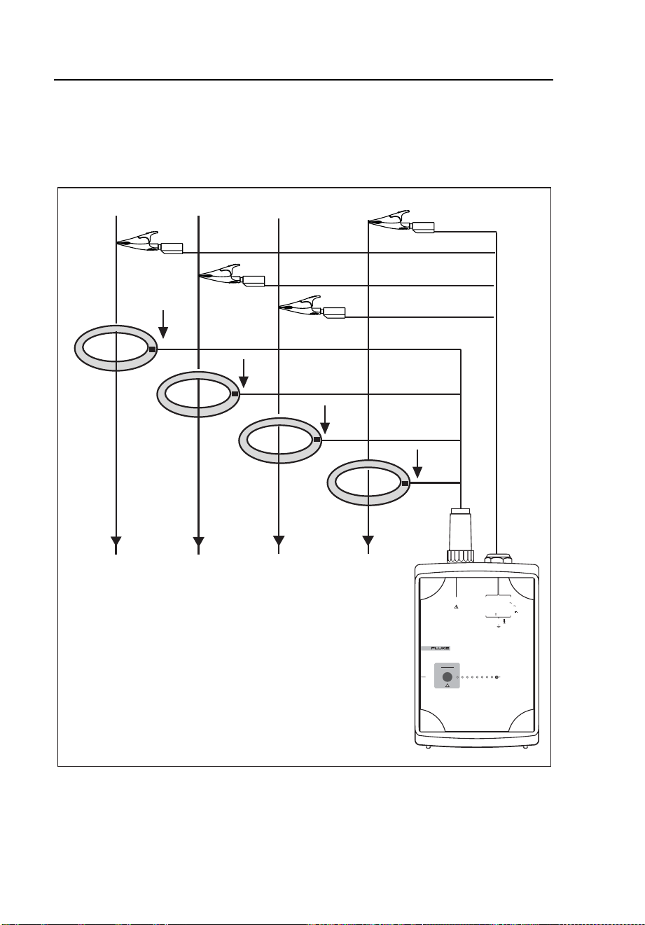
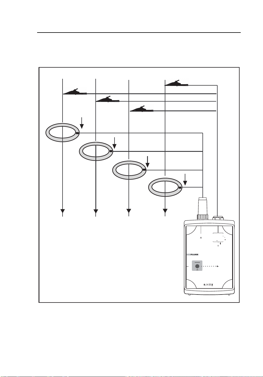
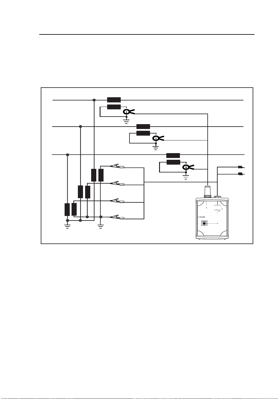
Connections for Medium-Voltage Networks
In a 3-phase 3-wire (Delta) system with three separate voltage converters and
three current transformers, the Logger can measure phase-phase (P-P, Delta) or
phase-N (P-N, Wye). See Figure 7.
Supply
L1
L2
L3
N
L1
L1
L2
L2
L3
L3
POWER LOGGER
1743
START
STOP
POWER
232SR
I
N
I
3
I
2
I
1
V
3
V
2
V
1
CURRENT INPUT
10V
RMS
MAX
L
1
/A
L
2
/B
L
3
/C
N
5VA
45-65 Hz
MEASUREMENT INPUT
SUPPLY INPUT
830V
RMS
MAX CAT
600VCAT
300V CAT
100-350V
660V MAX
88-660V
egb006.eps
Figure 7. Measuring 3-Phase Voltages in a 3-Wire (Delta) System with
Three Voltage Converters
1.888.610.7664 sales@GlobalTestSupply.com
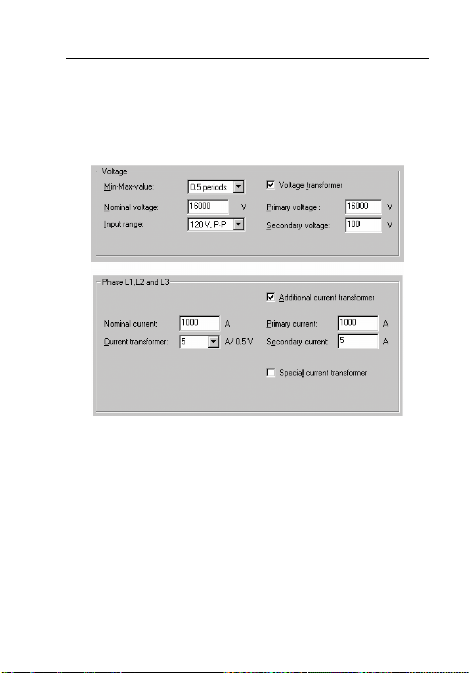
Fluke-Direct.com
1744/1743
Users Manual
22
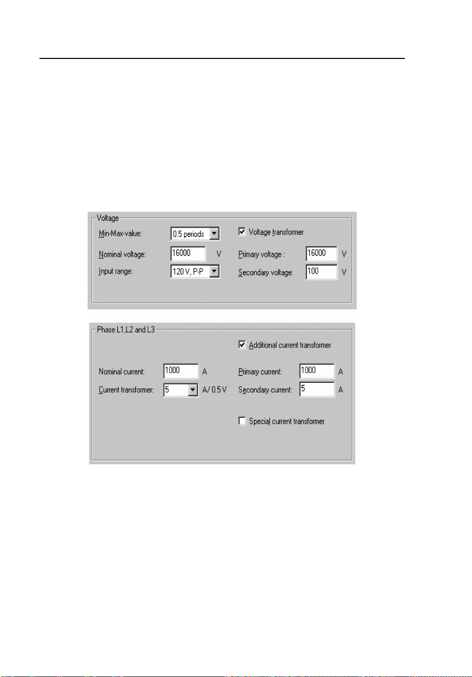
Phase-Phase Delta Logging
Figure 7 shows the connections for phase-phase Delta logging.
1. Connect the voltage test leads to the outputs of the voltage
transformers (VTs).
2. In PQ Log, select the measuring range with the matching nominal
voltage and P-P logging.
3. Enter the correct converter/transformer ratio for current and voltage.
egb007.bmp
Figure 8. PQ Log Settings for a 16 kV Network
1.888.610.7664 sales@GlobalTestSupply.com
Fluke-Direct.com
Power Quality Logger
Using the Logger
23
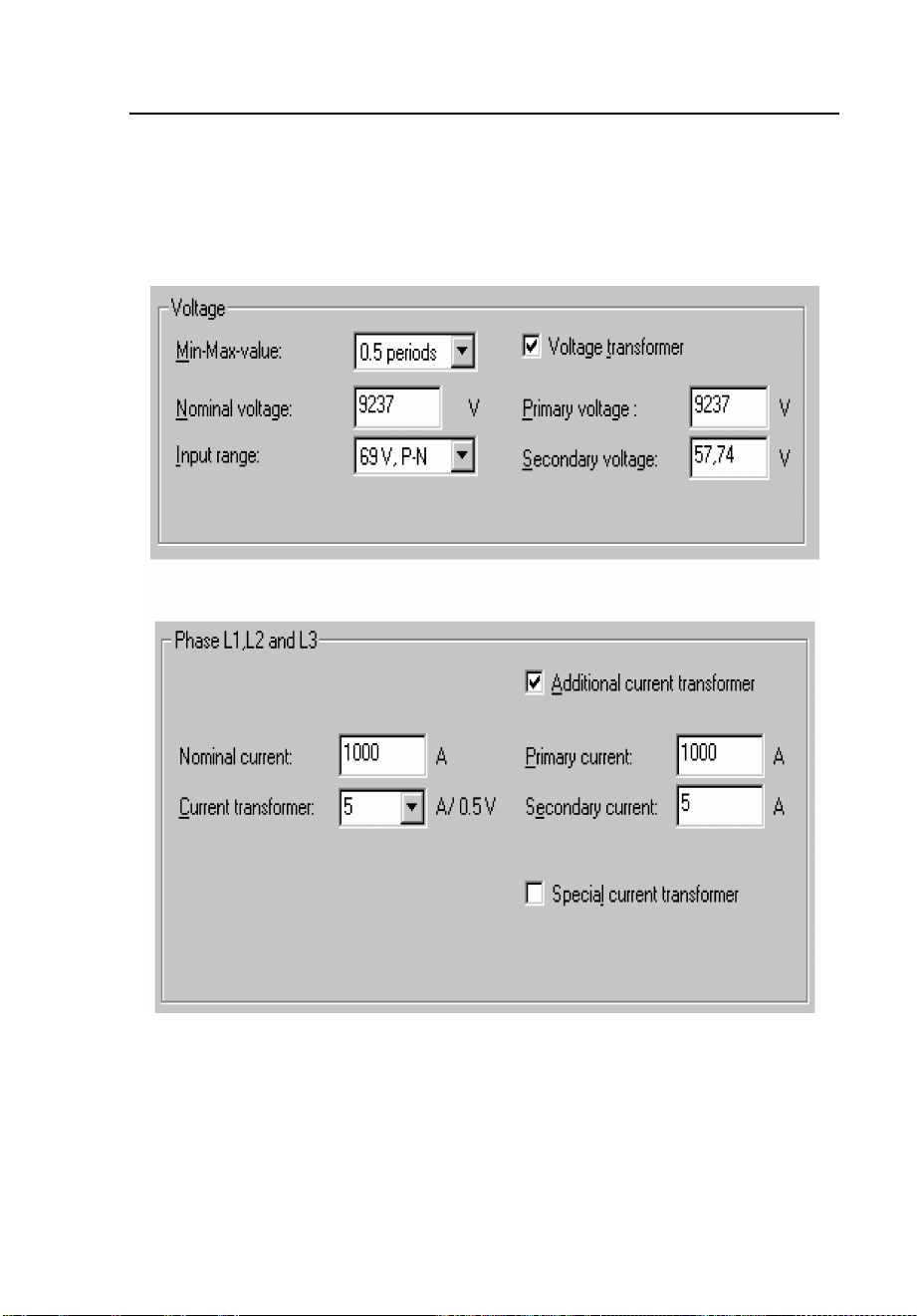
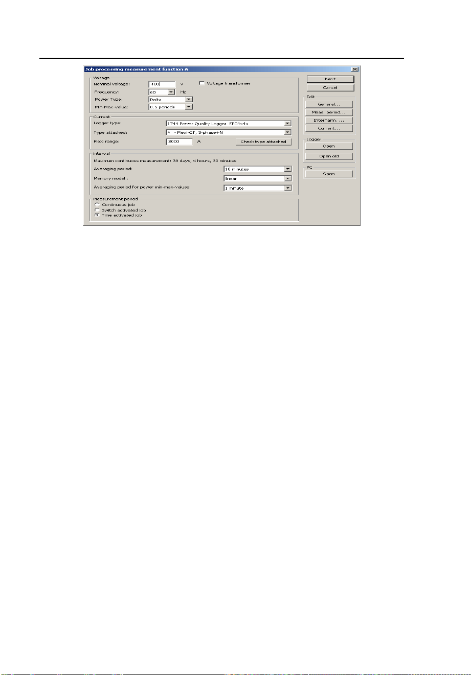
Phase-Ground, Wye-Logging
Figure 7 shows the Phase-Ground, Wye-Logging. Figure 9 shows typical PQ
Log settings for using potential transformers (PTs) and current transformers
(CTs) with a 16 kV network.
egb010.bmp
Figure 9. PQ Log Settings for a 16 kV Network
1.888.610.7664 sales@GlobalTestSupply.com
Fluke-Direct.com
1744/1743
Users Manual
24
1. Connect the voltage test leads to the outputs of the voltage
transformers (VTs).
2. In PQ Log, select the measuring range with P-N logging and
matching nominal voltage.
3. Enter the correct converter/transformer ratio for current and voltage.
Note
Current clamp sets are available for 1 A current transformers.
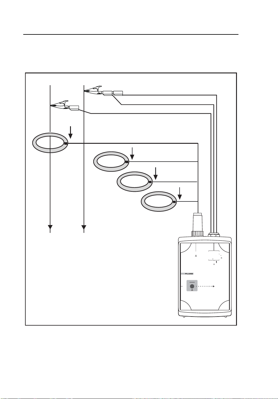
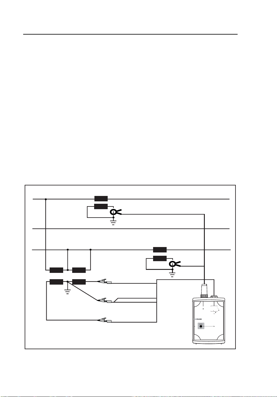
Logging with Two Voltage Converters and Two Current
Transformers
In 3-phase 3-wire systems with two voltage converters (VTs) and two current
transformers (CTs) in an Aron or Blondel measuring circuit, the Logger can
measure only phase-phase (P-P, Delta).
L1
L2, N
L1
L3
L2
L3
POWER LOGGER
1743
START
STOP
POWER
232SR
I
N
I
3
I
2
I
1
V
3
V
2
V
1
CURRENT INPUT
10V
RMS
MAX
L
1
/A
L
2
/B
L
3
/C
N
5VA
45-65 Hz
MEASUREMENT INPUT
SUPPLY INPUT
830V
RMS
MAX CAT
600V CAT
300V CAT
100-350 V
660V MAX
88-660 V
egb009.eps
Figure 10. Measuring 3-Phase Voltages in a 3-Wire System with Potential
Transformers (Aron Measuring Circuit)
1.888.610.7664 sales@GlobalTestSupply.com
Fluke-Direct.com
Power Quality Logger
Using the Logger
25
1. Connect the voltage test leads L2 or B and N to the common ground
point.
2. In PQ Log, select the measuring range with P-P logging and matching
nominal voltage.
3. Enter the correct converter/transformer ratio for current and voltage.
egb007.bmp
Figure 11. PQ Log Settings for a 16 kV Network
Note
Current clamp sets are available for 1 A current transformer.
Logging
When the Logger is connected and ready, you can perform three types of
logging:
• Switch-activated job: The status LED is blinking. Press the
START/STOP button once. As soon as the job is active, the LED is
on continuously. If needed, the job can be cancelled after running for
at least one minute, and restarted later.
1.888.610.7664 sales@GlobalTestSupply.com
Fluke-Direct.com

1744/1743
Users Manual
26
• Time-activated job: The Logger starts logging as soon as the
preprogrammed start time is reached, and stops at the defined end
time.
• Immediate job: The Logger starts logging as soon as power is on.
Note the following about logging jobs:
• The connection can be verified using the logging channel LEDs. If all
three LEDs are lit continuously, the connection and the signal levels
are within nominal range. For details, see Table 4 in the Features
section.
• The unit/job status is indicated by the status LED. For details, see
Table 4 in the Features section.
Completing the Logging Job
1. Terminate the job as follows:
• For switch-activated jobs: At the end of the logging period, stop
the logging job by pressing the START/STOP button.
• For time-activated and immediate jobs: Stop the job in PQ Log
with the icon, or with menu Logger/Stop logging.
Note
Make sure the logging job is stopped with the START/STOP button
(switch-activated jobs) or PQ Log (time-activated jobs) before the test
leads or power supply leads are removed. Otherwise, the Logger will
record a voltage interruption.
Only switch-activated jobs can be aborted. Time-activated jobs are
terminated only when the programmed measuring time has elapsed.
2. Remove the test leads of the three phases. Be sure to remove the
measuring cable of the neutral wire last.
3. Remove the current probes.
1.888.610.7664 sales@GlobalTestSupply.com
Fluke-Direct.com

Power Quality Logger
Methods of Logging
27
Evaluating the Logged Data
You’ll use PQ Log to evaluate the logged data. Data can be read out during
logging as well as at the end.
1. Connect the Logger to line power.
2. Connect the RS232 interface cable to your PC’s serial port, then to the
Logger.
3. Start the PQ Log software.
4. Use PQ Log to transfer the data from the Logger to the PC.
5. Once the data is transferred, remove the RS232 interface cable and
operating power from the Logger.
6. Evaluate the data using PQ Log.
For details, refer to the PQ Log manual.
Methods of Logging
The following section describes methods of logging using the 1744/1743
Logger.
Measuring Ranges
The Logger has three input ranges for each of its two connection systems: Wye
connection (3-phase, 4-wire) and Delta connection (3-phase, 3-wire).
Table 6. Measuring Ranges
Connection Nominal Voltages (Wye/Delta) Max. Input Voltage
Wye/Delta 69 V / 120 V 115 V / 200 V 230 V / 400 V 480 V / 830 V
Phase/Neutral
3-phase 4 wire
69 V ~, +20% 115 V ~, +20% 230 V ~, +20% 480 V ~, +20%
Phase/Phase
3-phase 3 wire
120 V ~, +20% 200 V ~, +20% 400 V ~, +20% 830 V ~, +20%
1.888.610.7664 sales@GlobalTestSupply.com
Fluke-Direct.com
1744/1743
Users Manual
28
egb015.bmp
Figure 12. Selecting Voltage Input Ranges During Job Processing
Note
For P-P logging, the P-P voltage must be entered as the nominal
voltage (e.g. 400 V for 230 V systems).
Signal Sampling
Input signals (up to three voltages and four currents) are filtered with an anti-
aliasing filter, and digitized with a 16-bit A/D converter. The sampling rate is
10.24 kHz. All parameters are calculated from this data.
Resolution Accuracy
Resolution and accuracy depend on the logging parameter. For details, see
1.888.610.7664 sales@GlobalTestSupply.com
Fluke-Direct.com
Power Quality Logger
Methods of Logging
29
Technical Specifications” on page 46.
Voltage Variations
The interval value of the voltage is defined as the mean value of the RMS
values over the interval length defined in PQ Log.
Averaging intervals can be set in PQ Log to the following:
• 1, 3, 5, 10, or 30 seconds
• 1, 5, 10, 15, or 60 minutes
1 Interval
Measuring period
Time
V
N
egb016.eps
Figure 13. Measuring Voltage Variations
Note
For logging in Wye configuration using logging function A, the
phase-phase voltages are measured and displayed separately from the
logging of the phase-neutral voltages.
1.888.610.7664 sales@GlobalTestSupply.com
Fluke-Direct.com
1744/1743
Users Manual
30
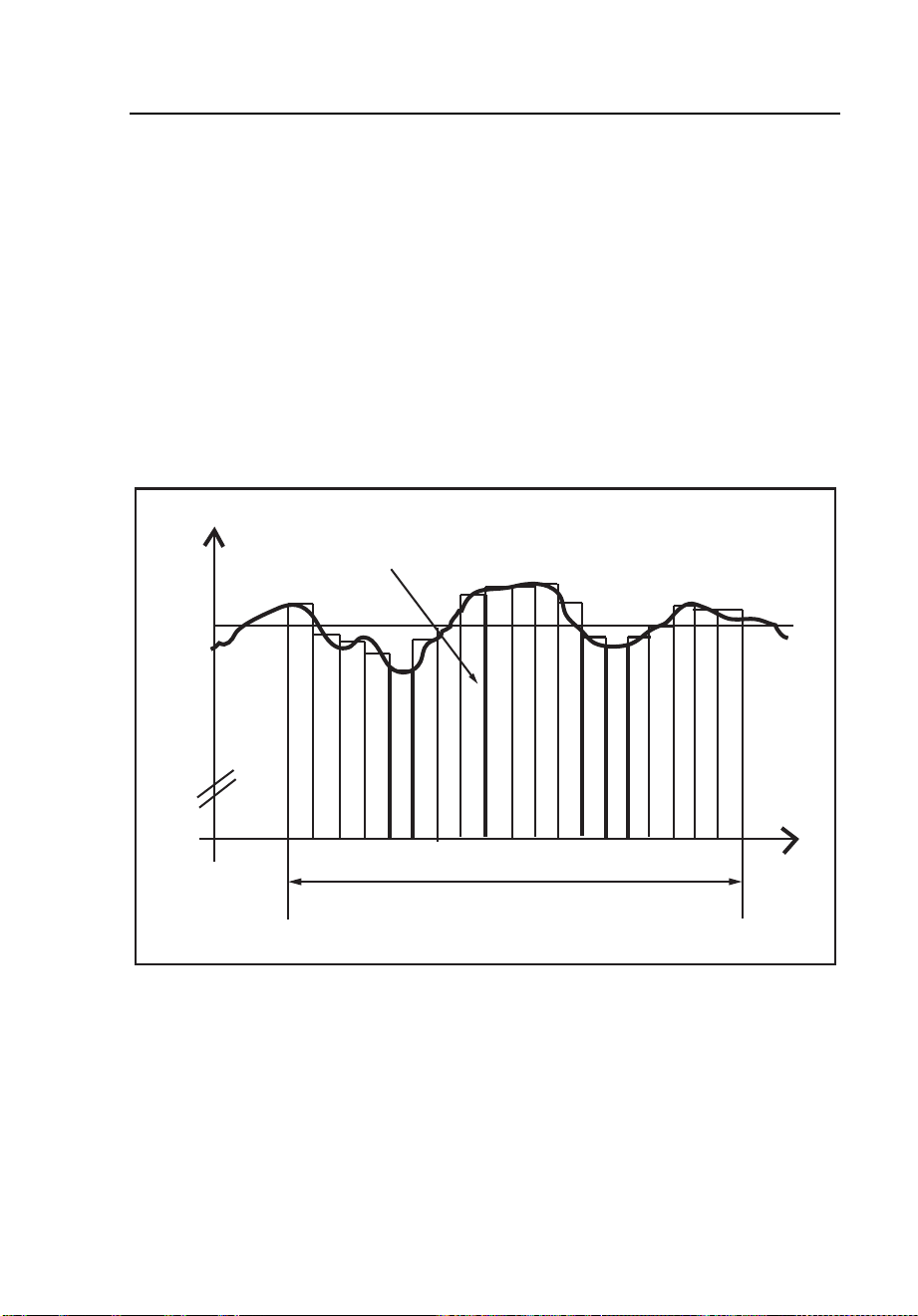
Min/Max Values
Logging detects the highest and lowest voltage RMS values and the highest
current RMS value during the test interval, using a minimum resolution of
10 ms.
The response time can be set in PQ Log to the following:
• 0.5 or 1 line power period
• 200 ms
• 1, 3, or 5 seconds.
U
t
Max. Value
Min. Value
Measuring Interval
egb017.jpg
Figure 14. Logging Min and Max Values
1.888.610.7664 sales@GlobalTestSupply.com
Fluke-Direct.com
Power Quality Logger
Methods of Logging
31
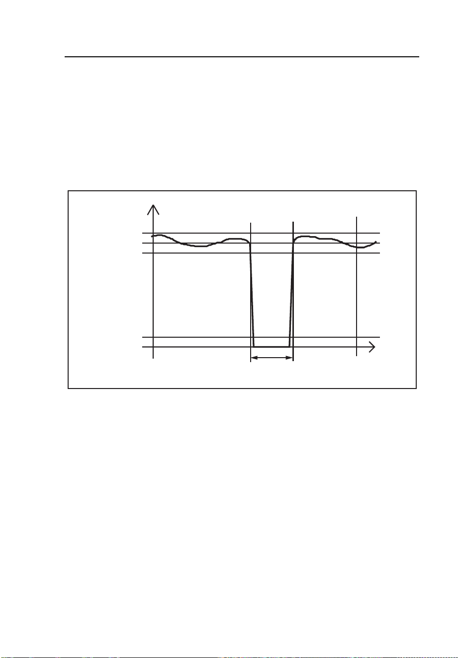
Voltage Interruptions
The Logger records two types of interruptions:
• All measured RMS values of input voltages that are < 1% of the
nominal voltage. (This threshold can be adjusted in PQ Log.)
• Interruptions > 10 ms (0.5 line power periods).
The start time and duration of each interruption are registered.
Time
90% Un
1%
Duration
100% Un
110% Un
egb018.eps
Figure 15. Voltage Interruption
1.888.610.7664 sales@GlobalTestSupply.com
Fluke-Direct.com
1744/1743
Users Manual
32
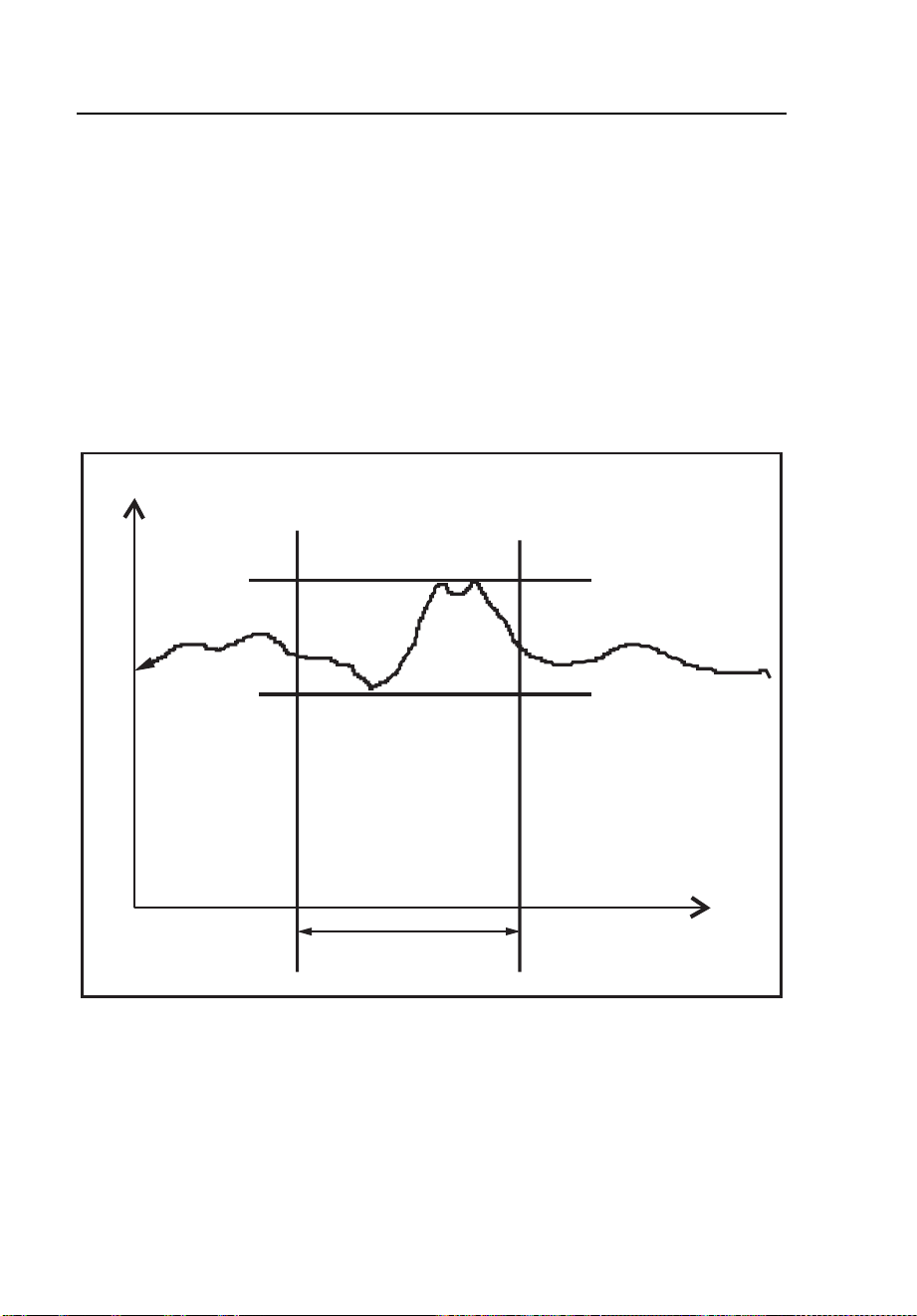
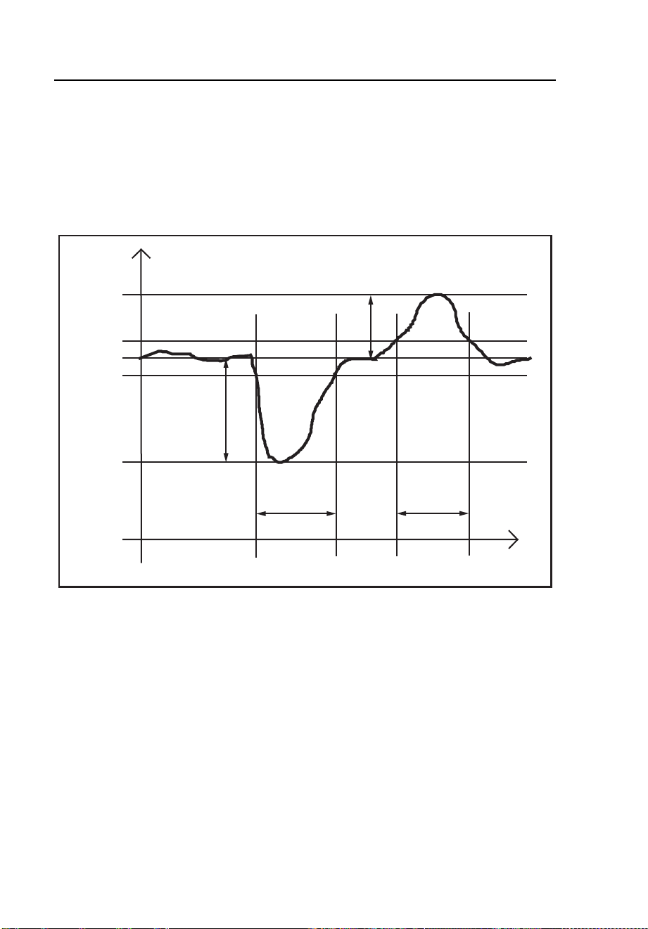
Voltage Dips and Swells
If the voltage passes the upper limit (V
N
+ 10%) or lower limit (V
N
– 10%), the
event is registered as a voltage swell or dip, respectively (thresholds are
adjustable in PQ Log).
The duration, time, and extreme value of the dip or swell is also recorded.
Zeit
Time
90% Un
Duration
Depth
Heigth
Duration
100% Un
110% Un
egb019.eps
Figure 16. Voltage Dips and Swells
Voltage Harmonics
Voltage harmonics are defined as voltage components that have a frequency
that is an integer multiple of the fundamental frequency of the line power
voltage. Logging function A records each individual voltage harmonic, up to
the 50
th
order. These values are averaged over the interval length defined in
PQ Log.
1.888.610.7664 sales@GlobalTestSupply.com
Fluke-Direct.com

Power Quality Logger
Methods of Logging
33
Current Harmonics
Current harmonics are defined as current components that have a frequency
that is an integer multiple of the fundamental frequency of the line power
current. Logging function A records each individual harmonic of the phase
currents and the neutral current, up to the 50
th
order, and presents the
harmonics as absolute values. The values are averaged over the interval length
defined in PQ Log.
Mains Signaling
Voltage components that have frequencies that are not integer multiples of the
fundamental frequency of the line power voltage are called Mains Signaling
voltages or ripple-control voltages (“interharmonics”).
The Logger can be programmed to record up to five interharmonics, with a
resolution of 5 Hz. This function can also be used to monitor ripple-control
signals, by entering the signal frequency of the local utility.
The Logger measures the three-second RMS value of each interharmonic, and
establishes statistics for EN 50160 evaluation. These statistics are available
after a minimum recording time of 24 hours, or after regular termination of the
measuring job, and can be exported from PQ Log and evaluated later.
Additionally, the Logger provides a long-term recording of the interharmonics.
You can select from the following special measurement methods in the PQ
Log software:
• 200 ms maximum value (recommended for estimating ripple-control
signal levels)
• 200 ms minimum value
• 3 seconds maximum value
• Average value over interval
In PQ Log, the frequency can be entered with a resolution of 0.5 Hz, but for
evaluation the values are corrected to a bandwidth of 5 Hz. One frequency can
be defined for each band: for example, for a ripple-control signal of 183 Hz,
the values will be corrected to 185 Hz. Interharmonics of voltages and currents
with these frequencies are recorded.
See the PQ Log manual for details.
1.888.610.7664 sales@GlobalTestSupply.com
Fluke-Direct.com

1744/1743
Users Manual
34
THDV – In Function A
Function A:
1
50
2
2
V
V
VTHD
n
n
∑
=
=
V
n
: RMS value of harmonic frequency #n.
V
1
: RMS value of the fundamental frequency.
THDV: total contents of harmonics of the line power voltage as a percentage
of the fundamental.
This algorithm is according to EN 61000-4-7.
THD of currents:
Function A:
1
50
2
2
I
I
THDI
n
n
∑
=
=
and
()
∑
=
=
50
2
2
n
n
IATHDI
I
n
: RMS value of harmonic frequency #n.
I
1
: RMS value of the fundamental frequency.
THDI: total contents of harmonics of the current as a percentage of the
fundamental.
1.888.610.7664 sales@GlobalTestSupply.com
Fluke-Direct.com

Power Quality Logger
Methods of Logging
35
Calculation of THD in Measuring Function P
THD – Measuring Function P
Function P does not measure harmonic values.
Voltages:
1
2
1
2
V
VV
THDV
RMS
−
=
V
RMS
: RMS value of total signal
V
1
: RMS value of the fundamental
Currents:
1
2
1
2
I
II
THDI
RMS
−
=
I
RMS
: RMS value of the total signal.
I
1
: RMS value of the fundamental.
Note
THDI for currents < 5% of IE (measuring range) can have additional
uncertainties, or can be suppressed.
Harmonics up to 50th order are taken into account.
Flicker
Flicker is the visual impression of unsteadiness in a light source whose
luminance or spectral distribution changes over time. Flicker is logged in
accordance with the IEC 61000-4-15 standard. The short-term (st) flicker Pst
t
is logged over a default standard interval of 10 minutes, and is used to
calculate the long-term (lt) flicker Plt (by taking the sliding average of 12
short-term values). The interval value can be changed as needed in PQ Log.
1.888.610.7664 sales@GlobalTestSupply.com
Fluke-Direct.com
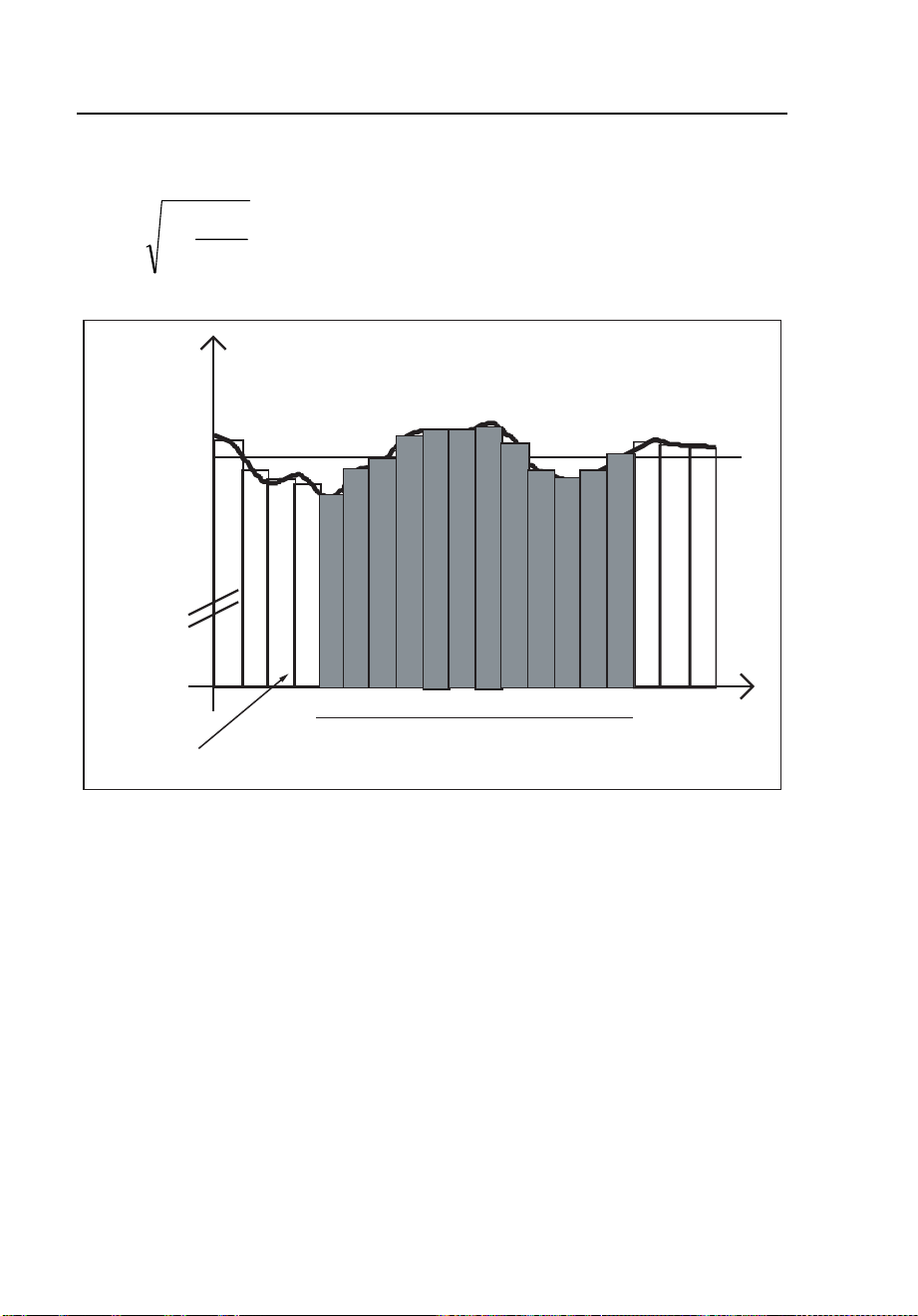
1744/1743
Users Manual
36
Formula for Plt Function
3
12
1
3
12
∑
=
=
i
Pst
Plt
Time
Flicker [%]
Interval length => 1 Pst
12 x interval length => 1 flicker value Plt
egb020.eps
Figure 17. Measuring Flicker Values
Unbalance
The ratio of negative-to-positive sequence harmonics is calculated, with the
angles and magnitudes of the phase voltages taken into account. These values
are averaged over the interval length defined in PQ Log.
Frequency
The line power frequency is measured and averaged over 10 seconds, and the
resulting values are divided into 42 classes for establishing statistics. Values
are also averaged over the interval length defined in PQ Log.
1.888.610.7664 sales@GlobalTestSupply.com
Fluke-Direct.com

Power Quality Logger
Methods of Logging
37
Current Logging
The maximum values of the currents (L1 or A, L2 or B, L3 or C, and N) are
measured, and the interval value of the current is calculated using the mean
value over the RMS values of the interval defined in PQ Log.
Logging Function A
If a 3-phase current sensor is connected, the neutral current is calculated on a
sample basis from the phase currents. If a 3-phase+N sensor is detected, you
can select between logging and calculating the neutral current in PQ Log.
I
peak
The peak values of the current (samples, not RMS values) are averaged in the
PQ Log software over the predefined measuring interval.
Note
Short peak values do not contribute much to the average value, and so
I
max
can be higher than I
peak
.
Crest Factor (CF)
The crest factor (CF) of the currents (L1 or A, L2 or B, L3 or C, and N) is the
ratio of current peak value divided by current RMS value, and is averaged over
the interval length defined in PQ Log. For sinusoidal signals: CF = 1.41, and
for square waves: CF = 1.00
Power
The power values (L1 or A, L2 or B, L3 or C and N) are averaged over the
interval length, and the maximum value of each is recorded.
The response time can be set to 1 second or 1 minute, and is independent of the
response time for voltage and current.
In logging function P, the active power, apparent power, and reactive power of
the phases and total power of all three phases is calculated.
Logging function A also calculates the distorting power D of the phases, and
D
total
.
1.888.610.7664 sales@GlobalTestSupply.com
Fluke-Direct.com

1744/1743
Users Manual
38
Logger Parameters with Function P
The following are the parameters of the 1744/1743 Logger with function P.
RMS value of voltage and current.
Basic values on 200 ms per phase.
∑
=
⋅=
N
i
ibas
V
N
V
1
2
1
∑
=
⋅=
N
i
ibas
I
N
I
1
2
1
N: Number of samples in 200 ms intervals
(2048)
RMS value of voltage and current
per logging interval per phase
∑
=
⋅=
M
j
j
basRMS
V
M
V
1
1
∑
=
⋅=
M
j
j
basRMS
I
M
I
1
1
M: Number of 200 ms intervals per
logging interval
Active power based on samples.
Basic value on 200 ms per phase.
i
N
i
ibas
IV
N
P ⋅=
∑
=1
1
Active power per logging interval
per phase
∑
=
⋅=
M
j
j
bas
P
M
P
1
1
P
bas
: 200 ms value
M: Number of 200 ms intervals per
logging interval
Total active power on all three
phases
∑
=
=
3
1k
ktotal
PP
1.888.610.7664 sales@GlobalTestSupply.com
Fluke-Direct.com

Power Quality Logger
Logger Parameters with Function P
39
P
k
: Active power of the phase
k: Phase (k = 1, 2, 3)
Absolute value of the active power
per interval per phase. Parameter in
PQ Log: |P|.
∑
=
⋅=
M
j
j
basbetr
P
M
P
1
1
M: Number of 200 ms intervals per
logging interval
Sum of the absolute value of the total
active power on all three phases. PQ
Log parameter: |P|
total
.
()
k
k
betrbetrtotal
PP
∑
=
=
3
1
K: Phase (k = 1, 2, 3)
Apparent power per phase
22
basbasbas
QPS +=
Apparent power per logging interval
per phase
∑
=
⋅=
M
j
j
bas
S
M
S
1
1
Total apparent power on all three
phases
∑
=
=
3
1k
ktotal
SS
Power factor per phase
S
P
Q
Q
PF ⋅==
λ
Total power factor on all three
phases
total
total
total
total
totaltotal
Q
Q
S
P
PF ⋅==
λ
Tangent φ per phase
P
Q
=
ϕ
tan
1.888.610.7664 sales@GlobalTestSupply.com
Fluke-Direct.com

1744/1743
Users Manual
40
Tangent φ total on all three phases
total
total
total
P
Q
=
ϕ
tan
Active energy per phase and total Active power accumulated on each
logging interval
Note
The sign of the active power P gives the direction of the power flow
(positive: from generator to load), and the sign of the power factor
distinguishes between inductive load (positive) and capacitive load
(negative).
Sign of PF, tan φ, cos φ:
• Sign “+” : Q positive (“inductive”)
• Sign “–” : Q negative (“capacitive”) independent of the sign of active
power P
1.888.610.7664 sales@GlobalTestSupply.com
Fluke-Direct.com

Power Quality Logger
Logger Parameters with Function A
41
Logger Parameters with Function A
The following are the parameters of the 1744/1743 Logger with function A.
TRMS value of voltage
and current. Basic values
on 200 ms per phase.
∑
=
=
N
i
ibas
V
N
V
1
2
.
1
∑
=
⋅=
N
i
ibas
I
N
I
1
2
1
N: Number of samples in 200 ms intervals (2048)
RMS value of voltage and
current per logging
interval per phase
∑
=
=
M
j
basjRMS
V
M
V
1
2
.
1
∑
=
⋅=
M
j
j
bas
RMS
I
M
I
1
2
1
M: Number of 200 ms intervals per logging interval
Active power calculated
from FFT from samples
of voltage and current.
Basic value on 200 ms per
phase.
nnnn
IVP
ϕ
cos..=
V
n
: RMS value of voltage harmonics of order n
I
n
: RMS value of current harmonics of order n
n: Order of the harmonics
φ
n
: Phase angle between current and voltage
harmonics of order n
P
n
: Harmonics of the active power of order n
Fundamental
∑
=
=
50
1
n
nbas
PP
1
1 PPh
bas
=
1.888.610.7664 sales@GlobalTestSupply.com
Fluke-Direct.com

1744/1743
Users Manual
42
Active power of logging
interval per phase
∑
=
⋅=
M
j
j
bas
P
M
P
1
1
P
bas j
to 200 ms value
M: Number of 200 ms intervals per logging interval
Total active power on all
three phases
∑
=
=
3
1k
ktotal
PP
P
k
: Active power of the phase
k: Phase (k = 1, 2, 3)
Absolute value of the
active power per interval
per phase
∑
=
⋅=
M
j
j
basbetr
P
M
P
1
1
Sum of the absolute
values of the active power
on all three phases
∑
=
++=
M
j
basbasbas
total
betr
PPP
M
P
1
321
1
Apparent power based on
RMS values of voltage
and current. Basic values
on 200 ms per phase
basbasbas
IVS .=
Apparent power per
logging interval per phase
∑
=
⋅=
M
j
j
bas
S
M
S
1
1
S
bas j
: 200 ms value
M: Number of 200 ms intervals per logging interval
Total apparent power on
three phases
∑
=
=
3
1K
ktotal
SS
k: Phase (k = 1, 2, 3)
1.888.610.7664 sales@GlobalTestSupply.com
Fluke-Direct.com

Power Quality Logger
Logger Parameters with Function A
43
Distortion power. Basic
value on 200 ms per
phase
222
basbasbasbas
QPSD −−=
Distortion power per
interval per phase
∑
=
⋅=
M
j
j
bas
D
M
D
1
1
D
bas j
: 200 ms value
M: Number of 200 ms intervals per logging interval
Total distortion power on
three phases
∑
=
=
3
1k
ktotal
DD
Distortion power per
phase
Q
Q
S
P
PF ⋅==
λ
Total distortion power on
three phases
total
total
total
total
totaltotal
Q
Q
S
P
PF ⋅==
λ
Tangent φ per phase
P
Q
=
ϕ
tan
Total tangent φ on three
phases
total
total
total
P
Q
=
ϕ
tan
Active power of the
fundamental per phase
Basic value for 200 ms.
1
1 PPh
bas
=
Active power of the
fundamental per phase per
interval
∑
=
⋅=
M
j
j
basbas
Ph
M
Ph
1
1
1
1
1.888.610.7664 sales@GlobalTestSupply.com
Fluke-Direct.com

1744/1743
Users Manual
44
Total active power of the
fundamental for three
phases
∑
=
⋅=
3
1
11
k
ktotal
PhPh
Apparent power of the
fundamental per phase.
Basic value for 200 ms.
11
.1 IVSh
bas
=
Apparent power of the
fundamental per phase per
interval
∑
=
⋅=
M
j
j
bas
Sh
M
Sh
1
1
1
1
Power factor of the
fundamental per phase
1
1
1
1
cos
1
Qh
Qh
Sh
Ph
total
⋅=
ϕ
Total power factor on all
three phases
total
total
total
total
Qh
Qh
ShShSh
Ph
1
1
111
1
cos
321
1
⋅
++
=
ϕ
Active energy per phase
and total
Active power accumulated on each logging interval
Sign of PF, tan φ, cos φ:
• Sign “+” : Q positive (“inductive”)
• Sign “–” : Q negative (“capacitive”) independent of the sign of active
power P
1.888.610.7664 sales@GlobalTestSupply.com
Fluke-Direct.com

Power Quality Logger
Maintenance
45
Maintenance
W Caution
Maintenance work on the Logger can be done only by
trained and qualified personnel at a company-approved
service center within the warranty period. For locations of
Fluke Service Centers worldwide and contact information,
see the Fluke website: www.fluke.com.
With proper use, the Logger does not require special maintenance other than
periodic calibration at a Fluke calibration center.
If the Logger gets dirty, wipe it off carefully with a damp cloth without
cleaning agents.
Lithium Battery
The 1744/1743 Logger contains a vanadium pentoxide lithium rechargeable
battery. This battery is automatically recharged during normal operation.
Disposal
If you discard the Logger, you must recycle it at an appropriate recycling
center as required by local regulations.
1.888.610.7664 sales@GlobalTestSupply.com
Fluke-Direct.com
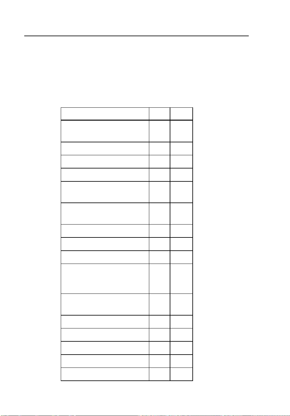
1744/1743
Users Manual
46
Technical Specifications
Logging Parameters – Overview
The following table gives an overview of the logging parameters.
Table 7. Logging Parameters – Overview
Measuring Function P A
Voltage: mean, min, max
values
z z
Current: mean, max values z z
Neutral current N z z
Voltage events z z
Power: P, |P|, S, D, PF,
tangent
z z
Power total P, |P|, S, D, PF,
tangent
z z
Energy z z
Flicker: Pst, Plt z z
Voltage harmonics z
Current harmonics (L1 or A,
L2 or B, L3 or C, N,
up to 50
th
order)
z
Interharmonics, ripple-control
signals
z
THDV (voltage) z z
THDI (current) z z
CF (crest factor current) z
Unbalance z
Frequency z
1.888.610.7664 sales@GlobalTestSupply.com
Fluke-Direct.com

Power Quality Logger
Technical Specifications
47
Maximum Number of Intervals for Logging Function P
The maximum recording period can be calculated by multiplying the interval
time defined in PQ Log with the maximum number of intervals in the
following table.
Version P, V+I A, V+I
Averaged
periods
> 24,000 > 10,000
General Information
Intrinsic uncertainty Valid for reference conditions, and guaranteed for
two years.
Quality system Developed, designed, and manufactured according to
DIN ISO 9001.
Recalibration interval Fluke recommends a recalibration interval of no
more than two years, depending on use.
Reference conditions 23 C ± 2 K, 230 V ± 10%
50 Hz ± 0.1 Hz / 60 Hz ± 0.1 Hz
Phase sequence: L1 or A, L2 or B, L3 or C
Interval length: 10 minutes, 3-phase Wye
configuration.
Power supply: 88 to 265 V ac
1.888.610.7664 sales@GlobalTestSupply.com
Fluke-Direct.com

1744/1743
Users Manual
48
Environmental Specifications
Working temperature
range
–10 °C to +55 °C
Operating temperature
range
0 °C to +35 °C
Storage temperature range –20 °C to +60 °C
Reference temperature
range
23 °C ± 2 K
Relative humidity 10 to 90%, no condensation
Housing Robust, compact housing of CYCOLOY
Protection IP65 per EN 60529
Safety EN 61010-1 600 V CAT III, 300 V CAT IV
pollution degree 2, double insulation
Type test voltage 5.2 kV ac, 50 Hz / 60 Hz, 5 s
EMC
Emission IEC/EN 61326-1, EN 55022
Immunity IEC/EN 61326-1
1.888.610.7664 sales@GlobalTestSupply.com
Fluke-Direct.com

Power Quality Logger
Technical Specifications
49
Power Supply
Functional range 88 to 660 V RMS ac absolute, 50 Hz / 60 Hz
Safety EN 61010-1 600 V CAT III, 300 V CAT IV,
pollution degree 2, double insulation
Fuse Power supply fuse can be replaced only in service
facility. Supply can be connected in parallel to
measuring inputs (up to 660 V RMS ac).
Power consumption 5 W
Memory capacity 8 MB Flash-EPROM
Intervals > 5.600 intervals, > 39 days with 10-min intervals
Events > 13.000
Memory model Linear, circular
Interface RS232, 9600 to 115000 Baud, automatic selection,
3-wire communication.
Dimensions 170 mm x 125 mm x 55 mm
Weight Approx. 0.9 kg
Measurement
A/D converter 16 bit
Sampling frequency 10.24 kHz
Anti-aliasing filter FIR-Filter, f
C
= 4.9 kHz
Frequency response Uncertainty < 1% of Vm for 40 to 2500 Hz
Interval length 1, 3, 5, 10, or 30 seconds,
1, 5, 10, 15, or 60 minutes
Averaging time for
min/max values
½ , 1 line power period
200 ms
1, 3, 5 s
Time base Resolution: 10 ms (at 50 Hz) deviation: 2 s/day
at 23 °C.
1.888.610.7664 sales@GlobalTestSupply.com
Fluke-Direct.com

1744/1743
Users Manual
50
Input Voltage
Input range V
I
P-N: 69, 115, 230, or 480 V ac
Input range V
I
P-P 120, 200, 400, or 830 V ac
Max overload voltage 1.2 V
I
Input range selection By job programming
Connections P-P or P-N, 1- or 3-phase
Nominal voltage V
N
≤ 999 kV (using PTs and ratios)
Input resistance Approx. 820 ke per channel. Lx-N
Single phase (L1 or A, L2 or B, L3 or C connected):
app. 300 ke
Intrinsic uncertainty 0.1% of V
I
Voltage transformer Ratio : < 999 kV / V
I
Ratio selection By job programming
Current Input with Flexi Set
Input ranges I
I
L1 or A, L2
or B, L3 or C, N:
15, 150, 1500, or 3000 A ac
Measuring range 0.75 A to 3000 A ac
Intrinsic uncertainty < 2% of I
I
Position influence Max. ±2% of m.v. for distance conductor to
measuring head >30 mm
Stray field influence <± 2 A for Iext= 500 A ac and distance to measuring
head >200 mm
Temperature coeff. 0.005% / K
Current transformer Ratio : ≤ 999 kA / I
I
Ratio selection By job programming
Connection 3-phase, 3-phase + N 2-phase L1 or A and L3 or C
(2 W-meter-method) 7-pole connector
1.888.610.7664 sales@GlobalTestSupply.com
Fluke-Direct.com

Power Quality Logger
Technical Specifications
51
Current Input for Clamp
Input signal: 0.5 V ac nominal (for I
I
) 1.4 V peak
Intrinsic uncertainty < 0.3% of I
I
Max. overload 10 V ac
Input resistance App. 8.2 ke
Current transformer Ratio : ≤ 999 kA / ≤ I
I
Ratio selection By job programming
1.888.610.7664 sales@GlobalTestSupply.com
Fluke-Direct.com

1744/1743
Users Manual
52
General Specifications
RMS Logging Slow Voltage Variations
Logging values: Mean value RMS values averaged over interval length
Min, Max values Averaging with selectable averaging time from
0.5 periods to 5 s
Max value Max 10 ms RMS value per interval
Min value: Min 10 ms RMS value per interval
Current Logging Values
Mean value RMS values averaged over interval length
Max value Highest RMS value per interval
Events Dips, Swells, Interruptions
Limit value Variable
Lower limit: 0 to 95% V
N
Upper limit: 105 to 120% V
N
Set in PQ Log
Range 0 to V
I
+ 20%
Logging value ½ period RMS value
Operating uncertainty < 2% of V
I
Response time ½ line power period
Flicker
Logging value Flicker severity (Pst / Plt) according to
IEC 61000-4-15
Intrinsic uncertainty Pst < 5% of m. v
Measuring range Pst 0.4 to 4
1.888.610.7664 sales@GlobalTestSupply.com
Fluke-Direct.com

Power Quality Logger
Technical Specifications
53
Power (Logging Functions A, P only) P, S, |P|
Active power P As per EN 61036, class 2
Distorting power D As per EN 61268, class 2 (A-version only)
Max value Highest value per interval
Min value Smallest value per interval
Phase uncertainty < 0.3 degrees
Conditions Conductor centered within clamp jaws or
Flexi Set
Harmonics
V
m
, I
m
, THDV, THDI per IEC/EN 61000-4-7, class B
Voltage harmonics (function A)
intrinsic uncertainty:
For V
m
< 3% V
N
: < 0.15% V
N
For V
m
≥ 3% V
N
: < 5% V
m
Current harmonics (function A)
intrinsic uncertainty
For I
m
< 10% I
N
: < 0.5% I
N
For I
m
≥ 10% I
N
: < 5% I
m
THDV (function A) intrinsic
uncertainty at V
N
For THDV < 3%: < 0.15%
For THDV ≥ 3%: < 5%
THDV (function P) intrinsic uncertainty
at V
N
For THDV < 3%: < 1%
For THDV ≥3%: < 5%
THDI (functions A, P) intrinsic
uncertainty at I
I
For THDI < 3%: < 2%
For THDI ≥ 3%: < 5%
Statistics
Frequency 42 classes for 10 s mean values
Ripple-control signals
Interharmonics 21 classes for 3 s mean values
Analysis of logging data
Programming and analysis is done by PQ Log software on PC.
1.888.610.7664 sales@GlobalTestSupply.com
Fluke-Direct.com

1744/1743
Users Manual
54
Logging Function P
Logging Values
Voltage L1 or A, L2 or B, L3 or C: phase-phase or phase-neutral:
• Voltage (mean, min, and max values)
• THDV (mean, and max values)
• Flicker Pst, Plt
• Voltage events (dips, swells, interruptions)
Current L1 or A, L2 or B, L3 or C, and N:
• Current (mean, max values), THDI
Power:
• Active power P (mean, min, and max values)
• Absolute values active power |P| (mean, min, and max values)
• Apparent power S (mean, min, and max values)
• Power Factor PF, tangent
• Energy per averaging interval
Total Power:
• Total power P, |P|, S
• 3-wattmeter and 2-wattmeter method (Aron circuitry)
Application
Power logging:
• Long-term analysis of active, reactive, apparent power
• Long-term analysis of power factor, symmetry
Disturbance analysis:
• Examination of voltage dips and swells, flicker measurement
Network optimization:
• Load measurements, acceptance of new loads
• Efficiency of compensation systems
1.888.610.7664 sales@GlobalTestSupply.com
Fluke-Direct.com

Power Quality Logger
Technical Specifications
55
Logging Function A – “All” parameters
Logging Values
All parameters for voltage quality per EN 50160:
Voltage L1 or A, L2 or B, L3 or C: phase-phase or phase-neutral:
• Voltage (mean, max, min values)
• Voltage harmonics 1
st
to 50
th
order
• THDV (harmonic contents of voltage)
• Interharmonics 5 to 2500 Hz (in steps of 0.5 Hz)
• Flicker Pst,Plt
• Unbalance
• Signaling voltages
• Frequency
• Voltage events (dips, swells, interruptions)
Current L1 or A, L2 or B, L3 or C, and N:
• Current (mean, max values)
• Harmonics of phase and neutral currents up to 50
th
order
• Crest factor and peak values of the currents
Power:
• Active power P (mean, min, and max values)
• Absolute values active power |P| (mean, min, and max values)
• Distorting power D (mean, min, and max values)
• Apparent power S (mean, min, and max values)
• Power Factor PF, tangent
• Energy per averaging interval
1.888.610.7664 sales@GlobalTestSupply.com
Fluke-Direct.com

1744/1743
Users Manual
56
Total power:
• Total power P, |P|, D, S
• 3-wattmeter method
• 2-wattmeter method (Aron circuitry)
• 2 ½ wattmeter method
Applications
Power quality:
• Voltage quality analysis according to EN 50160 over a 1-week period
(time-activated job)
• Examination of measurement quantities per standards
Disturbance analysis:
• Long-term analysis of line power voltage
• Examination of voltage dips, swells, and harmonic problems
• Flicker measurement
• Examination of ripple control signals (level)
• Specific search for disturbances through correlation of relevant
logging quantities (e.g. current, voltage, and flicker), time of
occurrence, periodicity
Network Optimization:
• Load logging
• Current logging (with Flexi Set 5 to 3000 A or clamps 1 to 1000 A)
• Capture of current peaks
1.888.610.7664 sales@GlobalTestSupply.com
Fluke-Direct.com

Power Quality Logger
PQ Log PC Application Software
57
PQ Log PC Application Software
PQ Log software for Windows
®
PCs is the application for use with the
1744/1743 Power Quality Logger. The data are also available in ASCII format.
Programs available for setting up the Logger:
• Interval length
• Memory model
• Voltage input range, nominal voltage, nominal current
• Response time for min, max values
• Connection type (P-N, P-P)
• Thresholds for event detection, interruptions
Setup:
• Internal clock (date/time)
• Define 1744/1743 Power Quality Logger designation
• Parameters for data export
• Software updates
Analysis:
• ASCII data export
• Graphical summary of all EN 50160 parameters
• Online test function
1.888.610.7664 sales@GlobalTestSupply.com
Fluke-Direct.com
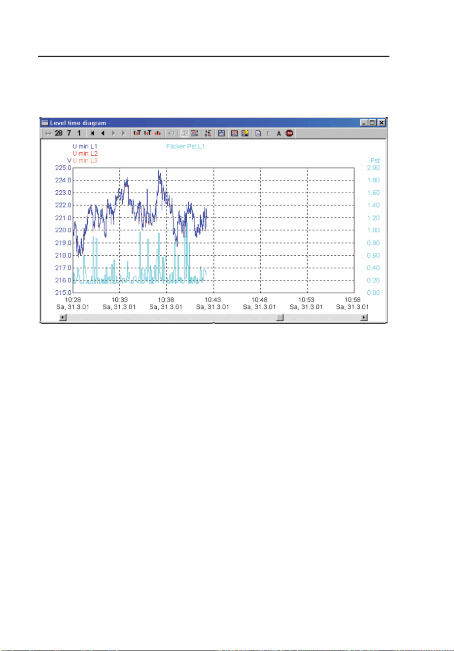
1744/1743
Users Manual
58
Online Test
The following figure shows the online test display.
egb024.bmp
Figure 18. Online Test
1.888.610.7664 sales@GlobalTestSupply.com
Fluke-Direct.com
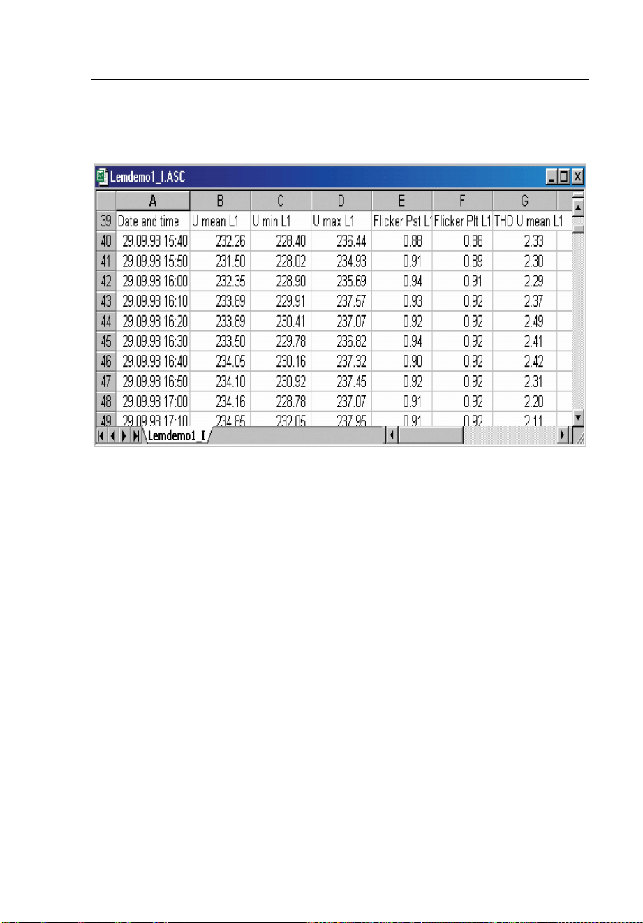
Power Quality Logger
PQ Log PC Application Software
59
ASCII Export
The following figure illustrates the ASCII export display:
egb025.bmp
Figure 19. ASCII Export
For special cases, additional evaluations are available:
• Graphic representation of measured data
• Timeplot diagrams
• Application oriented analysis
• Logging value list
• Table of events (UNIPEDE DISDIP)
• Table summary
• Cumulative frequency, harmonics (logging function A only)
• Statistical values (logging function A only)
• All exceeding table (logging function A only)
• Most critical values (logging function A only)
1.888.610.7664 sales@GlobalTestSupply.com
Fluke-Direct.com
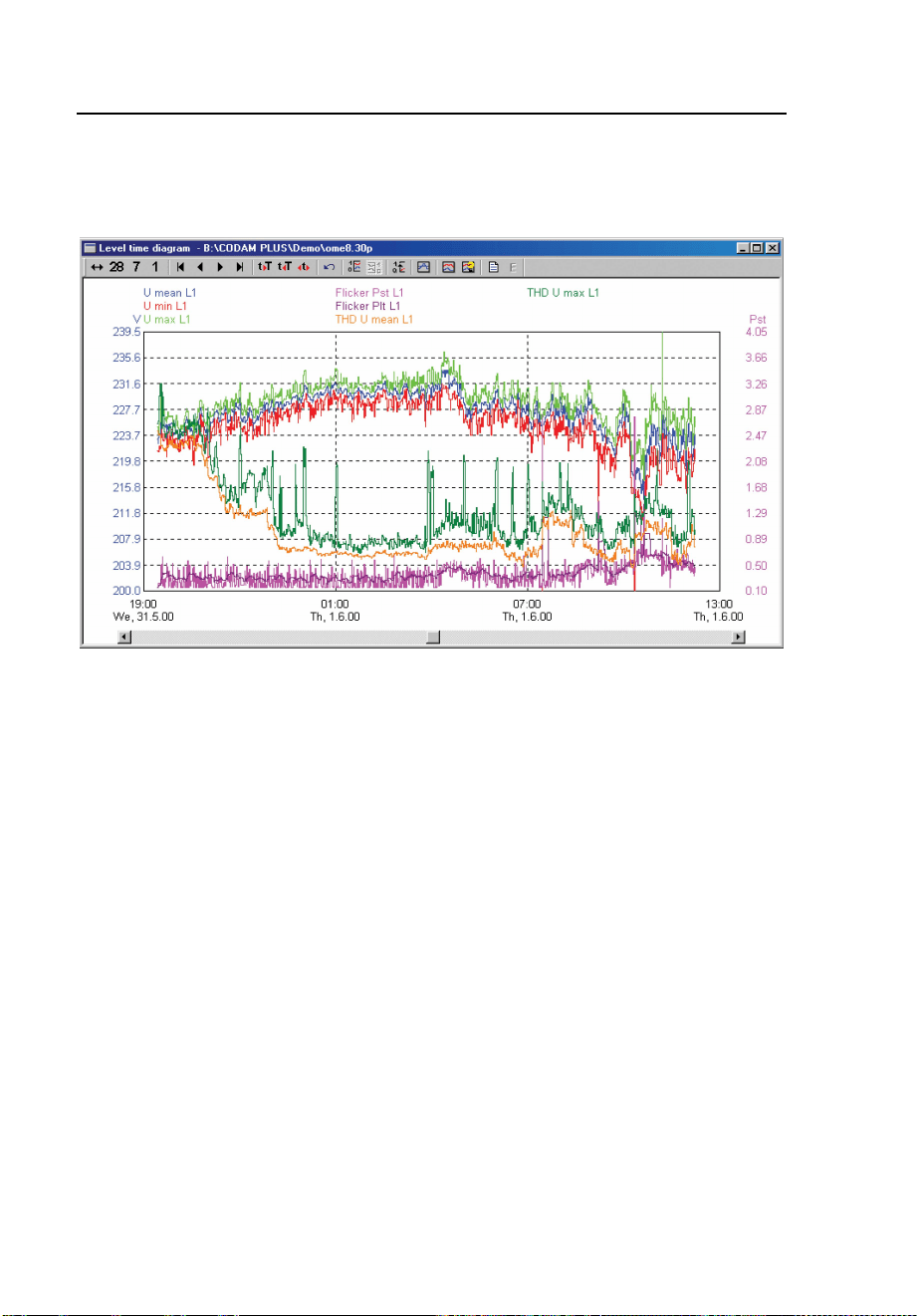
1744/1743
Users Manual
60
Timeplot diagram
The following figure shows a typical Timeplot diagram:
egb026.bmp
Figure 20. Timeplot Diagram
1.888.610.7664 sales@GlobalTestSupply.com
Fluke-Direct.com
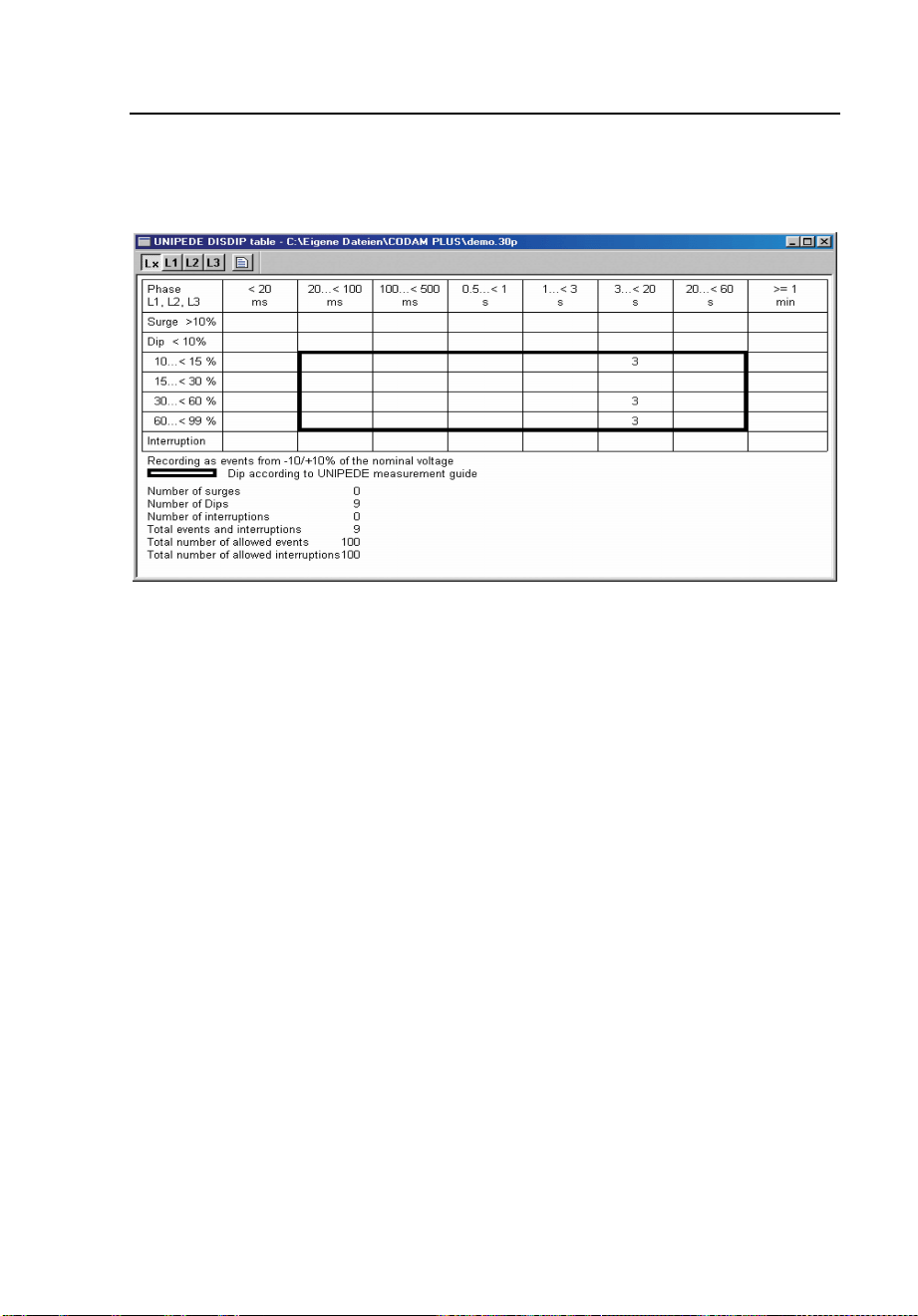
Power Quality Logger
PQ Log PC Application Software
61
UNIPEDE DISDIP Table
The following figure shows a typical UNIPEDE DISDIP table:
egb027.bmp
Figure 21. UNIPEDE DISDIP Table
1.888.610.7664 sales@GlobalTestSupply.com
Fluke-Direct.com
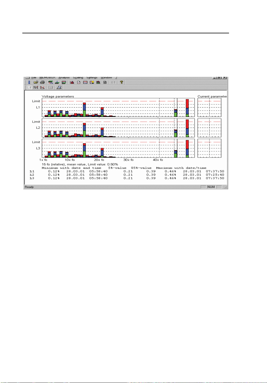
1744/1743
Users Manual
62
Cumulative Frequency – Harmonics
The following figure shows a typical display of cumulative frequencies for
current and voltage harmonics:
egb028.bmp
Figure 22. Cumulative Frequency – For Voltage and Current Harmonics
1.888.610.7664 sales@GlobalTestSupply.com
Fluke-Direct.com

63
Index
—A—
Anti aliasing filter, 28
Apparent Power, 37
—C—
Completing the Logging, 26
Connecting the clip on probes, 14
Connection modes, 27
Connections for Medium Voltage
Networks, 21
Crest Factor, 37
Current, 37
Current Harmonics, 33
—D—
Disposal, 45
—E—
Energy, 40
Evaluation, 27
Extreme values, 29
—F—
Flicker, 35
Frequency, 36
—I—
Installation at the measuring site, 17
Interharmonics, 11
Interval length, 11
I
peak
, 37
—L—
Limit values for events, 11
Lithium Battery, 45
Logging Configurations, 10
Logging input for voltages, 9
Logging segments, 11
Logging with two voltage converters and
two current transformers, 24
—M—
Maximum nominal voltages, 6, 16
Memory model, 11
Methods of Logging, 27
—N—
Nominal Voltages, 27
—P—
Phase-N, 11
Phase-Phase, 11
Power factor, 37, 39
—R—
Reactive Power, 37
—S—
Sampling rate, 28
signaling voltages, 11
Signaling voltages, interharmonics, 33
—T—
THD I, 35
THD V, 34
—U—
Unbalance, 36
User Interface, 1
—V—
Voltage dips/swells, 32
1.888.610.7664 sales@GlobalTestSupply.com
Fluke-Direct.com

1744/1743
Users Manual
64
Voltage Harmonics, 32
Voltage interruptions, 31
Voltage variations, 28
1.888.610.7664 sales@GlobalTestSupply.com
Fluke-Direct.com