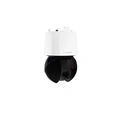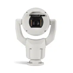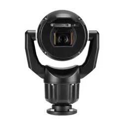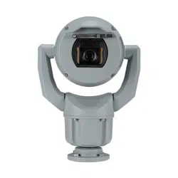
AUTODOME 7100i
NDP‑7602‑Z40 | NDP‑7602‑Z40L | NDP‑7604‑Z12L
en
User Manual


AUTODOME 7100i Table of contents | en 3
Bosch Security Systems B.V.
User Manual
2022-12 | V01 | DOC
Table of contents
1
Browser connection 5
1.1 Additional Accessories 5
1.2 System requirements 5
1.3 Establishing the connection 5
1.4 Access with Project Assistant app 6
1.5 Password protection in camera 6
2
System overview 8
2.1 Live 8
2.2 Playback 8
2.3 Configuration 8
2.4 Dashboard 9
3
Operation via the browser 10
3.1 Live page 10
3.2 Playback 13
3.2.1 Selecting the recording stream 13
3.2.2 Searching for recorded video 13
3.2.3 Exporting recorded video 13
3.2.4 Track list 14
3.2.5 Controlling playback 14
3.3 Dashboard 14
4
Configuration 15
4.1 General 15
4.1.1 Identification 15
4.1.2 User Management 15
4.1.3 Date/Time 16
4.2 Web Interface 17
4.2.1 Appearance 17
4.2.2 'Live' functions 19
4.3 Connectivity 20
4.3.1 Cloud Services 20
4.3.2 Accounts 20
4.3.3 DynDNS 21
4.4 Camera 22
4.4.1 Installer Menu 22
4.4.2 Scene Mode 28
4.4.3 Encoder Streams 32
4.4.4 Encoder Statistics 33
4.4.5 Privacy Masks 34
4.4.6 Lens Settings 35
4.4.7 PTZ Settings 36
4.4.8 Pre-positions and Tours 38
4.4.9 Pre-position settings 39
4.4.10 Sectors 40
4.4.11 Miscellaneous 40
4.4.12 Illuminator 40
4.4.13 Audio 40
4.4.14 Pixel Counter 41
4.5 Recording 41

4 en | Table of contents AUTODOME 7100i
2022-12 | V01 | DOC
User Manual
Bosch Security Systems B.V.
4.5.1 Storage Management 42
4.5.2 Recording Profiles 43
4.5.3 Maximum Retention Time 45
4.5.4 Recording Scheduler 45
4.5.5 Recording Status 46
4.5.6 Recording Statistics 46
4.5.7 Image Posting 47
4.5.8 SD Card Status 47
4.6 Alarm 48
4.6.1 Alarm Connections 48
4.6.2 Video Content Analysis (VCA) 49
4.6.3 Virtual Masks 50
4.6.4 Audio Alarm 50
4.6.5 Alarm E-Mail 51
4.6.6 Alarm Inputs 52
4.6.7 Alarm Outputs 53
4.6.8 Alarm Task Editor 53
4.6.9 Alarm Rules 53
4.7 Network 54
4.7.1 Network Services 54
4.7.2 Network Access 54
4.7.3 Advanced 56
4.7.4 Network Management 57
4.7.5 Multicast 57
4.7.6 IPv4 Filter 58
4.7.7 GB/T 28181 59
4.8 Service 59
4.8.1 Maintenance 59
4.8.2 Licenses 60
4.8.3 Certificates 60
4.8.4 Logging 61
4.8.5 Diagnostics 61
4.8.6 System Overview 61
5
Recommended Use of Your Camera 62
6
Troubleshooting 64
6.1 Completing a hardware reset 67
7
Status codes 69
8
AUX Commands 74
9
Support services and Bosch Academy 76

AUTODOME 7100i Browser connection | en 5
Bosch Security Systems B.V.
User Manual
2022-12 | V01 | DOC
1 Browser connection
1.1 Additional Accessories
Quantity Component
100 m
maximum
Ethernet cable (Cat5e or better)
* Power cable (24 VAC)
* Power cable (36 VDC)
* Alarm wiring as needed
* Audio wiring as needed
* PoE midspans IEEE 802.3bt Type 3 (60W)
* SFP modules (refer to chapter Support for Fiber optic cable installation,
in the Installation Manual)
* Media Converter
* Direct fiber connection
1 Full-sized SD card. Recommended: industrial SD cards from Western
Digital (sold separately by Bosch)
* Refer to the chapter Preparing Wiring in the Installation Manual.
1.2 System requirements
– Computer with Intel Xeon processor or better
– Graphic card with performance that matches or is better than the resolution of the
camera
– Windows10 or later
– Network access
– Google Chrome, Microsoft Edge, or Mozilla Firefox
- or -
Application software, for example, Application software, for example,
VideoSecurityClient, BVMS, or Project Assistant app.
– Configuration Manager 7.60 (or newer)
1.3 Establishing the connection
The unit must have a valid IP address to operate on your network and a compatible subnet
mask.
By default, DHCP is pre-set at the factory to On plus Link-Local so a DHCP server assigns an
IP address. The default IP address of this device is 192.168.0.1.
You can use the Configuration Manager to find an IP address. Download the software from
http://downloadstore.boschsecurity.com.
1. Start the Web browser.
2. Enter the IP address of the unit as the URL.
3. During initial installation, confirm any security questions that appear.
If a RADIUS server is used for network access control (802.1x authentication), you must
configure the device before the device can communicate with the network.

6 en | Browser connection AUTODOME 7100i
2022-12 | V01 | DOC
User Manual
Bosch Security Systems B.V.
To configure the device, connect it directly to a computer using a network cable and then set
the service-level password.
IP cameras from Bosch have many ways to connect.
The core communication protocol is called RCP+ (Remote Control Protocol plus), which
handles the connections between camera and connected clients.
Every camera can handle a maximum of 128 RCP+ connections, from which a few are used
internally, making 100+ external RCP+ connections possible for unicast, multi-unicast, or
multicast connections.
A video connection also requires one or two such connections, depending on the access
method. Assuming the accumulated requested bitrate does not exceed the available network
interface bandwidth, a minimum of five unicast connections is possible.
IP Helper
The IP Helper tool is a free PC application that makes it easy to detect Bosch cameras and
devices on your network.
Note:
If you cannot connect, the unit may have reached its maximum number of connections.
Depending on the network configuration, the device will require either one or two connectivity
options. A minimum of five unicast connections is possible. The unit can have more than 100
external Remote Control Protocol plus (RCP+) for unicast, multicast, or multicast connections,
or up to 100 connections via Video Security Client or BVMS. Some connections are used
internally.
1.4 Access with Project Assistant app
You can also use the Project Assistant app to complete the initial configuration of the camera.
In order to use this device with the Project Assistant app by Bosch, you must download the
app from the Bosch Download Store, from Google Play, or from the Apple Store.
You can access the app in several ways:
– Scan the QR code from the QIG.
– From www.boschsecurity.com, select Support > Apps and Tools > Online Apps - Video >
Bosch Project Assistant app. Select the appropriate operating system, and then click the
appropriate button to download and install the app.
– From Google Play Store (play.google.com), search for Bosch Project Assistant. Select the
app from the list. Click the Install button.
– From Apple Store (itunes.apple.com), search for Bosch Project Assistant. Select the app
from the list. Click the appropriate button to download and install the app.
1.5 Password protection in camera
The device is password-protected. The first time that any user accesses the device, the device
will prompt the user to set a password at the service level.
The camera requires a strong password. Follow the prompts in the dialog box, which specifies
what is required. The system measures the strength of the password that you enter.
When you use Configuration Manager to access your device for the first time, you must set the
initial password of the device in Configuration Manager. The Users section (General > Unit
Access > Users) displays the message, "Before you can use this device you have to secure it
with an initial password."
Note: After you set the initial password, a "lock" icon appears next to the device name in the
Devices list in Configuration Manager.
Make sure the password obeys these conditions:
– 8 to 19 characters in length

AUTODOME 7100i Browser connection | en 7
Bosch Security Systems B.V.
User Manual
2022-12 | V01 | DOC
– Upper and lower case letters
– Minimum of 1 digit
– Minimum of 1 special character
These special characters are not allowed: '@', '&', '<', '>', ':', '+'
Enter the user name (“service”) and a password in the appropriate fields. Refer to the section
User Management for more information.
You can also launch the device webpage directly. In the device webpage, an initial password
page appears, displaying input fields and a password strength gauge.
After a service-level password is set for the device, the device displays a dialog box that
prompts users to enter the user name (“service”) and the service-level password every time
that they access the device.
1. Fill in the fields User name and Password.
2. Click OK. If the password is correct, the desired page appears.
Note: New releases of software may require you to set a new and stronger password.
8 en | System overview AUTODOME 7100i
2022-12 | V01 | DOC
User Manual
Bosch Security Systems B.V.
2 System overview
Note: None of the pages are accessible until after you set a service-level password.
When a connection is established, the Live page is initially displayed.
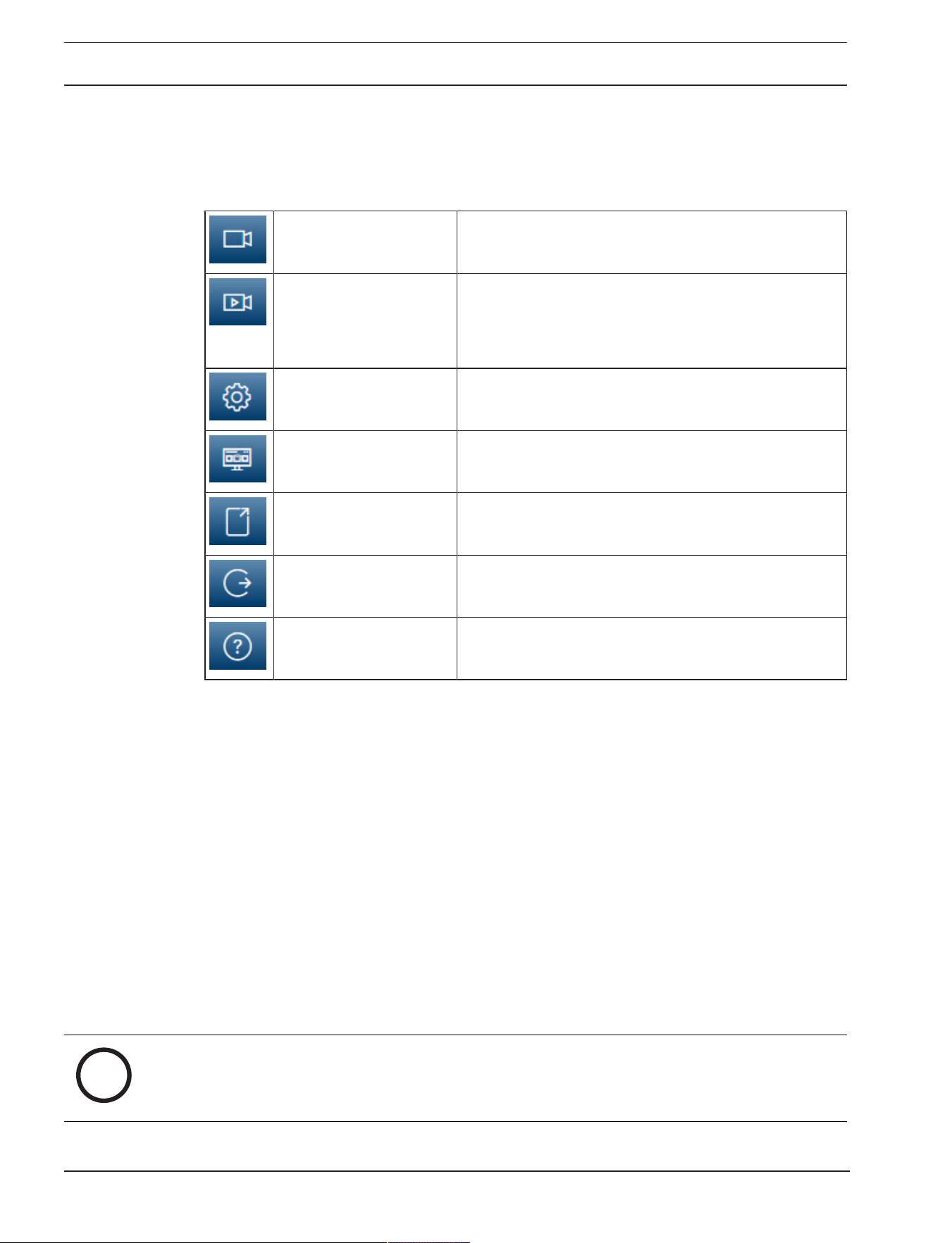
The application bar displays the following icons:
Live Click this icon to view the live video stream.
Playback Click this icon to play back recorded sequences.
This link is only visible if a storage medium has been
configured for recording. (With VRM recording, this
option is not active.)
Configuration Click this icon to configure the device.
Dashboard Click this icon to see detailed system information.
Links Click this icon to navigate to the Bosch download store.
Logout Click this icon to log out of the device.
Click this icon to get context-sensitive help for the page
you are browsing.
2.1 Live
The Live page is used to display the live video stream, and control the unit when service or
user level access is available.
2.2 Playback
The Playback page is used for playing back recorded sequences.
2.3 Configuration
The Configuration page is used to configure the unit and the application interface when
service is available.
Making Changes
Each configuration screen shows the current settings. You can change the settings by entering
new values or by selecting a predefined value from a list field.
Not every page has a Set button. Changes to pages without a Set button are set immediately.
If a page does show a Set button, you must click the Set button for a change to take effect.
i
Notice!
Most changes to the configuration settings have an immediate effect.
If a field has a Set button, press it to save the settings.

AUTODOME 7100i System overview | en 9
Bosch Security Systems B.V.
User Manual
2022-12 | V01 | DOC
Some changes only take effect after the unit is rebooted. In this case, the Set button changes
to Set and Reboot.
1. Make the desired changes.
2. Click the Set and Reboot button. The camera reboots and the changed settings are
activated.
2.4 Dashboard
The Dashboard page is used to display detailed information about the device.
The Dashboard is only visible in the application bar if the Show 'Dashboard' option is enabled
by a service-level user in the Configuration -> Web Interface -> Appearance page.

10 en | Operation via the browser AUTODOME 7100i
2022-12 | V01 | DOC
User Manual
Bosch Security Systems B.V.
3 Operation via the browser
3.1 Live page
After the connection is established, the Live page is initially displayed. It shows the live video
image on the right of the browser window. Depending on the configuration, various text
overlays may be visible on the live video image.
Other information may also be shown next to the live video image. The items shown depend
on the settings on the 'Live' functions page or upon the user access level established.
Connection
Image selection
To view a live stream of the selected video channel:
– On the left side of the browser, expand the Connection group if necessary.
– Click the Stream dropdown list arrow to see the options.
– Select the stream you want to view.
PTZ
Click and drag the virtual joystick to move the device in the intended direction.
Alternatively, you can click the directional arrow buttons to move the device in the respective
direction.
Click the + and - buttons to Zoom in and out respectively.
Click the Iris Close or Iris Open buttons to close or open the iris incrementally.
Click the Focus near or Focus far buttons to adjust the focus incrementally depending on the
object's distance.
Manual override changes in PTZ Iris and Focus are temporary. The execution of another PTZ
command resets to the automatic settings.
Pre-Positions
The Pre-positions menu provides easy access to Pre-position 1 through Pre-position 6. Select
the appropriate pre-position to view the video image for that pre-position/scene. In the lower
left of the video image, the OSD displays the Camera number (title), the Pre-position number,
and the Pre-position number stored.
Select the appropriate pre-position (1 through 6). Click to store the pre-position.
Note: If the pre-position is already stored, a dialog box displays the message, “Overwrite
current pre-position?” Click OK to overwrite, or click Cancel to cancel the operation.
Below the list of pre-positions/scenes is a drop-down list showing the stored pre-positions/
scenes.
Click to display the selected pre-position in the video image.
AUX Control
With the tab AUX Control you can enter pre-programmed keyboard control commands. These
commands are composed of a command number plus the appropriate function key (Show pre-
position, Set pre-position, AUX on, or AUX off). A valid combination either issues a command
to the device or displays an on-screen menu.
Show pre-position
Click this button to display a pre-position.
Set pre-position
Click this button to set a pre-position.

AUTODOME 7100i Operation via the browser | en 11
Bosch Security Systems B.V.
User Manual
2022-12 | V01 | DOC
AUX on
Click this button to switch an AUX command On.
AUX off
Click this button to switch an AUX command Off.
Intelligent Tracking
Select the option for object tracking. If Click is selected, use the mouse to click on an object
to track it.
When Intelligent Tracking is active, a tracking icon is shown on the image together
with the lines that track moving objects.
Digital I/O
Depending on the configuration of the unit, the alarm input and the output are displayed next
to the image. Expand the Digital I/O group if necessary.
The alarm symbol is for information and indicates the status of an alarm input:
– The symbol lights when the input alarm is active.
The alarm output allows the operation of an external device (for example, a light switch or a
door opener).
– To activate the output, click the checkmark symbol.
– The symbol lights when the output is activated.
Special Functions
Scan 360°
Click this button to start a continuous 360° pan. To stop the continuous pan, click a
directional control in the View Control tab.
Auto pan
Click to pan the device between user-defined limits. To stop the pan, click a directional
control in the PTZ tab.
Tour A / Tour B
Click one of these buttons to start the continuous playback of a recorded (guard) tour. A
recorded tour saves all manual camera movements made during the recording, including its
rate of pan, tilt and zoom speeds, and other lens setting changes.
To stop a tour, click a directional control in the View Control tab.
Note: Tour B is now intended for use with the 'IVA while moving' functions.
Focus
Click this button to activate the Auto Focus One Push mode on the camera.
The OSD displays the message, “Auto Focus: ONE PUSH.”
Custom tour
Click this button to view (in continuous playback) a custom tour that was previously
configured.
Crosshairs
Click to show/hide the crosshairs in the live image.
Recording status
The hard drive icon below the live camera image changes during an automatic recording.
The icon lights up and displays a moving graphic to indicate a running recording. If no
recording is taking place, a static icon is displayed.
12 en | Operation via the browser AUTODOME 7100i
2022-12 | V01 | DOC
User Manual
Bosch Security Systems B.V.
Recording live video
Video sequences from the displayed live video stream can be saved locally on the computer's
hard drive. The sequences are recorded at the resolution specified in the encoder
configuration. The storage location depends on the configuration of the camera.
1. Click the recording icon to record video sequences locally.
– Saving begins immediately. The red dot on the icon indicates that a local recording is
in progress.
2. Click the recording icon again to stop the local recording.
Audio Communication
Audio can be sent and received via the Live page if the device and the computer support
audio.
1. Press and hold the F12 key on the keyboard to send an audio signal to the unit.
2. Release the key to stop sending audio.
All connected users receive audio signals sent from the device but only the user who first
pressed the F12 key can send audio signals; others must wait for the first user to release the
key.
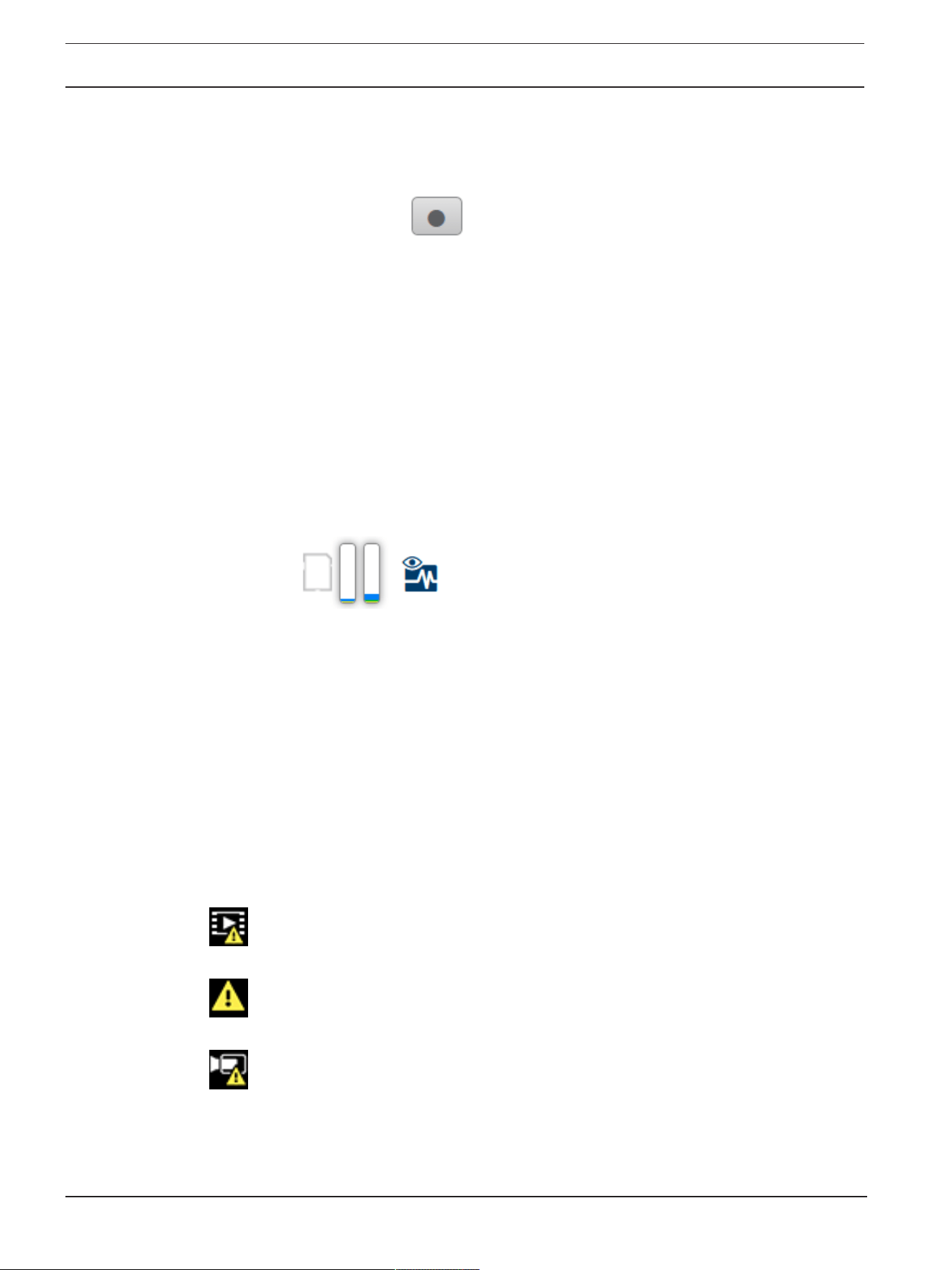
Storage, CPU and network status
When accessing the unit with a browser, the local storage , processor, WLAN, and network
status icons are shown in the upper right of the window.
When a local storage card is available, the memory card icon changes color (green, orange or
red) to indicate the local storage activity. If you hover over this icon with the mouse the
storage activity is shown as a percentage.
If you hover over the processor icon, the CPU load is shown.
If you hover over the WLAN icon, the WLAN status is shown.
If you hover over the right-hand icon, the network load is shown.
This information can help with problem solving or when fine tuning the device. For example:
– If the storage activity is too high, change the recording profile.
– If the CPU load is too big, change the VCA settings.
– If the network load is too big, change the encoder profile to reduce bitrate.
Status icons
Various overlays in the video image provide important status information. The overlays provide
the following information:
Decoding error
The frame might show artifacts due to decoding errors.
Alarm flag
Indicates that an alarm has occurred.
Communication error
A communication error, such as a connection failure to the storage medium, a protocol
violation or a timeout, is indicated by this icon.
AUTODOME 7100i Operation via the browser | en 13
Bosch Security Systems B.V.
User Manual
2022-12 | V01 | DOC
Gap
Indicates a gap in the recorded video.
Watermark valid
The watermark set on the media item is valid. The color of the check mark changes according
to the video authentication method that has been selected.
Watermark invalid
Indicates that the watermark is not valid.
Motion alarm
Indicates that a motion alarm has occurred.
Storage discovery
Indicates that a recorded video is being retrieved.
Indicates that Intelligent Tracking is enabled. If flashing, it indicates an object is being tracked.
3.2 Playback
Click Playback in the application bar to view, search or export recordings. This link is
only visible when a direct iSCSI or memory card is configured for recording (with Video
Recording Manager (VRM) recording this option is not active).
On the left side of the screen, there are four groups:
– Connection
– Search
– Export
– Track list
3.2.1 Selecting the recording stream
On the left side of the browser, expand the Connection group if necessary.
To view a recording stream:
1. Click the Recording arrow to see the options.
2. Select recording stream 1 or 2.
3.2.2 Searching for recorded video
On the left side of the browser, expand the Search group if necessary.
1. To limit the search to a particular time range, enter the date and times for the start and
stop points.
2. Select an option from the drop-down box to define a search parameter.
3. Click Search.
4. The results are shown.
5. Click a result to play it back.
6. Click Back to define a new search.
3.2.3 Exporting recorded video
Select a track from the Track list or from the Search results.

14 en | Operation via the browser AUTODOME 7100i
2022-12 | V01 | DOC
User Manual
Bosch Security Systems B.V.
The start and stop date and time are filled according to the selected track. The time values
can be adjusted, if necessary.
Select Original, to export the recorded video as its original or Condensed to export the
recorded video condensed to the given output time.
Select a target location to store the exported track.
Click to export and save the video track.
Note: The target server address can be configured in Connectivity>Accounts page.
3.2.4 Track list
The Track list shows all the available recordings.
3.2.5 Controlling playback
The time bar below the video window allows quick orientation. The time interval associated
with the sequence is displayed in the bar in gray. Arrows indicate the position of the image
currently being played back within the sequence.
If required, click in the bar at the point in time at which the playback should begin.
Change the time interval displayed by clicking the plus or minus icons, or use the mouse scroll
wheel. The display can span a range from six months to one minute.
Click the alarm jump buttons to go from one alarm event to the next or to the previous one.
Red bars indicate the points in time where alarms were triggered.
Control playback with the buttons below the video window.
The buttons have the functions that follow:
– Start/Pause playback
– Select the playback (forward or backward) speed using the speed regulator
– Step forward or backward frame-by-frame when paused (small arrows)
3.3 Dashboard
The Dashboard page is used to display detailed information about the device and is only
visible in the application bar if the Show 'Dashboard' option is enabled by a service-level user
in the Configuration > Web Interface > Appearance page.
The Dashboard page shows information on 4 topics:
– Device status
– Recording status
– Connection Status
– Services
You can also download a .JSON file with information about the device:
1. Click the Export button at the bottom of the page
2. Select a location in your hard drive to store the file

AUTODOME 7100i Configuration | en 15
Bosch Security Systems B.V.
User Manual
2022-12 | V01 | DOC
4 Configuration
4.1 General
4.1.1 Identification
Device name
Enter a unique, unambiguous name for the device (for example, the installation location of the
device). This name should be easy to identify in a list of devices in your system. The device
name is used for the remote identification of a unit, such as in the event of an alarm.
Do not use any special characters, for example &, in the name. Special characters are not
supported by the system's internal management.
Device ID
Enter a unique identifier for the device. This ID is additional identification for the device.
Video name
Enter a name for the video (for example, HDR ON).
Host name
Enter the unique identifier of your hardware device (host) that is connected to a network.
Initiator extension
Add text to an initiator name to make identification easier in large iSCSI systems. This text is
added to the initiator name, separated from it by a full stop. (You can see the initiator name in
the System Overview page.)
4.1.2 User Management
A password prevents unauthorized access to the device. You can use different authorization
levels to limit access.
Proper password protection is only guaranteed when all higher authorization levels are also
protected with a password. Therefore, you must always start from the highest authorization
level when assigning passwords.
You can define and change a password for each authorization level if you are logged into the
“service” user account.
Authentication modes
The section Authentication modes provides information about the authentication modes set
in the camera. A checkmark appears in the checkbox to the left of the mode if the mode is set.
If the mode is not set, the phrase, “No certificate installed” appears to the right of the mode
name.
Password
This field indicates if a password is set for the camera.
Certificate
A check mark in this check box indicates that at least one certificate is loaded onto the
camera. If no certificates are loaded, then “No certificate installed” appears to the right of the
text.
The Escrypt certificate is a root certificate for Bosch Security Systems that proves that the
device meets the following criteria:
– It originates from a Bosch factory that is a secure environment.
– It has not been tampered with.
Escrypt is a Bosch company and Certificate Authority (CA).
Active directory server (ADFS)
A check mark in this check box indicates that the camera uses an active directory server. If the
camera does not use ADFS, then “No certificate installed” appears to the right of the text.

16 en | Configuration AUTODOME 7100i
2022-12 | V01 | DOC
User Manual
Bosch Security Systems B.V.
Creating a new user
To create a new user, click Add in the section below Authentication modes.
In the box User, fill in the fields:
1. User name: Enter a name with a minimum of 5 and a maximum of 31 characters.
2. Group, select the appropriate authorization level:
– live is the lowest authorization level. At this level, it is only possible to view the live
video image, and switch between the different live image displays.
– user is the middle authorization level. At this level, it is possible to operate the
device and playback recordings, but configuration changes are not possible.
– service is the highest authorization level. Entering the correct password gives access
to all the functions, and allows all configuration settings to be changed.
3. Type, select either:
– Password for a new password.
Use a minimum of 6 and a maximum of 19 characters. The password must have
upper-case and lower-case letters, one or more numerical digits and one or more of
these special characters ! ? ” # $ % ( ) { } [ ] * - = . , ; ^ _ | ~ \
Special characters such as space @ : < > ‘ & + are not valid.
In this case, enter the new password a second time to eliminate typing mistakes.
– Certificate for a certificate that the new user is authorized to use.
To edit a password
To edit a password, click the pencil icon to the right of the column Type for the appropriate
User name.
Note: Use a maximum of 19 characters. Do no use special characters.
4.1.3 Date/Time
Date format
Select the required date format from the dropdown menu.
Device date/Device time
i
Notice!
Make sure that recording is stopped before synching to the PC.
If there are multiple devices operating in your system or network, it is important to
synchronize their internal clocks. For example, it is only possible to identify and correctly
evaluate simultaneous recordings when all units are operating on the same time.
1. Enter the current date. Since the unit time is controlled by the internal clock, there is no
need to enter the day of the week - it is added automatically.
2. Enter the current time or click the Sync to PC button to copy your computer's system
time to the camera.
Note: It is important that the date/time is correct for recording. An incorrect date/time setting
could prevent correct recording.
Device time zone
Select the time zone in which the system is located.
Daylight saving time
The internal clock can switch automatically between normal and daylight saving time (DST).
The unit already contains the data for DST switch-overs for many years in advance. If the date,
time and zone have been set up correctly, a DST table is automatically created.

AUTODOME 7100i Configuration | en 17
Bosch Security Systems B.V.
User Manual
2022-12 | V01 | DOC
If you decide to create alternative daylight saving time dates by editing the table, note that
values occur in linked pairs (DST start and end dates).
First, check the time zone setting. If it is not correct, select the appropriate time zone and
click Set.
1. Click Details to edit the DST table.
2. Click Generate to fill the table with the preset values from the unit.
3. Click one of the entries in the table to make changes. The entry is highlighted.
4. Click Delete to remove the entry from the table.
5. Choose other values from the list boxes under the table, to change the selected entry.
Changes are immediate.
6. If there are empty lines at the bottom of the table, for example after deletions, add new
data by marking the row and selecting values from the list boxes.
7. When finished, click OK to save and activate the table.
Time server address
The camera can receive the time signal from time server using various time server protocols,
and then use it to set the internal clock. The unit polls the time signal automatically once every
minute.
Enter the IP address of a time server here.
You can choose to have the DHCP server provide the IP address of the time server, by
selecting the Overwrite by DHCP option.
Time server type
Select the protocol that is supported by the selected time server.
– Select Time protocol if the server uses the protocol RFC868.
– The SNTP protocol supports a high level of accuracy and is required for special
applications and subsequent function extensions.
– Select TLS protocol if the server uses the RFC 5246 protocol.
– Select Off to disable the time server.
Click Set to apply the changes.
4.2 Web Interface
4.2.1 Appearance
You can adapt the appearance of the web interface and change the website language to meet
your requirements.
You can use GIF or JPEG images to replace the device logos. The image can be stored on a
web server.
Make sure that a connection to the web server is always available to display the image. The
image files are not stored on the device.
To use the original graphics, delete the entries in the Device logo field.
Website language
Select the language for the user interface.
The default language is English. After selecting a different language, click the Set button. The
page refreshes automatically. The GUI now displays field names and options as well as OSD
messages in the selected language.
Show VCA metadata
When video content analysis (VCA) is activated, additional information is displayed in the live
video stream. With the MOTION+ analysis type, for example, the sensor fields in which motion
is recorded are marked with yellow rectangles.

18 en | Configuration AUTODOME 7100i
2022-12 | V01 | DOC
User Manual
Bosch Security Systems B.V.
Using EssentialVideoAnalytics or Intelligent Video Analytics, the outlines of detected objects
are displayed in following colors:
– Red: Objects that generate an alarm event under the current settings appear on the
camera image inside a red outline.
– Orange: An object that has triggered one alarm event but does not generate another
appears inside an orange outline (example: object has crossed a line). During forensic
search, an object that triggers an alarm event has an orange outline from the beginning.
– Yellow: Objects that are detected as moving but do not generate an alarm event under
the current settings appear inside a yellow outline.
Show VCA trajectories
The trajectories (motion lines of objects) from the video content analysis are displayed in the
live video image if a corresponding analysis type is activated. The trajectory is shown as a
green line following the object base point.
Show overlay icons
Select this check box to show overlay icons on the live video image.
Show VCA items
Shows alarm fields, lines and routes configured for the video analytics in the following colors:
– Green: Fields, lines and routes used in a task are displayed in green. They can be edited
but not deleted.
– Red: Fields, lines and routes currently in alarm mode are displayed in red.
Show 'Dashboard'
Select this checkbox to enable the Dashboard in the application bar.
Secure cookies
Select this checkbox to secure the cookies sent through the camera.
i
Notice!
If cookies are secured, authentication forwarding to MPEG ActiveX and the Video Security
App is prohibited.
HTTP referrer check
Click the checkbox to enable or disable HTTP referrer checking.
The HTTP referrer check works as a protection against a CSRF (Cross-site request forgery)
attack.
If disabled, implement mitigations against CSRF attacks.
Video player
Select the type of player to be used for live mode viewing.
Latency mode
Select the required latency mode:
– Low delay: Default mode. Provides marginal buffering to display fluent video under
normal network conditions.
– Smooth video: Allows the buffer to automatically adjust to cover network jitter, inducing
higher latency.
– Unbuffered: Displays video as it is received by the decoder with minimum latency. Allows
the video to jerk if there is network jitter.
Video buffer
The value shown is calculated from the Latency mode setting. It cannot be changed.

AUTODOME 7100i Configuration | en 19
Bosch Security Systems B.V.
User Manual
2022-12 | V01 | DOC
JPEG resolution
Select the size of the JPEG image on the Live page. Options are Small, Medium, Large, 720p,
Maximum, and Resource based.
JPEG interval
You can specify the interval at which the individual images should be generated for the M-
JPEG image on the Live page.
JPEG quality
You can specify the quality at which the JPEG images appear on the Live page, if the JPEG
resolution is not Resource based.
4.2.2 'Live' functions
On this page you can adapt the functions on the LIVE page to your requirements. You can
choose from a variety of different options for displaying information and controls.
1. Check the box for the items that are to be made available on the LIVE page. The selected
items are indicated by a check mark.
2. Check whether the required functions are available on the LIVE page.
Transmit audio
You can only select this option if audio transmission is actually switched on (see Audio).The
audio signals are sent in a separate data stream parallel to the video data, and so increase the
network load. The audio data are encoded according to G.711 and require an additional
bandwidth of approx. 80 kbps per connection in each direction.
Lease time (s)
The lease time in seconds determines the time beyond which a different user is authorized to
control the camera after no further control signals are received from the current user. After
this time interval, the camera is automatically enabled for another user.
Set a lease time interval (in seconds) for the device control signals (default value is 0).
Auto logout time [min]
Set a time frame (in minutes) for the automatic logout. Default value is 0 (no automatic
logout).
Show alarm inputs
Select this checkbox if you want the alarm inputs to appear in the Digital I/O section of the
Live page.
Show alarm outputs
Select this checkbox if you want the alarm outputs to appear in the Digital I/O section of the
Live page.
Allow snapshots
Here you can specify whether the icon for saving individual images (snapshots) should be
displayed below the live image. Individual images can only be saved if this icon is visible.
Allow local recording
Here you can specify whether the icon for saving (recording) video sequences on the local
memory should be displayed below the live image. Video sequences can only be saved if this
icon is visible.
Show 'Pre-positions'
Here you can specify whether the section Pre-positions of the Live page displays a drop-down
box with the list of scenes set in the section Camera > Pre-positions and Tours of the
Configuration page.
Only the first six pre-positions are listed in the drop-down.

20 en | Configuration AUTODOME 7100i
2022-12 | V01 | DOC
User Manual
Bosch Security Systems B.V.
Show 'AUX Control'
Here you can specify whether the Live page displays the Show 'AUX Control' section.
Show ‘Intelligent Tracking’
Specify whether the Live page displays the controls for the Intelligent Tracking feature.
Show ‘Special Functions’
Specify whether the Live page displays the section 'Special Functions'.
Path for JPEG and video files
Enter the path for the storage location of individual images and video sequences saved from
the Live page.
Video file format
Select a file format for the live page display. The MP4 format does not include metadata.
4.3 Connectivity
4.3.1 Cloud Services
Operation
The operation mode determines how the camera communicates with the .
– Select On to poll the server constantly.
– Select Off to block polling.
Connectivity state
This field identifies any cloud-based services with which the camera communicates.
– If you have registered the device on a cloud-based service such as Bosch Remote Portal,
then this field identifies this fact (“Connected”).
Note: The button (Visit Remote Portal) to connect to the device with that service is
active.
– If you have not registered the device, then the message, “Not available. When
'Operation' is set to 'Auto', 'Automatic IP assignment (DHCP)' must be active to
connect to the Remote Portal“ appears.
Note: The button (Visit Remote Portal) to connect to the device with that service is not
active.
Partner services
Registration code
This area displays the state of the Stratocast registration code.
Connectivity state
This field indicates the device's connectivity state with .
– If the device is registered and the operation mode is set to On, the state will indicate that
the device is Connected (to the cloud service).
Note: The Visit Remote Portal button will become active.
– If the device is not registered or the operation mode is set to Off, the state will indicate
that the device is Not available.
Note: The Register button will become active only if you have not registered the device to
the .
4.3.2 Accounts
An account can be defined for posting and recording export.

AUTODOME 7100i Configuration | en 21
Bosch Security Systems B.V.
User Manual
2022-12 | V01 | DOC
Type
Select FTP as the account type.
Account name
Enter an account name to be shown as the target name.
Note: The fields that appear next depend on the option that you select in the field Type.
IP address
Enter the IP address of the server on which you wish to save the JPEG images.
Login
Enter the login ID for the server.
Password
Enter the password that gives you access to the server. To verify the password, click the
Check button to the right.
Path
Enter the exact path on which you wish to post the images on the server. To browse for the
correct path, click the Browse button to the right.
Maximum bit rate
Enter the maximum bit rate for the JPEG images (in kbps).
Encryption
Tick the box to use a secure FTP over TLS connection.
4.3.3 DynDNS
Enable DynDNS
A dynamic Domain Name Service (DNS) allows you to select the unit via the Internet using a
host name, without having to know the current IP address of the unit. You can enable this
service here. To do this, you must have an account with one of the dynamic DNS providers and
you must register the required host name for the unit on that site.
Note:
For information about the service, registration process and available host names refer to the
provider.
Provider
Select your dynamic DNS Provider from the drop-down list.
Host name
Enter the host name registered for the unit.
User name
Enter the user name you registered.
Password
Enter the password you registered.
Force registration now
Force the registration by transferring the IP address to the DynDNS server. Entries that change
frequently are not provided in the Domain Name System. It is a good idea to force the
registration when setting up the device for the first time. Only use this function when
necessary and no more than once a day, to avoid the possibility of being blocked by the
service provider. To transfer the IP address of the device, click the Register button.
Status
The status of the DynDNS function is displayed here for information purposes; these settings
cannot be changed.

22 en | Configuration AUTODOME 7100i
2022-12 | V01 | DOC
User Manual
Bosch Security Systems B.V.
Click Set to apply the changes.
4.4 Camera
4.4.1 Installer Menu
Application variant
Select one of the options from the dropdown list for each stream.
This functionality has no effect on video processed by 3rd party apps.
There are two application variants:
– AUTODOME 7100i (IR)
– AUTODOME 7100i (IR) - BLURRING
The blurring variant is useful when privacy is an issue, but determining the presence of motion
is still required.
i
Notice!
Select the application variant before making other changes.
The device restarts when you switch application variants. Restarting the device resets the
configuration options to factory defaults.
Sensor mode
The sensor mode specifies the base resolution and frame rates for the image quality settings.
Fast moving scenes use more frame rates (50 fps or 60 fps) for better image quality than slow
moving scenes. Adjust this setting as necessary.
This higher resolution (HD 1080p) gives maximum detail in these scenes, but can result in
motion artifacts for fast-moving objects because of the lower frame rates.
Some types of light can show flickering in the image when the frame rate is not synchronized
with the mains power frequency. To avoid this, the sensor mode frame rate should be in line
with the power frequency:
– 50Hz: 25 or 50fps
– 60Hz: 30 or 60fps
– AUTODOME 7100i IR 8MP model: 25 or 30fps
Camera LED
Select the Enabled or Disabled radio buttons to switch the Camera LED on or off.
Select Auto disable to let the device determine when the LED should be switched off.
The camera LED activates when powering on the device for the first time. The LED deactivates
automatically after 5min.
Reboot device
Click the Reboot button to reboot the camera. There is a ten (10) second pause before the
dome starts its homing phase. During the homing phase, the camera pans left and right and
tilts up and down. It also adjusts the lens focus. The entire homing phase lasts approximately
40 seconds.
System controller settings
Click the Restore button to restore some of the cameras settings to their original defaults.
Note: This operation does not affect any PTZ settings, such as Pre-positions, IVA profiles,
Tours A and B, among others.
Restore settings
Click Restore to restore all settings, except network settings, to their defaults.
Note: Clicking this button also clears the service-level password. Operators must reset the
password before doing anything else.
AUTODOME 7100i Configuration | en 23
Bosch Security Systems B.V.
User Manual
2022-12 | V01 | DOC
Restore settings
Click Defaults to restore the factory defaults for the camera. A confirmation screen appears.
Allow several seconds for the camera to optimize the picture after a reset.
Click Confirm in each dialog box that opens to complete a factory reset of the device.
This action deletes all third-party apps and resets all settings to defaults (including network
settings).
!
Caution!
Do not remove power to the unit during a factory default or a firmware update. Wait at least
two minutes for the default process to complete. If the unit appears to be "frozen" after two
minutes, then reboot the unit. Refer to Troubleshooting for more details.
4.4.1.1 Display Stamping
Various overlays or “stamps” in the video image provide important supplementary information.
These overlays can be enabled individually and are arranged on the image in a clear manner.
The drop-down menus below allow the configuration of the individual stamping options. The
respective sample windows show a preview of the configured text and background styles.
Click Set to apply the changes.
Global configuration
i
Notice!
These options can also be configured individually for all stamping settings.
Any changes to the global configuration settings will be applied to all stamping settings!
Stamping size
Select the desired font size of the overlays on the OSD: Normal or Large.
Select Custom to enable the Font size (‰) field.
Font size
Enter a number for a custom size (percentage) of the font, from 1 to 1000.
Text color
Select the color for the stamps to be displayed in.
Background color
Select the background color for the stamps to be displayed in.
If you have enabled the Transparent background option, the background color is not
displayed in the OSD.
Transparent background
Check this box to make transparent the stamp background on the image.
Camera name stamping
This field sets the position of the camera name overlay. It can be displayed at the Top, at the
Bottom or at a position of your choice that you can then specify using the Custom option. Or
it can be set to Off for no overlay information.
1. Select the desired option from the list.
2. If you select the Custom option, additional fields are displayed where you can specify the
exact position (Position (XY)).
3. In the Position (XY) fields, enter the values for the desired position.
Select the position of the camera name overlay in the drop-down box. It can be displayed at
the Top, at the Bottom, or at a position of choice using the Custom option, or it can be set to
Off for no overlay information.

24 en | Configuration AUTODOME 7100i
2022-12 | V01 | DOC
User Manual
Bosch Security Systems B.V.
If the Custom option is selected, enter values in the X and Y position fields.
Logo stamping
To place a logo on the image, select and upload an uncompressed .bmp file with a maximum
size of 1024x1024 pixels and 16 million colors to the camera. Its position on the image can
then be selected.
This option becomes available when the Camera name stamping option is enabled. Select:
– Off : This option is disabled.
– To the left of the name: The logo will be positioned to the left of the Camera name
stamping
– To the right of the name: The logo will be positioned to the right of the Camera name
stamping
– Logo only: The logo will be shown without the Camera name stamping.
Time stamping
This field sets the position of the time overlay. It can be displayed at the Top, at the Bottom or
at a position of your choice that you can then specify using the Custom option. Or it can be
set to Off for no overlay information.
1. Select the desired option from the list.
2. If you select the Custom option, additional fields are displayed where you can specify the
exact position (Position (XY)).
3. In the Position (XY) fields, enter the values for the desired position.
Display milliseconds
If necessary, you can also display milliseconds. This information can be useful for recorded
video images; however, it does increase the processor's computing time. Select Off if you do
not need to display milliseconds.
Alarm mode stamping
Select On to display a text message overlay in the image in the event of an alarm. It can be
displayed at a position of your choice that you can then specify using the Custom option. Or it
can be set to Off for no overlay information.
1. Select the desired option from the list.
2. If you select the Custom option, additional fields are displayed where you can specify the
exact position (Position (XY)).
3. In the Position (XY) fields, enter the values for the desired position.
Alarm message
Enter the message to be displayed in the image in the event of an alarm. The maximum text
length is 31 characters.
Info stamping
Check this box to activate the stamping.
The Position (XY) is displayed to enter the values in the X and Y position fields.
Title region
Select On to set or to edit the position of the Title region on the OSD.
The fields Position (XY) and (0...255) appear.
1. In the field Position (XY), specify the exact position. (The default is 10.)
2. In the field (0...255), enter the position range. (The default is 176).
Select Off to hide the region from view.

AUTODOME 7100i Configuration | en 25
Bosch Security Systems B.V.
User Manual
2022-12 | V01 | DOC
Telemetry region
Select On to set or to edit the position of the telemetry information (azimuth and elevation
(pan/tilt position)) and the zoom factor on the OSD. Refer to the section ”PTZ Settings“ to set
the pan and tilt limits.
The fields Position (XY) and (0...255) appear.
1. In the field Position (XY), specify the exact position. (The default is 10.)
2. In the field (0...255), enter the position range. (The default is 176).
Select Off to hide the region from view.
Feedback region
Select On to set or to edit the position of system feedback messages (including message for
camera settings such as focus, iris, and zoom level, etc.) on the OSD. Refer to the section
“Lens Settings” to configure these settings.
The fields Position (XY) and (0...255) appear.
1. In the field Position (XY), specify the exact position. (The default is 10.)
2. In the field (0...255), enter the position range. (The default is 176).
Select Off to hide the region from view.
Stream security
Video authentication
Select from the Video authentication drop-down box a method for verifying the integrity of
the video.
If you select Watermarking, all images are marked with an icon. The icon indicates if the
sequence (live or saved) has been manipulated.
If you want to add a digital signature to the transmitted video images to ensure their integrity,
select one of the cryptographic algorithms for this signature.
Signature interval [s]
For certain Video authentication modes, enter the interval (in seconds) between insertions of
the digital signature.
4.4.1.2 Positioning
The Positioning feature describes the location of the camera and the perspective in the
camera’s field of view.
Perspective information is essential to Video Analytics, as it enables the system to compensate
for the illusory smallness of distant objects.
Only through use of perspective information is it possible to distinguish objects such as
persons, bicycles, cars and trucks, and accurately compute their real size and speeds as they
move through 3D space.
However, to calculate perspective information accurately, the camera must be directed at a
single, flat horizontal plane. Multiple and inclined planes, hills, stairs can falsify perspective
information and produce incorrect object information such as size and speed.
Mounting position
The mounting position describes the perspective information that is also often called
calibration.
In general, the mounting position is determined by the parameters of the camera such as
height, roll angle, tilt angle, and focal length.
The height of the camera must always be entered manually. Whenever possible, roll angle and
tilt angle are provided by the camera itself. The focal length is provided, if the camera has a
built-in lens.
Select the appropriate mounting position of the camera. Options that appear depend on the
type of camera.

26 en | Configuration AUTODOME 7100i
2022-12 | V01 | DOC
User Manual
Bosch Security Systems B.V.
Height [m]
The height describes the vertical distance from the camera to the ground plane of the
captured image. Typically the elevation of the mounted camera above the ground.
Enter the height in meters of the position of the device.
Sketch
The Sketch functionality offers an additional, half-automatic calibration method. This
calibration method allows you to describe the perspective in the camera’s field of view by
drawing vertical lines, ground lines, and ground angles in the camera image and entering the
correct size and angle. Use the Sketch functionality if the result of the automatic calibration is
not sufficient.
You can also combine this manual calibration with the values for roll angle, tilt angle, height
and focal length calculated by the camera or entered manually.
Click to improve the automatic calibration. The Sketch-based calibration window is displayed.
VCA Profile
Select the appropriate profile.
Global
Select the Global check box to use the global, overall calibration for all AUTODOME and MIC
cameras.
Alternatively, clear the Global check box to obtain a local calibration and overwrite the global
calibration for the selected profile. To do this, select the VCA profile before.
i
Notice!
The Sketch functionality is only available for configured and assigned pre-positions.
For AUTODOME and MIC cameras, configure the pre-positions of the camera and assign the
pre-positions to one of the available 16 VCA profiles before calibration with Sketch.
Applications are pre-positions of cameras directed towards different ground planes, an
optimized calibration for inclined ground planes or large focal lengths. A local pre-position
calibration does not change the global calibration.
It is also possible to calibrate pre-positions without entering a global calibration.
Calculate
Select the Calculate check box to obtain the roll angle, tilt angle, height and focal length from
the sketched calibration elements - vertical lines, ground lines and angles - you have placed in
the camera.
Clear the Calculate check box to enter a value manually or to refresh to the values provided by
the camera itself.
Tilt angle [°]
Enter the angle manually, or click the refresh icon to obtain values that are provided by any
sensors that the camera may have. As an alternative, select the Calculate check box to get
values based on the calibration elements that are marked on the image.
Height [m]
Enter the height manually, or click the refresh icon to obtain values that are provided by any
sensors that the camera may have. As an alternative, select the Calculate check box to obtain
values based on the calibration elements that are marked on the image.
Focal length [mm]
Enter the focal length manually, or click the refresh icon to obtain values that are provided by
any sensors that the camera may have. As an alternative, select the Calculate check box to
obtain values based on the calibration elements that are marked on the image.
AUTODOME 7100i Configuration | en 27
Bosch Security Systems B.V.
User Manual
2022-12 | V01 | DOC
Calibrating cameras using the Sketch-based calibration window
To determine non-automatically set values:
1. Enter the value for tilt angle, roll angle, height and focal length if the value is known, for
example, by measuring the height of the camera above the ground, or reading the focal
length from the lens.
2. For each value that is still unknown, select the Calculate check box, then place a
calibration element on the camera image. Use these calibration elements to trace
individual outlines of the displayed environment in the camera image and define the
position and size of these lines and angles.
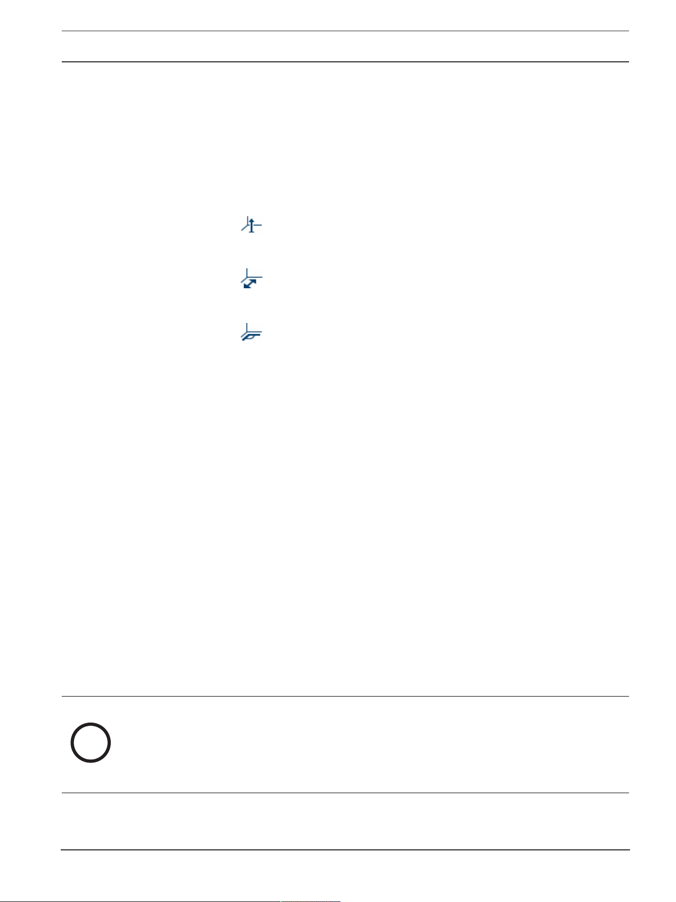
– Click to place a vertical line across the image.
A vertical line corresponds to a line that is perpendicular to the ground plane, such
as a door frame, edge of a building or a lamp post.
– Click to place a line across the ground in the image.
A line on ground corresponds to a line that is on the ground plane, such as a road
marking.
– Click to place an angle on the ground in the image.
The angle on ground represents an angle lying on the horizontal ground plane, such
as the corner of a carpet or parking bay markings.
3. Adjust the calibration elements to the situation:
– Enter the real size of a line or angle. To do this, select the line or angle, then enter
the size in the corresponding box.
Example: You have placed a line on ground across the lower side of an automobile.
You know that the automobile is 4m long. Enter 4m as the length of the line.
– Adjust the position or length of a line or angle. To do this, drag the line or angle or
move the end points to the desired position in the camera image.
– Remove a line or angle. To do this, select the line or angle, then click the trash can
icon.
Note:
Blue lines indicate calibration elements added by you.
White lines represent the element as it should be positioned on the camera image based
on the current calibration results or the determined calibration data.
Horizon
If the values correspond, areas on the camera image have a colored background.
blue: This area corresponds to the sky. The bottom line of the blue area represents the
horizon. Objects that are detected in the blue area cannot be filtered correctly by size or
speed.
If the camera is installed at a relatively low height in a building, for example, this display is not
required, because the entire area covered by the camera is below the horizon.
i
Notice!
If the distance to the camera (geolocation) is not relevant, it is enough to determine height
and focal length in relation to each other. This allows a simple calibration by marking 2-3
persons ‑ each with a vertical line ‑ and setting their size. 1,80m (71 in.) for all is sufficient.
Use at least one person in the front and one person in the background of the image for best
results.

28 en | Configuration AUTODOME 7100i
2022-12 | V01 | DOC
User Manual
Bosch Security Systems B.V.
Coordinate system
The Coordinate system feature describes the position of the camera in a local Cartesian or
the global WGS 84 coordinate system. The camera and the objects tracked by the video
analytics are displayed on a map.
Select the coordinate system and enter the appropriate values in the additional input fields
that appear depending on the coordinate system selected.
Cartesian
The Cartesian coordinate system describes each point in the space by a combination of the
position on three orthogonal axes X, Y and Z. A right-handed coordinate system is used, where
X and Y span the ground plane and Z describes the elevation of the ground plane.
X [m]
The location of the camera on the ground on the X-axis.
Y [m]
The location of the camera on the ground on the Y-axis.
Z [m]
The elevation of the ground plane. To determine the elevation of the camera, add the Z [m]
value and the Height [m] value of the camera.
WGS 84
The WGS 84 coordinate system is a spherical coordinate system description of the world and
used in many standards including GPS.
Latitude
Latitude is the north-south position of the camera in the spherical coordinate system WGS 84.
Longitude
Longitude is the east-west position of the camera in the spherical coordinate system WGS 84.
Ground level [m]
The elevation of the ground above sea level. To determine the elevation of the camera, add the
Ground level [m] value and the Height [m] value of the camera.
Azimuth [°]
The orientation of the camera in a counter-clockwise angle starting with 0° in the east (WGS
84) or on the X-axis (Cartesian). If the camera is directed towards the north (WGS 84) or the
Y-axis (Cartesian), the azimuth is 90°.
4.4.2 Scene Mode
A scene mode is a collection of image parameters that are set in the camera when that
particular mode is selected (installer menu settings are excluded). Several pre-defined modes
are available for typical scenarios. After a mode has been selected, additional changes can be
made through the user interface.
Customize the mode, if necessary, for the specific requirements of the site by selecting
different values for the fields below.
Current mode
Select the mode you wish to use from the drop-down menu.
– Standard
– Sensitivity boost
This mode provides maximum sensitivity in low light scenes by using longer exposure times,
resulting in bright images even in extreme low light.
– Fast movement

AUTODOME 7100i Configuration | en 29
Bosch Security Systems B.V.
User Manual
2022-12 | V01 | DOC
This mode is used for monitoring fast moving objects like cars in traffic scenes. Motion
artifacts are minimized and the image is optimized for a sharp and detailed picture in color
and monochrome.
– Vibrant
This mode provides a more vivid image with increased contrast, sharpness, and saturation.
– Color Only (Traffic)
In this mode, the camera does not switch to monochrome mode at low light levels. The mode
is optimized to minimize motion artifacts and to capture the color of vehicles/pedestrians and
traffic lights, even at night, for scenarios such as city surveillance and traffic monitoring.
– Illuminator
Illuminator is used to optimize performance when using an illuminator accessory.
– Custom mode #1
If necessary, select a custom mode.
– Custom mode #2
If necessary, select a second custom mode.
Mode ID
The name of the selected mode is displayed.
Copy mode to
Select the mode from the drop-down menu to which you wish to copy the active mode.
Restore mode defaults
Click Restore Mode Defaults to restore the factory default scene modes. Confirm your
decision.
4.4.2.1 Picture Settings
Color
White Balance
Adjusts the color settings to maintain the quality of the white areas of the image.
– ATW: allows the camera to adjust color reproduction continuously.
– Indoor: white balance tracking for indoor use.
– Outdoor: white balance tracking for outdoor use.
– AWB hold: places the ATW on hold and saves the color settings.
– Extended ATW (default): allows the camera to adjust constantly for optimal color
reproduction.
– Manual: Red and Blue gain can be set manually to a desired position.
Red Gain
The red gain adjustment offsets the factory white point alignment (reducing red introduces
more cyan).
Blue Gain
The blue gain adjustment offsets the factory white point alignment (reducing blue introduces
more yellow). It is only necessary to change the white point offset for special scene
conditions.
Note: The fields Sodium red level and Sodium blue level appear only when the value in the
field White balance is “Sodium lamp auto” or “Sodium lamp.”
This feature is not supported by 1080p resolution devices.
Saturation
Select the percentage of light or color in the video image.
Color hue
Select the degree of color in the video image.

30 en | Configuration AUTODOME 7100i
2022-12 | V01 | DOC
User Manual
Bosch Security Systems B.V.
Exposure and gain control
Brightness
Enter the value to adjust the brightness of the video image to your working environment.
This feature is only supported by 1080p resolution devices.
Contrast
Enter the value to adjust the contrast of the video image to your working environment.
This feature is only supported by 1080p resolution devices.
Gain control
Adjusts the automatic gain control (AGC).
– AGC (default): Automatically adjusts the gain to the lowest possible value needed to
maintain a good picture.
– Fixed: no enhancement. This setting disables the Max. Gain Level option.
Fixed gain
Select the desired number for Fixed gain from the drop-down box.
Maximum gain level
Select the desired maximum gain level from the drop-down list.
Note: This list is locked when Gain control is set to Fixed.
AE-response speed
Select the speed of the response of auto exposure. Options are Super slow, Slow, Medium
(default), Fast.
Shutter Mode
– Fixed: The shutter mode is fixed to a selectable shutter speed.
– Automatic exposure: increases camera sensitivity by increasing the integration time on
the camera. This is accomplished by integrating the signal from a number of consecutive
video frames to reduce signal noise.
If you select this option, the camera disables Shutter automatically.
Shutter
Adjusts the electronic shutter speed (AES). Controls the time period for which light is
gathered by the collecting device. The default setting is 1x (60 Hz: 1/30, 50 Hz: 1/25)
Maximum automatic exposure
Use this field to limit the integration time when Frame Integration is active.
Default shutter limit
The camera tries to hold this shutter value as long as sufficient ambient light is available in the
scene.
Backlight compensation
The function will ignore small areas of high illumination directly into the camera. The function
increases the brightness of the overall screen to make sure that subjects and the larger
portion of the scene remain bright.
Select Off to stop Backlight compensation. (Default)
Select On to start Backlight compensation.
Note: You cannot use High dynamic range and Backlight compensation at the same time.
(When High dynamic range is On, Backlight compensation is Off.)
※ Backlight compensation does not work in Fixed shutter mode.
High sensitivity
Adjusts the level of intensity or lux within the image. Select from Off or On.
This feature is only available for the AUTODOME 7100i IR 8MP model.

AUTODOME 7100i Configuration | en 31
Bosch Security Systems B.V.
User Manual
2022-12 | V01 | DOC
Day/night
Night mode
Selects night mode (B/W) to enhance lighting in low light scenes. Select from the following
options:
– Monochrome: Forces the camera to stay in Nigh Mode and transmit monochrome images.
– Color: The camera does not switch to Night Mode regardless of ambient light conditions.
– Auto (default): The camera switches out of Night Mode after the ambient light level
reaches a pre-defined threshold.
Night mode threshold
Adjusts the level of light at which the camera automatically switches out of night mode (B/W)
operation. Select a value between 10 and 55 (in increments of 5; default 40). The lower the
value, the earlier the camera will switch to color mode.
Night mode priority
Select the option to which the camera should give priority while in night mode:
– Motion
– Color (default)
The Night mode priority function is only available for 1080p devices.
Night mode shutter
Indicates the point of switching from illumination in color to illumination in monochrome when
a selection is made for Night mode priority.
4.4.2.2 Enhance
All settings on this page except for Noise reduction are scene-mode specific. This means that
you can adjust the sharpness/noise suppression/HDR on each scene mode.
High dynamic range
The High dynamic range mode uses an electronic shutter to capture multiple images with
different exposure times and to reproduce a high-contrast frame. The output frame combines
the bright area captured by the high-speed shutter image and the dark area captured by the
low-speed shutter image. The result is that you can view details in both the bright areas
(highlights) and the dark areas (shadows) of a scene at the same time.
– Use the radio buttons to turn High dynamic range on or off.
Note: High dynamic range does not work in Fixed shutter mode.
Stabilization
Stabilization reduces camera shake in both the vertical and horizontal axis. The 1080p
resolution camera compensates for the movement of the image by up to 2% of the image size.
This feature is ideal for cameras mounted on a pole or mast, or on another location that
shakes frequently.
– On - Stabilization is always on.
– Off - Stabilization is disabled.
Sharpness mode
Select the appropriate sharpness mode. Options are Manual and Auto.
Sharpness level
This field is active when Sharpness mode is set to Manual.
Adjust the level of sharpness of the video image (from 1 to 15) using the slider.
Adjustments to the Sharpness level appear on the OSD.
Gamma correction
This function lets you adjust the image contrast in the original scene, to make it lighter or
darker. Contrast lets you get more detail in a dark area, or get video with more contrast.

32 en | Configuration AUTODOME 7100i
2022-12 | V01 | DOC
User Manual
Bosch Security Systems B.V.
Use the slider to adjust the Gamma correction value. The higher the number, the better the
image contrast.
Intelligent Defog
Select the required Intelligent Defog option. This feature continuously adjusts image
parameters to provide the best picture possible under foggy or misty conditions.
Intelligent Defog intensity
Select the intensity level for the defog feature from the dropdown list.
Note: This field is active only when the option in Intelligent Defog is On.
Noise suppression
Adjust the balance between noise suppression in a frame over frame averaging way, at the
cost of motion blur. The higher the value the more noise is removed at the cost of more blur in
moving parts of the scene to achieve a lower bitrate and vice-versa for lower values.
The optimum for most scenes is value zero.
Noise reduction
By default, this option is On.
Noise reduction On enables temporal noise reduction, which reduces random video noise in
the picture by averaging pixels across time if the difference between them is below a
threshold. Off disables temporal noise reduction.
Use the radio buttons to turn 2D and 3D noise reduction on or off.
Select Auto to have the device adjust the 2D and 3D noise reduction level automatically.
4.4.2.3 Scene Mode Scheduler
The scene mode scheduler is used to determine which scene mode should be used during the
day and which scene mode should be used during the night.
1. Select the mode you wish to use during the day from Marked range drop-down box.
2. Select the mode you wish to use during the night from Unmarked range drop-down box.
3. Use the two slider buttons to set the Time ranges.
4.4.3 Encoder Streams
Stream prioritization
Click Default to return the profile to the factory default values.
Select which stream should be prioritized to ensure that no frames are dropped.
Coding standard
Select the maximum stream resolution as provided per stream.
Stream limits is a mandatory selection to pre-assign the maximum available resolution for each
of the four H.264/H.265 streams. If a lower resolution is selected, you will be more flexible in
streaming options on the second and third stream. The fourth JPEG stream always shows the
maximum resolution available in the camera.
Stream 1 always runs at the maximum selected resolution in stream limits. On stream 2 and 3,
you can select various downscaled resolutions.
Active profile
Active profile shows the profile that is in use and can be set differently per stream.
If no edge recording or VRM recording is active, the device switches to the Non-recording
profile.
Stream 1 always runs at maximum selected resolution in stream limits. On stream 2 and 3, you
can select various downscaled resolutions.
Non-recording profile
Select the required profile for the non-recording mode for each stream.

AUTODOME 7100i Configuration | en 33
Bosch Security Systems B.V.
User Manual
2022-12 | V01 | DOC
If you activate the recording function, the active profile switches from Non-recording profile
to Active profile.
The Active profile follows the scheduled profiles under Recording Profiles.
This behavior is only applicable when using Bosch recording solutions, including edge
recording or VRM recording. Third-party recording solutions might use the Non-recording
profile.
If no edge recording or VRM recording is active, the active profile is managed by way of the
dropdown list of Non-recording profile.
If edge recording or VRM recording is active, the active profile is managed by way of the menu
in Recording Profiles.
Default Profile name Description
1: HD Image Optimized For an HD image, the video bit rate and frame quality are
adjusted to ensure that the picture quality is the priority.
2: HD Balanced For an HD image, the video bit rate and frame quality are
adjusted to a median profile for everyday use.
3: HD Bit Rate Optimized For an HD image, the video bit rate and frame quality are
adjusted to ensure that the bit rate is the priority.
4: SD Image Optimized For an SD image, the video bit rate and frame quality are
adjusted to ensure that the picture quality is the priority.
5: SD Balanced For an SD image, the video bit rate and frame quality are
adjusted to a median profile for everyday use.
6: SD Bit Rate Optimized For an SD image, the video bit rate and frame quality are
adjusted to ensure that the bit rate is the priority.
7: DSL Optimized Ideal for encoding on a DSL uplink where bit rate limitations are
critical.
8: 3G Optimized Ideal for encoding on a 3G uplink where bit rate limitations are
critical.
Click the pencil button to open the Encoder profiles page to edit the respective encoder
profile.
Permanent metadata display
Select one of the options from the dropdown list for each stream.
This functionality has no effect on video processed by 3rd party apps.
i
Notice!
All parameters combine to make up a profile and are dependent on one another. If you enter a
setting that is outside the permitted range for a particular parameter, the nearest permitted
value will be substituted when the settings are saved.
Frame and bit rate test
Click to open the Frame and bit rate test window.
4.4.4 Encoder Statistics
This section gives the user information about the bit rate of the device. For each scene, it is
possible to determine the best target/max bit rate through the graphic shown.

34 en | Configuration AUTODOME 7100i
2022-12 | V01 | DOC
User Manual
Bosch Security Systems B.V.
Stream
Stream
Identifies the current stream (1, 2, or 3).
Zoom
Identifies the current zoom factor of the camera (1x, 2x, 4x, or 8x).
Averaging period
Identifies how often (in seconds, minutes, hours, days or weeks) the encoder time is
synchronized to the actual time.
4.4.5 Privacy Masks
Privacy Masking is used to block out a specific area of a scene from being viewed. Masks can
be configured as a gray area with four corners. You may define a total of 24 privacy masks.
Pattern
Select the color of the mask as it will appear in live video: Gray
Privacy mask
Select the number of the Privacy mask. A colored rectangle appears in the unlabeled video
preview window above the Set button.
Click the plus button to add a mask. Between three to eight vertices can be added for each
mask.
Note: If a mask already exists, this button displays a trash can icon instead. Press this button
to delete the existing mask.
To configure the mask:
– Double-click on the edges to add or remove nodes.
– Click and drag the nodes to position them correctly.
1. Select the privacy mask number to apply to the scene. The preview window displays a gray
rectangle (Mask Outline) in the scene.
2. Click the View Control link; the video control window appears next to the preview window.
3. Navigate to the scene where the privacy mask is required.
4. Use the Zoom controls to zoom in so that the object to be covered is approximately the
same size as the Mask Outline.
5. Use the Pan/Tilt controls to center the object inside the Mask Outline.
Note: Do not move the mask outline at this time. It should remain in the center of the preview
window.
6. If required, place the cursor on a corner or on a vertex of the mask rectangle, and then click
and drag to expand or to shrink the Mask Outline.
– To avoid hiding too much of the scene, don’t expand the mask outline more than twice
the default size.
– To provide the optimum mask performance, don’t shrink the mask outline to less than
half of the default size.
7. Click the Enabled check box to activate the privacy mask.
8. Move the privacy mask if desired. Place the cursor inside the privacy mask area in the
preview window and then click and drag to move the privacy mask. Note: Keep it as close to
the center of the Preview Window as possible.
9. Click SET to save the size and the position of the privacy mask.
10. The mask expands by 10% for a few seconds to illustrate how much the mask size will
increase during Pan/Tilt movement.
11. To hide an individual mask, select the mask number and clear the Enabled check box.
12. To hide all masks from an image view, click the Disable Masks check box.

AUTODOME 7100i Configuration | en 35
Bosch Security Systems B.V.
User Manual
2022-12 | V01 | DOC
Note: If you choose to hide all masks, you must enable each individual mask to show the mask
in the scene.
13. To display IVA behind privacy masks, click the IVA behind masks check box.
i
Notice!
Draw the mask at 50% optical zoom or less for improved masking performance.
Draw the mask 10% larger than the object to ensure that the mask completely covers the
object as the camera zooms in and out.
i
Notice!
The camera disables the Privacy Mask feature if the orientation of the camera is set to
Inverted. Refer to Installer Menu for orientation settings.
4.4.6 Lens Settings
Focus
Autofocus
Continuously adjusts the lens automatically to the correct focus for the sharpest picture.
– One Push (default; commonly called “Spot Focus”): activates the Auto Focus feature after
the camera stops moving. Once focused, Auto Focus is inactive until the camera is moved
again.
– Auto Focus: Auto Focus is always active.
– Manual: Auto Focus is inactive.
Focus speed
Use the slider (from 1 to 8) to control how fast the Auto focus will readjust when the focus
becomes blurred.
IR focus correction
Optimizes the focus for IR lighting. Options are: On, Off (default).
Day near limit [m]
Select the distance (in meters), from 0.1 to 20 m, for the minimum distance of the zoom focus
during the day.
Night near limit [m]
Select the distance (in meters), from 0.1 to 20 m, for the minimum distance of the zoom focus
during the night.
Iris
Auto iris
Automatically adjusts the lens to allow the correct illumination of the camera sensor. This type
of lens is recommended for use where there are low light or changing light conditions.
– Constant (default): camera constantly adjusts to varying light conditions (default).
If you select this option, the camera makes the following changes automatically:
– Gain Control: switches to AGC.
– Shutter Speed: switches to default.
– Manual: camera must be manually adjusted to compensate for varying light conditions.
Auto iris level
Increases or decreases brightness according to the amount of light. Type a value between 1
and 15.
Available only with Constant Iris mode.

36 en | Configuration AUTODOME 7100i
2022-12 | V01 | DOC
User Manual
Bosch Security Systems B.V.
Zoom
Maximum zoom speed
Controls the zoom speed.
Zoom limit
Select the appropriate limit for zooming the camera: 20x, 30x, or 40x.
Digital zoom
Digital zoom is a method of decreasing (narrowing) the apparent angle of view of a digital
video image. It is accomplished electronically, without any adjustment of the camera's optics,
and no optical resolution is gained in the process.
Select On to enable this feature.
Select Off to disable this feature.
4.4.7 PTZ Settings
Auto pan speed
Continuously pans the camera at a speed between right and left limit settings. Type a value
between 1 and 60 (expressed in degrees per second), inclusive. The default setting is 30.
Inactivity
Selects the time period the dome must be not controlled until the inactivity event will be
executed.
– Off (default): camera remains on a current scene indefinitely.
– Pre-position 1: camera returns to Pre-position 1.
– Previous AUX: camera returns to the previous AUX activity.
Inactivity period
Determines the behavior of the camera when the control for the camera is inactive. Select a
time period from the pull-down list (3 s - 24 h). The default setting is 30 seconds.
Number of sectors
Select the appropriate number of sectors (for example, 4, 6, 8, 9, 12, or 16).
Note: The number that you select in this field determines the number of sectors that appear in
the Sectors page (below).
Auto pivot
The Auto pivot tilts the camera through the vertical position as the camera is rotated to
maintain the correct orientation of the image. Set the Auto Pivot to On (default) to
automatically rotate the camera 180º when following a subject traveling directly beneath the
camera. To disable this feature, click Off.
Freeze frame
Select On to freeze the image while the camera moves to a predetermined scene position.
Azimuth
Select On to display azimuth/elevation readings.
Select Off to hide azimuth/elevation readings.
Maximum pan speed [%]
Select the maximum pan speed (in percent).
Maximum tilt speed [%]
Select the maximum tilt speed (in percent).
Tracking zoom-out limit [%]
This parameter defines the zoom ratio percentage to which the camera zooms out after
Tracking idel time [s] stops tracking, or if Intelligent Tracking loses visibility of an object being
tracked. This allows the camera to re-acquire the target in a new, wider FoV.

AUTODOME 7100i Configuration | en 37
Bosch Security Systems B.V.
User Manual
2022-12 | V01 | DOC
Tracking idle time [s]
This parameter allows the camera to stop tracking motion of certain objects, such as a tree or
a flag swaying in the wind, in a confined area after the specified number of seconds.
Auto pan left limit
Sets the left Auto Pan limit of the camera. Use the preview window to move the camera to the
left pan limit and click the Set button. The camera will not move past this limit when in Auto
Pan Between Limits mode (AUX 2 ON).
To move to the limit position, click the Show button.
Auto pan right limit
Sets the right Auto Pan limit of the camera. Use the preview window to move the camera to
the right pan limit and click the Set button. The camera will not move past this limit when in
Auto Pan Between Limits mode (AUX 2 ON).
To move to the limit position, click the Show button.
Tilt up limit
Sets the upper tilt limit of the camera. Use the preview window to move the camera to the tilt
limit and click the Set button.
To clear the Tilt up limit, click the Clear button.
Pan offset
Click Set to set the pan offset for the camera.
Click Clear to clear the pan offset position.
Tour A / Tour B
Starts and stops the recording of a recorded (guard) tour.
The camera can make up to two (2) recorded tours. A recorded tour saves all manual camera
movements made during the recording, including its rate of pan, tilt and zoom speeds, and
other lens setting changes. The tour does not capture camera video during the recording of
the tour.
Note 1: You can save a total of 15 minutes of recorded actions between the two tours.
To record a tour:
4 Click the Start Recording button. The system prompts you to overwrite the existing tour.
4 Click Yes to overwrite the existing tour movements.
4 Click the View Control link, under the image cameo, click the PTZ controls under the Live
preview section to access the directional and zoom controls.
4 Use the PTZ controls under the Live preview section to make the necessary camera
movements.
4 Click the Stop Recording button to save all actions.
Note: Tour B is now intended for use with the 'IVA while moving' functions.
Compass
The camera allows a user to display the compass heading of the camera in the lower-right
corner of the image display. The camera displays the cardinal or intercardinal (N, NE, E, SE, S,
SW, W, NW) heading in which the camera is pointing.
You must first calibrate the camera to North before the camera displays accurate compass
headings. The camera uses this calibration, usually set to magnetic North, as the zero degree
pan position and as the North compass heading. The camera then displays the compass
heading based on the number of degrees from the North calibration point.
To set the North calibration point:
1. Determine the North compass heading, then move the camera to that position.
2. Click the Set button next to “North point” to set the calibration point.
3. Click the On radio button for the Compass parameter.

38 en | Configuration AUTODOME 7100i
2022-12 | V01 | DOC
User Manual
Bosch Security Systems B.V.
North point
– Click the Set button to overwrite the existing North point. A dialog box appears with the
message, “Overwrite North point?” To confirm, click OK. To cancel, click Cancel.
– Click the Clear button to reset the North point to factory defaults. A dialog box appears
with the message, “Reset North point to factory defaults?” To confirm, click OK. To
cancel, click Cancel.
Alternative home position
Click Set to set the alternative home position for the camera.
Click Clear to clear the alternative home position.
4.4.8 Pre-positions and Tours
The camera can store up to 256 preset scenes. You can define the individual scenes that
comprise a Pre-position Tour.
You define individual pre-position scenes, then use these scenes to define the Pre-position
Tour. The tour starts from the lowest scene number in the tour and progresses sequentially to
the highest scene number in the tour. The tour displays each scene for a specified dwell time
before advancing to the next scene.
By default, all scenes are part of the Pre-position Tour unless removed.
Sequence settings
To define and edit an individual pre-position:
– Set the pre-position in the video image.
– Use the PTZ controls to move the device into position.
– Using the Live preview window as reference, navigate to the scene that you want to
define as a pre-position.
– Click the button Add pre-position ("+") to define the pre-position.
– Select a number for the pre-position, from 1 to 256.
– Type an optional name for the pre-position, up to 40 characters long.
– Click OK to save the pre-position to the list Pre-positions.
– To include the pre-position in a standard tour, select the checkbox to the left of the field
"Include in standard tour (marked with *)”. An asterisk (*) appears to the left of the
name in the list Pre-positions.
– To delete a pre-position from the list, select the pre-position and click the Delete pre-
position button.
– To overwrite an existing pre-position:
– Use the PTZ controls to navigate to the new pre-position.
– In the list Pre-positions, select the pre-position that you want to overwrite.
– Click the button Overwrite pre-position (disk icon) to apply the new pre-position to
the existing pre-position.
– To change the name of the pre-position, double-click the pre-position in the list.
Then, change the name in the dialog box Edit Pre-position and click OK.
– To view a pre-position in the preview window, select the pre-position in the list and click
the button Show pre-position (eye icon).
– To view a pre-position from the Live page:
– Click a pre-position number in the list Pre-positions.
OR
– Use the keypad and the button Show pre-position in AUX Control.
To define a Custom tour:
– Create the individual pre-positions.

AUTODOME 7100i Configuration | en 39
Bosch Security Systems B.V.
User Manual
2022-12 | V01 | DOC
– Select the pre-position from the Pre-positions list and click the triangle button to copy it
to the Custom tour list.
– Adjust the custom tour sequence by moving a pre-position up or down.
– To start the Custom tour:
Return to the Live page.
Select Special Functions.
Click Custom tour
- or -
Select AUX Control.
Type 7 in the input box.
Click AUX on.
– To stop the tour, type 7 and click AUX off.
Include in standard tour (marked with *)
Select this checkbox to include the pre-position in the standard tour.
Upload
Click the button to upload the tour configuration to the camera.
Dwell times
Standard pre-position tour
Select the dwell time in seconds or minutes for the Standard pre-position tour.
Custom pre-position tour
Select the dwell time in seconds or minutes for the Custom pre-position tour.
4.4.9 Pre-position settings
Pre-position
Select the number of the pre-position for which to save specific settings.
Name
Change the name of the pre-position if needed. Click Set to save the new name.
Automatic exposure
Select the automatic exposure mode. Options are Full-screen or Defined
Full-screen (Default)
The camera computes the lighting condition of the entire scene. Then the camera determines
the optimum level of iris, gain, and shutter speed.
Defined
Move and adjust the size of the green box to cover an interesting area.
The camera computes the lighting condition to the center spot of the specified area. Then the
camera determines the optimum level of iris, gain, and shutter speed to get an image.
Note: the size shape of the specified area does not matter.
Focus
Autofocus
The autofocus function continuously adjusts the lens automatically to the correct focus for the
sharpest picture.
Select one of the options from the dropdown list:
– One push: activates Autofocus after the device stops moving. Once focused, Autofocus
becomes inactive until the device is moved again.
– Autofocus: Autofocus is always active.
– Manual: Autofocus is inactive.

40 en | Configuration AUTODOME 7100i
2022-12 | V01 | DOC
User Manual
Bosch Security Systems B.V.
Day near limit [m]
Select the distance (in meters), from 0.1 to 20 m, for the minimum distance of the zoom focus
during the day.
Night near limit [m]
Select the distance (in meters), from 0.1 to 20 m, for the minimum distance of the zoom focus
during the night.
4.4.10 Sectors
To define a title for sectors:
1. Place the cursor in the input box to the right of the sector number.
2. Type a title for the sector, up to 40 characters long.
3. To blank the sector, click the check box to the right of the sector title.
4.4.11 Miscellaneous
Fast address
This parameter allows the appropriate camera to be operated via the numerical address in the
control system. Enter a number between 0000 and 9999, inclusive, to identify the camera.
4.4.12 Illuminator
Note: This menu page is valid for AUTODOME 7100i IR models only.
IR mode
Select the appropriate IR mode to control the IR illuminators:
– Off - This mode turns off the illuminators.
– Auto - This mode activates the 850 nm IR array in low-light scenes (for example, at night),
and deactivates the IR array in scenes with bright light (for example, during a sunny day).
IR operation range
Select the appropriate range of operation for the IR illuminator.
Maximum IR intensity
Select the percentage of maximum intensity of the infrared (IR) light.
4.4.13 Audio
You can set the gain of the audio signals to suit your specific requirements. The current video
image is shown in the small window next to the slide controls to help you check the audio
source and improve assignments. Your changes are effective immediately.
If you connect via Web browser, you must activate the audio transmission on the 'Live'
functions page. For other connections, the transmission depends on the audio settings of the
respective system.
Audio
The audio signals are sent in a separate data stream parallel to the video data, and so increase
the network load. The audio data are encoded according to the selected format and require
additional bandwidth. If you do not want any audio data to be transmitted, select Off.
Input volume
Set the input volume using the slide.
Line Out
Set the line output gain using the slider.
Recording format
Select a format for audio recording. The default value is 48 kbps. You can select 80 kbps,
G.711 or L16 depending on the required audio quality or sampling rate.

AUTODOME 7100i Configuration | en 41
Bosch Security Systems B.V.
User Manual
2022-12 | V01 | DOC
AAC audio technology is licensed by Fraunhofer IIS.
(http://www.iis.fraunhofer.de/amm/)
AAC bit rate
Select the required AAC bit rate.
4.4.14 Pixel Counter
The number of horizontal and vertical pixels covered by the highlighted area is displayed
below the picture. With these values you can check whether the requirements for specific
functions, for example, identification tasks, are fulfilled.
1. Click Freeze to freeze the camera image if the object that you want to measure is moving.
2. To reposition a zone, place the cursor over the zone, hold down the mouse button and
drag into position.
3. To change the shape of a zone, place the cursor over the edge of the zone, hold down the
mouse button and drag the edge of the zone to the required position.
4.5 Recording
Images can be recorded to an appropriately-configured iSCSI system or, for devices with the
appropriate storage slot, to a local media card such as a CompactFlash (CF) card.
Note: This is only required if the Transcoder is going to Manage the recordings. Otherwise, the
recording settings of the connected device will apply.
Images can be recorded to an appropriately configured iSCSI system or, for devices with an
SD slot, locally to an SD card.
SD cards are the ideal solution for shorter storage times and temporary recordings. They can
be used for local alarm recording or to improve the overall reliability of video recording.
For long-term authoritative images use an appropriately sized iSCSI system.
Two recording tracks are available (Recording 1 and Recording 2). The encoder streams and
profiles can be selected for each of these tracks for both standard and alarm recordings.
Ten recording profiles are available where these recording tracks can be defined differently.
These profiles are then used for building schedules.
A Video Recording Manager (VRM) can control all recording when accessing an iSCSI system.
The VRM is an external program for configuring recording tasks for video servers.
With WiFi models the recording performance depends on the wireless transmission efficiency.
To avoid degradation for continuous recording with an iSCSI target storage device, it is
essential to use the BoschVideoRecordingManager or a DIVARIP2000 / DIVARIP3000 to
manage all recordings without interruption.
You can define up to ten different recording profiles. You will then use these recording profiles
in the recording scheduler, where they are linked with the individual days and times.
i
Notice!
You can change or add to the recording profile description on the tabs on the Recording
Scheduler page.
CF cards are the ideal solution for shorter storage times and temporary recordings, for
example alarm recordings or local buffering in the event of network interruptions.
For long-term, authoritative images, it is essential that you use an appropriately sized iSCSI
system.

42 en | Configuration AUTODOME 7100i
2022-12 | V01 | DOC
User Manual
Bosch Security Systems B.V.
You can record the images from the camera connected to the VideoJetXFE on the local CF
card or on an appropriately configured iSCSI system.
It is also possible to let the VRM Video Recording Manager control all recordings when
accessing an iSCSI system. This is an external program for configuring recording tasks for
video servers. For further information please contact your local customer service at Bosch
Security Systems.
4.5.1 Storage Management
Device manager
The Device manager indicates if storage is controlled locally or by a VRM system.
An external Video Recording Manager (VRM) system for the unit is configured via the
Configuration Manager.
Recording media
Select a media tab to connect to the available storage media.
iSCSI Media
To use an iSCSI system as the storage medium, a connection to the desired iSCSI system is
required to set the configuration parameters.
The storage system selected must be available on the network and completely set up. It must
have an IP address and be divided into logical drives (LUNs).
1. Enter the IP address of the required iSCSI destination in the iSCSI IP address field.
2. If the iSCSI destination is password protected, enter the password into the Password
field.
3. Click Read.
– The connection to the IP address is established.
The Storage overview field displays the logical drives.
Local Media
An SD card inserted in the camera can be used for local recording.
4 If the SD card is password protected, enter the password into the Password field.
The Storage overview field displays the local media.
Note: SD card recording performance is highly dependent on the speed (class) and
performance of the SD card. It is recommended to use an industrial SD card with health
monitoring.
Local storage
To activate the ANR settings, Recording 1 must be assigned to an iSCSI target and Recording
2 to a local storage.
This function enables recording to the iSCSI target. If there is a network disconnection, the
video is recorded to the local storage. When the network is recovered, the video recorded to
the local storage is transferred to the iSCSI target and completes the missing information.
Activating and configuring storage media
Available media or iSCSI drives must be transferred to the Managed storage media list,
activated, and configured for storage.
Note:
An iSCSI target storage device can only be associated with one user. If a target is being used
by another user, ensure that the current user no longer needs the target before decoupling
that user.

AUTODOME 7100i Configuration | en 43
Bosch Security Systems B.V.
User Manual
2022-12 | V01 | DOC
1. In the Storage overview section, double-click a storage medium, an iSCSI LUN or one of
the other available drives.
– The medium is added as a target in the Managed storage media list.
– Newly added media is shown as Not active in the Status column.
2. Click Set to activate all media in the Managed storage media list.
– The Status column shows all media as Online.
3. Check the box in the Rec. 1 or Rec. 2 column to specify the recording tracks to be
recorded on the target selected.
Formatting and wiping storage media
Formatting the storage media can be necessary to delete all data and recreate a valid file
structure to be usable.
All recordings on a storage medium can be deleted at any time. Check the recordings before
deleting and back-up important sequences on the computer's hard drive.
1. Click a storage medium in the Managed storage media list to select it.
2. Click Edit below the list.
3. Click Format in the new window to delete all recordings in the storage medium.
4. Click OK to close the window.
Wiping the storage media deletes all data without recreating a valid file structure.
To wipe the recordings from the storage media:
1. Click a storage medium in the Managed storage media list to select it.
2. Click Edit below the list.
3. Click Wipe in the new window to wipe the recordings in the storage medium.
4. Click Close to close the window.
Deactivating storage media
A storage medium in the Managed storage media list can be deactivated. It is then no longer
used for recordings.
1. Click a storage medium in the Managed storage media list to select it.
2. Click Remove below the list. The storage medium is deactivated and removed from the
list.
Click Set to apply the changes.
4.5.2 Recording Profiles
A recording profile contains the characteristics of the tracks that are used for recording. These
characteristics can be defined for ten different profiles. The profiles can then be assigned to
days or times of day on the Recording Scheduler page.
Each profile is color-coded. The names of the profiles can be changed on the Recording
Scheduler page.
To configure a profile click its tab to open its settings page.
– To copy the currently visible settings to other profiles, click Copy Settings. A window
opens to select the target profiles for the copied settings.
– If you change a profile’s settings, click Set to save.
– If necessary, click Default to return all settings to their factory defaults.
Stream profile settings
Select the encoder profile setting that is to be used with stream 1 and 2 when recording. This
selection is independent of the selection for live stream transmission. (The properties of the
encoder profiles are defined on the Encoder Profile page.)

44 en | Configuration AUTODOME 7100i
2022-12 | V01 | DOC
User Manual
Bosch Security Systems B.V.
If the application variant is set to DEWARP, also an E-PTZ parameter is offered listing the
available options for selection.
1. Click one of the tabs to edit the corresponding profile.
2. In the table, click the name of the camera input for which you want to edit the settings.
3. You can select multiple camera inputs by holding down the shift or [Ctrl] key as usual in
Windows. The following settings apply to all selected entries.
4. If necessary, click the Default button to return all settings to their default values.
5. Click the Copy Settings button if you want to copy the currently visible settings to other
profiles. A new window will open and you can select the profiles in which you want to
copy the settings.
6. For each profile, click the Set button to save the settings in the unit.
Pre-position
Select the appropriate pre-position to record. Options are Tour A, Tour B, Custom Tour, and
configured pre-positions.
Settings for selected recordings
Recording includes
Select what is to be included in the recordings:
– Audio: If audio is not enabled, Off is shown. Click on Off and the page is redirected to
the Audio section.
– Metadata.
Standard recording
Select the mode for standard recordings:
– Continuous: the recording proceeds continuously. If the maximum recording capacity is
reached, older recordings are overwritten automatically.
– Pre-alarm: recording takes place in the pre-alarm time, during the alarm and during the
post-alarm time only.
– Off: no automatic recording takes place.
Stream
Select the stream to be used for standard recordings:
– Stream 1
– Stream 2
– I-frames only
Select the stream to be used for alarm recordings:
– Stream 1
– Stream 2
– I-frames only
Check the encoding interval and bit rates from profile: box and select an encoder profile to
set the associated encoding interval for alarm recording.
Export to account
To send standard H.264 or H.265 files to the target address, select an account and check
Export from memory.
If the target has not yet been defined, click Configure accounts to jump to the Accounts page
where the server information can be entered.
Alarm recording
Select a period for the Pre-alarm time from the list box.
Select a period for the Post-alarm time from the list box.

AUTODOME 7100i Configuration | en 45
Bosch Security Systems B.V.
User Manual
2022-12 | V01 | DOC
Alarm stream
Select the stream to be used for alarm recordings:
– Stream 1
– Stream 2
– I-frames only
Check the encoding interval and bit rates from profile: box and select an encoder profile to
set the associated encoding interval for alarm recording.
Alarm triggers
Select the alarm type that is to trigger a recording:
– Alarm input
– Analysis alarm
– Virtual alarm: select one of the sensors that are to trigger a recording, via RCP+
commands or alarm scripts, for example.
Export to account
Select an account from the drop-down box to export to an account. If an account has not yet
been defined, click Configure accounts to jump to the Accounts page where the server
information can be entered.
Export to account
Select this parameter if you want all alarm recordings to be exported to an FTP server
automatically. Make sure to have inserted all relevant data for FTP posting.
You can copy the settings from one profile to another with the Copy Settings button. Select
the target profile and click OK.
4.5.3 Maximum Retention Time
Maximum retention time
Enter the required retention time in hours or days for each recording. Recording 1
corresponds to Stream 1, Recording 2 corresponds to Stream 2.
Recordings are overwritten when the retention time entered here has expired.
4 Enter the required retention time in days for each recording track.
Once the storage unit is full, the previous recording will be overwritten.
4.5.4 Recording Scheduler
The recording scheduler allows you to link the created recording profiles to the days and
times at which the camera's images are to be recorded. Schedules can be defined for
weekdays and for holidays.
Weekdays
Define the settings for the normal weekly schedule.
Days that have already been defined are shown in the table.
Holidays
You can define holidays that are not in the standard weekly schedule on which recordings are
to apply. This allows you to apply a schedule for Sundays to other days with dates that fall on
varying weekdays.
1. Click the Holidays tab. Any days that have already been selected will be shown in the
table.
2. Click the Add button. A new window will open.
3. Select the desired date from the calendar. You can select several consecutive calendar
days by holding down the mouse button. These will later be displayed as a single entry in
the table.

46 en | Configuration AUTODOME 7100i
2022-12 | V01 | DOC
User Manual
Bosch Security Systems B.V.
4. Click OK to accept the selection. The window will close.
5. Assign the individual holidays to the recording profiles, as described above.
Deleting Holidays
You can delete holidays you have defined yourself at any time.
1. Click the Delete button. A new window will open.
2. Click the date you wish to delete.
3. Click OK. The item will be deleted from the table and the window will close.
4. The process must be repeated for deleting additional days.
Time periods
You can change the names of the recording profiles.
1. Click a profile and then the Rename button.
2. Enter your chosen name and then click the Rename button again.
Assign as many time periods (in 15-minute intervals) as needed for any day of the week. Move
the mouse cursor over the table — the time is displayed.
1. Click the profile to be assigned in the Time periods box.
2. Click a field in the table and, while holding down the left mouse button, drag the cursor
across all of the fields to be assigned to the selected profile.
3. Use the right mouse button to deselect any of the intervals.
4. Click Select All to select all of the intervals to be assigned to the selected profile.
5. Click Clear All to deselect all of the intervals.
6. When finished, click Set to save the settings to the device.
Activating the Recording
After completing configuration you must activate the recording scheduler and start the
recording. Once recording is underway, the Recording Profiles and Recording Scheduler
pages are deactivated and the configuration cannot be modified.
You can stop the recording activity at any time and modify the settings.
1. Click the Start button to activate the recording scheduler.
2. Click the Stop button to deactivate the recording scheduler. Running recordings are
interrupted and the configuration can be changed.
Recording status
The graphic indicates the recording activity. An animated graphic is displayed when recording
is taking place.
4.5.5 Recording Status
Details of the recording status are displayed here for information. These settings cannot be
changed.
If an error occurs during recording, the Status line for the recording may display informational
icons that provide additional information when you point to them with your mouse.
4.5.6 Recording Statistics
The bit rate of the recorded video (blue) and other data (grey), such as audio and metadata,
are shown in the graphic.
Line
Identifies the current recording video.
Recording
Identifies the current recording profile (1 or 2).

AUTODOME 7100i Configuration | en 47
Bosch Security Systems B.V.
User Manual
2022-12 | V01 | DOC
Averaging period
Identifies how often (in seconds, minutes, hours, days or weeks) the encoder time is
synchronized to the actual time.
4.5.7 Image Posting
You can save individual JPEG images on an FTP server at specific intervals. You can then
retrieve these images at a later date to reconstruct alarm events if required. In order to
configure image posting, and to save and retrieve JPEG images, you must create an Account in
which to save and access them. If you have not configured an account, the following error
message appears at the top of this page: “No configured account. Configure accounts.” Click
the link to access the Accounts page.
JPEG
Image size
Select the resolution you wish the JPEG images to have:
– Medium 352 × 288/240 pixels (CIF)
– Large 704 × 576/480 pixels (4CIF)
File name
Select how file names are created for the individual images that are transmitted.
– Overwrite: The same file name is always used and any existing file will be overwritten by
the current file.
– Increment: A number from 000 to 255 is added to the file name and automatically
incremented by 1. When it reaches 255, it starts again from 000.
– Date/time suffix: The date and time are automatically added to the file name. When
setting this parameter, make sure that the date and time of the device are always set
correctly. For example, the file snap011005_114530.jpg was stored on October 1, 2005 at
11:45 and 30 seconds.
VCA overlays
If you have enabled the display of VCA overlays on the Appearance page, select the VCA
overlays check box to have the overlays also visible in the JPEG image.
Posting interval
Enter the interval in seconds at which the images will be sent to an FTP server. Enter 0 (zero)
if you do not want any images to be sent.
Target
Select the target account for JPEG posting.
i
Notice!
The creation of JPEG images has a lower priority than video encoding and image analysis.
This can result in JPEG images being created with a delay of up to several seconds after the
triggering event. If reliable, real-time recording of the alarm is required, ensure that the
encoder has enough computing power available.
i
Notice!
You must configure an account in order to have functionality for Image Posting. Click on
Configure accounts to do so.
4.5.8 SD Card Status
It is recommended to use an industrial SD card with health monitoring and enhanced
performance. For non-industrial SD cards, the lifespan options are not available.
48 en | Configuration AUTODOME 7100i
2022-12 | V01 | DOC
User Manual
Bosch Security Systems B.V.
This section identifies the following details about the SD card installed in the camera:
– Manufacturer
– Product
– Size
– Lifespan Check
– Lifespan
– Lifespan alarm
4.6 Alarm
4.6.1 Alarm Connections
Connect on alarm
Select On so that the camera automatically connects to a predefined IP address in the event
of an alarm.
By setting Follows input 1*, the unit maintains the connection that has been automatically
established for as long as an alarm exists on alarm input 1.
i
Notice!
In the default setting, Stream 2 is transmitted for alarm connections. Consider this when
assigning the profile (see Encoder Profile).
Auto-connect
Select the On option to automatically re-establish a connection to one of the previously
specified IP addresses after each reboot, after a connection breakdown or after a network
failure.
i
Notice!
In the default setting, Stream 2 is transmitted for automatic connections. Bear this fact in
mind when assigning the profile (see Encoder Profile).
Number of destination IP address
Specify the numbers of the IP addresses to be contacted in the event of an alarm. The unit
contacts the remote stations one after the other in the numbered sequence until a connection
is made.
Destination IP address
For each number, enter the corresponding IP address for the desired remote station.
Destination password
If the remote station is password protected, enter the password here.
Only ten passwords can be defined here. Define a general password if more than ten
connections are required. The unit connects to all remote stations protected by the same
general password. To define a general password:
1. Select 10 in the Number of destination IP address list box.
2. Enter 0.0.0.0 in the Destination IP address field.
3. Enter the password in the Destination password field.
4. Set the user password of all the remote stations to be accessed using this password.
Setting destination 10 to the IP-address 0.0.0.0 overrides its function as the tenth address to
try.
AUTODOME 7100i Configuration | en 49
Bosch Security Systems B.V.
User Manual
2022-12 | V01 | DOC
Video transmission
If the unit is operated behind a firewall, TCP (HTTP port) should be selected as the transfer
protocol. For use in a local network, select UDP.
!
Caution!
Please note that in some circumstances, a larger bandwidth must be available on the network
for additional video images in the event of an alarm, in case multicast operation is not
possible. To enable multicast operation, select the UDP option for the Video transmission
parameter here and on the Network page.
Stream
Select the number of the stream from the drop-down list.
Remote port
Depending on the network configuration, select a browser port here. The ports for HTTPS
connections will be available only if the On option is selected in the SSL encryption
parameter.
Video output
If you know which unit is being used as the receiver, you can select the analog video output to
which the signal should be switched. If the destination unit is unknown, it is advisable to
select the First available option. In this case, the image is placed on the first free video
output. This is an output on which there is no signal. The connected monitor only displays
images when an alarm is triggered. If you select a particular video output and a split image is
set for this output on the receiver, you can also select from Decoder the decoder in the
receiver that is to be used to display the alarm image.
i
Notice!
Refer to the destination unit documentation concerning image display options and available
video outputs.
Decoder
If a split image is set for the selected video output, select a decoder to display the alarm
image. The decoder selected determines the position in the split image.
SSL encryption
SSL encryption protects data used for establishing a connection, such as the password. By
selecting On, only encrypted ports are available for the Remote port parameter. SSL
encryption must be activated and configured on both sides of a connection.
The appropriate certificates must also have been uploaded. (Certificates can be uploaded on
the Maintenance page.)
Configure and activate encryption for media data (such as video, metadata or audio when
available) on the Encryption page (encryption is only available if the appropriate license is
installed).
Audio
Select On to activate audio alarms.
4.6.2 Video Content Analysis (VCA)
Note: This section of the manual provides an overview of the fields and the options for each
field on the page VCA. This section is not a complete tutorial of setting up VCA. For more
information, refer to the separate manual
Video Content Analysis (VCA)
, available on the

50 en | Configuration AUTODOME 7100i
2022-12 | V01 | DOC
User Manual
Bosch Security Systems B.V.
product page for Intelligent Video Analytics. Access the product page on the online product
catalog through the appropriate link from https://www.boschsecurity.com/xc/en/product-
catalog/.
VCA configuration
Select one of the profiles here to activate it or edit it.
You can rename the profile.
1. To rename the file, click the icon to the right of the list field and enter the new profile
name in the field.
2. Click the icon again. The new profile name is saved.
If you select the option Silent VCA, then the system creates metadata to facilitate searches of
recordings but no alarm is triggered. You cannot change any parameters for this configuration.
If you want to turn off VCA, then select Off.
4.6.3 Virtual Masks
Virtual masks allow users to mask parts of the scene which should not be considered for flow
analysis to trigger Intelligent Tracking. This allows users to mask background motion in the
scene such as moving trees, pulsating lights, busy roads, etc.
Click the checkbox to disable virtual masks. The text "Virtual Masks: DISABLED" appears in the
view control window.
Select the virtual mask number from the dropdown list to display the mask.
Use the mouse to position it accordingly in the area you want to mask and click the Enabled
checkbox to enable the selected mask.
To create a virtual mask:
– Select the number of the Virtual mask. In the video preview window, a dark grey rectangle
appears with the text "Mask x", where "x" is the number of the mask.
– Select the mask with your mouse. Move the mouse to position the mask over the area of
the view that you want to mask, and then click "Set". The text "VM Configuration active!"
appears in the view control window.
– Click Enabled to enable the virtual mask. The rectangle that represents the mask in the
preview window becomes red. The text "Virtual Masks: ENABLED" appears in the view
control window.
4.6.4 Audio Alarm
The camera can create alarms on the basis of audio signals. You can configure signal strengths
and frequency ranges in such a way that false alarms, for example due to machine noise or
background noise, are avoided.
i
Notice!
First set up normal audio transmission before you configure the audio alarm here (see Audio).
Audio alarm
Select On if you want the device to generate audio alarms.
Name
Do not use any special characters, for example &, in the name. Special characters are not
supported by the system's internal management.

AUTODOME 7100i Configuration | en 51
Bosch Security Systems B.V.
User Manual
2022-12 | V01 | DOC
Signal Ranges
You can exclude particular signal ranges in order to avoid false alarms. For this reason the
total signal is divided into 13 tonal ranges (mel scale). Check or uncheck the boxes below the
graphic to include or exclude individual ranges.
Threshold
Set up the threshold on the basis of the signal visible in the graphic. You can set the threshold
using the slide control or, alternately, you can move the white line directly in the graphic using
the mouse.
Sensitivity
You can use this setting to adapt the sensitivity to the sound environment. You can effectively
suppress individual signal peaks. A high value represents a high level of sensitivity.
4.6.5 Alarm E-Mail
As an alternative to automatic connecting, alarm states can also be documented by e-mail. In
this way it is possible to notify a recipient who does not have a video receiver. In this case, the
camera automatically sends an e-mail to a previously defined e-mail address.
Send alarm e-mail
Select On if you want the unit to automatically send an alarm e-mail in the event of an alarm.
Mail server IP address
Enter the IP address of a mail server that operates on the SMTP standard (Simple Mail
Transfer Protocol). Outgoing e-mails are sent to the mail server via the address you entered.
Otherwise leave the box blank (0.0.0.0).
SMTP port
Select the appropriate SMTP port.
SMTP user name
Enter a registered user name for the chosen mailserver here.
SMTP password
Enter the required password for the registered user name here.
Format
You can select the data format of the alarm message.
– Standard (with JPEG) E-mail with attached JPEG image file.
– SMS E-mail in SMS format to an e-mail-to-SMS gateway (for example to send an alarm by
cellphone) without an image attachment.
!
Caution!
When a cellphone is used as the receiver, make sure to activate the e-mail or SMS function,
depending on the format, so that these messages can be received.
You can obtain information on operating your cellphone from your cellphone provider.
Image size
Select the appropriate image size:
– 512 x 288
– 640 x 480
– 704 x 480
– 704 x 576
– 768 x 432
– 1280 x 720
– 1536 x 864

52 en | Configuration AUTODOME 7100i
2022-12 | V01 | DOC
User Manual
Bosch Security Systems B.V.
– 1920 x 1080
– Resource based.
Attach JPEG from camera
Click the checkbox to specify that JPEG images are sent from the camera. An enabled video
input is indicated by a check mark.
VCA overlays
Select the VCA overlays check box, to place the outline of the object that triggered an alarm
into the camera image sent as snapshot via e-mail.
Destination address
Enter the e-mail address for alarm e-mails here. The maximum address length is 49 characters.
Sender address
Enter a unique name for the e-mail sender, for example the location of the device. This will
make it easier to identify the origin of the e-mail.
Note: The name must include at least two character groups separated by a blank (for example,
Parking Garage) in order for the system to generate an email from that name, as in “From
Parking Garage”. Text with only one group of characters (for example, Lobby) will not
generate an email.
Test e-mail
You can test the e-mail function by clicking the Send Now button. An alarm e-mail is
immediately created and sent.
4.6.6 Alarm Inputs
Active
Configure the alarm triggers for the unit.
Select N.C. (Normally Closed) if the alarm is to be triggered by opening the contact.
Select N.O. (Normally Open) if the alarm is to be triggered by closing the contact.
Select N.C.S. (Normally Closed Supervised) if the alarm is to be triggered by opening the
contact.
Select N.O.S. (Normally Open Supervised) if the alarm is to be triggered by closing the
contact.
A supervised alarm transmits both the alarm condition and the tamper condition. Depending
on how the alarm is configured, a short or a break in the alarm’s circuit can trigger the tamper
signal.
(NCS and NOS contacts are only present on some cameras)
Name
You can enter a name for each alarm input. If the Live functions are configured accordingly,
this name is displayed below the icon for the alarm input. You can also use the name in the
Forensic Search program function as a filter option for quick search in recordings. Enter a
unique and clear name here.
!
Caution!
Do not use any special characters, for example &, in the name.
Special characters are not supported by the system's internal management.
Note: This name appears in the Digital I/O section of the Live page.
Action
Select a type of action to be performed when an alarm input occurs:
– None

AUTODOME 7100i Configuration | en 53
Bosch Security Systems B.V.
User Manual
2022-12 | V01 | DOC
– Monochrome
This switches the camera to the monochrome mode.
– Switch mode
When this is selected, you can select the Scene Mode to be used for the active and
inactive period of the alarm.
4.6.7 Alarm Outputs
Idle state
Select Open for the output to operate as a normally open contact, or select Closed if the
output is to operate as a normally closed contact.
Operating mode
Select an operating mode for the relay.
For example, if you want an alarm-activated lamp to stay on after the alarm ends, select
Bistable. If you wish an alarm-activated siren to sound for ten seconds, for example, select
10s.
Output name
Enter a name for the alarm output.
This name appears on the Live page.
Note: This name appears in the Digital I/O section of the Live page.
Toggle
Click the button to test the relay / output connection.
4.6.8 Alarm Task Editor
Editing scripts on this page overwrites all settings and entries on the other alarm pages. This
procedure cannot be reversed.
To edit this page, you should have programming knowledge and be familiar with the
information in the Alarm Task Script Language document and the English language.
As an alternative to the alarm settings on the various alarm pages, enter the desired alarm
functions in script form here. This will overwrite all settings and entries on the other alarm
pages.
1. Click Examples under the Alarm Task Editor field to see some script examples. A new
window opens.
2. Enter new scripts in the Alarm Task Editor field or change existing scripts in line with your
requirements.
3. When finished, click Set to transmit the scripts to the device. If the transfer was
successful, the message Script successfully parsed. is displayed over the text field. If it
was not successful, an error message is displayed with further information.
4.6.9 Alarm Rules
An alarm rule can define which input(s) activate which output(s). Basically, an alarm rule
allows you to configure the device to respond automatically to different alarm inputs.
To configure an alarm rule, specify one input from a physical connection, from a motion
detection trigger, or from a connection to the device's LIVE page. The physical input
connection can be activated by dry contact devices such as pressure pads, door contacts, and
similar devices.
Next, specify up to two (2) rule outputs, or the device's response to the input. Outputs
include a physical alarm output, an AUX command, or a preposition scene.
Select the required Input (a physical alarm connection) from the dropdown list:

54 en | Configuration AUTODOME 7100i
2022-12 | V01 | DOC
User Manual
Bosch Security Systems B.V.
– Alarm input: Select the required alarm input in the second Input dropdown list to the
right.
– Video analytics/MOTION+: Triggers and alarm when IVA or motion detection is activated.
– Connection: Triggers an alarm will when an attempt is made to access the device's IP
address.
– Time: Enter the time for the activation of the alarm in hours and minutes in the input
field.
– Time range: Enter the time range for the activation of the alarm in hours and minutes in
the input fields.
Select the required output commands for both Output 1 and Output 2 settings from the
dropdown list:
Note: Not all options are available for all cameras.
– None: No defined command.
– Alarm output: Defines an alarm output.
– AUX on: Defines a standard or custom keyboard ON command.
– AUX off: Defines a standard or custom keyboard OFF command.
– Pre-position: Defines a pre-position from shot 1-256.
(Note: This option is not available for the input Time range.)
– Monochrome: Triggers the camera to give the output in monochrome mode.
Click the checkbox Enabled to activate the alarm.
Click Set to save. The camera’s system activates the alarm rules.
4.7 Network
4.7.1 Network Services
This page shows an overview of all available network services.
Use the checkbox to activate or deactivate a network service.
Click the settings symbol next to the network services to go to the respective settings page.
4.7.2 Network Access
The settings on this page are used to integrate the VideoJetXFE into an existing network.
IP V4 address
Automatic assignment (DHCP)
If the network has a DHCP server for the dynamic assignment of IP addresses, select On to
automatically accept the DHCP-assigned IP address.
For certain applications, the DHCP server must support the fixed assignment between IP
address and MAC address, and must be appropriately set up so that, once an IP address is
assigned, it is retained each time the system is rebooted.
IP address
Enter the desired IP address for the camera. The IP address must be valid for the network.
Subnet mask
Enter the appropriate subnet mask for the selected IP address here.
Gateway address
If you want the unit to establish a connection to a remote location in a different subnet, enter
the IP address of the gateway here. Otherwise leave the box blank (0.0.0.0).
IP V6 address
IP address
Enter the desired IP address for the camera in this field. The IP address must be valid for the
network. A typical IPv6 address may resemble the following example:
AUTODOME 7100i Configuration | en 55
Bosch Security Systems B.V.
User Manual
2022-12 | V01 | DOC
2001:db8: :52:1:1
Consult the network administrator for valid IPv6 address construction.
Prefix length
A typical IPv6 node address consists of a prefix and an interface identifier (total 128 bits). The
prefix is the part of the address where the bits have fixed values or are the bits that define a
subnet.
Additional addresses
This field displays additional IPv6 addresses that are also available.
Ethernet
The Ethernet options are defined in this section.
DNS server address 1 / DNS server address 2
The camera is easier to access if the unit is listed on a DNS server. If you wish, for example, to
establish an Internet connection to the camera, it is sufficient to enter the name given to the
unit on the DNS server as a URL in the browser. Enter the IP address of the DNS server here.
Servers are supported for secure and dynamic DNS.
Video transmission
If the unit is operated behind a firewall, TCP(HTTP port) should be selected as the transfer
protocol. For use in a local network, select UDP.
!
Caution!
Multicast operation is only possible with the UDP protocol. The TCP protocol does not
support multicast connections.
The MTU value in UDP mode is 1,514 bytes.
HTTP browser port
Select a different HTTP browser port from the list if required. The default HTTP port is 80. If
you want to allow only secure connections via HTTPS, you must deactivate the HTTP port. In
this case, select Off.
HTTPS browser port
If you wish to allow browser access on the network via a secure connection, select an HTTPS
browser port from the list if necessary. The default HTTPS port is 443. Select the Off option to
deactivate HTTPS ports; only unsecured connections will now be possible.
The camera uses the TLS 1.0 encryption protocol. You may have to activate this protocol via
your browser configuration. You must also activate the protocol for the Java applications (via
the Java control panel in the Windows control panel).
i
Notice!
If you want to allow only secure connections with SSL encryption, you must select the Off
option for each of the parameters HTTP browser port, RCP+ port1756 and Telnet support.
This deactivates all unsecured connections. Connections will then only be possible via the
HTTPS port.
You can activate and configure encryption of the media data (video and metadata) on the
Encryption page (see Encryption).
Minimum TLS version
Select the version for minimum Transport Layer Security (TLS).

56 en | Configuration AUTODOME 7100i
2022-12 | V01 | DOC
User Manual
Bosch Security Systems B.V.
Allow HTTP basic authentication
Select On if you want to allow HTTP basic authentication. This is a less secure authentication
option where passwords are transmitted in clear text. This option should only be used if the
network and system are otherwise secured.
HSTS
Select this option to use the web security policy HTTP Strict Transport Security (HSTS) to
provide secure connections.
RCP+ port 1756
To exchange connection data, you can activate the unsecured RCP+ port1756. If you want
connection data to be transmitted only when encrypted, select the Off option to deactivate
the port.
Discovery port (0 = Off)
Enter the number of the port that you want to discover.
To deactivate the port, enter 0.
If necessary, select the Ethernet link type for interface ETH. Depending on the device
connected, it may be necessary to select a special operation type.
Network MSS (Byte)
You can set the maximum segment size for the IP packet's user data. This gives you the option
to adjust the size of the data packets to the network environment and to optimize data
transmission. Please comply with the MTU value of 1,514bytes in UDP mode.
Network MTU [Byte]
Specify a maximum value in bytes for the package size (including IP header) to optimize data
transmission.
4.7.3 Advanced
The settings on this page are used to implement advanced settings for the network.
RTSP
RTSP port
If necessary, select a different port for the exchange of the RTSP data from the list. The
standard RTSP port is 554. Select Off to deactivate the RTSP function.
802.1x
If a RADIUS server is employed in the network for managing access rights, authentication must
be activated here to allow communication with the device. The RADIUS server must also
contain the corresponding data.
Connect the device directly to a computer using a network cable. Network communication is
not enabled until the Identity and Password parameters have been set and successfully
authenticated.
Authentication (802.1x)
Identity
Enter the name that the RADIUS server is to use for identifying the device.
Password [EAP-MD5]
Enter the password that is stored in the RADIUS server.
Certificates [EAP-TLS]
This field shows any certificates that are already uploaded at the client level or at the server
level.
Click Configure to be redirected to the Certificates page in order to add or configure any
existing certificates.

AUTODOME 7100i Configuration | en 57
Bosch Security Systems B.V.
User Manual
2022-12 | V01 | DOC
Syslog
Server IP Address
Enter the IP address of the server.
Server port (0=Off)
Enter the number of the server port.
Protocol
Displays the used network protocol for this device.
You can change the value manually.
4.7.4 Network Management
4.7.4.1 SNMP
The device supports two versions of Simple Network Management Protocol (SNMP) for
managing and monitoring network components, and can send SNMP messages (traps) to IP
addresses. The unit supports SNMP MIB II in the unified code.
Select the required protocol.
If you select either of the SNMP version, but do not enter an SNMP host address, the camera
does not send messages (traps) automatically, but only replies to SNMP requests.
– Selecting SNMP v1 legacy requires a reboot before the SNMP traps become available.
– When SNMP v3 is selected, the tabs User and Trap user are displayed.
The same fields show in both tabs.
– Select Off to deactivate the SNMP function.
Enter the IP addresses of one or two required target devices to send SNMP traps
automatically.
4.7.4.2 Quality of Service
Quality of Service (QoS) configuration options ensure fast network response to PTZ data and
images. QoS is the set of techniques to manage network resources. QoS manages the delay,
delay variation (jitter), bandwidth, and packet loss parameters to guarantee the ability of a
network to deliver predictable results. QoS identifies the type of data in a data packet and
divides the packets into traffic classes that can be prioritized for forwarding.
The priority of the different data channels can be set by defining the DiffServ Code Point
(DSCP).
Consult with your network administrator for assistance in configuring these parameters (the
values must be a multiple of 4).
Define the priority of the Audio data channel. Enter a number between 0 and 252 as a multiple
of four.
Define the priority of the Video data channel. Enter a number between 0 and 252 as a multiple
of four.
Define the priority of the Control data channel. Enter a number between 0 and 252 as a
multiple of four.
Define the priority of the Alarm video data channel. You can set a higher priority than for
regular video. Enter a number between 0 and 252 as a multiple of four.
Select the required Post-alarm time over which the priority is maintained.
4.7.5 Multicast
The camera can enable multiple receivers to receive the video signal simultaneously. The
stream is either duplicated and then distributed to multiple receivers (Multi-unicast), or it is
sent as a single stream to the network, where it is simultaneously distributed to multiple
receivers in a defined group (Multicast).

58 en | Configuration AUTODOME 7100i
2022-12 | V01 | DOC
User Manual
Bosch Security Systems B.V.
Multicast operation requires a multicast-enabled network that uses UDP and the Internet
Group Management protocol (IGMPV2). The network must support group IP addresses. Other
group management protocols are not supported. The TCP protocol does not support multicast
connections.
A special IP address from 225.0.0.0 to 239.255.255.255 (classD address) must be configured
for multicast operation in a multicast-enabled network. The multicast address can be the same
for multiple streams, however, it is necessary to use a different port in each case.
The settings must be made individually for each stream. Enter a dedicated multicast address
and port for each stream. Switch between the streams by clicking the appropriate tabs.
Enable
Enable simultaneous data reception on receivers that need to activate the multicast function.
To do this, check the box and enter the multicast address.
Multicast Address
Enter a valid multicast address to be operated in multicast mode (duplication of the data
stream in the network).
With a 0.0.0.0 setting, the encoder for the stream operates in multi-unicast mode (copying of
data stream in device). The camera supports multi-unicast connections for up to five
simultaneously connected receivers.
Duplication of data places a heavy demand on the CPU and can lead to impairment of the
image quality under certain circumstances.
Port
Enter the port address for the stream here.
Streaming
Click the checkbox to activate multicast streaming mode. An activated stream is marked with a
check. (Streaming is typically not required for standard multicast operation.)
Multicast packet TTL
Enter a value to specify how long the multicast data packets are active on the network. If
multicast is to be run via a router, the value must be greater than 1.
IGMP version
Set the multicast IGMP version to comply with the device.
4.7.6 IPv4 Filter
Use this setting to configure a filter that allows or blocks network traffic that matches a
specified address or protocol.
IP Address 1 / 2
Enter the IPv4 address that you want to allow or block
Mask 1 / 2
Enter the subnet mask for the appropriate IPv4 address.

AUTODOME 7100i Configuration | en 59
Bosch Security Systems B.V.
User Manual
2022-12 | V01 | DOC
4.7.7 GB/T 28181
Enable
Select this checkbox to enable the system to use the other parameters on this page in
accordance with the GB/T 28181 national standard ("Security and protection video monitoring
network system for information transport, switch and control").
Note: This protocol is a Chinese national standard.
H.264 elementary stream
Select this checkbox to select or to enable the H.264 elementary stream.
Registration timeout
Enter a value (in milliseconds) for the registration timeout. The default is 3600.
Heartbeat timeout
Enter the value (in seconds) for the heartbeat timeout. The default is 15.
Server ID
Enter the ID of the server.
Server IP address
Enter the server IP address.
Server port
Enter the number of the server port. The default is 5060.
Device ID
Enter the ID of the device.
Device port
Enter the number of the device port. The default is 5060.
Password
Enter the appropriate password.
Alarm device ID
Enter the ID of the alarm device.
4.8 Service
4.8.1 Maintenance
Update server
The address of the update server appears in the address box.
1. Click Check to make a connection to this server.
2. Select the appropriate version for your camera to download the firmware from the server.
Firmware
The camera functions and parameters can be updated by uploading new firmware. To do this,
the latest firmware package is transferred to the device via the network. The firmware is
installed there automatically. Thus, a camera can be serviced and updated remotely without
requiring a technician to make changes to the device on site. The latest firmware can be
obtained from your customer service center or from the download area.
i
Notice!
Potential loss of data
Bosch recommends that you save all device configurations, including IVA and calibration, on
your network before starting a firmware update.
60 en | Configuration AUTODOME 7100i
2022-12 | V01 | DOC
User Manual
Bosch Security Systems B.V.
i
Notice!
Before starting a firmware update, make sure to select the correct upload file.
Do not interrupt the firmware installation. Even changing to another page or closing the
browser window leads to interruption.
Uploading the wrong files or interrupting the upload can result in the device no longer being
addressable, requiring it to be replaced.
!
Caution!
Do not remove power to the unit during a factory default or a firmware update. Wait at least
two minutes for the default process to complete. If the unit appears to be "frozen" after two
minutes, then reboot the unit. Refer to Troubleshooting for more details.
Progress
The progress bar displays the progress of the firmware upload.
Note: Once the progress bar reaches 100%, a reset page may appear. If this page appears,
allow the reset page to complete its action.
Upload history
Click Show to view the firmware upload history.
Configuration
Click Browse... to navigate to the required firmware file (*.fw).
Note: Ensure that the file to be loaded comes from the same unit type as the unit that you
want to configure.
Click Upload to begin transferring the file to the unit. Click OK to the warning message to
continue the firmware upload, or Cancel to stop the upload.
Click Download to save the camera settings to a file to upload to the same camera or to a
similar camera in the future.
Maintenance log
Download an internal maintenance log from the device to send it to Customer Service for
support purposes. Click Download and select a storage location for the file.
4.8.2 Licenses
This window is for the activation of additional functions by entering activation codes. An
overview of installed licenses is shown. The installation code of the unit is also displayed here.
4.8.3 Certificates
Add a certificate/file to the file list
Click Add.
In the Add certificate window choose either:
– Upload certificate to select a file that is already available:
– Click Browse to navigate to the required file.
– Click Upload.
– Generate signing request for a signing authority to create a new certificate:
– Fill in all the required fields and click Generate.
– Generate certificate to create a new self-signed certificate:
– Fill in all the required fields and click Generate.
Delete a certificate from the file list
Click the trashcan icon to the right of the certificate. The Delete file window appears. To
confirm deletion, click OK. To cancel deletion, click Cancel.

AUTODOME 7100i Configuration | en 61
Bosch Security Systems B.V.
User Manual
2022-12 | V01 | DOC
Note: You can only delete certificates that you have added; you cannot delete the default
certificate.
4.8.4 Logging
Current log level
Select the level of event for which to display log entries or to log.
Number of displayed entries
Select the number of entries to display.
Enable software sealing
Select this check box to enable software protection that prevents users from adjusting camera
settings. This function also protects the camera from unauthorized access.
4.8.5 Diagnostics
Accesses the Self Test diagnostic, that displays status Passed or Failed on the most recent
event, not a counter.
Click the button Start self-test to initiate the diagnostic and display log events.
Logs
This section updates automatically with the history of the camera and maintains a log of all
events such as those listed below. Click the REFRESH button to reload log data.
– Low voltage - a drop in incoming power below the level where the camera becomes non-
functional
– Highest temperature - the internal temperature exceeds specifications
– Lowest temperature - the internal temperature exceeds minimum levels
– Day/Night switch
– Pan motor default
– Total time on
4.8.6 System Overview
This window is for information only and cannot be modified. Keep this information at hand
when seeking technical support.
Select the text on this page with a mouse and copy it so that it can be pasted into an e-mail if
required.
Click Open source licenses to open a browser page with information on the open source
software in use.
Click Other open source licenses to open a browser page with general open source software
license information.

62 en | Recommended Use of Your Camera AUTODOME 7100i
2022-12 | V01 | DOC
User Manual
Bosch Security Systems B.V.
5 Recommended Use of Your Camera
Bosch recommends that you consider the following in order to optimize the life of your Bosch
camera.
i
Notice!
Refer to the document “AUTODOME_OperationGuidelines_2014.pdf” for guidelines for
operating your camera using Guard Tours and Preset Tours. To access the document, go to
www.boschsecurity.com, navigate to the product page for your camera, and then locate the
document in the Documents tab.
1. Power-over-Ethernet (PoE)
Use the recommended Bosch High PoE IEEE 802.3bt Type 3 (60W) and Type 4 (90W)
Midspans (sold separately from the camera) between the camera and your PoE network.
Improper network connection can result in intermittent camera reboots.
If you choose to use a PoE switch, ensure that the switch supports High PoE IEEE 802.3bt
Type 3 (60W) and Type 4 (90W) devices to optimize its power management, and that the
switch meets requirements for power draw for the product.
2. Installation in an area with high humidity
Ideally, the bubble of your dome camera should remain in place. The dome contains a breather
vent, which generates equalization of pressure through air exchange to reduce stress in sealed
enclosures. It is able to withstand the most extreme weather conditions and environments.
If you must remove the bubble (for example, to install or remove an SD card), do not leave the
bubble off of the dome for longer than five minutes.
Bosch also recommends that you keep the dome camera in its packaging until you are ready to
install the camera.
3. Installation in a corrosive environment (for example, near a coastline)
The fasteners and fixtures shipped with the camera help to keep the camera secure. Always
use Bosch-supplied screws and other fasteners during the installation or maintenance of the
camera.
Before installation, inspect the metal parts of the camera for paint that is chipped or
otherwise damaged. If you notice any paint damage, touch up the damage with locally
available paint or sealants.
Avoid installation practices that can bring the camera’s metal mountings in contact with
materials such as stainless steel. Such contacts can result in galvanic corrosion and degrade
the cosmetic appearance of the camera. These cosmetic damages caused by improper
installation are not covered by warranty as they do not affect the functionality of the camera.
The customer is responsible for the choice of surface and environment to install the device.
4. Outdoor installation
Use proper surge suppression on your network video, power, audio, and alarm cables.
5. SD card
This information is provided to assist the customer in the selection of an appropriate SD
device as a means for recording video. It is not an endorsement of a specific technology or
supplier.
AUTODOME 7000i / 7100i cameras can record video and audio to user-supplied local memory
cards (SD, SDHC, or SDXC, hereafter referred to as “SD cards”). Bosch has identified best
practices with respect to the selection and use of SD cards in the products.
1. Select a full-sized SD card. (Bosch does not recommend the use of microSD cards or of
microSD to SD adapters.)
2. Select an SD card with a read/write speed of at least 10MB/second and class 6.

AUTODOME 7100i Recommended Use of Your Camera | en 63
Bosch Security Systems B.V.
User Manual
2022-12 | V01 | DOC
3. Ensure that write protection is off. (Check the slider if applicable.)
4. Switch off power to the unit before inserting the SD card.
5. Stop recording and switch off power to the unit before removing the SD card.
Bosch recommends that you do a frequent check of the recording status of your equipment.
Periodic replacement of the SD card may be required. Bosch recommends using redundant
recording systems and always backing up all information. As with all storage media, the
“lifetime” of an SD card varies by supplier and use conditions. The lifetime of a SD card is
normally dependent on the number of read/write activities.
Bosch provides this guidance as a service to our customers with no representation of
warranty, either expressed or implied, associated with the use of SD cards for recording.
Bosch is not liable for any damage that results from missing video information. Bosch does not
make any commitments or promises regarding quality, performance, or other features with
respect to third-party products (such as SD cards).

64 en | Troubleshooting AUTODOME 7100i
2022-12 | V01 | DOC
User Manual
Bosch Security Systems B.V.
6 Troubleshooting
If you experience difficulties operating your AUTODOME camera, refer to the following. If the
guidelines do not enable you to solve the problem, contact an authorized technician.
Problem Questions to Ask/Actions to Resolve the Problem
Nothing appears on the
screen.
Are the power cord and line connection between the camera and network made
properly?
The image on the
screen is dim.
Is the lens dirty?
For the bubble interior: use clean dry compressed air, preferably from a spray
can, to remove any dust from the interior surface.
For the bubble exterior: only use cleaning solutions and cloths suitable for
cleaning safety glass lenses. Dry the bubble thoroughly with a dry nonabrasive
cloth to prevent water spots.
Never scrub the bubble with any abrasive material or cleaners.
The contrast on the
screen is too weak.
Adjust the contrast feature of the monitor. Is the camera being exposed to strong
light? If so, change the camera position.
The image on the
screen is flickers.
Does the camera face directly into the sun or fluorescent lighting? If so,
reposition camera.
The image on the
screen is distorted.
Is the power frequency set properly in sync? If the power frequency is not set
correctly, the line lock synchronization mode cannot be used. Set the
synchronization mode to INT.NTSC Model power frequency in LL mode: 60 Hz.
No video. – Check that the mains power to the power supply is on.
– Check that the PoE switch or midspan supports IEEE 802.3bt Type 3 (60W),
for non-IR models, and IEEE 802.3bt Type 4 (90W), for the IR models.
– Check that the SFP module is used on both ends of the fibers, supports the
type of fiber being used and1000Mbits/sec.
– Check to see if you have a web page.
If you do not, then you may have the wrong IP address. Use Configuration
Manager to identify the correct IP address.
If OK, then:
– Check that there is 24 V output from the transformer.
If OK, then:
– Check the integrity of all wires and mating connectors to the camera.
If OK, then:
– Reset the camera to factory defaults. (Refer to the Troubleshooting section
“Physical reset button.”)
No video, but there is a
web page displayed.
– Refresh the web browser.
– Close and reopen the web browser.
– Try a different web browser.
– Check that the lens IRIS is not closed down all the way by manually
attempting to open it.
– If there is no STREAM1 or STREAM2 display check to see if there is a M-
JPEG display. If there is M-JPEG but not a STREAM1 or STREAM2 display in
H.264 or H.265 then the problem might be with the BOSCH VideoSDK
software version.

AUTODOME 7100i Troubleshooting | en 65
Bosch Security Systems B.V.
User Manual
2022-12 | V01 | DOC
Problem Questions to Ask/Actions to Resolve the Problem
– Check that there is adequate light in the video scene. If it is an IR model,
make sure that the illuminator is turned on.
No camera control. – Ensure that the LAN cable has good connection and is secured.
– Refresh the browser and ensure that video is updated.
– Ping the camera’s IP address and try again to control the camera.
If OK, then:
– Reset the camera to factory defaults. (Refer to the Troubleshooting section
“Physical reset button.”)
– If using PoE, check that the PoE midspan or PSE Ethernet switch support
IEEE 802.3bt Type 3 (60W) for Non-IR AUTODOME models, and IEEE 802.3bt
Type 4 (90W) for IR AUTODOME models. If a non-compliant midspan is used
it may not be able to provide adequate power for the AUTODOME and some
features like motor control may be disabled.
– Cycle the camera's power off and on.
Camera moves when
attempting to move
other cameras.
– Check that the camera’s IP address is properly set.
If camera’s IP address is not set, then:
– Use Configuration Manager to confirm that two cameras do not have the
same IP address. If they do, change the address of one of the cameras.
Picture is dark. – Check that the Gain Control is set to High via the Settings menu.
If OK, then:
– Check that the Auto Iris Level is set to the appropriate level via the Settings
menu, and/or that the Iris is open I the web GUI.
If OK, then:
– Check that the protective plastic sheet is removed from the bubble.
If OK, then:
– Check to see if the illuminators are On in the software menu if it is dark
outside (set to AUTO, with appropriate day/night threshold, or forced into
monochrome in picture settings)
– If the Illuminators are On, then check to see if the BOSCH temperature
specification has been exceeded. If so, it will automatically turn the
illuminators Off for product protection.
If OK, then:
– Check that the maximum Ethernet cable distance has not been exceeded.
If OK, then:
– Restore all camera settings via the Settings menu.
Background is too
bright to see subject.
– Turn on backlight compensation via the Settings menu (or by using 20 Aux
ON/OFF).
– Check if the Iris is in Manual mode and if it is too open.
Video is rolling, noisy
or distorted.
– Check that there is not too much vibration in the application.
– Check the frequency.
- From the SETTINGS page, click Advanced Mode.
- Click Camera, and then click Installer Menu.
- In the Base frame rate field, choose either 25ips or 30ips.
– Check the integrity of all connectors and splices of the Ethernet cable.

66 en | Troubleshooting AUTODOME 7100i
2022-12 | V01 | DOC
User Manual
Bosch Security Systems B.V.
Problem Questions to Ask/Actions to Resolve the Problem
– Reset the camera to factory defaults to ensure that the camera settings are
not corrupted (In the camera WebGUI: Configuration, Camera, Installer
menu, Factory Defaults).
If OK, then:
– Contact Bosch Technical Support.
Loss of Privacy when
using Privacy Mask.
– Web browsers, BVC or BVMS
– Press the FindHome key on the Special Functions menu in order to
align the mask back to the original position.
– Intuikey (when keyboard is connected to BVC or BVMS)
– Issue a SetScene 110 command in order to align the mask back to the
original position.
No Network
Connection.
– Check all network connections.
If OK, then:
– If you are behind a firewall, ensure that the Video Transmission mode is set
to UDP.
– Access the Settings Web page for the IP-enabled device.
– Expand the Service Settings link, and then click Network.
– Select UDP from the Video Transmission drop-down list. Then click Set.
If Ethernet output is used:
– If using an NDA-7100-PENF or NDA-7100-PIPEF mount, check that an SFP
module is not plugged into the mount since that will disable Ethernet even if
a fiber optic cable isn’t connected to it.
– Check all network connections including any connections through Ethernet
couplers.
– Ensure that the maximum distance between any two Ethernet connections is
100 m (328ft) or less.
– Check the LINK and transmission LEDs on any Ethernet switch used.
If OK, then:
– Try to power off then power on the camera.
– Trying pressing the Factory Default button.
If Fiber optic output is used with NDA-7100-PIPEF or NDA-7100-PENF:
– Check that a BOSCH 100Mbps SFP module is not being used since it is not
supported.
– Check that the SFP module supports 1.25Gbps.
– Check compatibility between the SFP modules on both sides of the fiber
optic, to the fiber optic cable type, and to the media converter.
– Check that the fiber optic cable is plugged into the SFP module on both
sides of the network.
– Check that the fiber optic cable is not damaged and is terminated properly.
– Check that there is a fiber link on the media converter.
– Ensure that the fiber optic cable distance specified by the SFP modules used
has not been exceeded.
– Cycle the camera’s power off and on.
– Cycle the media converters power off and on.
AUTODOME 7100i Troubleshooting | en 67
Bosch Security Systems B.V.
User Manual
2022-12 | V01 | DOC
Problem Questions to Ask/Actions to Resolve the Problem
Camera does not
operate at all, or does
not operate as
expected, after being
subjected to extreme
low temperatures
(below -40 ° (-40 °F)).
– The AUTODOME cold start temperature is -35°C (-31°F). If it is colder than
this outside, the warm-up the camera inside at a temperature of -35°C
(-31°F) or higher and while it is still warm install it outside and power it up.
– If the temperature is -35°C (-31°F) or warmer, the allow the camera to warm
up. The camera requires a 60-minute warm-up prior to PTZ operations.
– If camera does not operate after this warm-up period, then reset the camera.
In the URL line of your web browser, type “/reset” at the end of the IP
address of the camera.
Camera reboots
frequently or
intermittently.
– Your camera has an improper network connection.
– Test your camera with another power supply.
– Check the Bosch website for a software update that might address the
issue.
6.1 Completing a hardware reset
You may need to complete a hardware reset if you have the following issues:
– You can power up the camera but cannot log on to the camera using the web browser.
– The camera does not start up, or fails to power up via PoE.
– The camera cannot search an IP address.
– The camera’s firmware crashed.
– You forgot the password to access the camera.
– The image becomes frozen.
– You cannot update the firmware.
– The camera disconnects from the network at random and needs a reboot.
– The camera no longer finds pre-positions (preset positions).
– You cannot configure the camera using the web browser.
– The camera has no video out.
i
Notice!
A factory default deletes all camera settings including passwords, network settings, and
image settings.
Complete the following sequence of steps only if you have no other option to restore
operation to the camera.
Steps to complete a hardware reset for all camera models
1. Apply power to the camera.
2. Find the IP address of the camera.
3. Log on to the camera using the web browser. (Note: You can use Configuration Manager
to identify the IP address.)
4. Find the hardware reset area on the camera. (Refer to the figure below to find the reset
button or terminal for your camera model.)
5. Push and hold the reset button for more than 8 seconds.
!
Caution!
Make sure to use a non-electrical conductive tool to push the reset button. There is a risk of
electric shock.
6. Let the camera complete a self-check.
7. Find the IP address again.
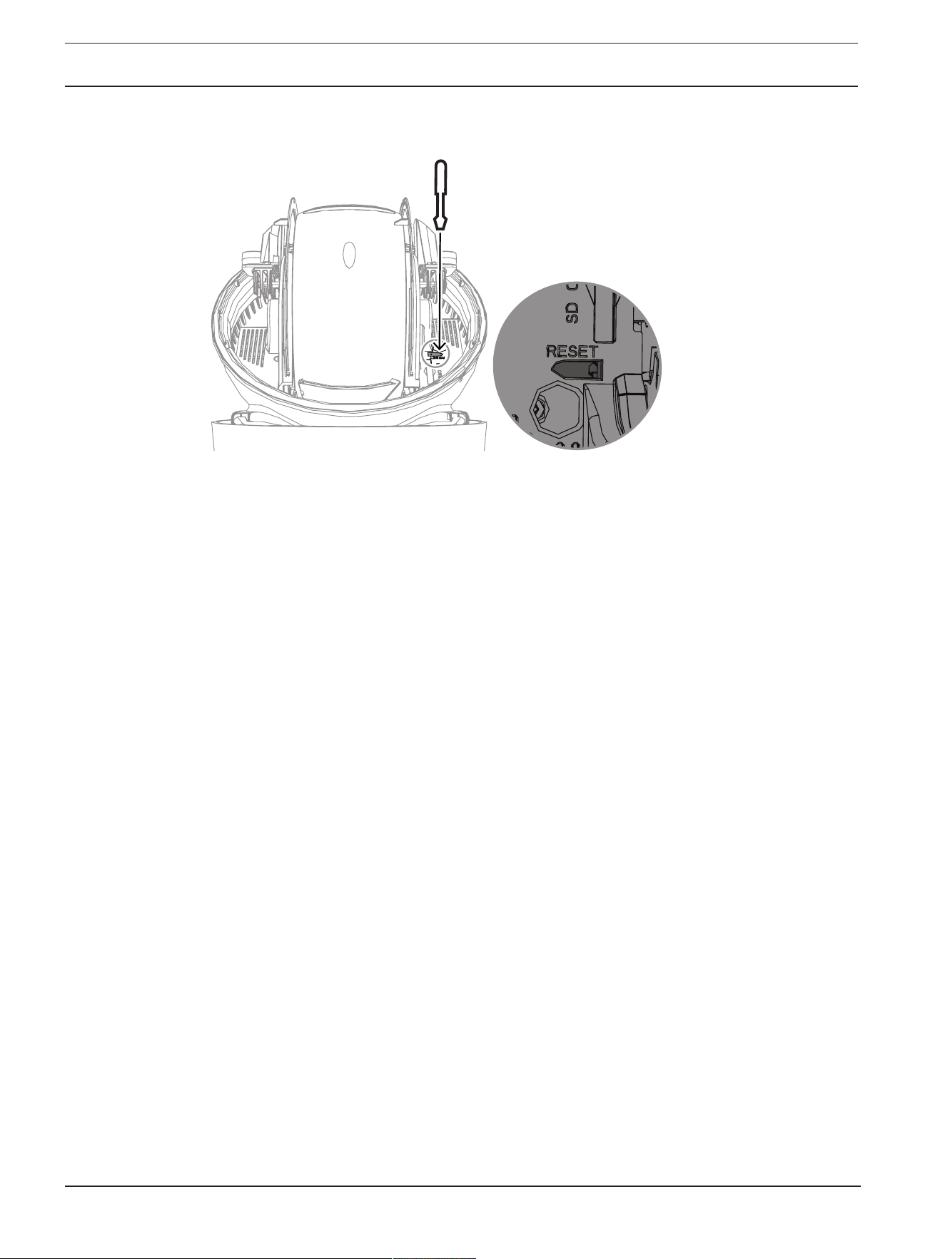
68 en | Troubleshooting AUTODOME 7100i
2022-12 | V01 | DOC
User Manual
Bosch Security Systems B.V.
8. Access the camera using the web browser.
9. Set the initial service-level password for the camera.

AUTODOME 7100i Status codes | en 69
Bosch Security Systems B.V.
User Manual
2022-12 | V01 | DOC
7 Status codes
Most status codes appear on the OSD until you acknowledge them. The codes identified with
asterisks (**) appear for approximately 10 seconds, then disappear automatically.
Status
Code
Description Recommended action
(to be completed by a qualified Service
Technician)
1 Waiting for power – Make sure that the length of the Cat5e/
Cat6e cable does not exceed 100 m
maximum.
– Check that the mains power meets the
specifications of the midspan.
– Follow all of the recommended practices
as outlined in the Installation Manual.
– Use 24 VAC power (100 VA), or make
sure that the High PoE source is an
appropriate Bosch midspan:
– NPD-6001C, NPD-6001C-E,
NDP-6001-I, NPD-6001C-BT,
NPD-6001C-EBT or NPD-6001-IBT
(60W);
– NPD-9001-E or NPD-9001-EBT
(90W) for cameras with an
illuminator
– Refer to the “Troubleshooting” section of
the midspan installation manual.
Note: Bosch does not recommend or test any
third-party High PoE sources. If you use a
non-Bosch PoE device, then contact the
manufacturer of that device for assistance.
3 Capacity of external PoE device is
insufficient to support operation
of the camera's internal heater.
An incorrect type of PoE+ or PoE++ (such as
one based on IEEE 802.3af or IEEE 802.3at)
with insufficient power output may be
connected to the camera.
4 Capacity of the external PoE
device is insufficient to support
operation of the camera's window
defroster.
An incorrect type of PoE+ or PoE++ (such as
one based on IEEE 802.3af or IEEE 802.3at)
with insufficient power output may be
connected to the camera.
5 When operating using redundant
power sources, the camera is
detecting insufficient voltage
being provided by the external
High PoE power source.
1. Verify that the High PoE power source
(midspan or switch) can provide 95 W of
output power.
2. Verify that the network cable is not longer
than 100 m maximum.

70 en | Status codes AUTODOME 7100i
2022-12 | V01 | DOC
User Manual
Bosch Security Systems B.V.
Status
Code
Description Recommended action
(to be completed by a qualified Service
Technician)
3. If using the IEEE 802.3bt, Type 4 (95W)
High PoE Midspan, verify that both LEDs are
green. If not, refer to the “Troubleshooting”
section of the installation manual of the
midspan.
6 When operating using redundant
power sources, or when using
only a 24 VAC/36 VDC power
source, the camera is detecting
insufficient voltage being
provided by the external 24
VAC/36VDC power source.
1. Verify that the 24 VAC/36VDC power
source can provide at least 4.0A to the
camera.
2. Verify that the wire gage of the power
cable is sufficient for the distance between
the power source and the camera and that
the voltage getting to the user cable of the
camera is between 21VAC and 30VAC.
7 Camera may be operating in an
environment where ambient
temperature is below the
specification of the camera.
1. Verify that the ambient temperature is not
below -40 °C (-40 °F).
2. Review the information about temperature
located in Logging diagnostics.
Note: Motorized zoom and focus functions of
the visible camera lens will be disabled until
the camera operates within the specified
temperature range.
8 Camera may be operating in an
environment where ambient
temperature is above
specification of the camera.
1. Verify that the ambient temperature is not
above +50 °C (+122 °F).
2. Review the diagnostic log of the camera
(accessible from the Service menu) for errors
related to the operation of the internal fan.
3. Add the optional sunshield accessory to
reduce internal heating caused by sun
loading.
9 Camera has been subjected to
high shock. Mechanical damage
to the camera may exist.
1. Verify the integrity of the mechanical parts
such as the arms and the pan body.
2. Verify the integrity/tightness of the
external fasteners. Tighten where necessary.
3. If obvious damage is present, stop using
the camera and contact the nearest Bosch
Security Systems Service Center.
4. If no damage is evident, power the camera
off and then on, and then evaluate
operational performance. If the camera does
not operate as expected, contact the nearest
Bosch Security Systems Service Center.

AUTODOME 7100i Status codes | en 71
Bosch Security Systems B.V.
User Manual
2022-12 | V01 | DOC
Status
Code
Description Recommended action
(to be completed by a qualified Service
Technician)
10 Camera is detecting high
humidity level inside housing. The
integrity of the housing seal may
be compromised.
1. Inspect the dome/housing for any cracks or
obvious damage.
2. Verify the integrity of the seals of the
camera, and mounts if applicable.
3. If damage to the seals is obvious, contact
the nearest Bosch Security Systems Service
Center.
4. Make sure the camera reaches an ambient
high air temperature on first use, to allow the
breather vent to remove possible initial
humidity.
5. If no obvious damage is found, power the
camera off and then on. If the status code
reappears, contact the nearest Bosch
Security Systems Service Center.
13** Autofocus has been turned off
because of excessive focus
activity.
1. If practical, increase lighting in the scene
so that the focus function stops “hunting.”
2. Use focus in manual mode or One-Push
mode.
15 Attempt was made to move to a
pre-position that is mapped to an
alternate function, so it is no
longer associated with a location.
1. Select/configure a different pre-position
number for the desired location.
2. Re-configure the pre-position assignment
so that this number is no longer associated
with an alternate function. Refer to the
subchapter “Pre-position mapping” in the
User Manual for details on re-mapping pre-
positions.
16** Motorized zoom function is
programmed to operate at a high
usage level in the Playback Tour.
This high rate of usage could
result in premature wear of the
zoom motor.
Re-configure the camera to decrease the
zoom activity to less than 30% during
recording.
17 Motor operation has been halted
due to an obstruction.
1. Remove any obvious materials that are
obstructing operation of the camera pan/tilt
function.
2. If the obstruction is from ice buildup,
review the diagnostic log of the camera
(accessible from the Service menu) for errors
related to the operation of the internal
heaters. If the log shows heater failure,
contact the nearest Bosch Security Systems
Service Center.

72 en | Status codes AUTODOME 7100i
2022-12 | V01 | DOC
User Manual
Bosch Security Systems B.V.
Status
Code
Description Recommended action
(to be completed by a qualified Service
Technician)
3. If operation is obstructed because of
excessive ice buildup, temporarily avoid
operating the pan/tilt functions of the camera
until internal heaters, combined with a rise in
ambient temperature, melt the ice buildup.
18** When operating using redundant
power sources, the camera has
detected a loss of power from the
external 24 VAC power source.
1. Verify the operating status of the external
24 VAC power source.
2. Verify the integrity of the electrical
connections between the power source and
the camera.
19** When operating using redundant
power sources, the camera has
detected a loss of power from the
external High PoE power source.
1. Verify the operating status of the external
High PoE power source.
2. Verify the integrity of the electrical
connections between the power source and
the camera.
20 Camera is configured to use the
“Hard Pan Limits” (HPL) feature
and power was applied with the
pan position in the forbidden
zone.
Temporarily remove one of the hard pan
limits (as described in PTZ Settings), pan the
camera out of the forbidden zone, and then
restore the hard pan limit.
Reboot the camera by powering the camera
off and then on, or by clicking the button
Reboot in the camera’s web browser
(Configuration > Camera > Installer Menu
>Reboot device).
Note: If pan movement is blocked only in one
direction, but possible in the other direction
(as when the camera is near the HPL), then
no status code appears.
23 An internal error has occurred.
(The optical video screen
becomes blue for 1 or 2 seconds
during the camera’s recovery
procedure).
If this problem begins to occur on a regular
basis:
1. Verify that the power source to the camera
is not experiencing brown-out conditions.
2. Verify that the camera’s earth ground
connection is attached per earlier
instructions.
If these actions do not resolve this problem,
contact the nearest Bosch Security Systems
Service Center.
25 When operating using redundant
power sources, the camera has
detected a loss of power from the
external 36 VDC power source.
1. Verify the operating status of the external
36 VDC power source.
2. Verify the integrity of the electrical
connections between the power source and
the camera.

AUTODOME 7100i Status codes | en 73
Bosch Security Systems B.V.
User Manual
2022-12 | V01 | DOC
!
Caution!
If you choose not to use a switch or midspan with the appropriate Power Sourcing Equipment
(PSE) chip, then the camera will not recognize the PoE as compliant, and the camera
firmware may disable some or all functionality.

74 en | AUX Commands AUTODOME 7100i
2022-12 | V01 | DOC
User Manual
Bosch Security Systems B.V.
8 AUX Commands
AUX Function Description
1 On/Off Auto Pan without limits (Continuous)
2 On/Off Auto Pan between limits
7 On/Off Run Custom Pre-Position Tour
8 On/Off Run Pre-Position Tour
18 On/Off Auto pivot
20 On/Off Backlight Compensation (BLC)
24 On/Off Video Stabilization
40 On/Off Restore camera settings [to factory defaults]
43 On/Off Auto Gain Control (AGC)
50 On/Off Playback A, continuous
51 On/Off Playback A, single
52 On/Off Playback B continuous
53 On/Off Playback B, single
54 On/Off IR illuminators mode (Available only in IR models)
57 On/Off Night mode
60 On/Off On-Screen Display (OSD)
65 Off Alarm Acknowledge Acknowledges alarm events/rules
67 On/Off IR Focus Correction
78 On/Off Intelligent Tracking
80 On/Off Digital Zoom
86 On/Off Sector Blanking
87 On/Off Privacy Masking
88 On/Off Proportional Speed
94 On Recalibrate Azimuth Compass
95 On/Off Azimuth/Elevation Display
96 On/Off Compass Points Display
100 On/Off Record Tour A
101 On/Off Record Tour B
149 On/Off Turbo Mode
606 On/Off Power Mode
700 On/Off Proportional speed control adjustment Aux

AUTODOME 7100i AUX Commands | en 75
Bosch Security Systems B.V.
User Manual
2022-12 | V01 | DOC
AUX Function Description
804 On/Off Mask Calibration Procedure
1-256 Set/Show Pre-position Programming/Pre-position Recall

76 en | Support services and Bosch Academy AUTODOME 7100i
2022-12 | V01 | DOC
User Manual
Bosch Security Systems B.V.
9 Support services and Bosch Academy
Support
Access our support services at www.boschsecurity.com/xc/en/support/.
Bosch Security and Safety Systems offers support in these areas:
– Apps & Tools
– Building Information Modeling
– Warranty
– Troubleshooting
– Repair & Exchange
– Product Security
Bosch Building Technologies Academy
Visit the Bosch Building Technologies Academy website and have access to training courses,
video tutorials and documents: www.boschsecurity.com/xc/en/support/training/

AUTODOME 7100i Support services and Bosch Academy | 77
Bosch Security Systems B.V.
User Manual
2022-12 | V01 | DOC

78 | Support services and Bosch Academy AUTODOME 7100i
2022-12 | V01 | DOC
User Manual
Bosch Security Systems B.V.


Bosch Security Systems B.V.
Torenallee 49
5617 BA Eindhoven
Netherlands
www.boschsecurity.com
© Bosch Security Systems B.V., 2022
202212131011
Building solutions for a better life.