

MIC IP ultra 7100i │ MIC IP starlight 7100i Table of contents | en 3
Bosch Security Systems
User Manual
2022-01 | 1.8 |
Table of contents
1
Introduction 6
1.1 System requirements 7
1.2 Establishing the connection 7
1.3 Password protection in camera 7
2
System overview 9
2.1 Live page 9
2.2 Playback 10
2.3 Configuration 10
2.4 Dashboard 10
3
General 11
3.1 Identification 11
3.2 User Management 11
3.3 Date/Time 12
4
Web Interface 14
4.1 Appearance 14
4.2 'Live' functions 15
5
Connectivity 17
5.1 Cloud Services 17
5.2 Accounts 17
5.3 DynDNS 18
6
Camera 19
6.1 Installer Menu 19
6.1.1 Display Stamping 20
6.1.2 Positioning 22
6.2 Scene Mode 26
6.2.1 Picture Settings 26
6.2.2 Enhance 28
6.2.3 Scene Mode Scheduler 29
6.3 Encoder Streams 31
6.4 Encoder Statistics 32
6.5 Privacy Masks 32
6.6 Lens Settings 33
6.7 PTZ Settings 34
6.8 Pre-positions and Tours 36
6.9 Pre-position settings 37
6.10 Pre-position mapping 38
6.11 Sectors 39
6.12 Miscellaneous 39
6.13 Illuminator 39
6.14 Audio 40
6.15 Pixel Counter 41
7
Recording 42
7.1 Introduction to recording 42
7.2 Storage Management 42
7.2.1 Device manager 42
7.2.2 Recording media 42
7.2.3 Activating and configuring storage media 42
7.2.4 Formatting storage media 43

4 en | Table of contents MIC IP ultra 7100i │ MIC IP starlight 7100i
2022-01 | 1.8 |
User Manual
Bosch Security Systems
7.2.5 Deactivating storage media 43
7.3 Recording Profiles 43
7.4 Maximum Retention Time 44
7.5 Recording Scheduler 45
7.6 Recording Status 46
7.7 Recording Statistics 46
7.8 Image Posting 46
7.9 SD Card Status 47
8
Alarm 48
8.1 Alarm Connections 48
8.2 Video Content Analysis (VCA) 49
8.3 Audio Alarm 51
8.4 Alarm E-Mail 52
8.5 Alarm Task Editor 53
8.6 Alarm Rules 53
9
Network 56
9.1 Network Services 56
9.2 Network Access 56
9.3 Advanced 58
9.4 Network Management 59
9.4.1 Quality of Service 59
9.5 Multicast 59
9.6 IPv4 Filter 60
10
Service 61
10.1 Maintenance 61
10.2 Licenses 62
10.3 Certificates 62
10.4 Logging 62
10.5 Diagnostics 62
10.6 System Overview 62
11
Operation via the browser 63
11.1 Live page 63
11.1.1 Connection 63
11.1.2 PTZ 63
11.1.3 Pre-positions 63
11.1.4 AUX Control 64
11.1.5 Special Functions 64
11.1.6 Recording status 65
11.1.7 Recording live video 65
11.1.8 Audio communication 65
11.1.9 Storage, CPU and network status 65
11.1.10 Status icons 66
11.2 Playback 67
11.2.1 Selecting the recording stream 67
11.2.2 Searching for recorded video 67
11.2.3 Exporting recorded video 67
11.2.4 Track list 67
11.2.5 Controlling playback 67
11.3 Dashboard 68

MIC IP ultra 7100i │ MIC IP starlight 7100i Table of contents | en 5
Bosch Security Systems
User Manual
2022-01 | 1.8 |
12
Using your MIC Camera 69
12.1 Recommended Use of Your MIC Camera 69
12.2 Using the Wiper/Washer (Bosch Protocol) 70
12.3 Using the Wiper/Washer (Pelco Protocol) 71
12.4 Uploading a User Logo 72
12.5 Two-line and Three-line Camera Titles 72
12.6 Azimuth, Elevation, and Compass Directions 74
13
Troubleshooting 75
13.1 Rebooting the unit 77
13.2 Physical reset button 78
13.3 Customer Service and Support 80
14
Decommissioning 81
14.1 Transfer 81
14.2 Disposal 81
15
Status Codes 82
16
AUX Commands 87
17
Support services and Bosch Academy 89

6 en | Introduction MIC IP ultra 7100i │ MIC IP starlight 7100i
2022-01 | 1.8 |
User Manual
Bosch Security Systems
1 Introduction

MIC IP ultra 7100i │ MIC IP starlight 7100i Introduction | en 7
Bosch Security Systems
User Manual
2022-01 | 1.8 |
1.1 System requirements
Our recommendations are:
– Computer with Dual core HyperThreading processor or better
– Graphic card with performance that matches or is better than the resolution of the
camera
– Windows10 or later
– Network access
– Google Chrome, Microsoft Edge, or Mozilla Firefox
- or -
Application software, for example, VideoSecurityClient, BoschVideoClient or BVMS.
1.2 Establishing the connection
The unit must have a valid IP address and a compatible subnet mask to operate on your
network. By default, DHCP is pre-set at the factory to On and so your DHCP server assigns an
IP address. With no DHCP server the default address is 192.168.0.1
The Project Assistant app or Configuration Manager (version 7.50 or higher) can be used to
find the IP address. Download the software from https://downloadstore.boschsecurity.com
:
1. Start the web browser.
2. Enter the IP address of the device as the URL.
3. During the initial installation, confirm any security questions that show.
If a RADIUS server is used for network access control (802.1x authentication), you must
configure the device before the device can communicate with the network.
To configure the device, connect it directly to a computer using a network cable and then set
the service-level password.
Note:
If you cannot connect, the unit may have reached its maximum number of connections.
Depending on the device and network configuration, each unit can have up to 50 web browser
connections, or up to 100 connections via BoschVideoClient or BVMS.
1.3 Password protection in camera
The device is password-protected. The first time that any user accesses the device, the device
will prompt the user to set a password at the service level.
The camera requires a strong password. Follow the prompts in the dialog box, which specifies
what is required. The system measures the strength of the password that you enter.
When you use Configuration Manager to access your device for the first time, you must set the
initial password of the device in Configuration Manager. The Users section (General > Unit
Access > Users) displays the message, "Before you can use this device you have to secure it
with an initial password."
Note: After you set the initial password, a "lock" icon appears next to the device name in the
Devices list in Configuration Manager.
You can also launch the device webpage directly. In the device webpage, an initial password
page appears, displaying input fields and a password strength gauge.
Enter the user name (“service”) and a password in the appropriate fields. Refer to the section
User Management for more information.
After a service-level password is set for the device, the device displays a dialog box that
prompts users to enter the user name (“service”) and the service-level password every time
that they access the device.
1. Fill in the fields User name and Password.

8 en | Introduction MIC IP ultra 7100i │ MIC IP starlight 7100i
2022-01 | 1.8 |
User Manual
Bosch Security Systems
2. Click OK. If the password is correct, the desired page appears.
MIC IP ultra 7100i │ MIC IP starlight 7100i System overview | en 9
Bosch Security Systems
User Manual
2022-01 | 1.8 |
2 System overview
When a connection is established, the Live page shows.
The page shows the live video from the camera.
The application bar near the top of the page, below the name of the product or of the product
family, displays the following icons:
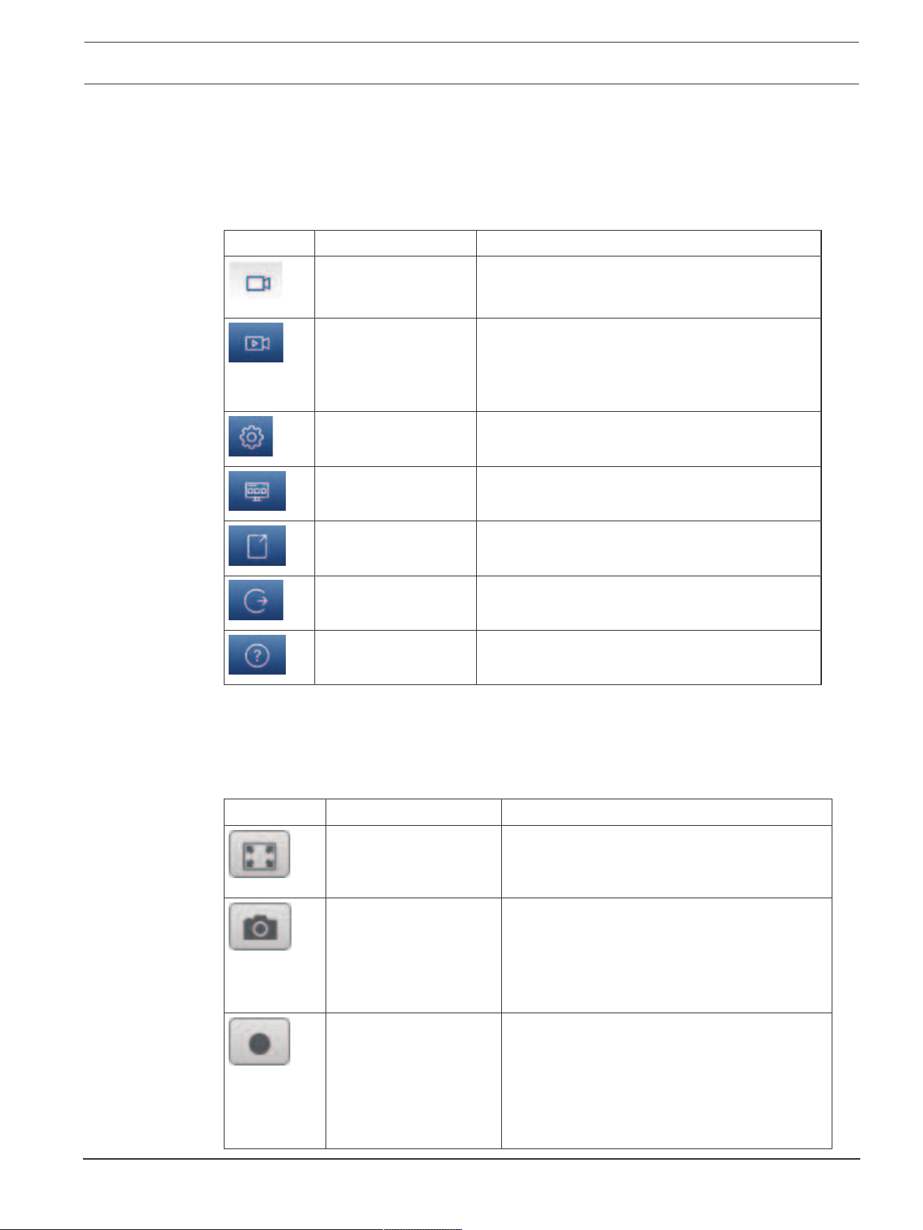
Icon Description Function
Live View the live video stream.
Playback Play back recorded sequences.
This link is only visible if a storage medium has
been configured for recording. (With VRM
recording, this option is not active.)
Configuration Configure the device.
Dashboard See detailed system information.
Links Navigate to the Bosch download store.
Logout Log out of the device.
Help on this page? Get context-sensitive help for the page that you
are seeing.
2.1 Live page
The Live page is used to display the live video stream and control the unit.
Below the live video is a field with the date and time. Below the date / time field is a row of
icons related to the video feed.
Icon Description Function
Full-screen video See the selected stream in full-screen mode;
press Esc on the keyboard to return to the
normal viewing window.
Save snapshots Save individual images from the displayed live
video stream in JPEG format on the computer's
hard drive.
The storage location depends on the
configuration of the camera.
Start recording Save video sequences from the displayed live
video stream on the computer's hard drive. The
sequences are recorded at the resolution
specified in the encoder configuration.
The storage location depends on the
configuration of the camera.
10 en | System overview MIC IP ultra 7100i │ MIC IP starlight 7100i
2022-01 | 1.8 |
User Manual
Bosch Security Systems
Icon Description Function
Start Video Security App Start the app and use It to view live images, to
configure and to operate the device from any
location.
Show latest event Open the Playback page to see the last
recorded important events.
2.2 Playback
The Playback page is used for playing back recorded sequences.
2.3 Configuration
The Configuration page is used to configure the unit and the application interface.
Making Changes
Each configuration screen shows the current settings. You can change the settings by entering
new values or by selecting a predefined value from a list field.
Not every page has a Set button. Changes to pages without a Set button are set immediately.
If a page does show a Set button, you must click the Set button for a change to take effect.
i
Notice!
Save each change with the associated Set button.
Clicking the Set button saves the settings only in the current field. Changes in any other fields
are ignored.
Some changes only take effect after the unit is rebooted. In this case, the Set button changes
to Set and Reboot.
1. Make the desired changes.
2. Click the Set and Reboot button. The camera reboots and the changed settings are
activated.
All settings are backed up in camera memory so they are not lost even if the power fails. The
exception is the time settings, which are lost after 1 hour without power if no central time
server is selected.
2.4 Dashboard
The Dashboard page is used to display detailed information about the device.
The Dashboard is only visible in the application bar if the Show 'Dashboard' option is enabled
by a service-level user in the Configuration -> Web Interface -> Appearance page.

MIC IP ultra 7100i │ MIC IP starlight 7100i General | en 11
Bosch Security Systems
User Manual
2022-01 | 1.8 |
3 General
3.1 Identification
Device name
Enter a unique, unambiguous name for the device (for example, the installation location of the
device). This name should be easy to identify in a list of devices in your system. The device
name is used for the remote identification of a unit, such as in the event of an alarm.
Do not use any special characters, for example &, in the name. Special characters are not
supported by the system's internal management.
Device ID
Enter a unique identifier for the device. This ID is additional identification for the device.
Video name
Enter a name for the video (for example, HDR ON).
Video 1
Enter a name or description for the Video 1 stream (for example, “Visible image”).
Host name
Enter a host name.
Initiator extension
Add text to an initiator name to make identification easier in large iSCSI systems. This text is
added to the initiator name, separated from it by a full stop. (You can see the initiator name in
the System Overview page.)
3.2 User Management
The section Authentication modes provides information about the authentication modes set
in the camera. A checkmark appears in the checkbox to the left of the mode if the mode is set.
If the mode is not set, the phrase, “No certificate installed” appears to the right of the mode
name.
Password
This field indicates if a password is set for the camera.
Certificate
A check mark in this check box indicates that at least one certificate is loaded onto the
camera. If no certificates are loaded, then “No certificate installed” appears to the right of the
text.
The Escrypt certificate is a root certificate for Bosch Security Systems that proves that the
device meets the following criteria:
– It originates from a Bosch factory that is a secure environment.
– It has not been tampered with.
Escrypt is a Bosch company and Certificate Authority (CA).
Active directory server (ADFS)
A check mark in this check box indicates that the camera uses an active directory server. If the
camera does not use ADFS, then “No certificate installed” appears to the right of the text.
Password management
A password prevents unauthorized access to the device. You can use different authorization
levels to limit access.
Proper password protection is only guaranteed when all higher authorization levels are also
protected with a password. Therefore, you must always start from the highest authorization
level when assigning passwords.

12 en | General MIC IP ultra 7100i │ MIC IP starlight 7100i
2022-01 | 1.8 |
User Manual
Bosch Security Systems
You can define and change a password for each authorization level if you are logged into the
“service” user account.
The device has three authorization levels: service, user, and live.
– service is the highest authorization level. Entering the correct password gives access to
all the functions and allows all configuration settings to be changed.
– user is the middle authorization level. At this level you can operate the device, play back
recordings, and also control camera, for example, but you cannot change the
configuration.
– live is the lowest authorization level. At this level you can only view the live video image
and switch between the different live image displays.
A fourth user group, VCA configuration, has the privilege to configure VCA only.
Note: Configuration and use of this user group is available only in Configuration Manager (7.20
or later).
To edit a password
To edit a password, click the pencil icon to the right of the column Type for the appropriate
User name.
To create a new user
To create a new user, click Add.
In the box User, fill in the fields. For Group, select the appropriate authorization level. For
Type, select either Password (for a new password) or Certificate (for a certificate that the
new user is authorized to use).
Note: Use a maximum of 19 characters. Do no use special characters.
Confirm password
In each case, enter the new password a second time to eliminate typing mistakes.
i
Notice!
A new password is only saved when you click the Set button. You should therefore click the
Set button immediately after entering and confirming a password.
3.3 Date/Time
Date format
Select the required date format from the dropdown menu.
Device date/Device time
i
Notice!
Make sure that recording is stopped before synching to the PC.
If there are multiple devices operating in your system or network, it is important to
synchronize their internal clocks. For example, it is only possible to identify and correctly
evaluate simultaneous recordings when all units are operating on the same time.
1. Enter the current date. Since the unit time is controlled by the internal clock, there is no
need to enter the day of the week - it is added automatically.
2. Enter the current time or click the Sync to PC button to copy your computer's system
time to the camera.
Note: It is important that the date/time is correct for recording. An incorrect date/time setting
could prevent correct recording.

MIC IP ultra 7100i │ MIC IP starlight 7100i General | en 13
Bosch Security Systems
User Manual
2022-01 | 1.8 |
Device time zone
Select the time zone in which the system is located.
Daylight saving time
The internal clock can switch automatically between normal and daylight saving time (DST).
The unit already contains the data for DST switch-overs for many years in advance. If the date,
time and zone have been set up correctly, a DST table is automatically created.
If you decide to create alternative daylight saving time dates by editing the table, note that
values occur in linked pairs (DST start and end dates).
First, check the time zone setting. If it is not correct, select the appropriate time zone and
click Set.
1. Click Details to edit the DST table.
2. Select the region or the city which is closest to the system's location from the list box
below the table.
3. Click Generate to fill the table with the preset values from the unit.
4. Click one of the entries in the table to make changes. The entry is highlighted.
5. Click Delete to remove the entry from the table.
6. Choose other values from the list boxes under the table, to change the selected entry.
Changes are immediate.
7. If there are empty lines at the bottom of the table, for example after deletions, add new
data by marking the row and selecting values from the list boxes.
8. When finished, click OK to save and activate the table.
Time server address
The camera can receive the time signal from time server using various time server protocols,
and then use it to set the internal clock. The unit polls the time signal automatically once every
minute.
Enter the IP address of a time server here.
You can choose to have the DHCP server give a time server date by selecting the Overwrite by
DHCP option.
Time server type
Select the protocol that is supported by the selected time server.
– Select Time protocol if the server uses the protocol RFC868.
– The SNTP protocol supports a high level of accuracy and is required for special
applications and subsequent function extensions.
– Select TLS protocol if the server uses the RFC 5246 protocol.
– Select Off to disable the time server.
Click Set to apply the changes.

14 en | Web Interface MIC IP ultra 7100i │ MIC IP starlight 7100i
2022-01 | 1.8 |
User Manual
Bosch Security Systems
4 Web Interface
4.1 Appearance
You can adapt the appearance of the web interface and change the website language to meet
your requirements.
You can use GIF or JPEG images to replace the company and device logos. The image can be
stored on a web server.
Make sure that a connection to the web server is always available to display the image. The
image files are not stored on the device.
To use the original graphics, delete the entries in the Company logo and Device logo fields.
Website language
Select the language for the user interface.
The default language is English. After selecting a different language, click the Set button. The
page refreshes automatically. The GUI now displays field names and options as well as OSD
messages in the selected language.
Company logo
To replace the company's logo in the top-right part of the window, enter the path to a suitable
image in this field. The image file must be stored on a web server.
Device logo
To replace the device name in the top-left part of the window, enter the path to a suitable
image in this field. The image file must be stored on a web server.
i
Notice!
If you want to use the original image again, delete the entries in the fields Company logo and
Device logo.
Show VCA metadata
When video content analysis (VCA) is activated, additional information is displayed in the live
video stream. With the MOTION+ analysis type, for example, the sensor fields in which motion
is recorded are marked with yellow rectangles.
Using EssentialVideoAnalytics or IntelligentVideoAnalytics, the outlines of detected objects
are displayed in following colors:
– Red: Objects that generate an alarm event under the current settings appear on the
camera image inside a red outline.
– Orange: An object that has triggered one alarm event but does not generate another
appears inside an orange outline (example: object has crossed a line). During forensic
search, an object that triggers an alarm event has an orange outline from the beginning.
– Yellow: Objects that are detected as moving but do not generate an alarm event under
the current settings appear inside a yellow outline.
Note: This feature is not available on 9mm models.
Show VCA trajectories
The trajectories (motion lines of objects) from the video content analysis are displayed in the
live video image if a corresponding analysis type is activated. The trajectory is shown as a
green line following the object base point.
Show overlay icons
Select this check box to show overlay icons on the live video image.
Show VCA items
Shows alarm fields, lines and routes configured for the video analytics in the following colors:

MIC IP ultra 7100i │ MIC IP starlight 7100i Web Interface | en 15
Bosch Security Systems
User Manual
2022-01 | 1.8 |
– Green: Fields, lines and routes used in a task are displayed in green. They can be edited
but not deleted.
– Red: Fields, lines and routes currently in alarm mode are displayed in red.
Show 'Dashboard'
Select this checkbox to enable the Dashboard in the application bar.
Secure cookies
Select this checkbox to secure the cookies sent through the camera.
i
Notice!
If cookies are secured, authentication forwarding to MPEG ActiveX and the Video Security
App is prohibited.
Video player
Select the type of player to be used for live mode viewing.
Latency mode
Select the required latency mode:
– Low delay: Default mode. Provides marginal buffering to display fluent video under
normal network conditions.
– Smooth video: Allows the buffer to automatically adjust to cover network jitter, inducing
higher latency.
– No buffering: Shows video as it is received by the decoder with minimum latency. Allows
the video to jerk if there is network jitter.
Video buffer
The value shown is calculated from the Latency mode setting. It cannot be changed.
JPEG resolution
Select the size of the JPEG image on the Live page. Options are Small, Medium, Large, 720p,
1080p, and Resource based.
JPEG interval
You can specify the interval at which the individual images should be generated for the M-
JPEG image on the Live page.
JPEG quality
You can specify the quality at which the JPEG images appear on the Live page.
4.2 'Live' functions
On this page you can adapt the functions on the LIVE page to your requirements. You can
choose from a variety of different options for displaying information and controls.
1. Check the box for the items that are to be made available on the LIVE page. The selected
items are indicated by a check mark.
2. Check whether the required functions are available on the LIVE page.
Transmit audio
You can only select this option if audio transmission is actually switched on (see Audio).The
audio signals are sent in a separate data stream parallel to the video data, and so increase the
network load. The audio data are encoded according to G.711 and require an additional
bandwidth of approx. 80 kbps per connection in each direction.

16 en | Web Interface MIC IP ultra 7100i │ MIC IP starlight 7100i
2022-01 | 1.8 |
User Manual
Bosch Security Systems
Auto logout time [min]
Set a time frame (in minutes) for the automatic logout. Default value is 0 (no automatic
logout).
Show alarm inputs
Select this checkbox if you want the alarm inputs to appear in the Digital I/O section of the
Live page.
Show alarm outputs
Select this checkbox if you want the alarm outputs to appear in the Digital I/O section of the
Live page.
Allow snapshots
Here you can specify whether the icon for saving individual images (snapshots) should be
displayed below the live image. Individual images can only be saved if this icon is visible.
Allow local recording
Here you can specify whether the icon for saving (recording) video sequences on the local
memory should be displayed below the live image. Video sequences can only be saved if this
icon is visible.
I-frame only stream
Here you can specify whether the Live page displays a viewing tab for an I-frame only stream.
Show 'Pre-positions'
Here you can specify whether the section Pre-positions of the Live page displays a drop-down
box with the list of scenes set in the section Camera > Pre-positions and Tours of the
Configuration page.
Show 'AUX Control'
Here you can specify whether the Live page displays the section Show 'AUX Control'.
Here you can specify whether the Live page displays the section Special Functions.
Path for JPEG and video files
Enter the path for the storage location of individual images and video sequences saved from
the Live page.
Video file format
Select a file format for the live page display. The MP4 format does not include metadata.

MIC IP ultra 7100i │ MIC IP starlight 7100i Connectivity | en 17
Bosch Security Systems
User Manual
2022-01 | 1.8 |
5 Connectivity
5.1 Cloud Services
Remote Portal
Operation
The operation mode determines how the camera communicates with the Remote Portal.
– Select On to poll the server constantly.
– Select Off to block polling.
Connectivity state
This field identifies any cloud-based services with which the camera communicates.
– If you have registered the device on a cloud-based service such as Bosch Remote Portal,
then this field identifies this fact (“Connected”).
Note: The button () to connect to the device with that service is active.
– If you have not registered the device, then the message, “Not available. When
'Operation' is set to 'Auto', 'Automatic IP assignment (DHCP)' must be active to
connect to the Bosch Remote Portal“ appears.
Note: The button () to connect to the device with that service is not active.
Partner services
Registration code
This area displays the state of the Stratocast registration code.
Connectivity state
This field indicates the device's connectivity state with Remote Portal.
– If the device is registered and the operation mode is set to On, the state will indicate that
the device is Connected (to the cloud service).
Note: The Visit Remote Portal button will become active.
– If the device is not registered or the operation mode is set to Off, the state will indicate
that the device is Not available.
Note: The Register button will become active only if you have not registered the device to the
Remote Portal.
5.2 Accounts
Four separate accounts can be defined for posting and recording export.
Type
Select either FTP or Dropbox for the account type.
Before using a Dropbox account ensure that the time settings of the device have been
correctly synchronized.
Authentication
Click the button to authenticate the account.
Account name
Enter an account name to be shown as the target name.
Note: The fields that appear next depend on the option that you select in the field Type.
IP address
Enter the IP address of the server on which you wish to save the JPEG images.
Login
Enter the login ID for the server.

18 en | Connectivity MIC IP ultra 7100i │ MIC IP starlight 7100i
2022-01 | 1.8 |
User Manual
Bosch Security Systems
Password
Enter the password that gives you access to the server. To verify the password, click the
Check button to the right.
Path
Enter the exact path on which you wish to post the images on the server. To browse for the
correct path, click the Browse button to the right.
Maximum bit rate
Enter the maximum bit rate for the JPEG images (in kbps).
Encryption
Tick the box to use a secure FTP over TLS connection.
5.3 DynDNS
Enable DynDNS
A dynamic Domain Name Service (DNS) allows you to select the unit via the Internet using a
host name, without having to know the current IP address of the unit. You can enable this
service here. To do this, you must have an account with one of the dynamic DNS providers and
you must register the required host name for the unit on that site.
Note:
For information about the service, registration process and available host names refer to the
provider.
Provider
Select your dynamic DNS Provider from the drop-down list.
Host name
Enter the host name registered for the unit.
User name
Enter the user name you registered.
Password
Enter the password you registered.
Force registration now
Force the registration by transferring the IP address to the DynDNS server. Entries that change
frequently are not provided in the Domain Name System. It is a good idea to force the
registration when setting up the device for the first time. Only use this function when
necessary and no more than once a day, to avoid the possibility of being blocked by the
service provider. To transfer the IP address of the device, click the Register button.
Status
The status of the DynDNS function is displayed here for information purposes; these settings
cannot be changed.
Click Set to apply the changes.

MIC IP ultra 7100i │ MIC IP starlight 7100i Camera | en 19
Bosch Security Systems
User Manual
2022-01 | 1.8 |
6 Camera
6.1 Installer Menu
Application variant
– If you are connecting to MIC-ALM-WAS-24, select “[camera name] - IO“ to allow the
camera to recognize additional inputs and outputs from this device and to allow control
of an external washer unit.
– Otherwise, select “[camera name].”
Sensor mode
The sensor mode specifies the base resolution and frame rates for the image quality settings.
Fast moving scenes use more frame rates (50 fps or 60 fps) for better image quality than slow
moving scenes. Adjust this setting as necessary.
This higher resolution (HD 1080p) gives maximum detail in these scenes, but can result in
motion artifacts for fast-moving objects because of the lower frame rates.
Some types of light can show flickering in the image when the frame rate is not synchronized
with the mains power frequency. To avoid this, the sensor mode frame rate should be in line
with the power frequency:
– 50Hz: 25 or 50 fps
– 60Hz: 30 or 60 fps
Select On to output a mirror image of the camera picture.
Note: Privacy masks are not supported in mirror image mode.
Coding standard
Select the encoding mode:
– H.264
– H.265
– H.265 (no B-frames)
H.265 (no B-frames) is a restrictive mode for the encoder where it only supports I and P
frames. This decreases calculation power so that there can be a higher frame rate (for
example, 30 fps for a camera that might be restricted to 25 fps).
Orientation
The orientation of the camera. Options: Normal, Inverted, Canted.
System controller settings
Click the Default button to restore all camera settings to their original defaults.
Reboot device
Click the Reboot button to reboot the camera. There is a ten (10) second pause before the
camera starts its homing phase. During the homing phase, the camera will complete finding
the upper and lower tilt limits.
Reboot device
Click Restore to restore the factory defaults of the device.
Note: Clicking this button also clears the service-level password. Operators must reset the
password before doing anything else.
Restore settings
Click Defaults to restore the factory defaults for the camera. A confirmation screen appears.
Allow several seconds for the camera to optimize the picture after a reset.
Click Confirm in each dialog box that opens to complete a factory reset of the device.
This action deletes all third-party apps and resets all settings to defaults (including network
settings).

20 en | Camera MIC IP ultra 7100i │ MIC IP starlight 7100i
2022-01 | 1.8 |
User Manual
Bosch Security Systems
!
Caution!
Do not remove power to the unit during a factory default or a firmware update. Wait at least
two minutes for the default process to complete. If the unit appears to be "frozen" after two
minutes, then reboot the unit. Refer to
Troubleshooting, page 75
for more details.
6.1.1 Display Stamping
Various overlays or “stamps” in the video image provide important supplementary information.
These overlays can be enabled individually and are arranged on the image in a clear manner.
The drop-down menus below allow the configuration of the individual stamping options. The
respective sample windows show a preview of the configured text and background styles.
Click Set to apply the changes.
Global configuration
i
Notice!
These options can also be configured individually for all stamping regions.
Any changes to the global configuration settings will be applied to all stamping regions!
Stamping size
Select the desired font size of the overlays on the OSD: Normal or Large.
Select Custom to enable the Font size (%) field.
Font size
Enter a number for a custom size (percentage) of the font, from 1 to 1000.
Text color
Select the color for the alarm message to be displayed in.
Background color
Select the background color for the alarm message to be displayed in.
If you have enabled the Transparent background option, the background color is not
displayed in the OSD.
Transparent background
Check this box to make transparent the stamp background on the image.
Camera name stamping
This field sets the position of the camera name overlay. It can be displayed at the Top, at the
Bottom or at a position of your choice that you can then specify using the Custom option. Or
it can be set to Off for no overlay information.
1. Select the desired option from the list.
2. If you select the Custom option, additional fields are displayed where you can specify the
exact position (Position (XY)).
3. In the Position (XY) fields, enter the values for the desired position.
Optionally, tick the Underlay with full-width bar box to place a full-width background-bar
beneath the time stamp.
Logo
To place a logo on the image, select and upload an uncompressed .bmp file with a maximum
size of 128x128 pixels and 256 colors to the camera. Its position on the image can then be
selected.
Logo position
Select the position for the logo on the OSD: To the left of the name, To the right of the
name, or Logo only.

MIC IP ultra 7100i │ MIC IP starlight 7100i Camera | en 21
Bosch Security Systems
User Manual
2022-01 | 1.8 |
Select Off (the default value) to disable logo positioning.
Time stamping
This field sets the position of the time overlay. It can be displayed at the Top, at the Bottom or
at a position of your choice that you can then specify using the Custom option. Or it can be
set to Off for no overlay information.
1. Select the desired option from the list.
2. If you select the Custom option, additional fields are displayed where you can specify the
exact position (Position (XY)).
3. In the Position (XY) fields, enter the values for the desired position.
Display milliseconds
If necessary, you can also display milliseconds. This information can be useful for recorded
video images; however, it does increase the processor's computing time. Select Off if you do
not need to display milliseconds.
Alarm mode stamping
Select On to display a text message overlay in the image in the event of an alarm. It can be
displayed at a position of your choice that you can then specify using the Custom option. Or it
can be set to Off for no overlay information.
1. Select the desired option from the list.
2. If you select the Custom option, additional fields are displayed where you can specify the
exact position (Position (XY)).
3. In the Position (XY) fields, enter the values for the desired position.
Alarm message
Enter the message to be displayed in the image in the event of an alarm. The maximum text
length is 31 characters.
Title OSD
OSD titles can be displayed at a position of your choice.
Select On to display sector or pre-position title overlays continuously in the image.
Select Momentary to display sector or pre-position title overlays for a few seconds.
1. Select the desired option from the list.
2. Specify the exact position (Position (XY)).
3. In the Position (XY) fields, enter the values for the desired position.
Select Off to deactivate the display of overlay information.
Camera OSD
Select On to momentarily display camera response information, such as Digital Zoom, Iris
open/close, and Focus near/far overlays in the image. Select Off to display no information.
1. Select the desired option from the list.
2. Specify the exact position (Position (XY)).
3. In the Position (XY) fields, enter the values for the desired position.
Live video indicator
Select On to display the Live video indicator, an icon that pulses on the OSD to show that the
video stream is live.
Select Off to hide the Live video indicator.
Title region
Select On to set or to edit the position of the title region on the OSD.
The fields Position (XY) and (0...255) appear.
1. In the field Position (XY), specify the exact position. (The default is 10.)
2. In the field (0...255), enter the position range. (The default is 176).

22 en | Camera MIC IP ultra 7100i │ MIC IP starlight 7100i
2022-01 | 1.8 |
User Manual
Bosch Security Systems
Select Off to hide the region from view.
Telemetry region
Select On to set or to edit the position of the telemetry information (azimuth and elevation
(pan/tilt position)) and the zoom factor on the OSD. Refer to the section ”
PTZ Settings, page
34
“ to set the pan and tilt limits.
The fields Position (XY) and (0...255) appear.
1. In the field Position (XY), specify the exact position. (The default is 10.)
2. In the field (0...255), enter the position range. (The default is 176).
Select Off to hide the region from view.
Feedback region
Select On to set or to edit the position of system feedback messages (including message for
camera settings such as focus, iris, and zoom level) on the OSD. Refer to the section “Lens
Settings” to configure these settings.
The fields Position (XY) and (0...255) appear.
1. In the field Position (XY), specify the exact position. (The default is 10.)
2. In the field (0...255), enter the position range. (The default is 176).
Select Off to hide the region from view.
Stream security
Video authentication
Select from the Video authentication drop-down box a method for verifying the integrity of
the video.
If you select Watermarking, all images are marked with an icon. The icon indicates if the
sequence (live or saved) has been manipulated.
If you want to add a digital signature to the transmitted video images to ensure their integrity,
select one of the cryptographic algorithms for this signature.
Signature interval [s]
For certain Video authentication modes, enter the interval (in seconds) between insertions of
the digital signature.
6.1.2 Positioning
The Positioning feature describes the location of the camera and the perspective in the
camera’s field of view.
Perspective information is essential to Video Analytics, as it enables the system to compensate
for the illusory smallness of distant objects.
Only through use of perspective information is it possible to distinguish objects such as
persons, bicycles, cars and trucks, and accurately compute their real size and speeds as they
move through 3D space.
However, to calculate perspective information accurately, the camera must be directed at a
single, flat horizontal plane. Multiple and inclined planes, hills, stairs can falsify perspective
information and produce incorrect object information such as size and speed.
Mounting position
The mounting position describes the perspective information that is also often called
calibration.
This parameter is important for Intelligent Tracking. If using Intelligent Tracking, select
Standard.
Note: Intelligent Tracking is not available on MIC inteox models.

MIC IP ultra 7100i │ MIC IP starlight 7100i Camera | en 23
Bosch Security Systems
User Manual
2022-01 | 1.8 |
Standard
VCA Profile
The MIC camera provides the tilt angle and the focal length automatically to complete the
global calibration for every potential field of view of the camera.
Height [m]
The height describes the vertical distance from the camera to the ground plane of the
captured image. Typically the elevation of the mounted camera above the ground.
Enter the height in meters of the position of the camera.
Sketch
The Sketch functionality offers an additional, half-automatic calibration method. This
calibration method allows you to describe the perspective in the camera’s field of view by
drawing vertical lines, ground lines, and ground angles in the camera image and entering the
correct size and angle. Use the Sketch functionality if the result of the automatic calibration is
not sufficient.
You can also combine this manual calibration with the values for roll angle, tilt angle, height
and focal length calculated by the camera or entered manually.
Click to improve the automatic calibration. The Sketch-based calibration window is displayed.
VCA Profile
Select the appropriate profile.
Global
Select the Global check box to use the global, overall calibration for all AUTODOME and MIC
cameras.
Alternatively, clear the Global check box to obtain a local calibration and overwrite the global
calibration for the selected profile. To do this, select the VCA profile before.
i
Notice!
The Sketch functionality is only available for configured and assigned pre-positions.
For AUTODOME and MIC cameras, configure the pre-positions of the camera and assign the
pre-positions to one of the available 16 VCA profiles before calibration with Sketch.
Applications are pre-positions of cameras directed towards different ground planes, an
optimized calibration for inclined ground planes or large focal lengths. A local pre-position
calibration does not change the global calibration.
It is also possible to calibrate pre-positions without entering a global calibration.
Calculate
Select the Calculate check box to obtain the roll angle, tilt angle, height and focal length from
the sketched calibration elements - vertical lines, ground lines and angles - you have placed in
the camera.
Clear the Calculate check box to enter a value manually or to refresh to the values provided by
the camera itself.
Tilt angle [°] / Roll angle [°]
Enter the angle manually, or click the refresh icon to obtain values that are provided by any
sensors that the camera may have. As an alternative, select the Calculate check box to get
values based on the calibration elements that are marked on the image.
Height [m]
Enter the height manually, or click the refresh icon to obtain values that are provided by any
sensors that the camera may have. As an alternative, select the Calculate check box to obtain
values based on the calibration elements that are marked on the image.

24 en | Camera MIC IP ultra 7100i │ MIC IP starlight 7100i
2022-01 | 1.8 |
User Manual
Bosch Security Systems
Focal length
Enter the focal length manually, or click the refresh icon to obtain values that are provided by
any sensors that the camera may have. As an alternative, select the Calculate check box to
obtain values based on the calibration elements that are marked on the image.
Calibrating cameras using the Sketch-based calibration window
To determine non-automatically set values:
1. Enter the value for tilt angle, roll angle, height and focal length if the value is known, for
example, by measuring the height of the camera above the ground, or reading the focal
length from the lens.
2. For each value that is still unknown, select the Calculate check box, then place a
calibration element on the camera image. Use these calibration elements to trace
individual outlines of the displayed environment in the camera image and define the
position and size of these lines and angles.
– Click to place a vertical line across the image.
A vertical line corresponds to a line that is perpendicular to the ground plane, such
as a door frame, edge of a building or a lamp post.
– Click to place a line across the ground in the image.
A line on ground corresponds to a line that is on the ground plane, such as a road
marking.
– Click to place an angle on the ground in the image.
The angle on ground represents an angle lying on the horizontal ground plane, such
as the corner of a carpet or parking bay markings.
3. Adjust the calibration elements to the situation:
– Enter the real size of a line or angle. To do this, select the line or angle, then enter
the size in the corresponding box.
Example: You have placed a line on ground across the lower side of an automobile.
You know that the automobile is 4m long. Enter 4m as the length of the line.
– Adjust the position or length of a line or angle. To do this, drag the line or angle or
move the end points to the desired position in the camera image.
– Remove a line or angle. To do this, select the line or angle, then click the trash can
icon.
Note:
Blue lines indicate calibration elements added by you.
White lines represent the element as it should be positioned on the camera image based
on the current calibration results or the determined calibration data.
Horizon
If the values correspond, areas on the camera image have a colored background.
blue: This area corresponds to the sky. The bottom line of the blue area represents the
horizon. Objects that are detected in the blue area cannot be filtered correctly by size or
speed.
If the camera is installed at a relatively low height in a building, for example, this display is not
required, because the entire area covered by the camera is below the horizon.

MIC IP ultra 7100i │ MIC IP starlight 7100i Camera | en 25
Bosch Security Systems
User Manual
2022-01 | 1.8 |
i
Notice!
If the distance to the camera (geolocation) is not relevant, it is enough to determine height
and focal length in relation to each other. This allows a simple calibration by marking 2-3
persons ‑ each with a vertical line ‑ and setting their size. 1,80m (71 in.) for all is sufficient.
Use at least one person in the front and one person in the background of the image for best
results.
Coordinate system
The Coordinate system feature describes the position of the camera in a local Cartesian or
the global WGS 84 coordinate system. The camera and the objects tracked by the video
analytics are displayed on a map.
Select the coordinate system and enter the appropriate values in the additional input fields
that appear depending on the coordinate system selected.
Cartesian
The Cartesian coordinate system describes each point in the space by a combination of the
position on three orthogonal axes X, Y and Z. A right-handed coordinate system is used, where
X and Y span the ground plane and Z describes the elevation of the ground plane.
X [m]
The location of the camera on the ground on the X-axis.
Y [m]
The location of the camera on the ground on the Y-axis.
Z [m]
The elevation of the ground plane. To determine the elevation of the camera, add the Z [m]
value and the Height [m] value of the camera.
Azimuth [°]
The orientation of the camera in a counter-clockwise angle starting with 0° in the east (WGS
84) or on the X-axis (Cartesian). If the camera is directed towards the north (WGS 84) or the
Y-axis (Cartesian), the azimuth is 90°.
WGS 84
The WGS 84 coordinate system is a spherical coordinate system description of the world and
used in many standards including GPS.
Latitude
Latitude is the north-south position of the camera in the spherical coordinate system WGS 84.
Longitude
Longitude is the east-west position of the camera in the spherical coordinate system WGS 84.
Ground level [m]
The elevation of the ground above sea level. To determine the elevation of the camera, add the
Ground level [m] value and the Height [m] value of the camera.
Azimuth [°]
The orientation of the camera in a counter-clockwise angle starting with 0° in the east (WGS
84) or on the X-axis (Cartesian). If the camera is directed towards the north (WGS 84) or the
Y-axis (Cartesian), the azimuth is 90°.

26 en | Camera MIC IP ultra 7100i │ MIC IP starlight 7100i
2022-01 | 1.8 |
User Manual
Bosch Security Systems
6.2 Scene Mode
A scene mode is a collection of image parameters that are set in the camera when that
particular mode is selected (installer menu settings are excluded). Several pre-defined modes
are available for typical scenarios. After a mode has been selected, additional changes can be
made through the user interface.
Customize the mode, if necessary, for the specific requirements of the site by selecting
different values for the fields below.
Current mode
Select the mode you wish to use from the drop-down menu.
– Standard
This mode is optimized for most standard scenes both indoor and outdoor.
– Sensitivity boost
This mode provides maximum sensitivity in low light scenes by using longer exposure times,
resulting in bright images even in extreme low light.
– Fast movement
This mode is used for monitoring fast moving objects like cars in traffic scenes. Motion
artifacts are minimized and the image is optimized for a sharp and detailed picture in color
and monochrome.
– Vibrant
This mode provides a more vivid image with increased contrast, sharpness, and saturation.
– Color Only (Traffic)
In this mode, the camera does not switch to monochrome mode at low light levels. The mode
is optimized to minimize motion artifacts and to capture the color of vehicles/pedestrians and
traffic lights, even at night, for scenarios such as city surveillance and traffic monitoring.
– Illuminator
This mode gives optimized performance when using the MIC illuminator accessory.
– Custom mode #1
If necessary, select a custom mode.
– Custom mode #2
If necessary, select a second custom mode.
Mode ID
The name of the selected mode is displayed.
Copy mode to
Select the mode from the drop-down menu to which you wish to copy the active mode.
Note: To restore the default setting of all scene modes, you must click the SC setting.
Restore mode defaults
Click Restore Mode Defaults to restore the factory default modes. Confirm you decision.
6.2.1 Picture Settings
Color
White Balance
Adjusts the color settings to maintain the quality of the white areas of the image.
– ATW: allows the camera to adjust color reproduction continuously.
– AWB hold: places the ATW on hold and saves the color settings.
– Extended ATW (default): allows the camera to adjust constantly for optimal color
reproduction.
– Manual: Red and Blue gain can be set manually to a desired position.

MIC IP ultra 7100i │ MIC IP starlight 7100i Camera | en 27
Bosch Security Systems
User Manual
2022-01 | 1.8 |
– Sodium lamp auto: Automatically adjusts for sodium vapor light to restore objects to
their original color.
Red Gain
The red gain adjustment offsets the factory white point alignment (reducing red introduces
more cyan).
Blue Gain
The blue gain adjustment offsets the factory white point alignment (reducing blue introduces
more yellow). It is only necessary to change the white point offset for special scene
conditions.
Sodium red level
Adjust the level of red for sodium vapor lighting with the slider from 0 to 255.
Sodium blue level
Adjust the level of blue for sodium vapor lighting with the slider from 0 to 255.
Note: The fields Sodium red level and Sodium blue level appear only when the value in the
field White balance is “Sodium lamp auto” or “Sodium lamp.”
Saturation
Select the percentage of light or color in the video image. The range of options is from 60% to
200%; the default is 100%.
Color hue
Select the degree of color in the video image. The range of options is from -14° to 14°; the
default is 0°.
Exposure and gain control
Gain control
Adjusts the automatic gain control (AGC).
– AGC (default): Automatically adjusts the gain to the lowest possible value needed to
maintain a good picture.
– Fixed: no enhancement. This setting disables the Max. Gain Level option.
Fixed gain
Select the desired number for Fixed gain from the drop-down box.
Maximum gain level
Adjust the decibels of maximum gain with the slider. The range is 6 to 72.
AE-response speed
Select the speed of the response of auto exposure. Options are Super slow, Slow, Medium
(default), Fast.
Shutter Mode
– Fixed: The shutter mode is fixed to a selectable shutter speed.
– Automatic exposure: increases camera sensitivity by increasing the integration time on
the camera. This is accomplished by integrating the signal from a number of consecutive
video frames to reduce signal noise.
If you select this option, the camera disables Shutter automatically.
Shutter
Adjusts the electronic shutter speed (AES). Controls the time period for which light is
gathered by the collecting device. The default setting is 1x (60 Hz: 1/30, 50 Hz: 1/25)
Maximum automatic exposure
Use this field to limit the integration time when Frame Integration is active. The range of
options is from 1/4 to 1/30 (default).

28 en | Camera MIC IP ultra 7100i │ MIC IP starlight 7100i
2022-01 | 1.8 |
User Manual
Bosch Security Systems
Default shutter limit
The camera tries to hold this shutter value as long as sufficient ambient light is available in the
scene.
The range of options is from 1/60 to 1/60000. The default value is 1/120 for all modes except
Motion (default 1/500).
Backlight compensation
The function will ignore small areas of high illumination directly into the camera. The function
increases the brightness of the overall screen to make sure that subjects and the larger
portion of the scene remain bright.
Select Off to stop Backlight compensation. (Default)
Select On to start Backlight compensation.
Note: You cannot use High dynamic range and Backlight compensation at the same time.
(When High dynamic range is On, Backlight compensation is Off.)
※ Backlight compensation does not work in Fixed shutter mode.
Day/night
Night mode
Selects night mode (B/W) to enhance lighting in low light scenes. Select from the following
options:
– Monochrome: Forces the camera to stay in Nigh Mode and transmit monochrome images.
– Color: The camera does not switch to Night Mode regardless of ambient light conditions.
– Auto (default): The camera switches out of Night Mode after the ambient light level
reaches a pre-defined threshold.
Night mode threshold
Adjusts the level of light at which the camera automatically switches out of night mode (B/W)
operation. Select a value between 10 and 55 (in increments of 5; default 40). The lower the
value, the earlier the camera will switch to color mode.
Night mode priority
Select the option to which the camera should give priority while in night mode:
– Motion
– Color (default)
Night mode shutter
Controls the time period for which light is gathered by the collecting device while in night
mode. Values are ¼, 1/8, 1/15, and 1/30; the default is 1/15.
6.2.2 Enhance
All settings on this page except for Intelligent Noise Reduction are scene-mode specific. This
means that sharpness/noise suppression/HDR can be adjusted on each scene mode.
High dynamic range
The High dynamic range mode uses an electronic shutter to capture multiple images with
different exposure times and to reproduce a high-contrast frame. The output frame combines
the bright area captured by the high-speed shutter image and the dark area captured by the
low-speed shutter image. The result is that you can view details in both the bright areas
(highlights) and the dark areas (shadows) of a scene at the same time.
※ High dynamic range does not work in Fixed shutter mode.
Select On to start High dynamic range. (Default)
Select Off to stop High dynamic range.

MIC IP ultra 7100i │ MIC IP starlight 7100i Camera | en 29
Bosch Security Systems
User Manual
2022-01 | 1.8 |
Stabilization
Stabilization reduces camera shake in both the vertical and horizontal axis. The camera
compensates for the movement of the image by up to 2% of the image size. This feature is
ideal for cameras mounted on a pole or mast, or on another location that shakes frequently.
– On - Stabilization is always on.
– Off - Stabilization is disabled.
– Auto - Stabilization activates automatically when the camera detects vibration greater
than the set threshold.
Sharpness mode
Select the appropriate sharpness mode. Options are Manual and Auto.
Sharpness level
This field is active when Sharpness mode is set to Manual.
Adjust the level of sharpness of the video image (from 1 to 15) using the slider.
Gamma correction
This function lets you adjust the image contrast in the original scene, to make it lighter or
darker. Contrast lets you get more detail in a dark area, or get video with more contrast.
Use the slider to adjust the Gamma correction value. The higher the number, the better the
image contrast.
Fine edge mode
This function makes video sharper for scenes with related colors and not much contrast.
Examples of scenes for which to use this function are scenes with a forest or a lawn.
Black line enhancement
This function increases the sharpness of objects in an image by adding a black line around the
objects. This effect makes more of a distinction between one element and another in a scene.
The default value is Auto.
Intelligent Defog
Select this to activate the automatic intelligent defog feature. This feature continuously
adjusts image parameters to provide the best picture possible under foggy or misty
conditions.
Intelligent Defog intensity
Select the amount of intensity for the defog feature.
Note: This field is active only when the option in Intelligent Defog is "On".
2D noise reduction level
This field operates in conjunction with the field Noise reduction to reduce the noise
introduced by the brightness of the image. When Noise reduction is set to “On,” then the 2D
noise reduction level field is active.
Select the appropriate level of noise reduction, from 1 to 5 (2 is the default).
3D noise reduction level
This field operates in conjunction with the field Noise reduction to reduce the noise
introduced by movements in the scene. When Noise reduction is set to “On,” then the 3D
noise reduction level field is active.
Select the appropriate level of noise reduction, from 1 to 5 (2 is the default).
6.2.3 Scene Mode Scheduler
The scene mode scheduler is used to determine which scene mode should be used during the
day and which scene mode should be used during the night.
1. Select the mode you wish to use during the day from Marked range drop-down box.
2. Select the mode you wish to use during the night from Unmarked range drop-down box.

30 en | Camera MIC IP ultra 7100i │ MIC IP starlight 7100i
2022-01 | 1.8 |
User Manual
Bosch Security Systems
3. Use the two slider buttons to set the Time ranges.

MIC IP ultra 7100i │ MIC IP starlight 7100i Camera | en 31
Bosch Security Systems
User Manual
2022-01 | 1.8 |
6.3 Encoder Streams
Note: If you access this menu while the camera is recording, the following message appears at
the top of the page:
Recording is currently active. Therefore, for ‘Current profile’ the respective stream profile
selected for recording is displayed for information.
Stream prioritization
Select the stream that should not drop any frame.
For each stream, select the appropriate options in the fields that follow.
Coding standard
Select the coding standard (H.264 or H.265) for the stream.
Active profile
For Stream 1, the options are 2560x1440 (3.7 MP) and 1536x864 (1.3 MP).
If you selected 2560x1440 (3.7 MP), the options for Stream 2 are:
– Copy Stream 1
– 1080p (2 MP)
– 1536x864 (1.3 MP)
– 720p (1 MP)
– SD
– D1 4:3 (cropped)
– 640x480
Non-recording profile
Select one of the following profiles for each stream:
Profile number Default Profile name Description
Profile 1 HD Image Optimized For an HD image, the video bit rate and frame
quality are adjusted to ensure that the picture
quality is the priority.
Profile 2 HD Balanced For an HD image, the video bit rate and frame
quality are adjusted to a median profile for
everyday use.
Profile 3 HD Bit Rate
Optimized
For an HD image, the video bit rate and frame
quality are adjusted to ensure that the bit rate is
the priority.
Profile 4 SD Image Optimized For an SD image, the video bit rate and frame
quality are adjusted to ensure that the picture
quality is the priority.
Profile 5 SD Balanced For an SD image, the video bit rate and frame
quality are adjusted to a median profile for
everyday use.
Profile 6 SD Bit Rate
Optimized
For an SD image, the video bit rate and frame
quality are adjusted to ensure that the bit rate is
the priority.
Profile 7 DSL Optimized Ideal for encoding on a DSL uplink where bit rate
limitations are critical.

32 en | Camera MIC IP ultra 7100i │ MIC IP starlight 7100i
2022-01 | 1.8 |
User Manual
Bosch Security Systems
Profile number Default Profile name Description
Profile 8 3G Optimized Ideal for encoding on a 3G uplink where bit rate
limitations are critical.
Note: Non-recording profiles (streams) are I-frame only.
Note: Each stream can have its own independent profile which does not need to be shared
with other streams.
Options include Off, On, or Privacy mode.
This functionality has no effect on video processed by 3rd party apps.
VCA overlays
Select Off to stop VCA overlays on the stream.
Select On to start VCA overlays on the stream.
Select Privacy mode to use VCA overlays with Privacy Masks.
Click Frame and bit rate test to see when and if a specific stream will drop frames.
Click Set to apply the changes.
6.4 Encoder Statistics
Stream
Identifies the current stream (1, 2, or JPEG).
Zoom
Identifies the current zoom factor of the camera (1x, 2x, 4x, or 8x).
Averaging period
Select the appropriate averaging period as a means of stabilizing the long term bit rate.
6.5 Privacy Masks
Note: The sequence of fields in the GUI may not match the sequence of the fields in this
section of the User Manual. In this section of the User Manual, fields appear in a more logical
functional sequence, identifying the sequence to create a new privacy mask, and then to
update a privacy mask.
Privacy Masks block specific areas of a scene from being seen in the camera's field of view.
This can be useful when public spaces are in the coverage area or monitoring will be limited to
a particular zone.
The areas covered are indicated by a colored pattern (Black, White, or Gray) in the video
image. The activated masked areas are filled with the selected pattern in live view.
You can define a total of thirty-two (32) privacy masks in the camera.
A total of eight (8) masks can be in view at the same time.
Privacy mask
Select the number of the Privacy mask. A colored rectangle appears in the unlabeled video
preview window above the Set button.
Use the mouse to define the area for each privacy mask.
Privacy Masks can have multiple corners (which are blue in the preview window) and can
form any convex shape.
The default mask template has four corners. You can add or delete corners as needed:
– To add a corner, double-click the side of the mask where you want to add the corner.
– To delete a corner, double-click the corner to remove.
– To amend the shape of a zone, place the cursor over the edge of the zone, hold down the
mouse button and drag the edge of the zone to the required position.

MIC IP ultra 7100i │ MIC IP starlight 7100i Camera | en 33
Bosch Security Systems
User Manual
2022-01 | 1.8 |
– To reposition a zone, place the cursor over the zone, hold down the mouse button and
drag into position.
i
Notice!
Draw the mask at 50% optical zoom or less for improved masking performance.
Draw the mask 10% larger than the object to ensure that the mask completely covers the
object as the camera zooms in and out.
i
Notice!
When MIC is canted, Privacy Masks should not be created for scene objects less than 2 m (6
feet) distance from camera.
Pattern
Select the color of the mask as it will appear in live video:
Black, Gray, White, or Custom Color.
If you select the Pattern “Auto,” the camera adjusts to the brightness or darkness of the
background scene of the video. In other words, the color of the Privacy mask is the most
prevalent of the three (Black, White, or Gray) in the background scene that the Privacy mask
covers.
If you select the Pattern “Mosaic,” the movements behind a Privacy Mask will stay visible.
Enabled
Select this check box to draw the mask for the corresponding Privacy mask zone.
Clear this check box to erase the mask for an individual Privacy mask zone.
Disable masks
Click the check box to hide all privacy masks.
Note: You can disable masks individually by deselecting the check box Disable masks.
Mask enlargement
Select this check box to enlarge all masks automatically while the camera is in motion.
Zoom threshold
Click this check box to select the current zoom position at which the mask will appear as the
camera zooms in or be hidden as the camera zooms out.
6.6 Lens Settings
Focus
Autofocus
Continuously adjusts the lens automatically to the correct focus for the sharpest picture.
– One Push (default; commonly called “Spot Focus”): activates the Auto Focus feature after
the camera stops moving. Once focused, Auto Focus is inactive until the camera is moved
again.
– Auto Focus: Auto Focus is always active.
– Manual: Auto Focus is inactive.
Focus speed
Use the slider (from 1 to 8) to control how fast the Auto focus will readjust when the focus
becomes blurred.
IR focus correction
Optimizes the focus for IR lighting. Options are: On, Off (default).

34 en | Camera MIC IP ultra 7100i │ MIC IP starlight 7100i
2022-01 | 1.8 |
User Manual
Bosch Security Systems
Day near limit [m]
Select the distance (in meters), from 0.1 to 20 m, for the minimum distance of the zoom focus
during the day.
Night near limit [m]
Select the distance (in meters), from 0.1 to 20 m, for the minimum distance of the zoom focus
during the night.
Auto iris
Automatically adjusts the lens to allow the correct illumination of the camera sensor. This type
of lens is recommended for use where there are low light or changing light conditions.
– Constant (default): camera constantly adjusts to varying light conditions (default).
If you select this option, the camera makes the following changes automatically:
– Gain Control: switches to AGC.
– Shutter Speed: switches to default.
– Manual: camera must be manually adjusted to compensate for varying light conditions.
Auto iris level
Increases or decreases brightness according to the amount of light. Type a value between 1
and 15.
Zoom
Maximum zoom speed
Controls the zoom speed.
Zoom limit
Select the appropriate limit for zooming the camera: 20x, 30x.
Digital zoom
Digital zoom is a method of decreasing (narrowing) the apparent angle of view of a digital
video image. It is accomplished electronically, without any adjustment of the camera's optics,
and no optical resolution is gained in the process.
Select On to enable this feature.
Select Off to disable this feature.
Super resolution zoom is always on when digital zoom is <1.5X. This feature is not available at
higher zoom values.
6.7 PTZ Settings
Auto pan speed
Continuously pans the camera at a speed between right and left limit settings. Type a value
between 1 and 60 (expressed in degrees), inclusive. The default setting is 30.
Inactivity
Selects the time period the dome must be not controlled until the inactivity event will be
executed.
– Off (default): camera remains on a current scene indefinitely.
– Pre-position 1: camera returns to Pre-position 1.
– Previous AUX: camera returns to the previous AUX activity.
Inactivity period
Determines the behavior of the camera when the control for the camera is inactive. Select a
time period from the pull-down list (3 s - 24 h). The default setting is 2 minutes.
Number of sectors
Select the appropriate number of sectors (for example, 4, 6, 12, or 16).

MIC IP ultra 7100i │ MIC IP starlight 7100i Camera | en 35
Bosch Security Systems
User Manual
2022-01 | 1.8 |
Note: The number that you select in this field determines the number of sectors that appear in
the Sectors page (below).
Auto pivot
The Auto pivot tilts the camera through the vertical position as the camera is rotated to
maintain the correct orientation of the image. Set the Auto Pivot to On (default) to
automatically rotate the camera 180º when following a subject traveling directly beneath the
camera. To disable this feature, click Off.
Freeze frame
Select On to freeze the image while the camera moves to a predetermined scene position.
Azimuth
Select On to display azimuth/elevation readings.
Select Off to hide azimuth/elevation readings.
Maximum pan speed [%]
Select the maximum pan speed (in percent). Settings range from 1 to 100. The default is 100.
Note: If you would like to pan/tilt manually, or to use recording Tour A / Tour B, while using
the “IVA while moving” feature, then you must set the value in this field to <5.
Maximum tilt speed [%]
Select the maximum tilt speed (in percent). Settings range from 1 to 100. The default is 100.
Note: If you would like to pan/tilt manually, or to use recording Tour A / Tour B, while using
the “IVA while moving” feature, then you must set the value in this field to <5.
Tracking zoom-out limit [%]
This parameter defines the zoom ratio percentage to which the camera zooms out after
Tracking idel time [s] stops tracking, or if Intelligent Tracking loses visibility of an object being
tracked. This allows the camera to re-acquire the target in a new, wider FoV. Settings range
from 0 to 100. The default is 50.
Note: Intelligent Tracking is not available on MIC inteox models.
Tracking idle time [s]
This parameter allows the camera to stop tracking motion of certain objects, such as a tree or
a flag swaying in the wind, in a confined area after the specified number of seconds. Settings
range from 5 to 120. The default is 30.
Auto pan left limit
Sets the left Auto Pan limit of the camera. Use the preview window to move the camera to the
left pan limit and click the button. The camera will not move past this limit when in Auto Pan
Between Limits mode (AUX 2 ON).
Auto pan right limit
Sets the right Auto Pan limit of the camera. Use the preview window to move the camera to
the right pan limit and click the button. The camera will not move past this limit when in Auto
Pan Between Limits mode (AUX 2 ON).
i
Notice!
Possible unintended camera operation
When setting hard pan limits, ensure that you set the left limit and the right limit at least 10°
apart. Pan limits of less than 10° apart could prevent the camera from operating properly.
Tilt up limit
Sets the upper tilt limit of the camera. Use the preview window to move the camera to the tilt
limit and click the button.

36 en | Camera MIC IP ultra 7100i │ MIC IP starlight 7100i
2022-01 | 1.8 |
User Manual
Bosch Security Systems
Pan limit left
Set the appropriate pan limit on the left.
Pan limit right
Set the appropriate pan limit on the right.
Tour A / Tour B
Starts and stops the recording of a recorded (guard) tour.
The camera can make up to two (2) recorded tours. A recorded tour saves all manual camera
movements made during the recording, including its rate of pan, tilt and zoom speeds, and
other lens setting changes. The tour does not capture camera video during the recording of
the tour.
Note 1: You can save a total of 15 minutes of recorded actions between the two tours.
To record a tour:
1. Click the Start Recording button. The system prompts you to overwrite the existing tour.
2. Click Yes to overwrite the existing tour movements.
3. Click the View Control link, under the image cameo, to access the directional and zoom
controls.
4. Use the View Control dialog box to make the necessary camera movements.
5. Click the Stop Recording button to save all actions.
Note: Tour B is now intended for use with the 'IVA while moving' functions.
Compass
The camera allows a user to display the compass heading of the camera in the lower-right
corner of the image display. The camera displays the cardinal or intercardinal (N, NE, E, SE, S,
SW, W, NW) heading in which the camera is pointing.
You must first calibrate the camera to North before the camera displays accurate compass
headings. The camera uses this calibration, usually set to magnetic North, as the zero degree
pan position and as the North compass heading. The camera then displays the compass
heading based on the number of degrees from the North calibration point.
To set the North calibration point:
1. Determine the North compass heading, then move the camera to that position.
2. Select the radio button On for the parameter Compass.
3. Click the button next to North point to set the calibration point.
North point
– Click the Set button to overwrite the existing North point. A dialog box appears with the
message, “Overwrite North point?” To confirm, click OK. To cancel, click Cancel.
– Click the Clear button to reset the North point to factory defaults. A dialog box appears
with the message, “Reset North point to factory defaults?” To confirm, click OK. To
cancel, click Cancel.
Alternative home position
Click Set to set the alternative home position for the camera.
Click Clear to clear the alternative home position.
6.8 Pre-positions and Tours
The camera can store up to 256 preset scenes. You can define the individual scenes that
comprise a Pre-position Tour.
You define individual pre-position scenes, then use these scenes to define the Pre-position
Tour. The tour starts from the lowest scene number in the tour and progresses sequentially to
the highest scene number in the tour. The tour displays each scene for a specified dwell time
before advancing to the next scene.

MIC IP ultra 7100i │ MIC IP starlight 7100i Camera | en 37
Bosch Security Systems
User Manual
2022-01 | 1.8 |
By default, all scenes are part of the Pre-position Tour unless removed.
To define a Pre-position Tour:
1. Create the individual pre-positions.
By default, all scenes in the list Pre-positions are in the Pre-position Tour.
2. To remove a pre-position from the tour, select the pre-position in the list and uncheck the
box Include in standard tour (marked with *).
3. Select a dwell time from the drop-down list Standard pre-position tour.
4. To start the Pre-position Tour:
Return to the Live page.
Click AUX Control.
Type 8 in the input box and click AUX on.
5. To stop the tour, type 8 and click AUX off.
To define a Custom tour
1. Create the individual pre-positions.
2. To add a pre-position into the custom tour, select the pre-position from the general list
and click the triangle button to copy it to the custom tour list.
3. Adjust the custom tour sequence by moving preposition up or down.
4. Select a dwell time from the drop-down list Custom tour .
5. To start the Custom tour:
Return to the Live page.
Select Special Functions.
Click AUX Control.
Type 7 in the input box and click AUX on.
6. To stop the tour, type 7 and click AUX off.
Sequence settings
White light (marked with #)
Select this checkbox to include white light in the scene.
Include in standard tour (marked with *)
Select this checkbox to include the pre-position in the standard tour.
Upload
Click the button to upload the tour configuration to the camera.
Dwell times
Standard pre-position tour
Select the dwell time in seconds or minutes for the Standard pre-position tour.
Custom pre-position tour
Select the dwell time in seconds or minutes for the Custom pre-position tour.
6.9 Pre-position settings
Pre-position
Select the number of the pre-position for which to save specific settings.
Name
Change the name of the pre-position if needed. Click Set to save the new name.

38 en | Camera MIC IP ultra 7100i │ MIC IP starlight 7100i
2022-01 | 1.8 |
User Manual
Bosch Security Systems
Automatic exposure
Select the automatic exposure mode. Options are Full-screen or Defined
Full-screen (Default)
The camera computes the lighting condition of the entire scene. Then the camera determines
the optimum level of iris, gain, and shutter speed.
Defined
Move and adjust the size of the green box to cover an interesting area.
The camera computes the lighting condition to the center spot of the specified area. Then the
camera determines the optimum level of iris, gain, and shutter speed to get an image.
Note: the size shape of the specified area does not matter.
Day near limit [m]
Select the distance (in meters), from 0.1 to 20 m, for the minimum distance of the zoom focus
during the day.
Night near limit [m]
Select the distance (in meters), from 0.1 to 20 m, for the minimum distance of the zoom focus
during the night.
White light illuminators
Select On to turn on the White light illuminators.
Select Off to turn off the White light illuminators.
White light intensity
Select the degree of intensity of the White light.
6.10 Pre-position mapping
Pre-position mapping allows you to map a function to a pre-position action. This feature works
for Bosch protocols and for non-Bosch protocols.
Action
Select the appropriate action: Show or Set.
Pre-position
Enter the number of the pre-position to map.
Function
Select the appropriate function from the drop-down list.
Start auto pan Gamma mode off
Start auto pan with limit Gamma mode smart 1
Stop auto pan Gamma mode smart 2
Start custom tour Gamma mode smart 3
Stop custom tour IR focus correction on
Start tour IR focus correction off
Stop tour OSD feedback on
Start playback A OSD feedback off
Stop playback A IR mode on
Start playback B IR mode off
Stop playback B IR mode auto

MIC IP ultra 7100i │ MIC IP starlight 7100i Camera | en 39
Bosch Security Systems
User Manual
2022-01 | 1.8 |
Compass on Visible light on
Compass off Visible light off
Azimuth on Visible light inhibit on
Azimuth off Visible light inhibit off
Stabilization auto Auto tracker on
Stabilization on Auto tracker off
Stabilization off Privacy mask on
WDR auto Privacy mask off
WDR on Acknowledge alarms
WDR off Wiper continuous
Night mode auto Wiper intermittent
Night mode on Wiper on shot
Night mode off Wiper off
Gamma mode on
6.11 Sectors
Sector
The camera’s pan capability is divided into equal sectors (2, 4, 8, 16), as defined in PTZ
Settings > Number of sectors, for a total of 360°.
To define a title for sectors:
1. Place the cursor in the input box to the right of the sector number.
2. Type a title for the sector, up to 20 characters long.
3. To blank the sector, click the check box to the right of the sector title.
No white light
Specifically for MIC cameras using the IR/White light illuminator:
Select this check box to prevent activation of the White light illuminator in the corresponding
sectors, such as those which include highways / roads where White light might create a
hazardous situation such as blinding a driver.
When this check box is selected, no White lights will activate for Presets stored in the
corresponding sector.
6.12 Miscellaneous
Fast address
This parameter allows the appropriate camera to be operated via the numerical address in the
control system. Enter a number between 0000 and 9999, inclusive, to identify the camera.
6.13 Illuminator
i
Notice!
The illuminator fields are available only when an illuminator is attached to a MIC camera.
The default intensity for illumination (both IR and White light) is 33%.

40 en | Camera MIC IP ultra 7100i │ MIC IP starlight 7100i
2022-01 | 1.8 |
User Manual
Bosch Security Systems
IR mode
Select the appropriate IR mode to control the IR illuminators:
– Off - This mode turns off the illuminators.
– Auto - This mode activates the 850 nm IR array in low-light scenes (for example, at night),
and deactivates the IR array in scenes with bright light (for example, during a sunny day).
– Auto (covert only) - This mode activates the 940 nm IR array, and functions as Auto does.
IR operation range
Select the appropriate range of operation for the IR illuminator:
– 1x to 30x (default)
– 5x to 30x
– 10x to 30x
– 20x to 30x
Maximum IR intensity
Select the percentage of maximum intensity of the infrared (IR) light, from 0 to 100.
No white light
Select On to disable the field White light illuminators. The options in the field White light
illuminators are disabled.
Select Off to enable field White light illuminators.
White light illuminators
Select On to turn on the White light illuminators.
Select Off to turn off the White light illuminators.
White light intensity
Select the degree of intensity of the White light.
Note: This field is active only if the White light illuminator is On.
White light timeout
Select On to enable a timeout for the White light feature.
Select Off to disable the timeout.
The timeout turns OFF the White light, after the light has been ON but idle for some time, to
help to retain the life of the LEDs.
Wiper
Controls the wiper of the MIC cameras. Options are:
– Off: Turns off the wiper.
– On: Wiper wipes continuously until deactivated manually, or until it has been on for five
minutes (after which the camera will stop the wiper automatically).
– Intermittent: Wipes twice, then stops. Every 15 seconds, this cycle repeats until users
select another option in this field.
– One shot: Wipes five times, then turns off.
Wiper/washer
Click Start to start the wiper/washer. Click Stop to stop the wiper/washer.
6.14 Audio
Audio
You can set the gain of the audio signals to suit your specific requirements. The live video
image is shown in the window to help you check the audio source. Your changes are effective
immediately.
If you connect via Web browser, you must activate the audio transmission on the 'Live'
functions page. For other connections, the transmission depends on the audio settings of the
respective system.

MIC IP ultra 7100i │ MIC IP starlight 7100i Camera | en 41
Bosch Security Systems
User Manual
2022-01 | 1.8 |
The audio signals are sent in a separate data stream parallel to the video data, and so increase
the network load. The audio data is encoded according to the selected format and requires
additional bandwidth. If you do not want any audio data to be transmitted, select Off.
Input volume
Set the input volume using the slide. Values range from 0 to 119.
Line Out
Set the line output gain using the slider. Values range from 0 to 115.
Recording format
Select a format for audio recording. The default value is AAC 48 kbps. You can select AAC 80
kbps, G.711 or L16 depending on the required audio quality or sampling rate.
AAC audio technology is licensed by Fraunhofer IIS.
(http://www.iis.fraunhofer.de/amm/
)
6.15 Pixel Counter
The number of horizontal and vertical pixels covered by the highlighted area is displayed
below the picture. With these values you can check whether the requirements for specific
functions, for example, identification tasks, are fulfilled.
1. Click Freeze to freeze the camera image if the object that you want to measure is moving.
2. To reposition a zone, place the cursor over the zone, hold down the mouse button and
drag into position.
3. To change the shape of a zone, place the cursor over the edge of the zone, hold down the
mouse button and drag the edge of the zone to the required position.

42 en | Recording MIC IP ultra 7100i │ MIC IP starlight 7100i
2022-01 | 1.8 |
User Manual
Bosch Security Systems
7 Recording
7.1 Introduction to recording
Images can be recorded to an appropriately configured iSCSI system or, for devices with an
SD slot, locally to an SD card.
SD cards are the ideal solution for shorter storage times and temporary recordings. They can
be used for local alarm recording or to improve the overall reliability of video recording.
For long-term authoritative images use an appropriately sized iSCSI system.
Two recording tracks are available (Recording 1 and Recording 2). The encoder streams and
profiles can be selected for each of these tracks for both standard and alarm recordings.
Ten recording profiles are available where these recording tracks can be defined differently.
These profiles are then used for building schedules.
A Video Recording Manager (VRM) can control all recording when accessing an iSCSI system.
The VRM is an external program for configuring recording tasks for video servers.
7.2 Storage Management
7.2.1 Device manager
An external Video Recording Manager (VRM) system for the unit is configured via the
Configuration Manager. The Managed by Video Recording Manager software box is only an
indicator; it cannot be changed here.
If the Managed by Video Recording Manager software box is checked, you are not able to
configure any further recording settings on this page.
7.2.2 Recording media
Select a media tab to connect to the available storage media.
iSCSI Media
To use an iSCSI system as the storage medium, a connection to the desired iSCSI system is
required to set the configuration parameters.
The storage system selected must be available on the network and completely set up. It must
have an IP address and be divided into logical drives (LUNs).
1. Enter the IP address of the required iSCSI destination in the iSCSI IP address field.
2. If the iSCSI destination is password protected, enter the password into the Password
field.
3. Click Read.
– The connection to the IP address is established.
The Storage overview field displays the logical drives.
7.2.3 Activating and configuring storage media
Available media or iSCSI drives must be transferred to the Managed storage media list,
activated, and configured for storage.
Note:
An iSCSI target storage device can only be associated with one user. If a target is being used
by another user, ensure that the current user no longer needs the target before decoupling
that user.

MIC IP ultra 7100i │ MIC IP starlight 7100i Recording | en 43
Bosch Security Systems
User Manual
2022-01 | 1.8 |
1. In the Storage overview section, double-click a storage medium, an iSCSI LUN or one of
the other available drives.
– The medium is added as a target in the Managed storage media list.
– Newly added media is shown as Not active in the Status column.
2. Click Set to activate all media in the Managed storage media list.
– The Status column shows all media as Online.
3. Check the box in the Rec. 1 or Rec. 2 column to specify the recording tracks to be
recorded on the target selected.
7.2.4 Formatting storage media
All recordings on a storage medium can be deleted at any time. Check the recordings before
deleting and back-up important sequences on the computer's hard drive.
1. Click a storage medium in the Managed storage media list to select it.
2. Click Edit below the list.
3. Click Format in the new window to delete all recordings in the storage medium.
4. Click OK to close the window.
7.2.5 Deactivating storage media
A storage medium in the Managed storage media list can be deactivated. It is then no longer
used for recordings.
1. Click a storage medium in the Managed storage media list to select it.
2. Click Remove below the list. The storage medium is deactivated and removed from the
list.
7.3 Recording Profiles
A recording profile contains the characteristics of the tracks that are used for recording. These
characteristics can be defined for ten different profiles. The profiles can then be assigned to
days or times of day on the Recording Scheduler page.
Each profile is color-coded. The names of the profiles can be changed on the Recording
Scheduler page.
To configure a profile, click its tab to open its settings page.
– To copy the currently visible settings to other profiles, click Copy Settings. A window
opens to select the target profiles for the copied settings.
– If you change a profile’s settings, click Set to save.
– If necessary, click Default to return all settings to their factory defaults.
Stream profile settings
Select the encoder profile setting that is to be used with stream 1 and 2 when recording. This
selection is independent of the selection for live stream transmission. (The properties of the
encoder profiles are defined on the Encoder Profile page.)
Pre-position
Select the appropriate pre-position to record. Options are Tour A, Tour B, Custom Tour, and
configured pre-positions.
Settings for selected recordings
Recording includes
You can specify whether, in addition to video data and metadata (for example alarms, VCA
data and serial data) should also be recorded. Including metadata could make subsequent
searches of recordings easier but it requires additional memory capacity.

44 en | Recording MIC IP ultra 7100i │ MIC IP starlight 7100i
2022-01 | 1.8 |
User Manual
Bosch Security Systems
!
Caution!
Without metadata, it is not possible to include video content analysis in recordings.
Select what is to be included in the recordings:
– Audio: If audio is not enabled, Off is shown. Click on Off and the page is redirected to
the Audio section.
– Metadata.
Standard recording
Select the mode for standard recordings:
– Continuous: the recording proceeds continuously. If the maximum recording capacity is
reached, older recordings are overwritten automatically.
– Pre-alarm: recording takes place in the pre-alarm time, during the alarm and during the
post-alarm time only.
– Off: no automatic recording takes place.
Stream
Select the stream to be used for standard recordings:
– Stream 1
– Stream 2
– I-frames only
Alarm recording
Select a period for the Pre-alarm time from the list box.
Select a period for the Post-alarm time from the list box.
Alarm stream
Select the stream to be used for alarm recordings:
– Stream 1
– Stream 2
– I-frames only
Check the encoding interval and bit rates from profile: box and select an encoder profile to
set the associated encoding interval for alarm recording.
Check the Export to account box to send standard H.264 or H.265 files to the target whose
address is displayed.
If the target has not yet been defined, click Configure accounts to jump to the Accounts page
where the server information can be entered.
Alarm triggers *
Select the alarm type that is to trigger an alarm recording:
– Alarm input
– Analysis alarm
– Video loss
Select the Virtual alarm sensors that are to trigger a recording, via RCP+ commands or alarm
scripts, for example.
7.4 Maximum Retention Time
Recordings are overwritten when the retention time entered here has expired.
4 Enter the required retention time in days for each recording track.

MIC IP ultra 7100i │ MIC IP starlight 7100i Recording | en 45
Bosch Security Systems
User Manual
2022-01 | 1.8 |
Make sure that the retention time does not exceed the available recording capacity.
7.5 Recording Scheduler
The recording scheduler allows you to link the created recording profiles with the days and
times at which the camera's images are to be recorded in the event of an alarm.
You can link any number of 15-minute intervals with the recording profiles for each day of the
week. Moving the mouse cursor over the table displays the time below it. This aids orientation.
In addition to the normal weekdays, you can define holidays that are not in the standard
weekly schedule on which recordings are to apply. This allows you to apply a schedule for
Sundays to other days with dates that fall on varying weekdays.
Weekdays
Assign as many time periods (in 15-minute intervals) as needed for any day of the week. Move
the mouse cursor over the table - the time is displayed.
1. Click the profile to be assigned in the Time periods box.
2. Click a field in the table and, while holding down the left mouse button, drag the cursor
across all of the fields to be assigned to the selected profile.
3. Click the No recordings profile in the Time periods box to deselect the intervals.
4. Click Select All to select all of the intervals to be assigned to the selected profile.
5. Click Clear All to deselect all of the intervals.
6. When finished, click Set to save the settings to the device.
Holidays
You can define holidays that are not in the standard weekly schedule on which recordings are
to apply. This allows you to apply a schedule for Sundays to other days with dates that fall on
varying weekdays.
1. Click the Holidays tab. Any days that have already been selected will be shown in the
table.
2. Click the Add button. A new window will open.
3. Select the desired date from the calendar. You can select several consecutive calendar
days by holding down the mouse button. These will later be displayed as a single entry in
the table.
4. Click OK to accept the selection. The window will close.
5. Assign the individual holidays to the recording profiles, as described above.
Deleting Holidays
You can delete holidays you have defined yourself at any time.
1. Click the Delete button. A new window will open.
2. Click the date you wish to delete.
3. Click OK. The item will be deleted from the table and the window will close.
4. The process must be repeated for deleting additional days.
Time periods
You can change the names of the recording profiles.
1. Click a profile and then the Rename button.
2. Enter your chosen name and then click the Rename button again.
Activating the Recording
After completing configuration you must activate the recording scheduler and start the
recording. Once recording is underway, the Recording Profiles and Recording Scheduler
pages are deactivated and the configuration cannot be modified.
You can stop the recording activity at any time and modify the settings.
1. Click the Start button to activate the recording scheduler.

46 en | Recording MIC IP ultra 7100i │ MIC IP starlight 7100i
2022-01 | 1.8 |
User Manual
Bosch Security Systems
2. Click the Stop button to deactivate the recording scheduler. Running recordings are
interrupted and the configuration can be changed.
Recording status
The graphic indicates the recording activity of the camera. You will see an animated graphic
while recording is taking place.
7.6 Recording Status
Details of the recording status are displayed here for information. These settings cannot be
changed.
7.7 Recording Statistics
Recording
Identifies the current recording profile (1 or 2).
Zoom
Identifies the current zoom factor of the camera (1x, 2x, 4x, or 8x).
Averaging period
Select the appropriate averaging period as a means of stabilizing the long term bit rate.
7.8 Image Posting
JPEG
Image size
Select the size of the JPEG images that are to be sent from the camera. JPEG resolution
corresponds to the highest setting from the two data streams.
Options are:
– 256 x 144
– 512 x 288
– 768 x 432
– 1280 x 720
– 1536 x 864
– 1920 x 1080
– 2560 x 1440
– Resource based
The default option is 256 x 144.
File name
Select how file names are created for the individual images that are transmitted.
– Overwrite: The same file name is always used and any existing file will be overwritten by
the current file.
– Increment: A number from 000 to 255 is added to the file name and automatically
incremented by 1. When it reaches 255, it starts again from 000.
– Date/time suffix: The date and time are automatically added to the file name. When
setting this parameter, make sure that the date and time of the device are always set
correctly. For example, the file snap011005_114530.jpg was stored on October 1, 2005 at
11:45 and 30 seconds.
VCA overlays
To include VCA overlays in the email, select this check box.
Posting interval
Enter the interval in seconds at which the images are sent to an FTP server. Enter zero for no
images to be sent.

MIC IP ultra 7100i │ MIC IP starlight 7100i Recording | en 47
Bosch Security Systems
User Manual
2022-01 | 1.8 |
The following field may or may not appear, depending on your camera:
Target
Select the target account for JPEG posting.
i
Notice!
You must configure an account in order to have functionality for Image Posting. Click on
Configure accounts to do so.
Target
Select the target account to which to save images.
7.9 SD Card Status
This section identifies the following details about the SD card installed in the camera:
– Manufacturer
– Product
– Size
– Lifespan Check
– Lifespan
– Lifespan alarm

48 en | Alarm MIC IP ultra 7100i │ MIC IP starlight 7100i
2022-01 | 1.8 |
User Manual
Bosch Security Systems
8 Alarm
8.1 Alarm Connections
You can select how the camera responds to an alarm. In the event of an alarm, the unit can
automatically connect to a pre-defined IP address. You can enter up to ten IP addresses to
which the camera will connect in sequence in the event of an alarm, until a connection is
made.
Connect on alarm
Select On so that the camera automatically connects to a predefined IP address in the event
of an alarm.
By setting Follows input 1*, the unit maintains the connection that has been automatically
established for as long as an alarm exists on alarm input 1.
i
Notice!
In the default setting, Stream 2 is transmitted for alarm connections. Consider this when
assigning the profile (see Encoder Profile).
Auto-connect
Select the On option to automatically re-establish a connection to one of the previously
specified IP addresses after each reboot, after a connection breakdown or after a network
failure.
i
Notice!
In the default setting, Stream 2 is transmitted for automatic connections. Bear this fact in
mind when assigning the profile (see Encoder Profile).
Number of destination IP address
Specify the numbers of the IP addresses to be contacted in the event of an alarm. The unit
contacts the remote stations one after the other in the numbered sequence until a connection
is made.
Destination IP address
For each number, enter the corresponding IP address for the desired remote station.
Destination password
If the remote station is password protected, enter the password here.
Only ten passwords can be defined here. Define a general password if more than ten
connections are required. The unit connects to all remote stations protected by the same
general password. To define a general password:
1. Select 10 in the Number of destination IP address list box.
2. Enter 0.0.0.0 in the Destination IP address field.
3. Enter the password in the Destination password field.
4. Set the user password of all the remote stations to be accessed using this password.
Setting destination 10 to the IP-address 0.0.0.0 overrides its function as the tenth address to
try.
Video transmission
If the unit is operated behind a firewall, select TCP(HTTP port) as the transfer protocol. For
use in a local network, select UDP.
MIC IP ultra 7100i │ MIC IP starlight 7100i Alarm | en 49
Bosch Security Systems
User Manual
2022-01 | 1.8 |
!
Caution!
Please note that in some circumstances, a larger bandwidth must be available on the network
for additional video images in the event of an alarm, in case Multicast operation is not
possible. To enable Multicast operation, select the UDP option for the Video transmission
parameter here and on Network Access.
Stream
Select the number of the stream from the drop-down list.
Remote port
Depending on the network configuration, select a browser port here. The ports for HTTPS
connections will be available only if the On option is selected in the SSL encryption
parameter.
Video output
If you know which unit is being used as the receiver, you can select the analog video output to
which the signal should be switched. If the destination unit is unknown, it is advisable to
select the First available option. In this case, the image is placed on the first free video
output. This is an output on which there is no signal. The connected monitor only displays
images when an alarm is triggered. If you select a particular video output and a split image is
set for this output on the receiver, you can also select from Decoder the decoder in the
receiver that is to be used to display the alarm image.
i
Notice!
Refer to the destination unit documentation concerning image display options and available
video outputs.
Decoder
If a split image is set for the selected video output, select a decoder to display the alarm
image. The decoder selected determines the position in the split image.
SSL encryption
SSL encryption protects data used for establishing a connection, such as the password. By
selecting On, only encrypted ports are available for the Remote port parameter. SSL
encryption must be activated and configured on both sides of a connection.
The appropriate certificates must also have been uploaded. (Certificates can be uploaded on
the Maintenance page.)
Configure and activate encryption for media data (such as video, metadata or audio when
available) on the Encryption page (encryption is only available if the appropriate license is
installed).
Audio
Select On to activate audio alarms.
8.2 Video Content Analysis (VCA)
Note: This section of the manual provides an overview of the fields and the options for each
field on the page VCA. This section is not a complete tutorial of setting up VCA. For more
information, refer to the separate manual Video Content Analysis (VCA), available on the
product page for Intelligent Video Analytics. Access the product page on the online product
catalog from http://www.boschsecurity.com/corporate/product-catalog/index.html
.
VCA configuration
Select one of the profiles here to activate it or edit it.

50 en | Alarm MIC IP ultra 7100i │ MIC IP starlight 7100i
2022-01 | 1.8 |
User Manual
Bosch Security Systems
You can rename the profile.
1. To rename the file, click the icon to the right of the list field and enter the new profile
name in the field.
2. Click the icon again. The new profile name is saved.
Do not use any special characters, for example &, in the name. Special characters are not
supported by the system's internal management.
If you select the option Silent VCA, then the system creates metadata to facilitate searches of
recordings but no alarm is triggered. You cannot change any parameters for this configuration.
If you want to turn off VCA, then select Off.
If necessary, click the button Default to return all settings to their default values. A dialog box
appears with the message, “Configuration of the video content analysis (VCA) will be reset
to factory defaults. The changes will be lost. Click 'OK' to continue.” Click OK to
acknowledge the message, or click Cancel.
Scenario
Scenarios are applications with pre-defined settings that are adapted to specific use cases. All
relevant settings, from tasks to metadata, are set automatically by the system.
The following scenarios are available:
– Intrusion (one field)
– Intrusion (two fields)
– People counting
– Traffic incidents
– Traffic wrong way
i
Notice!
A camera calibration is required for all scenarios.
Using the scenarios will reset the VCA configuration to the scenario defaults.
All values (Metadata Generation and Tasks) can be edited after activating the scenario
defaults.
Delete tasks that do not fit your use cases.
Analysis type
Select the appropriate option for VideoContentAnalysis: MOTION+, Intelligent Video
Analytics, or Intelligent Video Analytics Flow.
Note: When you select another analysis type, a dialog box appears with the message,
“Changing the analysis type resets motion and tamper parameters.” Click OK to
acknowledge the message (and to switch analysis types), or click Cancel.
Alarm status
The alarm status is displayed here for information purposes. This means you can check the
effects of your settings immediately.
Tamper detection
Detect tampering of cameras and video cables by means of various options. Run a series of
tests at different times of the day and night to ensure that the video sensor is operating as
intended.
Sensitivity and Trigger delay [s] can only be changed if Reference check is selected.

MIC IP ultra 7100i │ MIC IP starlight 7100i Alarm | en 51
Bosch Security Systems
User Manual
2022-01 | 1.8 |
Reference check
Save a reference image that can be continuously compared with the current video image. If
the current video image in the marked areas differs from the reference image, an alarm is
triggered. This detects tampering that would otherwise not be detected, for example, if the
camera is turned.
1. Click Reference to save the currently visible video image as a reference.
2. Click Add mask and select the areas in the reference image that are to be ignored. Click
Set to apply.
3. Check the box Reference check to activate the on-going check. The stored reference
image is displayed in black and white below the current video image.
4. Select the Disappearing edges or Appearing edges option to specify the reference check
once again.
Trigger delay [s]
Set delayed alarm triggering here. The alarm is only triggered after a set time interval in
seconds has elapsed and then only if the triggering condition still exists. If the original
condition has been restored before this time interval elapses, the alarm is not triggered. This
avoids false alarms triggered by short-term changes, for example, cleaning activities in the
direct field of vision of the camera.
Global change
You can set how large the global change in the video image must be for an alarm to be
triggered. This setting is independent of the sensor fields selected under Select Area. Set a
high value if fewer sensor fields need to change to trigger an alarm. With a low value, it is
necessary for changes to occur simultaneously in a large number of sensor fields to trigger an
alarm.
This option allows you to detect, independently of motion alarms, manipulation of the
orientation or location of a camera resulting from turning the camera mount bracket, for
instance.
Global change
Activate this function if the global change, as set with the Global change slide control, should
trigger an alarm.
8.3 Audio Alarm
The camera can create alarms on the basis of audio signals. You can configure signal strengths
and frequency ranges in such a way that false alarms, for example due to machine noise or
background noise, are avoided.
i
Notice!
First set up normal audio transmission before you configure the audio alarm here (see Audio).
Audio alarm
Select On if you want the device to generate audio alarms.
Do not use any special characters, for example &, in the name. Special characters are not
supported by the system's internal management.
Signal Ranges
You can exclude particular signal ranges in order to avoid false alarms. For this reason the
total signal is divided into 13 tonal ranges (mel scale). Check or uncheck the boxes below the
graphic to include or exclude individual ranges.
52 en | Alarm MIC IP ultra 7100i │ MIC IP starlight 7100i
2022-01 | 1.8 |
User Manual
Bosch Security Systems
Threshold
Set up the threshold on the basis of the signal visible in the graphic. You can set the threshold
using the slide control or, alternately, you can move the white line directly in the graphic using
the mouse.
Sensitivity
You can use this setting to adapt the sensitivity to the sound environment. You can effectively
suppress individual signal peaks. A high value represents a high level of sensitivity.
8.4 Alarm E-Mail
As an alternative to automatic connecting, alarm states can also be documented by e-mail. In
this way it is possible to notify a recipient who does not have a video receiver. In this case, the
camera automatically sends an e-mail to a previously defined e-mail address.
Send alarm e-mail
Select On if you want the unit to automatically send an alarm e-mail in the event of an alarm.
Mail server IP address
Enter the IP address of a mail server that operates on the SMTP standard (Simple Mail
Transfer Protocol). Outgoing e-mails are sent to the mail server via the address you entered.
Otherwise leave the box blank (0.0.0.0).
SMTP port
Select the appropriate SMTP port.
SMTP user name
Enter a registered user name for the chosen mailserver here.
SMTP password
Enter the required password for the registered user name here.
Format
You can select the data format of the alarm message.
– Standard (with JPEG) E-mail with attached JPEG image file.
– SMS E-mail in SMS format to an e-mail-to-SMS gateway (for example to send an alarm by
cellphone) without an image attachment.
!
Caution!
When a cellphone is used as the receiver, make sure to activate the e-mail or SMS function,
depending on the format, so that these messages can be received.
You can obtain information on operating your cellphone from your cellphone provider.
Image size
Select the size of the JPEG images that are to be sent from the camera.
Options are:
– 256 x 144
– 512 x 288
– 768 x 432
– 1280 x 720
– 1536 x 864
– 1920 x 1080
– 2560 x 1440
– Resource based

MIC IP ultra 7100i │ MIC IP starlight 7100i Alarm | en 53
Bosch Security Systems
User Manual
2022-01 | 1.8 |
Attach JPEG from camera
Click the checkbox to specify that JPEG images are sent from the camera. An enabled video
input is indicated by a check mark.
VCA overlays
Select the VCA overlays check box, to place the outline of the object that triggered an alarm
into the camera image sent as snapshot via e-mail.
Destination address
Enter the e-mail address for alarm e-mails here. The maximum address length is 49 characters.
Sender address
Enter a unique name for the e-mail sender, for example the location of the device. This will
make it easier to identify the origin of the e-mail.
Note: The name must include at least two character groups separated by a blank (for example,
Parking Garage) in order for the system to generate an email from that name, as in “From
Parking Garage”. Text with only one group of characters (for example, Lobby) will not
generate an email.
Test e-mail
You can test the e-mail function by clicking the Send Now button. An alarm e-mail is
immediately created and sent.
8.5 Alarm Task Editor
Editing scripts on this page overwrites all settings and entries on the other alarm pages. This
procedure cannot be reversed.
To edit this page, you should have programming knowledge and be familiar with the
information in the Alarm Task Script Language document and the English language.
As an alternative to the alarm settings on the various alarm pages, enter the desired alarm
functions in script form here. This will overwrite all settings and entries on the other alarm
pages.
1. Click Examples under the Alarm Task Editor field to see some script examples. A new
window opens.
2. Enter new scripts in the Alarm Task Editor field or change existing scripts in line with your
requirements.
3. When finished, click Set to transmit the scripts to the device. If the transfer was
successful, the message Script successfully parsed. is displayed over the text field. If it
was not successful, an error message is displayed with further information.
8.6 Alarm Rules
An alarm rule can define which input(s) activate which output(s). Basically, an alarm rule
allows you to customize the camera to respond automatically to different alarm inputs.
To configure an alarm rule, specify one input from a physical connection, from a motion
detection trigger, or from a connection to the camera’s LIVE page. The physical input
connection can be activated by dry contact devices such as pressure pads, door contacts, and
similar devices.
Next, specify up to two (2) rule outputs, or the camera’s response to the input. Outputs
include a physical alarm output, an AUX command, or a preposition scene.
Select the appropriate option in the field Input (a physical alarm connection):
– Video analytics/MOTION+: If you select this option, then an alarm will begin when IVA or
motion detection is activated.

54 en | Alarm MIC IP ultra 7100i │ MIC IP starlight 7100i
2022-01 | 1.8 |
User Manual
Bosch Security Systems
– Connection: If you select this option, then an alarm will begin when an attempt is made
to access the camera’s IP address.
– Time: If you select this option, then an input field appears to the right. In this field, enter
the time for the activation of the alarm in hours and minutes. (The default value is 00:00.)
– Time range: If you select this option, then two input fields appear to the right. In these
fields, enter the time range for the activation of the alarm in hours and minutes. (The
default values are 00:00 and 00:00.)
Select one of the following output commands for both Output 1 and Output 2 settings:
Note: Not all options are available for all cameras.
– None: no defined command.
– Alarm output: defines an alarm output.
– AUX on: defines a standard or custom keyboard ON command.
– AUX off: defines a standard or custom keyboard OFF command.
– Pre-position: defines a pre-position from shot 1-256. (Note: This option is not available
for the input Time range.)
– Monochrome: triggers the camera to give the output in monochrome mode.

MIC IP ultra 7100i │ MIC IP starlight 7100i Alarm | en 55
Bosch Security Systems
User Manual
2022-01 | 1.8 |
Note for MIC IP cameras only:
Alarm output is available only when the field Application variant in the
Application variant,
page 19
is set to [camera name] - IO“ (for a camera connected to MIC-ALM-WAS-24)
Click the checkbox Enabled to activate the alarm.
Click Set to save. The camera’s system activates the alarm rules.

56 en | Network MIC IP ultra 7100i │ MIC IP starlight 7100i
2022-01 | 1.8 |
User Manual
Bosch Security Systems
9 Network
9.1 Network Services
This page shows an overview of all available network services. Use the checkbox to activate or
deactivate a network service. Click on the settings symbol next to the network service to go to
the settings page for this network service.
9.2 Network Access
The settings on this page are used to integrate the camera into an existing network.
Automatic IPv4 assignment
If the network has a DHCP server for the dynamic assignment of IP addresses, select On to
accept automatically the DHCP-assigned IP address.
For certain applications, the DHCP server must support the fixed assignment between IP
address and MAC address, and must be set up appropriately so that, once an IP address is
assigned, it is retained each time the system is rebooted.
Ethernet
The Ethernet options are defined in this section.
IP V4 address
IP address
Enter the desired IP address for the camera in this field. The IP address must be valid for the
network.
Automatic address
If you have set up your network to use automatically assigned IP addresses, the assigned
address is displayed here for information.
Subnet mask
Enter the appropriate subnet mask for the selected IP address here.
Gateway address
If you want the unit to establish a connection to a remote location in a different subnet, enter
the IP address of the gateway here. Otherwise leave the box blank (0.0.0.0).
IP V6 address
IP address
Enter the desired IP address for the camera in this field. The IP address must be valid for the
network. A typical IPv6 address may resemble the following example:
2001:db8: :52:1:1
Consult the network administrator for valid IPv6 address construction.
Automatic address
If you have set up your network to use automatically assigned IP addresses, the assigned
address is displayed here for information.
Prefix length
A typical IPv6 node address consists of a prefix and an interface identifier (total 128 bits). The
prefix is the part of the address where the bits have fixed values or are the bits that define a
subnet.
Gateway address
If you want the unit to establish a connection to a remote location in a different subnet, enter
the IP address of the gateway here. Otherwise leave the box blank (0.0.0.0).

MIC IP ultra 7100i │ MIC IP starlight 7100i Network | en 57
Bosch Security Systems
User Manual
2022-01 | 1.8 |
DNS server address 1 / DNS server address 2
The camera is easier to access if the unit is listed on a DNS server. If you wish, for example, to
establish an Internet connection to the camera, it is sufficient to enter the name given to the
unit on the DNS server as a URL in the browser. Enter the IP address of the DNS server here.
Servers are supported for secure and dynamic DNS.
Video transmission
If the unit is operated behind a firewall, select TCP(HTTP port) as the transfer protocol. For
use in a local network, select UDP.
i
Notice!
Multicast operation is only possible with the UDP protocol. The TCP protocol does not
support multicast connections. The MTU value in UDP mode is 1,514 bytes.
HTTP browser port
Select a different HTTP browser port from the list if required. The default HTTP port is 80. If
you want to allow only secure connections via HTTPS, you must deactivate the HTTP port. In
this case, select Off.
HTTPS browser port
If you wish to allow browser access on the network via a secure connection, select an HTTPS
browser port from the list if necessary. The default HTTPS port is 443. Select the Off option to
deactivate HTTPS ports; only unsecured connections will now be possible.
The camera uses the TLS 1.0 encryption protocol. You may have to activate this protocol via
your browser configuration. You must also activate the protocol for the Java applications (via
the Java control panel in the Windows control panel).
i
Notice!
If you want to allow only secure connections with SSL encryption, you must select the Off
option for each of the parameters HTTP browser port, RCP+ port1756 and Telnet support.
This deactivates all unsecured connections. Connections will then only be possible via the
HTTPS port.
You can activate and configure encryption of the media data (video and metadata) on the
Encryption page (see Encryption).
Minimum TLS version
Select the version for minimum Transport Layer Security (TLS).
Allow HTTP basic authentication
Select On if you want to allow HTTP basic authentication. This is a less secure authentication
option where passwords are transmitted in clear text. This option should only be used if the
network and system are otherwise secured.
HSTS
Select this option to use the web security policy HTTP Strict Transport Security (HSTS) to
provide secure connections.
RCP+ port 1756
To exchange connection data, you can activate the unsecured RCP+ port1756. If you want
connection data to be transmitted only when encrypted, select the Off option to deactivate
the port.

58 en | Network MIC IP ultra 7100i │ MIC IP starlight 7100i
2022-01 | 1.8 |
User Manual
Bosch Security Systems
Discovery port (0 = Off)
Enter the number of the port that you want to discover.
To deactivate the port, enter 0.
Options are:
– Auto
– 10 Mbps HD (half duplex)
– 10 Mbps FD (full duplex)
– 100 Mbps HD (half duplex)
– 100 Mbps FD (full duplex)
Network MSS (Byte)
You can set the maximum segment size for the IP packet's user data. This gives you the option
to adjust the size of the data packets to the network environment and to optimize data
transmission. Please comply with the MTU value of 1,514bytes in UDP mode.
Network MTU [Byte]
Specify a maximum value in bytes for the package size (including IP header) to optimize data
transmission.
9.3 Advanced
The settings on this page are used to implement advanced settings for the network.
802.1x
Authentication
If a RADIUS server is employed in the network for managing access rights, authentication must
be activated here to allow communication with the unit. The RADIUS server must also contain
the corresponding data.
To configure the unit, you must connect the camera directly to a computer using a network
cable. This is because communication via the network is not enabled until the Identity and
Password parameters have been set and successfully authenticated.
Identity
Enter the name that the RADIUS server is to use for identifying the camera.
Password
Enter the password that is stored in the RADIUS server.
Password [EAP-MD5]
Enter the password that is stored in the RADIUS server.
Certificates [EAP-TLS]
If any certificates are already uploaded at the client level or at the server level, they show
here.
NTCIP
Specifies a set of rules and protocols for organizing, describing and exchanging transportation
management information between transportation management applications and
transportation equipment such that they interoperate with each other.
Select a port for NTCIP as well as the Address from the appropriate drop-down lists.
Note: The NTCIP section appears only for cameras with an NTCIP license.
Click Configure.
Syslog
Server IP address
Enter the appropriate IP address of the server.

MIC IP ultra 7100i │ MIC IP starlight 7100i Network | en 59
Bosch Security Systems
User Manual
2022-01 | 1.8 |
Server port (0 = Off)
Enter the number of the server port.
Protocol
Select the appropriate protocol: UDP, TCP, or TLS.
9.4 Network Management
9.4.1 Quality of Service
The priority of the different data channels can be set by defining the DiffServ Code Point
(DSCP). Enter a number between 0 and 252 as a multiple of four. For alarm video you can set
a higher priority than for regular video and you can define a Post Alarm Time over which this
priority is maintained.
9.5 Multicast
The device can enable multiple receivers to receive the video signal simultaneously. The
stream is either duplicated and then distributed to multiple receivers (Multi-unicast), or it is
sent as a single stream to the network, where it is simultaneously distributed to multiple
receivers in a defined group (Multicast).
Multicast operation requires a multicast-enabled network that uses UDP and the Internet
Group Management protocol (IGMPV2). The network must support group IP addresses. Other
group management protocols are not supported. The TCP protocol does not support multicast
connections.
A special IP address from 225.0.0.0 to 239.255.255.255 (classD address) must be configured
for multicast operation in a multicast-enabled network. The multicast address can be the same
for multiple streams, however, it is necessary to use a different port in each case.
The settings must be made individually for each stream. Enter a dedicated multicast address
and port for each stream.
The video channels can be individually selected for each stream.
Enable
Enable simultaneous data reception on receivers that need to activate the multicast function.
To do this, check the box and enter the multicast address.
Multicast Address
Enter a valid multicast address to be operated in multicast mode (duplication of the data
stream in the network).
With a 0.0.0.0 setting, the encoder for the stream operates in multi-unicast mode (copying of
data stream in device). The camera supports multi-unicast connections for up to five
simultaneously connected receivers.
Duplication of data places a heavy demand on the CPU and can lead to impairment of the
image quality under certain circumstances.
Port
Enter the port address for the stream here.
Streaming
Click the checkbox to activate multicast streaming mode. An activated stream is marked with a
check. (Streaming is typically not required for standard multicast operation.)

60 en | Network MIC IP ultra 7100i │ MIC IP starlight 7100i
2022-01 | 1.8 |
User Manual
Bosch Security Systems
Metadata
You can enable multicast metadata here. The configuration follows the same pattern as for
video multicast, but without the streaming option.
Define a multicast address and define a port.
Audio
You can enable multicast audio for different encoders here. The configuration follows the
same pattern as for video multicast, but without the streaming option.
Define a multicast address and define a port for the different encoders.
Multicast packet TTL
A value can be entered to specify how long the multicast data packets are active on the
network. If multicast is to be run via a router, the value must be greater than 1.
IGMP version
Set the multicast IGMP version to comply with the device.
Click Set to apply the changes.
Some changes only take effect after the unit is rebooted. In this case, the Set button changes
to Set and Reboot.
9.6 IPv4 Filter
Use this setting to configure a filter that allows or blocks network traffic that matches a
specified address or protocol.
IP Address 1 / 2
Enter the IPv4 address that you want to allow or block
Mask 1 / 2
Enter the subnet mask for the appropriate IPv4 address.
MIC IP ultra 7100i │ MIC IP starlight 7100i Service | en 61
Bosch Security Systems
User Manual
2022-01 | 1.8 |
10 Service
10.1 Maintenance
Update server
The address of the update server appears in the address box.
1. Click Check to make a connection to this server.
2. Select the appropriate version for your camera to download the firmware from the server.
Firmware
The camera functions and parameters can be updated by uploading new firmware. To do this,
the latest firmware package is transferred to the device via the network. The firmware is
installed there automatically. Thus, a camera can be serviced and updated remotely without
requiring a technician to make changes to the device on site. The latest firmware can be
obtained from your customer service center or from the download area.
i
Notice!
Potential loss of data
Bosch recommends that you save all device configurations, including IVA and calibration, on
your network before starting a firmware update.
i
Notice!
Before starting a firmware update, make sure to select the correct upload file.
Do not interrupt the firmware installation. Even changing to another page or closing the
browser window leads to interruption.
Uploading the wrong files or interrupting the upload can result in the device no longer being
addressable, requiring it to be replaced.
!
Caution!
Do not remove power to the unit during a factory default or a firmware update. Wait at least
two minutes for the default process to complete. If the unit appears to be "frozen" after two
minutes, then reboot the unit. Refer to
Troubleshooting, page 75
for more details.
Progress
The progress bar displays the progress of the firmware upload.
Note: Once the progress bar reaches 100%, a reset page may appear. If this page appears,
allow the reset page to complete its action.
Upload history
Click Show to view the firmware upload history.
Configuration
Click Browse... to navigate to the required firmware file (*.fw).
Note: Ensure that the file to be loaded comes from the same unit type as the unit that you
want to configure.
Click Upload to begin transferring the file to the unit. Click OK to the warning message to
continue the firmware upload, or Cancel to stop the upload.
Click Download to save the camera settings to a file to upload to the same camera or to a
similar camera in the future.
Maintenance log
You can download an internal maintenance log from the unit to send it to Customer Service
for support purposes. Click Download and select a storage location for the file.

62 en | Service MIC IP ultra 7100i │ MIC IP starlight 7100i
2022-01 | 1.8 |
User Manual
Bosch Security Systems
10.2 Licenses
This window is for the activation of additional functions by entering activation codes. An
overview of installed licenses is shown. The installation code of the unit is also displayed here.
10.3 Certificates
Add a certificate/file to the file list
Click Add.
In the Add certificate window choose either:
– Upload certificate to select a file that is already available:
– Click Browse to navigate to the required file.
– Click Upload.
– Generate signing request for a signing authority to create a new certificate:
– Fill in all the required fields and click Generate.
– Generate certificate to create a new self-signed certificate:
– Fill in all the required fields and click Generate.
Delete a certificate from the file list
Click the trashcan icon to the right of the certificate. The Delete file window appears. To
confirm deletion, click OK. To cancel deletion, click Cancel.
Note: You can only delete certificates that you have added; you cannot delete the default
certificate.
10.4 Logging
Current log level
Select the level of event for which to display log entries or to log.
Number of displayed entries
Select the number of entries to display.
Enable software sealing
Select this check box to enable software protection that prevents users from adjusting camera
settings. This function also protects the camera from unauthorized access.
10.5 Diagnostics
Accesses the Built-in Self Test (BIST). The BIST displays status Passed or Failed on the most
recent homing event, not a counter. For the other items, a counter is maintained.
Click the button Start self-test to show the number of times that the camera:
– performed a homing event.
– failed to home properly.
– restarted.
– lost video.
Logs
This section updates automatically with the history of the camera and maintains a log of all
events such as those listed below. Click the REFRESH button to reload log data.
10.6 System Overview
This window is for information only and cannot be modified. Keep this information at hand
when seeking technical support.
Select the text on this page with a mouse and copy it so that it can be pasted into an e-mail if
required.

MIC IP ultra 7100i │ MIC IP starlight 7100i Operation via the browser | en 63
Bosch Security Systems
User Manual
2022-01 | 1.8 |
11 Operation via the browser
11.1 Live page
11.1.1 Connection
Stream 1
Select this option to display stream 1 of the camera.
Stream 2
Select this option to display stream 2 of the camera.
Stream 3
Select this option to display stream 3 of the camera.
M-JPEG
Select this option to display the M-JPEG stream of the camera.
11.1.2 PTZ
When you use a browser to control the camera, the PTZ controls are HTML5 based.
Pan and tilt controls
– To tilt the camera up: Click and hold the up arrow.
– To tilt the camera down: Click and hold the down arrow.
– To pan the camera left: Click and hold the left arrow.
– To pan the camera right: Click and hold the right arrow.
– To pan and tilt the camera at the same time (variable pan/tilt): Click and drag the center
area (that resembles a point stick or a trackball on a computer keyboard) around the PTZ
control in the direction that you want to move the camera.
Zoom
Click the + button to zoom in.
Click the - button to zoom out.
A "snap to area" or "snap to zoom" function allows you to select a different area of the video
image to which to zoom the camera.
Hold the Ctrl key and use your mouse to draw a box/rectangle over the video to define the
area to which to zoom. When you release the Ctrl key, the camera zooms to the defined
position.
Iris
Click
(Iris close) to close the iris.
Click
(Iris open) to open the iris.
Note: When you close or open the iris, ALC level will be adjusted simultaneously.
Focus
Click
to focus near.
Click
to focus far.
11.1.3 Pre-positions
The camera displays Pre-position 1 through Pre-position 6. Select the appropriate pre-
position to view the video image for that pre-position/scene. In the lower left of the video
image, the OSD displays the Camera number (title), the Pre-position number, and the Pre-
position number stored.

64 en | Operation via the browser MIC IP ultra 7100i │ MIC IP starlight 7100i
2022-01 | 1.8 |
User Manual
Bosch Security Systems
Below the list of pre-positions/scenes is a drop-down list showing the stored pre-positions/
scenes.
Select the appropriate pre-position (1 through 6). Click
to store the pre-position.
Note: If the pre-position is already stored, a dialog box displays the message, “Overwrite
current pre-position?” Click OK to overwrite, or click Cancel to cancel the operation.
Click
to display the selected pre-position in the video image.
11.1.4 AUX Control
With the tab AUX Control you can enter pre-programmed keyboard control commands. These
commands are composed of a command number plus the appropriate function key (Show pre-
position, Set pre-position, AUX on, or AUX off). A valid combination either issues a command
to the device or displays an on-screen menu.
Show pre-position
Click this button to display a pre-position.
Set pre-position
Click this button to set a pre-position.
AUX on
Click this button to activate an AUX command.
AUX off
Click this button to deactivate an AUX command.
11.1.5 Special Functions
Scan 360°
Click this button to start a continuous 360° pan. To stop the continuous pan, click a
directional control in the View Control tab.
Autopan
Click this button to pan the camera between user-defined limits.
Tour A / Tour B
Click one of these buttons to start the continuous playback of a recorded (guard) tour. A
recorded tour saves all manual camera movements made during the recording, including its
rate of pan, tilt and zoom speeds, and other lens setting changes.
To stop a tour, click a directional control in the View Control tab.
Focus
Click this button to activate the Auto Focus One Push mode on the camera.
The OSD displays the message, “Auto Focus: ONE PUSH.”
IR light
Click this button to turn on the infrared (IR) light of the illuminator accessory (if available on
your camera).
Click this button again to turn off the IR light.
White light
Click this button to turn on the White light of the illuminator accessory (if available on your
camera).
Click this button again to turn off the White light.

MIC IP ultra 7100i │ MIC IP starlight 7100i Operation via the browser | en 65
Bosch Security Systems
User Manual
2022-01 | 1.8 |
Custom tour
Click this button to view (in continuous playback) a custom tour that was previously
configured.
11.1.6 Recording status
The hard drive icon
below the live camera image changes during an automatic recording.
The icon lights up and displays a moving graphic to indicate a running recording. If no
recording is taking place, a static icon is displayed.
11.1.7 Recording live video
Video sequences from the displayed live video stream can be saved locally on the computer's
hard drive. The sequences are recorded at the resolution specified in the encoder
configuration. The storage location depends on the configuration of the camera.
1. Click the recording icon to record video sequences.
– Saving begins immediately. The red dot on the icon indicates that a recording is in
progress.
2. Click the recording icon again to stop recording.
11.1.8 Audio communication
Audio can be sent and received via the Live page if the unit and the computer support audio.
1. Press and hold the F12 key on the keyboard to send an audio signal to the unit.
2. Release the key to stop sending audio.
All connected users receive audio signals sent from the unit but only the user who first
pressed the F12 key can send audio signals; others must wait for the first user to release the
key.
11.1.9 Storage, CPU and network status
When you access the unit with a browser, the icons in the list that follows are at the top right
corner of the window:
– CPU load icon
– Network load icon
The information from the icons can help with solving problems with the unit or with fine-
tuning the unit.
Hover over the CPU load icon
to see the CPU load. If the CPU load is too high, change the
VCA settings.
Hover over the Network load icon to see the network load. If the network load is too high,
change the encoder profile to reduce the bitrate.
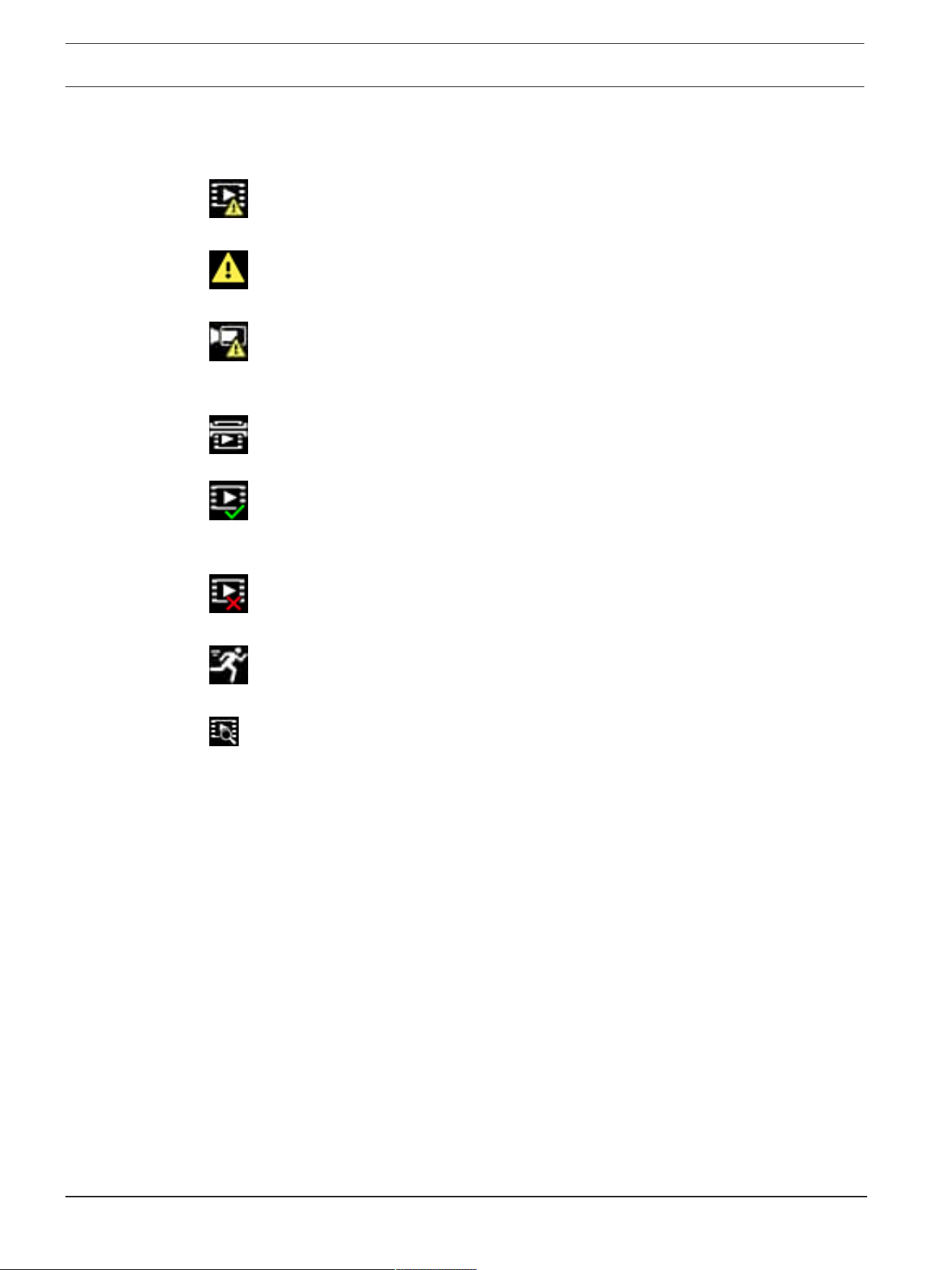
66 en | Operation via the browser MIC IP ultra 7100i │ MIC IP starlight 7100i
2022-01 | 1.8 |
User Manual
Bosch Security Systems
11.1.10 Status icons
Various overlays in the video image provide important status information. The overlays provide
the following information:
Decoding error
The frame might show artifacts due to decoding errors.
Alarm flag
Indicates that an alarm has occurred.
Communication error
A communication error, such as a connection failure to the storage medium, a protocol
violation or a timeout, is indicated by this icon.
Gap
Indicates a gap in the recorded video.
Watermark valid
The watermark set on the media item is valid. The color of the check mark changes according
to the video authentication method that has been selected.
Watermark invalid
Indicates that the watermark is not valid.
Motion alarm
Indicates that a motion alarm has occurred.
Storage discovery
Indicates that recorded video is being retrieved.

MIC IP ultra 7100i │ MIC IP starlight 7100i Operation via the browser | en 67
Bosch Security Systems
User Manual
2022-01 | 1.8 |
11.2 Playback
Click
Playback in the application bar to view, search or export recordings. This link is
only visible when a direct iSCSI or memory card is configured for recording (with Video
Recording Manager (VRM) recording this option is not active).
On the left side of the screen, there are four groups:
– Connection
– Search
– Export
– Track list
11.2.1 Selecting the recording stream
On the left side of the browser, expand the Connection group if necessary.
To view a recording stream:
1. Click the Recording drop-down arrow to see the options.
2. Select recording stream 1 or 2.
11.2.2 Searching for recorded video
On the left side of the browser, expand the Search group if necessary.
1. To limit the search to a particular time range, enter the date and times for the start and
stop points.
2. Select an option from the drop-down box to define a search parameter.
3. Click Search.
4. The results are shown.
5. Click a result to play it back.
6. Click Back to define a new search.
11.2.3 Exporting recorded video
On the left side of the browser, expand the Export group if necessary.
1. Select a track in the track list or in the search results.
2. The start and stop date and time are filled-in for the selected track. If required, change
the times.
3. In the Time lapse drop-down box, select the original or a condensed speed.
4. In the Location drop-down box, select a target.
5. Click Export to save the video track.
Note:
The target server address is set on the Network / Accounts page.
11.2.4 Track list
The Track list shows all the available recordings.
11.2.5 Controlling playback
The time bar below the video image allows quick orientation. The time interval associated with
the sequence is displayed in the bar in gray. Arrows indicate the position of the image
currently being played back within the sequence.
The time bar offers various options for navigation in and between sequences.
– If required, click in the bar at the point in time at which the playback should begin.
– Change the time interval displayed by clicking the plus or minus icons or use the mouse
scroll wheel. The display can span a range from six months to one minute.

68 en | Operation via the browser MIC IP ultra 7100i │ MIC IP starlight 7100i
2022-01 | 1.8 |
User Manual
Bosch Security Systems
– Click the alarm jump buttons to go from one alarm event to the next or to the previous
one. Red bars indicate the points in time where alarms were triggered.
Controls
Control playback by means of the buttons below the video image.
The buttons have the following functions:
– Start/Pause playback
– Select the playback (forward or backward) speed using the speed regulator
– Step forward or backward frame-by-frame when paused (small arrows)
11.3 Dashboard
The Dashboard page shows information on 4 topics:
– Device status
– Recording status
– Connection Status
– Services
You can also download a .JSON file with information about the device:
1. At the bottom of the page, locate the Export button
2. Click the Export button
3. Select a location in your hard drive to store the file

MIC IP ultra 7100i │ MIC IP starlight 7100i Using your MIC Camera | en 69
Bosch Security Systems
User Manual
2022-01 | 1.8 |
12 Using your MIC Camera
12.1 Recommended Use of Your MIC Camera
Bosch recommends that you consider the following in order to optimize the life of your Bosch
camera.
1. Guard Tours and Preset Tours
With your camera, you can cover a full 360° view using continuous Guard Tours or Preset
Tours. Depending on the type of camera tour selected, your camera might be either in
continuous motion (pan, tilt, or both) or moving between selected preset positions.
Continuous Guard Tours
Guard Tours are a very effective way of monitoring the entire scene; however, if not configured
properly, continuous Guard Tours can reduce the service life of your camera considerably.
Continuous Guard Tours should be used in applications where the tours are required to run
for a fixed duration during the day (not more than twelve hours/day). Additionally, for best
results, the continuous guard tour should be used in scenes with sufficient illumination levels
(50 lux or better), should be at least 60 seconds in duration, and should have a smooth pan/
tilt path (without erratic stops and starts), with the lens set at a wide angle (infinity focus).
The tour should also include at least 10° of tilt movement.
Note: Tour B is now intended for use with the 'IVA while moving' functions.
Preset Tours
For scenarios that require the camera to be in continuous motion for most of the day, Bosch
recommends that you set the camera in Preset Tour mode, moving between a desired set of
presets. For best results, always ensure that each preset has a dwell time of at least 5
seconds.

70 en | Using your MIC Camera MIC IP ultra 7100i │ MIC IP starlight 7100i
2022-01 | 1.8 |
User Manual
Bosch Security Systems
12.2 Using the Wiper/Washer (Bosch Protocol)
The "predefined position" for the wash/wipe function is preset 62. The installer must define
preset 62 (preferably where the washer nozzle is located and can direct washer fluid towards
the camera window) before using the wiper/washer function.
To activate the washer/wiper function, press ON-105-ENTER and confirm this sequence:
1. The wiper moves to a predefined position.
2. The washer turns on for five seconds. Simultaneously, the wiper turns on and wipes five
times.
3. The washer turns off. The wiper turns off.
4. The camera returns to its previous PTZ position (and to inactive mode if applicable).
To activate the wiper manually (or if the corresponding alarm was activated or
deactivated):
Press ON-102-ENTER.
Note: The wiper will turn off automatically after 5 minutes of use.
To activate intermittent wipe:
Press ON-103-ENTER. The wiper wipes twice, then returns to parked position, and then turns
off 15 seconds later.
To activate the wiper to wipe five (5) times:
Press ON-104-ENTER. The wiper wipes five times, then returns to parked position and turns
off.
i
Notice!
If the power fails while the wiper is activated, the wiper will return to parked position, after
power is restored, before turning off. The wiper will not stop in front of the camera window.

MIC IP ultra 7100i │ MIC IP starlight 7100i Using your MIC Camera | en 71
Bosch Security Systems
User Manual
2022-01 | 1.8 |
12.3 Using the Wiper/Washer (Pelco Protocol)
To activate the washer/wiper in Pelco protocol, follow these steps:
1. From the Configuration page > Illumination/Wiper > Wiper/washer, click Start, and then exit
the menu.
2. Position the camera so that the nozzle of the washer will spray the camera window.
3. Press 62 and then Preset. Press and hold "Preset" for 2 seconds until the text "Scene 62
Stored" appears on the OSD.
Note: If you already have a preset stored at that position, the system prompts you to overwrite
the current scene.
4. Activate the wash/wiper function. Press 1 and then press AUX-ON on the keyboard. The
camera moves to preset 62. The nozzle sprays cleaner onto the camera window, and then the
wiper wipes the window. The camera then returns to where it was positioned previously, or it
continues to perform the tour that it was performing when you activated the wash/wipe
function.
i
Notice!
Depending on your camera settings, your monitor may display a freeze frame image of the
wiper during or at the end of the wipe cycle. If you prefer not to see this freeze frame, you
can turn off the Freeze Frame on Preposition in the PTZ Setup menu.

72 en | Using your MIC Camera MIC IP ultra 7100i │ MIC IP starlight 7100i
2022-01 | 1.8 |
User Manual
Bosch Security Systems
12.4 Uploading a User Logo
Customers have the option to upload custom logos that display on the web browser of the
device.
All user logo images must comply with the following requirements:
– The file format must be a bitmap (.bmp).
– Height and width must not exceed 128 pixels.
– Color depth must be 8 bit (256 color bitmap).
Upload the Logo File
1. If necessary, open the browser. Click Configuration.
2. Click General. Select Display Stamping.
3. Select the field Camera name stamping. Select the position of the logo: Bottom, Top, or
Custom.
Note: If you select Custom, then additional fields (Position (XY)) appear where you can
specify the exact position of the logo. In the fields Position (XY), enter the values for the
desired position (0 - 255).
4. Click Logo Browse to open a file-search dialog. Select the image file (.bmp).
5. Click Upload to transfer the file to the camera.
The message “Upload successful” should appear.
The new logo, if applicable, replaces the previous one.
6. Select the field Logo position. Select the position of the logo on either side of the camera
name: Left, Right, or Logo only. (The default value is Off.)
7. Click Set to save.
Set Logo Transparency (Optional)
1. Click the check box Transparent background.
2. Click Set to save.
3. Note that the color of the entire first line of the logo is the color that will be changed to
transparent in the remainder of the logo. For example, if the first line is white, then all of
the identical white colors of the logo image will become transparent.
Change the Camera Title
1. Click General. Select Identification.
2. Delete all of the text in the field Camera name.
3. Rename the camera if desired.
4. Click Set to save.
12.5 Two-line and Three-line Camera Titles
There are two options to display camera titles, but these should not be used together. Choose
one of the following modes.
– Mode 1: Azimuth/Elevation/Compass/Zoom Options
– Mode 2: Camera Title combined with Compass
Mode 1: Azimuth/Elevation/Compass/Zoom Options
Select one of the following options:
– Display Azimuth/Elevation and ZOOM value (Optical/Digital) at the bottom of the screen.
Use the command AUX ON-95-ENTER.
– Display Azimuth/Elevation/Compass at the bottom of the screen. Use the command AUX
ON-96-ENTER.
Mode 2: Camera Title combined with Compass
Select one of the following options. Users can toggle between the two options.
– Display two (2) lines of text at the top of the video. Use the command AUX ON-75-ENTER.

MIC IP ultra 7100i │ MIC IP starlight 7100i Using your MIC Camera | en 73
Bosch Security Systems
User Manual
2022-01 | 1.8 |
– Display three (3) lines of text at the top of the video. Use the command AUX ON-76-
ENTER.
About Fonts for Camera Titles
– The default font style is white text with a clear background. The font size cannot be
changed.
– Using the command AUX ON-77-ENTER, users can change the font color manually when
the camera is in Day Mode. Toggle the text colors in the following sequence: White-
>Yellow->Violet->Red->Cyan->Green->Blue->White.
– Using the command AUX OFF-77-ENTER, users can set the color again to the default
white.
– The font color changes automatically to white when the camera enters Night Mode.
– When the camera returns to Day Mode, the camera will use the selected font color
automatically.
Available Character Set
Characters permitted:
– A-Z (upper case only)
– 0-9
– Miscellaneous characters such as - [SPACE]! " $ & ' , . / : ?
Characters not permitted:
– Lower case characters (a-z)
– Underscores (_)
– Save these settings so that, in case of a power failure, the system will recover and then
restore the user values.
Two-line Camera Title
At the top of the video, there are two lines of text.
Line 1 displays the first 20 characters of the Camera Name/ID. Users can edit this text to enter
a highway name, camera location, etc.
Line 2 displays the text, “LOOKING: X” or “LOOKING: XX” (without quotation marks), where
“X” or “XX” is the compass direction. This line cannot be edited by the end user.
– LOOKING will always appear in English and will be at a fixed location on the OSD.
– The X or XX designates the compass direction that updates automatically as the camera
pans. A identifies “North,” “South,” “East,” or West.” AA identifies “Northeast,”
“Northwest,” “Southeast,” or “Southwest.”
Three-line Camera Title
Lines 1 and 2 display the first 20 characters of both lines of the Camera Name/ID. Users can
edit both of these lines to enter a highway name, camera location, etc.
Line 3 displays the text, “LOOKING: X” or “LOOKING: XX” (without quotation marks), where
“X” or “XX” is the compass direction. This line cannot be edited by the end user.
– LOOKING will always appear in English and will be at a fixed location on the OSD.
– The X or XX designates the compass direction that updates automatically as the camera
pans. A identifies “North,” “South,” “East,” or West.” AA identifies “Northeast,”
“Northwest,” “Southeast,” or “Southwest.”

74 en | Using your MIC Camera MIC IP ultra 7100i │ MIC IP starlight 7100i
2022-01 | 1.8 |
User Manual
Bosch Security Systems
12.6 Azimuth, Elevation, and Compass Directions
The camera can display the following data in the lower-right corner of the image display:
– Azimuth - The pan angle from zero to 359 degrees in one-degree increments. An azimuth
of zero degrees corresponds to North.
– Elevation - The tilt position from zero (horizon) to -90 degrees (camera pointing straight
down) in one-degree increments.
– Compass - The cardinal or intercardinal (N, NE, E, SE, S, SW, W, NW) heading in which
the camera is pointing.
The camera allows users to display only the azimuth/elevation readings or only the compass
reading, or both readings at the same time. The camera displays the azimuth/ elevation
readings and the compass heading in a format such as “180 / -45 S,” where:
– 180 is the Azimuth or the pan location in degrees.
– -45 is the Elevation or the tilt location in degrees.
– S is the compass direction (cardinal or intercardinal).
The camera uses the azimuth to determine the compass direction. The following table shows
the azimuth range and its corresponding compass heading:
Azimuth Range Compass Direction
21° to 65° NE (Northeast) 66° to 110° E (East)
111° to 155° SE (Southeast) 156° to 200° S (South)
201° to 245° SW (Southwest) 246° to 290° W (West)
291° to 335° NW (Northwest) 336° to 20° N (North)
21° to 65° NE (Northeast) 66° to 110° E (East)
111° to 155° SE (Southeast) 156° to 200° S (South)
201° to 245° SW (Southwest) 246° to 290° W (West)
291° to 335° NW (Northwest) 336° to 20° N (North)
The camera uses the Azimuth Zero point, usually set to magnetic North, as the zero degree
pan position and as the North compass heading. The camera then displays the azimuth
reading and the compass heading based on the number of degrees from the Azimuth Zero
point.
i
Notice!
Bosch recommends that only the installer calibrate the Azimuth Zero point. A recalibration to
the Azimuth Zero point may cause inaccurate compass headings.
Set the Azimuth Zero point:
1. Determine the North compass heading, then move the camera to that position.
2. Use the command AUX OFF-90-ENTER to turn off the command lock (if active).
3. Use the command AUX ON-94-ENTER to set the Azimuth Zero point.
Display/hide the azimuth/elevation reading:
– Use the command AUX ON-95-ENTER to display the azimuth/elevation reading.
– Use the command AUX OFF-95-ENTER to hide the azimuth/elevation reading.
Display/hide the compass heading:
– Use the command AUX ON-96-ENTER to display the compass heading.
– Use the command AUX OFF-96-ENTER to hide the compass heading.

MIC IP ultra 7100i │ MIC IP starlight 7100i Troubleshooting | en 75
Bosch Security Systems
User Manual
2022-01 | 1.8 |
13 Troubleshooting
Table of Troubleshooting Issues
The table below identifies issues that could occur with the camera, and how to resolve them.
Problem Questions to Ask/Actions to Resolve the Problem
No camera control. – Ensure that the LAN cable has good connection and
is secured.
– Refresh the browser and ensure that video is
updated.
– Cycle the camera's power off and on.
Video is rolling, noisy, or distorted. – Check the integrity of all connectors and splices of
the Ethernet cable.
If O.K., then:
– Contact Bosch Technical Support.
Camera moves when attempting to
move other cameras.
– Check that the camera’s IP address is properly set.
If camera’s IP address is not set, then:
– Use Configuration Manager to confirm that two
cameras do not have the same IP address. If they do,
change the address of one of the cameras.
No Network Connection. – Check all network connections.
– Ensure that the maximum distance between any
two Ethernet connections is 100 m (328 ft) or less.
If O.K., then:
– If you are behind a firewall, ensure that the Video
Transmission mode is set to UDP.
Camera does not operate at all, or
does not operate as expected, after
being subjected to extreme low
temperatures (below -40 ° (-40 °F)).
- Allow the camera to warm up. The camera requires
a 60-minute warm-up prior to PTZ operations.
- If camera does not operate after this warm-up
period, then reset the camera. In the URL line of your
web browser, type “/reset” at the end of the IP
address of the camera.
Camera reboots frequently or
intermittently
Your camera has an improper network connection.
Test your camera with another power supply.
Check the Bosch website for a software update that
might address the issue.
Nothing appears on the screen. Are the power cord and line connection between the
camera and monitor made properly?
The image on the screen is dim. Is the lens dirty? If so, clean the lens with a soft,
clean cloth.
The contrast on the screen is too
weak.
Adjust the contrast feature of the monitor. Is the
camera exposed to strong light? If so, change the
camera position.
The image on the screen flickers. Does the camera face directly into the sun or
fluorescent lighting? If so, reposition camera.

76 en | Troubleshooting MIC IP ultra 7100i │ MIC IP starlight 7100i
2022-01 | 1.8 |
User Manual
Bosch Security Systems
The image on the screen is distorted. Is the power frequency set properly in sync? If the
power frequency is not set correctly, the line lock
synchronization mode cannot be used. Set the
synchronization mode to INT. (NTSC Model power
frequency in LL mode: 60 Hz.)
No video. – Check that the mains power to the power supply is
on.
– For IP-enabled cameras: Check to see if you have a
web page.
If you do, then try cycling the camera’s power off and
on.
If you do not, then you may have the wrong IP
address. Use Configuration Manager to identify the
correct IP address.
If O.K., then:
– Check that there is 24 V output from the
transformer.
If O.K., then:
– Check the integrity of all wires and mating
connectors to the camera.
Picture is dark. – Check that the Gain Control is set to High.
If O.K., then:
– Check that the Auto Iris Level is set to the
appropriate level.
If O.K., then:
– Check that the maximum Ethernet cable distance
has not been exceeded.
If O.K., then:
– Restore all camera settings.
Background is too bright to see
subject.
Turn on backlight compensation.
“High Shock Event” appears in
English in the middle of the OSD until
the camera is reset.
The camera experienced a high shock event.
– Check the integrity of the mechanical parts and
the screws (especially on the yoke arms).
– If there is obvious and severe damage, stop using
the camera and contact your Bosch Service
Center for assistance.
– If no damage is evident, complete one of the
following steps:
a) Cycle the power on the camera.
b) Send command AUX OFF 65 to remove the
OSD message.
– If IVA is configured on your camera, the OSD
message may interfere with IVA operation.

MIC IP ultra 7100i │ MIC IP starlight 7100i Troubleshooting | en 77
Bosch Security Systems
User Manual
2022-01 | 1.8 |
Configuration or video management
software identifies the unit as
“Videojet Generic”.
The model ID may be corrupt.
Complete the steps in the section
Rebooting the unit,
page 77
.
13.1 Rebooting the unit
Reboot the unit
After a Factory Default or firmware update, reboot the unit if:
– You cannot connect to the unit in the Web browser.
OR
– Configuration Manager or BVMS or similar software identifies the unit as “Videojet
Generic”.
4 Reboot the unit using one of the following methods:
– In the web browser, type the IP address and then /reset (without any punctuation). Press
the Enter key.
OR
– In Configuration Manager, right-click the IP address and click Restart.
4 Wait two minutes for the process to complete.
If you cannot control the unit after the firmware upgrade, then cycle the power to the unit. If a
power reset does not solve the problem, or if Configuration or video management software
identifies the unit as “Videojet Generic,” then contact your Bosch Service Center for an RMA
for the unit.
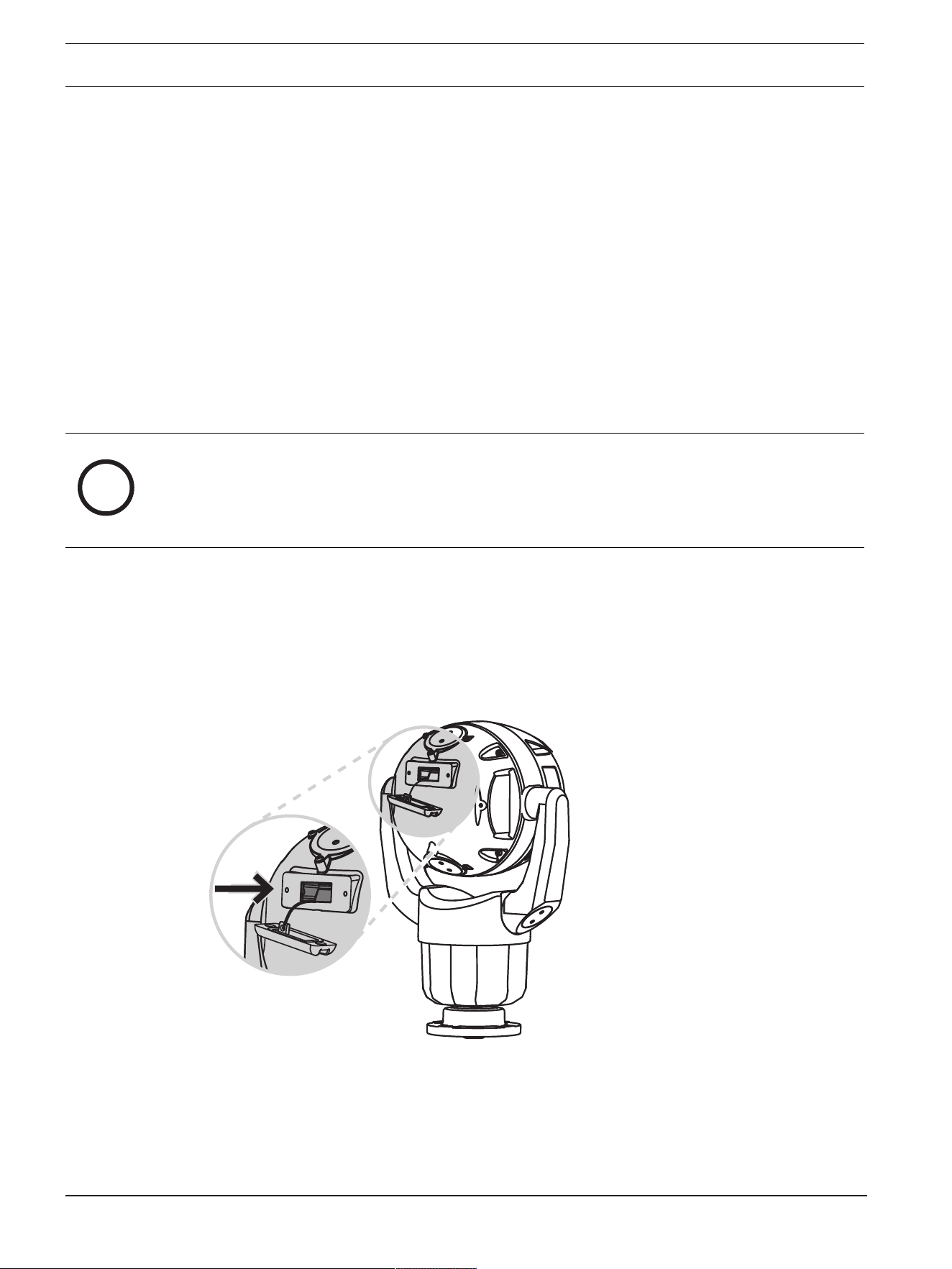
78 en | Troubleshooting MIC IP ultra 7100i │ MIC IP starlight 7100i
2022-01 | 1.8 |
User Manual
Bosch Security Systems
13.2 Physical reset button
Each camera has a hardware reset button. You may need to press the reset button to reset the
camera to factory defaults if you encounter the following circumstances:
– You can power up the camera but cannot log on to the camera using the web browser.
– The camera doesn’t start up, or fails to power up via PoE.
– The camera cannot search an IP address.
– The camera’s firmware crashed.
– You forgot the password to access the camera.
– The image becomes frozen.
– You cannot update the firmware.
– The camera disconnects from the network at random and needs a reboot.
– The camera no longer finds pre-positions (preset positions).
– You cannot configure the camera using the web browser.
– The camera has no video out.
i
Notice!
A factory default deletes all camera settings including passwords, network settings, and
image settings.
Complete the following sequence of steps only if you have no other option to restore
operation to the camera.
Steps to complete a hardware reset for all camera models
1. Apply power to the camera.
2. Find the IP address of the camera.
3. Log on to the camera using the web browser. (Note: You can use Configuration Manager
to identify the IP address.)
4. Find the hardware reset button on the camera. (Refer to the figure below to find the reset
button for your camera model.)
5. Push and hold the reset button for more than 8 seconds. The red LED indicator on the
PCBA board will come on to show that the hardware reset started.
Note: You can also use a conductive wire to short the terminal block.
1. Let the camera complete a self-check. When the self-check completes, the red LED will go
off.
2. Find the IP address again.
3. Access the camera using the web browser.

MIC IP ultra 7100i │ MIC IP starlight 7100i Troubleshooting | en 79
Bosch Security Systems
User Manual
2022-01 | 1.8 |
4. Set the initial service-level password for the camera.

80 en | Troubleshooting MIC IP ultra 7100i │ MIC IP starlight 7100i
2022-01 | 1.8 |
User Manual
Bosch Security Systems
13.3 Customer Service and Support
If this unit needs service, contact the nearest Bosch Security Systems Service Center for
authorization to return and shipping instructions.
USA and Canada
Telephone: 800-289-0096, option 5
Fax: 800-366-1329
Email: [email protected]
Customer Service
Telephone: 800-289-0096, option 3
Fax: 800-315-0470
Email: [email protected]
Technical Support
Telephone: 800-289-0096, option 4
Fax: 800-315-0470
Email: [email protected]
Europe, Middle East, Africa, and Asia Pacific Regions
Contact your local distributor or Bosch sales office. Use this link: https://
www.boschsecurity.com/xc/en/where-to-buy/
MIC IP ultra 7100i │ MIC IP starlight 7100i Decommissioning | en 81
Bosch Security Systems
User Manual
2022-01 | 1.8 |
14 Decommissioning
14.1 Transfer
The device should only be passed on together with this Installation manual.
14.2 Disposal
Disposal - Your Bosch product was developed and manufactured with high-quality
material and components that can be recycled and reused. This symbol means that
electronic and electrical appliances, which have reached the end of their working life,
must be collected and disposed of separately from household waste material.
Separate collecting systems are usually in place for disused electronic and electrical
products. Please dispose of these units at an environmentally compatible recycling
facility, per European Directive 2012/19/EU.

82 en | Status Codes MIC IP ultra 7100i │ MIC IP starlight 7100i
2022-01 | 1.8 |
User Manual
Bosch Security Systems
15 Status Codes
For certain conditions, MIC cameras will display status codes on the video image. The table
below identifies the status codes, their descriptions, and the recommended action to resolve
the condition.
Most status codes appear on the OSD until you acknowledge them. The codes identified with
asterisks (**) appear for approximately 10 seconds, then disappear automatically.
To clear the status code in the OSD, send the appropriate acknowledge command. If
necessary, refer to the operation instructions in the Video Management System software for
issuing acknowledge commands, or to the appropriate section in the User Manual for your MIC
camera for details on issuing the “AUX OFF 65” command.
Status
Code
Description Recommended action
(to be completed by a qualified Service
Technician)
2 Capacity of external PoE device is
insufficient to support operation of
the camera's window defroster.
Note: MIC IP fusion 9000i only.
An incorrect type of PoE (such as one based
on IEEE 802.3af) with insufficient power
output may be connected to the camera.*
3 Capacity of external PoE device is
insufficient to support operation of
the camera's internal heater.
An incorrect type of PoE+ or PoE++ (such as
one based on IEEE 802.3af or IEEE 802.3at)
with insufficient power output may be
connected to the camera.*
4 Capacity of the external PoE device
is insufficient to support operation
of the camera's window defroster.
Note: MIC IP fusion 9000i only.
An incorrect type of PoE+ or PoE++ (such as
one based on IEEE 802.3af or IEEE 802.3at)
with insufficient power output may be
connected to the camera.*
5 When operating using redundant
power sources, the camerais
detecting insufficient voltage being
provided by the external High PoE
power source.
1. Verify that the High PoE power source
(midspan or switch) can provide 95 W of
output power.
2. Verify that the network cable is not longer
than 100 m maximum.
3. If using the 95W High PoE Midspan
(NPD-9501A), verify that both LEDs are
green. If not, refer to the “Troubleshooting”
section of the installation manual of the
midspan.
6 When operating using redundant
power sources, the camera is
detecting insufficient voltage being
provided by the external 24 VAC
power source.
1. Verify that the 24 VAC power source can
provide at least 4.0 A to the camera.
2. Verify that the wire gage of the power
cable is sufficient for the distance between
the power source and the camera and that
the voltage getting to the user cable of the
camera is between 21 VAC and 30 VAC.
7 Camera may be operating in an
environment where ambient
temperature is below the
specification of the camera.
1. Verify that the ambient temperature is not
below -40 °C (-40 °F).

MIC IP ultra 7100i │ MIC IP starlight 7100i Status Codes | en 83
Bosch Security Systems
User Manual
2022-01 | 1.8 |
Status
Code
Description Recommended action
(to be completed by a qualified Service
Technician)
2. Review the diagnostic log of the camera
(accessible from the Service menu) for errors
related to the operation of the internal
heaters.
Note: Motorized zoom and focus functions of
the visible camera lens will be disabled until
the camera operates within the specified
temperature range.
8 Camera may be operating in an
environment where ambient
temperature is above specification
of the camera.
1. Verify that the ambient temperature is not
above +65 °C (+149 °F).
2. Review the diagnostic log of the camera
(accessible from the Service menu) for errors
related to the operation of the internal fan.
3. Add the optional sunshield accessory to
reduce internal heating caused by sun
loading.
9 Camera has been subjected to high
shock. Mechanical damage to the
camera may exist.
1. Verify the integrity of the mechanical parts
such as the arms and the pan body.
2. Verify the integrity/tightness of the
external fasteners. Tighten where necessary.
3. If obvious damage is present, stop using
the camera and contact the nearest Bosch
Security Systems Service Center.
4. If no damage is evident, power the camera
off and then on, and then evaluate
operational performance. If the camera does
not operate as expected, contact the nearest
Bosch Security Systems Service Center.
10 Camera is detecting high humidity
level inside housing. The integrity of
the housing seal may be
compromised.
1. Inspect the window for any cracks or
obvious damage around the edge of the
window.
2. Verify the integrity/tightness of the
external fasteners. Tighten where necessary.
3. Verify the integrity of the mechanical seals
around the tilt head, pan body, and arm
joints.
4. If damage to the seals is obvious, contact
the nearest Bosch Security Systems Service
Center.
5. If no obvious damage is found, power the
camera off and then on. If the status code
reappears, contact the nearest Bosch
Security Systems Service Center.

84 en | Status Codes MIC IP ultra 7100i │ MIC IP starlight 7100i
2022-01 | 1.8 |
User Manual
Bosch Security Systems
Status
Code
Description Recommended action
(to be completed by a qualified Service
Technician)
11 Wiper operation has been halted
because of an obstruction.
1. Remove any obvious materials that are
obstructing operation of the wiper.
2. If the obstruction is from ice buildup,
review the diagnostic log of the camera
(accessible from the Service menu) for errors
related to operation of the internal heaters
(and the window defrosters, for MIC IP fusion
9000i). If possible, tilt the camera so that the
front faceplate is pointed straight up. (In this
position, heat generated by the camera will
help to melt ice buildup from its front
faceplate area.)
3. If the obstruction is from extreme ice
buildup, temporarily avoid operating the
wiper until internal heaters, combined with a
rise in ambient temperature, melt the ice
buildup.
12 Left and Right Pan Limits have been
set too close to each other.
Re-configure one camera stop limit or the
other to increase the distance between limit
stops to at least 10° apart.
13** Autofocus has been turned off
because of excessive focus activity.
1. If practical, increase lighting in the scene
so that the focus function stops “hunting.”
2. Use focus in manual mode or One-Push
mode.
14** Washer operation was attempted
without washer pre-position being
stored.
Configure the washer pre-position. If
necessary, refer to the subchapter “Using the
Wiper/Washer (Bosch AUX/Pre-position
Commands)” in the User Manual for details
on configuring washer functions.
15 Attempt was made to move to a pre-
position that is mapped to an
alternate function, so it is no longer
associated with a location.
1. Select/configure a different pre-position
number for the desired location.
2. Re-configure the pre-position assignment
so that this number is no longer associated
with an alternate function. Refer to the
subchapter “Pre-position mapping” in the
User Manual for details on re-mapping pre-
positions.
16** Motorized zoom function is
programmed to operate at a high
usage level in the Playback Tour.
This high rate of usage could result
in premature wear of the zoom
motor.
Re-configure the camera to decrease the
zoom activity to less than 30% during
recording.

MIC IP ultra 7100i │ MIC IP starlight 7100i Status Codes | en 85
Bosch Security Systems
User Manual
2022-01 | 1.8 |
Status
Code
Description Recommended action
(to be completed by a qualified Service
Technician)
17 Motor operation has been halted
due to an obstruction.
1. Remove any obvious materials that are
obstructing operation of the camera pan/tilt
function.
2. If the obstruction is from ice buildup,
review the diagnostic log of the camera
(accessible from the Service menu) for errors
related to the operation of the internal
heaters (and the window defrosters, for MIC
IP fusion 9000i). If the log notes heater or
defroster failure, contact the nearest Bosch
Security Systems Service Center.
3. If operation is obstructed because of
excessive ice buildup, temporarily avoid
operating the pan/tilt functions of the camera
until internal heaters, combined with a rise in
ambient temperature, melt the ice buildup.
18** When operating using redundant
power sources, the camera has
detected a loss of power from the
external High PoE power source.
1. Verify the operating status of the external
High PoE power source.
2. Verify the integrity of the electrical
connections between the power source and
the camera.
19** When operating using redundant
power sources, the camera has
detected a loss of power from the
external 24 VAC power source.
1. Verify the operating status of the external
24 VAC power source.
2. Verify the integrity of the electrical
connections between the power source and
the camera.
20 Camera is configured to use the
“Hard Pan Limits” (HPL) feature, and
it has been powered-up with pan
position in the forbidden zone.
Temporarily remove one of the hard pan
limits (as described in
PTZ Settings, page
34
), pan the camera out of the forbidden
zone, and then restore the hard pan limit.
Reboot the camera by powering the camera
off and then on, or by clicking the button
Reboot in the camera’s web browser
(Configuration > Camera > Installer Menu
>Reboot device).
Note: If pan movement is blocked only in one
direction, but possible in the other direction
(as when the camera is near the HPL), then
no status code appears.
The Hard Pan Limits feature is for MIC cameras only.
Washer and wiper apply to MIC cameras only.

86 en | Status Codes MIC IP ultra 7100i │ MIC IP starlight 7100i
2022-01 | 1.8 |
User Manual
Bosch Security Systems
21 Illuminator error: IR Reboot the camera by powering the camera
off and then on, or by clicking the button
Reboot in the camera’s web browser
(Configuration > Camera > Installer Menu
>Reboot device).
If this action does not resolve the problem,
contact the nearest Bosch Security Systems
Service Center. The Service Center may
request information from the diagnostics log
of the camera (accessible from the Service
menu).
23 An internal error has occurred.
(The optical video screen becomes
blue for 1 or 2 seconds during the
camera’s recovery procedure.)
If this problem begins to occur on a regular
basis:
1. Verify that the power source to the camera
is not experiencing brown-out conditions.
2. Verify that the camera’s earth ground
connection is attached per earlier
instructions.
If these actions do not resolve this problem,
contact the nearest Bosch Security Systems
Service Center.
!
Caution!
If you choose not to use a switch or midspan with the appropriate Power Sourcing Equipment
(PSE) chip, then the camera will not recognize the PoE as compliant, and the camera
firmware may disable some or all functionality.

MIC IP ultra 7100i │ MIC IP starlight 7100i AUX Commands | en 87
Bosch Security Systems
User Manual
2022-01 | 1.8 |
16 AUX Commands
AUX Function Command Description
1 On/Off Auto Pan without limits
(Continuous)
2 On/Off Auto Pan between limits
7 On/Off Run Custom Pre-Position Tour
8 On/Off Run Pre-Position Tour
18 On/Off AutoPivot Enable
20 On/Off Backlight Compensation (BLC)
24 On/Off Video Stabilization
40 On/Off Restore camera settings [to
factory defaults]
43 On/Off Auto Gain Control (AGC)
50 On/Off Playback A, continuous
51 On/Off Playback A, single
52 On/Off Playback B, continuous
53 On/Off Playback B, single
57 On/Off Night mode IR Filter In/Out
60 On/Off On-Screen Display (OSD)
61 On/Off Preset & Sector Titles Camera
Block Overlay VDSK not required
65 Off Alarm Acknowledge Acknowledges alarm events/rules or
deactivates physical outputs.
67 On/Off IR Focus Correction
78 On/Off Intelligent Tracking (Not available on MIC inteox
models.)
80 On/Off Digital Zoom lock
86 On/Off Sector Blanking
87 On/Off Privacy Masking
88 On/Off Proportional Speed
94 On/- Recalibrate Azimuth Compass
95 On/Off Azimuth/Elevation Display
96 On/Off Compass Points Display
100 On/Off Record Tour A
101 On/Off Record Tour B
102 On/Off Wiper On/Off (Continuous)

88 en | AUX Commands MIC IP ultra 7100i │ MIC IP starlight 7100i
2022-01 | 1.8 |
User Manual
Bosch Security Systems
AUX Function Command Description
103 On/Off Wiper On/Off (Intermittent)
104 On/Off Wiper On/Off (One shot)
105 On/Off Wash/Wipe On/Off
121 On/Off Left Hard Pan Limit
122 On/Off Right Hard Pan Limit
123 On/Off Clear Hard Pan Limits
221 On Pan 180 degrees at maximum
speed
606 On/Off Power Mode
700 On/Off Proportional speed control
adjustment
Aux On, entered repeatedly, cycles
through increasing speeds Super
Slow, Slow, Medium, and Fast.
Aux Off, decreases speeds through
the same settings.
804 On/Off Mask Calibration Procedure
908 Increase Privacy Mask Size while
moving
1-256 Set/- Pre-position Programming
1-256 -/Shot Pre-position Recall
The following commands are specific to MIC7000 models, including MIC IP starlight 7000i.
AUX Function Command Description
54 On/Off IR mode AUX ON sets IR to Auto.
AUX OFF sets IR to OFF.
Available only for a MIC camera with
an attached illuminator.
57 On/Off Night mode IR Filter In/Out
68 On/Off White light illumination

MIC IP ultra 7100i │ MIC IP starlight 7100i Support services and Bosch Academy | en 89
Bosch Security Systems
User Manual
2022-01 | 1.8 |
17 Support services and Bosch Academy
Support
Access our support services at www.boschsecurity.com/xc/en/support/
.
Bosch Security and Safety Systems offers support in these areas:
– Apps & Tools
– Building Information Modeling
– Warranty
– Troubleshooting
– Repair & Exchange
– Product Security
Bosch Building Technologies Academy
Visit the Bosch Building Technologies Academy website and have access to training courses,
video tutorials and documents: www.boschsecurity.com/xc/en/support/training/

90 | Support services and Bosch Academy MIC IP ultra 7100i │ MIC IP starlight 7100i
2022-01 | 1.8 |
User Manual
Bosch Security Systems


Bosch Security Systems B.V.
Torenallee 49
5617 BA Eindhoven
Netherlands
www.boschsecurity.com
© Bosch Security Systems B.V., 2022
202201142232
Building solutions for a better life.