
BPRZR5
INSTALLATION MANUAL
IPX6 RATED 1000 WATTS TRUE PLUG-N-PLAY
COMPLETE POLARIS RZR XP1000 5 SPEAKER AUDIO SYSTEM
5” (127 mm) BLUETOOTH
®
TOUCHSCREEN DIGITAL MEDIA PLAYER
(4) 100 WATT 6.5” (165 mm) AMPLIFIED FULL RANGE SPEAKERS
(1) 600 WATT 10” (254 mm) AMPLIFIED SUBWOOFER ENCLOSURE

- 1 -
INSTALLATION MANUAL
BPRZR5
IPX6 RATED 1000 WATTS TRUE PLUG-N-PLAY
POLARIS RZR XP1000 5 SPEAKER AUDIO SYSTEM KIT
BPRZR5
IPX6 RATED 1000 WATTS TRUE PLUG-N-PLAY
POLARIS RZR XP1000 5 SPEAKER AUDIO SYSTEM KIT
Congratulations on your purchase of a
POWERSPORTS product.
Table of contents
Introduction and features ................................................................................................................................1
Delivery content ................................................................................................................................................2
Specications ...................................................................................................................................................2
Disassembly ......................................................................................................................................................3
Wiring overview ................................................................................................................................................6
RZR-10A Subwoofer enclosure installation ..................................................................................................8
RZR-FSA Front Speaker enclosure installation ...........................................................................................11
RZR-62A Rear Speaker enclosure installation ............................................................................................15
MGV550B Source Unit connection ...............................................................................................................18
MGV550B Source Unit installation ................................................................................................................21
Introduction and features
• Estimated Installation Time: 4 HOURS
• True “Plug and Play” components.
• No drilling or cutting required.
• Kit includes everything needed for installation and will t every model RZR XP1000 from 2014 to current
year (Not Compatible with Ride Command).
• Each IPX6 rated component is self-powered with a high-powered amplier that is matched to the speakers
perfectly.
• Direct t installation designed specically for the Polaris RZR XP1000.
• Rugged kit mounts to components designed to withstands harsh outdoor environment.
• Speaker & Sub enclosures integrate with no loss of passenger space.
• Source unit Dash install kit includes upper and lower kits that t RZR models from 2014 to current models.
Installation/Disassembly tools required
• T40 Torx
• Panel tool or Flathead screwdriver
• Metric/Standard sockets
• Ratchet with extension
• #2 phillips screw driver
• Allen Key Set
- 2 -
BPRZR5
IPX6 RATED 1000 WATTS TRUE PLUG-N-PLAY
POLARIS RZR XP1000 5 SPEAKER AUDIO SYSTEM KIT
INSTALLATION MANUAL
Delivery content
MGV550B
• Marine Gauge Digital Media AM/FM Receiver (1)
• Rubber Cover (1)
• USB Wire Harness (1)
• Machine Screws (4)
• MRANT10 FM Antenna (1)
• MUSB35 Universal USB, 3.5 mm AUX Port (1)
RZR-10A
• 10” Amplied Subwoofer (1)
• Port Plug (1)
• M5x27mm mounting screws (2)
BPRZRD/BPRZR5D
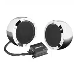
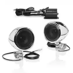
RZR-FSA
• 6.5” Amplied speakers (2)
• M5x27mm mounting screws (4)
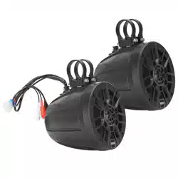
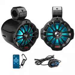
RZR-62A
• 6.5” Amplied speaker pods (2)
• M6 locknuts (4)
• M6 at washers (4); M6 x 60mm screws (4)
• 1.75” mounting aluminum bands for 1.75” and
1.5” installation (4)
• 130 x 14 x 2mm rubber mounting pads (4)
• 120 x 14 x 1mm rubber mounting pads (4)
• 48 x 30 x 2mm rubber mounting pads (2)
• Rear decal (2)
M3x30mm (x4)
3.5x12mm (x4)
x4
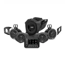
Upper dash mount panel
Metal brace plate
Lower dash mount panel
Screw bag
x1
x1
x1
x1
Specications
RZR-10A
• Max output power: 600 W
• Impedance: 2 Ω
• Speaker driver: 10” (amplified)
• Dimensions: 450 x 445 x 360 mm
• Weight: 8.0 kg
RZR-FSA
• Max output power: 2 x 100 W
• Impedance: 4 Ω
• Speaker driver: 6.5” (full-range, amplified)
• Dimensions: 295 x 185 x 233 mm
• Weight: 2.1 kg (left) / 1.81 kg (right)
RZR-62A
• Max output power: 2 x 100 W
• Impedance: 4 Ω
• Speaker driver: 6.5” (full-range, amplified)
• Dimensions: 182 x 186 x 250 mm
• Weight: 2.23 kg (left) / 1.77 kg (right)
MGV550B
Refer to the separate user manual of MGV550B
- 3 -
INSTALLATION MANUAL
BPRZR5
IPX6 RATED 1000 WATTS TRUE PLUG-N-PLAY
POLARIS RZR XP1000 5 SPEAKER AUDIO SYSTEM KIT
Disassembly
1. Remove all seats from the vehicle and disconnect the negative battery terminal.
2. Disengage the twist locks to the hood and set it aside.
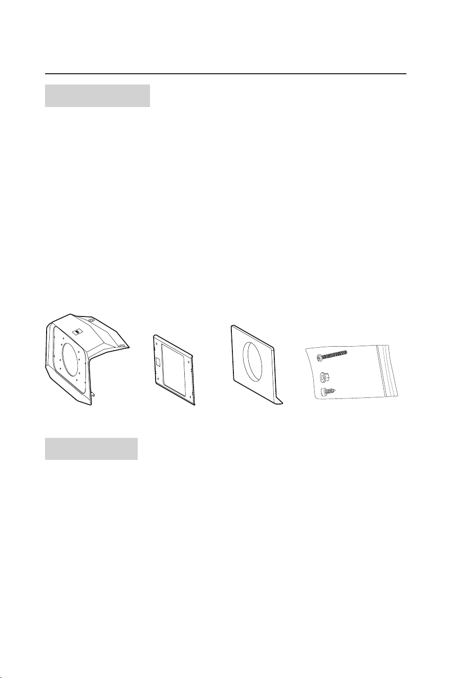
3. Using a panel tool or at head screwdriver, remove the push pins and upper storage compartment. Unfasten
all four T40 torx screws and remove the upper dash panel.
4. Remove the remaining push pins, T40 screws from the remaining dash components.
Label takes photos/notes of all wiring that is connected to the dash face. Disconnect ignition, rocker
switches, and 12V socket (from main dash face), and LED (lower storage compartment).
- 4 -
BPRZR5
IPX6 RATED 1000 WATTS TRUE PLUG-N-PLAY
POLARIS RZR XP1000 5 SPEAKER AUDIO SYSTEM KIT
INSTALLATION MANUAL
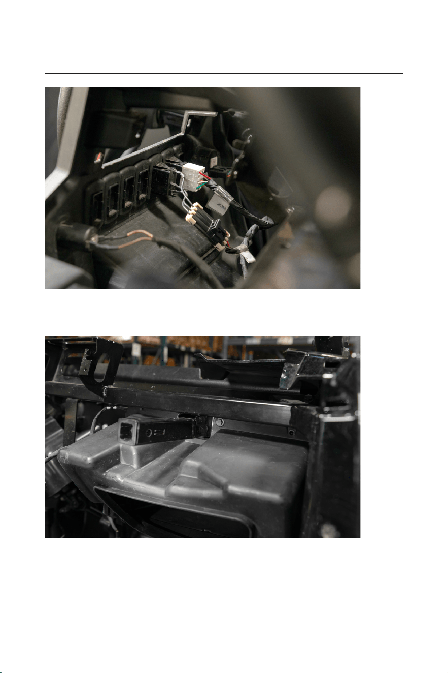
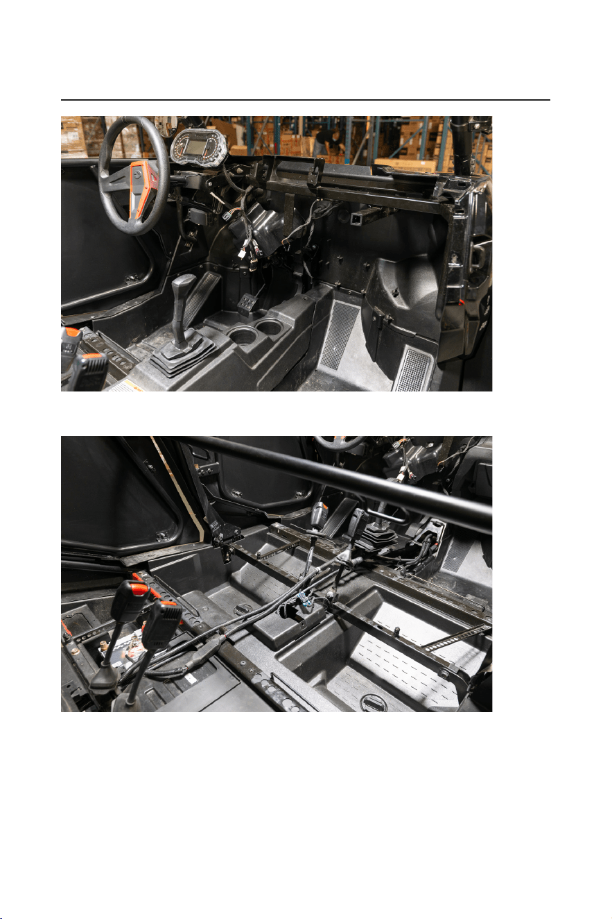
5. Gently pull the left and right side of the main dash face to disengage the body clips, remove the main dash
face. Remove the two 10mm screws from the glovebox and dismount the glovebox from the chassis.
The glovebox will not be reinstalled, RZR-10A will take its place.
- 5 -
INSTALLATION MANUAL
BPRZR5
IPX6 RATED 1000 WATTS TRUE PLUG-N-PLAY
POLARIS RZR XP1000 5 SPEAKER AUDIO SYSTEM KIT
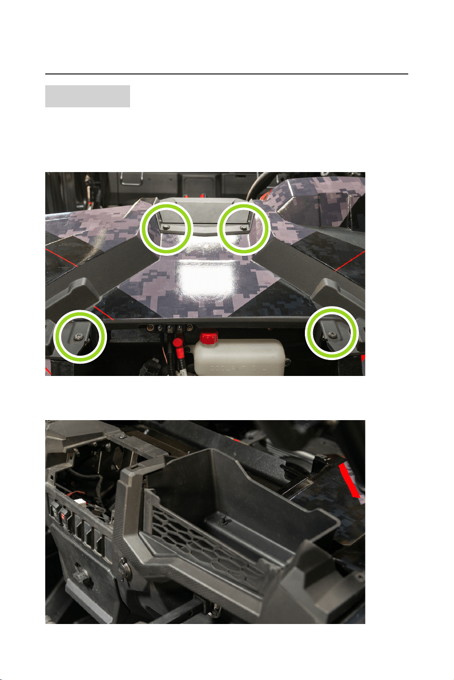
6. When removing the center console from a four-seat machine, disconnect the 12V socket found at the
passenger rear of the center console.
- 6 -
BPRZR5
IPX6 RATED 1000 WATTS TRUE PLUG-N-PLAY
POLARIS RZR XP1000 5 SPEAKER AUDIO SYSTEM KIT
INSTALLATION MANUAL
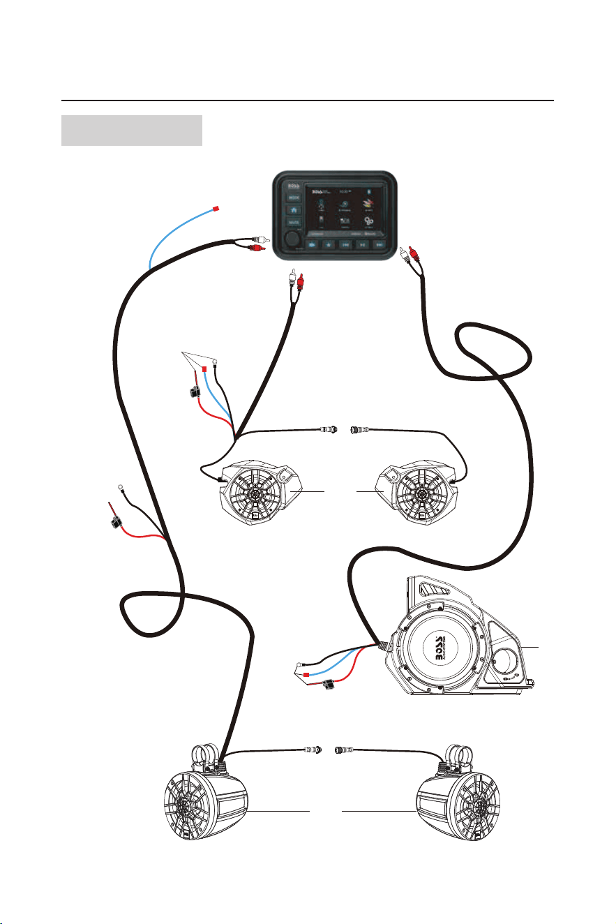
Wiring overview
(4)
(3)
(5)

- 7 -
INSTALLATION MANUAL
BPRZR5
IPX6 RATED 1000 WATTS TRUE PLUG-N-PLAY
POLARIS RZR XP1000 5 SPEAKER AUDIO SYSTEM KIT
Item Description/specications
(1) MGV550B Audio source unit
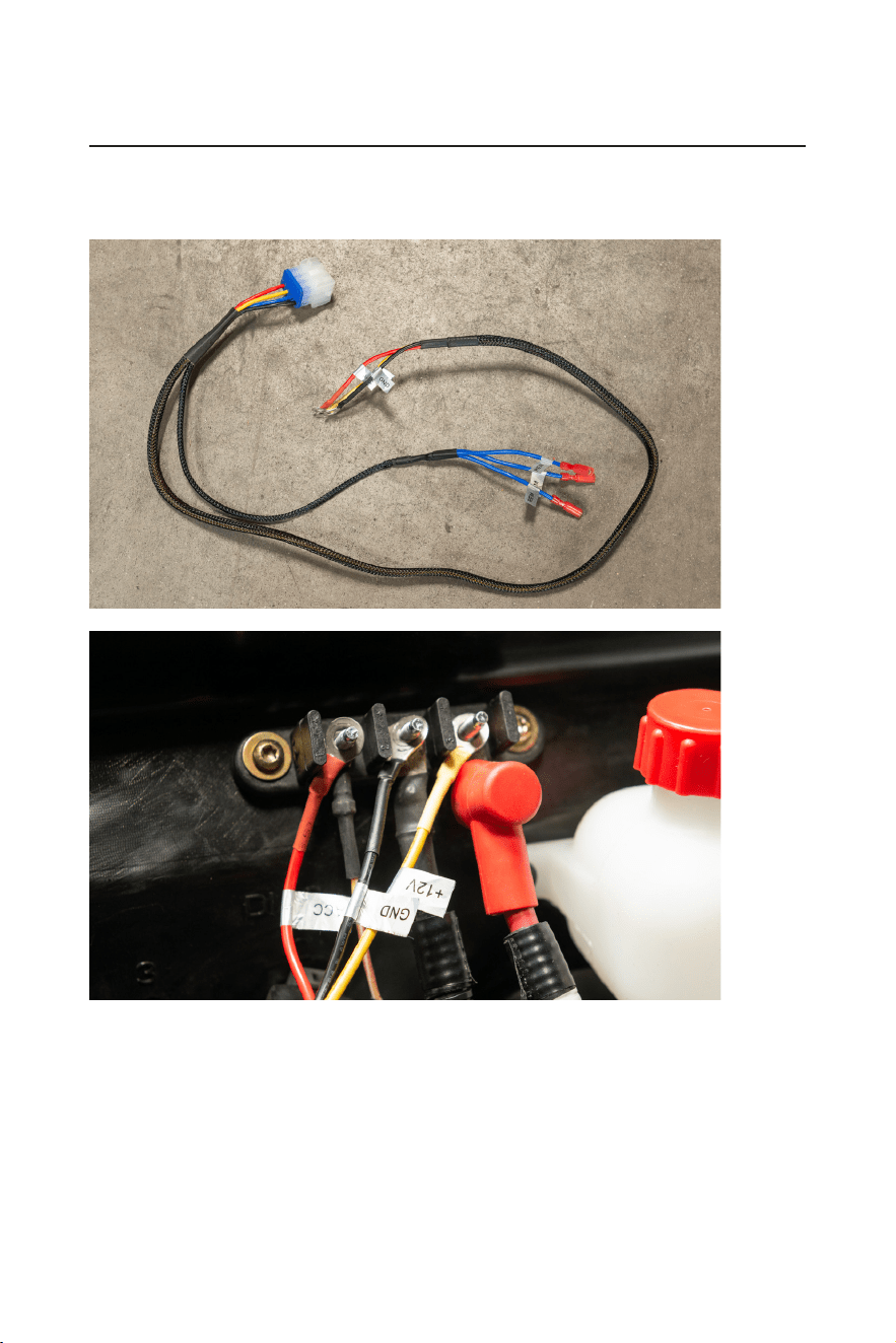
(2)
MGV550B power harness
(not shown in diagram)
• Power, ground, and accessory wire connect to the bus
bar for power.
• Connect the Molex to the MGV550B to power the
MGV550B.
• The three blue remote wires on the power harness
connect to items #3, #4, #5 respectively.
(3) RZR-10A
• Power and ground connects directly to battery.
• Blue remote wire connects to MGV550B power harness.
• RCA input connects to “Sub output” RCAs from the
MGV550B
(4) RZR-FSA
• Power and ground connects to the bus bar under the
hood.
• Blue remote wire connects to MGV550B power harness.
• RCA input connects to the “Front output” RCAs from the
MGV550B.
• Right RZR-FSA input signal connects to the left RZR-
FSA for audio signal.
(5) RZR-62A
• Power and ground connects directly to battery.
• Blue remote wire connects to MGV550B power harness.
• RCA input connects to “Rear output” RCA from the
MGV550B.
• Right RZR-62A input signal connects to the left RZR-62A
for audio signal.
(6) MRANT (not shown in diagram)
• Radio antenna connects to antenna input found on the
MGV550B
(7) MUSB35 (not shown in diagram)
• 3.5mm AUX/USB input connect directly to the MGV550B.
• The RCAs connects to the “Audio input” of the MGV550B.
• USB connects to the MGV500B USB port.
Note: The color and shape of the fuse holder which appears in the following illustrations may vary from the
actual product.
- 8 -
BPRZR5
IPX6 RATED 1000 WATTS TRUE PLUG-N-PLAY
POLARIS RZR XP1000 5 SPEAKER AUDIO SYSTEM KIT
INSTALLATION MANUAL
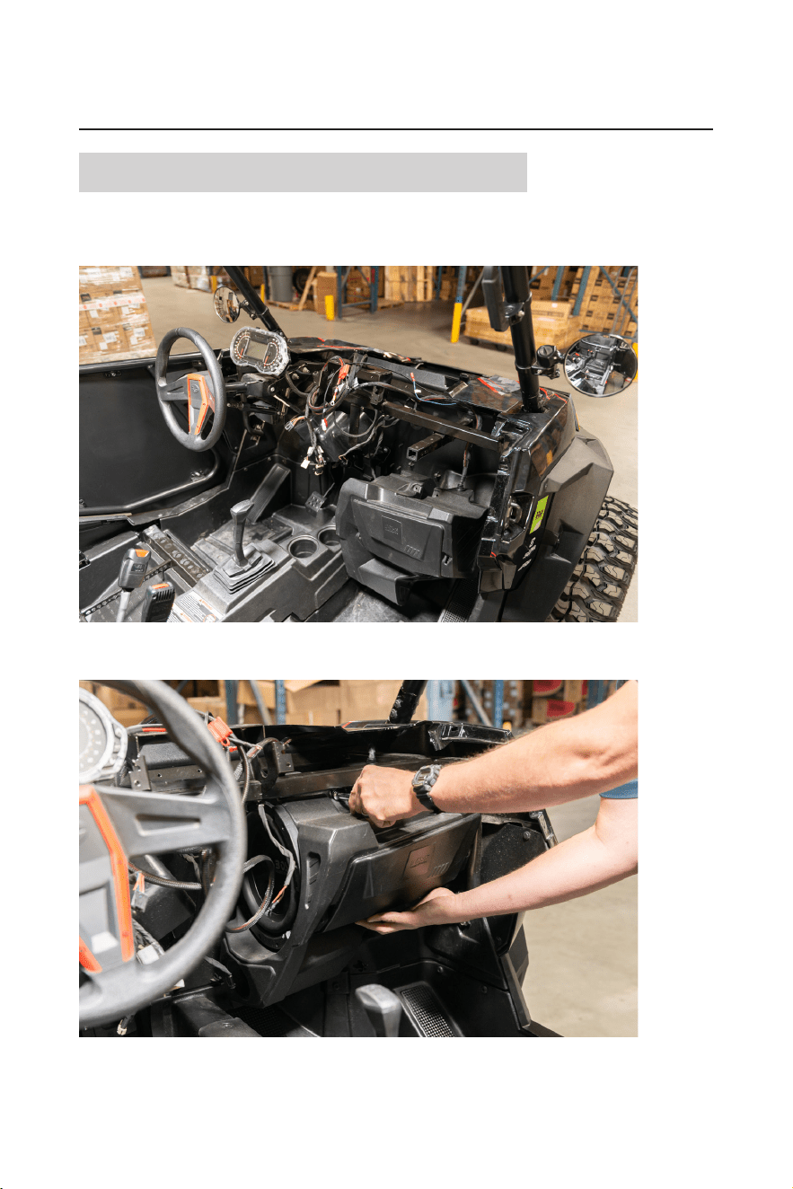
RZR-10A Subwoofer enclosure installation
1. Place the RZR-10A subwoofer enclosure into the passenger footwell of the machine. Route the wiring
harness around the chassis being mindful that the wiring will not be pinched or damaged when the RZR-
10A is mounted.
2. Lift the RZR-10A to the dash cavity crossbar. Secure the enclosure to the chassis with the factory 10mm
hardware that was formally used to secure the glovebox to the machine.
- 9 -
INSTALLATION MANUAL
BPRZR5
IPX6 RATED 1000 WATTS TRUE PLUG-N-PLAY
POLARIS RZR XP1000 5 SPEAKER AUDIO SYSTEM KIT
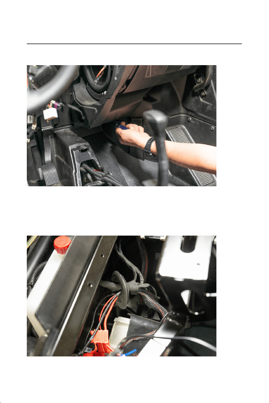
3. Fasten the lower portion of the RZR-10A to the rewall of the machine with two of the provided #2 phillips
screws.
4. Feed the power and ground cables from the RZR-10A through the rewall grommet (Depending on model
year, some tape may have to be removed from the grommet).
To assist with feeding the fuse holder through the grommet, use a punch or long screwdrivers to help stretch
the grommet.
DO NOT feed the RCA input and amp turn on wire through the grommet. They will be staying in the dash
cavity.
- 10 -
BPRZR5
IPX6 RATED 1000 WATTS TRUE PLUG-N-PLAY
POLARIS RZR XP1000 5 SPEAKER AUDIO SYSTEM KIT
INSTALLATION MANUAL
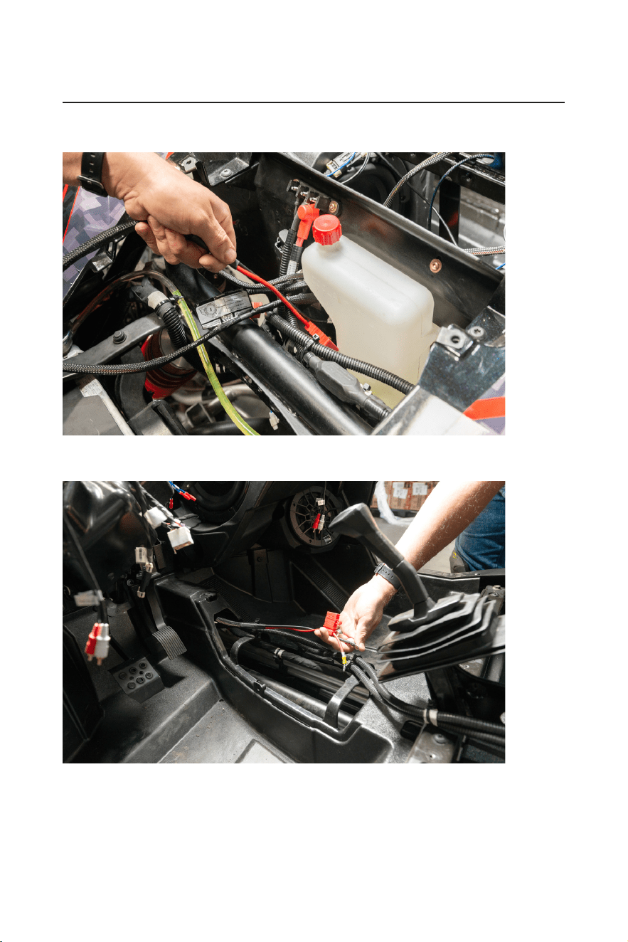
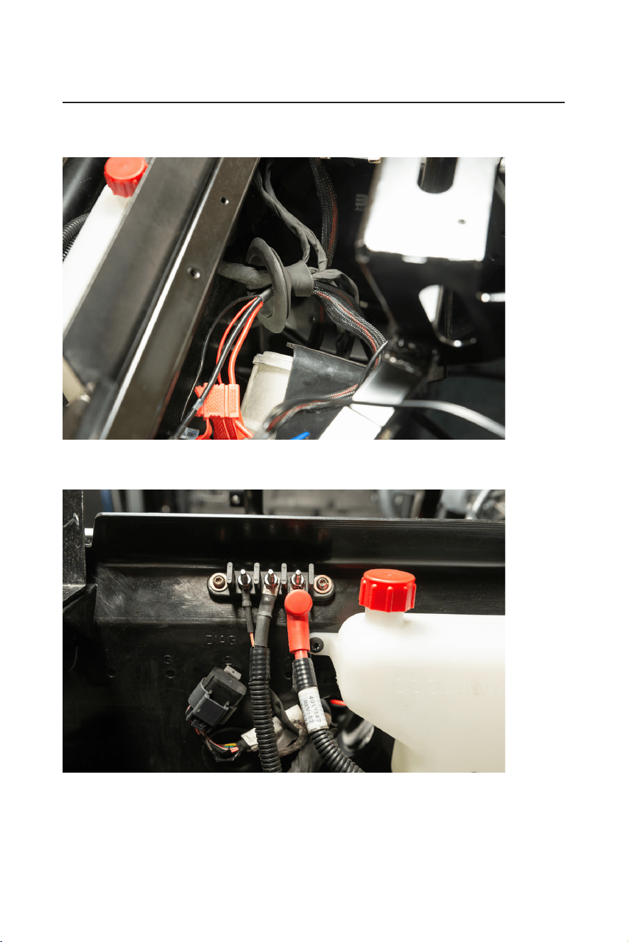
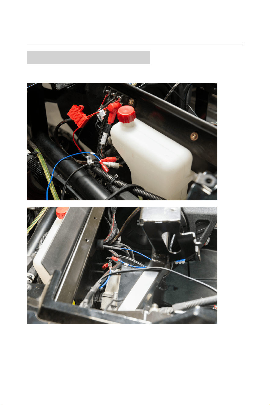
5. Gently pull the slack of power and ground wire through the grommet to the outside of the vehicle. Feed the
power and ground down the exterior of the rewall along the factory wiring harnesses.
6. Feed the power and ground cables along the center of the vehicle along all factory wiring. Avoid any rotating
parts or sharp edges when leading the cables to the battery.
- 11 -
INSTALLATION MANUAL
BPRZR5
IPX6 RATED 1000 WATTS TRUE PLUG-N-PLAY
POLARIS RZR XP1000 5 SPEAKER AUDIO SYSTEM KIT
7. The power and ground will end at the battery. Remove the fuse from the fuse holder. Do not connect the
RZR-10A to power until the BPRZR5 installation has been completed.
Note: The wire lengths were designed with four seat machines in mind. Any extra wire on a two machine
can be neatly coiled zip-tied in a safe location at the end of installation.
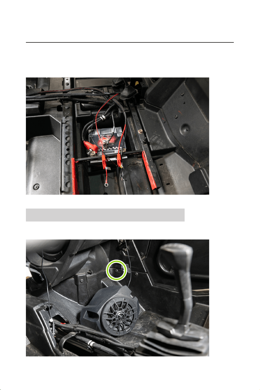
RZR-FSA Front Speaker enclosure installation
1. Remove the one T40 torx screw found two inches above the passenger footrest. Route the input signal
cable of the passenger RZR-FSA up the right side of the RZR-10A.
- 12 -
BPRZR5
IPX6 RATED 1000 WATTS TRUE PLUG-N-PLAY
POLARIS RZR XP1000 5 SPEAKER AUDIO SYSTEM KIT
INSTALLATION MANUAL
2. Refasten the T40 Torx screw through the lower bracket of the RZR-FSA.
3. Using two of the provided #2 phillips screws, secure the inner two mounting points of the RZR-FSA to the
rewall.
Once mounted, route the input signal cable across the dash cavity to the location of the driver side where
RZR-FSA will be mounted.
- 13 -
INSTALLATION MANUAL
BPRZR5
IPX6 RATED 1000 WATTS TRUE PLUG-N-PLAY
POLARIS RZR XP1000 5 SPEAKER AUDIO SYSTEM KIT
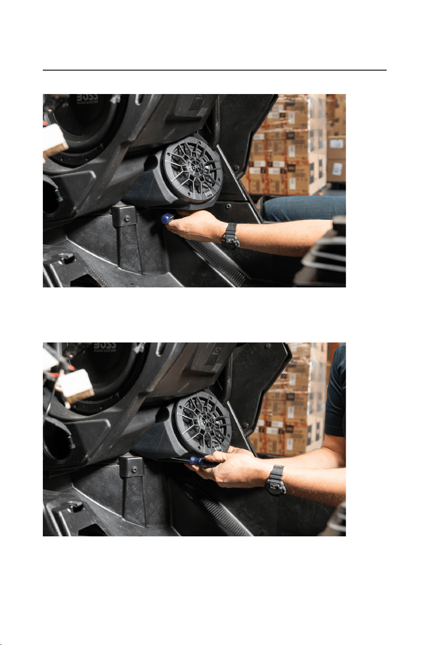
4. Repeat passenger RZR-FSA installation steps to the driver side.
Remove one T40 torx screw, connect the passenger input signal cable to the output signal cable on the
driver side pod. Route the driver RZR-FSA wiring up along the chassis to the center of the dash cavity (near
the rewall grommet).
5. Reinstall one T40 Torx screw and fasten the two inner #2 Phillips screws.
- 14 -
BPRZR5
IPX6 RATED 1000 WATTS TRUE PLUG-N-PLAY
POLARIS RZR XP1000 5 SPEAKER AUDIO SYSTEM KIT
INSTALLATION MANUAL
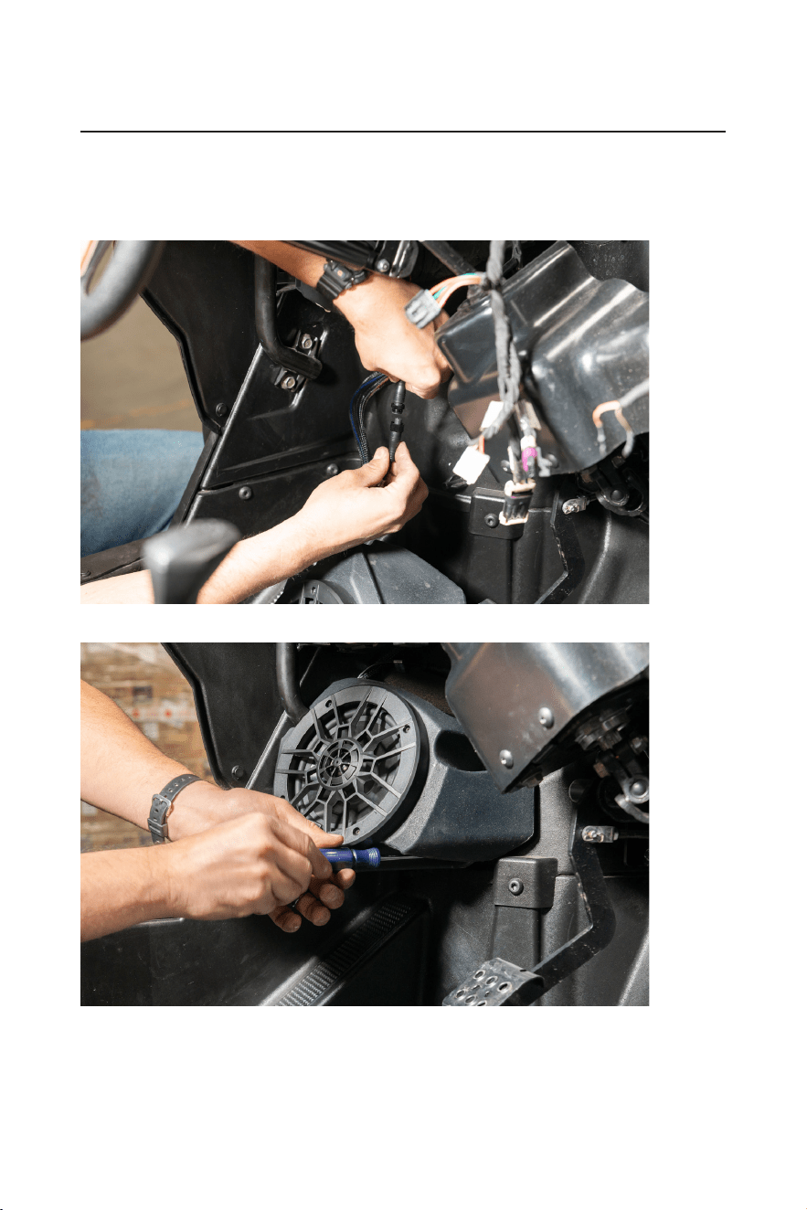
6. Feed the power and ground of the RZR-FSA through the grommet and out of the rewall.
DO NOT feed the RCA and amp turn on wire through the grommet. They will be staying in the dash cavity.
7. Connect the power and ground to the factory bus bar for power.
Remove the fuse from the fuse holder. Do not connect to power until the end of installation.
- 15 -
INSTALLATION MANUAL
BPRZR5
IPX6 RATED 1000 WATTS TRUE PLUG-N-PLAY
POLARIS RZR XP1000 5 SPEAKER AUDIO SYSTEM KIT
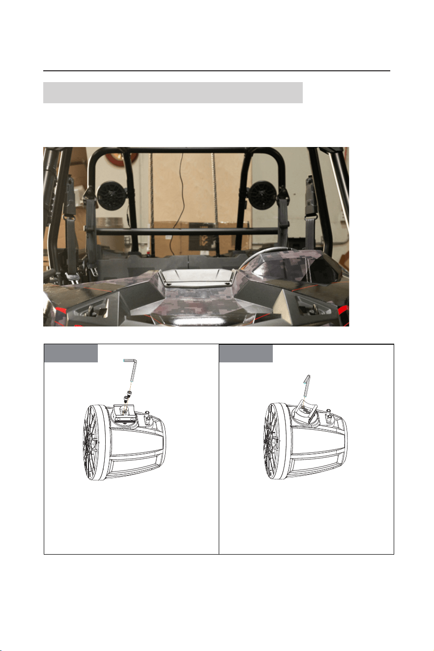
RZR-62A Rear Speaker enclosure installation
1. Mount the main RZR-62A to the driver side rear of the roll cage in sure preferred location.
Take blind spots into consideration when mounting the RZR-62A to help ensure safety and visibility when
out of the trail. Follow the guidelines below for proper clamp installation.
STEP2STEP1
Two screws can be unbolted to loosen the metal
base of mounting band to adjust the mounting
angle. Making sure to put all components of the
mounting hardwares in a safe location.
After loosening two bolted screws and then twist
the metal base to determine the optimal location
for your speakers onto
the roll cage of your RZR.
And then
re-bolted two screws in place to secure
the metal base of mounting band tightly.
Two screws can be unbolted to loosen the metal
base of mounting band to adjust the mounting angle.
Make sure to put all components of the mounting
hardwares in a safe location.
After loosening two bolted screws, then twist the
metal base to determine the optimal location for your
speaker onto the roll cage of your RZR.
Then re-bolt two screws in place to secure the metal
base of the mounting band tightly.
- 16 -
BPRZR5
IPX6 RATED 1000 WATTS TRUE PLUG-N-PLAY
POLARIS RZR XP1000 5 SPEAKER AUDIO SYSTEM KIT
INSTALLATION MANUAL
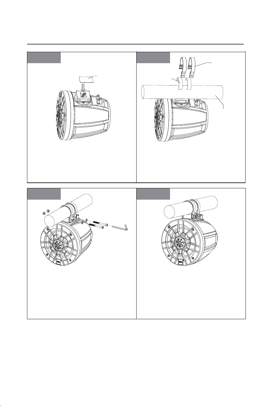
STEP4STEP3
Place the front rubber pad on the metal base of
the mounting clamp.
Place the supplied rubber strip arround the cage
bar to prevent scraching. Push the aluminum band
over the cage bar. Align the a luminum bands with the metal
base of mounting
bands
on the waketower
speaker.
STEP6STEP5
Secure the aluminum bands to the metal base of
mounting bands using a pair of M6 x 60mm screw,
M6 flat washers, and
M6 locknuts as illustrated. The
locknut should be i
nstalled in to the hex shaped recess
on one end of
each band.Hand-tighten, allowing just
enough freedom to rotate the waketower speaker
arround the cage bar.
RZR-62A speaker installation completed.
Place the front rubber pad on the metal base of the
mounting band.
Place the supplied rubber strip around the cage bar
to prevent scratching.
Then push the aluminum bands over the cage bar,
and align the aluminum bands with the metal base
of the mounting band on the speaker.
48 x 30 mm rubber pad
Aluminum band
Rubber strip
Mounting cage
bar of your RZR
Secure the aluminum bands to the metal base of the
mounting band using a pair of M6 x 60mm screws,
M6 at washers, and M6 locknuts as illustrated. The
locknuts should be installed into the hex shaped
recess on one end of each band.
Hand-tighten to the degree which allows just enough
freedom to rotate the speaker around the cage bar.
The RZR-62A speaker installation now completes.
- 17 -
INSTALLATION MANUAL
BPRZR5
IPX6 RATED 1000 WATTS TRUE PLUG-N-PLAY
POLARIS RZR XP1000 5 SPEAKER AUDIO SYSTEM KIT
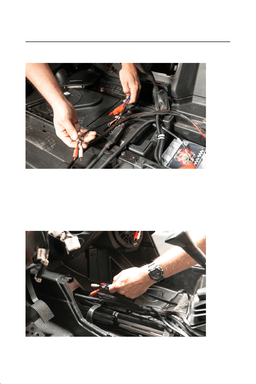
2. Route the input signal cable from the right rear speaker to the rear left (main) speaker.
Follow the factory wiring, avoid heat sources, sharp edges, and rotating parts when routing the cable.
3. Route RZR-62A power, ground, RCA inputs, and remote turn on wire to the center console of the vehicle.
The power and ground will stop at the battery. The RCA inputs and remote turn on wire will continue down
the center of the vehicle.
Remove the fuse from the RZR-62A fuse holder. Do not connect to power until the end of the BPRZR5
installation.
4. Route the RZR-62A RCA inputs and remote turn on wire out of the inside of the vehicle to follow up the
exterior of the re wall. They will then be fed through the outside of the rewall grommet to the inside of
the dash cavity.
- 18 -
BPRZR5
IPX6 RATED 1000 WATTS TRUE PLUG-N-PLAY
POLARIS RZR XP1000 5 SPEAKER AUDIO SYSTEM KIT
INSTALLATION MANUAL
MGV550B Source Unit connection
1. Feed all the RCA inputs and remote turn on wires through the grommet then into the dash cavity in which
the source unit is located.
- 19 -
INSTALLATION MANUAL
BPRZR5
IPX6 RATED 1000 WATTS TRUE PLUG-N-PLAY
POLARIS RZR XP1000 5 SPEAKER AUDIO SYSTEM KIT
2. Feed the power, ground and accessory power wires of the MGV550B power harness from the dash cavity
out of the grommet to the bus bar for power. Then connect the power and ground accessory power to the
bus bar.
- 20 -
BPRZR5
IPX6 RATED 1000 WATTS TRUE PLUG-N-PLAY
POLARIS RZR XP1000 5 SPEAKER AUDIO SYSTEM KIT
INSTALLATION MANUAL
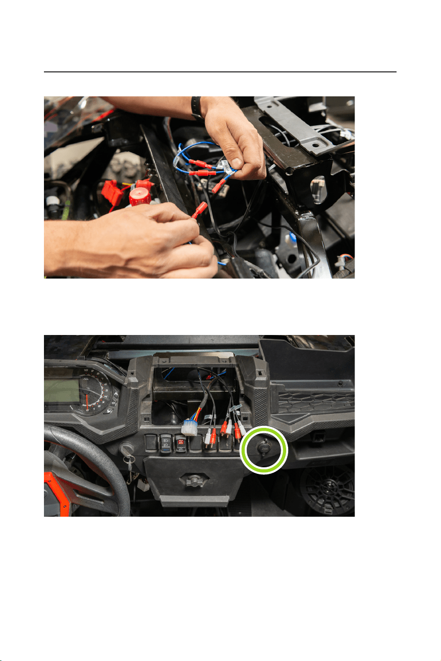
3. Connect all three blue remote wires to the three remote outputs of the MGV550B power harness respectively.
4. Replace the 12V socket with MUSB35, then tape off the power and ground to the 12V socket to prevent
electrical short.
Route the MRANT antenna along the factory wiring. Partially assemble the dash, so that the RCAs,
antenna, power harness and MUSB35 inputs can be easily accessible.
- 21 -
INSTALLATION MANUAL
BPRZR5
IPX6 RATED 1000 WATTS TRUE PLUG-N-PLAY
POLARIS RZR XP1000 5 SPEAKER AUDIO SYSTEM KIT
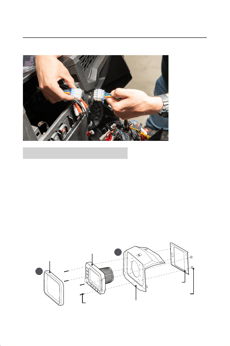
5. Install the source unit in your dash (see section “MGV550B Source Unit installation). Then make your nal
connections to the MGV550B.
MGV550B Source Unit installation
With the supplied source unit mounting kit (BPRZRD/BPRZR5D), you can install the MGV550B source unit in
the place where the factory dash pocket sits. The dash pocket can be the upper or lower one, depending on
the conguration of your Polaris RZR model.
Upper dash mounting
1. Remove the push pins that secure the upper dash pocket, and set aside the push pins for the source unit
mounting. Then remove the upper dash pocket by tilting it away from the dash.
2. Fasten the source unit to the mounting kit.
a. Remove the trim plate from the front panel of the source unit to access the four screw holes on the left
and right edges of the source unit.
b. Fix the source unit by using the upper dash mount panel, metal brace plate, and four supplied bolts
and ange nuts.
IMPORTANT! When sliding the ange nut on the bolt, make sure the wide at face of the nut points
inward (toward the metal plate) to provide more locking effect.
a
b
Trim plate
Source unit
(MGV550B)
Upper dash mount panel
Metal brace plate
Flange nut
Bolt
3. After the source unit is fastened to the dash mount panel, secure the dash mount panel in the place where
the previous upper dash pocket sits by using the push pins. Finally, replace the trim plate.
- 22 -
BPRZR5
IPX6 RATED 1000 WATTS TRUE PLUG-N-PLAY
POLARIS RZR XP1000 5 SPEAKER AUDIO SYSTEM KIT
INSTALLATION MANUAL
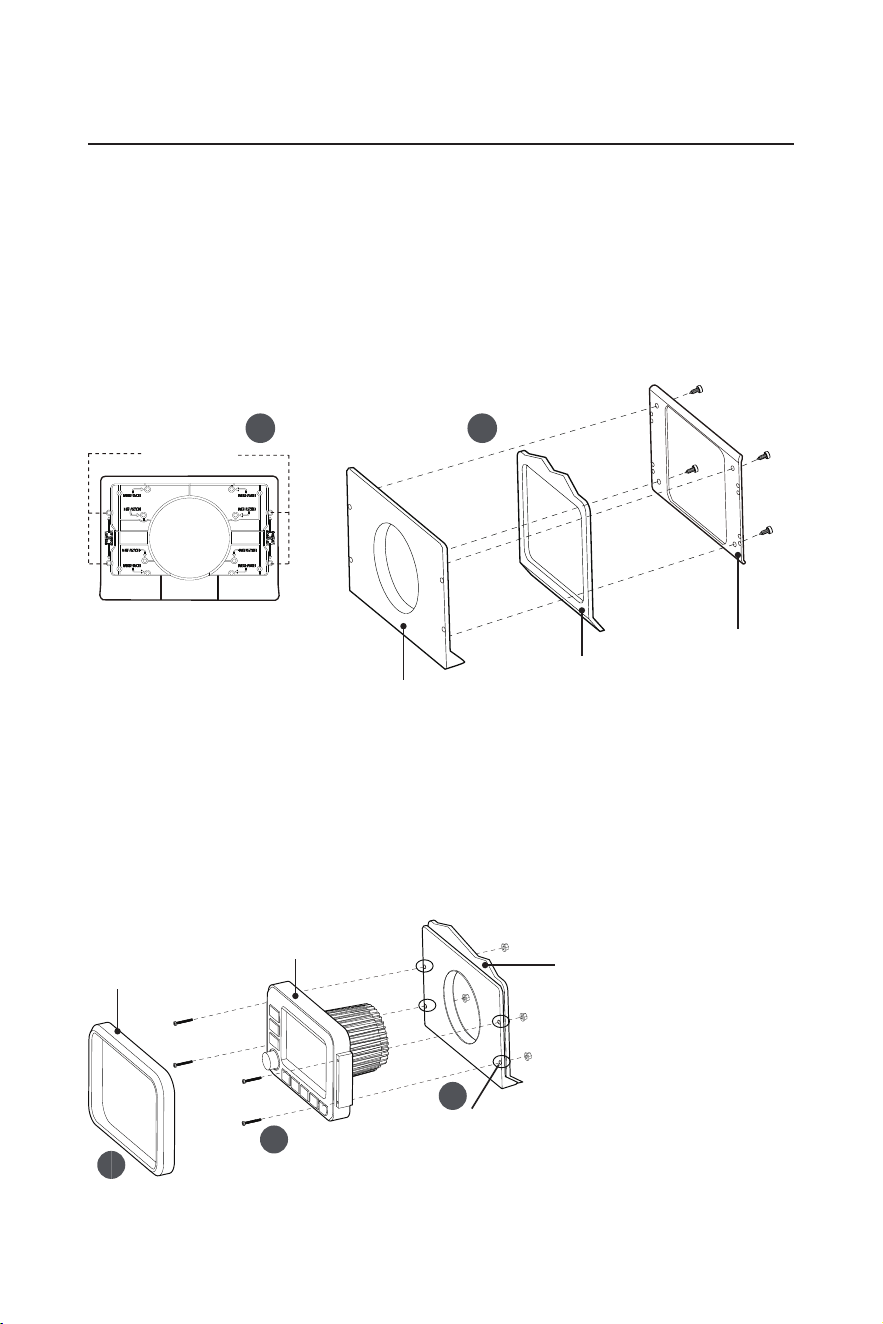
Lower dash mounting
1. Locate the lower dash pocket and remove the lower dash pocket panel from your RZR.
2. Fasten both the lower dash mount panel and the metal brace plate to the lower dash pocket panel of your
RZR.
a. Find the lower dash mount panel from the supplied mounting kit, and locate the four hole marks
indicated as “MGV550B” on the back side of the lower dash mount. Then use a proper tool to drill these
four holes as mounting holes.
b. Correctly orientate the lower dash mount and the metal brace plate, then x both to the lower dash
pocket panel of your RZR by using the supplied hexagon screws.
a
b
Drill 4 holes
Lower dash mount panel
Lower dash mount panel
Lower dash pocket
panel of your RZR
Metal brace plate
3. Fix the source unit to the 3-in-1 panel (Lower dash mount panel, lower dash pocket panel of your RZR and
metal brace plate are fastened together as described in Step 2 above).
a. Use a proper tool to drill four holes into the lower dash pocket panel of your RZR for screw fastening, by
using the four mounting holes which are previously drilled (see Step 2) on the lower dash mount panel.
b. Remove the trim plate from the front panel of the source unit to access the four screw holes on the left
and right edges of the source unit.
c. Fix the source unit to the 3-in-1 panel using four supplied screws and ange nuts.
IMPORTANT! When sliding the ange nut on the bolt, make sure the wide at face of the nut points
inward (toward the metal plate) to provide more locking effect.
a
c
b
Trim plate
Source unit
(MGV550B)
3-in-1 panel (Lower dash mount
panel, lower dash pocket panel of
your RZR and metal brace plate are
fastened together)
Drill holes into the lower dash
pocket panel of your RZR
4. After the source unit is xed, secure it in the place where the lower dash pocket sits. Finally, replace the
trim plate.
0821

BOSS Audio Systems
3451 Lunar Court • Oxnard, CA 93030
www.bossaudio.com
805-751-4853 Customer Service
Tech Support: www.bossaudio.com/support
0821
The Bluetooth® word mark and logos are registered trademarks owned by Bluetooth SIG, Inc. and any use of such marks by
BOSS Audio Systems is under license. Other trademarks and trade names are those of their respective owners.