

1/29/2021
SWISHER ACQUISITION INC.
1602 CORPORATE DRIVE, WARRENSBURG, MISSOURI 64093
PHONE 660-747-8183 FAX 660-747-8650
20440 REV 17-001
Starting Serial #: L117-001001
OWNER’S
MANUAL
www.ESP.swisherinc.com
SR114X84G
ade I The
USA
of US and Global Parts
TM
Patent No. 9,644,420
FEMA P-320-2014 Fourth Edition
ICC 500-2014
FEMA P-361-2015 Third Edition

ꉀ
ǩ
2
Near-Absolute Protection
“Having a safe room in your home or small business can help provide near-
absolute
protection
for you and your family or employees from injury or death caused by the
dangerous forces of extreme winds. Near-absolute protection means
that, based on our
current knowledge of tornadoes and hurricanes, the occupants of a safe room built
and
installed
according to the guidance in this publication will have a high probability of
being protected from injury or death.” FEMA P-320 (2014)
Lifetime Storm Damage Replacement Benefit
For the life of this product and
to the original purchaser, the manufacturer will replace any
structurally damaged components (excluding accessories) of the Safe Room
resulting
from a NOAA (National Oceanic and Atmospheric Association)
confirmed tornado
missile impact
. This replacement benefit does not include labor to replace the
components, cosmetic damages to any surface, or shipping. For this benefit t
o be valid this
Safe Room must have been properly installed (or if moved properly reinstalled)
per all the
manufacturer’s guidelines, and affixed with a valid NSSA
(National Storm Shelter
Association) Type 4 Seal (for its current location) which was
obtained from the
manufacturer. This replacement benefit is not tran
sferable to anyone beyond the original
purchaser.
To obtain this benefit, the owner of the Safe Room must also allow the Manufacturer (or
its representative) onsite to inspect the structurally damaged components if requested
. The
owner must also agree in
writing to allow manufacturer to take photographs of the Safe
Room and to use these photographs and story for marketing purposes at its sole discretion.
In the event you have a claim under this benefit, you must
notify the manufacturer in
writing either via US mail or electronic mail
. All transportation charges, damage, or loss
incurred during transportation of parts submitted for replacement or repair under this
benefit
shall be borne by the purchaser. Should you have any questions concerning this
benefit, please contact us toll-free at 1-800-222-
8183. The model number, serial number,
date of purchase, NSSA Type 4 Seal Number and the name of the authorized
dealer from
whom you purchased the product will be needed before any benefit
claim can be
processed.
To maintain this replacement benefit the original owner must perform the following:
1. During installation the original owner must f
ollow all manufacturer’s
installation guidelines, checklists and inspection requirements as needed
to
obtain the NSSA’s
(National Storm Shelter Association) Type 4 Seal
which is outlined here:
a.
This tornado safe room was designed, tested and manufactured by a
Producer Member of the National Storm
Shelter Association (NSSA) in
accordance with FEMA, ICC, and NSSA requiremen
ts, but may have
been
assembled and/or installed outside of the control of the Producer
Member. The manner, in which this safe room is installed, i
ncluding
the foundation to which this safe room is affixed, is
integral to the

绀
Ҵ
3
successful performance of this product under extreme weather
conditions. The manufacturer has provided detailed Install
ation
Instructions, including an
Installation Checklist and an Inspection
Checklist. Installation must be in strict accordance with the
se
instructions.
The National Storm Shelter Association (NSSA) and the
Producer Member recommend that the owner or their
representative
arrange for inspection by a Qualified Inspector immediately upon
installation of this shelter. A Qualified Inspector is
defined as either a
local building inspector or the authority having jurisdiction where the
safe room is installed, a registered architect, a professional engineer, a
licensed professional inspector, or the
NSSA Producer Member or his
qualified safe room installer or qualified technical representative.
The
Inspector should complete the Inspection Checklist, and this Checklist
should be returned to the Producer
Member. Upon receipt of the
completed Checklist, the Producer Member will issue a Type 4 NSSA
Seal to affix
to the shelter to confirm that the shelter meets all FEMA,
ICC, and NSSA standards. We encourage you to
contact the
manufacturer of this shelter with any questions that you may have.
b. If the original purchaser removes the Safe Room from its origina
lly
installed location all warranties and benefits are immediately
null and
void. However, if the original owner follows all the required
installation,
inspection and certification procedures at the new location then
the
replacement benefit can be reinstated.
FAILING TO FOLLOW ALL THE INSTALLATION,
INSPECTION AND
DOCUMENTATION PROCEDURES REQUIRED TO OBT
AIN THE NSSA TYPE
4 SEAL THE SAFE ROOM MAY NOT DELIVER THE NEAR-
ABSOLUTE
PROTECTION IT WAS DESIGNED TO PROVIDE AN
D WILL MAKE ALL
BENEFITS PROVIDED TO THE PURCHASER UNDER THE
LIFETIME STORM
DAMAGE REPLACEMENT BENEFIT NULL AND VOID.
5 Year Manufacturer’s Limited Warranty
The manufacturer’s limited warranty to the original consumer purchaser is
as follows: The
Safe Room is free from defects in materials and workmanship for a period of five (5) year
s
from the date of purchase by the original consumer purchaser. The manufacturer
will
repair or replace, at its
discretion, parts found to be defective due to materials or
workmanship only.
To exercise thi
s limited warranty the owner must allow the manufacturer (or its
representative) at its discretion to inspect the Safe Room onsite. Failure to allow this
inspection will void the warranty. Upon inspection, the manufacturer will determine if the
damaged or malfunctioning components will be repaired or replaced.

绀
Ҵ
4
Limitations and Exclusions
This limited warranty is subject to the following limitations and exclusions:
1) Limitation - This limited warranty applies only to pro
ducts which have been
properly assembled, adjusted, and operated in accordance with the instr
uctions
contained within this manual. This limited warranty does not apply to any
product
that has been subject to alteration, misuse, abuse, improper
assembly or
installation, shipping damage, or to normal wear of product. This limited w
arranty
does not apply to damage caused by any act of man or any natural event.
2) Exclusions - Excluded from this limited warranty are: N
ormal wear, normal
adjustments, and normal maintenance.
Small damage to the powder coat finish
that may have occurred during shipping, ins
tallation, or from normal wear and
tear. To reduce the likelihood of rusting, the owner should repair any damage to
the powder coat finish as soon as possible. This limited
warranty is not
transferable to anyone beyond the original purchaser.
In the event you have a claim under this limited warranty, you must
notify the
manufacturer in writing either via US mail or electronic mail
. All transportation charges,
damage, or loss incurred during transportation of parts submitted for replacement or
repair under this limited
warranty shall be borne by the purchaser. Should you have any
questions concerning this limited warranty, please contact us toll-free at 1-800-222-
8183.
The model number, serial number, date of purchase, NSSA Type 4 Seal Number
and the
name of the authorized
dealer from whom you purchased the product will be needed
before any limited warranty claim can be processed.
THIS LIMITED
WARRANTY DOES NOT APPLY TO ANY INCIDENTAL OR
CONSEQUENTIAL DAMAGES AND ANY IMPLIED WARRANTIES ARE
LIMITED TO T
HE SAME TIME PERIODS STATED HEREIN FOR ALL
EXPRESSED WARRANTIES
. Some states do not allow the limitation of
consequential damages or limitations on how long an implied warranty may last, so the
above limitations or exclusions may not apply to you. This limited
warranty gives you
specific legal rights and you may have other rights, which vary from state-to-
state. This is
a limited warranty as defined by the Magnuson-Moss Act of 1975.

绀
Ҵ
Operating and Safety Instructions
Safety Precautions
1) Your ESP Safety Shelter has been designed and certified by Professional Registered
Engineers and physically tested at Texas Tech University to ensure that it meets or exceeds
FEMA P-320 Guidelines and the ICC-500 Specifications.
2) Your Safety Shelter also meets the standards set for by the National Storm Shelter
Association (NSSA) and once properly installed can bear their Seal.
3) NEVER allow children to play in or around the Safety Shelter.
4) Keep the Safety Shelter locked at all times and place the keys out of reach of children but
where they can be located quickly in case of emergency.
5) When closing door from the inside one hand must be on the long handle located on the
door jamb and the other hand on the inside door handle. NEVER place hands on or near
either edge of the door or the door jamb while closing the door. Failure to strictly follow
this procedure could result in serious injury to the user.
When Choosing a Location For Your Safety Shelter:
1) Location of Shelter is at the minimum elevation of the lowest floor required by the
floodplain ordinance of the community, or One Foot above the flood elevation
corresponding to the highest recorded elevation if the area is not in a mapped special flood
hazard area or is in a mapped nonparticipating community.
2) Shelter is located within the interior of a residence or located within 150 feet of the
residence it is intended to serve. If located outside the residence, shelter is protected from
all external weather conditions.
3) Do not locate the Safety Shelter over an expansion joint in the concrete slab.
4) Do not locate the Safety Shelter in a low or potentially wet area. If the Safety Shelter is
allowed to sit in water or a damp area, damage may result that is not covered by the
manufacturer’s warranty.
5) Do not locate Safety Shelter closer than three (3) feet to any electrical or gas appliance.
6) Do not locate Safety Shelter where it will block access to any electrical panel or breaker
box.
7) Do not locate Safety Shelter closer than 2” from any wall or structure. The side of the
Safety Shelter you install the Lower and Upper Wall Panel Assembly should be far enough
away from any wall or structure to allow a person to be able to safely walk between. A
distance of at least 32” is recommended for wheelchair accessibility. See pgs 12 & 22 of
this manual and the yellow Emergency Exit Instruction Sheet (PN 20056) for additional
information.
8) Do not store any items in a manner that would block any of the Safety Shelter vents.
5

춰
Ҵ
6) NEVER attempt to attach any type of AC (alternating current) or high voltage
lighting fixtures or appliance to the Safety Shelter without first consulting a licensed
electrician and your local electrical codes. Failure to strictly comply with all
applicable electrical codes could result in serious injury and/or death. Battery
operated lights and appliances can be used inside the Safety Shelter.
7) NEVER store flammable materials or fuel in your Safety Shelter.
8) NEVER have an open flame in your Safety Shelter. An open flame could deplete the
oxygen in the room and cause asphyxiation.
9) Keep a flashlight(s) or other battery operated lights inside the Safety Shelter. Check
or replace the batteries in these lights twice per year.
10) Become familiar with your Safety Shelter and the operation of the door, so that in
case of an emergency you can open and close it quickly and safely.
11) NEVER store any items in front of the Safety Shelter that would block access to the
door in the event of an emergency.
12) Establish and practice a plan for all family members to meet and enter the Safety
Shelter in case of an emergency. Practice the plan at least once a year.
13) When entering the Safety Shelter during a storm be aware that the floor may be wet
and slippery from water entering the open door (depending upon the location).
14) You should always take a mobile phone with you into the Safety Shelter so you can
contact emergency help if needed. However, if you forget your phone during a
Tornado Watch or Warning do not leave the Safety Shelter to retrieve your phone.
15) Any time the National Weather Service issues a Tornado Watch or Warning for your
area you should enter the Safety Shelter.
16) We suggest stocking your Safety Shelter with provisions and supplies so that it is
ready when needed.
6

绀
Ҵ
4)
Slide the door to the fully open position. If the door does not slide freely look
for obstructions behind the door or inside the door’s overhead rail and
remove. The bearings inside the door rollers are sealed for the life of the
Safety Shelter and should not need lubrication.
5)
Using a flashlight or lights inside the Safety Shelter move the door latch
handle. Everything should move freely without binding. Adjust and/or apply
light oil to all joints if necessary.
6)
Close the door. In the closed position the latch must fully engage over the three
latch pins (without force). If not, follow the procedures in the Installation
Instructions for alignment of the door.
7)
8) Relock the deadbolt and remove all three Latch Pins and the Locking Pin
from the Door Jamb. The door should open freely for an emergency escape.
9) Reinstall the three Latch Pins, exit the Safety Shelter and close the door. Test
that the door is fully latched onto the pins by pulling strongly on the door to
the right. Lock the deadbolt and attempt to open the door by pulling on the
Handle. If it does open follow the Installation Instructions for alignment of
the door.
10) Once a year check the torque on all anchor bolts to 40 ft-lbs and all other bolts
in the Safety Shelter to 31 ft-lbs.
7
3)
Unlock the Safety Shelter Door.
Safety Shelter Periodic Inspection
1)
At least twice a year inspect the operation of the Safety Shelter.
2)
Inspect the outside of the Safety Shelter for items blocking the door or any
vents. Remove these items if found.
Turn the deadbolt to the locked position and attempt to unlatch the door with
the knurled door handle. The handle should not move or in any manner
unlatch the door from the three latch pins. If the deadbolt fails to prevent the
handle from unlatching the door check the deadbolt lock for proper operation
and engagement into the latch bar.

쪠
Ҿ
1)
To clean your Safety Shelter use warm water and a damp rag with dish
soap. Thoroughly rinse with water and dry.
2)
Solvents and harsh chemicals should NEVER be used on the Safety
Shelter. They will damage the powder coat finish causing the metal to rust
and will void the Warranty.
3)
NEVER attempt to repair the Safety Shelter yourself. Call the
manufacturer at 800-222-8183.
4)
Once every year lubricate all moving joints on the door latch mechanism
with light (3n1) oil.
Safety Shelter Operation Instructions
1) Children should NEVER be allowed to play near or in the Safety
Shelter.
2)
Your Safety Shelter can be used for many purposes: 1) As a Storm Shelter to
provide near-absolute protection from wind blown debris during a Tornadic
event or sever wind storm, 2) as a panic room or safe place of harbor during a
home invasion or similar type event, and 3) as a vault to store valuable items.
If used as a vault be sure that no items are placed in the Safety Shelter that
would inhibit a person from using it as a Storm Shelter or Panic Room.
3)
Be sure to store the keys to the Safety Shelter deadbolt out of reach of
children but where an adult can get to it easily and quickly.
4)
To be ready for any type of event equip your Safety Shelter with a minimum
list of supplies: first aid kit, weather radio (with extra batteries), ear plugs of
the appropriate size and quantity for everyone expected to use the Safety
Shelter, drinking water (approximately one (1) gallon per person), books and
games to keep children occupied, extra flashlights (with extra batteries and
suggest one flashlight for each person using the Safety Shelter). Be sure to
also keep the supplied Wrench (item 32 on page 12) or similar tools, this
manual and the yellow Emergency Exit Instruction Sheet in the Safety Shelter
at all times. Other items could be included as deemed necessary.
5)
Have a family meeting and make an emergency plan. Practice your plan
once a year including entering and exiting the Safety Shelter. This will also
allow everyone an opportunity to become comfortable inside the Safety
Shelter.
6) You should always take a mobile phone with you into the Safety Shelter so
you can contact emergency help if needed. However, if you forget your
phone during a Tornado Watch or Warning do not leave the Safety Shelter to
retrieve your phone.
8
Safety Shelter Periodic Maintenance

쪠
Ҿ
7)
Family members that are old enough to be left home alone should be
trained on how to properly and safely use the Safety Shelter. A plan should
be established and practiced just for them.
8)
To prevent children from playing inside the Safety Shelter it is
recommended that it remain locked at all times.
9)
To enter the Safety Shelter unlock the deadbolt and remove the key from
the deadbolt. Take the key with you into the Safety Shelter.
10) To open the door from the outside, rotate the handle to the right and pull the
door from left to right. Slide the door all the way to the right until it is fully
opened.
11) Enter the Safety Shelter and be sure everyone is accounted for.
12) Be sure everyone is clear of the door. Place your right hand on the vertical
handle on the door jamb. Then, grasp the round vertical Door Handle Bar
(not the black knurled handle) with your left hand and pull the door closed to
the right until it latches inside the door jamb and all three pins are engaged.
13) To ensure the door has properly latched push the Black Knurled Door Handle
to the right and visibly check that the latch bar is fully engaged over the three
latch pins. Lock the Deadbolt lock by turning the key to the right. Grab the
vertical door handle and pull back to the left to ensure the door is properly
latched. If the door opens, repeat the previous steps above until the door
latches to the jamb properly and all three latches pins are engaged.
14) During a high wind event occupants MUST stay at least 3” away from
the walls and door and remove all loose items from walls, shelves and
other accessories by placing them on the floor to avoid potential injury
from debris impact. If sitting on a bench, do not lean back against the
wall during an event.
15) In the event of a direct hit or damage outside, it is recommended not to leave
the Safety Shelter until emergency personnel arrive to assist. There may be
unforeseen hazards directly outside the Safety Shelter created by the storm
that could cause serious injury or death. If you have a cell phone in the Safety
Shelter with you call 911 and let them know your location. If you must exit
the Safety Shelter prior to emergency personnel arriving, do so with extreme
caution and be aware of all your surroundings.
16) You should also listen to your weather radio to determine when it is safe to
leave your Safety Shelter. Just because the wind has slowed, does not mean it
is safe to exit!
9

쪠
Ҿ
17) To exit the Safety Shelter, unlock the Deadbolt, move the Black Knurled Door
Handle to the left and slide the door open to the left. Exit the Safety Shelter to
a safe location.
18) If for any reason any part of the door latching mechanism becomes damaged
and inoperable causing the door to not open, there is a failsafe relief method
to get the door open. There are three Latch Pins in the jamb. Remove the
Cotter Pins from the back of these pins and then pull these three pins out of
the jamb. The door will now open no matter how it is locked. This can only be
performed from inside the Safety Shelter.
19) In the unlikely event that the door or exit path beyond the door becomes
blocked by debris, the Lower and Upper Wall Panel Assembly can be
disassembled from the inside of the Safety Shelter using the supplied Wrench
(PN 20075Y) or similar tools. See pgs 12, 22 and 26 of this manual and the
yellow Emergency Exit Instruction Sheet (PN 20056) for additional
information.
10
Recommended Tools For Assembly:
• Leather Gloves
• Safety Glasses
• Flashlight
• (1) Hammer Drill with 1/2” Carbide Concrete Drill Bits
(Do Not Use Diamond Bits)
• (1) Hammer
• (1) Torque Wrench Capable of 40 Ft-lbs
• (1) 9/16” Open End Wrench or Socket Wrench
• (1) 3/8” Drive X 9/16” Deep Well Socket Wrench & Extension
• (2) 3/4” Open End Wrenches
• (1) 3/4” Deep Well Socket Wrench
• (1) Screwdriver or Punch for Aligning Holes
Note:
The supplied Wrench (PN 20075Y) is
intended to be used in an emergency.
It is not recommended to be used to
assemble the Safety Shelter.
쪠
Ҿ
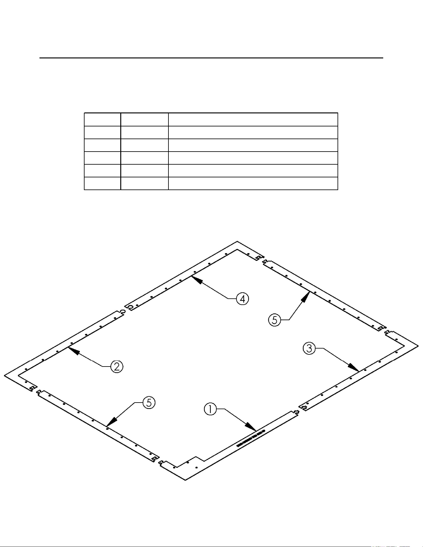
ANCHOR BOLT ALIGNMENT TEMPLATE
11
Item #
Part #
Description
1 20434 Template - Anchor Bolt, Front Left
2 20435 Template - Anchor Bolt, Rear Left
3 20436 Template - Anchor Bolt, Front Right
4 20437 Template - Anchor Bolt, Rear Right
5 19797 Template - Anchor Bolt, 60"
ꉀ
ǩ
Some components have
been hidden for clarity.
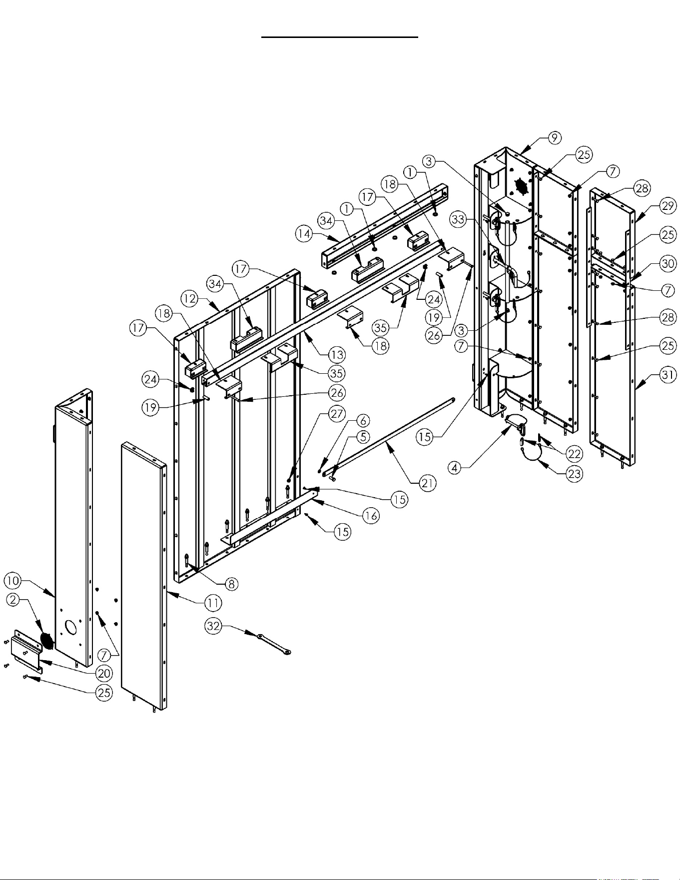
ASSEMBLY
12
It is essential that the Lower and Upper
Wall Panel Assembly (items 29, 30 & 31)
be positioned so that in the event of an
emergency they can be disassembled
to allow for a safe exit. Do not place these
panels against a wall or other obstruction.
See Step 1 on pg 22 of this Manual and
the yellow Emergency Exit Instruction
Sheet (PN 20056). It is recommended
that you keep the supplied Wrench
(item 32) or similar tools, this manual
and the yellow Emergency Exit Instruction
Sheet in the Safety Shelter at all times. The
supplied Wrench is intended to be used in
an emergency. It is not recommended to
be used to assemble the Safety Shelter.
Note:
One Cage Nut (item 24) is preassembled in
two of the Inside Hanger brackets (item 17).
The Locking Pin Weldment (item 33) is sold
separately by buying Kit part number 21160.
It can be used to lock the Door from the inside
even if someone on the outside has a key. It
is not necessary for protection in a severe
weather event.

ꉀ
ǩ
Item #
Part #
Description
1 19785 Plug - 3/16 Plate, 1" Steel
2 19775 Vent - Round, 4"
3 19784 Plug - End, 1" Tube 10-14ga
4 19758 Pin - Ø1/2", w/ Hair Pin & Tether
5 NB647 Bolt - 1/2-13 X 1 1/4
6 NB177 Washer - 1/2 NR
7 19799 Nut - Serrated Flange, Hex 3/8-16
8 19790 Anchor - Concrete 1/2 X 3 3/4
9 19736* Weldment - Jamb Corner
10 19742* Panel - Corner
11 19743* Panel - Wall
12 20417* Weldment - Front Wall Panel
13 20419 Channel - Trolley
14 20412* Brace - Doorway
15 19135 Clip - Panel
16 20421* Guide - Door
17 21074* Bracket - Inside Hanger
18 19774* Bracket - Outside Hanger
19 12785* Spacer - .407 X .625 X 1.750
20 19776* Shield - Vent
21 20422Y Support - Threshold
22 NB781 Connector - Chain, 3/16"
23 20197 Cable Assembly
24 21075 Cage Nut - 3/8-16
25 19828 Bolt - Carriage 3/8-16 X 1
26 19831 Bolt - 3/8-16 X 3
27 19832 Nut - Jam, 1/2-13
28 19829 Bolt - Carriage 3/8-16 X 1 1/4
29 20062* Panel - Wall, Upper
30 20063* Gusset - Wall Panel
31 20061* Panel - Wall, Lower
32 20075Y Wrench - Combination, 9/16 & 3/4; Yellow
33** 20131Z Weldment - Locking Pin ZP
34 20430* Bracket - Inside Hanger, Long
35 20429* Bracket - Outside Hanger, Long
ASSEMBLY
When ordering replacement parts:
*= USE PAINT CODE: GT=GREY
13
**Sold Separately, Kit PN 21160
ҹ
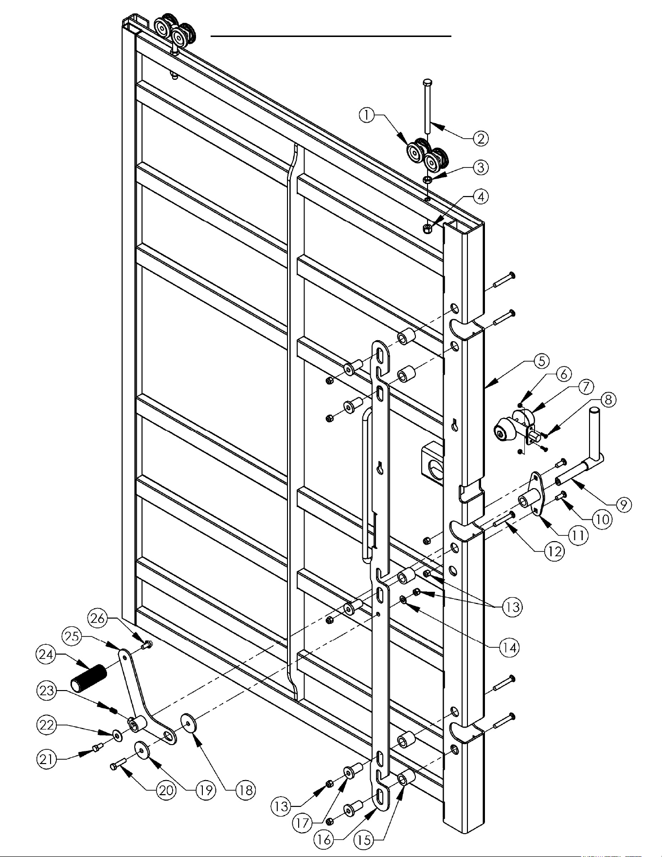
DOOR ASSEMBLY
14

ꉀ
ǩ
Item #
Part #
Description
1 20137 5050 Box Rail Truck Pair Steel Brgs 600#
2 19787 Bolt - 1/2-13 X 6, GR8 Full
3 19832 Nut - Jam, 1/2-13
4 20117 Nut - Nyloc 1/2-13
5 20413* Weldment - Door
6 024900 Nut - 10-24 Nylon Lock
7 21094 Lock - 2 Cylinder Deadbolt
8 19782 Screw - Phillips Pan Head, 10-24X5/8
9 19770Z Weldment - Door Handle
10 19828 Bolt - Carriage 3/8-16 X 1
11 19767Z Weldment - Handle Housing
12 19313 Bolt - Carriage, 3/8-16X2 1/2
13 19825 Nut - Nyloc 3/8-16
14 19826 Washer - SAE Flat 3/8
15 19761Z Spacer - Latch
16 20121Z Latch - Door, Three Pin
17 19762Z Bushing - Latch
18 6040Z Washer - .390 X 2
19 6037 Bushing - .870 x 1.875
20 19833 Bolt - 3/8-16 X 1 1/2
21 19783 Bolt - 3/8-16 X 3/4
22 699 Washer - Belleville 7/16 X 1 1/4
23 19781 Screw - Set, Knurl-Grip .375-16 X 3/4
24 18603B Handle - Latch
25 20119Z Weldment - Latch Handle
26 19830 Bolt - Serr Flange 3/8-16X3/4
DOOR ASSEMBLY
15
When ordering replacement parts:
*= USE PAINT CODE: GT=GREY
즀
ҵ
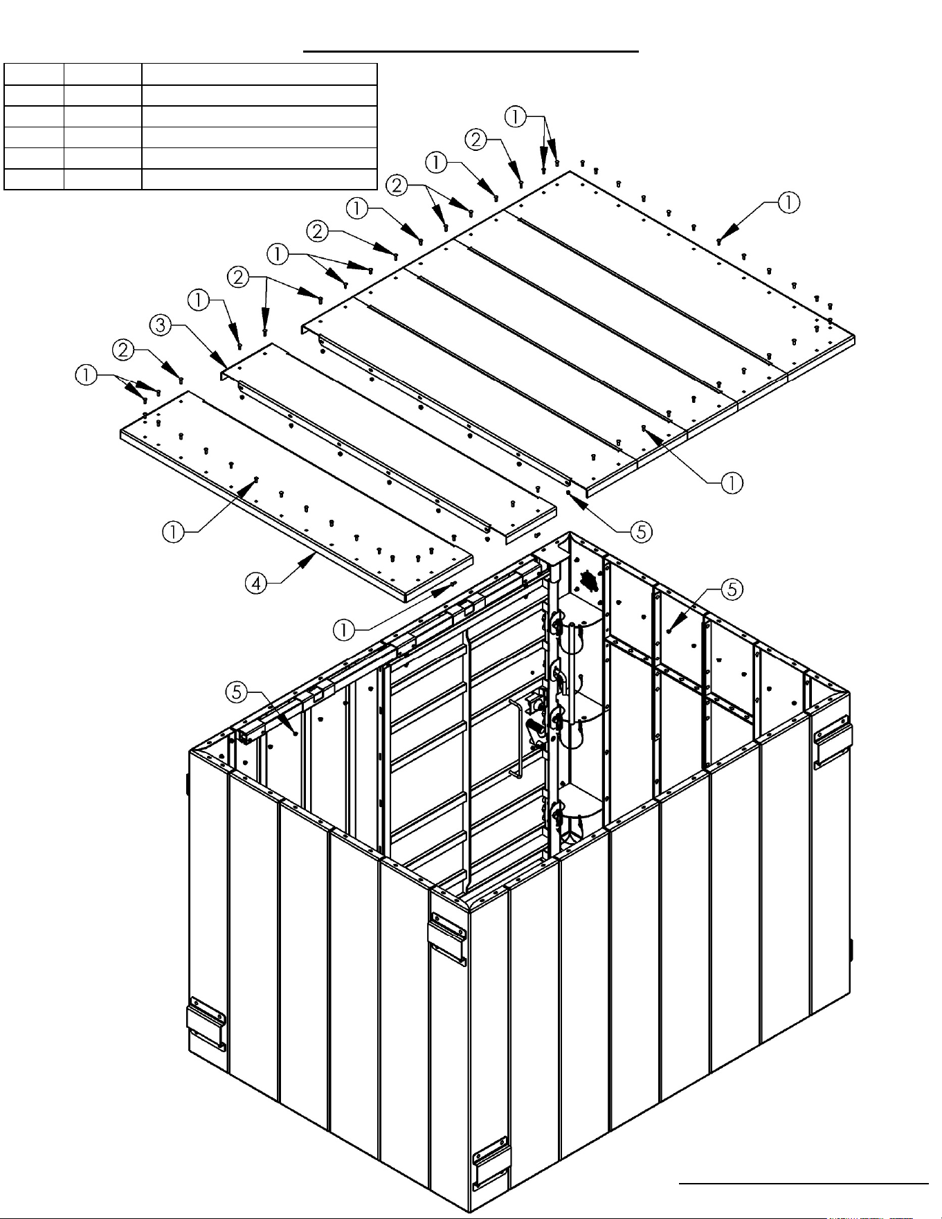
ROOF ASSEMBLY
16
Item #
Part #
Description
1 19828 Bolt - Carriage 3/8-16 X 1
2 19829 Bolt - Carriage 3/8-16 X 1.25
3 20442 Panel - Center Roof
4 20441 Panel - Roof
5 19799 Nut - Serr Flange, Hex 3/8-16
When ordering replacement parts:
*= USE PAINT CODE: GT=GREY
ꉀ
ǩ
17
Part # 20254
Decal - NSSA Producer Member
Part # 20363
Decal - ESP Safety Shelter
TM
Part # 20884
Decal - Swisher Information

ꉀ
ǩ
!!! WARNING !!!
During a high wind event occupants MUST
stay at least 3” away from the walls and door
and remove all loose items from shelves and
walls by placing them on the floor to avoid
potential injury from debris impact.
!!! WEAR HEARING PROTECTION !!!
20006
18
Swisher Acquisition Inc.
WARNING!! PROPER INSTALLATION & INSPECTION ARE REQUIRED!
This shelter will not meet the requirements of the ICC/NSSA Standard or FEMA
safe room guidelines for storm shelter construction unless properly installed and
inspected by a Qualified Inspector as described below.
This tornado safe room was manufactured by the above-named Producer Member of the
National Storm Shelter Association (NSSA) in accordance with the ICC/NSSA Standard but
was not installed or site-built by the Producer Member
or an NSSA Installer Member.
Correct storm shelter installation and the adequacy of the foundation to which this shelter
is anchored are integral to the successful performance of the shelter under extreme
weather conditions. The Producer Member has provided detailed installation instructions,
including an Installation Checklist and an Inspection Checklist. Installation must be in
strict accordance with these installation instructions.
The owner or the contractor installing the shelter is required to arrange for inspection by a
Qualified Inspector to be conducted upon installation and before enclosing this shelter. A
Qualified Inspector is defined as a local building inspector or the authority having
jurisdiction where the safe room is installed, a registered architect, a professional engineer,
a licensed professional inspector, or a Producer Member’s safe room installer or technical
representative.
The Inspector should complete the Inspection Checklist and promptly return this Checklist
to the Producer Member. Upon receipt of the completed and signed Checklist, the Producer
Member will issue a NSSA Seal Type 4 to affix to the shelter to confirm that the shelter
meets the requirements of the ICC/NSSA Standard. Until receipt of the Inspection Checklist
by the Producer Member, this shelter is to be deemed non-compliant with the ICC/NSSA
Standard.
20007
Part # 20006
Decal - Impact Warning
Part # 20007
Decal - Proper Installation

ѠҺ
Closing Instructions
• NEVER place hands or feet near Door Jamb while moving Door.
• With your right hand, grasp the Vertical Handle on the Door Jamb.
• With your left hand, grasp the Vertical Handle on the Door.
• Pull the Door to the right until it securely latches on all three Pins.
• Ensure the Black Knurled Door Handle is fully rotated clockwise to the Latched position.
• Attempt to pull the Door to the left using the Vertical Handle on the Door; it should not open.
If it opens, repeat the previous steps.
• Lock the Deadbolt by inserting the key and turning it clockwise.
Opening Instructions
• Unlock the Deadbolt by inserting the key and turning it counterclockwise.
• Pull the Black Knurled Door Handle counterclockwise to the Unlatched position until the Latch
disengages all three Pins.
• Pull the Door to the left using the Vertical Handle on the Door.
• If the Door Latch Mechanism or Lock isn’t functioning properly, pull the three Pins from the
Door Jamb by first removing the Cotter Pins at the back of the Jamb. The door should now
open freely.
• If an obstruction will not allow the Door to be opened, refer to the Emergency Exit Instruction
Sheet that is included with your Owner’s Manual.
21097
Part # 20025
Decal - Caution,
Upper Jamb
Part # 20026
Decal - Caution,
Middle Jamb
Part # 20027
Decal - Caution,
Lower Jamb
19
Part # 20055
Decal – Caution,
Locking Pin
Part # 20053
Decal - Unlatch & Latch
Part # 21097
Decal - Closing & Opening

Һ
Concrete Slab and Anchoring Requirements
20
Model
Number
Minimum
Thickness
Minimum
Reinforcing
Overhang
(Minimum All Sides)
Minimum
Strength
SR114X84G 4” #4’s @ 18” O.C. 2’-5” 2,500 psi
To ensure Near-Absolute Protection the ESP Safety Shelter must be
anchored to an adequately reinforced concrete slab to resist the
forces applied during a severe wind event. The minimum thickness,
reinforcing and overhang of the concrete slab are shown in the chart
below. If the thickness of the concrete is increased then the
overhang could be decreased if reviewed and approved by a
Licensed Structural Engineer.
Any deviation from the design criteria will require a Licensed
Structural Engineer in your State to review and make
recommendations for your specific situation and approve your
slab. This slab analysis is not provided by the manufacturer. Failure
to follow the installation and inspection checklist provided with this
shelter can result in catastrophic failure up to and including loss of
life as a result. ESP Safety Shelters, Swisher Acquisition Inc. (SAI) or
any of its affiliated companies have no liability if the slab and
anchoring design criteria are not followed and verified by a third party
qualified inspector.
Anchor bolt installation is for slab on grade applications only. Do not
drill or cut into supported slab over a basement or crawl space.
Steps should be taken to avoid drilling into pre-tensioning or post
tensioning strands or reinforcing in the slab.
MINIMUM SLAB REQUIREMENTS

釐
Һ
21
Guidelines for Locating a Qualified Installer
ESP Safety Shelters, Swisher Acquisition Inc. or any of its affiliated companies do
not endorse, recommend or prequalify any shelter installation companies or
individuals. The information below is only provided as a guide to assisting the
shelter owner in identifying a qualified installer. ESP Safety Shelters, Swisher
Acquisition Inc. or any of its affiliated companies shall have no liability in
regards to the performance or cost of any installer hired by the shelter owner.
ESP Safety Shelters are designed to be installed by the owner (DIY) if desired.
DIY Installation does require heavy lifting, some tools (as listed in this
manual) and assistance from 2 to 3 additional people. DIY Installation does
not eliminate the need for a Qualified Inspector to certify the installation.
ESP Safety Shelters can also be installed by a third party. To locate a third party
installer you have a few choices:
1) Visit the National Storm Shelter Association’s website
www.nssa.cc/installers. This site will provide you with a list of pre-
approved installation companies who are registered members of the
NSSA.
2) Locate a local installer that is experienced in general construction and
installing anchor bolts in concrete. There are also a number of
resources online to assist in your search. However, word of mouth
referrals are always the best option. The installer you choose does not
have to be experienced in Storm Shelter installation, but they should
have experience in the above mentioned trades. Always ask for
references and contact the Better Business Bureau to thoroughly check
the installer’s reputation.
3) Remember, the Installation and Inspection Checklists MUST always be
followed to ensure the near-absolute protection provided by your ESP
Safety Shelter.
4) Finally, regardless of who installs your ESP Safety Shelter it MUST be
inspected by a Qualified Inspector using the Inspection Checklist that
came with your unit.
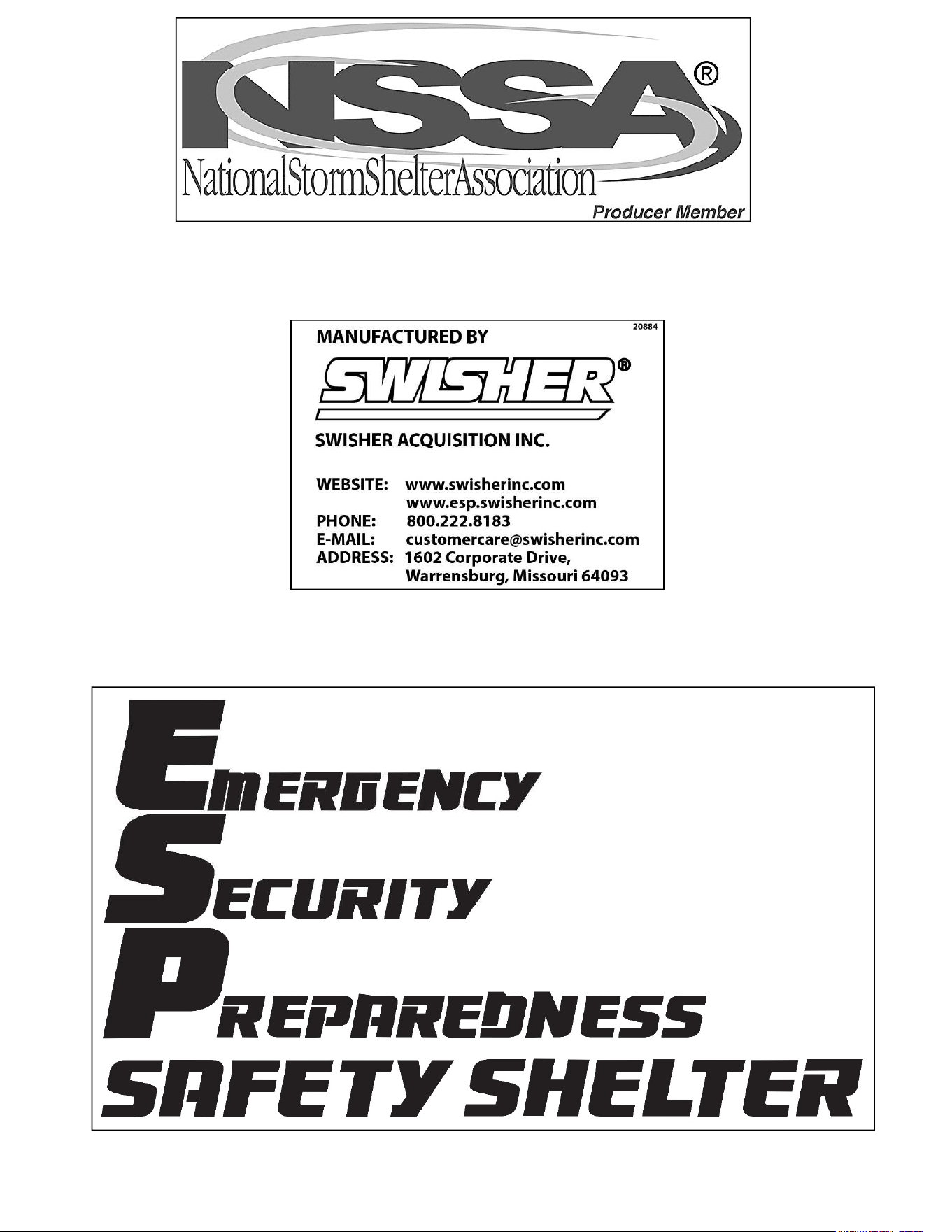
Ҽ
1. Locate all pieces of the Anchor Bolt
Alignment Template (see pg 11). Lay
the template out on the floor in the
approximate location the Safety
Shelter will sit. See note at left
regarding the proper placement of
the Emergency Exit Wall Assembly It
should not be against a solid object
or wall. Be sure the door side
template labeled “Door Opening This
Side Up” is in the front left and all
pieces are solidly locked together.
Check to ensure there is a minimum
of 7’ of vertical clearance above the
footprint of the template and a
minimum of 2” clearance around all
sides. See the table on Page 20 to
determine the minimum concrete
requirements for your Model. Once
the final location is set, draw a line
on the floor along the inside edge of
the template. Use this line to ensure
the template does not move while
drilling the anchor holes.
2. Do not allow the template to move
during this next step. Using the
template as a guide, drill all holes in
the concrete floor to a minimum
depth of 2 ¾” and a maximum depth
of 3”. Do not drill completely
through the concrete slab. If a hole
is drilled through slab an adjacent
hole may be drilled not closer than
3” from the abandoned hole or
contact supplier or a licensed
engineer to evaluate alternatives.
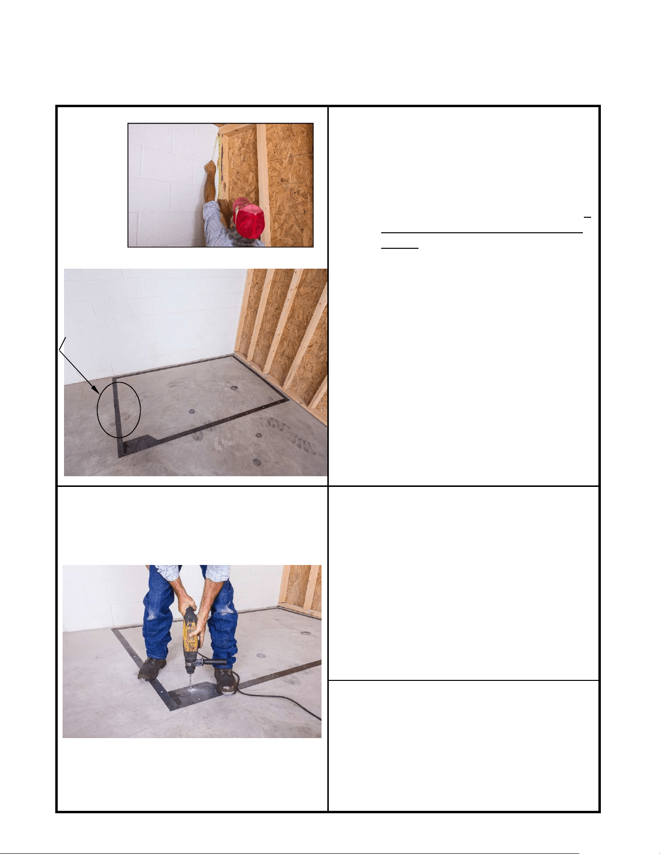
3. After all the holes have been drilled,
remove the template and store it in a
safe location for future use. Using a
vacuum cleaner remove all concrete
dust from each hole and from the
surrounding area. The template
should NOT be left under the
Safety Shelter.
22
When drilling holes in concrete a Carbide Bit
MUST BE used, DO NOT use a Diamond Bit.
See Step 5 below for further information.
In this instance, you would
assemble the Lower and Upper
Wall Panel Assembly (see pg 12)
on the left side. See Emergency
Exit Instructions (PN 20056).
Assembly Instructions
ꉀ
ǩ
Template shown for illustrations purposes only. It
must be removed prior to installing any anchor
bolts.
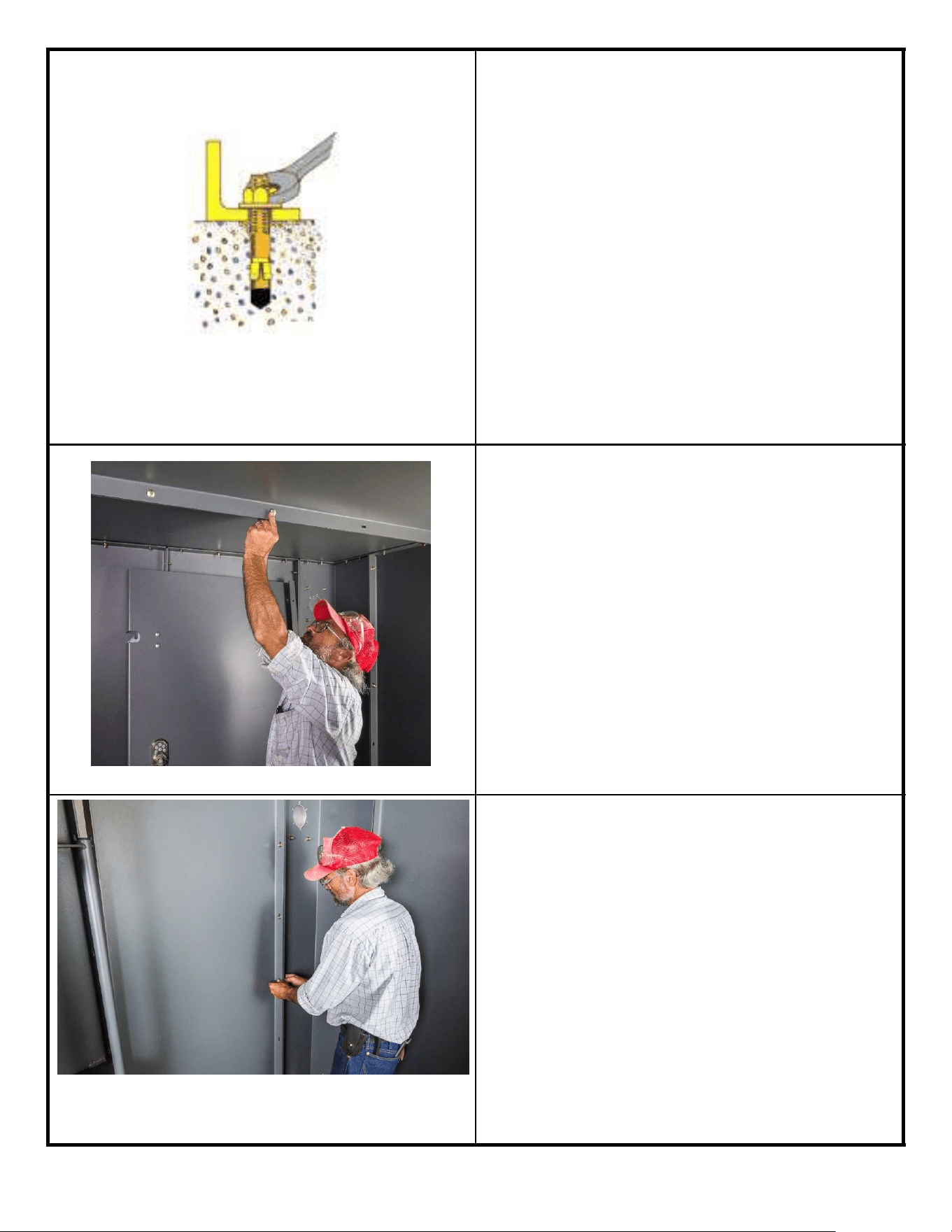
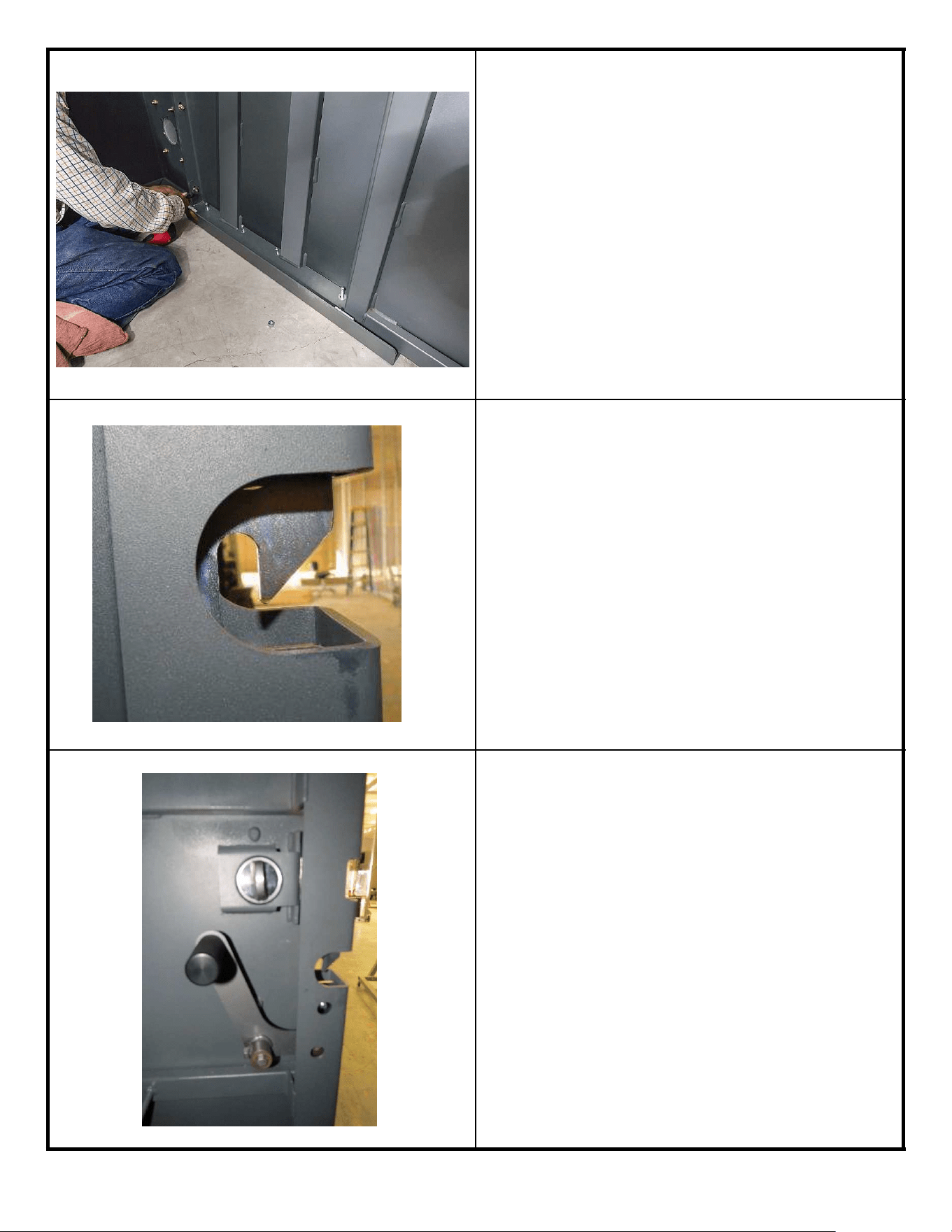
4. Following the manufacturers instructions,
install the 3 anchor bolts (PN 19790) in
the front left corner (Door Jamb Corner)
to the proper depth in the concrete (see
next step). At this time leave the washer
and nut on the bolts to protect the
threads.
Mark depth on Drill Bit to 2.75”-3.00”.
Be sure NOT to drill through concrete.
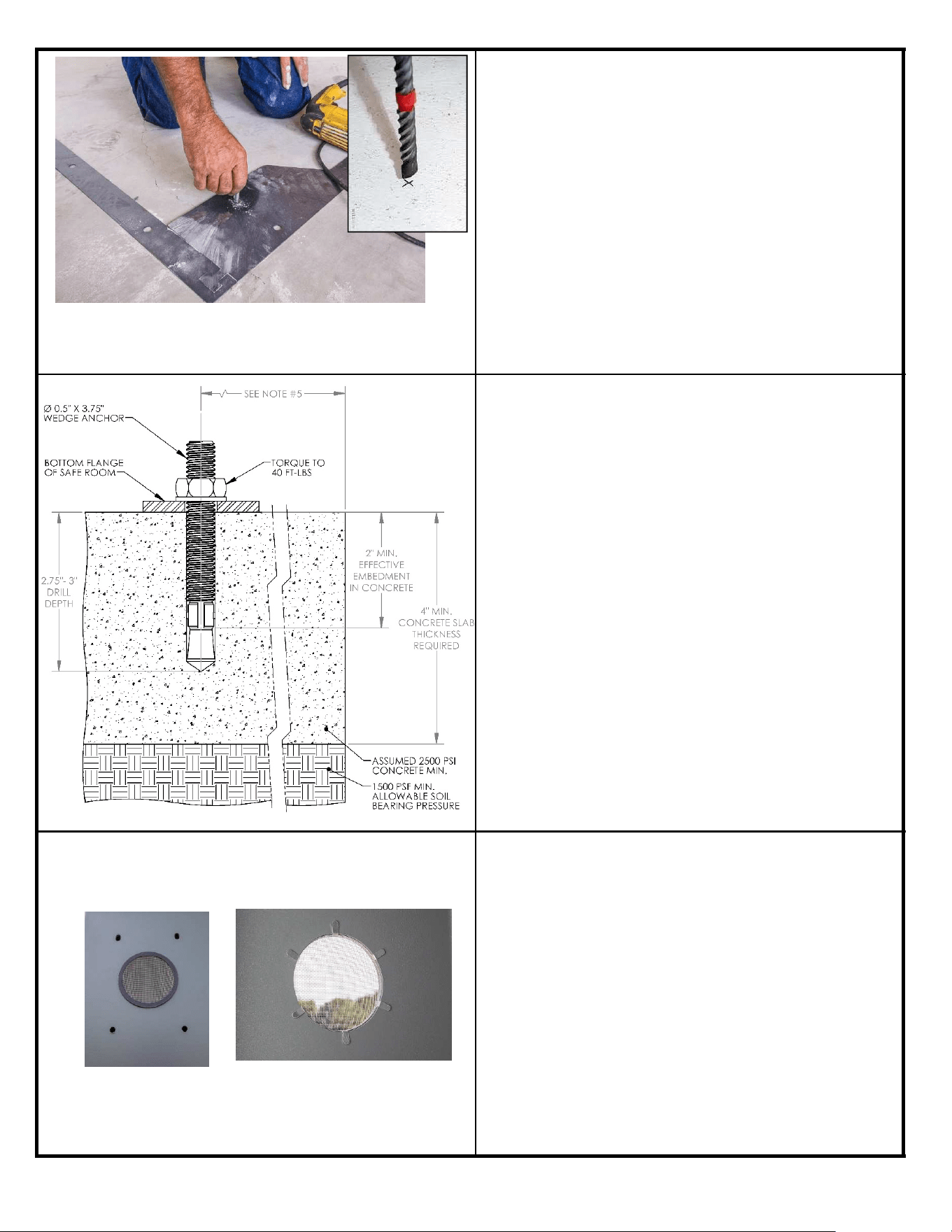
5. To the left is a view of the proper anchor
bolt installation. The embedment length
of 2” is critical to the safe function of the
Safety Shelter.
Note: The minimum thickness of
concrete is 4” as long as appropriate
overhang outside the Safety Shelter
exists on all four sides (see chart on
Page 20).
When drilling holes in concrete a
Carbide Bit MUST BE used, DO NOT
use a Diamond Bit.
6. Install 8 Vents (PN 19775), two vents in
each corner section. Vents should be
installed from the outside the tabs should
be bent to the inside.
Inside View
Outside View
23
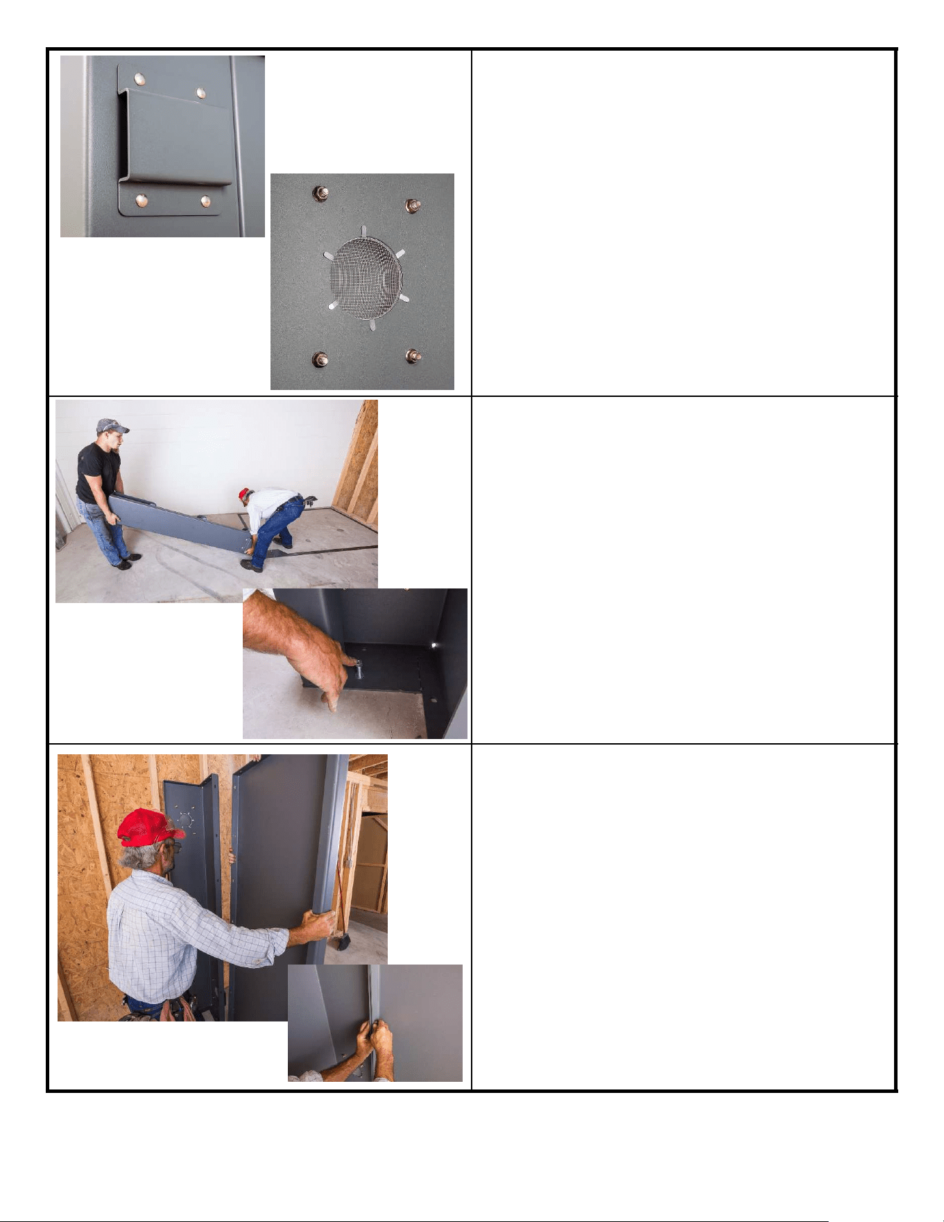
ꉀ
ǩ
7. Install a Vent Cover (PN 19776) over
each of the 8 Vents using 4 Carriage
Bolts (PN 19828) and 4 Nuts (PN 19799)
each. Torque each bolt to 31 Ft-lbs.
8. Remove the nuts and washers from the
3 anchor bolts previously installed.
9. Locate the Door Jamb Corner (PN
19736) and place it over the 3 anchor
bolts at the front left of the Safety
Shelter. Replace the Flat Washer and
Nut on each anchor bolt. Only finger-
tighten the nuts at this point.
10. Repeat this procedure for the Right Front
Corner section (PN 19742) opposite the
door. Install 2 anchor bolts in the corner
section but only finger-tighten the nuts at
this time.
11. Using 7 Carriage Bolts (PN 19828) and
Nuts (PN 19799) attach the Front Wall
section (PN 20417) to the Right Corner
Sections (PN 19742) installed in Step 10.
Be sure the Front Wall is placed with the
six large round holes at the bottom. The
end with the six smaller slotted holes will
be on top for the roof to be attached
later. Finger-tighten these bolts at this
time.
Outside View
Inside View
24
ꉀ
ǩ
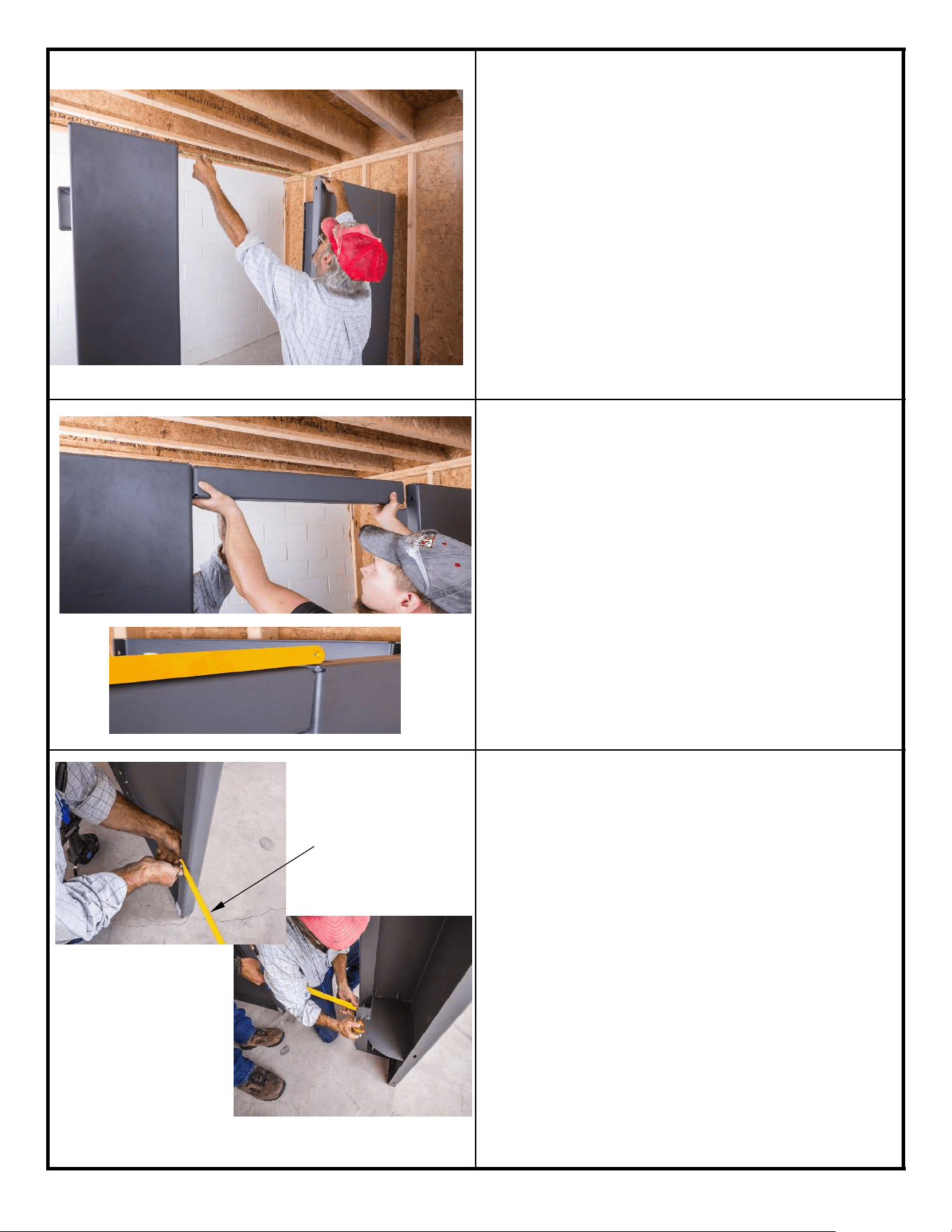
12. The Front Wall Section (PN 20417)
should be set exactly 45” away from the
Jamb Corner (PN 19736) (see picture at
left). This will become the Door Opening.
13. Using 2 Bolts (PN 19828) and 2 Nuts
(PN 19799) install the Door Header
Brace (PN 20412) between the Corner
Jamb (PN 19736) and the Front Wall
Panel (PN 20417). Using a Straight Edge
(see inset) be sure the Door Header,
Door Jamb and the Front Wall Panel are
all flush at the top. Tighten the two Bolts
and Nuts to 31 Ft-lbs.
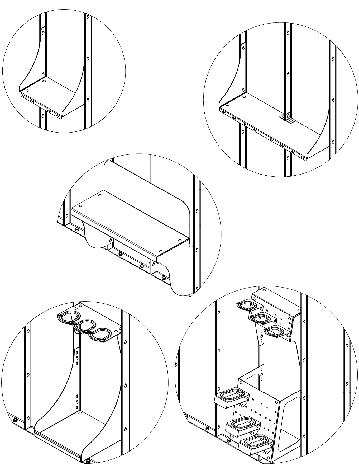
14. Attach one side of the Door Alignment
Bar (PN 20422Y) to the lower Door Latch
Pin (PN 19758) by removing the pin and
sliding it back through one end of the
Alignment Bar (PN 20422Y). Using a Bolt
(PN NB647), Washer (PN NB177) and
Nut (PN 19832), attach the other end of
the Alignment Bar to the back flange of
the Front Wall Panel (PN 20417). The
hole in the flange is directly across the
door opening from the Lower Door Latch
Pin. Leave this bar in place until after all
the Anchor Bolts are installed and
remove before the door is installed. This
bar will ensure that the door opening
remains at the correct width throughout
the assembly process.
25
Yellow Door
Alignment Bar
PN 20422Y
Use caution to
avoid tripping
while the
Alignment Bar
is in place.
ꉀ
ǩ
15. At this point it is suggested that you
determine how the door will be brought
into the Safety Shelter. If clear access
can be gained on either side then leave
the panel for that side out until after the
door is installed. If clear access is not
available to either side or back of the
Safety Shelter, the door can later be
brought in through the door opening. It is
just much easier to bring it in through
one of the sides or the back.
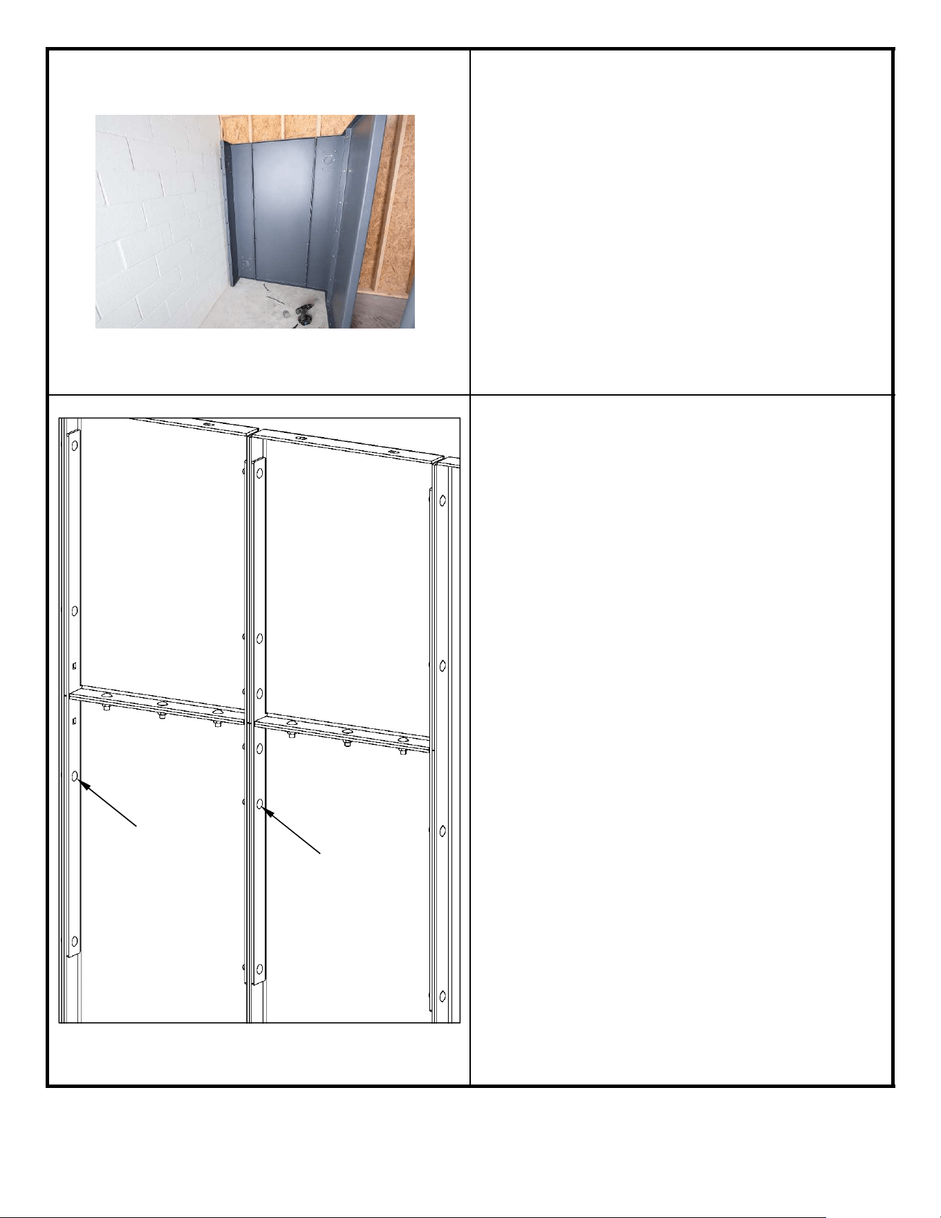
16. Emergency Exit Lower and Upper Wall
Section Assembly – The Emergency Exit
Wall Sections must not be located where
there is an obstruction or wall blocking
your exit from the shelter through this
wall when removed. You do have the
flexibility to place it in either of the Side
Walls or the Back Wall. It cannot be
placed in the front wall. When
assembling these panels, Gussets (PN
20063) must be installed along the inside
edge of each vertical wall section rib (as
seen at left), two per wall panel section.
Note that the two innermost bolt holes
are used on the center rib. The outside
ribs do not require these bolts. See Page
12 for the appropriate size bolts and nuts
for this assembly. Tighten all nuts to 31
Ft-lbs torque.
26
3/8-16 X 1
Carriage Bolt 19828
3/8-16 X 1 1/4
Carriage Bolt 19829
ꉀ
ǩ
17. Using Carriage Bolts (PN 19828) and
Nuts (PN 19799) attach all the remaining
Wall Panels (PN 19743) and Corner
Sections (EXCEPT where you want to
bring the door into the Safety Shelter).
Be sure the large round holes are in the
lower flange of each wall and corner
panel. The top flange of the wall and
corner panels will have smaller slotted
holes that will be used to attach the roof
panels. Only finger-tighten all the bolts
between panels and corners at this time.
Be sure to line up each panel and corner
on the lines placed on the floor and over
the anchor bolt holes.
Note: For our application the door was brought in from the
left because there was no access from the right or back.
Your application may be different but the procedure for
installing each panel and corner is the same, no matter the
order or direction.
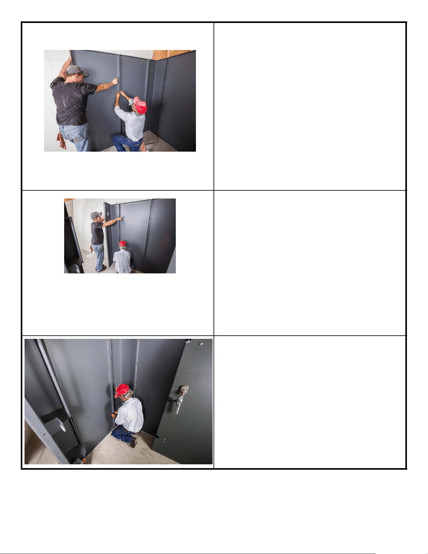
18. With the help of a second person carry
the preassembled Door into the Safety
Shelter and lean it safely against the
back or side wall of the Safety Shelter.
19. Install the last remaining Wall Section
following the same procedures. Leave all
bolts finger-tight at this time.
27
ꉀ
ǩ
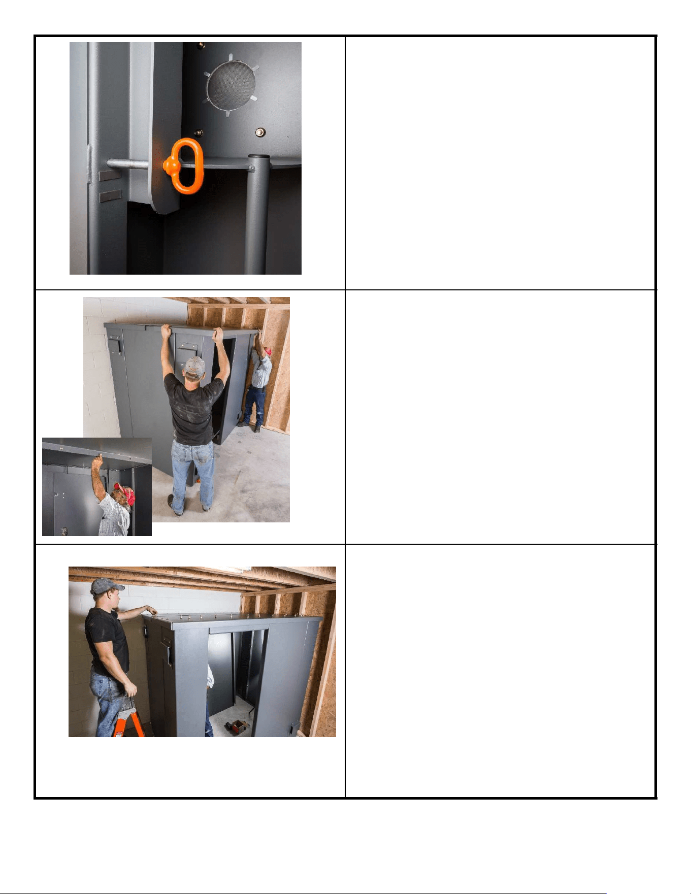
20. Ensure the Door Latch Pins (PN 19758)
are installed in the Door Jamb (PN
19736) as shown.
21. With the help of a second person install
the End Roof Panels (PN 20441) and
Center Roof Panels (PN 20442) over the
Safety Shelter walls. For the End Roof
Panels the flange with holes always goes
to the inside of the Safety Shelter.
22. Attach Roof Panels using Carriage Bolts
(PN 19828) and Nuts (PN 19799) to top
of side walls and corners. At this time do
not install the 7 Bolts (PN 19829) in the
front wall/roof that hold the Rail Support
Brackets. Only hand tighten all nuts at
this time.
28
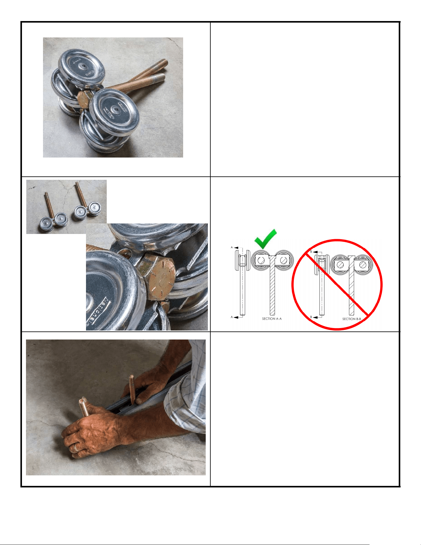
23. Locate the following Door Rail Items:
1 PR Box Rail Truck Roller (PN 20137)
2 Bolt ½” x 6” (PN 19787)
1 Rail (PN 20419)
3 Rail Support Outside (PN 19774)
3 Rail Support Inside (PN 21074)
2 Rail Support Outside, Long (PN 20429)
2 Rail Support Inside, Long (PN 20430)
2 Stop Bolt (PN 19831)
2 Spacer (PN 12785)
24. Install a ½” Bolt (PN 19787) into the
center of each Roller Truck (PN 20137)
from the top. The head of the Bolt should
rest solidly between the inner flanges of
the Roller, locking it into place.
25. Install two sets of rollers into Rail and
secure with a rubber band or tape to
temporarily hold them in place during
assembly.
½” Bolts shown
installed in Roller
Assemblies
29
Note: Tighten the two Carriage Bolts
(PN 19828 from Step 22) that connect the
Roof Panel to the Door Header Brace prior
to attaching the Rail Assembly to the Shelter.
ꉀ
ǩ
30
Cage Nut
Cage Nut
1 2 3 4 5
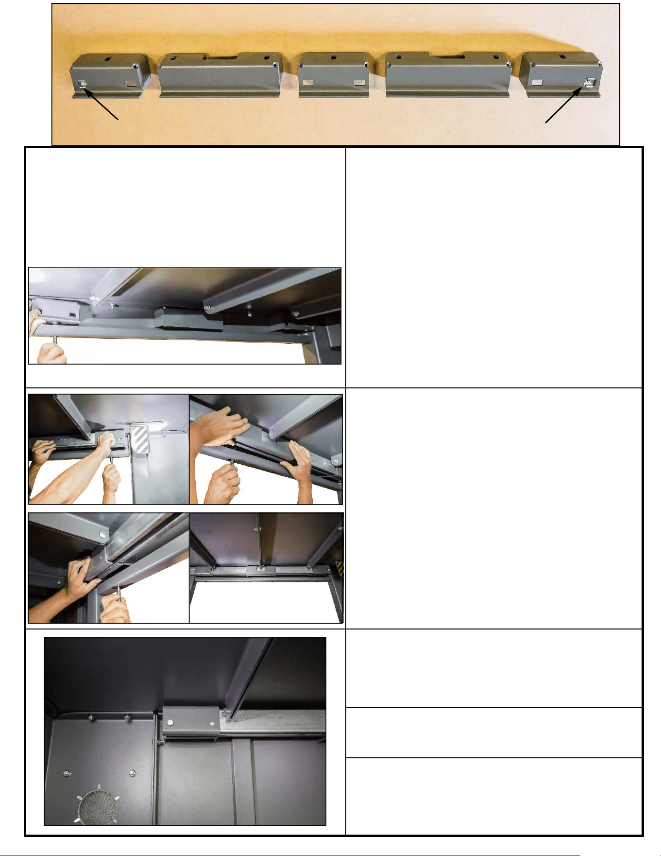
26. Lay out the three Inside Rail Supports
(PN 21074) and two Long Inside Rail
Supports (PN 20430) as shown above.
This is the order of the brackets as seen
from the inside of the Shelter. Note the
orientation of the Cage Nuts (PN 21075)
on the two outermost Inside Rail
Supports. Loosely install brackets 3, 4
and 5 to the roof using four Carriage
Bolts (PN 19829) and Nuts (PN 19799).
This is necessary to keep the bracket
from falling out while installing the Rail
(PN 20419). The holes in the Doorway
Brace (PN 20412) are access holes for
these nuts.
27. Place the Rail (PN 20419) within the
three brackets. While holding the Rail,
remove the nut from bracket 5 and install
an Outside Rail Support (PN 19774)
between the Inside Rail Support and the
Roof. Loosely reassemble with the Nut
(PN 19799). Repeat this process for
bracket 4 using a Long Outside Rail
Support (PN 20429). Continue for
bracket 3 using an Outside Rail Support
(PN 19774). Loosely install brackets 1
and 2 using an Outside Rail Support (PN
19774), a Long Outside Rail Support (PN
20429), three Bolts (PN 19829) and
three Nuts (PN 19799).
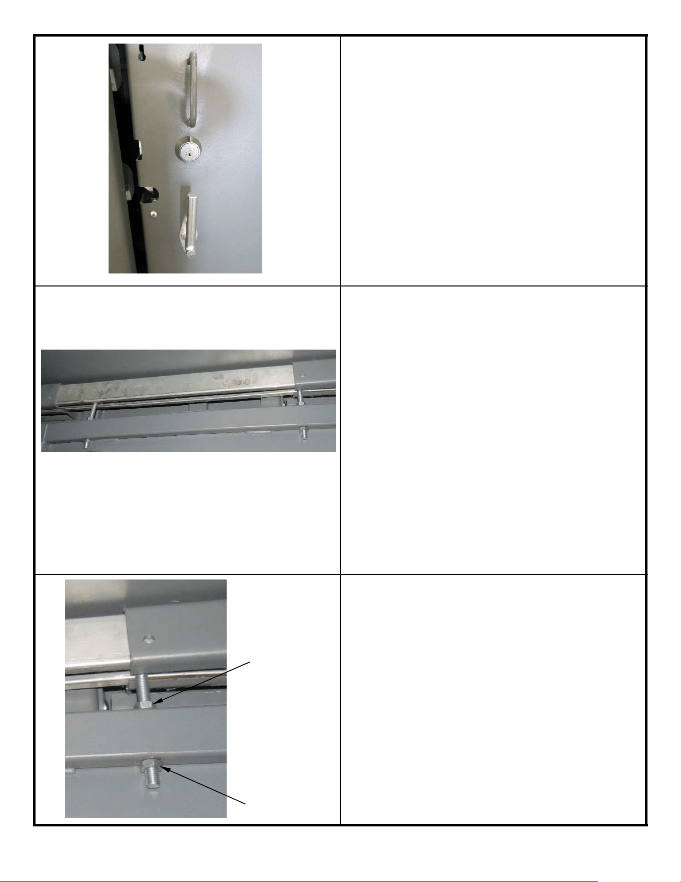
28. Install a spacer (PN 12785) inside each
end of the Rail (PN 20419) and secure
using a Stop Bolt (PN 19831) and the
preinstalled Cage Nut (PN 21075).
29. Tighten all bolts in the rail assembly to
31 Ft-lbs.
30. Remove the tape or rubber bands (see
Step 24) from both Rollers and test that
they move freely back and forth the
complete length of the Door Rail.
The bolt pattern on page 16 identifies the roof hole
locations for Bolt 19829. One person must be on the
outside holding the bolts down in the roof and the
other lifting the rail assembly in place and putting the
7 nuts on. A deep socket and extension must be
used to place the nuts through the access holes in
the Door Header (PN 20412).
ꉀ
ǩ
31. Install all the remaining anchor bolts
around the bottom flange of the entire
Safety Shelter. Once installed, make
sure to torque them to 40 Ft-lbs. See
instruction in Step 5 of this manual and
follow the Manufacturers Instructions. If
needed a steel punch or large screw
driver can be used to help align the holes
in the base flanges with the holes in the
concrete.
It is ok to install the six anchor bolts at
the base of the Front Wall. However,
before you torque them down, remove
the nuts and washers. In a later Step
these will be reinstalled.
32. Tighten all bolts around the roof exterior
and interior flanges to 31 Ft-lbs.
33. Tighten all bolts in every wall flange to 31
Ft-lbs.
31
ꉀ
ǩ
34. The Door will come to you pre-
assembled with all latches and hardware
installed.
The Door is extremely heavy so you must
use caution and practice proper lifting
techniques when positioning it.
Hanging the Door is a 2 to 3 person job.
It cannot be done by one person!
35. In preparation for hanging the door you
will need 2 ea. 1/2” Nuts (PN 19832) and
2 ea. Nyloc Nuts (PN 20117). First,
install 1 Nut on each ½” bolt hanging
from the Rollers. Thread this nut all the
way up the bolt to just below the roller.
Position the two rollers so that the ½”
bolts hanging from them are
approximately 35” apart and centered on
the Door Rail.
While raising the door carefully align the
two ½” bolts into the holes in the top
frame member of the door. Once both
bolts are in the holes slightly raise the
door just enough to put the ½” Nyloc Nut
on the bolt under the top frame of the
door.
36. Using a wrench, tighten the nuts under
the door frame upward (raising the door)
evenly until there is approximately ¾” of
thread exposed on the ½” bolts. This is a
good starting place for the door
alignment to be done later.
32
1/2” Nut 19832
1/2” Nyloc Nut 20117
ꉀ
ǩ
37. You will need a light inside the Safety
Shelter for the following steps.
Position the door all the way in the
closed position to expose the inside of
the Front Wall Panel.
Install the Lower Door Guide (PN 20421)
over the anchor bolts at the base of the
Front Wall Panel. Reinstall the flat
washers and nuts and torque to 40 Ft-
lbs.
38. Door Adjustment/Alignment – For proper
and safe operation the door must be
aligned so that it will easily latch on all
three pins without forcing the handle.
Adjust both nuts evenly on the bottom of
the ½” Roller Bolts supporting the door
until the hook point on the center Door
Latch (in the unlocked up position) is
1/16” above the Center Latch Pin in the
Corner Jamb. Adjust each nut evenly so
that the door remains level.
39. Now attempt to close the door. If it shuts
and all three latches easily engage with
out forcing them down, you’re done. If
not, follow the steps below:
First, remove the three latch pins from
the Door Jamb.
Close the door and place the handle in
the locked position.
Replace the center latch pin only. It
should slide through the center Door
Latch Plate easily. If it does not, adjust
both nuts evenly to move the door up or
down until the pin moves freely.
33
ꉀ
ǩ
40. Attempt to replace the top Latch Pin
through the Jamb and the Door Latch
Plate. If it hits the Door Latch Plate
adjust the ½” Nyloc Nuts (PN 20117)
under the top door frame until the Latch
Pin will easily slide through the Latch
Plate.
Do not make large adjustment to the
nuts, ¼ or ½ turns will make a significant
change in the location of the Latch Plate.
Make small adjustments and check
alignment often.
Double check that the center Latch Pin
continues to slide in and out freely.
Repeat the alignment procedure above
for the bottom Latch Pin. It may take
some time (depending upon how level
the concrete floor is) going back and
forth, checking all three Latch Pins often
and making small adjustments to get
them all latching freely.
Once the door is aligned, securely
tighten the ½” Nuts (PN 19832) on the
top side of the door frame down to the
frame.
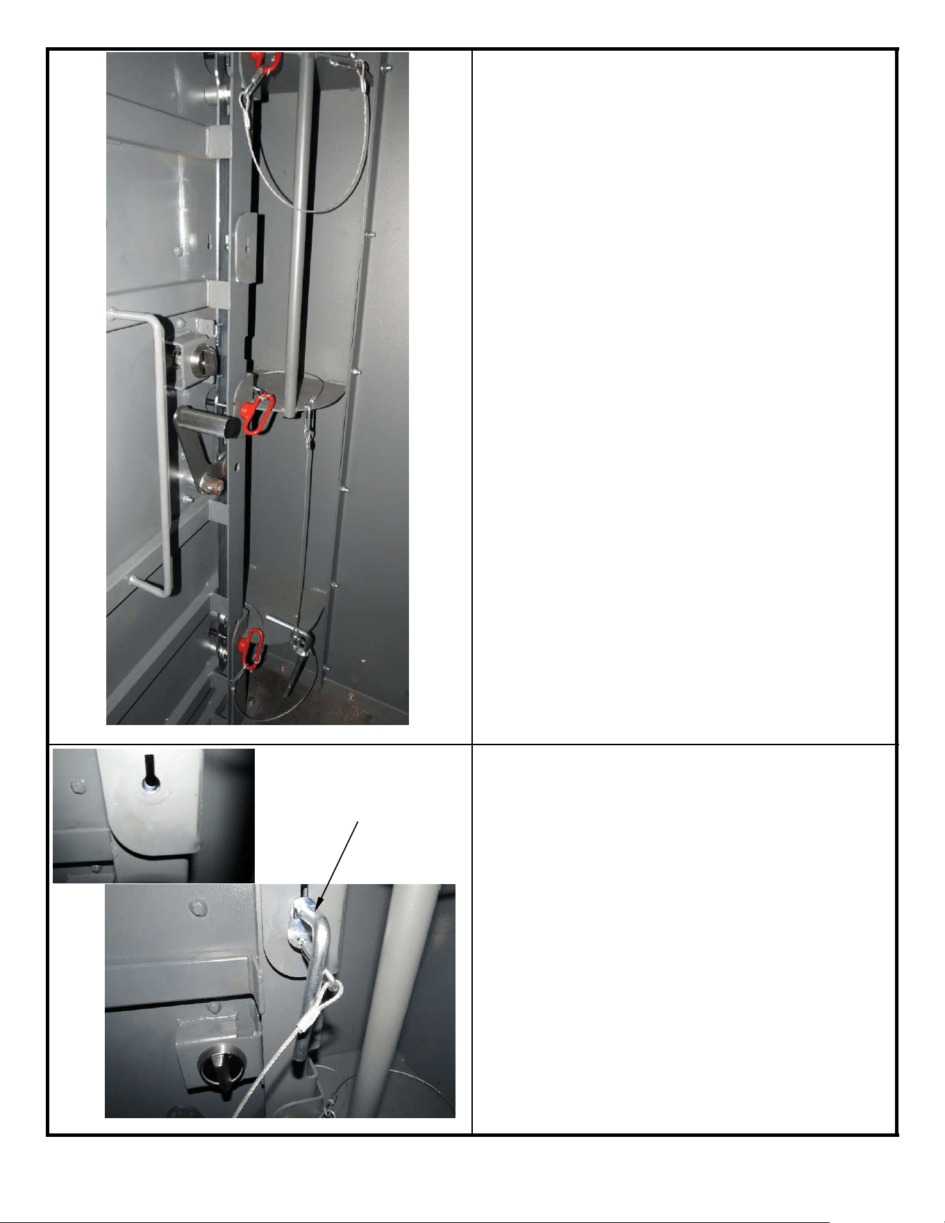
41. The Locking Pin is sold separately by
buying Kit part number 21160. It can
be used to lock the Door from the
inside even if someone on the outside
has a key. It is not necessary for
protection in a severe weather event.
With the door in the closed and latched
position check the operation of the
Locking Pin. Install the Locking Pin into
the Key Hole on the Door Jamb. If the
Pin will not freely slide through the Jamb
further adjustment is needed to the door.
Once the Pin is fully engaged through
the Jamb and Door rotate the handle 90°
counterclockwise (down) to the locked
position.
34
Locking Pin

ꉀ
ǩ
IMPORTANT!
Medeco Key Registration Card
Inside your Owners Hardware Bag you will
f
ind two keys to your new Safety Shelter
Door and a Key Registration Card (it looks
like a credit card).
DO NOT LOSE THIS CARD
Keep the Key Registration Card in a safe
location. In the event you lose your keys,
take this card to a participating Medeco
Locksmith to have replacement keys made.
You will need this card to have duplicate
keys made. Without this card you will not
be able to get replacement keys made.
35
綠
һ
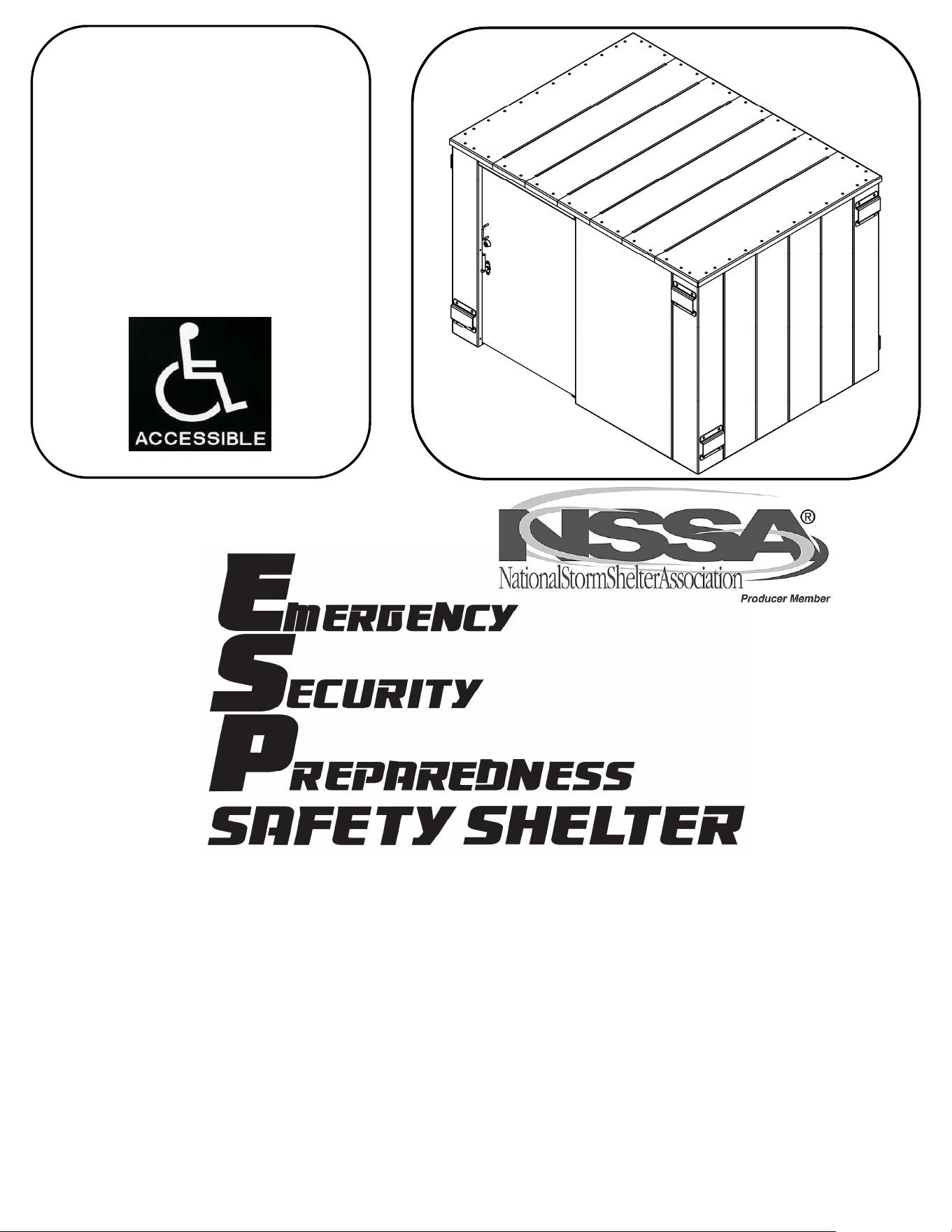
ALSO AVAILABLE
Visit www.ESP.swisherinc.com for details.
36
Single Panel Shelf
SRAC20221
Double Panel Shelf
SRAC20226
Bench
SRAC20229
Gun Rack
SRAC20282
Adjustable Gun Rack
SRAC20338

ꉀ
ǩ
NOTES:
37

緰
һ
NOTES:
38

砠
һ
NOTES:
39
繀
һ
WHEN ORDERING PARTS, PLEASE HAVE THE
FOLLOWING INFORMATION AVAILABLE:
* PRODUCT - ________________
* SERIAL NUMBER - _______________
* MODEL NUMBER - _______________
* PART NUMBER WITH PAINT CODE
* PART DESCRIPTION
TELEPHONE - 1-800-222-8183
FAX - 1-660-747-8650
SWISHER ACQUISITION INC.
1602 CORPORATE DRIVE
WARRENSBURG, MO 64093
OWNER’S
MANUAL
www.ESP.swisherinc.com
SR114X84G
TM
Patent No. 9,644,420
