
Access Control Terminal
User Manual

Legal Informaon
©2020 Hangzhou Hikvision Digital Technology Co., Ltd. All rights reserved.
About this Manual
The Manual includes instrucons for using and managing the Product. Pictures, charts, images and
all other informaon hereinaer are for descripon and explanaon only. The informaon
contained in the Manual is subject to change, without noce, due to rmware updates or other
reasons. Please nd the latest version of this Manual at the Hikvision website ( hps://
www.hikvision.com/ ).
Please use this Manual with the guidance and assistance of professionals trained in supporng the
Product.
Trademarks
and other Hikvision's trademarks and logos are the properes of
Hikvision in various jurisdicons.
Other trademarks and logos menoned are the properes of their respecve owners.
Disclaimer
TO THE MAXIMUM EXTENT PERMITTED BY APPLICABLE LAW, THIS MANUAL AND THE PRODUCT
DESCRIBED, WITH ITS HARDWARE, SOFTWARE AND FIRMWARE, ARE PROVIDED “AS IS” AND “WITH
ALL FAULTS AND ERRORS”. HIKVISION MAKES NO WARRANTIES, EXPRESS OR IMPLIED, INCLUDING
WITHOUT LIMITATION, MERCHANTABILITY, SATISFACTORY QUALITY, OR FITNESS FOR A PARTICULAR
PURPOSE. THE USE OF THE PRODUCT BY YOU IS AT YOUR OWN RISK. IN NO EVENT WILL HIKVISION
BE LIABLE TO YOU FOR ANY SPECIAL, CONSEQUENTIAL, INCIDENTAL, OR INDIRECT DAMAGES,
INCLUDING, AMONG OTHERS, DAMAGES FOR LOSS OF BUSINESS PROFITS, BUSINESS
INTERRUPTION, OR LOSS OF DATA, CORRUPTION OF SYSTEMS, OR LOSS OF DOCUMENTATION,
WHETHER BASED ON BREACH OF CONTRACT, TORT (INCLUDING NEGLIGENCE), PRODUCT LIABILITY,
OR OTHERWISE, IN CONNECTION WITH THE USE OF THE PRODUCT, EVEN IF HIKVISION HAS BEEN
ADVISED OF THE POSSIBILITY OF SUCH DAMAGES OR LOSS.
YOU ACKNOWLEDGE THAT THE NATURE OF INTERNET PROVIDES FOR INHERENT SECURITY RISKS,
AND HIKVISION SHALL NOT TAKE ANY RESPONSIBILITIES FOR ABNORMAL OPERATION, PRIVACY
LEAKAGE OR OTHER DAMAGES RESULTING FROM CYBER-ATTACK, HACKER ATTACK, VIRUS
INSPECTION, OR OTHER INTERNET SECURITY RISKS; HOWEVER, HIKVISION WILL PROVIDE TIMELY
TECHNICAL SUPPORT IF REQUIRED.
YOU AGREE TO USE THIS PRODUCT IN COMPLIANCE WITH ALL APPLICABLE LAWS, AND YOU ARE
SOLELY RESPONSIBLE FOR ENSURING THAT YOUR USE CONFORMS TO THE APPLICABLE LAW.
ESPECIALLY, YOU ARE RESPONSIBLE, FOR USING THIS PRODUCT IN A MANNER THAT DOES NOT
INFRINGE ON THE RIGHTS OF THIRD PARTIES, INCLUDING WITHOUT LIMITATION, RIGHTS OF
PUBLICITY, INTELLECTUAL PROPERTY RIGHTS, OR DATA PROTECTION AND OTHER PRIVACY RIGHTS.
YOU SHALL NOT USE THIS PRODUCT FOR ANY PROHIBITED END-USES, INCLUDING THE
Access Control Terminal User Manual
i

DEVELOPMENT OR PRODUCTION OF WEAPONS OF MASS DESTRUCTION, THE DEVELOPMENT OR
PRODUCTION OF CHEMICAL OR BIOLOGICAL WEAPONS, ANY ACTIVITIES IN THE CONTEXT RELATED
TO ANY NUCLEAR EXPLOSIVE OR UNSAFE NUCLEAR FUEL-CYCLE, OR IN SUPPORT OF HUMAN
RIGHTS ABUSES.
IN THE EVENT OF ANY CONFLICTS BETWEEN THIS MANUAL AND THE APPLICABLE LAW, THE LATER
PREVAILS.
Data Protecon
During the use of device, personal data will be collected, stored and processed. To protect data,
the development of Hikvision devices incorporates privacy by design principles. For example, for
device with facial recognion features, biometrics data is stored in your device with encrypon
method; for ngerprint device, only ngerprint template will be saved, which is impossible to
reconstruct a ngerprint image.
As data controller, you are advised to collect, store, process and transfer data in accordance with
the applicable data protecon laws and regulaons, including without limitaon, conducng
security controls to safeguard personal data, such as, implemenng reasonable administrave and
physical security controls, conduct periodic reviews and assessments of the eecveness of your
security controls.
Access Control Terminal User Manual
ii
Symbol Convenons
The symbols that may be found in this document are dened as follows.
Symbol Descripon
Danger
Indicates a hazardous situaon which, if not avoided, will or could
result in death or serious injury.
Cauon
Indicates a potenally hazardous situaon which, if not avoided, could
result in equipment damage, data loss, performance degradaon, or
unexpected results.
Note
Provides addional informaon to emphasize or supplement
important points of the main text.
Access Control Terminal User Manual
iii

Regulatory Informaon
FCC Informaon
Please take aenon that changes or modicaon not expressly approved by the party responsible
for compliance could void the user’s authority to operate the equipment.
FCC compliance: This equipment has been tested and found to comply with the limits for a Class B
digital device, pursuant to part 15 of the FCC Rules. These limits are designed to provide
reasonable protecon against harmful interference in a residenal installaon. This equipment
generates, uses and can radiate radio frequency energy and, if not installed and used in accordance
with the instrucons, may cause harmful interference to radio communicaons. However, there is
no guarantee that interference will not occur in a parcular installaon. If this equipment does
cause harmful interference to radio or television recepon, which can be determined by turning
the equipment o and on, the user is encouraged to try to correct the interference by one or more
of the following measures:
—Reorient or relocate the receiving antenna.
—Increase the separaon between the equipment and receiver.
—Connect the equipment into an outlet on a circuit dierent from that to which the receiver is
connected.
—Consult the dealer or an experienced radio/TV technician for help
This equipment should be installed and operated with a minimum distance 20cm between the
radiator and your body.
FCC Condions
This device complies with part 15 of the FCC Rules. Operaon is subject to the following two
condions:
1. This device may not cause harmful interference.
2. This device must accept any interference received, including interference that may cause
undesired operaon.
EU Conformity Statement
This product and - if applicable - the supplied accessories too are marked with "CE"
and comply therefore with the applicable harmonized European standards listed
Access Control Terminal User Manual
iv

under the EMC Direcve 2014/30/EU, RE Direcve 2014/53/EU,the RoHS Direcve
2011/65/EU
2012/19/EU (WEEE direcve): Products marked with this symbol cannot be disposed
of as unsorted municipal waste in the European Union. For proper recycling, return
this product to your local supplier upon the purchase of equivalent new equipment,
or dispose of it at designated collecon points. For more informaon see:
www.recyclethis.info
2006/66/EC (baery direcve): This product contains a baery that cannot be
disposed of as unsorted municipal waste in the European Union. See the product
documentaon for specic baery informaon. The baery is marked with this
symbol, which may include leering to indicate cadmium (Cd), lead (Pb), or mercury
(Hg). For proper recycling, return the baery to your supplier or to a designated
collecon point. For more informaon see:www.recyclethis.info
Industry Canada ICES-003 Compliance
This device meets the CAN ICES-3 (B)/NMB-3(B) standards requirements.
This device complies with Industry Canada licence-exempt RSS standard(s). Operaon is subject to
the following two condions:
1. this device may not cause interference, and
2. this device must accept any interference, including interference that may cause undesired
operaon of the device.
Le présent appareil est conforme aux CNR d'Industrie Canada applicables aux appareils
radioexempts de licence. L'exploitaon est autorisée aux deux condions suivantes :
1. l'appareil ne doit pas produire de brouillage, et
2. l'ulisateur de l'appareil doit accepter tout brouillage radioélectrique subi, même si le brouillage
est suscepble d'en compromere le fonconnement.
Under Industry Canada regulaons, this radio transmier may only operate using an antenna of a
type and maximum (or lesser) gain approved for the transmier by Industry Canada. To reduce
potenal radio interference to other users, the antenna type and its gain should be so chosen that
the equivalent isotropically radiated power (e.i.r.p.) is not more than that necessary for successful
communicaon.
Conformément à la réglementaon d'Industrie Canada, le présent émeeur radio peut fonconner
avec une antenne d'un type et d'un gain maximal (ou inférieur) approuvé pour l'émeeur par
Industrie Canada. Dans le but de réduire les risques de brouillage radioélectrique à l'intenon des
autres ulisateurs, il faut choisir le type d'antenne et son gain de sorte que la puissance isotrope
rayonnée équivalente (p.i.r.e.) ne dépasse pas l'intensité nécessaire à l'établissement d'une
communicaon sasfaisante.
This equipment should be installed and operated with a minimum distance 20cm between the
radiator and your body.
Access Control Terminal User Manual
v

Cet équipement doit être installé et ulisé à une distance minimale de 20 cm entre le radiateur et
votre corps.
Access Control Terminal User Manual
vi

Safety Instrucon
These instrucons are intended to ensure that user can use the product correctly to avoid danger
or property loss.
The precauon measure is divided into Dangers and Cauons:
Dangers: Neglecng any of the warnings may cause serious injury or death.
Cauons: Neglecng any of the cauons may cause injury or equipment damage.
Dangers: Follow these safeguards to prevent
serious injury or death.
Cauons: Follow these precauons to prevent
potenal injury or material damage.
Dangers
●
The socket-outlet shall be installed near the equipment and shall be easily accessible.
●
An all-pole mains switch shall be incorporated in the electrical installaon of the building.
●
1. This equipment is not suitable for use in locaons where children are likely to be present.
2. CAUTION: Risk of explosion if the baery is replaced by an incorrect type.
3. Improper replacement of the baery with an incorrect type may defeat a safeguard (for
example, in the case of some lithium baery types).
4. Do not dispose of the baery into re or a hot oven, or mechanically crush or cut the baery,
which may result in an explosion.
5. Do not leave the baery in an extremely high temperature surrounding environment, which
may result in an explosion or the leakage of ammable liquid or gas.
6. Do not subject the baery to extremely low air pressure, which may result in an explosion or
the leakage of ammable liquid or gas.
7. Dispose of used baeries according to the instrucons.
●
To prevent possible hearing damage, do not listen at high volume levels for long periods.
●
All the electronic operaon should be strictly compliance with the electrical safety regulaons,
re prevenon regulaons and other related regulaons in your local region.
●
Please use the power adapter, which is provided by normal company. The power consumpon
cannot be less than the required value.
●
Do not connect several devices to one power adapter as adapter overload may cause over-heat
or re hazard.
●
Please make sure that the power has been disconnected before you wire, install or dismantle the
device.
●
When the product is installed on wall or ceiling, the device shall be rmly xed.
Access Control Terminal User Manual
vii

●
If smoke, odors or noise rise from the device, turn o the power at once and unplug the power
cable, and then please contact the service center.
●
If the product does not work properly, please contact your dealer or the nearest service center.
Never aempt to disassemble the device yourself. (We shall not assume any responsibility for
problems caused by unauthorized repair or maintenance.)
Cauons
●
The equipment has been designed, when required, modied for connecon to an IT power
distribuon system.
●
The USB port of the equipment is used for connecng to a mouse, a keyboard, or a USB ash
drive only.
●
The serial port of the equipment is used for debugging only.
●
+ idenes the posive terminal(s) of equipment which is used with, or generates direct current.
+ idenes the negave terminal(s) of equipment which is used with, or generates direct
current.
●
Do not drop the device or subject it to physical shock, and do not expose it to high
electromagnesm radiaon. Avoid the equipment installaon on vibraons surface or places
subject to shock (ignorance can cause equipment damage).
●
Do not place the device in extremely hot (refer to the specicaon of the device for the detailed
operang temperature), cold, dusty or damp locaons, and do not expose it to high
electromagnec radiaon.
●
The device cover for indoor use shall be kept from rain and moisture.
●
Exposing the equipment to direct sun light, low venlaon or heat source such as heater or
radiator is forbidden (ignorance can cause re danger).
●
Do not aim the device at the sun or extra bright places. A blooming or smear may occur
otherwise (which is not a malfuncon however), and aecng the endurance of sensor at the
same me.
●
Please use the provided glove when open up the device cover, avoid direct contact with the
device cover, because the acidic sweat of the ngers may erode the surface coang of the device
cover.
●
Please use a so and dry cloth when clean inside and outside surfaces of the device cover, do
not use alkaline detergents.
●
Please keep all wrappers aer unpack them for future use. In case of any failure occurred, you
need to return the device to the factory with the original wrapper. Transportaon without the
original wrapper may result in damage on the device and lead to addional costs.
Access Control Terminal User Manual
viii

Available Model
Product Name Model
Access Control Terminal DS-K1T105AM
DS-K1T105AE
DS-K1T201AMF
DS-K1T201AEF
Use only power supplies listed in the user instrucons:
Model Manufacturer
KPL-050F-VI Channel Well Technology Co Ltd.
Access Control Terminal User Manual
ix

Contents
Chapter 1 Overview .................................................................................................................... 1
1.1 Introducon ........................................................................................................................... 1
1.2 Features ................................................................................................................................. 1
1.2.1 Features of Device without Fingerprint Module ........................................................... 1
1.2.2 Features of Device with Fingerprint Module ................................................................ 2
Chapter 2 Appearance ................................................................................................................ 3
2.1 Appearance of Access Control Terminal without Fingerprint Module ................................... 3
2.2 Appearance of Access Control Terminal with Fingerprint Module ........................................ 4
2.3 Appearance Descripon ......................................................................................................... 4
Chapter 3 Installaon ................................................................................................................. 7
3.1 Install Access Control Terminal (Without Fingerprint Module) .............................................. 7
3.2 Install Access Control Terminal (With Fingerprint Module) ................................................. 10
Chapter 4 Wiring ...................................................................................................................... 15
4.1 Terminal Descripon ............................................................................................................ 15
4.2 Access Control Terminal Wiring ........................................................................................... 18
4.3 RS-485 Card Reader Wiring .................................................................................................. 18
4.4 Wiegand Card Reader Wiring ............................................................................................... 19
4.5 Device Wiring as RS-485 Card Reader .................................................................................. 20
4.6 Device Wiring as Wiegand Card Reader ............................................................................... 21
Chapter 5 Acvaon ................................................................................................................. 23
5.1 Acvate via Device ............................................................................................................... 23
5.2 Acvate via SADP ................................................................................................................. 23
5.3 Acvate Device via Client Soware ...................................................................................... 25
Chapter 6 Local Sengs ............................................................................................................ 26
6.1 Add Administrator ................................................................................................................ 26
6.2 Login .................................................................................................................................... 27
Access Control Terminal User Manual
x

6.3 Communicaon Sengs ...................................................................................................... 28
6.3.1 Set Wired Network ...................................................................................................... 28
6.3.2 Set Wi-Fi Parameters ................................................................................................... 28
6.3.3 Set EHome Parameters ............................................................................................... 29
6.3.4 Set Wiegand Parameters ............................................................................................. 31
6.3.5 Set RS-485 Parameters ................................................................................................ 32
6.4 Person Management ............................................................................................................ 32
6.4.1 Add Person .................................................................................................................. 32
6.4.2 Manage Person (Search/Edit/Delete) ......................................................................... 35
6.5 Identy Authencaon ........................................................................................................ 35
6.6 Set Access Control Parameters ............................................................................................ 36
6.7 Basic Sengs ....................................................................................................................... 38
6.7.1 Set System Parameters ................................................................................................ 38
6.7.2 Manage System Data .................................................................................................. 40
6.7.3 System Upgrade .......................................................................................................... 40
6.7.4 Restore/Reboot Sengs ............................................................................................. 41
6.7.5 Data Transfer ............................................................................................................... 42
6.7.6 Log Query .................................................................................................................... 43
6.7.7 Set Time ...................................................................................................................... 43
6.7.8 View System Informaon ............................................................................................ 45
Chapter 7 Client Soware Conguraon ................................................................................... 47
7.1 Conguraon Flow of Client Soware ................................................................................. 47
7.2 Device Management ............................................................................................................ 47
7.2.1 Add Device .................................................................................................................. 48
7.2.2 Reset Device Password ................................................................................................ 57
7.3 Group Management ............................................................................................................. 58
7.3.1 Add Group ................................................................................................................... 58
7.3.2 Import Resources to Group ......................................................................................... 58
Access Control Terminal User Manual
xi

7.3.3 Edit Resource Parameters ........................................................................................... 58
7.3.4 Remove Resources from Group .................................................................................. 59
7.4 Person Management ............................................................................................................ 59
7.4.1 Add Organizaon ........................................................................................................ 59
7.4.2 Congure Basic Informaon ....................................................................................... 60
7.4.3 Issue a Card to One Person ......................................................................................... 60
7.4.4 Collect Fingerprint via Client ....................................................................................... 62
7.4.5 Collect Fingerprint via Access Control Device ............................................................. 62
7.4.6 Congure Access Control Informaon ........................................................................ 63
7.4.7 Customize Person Informaon .................................................................................... 64
7.4.8 Congure Resident Informaon .................................................................................. 64
7.4.9 Congure Addional Informaon ............................................................................... 65
7.4.10 Import and Export Person Idenfy Informaon ........................................................ 65
7.4.11 Import Person Informaon ....................................................................................... 65
7.4.12 Export Person Informaon ........................................................................................ 66
7.4.13 Get Person Informaon from Access Control Device ................................................ 67
7.4.14 Move Persons to Another Organizaon .................................................................... 67
7.4.15 Issue Cards to Persons in Batch ................................................................................. 67
7.4.16 Report Card Loss ....................................................................................................... 68
7.4.17 Set Card Issuing Parameters ...................................................................................... 68
7.5 Congure Schedule and Template ....................................................................................... 69
7.5.1 Add Holiday ................................................................................................................. 70
7.5.2 Add Template .............................................................................................................. 70
7.6 Set Access Group to Assign Access Authorizaon to Persons .............................................. 72
7.7 Congure Advanced Funcons ............................................................................................ 73
7.7.1 Congure Device Parameters ...................................................................................... 73
7.7.2 Congure Remaining Open/Closed ............................................................................. 78
7.7.3 Congure Mul-Factor Authencaon ....................................................................... 79
Access Control Terminal User Manual
xii

7.7.4 Congure Custom Wiegand Rule ................................................................................ 81
7.7.5 Congure Card Reader Authencaon Mode and Schedule ...................................... 83
7.7.6 Congure First Person In ............................................................................................. 85
7.7.7 Congure An-Passback ............................................................................................. 86
7.7.8 Congure Device Parameters ...................................................................................... 87
7.8 Congure Linkage Acons for Access Control ...................................................................... 90
7.8.1 Congure Client Acons for Access Event ................................................................... 90
7.8.2 Congure Device Acons for Access Event ................................................................. 91
7.8.3 Congure Device Acons for Card Swiping ................................................................. 92
7.8.4 Congure Device Acons for Person ID ...................................................................... 93
7.9 Door Control ........................................................................................................................ 94
7.9.1 Control Door Status ..................................................................................................... 94
7.9.2 Check Real-Time Access Records ................................................................................ 95
7.10 Event Center ...................................................................................................................... 96
7.10.1 Enable Receiving Events from Devices ...................................................................... 96
7.10.2 View Real-Time Events .............................................................................................. 97
7.10.3 Search Historical Events .......................................................................................... 100
7.11 Time and Aendance ....................................................................................................... 103
7.11.1 Congure Aendance Parameters .......................................................................... 103
7.11.2 Add General Timetable ........................................................................................... 108
7.11.3 Add Shi .................................................................................................................. 111
7.11.4 Manage Shi Schedule ........................................................................................... 113
7.11.5 Manually Correct Check-in/out Record ................................................................... 116
7.11.6 Add Leave and Business Trip ................................................................................... 117
7.11.7 Calculate Aendance Data ...................................................................................... 118
7.11.8 Aendance Stascs .............................................................................................. 120
7.12 Remote Conguraon (Web) ........................................................................................... 122
7.12.1 View Device Informaon ......................................................................................... 122
Access Control Terminal User Manual
xiii

7.12.2 Change Device Password ........................................................................................ 123
7.12.3 Time Management .................................................................................................. 124
7.12.4 System Maintenance ............................................................................................... 125
7.12.5 Congure RS-485 Parameters ................................................................................. 125
7.12.6 Security Mode Sengs ........................................................................................... 126
7.12.7 Network Parameters Sengs ................................................................................. 126
7.12.8 Report Strategy Sengs .......................................................................................... 127
7.12.9 Network Center Parameters Sengs ...................................................................... 127
7.12.10 Congure Wi-Fi ..................................................................................................... 127
7.12.11 Set Relay Parameters ............................................................................................ 128
7.12.12 Set Access Control Parameters ............................................................................. 128
7.12.13 Set CPU Card Reading Mode ................................................................................. 128
7.12.14 Congure Volume Input or Output ....................................................................... 128
7.12.15 Operate Relay ........................................................................................................ 129
7.12.16 View Relay Status .................................................................................................. 129
Appendix A. Tips for Scanning Fingerprint ............................................................................... 130
Appendix B. Dimension .......................................................................................................... 132
Appendix C. Communicaon Matrix and Device Command ..................................................... 134
Access Control Terminal User Manual
xiv
Chapter 1 Overview
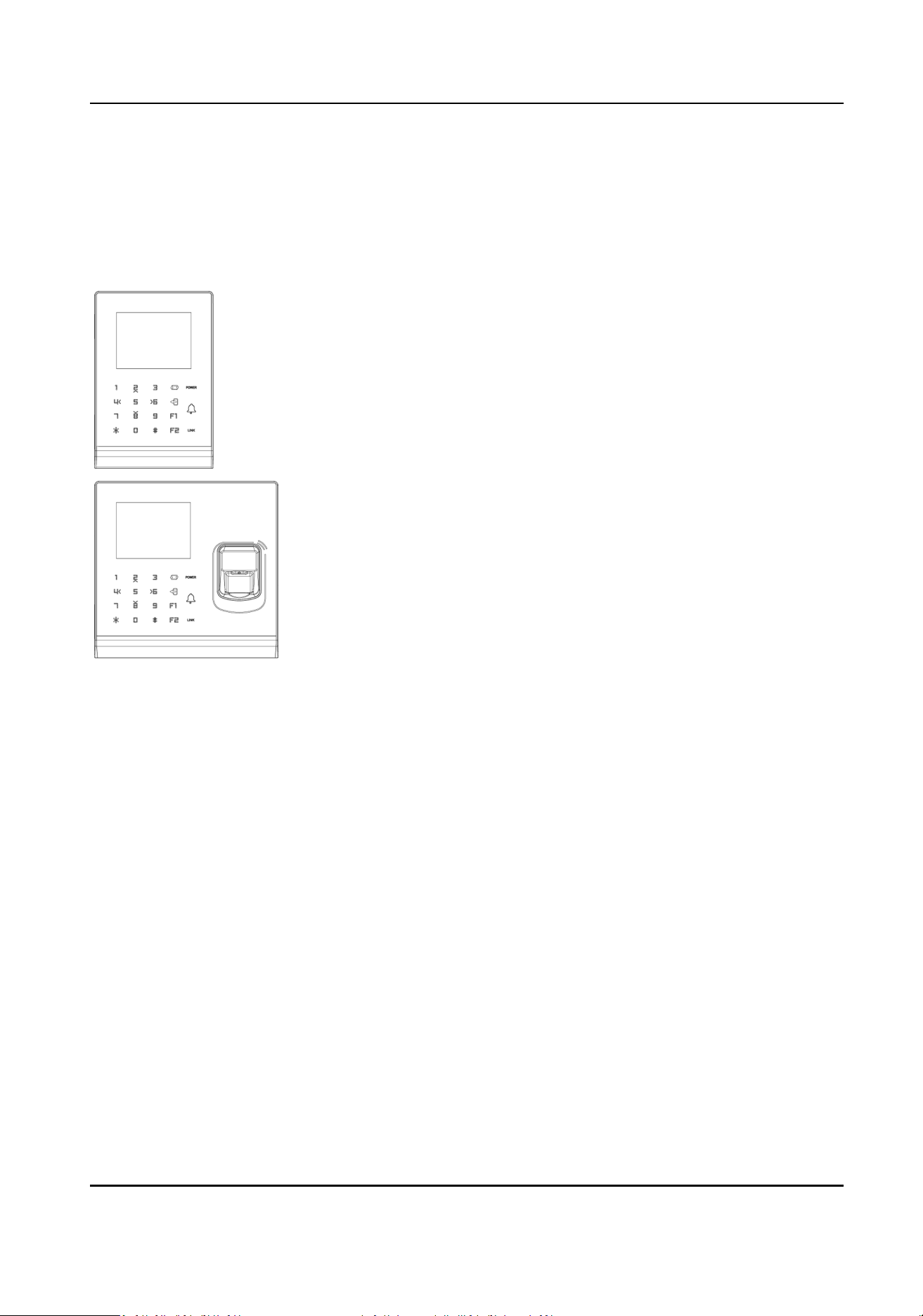
1.1 Introducon
DS-K1T105A is a series of standalone access control terminal
with a 2.8-inch LCD display screen. It supports smart card
recognion TCP/IP communicaon method, Wi-Fi
communicaon method, and also supports oine operaon.
DS-K1T201A series is an opcal ngerprint access control
terminal with mulple advanced technologies including
ngerprint recognion, Wi-Fi, card recognion, 2.8-inch LCD
display screen. It is equipped with opcal ngerprint recognion
module, and supports oine operaon.
1.2 Features
1.2.1 Features of Device without Fingerprint Module
●
Doorbell ringtone sengs funcon.
●
Touch mode and blue light display technique for keypad.
●
Stand-alone sengs for the device.
●
2.8-inch LCD display screen.
●
Transmission modes of wired network (TCP/TP) and Wi-Fi.
●
Supports mulple door opening modes (card, card + password, exit buon, etc.).
●
Supports RS-485 communicaon for connecng to external card reader.
●
Supports working as a card reader, and supports Wiegand interface and RS-485 interface for
accessing the controller.
●
Max. 100,000 valid card No., and Max. 300,000 access control events records storage.
●
Supports EM card reading (supported by device that can read EM card).
●
Supports M1 card reading, including card No. reading, & wring funcon (supported by device
that can read M1 card).
Access Control Terminal User Manual
1

●
Tampering detecon, unlocking overme alarm, invalid card swiping over mes alarm, and
duress card alarm.
●
Accurate data and me display provided by built-in electronic clock and watchdog program to
ensure the basic funcon of the terminal.
●
Data can be permanently saved aer power-o.
1.2.2 Features of Device with Fingerprint Module
●
Doorbell ringtone sengs funcon.
●
Touch mode and blue light display technique for keypad.
●
Stand-alone sengs for the device.
●
2.8-inch LCD display screen.
●
Transmission modes of wired network (TCP/TP) and Wi-Fi.
●
Supports RS-485 communicaon for connecng external card reader.
●
Supports working as a card reader, and supports Wiegand interface and RS-485 interface for
accessing the controller.
●
Max. 10,000 card No., Max. 300,000 access control events records, and Max. 5000 ngerprints
storage.
●
Adopts the opcal ngerprint module, supporng 1:N mode (ngerprint, card + ngerprint) and
1:1 mode (card + ngerprint).
●
Supports mulple authencaon modes (card, ngerprint, card + ngerprint, card + password,
ngerprint + password, card + ngerprint + password, and so on).
●
Supports EM card reading (supported by device that can read EM card).
●
Supports M1 card reading, including card No. reading, and sector reading & wring (supported
by device that can read M1 card).
●
Tampering detecon, unlocking overme alarm, invalid card swiping over mes alarm, duress
card alarm, and so on.
●
Accurate data and me display provided by built-in electronic clock and watchdog program to
ensure the basic funcon of the device.
●
Data can be permanently saved aer power-o.
Access Control Terminal User Manual
2
Chapter 2 Appearance
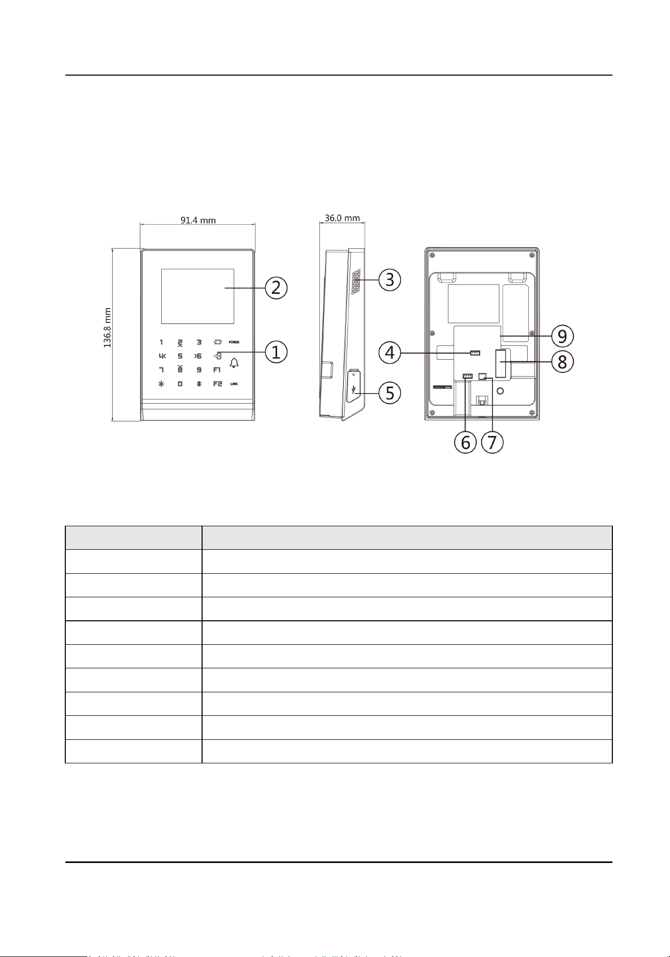
2.1 Appearance of Access Control Terminal without Fingerprint Module
Figure 2-1 Diagram of Access Control Terminal Appearance (Without Fingerprint Module)
Table 2-1 Descripon of Access Control Terminal (Without Fingerprint Module)
No. Descripon
1 Keypad
2 Display Screen
3 Loudspeaker
4 MDEBUG Debugging Port (for debugging use only)
5 USB Interface
6 SDEBUG Debugging Port (for debugging use only)
7 Power Interface
8 Wiring Terminal
9 Network Interface
Access Control Terminal User Manual
3
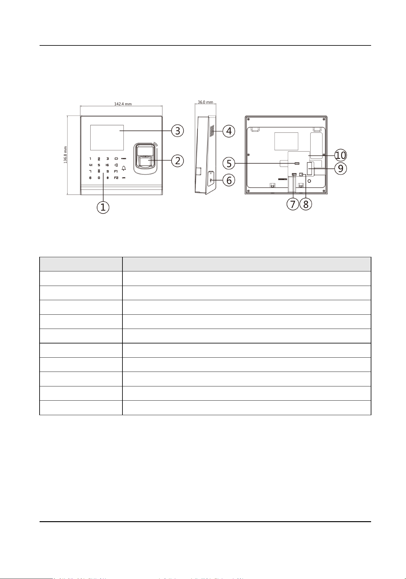
2.2 Appearance of Access Control Terminal with Fingerprint Module
Figure 2-2 Diagram of Access Control Terminal Appearance (With Fingerprint Module)
Table 2-2 Descripon of Access Control Terminal (With Fingerprint Module)
No. Descripon
1 Keypad
2 Fingerprint Module/Card Presenng Area
3 Display Screen
4 Loudspeaker
5 MDEBUG Debugging Port (for debugging only)
6 USB Interface
7 SDEBUG Debugging Port (for debugging use only)
8 Power Interface
9 Wiring Terminal
10 Network Interface
2.3 Appearance Descripon
View the device keypad's descripon.
Access Control Terminal User Manual
4
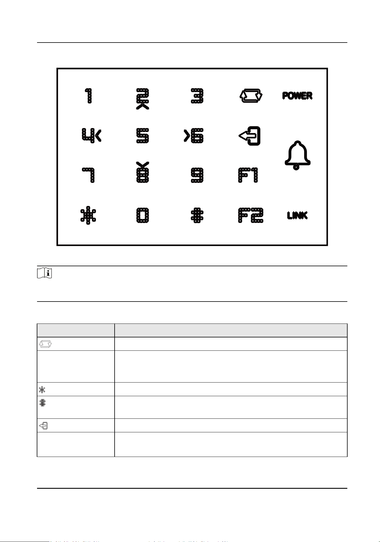
Figure 2-3 Keypad Diagram
Note
The pictures here are for reference only. Some models do not support card swiping funcon. For
details, refer to the actual product.
Table 2-3 Keypad Descripon
Buon Descripon
Shi between numeric key and direcon key on the non-inial page.
0~9 Numeric Key: Enter numbers/lowercases, numbers/uppercases and
symbols in the textbox. When entering non-numeric characters, 0 can be
a space key.
Exing key.
Hold the key to enter the login page. Press the key to conrm. Aer
login, the key can be a conrmaon or selecon key.
Deleng key. Press to delete contents in the textbox.
POWER Power status indicator.
Solid Blue: Normal Power;
Access Control Terminal User Manual
5

Buon Descripon
O: Power Excepon
LINK Solid Blue: Present normal card/Network or Wi-Fi is connected/Client
soware is armed.
Flashing Blue: Card reader mode.
Solid Red: Present illegal card.
O: Network or Wi-Fi is disconnected/Client soware is not armed.
F1 Eding key. Press to shi among numbers/lowercases, numbers/
uppercases and symbols.
F2 Reserved.
Access Control Terminal User Manual
6

Chapter 3 Installaon
3.1 Install Access Control Terminal (Without Fingerprint Module)
Before You Start
Make sure that the wall is strong enough to withstand three mes the weight of the device.
Steps
1.
Install the 86 gang box into the wall.
Figure 3-1 Install 86 Gang box
2.
Secure the device mounng plate on the gang box with 2 screws (supplied).
Access Control Terminal User Manual
7
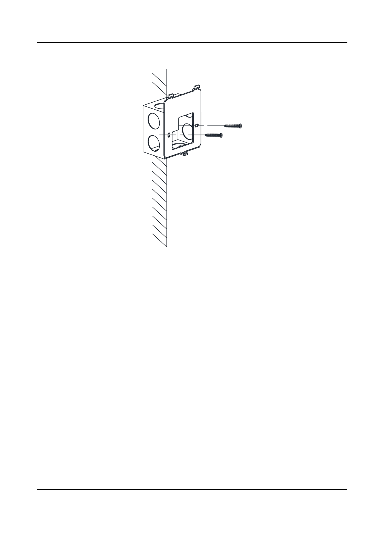
Figure 3-2 Install Mounng Plate
3.
Route the cables through the cable hole of the mounng plate and connect the cables with the
connecter on the rear panel of the device.
4.
Align the terminal with mounng plate.
5.
Buckle the terminal on the plate.
Access Control Terminal User Manual
8
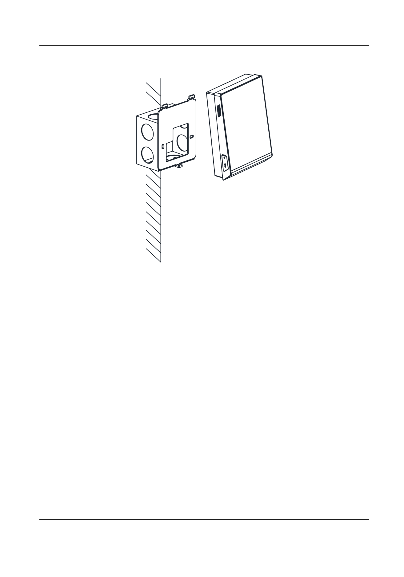
Figure 3-3 Buckle Terminal on Plate
6.
Tighten the screw to x the terminal on the mounng plate and complete the installaon.
Access Control Terminal User Manual
9
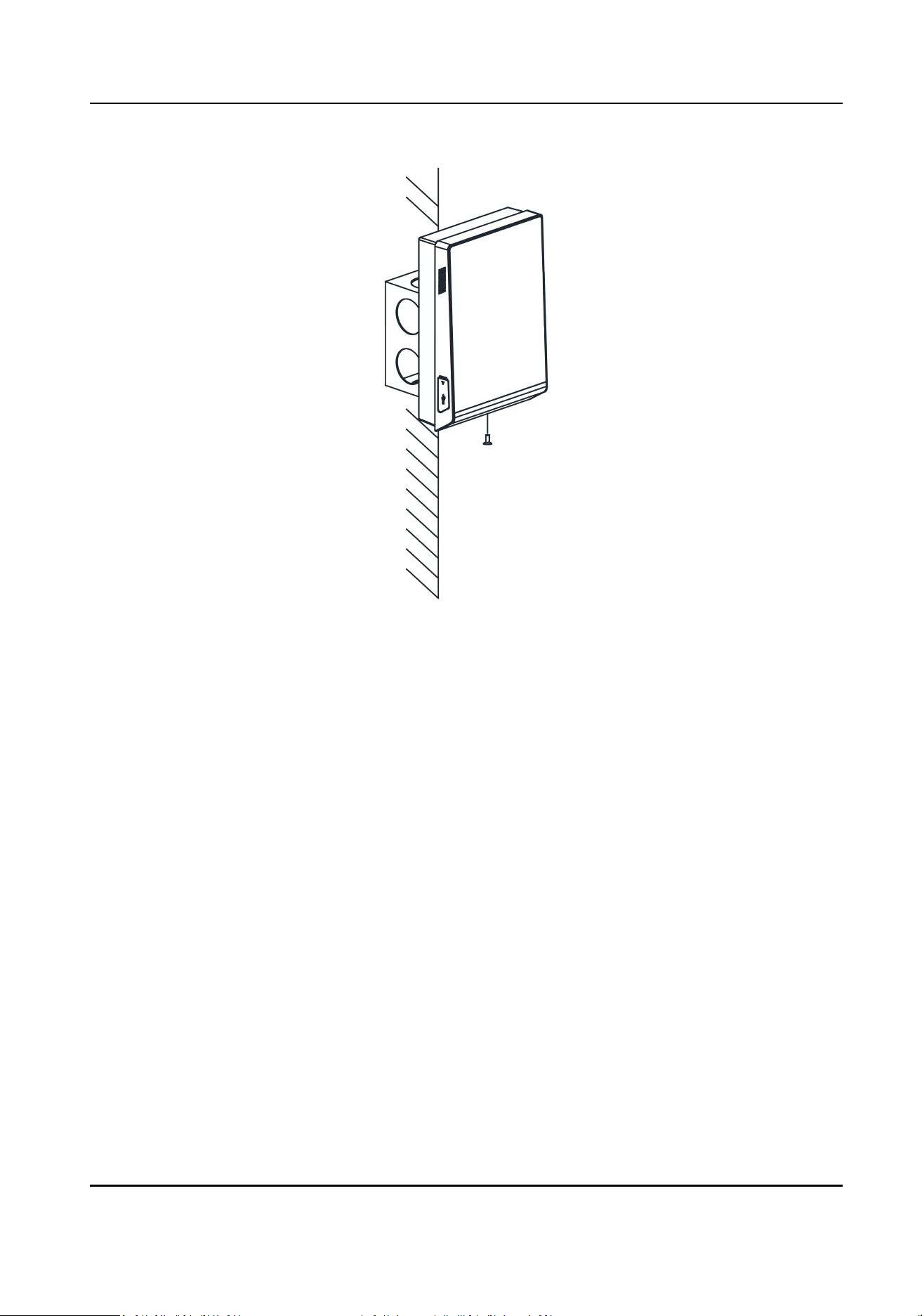
Figure 3-4 Tighten Screw
3.2 Install Access Control Terminal (With Fingerprint Module)
Before You Start
Make sure that the wall is strong enough to withstand three mes the weight of the device.
Steps
1.
Install the 86 gang box into the wall.
Access Control Terminal User Manual
10

Figure 3-5 Install 86 Gang box
2.
Secure the device mounng plate on the gang box with 2 screws (supplied).
Access Control Terminal User Manual
11
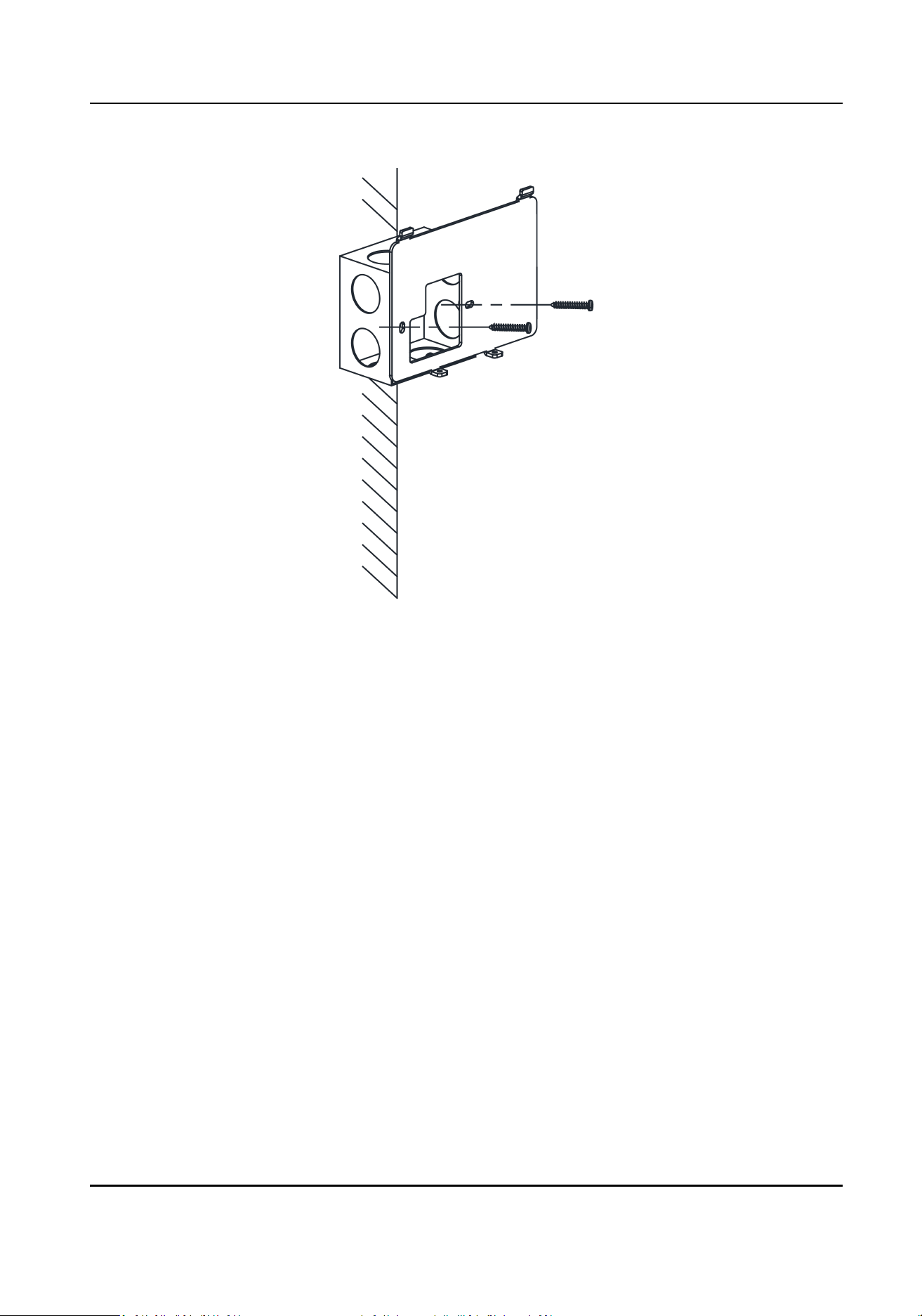
Figure 3-6 Install Mounng Plate
3.
Route the cables through the cable hole of the mounng plate and connect the cables with the
connecter on the rear panel of the device.
4.
Align the terminal with mounng plate.
5.
Buckle the terminal on the plate.
Access Control Terminal User Manual
12
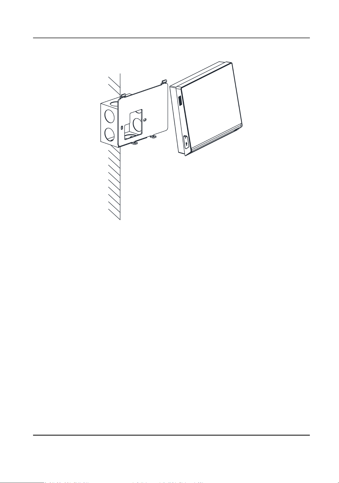
Figure 3-7 Buckle Terminal on Plate
6.
Tighten the screws to x the terminal on the mounng plate and complete the installaon.
Access Control Terminal User Manual
13
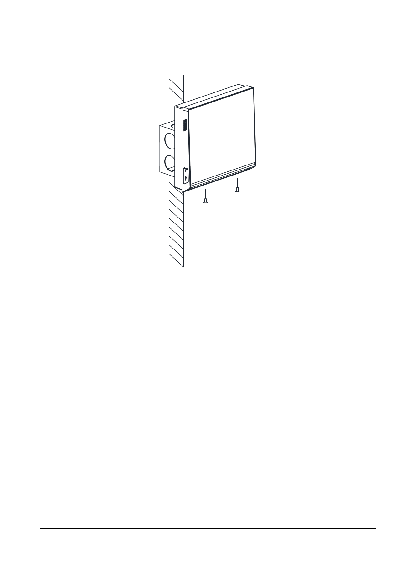
Figure 3-8 Tighten Screws
Access Control Terminal User Manual
14

Chapter 4 Wiring
The device supports connecng to the RS-485 terminal, the door lock, the exit buon, the alarm
output/input devices, the Wiegand card reader, the access controller, and the power supply. You
can wire the peripherals according to the descripons below.
If connect the Wiegand card reader with the access controller, the face recognion terminal can
transmit the authencaon informaon to the access controller and the access controller can
judge whether to open the door or not.
Note
●
If the cable size is 18 AWG, you should use a 12 V switched-mode power supply. And the
distance between the power supply and the device should be no more than 20 m.
●
If the cable size is 15 AWG, you should use a 12 V switched-mode power supply. And the
distance between the power supply and the device should be no more than 30 m.
●
If the cable size is 12 AWG, you should use a 12 V switched-mode power supply. And the
distance between the power supply and the device should be no more than 40 m.
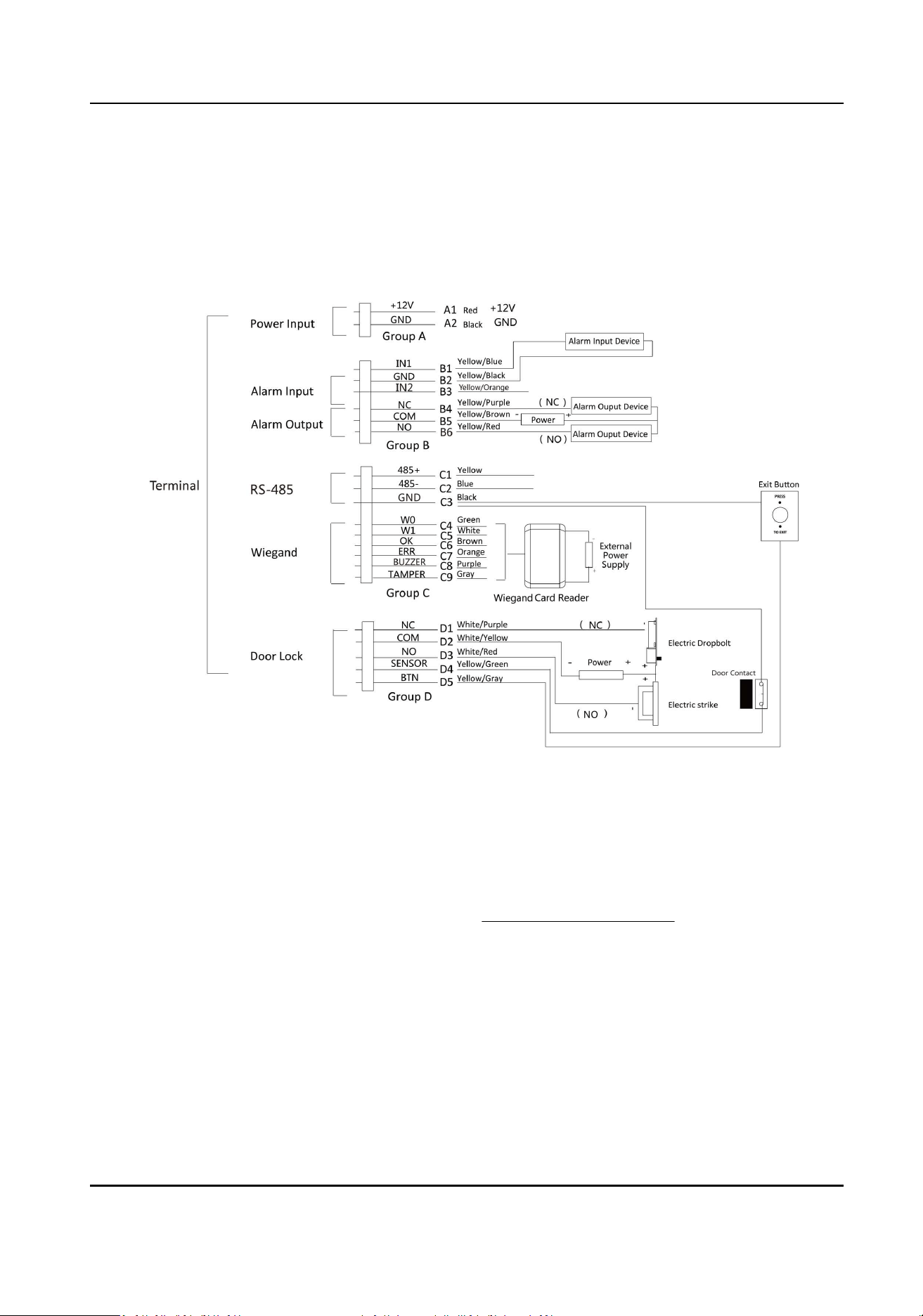
4.1 Terminal Descripon
You can view the terminal names of the access control terminal and their detailed informaon,
including the terminal funcon, cable color, terminal name, etc.
The terminals diagram is as follows:
Access Control Terminal User Manual
15
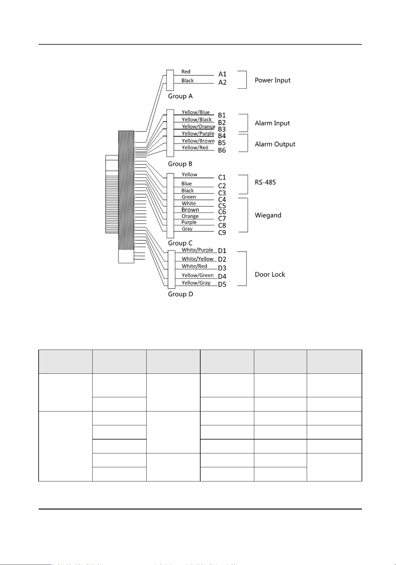
Figure 4-1 Terminal Diagram
The descripon of each terminal are as follows:
Table 4-1 Terminal Descripons
Line Group No. Funcon Color Terminal
Name
Descripon
Line Group A A1 Power Input Red +12V 12 V DC Power
Supply
A2 Black GND GND
Line Group B1 Alarm Input Yellow/Blue IN1 Alarm Input 1
B2 Yellow/Black GND GND
B3 Yellow/Orange IN2 Alarm Input2
B4 Alarm Output Yellow/Purple NC Alarm Output
Wiring
B5 Yellow/Brown COM
Access Control Terminal User Manual
16

Line Group No. Funcon Color Terminal
Name
Descripon
B6 Yellow/Red NO
Line Group C C1 RS-485
Communicao
n Port
Yellow 485 + RS-485 Wiring
C2 Blue 485 -
C3 Black GND
C4 Wiegand Green W0 Wiegand
Wiring 0
C5 White W1 Wiegand
Wiring 1
C6 Brown WG_OK Indicator of
Card Reader
Control Output
(Valid Card
Output)
C7 Orange WG_ERR Indicator of
Card Reader
Control Output
(Invalid Card
Output)
C8 Purple BUZZER Buzzer Wiring
C9 Grey TAMPER Tampering
Alarm Wiring
Line Group D D1 Lock White/Purple NC Lock Wiring
D2 White/Yellow COM
D3 White/Red NO
D4 Yellow/Green SENSOR Door Contact
Signal Input
D5 Yellow/Grey BUTTON Exit Door
Wiring
Access Control Terminal User Manual
17
4.2 Access Control Terminal Wiring
You can wire the external devices, including power supply, the alarm input devices, the alarm
output devices, the security control panel, the Wiegand card, the door lock, the door contact, and
the exit buon, with the access control terminal according to the following diagram.
Figure 4-2 Wiring Overview
●
When connecng door contact and exit buon, the device and the RS-485 card reader should
use the common ground connecon.
●
You should set the face recognion terminal's Wiegand direcon as Input to connect to a
Wiegand card reader. If connects to an access controller, you should set the Wiegand direcon as
Output to transmit authencaon informaon to the access controller.
●
For details about Wiegand direcon sengs, see Set Wiegand Parameters .
●
The suggested external power supply for door lock is 12 V, 1 A. The suggested external power
supply for the Wiegand card reader is 12 V, 1 A.
●
Do not wire the device to the electric supply directly.
4.3 RS-485 Card Reader Wiring
You can connect the access control terminal with the external RS-485 card reader by wiring the
RS-485 cables and the external power supply cables with the RS-485 card reader.
Access Control Terminal User Manual
18
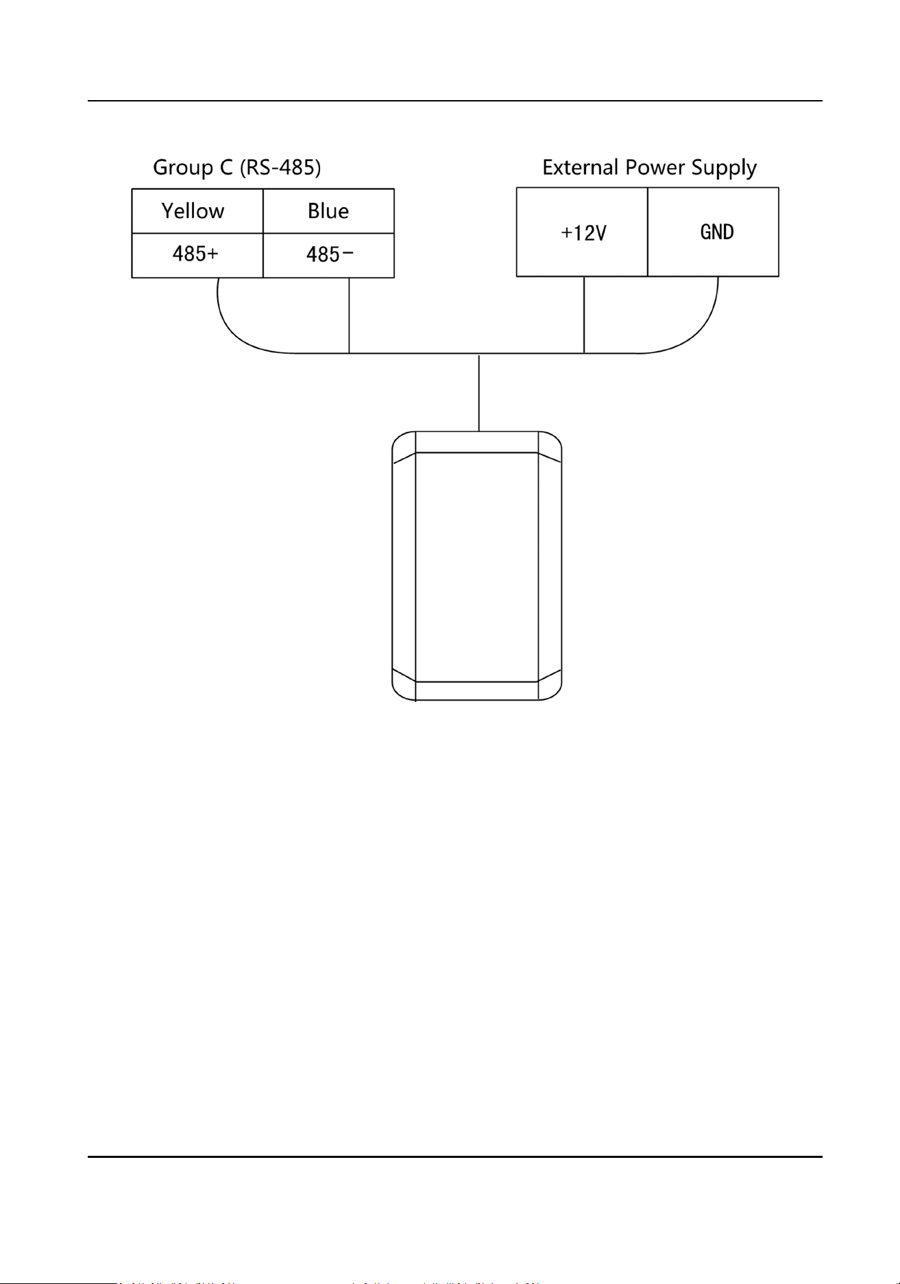
Figure 4-3 Wiring of External RS-485 Card Reader
4.4 Wiegand Card Reader Wiring
You can connect the access control terminal with the external Wiegand card reader by wiring the
Wiegand cables and the external power supply cables with the Wiegand card reader.
Access Control Terminal User Manual
19
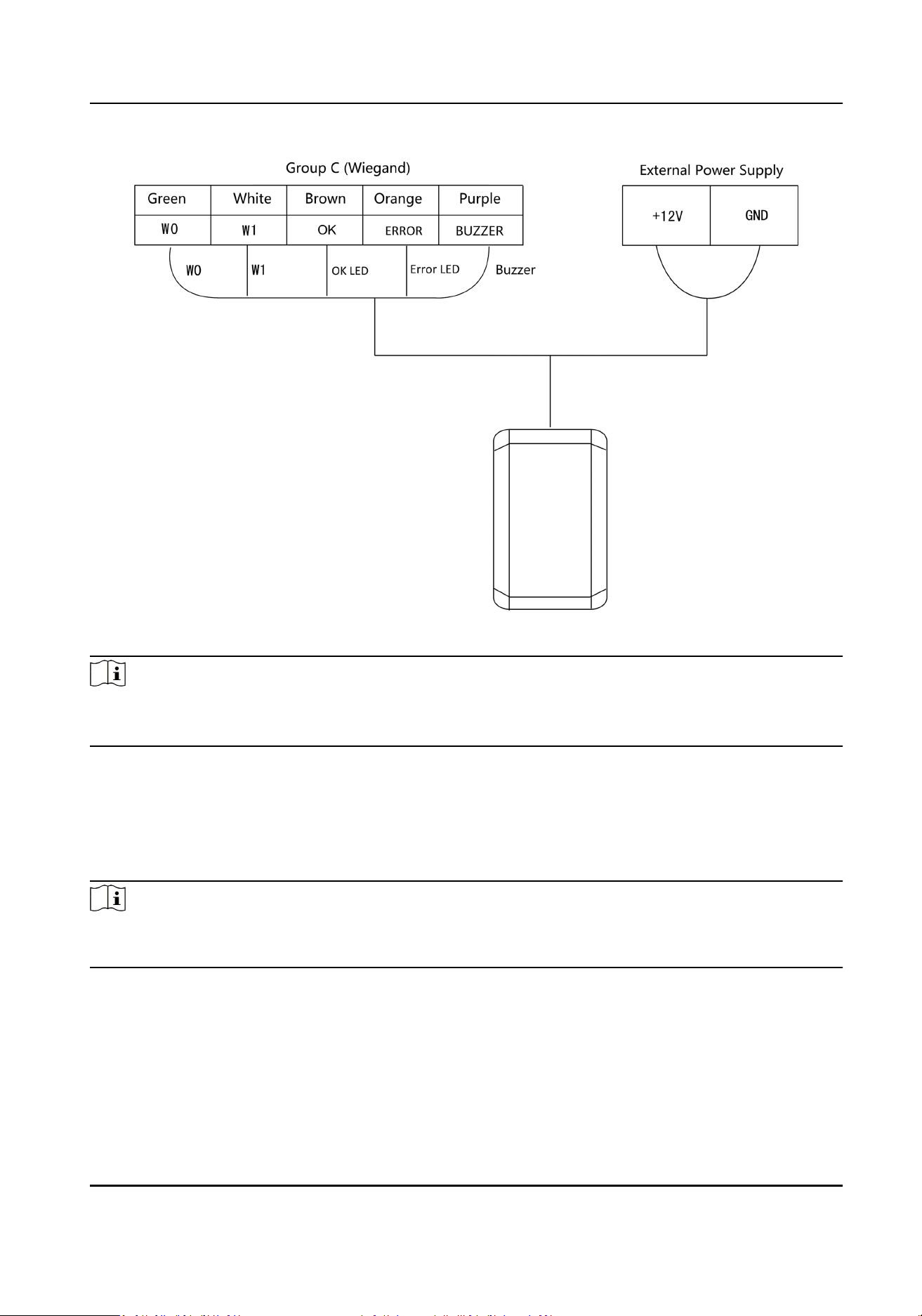
Figure 4-4 Wiring of Wiegand Card Reader
Note
●
Set the dial-up of the external card reader as 2 when connected to the access control terminal.
●
The external power supply and the access control terminal should use the same GND cable.
4.5 Device Wiring as RS-485 Card Reader
The access control terminal can be switched into the card reader mode. It can access to the access
control as a RS-485 card reader.
Note
When the access control terminal works as a card reader, it only supports being connected to the
controller, but does not support alarm input or output, or the connecon of external devices.
The wiring diagram is as follows:
Access Control Terminal User Manual
20
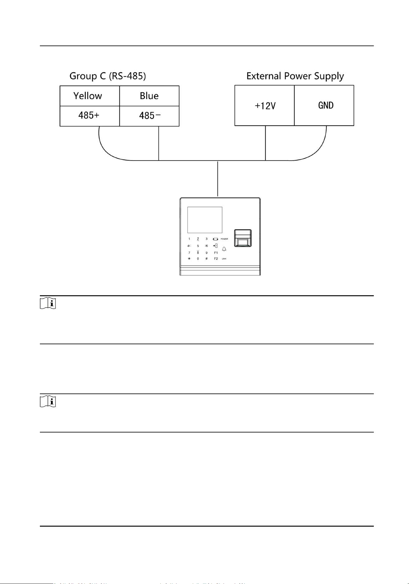
Figure 4-5 Wiring of RS-485 Output
Note
●
●
When the access control terminal works as a RS-485 card reader, the default RS-485 address is 1.
●
The external power supply and the access control terminal should use the same GND cable.
4.6 Device Wiring as Wiegand Card Reader
The access control terminal can access to the access control as a Wiegand card reader.
Note
When the access control terminal works as a card reader, it only supports being connected to the
controller, but does not support alarm input or output, or the connecon of external devices.
The wiring diagram is as follows:
Access Control Terminal User Manual
21
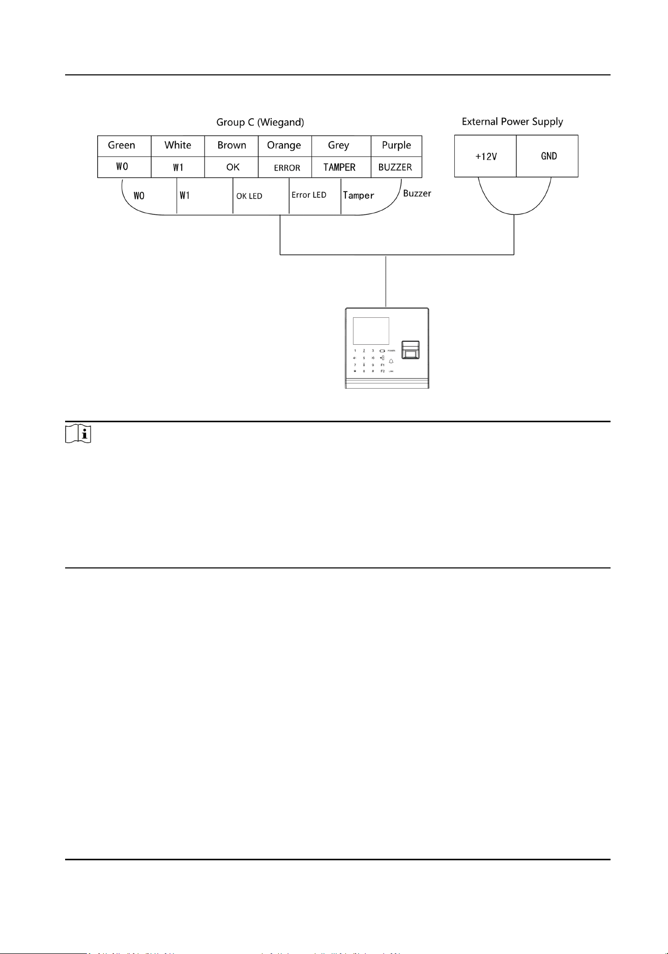
Figure 4-6 Wiring as Wiegand Card Reader
Note
●
When the access control terminal works as a card reader, you must connect the WG_ERR,
BUZZER and WG_OK terminals if you want to control the LED and buzzer of the Wiegand card
reader.
●
Set the working mode of the terminal as card reader. If the terminal is required to work as a card
reader. The card reader mode support to communicate by Wiegand or RS-485.
●
The distance of Wiegand communicaon should be no longer than 80 m.
●
The external power supply and the access control terminal should use the same GND cable.
Access Control Terminal User Manual
22
Chapter 5 Acvaon
You should acvate the device before the rst login. Aer powering on the device, the system will
switch to Device Acvaon page.
Acvaon via the device, SADP tool and the client soware are supported.
The default values of the device are as follows:
●
The default IP address: 192.0.0.64
●
The default port No.: 8000
●
The default user name: admin
5.1 Acvate via Device
If the device is not acvated before rst login, the system will enter the Device Acvaon interface
aer powering on.
Steps
1.
Create a device password for acvaon.
2.
Conrm the password.
Note
Press the up or down key on the keypad to change the input method.
3.
Press OK to acvate the device.
Note
We highly recommend you to create a strong password of your own choosing (using a minimum
of 8 characters, including at least three kinds of following categories: upper case leers, lower
case leers, numbers, and special characters) in order to increase the security of your product.
And we recommend you change your password regularly, especially in the high security system,
changing the password monthly or weekly can beer protect your product.
What to do next
Aer the device acvaon, you will enter the administrator adding page. Add an administrator
before other operaons.
5.2 Acvate via SADP
SADP is a tool to detect, acvate and modify the IP address of the device over the LAN.
Access Control Terminal User Manual
23
Before You Start
●
Get the SADP soware from the supplied disk or the ocial website hp://
www.hikvision.com/en/ , and install the SADP according to the prompts.
●
The device and the PC that runs the SADP tool should be within the same subnet.
The following steps show how to acvate a device and modify its IP address. For batch acvaon
and IP addresses modicaon, refer to User Manual of SADP for details.
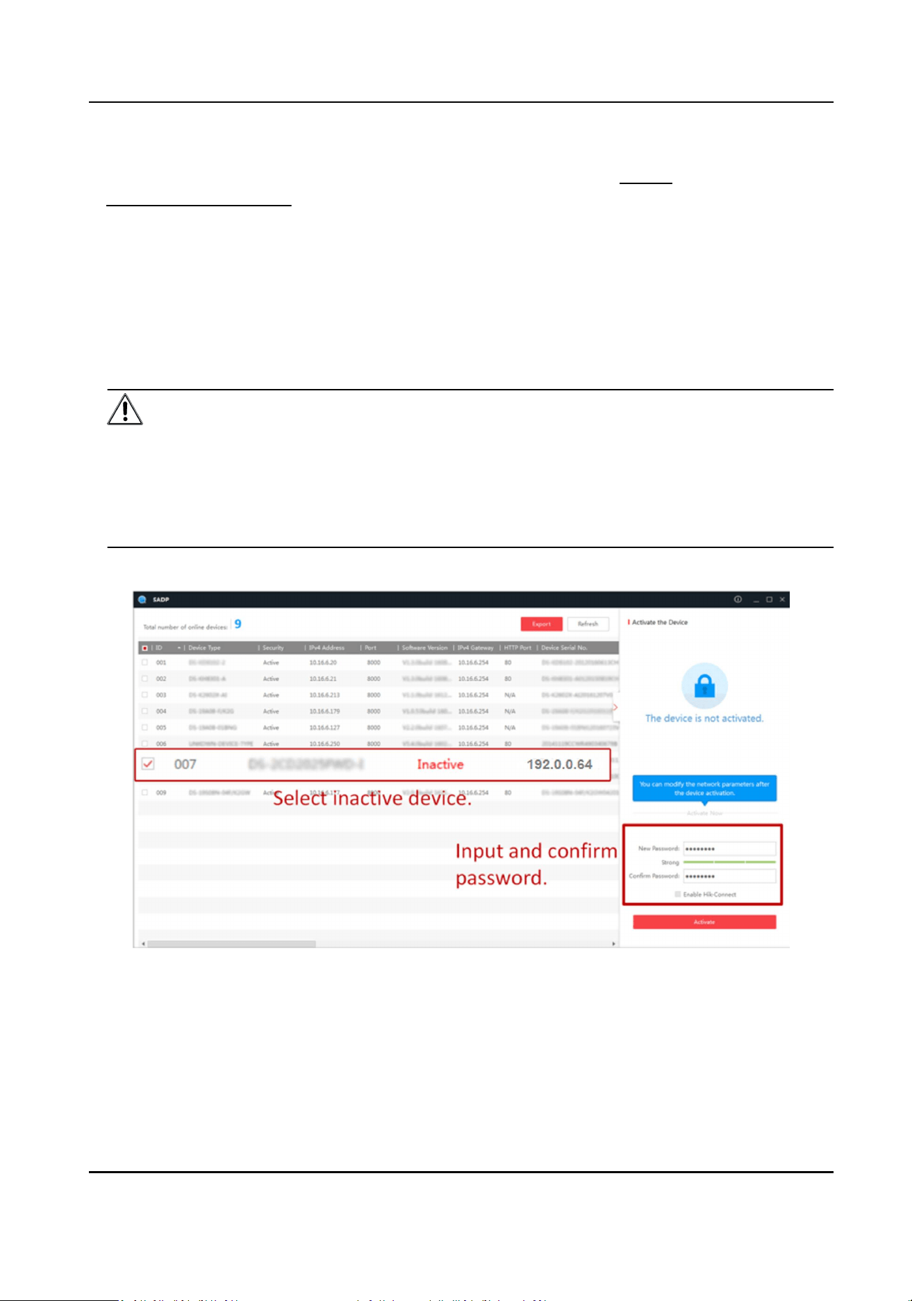
Steps
1.
Run the SADP soware and search the online devices.
2.
Find and select your device in online device list.
3.
Input new password (admin password) and conrm the password.
Cauon
STRONG PASSWORD RECOMMENDED-We highly recommend you create a strong password of
your own choosing (using a minimum of 8 characters, including upper case leers, lower case
leers, numbers, and special characters) in order to increase the security of your product. And
we recommend you reset your password regularly, especially in the high security system,
reseng the password monthly or weekly can beer protect your product.
4.
Click Acvate to start acvaon.
Status of the device becomes Acve aer successful acvaon.
5.
Modify IP address of the device.
1) Select the device.
2) Change the device IP address to the same subnet as your computer by either modifying the IP
address manually or checking Enable DHCP.
3) Input the admin password and click Modify to acvate your IP address modicaon.
Access Control Terminal User Manual
24
5.3 Acvate Device via Client Soware
For some devices, you are required to create the password to acvate them before they can be
added to the soware and work properly.
Steps
Note
This funcon should be supported by the device.
1.
Enter the Device Management page.
2.
Click on the right of Device Management and select Device.
3.
Click Online Device to show the online device area.
The searched online devices are displayed in the list.
4.
Check the device status (shown on Security Level column) and select an inacve device.
5.
Click Acvate to open the Acvaon dialog.
6.
Create a password in the password eld, and conrm the password.
Cauon
The password strength of the device can be automacally checked. We highly recommend you
change the password of your own choosing (using a minimum of 8 characters, including at least
three kinds of following categories: upper case leers, lower case leers, numbers, and special
characters) in order to increase the security of your product. And we recommend you change
your password regularly, especially in the high security system, changing the password monthly
or weekly can beer protect your product.
Proper conguraon of all passwords and other security sengs is the responsibility of the
installer and/or end-user.
7.
Click OK to acvate the device.
Access Control Terminal User Manual
25
Chapter 6 Local Sengs
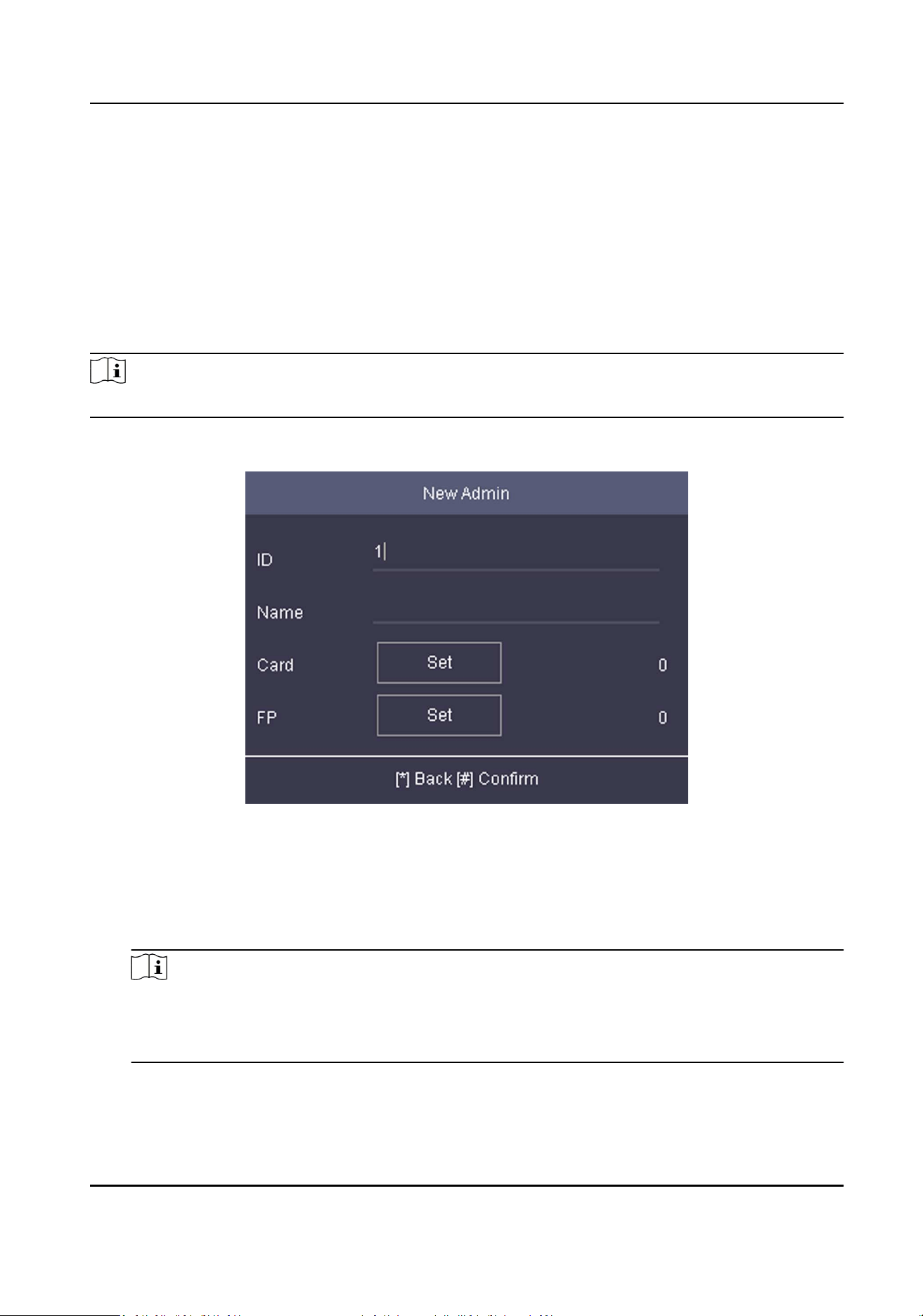
6.1 Add Administrator
Aer the device acvaon, you are required to add an administrator. You can set the
administrator's user name, the card No, and ngerprint.
Steps
Note
Parts of device models supports the ngerprint funcon.
1.
Enter the New Admin page.
Figure 6-1 Add Administrator
2.
Enter the administrator's parameters.
ID (Employee ID)
By default, the ID No. will be increased in sequence. You can edit the ID according to your
preference.
Note
●
The ID refers to the user aendance serial No.
●
The ID should be between 1 and 99999999 and should not start with 0.
●
The ID should be used for once.
Name
Access Control Terminal User Manual
26
Enter the new user name.
Note
●
Press the up or down key on the keypad to change the input method.
●
Up to 64 characters are allowed in the user name.
Card
Set: Present card on the card presenng area or enter card No. manually, and select a card
property.
View Info.: View the user's added card informaon.
Note
●
The card No. is required.
●
Up to 20 digits can be contained in the card No.
●
The card No. can be 0.
●
The card No. can start with 0 when it contains more than one numbers. E.g. 012345.
●
The card No. should be used for once.
FP (Fingerprint)
On the Fingerprint page, select a target nger and record according to the voice prompt.
Note
●
The same ngerprint cannot be repeatedly added.
●
Up to 10 ngerprints can be added to one user.
●
You can also scan the ngerprints via the external ngerprint recorder and apply the
ngerprints to the device by the client soware.
●
For detailed informaon about scanning the ngerprint, see Tips for Scanning Fingerprint .
●
Parts of device models supports the ngerprint funcon.
3.
Press # to save the sengs and exit the page.
6.2 Login
Log in the device as an administrator to mange the device parameters, including the
communicaon, the user, the access control parameters, the me, the report, the system, etc.
Hold * for 3 s to enter the login page. Select FP, DEV PWD (Device Password), or Card, and
authencate to enter the home page.
Note
●
Press F1 on the keypad to change the input method.
●
The login page varies depending on dierent device model. When operaon, refer to the actual
device page.
Access Control Terminal User Manual
27
6.3 Communicaon Sengs
Set device wired network, RS-485, Wiegand, Wi-Fi, EHome parameters.
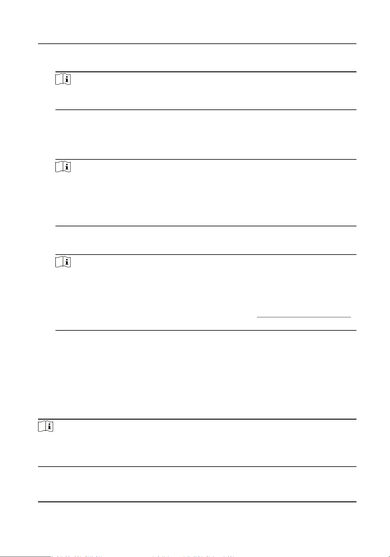
6.3.1 Set Wired Network
You can set the device network parameters, including the IP address, the subnet mask, the gateway
address, and the DHCP.
Steps
1.
Move the cursor and select Comm. → Wired .
2.
Press * to enter the Wired Network page.
Figure 6-2 Wired Network Sengs
3.
Edit the IP address, the subnet mask, and the gateway.
Note
The device's IP address and the PC's should be in the same network segment.
4.
Oponal: Enable DHCP.
The system will automacally assign IP address for the device.
5.
Press * to save the sengs and exit the page.
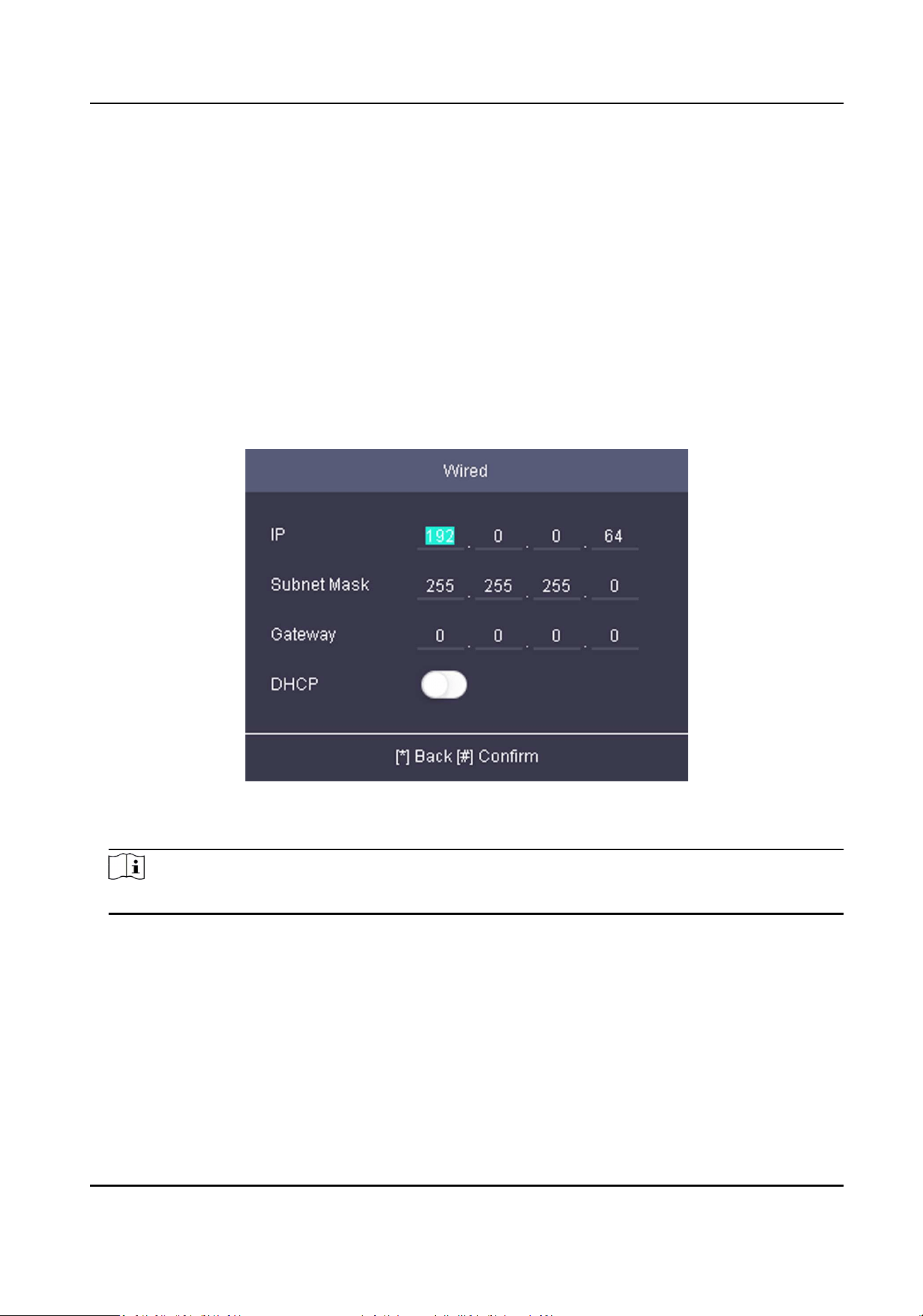
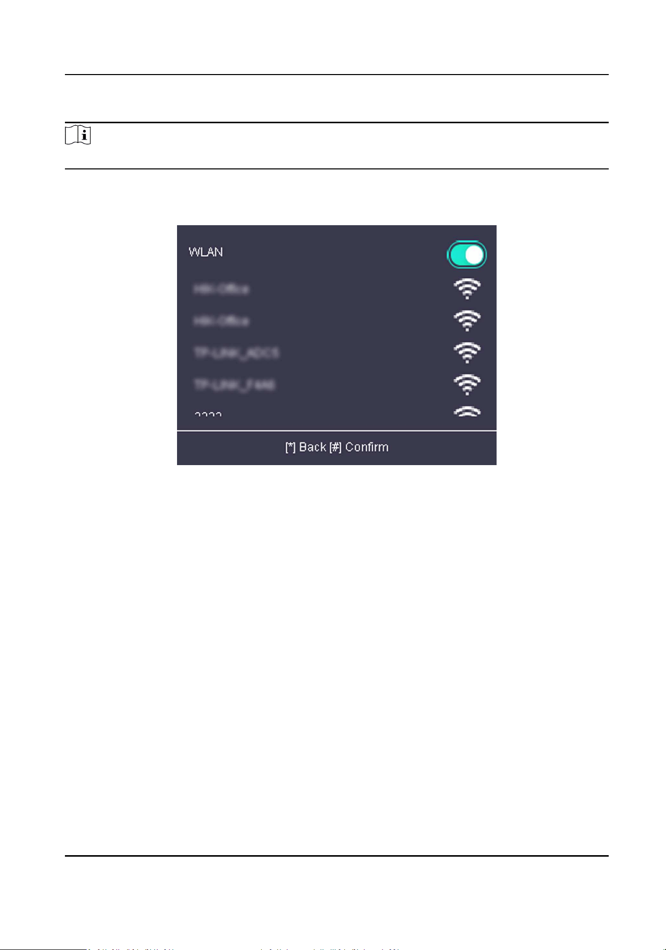
6.3.2 Set Wi-Fi Parameters
You can enable the Wi-Fi funcon and you can transmit the data via Wi-Fi.
Access Control Terminal User Manual
28
Steps
Note
The funcon is supported by parts of the device models.
1.
Move the cursor and select Comm. → Wi-Fi .
2.
Press * to enter the Wi-Fi page.
Figure 6-3 Wi-Fi Page
3.
Enable the WLAN funcon.
4.
Select a Wi-Fi from the list and set the Wi-Fi parameters, including the Wi-Fi password and
DHCP.
-
Enable DHCP, and the system will automacally assign IP address for the Wi-Fi.
-
Disable DHCP, and you should set the IP address, subnet mask, and gateway.
5.
Press * to save the sengs and exit the page.
6.3.3 Set EHome Parameters
Set EHome parameters and the device can upload data via EHome protocol.
Before You Start
Make sure your device has connect to a network.
Steps
1.
Move the cursor and select Comm. → EHome .
Access Control Terminal User Manual
29
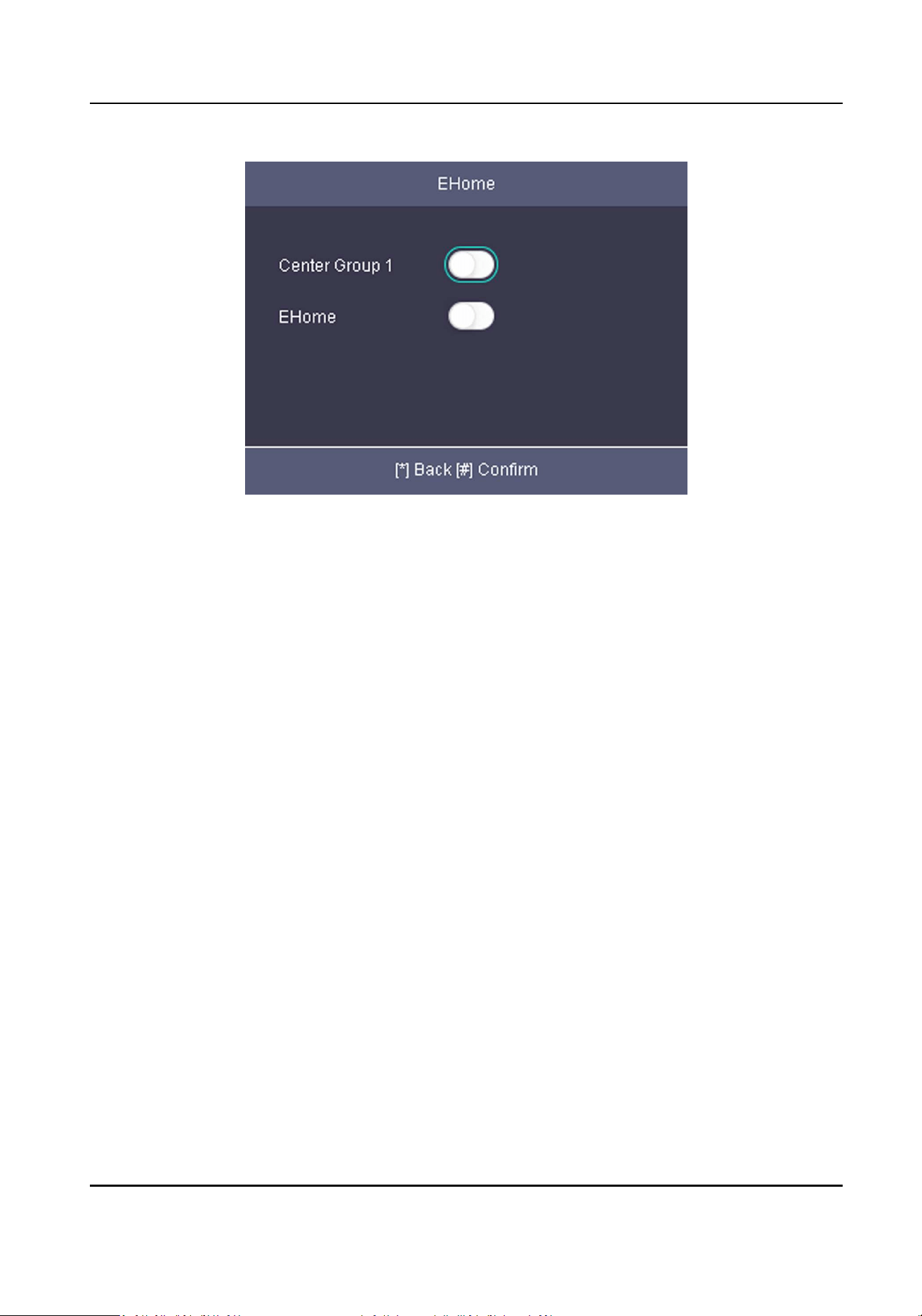
Figure 6-4 EHome Sengs
2.
Enable the EHome funcon and set the EHome server parameters.
Center Group 1
Enable center group 1 and the data will be uploaded to the center group.
EHome
Enable EHome funcon and the data will be uploaded via EHome protocol.
Address Type
Select an address type according to your actual needs. If you select domain name, you should
congure the domain name.
IP Address
Set the EHome server's IP address.
Port No.
Set the EHome server's port No.
Domain Name
Set the domain name of EHome server.
EHome Version
Set the EHome version according to your actual needs. If you choose V5.0, you should create
an account and EHome key. If you choose other version, you should create an EHome account
only.
Access Control Terminal User Manual
30
Note
●
Remember the EHome account and EHome key. You should enter the account name or the
key when the device should communicate with other plaorms via EHome protocol.
●
EHome key range: 8 to 32 characters.
3.
Press * and select Yes to save the sengs and exit the page.
6.3.4 Set Wiegand Parameters
You are able to set the Wiegand direcon (send/receive) and the Wiegand mode (Wiegand 26/
Wiegand 34).
Steps
1.
Move the cursor and select Comm. → Wiegand .
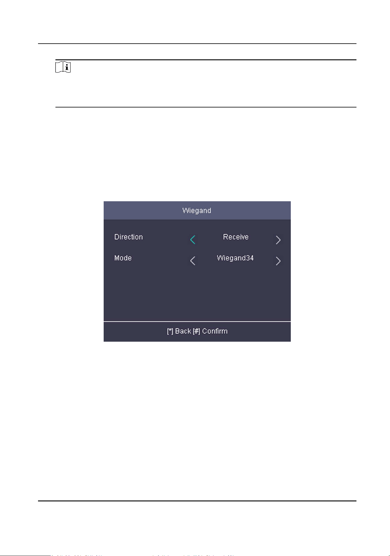
Figure 6-5 Wiegand Sengs
2.
Set the Wiegand parameters.
Direcon
Send
The device can connect to the access controller to upload the card No. bia the Wiegand 26
or the Wiegand 34 mode.
Receive
The terminal can connect to the Wiegand card readers. No need to congure the Wiegand
mode.
Mode
Wiegand 26 and Wiegand 34 can be selected. The default Wiegand mode is Wiegand 34.
Access Control Terminal User Manual
31
3.
Press * and select Yes to save the sengs and exit the page.
6.3.5 Set RS-485 Parameters
The face recognion terminal can connect card reader via the RS-485 terminal.
Steps
1.
Move the cursor and select Comm. → RS-485 on the Home page to enter the RS-485 page.
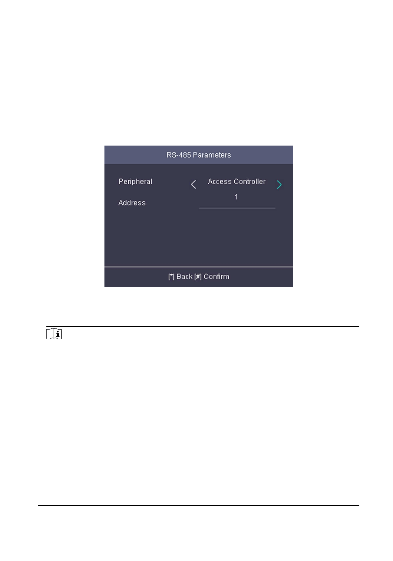
Figure 6-6 Set RS-485 Parameters
2.
Select an peripheral type according to your actual needs.
3.
Press * and select Yes to save the sengs and exit the page.
Note
The device will reboot automacally aer change the peripheral type.
6.4 Person Management
6.4.1 Add Person
You can add users by seng the ID No., the user name, and the card No. You can also record the
user ngerprint, set the password, the department, the role and the authencaon mode.
Steps
1.
Move the cursor and select User → New to enter the New page.
Access Control Terminal User Manual
32
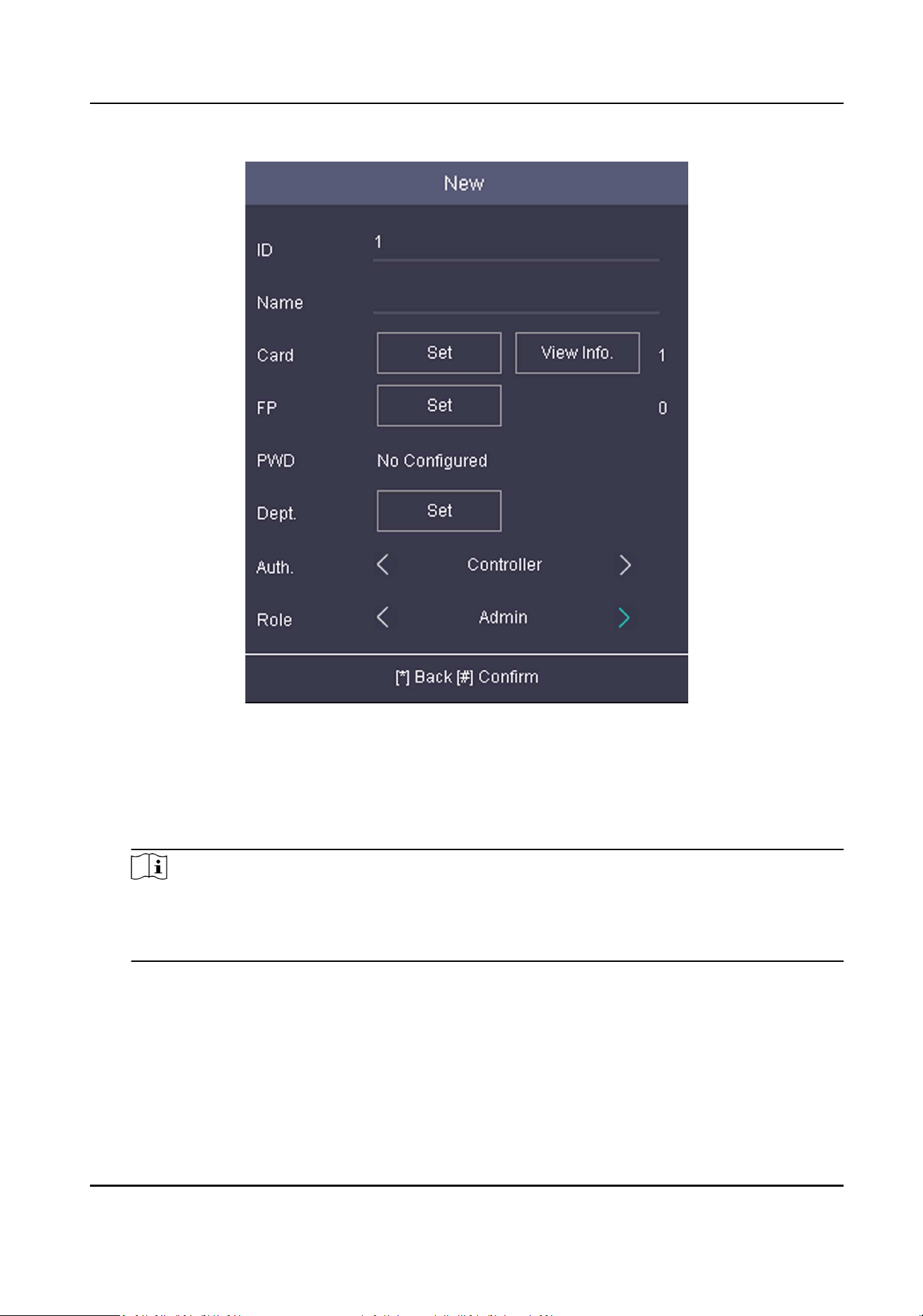
Figure 6-7 New Page
2.
Enter the new user's parameters.
ID (Employee ID)
By default, the ID No. will be increased in sequence. You can edit the ID according to your
preference.
Note
●
The ID refers to the user aendance serial No.
●
The ID should be between 1 and 99999999 and should not start with 0.
●
The ID should be unique.
Name
Enter the new user name.
Access Control Terminal User Manual
33

Note
●
Press the up or down key on the keypad to change the input method.
●
Up to 64 characters are allowed in the user name.
Card
Set: Present card on the card presenng area or enter card No. manually, and select a card
property.
View Info.: View the user's added card informaon.
Note
●
The card No. is required.
●
Up to 20 digits can be contained in the card No.
●
The card No. can be 0.
●
The card No. can start with 0 when it contains more than one numbers. E.g. 012345.
●
The card No. should be unique.
FP (Fingerprint)
On the Fingerprint page, select a target nger and record according to the voice prompt.
Note
●
The same ngerprint cannot be repeatedly added.
●
Up to 10 ngerprints can be added to one user.
●
You can also scan the ngerprints via the external ngerprint recorder and apply the
ngerprints to the device by the client soware.
●
For detailed informaon about scanning the ngerprint, see Tips for Scanning Fingerprint .
●
Parts of device models supports the ngerprint funcon.
Dept. (Department)
Select a department in the list and edit the department.
Note
For detailed informaon about eding the department, see Manage Department .
Auth.
Select an authencaon mode when verifying user's permission.
Note
●
If you select the authencaon mode as Controller, you should set the authencaon
mode in Set System Parameters . The system will authencate user's identy according to
Access Control Terminal User Manual
34

the congured authencaon mode. By default, the authencaon mode is Controller.
This mode is applicable to edit users' authencaon modes in batch.
●
If an user needs to use a special authencaon mode, which is dierent from the
authencaon mode congured in Set System Parameters , he can use card/ngerprint,
card, etc. The system will authencate the user's identy according to the congured
authencaon mode rst. This mode is applicable to edit single user's authencaon
mode, which has special permissions.
Role
Select the user's role as administrator or normal user.
●
Admin: The admin has all permissions to operate the device.
●
User: The normal user can check aendance on the inial page.
Note
●
All persons can enter the main page by entering the device password to operate if there is
no admin user congured.
●
Aer conguring the admin, you should authencate the admin to enter the main page.
●
You can use the USB interface to import the user informaon. For details, see Data
Transfer .
3.
Press * to save the sengs and exit the page.
6.4.2 Manage Person (Search/Edit/Delete)
Search, edit, delete the added users. You can also manage added ngerprints, manage user's cards.
Search User
Move the cursor and select User → User to enter the user list.
Enter the user's name or employee ID in the search box, and press * to start search.
Edit User
Move the cursor and select User → User to enter the user list. Select an user in the list and press *.
Select Edit User and refer to Add Person to edit the user's informaon.
Delete
You can delete user, delete password, clear all ngerprints, and clear all added cards' informaon .
6.5 Identy Authencaon
Aer network conguraon, system parameters conguraon and user conguraon, you can go
back to the inial page for identy authencaon. The system will authencate person according
to the congured authencaon mode.
Access Control Terminal User Manual
35

Authencaon via Mulple Credenals
If the congured authencaon mode is Card & Password, Card & Fingerprint, Card & Fingerprint
& Password, you should authencate the card rst, and then authencate other credenals
according to the prompt.
If the congured authencaon mode is Fingerprint & Password, you should authencate the
ngerprint rst, and then authencate other credenals according to the prompt.
Note
●
Parts of device models supports the ngerprint funcon.
●
For details about ngerprint authencaon, see Tips for Scanning Fingerprint .
Authencaon via Mulple Credenals
If the congured authencaon mode is Card/Password, Card/Fingerprint, Card/Fingerprint/
Password, ngerprint, card, you should authencate the credenal.
6.6 Set Access Control Parameters
Set the device's access control parameters, including the device authencaon, the sub reader
authencaon, the door contact status, the door locked me, the door-open meout alarm, and
the authencaon mes exceeded, and the super password.
On the Home page, move the cursor and select ACS (Access Control Sengs) to enter the Access
Control Sengs page. Edit the access control parameters on this page.
Access Control Terminal User Manual
36
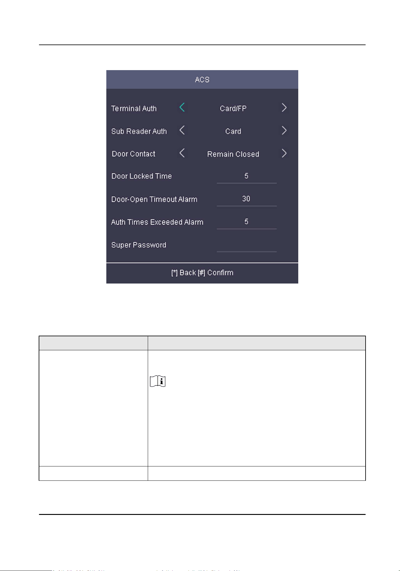
Figure 6-8 Access Control Parameters
The available parameters descripons are as follows:
Table 6-1 Access Control Parameters Descripons
Parameter Descripon
Terminal Auth Select the face recognion terminal's authencaon mode. You
can also customize the authencaon mode.
Note
●
Only the device with the ngerprint module supports the
ngerprint related funcon.
●
Biometric recognion products are not completely applicable
to an-spoong environments. If you require a higher
security level, use mulple authencaon modes.
●
If you adopt mulple authencaon modes, you should
authencate other methods before authencang face.
Sub Reader Auth Select the card reader's authencaon mode.
Access Control Terminal User Manual
37
Parameter Descripon
Door Contact You can select "Remain Open" or "Remain Closed" according to
your actual needs. By default, it is Remain Closed.
Door Locked Time Set the door unlocking duraon. If the door is not opened for
the set me, the door will be locked. Available door locked me
range: 1 to 255s.
Door-Open Timeout Alarm Congure the maximum me duraon for door opening. If the
door-open me has exceeded the congured value, it will trigger
an alarm.
Auth Times Exceeded Alarm Congure the maximum mes for authencaon.
Super Password Set the device super password. Aer saving the sengs, you can
input the super password in the inial interface to access the
door.
6.7 Basic Sengs
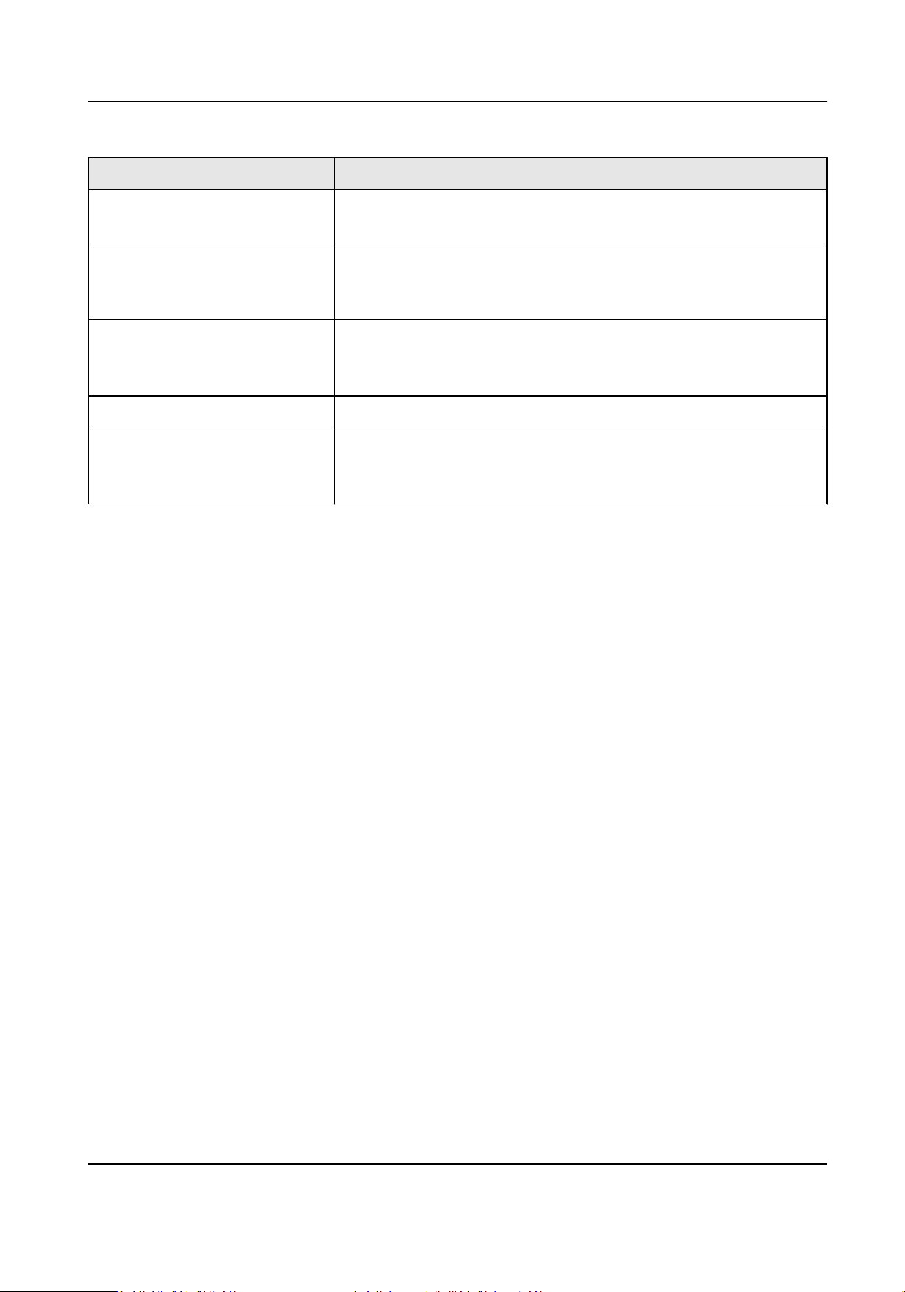
6.7.1 Set System Parameters
Set the system parameters, including the device me format, the keypad sound, the voice prompt,
the volume, and the sleeping mode.
Steps
1.
Move the cursor and select System → System .
2.
Press * to enter the System page.
Access Control Terminal User Manual
38
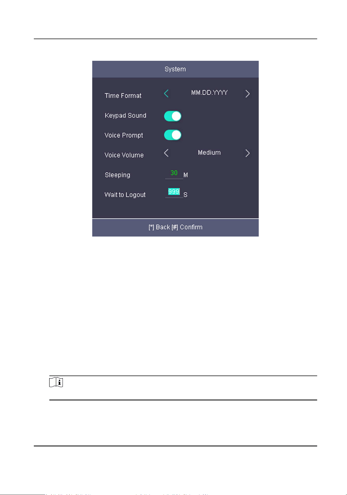
Figure 6-9 System Page
3.
Edit the parameters.
Time Format
Select an appropriate me format according to your preference.
Keypad Sound
Enable or disable the keypad sound according to your preference.
Voice Prompt
Enable or disable the voice prompt according to your preference.
Voice Volume
Set the device voice prompt volume.
Sleeping
Set the device sleeping waing me (minute). When you are on the inial page and if you set
the sleeping me to 30 min, the device will sleep aer 30 min without any operaon.
Note
If you set the sleeping me to 0, the device will not enter sleeping mode.
Wait to Logout
If there is no operaon within the congured me, the system will logout.
Access Control Terminal User Manual
39
6.7.2 Manage System Data
Delete the saved event, aendance data, user data, or permission.
Steps
1.
Move the cursor and select System → Data .
2.
Press * to enter the Data page.
Figure 6-10 Data Page
3.
Select an item and press OK to delete.
Delete Event Only
Delete all recorded events in the device.
Delete User Only
Delete all user data in the device, including the aendance records.
Clear Permission
Clear the admin management permission. The admin will turn to the normal user. The user
will not be deleted.
6.7.3 System Upgrade
You can upgrade the system online or locally. The system reads the upgrading le in the plugged
USB ash drive or gain the upgrading package from the plaorm to upgrade the device.
Steps
1.
Move the cursor and select System → Upgrade .
2.
Upgrade the system.
Access Control Terminal User Manual
40
-
Local Upgrade: Plug the USB ash drive to the USB interface. Press OK. The system will read
the digicap.dav le and upgrading automacally. Aer the upgrading is completed, the device
will reboot automacally.
Note
●
The upgrading le should be in the root directory.
●
The upgrading le name in the USB ash drive should be digicap.dav.
●
Do not power o during the device upgrading.
●
Aer the upgrading is completed, remove the USB ash drive.
-
Online upgrade: The system will gain the upgrade package from the plaorm to upgrade.
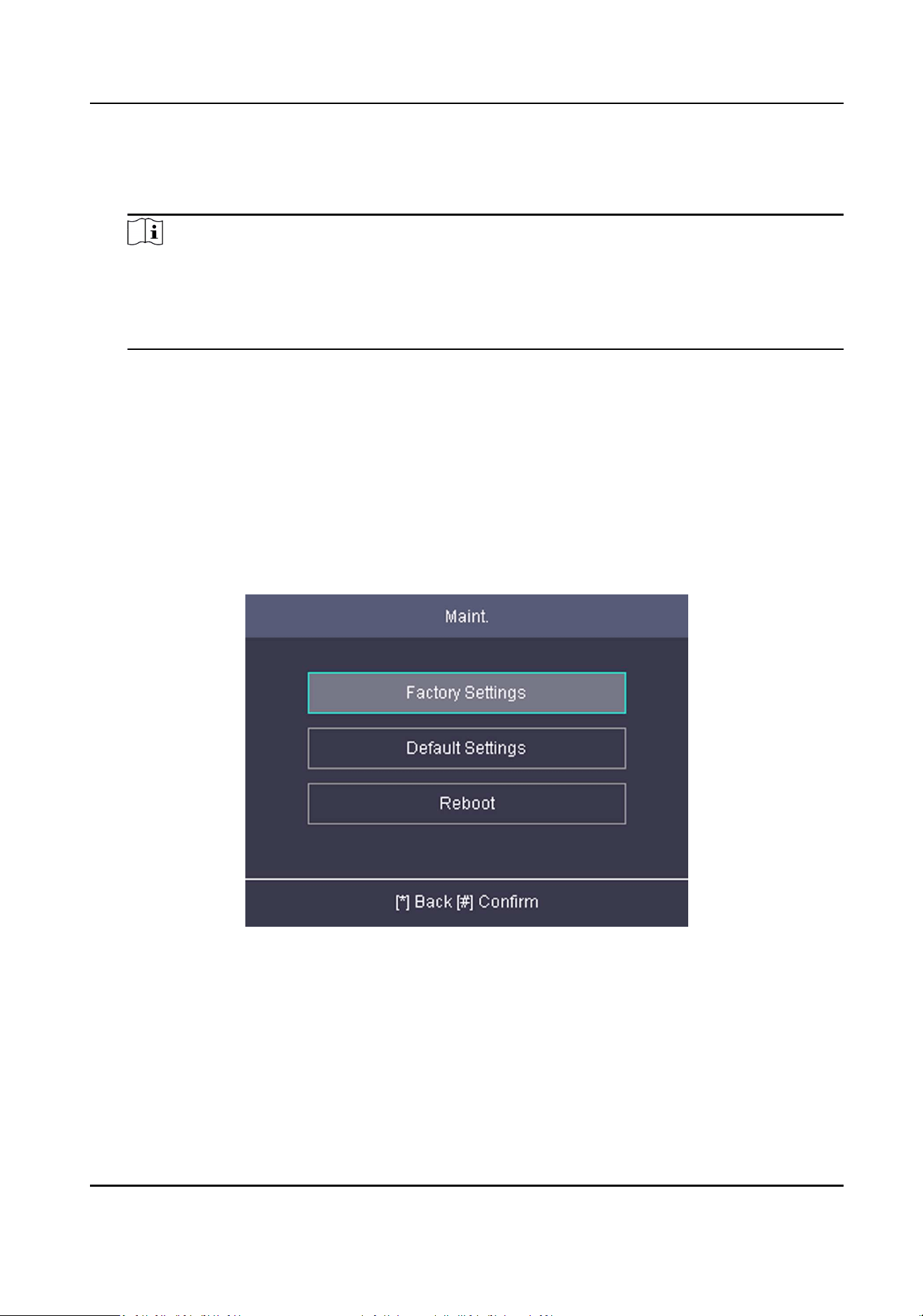
6.7.4 Restore/Reboot Sengs
Restore system parameters to factory sengs or default sengs. And you can also reboot the
device.
Steps
1.
Move the cursor and select System → Maint. .
2.
Press * to enter the Reset page.
Figure 6-11 Reset Page
3.
Select Factory Sengs or Default Sengs.
Factory Sengs
All parameters of the device will restore to the factory parameters.
Default Sengs
All parameters, excluding the communicaon parameters, the remote user management, and
events, will restore to the factory parameters.
Access Control Terminal User Manual
41
Reboot
Reboot the device.
4.
Press * to conrm the sengs in the prompt page and the device starts restoring.
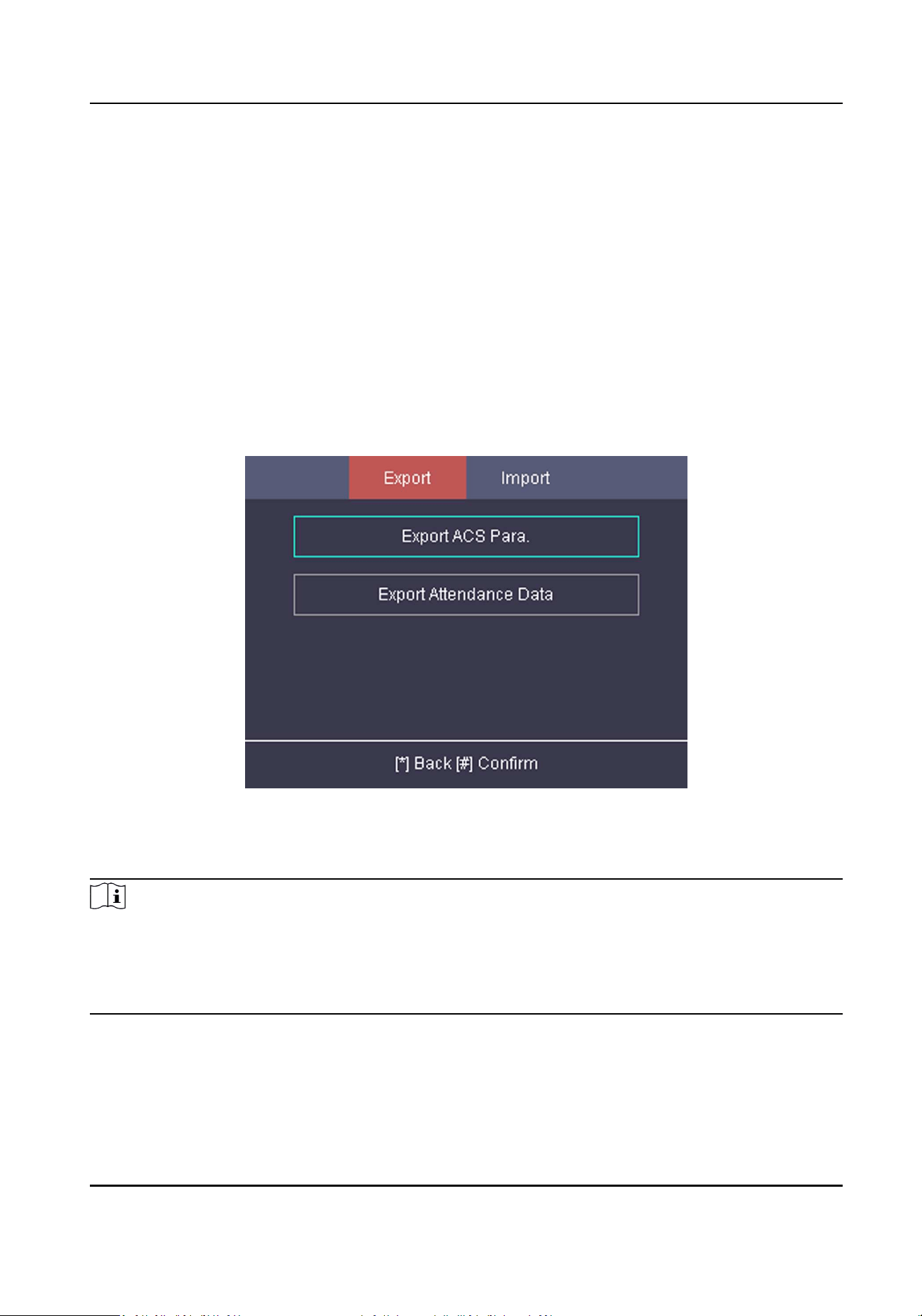
6.7.5 Data Transfer
You can export the access control parameters (ngerprint and user informaon) and the
aendance data (data aer aendance, card swiping data for instance). You can also import the
access control parameters from the USB ash drive.
Export Data
Move the cursor and select Transfer → Export to enter the Export page.
Figure 6-12 Export Data Page
Plug a USB ash drive in the device USB interface, and select Export ACS Para. or Export
Aendance Data, enter the key, and press *. The data will be exported to the USB ash drive.
Note
●
The supported USB ash drive format is FAT32.
●
The USB ash drive memory should be from 1G to 32G. Make sure the free space of the USB
ash drive should be more than 512 M.
●
Remember the key property, and you should use the key to import the data to another device.
Import Data
Move the cursor and select Transfer → Import to enter the Import page. Select Import ACS Para,
enter the key, and press *. The system will gain access control parameters from the USB ash drive.
Access Control Terminal User Manual
42
Note
●
The supported USB ash drive format is FAT32.
●
The le for imporng should be in the root directory.
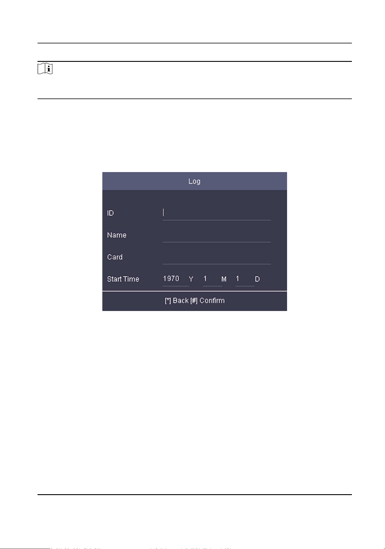
6.7.6 Log Query
You can search the authencaon logs via the user's employee ID, name, or card.
Steps
1.
On the Home page, move the cursor and select Log.
Figure 6-13 Log Query Page
2.
Enter the employee ID, the user name, the card No., the start me, and the end me.
3.
Press *to start searching.
The result will be displayed on the page.
6.7.7 Set Time
Set the device me and DST.
Steps
1.
Move the cursor and select Time in the main page and press OK to enter the Time page.
Access Control Terminal User Manual
43
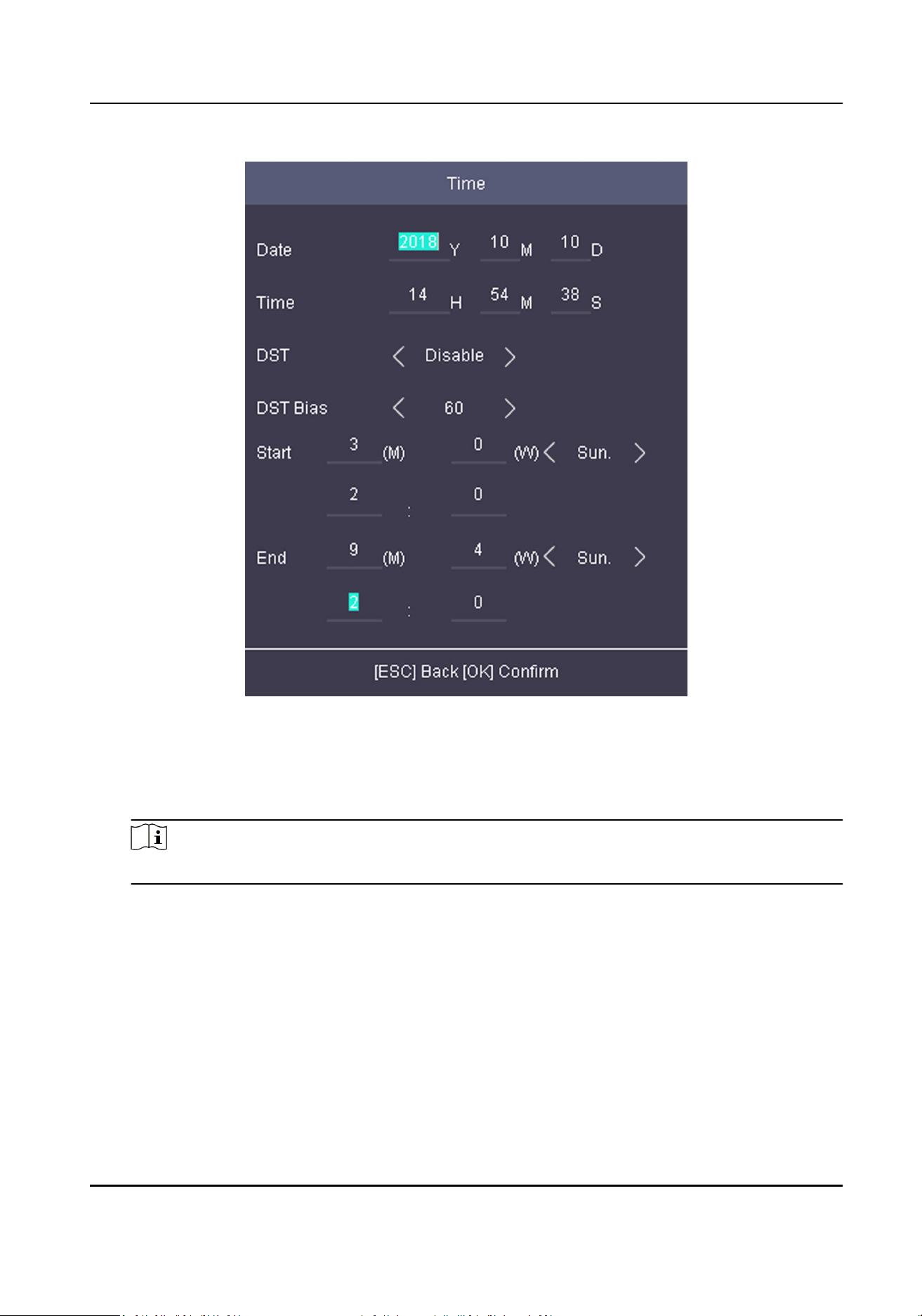
Figure 6-14 Time Page
2.
Edit the parameters.
Date
The displayed date on the device.
Note
The available range is from 1970.01.01 to 2037.12.31.
Time
The displayed me on the device.
DST
Select to enable or disable the DST. When the DST is enabled, you can set the DST bias me,
the start me and the end me.
●
DST Bias: You can select 30min, 60min, 90min and 120min.
●
Start: Set the start me of the DST.
●
End: Set the end me of the DST.
3.
Press ESC and select Yes to save the sengs and exit the page.
Access Control Terminal User Manual
44
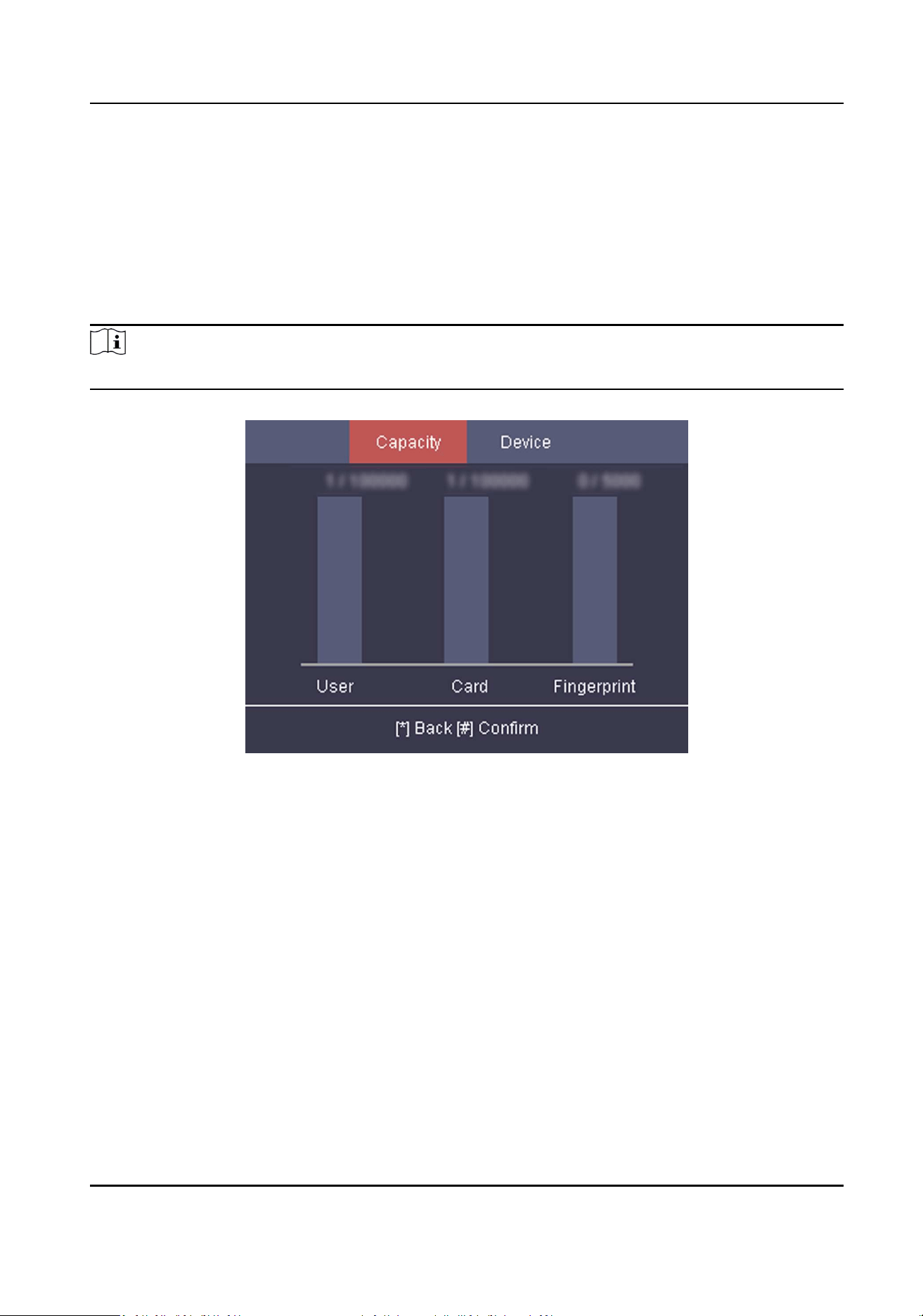
6.7.8 View System Informaon
View system informaon, including system capacity and device informaon.
View System Capacity
Move the cursor and select Info. → Capacity to enter the Capacity page.
You can view the added device user number, card number, and ngerprint number.
Note
Parts of device models supports display the ngerprint capacity.
Figure 6-15 Capacity Page
View Device Informaon
Move the cursor and select Info. → Device to enter the Device page.
Select Device Informaon or User Manual.
Device Informaon
You can view the device name, the serial No., the MAC address, the rmware, and the
producon date.
User Manual
Scan the QR code to view the device user manual.
Access Control Terminal User Manual
45
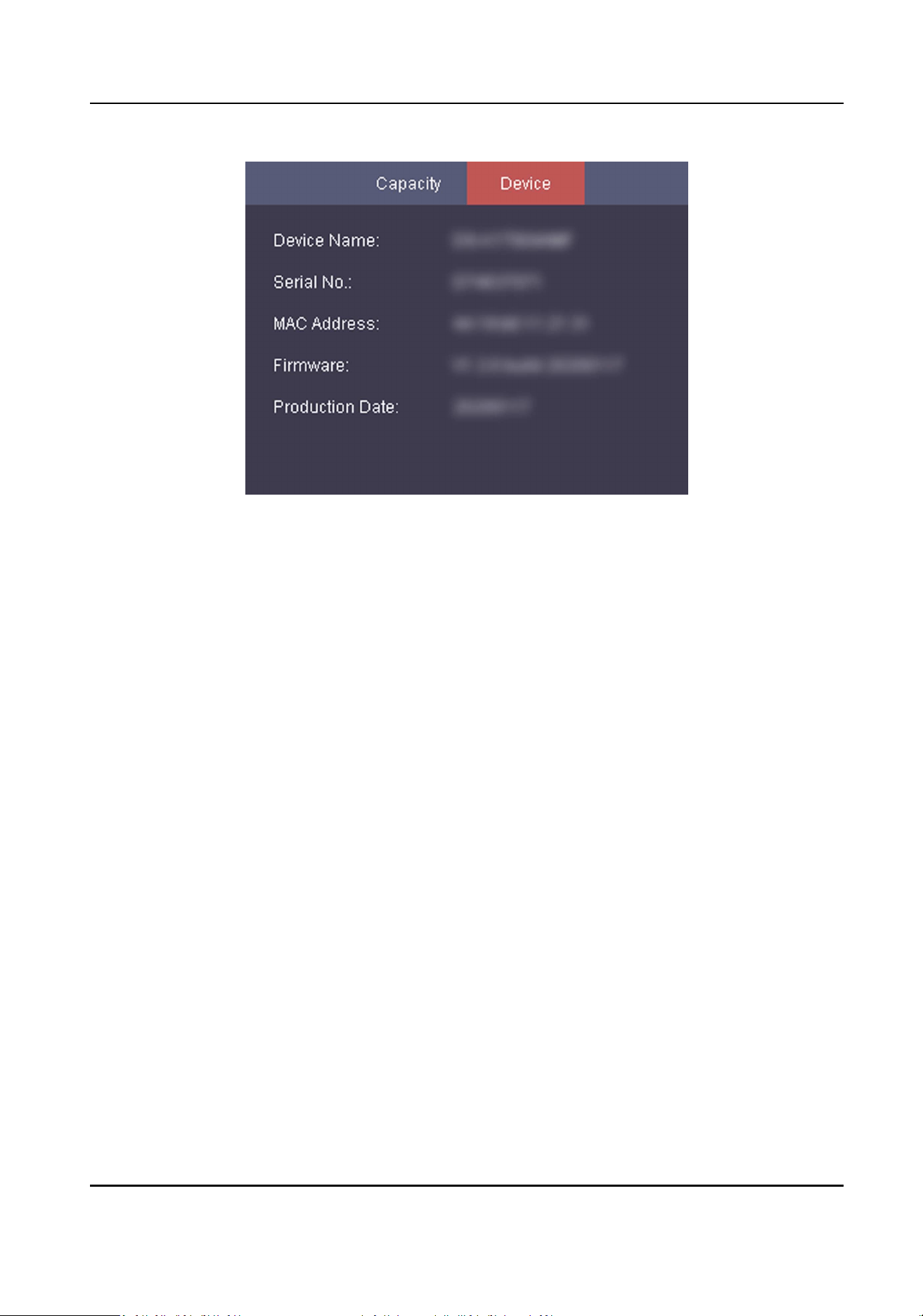
Figure 6-16 Device Page
Access Control Terminal User Manual
46
Chapter 7 Client Soware Conguraon
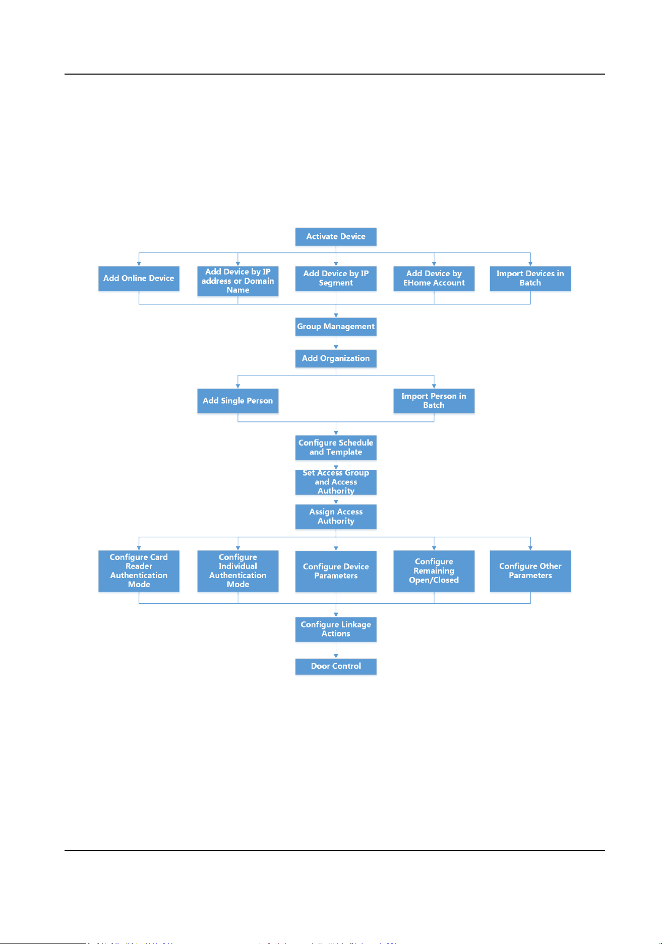
7.1 Conguraon Flow of Client Soware
Follow the ow diagram below to congure on the client soware.
Figure 7-1 Flow Diagram of Conguraon on Client Soware
7.2 Device Management
You can manage devices on the client, including adding, eding, and deleng the devices. You can
also perform operaons such as checking device status.
Access Control Terminal User Manual
47
7.2.1 Add Device
Aer running the client, devices including access control devices, video intercom devices, etc.,
should be added to the client for the remote conguraon and management, such as controlling
door status, aendance management, event sengs, etc.
Add Online Device
The acve online devices in the same local subnet with the client soware will be displayed on the
Online Device area.
Note
●
You can click Refresh per 60s to refresh the informaon of the online devices.
●
SADP log funcon can be enabled or disabled by right-clicking Online Device.
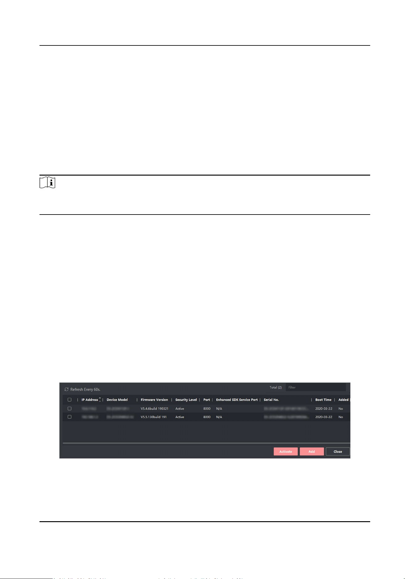
Add Single or Mulple Online Devices
The client can detect online devices which are in the same network as the PC running the client.
You can select a detected online device displayed in the online device list and add it to the client.
For detected online devices sharing the same user name and password, you can add them to the
client in a batch.
Before You Start
●
The device(s) to be added are in the same network as the PC running the client.
●
The device(s) to be added have been acvated.
Steps
1.
Click Device Management → Device 。
2.
Click Online Device to show the online device area.
The searched online devices are displayed in the list.
Figure 7-2 Online Device
3.
In the Online Device area, check one or more online device(s), and click Add to open the device
adding window.
Access Control Terminal User Manual
48
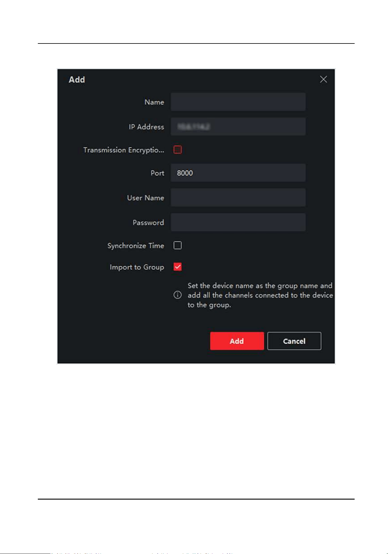
Figure 7-3 Add Single Online Device
Access Control Terminal User Manual
49
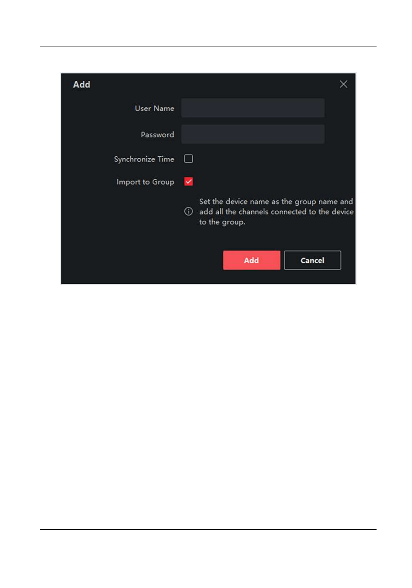
Figure 7-4 Add Mulple Online Devices
4.
Enter the required informaon.
Name
Enter a descripve name for the device.
IP Address
Enter the device's IP address. The IP address of the device is obtained automacally in this
adding mode.
Port
You can customize the port number. The port number of the device is obtained automacally
in this adding mode.
User Name
By default, the user name is admin.
Password
Enter the device password.
Access Control Terminal User Manual
50

Cauon
The password strength of the device can be automacally checked. We highly recommend
you change the password of your own choosing (using a minimum of 8 characters, including
at least three kinds of following categories: upper case leers, lower case leers, numbers,
and special characters) in order to increase the security of your product. And we recommend
you change your password regularly, especially in the high security system, changing the
password monthly or weekly can beer protect your product.
Proper conguraon of all passwords and other security sengs is the responsibility of the
installer and/or end-user.
5.
Check Synchronize Time to synchronize the device me with the PC running the client aer
adding the device to the client.
6.
Oponal: Check Import to Group to create a group by the device name, and import all the
channels of the device to this group.
Example
For access control device, its access points, alarm inputs/outputs, and encoding channels (if
exist) will be imported to this group.
7.
Click Add.
Add Mulple Detected Online Devices
For detected online devices sharing the same user name and password, you can add them to the
client in a batch.
Before You Start
Make sure the to-be-added devices are online.
Steps
1.
Enter the Device Management module.
2.
Click Device tab on the top of the right panel.
3.
Click Online Device to show the online device area at the boom of the page.
The searched online devices are displayed in the list.
4.
Select mulple devices.
Note
For the inacve device, you need to create the password for it before you can add the device
properly. For details, refer to .
5.
Click Add to open the device adding window.
6.
Enter the required informaon.
User Name
By default, the user name is admin.
Password
Access Control Terminal User Manual
51

Enter the device password.
Cauon
The password strength of the device can be automacally checked. We highly recommend
you change the password of your own choosing (using a minimum of 8 characters, including
at least three kinds of following categories: upper case leers, lower case leers, numbers,
and special characters) in order to increase the security of your product. And we recommend
you change your password regularly, especially in the high security system, changing the
password monthly or weekly can beer protect your product.
Proper conguraon of all passwords and other security sengs is the responsibility of the
installer and/or end-user.
7.
Oponal: Check Synchronize Time to synchronize the device me with the PC running the client
aer adding the device to the client.
8.
Oponal: Check Import to Group to create a group by the device name, and import all the
channels of the device to this group.
Example
For access control device, its access points, alarm inputs/outputs, and encoding channels (if
exist) will be imported to this group.
9.
Click Add to add the devices.
Add Device by IP Address or Domain Name
When you know the IP address or domain name of the device to add, you can add devices to the
client by specifying the IP address (or domain name), user name, password, and other related
parameters.
Steps
1.
Enter Device Management module.
2.
Oponal: Click on the right of Device Management and select Device.
The added devices are displayed in the list.
3.
Click Add to open the Add window.
4.
Select IP/Domain as the adding mode.
5.
Enter the required informaon, including name, address, port number, user name, and
password.
Name
Create a descripve name for the device. For example, you can use a name that can show the
locaon or feature of the device.
Address
The IP address or domain name of the device.
Port
Access Control Terminal User Manual
52
The devices to add have the same port No. The default value is 8000.
User Name
Enter the device user name. By default, the user name is admin.
Password
Enter the device password.
Cauon
The password strength of the device can be automacally checked. We highly recommend
you change the password of your own choosing (using a minimum of 8 characters, including
at least three kinds of following categories: upper case leers, lower case leers, numbers,
and special characters) in order to increase the security of your product. And we recommend
you change your password regularly, especially in the high security system, changing the
password monthly or weekly can beer protect your product.
Proper conguraon of all passwords and other security sengs is the responsibility of the
installer and/or end-user.
6.
Oponal: Check Synchronize Time to synchronize the device me with the PC running the client
aer adding the device to the client.
7.
Oponal: Check Import to Group to create a group by the device name.
Note
You can import all the channels of the device to the corresponding group by default.
8.
Finish adding the device.
-
Click Add to add the device and back to the device list page.
-
Click Add and New to save the sengs and connue to add other device.
9.
Perform the following operaons aer adding the devices.
Remote
Conguraon
Click
on Operaon column to set remote conguraon of the
corresponding device.
Note
●
For some models of devices, you can open its web window. To open the
original remote conguraon window, press Ctrl and click .
●
For detail operaon steps for the remote conguraon, see the user
manual of the device.
Device Status Click on Operaon column to view device status.
Add Devices by IP Segment
If you want to add devices of which the IP addresses are within an IP segment, you can specify the
start IP address and end IP address, user name, password, and other parameters to add them.
Access Control Terminal User Manual
53
Steps
1.
Enter the Device Management module.
2.
Oponal: Click on the right of Device Management and select Device.
The added devices are displayed in the list.
3.
Click Add to open the Add window.
4.
Select IP Segment as the adding mode.
5.
Enter the required informaon.
Start IP
Enter a start IP address.
End IP
Enter an end IP address in the same network segment with the start IP.
Port
Enter the device port No. The default value is 8000.
User Name
By default, the user name is admin.
Password
Enter the device password.
Cauon
The password strength of the device can be automacally checked. We highly recommend
you change the password of your own choosing (using a minimum of 8 characters, including
at least three kinds of following categories: upper case leers, lower case leers, numbers,
and special characters) in order to increase the security of your product. And we recommend
you change your password regularly, especially in the high security system, changing the
password monthly or weekly can beer protect your product.
Proper conguraon of all passwords and other security sengs is the responsibility of the
installer and/or end-user.
6.
Oponal: Check Synchronize Time to synchronize the device me with the PC running the client
aer adding the device to the client.
7.
Oponal: Check Import to Group to create a group by the device name.
Note
You can import all the channels of the device to the corresponding group by default.
8.
Finish adding the device.
-
Click Add to add the device and back to the device list page.
-
Click Add and New to save the sengs and connue to add other device.
9.
Oponal: Click
on Operaon column to view device status.
Access Control Terminal User Manual
54
Add Device by EHome Account
For access control devices supports EHome 5.0 protocol, you can add them to the client by EHome
protocol aer entering device ID and key, if you have congured their server addresses, port No.,
and device IDs.
Before You Start
Make sure the devices have connected to the network properly.
Steps
1.
Enter Device Management module.
The added devices are displayed on the right panel.
2.
Click Add to open the Add window.
3.
Select EHome as the adding mode.
4.
Enter the required informaon.
Device Account
Enter the account name registered on EHome protocol.
EHome Key
For EHome 5.0 devices, enter the EHome key if you have set it when conguring network
center parameter for the device.
Note
This funcon should be supported by the device.
5.
Oponal: Check Synchronize Time to synchronize the device me with the PC running the client
aer adding the device to the client.
6.
Oponal: Check Import to Group to create a group by the device name, and import all the
channels of the device to the group.
7.
Finish adding the device.
-
Click Add to add the device and go back to the device list.
-
Click Add and New to save the sengs and connue to add other device.
Note
Face pictures cannot be applied to devices added by EHome account.
8.
Oponal: Perform the following operaon(s).
Device Status Click
on Operaon column to view device status.
Edit Device
Informaon
Click
on Operaon column to edit the device informaon, such as
device name, device account, and EHome key.
Check Online User Click
on Operaon column to check the online users who access the
device, such as user name, user type, user's IP address, and login me.
Refresh Click
on Operaon column to get the latest device informaon.
Access Control Terminal User Manual
55
Delete Device Select one or mulple devices and click Delete to delete the selected
device(s) from the client.
Import Devices in a Batch
You can add mulple devices to the client in a batch by entering the device parameters in a pre-
dened CSV le.
Steps
1.
Enter the Device Management module.
2.
Click Device tab on the top of the right panel.
3.
Click Add to open the Add window, and then select Batch Import as the adding mode.
4.
Click Export Template and then save the pre-dened template (CSV le) on your PC.
5.
Open the exported template le and enter the required informaon of the devices to be added
on the corresponding column.
Note
For detailed descripon of the required elds, refer to the introducons in the template.
Adding Mode
Enter 0 or 1 or 2.
Address
Edit the address of the device.
Port
Enter the device port number. The default port number is 8000.
User Name
Enter the device user name. By default, the user name is admin.
Password
Enter the device password.
Cauon
The password strength of the device can be automacally checked. We highly recommend
you change the password of your own choosing (using a minimum of 8 characters, including
at least three kinds of following categories: upper case leers, lower case leers, numbers,
and special characters) in order to increase the security of your product. And we recommend
you change your password regularly, especially in the high security system, changing the
password monthly or weekly can beer protect your product.
Proper conguraon of all passwords and other security sengs is the responsibility of the
installer and/or end-user.
Import to Group
Access Control Terminal User Manual
56
Enter 1 to create a group by the device name. All the channels of the device will be imported
to the corresponding group by default. Enter 0 to disable this funcon.
6.
Click and select the template le.
7.
Click Add to import the devices.
8.
Perform the following operaons aer adding the devices.
Remote
Conguraon
Click
on Operaon column to set remote conguraon of the
corresponding device.
Note
●
For some models of devices, you can open its web window. To open the
original remote conguraon window, press Ctrl and click .
●
For detail operaon steps for the remote conguraon, see the user
manual of the device.
Device Status Click on Operaon column to view device status.
7.2.2 Reset Device Password
If you forgot the password of the detected online devices, you can reset the device password
through the client.
Steps
1.
Enter Device Management page.
2.
Click Online Device to show the online device area.
All the online devices in the same subnet will display in the list.
3.
Select the device from the list and click on the Operaon column.
4.
Click Export to save the device le on your PC and then send the le to our technical support.
Note
For the following operaons for reseng the password, contact our technical support.
Cauon
The password strength of the device can be automacally checked. We highly recommend you
change the password of your own choosing (using a minimum of 8 characters, including at least
three kinds of following categories: upper case leers, lower case leers, numbers, and special
characters) in order to increase the security of your product. And we recommend you change
your password regularly, especially in the high security system, changing the password monthly
or weekly can beer protect your product.
Proper conguraon of all passwords and other security sengs is the responsibility of the
installer and/or end-user.
Access Control Terminal User Manual
57

7.3 Group Management
The client provides groups to manage the added resources in dierent groups. You can group the
resources into dierent groups according to the resources' locaons.
Example
For example, on the 1st oor, there mounted 16 doors, 64 alarm inputs, and 16 alarm outputs. You
can organize these resources into one group (named 1st Floor) for convenient management. You
can control door status, and do some other operaons of the devices aer managing the resources
by groups.
7.3.1 Add Group
You can add group to organize the added device for convenient management.
Steps
1.
Enter the Device Management module.
2.
Click Device Management → Group to enter the group management page.
3.
Create a group.
-
Click Add Group and enter a group name as you want.
-
Click Create Group by Device Name and select an added device to create a new group by the
name of the selected device.
7.3.2 Import Resources to Group
You can import the device resources to the added group in a batch.
Before You Start
Add a group for managing devices. Refer to
Add Group .
Steps
1.
Enter the Device Management module.
2.
Click Device Management → Group to enter the group management page.
3.
Select a group from the group list and select the resource type such as Access Control Point.
4.
Click Import.
5.
Select the channel names from the To Be Imported area.
6.
Click Import to import the selected resources to the group.
7.3.3 Edit Resource Parameters
Aer imporng the resources to the group, you can edit the resource parameters. For access
points, you can edit the resource name.
Access Control Terminal User Manual
58

Before You Start
Import the resources to group. Refer to Import Resources to Group .
Steps
1.
Enter the Device Management module.
2.
Click Device Management → Group to enter the group management page.
All the added groups are displayed on the le.
3.
Select a group on the group list and click a resource type.
The resource channels imported to the group will display.
4.
Click in the Operaon column to open the Edit Camera window.
5.
Edit the required informaon.
6.
Click OK to save the new sengs.
7.3.4 Remove Resources from Group
You can remove the added resources from the group.
Steps
1.
Enter the Device Management module.
2.
Click Device Management → Group to enter the group management page.
All the added groups are displayed on the le.
3.
Click a group to show the resources added to this group.
4.
Select the resource(s) and click Delete to remove the resource(s) from the group.
7.4 Person Management
You can add person informaon to the system for further operaons such as access control, video
intercom, me and aendance, etc. You can manage the added persons such as issuing cards to
them in a batch, imporng and exporng person informaon in a batch, etc.
7.4.1 Add Organizaon
You can add an organizaon and import person informaon to the organizaon for eecve
management of the persons. You can also add a surbodinate organizaon for the added one.
Steps
1.
Enter Person module.
2.
Select a parent organizaon in the le column and click Add in the upper-le corner to add an
organizaon.
3.
Create a name for the added organizaon.
Access Control Terminal User Manual
59

Note
Up to 10 levels of organizaons can be added.
4.
Oponal: Perform the following operaon(s).
Edit Organizaon Hover the mouse on an added organizaon and click
to edit its name.
Delete
Organizaon
Hover the mouse on an added organizaon and click
to delete it.
Note
●
The lower-level organizaons will be deleted as well if you delete an
organizaon.
●
Make sure there is no person added under the organizaon, or the
organizaon cannot be deleted.
Show Persons in
Sub Organizaon
Check Show Persons in Sub Organizaon and select an organizaon to
show persons in its sub organizaons.
7.4.2 Congure Basic Informaon
You can add person to the client soware one by one and congure the person's basic informaon
such as name, phone number, etc.
Steps
1.
Enter Person module.
2.
Select an organizaon in the organizaon list to add the person.
3.
Click Add to open the adding person window.
The Person ID will be generated automacally.
4.
Enter the basic informaon including person name, tel, email address, etc.
5.
Oponal: Set the eecve period of the person. Once expired, the credenals and access
control sengs of the person will be invalid and the person will have no authorizaon to access
the doors\oors.
Example
For example, if the person is a visitor, his/her eecve period may be short and temporary.
6.
Conrm to add the person.
-
Click Add to add the person and close the Add Person window.
-
Click Add and New to add the person and connue to add other persons.
7.4.3 Issue a Card to One Person
When adding person, you can issue a card with a unique card number to the person as a
credenal. Aer issued, the person can access the doors which he/she is authorized to access by
swiping the card on the card reader.
Access Control Terminal User Manual
60

Steps
Note
Up to ve cards can be issued to one person.
1.
Enter Person module.
2.
Select an organizaon in the organizaon list to add the person and click Add.
Note
Enter the person's basic informaon rst. For details about conguring person's basic
informaon, refer to Congure Basic Informaon .
3.
In the Credenal → Card panel, click +.
4.
Enter the card number.
-
Enter the card number manually.
-
Place the card on the card enrollment staon or card reader and click Read to get the card
number. The card number will display in the Card No. eld automacally.
Note
You need to click Sengs to set the card issuing mode and related parameters rst. For
details, refer to Set Card Issuing Parameters .
5.
Select the card type according to actual needs.
Normal Card
The card is used for opening doors for normal usage.
Duress Card
When the person is under duress, he/she can swipe the duress card to open the door. The
door will be unlocked and the client will receive a duress event to nofy the security
personnel.
Patrol Card
This card is used for the inspecon sta to check the their aendance of inspecon. By
swiping the card on the specied card reader, the person is marked as on duty of inspecon
at that me.
Dismiss Card
By swiping the card on the card reader, it can stop the buzzing of the card reader.
6.
Click Add.
The card will be issued to the person.
7.
Conrm to add the person.
-
Click Add to add the person and close the Add Person window.
-
Click Add and New to add the person and connue to add other persons.
Access Control Terminal User Manual
61
7.4.4 Collect Fingerprint via Client
Collecng ngerprints locally means you can collect the ngerprint via the ngerprint recorder
connected directly to the PC running the client. The ngerprints recorded can be used as
credenals of the persons to access the authorized doors.
Before You Start
Connect the ngerprint recorder to the PC running the client.
Steps
1.
Enter Person module.
2.
Select an organizaon in the organizaon list to add the person and click Add.
Note
Enter the person's basic informaon rst. For details about conguring person's basic
informaon, refer to Congure Basic Informaon .
3.
In the Credenal → Fingerprint panel, click +.
4.
In the pop-up window, select the collecon mode as Local.
5.
Select the model of the connected ngerprint recorder.
Note
If the ngerprint recorder is DS-K1F800-F, you can click Sengs to select the COM the
ngerprint recorder connects to.
6.
Collect the ngerprint.
1) Click Start.
2) Place and li your ngerprint on the ngerprint recorder to collect the ngerprint.
3) Click Add to save the recorded ngerprint.
7.
Conrm to add the person.
-
Click Add to add the person and close the Add Person window.
-
Click Add and New to add the person and connue to add other persons.
Note
Once the ngerprint is added, the ngerprint type cannot be changed.
7.4.5 Collect Fingerprint via Access Control Device
When adding person, you can collect ngerprint informaon via the access control device's
ngerprint module. The ngerprints recorded can be used as credenals of the persons to access
the authorized doors.
Before You Start
Make sure ngerprint collecon is supported by the access control device.
Access Control Terminal User Manual
62
Steps
1.
Enter Person module.
2.
Select an organizaon in the organizaon list to add the person and click Add.
Note
Enter the person's basic informaon rst. For details about conguring person's basic
informaon, refer to Congure Basic Informaon .
3.
In the Credenal → Fingerprint panel, click +.
4.
In the pop-up window, select the collecon mode as Remote.
5.
Select an access control device which supports ngerprint recognion funcon from the drop-
down list.
6.
Collect the ngerprint.
1) Click Start.
2) Place and li your ngerprint on the ngerprint scanner of the selected access control device
to collect the ngerprint.
3) Click Add to save the recorded ngerprint.
7.
Conrm to add the person.
-
Click Add to add the person and close the Add Person window.
-
Click Add and New to add the person and connue to add other persons .
Note
Once the ngerprint is added, the ngerprint type cannot be changed.
7.4.6 Congure Access Control Informaon
When adding a person, you can set her/his access control properes, such as seng the person as
visitor or as blocklist person, or as super user who has super authorizaon.
Steps
1.
Enter Person module.
2.
Select an organizaon in the organizaon list to add the person and click Add.
Note
Enter the person's basic informaon rst. For details about conguring person's basic
informaon, refer to Congure Basic Informaon .
3.
In the Access Control panel, set the person's access control properes.
PIN Code
The PIN code must be used aer card or ngerprint when accessing. It cannot be used
independently. It should contain 4 to 8 digits.
Device Operator
Access Control Terminal User Manual
63

For person with device operator role, he/she is authorized to operate on the access control
devices.
Note
The Super User, Extended Door Open Time, Add to Blocklist, and Mark as Visitor funcons
cannot be enabled concurrently. For example, if one person is set as super user, you cannot
enable extended door open me for her/him, add her/him to the blocklist, or set her/him as
visitor.
4.
Conrm to add the person.
-
Click Add to add the person and close the Add Person window.
-
Click Add and New to add the person and connue to add other persons.
7.4.7 Customize Person Informaon
You can customize the person properes which are not pre-dened in the client according to actual
needs, e.g., place of birth. Aer customizing, when add a person, you can enter the custom
informaon to make the person informaon complete.
Steps
1.
Enter Person module.
2.
Set the elds of custom informaon.
1) Click Custom Property.
2) Click Add to add a new property.
3) Enter the property name.
4) Click OK.
3.
Set the custom informaon when adding a person.
1) Select an organizaon in the organizaon list to add the person and click Add.
Note
Enter the person's basic informaon rst. For details about conguring person's basic
informaon, refer to Congure Basic Informaon .
2) In the Custom Informaon panel, enter the person informaon.
3) Click Add to add the person and close the Add Person window, or click Add and New to add
the person and connue to add other persons.
7.4.8 Congure Resident Informaon
If the person is resident, for video intercom purpose, you need to set the room number for
her/him and bind an indoor staon. Aer bound, you can call this person by calling the indoor
staon and perform video intercom with her/him.
Steps
1.
Enter Person module.
Access Control Terminal User Manual
64

2.
Select an organizaon in the organizaon list to add the person and click Add.
Note
Enter the person's basic informaon rst. For details about conguring person's basic
informaon, refer to Congure Basic Informaon .
3.
In the Resident Informaon panel, select the indoor staon to bind it to the person.
Note
If you select Analog Indoor Staon, the Door Staon eld will display and you are required to
select the door staon to communicate with the analog indoor staon.
4.
Enter the oor No. and room No. of the person.
5.
Conrm to add the person.
-
Click Add to add the person and close the Add Person window.
-
Click Add and New to add the person and connue to add other persons.
7.4.9 Congure Addional Informaon
When adding person, you can congure the addional informaon for the person, such as person's
identy type, identy No., country, etc., according to actual needs.
Steps
1.
Enter Person module.
2.
Select an organizaon in the organizaon list to add the person and click Add.
Note
Enter the person's basic informaon rst. For details about conguring person's basic
informaon, refer to Congure Basic Informaon .
3.
In the Addional Informaon panel, enter the addional informaon of the person, including
person's ID type, ID No., job tle, etc., according to actual needs.
4.
Conrm to add the person.
-
Click Add to add the person and close the Add Person window.
-
Click Add and New to add the person and connue to add other persons .
7.4.10 Import and Export Person Idenfy Informaon
You can import the informaon of mulple persons to the client soware in a batch. Meanwhile,
you can also export the person informaon and save them in your PC.
7.4.11 Import Person Informaon
You can enter the informaon of mulple persons in a predened template (a CSV le) to import
the informaon to the client in a batch.
Access Control Terminal User Manual
65
Steps
1.
Enter the Person module.
2.
Select an added organizaon in the list, or click Add in the upper-le corner to add an
organizaon and then select it.
3.
Click Import to open the Import panel.
4.
Select Person Informaon as the imporng mode.
5.
Click Download Template for Imporng Person to download the template.
6.
Enter the person informaon in the downloaded template.
Note
●
If the person has mulple cards, separate the card No. with semicolon.
●
Items with asterisk are required.
●
By default, the Hire Date is the current date.
7.
Click to select the CSV le with person informaon.
8.
Click Import to start imporng.
Note
●
If a person No. already exists in the client's database, delete the exisng informaon before
imporng.
●
You can import informaon of no more than 10,000 persons.
7.4.12 Export Person Informaon
You can export the added persons' informaon to local PC as a CSV le.
Before You Start
Make sure you have added persons to an organizaon.
Steps
1.
Enter the Person module.
2.
Oponal: Select an organizaon in the list.
Note
All persons' informaon will be exported if you do not select any organizaon.
3.
Click Export to open the Export panel and check Person Informaon as the content to export.
4.
Check desired items to export.
5.
Click Export to save the exported CSV le in your PC.
Access Control Terminal User Manual
66

7.4.13 Get Person Informaon from Access Control Device
If the added access control device has been congured with person informaon (including person
details, ngerprint, and issued card informaon), you can get the person informaon from the
device and import them to the client for further operaons.
Steps
Note
●
If the person name stored in the device is empty, the person name will be lled with the issued
card No. aer imporng to the client.
●
If the card number or person ID (employee ID) stored on the device already exists in the client
database, the person with this card number or person ID will not be imported to the client.
1.
Enter Person module.
2.
Select an organizaon to import the persons.
3.
Click Get from Device.
4.
Select the access control device from the drop-down list.
5.
Click Get to start imporng the person informaon to the client.
The person informaon, including person details, person's ngerprint informaon (if
congured), and the linked cards (if congured), will be imported to the selected organizaon.
7.4.14 Move Persons to Another Organizaon
You can move the added persons to another organizaon if you need.
Before You Start
●
Make sure you have added at least two organizaons.
●
Make sure you have imported person informaon.
Steps
1.
Enter Person module.
2.
Select an organizaon in the le panel.
The persons under the organizaon will be displayed in the right panel.
3.
Select the person to move.
4.
Click Change Organizaon.
5.
Select the organizaon to move persons to.
6.
Click OK.
7.4.15 Issue Cards to Persons in Batch
The client provides a convenient way to issue cards to mulple persons in a batch.
Access Control Terminal User Manual
67

Steps
1.
Enter Person module.
2.
Click Batch Issue Cards.
All the added persons with no card issued will display.
3.
Set the card issuing parameters. For details, refer to Set Card Issuing Parameters .
4.
Click Inialize to inialize the card enrollment staon or card reader to make it ready for issuing
cards.
5.
Click the card number column and enter the card number.
-
Place the card on the card enrollment staon.
-
Swipe the card on the card reader.
-
Enter the card number manually and press Enter key on your keyboard.
The card number will be read automacally and the card will be issued to the person in the list.
6.
Repeat the above step to issue the cards to the persons in the list in sequence.
7.4.16 Report Card Loss
If the person lost his/her card, you can report the card loss so that the card's related access
authorizaon will be inacve.
Steps
1.
Enter Person module.
2.
Select the person you want to report card loss for and click Edit to open the Edit Person window.
3.
In the Credenal → Card panel, click
on the added card to set this card as lost card.
Aer reporng card loss, the access authorizaon of this card will be invalid and inacve. Other
person who gets this card cannot access the doors by swiping this lost card.
4.
Oponal: If the lost card is found, you can click
to cancel the loss.
Aer cancelling card loss, the access authorizaon of the person will be valid and acve.
5.
If the lost card is added in one access group and the access group is applied to the device
already, aer reporng card loss or cancelling card loss, a window will pop up to nofy you to
apply the changes to the device. Aer applying to device, these changes can take eect on the
device.
7.4.17 Set Card Issuing Parameters
The client provides two modes for reading a card's number: via card enrollment staon or via the
card reader of the access control device. If a card enrollment staon is available, connect it to the
PC running the client by USB interface or COM, and place the card on the card enrollment to read
the card number. If not, you can also swipe the card on the card reader of the added access control
device to get the card number. As a result, before issuing a card to one person, you need to set the
card issuing parameters including the issuing mode and related parameters.
When adding a card to one person, click Sengs to open the Card Issuing Sengs window.
Access Control Terminal User Manual
68

Local Mode: Issue Card by Card Enrollment Staon
Connect a card enrollment staon to the PC running the client. You can place the card on the card
enrollment staon to get the card number.
Card Enrollment Staon
Select the model of the connected card enrollment staon
Note
Currently, the supported card enrollment staon models include DS-K1F100-D8, DS-K1F100-M,
DS-K1F100-D8E, and DS-K1F180-D8E.
Card Type
This eld is only available when the model is DS-K1F100-D8E or DS-K1F180-D8E.
Select the card type as EM card or IC card according to the actual card type.
Serial Port
It is only available when the model is DS-K1F100-M.
Select the COM the card enrollment staon connects to.
Buzzing
Enable or disable the buzzing when the card number is read successfully.
Card No. Type
Select the type of the card number according to actual needs.
M1 Card Encrypon
This eld is only available when the model is DS-K1F100-D8, DS-K1F100-D8E, or DS-K1F180-D8E.
If the card is M1 card, and if you need to enable the M1 Card Encrypon funcon, you should
enable this funcon and select the sector of the card to encrypt.
Remote Mode: Issue Card by Card Reader
Select an access control device added in the client and swipe the card on its card reader to read
the card number.
7.5 Congure Schedule and Template
You can congure the template including holiday and week schedule. Aer seng the template,
you can adopt the congured template to access groups when seng the access groups, so that
the access group will take eect in the me duraons of the template.
Note
For access group sengs, refer to Set Access Group to Assign Access Authorizaon to Persons .
Access Control Terminal User Manual
69
7.5.1 Add Holiday
You can create holidays and set the days in the holidays, including start date, end date, and holiday
duraon in one day.
Steps
Note
You can add up to 64 holidays in the soware system.
1.
Click Access Control → Schedule → Holiday to enter the Holiday page.
2.
Click Add on the le panel.
3.
Create a name for the holiday.
4.
Oponal: Enter the descripons or some nocaons of this holiday in the Remark box.
5.
Add a holiday period to the holiday list and congure the holiday duraon.
Note
Up to 16 holiday periods can be added to one holiday.
1) Click Add in the Holiday List eld.
2) Drag the cursor to draw the me duraon, which means in that duraon of me, the
congured access group is acvated.
Note
Up to 8 me duraons can be set to one holiday period.
3) Oponal: Perform the following operaons to edit the me duraons.
●
Move the cursor to the me duraon and drag the me duraon on the meline bar to the
desired posion when the cursor turns to .
●
Click the me duraon and directly edit the start/end me in the appeared dialog.
●
Move the cursor to the start or the end of me duraon and drag to lengthen or shorten
the me duraon when the cursor turns to .
4) Oponal: Select the me duraon(s) that need to be deleted, and then click
in the
Operaon column to delete the selected me duraon(s).
5) Oponal: Click
in the Operaon column to clear all the me duraon(s) in the me bar.
6) Oponal: Click in the Operaon column to delete this added holiday period from the
holiday list.
6.
Click Save.
7.5.2 Add Template
Template includes week schedule and holiday. You can set week schedule and assign the me
duraon of access authorizaon for dierent person or group. You can also select the added
holiday(s) for the template.
Access Control Terminal User Manual
70
Steps
Note
You can add up to 255 templates in the soware system.
1.
Click Access Control → Schedule → Template to enter the Template page.
Note
There are two default templates: All-Day Authorized and All-Day Denied, and they cannot be
edited or deleted.
All-Day Authorized
The access authorizaon is valid in each day of the week and it has no holiday.
All-Day Denied
The access authorizaon is invalid in each day of the week and it has no holiday.
2.
Click Add on the le panel to create a new template.
3.
Create a name for the template.
4.
Enter the descripons or some nocaon of this template in the Remark box.
5.
Edit the week schedule to apply it to the template.
1) Click Week Schedule tab on the lower panel.
2) Select a day of the week and draw me duraon(s) on the meline bar.
Note
Up to 8 me duraon(s) can be set for each day in the week schedule.
3) Oponal: Perform the following operaons to edit the me duraons.
●
Move the cursor to the me duraon and drag the me duraon on the meline bar to the
desired posion when the cursor turns to .
●
Click the me duraon and directly edit the start/end me in the appeared dialog.
●
Move the cursor to the start or the end of me duraon and drag to lengthen or shorten
the me duraon when the cursor turns to .
4) Repeat the two steps above to draw more me duraons on the other days of the week.
6.
Add a holiday to apply it to the template.
Note
Up to 4 holidays can be added to one template.
1) Click Holiday tab.
2) Select a holiday in the le list and it will be added to the selected list on the right panel.
3) Oponal: Click Add to add a new holiday.
Note
For details about adding a holiday, refer to Add Holiday .
Access Control Terminal User Manual
71

4) Oponal: Select a selected holiday in the right list and click to remove the selected one, or
click Clear to clear all the selected holiday(s) in the right list.
7.
Click Save to save the sengs and nish adding the template.
7.6 Set Access Group to Assign Access Authorizaon to Persons
Aer adding the person and conguring the person's credenals, you can create the access groups
to dene which person(s) can get access to which door(s) and then apply the access group to the
access control device to take eect.
Steps
●
For one person, you can add up to 4 access groups to one access control point of one device.
●
You can add up to 128 access groups in total.
●
When the access group sengs are changed, you need to apply the access groups to the devices
again to take eect. The access group changes include changes of template, access group
sengs, person's access group sengs, and related person details (including card number,
ngerprint, linkage between card number and ngerprint, linkage between card number and
ngerprint, card password, card eecve period, etc).
1.
Click Access Control → Access Group to enter the Access Group interface.
2.
Click Add to open the Add window.
3.
In the Name text eld, create a name for the access group as you want.
4.
Select a template for the access group.
Note
You should congure the template before access group sengs. Refer to Congure Schedule
and Template for details.
5.
In the le list of the Select Person eld, select person(s) and the person(s) will be added to the
selected list .
6.
In the le list of the Select Door eld, select door(s) or door staon(s) for the selected persons
to access, and the selected door(s) or door staon(s) will be added to the selected list.
7.
Click OK.
8.
Aer adding the access groups, you need to apply them to the access control device to take
eect.
1) Select the access group(s) to apply to the access control device.
To select mulple access groups, you can hold the Ctrl or Shi key and select access groups.
2) Click Apply All to Devices to start applying all the selected access group(s) to the access
control device or door staon.
Access Control Terminal User Manual
72
Cauon
●
Be careful to click Apply All to Devices, since this operaon will clear all the access groups
of the selected devices and then apply the new access group, which may brings risk to the
devices.
●
You can click Apply Changes to Devices to only apply the changed part of the selected
access group(s) to the device(s).
3) View the apply status in the Status column or click Applying Statusto view all the applied
access group(s).
The selected persons in the applied access groups will have the authorizaon to enter/exit the
selected doors/door staons with their linked card(s) or ngerprints.
9.
Oponal: Click to edit the access group if necessary.
7.7 Congure Advanced Funcons
You can congure the advanced funcons of access control to meet some special requirements in
dierent scene.
Note
●
For the card related funcons(the type of access control card), only the card(s) with access group
applied will be listed when adding cards.
●
The advanced funcons should be supported by the device.
●
Hover the cursor on the Advanced Funcon, and then Click to customize the advanced
funcon(s) to be displayed.
7.7.1 Congure Device Parameters
Aer adding the access control device, you can congure the parameters of access control device,
access control points.
Congure Parameters for Access Control Device
Aer adding the access control device, you can congure its parameters, including overlaying user
informaon on picture, uploading pictures aer capturing, saving captured pictures, etc.
Steps
1.
Click Access Control → Advanced Funcon → Device Parameter .
Note
If you can nd Device Parameter in the Advanced Funcon list, Hover the cursor on the
Advanced Funcon, and then Click to select the Device Parameter to be displayed.
Access Control Terminal User Manual
73

2.
Select an access device to show its parameters on the right page.
3.
Turn the switch to ON to enable the corresponding funcons.
Note
●
The displayed parameters may vary for dierent access control devices.
●
Some of the following parameters are not listed in the Basic Informaon page, click More to
edit the parameters.
Voice Prompt
If you enable this funcon, the voice prompt is enabled in the device. You can hear the voice
prompt when operang in the device.
Enable NFC Card
If enable the funcon, the device can recognize the NFC card. You can present NFC card on
the device.
Enable M1 Card
If enable the funcon, the device can recognize the M1 card. You can present M1 card on the
device.
Enable EM Card
If enable the funcon, the device can recognize the EM card. You can present EM card on the
device.
Enable CPU Card
Reserved. If enable the funcon, the device can recognize the CPU card. You can present CPU
card on the device.
Enable ID Card
Reserved. If enable the funcon, the device can recognize the ID card. You can present ID
card on the device.
4.
Click OK.
5.
Oponal: Click Copy to, and then select the access control device(s) to copy the parameters in
the page to the selected device(s).
Congure Parameters for Door
Aer adding the access control device, you can congure its access point parameters.
Steps
1.
Click Access Control → Advanced Funcon → Device Parameter .
2.
Select an access control device on the le panel, and then click
to show the doors of the
selected device.
3.
Select a door to show its parameters on the right page.
4.
Edit the door or oor parameters.
Access Control Terminal User Manual
74

Note
●
The displayed parameters may vary for dierent access control devices.
●
Some of the following parameters are not listed in the Basic Informaon page, click More to
edit the parameters.
Name
Edit the card reader name as desired.
Door Contact
You can set the door sensor as remaining closed or remaining open. Usually, it is remaining
closed.
Exit Buon Type
You can set the exit buon as remaining closed or remaining open. Usually, it is remaining
open.
Door Locked Time
Aer swiping the normal card and relay acon, the mer for locking the door starts working.
Door Le Open Timeout Alarm
The alarm can be triggered if the door has not been closed in a congured me period. If it is
set as 0, no alarm will be triggered.
Super Password
The specic person can open the door by inpung the super password.
Duress Code
The door can open by inpung the duress code when there is duress. At the same me, the
client can report the duress event.
Dismiss Code
Create a dismiss code which can be used to stop the buzzer of the card reader (by entering
the dismiss code on the keypad).
Note
●
The duress code, super code, and dismiss code should be dierent.
●
The duress code, super password, and the dismiss code should be dierent from the
authencaon password.
●
The length of duress code, super password, and the dismiss code is according the device,
usually it should contains 4 to 8 digits.
5.
Click OK.
6.
Oponal: Click Copy to , and then select the door to copy the parameters in the page to the
selected doors.
Access Control Terminal User Manual
75

Note
The door's status duraon sengs will be copied to the selected door as well.
Congure Parameters for Card Reader
Aer adding the access control device, you can congure its card reader parameters.
Steps
1.
Click Access Control → Advanced Funcon → Device Parameter .
2.
In the device list on the le, click to expand the door, select a card reader and you can edit the
card reader's parameters on the right.
3.
Edit the card reader basic parameters in the Basic Informaon page.
Note
●
The displayed parameters may vary for dierent access control devices. There are part of
parameters listed as follows. Refer to the user manual of the device for more details.
●
Some of the following parameters are not listed in the Basic Informaon page, click More to
edit the parameters.
Basic
Name
Edit the card reader name as desired.
Minimum Card Swiping Interval
If the interval between card swiping of the same card is less than the set value, the card
swiping is invalid. You can set it as 0 to 255.
Alarm of Max. Failed Aempts
Enable to report alarm when the card reading aempts reach the set value.
Max. Times of Card Failure
Set the max. failure aempts of reading card.
Default Card Reader Authencaon Mode
View the default card reader authencaon mode.
Card Reader Type/Card Reader Descripon
Get card reader type and descripon. They are read-only.
Fingerprint
Fingerprint Capacity
View the maximum number of available ngerprints.
Exisng Fingerprint Number
View the number of existed ngerprints in the device.
4.
Click Advanced to congure more parameters.
Access Control Terminal User Manual
76

Basic Informaon
Enable Card Reader
Enable the funcon and e device can be used as an card reader.
OK LED Polarity/Error LED Polarity/Buzzer Polarity
Set OK LED Polarity/Error LED Polarity/Buzzer LED Polarity of main board according to the
card reader parameters. Generally, adopts the default sengs.
Buzzing Time
Set the card reader buzzing me. The available me ranges from 0 to 5,999s. 0 represents
connuous buzzing.
Tampering Detecon
Enable the an-tamper detecon for the card reader.
Fingerprint
Fingerprint Recognion Level
Select the ngerprint recognion level in the drop-down list.
Fingerprint Recognion Interval
Select the ngerprint recognion level in the drop-down list.
5.
Click OK.
6.
Oponal: Click Copy to, and then select the card reader(s) to copy the parameters in the page to
the selected card reader(s).
Congure Parameters for Alarm Output
Aer adding the access control device, if the device links to alarm outputs, you can congure the
parameters.
Before You Start
Add access control device to the client, and make sure the device supports alarm output.
Steps
1.
Click Access Control → Advanced Funcon → Device Parameter to enter access control
parameter conguraon page.
2.
In the device list on the le, click
to expand the door, select an alarm input and you can edit
the alarm input's parameters on the right.
3.
Set the alarm output parameters.
Name
Edit the card reader name as desired.
Alarm Output Acve Time
How long the alarm output will last aer triggered.
4.
Click OK.
5.
Oponal: Set the switch on the upper right corner to ON to trigger the alarm output.
Access Control Terminal User Manual
77

7.7.2 Congure Remaining Open/Closed
You can set the status of the door as open or closed. For example, you can set the door remaining
closed in the holiday, and set the door remaining open in the specied period of the work day.
Before You Start
Add the access control devices to the system.
Steps
1.
Click Access Control → Advanced Funcon → Remain Open/Closed to enter the Remain Open/
Closed page.
2.
Select the door that need to be congured on the le panel.
3.
To set the door status during the work day, click the Week Schedule and perform the following
operaons.
1) Click Remain Open or Remain Closed.
2) Drag the cursor to draw the me duraon, which means in that duraon of me, the
congured access group is acvated.
Note
Up to 8 me duraons can be set to each day in the week schedule.
3) Oponal: Perform the following operaons to edit the me duraons.
●
Move the cursor to the me duraon and drag the me duraon on the meline bar to the
desired posion when the cursor turns to .
●
Click the me duraon and directly edit the start/end me in the appeared dialog.
●
Move the cursor to the start or the end of me duraon and drag to lengthen or shorten
the me duraon when the cursor turns to
.
4) Click Save.
Related Operaons
Copy to Whole
Week
Select one duraon on the me bar, click Copy to Whole Week to copy all
the duraon sengs on this me bar to other week days.
Delete Selected Select one duraon on the me bar, click Delete Selected to delete this
duraon.
Clear Click Clear to clear all the duraon sengs in the week schedule.
4.
To set the door status during the holiday, click the Holiday and perform the following operaons.
1) Click Remain Open or Remain Closed.
2) Click Add.
3) Enter the start date and end date.
4) Drag the cursor to draw the me duraon, which means in that duraon of me, the
congured access group is acvated.
Access Control Terminal User Manual
78

Note
Up to 8 me duraons can be set to one holiday period.
5) Perform the following operaons to edit the me duraons.
●
Move the cursor to the me duraon and drag the me duraon on the meline bar to the
desired posion when the cursor turns to .
●
Click the me duraon and directly edit the start/end me in the appeared dialog.
●
Move the cursor to the start or the end of me duraon and drag to lengthen or shorten
the me duraon when the cursor turns to .
6) Oponal: Select the me duraon(s) that need to be deleted, and then click in the
Operaon column to delete the selected me duraon(s).
7) Oponal: Click in the Operaon column to clear all the me duraon(s) in the me bar.
8) Oponal: Click in the Operaon column to delete this added holiday period from the
holiday list.
9) Click Save.
5.
Oponal: Click Copy to to copy the door status sengs of this door to other door(s).
7.7.3 Congure Mul-Factor Authencaon
You can manage the persons by group and set the authencaon for mulple persons of one
access control point (door).
Before You Start
Set access group and apply the access group to the access control device. For details, refer to Set
Access Group to Assign Access Authorizaon to Persons .
Perform this task when you want to set authencaons for mulple cards of one access control
point (door).
Steps
1.
Click Access Control → Advanced Funcon → Mul-Factor Auth .
2.
Select an access control device in device list on the le panel.
3.
Add a person/card group for the access control device.
1) Click Add on the right panel.
2) Create a name for the group as desired.
3) Specify the start me and end me of the eecve period for the person/card group.
4) Select members(s) and card(s) in the Available list, and the selected member(s) and card(s)
will be added to the Selected list.
Note
Make sure you have issue card to the person.
Make sure you have set access group and apply the access group to the access control device
successfully.
5) Click Save.
Access Control Terminal User Manual
79
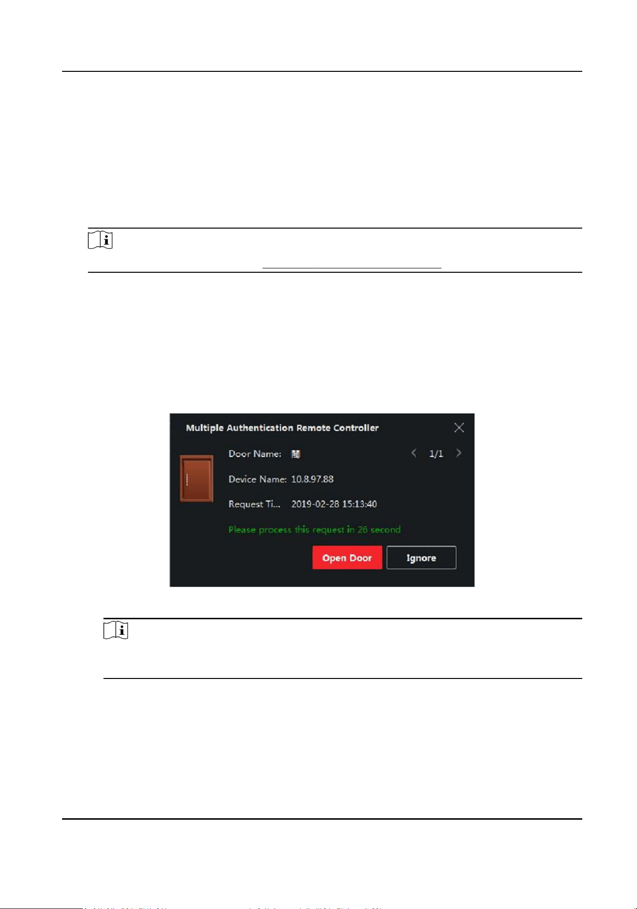
6) Oponal: Select the person/card group(s), and then click Delete to delete it(them).
7) Oponal: Select the person/card group(s), and then click Apply to re-apply access group that
failed to be applied previously to the access control device.
4.
Select an access control point (door) of selected device on the le panel.
5.
Enter the maximum interval when entering password.
6.
Add an authencaon group for the selected access control point.
1) Click Add on the Authencaon Groups panel.
2) Select a congured template as the authencaon template from the drop-down list.
Note
For seng the template, refer to Congure Schedule and Template .
3) Select the authencaon type as Local Authencaon, Local Authencaon and Remotely
Open Door, or Local Authencaon and Super Password from the drop-down list.
Local Authencaon
Authencaon by the access control device.
Local Authencaon and Remotely Open Door
Authencaon by the access control device and by the client. When the person swipes the
card on the device, a window will pop up. You can unlock the door via the client.
Figure 7-5 Remotely Open Door
Note
You can check Oine Authencaon to enable the super password authencaon when
the access control device is disconnected with the client.
Local Authencaon and Super Password
Authencaon by the access control device and by the super password.
4) Select the added person/card group in the le list below and it will be added to the Selected
list on the right as the authencaon group.
Access Control Terminal User Manual
80
5) Click the added authencaon group in the right list to set authencaon mes in the Auth
Times column.
Note
●
The authencaon mes should be larger than 0 and smaller than the added personnel
quanty in the personnel group.
●
The maximum value of authencaon mes is 16.
6) Click Save.
Note
●
For each access control point (door), up to four authencaon groups can be added.
●
For the authencaon group of which authencaon type is Local Authencaon, up to 8
person/card groups can be added to the authencaon group.
●
For the authencaon group of which authencaon type is Local Authencaon and Super
Password or Local Authencaon and Remotely Open Door, up to 7 person/card groups can
be added to the authencaon group.
7.
Click Save.
7.7.4 Congure Custom Wiegand Rule
Based on the knowledge of uploading rule for the third party Wiegand, you can set mulple
customized Wiegand rules to communicate between the device and the third party card readers.
Before You Start
Wire the third party card readers to the device.
Steps
Note
●
By default, the device disables the custom wiegand funcon. If the device enables the custom
Wiegand funcon, all wiegand interfaces in the device will use the customized wiegand protocol.
●
Up to 5 custom Wiegands can be set.
●
For details about the custom Wiegand, see Custom Wiegand Rule Descripons.
1.
Click Access Control → Advanced Funcon → Custom Wiegand to enter the Custom Wiegand
page.
2.
Select a custom Wiegand on the le.
3.
Create a Wiegand name.
Note
Up to 32 characters are allowed in the custom Wiegand name.
4.
Click Select Device to select the access control device for seng the custom wiegand.
5.
Set the parity mode according to the property of the third party card reader.
Access Control Terminal User Manual
81
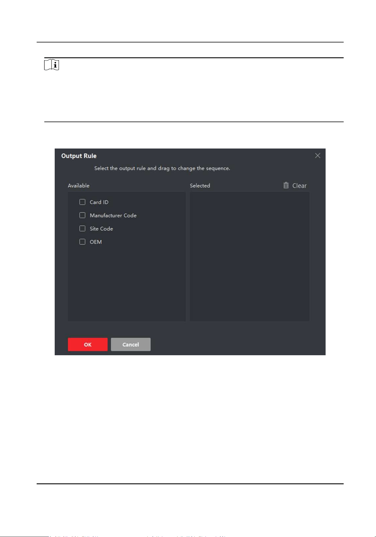
Note
●
Up to 80 bits are allowed in the total length.
●
The odd parity start bit, the odd parity length, the even parity start bit and the even parity
length range from 1 to 80 bit.
●
The start bit of the card ID, the manufacturer code, the site code, and the OEM should range
from 1 to 80 bit.
6.
Set output transformaon rule.
1) Click Set Rule to open the Set Output Transformaon Rules window.
Figure 7-6 Set Output Transformaon Rule
2) Select rules on the le list.
The selected rules will be added to the right list.
3) Oponal: Drag the rules to change the rule order.
4) Click OK.
5) In the Custom Wiegand tab, set the rule's start bit, length, and the decimal digit.
7.
Click Save.
Access Control Terminal User Manual
82

7.7.5 Congure Card Reader Authencaon Mode and Schedule
You can set the passing rules for the card reader of the access control device according to your
actual needs.
Steps
1.
Click Access Control → Advanced Funcon → Authencaon to enter the authencaon mode
conguraon page.
2.
Select a card reader on the le to congure.
3.
Set card reader authencaon mode.
1) Click Conguraon.
Access Control Terminal User Manual
83
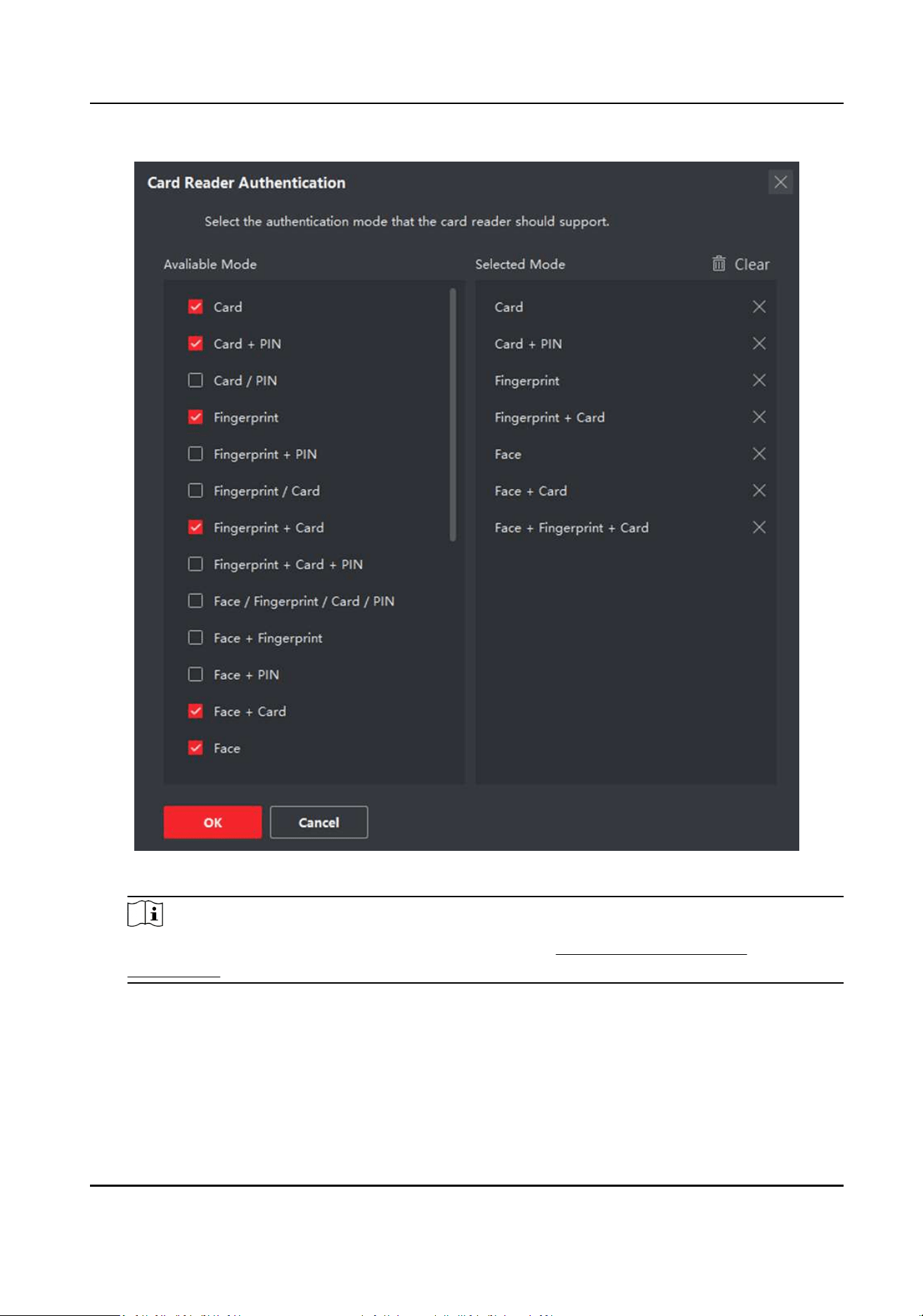
Figure 7-7 Select Card Reader Authencaon Mode
Note
PIN refers to the PIN code set to open the door. Refer to Congure Access Control
Informaon .
2) Check the modes in the Available Mode list and they will be added to the selected modes list.
3) Click OK.
Aer selecng the modes, the selected modes will display as icons with dierent color.
4.
Click the icon to select a card reader authencaon mode, and drag the cursor to draw a color
bar on the schedule, which means in that period of me, the card reader authencaon is valid.
5.
Repeat the above step to set other me periods.
Access Control Terminal User Manual
84
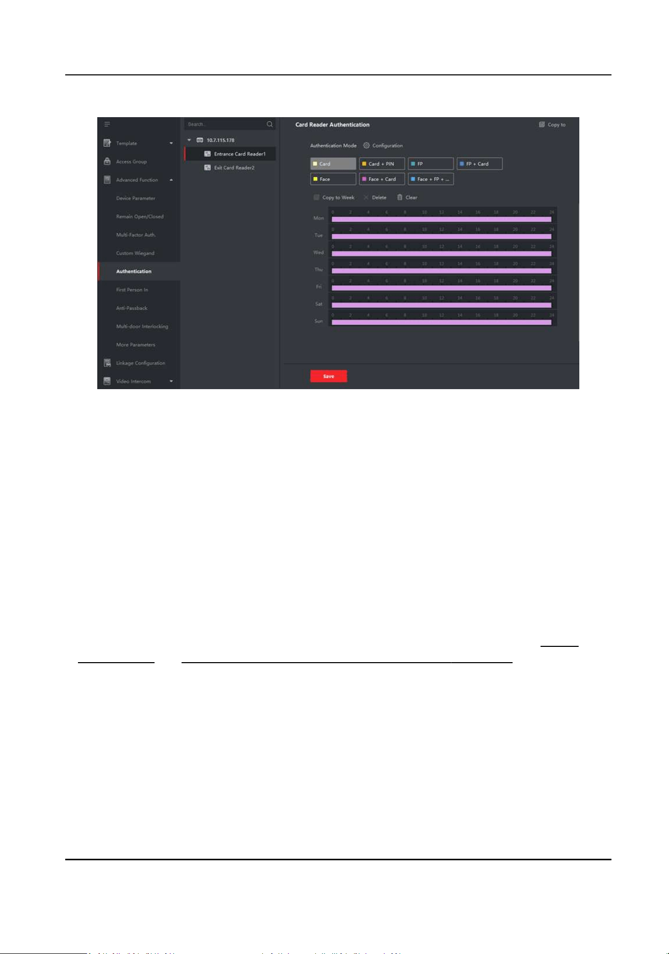
Figure 7-8 Set Authencaon Modes for Card Readers
6.
Oponal: Select a congured day and click Copy to Week to copy the same sengs to the whole
week.
7.
Oponal: Click Copy to to copy the sengs to other card readers.
8.
Click Save.
7.7.6 Congure First Person In
You can set mulple rst persons for one access control point. Aer the rst person is authorized,
it allows mulple persons access the door or other authencaon acons.
Before You Start
●
Add access control device to the client, and make sure the device supports the rst person in
funcon.
●
Add person and assign access authorizaon to designed person. For details, refer to
Person
Management and Set Access Group to Assign Access Authorizaon to Persons .
Steps
1.
Click Access Control → Advanced Funcon → First Person In to enter the First Person In page.
2.
Select an access control device in the list on the le panel.
3.
Select the current mode as Enable Remaining Open aer First Person, Disable Remaining Open
aer First Person, or Authorizaon by First Person from the drop-down list for each access
control point of the selected device.
Enable Remaining Open aer First Person
Access Control Terminal User Manual
85
The door remains open for the congured me duraon aer the rst person is authorized
unl the remain open duraon ends. If you select this mode, you should set the remain open
duraon.
Note
The remain open duraon should be between 0 and 1440 minutes. By default, the remain
open duraon is 10 minutes.
Disable Remaining Open aer First Person
Disable the funcon of rst person in, namely normal authencaon.
Authorizaon by First Person
All authencaons (except for the authencaons of super card, super password, duress
card, and duress code) are allowed only aer the rst person authorizaon.
Note
You can authencate by the rst person again to disable the rst person mode.
4.
Click Add on the First Person List panel.
5.
Select person(s) in the le list and the person(s) will be add to the selected persons as the rst
person(s) of the doors.
The added rst person(s) will list in the First Person List
6.
Oponal: Select a rst person from the list and click Delete to remove the person from the rst
person list.
7.
Click Save.
7.7.7 Congure An-Passback
You can set to only pass the access control point according to the specied path and only one
person could pass the access control point aer swiping the card.
Before You Start
Enable the an-passing back funcon of the access control device.
Perform this task when you want to congure the an-passing back for the access control device.
Steps
Note
Either the an-passing back or mul-door interlocking funcon can be congured for an access
control device at the same me. For the conguraon of mul-door interlocking, refer to .
1.
Click Access Control → Advanced Funcon → An-Passback to enter the An-Passpack Sengs
page.
2.
Select an access control device on the le panel.
3.
Select a card reader as the beginning of the path in the First Card Reader eld.
Access Control Terminal User Manual
86

4.
Click of the selected rst card reader in the Card Reader Aerward column to open the select
card reader dialog.
5.
Select the aerward card readers for the rst card reader.
Note
Up to four aerward card readers can be added as aerward card readers for one card reader.
6.
Click OK in the dialog to save the selecons.
7.
Click Save in the An-Passback Sengs page to save the sengs and take eect.
Example
Set Card Swiping Path
If you select Reader In_01 as the beginning, and select Reader In_02, Reader Out_04 as the linked
card readers. Then you can only get through the access control point by swiping the card in the
order as Reader In_01, Reader In_02 and Reader Out_04.
7.7.8 Congure Device Parameters
Aer adding the access control device, you can set its parameters such as network parameters.
Set Network Parameters
Aer adding the access control device, you can set the device log uploading mode, and create ISUP
account via wired network.
Set Log Uploading Mode
You can set the mode for the device to upload logs via ISUP protocol.
Steps
Note
Make sure the device is not added by ISUP.
1.
Enter the Access Control module.
2.
On the navigaon bar on the le, enter Advanced Funcon → More Parameters .
3.
Select an access control device in the device list and enter Network → Uploading Mode .
4.
Select the center group from the drop-down list.
5.
Check Enable to enable to set the uploading mode.
6.
Select the uploading mode from the drop-down list.
-
Enable N1 or G1 for the main channel and the backup channel.
-
Select Close to disable the main channel or the backup channel
Access Control Terminal User Manual
87
Note
●
The main channel and the backup channel cannot enable N1 or G1 at the same me.
●
N1 refers to wired network and G1 refers to GPRS.
7.
Click Save.
Create EHome Account in Wired Communicaon Mode
You can set the account for EHome protocol in wired communicaon mode. Then you can add
devices via EHome protocol.
Steps
Note
●
This funcon should be supported by the device.
●
Make sure the device is not added by EHome.
1.
Enter the Access Control module.
2.
On the navigaon bar on the le, enter Advanced Funcon → More Parameters .
3.
Select an access control device in the device list and enter Network → Network Center .
4.
Select the center group from the drop-down list.
5.
Select the Address Type as IP Address or Domain Name.
6.
Enter IP address or domain name according to the address type.
7.
Enter the port number for the protocol.
Note
The port number of the wireless network and wired network should be consistent with the port
number of EHome.
8.
Select the Protocol Type as EHome and select EHome version.
Note
If set the EHome version as 5.0, you should create an EHome key for the EHome account.
9.
Set an account name for the network center.
10.
Click Save.
Enable M1 Card Encrypon
M1 card encrypon can improve the security level of authencaon.
Access Control Terminal User Manual
88
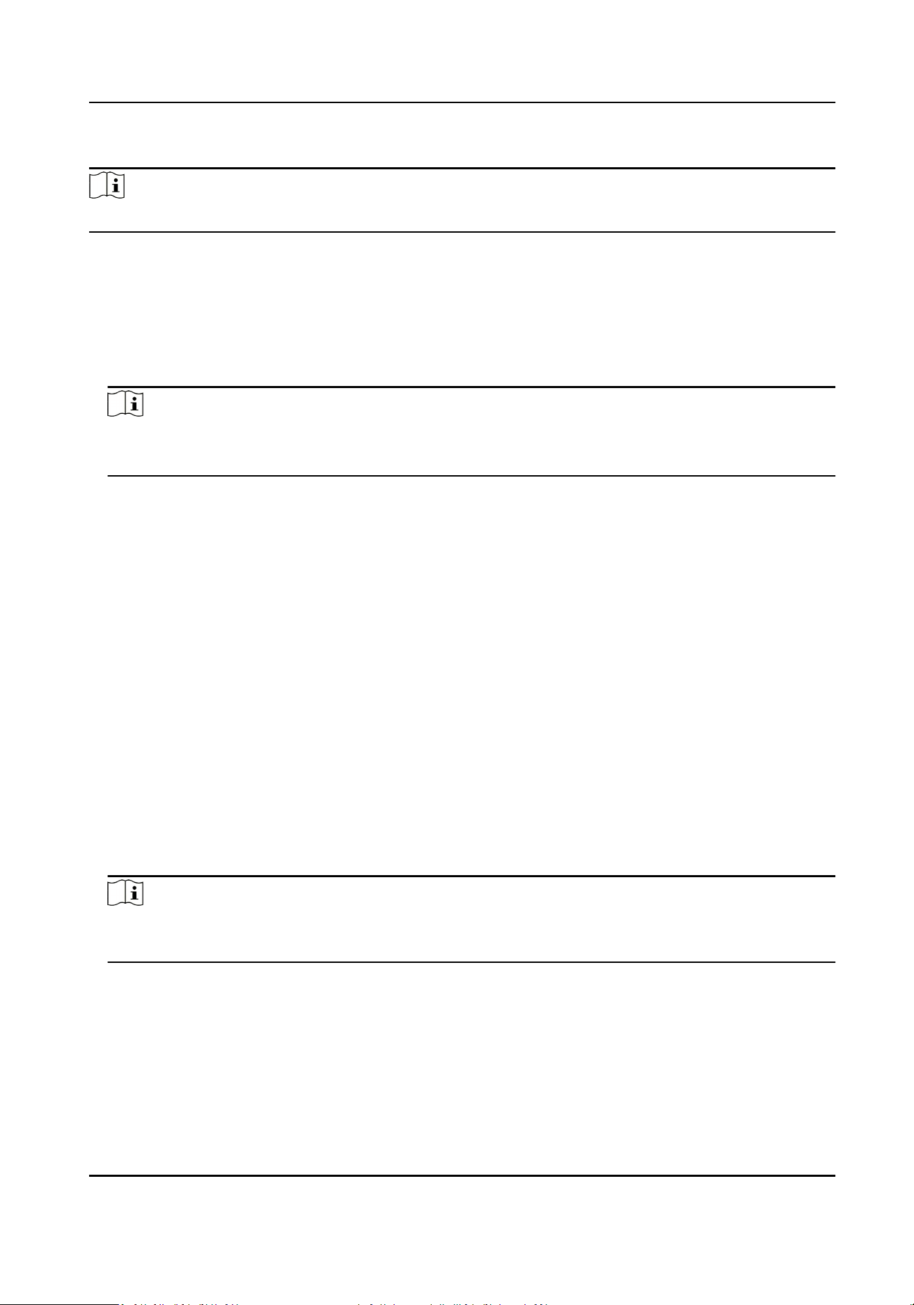
Steps
Note
The funcon should be supported by the access control device and the card reader.
1.
Enter the Access Control module.
2.
On the navigaon bar on the le, enter Advanced Funcon → More Parameters .
3.
Select an access control device in the device list and click M1 Card Encrypon Vericaon to
enter the M1 Card Encrypon Vericaon page.
4.
Set the switch to on to enable the M1 card encrypon funcon.
5.
Set the sector ID.
Note
●
The sector ID ranges from 1 to 100.
●
By default, Sector 13 is encrypted. It is recommended to encrypt sector 13.
6.
Click Save to save the sengs.
Set RS-485 Parameters
You can set the access control device's RS-485 parameters including the baud rate, data bit, the
stop bit, parity type, ow control type, communicaon mode, work mode, and connecon mode.
Before You Start
Add access control device to the client, and make sure the device supports RS-485 interface.
Steps
1.
Enter the Access Control module.
2.
On the navigaon bar on the le, enter Advanced Funcon → More Parameters .
3.
Select an access control device in the device list and click RS-485 to enter the RS-485 Sengs
page.
4.
Select the serial port number from the drop-down list to set the RS-485 parameters.
5.
Set the baud rate, data bit, the stop bit, parity type, communicaon mode, working mode, and
connecon mode in the drop-down list.
Note
When the connecon mode is Connect Access Control Device, you can select Card No. or
Person ID as the output type.
6.
Click Save.
●
The congured parameters will be applied to the device automacally.
●
When you change the working mode or connecon mode, the device will reboot
automacally.
Access Control Terminal User Manual
89

Set Wiegand Parameters
You can set the access control device's Wiegand channel and the communicaon mode. Aer
seng the Wiegand parameters, the device can connect to Wiegand card reader via Wiegand
communicaon.
Before You Start
Add access control device to the client, and make sure the device supports Wiegand.
Steps
1.
Enter the Access Control module.
2.
On the navigaon bar on the le, enter Advanced Funcon → More Parameters .
3.
Select an access control device in the device list and click Wiegand to enter the Wiegand
Sengs page.
4.
Set the switch to on to enable the Wiegand funcon for the device.
5.
Select the Wiegand channel No. and the communicaon mode from the drop-down list.
Note
If you set Communicaon Direcon as Sending, you are required to set the Wiegand Mode as
Wiegand 26 or Wiegand 34.
6.
Click Save.
●
The congured parameters will be applied to the device automacally.
●
Aer changing the communicaon direcon, the device will reboot automacally.
7.8 Congure Linkage Acons for Access Control
You can congure dierent linkage acons for the event detected by the access control device.
Aer that, linkage acons will be triggered once the event happens. This mechanism is used for
nofying the security personnel the event, or triggering automac access control in real me.
Two types of linkage acons are supported:
●
Client Acons: When the event is detected, it will trigger the acons on the client, such as the
client making an audible warning..
●
Device Acons: When the event is detected, it will trigger the acons of a specic device, such
as buzzing of a card reader and, opening/closing of a door, ..
7.8.1 Congure Client Acons for Access Event
Even if you are far away from an access point, you can sll know what happens and how urgent the
event is by conguring linked acons of access event on the client. You will be noed on the client
once an event is triggered, so that you can response to the event instantly. You can also congure
client acons of access points in a batch at a me.
Access Control Terminal User Manual
90

Steps
Note
The linkage acons here refer to the linkage of the client soware's own acons such as audible
warning, email linkage, etc.
1.
Click Event Management → Access Control Event .
The added access control devices will display in the device list.
2.
Select a resource (including device, alarm input, door/elevator, and card reader) from the device
list.
The event types which the selected resource supports will display.
3.
Select the event(s) and click Edit Priority to dene the priority for the event(s), which can be
used to lter events in the Event Center.
4.
Set the linkage acons of the event.
1) Select the event(s) and click Edit Linkage to set the client acons when the events triggered.
Audible Warning
The client soware gives an audible warning when alarm is triggered. You can select the
alarm sound for audible warning.
Note
For seng the alarm sound, please refer to Set Alarm Sound in the user manual of client
soware..
Send Email
Send an email nocaon of the alarm informaon to one or more receivers.
For details about seng email parameters, refer to Set Email Parameters in the user
manual of client soware..
2) Click OK.
5.
Enable the event so that when the event is detected, en event will be sent to the client and the
linkage acons will be triggered.
6.
Oponal: Click Copy to... to copy the event sengs to other access control device, alarm input,
door, or card reader.
7.8.2 Congure Device Acons for Access Event
You can set the access control device's linkage acons for the access control device's triggered
event. When the event is triggered, it can trigger the alarm output, host buzzer, and other acons
on the same device.
Access Control Terminal User Manual
91

Steps
Note
It should be supported by the device.
1.
Click Access Control → Linkage Conguraon .
2.
Select the access control device from the list on the le.
3.
Click Add buon to add a new linkage.
4.
Select the event source as Event Linkage.
5.
select the event type and detailed event to set the linkage.
6.
In the Linkage Target area, set the property target to enable this acon.
Buzzer on Controller
The audible warning of access control device will be triggered.
Capture
The real-me capture will be triggered.
Access Point
The door status of open, close, remain open, and remain close will be triggered.
Note
The target door and the source door cannot be the same one.
7.
Click Save.
8.
Oponal: Aer adding the device linkage, you can do one or more of the following:
Edit Linkage
Sengs
Select the congured linkage sengs in the device list and you can edit its
event source parameters, including event source and linkage target.
Delete Linkage
Sengs
Select the congured linkage sengs in the device list and click Delete to
delete it.
7.8.3 Congure Device Acons for Card Swiping
You can set the access control device's linkage acons for the specied card swiping. When you
swipe the specied card, it can trigger the host buzzer, and other acons on the same device.
Steps
Note
It should be supported by the device.
1.
Click Access Control → Linkage Conguraon .
2.
Select the access control device from the list on the le.
3.
Click Add buon to add a new linkage.
4.
Select the event source as Card Linkage.
Access Control Terminal User Manual
92

5.
Enter the card number or select the card from the drop-down list.
6.
Select the card reader where the card swipes to trigger the linked acons.
7.
In the Linkage Target area, set the property target to enable this acon.
Buzzer on Controller
The audible warning of access control device will be triggered.
Capture
The real-me capture will be triggered.
Access Point
The door status of open, close, remain open, or remain closed will be triggered.
8.
Click Save.
When the card (congured in Step 5) swipes on the card reader (congured in Step 6), it can
trigger the linked acons (congured in step 7).
9.
Oponal: Aer adding the device linkage, you can do one or more of the following:
Delete Linkage
Sengs
Select the congured linkage sengs in the device list and click Delete to
delete it.
Edit Linkage
Sengs
Select the congured linkage sengs in the device list and you can edit its
event source parameters, including event source and linkage target.
7.8.4 Congure Device Acons for Person ID
You can set the access control device's linkage acons for the specied person ID. When access
control device detects the specied person ID, it can trigger buzzer on card reader, and other
acons.
Steps
Note
It should be supported by the device.
1.
Click Access Control → Linkage Conguraon .
2.
Select the access control device from the list on the le.
3.
Click Add to add a new linkage.
4.
Select Person Linkage as the event source.
5.
Enter the employee number or select the person from the drop-down list.
6.
Select the card reader where the card swipes.
7.
In the Linkage Target area, set the property target to enable this acon.
Buzzer on Controller
The audible warning of access control device will be triggered.
Buzzer on Reader
The audible warning of card reader will be triggered.
Access Control Terminal User Manual
93

Capture
An event-related picture will be captured when the selected event happens.
Recording
An event-related picture will be captured when the selected event happens.
Note
The device should support recording.
Access Point
The door status of open, close, remain open, or remain closed will be triggered.
8.
Click Save.
9.
Oponal: Aer adding the device linkage, you can do one or more of the followings:
Delete Linkage
Sengs
Select the congured linkage sengs in the device list and click Delete to
delete it.
Edit Linkage
Sengs
Select the congured linkage sengs in the device list and you can edit its
event source parameters, including event source and linkage target.
7.9 Door Control
In Monitoring module, you can view the real-me status of the doors managed by the added
access control device. You can also control the doors such as open/close the door, or remain the
door open/closed via the client remotely. The real-me access event are displayed in this module.
You can view the access details and person details.
Note
For the user with door control permission, the user can enter the Monitoring module and control
the door. Or the icons used for control will not show. For seng the user permission, refer to
Person Management .
7.9.1 Control Door Status
You can control the status for a single door, including opening door, closing door, remaining the
door open, and remaining the door closed.
Steps
1.
Click Monitoring to enter the status monitoring page.
2.
Select an access point group on the upper-right corner.
Access Control Terminal User Manual
94

Note
For managing the access point group, refer to Group Management in the user manual of the
client soware.
The doors in the selected access control group will display.
3.
Click a door icon to select a door, or press Ctrl and select mulple doors.
4.
Click the following buons to control the door.
Open Door
When the door is locked, unlock it and it will be open for once. Aer the open duraon, the
door will be closed and locked again automacally.
Close Door
When the door is unlocked, lock it and it will be closed. The person who has the access
authorizaon can access the door with credenals.
Remain Open
The door will be unlocked (no maer closed or open). All the persons can access the door
with no credenals required.
Remain Closed
The door will be closed and locked. No person can access the door even if he/she has the
authorized credenals, except the super users.
Capture
Capture a picture manually.
Note
The Capture buon is available when the device supports capture funcon. The picture is
saved in the PC running the client. For seng the saving path, refer to Set File Saving Path in
the user manual of the client soware.
Result
The icon of the doors will change in real-me according to the operaon if the operaon is
succeeded.
7.9.2 Check Real-Time Access Records
The access records will display in real me, including card swiping records, ngerprint comparison
records, etc. You can view the person informaon and view the picture captured during access.
Steps
1.
Click Monitoring and select a group from the drop-down list on the upper-right corner.
The access records triggered at the doors in the selected group will display in real me. You can
view the details of the records, including card No., person name, organizaon, event me, etc.
Access Control Terminal User Manual
95

2.
Oponal: Check the event type and event status so that these events will show in the list if the
events are detected. The events of unchecked type or status will not be displayed in the list.
3.
Oponal: Check Show Latest Event and the latest access record will be selected and displayed at
the top of the record list.
4.
Oponal: Click the event to view the accessed person details, including person pictures
(captured picture and prole), person No., person name, organizaon, phone, contact address,
etc.
Note
You can double click the captured picture to enlarge it to view the details.
5.
Oponal: Right click on the column name of the access event table to show or hide the column
according to actual needs.
7.10 Event Center
In the Event Center, you can view the real-me events, search the historical events and view the
pop-up alarm informaon.
Before the client can receive the event informaon from the device, you need to arm the device
rst. For details, refer to Enable Receiving Events from Devices .
Before the you can view the pop-up alarm informaon, you need to enable alarm triggered pop-up
image in the event center. For details, refer to .
7.10.1 Enable Receiving Events from Devices
Before the client can receive the event informaon from the device, you need to arm the device
rst.
Steps
1.
Click → Tool → Device Arming Control open Device Arming Control page.
All the added devices display on this page.
2.
In the Operaon column, turn on the switch to enable auto-arming, or click Arm All to arm all
the devices.
Access Control Terminal User Manual
96
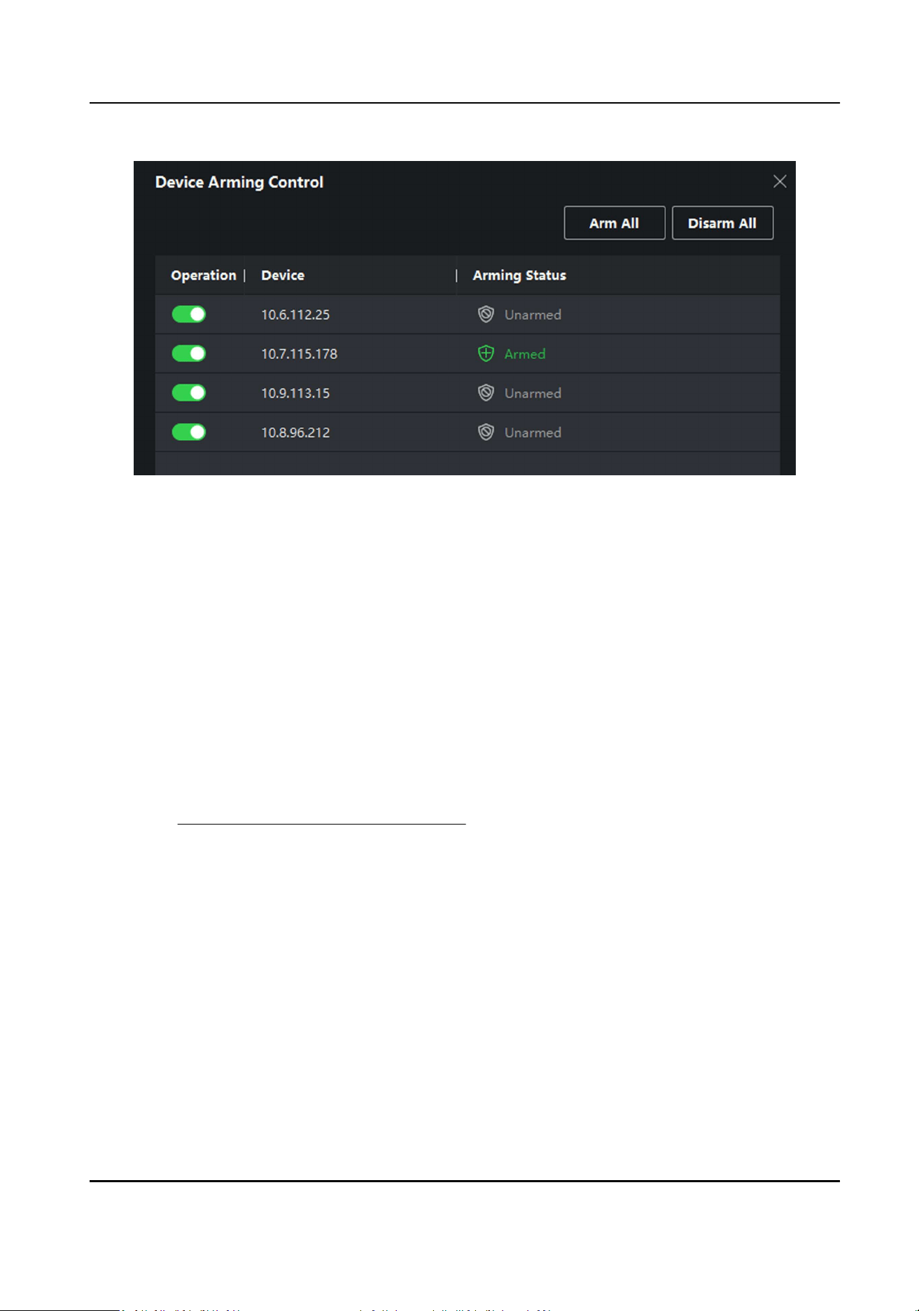
Figure 7-9 Device Arming Control
3.
View the arming status of each device in the Arming Status column.
Result
The events of armed device(s) are automacally uploaded to the client when the event is
triggered.
7.10.2 View Real-Time Events
In the Real-me Event module of the event center page, you can view the real-me event
informaon, including event source, event me, priority, event key words, etc.
Before You Start
Enable receiving events from devices before the client can receive event informaon from the
device, see Enable Receiving Events from Devices for details.
Steps
1.
Click Event Center → Real-me Event to enter the real-me event page and you can view the
real-me events received by the client.
Event Time
For video device, event me is the client me when it receives the event. For none-video
device, event me is the me when the event is triggered.
Access Control Terminal User Manual
97
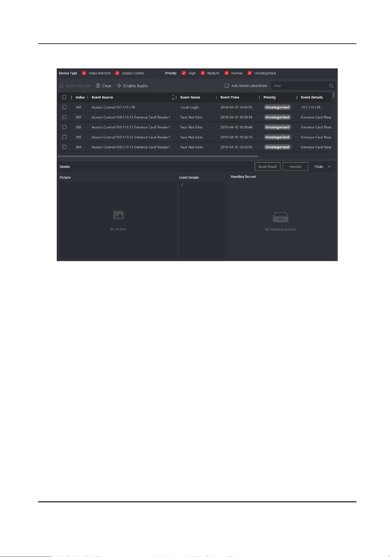
Figure 7-10 View Real-Time Events
2.
Set the lter condions or enter the event key word in the Filter text eld to display the required
events only.
Device Type
The type of device that occurred the event.
Priority
The priority of the event that indicates the urgent degree of the event.
3.
Oponal: Right click the table header of the event list to customize the event related items to be
displayed in the event list.
Access Control Terminal User Manual
98
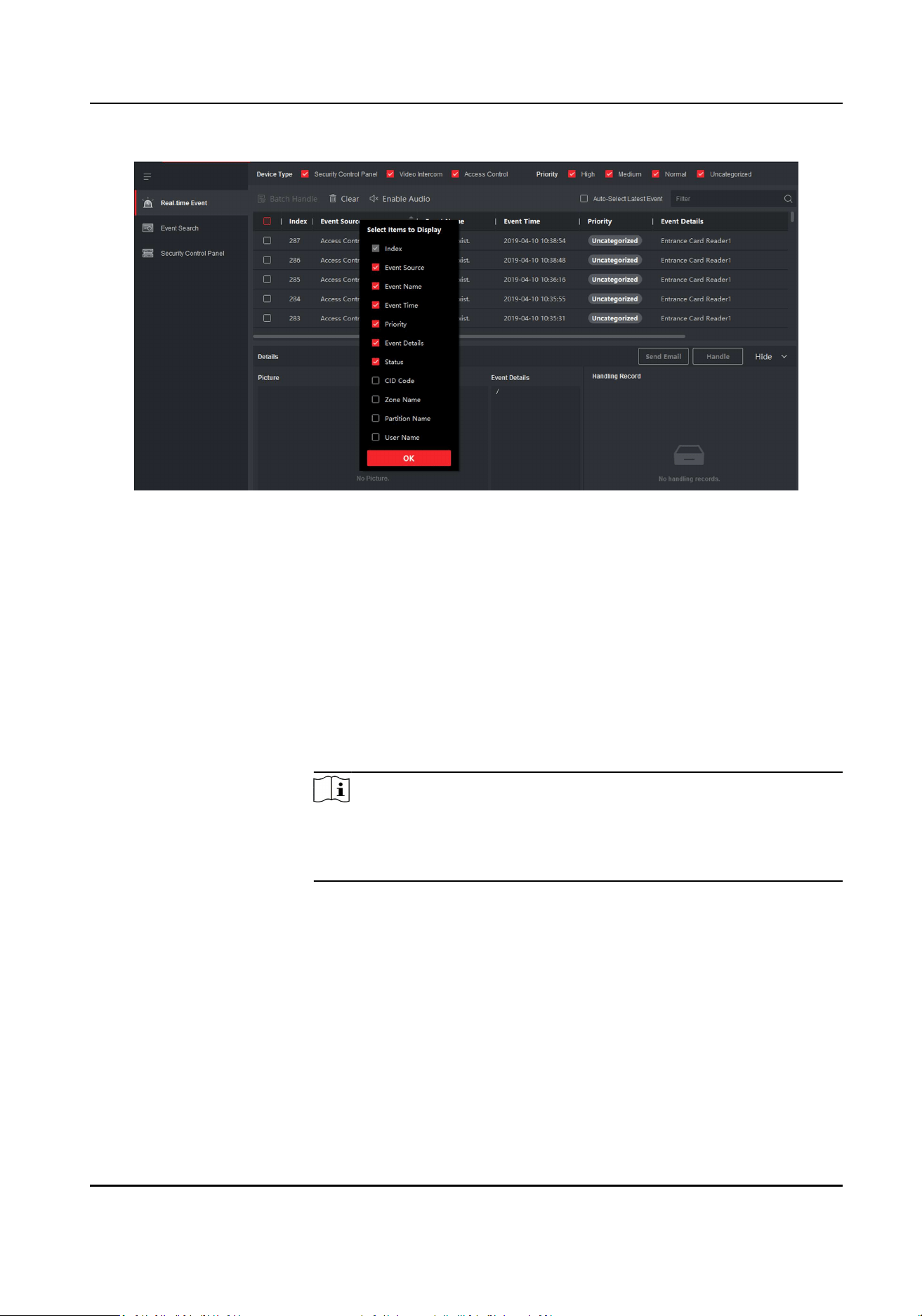
Figure 7-11 Customize Event Related Items to be Displayed
4.
View the event informaon details.
1) Select an event in the event list.
2) Click Expand in the right-lower corner of the page.
3) View the related picture, detail descripon and handing records of the event.
4) Oponal: Hover the cursor on the related picture, and then click the download icon on the
upper-right corner of the picture to download it to the local PC. You can set the saving path
manually.
5.
Oponal: Perform the following operaons if necessary.
Handle Single Event Click Handle to enter the processing suggeson, and then click
Commit.
Note
Aer an event is handled, the Handle buon will become Add
Remark, click Add Remark to add more remarks for this handled
event.
Handle Events in a
Batch
Select events that need to be processed, and then click Handle in
Batch. Enter the processing suggeson, and then click Commit.
Enable/Disable
Alarm Audio
Click Enable Audio/Disable Audio to enable/disable the audio of the
event.
Select the Latest
Event Automacally
Check Auto-Select Latest Event to select the latest event
automacally and the event informaon details is displayed.
Clear Events Click Clear to clear the all the events in the event list.
Access Control Terminal User Manual
99
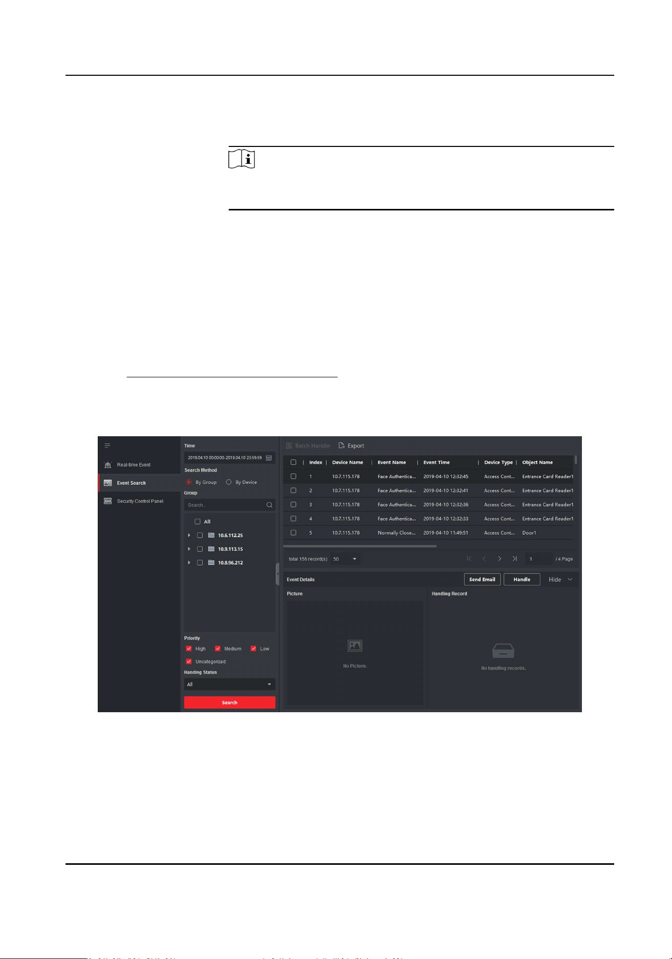
Send Email Select an event and then click Send Email, and the informaon
details of this event will be sent by email.
Note
You should congure the email parameters rst, see Set Email
Parameters in the user manual of client soware for details.
7.10.3 Search Historical Events
In the Event Search module of the event center page, you can search the historical events via me,
device type, and other condions according to the specied device type, and then process the
events.
Before You Start
Enable receiving events from devices before the client can receive event informaon from the
device,see Enable Receiving Events from Devices for details.
Steps
1.
Click Event Center → Event Search to enter the event search page.
Figure 7-12 Search History Event
2.
Set the lter condions to display the required events only.
Time
The client me when the event starts.
Access Control Terminal User Manual
100

Search by
Group: Search the events occurred on the resources in the selected group.
Device: Search the events occurred on the selected device.
Device Type
The type of device that occurred the event.
All
All the device types, and you can set the following lter condions: group, priority, and
status.
Video Intercom
For the events of video intercom, you need to select searching scope: All Record and Only
Unlocking.
●
All Records: You can lter the events from all the video intercom events, and you need
to set the following lter condions: device, priority, status.
●
Only Unlocking: You can lter the events from all the video intercom unlocking events,
and you need to set the following lter condions: device, unlocking type.
Access Control
For the events of access control, you can set the following lter condions: device, priority,
status, event type, card reader type, person name, card no., organizaon.
Note
Click Show More to set the event type, card reader type, person name, card no.,
organizaon.
Group
The group of the device that occurred the event. You should set the group as condion only
when you select the Device Type as All.
Device
The device that occurred the event.
Priority
The priority including low, medium, high and uncategorized which indicates the urgent
degree of the event.
Status
The handling status of the event.
3.
Click Search to search the events according the condions you set.
4.
Oponal: Right click the table header of the event list to customize the event related items to be
displayed in the event list.
Access Control Terminal User Manual
101
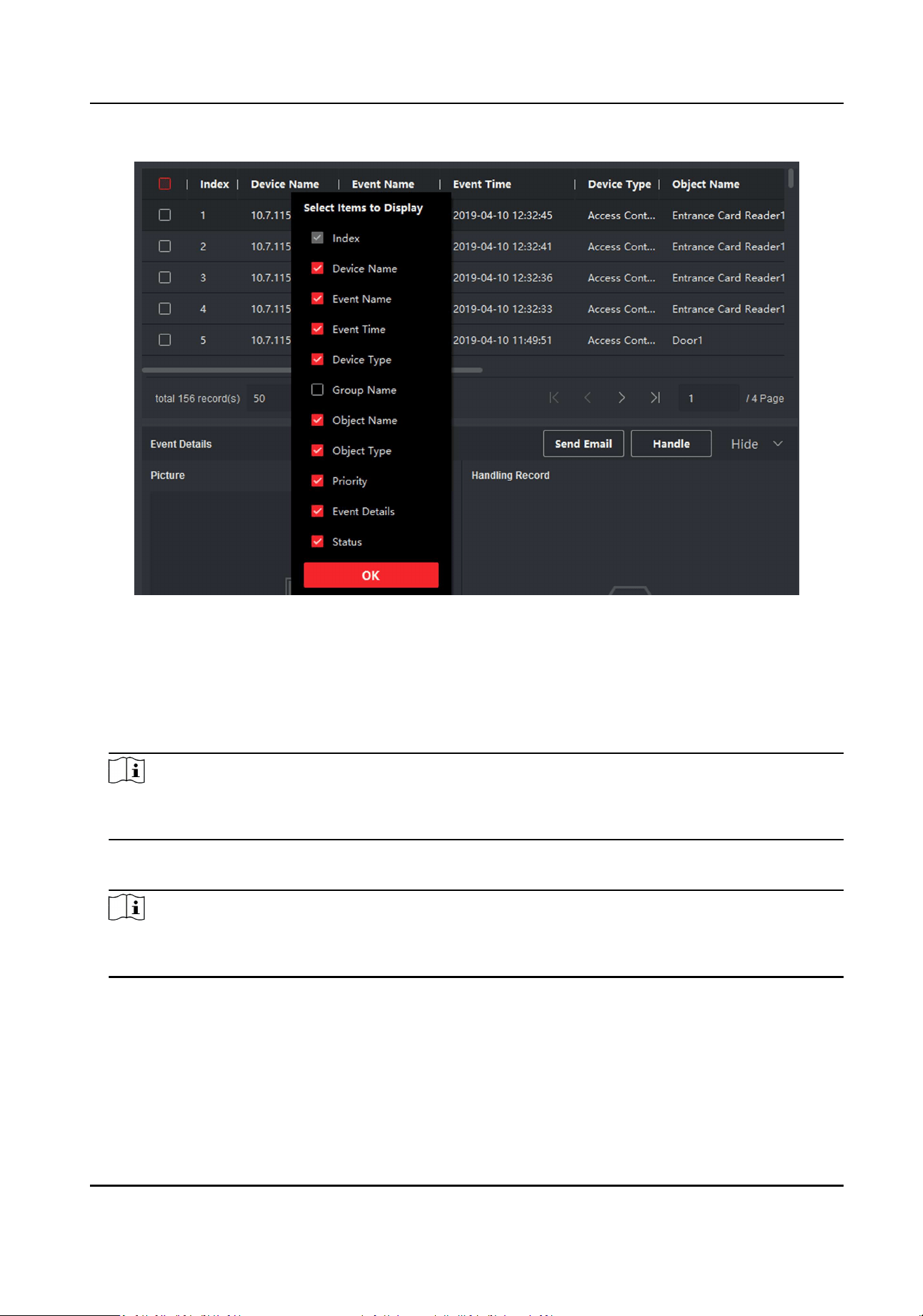
Figure 7-13 Customize Event Related Items to be Displayed
5.
Oponal: Handle the event(s).
-
Handle single event: Select one event that need to be processed, and then click Handle in the
event informaon details page, and enter the processing suggeson.
-
Handle events in a batch: Select the events which need to be processed, and then click
Handle in Batch, and enter the processing suggeson.
Note
Aer an event is handled, the Handle buon will become Add Remark, click Add Remark to add
more remarks for this handled event.
6.
Oponal: Select an event and then click Send Email, and the informaon details of this event
will be sent by email.
Note
You should congure the email parameters rst, see Set Email Parameters in the user manual of
client soware for details.
7.
Oponal: Click Export to export the event log or event pictures to the local PC in CSV format.
You can set the saving path manually.
8.
Hover the cursor on the related picture, and then click the download icon on the upper-right
corner of the picture to download it to the local PC. You can set the saving path manually.
Access Control Terminal User Manual
102

7.11 Time and Aendance
The Time and Aendance module provides mulple funconalies to track and monitor when
employees start and stop work, and full control of employees working hours such as late arrivals,
early departures, me taken on breaks and absenteeism.
Note
In this secon, we introduce the conguraons before you can geng the aendance reports. The
access records recorded aer these conguraons will be calculated in the stascs.
7.11.1 Congure Aendance Parameters
You can congure the aendance parameters, including the general rule, overme parameters,
aendance check point, holiday, leave type, etc.
Set Weekend
The days of weekends may vary in dierent countries and regions. The client provides weekends
denion funcon. You can select one or more days as the weekends according to actual
requirements, and set dierent aendance rules for weekends from workdays.
Steps
Note
The parameters congured here will be set as default for the newly added me period. It will not
aect the existed one(s).
1.
Enter Time & Aendance module.
2.
Click Aendance Sengs → General Rule .
3.
Select the day(s) as weekend, such as Saturday and Sunday.
4.
Click Save.
Congure Overme Parameters
You can congure the overme parameters for workday and weekend, including overme level,
work hour rate, aendance status for overme, etc.
Steps
1.
Click Time & Aendance → Aendance Sengs → Overme .
2.
Set required informaon.
Overme Level for Workday
Access Control Terminal User Manual
103

When you work for a certain period aer end-work me on workday, you will reach dierent
overme level: overme level 1, overme level 2 and overme level 3. You can set dierent
work hour rate for three overme levels, respecvely.
Work Hour Rate
Work Hour Rate is used to calculate work hours by mulplying it by overme. When you work
for a certain period aer end-work me on workday, you will reach dierent overme level.
You can set dierent work hour rates (1-10, can be a decimal) for three overme levels. For
example, your valid overme is one hour (in overme level 1), and the work hour rate of
overme level 1 is set as 2, then the work hours in the period will be calculated as 2 hours.
Overme Rule for Weekend
You can enable overme rule for weekend and set calculaon mode.
3.
Click Save.
Congure Aendance Check Point
You can set the card reader(s) of the access point as the aendance check point, so that the
authencaon on the card readers will be recorded for aendance .
Before You Start
You should add access control device before conguring aendance check point. For details, refer
to Add Device .
Steps
Note
By default, all card readers of the added access control devices are set as aendance checkpoint.
1.
Enter the Time & Aendance module.
2.
Click Aendance Sengs → Aendance Check Point to enter the Aendance Check Point
Sengs page.
3.
Oponal: Set Set All Card Readers as Check Points switch to o.
Only the card readers in the list will be set as the aendance check points.
4.
Check the desired card reader(s) in the device list as aendance check point(s).
5.
Set check point funcon as Start/End-Work, Start-Work or End-Work.
6.
Click Set as Check Point.
The congured aendance check point displays on the right list.
Congure Holiday
You can add the holiday during which the check-in or check-out will not be recorded.
Access Control Terminal User Manual
104

Add Regular Holiday
You can congure a holiday which will take eect annually on regular days during the eecve
period, such as New Year's Day, Independence Day, Christmas Day, etc.
Steps
1.
Enter the Time & Aendance module.
2.
Click Aendance Sengs → Holiday to enter the Holiday Sengs page.
3.
Check Regular Holiday as holiday type.
4.
Custom a name for the holiday.
5.
Set the rst day of the holiday.
6.
Enter the number of the holiday days.
7.
Set the aendance status if the employee works on holiday.
8.
Oponal: Check Repeat Annually to make this holiday seng eecve every year.
9.
Click OK.
The added holiday will display in the holiday list and calendar.
If the date is selected as dierent holidays, it will be recorded as the rst-added holiday.
10.
Oponal: Aer adding the holiday, perform one of the following operaons.
Edit Holiday Click
to edit the holiday informaon.
Delete Holiday Select one or more added holidays, and click Delete to delete the
holiday(s) from the holiday list.
Add Irregular Holiday
You can congure a holiday which will take eect annually on irregular days during the eecve
period, such as Bank Holiday.
Steps
1.
Enter the Time & Aendance module.
2.
Click Aendance Sengs → Holiday to enter the Holiday Sengs page.
3.
Click Add to open the Add Holiday page.
4.
Check Irregular Holiday as holiday type.
5.
Custom a name for the holiday.
6.
Set the start date of the holiday.
Example
If you want to set the forth Thursday in November, 2019 as the Thanksgiving Day holiday, you
should select 2019, November, 4th, and Thursday from the four drop-down lists.
7.
Enter the number of the holiday days.
8.
Set the aendance status if the employee works on holiday.
9.
Oponal: Check Repeat Annually to make this holiday seng eecve every year
Access Control Terminal User Manual
105

10.
Click OK.
The added holiday will display in the holiday list and calendar.
If the date is selected as dierent holidays, it will be recorded as the rst-added holiday.
11.
Oponal: Aer adding the holiday, perform one of the following operaons.
Edit Holiday Click
to edit the holiday informaon.
Delete Holiday Select one or more added holidays, and click Delete to delete the
holiday(s) from the holiday list.
Congure Leave Type
You can customize the leave type (major leave type and minor leave type) according to actual
needs. You can also edit or delete the leave type.
Steps
1.
Enter the Time & Aendance module.
2.
Click Aendance Sengs → Leave Type to enter the Leave Type Sengs page.
3.
Click Add on the le to add a major leave type.
4.
Oponal: Perform one of the following operaons for major leave type.
Edit Move the cursor over the major leave type and click
to edit the major leave type.
Delete Select one major leave type and click Delete on the le to delete the major leave
type.
5.
Click Add on the right to add a minor leave type.
6.
Oponal: Perform one of the following operaons for minor leave type.
Edit Move the cursor over the minor leave type and click
to edit the minor leave type.
Delete Select one or mulple major leave types and click Delete on the right to delete the
selected minor leave type(s).
Synchronize Authencaon Record to Third-Party Database
The aendance data recorded in client soware can be used by other system for calculaon or
some other operaons. You can enable synchronizaon funcon to apply the authencaon record
from client soware to the third-party database automacally.
Steps
1.
Enter Time & Aendance module.
2.
Click Aendance Sengs → Third-Party Database .
3.
Set Apply to Database switch to on to enable synchronizaon funcon.
4.
Select database Type as SQLServer or MySql.
Access Control Terminal User Manual
106

Note
If you select MySql, you should import the conguraon le (libmysql.dll) from local PC.
5.
Set the other required parameters of the third-party database, including server IP address,
database name, user name and password.
6.
Set table parameters of database according to the actual conguraon.
1) Enter the table name of the third-party database.
2) Set the mapped table elds between the client soware and the third-party database.
7.
Click Save to test whether database can be connected and save the sengs for the successful
connecon.
●
The aendance data will be wrien to the third-party database.
●
During synchronizaon, if the client disconnects with the third-party database, the client will
start reconnecon every 30 mins. Aer being reconnected, the client will synchronize the data
recorded during the disconnected me period to the third-party database.
Congure Break Time
You can add break me and set start me, end me, duraon, calculaon mode and other
parameters for the break. The added break me can also be edited or deleted.
Steps
1.
Click Time & Aendance → Timetable .
The added metables are displayed in the list.
2.
Select an added metable or click Add to enter seng metable page.
3.
Click Break Time to enter Break Time page.
4.
Click Break Time Sengs.
5.
Add break me.
1) Click Add.
2) Enter a name for the break me.
3) Set related parameters for the break me.
Start Time / End Time
Set the me when the break starts and ends.
No Earlier Than / No Later Than
Set the earliest swiping me for starng break and the latest swiping me for ending
break.
Break Duraon
The duraon from start me to end me of the break.
Calculaon
Auto Deduct
The xed break duraon will be excluded from work hours.
Access Control Terminal User Manual
107

Must Check
The break duraon will be calculated and excluded from work hours according to actual
check-in and check-out me.
Note
If you select Must Check as calculaon method, you need to set aendance status for
late or early returning from break.
6.
Click Save to save the sengs.
7.
Oponal: Click Add to connue adding break me.
Congure Report Display
You can congure display contents displayed in the aendance report, such as the company name,
logo, date format, me format, and mark.
Steps
1.
Enter Time & Aendance module.
2.
Click Aendance Stascs → Report Display .
3.
Set the display sengs for aendance report.
Company Name
Enter a company name to display the name in the report.
Aendance Status Mark
Enter the mark and select the color. The related elds of aendance status in the report will
display with the mark and color.
Weekend Mark
Enter the mark and select the color. The weekend elds in the report will display with the
mark and color.
4.
Click Save.
7.11.2 Add General Timetable
On the metable page, you can add general metable for employees, which requires the xed
start-work me and end-work me. Also, you can set valid check-in/out me, allowable metable
for being late and leaving early.
Steps
1.
Click Time and Aendance → Timetable to enter the metable sengs page.
2.
Click Add to enter add metable page.
Access Control Terminal User Manual
108
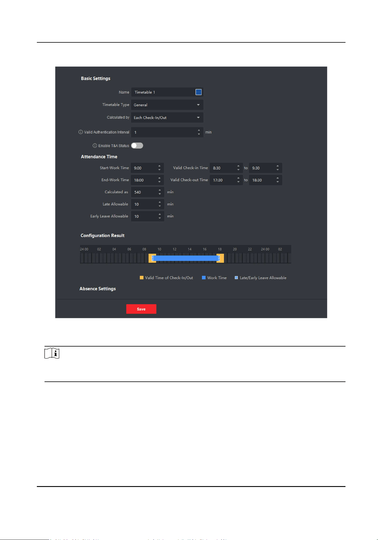
Figure 7-14 Add Timetable
3.
Create a name for the metable.
Note
You can click the color icon beside the name to customize the color for the valid metable on
the me bar in the Conguraon Result area.
4.
Select the metable type as general.
5.
Select calculaon method.
First In & Last Out
The rst check-in me is recorded as start work me and the last check-out me is recorded
as the end-work me.
Each Check-In/Out
Access Control Terminal User Manual
109

Each check-in me and check-out me is valid and the sum of all periods between adjacent
check-in and check-out me will be recorded as the valid working duraon.
You need to set Valid Authencaon Interval for this calculaon method. For example, if the
interval between card swiping of the same card is less than the set value, the card swiping is
invalid.
6.
Oponal: Set Enable T&A Status switch to on to calculate according to aendance status of the
device.
Note
This funcon should be supported by the device.
7.
Set the related aendance me parameters as the following:
Start/End-Work Time
Set the start-work me and end-work-me.
Valid Check-in/out Time
On the me bar, adjust the yellow bar to set the metable during which the check-in or
check-out is valid.
Calculated as
Set the duraon calculated as the actual work duraon.
Late/Early Leave Allowable
Set the metable for late or early leave.
8.
Set absence related parameters.
Check-In, Late for
You can set the late me duraon for the employee who has checked in but is late for work. If
the employee exceeds the required me period, his/her aendance data will be marked as
absent.
Check-Out, Early Leave for
You can set the early leave me duraon for the employee who checks out earlier than the
normal leave me, and his/her aendance data will be marked as absent.
No Check-in
If the employee does not check in, his/her aendance data may be marked as absent or late.
No Check-Out
If the employee does not check out, his/her aendance data may be marked as absent or
early leave.
9.
Click Save to add the metable.
10.
Oponal: Perform one or more following operaons aer adding metable.
Edit Timetable Select a metable from the list to edit related informaon.
Delete Timetable Select a metable from the list and click Delete to delete it.
Access Control Terminal User Manual
110
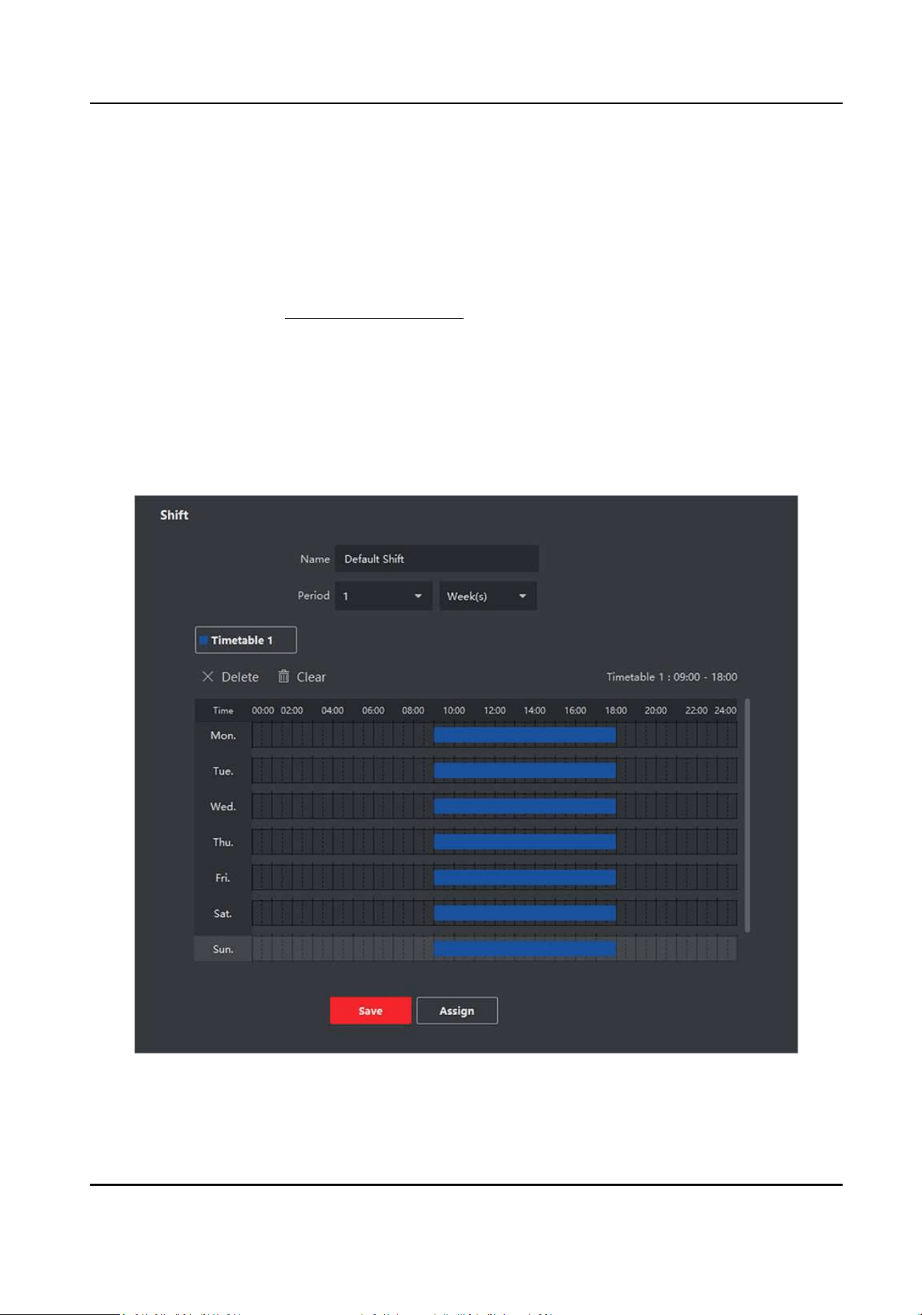
7.11.3 Add Shi
You can add shi for employees including seng shi period (day, week, month) and the eecve
aendance me. According to the actual requirements, you can adding mulple metables in one
shi for employees, which requires them to check in and check out for each metable.
Before You Start
Add a metable rst. See Add General Timetable for details.
Steps
1.
Click Time & Aendance → Shi to enter shi sengs page.
2.
Click Add to enter Add Shi page.
3.
Enter the name for shi.
4.
Select the shi period from the drop-down list.
5.
Select the added metable and click on the me bar to apply the metable.
Figure 7-15 Add Shi
Access Control Terminal User Manual
111
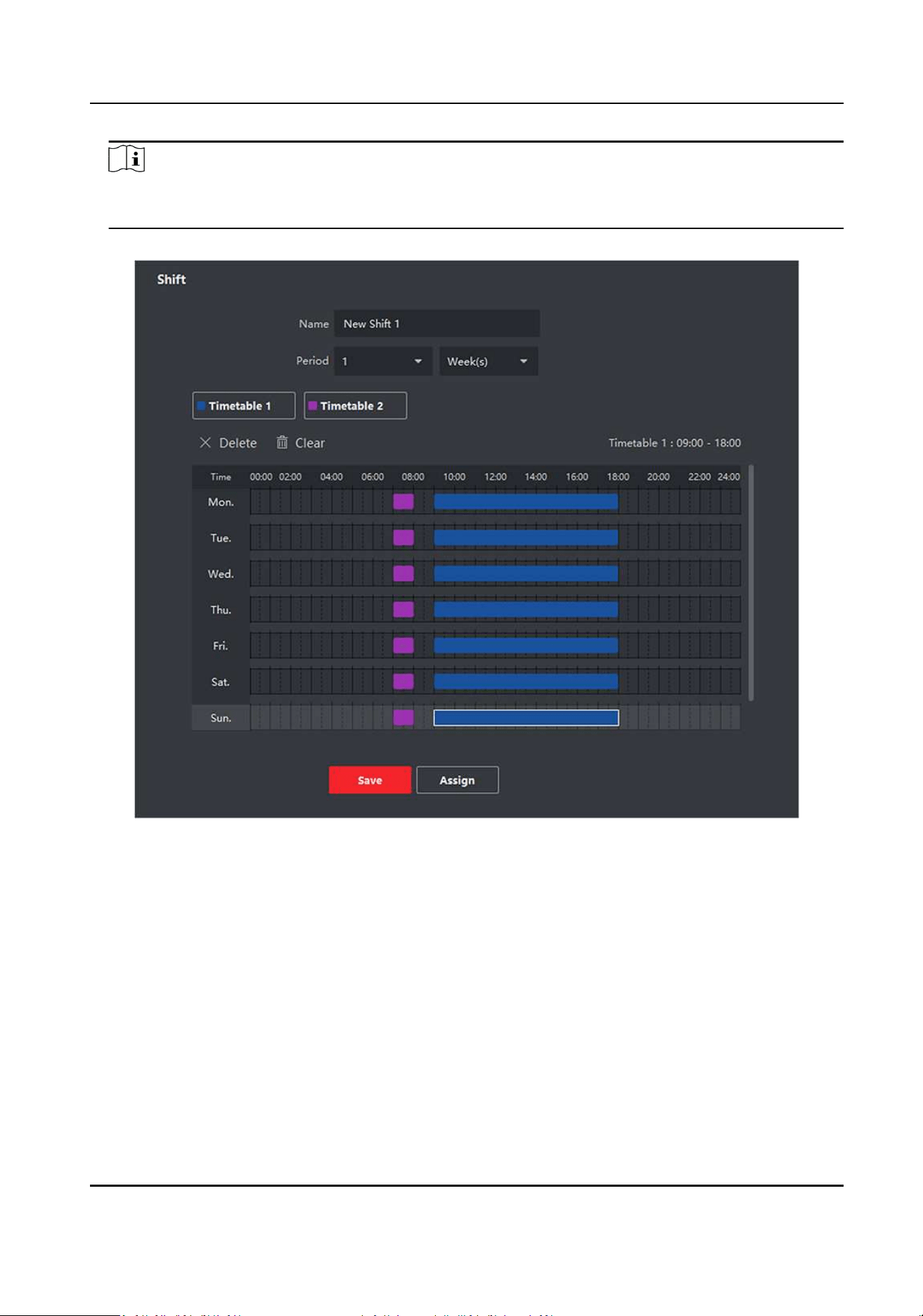
Note
You can select more than one metables. The start and end work me and the valid check-in
and out me in dierent me tables can not be overlapped.
Figure 7-16 Add Mulple Timetables
6.
Click Save.
The added shi lists on the le panel of the page. At most 64 shis can be added.
7.
Oponal: Assign the shi to organizaon or person for a quick shi schedule.
1) Click Assign.
2) Select Organizaon or Person tab and check the desired organizaon(s) or person(s) box.
The selected organizaons or persons will list on the right page.
3) Set the Expire Date for the shi schedule.
4) Set other parameters for the schedule.
Check-in Not Required
Persons in this schedule do not need to check-in when they come to work.
Access Control Terminal User Manual
112

Check-out Not Required
Persons in this schedule do not need to check-out when they end work.
Scheduled on Holidays
On the holidays, this schedule is sll eecve and the persons needs to go to work
according to the schedule.
Eecve for Overme
The persons' overme will be recorded for this schedule.
5) Click Save to save the quick shi schedule.
7.11.4 Manage Shi Schedule
Shi work is an employment pracce designed to make use of all 24 hours of the clock each day of
the week. The pracce typically sees the day divided into shis, set periods of me during which
dierent shis perform their dues.
You can set department schedule, person schedule, and temporary schedule.
Set Department Schedule
You can set the shi schedule for one department, and all the persons in the department will be
assigned with the shi schedule.
Before You Start
In Time & Aendance module, the department list is the same with the organizaon. You should
add organizaon and persons in Person module rst. See Person Management for details.
Steps
1.
Click Time & Aendance → Shi Schedule to enter the Shi Schedule Management page.
2.
Click Department Schedule to enter Department Schedule page.
3.
Select the department from the organizaon list on the le.
Note
If Include Sub Organizaon is checked, when selecng the organizaon, its sub organizaons are
selected at the same me.
4.
Select the shi from the drop-down list.
5.
Oponal: Enable Mulple Shi Schedules and select the eecve me period(s) from the
added metables for the persons.
Note
This is only available for shi with only one metable.
Mulple Shi Schedules
Access Control Terminal User Manual
113

It contains more than one metables. The person can check in/out in any of the metables
and the aendance will be eecve.
If the mulple shi schedules contains three metables: 00:00 to 07:00, 08:00 to 15:00 and
16:00 to 23:00. The aendance of the person adopng this mulple shi schedules will be
eecve in any of the three metables. If the person checks in at 07:50, it will apply the
nearest metable 08:00 to 15:00 to the person's aendance.
6.
Set the start date and end date.
7.
Set other parameters for the schedule.
Check-in Not Required
Persons in this schedule do not need to check-in when they come to work.
Check-out Not Required
Persons in this schedule do not need to check-out when they end work.
Scheduled on Holidays
On the holidays, this schedule is sll eecve and the persons needs to go to work according
to the schedule.
Eecve for Overme
The persons' overme will be recorded for this schedule.
8.
Click Save.
Set Person Schedule
You can assign the shi schedule to one or more persons. You can also view and edit the person
schedule details.
Before You Start
Add department and person in Person module. See
Person Management for details.
Steps
Note
The person schedule has the higher priority than department schedule.
1.
Click Time & Aendance → Shi Schedule to enter the Shi Schedule page.
2.
Click Person Schedule to enter Person Schedule page.
3.
Select the organizaon and select the person(s).
4.
Select the shi from the drop-down list.
5.
Oponal: Enable Mulple Shi Schedules and select the eecve me period(s) from the
added metables for the persons.
Note
This is only available for shi with only one metable.
Access Control Terminal User Manual
114

Mulple Shi Schedules
It contains more than one metables. The person can check in/out in any of the metables
and the aendance will be eecve.
If the mulple shi schedules contains three metables: 00:00 to 07:00, 08:00 to 15:00 and
16:00 to 23:00. The aendance of the person adopng this mulple shi schedules will be
eecve in any of the three metables. If the person checks in at 07:50, it will apply the
nearest metable 08:00 to 15:00 to the person's aendance.
6.
Set the start date and end date.
7.
Set other parameters for the schedule.
Check-in Not Required
Persons in this schedule do not need to check-in when they come to work.
Check-out Not Required
Persons in this schedule do not need to check-out when they end work.
Scheduled on Holidays
On the holidays, this schedule is sll eecve and the persons needs to go to work according
to the schedule.
Eecve for Overme
The persons' overme will be recorded for this schedule.
8.
Click Save.
Set Temporary Schedule
You can add a temporary schedule for the person and the person will be assigned with the shi
schedule temporarily. You can also view and edit the temporary schedule details.
Before You Start
Add department and person in Person module. See
Person Management for details.
Steps
Note
The temporary schedule has higher priority than department schedule and person schedule.
1.
Click Time & Aendance → Shi Schedule to enter the Shi Schedule Management page.
2.
Click Temporary Schedule to enter Temporary Schedule page.
3.
Select the organizaon and select the person(s).
4.
Click one date or click and drag to select mulple dates for the temporary schedule.
5.
Select Workday or Non-Workday from drop-down list.
If Non-Workday is selected, you need to set the following parameters.
Calculated as
Access Control Terminal User Manual
115

Select normal or overme level to mark the aendance status for temporary schedule.
Timetable
Select a metable from drop-down list.
Mulple Shi Schedule
It contains more than one metables. The person can check in/out in any of the metables
and the aendance will be eecve.
If the mulple shi schedules contains three metables: 00:00 to 07:00, 08:00 to 15:00 and
16:00 to 23:00. The aendance of the person adopng this mulple shi schedules will be
eecve in any of the three metables. If the person checks in at 07:50, it will apply the
nearest metable 08:00 to 15:00 to the person's aendance.
Rule
Set other rule for the schedule, such as Check-in Not Required, andCheck-out Not Required.
6.
Click Save.
Check Shi Schedule
You can check the shi schedule in calendar or list mode. You ca also edit or delete the shi
schedule.
Steps
1.
Click Time & Aendance → Shi Schedule to enter the Shi Schedule Management page.
2.
Select the organizaon and corresponding person(s).
3.
Click
or to view the shi schedule in calendar or list mode.
Calendar
In calendar mode, you can view the shi schedule for each day in one month. You can click
the temporary schedule for one day to edit or delete it.
List
In list mode, you can view the shi schedule details about one person or organizaon, such as
shi name, type, eecve period and so on. Check the shi schedule(s), and click Delete to
delete the selected shi schedule(s).
7.11.5 Manually Correct Check-in/out Record
If the aendance status is not correct, you can manually correct the check-in or check out record.
You can also edit, delete, search, or export the check-in or check-out record.
Before You Start
●
You should add organizaons and persons in Person module. For details, refer to Person
Management .
●
The person's aendance status is incorrect.
Access Control Terminal User Manual
116
Steps
1.
Click Time & Aendance → Aendance Handling to enter aendance handling page.
2.
Click Correct Check-In/Out to enter adding the check-in/out correcon page.
3.
Select person from le list for correcon.
4.
Select the correcon date.
5.
Set the check-in/out correcon parameters.
-
Select Check-in and set the actual start-work me.
-
Select Check-out and set the actual end-work me.
Note
You can click to add mulple check in/out items. At most 8 check-in/out items can be
supported.
6.
Oponal: Enter the remark informaon as desired.
7.
Click Save.
8.
Oponal: Aer adding the check-in/out correcon, perform one of the following operaons.
View Click
or to view the added aendance handling informaon in calendar or list
mode.
Note
In calendar mode, you need to click Calculate to get the aendance status of the
person in one month.
Edit
●
In calendar mode, click the related label on date to edit the details.
●
In list mode, double-click the related led in Date, Handling Type, Time, or Remark
column to edit the informaon.
Delete Delete the selected items.
Export Export the aendance handling details to local PC.
Note
The exported details are saved in CSV format.
7.11.6 Add Leave and Business Trip
You can add leave and business trip when the employee want to ask for leave or go on a business
trip.
Before You Start
You should add organizaons and persons in the Person module. For details, refer to
Person
Management .
Steps
1.
Click Time & Aendance → Aendance Handling to enter aendance handling page.
Access Control Terminal User Manual
117
2.
Click Apply for Leave/Business Trip to enter adding the leave/business trip page.
3.
Select person from le list.
4.
Set the date(s) for your leave or business trip.
5.
Select the major leave type and minor leave type from the drop-down list.
Note
You can set the leave type in Aendance Sengs. For details, refer to Congure Leave Type .
6.
Set the me for leave.
7.
Oponal: Enter the remark informaon as desired.
8.
Click Save.
9.
Oponal: Aer adding the leave and business trip, perform one of the following operaons.
View Click
or to view the added aendance handling informaon in calendar or list
mode.
Note
In calendar mode, you need to click Calculate to get the aendance status of the
person in one month.
Edit
●
In calendar mode, click the related label on date to edit the details.
●
In list mode, double-click the led in Date, Handling Type, Time, or Remark column
to edit the related informaon.
Delete Delete the selected items.
Export Export the aendance handling details to local PC.
Note
The exported details are saved in CSV format.
7.11.7 Calculate Aendance Data
You need to calculate the aendance data before searching and viewing the overview of the
aendance data, employees' detailed aendance data, employees' abnormal aendance data, the
employees' overme working data, and card swiping log.
Automacally Calculate Aendance Data
You can set a schedule so that the client can automacally calculate aendance data of the
previous day at the me you congured every day.
Access Control Terminal User Manual
118

Steps
Note
1.
Enter the Time & Aendance module.
2.
Click Aendance Sengs → General Rule .
3.
In the Auto-Calculate Aendance area, set the me that you want the client to calculate the
data.
4.
Click Save.
The client will calculate the aendance data of the previous day from the me you have
congured.
Manually Calculate Aendance Data
You can manually calculate aendance data by seng condions including aendance me,
department, aendance status, etc.
Steps
1.
Enter the Time & Aendance module.
2.
Click Aendance Stascs → Calculaon .
3.
Set the start me and end me to dene the aendance data range.
4.
Select the department from the drop-down list.
5.
Oponal: Set other condions, including name and person ID.
6.
Check aendance status (supports mul-selecon).
7.
Click Calculate.
Note
Only the aendance data within three months can be calculated.
8.
Oponal: Perform one of the following operaons.
Correct Check-
in/out
Select one person, click Correct Check-in/out to add check-in/out
correcon.
Select Items to
Display
Click
on the upper right corner, or right click the table header of the
aendance data list to customize the items to be displayed in the list.
Adjust Items
Sequence
Click one item (except Person ID) and move the mouse to customize the
sequence of dierent items.
Generate Report Click Report to generate the aendance report.
Note
The report items will be displayed in the sequence you have set.
Export Report Click Export to export aendance data (CSV le) to local PC.
Access Control Terminal User Manual
119

Note
The report items will be displayed in the sequence you have set.
7.11.8 Aendance Stascs
You can check the original aendance record, generate and export the aendance report based on
the calculated aendance data.
Get an Overview of Employees' Aendance Data
You can search and view the employee's aendance records on the client, including aendance
me, aendance status, check point, etc.
Before You Start
●
You should add organizaons and persons in Person module and the persons have swiped cards.
For details, refer to Person Management .
●
Calculate the aendance data.
Note
○
The client will automacally calculate the previous day's aendance data at 1:00 am on the
next day.
○
Keep the client running at 1:00 am or it cannot calculate the previous day's aendance data
automacally. If not calculated automacally, you can calculate the aendance data manually.
For details, refer to Manually Calculate Aendance Data .
Steps
1.
Enter the Time & Aendance module.
2.
Click Aendance Stascs → Aendance Record .
3.
Set the aendance start me and end me that you want to search.
4.
Set other search condions, including department, name, and person ID.
5.
Select data source as Original Records on Device or Manual Handling Records.
6.
Oponal: Click Get Events from Device to get the aendance data from the device.
7.
Oponal: Click Reset to reset all the search condions and edit the search condions again.
8.
Click Search.
The result displays on the page. You can view the employee's required aendance status and
check point.
9.
Oponal: Aer searching the result, perform one of the following operaons.
Generate Report Click Report to generate the aendance report.
Export Report Click Export to export the results to the local PC.
Custom Export For details, refer to .
Access Control Terminal User Manual
120

Generate Instant Report
It supports to generate the a series of aendance reports manually to view the employees'
aendance results.
Before You Start
Calculate the aendance data.
Note
You can calculate the aendance data manually, or set the schedule so that the client can calculate
the data automacally every day. For details, refer to Calculate Aendance Data .
Steps
1.
Enter the Time & Aendance module.
2.
Click Aendance Stascs → Report .
3.
Select a report type.
4.
Select the department or person to view the aendance report.
5.
Set the start me and end me during which the aendance data will be displayed in the report.
6.
Click Report to generate the stascs report and open it.
Custom Aendance Report
The client supports mulple report types and you can pre-dene the report content and it can
send the report automacally to the email address you congured.
Steps
Note
Set the email parameters before you want to enable auto-sending email funcons. For details,
refer to Set Email Parameters in the user manual of the client soware.
1.
Enter the Time & Aendance module.
2.
Click Aendance Stascs → Custom Report .
3.
Click Add to pre-dene a report.
4.
Set the report content.
Report Name
Enter a name for the report.
Report Type
Select one report type and this report will be generated.
Report Time
The me to be selected may vary for dierent report type.
Person
Access Control Terminal User Manual
121
Select the added person(s) whose aendance records will be generated for the report.
5.
Oponal: Set the schedule to send the report to the email address(es) automacally.
1) Check the Auto-Sending Email to enable this funcon.
2) Set the eecve period during which the client will send the report on the selected sending
date(s).
3) Select the date(s) on which the client will send the report.
4) Set the me at which the client will send the report.
Example
If you set the eecve period as 2018/3/10 to 2018/4/10, select Friday as the sending date,
and set the sending me as 20:00:00, the client will send the report at 8 p.m. on Fridays
during 2018/3/10 to 2018/4/10.
Note
Make sure the aendance records are calculated before the sending me. You can calculate
the aendance data manually, or set the schedule so that the client can calculate the data
automacally every day. For details, refer to Calculate Aendance Data .
5) Enter the receiver email address(es).
Note
You can click + to add a new email address. Up to 5 email addresses are allowed.
6) Oponal: Click Preview to view the email details.
6.
Click OK.
7.
Oponal: Aer adding the custom report, you can do one or more of the followings:
Edit Report Select one added report and click Edit to edit its sengs.
Delete Report Select one added report and click Delete to delete it.
Generate Report Select one added report and click Report to generate the report instantly
and you can view the report details.
7.12 Remote Conguraon (Web)
Congure device parameters remotely.
7.12.1 View Device Informaon
View and set device name, view device type, serial No., version, relay number, and lock number.
Select a device from the Device for Management tab and click
→ System → Device Informaon
to enter the Device Informaon page.
Access Control Terminal User Manual
122
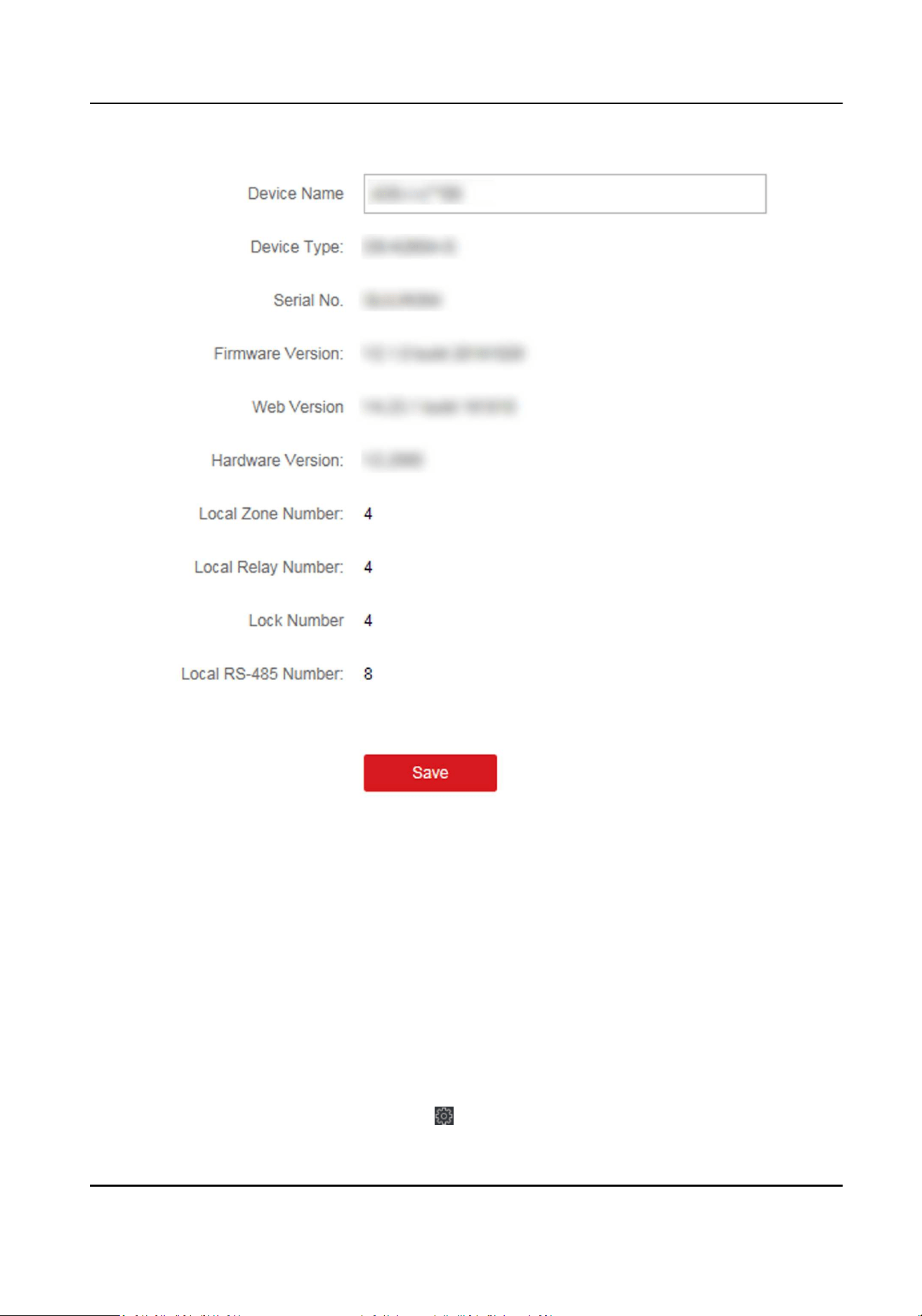
Figure 7-18 View Device Informaon
You can set the device name, view the device type, serial No., version, relay number, and lock
number. Click Save to save the sengs.
7.12.2 Change Device Password
You can change the device password.
Before You Start
Make sure the device is acvated. For details, see Acvaon.
Steps
1.
On the Device for Management page, click → System → User to enter the User tab.
Access Control Terminal User Manual
123

2.
Select a user and click Edit to enter the Edit page.
3.
Input the old password, create a new password, and conrm the new password.
Cauon
The password strength of the device can be automacally checked. We highly recommend you
change the password of your own choosing (using a minimum of 8 characters, including at least
three kinds of following categories: upper case leers, lower case leers, numbers, and special
characters) in order to increase the security of your product. And we recommend you change
your password regularly, especially in the high security system, changing the password monthly
or weekly can beer protect your product.
Proper conguraon of all passwords and other security sengs is the responsibility of the
installer and/or end-user.
4.
Click OK.
Result
The device password is changed. You should enter the new password on the Device for
Management page to reconnect the device.
7.12.3 Time Management
Manage device's me zone, me synchronizaon, and DST parameters.
Time Zone and Time Synchronizaon
On the Device for Management page, select a device and click → System → Time to enter the
Time tab.
You can select a me zone, set NTP parameters, or manually synchronize me.
Time Zone
Select a me zone from the drop-down list.
NTP
The device will synchronize me with NTP automacally. Aer you enable NTP, you should set
the NTP server address, NTP port, and synchronizaon interval.
Manual Time Synchronizaon
Aer you enable Manual Time Synchronizaon, you can manually set the device me.
If you check Synchronize with Computer Time, the Set Time will display the current computer's
me. At this me, uncheck Synchronize with Computer Time, and click
, you can edit the
device me manually.
Click Save to save the sengs.
Access Control Terminal User Manual
124

DST
On the Device for Management page, click Remote Conguraon → System → Time → DST to
enter the DST tab.
Enable DST and you can edit the DST bias me, the DST start me, and end me.
Click Save.
7.12.4 System Maintenance
You can reboot the device, restore the device to the default sengs, and upgrade the device.
Reboot
On the Device for Management page, click → System → System Maintenance to enter the
System Maintenance tab.
Click Reboot and the device starts reboong.
Restore Default Sengs
On the Device for Management page, click Remote Conguraon → System → System
Maintenance to enter the System Maintenance tab.
Restore Default
The parameters will be restored the default ones, excluding the IP address.
Restore All
All device parameters will be restored to the default ones. The device should be acvated aer
restoring.
Upgrade
On the Device for Management page, click Remote Conguraon → System → System
Maintenance to enter the System Maintenance tab.
Select a device type from the drop-down list, click Browse and select an upgrade le from the local
computer, and click Upgrade.
Note
●
If you select Card reader as the device type, you should also select a card reader No. from the
drop-down list.
●
The upgrade will lasts for about 2 min. Do not power o during the upgrading. Aer upgrading,
the device will reboot automacally.
7.12.5 Congure RS-485 Parameters
You can set the RS-485 parameters including the baud rate, data bit, stop bit, parity type,
communicaon mode, work mode, and connecon mode.
Access Control Terminal User Manual
125

Steps
1.
Click Maintenance and Management → Device to enter the device list.
2.
Click to enter the remote conguraon page.
3.
Click System → RS-485 Sengs to enter the Conguring the RS-485 Parameters tab.
4.
Select the serial No. of the port from the drop-down list to set the RS-485 parameters.
5.
Set the baud rate, data bit, the stop bit, parity, ow control, communicaon mode, working
mode, and the connecon mode from the drop-down list.
6.
Click Save and the congured parameters will be applied to the device automacally.
Note
Aer changing the working mode, the device will be rebooted. A prompt will be popped up aer
changing the working mode.
7.12.6 Security Mode Sengs
Set the security mode for logging in the client soware.
On the Device for Management page, click → System → Security to enter the Security Mode
tab.
Select a security mode from the drop-down list, and click Save.
You can also enable SSH or HTTP to get a more secure network.
Security Mode
High security level for user informaon vericaon when logging in the client soware.
Compable Mode
The user informaiton vericaon is compable with the old client soware version when
logging in.
7.12.7 Network Parameters Sengs
Set device network parameters, including the NIC type, DHCP, and HTTP.
On the Device for Management page, click → Network → Network Parameters to enter the
Network Parameters Sengs tab.
NIC Type
Select a NIC type from the drop-down list. You can select either Self-adapve, 10M, or 100M.
DHCP
If you disable the funcon, you should manually set the device's IPv4 address, IPv4 subnet
mask, IPv4 default gateway, MTU, and port.
If you enable the funcon, the system will automacally assign IPv4 address, IPv4 subnet mask,
IPv4 default gateway for the device.
Access Control Terminal User Manual
126

HTTP
Set the HTTP port, DNS1 server address, and DNS2 server address.
Note
Aer changing the HTTP port, you should reboot the device to take eect the sengs.
7.12.8 Report Strategy Sengs
You can set the center group for uploading the log via the EHome protocol.
On the Device for Management page, click → Network → Report Strategy to enter the Report
Strategy Sengs tab.
You can set the center group and the system will transfer logs via EHome protocol. Click Save to
save the sengs.
Center Group
Select a center group from the drop-down list.
Main Channel
The device will communicate with the center via the main channel.
Note
N1 refers to wired network.
7.12.9 Network Center Parameters Sengs
You can set the nofy center, center's IP address, the port No., the protocol (EHome), the EHome
account user name,etc. to transmit data via EHome protocol.
On the Device for Management page, click
→ Network → Network Center Parameters to enter
the Network Center Parameters Sengs tab.
Select a center from the drop-down list.
Aer enabling the funcon, you can set the center's address type, IP address/domain name, port
No., EHome user name, etc.
Click Save.
7.12.10 Congure Wi-Fi
Steps
1.
On the Device for Management page, click → Network → Wi-Fi to enter the Wi-Fi Sengs
tab.
2.
Check Enable to enable the Wi-Fi funcon.
3.
Enter the SSID name and password or you can select a network from the Wi-Fi list.
Access Control Terminal User Manual
127

4.
Set the Wi-Fi Security Mode from the drop-down list.
5.
Oponal: Click Refresh to refresh the network status.
6.
Oponal: Set WLAN parameters.
1) On the Wi-Fi Sengs page, click WLAN to enter the WLAN page.
2) Uncheck DHCP and set the IP address, the subnet mask, the default gateway, the MAC
address, the DNS1 IP Address, and the DNS2 IP address.
7.
Click Save.
7.12.11 Set Relay Parameters
Click Maintenance and Management → Device to enter the device list.
Click to enter the remote conguraon page.
Click Alarm → Relay . Select a relay and click and set the relay name and output delay me.
Click OK to save the sengs.
7.12.12 Set Access Control Parameters
Steps
1.
On the Device for Management page, click → Others → Access Control Parameters to enter
the Access Control Parameters tab.
2.
Check the checkbox to enable the funcon.
Voice Prompt
If you enable this funcon, the voice prompt is enabled in the device. You can hear the voice
prompt when operang in the device.
3.
Click Save.
7.12.13 Set CPU Card Reading Mode
Steps
1.
On the Device for Management page, click → Others → CPU Card Reading Sengs to enter
the CPU Card Reading Sengs tab.
2.
Select a reading mode from the dropdown list.
3.
Click Save.
7.12.14 Congure Volume Input or Output
Steps
1.
On the Device for Management page, click → Image → Audio Input or Output to enter Audio
Input or Output tab.
2.
Move the block to adjust the device output volume.
Access Control Terminal User Manual
128

3.
Click Save.
7.12.15 Operate Relay
Steps
1.
Click Maintenance and Management → Device to enter the device list.
2.
Click to enter the remote conguraon page.
3.
Click Operaon → Relay .
4.
Enable or disable the relay.
7.12.16 View Relay Status
Click Maintenance and Management → Device Management → Device to enter the device list.
Click to enter the remote conguraon page.
Click Status → Relay and you can view the relay status.
Access Control Terminal User Manual
129
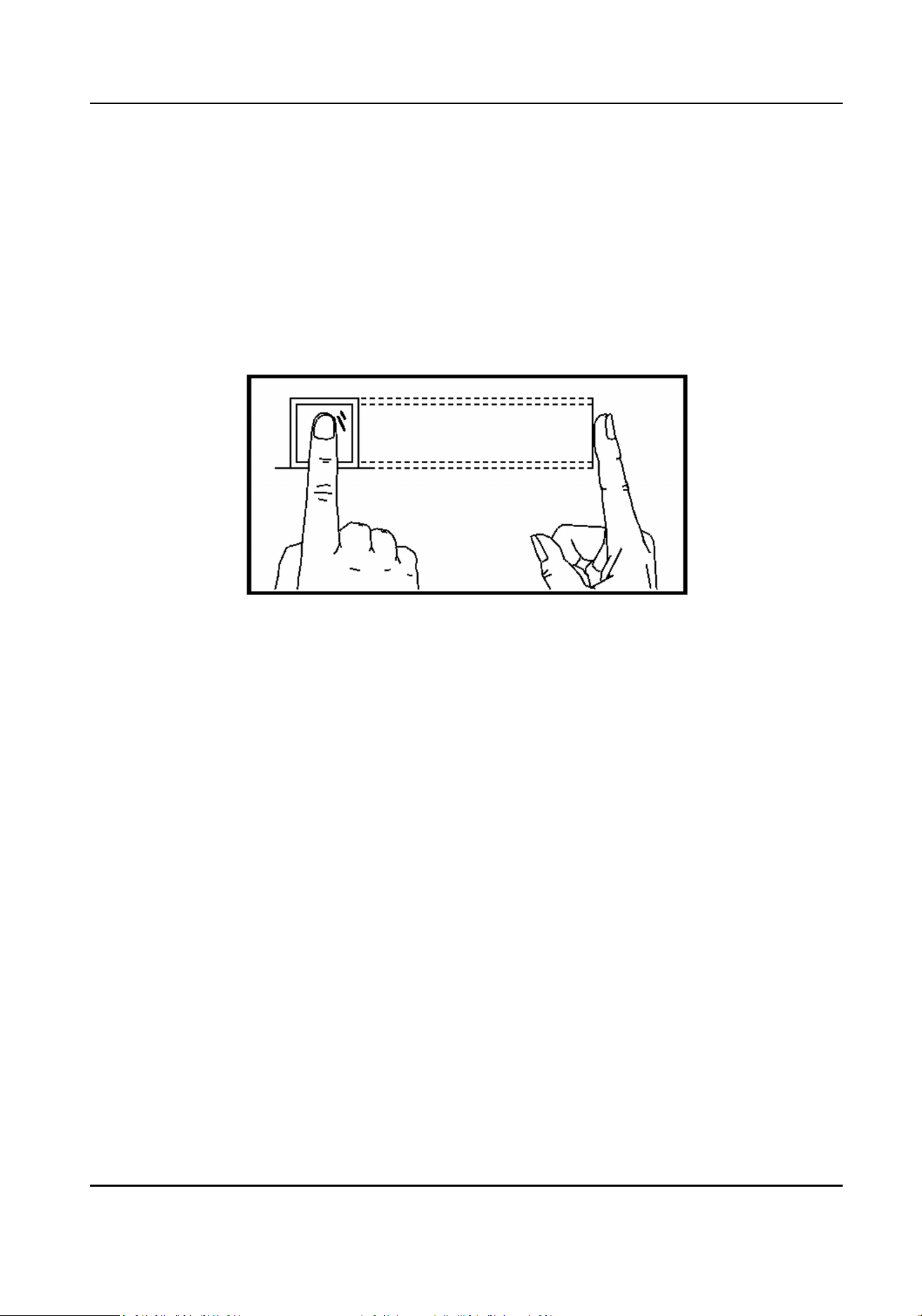
Appendix A. Tips for Scanning Fingerprint
Recommended Finger
Forenger, middle nger or the third nger.
Correct Scanning
The gure displayed below is the correct way to scan your nger:
You should press your nger on the scanner horizontally. The center of your scanned nger should
align with the scanner center.
Incorrect Scanning
The gures of scanning ngerprint displayed below are incorrect:
Access Control Terminal User Manual
130
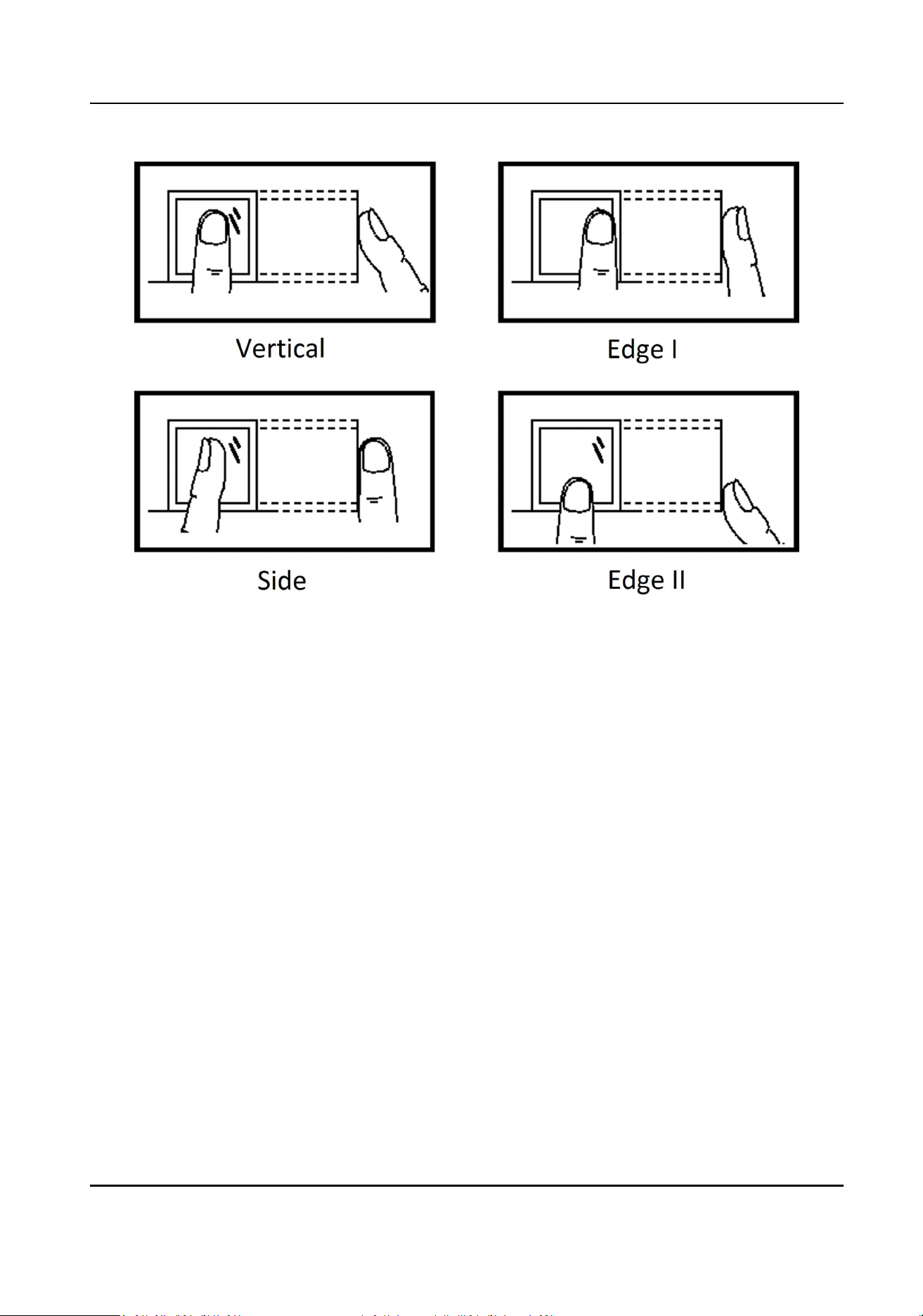
Environment
The scanner should avoid direct sun light, high temperature, humid condions and rain.
When it is dry, the scanner may not recognize your ngerprint successfully. You can blow your
nger and scan again.
Others
If your ngerprint is shallow, or it is hard to scan your ngerprint, we recommend you to use other
authencaon methods.
If you have injuries on the scanned nger, the scanner may not recognize. You can change another
nger and try again.
Access Control Terminal User Manual
131
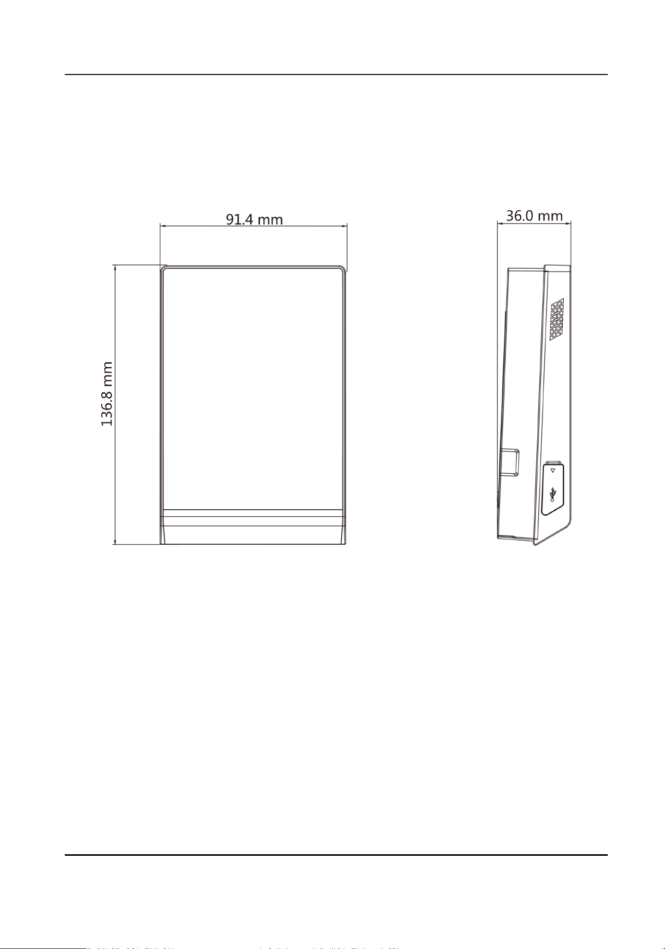
Appendix B. Dimension
Dimension of Device without Fingerprint Module
Access Control Terminal User Manual
132
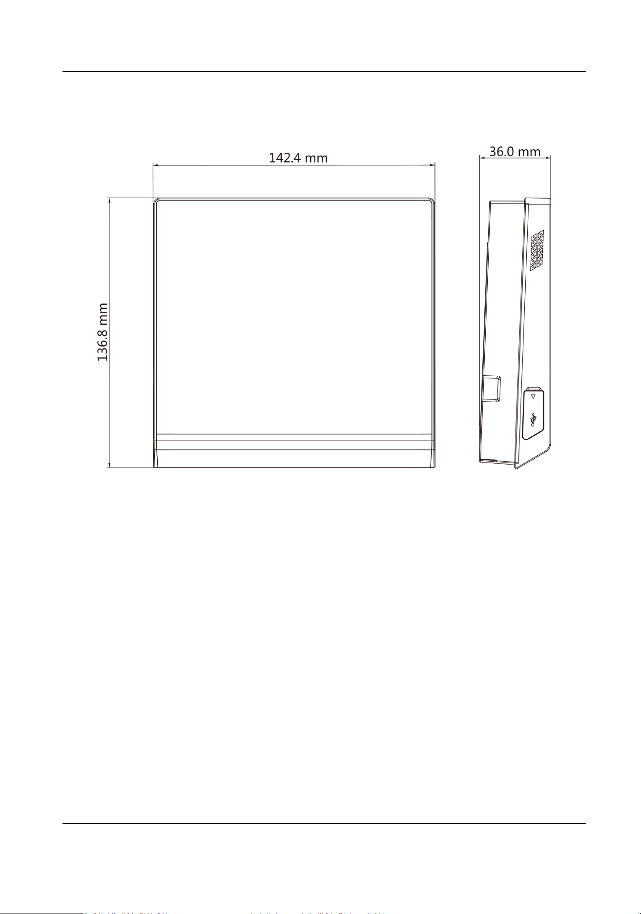
Dimension of Device with Fingerprint Module
Access Control Terminal User Manual
133

Appendix C. Communicaon Matrix and Device
Command
Communicaon Matrix
Scan the following QR code to get the device communicaon matrix.
Note that the matrix contains all communicaon ports of Hikvision access control and video
intercom devices.
Figure C-1 QR Code of Communicaon Matrix
Device Command
Scan the following QR code to get the device common serial port commands.
Note that the command list contains all commonly used serial ports commands for all Hikvision
access control and video intercom devices.
Figure C-2 Device Command
Access Control Terminal User Manual
134

UD19607B-A