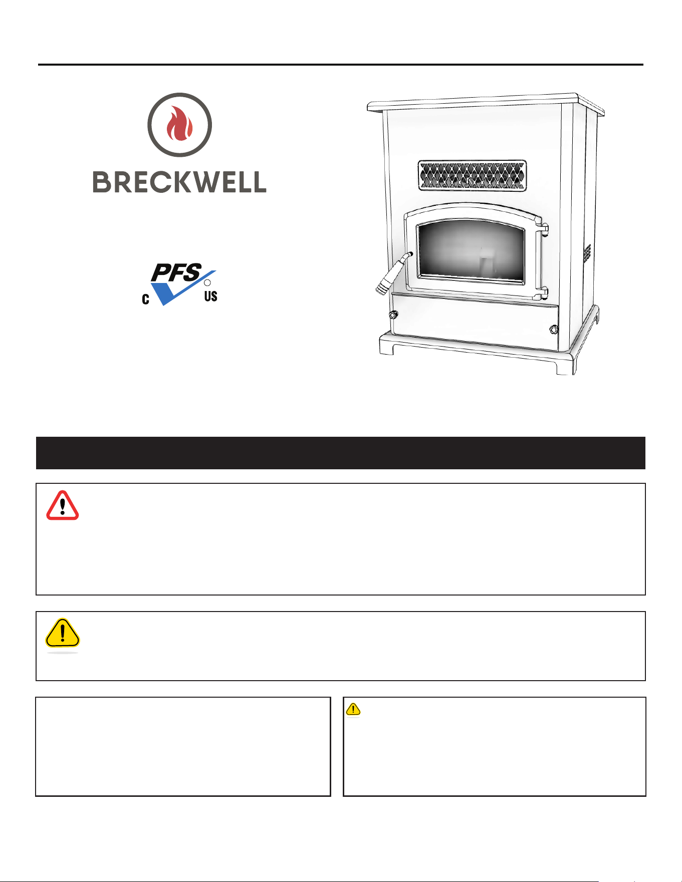
* All Pictures In This Manual Are For Illustrative Purposes Only. Actual Product May Vary.
© 2024 Breckwell, 227 Industrial Park Rd., South Pittsburg, TN 37380 Ph. 423-403-4031
THIS MANUAL IS SUBJECT TO CHANGE WITHOUT NOTICE.
Owner’s Instruction and Operation Manual
U.S. Environmental Protection Agency
Certied to comply with 2020 particulate
emissions standards.
SAFETY NOTICE: If this heater is not properly installed, a house re may result.
For your safety, follow the installation instructions. Never use make-shift compromises
during the installation of this heater. Contact local building or re ofcials about permits,
restrictions and installation requirements in your area. NEVER OPERATE THIS PRODUCT
WHILE UNATTENDED.
CAUTION! Please read this entire manual before you install or use your new room heater.
Failure to follow instructions may result in property damage, bodily injury, or even death.
Improper Installation Could Void Your Warranty!
Save These Instructions In A Safe Place For Future Reference.
CALIFORNIA PROPOSITION 65 WARNING:
This product can expose you to chemicals including carbon
monoxide, which is known to the State of California to cause
cancer, birth defects, and/or other reproductive harm. For
more information, go to www.P65warnings.ca.gov
854042C-1004N
SP1000E
Certied to ASTM E1509-2022, and
CAN/ULC S627:2023
Mobile Home / Transportable
Building Approved
Model Number:
R
Report Number: F21-690
2
© 2024 Breckwell
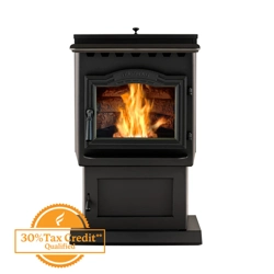
This manual describes the installation and operation of the Breckwell, SP1000E wood heater. This heater meets the 2020
U.S. Environmental Protection Agency’s emission limits for wood heaters sold after May 15, 2020. Under specic test
conditions this heater has been shown to deliver heat at rates ranging from 6,580 to 39,121 Btu/hr, 1.0 g/hr, and 75%
efciency.
INTRODUCTION
Heating Specications
Fuel Burn Rate 1 - 5.5 lbs (0.45 - 2.5 kh) per hr
* Pellet size may affect the actual rate of fuel feed,
burn times, and hopper capacity. Fuel feed rates
may vary by as much as 20%. Use PFI listed fuel
for best results.
Hopper Capacity * Up to 140lbs. (63.5 kg)
Flue Size 3” or 4” (77 mm or 102 mm)
Electrical Rating 115V 60Hz 3A
Dimensions
Overall: Height x Width x Depth 25-3/4” (655 mm) X 32-5/8” (829 mm) X 23-7/8” (607 mm)
Floor To Exhaust Pipe Center 8.875” (226 mm)
Floor To Fresh Air Intake Center 6.625” (169 mm)
WARNING:
IT IS AGAINST FEDERAL REGULATIONS TO OPERATE THIS WOOD HEATER IN A MANNER INCONSISTENT WITH THE
OPERATING INSTRUCTIONS IN THE OWNER’S MANUAL.
RETAIN YOUR ORIGINAL RECEIPT FOR ANY WARRANTY CLAIMS. CONTACT YOUR DEALER OR INSTALLER IF YOU NEED
TO FILE A CLAIM.
Note: Register your product by using your smart
phone with the QR code. Save your receipts with
your records for any warranty claims.
You can also register your product online at
www.breckwell.com/product-registration
© 2024 Breckwell
3
INSTALLATION CHECKLIST
Your wood stove should be installed by a qualied installer only. An NFI qualied Installer can be found at www.ncertied.
org/public/nd-an-n-pro/
For customer service, please contact your Breckwell dealer.
COMMISSIONING CHECKLIST
This checklist is to be completed in full by the qualied person who installs this unit. Keep this page for future reference.
Failure to install and commission according to the manufacturer’s instructions and complete this checklist will invalidate the
warranty.
Please Print
Customer Name: Telephone Number:
Address:
Model:
Serial Number:
Installation Company Name: Phone Number:
Installation Technician’s Name: License Number:
DESCRIPTION OF WORK
Location of installed appliance: _____________________________________________________________________________
Venting System: New Venting System Yes No If yes, Brand ________________________________________
If no, Date of inspection of existing venting system: _____________________________________________________________
COMMISSIONING
Conrm Hearth Pad Installation as per Installation Instructions ................................................................................
Conrm proper placement of internal parts ..........................................................................................................
Check soundness of door gasket and door seals ...................................................................................................
Conrm clearances to combustibles as per installation instructions in this manual ......................................................
Check the operations of the air controls ...............................................................................................................
Conrm the venting system is secure and sealed ...................................................................................................
Conrm the stove starts and operates properly ......................................................................................................
Check to ensure a CO alarm is installed as per local building codes and is functional ...............................................
Explain the safe operation, proper fuel usage, cleaning, and routine maintenance requirements .................................
Declaration of Completion: As the qualied person responsible for the work described above, I conrm that the appliance as
associated work has been installed as per manufacturer’s instructions and following any applicable building and installation
codes.
Signed: ____________________________________Print Name: ________________________________ Date: _____________
Home Owner: RETAIN THIS INFORMATION FOR FUTURE REFERENCE
4
© 2024 Breckwell
SAFETY NOTICE
• IF THIS STOVE IS NOT PROPERLY INSTALLED, A HOUSE
FIRE MAY RESULT. TO REDUCE THE RISK OF FIRE,
FOLLOW THE INSTALLATION INSTRUCTIONS.
• CONTACT YOUR LOCAL BUILDING OFFICIALS TO
OBTAIN A PERMIT AND INFORMATION ON ANY
ADDITIONAL INSTALLATION RESTRICTIONS OR
INSPECTION REQUIREMENTS IN YOUR AREA.
• DO NOT PLACE CLOTHING OR OTHER FLAMMABLE
ITEMS ON OR NEAR THIS STOVE.
• NEVER USE GASOLINE, GASOLINE-TYPE LANTERN
FUEL, KEROSENE, CHARCOAL LIGHTER FLUID, OR
SIMILAR LIQUIDS TO START OR ’FRESHEN UP’ A FIRE
IN THIS STOVE. KEEP ALL SUCH LIQUIDS WELL AWAY
FROM THE STOVE WHILE IT IS IN USE.
• THIS APPLIANCE IS A FREESTANDING HEATER. IT IS
NOT INTENDED TO BE ATTACHED TO ANY TYPE OF
DUCTING. IT IS NOT A FURNACE. DO NOT CONNECT
THIS UNIT TO ANY AIR DISTRIBUTION DUCT OR
SYSTEM. THIS APPLIANCE IS NOT INTENDED FOR
COMMERCIAL USE.
• INSTALL VENT AT CLEARANCES SPECIFIED BY THE
VENT MANUFACTURER.
• DO NOT INSTALL A FLUE DAMPER IN THE EXHAUST
VENTING SYSTEM OF THIS UNIT.
• YOUR STOVE REQUIRES PERIODIC MAINTENANCE
AND CLEANING (SEE ”MAINTENANCE”). FAILURE TO
MAINTAIN YOUR STOVE MAY LEAD TO IMPROPER
AND/OR UNSAFE OPERATION.
• A POWER SURGE PROTECTOR IS REQUIRED. THIS
UNIT MUST BE PLUGGED INTO A 110 - 120V, 60 HZ
GROUNDED ELECTRICAL OUTLET. DO NOT USE AN
ADAPTER PLUG OR SEVER THE GROUNDING PLUG.
DO NOT ROUTE THE ELECTRICAL CORD UNDERNEATH,
IN FRONT OF, OR OVER THE HEATER. DO NOT ROUTE
THE CORD IN FOOT TRAFFIC AREAS OR PINCH THE
CORD UNDER FURNITURE.
ATTENTION:
• A WORKING SMOKE DETECTOR MUST BE INSTALLED
IN THE SAME ROOM AS THIS PRODUCT.
• INSTALL A SMOKE DETECTOR ON EACH FLOOR OF
YOUR HOME; INCASE OF ACCIDENTAL FIRE FROM
ANY CAUSE IT CAN PROVIDE TIME FOR ESCAPE.
• THE SMOKE DETECTOR MUST BE INSTALLED AT LEAST
15 FEET (4,57 M) FROM THE APPLIANCE IN ORDER
TO PREVENT UNDUE TRIGGERING OF THE DETECTOR
WHEN RELOADING.
CAUTION:
• DO NOT UNPLUG THE STOVE IF YOU SUSPECT A
MALFUNCTION. TURN THE ON/OFF SWITCH TO
”OFF’ AND CONTACT YOUR DEALER.
• THE HEATER WILL NOT OPERATE DURING A POWER
OUTAGE. IF A POWER OUTAGE DOES OCCUR, CHECK
THE HEATER FOR SMOKE SPILLAGE AND OPEN A
WINDOW IF ANY SMOKE SPILLS INTO THE ROOM.
• NEVER BLOCK FREE AIRFLOW THROUGH THE OPEN
VENTS OF THE UNIT.
CAUTION:
BURNING FUEL CREATES CARBON MONOXIDE AND CAN
BE HAZARDOUS TO YOUR HEALTH IF NOT PROPERLY
VENTED.
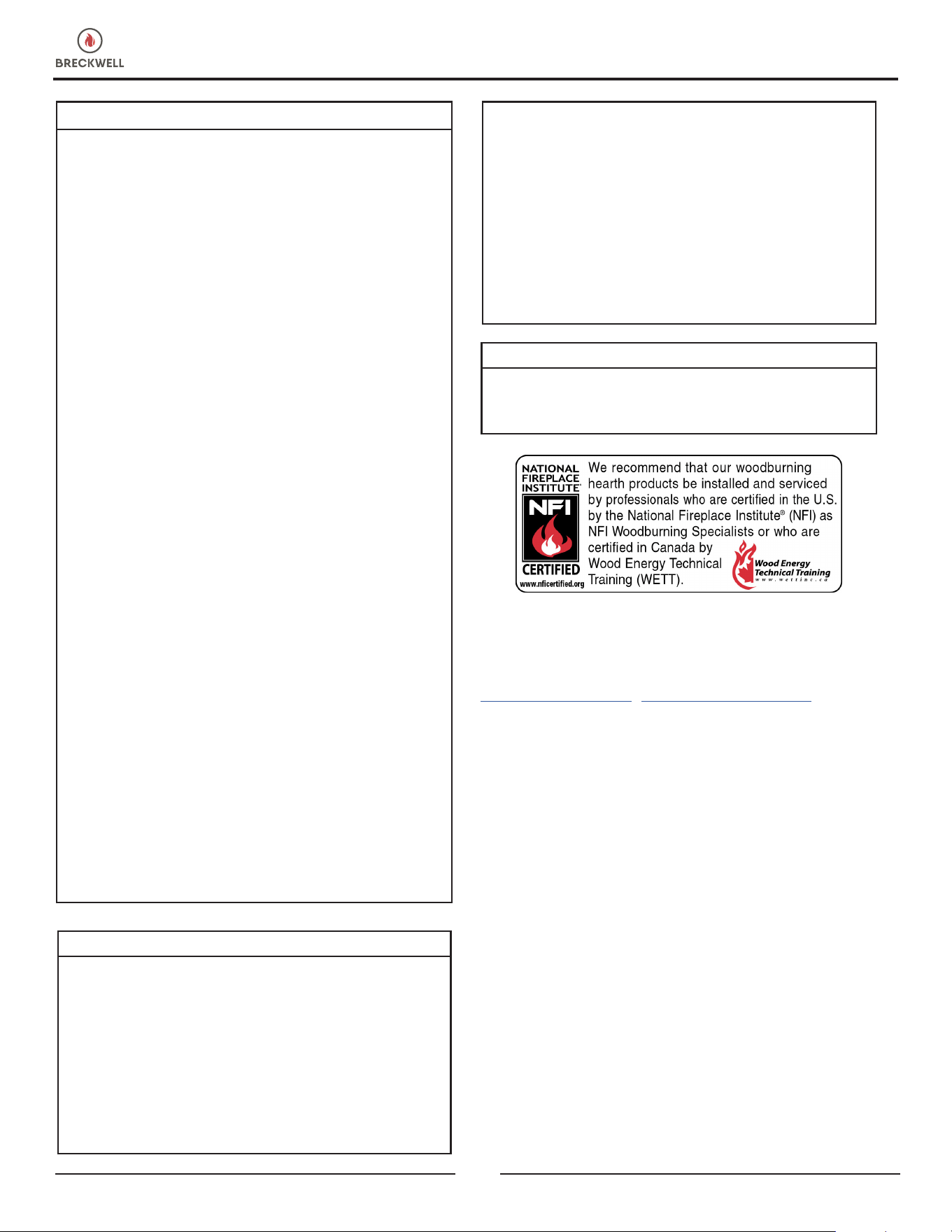
Breckwell highly recommends your stove be installed by a
qualied NFI (US) or WETT (Canada) technician. To nd the
nearest qualied installer, go to:
https://ncertied.org, https://www.wettinc.ca/
PREPARATION
Factory packaging must be removed, and some minor
assembly work is required prior to installation. Access to
the rear of the stove is necessary. NOTE: Normally, your
dealer will perform these functions.
FLOOR PROTECTION
The stove must be placed on a continuous (grouted joints)
non-combustible material such as ceramic tile, cement
board, brick, 3/8” (10 mm) millboard or equivalent, or
other approved or listed material suited for oor protection.
THE MATERIAL(S) USED MUST HAVE, OR COMBINE
TO HAVE, A MINIMUM INSULATIVE RATING OF ‘R1.’
NOTE: ceramic tile, or any tile, requires a continuous sheet
beneath to prevent the possibility of embers falling through
to the combustible if cracks or separation should occur in
the nished surface, this would include oor protection for
Built-in raised hearths. Check local codes for approved
alternatives. Clearances are measured from the sides, back
and face (door opening) or stove body. Clearances may
only be reduced by means approved by the regulatory
INSTALLATION
© 2024 Breckwell
5
authority having jurisdiction. DO NOT USE MAKESHIFT
MATERIALS OR COMPROMISES IN THE INSTALLATION
OF THIS UNIT. INSTALL VENT AT CLEARANCES SPECIFIED
BY THE VENT MANUFACTURER.
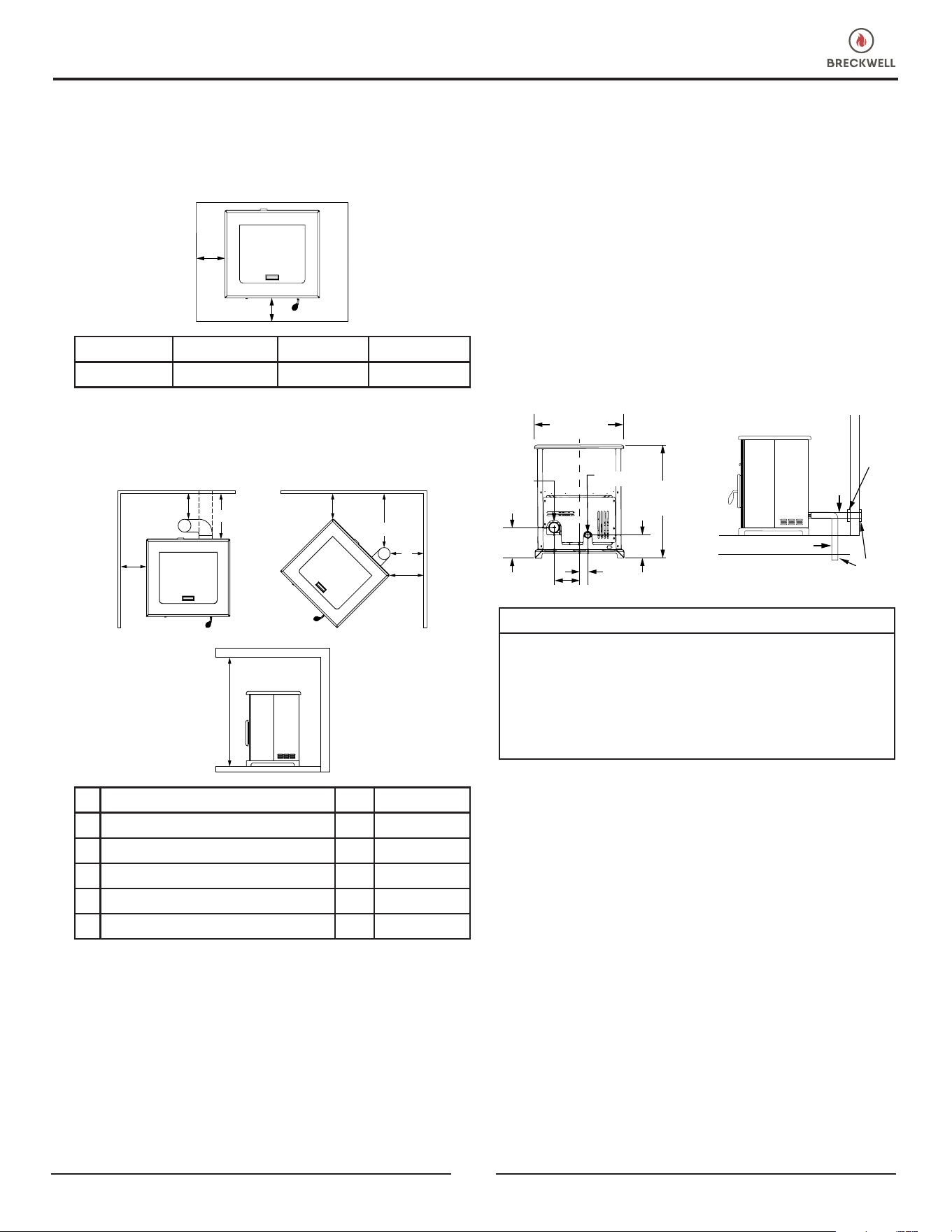
A
B
A Side to Stove 6” 153 mm
B Front to Stove 6” 153 mm
CLEARANCES
This unit has been tested and listed for installation in
residential and mobile home/transportable buildings.
G
G
F
F
D
C
E
H
C Side Wall to Stove 12” 305 mm
D Back Wall to Vertical Exhaust 3” 77 mm
E Back Wall to Horizontal Exhaust 1” 26 mm
F Side Wall to Stove 1” 26 mm
G Wall to Vent Pipe 3” 77 mm
H Ceiling Height to Floor 60” 1524 mm
COMBUSTION AIR SUPPLY
For a mobile home/transportable building installation,
the stove must be connected to an outside source of
combustion air. A 2” (51 mm) inside diameter metallic
pipe, either exible or rigid, may be attached to the inlet
at the stove’s rear. A rodent guard (minimum 1/4” (7 mm)
wire mesh) wind hood must be used at the terminus. All
connections must be secured and airtight by either using
the appropriately sized hose clamp and/or UL-181-AP foil
tape. For mobile home/transportable building installations
only: 2” (51 mm) inside diameter pipe may be used for the
rst 5 feet of combustion air supply run. From 5 to 10 feet,
use 2-3/4” (70 mm) inside diameter pipe. No combustion
air supply may exceed 10 feet.
Sources of Outside Combustion Air
a. In replaces
• Chimney top.
• Ash clean out door.
b. For freestanding installations
• A hole in oor near stove rear terminating only a ventilated
crawl space.
• A hole in the wall behind the stove.
25-3/4” (655 mm)
32-5/8”
(829 mm)
6-5/8”
(169 mm)
2-7/16”
(62 mm)
7-5/16”
(186 mm)
8-7/8”
(226 mm)
C
L
Exhaust
Pipe
Fresh Air
Intake
TRIM
COLLAR
VENTILATED
CRAWL SPACE
RODENT
GUARD
FRESH
AIR
INTAKE
FRESH AIR INTAKE
ATTENTION:
DO NOT VENT UNDER ANY PORCH, DECK, AWNING, OR
IN ANY SEMI ENCLOSED OR ROOFED AREA. DOING SO
MAY RESULT IN UNPREDICTABLE AIRFLOW AT THE VENT
CAP UNDER CERTAIN CONDITIONS AND CAN AFFECT
THE PERFORMANCE OF YOUR STOVE, AS WELL AS,
OTHER UNFORESEEABLE ISSUES.
WHEN OUTSIDE AIR IS NOT USED
If outside air is not used, it is important that combustion air
is easily available to the air inlet. A closeable outside air
register can be used in tightly insulated homes.
IMPORTANCE OF PROPER DRAFT
Draft is the force which moves air from the appliance up
through the chimney. The amount of draft in your chimney
depends on the length of the chimney, local geography,
nearby obstructions and other factors. Too much draft may
cause excessive temperatures in the appliance. Inadequate
draft may cause backpufng into the room and ‘plugging’
of the chimney. Inadequate draft will cause the appliance to
leak smoke into the room through appliance and chimney
connector joints. An uncontrollable burn or excessive
temperature indicates excessive draft. Take into account the
chimney’s location to ensure it is not too close to neighbours
or in a valley which may cause unhealthy or nuisance
conditions.
INSTALLATION

6
© 2024 Breckwell
VENTING REQUIREMENTS
A compatible appliance adapter is required for the proper
venting installation of this unit. Purchase the appropriate
appliance adapter from your preferred venting company
prior to starting the ventilation process.
This unit is certied for use with listed TYPE PL-Vent, 3” or
4” (diameter in size. The stove was tested with Simpson
Duravent brand. CLass “A” chimney is not required. Refer
to the instructions provided by the vent manufacturer,
especially when passing through a wall, ceiling or roof. This
is a pressurized exhaust system. All vent connector joints
must be sealed with 500°F (260°C) RTV silicone sealant to
ensure consistent performance and avoid smoke spillage.
All horizontal connector joints must be sealed with UL-181-
AP foil tape. All vertical vent connector joints are required
to be secured with a minimum of 3 screws. The chimney
connector shall not pass through an attic or roof space,
closet or similar concealed space, or a oor, or ceiling.
Where passage though a wall, or partition of combustible
construction is desired, the installation shall conform to
CAN/CSA-B365, Installation Code for Solid-Fuel-Burning
Appliances and Equipment.
WARNING:
• INSTALL VENT AT CLEARANCES SPECIFIED BY THE
VENT MANUFACTURER.
• DO NOT CONNECT THE PELLET VENT TO A VENT
SERVING ANY OTHER APPLIANCE OR STOVE.
• DO NOT INSTALL A FLUE DAMPER IN THE EXHAUST
VENTING SYSTEM OF THIS UNIT.
HORIZONTALLY THROUGH WALL
1. Positions stove, adhering to clearances shown.
2. Locate position of hole in wall; directly behind stove
exhaust vent.
3. Always maintain 3” (77 mm) clearance from
combustible materials.
4. Install PL-Vent wall thimble per PL-Vent manufacturer’s
instructions.
5. Attach enough piping to penetrate and extend at least
6” beyond exterior walls. An 8-foot vertical pipe run
is suggested where possible to reduce the possibility
of smoke spillage in the event of a loss of negative
pressure.
6. Attach cap and seal outside wall thimbles with non-
hardening waterproof mastic.
7. Terminations should not be located so that hot exhaust
gases can ignite trees, shrubs, or grass or be a hazard
to children. Exhaust gases can reach temperatures of
500°F and cause serious burns if touched.
8. Locate terminations:
a. Not less than 3 feet above any forced air inlet located
within 10 feet;
b. Not less than 4 feet below or horizontally from, or 1
foot above any door, window or gravity air inlet into
any building;
c. Not less than 2 feet from an adjacent building and not
less than 7 feet above grade when located adjacent to
a public walkway. Mobile home/transportable building
installations must use a spark arrester.
VERTICAL ROOF VENT
WALL
THIMBLE
6” MINIMUM CLEARANCE
TO ANY COMBUSTIBLE
SURFACE
CLEAN-OUT TEE
A 90 DEGREE ELBOW
MAY ALSO BE USED
L-VENT ADAPTER
WALL STRAP
SEE VENT MANUFACTURER
FOR NUMBER AND SPACING
VERTICALLY WITH NEW CHIMNEY SYSTEM
OPTION: To achieve a center vertical installation, a 45°
elbow and a clean-out tee can be used to offset the pipe
from the exhaust outlet to the rear center of the stove.
INSTALLATION
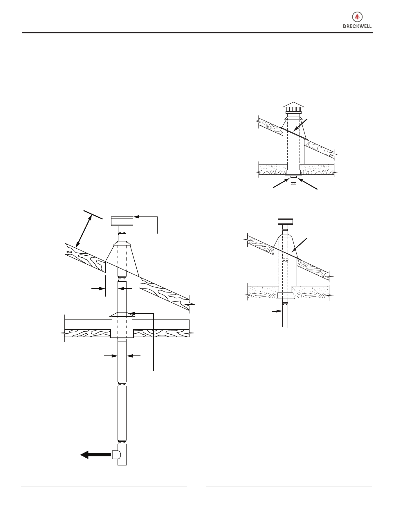
© 2024 Breckwell
7
OPTION: Install PL-Vent elbow in place of clean-out tee.
Locate stove. Drop plumb bob to center of tee outlet , mark
point on ceiling. Install ceiling support and PL-Vent pipe per
PL-Vent manufacturer’s instructions.
1. Always maintain 3” (77 mm) clearance from combustible
materials. When passing through additional oors or
ceilings, always install restop spacer.
2. After lining up for hole in roof, cut either a round or
square hole in roof, always 3” (77 mm) larger all the
way around pipe. Install upper edge and sides of
ashing under roong materials, nail to the roof along
upper edge. Do not nail lower edge. Seal nail heads
with non-hardening waterproof mastic.
3. Apply non-hardening, waterproof mastic where the
storm collar will meet the vent and ashing. Slide storm
collar down until it sits on the ashing. Seal and install
cap. Mobile home/transportable building installations
must use a spark arrester.
12” MINIMUM
CLEARANCE
TO ROOF
VERTICAL
ROOF VENT
ATTIC
INSULATION
SHIELD
TO STOVE
3” MINUMUM
CLEARANCES TO
COMBUSTIBLES
3” MINUMUM
CLEARANCES TO
COMBUSTIBLES
VERTICALLY INTO EXISTING CHIMNEY SYSTEM
Adapters are available to adapt from 3” (77 mm) L-Vent
to 6” (153 mm) or 8” (204 mm) Class-A chimney. As an
alternative, 3” (77 mm) or 4” (102 mm) L-Vent can be run
inside existing chimney to termination. This is the preferred
method. Follow guidelines for equivalent vent length.
PELLET
VENT
NOTE:
THIS METHOD
IS PREFERRED
EXISTING
CHIMNEY
SYSTEM
PELLET VENT TO
CHIMNEY ADAPTER
(SPV-CA)
UNIVERSAL
CONNECTOR
EXISTING
CHIMNEY
SYSTEM
VERTICALLY INTO EXISTING MASONRY
FIREPLACE
1. Have the masonry chimney inspected by a qualied
chimney sweep or installer to determine its structural
condition.
2. You will need a pipe length equal to the chimney height
from the hearth. If outside combustion air is to be used,
you will need a pipe length equal to the chimney height
plus 18” (458 mm).
3. Install a blanking plate and the chimney pipe, and if
used the outside air pipe, as shown.
4. Attach the L-Vent adapter, a section of pipe and clean-
out tee, making sure the clean-out tee is centered in
the chimney ue area. Use RTV, metallic tape, and
a minimum of three self-taping screw at all joint
connections to ensure a tight seal.
INSTALLATION
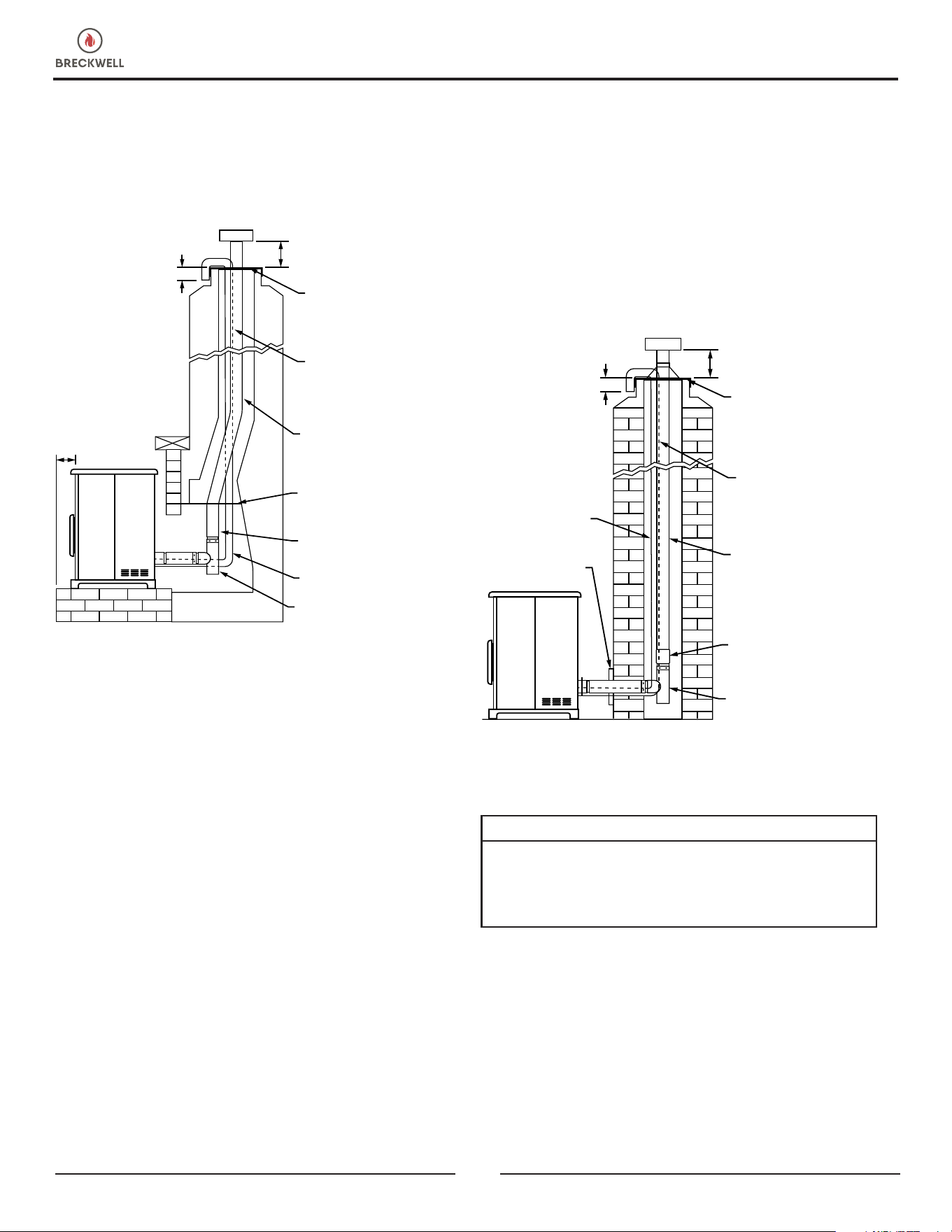
8
© 2024 Breckwell
INSTALLATION
5. Position the stove, adhering to the clearances.
6. Measure and build chimney top plate. Cut out holes for
chimney pipe, and if used the outside air pipe. Install
and seal with non-hardening mastic to prevent water
leakage. Install vent cap.
6”
(153 mm)
6”
(153 mm)
3”
(77 mm)
NOTE: FOLLOW
METAL CHIMNEY
INSTALLATION
INSTRUCTIONS
TOP PLATE (SEAL
TO CHIMNEY TOP
WITH NON-
HARDENING
MASTIC)
EXTENSION TO
CHIMNEY TOP
REQUIRED.
3” OR 4” STAINLESS
STEEL SINGLE WALL
PIPE OR FLEX PIPE.
BLANKING PLATE
(SEAL WITH NON-
HARDENING MASTIC).
3” OR 4” STAINLESS
STEEL FLEX PIPE.
OPTIONAL OUTSIDE AIR
CLEAN-OUT-TEE (TYPE L)
OR 90 DEGREE ELBOW
HEARTH
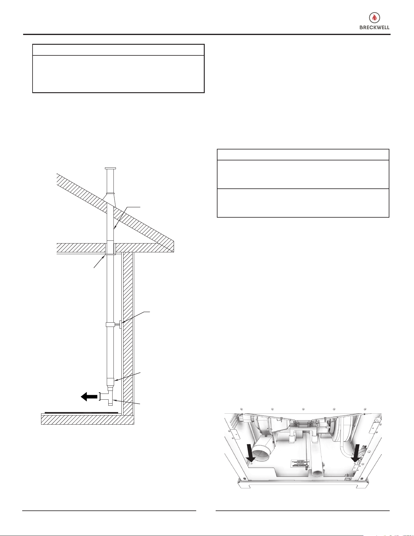
THROUGH SIDE OF MASONRY CHIMNEY
1. Position the stove, adhering to the clearances. Mark
the center of the hole where the pipe is to pierce the
masonry chimney.
2. It will be necessary to break out the masonry around
the location of the pipe center mark. Use a 4” (102
mm) diameter hole for 3” (77 mm) pipe and 5” (127
mm) diameter hole for 4” (102 mm) pipe.
3. Measure and build chimney top plate. Cut out holes for
chimney pipe, and if used, the outside air pipe.
4. Install the tee on the bottom of the vertical pipe system
and lower it down the chimney until the center branch
of the tee is level with the center of the hole in the
masonry as shown.
5. Install and seal the top plate from step 3 with non-
hardening mastic. Slip the storm collar over the pipe,
and while holding the pipe at the proper elevation,
afx the collar with a minimum of 3-1/4” (83 mm)
stainless steel sheet metal screws. Seal all joints and
seams around the collar.
6. Connect the horizontal pipe by pushing it through the
hole in the masonry and lining it up with the branch in
the tee. Push the pipe into the tee while twisting it to
lock it into the tee.
7. If desired, once the horizontal pipe is in place, the
space between the pipe and masonry may be lled
with high-temperature grout.
8. Install the trim collar. An adjustable pipe length and
adapter may be needed to nish the connection to the
stove.
L-VENT OR OPTIONAL
3 OR 4 “ STAINLESS
STEEL SINGLE WALL
PIPE OR FLEX PIPE.
OPTIONAL
OUTSIDE AIR
TRIM COLLAR
6”
(153 mm)
3”
(77 mm)
NOTE: FOLLOW
METAL CHIMNEY
INSTALLATION
INSTRUCTIONS
TOP PLATE (SEAL
TO CHIMNEY TOP
WITH NON-
HARDENING
MASTIC)
EXTENSION TO
CHIMNEY TOP
REQUIRED
PIPE ADAPTER
CLEAN-OUT-TEE
(TYPE L)
VENTING YOUR PELLET STOVE INTO AN
EXISTING CLASS A 6” CHIMNEY SYSTEM
IMPORTANT:
IF YOU ARE INSTALLING YOUR PELLET STOVE AS A
REPLACEMENT TO AN EXISTING WOOD STOVE, YOU
CAN INSTALL YOUR PELLET STOVE USING THE EXISTING
CLASS A 6” VENTING SYSTEM.
1. You must have the existing chimney system cleaned
and/ or inspected by a qualied chimney sweep before
proceeding with the installation of your pellet stove.
2. To the right is an example of an installation using part
number 860001, 3-6” transition into 6” connector
pipe. The illustration is only an example. Please
conform to any local building codes or regulations
having jurisdiction before you have a qualied installer
proceed with this installation.
© 2024 Breckwell
9
INSTALLATION
WARNING:
YOU MAY WANT TO LOCATE ANY UTILITIES OR
OBSTACLES INSIDE THE WALL BEFORE ATTEMPTING THIS
INSTALL. MAKE SURE TO KEEP IN MIND YOUR UNIT’S
CLEARANCE REQUIREMENTS.
1. Mark the area and then cut the wall for vent installation
if needed.
2. Install the wall thimble as specied by the manufacturer
(wall thimble sold separately)
3. Install venting.
Existing Class ‘A’
6” Chimney System
3” PL Vent
Clean Out Tee
Support
Bracket
Ceiling
Support
3” to 6” Pipe
Adapter
TO STOVE
ELECTRICAL INSTALLATION
This stove is provided with a 6-foot grounded electrical
cord extending from the rear of the stove. We recommend
connecting to a good quality surge protector that is plugged
into a standard three-prong, 120V, 60Hz electrical outlet.
DO NOT connect the unit to a GFCI socket. Voltage
variations can lead to serious performance problems.
The Breckwell electrical system is designed for 120V AC
with no more than 5% variation. Breckwell cannot accept
responsibility for poor performance or damage due to
inadequate voltage. If connected to an older, two-prong
outlet, a separate ground wire should be run to a proper
ground (refer this to a qualied technician). Always route
the electrical cord so that it will not come in contact with any
hot part of the stove.
SPECIAL MOBILE HOME/TRANSPORTABLE
BUILDING REQUIREMENTS
WARNING! DO NOT INSTALL IN SLEEPING ROOM.
CAUTION! THE STRUCTURAL INTEGRITY OF THE MOBILE
HOME/TRANSPORTABLE BUILDING FLOOR, WALL, AND
CEILING/ROOF MUST BE MAINTAINED.
WHEN INSTALLED IN A MOBILE HOME/TRANSPORTABLE
BUILDING, THE STOVE MUST BE GROUNDED DIRECTLY
TO THE STEEL CHASSIS AND BOLTED TO THE FLOOR.
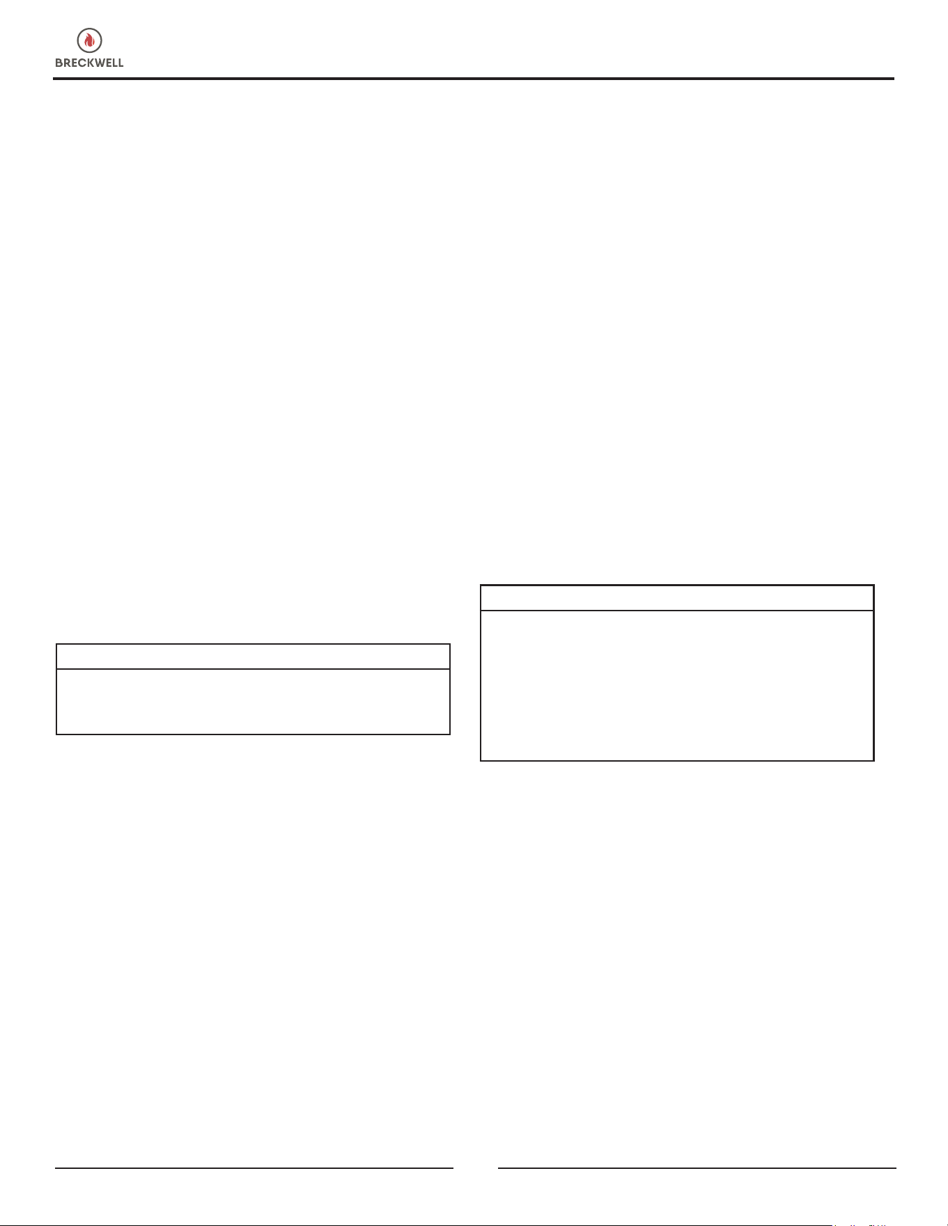
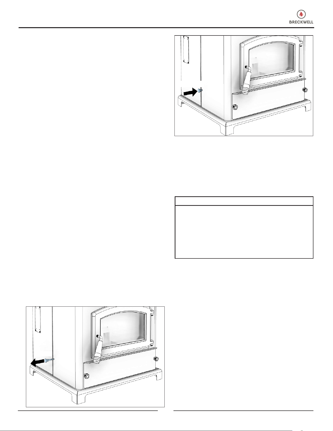
For installation in a mobile home/transportable building,
an outside source of combustion air must be used (see
“Combustion Air Supply”). This unit must be grounded to
the steel chassis with 8 ga. copper wire using a serrated
or star washer to penetrate paint or protection coating to
ensure grounding. This unit must be securely fastened to the
oor of the mobile home/transportable building through the
two holes in the rear of the stove using 2-1/4” (58 mm) lag
bolts that are long enough to go through both a hearth pad,
if used, and the oor of the home. Refer to “Venting” for
proper exhaust congurations. When installing in a mobile
home/transportable building ensure that the vapor barrier
at the location where the chimney or other component
penetrates to the exterior of the structure. Never operate
with the ring doors open. A smoke detector should be
installed in the room where the heater is installed. The
smoke detector should be installed at least 10 feet away
from the heater to prevent accidentally setting the detector
off.
10
© 2024 Breckwell
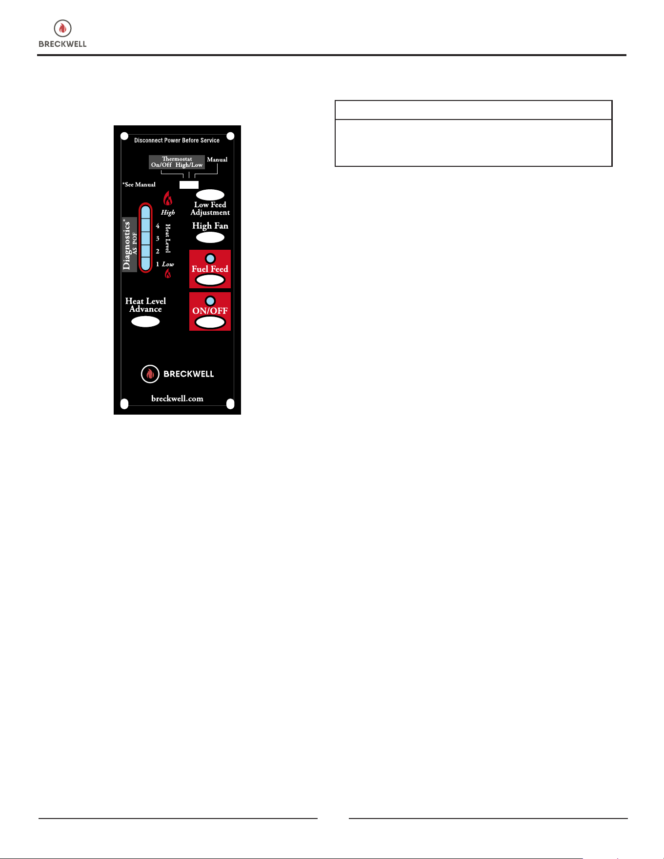
OPERATION
PANEL CONTROLS
5
The blowers and automatic fuel supply are controlled from
a panel on the left-hand side of this unit. The control panel
functions are a follows.
ON/OFF SWITCH
• When pushed, the stove will automatically ignite. No
other restarter is necessary. The igniter will stay on for at
least 10 and up to 15 minutes, depending on when Proof
of Fire is reached. The re should start in about 5 minutes.
• The green light located above the ON/OFF button (in
the ON/OFF box) will ash during the ignition start-up
period.
• The Heat Level Advance is inoperable during the ignition
start-up period. When the green light continuously stays
on, the Heat Level Advance can be adjusted to achieve
the desired heat output.
NOTE: If the stove has been shut off, and you want to re-
start it while it is still warm, the “On/Off” button must be
held down for 2 seconds.
FUEL FEED SWITCH
• When the “Fuel Feed” button is pushed and held down,
the stove will feed pellets continuously into the burnpot.
• While the stove’s auger system is feeding pellets, the
green light (in the “Fuel Feed” box) will be on.
CAUTION:
DO NOT USE THIS CONTROL DURING NORMAL
OPERATION BECAUSE IT COULD SMOTHER THE FIRE AND
LEAD TO A DANGEROUS SITUATION.
HIGH FAN SWITCH
• The room air fan speed varies directly with the feed rate.
The “High Fan” switch overrides this variable speed
function. It will set the room air blower speed to high at
any feed rate setting.
• When the “High Fan” button is pushed, the room air fan
will switch to its highest setting.
• When this button is pushed again, the room air fan will
return to its original setting based on the Heat Level
Advance setting.
RESET TRIM
Different sizes and quality pellet fuel may require adjustment
of the “1” feed setting on the Heat Level Advance bar
graph. This is usually a one-time adjustment based on the
fuel you are using. The “Reset Trim” button, when adjusted,
will allow for 3 different feed rate settings for the #1 feed
setting only. To adjust, simply push the “Reset Trim” button
while the stove is operating at setting “1” and watch the
bar graph.
• When the “1” & “3” light are illuminated on the bar
graph, the low feed rate is at its “lowest” setting. (approx.
0.9 pounds per hour)
• When the “1” light is illuminated on the bar graph, the
low feed rate is at its “normal” setting.
• When the “1” & “4” lights are illuminated on the bar
graph, the low feed rate is at its “highest” setting.
NOTE: When the stove is set on “1” the “Reset Trim” values
will be shown in the Heat Level Advance bar graph. For
example: if the “Reset Trim” is set to its lowest setting every
time the stove is set to low, the “1” and “3” lights will be
illuminated on the bar graph.
HEAT LEVEL ADVANCE
• This button, when pushed, will set the pellet feed rate,
hence the heat output of your stove. The levels of heat
output will incrementally change on the bar graph starting
from level “1” to “5.”
NOTE: When dropping 3 or more heat level settings (4 to
1, or 5 to 2 or 1), push the “High Fan” button and allow the
room air fan to run at that setting for at least 5 minutes to
NEVER OPERATE THIS PRODUCT WHILE UNATTENDED
© 2024 Breckwell
11
prevent the stove from tripping the high temp thermodisc. If
the high temp thermodisc does trip, see “Safety Features.”
CAUTION:
THE “5” SETTING IS DESIGNED FOR TEMPORARY USE
ONLY. IF USED FOR EXTENDED PERIODS, IT CAN SHORTEN
THE LIFE EXPECTANCY OF THE UNITS COMPONENTS.
AVOID USE AT THIS SETTING FOR MORE THAN ONE OR
TWO HOURS AT A TIME.
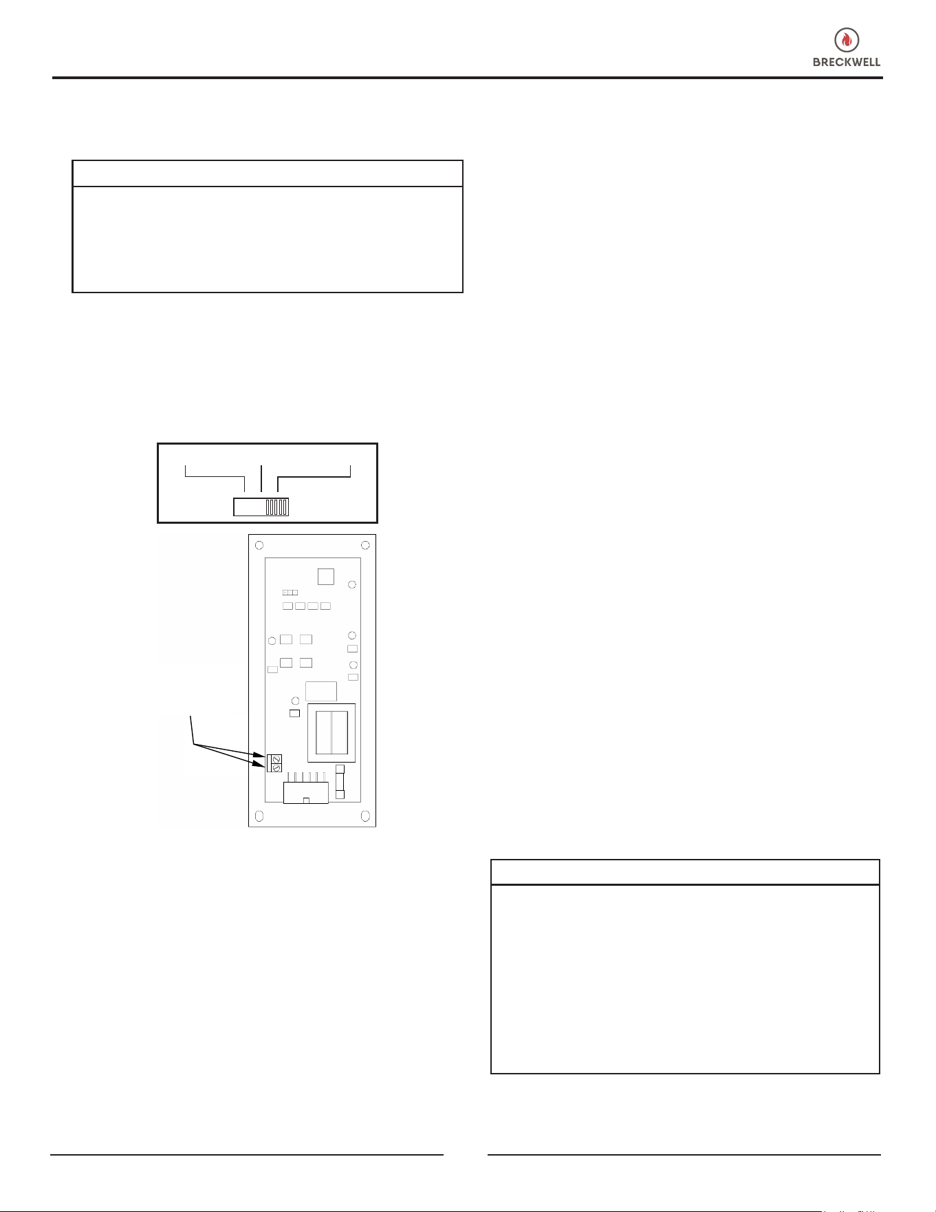
OPTIONAL THERMOSTAT
An optional thermostat may help you maintain a constant
house temperature automatically. A millivolt thermostat
is required. The control panel can be set up two ways to
operate your stove in thermostat mode.
FIGURE 14
N
On/Off High/Low Manual
Connect
Thermostat
Wires Here
On/Off High/Low Manual
THERMOSTAT INSTALLATION
• A MILLIVOLT THERMOSTAT IS REQUIRED.
• Unplug stove from power outlet.
• Remove control board from stove.
• The two thermostat wires connect to the terminal block on
the lower left side of the back of the control board.
• Insert wires in the terminal side and tighten the two screws.
MODES
TO SWITCH BETWEEN ANY OF THE THREE MODES, THE
STOVE MUST BE SHUT OFF, THE NEW MODE SELECTED
AND THE STOVE RESTARTED.
MANUAL MODE
• USE THIS MODE EXCLUSIVELY IF YOU DO NOT
CONNECT AN OPTIONAL THERMOSTAT.
• In this mode, the stove will operate only from the control
panel as detailed in the “Operation” section of this
owner’s manual.
HIGH/LOW THERMOSTAT MODE
• USE THIS MODE ONLY IF YOU CONNECT A
THERMOSTAT.
• When engaged in this mode, the stove will automatically
switch be- tween two settings. When warm enough, it will
switch to the #1 or low setting. The room air blower will
also slow to its lowest speed.
• The Heat Level Advance setting on the bar graph will stay
where it was initially set. When the home cools below the
thermostat setting, the stove will switch to the feed rate of
the heat level advance setting.
ON/OFF THERMOSTAT MODE
• USE THIS MODE ONLY OF YOU CONNECT A
THERMOSTAT
• In this mode, when the home is warm enough, the stove
will shut off. The fans will continue to run until the stove
cools.
• When the home cools below the thermostat setting, the
stove will automatically restart and run at the last feed
rate setting.
NOTE: When in “High/Low” or “On/Off” thermostat mode
• Do not operate the stove higher than the #3 setting.
• Set damper control rod approximately 1/4” (7 mm) to
1/2” (13 mm) out. This will vary depending on elevation
and weather conditions. Observe stoves operation and
adjust damper as necessary.
WARNING:
• DO NOT USE CHEMICALS OR FLUIDS TO START
THE FIRE - NEVER USE GASOLINE, GASOLINE-TYPE
LANTERN FUEL, KEROSENE, CHARCOAL LIGHTER
FLUID, OR SIMILAR LIQUIDS TO START OR “FRESHEN
UP” A FIRE IN THIS STOVE. KEEP ALL SUCH LIQUIDS
WELL AWAY FROM THE STOVE WHILE IT IS IN USE.
• HOT WHILE IN OPERATION. KEEP CHILDREN,
CLOTHING AND FURNITURE AWAY. CONTACT MAY
CAUSE SKIN BURNS.
This heater is designed to burn only PFI Premium grade
pellets. DO NOT BURN:
OPERATION
12
© 2024 Breckwell
1. Garbage;
2. Lawn clippings or yard waste;
3. Materials containing rubber, including tires;
4. Materials containing plastic;
5. Waste petroleum products, paints or paint thinners, or
asphalt products;
6. Materials containing asbestos;
7. Construction or demolition debris;
8. Railroad ties or pressure-treated wood;
9. Manure or animal remains;
10. Salt water driftwood or other previously salt water
saturated materials;
11. Unseasoned wood; or
12. Paper products, cardboard, plywood, or particleboard.
The prohibition against burning these materials does
not prohibit the use of re starters made from paper,
cardboard, saw dust, wax and similar substances for
the purpose of starting a re in an affected wood heater.
Burning these materials may result in release of toxic fumes
or render the heater ineffective and cause smoke.
PROPER FUEL
ATTENTION:
THIS APPLIANCE IS DESIGNED FOR THE USE OF PELLETIZED
FUEL THAT MEET OR EXCEED THE STANDARD SET BY THE
PELLET FUEL INSTITUTE (PFI).
Your pellet stove is designed to burn premium hardwood
pellets that comply with the Pellet Fuels Institute (PFI)
standard (minimum of 40 lbs density per cubic ft, 1/4” to
5/16” diameter, length no greater than 1.5”, not less than
8,200 BTU/lb, moisture under 8% by weight, ash under
1% by weight, and salt under 300 parts per million). Pellets
that are soft, contain excessive amounts of loose sawdust,
have been, or are wet, will result in reduced performance.
Store your pellets in a dry place. DO NOT store the fuel
within the installation clearances of the unit or within the
space required for refuelling and ash removal. Doing so
could result in a house re. Do not over re or use volatile
fuels or combustibles, doing so may cause a personal and
property damage hazards.
THIS STOVE IS APPROVED FOR BURNING PELLETIZED
WOOD FUEL ONLY ! Factory-approved pellets are those
1/4” or 5/16” in diameter and not over 1” long. Longer
or thicker pellets sometimes bridge the auger ights, which
prevents proper pellet feed. Burning wood in forms other
than pellets is not permitted. It will violate the building
codes for which the stove has been approved and will void
all warranties. The design incorporates automatic feed of
the pellet fuel into the re at a carefully prescribed rate. Any
additional fuel introduced by hand will not increase heat
output but may seriously impair the stoves performance by
generating considerable smoke. Do not burn wet pellets.
The stove’s performance depends heavily on the quality
of your pellet fuel. Avoid pellet brands that display these
characteristics:
• Excess Fines – “Fines” is a term describing crushed
pellets or loose material that looks like sawdust or sand.
Pellets can be screened before being placed in hopper to
remove most nes.
• Binders – Some pellets are produced with materials to
hold the together, or “bind” them.
• High ash content – Poor quality pellets will often create
smoke and dirty glass. They will create a need for more
frequent maintenance. You will have to empty the burn
pot plus vacuum the entire system more often. Poor quality
pellets could damage the auger. We cannot accept
responsibility for damage due to poor quality pellet.
CAUTION:
• KEEP FOREIGN OBJECTS OUT OF THE HOPPER.
• THE MOVING PARTS OF THIS STOVE ARE PROPELLED
BY HIGH TORQUE ELECTRIC MOTORS. KEEP ALL BODY
PARTS AWAY FROM THE AUGER WHILE THE STOVE
IS PLUGGED INTO AN ELECTRICAL OUTLET. THESE
MOVING PARTS MAY BEGIN TO MOVE AT ANY TIME
WHILE THE STOVE IS PLUGGED IN.
PRE-START-UP CHECK
Remove burn pot, making sure it is clean and none of the
air holes are plugged. Clean the rebox, and then reinstall
burn pot. Clean door glass if necessary (a dry cloth or paper
towel is usually sufcient). Never use abrasive cleaners on
the glass or door. Check fuel in the hopper, and rell if
necessary.
BUILDING A FIRE
Never use a grate or other means of supporting the fuel.
Use only the burn pot supplied with this heater. Hopper lid
must be closed in order for the unit to feed pellets. During
the start-up period:
• Make sure the burn pot is free of pellets.
• DO NOT open the viewing door.
• The damper may need to be closed during startup.
• DO NOT add pellets to the burn pot by hand.
OPERATION
© 2024 Breckwell
13
NOTE: During the rst few res, your stove will emit an odor
as the high-temperature paint cures or becomes seasoned to
the metal. Maintaining smaller res will minimize this. Avoid
placing items on the stovetop during this period because the
paint could be affected. Attempts to achieve heat output
rates that exceed heater design specications can result in
permanent damage to the heater.
AUTOMATIC IGNITOR
1. Fill hopper and clean burn pot.
2. Press “On/Off” button. Make sure green light comes
on.
3. The damper should be completely closed or open no
more than 1/4 of the way during start-up. This will vary
depending on your installation and elevation. Once
re is established adjust for desired ame increasing
the amount the damper is open as the heat setting is
increased (see “Damper Control”).
4. Adjust feed rate to desired setting by pressing “Heat
Level Advance” button.
OPTIMAL OPERATION
This pellet stove has been certied by the US EPA to meet
strict 2020 guidelines. To ensure this unit produces the
optimal minimal emissions, it is critical to follow the following
guidelines. To achieve a “high burn”, your stove should be
set on setting 5 with the damper fully open. To achieve a
“medium burn”, your stove should be set on setting 2 with
the damper closed. To achieve a “low burn”, your stove
should be set on setting 1 with the damper closed. Settings 3
and 4 will give you a higher heat output above the medium
setting. If the door is opened while the stove is in operation,
it must be closed within 30 seconds or the stove will shut
down. If the stove shuts down, push the “On/Off” button to
restart your stove. The stove will have to fully shut down and
turn off before you will be able to restart the stove.
OPEN
CLOSED
OPENING DOOR
If the door is opened while the stove is in operation it must
be closed within 30 seconds or the stove will shut down. If
the stove shuts down push the “On/Off” button to re-start
your stove. The stove will have to fully shut down and turn
off before you will be able to restart the stove.
CAUTION:
• DO NOT OPERATE YOUR STOVE WITH THE VIEWING
DOOR OPEN. THE AUGER WILL NOT FEED PELLETS
UNDER THESE CIRCUMSTANCES AND A SAFETY
CONCERN MAY ARISE FROM SPARKS OR FUMES
ENTERING THE ROOM.
• THE FEED DOOR MUST BE CLOSED AND SEALED
DURING OPERATION.
ROOM AIR FAN
When starting your stove the Room Air Fan will not come
on until the stove’s heat exchanger warms up. This usually
takes about 10 minutes from start-up.
IF STOVE RUNS OUT OF PELLETS
The re goes out and the auger motor and blowers will
run until the stove cools. This will take 30 to 45 minutes.
After the stove components stop running, the “On/Off” and
the Bar Graph lights stay on for 10 minutes. After the 10
minutes, the “3” light on the bar graph will ash and the
“On/Off” light will go off. To re-start, rell hopper and press
“Fuel Feed” button until pellets begin to fall into burnpot.
Press “On/Off” button.
OPERATION
14
© 2024 Breckwell
REFUELING
CAUTION:
• THE HOPPER AND STOVE TOP WILL BE HOT DURING
OPERATION; THEREFORE, YOU SHOULD ALWAYS USE
SOME TYPE OF HAND PROTECTION WHEN REFUELING
YOUR STOVE.
• DO NOT TOUCH THE HOT SURFACES OF THE STOVE.
EDUCATE ALL CHILDREN ON THE DANGERS OF A
HIGH-TEMPERATURE STOVE. YOUNG CHILDREN
SHOULD BE SUPERVISED WHEN THEY ARE IN THE
SAME ROOM AS THE STOVE.
• NEVER PLACE YOUR HAND NEAR THE AUGER WHILE
THE STOVE IS IN OPERATION.
• WE RECOMMEND THAT YOU NOT LET THE HOPPER
DROP BELOW 1/4 FULL.
WARNING:
• KEEP HOPPER LID CLOSED AT ALL TIMES EXCEPT
WHEN REFILLING.
• DO NOT OVERFILL HOPPER.
TAMPER WARNING
This wood heater has a manufacturer-set minimum low burn
rate that must not be altered. It is against federal regulations
to alter this setting or otherwise operate this wood heater
in a manner inconsistent with operating instructions in this
manual.
SHUTDOWN PROCEDURE
WARNING:
NEVER SHUT DOWN THIS UNIT BY UNPLUGGING IT
FROM THE POWER SOURCE.
Turning your stove off is a matter of pressing the “POWER”
button on the display board. The green light will turn back to
red when the “POWER” button is pushed. The auger motor
will stop, and the blowers will continue to operate until the
internal rebox temperatures have fallen to a preset level.
1. Your stove is equipped with a high temperature
thermodisc. This unit has a manual reset thermodisc.
This safety switch has two functions.
A. To recognize an overheat situation in the stove and shut
down the fuel feed or auger system.
B. In case of a malfunctioning convection blower, the high-
temperature thermodisc will automatically shut down
the auger, preventing the stove from overheating.
NOTE: On some units, once tripped, like a circuit breaker,
the reset button will have to be pushed before restarting your
stove. On other units the thermodisc has no reset button and
will reset itself once the stove has cooled. The manufacturer
recommends that you call your dealer if this occurs as this
may indicate a more serious problem. A service call may
be required.
2. If the combustion blower fails, an air pressure switch
will automatically shut down the auger.
NOTE: Opening the stove door for more than 30 seconds
during operation will cause enough pressure change to
activate the air switch, shutting the fuel feed off. The stove
will shut down and show “E2” on the two digit display. The
stove has to fully shut down before restarting.
INTERIOR CHAMBERS
• Burn Pot - Periodically remove and clean the burn pot and
the area inside the burn pot housing. In particular, it is
advisable to clean out the holes in the burn pot to remove
any build up that may prevent air from moving through
the burn pot freely.
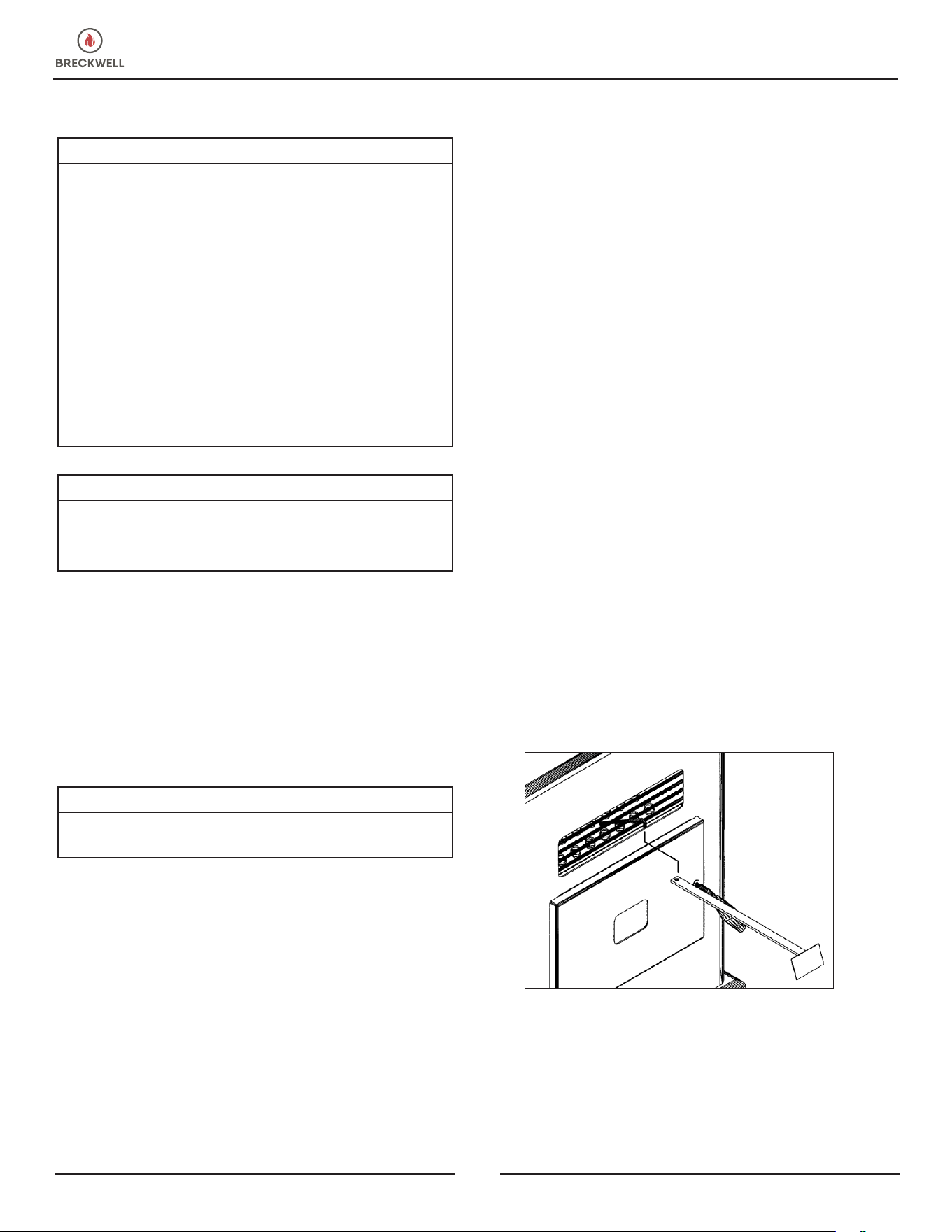
• Heat Exchange Tubes - This stove is designed with a built-
in heat exchange tube cleaner. This should be used every
two or three days to remove accumulated ash on the tubes,
which reduces the efciency of your unit. Insert the handle
end (with hole) of the cleaning tool onto the cleaning rod.
The cleaner rod is located in the grill above the stove
door. Move the cleaner rod back and forth several times
to clean the heat exchanger tubes. When nished, be
sure to leave tube cleaner at the rear of the stove.
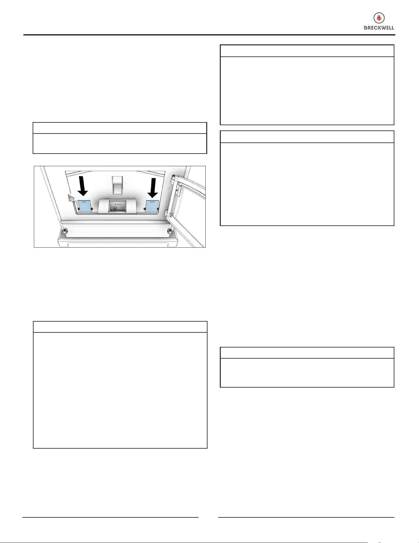
• Heat Exchanger - There is a clean out plate on both sides
of the heat exchanger that need to be removed to clean y
ash out of the heat exchanger. The cleanouts are located
inside the rebox as shown. The clean outs are secured to
the rebox with (2) 5/16” screws. Remove the clean outs
and vacuum out any accumulated ash. This should be
done at least once per month or more frequently if large
OPERATION
© 2024 Breckwell
15
OPERATION
MAINTENANCE
CAUTION:
• FAILURE TO CLEAN AND MAINTAIN THIS UNIT AS
INDICATED CAN RESULT IN POOR PERFORMANCE,
SAFETY HAZARDS, FIRE, AND EVEN DEATH.
• NEVER PERFORM ANY INSPECTIONS, CLEANING, OR
MAINTENANCE ON A HOT STOVE.
• DISCONNECT THE POWER CORD BEFORE PERFORMING
ANY MAINTENANCE! NOTE: TURNING THE ON/
OFF SWITCH TO ”OFF” DOES NOT DISCONNECT ALL
POWER TO THE ELECTRICAL COMPONENTS OF THE
STOVE.
• DO NOT OPERATE STOVE WITH BROKEN GLASS,
LEAKAGE OF FLUE GAS MAY RESULT.
CREOSOTE FORMATION, INSPECTION, &
REMOVAL
CAUTION:
THE EXHAUST SYSTEM SHOULD BE CHECKED MONTHLY
DURING THE BURNING SEASON FOR ANY BUILD-UP OF
SOOT OR CREOSOTE.
When any wood is burned slowly, it produces tar and other
organic vapors, which combine with expelled moisture
to form creosote. The creosote vapors condense in the
relatively cool chimney ue or a newly started re or from a
slow-burning re. As a result, creosote residue accumulates
on the ue lining. When ignited, this creosote makes an
extremely hot re, which may damage the chimney or even
destroy the house. Despite their high efciency, pellet stoves
can accumulate creosote under certain conditions. The
chimney connector and chimney should be inspected by a
qualied person annually or per ton of pellets to determine
if a creosote or y ash build-up has occurred. If creosote has
accumulated, it should be removed to reduce the risk of a
NEVER OPERATE THIS PRODUCT WHILE UNATTENDED
amounts of ash are noticed while cleaning or if the stove
does not seem to be burning properly.
If a vacuum is used to clean your stove, we suggest using
the AV15E AshVac vacuum. The AV15E AshVac is designed
for ash removal. Some regular vacuum cleaner (i.e. shop
vacs) may leak ash into the room.
DO NOT VACUUM HOT ASH.
WARNING:
FAILURE TO PROPERLY MAINTENANCE THE CLEAN OUTS
WILL RESULT IN POOR PERFORMANCE OF THIS STOVE.
CAUTION:
• DO NOT OPERATE YOUR STOVE IF YOU SMELL SMOKE
COMING FROM IT. TURN IT OFF, MONITOR IT, AND
CALL YOUR DEALER.
• DO NOT OPERATE THE STOVE IF THE FLAME BECOMES
DARK AND SOOTY OR IF THE BURNPOT OVERFILLS
WITH PELLETS. TURN THE STOVE OFF, PERIODICALLY
INSPECT IT, AND CALL YOUR DEALER
CAUTION:
IF THE STOVE IS INSTALLED IN A ROOM WITHOUT
AIR CONDITIONING, OR IN AN AREA WHERE DIRECT
SUNLIGHT CAN SHINE ON THE UNIT, IT IS POSSIBLE
THIS CAN CAUSE THE TEMPERATURE OF THE STOVE TO
RISE TO OPERATIONAL LEVELS; ONE OF THE SENSORS
COULD THEN MAKE THE STOVE START ON ITS OWN.
IT IS RECOMMENDED THAT THE STOVE BE UNPLUGGED
WHEN NOT IN USE FOR EXTENDED AMOUNTS OF TIME
(I.E. DURING THE SUMMER MONTHS).
16
© 2024 Breckwell
MAINTENANCE
chimney re. Inspect the system at the stove connection and
at the chimney top. Cooler surfaces tend to build creosote
deposits quicker, so it is important to check the chimney
from the top as well as from the bottom. The creosote
should be removed with a brush specically designed for
the type of chimney in use. A qualied chimney sweep can
perform this service. It is also recommended that before
each heating season the entire system be professionally
inspected, cleaned and, if necessary, repaired. To clean the
chimney, disconnect the vent from the stove.
FLY ASH
This accumulates in the horizontal portion of an exhaust
run. Though non-combustible, it may impede the normal
exhaust ow. It should therefore be periodically removed.
ASH REMOVAL & DISPOSAL
CAUTION:
ALLOW THE STOVE TO COOL BEFORE PERFORMING
ANY MAINTENANCE OR CLEANING. ASHES MUST
BE DISPOSED IN A METAL CONTAINER WITH A TIGHT
FITTING LID. THE CLOSED CONTAINER OF ASHES SHOULD
BE PLACED ON A NON-COMBUSTIBLE SURFACE OR ON
THE GROUND, WELL AWAY FROM ALL COMBUSTIBLE
MATERIALS, PENDING FINAL DISPOSAL.
Remove the ashes periodically to avoid unnecessary ash
build up. Remove ashes when unit has cooled. Ashes
should be placed in a metal container with a tight tting
lid. The closed container of ashes should be placed on a
noncombustible oor or on the ground, well away from
all combustible materials, pending nal disposal. If the
ashes are disposed of by burial in soil or otherwise locally
dispersed, they should be retained in the closed container
until all embers have been thoroughly cooled. The container
shall not be used for other trash or waste disposal. If
combined with combustible substances, ashes and embers
may ignite. Ash removal is as follows:
1. Let the re burn out and allow the unit to cool to room
temperature.
2. Make sure the pellet stove is at room temperature before
touching. Clean the heat exchanger tubes.
3. Remove the burnpots inner section by grasping it and
pulling straight up.
4. Empty ashes from the inner section and scrape with
cleaning tool; make sure holes are not plugged.
5. Vacuum to remove ashes from the burn chamber interior
and the burnpot shell. WARNING: Make sure ashes are
cool to the touch before using a vacuum (see “Vacuum
Use”).
6. Dispose of ashes properly (see “Ash Removal”).
7. Replace inner section into burnpot; make sure it is level
and pushed all the way back down and that the igniter
hole is to the rear when it is reinstalled.
8. Make sure the burnpot is level and pushed all the way
in. If the collar on the burnpot, attached to the fresh air
tube, is not pushed back to meet the rebox wall. The
igniter will not work properly.
SMOKE & CO MONITORS
Burning wood naturally produces smoke and carbon
monoxide(CO) emissions. CO is a poisonous gas when
exposed to elevated concentrations for extended periods
of time. While the modern combustion systems in heaters
drastically reduce the amount of CO emitted out the chimney,
exposure to the gases in closed or conned areas can be
dangerous. Make sure you stove gaskets and chimney joints
are in good working order and sealing properly to ensure
unintended exposure. It is recommended that you use both
smoke and CO monitors in areas having the potential to
generate CO.
CHECK & CLEAN THE HOPPER
Check the hopper periodically to determine if there is any
sawdust (nes) that is building up in the feed system or
pellets that are sticking to the hopper surface. Clean as
needed.
DOOR & GLASS GASKETS
Inspect the main door and glass window gaskets periodically.
The main door may need to be removed to have frayed,
broken, or compacted gaskets replaced by your authorized
dealer. This unit’s door uses a 3/4” diameter rope gasket.
BLOWER MOTORS
Clean the air holes on the motors of both the exhaust and
distribution blowers annually. Remove the exhaust blower
from the exhaust duct and clean out the internal fan blades
as part of your fall start-up. If you have indoor pets your
power motors should be inspected monthly to make sure
they are free of animal hair build up. Animal hair build up
in blowers can result in poor performance or unforeseen
safety hazards.
PAINTED SURFACES
Painted surfaces may be wiped down with a damp cloth. If
scratches appear, or you wish to renew your paint, contact
your authorized dealer to obtain a can of suitable high-
temperature paint.
© 2024 Breckwell
17
MAINTENANCE
REMOVAL AND REPLACEMENT OF BROKEN
DOOR GLASS
While wearing leather gloves (or any other gloves suitable
for handling broken glass), carefully remove any loose
pieces of glass from the door frame. Dispose of all broken
glass properly. Return the damaged door to your dealer
for repair or replacement. Neither the appliance owner
nor any other unauthorized person(s) should replace the
door glass. An authorized dealer must perform all repairs
involving door glass.
FALL START UP
Prior to starting the rst re of the heating season, check
the outside area around the exhaust and air intake systems
for obstructions. Clean and remove any y ash from the
exhaust venting system. Clean any screens on the exhaust
system and on the outside air intake pipe. Turn all of the
controls on and make sure that they are working properly.
This is also a good time to give the entire stove a good
cleaning throughout.
SPRING SHUTDOWN
After the last burn in the spring, remove any remaining pellets
from the hopper and the auger feed system. Scoop out the
pellets and then run the auger until the hopper is empty
and pellets stop owing (this can be done by pressing the
“ON” button with the viewing door open). Vacuum out the
hopper. Thoroughly clean the burn pot, and rebox. It may
be desirable to spray the inside of the cleaned hopper with
an aerosol silicone spray if your stove is in a high humidity
area. The exhaust system should be thoroughly cleaned.
MAINTENANCE SCHEDULE
CAUTION:
THIS WOOD HEATER NEEDS PERIODIC INSPECTION
AND REPAIR FOR PROPER OPERATION. IT IS AGAINST
FEDERAL REGULATIONS TO OPERATE THIS WOOD
HEATER IN A MANNER INCONSISTENT WITH OPERATING
INSTRUCTIONS IN THIS MANUAL.
Use the following as a guide under average use conditions.
Gaskets around door and door glass should be inspected
and repaired or replaced when necessary.
Daily Weekly
Monthly or
as needed
Burn Pot Stirred Empty
Combustion Chamber Brushed
Ashes Check Empty
Interior Chambers Vacuumed
Combustion Blower
Blades
Vacuumed
/ Brushed
Convection Blower
Impeller
Vacuumed
/ Brushed
Vent System Cleaned
Gaskets Inspected
Glass Wiped Cleaned
Hopper (end of season)
Empty &
Vacuumed
INSTRUCTIONS SPECIFIC FOR CANADIAN INSTALLATIONS
Do not obstruct the space under the heater and do not
obstruct the combustion air openings.
Refer to the chimney manufacturer’s instructions for
disassembling the chimney/venting for transportation of a
transportable building.
The parts or materials to be employed for ember protectors
and the minimum areas to be covered and their relation
to the space heater, as well as the notice: “In Canada, to
comply with CSA B365, Installation Code for Solid-Fuel-
Burning Appliances and Equipment, any combustible
covering beneath the appliance and/or within the area
extending horizontally at least 450 mm (18 in) beyond the
appliance on any side equipped with a door, and at least
200 mm (8 in) beyond the appliance on other sides, shall
be protected by a continuous, durable, non-combustible
pad that will provide ember protection. The 450 mm (18
in) ember protection required on any side with a door shall
extend for the full width of the appliance plus the 200 mm
(8 in) required on each side of the appliance without a
door. Where an appliance is installed less than 200 mm (8
in) from a wall, the ember pad need only extend to the base
of the wall. An ember pad shall not be placed on top of a
carpet unless the pad is structurally supported to prevent
displacement and distortion.
If this appliance is installed in a transportable building,
removal of the chimney/venting is required for transportation
of the building.
DO NOT INSTALL IN AN ALCOVE
DO NOT INSTALL IN ANY FIREPLACE
18
© 2024 Breckwell
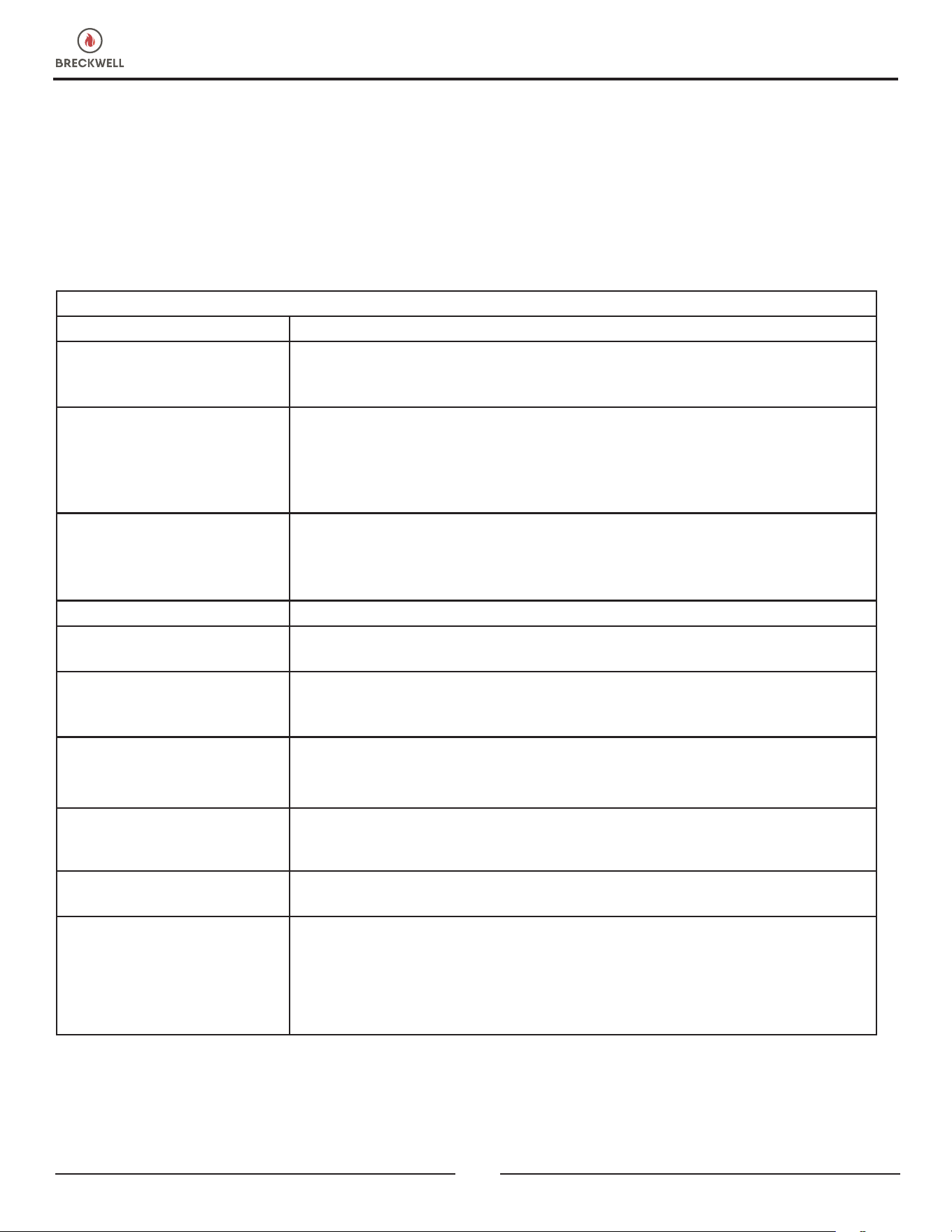
When your stove acts out of ordinary, the rst reaction is to call for help. This guide may save time and money by enabling
you to solve simple problems yourself. Problems encountered are often the result of only ve factors: 1) poor fuel; 2)
poor operation or maintenance; 3) poor installation; 4) component failure; 5) factory defect. You can usually solve those
problems related to 1 and 2. Your dealer can solve problems relating to 3, 4, and 5. Refer to diagrams on page 17 to help
locate indicated parts.
For the sake of troubleshooting and using this guide to assist you should look at your heat level setting to see which light is
ashing.
***CAUTION - UNPLUG THE STOVE FROM ALL POWER PRIOR TO ATTEMPTING TO SERVICE THE UNIT!***
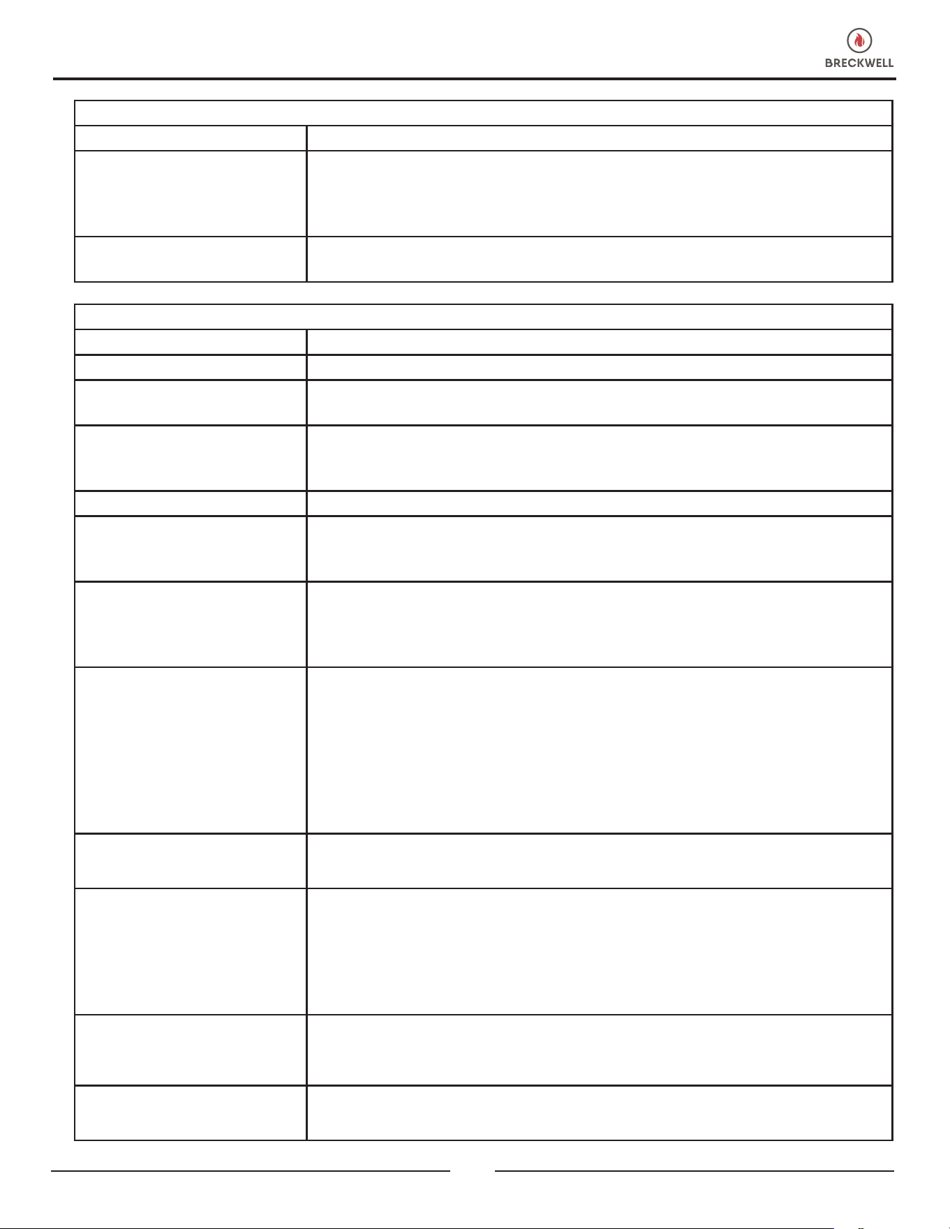
STOVE SHUTS OFF AND THE #2 LIGHT FLASHES
Possible Causes: Possible Remedies:
Airow switch hose or stove
attachment pipes for hose are
blocked.
Unhook air hose from the air switch and blow through it. If air ows freely, the hose
and tubes are ne. If air will not ow through the hose, use a wire coat hanger to clear
the blockage.
The air inlet, burnpot, interior
combustion air chambers,
combustion blower, or exhaust
pipe are blocked with ash or
foreign material.
Follow all clearing procedures in the maintenance section of the owner’s manual.
The rebox is not properly
sealed.
Make sure the door is closed and that the gasket is in good shape. If the ash door has
a latch, make sure the ash door is properly latched and the gasket is sealing good.
If the stove has just a small hole for the ashes to fall through under the burnpot, make
sure the slider plate is in place to seal off the rebox oor.
Vent pipe is incorrectly installed. Check to make sure vent pipe installation meets criteria in owner’s manual.
The airow switch wire
connections are bad.
Check the connectors that attach the gray wires to the air switch.
The gray wires are pulled loose
at the Molex connector on the
wiring harness.
Check to see if the gray wires are loose at the Molex connector.
Combustion blower failure
With the stove on, check to see if the combustion blower is running. If it is not, you will
need to check for power going to the combustion blower. It should be a full current. If
there is power, the blower is bad. If there is not, see #8.
Control board not sending power
to combustion blower.
If there is no current going to the combustion blower, check all wire connections. If all
wires are properly connected, you have a bad control board.
Control board not sending power
to air switch.
There should be a 5-volt current (approximately) going to the air switch after the stove
has been on for 30 seconds.
Air switch has failed (very rare).
To test air switch, you will need to disconnect the air hose from the body of the stove.
With the other end still attached to the air switch, very gently suck on the loose end of
the hose (you may want to remove the hose entirely off the stove and the air switch rst
and make sure it is clear). If you hear a click, the air switch is working. BE CAREFUL!
TOO MUCH VACUUM CAN DAMAGE THE AIR SWITCH.
TROUBLESHOOTING GUIDE
© 2024 Breckwell
19
TROUBLESHOOTING GUIDE
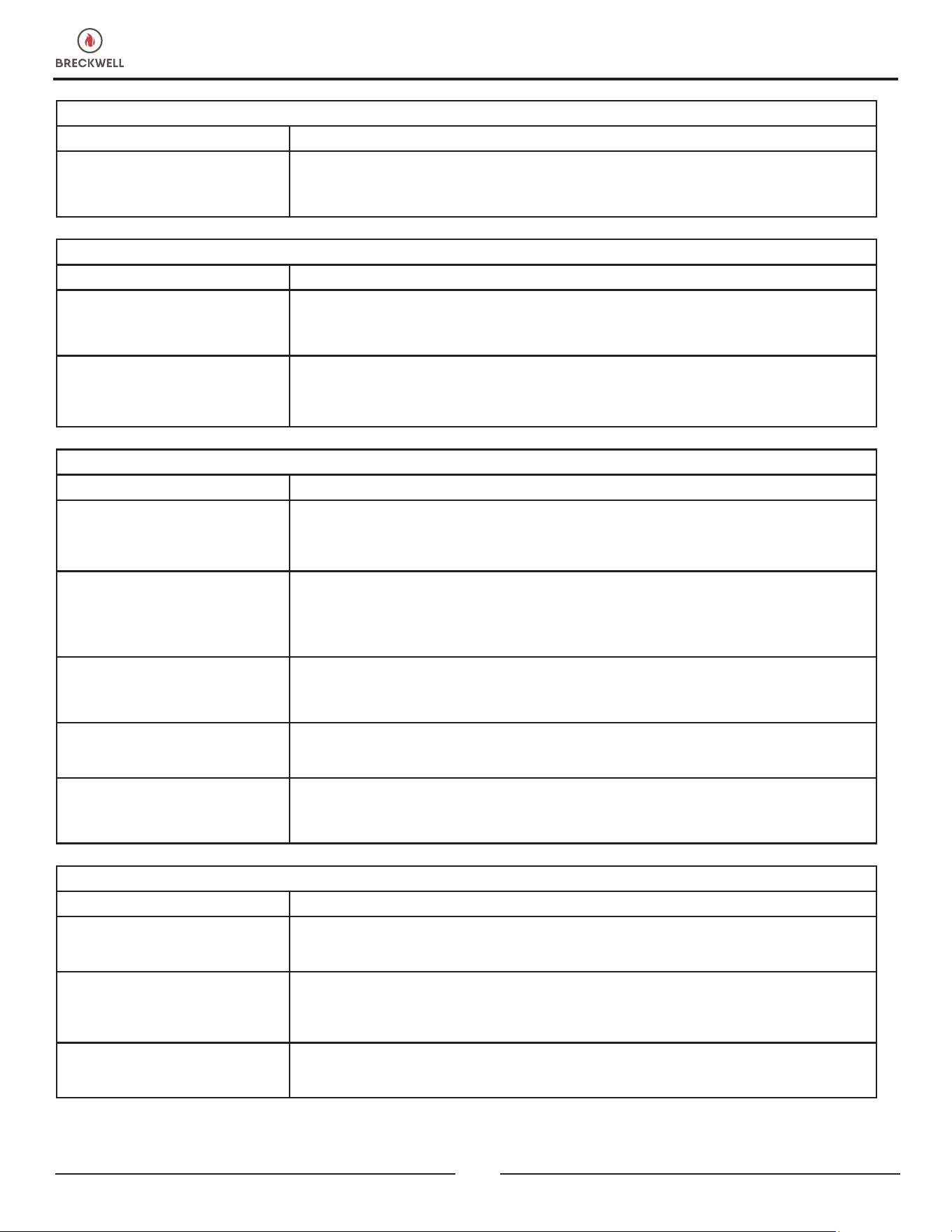
STOVE SHUTS OFF AND THE #3 LIGHT FLASHES
Possible Causes: Possible Remedies: (Unplug stove rst when possible)
The hopper is out of pellets. Rell the hopper
The air damper is too far open
for a low feed setting.
If burning on the low setting, you may need to close the damper all the way (push the
knob in so it touches the side of the stove).
The burnpot is not pushed
completely to the rear of the
rebox.
Make sure that the air intake collar on the burnpot is touching the rear wall of the
rebox.
The burnpot holes are blocked. Remove the burnpot and thoroughly clean it.
The air inlet, the interior
chambers, or exhaust system has
a partial blockage.
Follow all cleaning procedures in the maintenance section of the owner’s manual.
The hopper safety switch has
failed or hopper is open.
When operating the unit, be sure the hopper lid is closed so that the hopper safety
switch will activate. Check the wires leading from the hopper safety switch to the
control panel and auger motor for secure connections. Use a continuity tester to test
the hopper safety switch, replace if necessary.
The auger is jammed.
Start emptying the hopper. Then remove the auger motor by removing the auger pin.
Remove the auger shaft. Gently lift the auger shaft straight up so that the end of the
auger shaft comes up out of the bottom auger bushing. Next, remove the two nuts
that hold the top auger biscuit in. Then rotate the bottom end of the auger shaft up
towards you until you can lift the shaft out of the stove. After you have removed the
shaft, inspect it for bent ights, burrs, or broken welds. Remove any foreign material
that might have caused the jam. Also, check the auger tube for signs of damage such
as burrs, rough spots, or grooves cut into the metal that could have caused a jam.
The auger motor has failed.
Remove the auger motor from the auger shaft and try to run the unit. If the motor will
turn, the shaft is jammed on something. If the motor will not turn, the motor is bad.
The Proof of Fire (POF) thermodisc
has malfunctioned.
Temporarily bypass the POF thermodisc by disconnecting the two brown wires and
connecting them with a short piece of wire. Then plug the stove back in. If the stove
comes on and works, you need to replace the POF thermodisc. This is for testing only.
DO NOT LEAVE THE THERMODISC BYPASSED. Your blowers will never shut off and if
the re went out, the auger will continue to feed pellets until the hopper is empty if you
leave the POF thermodisc bypassed.
The high limit thermodisc has
tripped or is defective
Wait for the stove to cool for about 30-45 minutes. It should now function normally. If
not, use the owner’s manual to locate the high limit thermodisc. To test if the thermodisc
is bad, you can bypass it as described previously for the POF thermodisc.
The fuse on the control board has
blown.
Remove the control board. On the back, there is one fuse. If it appears to be bad,
replace it with a 5 Amp 125 Volt fuse. Plug the stove back in and try to run the unit.
SMOKE SMELL COMING BACK INTO THE HOME
Possible Causes: Possible Remedies:
There is a leak in the vent pipe
system.
Inspect all vent pipe connections. Make sure they are sealed with RTV silicone that has
a temperature rating of 500°F or higher. Also, seal joints with UL-181-AP foil tape.
Also, make sure the square to round adapter piece on the combustion blower has been
properly sealed with the same RTV.
The gasket on the combustion
blower has gone bad.
Inspect both gaskets on the combustion blower to make sure they are in good shape.
20
© 2024 Breckwell
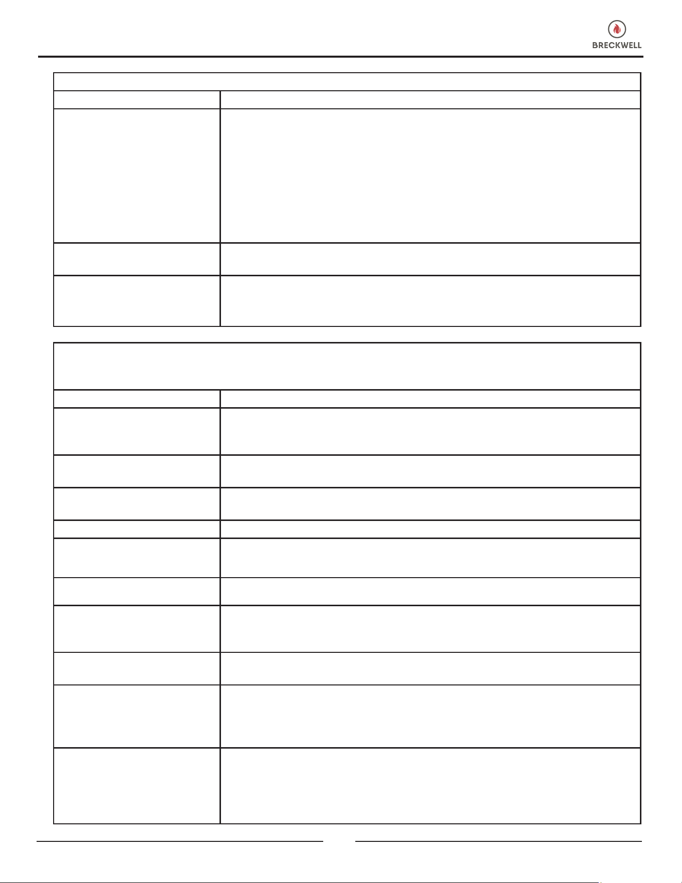
STOVE FEEDS PELLETS, BUT WILL NOT IGNITE
Possible Causes: Possible Remedies:
Air damper open too far for
ignition.
Push the air damper in closer to the side of the stove for startup. In some situations,
it may be necessary to have the damper completely closed for ignition to take place.
After there is a ame, the damper can then be adjusted for the desired feed setting.
Blockage in igniter tube or inlet
for igniter tube.
Find the igniter housing on the backside of the rewall. The air intake hole is a small
hole located on the bottom side of the housing. Make sure it is clear. Also, look from
the front of the stove to make sure there is not any debris around the igniter element
inside of the igniter housing.
The burnpot is not pushed
completely to the rear of the
rebox.
Make sure that the air intake collar on the burnpot is touching the rear wall of the
rebox.
Bad igniter element.
Put power directly to the igniter element. Watch the tip of the igniter from the front of
the stove. After about 2 minutes, the tip should glow. If it does not, the element is bad.
The control board is not sending
power to the igniter.
Check the voltage going to the igniter during startup. It should be a full current. If the
voltage is lower than full current, check the wiring. If the wiring checks out good, the
board is bad.
CONVECTION BLOWER SHUTS OFF AND COMES BACK ON
Possible Causes: Possible Remedies:
The convection blower is
overheating and tripping the
internal temperature shutoff.
Clean any dust off the windings and fan blades. If clearing the blower does not help,
the blower may be bad.
Circuit board malfunction.
Test the current going to the convection blower. If there is power being sent to the
blower when it is shut off, the control board is ne. If there is NOT power being sent
to the blower when it shuts off during operation, then you have a bad control board.
STOVE WILL NOT FEED PELLETS, BUT FUEL FEED LIGHT COMES ON AS DESIGNED
Possible Causes: Possible Remedies:
Fuse on control board blew.
Remove the control board. On the back, there is one fuse. If it appears to be bad,
replace it with a 5 Amp 125 Volt fuse. Plug the stove back in and try to run the unit.
High limit switch has tripped or
is defective.
Wait for the stove to cool for about 30-45 minutes. It should now function normally. If
not, use the owner’s manual to locate the high limit thermodisc. To test if the thermodisc
is bad, you can bypass it as described previously for the POF thermodisc.
Bad auger motor.
Remove the auger motor from the auger shaft and try to run the unit. If the motor will
turn, the shaft is jammed on something. If the motor will not turn, the motor is bad.
STOVE SHUTS OFF AND THE #3 LIGHT FLASHES
Possible Causes: Possible Remedies: (Unplug stove rst when possible)
The control board is not sending
power to the POF thermodisc or
other auger system components.
There should be a 5-volt (approximately) current going to the POF thermodisc after the
stove has been on for 10 minutes.
TROUBLESHOOTING GUIDE
© 2024 Breckwell
21
STOVE WILL NOT FEED PELLETS, BUT FUEL FEED LIGHT COMES ON AS DESIGNED
Possible Causes: Possible Remedies:
Auger jam
Start by emptying the hopper. Then remove the auger motor by removing the auger
pin. Remove the auger shaft inspection plate in the hopper so that you see the auger
shaft. Gently lift the auger shaft straight up so that the end of the auger shaft comes
up out of the bottom auger bushing. Next, remove the two nuts that hold the top auger
biscuit in. Then rotate the bottom end of the auger shaft up towards you until you can
lift the shaft out of the stove. After you have removed the shaft, inspect it for bent ights,
burrs, or broken welds. Remove any foreign material that might have caused the jam.
Also, check the auger tube for signs of damage such as burrs, rough spots, or grooves
cut into the metal that could have caused a jam.
Loose wire or connector
Check all wires and connectors that connect to the auger motor, high limit switch, and
the Molex connector.
Bad control board
If the fuse is good, the wires and connectors check out good, and the high limit switch
did not trip, test r power going to the auger motor. If there is not a full current going
to the auger motor when the fuel feed light is on, you have a bad control board.
TROUBLESHOOTING GUIDE
GLASS “SOOTS” UP AT A VERY FAST RATE
FLAME IS LAZY, DARK AND HAS BLACK TIPS
AFTER STOVE HAS BEEN ON FOR A WHILE, THE BURNPOT OVERFILLS
Possible Cause: Possible Remedies:
Stove or vent pipe is dirty, which
restricts airow through the
burnpot.
Follow all cleaning procedure in the maintenance section of the owner’s manual.
Vent pipe installed improperly.
Check to make sure the vent pipe has been installed according to the criteria in the
owner’s manual.
Air damper is set too far in
(closed) for a higher setting.
Put the damper knob farther out away from the side of the stove and try not to burn
the unit again.
Burnpot holes are blocked. Remove the burnpot and thoroughly clean it.
Air damper is broken.
Visually inspect the damper assembly. Make sure the damper plate is attached to the
damper rod. When the damper rod is moved, the plate should move with it.
Blockage in air intake pipe. Visually inspect the air intake pipe that leads into the burnpot for foreign material.
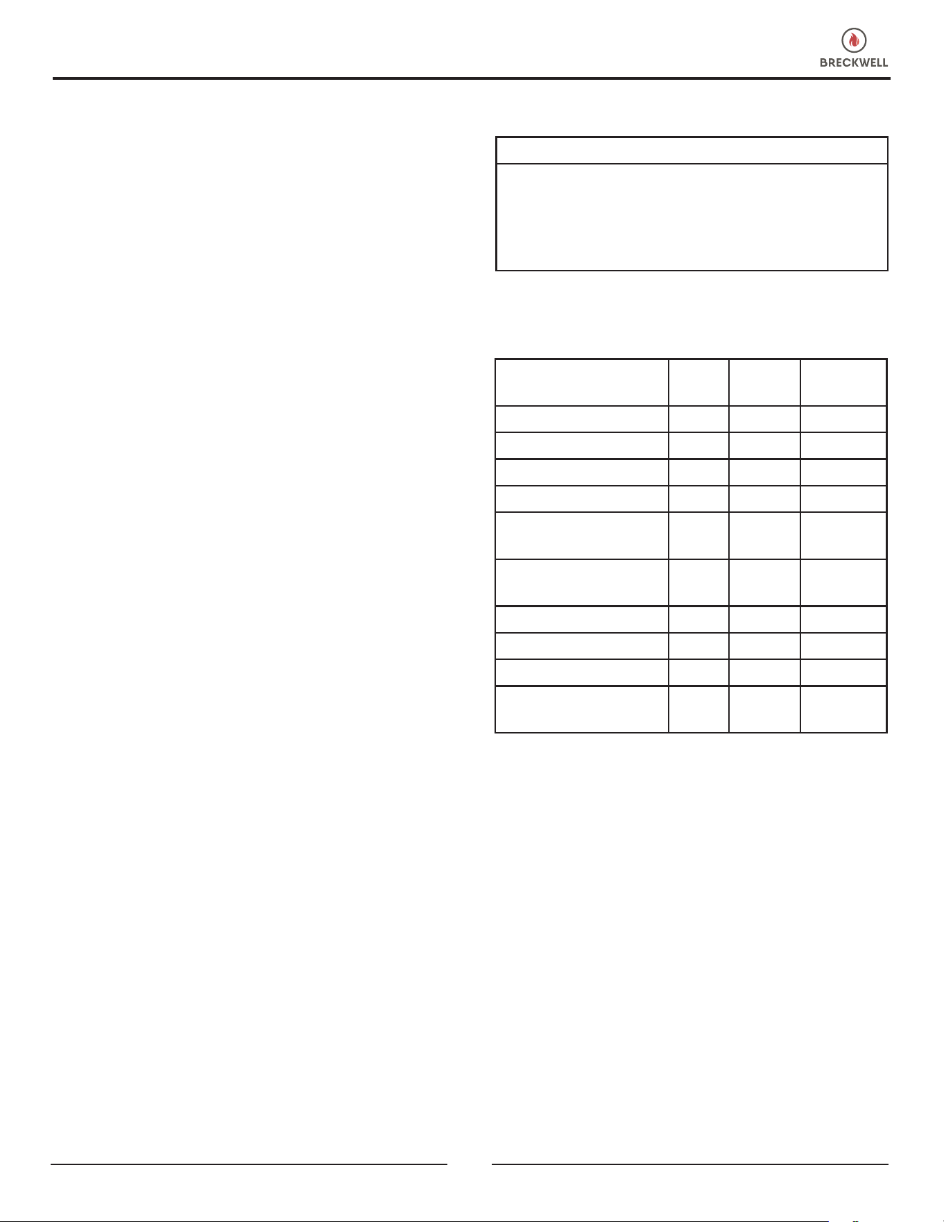
Circuit board malfunction.
Time the fuel feed light at each setting (after the stove has completed the startup cycle).
Make sure the times match the auger timing chart. If the auger motor runs constantly,
the board is bad.
Combustion blower is not
spinning fast enough.
Test the RPM on the blower after the blades have been cleaned. The RPM should be
approximately 3000RPM.
Bad Pellets (Applies to “GLASS
‘SOOTS’ UP AT A VERY FAST
RATE” only.
The brand of pellets or the batch of pellets that are being used may be of poor quality.
If possible, try a different brand of pellets. You might also want to try a brand that is
made from a different type of wood (softwood vs. hardwood). Different woods have
different characteristics when being burned.
The trim setting on the low feed
rate is too low. (Applies to
“GLASS ‘SOOTS’ UP AT A VERY
FAST RATE” only.
Use the “Reset Trim” button to increase the low feed rate setting. If the “1” & “3” lights
are on, the stove is currently on the lowest setting. If only the “1” light is on, the stove
is in the default (medium) setting. If the “1” & “4” lights are on, the stove is in the high
trim setting for the low feed rate. If the stove is being burned on one of the two lower
settings, advance to the next trim setting and try burning the stove.
22
© 2024 Breckwell
TROUBLESHOOTING GUIDE
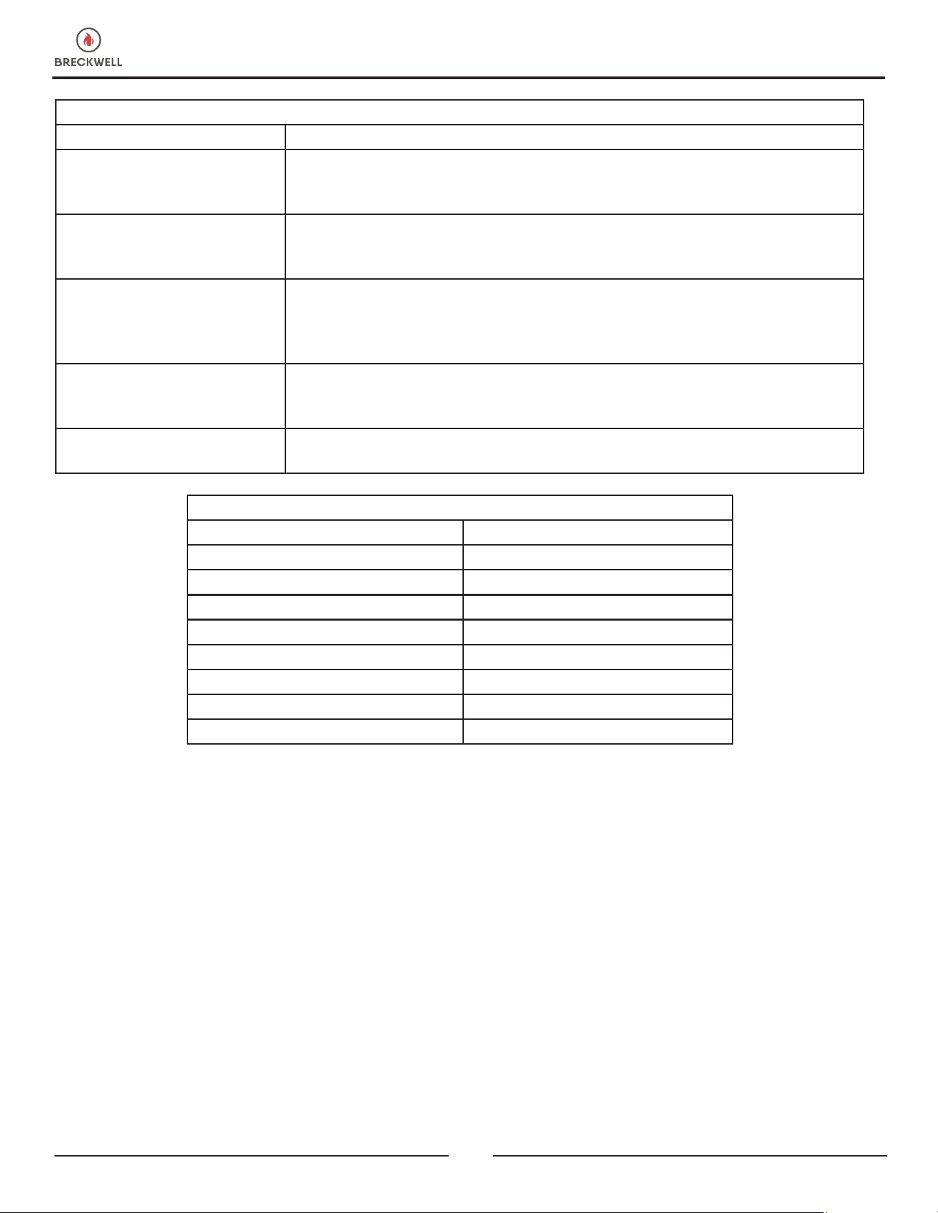
DIGITAL CIRCUIT BOARD TIMING RATES
Heat Level Setting
1 & 3 1.4 seconds
1 2 seconds
1 & 4 2.5 seconds
2 4 seconds
3 7 seconds
4 9 seconds
5 12 seconds
Total Cycle Time 14.5 seconds
SMOKE SMELL OR SOOT BUILD-UP
Because it is a wood-burning device, your stove may emit a faint wood-burning odor. If this increases beyond normal or
is you notice an unusual soot buildup on walls or furniture, check your exhaust system carefully for leaks. All joints should
be properly sealed. Also, clean your stove following instructions in the “Maintenance” section of this manual. If problem
persists, contact your dealer.
HIGH LIMIT SWITCH KEEPS TRIPPING
Possible Causes: Possible Remedies:
The convection blower is
overheating and tripping the
internal temperature shutoff.
Clean any dust off the windings and fan blades. If oiling the blower does not help, the
blower may be bad
The stove is being left on the
highest setting for extended
periods of time.
The highest level setting is designated for use over short periods of time. Burning the
stove on the highest setting for longer that 1-2 hours could lead to potential overheating
situations.
Fuel other than wood pellets is
being burned in the stove
This unit is designed and tested to use wood pellets. Check for signs of fuel other than
wood pellets. No other type of fuel have been approved for this pellet stoves. If there
are signs of other types of fuel being used, stop using them immediately.
Power surge or brown out
situation.
A power surge, spike, or voltage drop could cause the high limit switch to trip. Check
to see if a surge protector is being used on the stove. If not, recommend one to the
consumer.
High limit switch is
malfunctioning.
If the other items checked out okay, replace the high limit switch.
© 2024 Breckwell
23
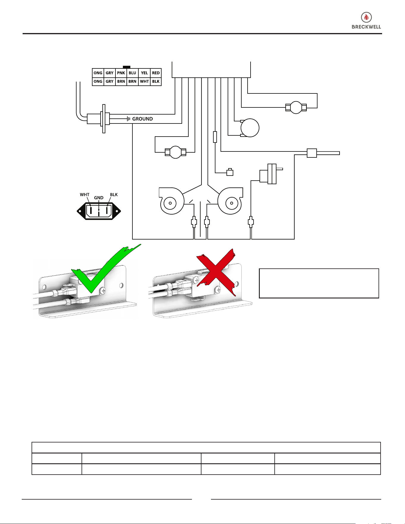
ELECTRICAL DIAGRAM
CORRECT WRONG
ENSURE THE WIRES ARE CONNECTED
TO THE BOTTOM TWO PRONGS OF THE
HOPPER SWITCH AS SHOWN.
MOLEX CONNECTOR
POWER SUPPLY
120 VOLTS AC
BROWN
BROWN
POF THERMODISC
AIR SWITCH
RED
IGNITER
HOPPER
SWITCH
PURPLE
AUGER
MOTOR
WHITE
WHITE
WHITE
HIGH TEMP.
THERMODISC
PURPLE
BLACK
WHITE
ORANGE
ORANGE
BLUE
PINK
YELLOW
RED
GRAY
GRAY
WHITEWHITE
COMBUSTION
BLOWER
CONVECTION
BLOWER
POWER OUTLET DETAIL
LOOKING FROM THE REAR
OF THE STOVE
MOLEX CONNECTOR DETAIL
CONTACT YOUR DEALER OR INSTALLER FOR PARTS AND SERVICE
The information in this owner’s manual is specic to your unit. When ordering replacement parts the information in this
manual will help to ensure the correct items are ordered. Before contacting customer service write down the model number
and the serial number of this unit. That information can be found on the certication label attached to the back of the
unit. Other information that may be needed would be the part number and part description of the item(s) in question.
Part numbers and descriptions can be found in the “Repair Parts” section of this manual. Once this information has been
gathered you can contact your Breckwell dealer or visit www.Breckwell.com
Model Information
Model Number Dealer’s Name
Serial Number Dealer’s Phone Number
HOW TO ORDER REPAIR PARTS
24
© 2024 Breckwell
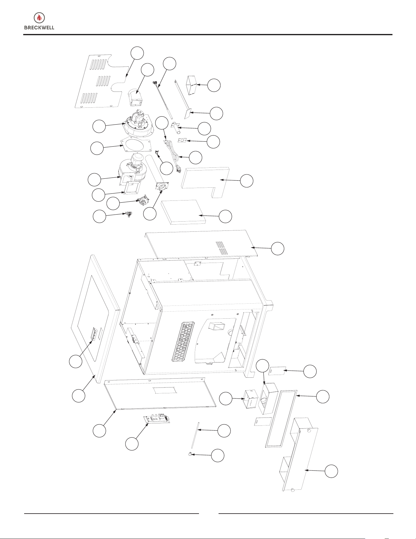
REPLACEMENT PARTS
1
2
3
4
5
6
7
8
9
10
11
12
13
27
14
15
16
17
18
19
20
21
32
22
23
24
29
28
30
26
25
© 2024 Breckwell
25
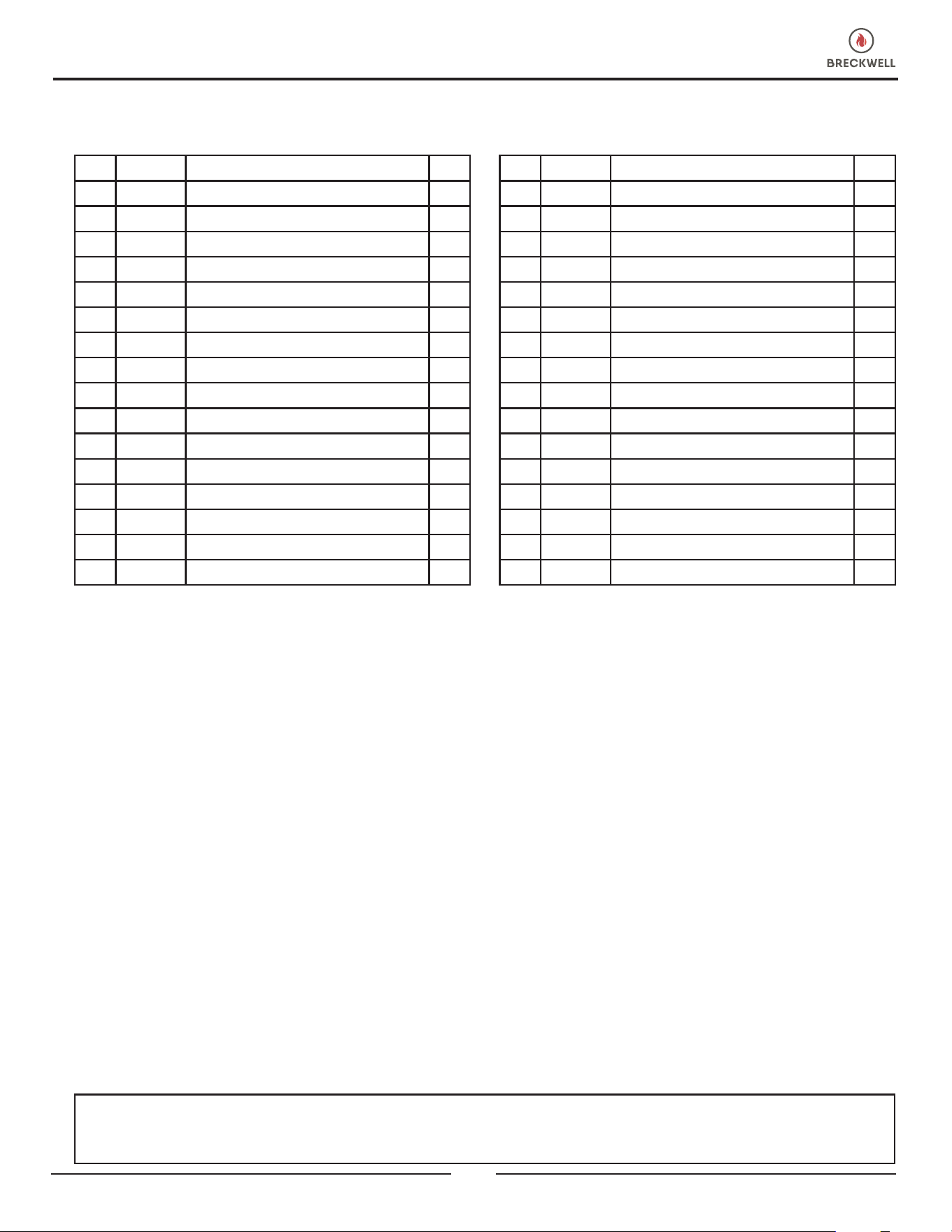
REPLACEMENT PARTS
IN ORDER TO MAINTAIN WARRANTY, COMPONENTS MUST BE REPLACED USING BRECKWELL PARTS PURCHASED
THROUGH YOUR DEALER OR DIRECTLY FROM BRECKWELL. USE OF THIRD PARTY COMPONENTS WILL VOID THE
WARRANTY.
Contact an Authorized Dealer to obtain any of these parts. Never use substitute materials. Use of non-approved parts can
result in poor performance and safety.
Key Part # Description Qty
1 69971 Ash Pan 1
2 88174 Gasket-Flat (3/16T X 3/8W) 1
3 26799 Ash Door 2
4 69964 Burnpot Housing Weldment 1
5 894097 Burnpot Weldment 1
6 86668 Damper Rod 1
7 891987 Plastic Knob 3
8 610326 Control Plate 1
9 26794 Left Side Cabinet 1
10 69703 Top Lid Weldment 1
11 891148 Plastic Handle 1
12 80683 300° Thermodisc 1
13 80621 Pressure Switch 1
14 88205 Gasket Convection Blower 1
15 80647 Distribution Blower 1
16 88100 Exhaust Blower Gasket 1
Key Part # Description Qty
17 80641 Exhaust Blower 1
18 26793 Cabinet Back 1
19 40494 Transition Blower 1
20 80909 Ignitor Cartridge 1
21 25589 Burnpot Poker 1
22 86999 Ignitor Housing Assembly 1
23 88202 Ignitor Housing Gasket 1
24 80461 Power Supply Cord 1
25 80462 3 Prong Receptacle 1
26 80610 Low Limit POF Thermodisc 1
27 69966 Damper Assembly 1
28 88208 Blower Blanket 1
29 88207 Rear Blanket 1
30 26795 Right Side Cabinet 1
31 80642 Auger Motor 1
32 893551 (Optional) Burnpot Extender 1
26
© 2024 Breckwell
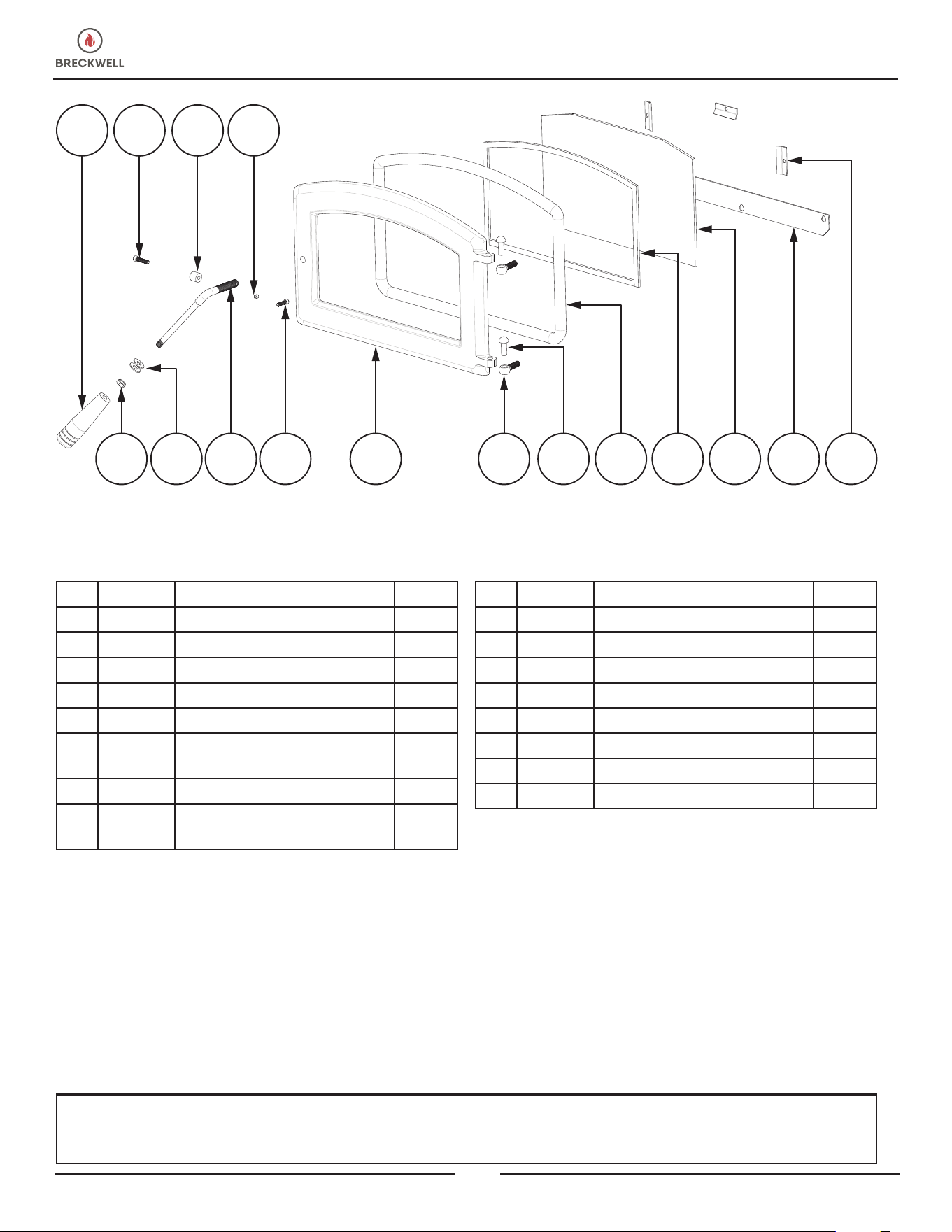
2 3 4
87 9 121110 13 14 15 1665
1
Key Part # Description Qty
1 893919 Wood Handle 1
2 83788 Socket Head Screw 1
3 893062 Roller Sleeve 1
4 83242 1/4-20 X 1/4 Allen Set Screw 1
5 83178 3/8-16 Jamb Nut 1
6 83045A
Washer, 3/8”ID X 7/8” OD X
1/16 THK
2 per
7 893071 Door Handle 1
8 83633
#12 X .75 Socket HD Cap
Screw
1
Key Part # Description Qty
9 40915 Cast Door - 2023 1
10 83575 Hinge Pin (.370 Dia X 1.00) 2
11 40571 Hinge Block 2
12 88082 3/4 Round Rope Gasket-BLK 4.3 ft
13 88174 Glass Gasket 3.75 ft
14 893934 Door Glass 1
15 25905 Air Wash Plate 1
16 25904 Glass Clip 3
IN ORDER TO MAINTAIN WARRANTY, COMPONENTS MUST BE REPLACED USING BRECKWELL PARTS PURCHASED
THROUGH YOUR DEALER OR DIRECTLY FROM BRECKWELL. USE OF THIRD PARTY COMPONENTS WILL VOID THE
WARRANTY.
Contact an Authorized Dealer to obtain any of these parts. Never use substitute materials. Use of non-approved parts can
result in poor performance and safety.
REPLACEMENT PARTS
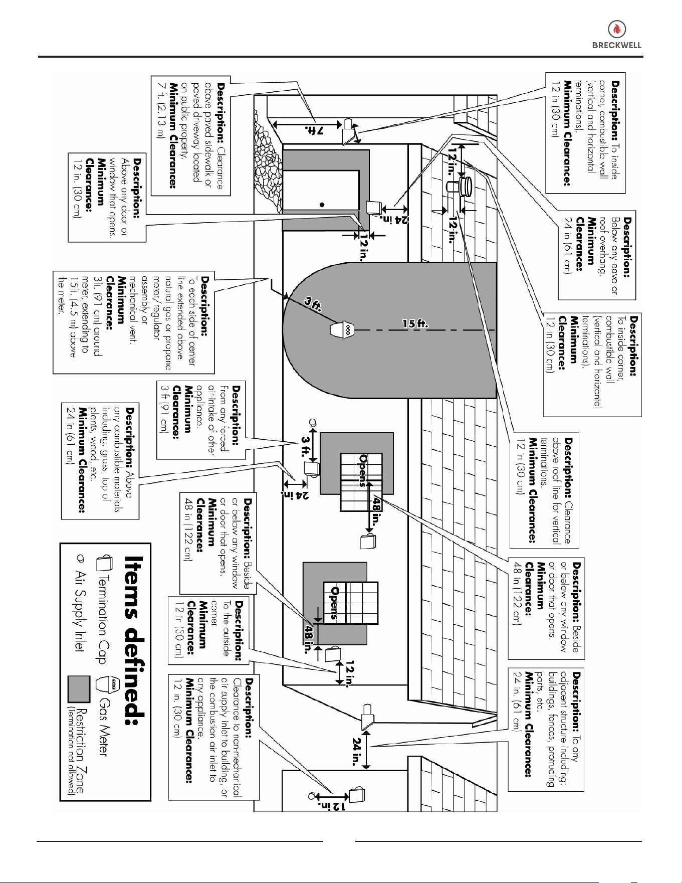
© 2024 Breckwell
27
ITEMS DEFINED
28
© 2024 Breckwell
It is recommended that your heating system is serviced regularly and that the appropriate Service Interval Record is
completed.
SERVICE PROVIDER
Before completing the appropriate Service Record below, please ensure you have carried out the service as described in
the manufacturer’s instructions. Always use the manufacturer's specied spare part when replacement is necessary.
Service 01 Date: _____________________
Engineer Name: _________________________________
License No.: _____________________________________
Company: ______________________________________
Telephone No.: __________________________________
Stove Inspected: Chimney Swept:
Items Replaced: __________________________________
Service 03 Date: _____________________
Engineer Name: _________________________________
License No.: _____________________________________
Company: ______________________________________
Telephone No.: __________________________________
Stove Inspected: Chimney Swept:
Items Replaced: __________________________________
Service 05 Date: _____________________
Engineer Name: _________________________________
License No.: _____________________________________
Company: ______________________________________
Telephone No.: __________________________________
Stove Inspected: Chimney Swept:
Items Replaced: __________________________________
Service 07 Date: _____________________
Engineer Name: _________________________________
License No.: _____________________________________
Company: ______________________________________
Telephone No.: __________________________________
Stove Inspected: Chimney Swept:
Items Replaced: __________________________________
Service 02 Date: _____________________
Engineer Name: _________________________________
License No.: _____________________________________
Company: ______________________________________
Telephone No.: __________________________________
Stove Inspected: Chimney Swept:
Items Replaced: __________________________________
Service 04 Date: _____________________
Engineer Name: _________________________________
License No.: _____________________________________
Company: ______________________________________
Telephone No.: __________________________________
Stove Inspected: Chimney Swept:
Items Replaced: __________________________________
Service 06 Date: _____________________
Engineer Name: _________________________________
License No.: _____________________________________
Company: ______________________________________
Telephone No.: __________________________________
Stove Inspected: Chimney Swept:
Items Replaced: __________________________________
Service 08 Date: _____________________
Engineer Name: _________________________________
License No.: _____________________________________
Company: ______________________________________
Telephone No.: __________________________________
Stove Inspected: Chimney Swept:
Items Replaced: __________________________________
SERVICE RECORD
28
© 2024 Breckwell Hearth
Il est recommandé que votre système de chauffage est desservi régulièrement et que le Service Interval enregistrement approprié est
terminée.
FOURNISSEUR DE SERVICES
Avant de terminer l’enregistrement de service approprié ci-dessous, s’il vous plaît vous assurer que vous avez effectué le service tel
que décrit dans le les instructions du fabricant. Toujours utiliser pièce de rechange indiquée par le fabricant lors de remplacement est
nécessaire.
Service de 01 Date: _____________________
Nom de l’ingénieur: ______________________________
N° de licence.: __________________________________
Compagnie: _____________________________________
N° de téléphone: _________________________________
Poêle Inspecté:
Cheminée balayée:
Articles Remplacé: ________________________________
Service de 03 Date: _____________________
Nom de l’ingénieur: ______________________________
N° de licence.: __________________________________
Compagnie: _____________________________________
N° de téléphone: _________________________________
Poêle Inspecté:
Cheminée balayée:
Articles Remplacé: ________________________________
Service de 05 Date: _____________________
Nom de l’ingénieur: ______________________________
N° de licence.: __________________________________
Compagnie: _____________________________________
N° de téléphone: _________________________________
Poêle Inspecté:
Cheminée balayée:
Articles Remplacé: ________________________________
Service de 07 Date: _____________________
Nom de l’ingénieur: ______________________________
N° de licence.: __________________________________
Compagnie: _____________________________________
N° de téléphone: _________________________________
Poêle Inspecté:
Cheminée balayée:
Articles Remplacé: ________________________________
Service de 02 Date: _____________________
Nom de l’ingénieur: ______________________________
N° de licence.: __________________________________
Compagnie: _____________________________________
N° de téléphone: _________________________________
Poêle Inspecté:
Cheminée balayée:
Articles Remplacé: ________________________________
Service de 04 Date: _____________________
Nom de l’ingénieur: ______________________________
N° de licence.: __________________________________
Compagnie: _____________________________________
N° de téléphone: _________________________________
Poêle Inspecté:
Cheminée balayée:
Articles Remplacé: ________________________________
Service de 06 Date: _____________________
Nom de l’ingénieur: ______________________________
N° de licence.: __________________________________
Compagnie: _____________________________________
N° de téléphone: _________________________________
Poêle Inspecté: Cheminée balayée:
Articles Remplacé: ________________________________
Service de 08 Date: _____________________
Nom de l’ingénieur: ______________________________
N° de licence.: __________________________________
Compagnie: _____________________________________
N° de téléphone: _________________________________
Poêle Inspecté:
Cheminée balayée:
Articles Remplacé: ________________________________
ENREGISTREMENT DE SERVICE
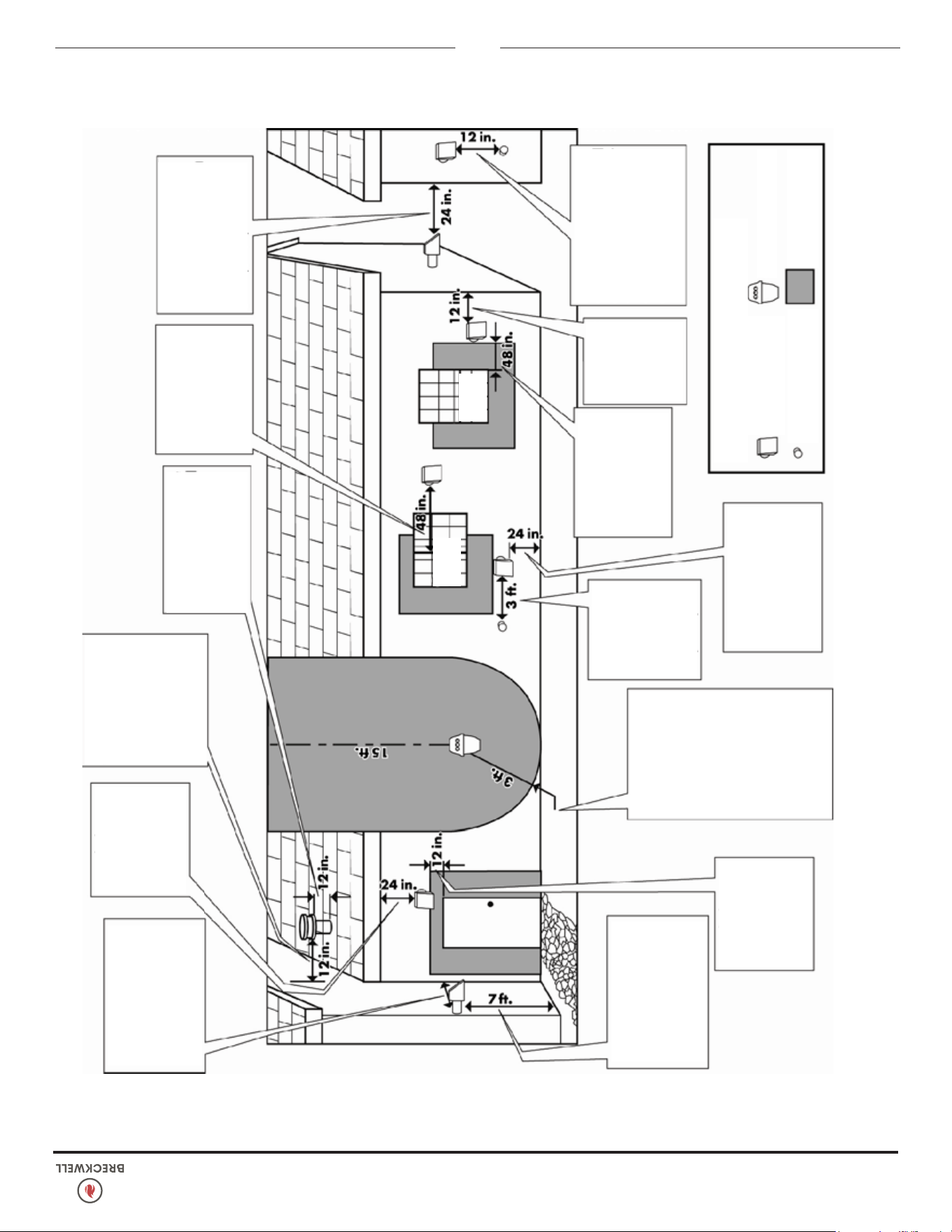
© 2024 Breckwell Hearth
27
2 7
Description : Jusqu’à
un angle rentrant de mur
combustible (terminaisons
verticales et horizontales).
Écartement minimal :
12 po. (30 cm)
Description : Écartement au-
dessus d’un trottoir pavé ou
d’une rue pavée appartenant
au domaine public.
Écartement minimal :
7 po. (2,13 m)
Description : Au-
dessus de toute
fenêtre ou porte qui
peut s’ouvrir.
Écartement
minimal :
12 po. (30 cm)
Capuchon de
terminaison
Qui
s’ouvre
Qui
s’ouvre
Entrée d’alimen-
tation en air
Compteur de gaz
Zone à restriction
(Terminaison non permise)
Légende des parties
Description : Écartement par
rapport à une entrée d’air non-
mécanique du bâtiment, ou à
l’admission d’air de tout autre
appareil.
Écartement minimal :
12 po. (30 cm)
Description :
Par rapport à un
angle extérieur.
Écartement
minimal :
12 po. (30 cm)
Description : Au-dessus
de toute matière combusti-
ble comme de l’herbe, des
plantes, du bois, etc.
Écartement
minimal :
24 po. (61 cm)
Description : À côté ou
sous toute fenêtre ou
porte qui peut s’ouvrir.
Écartement
minimal :
48 po. (61 cm)
Description :
Depuis toute prise
d’air forcée ou au-
tre appareillage.
Écartement
minimal :
3 pieds (91 cm)
Description : De
chaque côté d’une ligne
centrale prolongée au-
dessus d’un ensemble
de compteur / régula-
teur de gaz naturel ou
propane, ou de ventila-
tion mécanique.
Écartement minimal :
3 pieds (91 cm) autour
du compteur, et jusqu’à
15 pieds (4,5 m) au-
dessus du compteur.
Description :
En-dessous de
tout avant-toit ou
surplomb.
Écartement
minimal :
24 po. (61 cm)
Description : Jusqu’à
un angle rentrant de mur
combustible (termi-
naisons verticales et
horizontales).
Écartement minimal :
12 po. (30 cm)
Description : Écartement
au-dessus de la ligne de
faîte de toiture pour les
terminaisons verticales.
Écartement minimal :
12 po. (30 cm)
Description : À côté ou
sous toute fenêtre ou
porte qui peut s’ouvrir.
Écartement minimal :
48 po. (122 cm)
Description : Par rapport à
toute structure adjacente, y
compris : bâtiments, clôtures,
parties protubérantes, etc.
Écartement minimal :
24 po. (61 cm)
LÉGENDE DES PARTIES
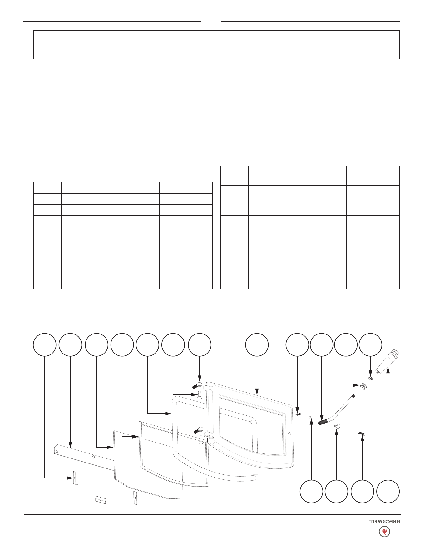
26
© 2024 Breckwell Hearth
2 3 4
87 9 121110 13 14 15 1665
1
Clé Partie La Description Qté
1 893919 Manche en bois 1
2 83788 Vis à tête creuse 1
3 893062 Manchon de rouleau 1
4 83242
Vis de réglage Allen 1/4-20 X
1/4
1
5 83178 Écrou de montant 3/8-16 1
6 83045A
Rondelle, 3/8" ID X 7/8" OD X
1/16 ÉPAIS
2
7 893071 Poignée de porte 1
8 83633
Vis d'assemblage HD à douille
#12 x 0,75
1
Clé Partie La Description Qté
9 40915 Porte coulée - 2023 1
10 83575
Goupille de charnière (.370 Dia
X 1.00)
2
11 40571 Bloc de charnière 2
12 88082 Joint de corde ronde 3/4-BLK 4,3 pi
13 88174 Joint de verre 3,75 pi
14 893934 Verre de porte 1
15 25905 Plaque de lavage à l'air 1
16 25904 Pince à verre 3
AFIN DE MAINTENIR LA GARANTIE, LES COMPOSANTS DOIVENT ÊTRE REMPLACÉS PAR DES PIÈCES D’ORIGINE DU FABRICANT
ACHETÉS AUPRÈS DE VOTRE REVENDEUR OU DIRECTEMENT AUPRÈS DU FABRICANT DE L’APPAREIL. L’UTILISATION DE COMPOSANTS
TIERS ANNULERA LA GARANTIE.
Contactez un revendeur agréé pour obtenir l’une de ces pièces. N’utilisez jamais de matériaux de substitution. L’utilisation de pièces non
approuvées peut entraînent des performances et une sécurité médiocres.
PIÈCES DE RECHANGE
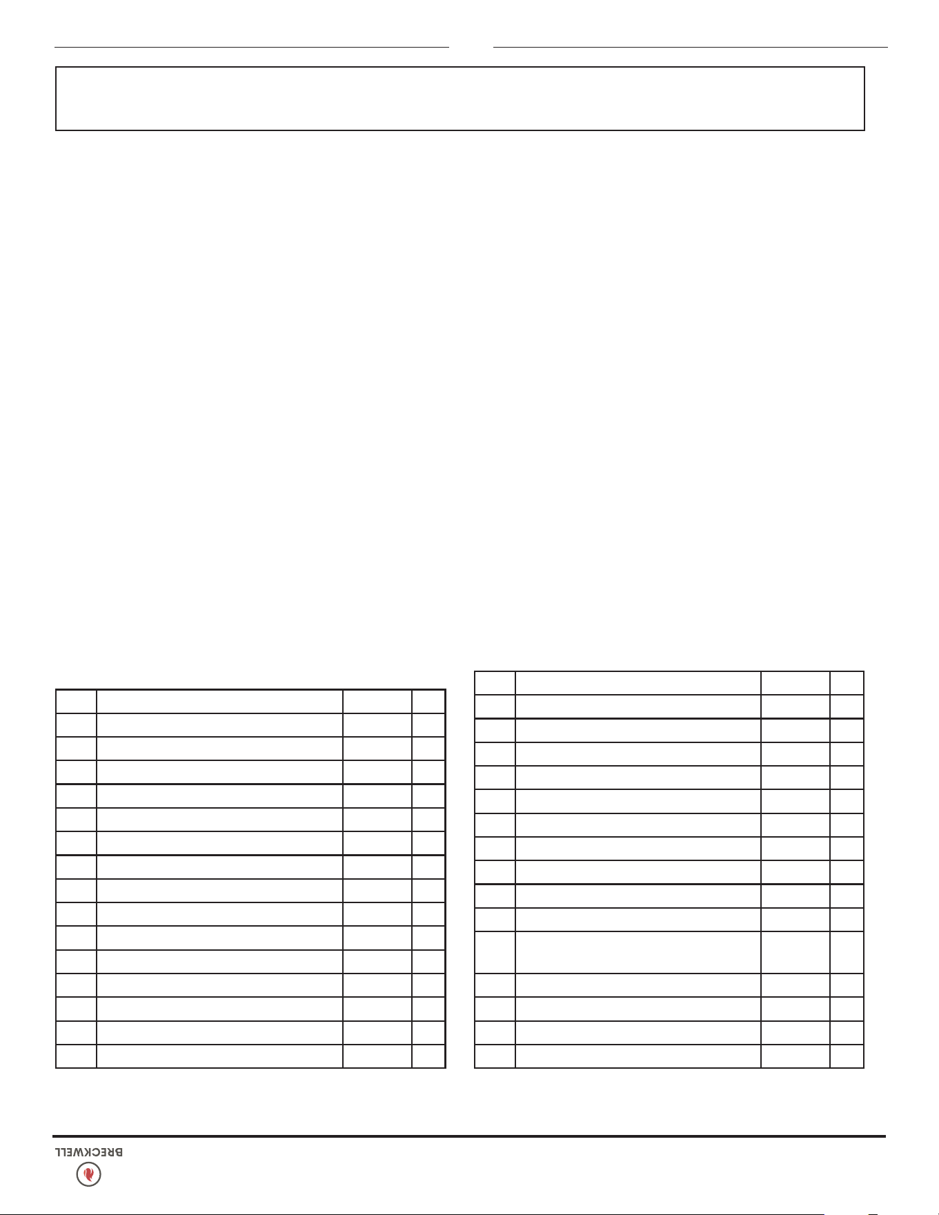
© 2024 Breckwell Hearth
25
AFIN DE MAINTENIR LA GARANTIE, LES COMPOSANTS DOIVENT ÊTRE REMPLACÉS PAR DES PIÈCES D’ORIGINE DU FABRICANT
ACHETÉS AUPRÈS DE VOTRE REVENDEUR OU DIRECTEMENT AUPRÈS DU FABRICANT DE L’APPAREIL. L’UTILISATION DE COMPOSANTS
TIERS ANNULERA LA GARANTIE.
Clé Partie La Description Qté
1 69971 Cendrier 1
2 88174 Joint Plat (3/16 X 3/8) 1
3 26799 Porte Cendrée 2
4 69964
Construction Soudée, Logement De Pot
De Combustion
1
5 894097 Soudé, Pot De Combustion 1
6 86668 Tige D’amortisseur 1
7 891987 Bouton En Plastique 3
8 610326 Plaque De Contrôle 1
9 26794 Meuble Gauche 1
10 69703 Soudé, Couvercle Supérieur 1
11 891148 Poignée En Plastique 1
12 80683 300° Thermodisque 1
13 80621 Interrupteur À Pression 1
14 88205 Joint Ventilateur De Convection 1
15 80647 Ventilateur, Distribution 1
16 88100 Joint, Ventilateur D’échappement 1
17 80641 Ventilateur, Échappement 1
18 26793 Armoire Arrière 1
19 40494 Transition, Ventilateur 1
20 80909 Cartouche D’allumage 1
21 25589 Poker, Pot De Combustion 1
22 86999 Ensemble Boîtier D’allumeur 1
23 88202 Joint De Boîtier D’allumeur 1
24 80461 Cordon D’alimentation 1
25 80462 Réceptacle, 3 Broches 1
26 80610 Limite Inférieure POF Thermodisque 1
27 69966 Amortisseur Assy 1
28 88208 Couverture De Ventilateur 1
29 88207 Couverture Arrière 1
30 26795 Armoire À Droite 1
31 80642 Moteur De Tarière 1
PIÈCES DE RECHANGE
Contactez un revendeur agréé pour obtenir l’une de ces pièces. N’utilisez jamais de matériaux de substitution. L’utilisation de pièces non
approuvées peut entraînent des performances et une sécurité médiocres.
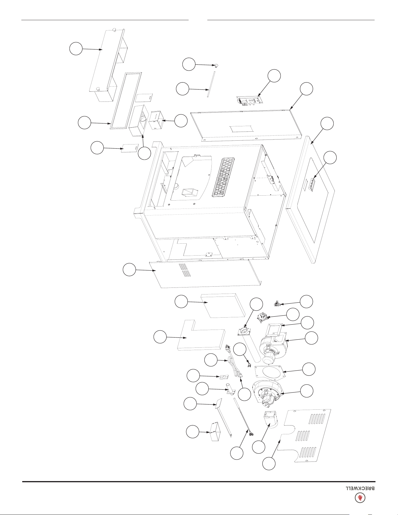
24
© 2024 Breckwell Hearth
PIÈCES DE RECHANGE
1
2
3
4
5
6
7
8
9
10
11
12
13
27
14
15
16
17
18
19
20
21
32
22
23
24
29
28
30
26
25
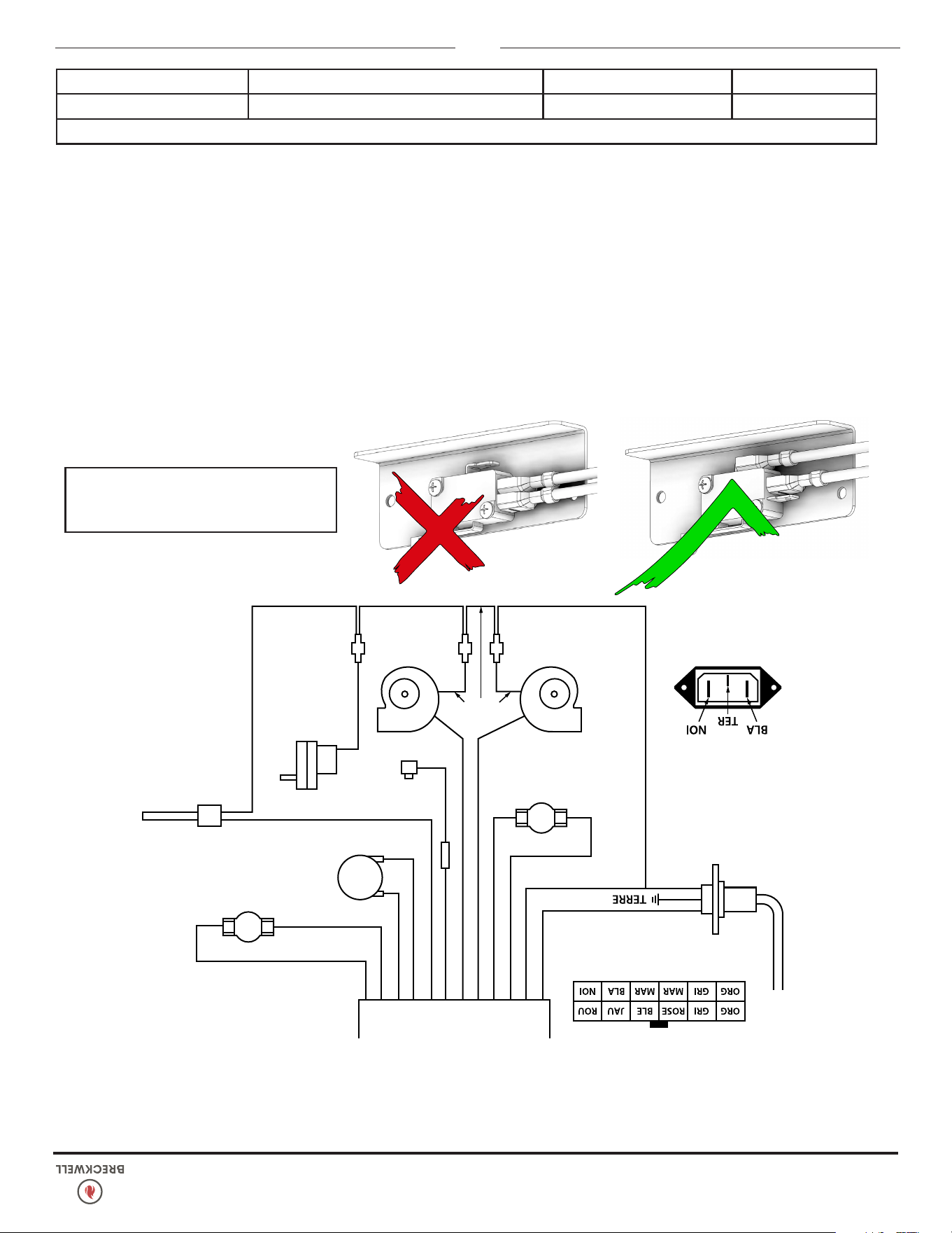
© 2024 Breckwell Hearth
23
CONNECTEUR MOLEX
ALIMENTATION SECTEUR
120 VOLTS CA
COMMUTATEUR
D'AIR
ROUGE
ALLUMEUR
INTERRUPTEUR
DE TRÉMIE
MAUVE
MOTEUR DE
VIS SANS
FIN
BLANC
BLANC
BLANC
THERMODISQUE
HAUTE TEMP.
MAUVE
NOIR
BLANC
ORANGE
ORANGE
BLEU
ROSE
JAUNE
ROUGE
GRIS
GRIS
BLANCBLANC
SOUFFLANTE
DE CONVECTION
SOUFFLANTE
DE COMBUSTION
DÉTAIL DE LA PRISE
D’ALIMENTATION EN
REGARDANT DE
L’ARRIÈRE DU POÊLE
DÉTAIL DE CONNECTEUR MOLEX
MARRON
MARRON
POF THERMODISQUE
DE CONFIRATION
DE FEU
CORRECT FAUX
Assurez-vous que les ls sont connectés aux
deux broches inférieures de l’interrupteur
de la trémie, comme illustré.
SCHÉMA ÉLECTRIQUE
CONTACTEZ VOTRE REVENDEUR OU INSTALLATEUR POUR LES PIÈCES ET LE SERVICE
Les informations contenues dans ce manuel du propriétaire sont spéciques à votre appareil. Lors de la commande de pièces de
rechange, les informations contenues dans ce manuel vous aideront à vous assurer que les bons articles sont commandés. Avant de
contacter le service client, notez le numéro de modèle et le numéro de série de cet appareil. Ces informations se trouvent sur l’étiquette de
certication apposée à l’arrière de l’appareil. D’autres informations qui peuvent être nécessaires sont le numéro de pièce et la description
de la pièce (s) en question. Les numéros de pièces et les descriptions se trouvent dans la section «Pièces de réparation» de ce manuel.
Une fois ces informations recueillies, vous pouvez contacter votre revendeur Breckwell ou visiter www.Breckwell.com
Informations sur le modèle
Numéro de modèle Nom du revendeur
Numéro de série Numéro de téléphone du concessionnaire
COMMENT COMMANDER DES PIÈCES DE RÉPARATION
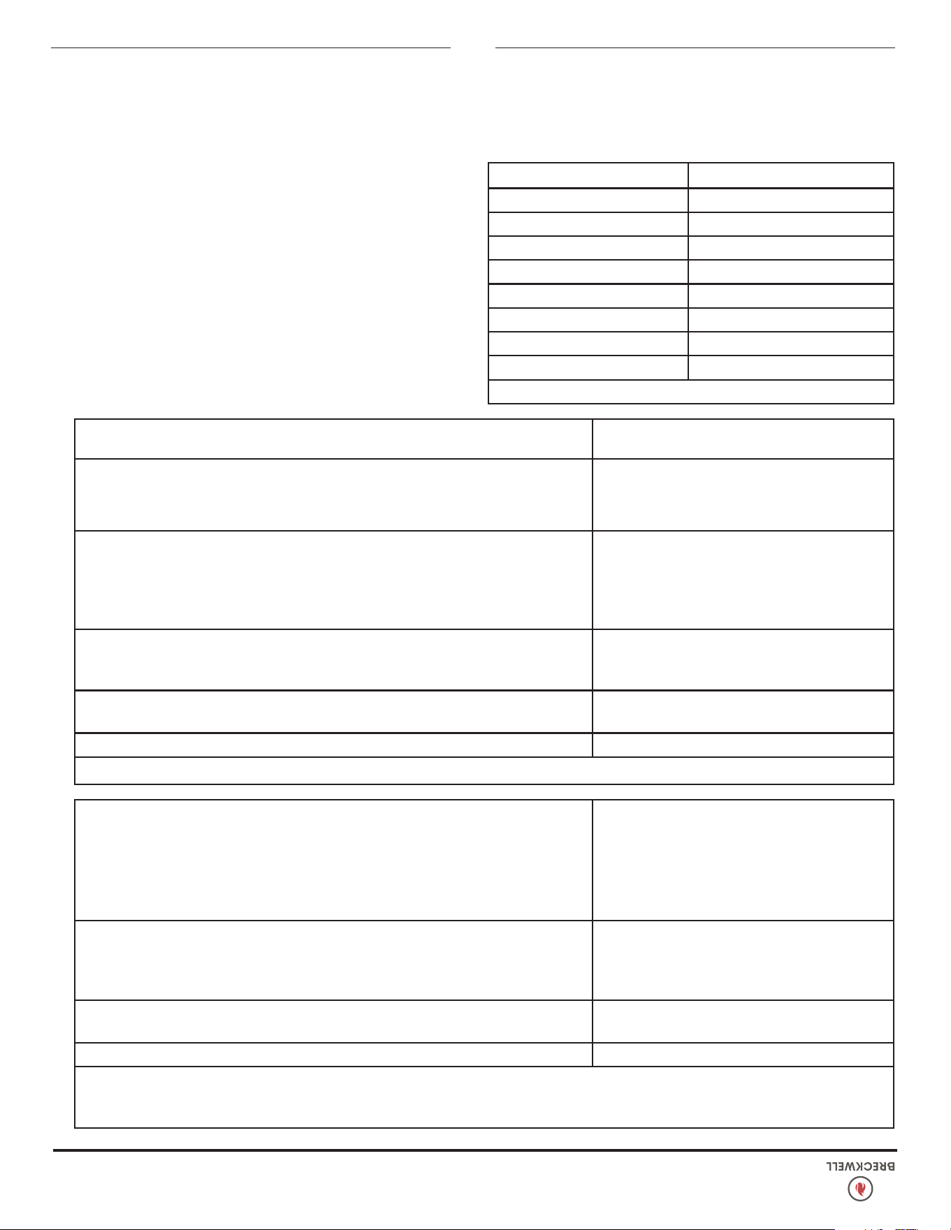
22
© 2024 Breckwell Hearth
L’INTERRUPTEUR SUR DÉPASSEMENT DE LIMITE HAUTE DÉCLENCHE
Causes possibles: Remèdes possibles:
La soufante de convection est en surchauffe et
fait déclencher la protection thermique interne.
Enlevez la poussière des enroulements et des pales du ventilateur. Si huiler le
ventilateur ne résout pas le problème, le ventilateur peut être défectueux
Le poêle a été laissé sur le réglage le plus fort
pendant de longues périodes.
Le réglage de niveau le plus élevé est conçu pour une utilisation sur de courtes
périodes. Brûler le poêle au réglage le plus élevé pendant plus de 1 à 2 heures peut
entraîner des situations de surchauffe.
Du combustible autre que des granulés est
consumé dans le poêle.
Les poêles à pellets Breckwell sont conçus et testés pour utiliser des pellets de bois.
Recherchez des traces de combustible autres que des granulés de bois. Aucun
autre type de combustible n'a été approuvé pour les poêles à granulés Breckwell.
S'il y a des signes d'utilisation d'autres types de carburant, arrêtez de les utiliser
immédiatement.
Surtension ou panne secteur localisée.
Une surtension, un pic ou une chute de tension pourraient provoquer le déclenchement
du commutateur de limite supérieure. Vériez si un limiteur de surtension est utilisé
sur le poêle. Sinon, en recommander un au consommateur.
Interrupteur de limite haute ne fonctionnant pas Si les autres éléments sont corrects, remplacez le commutateur de limite supérieure.
DURÉES DES SÉQUENCES DE CARTE DE CIRCUIT NUMÉRIQUE
Réglage de chauffe haut unité
1 & 3 1,4 seconds
1 2 seconds
1 & 4 2,5 seconds
2 4 seconds
3 7 seconds
4 9 seconds
5 12 seconds
Durée totale de cycle 14,5 seconds
ODEUR DE FUMÉE OU ACCUMULATION DE SUIE
Du fait que c’est un appareil carburant au bois, votre poêle à
granulés Breckwell peut émettre une légère odeur de bois
brûlé. Si l’odeur augmente au-delà de la normale, ou si vous
remarquez un dépôt anormal de suie sur vos murs ou meubles,
vériez attentivement votre système d’évacuation pour y chercher
des fuites. Tous les joints doivent être correctement étanchéiés.
Nettoyez également votre poêle, en suivant les instructions de la
section “ENTRETIEN”. Si le problème persiste, contactez votre
revendeur.
Le verre «tire» à un rythme très rapide
LA FLAMME EST LAZY, DARK ET A DES CONSEILS NOIRS
APRÈS QUE LE POÊLE A ÉTÉ ALLUMÉ, LE TROP-POT DE BRÛLURE
Causes possibles: Remèdes possibles:
La soufante de combustion ne tourne pas assez
vite.
Testez la vitesse en tours/minute de la soufante après nettoyage de ses pales. Elle
doit être d’environ 3 000 tours/minute;
Mauvais granulés (Ne s’applique qu’à “La Vitre
S’encrasse Très Rapidement”).
La marque ou le lot de granulés utilisés peut être de qualité médiocre. Si possible
utilisez-en d’autres. Vous pourriez aussi essayer une marque différente avec un
autre type de bois (bois tendre au lieu de bois dur). Des bois différents ont des
caractéristiques différentes quand ils brûlent.
Le réglage d’adaptation pour le taux
d’alimentation faible est trop bas (Ne s’applique
qu’à “La Vitre S’encrasse Très Rapidement”).
Utilisez la commande “Reset Trim” pour augmenter le réglage pour taux d’alimentation
faible. Si les voyants 1 et 3 sont allumés, le poêle est actuellement sur le réglage le
plus bas. Si seul le voyant 1 est allumé, le poêle est au réglage par défaut (moyen).
Si les voyants 1 et 4 sont allumés, le poêle est au réglage le plus élevé d’adaptation
pour le taux d’alimentation faible. Si le poêle fonctionne sur l’un des deux réglages
les plus faibles, passez à l’adaptation supérieure et essayez de nouveau le poêle.
GUIDE DE DÉPANNAGE
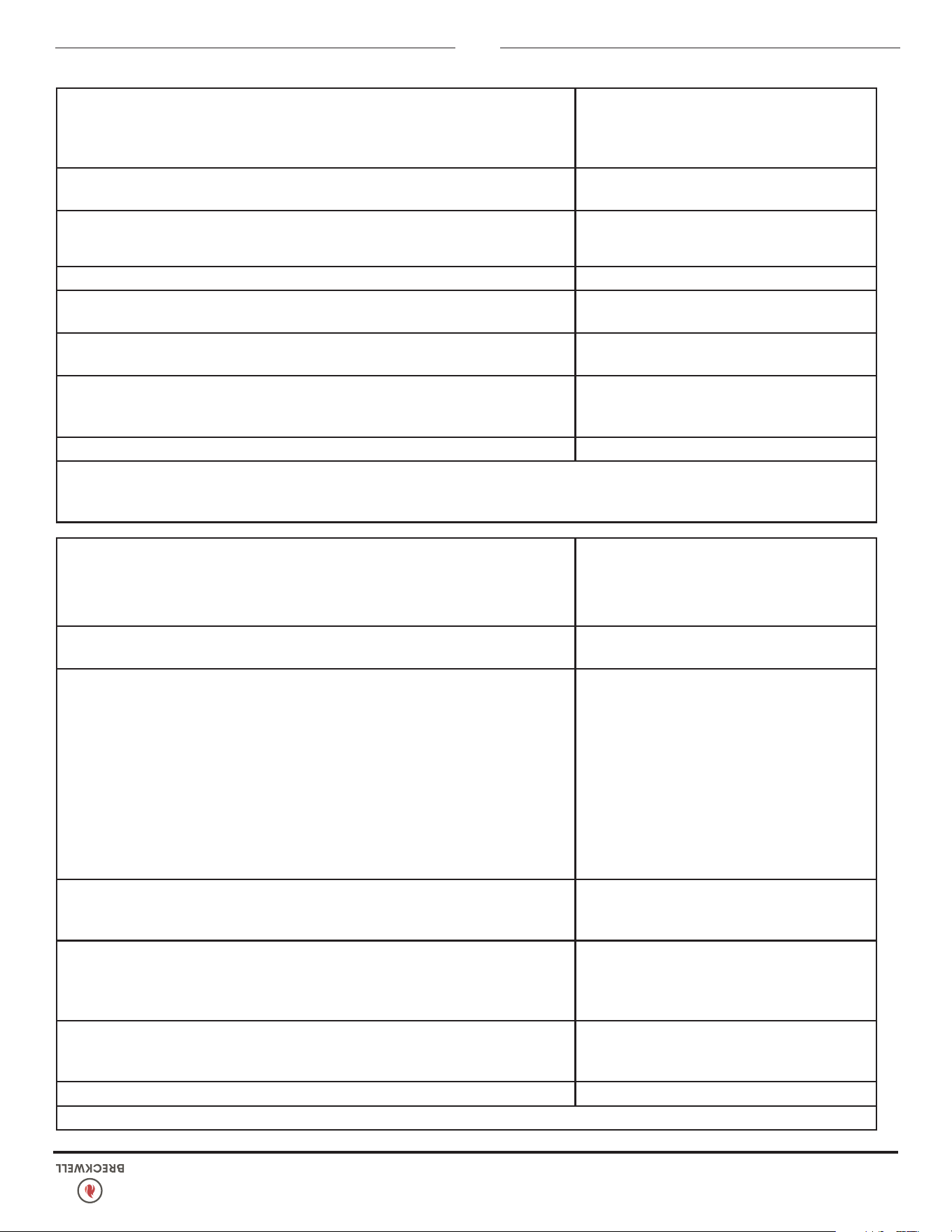
© 2024 Breckwell Hearth
21
Le verre «tire» à un rythme très rapide
LA FLAMME EST LAZY, DARK ET A DES CONSEILS NOIRS
APRÈS QUE LE POÊLE A ÉTÉ ALLUMÉ, LE TROP-POT DE BRÛLURE
Causes possibles: Remèdes possibles:
Le poêle ou son tuyau de ventilation est sale,
ce qui restreint le ux d’air au travers du pot de
combustion.
Appliquez toutes les procédures de nettoyage de la section d’entretien de ce manuel.
Le tuyau de ventilation est installé de façon
incorrecte.
Contrôlez si le tuyau de ventilation a bien été installé selon les critères donnés dans
ce manuel.
Le registre de tirage est trop repoussé (fermé)
pour un réglage à forte puissance.
Tirez le bouton de registre un peu plus ouvert par rapport au côté du poêle, et
essayez de nouveau de le faire fonctionner.
Les trous du pot de combustion sont bouchés. Sortez le pot de combustion et nettoyez-le bien.
Le registre de tirage est cassé.
Inspectez visuellement l’ensemble de tirage. Assurez-vous que la plaque de registre
est xée à la tige de registre. Quand cette tige est tirée la plaque doit venir avec.
Blocage dans le tuyau d’admission d’air.
Inspectez visuellement le tuyau d’admission d’air qui mène au pot de combustion
pour y chercher des matières étrangères.
Dysfonctionnement de la carte de circuit
imprimé.
Chronométrez la séquence de voyant d’alimentation en carburant pour chaque
réglage (après que le poêle ait terminé sa séquence de démarrage). Assurez fois
que les durées correspondent au tableau de séquences de la vis sans n. Si le moteur
de vis tourne en permanence, la carte est défectueuse.
LE POÊLE N’EST PAS ALIMENTÉ EN GRANULÉS, MAIS LE VOYANT CORRESPONDANT EST CEPENDANT ALLUMÉ
Causes possibles: Remèdes possibles:
Fusible grillé sur la carte de contrôle.
Sortez la carte de contrôle. À l’arrière il y a un fusible. S’il semble défectueux,
remplacez-le par un équivalent (5 A/125 V). Rebranchez le poêle et essayez de le
faire fonctionner.
Le thermodisque pour limite haute a déclenché
ou est défectueux.
Laissez refroidir le poêle 30-45 minutes. Il devrait alors fonctionner normalement. Si
ce n’est pas le cas utilisez le manuel d’utilisateur pour situer le thermodisque pour
limite haute. Pour le tester, vous pouvez le contourner comme décrit plus haut pour
le thermodisque POF.
Moteur de vis sans n défectueux.
Dégagez le moteur de vis de l’axe de vis et essayez de démarrer l’appareil. Si le
moteur tourne, c’est que l’axe est bloqué sur quelque chose. Mais si le moteur ne
tourne pas c’est qu’il est défectueux.
Auger jam
Commencez par vider la trémie. Puis ôtez le moteur de vis sans n en enlevant la
goupille de vis. Ôtez la plaque d’inspection d’axe de vis sans n dans la trémie
pour pouvoir la voir. Levez doucement tout droit l’axe de vis de façon à ce que
son extrémité sorte de la douille du bas de trémie. Ensuite ôtez les deux écrous
qui maintiennent le biscuit du haut de vis sans n. Puis faites tourner l’extrémité
du bas de l’axe de vis vers vous jusqu’à pouvoir lever la vis hors du poêle. Une
fois l’axe sorti, inspectez-le pour chercher des lets déformés, des ébarbures ou
des soudures cassées. Enlevez toute matière étrangère qui pourrait avoir causé le
blocage. Vériez aussi le tube de vis sans n pour d’éventuels dommages comme
des ébarbures, points rugueux ou entailles dans le métal qui auraient pu causer un
bourrage.
Desserrage de l ou de connecteur.
Vériez tous les ls et connecteurs desservant le moteur de vis sans n, l’interrupteur
sur limite haute et le connecteur Molex.
Carte de contrôle défectueuse.
Si son fusible est bon, et que le contrôle des connexions est correct, et que l’interrupteur
sur limite haute n’a pas déclenché, testez si la moteur de la vis est alimenté. Si une
alimentation intégrale est envoyée au moteur quand le voyant d’alimentation en
carburant est allumé, c’est que la carte de contrôle est défectueuse.
GUIDE DE DÉPANNAGE
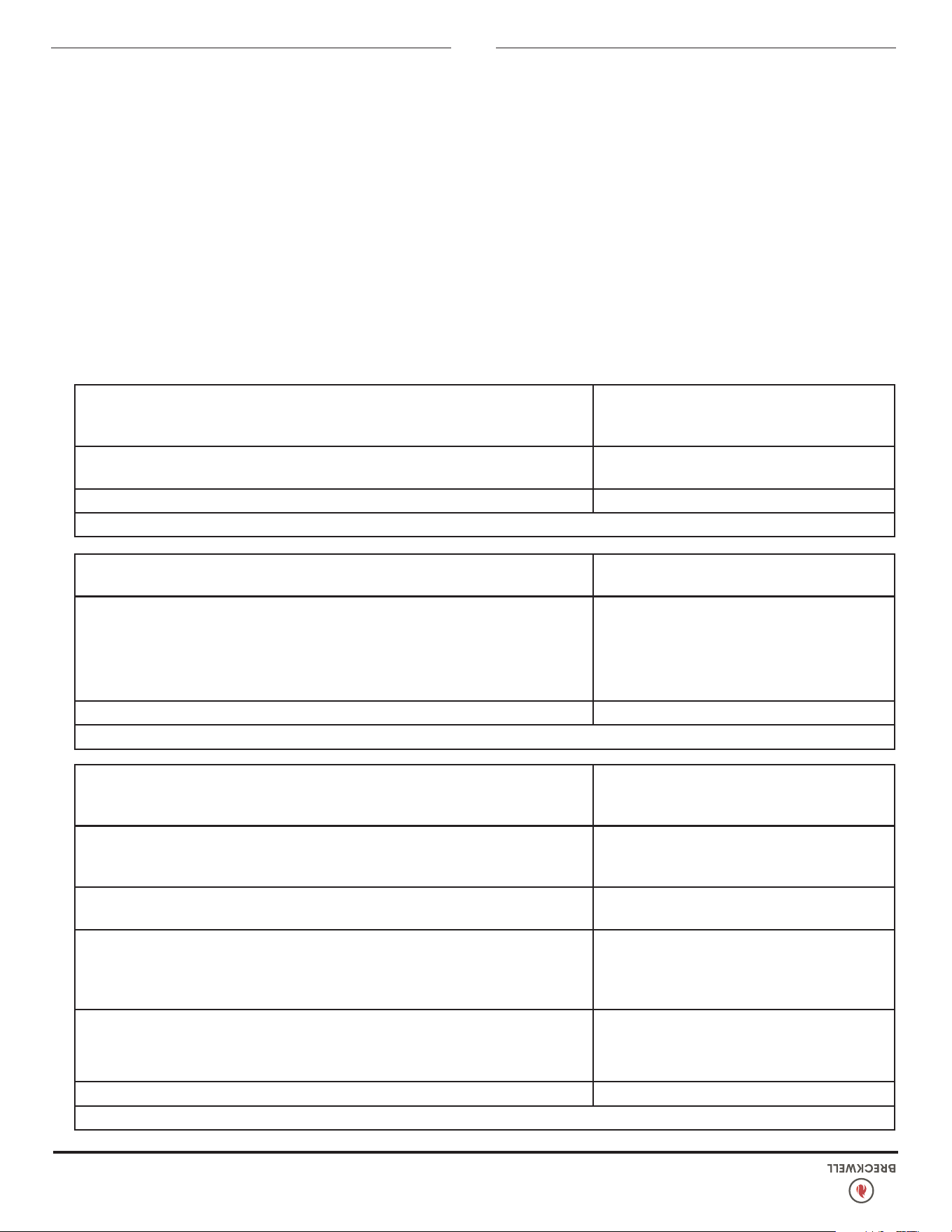
20
© 2024 Breckwell Hearth
UNE ODEUR DE FUMÉE PÉNÊTRE DANS LA MAISON
Causes possibles: Remèdes possibles:
Il y a une fuite dans le système de tuyaux de
ventilation.
Inspectez tous les raccordements de tuyaux de ventilation. Assurez-vous qu’ils sont
étanchéiés avec de l’enduit à la silicone pouvant résister à une température d’au
moins 500°F (260 °C). Recouvrez également les joints avec de la bande métallique
UL-181-AP. Assurez-vous aussi que la pièce d’adaptation carré/rond sur la soufante
de combustion a été correctement étanchéiée avec le même RTV.
Un joint de la soufante de combustion s’est
détérioré.
Inspect both gaskets on the combustion blower to make Inspectez les deux joints de
la soufante de combustion pour vérier qu’ils sont en bon état.
LA SOUFFLANTE DE CONVECTION S’ARRÊTE ET REPART
Causes possibles: Remèdes possibles:
La soufante de convection est en surchauffe et
fait déclencher la protection thermique interne.
Nettoyez toute la poussière des ailettes et pales de ventilateur. Si le nettoyage de la
soufante est inefcace, elle peut être défectueuse.
Dysfonctionnement de la carte de circuit
imprimé.
Testez l’alimentation allant à la soufante de convection. Si elle est envoyée durant
la coupure, la carte de contrôle est correcte. S’il n’y a PAS d’alimentation durant la
coupure en fonctionnement, c’est la carte qui est défectueuse.
LE POÊLE EST ALIMENTÉ EN GRANULÉS, MAIS ILS NE S’ALLUMENT PAS
Causes possibles: Remèdes possibles:
Registre de tirage ouvert trop loin pour permettre
l’allumage.
Repoussez le registre plus près du côté du poêle au démarrage. Dans certains cas il
peut être nécessaire de l’avoir complètement fermé pour rendre l’allumage possible.
Une fois qu’il y a une amme, le registre peut être ajusté pour le tirage voulu.
Blocage dans le tube d’allumage ou l’entrée
pour le tube d’allumage.
Cherchez le logement d’allumeur au dos de la cloison parefeu. Le trou d’admission
d’air est petit et situé en bas de ce logement. Assurez-vous qu’il est dégagé.
Regardez aussi à l’avant du poêle pour vous assurer qu’il n’y a pas de débris autour
de l’élément d’allumeur à l’intérieur de son logement.
Le pot de combustion n’est pas poussé
complètement à l’arrière de la chambre.
Assurez-vous que le collier d’admission d’air sur le pot de combustion touche la
paroi arrière de la chambre.
Élément d’allumage défectueux.
Appliquez une alimentation directement sur l’élément d’allumage. Regardez le bout
de l’allumeur depuis l’avant du poêle. Après 2 minutes ce boit doit être rougeoyant.
Sinon c’est que l’élément est défectueux.
La carte de contrôle n’envoie pas d’alimentation
à l’allumeur.
Vériez la tension allant à l’allumeur au démarrage. Il doit y avoir l’intégralité du
courant. Si la tension est inférieure à la valeur intégrale, vériez le câblage. Si le
câblage est contrôlé bon, la carte est défectueuse.
GUIDE DE DÉPANNAGE
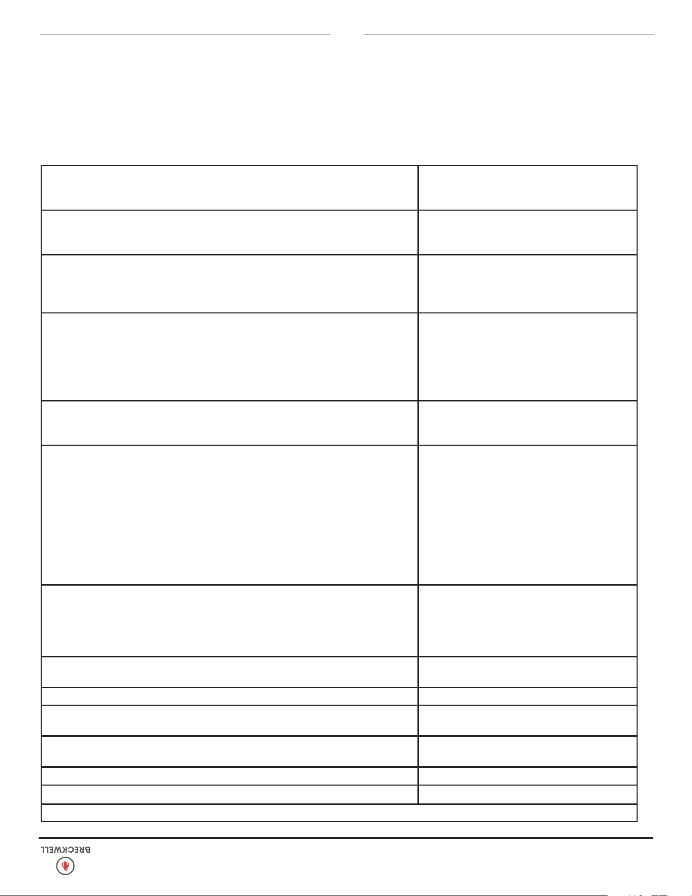
© 2024 Breckwell Hearth
19
LE POÊLE S’ÉTEINT ET LE VOYANT N° 3 CLIGNOTE
Causes possibles Remèdes possibles: (Si possible débranchez d’abord le poêle)
La trémie n’a plus de granulés. Regarnissez la trémie.
Le registre de tirage est trop ouvert pour un
réglage à faible alimentation.
Si vous carburez à réglage faible, vous pouvez avoir à fermer complètement le
registre (poussez le bouton pour qu’il touche le côté du poêle).
Le pot de combustion n’est pas poussé
complètement à l’arrière de la chambre.
Assurez-vous que le collier d’admission d’air sur le pot de combustion touche la
paroi arrière de la chambre.
Les trous du pot de combustion sont bouchés. Sortez le pot de combustion et nettoyez-le bien.
L’admission d’air, les chambres intérieures ou le
système d’évacuation ont un blocage partiel.
Appliquez toutes les procédures de nettoyage de la section d’entretien de ce manuel.
L’interrupteur de sécurité de la trémie est en
panne ou la trémie est ouverte.
Quand vous faites fonctionner le poêle, assurez-vous que l’interrupteur de sécurité
du couvercle de trémie s’active. Contrôlez les bonnes connexions des ls allant à
l’interrupteur de sécurité de la trémie au panneau de commande et au moteur de
vis sans n. Utilisez un testeur de continuité pour tester l’interrupteur de sécurité,
remplacez-le si nécessaire.
L’arbre de la vis sans n est bloqué.
Commencez par vider la trémie. Puis ôtez le moteur de vis sans n en enlevant la
goupille de vis. Ôtez la plaque d’inspection d’axe de vis sans n dans la trémie
pour pouvoir la voir. Levez doucement tout droit l’axe de vis de façon à ce que
son extrémité sorte de la douille du bas de trémie. Ensuite ôtez les deux écrous
qui maintiennent le biscuit du haut de vis sans n. Puis faites tourner l’extrémité du
bas de l’axe de vis vers vous jusqu’à pouvoir le lever hors du poêle. Une fois l’axe
sorti, inspectez-le pour chercher des lets déformés, des ébarbures ou des soudures
cassées. Enlevez toute matière étrangère qui pourrait avoir causé le blocage. Vériez
aussi le tube de vis sans n pour d’éventuels dommages comme des ébarbures,
points rugueux ou entailles dans le métal qui auraient pu causer un bourrage.
Le moteur de vis sans n est tombé en panne.
Dégagez le moteur de vis de l’axe de vis et essayez de démarrer l’appareil. Si le
moteur tourne, c’est que l’axe est bloqué sur quelque chose. Mais si le moteur ne
tourne pas c’est qu’il est défectueux.
Le thermodisque témoin de la présence de feu
(POF) n’a pas fonctionné.
Contournez temporairement le thermodisque POF en débranchant les deux ls marron
et en les réunissant avec un petit morceau de l conducteur. Puis remettez le poêle
en marche. S’il redémarre et fonctionne, vous devrez remplacer le thermodisque.
Ceci n’était que pour le test. NE LAISSEZ PAS LE THERMODISQUE CONTOURNÉ.
Sinon vos soufantes ne s’arrêteraient jamais et si le feu s’éteignait la vis continuerait
d’alimenter en granulés jusqu’à ce que la trémie soit vide.
Le thermodisque pour limite haute a déclenché
ou est défectueux.
Laissez refroidir le poêle 30-45 minutes. Il devrait alors fonctionner normalement. Si
ce n’est pas le cas utilisez le manuel d’utilisateur pour situer le thermodisque pour
limite haute. Pour le tester, vous pouvez le contourner comme décrit plus haut pour
le thermodisque POF.
Le fusible du panneau de commande est grillé.
Sortez la carte de contrôle. À l’arrière il y a un fusible. S’il semble défectueux,
remplacez-le par un équivalent (5 A/125 V). Rebranchez le poêle et essayez de le
faire fonctionner.
La carte de contrôle n’envoie pas d’alimentation
au thermodisque POF ou aux autres composants
du système de vis sans n.
Il doit y avoir 5 V environ allant au commutateur d’air une fois que le poêle a été
activé pendant 10 secondes.
GUIDE DE DÉPANNAGE
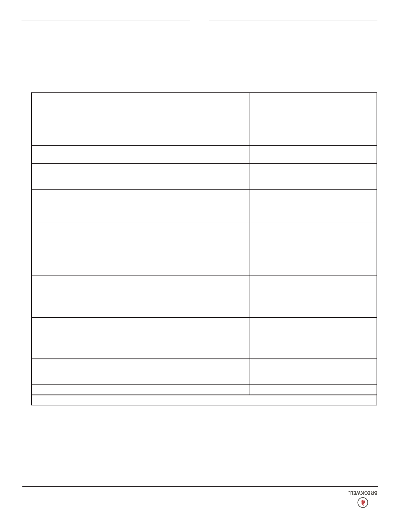
18
© 2024 Breckwell Hearth
Quand votre poêle se comporte anormalement, la première réaction est d’appeler pour de l’aide. Ce guide peut faire économiser du
temps et de l’argent en vous permettant de solutionner par vous-même des problèmes simples. Les problèmes rencontrés sont souvent
le résultat de seulement 5 facteurs : 1) carburant médiocre ; 2) utilisation ou entretien inadéquats ; 3) mauvaise installation; 4) panne
de composant ; 5) défaut d’origine. Vous pouvez généralement résoudre les problèmes venant des causes 1 et 2. Votre revendeur peut
solutionner ceux des causes 3 à 5. Référez-vous au schéma de la page 17 pour vous aider à localiser les pièces indiquées.
Dans le but de dépanner en utilisant ce guide pour vous aider, vous devez regarder quel est votre niveau de réglage de chauffe pour
voir quel voyant clignote.
***ATTENTION – DÉBRANCHEZ L’ALIMENTATION ÉLECTRIQUE AVANT TOUTE INTERVENTION SUR LE POÊLE!
LE POÊLE S’ÉTEINT ET LE VOYANT N° 2 CLIGNOTE
Causes possibles Remèdes possibles: (Si possible débranchez d’abord le poêle)
Le tuyau de commutateur d’air ou les tuyaux de
xation au poêle sont obstrués.
Ôtez le tuyau d’air du commutateur d’air et soufez dedans. Si l’air passe librement,
le tuyau et le tube sont corrects. Sinon, utilisez le l de fer d’un cintre pour dégager
le blocage.
L’admission d’air, le pot de combustion, l’intérieur
des chambres de combustion, la soufante
de combustion ou le tuyau d’évacuation sont
obstrués par de la cendre ou des matières
étrangères.
Appliquez toutes les procédures de nettoyage de la section d’entretien de ce manuel.
La chambre de combustion n’est pas bien
étanche.
Assurez-vous que la porte est fermée et le joint est en bon état. Si la porte des
cendres a un loquet, vériez qu’elle est bien fermée et que le joint est bien étanche.
Si le poêle a juste un petit trou pour que les cendres tombent en travers sous le pot de
combustion, vériez que la plaque coulissante est en pace pour fermer le plancher
de la chambre.
Le tuyau de ventilation est mal installé. Vériez que l’installation du tuyau répond aux critères du manuel d’utilisation.
Les connexions de ls du commutateur d’air sont
mauvaises.
Contrôlez les connecteurs qui tiennent les ls gris sur le commutateur d’air.
Les ls gris sont désengagés du connecteur
Molex sur le harnais de câblage.
Contrôlez si les ls gris sont désengagés au connecteur Molex.
Panne de soufante de combustion.
Le poêle étant allumé, vériez si la soufante de combustion tourne. Si ce n’est pas
le cas, vous devez vérier qu’elle est bien alimentée. Il doit y avoir l’intégralité du
courant. Si elle est alimentée, c’est que la soufante est défectueuse. Sinon, allez au
point suivant 8.
La carte de contrôle n‘envoie pas d’alimentation
à la soufante de combustion.
S’il n’y a pas de courant allant à la soufante de combustion, vériez toutes les
connexions de câblage. Si tous les ls sont bien branchés, votre carte de contrôle
est défectueuse.
La carte de contrôle n‘envoie pas d’alimentation
au commutateur de débit d’air de combustion.
Il doit y avoir 5 V environ allant au commutateur d’air une fois que le poêle a été
activé pendant 30 secondes.
Panne du commutateur de débit d’air (très rare).
Pour tester le commutateur de débit d’air, vous devez débrancher le tuyau d’air
du corps du poêle. Avec l’autre bout restant xé au commutateur d’air, aspirez
doucement le bout libre du tuyau (vous pouvez vouloir ôtez le tuyau complètement
du poêle et du commutateur d’air, pour vous assurer qu’il n’est pas bouché). Si
vous entendez un déclic, le commutateur fonctionne. FAITES ATTENTION, TROP DE
DÉPRESSION PEUT ENDOMMAGER LE COMMUTATEUR D’AIR.
GUIDE DE DÉPANNAGE
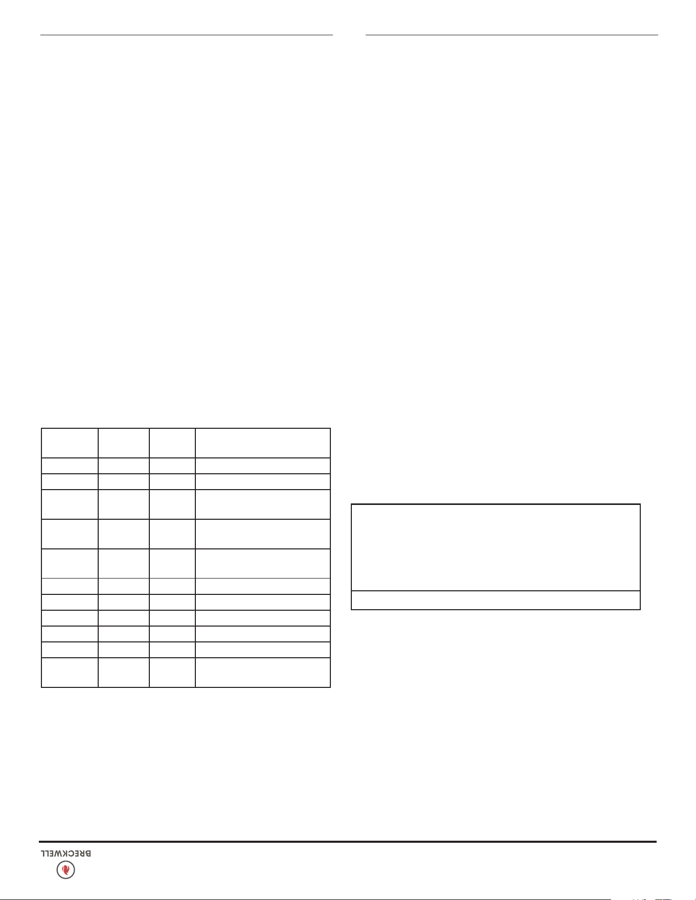
© 2024 Breckwell Hearth
17
ARRÊT DE PRINTEMPS
Après la dernière brûlure au printemps, retirez tous les granulés
restants de la trémie et du système d’alimentation à vis sans n.
Retirez les granulés, puis faites fonctionner la vis sans n jusqu’à
ce que la trémie soit vide et que les granulés cessent de couler
(cela peut être fait en appuyant sur le bouton «ON» avec la
porte de visualisation ouverte). Passez l’aspirateur dans la trémie.
Nettoyez soigneusement le pot de combustion et la chambre de
combustion. Il peut être souhaitable de vaporiser l’intérieur de la
trémie nettoyée avec un spray silicone aérosol si votre poêle se
trouve dans une zone très humide. Le système d’échappement doit
être soigneusement nettoyé.
CALENDRIER D’ENTRETIEN RECOMMANDÉ
MISE EN GARDE:
CE CHAUFFE-BOIS A BESOIN D'INSPECTIONS ET DE
RÉPARATIONS PÉRIODIQUES POUR UN FONCTIONNEMENT
APPROPRIÉ. IL EST CONTRE LES RÈGLEMENTS FÉDÉRAUX DE
FAIRE FONCTIONNER CE CHAUFFE À BOIS D'UNE MANIÈRE
NON CONSTANTE AUX INSTRUCTIONS D'UTILISATION DE CE
MANUEL.
Etablissez une routine pour la gestion du combustible, de
l’insert et de la technique d’allumage. Inspectez tout d’abord
quotidiennement l’accumulation de créosote an de déterminer
précisément les fréquences de nettoyage pour assurer un
fonctionnement sûr. Soyez conscient que la quantité de dépôt
de créosote est inversement proportionnelle à la température
du feu. Ainsi, des nettoyages hebdomadaires seront peut être
nécessaires en période de temps doux alors que des nettoyages
mensuels seront sufsants durant les mois plus froids. Utilisez le
guide qui suit, fait pour des conditions d’utilisation moyennes. Les
joints autour de la porte et de la vitre de porte sont à inspecter,
et à réparer ou remplacer si nécessaire. Voyez à “Pièces De
Rechange”. La porte ce cette unité utilise un joint de corde de 3/4
po (20 mm) de diamètre.
Tous les
jours
Toutes les
semaines
Annuel ou
par tonne
Pot de combustion Agité Vidé
Vitre Essuyée Nettoyée
Chambre de combustion Brossée
Cendres Vidées
Chambres intérieures Aspirées
Tubes d’échangeur
thermique
Deux
passages
Pales de soufante de
combustion
Aspirées/
Brossées
Turbine de soufante de
convection
Aspirée/
Brossée
Système de ventilation Nettoyé
Joints Inspectés
Trémie (n de saison)
Vidée et
aspirée
ENTRETIEN
N’obstruez pas l’espace sous l’appareil de chauffage et n’obstruez
pas les ouvertures d’air de combustion.
Reportez-vous aux instructions du fabricant de la cheminée pour
le démontage de la cheminée/ventilation pour le transport d’un
bâtiment transportable.
Les pièces ou matériaux à utiliser pour les protecteurs de braises et
les surfaces minimales à couvrir et leur relation avec le radiateur
d’appoint, ainsi que l’avis : « Au Canada, pour se conformer à la
norme CSA B365, Code d’installation des appareils à combustible
solide et équipement, tout revêtement combustible sous l’appareil
et/ou dans la zone s’étendant horizontalement à au moins 450
mm (18 po) au-delà de l’appareil de tout côté équipé d’une porte,
et à au moins 200 mm (8 po) au-delà de l’appareil de l’autre
côtés, doivent être protégés par un tampon continu, durable
et incombustible qui fournira une protection contre les braises.
La protection contre les braises de 450 mm (18 po) requise de
chaque côté avec une porte doit s’étendre sur toute la largeur
de l’appareil plus les 200 mm (8 po) requis de chaque côté de
l’appareil sans porte. Lorsqu’un appareil est installé à moins de
200 mm (8 po) d’un mur, le tampon de braises ne doit s’étendre
que jusqu’à la base du mur. Un tampon de braises ne doit pas être
placé sur un tapis à moins que le tampon ne soit structurellement
soutenu pour empêcher le déplacement et la distorsion.
Si cet appareil est installé dans un bâtiment transportable, le
retrait de la cheminée/ventilation est requis pour le transport du
bâtiment.
NE PAS INSTALLER DANS UNE ALCÔVE
NE PAS INSTALLER DANS AUCUN FOYER
INSTRUCTIONS SPÉCIFIQUES AUX INSTALLATIONS CANADIENNES
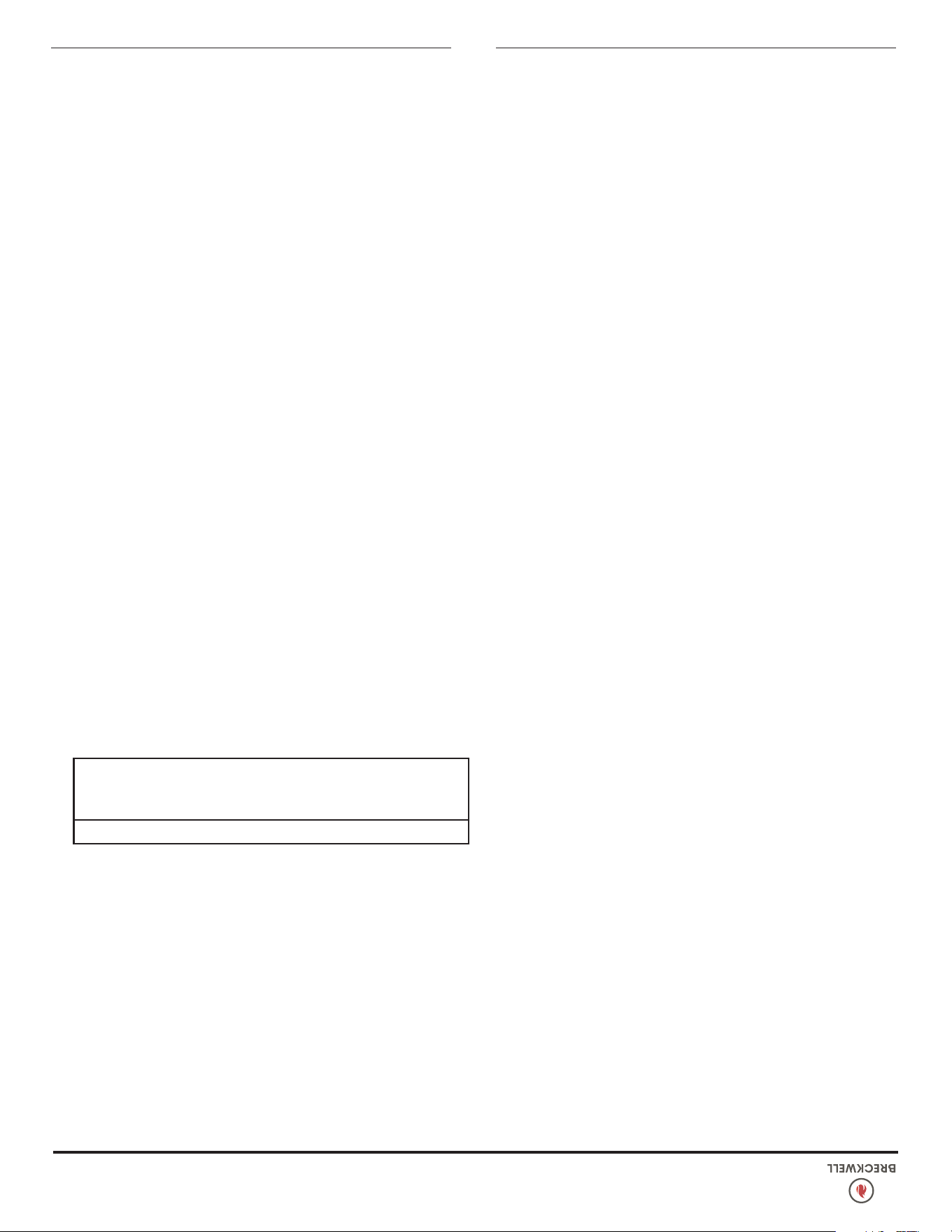
16
© 2024 Breckwell Hearth
ENTRETIEN
un couvercle hermétique. Le contenant fermé de cendres doit être
placé sur un sol incombustible ou sur le sol, bien à l’écart de
toutes matières combustibles, en attendant l’élimination nale.
Si les cendres sont éliminées par enfouissement dans le sol ou
autrement dispersées localement, elles doivent être conservées
dans le récipient fermé jusqu’à ce que toutes les braises aient été
complètement refroidies. Le conteneur ne doit pas être utilisé pour
d’autres déchets ou l’élimination des déchets. S’ils sont combinés
avec des substances combustibles, les cendres et les braises
peuvent s’enammer. L’élimination des cendres est la suivante:
Pour enlever les cendres:
1. Laissez le feu s’éteindre et laissez l’appareil refroidir à
température ambiante.
2. Assurez-vous que le poêle à granulés est à température
ambiante avant de le toucher. Nettoyez les tubes de
l’échangeur de chaleur.
3. Retirez la section intérieure du pot de combustion en la
saisissant et en la tirant vers le haut.
4. Vider les cendres de la partie intérieure et gratter avec un
outil de nettoyage; assurez-vous que les trous ne sont pas
bouchés.
5. Passer l’aspirateur pour éliminer les cendres de l’intérieur
de la chambre de combustion et de la coque du pot de
combustion. AVERTISSEMENT: assurez-vous que les cendres
sont froides au toucher avant d’utiliser un aspirateur (voir
«Utilisation de l’aspirateur»).
6. Éliminez les cendres correctement (voir «Enlèvement des
cendres»).
7. Replacez la section intérieure dans le pot de combustion;
assurez-vous qu’il est de niveau et poussé complètement vers
le bas et que l’orice de l’allumeur est à l’arrière lorsqu’il est
réinstallé.
8. Assurez-vous que le pot de combustion est de niveau et
enfoncé à fond. Si le collier du pot de combustion, attaché
au tube d’air frais, n’est pas repoussé pour rejoindre la paroi
de la chambre de combustion. L’allumeur ne fonctionnera pas
correctement.
DÉTECTEURS DE FUMÉE ET DE CO
Le brûlage du bois produit naturellement des émissions de fumée
et du monoxyde de carbone (CO). Le CO est un gaz poison
lorsque l’exposition se fait à des concentrations élevées pour une
période de temps prolongée. Bien que les systèmes de combustion
modernes des chauffages réduisent de façon importante la
quantité de CO émis par la cheminée, l’exposition aux gaz
dans des endroits fermés ou clos peut être dangereuse. Assurez-
vous que les joints d’étanchéité de votre poêle et les joints de la
cheminée soient en bon état et qu’ils scellent correctement, évitant
les expositions indésirables. Il est recommandé que vous utilisiez
des détecteurs de fumée et de CO dans les zones où se trouve un
potentiel de génération de CO.
VÉRIFIER ET NETTOYER LA TRÉMIE
Vériez périodiquement la trémie pour déterminer s’il y a de la
sciure (nes) qui s’accumule dans le système d’alimentation ou des
granulés qui collent à la surface de la trémie. Nettoyez au besoin.
JOINTS DE PORTE ET DE VERRE
Inspectez périodiquement les joints de la porte principale et de
la fenêtre en verre. Il se peut que la porte principale doive être
retirée pour que les joints eflochés, cassés ou compactés soient
remplacés par votre revendeur agréé. La porte de cet appareil
utilise un joint de corde de 3/4 po de diamètre.
SOUFFLANTES
DANGER:
RISQUE DE COMMOTION ÉLECTRIQUE. DÉBRANCHEZ
L’ALIMENTATION ÉLECTRIQUE AVANT D’INTERVENIR SUR LE
POÊLE.
Nettoyez annuellement les trous d’air sur les moteurs des ventilateurs
d’extraction et de distribution. Retirez le ventilateur d’évacuation
du conduit d’évacuation et nettoyez les pales du ventilateur interne
dans le cadre de votre démarrage d’automne. Si vous avez des
animaux domestiques à l’intérieur, vos moteurs électriques doivent
être inspectés tous les mois pour vous assurer qu’ils ne présentent
pas d’accumulation de poils d’animaux. L’accumulation de poils
d’animaux dans les soufeurs peut entraîner des performances
médiocres ou des risques de sécurité imprévus.
DÉMONTAGE ET REMPLACEMENT D’UNE VITRE
DE PORTE CASSÉE
Lorsque vous portez des gants en cuir (ou tout autre gant adapté
à la manipulation de verre brisé), retirez soigneusement tout
morceau de verre en vrac du cadre de la porte. Jetez tout le
verre brisé correctement. Retournez la porte endommagée à votre
revendeur pour réparation ou remplacement. Ni le propriétaire
de l’appareil ni aucune autre personne non autorisée ne doivent
remplacer la vitre de la porte. Un revendeur agréé doit effectuer
toutes les réparations concernant la vitre de porte.
DÉMARRAGE D’AUTOMNE
Avant de commencer le premier feu de la saison de chauffage,
vériez la zone extérieure autour des systèmes d’échappement
et d’admission d’air pour déceler toute obstruction. Nettoyez
et enlevez toutes les cendres volantes du système d’évacuation
des gaz d’échappement. Nettoyez les grilles du système
d’échappement et du tuyau d’admission d’air extérieur. Activez
toutes les commandes et assurez-vous qu’elles fonctionnent
correctement. C’est également le bon moment pour nettoyer
l’ensemble du poêle.
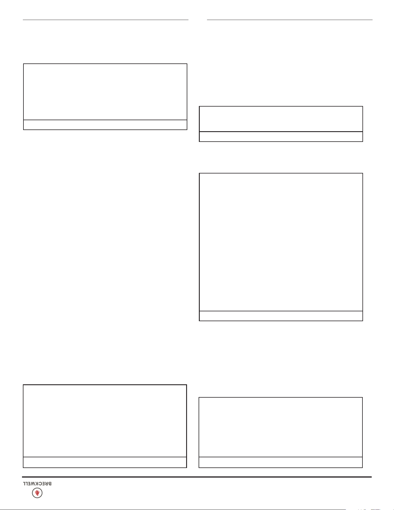
© 2024 Breckwell Hearth
15
FONCTIONNEMENT
MISE EN GARDE:
• NE FAITES PAS FONCTIONNER VOTRE POÊLE SI VOUS SENTEZ
UNE ODEUR DE FUMÉE EN PROVENANCE. ÉTEIGNEZ-LE,
SURVEILLEZ-LE ET APPELEZ VOTRE CONCESSIONNAIRE.
• NE PAS FAIRE FONCTIONNER LE POÊLE SI LA FLAMME
DEVIENT SOMBRE ET SUBLIMÉE OU SI LE BRÛLEUR TROP-
REMPLIT DE GRANULES. ÉTEIGNEZ LE POÊLE, INSPECTEZ-LE
PÉRIODIQUEMENT ET APPELEZ VOTRE CONCESSIONNAIRE
MISE EN GARDE:
SI LE POÊLE EST INSTALLÉ DANS UNE PIÈCE SANS CLIMATISATION
OU DANS UNE ZONE O WH LA LUMIÈRE DIRECTE DU SOLEIL
PEUT BRILLER SUR L’APPAREIL, IL EST POSSIBLE QUE CELA PEUT
PROVOQUER LA TEMPÉRATURE DU POÊLE AU NIVEAU DE
FONCTIONNEMENT; UN DES CAPTEURS POURRAIT PUIS FAIRE
DÉMARRER LE POÊLE DE SON PROPRE. IL EST RECOMMANDÉ
QUE LE POÊLE SOIT DÉBRANCHÉ LORSQU’IL N’EST PAS UTILISÉ
POUR UNE DURÉE DE TEMPS PROLONGÉE (c.-à-d. PENDANT
LES MOIS D’ÉTÉ).
N’UTILISEZ JAMAIS CE PRODUIT SANS SURVEILLANCE
MISE EN GARDE:
• NE PAS NETTOYER ET ENTRETENIR CET APPAREIL COMME
INDIQUÉ PEUT ENTRAÎNER DES PERFORMANCES, DES
RISQUES DE SÉCURITÉ, UN INCENDIE ET MÊME LA MORT.
• NE JAMAIS EFFECTUER D'INSPECTION, DE NETTOYAGE OU
D'ENTRETIEN SUR UN POÊLE CHAUD.
• DÉBRANCHEZ LE CORDON D'ALIMENTATION AVANT
D'EFFECTUER TOUT ENTRETIEN! REMARQUE: METTRE
L'INTERRUPTEUR MARCHE / ARRÊT SUR «OFF»
NE DÉBRANCHE PAS TOUTE L'ALIMENTATION DES
COMPOSANTS ÉLECTRIQUES DU POÊLE.
• NE PAS FAIRE FONCTIONNER LE POÊLE AVEC DE LA VITRE
CASSÉE, UNE FUITE DE GAZ DE FUMÉE PEUT EN RÉSULTER.
• NE PAS ABUSER LA VITRE DE LA PORTE EN FRAPPE, EN
CLAQUANT OU EN TRAUMATISME SIMILAIRE. NE PAS FAIRE
FONCTIONNER LE POÊLE AVEC LA VITRE RETIRÉE, FISSURÉE
OU CASSÉE.
FORMATION ET ÉLIMINATION DE LA CRÉOSOTE
MISE EN GARDE:
LE SYSTÈME D'ÉCHAPPEMENT DOIT ÊTRE VÉRIFIÉ MENSUEL
PENDANT LA SAISON DE BRÛLURE POUR TOUT ACCUMULATION
DE SUIE OU DE CRÉOSOTE.
Lorsque le bois brûle lentement, il produit du goudron et d’autres
vapeurs organiques qui se combinent avec l’humidité rejetée
pour former la créosote. Les vapeurs de créosote se condensent
dans un conduit de cheminée relativement froid ou si le feu vient
de démarrer ou brûle lentement. Ainsi, les résidus de créosote
s’accumulent sur le boisseau. Si elle prend feu, cette créosote
produit un feu extrêmement chaud qui peut endommager la
cheminée, voire détruire la maison. En dépit de leur grande
efcacité, les poêles à granulés peuvent accumuler de la créosote
dans certaines conditions. Le raccord et le conduit de cheminée
doivent être inspectés par une personne qualiée une fois par an
ou par tonne de granulés pour déterminer si une accumulation de
créosote ou de cendres volantes s’est produite. Si la créosote s’est
accumulée, elle doit être enlevée pour réduire le risque de feu de
cheminée. Inspectez le système au niveau du raccord avec le poêle
et en haut de la cheminée. Les surfaces plus froides ont tendance
à accumuler les dépôts de créosote plus rapidement; il est donc
important de vérier la cheminée par le haut ainsi que par le
bas. La créosote doit être éliminée avec une brosse spécialement
conçue pour le type de cheminée utilisé. Un ramoneur qualié
peut fournir ce service. Il est également conseillé d’inspecter,
de nettoyer et si nécessaire de réparer la totalité du système
avant chaque saison de chauffage. Pour nettoyer la cheminée,
déconnecter l’évacuation du poêle.
CENDRES VOLANTES
Cela s’accumule dans la partie horizontale d’une course
d’échappement. Bien qu’incombustible, il peut gêner le débit
normal des gaz d’échappement. Il doit donc être périodiquement
supprimé.
ÉVACUATION DES CENDRES
MISE EN GARDE:
LAISSEZ LE POÊLE REFROIDIR AVANT D'EFFECTUER TOUT
ENTRETIEN OU NETTOYAGE. LES CENDRES DOIVENT ÊTRE
JETÉES DANS UN RÉCIPIENT MÉTALLIQUE AVEC UN COUVERCLE
FERMÉ. LE RÉCIPIENT DE CENDRES FERMÉ DOIT ÊTRE PLACÉ
SUR UNE SURFACE NON COMBUSTIBLE OU AU SOL, BIEN À
L'ÉCART DE TOUT MATÉRIEL COMBUSTIBLE, EN ATTENTE DE
L'ÉLIMINATION FINALE.
Retirez les cendres périodiquement pour éviter l’accumulation
inutile de cendres. Retirez les cendres lorsque l’unité a refroidi.
Les cendres doivent être placées dans un récipient en métal avec
ENTRETIEN
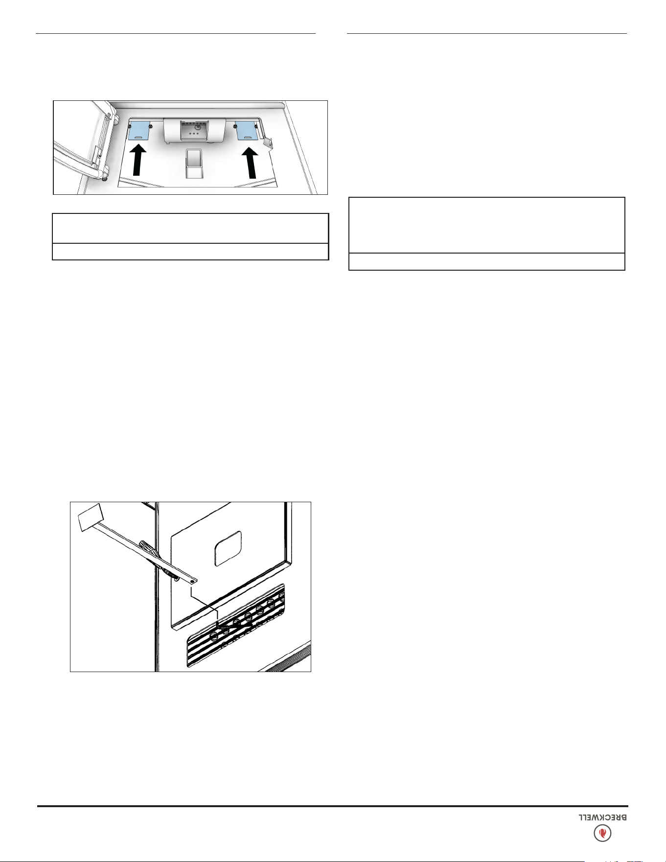
14
© 2024 Breckwell Hearth
FONCTIONNEMENT
réglage ou une utilisation autre de ce chauffage au bois qui ne
respecterait pas les directives du présent manuel contrevient aux
réglementations fédérales.
PROCÉDURE D’ARRÊT
Pour éteindre votre poêle, il suft d’appuyer sur le bouton
«POWER» du panneau d’afchage. Le voyant vert redevient rouge
lorsque le bouton «POWER» est enfoncé. Le moteur de la vis sans
n s’arrêtera et les ventilateurs continueront de fonctionner jusqu’à
ce que les températures internes de la chambre de combustion
soient tombées à un niveau préréglé.
1. Votre poêle est équipé d’un thermodisque haute température.
Cet appareil dispose d’un thermodisque à réarmement
manuel. Cet interrupteur de sécurité a deux fonctions.
A. Pour reconnaître une situation de surchauffe dans le poêle et
arrêter l’alimentation en carburant ou le système de vis sans
n.
B. En cas de dysfonctionnement du ventilateur de convection, le
thermodisque haute température arrêtera automatiquement la
vis sans n, empêchant le poêle de surchauffer.
REMARQUE: Sur certaines unités, une fois déclenché, comme
un disjoncteur, le bouton de réinitialisation devra être enfoncé
avant de redémarrer votre poêle. Sur les autres appareils,
le thermodisque n’a pas de bouton de réinitialisation et se
réinitialisera une fois que le poêle aura refroidi. Le fabricant vous
recommande d’appeler votre revendeur si cela se produit car cela
peut indiquer un problème plus grave. Un appel de service peut
être nécessaire.
2. Si le ventilateur de combustion tombe en panne, un pressostat
d’air arrête automatiquement la vis sans n.
REMARQUE: L’ouverture de la porte du poêle pendant plus de 30
secondes pendant le fonctionnement entraînera un changement
de pression sufsant pour activer l’interrupteur d’air, coupant
l’alimentation en carburant. Le poêle s’éteindra et afchera
«E2» sur l’afchage à deux chiffres. Le poêle doit s’éteindre
complètement avant de redémarrer.
ATTENTION:
LES TENTATIVES D'OBTENIR DES TAUX DE SORTIE DE CHALEUR
QUI DÉPASSENT LES SPÉCIFICATIONS DE CONCEPTION DU
CHAUFFAGE PEUVENT CAUSER DES DOMMAGES PERMANENTS
AU CHAUFFAGE.
CHAMBRES INTÉRIEURES
• Pot de combustion - Retirez et nettoyez périodiquement le
pot de combustion et la zone à l’intérieur du boîtier du pot
de combustion. En particulier, il est conseillé de nettoyer les
trous du pot de combustion pour éliminer toute accumulation
qui pourrait empêcher l’air de circuler librement dans le pot de
combustion.
• Tubes d’échange de chaleur - Ce poêle est conçu avec un
nettoyeur de tube d’échange de chaleur intégré. Cela devrait
être utilisé tous les deux ou trois jours pour éliminer les cendres
accumulées sur les tubes, ce qui réduit l’efcacité de votre
appareil. Insérez l’extrémité de la poignée (avec trou) de l’outil
de nettoyage sur la tige de nettoyage. La tige de nettoyage est
située dans la grille au-dessus de la porte du poêle. Déplacez la
tige de nettoyage d’avant en arrière plusieurs fois pour nettoyer
les tubes de l’échangeur de chaleur. Lorsque vous avez terminé,
assurez-vous de laisser le nettoyeur de tube à l’arrière du poêle.
• Échangeur de chaleur - Il y a une plaque de nettoyage des
deux côtés de l’échangeur de chaleur qui doit être enlevée pour
nettoyer les cendres volantes de l’échangeur de chaleur. Les
nettoyages sont situés à l’intérieur de la chambre de combustion,
comme illustré. Les nettoyages sont xés à la chambre de
combustion avec (2) vis 5/16 ”. Retirez les nettoyages et
aspirez les cendres accumulées. Cela devrait être fait au moins
une fois par mois ou plus fréquemment si de grandes quantités
de cendres sont remarquées pendant le nettoyage ou si le poêle
ne semble pas brûler correctement.
Si un aspirateur est utilisé pour nettoyer votre poêle, nous vous
suggérons d’utiliser l’aspirateur AV15E AshVac. L’AV15E AshVac
est conçu pour l’élimination des cendres. Certains aspirateurs
ordinaires (c.-à-d. Les aspirateurs d’atelier) peuvent laisser
échapper des cendres dans la pièce.
NE PAS ASPIRER LES CENDRES CHAUDES.
ATTENTION:
NE PAS ENTRETENIR CORRECTEMENT LES EXTÉRIEURS PROPRES
ENTRAÎNERA UNE MAUVAISE PERFORMANCE DE CE POÊLE.
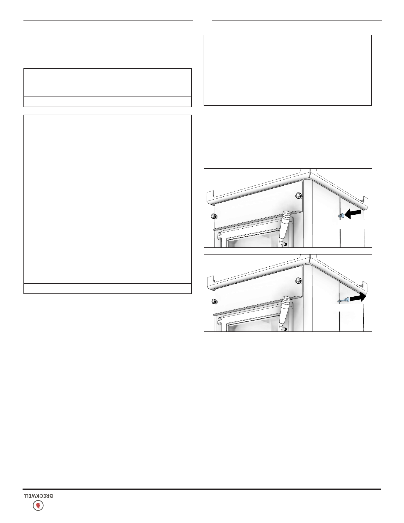
© 2024 Breckwell Hearth
13
FONCTIONNEMENT OPTIMAL
Ce poêle à granulés a été certié par l’EPA des États-Unis pour
répondre aux directives strictes de 2020. Pour garantir que cette
unité produit les émissions minimales optimales, il est essentiel
de suivre les directives suivantes. Pour obtenir une « combustion
élevée », votre poêle doit être réglé sur le réglage 5 avec le
registre complètement ouvert. Pour obtenir une « combustion
moyenne », votre poêle doit être réglé sur le réglage 2 avec le
registre fermé. Pour obtenir une « combustion faible », votre poêle
doit être réglé sur le réglage 1 avec le registre fermé. Les réglages
3 et 4 vous donneront une puissance calorique plus élevée que
le réglage moyen. Si la porte est ouverte pendant que le poêle
est en fonctionnement, elle doit être fermée dans les 30 secondes
sinon le poêle s’éteindra. Si le poêle s’éteint, appuyez sur le
bouton « On/Off » pour redémarrer votre poêle. Le poêle devra
être complètement éteint et éteint avant de pouvoir redémarrer le
poêle.
OUVRIR
FERMÉ
OUVERTURE DE PORTE
Si la porte est ouverte pendant que le poêle fonctionne, il faut
la refermer dans les 30 secondes sinon le poêle va s’éteindre.
Si cela se produisait, actionnez la commande «ON/OFF» pour
redémarrer votre poêle.
MISE EN GARDE:
• NE FAITES PAS FONCTIONNER VOTRE POÊLE AVEC LA
PORTE VUE OUVERTE. LA TARIERE N'ALIMENTERA PAS DE
GRANULES DANS CES CIRCONSTANCES ET UN PROBLÈME
DE SÉCURITÉ PEUT PROVOQUER DES ÉTINCELLES OU DES
FUMÉES ENTRANT DANS LA PIÈCE.
• LA PORTE D'ALIMENTATION DOIT ÊTRE FERMÉE ET SCELLÉE
PENDANT LE FONCTIONNEMENT.
VENTILATEUR D’AIR DE LA PIÈCE
Quand vous démarrez votre poêle, le ventilateur d’air de la pièce
ne s’active pas avant que l’échangeur thermique se soit réchauffé.
Cela prend en général 10 minutes à partir du démarrage.
SI LE POÊLE N’A PLUS DE GRANULÉS
• Le feu s’éteint et le moteur de vis sans n et les soufantes restent
activés jusqu’à ce que le poêle ait refroidi. Cela prend 30 à 40
minutes.
• Une fois que les composants du poêle ont cessé de tourner, les
voyants de “ON/OFF” et de la barre restent allumés pendant
10 minutes.
• Après les 10 minutes, le voyant “3” de la barre va clignoter et
le voyant “ON/OFF” s’éteint.
• Pour redémarrer, regarnissez la trémie, appuyer sur le bouton
“ON/OFF” et actionnez la commande “Fuel Feed” jusqu’à
ce que des granulés commencent à tomber dans le pot de
combustion.
RAVITAILLEMENT
MISE EN GARDE:
• LA TRÉMIE ET LA CUISINIÈRE SERONT CHAUDES PENDANT
LE FONCTIONNEMENT; PAR CONSÉQUENT, VOUS DEVEZ
TOUJOURS UTILISER UN TYPE DE PROTECTION DES MAINS
LORS DU RAVITAILLEMENT DE VOTRE POÊLE.
• NE TOUCHEZ PAS LES SURFACES CHAUDES DU POÊLE.
ÉDUQUER TOUS LES ENFANTS SUR LES DANGERS D'UN
POÊLE À HAUTE TEMPÉRATURE. LES JEUNES ENFANTS
DOIVENT ÊTRE SURVEILLÉS LORSQU'ILS SE TROUVENT
DANS LA MÊME PIÈCE QUE LE POÊLE.
• NE JAMAIS PLACER VOTRE MAIN PRÈS DE LA TARIERE
PENDANT QUE LE POÊLE EST EN FONCTIONNEMENT.
• NOUS VOUS RECOMMANDONS DE NE PAS LAISSER LA
TRÉMIE TOMBER EN DESSOUS DE 1/4 PLEINE.
• GARDER LE COUVERCLE DE LA TRÉMIE FERMÉ EN TOUT
TEMPS SAUF LORS DU REMPLISSAGE.
• AVERTISSEMENT: NE PAS AJOUTER DE GRANULÉS AU
BRÛLEUR À LA MAIN À TOUT MOMENT, UNE CONDITION
DANGEREUSE POURRAIT EN RÉSULTER.
• NE REMPLISSEZ PAS TROP LA TRÉMIE.
ATTENTION:
• GARDER LE COUVERCLE DE LA TRÉMIE FERMÉ EN TOUT
TEMPS SAUF LORS DU REMPLISSAGE.
• NE REMPLISSEZ PAS TROP LA TRÉMIE.
AVERTISSEMENT DE FALSIFICATION
Ce chauffage au bois a un taux de combustion minimum réglé à
la fabrication, et qui ne peut être modié. La modication de ce
FONCTIONNEMENT
12
© 2024 Breckwell Hearth
7. Débris de construction ou de démolition;
8. Traverses de voie ferrée ou bois traité sous pression;
9. Fumier ou restes d’animaux;
10. Bois de grève en eau salée ou autres matériaux précédemment
saturés par de l’eau salée;
11. Bois non séché; ou
12. Produits du papier, carton, contreplaqué, ou panneau
de particules. L’interdiction de brûlage de ces matériaux
n’interdit pas l’utilisation d’allume-feu composés de papier,
carton, sciure de bois, cire et substances similaires, aux ns
de démarrer le feu dans un chauffage au bois modié.
Le brûlage de ces matériaux peut causer des émanations de
fumées toxiques ou rendre le chauffage inefcace en raison de
la fumée.
CARBURANT APPROPRIÉ
ATTENTION:
CET APPAREIL EST CONÇU POUR L'UTILISATION DE
COMBUSTIBLES GRANULÉS QUI RÉPOND OU DÉPASSENT LA
NORME DÉFINIE PAR LE PELLET FUEL INSTITUTE (PFI).
CE POÊLE EST APPROUVÉ POUR BRÛLER DU CARBURANT À
GRANULÉS DE BOIS UNIQUEMENT! Les granulés approuvés par
l’usine font un diamètre de 1/4 po à 5/16 po (7-8 mm), avec
une longueur inférieure à 1 po (25 mm) Des granulés plus longs
ou plus épais n’entrent pas dans les entraînements de la vis sans
n, ce qui empêche une alimentation correcte. Il n’est pas autorisé
de faire brûler du bois sous une forme différente de granulés. Ce
serait une infraction aux normes de construction pour lesquelles
ce poêle a été approuvé, et cela annulerait toutes les garanties.
La conception comprend une alimentation automatique du feu par
du carburant en granulés à un taux soigneusement étudié. Toute
introduction manuelle de carburant supplémentaire n’augmenterait
pas la puissance de chauffe, mais dégraderait considérablement
la performance du poêle en générant beaucoup de fumée. Ne
faites pas brûler des granulés mouillés. La performance du poêle
dépend fortement de la qualité de votre carburant en granulés.
Évitez les marques de granulés présentant ces caractéristiques:
• Trop de poussier – Ce terme décrit des résidus de granulés
écrasés ou de matière libre ressemblant à de la sciure ou du
sable. Les granulés peuvent être tamisés avant d’être mis dans
la trémie pour éliminer le plus gros du poussier.
• Présence de liants – Certains granulés sont produits avec des
composants pour les agglomérer ou les lier.
• Fort contenu en cendres – Granulés de qualité médiocre qui
souvent fument et salissent la vitre. Ils créent le besoin pour de
l’entretien plus fréquent. Vous aurez à vider le pot de combustion
et à aspirer tout le système plus fréquemment. Des granulés de
mauvaise qualité peuvent endommager la vis sans n. Ne peut
pas assumer la responsabilité de dommages dus à la mauvaise
qualité des granulés. Votre revendeur peut vous recommander
un fournisseur de granulés de bonne qualité dans votre secteur.
MISE EN GARDE:
• GARDER LES OBJETS ÉTRANGERS HORS DE LA TRÉMIE.
• LES PIÈCES MOBILES DE CE POÊLE SONT PROPULSÉES PAR
DES MOTEURS ÉLECTRIQUES À COUPLE ÉLEVÉ. GARDER
TOUTES LES PIÈCES DU CORPS À L'ÉCART DE LA TARIERE
PENDANT QUE LE POÊLE EST BRANCHÉ À UNE PRISE
ÉLECTRIQUE. CES PIÈCES EN MOUVEMENT PEUVENT
COMMENCER À DÉPLACER À TOUT MOMENT PENDANT
QUE LE POÊLE EST BRANCHÉ.
CONTRÔLE D’AVANT DÉMARRAGE
Enlevez le pot de combustion, en vous assurant qu’il est propre et
qu’aucun des trous pour l’air n’est obstrué. Nettoyez la chambre
de combustion, puis remettez en place le pot de combustion.
Nettoyez la porte vitrée si nécessaire (un chiffon sec ou du papier
essuie-tout sufsent généralement). N’utilisez jamais de nettoyants
abrasifs sur la vitre ou la porte. Vériez le niveau de carburant
dans la trémie, et faites l’appoint si nécessaire.
CONSTRUCTION D’UN FEU
N’utilisez jamais de grille ou d’autre support pour le carburant.
N’utilisez qu’un pot de combustion approuvé par. Durant la
période de démarrage:
• N’ouvrez PAS la porte de contrôle.
• N’ouvrez PAS le registre de plus de 1/4 po (7 mm).
• N’ajoutez PAS à la main de granulés dans le pot de combustion.
• N’utilisez PAS la commande d’alimentation en carburant (sauf
si vous devez amorcer la vis sans n après un manque de
granulés). Sinon une situation dangereuse pourrait en résulter.
REMARQUE: Durant les premiers feux, votre poêle va émettre
une odeur au fur et à mesure du durcissement de la peinture
pour forte température ou du vieillissement du métal. Maintenir
des feux modestes va minimiser le phénomène. Évitez de placer
des choses sur le dessus du poêle durant cette période car la
peinture pourrait en souffrir.
ALLUMEUR AUTOMATIQUE PAR TIGE CHAUDE
1. Remplissez la trémie et nettoyez le pot de combustion.
2. Appuyez sur le bouton “ON/OFF” Assurez-vous que son
voyant est allumé.
3. Le registre doit être complètement fermé ou n’être ouvert
qu’à moins de 1/4 po (7 mm) durant le démarrage. Cela
va dépendre de votre installation et de l’altitude. Une fois le
feu allumé, réglez pour la amme voulue en augmentant de
degré d’ouverture du registre quand le réglage de puissance
de chauffe est augmenté (voyez à «Commande De Registre»).
4. Ajustez le taux d’alimentation au niveau désiré en actionnant
la commande «Feed Rate Advance». Si le feu n’a pas
démarré dans les 15 minutes, actionnez «ON/OFF»,
attendez quelques minutes, nettoyez le pot de combustion et
recommencez la procédure.
FONCTIONNEMENT
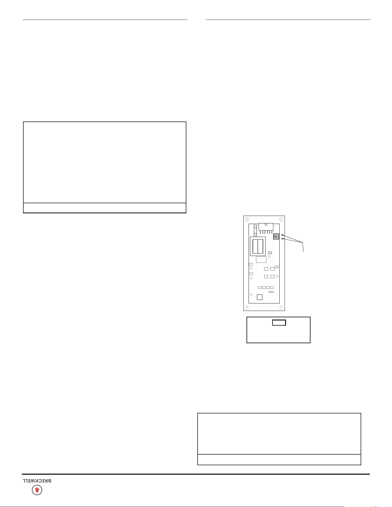
© 2024 Breckwell Hearth
11
MISE EN GARDE:
LE RÉGLAGE À “5” N’EST PRÉVU QUE POUR UNE UTILISATION
TEMPORAIRE. SUR DES DURÉES PROLONGÉES, IL PEUT RÉDUIRE
DE FAÇON SIGNIFICATIVE LA DURÉE DE VIE DES COMPOSANTS
ÉLECTRIQUES. ÉVITEZ D’UTILISER CE RÉGLAGE PENDANT PLUS
D’UNE HEURE OU DEUX D’AFFILÉE.
THERMOSTAT OPTIONNEL
Un thermostat optionnel peut vous aider à maintenir
automatiquement constante la température de la maison. Un
thermostat millivolt est nécessaire. Le panneau de commandes
peut être conguré de deux façons pour faire fonctionner votre
poêle en mode avec thermostat.
FIGURE 24
BRANCHEZ LES
FILS DE
THERMOSTAT ICI
M/A Fort/Faible Manuel
INSTALLATION DE THERMOSTAT
• UN THERMOSTAT MILLIVOLT EST NÉCESSAIRE.
• Débranchez le poêle de la prise secteur.
• Sortez la carte de contrôle du poêle.
• Les deux ls de thermostat se branchent au bornier sur le côté
inférieur gauche de l’envers de la carte.
• Insérez ces deux ls dans le bornier et serrez-les avec les vis.
MODES
POUR COMMUTER ENTRE CES TROIS MODES, LE POÊLE DOIT
ÊTRE ARRÊTÉ, LE NOUVEAU MODE SÉLECTIONNÉ ET LE POÊLE
REDÉMARRÉ.
MODE MANUEL
• N’UTILISEZ CE MODE QUE SI VOUS NE BRANCHEZ PAS UN
THERMOSTAT OPTIONNEL.
• Dans ce mode le poêle ne va être piloté que depuis le
panneau de commande, comme c’est détaillé dans la section
“Fonctionnement” de ce manuel d’utilisateur.
MODE THERMOSTAT FORT/FAIBLE
• N’UTILISEZ CE MODE QUE SI VOUS BRANCHEZ UN
THERMOSTAT
• Une fois dans ce mode le poêle va automatiquement commuter
entre les deux réglages. Quand il est assez chaud, il va revenir
au niveau 1 ou réglage faible. La soufante d’air de la pièce va
aussi passer à sa vitesse inférieure.
• Le réglage “Heat Level Advance” de la barre va rester où il a été
mis initialement. Quand la maison refroidit sous la température
de consigne du thermostat, le poêle va commuter sur le réglage
fort du chauffage.
MODE THERMOSTAT M/A
• N’UTILISEZ CE MODE QUE SI VOUS BRANCHEZ UN
THERMOSTAT
• Dans ce mode tout-ou-rien, quand la maison est assez réchauffée
le poêle s’arrête. Les ventilateurs continuent de tourner jusqu’au
refroidissement du poêle.
• Quand la maison refroidit sous la température de consigne du
thermostat, le poêle va redémarrer automatiquement avec le
plus faible taux d’alimentation.
REMARQUE : Quand vous êtes dans un de ces deux modes avec
thermostat -
• Ne faites pas fonctionner le poêle plus fort que le réglage 3.
• Mettez la tige de commande de registre sortie de 3 à 6 mm.
Cela va dépendre de l’altitude et des conditions climatiques.
Observez le fonctionnement du poêle et ajustez le registre si
nécessaire.
ATTENTION:
• N'UTILISEZ PAS DE PRODUITS CHIMIQUES OU DE FLUIDES
POUR ALLUMER LE FEU - NE JAMAIS UTILISER D'ESSENCE,
DE CARBURANT POUR LANTERNE DE TYPE ESSENCE, DE
KÉROSÈNE, DE LIQUIDE À BRIQUET AU CHARBON OU DE
LIQUIDES SIMILAIRES POUR ALLUMER OU «RAFRAÎCHIR»
UN FEU DANS CE POÊLE. GARDEZ TOUS CES LIQUIDES BIEN
ÉLOIGNÉS DU POÊLE PENDANT SON UTILISATION.
• CHAUD EN FONCTIONNEMENT. TENIR LES ENFANTS, LES
VÊTEMENTS ET LES MEUBLES À L'ÉCART. LE CONTACT PEUT
CAUSER DES BRÛLURES DE LA PEAU.
Le chauffage est conçu pour ne brûler que des granulés de classe
supérieure PFI. NE PAS BRÛLER:
1. Des ordures;
2. Des déchets de tonte ou résidus de jardin;
3. Des matériaux contenant du caoutchouc, incluant les pneus;
4. Matériaux contenant du plastique;
5. Des déchets de produits du pétrole, des peintures ou diluants
à peinture, ou des produits d’asphalte;
6. Matériaux contenant de l’amiante;
FONCTIONNEMENT
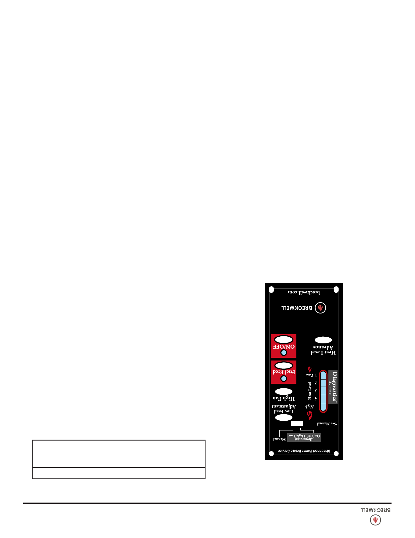
10
© 2024 Breckwell Hearth
PANNEAU DE COMMANDES
5
Les soufantes et l’alimentation automatique en carburant sont
commandées depuis un panneau situé sur le côté droit du poêle
unité. Voici ses fonctions :
COMMANDE M/A
• Quand cette commande est actionnée le poêle s’allume
automatiquement. Aucun autre allumeur de feu n’est nécessaire.
L’allumeur reste activé de 10 à 15 minutes, selon le moment
ou la présence de feu est établie. Le feu doit prendre après 5
minutes environ.
• Le voyant vert situé au-dessus du bouton de M/A (dans la
case ON/OFF) va clignoter durant la période d’allumage au
démarrage.
• La sélection de puissance “Heat Level Advance” est inhibée
durant cette période d’allumage. Quand le précédent voyant
vert reste allumé en xe la puissance de chauffe peut être ajustée
au niveau voulu avec la commande “Heat Level Advance”.
REMARQUE : Si le poêle a été coupé, et que vous voulez le
redémarrer pendant qu’il est encore chaud, il faut maintenir
activée la commande ON/OFF pendant 2 secondes.
COMMANDE D’ALIMENTATION EN CARBURANT
• Quand la commande “Fuel Feed” est actionnée et maintenue
appuyée, le poêle va envoyer continuellement des granulés
dans le pot de combustion.
• Pendant que le système de vis sans n du poêle alimente en
granulés, le voyant vert dans le carré “Fuel Feed” sera allumé.
MISE EN GARDE:
N'UTILISEZ PAS CETTE COMMANDE PENDANT UN
FONCTIONNEMENT NORMAL, CAR ELLE POURRAIT ÉTENDRE LE
FEU ET ENTRAÎNER UNE SITUATION DANGEREUSE.
COMMANDE DE VENTILATION RAPIDE
• La vitesse de ventilation dans la pièce varie directement en
fonction du taux d’alimentation. La commande “High Fan”
surpasse cette fonction de ventilation à vitesse variable. Elle xe
la vitesse de ventilation dans la pièce au maximum quelque soit
le taux d’alimentation en carburant.
• Quand cette commande “High Fan” est actionnée le ventilateur
tourne à son régime maximal.
• Quand cette commande est actionnée de nouveau, le ventilateur
revient à sa vitesse d’origine déterminée par le réglage de
“Heat Level Advance”.
COMMANDE D’ADAPTATION
Des granulés de carburant de taille/qualité différentes peuvent
nécessiter un ajustement du réglage “1” d’alimentation sur la
barre de “Heat Level Advance”. C’est généralement un ajustement
ponctuel selon le carburant utilisé. Cette commande permet trois
niveaux différents d’adaptation d’alimentation pour le réglage
“1” uniquement. (petite vitesse au ralenti). Il suft d’actionner la
commande “Reset Trim” pendant le fonctionnement du poêle en
réglage “1” et de regarder la barre.
• Les voyants “1” et “3” sont allumés sur la barre : le taux
d’alimentation faible est à son plus bas niveau (environ 0,4
kg/h).
• Le voyant “1” est seul allumé sur la barre : le taux d’alimentation
faible est à son niveau normal.
• Les voyants “1” et “4” sont allumés sur la barre : le taux
d’alimentation faible est à son plus haut niveau.
REMARQUE : Quand le poêle est réglé sur “1” les valeurs
d’adaptation sont indiquées dur la barre de “Reset Trim”. Par
exemple : Si l’ajustement a été mis au plus bas niveau, chaque
fois que le poêle est réglé sur chauffage faible les voyants “1” et
“3” seront allumés sur la barre.
PROGRESSION DU NIVEAU DE CHAUFFE
• Quand cette commande est actionnée elle règle le taux
d’alimentation en granulés, donc la puissance de chauffe de
votre poêle. Ces niveaux vont progresser de façon incrémentale
sur la barre indicatrice, en allant de “1” à “5”.
REMARQUE : Quand vous baissez la puissance de chauffe de
plusieurs niveaux (de 4 à 1, ou bien de 5 à 2 ou 1), actionnez
la commande “High Fan” pour ventiler à pleine puissance au
moins 5 minutes, an d’éviter que le poêle ne fasse déclencher
son thermodisque pour température trop forte. S’il se déclenchait
consultez “Dispositifs De Sécurité”.
FONCTIONNEMENT
N’UTILISEZ JAMAIS CE PRODUIT SANS SURVEILLANCE
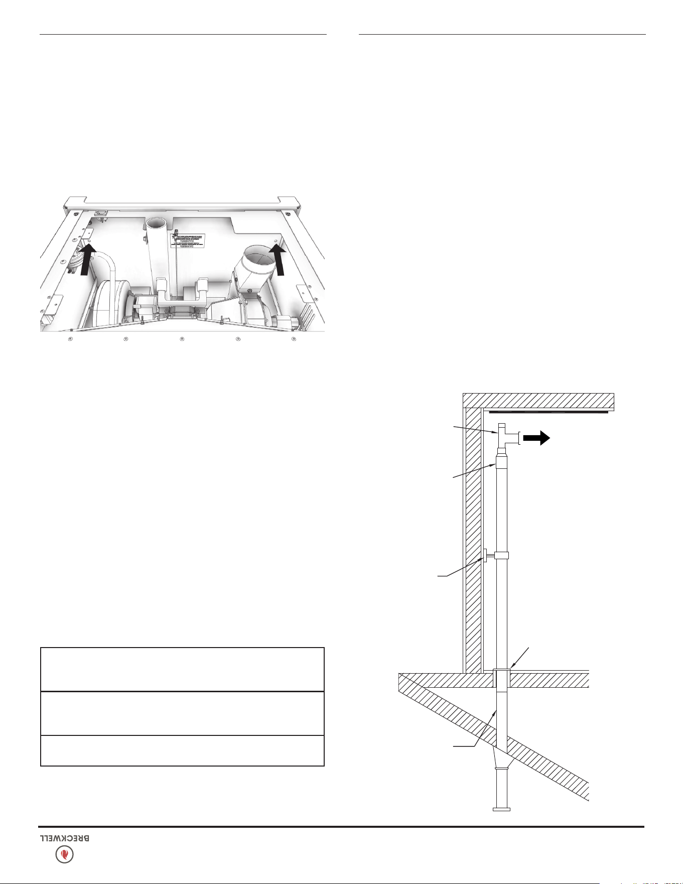
© 2024 Breckwell Hearth
9
INSTALLATION
Système de
cheminée existant
de classe A de 6
pouce
3 pouce PL
Vent Nettoyer
Tee
Support
de tuyau
Support de
plafond
Adaptateur de
tuyau de 3 pouce
à 6 pouce
AU CHAUFFAGE
INSTALLATION ÉLECTRIQUE
Ce poêle est fourni avec un cordon d’alimentation secteur de
1,8 m comportant une liaison de terre, qui sort à son arrière.
Nous recommandons son branchement sur un para sur tenseur
de qualité lui-même branché sur une prise secteur standard trois
broches en 120 V/60Hz. NE branchez PAS sur une prise avec
disjoncteur sur défaut de terre (GFCI). Des variations de tension
peuvent causer de sérieux problèmes de performance. Le système
électrique du Breckwell est conçu pour du 120 V CA présentant
moins de 5% de variation. Breckwell ne peut pas endosser de
responsabilité pour une performance médiocre ou des dommages
qui viendraient d’une tension inadéquate. En cas de branchement
sur une ancienne prise à deux broches il faut tirer une liaison
séparée sur une terre électrique de bonne qualité (référez-vous
pour cela à un électricien qualié). Faites toujours passer le cordon
d’alimentation de telle façon qu’il n’entre pas en contact avec une
quelconque partie chaude du poêle.
EXIGENCES SPÉCIALES POUR MAISONS
MOBILES/BÂTIMENTS PORTATIF
ATTENTION! NE PAS INSTALLER DANS UNE CHAMBRE À
COUCHER.
MISE EN GARDE! L'INTÉGRITÉ STRUCTURELLE DU PLANCHER,
DES MURS ET DU PLAFOND / TOIT DE LA MAISONS MOBILES /
BÂTIMENTS PORTATIF DOIT ÊTRE MAINTENUE.
LORSQU'IL EST INSTALLÉ DANS UNE MAISONS MOBILES /
BÂTIMENTS PORTATIF, LE POÊLE DOIT ÊTRE MIS À LA TERRE
DIRECTEMENT AU CHÂSSIS EN ACIER ET BOULONNÉ AU SOL.
Pour l’installation dans une maisons mobiles/bâtiments portatif,
une source extérieure d’air de combustion doit être utilisée (voir
«Alimentation en air de combustion»). Cette unité doit être mise
à la terre au châssis en acier avec un l de cuivre de 8 Ga.
À l’aide d’une rondelle dentelée ou en étoile pour pénétrer la
peinture ou le revêtement de protection an d’assurer la mise à
la terre. Cet appareil doit être solidement xé au plancher de
la maisons mobiles/bâtiments portatif à travers les deux trous à
l’arrière du poêle à l’aide de tire-fonds de 2 1/4 po (58 mm) qui
sont sufsamment longs pour passer à travers les deux coussinets
de l’âtre, le cas échéant. , et le sol de la maison. Reportez-vous
à «Ventilation» pour les congurations d’évacuation appropriées.
Lors de l’installation dans une maisons mobiles/bâtiments portatif,
assurez-vous que le pare-vapeur à l’endroit où la cheminée ou un
autre composant pénètre à l’extérieur de la structure. Ne faites
jamais fonctionner avec les portes de tir ouvertes. Un détecteur de
fumée doit être installé dans la pièce où le radiateur est installé.
Le détecteur de fumée doit être installé à au moins 10 pieds de
l’appareil de chauffage pour éviter d’éteindre accidentellement le
détecteur.
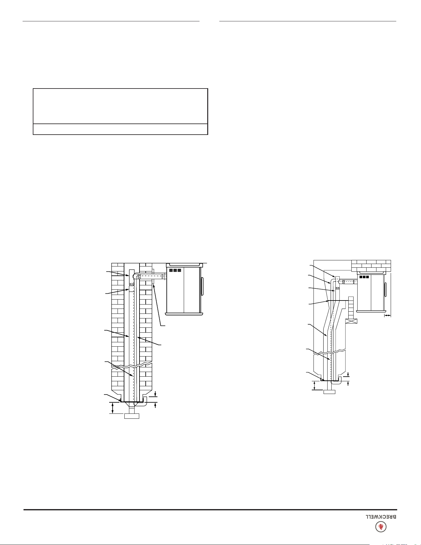
8
© 2024 Breckwell Hearth
4. Fixez l’adaptateur de ventilation en PL, une section de tuyau et
un té de nettoyage, en vous assurant que ce dernier est centré
dans la zone de conduit de cheminée. Utilisez de la bande
métallique RTV et un minimum de trois vis auto taraudeuses à
tous les points de jonction an d’assurer un bon scellement.
5. Positionnez le poêle en respectant les écartements montrés.
6. Mesurez et construisez une plaque sommitale de cheminée.
Découpez des trous pour le tuyau de cheminée, et s’il y a
lieu pour le tuyau d’air extérieur. Installez et scellez avec du
mastic ne durcissant pas pour éviter des fuites d’eau. Installez
un capuchon de ventilation.
6”
(153 mm)
6”
(153 mm)
3”
(77 mm)
PLAQUE SOMMITALE
(SCELLÉE AU HAUT DE
CHEMINÉE AVEC DU MASTIC
NON-DURCISSANT)
EXTENSION EN HAUT DE
CHEMINÉE NÉCESSAIRE
TUYAU RIGIDE OU FLEXIBLE EN ACIER
INOX À PAROI UNIQUE DE 3 OU 4 po
PLAQUE D’OBTURATION (SCELLÉE
AVEC DU MASTIC NE DURCISSANT PAS)
TUYAU FLEXIBLE EN ACIER INOX DE
3 OU 4 po
OPTIONAL OUTSIDE AIR
CLEAN-OUT-TEE (TYPE L)
OU COUDE DE 90 DEGRÉS
ÂTRE
REMARQUE :
SUIVEZ LES
INSTRUCTIONS
D’INSTALLATION
DE LA CHEMINÉE
MÉTALLIQUE
INSTALLATION AU TRAVERS DU CÔTÉ D’UNE
CHEMINÉE EN MAÇONNERIE
1. Positionnez le poêle en respectant les écartements montrés
en Marquez le centre du trou où le tuyau doit pénétrer la
cheminée en maçonnerie.
2. Il peut être nécessaire de casser la maçonnerie autour de
l’emplacement du marquage central pour le tuyau. Faites un
trou de 4 po (102 mm) de diamètre pour un tuyau de 3 po, et
un trou de 5 po (127 mm) pour un tuyau de 4 po (102 mm).
3. Mesurez et construisez une plaque sommitale de cheminée.
Découpez des trous pour le tuyau de cheminée, et s’il y a lieu
pour le tuyau d’air extérieur.
4. Installez le té en bas sur le système de tuyau vertical, et
abaissez-le dans la cheminée jusqu’à ce que sa branche
centrale soit au niveau du centre du trou dans la maçonnerie,
comme c’est montré en.
5. Installez et scellez la plaque sommitale de l’étape 3 avec du
mastic ne durcissant pas. Glissez la mitre sur le tuyau, et tout
en maintenant le tuyau à la bonne hauteur, xez-la avec au
moins trois vis de tôlerie en acier inox de 1/4 po. Scellez tous
les joints et raccords autour de la mitre.
6. Branchez le tuyau horizontal en le poussant au travers du trou
dans la maçonnerie et en l’alignant avec la branche centrale
du té. Poussez ce tuyau dans le té en le tournant pour le
verrouiller dedans.
7. Si vous le souhaitez, une fois que ce tuyau horizontal est en
place, l’espace entre tuyau et maçonnerie peut être comblé
avec du mortier pour températures élevées.
8. Installez le collier de parure. Une longueur de tuyau réglable
et un adaptateur peuvent être nécessaires pour terminer le
raccordement au poêle.
L-VENT OUOPTIONNEL
3 OU 4 po INOXYDABLE
MUR UNIQUE EN ACIER
TUYAU OU TUYAU
FLEXIBLE.
AIR EXTÉRIEUR
OPTIONNEL
COLLIER
DE PARURE
6”
(153 mm)
3”
(77 mm)
REMARQUE :
SUIVEZ LES
INSTRUCTIONS
D’INSTALLATION
DE LA CHEMINÉE
MÉTALLIQUE
PLAQUE SOMMITALE
(SCELLÉE AU HAUT
DE CHEMINÉE AVEC
DU MASTIC
NON-DURCISSANT)
EXTENSION EN
HAUT DE CHEMINÉE
NÉCESSAIRE
ADAPTATEUR DE TUYAU
TÉ DE NETTOYAGE (TYPE L)
VENTILER VOTRE POÊLE À GRANULÉS DANS UN
SYSTÈME DE CHEMINÉE EXISTANT DE 6” PO
1. Vous devez faire nettoyer et / ou inspecter le système de
cheminée existant par un ramoneur qualié avant de procéder
à l’installation de votre poêle à granulés.
2. Vous trouverez ci-dessous des exemples d’installations utilisant
le numéro de pièce 860001, transition de 3 à 6 pouces vers
un tuyau de connecteur de 6 pouces. les illustrations ci-dessous
ne sont que des exemples. Veuillez conrmer à tous les codes
du bâtiment locaux ou ragulations ayant compétence avant
de demander à un installateur qualié de procéder à cette
installation.
AVERTISSEMENT:
VOUS VOUDREZ PEUT-ÊTRE LOCALISER LES UTILITAIRES OU LES
OBSTACLES À L’INTÉRIEUR DU MUR AVANT DE TENTER CETTE
INSTALLATION. ASSUREZ-VOUS DE GARDER À L’ESPRIT LES
EXIGENCES DE DÉGAGEMENT DE VOTRE UNITÉ
1. Marquez la zone, puis coupez le mur pour l’installation de
l’évent si nécessaire.
2. Installez le dé à coudre mural comme spécié par le fabricant.
(dé à coudre de mur vendu séparément)
3. Installez la ventilation.
INSTALLATION
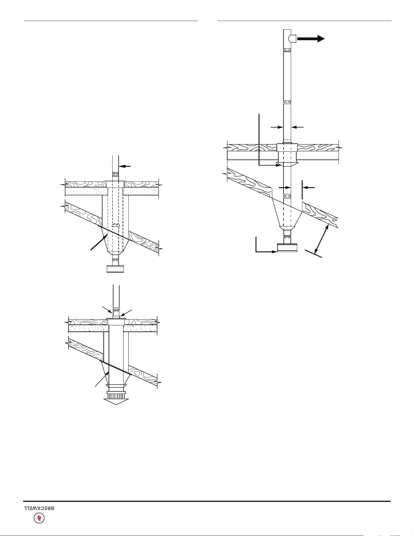
© 2024 Breckwell Hearth
7
VERTICALEMENT AVEC UN SYSTÈME DE
CHEMINÉE NEUF
OPTION : Pour réaliser une installation verticale centrale, un coude
à 45° et un té de nettoyage peuvent être utilisés pour décaler la
tuyauterie de la sortie d’évacuation au milieu de l’arrière du poêle.
OPTION : Installez un coude de ventilation en PL à la place du té
de nettoyage. Positionnez le poêle. Laissez tomber le poids d’un
l à plomb au centre du té de sortie, et marquez la verticale au
plafond. Installez un manchon d’emboîtement de ventilation en PL
suivant les instructions du constructeur.
1. Maintenez toujours un écartement de 3 po (75 mm) par
rapport à des matériaux combustibles. En cas de traversée
supplémentaire de planchers ou plafonds, installez toujours
un coupe-feu.
2. Après l’alignement pour le trou dans le toit, découpez un trou
rond ou carré dans le toit, toujours plus gros de 3 Po (77
mm) tout du long que le passage de tuyau. Installez le bord
supérieur et les côtés du solin sous le matériau de toiture,
clouez au toit en suivant le bord supérieur. Ne clouez pas
le bord inférieur. Protégez les têtes de clous avec du mastic
étanche ne durcissant pas.
3. Appliquez du mastic étanche ne durcissant pas à l’endroit
où la mitre va rejoindre la ventilation et le solin. Faites glisser
en l’abaissant la mitre jusqu’à ce qu’elle repose sur le solin.
Installez et scellez un capuchon. Les installations en maisons
mobiles/bâtiments portatif doivent utiliser un pare-étincelles.
AU POÊLE
ÉCARTEMENT D’AU
MOINS 12”
PAR RAPPORT
AU TOIT
VENTILATION DE
TOIT VERTICALE
ÉCRAN
D’ISOLATION
DE COMBLES
ÉCARTEMENT
D’AU MOINS
3’ PAR RAPPORT
AUX COMBUSTIBLES
ÉCARTEMENT
D’AU MOINS 3’ PAR
RAPPORT AUX
COMBUSTIBLES
VERTICALEMENT AVEC UN SYSTÈME DE
CHEMINÉE EXISTANT
Des adaptateurs sont disponibles pour raccorder depuis une
ventilation en PL de 3 po (77 mm) ou une cheminée de Classe
A de 8 po. En solution alternative, une ventilation en PL de 3
ou 4 po (77 mm ou 102 mm) peut être tirée à l’intérieur de la
cheminée existante jusqu’à sa terminaison. C’est la méthode à
préférer. Respectez les consignes pour la longueur équivalente de
ventilation.
PELLET
VENT
NOTE:
THIS METHOD
IS PREFERRED
EXISTING
CHIMNEY
SYSTEM
PELLET VENT TO
CHIMNEY ADAPTER
(SPV-CA)
UNIVERSAL
CONNECTOR
EXISTING
CHIMNEY
SYSTEM
VERTICALEMENT DANS UN FOYER EN
MAÇONNERIE EXISTANT
1. Votre cheminée doit être inspectée par une entreprise
qualiée de ramonage ou d’installation pour déterminer son
état structurel.
2. Vous aurez besoin d’une longueur de tuyau égale à la hauteur
de cheminée depuis l’âtre. Si de l’air de combustion extérieur
est utilisé, vous aurez besoin d’une longueur de tuyau égale
à la hauteur de cheminée plus 18 po (45,7 cm).
3. Installez une plaque d’obturation et le tuyau de cheminée, et
si vous l’utilisez le tuyau d’air extérieur, comme montré.
INSTALLATION
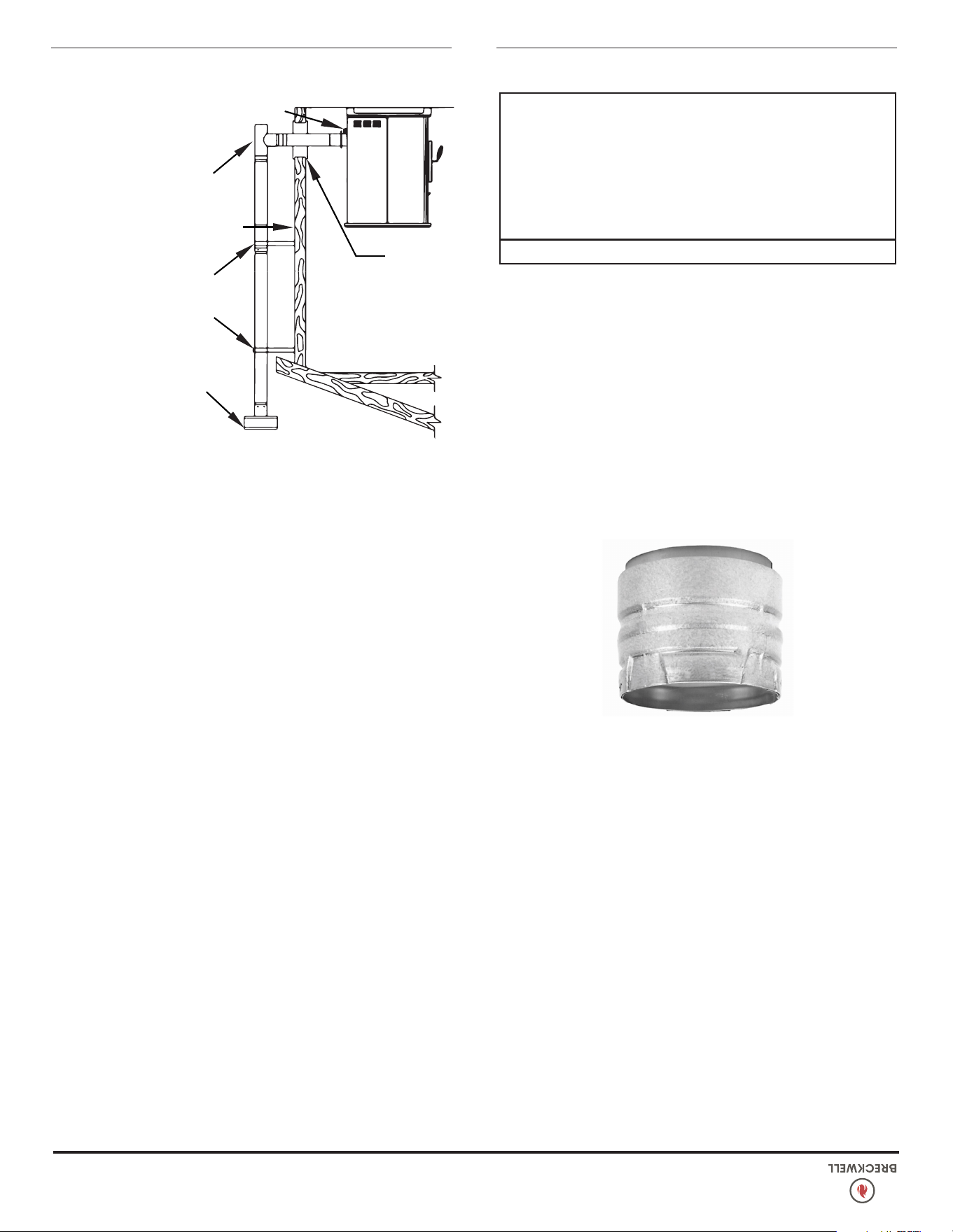
6
© 2024 Breckwell Hearth
IMPORTANCE D’UN TIRAGE ADÉQUAT
Le tirage est une force déplaçant l’air de l’appareil vers la
cheminée. La quantité de tirage dans votre cheminée dépend de sa
longueur, son emplacement géographique local, les obstructions
à proximité et autres facteurs. Trop de tirage peut causer des
températures excessives dans l’appareil. Un tirage inadéquat peut
causer des retours de fumée dans la pièce et causer l’obturation
de la cheminée. Un tirage inadéquat causera des fuites de fumée
par l’appareil dans la pièce, s’inltrant par l’appareil, et les joints
du conduit de raccordement. Un brûlage incontrôlable ou une
température excessive indique un tirage excessif. Tenez compte
de l’emplacement de la cheminée pour veiller à ce qu’elle ne soit
pas trop près des voisins ou dans une vallée pouvant causer des
conditions malsaines ou nuisibles.
EXIGENCES POUR L’EVACUATION
Un adaptateur d’appareil compatible est requis pour l’installation
correcte de la ventilation de cet appareil. Achetez l’adaptateur
d’appareil approprié auprès de votre entreprise de ventilation
préférée avant de commencer le processus de ventilation.
Le unité est certié pour une utilisation avec une ventilation type
en PL agréée, de diamètre 3 ou 4 po (7 mm et 102 mm). Le poêle
a été testé avec la marque Simpson Duravent. Une cheminée de
classe “A” n’est pas nécessaire. Référez-vous aux instructions
fournies par le fabricant de la ventilation, en particulier si vous
devez traverser mur, plafond ou toit. C’est un système à évacuation
sous pression. Toutes les jonctions de connecteur de ventilation
doivent être scellées avec du mastic à la silicone RTV résistant
à 500°F (260 °C) an d’assurer une performance constante et
éviter des dispersions de fumée. Toutes les jonctions de connecteur
horizontal doivent être scellées avec de la bande métallique
UL-181-AP. Nous recommandons que toutes les jonctions de
ventilation verticale soient xées avec au moins 3 vis.
ATTENTION:
• INSTALLER L'ÉVENT AUX DÉGAGEMENTS SPÉCIFIÉS PAR LE
FABRICANT DE L'ÉVENT.
• NE PAS RACCORDER L'ÉVENT À GRANULES À UN ÉVENT
SERVANT À UN AUTRE APPAREIL OU À UN POÊLE.
• N'INSTALLEZ PAS D'AMORTISSEUR DE FUMÉE DANS
LE SYSTÈME D'ÉVACUATION D'ÉCHAPPEMENT DE CET
APPAREIL.
HORIZONTALEMENT AU TRAVERS D’UN MUR
1. Positionnez le poêle en respectant les écartements montrés.
2. Situez la position du trou dans le mur, directement derrière la
sortie d’évacuation du poêle.
3. Maintenez toujours un écartement de 3 po (75 mm) par
rapport à des matériaux combustibles.
4. Installez un manchon d’emboîtement de ventilation en PL
suivant les instructions du constructeur.
5. Raccordez assez de tuyau pour pénétrer et dépasser d’au
moins 6 po (15 cm) à l’extérieur de l’autre côté du mur. Un
tronçon de tuyau vertical de 8 pieds (2,4 m) est suggéré
quand c’est possible pour réduire l’éventualité de dispersion
de fumée en cas de perte de pression négative.
6. Fixez un capuchon et scellez l’extérieur des manchons
d’emboîtement avec du mastic étanche à l’eau ne durcissant
pas.
7. La terminaison ne doit pas être située à un endroit où elle
serait susceptible d’enammer arbres, buissons ou herbes, ou
de présenter un risque pour des enfants. Les gaz d’évacuation
peuvent atteindre des températures de 500°F (260 °C) et
causer de sérieuses brûlures en cas de contact.
8. Positionnement des terminaisons :
a. Pas moins de 3 pi (90 cm), au-dessus de toute entrée
d’extraction d’air située à moins de 10 pi (3 m);
b. Pas moins de 4 pi (120 cm) en dessous ou latéralement, et
1 pi (30 cm) au-dessus de toute porte, fenêtre ou admission
d’air par gravité dans tout bâtiment;
c. Pas moins de 2 pi (60 cm) par rapport à un bâtiment adjacent,
et pas moins de 7 pi (210 cm) au-dessus du sol en cas de
situation adjacente à un passage public. Les installations en
maisons mobiles/bâtiments portatif doivent utiliser un pare-
étincelles.
ÉVENT DE TOIT
VERTICAL
WALL
THIMBLE
ÉCARTEMENT D’AU MOINS
6’ PAR RAPPORT À TOUTE
SURFACE COMBUSTIBLE
TÉ DE NETTOYAGE
UN COUDE À 90° PEUT
AUSSI ÊTRE EMPLOYÉ
ADAPTATEUR POUR
VENTILATION EN L
ATTACHE MURALE
VOIR LE FABRICANT DE
VENTILATION POUR LE
NOMBRE ET
L’ESPACEMENT
INSTALLATION
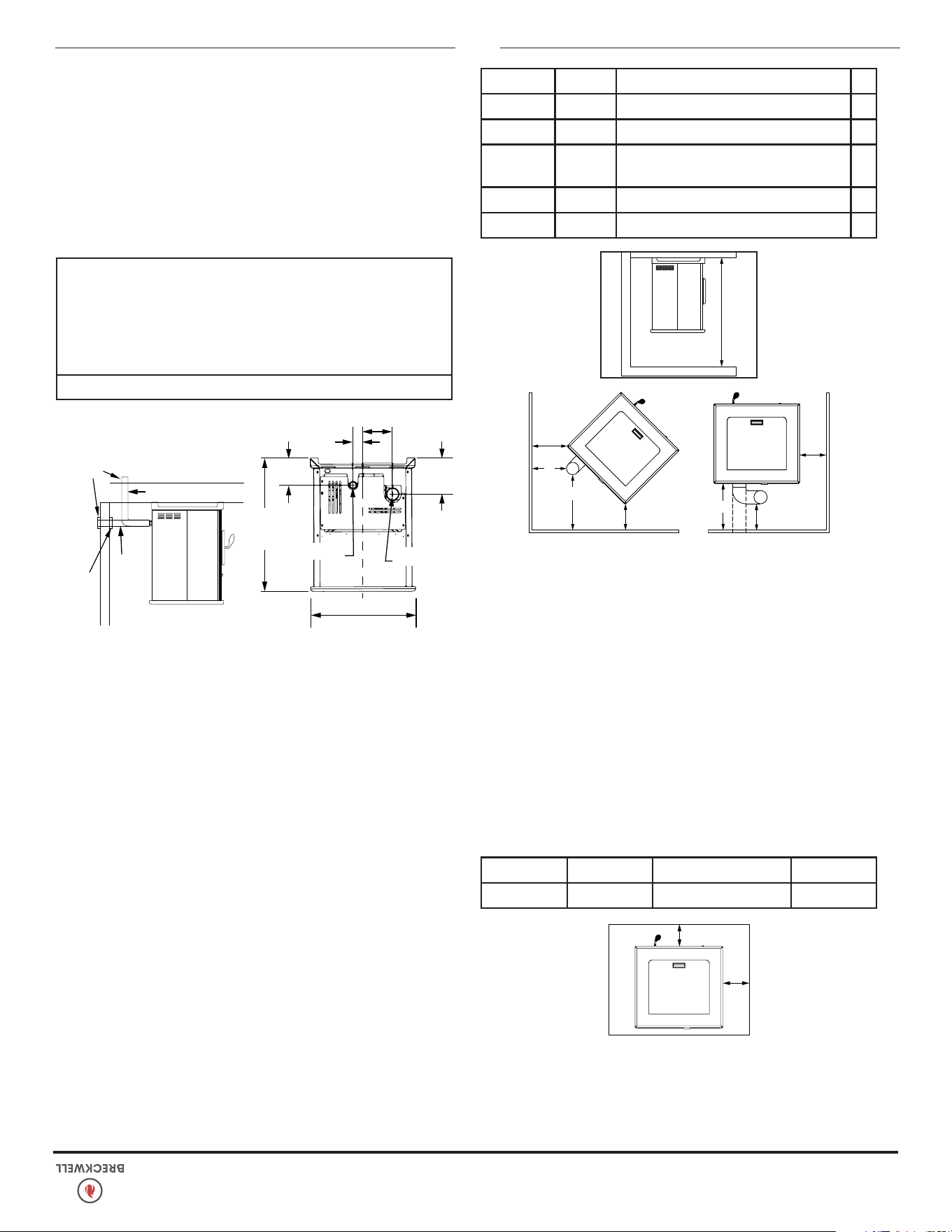
© 2024 Breckwell Hearth
5
INSTALLATION
équivalent, ou d’autres matériaux approuvés ou listés pour la
protection de sol. LE(S) MATÉRIAU(X) UTILISÉ(S) DOIT/DOIVENT
AVOIR OU SE COMBINER POUR AVOIR UN TAUX D’ISOLATION
D’AU MOINS ‘R1’.
A
B
A Côté à cuisinière 6 po 153 mm
B De l'avant au poêle 6 po 153 mm
REMARQUE: Un carrelage, en céramique ou autre, nécessite
une feuille continue par-dessous pour éviter la possibilité que des
braises tombent au travers jusqu’au plancher combustible en cas
de craquelure ou de séparation sur la surface de nition, cela
inclut une protection de sol pour des âtres intégrés surélevés.
Vériez les normes locales pour des alternatives approuvées. Les
écartements sont mesurés à partir des côtés, de l’arrière et de la
façade (ouverture de porte) ou du corps du poêle.
N’UTILISEZ PAS DE MATÉRIAUX IMPROVISÉS OU DE COMPROMIS
À L’INSTALLATION DE L’APPAREIL. INSTALLEZ LA VENTILATION
AVEC LES ÉCARTEMENTS SPÉCIFIÉS PAR SON FABRICANT.
ÉCARTEMENTS
Le unité a été testé et homologué pour des applications d’installation
en maison résidentielle et en maisons mobiles/bâtiments portatif.
G
G
F
F
D
C
E
H
C Mur latéral au poêle 12 po 305 mm
D Mur arrière à échappement vertical 3 po 77 mm
E
Mur arrière à échappement
horizontal
1 po 26 mm
F Mur latéral au poêle 1 po 26 mm
G Mur à tuyau d’évent 3 po 77 mm
H Hauteur du plafond au sol 60 po 1524 mm
FOURNITURE D’AIR DE COMBUSTION
Pour une installation en maisons mobiles/bâtiments portatif, le
poêle doit être relié à une source extérieure d’air de combustion.
Un tuyau métallique de diamètre intérieur 2 po (51 mm), exible
ou bien rigide, peut être xé sur l’entrée à l’arrière du poêle. Une
protection contre les rongeurs (avec mailles de grillage d’au moins
1/4 po (7 mm) hotte anti-vent doit être utilisée à la terminaison.
Tous les raccordements doivent être xés et étanchéiés, en utilisant
une attache de tuyau du bon calibre et/ou du ruban métallique
UL-181-AP. Pour des installations en maisons mobiles/bâtiments
portatif uniquement : Un tuyau de diamètre intérieur 2 po (51
mm) peut être utilisé pour le premier mètre cinquante de tronçon
pour l’air de combustion. De 1,5 à 3 mètres, utilisez du tuyau
de diamètre intérieur 2-3/4 po (70 mm). Aucune alimentation en
air de combustion ne doit dépasser 3 mètres. Sources d’air de
combustion extérieur
a. Installations en foyer
• Haut de cheminée.
• Porte pour évacuation des cendres.
b. Installations en autonome
• Un trou dans le sol près du poêle ne pouvant se terminer que
dans un vide sanitaire ventilé.
• Un trou dans le mur derrière le poêle.
COLLIER
DE PARURE
VIDE SANITAIRE
VENTILÉ
PROTECTION
CONTRE LES
RONGEURS
AIR
FRAIS
ADMISSION
AIR FRAIS ADMISSION
25-3/4 po (655 mm)
32-5/8 po
(829 mm)
6-5/8 po
(169 mm)
2-7/16 po
(62 mm)
7-5/16 po
(186 mm)
8-7/8 po
(226 mm)
C
L
Air frais
Admission
Échappement
Tuyau
ATTENTION:
NE PAS VENTILER SOUS UNE PORCHE, UNE PONT, UN AUVENT
OU DANS TOUTE ZONE SEMI-CLOS OU TOIT. LE FAIRE PEUT
ENTRAÎNER UN FLUX D'AIR IMPRÉVISIBLE AU BOUCHON
D'ÉVENT DANS CERTAINES CONDITIONS ET PEUT AFFECTER
LES PERFORMANCES DE VOTRE POÊLE, AINSI QUE D'AUTRES
PROBLÈMES IN PRÉVISIBLES.
NON-UTILISATION D’AIR EXTÉRIEUR
Si de l’air extérieur n’est pas utilisé, il est important que l’air de
combustion soit facilement disponible à l’entrée d’air. Un registre
d’air extérieur pouvant se fermer peut être utilisé dans les maisons
très bien isolées.
4
© 2024 Breckwell Hearth
AVIS DE SÉCURITÉ
• SI CE POÊLE N'EST PAS INSTALLÉ CORRECTEMENT, UN
INCENDIE PEUT EN RÉSULTER. POUR RÉDUIRE LES RISQUES
D'INCENDIE, SUIVEZ LES INSTRUCTIONS D'INSTALLATION.
• CONTACTEZ VOS OFFICIELS DE BÂTIMENT LOCAUX POUR
OBTENIR UN PERMIS ET DES INFORMATIONS SUR TOUTES
LES RESTRICTIONS SUPPLÉMENTAIRES D'INSTALLATION OU
LES EXIGENCES D'INSPECTION DANS VOTRE RÉGION.
• NE PLACEZ PAS DE VÊTEMENTS OU D'AUTRES ARTICLES
INFLAMMABLES SUR OU À PROXIMITÉ DE CE POÊLE.
• N'UTILISEZ JAMAIS D'ESSENCE, DE CARBURANT DE
LANTERNE DE TYPE ESSENCE, DE KÉROSÈNE, DE LIQUIDE
POUR BRIQUET AU CHARBON OU DE LIQUIDES SIMILAIRES
POUR ALLUMER OU «RAFRAÎCHIR» UN FEU DANS CE FOUR.
GARDEZ TOUS CES LIQUIDES BIEN ÉLOIGNÉS DU POÊLE
PENDANT SON UTILISATION.
• LE SYSTÈME D'ÉCHAPPEMENT DOIT ÊTRE COMPLÈTEMENT
ÉTANCHE ET CORRECTEMENT INSTALLÉ. LES JOINTS D'ÉVENT
À GRANULÉS DOIVENT ÊTRE SCELLÉS AVEC DU SCELLANT
AU SILICONE RTV 500 ° F (260 ° C) ET AVEC LE RUBAN ALU
UL-181-AP.
• INSTALLER L'ÉVENT AUX DÉGAGEMENTS SPÉCIFIÉS PAR LE
FABRICANT DE L'ÉVENT.
• NE PAS INSTALLER D'AMORTISSEUR DE FUMÉE DANS
LE SYSTÈME D'ÉVACUATION D'ÉCHAPPEMENT DE CET
APPAREIL.
• VOTRE POÊLE NÉCESSITE UN ENTRETIEN ET UN NETTOYAGE
PÉRIODIQUES (VOIR «ENTRETIEN»). NE PAS ENTRETENIR
VOTRE POÊLE PEUT ENTRAÎNER UN FONCTIONNEMENT
INCORRECT ET / OU DANGEREUX.
• UN PROTECTEUR DE SURTENSION EST NÉCESSAIRE. CET
APPAREIL DOIT ÊTRE BRANCHÉ À UNE PRISE ÉLECTRIQUE DE
120 V, 60 HZ MISE À LA TERRE. N'UTILISEZ PAS DE FICHE
D'ADAPTATEUR OU NE COUPEZ PAS LA FICHE DE MISE À
LA TERRE. NE PAS FAIRE PASSER LE CORDON ÉLECTRIQUE
SOUS, DEVANT OU AU-DESSUS DU CHAUFFAGE. NE PAS
FAIRE PASSER LE CORDON DANS LES ZONES DE TRAFIC À
PIED NI LE PINCER SOUS LES MEUBLES.
ATTENTION:
• UN DÉTECTEUR DE FUMÉE EN FONCTIONNEMENT DOIT
ÊTRE INSTALLÉ DANS LA MÊME PIÈCE QUE CE PRODUIT.
• INSTALLER UN DÉTECTEUR DE FUMÉE À CHAQUE ÉTAGE
DE VOTRE MAISON; EN CAS D'INCENDIE ACCIDENTEL DE
TOUTE CAUSE, IL PEUT FOURNIR DU TEMPS D'ÉVASION.
• LE DÉTECTEUR DE FUMÉE DOIT ÊTRE INSTALLÉ À AU
MOINS 15 PIEDS (4,57 M) DE L'APPAREIL AFIN D'ÉVITER
UN DÉCLENCHEMENT INDUSÉ DU DÉTECTEUR LORS DU
RECHARGEMENT.
MISE EN GARDE:
• NE DÉBRANCHEZ PAS LE POÊLE SI VOUS SUSPECTEZ UN
MAUVAIS FONCTIONNEMENT. METTEZ L'INTERRUPTEUR
MARCHE / ARRÊT SUR «OFF» ET CONTACTEZ VOTRE
CONCESSIONNAIRE.
• LE CHAUFFAGE NE FONCTIONNE PAS PENDANT UNE
PANNE DE COURANT. EN CAS DE PANNE DE COURANT,
VÉRIFIEZ LE CHAUFFAGE POUR DÉVERSER DE FUMÉE ET
OUVREZ UNE FENÊTRE SI UNE FUMÉE SE DÉVERSE DANS
LA PIÈCE.
• NE JAMAIS BLOQUER LE FLUX D'AIR LIBRE À TRAVERS LES
ÉVENTS OUVERTS DE L'APPAREIL.
MISE EN GARDE:
• LA BRÛLURE DU CARBURANT CRÉE DU MONOXYDE DE
CARBONE ET PEUT ÊTRE DANGEREUX POUR LA SANTÉ S'IL
N'EST PAS CORRECTEMENT VENTILÉ.
• AVERTISSEMENT: NE PAS SURCHAUFFER CE POÊLE. CELA
PEUT CAUSER DES DOMMAGES GRAVES À VOTRE POÊLE ET
ANNULER VOTRE GARANTIE. CELA PEUT ÉGALEMENT CRÉER
UN RISQUE D'INCENDIE DANS VOTRE MAISON. SI UNE
PIÈCE EXTÉRIEURE DE L'APPAREIL COMMENCE À LUMINER,
VOUS ÊTES EN SURCHARGE. APPUYEZ IMMÉDIATEMENT SUR
L'INTERRUPTEUR «POWER» DU PANNEAU DE COMMANDE
Nous recommandons que nos produits de foyer
des
au Canada par le
programme de formation
technique en énergie
du bois (WETT).
CERTIFIÉ
Breckwell recommande fortement que votre poêle soit installé par
un technicien qualié NFI (États-Unis) ou WETT (Canada). Pour
trouver l’installateur qualié le plus proche, accédez à:
https://ncertied.org,
https://www.wettinc.ca/
PRÉPARATION
L’emballage d’usine doit être enlevé, et un travail d’assemblage
mineur est nécessaire avant l’installation. Un accès à l’arrière
du poêle est nécessaire. REMARQUE: Normalement c’est votre
revendeur qui doit exécuter ces étapes.
PROTECTION DE PLANCHER
Pour les installations en autonome, au minimum de 30 po de
large et 32 po de profondeur (762 x 813 mm). Le poêle doit être
placé sur un matériau continu (joints avec coulis) non combustible,
comme des carreaux de céramique, une plaque de béton, de
la brique, du celloderme de 3/8 (10 mm) po ou un matériau
INSTALLATION
© 2024 Breckwell Hearth
3
LISTE DE CONTRÔLE D’INSTALLATION
Votre poêle à bois ne doit être installé que par un installateur qualié. Un installateur qualié NFI est disponible à l’adresse www.
ncertied.org/public/nd-an-n-pro/
Pour le service client, veuillez contacter votre revendeur Breckwell.
LISTE DE CONTRÔLE DE MISE EN SERVICE
Cette liste de contrôle doit être remplie intégralement par la personne qualiée qui installe cet appareil. Conservez cette page pour
référence future.
Le fait de ne pas installer et mettre en service selon les instructions du fabricant et de remplir cette liste de contrôle annulera la garantie.
S’il te plaît imprime
Nom du client: Numéro de téléphone:
Adresse:
Modèle:
Numéro de série:
Nom de la société d’installation: Numéro de téléphone:
Nom du technicien d’installation: Numéro de licence:
DESCRIPTION DU TRAVAIL
Emplacement de l’appareil installé: _____________________________________________________________________________________
Système de ventilation: nouveau système de ventilation
Oui Non Si oui, marque _________________________________
Si non, date d’inspection du système de ventilation existant: _________________________________________________________________
MISE EN SERVICE
Conrmer l’installation du tapis de foyer conformément aux instructions d’installation ..................................................................
Conrmer le bon placement des pièces internes ......................................................................................................................
Vérier la solidité du joint de porte et des joints de porte .........................................................................................................
Conrmer les dégagements aux combustibles selon les instructions d’installation de ce manuel .....................................................
Vérier le fonctionnement des commandes pneumatiques .........................................................................................................
Conrmez que le système de ventilation est sécurisé et scellé ....................................................................................................
Conrmer que le poêle démarre et fonctionne correctement .....................................................................................................
Assurez-vous qu’un avertisseur de CO est installé conformément aux codes du bâtiment locaux et qu’il est fonctionnel ....................
Expliquer le fonctionnement en toute sécurité, l’utilisation appropriée du carburant, le nettoyage et les exigences d’entretien de routine ...
Déclaration d’achèvement: En tant que personne qualiée responsable des travaux décrits ci-dessus, je conrme que l’appareil en tant
que travail associé a été installé selon les instructions du fabricant et en suivant les codes de construction et d’installation applicables.
Signé: ____________________________________ Nom en lettres moulées: ________________________________Date: _______________
Propriétaire du domicile: CONSERVEZ CETTE INFORMATION POUR RÉFÉRENCE FUTURE
2
© 2024 Breckwell Hearth
Ce manuel décrit l’installation et le fonctionnement du chauffage au bois, Breckwell, SP1000E. Ce chauffage respecte les limites
d’émission 2020 de bois en caisson de la U.S. Environmental Protection Agency pour les chauffages au bois solide après le 15 mai 2020.
Sous les conditions spéciques du test, ce chauffage a démontré un taux de chauffage de 6 580 à 39 121 Btu/h 1,0 g/h et 75%
d’efcacité.
INTRODUCTION
Spécications de chauffage
Taux de combustion du carburant 1 - 5.5 lbs/hr (0,45 - 2,5 kh/hr)
* La taille des granulés peut affecter le débit
réel d’alimentation en carburant, les durées de
combustion et la capacité de la trémie. Les débits
d’alimentation en carburant peuvent varier jusqu’à
20 %. Utilisez du carburant homologué PFI pour de
meilleurs résultats.
Capacité de trémie * jusqu’à 140 lbs (63,5 kg)
Taille du conduit 3 po ou 4 po (77 mm or 102 mm)
Tarif Électrique 115V 60Hz 3A
Dimensions
Hors tout: hauteur x largeur x profondeur 25-3/4 po (655 mm) X 32-5/8 po (829 mm) X 23-7/8 po (607 mm)
Du sol au centre du tuyau d’échappement 8,875 po (226 mm)
Du sol au centre d’admission d’air frais 6,625 po (169 mm)
CONSERVEZ VOTRE REÇU ORIGINAL POUR TOUTE RÉCLAMATION DE GARANTIE. CONTACTEZ VOTRE CONCESSIONNAIRE OU
INSTALLATEUR SI VOUS DEVEZ DÉPOSER UNE RÉCLAMATION.
AVERTISSEMENT:
IL EST CONTRE LES RÈGLEMENTS FÉDÉRAUX DE FAIRE FONCTIONNER CE CHAUFFE À BOIS D’UNE MANIÈRE INCOMPATIBLE AVEC LES
INSTRUCTIONS D’UTILISATION DU MANUEL DU PROPRIÉTAIRE.
Remarque : Enregistrez votre produit en utilisant votre téléphone
intelligent avec le code QR. Conservez vos reçus avec vos
dossiers pour toute réclamation au titre de la garantie.
Vous pouvez également enregistrer votre produit en ligne sur
www.breckwell.com/product-registration
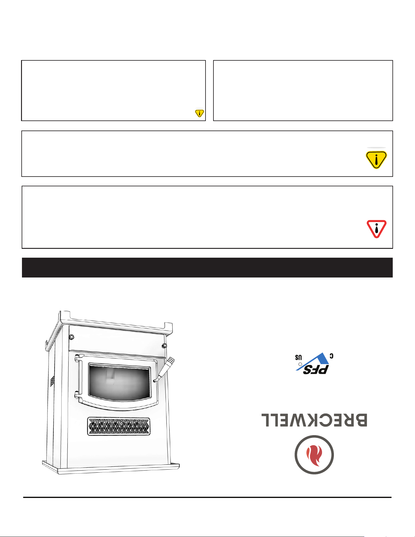
* Toutes les images de ce manuel sont à des ns d’illustration uniquement. Le produit réel peut varier.
© 2024 Breckwell Hearth, South Pittsburg, TN 37380 PH. 423-403-4031
CE MANUEL EST SUJET À MODIFICATION SANS PRÉAVIS.
Manuel d’instructions et d’utilisation du propriétaire
AVIS DE SÉCURITÉ: Si ce radiateur n’est pas correctement installé, un incendie peut en résulter.
Pour votre sécurité, suivez les instructions d’installation. N’utilisez jamais de compromis de
fortune lors de l’installation de ce radiateur. Contactez les responsables locaux du bâtiment ou
des pompiers pour connaître les permis, les restrictions et les exigences d’installation dans votre
région. NE JAMAIS UTILISER CE PRODUIT SANS SURVEILLANCE.
Conservez ces instructions dans un endroit sûr pour référence ultérieure.
AGENCE AMÉRICAINE DE PROTECTION DE
L’ENVIRONNEMENT
Certié conforme aux normes d’émissions de
particules 2020.
MISE EN GARDE! Veuillez lire l’intégralité de ce manuel avant d’installer ou d’utiliser votre nouveau
radiateur. Le non-respect des instructions peut entraîner des dommages matériels, des blessures corporelles
ou même la mort. Une installation incorrecte pourrait annuler votre garantie!
AVERTISSEMENT SUR LA PROPOSITION 65 DE LA
CALIFORNIE:
Ce produit peut vous exposer à des produits chimiques, y compris le
monoxyde de carbone, qui est connu dans l’État de Californie pour
provoquer le cancer, des anomalies congénitales et / ou d’autres
troubles de la reproduction. Pour plus d’informations, visitez www.
P65warnings.ca.gov
SP1000E
Certié selon ASTM E1509-2022
et ULC S627:2023
Maisons Mobiles / Bâtiments
Portatif Approuvé.
Numéros De Modèle:
Numéro du rapport: F21-690
R