
© 2023 GeoVision, Inc. All rights reserved.
Under the copyright laws, this manual may not be copied, in whole or in part,
without the written consent of GeoVision.
Every effort has been made to ensure that the information in this manual is
accurate. GeoVision, Inc. makes no expressed or implied warranty of any kind
and assumes no responsibility for errors or omissions. No liability is assumed
for incidental or consequential damages arising from the use of the information
or products contained herein. Features and specifications are subject to
change without notice.
GeoVision, Inc.
9F, No. 246, Sec. 1, Neihu Rd.,
Neihu District, Taipei, Taiwan
Tel: +886-2-8797-8377
Fax: +886-2-8797-8335
http://www.geovision.com.tw
Trademarks used in this manual: GeoVision, the GeoVision logo and GV
series products are trademarks of GeoVision, Inc. Windows is the registered
trademark of Microsoft Corporation.
March 2023
Scan the following QR codes for product warranty and technical support
policy:
[Warranty] [Technical Support Policy]

Contents
Safety Precautions ...................................................................................................................i
Chapter 1 Introduction to the User Guide ........................................................................... 1
1.1 Use ............................................................................................................................. 1
1.2 User Manual Overview .......................................................................................... 1
Chapter 2 Product Introduction ............................................................................................. 2
2.1 Product Overview .................................................................................................. 2
2.2 Product Features.................................................................................................... 2
2.3 Product Advantage ................................................................................................ 2
Chapter 3 Product Appearance Description ....................................................................... 4
3.1 Front Panel .............................................................................................................. 4
3.2 Dip Switch Indicator Status Description .......................................................... 5
3.3 LED Indicator .......................................................................................................... 6
3.4 Side Plate ................................................................................................................. 6
Chapter 4 Installation Guide.................................................................................................. 8
4.1 Installation Precautions ....................................................................................... 8
4.2 Installation Environment ...................................................................................... 8
4.3 Installation ............................................................................................................... 9

i
Safety Precautions
Note: Precision devices are built in the device, please handle them carefully to
avoid violent vibration, which may affect the performance of the device. If you find that
the equipment is damaged or any parts are lost in the process of transportation,
please inform us, we will give you a proper solution as soon as possible.
Statement
Product specifications and information mentioned in this manual are for reference
only and are subject to change without prior notice. Unless otherwise agreed, this
manual is for use only and does not constitute any form of warranty.
Convention
The product pictures in this document are for illustration only. The number and
positions of ports depend on actual models. This document helps you correctly use
the Switch. It describes the performance characteristics of the Switch and describes
how to install the Switch. Read this manual carefully before operating the Switch.

1
Chapter 1 Introduction to the User Guide
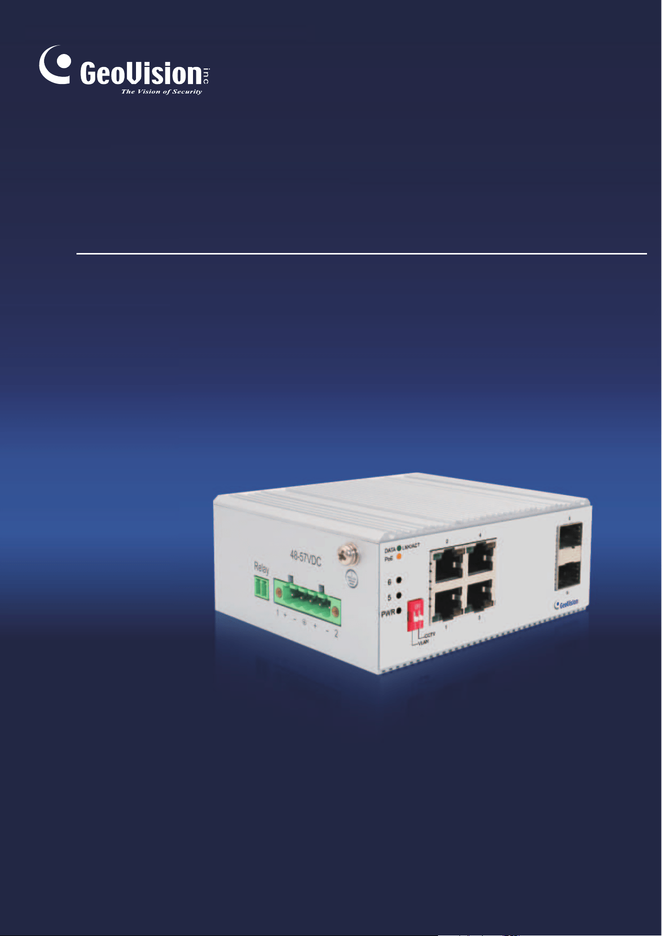
Thank you for purchasing our 4-Port Gigabit+2G SFP industrial grade Unmanaged
PoE Switch! The device adopts no fan, low power consumption design, has the
advantages of easy to use, compact and beautiful, simple installation. The product is
designed to meet Ethernet standards, with lightning protection, static protection
mechanism, operating temperature range of -40°C to 75°C, stable performance, safety
and reliability, can be widely used in intelligent transportation, telecommunications,
security, financial securities, customs and other broadband data transmission fields.
1.1 Use
This document aims to familiarized users with and correctly use 4-Port Gigabit+2G
SFP industrial Unmanaged PoE Switches.
1.2 User Manual Overview
Chapter 1: Introduction to the User Guide.
Chapter 2: Product Introduction.
Chapter 3: Product Appearance Description.
Chapter 4: Installation Guide.

2
Chapter 2 Product Introduction
2.1 Product Overview
GV-APOE0410-E is an industrial-grade, unmanaged PoE switch with 4 PoE+
10/100/1000 BaseT(X) ports and 2 Gigabit SFP ports. The switch supports IEEE
802.3at Power over Ethernet standard with up to 30 W per port and a maximum
power consumption of 125 W. It not only eliminates the need for power cables to
connect your powered devices (PD), such as IP cameras, but it also allows power
supply over cables up to 250 m (820 ft) in length, at 10 Mbps.
The switch is ideal for small or medium network environments to strengthen network
connection and efficiency. It includes the smart PD Alive Check feature and the option
to isolate each PoE port for a faster forwarding rate of time.
2.2 Product Features
➢ 4-port PoE+ 10/100/1000 BaseT(X), 2-port Gigabit SFP
➢ IEEE 802.3at Compliant (4 Ports at Full 30 W)
➢ Max. 125 W power consumption
➢ Extreme temperature tolerance (‐40 °C ~ 75 °C / ‐40 °F ~ 167 °F)
➢ Auto-MDI/MDI-X
➢ DIN-Rail Installation
➢ Redundant DC power
➢ Support for VLAN mode for network partition and enhanced performance
➢ Support for PD Alive Check
➢ PoE connection for network cables up to 250 m (820 ft) at 10 Mbps transfer rate
➢ 4 kV surge protection
➢ Up to 4 GV-IP Camera support
2.3 Product Advantage
-40°C ~ 75 °C operating temperature design
-40°C ~ 75 °C operating temperature design, selected industrial components, the use
of natural heat dissipation, to ensure that the Switch can achieve long-term stable
operation within the temperature range, to meet all kinds of use environment.

3
High energy aluminum alloy roof heat conduction groove shell design
Body size 110*90*46 mm, compact and light, full aluminum alloy high energy roof heat
conduction groove shell design, better heat dissipation effect.
DIN-Rail installation, simple and flexible
DIN-Rail installation design, easy and quick installation, so that users reduce
unnecessary installation time, save time cost.
Select industrial grade components
Chemical nickel gold PCB board, with high corrosion resistance, oxidation resistance.
Select high specification capacitor, greatly improve the service life of products.
Supports power supply priorities
The device supports port power supply priorities to ensure continuous power supply
for key nodes on the network.
Supports relay alarm function
Support system startup abnormal and power alarm function, if the system startup or
input power abnormal can be timely output alarm signal.
Supports PD-ALIVE function
PoE ports support automatic PD monitoring and port data detection. After the PoE
port is powered on, the device starts to detect if the port is transmitting data. If the port
is not transmitting data and lasts longer than a specific time, the PoE will automatically
power down and then power up again.
Supports VLAN function
VLAN isolation mode divides ports 1~4 and ports 5/6 of the switch into a separate
VLAN. Ports 1~4 can only communicate with 5/6. Ports 1~4 cannot communicate with
each other to ensure the security of the network. In this mode, please connect port 5/6
to the central switching device.
Supports CCTV function
The transmission rate of the port in this mode is reduced to 10Mbps and the
transmission distance is extended to 250m, which can solve the problem of
long-distance transmission in network monitoring projects and can replace optical
fibers and network extenders, solving the problem of difficult ultra-remote power
extraction and reducing engineering wiring costs. To ensure the stability and distance
of PoE power transmission, always use 8-core all-copper 0.5 or above national
standard cables.
4
Chapter 3 Product Appearance Description
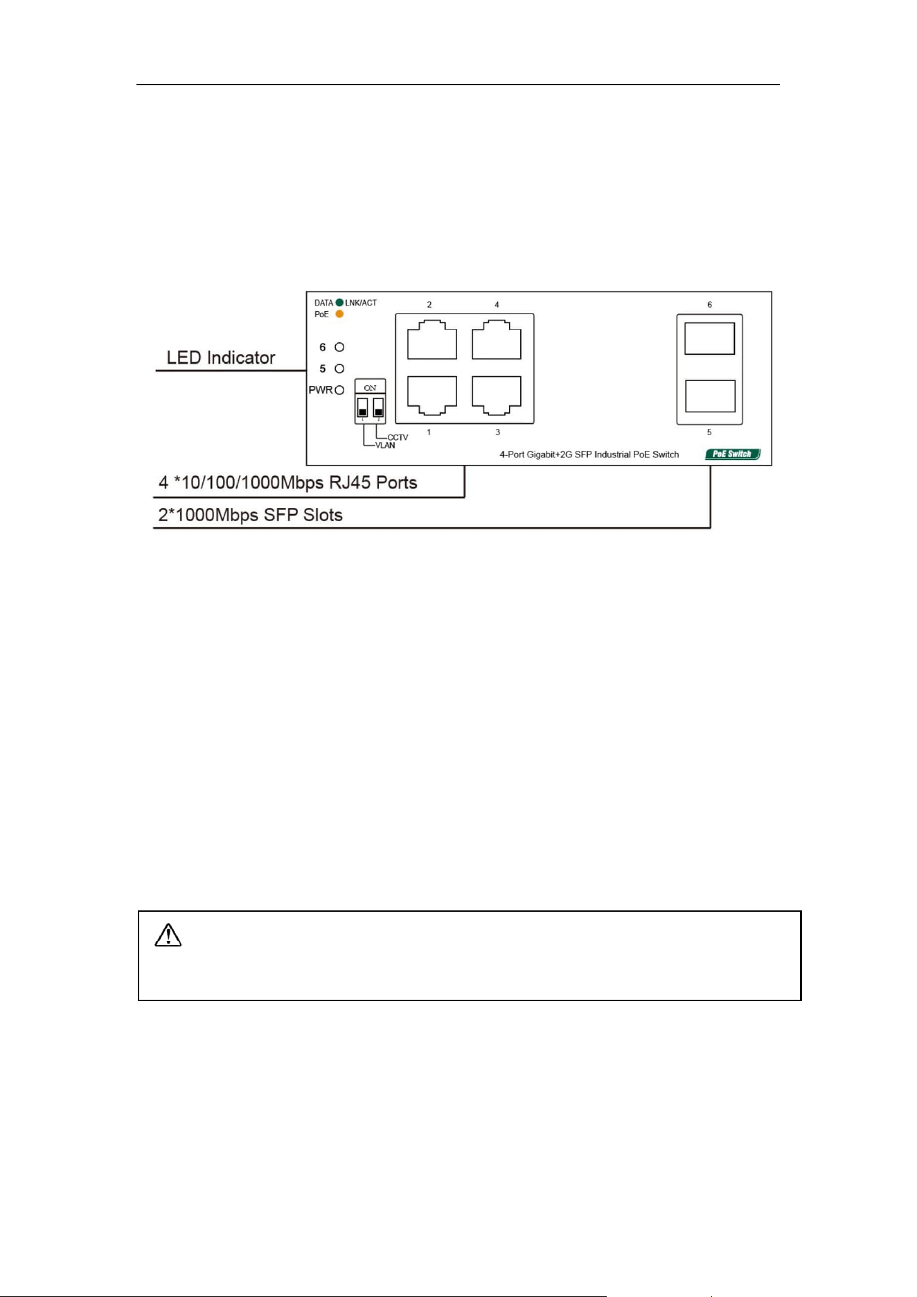
3.1 Front Panel
The front panel consists of 4*10/100/1000Mbps adaptive RJ45 ports, 2*1000Mbps
SFP slots and related indicators, as shown in the following figure:
Figure 3-1 Front panel of the 4-Port Gigabit+2G SFP Switch
4-Port Gigabit+2G SFP Port description:
10/100/1000Mbps RJ45 Ports
Supports 10Mbps, 100Mbps, or 1000Mbps rate adaptation, auto-MDI /MDIX, and
each port has a corresponding indicator, that is, port indicators 1-4 as shown on the
panel in the figure above.
1000Mbps SFP Slots
SFP slots are independent SFP slots on the right of the panel. Each port has a
corresponding indicator, that is, the indicator 5-6 on the panel in the figure above.
Note: To smoothly remove the transceivers from the SFP ports, tilt the ends of
the transceivers upward for port No.6 and downward for port No. 5.

5
3.2 Dip Switch Indicator Status Description

6
3.3 LED Indicator
The LED indicators of the Switch are shown in the following table. Users can monitor
the work and running status of the Switch conveniently and quickly through the
following indicators:
LED
Color
Function
PWR
Green
Off: No Power supply.
Light: Indicates the Switch has power.
DATA
Green
Off: No device is connected to the corresponding port.
Light: Indicates the link through that port is successfully
established at 10/100/1000Mbps.
Blink: Indicates that the Switch is actively sending or
receiving data over that port.
PoE
Orange
Off: No PoE powered device (PD) connected.
Light: There is a PoE PD connected to be port, which
supply power successfully.
Blink: Indicates port abnormal PoE supply.
3.4 Side Plate
Figure 3-2 4-Port Gigabit+2G SFP Switch side panel
The side panel of the Switch provides 5-position industrial wiring terminals and power
input DC: The standard voltage ranges from 48V to 57V, and the input voltage of 2
PWR1 and PWR2 power supplies ranges from 48V to 57V. The DC power input of the
Switch is redundant. The PWR1 and PWR2 power supplies can be used individually
or connected to 2 independent DC power supply systems. When any power supply
system fails, the device can run normally without interruption, which improves the
reliability of network operation.

7
Relay port:Alarm port, support machine abnormal alarm function. This interface
needs to be connected to an external alarm device. When the machine starts
abnormally or when the power is on, the internal relay will close and output the alarm
signal in time, which has the function of automatic alarm, safety protection and
isolation conversion in the circuit.

8
Chapter 4 Installation Guide
This chapter helps users correctly install and safely use Switches.
4.1 Installation Precautions
Precautions: To avoid equipment damage and personal injury, observe the
following precautions:
➢ The Switch room should be dry and ventilated, free from corrosive gases and
strong electromagnetic interference;
➢ The humidity of the switch room should be 5% to 95%. If possible, install
corresponding facilities;
➢ The grounding of the Switch shall comply with the grounding requirements
described in this manual, and shall be separately and well grounded;
➢ Keep a proper distance between the Switch and other devices. Do not stack other
devices with the Switch.
➢ The connection cable between the Switch and the distribution frame should be
standardized and reasonable, and the distribution frame (box) jumper wire should
be concise and clear to prevent the phenomenon of parallel lines and wires;
➢ To reduce the risk of electric shock, do not open the shell of the Switch when it is
working. Do not open the shell of the Switch even when it is not powered on.
Safety Tips:
➢ Ensure that the PGND cable of the power socket is properly grounded.
➢ Ensure sufficient space for heat dissipation and ventilation of the Switch. Do not
place heavy objects on the Switch.
4.2 Installation Environment
Before installation, make sure that the proper working environment is available,
including power requirements, adequate space, proximity to other equipment to be
connected, and other equipment in place. Please confirm the following installation
requirements:
➢ Ensure the stability of the workbench and good grounding;
➢ Check whether cables and connectors required for installation are in place (less
than 100m).
9
➢ Power supply: 48V to 57V DC power supply;
➢ Environment: operating temperature: -40°C to 75 °C relative humidity: 5% to
95%.
4.3 Installation
DIN-Rail Installation
The 45mm standard DIN-Rail installation is very convenient for most industrial
applications. The installation steps are as follows:
➢ Check whether the installation accessories of DIN-Rail guide tools are available
(installation accessories are provided for this product);
➢ Check whether DIN-Rail is firmly fixed, whether there is a suitable place to install
the product;
➢ Clamp the lower part of the DIN-Rail connecting seat of the product accessories
into the DIN-Rail (lower part with spring support), and then clamp the upper part
of the connecting seat into the DIN-Rail (lower part clamp a little, slightly force to
keep the balance of the equipment stuck into the upper part).
Figure 4-1 Schematic diagram of industrial machine guide rail installation
Note: Aluminum alloy DIN-Rail hooks have been fixed to the rear panel of the
Switch.

10
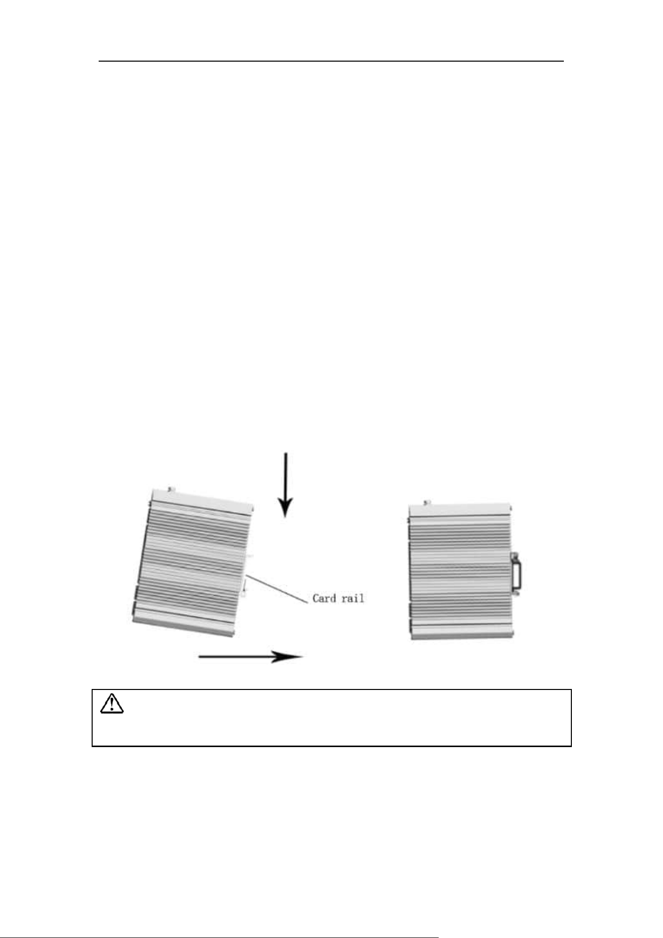
Figure 4-2 Schematic diagram of industrial machine guide rail disassembly
Power on
➢ Power on: First insert the power terminal of the power cable into the power port of
the device, then plug in the power plug and power on. After the Switch is started,
the Switch automatically initializes. If all port indicators are on and then off, the
system is successfully reset, and the power LED indicator is always on.
➢ Power off operation: Unplug the power plug first, and then remove the wiring part
of the terminal. Please pay attention to the above operation sequence.
Wall mounted installation
The following describes how to install a Switch on the wall:

11
Schematic diagram of wall mounted installation of industrial machine
➢ Remove the DIN-Rail mounting plate on the rear board of the Switch;
➢ Install the wall mounting board on the Switch as shown below.
➢ Four wall screws are required to mount the Switch on the wall, as shown in
the figure above.
➢ When fixing the screws to the wall, do not screw the screws into the wall
completely. Leave a space of about 2 mm for sliding the wall panel between
the wall and the screws.
➢ After securing the screws to the wall, place the 4 screw heads through most
of the keyhole, then place the Switch vertically and tighten the screws to
increase stability.