
Dashboard Camera
User Manual
UD13287B-B

i
User Manual
©2018 Hangzhou Hikvision Digital Technology Co., Ltd.
About this Manual
This manual applies to Dashboard Camera.
This Manual is subject to domestic and international
copyright protection. Hangzhou Hikvision Digital
Technology Co., Ltd. (“Hikvision”) reserves all rights to
this manual. This manual cannot be reproduced, changed,
translated, or distributed, partially or wholly, by any
means, without the prior written permission of Hikvision.
Trademarks
and other Hikvision marks are the
property of Hikvision and are registered trademarks or the
subject of applications for the same by Hikvision and/or its
affiliates. Other trademarks mentioned in this manual are
the properties of their respective owners. No right of
license is given to use such trademarks without express
permission.
Disclaimer
TO THE MAXIMUM EXTENT PERMITTED BY APPLICABLE
LAW, HIKVISION MAKES NO WARRANTIES, EXPRESS OR
IMPLIED, INCLUDING WITHOUT LIMITATION THE IMPLIED
WARRANTIES OF MERCHANTABILITY AND FITNESS FOR A
PARTICULAR PURPOSE, REGARDING THIS MANUAL.
HIKVISION DOES NOT WARRANT, GUARANTEE, OR MAKE
ANY REPRESENTATIONS REGARDING THE USE OF THE
MANUAL, OR THE CORRECTNESS, ACCURACY, OR
RELIABILITY OF INFORMATION CONTAINED HEREIN. YOUR
USE OF THIS MANUAL AND ANY RELIANCE ON THIS
MANUAL SHALL BE WHOLLY AT YOUR OWN RISK AND
RESPONSIBILITY.
TO THE MAXIMUM EXTENT PERMITTED BY APPLICABLE
LAW, IN NO EVENT WILL HIKVISION, ITS DIRECTORS,
OFFICERS, EMPLOYEES, OR AGENTS BE LIABLE TO YOU
FOR ANY SPECIAL, CONSEQUENTIAL, INCIDENTAL, OR
INDIRECT DAMAGES, INCLUDING, AMONG OTHERS,
DAMAGES FOR LOSS OF BUSINESS PROFITS, BUSINESS
INTERRUPTION, SECURITY BREACHES, OR LOSS OF DATA
OR DOCUMENTATION, IN CONNECTION WITH THE USE OF
OR RELIANCE ON THIS MANUAL, EVEN IF HIKVISION HAS
BEEN ADVISED OF THE POSSIBILITY OF SUCH DAMAGES.
SOME JURISDICTIONS DO NOT ALLOW THE EXCLUSION OR
LIMITATION OF LIABILITY OR CERTAIN DAMAGES, SO
SOME OR ALL OF THE ABOVE EXCLUSIONS OR
LIMITATIONS MAY NOT APPLY TO YOU.

ii
Regulatory Information
FCC Information
FCC compliance: This product has been tested and found
to comply with the limits for a Class B digital device,
pursuant to Part 15 of the FCC Rules. These limits are
designed to provide reasonable protection against harmful
interference in a residential installation. This product
generates, uses, and can radiate radio frequency energy
and, if not installed and used in accordance with the
instructions, may cause harmful interference to radio
communications. However, there is no guarantee that
interference will not occur in a particular installation. If this
product does cause harmful interference to radio or
television reception, which can be determined by turning
the equipment off and on, the user is encouraged to try to
correct the interference by one or more of the following
measures:
—Reorient or relocate the receiving antenna.
—Increase the separation between the equipment and
receiver.
— Connect the equipment into an outlet on a circuit
different from that to which the receiver is connected.
—Consult the dealer or an experienced radio/TV
technician for help.
FCC Conditions
This device complies with part 15 of the FCC Rules.
Operation is subject to the following two conditions:
1. This device may not cause harmful interference.
2. This device must accept any interference received,
including interference that may cause undesired operation.
Please take attention that changes or modification not
expressly approved by the party responsible for compliance
could void the user’s authority to operate the equipment.
This equipment complies with FCC/IC RSS-102 radiation
exposure limits set forth for an uncontrolled environment.
This equipment should be installed and operated with
minimum distance 20cm between the radiator & your
body.
EU Conformity Statement
This product and - if applicable - the supplied
accessories too are marked with "CE" and
comply therefore with the
applicable harmonized European standards listed under the
Low Voltage Directive 2014/35/EU, the EMC Directive
2014/30/EU, RE Directive 2014/53/EU.

iii
2012/19/EU (WEEE directive): Products
marked with this symbol cannot be
disposed of as unsorted municipal waste in
the European Union. For proper recycling,
return this product to your local supplier
upon the purchase of equivalent new equipment, or
dispose of it at designated collection points. For more
information see: www.recyclethis.info.
2006/66/EC (battery directive): This product
contains a battery that cannot be disposed
of as unsorted municipal waste in the
European Union. See the product
documentation for specific battery information. The
battery is marked with this symbol, which may include
lettering to indicate cadmium (Cd), lead (Pb), or mercury
(Hg). For proper recycling, return the battery to your
supplier or to a designated collection point. For more
information see: www.recyclethis.info.
Industry Canada ICES-003 Compliance
This device meets the CAN ICES-3 (B)/NMB-3(B) standards
requirements.
Safety Instruction
These instructions are intended to ensure that user can
use the product correctly to avoid danger or property loss.
The precaution measure is divided into “Warnings” and
“Cautions”
Warnings: Serious injury or death may occur if any of the
warnings are neglected.
Cautions: Injury or equipment damage may occur if any
of the cautions are neglected.
� In the use of the product, you must be in strict
compliance with the electrical safety regulations of
the nation and region.
� Refer to technical specifications for detailed
information.
� Input voltage should meet both the SELV (Safety Extra
Low Voltage) and the Limited Power Source with AC
24V or DC 12V according to the IEC60950-1 standard.
Refer to technical specifications for detailed
information.
� Do not connect several devices to one power adapter
as adapter overload may cause over-heating or a fire
hazard.
� Make sure that the plug is firmly connected to the
power socket.
iv
� When the product is mounted on wall or ceiling, the
device shall be firmly fixed.
� If smoke, odor or noise rise from the device, turn off
the power at once and unplug the power cable, and
then please contact the service center.
� If the product does not work properly, contact your
dealer or the nearest service center. Never attempt to
disassemble the camera by yourself. (We shall not
assume any responsibility for problems caused by
unauthorized repair or maintenance.)
� Make sure the power supply voltage is correct before
using the camera.
� Do not drop the camera or subject it to physical shock.
� Do not touch senor modules with fingers. If cleaning is
necessary, use clean cloth with a bit of ethanol and
wipe it gently. If the camera will not be used for an
extended period, replace the lens cap to protect the
sensor from dirt.
� Do not aim the camera at the sun or extra bright
places. Blooming or smearing may occur otherwise
(which is not a malfunction), and affect the endurance
of sensor at the same time.
� The sensor may be burned out by a laser beam, so
when any laser equipment is in using, make sure that
the surface of sensor will not be exposed to the laser
beam.
� Do not place the camera in extremely hot, cold, dusty
or damp locations, and do not expose it to high
electromagnetic radiation.
� To avoid heat accumulation, good ventilation is
required for operating environment.
� Keep the camera away from liquid while in use.
� While in delivery, the camera shall be packed in its
original packing, or packing of the same texture.
Symbol Conventions
The symbols that may be found in this document are
defined as follows.
Symbol Description
Provides additional information to
emphasize or supplement important
points of the main text.
Indicates a potentially hazardous
situation, which if not avoided, could
result in equipment damage, data
loss, performance degradation, or
unexpected results.
Indicates a hazard with a high level of

ii
risk, which if not avoided, will result in
death or serious injury.
1
1 Introduction
1.1 Product Features
Dashboard camera records the traffic status via access of
multiple cameras.
Dashboard camera adopts integrated structure and
design. It features with high resolution, wide field angle
and easy installation, etc., which makes it suitable for
variety traffic status.
The main features are as follows:
� Supports the access of 4-ch of TVI cameras �
Supports two-way audio
� Built-in Wi-Fi module, supports Wi-Fi AP �
Supports 4G network
� Supports preview, playback and editing parameters via
APP
� Supports connecting to iVMS-5200 for uploading and
playback
� Supports license recognition, object detection,
abnormal detection etc.
� Easy installation and operation
� Low power consumption and high performance
The smart analysis function subjects the device.
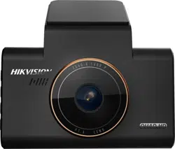
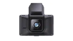
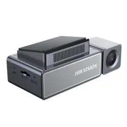
1.2 Overview
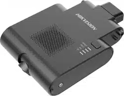
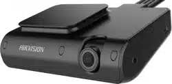
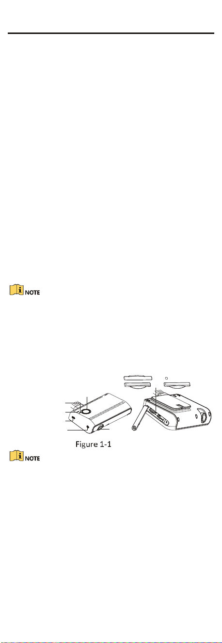
1.2.1 Camera
The overview of the camera is shown below.
USB Interface
Recording Indicator
4G Indicator
Wi-Fi AP Indicator
Lens
Mounting Screw
SIM
RESET
TF1
TF2
Overview
� You can also turn on/off Wi-Fi AP by pressing Wi-Fi AP
indicator.
� You can reboot the device by pressing RESET for 3s.

2
Indicator Status Description
REC
Indicator
Solid Recording is normal.
Unlit
Recording exception.
Check the TF card.
4G
Indicator
Solid
4G signal is normal;
platform has connected.
Flashing
4G signal is normal;
platform unconnected.
Unlit No signal.
Wi-FiAP
Indicator
Solid->
Fast
Flashing
Wi-Fi AP is on.
You can connectother
device to Wi-Fi AP.
Flashing
->Slow
Flashing
Wi-Fi AP is off.
Press it to turn on.
1.2.2 Cable
The device’s cables are shown in below.
8 PIN Expansion
Interface
4 PIN DBA Interface
4 PIN TVI
Interface
Power Cable
Alarm
Interface
OBD Port
Expansion Cable
Cable Description
� 4 PIN TVI Interface:connect 4 PIN TVI camera
� 4 PIN DBA Interface:connect 4 PIN DBA camera
� 8 PIN Expansion Interface:connects expansion cable,
involving:
1. Power Cable: connect ACC with vehicle’s ACC,
VCC with vehicle battery’s positive pole, GND with
vehicle battery’s negative pole.
2. Alarm Interface: connect 4 PIN alarm button. Press
alarm button to send alarm to the platform when in
emergency.
OBD Port: Connect serial port line for debugging.
� The camera connected should be compatible to the
device.
� The power supply of the dashboard camera subjects
to the specification.
3
2 Installation
Before you start:
� Please make sure that the device in the package is in
good condition and all the assembly parts are
included.
� Make sure that all the related equipment is power-off
during the installation.
� Check the specification of the products for the
installation environment.
� Check whether the power supply is matched with your
power output to avoid damage.
� Be sure that there is enough space to install the
camera and accessories.
� Make sure the part, which is used to install the camera,
is strong enough to withstand four times the weight of
the camera and the mounting.
� If the product does not function properly, please
contact your dealer or the nearest service center. Do
not disassemble the camera for repair or maintenance
by yourself.
� Do not pull and drag the camera cables hard.
2.1 Install TF Card and SIM Card
You can install TF card and SIM card according to needs.
� TF card will be overwritten when it’s full. The former
recording will be covered automatically. Please backup
recording when accident occurred.
� SIM card is used to connect 3G/4G network. The
installation of SIM card and TF card is same.
Steps:
1. Remove the screw, open the card cover.
Remove the screw.
Open Card Cover
2. Push the TF card (self-provided) into the slot
until you hear a click.
3. Cover back the card cover, and tighten the
screw.
4
2.2 Install Dashboard Camera
Steps:
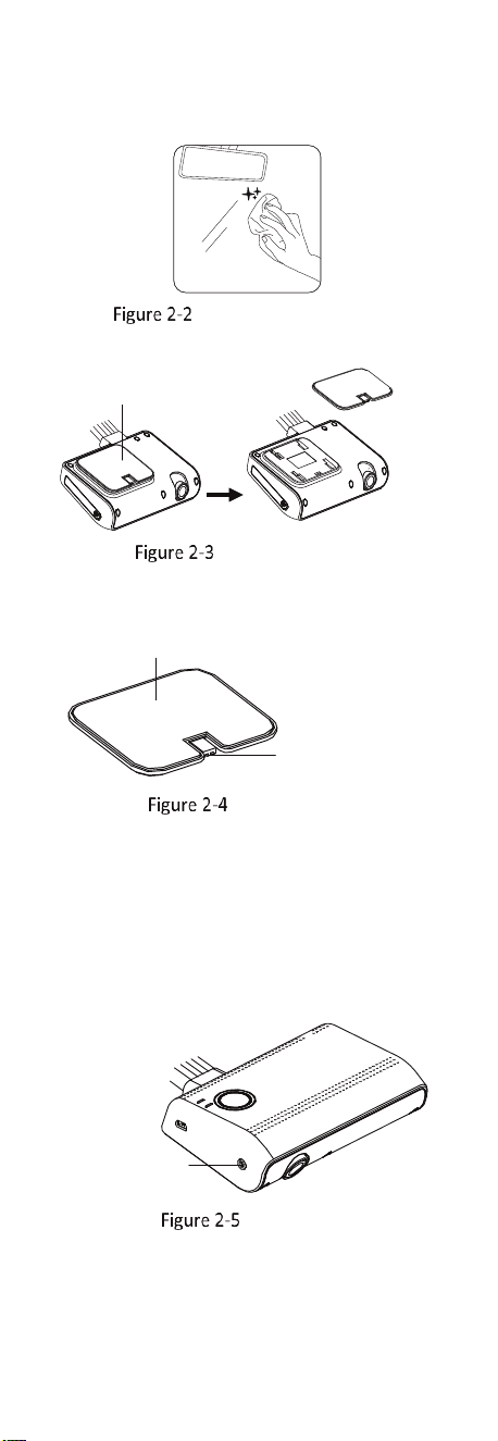
1. Clean the mounting surface with a mixture of
isopropyl and water.
Clean Mounting Surface
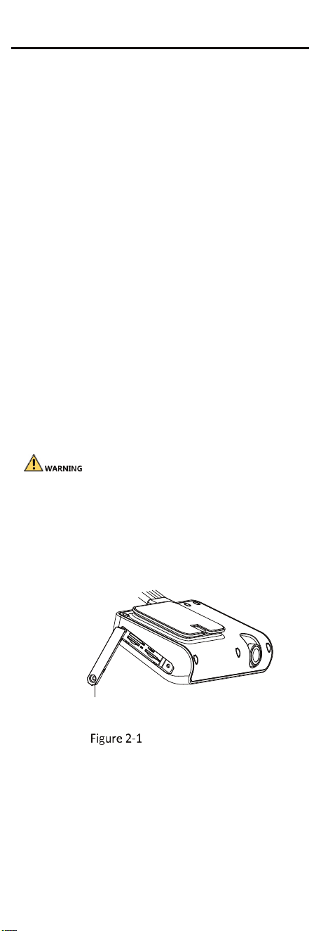
2. Remove the stand from the device.
Remove the s tand.
Remove the Stand
3. Peal the paster off the stand.
Paster
Stand Notch
Peal the Paster
4. Paste the stand to the mounting surface with
stand notch vertically downward.
5. Push the dashboard camera to the stand along
the notch direction, until the camera stuck to the
notch.
6. Adjust the lens to the target angle.
7. Remove the camera from the stand. Tighten the
set screw of the lens. Attach the camera to the stand
again. Installation finished.
Set Screw of
the Lens
Fix the Lens

5
2.3 Wiring and Start Device
Steps:
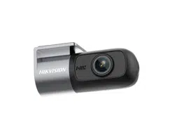
1. (Optional) Connect TVI camera to the dashboard
camera’s TVI interface according to needs.
2. Connect the dashboard camera’s power cable to
the vehicle’s battery:
a. Connect ACC with vehicle’s ACC;
b. Connect VCC with vehicle battery’s positive pole;
c. Connect GND with vehicle battery’s negative pole.
3. The dashboard camera starts automatically once the
vehicle started. Check the recording indicator.
If recording indicator is bright and steady, the camera is
started normally.
� Dashboard camera starts recording automatically after
powered on.
� Contact the dealer to obtain the APP to manage the
device.
3 Trouble Shooting
Trouble Solution
Starting dashcam
failed.
� Ensure the automobile’s battery
met the needs of the camera.
� Ensure the power cable is connected
normally.
� Ensure the automobile started
normally and the power supply is
normal.
Recording
failed.
� Ensure TF card is installed.
(8G, Class 10 or above)
� Check TF card status, e.g., its
format and lifespan. If it is not
well, replace it with a good
one.
Recorded
videos are
fuzzy.
� Tear off the proof film on lens.
� Clean the lens and glass.