Loading ...
Loading ...
Loading ...

GETTING STARTED
25
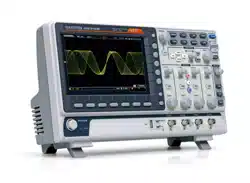
Display
Memory bar
Reference
waveform
Analog
Waveform
Bus
Channel status Horizontal status
Trigger
configuration
Waveform
frequency
Date and time
Trigger position
Trigger status
Acquistion mode
Trigger level
Channel
Indicators
Memory length
and sample rate
Analog
Waveforms
Shows the analog input signal waveforms.
Channel 1: Yellow
Channel 2: Blue
Channel 3: Pink
Channel 4: Green
Bus Waveforms
Shows the bus waveforms for serial buses. The
values are displayed in hex or binary.
Channel
Indicators
The channel indicators show the zero volt level of
the signal waveform for each activated channel.
Any active channel is shown with a solid color.
Analog channel indicator
Bus indicator(B)
Reference waveform indicator
Math indicator
Trigger Position
Shows the position of the trigger.
Horizontal Status
Shows the horizontal scale and position.
Date and Time
Current date and time (page 188).
Loading ...
Loading ...
Loading ...