Home
Bookmarks
Home
GW Instek
GW Instek GDS-2204E User Manual
Page 24
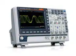
GW Instek GDS-2204E oscilloscope
GDS 2000E User Manual - Page 24
For GDS-2204E.
PDF File Manual
,
284 pages
,
Read Online
|
Download pdf file
SAFETY INSTRUCTIONS
Safety Symbols
Safety Guidelines
Power cord for the United Kingdom
GETTING STARTED
GDS-2000E Series Overview
Series lineup
Main Features
Accessories
Appearance
GDS-2074E/2104E/2204E Front Panel
GDS-2072E/2102E/2202E Front Panel
Rear Panel
Display
Set Up
Tilt Stand
Power Up
First Time Use
How to Use This Manual
Built-in Help
MEASUREMENT
Basic Measurement
Channel Activation
Autoset
Run/Stop
Horizontal Position/Scale
Vertical Position/Scale
Automatic Measurement
Measurement Items
Add Measurement
Remove Measurement
Gated mode
Display All mode
High Low Function
Statistics
Reference Levels
Cursor Measurement
Use Horizontal Cursors
Use Vertical Cursors
Math Operation
Basic Math Overview & Operators
Addition/Subtraction/Multiplication/Division
FFT Overview & Window Functions
FFT Operation
Advanced Math Overview
Advanced Math Operation
CONFIGURATION
Acquisition
Select Acquisition Mode
Show Waveform in XY Mode
Set the Record Length
Segmented Memory Acquisition Overview
Segments Display
Set the Number of Segments
Run Segmented Memory
Navigate Segmented Memory
Play Through Each Segment
Segment Measurement
Automatic Measurement
Segment Info
Display
Display Waveform as Dots or Vectors
Set the Level of Persistence
Set the Intensity Level
Select Display Graticule
Freeze the Waveform (Run/Stop)
Turn Off Menu
Horizontal View
Move Waveform Position Horizontally
Select Horizontal Scale
Select Waveform Update Mode
Zoom Waveform Horizontally
Play/Pause
Vertical View (Channel)
Move Waveform Position Vertically
Select Vertical Scale
Select Coupling Mode
Input Impedance
Invert Waveform Vertically
Limit Bandwidth
Expand by Ground/Center
Select Probe Type
Select Probe Attenuation Level
Set the Deskew
Bus Key Configuration
Bus Display
Serial Bus
Serial Bus Overview
UART Serial Bus Configuration
I2C Serial Bus Interface
SPI Serial Bus Interface
CAN Serial Bus Interface
LIN Serial Bus Interface
Bus Encoding
Threshold Configuration
Serial Bus Event Tables
Event Tables Format
Adding a Label to the Serial Bus
Using Cursors with the Serial Bus
Trigger
Trigger Type Overview
Trigger Parameter Overview
Setup Holdoff Level
Setup Trigger Mode
Using the Edge Trigger
Using Advanced Delay Trigger
Using Pulse Width Trigger
Using Video Trigger
Pulse Runt trigger
Using Rise and Fall Trigger
Using the Timeout Trigger
Using the Bus Trigger
UART BUS Trigger Settings
I2C Bus Trigger Settings
SPI Bus Trigger Settings
CAN Bus Trigger
LIN Bus Trigger
Common Bus Trigger Settings
Bus Trigger Mode
Search
Configuring Search Events
Copying Search Event To/From Trigger Events
Search Event Navigation
Save Search Marks
Setting/Clearing Single Search Events
FFT Peak
System Settings and Miscellaneous Settings
Select Menu Language
View System Information
Erase Memory
Set Date and Time
Probe Compensation Frequency
QR Code Reader Function
APPS
Applications
Overview
Running Applications
Using Go-NoGo
Using the DVM
Using the Data Logger
Using the Digital Filter
Remote Disk
Demo App
SAVE/RECALL
File Format/Utility
Image File Format
Waveform File Format
Spreadsheet File Format
Setup File Format
Create/Edit Labels
Save
File Type/Source/Destination
Save Image
Save Waveform
Save Setup
Recall
File Type/Source/Destination
Recall Default Panel Setting
Recall Waveform
Recall Setup
Reference Waveforms
Recall and Display Reference Waveforms
FILE UTILITIES
File Navigation
Create Folder
Rename File
Delete File or Folder
Copy File to USB
HARDCOPY KEY
Printer I/O Configuration
Print Output
Save - Hardcopy Key
REMOTE CONTROL CONFIG
Interface Configuration
Configure USB Interface
USB Functionality Check
Configure the Ethernet Interface
Configure Socket Server
Socket Server Functionality Check
MAINTENANCE
How to use SPC function
Vertical Accuracy Calibration
Probe Compensation
FAQ
I connected the signal but it does not appear on the display.
I want to remove the (Measurement result / FFT result / Help contents) from the display.
The waveform does not update (frozen).
The probe waveform is distorted.
Autoset does not catch the signal well.
The display image printout is too dark on the background.
The date and time settings are not correct.
The accuracy does not match the specification.
APPENDIX
Updating the Firmware
GDS-2000E Specifications
Model-specific
Common
Probe Specifications
GTP-070B -4
GTP-100B -4
GTP-200B -4
GDS-2000E Dimensions
INDEX
Page 24/284
Page 1
Page 2
Page 3
Page 4
Page 5
Page 6
Page 7
Page 8
Page 9
Page 10
Page 11
Page 12
Page 13
Page 14
Page 15
Page 16
Page 17
Page 18
Page 19
Page 20
Page 21
Page 22
Page 23
Page 24
Page 25
Page 26
Page 27
Page 28
Page 29
Page 30
Page 31
Page 32
Page 33
Page 34
Page 35
Page 36
Page 37
Page 38
Page 39
Page 40
Page 41
Page 42
Page 43
Page 44
Page 45
Page 46
Page 47
Page 48
Page 49
Page 50
Page 51
Page 52
Page 53
Page 54
Page 55
Page 56
Page 57
Page 58
Page 59
Page 60
Page 61
Page 62
Page 63
Page 64
Page 65
Page 66
Page 67
Page 68
Page 69
Page 70
Page 71
Page 72
Page 73
Page 74
Page 75
Page 76
Page 77
Page 78
Page 79
Page 80
Page 81
Page 82
Page 83
Page 84
Page 85
Page 86
Page 87
Page 88
Page 89
Page 90
Page 91
Page 92
Page 93
Page 94
Page 95
Page 96
Page 97
Page 98
Page 99
Page 100
Page 101
Page 102
Page 103
Page 104
Page 105
Page 106
Page 107
Page 108
Page 109
Page 110
Page 111
Page 112
Page 113
Page 114
Page 115
Page 116
Page 117
Page 118
Page 119
Page 120
Page 121
Page 122
Page 123
Page 124
Page 125
Page 126
Page 127
Page 128
Page 129
Page 130
Page 131
Page 132
Page 133
Page 134
Page 135
Page 136
Page 137
Page 138
Page 139
Page 140
Page 141
Page 142
Page 143
Page 144
Page 145
Page 146
Page 147
Page 148
Page 149
Page 150
Page 151
Page 152
Page 153
Page 154
Page 155
Page 156
Page 157
Page 158
Page 159
Page 160
Page 161
Page 162
Page 163
Page 164
Page 165
Page 166
Page 167
Page 168
Page 169
Page 170
Page 171
Page 172
Page 173
Page 174
Page 175
Page 176
Page 177
Page 178
Page 179
Page 180
Page 181
Page 182
Page 183
Page 184
Page 185
Page 186
Page 187
Page 188
Page 189
Page 190
Page 191
Page 192
Page 193
Page 194
Page 195
Page 196
Page 197
Page 198
Page 199
Page 200
Page 201
Page 202
Page 203
Page 204
Page 205
Page 206
Page 207
Page 208
Page 209
Page 210
Page 211
Page 212
Page 213
Page 214
Page 215
Page 216
Page 217
Page 218
Page 219
Page 220
Page 221
Page 222
Page 223
Page 224
Page 225
Page 226
Page 227
Page 228
Page 229
Page 230
Page 231
Page 232
Page 233
Page 234
Page 235
Page 236
Page 237
Page 238
Page 239
Page 240
Page 241
Page 242
Page 243
Page 244
Page 245
Page 246
Page 247
Page 248
Page 249
Page 250
Page 251
Page 252
Page 253
Page 254
Page 255
Page 256
Page 257
Page 258
Page 259
Page 260
Page 261
Page 262
Page 263
Page 264
Page 265
Page 266
Page 267
Page 268
Page 269
Page 270
Page 271
Page 272
Page 273
Page 274
Page 275
Page 276
Page 277
Page 278
Page 279
Page 280
Page 281
Page 282
Page 283
Page 284
Contents
Table of Contents
Search
Previous
Next
Bookmarks
Loading ...
Loading ...
Loading ...
GDS-2000E Series
User Manual
24
Power Input
Socket
Power cord socket accepts
AC
mains, 100 ~ 240
V, 50/60Hz.
For power up sequence,
see pa
ge
28
.
Security Slot
Kensington security slo
t
compatible.
Go
-No Go
Output
Outputs Go-No
Go test results
(page
194
) as
a 500
us pulse signal.
Loading ...
Loading ...
Loading ...
File type: PDF
File name: 75181416_gds-2104e.pdf
File size: 7.75 MB
File Language: English
Pages: 284
Author: GW Instek
File created: 2016-04-21
Published:
2024-01-16
Updated: 2024-01-15
Download File
Table of Contents
×
SAFETY INSTRUCTIONS
5
Safety Symbols
5
Safety Guidelines
6
Power cord for the United Kingdom
9
GETTING STARTED
10
GDS-2000E Series Overview
11
Series lineup
11
Main Features
12
Accessories
13
Appearance
15
GDS-2074E/2104E/2204E Front Panel
15
GDS-2072E/2102E/2202E Front Panel
16
Rear Panel
23
Display
25
Set Up
27
Tilt Stand
27
Power Up
28
First Time Use
29
How to Use This Manual
32
Built-in Help
37
MEASUREMENT
38
Basic Measurement
39
Channel Activation
39
Autoset
40
Run/Stop
42
Horizontal Position/Scale
43
Vertical Position/Scale
45
Automatic Measurement
46
Measurement Items
46
Add Measurement
50
Remove Measurement
52
Gated mode
53
Display All mode
54
High Low Function
55
Statistics
56
Reference Levels
59
Cursor Measurement
60
Use Horizontal Cursors
60
Use Vertical Cursors
64
Math Operation
68
Basic Math Overview & Operators
68
Addition/Subtraction/Multiplication/Division
68
FFT Overview & Window Functions
70
FFT Operation
71
Advanced Math Overview
73
Advanced Math Operation
74
CONFIGURATION
78
Acquisition
81
Select Acquisition Mode
81
Show Waveform in XY Mode
83
Set the Record Length
85
Segmented Memory Acquisition Overview
86
Segments Display
88
Set the Number of Segments
89
Run Segmented Memory
90
Navigate Segmented Memory
92
Play Through Each Segment
92
Segment Measurement
94
Automatic Measurement
94
Segment Info
98
Display
99
Display Waveform as Dots or Vectors
99
Set the Level of Persistence
100
Set the Intensity Level
100
Select Display Graticule
103
Freeze the Waveform (Run/Stop)
104
Turn Off Menu
104
Horizontal View
105
Move Waveform Position Horizontally
105
Select Horizontal Scale
106
Select Waveform Update Mode
107
Zoom Waveform Horizontally
108
Play/Pause
111
Vertical View (Channel)
114
Move Waveform Position Vertically
114
Select Vertical Scale
115
Select Coupling Mode
115
Input Impedance
116
Invert Waveform Vertically
116
Limit Bandwidth
117
Expand by Ground/Center
118
Select Probe Type
119
Select Probe Attenuation Level
120
Set the Deskew
120
Bus Key Configuration
122
Bus Display
122
Serial Bus
124
Serial Bus Overview
124
UART Serial Bus Configuration
126
I2C Serial Bus Interface
128
SPI Serial Bus Interface
129
CAN Serial Bus Interface
131
LIN Serial Bus Interface
132
Bus Encoding
133
Threshold Configuration
134
Serial Bus Event Tables
136
Event Tables Format
140
Adding a Label to the Serial Bus
141
Using Cursors with the Serial Bus
143
Trigger
145
Trigger Type Overview
145
Trigger Parameter Overview
147
Setup Holdoff Level
152
Setup Trigger Mode
153
Using the Edge Trigger
153
Using Advanced Delay Trigger
155
Using Pulse Width Trigger
156
Using Video Trigger
158
Pulse Runt trigger
159
Using Rise and Fall Trigger
161
Using the Timeout Trigger
162
Using the Bus Trigger
164
UART BUS Trigger Settings
164
I2C Bus Trigger Settings
165
SPI Bus Trigger Settings
169
CAN Bus Trigger
171
LIN Bus Trigger
174
Common Bus Trigger Settings
176
Bus Trigger Mode
176
Search
177
Configuring Search Events
177
Copying Search Event To/From Trigger Events
179
Search Event Navigation
179
Save Search Marks
180
Setting/Clearing Single Search Events
181
FFT Peak
182
System Settings and Miscellaneous Settings
186
Select Menu Language
186
View System Information
187
Erase Memory
187
Set Date and Time
188
Probe Compensation Frequency
189
QR Code Reader Function
189
APPS
191
Applications
192
Overview
192
Running Applications
193
Using Go-NoGo
194
Using the DVM
199
Using the Data Logger
201
Using the Digital Filter
203
Remote Disk
205
Demo App
208
SAVE/RECALL
214
File Format/Utility
215
Image File Format
215
Waveform File Format
215
Spreadsheet File Format
216
Setup File Format
218
Create/Edit Labels
220
Save
223
File Type/Source/Destination
223
Save Image
224
Save Waveform
227
Save Setup
229
Recall
231
File Type/Source/Destination
231
Recall Default Panel Setting
232
Recall Waveform
234
Recall Setup
235
Reference Waveforms
237
Recall and Display Reference Waveforms
237
FILE UTILITIES
239
File Navigation
240
Create Folder
242
Rename File
243
Delete File or Folder
244
Copy File to USB
245
HARDCOPY KEY
246
Printer I/O Configuration
246
Print Output
247
Save - Hardcopy Key
248
REMOTE CONTROL CONFIG
250
Interface Configuration
251
Configure USB Interface
251
USB Functionality Check
252
Configure the Ethernet Interface
253
Configure Socket Server
255
Socket Server Functionality Check
256
MAINTENANCE
262
How to use SPC function
263
Vertical Accuracy Calibration
264
Probe Compensation
265
FAQ
268
I connected the signal but it does not appear on the display.
268
I want to remove the (Measurement result / FFT result / Help contents) from the display.
268
The waveform does not update (frozen).
269
The probe waveform is distorted.
269
Autoset does not catch the signal well.
269
The display image printout is too dark on the background.
269
The date and time settings are not correct.
269
The accuracy does not match the specification.
270
APPENDIX
271
Updating the Firmware
271
GDS-2000E Specifications
273
Model-specific
273
Common
274
Probe Specifications
277
GTP-070B -4
277
GTP-100B -4
277
GTP-200B -4
278
GDS-2000E Dimensions
279
INDEX
281
Search:
×
Search