Air conditioner
User manual
AJ***NBNDEH
• Thank you for purchasing this Samsung air conditioner.
• Before operating this unit, please read this user manual carefully and retain it for future reference.

2
English
Contents
Safety Information 4
Safety Information 4
At a Glance 11
Indoor Unit Overview 11
Operation Features 12
Operating temperature and humidity
Cleaning and Maintenance 13
Cleaning and Maintaining 13
Cleaning the indoor unit exterior • Cleaning the outdoor unit heat exchanger
Cleaning the air filter • Periodical maintenance • Troubleshooting
Installation 19
Safety Information on Installation 19
Installation Procedure 21
Step 1 Checking and preparing accessories
Step 2 Choosing the installation location
Step 3 Optional: Insulating the body of the indoor unit
Step 4 Installing the indoor unit
Step 5 Purging inert gas from the indoor unit
Step 6 Cutting and flaring the pipes
Step 7 Connecting the assembly pipes to the refrigerant pipes
Step 8 Performing the gas leak test
Step 9 Insulating the refrigerant pipes
Step 10 Installing the drain hose and drain pipe
Step 11 Performing the drainage test
Step 12 Connecting the power and communication cables
Step 13 Optional: Extending the power cable
Step 14 Setting the indoor unit addresses and the installation options
Troubleshooting 45
3
English
Correct Disposal of This Product
(Waste Electrical & Electronic Equipment)
(Applicable in countries with separate collection systems)
This marking on the product, accessories or literature indicates that the product and its electronic accessories (e.g. charger, headset, USB cable) should
not be disposed of with other household waste at the end of their working life. To prevent possible harm to the environment or human health from
uncontrolled waste disposal, please separate these items from other types of waste and recycle them responsibly to promote the sustainable reuse of
material resources.
Household users should contact either the retailer where they purchased this product, or their local government office, for details of where and how they
can take these items for environmentally safe recycling.
Business users should contact their supplier and check the terms and conditions of the purchase contract. This product and its electronic accessories
should not be mixed with other commercial wastes for disposal.
Safety Information
Safety Information
4
English
Before using your new air conditioner, please read this manual thoroughly
to ensure that you know how to safely and efficiently operate the extensive
features and functions of your new appliance.
Because the following operating instructions cover various models, the
characteristics of your air conditioner may differ slightly from those described in
this manual. If you have any questions, call your nearest contact centre or find
help and information online at www.samsung.com.
WARNING
Hazards or unsafe practices that may result in severe personal injury or death.
CAUTION
Hazards or unsafe practices that may result in minor personal injury or property
damage.
Follow directions.
Do NOT attempt.
Make sure the machine is grounded to prevent electric shock.
Cut-off the power supply.
Do NOT disassemble.
FOR INSTALLATION
WARNING
Use the power line with the power specifications of the product or higher
and use the power line for this appliance only. In addition, do not use an
extension line.
• Extending the power line may result in electric shock or fire.
• Do not use an electric transformer. This may result in electric shock or fire.
• If the voltage/frequency/rated current condition is different, it may cause fire.
Safety Information
Safety Information
Safety Information
5
English
The installation of this appliance must be performed by a qualified
technician or service company.
• Failing to do so may result in electric shock, fire, explosion, problems with
the product, or injury.
Install a switch and circuit breaker dedicated to the air conditioner.
• Failing to do so may result in electric shock or fire.
Fix the outdoor unit firmly so that the electric part of the outdoor unit is
not exposed.
• Failing to do so may result in electric shock or fire.
Do not install this appliance near a heater, inflammable material. Do
not install this appliance in a humid, oily or dusty location, in a location
exposed to direct sunlight and water (rain drops). Do not install this
appliance in a location where gas may leak.
• This may result in electric shock or fire.
Never install the outdoor unit in a location such as on a high external wall
where it could fall.
• If the outdoor unit falls, it may result in injury, death or property damage.
This appliance must be properly grounded. Do not ground the appliance to
a gas pipe, plastic water pipe, or telephone line.
• Failure to do so may result in electric shock, fire, an explosion, or other
problems with the product.
• Never plug the power cord into a socket that is not grounded correctly
and make sure that it is in accordance with local and national codes.
Safety Information
Safety Information
6
English
CAUTION
Install your appliance on a level and hard floor that can support its weight.
• Failing to do so may result in abnormal vibrations, noise, or problems with
the product.
Install the drain hose properly so that water is drained correctly.
• Failing to do so may result in water overflowing and property damage.
Avoid adding drain to waste pipes as odours may arise in the future.
When installing the outdoor unit, make sure to connect the drain hose so
that draining is performed correctly.
• The water generated during the heating operation in the outdoor unit
may overflow and result in property damage.
In particular, in winter, if a block of ice falls, it may result in injury, death
or property damage.
FOR POWER SUPPLY
WARNING
When the circuit breaker is damaged, contact your nearest service centre.
Do not pull or excessively bend the power line. Do not twist or tie the
power line. Do not hook the power line over a metal object, place a heavy
object on the power line, insert the power line between objects, or push
the power line into the space behind the appliance.
• This may result in electric shock or fire.
CAUTION
When not using the air conditioner for a long period of time or during a
thunder/lightning storm, cut the power at the circuit breaker.
• Failing to do so may result in electric shock or fire.
Safety Information
7
English
FOR USING
WARNING
If the appliance is flooded, please contact your nearest service centre.
• Failing to do so may result in electric shock or fire.
If the appliance generates a strange noise, a burning smell or smoke,
unplug the power plug immediately and contact your nearest service
centre.
• Failing to do so may result in electric shock or fire.
In the event of a gas leak (such as propane gas, LP gas, etc.), ventilate
immediately without touching the power line. Do not touch the appliance
or power line.
• Do not use a ventilating fan.
• A spark may result in an explosion or fire.
To reinstall the air conditioner, please contact your nearest service centre.
• Failing to do so may result in problems with the product, water leakage,
electric shock, or fire.
• A delivery service for the product is not provided. If you reinstall the
product in another location, additional construction expenses and an
installation fee will be charged.
• Especially, when you wish to install the product in an unusual location
such as in an industrial area or near the seaside where it is exposed to salt
in the air, please contact your nearest service centre.
Do not touch the circuit breaker with wet hands.
• This may result in electric shock.
Do not turn the air conditioner off with the circuit breaker while it is
operating.
• Turning the air conditioner off and then on again with the circuit breaker
may cause a spark and result in electric shock or fire.

Safety Information
Safety Information
8
English
After unpacking the air conditioner, keep all packaging materials well
out of the reach of children, as packaging materials can be dangerous to
children.
• If a child places a bag over its head, it may result in suffocation.
Do not touch the front panel with your hands or fingers during the heating
operation.
• This may result in electric shock or burns.
Do not insert your fingers or foreign substances into the outlet when the
air conditioner is operating or the front panel is closing.
• Take special care that children do not injure themselves by inserting their
fingers into the product.
Do not insert your fingers or foreign substances into the air inlet/outlet of
the air conditioner.
• Take special care that children do not injure themselves by inserting their
fingers into the product.
Do not strike or pull the air conditioner with excessive force.
• This may result in fire, injury, or problems with the product.
Do not place an object near the outdoor unit that allows children to climb
onto the machine.
• This may result in children seriously injuring themselves.
Do not use this air conditioner for long periods of time in badly ventilated
locations or near infirm people.
• Since this may be dangerous due to a lack of oxygen, open a window at
least once an hour.
If any foreign substance such as water has entered the appliance, cut the
power by unplugging the power plug and turning the circuit breaker off
and then contact your nearest service centre.
• Failing to do so may result in electric shock or fire.
Do not attempt to repair, disassemble, or modify the appliance yourself.
• Do not use any fuse (such as copper, steel wire, etc.)other than the
standard fuse.
• Failing to do so may result in electric shock, fire, problems with the
product, or injury.
Safety Information
9
English
CAUTION
Do not place objects or devices under the indoor unit.
• Water dripping from the indoor unit may result in fire or property damage.
Check that the installation frame of the outdoor unit is not broken at least
once a year.
• Failing to do so may result in injury, death or property damage.
Max current is measured according to IEC standard for safety and current
is measured according to ISO standard for energy efficiency.
Do not stand on top of the appliance or place objects (such as laundry,
lighted candles, lighted cigarettes, dishes, chemicals, metal objects, etc.)
on the appliance.
• This may result in electric shock, fire, problems with the product, or injury.
Do not operate the appliance with wet hands.
• This may result in electric shock.
Do not spray volatile material such as insecticide onto the surface of the
appliance.
• As well as being harmful to humans, it may also result in electric shock,
fire or problems with the product.
Do not drink the water from the air conditioner.
• The water may be harmful to humans.
Do not apply a strong impact to the remote controller and do not
disassemble the remote controller.
Do not touch the pipes connected with the product.
• This may result in burns or injury.
Do not use this air conditioner to preserve precision equipment, food,
animals, plants or cosmetics, or for any other unusual purposes.
• This may result in property damage.
Avoid directly exposing humans, animals or plants to the air flow from the
air conditioner for long periods of time.
• This may result in harm to humans, animals or plants.
Safety Information
Safety Information
10
English
This appliance is not intended for use by persons (including children) with
reduced physical, sensory or mental capabilities, or lack of experience and
knowledge, unless they have been given supervision or instruction concerning
use of the appliance by a person responsible for their safety. Children should
be supervised to ensure that they do not play with the appliance.
FOR CLEANING
WARNING
Do not clean the appliance by spraying water directly onto it. Do not use
benzene, thinner, alcohol or acetone to clean the appliance.
• This may result in discoloration, deformation, damage, electric shock or
fire.
Before cleaning or performing maintenance, unplug the air conditioner
from the wall socket and wait until the fan stops.
• Failing to do so may result in electric shock or fire.
CAUTION
Take care when cleaning the surface of the heat exchanger of the outdoor
unit since it has sharp edges.
• To avoid cutting your fingers, wear thick cotton gloves when cleaning it.
• This should be done by a qualified technician please contact your installer
or service centre.
Do not clean the inside of the air conditioner by yourself.
• For cleaning inside the appliance, contact your nearest service centre.
• When cleaning the internal filter, refer to the descriptions in the ‘Cleaning
and Maintaining’ section.
• Failure to do may result in damage, electric shock or fire.
At a Glance
11
English
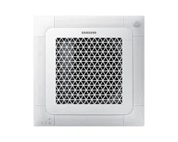
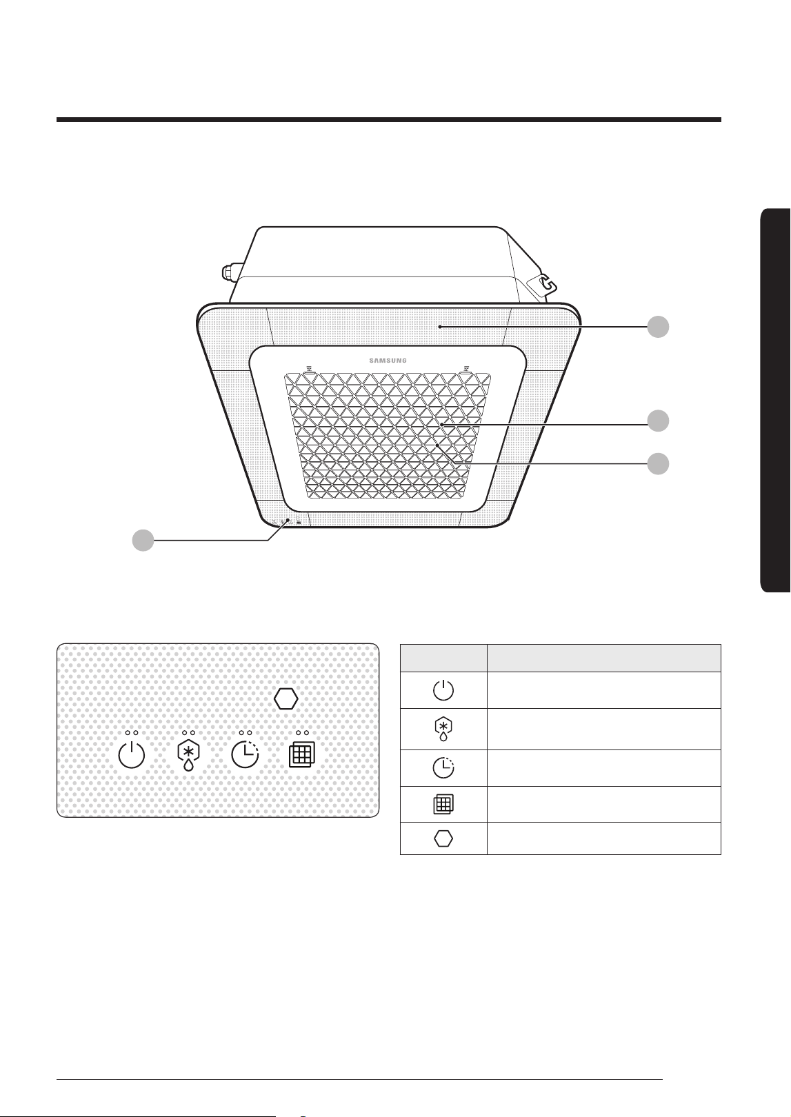
The indoor unit and its display may look slightly different from the illustration shown below,
depending on the model and the panel type.
Indoor Unit Overview
02
04
03
01
At a Glance
01 Display
02 Air flow blade/Air outlet (inside) /
Wind-Free panel
(You can use the Wind-Free Cooling function
when the Cool, Dry, or Fan mode is running.)
(Refer to the remote control manual for
product operation.)
03 Air intake
04 Air filter (under the grille)
Indication Function
On/Off operation indicator
Removing frost indicator
Timer indicator
Filter cleaning indicator
Remote control sensor
At a Glance
12
English
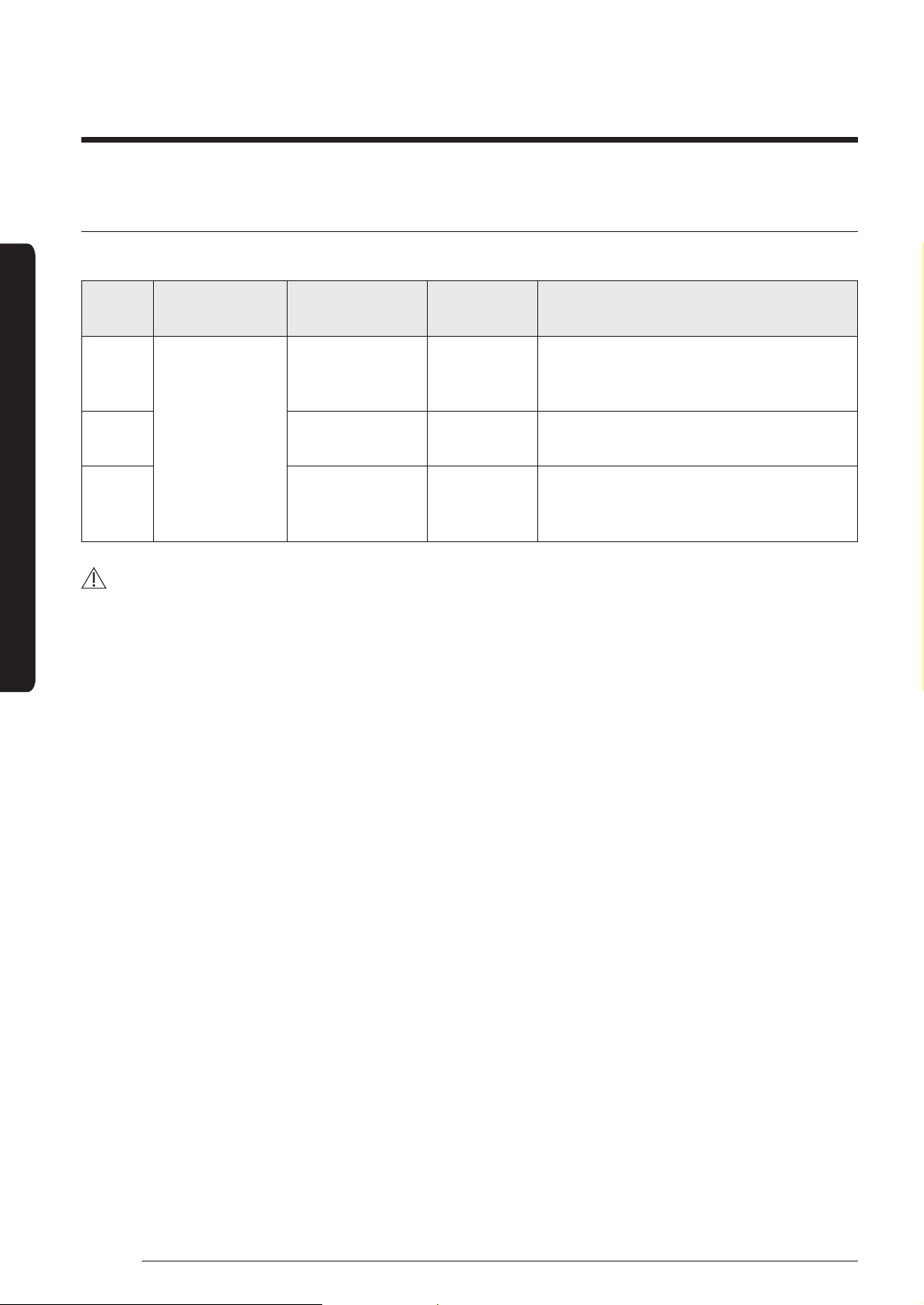
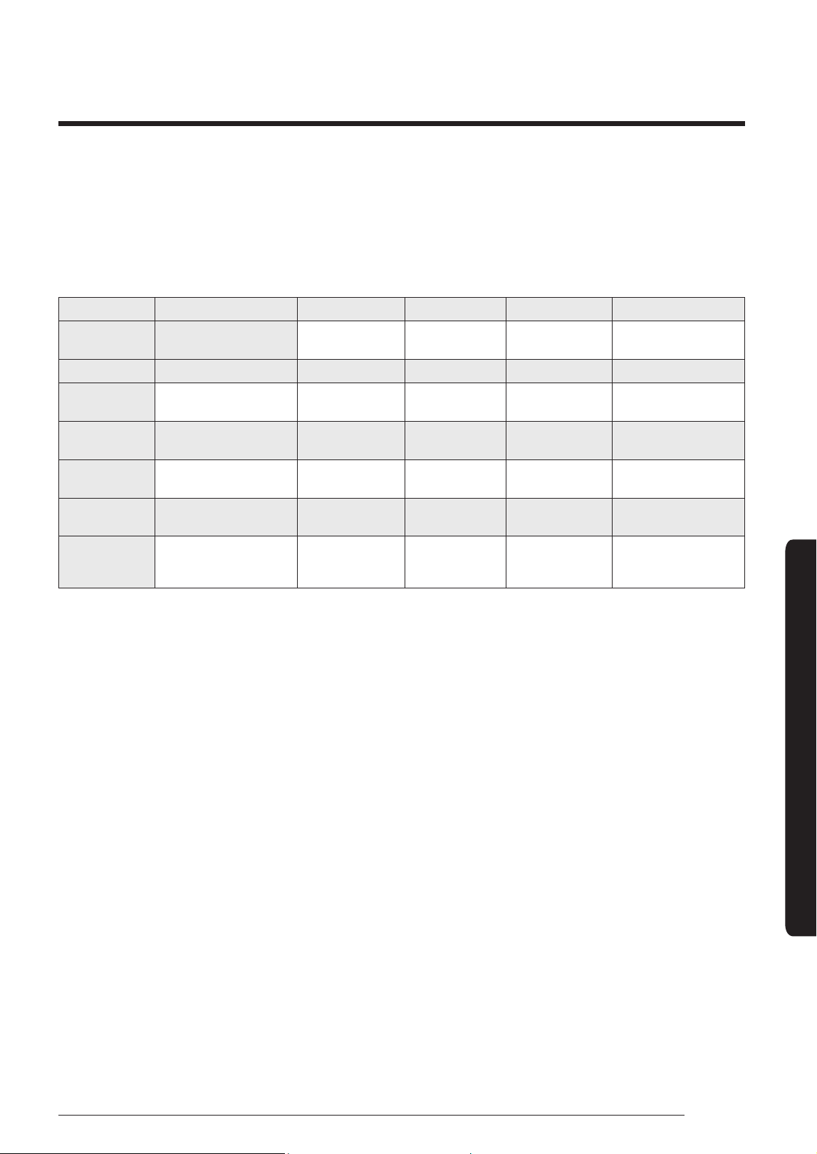
Operation Features
Operating temperature and humidity
When using the air conditioner follow the operating temperature and humidity ranges.
Mode
Outdoor
temperature
Indoor
temperature
Indoor
humidity
If out of conditions
Cool
mode
Depending
on the
outdoor unit
specifications
16˚C to 32˚C 80% or less
Condensation may occur on the indoor
unit with risk to have either water
blow off or drop on the floor.
Heat
mode
27˚C or less
Internal protection triggers and the air
conditioner will stop.
Dry
mode
18˚C to 32˚C
Condensation may occur on the indoor
unit with risk to have either water
blow off or drop on the floor.
CAUTION
• If you use the air conditioner at a relative humidity above 80%, it may cause a formation of
condensation and a leakage of water on the floor.
• The standardized temperature for heating is 7˚C. If the outdoor temperature drops to 0˚C or
below, the heating capacity can be reduced depending on the temperature condition.If the
cooling operation is used at over 32˚C (indoor temperature), it does not cool at its full capacity.
• If the indoor unit is out of the operating temperature and humidity range, the safery device may
operate and the air conditioner may stops.
13
English
Cleaning and Maintenance
Before cleaning the indoor unit, be sure to turn off the auxiliary power switch.
Cleaning and Maintaining
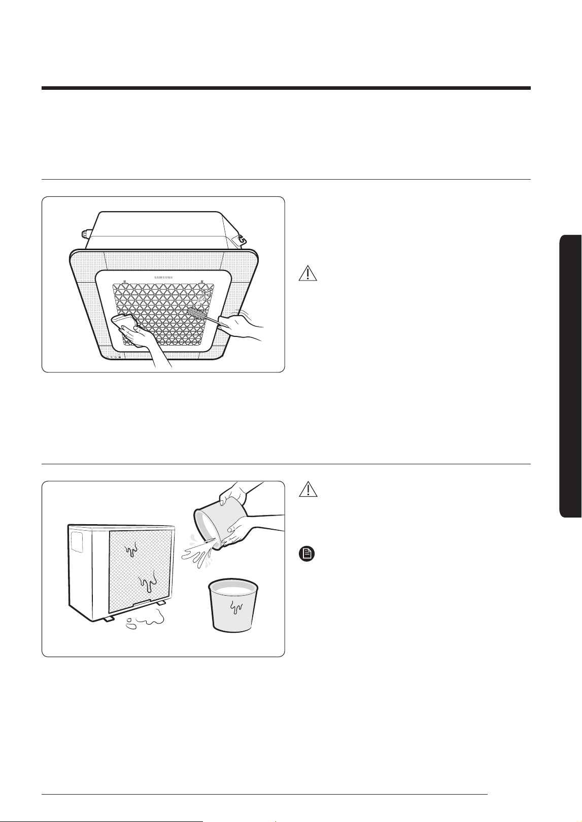
Cleaning the indoor unit exterior
Wipe the surface of the unit with a slightly wet
or dry cloth when needed. Wipe off dirt of odd-
shaped areas by using a soft brush.
CAUTION
• Do not use alkaline detergent, sulphuric
acid, hydrochloric acid, or organic solvents
(such as thinner, kerosene, and acetone) to
clean the surfaces.
• Do not attach any stickers on the surfaces
because this may cause damage.
• When you clean the heat exchanger on the
indoor unit, you need to disassemble the
indoor unit. Therefore, you must contact the
local service center for help.
Cleaning the outdoor unit heat exchanger
Spray water to clean the dust.
CAUTION
• The heat exchanger of the outdoor unit has
sharp edges. Take care when cleaning its
surface.
NOTE
• If it is difficult to clean the heat exchanger
of the outdoor unit, contact the local service
center.
Cleaning and Maintenance
14
English
Cleaning and Maintaining
Cleaning and Maintenance
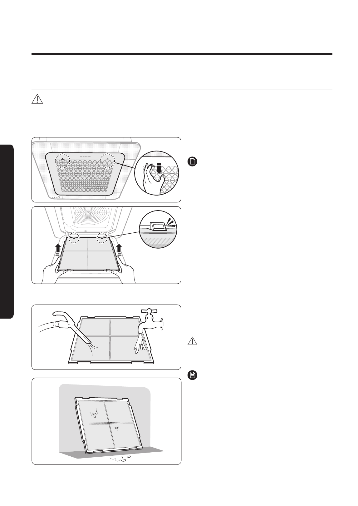
Cleaning the air filter
CAUTION
• Be sure to hold the grille with a hand to prevent dropping from the opening of the front grille.
1 Detaching the air filter
Push down the hooks at each side of the front
grille to open the grille.
NOTE
• The hooks are located on both sides of the
front grill with the Samsung logo.
Pull out the air filter from the indoor unit.
2 Cleaning the air filter
Clean the air filter with a vacuum cleaner or soft
brush. If dust is too heavy, then rinse it with
running water and dry it in a ventilated area.
CAUTION
Do not scrub the air filter with a brush or other
cleaning utensil. This may damage the filter.
NOTE
• If the air filter dries in a humid area, it may
produce offensive odours. Clean it again and
dry it in a well-ventilated area.
• The cleaning period may differ depending on
the usage and environmental conditions, so
clean the air filter every week if the indoor
unit is in the dusty area.
15
English
Cleaning and Maintenance
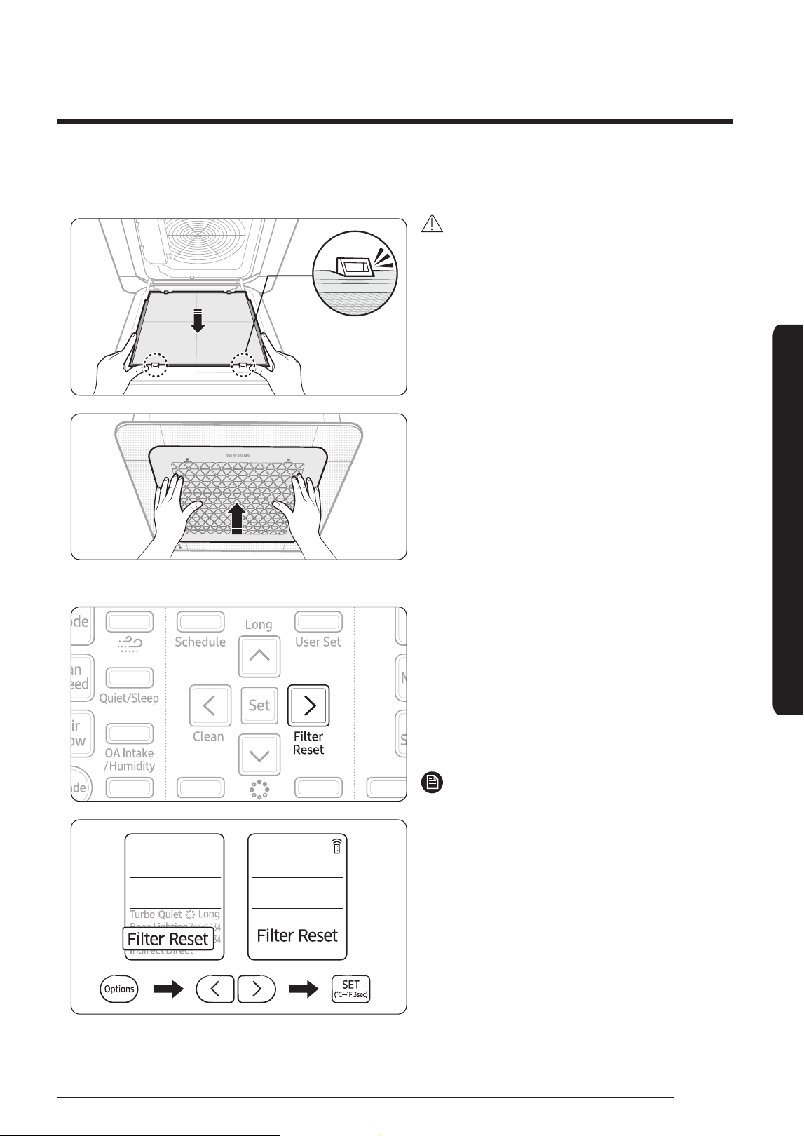
3 Reassembling the air filter
CAUTION
• If the indoor unit is used without the air filter,
the indoor unit may be damaged due to dust.
4 Resetting the air filter (Wired remote control is an optional item)
After cleaning and reassembling the air filter,
be sure to reset the filter-cleaning reminder as
follows:
• Indoor unit with the wired remote control:
Press the Filter Reset button.
• Indoor unit with the wireless remote control:
Press the Options button → < or > → (Filter
Reset) Blinking → press the SET button.
NOTE
• The filter reset indicator blinks when the air
filter should be cleaned.
• If the angle of the air flow blade is changed
by opening the front grille for installation
or maintenance of the indoor unit, be sure
to turn off and then on the auxiliary switch
before operating the indoor unit again. If
not, the angle of the air flow blade may be
changed and the blades may not be closed
after turning off the indoor unit.
16
English
Cleaning and Maintaining
Cleaning and Maintenance
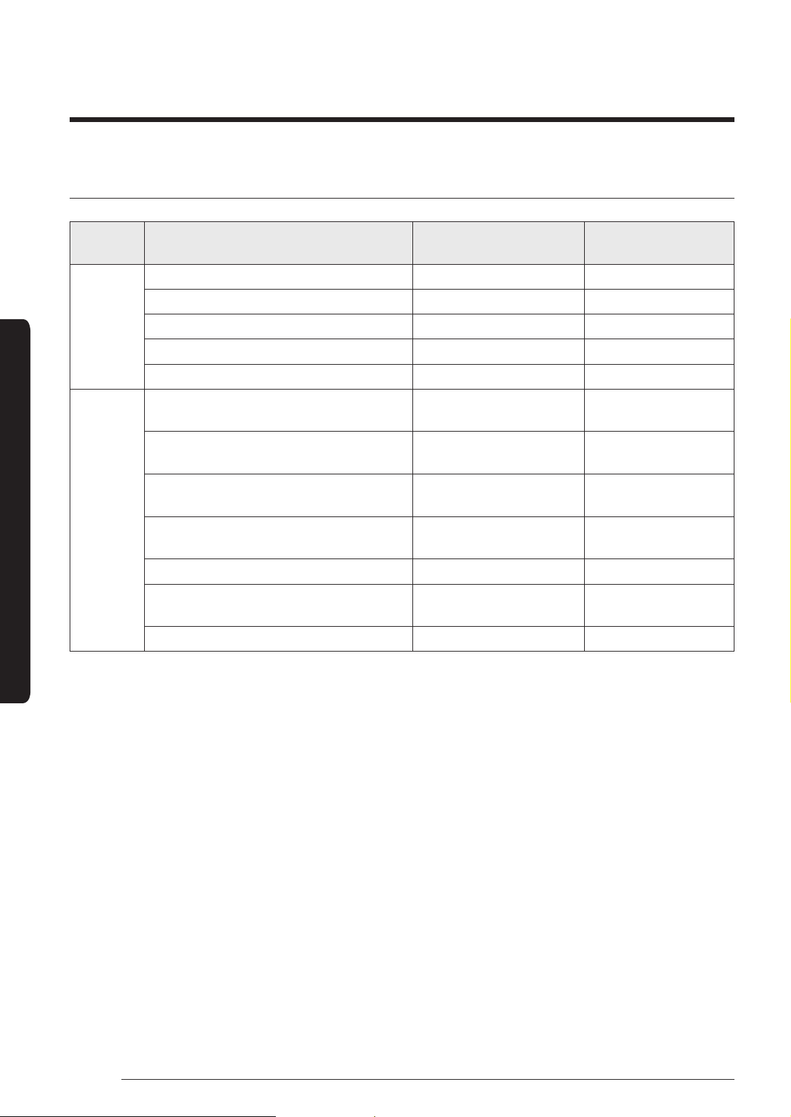
Periodical maintenance
Unit Maintenance item Interval
Requires qualified
technicians
Indoor
unit
Clean the air filter. At least once a month
Clean the condensate drain pan. Once a year Required
Clean up the heat exchange. Once a year Required
Clean the condensate drain pipe. Once every 4 months Required
Replace the remote control batteries. At least once a year
Outdoor
unit
Clean the heat exchanger on the
outside of the unit.
Once every 4 months Required
Clean the heat exchanger on the
inside of the unit.
Once a year Required
Clean the electric components with
jets of air.
Once a year Required
Verify that all the electric
components are firmly tightened.
Once a year Required
Clean the fan. Once a year Required
Verify that the fan assemblies are
firmly tightened.
Once a year Required
Clean the condensate drain pan. Once a year Required
17
English
Cleaning and Maintenance
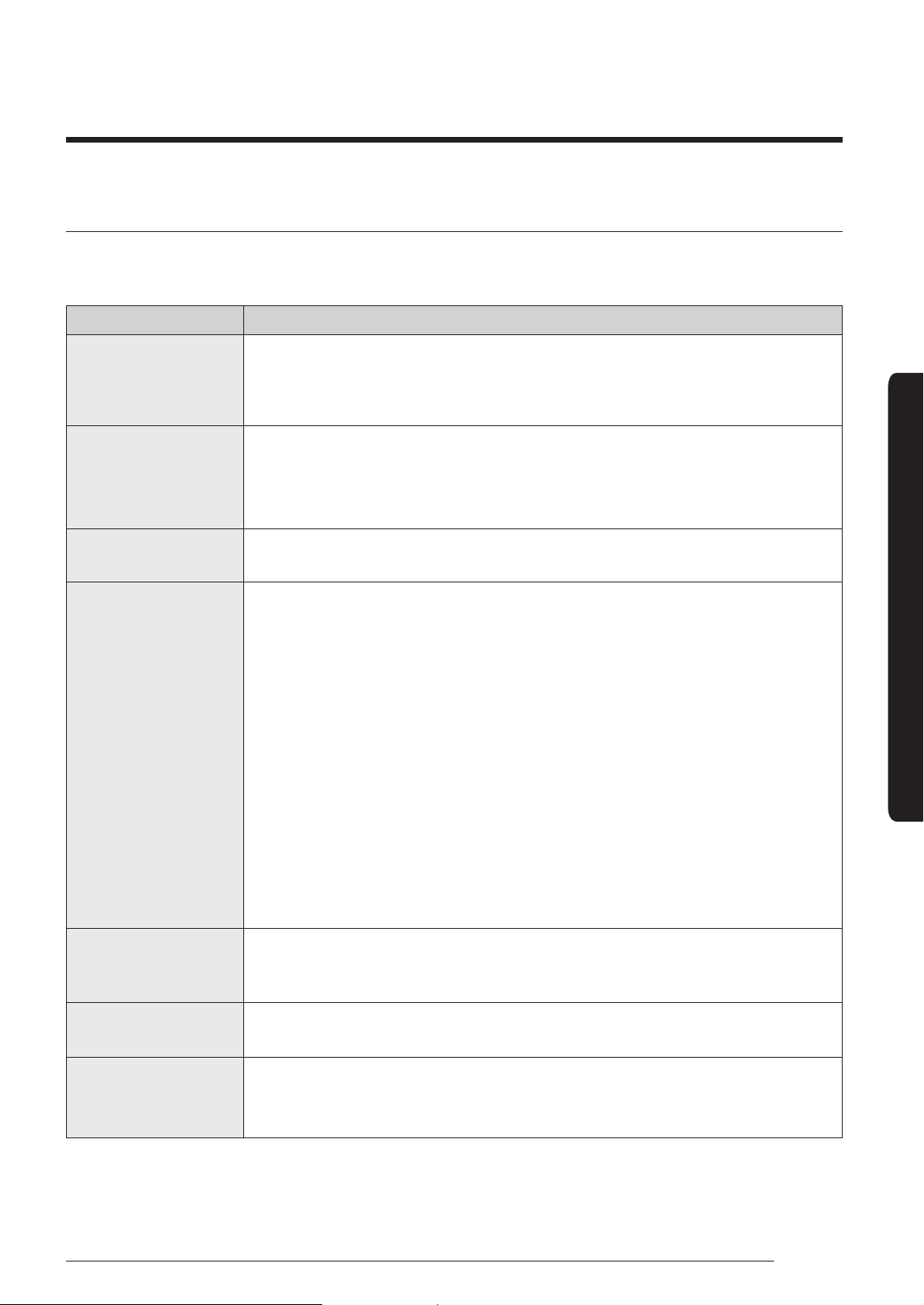
Troubleshooting
Refer to the following chart if the air conditioner operates abnormally. This may save time and
unnecessary expense.
Problem Solution
The air conditioner
does not operate
immediately after it
has been restarted.
• Because of the protective mechanism, the appliance does not start
operating immediately to keep the unit from overloading. The air
conditioner will start in 3 minutes.
The air conditioner
does not work at
all.
• Check power status and then operate the air conditioner again.
• Check if the circuit breaker is switched off.
• Check if there is a power failure.
• Check your fuse. Make sure it is not blown out.
The temperature
does not change.
• Check if you selected Fan mode.
Press the Mode button on the remote control to select another mode.
The cool (warm)
air does not come
out of the air
conditioner.
• Check if the set temperature is higher (lower) than the current
temperature. Press the Temperature button on the remote control to
change the set temperature. Press the Temperature button to decrease
or increase the temperature.
• Check if the air filter is blocked by dirt. Clean the air filter every two
weeks.
• Check if the air conditioner has just been turned on. If so, wait 3
minutes. Cool air does not come out to protect the compressor of the
outdoor unit.
• Check if the air conditioner is installed in a place with a direct exposure
to sunlight. Hang curtains on windows to boost cooling efficiency.
• Check if the cover or any obstacle is not near the outdoor unit.
• Check if the refrigerant pipe is too long.
• Check if the air conditioner is only available in Cool mode.
• Check if the remote control is only available for cooling model.
The fan speed does
not change.
• Check if you selected Auto or Dry mode.
The air conditioner automatically adjusts the fan speed to Auto in Auto/
Dry mode.
Timer function does
not set.
• Check if you press the Power button on the remote control after you
have set the time.
Odors permeate in
the room during
operation.
• Check if the appliance is running in a smoky area or if there is a smell
entering from outside. Operate the air conditioner in Fan mode or open
the windows to air out the room.
18
English
Cleaning and Maintaining
Cleaning and Maintenance
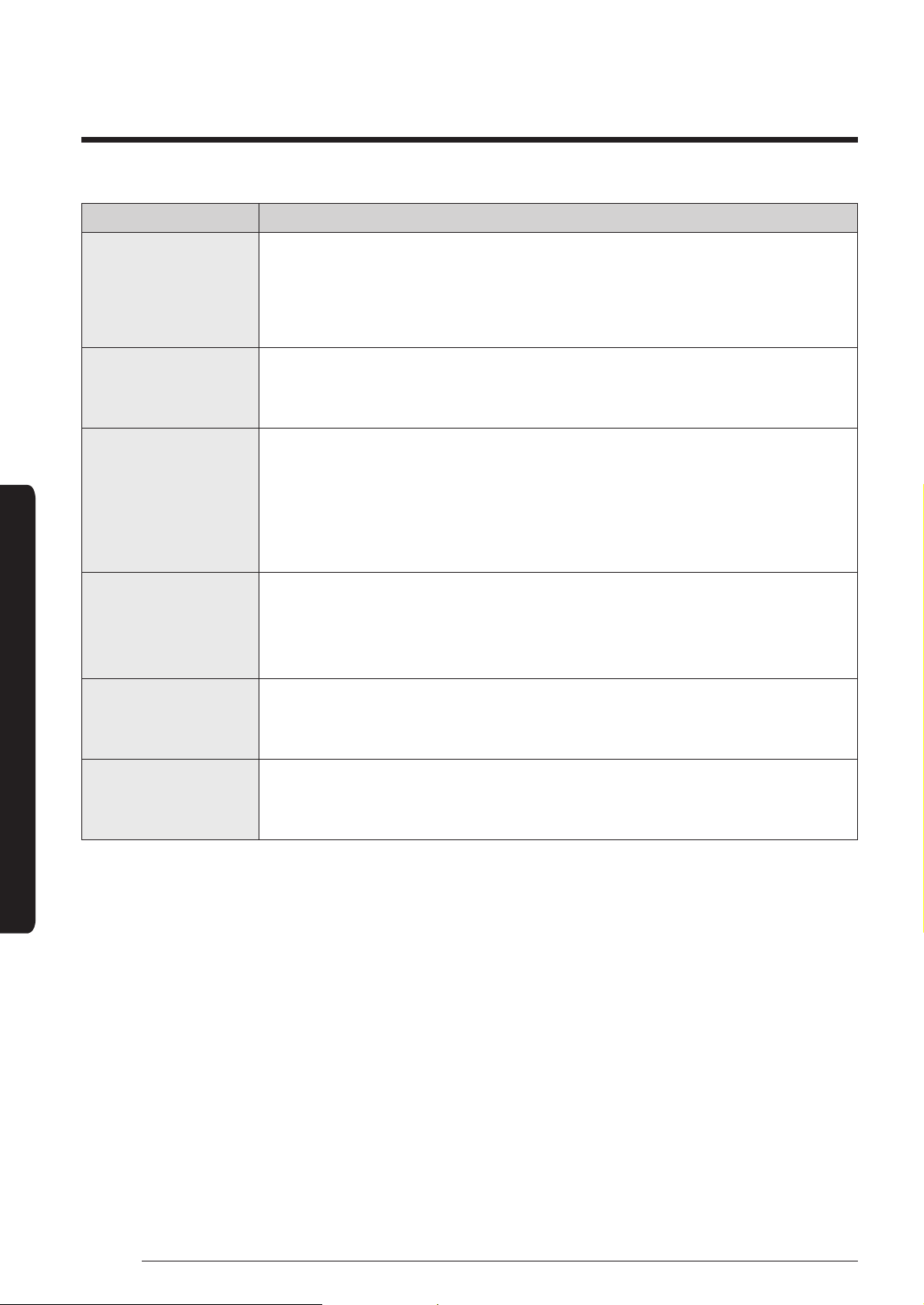
Problem Solution
The air conditioner
makes a bubbling
sound.
• A bubbling sound may be heard when the refrigerant is circulating
through the compressor. Let the air conditioner operate in a selected
mode.
• When you press the Power button on the remote control, noise may be
heard from the drain pump inside the air conditioner.
Water is dripping
from the air flow
blades.
• Check if the air conditioner has been cooling for an extended period of
time with the air flow blades pointed downwards. Condensation may
generate due to the difference in temperature.
Remote control is
not working.
• Check if your batteries are depleted.
• Make sure batteries are correctly installed.
• Make sure nothing is blocking your remote control sensor.
• Check that there are strong lighting apparatus near the air conditioner.
Strong light which comes from fluorescent bulbs or neon signs may
interrupt the electric waves.
The air conditioner
does not turn on or
off with the wired
remote control.
• Check if you set the wired remote control for group control.
The wired remote
control does not
operate.
• Check if TEST indicator is displayed on the wired remote control. If so,
turn off the unit and switch off the circuit breaker. Call your nearest
contact center.
The indicators of
the digital display
flashes.
• Press the Power button on the remote control to turn the unit off and
switch the circuit breaker off. Then, switch it on again.
19
English
Safety Information
Safety Information on Installation
WARNING
• Hazards or unsafe practices that may result in
severe personal injury or death.
CAUTION
• Hazards or unsafe practices that may result in
minor personal injury or property damage.
• Carefully follow the precautions listed below
because they are essential to guarantee the safety
of the equipment.
WARNING
• Always disconnect the air conditioner from the
power supply before servicing it or accessing its
internal components.
• Verify that installation and testing operations are
performed by qualified personnel.
• Verify that the air conditioner is not installed in an
easily accessible area.
General information
WARNING
• Carefully read the content of this manual before
installing the air conditioner and store the manual in a
safe place in order to be able to use it as reference after
installation.
• For maximum safety, installers should always carefully
read the following warnings.
• Store the operation and installation manual in a safe
location and remember to hand it over to the new owner
if the air conditioner is sold or transferred.
• This manual explains how to install an indoor unit with
a split system with two SAMSUNG units. The use of
other types of units with different control systems may
damage the units and invalidate the warranty. The
manufacturer shall not be responsible for damages
arising from the use of non compliant units.
• The manufacturer shall not be responsible for damage
originating from unauthorized changes or the improper
connection of electric and requirements set forth in the
“Operating limits” table, included in the manual, shall
immediately invalidate the warranty.
• The air conditioner should be used only for the
applications for which it has been designed: the indoor
unit is not suitable to be installed in areas used for
laundry.
• Do not use the units if damaged. If problems occur,
switch the unit off and disconnect it from the power
supply.
• In order to prevent electric shocks, fires or injuries,
always stop the unit, disable the protection switch
and contact SAMSUNG’s technical support if the unit
produces smoke, if the power cable is hot or damaged or
if the unit is very noisy.
• Always remember to inspect the unit, electric
connections, refrigerant tubes and protections regularly.
These operations should be performed by qualified
personnel only.
• The unit contains moving parts, which should always be
kept out of the reach of children.
• Do not attempt to repair, move, alter or reinstall the
unit. If performed by unauthorized personnel, these
operations may cause electric shocks or fires.
• Do not place containers with liquids or other objects on
the unit.
• All the materials used for the manufacture and
packaging of the air conditioner are recyclable.
• The packing material and exhaust batteries of the
remote controller(optional) must be disposed of in
accordance with current laws.
• The air conditioner contains a refrigerant that has to be
disposed of as special waste. At the end of its life cycle,
the air conditioner must be disposed of in authorised
centres or returned to the retailer so that it can be
disposed of correctly and safely.
Installing the unit
WARNING
IMPORTANT: When installing the unit, always remember to
connect first the refrigerant tubes, then the electrical lines.
• Always disassemble the electric lines before the
refrigerant tubes.
• Upon receipt, inspect the product to verify that it has not
been damaged during transport. If the product appears
damaged, DO NOT INSTALL it and immediately report
the damage to the carrier or retailer (if the installer or
the authorized technician has collected the material
from the retailer.)
Safety Information
20
English
Safety Information on Installation
Safety Information
• After completing the installation, always carry out a
functional test and provide the instructions on how to
operate the air conditioner to the user.
• Do not use the air conditioner in environments with
hazardous substances or close to equipment that release
free flames to avoid the occurrence of fires, explosions or
injuries.
• Our units should be installed in compliance with the
spaces shown in the installation manual, to ensure
accessibility from both sides and allow repairs or
maintenance operations to be carried out. The unit’s
components should be accessible and easy to disassemble
without endangering people and objects.
For this reason, when provisions of the installation
manual are not complied with, the cost required to
access and repair the units (in SAFETY CONDITIONS, as
set out in prevailing regulations) with harnesses, ladders,
scaffolding or any other elevation system will NOT be
considered part of the warranty and will be charged to the
end customer.
Power supply line, fuse or circuit
breaker
WARNING
• Always make sure that the power supply is
compliant with current safety standards. Always
install the air conditioner in compliance with
current local safety standards.
• Always verify that a suitable grounding connection
is available.
• Verify that the voltage and frequency of the
power supply comply with the specifications and
that the installed power is sufficient to ensure
the operation of any other domestic appliance
connected to the same electric lines.
• Always verify that the cut-off and protection
switches are suitably dimensioned.
• Verify that the air conditioner is connected to the
power supply in accordance with the instructions
provided in the wiring diagram included in the manual.
• Always verify that electric connections (cable
entry, section of leads, protections…) are compliant
with the electric specifications and with the
instructions provided in the wiring scheme.
Always verify that all connections comply with
the standards applicable to the installation of air
conditioners.
• ices disconnected from the power supply should be
completely disconnected in the condition of overvoltage
category.
• Be sure not to perform power cable modification,
extension wiring, and multiple wire connection.
– It may cause electric shock or fire due to poor
connection, poor insulation, or current limit override.
– When extension wiring is required due to power line
damage, refer to Step 13 Optional: Extending the
power cable in the installation manual.
CAUTION
Make sure that you earth the cables.
• Do not connect the earth wire to the gas pipe, water
pipe, lighting rod or telephone wire. If earthing is not
complete, electric shock or fire may occur.
Install the circuit breaker.
• If the circuit breaker is not installed, electric shock or
fire may occur.
Make sure that the condensed water dripping from the drain hose
runs out properly and safely.
Install the power cable and communication cable of the indoor
and outdoor unit at least 1m away from the electric appliance.
Install the indoor unit away from lighting apparatus using the
ballast.
• If you use the wireless remote control, reception error
may occur due to the ballast of the lighting apparatus.
21
English
Installation Procedure
Installation Procedure
Installation Procedure
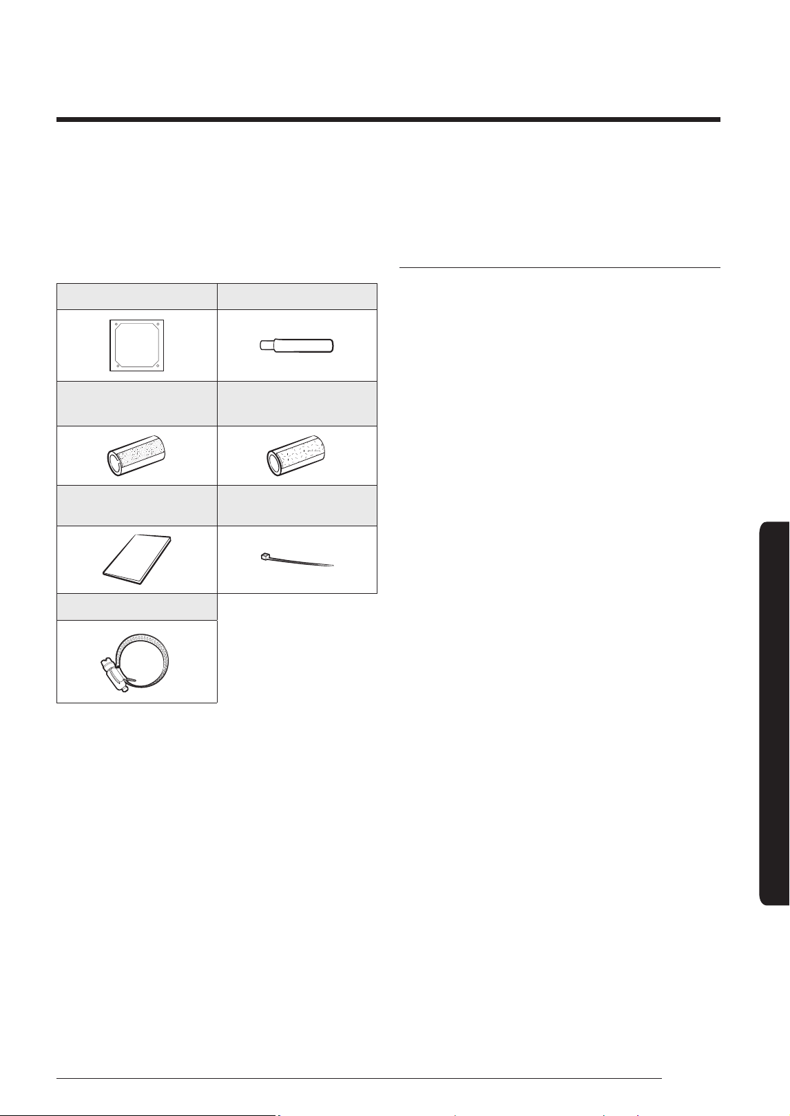
Step 1 Checking and preparing
accessories
The following accessories are supplied with the indoor
unit. The type and quantity may differ, depending on the
specifications.
Pattern sheet (1) Drain hose (1)
Insulation pipe
(Liquid side1, gas side1)
Insulation drain hose (1)
User & Installation
manual(1)
Cable-tie (6)
Clamp (1)
Step 2 Choosing the installation
location
Installation location requirements
• There must be no obstacles near the air inlet and
outlet.
• Install the indoor unit on a ceiling that can support
its weight.
• Maintain sufficient clearance around the indoor
unit.
• Before installing the indoor unit, be sure to check
whether the chosen location is well-drained.
• The indoor unit must be installed such that it is
beyond public access and is not touchable by
users.
Do not install the air conditioner in following places.
• Place where there is mineral oil or arsenic acid. Resin
parts flame and the accessories may drop or water may
leak. The capacity of the heat exchanger may reduce or
the air conditioner may be out of order.
• The place where corrosive gas such as sulphuric acid gas
generates from the vent pipe or air outlet.
• The copper pipe or connection pipe may corrode and
refrigerant may leak.
• The place where there is a machine that generates
electromagnetic waves. The air conditioner may not
operate normally due to control system.
• The place where there is a danger of existing
combustible gas, carbon fibre or flammable dust.
• The place where thinner or gasoline is handled. Gas may
leak and it may cause fire.
22
English
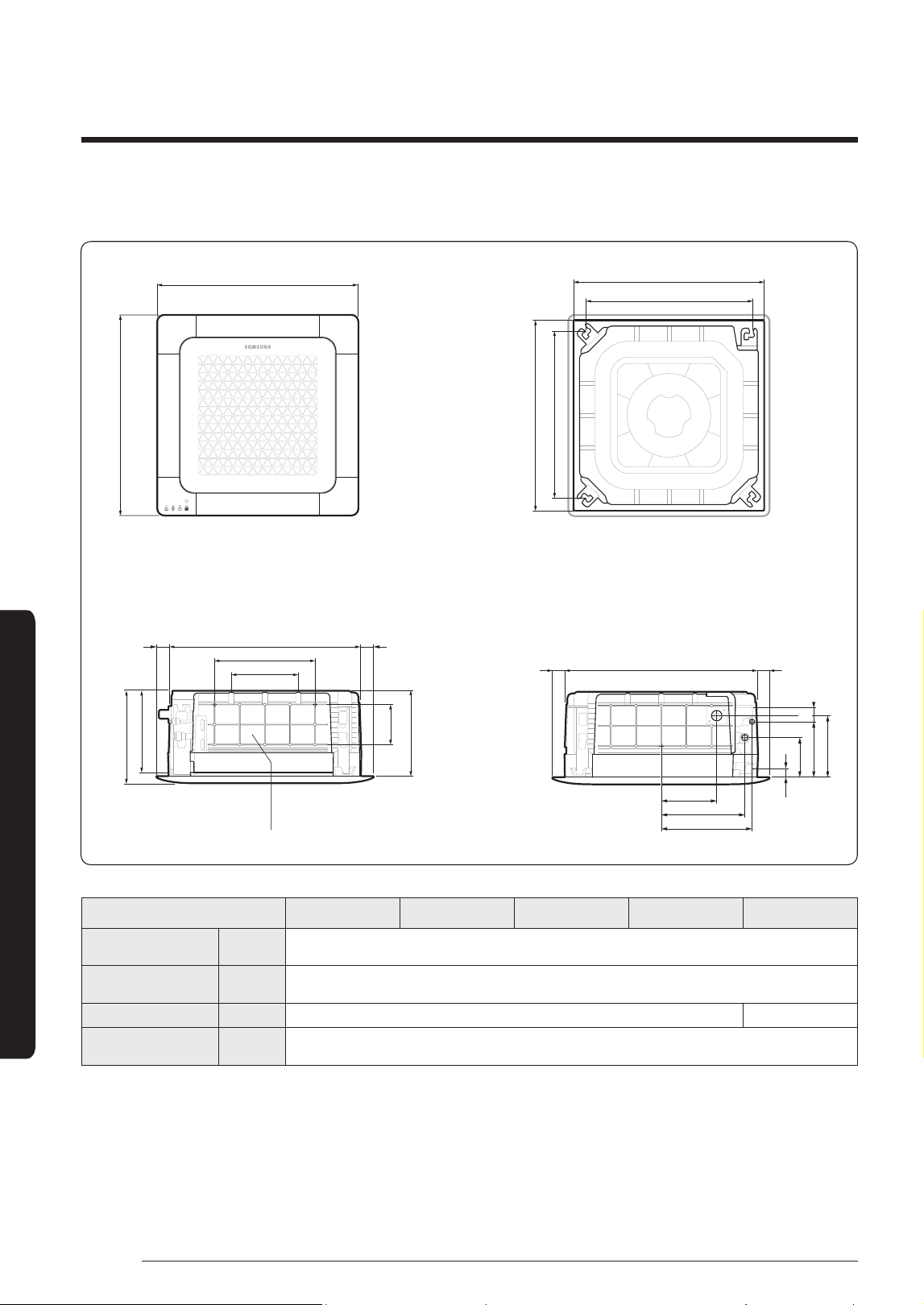
Installation Procedure
Installation Procedure
(Unit: mm)
165
575
22.5 22.5
249
269
207
188
140
51
43
575
200
300
22.522.5
120
250
312
278
Sub duct connection
Sub duct hole is not applicable to Wind-Free models.
580~585 (Celling opening)
500 (Suspension position)
580~585 (Celling opening)
500 (Suspension position)
620
620
Model AJ016NBNDEH AJ020NBNDEH AJ026NBNDEH AJ035NBNDEH AJ052NBNDEH
Net dimension
(W × D × H)
mm 575 X 575 X 250
Liquid pipe
connection
mm Ø6.35 (1/4”)
Gas pipe connection mm Ø9.52 (3/8") Ø12.70 (1/2")
Drain hose
connection
mm VP20 (outer diameter : Ø25, inner diameter : Ø20)
23
English
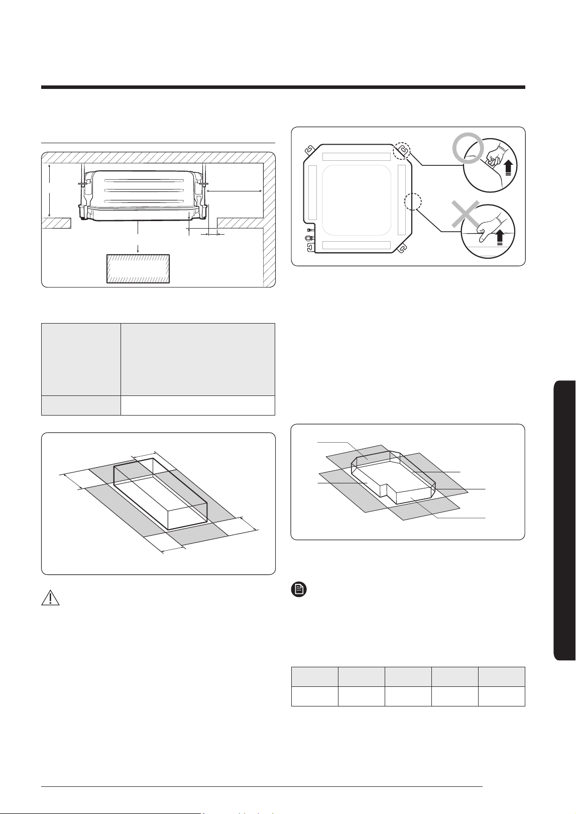
Installation Procedure
Spacing requirements
1500 mm or more
Obstruction
1500 mm or more
20 mm
17 mm
A
(Unit: mm)
Model
AJ016NBNDEH
AJ020NBNDEH
AJ026NBNDEH
AJ035NBNDEH
AJ052NBNDEH
A 297
C: 1500 mm or more
C
C
C
C
CAUTION
• The indoor unit must be installed according to the
specified distances in order to permit accessibility
from each side, to guarantee correct operation,
maintenance, and repair of the unit. The components
of the indoor unit must be reachable and removable
under safe conditions for people and the unit.
• Do not hold the discharge while carrying the indoor
unit to avoid the possibility of breakage.
• You must hold the hanger plate on the corner and
carry the indoor unit.
Step 3 Optional: Insulating the body of
the indoor unit
If you install a cassette type indoor unit on the ceiling
when temperature is over 27°C and humidity is over
80%, you must apply an extra 10 mm thick polyethylene
insulation or a similar type of insulation to the body of the
indoor unit.
Cut away the part where pipes are pulled out for the
insulating work.
D
C
A
E
B
Insulate the end of the pipe and some curved area by
using separate insulator.
NOTE
• A: Reference for the outer circumference of the unit
(When insulating the body of the indoor unit, use A as
the reference for its outer circumference.)
(Unit: mm)
A B C D E
400X190 400X190 400X190 400X190 550X550
24
English
Installation Procedure
Installation Procedure
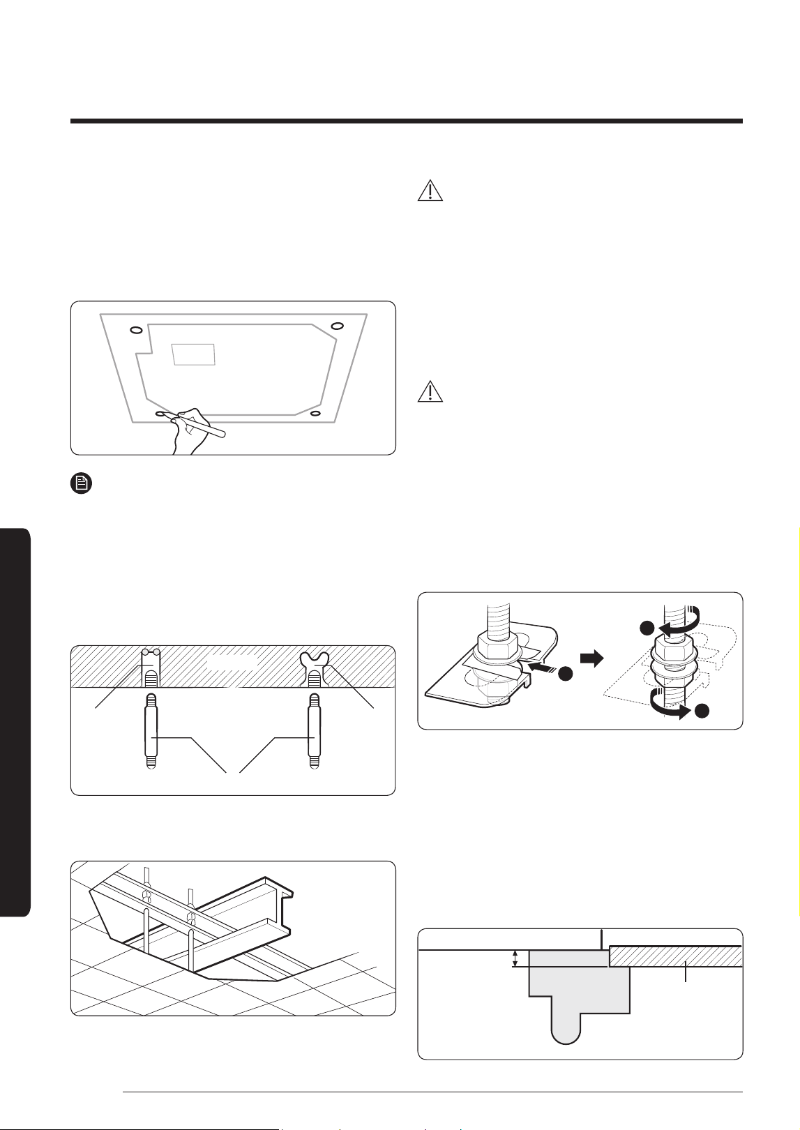
Step 4 Installing the indoor unit
When deciding on the location of the air conditioner the
following restrictions must be taken into account.
1 Place the pattern sheet on the ceiling at the spot
where you want to install the indoor unit.
NOTE
• Since the diagram is made of paper, it may shrink
or stretch slightly due to temperature or humidity.
For this reason, before drilling the holes, be sure
to maintain the correct dimensions between the
markings.
2 Insert bolt anchors, use existing ceiling supports or
construct a suitable support as shown in figure.
Concrete
Hole in anchor
Hole in plug
Suspension bolt (M8) - field supply
Insert
3 Install the suspension bolts, depending on the ceiling
type.
Ceiling support
CAUTION
• Make sure that the ceiling is strong enough to support
the weight of the indoor unit. Before hanging the unit,
test the strength of each attached suspension bolt.
• If the length of the suspension bolt is more than
4.9 ft (1.5 m), you are required to prevent vibration.
4 Screw eight pairs of nuts and washers to the
suspension bolts, making space for hanging the indoor
unit.
CAUTION
• You must install all of the suspension rods.
• It is important to leave sufficient space in the false
ceiling to allow access for maintenance or repairs to
the drainage pipe connection, the refrigerant pipe
connection, or to remove the unit if necessary.
5 Hang the indoor unit to the suspension bolts between
two nuts. Cut a pad stopper and place it on the
suspension bolts to hold the washer. Remove the
stopper and screw the nuts to fix the unit.
1
2
2
6 Adjust the unit to the appropriate position, taking into
account the installation area for the front panel.
• Place the pattern sheet on the indoor unit.
• Adjust the space between the ceiling and the
indoor unit by using a dimension gauge.
• Fix the indoor unit securely after adjusting the level
of the unit by using a leveller.
• Remove the pattern sheet, connect the other
cables. and install the front panel.
Ceiling
Indoor unit
23 mm
Gauge of dimensions
25
English
Installation Procedure
Step 5 Purging inert gas from the
indoor unit
The indoor unit comes with nitrogen gas (inert gas)
charged at the factory. Therefore, all inert gas must be
purged before connecting the assembly piping.
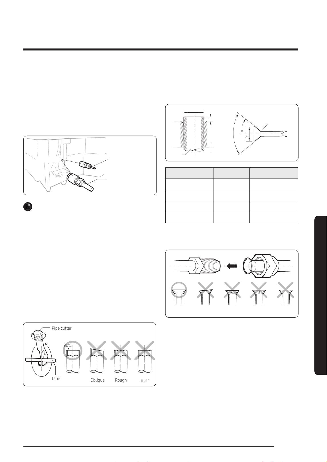
Unscrew the pinch pipe at the end of each refrigerant
pipe.
Liquid side
Gas side
Insulator
NOTE
• To prevent dirt or foreign objects from getting into the
pipes during installation, do not remove the pinch pipe
completely until you are ready to connect the piping.
Step 6 Cutting and flaring the pipes
1 Make sure that you have the required tools available:
pipe cutter, reamer, flaring tool, and pipe holder.
2 If you wish to shorten the pipes, cut them with a pipe
cutter, ensuring that the cut edge remains at a 90°
angle to the side of the pipe. Refer to the illustrations
below for examples of edges cut correctly and
incorrectly.
Pipe cutter
Pipe
90°
Oblique
Rough
Burr
3 To prevent any gas from leaking out, remove all burrs
at the cut edge of the pipe, using a reamer.
4 Slide a flare nut on to the pipe and modify the flare.
Pipe
Flare
D
A
Flare
90° ±2°
R 0.4 to 0.8 mm
D
L
45° ±2°
Outer Diameter (D) Depth (A) Flare dimension (L)
Ø6.35 mm 1.3 mm 8.7 to 9.1 mm
Ø9.52 mm 1.8 mm 12.8 to 13.2 mm
Ø12.70 mm 2.0 mm 16.2 to 16.6 mm
Ø15.88 mm 2.2 mm 19.3 to 19.7 mm
5 Check that the flaring is correct, referring to the
illustrations below for examples of incorrect flaring.
Correct
Inclined
Damaged
Surface
Cracked
Uneven
Thickness
26
English
Installation Procedure
Installation Procedure
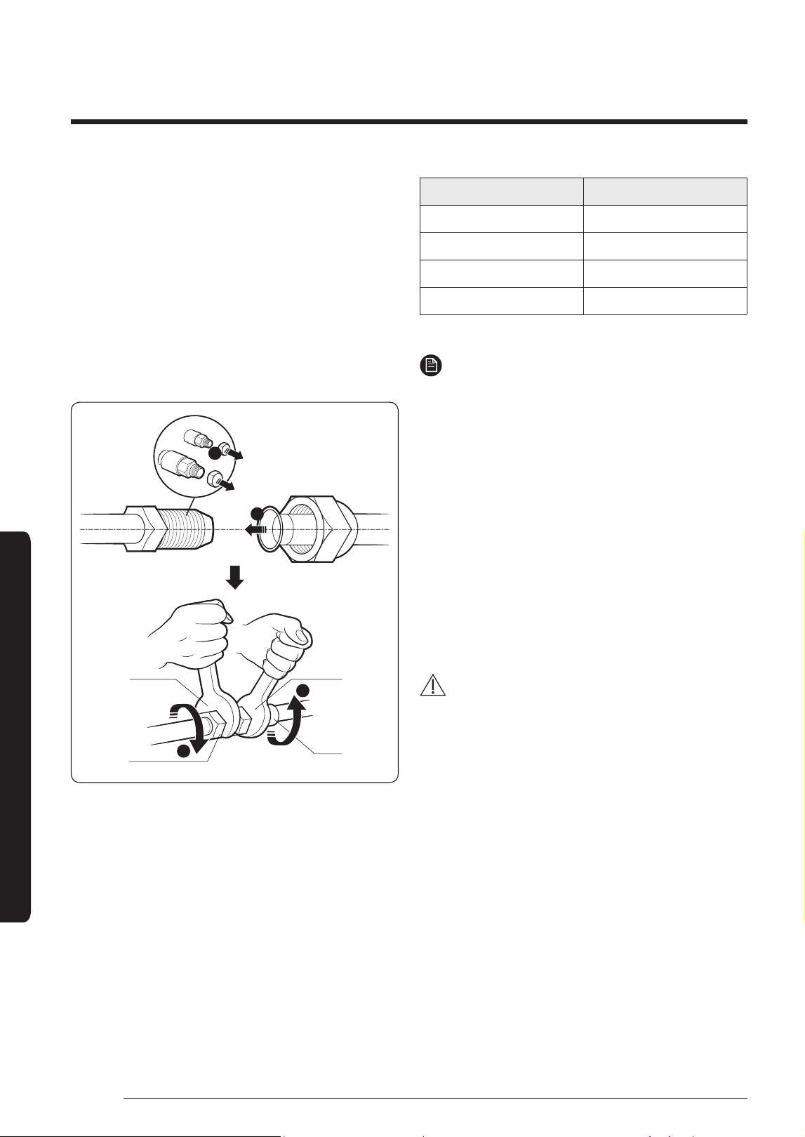
Step 7 Connecting the assembly pipes to
the refrigerant pipes
There are two refrigerant pipes of different diameters :
• A smaller one for the liquid refrigerant.
• A larger one for the gas refrigerant. The inside of
copper pipe must be clean and has no dust.
1 Remove the pinch pipe on the pipes and connect the
assembly pipes to each pipe, tightening the nuts, first
manually and then with a torque wrench, a spanner
applying the following torque.
2
3
3
1
Torque
wrench
Flare nut
Spanner
Union
Outer Diameter (mm) Torque (N•m)
Ø6.35 14 to 18
Ø9.52 34 to 42
Ø12.70 49 to 61
Ø15.88 68 to 82
(1 N•m=10 kgf•cm)
NOTE
• If the pipes must be shortened, see Step 6 Cutting
and flaring the pipes on page 25.
2 Be sure to use an insulator thick enough to cover the
refrigerant tube to protect the condensate water on
the outside of the pipe falling onto the floor and to
improve the efficiency of the unit.
3 Cut off any excess foam insulation.
4 Make sure that there are no cracks or waves on the
bent area.
5 It would be necessary to double the insulation
thickness (10 mm or more) to prevent condensation
even on the insulator when if the installed area is
warm and humid.
CAUTION
• Connect the indoor and outdoor units using pipes with
flared connections (not supplied). For the lines, use
insulated, unwelded, degreased and deoxidized copper
pipe (Cu DHP type to ISO 1337 or UNI EN 12735-1),
suitable for operating pressures of at least 4.2MPa
and for a burst pressure of at least 20.7MPa. Copper
pipe for hydro-sanitary applications is completely
unsuitable.
• For sizing and limits (height difference, line length,
max. bends, refrigerant charge, etc.) see the outdoor
unit installation manual.
• All refrigerant connection must be accessible, in order
to permit either unit maintenance or removing it
completely.
• If the pipes require brazing, make sure that oxygen
free nitrogen (OFN) is flowing through the system.
• Nitrogen blowing pressure range is 0.02 to 0.05 MPa.
27
English
Installation Procedure
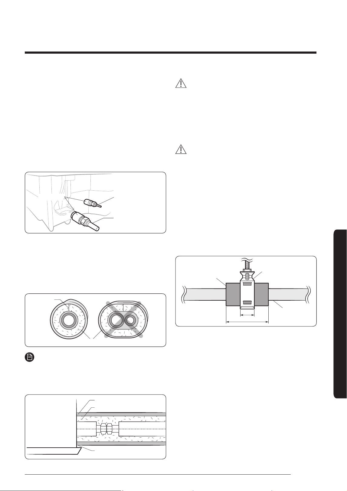
Step 8 Performing the gas leak test
To identify potential gas leaks on the indoor unit, inspect
the connection area of each refrigerant pipe using a leak
detector for R-410A.
Before recreating the vacuum and recirculating the
refrigerant gas, pressurize the whole system with
nitrogen (using a cylinder with a pressure reducer) at a
pressure above 0.2 MPa, less than 4 MPa (gauge) in order
to immediately detect leaks on the refrigerant fittings.
Made vacuum for 10 minutes and pressurizing system
with nitrogen.
Liquid side
Gas side
Insulator
Step 9 Insulating the refrigerant pipes
Once you have checked that there are no leaks in the
system, you can insulate the piping and hose.
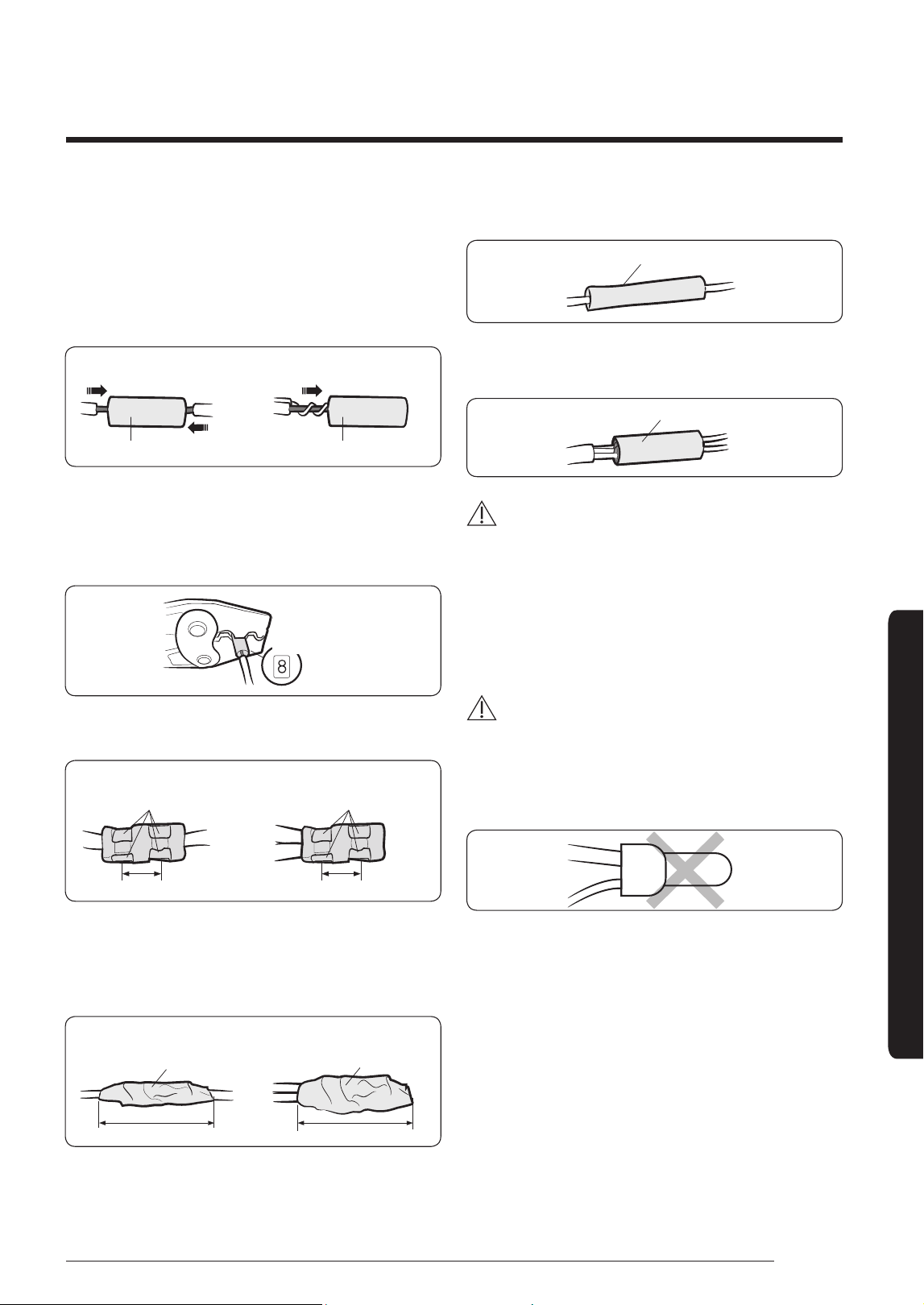
1 To avoid condensation problems, place Acrylonitrile
Butadien Rubber separately around each refrigerant pipe.
No gap
NBR
NOTE
• Always make the seam of pipes face upwards.
2 Wind insulating tape around the pipes and drain hose
avoiding compressing the insulation too much.
Insulation cover pipe
Insulation pipe
Be sure to overlap the insulation.
Indoor unit
CAUTION
• Be sure to wrap insulation tightly without any gaps.
3 Finish wrapping insulating tape around the rest of the
pipes leading to the outdoor unit.
4 The pipes and electrical cables connecting the indoor
unit with the outdoor unit must be fixed to the wall
with suitable ducts.
CAUTION
• Make sure that all refrigerant connection must be
accessible for easy maintenance and detachment.
• Install the insulation not to get wider and use the
adhesives on the connection part of it to prevent
moisture from entering.
• Wind the refrigerant pipe with insulation tape if it is
exposed to outside sunlight.
• Install the refrigerant pipe respecting that the
insulation does not get thinner on the bent part or
hanger of pipe.
• Add the additional insulation if the insulation plate
gets thinner.
a x 3
Hanger
Additional insulation
a
Refrigerant pipe
insulation
5 Select the insulation of the refrigerant pipe.
• Insulate the gas side and liquid side pipe, noting
the insulation thickness that must differ according
to the pipe size.
• Standard: Less than an indoor temperature
of 30°C, with humidity at 85%. If installing in
a high humidity environment, use one grade
thicker insulator by referring to the table below.
If installing in an unfavourable environment, use
thicker one.
• The heat-resistance temperature of the insulator
must be more than 120°C.
28
English
Installation Procedure
Installation Procedure
Pipe
Pipe size
(mm)
Insulation type
(heating/cooling)
Remarks
Standard
(Less than
30°C,
85%)
High
humidity
(Over 30°C,
85%)
EPDM, NBR
Liquid
pipe
Ø6.35 to
Ø9.52
9t 9t
The internal
temperature
is higher than
120°C.
Ø12.7 to
Ø15.88
13t 13t
Gas
pipe
Ø6.35 13t 19t
Ø9.52
19t 25tØ12.70
Ø15.88
• When installing insulation in the places and
conditions below, use the same insulation that is
used for high humidity conditions.
<Geological condition>
High humidity locations such as shorelines, hot springs, lake
or riversides, and ridges (when part of the building is covered
by earth and sand)
<Operation purpose condition>
Restaurant ceiling, sauna, swimming pool etc.
<Building construction condition>
Ceilings frequently exposed to moisture and cooling are
not covered. For example, pipes installed at a corridor of a
dormitory and studio or near an exit that opens and closes
frequently.
Places (where the pipes are installed) that are highly humid
due to a lack of ventilation.
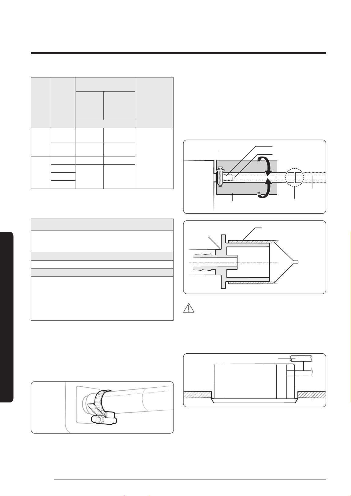
Step 10 Installing the drain hose and
drain pipe
1 Push the supplied drain hose as far as possible over
the drain socket.
2 Tighten the metal clamp as shown in the picture.
3 Wrap the supplied large sealing pad over the metal
clamp and drain hose to insulate and fix it with
clamps.
4 Insulate the complete drain piping inside the building
(field supply).
If the drain hose cannot be sufficiently set on a slope,
fit the hose with drain raising piping (field supply).
5 Push the drain hose up to insulation when connecting
the drain hose to drain socket.
Metal clamp
Drain socket
Drain hose
Large seailng pad
Be sure to bond the drain
hose and the main pipe.
Drain pipe
Drain hose
PVC Tube Joint
+ VP25 (OD: 32 mm, ID: 25 mm)
Drain pipe
CAUTION
Check that the indoor unit is level with the ceiling by
using the leveller.
• Install air ventilation to drain condensation smoothly.
Air ventilation
Ceiling
29
English
Installation Procedure
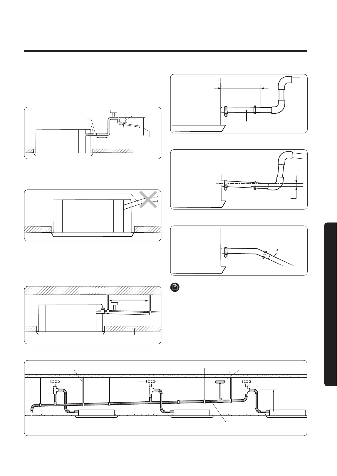
• If it is necessary to increase the height of the drain
pipe, install the drain pipe straight within 300 mm
from the drain hose port. If it is raised higher than 550
mm, there may be water leaks.
Band joint
300 mm or
less
550 mm or
less
20 mm or more
1/100 or more
Drain hose
Ceiling
• Do not give the hose an upward gradient beyond the
connection port. This will cause water to flow backwards
when the unit is stopped, resulting in water leaks.
Under gradient
Ceiling
• Do not apply force to the piping on the unit side when
connecting the drain hose. The hose should not be
allowed to hang loose from its connection to the unit.
Fasten the hose to a wall, frame or other support as
close to the unit as possible.
Support pieces
1 to 1.5 m
1/100 or more
Ceiling
• Install horizontally.
Indoor unit
Be horizontal
Flexible hose
• Max. allowable axis gap.
Indoor unit
Max. 20 mm
• Max. allowable bending angle.
Max. 30˚
Indoor unit
NOTE
• If a concentrated drain pipe is installed, refer to the
figure below.
Main drainpipe
Hanger
Centralized horizontal drainpipe
(more than 1/100 slope)
550mm or less
1~1.5m
Main air vent
Individual
air vent
30
English
Installation Procedure
Installation Procedure
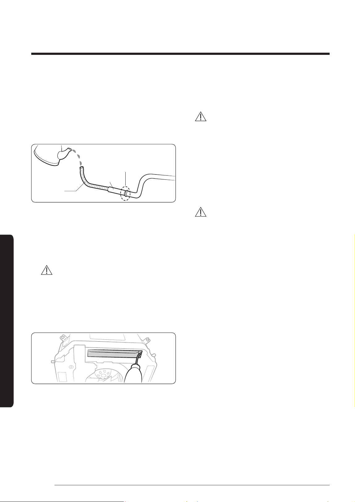
Step 11 Performing the drainage test
1 Do a leak test at the connection part of the flexible
hose and the drian pipe:
a Connect a general hose to the connection part of
the flexible hose of the indoor unit, and pour in
some water.
Hose
Flexible hose
Water leakage
check part
b After pouring some water, reassemble the rubber
cap on the connection part of a flexible hose of
the indoor unit and firmly tighten it with a band to
prevent leakage.
c Check the leak test at the part where the adhesive
for the flexible hose and the drian pipe is used.
CAUTION
• The leak test must be performed for at least 24
hours.
2 Check the condensed water drainage:
a Pour about 2 liters of water into the indoor unit
drain pan as shown in the picture.
b When the electric cable connection is completed
• Turn on the indoor unit and outdoor unit.
• Operate in the Cool mode.
CAUTION
• Only in the Cool mode, you can check the correct
operation of the drain pump.
When the electric cable connection has not been
completed
• Remove the control box cover of the indoor unit.
• Connect the power supply (220~240V, 50 Hz) to the
L and N terminals.
• Reassemble the control box cover and turn on the
indoor unit.
CAUTION
• When the float switch is not detected due to
insufficient water on the drain pan, the drain
pump will not work.
• If the power supply is directly connected to the L
and N terminals, communication error message
might appear.
• After completing the drainage check, turn the
unit off and disconnect the power supply.
• Reassemble the control box cover.
c Check whether the drain pump works correctly.
d Check whether the drainage is performing
correctly at the end of the drain pipe.
e Check for leakage at the drain pipe and drain pipe
connection part.
f When leakage occurs, check whether the indoor
unit is level and check the drain hose connection
part, drainpipe connection part and drain pump
connection.
g When the drainage check is completed and
the condensed water remains on the drain pan,
remove the water.
31
English
Installation Procedure
Step 12 Connecting the power and
communication cables
CAUTION
• Always remember to connect the refrigerant pipes
before performing the electric connections.
When disconnecting the system, always disconnect
the electric cables before disconnecting the
refrigerant pipes.
CAUTION
• Always remember to connect the air conditioner to
the grounding system before performing the electric
connections. Use a crimp ring terminal at the end of
each wire.
The indoor unit is powered through the outdoor unit by
means of a H07 RN-F connection cable (or a more power
model), with insulation in synthetic rubber and a jacket
in polychloroprene (neoprene), in accordance with the
requirements specified in the standard EN 60335-2-40.
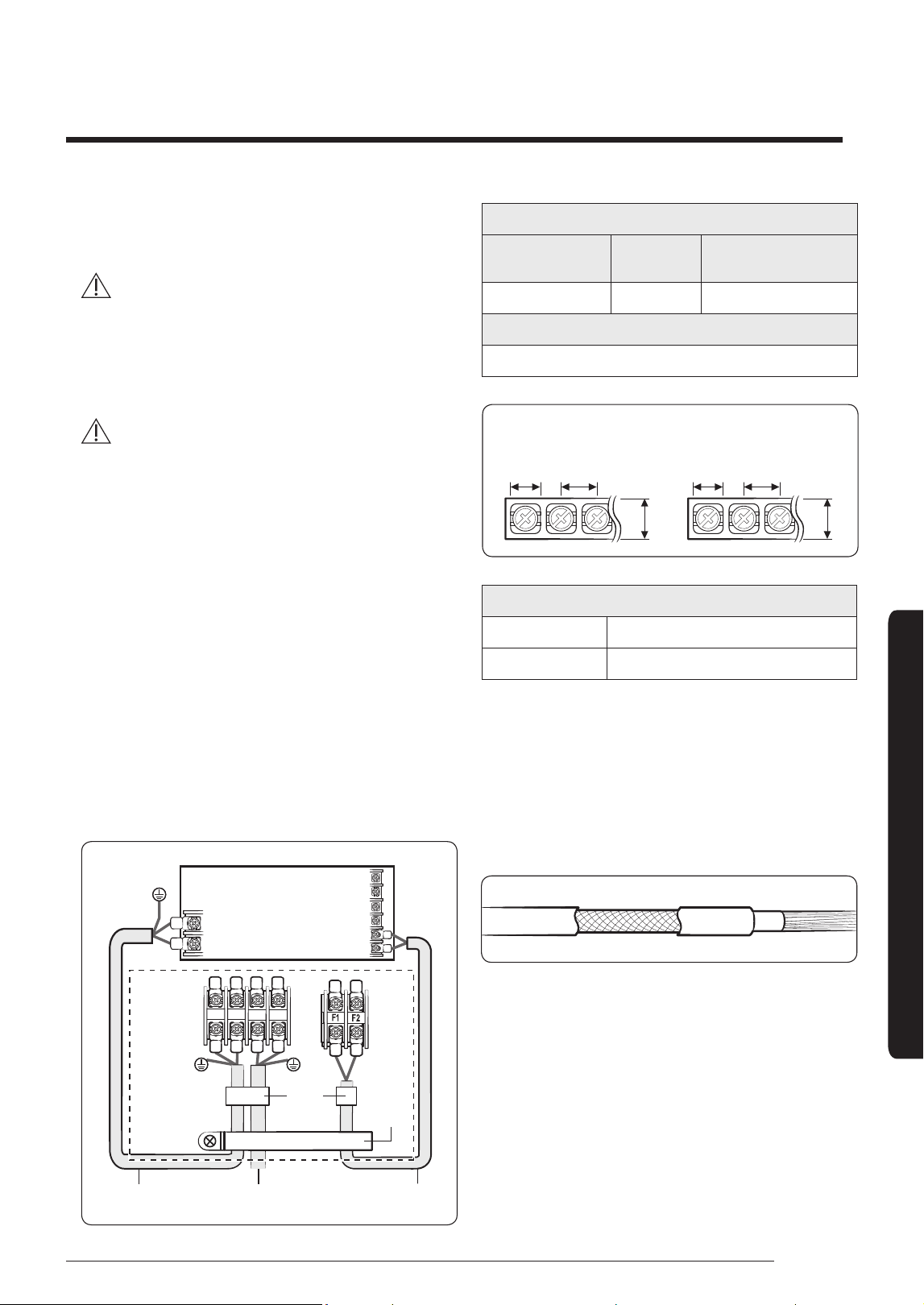
1 Remove the screw on the electrical component box
and remove the cover plate.
2 Route the connection cord through the side of the
indoor unit and connect the cable to the terminals
refer to the figure below.
3 Route the other end of the cable to the outdoor unit
through the ceiling & the hole on the wall.
4 Reassemble the electrical component box cover,
carefully tightening the screw.
Indoor Unit
1(L)
2(N)
F2
F1
Outdoor
Unit
Indoor Power Main power cable Communication cable
Cable
Tie
1(L) 2(N)
N
L
Cable
clamp
Indoor power supply
Power supply
Max/
Min(V)
Indoor power cable
220 to 240V, 50 Hz
±10%
1.0 mm², 3 wires
Communication cable
0.75 to 1.0 mm², 2 wires
AC power: M4 screw
Communication: M3.5 screw
11
13
7. 5
9.0
18
13.8
(Unit: mm)
Tightening torque (N• m)
M3.5 0.8 to 1.2
M4 1.2 to 1.8
• 1 N·m = 10 kgf·cm
• Power supply cords of parts of appliances for outdoor
use shall not be lighter than polychloroprene sheathed
flexible cord. (Code designation IEC:60245 IEC 57 /
CENELEC: H05RN-F or IEC:60245 IEC 66 / CENELEC:
H07RN-F)
• Since it has the external power supply, refer to the
outdoor unit installation manual for MAIN POWER.
32
English
Installation Procedure
Installation Procedure
CAUTION
• When installing the indoor unit in a computer
room or network room, use the double shielded
communication cable (tape aluminum / polyester
braid + copper) of FROHH2R type.
• Select the power cable in accordance with relevant
local and national.
• Wire size must comply with local and national code.
• You should connect the power cable into the power
cable terminal and fasten it with a clamp.
• The unbalanced power must be maintained within 10%
of supply rating among whole indoor units.
• If the power is unbalanced greatly, it may shorten
the life of the condenser. If the unbalanced power is
exceeded over 10% of supply rating, the indoor unit is
protected, stopped and the error mode indicates
• Connect the power cable to the auxiliary circuit
breaker. An all pole disconnection from the power
supply must be incorporated in the fixed wiring
(≥3mm).
• You must keep the cable in a protection tube.
• Maximum length of power cables are decided within
10% of power drop. If it exceeds, you must consider
another power supplying method.
• The circuit breaker (MCCB, ELB) should be considered
more capacity if many indoor units are connected from
one breaker.
• Use round pressure terminal for connections to the
power terminal block.
• For wiring, use the designated power cable and
connect it firmly, then secure to prevent outside
pressure being exerted on the terminal board.
• Use an appropriate screwdriver for tightening the
terminal screws. A screwdriver with a small head will
strip the head and make proper tightening impossible.
• Over-tightening the terminal screws may break them.
Step 13 Optional: Extending the power
cable
1 Prepare the following tools.
Tools Spec Shape
Crimping pliers MH-14
Connection sleeve
(mm)
20xØ6.5
(HxOD)
Insulation tape
Width 19
mm
Contraction tube
(mm)
70xØ8.0
(LxOD)
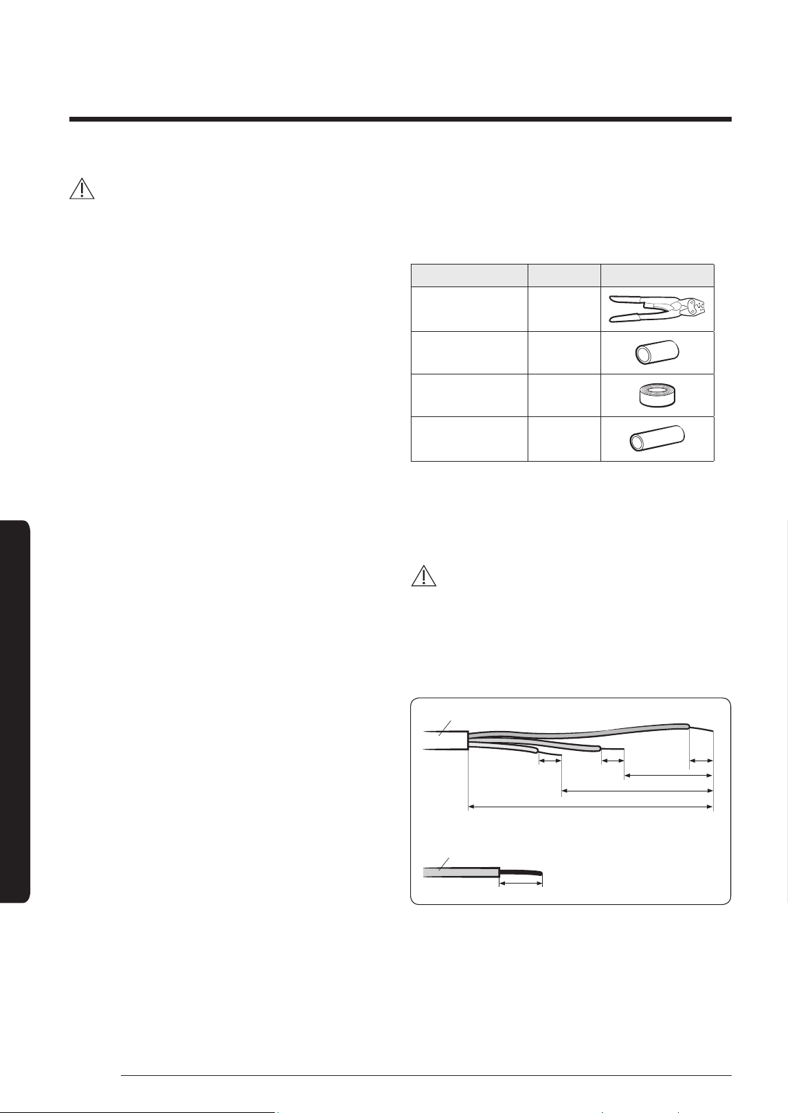
2 As shown in the figure, peel off the shields from the
rubber and wire of the power cable.
• Peel off 20 mm of cable shields from the pre-
installed tube.
CAUTION
• For information about the power cable
specifications for indoor and outdoor units, refer to
the installation manual.
• After peeling off cable wires from the pre-installed
tube, insert a contraction tube.
Power cable
Pre-installed tube for the power cable
(Unit: mm)
(Unit: mm)
20 20
20
20
60
120
180
33
English
Installation Procedure
3 Insert both sides of core wire of the power cable into
the connection sleeve.
• Method 1: Push the core wire into the sleeve from
both sides.
• Method 2: Twist the wire cores together and push it
into the sleeve.
Connection sleeve Connection sleeve
Method 1 Method 2
4 Using a crimping tool, compress the two points and
flip it over and compress another two points in the
same location.
• The compression dimension should be 8.0.
Compression
dimension
• After compressing it, pull both sides of the wire to
make sure it is firmly pressed.
Compress it 4 times.
5 mm
Compress it 4 times.
5 mm
Method 1 Method 2
5 Wrap it with the insulation tape twice or more and
position your contraction tube in the middle of the
insulation tape.
Three or more layers of insulation are required.
Method 1 Method 2
Insulation tape
35 mm40 mm
Insulation tape
6 Apply heat to the contraction tube to contract it.
Contraction tube
7 After tube contraction work is completed, wrap it with
the insulation tape to finish.
Insulation tape
CAUTION
• Make sure that the connection parts are not exposed
to outside.
• Be sure to use insulation tape and a contraction tube
made of approved reinforced insulating materials that
have the same level of withstand voltage with the
power cable. (Comply with the local regulations on
extensions.)
WARNING
• In case of extending the electric wire, please DO NOT
use a round-shaped Pressing socket.
– Incomplete wire connections can cause electric
shock or a fire.
34
English
Installation Procedure
Installation Procedure
Step 14 Setting the indoor unit
addresses and the installation options
You cannot set both of the indoor unit addresses and
the installation options in a batch: set both of them
respectively.
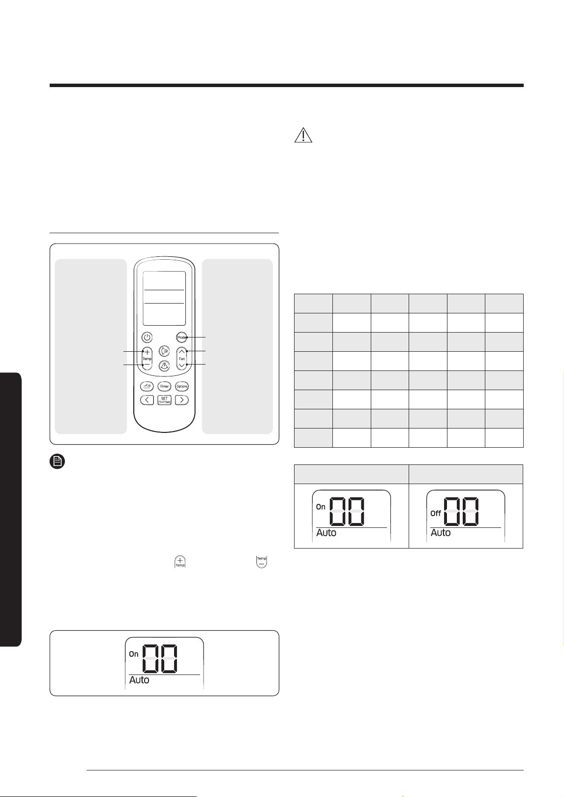
Common steps for setting the addresses and
options
Low Temp button
High Temp button
Mode button
Low Fan button
High Fan button
Setting the
option values
Entering the
mode for setting
the options
NOTE
• The remote control display and buttons may vary
depending on the model.
1 Enter the mode for setting the options:
a Remove the batteries from the remote control,
and then insert them again.
b While holding down the (High Temp) and
(Low Temp) buttons simultaneously, insert the
batteries into the remote control.
c Make sure that you are entered to the mode for
setting the options:
2 Set the option values.
CAUTION
• The total number of available options are 24: SEG1 to
SEG24.
• Because SEG1, SEG7, SEG13, and SEG19 are the page
options used by the previous remote control models,
the modes to set values for these options are skipped
automatically.
• Set a 2-digit value for each option pair in the following
order: SEG2 and SEG3
→
SEG4 and SEG5
→
SEG6
and SEG8
→
SEG9 and SEG10
→
SEG11 and SEG12
→
SEG14 and SEG15
→
SEG16 and SEG17
→
SEG18 and
SEG20
→
SEG21 and SEG22
→
SEG23 and SEG24
SEG1 SEG2 SEG3 SEG4 SEG5 SEG6
0 X X X X X
SEG7 SEG8 SEG9 SEG10 SEG11 SEG12
1 X X X X X
SEG13 SEG14 SEG15 SEG16 SEG17 SEG18
2 X X X X X
SEG19 SEG20 SEG21 SEG22 SEG23 SEG24
3 X X X X X
On (SEG1 to SEG12) Off (SEG13 to SEG24)
35
English
Installation Procedure
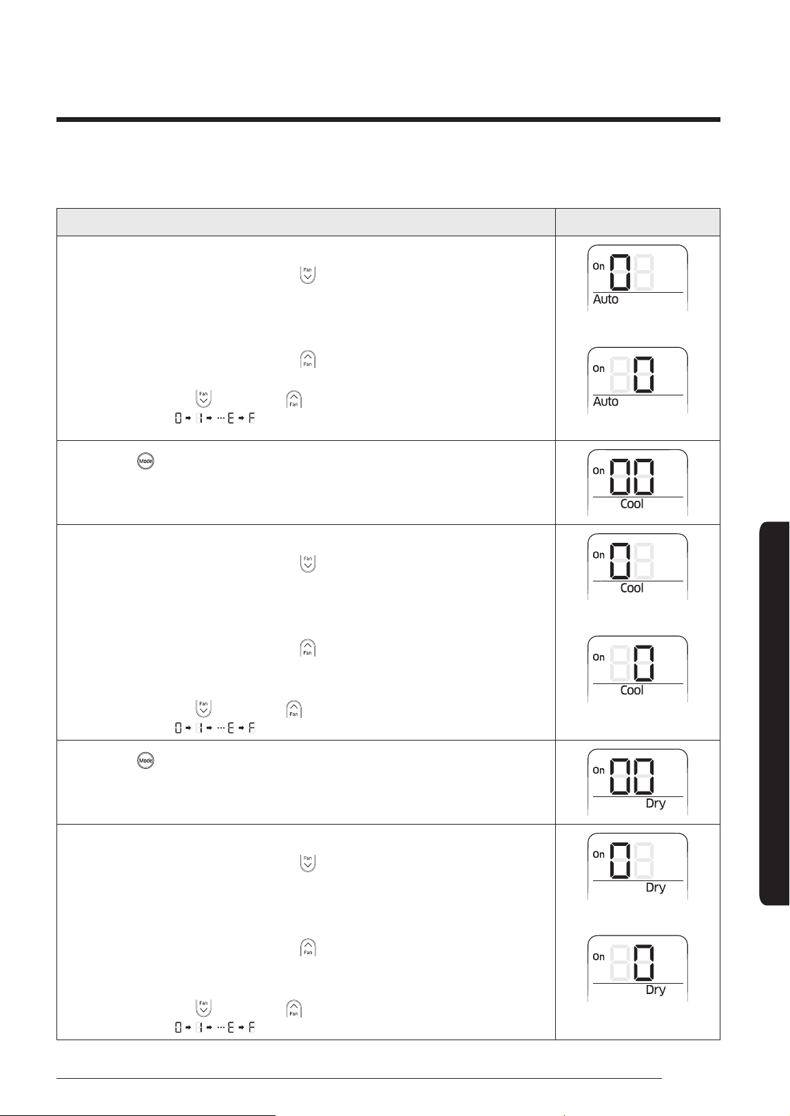
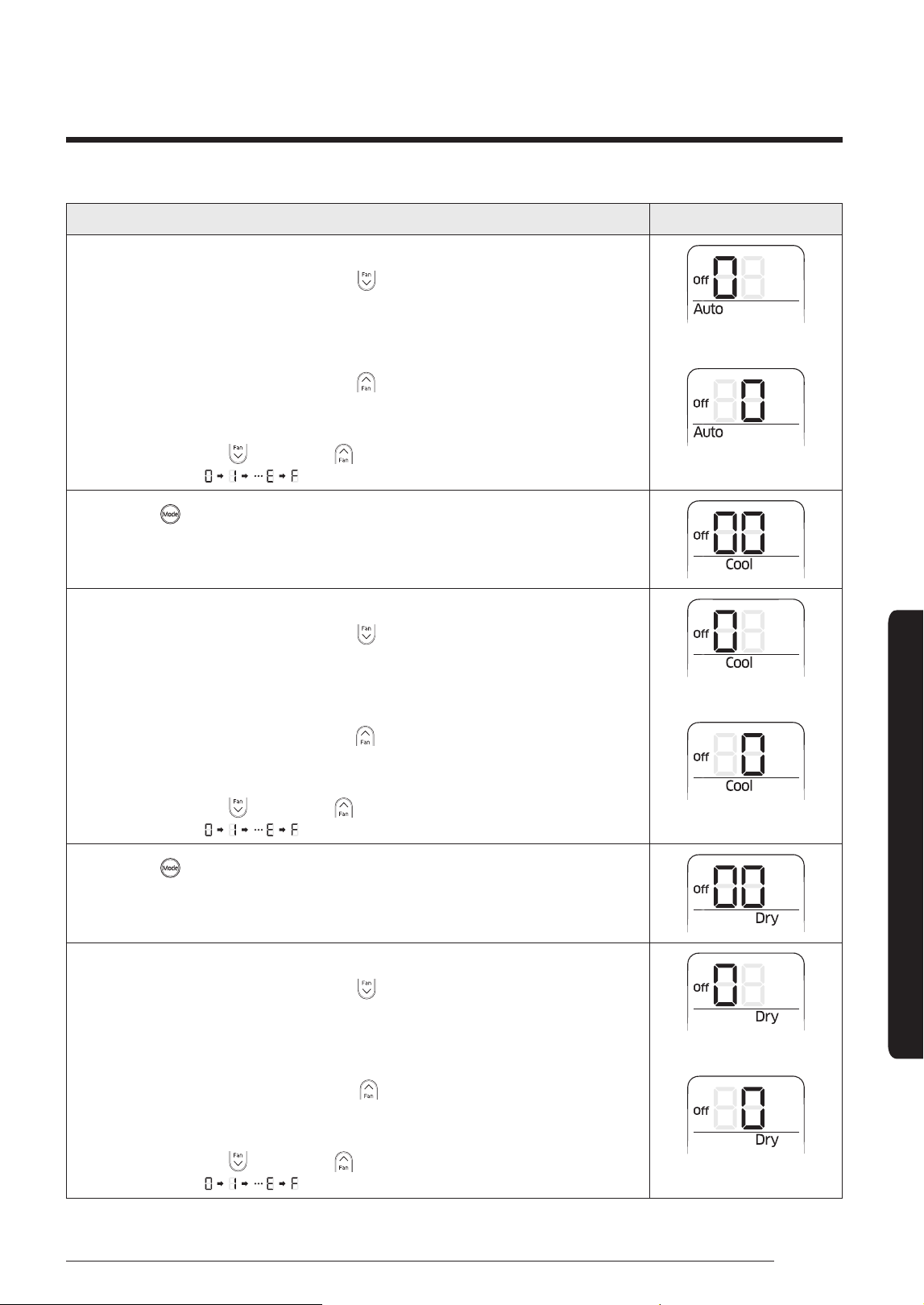
Take the steps presented in the following table:
Steps Remote control display
1 Set the SEG2 and SEG3 values:
a Set the SEG2 value by pressing the (Low Fan) button repeatedly until the
value you want to set appears on the remote control display.
SEG2
b Set the SEG3 value by pressing the (High Fan) button repeatedly until the
value you want to set appears on the remote control display.
When you press the (Low Fan) or (High Fan) button, values appear in the
following order:
SEG3
2 Press the (Mode) button. Cool and On appear on the remote control display.
3 Set the SEG4 and SEG5 values:
a Set the SEG4 value by pressing the (Low Fan) button repeatedly until the
value you want to set appears on the remote control display.
SEG4
b Set the SEG5 value by pressing the (High Fan) button repeatedly until the
value you want to set appears on the remote control display.
When you press the (Low Fan) or (High Fan) button, values appear in the
following order:
SEG5
4 Press the (Mode) button. Dry and On appear on the remote control display.
5 Set the SEG6 and SEG8 values:
a Set the SEG6 value by pressing the (Low Fan) button repeatedly until the
value you want to set appears on the remote control display.
SEG6
b Set the SEG8 value by pressing the (High Fan) button repeatedly until the
value you want to set appears on the remote control display.
When you press the (Low Fan) or (High Fan) button, values appear in the
following order:
SEG8
36
English
Installation Procedure
Installation Procedure
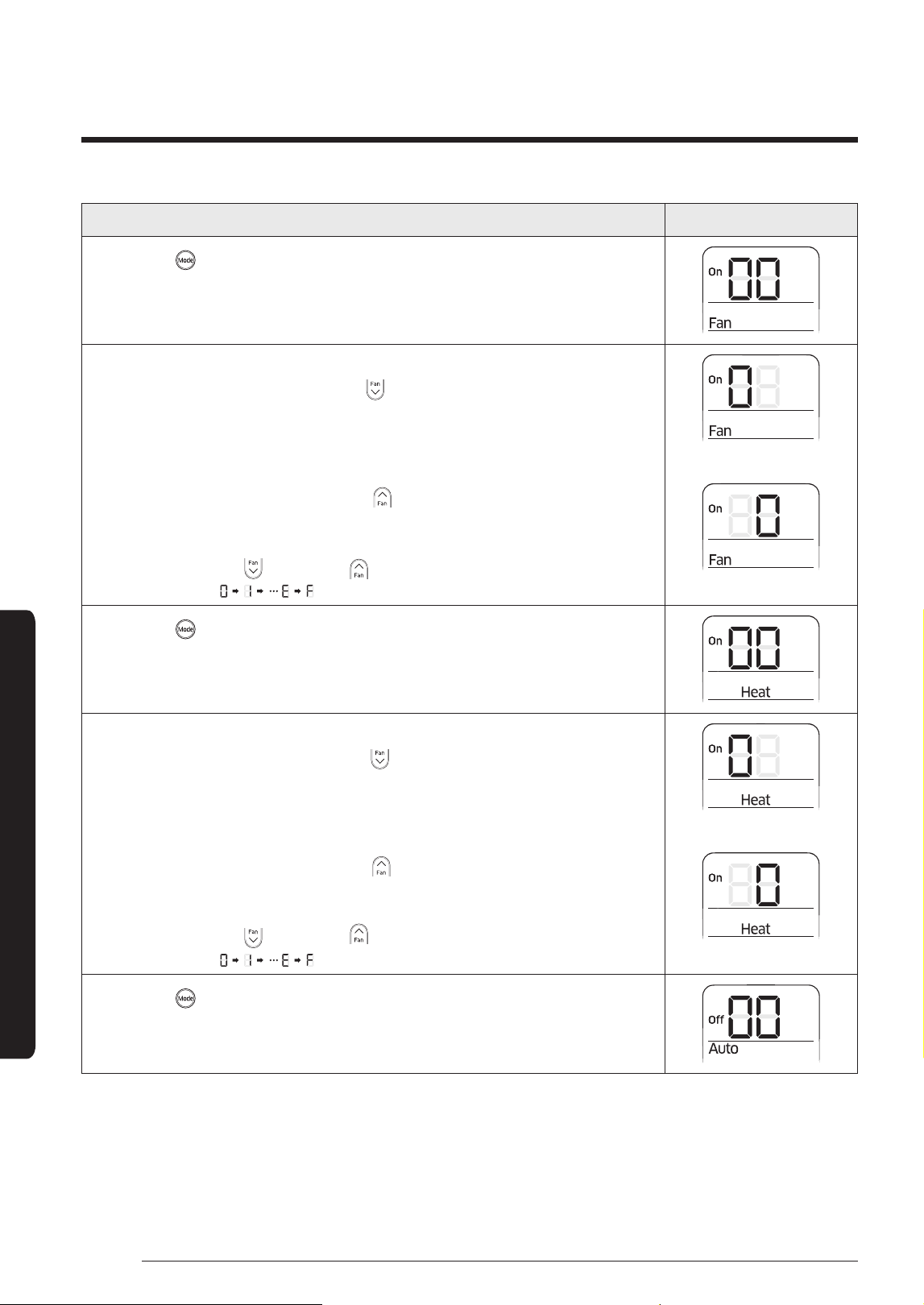
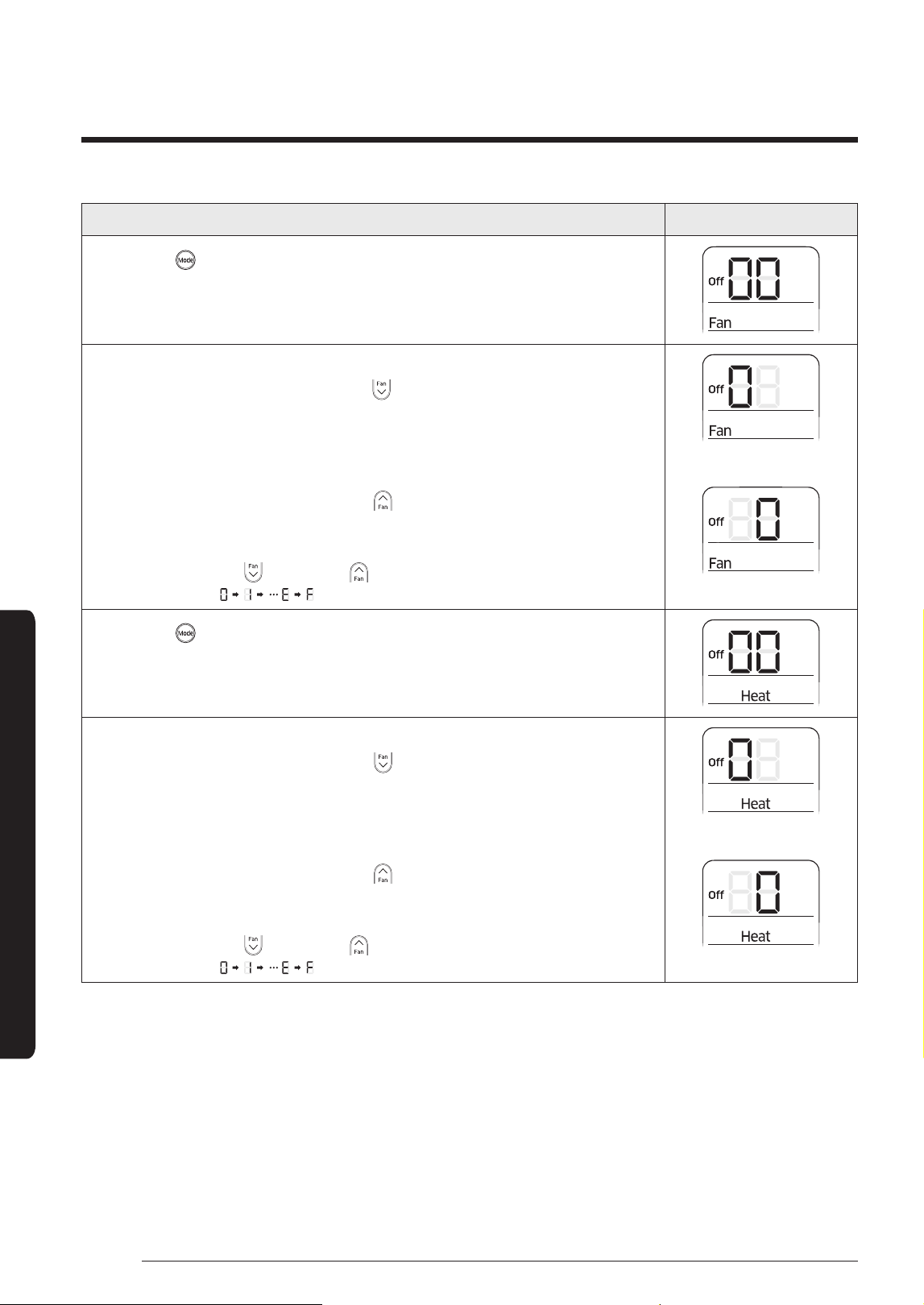
Steps Remote control display
6 Press the (Mode) button. Fan and On appear on the remote control display.
7 Set the SEG9 and SEG10 values:
a Set the SEG9 value by pressing the (Low Fan) button repeatedly until the
value you want to set appears on the remote control display.
SEG9
b Set the SEG10 value by pressing the (High Fan) button repeatedly until the
value you want to set appears on the remote control display.
When you press the (Low Fan) or (High Fan) button, values appear in the
following order:
SEG10
8 Press the (Mode) button. Heat and On appear on the remote control display.
9 Set the SEG11 and SEG12 values:
a Set the SEG11 value by pressing the (Low Fan) button repeatedly until the
value you want to set appears on the remote control display.
SEG11
b Set the SEG12 value by pressing the (High Fan) button repeatedly until the
value you want to set appears on the remote control display.
When you press the (Low Fan) or (High Fan) button, values appear in the
following order:
SEG12
10 Press the (Mode) button. Auto and Off appear on the remote control display.
37
English
Installation Procedure
Steps Remote control display
11 Set the SEG14 and SEG15 values:
a Set the SEG14 value by pressing the (Low Fan) button repeatedly until the
value you want to set appears on the remote control display.
SEG14
b Set the SEG15 value by pressing the (High Fan) button repeatedly until the
value you want to set appears on the remote control display.
When you press the (Low Fan) or (High Fan) button, values appear in the
following order:
SEG15
12 Press the (Mode) button. Cool and Off appear on the remote control display.
13 Set the SEG16 and SEG17 values:
a Set the SEG16 value by pressing the (Low Fan) button repeatedly until the
value you want to set appears on the remote control display.
SEG16
b Set the SEG17 value by pressing the (High Fan) button repeatedly until the
value you want to set appears on the remote control display.
When you press the (Low Fan) or (High Fan) button, values appear in the
following order:
SEG17
14 Press the (Mode) button. Dry and Off appear on the remote control display.
15 Set the SEG18 and SEG20 values:
a Set the SEG18 value by pressing the (Low Fan) button repeatedly until the
value you want to set appears on the remote control display.
SEG18
b Set the SEG20 value by pressing the (High Fan) button repeatedly until the
value you want to set appears on the remote control display.
When you press the (Low Fan) or (High Fan) button, values appear in the
following order:
SEG20
38
English
Installation Procedure
Installation Procedure
Steps Remote control display
16 Press the (Mode) button. Fan and Off appear on the remote control display.
17 Set the SEG21 and SEG22 values:
a Set the SEG21 value by pressing the (Low Fan) button repeatedly until the
value you want to set appears on the remote control display.
SEG21
b Set the SEG22 value by pressing the (High Fan) button repeatedly until the
value you want to set appears on the remote control display.
When you press the (Low Fan) or (High Fan) button, values appear in the
following order:
SEG22
18 Press the (Mode) button. Heat and Off appear on the remote control display.
19 Set the SEG23 and SEG24 values:
a Set the SEG23 value by pressing the (Low Fan) button repeatedly until the
value you want to set appears on the remote control display.
SEG23
b Set the SEG24 value by pressing the (High Fan) button repeatedly until the
value you want to set appears on the remote control display.
When you press the (Low Fan) or (High Fan) button, values appear in the
following order:
SEG24
39
English
Installation Procedure
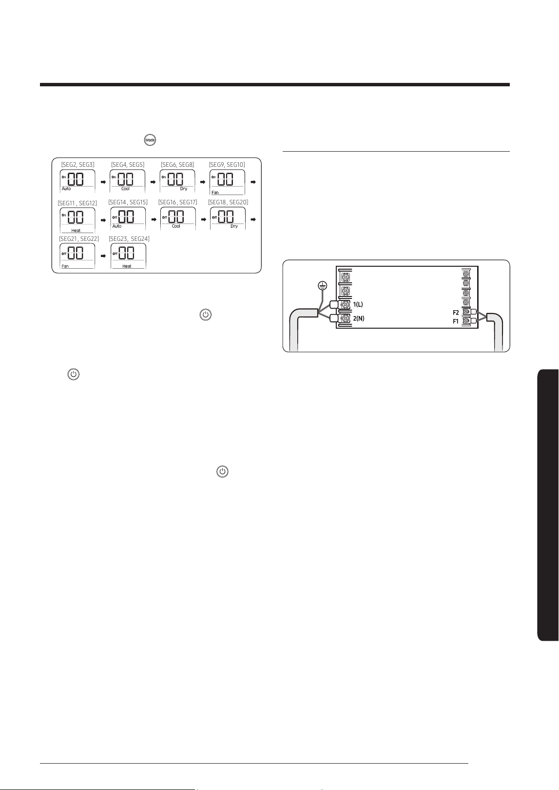
3 Check whether the option values that you have set are
correct by pressing the (Mode) button repeatedly
[SEG2, SEG3] [SEG4, SEG5] [SEG6, SEG8] [SEG9, SEG10]
[SEG11 , SEG12]
[SEG14 , SEG15] [SEG16 , SEG17] [SEG18 , SEG20]
[SEG21 , SEG22] [SEG23, SEG24]
4 Save the option values into the indoor unit:
Point the remote control to the remote control sensor
on the indoor unit and then press the (Power)
button on the remote control twice. Make sure that
this command is received by the indoor unit. When it is
successfully received, you can hear a short sound from
the indoor unit. If the command is not received, press
the (Power) button again.
5 Check whether the air conditioner operates in
accordance with the option values you have set:
a Reset the indoor unit by disconnecting and then
reconnecting the power cable of the indoor unit or
by pressing the RESET button on the outdoor unit.
b Remove the batteries from the remote control,
insert them again, and then press the (Power)
button on the remote control.
Setting the indoor unit address and installation
option
1 Make sure that the power is supplied to the indoor
unit.
• If the indoor unit is not plugged in, it must include a
power supply.
2 Make sure that the panel or display is connected to the
indoor unit so that it can receive options
Indoor unit
3 Set an address and installation option for each indoor
unit using the remote control, according to your air
conditioning system plan.
40
English
Installation Procedure
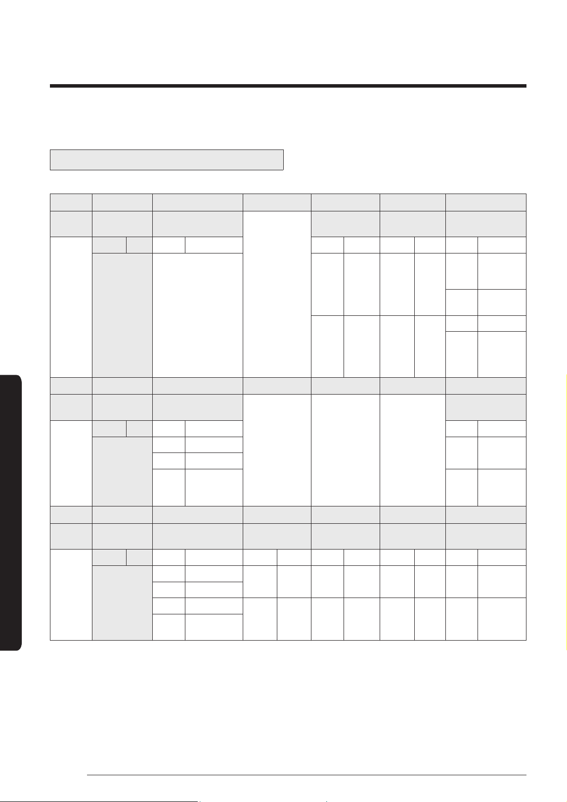
Setting an indoor unit address (MAIN/RMC)
• The indoor unit address are set to 0A0000-100000-200000-300000 by default.
Option No. : 0AXXXX-1XXXXX-2XXXXX-3XXXXX
Option SEG1 SEG2 SEG3 SEG4 SEG5 SEG6
Explanation Page Mode
Setting main
address
100-digit of indoor
unit address
10-digit of indoor
unit
A single digit of
indoor unit
Indication
and details
Indication Details Indication Details Indication Details Indication Details Indication Details Indication Details
0 A
0
No main
address
0~9 100-digit 0~9 10-digit 0~9
A
single
digit
1
Main
address
setting
mode
Option SEG7 SEG8 SEG9 SEG10 SEG11 SEG12
Explanation Page
Reserved
Setting RMC
address
Reserved
Group channel(*16) Group address
Indication
and details
Indication Details Indication Details Indication Details Indication Details
1
0
No RMC
address
RMC1 1~F RMC2 1~F
1
RMC
address
setting
mode
∗ You must set RMC address setting mode when using the centralized Control.
CAUTION
• When “A”~”F” is entered to SEG4~6, the indoor unit MAIN ADDRESS is not changed.
• If you set the SEG 3 as 0, the indoor unit will maintain the previous MAIN ADDRESS even if you input the option value
of SEG4~6.
• If you set the SEG 9 as 0, the indoor unit will maintain previous RMC ADDRESS even if you input the option value of
SEG11~12.
Installation Procedure
41
English
Installation Procedure
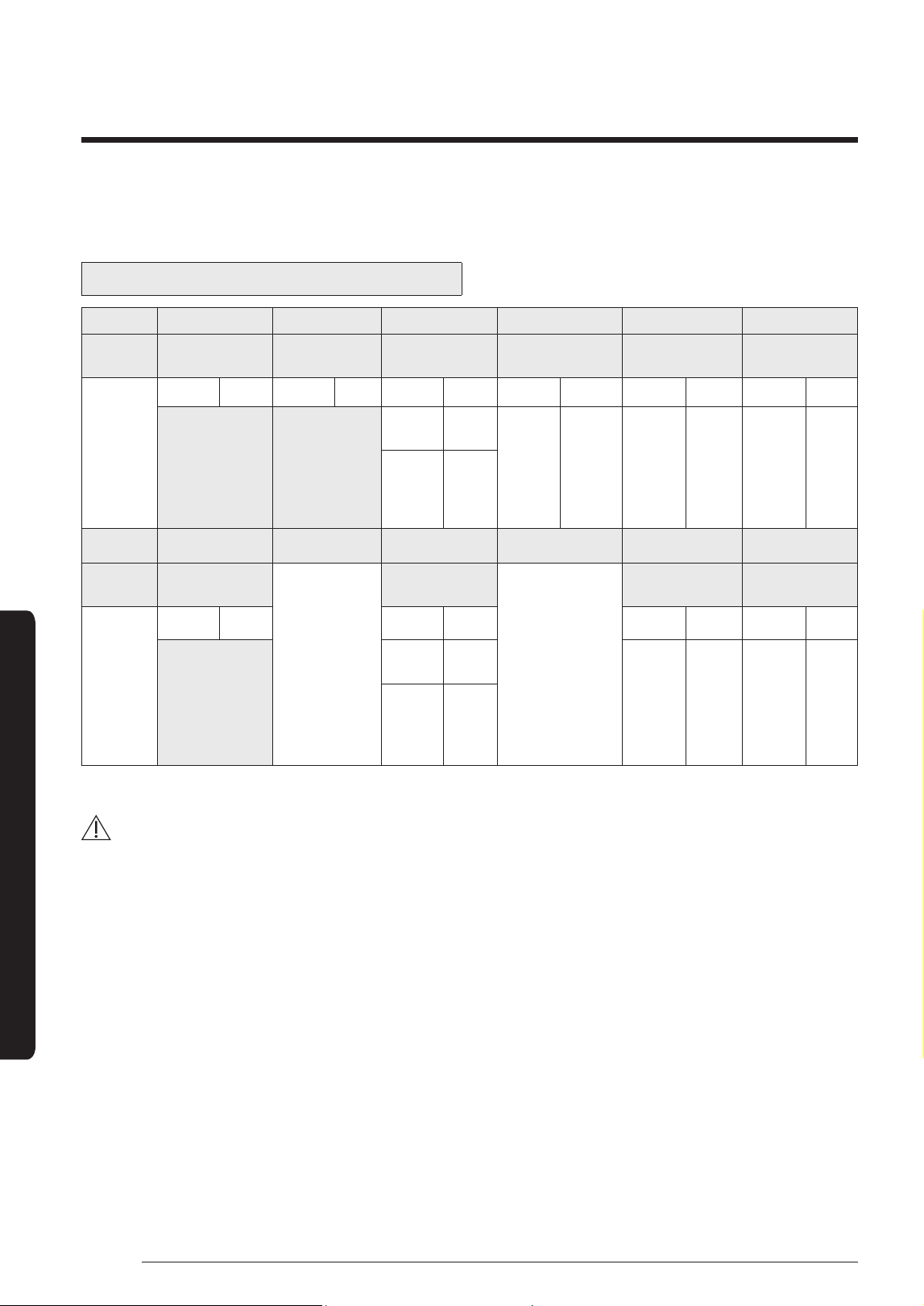
Setting an indoor unit installation option (suitable for the condition of each installation location)
• The indoor unit installation option are set to 020000-100000-200000-300000 by default.
• Set the indoor unit option by wireless remote controller. When entering Address option, connect remote controller
receiver.
Installation options
SEG1 SEG2 SEG3 SEG4 SEG5 SEG6
0 2 Reserved
Use of external
temperature sensor
Use of central control Compensation of the fan RPM
SEG7 SEG8 SEG9 SEG10 SEG11 SEG12
1 Using of drain pump Reserved Reserved Reserved Remote control
SEG13 SEG14 SEG15 SEG16 SEG17 SEG18
2
Use of external
control
Setting the output of
external control
S-Plasma ion Buzzer Control Hours of filter usage
SEG19 SEG20 SEG21 SEG22 SEG23 SEG24
3
Individual control
with remote control
Heating setting
compensation offset
Dew removal
operation in wind free
mode
Motion detection
sensor
Reserved
• Even if you set the Use of drain pump (SEG8) option to 0, it is automatically set to 2 (the drain pump is used with 3
minute delay).
• If you set the Maximum filter usage time (SEG18) option to a value other than 2 and 6, it is automatically set to 2
(1000 hours).
• If you set an option to a value that is out of range specified above, the option is automatically set to 0 by default.
• The external output of SEG15 is generated via MIM-B14 connection. (Refer to the manual of MIM-B14.)
• If you set the Individual control with remote control (SEG20) option to a value other than 0 to 4, it is automatically set
to 0 (Indoor 1).
42
English
Installation Procedure
Installation option (Detailed)
Option No. : 02XXXX-1XXXXX-2XXXXX-3XXXXX
Option SEG1 SEG2 SEG3 SEG4 SEG5 SEG6
Explanation Page Mode
Reserved
Use of external
temperature sensor
Use of central control
Compensation of the fan
RPM
Indication
and details
Indication Details Indication Details Indication Details Indication Details Indication Details
0 2
0 Disuse 0 Disuse
0
Disuse
(recessed
installation)
1
High ceiling
mode
1 Use 1 Use
2 High ceiling Kit
3
Noise
reduction
operation
mode
Option SEG7 SEG8 SEG9 SEG10 SEG11 SEG12
Explanation Page Use of drain pump
Reserved Reserved Reserved
Remote control
Indication
and details
Indication Details Indication Details Indication Details
1
0 Disuse
0 Slave
1 Use
2
Use with 3 minute
delay
1 Master
Option SEG13 SEG14 SEG15 SEG16 SEG17 SEG18
Explanation Page Use of external control
Setting the output of
external control
S-Plasma ion Buzzer control Maximum filter usage time
Indication
and details
Indication Details Indication Details Indication Details Indication Details Indication Details Indication Details
2
0 Disuse
0 Thermo ON 0 Disuse 0
Use of
buzzer
2 1000 hours
1 ON or OFF control
2 OFF control
1
Operation
ON
1 Use 1
Disuse of
buzzer
6 2000 hours
3
Window ON or OFF
control
Installation Procedure
43
English
Installation Procedure
Option SEG19 SEG20 SEG21 SEG22 SEG23 SEG24
Explanation Page
Individual control with remote
control
Heating setting
compensation offset
Dew removal
operation
in wind free mode
Reserved Reserved
Indication
and details
Indication Details Indication Details Indication Details Indication Details
3
0 or 1 channel 1 0
Default
(*1)
0
(Default)
Maintain
blade
status in
wind free
mode
2 channel 2 1 2°C
3 channel 3
2 5°C 1
Cooling
operation
by
opening
the blade
4 channel 4
(*1) Default setting value: 2 °C
(*2) If you input a number other than 0~4 of the individual control of the indoor unit(SEG20), the indoor is set as
“channel 1”.
44
English
Installation Procedure
Installation Procedure
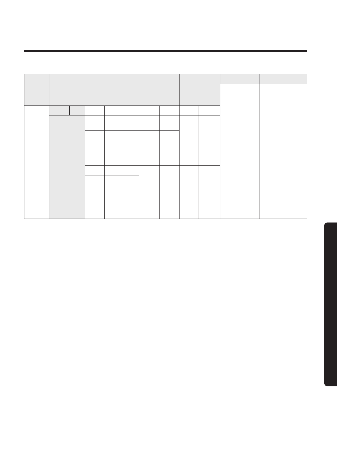
Changing the addresses and options individually
When you want to change the value of a specific option, refer to the following table and follow the steps in Common
steps for setting the addresses and options on page 34.
Option SEG1 SEG2 SEG3 SEG4 SEG5 SEG6
Function Page Mode
Type of the option to
change
Tens position of the
option number
Units position of the
option number
New value
Indication
and details
Indication Details Indication Details Indication Details Indication Details Indication Details Indication Details
0 D
Option
type
0 to F
Tens
position
value
0 to 9
Units
position
value
0 to 9
New
value
0 to F
Example: Changing the Buzzer control (SEG17) option of the installation options to 1 disuse.
Option SEG1 SEG2 SEG3 SEG4 SEG5 SEG6
Function Page Mode
Type of the option to
change
Tens position of the
option number
Units position of the
option number
New value
Indication 0 D 2 1 7 1
CAUTION
• If your indoor units support both cooling and heating, the mixed operation (two or more indoor units operate in
different modes simultaneously) is not available when the indoor units are connected to the same outdoor unit. If
you set an indoor unit as the master indoor unit by using the remote control, the outdoor unit automatically operate
in the current mode of the master indoor unit.
45
English
Appendix
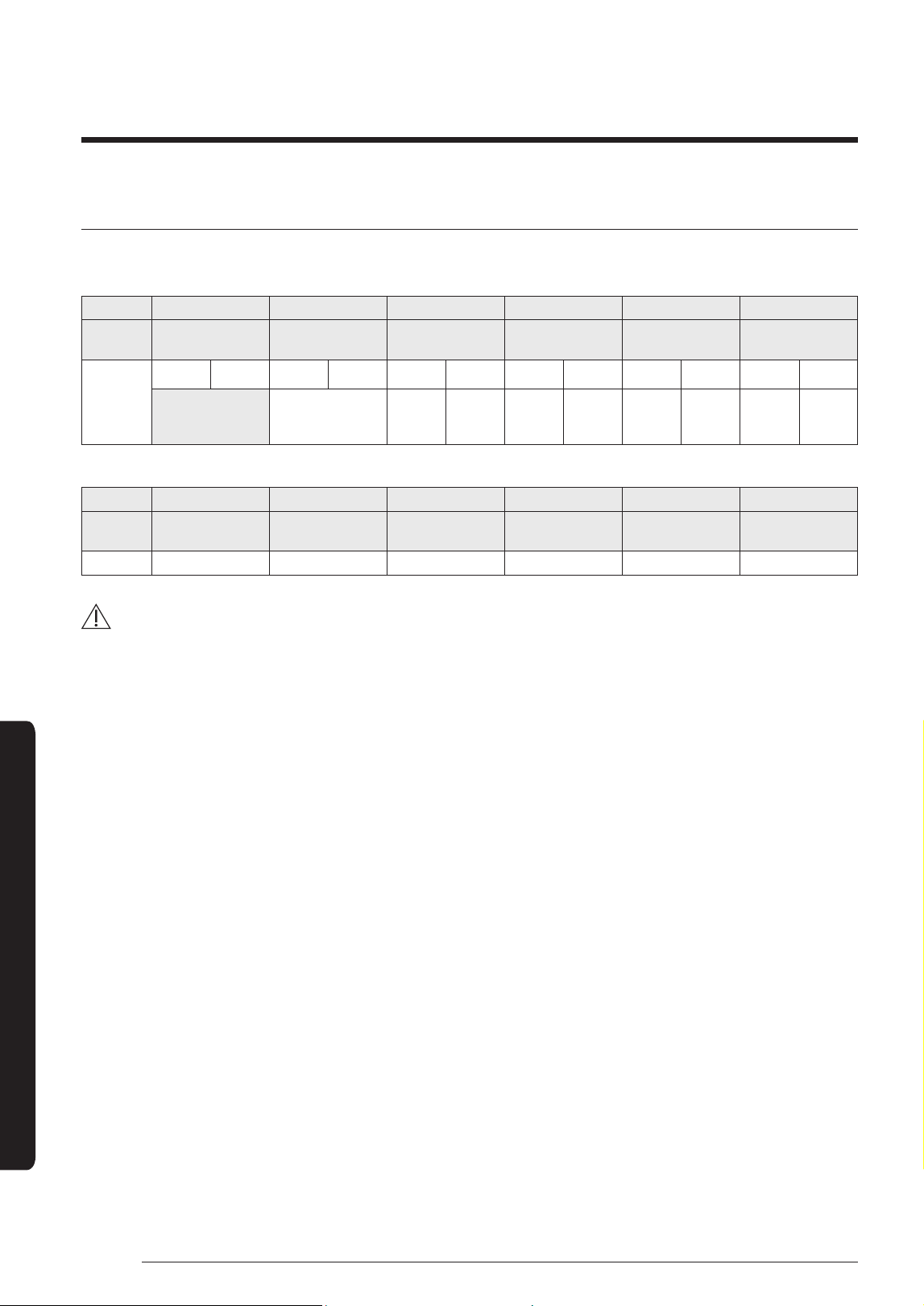
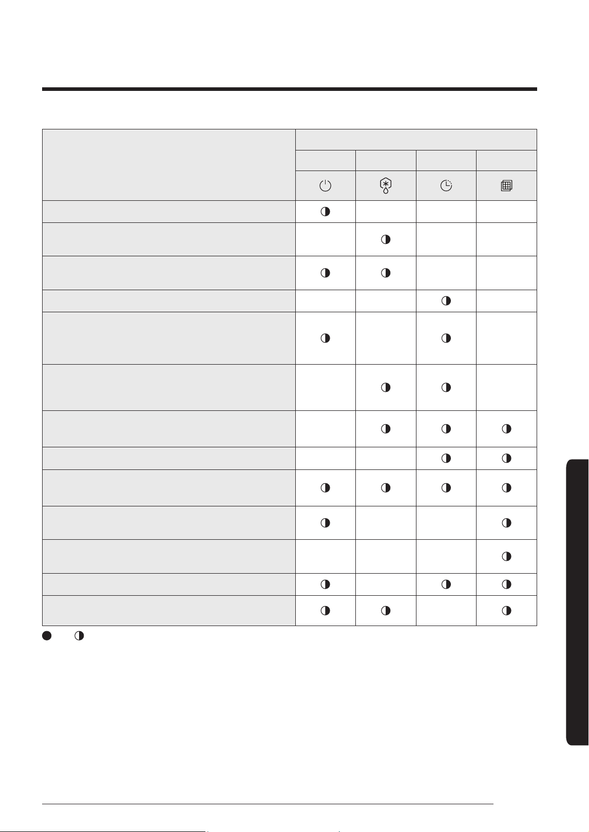
Troubleshooting
Abnormal conditions
LED lamp display
Operation Defrost Timer Filter
Power reset
X X X
Error of tempreature sensor in the indoor unit (Open/
Short)
X X X
Error of heat exchanger sensor in the indoor unit (Open/
Short)
X X
Error of fan motor in the indoor unit
X X X
Error of the outdoor temperature sensor
Error of the condensor temperature sensor
Error of the discharge temperature sensor
X X
No communication for 2 minutes between indoor and
outdoor unit (communication error for more than 2
minutes)
X X
Error of outdoor unit
Error of the terminal block thermal fuse (Open)
X
Detection of the float switch
X X
EEPROM error
EEPROM option error
Motion detect sensor error
X X
Mixed operatiion error
X X X
Outdoor valve clogging error
X
Miss matching error between indoor unit and outdoor unit
X
: On,
: Flickering, X : Off
• If you turn off the air conditioner when the LED is flickering, the LED is also turned off.
Appendix
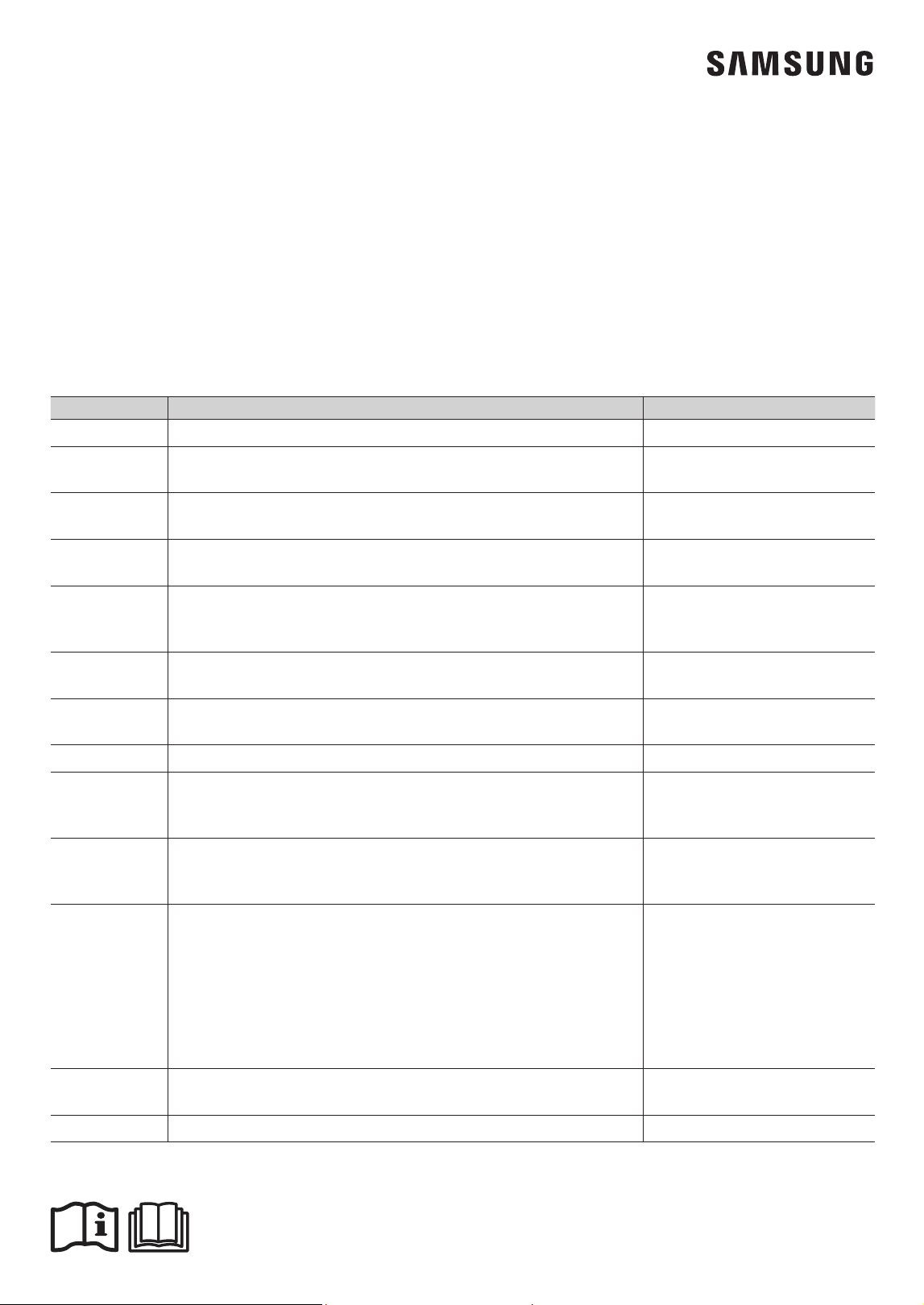
QUESTIONS OR COMMENTS?
COUNTRY CALL OR VISIT US ONLINE AT
SINGAPORE 1800-SAMSUNG(726-7864) www.samsung.com/sg/support
AUSTRALIA
1300 362 603 (Other)
1300 425 299 (HHP)
www.samsung.com/au/support
NEW ZEALAND
0800 726 786 (All Product)
0800 6 726 786 (Support for Smart Mobile Devices)
www.samsung.com/nz/support
VIETNAM
1800 588 889 (OTH)
1800-588-855 (HHP)
www.samsung.com/vn/support
THAILAND
0-2689-3233 (only for HHP)
0-2689-3232 (OTH products)
1800-29-3232 (Toll free)
www.samsung.com/th/support
MYANMAR
+95-1-2399-888
VIP HHP +95-1-2399-990
www.samsung.com/th/support
CAMBODIA
+855-23-993232
1800-20-3232 (Toll free)
www.samsung.com/th/support
LAOS +856-214-17333 www.samsung.com/th/support
MALAYSIA
1800-22-8899 (HHP)
1800-88-9999 (OTH)
+603-7713 7420 (Overseas contact)
www.samsung.com/my/support
INDONESIA
021-5699-7777
0800-112-8888 (All Product, Toll Free)
0800-112-7777 (Only for HHP, Toll Free)
www.samsung.com/id/support
PHILIPPINES
Only for HHP PRODUCT :
#GALAXY (just dial #425-299) [ PLDT / Globe / Smart / Sun Toll Free ]
02-422-2117 [ Standard Landline ]
OTH PRODUCT :
1-800-10-726-7864 [ PLDT Toll Free ]
1-800-8-726-7864 [ Globe Landline and Mobile ]
02-422-2111 [ Standard Landline ]
www.samsung.com/ph/support
TAIWAN
0800-329-999 (All Product)
0809-05-5237 (Only for HHP)
www.samsung.com/tw/support
JAPAN 0120-363-905 www.galaxymobile.jp/jp/support