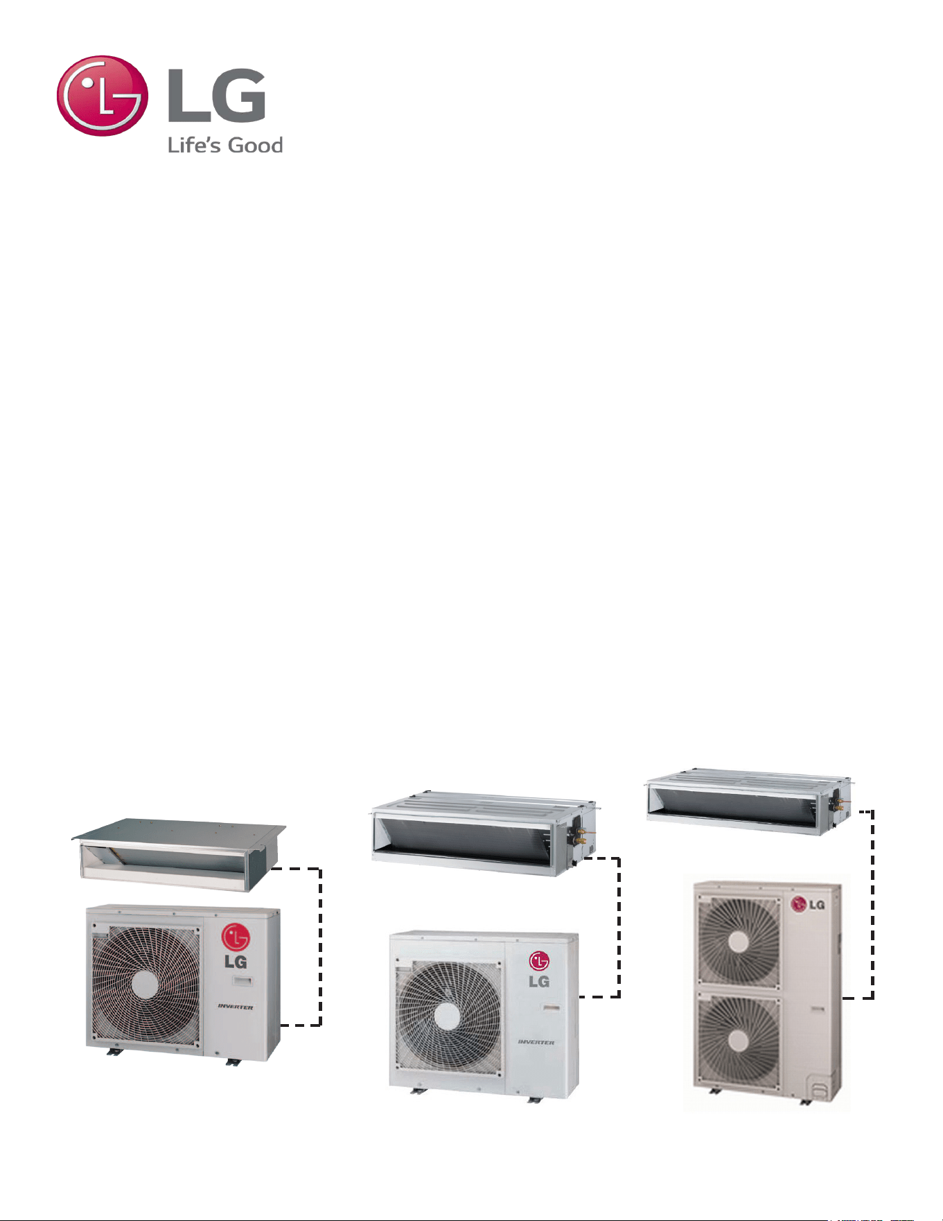
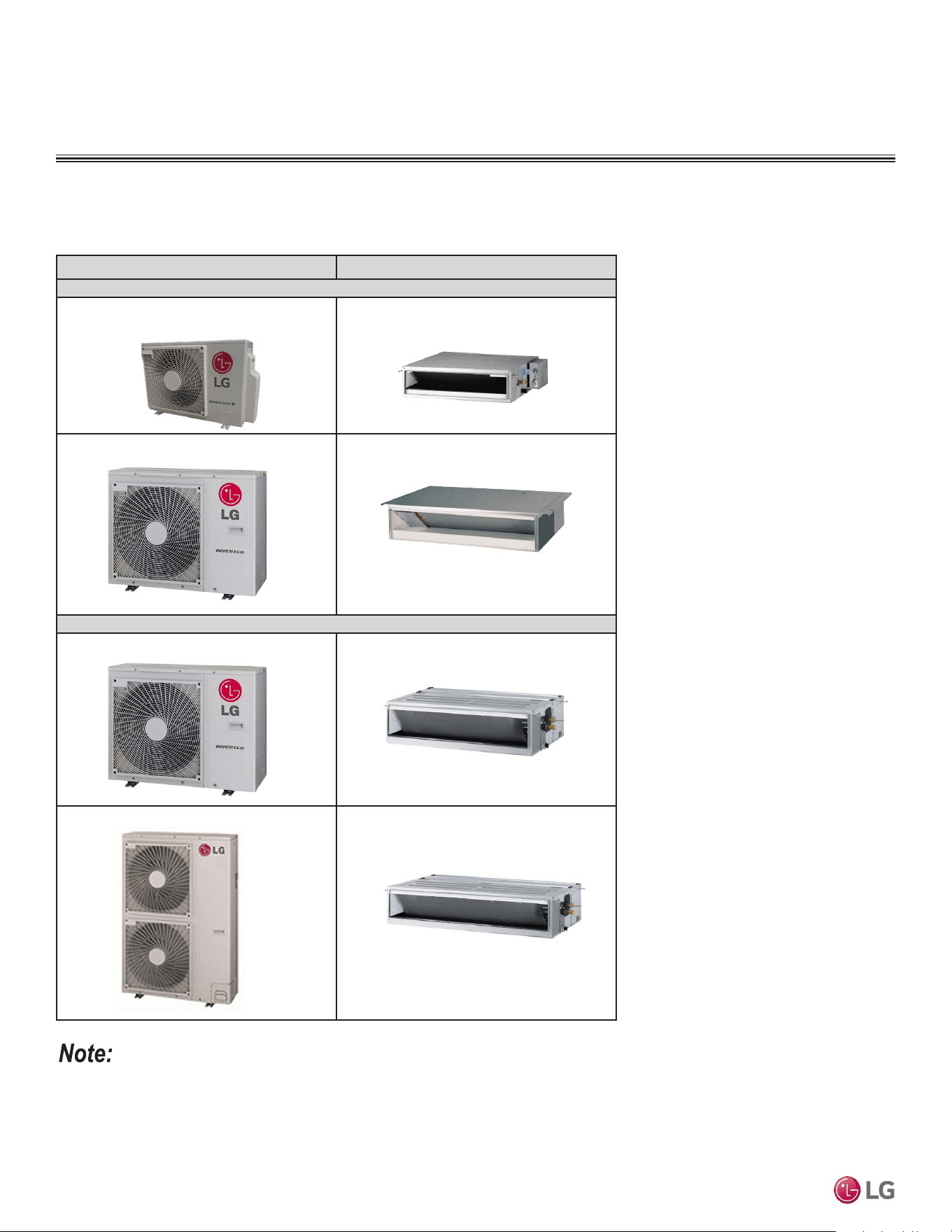
SINGLE-ZONE
CEILING-CONCEALED
DUCTED SYSTEM
ENGINEERING MANUAL
Single-Zone Ceiling-Concealed
Ducted Heat Pump Systems
3/4 to 3 Tons
High Static
LH248HV4 (24,000 Btu/h)
High Static
LH368HV4 (36,000 Btu/h)
Low Static
LD097HV4 (9,000 Btu/h)
LD127HV4 (12,000 Btu/h)
LD187HV4 (18,000 Btu/h)

For continual product development, LG Electronics U.S.A., Inc., reserves the right to change specifications without notice.
© LG Electronics U.S.A., Inc.
PROPRIETARY DATA NOTICE
This document, as well as all reports, illustrations, data, information,
and other materials are the property of LG Electronics U.S.A., Inc., and are
disclosed by LG Electronics U.S.A., Inc. only in confidence.
This document is for design purposes only.
A summary list of safety precautions is on page 4.
For more technical materials such as submittals, catalogs, installation,
owner’s, and service manuals, visit www.lghvac.com.
Due to our policy of continuous product innovation, some specications may change without notication.
©LG Electronics U.S.A., Inc., Englewood Cliffs, NJ. All rights reserved. “LG” is a registered trademark of LG Corp.
INTRODUCTION | 3
Introduction
TABLE OF CONTENTS
Unit Nomenclature .......................................................................................................................................................................................................... 4
LG Air Conditioner Technical Solution (LATS) .........................................................................................................................................................5-6
Ducted System Data .................................................................................................................................................................................................. 7-50
Mechanical Specications ......................................................................................................................................................................................... 8-9
General Data ......................................................................................................................................................................................................... 10-12
Electrical Data ............................................................................................................................................................................................................ 13
Functions, Controls, and Options .......................................................................................................................................................................... 14-15
Dimensions ............................................................................................................................................................................................................ 16-21
Acoustic Data ........................................................................................................................................................................................................ 22-25
Refrigerant Flow Diagrams .................................................................................................................................................................................... 26-32
Wiring Diagrams .................................................................................................................................................................................................... 33-39
Electrical Connections ........................................................................................................................................................................................... 40-45
External Static Pressure ........................................................................................................................................................................................ 46-47
Accessories ........................................................................................................................................................................................................... 48-50
Performance Data .................................................................................................................................................................................................... 51-63
Cooling Capacity Tables ........................................................................................................................................................................................ 52-56
Heating Capacity Tables ........................................................................................................................................................................................ 57-61
Maximum Heating Capacity Tables ....................................................................................................................................................................... 62-63
Application Guidelines ............................................................................................................................................................................................ 64-82
Equipment Selection Procedure ............................................................................................................................................................................ 65-66
Placement Considerations ..................................................................................................................................................................................... 67-76
Clearances ............................................................................................................................................................................................................ 77-79
Installing Outdoor Unit Indoors .............................................................................................................................................................................. 80-81
Refrigerant Piping Design ........................................................................................................................................................................................... 82
TABLE OF SYMBOLS
DANGER
This symbol indicates an imminently hazardous situation which, if not avoided, will result in death or
serious injury.
This symbol indicates a potentially hazardous situation which, if not avoided, could result in death or
serious injury.
CAUTION
This symbol indicates a potentially hazardous situation which, if not avoided, may result in minor or
moderate injury.
Note:
This symbol indicates situations that may result in equipment or property damage accidents only.
This symbol indicates an action that must not be performed.
Due to our policy of continuous product innovation, some specications may change without notication.
©LG Electronics U.S.A., Inc., Englewood Cliffs, NJ. All rights reserved. “LG” is a registered trademark of LG Corp.
4 | INTRODUCTION
Single Zone Ceiling-Concealed Ducted System Engineering Manual
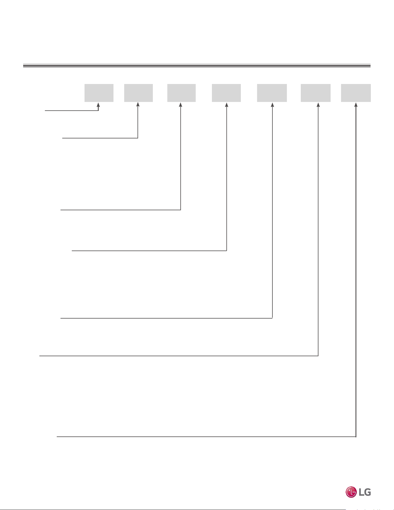
UNIT NOMENCLATURE
H 248 H
System Type:
Style:
SV = High Efficiency Inverter
VP = Gallery
YV = Premier
EV = Mega
V = Standard Inverter
T = Thermostat Compatible
Nominal Capacity
(Nominal cooling capacity in Btu/h):
Frame Type:
A: Art Cool™
S: Standard
C: Four-Way Ceiling-Cassette
D: Ceiling-Concealed Duct (Low Static)
H: Ceiling-Concealed Duct (High Static)
V: Vertical-Horizontal Air Handling
L = LG
09 = 9,000
12 = 12,000
18 = 18,000
24 = 24,000
30 = 30,000
36 = 36,000
42 = 42,000
54 = 54,000
L V 4N
N: Indoor Unit
U: Outdoor Unit
No N or U: System
H = Heat Pump
Generation:
Due to our policy of continuous product innovation, some specications may change without notication.
©LG Electronics U.S.A., Inc., Englewood Cliffs, NJ. All rights reserved. “LG” is a registered trademark of LG Corp.
INTRODUCTION | 5
Introduction
LG AIR CONDITIONER
TECHNICAL SOLUTION (LATS)
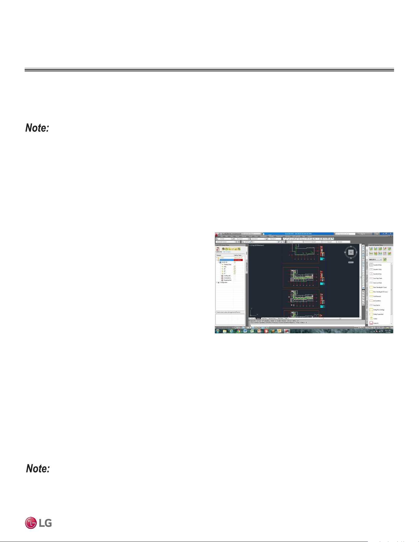
LG Air Conditioner Technical Solution (LATS) Software
A properly designed and installed refrigerant piping system is critical to the optimal performance of LG air-conditioning systems. To assist
engineers, LG offers, free of charge, LG Air Conditioner Technical Solution (LATS) software—a total design solution for LG air conditioning
systems. Contact your LG Rep for the best software program for your application.
To reduce the risk of designing an improper applied system or one that will not operate correctly, LG requires that LATS software be used on all projects.
Formats
LATS is available to LG customers in three user interfaces: LATS HVAC, LATS CAD2, and LATS Revit. All three LATS formats are available
through www.myLGHVAC.com, or contact an LG Sales Representative.
LATS HVAC is a Windows
®
-based application that aids engineers in designing LG Variable Refrigerant Flow (VRF), Multi F / Multi F MAX,
Single-Zone, and Energy Recovery Ventilator (ERV) systems.
*Windows
®
is a registered mark of Microsoft
®
Corporation.
LATS CAD2 combines the LG LATS program with AutoCAD
®
software**. It permits engineers to layout and validate LG Multi V
Variable Refrigerant Flow (VRF), Multi F / Multi F MAX, Single-Zone,
and Energy Recovery Ventilator (ERV) systems directly into CAD
drawings.
LATS Revit integrates the LG LATS program with Revit
®
software**.
It permits engineers to layout and validate Multi V VRF systems
directly into Revit drawings.
**AutoCAD® and Revit® are both registered marks of Autodesk, Inc.
Features
All LG product design criteria have been loaded into the program,
making LATS simple to use: double click or drag and drop the
component choices. Build systems in Tree Mode where the refriger-
ant system can be viewed. Switch to a Schematic diagram to see the
electrical and communications wiring.
LATS software permits the user to input region data, indoor and outdoor design temperatures, modify humidity default values, zoning, specify
type and size of outdoor units and indoor units, and input air flow and external static pressure (ESP) for ducted indoor units.
The program can also:
• Import building loads from a separate Excel file.
• Present options for outdoor unit auto selection.
• Automatically calculate component capacity based on design
conditions for the chosen region.
• Verify if the height differences between the various system
components are within system limits.
• Provide the correct size of each refrigerant piping segment and LG
Y-Branches and Headers.
• Adjust overall piping system length when elbows are added.
• Check for component piping limitations and flag if any parameters
are broken.
• Factor operation and capacity for defrost operation.
• Calculate refrigerant charge, noting any additional trim charge.
• Suggest accessories for indoor units and outdoor units.
• Run system simulation.
Features depend on which LATS program is being used, and the type of system being designed.
Figure 1:Example of LATS CAD2.
Due to our policy of continuous product innovation, some specications may change without notication.
©LG Electronics U.S.A., Inc., Englewood Cliffs, NJ. All rights reserved. “LG” is a registered trademark of LG Corp.
6 | INTRODUCTION
Single Zone Ceiling-Concealed Ducted System Engineering Manual
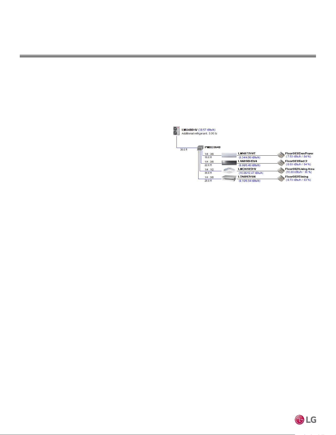
LATS Generates a Complete Project Report
LATS software also generates a report containing project design parameters, cooling and heating design data, system component perfor-
mance, and capacity data. The report includes system combination ratio and refrigerant charge calculations; and provides detailed bill of
material, including outdoor units, indoor units, control devices, accessories, refrigerant pipe sizes segregated by building, by system, by pipe
size, and by pipe segments. LATS can generate an Excel GERP report that can imported into the LG SOPS pricing and ordering system.
Proper Design to Install Procedure
LG encourages a two report design-to-install-procedure. After the
design engineer determines building / zone loads and other details,
the engineer opens the LATS program and inputs the project’s infor-
mation. When the design is complete, the “Auto Piping” and “System
Check” functions must be used to verify piping sizes, limitations, and
if any design errors are present. If errors are found, engineers must
adjust the design, and run Auto Piping and System Check again.
When the design passes the checks, then the engineer prints out
a project “Shop Drawing” (LATS Tree Diagram) and provides it to
the installing contractor. The contractor must follow the LATS Tree
Diagram when building the piping system, but oftentimes the design
changes on the building site:
• Architect has changed location and/or purpose of room(s).
• Outdoor unit cannot be placed where originally intended.
• Structural elements prevent routing the piping as planned.
• Air conditioning system conflicts with other building systems (plumbing, gas lines, etc.).
The contractor must mark any deviation from the design on the Shop Drawing, including as-built straight lines and elbows. This “Mark Up”
drawing must be returned to the design engineer or Rep, who must input contractor changes into the LATS file. (Copy the original LATS soft-
ware file, save and rename as a separate file, and modify all piping lengths by double-clicking on each length and editing information.) Like
the shop drawing, the Auto Piping and System Check must also be run on this new “As Built” drawing. The design engineer or Rep must then
provide the final As Built file to the contractor. The Mark Up version must be compared to the As Built version for the following:
• Differences in pipe diameter(s). If incorrect diameters have been installed, the piping must be changed out. If pipe diameters have changed,
check to see if Y-Branches will also need to be changed.
• Changes to outdoor unit and indoor unit capacities. Capacities changes may impact line length changes.
• Additional refrigerant charge quantity (“Trim Charge”). Trim charge will change if piping lengths and diameters change. The As Built version
must reflect installed piping lengths to ensure correct trim charge.
All documents submitted by the contractor, as well as the Shop Drawing and the As Built Drawing files must be provided for commissioning
purposes. Model and serial numbers for all system components must also be submitted. If the steps previously detailed are not followed, and
all documents are not provided to the LG Commissioner, the project runs the risk of not being commissioned and voiding any limited warranty
LG offers on the equipment.
LG AIR CONDITIONER
TECHNICAL SOLUTION (LATS)
Figure 2:Example of a LATS Tree Diagram.

Mechanical Specifications on page 8
General Data on page 10
Electrical Data on page 13
Functions, Controls, and Options on page 14
Dimensions on page 16
Acoustic Data on page 22
Refrigerant Flow Diagrams on page 26
Wiring Diagrams on page 33
Electrical Connections on page 40
External Static Pressure on page 46
Accessories on page 48
CEILING-CONCEALED
DUCTED UNIT PRODUCT
DATA
Due to our policy of continuous product innovation, some specications may change without notication.
©LG Electronics U.S.A., Inc., Englewood Cliffs, NJ. All rights reserved. “LG” is a registered trademark of LG Corp.
8 | DUCTED
Single Zone Ceiling-Concealed Ducted System Engineering Manual
MECHANICAL SPECIFICATIONS
Ceiling-Concealed Ducted System
General
System
LG single zone ceiling-concealed ducted system comprises of a
single frame outdoor unit connected to a single indoor unit with a
single refrigerant circuit. An LG single zone ceiling-concealed ducted
system can operate in either cooling or heating mode. The system
is capable of changing mode within a maximum time of three (3)
minutes to ensure indoor temperature can be
properly maintained. LG components are manufactured in a facility
registered to ISO 9001 and ISO 14001, which is a set of
standards applying to environmental protection set by the
International organization for Standardization (ISO). The system
components comply with Underwriters Laboratories (UL) 1995
Heating and Cooling Equipment Standard for Safety and bear the
CSA label. Wiring in these units are in accordance with the national
Electrical Code (NEC). LG single zone ceiling-concealed ducted
systems have published performance ratings certified by AHRI (Air-
Conditioning, Heating, and Refrigeration Institute) and are listed in
the AHRI Standard 210/240 certified product directory.
Outdoor Unit
The outdoor unit has sound levels not exceeding 54 dB(A) tested in
an anechoic chamber under ISO Standard 3745.
Indoor Unit
Ceiling-Concealed Ducted units are designed for air volume against
an external static pressure up to 0.59″WG for the 24,000 Btu/h and
36,000 Btu/h model.
Temperature Ranges
9,000 and 12,000 Btu/h Low Static Operating Ranges
• Operating ranges for outdoor units of 0°F to +118°F (DB) for
cooling (Cooling range can be extended from 0°F down to -4°F
using the Low Ambient Wind Baffle Kit [sold separately]); -4°F to
+64°F (WB) for heating.
• Operating ranges for indoor units of 57°F to 77°F (WB) for cooling;
59°F to 81°F (DB) for heating.
• Indoor unit temperature setting range of 65°F to 86°F (DB) for
cooling; 61°F to 86°F (WB) for heating.
18,000, 24,000, and 36,000 Btu/h Low Static Operating
Ranges
• Operating ranges for outdoor units of 5°F to +118°F (DB) for
cool ing; -4°F to +64°F (WB) for heating.
• Operating ranges for indoor units of 57°F to 77°F (WB) for cooling;
59°F to 81°F (DB) for heating.
• Indoor unit temperature setting range of 65°F to 86°F (DB) for
cooling; 61°F to 86°F (WB) for heating.
• Cooling range can be extended from 5°F down to -4°F using the
Low Ambient Wind Baffle Kit (sold separately).
Casing / Frame
Outdoor Unit
The outdoor condensing unit case is constructed from pre-coated
metal (PCM) that has been tested in accordance with ASTM B-117
salt spray procedure for a minimum of 1,000 hours. Case has a
removable panel to allow access to major internal components, and
legs to secure the unit during installation.
Indoor Unit
The indoor unit casing is designed to mount fully concealed above
a finished ceiling. Casing is manufactured of galvanized steel plate.
Cold surfaces of the unit are covered internally with a coated poly-
styrene insulating material, and covered externally with sheet insula-
tion made of ethylene propylene diene monomer (M-Class) (EPDM).
External insulation is plenum rated and conforms to ASTM Standard
D-1418. Hanger brackets are included on the casing to support the
weight on four corners. The indoor unit has a front horizontal supply
air discharge, and one dedicated rear horizontal return air. The
supply air opening is flanged to accept field-installed ductwork that
must not exceed the external static pressure limitation of the unit.
Refrigerant System
The system is designed for use with R410A refrigerant, and consists
of a single refrigeration circuit. The refrigeration circuit is pressure-
tested at the factory and shipped with a holding charge of helium
gas. The outdoor unit is provided with factory installed components,
including a refrigerant strainer, accumulator, four-way reversing
valve, electronic expansion valve (EEV), high and low side charging
ports, service valves, and interconnecting piping. All refrigerant lines
from the outdoor unit to the indoor unit are field-installed and must
be insulated separately.
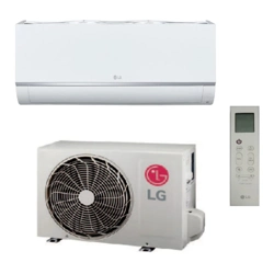
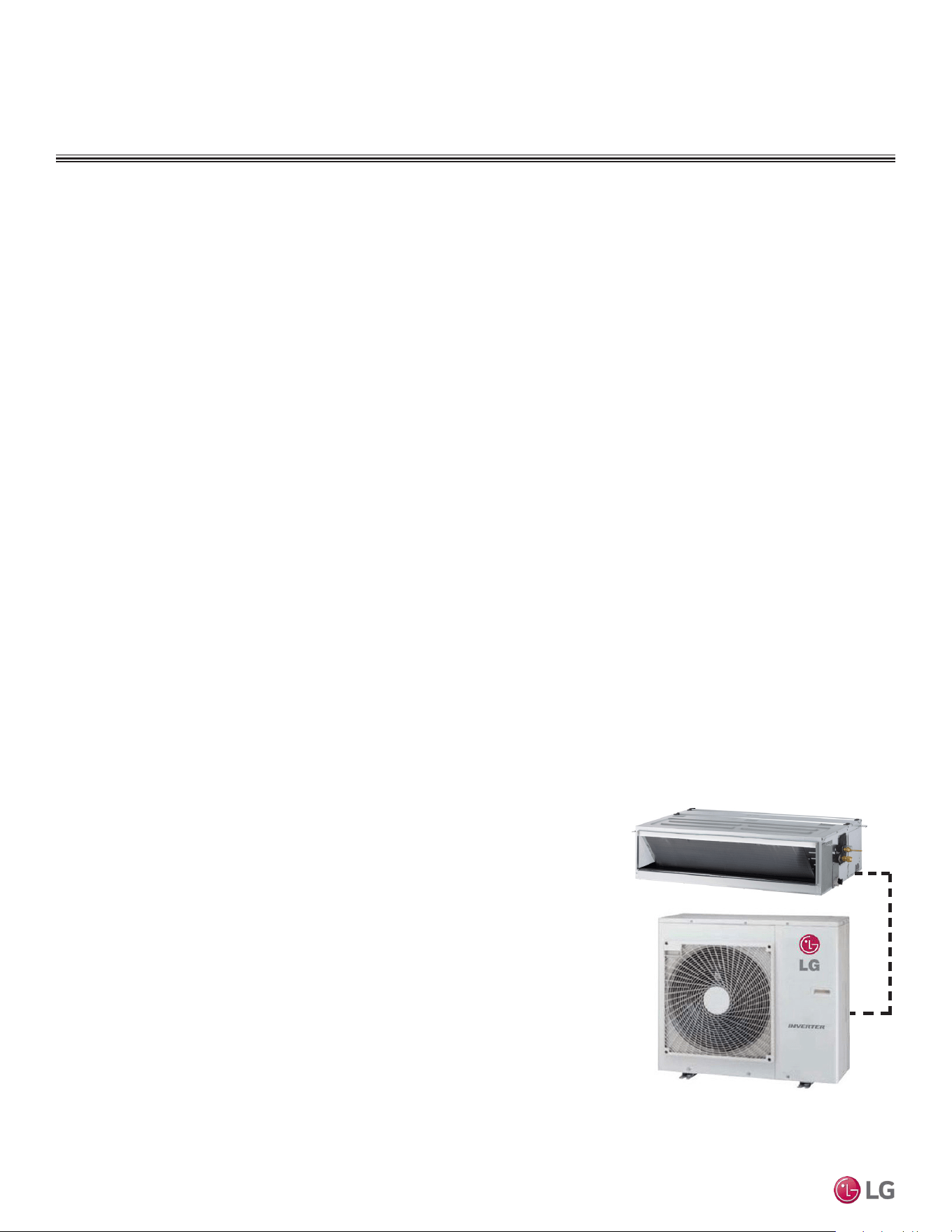
Figure 3: Ceiling-Concealed Ducted
System (LH248HV4 High Static Model).
DUCTED | 9
Product Data
Due to our policy of continuous product innovation, some specications may change without notication.
©LG Electronics U.S.A., Inc., Englewood Cliffs, NJ. All rights reserved. “LG” is a registered trademark of LG Corp.
Compressors
The 9,000 ~ 24,000 Btu/h outdoor units are equipped with one
hermetically sealed, digitally controlled, inverter-driven twin rotary
compressor to modulate capacity (modulation in 1 Hz increments).
The 36,000 Btu/h outdoor unit is equipped with one hermetically
sealed, digitally controlled, inverter-driven scroll compressor to
modulate capacity (modulation in 1 Hz increments). Teflon coated
bearings, overcurrent protection, and vibration isolation are
integrated with the compressor.
Frequency ranges for the 9,000 ~ 36,000 Btu/h outdoor units are:
9k Btu/h = 20 Hz to 100 Hz
12k Btu/h = 20 Hz to 100 Hz
18 Btu/h = 15 to 80 Hz Cooling; 15 to 100 Hz Heating
24k Btu/h = 15 to 80 Hz Cooling; 15 to 100 Hz Heating
36k Btu/h = 15 to 120 Hz Cooling; 15 to 130 Hz Heating
Coil
Outdoor Unit
Heat pump outdoor unit coils are made of nonferrous louvered
aluminum fins protected with an integral coil guard. The coil for each
outdoor unit has a minimum of 14 fins per inch (FPI); heat exchanger
has two rows. The coil fins have a factory applied corrosion resistant
GoldFin™ material with hydrophilic coating tested in accordance with
ASTM B-117 salt spray test procedure for a minimum of 1,000 hours.
Coils are factory tested to a pressure of 551 psig.
Indoor Unit
Indoor unit coils are factory built and are comprised of aluminum fins
mechanically bonded to copper tubing. Each indoor unit has a mini-
mum of three rows of coils, which are pressure tested to 551 psig at
the factory. Each unit is provided with a factory installed condensate
drain pan below the coil.
Fans and Motors
Outdoor Unit
The 9,000 Btu/h (LUU097HV), 12,000 Btu/h (LUU127HV), 18,000
Btu/h (LUU189HV), and 24,000 Btu/h (LUU249HV) outdoor units
include one direct drive, variable speed axial / propeller type fan
with a horizontal air discharge; the 36,000 Btu/h outdoor unit
(LUU369HV) includes two fans. Fan blades are made of Acrylonitrile
Butadiene Styrene (ABS) material, and have a Brushless Digitally
Controlled (BLDC) fan motor. The fan motor has inherent
protection, permanently lubricated bearings, and variable speed with
a maximum speed up to 950 rpm. Raised guards are provided to limit
contact with moving parts.
Indoor Unit
The 9,000 Btu/h (LDN097HV4) indoor unit has 2 direct-drive
Sirocco fans. The 12,000 Btu/h (LDN127HV4) and 18,000 Btu/h
(LDN187HV4) indoor units have three direct-drive Sirocco fans. The
24,000 Btu/h (LHN248HV) indoor unit has one direct-drive Sirocco
fan.
The 36,000 Btu/h (LHN368HV) indoor unit has two direct-drive,
Sirocco fans made of high strength ABS GP-2200 polymeric resin.
The fans are statically and dynamically balanced, mounted on a
common brushless digitally controlled (BLDC) motor, and mounted
on vibration-attenuating rubber grommets. Fan speed is controlled
using a microprocessor-based direct digital control algorithm. The
indoor fan has Low, Med, High, and Auto settings for Cooling mode;
and has Low, Med, High, and Auto settings for Heating mode. The
Auto setting adjusts the fan speed based on the difference between
the controller set-point and space temperature.
Air Filter - Indoor Unit
The return air inlet on the indoor unit includes a factory-supplied
removable, washable filter that is accessible from the back of the
unit. Options include a return filter box that holds a field-provided
high efficiency one or two inch MERV-rated filters, and a LG-supplied
air cleaner (each sold separately).
Electrical
The system is designed to operate using 208–230 / 60 /1 power with
voltage variances of ±10% and includes overcurrent protection. The
indoor unit is powered through the outdoor unit.
Controls
Indoor and outdoor units are factory wired with necessary electrical
control components, printed circuit boards, thermistors, sensors,
terminal blocks, and lugs for power wiring. Factory installed
microprocessor controls in the outdoor unit and indoor unit perform
functions to efficiently operate the single zone system,
communicating via an 14 AWG four stranded and shielded conductor
power/transmission cable. Microprocessor-based algorithms provide
component protection, soft-start capability, refrigeration system
pressure, temperature, defrost, and ambient control. System can be
operated through a simple wired remote controller (required, but sold
separately).
Condensate Lift/Pump
The indoor unit is
provided with a factory
installed and wired
condensate lift/pump
capable of providing
a minimum 27-9/16 inch
lift from the bottom
surface of the unit.
Drain pump has a safety
switch to shut off the
indoor unit if the
condensate rises too
high in the drain pan.
MECHANICAL SPECIFICATIONS
Ceiling-Concealed Ducted System
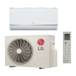
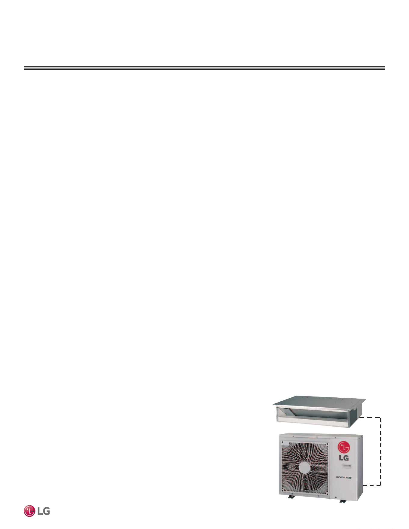
Figure 4: Ceiling-Concealed Ducted
System (LD187HV4 Low Static Model).
Due to our policy of continuous product innovation, some specications may change without notication.
©LG Electronics U.S.A., Inc., Englewood Cliffs, NJ. All rights reserved. “LG” is a registered trademark of LG Corp.
10 | DUCTED
Single Zone Ceiling-Concealed Ducted System Engineering Manual
Outdoor Unit Model Indoor Unit Model
Low Static
LUU097HV
LUU127HV
LDN097HV4
LDN127HV4
LUU189HV LDN187HV4
High Static
LUU249HV LHN248HV
LUU369HV LHN368HV
The following table shows the available outdoor and indoor unit.
Table 1: Ceiling-Concealed Ducted System Pairing Table
GENERAL DATA
Ceiling Concealed Ducted Pairing Table
The above units require any LG wired remote controller for operation. The LG wired remote controller is sold separately.
EEV: Electronic Expansion Valve, IDU: Indoor Unit, ODU: Outdoor Unit. This unit comes with a dry
helium charge.
This data is rated 0 ft above sea level, with 24.6 ft of refrigerant line per indoor unit and a 0 ft level differ-
ence between outdoor and indoor units.
Cooling capacity rating obtained with air entering the indoor coil at 80ºF dry bulb (DB) and 67ºF wet bulb
(WB); and outdoor ambient conditions of 95ºF dry bulb (DB) and 75ºF wet bulb (WB).
Heating capacity rating obtained with air entering the indoor unit at 70ºF dry bulb (DB) and 60ºF wet bulb
(WB); and outdoor ambient conditions of 47ºF dry bulb (DB) and 43ºF wet bulb (WB).
1
Power Input is rated at high speed.
2
All power wiring/communication cables from ODU to IDU are field supplied and are to be minimum
14 AWG, 4-conductor, stranded, shielded or unshielded (if shielded, must be grounded to chassis at
ODU only), and must comply with applicable local and national codes.
3
Take appropriate actions at the end of HVAC equipment life to recover, recycle, reclaim or destroy
R410A refrigerant according to applicable regulations (40 CFR Part 82, Subpart F) under section 608 of
CAA.
4
Sound pressure levels are tested in an anechoic chamber under ISO Standard 3745 and are the same
in both cooling and heating mode. These values can increase due to ambient conditions during opera-
tion.
5
Piping lengths are equivalent.
6
Cooling range can be extended from 0°F/ 5°F down to -4°F using the Low Ambient Wind Baffle Kit
(sold separately).
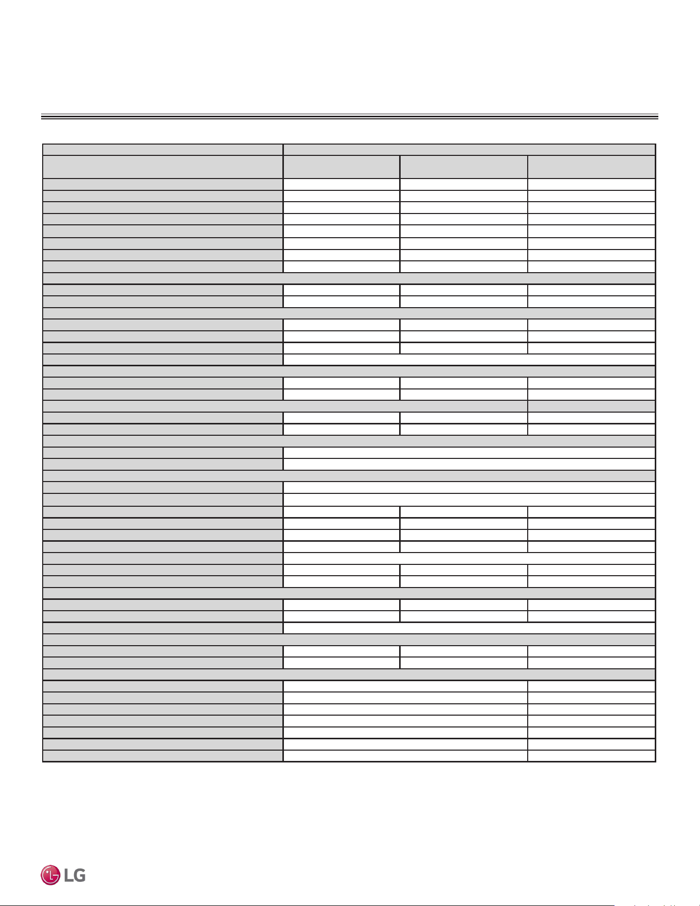
Type Single Zone Ceiling-Concealed Ducted (Low Static)
System (Model) (Indoor Unit / Outdoor Unit)
LD097HV4 (LDN097HV4 /
LUU097HV)
LD127HV4 (LDN127HV4 /
LUU127HV)
LD187HV4 (LDN187HV4 /
LUU189HV)
Cooling Capacity (Min / Rated / Max) (Btu/h)
3,600 ~ 9,000 ~ 9,900 4,640 ~ 11,600 ~ 12,760 7,400 ~ 18,000 ~ 21,100
Cooling Power Input
1
(kW)
0.20 ~ 0.71 ~ 0.89 0.26 ~ 0.9 ~ 1.13 0.55 ~ 1.56 ~ 2.00
EER (OD 95°F)
12.7 12.9 11.5
SEER
18.5 19.6 18
Heating Capacity (Min / Rated / Max) (Btu/h)
5,600 ~ 14,000 ~ 15,400 6,400 ~ 16,000 ~ 17,600 6,800 ~ 20,000 ~ 21,800
Heating Power Input
1
(kW)
0.26 ~ 1.43 ~ 1.80 0.37 ~ 1.29 ~ 1.63 0.52 ~ 2.00 ~ 2.10
COP (OD 47°F)
2.86 3.64 2.93
HSPF
10.3 10.5 10
Rated Low Heating Capacity (Btu/h)
Outdoor 17°F (WB)/Indoor 70°F (DB)
9,500 10,000 12,700
Low COP (OD 17°F)
2.54 2.7 2.42
Maximum Heating Capacity (Btu/h)
Outdoor 17°F (DB) / Indoor 70°F (DB)
11,900 (85%) 13,600 (85%) 18,000 (90%)
Outdoor 5°F (DB) / Indoor 70°F (DB)
10,500 (75%) 12,000 (75%) 16,000 (80%)
Outdoor -4°F (DB) / Indoor 70°F (DB)
8,960 (64%) 10,240 (64%) 14,000 (70%)
Power Supply V, Ø, Hz
2
208-230 / 1 / 60
Outdoor Unit Operating Range
Cooling (°F DB)
0 to 118
6
0 to 118
6
5 to 118
6
Heating (°F WB)
-4 to 64 -4 to 64 -4 to 64
Indoor Unit Operating Range
Cooling (°F WB)
57 to 77 57 to 77 57 to 77
Heating (°F DB)
59 to 81 59 to 81 59 to 81
Indoor Temperature Setting Range
Cooling (°F DB)
65 to 86
Heating (°F WB)
61 to 86
Unit Data
Refrigerant Type
3
R410A
Refrigerant Control
EEV
Indoor Unit Sound Pressure Level dB(A) (H/M/L)
4
30 / 26 / 23 31 / 28 / 27 36 / 34 / 31
Outdoor Unit Sound Pressure Level dB(A) (Cool/Heat)
4
47 / 51 49 / 52 48 / 52
Indoor Unit Net / Shipping Weight (lbs.)
38.6 / 45.2 50.7 / 59.5 48.5 / 57.3
Outdoor Unit Net / Shipping Weight (lbs.)
81.5 / 88.2 81.5 / 88.2 127.8 / 140.0
Power Wiring / Communications Cable (No. x AWG)
2
4 x 14
Compressor (Type x Qty.)
Twin Rotary x 1 Twin Rotary x 1 Twin Rotary x 1
Dehumidification Rate (pts./hr.)
1.5 2.28 2.4
Fan
Indoor Unit Type x Qty.
Sirocco x 2 Sirocco x 3 Sirocco x 3
Outdoor Unit Type x Qty.
Propeller x 1 Propeller x 1 Propeller x 1
Motor / Drive
Brushless Digitally Controlled / Direct
Airflow Rate
Indoor Unit (H / M / L [CFM])
318 / 247 / 194 353 / 300 / 247 530 / 441 / 353
Outdoor Unit (CFM)
988 988 2,048
Piping
Liquid (in.) (Connection size / Pipe size)
1/4 / 1/4 1/4 / 3/8
Vapor (in.) (Connection size / Pipe size)
3/8 / 3/8 1/2 / 5/8
Indoor Unit Condensate Drain O.D. / I.D. (in.)
1-1/4 / 1 1-1/4 / 1
Additional Refrigerant Charge (oz./ft.)
0.22 0.43
Maximum Pipe Length (ft.)
66 164
Piping Length
5
(no additional refrigerant, ft.)
24.6 24.6
Maximum Elevation Difference (ft.)
49 98.4
Table 2: Ceiling-Concealed Ducted (Low Static) System General Data.
GENERAL DATA / SPECIFICATIONS
Low Static Ducted
DUCTED | 11
Product Data
Due to our policy of continuous product innovation, some specications may change without notication.
©LG Electronics U.S.A., Inc., Englewood Cliffs, NJ. All rights reserved. “LG” is a registered trademark of LG Corp.
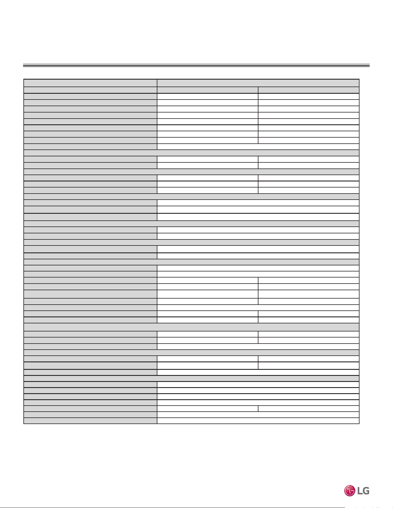
Type Single Zone Ceiling-Concealed Ducted (High Static)
System (Model) (Indoor Unit / Outdoor Unit) LH248HV4 (LHN248HV / LUU249HV) LH368HV4 (LHN368HV / LUU369HV)
Cooling Capacity (Min / Rated / Max) (Btu/h)
9,600 ~ 24,000 ~ 27,000 14,400 ~ 36,000 ~ 41,400
Cooling Power Input
1
(kW)
0.72 ~ 2.98 ~ 4.00 0.72 ~ 2.98 ~ 4.00
EER (OD 95°F)
12.0 12.1
SEER
19.0 19.0
Heating Capacity (Min / Rated / Max) (Btu/h)
10,800 ~ 27,000 ~ 30,000 16,000 ~ 40,000 ~ 42,200
Heating Power Input
1
(kW)
0.58 ~ 2.08 ~ 3.10 0.77 ~ 3.08~ 3.50
COP (OD 47°F)
3.81 3.81
HSPF
10.5 9.7
Power Supply V, Ø, Hz
2
208-230 / 1 / 60
Rated Low Heating Capacity (Btu/h)
Outdoor 17°F (WB) / Indoor 70°F (DB)
17,500 24,000
Low COP (OD 17°F)
2.73 2.69
Maximum Heating Capacity (Btu/h)
Outdoor 17°F (DB) / Indoor 70°F (DB)
26,000 41,500
Outdoor 5°F (DB) / Indoor 70°F (DB)
23,600 35,000
Outdoor -4°F (DB) / Indoor 70°F (DB)
20,760 27,310
Outdoor Unit Operating Range
Cooling (°F DB)
5 to 118
Optional Wind Baffle Cooling (°F DB)
Yes (-4)
Heating (°F WB)
-4 to 64
Indoor Unit Operating Range
Cooling (°F WB)
57 to 77
Heating (°F DB)
59 to 81
Indoor Temperature Setting Range
Cooling (°F)
65 to 86
Heating (°F)
61 to 86
Unit Data
Refrigerant Type
3
R410A
Refrigerant Control EEV
Indoor Unit Sound Pressure Level ±1 dB(A) (H/M/L)
4
37 / 35 / 34 44 / 42 / 40
Outdoor Unit Sound Pressure Level ±1 dB(A) (Cool/Heat)
4
48 / 52 52 / 54
Indoor Unit Net / Shipping Weight (lbs.)
58.6 / 71.9 85.3 / 99.4
Outdoor Unit Net / Shipping Weight (lbs.)
130.0 / 143.3 198.9 / 223.1
Power Wiring / Communications Cable (No. x AWG)
2
4 x 14
Compressor (Type x Qty.)
Twin Rotary x 1 Scroll x 1
Dehumidification Rate (pts./hr.)
5.1 5.9
Fan
Indoor Unit Type x Qty.
Sirocco x 1 Sirocco x 2
Outdoor Unit Type x Qty.
Propeller x 1 Propeller x 2
Motor / Drive Brushless Digitally Controlled / Direct
Airflow Rate
Indoor Unit (Max. / H / M / L [CFM])
777 / 706 / 636 1,130 / 989 / 848
Outdoor Unit (CFM)
2,048 3,884
Factory Set (High) External Static Pressure (in. wg) 0.24
Piping
Liquid (in.) (Connection size / Pipe size)
3/8 / 3/8
Vapor (in.) (Connection size / Pipe size) 5/8 / 5/8
Indoor Unit Condensate Drain O.D. / I.D. (in.) 1-1/ 4, / 1
Additional Refrigerant Charge (oz./ft.) 0.43
Maximum Pipe Length (ft.) 164 246
Piping Length (no additional refrigerant, ft.) 24.6
Maximum Elevation Difference (ft.) 98.4
Table 3: Ceiling-Concealed Ducted (High Static) System General Data.
GENERAL DATA / SPECIFICATIONS
High Static Ducted
EEV: Electronic Expansion Valve, IDU: Indoor Unit, ODU: Outdoor Unit. This unit comes with a
dry helium charge.
This data is rated 0 ft above sea level, with 24.6 ft of refrigerant line per indoor unit and a 0 ft
level difference between outdoor and indoor units.
Cooling capacity rating obtained with air entering the indoor coil at 80ºF dry bulb (DB) and 67ºF
wet bulb (WB); and outdoor ambient conditions of 95ºF dry bulb (DB) and 75ºF wet bulb (WB).
Heating capacity rating obtained with air entering the indoor unit at 70ºF dry bulb (DB) and 60ºF
wet bulb (WB); and outdoor ambient conditions of 47ºF dry bulb (DB) and 43ºF wet bulb (WB).
1 Power Input is rated at high speed.
2 All power wiring / communication cables from ODU to IDU are field supplied and are to be minimum
four-conductor, 14 AWG, stranded, shielded or unshielded (if shielded, it must be grounded to
the chassis of ODU only), and must comply with applicable local and national codes.
3 Take appropriate actions at the end of HVAC equipment life to recover, recycle, reclaim or
destroy R410A refrigerant according to applicable regulations (40 CFR Part 82, Subpart F) under
section 608 of CAA.
4 Sound pressure levels are tested in an anechoic chamber under ISO Standard 3745 and are
the same in both cooling and heating mode. These values can increase due to ambient condi-
tions during operation.
5 Piping lengths are equivalent.
Due to our policy of continuous product innovation, some specications may change without notication.
©LG Electronics U.S.A., Inc., Englewood Cliffs, NJ. All rights reserved. “LG” is a registered trademark of LG Corp.
12 | DUCTED
Single Zone Ceiling-Concealed Ducted System Engineering Manual
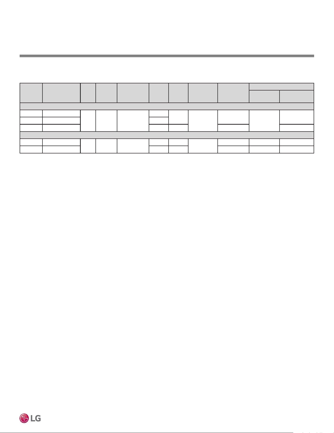
ELECTRICAL DATA
Nominal
Tons
Unit Model No. Hertz Voltage
Voltage
Range
(Min. to Max.)
MCA MOP
Compressor
Quantity
Compressor
Motor RLA
(Cooling)
Condenser Fan Motor(s)
Condenser
Fan Quantity.
Condenser Fan
Motor FLA
Low Static
3/4 LUU097HV
60 208 - 230 187 - 253
11.9
15
1
9.0
1
0.25
1 LUU127HV 12.3
1.5 LUU189HV 20 30 13.5 1.6
High Static
2 LUU249HV
60 208 - 230 187 - 253
20 30
1
13.5 1 1.6
3 LUU369HV 32 40 22 2 1.6 x 2
Voltage tolerance is ±10%.
Maximum allowable voltage unbalance is 2%.
RLA = Rated Load Amps.
MCA = Minimum Circuit Ampacity.
Maximum Overcurrent Protection (MOP) is calculated as follows:
(Largest motor FLA x 2.25) + (Sum of other motor FLA) rounded down
to the nearest standard fuse size.
Table 4: Electrical Data.
Electrical Data
DUCTED | 13
Product Data
Due to our policy of continuous product innovation, some specications may change without notication.
©LG Electronics U.S.A., Inc., Englewood Cliffs, NJ. All rights reserved. “LG” is a registered trademark of LG Corp.
Table 5: Indoor Unit—Functions, Controls, and Options.
Indoor Unit Type
Ceiling Concealed Ducted
(Low Static)
Ceiling Concealed Ducted
(High Static)
Air-
ow
Air supply outlets
1 2
Airflow steps (fan/cool/heat)
3 / 3 / 3 3 / 3 / 3
Washable anti-fungal filter
1
√ √
Operation
Drain pump
√ √
E.S.P. control
√ √
Hot Start
√ √
Self diagnostics
√ √
Auto changeover
√ √
Auto restart
√ √
Child lock
√ √
Sleep mode
√ √
Timer (on/off)
√ √
Weekly schedule
√ √
Two thermistor control
o o
Controllers
7-Day programmable controller
o o
Simple wired remote controller
o o
Wireless LCD remote control
2
o o
Dry contact
o o
Dry contact (temperature setting)
o o
Central control (LGAP)
√ √
Special
Functions
Wi-Fi
3
o o
Auxiliary Heater Relay Kit (PRARH1)
o o
AHU Communications Kit (PAHCMR000)
o o
1
Primary washable filters.
2
Requires wired zone controller.
3
Requires Wi-Fi module PWFMDD200.
√ = Standard feature
o = Unit option
FUNCTIONS, CONTROLS, AND OPTIONS
Functions, Controls, and Options for LDN097HV4, LDN127HV4, LDN187HV4
LHN248HV, LHN368HV
Indoor Unit
Due to our policy of continuous product innovation, some specications may change without notication.
©LG Electronics U.S.A., Inc., Englewood Cliffs, NJ. All rights reserved. “LG” is a registered trademark of LG Corp.
14 | DUCTED
Single Zone Ceiling-Concealed Ducted System Engineering Manual
Functions, Controls, and Options for LUU097HV, LUU127HV, LUU189HV,
LUU249HV, LUU369HV
Table 6: Outdoor Unit—Functions, Controls, and Options.
Outdoor Unit
Category Functions LUU097HV LUU127HV LUU189HV LUU249HV LUU369HV
Reliability
Defrost / Deicing
O O O O O
High pressure sensor O O O O O
Phase protection X X X X X
Restart delay (3-minutes) O O O O O
Self diagnosis O O O O O
Soft start O O O O O
Convenience
Night Quiet Operation O O O O O
Mode Lock O O O O O
Pump Down (Forced
Cooling Operation)
O O O O O
Network solution (LGAP) O O O O O
Central
Controller
AC Smart 5 PACS5A000 PACS5A000 PACS5A000 PACS5A000 PACS5A000
ACP 5 PACP5A000 PACP5A000 PACP5A000 PACP5A000 PACP5A000
PI485 PMNFP14A1 PMNFP14A1 PMNFP14A1 PMNFP14A1 PMNFP14A1
Remote
Controller
MultiSITE CRC1 PREMTBVC0 PREMTBVC0 PREMTBVC0 PREMTBVC0 PREMTBVC0
MultiSITE CRC1+ PREMTBVC1 PREMTBVC1 PREMTBVC1 PREMTBVC1 PREMTBVC1
Integration
Solution
MultiSITE
Communications Manager
PBACNBTR0A PBACNBTR0A PBACNBTR0A PBACNBTR0A PBACNBTR0A
FUNCTIONS, CONTROLS, AND OPTIONS
Outdoor Unit
√ = Standard feature
o = Unit option
X = Not Available
DUCTED | 15
Product Data
Due to our policy of continuous product innovation, some specications may change without notication.
©LG Electronics U.S.A., Inc., Englewood Cliffs, NJ. All rights reserved. “LG” is a registered trademark of LG Corp.
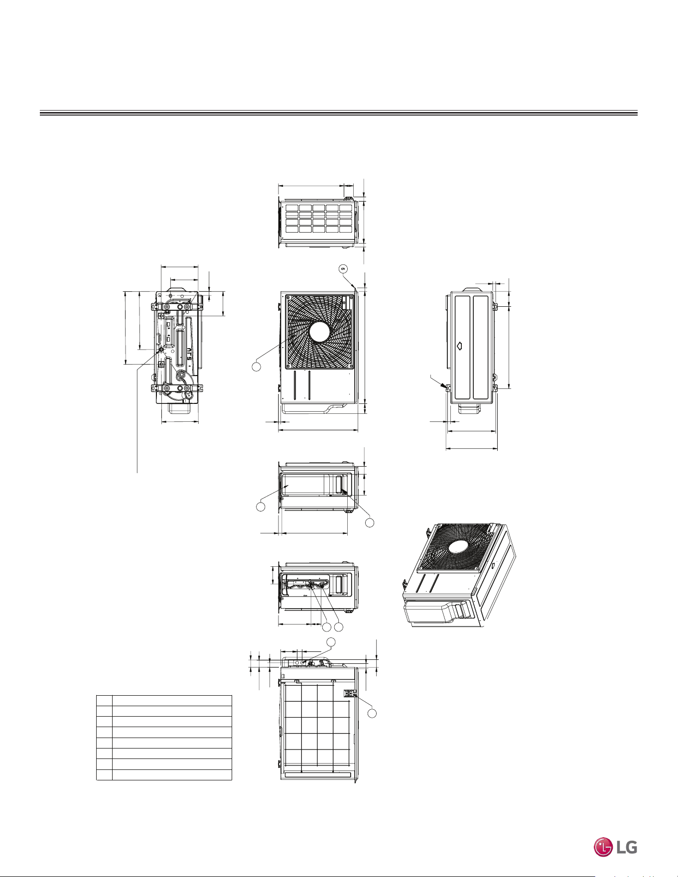
Figure 5: LUU097HV, LUU127HV Dimensions.
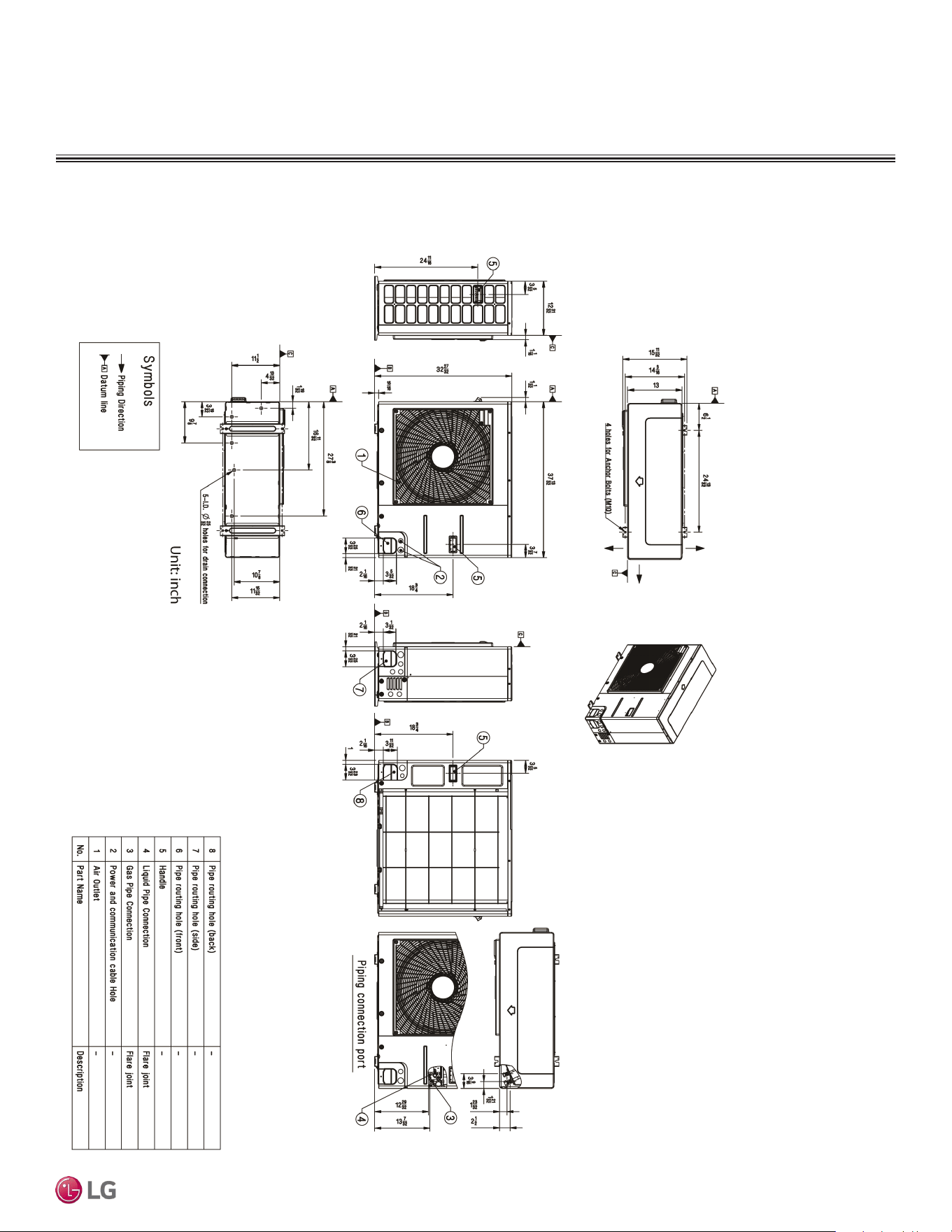
OUTDOOR UNIT DIMENSIONS
4-3/32 22-3/16
13/16
12-31/32
13-29/32
13/16
4 Holes for Anchor Bolts (M 13/32)
3D View
1-3/16 11-11/32 31/32
2-9/16
17-11/16
15/16
21-15/32
30-5/16
2-23/32
5/8
2-3/32 5-21/32
6
2
3
4
5
7
1
17-11/1615/16
4-25/32
Side View
(Valve Cover Removed)
8-25/32
2-3/4
4-7/16 1-11/32
1-7/32
1-29/32
2
2-3/32
1-13/32
1-1/16
6-5/8
10
7-1/2
15-11/16
19-11/16
4 - LD.
Ф25/32 Holes for drain connection
9-29/32
Intake air temperature sensor cover
Handle
Conduit
Liquid pipe connection
Vapor pipe connection
Control cover & service valve cover
Air outlet
No. Part Name
1
2
3
4
5
6
7
[Unit: inch]
Dimensions for LUU097HV, LUU127HV
Due to our policy of continuous product innovation, some specications may change without notication.
©LG Electronics U.S.A., Inc., Englewood Cliffs, NJ. All rights reserved. “LG” is a registered trademark of LG Corp.
16 | DUCTED
Single Zone Ceiling-Concealed Ducted System Engineering Manual
OUTDOOR UNIT DIMENSIONS
Figure 6: LUU189HV, LUU249HV Dimensions.
Dimensions for LUU189HV, LUU249HV
DUCTED | 17
Product Data
Due to our policy of continuous product innovation, some specications may change without notication.
©LG Electronics U.S.A., Inc., Englewood Cliffs, NJ. All rights reserved. “LG” is a registered trademark of LG Corp.
OUTDOOR UNIT DIMENSIONS
Dimensions for LUU369HV
Figure 7: LUU369HV Unit Dimensions.
Due to our policy of continuous product innovation, some specications may change without notication.
©LG Electronics U.S.A., Inc., Englewood Cliffs, NJ. All rights reserved. “LG” is a registered trademark of LG Corp.
18 | DUCTED
Single Zone Ceiling-Concealed Ducted System Engineering Manual
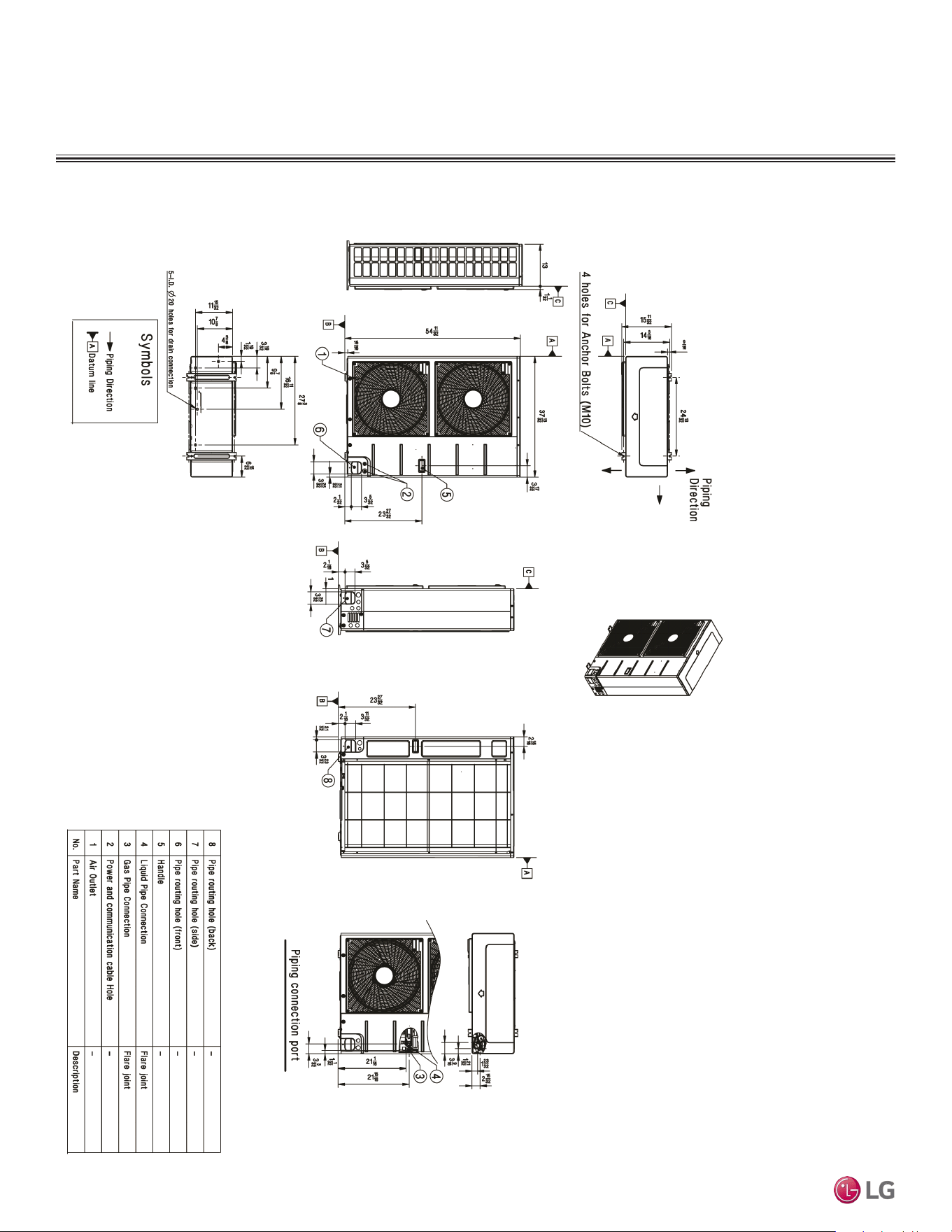
INDOOR UNIT DIMENSIONS
Figure 8: LDN097HV4, LDN127HV4, LDN187HV4 Indoor Unit Dimensions.
Dimensions for LDN097HV4, LDN127HV4, LDN187HV4
Supply Air
5-5/16 1-3/8
13/16
D
Top
LDN187HV4
DUCTED | 19
Product Data
Due to our policy of continuous product innovation, some specications may change without notication.
©LG Electronics U.S.A., Inc., Englewood Cliffs, NJ. All rights reserved. “LG” is a registered trademark of LG Corp.
INDOOR UNIT DIMENSIONS
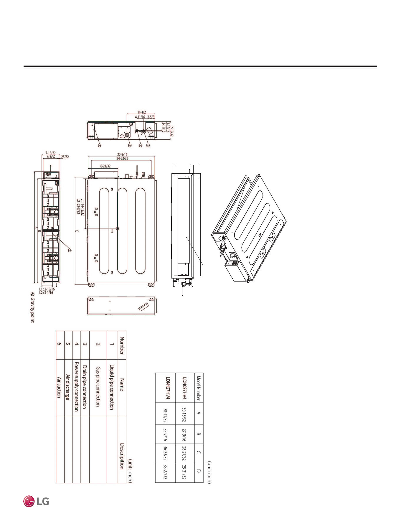
Figure 9: LHN248HV Indoor Unit Dimensions.
Dimensions for LHN248HV
Due to our policy of continuous product innovation, some specications may change without notication.
©LG Electronics U.S.A., Inc., Englewood Cliffs, NJ. All rights reserved. “LG” is a registered trademark of LG Corp.
20 | DUCTED
Single Zone Ceiling-Concealed Ducted System Engineering Manual
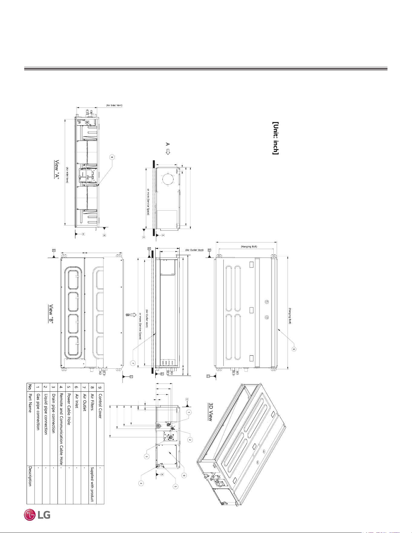
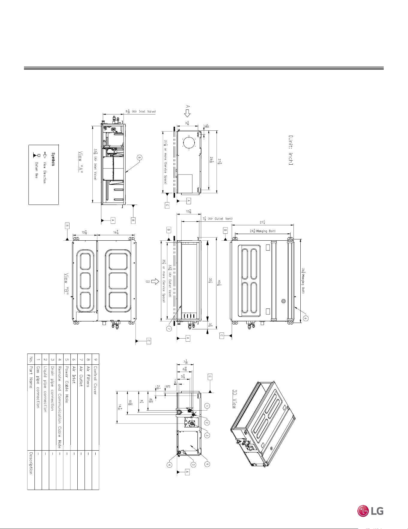
Figure 10: LHN368HV Indoor Unit Dimensions.
INDOOR UNIT DIMENSIONS
7-7/32
6-19/32
5-15/32
7/8
27-1/4
24-3/8
7-7/8
10-11/16
9-5/16
9-3/32
10-11/16 16-9/16
50-17/32
27/32
2-1/32
8-21/32
9-1/4
10-13/32
14-9/32
54-7/32
49-9/32
47-15/32
49-3/16
47-1/2
3-9/16
27-9/16
26-5/32
1-25/32
27-1/16
Dimensions for LHN368HV
DUCTED | 21
Product Data
Due to our policy of continuous product innovation, some specications may change without notication.
©LG Electronics U.S.A., Inc., Englewood Cliffs, NJ. All rights reserved. “LG” is a registered trademark of LG Corp.
ACOUSTIC DATA
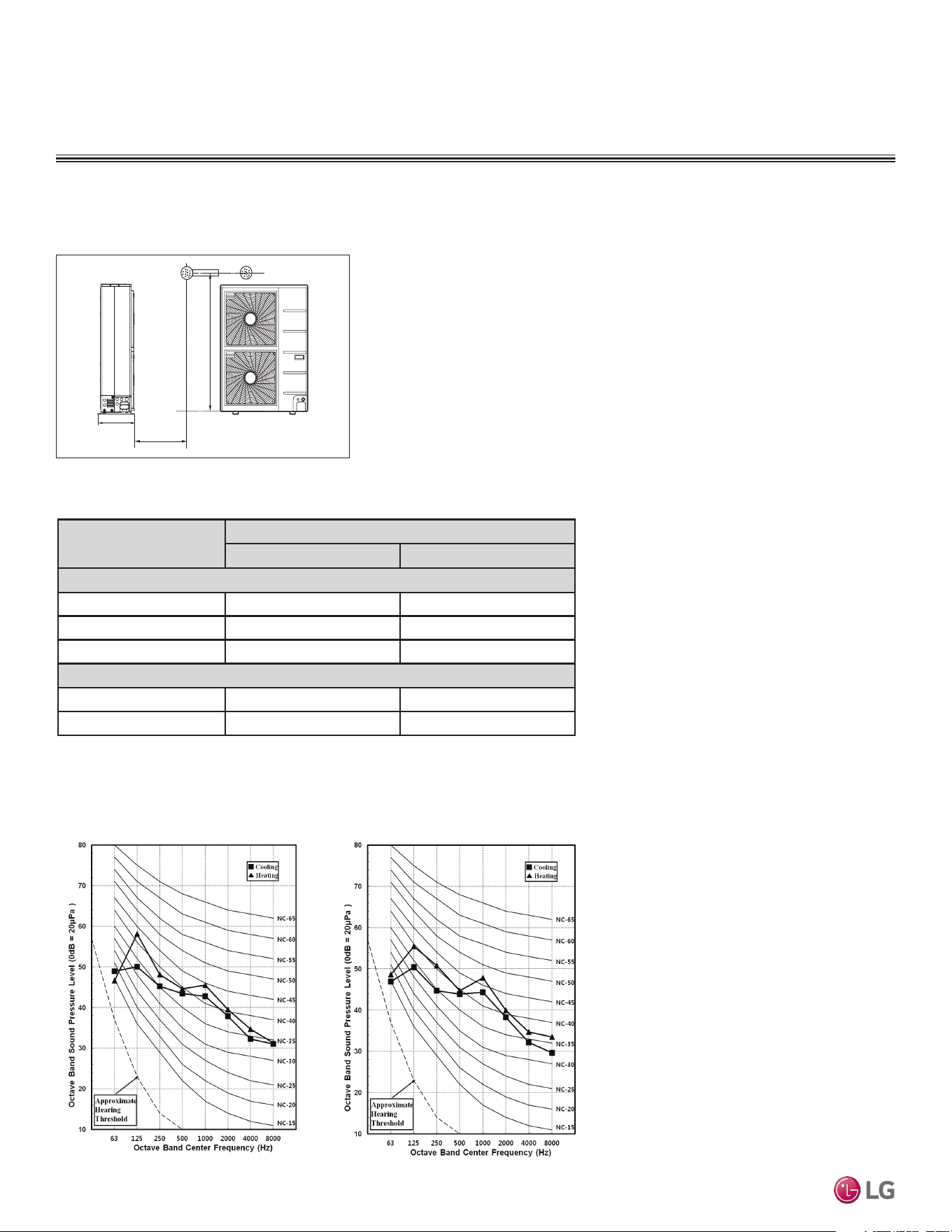
Sound Pressure for Outdoor Units
• Measurements taken with no attenuation and units operating at full load normal
operating condition.
• Sound level will vary depending on a range of factors such as construction (acoustic
absorption coefficient) of particular area in which the equipment is installed.
• Sound power levels are measured in dB(A)±1.
• Tested in anechoic chamber per ISO Standard 3745.
Figure 11: Ceiling-Concealed Ducted Outdoor Unit
Sound Pressure Level Measurement Location.
3.3 ft.
4.9 ft.
D
Table 7: Ceiling-Concealed Ducted Outdoor Unit Sound Pressure Levels (dB[A]).
Model
Sound Pressure Levels (dB[A])
Cooling Heating
Low Static
LUU097HV 47 51
LUU127HV 49 52
LUU189HV 48 52
High Static
LUU249HV 48 52
LUU369HV 52 54
Figure 12: Ducted Outdoor Unit Sound Pressure Level Diagrams.
LUU097HV
LUU127HV
Outdoor Unit Sound Pressure Diagrams
Outdoor Unit Sound Pressure Level Measurement
Outdoor Unit Sound Pressure Levels
Due to our policy of continuous product innovation, some specications may change without notication.
©LG Electronics U.S.A., Inc., Englewood Cliffs, NJ. All rights reserved. “LG” is a registered trademark of LG Corp.
22 | DUCTED
Single Zone Ceiling-Concealed Ducted System Engineering Manual
Octave Band Center Frequency (Hz)
Octave Band Sound Pressure Level (0dB = 20μPa)
10
20
30
40
50
60
70
80
63 125 250 500 1000 2000 4000 8000
NC-15
NC-20
NC-25
NC-30
NC-35
NC-40
NC-45
NC-50
NC-55
NC-60
NC-65
Approximate
Hearing
Threshold
▲ Cooling
Heating
10
15
20
25
30
35
40
45
50
55
60
65
70
75
80
63
125
250
500
1000
2000
4000
8000
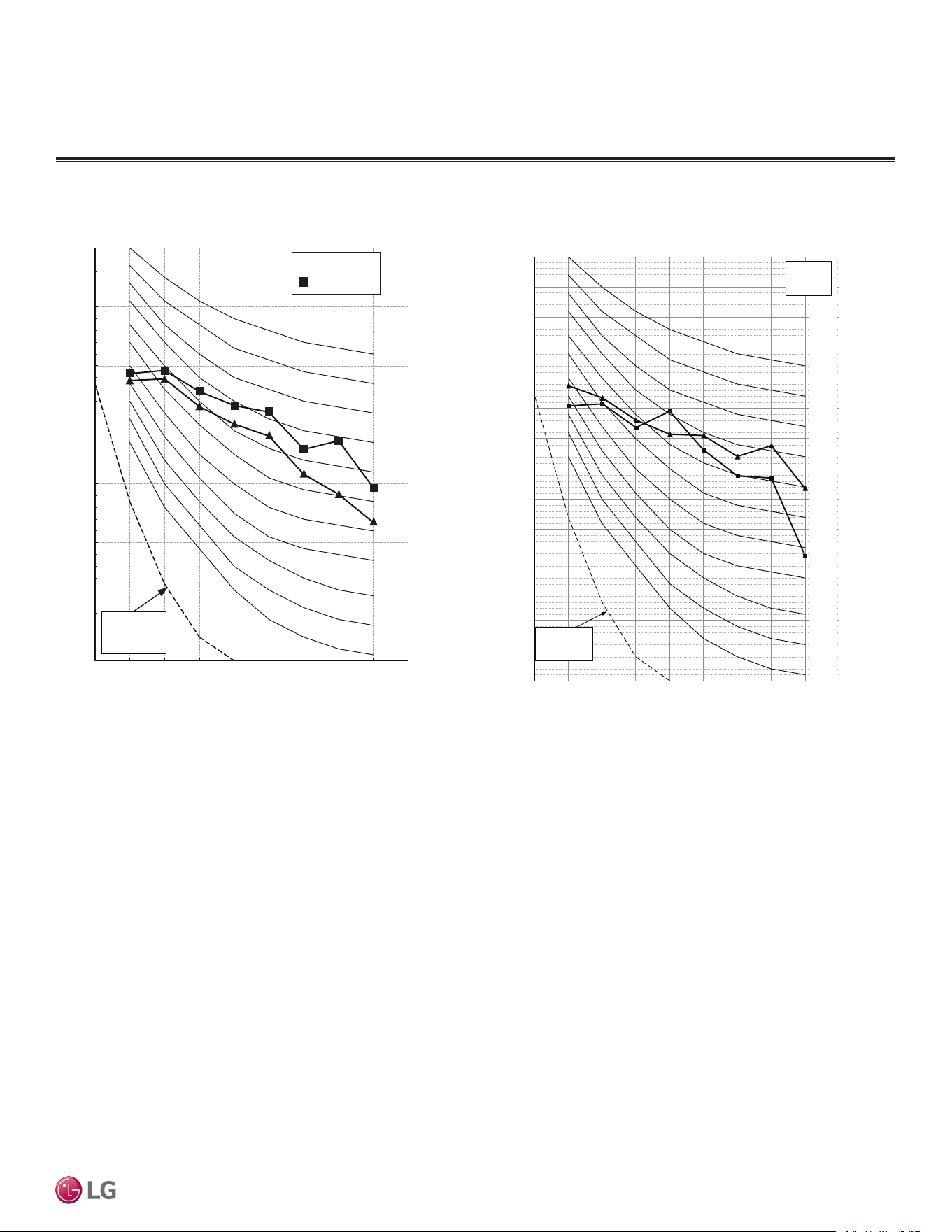
Octave Band Sound Pressure Level (dB = 20μPa )
Octave Band Center Frequency (Hz)
NC-15
NC-20
NC-25
NC-30
NC-35
NC-40
NC-45
NC-50
NC-55
NC-60
NC-65
Approxim ate
Hearing
■ Cooling
▲Heating
LUU189HV, LUU249HV LUU369HV
Outdoor Unit Sound Pressure Diagrams
ACOUSTIC DATA
Sound Pressure for Outdoor Units
DUCTED | 23
Product Data
Due to our policy of continuous product innovation, some specications may change without notication.
©LG Electronics U.S.A., Inc., Englewood Cliffs, NJ. All rights reserved. “LG” is a registered trademark of LG Corp.
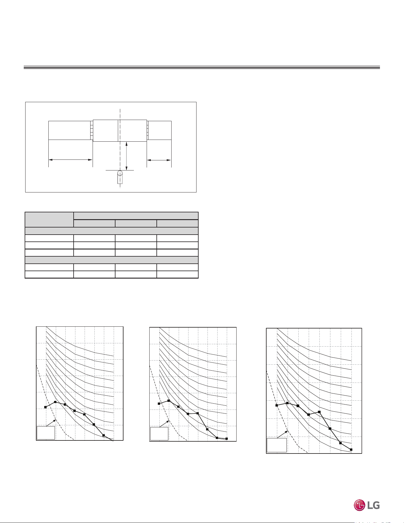
Model
Sound Pressure Levels (dB[A])
H M L
Low Static
LDN097HV4 30 26 23
LDN127HV4 31 28 27
LDN187HV4 36 34 31
High Static
LHN248HV 37 35 34
LHN368HV 44 42 40
Table 8: Ducted Indoor Unit Sound Pressure Levels (dB[A]).
Figure 13: Indoor Unit Sound Pressure Level Measurement Location.
Figure 14: Ducted Indoor Unit Sound Pressure Level Diagrams.
• Measurements taken with no attenuation and units operating at full
load normal operating condition.
• Sound level will vary depending on a range of factors such as con-
struction (acoustic absorption coefficient) of particular area in which
the equipment is installed.
• Sound power levels are measured in dB(A)±1.
• Tested in anechoic chamber per ISO Standard 3745.
4.9 ft.
6.6 ft.
3.3 ft.
DUCT
DISCHARG
ES
UCTION
DUCT
Sound Pressure for Indoor Units
ACOUSTIC DATA
Octave Band Center Frequency (Hz)
Octave Band Sound Pressure Level (0dB = 20μPa)
10
20
30
40
50
60
70
80
63 125 250 500 1000 2000 4000 8000
NC-15
NC-20
NC-25
NC-30
NC-35
NC-40
NC-45
NC-50
NC-55
NC-60
NC-65
Approximate
Hearing
Threshold
Octave Band Center Frequency (Hz)
Octave Band Sound Pressure Level (0dB = 20μPa)
10
20
30
40
50
60
70
80
63 125 250 500 1000 2000 4000 8000
NC-15
NC-20
NC-25
NC-30
NC-35
NC-40
NC-45
NC-50
NC-55
NC-60
NC-65
Approximate
Hearing
Threshold
LDN097HV4LDN127HV4
LDN187HV4
Octave Band Center Frequency (Hz)
Octave Band Sound Pressure Level (0dB = 20μPa)
10
20
30
40
50
60
70
80
63 125 250 500 1000 2000 4000 8000
NC-15
NC-20
NC-25
NC-30
NC-35
NC-40
NC-45
NC-50
NC-55
NC-60
NC-65
Approximat e
Hearing
Threshold
Indoor Unit Sound Pressure Measurement
Indoor Unit Sound Pressure Diagrams
Due to our policy of continuous product innovation, some specications may change without notication.
©LG Electronics U.S.A., Inc., Englewood Cliffs, NJ. All rights reserved. “LG” is a registered trademark of LG Corp.
24 | DUCTED
Single Zone Ceiling-Concealed Ducted System Engineering Manual
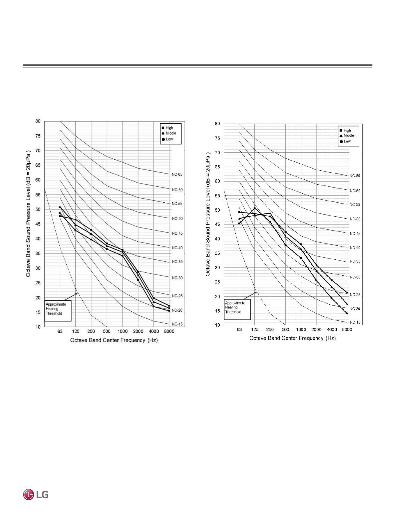
LHN248HV
Figure 15: Ducted Indoor Unit Sound Pressure Level Diagrams.
Indoor Unit Sound Pressure Diagrams
LHN368HV
Sound Pressure for Indoor Units
ACOUSTIC DATA
DUCTED | 25
Product Data
Due to our policy of continuous product innovation, some specications may change without notication.
©LG Electronics U.S.A., Inc., Englewood Cliffs, NJ. All rights reserved. “LG” is a registered trademark of LG Corp.
OUTDOOR UNIT REFRIGERANT FLOW DIAGRAM
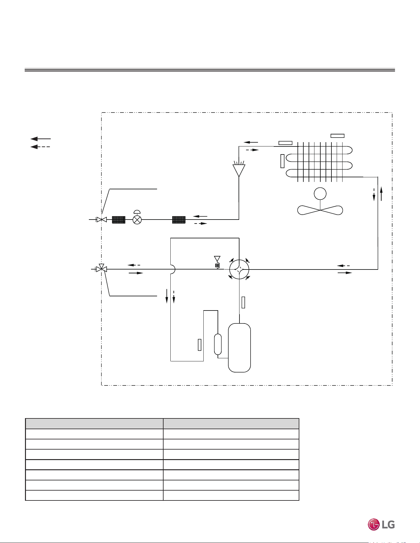
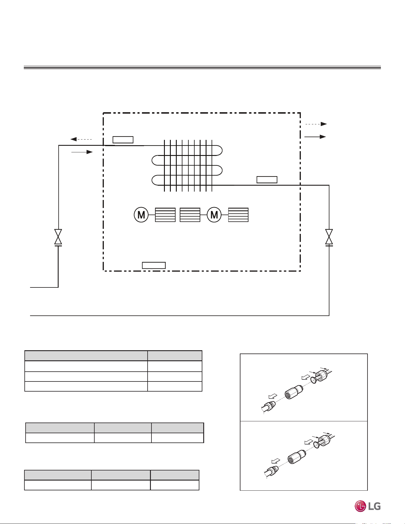
Figure 16: LUU097HV and LUU127HV Ceiling-Concealed Ducted (Low Static) Outdoor Unit Refrigerant Flow Diagram.
Refrigerant Flow
Cooling
Heating
M
High
Pressure
Sensor
4 way
Valve
Discharge
Temperature
Thermistor
Suction
Temperature
Thermistor
Inverter
Compressor
Electronic
Expansion
Valve
Strainer Strainer
Condenser Out
Temperature
Thermistor
Inlet Air
Temperature
Thermistor
1/4
Flare Connection
3/8
Flare Connection
Condensing
Temperature
Thermistor
Description PCB Connector
Condenser Inlet Temperature Thermistor CN-AIR
Condenser Outlet Temperature Thermistor CN-C_PIPE
Discharge Temperature Thermistor CN-DISCHARGE
Suction Temperature Thermistor CN-SUCTION
Condensing Temperature Thermistor CN-MID
High Pressure Sensor CN-H_PRESSURE
Electronic Expansion Valve CN-EEV_A
Table 9: LUU097HV and LUU127HV Ceiling-Concealed Ducted (Low Static) Outdoor Unit Thermistor Details.
Refrigerant Flow Diagram for LUU097HV, LUU127HV
Due to our policy of continuous product innovation, some specications may change without notication.
©LG Electronics U.S.A., Inc., Englewood Cliffs, NJ. All rights reserved. “LG” is a registered trademark of LG Corp.
26 | DUCTED
Single Zone Ceiling-Concealed Ducted System Engineering Manual
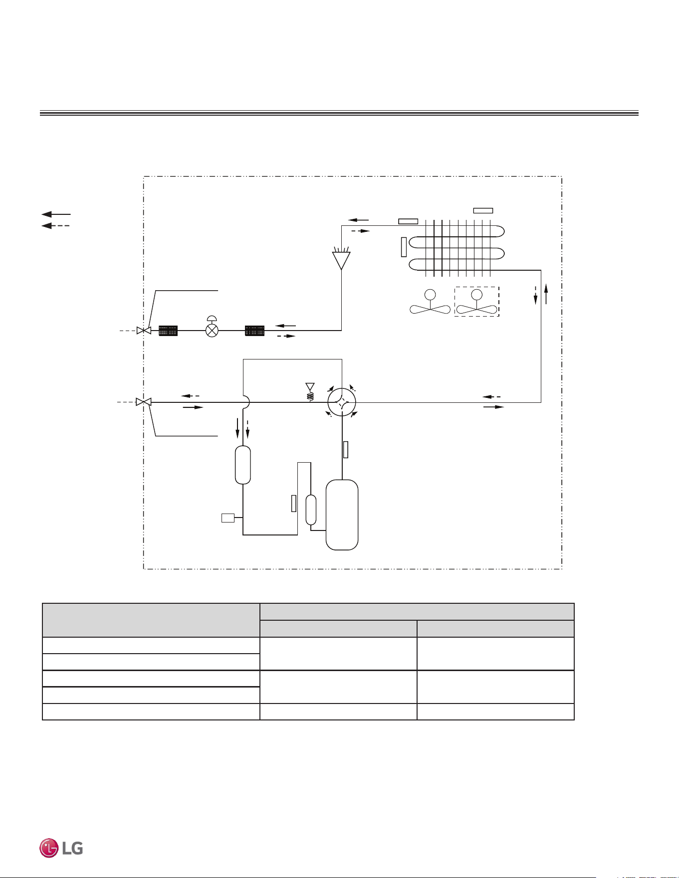
OUTDOOR UNIT REFRIGERANT FLOW DIAGRAM
Refrigerant Flow
Cooling
Heating
MM
High Pressure
Sensor
4 way
36k model only
Valve
Discharge
Temperature
Thermistor
Suction
Temperature
Fusible
Plug
Thermistor
Accumulator
Inverter
Compressor
Strainer Strainer
Condenser Out
Temperature
Thermistor
Outdoor Ambient Air
Temperature
Thermistor
Ø3/8
Flare Connection
Ø5/8
Flare Connection
Condensing
Temperature
Thermistor
Electronic
Expansion Valve
Liquid Side
Piping
Vapor Side
Piping
SVC
SVC
CN-TH2
CN-TH2
CN-TH3
CN-TH3
Description (Based on Cooling Mode)
PCB Connector
Suction Temperature Thermistor
CN-TH3 CN-TH3
Discharge Temperature Thermistor
Condenser Outlet Temperature Thermistor
CN-TH2 CN-TH2
Outdoor Ambient Air Temperature Thermistor
Condenser Inlet Temperature Thermistor CN-TH4 CN-TH4
Table 10: LUU189HV, LUU249HV, LUU369HV Ceiling-Concealed Ducted (Low Static) Outdoor Unit Thermistor Details.
Refrigerant Flow Diagram for LUU189HV, LUU249HV, LUU369HV
Figure 17: LUU189HV, LUU249HV, LUU369HV Refrigerant Flow Diagrams.
DUCTED | 27
Product Data
Due to our policy of continuous product innovation, some specications may change without notication.
©LG Electronics U.S.A., Inc., Englewood Cliffs, NJ. All rights reserved. “LG” is a registered trademark of LG Corp.
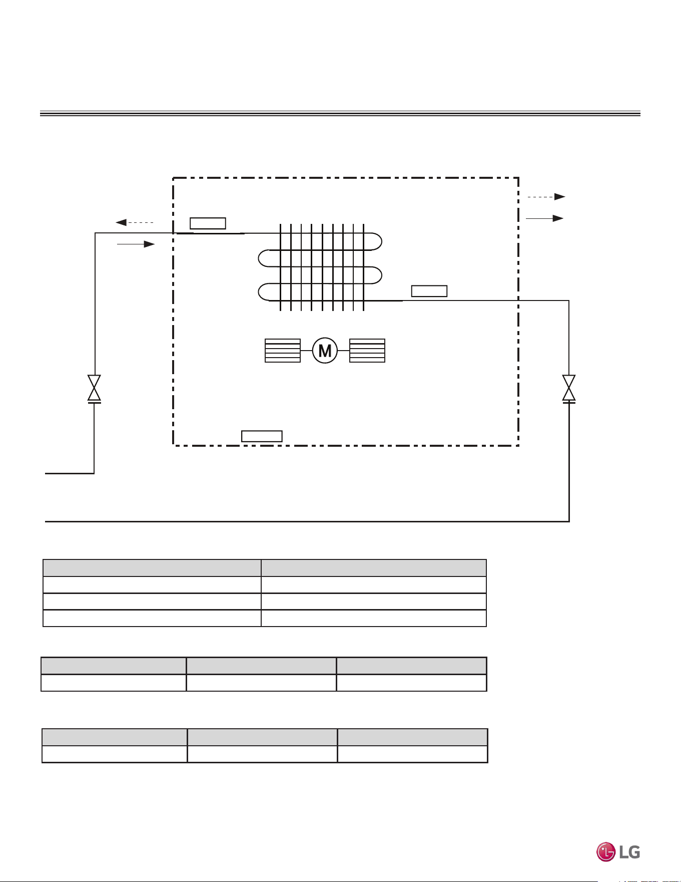
INDOOR UNIT REFRIGERANT FLOW DIAGRAM
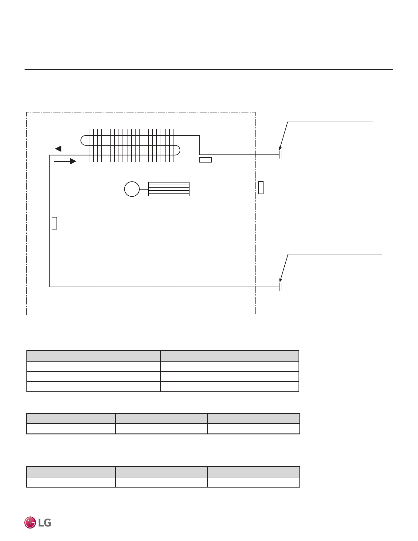
Figure 18: LDN097HV4 Ceiling-Concealed Ducted (Low Static) Refrigerant Flow Diagram.
Indoor Unit
: Cooling
: Heating
M
Sirocco Fan
Indoor Air
Temperature
Thermistor
Evaporator
Outlet
Temperature
Thermistor
Evaporator
Inlet
Temperature
Thermistor
Description (Based on Cooling Mode) PCB Connector
Indoor Air Temperature Thermistor CN-ROOM
Evaporator Inlet Temperature Thermistor CN-PIPE/IN
Evaporator Outlet Temperature Thermistor CN-PIPE/OUT
Table 11: LDN097HV4 Ceiling-Concealed Ducted (Low Static) Indoor Unit Thermistor Details.
Table 12: LDN097HV4 Ceiling-Concealed Ducted (Low Static) Indoor Unit Refrigerant Pipe Connection Port Diameters.
Model No. Vapor (inch) Liquid (inch)
LDN097HV4 3/8 1/4
Table 13: LDN097HV4 Ceiling-Concealed Ducted (Low Static) Indoor Unit Refrigerant Pipe Connections.
Model No. Vapor (inch) Liquid (inch)
LDN097HV4 3/8 1/4
Refrigerant Flow Diagram for LDN097HV4
Due to our policy of continuous product innovation, some specications may change without notication.
©LG Electronics U.S.A., Inc., Englewood Cliffs, NJ. All rights reserved. “LG” is a registered trademark of LG Corp.
28 | DUCTED
Single Zone Ceiling-Concealed Ducted System Engineering Manual
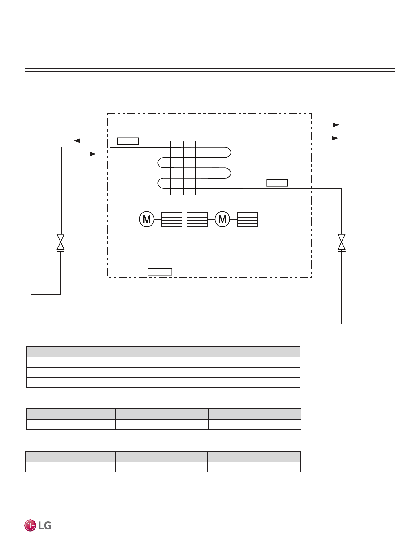
INDOOR UNIT REFRIGERANT FLOW DIAGRAM
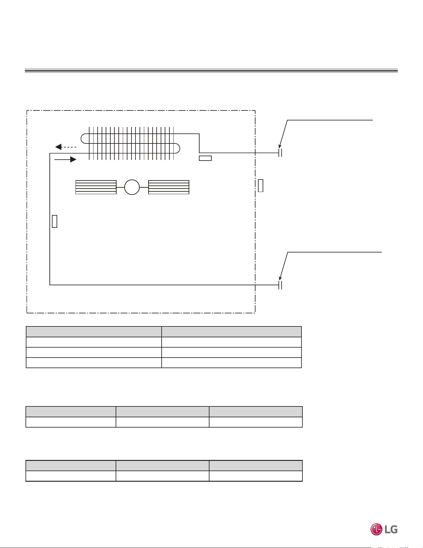
Figure 19: LDN127HV4 Ceiling-Concealed Ducted (Low Static) Indoor Unit Refrigerant Flow Diagram.
Indoor Unit
: Cooling
: Heating
MM
Sirocco Fan
Indoor Air
Temperature
Thermistor
Evaporator
Outlet
Temperature
Thermistor
Evaporator
Inlet
Temperature
Thermistor
Description (Based on Cooling Mode) PCB Connector
Indoor Air Temperature Thermistor CN-ROOM
Evaporator Inlet Temperature Thermistor CN-PIPE/IN
Evaporator Outlet Temperature Thermistor CN-PIPE/OUT
Table 14: LDN127HV4 Ceiling-Concealed Ducted (Low Static) Indoor Unit Refrigerant Pipe Connection Port Diameters.
Model No. Vapor (inch) Liquid (inch)
LDN127HV4 3/8 1/4
Table 15: LDN127HV4 Ceiling-Concealed Ducted (Low Static) Indoor Unit Thermistor Details.
Table 16: LDN127HV4 Ceiling-Concealed Ducted (Low Static) Indoor Unit Refrigerant Pipe Connections.
Model No. Vapor (inch) Liquid (inch)
LDN127HV4 3/8 1/4
Refrigerant Flow Diagram for LDN127HV4
DUCTED | 29
Product Data
Due to our policy of continuous product innovation, some specications may change without notication.
©LG Electronics U.S.A., Inc., Englewood Cliffs, NJ. All rights reserved. “LG” is a registered trademark of LG Corp.
INDOOR UNIT REFRIGERANT FLOW DIAGRAM
Figure 20: LDN187HV4 Ceiling-Concealed Ducted Refrigerant Flow Diagram.
Table 17: LDN187HV4 Ceiling-Concealed Ducted (Low Static) Indoor Unit
Thermistor Details.
Description (Based on Cooling Mode) PCB Connector
Indoor Air Temperature Thermistor CN-ROOM
Evaporator Inlet Temperature Thermistor CN-PIPE/IN
Evaporator Outlet Temperature Thermistor CN-PIPE/OUT
Indoor Unit
: Cooling
: Heating
MM
Sirocco Fan
Indoor Air
Temperature
Thermistor
Evaporator
Outlet
Temperature
Thermistor
Evaporator
Inlet
Temperature
Thermistor
Table 18: LDN187HV4 Ceiling-Concealed Ducted (Low Static) Indoor Unit
Refrigerant Pipe Connection Port Diameters.
Model No. Vapor (inch) Liquid (inch)
LDN187HV4 Ø1/2 Ø1/4
Table 19: LDN187HV4 Ceiling-Concealed Ducted (Low Static) Indoor
Unit Refrigerant Pipe Sizes.
Model No. Vapor (inch) Liquid (inch)
LDN187HV4 5/8 3/8
1/2 in. to 5/8 in.
Connection
Ø5/8 in.
Connection socket
Flare nut
Piping
Ø1/2 in.
1/4 in. to 3/8
Connection
Flare side to indoor
unit
Ø3/8 in.
Connection socket
Flare nut
Piping
Ø1/4 in.
Flare side to indoor
unit
Flare side
to outdoor unit
Flare side
to outdoor unit
Table 20: LDN187HV4 Ceiling-Concealed Duct (Low Static)
Indoor Unit Refrigerant Pipe Connections.
Refrigerant Flow Diagram for LDN187HV4
Due to our policy of continuous product innovation, some specications may change without notication.
©LG Electronics U.S.A., Inc., Englewood Cliffs, NJ. All rights reserved. “LG” is a registered trademark of LG Corp.
30 | DUCTED
Single Zone Ceiling-Concealed Ducted System Engineering Manual
INDOOR UNIT REFRIGERANT FLOW DIAGRAM
Figure 21: LHN248HV Ceiling-Concealed Ducted (High Static) Indoor Unit Refrigerant Flow Diagram.
Table 21: LHN248HV Ceiling-Concealed Ducted (High Static) Indoor Unit Thermistor Details.
Description (Based on Cooling Mode) PCB Connector
Indoor Air Temperature Thermistor CN-ROOM
Evaporator Inlet Temperature Thermistor CN-PIPE / IN
Evaporator Outlet Temperature Thermistor CN-PIPE / OUT
Table 22: LHN248HV Ceiling-Concealed Ducted (High Static) Indoor Unit Refrigerant Pipe Connection Port Diameters.
Model No. Vapor (inch) Liquid (inch)
LHN248HV 5/8 3/8
Table 23: LHN248HV Ceiling-Concealed Ducted (High Static) Indoor Unit Refrigerant Pipe Sizes.
Model No. Vapor (inch) Liquid (inch)
LHN248HV 5/8 3/8
Sirocco Fan
Heat Exchanger
Vapor Pipe Connection Port
(Flare Connection)
Liquid Pipe Connection Port
(Flare Connection)
Cooling
Heating
M
Evaporator Outlet
Temperature
Thermistor
Evaporator Inlet
Temperature Thermistor
Indoor Air Temperature
Thermistor
Refrigerant Flow Diagram for LHN248HV
DUCTED | 31
Product Data
Due to our policy of continuous product innovation, some specications may change without notication.
©LG Electronics U.S.A., Inc., Englewood Cliffs, NJ. All rights reserved. “LG” is a registered trademark of LG Corp.
INDOOR UNIT REFRIGERANT FLOW DIAGRAM
Figure 22: LHN368HV Ceiling-Concealed Ducted (High Static) Indoor Unit Refrigerant Flow Diagram.
Table 24: LHN368HV Ceiling-Concealed Ducted (High Static) Indoor Unit Thermistor Details.
Description (Based on Cooling Mode) PCB Connector
Indoor Air Temperature Thermistor CN-ROOM
Evaporator Inlet Temperature Thermistor CN-PIPE / IN
Evaporator Outlet Temperature Thermistor CN-PIPE / OUT
Table 25: LHN368HV Ceiling-Concealed Ducted (High Static) Indoor Unit Refrigerant Pipe Connection Port Diameters.
Model No. Vapor (inch) Liquid (inch)
LHN368HV 5/8 3/8
Table 26: LHN368HV Ceiling-Concealed Ducted (High Static) Indoor Unit Refrigerant Pipe Sizes.
Model No. Vapor (inch) Liquid (inch)
LHN368HV 5/8 3/8
Sirocco Fan
Heat Exchanger
Vapor Pipe Connection Port
(Flare Connection)
Liquid Pipe Connection Port
(Flare Connection)
Cooling
Heating
M
Evaporator Outlet
Temperature
Thermistor
Evaporator Inlet
Temperature Thermistor
Indoor Air Temperature
Thermistor
Refrigerant Flow Diagram for LHN368HV
Due to our policy of continuous product innovation, some specications may change without notication.
©LG Electronics U.S.A., Inc., Englewood Cliffs, NJ. All rights reserved. “LG” is a registered trademark of LG Corp.
32 | DUCTED
Single Zone Ceiling-Concealed Ducted System Engineering Manual
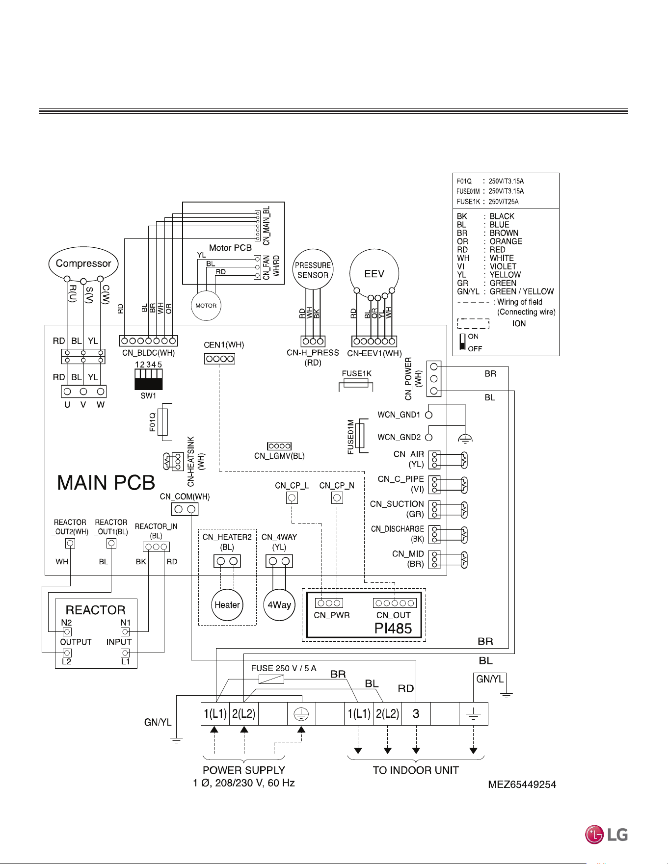
OUTDOOR UNIT WIRING DIAGRAM
Figure 23: LUU097HV and LUU127HV Ceiling-Concealed (Low Static) Ducted Outdoor Unit Wiring Diagram.
Wiring Diagram for LUU097HV, LUU127HV
DUCTED | 33
Product Data
Due to our policy of continuous product innovation, some specications may change without notication.
©LG Electronics U.S.A., Inc., Englewood Cliffs, NJ. All rights reserved. “LG” is a registered trademark of LG Corp.
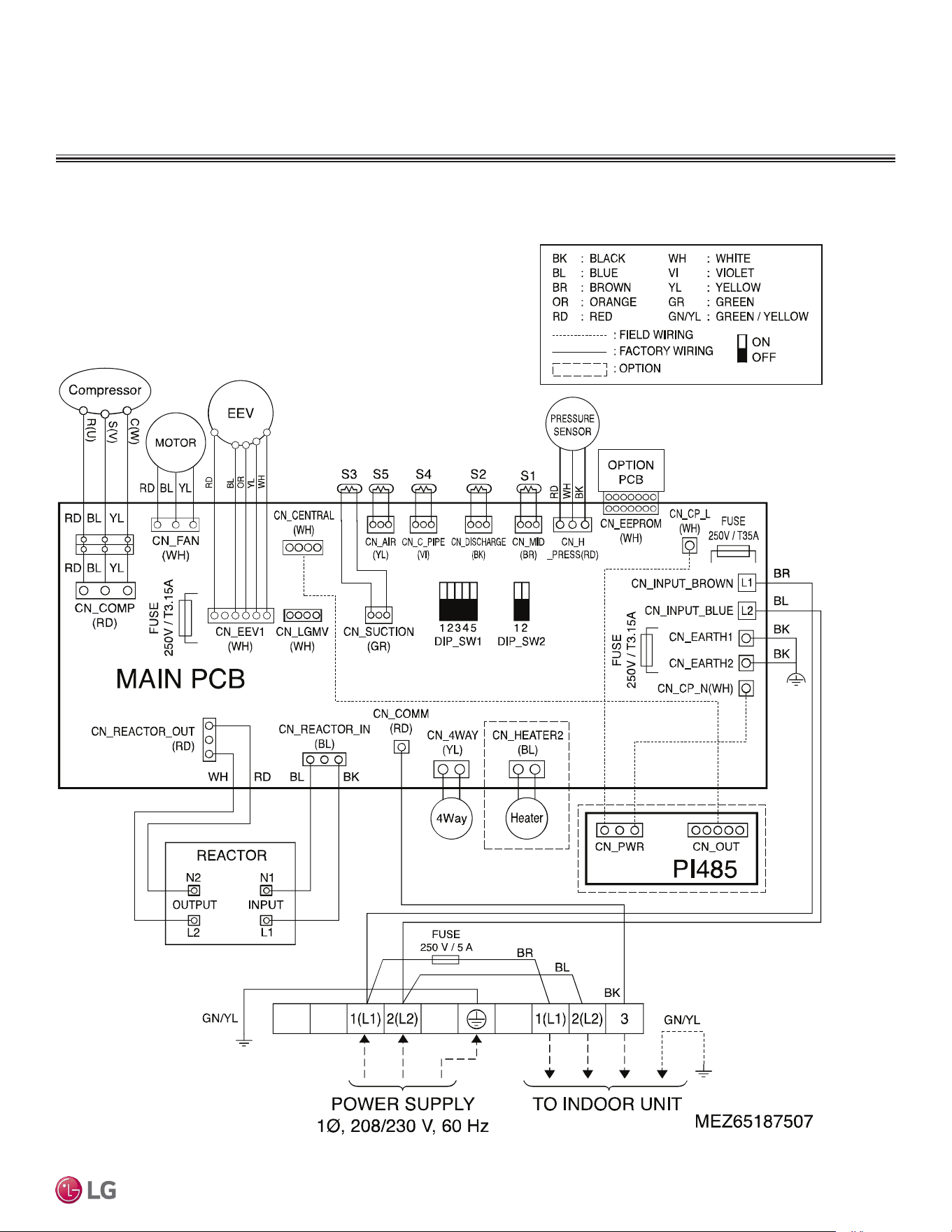
OUTDOOR UNIT WIRING DIAGRAM
Figure 24: LUU189HV Outdoor Unit Wiring Diagram.
7.19
Wiring Diagram for LUU189HV
Due to our policy of continuous product innovation, some specications may change without notication.
©LG Electronics U.S.A., Inc., Englewood Cliffs, NJ. All rights reserved. “LG” is a registered trademark of LG Corp.
34 | DUCTED
Single Zone Ceiling-Concealed Ducted System Engineering Manual
OUTDOOR UNIT WIRING DIAGRAM
Figure 25: LUU249HV Outdoor Unit Wiring Diagram.
7.19
Wiring Diagram for LUU249HV
DUCTED | 35
Product Data
Due to our policy of continuous product innovation, some specications may change without notication.
©LG Electronics U.S.A., Inc., Englewood Cliffs, NJ. All rights reserved. “LG” is a registered trademark of LG Corp.
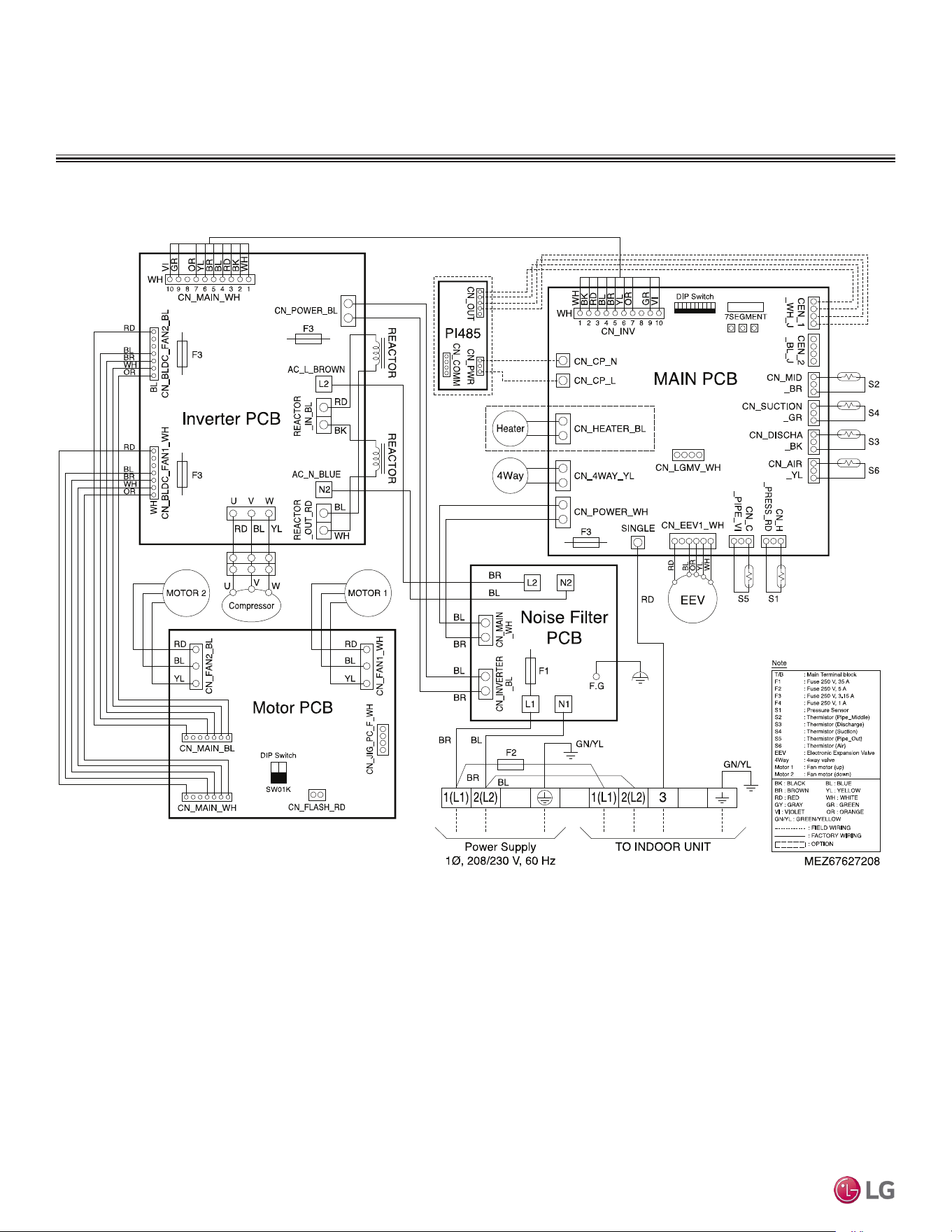
OUTDOOR UNIT WIRING DIAGRAM
Figure 26: LUU369HV Outdoor Unit Wiring Diagram.
7.19
Wiring Diagram for LUU369HV
Due to our policy of continuous product innovation, some specications may change without notication.
©LG Electronics U.S.A., Inc., Englewood Cliffs, NJ. All rights reserved. “LG” is a registered trademark of LG Corp.
36 | DUCTED
Single Zone Ceiling-Concealed Ducted System Engineering Manual
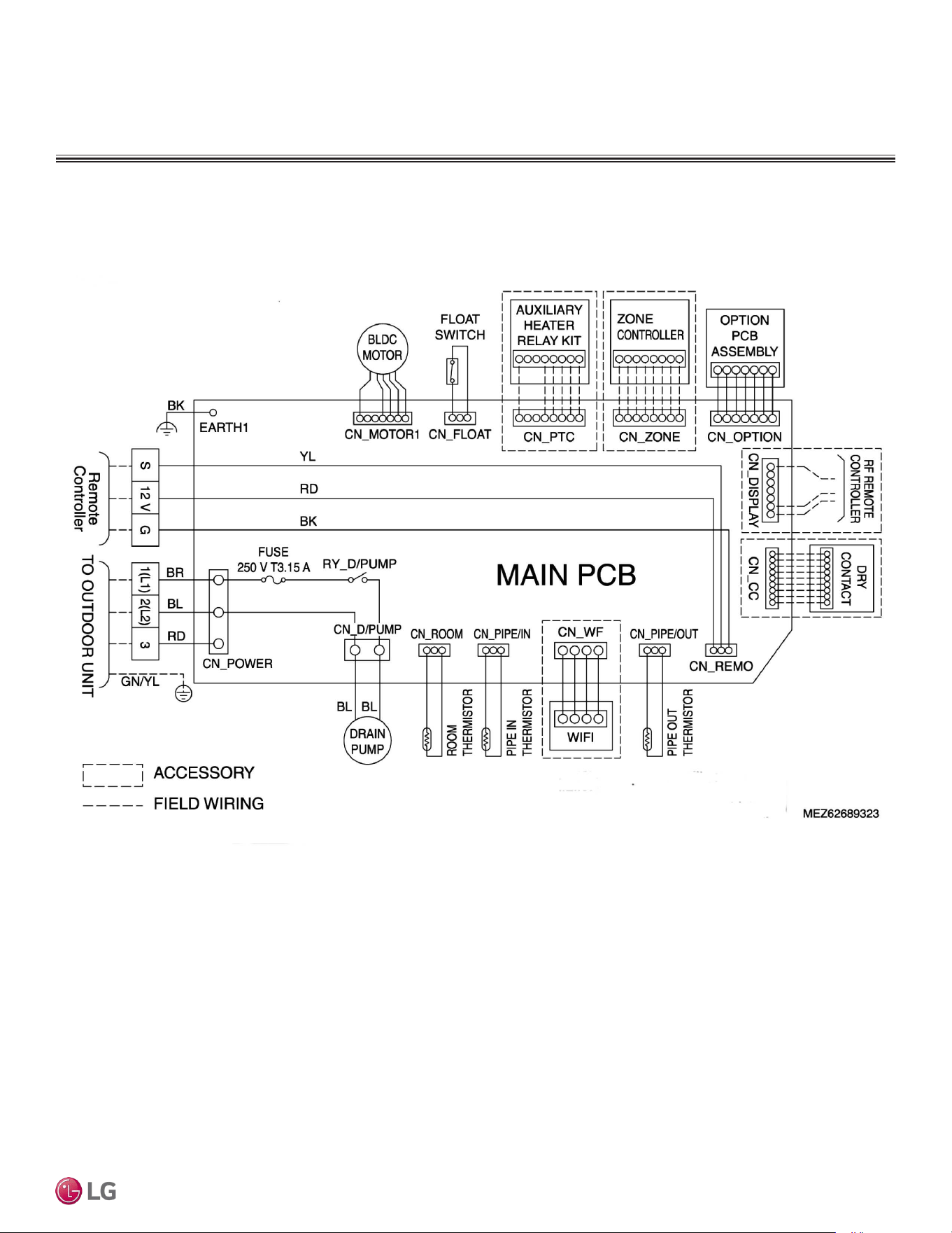
Figure 27: LDN097HV4 Ceiling-Concealed Ducted (Low Static) Indoor Unit Wiring Diagram.
INDOOR UNIT WIRING DIAGRAM
Wiring Diagram for LDN097HV4
8.19.
DUCTED | 37
Product Data
Due to our policy of continuous product innovation, some specications may change without notication.
©LG Electronics U.S.A., Inc., Englewood Cliffs, NJ. All rights reserved. “LG” is a registered trademark of LG Corp.
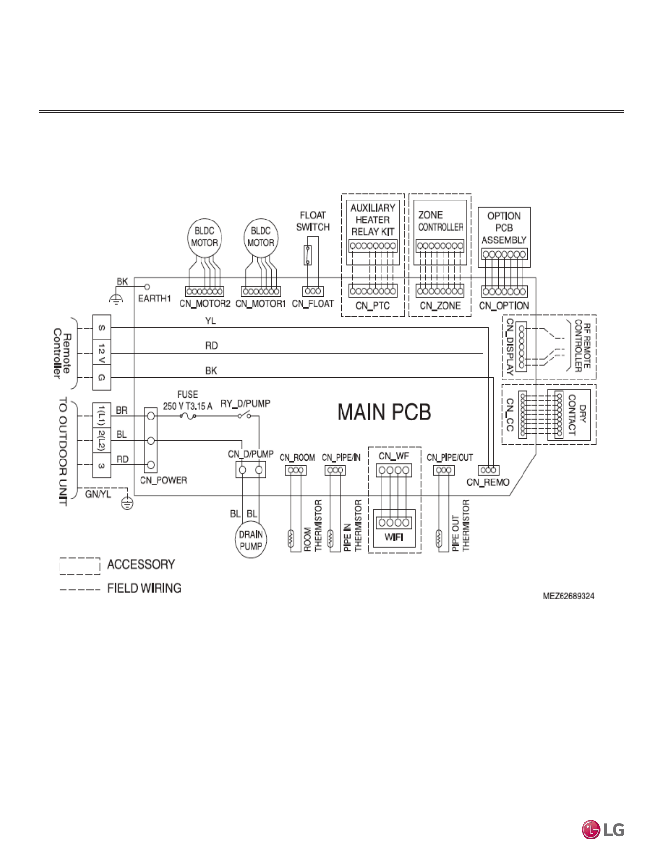
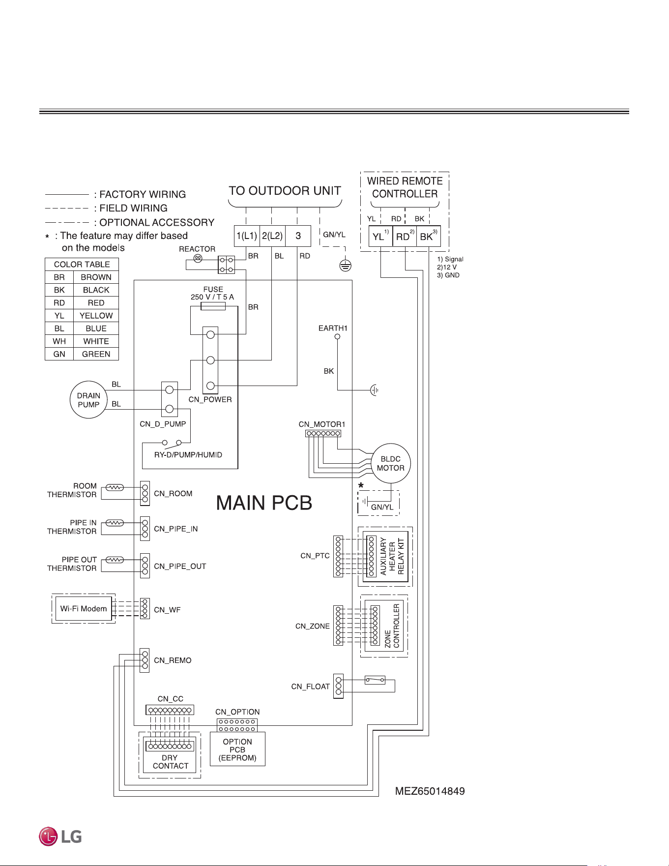
Figure 28: LDN127HV4, LDN187HV4 Ceiling-Concealed Ducted (Low Static) Indoor Unit Wiring Diagram.
INDOOR UNIT WIRING DIAGRAM
Wiring Diagram for LDN127HV4, LDN187HV4
Due to our policy of continuous product innovation, some specications may change without notication.
©LG Electronics U.S.A., Inc., Englewood Cliffs, NJ. All rights reserved. “LG” is a registered trademark of LG Corp.
38 | DUCTED
Single Zone Ceiling-Concealed Ducted System Engineering Manual
INDOOR UNIT WIRING DIAGRAM
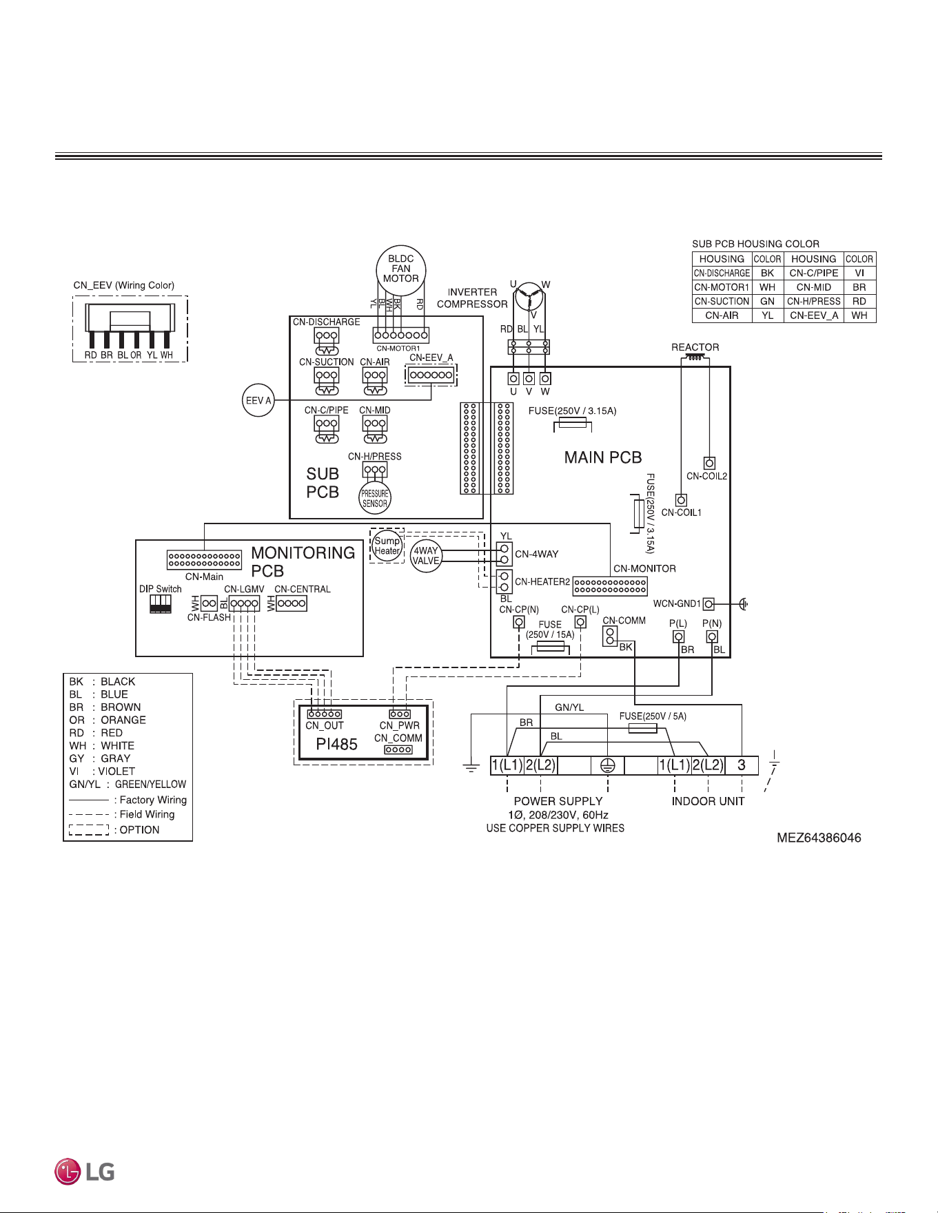
Figure 29: LHN248HV, LHN368HV Ceiling-Concealed Ducted (High Static) Indoor Unit Wiring Diagram.
Wiring Diagram for LHN248HV, LHN368HV
7.19
DUCTED | 39
Product Data
Due to our policy of continuous product innovation, some specications may change without notication.
©LG Electronics U.S.A., Inc., Englewood Cliffs, NJ. All rights reserved. “LG” is a registered trademark of LG Corp.
General Power Wiring / Communications Cable Guidelines
• Follow manufacturer’s circuit diagrams displayed on the inside of the control box cover.
• Have a separate power supply for the indoor units.
• Provide a circuit breaker switch between the power source and the indoor unit.
• Confirm power source specifications.
• Properly ground the outdoor unit and the indoor unit per NEC and local codes.
• Connect the wiring firmly so that the wires cannot be easily pulled out.
• Confirm that the electrical capacity is sufficient.
• Power supply to the outdoor unit must be selected based on NEC and local codes. Maximum allowable voltage fluctuation ±10% or name-
plate rated value.
• It is recommended that a circuit breaker is installed, especially if conditions could become wet or moist.
• Include a disconnect in the power wiring system. Add an air gap contact separation of at least 1/8 inch in each active (phase) conductor.
• Any openings where the field wiring enters the cabinet must be completely sealed.
Do not install power wiring to the outdoor unit and the communication / connection (power) cable to the indoor unit in the same conduit.
Use separate conduits.
Power Wiring / Communications Cable Specifications
• Power wiring to the outdoor unit must be solid or stranded, and must comply with the applicable local and national electric codes.
• Communication cable from the outdoor unit to the indoor unit must be a minimum of 14 AWG, four (4) conductor, shielded or unshielded (if
shielded, must be grounded to chassis at ODU only) and must comply with applicable local and national codes.
• Communication cable from indoor unit to remote controller(s) is to be 22 AWG, 3-conductor, twisted, stranded, unshielded. Wiring must
comply with all applicable local and national codes.
• Terminal screws may become loose during transport. Properly tighten the terminal connections during installation or risk electric shock,
physical injury, or death.
• Loose wiring may cause unit to malfunction, overheat, and catch fire, resulting in severe injury or death.
• Terminal screws may loosen during transport. Properly tighten the terminal connections during installation or risk equipment malfunction or
property damage.
• Loose wiring may cause unit malfunction, the wires to burnout or the terminal to overheat and catch fire. There is a risk of equipment malfunc-
tion or property damage.
A voltage drop may cause the following problems:
• Magnetic switch vibration, fuse breaks, or disturbance to the normal function of an overload protection device.
• Compressor will not receive the proper starting current.
ELECTRICAL CONNECTIONS
Due to our policy of continuous product innovation, some specications may change without notication.
©LG Electronics U.S.A., Inc., Englewood Cliffs, NJ. All rights reserved. “LG” is a registered trademark of LG Corp.
40 | DUCTED
Single Zone Ceiling-Concealed Ducted System Engineering Manual
ELECTRICAL CONNECTIONS
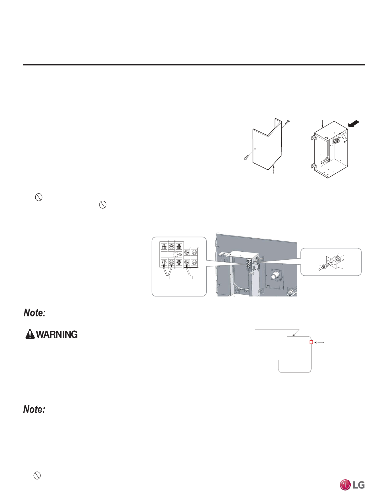
LUU097HV, LUU127HV, LUU189HV, LUU249HV, LUU369HV Outdoor Unit Connections
1. Remove the cover or control cover from the unit by loosening the fastening screws.
2. Take off the caps on the conduit panel.
3. Connect both the power supply and low voltage lines to the corresponding terminals on the terminal block.
4. Be sure to ground the unit by following local codes.
5. Allow for enough length (add several inches) for each wiring.
6. Secure the cable with the cord clamp.
7. Secure conduit tubes with lock nuts.
8. Reattach the control cover to the original position with the fastening screws.
LUU369HV Outdoor Unit Connections
1. Remove the side panel.
2. Use the clamp to attach the wiring / cable.
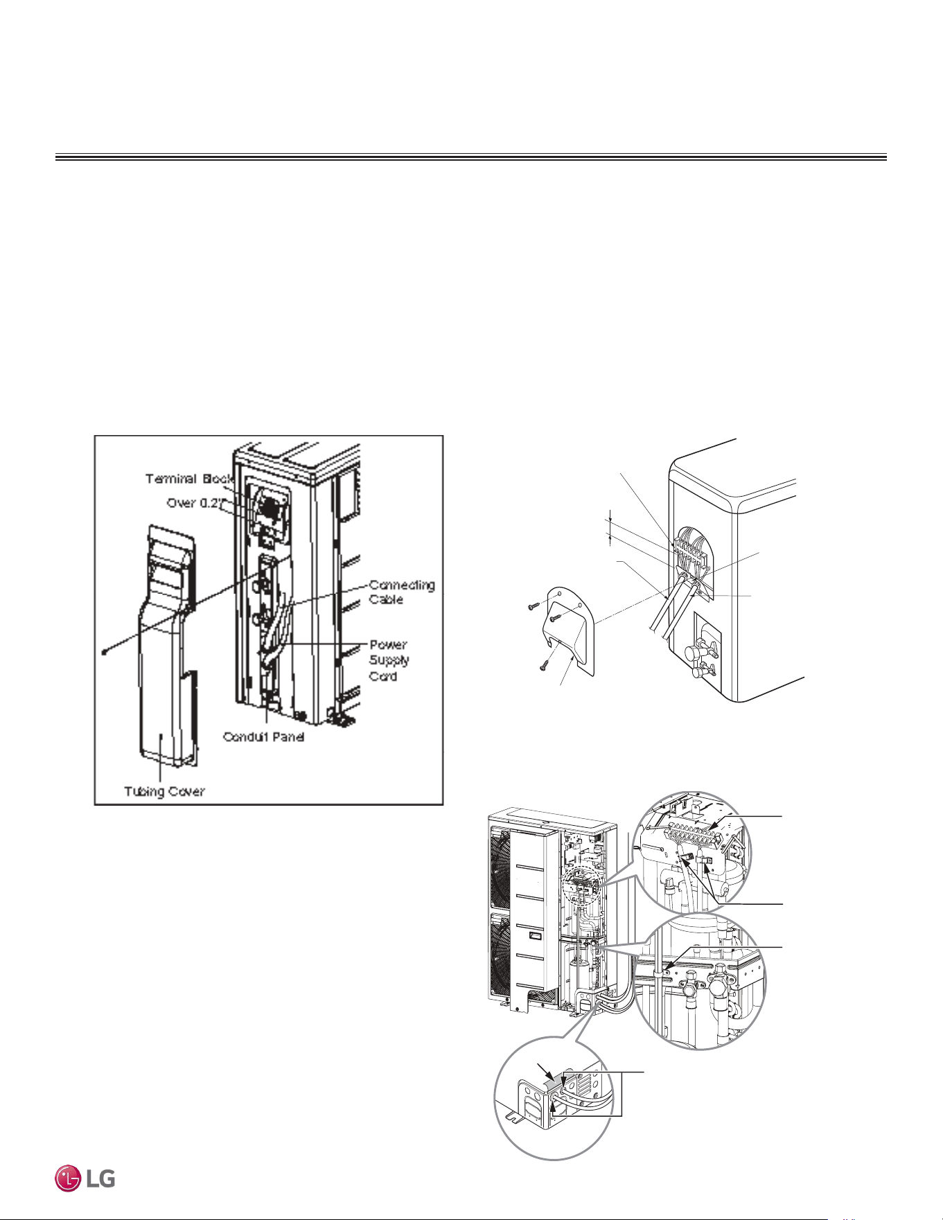
Figure 30: LUU097HV, LUU127HV ODU Terminal Block Location.
Terminal block
Over 0.2”
Control cover
Conduit panel
Connecting
cable
Power supply
cord
Figure 31: LUU189HV, LUU249HV ODU Terminal Block Location.
When connecting the power wiring /
communication cables, make sure
the rubber bushing is properly inserted
in the access holes after removing the insulation.
Insulation
Main
Terminal
Block
Clamps
Clamp
Outdoor Unit Power Wiring / Communications Cable Connections
Figure 32: LUU369HV ODU Terminal Block Location.
DUCTED | 41
Product Data
Due to our policy of continuous product innovation, some specications may change without notication.
©LG Electronics U.S.A., Inc., Englewood Cliffs, NJ. All rights reserved. “LG” is a registered trademark of LG Corp.
ELECTRICAL CONNECTIONS
Always use a circuit breaker or time delay fuse when connecting electrical wiring to the unit.
Figure 33: Circuit Breaker/Time Delay Fuse Con-
nection.
Air
Conditioner
Main Power Source
Circuit Breaker
Use a circuit breaker
Or time delay fuse
Ducted Indoor Unit Power Wiring / Communications Cable Connections
Lock Nut
Conduit
Mounting
Plate
Conduit
1(L1) 2(L2)
3(A) 4(B)
Power Supply
(208-230V)
Communication
1. To access the terminal block, first detach the cover from the control box.
2. Insert the power wiring / communications cable from the outdoor unit through the
sides of the indoor unit and control box. Pass the wiring through the designated
access holes to prevent damage. To prevent electromagnetic interference and
product malfunction, leave a space between the power wiring and communications
cable outside of the indoor unit. (For power wiring / communications cable between
the single zone outdoor unit and the indoor unit, use a four-conductor, stranded,
shielded or unshielded wire. If shielded, the wire must be grounded to the chassis
at the outdoor unit only.)
3. Connect each wire to its appropriate terminal on the indoor unit control board.
Verify that the color and terminal numbers from the outdoor unit wiring match the
color and terminal numbers on the indoor unit.
4. Secure the power wiring / communications cable with the cable restraint.
5. Reattach the steel clamp to the inside of the control panel.
• Place the wiring / cables in the clamp and tighten the plastic clamp to an open surface of the control panel.
• Do not apply force to the wiring connections when clamping.
• Neatly arrange the wiring. Do not catch the wiring in the electric box cover. Ensure the cover firmly closes.
6. Fill in any gaps around the wiring access holes with sealant to prevent foreign particles from entering the indoor unit.
Figure 34: Accessing the Indoor Unit Terminal Block.
A
Control Box
Terminal Block
Control Box Cover
Using a Conduit
1. Remove the rubber stopper on the indoor unit.
Pass the power wiring / communications cable
through the conduit, the conduit mounting
plate, and to / through the control panel of the
indoor unit.
2. Connect the power wiring / communications
cable to the indoor unit terminal block.
3. Screw the conduit mounting plate to the
indoor unit.
4. Tighten the conduit and the conduit mounting
plate together.
Figure 35: Ducted Indoor Unit Terminal Block Location / Using a Conduit.
• Separately wire the high and low voltage lines. There is a risk of electric shock, physical
injury, or death.
• Use heat-proof electrical wire capable of withstanding temperatures up to 167°F to avoid
wiring malfunction and electrical shock, which may cause physical injury or death.
• Ensure you connect the wire firmly. Loose wiring may cause unit malfunction, the wires
to burnout or the terminal to overheat and catch fire. There is a risk of electric shock,
physical injury or death.
• Use outdoor and waterproof connection cable rated up to 300V for the connection between the indoor and outdoor unit to avoid electrical
shock, which may cause physical injury or death.
• Separately wire the high and low voltage lines to avoid damage to unit.
• Use heat-proof electrical wire capable of withstanding temperatures up to 167°F to avoid damage to unit.
• Always use a circuit breaker or time delay fuse when connecting electrical wiring to the unit.
• Connect the wire firmly. Loose wiring may cause unit malfunction, the wires to burnout or the terminal to overheat and catch fire. There is
a risk of equipment malfunction or property damage.
• Use outdoor and waterproof connection cable rated up to 300V for the connection between the indoor and outdoor unit to avoid damage
to the unit.
• Comply with local codes while running wire from the indoor unit to the outdoor unit.
•
Do not allow wire to touch refrigerant tubing, the compressor or any moving parts since it can lead to mechanical failure.
Due to our policy of continuous product innovation, some specications may change without notication.
©LG Electronics U.S.A., Inc., Englewood Cliffs, NJ. All rights reserved. “LG” is a registered trademark of LG Corp.
42 | DUCTED
Single Zone Ceiling-Concealed Ducted System Engineering Manual
ELECTRICAL CONNECTIONS
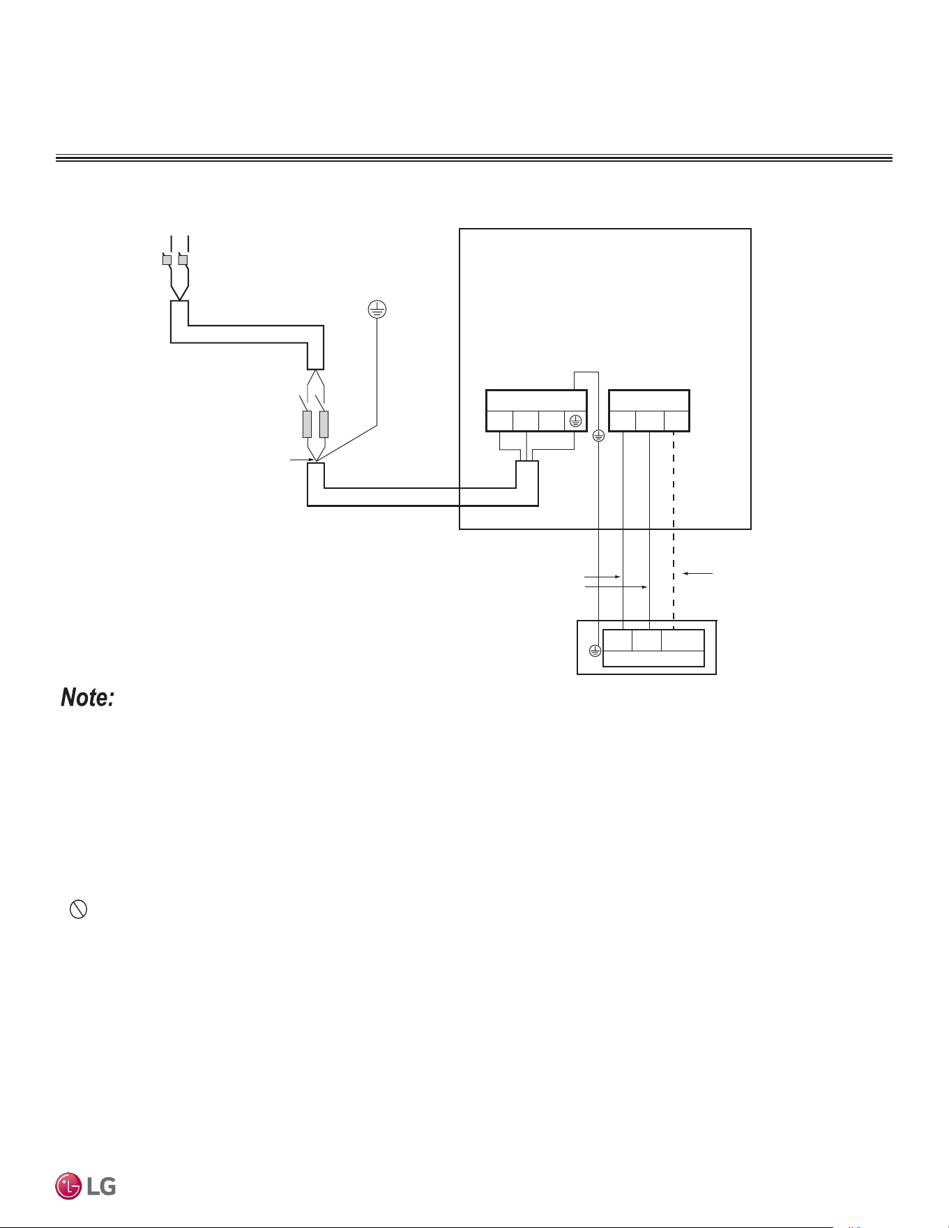
Wiring Connections
• Power wiring and communications cable sizes must comply with applicable federal UL / ETL, state, and local codes.
• Separately wire the high and low voltage lines to avoid damage to the unit.
• Local codes may require field-installed disconnect switches from outdoor unit to indoor unit.
• Use heat-proof electrical wire capable of withstanding temperatures up to 167°F to avoid damage to unit.
• Always use a circuit breaker or time delay fuse when connecting electrical wiring to the unit.
• Firmly connect the wire. Loose wiring may cause unit malfunction, the wires to burnout or the terminal to overheat and catch fire. There is a
risk of equipment malfunction or property damage.
• Use outdoor and waterproof connection cable rated up to 300V for the connection between the indoor and outdoor unit to avoid damage to
the unit.
• Comply with local codes while running wire from the indoor unit to the outdoor unit.
• Do not allow wire to touch refrigerant tubing, the compressor or any moving parts since it can lead to mechanical failure.
Figure 36: Detailed Power / Communications System Schematic.
L
L
N
N
G
Power Supply
Main Switch
Circuit Breaker
Fuse
Power Wiring
(Including Ground)
Outdoor Unit
1(L1) 2(L2)
Terminal Block Outdoor
1(L1) 2(L2) 3
Terminal Block Outdoor
Communication
Cable
1(L1) 2(L2)
Terminal Block Indoor
3
Indoor Unit
Power
Wiring
DUCTED | 43
Product Data
Due to our policy of continuous product innovation, some specications may change without notication.
©LG Electronics U.S.A., Inc., Englewood Cliffs, NJ. All rights reserved. “LG” is a registered trademark of LG Corp.
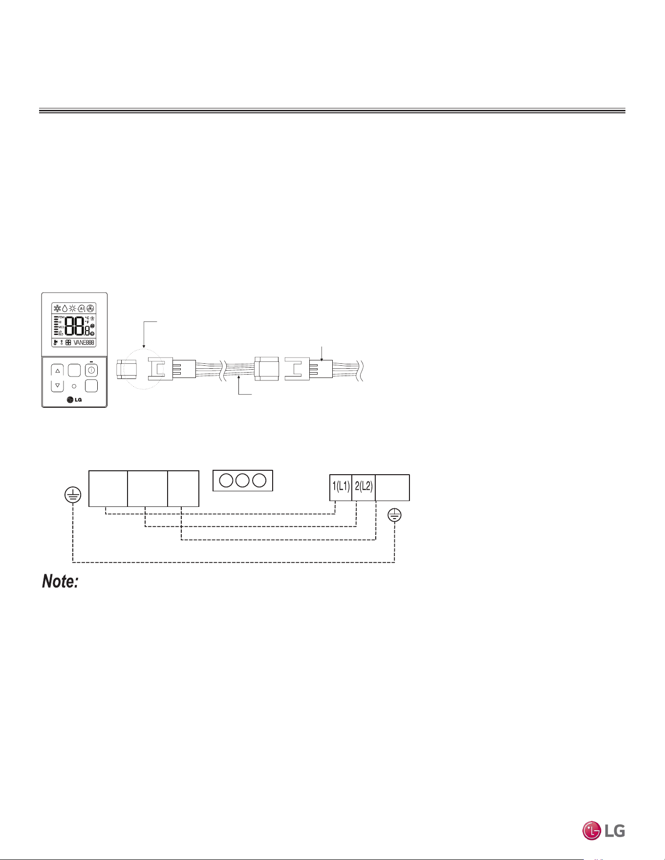
Verify the connectors are properly inserted.
C/BOX Cable (Plug type)
Extension cable
To Indoor Unit
CN-REMO
Terminal
TEMP
FAN
SPEED
OPER
MODE
Figure 37: PZCWRC1 LG Wired Remote Extension Cable
Wired Controller Connections
Optional controllers can connect to the Single Zone Ducted indoor unit in one of two different ways.
1. LG Wired Remote Extension Cable with Molex plug (PZCWRC1; sold separately) that connects to the CN-REMO terminal on the indoor
unit PCB.
2. Field-supplied controller cable that connects to the indoor unit terminal block (must be at least UL2547 or UL1007, and at least FT-6
rated if local electric and building codes require plenum cable usage). Communication cable from indoor unit to remote controller(s) is to
be 22 AWG, 3-conductor, twisted, stranded, unshielded. Wiring must comply with all applicable local and national codes.
Figure 38: Wired Controller Connection on the Indoor Unit Terminal Block.
ELECTRICAL CONNECTIONS
Indoor Unit Terminal Block
1(L1 )2(L2)
GND
3
Outdoor Unit Terminal Block
GND
GRN /
YLW
BR
BL
RD
3
CN-REMO
When using eld-supplied controller cable, make sure to connect the yellow to yellow (communications wire), red to red (12V power wire), and black
to black (ground wire) terminals from the remote controller to the indoor unit terminal blocks.
Due to our policy of continuous product innovation, some specications may change without notication.
©LG Electronics U.S.A., Inc., Englewood Cliffs, NJ. All rights reserved. “LG” is a registered trademark of LG Corp.
44 | DUCTED
Single Zone Ceiling-Concealed Ducted System Engineering Manual
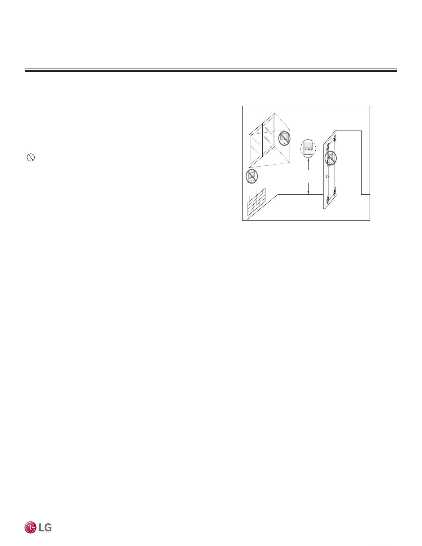
Figure 39: Proper Location for the Wired Controller.
4 to 5 feet
above the floor
NO
NO
NO
YES
Remote Controlle r
TEMP
Remote Controller
TEMP
Re
m
ot
e Co
n
t
roller
TEMP
Wired Controller Placement
Wired controllers include a sensor to detect room temperature. To
maintain comfort levels in the conditioned space, the wired control-
ler must be installed in a location away from direct sunlight, high
humidity, and where it could be directly exposed to cold air. Control-
ler must be installed four (4) to five (5) feet above the floor where its
LED display can be read easily, in an area with good air circulation,
and where it can detect an average room temperature.
Do not install the wired controller near or in:
• Drafts or dead spots behind doors and in corners.
• Hot or cold air from ducts.
• Radiant heat from the sun or appliances.
• Concealed pipes and chimneys.
• An area where temperatures are uncontrolled, such as an outside
wall.
Assigning the Thermistor for Temperature Detection
Each indoor unit includes a return air thermistor assigned to sense the temperature. If a wired controller is installed, there is a choice of
sensing temperature with either the indoor unit return air thermistor or the thermistor in the wired controller. It is also an option to set both
thermistors to sense temperature so that indoor unit bases its operation on the first thermistor to reach the designated temperature differen-
tial.
ELECTRICAL CONNECTIONS
DUCTED | 45
Product Data
Due to our policy of continuous product innovation, some specications may change without notication.
©LG Electronics U.S.A., Inc., Englewood Cliffs, NJ. All rights reserved. “LG” is a registered trademark of LG Corp.
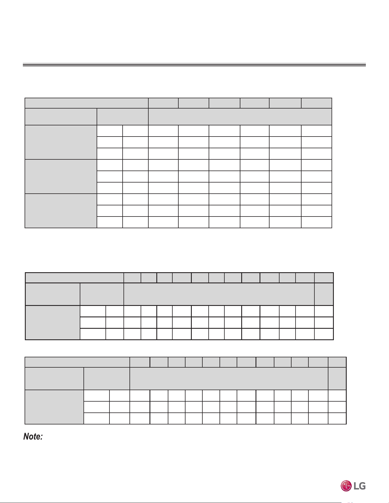
EXTERNAL STATIC PRESSURE
Table 27: Ceiling-Concealed Ducted (Low Static) Indoor Unit External Static Pressure Setting Values Table.
• To get the desired air flow and external static pressure combination, use the setting value from the table. Using a setting value other than that
listed in the table will not provide the desired combination.
• Table data is based at 230V. Air flow rate varies according to voltage fluctuation.
Static Pressure (in. wg) 0.1 0.16 0.2 0.24 0.28 0.31 0.35 0.39 0.43 0.47 0.51 0.59
Model No. / Nominal
Capacity of System
(Btu/h)
Airflow Rate /
CFM
Setting Value (in. wg)
LHN248HV
24,000
High 777 110 117 121 124 127 130 133 136 137 - 138 140
Mid 706 102 110 114 118 120 125 127 130 133 - 134 136
Low 636 96 102 107 110 114 118 122 125 127 - 130 132
Indoor Units
Table 28: Ceiling-Concealed Ducted (High Static) LHN248HV Indoor Unit External Static Pressure Setting Values Table.
Static Pressure (in. wg) 0.0 0.04 0.08 0.12 0.16 0.20
Model No. / Nominal Capacity
of System (Btu/h)
Airflow Rate / CFM Setting Value (in. wg)
LDN097HV4
9,000
High 318 98 103 108 116 123 130
Mid 247 82 88 94 102 110 118
Low 194 69 76 83 91 99 109
LDN127HV4
12,000
High 353 95 99 104 109 116 124
Mid 300 86 91 96 101 108 116
Low 247 78 82 87 93 100 108
LDN187HV4
18,000
High 530 123 125 129 134 141 145
Mid 441 109 112 117 123 129 136
Low 353 95 99 104 109 116 124
Ceiling-Concealed Low Static Ducted External Static Pressure Settings
Ceiling-Concealed High Static Ducted External Static Pressure Settings
Static Pressure (in. wg) 0.1 0.16 0.2 0.24 0.28 0.31 0.35 0.39 0.43 0.47 0.51 0.59
Model No. / Nominal
Capacity of System
(Btu/h)
Airflow Rate /
CFM
Setting Value (in. wg)
LHN368HV
36,000
High 1,130 - 109 112 115 119 122 126 128 131 134 137 144
Mid 989 - 101 105 108 112 115 119 123 127 130 133 138
Low 848 - 92 97 101 105 109 113 117 121 124 127 134
Table 29: Ceiling-Concealed Ducted (High Static) LHN368HV Indoor Unit External Static Pressure Setting Values Table.
Due to our policy of continuous product innovation, some specications may change without notication.
©LG Electronics U.S.A., Inc., Englewood Cliffs, NJ. All rights reserved. “LG” is a registered trademark of LG Corp.
46 | DUCTED
Single Zone Ceiling-Concealed Ducted System Engineering Manual
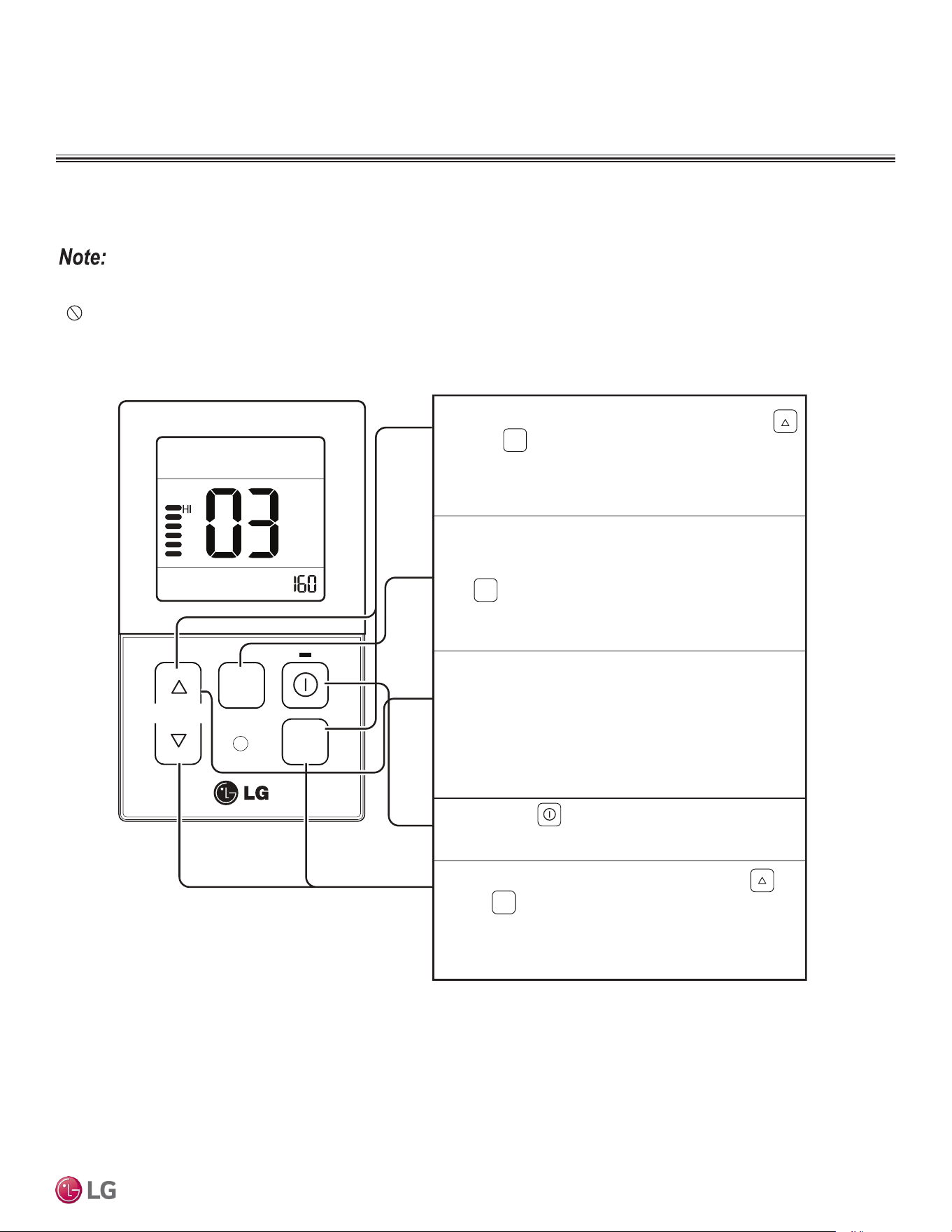
EXTERNAL STATIC PRESSURE
Indoor Units
Setting the External Static Pressure on the Remote Controller
Use this function to set the wind strength for each airflow level.
TEMP
FAN
SPEED
OPER
MODE
To access the controller set mode, press the
and buttons simultaneously
for >three (3)
* External Static Pressure Code: 03
1
Select the desired air flow rate with the
button.
2
Select the desired air flow rate value with
the temperature up), down) button.
* External Static Pressure value range: 0~255
- External Static Pressure value will be displayed
at the upper right-hand section of the screen.
3
Press the button to save / set the chosen
External Static Pressure value.
4
To deactivate the controller set mode, press the
and buttons simultaneously for > three (3) seconds.
- If there is no input (no buttons pressed) for
more than 25 seconds, the controller set mode
will automatically deactivate.
5
OPER
MODE
FAN
SPEED
OPER
MODE
seconds.
(Choose from SLo
→Lo→Med→Hi→Po
.)
• The external static pressure must be set by a trained service provider, and it must be set correctly. If the external static pressure is set incor-
rectly, the product may malfunction.
• Do not alter the external static pressure value that corresponds to each airflow level.
• External static pressure values vary according to the model.
• When the airflow rate is increased to a higher value, during the external static value setup, the previous airflow value will be stored in the
system memory. (External static pressure values are saved to system memory before the changes are implemented).
DUCTED | 47
Product Data
Due to our policy of continuous product innovation, some specications may change without notication.
©LG Electronics U.S.A., Inc., Englewood Cliffs, NJ. All rights reserved. “LG” is a registered trademark of LG Corp.
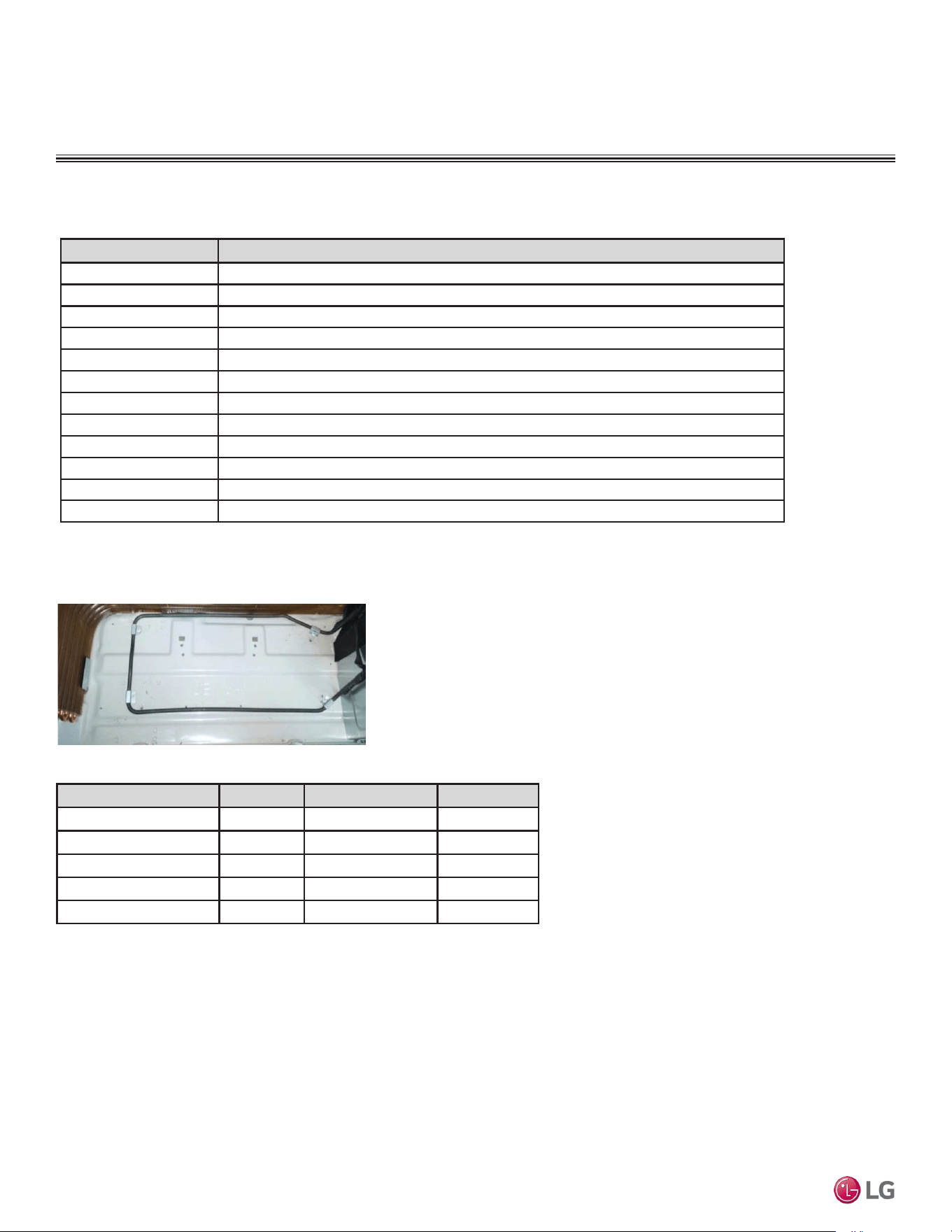
ACCESSORIES
Table 30: Ceiling-Concealed Ducted Indoor Unit Accessories.
Model No. Description
ZLABGP04A Low Ambient Wind Baffle for Low Static Ducted Indoor Units
ZLABGP01A Low Ambient Wind Baffle for Low Static Ducted Indoor Units
ZFBXM101A High Efficiency Filter Box for High Static Ducted Indoor Unit LHN248HV
ZFBXM201A High Efficiency Filter Box for High Static Ducted Indoor Unit LHN368HV
ZFBXD201A Dynamic V8 2VL Low Profile Air Cleaner for High Static Ducted Indoor Units
ZPLMV201A Dynamic 2VL Air Cleaner Low Profile Return Air Plenum for High Static Ducted Indoor Units
ZFBXD402A Dynamic V8 4VL Low Profile Air Cleaner for High Static Ducted Indoor Units
ZPLMV402A Dynamic 4VL Air Cleaner Low Profile Return Air Plenum for High Static Ducted Indoor Units
ZFLT1301A 4-Pack Dynamic V8 VL Air Cleaner Replacement Filter Pads for High Static Ducted Indoor Units
ZFLT1302A 24-Pack Dynamic V8 VL Air Cleaner Replacement Filter Pads for High Static Ducted Indoor Units
ZGRLRA01A Dynamic V8 Air Cleaner Louvered Return Air Grille (one per plenum) for High Static Ducted Indoor Units
ZGRLRA02A Dynamic V8 Air Cleaner Egg Crate Return Air Grille (one per plenum) for High Static Ducted Indoor Units
Ceiling-Concealed Ducted Indoor Unit Accessories
ODU Heater kW Accessory Model Note
LUU097HV 120W PQSH1202 Optional
LUU127HV 120W PQSH1202 Optional
LUU189HV 120W PQSH1200 Optional
LUU249HV 120W PQSH1200 Optional
LUU369HV 120W PQSH1200 Optional
Drain Pan Heater
Table 31: Drain Pan Heater Capacities.
Figure 40: Drain Pan Heater.
Due to our policy of continuous product innovation, some specications may change without notication.
©LG Electronics U.S.A., Inc., Englewood Cliffs, NJ. All rights reserved. “LG” is a registered trademark of LG Corp.
48 | DUCTED
Single Zone Ceiling-Concealed Ducted System Engineering Manual
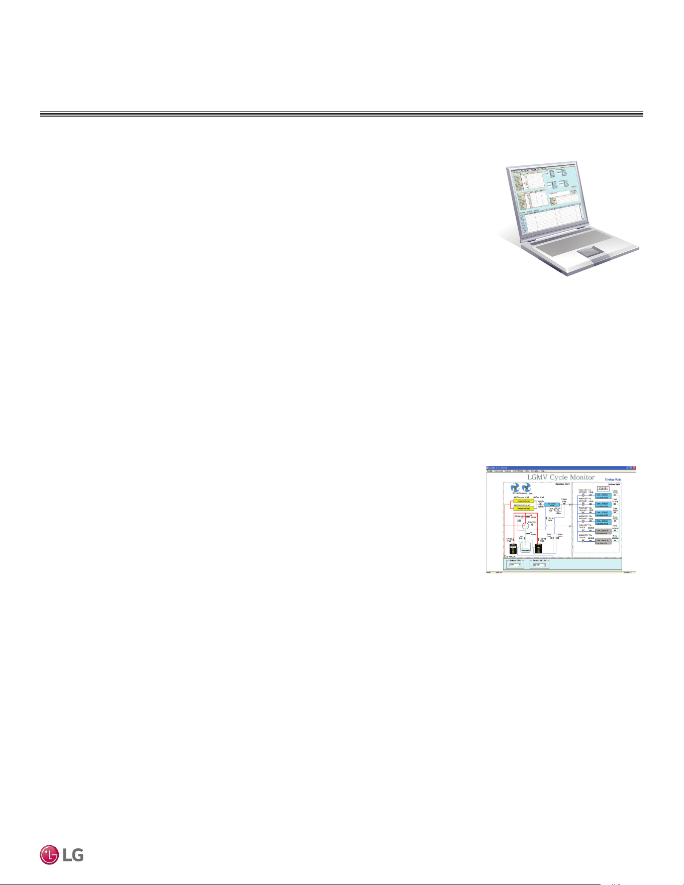
LG Monitoring View (LGMV) Diagnostic Software and Cable
LGMV software allows the service technician or commissioning agent to connect a computer USB
port to the outdoor unit main printed circuit board (PCB) using an accessory cable without the need
for a separate interface device. The main screen for LGMV allows the user to view the following real
time data on one screen:
ACCESSORIES
• Actual inverter compressor speed
• Target inverter compressor speed
• Actual outdoor fan speed
• Target outdoor unit fan speed
• Actual superheat
• Target superheat
• Actual subcooler circuit superheat
• Target subcooler circuit superheat
• Main EEV position
• Subcooling EEV position
• Inverter compressor current transducer
value
• Outdoor air temperature
• Actual high pressure/saturation temperature
• Actual low pressure/saturation temperature
• Suction temperature
• Inverter compressor discharge temperature
• Constant speed compressor discharge
temperature
• Front outdoor coil pipe temperature
• Back outdoor coil pipe temperature
• Liquid line pipe temperature
• Subcooler inlet temperature
• Subcooler outlet temperature
• Average indoor unit (IDU) pipe temperature
• Inverter compressor operation indicator
light
• Four-way reversing valve operation
indicator light
• Pressure graph showing actual low pres-
sure and actual high pressure levels
• Error code display
• Operating mode indicator
• Target high pressure
• Target low pressure
• PCB (printed circuit board) version
• Software version
• Installer name
• Model no. of outdoor units
• Site name
• Total number of connected indoor units
• Communication indicator lights
• Indoor unit capacity
• Indoor unit operating mode
• Indoor unit fan speed
• Indoor unit EEV position
• Indoor unit room temperature
• Indoor unit inlet pipe temperature
• Indoor unit outlet pipe temperature
• Indoor unit error code
Additional screens can be accessed by tabs on the main screen:
1. Cycleview: Graphic of internal components including:
2. Graph:
Full screen graph of actual high and low pressures and high and low pressure limits. A
sliding bar enables user to go back in time and view data.
3. Control IDU: Enables user to turn on all IDU’s default setpoints of 86°F in heat mode or 64°F in
cool mode.
4. Setting: Converts metric values to imperial values.
5. Making Data: Recording of real time data to a separate file created to be stored on the user’s computer.
6. Loading Data: Recorded data from a saved “.CSV” file can be loaded to create an LGMV session.
7. Electrical Data: The lower half of main screen is changed to show the following:
Figure 41: Sample Cycleview.
• Compressors showing actual speeds
• EEVs
• Indoor Units
• Liquid injection valves
• Temperature and pressure sensors
• Four-way reversing valve
• Outdoor fans showing status and speeds
• Inverter compressor
- Amps
- Volts
- Power Hz
- Inverter control board fan Hz
• Constant compressor
- Current transducer value
- Phase
• CPU: Pentium
®
IV 1.6 GHz
• Operating System: Windows
®
NT/2000/XP/Vista
• Main Memory: 256 MB
• Hard Disk: 600 MB when operating
• Web Browser: Internet Explorer
®
5.0
LGMV is available in different formats, including Mobile LGMV, which is a app for use on wireless devices. Contact your LG
Sales Representative for more information.
In lieu of connecting to the outdoor unit, user has the option to connect to the indoor unit with the use of a USB to RS-485 connector kit.
When connected through the indoor unit, user will not be able to record data.
This software can be used to both commission new systems and troubleshoot existing systems. LGMV data can be recorded to a “.CSV” file
and emailed to an LG representative to assist with diagnostic evaluations.
Recommended Minimum PC Configuration:
DUCTED | 49
Product Data
Due to our policy of continuous product innovation, some specications may change without notication.
©LG Electronics U.S.A., Inc., Englewood Cliffs, NJ. All rights reserved. “LG” is a registered trademark of LG Corp.
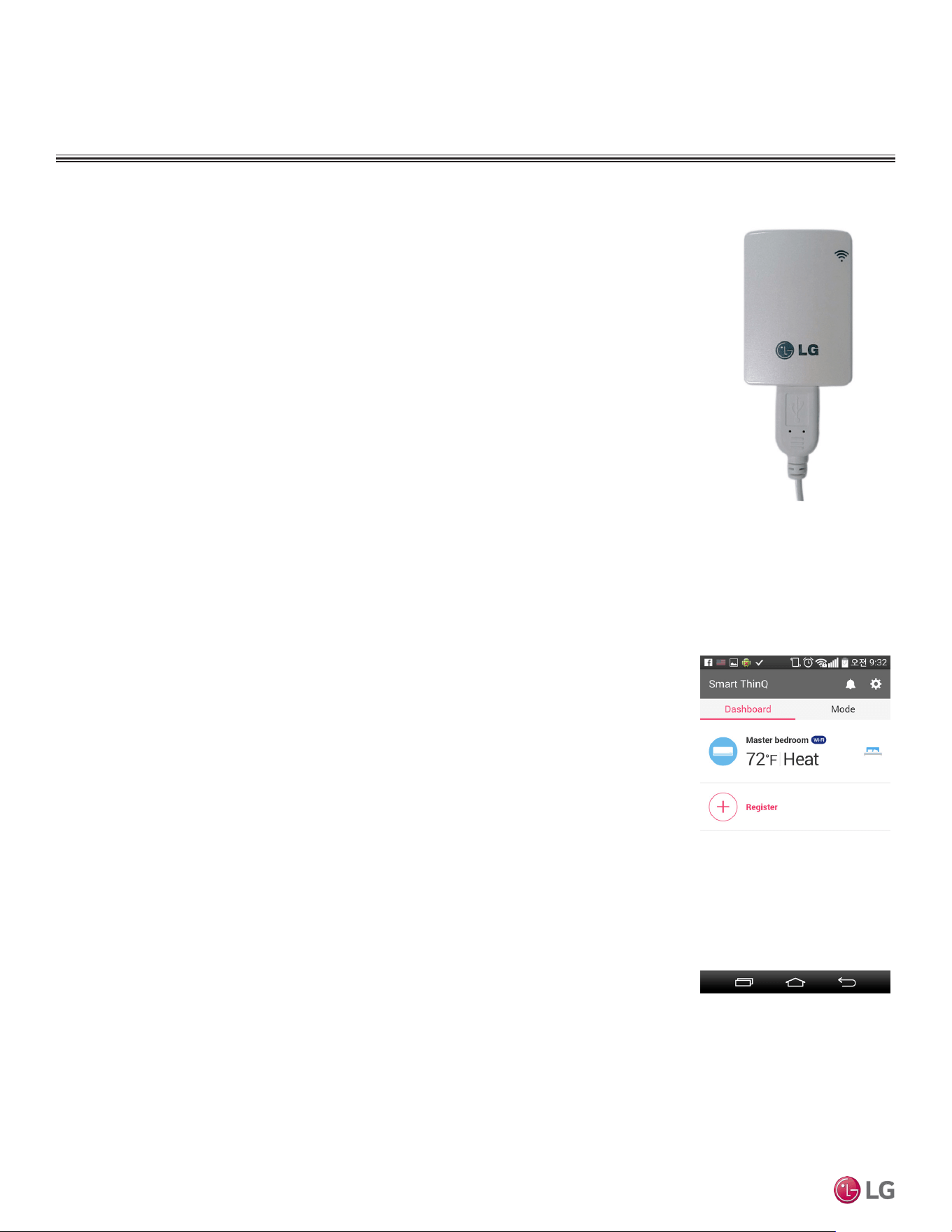
ACCESSORIES
Contact your LG Sales Representative for system requirements, the latest version of SIMS,
how to download the app, or other information.
Figure 42: LG SIMS WLAN
Module.
LG Smart Inverter Monitoring System (SIMS)
SIMS can be used to display and graph operational data for single zone systems and respective com-
ponents (indoor unit and outdoor unit). SIMS also displays error codes and a troubleshooting guide.
SIMs consists of a hardware Wireless Local Area Network (WLAN) module, an interface cable, and a
free downloadable application (app) for iOS® or Android™. The user must supply either an Apple® or an
Android smart phone; SIMs is not optimized for tablets, and only be used with LG single zone and Multi F
systems.
Only trained HVAC service technicians familiar with variable refrigerant flow (VRF) systems in general
and with LG’s DFS products can use SIMS. The technician must understand inverter air conditioning
operation cycles, the meaning of the data displayed by SIMS, and how to use the data to troubleshoot
the system.
LG Smart ThinQ
LG Smart ThinQ is a built-in Wi-Fi module, along with a free smart phone app that provides monitoring
and remote control capabilities for certain LG single zone systems. The app has the following features
and benefits:
• Sign in to the app using LG credentials, or using Google® or Facebook® login credentials. Users only
have to log in to the app once; the app remembers login details for subsequent logins.
• View current temperature settings of the air conditioning unit and change temperature, fan speed, and
air flow direction from anywhere in the house or at a remote location (through the use of wireless con-
nection). Multiple users can control the household air conditioning unit remotely.
• Monitor filter usage of the unit.
• Set up weekly schedules to start and stop air conditioner activity.
• Set up the unit to run in different Modes, depending on the user’s schedule. Set up specific tempera-
tures for when the user is home, away on vacation, or sleeping.
• Troubleshoot problems, and view tips on general maintenance of the system using the Smart Diagnosis
function.
Contact your LG Sales Representative or visit www.lg-dfs.com for system requirements, how
to download the app, a user’s manual, or other information.
Figure 43: Example of an LG
Smart ThinQ Screen (appearanc-
es my differ depending on version
of software).
*Google is a registered trademark of Google Inc.; Facebook is a registered trademark of Facebook.
iOS is a registered trademark of Cisco in the U.S. and other countries. Android is a trademark of Google Inc.
Apple is a trademark of Apple Inc., registered in the U.S. and other countries.
Due to our policy of continuous product innovation, some specications may change without notication.
©LG Electronics U.S.A., Inc., Englewood Cliffs, NJ. All rights reserved. “LG” is a registered trademark of LG Corp.
50 | DUCTED
Single Zone Ceiling-Concealed Ducted System Engineering Manual

Cooling Capacity Data on page 52
Heating Capacity Data on page 57
Maximum Heating Capacity Data on page 62
CEILING-CONCEALED
DUCTED UNIT
PERFORMANCE DATA
PERFORMANCE DATA
Low Static Ducted Cooling Capacity Tables
TC = Total Capacity (kBtu/h).
SHC: Sensible Heat Capacity (kBtu/h).
PI = Power input (KW). Power input (KW) includes compressor and fan(s).
Nominal capacity as rated 0 ft. above sea level and a 0 ft. level difference between outdoor and indoor
unit. Corresponding refrigerant piping length is accordance with standard length of each outdoor unit.
Nominal cooling capacity rating obtained with air entering the indoor unit at 80ºF dry bulb (DB) and 67ºF
wet bulb (WB), and outdoor ambient conditions of 95ºF dry bulb (DB) and 75ºF wet bulb (WB).
Cooling range can be extended from 0°F down to -4°F using the Low Ambient Wind Baffle Kit (sold
separately).
The shaded table rows indicate reference data. When operating at this temperature, these values can
be different if the system is not running consistently.
Due to our policy of continuous product innovation, some specications may change without notication.
©LG Electronics U.S.A., Inc., Englewood Cliffs, NJ. All rights reserved. “LG” is a registered trademark of LG Corp.
52 | DUCTED
Single Zone Ceiling-Concealed Ducted System Engineering Manual
Table 32: LD097HV4 Ceiling-Concealed Ducted (Low Static) System Cooling Capacity Table.
Outdoor
Air
Temp.
(°F DB)
Indoor Air Temp. °F DB / °F WB
68 / 57 73 / 61 77 / 64 80 / 67 86 / 72 90 / 75
TC SHC PI TC SHC PI TC SHC PI TC SHC PI TC SHC PI TC SHC PI
-4 8.85 6.84 0.42 9.40 7.23 0.44 9.95 7.00 0.45 10.34 7.15 0.46 11.05 7.21 0.47 11.60 7.34 0.47
0 8.84 6.88 0.42 9.39 7.27 0.44 9.94 7.04 0.46 10.34 7.19 0.46 11.04 7.25 0.47 11.59 7.39 0.48
5 8.84 6.94 0.43 9.38 7.33 0.45 9.93 7.10 0.46 10.33 7.25 0.47 11.03 7.31 0.48 11.58 7.45 0.49
10 8.83 7.00 0.44 9.38 7.39 0.45 9.93 7.16 0.47 10.32 7.31 0.48 11.02 7.37 0.48 11.57 7.51 0.49
15 8.82 7.05 0.44 9.37 7.45 0.46 9.92 7.21 0.48 10.31 7.37 0.48 11.01 7.43 0.49 11.56 7.57 0.50
20 8.82 7.11 0.45 9.36 7.51 0.47 9.91 7.27 0.48 10.31 7.42 0.49 11.01 7.49 0.50 11.55 7.63 0.51
25 8.81 7.16 0.46 9.36 7.57 0.47 9.90 7.33 0.49 10.30 7.48 0.50 11.00 7.54 0.51 11.54 7.69 0.52
30 8.80 7.22 0.46 9.35 7.63 0.48 9.90 7.38 0.50 10.29 7.54 0.50 10.99 7.60 0.51 11.54 7.75 0.52
35 8.80 7.27 0.47 9.34 7.68 0.49 9.89 7.44 0.50 10.28 7.60 0.51 10.98 7.66 0.52 11.53 7.81 0.53
40 8.79 7.33 0.48 9.33 7.74 0.49 9.88 7.50 0.51 10.27 7.65 0.52 10.97 7.72 0.53 11.52 7.86 0.54
45 8.78 7.38 0.48 9.33 7.80 0.50 9.87 7.55 0.52 10.27 7.71 0.52 10.96 7.78 0.53 11.51 7.92 0.55
50 8.78 7.44 0.49 9.32 7.86 0.51 9.87 7.61 0.53 10.26 7.77 0.53 10.96 7.83 0.54 11.50 7.98 0.55
55 8.77 7.49 0.50 9.31 7.91 0.51 9.86 7.66 0.53 10.25 7.82 0.54 10.95 7.89 0.55 11.49 8.04 0.56
60 8.76 7.55 0.50 9.31 7.97 0.52 9.85 7.72 0.54 10.24 7.88 0.55 10.94 7.95 0.56 11.48 8.10 0.57
65 8.76 7.60 0.51 9.30 8.03 0.53 9.84 7.77 0.55 10.24 7.94 0.55 10.93 8.00 0.56 11.47 8.16 0.57
70 8.75 7.65 0.51 9.29 8.09 0.53 9.84 7.83 0.55 10.23 7.99 0.56 10.92 8.06 0.57 11.47 8.21 0.58
75 8.54 7.53 0.54 9.08 7.96 0.56 9.62 7.72 0.58 10.01 7.89 0.59 10.71 7.96 0.60 11.25 8.12 0.61
80 8.33 7.40 0.57 8.87 7.84 0.59 9.41 7.61 0.61 9.80 7.78 0.62 10.49 7.86 0.63 11.03 8.03 0.64
85 8.12 7.27 0.60 8.66 7.71 0.62 9.20 7.49 0.64 9.59 7.66 0.65 10.28 7.76 0.66 10.82 7.92 0.68
90 7.91 7.13 0.63 8.45 7.57 0.65 8.99 7.37 0.67 9.37 7.55 0.68 10.06 7.65 0.69 10.60 7.82 0.71
95 7.68 7.05 0.65 8.22 7.50 0.68 8.75 7.31 0.70 9.00 7.38 0.71 9.83 7.61 0.72 10.36 7.79 0.74
100 7.50 6.86 0.68 8.03 7.31 0.71 8.57 7.14 0.73 8.88 7.27 0.74 9.64 7.44 0.75 10.17 7.63 0.77
105 7.31 6.68 0.71 7.84 7.13 0.73 8.38 6.96 0.76 8.77 7.15 0.77 9.45 7.28 0.78 9.99 7.47 0.80
110 7.12 6.45 0.74 7.66 6.89 0.76 8.19 6.75 0.79 8.58 6.94 0.80 9.26 7.07 0.82 9.80 7.26 0.83
115 6.94 6.25 0.76 7.47 6.70 0.79 8.01 6.57 0.82 8.39 6.76 0.83 9.08 6.90 0.85 9.61 7.10 0.86
118 6.82 6.21 0.78 7.36 6.66 0.81 7.89 6.54 0.84 8.28 6.73 0.85 8.96 6.88 0.86 9.50 7.08 0.88
122 6.79 6.19 0.80 7.32 6.65 0.83 7.86 6.52 0.86 8.24 6.72 0.87 8.93 6.87 0.89 9.46 7.07 0.91
Cooling Capacity Table for LD097HV4 (LDN097HV4 + LUU097HV)
PERFORMANCE DATA
Low Static Ducted Cooling Capacity Tables
DUCTED | 53
Product Data
Due to our policy of continuous product innovation, some specications may change without notication.
©LG Electronics U.S.A., Inc., Englewood Cliffs, NJ. All rights reserved. “LG” is a registered trademark of LG Corp.
Table 33: LD127HV4 Ceiling-Concealed Ducted (Low Static) System Cooling Capacity Table.
Outdoor
Air
Temp.
(°F DB)
Indoor Air Temp. °F DB / °F WB
68 / 57 73 / 61 77 / 64 80 / 67 86 / 72 90 / 75
TC SHC PI TC SHC PI TC SHC PI TC SHC PI TC SHC PI TC SHC PI
-4 11.40 9.03 0.53 12.11 9.54 0.55 12.82 9.24 0.57 13.33 9.43 0.58 14.24 9.51 0.59 14.95 9.69 0.60
0 11.40 9.08 0.54 12.11 9.60 0.56 12.81 9.29 0.58 13.33 9.49 0.58 14.23 9.57 0.60 14.94 9.75 0.61
5 11.39 9.17 0.55 12.10 9.68 0.57 12.80 9.38 0.59 13.31 9.57 0.59 14.22 9.65 0.61 14.93 9.84 0.62
10 11.38 9.24 0.56 12.09 9.76 0.58 12.79 9.45 0.60 13.30 9.65 0.60 14.21 9.73 0.61 14.91 9.92 0.63
15 11.37 9.31 0.56 12.08 9.84 0.58 12.78 9.53 0.61 13.29 9.73 0.61 14.20 9.81 0.62 14.90 9.99 0.64
20 11.36 9.39 0.57 12.07 9.91 0.59 12.77 9.60 0.61 13.28 9.80 0.62 14.19 9.88 0.63 14.89 10.07 0.65
25 11.35 9.46 0.58 12.06 9.99 0.60 12.76 9.67 0.62 13.27 9.88 0.63 14.17 9.96 0.64 14.88 10.15 0.65
30 11.35 9.53 0.59 12.05 10.07 0.61 12.75 9.75 0.63 13.26 9.95 0.64 14.16 10.04 0.65 14.87 10.23 0.66
35 11.34 9.60 0.60 12.04 10.14 0.62 12.74 9.82 0.64 13.25 10.03 0.65 14.15 10.11 0.66 14.86 10.31 0.67
40 11.33 9.68 0.60 12.03 10.22 0.63 12.74 9.90 0.65 13.24 10.10 0.66 14.14 10.19 0.67 14.85 10.38 0.68
45 11.32 9.75 0.61 12.02 10.30 0.63 12.73 9.97 0.66 13.23 10.18 0.66 14.13 10.27 0.68 14.83 10.46 0.69
50 11.31 9.82 0.62 12.01 10.37 0.64 12.72 10.04 0.67 13.22 10.26 0.67 14.12 10.34 0.69 14.82 10.54 0.70
55 11.30 9.89 0.63 12.00 10.45 0.65 12.71 10.12 0.67 13.21 10.33 0.68 14.11 10.42 0.70 14.81 10.61 0.71
60 11.29 9.96 0.64 11.99 10.53 0.66 12.70 10.19 0.68 13.20 10.41 0.69 14.10 10.49 0.70 14.80 10.69 0.72
65 11.28 10.04 0.64 11.99 10.60 0.67 12.69 10.26 0.69 13.19 10.48 0.70 14.09 10.57 0.71 14.79 10.77 0.73
70 11.28 10.11 0.65 11.98 10.68 0.68 12.68 10.34 0.70 13.18 10.56 0.71 14.08 10.64 0.72 14.78 10.85 0.74
75 11.00 9.94 0.69 11.70 10.51 0.71 12.40 10.19 0.74 12.91 10.41 0.75 13.80 10.52 0.76 14.50 10.72 0.78
80 10.73 9.77 0.72 11.43 10.35 0.75 12.13 10.04 0.78 12.63 10.27 0.79 13.52 10.38 0.80 14.22 10.60 0.82
85 10.46 9.59 0.76 11.16 10.17 0.79 11.85 9.89 0.81 12.36 10.12 0.82 13.24 10.24 0.84 13.94 10.46 0.86
90 10.20 9.41 0.79 10.89 10.00 0.82 11.58 9.73 0.85 12.08 9.96 0.86 12.97 10.10 0.88 13.66 10.33 0.90
95 9.90 9.31 0.83 10.59 9.91 0.86 11.28 9.65 0.89 11.60 9.74 0.90 12.66 10.05 0.92 13.35 10.28 0.94
100 9.66 9.06 0.86 10.35 9.66 0.89 11.04 9.42 0.93 11.45 9.59 0.94 12.42 9.83 0.96 13.11 10.07 0.98
105 9.42 8.81 0.90 10.11 9.41 0.93 10.80 9.19 0.97 11.30 9.44 0.98 12.18 9.61 0.99 12.87 9.86 1.01
110 9.18 8.51 0.93 9.87 9.10 0.97 10.56 8.91 1.00 11.06 9.16 1.01 11.94 9.34 1.03 12.63 9.59 1.05
115 8.94 8.26 0.97 9.63 8.85 1.00 10.32 8.67 1.04 10.82 8.93 1.05 11.70 9.12 1.07 12.39 9.37 1.09
118 8.79 8.20 0.99 9.48 8.79 1.03 10.17 8.63 1.06 10.67 8.89 1.08 11.55 9.09 1.10 12.24 9.35 1.12
122 8.75 8.18 1.02 9.44 8.77 1.06 10.13 8.61 1.09 10.62 8.87 1.11 11.51 9.08 1.13 12.20 9.34 1.15
TC = Total Capacity (kBtu/h).
SHC: Sensible Heat Capacity (kBtu/h).
PI = Power input (KW). Power input (KW) includes compressor and fan(s).
Nominal capacity as rated 0 ft. above sea level and a 0 ft. level difference between outdoor and indoor
unit. Corresponding refrigerant piping length is accordance with standard length of each outdoor unit.
Nominal cooling capacity rating obtained with air entering the indoor unit at 80ºF dry bulb (DB) and 67ºF
wet bulb (WB), and outdoor ambient conditions of 95ºF dry bulb (DB) and 75ºF wet bulb (WB).
Cooling range can be extended from 0°F down to -4°F using the Low Ambient Wind Baffle Kit (sold
separately).
The shaded table rows indicate reference data. When operating at this temperature, these values can
be different if the system is not running consistently.
Cooling Capacity Table for LD127HV4 (LDN127HV4 + LUU127HV)
PERFORMANCE DATA
Low Static Ducted Cooling Capacity Tables
Due to our policy of continuous product innovation, some specications may change without notication.
©LG Electronics U.S.A., Inc., Englewood Cliffs, NJ. All rights reserved. “LG” is a registered trademark of LG Corp.
54 | DUCTED
Single Zone Ceiling-Concealed Ducted System Engineering Manual
Outdoor
Air
Temp.
(°F DB)
Indoor Air Temp. °F DB / °F WB
68 / 57 72 / 61 77 / 64 80 / 67 86 / 72 90 / 75
TC SHC PI TC SHC PI TC SHC PI TC SHC PI TC SHC PI TC SHC PI
-4 17.70 12.40 0.92 18.80 13.10 0.96 19.89 12.68 0.99 20.69 12.95 1.00 22.09 13.06 1.02 23.19 13.31 1.04
0 17.69 12.47 0.93 18.79 13.18 0.97 19.88 12.76 1.00 20.68 13.03 1.01 22.08 13.14 1.03 23.18 13.39 1.05
5 17.67 12.58 0.95 18.77 13.29 0.98 19.87 12.87 1.02 20.66 13.14 1.03 22.06 13.25 1.05 23.16 13.50 1.07
10 17.66 12.68 0.96 18.76 13.40 1.00 19.85 12.97 1.03 20.64 13.24 1.05 22.05 13.36 1.07 23.14 13.61 1.09
15 17.65 12.78 0.98 18.74 13.50 1.01 19.84 13.07 1.05 20.63 13.35 1.06 22.03 13.46 1.08 23.12 13.72 1.10
20 17.63 12.88 0.99 18.73 13.61 1.03 19.82 13.18 1.06 20.61 13.45 1.08 22.01 13.57 1.10 23.11 13.82 1.12
25 17.62 12.98 1.00 18.71 13.71 1.04 19.81 13.28 1.08 20.60 13.56 1.09 22.00 13.67 1.11 23.09 13.93 1.13
30 17.60 13.08 1.02 18.70 13.82 1.06 19.79 13.38 1.09 20.58 13.66 1.11 21.98 13.78 1.13 23.07 14.04 1.15
35 17.59 13.18 1.03 18.68 13.92 1.07 19.78 13.48 1.11 20.57 13.77 1.12 21.96 13.88 1.14 23.05 14.14 1.17
40 17.58 13.28 1.05 18.67 14.03 1.08 19.76 13.58 1.12 20.55 13.87 1.14 21.94 13.99 1.16 23.04 14.25 1.18
45 17.56 13.38 1.06 18.66 14.13 1.10 19.75 13.68 1.14 20.53 13.97 1.15 21.93 14.09 1.17 23.02 14.36 1.20
50 17.55 13.48 1.07 18.64 14.24 1.11 19.73 13.79 1.15 20.52 14.08 1.17 21.91 14.19 1.19 23.00 14.46 1.21
55 17.54 13.58 1.09 18.63 14.34 1.13 19.72 13.89 1.17 20.50 14.18 1.18 21.89 14.30 1.21 22.98 14.57 1.23
60 17.52 13.68 1.10 18.61 14.45 1.14 19.70 13.99 1.18 20.49 14.28 1.20 21.88 14.40 1.22 22.97 14.68 1.25
65 17.51 13.77 1.12 18.60 14.55 1.16 19.69 14.09 1.20 20.47 14.38 1.21 21.86 14.51 1.24 22.95 14.78 1.26
70 17.50 13.87 1.13 18.58 14.65 1.17 19.67 14.19 1.21 20.46 14.49 1.23 21.84 14.61 1.25 22.93 14.89 1.28
75 17.08 13.64 1.19 18.16 14.43 1.24 19.24 13.99 1.28 20.03 14.29 1.29 21.41 14.43 1.32 22.50 14.72 1.35
80 16.66 13.41 1.25 17.74 14.20 1.30 18.82 13.79 1.35 19.60 14.10 1.36 20.98 14.25 1.39 22.06 14.55 1.41
85 16.24 13.17 1.31 17.32 13.96 1.36 18.40 13.57 1.41 19.17 13.89 1.43 20.55 14.06 1.45 21.63 14.36 1.48
90 15.82 12.92 1.37 16.90 13.72 1.42 17.97 13.35 1.48 18.75 13.68 1.49 20.12 13.86 1.52 21.20 14.17 1.55
95 15.37 12.78 1.44 16.44 13.60 1.49 17.51 13.25 1.54 18.00 13.37 1.56 19.65 13.79 1.59 20.72 14.11 1.62
100 14.99 12.44 1.50 16.06 13.25 1.55 17.13 12.93 1.61 17.77 13.17 1.63 19.28 13.49 1.66 20.35 13.82 1.69
105 14.62 12.10 1.56 15.69 12.91 1.61 16.76 12.62 1.67 17.53 12.96 1.69 18.90 13.19 1.72 19.97 13.53 1.76
110 14.24 11.68 1.62 15.32 12.49 1.68 16.39 12.23 1.74 17.16 12.57 1.76 18.53 12.82 1.79 19.60 13.16 1.83
115 13.87 11.33 1.68 14.94 12.14 1.74 16.01 11.90 1.80 16.79 12.25 1.83 18.15 12.51 1.86 19.22 12.86 1.90
118 13.65 11.25 1.72 14.72 12.07 1.78 15.79 11.84 1.84 16.56 12.20 1.86 17.93 12.47 1.90 19.00 12.83 1.94
122 13.57 11.22 1.76 14.64 12.04 1.83 15.71 11.82 1.90 16.49 12.18 1.92 17.85 12.46 1.95 18.92 12.82 1.99
Table 34: LD187HV4 Ceiling-Concealed Ducted (Low Static) System Cooling Capacity Table.
TC = Total Capacity (kBtu/h).
SHC: Sensible Heat Capacity (kBtu/h).
PI = Power input (KW). Power input (KW) includes compressor and fan(s).
Nominal capacity as rated 0 ft. above sea level and a 0 ft. level difference between outdoor and indoor
unit. Corresponding refrigerant piping length is accordance with standard length of each outdoor unit.
Nominal cooling capacity rating obtained with air entering the indoor unit at 80ºF dry bulb (DB) and 67ºF
wet bulb (WB), and outdoor ambient conditions of 95ºF dry bulb (DB) and 75ºF wet bulb (WB).
Cooling range can be extended from 0°F down to -4°F using the Low Ambient Wind Baffle Kit (sold
separately).
The shaded table rows indicate reference data. When operating at this temperature, these values can
be different if the system is not running consistently.
Cooling Capacity Table for LD187HV4 (LDN187HV4 + LUU189HV)
Table 35: LH248HV4 Ceiling-Concealed Ducted (High Static) System Cooling Capacity Table.
PERFORMANCE DATA
High Static Ducted Cooling Capacity Tables
Cooling Capacity Table for LH248HV4 (LHN248HV + LUU249HV)
Outdoor
Air
Temp.
(°F DB)
Indoor Air Temp. °F DB / °F WB
68 / 57 72 / 61 77 / 64 80 / 67 86 / 72 90 / 75
TC SHC PI TC SHC PI TC SHC PI TC SHC PI TC SHC PI TC SHC PI
-4 23.60 18.47 1.18 25.06 19.51 1.23 26.53 18.89 1.27 27.58 19.29 1.29 29.46 19.45 1.31 30.92 19.82 1.34
-0.4 23.58 18.58 1.20 25.05 19.63 1.24 26.51 19.00 1.29 27.57 19.40 1.30 29.44 19.57 1.32 30.91 19.94 1.35
5 23.56 18.74 1.22 25.03 19.80 1.26 26.49 19.17 1.31 27.55 19.57 1.32 29.42 19.74 1.35 30.88 20.11 1.37
10 23.55 18.89 1.23 25.01 19.95 1.28 26.47 19.32 1.33 27.53 19.73 1.34 29.39 19.89 1.37 30.86 20.27 1.39
15 23.53 19.04 1.25 24.99 20.11 1.30 26.45 19.47 1.34 27.50 19.88 1.36 29.37 20.05 1.39 30.83 20.43 1.41
20 23.51 19.19 1.27 24.97 20.27 1.32 26.43 19.63 1.36 27.48 20.04 1.38 29.35 20.21 1.41 30.81 20.59 1.43
25 23.49 19.34 1.29 24.95 20.43 1.33 26.41 19.78 1.38 27.46 20.19 1.40 29.33 20.36 1.43 30.79 20.75 1.45
30 23.47 19.48 1.31 24.93 20.58 1.35 26.39 19.93 1.40 27.44 20.35 1.42 29.30 20.52 1.45 30.76 20.91 1.47
35 23.46 19.63 1.32 24.91 20.74 1.37 26.37 20.08 1.42 27.42 20.50 1.44 29.28 20.68 1.47 30.74 21.07 1.49
40 23.44 19.78 1.34 24.89 20.89 1.39 26.35 20.23 1.44 27.40 20.66 1.46 29.26 20.83 1.49 30.72 21.23 1.52
45 23.42 19.93 1.36 24.87 21.05 1.41 26.33 20.38 1.46 27.38 20.81 1.48 29.24 20.99 1.51 30.69 21.38 1.54
50 23.40 20.07 1.38 24.85 21.21 1.43 26.31 20.53 1.48 27.36 20.97 1.50 29.21 21.14 1.52 30.67 21.54 1.56
55 23.38 20.22 1.40 24.84 21.36 1.45 26.29 20.68 1.50 27.34 21.12 1.52 29.19 21.30 1.54 30.64 21.70 1.58
60 23.37 20.37 1.41 24.82 21.52 1.47 26.27 20.83 1.52 27.32 21.27 1.54 29.17 21.45 1.56 30.62 21.86 1.60
65 23.35 20.52 1.43 24.80 21.67 1.48 26.25 20.98 1.54 27.29 21.43 1.56 29.15 21.61 1.58 30.60 22.02 1.62
70 23.33 20.66 1.45 24.78 21.83 1.50 26.23 21.13 1.56 27.27 21.58 1.58 29.13 21.76 1.60 30.57 22.17 1.64
75 22.77 20.32 1.53 24.21 21.49 1.58 25.66 20.84 1.64 26.70 21.29 1.66 28.55 21.50 1.69 29.99 21.92 1.73
80 22.21 19.97 1.61 23.65 21.16 1.66 25.09 20.53 1.73 26.13 21.00 1.75 27.97 21.23 1.78 29.42 21.66 1.81
85 21.65 19.61 1.68 23.09 20.80 1.75 24.53 20.21 1.81 25.57 20.69 1.83 27.40 20.94 1.86 28.84 21.39 1.90
90 21.09 19.24 1.76 22.53 20.44 1.83 23.96 19.89 1.89 25.00 20.37 1.92 26.83 20.65 1.95 28.27 21.11 1.99
95 20.49 19.04 1.84 21.92 20.25 1.91 23.35 19.73 1.98 24.00 19.92 2.00 26.20 20.54 2.04 27.63 21.02 2.08
100 19.99 18.53 1.92 21.42 19.74 1.99 22.85 19.26 2.06 23.69 19.61 2.08 25.70 20.09 2.12 27.13 20.59 2.17
105 19.49 18.02 2.00 20.92 19.23 2.07 22.35 18.79 2.15 23.38 19.30 2.17 25.20 19.65 2.21 26.63 20.16 2.26
110 18.99 17.40 2.07 20.42 18.61 2.15 21.85 18.21 2.23 22.88 18.73 2.25 24.70 19.09 2.30 26.13 19.60 2.34
115 18.49 16.88 2.15 19.92 18.09 2.23 21.35 17.73 2.31 22.38 18.25 2.34 24.20 18.64 2.38 25.63 19.16 2.43
118 18.19 16.76 2.20 19.62 17.98 2.28 21.05 17.64 2.36 22.08 18.17 2.39 23.90 18.57 2.44 25.33 19.11 2.48
122 18.10 16.72 2.26 19.52 17.94 2.35 20.95 17.61 2.43 21.98 18.14 2.46 23.81 18.55 2.50 25.23 19.09 2.56
DUCTED | 55
Product Data
Due to our policy of continuous product innovation, some specications may change without notication.
©LG Electronics U.S.A., Inc., Englewood Cliffs, NJ. All rights reserved. “LG” is a registered trademark of LG Corp.
TC = Total Capacity (kBtu/h).
SHC: Sensible Heat Capacity (kBtu/h).
PI = Power input (KW). Power input (KW) includes compressor and fan(s).
Nominal capacity as rated 0 ft. above sea level and a 0 ft. level difference between outdoor and indoor
unit. Corresponding refrigerant piping length is accordance with standard length of each outdoor unit.
Nominal cooling capacity rating obtained with air entering the indoor unit at 80ºF dry bulb (DB) and 67ºF
wet bulb (WB), and outdoor ambient conditions of 95ºF dry bulb (DB) and 75ºF wet bulb (WB).
Cooling range can be extended from 0°F down to -4°F using the Low Ambient Wind Baffle Kit (sold
separately).
The shaded table rows indicate reference data. When operating at this temperature, these values can
be different if the system is not running consistently.
PERFORMANCE DATA
High Static Ducted Cooling Capacity Tables
Table 36: LH368HV4 Ceiling-Concealed Ducted (High Static) System Cooling Capacity Table.
Cooling Capacity Table for LH368HV4 (LHN368HV + LUU369HV)
Outdoor
Air
Temp.
(°F DB)
Indoor Air Temp. °F DB / °F WB
68 / 57 72 / 61 77 / 64 80 / 67 86 / 72 90 / 75
TC SHC PI TC SHC PI TC SHC PI TC SHC PI TC SHC PI TC SHC PI
-4 35.39 25.44 1.76 37.59 26.87 1.83 39.79 26.02 1.89 41.38 26.56 1.92 44.19 26.79 1.95 46.38 27.30 1.99
-0.4 35.37 25.58 1.78 37.57 27.03 1.85 39.77 26.17 1.91 41.35 26.72 1.94 44.16 26.94 1.97 46.36 27.46 2.01
5 35.34 25.81 1.81 37.54 27.26 1.88 39.73 26.40 1.95 41.32 26.95 1.97 44.12 27.18 2.01 46.32 27.69 2.05
10 35.32 26.01 1.84 37.51 27.48 1.91 39.70 26.61 1.97 41.29 27.17 2.00 44.09 27.40 2.03 46.28 27.91 2.08
15 35.29 26.22 1.86 37.48 27.70 1.93 39.67 26.82 2.00 41.26 27.38 2.03 44.06 27.61 2.06 46.25 28.13 2.11
20 35.26 26.42 1.89 37.45 27.91 1.96 39.64 27.03 2.03 41.23 27.60 2.06 44.02 27.83 2.09 46.21 28.35 2.14
25 35.24 26.63 1.92 37.43 28.13 1.99 39.61 27.24 2.06 41.19 27.81 2.08 43.99 28.04 2.12 46.18 28.57 2.17
30 35.21 26.83 1.95 37.40 28.34 2.02 39.58 27.44 2.09 41.16 28.02 2.11 43.96 28.26 2.15 46.14 28.79 2.20
35 35.18 27.04 1.97 37.37 28.56 2.04 39.55 27.65 2.12 41.13 28.23 2.14 43.92 28.47 2.18 46.11 29.01 2.23
40 35.16 27.24 2.00 37.34 28.77 2.07 39.52 27.86 2.15 41.10 28.45 2.17 43.89 28.69 2.21 46.07 29.23 2.26
45 35.13 27.44 2.03 37.31 28.99 2.10 39.49 28.07 2.18 41.07 28.66 2.20 43.86 28.90 2.24 46.04 29.45 2.29
50 35.10 27.65 2.05 37.28 29.20 2.13 39.46 28.28 2.21 41.04 28.87 2.23 43.82 29.12 2.27 46.00 29.67 2.32
55 35.08 27.85 2.08 37.25 29.42 2.16 39.43 28.48 2.23 41.01 29.08 2.26 43.79 29.33 2.30 45.97 29.88 2.35
60 35.05 28.05 2.11 37.23 29.63 2.18 39.40 28.69 2.26 40.97 29.29 2.29 43.76 29.54 2.33 45.93 30.10 2.38
65 35.02 28.25 2.13 37.20 29.84 2.21 39.37 28.90 2.29 40.94 29.51 2.32 43.72 29.75 2.36 45.90 30.32 2.41
70 34.99 28.45 2.16 37.17 30.06 2.24 39.34 29.10 2.32 40.91 29.72 2.35 43.69 29.97 2.39 45.86 30.53 2.44
75 34.15 27.98 2.28 36.32 29.60 2.36 38.49 28.69 2.45 40.05 29.32 2.47 42.82 29.60 2.52 44.99 30.19 2.57
80 33.31 27.51 2.39 35.47 29.13 2.48 37.64 28.28 2.57 39.20 28.91 2.60 41.96 29.23 2.65 44.12 29.83 2.70
85 32.48 27.00 2.51 34.63 28.64 2.60 36.79 27.83 2.70 38.35 28.49 2.73 41.10 28.84 2.78 43.26 29.46 2.83
90 31.64 26.49 2.63 33.79 28.14 2.72 35.94 27.38 2.82 37.50 28.05 2.85 40.25 28.43 2.91 42.40 29.07 2.97
95 30.74 26.22 2.74 32.88 27.89 2.84 35.02 27.18 2.95 36.00 27.43 2.98 39.30 28.28 3.04 41.44 28.95 3.10
100 29.99 25.51 2.86 32.13 27.19 2.96 34.27 26.53 3.07 35.53 27.01 3.11 38.55 27.67 3.16 40.69 28.35 3.23
105 29.24 24.81 2.98 31.38 26.48 3.08 33.52 25.88 3.20 35.07 26.58 3.23 37.80 27.06 3.29 39.94 27.76 3.36
110 28.49 23.96 3.09 30.63 25.63 3.20 32.77 25.08 3.32 34.32 25.79 3.36 37.05 26.29 3.42 39.20 27.00 3.49
115 27.74 23.25 3.21 29.88 24.91 3.33 32.02 24.42 3.45 33.57 25.13 3.49 36.31 25.67 3.55 38.45 26.38 3.62
118 27.29 23.08 3.28 29.43 24.75 3.40 31.57 24.29 3.52 33.12 25.02 3.56 35.86 25.58 3.63 38.00 26.31 3.70
122 27.14 23.02 3.37 29.28 24.70 3.49 31.43 24.25 3.62 32.97 24.98 3.66 35.71 25.55 3.73 37.85 26.29 3.81
Due to our policy of continuous product innovation, some specications may change without notication.
©LG Electronics U.S.A., Inc., Englewood Cliffs, NJ. All rights reserved. “LG” is a registered trademark of LG Corp.
56 | DUCTED
Single Zone Ceiling-Concealed Ducted System Engineering Manual
TC = Total Capacity (kBtu/h).
SHC: Sensible Heat Capacity (kBtu/h).
PI = Power input (KW). Power input (KW) includes compressor and fan(s).
Nominal capacity as rated 0 ft. above sea level and a 0 ft. level difference between outdoor and indoor
unit. Corresponding refrigerant piping length is accordance with standard length of each outdoor unit.
Nominal cooling capacity rating obtained with air entering the indoor unit at 80ºF dry bulb (DB) and 67ºF
wet bulb (WB), and outdoor ambient conditions of 95ºF dry bulb (DB) and 75ºF wet bulb (WB).
Cooling range can be extended from 0°F down to -4°F using the Low Ambient Wind Baffle Kit (sold
separately).
The shaded table rows indicate reference data. When operating at this temperature, these values can
be different if the system is not running consistently.
Low Static Ducted Heating Capacity Tables
PERFORMANCE DATA
Table 37: LD097HV4 Ceiling-Concealed Ducted (Low Static) System Heating Capacity Table.
Outdoor Air
Temp.
Indoor Air Temp. °F DB
°F DB °F WB
61 64 68 70 72 75
TC PI TC PI TC PI TC PI TC PI TC PI
-4 -4.4 8.12 0.86 7.68 0.90 7.53 0.90 7.42 0.91 7.33 0.91 7.03 0.95
0 -0.4 8.58 0.89 8.16 0.93 7.98 0.94 7.85 0.95 7.75 0.95 7.43 0.99
5 4.5 9.14 0.93 8.74 0.96 8.52 0.98 8.38 0.99 8.26 1.00 7.93 1.04
10 9 9.66 0.97 9.28 1.00 9.01 1.02 8.86 1.04 8.73 1.05 8.39 1.08
17 15 10.35 1.01 9.99 1.05 9.68 1.08 9.50 1.10 9.36 1.11 9.00 1.14
20 19 10.81 1.04 10.47 1.08 10.12 1.11 9.93 1.13 9.78 1.15 9.41 1.18
25 23 11.58 1.10 11.24 1.13 10.85 1.17 10.64 1.20 10.48 1.22 10.08 1.25
30 28 12.36 1.16 11.98 1.20 11.57 1.24 11.36 1.26 11.19 1.28 10.78 1.32
35 32 13.14 1.22 12.73 1.26 12.29 1.30 12.07 1.33 11.89 1.35 11.46 1.38
40 36 13.81 1.26 13.43 1.30 13.00 1.34 12.77 1.36 12.59 1.39 12.14 1.42
45 41 14.65 1.30 14.30 1.34 13.88 1.39 13.65 1.41 13.46 1.43 12.98 1.47
47 43 14.99 1.32 14.65 1.36 14.23 1.41 14.00 1.43 13.81 1.45 13.31 1.49
50 46 15.03 1.31 14.73 1.35 14.36 1.39 14.15 1.41 13.99 1.43 13.52 1.46
55 51 15.10 1.30 14.85 1.33 14.58 1.36 14.41 1.38 14.28 1.39 13.85 1.42
60 56 15.18 1.28 14.98 1.31 14.80 1.33 14.67 1.34 14.57 1.35 14.19 1.37
63 59 15.22 1.27 15.05 1.29 14.92 1.31 14.82 1.32 14.74 1.33 14.40 1.34
68 64 15.26 1.27 15.13 1.28 15.06 1.30 14.98 1.30 14.92 1.30 14.61 1.31
TC = Total Capacity (kBtu/h).
PI = Power input (KW). Power input (KW) includes compressor and fan(s).
Nominal capacity as rated 0 ft. above sea level and a 0 ft. level difference between outdoor and indoor
unit. Corresponding refrigerant piping length is accordance with standard length of each outdoor unit.
Nominal heating capacity rating obtained with air entering the indoor unit at 70ºF dry bulb (DB) and
60ºF wet bulb (WB), and outdoor ambient conditions of 47ºF dry bulb (DB) and 43ºF wet bulb (WB).
Heating Capacity Table for LD097HV4 (LDN097HV4 + LUU097HV)
DUCTED | 57
Product Data
Due to our policy of continuous product innovation, some specications may change without notication.
©LG Electronics U.S.A., Inc., Englewood Cliffs, NJ. All rights reserved. “LG” is a registered trademark of LG Corp.
Table 38: LD127HV4 Ceiling-Concealed Ducted (Low Static) System Heating Capacity Table.
Outdoor Air
Temp.
Indoor Air Temp. °F DB
°F DB °F WB
61 64 68 70 72 75
TC PI TC PI TC PI TC PI TC PI TC PI
-4 -4.4 5.93 0.93 5.48 0.97 5.46 0.98 5.40 0.99 5.35 0.99 5.11 1.03
0 -0.4 7.22 0.94 6.79 0.98 6.68 1.00 6.59 1.00 6.52 1.01 6.24 1.05
5 4.5 8.75 0.96 8.34 1.00 8.14 1.02 8.01 1.03 7.90 1.04 7.58 1.07
10 9 9.77 0.98 9.37 1.01 9.11 1.04 8.96 1.05 8.83 1.06 8.48 1.10
17 15 10.89 1.00 10.52 1.03 10.18 1.06 10.00 1.08 9.85 1.09 9.47 1.13
20 19 11.58 1.01 11.21 1.04 10.83 1.08 10.63 1.10 10.47 1.12 10.07 1.15
25 23 12.72 1.04 12.34 1.07 11.91 1.11 11.69 1.13 11.51 1.15 11.07 1.18
30 28 13.87 1.07 13.44 1.11 12.98 1.14 12.74 1.16 12.55 1.18 12.09 1.21
35 32 15.02 1.10 14.54 1.14 14.05 1.17 13.80 1.20 13.59 1.22 13.10 1.25
40 36 15.79 1.13 15.34 1.17 14.85 1.21 14.60 1.23 14.39 1.25 13.87 1.28
45 41 16.74 1.17 16.34 1.21 15.86 1.25 15.60 1.27 15.39 1.29 14.83 1.33
47 43 17.13 1.19 16.74 1.23 16.27 1.27 16.00 1.29 15.79 1.31 15.21 1.35
50 46 17.18 1.18 16.83 1.22 16.41 1.25 16.18 1.27 15.99 1.29 15.45 1.32
55 51 17.26 1.17 16.97 1.20 16.66 1.23 16.47 1.24 16.32 1.25 15.83 1.28
60 56 17.34 1.16 17.12 1.18 16.91 1.20 16.76 1.21 16.65 1.22 16.22 1.24
63 59 17.40 1.15 17.21 1.17 17.06 1.19 16.94 1.19 16.85 1.20 16.46 1.21
68 64 17.45 1.14 17.29 1.16 17.21 1.17 17.12 1.17 17.05 1.18 16.69 1.19
TC = Total Capacity (kBtu/h).
PI = Power input (KW). Power input (KW) includes compressor and fan(s).
Nominal capacity as rated 0 ft. above sea level and a 0 ft. level difference between outdoor and indoor
unit. Corresponding refrigerant piping length is accordance with standard length of each outdoor unit.
Nominal heating capacity rating obtained with air entering the indoor unit at 70ºF dry bulb (DB) and
60ºF wet bulb (WB), and outdoor ambient conditions of 47ºF dry bulb (DB) and 43ºF wet bulb (WB).
Heating Capacity Table for LD127HV4 (LDN127HV4 + LUU127HV)
Low Static Ducted Heating Capacity Tables
PERFORMANCE DATA
Due to our policy of continuous product innovation, some specications may change without notication.
©LG Electronics U.S.A., Inc., Englewood Cliffs, NJ. All rights reserved. “LG” is a registered trademark of LG Corp.
58 | DUCTED
Single Zone Ceiling-Concealed Ducted System Engineering Manual
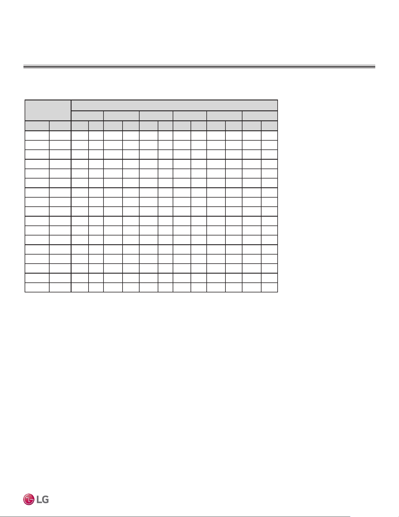
Low Static Ducted Heating Capacity Tables
PERFORMANCE DATA
Table 39: LD187HV4 Ceiling-Concealed Ducted (Low Static) System Heating Capacity Table.
Outdoor Air
Temp.
Indoor Air Temp. °F DB
61.0 64.0 68.0 70.0 72.0 75.0
°F DB °F WB TC PI TC PI TC PI TC PI TC PI TC PI
-4 -4.4 7.90 6.83 7.31 7.05 7.27 7.26 7.19 7.38 7.12 7.48 6.80 7.70
0 -0.4 9.44 6.41 8.88 6.61 8.74 6.82 8.62 6.93 8.52 7.02 8.16 7.22
5 4.5 11.27 5.89 10.74 6.08 10.48 6.27 10.31 6.37 10.18 6.46 9.77 6.64
10 9 12.49 5.42 11.98 5.59 11.65 5.77 11.45 5.86 11.29 5.94 10.85 6.11
17 15 13.84 4.79 13.36 4.94 12.93 5.10 12.70 5.18 12.51 5.25 12.03 5.40
20 19 14.65 4.37 14.19 4.51 13.71 4.65 13.46 4.73 13.25 4.79 12.75 4.93
25 23 16.02 3.95 15.54 4.07 15.00 4.20 14.72 4.27 14.49 4.33 13.95 4.45
30 28 17.40 3.42 16.86 3.53 16.28 3.64 15.98 3.70 15.74 3.75 15.16 3.86
35 32 18.78 3.00 18.18 3.10 17.56 3.20 17.24 3.25 16.99 3.29 16.38 3.39
40 36 19.73 2.58 19.18 2.66 18.57 2.75 18.25 2.80 17.99 2.83 17.34 2.92
45 41 20.93 2.05 20.43 2.12 19.83 2.19 19.50 2.23 19.24 2.26 18.54 2.32
47 43 21.41 1.84 20.93 1.91 20.33 1.97 20.00 2.00 19.73 2.03 19.02 2.09
50 46 21.47 1.83 21.04 1.89 20.52 1.94 20.22 1.97 19.98 1.99 19.31 2.05
55 51 21.58 1.81 21.22 1.86 20.83 1.90 20.59 1.92 20.40 1.94 19.79 1.98
60 56 21.68 1.79 21.40 1.83 21.14 1.86 20.95 1.88 20.81 1.89 20.28 1.92
63 59 21.74 1.78 21.51 1.81 21.32 1.84 21.18 1.85 21.06 1.85 20.57 1.88
68 64 21.81 1.77 21.62 1.79 21.51 1.81 21.40 1.82 21.31 1.82 20.86 1.84
TC = Total Capacity (kBtu/h).
PI = Power input (KW). Power input (KW) includes compressor and fan(s).
Nominal capacity as rated 0 ft. above sea level and a 0 ft. level difference between outdoor and indoor
unit. Corresponding refrigerant piping length is accordance with standard length of each outdoor unit.
Nominal heating capacity rating obtained with air entering the indoor unit at 70ºF dry bulb (DB) and
60ºF wet bulb (WB), and outdoor ambient conditions of 47ºF dry bulb (DB) and 43ºF wet bulb (WB).
Heating Capacity Table for LD187HV4 (LDN187HV4 + LUU189HV)
DUCTED | 59
Product Data
Due to our policy of continuous product innovation, some specications may change without notication.
©LG Electronics U.S.A., Inc., Englewood Cliffs, NJ. All rights reserved. “LG” is a registered trademark of LG Corp.
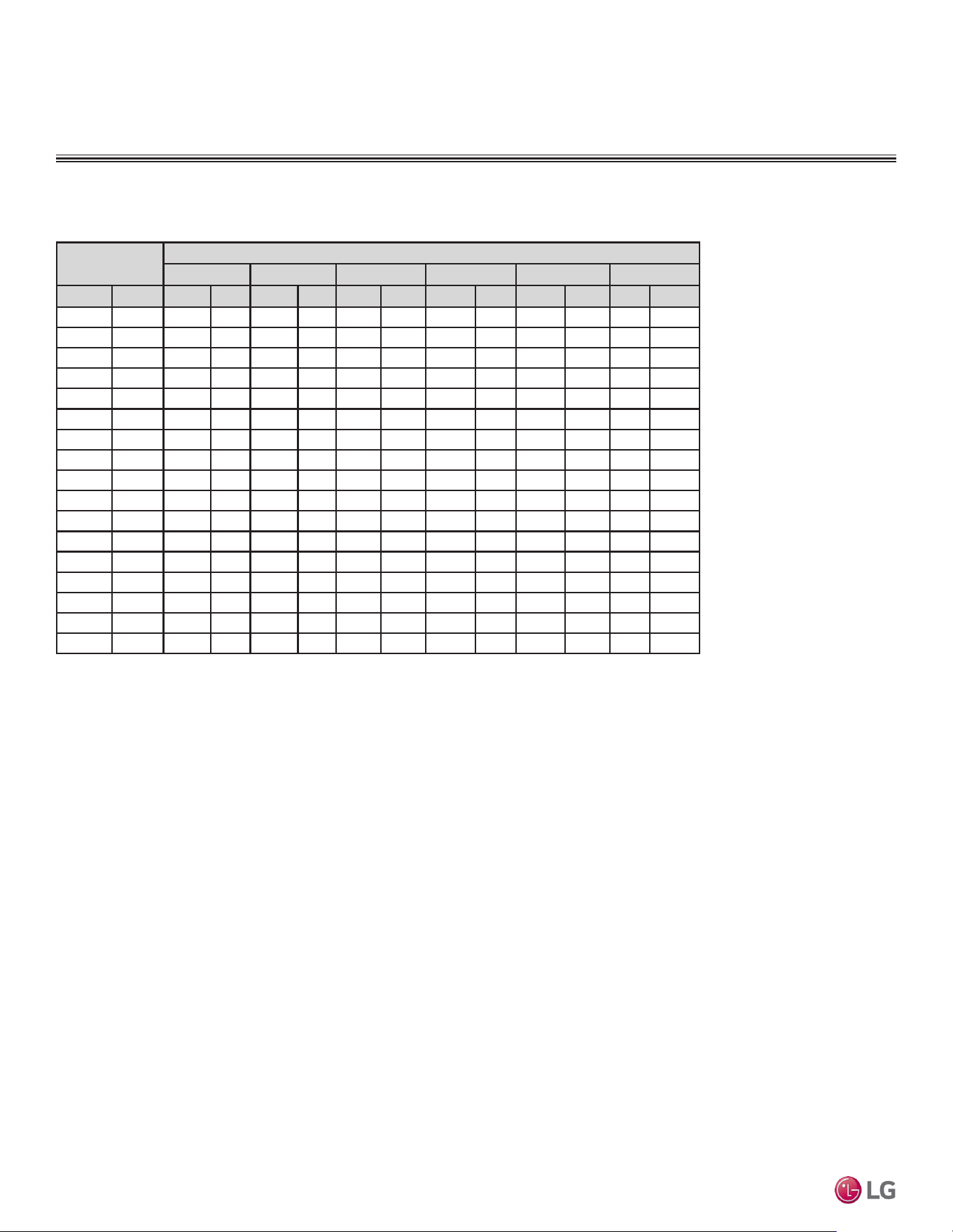
Outdoor Air
Temp.
Indoor Air Temperature:°F DB
61.0 64.0 68.0 70.0 72.0 75.0
°F DB °F WB TC PI TC PI TC PI TC PI TC PI TC PI
-4 -4.4 13.03 1.60 12.24 1.65 12.06 1.70 11.89 1.72 11.76 1.75 11.26 1.80
0 -0.4 14.47 1.63 13.71 1.68 13.44 1.73 13.23 1.75 13.07 1.78 12.53 1.83
5 4.5 16.07 1.66 15.34 1.71 14.96 1.76 14.72 1.79 14.52 1.81 13.94 1.87
10 9 17.43 1.69 16.73 1.74 16.26 1.80 15.98 1.83 15.76 1.85 15.14 1.90
17 15 19.07 1.73 18.40 1.78 17.82 1.84 17.50 1.87 17.24 1.89 16.58 1.95
20 19 20.10 1.76 19.46 1.81 18.81 1.87 18.46 1.90 18.18 1.93 17.49 1.98
25 23 21.84 1.78 21.19 1.84 20.46 1.90 20.07 1.93 19.76 1.96 19.02 2.01
30 28 23.60 1.82 22.87 1.88 22.08 1.93 21.67 1.97 21.35 1.99 20.57 2.05
35 32 25.35 1.84 24.54 1.90 23.71 1.96 23.28 2.00 22.94 2.02 22.11 2.08
40 36 26.64 1.87 25.89 1.93 25.07 1.99 24.63 2.03 24.29 2.05 23.41 2.12
45 41 28.26 1.90 27.58 1.97 26.77 2.03 26.32 2.07 25.97 2.09 25.02 2.16
47 43 28.90 1.92 28.26 1.98 27.45 2.04 27.00 2.08 26.64 2.11 25.67 2.17
50 46 28.99 1.91 28.40 1.96 27.70 2.02 27.30 2.05 26.98 2.07 26.07 2.13
55 51 29.13 1.89 28.65 1.93 28.12 1.98 27.79 2.00 27.54 2.02 26.72 2.06
60 56 29.27 1.87 28.89 1.90 28.53 1.94 28.29 1.95 28.09 1.96 27.38 1.99
63 59 29.35 1.85 29.03 1.88 28.78 1.91 28.59 1.92 28.43 1.93 27.77 1.95
68 64 29.44 1.84 29.18 1.87 29.04 1.89 28.89 1.89 28.77 1.90 28.17 1.91
Table 40: LH248HV4 Ceiling-Concealed Ducted (High Static) System Heating Capacity Table.
High Static Ducted Heating Capacity Tables
PERFORMANCE DATA
Heating Capacity Table for LH248HV4 (LHN248HV + LUU249HV)
TC = Total Capacity (kBtu/h).
PI = Power input (KW). Power input (KW) includes compressor and fan(s).
Nominal capacity as rated 0 ft. above sea level and a 0 ft. level difference between outdoor and indoor
unit. Corresponding refrigerant piping length is accordance with standard length of each outdoor unit.
Nominal heating capacity rating obtained with air entering the indoor unit at 70ºF dry bulb (DB) and
60ºF wet bulb (WB), and outdoor ambient conditions of 47ºF dry bulb (DB) and 43ºF wet bulb (WB).
Due to our policy of continuous product innovation, some specications may change without notication.
©LG Electronics U.S.A., Inc., Englewood Cliffs, NJ. All rights reserved. “LG” is a registered trademark of LG Corp.
60 | DUCTED
Single Zone Ceiling-Concealed Ducted System Engineering Manual
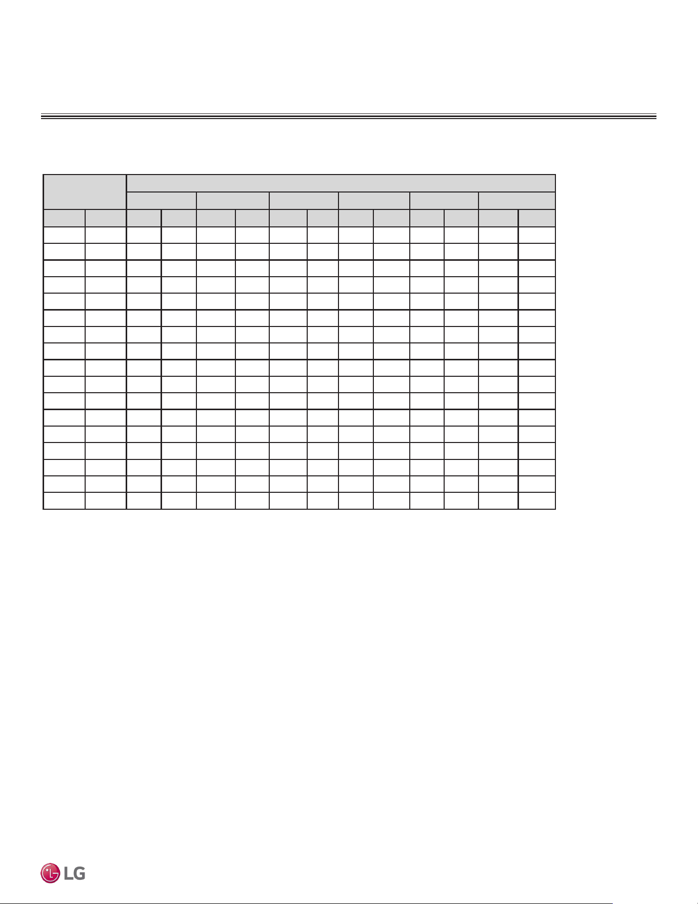
High Static Ducted Heating Capacity Tables
PERFORMANCE DATA
Heating Capacity Table for LH368HV4 (LHN368HV + LUU369HV)
Table 41: LH368HV4 Ceiling-Concealed Duct (High Static) System Heating Capacity Table.
Outdoor Air
Temp.
Indoor Air Temp. °F DB
61.0 64.0 68.0 70.0 72.0 75.0
°F DB °F WB TC PI TC PI TC PI TC PI TC PI TC PI
-4 -4.4 15.17 2.12 14.16 2.18 14.01 2.25 13.83 2.28 13.68 2.31 13.08 2.38
0 -0.4 17.79 2.18 16.81 2.25 16.50 2.31 16.26 2.35 16.06 2.38 15.39 2.45
5 4.5 20.70 2.25 19.74 2.32 19.26 2.39 18.95 2.43 18.70 2.47 17.95 2.54
10 9 23.18 2.32 22.24 2.40 21.62 2.47 21.25 2.51 20.95 2.54 20.12 2.62
17 15 26.15 2.41 25.24 2.49 24.44 2.57 24.00 2.61 23.65 2.64 22.74 2.72
20 19 28.03 2.47 27.14 2.55 26.24 2.63 25.75 2.68 25.36 2.71 24.40 2.79
25 23 31.19 2.54 30.27 2.62 29.21 2.70 28.66 2.74 28.22 2.78 27.16 2.86
30 28 34.37 2.61 33.31 2.70 32.17 2.78 31.58 2.83 31.10 2.87 29.96 2.95
35 32 37.55 2.67 36.36 2.76 35.12 2.85 34.49 2.90 33.98 2.93 32.76 3.02
40 36 39.47 2.73 38.36 2.82 37.14 2.91 36.49 2.96 35.98 3.00 34.68 3.09
45 41 41.86 2.81 40.86 2.90 39.66 2.99 39.00 3.05 38.47 3.09 37.07 3.18
47 43 42.82 2.84 41.86 2.93 40.66 3.03 40.00 3.08 39.47 3.12 38.03 3.22
50 46 42.94 2.82 42.08 2.91 41.04 2.99 40.44 3.04 39.97 3.07 38.62 3.15
55 51 43.15 2.79 42.44 2.86 41.65 2.93 41.18 2.96 40.79 2.99 39.59 3.05
60 56 43.36 2.76 42.80 2.82 42.27 2.87 41.91 2.89 41.62 2.91 40.56 2.95
63 59 43.49 2.74 43.01 2.79 42.64 2.83 42.35 2.84 42.12 2.86 41.14 2.89
68 64 43.61 2.73 43.23 2.76 43.02 2.79 42.80 2.80 42.62 2.81 41.73 2.83
TC = Total Capacity (kBtu/h).
PI = Power input (KW). Power input (KW) includes compressor and fan(s).
Nominal capacity as rated 0 ft. above sea level and a 0 ft. level difference between outdoor and indoor
unit. Corresponding refrigerant piping length is accordance with standard length of each outdoor unit.
Nominal heating capacity rating obtained with air entering the indoor unit at 70ºF dry bulb (DB) and
60ºF wet bulb (WB), and outdoor ambient conditions of 47ºF dry bulb (DB) and 43ºF wet bulb (WB).
DUCTED | 61
Product Data
Due to our policy of continuous product innovation, some specications may change without notication.
©LG Electronics U.S.A., Inc., Englewood Cliffs, NJ. All rights reserved. “LG” is a registered trademark of LG Corp.
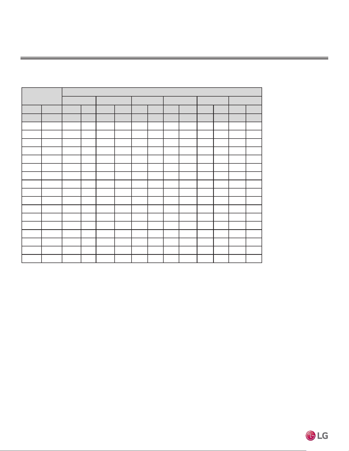
High Static Ducted Maximum Heating Capacity Tables
PERFORMANCE DATA
Maximum Heating Capacity Table for LH248HV4 (LHN248HV + LUU249HV)
Table 42: LH248HV4 Ceiling-Concealed Duct (High Static) System Max Heating Capacity Table.
Outdoor Air
Temp.
Indoor Air Temp. °F DB
61 64 68 70 72 75
°F DB °F WB TC PI TC PI TC PI TC PI TC PI TC PI
-13 -13.4 19.66 2.66 19.22 2.74 18.67 2.83 18.36 2.88 18.12 2.92 17.46 3.01
-4 -4.4 22.22 2.84 21.73 2.94 21.11 3.03 20.76 3.08 20.49 3.12 19.74 3.22
0 -0.4 23.57 2.95 23.05 3.05 22.39 3.15 22.02 3.20 21.73 3.24 20.94 3.34
5 4.5 25.26 3.09 24.70 3.19 23.99 3.29 23.60 3.35 23.29 3.40 22.44 3.50
10 9 26.36 2.78 25.77 2.88 25.04 2.97 24.63 3.02 24.30 3.06 23.42 3.15
17 15 27.83 2.56 27.21 2.65 26.43 2.73 26.00 2.78 25.65 2.82 24.72 2.90
20 19 28.44 2.61 27.81 2.69 27.01 2.78 26.57 2.83 26.22 2.86 25.26 2.95
25 23 29.05 2.65 28.41 2.74 27.59 2.82 27.14 2.87 26.78 2.91 25.81 3.00
30 28 29.82 2.70 29.15 2.79 28.32 2.88 27.86 2.93 27.49 2.97 26.49 3.06
35 32 30.43 2.74 29.75 2.83 28.90 2.92 28.43 2.97 28.05 3.01 27.03 3.11
40 36 31.04 2.78 30.35 2.88 29.48 2.97 29.00 3.02 28.61 3.06 27.57 3.15
45 41 31.81 2.84 31.10 2.93 30.21 3.03 29.71 3.08 29.32 3.12 28.25 3.21
47 43 32.11 2.86 31.40 2.95 30.50 3.05 30 3.1 29.60 3.14 28.52 3.24
50 46 32.21 2.84 31.56 2.93 30.78 3.01 30.33 3.06 29.97 3.09 28.96 3.18
55 51 32.36 2.81 31.83 2.88 31.24 2.95 30.88 2.98 30.59 3.01 29.69 3.07
60 56 32.52 2.78 32.10 2.83 31.70 2.89 31.43 2.91 31.22 2.93 30.42 2.97
63 59 32.62 2.76 32.26 2.81 31.98 2.85 31.76 2.86 31.59 2.88 30.85 2.91
68 64 32.71 2.74 32.42 2.78 32.26 2.81 32.10 2.82 31.96 2.83 31.30 2.85
TC = Total Capacity (kBtu/h).
PI = Power input (KW). Power input (KW) includes compressor and fan(s).
The shaded table rows indicate reference data. When operating at this temperature, these values can
be different if the system is not running consistently.
Nominal capacity as rated 0 ft. above sea level and a 0 ft. level difference between outdoor and indoor
unit. Corresponding refrigerant piping length is accordance with standard length of each outdoor unit.
Nominal heating capacity rating obtained with air entering the indoor unit at 70ºF dry bulb (DB) and
60ºF wet bulb (WB), and outdoor ambient conditions of 47ºF dry bulb (DB) and 43ºF wet bulb (WB).
Due to our policy of continuous product innovation, some specications may change without notication.
©LG Electronics U.S.A., Inc., Englewood Cliffs, NJ. All rights reserved. “LG” is a registered trademark of LG Corp.
62 | DUCTED
Single Zone Ceiling-Concealed Ducted System Engineering Manual
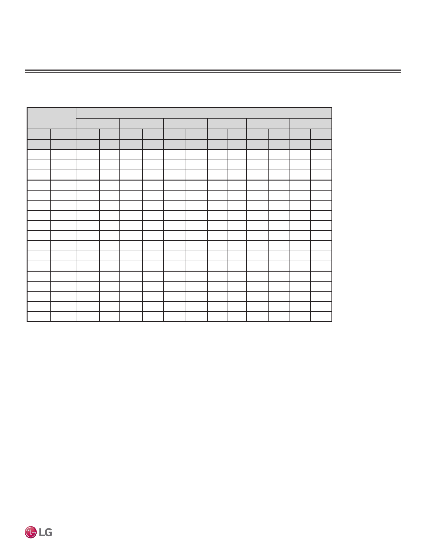
High Static Ducted Maximum Heating Capacity Tables
PERFORMANCE DATA
Maximum Heating Capacity Table for LH368HV4 (LHN368HV + LUU369HV)
Table 43: LH368HV4 Ceiling-Concealed Duct (High Static) System Max Heating Capacity Table.
Outdoor Air
Temp.
Indoor Air Temperature: °F DB
61.0 64.0 68.0 70.0 72.0 75.0
°F DB °F WB TC PI TC PI TC PI TC PI TC PI TC PI
-13 -13.4 22.28 4.35 21.78 4.49 21.16 4.63 20.82 4.71 20.54 4.78 19.79 4.92
-4 -4.4 29.24 4.65 28.58 4.80 27.77 4.96 27.31 5.04 26.95 5.11 25.97 5.26
0 -0.4 32.89 4.83 32.16 4.99 31.24 5.15 30.73 5.24 30.32 5.31 29.22 5.47
5 4.5 37.47 5.05 36.63 5.22 35.58 5.39 35.00 5.48 34.53 5.55 33.28 5.72
10 9 40.45 4.96 39.54 5.12 38.41 5.28 37.79 5.38 37.28 5.45 35.93 5.61
17 15 44.42 4.89 43.43 5.05 42.19 5.21 41.50 5.30 40.95 5.37 39.46 5.53
20 19 44.53 4.65 43.53 4.80 42.29 4.96 41.60 5.04 41.05 5.11 39.55 5.26
25 23 44.64 4.41 43.64 4.56 42.39 4.70 41.70 4.79 41.15 4.85 39.65 5.00
30 28 44.77 4.12 43.77 4.25 42.52 4.39 41.83 4.46 41.27 4.52 39.77 4.66
35 32 44.88 3.88 43.88 4.01 42.62 4.14 41.93 4.21 41.37 4.26 39.86 4.39
40 36 44.98 3.64 43.98 3.76 42.72 3.88 42.03 3.95 41.47 4.00 39.96 4.12
45 41 45.12 3.35 44.11 3.46 42.85 3.57 42.15 3.63 41.59 3.68 40.08 3.79
47 43 45.17 3.23 44.16 3.33 42.90 3.44 42.20 3.50 41.64 3.55 40.13 3.65
50 46 45.30 3.21 44.39 3.30 43.29 3.40 42.66 3.45 42.16 3.49 40.74 3.58
55 51 45.53 3.17 44.77 3.25 43.94 3.33 43.44 3.37 43.04 3.40 41.76 3.47
60 56 45.75 3.14 45.15 3.20 44.60 3.26 44.21 3.28 43.91 3.30 42.79 3.35
63 59 45.88 3.12 45.38 3.17 44.99 3.22 44.68 3.23 44.43 3.25 43.40 3.28
68 64 46.01 3.10 45.61 3.14 45.38 3.18 45.15 3.18 44.96 3.19 44.02 3.22
TC = Total Capacity (kBtu/h).
PI = Power input (KW). Power input (KW) includes compressor and fan(s).
The shaded table rows indicate reference data. When operating at this temperature, these values can
be different if the system is not running consistently.
Nominal capacity as rated 0 ft. above sea level and a 0 ft. level difference between outdoor and indoor
unit. Corresponding refrigerant piping length is accordance with standard length of each outdoor unit.
Nominal heating capacity rating obtained with air entering the indoor unit at 70ºF dry bulb (DB) and
60ºF wet bulb (WB), and outdoor ambient conditions of 47ºF dry bulb (DB) and 43ºF wet bulb (WB).
DUCTED | 63
Product Data
Due to our policy of continuous product innovation, some specications may change without notication.
©LG Electronics U.S.A., Inc., Englewood Cliffs, NJ. All rights reserved. “LG” is a registered trademark of LG Corp.

Equipment Selection Procedure on page 65
Placement Considerations on page 67
Clearances on page 77
Installing Outdoor Unit Indoors on page 80
Refrigerant Piping Design on page 82
CEILING-CONCEALED
DUCTED UNIT
APPLICATION
GUIDELINES
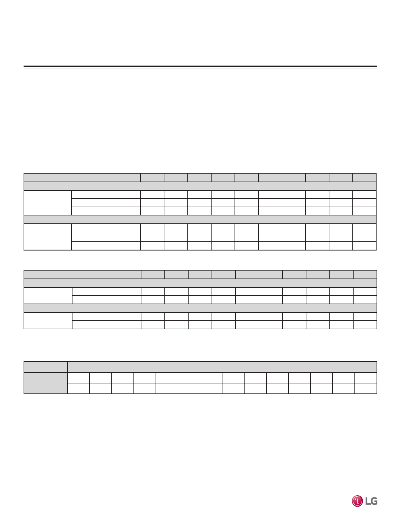
Due to our policy of continuous product innovation, some specications may change without notication.
©LG Electronics U.S.A., Inc., Englewood Cliffs, NJ. All rights reserved. “LG” is a registered trademark of LG Corp.
65 | DUCTED
Single Zone Ceiling-Concealed Ducted System Engineering Manual
Altitude Correction Factor
The impact of air density must be considered on systems installed at a significant altitude above sea level, therefore, locally accepted
altitude correction factors must be applied.
Cooling / Heating Correction Factors
For Ceiling-Concealed Ducted systems, calculate the equivalent length of the liquid line from the outdoor unit to the indoor unit. Also, deter-
mine the elevation difference of the indoor unit above or below the outdoor unit. Find corresponding cooling or heating capacity correction
factors as shown below. Multiply the correction factors by the cooling or heating capacity obtained from the capacity table using design
conditions. The result is the NET cooling or heating capacity.
Refrigerant Line Length Derates
For air-cooled systems, a capacity correction factor may have to be applied to account for the length of the system’s refrigerant pipe. Rate of
change in capacity due to increased piping lengths is shown below.
Table 44: Low Static Ducted System Cooling and Heating Capacity Coefcient Factors.
Equivalent Piping Length for Piping Components
Piping Length (ft.) 24.6 32.8 49.2 65.6 98.4 131.2 164.0 196.9 229.7 246.0
Cooling Capacity Coefficient Factor
Rate of Capacity
Change (%)
LD097HV4 (9,000) 100 99.7 99.2 98.7 - - - - - -
LD127HV4 (12,000) 100 99.7 99.2 98.7 - - - - - -
LD187HV4 (18,000) 100 100 99.3 97.9 96.6 93.8 91.1
Heating Capacity Coefficient Factor
Rate of Capacity
Change (%)
LD097HV4 (9,000) 100 99.7 99.2 98.7 - - - - - -
LD127HV4 (12,000) 100 99.7 99.2 98.7 - - - - - -
LD187HV4 (18,000) 100 99.3 97.9 96.6 94.8 91.1 88.4
Table 45: High Static Ducted System Cooling and Heating Capacity Coefcient Factors.
Component Size (Inches)
Elbow (ft.)
1/4 3/8 1/2 5/8 3/4 7/8 1 1-1/8 1-1/4 1-3/8 1-1/2 1-5/8 1-3/4 2-1/8
0.5 0.6 0.7 0.8 1.2 1.3 1.5 1.6 1.8 2.0 2.1 2.3 2.5 2.8
EQUIPMENT SELECTION PROCEDURE
Table 46: Equivalent Piping Length for Elbows.
Piping Length (ft.) 24.6 32.8 49.2 65.6 98.4 131.2 164.0 196.9 229.7 246.0
Cooling Capacity Coefficient Factor
Rate of Capacity
Change (%)
LH248HV4 (24,000 Btu/h) 100 100 99.3 97.9 96.6 93.8 91.1 - - -
LH368HV4 (36,000 Btu/h) 100 100 99.3 97.9 96.6 93.8 91.1 88.4 85.6 82.9
Heating Capacity Coefficient Factor
Rate of Capacity
Change (%)
LH248HV4 (24,000 Btu/h) 100 99.3 97.9 96.6 93.8 91.1 88.4 - - -
LH368HV4 (36,000 Btu/h) 100 99.7 99.2 98.7 97.7 96.6 95.6 94.6 93.5 93.0
Due to our policy of continuous product innovation, some specications may change without notication.
©LG Electronics U.S.A., Inc., Englewood Cliffs, NJ. All rights reserved. “LG” is a registered trademark of LG Corp.
DUCTED | 66
Application Guidelines
EQUIPMENT SELECTION PROCEDURE
Table 47: Outdoor Unit Frost Accumulation Factor (Heating)
1
.
There will be temporary reduction in capacity when frost / ice accumulates on the outside surface of the outdoor unit heat exchanger. The level of
capacity reduction depends on a number of factors, for example, outdoor temperature (°F DB), relative humidity (RH), and the amount of frost present.
Entering DB (ºF)
19.4 23.0 26.6 32.0 37.4 41.0 44.6
Derate factor
0.98 0.95 0.93 0.86 0.93 0.96 1.0
1
At 85% outdoor air relative humidity.
The frost accumulation factor does not account for effects of snow accumulation restricting airflow
through the outdoor unit coil.
Defrost Correction Factor for Heating Operation
The outdoor unit heating capacity may need to be adjusted for frost accumulation on air-cooled systems. If design day conditions are below
the dewpoint of the surrounding air, frost may not be a problem and no correction factor is needed. In certain weather conditions, however,
frost may form and accumulate on the air-cooled outdoor unit coil and impact the coils ability to transfer heat. If significant frost accumulates
on the outdoor unit coil, a defrost algorithm will start automatically. The timing between defrost periods is determined by the system’s ability
to achieve a target head pressure value.
Capacity and AHRI ratings tables do not factor in capacity reduction when frost has accumulated on the condenser coil, nor during defrost
operation.
Integrated heating capacity values can be obtained using the formula:
A = B x C
Where:
A = Integrated Heating Capacity.
B = Value found in the Capacity Table.
C = Correction Factor for Frost Accumulation Factor (from Table 24).
Check the Indoor and Outdoor Unit Selection(s)
Compare the corrected cooling and heating capacities to the load calculations. Is each capacity sufficient for the zone it serves?
For each indoor unit, the corrected capacity must be at least equal to the total of the cooling design load (plus ventilation load, if applicable)
for the space(s) served by the indoor unit. For each indoor unit, the corrected capacity also must be at least equal to the total of the heating
design load (plus ventilation load, if applicable) for the space(s) and / or thermal zones served by the indoor unit.
The outdoor unit selected must be large enough to offset the total cooling load for all spaces it serves (account for ventilation air cooling
load if the ventilation air has not been pretreated to room neutral conditions). The outdoor unit must also be large enough to offset the total
heating load for all spaces it serves.
If the corrected heating capacity ratio exceeds 100%, reselect the equipment, or change the system design by moving some of the load to
another system.
• Understand the design safety factors.
• Reference load calculations for actual cooling and heating capac-
ities (applies in 99% of applications – consider total load when
latent load is greater than 30%).
• Verify that the sensible load of the zone is satisfied.
• Use caution when sizing to meet listed capacity specifications for
the scheduled manufacturer’s equipment.
If further system design assistance is needed, or you have a unique
application you would like to discuss, contact your LG sales rep.
1. Outdoor Unit Rated Capacity.
Q
odu(rated)
(From capacity tables).
2. Outdoor Unit Capacity at Ti, To Temperature.
Q
odu(Ti, To)
(From capacity tables).
3 Outdoor Unit Capacity Coefficient Factor.
F
(Ti, To)
= Q
odu(Ti, To)
/ Q
odu(rated)
4. Piping Correction Factor (From Capacity Coefficient
Factor Tables).
F
(length)
for each piping length
5. Individual Indoor Unit Combination Capacity.
Q
idu (combi)
= Q
odu(rated)
x Q
idu(rated)
/ Q
idu(rated-total)
6. Individual Indoor Unit Actual Capacity.
Q
idu (actual)
= Q
odu(combi)
x F
(Ti, To)
x F
(length, altitude)
System Sizing Check Formulas
Conclusions and Recommendations
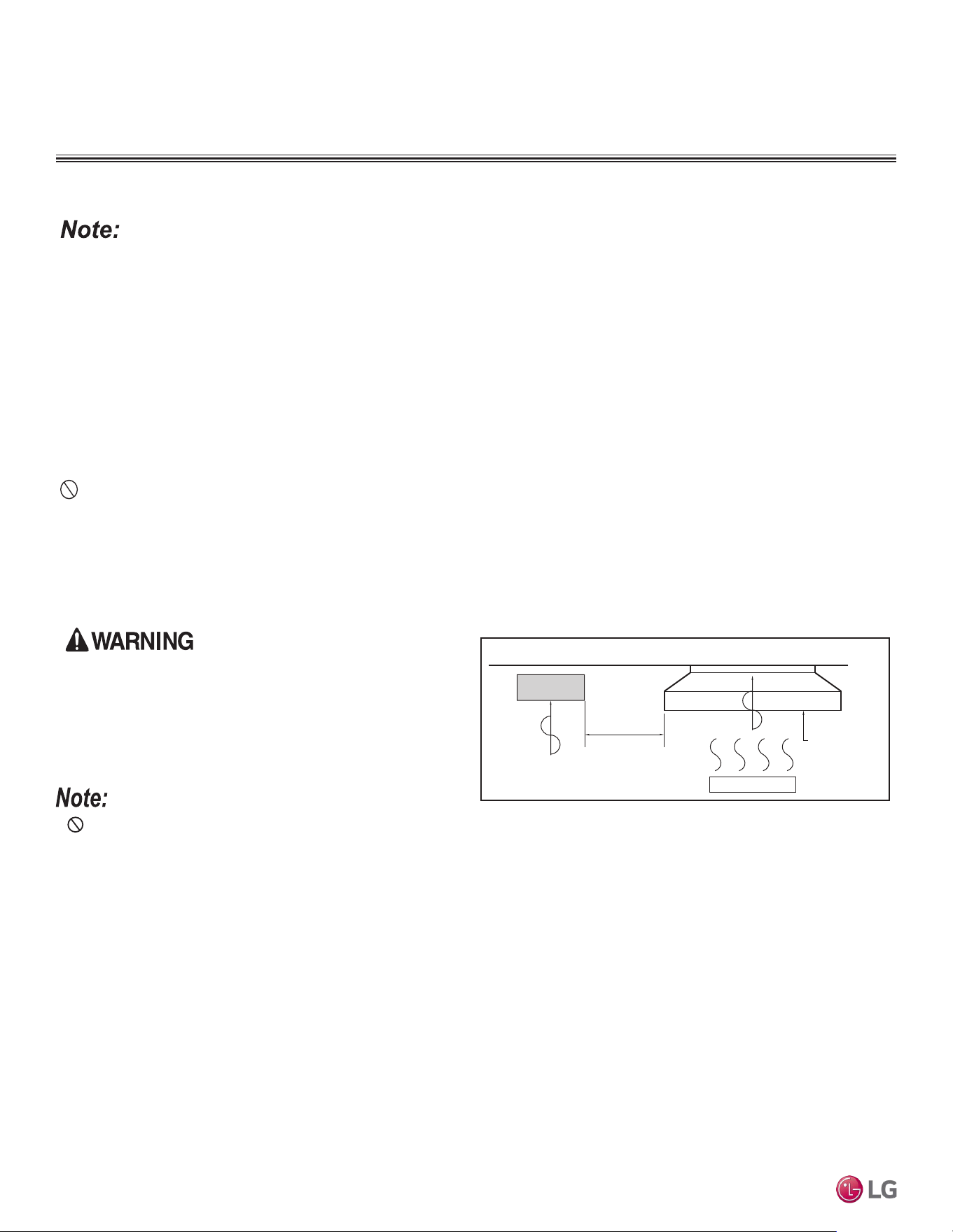
Due to our policy of continuous product innovation, some specications may change without notication.
©LG Electronics U.S.A., Inc., Englewood Cliffs, NJ. All rights reserved. “LG” is a registered trademark of LG Corp.
67 | DUCTED
Single Zone Ceiling-Concealed Ducted System Engineering Manual
Follow recommended best practices when choosing an indoor location for the single zone indoor unit.
Dos
• Place the unit where air circulation will not be blocked.
• Locate the indoor unit in a location that is level, and where it can be easily connected to the outdoor unit.
• Place the unit where drainage can be obtained easily. Condensation drain must be conveniently routed away from the unit.
• Include enough space around the indoor unit so that it is accessible for maintenance and service purposes.
• Where electrical noise / electromagnetic waves will not affect indoor unit operation. Maintain proper distances between the indoor units and
electric wires, audio and visual appliances, breaker / circuit panels, etc. If the frequency signal of the appliance is unstable, then install the
indoor unit a minimum of ten (10) feet away, and run the power and transmission cables through a conduit.
• An area that is level and with enough strength to bear the weight of the indoor unit(s).
Dont’s
• Do not install the unit near a heat or steam source, or where considerable amounts of oil, iron powder, or flour are used. (These materials
may generate condensate, cause a reduction in heat exchanger efficiency, or the drain to malfunction. If this is a potential problem, install a
ventilation fan large enough to vent out these materials.)
• Ensure there are no obstacles to air circulation around the unit; keep proper distances from ceilings, doorways, floor, walls, etc.
• Avoid installing the unit near high-frequency generators or near any equipment that generates an electromagnetic field (minimum 3-1/3 feet
away).
Selecting the Best Location for the Indoor Unit
The unit must not be installed where sulfuric acid and ammable or cor-
rosive gases are generated, vented into, or stored. There is risk of re,
explosion, and physical injury or death.
The unit may be damaged, may malfunction, and / or will
not operate as designed if installed in any of the conditions
listed.
Install a ventilation fan
with sufficient capacity
Heat or steam source
Include enough
distance
Indoor Unit
Figure 44: Installing Near a Heat or Steam Source.
• Indoor units (IDUs) must not be placed in an environment where the IDUs may be exposed to harmful volatile organic compounds (VOCs)
or in environments where there is improper air make up or supply or inadequate ventilation. If there are concerns about VOCs in the envi-
ronment where the IDUs are installed, proper air make up or supply and/ or adequate ventilation must be provided. Additionally, in buildings
where IDUs will be exposed to VOCs consider a factory-applied epoxy coating to the fan coils for each IDU.
• If the unit is installed near a body of water, the installation parts are at risk of corroding. Appropriate anti-corrosion methods must be taken for
the unit and all installation parts.
Installing in an Area Exposed to Unconditioned Air
In some installation applications, areas (floors, walls) in some rooms may be exposed to unconditioned air (room may be above or next to an
unheated garage or storeroom). To countermeasure:
• Verify that carpet is or will be installed (carpet may increase the temperature by three [3] degrees).
• Add insulation between the floor joists.
• Install radiant heat or another type of heating system to the floor.
Installing in an Area with High Humidity Levels
If the environment is prone to humidity levels of 80% or more (near the ocean, lakes, etc.) or where steam could collect in the plenum:
• Install additional insulation to the indoor unit (glass wool insulation >13/32 inches thick).
• Install additional insulation to the refrigerant piping (insulation >13/16 inches thick).
• Seal all gaps between the indoor unit and the ceiling tiles (make the area air tight) so that humidity does not transfer from the plenum to the
conditioned space. Also, add a ceiling grille for ventilation.
PLACEMENT CONSIDERATIONS
Indoor Unit
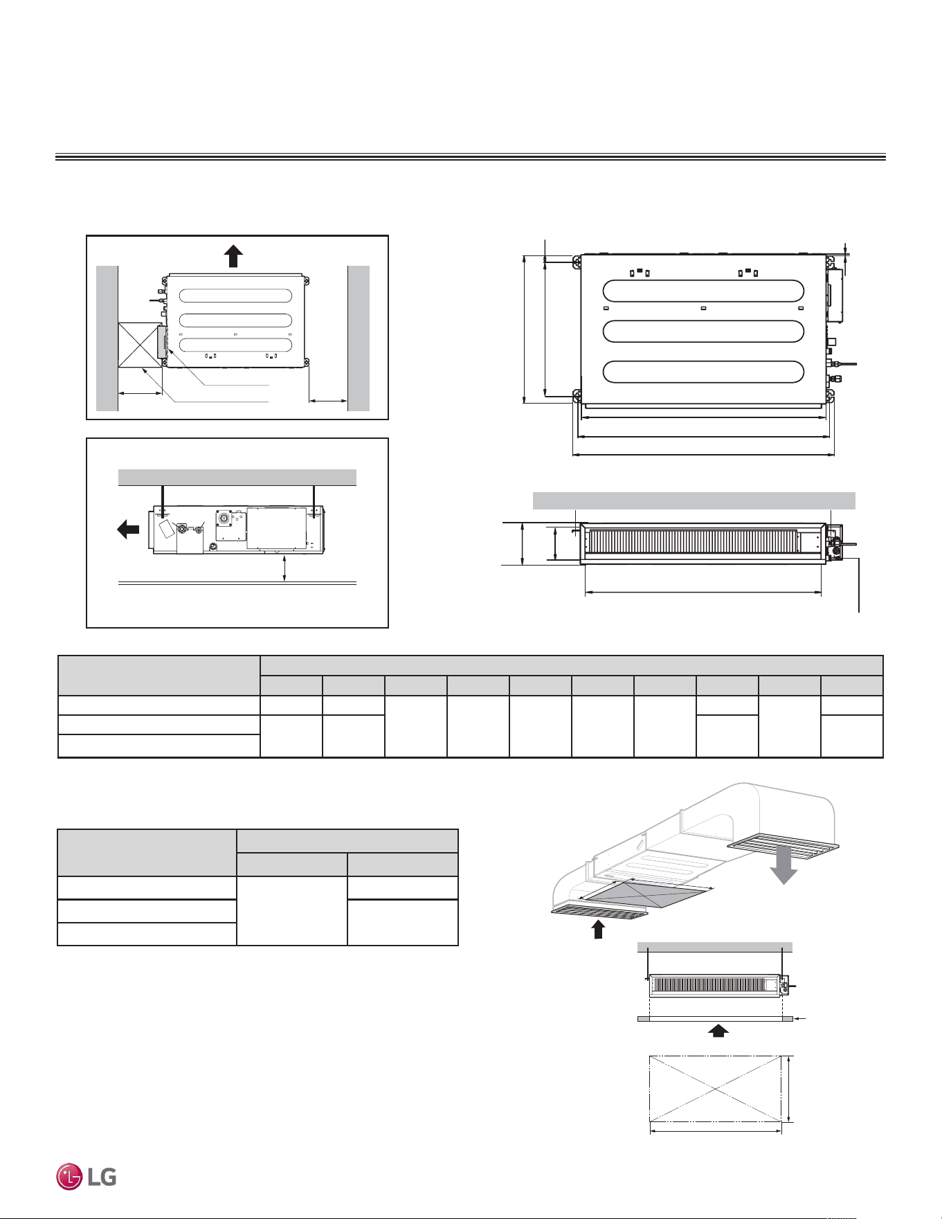
Due to our policy of continuous product innovation, some specications may change without notication.
©LG Electronics U.S.A., Inc., Englewood Cliffs, NJ. All rights reserved. “LG” is a registered trademark of LG Corp.
DUCTED | 68
Application Guidelines
Figure 45: Low Static Ducted Indoor Unit General Service Space Required Dimensions and Bolt Locations
Figure 46: Low Static Ducted IDU Access Panel Required Dimensions.
Table 48: Low Static Ducted Indoor Unit Bolt Location Dimensions.
C
E
G
D
F
I
A
J
B
H
Drainage hole
Model / Capacity (Btu/h)
Dimensions (in.)
A B
LDN097HV4 / 9,000
31-1/2
31-1/2
LDN127HV4 / 12,000
39-3/8
LDN187HV4 / 18,000
Access Opening
(
23-5/8
x
23-5/8
)
Control box
H = ≤25/32
• "H" dimension is necessary to ensure a slope is included for
condensate drainage.
Side view
23-5/8
23-5/8
(Unit : Inch)
(Unit : Inch)
Top view
A (Min)
Ceiling
Service Space
A
B
B (Min)
Model / Capacity (Btu/h)
Dimensions (in.)
A B C D E F G H I J
LDN097HV4 / 9,000 28-27/32 30-13/32
24-23/32 27-9/16 1-13/32 7-15/32 25/32
25-31/32
6-3/32
27-9/16
LDN127HV4 / 12,000
36-23/32 38-9/32 33-27/32 35-7/16
LDN187HV4 / 18,000
Table 49: Low Static Ducted Indoor Unit Access Panel Required
Dimensions.
PLACEMENT CONSIDERATIONS
Indoor Unit
Low Static Ducted IDU Service Space Required Dimensions, Bolt Locations
Refer to figure 46 on the right.
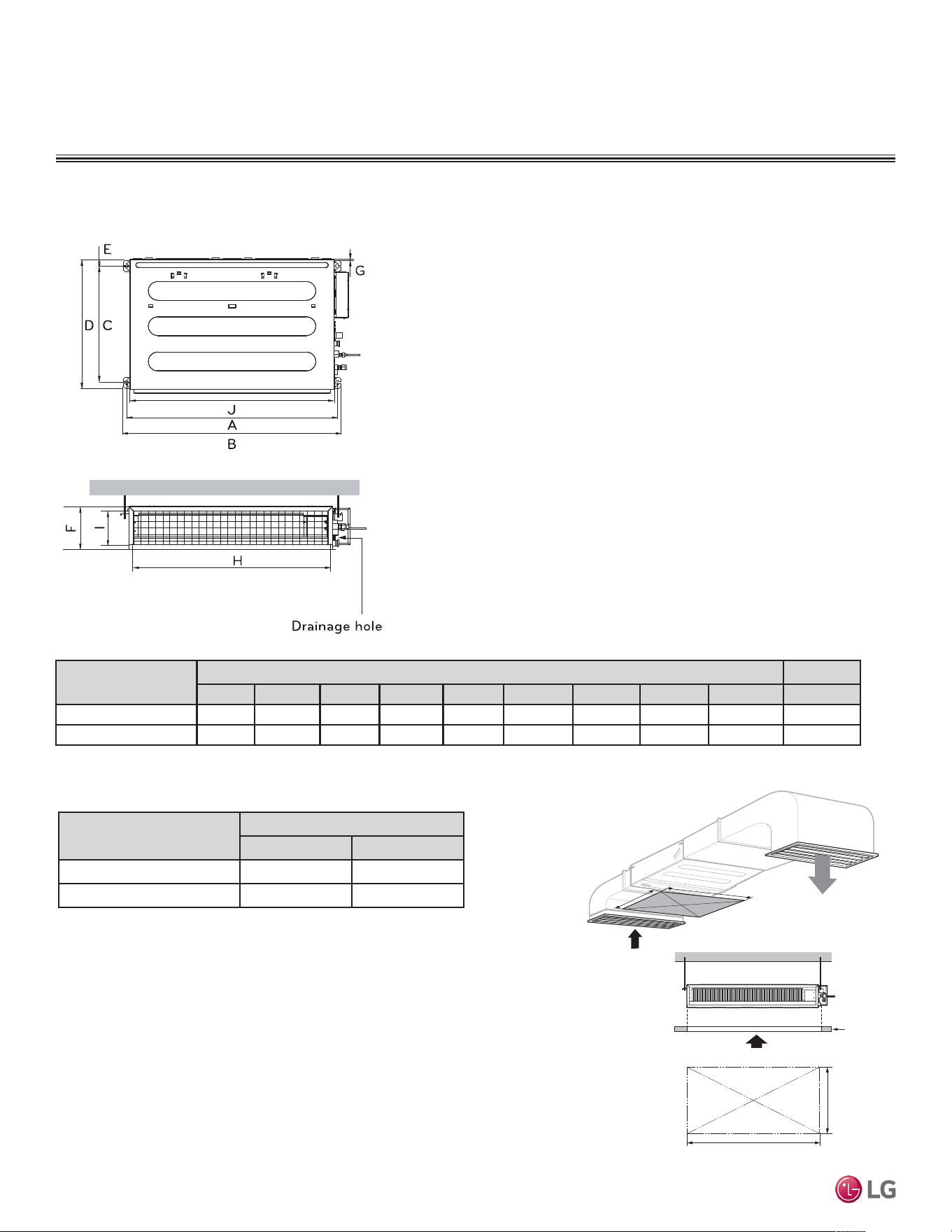
Due to our policy of continuous product innovation, some specications may change without notication.
©LG Electronics U.S.A., Inc., Englewood Cliffs, NJ. All rights reserved. “LG” is a registered trademark of LG Corp.
69 | DUCTED
Single Zone Ceiling-Concealed Ducted System Engineering Manual
Model / Capacity
(Btu/h)
Dimensions (inches)
A B C D E F G H I J
LHN248HV / 24,000
36-3/4 38-1/4 24-3/8 27-9/16 1-3/16 10-5/8 19/32 33-25/32 7-15/16 35-7/16
LHN368HV / 36,000
50-17/32 52-1/32 24-3/8 27-9/16 1-3/16 10-5/8 19/32 47-9/16 7-15/16 49-7/32
Figure 47: High Static Ducted Indoor Unit Bolt Locations.
Table 50: High Static Ducted Indoor Unit Bolt Location Dimensions.
PLACEMENT CONSIDERATIONS
Indoor Unit
High Static Ducted IDU Service Space Required Dimensions, Bolt Locations
A (Min)
Ceiling
Service Space
A
B
B (Min)
Figure 48: High Static Ducted IDU Access Panel Required
Dimensions.
Model / Capacity (Btu/h)
Dimensions (in.)
A B
LHN248HV
31-1/2 39-3/4
LHN368HV
31-1/2 53-1/2
Table 51: High Static Ducted Indoor Unit Bolt Location Dimensions.
Refer to figure 48 on the right.
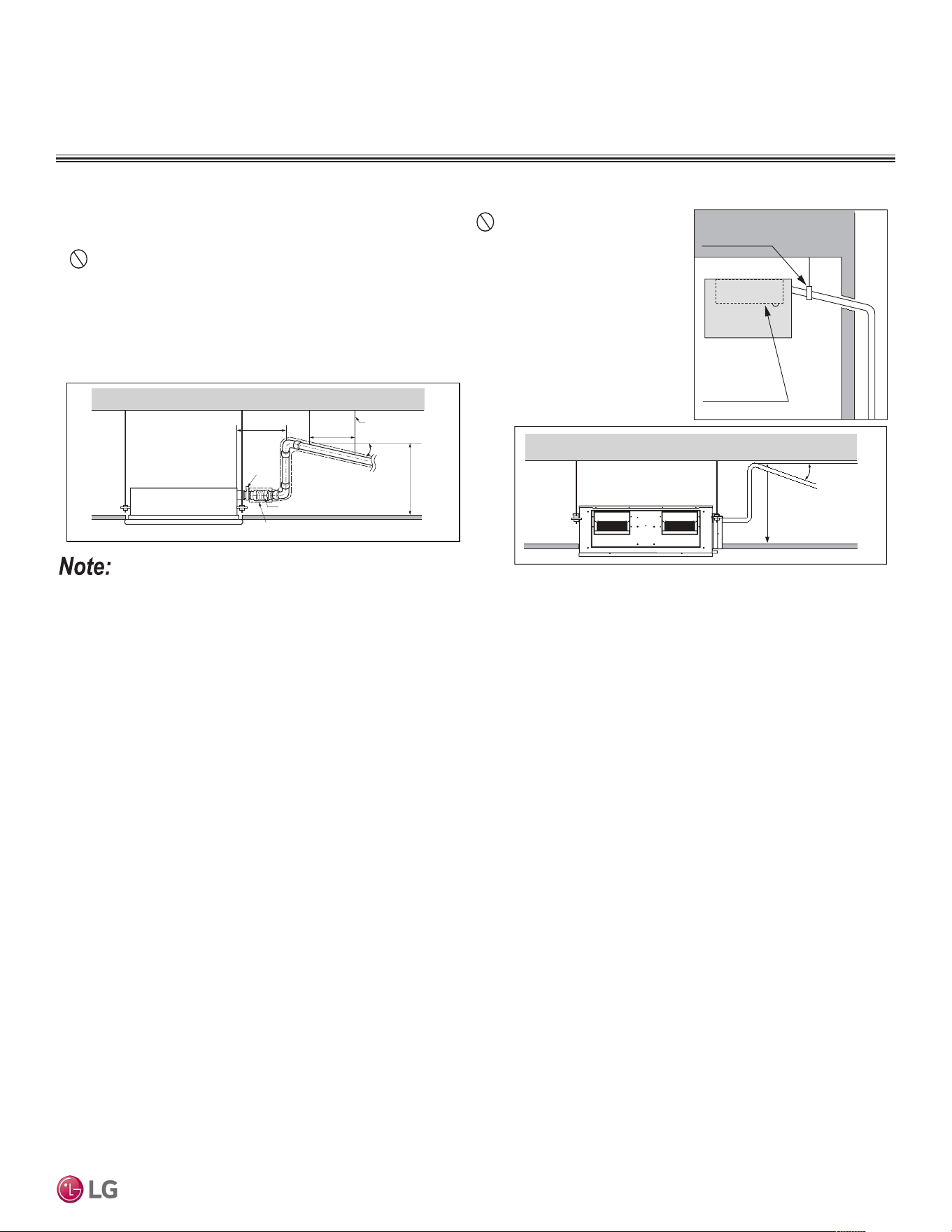
Due to our policy of continuous product innovation, some specications may change without notication.
©LG Electronics U.S.A., Inc., Englewood Cliffs, NJ. All rights reserved. “LG” is a registered trademark of LG Corp.
DUCTED | 70
Application Guidelines
1/50~1/100 slope
Hanger distance
3.3~49.2 feet
Hanger Bracket
Maximum
27-9/16 inches
Flexible drain hose
Insulation
Metal
clamp
Maximum
11-13/16 inches
Indoor Unit Drain System
• Drain piping must have downward gradient of at least 1/50 to 1/100; to prevent reverse flow, slope
must not be straight up and down.
• Do not damage the drain port on the indoor unit when connecting the field-supplied drain piping.
• Drain piping specifications:
- Indoor Unit Drain Connection: 1-1/4 inch outside diameter.
- Field-Supplied Drain Piping: Polyvinyl chloride piping with 1-inch inside diameter and pipe fittings.
Drain Port
Maintenance
Drain Pipe Support
Indoor unit
1/50~1/100mm
Maximum
27-9/16 inches
Figure 49: Indoor Unit Drain Piping.
Figure 50: Drain Piping Installation Dimensions.
Indoor unit appearances may vary depending on the model.
PLACEMENT CONSIDERATIONS
Indoor Unit
Due to our policy of continuous product innovation, some specications may change without notication.
©LG Electronics U.S.A., Inc., Englewood Cliffs, NJ. All rights reserved. “LG” is a registered trademark of LG Corp.
DUCTED | 71
Application Guidelines
Selecting the Best Location for the Outdoor Unit
Do not install the unit in an area where combustible gas may generate, ow, stagnate, or leak. These conditions can cause a re, resulting in bodily
injury or death.
• Do not install the unit in a location where acidic solution and spray (sulfur) are often used as it can cause bodily injury or death.
• Do not use the unit in environments where oil, steam, or sulfuric gas are present as it can cause bodily injury or death.
When deciding on a location to place the outdoor unit, be sure to choose an area where run-off from defrost will not accumulate and freeze on
sidewalks or driveways, which may create unsafe conditions. Properly install and insulate any drain hoses to prevent the hose from freezing,
cracking, leaking, and causing unsafe conditions from frozen condensate.
Install a fence to prevent vermin from crawling into the unit or unauthorized individuals from accessing it. Follow the placement guidelines set forth in
“Clearance Requirements”.
Select a location for installing the outdoor unit that will meet the following conditions:
• Where there is enough strength to bear the weight of the outdoor unit.
• A location that allows for optimum air flow and is easily accessible for inspection, maintenance, and service.
• Where piping between the outdoor unit and indoor unit(s) are within allowable limits.
• Include space for drainage to ensure condensate flows properly out of the unit when it is in heating mode. Avoid placing the outdoor unit in
a low-lying area where water could accumulate.
• If the outdoor unit is installed in a highly humid environment (near an ocean, lake, etc.), ensure that the site is well-ventilated and has a lot
of natural light (Example: Install on a rooftop).
Don’ts
• Where it will be subjected to direct thermal radiation from other heat sources, or an area that would expose the outdoor unit to heat or steam
like discharge from boiler stacks, chimneys, steam relief ports, other air conditioning units, kitchen vents, plumbing vents, and other sources
of extreme temperatures.
• Where high-frequency electrical noise / electromagnetic waves will not affect operation.
• Where operating sound from the unit will disturb inhabitants of surrounding buildings.
• Where the unit will be exposed to direct, strong winds.
• Where the discharge of one outdoor unit will blow into the inlet side of an adjacent unit (when installing multiple outdoor units).
The indoor unit may take longer to provide heat, or heating performance will be reduced in winter if the unit is installed:
1. In a narrow, shady location.
2. Near a location that has a lot of ground moisture.
3. In a highly humid environment.
4. In an area in which condensate does not drain properly.
PLACEMENT CONSIDERATIONS
Outdoor Unit
Due to our policy of continuous product innovation, some specications may change without notication.
©LG Electronics U.S.A., Inc., Englewood Cliffs, NJ. All rights reserved. “LG” is a registered trademark of LG Corp.
72 | DUCTED
Single Zone Ceiling-Concealed Ducted System Engineering Manual
Planning for Snow and Ice
To ensure the outdoor unit operates properly, certain measures are required in locations where there is a possibility of heavy snowfall or
severe windchill or cold:
1. Prepare for severe winter wind chills and heavy snowfall, even in areas of the country where these are unusual phenomena.
2. Position the outdoor unit so that its airflow fans are not buried by direct, heavy snowfall. If snow piles up and blocks the airflow, the
system may malfunction.
3. Remove any snow that has accumulated four (4) inches or more on the top of the outdoor unit.
4. In climates that may experience significant snow buildup, mount the outdoor unit on a raised, field-provided platform or stand. The raised
support platform must be high enough to allow the unit to remain above possible snow drifts, and must be higher than the maximum antici-
pated snowfall for the location.
5. Design the mounting base to prevent snow accumulation on the platform in front or back of the unit frame.
6. Provide a field fabricated snow protection hood to keep snow and ice and/or drifting snow from accumulating on the coil surfaces.
7. Install a hail guard kit and air guide accessories (sold separately) to prevent snow or rain from accumulating on the fan inlet / outlet guards.
8. Consider tie-down requirements in case of high winds or where required by local codes.
When deciding on a location to place the outdoor unit, be sure to choose an area where run-off from defrost will not accumulate and freeze on sidewalks
or driveways, which may create unsafe conditions.
Choose an area where run-off from defrost mode will not accumulate and freeze on sidewalks or driveways. Properly install and insulate any drain
hoses to prevent the hose from freezing, cracking, leaking, and damaging the outdoor unit.
PLACEMENT CONSIDERATIONS
Outdoor Unit
Outdoor Unit Condensate Drain Piping
Outdoor unit requires condensate drain piping. Condensate drain pipe is constructed with materials approved by local code. See Placement
Considerations for information in reference to outdoor unit placement.
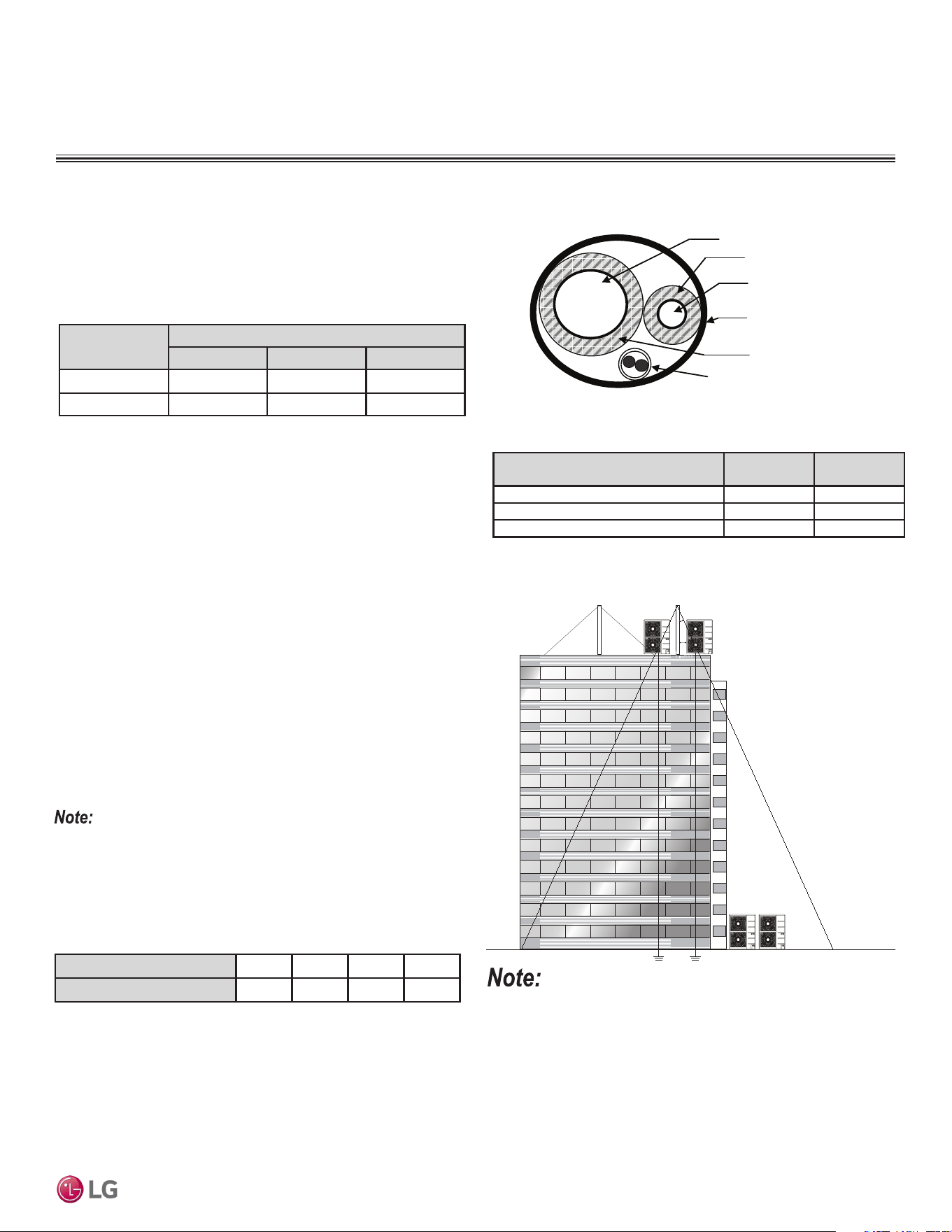
Due to our policy of continuous product innovation, some specications may change without notication.
©LG Electronics U.S.A., Inc., Englewood Cliffs, NJ. All rights reserved. “LG” is a registered trademark of LG Corp.
DUCTED | 73
Application Guidelines
Figure 51: Lightning Protection Diagram.
Tie-Downs, Wind Restraints, and
Lightning Protection
Tie-Downs
• The strength of the roof must be checked before installing the
outdoor units.
• If the installation site is prone to high winds or earthquakes, when
installing on the wall or roof, securely anchor the mounting base
using a field-provided tie-down configuration approved by a local
professional engineer.
• The overall tie-down configuration must be approved by a local
professional engineer. Always refer to local code when using a
wind restraint system.
Always refer to local code when designing a wind restraint system.
Lightning Protection
• To protect the outdoor unit from lightning, place the unit within the
specified lightning safety zone.
• Power cable and communication cable must be installed five (5)
feet away from lightning rod.
• A high-resistance ground system must be included to protect
against induced lightning or indirect strike.
Ground
Safe zone
Lightning rod
Protection Angle (25˚~55˚)
1.5m
5 feet
Lightning rod
Table 52: Safety Zone Specications.
Building Height (feet) 66 98 148 197
Protection Angle (˚) 55 45 35 25
If the building does not include lightning protection, the outdoor unit
may be damaged from a lightning strike. Inform the customer of this
possibility in advance.
Figure 52: Typical Arrangement of Refrigerant Pipe and Cable(s) in a
Utility Conduit.
Underground Refrigerant Piping
Refrigerant pipe installed underground must be routed inside a vapor
tight protective sleeve to prevent insulation deterioration and water
infiltration. Refrigerant pipe installed inside underground
casing must be continuous without any joints. Underground refriger-
ant pipe must be located at a level below the frost line.
Table 53: Utility Conduit Sizes (Inches).
1
OD pipe diameter in inches; Values in parenthesis () indicate OD of pipe with insulation jacket.
2
Diameter of pipe with insulation. Thickness of pipe insulation is typical. Actual required thickness may
vary based on surrounding ambient conditions and must be calculated and specified by the design
engineer.
3
Insulation thickness (value in parenthesis) = 3/8 inch.
4
Insulation thickness (value in parenthesis) = 3/4 inch.
Liquid Pipe
1
Vapor Pipe
1
3/8 (1-1/8
2,3
) 1/2 (2.0
2,4
) 5/8 (2-1/8
2,4
)
1/4 (1.0)
4
4 4 4
3/8 (1-1/8)
4
4 4 4
Table 54: Outdoor Unit Refrigerant Pipe Connections (All Brazed Type).
Vapor Line
Liquid Line
Min. 18 Gauge
Cable
Power/Communication
Pi
p
e Sleeve
Insulation Material
Insulation
Material
Model
Liquid Conn.
(inches)
Vapor Conn.
(inches)
LD097HV4, LD127HV4 1/4 3/8
LD187HV4 1/4 1/2
LH248HV4, LH368HV4 3/8 5/8
PLACEMENT CONSIDERATIONS
Outdoor Unit
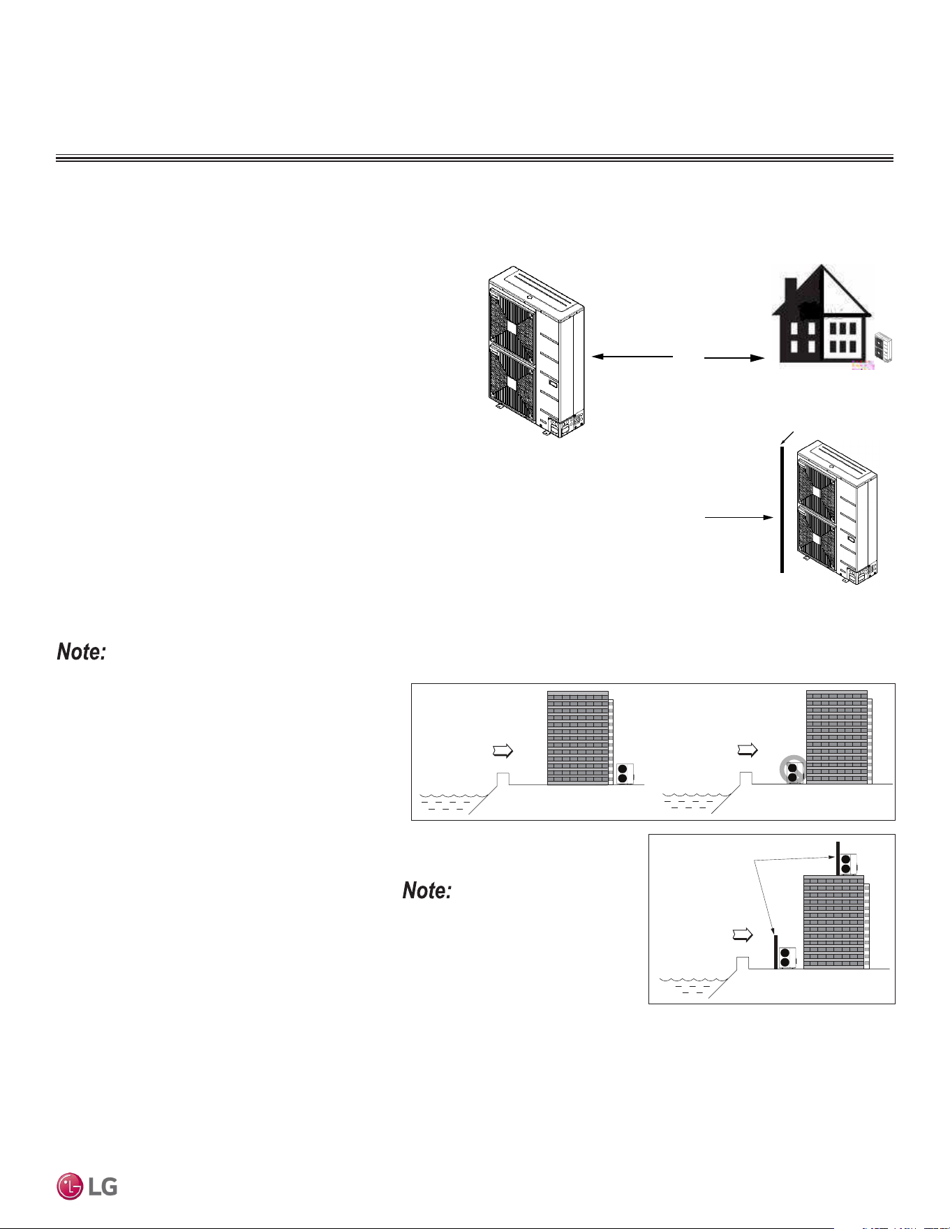
Due to our policy of continuous product innovation, some specications may change without notication.
©LG Electronics U.S.A., Inc., Englewood Cliffs, NJ. All rights reserved. “LG” is a registered trademark of LG Corp.
DUCTED | 74
Application Guidelines
Figure 53: Prevailing Wind
Direction.
Wind Protection
If the outdoor unit is placed on a roof, position it with the compressor
end (no coil surface) in the direction of the prevailing wind as shown
in the figure at right. In cooler climates, it may be beneficial to posi-
tion the unit in direct sunlight to assist with defrost operations.
If the outdoor unit is not placed on a roof, place it on the leeward
side of the building or in a location where the unit will not be ex-
posed to constant wind.
If placement exposes the unit to constant wind activity, construct a
wind break in front of the unit. Follow the placement guidelines set
forth in “Clearance Requirements”.
Prevailing Winds
Prevailing
Winds
Figure 54: Leeward Side of the
Building.
Prevailing Winds
Wall or Other Wind Break
Figure 55: Wind Break.
Mounting Platform
The underlying structure or foundation must be designed to support the weight of the unit. Avoid placing
the unit in a low lying area where water may accumulate.
Oceanside Installation Precautions
• Avoid installing the outdoor unit where it would
be directly exposed to ocean winds.
• Install the outdoor unit on the side of the building
opposite from direct ocean winds.
• Select a location with good drainage.
• Periodically clean dust or salt particles off of the
heat exchanger with water.
Tie-Downs and Wind Restraints
The strength of the Vertical Air Handling Unit frames is adequate to be used with field-provided wind re-
straint tie-downs. The overall tie-down configuration must be approved by a local professional engineer.
Always refer to local code when designing a wind restraint system.
If the outdoor unit must be placed in a location
where it would be subjected to direct ocean winds,
install a concrete windbreaker strong enough to
block any winds. Windbreaker height and width
must be more than 150% of the outdoor unit, and
be installed at least 27-1/2 inches away from the
outdoor unit to allow for airflow.
Ocean winds may cause corrosion, particularly on the
condenser and evaporator ns, which, in turn could
cause product malfunction or inefcient performance.
Ocean winds
Ocean winds
Ocean winds
Windbreaker
Figure 56: Oceanside Placement Using a Building as Shield, and Placement Using a
Windbreak.
Additional anti-corrosion treatment may
need to be applied to the outdoor unit at
oceanside locations.
PLACEMENT CONSIDERATIONS
Outdoor Unit
Oceanside Applications
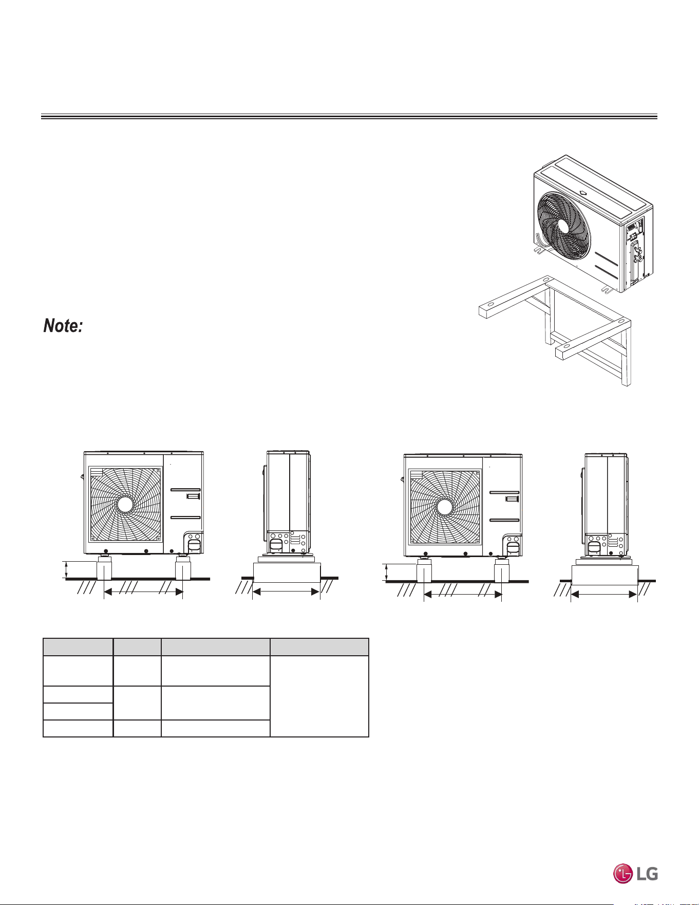
Due to our policy of continuous product innovation, some specications may change without notication.
©LG Electronics U.S.A., Inc., Englewood Cliffs, NJ. All rights reserved. “LG” is a registered trademark of LG Corp.
75 | DUCTED
Single Zone Ceiling-Concealed Ducted System Engineering Manual
Outdoor Unit
PLACEMENT CONSIDERATIONS
General Mounting
Securely attach the outdoor unit to a condenser pad, base rails, or other mounting platform
that is securely anchored to the ground or building structure. The underlying structure or
foundation must be designed to support the weight of the unit, and avoid placing the outdoor
unit in a low lying area where water may accumulate.
Attaching the Outdoor Unit to the Bracket
When installing the outdoor unit on a wall or roof top, anchor the mounting base securely
using nails or wire with regard to wind and earthquake or vibration.
Refer to installation manual, and follow the applicable local code for clearance, mounting,
anchor, and vibration attenuation requirements.
Figure 57: Bracket Mounting.
• All referenced materials are to be field-supplied.
• Images are not to scale.
Figure 58: Bolting the LUU189HV AND LUU249HV Outdoor Units to the
Platform (Appearance May Vary).
Figure 59: Bolting the LUU097HV and LUU127HV Outdoor Units to the
Platform (Appearance May Vary).
Bolting the Outdoor Unit to the Platform
Minimum
7-7/8 inches
Minimum 24-13/32 inches
Minimum 15-3/4 inches
Minimum
3-15/16
inches
Minimum 22-3/16 inches
Minimum 14-19/32 inches
Outdoor Unit Bolt Type Concrete Height Bolt Depth
LUU097HV
LUU127HV
M10-J Minimum 3-15/16 inches
Minimum 2-3/8 inches
LUU189HV
M10-J Minimum 7-7/8 inches
LUU249HV
LUU369HV M10-J Minimum 7-7/8 inches
Table 55: Outdoor Unit Foundation Specications.
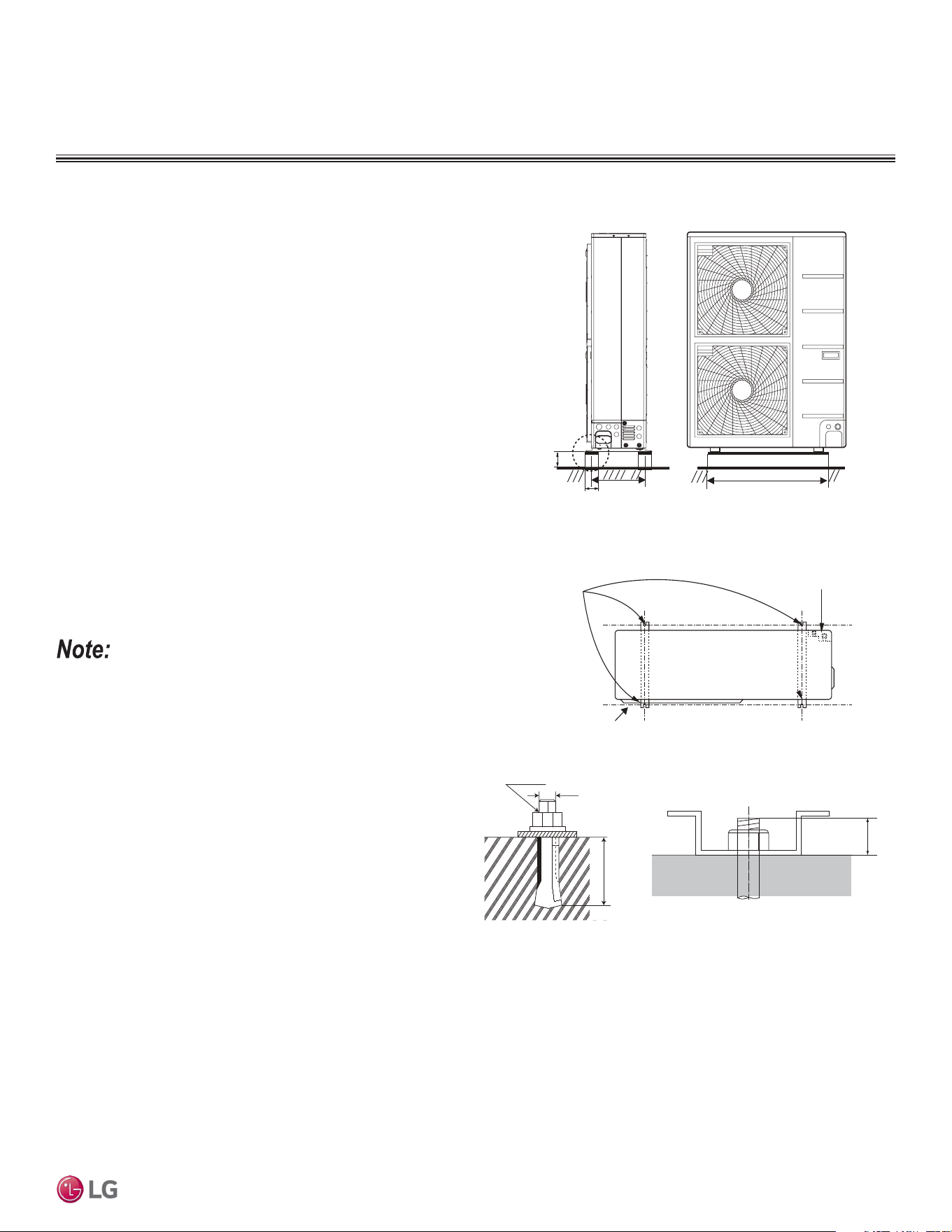
Due to our policy of continuous product innovation, some specications may change without notication.
©LG Electronics U.S.A., Inc., Englewood Cliffs, NJ. All rights reserved. “LG” is a registered trademark of LG Corp.
DUCTED | 76
Application Guidelines
Concrete Platform Specifications
• Concrete foundations must be made of one part cement, two parts
sand, and four parts gravel.
• The surface of the foundation must be finished with mortar with
rounded edges, and weatherproofed.
Minimum
7-7/8
7-7/8
Minimum
15-3/4
Minimum 24-13/32
Unit: Inch
Bolting the Outdoor Unit to the Platform Procedure
When installing the outdoor unit onto a concrete or rigid mount, use
a bolt and nut.
1. Ensure that the concrete platform will not degrade easily, and has
enough strength to bear the weight of the unit.
2. Include an H-beam support. Firmly attach the corners, otherwise
the support will bend.
3. Use a hexagon nut.
4. Use anti-vibration material.
5. Include enough space around the concrete foundation for con-
densate drainage.
6. Seal all wiring and piping access holes to prevent bugs from
entering the unit.
• All referenced materials are to be field-supplied.
• Images are not to scale.
Bolt and
A
nti-vibration
Pad Placement
Refrigerant Piping
Connection Location
Foundation
Top of Outdoor Unit
(Looking Down)
Figure 60: Bolting the LUU369HV Outdoor Unit to the Platform.
Figure 61: Platform Mounting.
M10
Anchor Bolt
2-3/8 ~ 4-3/32
25/32
Unit: Inch
Figure 62: Close up of Bolt Attachment.
Outdoor Unit
PLACEMENT CONSIDERATIONS
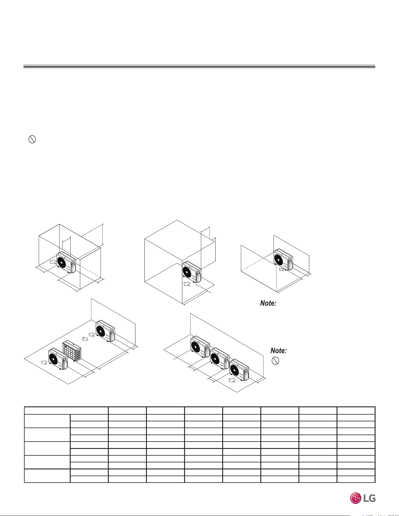
Due to our policy of continuous product innovation, some specications may change without notication.
©LG Electronics U.S.A., Inc., Englewood Cliffs, NJ. All rights reserved. “LG” is a registered trademark of LG Corp.
77 | DUCTED
Single Zone Ceiling-Concealed Ducted System Engineering Manual
Outdoor Unit
CLEARANCES
Outdoor Unit (9,000 to 24,000 Capacity) Service Access and Allowable Clearances
Specific clearance requirements in the diagram below are for (9,000 to 24,000 Btu/h capacities). The figure below shows the overall minimum
clearances that must be observed for safe operation and adequate airflow around the outdoor unit.
When placing the outdoor unit under an overhang, awning, sunroof or other “roof-like structure”, observe the clearance requirements (as
shown in Cases 1 and 2) for height in relation to the unit. To have successful service access to the outdoor unit, see the figure below for
minimum spacing. When installing multiple outdoor units, see Cases 4 and 5 for correct spacing requirements.
Figure 63: 9,000 to 24,000 Capacity Outdoor Unit Service Access and Allowable Clearances Diagram.
A
B
D
G
C
G
C
D
E
D
D
B
B
F
1/16 inch
20 inches or less
Case 1
Case 4
Case 2 Case 3
Case 5
20 inches or less
Unit: Inch A B C D E F G
Case 1
Standard 12 24 - 12 - - -
Minimum 4 10 - 4 - - 40
Case 2
Standard - - 20 - - - -
Minimum - - 14 - - - 40
Case 3
Standard - - 20 12 - - -
Minimum - - 14 4 - - -
Case 4
Standard - - - 12 24 - -
Minimum - - - 4 8 79 -
Case 5
Standard - 24 - 12 - - -
Minimum - 10 - 4 - - -
Table 56: 9,000 to 24,000 Outdoor Unit Service Access and Allowable Clearances Diagram Legend.
Do not place the unit where animals
and/or plants will be in the path of the warm
air, or where the warm air and/or noise will
disturb neighbors.
If the outdoor unit is installed between standard
and minimum clearances, capacity decreases
approximately 10%.
Minimum Allowable Clearance and Service Access Requirements
Proper clearance for the outdoor unit coil is critical for proper unit operation. When installing the outdoor unit, consider service, inlet and
outlet and minimum allowable space requirements as illustrated in the diagrams on the following pages.
• Include enough space for airflow and for service access. If installing multiple outdoor units, avoid placing the units where the discharge of
one unit will blow into the inlet side of an adjacent unit.
• If an awning is built over the unit to prevent direct sunlight or rain exposure, make sure that the discharge air of the outdoor unit isn’t
restricted.
• No obstacles to air circulation around the unit; keep proper distances from ceilings, fences, floor, walls, etc. (Install a fence to prevent
pests from damaging the unit or unauthorized individuals from accessing it.)
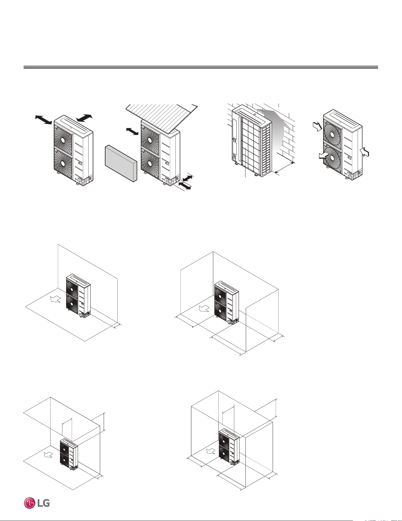
Due to our policy of continuous product innovation, some specications may change without notication.
©LG Electronics U.S.A., Inc., Englewood Cliffs, NJ. All rights reserved. “LG” is a registered trademark of LG Corp.
DUCTED | 78
Application Guidelines
Minimum 11-13/16"
Minimum 19-11/16"
Minimum 39-3/8"
Minimum 11-13/16"
Maximum 19-11/16"
Minimum 11-13/16"
Minimum 39-3/8"
Minimum 23-19/32"
Obstacles above and on the air intake side. Obstacles above, on the air intake side,
and on both left and right sides
CLEARANCES
Outdoor Unit
Minimum 11-13/16
Air inlet grille
Blown
air
Strong
wind
Strong
wind
Minimum 11-13/16
Minimum 23-5/8
Sunroof
Fence or
obstacles
Minimum 11-13/16
Air inlet grille
Blown
air
Strong
wind
Strong
wind
Minimum 19-1/16
Fence or
obstacles
Unit: Inch
Minimum 11-13/16
Ensure that the space at the back of the outdoor unit is a minimum of 11-13/16 inches, and
include a minimum of 23-5/8 inches at the right side of the unit for service.
If the outdoor unit discharge side faces a wall, include a minimum of 19-11/16 inches
between the outdoor unit and the wall. Install the outdoor unit so that the discharge port is
set at a right angle to the wind direction.
Outdoor Unit (36,000 Btu/h Capacity) Service Access and Allowable Clearances
When installing the outdoor unit, consider service, inlet, and outlet, and minimum allowable space requirements as illustrated in the following
diagrams.
Clearance Requirements when Different Obstacles are Present (Unit: Inch).
Minimum 11-13/16"
Minimum 11-13/16"
Minimum 11-13/16"
Minimum 23-19/32"
Obstacle on the suction side only.
Obstacles on the suction side and
on both left and right sides.
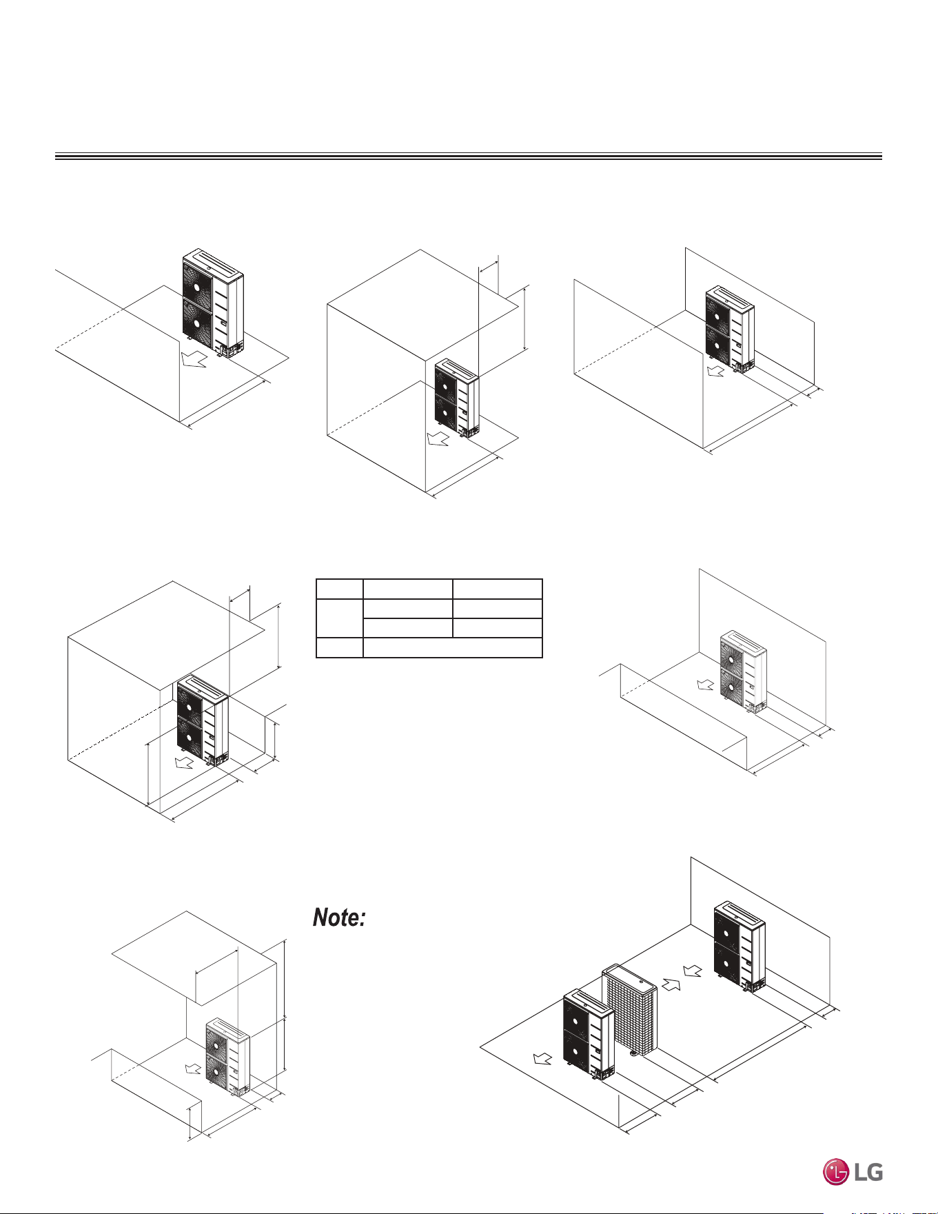
Due to our policy of continuous product innovation, some specications may change without notication.
©LG Electronics U.S.A., Inc., Englewood Cliffs, NJ. All rights reserved. “LG” is a registered trademark of LG Corp.
79 | DUCTED
Single Zone Ceiling-Concealed Ducted System Engineering Manual
Minimum 19-11/16"
Obstacle just on the
air discharge side.
Where there are obstacles on both suction
and discharge sides (discharge side obstacle
is higher than the outdoor unit).
Minimum 19-11/16"
Minimum 11-13/16"
Where there are obstacles above, and on both
suction and discharge sides (discharge side obstacle
is higher than the outdoor unit).
Maximum 19-11/16"
Minimum 11-13/16"
Minimum 39-3/8"
L
H
A
Table 57: Ratio among H, A, and L.
If a stand is necessary, it must be contained (not open
frame) to prevent the discharge air from short cycling.
L A
L
≤ H
0 < L ≤ 1/2 H 29-1/32 inches
1/2 H < L 39-3/8 inches
H < L
Set Stand as: L ≤ H
CLEARANCES
Outdoor Unit
L
Minimum 39-3/8"
Minimum 39-3/8
"
Maximum 19-11/16"
Minimum 11-13/16"
Where there are obstacles above, and on both
suction and discharge sides (discharge side obstacle
is lower than the outdoor unit).
H
“L” must be lower than
“H”. If a stand is neces-
sary, it must be contained
(not open frame) to
prevent the discharge air
from short cycling.
Minimum 19-11/16"
Minimum 19-11/16"
Minimum 39-3/8"
Obstacles above and on the
air discharge side.
Where there are obstacles on both suction
and discharge sides (discharge side obstacle
is lower than the outdoor unit).
Minimum 19-11/16"
Minimum 11-13/16"
Minimum 11-13/16"
Minimum 78-3/4"
Minimum 23-19/32"
Minimum 39-3/8"
Series installation
Due to our policy of continuous product innovation, some specications may change without notication.
©LG Electronics U.S.A., Inc., Englewood Cliffs, NJ. All rights reserved. “LG” is a registered trademark of LG Corp.
DUCTED | 80
Application Guidelines
Installing Outdoor Units Indoors
LG outdoor units are engineered to be mounted outdoors and include technology designed to minimize the negative effects of winter weath-
er’s freezing rain, sleet, and snow. Some building projects, however, necessitate placing the HVAC outdoor units indoors:
• Lack of ground space.
• Lack of an appropriate outdoor location that meets system design requirements.
• When mounting on the roof is not an option due to a lack of roof space.
• Roof warranty will be voided if mechanical equipment is placed on the membrane.
• On retrofit projects, a former chiller / boiler / air handler equipment room, mechanical area, or penthouse already exists.
• Where a project has vertical, self-contained VAV air handlers on each floor (in lieu of a centralized mechanical room).
• To curtail the potential need for redundant zone heating devices such as wall-fin radiators or duct heaters.
• In extremely cold environments where there is a significant amount of run-time at temperatures well below freezing outside the outdoor unit
ambient air temperature range published in this engineering manual.
Benefits of Installing Outdoor Units Indoors
• Shelters the outdoor unit from direct exposure to prevailing winds that decrease the heating capability of the outdoor unit.
• Protects equipment from freezing precipitation and / or potential ice build-up that could hinder unit operation.
• Maintains coil heat transfer efficiency by reducing the number of and shortening the cycle time for defrost operation.
• Easier maintenance and servicing during inclement weather.
• When mounted in a fully enclosed space, limiting the ambient air temperature may allow the system designer to eliminate oversizing the
outdoor unit to compensate for loss of capacity at low ambient temperatures.
• May also curtail the need to provide inefficient redundant zone heating devices such as wall-fin radiators and second-stage ancillary
heating devices.
Design Considerations Include:
• Enclosure types and elements such as louvers, rain hoods, dampers and controls, heating methods and sizing of heating devices
• Heating strategies
• Duct design
• Condensate handling
General Guidelines
• Follow ASHRAE 62.1 design guidelines.
• Depending on the project / application, a roof over the outdoor units in combination with a wind break may be all that is necessary.
• Consider the potential for snow accumulation near louvers / roof openings. Outside air intakes and discharge ducts/louvers must be engi-
neered to clear anticipated snow accumulation levels by at least one (1) foot.
• In situations where operation is anticipated at temperatures of -13°F and lower, ancillary heat must be provided to heat the outdoor unit
coils to assure continuous compressor operation and heating.
It may be necessary to use an air guide accessory to prevent discharge air from short-cycling back to the coil inlet.
• Another option is to field manufacture ductwork and mount on top of the unit to encompass the outdoor unit fan discharge and connect to
the exterior discharge grille on the building.
• Avoid using a single duct on multi-fan units to prevent short cycling. Provide a dedicated duct for each outdoor unit fan discharge.
• Consider the direction of prevailing winds and opening placement. If possible, locate inlet openings upwind of discharge openings and other
exhaust outlets.
• When inlet and outlet openings are placed on the same wall, minimum distance between the two openings must be approximately three (3)
feet (minimum distance varies significantly with variations in outlet opening face velocity).
• If roof-mounted ventilation openings are used, strategically locate the inlet ventilation opening(s) upwind of the outlet opening(s).
• Discharge and supply ductwork must be designed to avoid weather related long periods of water entrainment and the potential for
microbial growth.
INSTALLING OUTDOOR UNITS INDOORS
Due to our policy of continuous product innovation, some specications may change without notication.
©LG Electronics U.S.A., Inc., Englewood Cliffs, NJ. All rights reserved. “LG” is a registered trademark of LG Corp.
81 | DUCTED
Single Zone Ceiling-Concealed Ducted System Engineering Manual
Provide a means to drain the condensate generated during heating mode and defrost cycle in addition to rainwater that infiltrates the inlet
louver enclosed area.
• Install a field-provided drain pan under the outdoor units and provide a path to a nearby floor drain.
• If the ambient air temperature is expected to drop below 32°F in the enclosure, heat the bottom surface of the pan, drain line, and floor
drain so that the condensate does not freeze before reaching the drain.
Allow for ventilation intake and exhaust air based on maximum outdoor unit fan capacity.
• Select the size, type and orientation of architectural louvers with adequate "net free area" face velocity to ensure the total external static
pressure from the outdoor unit fan does not exceed design limitations (see specification data tables).
• No obstructions must be placed in front of the louver that could hamper the free flow (throw) of air.
• Roof top openings and / or discharge and supply louvers must be equipped with screens to prevent bird and insect infiltration.
As always, the best solution for each project balances acceptable heating performance (considering local weather conditions), capital costs,
life cycle energy consumption, and limitations set forth by local building codes.
INSTALLING OUTDOOR UNITS INDOORS
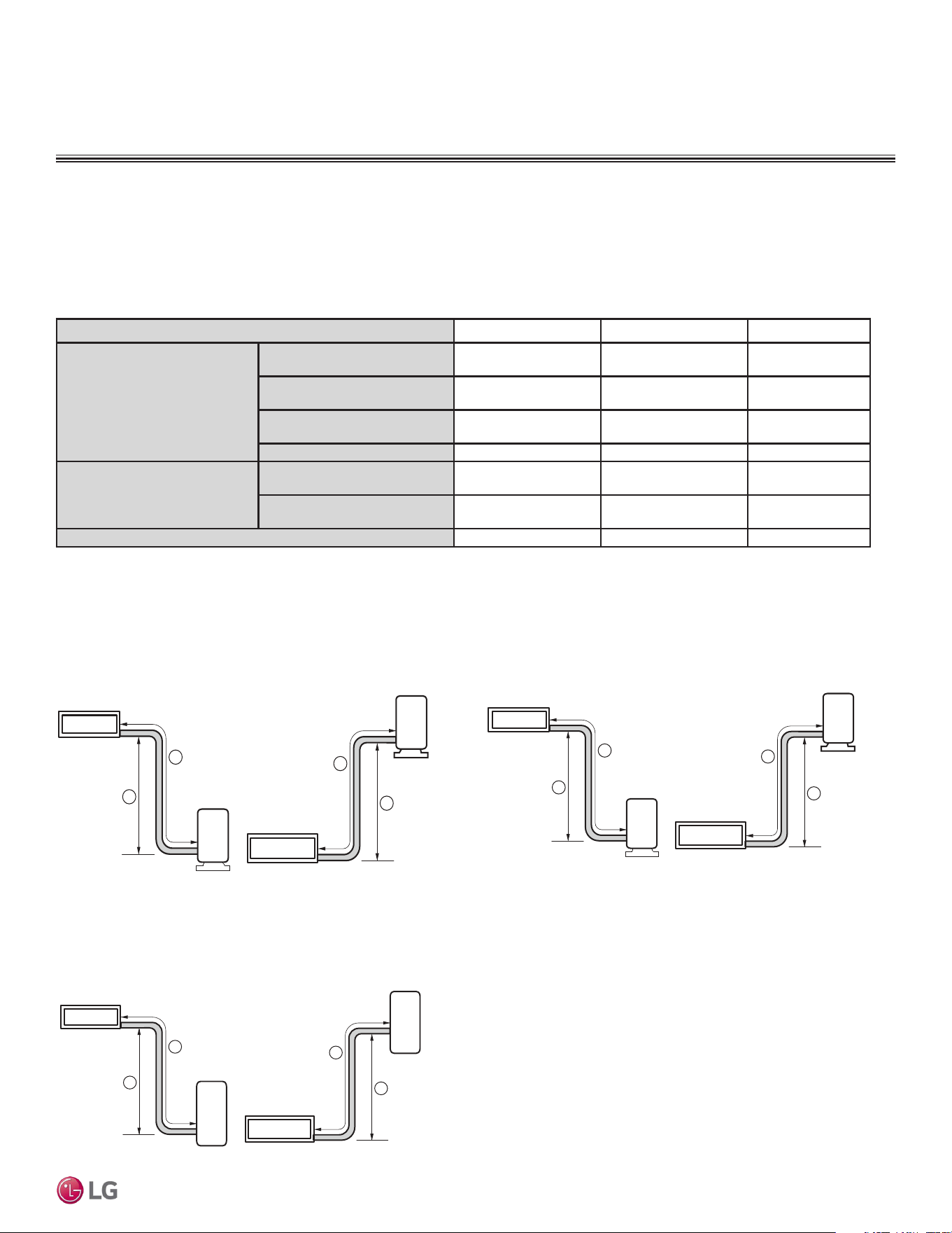
Due to our policy of continuous product innovation, some specications may change without notication.
©LG Electronics U.S.A., Inc., Englewood Cliffs, NJ. All rights reserved. “LG” is a registered trademark of LG Corp.
DUCTED | 82
Application Guidelines
Device Connection Limitations
A single-zone ceiling-concealed ducted system consists of one outdoor unit and one indoor unit. One of the most critical elements of a
single-zone ceiling-concealed ducted system is the refrigerant piping. The table below lists pipe length limits that must be followed in the
design of a single-zone ceiling-concealed ducted refrigerant pipe system:
REFRIGERANT PIPING DESIGN
Design Guideline Summary
Table 58: Single-Zone Ceiling-Concealed Ducted Refrigerant Piping System Limitations.
System Model Name LD097HV4, LD127HV4 LD187HV4, LH248HV4 LH368HV4
Pipe Length
(ELF = Equivalent Length of Pipe)
Longest total equivalent piping
length
66 feet 164 feet 246 feet
Shortest total equivalent
piping length
6.6 6.6 6.6
Distance between ttings and
indoor or outdoor units
≥20 inches ≥20 inches ≥20 inches
No additional refrigerant
25 feet 25 feet 25 feet
Elevation
(All Elevation Limitations are
Measured in Actual Feet)
If outdoor unit is above indoor
unit
49 feet 98 feet 98 feet
If outdoor unit is below indoor
unit
49 feet 98 feet 98 feet
Additional Refrigerant Needed (oz/ft)
0.22 0.43 0.43
System Layout
Figure 64: Typical LD097HV4, LD127HV4 System Layout. Figure 65: Typical LD187HV4, LH248HV4 System Layout.
Outdoor unit
Indoor unit
A
B
Outdoor unit
Indoor unit
A
B
98
98
164
Max Length = A
Max Elevation = B
164
Unit = Feet
Outdoor unit
Indoor unit
A
B
Outdoor unit
Indoor unit
A
B
98
98
246
Max Length = A
Max Elevation = B
246
Unit = Feet
Figure 66: Typical LH368HV4 System Layout.
Outdoor unit
Indoor unit
A
B
Outdoor unit
Indoor unit
A
B
49
49
66
Max Length = A
Max Elevation = B
66
Unit = Feet
20001747 ISO 9001: 2008
LG ELECTRONICS INC.
EM_SZ_Ducted_09_19
Supersedes: EM_SZ_Ducted_12_18
EM_SZ_Ducted_11_18
EM_SZ_Ducted_8_17
EM_SZ_Ducted_5_16
DFS-EM-AM-001-US_014D02
LG Electronics, U.S.A., Inc.
Air Conditioning Technologies
4300 North Point Parkway
Alpharetta, Georgia 30022
www.lghvac.com