R32 SINGLE-ZONE
STANDARD EFFICIENCY,
MEGA, AND MEGA 115V
WALL-MOUNTED
ENGINEERING MANUAL
Mega
KSSAC091A (9,000 Btu/h)
KSSAC121A (12,000 Btu/h)
Mega
KSSAC181A (18,000 Btu/h)
KSSAC241A (24,000 Btu/h)
Standard Efficiency
KSSAE091A (9,000 Btu/h)
KSSAE121A (12,000 Btu/h
Standard Efficiency
KSSAE181A (18,000 Btu/h)
KSSAE241A (24,000 Btu/h)
Mega 115V
KSSAC091B (9,000 Btu/h)
KSSAC121B (12,000 Btu/h)

For continual product development, LG Electronics U.S.A., Inc., reserves the right to change specifications without notice.
© LG Electronics U.S.A., Inc.
This document, as well as all reports, illustrations, data, information, and other materials are the property of LG Electronics U.S.A., Inc.
PROPRIETARY DATA NOTICE
This document, as well as all reports, illustrations, data, information,
and other materials are the property of LG Electronics U.S.A., Inc., and are
disclosed by LG Electronics U.S.A., Inc. only in confidence.
This document is for design purposes only.
A summary list of safety precautions is on page 6.
For more technical materials such as submittals, catalogs, installation,
owner’s, and service manuals, visit www.lghvac.com.
Proper sizing and installation of equipment is critical to achieve optimal performance. Split system air conditioners and heat pumps
(excluding ductless systems) must be matched with appropriate coil components to meet ENERGY STAR
®
criteria. Ask your contractor for
details or visit www.energystar.gov.
(ENERGY STAR and the ENERGY STAR mark are registered trademarks owned by the U.S. Environmental Protection Agency.)
'XHWRRXUSROLF\RIFRQWLQXRXVSURGXFWLQQRYDWLRQVRPHVSHFL¿FDWLRQVPD\FKDQJHZLWKRXWQRWL¿FDWLRQ
©
/*(OHFWURQLFV86$,QF(QJOHZRRG&OLIIV1-$OOULJKWVUHVHUYHG³/*´LVDUHJLVWHUHGWUDGHPDUNRI/*&RUS
3
56LQJOH=RQH6WDQGDUG(ႈFLHQF\0HJDDQG0HJD9:DOO0RXQWHG(QJLQHHULQJ0DQXDO
LG AIR CONDITIONER
TECHNICAL SOLUTION (LATS)
LG Air Conditioner Technical Solution (LATS) Software
A properly designed and installed refrigerant piping system is critical
to the optimal performance of LG air-conditioning systems. To assist
engineers, LG offers, free of charge, LG Air Conditioner Technical
Solution (LATS) software—a total design solution for LG air condi-
tioning systems. Contact your LG Rep for the best software program
for your application.
To reduce the risk of designing an improper applied system or one that
will not operate correctly, LG requires that LATS software be used on all
projects.
Formats
LATS is available to LG customers in two user interfaces: LATS HVAC and LATS Revit. Both LATS formats are available through
www.myLGHVAC.com, or contact an LG Sales Representative.
LATS HVAC is a Windows
®
-based application that aids engineers in designing LG Variable Refrigerant Flow (VRF), Multi F / Multi F MAX,
Single-Zone, DOAS, and Energy Recovery Ventilator (ERV) systems.
*Windows
®
is a registered mark of Microsoft
®
Corporation.
LATS Revit integrates the LG LATS program with Revit
®
software**. It permits engineers to layout and validate LG VRF, Multi F / Multi F
MAX, Single-Zone, and DOAS directly into Revit drawings.
**Revit
®
is a registered mark of Autodesk, Inc.
Features
All LG product design criteria have been loaded into the program, making LATS simple to use: double click or drag and drop the component
choices. Build systems in Tree Mode where the refrigerant system can be viewed. Switch to a Schematic diagram to see the electrical and
communications wiring.
LATS software permits the user to input region data, indoor and outdoor design temperatures, modify humidity default values, zoning, specify
type and size of outdoor units and indoor units, and input air flow and external static pressure (ESP) for ducted indoor units.
The program can also:
• Import building loads from a separate Excel file.
• Present options for outdoor unit auto selection.
• Automatically calculate component capacity based on design
conditions for the chosen region.
• Verify if the height differences between the various system
components are within system limits.
• Provide the correct size of each refrigerant piping segment and LG
Y-Branches and Headers.
• Adjust overall piping system length when elbows are added.
• Check for component piping limitations and flag if any parameters
are broken.
• Factor operation and capacity for defrost operation.
• Calculate refrigerant charge, noting any additional trim charge.
• Suggest accessories for indoor units and outdoor units.
• Run system simulation.
Features depend on which LATS program is being used, and the type of system being designed. Contact your LG representative for the best soft-
ware program for your application.
$Q\¿HOGFKDQJHVVXFKDVUHURXWLQJVKRUWHQLQJRUOHQJWKHQLQJDSLSHVHJPHQWDGGLQJRUHOLPLQDWLQJHOERZVDQGRU¿WWLQJV
UHVL]LQJDGGLQJRUHOLPLQDWLQJLQGRRUXQLWVFKDQJLQJWKHPRXQWLQJKHLJKWRUPRYLQJWKHORFDWLRQRIDGHYLFHRU¿WWLQJGXU-
ing installation must be done with caution and ALWAYS VERIFIED in LATS SOFTWARE BEFORE supplies are purchased or
LQVWDOOHG'RLQJVRZLOOOHDGWRDPRUHSUR¿WDEOHLQVWDOODWLRQUHGXFHWKHSRWHQWLDOIRUUHZRUNDQGZLOOUHGXFHWKHSRWHQWLDOIRU
multiple visits to the job site to complete the system set up.
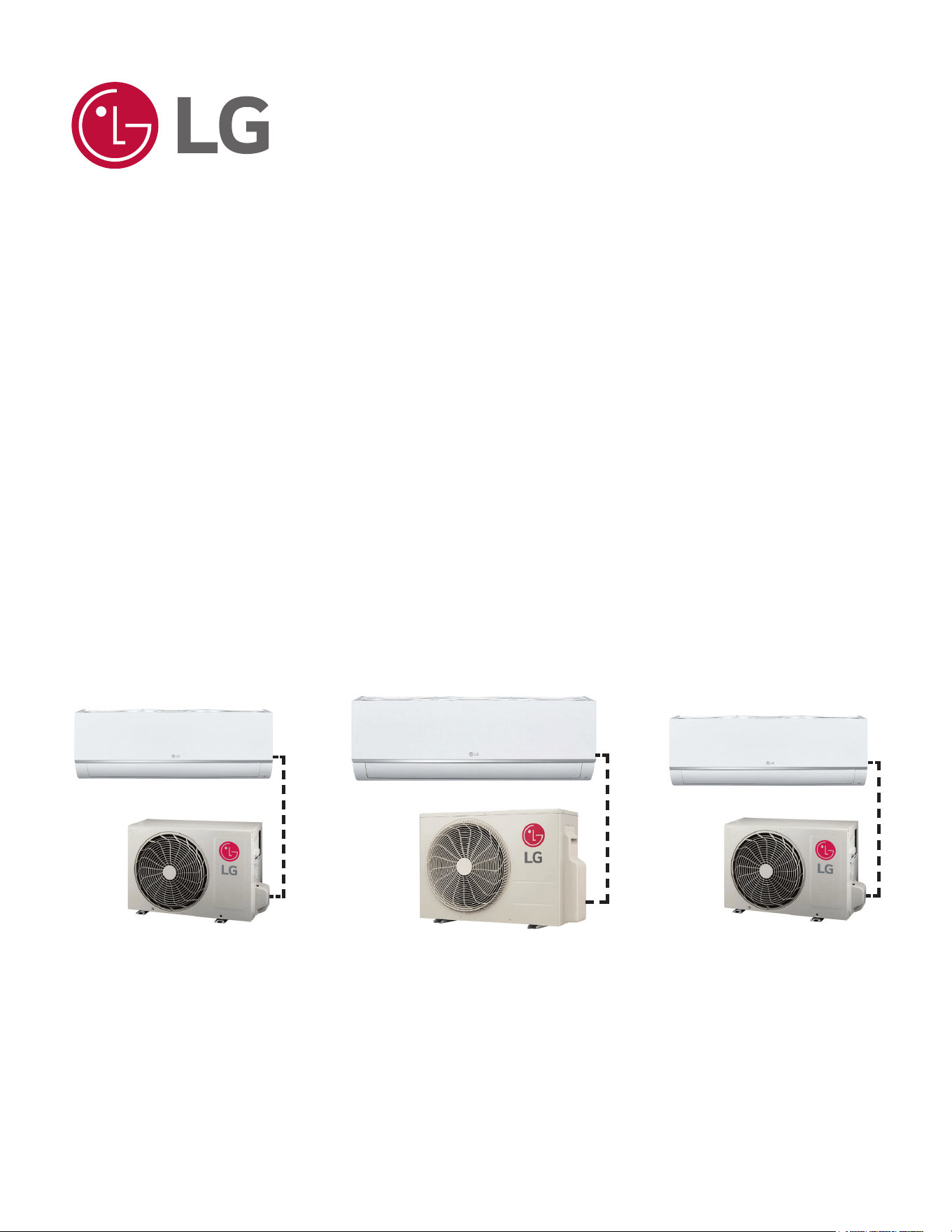
Figure 1: LATS Example (Tree Diagram; Illustrative Purposes Only.
System will Vary Depending On Model).
'XHWRRXUSROLF\RIFRQWLQXRXVSURGXFWLQQRYDWLRQVRPHVSHFL¿FDWLRQVPD\FKDQJHZLWKRXWQRWL¿FDWLRQ
©
/*(OHFWURQLFV86$,QF(QJOHZRRG&OLIIV1-$OOULJKWVUHVHUYHG³/*´LVDUHJLVWHUHGWUDGHPDUNRI/*&RUS
4
56LQJOH=RQH6WDQGDUG(ႈFLHQF\0HJDDQG0HJD9:DOO0RXQWHG(QJLQHHULQJ0DQXDO
LG AIR CONDITIONER
TECHNICAL SOLUTION (LATS)
LATS Generates a Complete Project Report
LATS software also generates a report containing project design parameters, cooling and heating design data, system component perfor-
mance, and capacity data. The report includes system combination ratio and refrigerant charge calculations; and provides detailed bill of
material, including outdoor units, indoor units, control devices, accessories, refrigerant pipe sizes segregated by building, by system, by pipe
size, and by pipe segments. LATS can generate an Excel GERP report that can be imported into the LG SOPS pricing and ordering system.
Proper Design to Install Procedure
LG encourages a two report design-to-install-procedure. After the design engineer determines building / zone loads and other details, the
engineer opens the LATS program and inputs the project’s information. When the design is complete, the “Auto Piping” and “System Check”
functions must be used to verify piping sizes, limitations, and if any design errors are present. If errors are found, engineers must adjust the
design, and run Auto Piping and System Check again. When the design passes the checks, then the engineer prints out a project “Shop
Drawing” (LATS Tree Diagram) and provides it to the installing contractor. The contractor must follow the LATS Tree Diagram when building
the piping system, but oftentimes the design changes on the building site:
• Architect has changed location and/or purpose of room(s).
• Outdoor unit cannot be placed where originally intended.
• Structural elements prevent routing the piping as planned.
• Air conditioning system conflicts with other building systems (plumbing, gas lines, etc.).
The contractor must mark any deviation from the design on the Shop Drawing, including as-built straight lines and elbows. This “Mark Up”
drawing must be returned to the design engineer or Rep, who must input contractor changes into the LATS file. (Copy the original LATS soft-
ware file, save and rename as a separate file, and modify all piping lengths by double-clicking on each length and editing information.) Like
the shop drawing, the Auto Piping and System Check must also be run on this new “As Built” drawing. The design engineer or Rep must then
provide the final As Built file to the contractor. The Mark Up version must be compared to the As Built version for:
• Differences in pipe diameter(s). If incorrect diameters have been installed, the piping must be changed out. If pipe diameters have changed,
check if Y-Branches will also need to be changed.
• Changes to outdoor unit and indoor unit capacities. Capacities changes will impact line length changes.
• Additional refrigerant charge quantity (“Trim Charge”). Trim charge will change if piping lengths and diameters change. The As Built version
must reflect installed piping lengths to ensure correct trim charge.
All documents submitted by the contractor, as well as the Shop Drawing and the As Built Drawing files must be provided for commissioning
purposes. Model and serial numbers for all system components must also be submitted. If the steps previously detailed are not followed, and
all documents are not provided to the commissioning agent, the project runs the risk of not being commissioned and voiding any limited war-
ranty LG offers on the equipment.
$Q\¿HOGFKDQJHVVXFKDVUHURXWLQJVKRUWHQLQJRUOHQJWKHQLQJDSLSHVHJPHQWDGGLQJRUHOLPLQDWLQJHOERZVDQGRU¿WWLQJV
UHVL]LQJDGGLQJRUHOLPLQDWLQJLQGRRUXQLWVFKDQJLQJWKHPRXQWLQJKHLJKWRUPRYLQJWKHORFDWLRQRIDGHYLFHRU¿WWLQJGXU-
ing installation must be done with caution and ALWAYS VERIFIED in LATS SOFTWARE BEFORE supplies are purchased or
LQVWDOOHG'RLQJVRZLOOOHDGWRDPRUHSUR¿WDEOHLQVWDOODWLRQUHGXFHWKHSRWHQWLDOIRUUHZRUNDQGZLOOUHGXFHWKHSRWHQWLDOIRU
multiple visits to the job site to complete the system commissioning.

'XHWRRXUSROLF\RIFRQWLQXRXVSURGXFWLQQRYDWLRQVRPHVSHFL¿FDWLRQVPD\FKDQJHZLWKRXWQRWL¿FDWLRQ
©
/*(OHFWURQLFV86$,QF(QJOHZRRG&OLIIV1-$OOULJKWVUHVHUYHG³/*´LVDUHJLVWHUHGWUDGHPDUNRI/*&RUS
5
56LQJOH=RQH6WDQGDUG(ႈFLHQF\0HJDDQG0HJD9:DOO0RXQWHG(QJLQHHULQJ0DQXDO
TABLE OF CONTENTS
LG Air Conditioner Technical Solution (LATS) ......................................................................................................................................................... 3-4
Table of Symbols ............................................................................................................................................................................................................ 6
Product Data .............................................................................................................................................................................................................. 7-39
Unit Nomenclature ............................................................................................................................................................................................................ 8
Pairing Table ..................................................................................................................................................................................................................... 9
0HFKDQLFDO6SHFL¿FDWLRQV .............................................................................................................................................................................................. 10
General Data ............................................................................................................................................................................................................. 11-16
Electrical Data ................................................................................................................................................................................................................ 17
Functions, Controls, Options .......................................................................................................................................................................................... 18
Accessories ............................................................................................................................................................................................................... 19-20
Outdoor Unit Dimensions .......................................................................................................................................................................................... 21-22
Outdoor Unit Center of Gravity / Corner Weight ............................................................................................................................................................. 23
Indoor Unit Dimensions ............................................................................................................................................................................................. 24-25
Indoor Unit Air Flow, Temp. Distribution Graphs ........................................................................................................................................................ 26-37
Acoustic Data ............................................................................................................................................................................................................ 38-39
Performance Data .................................................................................................................................................................................................... 40-82
Cooling Capacity ....................................................................................................................................................................................................... 41-50
Maximum Cooling Capacity ....................................................................................................................................................................................... 51-60
Heating Capacity ....................................................................................................................................................................................................... 61-70
Maximum Heating Capacity ....................................................................................................................................................................................... 71-80
Equipment Selection Procedure ..................................................................................................................................................................................... 81
Check Selection .............................................................................................................................................................................................................. 82
Application Guidelines ............................................................................................................................................................................................ 83-91
Indoor Unit Placement / Clearance Considerations ................................................................................................................................................... 84-85
Outdoor Unit Placement / Clearance Considerations ................................................................................................................................................ 85-88
Installing Outdoor Units Indoors ................................................................................................................................................................................ 89-91
Refrigerant Piping Design .................................................................................................................................................................................... 92-101
Refrigerant Flow Diagrams ............................................................................................................................................................................................. 93
Connection Limitations and System Layout ................................................................................................................................................................... 94
Additional Refrigerant Charge ........................................................................................................................................................................................ 95
Refrigerant Piping System Engineering ................................................................................................................................................................... 96-101
Electrical ................................................................................................................................................................................................................102-111
General Guidelines ....................................................................................................................................................................................................... 103
Wiring Diagrams .................................................................................................................................................................................................... 104-107
Power Supply / Power Wiring ....................................................................................................................................................................................... 108
Communication / Connection Cable ............................................................................................................................................................................. 109
Controllers .............................................................................................................................................................................................................. 110-111
Limited Warranty .........................................................................................................................................................................................................112
'XHWRRXUSROLF\RIFRQWLQXRXVSURGXFWLQQRYDWLRQVRPHVSHFL¿FDWLRQVPD\FKDQJHZLWKRXWQRWL¿FDWLRQ
©
/*(OHFWURQLFV86$,QF(QJOHZRRG&OLIIV1-$OOULJKWVUHVHUYHG³/*´LVDUHJLVWHUHGWUDGHPDUNRI/*&RUS
6
56LQJOH=RQH6WDQGDUG(ႈFLHQF\0HJDDQG0HJD9:DOO0RXQWHG(QJLQHHULQJ0DQXDO
TABLE OF SYMBOLS
,QGLFDWHVWKDWWKLVDSSOLDQFHXVHVDÀDPPDEOHUHIULJHUDQW,IWKHUHIULJHUDQWOHDNVDQGLVH[SRVHGWRDQH[WHUQDO
LJQLWLRQVRXUFHWKHUHLVDULVNRI¿UH
Indicates a hazardous situation that, if not avoided, WILL RESULT IN DEATH OR SERIOUS INJURY.
1
Indicates a hazardous situation that, if not avoided, COULD RESULT IN DEATH OR SERIOUS INJURY.
1
Indicates a hazardous situation that, if not avoided, COULD RESULT IN MINOR OR MODERATE INJURY.
1
Indicates information considered important, but not hazard-related; indicates situations that may result in equipment
or property damage accidents.
1
This symbol indicates an action that should not be performed.
D ANGER
CAUTION
1
6LJQDOZRUGVV\PEROVDQGGH¿QLWLRQVWDNHQIURP$PHULFDQ1DWLRQDO6WDQGDUGV,QVWLWXWH$16,=6HHKWWSVZZZDQVLRUJIRUPRUH
information.
/*(OHFWURQLFVSOLWV\VWHPKHDWLQJDQGDLUFRQGLWLRQLQJ+9$&SURGXFWVQRZFRQWDLQ5UHIULJHUDQW:KLOH5UHIULJHUDQWLVVOLJKWO\ÀDPPDEOHLW
KDVDKLJKHUHI¿FLHQF\DORZHU*OREDO:DUPLQJ3RWHQWLDO*:3YDOXHDQGLVPRUHHQYLURQPHQWDOO\IULHQGO\WKDQ5$
52]RQH'HSOHWLRQ3RWHQWLDO2'39DOXH
5*OREDO:DUPLQJ3RWHQWLDO*:39DOXH
7KHDPRXQWRIUHIULJHUDQWGHSHQGVRQRXWGRRUXQLWWRLQGRRUXQLWFRQ¿JXUDWLRQ$OOUHIULJHUDQWSLSLQJV\VWHPFRPSRQHQWVFRSSHUSLSLQJMRLQWVDQG
RWKHU¿WWLQJVPXVWEHVHOHFWHGDQGLQVWDOOHGWRFRQIRUPZLWK5HIULJHUDWLRQ6DIHW\5HJXODWLRQVWDQGDUGV8VH/*$LU&RQGLWLRQHU7HFKQLFDO6ROXWLRQ
/$766RIWZDUHWRYHULI\WKHUHIULJHUDQWDPRXQWQHHGHGIRUHDFKLQVWDOODWLRQ
• 7KLV+9$&V\VWHPFRQWDLQVIOXRULQDWHGJUHHQKRXVHJDVHVLQWKHIRUPRI5UHIULJHUDQW Do not leak refrigerant gas into the atmo-
sphere.
• 2QO\XVH5DVWKHUHIULJHUDQWLQWKHVH+9$&V\VWHPV,IRWKHUVXEVWDQFHVDUHDGGHGLWPD\FDXVHDQH[SORVLRQ
• R32 refrigerant is slightly flammable. When handled properly, it does not leak. If the refrigerant leaks in the installation area and comes in
contact with a flame, it may generate a fire and / or harmful gas.
• If a leak occurs, immediately turn off any combustion devices, ventilate the installation area, and contact the dealer / contractor where the
+9$&XQLWZDVSXUFKDVHG
Do not operate the unit until the refrigerant leaked is repaired.
CAUTION
• Piping wall thickness must comply with all applicable local, state, and federal regulations for the design pressures listed by the manufac-
turer. Unapproved piping must not be used.
• To prevent piping from softening,
do not heat the piping more than necessary.
R32 Refrigerant

PRODUCT DATA
Unit Nomenclature on page 8
Pairing Table on Page 9
Mechanical Specifications on page 10
General Data on page 11
Electrical Data on page 17
Functions, Controls, and Options on page 18
Accessories on page 19
Outdoor Unit Dimensions on page 21
2XWGRRU8QLW&HQWHURI*UDYLW\&RUQHU:HLJKWRQSDJH
Indoor Unit Dimensions on page 24
Air Flow, Temperature Distribution Graphs on page 26
Acoustic Data on page 38
'XHWRRXUSROLF\RIFRQWLQXRXVSURGXFWLQQRYDWLRQVRPHVSHFL¿FDWLRQVPD\FKDQJHZLWKRXWQRWL¿FDWLRQ
©
/*(OHFWURQLFV86$,QF(QJOHZRRG&OLIIV1-$OOULJKWVUHVHUYHG³/*´LVDUHJLVWHUHGWUDGHPDUNRI/*&RUS
8
56LQJOH=RQH6WDQGDUG(ႈFLHQF\0HJDDQG0HJD9:DOO0RXQWHG(QJLQHHULQJ0DQXDO
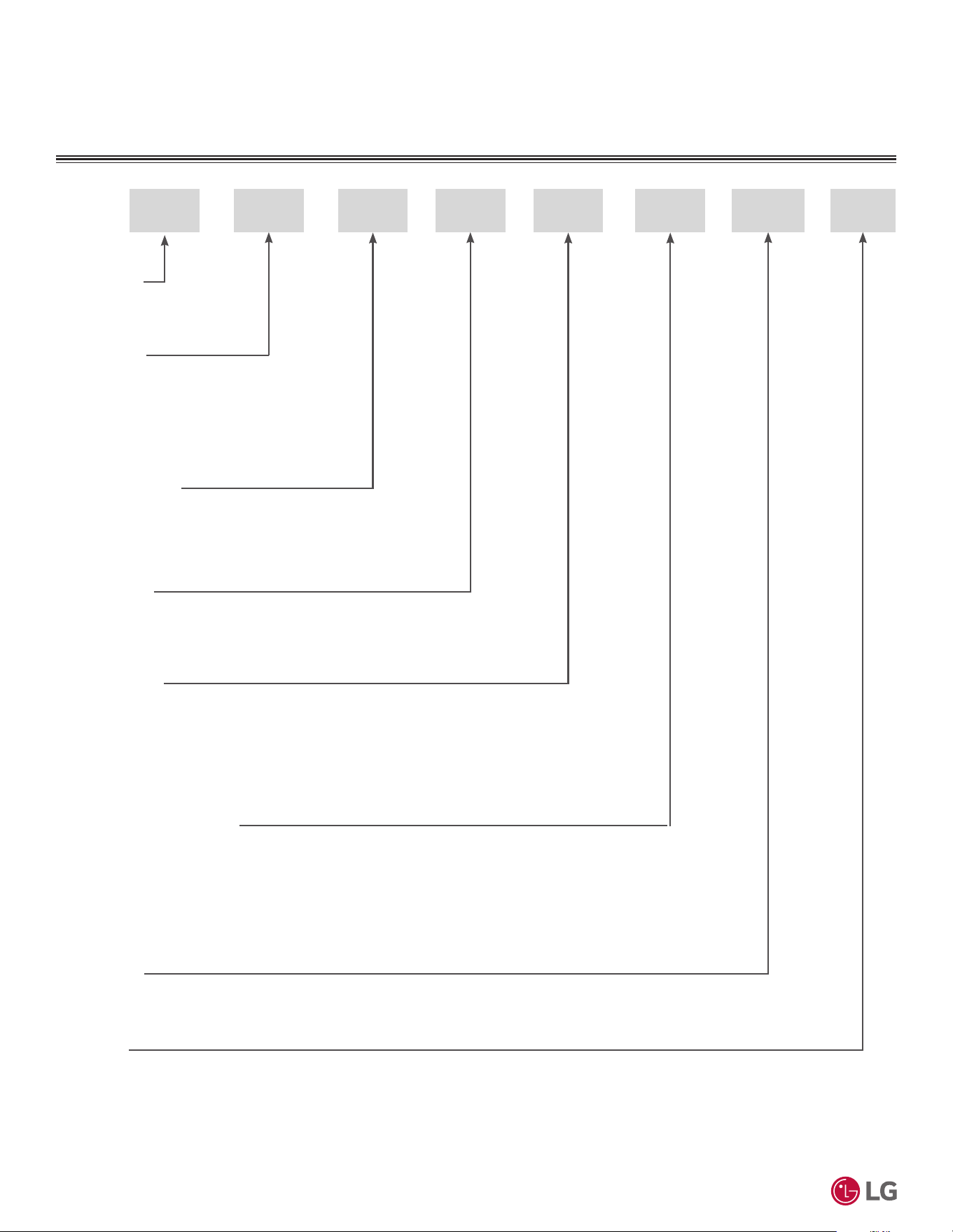
UNIT NOMENCLATURE
A C 09 1 A
1. Refrigerant
K = R32
7. Generation
1 to 9
09 = 9,000 Btu/h
12 = 12,000 Btu/h
18 = 18,000 Btu/h
24 = 24,000 Btu/h
S SK
2. Component
N = Indoor Unit
S = System
U = Outdoor Unit
3. Product Category
S = Single
U = Universal
4. Product Type
A = Wall-Mounted
5. Product Grade
B = High Efficiency (Deluxe)
C = Standard Efficiency (Mega 19)
E = Contractor Inverter (Mega 17)
8. Function
A = 208~230V
B = 115~120V
6. Nominal Capacity (Btu/h)
'XHWRRXUSROLF\RIFRQWLQXRXVSURGXFWLQQRYDWLRQVRPHVSHFL¿FDWLRQVPD\FKDQJHZLWKRXWQRWL¿FDWLRQ
©
/*(OHFWURQLFV86$,QF(QJOHZRRG&OLIIV1-$OOULJKWVUHVHUYHG³/*´LVDUHJLVWHUHGWUDGHPDUNRI/*&RUS
9
Product Data
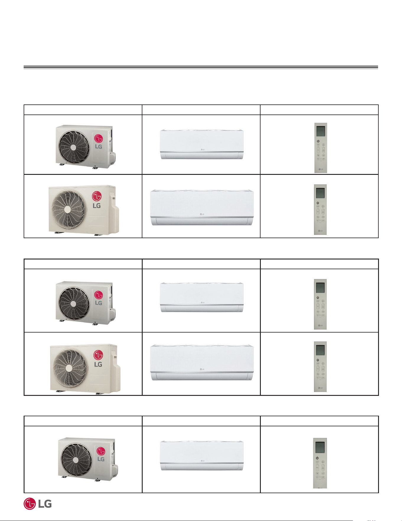
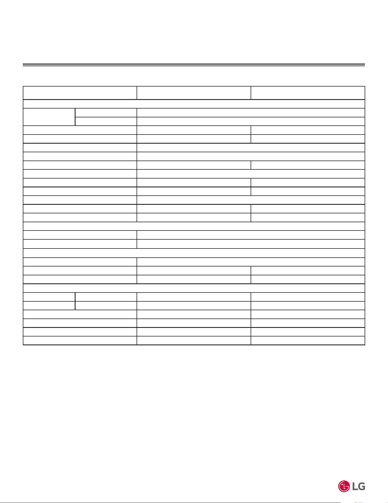
PAIRING TABLE
Outdoor Unit Model Indoor Unit Model Controller
KUSAE091A, KUSAE121A KNSAE091A, KNSAE121A AKB76044207
KUSAE181A, KUSAE241A KNSAE181A, KNSAE241A AKB76044207
The following tables show the available outdoor and indoor units, along with the factory provided controllers.
Table 1: 6LQJOH=RQH6WDQGDUG(I¿FLHQF\:DOO0RXQWHG6\VWHP3DLULQJ7DEOH
Table 2: Single Zone Mega Wall-Mounted System Pairing Table.
Table 3: Single Zone Mega 115V Wall-Mounted System Pairing Table.
Outdoor Unit Model Indoor Unit Model Controller
KUSAC091A, KUSAC121A KNSAC091A, KNSAC121A AKB76044207
KUSAC181A, KUSAC241A KNSAC181A, KNSAC241A AKB76044207
Outdoor Unit Model Indoor Unit Model Controller
KUSAC091B, KUSAC121B KNSAC091B, KNSAC121B AKB76044207
'XHWRRXUSROLF\RIFRQWLQXRXVSURGXFWLQQRYDWLRQVRPHVSHFL¿FDWLRQVPD\FKDQJHZLWKRXWQRWL¿FDWLRQ
©
/*(OHFWURQLFV86$,QF(QJOHZRRG&OLIIV1-$OOULJKWVUHVHUYHG³/*´LVDUHJLVWHUHGWUDGHPDUNRI/*&RUS
10
56LQJOH=RQH6WDQGDUG(ႈFLHQF\0HJDDQG0HJD9:DOO0RXQWHG(QJLQHHULQJ0DQXDO
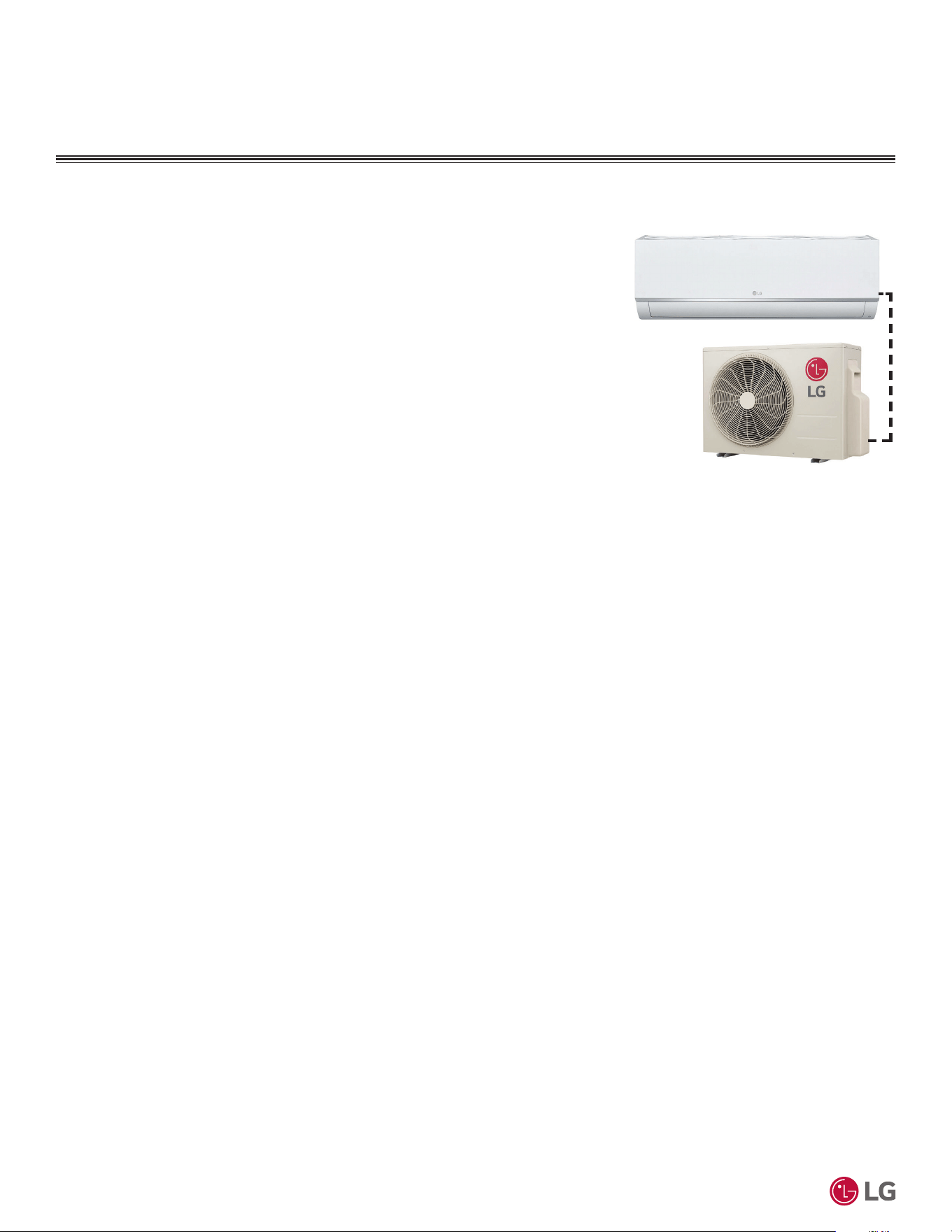
MECHANICAL SPECIFICATIONS
General
LG Single Zone Standard Efficiency, Mega,
and Mega 115V Wall Mounted systems
comprise of a single outdoor unit connected
to a single indoor unit with a single refriger-
ant circuit.
This system is a Duct-Free Split system
that can operate in either cooling or heat-
ing mode. The system shall be capable of
changing mode within a maximum time of
three (3) minutes to ensure indoor tempera-
ture can be properly maintained.
The system is manufactured in a facility reg-
istered to ISO 9001 and ISO 14001, which is
a set of standards applying to environmental
protection set by the International Orga-
nization for Standardization (ISO). Wiring
in these units are in accordance with the
National Electrical Code (NEC).
Temperature Ranges
Standard Efficiency and Mega
Operating ranges for outdoor unit of 14°F to
118°F (DB) for cooling; 5°F to 65°F (WB) for
heating.
Operating ranges for indoor unit of 53°F to
75°F (WB) for cooling; 60°F to 86°F (DB) for
heating.
Mega 115V
Operating ranges for outdoor unit of 14°F to
118°F (DB) for cooling; 5°F to 65°F (WB) for
heating.
Operating ranges for indoor unit of 53°F to
75°F (WB) for cooling; 60°F to 86°F (DB) for
heating.
&DVLQJ)UDPH
Outdoor unit is constructed with pre-coated
metal (PCM).
Indoor unit is constructed of heavy duty
Acrylonitrile Butadiene Styrene (ABS) and
High Impact Polystyrene (HIPS) plastic.
Refrigerant System
The refrigeration system consists of a single
refrigeration circuit and uses R32 refriger-
ant. The outdoor unit is provided with factory
installed components, including a refrigerant
strainer, check valves, oil separator, accu-
mulator, four-way reversing valve, EEV, high
and low side charging ports, service valves,
and interconnecting piping.
Refrigeration Oil Control
Heat Pump outdoor units have a centrifugal
oil separator and controls to ensure suf-
ficient oil supply is maintained, and that oil
does not travel with the refrigerant.
Compressors
The outdoor unit is equipped with one
hermetic, digitally controlled, inverter driven,
twin-rotary compressor to modulate capacity
(modulation in 1 Hz increments).
Frequency ranges for the Standard Efficien-
cy, Mega, and Mega 115V outdoor units are:
9k Btu/h = 10 to 70 Hz (cooling); 10 to 94 Hz
(heating)
12k Btu/h = 10 to 78 Hz (cooling); 10 to 98
Hz (heating)
18 Btu/h = 10 to 70 Hz (cooling); 10 to 105
Hz (heating)
24k Btu/h = 10 to 87 Hz (cooling); 10 to 110
Hz (heating)
Over-current protection and vibration isola-
tion are integrated with the compressor.
Outdoor Unit Coil
Heat Pump outdoor unit coils are of a
nonferrous construction with louvered fins
on copper tubing, and are protected with an
integral coil guard. Coil fins have a factory
applied corrosion resistant GoldFin™ mate-
rial with hydrophilic coating.
Fans and Motors
The outdoor unit includes one direct drive,
variable speed propeller type fan.
The Brushless Digitally Controlled (BLDC)
fan motor has inherent protection, perma-
nently lubricated bearings, and variable
speed with a maximum speed up to 950 rpm.
Raised guards are provided to limit contact
with moving parts.
The outdoor unit has horizontal discharge
airflow.
Electrical
The Standard Efficiency and Mega models
are available in a 208-230V 60 Hz, 1-phase
power supply. The Mega 115V models are
available in a 115V 60 Hz, 1-phase power
supply. The units are capable of operating
within voltage limits of ±10% rated voltage,
and include overcurrent protection.
Air Filter
Return air inlet has a factory-supplied pri-
mary removable, washable filter. Filters are
accessed from the front of the unit without
the use of tools.
Controls
The unit is factory wired with necessary elec-
trical control components, integral micropro-
cessors, printed circuit boards, thermistors,
sensors, terminal blocks, and lugs for power
wiring.
Microprocessor-based algorithms provide
component protection, soft-start capability,
refrigeration system pressure, temperature,
defrost, and ambient control.
Figure 2: 6WDQGDUG(I¿FLHQF\DQG0HJD
Systems (18,000 and 24,000 Btu/h)
'XHWRRXUSROLF\RIFRQWLQXRXVSURGXFWLQQRYDWLRQVRPHVSHFL¿FDWLRQVPD\FKDQJHZLWKRXWQRWL¿FDWLRQ
©
/*(OHFWURQLFV86$,QF(QJOHZRRG&OLIIV1-$OOULJKWVUHVHUYHG³/*´LVDUHJLVWHUHGWUDGHPDUNRI/*&RUS
11
Product Data
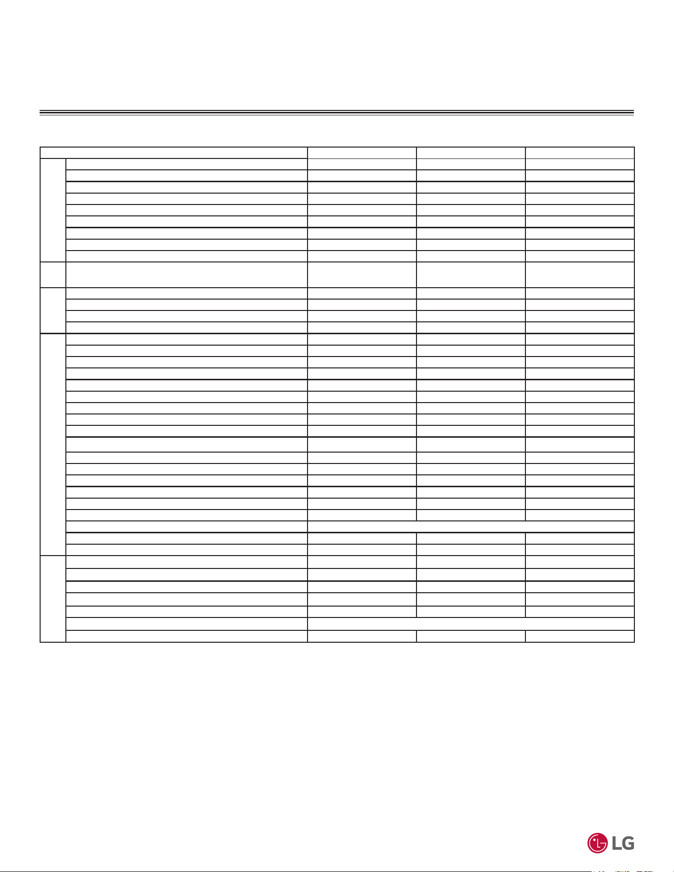
GENERAL DATA
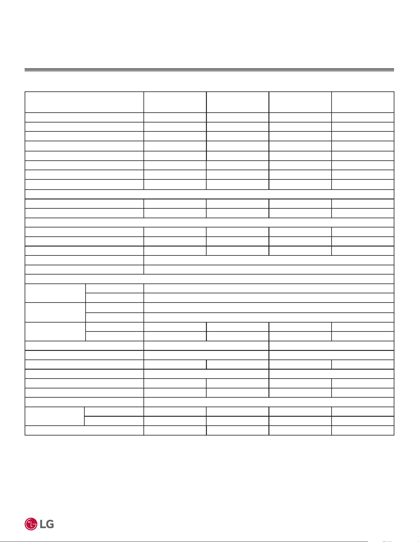
Table 4: 6LQJOH=RQH6WDQGDUG(I¿FLHQF\6\VWHP6SHFL¿FDWLRQV
System (Model) (Indoor Unit / Outdoor Unit)
KSSAE091A
(KNSAE091A /
KUSAE091A)
KSSAE121A
(KNSAE121A /
KUSAE121A)
KSSAE181A
(KNSAE181A /
KUSAE181A)
KSSAE241A
(KNSAE241A /
KUSAE241A)
Cooling Capacity (Min/Rated/Max) (Btu/h) 3,070~9,000~11,980 3,070~11,000~13,780 3,685~18,000~19,600 3,685~21,200~24,500
Cooling Power Input
1
(Min/Rated/Max) (kW) 0.2~0.75~1.4 0.2~0.917~1.540 0.238~1.500~2.180 0.240~1.767~2.800
EER2 (@95°F) 12.0 12.0 12.0 12.0
SEER2 18.0 18.0 18.0 18.0
Heating Capacity (Min/Rated/Max) (Btu/h) 3,070~10,900~12,930 3,070~12,000~13,780 3,685~19,000~23,000 3,685~22,000~25,260
Heating Power Input
1
(Min/Rated/Max) (kW) 0.195~0.885~1.5 0.195~1.02~1.64 0.238~1.60~2.45 0.24~2.02~2.60
COP (@47°F) 3.61 3.45 3.48 3.19
HSPF2 8.7 8.5 8.9 8.3
5DWHG/RZ+HDWLQJ&DSDFLW\%WXK
Outdoor 17°F (WB)/Indoor 70°F (DB) 6,900 8,000 11,600 13,500
Low COP (@17°F) 2.55 2.50 2.40 2.40
0D[LPXP+HDWLQJ&DSDFLW\%WXK
Outdoor 17°F (WB)/Indoor 70°F (DB) 9,810 (90%) 10,560 (88%) 15,800 (83%) 17,700 (80%)
Outdoor 5°F (WB)/Indoor 70°F (DB) 7,700 (71%) 8,400 (70%) 13,300 (70%) 13,800 (63%)
ENERGY STAR / Cold Climate Yes / No Yes / No Yes / No Yes / No
Power Supply (V/Hz/Ø)
2
208-230 / 60 / 1
Power/Communication Cable
3
(No. x AWG) 4 x 14
Indoor Unit Data
Operating Range
Cooling (°F WB) 53 to 75
Heating (°F DB) 60 to 86
Temperature Setting
Range
Cooling (°F) 64 to 86
Heating (°F) 60 to 86
Sound Pressure
4
dB(A)
Cooling (H/M/L/SL) 42 / 36 / 28 / 21 42 / 36 / 28 / 21 48 / 43 / 38 / 32 48 / 43 / 38 / 32
Heating (H/M/L) 42 / 36 / 28 42 / 36 / 28 48 / 43 / 38 48 / 43 / 38
Net Dimensions (W x H x D) (in.) 32-15/16 × 12-1/8 × 7-7/16 39-9/32 × 13-19/32 × 8-9/32
Shipping Dimensions (W x H x D) (in.) 35-5/16 × 15-11/32 × 10 42-1/16 × 16-23/32 × 10-31/32
Net / Shipping Weight (lbs.) 19.2 / 22 19.2 / 22 26 / 30 26 / 30
Exterior Color Codes Munsell 7.5BG 10/2 (RAL 9016) Munsell 7.5BG 10/2 (RAL 9016)
Fan Type x Qty. Cross Flow x 1 Cross Flow x 1 Cross Flow x 1 Cross Flow x 1
Fan Motor Output (W) x Qty. 30 x 1 30 x 1 58 x 1 58 x 1
Fan Motor / Drive Brushless Digitally Controlled / Direct
Airflow Rate
Max/H/M/L (CFM)
Cooling 459 / 353 / 264 / 148 459 / 353 / 264 / 148 689 / 512 / 459 / 371 689 / 512 / 459 / 371
Heating 459 / 353 / 254 / 198 459 / 353 / 254 / 198 653 / 565 / 477 / 388 653 / 565 / 477 / 388
Dehumidification Rate (pts./hr.) 2.32 2.75 3.38 3.38
EEV: Electronic Expansion Valve IDU: Indoor Unit ODU: Outdoor Unit
This data is rated 0 feet above sea level with 24.6 feet of refrigerant line per indoor unit and a 0 foot
level difference outdoor and indoor units.
Cooling capacity rating obtained with air entering the indoor unit at 80ºF dry bulb (DB) and 67ºF wet
bulb (WB) and outdoor ambient conditions of 95ºF dry bulb (DB) and 75ºF wet bulb (WB).
Heating capacity rating obtained with air entering the indoor unit at 70ºF dry bulb (DB) and 59ºF wet
bulb (WB) and outdoor ambient conditions of 47ºF dry bulb (DB) and 43ºF wet bulb (WB).
1
Power Input is rated at high speed.
2
Power wiring to the ODU is field supplied, solid or stranded, and must comply with the applicable local
and national codes.
3
All power wiring/communication cables from outdoor unit to indoor unit are field supplied and are to
be minimum 14 AWG, 4-conductor, stranded, shielded or unshielded (if shielded, must be grounded to
chassis at outdoor unit only) and must comply with applicable local and national codes.
4
Sound Pressure levels are tested in an anechoic chamber under ISO Standard 3745.
'XHWRRXUSROLF\RIFRQWLQXRXVSURGXFWLQQRYDWLRQVRPHVSHFL¿FDWLRQVPD\FKDQJHZLWKRXWQRWL¿FDWLRQ
©
/*(OHFWURQLFV86$,QF(QJOHZRRG&OLIIV1-$OOULJKWVUHVHUYHG³/*´LVDUHJLVWHUHGWUDGHPDUNRI/*&RUS
12
56LQJOH=RQH6WDQGDUG(ႈFLHQF\0HJDDQG0HJD9:DOO0RXQWHG(QJLQHHULQJ0DQXDO
EEV: Electronic Expansion Valve IDU: Indoor Unit ODU: Outdoor Unit
This data is rated 0 feet above sea level with 24.6 feet of refrigerant line per indoor unit and a 0 foot
level difference outdoor and indoor units.
Cooling capacity rating obtained with air entering the indoor unit at 80ºF dry bulb (DB) and 67ºF wet
bulb (WB) and outdoor ambient conditions of 95ºF dry bulb (DB) and 75ºF wet bulb (WB).
Heating capacity rating obtained with air entering the indoor unit at 70ºF dry bulb (DB) and 59ºF wet
bulb (WB) and outdoor ambient conditions of 47ºF dry bulb (DB) and 43ºF wet bulb (WB).
1
Sound Pressure levels are tested in an anechoic chamber under ISO Standard 3745.
2
Take appropriate actions at the end of HVAC equipment life to recover, recycle, reclaim or destroy R32
refrigerant according to applicable regulations (40 CFR Part 82, Subpart F) under section 608 of CAA.
3
Piping lengths are equivalent.
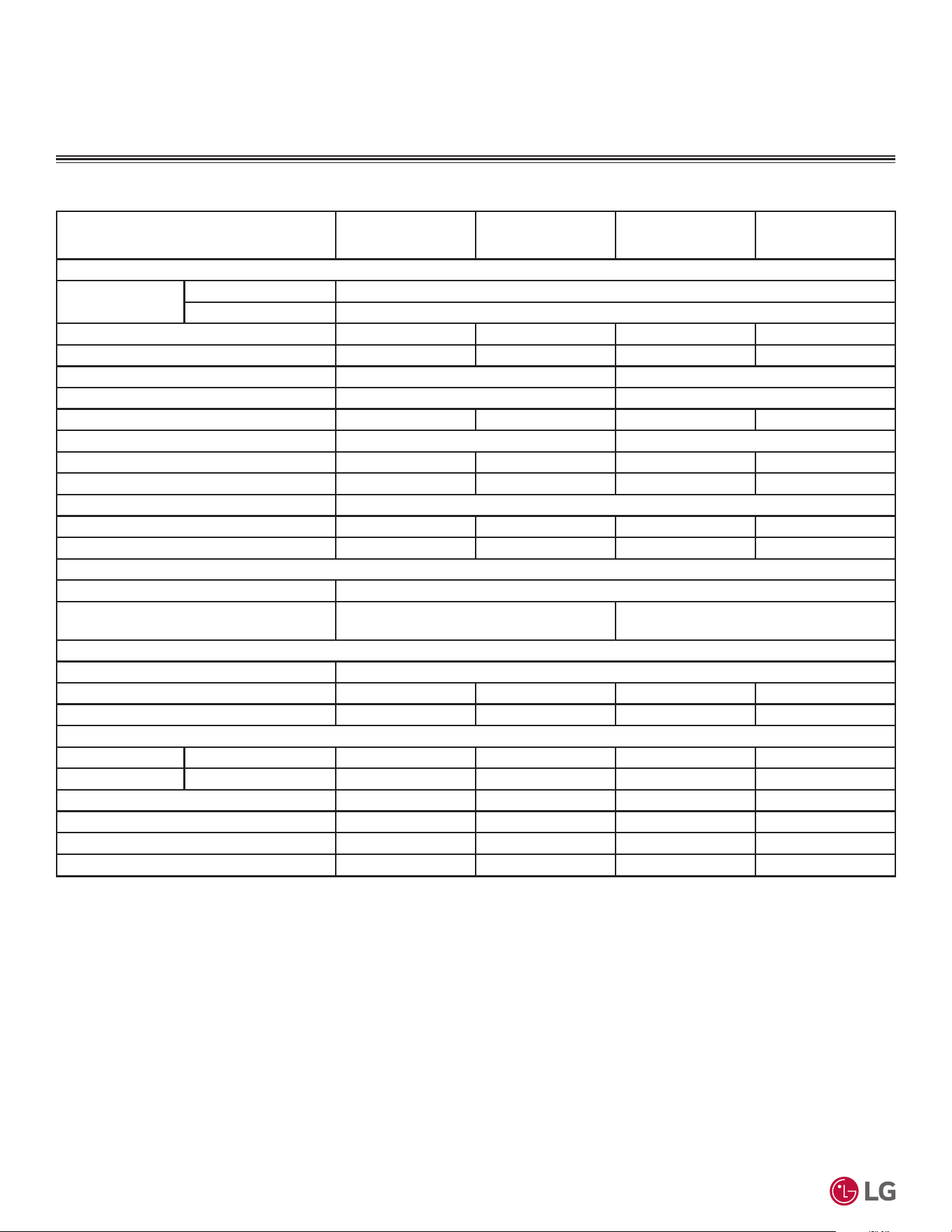
Table 5: 6LQJOH=RQH6WDQGDUG(I¿FLHQF\6SHFL¿FDWLRQVFRQWLQXHG
System (Model) (Indoor Unit / Outdoor Unit)
KSSAE091A
(KNSAE091A /
KUSAE091A)
KSSAE121A
(KNSAE121A /
KUSAE121A)
KSSAE181A
(KNSAE181A /
KUSAE181A)
KSSAE241A
(KNSAE241A /
KUSAE241A)
Outdoor Unit Data
Operating Range
Cooling (°F DB) 14 to 118
Heating (°F WB) 5 to 65
Sound Pressure
1
dB(A) (Cool/Heat) 50 / 50 50 / 50 55 / 55 55 / 55
Max. External Static Pressure (in.wg) 0.0284 0.0284 0.0387 0.0387
Net Dimensions (W x H x D) (in.) 28-7/32 × 19-1/2 × 9-1/16 34-1/4 × 25-19/32 × 13
Shipping Dimensions (W x H x D) (in.) 33-1/32 × 20-15/16 × 12-3/4 40-15/16 × 27-15/16 × 17-29/32
Net / Shipping Weight (lbs.) 55.3 / 60 55.3 / 60 92.6 / 102.5 92.6 / 102.5
Exterior Color Codes Munsell 9.54Y 8.34/1.31 (RAL 9001) Munsell 9.54Y 8.34/1.31 (RAL 9001)
Fan Type x Qty. Propeller x 1 Propeller x 1 Propeller x 1 Propeller x 1
Fan Motor Output (W) x Qty. 43 x 1 43 x 1 85 x 1 85 x 1
Fan Motor / Drive Brushless Digitally Controlled / Direct
Airflow Rate Max. (CFM) 953 953 1,730 1,730
Compressor (Type x Qty.) Twin Rotary x 1 Twin Rotary x 1 Twin Rotary x 1 Twin Rotary x 1
Heat Exchanger
Material and Fin Coating Copper Tube / Aluminum Fin (Gold Fin™ Coating on Outdoor Unit Coil; N/A on Indoor Unit Coil)
Rows / Columns / Fin per inch x Qty.
Outdoor Unit: (2 x 22 x 18) x 1;
Indoor Unit: (2 x 15 x 21) x 1
Outdoor Unit: (2 x 28 x 18) x 1;
Indoor Unit: (2 x 16 x 20) x 1
Refrigerant
Type
2
/ Control R32 / EEV
Pre-Charge (oz.) 24.7 24.7 38.8 38.8
Additional Charge (oz./ft.) 0.16 0.16 0.22 0.22
Piping
Liquid (in.) Connection / Pipe Size 1/4 Flare / 1/4 Flare 1/4 Flare / 1/4 Flare 1/4 Flare / 1/4 Flare 1/4 Flare / 1/4 Flare
Vapor (in.) Connection / Pipe Size 3/8 Flare / 3/8 Flare 3/8 Flare / 3/8 Flare 1/2 Flare / 1/2 Flare 1/2 Flare / 1/2 Flare
Condensation Line (O.D., I.D., in.) 27/32, 5/8 27/32, 5/8 27/32, 5/8 27/32, 5/8
Pipe Length
3
(Min./Standard/Max.) (ft.) 9.8 / 24.6 / 49.2 9.8 / 24.6 / 49.2 9.8 / 24.6 / 65.6 9.8 / 24.6 / 65.6
Piping Length
3
(no add’l refrigerant, ft.) 24.6 24.6 24.6 24.6
Max Elevation Difference (ft.) 23 23 32.8 32.8
GENERAL DATA
'XHWRRXUSROLF\RIFRQWLQXRXVSURGXFWLQQRYDWLRQVRPHVSHFL¿FDWLRQVPD\FKDQJHZLWKRXWQRWL¿FDWLRQ
©
/*(OHFWURQLFV86$,QF(QJOHZRRG&OLIIV1-$OOULJKWVUHVHUYHG³/*´LVDUHJLVWHUHGWUDGHPDUNRI/*&RUS
13
Product Data
System (Model) (Indoor Unit / Outdoor Unit)
KSSAC091A
(KNSAC091A /
KUSAC091A)
KSSAC121A
(KNSAC121A /
KUSAC121A)
KSSAC181A
(KNSAC181A /
KUSAC181A)
KSSAC241A
(KNSAC241A /
KUSAC241A)
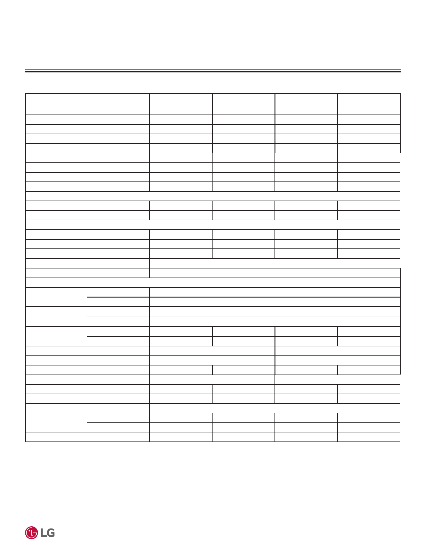
Cooling Capacity (Min/Rated/Max) (Btu/h) 3,070~9,000~11,980 3,070~11,000~13,780 3,685~18,000~19,600 3,685~21,200~24,500
Cooling Power Input
1
(Min/Rated/Max) (kW) 0.20~0.72~1.33 0.20~0.894~1.44 0.238~1.44~2.10 0.24~1.723~2.70
EER2 (@95°F) 12.5 12.3 12.5 12.3
SEER2 21.0 20.0 21.0 20.0
Heating Capacity (Min/Rated/Max) (Btu/h) 3,070~10,900~12,930 3,070~12,000~13,780 3,685~19,000~23,000 3,685~22,000~25,260
Heating Power Input
1
(Min/Rated/Max) (kW) 0.195~0.838~1.40 0.195~0.965~1.55 0.238~1.50~2.35 0.24~1.894~2.50
COP (@47°F) 3.81 3.64 3.71 3.40
HSPF2 9.2 9.0 9.4 8.8
5DWHG/RZ+HDWLQJ&DSDFLW\%WXK
Outdoor 17°F (WB)/Indoor 70°F (DB) 6,900 8,000 11,600 13,500
Low COP (@17°F) 2.65 2.65 2.65 2.55
0D[LPXP+HDWLQJ&DSDFLW\%WXK
Outdoor 17°F (WB)/Indoor 70°F (DB) 9,810 (90%) 10,560 (88%) 15,800 (83%) 17,700 (80%)
Outdoor 5°F (WB)/Indoor 70°F (DB) 7,700 (71%) 8,400 (70%) 13,300 (70%) 13,800 (63%)
ENERGY STAR / Cold Climate Yes / Yes Yes / Yes Yes / Yes Yes / No
Power Supply (V/Hz/Ø)
2
208-230/60/1
Power/Communication Cable
3
(No. x AWG) 4 x 14
Indoor Unit Data
Operating Range
Cooling (°F WB) 53 to 75
Heating (°F DB) 60 to 86
Temperature Setting
Range
Cooling (°F) 64 to 86
Heating (°F) 60 to 86
Sound Pressure
4
dB(A)
Cooling (H/M/L/SL) 42 / 36 / 28 / 21 42 / 36 / 28 / 21 48 / 43 / 38 / 32 48 / 43 / 38 / 32
Heating (H/M/L) 42 / 36 / 28 42 / 36 / 28 48 / 43 / 38 48 / 43 / 38
Net Dimensions (W x H x D) (in.) 32-15/16 × 12-1/8 × 7-7/16 39-9/32 × 13-19/32 × 8-9/32
Shipping Dimensions (W x H x D) (in.) 35-5/16 × 15-11/32 × 10 42-1/16 × 16-23/32 × 10-31/32
Net / Shipping Weight (lbs.) 19.2 / 22 19.2 / 22 26 / 30 26 / 30
Exterior Color Codes Munsell 7.5BG 10/2 (RAL 9016) Munsell 7.5BG 10/2 (RAL 9016)
Fan Type x Qty. Cross Flow x 1 Cross Flow x 1 Cross Flow x 1 Cross Flow x 1
Fan Motor Output (W) x Qty. 30 x 1 30 x 1 58 x 1 58 x 1
Fan Motor / Drive Brushless Digitally Controlled / Direct
Airflow Rate
Max./H/M/L (CFM)
Cooling 459 / 353 / 264 / 148 459 / 353 / 264 / 148 689 / 512 / 459 / 371 689 / 512 / 459 / 371
Heating 459 / 353 / 254 / 198 459 / 353 / 254 / 198 653 / 565 / 477 / 388 653 / 565 / 477 / 388
Dehumidification Rate (pts./hr.) 2.32 2.75 3.38 3.38
Table 6: 6LQJOH=RQH0HJD6\VWHP6SHFL¿FDWLRQV
GENERAL DATA
EEV: Electronic Expansion Valve IDU: Indoor Unit ODU: Outdoor Unit
This data is rated 0 feet above sea level with 24.6 feet of refrigerant line per indoor unit and a 0 foot
level difference outdoor and indoor units.
Cooling capacity rating obtained with air entering the indoor unit at 80ºF dry bulb (DB) and 67ºF wet
bulb (WB) and outdoor ambient conditions of 95ºF dry bulb (DB) and 75ºF wet bulb (WB).
Heating capacity rating obtained with air entering the indoor unit at 70ºF dry bulb (DB) and 59ºF wet
bulb (WB) and outdoor ambient conditions of 47ºF dry bulb (DB) and 43ºF wet bulb (WB).
1
Power Input is rated at high speed.
2
Power wiring to the ODU is field supplied, solid or stranded, and must comply with the applicable local
and national codes.
3
All power wiring/communication cables from outdoor unit to indoor unit are field supplied and are to
be minimum 14 AWG, 4-conductor, stranded, shielded or unshielded (if shielded, must be grounded to
chassis at outdoor unit only) and must comply with applicable local and national codes.
4
Sound Pressure levels are tested in an anechoic chamber under ISO Standard 3745.

'XHWRRXUSROLF\RIFRQWLQXRXVSURGXFWLQQRYDWLRQVRPHVSHFL¿FDWLRQVPD\FKDQJHZLWKRXWQRWL¿FDWLRQ
©
/*(OHFWURQLFV86$,QF(QJOHZRRG&OLIIV1-$OOULJKWVUHVHUYHG³/*´LVDUHJLVWHUHGWUDGHPDUNRI/*&RUS
14
56LQJOH=RQH6WDQGDUG(ႈFLHQF\0HJDDQG0HJD9:DOO0RXQWHG(QJLQHHULQJ0DQXDO
System (Model) (Indoor Unit / Outdoor Unit)
KSSAC091A
(KNSAC091A /
KUSAC091A)
KSSAC121A
(KNSAC121A /
KUSAC121A)
KSSAC181A
(KNSAC181A /
KUSAC181A)
KSSAC241A
(KNSAC241A /
KUSAC241A)
Outdoor Unit Data
Operating Range
Cooling (°F DB) 14 to 118
Heating (°F WB) 5 to 65
Sound Pressure
1
dB(A) (Cool/Heat) 50 / 50 50 / 50 55 / 55 55 / 55
Max. External Static Pressure (in. wg) 0.0284 0.0284 0.0387 0.0387
Net Dimensions (W x H x D) (in.) 28-7/32 × 19-1/2 × 9-1/16 34-1/4 × 25-19/32 × 13
Shipping Dimensions (W x H x D) (in.) 33-1/32 × 20-15/16 × 12-3/4 40-15/16 × 27-15/16 × 17-29/32
Net / Shipping Weight (lbs.) 55.3 / 60 55.3 / 60 92.6 / 102.5 92.6 / 102.5
Exterior Color Codes Munsell 9.54Y 8.34/1.31 (RAL 9001) Munsell 9.54Y 8.34/1.31 (RAL 9001)
Fan Type x Qty. Propeller x 1 Propeller x 1 Propeller x 1 Propeller x 1
Fan Motor Output (W) x Qty. 43 x 1 43 x 1 85 x 1 85 x 1
Fan Motor / Drive Brushless Digitally Controlled/Direct
Airflow Rate Max. (CFM) 953 953 1,730 1,730
Compressor (Type x Qty.) Twin Rotary x 1 Twin Rotary x 1 Twin Rotary x 1 Twin Rotary x 1
Heat Exchanger
Material and Fin Coating Copper Tube / Aluminum Fin (Gold Fin™ Coating on Outdoor Unit Coil; N/A on Indoor Unit Coil)
Rows / Columns / Fin per inch x Qty.
Outdoor Unit: (2 x 22 x 18) x 1;
Indoor Unit: (2 x 15 x 21) x 1
Outdoor Unit: (2 x 28 x 18) x 1;
Indoor Unit: (2 x 16 x 20) x 1
Refrigerant
Type
2
/ Control R32 / EEV
Pre-Charge (oz.) 24.7 24.7 38.8 38.8
Additional Charge (oz./ft.) 0.16 0.16 0.22 0.22
Piping
Liquid (in.) Connection / Pipe Size 1/4 Flare / 1/4 Flare 1/4 Flare / 1/4 Flare 1/4 Flare / 1/4 Flare 1/4 Flare / 1/4 Flare
Vapor (in.) Connection / Pipe Size 3/8 Flare / 3/8 Flare 3/8 Flare / 3/8 Flare 1/2 Flare / 1/2 Flare 1/2 Flare / 1/2 Flare
Condensation Line (OD, ID, in.) 27/32, 5/8 27/32, 5/8 27/32, 5/8 27/32, 5/8
Pipe Length
3
(Min./Standard/Max.) (ft.) 9.8 / 24.6 / 49.2 9.8 / 24.6 / 49.2 9.8 / 24.6 / 65.6 9.8 / 24.6 / 65.6
Piping Length
3
(no add’l refrigerant, ft.) 24.6 24.6 24.6 24.6
Max. Elevation Difference (ft.) 23 23 32.8 32.8
Table 7: 6LQJOH=RQH0HJD6\VWHP6SHFL¿FDWLRQVFRQWLQXHG
GENERAL DATA
EEV: Electronic Expansion Valve IDU: Indoor Unit ODU: Outdoor Unit
This data is rated 0 feet above sea level with 24.6 feet of refrigerant line per indoor unit and a 0 foot
level difference outdoor and indoor units.
Cooling capacity rating obtained with air entering the indoor unit at 80ºF dry bulb (DB) and 67ºF wet
bulb (WB) and outdoor ambient conditions of 95ºF dry bulb (DB) and 75ºF wet bulb (WB).
Heating capacity rating obtained with air entering the indoor unit at 70ºF dry bulb (DB) and 59ºF wet
bulb (WB) and outdoor ambient conditions of 47ºF dry bulb (DB) and 43ºF wet bulb (WB).
1
Sound Pressure levels are tested in an anechoic chamber under ISO Standard 3745.
2
Take appropriate actions at the end of HVAC equipment life to recover, recycle, reclaim or destroy R32
refrigerant according to applicable regulations (40 CFR Part 82, Subpart F) under section 608 of CAA.
3
Piping lengths are equivalent.
'XHWRRXUSROLF\RIFRQWLQXRXVSURGXFWLQQRYDWLRQVRPHVSHFL¿FDWLRQVPD\FKDQJHZLWKRXWQRWL¿FDWLRQ
©
/*(OHFWURQLFV86$,QF(QJOHZRRG&OLIIV1-$OOULJKWVUHVHUYHG³/*´LVDUHJLVWHUHGWUDGHPDUNRI/*&RUS
15
Product Data
System (Model) (Indoor Unit / Outdoor Unit)
KSSAC091B
(KNSAC091B / KUSAC091B)
KSSAC121B
(KNSAC121B / KUSAC121B)
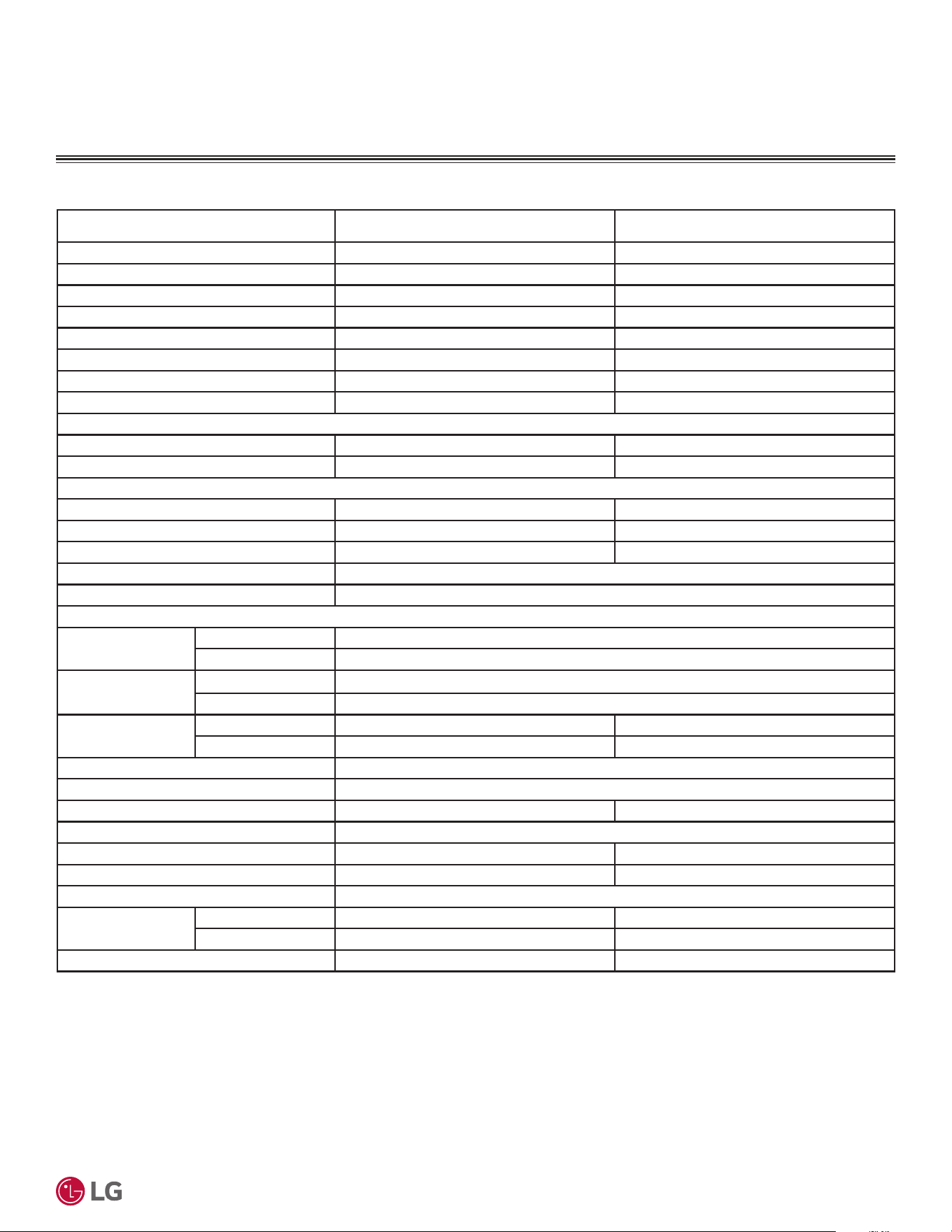
Cooling Capacity (Min/Rated/Max) (Btu/h) 3,070~9,000~11,980 3,070~11,000~13,780
Cooling Power Input
1
(Min/Rated/Max) (kW) 0.20~0.72~1.33 0.20~0.894~1.44
EER2 (@95°F) 12.5 12.3
SEER2 21.0 20.0
Heating Capacity (Min/Rated/Max) (Btu/h) 3,070~10,900~12,930 3,070~12,000~13,780
Heating Power Input
1
(Min/Rated/Max) (kW) 0.195~0.838~1.40 0.195~0.965~1.55
COP (@47°F) 3.81 3.64
HSPF2 9.2 9.0
5DWHG/RZ+HDWLQJ&DSDFLW\%WXK
Outdoor 17°F (WB)/Indoor 70°F (DB) 6,900 8,000
Low COP (@17°F) 2.65 2.65
0D[LPXP+HDWLQJ&DSDFLW\%WXK
Outdoor 17°F (WB)/Indoor 70°F (DB) 9,810 (90%) 10,560 (88%)
Outdoor 5°F (WB)/Indoor 70°F (DB) 7,700 (71%) 8,400 (70%)
ENERGY STAR / Cold Climate Yes / Yes Yes / Yes
Power Supply (V/Hz/Ø)
2
115/60/1
Power/Communication Cable
3
(No. x AWG) 4 x 14
Indoor Unit Data
Operating Range
Cooling (°F WB) 53 to 75
Heating (°F DB) 60 to 86
Temperature Setting
Range
Cooling (°F) 64 to 86
Heating (°F) 60 to 86
Sound Pressure
4
dB(A)
Cooling (H/M/L/SL) 42 / 36 / 28 / 21 42 / 36 / 28 / 21
Heating (H/M/L) 42 / 36 / 28 42 / 36 / 28
Net Dimensions (W x H x D) (in.) 32-15/16 × 12-1/8 × 7-7/16
Shipping Dimensions (W x H x D) (in.) 35-5/16 × 15-11/32 × 10
Net / Shipping Weight (lbs.) 19.2 / 22 19.2 / 22
Exterior Color Codes Munsell 7.5BG 10/2 (RAL 9016)
Fan Type x Qty. Cross Flow x 1 Cross Flow x 1
Fan Motor Output (W) x Qty. 30 x 1 30 x 1
Fan Motor / Drive Brushless Digitally Controlled / Direct
Airflow Rate
Max./H/M/L (CFM)
Cooling 459 / 353 / 264 / 148 459 / 353 / 264 / 148
Heating 459 / 353 / 254 / 198 459 / 353 / 254 / 198
Dehumidification Rate (pts./hr.) 2.32 2.75
Table 8: 6LQJOH=RQH0HJD96\VWHP6SHFL¿FDWLRQV
GENERAL DATA
EEV: Electronic Expansion Valve IDU: Indoor Unit ODU: Outdoor Unit
This data is rated 0 feet above sea level with 24.6 feet of refrigerant line per indoor unit and a 0 foot
level difference outdoor and indoor units.
Cooling capacity rating obtained with air entering the indoor unit at 80ºF dry bulb (DB) and 67ºF wet
bulb (WB) and outdoor ambient conditions of 95ºF dry bulb (DB) and 75ºF wet bulb (WB).
Heating capacity rating obtained with air entering the indoor unit at 70ºF dry bulb (DB) and 59ºF wet
bulb (WB) and outdoor ambient conditions of 47ºF dry bulb (DB) and 43ºF wet bulb (WB).
1
Power Input is rated at high speed.
2
Power wiring to the ODU is field supplied, solid or stranded, and must comply with the applicable local
and national codes.
3
All power wiring/communication cables from outdoor unit to indoor unit are field supplied and are to
be minimum 14 AWG, 4-conductor, stranded, shielded or unshielded (if shielded, must be grounded to
chassis at outdoor unit only) and must comply with applicable local and national codes.
4
Sound Pressure levels are tested in an anechoic chamber under ISO Standard 3745.
'XHWRRXUSROLF\RIFRQWLQXRXVSURGXFWLQQRYDWLRQVRPHVSHFL¿FDWLRQVPD\FKDQJHZLWKRXWQRWL¿FDWLRQ
©
/*(OHFWURQLFV86$,QF(QJOHZRRG&OLIIV1-$OOULJKWVUHVHUYHG³/*´LVDUHJLVWHUHGWUDGHPDUNRI/*&RUS
16
56LQJOH=RQH6WDQGDUG(ႈFLHQF\0HJDDQG0HJD9:DOO0RXQWHG(QJLQHHULQJ0DQXDO
System (Model) (Indoor Unit / Outdoor Unit)
KSSAC091B
(KNSAC091B / KUSAC091B)
KSSAC121B
(KNSAC121B / KUSAC121B)
Outdoor Unit Data
Operating Range
Cooling (°F DB) 14 to 118
Heating (°F WB) 5 to 65
Sound Pressure
1
dB(A) (Cool/Heat) 50 / 50 50 / 50
Max. External Static Pressure (in.wg) 0.0284 0.0284
Net Dimensions (W x H x D) (in.) 28-7/32 × 19-1/2 × 9-1/16
Shipping Dimensions (W x H x D) (in.) 33-1/32 × 20-15/16 × 12-3/4
Net / Shipping Weight (lbs.) 55.3 / 60 55.3 / 60
Exterior Color Codes Munsell 9.54Y 8.34/1.31 (RAL 9001)
Fan Type x Qty. Propeller x 1 Propeller x 1
Fan Motor Output (W) x Qty. 43 x 1 43 x 1
Fan Motor / Drive Brushless Digitally Controlled/Direct
Airflow Rate Max. (CFM) 953 953
Compressor (Type x Qty.) Twin Rotary x 1 Twin Rotary x 1
Heat Exchanger
Material and Fin Coating Copper Tube / Aluminum Fin (Gold Fin™ Coating on Outdoor Unit Coil; N/A on Indoor Unit Coil)
Rows / Columns / Fin per inch x Qty. Outdoor Unit: (2 x 22 x 18) x 1; Indoor Unit: (2 x 15 x 21) x 1
Refrigerant
Type
2
/ Control R32 / EEV
Pre-Charge (oz.) 24.7 24.7
Additional Charge (oz./ft.) 0.16 0.16
Piping
Liquid (in.) Connection / Pipe Size 1/4 Flare / 1/4 Flare 1/4 Flare / 1/4 Flare
Vapor (in.) Connection / Pipe Size 3/8 Flare / 3/8 Flare 3/8 Flare / 3/8 Flare
Condensation Line (OD, ID, in.) 27/32, 5/8 27/32, 5/8
Pipe Length
3
(Min./Standard/Max.) (ft.) 9.8 / 24.6 / 49.2 9.8 / 24.6 / 49.2
Piping Length
3
(no add’l refrigerant, ft.) 24.6 24.6
Max Elevation Difference (ft.) 23 23
Table 9: 6LQJOH=RQH0HJD96\VWHP6SHFL¿FDWLRQVFRQWLQXHG
GENERAL DATA
EEV: Electronic Expansion Valve IDU: Indoor Unit ODU: Outdoor Unit
This data is rated 0 feet above sea level with 24.6 feet of refrigerant line per indoor unit and a 0 foot
level difference outdoor and indoor units.
Cooling capacity rating obtained with air entering the indoor unit at 80ºF dry bulb (DB) and 67ºF wet
bulb (WB) and outdoor ambient conditions of 95ºF dry bulb (DB) and 75ºF wet bulb (WB).
Heating capacity rating obtained with air entering the indoor unit at 70ºF dry bulb (DB) and 59ºF wet
bulb (WB) and outdoor ambient conditions of 47ºF dry bulb (DB) and 43ºF wet bulb (WB).
1
Sound Pressure levels are tested in an anechoic chamber under ISO Standard 3745.
2
Take appropriate actions at the end of HVAC equipment life to recover, recycle, reclaim or destroy R32
refrigerant according to applicable regulations (40 CFR Part 82, Subpart F) under section 608 of CAA.
3
Piping lengths are equivalent.
'XHWRRXUSROLF\RIFRQWLQXRXVSURGXFWLQQRYDWLRQVRPHVSHFL¿FDWLRQVPD\FKDQJHZLWKRXWQRWL¿FDWLRQ
©
/*(OHFWURQLFV86$,QF(QJOHZRRG&OLIIV1-$OOULJKWVUHVHUYHG³/*´LVDUHJLVWHUHGWUDGHPDUNRI/*&RUS
17
Product Data
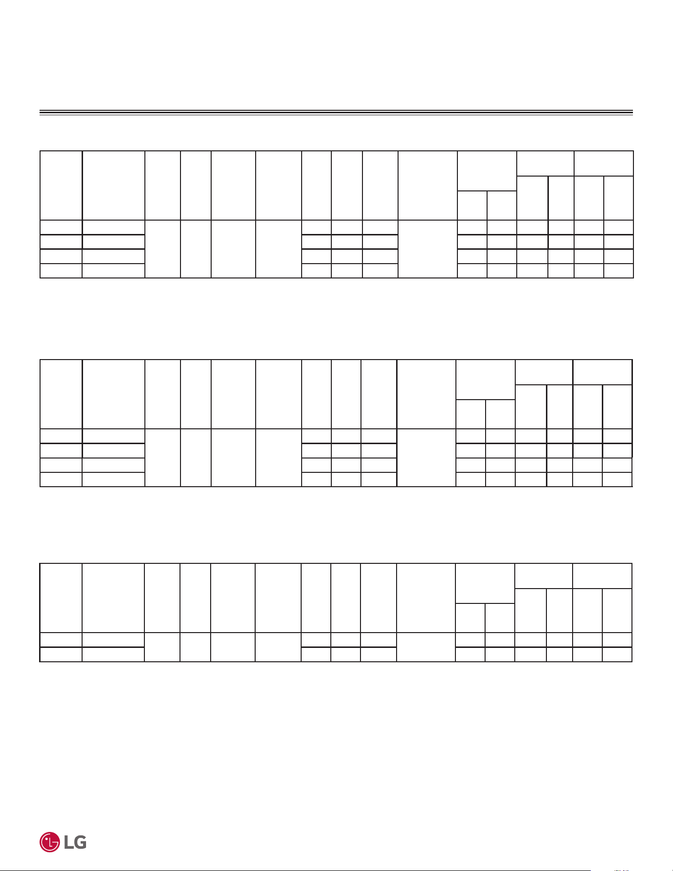
ELECTRICAL DATA
Table 10: 6LQJOH=RQH6WDQGDUG(I¿FLHQF\:DOO0RXQWHG(OHFWULFDO'DWD7DEOH
Nominal
Tons
Unit Model
No.
Phase Hertz Voltage
Voltage
Range
(Min. to
Max.)
MCA MOP LRA
Compressor
Quantity
Compressor
Motor RLA
Condenser
Fan Motor
Indoor Unit
Fan Motor
W x
Qty.
FLA W FLA
Cool Heat
3/4 KSSAE091A
1 60 208 - 230 187 - 253
10.0 15.0 7.5
1
4.7 6.7 43 x1 0.6 30 0.4
1 KSSAE121A 10.0 15.0 7.5 4.7 6.7 43 x1 0.6 30 0.4
1-1/2 KSSAE181A 15.0 20.0 14 9.6 10.0 85 x 1 0.6 58 0.4
2 KSSAE241A 15.0 20.0 14 9.6 10.0 85 x 1 0.6 58 0.4
Table 11: Single Zone Mega Wall-Mounted Electrical Data Table.
Table 12: Single Zone Mega 115V Wall-Mounted Electrical Data Table.
Nominal
Tons
Unit Model
No.
Phase Hertz Voltage
Voltage
Range
(Min. to
Max.)
MCA MOP LRA
Compressor
Quantity
Compressor
Motor RLA
Condenser
Fan Motor
Indoor Unit
Fan Motor
W x
Qty.
FLA W FLA
Cool Heat
3/4 KSSAC091A
1 60 208 - 230 187 - 253
10.0 15.0 7.5
1
4.7 6.7 43 x 1 0.6 30 0.4
1 KSSAC121A 10.0 15.0 7.5 4.7 6.7 43 x 1 0.6 30 0.4
1-1/2 KSSAC181A 15.0 20.0 14 9.6 10.0 85 x 1 0.6 58 0.4
2 KSSAC241A 15.0 20.0 14 9.6 10.0 85 x 1 0.6 58 0.4
Nominal
Tons
Unit Model
No.
Phase Hertz Voltage
Voltage
Range
(Min. to
Max.)
MCA MOP LRA
Compressor
Quantity
Compressor
Motor RLA
Condenser
Fan Motor
Indoor Unit
Fan Motor
W x
Qty.
FLA W FLA
Cool Heat
3/4 KSSAC091B
1 60 115 98 - 132
15.0 20.0 12.5
1
9.5 11.0 43 x 1 0.7 30 0.4
1 KSSAC121B 15.0 20.0 12.5 9.5 11.0 43 x 1 0.7 30 0.4
Voltage tolerance is ±10%.
Maximum allowable voltage unbalance is 2%.
MCA = Minimum Circuit Ampacity.
Maximum Overcurrent Protection (MOP) is calculated as follows: (Largest motor FLA x 2.25) + (Sum of
other motor FLA) rounded down to the nearest standard fuse size.
LRA = Locked Rotor Amps
RLA = Rated Load Amps
OFM: Outdoor Fan Motor
IFM : Indoor Fan Motor
FLA = Full Load Amps
Short Circuit Current Rating (SCCR) is 5,000A
'XHWRRXUSROLF\RIFRQWLQXRXVSURGXFWLQQRYDWLRQVRPHVSHFL¿FDWLRQVPD\FKDQJHZLWKRXWQRWL¿FDWLRQ
©
/*(OHFWURQLFV86$,QF(QJOHZRRG&OLIIV1-$OOULJKWVUHVHUYHG³/*´LVDUHJLVWHUHGWUDGHPDUNRI/*&RUS
18
56LQJOH=RQH6WDQGDUG(ႈFLHQF\0HJDDQG0HJD9:DOO0RXQWHG(QJLQHHULQJ0DQXDO
FUNCTIONS, CONTROLS, OPTIONS
Table 13: 6LQJOH=RQH6WDQGDUG(I¿FLHQF\0HJDDQG0HJD96\VWHP)XQFWLRQV&RQWUROV2SWLRQV7DEOH
System Type 6WDQGDUG(IÀFLHQF\ Mega Mega 115V
$LUÁRZ
Air Supply Outlet 1 1 1
Airflow Direction Control (Left/Right) Manual Manual Manual
Airflow Direction Control (Up/Down) Six (6) Steps Six (6) Steps Six (6) Steps
Auto Swing (Up /Down) ¥¥¥
Fan Speed Steps (Fan/Cool/Heat) 6 / 6 / 6 6 / 6 / 6 6 / 6 / 6
Natural Wind (Auto Wind) ¥¥¥
Jet Cool/Heat (Power Wind) ¥¥ ¥¥ ¥¥
Auto Fan (Fan Speed Auto) ¥¥ ¥¥ ¥¥
Comfort Air ¥¥¥
Filter
Prefilter (Washable)
1
¥¥¥
Reliability
Hot Start ¥¥¥
Self Diagnosis / Smart Diagnosis ¥¥ ¥¥ ¥¥
Defrost/Deicing ¥¥¥
Dry (Dehumidification) Operation ¥¥¥
Convenience
Auto Changeover ¥¥¥
Auto Cleaning (Coil Dry) ¥¥¥
Auto Restart ¥¥¥
Child Lock
2
ooo
Forced Operation ¥¥¥
Sleep Mode ¥+RXU ¥+RXU ¥+RXU
Timer 24 Hour (On/Off) / 7 Hour (Off)
2
¥ ¥ ¥
Timer (Weekly)
2
¥¥¥
Two Thermistor Control
2
¥¥¥
Overheating Protection ¥¥¥
Low Heating ¥¥¥
Smart Care ¥¥¥
Night Mode ¥¥¥
Indoor Unit Display Type Number Display Number Display Number Display
Indoor Unit Display Light On / Off On / Off On / Off
Energy Control Active Energy Control Active Energy Control Active Energy Control
Mode Lock ¥&RROLQJ2QO\RU+HDWLQJ2QO\
Temperature Control Thermistor Thermistor Thermistor
Network Solution (LGAP) ¥¥¥
Controllers
Program Controllers (MultiSITE CRC) ż35(07%9&&& ż35(07%9&&& ż35(07%9&&&
Simple Remote Controller ż35(07&8 ż35(07&8 ż35(07&8
Standard III Remote Controllers ż35(07%%% ż35(07%%% ż35(07%%%
Deluxe Remote Controller ż35(07$ ż35(07$ ż35(07$
Wireless Handheld Remote Controller ż$.% ż$.% ż$.%
Dry Contact ż3'5<&%3'5<&%3'5<&%3'5<&%
WiFi
3
ż(PEHGGHG ż(PEHGGHG ż(PEHGGHG
¥6WDQGDUG)HDWXUH
O: Unit Option
X: Not Available
1
Primary washable filter.
2
Requires wired zone controller.
3
If shown as “Embedded”, this function is included in product. The function Wi-Fi is only
compatible with 2.4 GHz band. (802.11 b/g/n). When Dry Contact Mode active, Wi-Fi
Function can not be used. When changing from Wi-Fi mode to dry contact mode, normal
operation resumes in approximately 3 minutes.
4
Not all controllers can support all features. Contact your LG representative for details.
'XHWRRXUSROLF\RIFRQWLQXRXVSURGXFWLQQRYDWLRQVRPHVSHFL¿FDWLRQVPD\FKDQJHZLWKRXWQRWL¿FDWLRQ
©
/*(OHFWURQLFV86$,QF(QJOHZRRG&OLIIV1-$OOULJKWVUHVHUYHG³/*´LVDUHJLVWHUHGWUDGHPDUNRI/*&RUS
19
Product Data
LG Monitoring View (LGMV) Diagnostic Software and Cable
ACCESSORIES
• Actual inverter compressor speed
• Target inverter compressor speed
• Actual outdoor fan speed
• Target outdoor unit fan speed
• Actual superheat
• Target superheat
• Actual subcooler circuit superheat
• Target subcooler circuit superheat
• Main EEV position
• Subcooling EEV position
• Inverter compressor current transducer
value
• Outdoor air temperature
• Actual high pressure/saturation temperature
• Actual low pressure/saturation temperature
• Suction temperature
• Inverter compressor discharge temperature
• Constant speed compressor discharge
temperature
• Front outdoor coil pipe temperature
• Back outdoor coil pipe temperature
• Liquid line pipe temperature
• Subcooler inlet temperature
• Subcooler outlet temperature
• Average indoor unit (IDU) pipe temperature
• Inverter compressor operation indicator
light
• Four-way reversing valve operation
indicator light
• Pressure graph showing actual low pres-
sure and actual high pressure levels
• Error code display
• Operating mode indicator
• Target high pressure
• Target low pressure
• PCB (printed circuit board) version
• Software version
• Installer name
• Model no. of outdoor units
• Site name
• Total number of connected indoor units
• Communication indicator lights
• Indoor unit capacity
• Indoor unit operating mode
• Indoor unit fan speed
• Indoor unit EEV position
• Indoor unit room temperature
• Indoor unit inlet pipe temperature
• Indoor unit outlet pipe temperature
• Indoor unit error code
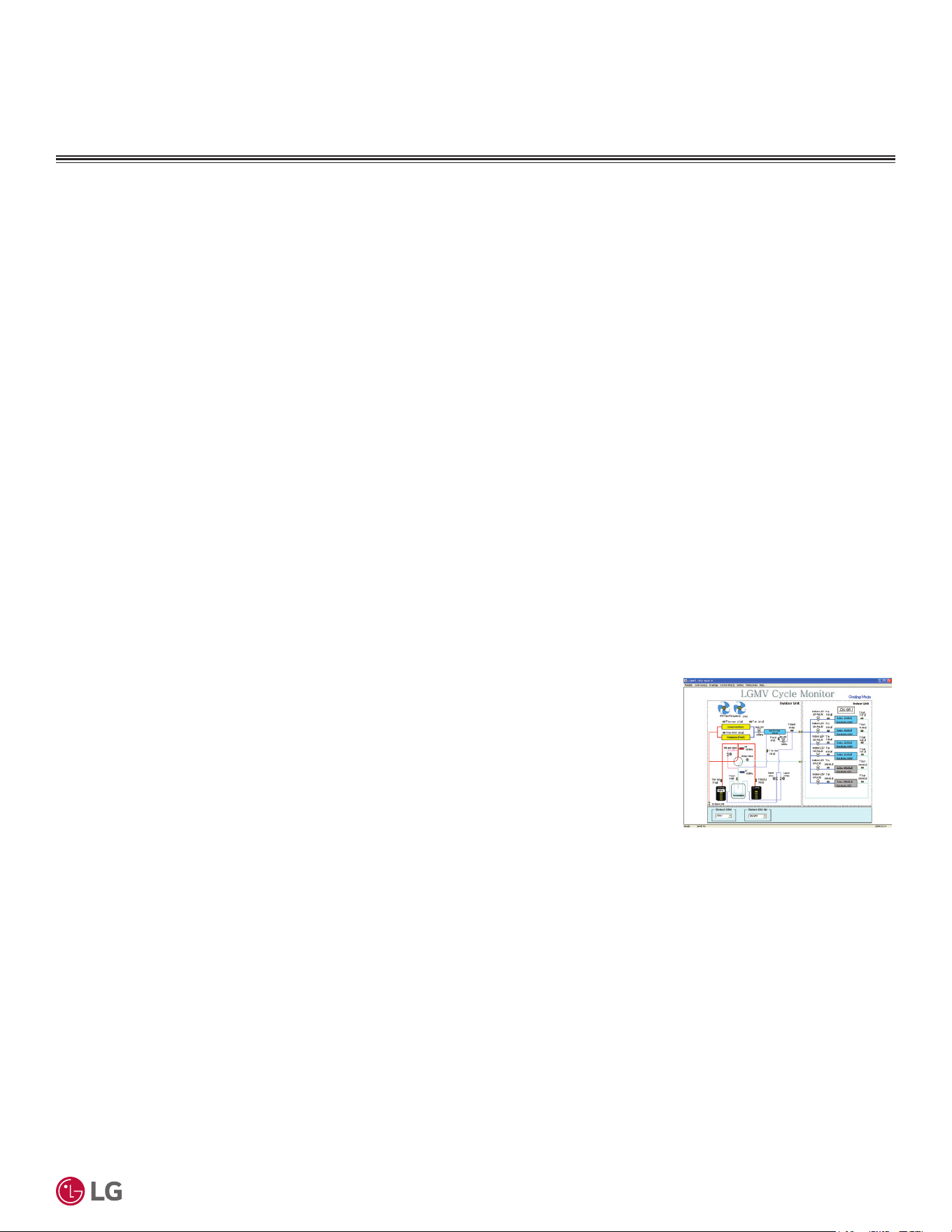
Additional screens can be accessed by tabs on the main screen
1. Cycleview: Graphic of internal components including
2. Graph:
Full screen graph of actual high and low pressures and high and low pressure limits. A
sliding bar enables user to go back in time and view data.
3. Control IDU: Enables user to turn on all IDUs default setpoints of 86°F in heat mode or 64°F in cool
mode.
4. Setting: Converts metric values to imperial values.
5. Making Data: Recording of real time data to a separate file created to be stored on the user’s computer.
6. Loading Data: Recorded data from a saved “.CSV” file can be loaded to create an LGMV session.
7. Electrical Data: Screen is changed to show the following:
Figure 3: Sample Cycleview (Com-
puter View Example).
• Compressors showing actual speeds
• EEVs
• Indoor Units
• Liquid injection valves
• Temperature and pressure sensors
• Four-way reversing valve
• Outdoor fans showing status and speeds
• Inverter compressor
- Amps / Volts / Power Hz
- Inverter control board fan Hz
• Constant compressor
- Current transducer value
- Phase
/*09LVDYDLODEOHLQGLႇHUHQWIRUPDWV&RQWDFW\RXU/*6DOHV5HSUHVHQWDWLYHIRUV\VWHPUHTXLUHPHQWVDQGIRUPRUH
information.
In lieu of connecting to the outdoor unit, user has the option to connect to the indoor unit with a connector kit. When connected through the
indoor unit, user will not be able to record data.
This software can be used to both pre-set-up new systems and troubleshoot existing systems. LGMV data can be recorded to a “.CSV” file
and emailed to an LG representative to assist with diagnostic evaluations.
LG Monitoring View (LGMV) is a maintenance and troubleshooting tool for Multi V™ air conditioning systems. LGMV formats are available for
computer or mobile phone use.
The main screen for LGMV allows the user to view the following real time data:
'XHWRRXUSROLF\RIFRQWLQXRXVSURGXFWLQQRYDWLRQVRPHVSHFL¿FDWLRQVPD\FKDQJHZLWKRXWQRWL¿FDWLRQ
©
/*(OHFWURQLFV86$,QF(QJOHZRRG&OLIIV1-$OOULJKWVUHVHUYHG³/*´LVDUHJLVWHUHGWUDGHPDUNRI/*&RUS
20
56LQJOH=RQH6WDQGDUG(ႈFLHQF\0HJDDQG0HJD9:DOO0RXQWHG(QJLQHHULQJ0DQXDO
ACCESSORIES
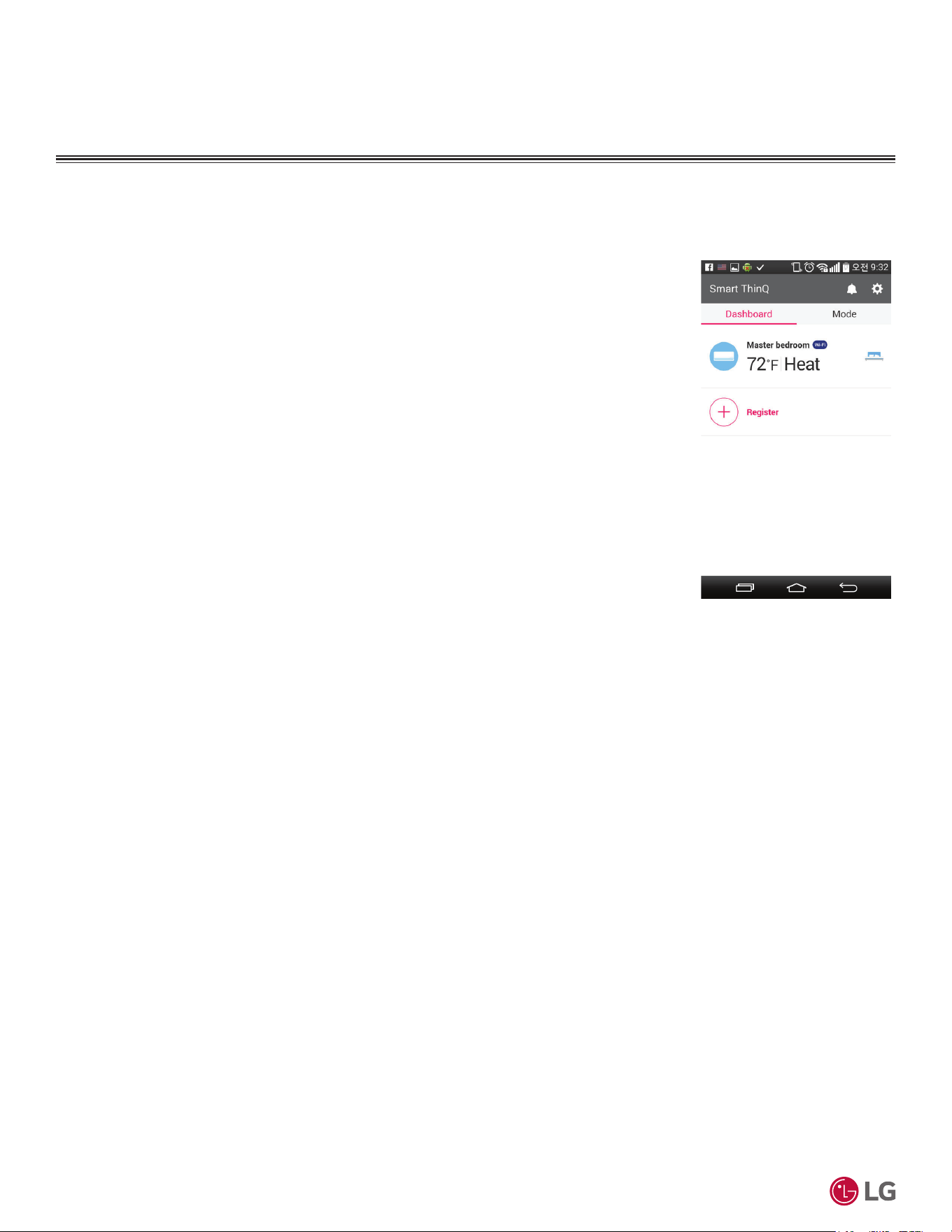
ThinQ
LG ThinQ is a built-in Wi-Fi module, along with a free smart phone app that provides monitoring and
remote control capabilities for certain LG single zone systems. The app has the following features and
benefits:
• Sign in to the app using LG credentials, or using Google
®
or Facebook
®
login credentials. Users only
have to log in to the app once; the app remembers login details for subsequent logins.
• View current temperature settings of the air conditioning unit and change temperature, fan speed, and
air flow direction from anywhere in the house or at a remote location (through the use of wireless con-
nection). Multiple users can control the household air conditioning unit remotely.
• Monitor filter usage of the unit.
• Set up weekly schedules to start and stop air conditioner activity.
• Set up the unit to run in different Modes, depending on the user’s schedule. Set up specific tempera-
tures for when the user is home, away on vacation, or sleeping.
• Troubleshoot problems, and view tips on general maintenance of the system using the Smart Diagnosis
function.
&RQWDFW\RXU/*6DOHV5HSUHVHQWDWLYHRUYLVLWZZZOJKYDFFRPIRUV\VWHPUHTXLUHPHQWVKRZ
to download the app, a user’s manual, or other information.
Figure 4: Example of an LG
Smart ThinQ Screen (appearanc-
es my differ depending on version
of software).
*Google is a registered trademark of Google Inc.; Facebook is a registered trademark of Facebook.
'XHWRRXUSROLF\RIFRQWLQXRXVSURGXFWLQQRYDWLRQVRPHVSHFL¿FDWLRQVPD\FKDQJHZLWKRXWQRWL¿FDWLRQ
©
/*(OHFWURQLFV86$,QF(QJOHZRRG&OLIIV1-$OOULJKWVUHVHUYHG³/*´LVDUHJLVWHUHGWUDGHPDUNRI/*&RUS
21
Product Data
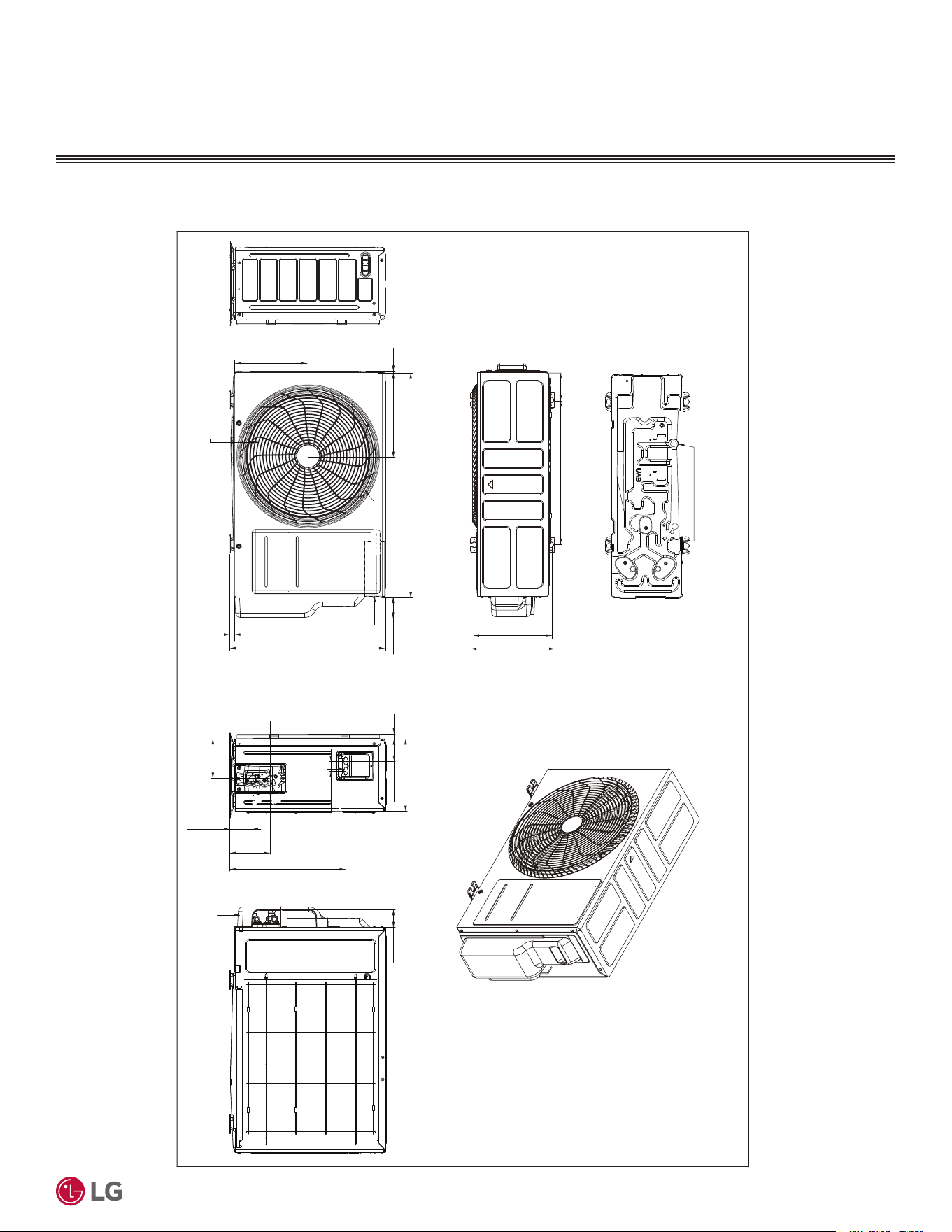
OUTDOOR UNIT DIMENSIONS
Figure 5: 6WDQGDUG(I¿FLHQF\.86$($DQG.86$($0HJD.86$&$DQG.86$&$DQG0HJD9.86$&%DQG.86$&%
Outdoor Unit Dimensions.
6WDQGDUG(ႈFLHQF\.86$($DQG.86$($0HJD.86$&$DQG
.86$&$DQG0HJD9.86$&%DQG.86$&%
U12A Chassis
Unit: Inch (mm)
9/27-32 (250)
10-5/8 (270)
Drain Hole 2-Ø13/16 (20)
3-1/2 (89)
18-7/32 (463)
5/8 (16)
2-9/16 (65)
28-7/32 (717)
10-1/2 (267)3/16 (5)
19-1/2 (495)
9/16 (14)
9-1/4 (235)
Control
Box
Air Outlet
2-7/32 (56)
Ø16-1/4 (413)
9-1/16 (230)
2-13/16 (71)
14-5/8 (371)
5-3/32 (129)
2-15/16 (74)
5 (127)
1-1/4 (31)
21°
21°
Power and
Communication
Wiring Hole
Vapor Pipe
Connection
(Flare Joint)
Liquid Pipe
Connection
(Flare Joint)
Service Valve Cover
'XHWRRXUSROLF\RIFRQWLQXRXVSURGXFWLQQRYDWLRQVRPHVSHFL¿FDWLRQVPD\FKDQJHZLWKRXWQRWL¿FDWLRQ
©
/*(OHFWURQLFV86$,QF(QJOHZRRG&OLIIV1-$OOULJKWVUHVHUYHG³/*´LVDUHJLVWHUHGWUDGHPDUNRI/*&RUS
22
56LQJOH=RQH6WDQGDUG(ႈFLHQF\0HJDDQG0HJD9:DOO0RXQWHG(QJLQHHULQJ0DQXDO
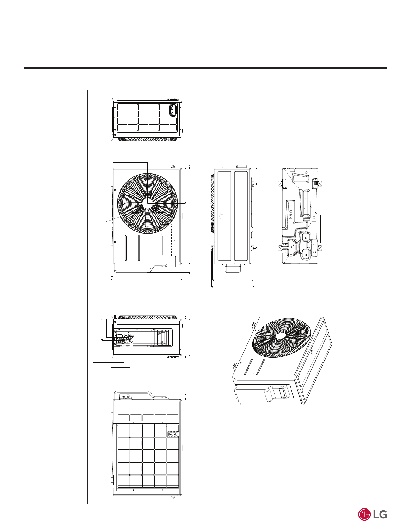
OUTDOOR UNIT DIMENSIONS
6WDQGDUG(ႈFLHQF\.86$($DQG.86$($DQG
0HJD.86$&$DQG.86$&$
Figure 6: 6WDQGDUG(I¿FLHQF\.86$($DQG.86$($DQG0HJD.86$&$DQG.86$&$2XWGRRU8QLW'LPHQVLRQV
25°
U24A Chassis
Unit: Inch (mm)
Drain Hole 6-Ø25/32 (20)
5-5/8 (143) 23-1/16 (586)
14-13/32 (366)
15-3/16 (386)
1-1/32 (26)
12-5/16 (313)
12-11/16 (322)
34-1/4 (870)
20-9/32 (515)
3-1/16 (78)
1-1/14 (32)
13 (330)
6-17/32 (166)
4-19/32 (117)
6-25/32 (172)
7-9/16 (192)
3/4 (19)
2-1/16 (52)
25-19/32 (650)
7/8 (22)
25°
25°
25°
Air Outlet
Control Box
Service
Valve Cover
Power and
Communication
Wiring Hole
Liquid Pipe
Connection
(Flare Joint)
Vapor Pipe
Connection
(Flare Joint)
'XHWRRXUSROLF\RIFRQWLQXRXVSURGXFWLQQRYDWLRQVRPHVSHFL¿FDWLRQVPD\FKDQJHZLWKRXWQRWL¿FDWLRQ
©
/*(OHFWURQLFV86$,QF(QJOHZRRG&OLIIV1-$OOULJKWVUHVHUYHG³/*´LVDUHJLVWHUHGWUDGHPDUNRI/*&RUS
23
Product Data
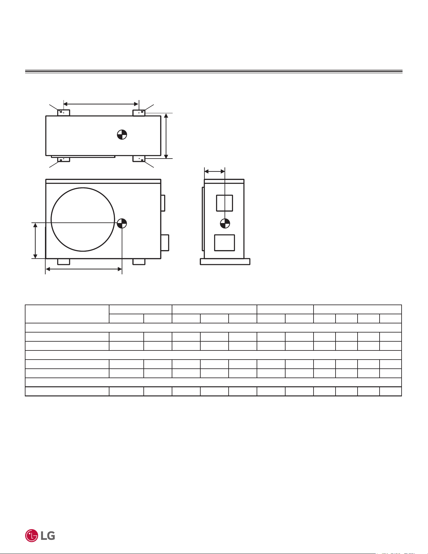
287'22581,7&(17(52)*5$9,7<
CORNER WEIGHT
Model
Weight (lb.) Center of Gravity (inch) Leg (inch) Corner Weight (lb.)
Shipping Net a b c d e A B C D
Standard Efficiency
KUSAE091A, KUSAE121A 60.0 55.3 18-11/16 8-5/8 4-7/16 18-7/32 10-3/32 3.5 5.7 23.1 23.0
KUSAE181A, KUSAE241A 102.5 92.6 22-1/4 10-1/4 5-29/32 23-1/16 14-13/32 10.9 14.9 35.4 31.4
Mega
KUSAC091A, KUSAC121A 60.0 55.3 18-11/16 8-5/8 4-7/16 18-7/32 10-3/32 3.5 5.7 23.1 23.0
KUSAC181A, KUSAC241A 102.5 92.6 22-1/4 10-1/4 5-29/32 23-1/16 14-13/32 10.9 14.9 35.4 31.4
0HJD9
KUSAC091B, KUSAC121B 60.0 55.3 18-11/16 8-5/8 4-7/16 18-7/32 10-3/32 3.5 5.7 23.1 23.0
Table 14: Center of Gravity and Corner Weight Dimensions.
d
e
a
b
c
A
D
B
C
Figure 7: Center of Gravity and Corner Weight Dimensions Diagram.
'XHWRRXUSROLF\RIFRQWLQXRXVSURGXFWLQQRYDWLRQVRPHVSHFL¿FDWLRQVPD\FKDQJHZLWKRXWQRWL¿FDWLRQ
©
/*(OHFWURQLFV86$,QF(QJOHZRRG&OLIIV1-$OOULJKWVUHVHUYHG³/*´LVDUHJLVWHUHGWUDGHPDUNRI/*&RUS
24
56LQJOH=RQH6WDQGDUG(ႈFLHQF\0HJDDQG0HJD9:DOO0RXQWHG(QJLQHHULQJ0DQXDO
INDOOR UNIT DIMENSIONS
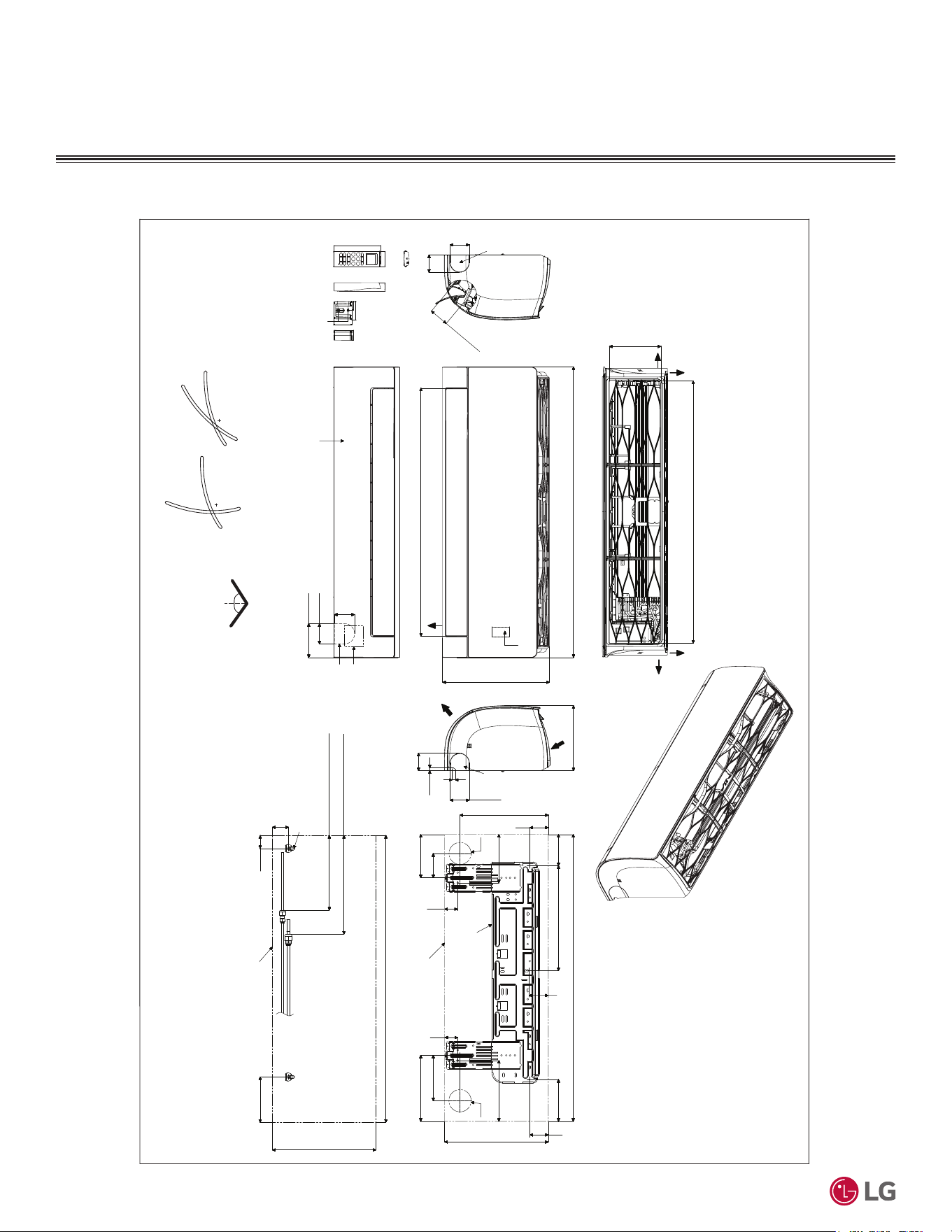
Figure 8: 6WDQGDUG(I¿FLHQF\.16$($DQG.16$($0HJD.16$&$DQG.16$&$DQG0HJD9.16$&%DQG
KNSAC121B Indoor Unit Dimensions.
6WDQGDUG(ႈFLHQF\.16$($DQG.16$($0HJD.16$&$DQG
.16$&$DQG0HJD9.16$&%DQG.16$&%
SJ Chassis
Unit: Inch (mm)
[30-3/16 (767)]
32-15/16 (837)
3-5/8 (92)
2-3/8 (60)
2-5/16
(59)
12-1/8 (308)
7-7/16 (189)
32-15/16 (837)
1-1/2 (38)
Approx. 8-19/32 (218) to liquid pipe
Approx. 11-11/32 (288) to gas pipe
1-27/32(47)
5-3/16 (132)
In Case of Left Side Piping
Unit Outline
Connecting Gas/Liquid Pipe
12-1/8 (308)
Decoration Cover
Display / Remote
Controller Signal
Receiver
Terminal Block for
Power Supply
and Communication
Drain Hose Connection
(Knock-out
Type)
2-7/32(56)
11/32 (9)
Installation Plate
Refrigerant Piping,
Drain Piping, and
Wiring Routing Hole
5/16 (8)
2 (51)
Air Intake
Air Outlet
Bottom
[28-5/32 (715)]
Air Outlet Hole
* If airflow direction control is available,
Cooling Heating
thgiR & tfeLnwoD & pU
Air Outlet Hole
Air Intake Hole
[5-29/32 (150)]
Air Intake Hole
Rear
Rear
Right
Left
55°
15°
15°
85°
45°
55°
1-3/32 (50.2)
1-1/16 (26.2)
2-7/16 (61.5)
1-7/16(33.5)
1/4(6) x 1/8(3)
1/8(3) x 1/4(6)
5/8(15.3)
1-9/32(32.7)
2-13/32(61)
5-31/32 (152)
1-1/4 (31)
2-7/32 (56)
2 (51)
2-7/32 (56)
32-15/16 (837)
2-9/16(65)
12-1/16(306)
3-21/32(93)
2-7/16(62)
10-11/32(263)
4-7/16(113)
5-1/8(130)
3(76)
5-9/32(134)
7(178)
12-1/8(308)
2-7/16(62)
4-27/32(123)
7-5/8(194)
Unit Outline
Fixing the Installation Plate, Drilling Hole
1-15/32(37)
1-15/32(37)
Ø2-9/16(65)
Ø2-9/16(65)
Refrigerant
Piping,
Drain Piping,
and
Wiring
Routing Hole
Refrigerant
Piping,
Drain
Piping,
and
Wiring
Routing
Hole
(Knock-out Type)
(Knock-
out
Type)
'XHWRRXUSROLF\RIFRQWLQXRXVSURGXFWLQQRYDWLRQVRPHVSHFL¿FDWLRQVPD\FKDQJHZLWKRXWQRWL¿FDWLRQ
©
/*(OHFWURQLFV86$,QF(QJOHZRRG&OLIIV1-$OOULJKWVUHVHUYHG³/*´LVDUHJLVWHUHGWUDGHPDUNRI/*&RUS
25
Product Data
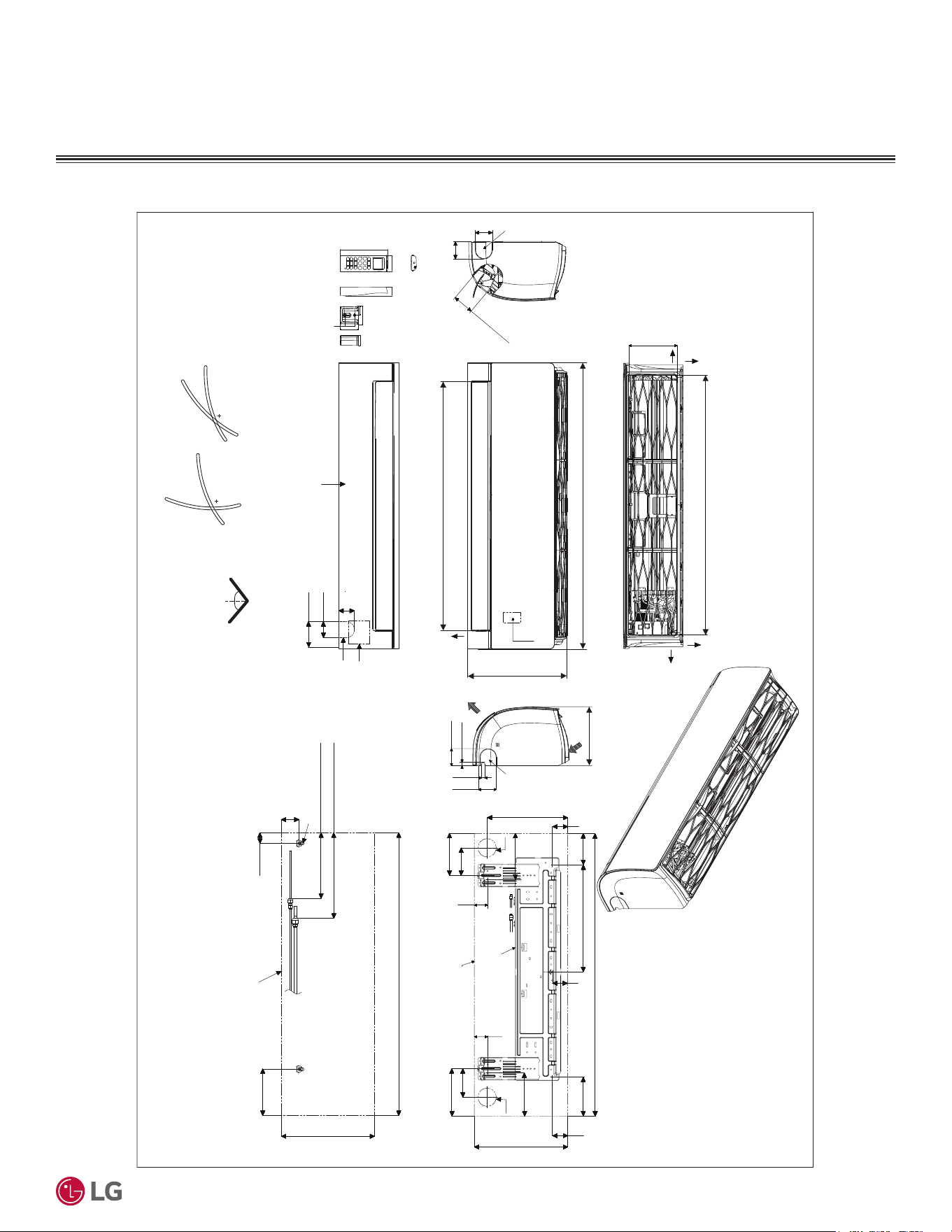
Figure 9: 6WDQGDUG(I¿FLHQF\.16$($DQG.16$($DQG0HJD.16$&$DQG.16$&$,QGRRU8QLW'LPHQVLRQV
6WDQGDUG(ႈFLHQF\.16$($DQG.16$($DQG
0HJD.16$&$DQG.16$&$
INDOOR UNIT DIMENSIONS
SK Chassis
Unit: Inch (mm)
[36-5/32 (918)]
Air Intake Hole
[6-11/16 (170)]
Air Intake Hole
[2-29/32 (74)]
Air Outlet Hole
Rear
39-9/32 (998)
2-1/4 (57)
2-7/32 (56)
3-17/32 (90)
Bottom
Air
Outlet
[34-11/32 (872)]
Air Outlet Hole
13-19/32 (345)
2-3/8 (60)
7/16(11)
Air Intake
8-9/32 (210)
13-19/32 (345)
39-9/32 (998)
6-15/32 (164)
1-15/32 (37)
2-15/32 (63)
In case of Left Side Piping
Unit Outline
Approx. 9-7/16 (240) to gas pipe
Approx. 6-5/16 (160) to liquid pipe
Connecting Gas/Liquid Pipe
2-3/8 (60)
2-3/8 (60)
Rear
Left
Right
Decoration Cover
Drain Hose Connection
Installation Plate
If airflow direction control is available,*
Cooling Heating
thgiR & tfeLnwoD & pU
50°
15°
20°
85°
45°
50°
7/16 (11)
1-3/32 (50.2)
1-1/16 (26.2)
2-7/16 (61.5)
1-7/16(33.5)
1/4(6) x 1/8(3)
1/8(3) x 1/4(6)
5/8(15.3)
1-9/32(32.7)
2-13/32(61)
5-31/32 (152)
1-1/4 (31)
2-3/8 (60)
39-9/32 (998)
2-3/470
14-29/32 (379)
5-15/32(139)
2-3/4(70)
13-19/32(345)
6-1/32(153)
Ø2-9/16(65)
4-1/32(102)
Unit Outline
Fixing the Installation Plate, Drilling Hole
1-27/32(47)
6-5/8(168)
4-1/4(108)
6-11/32(161)
Ø2-9/16(65)
3-13/16(97)
5-3/4(146)
1-27/32(47)
2-3/4(70)
11-13/16(300)
Refrigerant
Piping,
Drain
Piping,
and
Wiring
Routing
Hole
(Knock-
out
Type)
Refrigerant Piping,
Drain Piping, and
Wiring Routing Hole
(Knock-out Type)
Refrigerant
Piping,
Drain
Piping,
and
Wiring
Routing
Hole
(Knock-
out
Type)
Terminal Block for
Power Supply
and Communication
Display / Remote
Controller Signal
Receiver
'XHWRRXUSROLF\RIFRQWLQXRXVSURGXFWLQQRYDWLRQVRPHVSHFL¿FDWLRQVPD\FKDQJHZLWKRXWQRWL¿FDWLRQ
©
/*(OHFWURQLFV86$,QF(QJOHZRRG&OLIIV1-$OOULJKWVUHVHUYHG³/*´LVDUHJLVWHUHGWUDGHPDUNRI/*&RUS
26
56LQJOH=RQH6WDQGDUG(ႈFLHQF\0HJDDQG0HJD9:DOO0RXQWHG(QJLQHHULQJ0DQXDO
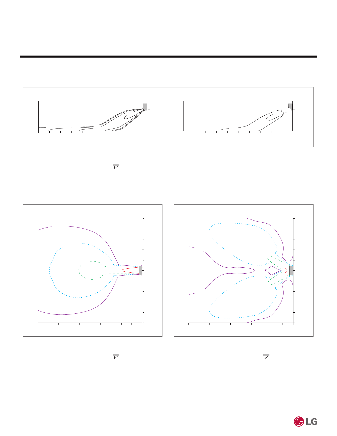
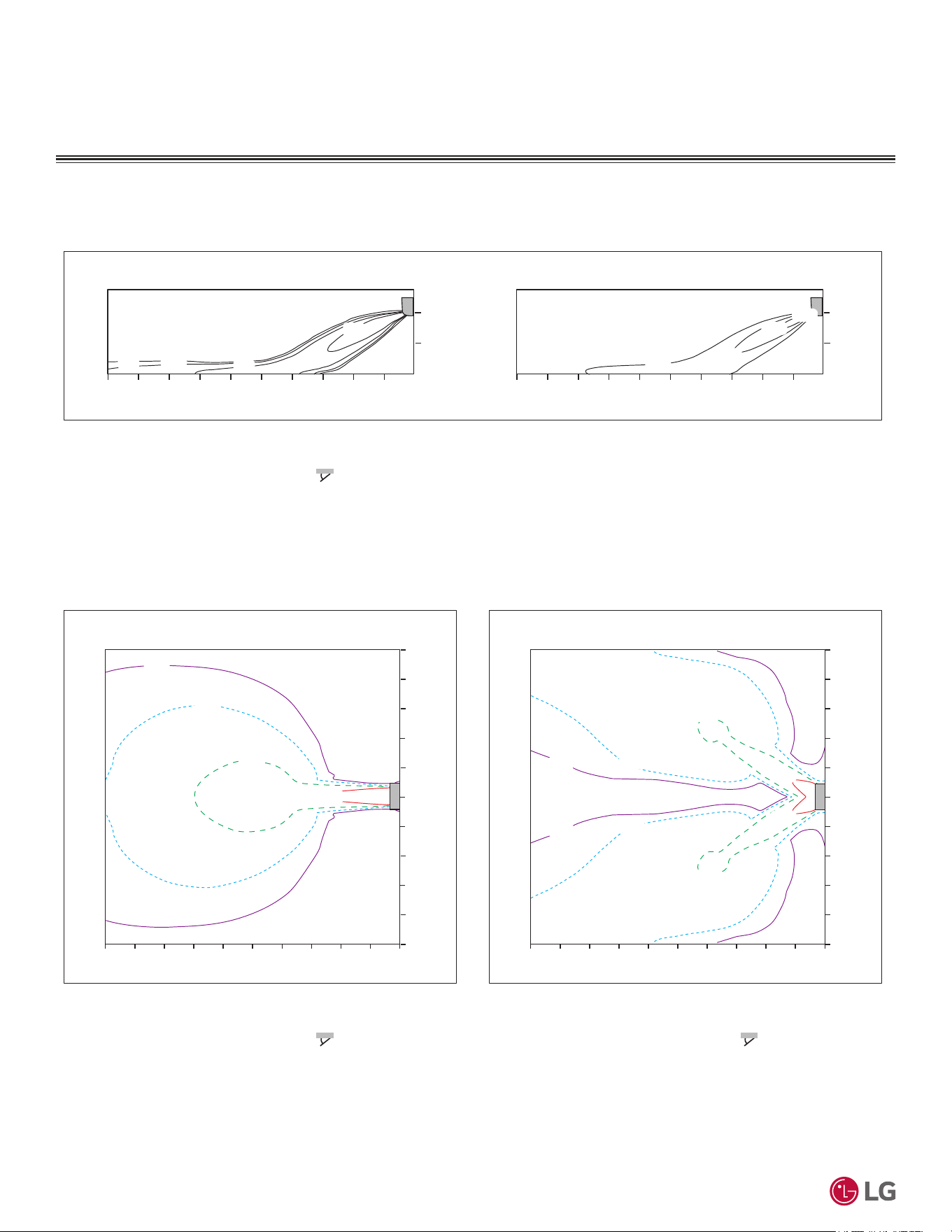
AIR FLOW
,QGRRU8QLW$LU)ORZ7HPSHUDWXUH'LVWULEXWLRQ
Figure 10: 6WDQGDUG(I¿FLHQF\.16$($DQG0HJD.16$&$$LU9HORFLW\DQG7HPSHUDWXUH'LVWULEXWLRQ&KDUWV
Cooling
0.5(1.6)
0.3(1)
1(3.3)
2(6.6)
Air Velocity [m/s (ft./s)]
1
0
0
10
2
2468
m
m
06.6
ft.
32.8 13.119.726.2
1
0
0
10
2
2468
m
3.3
0
mft.
6.6
ft.
3.3
0
6.6
0
ft.
32.8 6.613.119.726.2
28(82)
26(79)
24(75)
22(72)
0.3(1)
0.5(1.6)
1(3.3)
1(3.3)
1(3.3)
2(6.6)
0.3(1)
0.3(1)
0.5(1.6)
0.5(1.6)
2(6.6)
2(6.6)
Air Velocity [m/s (ft./s)]
0
m
10 2468
m
1
0
1
2
3
4
3
2
4
5
5
0
Air Velocity [m/s (ft./s)]
10 2468
m
1
0
1
2
3
4
3
2
4
5
5
0
ft.
32.8 6.613.119.726.2 032.8 6.613.119.726.2
m
ft.
ft.
3.3
0
3.3
6.6
9.8
13.1
9.8
6.6
13.1
16.4
16.4
3.3
3.3
6.6
9.8
13.1
9.8
6.6
13.1
16.4
16.4
ft.
0
Side View
Discharge $QJOHÛ)URPWKHIORRU )
Vertical Louver : Center
)DQ6SHHG3RZHU
TRSView
Discharge $QJOHÛ)URPWKHIORRU )
Vertical Louver : Center
)DQ6SHHG3RZHU
$LU6SHHGPVIWV5DQJH11.5 m (37.7 ft.)
TRSView
Discharge $QJOHÛ)URPWKHIORRU )
VHUWLFDO/RXYHU/HIW5LJKW
)DQ6SHHG3RZHU
THPSHUDWXUH>Û&Û)@
'XHWRRXUSROLF\RIFRQWLQXRXVSURGXFWLQQRYDWLRQVRPHVSHFL¿FDWLRQVPD\FKDQJHZLWKRXWQRWL¿FDWLRQ
©
/*(OHFWURQLFV86$,QF(QJOHZRRG&OLIIV1-$OOULJKWVUHVHUYHG³/*´LVDUHJLVWHUHGWUDGHPDUNRI/*&RUS
27
Product Data
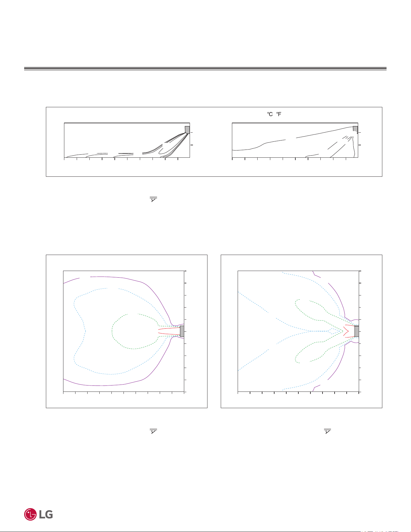
AIR FLOW
,QGRRU8QLW$LU)ORZ7HPSHUDWXUH'LVWULEXWLRQ
Figure 11: 6WDQGDUG(I¿FLHQF\.16$($DQG0HJD.16$&$$LU9HORFLW\DQG7HPSHUDWXUH'LVWULEXWLRQ&KDUWVFRQWLQXHG
Heating
26(79)
24(75)
22(72)
2(6.6)
1(3.3)
0.5(1.6)
0.3(1)
1
Air Velocity [m/s (ft./s)]
0
0
10
2
2468
m
m
06.6
ft.
32.8 13.119.726.2
1
0
0
10
2
2468
m
3.3
mft.
0
6.6
ft.
3.3
0
6.6
0
ft.
32.8 6.613.119.726.2
28(82)
0.3(1)
0.5(1.6)
1(3.3)
1(3.3)
1(3.3)
2(6.6)
0.3(1)
0.3(1)
0.5(1.6)
0.5(1.6)
2(6.6)
2(6.6)
0
Air Velocity [m/s (ft./s)]
m
10 2468
m
1
0
1
2
3
4
3
2
4
5
5
0
Air Velocity [m/s (ft./s)]
10 2468
m
1
0
1
2
3
4
3
2
4
5
5
06.6
ft.
32.8 13.119.726.2 032.8 6.613.119.726.2
m
ft.
ft.
3.3
0
3.3
6.6
9.8
13.1
9.8
6.6
13.1
16.4
16.4
3.3
3.3
6.6
9.8
13.1
9.8
6.6
13.1
16.4
16.4
ft.
0
Side View
Discharge $QJOHÛ)URPWKHIORRU )
Vertical Louver : Center
)DQ6SHHG3RZHU
TRSView
Discharge $QJOHÛ)URPWKHIORRU )
Vertical Louver : Center
)DQ6SHHG3RZHU
$LU6SHHGPVIWV5DQJHPIW
TRSView
Discharge $QJOHÛ)URPWKHIORRU )
VHUWLFDO/RXYHU/HIW5LJKW
)DQ6SHHG3RZHU
THPSHUDWXUH> ( )]
'XHWRRXUSROLF\RIFRQWLQXRXVSURGXFWLQQRYDWLRQVRPHVSHFL¿FDWLRQVPD\FKDQJHZLWKRXWQRWL¿FDWLRQ
©
/*(OHFWURQLFV86$,QF(QJOHZRRG&OLIIV1-$OOULJKWVUHVHUYHG³/*´LVDUHJLVWHUHGWUDGHPDUNRI/*&RUS
28
56LQJOH=RQH6WDQGDUG(ႈFLHQF\0HJDDQG0HJD9:DOO0RXQWHG(QJLQHHULQJ0DQXDO
AIR FLOW
,QGRRU8QLW$LU)ORZ7HPSHUDWXUH'LVWULEXWLRQ
Figure 12: 6WDQGDUG(I¿FLHQF\.16$($DQG0HJD.16$&$$LU9HORFLW\DQG7HPSHUDWXUH'LVWULEXWLRQ&KDUWV
Cooling
0.3(1)
0.5(1.6)
1(3.3)
2(6.6)
Air Velocity [m/s (ft./s)]
1
0
0
10
2
2468
m
m
06.6
ft.
32.8 13.119.726.2
1
0
0
10
2
2468
m
3.3
mft.
0
6.6
ft.
3.3
0
6.6
06.6
ft.
32.8 13.119.726.2
28(82)
26(79)
24(75)
22(72)
0.3(1)
0.5(1.6)
1(3.3)
1(3.3)
1(3.3)
2(6.6)
0.3(1)
0.3(1)
0.5(1.6)
0.5(1.6)
2(6.6)
2(6.6)
Air Velocity [m/s (ft./s)]
02
m
10 468
m
1
0
1
2
3
4
3
2
4
5
5
0
Air Velocity [m/s (ft./s)]
10 2468
m
1
0
1
2
3
4
3
2
4
5
5
0
ft.
32.8 6.613.119.726.2 032.8 6.613.119.726.2
m
ft.
ft.
3.3
0
3.3
6.6
9.8
13.1
9.8
6.6
13.1
16.4
16.4
3.3
3.3
6.6
9.8
13.1
9.8
6.6
13.1
16.4
16.4
ft.
0
Side View
Discharge $QJOHÛ)URPWKHIORRU )
Vertical Louver : Center
)DQ6SHHG3RZHU
TRSView
Discharge $QJOHÛ)URPWKHIORRU )
Vertical Louver : Center
)DQ6SHHG3RZHU
$LU6SHHGPVIWV5DQJHPIW
TRSView
Discharge $QJOHÛ)URPWKHIORRU )
VHUWLFDO/RXYHU/HIW5LJKW
)DQ6SHHG3RZHU
THPSHUDWXUH>Û&Û)@
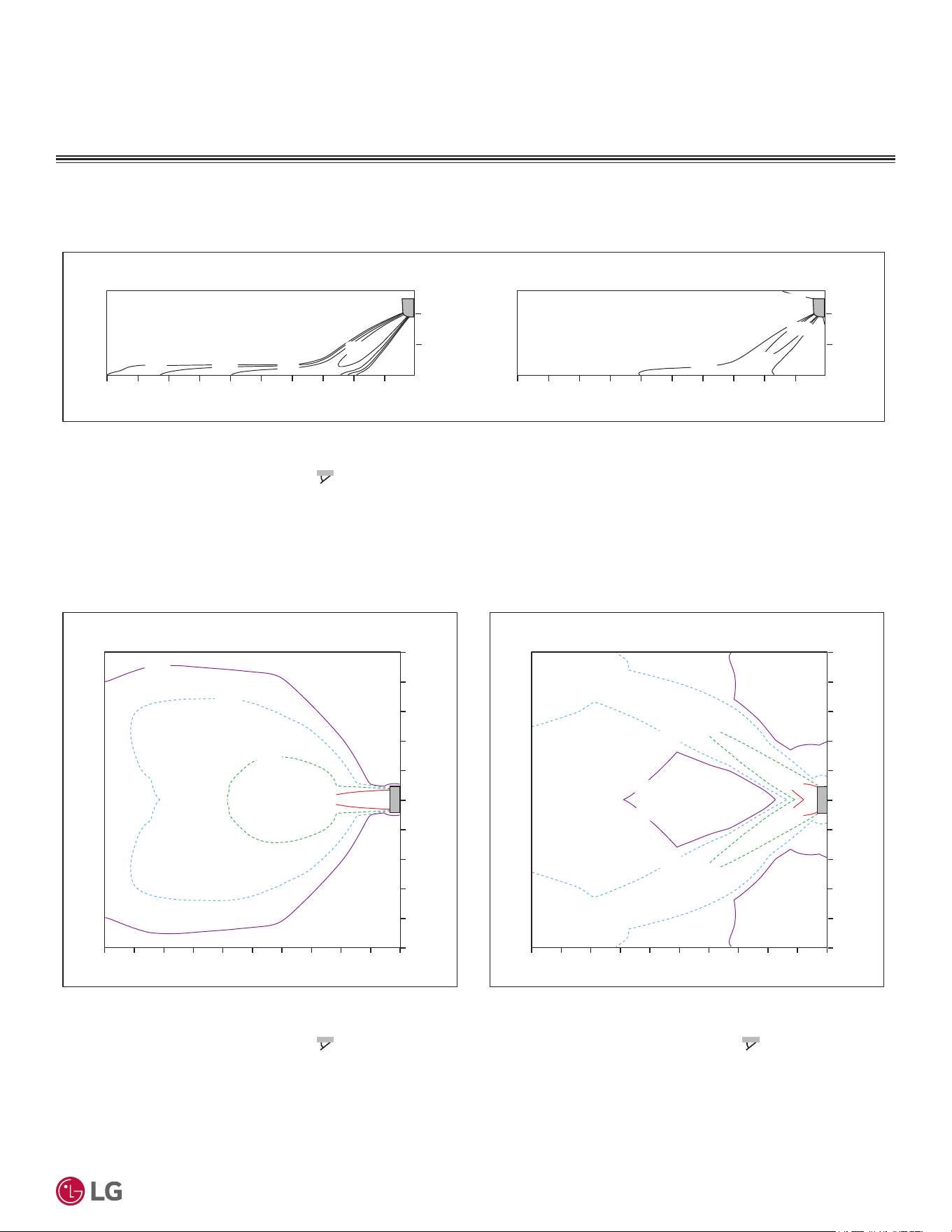
'XHWRRXUSROLF\RIFRQWLQXRXVSURGXFWLQQRYDWLRQVRPHVSHFL¿FDWLRQVPD\FKDQJHZLWKRXWQRWL¿FDWLRQ
©
/*(OHFWURQLFV86$,QF(QJOHZRRG&OLIIV1-$OOULJKWVUHVHUYHG³/*´LVDUHJLVWHUHGWUDGHPDUNRI/*&RUS
29
Product Data
AIR FLOW
,QGRRU8QLW$LU)ORZ7HPSHUDWXUH'LVWULEXWLRQ
Figure 13: 6WDQGDUG(I¿FLHQF\.16$($DQG0HJD.16$&$$LU9HORFLW\DQG7HPSHUDWXUH'LVWULEXWLRQ&KDUWVFRQWLQXHG
Heating
Temperature [Û&Û)@
Air VHORFLW\>PVIWV@
1
0
0
10
2
2468
m
m
0
IW
86612
1
0
0
10
2
2468
m
0
m IW
IW
0
0
IW
8661262
Air VHORFLW\>PVIWV@
0
m
10 2468
m
1
0
1
2
4
2
4
Air VHORFLW\>PVIWV@
010 2468
m
1
0
1
2
4
2
4
066
IW
8 12 08661262
m
IW
IW
0
8
1
8
1
8
1
8
1
IW
0
Side View
Discharge $QJOHÛ)URPWKHIORRU
VHUWLFDO/RXYHU&HQWHU
)DQ6SHHG3RZHU
Top View
Discharge $QJOHÛ)URPWKHIORRU
VHUWLFDO/RXYHU&HQWHU
)DQ6SHHG3RZHU
$LU6SHHGPVIWV5DQJHPIW
Top View
Discharge $QJOHÛ)URPWKHIORRU
VHUWLFDO/RXYHU/HIW5LJKW
)DQ6SHHG3RZHU
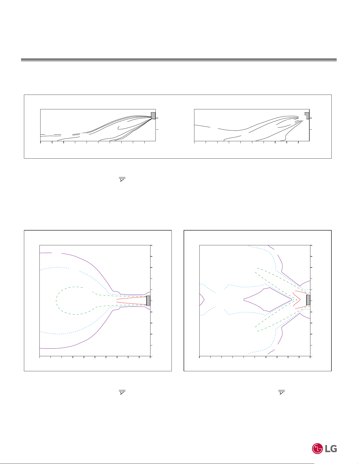
'XHWRRXUSROLF\RIFRQWLQXRXVSURGXFWLQQRYDWLRQVRPHVSHFL¿FDWLRQVPD\FKDQJHZLWKRXWQRWL¿FDWLRQ
©
/*(OHFWURQLFV86$,QF(QJOHZRRG&OLIIV1-$OOULJKWVUHVHUYHG³/*´LVDUHJLVWHUHGWUDGHPDUNRI/*&RUS
30
56LQJOH=RQH6WDQGDUG(ႈFLHQF\0HJDDQG0HJD9:DOO0RXQWHG(QJLQHHULQJ0DQXDO
AIR FLOW
,QGRRU8QLW$LU)ORZ7HPSHUDWXUH'LVWULEXWLRQ
Figure 14: 6WDQGDUG(I¿FLHQF\.16$($DQG0HJD.16$&$$LU9HORFLW\DQG7HPSHUDWXUH'LVWULEXWLRQ&KDUWV
Cooling
Temperature [ഒ (ഘ)]
2(6.6)
0.3(1)
1(3.3)
Air Velocity [m/s (ft./s)]
1
0
0
10
2
2468
m
m
06.6
ft.
32.8 13.119.726.2
1
0
0
10
2
2468
m
3.3
0
mft.
6.6
ft.
3.3
0
6.6
06.6
ft.
32.8 13.119.726.2
22(72)
24(75)
26(79)
28(82)
20(68)
0.3(1)
0.5(1.6)
1(3.3)
2(6.6)
2(6.6)
2(6.6)
1(3.3)
1(3.3)
0.5(1.6)
0.5(1.6)
0.3(1)
0.3(1)
Air Velocity [m/s (ft./s)]
0
m
10 2468
m
1
0
1
2
3
4
3
2
4
5
5
Air Velocity [m/s (ft./s)]
010 2468
m
1
0
1
2
3
4
3
2
4
5
5
0
ft.
32.8 6.613.119.726.2 032.8 6.613.119.726.2
m
ft.
ft.
3.3
0
3.3
6.6
9.8
13.1
9.8
6.6
13.1
16.4
16.4
3.3
3.3
6.6
9.8
13.1
9.8
6.6
13.1
16.4
16.4
ft.
0
Side View
Discharge $QJOHÛ)URPWKHIORRU )
Vertical Louver : Center
)DQ6SHHG3RZHU
Top View
Discharge $QJOHÛ)URPWKHIORRU )
Vertical Louver : Center
)DQ6SHHG3RZHU
Air Speed 0.3 m/s (1 ft./s) Range : 15.8 m (51.8 ft.)
Top View
Discharge $QJOHÛ)URPWKHIORRU )
Vertical Louver : Left & Right
)DQ6SHHG3RZHU
0.5(1.6)
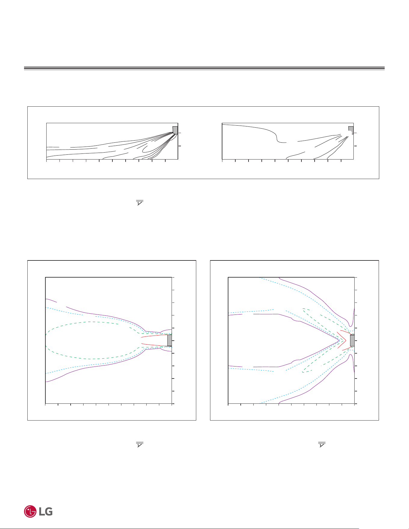
'XHWRRXUSROLF\RIFRQWLQXRXVSURGXFWLQQRYDWLRQVRPHVSHFL¿FDWLRQVPD\FKDQJHZLWKRXWQRWL¿FDWLRQ
©
/*(OHFWURQLFV86$,QF(QJOHZRRG&OLIIV1-$OOULJKWVUHVHUYHG³/*´LVDUHJLVWHUHGWUDGHPDUNRI/*&RUS
31
Product Data
AIR FLOW
,QGRRU8QLW$LU)ORZ7HPSHUDWXUH'LVWULEXWLRQ
Figure 15: 6WDQGDUG(I¿FLHQF\.16$($DQG0HJD.16$&$$LU9HORFLW\DQG7HPSHUDWXUH'LVWULEXWLRQ&KDUWVFRQWLQXHG
Heating
24(75)
26(79)
28(82)
1
Air Velocity [m/s (ft./s)]
0
0
10
2
2468
m
m
0
ft.
32.8 6.613.119.726.2
1
0
0
10
2
2468
m
3.3
0
mft.
6.6
ft.
3.3
0
6.6
06.6
ft.
32.8 13.119.726.2
0.3(1)
0.5(1.6)
1(3.3)
2(6.6)
1.5(4.9)
32(90)
0.3(1)
0.5(1.6)
1(3.3)
2(6.6)
0.5(1.6)
0.5(1.6)
1(3.3)
1(3.3)
0.3(1)
0.3(1)
2(6.6)
2(6.6)
Air Velocity [m/s (ft./s)]
02
m
10 468
m
1
0
1
2
3
4
3
2
4
5
5
Air Velocity [m/s (ft./s)]
010 2468
m
1
0
1
2
3
4
3
2
4
5
5
0
ft.
32.8 6.613.119.726.2 032.8 6.613.119.726.2
m
ft.
ft.
3.3
0
3.3
6.6
9.8
13.1
9.8
6.6
13.1
16.4
16.4
3.3
3.3
6.6
9.8
13.1
9.8
6.6
13.1
16.4
16.4
ft.
0
Side View
Discharge $QJOHÛ)URPWKHIORRU )
Vertical Louver : Center
)DQ6SHHG3RZHU
TRSView
Discharge $QJOHÛ)URPWKHIORRU )
Vertical Louver : Center
)DQ6SHHG3RZHU
$LU6SHHGPVIWV5DQJHPIW
TRSView
Discharge $QJOHÛ)URPWKHIORRU )
VHUWLFDO/RXYHU/HIW5LJKW
)DQ6SHHG3RZHU
THPSHUDWXUH>ഒ (ഘ)]
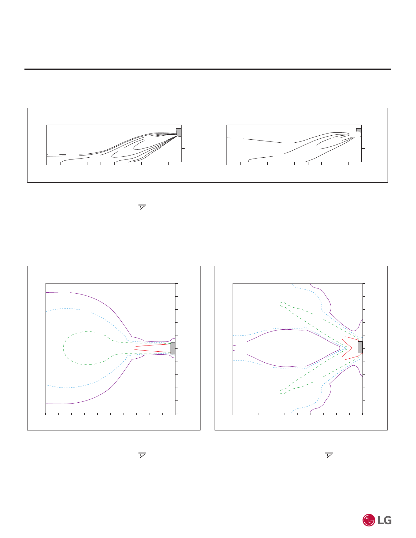
'XHWRRXUSROLF\RIFRQWLQXRXVSURGXFWLQQRYDWLRQVRPHVSHFL¿FDWLRQVPD\FKDQJHZLWKRXWQRWL¿FDWLRQ
©
/*(OHFWURQLFV86$,QF(QJOHZRRG&OLIIV1-$OOULJKWVUHVHUYHG³/*´LVDUHJLVWHUHGWUDGHPDUNRI/*&RUS
32
56LQJOH=RQH6WDQGDUG(ႈFLHQF\0HJDDQG0HJD9:DOO0RXQWHG(QJLQHHULQJ0DQXDO
Figure 16: 6WDQGDUG(I¿FLHQF\.16$($DQG0HJD.16$&$$LU9HORFLW\DQG7HPSHUDWXUH'LVWULEXWLRQ&KDUWV
AIR FLOW
,QGRRU8QLW$LU)ORZ7HPSHUDWXUH'LVWULEXWLRQ
Cooling
2(6.6)
0.3(1)
1(3.3)
1
Air Velocity [m/s (ft./s)]
0
0
10
2
2468
m
m
0
ft.
32.8 6.613.119.726.2
1
0
0
10
2
2468
m
3.3
0
mft.
6.6
ft.
3.3
0
6.6
0
ft.
32.8 6.613.119.726.2
1.5(4.9)
0.5(1.6)
28(82)
26(79)
24(75)
22(72)
18(64)
0.3(1)
0.5(1.6)
1(3.3)
2(6.6)
2(6.6)
2(6.6)
1(3.3)
1(3.3)
0.5(1.6)
0.5(1.6)
0.3(1)
0.3(1)
0
Air Velocity [m/s (ft./s)]
2
m
10 468
m
1
0
1
2
3
4
3
2
4
5
5
0
Air Velocity [m/s (ft./s)]
10 2468
m
1
0
1
2
3
4
3
2
4
5
5
06.6
ft.
32.8 13.119.726.2 032.8 6.613.119.726.2
m
ft.
ft.
3.3
0
3.3
6.6
9.8
13.1
9.8
6.6
13.1
16.4
16.4
3.3
3.3
6.6
9.8
13.1
9.8
6.6
13.1
16.4
16.4
ft.
0
Side View
Discharge $QJOHÛ)URPWKHIORRU )
Vertical Louver : Center
)DQ6SHHG3RZHU
TRSView
Discharge $QJOHÛ)URPWKHIORRU )
Vertical Louver : Center
)DQ6SHHG3RZHU
$LU6SHHGPVIWV5DQJHPIW
TRSView
Discharge $QJOHÛ)URPWKHIORRU )
VHUWLFDO/RXYHU/HIW5LJKW
)DQ6SHHG3RZHU
THPSHUDWXUH>Û&Û)@
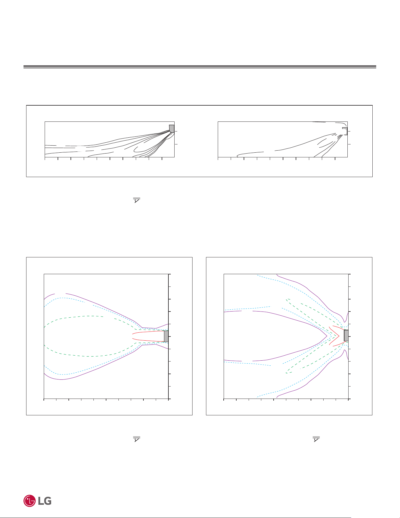
'XHWRRXUSROLF\RIFRQWLQXRXVSURGXFWLQQRYDWLRQVRPHVSHFL¿FDWLRQVPD\FKDQJHZLWKRXWQRWL¿FDWLRQ
©
/*(OHFWURQLFV86$,QF(QJOHZRRG&OLIIV1-$OOULJKWVUHVHUYHG³/*´LVDUHJLVWHUHGWUDGHPDUNRI/*&RUS
33
Product Data
AIR FLOW
,QGRRU8QLW$LU)ORZ7HPSHUDWXUH'LVWULEXWLRQ
Figure 17: 6WDQGDUG(I¿FLHQF\.16$($DQG0HJD.16$&$$LU9HORFLW\DQG7HPSHUDWXUH'LVWULEXWLRQ&KDUWVFRQWLQXHG
Heating
24(75)
26(79)
28(82)
30(86)
0.3(1)
0.5(1.6)
1(3.3)
1.5(4.9)
2(6.6)
Air Velocity [m/s (ft./s)]
1
0
0
10
2
2468
m
m
0
ft.
32.8 6.613.119.726.2
1
0
0
10
2
2468
m
3.3
0
mft.
6.6
ft.
3.3
0
6.6
06.6
ft.
32.8 13.119.726.2
32(90)
0
Air Velocity [m/s (ft./s)]
2
m
10 468
m
1
0
1
2
3
4
3
2
4
5
5
Air Velocity [m/s (ft./s)]
010 2468
m
1
0
1
2
3
4
3
2
4
5
5
0
ft.
32.8 6.613.119.726.2 032.8 6.613.119.726.2
m
ft.
ft.
3.3
0
3.3
6.6
9.8
13.1
9.8
6.6
13.1
16.4
16.4
3.3
3.3
6.6
9.8
13.1
9.8
6.6
13.1
16.4
16.4
ft.
0
0.3(1)
0.3(1)
0.5(1.6)
0.5(1.6)
1(3.3)
1(3.3)
2(6.6)
2(6.6)
0.3(1)
0.5(1.6)
1(3.3)
2(6.6)
Side View
Discharge $QJOHÛ)URPWKHIORRU )
Vertical Louver : Center
)DQ6SHHG3RZHU
TRSView
Discharge $QJOHÛ)URPWKHIORRU )
Vertical Louver : Center
)DQ6SHHG3RZHU
$LU6SHHGPVIWV5DQJHPIW
TRSView
Discharge $QJOHÛ)URPWKHIORRU )
VHUWLFDO/RXYHU/HIW5LJKW
)DQ6SHHG3RZHU
THPSHUDWXUH>ഒ (ഘ)]
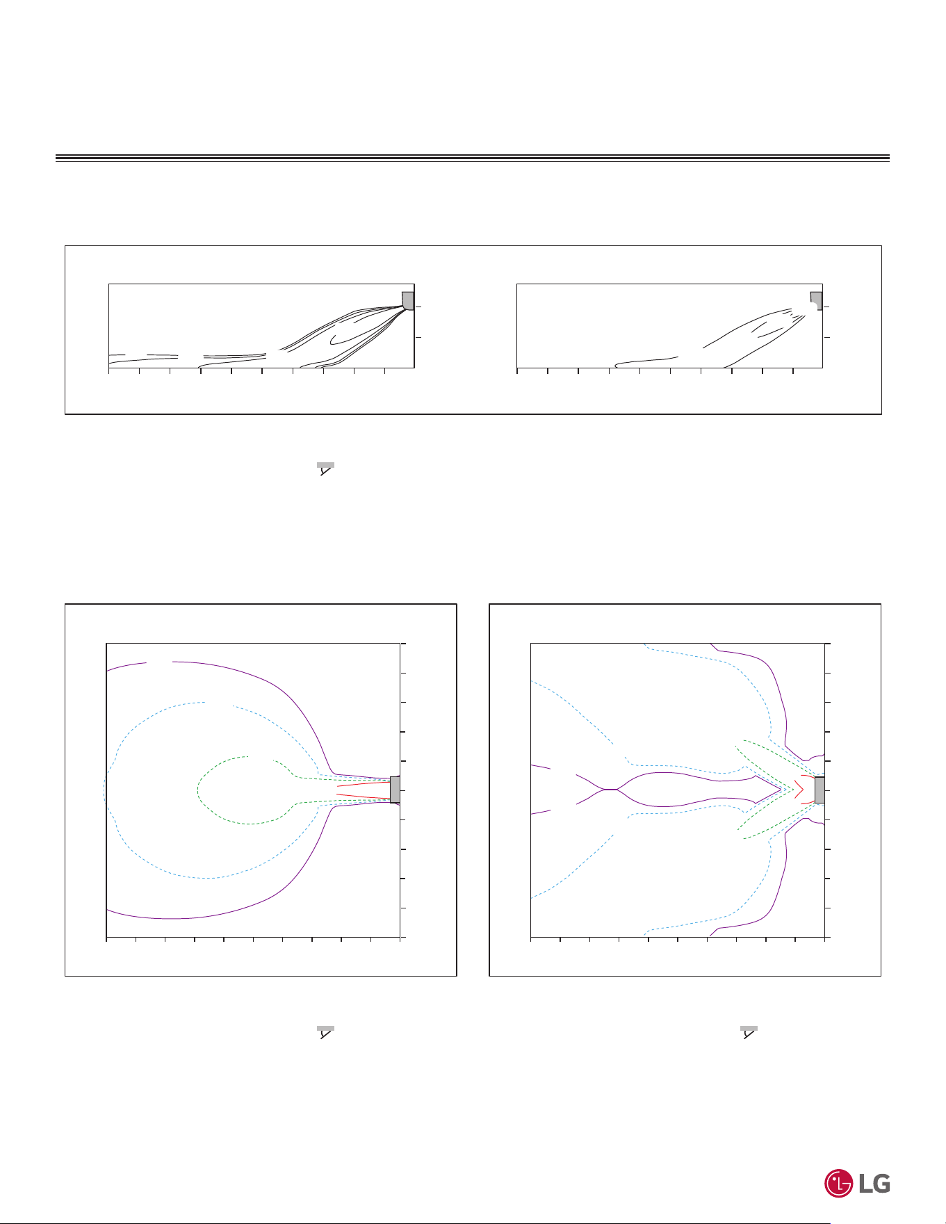
'XHWRRXUSROLF\RIFRQWLQXRXVSURGXFWLQQRYDWLRQVRPHVSHFL¿FDWLRQVPD\FKDQJHZLWKRXWQRWL¿FDWLRQ
©
/*(OHFWURQLFV86$,QF(QJOHZRRG&OLIIV1-$OOULJKWVUHVHUYHG³/*´LVDUHJLVWHUHGWUDGHPDUNRI/*&RUS
34
56LQJOH=RQH6WDQGDUG(ႈFLHQF\0HJDDQG0HJD9:DOO0RXQWHG(QJLQHHULQJ0DQXDO
AIR FLOW
,QGRRU8QLW$LU)ORZ7HPSHUDWXUH'LVWULEXWLRQ
Figure 18: Mega 115V KNSAC091B Air Velocity and Temperature Distribution Charts.
Cooling
28(82)
26(79)
24(75)
2(6.6)
1(3.3)
0.5(1.6)
0.3(1)
1
Air Velocity [m/s (ft./s)]
0
0
10
2
2468
m
m
06.6
ft.
32.8 13.119.726.2
1
0
0
10
2
2468
m
3.3
mft.
0
6.6
ft.
3.3
0
6.6
06.6
ft.
32.8 13.119.726.2
22(72)
0.3(1)
0.5(1.6)
1(3.3)
1(3.3)
1(3.3)
2(6.6)
0.3(1)
0.3(1)
0.5(1.6)
0.5(1.6)
2(6.6)
2(6.6)
Air Velocity [m/s (ft./s)]
0
m
10 2468
m
1
0
1
2
3
4
3
2
4
5
5
Air Velocity [m/s (ft./s)]
010 2468
m
1
0
1
2
3
4
3
2
4
5
5
06.6
ft.
32.8 13.119.726.2 032.8 6.613.119.726.2
m
ft.
ft.
3.3
0
3.3
6.6
9.8
13.1
9.8
6.6
13.1
16.4
16.4
3.3
3.3
6.6
9.8
13.1
9.8
6.6
13.1
16.4
16.4
ft.
0
Side View
Discharge $QJOHÛ)URPWKHIORRU )
Vertical Louver : Center
)DQ6SHHG3RZHU
TRSView
Discharge $QJOHÛ)URPWKHIORRU )
Vertical Louver : Center
)DQ6SHHG3RZHU
$LU6SHHGPVIWV5DQJHPIW
TRSView
Discharge $QJOHÛ)URPWKHIORRU )
VHUWLFDO/RXYHU/HIW5LJKW
)DQ6SHHG3RZHU
THPSHUDWXUH>ഒ (ഘ)]
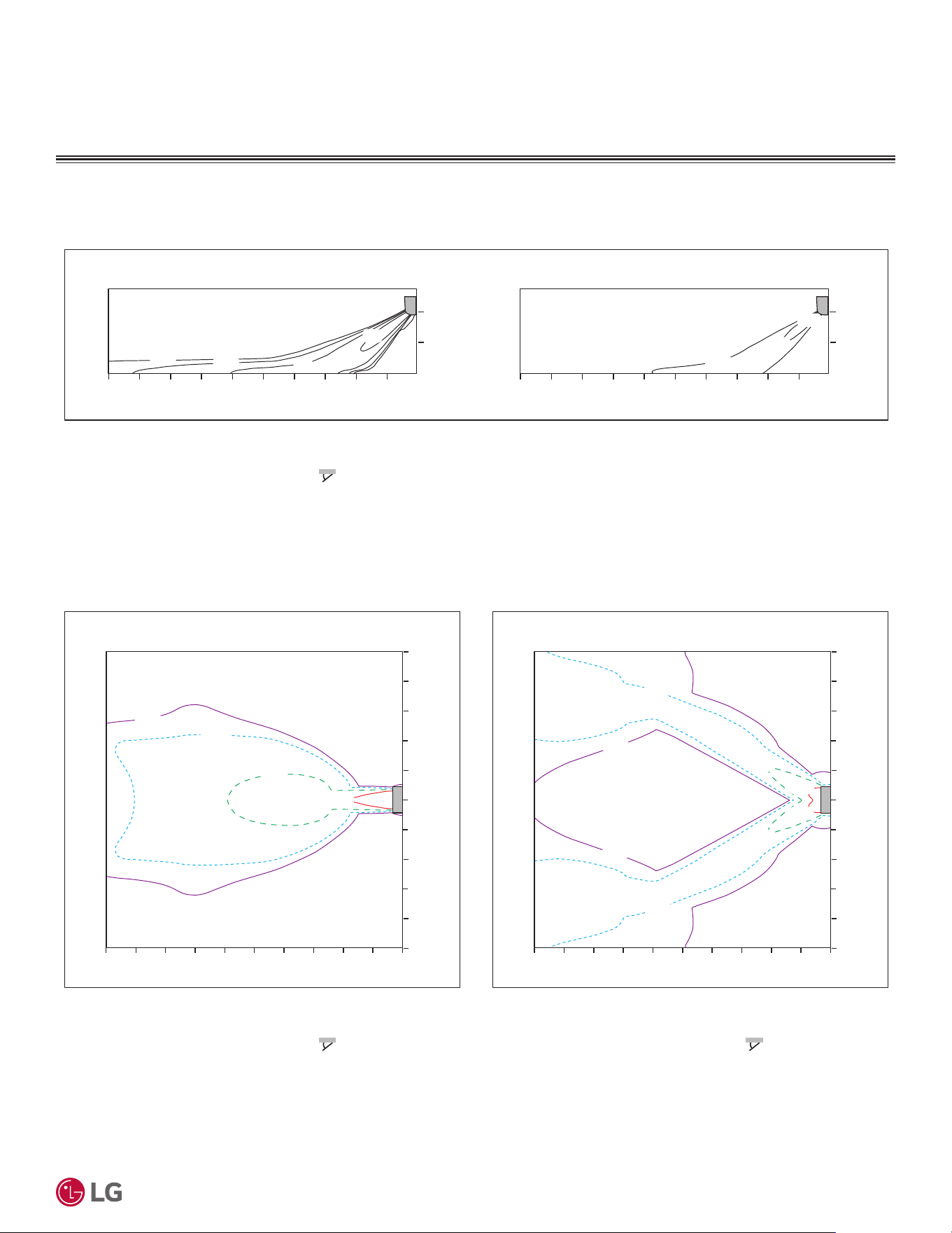
'XHWRRXUSROLF\RIFRQWLQXRXVSURGXFWLQQRYDWLRQVRPHVSHFL¿FDWLRQVPD\FKDQJHZLWKRXWQRWL¿FDWLRQ
©
/*(OHFWURQLFV86$,QF(QJOHZRRG&OLIIV1-$OOULJKWVUHVHUYHG³/*´LVDUHJLVWHUHGWUDGHPDUNRI/*&RUS
35
Product Data
AIR FLOW
,QGRRU8QLW$LU)ORZ7HPSHUDWXUH'LVWULEXWLRQ
Figure 19: Mega 115V KNSAC091B Air Velocity and Temperature Distribution Charts, continued.
Heating
0.3(1)
0.5(1.6)
1(3.3)
2(6.6)
24(75)
26(79)
1
Air Velocity [m/s (ft./s)]
0
0
10
2
2468
m
m
06.6
ft.
32.8 13.119.726.2
1
0
0
10
2
2468
m
3.3
0
mft.
6.6
ft.
3.3
0
6.6
0
ft.
32.8 6.613.119.726.2
28(82)
0.3(1)
0.5(1.6)
1(3.3)
2(6.6)
0.5(1.6)
0.5(1.6)
1(3.3)
1(3.3)
0.3(1)
0.3(1)
2(6.6)
2(6.6)
0
Air Velocity [m/s (ft./s)]
2
m
10 468
m
1
0
1
2
3
4
3
2
4
5
5
0
Air Velocity [m/s (ft./s)]
10 2468
m
1
0
1
2
3
4
3
2
4
5
5
06.6
ft.
32.8 13.119.726.2 032.8 6.613.119.726.2
m
ft.
ft.
3.3
0
3.3
6.6
9.8
13.1
9.8
6.6
13.1
16.4
16.4
3.3
3.3
6.6
9.8
13.1
9.8
6.6
13.1
16.4
16.4
ft.
0
Side View
Discharge $QJOHÛ)URPWKHIORRU )
Vertical Louver : Center
)DQ6SHHG3RZHU
TRSView
Discharge $QJOHÛ)URPWKHIORRU )
Vertical Louver : Center
)DQ6SHHG3RZHU
$LU6SHHGPVIWV5DQJHPIW
TRSView
Discharge $QJOHÛ)URPWKHIORRU )
VHUWLFDO/RXYHU/HIW5LJKW
)DQ6SHHG3RZHU
THPSHUDWXUH>ഒ (ഘ)]
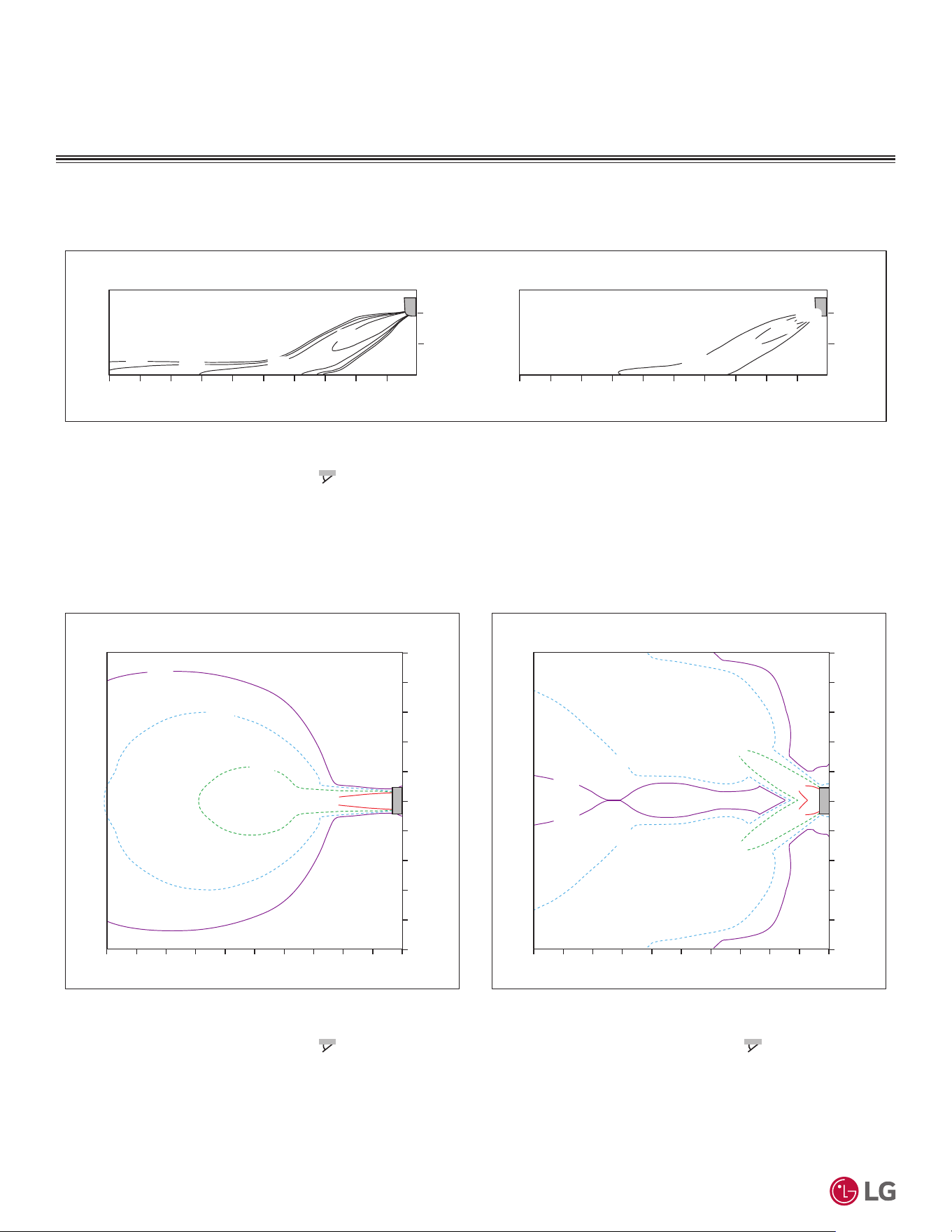
'XHWRRXUSROLF\RIFRQWLQXRXVSURGXFWLQQRYDWLRQVRPHVSHFL¿FDWLRQVPD\FKDQJHZLWKRXWQRWL¿FDWLRQ
©
/*(OHFWURQLFV86$,QF(QJOHZRRG&OLIIV1-$OOULJKWVUHVHUYHG³/*´LVDUHJLVWHUHGWUDGHPDUNRI/*&RUS
36
56LQJOH=RQH6WDQGDUG(ႈFLHQF\0HJDDQG0HJD9:DOO0RXQWHG(QJLQHHULQJ0DQXDO
Figure 20: Mega 115V KNSAC121B Air Velocity and Temperature Distribution Charts, continued.
AIR FLOW
,QGRRU8QLW$LU)ORZ7HPSHUDWXUH'LVWULEXWLRQ
Cooling
28(82)
26(79)
24(75)
2(6.6)
1(3.3)
0.5(1.6)
0.3(1)
1
Air Velocity [m/s (ft./s)]
0
0
10
2
2468
m
m
06.6
ft.
32.8 13.119.726.2
1
0
0
10
2
2468
m
3.3
mft.
0
6.6
ft.
3.3
0
6.6
06.6
ft.
32.8 13.119.726.2
22(72)
0.3(1)
0.5(1.6)
1(3.3)
1(3.3)
1(3.3)
2(6.6)
0.3(1)
0.3(1)
0.5(1.6)
0.5(1.6)
2(6.6)
2(6.6)
Air Velocity [m/s (ft./s)]
0
m
10 2468
m
1
0
1
2
3
4
3
2
4
5
5
Air Velocity [m/s (ft./s)]
010 2468
m
1
0
1
2
3
4
3
2
4
5
5
06.6
ft.
32.8 13.119.726.2 032.8 6.613.119.726.2
m
ft.
ft.
3.3
0
3.3
6.6
9.8
13.1
9.8
6.6
13.1
16.4
16.4
3.3
3.3
6.6
9.8
13.1
9.8
6.6
13.1
16.4
16.4
ft.
0
Side View
Discharge $QJOHÛ)URPWKHIORRU )
Vertical Louver : Center
)DQ6SHHG3RZHU
TRSView
Discharge $QJOHÛ)URPWKHIORRU )
Vertical Louver : Center
)DQ6SHHG3RZHU
$LU6SHHGPVIWV5DQJHPIW
TRSView
Discharge $QJOHÛ)URPWKHIORRU )
VHUWLFDO/RXYHU/HIW5LJKW
)DQ6SHHG3RZHU
THPSHUDWXUH>ഒ (ഘ)]
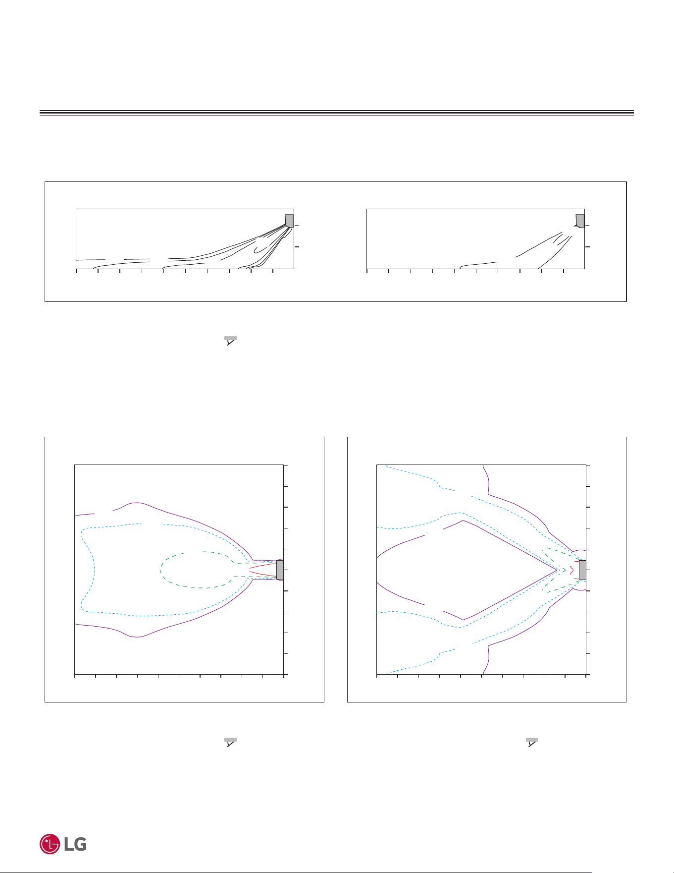
'XHWRRXUSROLF\RIFRQWLQXRXVSURGXFWLQQRYDWLRQVRPHVSHFL¿FDWLRQVPD\FKDQJHZLWKRXWQRWL¿FDWLRQ
©
/*(OHFWURQLFV86$,QF(QJOHZRRG&OLIIV1-$OOULJKWVUHVHUYHG³/*´LVDUHJLVWHUHGWUDGHPDUNRI/*&RUS
37
Product Data
Heating
0.3(1)
0.5(1.6)
1(3.3)
2(6.6)
24(75)
26(79)
1
Air Velocity [m/s (ft./s)]
0
0
10
2
2468
m
m
06.6
ft.
32.8 13.119.726.2
1
0
0
10
2
2468
m
3.3
0
mft.
6.6
ft.
3.3
0
6.6
0
ft.
32.8 6.613.119.726.2
28(82)
0.3(1)
0.5(1.6)
1(3.3)
2(6.6)
0.5(1.6)
0.5(1.6)
1(3.3)
1(3.3)
0.3(1)
0.3(1)
2(6.6)
2(6.6)
0
Air Velocity [m/s (ft./s)]
2
m
10 468
m
1
0
1
2
3
4
3
2
4
5
5
0
Air Velocity [m/s (ft./s)]
10 2468
m
1
0
1
2
3
4
3
2
4
5
5
06.6
ft.
32.8 13.119.726.2 032.8 6.613.119.726.2
m
ft.
ft.
3.3
0
3.3
6.6
9.8
13.1
9.8
6.6
13.1
16.4
16.4
3.3
3.3
6.6
9.8
13.1
9.8
6.6
13.1
16.4
16.4
ft.
0
Side View
Discharge $QJOHÛ)URPWKHIORRU )
Vertical Louver : Center
)DQ6SHHG3RZHU
TRSView
Discharge $QJOHÛ)URPWKHIORRU )
Vertical Louver : Center
)DQ6SHHG3RZHU
$LU6SHHGPVIWV5DQJHPIW
TRSView
Discharge $QJOHÛ)URPWKHIORRU )
VHUWLFDO/RXYHU/HIW5LJKW
)DQ6SHHG3RZHU
THPSHUDWXUH>ഒ (ഘ)]
AIR FLOW
,QGRRU8QLW$LU)ORZ7HPSHUDWXUH'LVWULEXWLRQ
Figure 21: Mega 115V KNSAC121B Air Velocity and Temperature Distribution Charts, continued.
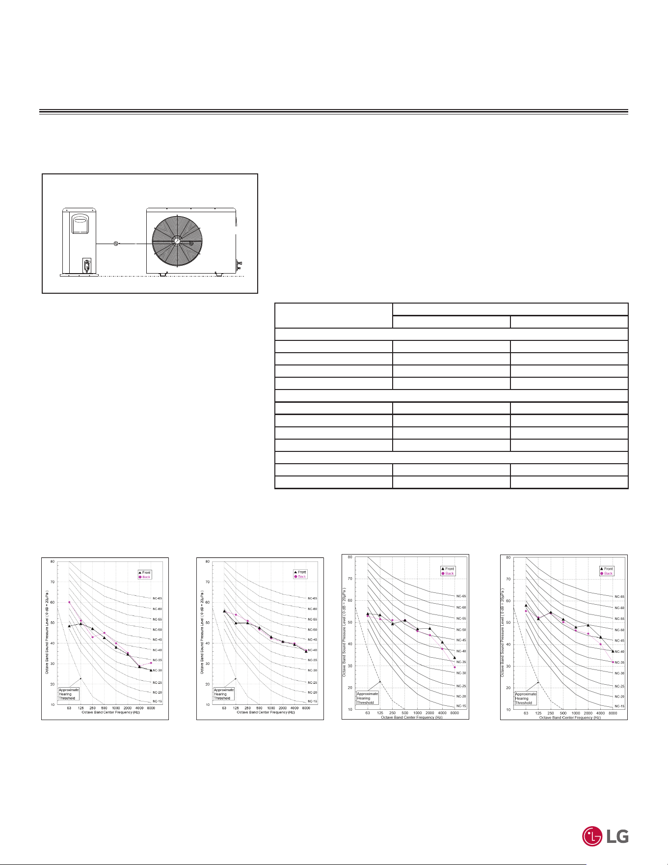
'XHWRRXUSROLF\RIFRQWLQXRXVSURGXFWLQQRYDWLRQVRPHVSHFL¿FDWLRQVPD\FKDQJHZLWKRXWQRWL¿FDWLRQ
©
/*(OHFWURQLFV86$,QF(QJOHZRRG&OLIIV1-$OOULJKWVUHVHUYHG³/*´LVDUHJLVWHUHGWUDGHPDUNRI/*&RUS
38
56LQJOH=RQH6WDQGDUG(ႈFLHQF\0HJDDQG0HJD9:DOO0RXQWHG(QJLQHHULQJ0DQXDO
ACOUSTIC DATA
Table 15: 6WDQGDUG(I¿FLHQF\0HJDDQG0HJD92XWGRRU8QLW6RXQG3UHVVXUH
Levels (dB[A]).
Model Nos.
Sound Pressure Levels (dB[A])
Cooling Heating
Standard Efficiency
KUSAE091A 50 50
KUSAE121A 50 50
KUSAE181A 55 55
KUSAE241A 55 55
Mega
KUSAC091A 50 50
KUSAC121A 50 50
KUSAC181A 55 55
KUSAC241A 55 55
0HJD9
KUSAC091B 50 50
KUSAC121B 50 50
Figure 22: 6WDQGDUG(I¿FLHQF\0HJDDQG0HJD9
Outdoor Unit Sound Pressure Level Measurement
Location.
Figure 23: 6WDQGDUG(I¿FLHQF\0HJDDQG0HJD92XWGRRU8QLW6RXQG3UHVVXUH/HYHO'LDJUDPV
6RXQG3UHVVXUHIRU2XWGRRU8QLWV
3.3 (1)
Center of
Outdoor Unit
Unit: ft. (mm)
• Measurements are taken 3.3 feet away from the front of the unit.
• Sound pressure levels are measured in dB(A) with a tolerance of ±1.
• Data is valid at nominal operation conditions. Operating conditions are assumed to
be standard.
• 5HIHUHQFHDFRXVWLFSUHVVXUHG% ȝ3D
• Sound pressure levels are tested in an anechoic chamber under ISO Standard
3745, and may be different according to the test condition or equipment.
• Sound level will vary depending on a range of factors including the construc-
tion (acoustic absorption coefficient) of a particular room in which the unit was
installed.
Cooling Heating
All 18,000 and 24,000 Btu/h
Cooling Heating
All 9,000 and 12,000 Btu/h
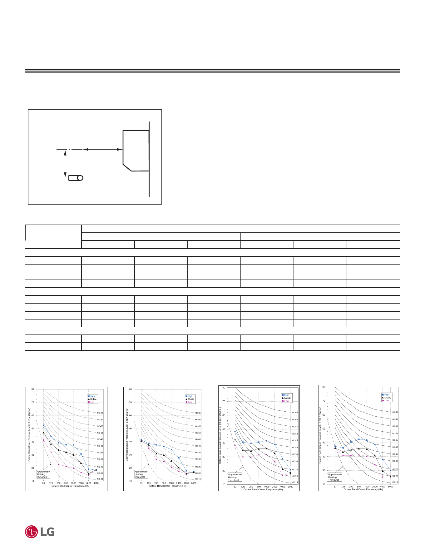
'XHWRRXUSROLF\RIFRQWLQXRXVSURGXFWLQQRYDWLRQVRPHVSHFL¿FDWLRQVPD\FKDQJHZLWKRXWQRWL¿FDWLRQ
©
/*(OHFWURQLFV86$,QF(QJOHZRRG&OLIIV1-$OOULJKWVUHVHUYHG³/*´LVDUHJLVWHUHGWUDGHPDUNRI/*&RUS
39
Product Data
ACOUSTIC DATA
6RXQG3UHVVXUHIRU,QGRRU8QLWV
Figure 24: 6WDQGDUG(I¿FLHQF\0HJDDQG0HJD9
Indoor Unit Sound Pressure Level Measurement
Location.
Figure 25: 6WDQGDUG(I¿FLHQF\0HJDDQG0HJD9,QGRRU8QLW6RXQG3UHVVXUH/HYHO'LDJUDPV
Table 16: 6WDQGDUG(I¿FLHQF\0HJDDQG0HJD9,QGRRU8QLW6RXQG/HYHOVG%>$@
Model Nos.
Sound Pressure Levels (dB[A])
Cooling Heating
HMLHML
Standard Efficiency
KNSAC091A 42 36 28 42 36 28
KNSAC121A 42 36 28 42 36 28
KNSAC181A 48 43 38 48 43 38
KNSAC241A 48 43 38 48 43 38
Mega
KNSAC091A 42 36 28 42 36 28
KNSAC091A 42 36 28 42 36 28
KNSAC091A 48 43 38 48 43 38
KNSAC091A 48 43 38 48 43 38
0HJD9
KNSAC091B 42 36 28 42 36 28
KNSAC091B 42 36 28 42 36 28
2.6 (0.8)
3.3 (1)
Microphone
Unit : ft. (m)
• Measurements are taken 3.3 feet away from the front of the unit.
• Sound pressure levels are measured in dB(A) with a tolerance of ±1.
• Data is valid at nominal operation conditions. Operating conditions are assumed to
be standard.
• 5HIHUHQFHDFRXVWLFSUHVVXUHG% ȝ3D
• Sound pressure levels are tested in an anechoic chamber under ISO Standard
3745, and may be different according to the test condition or equipment.
• Sound level will vary depending on a range of factors including the construction
(acoustic absorption coefficient) of a particular room in which the unit was installed.
Cooling Heating
All 18,000 and 24,000 Btu/h
Cooling Heating
All 9,000 and 12,000 Btu/h

PERFORMANCE DATA
Cooling Capacity on page 41
Maximum Cooling Capacity on page 51
Heating Capacity on page 61
Maximum Heating Capacity on page 71
Correction Factors on page 81
&KHFN6HOHFWLRQRQSDJH

'XHWRRXUSROLF\RIFRQWLQXRXVSURGXFWLQQRYDWLRQVRPHVSHFL¿FDWLRQVPD\FKDQJHZLWKRXWQRWL¿FDWLRQ
©
/*(OHFWURQLFV86$,QF(QJOHZRRG&OLIIV1-$OOULJKWVUHVHUYHG³/*´LVDUHJLVWHUHGWUDGHPDUNRI/*&RUS
41
Performance Data
COOLING CAPACITY
Table 17: 6WDQGDUG(I¿FLHQF\:DOO0RXQWHG6\VWHP.66$($.16$($.86$($&RROLQJ&DSDFLWLHV
Outdoor
Air Temp.
(°F DB)
Indoor Air Temperature (°F DB / °F WB)
64 / 53 68 / 57 72 / 61 77 / 64 80 / 67 86 / 72 90 / 75
TC SHC PI TC SHC PI TC SHC PI TC SHC PI TC SHC PI TC SHC PI TC SHC PI
14 5.53 4.92 0.32 6.92 5.24 0.38 8.30 5.56 0.44 10.03 5.96 0.51 11.07 6.20 0.56 11.84 8.75 0.59 12.35 10.45 0.61
23 5.98 5.08 0.31 7.20 5.40 0.38 8.41 5.73 0.45 9.93 6.14 0.53 10.84 6.39 0.58 11.69 8.45 0.61 12.26 9.82 0.64
25 6.05 5.16 0.32 7.24 5.48 0.39 8.42 5.79 0.45 9.90 6.19 0.53 10.79 6.43 0.58 11.64 8.45 0.62 12.20 9.79 0.65
30 6.23 5.36 0.35 7.34 5.65 0.41 8.44 5.95 0.47 9.83 6.32 0.55 10.66 6.54 0.59 11.50 8.44 0.63 12.06 9.70 0.66
35 6.40 5.56 0.38 7.43 5.83 0.44 8.47 6.10 0.49 9.76 6.44 0.56 10.53 6.64 0.61 11.36 8.43 0.64 11.91 9.62 0.67
40 6.56 5.76 0.41 7.52 6.01 0.46 8.48 6.25 0.51 9.68 6.56 0.58 10.41 6.75 0.62 11.22 8.42 0.66 11.76 9.53 0.68
45 6.72 5.96 0.44 7.61 6.19 0.49 8.50 6.41 0.53 9.61 6.69 0.59 10.28 6.85 0.63 11.08 8.41 0.67 11.62 9.44 0.70
50 6.88 6.16 0.47 7.70 6.36 0.51 8.51 6.56 0.56 9.54 6.81 0.61 10.15 6.96 0.64 10.94 8.40 0.68 11.47 9.36 0.71
55 7.03 6.37 0.50 7.78 6.54 0.54 8.52 6.72 0.58 9.46 6.93 0.63 10.02 7.07 0.65 10.81 8.39 0.69 11.33 9.27 0.72
60 7.17 6.57 0.53 7.85 6.72 0.57 8.53 6.87 0.60 9.38 7.06 0.64 9.89 7.17 0.67 10.67 8.38 0.71 11.18 9.18 0.74
65 7.16 6.54 0.55 7.82 6.73 0.58 8.47 6.91 0.61 9.28 7.14 0.65 9.77 7.28 0.68 10.54 8.43 0.72 11.06 9.19 0.74
70 7.16 6.51 0.57 7.78 6.73 0.60 8.40 6.95 0.63 9.17 7.22 0.67 9.64 7.38 0.69 10.42 8.47 0.73 10.95 9.20 0.75
75 7.15 6.48 0.59 7.74 6.74 0.62 8.33 6.99 0.65 9.07 7.30 0.68 9.51 7.49 0.70 10.30 8.52 0.74 10.83 9.20 0.76
80 7.15 6.45 0.61 7.71 6.74 0.64 8.27 7.02 0.66 8.96 7.38 0.69 9.38 7.59 0.71 10.18 8.56 0.75 10.71 9.21 0.77
85 7.15 6.42 0.63 7.67 6.74 0.65 8.20 7.06 0.68 8.86 7.46 0.71 9.26 7.70 0.73 10.06 8.61 0.76 10.59 9.21 0.78
90 7.15 6.39 0.65 7.64 6.74 0.67 8.14 7.10 0.69 8.76 7.54 0.72 9.13 7.81 0.74 9.94 8.65 0.77 10.48 9.21 0.80
95 7.15 6.36 0.66 7.61 6.75 0.69 8.07 7.13 0.71 8.65 7.62 0.73 9.00 7.91 0.75 9.82 8.69 0.78 10.36 9.21 0.81
100 6.95 6.16 0.67 7.42 6.56 0.69 7.90 6.97 0.72 8.49 7.48 0.74 8.84 7.78 0.76 9.63 8.51 0.79 10.16 9.00 0.82
105 6.75 5.96 0.68 7.23 6.38 0.70 7.72 6.81 0.73 8.32 7.33 0.75 8.69 7.65 0.77 9.44 8.33 0.80 9.95 8.79 0.82
110 6.55 5.77 0.69 7.04 6.21 0.71 7.54 6.64 0.73 8.16 7.19 0.76 8.53 7.51 0.78 9.26 8.16 0.81 9.74 8.58 0.83
115 6.42 5.66 0.70 6.91 6.09 0.72 7.40 6.52 0.74 8.01 7.06 0.77 8.37 7.38 0.79 9.10 8.01 0.82 9.58 8.43 0.85
118 6.35 5.59 0.71 6.83 6.02 0.73 7.31 6.45 0.75 7.92 6.98 0.78 8.28 7.30 0.80 9.00 7.93 0.83 9.48 8.34 0.85
122 6.02 5.63 0.71 6.48 6.06 0.74 6.94 6.50 0.76 7.51 7.04 0.79 7.86 7.36 0.80 8.54 7.99 0.84 8.99 8.41 0.87
DB: Dry Bulb Temperature (°F) WB: Wet Bulb Temperature (°F) TC: Total Capacity (kBtu/h)
SHC: Sensible Capacity (kBtu/h) PI: Power Input (kW) (includes compressor, indoor fan motor and
outdoor fan motor)
1. All capacities are net, evaporator fan motor heat is deducted.
2.Grey shading indicates reference data. Operation outside of the verified temperature range is subject
to decreased performance and / or safety interruption.
3. Direct interpolation is permissible.
Do not extrapolate.
Capacity as rated: 0 ft. above sea level with 24.6 ft. of refrigerant piping. 0 ft. level difference between
outdoor and indoor units.
Cooling capacity rating obtained with air entering the indoor unit at 80ºF dry bulb (DB) and 67ºF wet
bulb (WB), and outdoor ambient conditions of 95ºF dry bulb (DB) and 75ºF wet bulb (WB).
6WDQGDUG(ႈFLHQF\.66$($.16$($.86$($
'XHWRRXUSROLF\RIFRQWLQXRXVSURGXFWLQQRYDWLRQVRPHVSHFL¿FDWLRQVPD\FKDQJHZLWKRXWQRWL¿FDWLRQ
©
/*(OHFWURQLFV86$,QF(QJOHZRRG&OLIIV1-$OOULJKWVUHVHUYHG³/*´LVDUHJLVWHUHGWUDGHPDUNRI/*&RUS
42
56LQJOH=RQH6WDQGDUG(ႈFLHQF\0HJDDQG0HJD9:DOO0RXQWHG(QJLQHHULQJ0DQXDO
COOLING CAPACITY
Table 18: 6WDQGDUG(I¿FLHQF\:DOO0RXQWHG6\VWHP.66$($.16$($.86$($&RROLQJ&DSDFLWLHV
Outdoor
Air Temp.
(°F DB)
Indoor Air Temperature (°F DB / °F WB)
64 / 53 68 / 57 72 / 61 77 / 64 80 / 67 86 / 72 90 / 75
TC SHC PI TC SHC PI TC SHC PI TC SHC PI TC SHC PI TC SHC PI TC SHC PI
14 6.76 5.40 0.39 8.45 5.75 0.46 10.14 6.11 0.54 12.26 6.54 0.63 13.53 6.81 0.68 14.47 9.61 0.72 15.10 11.47 0.74
23 7.31 5.57 0.38 8.80 5.94 0.46 10.28 6.30 0.54 12.14 6.75 0.65 13.25 7.02 0.71 14.29 9.28 0.75 14.98 10.79 0.78
25 7.40 5.66 0.40 8.85 6.01 0.48 10.29 6.36 0.55 12.10 6.80 0.65 13.19 7.06 0.71 14.22 9.27 0.76 14.91 10.75 0.79
30 7.61 5.89 0.43 8.97 6.21 0.51 10.32 6.53 0.58 12.01 6.94 0.67 13.03 7.18 0.73 14.05 9.27 0.77 14.73 10.66 0.81
35 7.82 6.11 0.47 9.08 6.40 0.54 10.35 6.70 0.60 11.93 7.07 0.69 12.87 7.30 0.74 13.88 9.26 0.79 14.56 10.56 0.82
40 8.02 6.33 0.50 9.19 6.60 0.57 10.37 6.87 0.63 11.84 7.21 0.71 12.72 7.41 0.76 13.71 9.25 0.80 14.38 10.47 0.84
45 8.22 6.55 0.54 9.30 6.80 0.60 10.39 7.04 0.65 11.75 7.35 0.73 12.56 7.53 0.77 13.55 9.24 0.82 14.20 10.38 0.85
50 8.41 6.77 0.57 9.41 6.99 0.63 10.41 7.21 0.68 11.66 7.48 0.75 12.41 7.65 0.78 13.38 9.23 0.83 14.02 10.28 0.87
55 8.59 7.00 0.61 9.50 7.19 0.66 10.42 7.38 0.71 11.56 7.62 0.76 12.25 7.76 0.80 13.21 9.22 0.85 13.84 10.19 0.88
60 8.77 7.22 0.65 9.60 7.38 0.69 10.43 7.55 0.73 11.47 7.76 0.78 12.09 7.88 0.81 13.04 9.21 0.87 13.67 10.09 0.90
65 8.76 7.19 0.67 9.55 7.39 0.71 10.35 7.59 0.75 11.34 7.85 0.80 11.94 8.00 0.83 12.89 9.26 0.88 13.52 10.10 0.91
70 8.75 7.16 0.70 9.51 7.40 0.73 10.26 7.64 0.77 11.21 7.94 0.82 11.78 8.12 0.84 12.74 9.31 0.89 13.38 10.11 0.92
75 8.74 7.13 0.72 9.46 7.41 0.76 10.18 7.68 0.79 11.08 8.03 0.83 11.62 8.23 0.86 12.59 9.36 0.90 13.23 10.12 0.94
80 8.74 7.10 0.74 9.42 7.41 0.78 10.10 7.72 0.81 10.96 8.11 0.85 11.47 8.35 0.87 12.44 9.41 0.92 13.09 10.12 0.95
85 8.73 7.06 0.77 9.38 7.41 0.80 10.02 7.76 0.83 10.83 8.20 0.87 11.31 8.47 0.89 12.29 9.46 0.93 12.95 10.13 0.96
90 8.73 7.03 0.79 9.34 7.42 0.82 9.94 7.81 0.85 10.70 8.29 0.88 11.16 8.58 0.90 12.15 9.51 0.94 12.81 10.13 0.97
95 8.74 6.99 0.81 9.30 7.42 0.84 9.87 7.85 0.86 10.58 8.38 0.90 11.00 8.70 0.92 12.00 9.56 0.96 12.67 10.13 0.98
100 8.49 6.79 0.82 9.07 7.23 0.85 9.65 7.68 0.88 10.37 8.24 0.91 10.81 8.57 0.93 11.77 9.38 0.97 12.41 9.92 1.00
105 8.25 6.58 0.83 8.84 7.05 0.86 9.43 7.51 0.89 10.17 8.09 0.92 10.62 8.44 0.94 11.54 9.20 0.98 12.16 9.70 1.01
110 8.00 6.38 0.84 8.61 6.86 0.87 9.22 7.34 0.90 9.97 7.94 0.93 10.43 8.31 0.95 11.32 9.02 0.99 11.91 9.49 1.02
115 7.85 6.26 0.86 8.45 6.74 0.88 9.04 7.22 0.91 9.79 7.82 0.94 10.23 8.17 0.96 11.12 8.87 1.01 11.70 9.34 1.04
118 7.76 6.19 0.86 8.35 6.67 0.89 8.94 7.15 0.92 9.68 7.74 0.95 10.12 8.10 0.97 11.00 8.79 1.02 11.58 9.25 1.04
122 7.36 6.19 0.87 7.92 6.67 0.90 8.48 7.14 0.93 9.18 7.74 0.96 9.60 8.09 0.98 10.44 8.78 1.03 10.99 9.25 1.06
6WDQGDUG(ႈFLHQF\.66$($.16$($.86$($
DB: Dry Bulb Temperature (°F) WB: Wet Bulb Temperature (°F) TC: Total Capacity (kBtu/h)
SHC: Sensible Capacity (kBtu/h) PI: Power Input (kW) (includes compressor, indoor fan motor and
outdoor fan motor)
1. All capacities are net, evaporator fan motor heat is deducted.
2.Grey shading indicates reference data. Operation outside of the verified temperature range is subject
to decreased performance and / or safety interruption.
3. Direct interpolation is permissible.
Do not extrapolate.
Capacity as rated: 0 ft. above sea level with 24.6 ft. of refrigerant piping. 0 ft. level difference between
outdoor and indoor units.
Cooling capacity rating obtained with air entering the indoor unit at 80ºF dry bulb (DB) and 67ºF wet
bulb (WB), and outdoor ambient conditions of 95ºF dry bulb (DB) and 75ºF wet bulb (WB).
'XHWRRXUSROLF\RIFRQWLQXRXVSURGXFWLQQRYDWLRQVRPHVSHFL¿FDWLRQVPD\FKDQJHZLWKRXWQRWL¿FDWLRQ
©
/*(OHFWURQLFV86$,QF(QJOHZRRG&OLIIV1-$OOULJKWVUHVHUYHG³/*´LVDUHJLVWHUHGWUDGHPDUNRI/*&RUS
43
Performance Data
COOLING CAPACITY
Table 19: 6WDQGDUG(I¿FLHQF\:DOO0RXQWHG6\VWHP.66$($.16$($.86$($&RROLQJ&DSDFLWLHV
Outdoor
Air Temp.
(°F DB)
Indoor Air Temperature (°F DB / °F WB)
64 / 53 68 / 57 72 / 61 77 / 64 80 / 67 86 / 72 90 / 75
TC SHC PI TC SHC PI TC SHC PI TC SHC PI TC SHC PI TC SHC PI TC SHC PI
14 11.06 8.81 0.64 13.83 9.38 0.76 16.60 9.95 0.88 20.06 10.66 1.02 22.14 11.09 1.11 23.68 15.66 1.17 24.70 18.70 1.21
23 11.97 9.08 0.63 14.39 9.67 0.76 16.82 10.26 0.89 19.86 10.99 1.05 21.68 11.43 1.15 23.38 15.12 1.23 24.52 17.58 1.28
25 12.11 9.23 0.65 14.48 9.80 0.78 16.84 10.37 0.91 19.80 11.08 1.07 21.58 11.51 1.16 23.27 15.11 1.24 24.40 17.51 1.29
30 12.46 9.59 0.71 14.67 10.12 0.83 16.89 10.64 0.95 19.66 11.30 1.10 21.32 11.70 1.19 23.00 15.10 1.26 24.11 17.36 1.32
35 12.80 9.95 0.76 14.86 10.44 0.87 16.93 10.92 0.99 19.52 11.53 1.13 21.07 11.89 1.21 22.72 15.08 1.29 23.82 17.21 1.34
40 13.12 10.31 0.82 15.05 10.75 0.92 16.97 11.20 1.03 19.37 11.75 1.16 20.81 12.08 1.24 22.44 15.06 1.31 23.53 17.06 1.37
45 13.44 10.67 0.88 15.22 11.07 0.97 17.00 11.47 1.07 19.22 11.97 1.19 20.56 12.27 1.26 22.16 15.05 1.34 23.24 16.90 1.39
50 13.75 11.03 0.94 15.39 11.39 1.03 17.03 11.75 1.11 19.07 12.19 1.22 20.30 12.46 1.28 21.89 15.03 1.36 22.95 16.75 1.42
55 14.06 11.40 1.00 15.55 11.71 1.08 17.05 12.02 1.15 18.92 12.41 1.25 20.04 12.65 1.31 21.61 15.02 1.39 22.66 16.59 1.44
60 14.35 11.76 1.06 15.71 12.03 1.13 17.07 12.30 1.20 18.77 12.64 1.28 19.79 12.84 1.33 21.33 15.00 1.41 22.36 16.44 1.47
65 14.33 11.71 1.10 15.63 12.04 1.17 16.93 12.37 1.23 18.56 12.78 1.31 19.53 13.03 1.36 21.09 15.08 1.44 22.13 16.45 1.49
70 14.31 11.66 1.14 15.56 12.05 1.20 16.80 12.44 1.26 18.35 12.93 1.33 19.28 13.22 1.38 20.85 15.17 1.46 21.89 16.47 1.51
75 14.30 11.61 1.18 15.48 12.06 1.24 16.66 12.51 1.29 18.14 13.07 1.36 19.02 13.41 1.40 20.60 15.25 1.48 21.66 16.48 1.53
80 14.30 11.56 1.22 15.41 12.07 1.27 16.53 12.58 1.32 17.93 13.21 1.39 18.77 13.60 1.43 20.36 15.33 1.50 21.42 16.48 1.55
85 14.29 11.50 1.26 15.35 12.07 1.30 16.40 12.64 1.35 17.72 13.36 1.42 18.51 13.79 1.45 20.12 15.41 1.52 21.19 16.49 1.57
90 14.29 11.44 1.29 15.28 12.08 1.34 16.27 12.71 1.38 17.51 13.50 1.44 18.26 13.98 1.48 19.88 15.49 1.54 20.96 16.49 1.59
95 14.29 11.38 1.33 15.22 12.08 1.37 16.15 12.77 1.41 17.31 13.64 1.47 18.00 14.17 1.50 19.63 15.56 1.57 20.72 16.50 1.61
100 13.89 11.05 1.35 14.84 11.78 1.39 15.79 12.50 1.43 16.98 13.41 1.49 17.69 13.96 1.52 19.26 15.27 1.59 20.31 16.15 1.63
105 13.50 10.72 1.36 14.47 11.48 1.41 15.44 12.23 1.45 16.65 13.18 1.51 17.37 13.75 1.54 18.89 14.98 1.61 19.90 15.80 1.65
110 13.10 10.39 1.38 14.09 11.18 1.43 15.08 11.96 1.47 16.32 12.95 1.53 17.06 13.53 1.56 18.52 14.69 1.62 19.49 15.46 1.67
115 12.85 10.21 1.40 13.82 10.99 1.44 14.80 11.77 1.49 16.02 12.74 1.54 16.75 13.32 1.58 18.19 14.46 1.65 19.15 15.22 1.69
118 12.70 10.10 1.41 13.66 10.87 1.46 14.63 11.65 1.50 15.84 12.62 1.56 16.56 13.20 1.59 18.00 14.32 1.66 18.95 15.07 1.71
122 12.05 10.08 1.43 12.96 10.86 1.47 13.88 11.63 1.52 15.03 12.60 1.58 15.71 13.18 1.61 17.08 14.30 1.68 17.98 15.05 1.73
6WDQGDUG(ႈFLHQF\.66$($.16$($.86$($
DB: Dry Bulb Temperature (°F) WB: Wet Bulb Temperature (°F) TC: Total Capacity (kBtu/h)
SHC: Sensible Capacity (kBtu/h) PI: Power Input (kW) (includes compressor, indoor fan motor and
outdoor fan motor)
1. All capacities are net, evaporator fan motor heat is deducted.
2.Grey shading indicates reference data. Operation outside of the verified temperature range is subject
to decreased performance and / or safety interruption.
3. Direct interpolation is permissible.
Do not extrapolate.
Capacity as rated: 0 ft. above sea level with 24.6 ft. of refrigerant piping. 0 ft. level difference between
outdoor and indoor units.
Cooling capacity rating obtained with air entering the indoor unit at 80ºF dry bulb (DB) and 67ºF wet
bulb (WB), and outdoor ambient conditions of 95ºF dry bulb (DB) and 75ºF wet bulb (WB).

'XHWRRXUSROLF\RIFRQWLQXRXVSURGXFWLQQRYDWLRQVRPHVSHFL¿FDWLRQVPD\FKDQJHZLWKRXWQRWL¿FDWLRQ
©
/*(OHFWURQLFV86$,QF(QJOHZRRG&OLIIV1-$OOULJKWVUHVHUYHG³/*´LVDUHJLVWHUHGWUDGHPDUNRI/*&RUS
44
56LQJOH=RQH6WDQGDUG(ႈFLHQF\0HJDDQG0HJD9:DOO0RXQWHG(QJLQHHULQJ0DQXDO
COOLING CAPACITY
Table 20: 6WDQGDUG(I¿FLHQF\:DOO0RXQWHG6\VWHP.66$($.16$($.86$($&RROLQJ&DSDFLWLHV
Outdoor
Air Temp.
(°F DB)
Indoor Air Temperature (°F DB / °F WB)
64 / 53 68 / 57 72 / 61 77 / 64 80 / 67 86 / 72 90 / 75
TC SHC PI TC SHC PI TC SHC PI TC SHC PI TC SHC PI TC SHC PI TC SHC PI
14 13.03 9.86 0.75 16.29 10.50 0.89 19.55 11.13 1.03 23.63 11.93 1.20 26.08 12.41 1.31 27.89 17.52 1.38 29.09 20.92 1.43
23 14.09 10.17 0.74 16.95 10.83 0.89 19.81 11.48 1.05 23.39 12.31 1.24 25.53 12.80 1.36 27.54 16.93 1.45 28.88 19.68 1.51
25 14.26 10.33 0.77 17.05 10.97 0.92 19.84 11.61 1.07 23.32 12.41 1.26 25.41 12.89 1.37 27.41 16.92 1.46 28.74 19.61 1.52
30 14.67 10.74 0.83 17.28 11.33 0.97 19.89 11.92 1.12 23.15 12.66 1.29 25.11 13.10 1.40 27.08 16.91 1.49 28.40 19.44 1.55
35 15.07 11.15 0.90 17.51 11.69 1.03 19.94 12.23 1.16 22.99 12.91 1.33 24.81 13.32 1.43 26.76 16.89 1.52 28.05 19.28 1.58
40 15.46 11.55 0.97 17.72 12.05 1.09 19.98 12.54 1.21 22.81 13.16 1.36 24.51 13.53 1.46 26.43 16.88 1.55 27.71 19.11 1.61
45 15.83 11.96 1.04 17.93 12.41 1.15 20.02 12.85 1.26 22.64 13.41 1.40 24.21 13.75 1.48 26.10 16.86 1.58 27.37 18.94 1.64
50 16.20 12.37 1.11 18.13 12.77 1.21 20.05 13.16 1.31 22.46 13.66 1.44 23.91 13.96 1.51 25.78 16.85 1.61 27.03 18.77 1.67
55 16.55 12.77 1.18 18.32 13.12 1.27 20.08 13.48 1.36 22.29 13.91 1.47 23.61 14.18 1.54 25.45 16.83 1.64 26.68 18.60 1.70
60 16.90 13.18 1.25 18.50 13.48 1.33 20.10 13.79 1.41 22.10 14.17 1.51 23.31 14.39 1.57 25.13 16.82 1.67 26.34 18.43 1.73
65 16.88 13.13 1.30 18.41 13.50 1.37 19.94 13.87 1.45 21.86 14.33 1.54 23.01 14.61 1.60 24.84 16.91 1.69 26.06 18.45 1.76
70 16.86 13.08 1.34 18.32 13.51 1.41 19.78 13.95 1.49 21.61 14.50 1.57 22.70 14.82 1.63 24.55 17.01 1.72 25.78 18.47 1.78
75 16.85 13.02 1.39 18.24 13.53 1.46 19.63 14.03 1.52 21.36 14.66 1.60 22.40 15.04 1.65 24.26 17.10 1.74 25.51 18.48 1.80
80 16.84 12.96 1.43 18.15 13.54 1.50 19.47 14.11 1.56 21.12 14.82 1.64 22.10 15.25 1.68 23.98 17.20 1.77 25.23 18.49 1.83
85 16.83 12.90 1.48 18.07 13.55 1.54 19.32 14.19 1.59 20.87 14.99 1.67 21.80 15.47 1.71 23.69 17.29 1.79 24.95 18.50 1.85
90 16.83 12.84 1.52 18.00 13.55 1.58 19.17 14.26 1.63 20.63 15.15 1.70 21.50 15.68 1.74 23.41 17.38 1.82 24.68 18.51 1.87
95 16.83 12.78 1.57 17.93 13.56 1.62 19.02 14.34 1.67 20.38 15.31 1.73 21.20 15.90 1.77 23.13 17.47 1.85 24.41 18.52 1.90
100 16.36 12.39 1.59 17.48 13.20 1.64 18.60 14.01 1.69 19.99 15.03 1.75 20.83 15.64 1.79 22.69 17.12 1.87 23.92 18.10 1.92
105 15.90 12.00 1.61 17.04 12.84 1.66 18.18 13.69 1.71 19.61 14.75 1.77 20.46 15.38 1.81 22.25 16.76 1.89 23.44 17.68 1.94
110 15.43 11.61 1.63 16.59 12.49 1.68 17.76 13.37 1.73 19.22 14.46 1.80 20.09 15.12 1.84 21.81 16.41 1.91 22.95 17.27 1.97
115 15.13 11.39 1.65 16.28 12.26 1.70 17.43 13.12 1.75 18.86 14.21 1.82 19.73 14.86 1.86 21.42 16.13 1.94 22.56 16.97 2.00
118 14.95 11.25 1.66 16.09 12.12 1.72 17.23 12.98 1.77 18.65 14.06 1.83 19.50 14.71 1.87 21.19 15.96 1.96 22.32 16.80 2.01
122 14.19 11.32 1.68 15.27 12.19 1.74 16.35 13.05 1.79 17.70 14.14 1.86 18.51 14.79 1.90 20.11 16.05 1.98 21.18 16.89 2.04
6WDQGDUG(ႈFLHQF\.66$($.16$($.86$($
DB: Dry Bulb Temperature (°F) WB: Wet Bulb Temperature (°F) TC: Total Capacity (kBtu/h)
SHC: Sensible Capacity (kBtu/h) PI: Power Input (kW) (includes compressor, indoor fan motor and
outdoor fan motor)
1. All capacities are net, evaporator fan motor heat is deducted.
2.Grey shading indicates reference data. Operation outside of the verified temperature range is subject
to decreased performance and / or safety interruption.
3. Direct interpolation is permissible.
Do not extrapolate.
Capacity as rated: 0 ft. above sea level with 24.6 ft. of refrigerant piping. 0 ft. level difference between
outdoor and indoor units.
Cooling capacity rating obtained with air entering the indoor unit at 80ºF dry bulb (DB) and 67ºF wet
bulb (WB), and outdoor ambient conditions of 95ºF dry bulb (DB) and 75ºF wet bulb (WB).
'XHWRRXUSROLF\RIFRQWLQXRXVSURGXFWLQQRYDWLRQVRPHVSHFL¿FDWLRQVPD\FKDQJHZLWKRXWQRWL¿FDWLRQ
©
/*(OHFWURQLFV86$,QF(QJOHZRRG&OLIIV1-$OOULJKWVUHVHUYHG³/*´LVDUHJLVWHUHGWUDGHPDUNRI/*&RUS
45
Performance Data
COOLING CAPACITY
Table 21: Mega Wall-Mounted System KSSAC091A / KNSAC091A - KUSAC091A Cooling Capacities.
Outdoor
Air Temp.
(°F DB)
Indoor Air Temperature (°F DB / °F WB)
64 / 53 68 / 57 72 / 61 77 / 64 80 / 67 86 / 72 90 / 75
TC SHC PI TC SHC PI TC SHC PI TC SHC PI TC SHC PI TC SHC PI TC SHC PI
14 5.53 4.92 0.31 6.92 5.24 0.36 8.30 5.56 0.42 10.03 5.96 0.49 11.07 6.20 0.53 11.84 8.75 0.56 12.35 10.45 0.58
23 5.98 5.08 0.30 7.20 5.40 0.36 8.41 5.73 0.43 9.93 6.14 0.51 10.84 6.39 0.55 11.69 8.45 0.59 12.26 9.82 0.61
25 6.05 5.16 0.31 7.24 5.48 0.37 8.42 5.79 0.44 9.90 6.19 0.51 10.79 6.43 0.56 11.64 8.45 0.60 12.20 9.79 0.62
30 6.23 5.36 0.34 7.34 5.65 0.40 8.44 5.95 0.45 9.83 6.32 0.53 10.66 6.54 0.57 11.50 8.44 0.61 12.06 9.70 0.63
35 6.40 5.56 0.37 7.43 5.83 0.42 8.47 6.10 0.47 9.76 6.44 0.54 10.53 6.64 0.58 11.36 8.43 0.62 11.91 9.62 0.64
40 6.56 5.76 0.39 7.52 6.01 0.44 8.48 6.25 0.49 9.68 6.56 0.56 10.41 6.75 0.59 11.22 8.42 0.63 11.76 9.53 0.66
45 6.72 5.96 0.42 7.61 6.19 0.47 8.50 6.41 0.51 9.61 6.69 0.57 10.28 6.85 0.60 11.08 8.41 0.64 11.62 9.44 0.67
50 6.88 6.16 0.45 7.70 6.36 0.49 8.51 6.56 0.53 9.54 6.81 0.59 10.15 6.96 0.62 10.94 8.40 0.66 11.47 9.36 0.68
55 7.03 6.37 0.48 7.78 6.54 0.52 8.52 6.72 0.55 9.46 6.93 0.60 10.02 7.07 0.63 10.81 8.39 0.67 11.33 9.27 0.69
60 7.17 6.57 0.51 7.85 6.72 0.54 8.53 6.87 0.57 9.38 7.06 0.62 9.89 7.17 0.64 10.67 8.38 0.68 11.18 9.18 0.71
65 7.16 6.54 0.53 7.82 6.73 0.56 8.47 6.91 0.59 9.28 7.14 0.63 9.77 7.28 0.65 10.54 8.43 0.69 11.06 9.19 0.72
70 7.16 6.51 0.55 7.78 6.73 0.58 8.40 6.95 0.61 9.17 7.22 0.64 9.64 7.38 0.66 10.42 8.47 0.70 10.95 9.20 0.72
75 7.15 6.48 0.57 7.74 6.74 0.59 8.33 6.99 0.62 9.07 7.30 0.65 9.51 7.49 0.67 10.30 8.52 0.71 10.83 9.20 0.73
80 7.15 6.45 0.58 7.71 6.74 0.61 8.27 7.02 0.63 8.96 7.38 0.67 9.38 7.59 0.69 10.18 8.56 0.72 10.71 9.21 0.74
85 7.15 6.42 0.60 7.67 6.74 0.63 8.20 7.06 0.65 8.86 7.46 0.68 9.26 7.70 0.70 10.06 8.61 0.73 10.59 9.21 0.75
90 7.15 6.39 0.62 7.64 6.74 0.64 8.14 7.10 0.66 8.76 7.54 0.69 9.13 7.81 0.71 9.94 8.65 0.74 10.48 9.21 0.76
95 7.15 6.36 0.64 7.61 6.75 0.66 8.07 7.13 0.68 8.65 7.62 0.70 9.00 7.91 0.72 9.82 8.69 0.75 10.36 9.21 0.77
100 6.95 6.16 0.65 7.42 6.56 0.67 7.90 6.97 0.69 8.49 7.48 0.71 8.84 7.78 0.73 9.63 8.51 0.76 10.16 9.00 0.78
105 6.75 5.96 0.65 7.23 6.38 0.68 7.72 6.81 0.70 8.32 7.33 0.72 8.69 7.65 0.74 9.44 8.33 0.77 9.95 8.79 0.79
110 6.55 5.77 0.66 7.04 6.21 0.68 7.54 6.64 0.71 8.16 7.19 0.73 8.53 7.51 0.75 9.26 8.16 0.78 9.74 8.58 0.80
115 6.42 5.66 0.67 6.91 6.09 0.69 7.40 6.52 0.71 8.01 7.06 0.74 8.37 7.38 0.76 9.10 8.01 0.79 9.58 8.43 0.81
118 6.35 5.59 0.68 6.83 6.02 0.70 7.31 6.45 0.72 7.92 6.98 0.75 8.28 7.30 0.76 9.00 7.93 0.80 9.48 8.34 0.82
122 6.02 5.63 0.69 6.48 6.06 0.71 6.94 6.50 0.73 7.51 7.04 0.76 7.86 7.36 0.77 8.54 7.99 0.81 8.99 8.41 0.83
0HJD.66$&$.16$&$.86$&$
DB: Dry Bulb Temperature (°F) WB: Wet Bulb Temperature (°F) TC: Total Capacity (kBtu/h)
SHC: Sensible Capacity (kBtu/h) PI: Power Input (kW) (includes compressor, indoor fan motor and
outdoor fan motor)
1. All capacities are net, evaporator fan motor heat is deducted.
2.Grey shading indicates reference data. Operation outside of the verified temperature range is subject
to decreased performance and / or safety interruption.
3. Direct interpolation is permissible.
Do not extrapolate.
Capacity as rated: 0 ft. above sea level with 24.6 ft. of refrigerant piping. 0 ft. level difference between
outdoor and indoor units.
Cooling capacity rating obtained with air entering the indoor unit at 80ºF dry bulb (DB) and 67ºF wet
bulb (WB), and outdoor ambient conditions of 95ºF dry bulb (DB) and 75ºF wet bulb (WB).

'XHWRRXUSROLF\RIFRQWLQXRXVSURGXFWLQQRYDWLRQVRPHVSHFL¿FDWLRQVPD\FKDQJHZLWKRXWQRWL¿FDWLRQ
©
/*(OHFWURQLFV86$,QF(QJOHZRRG&OLIIV1-$OOULJKWVUHVHUYHG³/*´LVDUHJLVWHUHGWUDGHPDUNRI/*&RUS
46
56LQJOH=RQH6WDQGDUG(ႈFLHQF\0HJDDQG0HJD9:DOO0RXQWHG(QJLQHHULQJ0DQXDO
COOLING CAPACITY
Table 22: Mega Wall-Mounted System KSSAC121A / KNSAC121A - KUSAC121A Cooling Capacities.
Outdoor
Air Temp.
(°F DB)
Indoor Air Temperature (°F DB / °F WB)
64 / 53 68 / 57 72 / 61 77 / 64 80 / 67 86 / 72 90 / 75
TC SHC PI TC SHC PI TC SHC PI TC SHC PI TC SHC PI TC SHC PI TC SHC PI
14 6.76 5.40 0.38 8.45 5.75 0.45 10.14 6.11 0.52 12.26 6.54 0.61 13.53 6.81 0.66 14.47 9.61 0.70 15.10 11.47 0.72
23 7.31 5.57 0.37 8.80 5.94 0.45 10.28 6.30 0.53 12.14 6.75 0.63 13.25 7.02 0.69 14.29 9.28 0.73 14.98 10.79 0.76
25 7.40 5.66 0.39 8.85 6.01 0.46 10.29 6.36 0.54 12.10 6.80 0.64 13.19 7.06 0.69 14.22 9.27 0.74 14.91 10.75 0.77
30 7.61 5.89 0.42 8.97 6.21 0.49 10.32 6.53 0.56 12.01 6.94 0.65 13.03 7.18 0.71 14.05 9.27 0.75 14.73 10.66 0.79
35 7.82 6.11 0.45 9.08 6.40 0.52 10.35 6.70 0.59 11.93 7.07 0.67 12.87 7.30 0.72 13.88 9.26 0.77 14.56 10.56 0.80
40 8.02 6.33 0.49 9.19 6.60 0.55 10.37 6.87 0.61 11.84 7.21 0.69 12.72 7.41 0.74 13.71 9.25 0.78 14.38 10.47 0.82
45 8.22 6.55 0.52 9.30 6.80 0.58 10.39 7.04 0.64 11.75 7.35 0.71 12.56 7.53 0.75 13.55 9.24 0.80 14.20 10.38 0.83
50 8.41 6.77 0.56 9.41 6.99 0.61 10.41 7.21 0.66 11.66 7.48 0.73 12.41 7.65 0.77 13.38 9.23 0.81 14.02 10.28 0.85
55 8.59 7.00 0.60 9.50 7.19 0.64 10.42 7.38 0.69 11.56 7.62 0.75 12.25 7.76 0.78 13.21 9.22 0.83 13.84 10.19 0.86
60 8.77 7.22 0.63 9.60 7.38 0.67 10.43 7.55 0.71 11.47 7.76 0.76 12.09 7.88 0.79 13.04 9.21 0.84 13.67 10.09 0.88
65 8.76 7.19 0.66 9.55 7.39 0.70 10.35 7.59 0.73 11.34 7.85 0.78 11.94 8.00 0.81 12.89 9.26 0.86 13.52 10.10 0.89
70 8.75 7.16 0.68 9.51 7.40 0.72 10.26 7.64 0.75 11.21 7.94 0.80 11.78 8.12 0.82 12.74 9.31 0.87 13.38 10.11 0.90
75 8.74 7.13 0.70 9.46 7.41 0.74 10.18 7.68 0.77 11.08 8.03 0.81 11.62 8.23 0.84 12.59 9.36 0.88 13.23 10.12 0.91
80 8.74 7.10 0.73 9.42 7.41 0.76 10.10 7.72 0.79 10.96 8.11 0.83 11.47 8.35 0.85 12.44 9.41 0.89 13.09 10.12 0.92
85 8.73 7.06 0.75 9.38 7.41 0.78 10.02 7.76 0.81 10.83 8.20 0.84 11.31 8.47 0.87 12.29 9.46 0.91 12.95 10.13 0.94
90 8.73 7.03 0.77 9.34 7.42 0.80 9.94 7.81 0.83 10.70 8.29 0.86 11.16 8.58 0.88 12.15 9.51 0.92 12.81 10.13 0.95
95 8.74 6.99 0.79 9.30 7.42 0.82 9.87 7.85 0.84 10.58 8.38 0.87 11.00 8.70 0.89 12.00 9.56 0.93 12.67 10.13 0.96
100 8.49 6.79 0.80 9.07 7.23 0.83 9.65 7.68 0.85 10.37 8.24 0.89 10.81 8.57 0.91 11.77 9.38 0.95 12.41 9.92 0.97
105 8.25 6.58 0.81 8.84 7.05 0.84 9.43 7.51 0.87 10.17 8.09 0.90 10.62 8.44 0.92 11.54 9.20 0.96 12.16 9.70 0.98
110 8.00 6.38 0.82 8.61 6.86 0.85 9.22 7.34 0.88 9.97 7.94 0.91 10.43 8.31 0.93 11.32 9.02 0.97 11.91 9.49 0.99
115 7.85 6.26 0.83 8.45 6.74 0.86 9.04 7.22 0.89 9.79 7.82 0.92 10.23 8.17 0.94 11.12 8.87 0.98 11.70 9.34 1.01
118 7.76 6.19 0.84 8.35 6.67 0.87 8.94 7.15 0.89 9.68 7.74 0.93 10.12 8.10 0.95 11.00 8.79 0.99 11.58 9.25 1.02
122 7.36 6.19 0.85 7.92 6.67 0.88 8.48 7.14 0.91 9.18 7.74 0.94 9.60 8.09 0.96 10.44 8.78 1.00 10.99 9.25 1.03
0HJD.66$&$.16$&$.86$&$
DB: Dry Bulb Temperature (°F) WB: Wet Bulb Temperature (°F) TC: Total Capacity (kBtu/h)
SHC: Sensible Capacity (kBtu/h) PI: Power Input (kW) (includes compressor, indoor fan motor and
outdoor fan motor)
1. All capacities are net, evaporator fan motor heat is deducted.
2.Grey shading indicates reference data. Operation outside of the verified temperature range is subject
to decreased performance and / or safety interruption.
3. Direct interpolation is permissible.
Do not extrapolate.
Capacity as rated: 0 ft. above sea level with 24.6 ft. of refrigerant piping. 0 ft. level difference between
outdoor and indoor units.
Cooling capacity rating obtained with air entering the indoor unit at 80ºF dry bulb (DB) and 67ºF wet
bulb (WB), and outdoor ambient conditions of 95ºF dry bulb (DB) and 75ºF wet bulb (WB).

'XHWRRXUSROLF\RIFRQWLQXRXVSURGXFWLQQRYDWLRQVRPHVSHFL¿FDWLRQVPD\FKDQJHZLWKRXWQRWL¿FDWLRQ
©
/*(OHFWURQLFV86$,QF(QJOHZRRG&OLIIV1-$OOULJKWVUHVHUYHG³/*´LVDUHJLVWHUHGWUDGHPDUNRI/*&RUS
47
Performance Data
COOLING CAPACITY
Table 23: Mega Wall-Mounted System KSSAC181A / KNSAC181A - KUSAC181A Cooling Capacities.
Outdoor
Air Temp.
(°F DB)
Indoor Air Temperature (°F DB / °F WB)
64 / 53 68 / 57 72 / 61 77 / 64 80 / 67 86 / 72 90 / 75
TC SHC PI TC SHC PI TC SHC PI TC SHC PI TC SHC PI TC SHC PI TC SHC PI
14 11.06 8.81 0.62 13.83 9.38 0.73 16.60 9.95 0.84 20.06 10.66 0.98 22.14 11.09 1.07 23.68 15.66 1.13 24.70 18.70 1.16
23 11.97 9.08 0.60 14.39 9.67 0.73 16.82 10.26 0.86 19.86 10.99 1.01 21.68 11.43 1.11 23.38 15.12 1.18 24.52 17.58 1.23
25 12.11 9.23 0.62 14.48 9.80 0.75 16.84 10.37 0.87 19.80 11.08 1.02 21.58 11.51 1.12 23.27 15.11 1.19 24.40 17.51 1.24
30 12.46 9.59 0.68 14.67 10.12 0.79 16.89 10.64 0.91 19.66 11.30 1.05 21.32 11.70 1.14 23.00 15.10 1.21 24.11 17.36 1.26
35 12.80 9.95 0.73 14.86 10.44 0.84 16.93 10.92 0.95 19.52 11.53 1.08 21.07 11.89 1.16 22.72 15.08 1.24 23.82 17.21 1.29
40 13.12 10.31 0.79 15.05 10.75 0.89 16.97 11.20 0.99 19.37 11.75 1.11 20.81 12.08 1.19 22.44 15.06 1.26 23.53 17.06 1.31
45 13.44 10.67 0.85 15.22 11.07 0.94 17.00 11.47 1.03 19.22 11.97 1.14 20.56 12.27 1.21 22.16 15.05 1.29 23.24 16.90 1.34
50 13.75 11.03 0.90 15.39 11.39 0.99 17.03 11.75 1.07 19.07 12.19 1.17 20.30 12.46 1.23 21.89 15.03 1.31 22.95 16.75 1.36
55 14.06 11.40 0.96 15.55 11.71 1.03 17.05 12.02 1.11 18.92 12.41 1.20 20.04 12.65 1.26 21.61 15.02 1.33 22.66 16.59 1.39
60 14.35 11.76 1.02 15.71 12.03 1.09 17.07 12.30 1.15 18.77 12.64 1.23 19.79 12.84 1.28 21.33 15.00 1.36 22.36 16.44 1.41
65 14.33 11.71 1.06 15.63 12.04 1.12 16.93 12.37 1.18 18.56 12.78 1.26 19.53 13.03 1.30 21.09 15.08 1.38 22.13 16.45 1.43
70 14.31 11.66 1.10 15.56 12.05 1.15 16.80 12.44 1.21 18.35 12.93 1.28 19.28 13.22 1.32 20.85 15.17 1.40 21.89 16.47 1.45
75 14.30 11.61 1.13 15.48 12.06 1.19 16.66 12.51 1.24 18.14 13.07 1.31 19.02 13.41 1.35 20.60 15.25 1.42 21.66 16.48 1.47
80 14.30 11.56 1.17 15.41 12.07 1.22 16.53 12.58 1.27 17.93 13.21 1.33 18.77 13.60 1.37 20.36 15.33 1.44 21.42 16.48 1.49
85 14.29 11.50 1.21 15.35 12.07 1.25 16.40 12.64 1.30 17.72 13.36 1.36 18.51 13.79 1.39 20.12 15.41 1.46 21.19 16.49 1.51
90 14.29 11.44 1.24 15.28 12.08 1.28 16.27 12.71 1.33 17.51 13.50 1.38 18.26 13.98 1.42 19.88 15.49 1.48 20.96 16.49 1.53
95 14.29 11.38 1.28 15.22 12.08 1.32 16.15 12.77 1.36 17.31 13.64 1.41 18.00 14.17 1.44 19.63 15.56 1.50 20.72 16.50 1.55
100 13.89 11.05 1.29 14.84 11.78 1.33 15.79 12.50 1.38 16.98 13.41 1.43 17.69 13.96 1.46 19.26 15.27 1.52 20.31 16.15 1.56
105 13.50 10.72 1.31 14.47 11.48 1.35 15.44 12.23 1.39 16.65 13.18 1.45 17.37 13.75 1.48 18.89 14.98 1.54 19.90 15.80 1.58
110 13.10 10.39 1.33 14.09 11.18 1.37 15.08 11.96 1.41 16.32 12.95 1.46 17.06 13.53 1.50 18.52 14.69 1.56 19.49 15.46 1.60
115 12.85 10.21 1.34 13.82 10.99 1.39 14.80 11.77 1.43 16.02 12.74 1.48 16.75 13.32 1.51 18.19 14.46 1.58 19.15 15.22 1.63
118 12.70 10.10 1.35 13.66 10.87 1.40 14.63 11.65 1.44 15.84 12.62 1.49 16.56 13.20 1.53 18.00 14.32 1.59 18.95 15.07 1.64
122 12.05 10.08 1.37 12.96 10.86 1.42 13.88 11.63 1.46 15.03 12.60 1.51 15.71 13.18 1.55 17.08 14.30 1.61 17.98 15.05 1.66
0HJD.66$&$.16$&$.86$&$
DB: Dry Bulb Temperature (°F) WB: Wet Bulb Temperature (°F) TC: Total Capacity (kBtu/h)
SHC: Sensible Capacity (kBtu/h) PI: Power Input (kW) (includes compressor, indoor fan motor and
outdoor fan motor)
1. All capacities are net, evaporator fan motor heat is deducted.
2.Grey shading indicates reference data. Operation outside of the verified temperature range is subject
to decreased performance and / or safety interruption.
3. Direct interpolation is permissible.
Do not extrapolate.
Capacity as rated: 0 ft. above sea level with 24.6 ft. of refrigerant piping. 0 ft. level difference between
outdoor and indoor units.
Cooling capacity rating obtained with air entering the indoor unit at 80ºF dry bulb (DB) and 67ºF wet
bulb (WB), and outdoor ambient conditions of 95ºF dry bulb (DB) and 75ºF wet bulb (WB).

'XHWRRXUSROLF\RIFRQWLQXRXVSURGXFWLQQRYDWLRQVRPHVSHFL¿FDWLRQVPD\FKDQJHZLWKRXWQRWL¿FDWLRQ
©
/*(OHFWURQLFV86$,QF(QJOHZRRG&OLIIV1-$OOULJKWVUHVHUYHG³/*´LVDUHJLVWHUHGWUDGHPDUNRI/*&RUS
48
56LQJOH=RQH6WDQGDUG(ႈFLHQF\0HJDDQG0HJD9:DOO0RXQWHG(QJLQHHULQJ0DQXDO
COOLING CAPACITY
Table 24: Mega Wall-Mounted System KSSAC241A / KNSAC241A - KUSAC241A Cooling Capacities.
Outdoor
Air Temp.
(°F DB)
Indoor Air Temperature (°F DB / °F WB)
64 / 53 68 / 57 72 / 61 77 / 64 80 / 67 86 / 72 90 / 75
TC SHC PI TC SHC PI TC SHC PI TC SHC PI TC SHC PI TC SHC PI TC SHC PI
14 13.03 9.86 0.74 16.29 10.50 0.87 19.55 11.13 1.01 23.63 11.93 1.17 26.08 12.41 1.28 27.89 17.52 1.35 29.09 20.92 1.39
23 14.09 10.17 0.72 16.95 10.83 0.87 19.81 11.48 1.02 23.39 12.31 1.21 25.53 12.80 1.32 27.54 16.93 1.41 28.88 19.68 1.47
25 14.26 10.33 0.75 17.05 10.97 0.89 19.84 11.61 1.04 23.32 12.41 1.23 25.41 12.89 1.34 27.41 16.92 1.42 28.74 19.61 1.48
30 14.67 10.74 0.81 17.28 11.33 0.95 19.89 11.92 1.09 23.15 12.66 1.26 25.11 13.10 1.36 27.08 16.91 1.45 28.40 19.44 1.51
35 15.07 11.15 0.88 17.51 11.69 1.00 19.94 12.23 1.13 22.99 12.91 1.29 24.81 13.32 1.39 26.76 16.89 1.48 28.05 19.28 1.54
40 15.46 11.55 0.94 17.72 12.05 1.06 19.98 12.54 1.18 22.81 13.16 1.33 24.51 13.53 1.42 26.43 16.88 1.51 27.71 19.11 1.57
45 15.83 11.96 1.01 17.93 12.41 1.12 20.02 12.85 1.23 22.64 13.41 1.36 24.21 13.75 1.45 26.10 16.86 1.54 27.37 18.94 1.60
50 16.20 12.37 1.08 18.13 12.77 1.18 20.05 13.16 1.28 22.46 13.66 1.40 23.91 13.96 1.47 25.78 16.85 1.57 27.03 18.77 1.63
55 16.55 12.77 1.15 18.32 13.12 1.24 20.08 13.48 1.33 22.29 13.91 1.44 23.61 14.18 1.50 25.45 16.83 1.60 26.68 18.60 1.66
60 16.90 13.18 1.22 18.50 13.48 1.30 20.10 13.79 1.38 22.10 14.17 1.47 23.31 14.39 1.53 25.13 16.82 1.63 26.34 18.43 1.69
65 16.88 13.13 1.27 18.41 13.50 1.34 19.94 13.87 1.41 21.86 14.33 1.50 23.01 14.61 1.56 24.84 16.91 1.65 26.06 18.45 1.71
70 16.86 13.08 1.31 18.32 13.51 1.38 19.78 13.95 1.45 21.61 14.50 1.53 22.70 14.82 1.58 24.55 17.01 1.67 25.78 18.47 1.73
75 16.85 13.02 1.36 18.24 13.53 1.42 19.63 14.03 1.48 21.36 14.66 1.56 22.40 15.04 1.61 24.26 17.10 1.70 25.51 18.48 1.76
80 16.84 12.96 1.40 18.15 13.54 1.46 19.47 14.11 1.52 21.12 14.82 1.59 22.10 15.25 1.64 23.98 17.20 1.72 25.23 18.49 1.78
85 16.83 12.90 1.44 18.07 13.55 1.50 19.32 14.19 1.55 20.87 14.99 1.63 21.80 15.47 1.67 23.69 17.29 1.75 24.95 18.50 1.80
90 16.83 12.84 1.48 18.00 13.55 1.54 19.17 14.26 1.59 20.63 15.15 1.66 21.50 15.68 1.70 23.41 17.38 1.77 24.68 18.51 1.83
95 16.83 12.78 1.53 17.93 13.56 1.58 19.02 14.34 1.63 20.38 15.31 1.69 21.20 15.90 1.72 23.13 17.47 1.80 24.41 18.52 1.85
100 16.36 12.39 1.55 17.48 13.20 1.60 18.60 14.01 1.65 19.99 15.03 1.71 20.83 15.64 1.75 22.69 17.12 1.82 23.92 18.10 1.87
105 15.90 12.00 1.57 17.04 12.84 1.62 18.18 13.69 1.67 19.61 14.75 1.73 20.46 15.38 1.77 22.25 16.76 1.84 23.44 17.68 1.89
110 15.43 11.61 1.59 16.59 12.49 1.64 17.76 13.37 1.69 19.22 14.46 1.75 20.09 15.12 1.79 21.81 16.41 1.87 22.95 17.27 1.92
115 15.13 11.39 1.61 16.28 12.26 1.66 17.43 13.12 1.71 18.86 14.21 1.77 19.73 14.86 1.81 21.42 16.13 1.89 22.56 16.97 1.95
118 14.95 11.25 1.62 16.09 12.12 1.67 17.23 12.98 1.72 18.65 14.06 1.79 19.50 14.71 1.83 21.19 15.96 1.91 22.32 16.80 1.96
122 14.19 11.32 1.64 15.27 12.19 1.69 16.35 13.05 1.75 17.70 14.14 1.81 18.51 14.79 1.85 20.11 16.05 1.93 21.18 16.89 1.99
0HJD.66$&$.16$&$.86$&$
DB: Dry Bulb Temperature (°F) WB: Wet Bulb Temperature (°F) TC: Total Capacity (kBtu/h)
SHC: Sensible Capacity (kBtu/h) PI: Power Input (kW) (includes compressor, indoor fan motor and
outdoor fan motor)
1. All capacities are net, evaporator fan motor heat is deducted.
2.Grey shading indicates reference data. Operation outside of the verified temperature range is subject
to decreased performance and / or safety interruption.
3. Direct interpolation is permissible.
Do not extrapolate.
Capacity as rated: 0 ft. above sea level with 24.6 ft. of refrigerant piping. 0 ft. level difference between
outdoor and indoor units.
Cooling capacity rating obtained with air entering the indoor unit at 80ºF dry bulb (DB) and 67ºF wet
bulb (WB), and outdoor ambient conditions of 95ºF dry bulb (DB) and 75ºF wet bulb (WB).

'XHWRRXUSROLF\RIFRQWLQXRXVSURGXFWLQQRYDWLRQVRPHVSHFL¿FDWLRQVPD\FKDQJHZLWKRXWQRWL¿FDWLRQ
©
/*(OHFWURQLFV86$,QF(QJOHZRRG&OLIIV1-$OOULJKWVUHVHUYHG³/*´LVDUHJLVWHUHGWUDGHPDUNRI/*&RUS
49
Performance Data
COOLING CAPACITY
Table 25: Mega 115V Wall-Mounted System KSSAC091B / KNSAC091B - KUSAC091B Cooling Capacities.
Outdoor
Air Temp.
(°F DB)
Indoor Air Temperature (°F DB / °F WB)
64 / 53 68 / 57 72 / 61 77 / 64 80 / 67 86 / 72 90 / 75
TC SHC PI TC SHC PI TC SHC PI TC SHC PI TC SHC PI TC SHC PI TC SHC PI
14 5.53 4.92 0.31 6.92 5.24 0.36 8.30 5.56 0.42 10.03 5.96 0.49 11.07 6.20 0.53 11.84 8.75 0.56 12.35 10.45 0.58
23 5.98 5.08 0.30 7.20 5.40 0.36 8.41 5.73 0.43 9.93 6.14 0.51 10.84 6.39 0.55 11.69 8.45 0.59 12.26 9.82 0.61
25 6.05 5.16 0.31 7.24 5.48 0.37 8.42 5.79 0.44 9.90 6.19 0.51 10.79 6.43 0.56 11.64 8.45 0.60 12.20 9.79 0.62
30 6.23 5.36 0.34 7.34 5.65 0.40 8.44 5.95 0.45 9.83 6.32 0.53 10.66 6.54 0.57 11.50 8.44 0.61 12.06 9.70 0.63
35 6.40 5.56 0.37 7.43 5.83 0.42 8.47 6.10 0.47 9.76 6.44 0.54 10.53 6.64 0.58 11.36 8.43 0.62 11.91 9.62 0.64
40 6.56 5.76 0.39 7.52 6.01 0.44 8.48 6.25 0.49 9.68 6.56 0.56 10.41 6.75 0.59 11.22 8.42 0.63 11.76 9.53 0.66
45 6.72 5.96 0.42 7.61 6.19 0.47 8.50 6.41 0.51 9.61 6.69 0.57 10.28 6.85 0.60 11.08 8.41 0.64 11.62 9.44 0.67
50 6.88 6.16 0.45 7.70 6.36 0.49 8.51 6.56 0.53 9.54 6.81 0.59 10.15 6.96 0.62 10.94 8.40 0.66 11.47 9.36 0.68
55 7.03 6.37 0.48 7.78 6.54 0.52 8.52 6.72 0.55 9.46 6.93 0.60 10.02 7.07 0.63 10.81 8.39 0.67 11.33 9.27 0.69
60 7.17 6.57 0.51 7.85 6.72 0.54 8.53 6.87 0.57 9.38 7.06 0.62 9.89 7.17 0.64 10.67 8.38 0.68 11.18 9.18 0.71
65 7.16 6.54 0.53 7.82 6.73 0.56 8.47 6.91 0.59 9.28 7.14 0.63 9.77 7.28 0.65 10.54 8.43 0.69 11.06 9.19 0.72
70 7.16 6.51 0.55 7.78 6.73 0.58 8.40 6.95 0.61 9.17 7.22 0.64 9.64 7.38 0.66 10.42 8.47 0.70 10.95 9.20 0.72
75 7.15 6.48 0.57 7.74 6.74 0.59 8.33 6.99 0.62 9.07 7.30 0.65 9.51 7.49 0.67 10.30 8.52 0.71 10.83 9.20 0.73
80 7.15 6.45 0.58 7.71 6.74 0.61 8.27 7.02 0.63 8.96 7.38 0.67 9.38 7.59 0.69 10.18 8.56 0.72 10.71 9.21 0.74
85 7.15 6.42 0.60 7.67 6.74 0.63 8.20 7.06 0.65 8.86 7.46 0.68 9.26 7.70 0.70 10.06 8.61 0.73 10.59 9.21 0.75
90 7.15 6.39 0.62 7.64 6.74 0.64 8.14 7.10 0.66 8.76 7.54 0.69 9.13 7.81 0.71 9.94 8.65 0.74 10.48 9.21 0.76
95 7.15 6.36 0.64 7.61 6.75 0.66 8.07 7.13 0.68 8.65 7.62 0.70 9.00 7.91 0.72 9.82 8.69 0.75 10.36 9.21 0.77
100 6.95 6.16 0.65 7.42 6.56 0.67 7.90 6.97 0.69 8.49 7.48 0.71 8.84 7.78 0.73 9.63 8.51 0.76 10.16 9.00 0.78
105 6.75 5.96 0.65 7.23 6.38 0.68 7.72 6.81 0.70 8.32 7.33 0.72 8.69 7.65 0.74 9.44 8.33 0.77 9.95 8.79 0.79
110 6.55 5.77 0.66 7.04 6.21 0.68 7.54 6.64 0.71 8.16 7.19 0.73 8.53 7.51 0.75 9.26 8.16 0.78 9.74 8.58 0.80
115 6.42 5.66 0.67 6.91 6.09 0.69 7.40 6.52 0.71 8.01 7.06 0.74 8.37 7.38 0.76 9.10 8.01 0.79 9.58 8.43 0.81
118 6.35 5.59 0.68 6.83 6.02 0.70 7.31 6.45 0.72 7.92 6.98 0.75 8.28 7.30 0.76 9.00 7.93 0.80 9.48 8.34 0.82
122 6.02 5.63 0.69 6.48 6.06 0.71 6.94 6.50 0.73 7.51 7.04 0.76 7.86 7.36 0.77 8.54 7.99 0.81 8.99 8.41 0.83
0HJD9.66$&%.16$&%.86$&%
DB: Dry Bulb Temperature (°F) WB: Wet Bulb Temperature (°F) TC: Total Capacity (kBtu/h)
SHC: Sensible Capacity (kBtu/h) PI: Power Input (kW) (includes compressor, indoor fan motor and
outdoor fan motor)
1. All capacities are net, evaporator fan motor heat is deducted.
2.Grey shading indicates reference data. Operation outside of the verified temperature range is subject
to decreased performance and / or safety interruption.
3. Direct interpolation is permissible.
Do not extrapolate.
Capacity as rated: 0 ft. above sea level with 24.6 ft. of refrigerant piping. 0 ft. level difference between
outdoor and indoor units.
Cooling capacity rating obtained with air entering the indoor unit at 80ºF dry bulb (DB) and 67ºF wet
bulb (WB), and outdoor ambient conditions of 95ºF dry bulb (DB) and 75ºF wet bulb (WB).

'XHWRRXUSROLF\RIFRQWLQXRXVSURGXFWLQQRYDWLRQVRPHVSHFL¿FDWLRQVPD\FKDQJHZLWKRXWQRWL¿FDWLRQ
©
/*(OHFWURQLFV86$,QF(QJOHZRRG&OLIIV1-$OOULJKWVUHVHUYHG³/*´LVDUHJLVWHUHGWUDGHPDUNRI/*&RUS
50
56LQJOH=RQH6WDQGDUG(ႈFLHQF\0HJDDQG0HJD9:DOO0RXQWHG(QJLQHHULQJ0DQXDO
COOLING CAPACITY
Table 26: Mega 115V Wall-Mounted System KSSAC121B / KNSAC121B - KUSAC121B Cooling Capacities.
Outdoor
Air Temp.
(°F DB)
Indoor Air Temperature (°F DB / °F WB)
64 / 53 68 / 57 72 / 61 77 / 64 80 / 67 86 / 72 90 / 75
TC SHC PI TC SHC PI TC SHC PI TC SHC PI TC SHC PI TC SHC PI TC SHC PI
14 6.76 5.40 0.38 8.45 5.75 0.45 10.14 6.11 0.52 12.26 6.54 0.61 13.53 6.81 0.66 14.47 9.61 0.70 15.10 11.47 0.72
23 7.31 5.57 0.37 8.80 5.94 0.45 10.28 6.30 0.53 12.14 6.75 0.63 13.25 7.02 0.69 14.29 9.28 0.73 14.98 10.79 0.76
25 7.40 5.66 0.39 8.85 6.01 0.46 10.29 6.36 0.54 12.10 6.80 0.64 13.19 7.06 0.69 14.22 9.27 0.74 14.91 10.75 0.77
30 7.61 5.89 0.42 8.97 6.21 0.49 10.32 6.53 0.56 12.01 6.94 0.65 13.03 7.18 0.71 14.05 9.27 0.75 14.73 10.66 0.79
35 7.82 6.11 0.45 9.08 6.40 0.52 10.35 6.70 0.59 11.93 7.07 0.67 12.87 7.30 0.72 13.88 9.26 0.77 14.56 10.56 0.80
40 8.02 6.33 0.49 9.19 6.60 0.55 10.37 6.87 0.61 11.84 7.21 0.69 12.72 7.41 0.74 13.71 9.25 0.78 14.38 10.47 0.82
45 8.22 6.55 0.52 9.30 6.80 0.58 10.39 7.04 0.64 11.75 7.35 0.71 12.56 7.53 0.75 13.55 9.24 0.80 14.20 10.38 0.83
50 8.41 6.77 0.56 9.41 6.99 0.61 10.41 7.21 0.66 11.66 7.48 0.73 12.41 7.65 0.77 13.38 9.23 0.81 14.02 10.28 0.85
55 8.59 7.00 0.60 9.50 7.19 0.64 10.42 7.38 0.69 11.56 7.62 0.75 12.25 7.76 0.78 13.21 9.22 0.83 13.84 10.19 0.86
60 8.77 7.22 0.63 9.60 7.38 0.67 10.43 7.55 0.71 11.47 7.76 0.76 12.09 7.88 0.79 13.04 9.21 0.84 13.67 10.09 0.88
65 8.76 7.19 0.66 9.55 7.39 0.70 10.35 7.59 0.73 11.34 7.85 0.78 11.94 8.00 0.81 12.89 9.26 0.86 13.52 10.10 0.89
70 8.75 7.16 0.68 9.51 7.40 0.72 10.26 7.64 0.75 11.21 7.94 0.80 11.78 8.12 0.82 12.74 9.31 0.87 13.38 10.11 0.90
75 8.74 7.13 0.70 9.46 7.41 0.74 10.18 7.68 0.77 11.08 8.03 0.81 11.62 8.23 0.84 12.59 9.36 0.88 13.23 10.12 0.91
80 8.74 7.10 0.73 9.42 7.41 0.76 10.10 7.72 0.79 10.96 8.11 0.83 11.47 8.35 0.85 12.44 9.41 0.89 13.09 10.12 0.92
85 8.73 7.06 0.75 9.38 7.41 0.78 10.02 7.76 0.81 10.83 8.20 0.84 11.31 8.47 0.87 12.29 9.46 0.91 12.95 10.13 0.94
90 8.73 7.03 0.77 9.34 7.42 0.80 9.94 7.81 0.83 10.70 8.29 0.86 11.16 8.58 0.88 12.15 9.51 0.92 12.81 10.13 0.95
95 8.74 6.99 0.79 9.30 7.42 0.82 9.87 7.85 0.84 10.58 8.38 0.87 11.00 8.70 0.89 12.00 9.56 0.93 12.67 10.13 0.96
100 8.49 6.79 0.80 9.07 7.23 0.83 9.65 7.68 0.85 10.37 8.24 0.89 10.81 8.57 0.91 11.77 9.38 0.95 12.41 9.92 0.97
105 8.25 6.58 0.81 8.84 7.05 0.84 9.43 7.51 0.87 10.17 8.09 0.90 10.62 8.44 0.92 11.54 9.20 0.96 12.16 9.70 0.98
110 8.00 6.38 0.82 8.61 6.86 0.85 9.22 7.34 0.88 9.97 7.94 0.91 10.43 8.31 0.93 11.32 9.02 0.97 11.91 9.49 0.99
115 7.85 6.26 0.83 8.45 6.74 0.86 9.04 7.22 0.89 9.79 7.82 0.92 10.23 8.17 0.94 11.12 8.87 0.98 11.70 9.34 1.01
118 7.76 6.19 0.84 8.35 6.67 0.87 8.94 7.15 0.89 9.68 7.74 0.93 10.12 8.10 0.95 11.00 8.79 0.99 11.58 9.25 1.02
122 7.36 6.19 0.85 7.92 6.67 0.88 8.48 7.14 0.91 9.18 7.74 0.94 9.60 8.09 0.96 10.44 8.78 1.00 10.99 9.25 1.03
0HJD9.66$&%.16$&%.86$&%
DB: Dry Bulb Temperature (°F) WB: Wet Bulb Temperature (°F) TC: Total Capacity (kBtu/h)
SHC: Sensible Capacity (kBtu/h) PI: Power Input (kW) (includes compressor, indoor fan motor and
outdoor fan motor)
1. All capacities are net, evaporator fan motor heat is deducted.
2.Grey shading indicates reference data. Operation outside of the verified temperature range is subject
to decreased performance and / or safety interruption.
3. Direct interpolation is permissible.
Do not extrapolate.
Capacity as rated: 0 ft. above sea level with 24.6 ft. of refrigerant piping. 0 ft. level difference between
outdoor and indoor units.
Cooling capacity rating obtained with air entering the indoor unit at 80ºF dry bulb (DB) and 67ºF wet
bulb (WB), and outdoor ambient conditions of 95ºF dry bulb (DB) and 75ºF wet bulb (WB).

'XHWRRXUSROLF\RIFRQWLQXRXVSURGXFWLQQRYDWLRQVRPHVSHFL¿FDWLRQVPD\FKDQJHZLWKRXWQRWL¿FDWLRQ
©
/*(OHFWURQLFV86$,QF(QJOHZRRG&OLIIV1-$OOULJKWVUHVHUYHG³/*´LVDUHJLVWHUHGWUDGHPDUNRI/*&RUS
51
Performance Data
MAXIMUM COOLING CAPACITY
Table 27: 6WDQGDUG(I¿FLHQF\:DOO0RXQWHG6\VWHP.66$($.16$($.86$($0D[LPXP&RROLQJ&DSDFLWLHV
6WDQGDUG(ႈFLHQF\.66$($.16$($.86$($
Outdoor
Air Temp.
(°F DB)
Indoor Air Temperature (°F DB / °F WB)
64 / 53 68 / 57 72 / 61 77 / 64 80 / 67 86 / 72 90 / 75
TC SHC PI TC SHC PI TC SHC PI TC SHC PI TC SHC PI TC SHC PI TC SHC PI
14 7.09 6.09 0.58 8.87 6.48 0.68 10.65 6.88 0.79 12.87 7.37 0.92 14.20 7.67 1.00 15.19 10.57 1.06 15.84 12.33 1.09
23 7.70 6.29 0.57 9.26 6.70 0.69 10.83 7.11 0.81 12.78 7.62 0.96 13.95 7.92 1.04 15.05 10.47 1.11 15.78 12.18 1.16
25 7.80 6.40 0.59 9.32 6.79 0.71 10.85 7.19 0.82 12.75 7.68 0.97 13.90 7.98 1.05 14.99 10.47 1.12 15.72 12.14 1.17
30 8.04 6.65 0.64 9.47 7.02 0.75 10.90 7.39 0.86 12.69 7.84 1.00 13.76 8.12 1.08 14.84 10.47 1.15 15.56 12.05 1.20
35 8.27 6.91 0.70 9.61 7.25 0.80 10.95 7.58 0.90 12.62 8.01 1.03 13.62 8.26 1.10 14.69 10.48 1.18 15.40 11.95 1.22
40 8.51 7.17 0.75 9.75 7.48 0.84 11.00 7.78 0.94 12.55 8.17 1.06 13.49 8.40 1.13 14.54 10.47 1.20 15.25 11.86 1.25
45 8.73 7.43 0.81 9.89 7.71 0.89 11.04 7.98 0.98 12.48 8.33 1.09 13.35 8.54 1.15 14.40 10.47 1.23 15.09 11.76 1.28
50 8.95 7.69 0.86 10.02 7.94 0.94 11.08 8.18 1.02 12.41 8.49 1.12 13.21 8.68 1.18 14.25 10.47 1.25 14.94 11.67 1.30
55 9.17 7.95 0.92 10.15 8.16 0.99 11.12 8.38 1.06 12.34 8.66 1.15 13.08 8.82 1.20 14.10 10.47 1.28 14.78 11.57 1.33
60 9.38 8.21 0.98 10.27 8.39 1.04 11.16 8.58 1.10 12.27 8.82 1.18 12.94 8.96 1.23 13.95 10.47 1.30 14.62 11.47 1.35
65 9.39 8.18 1.02 10.24 8.41 1.08 11.10 8.64 1.14 12.16 8.93 1.21 12.80 9.10 1.25 13.82 10.54 1.33 14.50 11.49 1.38
70 9.40 8.15 1.06 10.22 8.42 1.11 11.03 8.70 1.17 12.05 9.04 1.24 12.67 9.24 1.28 13.70 10.60 1.35 14.38 11.51 1.40
75 9.42 8.12 1.09 10.20 8.44 1.15 10.97 8.75 1.20 11.95 9.15 1.26 12.53 9.38 1.30 13.57 10.67 1.37 14.26 11.53 1.42
80 9.44 8.09 1.13 10.18 8.45 1.18 10.92 8.81 1.23 11.84 9.25 1.29 12.39 9.52 1.33 13.44 10.74 1.39 14.14 11.54 1.44
85 9.46 8.06 1.17 10.16 8.46 1.21 10.86 8.86 1.26 11.73 9.36 1.32 12.25 9.66 1.35 13.32 10.80 1.42 14.03 11.56 1.46
90 9.49 8.03 1.20 10.14 8.47 1.25 10.80 8.91 1.29 11.62 9.47 1.34 12.12 9.80 1.38 13.19 10.86 1.44 13.91 11.57 1.48
95 9.51 7.99 1.24 10.13 8.48 1.28 10.75 8.97 1.32 11.52 9.58 1.37 11.98 9.94 1.40 13.07 10.92 1.46 13.79 11.58 1.50
100 9.16 7.72 1.26 9.78 8.22 1.30 10.41 8.73 1.34 11.19 9.36 1.39 11.66 9.74 1.42 12.70 10.66 1.48 13.39 11.28 1.52
105 8.81 7.45 1.27 9.44 7.97 1.31 10.07 8.50 1.35 10.86 9.15 1.40 11.34 9.55 1.43 12.32 10.40 1.50 12.98 10.98 1.54
110 8.46 7.18 1.29 9.10 7.72 1.33 9.74 8.26 1.37 10.54 8.94 1.42 11.01 9.35 1.45 11.95 10.15 1.51 12.58 10.68 1.55
115 8.20 7.01 1.30 8.83 7.54 1.35 9.45 8.08 1.39 10.23 8.75 1.44 10.69 9.15 1.47 11.61 9.93 1.53 12.23 10.45 1.58
118 8.05 6.91 1.31 8.66 7.44 1.36 9.28 7.97 1.40 10.04 8.63 1.45 10.50 9.03 1.48 11.41 9.80 1.55 12.02 10.31 1.59
DB: Dry Bulb Temperature (°F) WB: Wet Bulb Temperature (°F) TC: Total Capacity (kBtu/h)
SHC: Sensible Capacity (kBtu/h) PI: Power Input (kW) (includes compressor, indoor fan motor and
outdoor fan motor)
1. All capacities are net, evaporator fan motor heat is deducted.
2. Direct interpolation is permissible.
Do not extrapolate.
Capacity as rated: 0 ft. above sea level with 24.6 ft. of refrigerant piping. 0 ft. level difference between
outdoor and indoor units.
Cooling capacity rating obtained with air entering the indoor unit at 80ºF dry bulb (DB) and 67ºF wet
bulb (WB), and outdoor ambient conditions of 95ºF dry bulb (DB) and 75ºF wet bulb (WB).

'XHWRRXUSROLF\RIFRQWLQXRXVSURGXFWLQQRYDWLRQVRPHVSHFL¿FDWLRQVPD\FKDQJHZLWKRXWQRWL¿FDWLRQ
©
/*(OHFWURQLFV86$,QF(QJOHZRRG&OLIIV1-$OOULJKWVUHVHUYHG³/*´LVDUHJLVWHUHGWUDGHPDUNRI/*&RUS
52
56LQJOH=RQH6WDQGDUG(ႈFLHQF\0HJDDQG0HJD9:DOO0RXQWHG(QJLQHHULQJ0DQXDO
MAXIMUM COOLING CAPACITY
Table 28: 6WDQGDUG(I¿FLHQF\:DOO0RXQWHG6\VWHP.66$($.16$($.86$($0D[LPXP&RROLQJ&DSDFLWLHV
6WDQGDUG(ႈFLHQF\.66$($.16$($.86$($
Outdoor
Air Temp.
(°F DB)
Indoor Air Temperature (°F DB / °F WB)
64 / 53 68 / 57 72 / 61 77 / 64 80 / 67 86 / 72 90 / 75
TC SHC PI TC SHC PI TC SHC PI TC SHC PI TC SHC PI TC SHC PI TC SHC PI
14 8.54 6.21 0.65 10.58 6.62 0.76 12.46 7.02 0.88 14.87 7.52 1.03 16.30 7.82 1.12 17.33 10.74 1.18 18.19 12.54 1.22
23 8.84 6.41 0.63 10.64 6.83 0.77 12.43 7.24 0.90 14.67 7.76 1.07 16.02 8.07 1.17 17.28 10.67 1.24 18.12 12.41 1.30
25 8.95 6.52 0.66 10.70 6.92 0.79 12.46 7.32 0.92 14.64 7.83 1.08 15.96 8.13 1.18 17.21 10.67 1.25 18.05 12.37 1.31
30 9.23 6.77 0.72 10.87 7.15 0.84 12.52 7.52 0.96 14.57 7.99 1.11 15.80 8.27 1.20 17.04 10.67 1.28 17.87 12.27 1.33
35 9.50 7.03 0.77 11.04 7.38 0.89 12.57 7.72 1.00 14.49 8.15 1.14 15.65 8.40 1.23 16.87 10.66 1.31 17.69 12.16 1.36
40 9.77 7.29 0.83 11.20 7.60 0.94 12.63 7.92 1.04 14.42 8.31 1.18 15.49 8.54 1.25 16.70 10.65 1.34 17.51 12.06 1.39
45 10.03 7.55 0.90 11.36 7.83 0.99 12.68 8.12 1.09 14.34 8.47 1.21 15.34 8.68 1.28 16.54 10.65 1.36 17.34 11.96 1.42
50 10.29 7.81 0.96 11.51 8.06 1.04 12.73 8.31 1.13 14.26 8.63 1.24 15.18 8.82 1.31 16.37 10.64 1.39 17.16 11.85 1.44
55 10.54 8.07 1.02 11.66 8.29 1.10 12.78 8.51 1.18 14.18 8.79 1.27 15.02 8.96 1.33 16.20 10.63 1.42 16.98 11.75 1.47
60 10.78 8.33 1.08 11.80 8.52 1.15 12.82 8.71 1.22 14.10 8.95 1.31 14.87 9.09 1.36 16.03 10.62 1.44 16.80 11.64 1.50
65 10.79 8.30 1.13 11.77 8.53 1.19 12.75 8.76 1.26 13.98 9.06 1.34 14.71 9.23 1.38 15.89 10.69 1.47 16.67 11.66 1.52
70 10.81 8.27 1.17 11.75 8.54 1.23 12.68 8.82 1.29 13.86 9.16 1.36 14.56 9.37 1.41 15.74 10.75 1.49 16.53 11.67 1.54
75 10.83 8.23 1.21 11.72 8.55 1.26 12.62 8.87 1.32 13.73 9.27 1.39 14.40 9.51 1.44 15.60 10.81 1.51 16.40 11.68 1.57
80 10.85 8.20 1.25 11.70 8.56 1.30 12.55 8.92 1.35 13.61 9.37 1.42 14.25 9.65 1.46 15.46 10.87 1.54 16.26 11.69 1.59
85 10.88 8.16 1.29 11.68 8.57 1.34 12.49 8.97 1.39 13.49 9.48 1.45 14.09 9.78 1.49 15.31 10.93 1.56 16.13 11.70 1.61
90 10.91 8.12 1.33 11.67 8.57 1.37 12.42 9.02 1.42 13.37 9.58 1.48 13.94 9.92 1.51 15.17 10.99 1.58 16.00 11.71 1.63
95 10.94 8.08 1.37 11.65 8.58 1.41 12.36 9.07 1.45 13.25 9.69 1.51 13.78 10.06 1.54 15.03 11.05 1.61 15.87 11.71 1.65
100 10.56 7.87 1.38 11.28 8.39 1.42 12.00 8.91 1.47 12.90 9.55 1.52 13.44 9.94 1.56 14.63 10.88 1.63 15.43 11.50 1.67
105 10.17 7.66 1.40 10.90 8.20 1.44 11.63 8.74 1.49 12.55 9.42 1.54 13.09 9.82 1.57 14.23 10.71 1.64 15.00 11.29 1.69
110 9.79 7.45 1.41 10.53 8.01 1.46 11.27 8.58 1.50 12.19 9.28 1.56 12.75 9.71 1.59 13.84 10.53 1.66 14.56 11.08 1.70
115 9.52 7.35 1.43 10.24 7.91 1.47 10.96 8.47 1.52 11.86 9.17 1.58 12.41 9.59 1.61 13.47 10.40 1.68 14.19 10.95 1.73
118 9.35 7.28 1.44 10.07 7.84 1.48 10.78 8.40 1.53 11.67 9.10 1.59 12.20 9.52 1.62 13.26 10.33 1.69 13.96 10.87 1.74
DB: Dry Bulb Temperature (°F) WB: Wet Bulb Temperature (°F) TC: Total Capacity (kBtu/h)
SHC: Sensible Capacity (kBtu/h) PI: Power Input (kW) (includes compressor, indoor fan motor and
outdoor fan motor)
1. All capacities are net, evaporator fan motor heat is deducted.
2. Direct interpolation is permissible.
Do not extrapolate.
Capacity as rated: 0 ft. above sea level with 24.6 ft. of refrigerant piping. 0 ft. level difference between
outdoor and indoor units.
Cooling capacity rating obtained with air entering the indoor unit at 80ºF dry bulb (DB) and 67ºF wet
bulb (WB), and outdoor ambient conditions of 95ºF dry bulb (DB) and 75ºF wet bulb (WB).

'XHWRRXUSROLF\RIFRQWLQXRXVSURGXFWLQQRYDWLRQVRPHVSHFL¿FDWLRQVPD\FKDQJHZLWKRXWQRWL¿FDWLRQ
©
/*(OHFWURQLFV86$,QF(QJOHZRRG&OLIIV1-$OOULJKWVUHVHUYHG³/*´LVDUHJLVWHUHGWUDGHPDUNRI/*&RUS
53
Performance Data
MAXIMUM COOLING CAPACITY
Table 29: 6WDQGDUG(I¿FLHQF\:DOO0RXQWHG6\VWHP.66$($.16$($.86$($0D[LPXP&RROLQJ&DSDFLWLHV
6WDQGDUG(ႈFLHQF\.66$($.16$($.86$($
Outdoor
Air Temp.
(°F DB)
Indoor Air Temperature (°F DB / °F WB)
64 / 53 68 / 57 72 / 61 77 / 64 80 / 67 86 / 72 90 / 75
TC SHC PI TC SHC PI TC SHC PI TC SHC PI TC SHC PI TC SHC PI TC SHC PI
14 11.74 8.96 0.90 14.68 9.54 1.07 17.62 10.12 1.23 21.30 10.84 1.44 23.50 11.28 1.56 25.13 15.42 1.65 26.22 18.01 1.70
23 12.73 9.23 0.89 15.31 9.83 1.07 17.90 10.42 1.26 21.13 11.17 1.49 23.07 11.62 1.63 24.88 15.36 1.74 26.09 17.86 1.81
25 12.89 9.37 0.92 15.41 9.95 1.10 17.93 10.53 1.28 21.08 11.26 1.51 22.97 11.69 1.64 24.77 15.35 1.75 25.98 17.79 1.82
30 13.28 9.74 1.00 15.64 10.27 1.17 18.00 10.81 1.34 20.96 11.48 1.55 22.73 11.88 1.68 24.51 15.33 1.79 25.70 17.63 1.87
35 13.66 10.10 1.08 15.87 10.59 1.24 18.07 11.08 1.40 20.83 11.70 1.60 22.49 12.07 1.72 24.25 15.30 1.83 25.43 17.46 1.91
40 14.03 10.46 1.17 16.09 10.91 1.32 18.14 11.36 1.46 20.71 11.92 1.65 22.25 12.25 1.76 23.99 15.28 1.87 25.15 17.30 1.95
45 14.39 10.82 1.26 16.30 11.23 1.39 18.20 11.63 1.53 20.58 12.14 1.70 22.01 12.44 1.80 23.73 15.26 1.91 24.88 17.14 1.99
50 14.75 11.18 1.34 16.50 11.54 1.47 18.26 11.90 1.59 20.45 12.36 1.74 21.77 12.63 1.84 23.47 15.23 1.95 24.60 16.97 2.03
55 15.09 11.54 1.44 16.70 11.86 1.54 18.31 12.18 1.65 20.32 12.57 1.79 21.53 12.81 1.87 23.21 15.21 1.99 24.33 16.81 2.07
60 15.43 11.91 1.53 16.89 12.18 1.62 18.36 12.45 1.72 20.19 12.79 1.84 21.29 13.00 1.91 22.95 15.19 2.03 24.06 16.65 2.11
65 15.44 11.85 1.59 16.84 12.19 1.68 18.24 12.52 1.77 19.99 12.94 1.88 21.04 13.19 1.95 22.72 15.27 2.07 23.84 16.65 2.14
70 15.45 11.80 1.65 16.79 12.19 1.73 18.13 12.59 1.82 19.80 13.08 1.92 20.80 13.37 1.99 22.50 15.35 2.10 23.62 16.66 2.18
75 15.46 11.74 1.70 16.74 12.20 1.78 18.01 12.65 1.87 19.61 13.22 1.97 20.56 13.56 2.03 22.27 15.42 2.14 23.41 16.66 2.21
80 15.48 11.68 1.76 16.69 12.20 1.84 17.90 12.72 1.91 19.41 13.36 2.01 20.32 13.75 2.07 22.05 15.50 2.17 23.20 16.67 2.24
85 15.50 11.62 1.82 16.65 12.20 1.89 17.79 12.78 1.96 19.22 13.50 2.05 20.08 13.93 2.10 21.82 15.57 2.21 22.99 16.67 2.27
90 15.53 11.56 1.88 16.61 12.20 1.94 17.69 12.84 2.01 19.03 13.64 2.09 19.84 14.12 2.14 21.60 15.65 2.24 22.78 16.66 2.31
95 15.56 11.50 1.93 16.57 12.20 1.99 17.58 12.90 2.06 18.84 13.78 2.13 19.60 14.31 2.18 21.38 15.72 2.28 22.57 16.66 2.34
100 15.05 11.23 1.96 16.08 11.96 2.02 17.10 12.70 2.08 18.39 13.62 2.16 19.16 14.18 2.21 20.86 15.51 2.30 22.00 16.41 2.37
105 14.54 10.96 1.98 15.58 11.73 2.04 16.63 12.50 2.10 17.93 13.47 2.18 18.72 14.05 2.23 20.35 15.31 2.33 21.44 16.15 2.39
110 14.03 10.68 2.00 15.09 11.49 2.06 16.15 12.30 2.13 17.48 13.31 2.21 18.28 13.91 2.26 19.83 15.10 2.35 20.87 15.89 2.42
115 13.68 10.56 2.03 14.72 11.37 2.09 15.76 12.17 2.16 17.06 13.18 2.24 17.83 13.78 2.28 19.37 14.96 2.38 20.39 15.74 2.45
118 13.47 10.49 2.04 14.50 11.29 2.11 15.52 12.10 2.17 16.80 13.10 2.25 17.57 13.70 2.30 19.09 14.87 2.40 20.11 15.65 2.47
DB: Dry Bulb Temperature (°F) WB: Wet Bulb Temperature (°F) TC: Total Capacity (kBtu/h)
SHC: Sensible Capacity (kBtu/h) PI: Power Input (kW) (includes compressor, indoor fan motor and
outdoor fan motor)
1. All capacities are net, evaporator fan motor heat is deducted.
2. Direct interpolation is permissible.
Do not extrapolate.
Capacity as rated: 0 ft. above sea level with 24.6 ft. of refrigerant piping. 0 ft. level difference between
outdoor and indoor units.
Cooling capacity rating obtained with air entering the indoor unit at 80ºF dry bulb (DB) and 67ºF wet
bulb (WB), and outdoor ambient conditions of 95ºF dry bulb (DB) and 75ºF wet bulb (WB).
'XHWRRXUSROLF\RIFRQWLQXRXVSURGXFWLQQRYDWLRQVRPHVSHFL¿FDWLRQVPD\FKDQJHZLWKRXWQRWL¿FDWLRQ
©
/*(OHFWURQLFV86$,QF(QJOHZRRG&OLIIV1-$OOULJKWVUHVHUYHG³/*´LVDUHJLVWHUHGWUDGHPDUNRI/*&RUS
54
56LQJOH=RQH6WDQGDUG(ႈFLHQF\0HJDDQG0HJD9:DOO0RXQWHG(QJLQHHULQJ0DQXDO
MAXIMUM COOLING CAPACITY
Table 30: 6WDQGDUG(I¿FLHQF\:DOO0RXQWHG6\VWHP.66$($.16$($.86$($0D[LPXP&RROLQJ&DSDFLWLHV
6WDQGDUG(ႈFLHQF\.66$($.16$($.86$($
Outdoor
Air Temp.
(°F DB)
Indoor Air Temperature (°F DB / °F WB)
64 / 53 68 / 57 72 / 61 77 / 64 80 / 67 86 / 72 90 / 75
TC SHC PI TC SHC PI TC SHC PI TC SHC PI TC SHC PI TC SHC PI TC SHC PI
14 14.49 10.59 1.15 18.12 11.28 1.37 21.74 11.97 1.58 26.28 13.03 1.84 29.00 13.34 2.00 31.01 18.23 2.11 32.36 21.29 2.18
23 15.73 10.94 1.14 18.92 11.64 1.37 22.11 12.35 1.61 26.11 13.23 1.91 28.50 13.76 2.09 30.74 18.20 2.23 32.23 21.16 2.32
25 15.93 11.11 1.18 19.04 11.80 1.41 22.16 12.48 1.64 26.05 13.34 1.93 28.39 13.86 2.11 30.62 18.20 2.25 32.10 21.09 2.34
30 16.42 11.55 1.28 19.34 12.19 1.50 22.27 12.82 1.72 25.92 13.62 1.99 28.11 14.09 2.16 30.32 18.19 2.30 31.79 20.91 2.39
35 16.90 11.99 1.39 19.64 12.58 1.59 22.37 13.16 1.80 25.78 13.89 2.05 27.83 14.33 2.21 30.02 18.17 2.35 31.47 20.74 2.45
40 17.38 12.43 1.50 19.92 12.96 1.69 22.47 13.50 1.88 25.65 14.16 2.11 27.56 14.56 2.26 29.71 18.16 2.40 31.15 20.56 2.50
45 17.84 12.87 1.61 20.20 13.35 1.79 22.56 13.84 1.96 25.51 14.44 2.18 27.28 14.80 2.31 29.41 18.15 2.45 30.84 20.39 2.55
50 18.29 13.31 1.73 20.47 13.74 1.88 22.65 14.17 2.04 25.37 14.71 2.24 27.00 15.03 2.36 29.11 18.14 2.51 30.52 20.21 2.60
55 18.74 13.76 1.84 20.73 14.13 1.98 22.73 14.51 2.12 25.23 14.99 2.30 26.72 15.27 2.40 28.81 18.13 2.56 30.20 20.03 2.66
60 19.17 14.20 1.96 20.99 14.53 2.08 22.81 14.85 2.21 25.08 15.26 2.36 26.44 15.50 2.45 28.51 18.11 2.61 29.89 19.85 2.71
65 19.19 14.15 2.04 20.94 14.55 2.15 22.68 14.94 2.27 24.86 15.44 2.42 26.17 15.74 2.50 28.25 18.22 2.65 29.64 19.88 2.75
70 19.22 14.09 2.11 20.89 14.56 2.22 22.56 15.03 2.33 24.64 15.62 2.47 25.89 15.97 2.55 27.99 18.33 2.70 29.40 19.90 2.79
75 19.26 14.04 2.19 20.85 14.58 2.29 22.43 15.12 2.40 24.42 15.80 2.52 25.61 16.21 2.60 27.74 18.44 2.74 29.16 19.92 2.84
80 19.30 13.98 2.26 20.81 14.59 2.36 22.32 15.21 2.46 24.20 15.98 2.58 25.33 16.44 2.65 27.48 18.54 2.79 28.92 19.94 2.88
85 19.34 13.91 2.34 20.77 14.60 2.43 22.20 15.30 2.52 23.98 16.16 2.63 25.06 16.68 2.70 27.23 18.64 2.83 28.68 19.95 2.92
90 19.40 13.85 2.41 20.74 14.61 2.49 22.09 15.38 2.58 23.77 16.34 2.69 24.78 16.91 2.75 26.98 18.74 2.88 28.44 19.96 2.96
95 19.46 13.78 2.48 20.72 14.62 2.56 21.98 15.47 2.64 23.55 16.52 2.74 24.50 17.15 2.80 26.73 18.84 2.92 28.21 19.97 3.01
100 18.75 13.31 2.51 20.03 14.18 2.59 21.31 15.05 2.67 22.91 16.15 2.77 23.87 16.80 2.83 25.99 18.39 2.95 27.41 19.44 3.04
105 18.05 12.83 2.53 19.35 13.74 2.62 20.65 14.65 2.70 22.27 15.78 2.80 23.24 16.46 2.86 25.27 17.93 2.98 26.62 18.92 3.07
110 17.36 12.37 2.56 18.67 13.30 2.64 19.98 14.24 2.73 21.62 15.41 2.83 22.61 16.11 2.89 24.54 17.48 3.01 25.82 18.40 3.10
115 16.86 12.08 2.59 18.14 13.00 2.67 19.42 13.92 2.76 21.02 15.07 2.86 21.98 15.76 2.92 23.87 17.10 3.05 25.13 18.00 3.14
118 16.56 11.90 2.61 17.82 12.81 2.69 19.08 13.73 2.77 20.66 14.87 2.88 21.60 15.55 2.94 23.47 16.88 3.07 24.72 17.76 3.16
DB: Dry Bulb Temperature (°F) WB: Wet Bulb Temperature (°F) TC: Total Capacity (kBtu/h)
SHC: Sensible Capacity (kBtu/h) PI: Power Input (kW) (includes compressor, indoor fan motor and
outdoor fan motor)
1. All capacities are net, evaporator fan motor heat is deducted.
2. Direct interpolation is permissible.
Do not extrapolate.
Capacity as rated: 0 ft. above sea level with 24.6 ft. of refrigerant piping. 0 ft. level difference between
outdoor and indoor units.
Cooling capacity rating obtained with air entering the indoor unit at 80ºF dry bulb (DB) and 67ºF wet
bulb (WB), and outdoor ambient conditions of 95ºF dry bulb (DB) and 75ºF wet bulb (WB).
'XHWRRXUSROLF\RIFRQWLQXRXVSURGXFWLQQRYDWLRQVRPHVSHFL¿FDWLRQVPD\FKDQJHZLWKRXWQRWL¿FDWLRQ
©
/*(OHFWURQLFV86$,QF(QJOHZRRG&OLIIV1-$OOULJKWVUHVHUYHG³/*´LVDUHJLVWHUHGWUDGHPDUNRI/*&RUS
55
Performance Data
MAXIMUM COOLING CAPACITY
Table 31: Mega Wall-Mounted System KSSAC091A / KNSAC091A - KUSAC091A Maximum Cooling Capacities.
0HJD.66$&$.16$&$.86$&$
Outdoor
Air Temp.
(°F DB)
Indoor Air Temperature (°F DB / °F WB)
64 / 53 68 / 57 72 / 61 77 / 64 80 / 67 86 / 72 90 / 75
TC SHC PI TC SHC PI TC SHC PI TC SHC PI TC SHC PI TC SHC PI TC SHC PI
14 7.09 6.09 0.55 8.87 6.48 0.66 10.65 6.88 0.76 12.87 7.37 0.88 14.20 7.67 0.96 15.19 10.57 1.01 15.84 12.33 1.05
23 7.70 6.29 0.54 9.26 6.70 0.66 10.83 7.11 0.77 12.78 7.62 0.92 13.95 7.92 1.00 15.05 10.47 1.07 15.78 12.18 1.11
25 7.80 6.40 0.56 9.32 6.79 0.68 10.85 7.19 0.79 12.75 7.68 0.93 13.90 7.98 1.01 14.99 10.47 1.08 15.72 12.14 1.12
30 8.04 6.65 0.61 9.47 7.02 0.72 10.90 7.39 0.82 12.69 7.84 0.95 13.76 8.12 1.03 14.84 10.47 1.10 15.56 12.05 1.15
35 8.27 6.91 0.67 9.61 7.25 0.76 10.95 7.58 0.86 12.62 8.01 0.98 13.62 8.26 1.06 14.69 10.48 1.12 15.40 11.95 1.17
40 8.51 7.17 0.72 9.75 7.48 0.81 11.00 7.78 0.90 12.55 8.17 1.01 13.49 8.40 1.08 14.54 10.47 1.15 15.25 11.86 1.19
45 8.73 7.43 0.77 9.89 7.71 0.85 11.04 7.98 0.94 12.48 8.33 1.04 13.35 8.54 1.10 14.40 10.47 1.17 15.09 11.76 1.22
50 8.95 7.69 0.82 10.02 7.94 0.90 11.08 8.18 0.97 12.41 8.49 1.07 13.21 8.68 1.12 14.25 10.47 1.20 14.94 11.67 1.24
55 9.17 7.95 0.88 10.15 8.16 0.95 11.12 8.38 1.01 12.34 8.66 1.10 13.08 8.82 1.15 14.10 10.47 1.22 14.78 11.57 1.27
60 9.38 8.21 0.93 10.27 8.39 0.99 11.16 8.58 1.05 12.27 8.82 1.13 12.94 8.96 1.17 13.95 10.47 1.24 14.62 11.47 1.29
65 9.39 8.18 0.97 10.24 8.41 1.03 11.10 8.64 1.08 12.16 8.93 1.15 12.80 9.10 1.19 13.82 10.54 1.26 14.50 11.49 1.31
70 9.40 8.15 1.01 10.22 8.42 1.06 11.03 8.70 1.11 12.05 9.04 1.18 12.67 9.24 1.22 13.70 10.60 1.28 14.38 11.51 1.33
75 9.42 8.12 1.04 10.20 8.44 1.09 10.97 8.75 1.14 11.95 9.15 1.20 12.53 9.38 1.24 13.57 10.67 1.31 14.26 11.53 1.35
80 9.44 8.09 1.08 10.18 8.45 1.12 10.92 8.81 1.17 11.84 9.25 1.23 12.39 9.52 1.26 13.44 10.74 1.33 14.14 11.54 1.37
85 9.46 8.06 1.11 10.16 8.46 1.15 10.86 8.86 1.20 11.73 9.36 1.25 12.25 9.66 1.28 13.32 10.80 1.35 14.03 11.56 1.39
90 9.49 8.03 1.14 10.14 8.47 1.19 10.80 8.91 1.23 11.62 9.47 1.28 12.12 9.80 1.31 13.19 10.86 1.37 13.91 11.57 1.41
95 9.51 7.99 1.18 10.13 8.48 1.22 10.75 8.97 1.25 11.52 9.58 1.30 11.98 9.94 1.33 13.07 10.92 1.39 13.79 11.58 1.43
100 9.16 7.72 1.19 9.78 8.22 1.23 10.41 8.73 1.27 11.19 9.36 1.32 11.66 9.74 1.35 12.70 10.66 1.40 13.39 11.28 1.44
105 8.81 7.45 1.21 9.44 7.97 1.24 10.07 8.50 1.28 10.86 9.15 1.33 11.34 9.55 1.36 12.32 10.40 1.42 12.98 10.98 1.46
110 8.46 7.18 1.22 9.10 7.72 1.26 9.74 8.26 1.30 10.54 8.94 1.35 11.01 9.35 1.38 11.95 10.15 1.43 12.58 10.68 1.47
115 8.20 7.01 1.23 8.83 7.54 1.27 9.45 8.08 1.31 10.23 8.75 1.36 10.69 9.15 1.39 11.61 9.93 1.45 12.23 10.45 1.49
118 8.05 6.91 1.24 8.66 7.44 1.28 9.28 7.97 1.32 10.04 8.63 1.37 10.50 9.03 1.40 11.41 9.80 1.46 12.02 10.31 1.50
DB: Dry Bulb Temperature (°F) WB: Wet Bulb Temperature (°F) TC: Total Capacity (kBtu/h)
SHC: Sensible Capacity (kBtu/h) PI: Power Input (kW) (includes compressor, indoor fan motor and
outdoor fan motor)
1. All capacities are net, evaporator fan motor heat is deducted.
2. Direct interpolation is permissible.
Do not extrapolate.
Capacity as rated: 0 ft. above sea level with 24.6 ft. of refrigerant piping. 0 ft. level difference between
outdoor and indoor units.
Cooling capacity rating obtained with air entering the indoor unit at 80ºF dry bulb (DB) and 67ºF wet
bulb (WB), and outdoor ambient conditions of 95ºF dry bulb (DB) and 75ºF wet bulb (WB).

'XHWRRXUSROLF\RIFRQWLQXRXVSURGXFWLQQRYDWLRQVRPHVSHFL¿FDWLRQVPD\FKDQJHZLWKRXWQRWL¿FDWLRQ
©
/*(OHFWURQLFV86$,QF(QJOHZRRG&OLIIV1-$OOULJKWVUHVHUYHG³/*´LVDUHJLVWHUHGWUDGHPDUNRI/*&RUS
56
56LQJOH=RQH6WDQGDUG(ႈFLHQF\0HJDDQG0HJD9:DOO0RXQWHG(QJLQHHULQJ0DQXDO
MAXIMUM COOLING CAPACITY
Table 32: Mega Wall-Mounted System KSSAC121A / KNSAC121A - KUSAC121A Maximum Cooling Capacities.
0HJD.66$&$.16$&$.86$&$
Outdoor
Air Temp.
(°F DB)
Indoor Air Temperature (°F DB / °F WB)
64 / 53 68 / 57 72 / 61 77 / 64 80 / 67 86 / 72 90 / 75
TC SHC PI TC SHC PI TC SHC PI TC SHC PI TC SHC PI TC SHC PI TC SHC PI
14 8.54 6.21 0.60 10.58 6.62 0.71 12.46 7.02 0.82 14.87 7.52 0.96 16.30 7.82 1.04 17.33 10.74 1.10 18.19 12.54 1.14
23 8.84 6.41 0.59 10.64 6.83 0.71 12.43 7.24 0.84 14.67 7.76 0.99 16.02 8.07 1.08 17.28 10.67 1.16 18.12 12.41 1.20
25 8.95 6.52 0.61 10.70 6.92 0.73 12.46 7.32 0.85 14.64 7.83 1.00 15.96 8.13 1.09 17.21 10.67 1.17 18.05 12.37 1.21
30 9.23 6.77 0.67 10.87 7.15 0.78 12.52 7.52 0.89 14.57 7.99 1.03 15.80 8.27 1.12 17.04 10.67 1.19 17.87 12.27 1.24
35 9.50 7.03 0.72 11.04 7.38 0.83 12.57 7.72 0.93 14.49 8.15 1.06 15.65 8.40 1.14 16.87 10.66 1.22 17.69 12.16 1.27
40 9.77 7.29 0.78 11.20 7.60 0.87 12.63 7.92 0.97 14.42 8.31 1.09 15.49 8.54 1.17 16.70 10.65 1.24 17.51 12.06 1.29
45 10.03 7.55 0.83 11.36 7.83 0.92 12.68 8.12 1.01 14.34 8.47 1.13 15.34 8.68 1.19 16.54 10.65 1.27 17.34 11.96 1.32
50 10.29 7.81 0.89 11.51 8.06 0.97 12.73 8.31 1.05 14.26 8.63 1.16 15.18 8.82 1.22 16.37 10.64 1.30 17.16 11.85 1.35
55 10.54 8.07 0.95 11.66 8.29 1.02 12.78 8.51 1.10 14.18 8.79 1.19 15.02 8.96 1.24 16.20 10.63 1.32 16.98 11.75 1.37
60 10.78 8.33 1.01 11.80 8.52 1.08 12.82 8.71 1.14 14.10 8.95 1.22 14.87 9.09 1.27 16.03 10.62 1.35 16.80 11.64 1.40
65 10.79 8.30 1.05 11.77 8.53 1.11 12.75 8.76 1.17 13.98 9.06 1.25 14.71 9.23 1.29 15.89 10.69 1.37 16.67 11.66 1.42
70 10.81 8.27 1.09 11.75 8.54 1.15 12.68 8.82 1.20 13.86 9.16 1.27 14.56 9.37 1.32 15.74 10.75 1.39 16.53 11.67 1.44
75 10.83 8.23 1.13 11.72 8.55 1.18 12.62 8.87 1.23 13.73 9.27 1.30 14.40 9.51 1.34 15.60 10.81 1.41 16.40 11.68 1.46
80 10.85 8.20 1.17 11.70 8.56 1.22 12.55 8.92 1.27 13.61 9.37 1.33 14.25 9.65 1.37 15.46 10.87 1.44 16.26 11.69 1.48
85 10.88 8.16 1.20 11.68 8.57 1.25 12.49 8.97 1.30 13.49 9.48 1.36 14.09 9.78 1.39 15.31 10.93 1.46 16.13 11.70 1.50
90 10.91 8.12 1.24 11.67 8.57 1.28 12.42 9.02 1.33 13.37 9.58 1.38 13.94 9.92 1.42 15.17 10.99 1.48 16.00 11.71 1.52
95 10.94 8.08 1.28 11.65 8.58 1.32 12.36 9.07 1.36 13.25 9.69 1.41 13.78 10.06 1.44 15.03 11.05 1.50 15.87 11.71 1.55
100 10.56 7.87 1.29 11.28 8.39 1.33 12.00 8.91 1.37 12.90 9.55 1.42 13.44 9.94 1.46 14.63 10.88 1.52 15.43 11.50 1.56
105 10.17 7.66 1.30 10.90 8.20 1.34 11.63 8.74 1.39 12.55 9.42 1.44 13.09 9.82 1.47 14.23 10.71 1.53 15.00 11.29 1.58
110 9.79 7.45 1.32 10.53 8.01 1.36 11.27 8.58 1.40 12.19 9.28 1.45 12.75 9.71 1.49 13.84 10.53 1.55 14.56 11.08 1.59
115 9.52 7.35 1.33 10.24 7.91 1.37 10.96 8.47 1.42 11.86 9.17 1.47 12.41 9.59 1.50 13.47 10.40 1.57 14.19 10.95 1.61
118 9.35 7.28 1.34 10.07 7.84 1.38 10.78 8.40 1.43 11.67 9.10 1.48 12.20 9.52 1.51 13.26 10.33 1.58 13.96 10.87 1.62
DB: Dry Bulb Temperature (°F) WB: Wet Bulb Temperature (°F) TC: Total Capacity (kBtu/h)
SHC: Sensible Capacity (kBtu/h) PI: Power Input (kW) (includes compressor, indoor fan motor and
outdoor fan motor)
1. All capacities are net, evaporator fan motor heat is deducted.
2. Direct interpolation is permissible.
Do not extrapolate.
Capacity as rated: 0 ft. above sea level with 24.6 ft. of refrigerant piping. 0 ft. level difference between
outdoor and indoor units.
Cooling capacity rating obtained with air entering the indoor unit at 80ºF dry bulb (DB) and 67ºF wet
bulb (WB), and outdoor ambient conditions of 95ºF dry bulb (DB) and 75ºF wet bulb (WB).

'XHWRRXUSROLF\RIFRQWLQXRXVSURGXFWLQQRYDWLRQVRPHVSHFL¿FDWLRQVPD\FKDQJHZLWKRXWQRWL¿FDWLRQ
©
/*(OHFWURQLFV86$,QF(QJOHZRRG&OLIIV1-$OOULJKWVUHVHUYHG³/*´LVDUHJLVWHUHGWUDGHPDUNRI/*&RUS
57
Performance Data
MAXIMUM COOLING CAPACITY
Table 33: Mega Wall-Mounted System KSSAC181A / KNSAC181A - KUSAC181A Maximum Cooling Capacities.
0HJD.66$&$.16$&$.86$&$
Outdoor
Air Temp.
(°F DB)
Indoor Air Temperature (°F DB / °F WB)
64 / 53 68 / 57 72 / 61 77 / 64 80 / 67 86 / 72 90 / 75
TC SHC PI TC SHC PI TC SHC PI TC SHC PI TC SHC PI TC SHC PI TC SHC PI
14 11.74 8.96 0.87 14.68 9.54 1.02 17.62 10.12 1.18 21.30 10.84 1.38 23.50 11.28 1.50 25.13 15.42 1.58 26.22 18.01 1.64
23 12.73 9.23 0.85 15.31 9.83 1.03 17.90 10.42 1.21 21.13 11.17 1.43 23.07 11.62 1.57 24.88 15.36 1.67 26.09 17.86 1.74
25 12.89 9.37 0.88 15.41 9.95 1.06 17.93 10.53 1.23 21.08 11.26 1.45 22.97 11.69 1.58 24.77 15.35 1.69 25.98 17.79 1.76
30 13.28 9.74 0.96 15.64 10.27 1.13 18.00 10.81 1.29 20.96 11.48 1.50 22.73 11.88 1.62 24.51 15.33 1.72 25.70 17.63 1.80
35 13.66 10.10 1.04 15.87 10.59 1.20 18.07 11.08 1.35 20.83 11.70 1.54 22.49 12.07 1.66 24.25 15.30 1.76 25.43 17.46 1.83
40 14.03 10.46 1.13 16.09 10.91 1.27 18.14 11.36 1.41 20.71 11.92 1.59 22.25 12.25 1.69 23.99 15.28 1.80 25.15 17.30 1.87
45 14.39 10.82 1.21 16.30 11.23 1.34 18.20 11.63 1.47 20.58 12.14 1.63 22.01 12.44 1.73 23.73 15.26 1.84 24.88 17.14 1.91
50 14.75 11.18 1.29 16.50 11.54 1.41 18.26 11.90 1.53 20.45 12.36 1.68 21.77 12.63 1.77 23.47 15.23 1.88 24.60 16.97 1.95
55 15.09 11.54 1.38 16.70 11.86 1.49 18.31 12.18 1.59 20.32 12.57 1.72 21.53 12.81 1.80 23.21 15.21 1.92 24.33 16.81 1.99
60 15.43 11.91 1.47 16.89 12.18 1.56 18.36 12.45 1.66 20.19 12.79 1.77 21.29 13.00 1.84 22.95 15.19 1.96 24.06 16.65 2.03
65 15.44 11.85 1.53 16.84 12.19 1.62 18.24 12.52 1.70 19.99 12.94 1.81 21.04 13.19 1.88 22.72 15.27 1.99 23.84 16.65 2.06
70 15.45 11.80 1.58 16.79 12.19 1.67 18.13 12.59 1.75 19.80 13.08 1.85 20.80 13.37 1.91 22.50 15.35 2.02 23.62 16.66 2.10
75 15.46 11.74 1.64 16.74 12.20 1.72 18.01 12.65 1.80 19.61 13.22 1.89 20.56 13.56 1.95 22.27 15.42 2.06 23.41 16.66 2.13
80 15.48 11.68 1.70 16.69 12.20 1.77 17.90 12.72 1.84 19.41 13.36 1.93 20.32 13.75 1.99 22.05 15.50 2.09 23.20 16.67 2.16
85 15.50 11.62 1.75 16.65 12.20 1.82 17.79 12.78 1.89 19.22 13.50 1.97 20.08 13.93 2.03 21.82 15.57 2.12 22.99 16.67 2.19
90 15.53 11.56 1.81 16.61 12.20 1.87 17.69 12.84 1.93 19.03 13.64 2.01 19.84 14.12 2.06 21.60 15.65 2.16 22.78 16.66 2.22
95 15.56 11.50 1.86 16.57 12.20 1.92 17.58 12.90 1.98 18.84 13.78 2.06 19.60 14.31 2.10 21.38 15.72 2.19 22.57 16.66 2.26
100 15.05 11.23 1.88 16.08 11.96 1.94 17.10 12.70 2.00 18.39 13.62 2.07 19.16 14.18 2.12 20.86 15.51 2.21 22.00 16.41 2.27
105 14.54 10.96 1.90 15.58 11.73 1.96 16.63 12.50 2.02 17.93 13.47 2.09 18.72 14.05 2.14 20.35 15.31 2.23 21.44 16.15 2.29
110 14.03 10.68 1.91 15.09 11.49 1.97 16.15 12.30 2.04 17.48 13.31 2.11 18.28 13.91 2.16 19.83 15.10 2.25 20.87 15.89 2.31
115 13.68 10.56 1.93 14.72 11.37 1.99 15.76 12.17 2.06 17.06 13.18 2.13 17.83 13.78 2.18 19.37 14.96 2.27 20.39 15.74 2.34
118 13.47 10.49 1.94 14.50 11.29 2.01 15.52 12.10 2.07 16.80 13.10 2.14 17.57 13.70 2.19 19.09 14.87 2.29 20.11 15.65 2.35
DB: Dry Bulb Temperature (°F) WB: Wet Bulb Temperature (°F) TC: Total Capacity (kBtu/h)
SHC: Sensible Capacity (kBtu/h) PI: Power Input (kW) (includes compressor, indoor fan motor and
outdoor fan motor)
1. All capacities are net, evaporator fan motor heat is deducted.
2. Direct interpolation is permissible.
Do not extrapolate.
Capacity as rated: 0 ft. above sea level with 24.6 ft. of refrigerant piping. 0 ft. level difference between
outdoor and indoor units.
Cooling capacity rating obtained with air entering the indoor unit at 80ºF dry bulb (DB) and 67ºF wet
bulb (WB), and outdoor ambient conditions of 95ºF dry bulb (DB) and 75ºF wet bulb (WB).
'XHWRRXUSROLF\RIFRQWLQXRXVSURGXFWLQQRYDWLRQVRPHVSHFL¿FDWLRQVPD\FKDQJHZLWKRXWQRWL¿FDWLRQ
©
/*(OHFWURQLFV86$,QF(QJOHZRRG&OLIIV1-$OOULJKWVUHVHUYHG³/*´LVDUHJLVWHUHGWUDGHPDUNRI/*&RUS
58
56LQJOH=RQH6WDQGDUG(ႈFLHQF\0HJDDQG0HJD9:DOO0RXQWHG(QJLQHHULQJ0DQXDO
MAXIMUM COOLING CAPACITY
Table 34: Mega Wall-Mounted System KSSAC241A / KNSAC241A - KUSAC241A Maximum Cooling Capacities.
0HJD.66$&$.16$&$.86$&$
Outdoor
Air Temp.
(°F DB)
Indoor Air Temperature (°F DB / °F WB)
64 / 53 68 / 57 72 / 61 77 / 64 80 / 67 86 / 72 90 / 75
TC SHC PI TC SHC PI TC SHC PI TC SHC PI TC SHC PI TC SHC PI TC SHC PI
14 14.49 10.59 1.12 18.12 11.28 1.32 21.74 11.97 1.53 26.28 13.03 1.79 29.00 13.34 1.94 31.01 18.23 2.05 32.36 21.29 2.12
23 15.73 10.94 1.10 18.92 11.64 1.33 22.11 12.35 1.56 26.11 13.23 1.85 28.50 13.76 2.02 30.74 18.20 2.16 32.23 21.16 2.25
25 15.93 11.11 1.14 19.04 11.80 1.37 22.16 12.48 1.59 26.05 13.34 1.87 28.39 13.86 2.04 30.62 18.20 2.18 32.10 21.09 2.27
30 16.42 11.55 1.24 19.34 12.19 1.45 22.27 12.82 1.67 25.92 13.62 1.93 28.11 14.09 2.09 30.32 18.19 2.23 31.79 20.91 2.32
35 16.90 11.99 1.35 19.64 12.58 1.54 22.37 13.16 1.74 25.78 13.89 1.99 27.83 14.33 2.14 30.02 18.17 2.28 31.47 20.74 2.37
40 17.38 12.43 1.45 19.92 12.96 1.63 22.47 13.50 1.82 25.65 14.16 2.05 27.56 14.56 2.18 29.71 18.16 2.32 31.15 20.56 2.42
45 17.84 12.87 1.56 20.20 13.35 1.73 22.56 13.84 1.90 25.51 14.44 2.10 27.28 14.80 2.23 29.41 18.15 2.37 30.84 20.39 2.47
50 18.29 13.31 1.67 20.47 13.74 1.82 22.65 14.17 1.97 25.37 14.71 2.16 27.00 15.03 2.28 29.11 18.14 2.42 30.52 20.21 2.52
55 18.74 13.76 1.78 20.73 14.13 1.92 22.73 14.51 2.05 25.23 14.99 2.22 26.72 15.27 2.32 28.81 18.13 2.47 30.20 20.03 2.57
60 19.17 14.20 1.89 20.99 14.53 2.01 22.81 14.85 2.13 25.08 15.26 2.28 26.44 15.50 2.37 28.51 18.11 2.52 29.89 19.85 2.62
65 19.19 14.15 1.97 20.94 14.55 2.08 22.68 14.94 2.19 24.86 15.44 2.33 26.17 15.74 2.42 28.25 18.22 2.56 29.64 19.88 2.66
70 19.22 14.09 2.04 20.89 14.56 2.15 22.56 15.03 2.25 24.64 15.62 2.39 25.89 15.97 2.47 27.99 18.33 2.60 29.40 19.90 2.70
75 19.26 14.04 2.11 20.85 14.58 2.21 22.43 15.12 2.31 24.42 15.80 2.44 25.61 16.21 2.51 27.74 18.44 2.65 29.16 19.92 2.74
80 19.30 13.98 2.18 20.81 14.59 2.28 22.32 15.21 2.37 24.20 15.98 2.49 25.33 16.44 2.56 27.48 18.54 2.69 28.92 19.94 2.78
85 19.34 13.91 2.25 20.77 14.60 2.34 22.20 15.30 2.43 23.98 16.16 2.54 25.06 16.68 2.61 27.23 18.64 2.73 28.68 19.95 2.82
90 19.40 13.85 2.32 20.74 14.61 2.41 22.09 15.38 2.49 23.77 16.34 2.59 24.78 16.91 2.65 26.98 18.74 2.78 28.44 19.96 2.86
95 19.46 13.78 2.39 20.72 14.62 2.47 21.98 15.47 2.55 23.55 16.52 2.64 24.50 17.15 2.70 26.73 18.84 2.82 28.21 19.97 2.90
100 18.75 13.31 2.42 20.03 14.18 2.50 21.31 15.05 2.57 22.91 16.15 2.67 23.87 16.80 2.73 25.99 18.39 2.85 27.41 19.44 2.93
105 18.05 12.83 2.44 19.35 13.74 2.52 20.65 14.65 2.60 22.27 15.78 2.70 23.24 16.46 2.76 25.27 17.93 2.88 26.62 18.92 2.95
110 17.36 12.37 2.47 18.67 13.30 2.55 19.98 14.24 2.63 21.62 15.41 2.73 22.61 16.11 2.78 24.54 17.48 2.90 25.82 18.40 2.98
115 16.86 12.08 2.50 18.14 13.00 2.57 19.42 13.92 2.65 21.02 15.07 2.75 21.98 15.76 2.81 23.87 17.10 2.94 25.13 18.00 3.02
118 16.56 11.90 2.51 17.82 12.81 2.59 19.08 13.73 2.67 20.66 14.87 2.77 21.60 15.55 2.83 23.47 16.88 2.96 24.72 17.76 3.04
DB: Dry Bulb Temperature (°F) WB: Wet Bulb Temperature (°F) TC: Total Capacity (kBtu/h)
SHC: Sensible Capacity (kBtu/h) PI: Power Input (kW) (includes compressor, indoor fan motor and
outdoor fan motor)
1. All capacities are net, evaporator fan motor heat is deducted.
2. Direct interpolation is permissible.
Do not extrapolate.
Capacity as rated: 0 ft. above sea level with 24.6 ft. of refrigerant piping. 0 ft. level difference between
outdoor and indoor units.
Cooling capacity rating obtained with air entering the indoor unit at 80ºF dry bulb (DB) and 67ºF wet
bulb (WB), and outdoor ambient conditions of 95ºF dry bulb (DB) and 75ºF wet bulb (WB).
'XHWRRXUSROLF\RIFRQWLQXRXVSURGXFWLQQRYDWLRQVRPHVSHFL¿FDWLRQVPD\FKDQJHZLWKRXWQRWL¿FDWLRQ
©
/*(OHFWURQLFV86$,QF(QJOHZRRG&OLIIV1-$OOULJKWVUHVHUYHG³/*´LVDUHJLVWHUHGWUDGHPDUNRI/*&RUS
59
Performance Data
Table 35: Mega 115V Wall-Mounted System KSSAC091B / KNSAC091B - KUSAC091B Maximum Cooling Capacities.
0HJD9.66$&%.16$&%.86$&%
MAXIMUM COOLING CAPACITY
Outdoor
Air Temp.
(°F DB)
Indoor Air Temperature (°F DB / °F WB)
64 / 53 68 / 57 72 / 61 77 / 64 80 / 67 86 / 72 90 / 75
TC SHC PI TC SHC PI TC SHC PI TC SHC PI TC SHC PI TC SHC PI TC SHC PI
14 7.09 6.09 0.55 8.87 6.48 0.66 10.65 6.88 0.76 12.87 7.37 0.88 14.20 7.67 0.96 15.19 10.57 1.01 15.84 12.33 1.05
23 7.70 6.29 0.54 9.26 6.70 0.66 10.83 7.11 0.77 12.78 7.62 0.92 13.95 7.92 1.00 15.05 10.47 1.07 15.78 12.18 1.11
25 7.80 6.40 0.56 9.32 6.79 0.68 10.85 7.19 0.79 12.75 7.68 0.93 13.90 7.98 1.01 14.99 10.47 1.08 15.72 12.14 1.12
30 8.04 6.65 0.61 9.47 7.02 0.72 10.90 7.39 0.82 12.69 7.84 0.95 13.76 8.12 1.03 14.84 10.47 1.10 15.56 12.05 1.15
35 8.27 6.91 0.67 9.61 7.25 0.76 10.95 7.58 0.86 12.62 8.01 0.98 13.62 8.26 1.06 14.69 10.48 1.12 15.40 11.95 1.17
40 8.51 7.17 0.72 9.75 7.48 0.81 11.00 7.78 0.90 12.55 8.17 1.01 13.49 8.40 1.08 14.54 10.47 1.15 15.25 11.86 1.19
45 8.73 7.43 0.77 9.89 7.71 0.85 11.04 7.98 0.94 12.48 8.33 1.04 13.35 8.54 1.10 14.40 10.47 1.17 15.09 11.76 1.22
50 8.95 7.69 0.82 10.02 7.94 0.90 11.08 8.18 0.97 12.41 8.49 1.07 13.21 8.68 1.12 14.25 10.47 1.20 14.94 11.67 1.24
55 9.17 7.95 0.88 10.15 8.16 0.95 11.12 8.38 1.01 12.34 8.66 1.10 13.08 8.82 1.15 14.10 10.47 1.22 14.78 11.57 1.27
60 9.38 8.21 0.93 10.27 8.39 0.99 11.16 8.58 1.05 12.27 8.82 1.13 12.94 8.96 1.17 13.95 10.47 1.24 14.62 11.47 1.29
65 9.39 8.18 0.97 10.24 8.41 1.03 11.10 8.64 1.08 12.16 8.93 1.15 12.80 9.10 1.19 13.82 10.54 1.26 14.50 11.49 1.31
70 9.40 8.15 1.01 10.22 8.42 1.06 11.03 8.70 1.11 12.05 9.04 1.18 12.67 9.24 1.22 13.70 10.60 1.28 14.38 11.51 1.33
75 9.42 8.12 1.04 10.20 8.44 1.09 10.97 8.75 1.14 11.95 9.15 1.20 12.53 9.38 1.24 13.57 10.67 1.31 14.26 11.53 1.35
80 9.44 8.09 1.08 10.18 8.45 1.12 10.92 8.81 1.17 11.84 9.25 1.23 12.39 9.52 1.26 13.44 10.74 1.33 14.14 11.54 1.37
85 9.46 8.06 1.11 10.16 8.46 1.15 10.86 8.86 1.20 11.73 9.36 1.25 12.25 9.66 1.28 13.32 10.80 1.35 14.03 11.56 1.39
90 9.49 8.03 1.14 10.14 8.47 1.19 10.80 8.91 1.23 11.62 9.47 1.28 12.12 9.80 1.31 13.19 10.86 1.37 13.91 11.57 1.41
95 9.51 7.99 1.18 10.13 8.48 1.22 10.75 8.97 1.25 11.52 9.58 1.30 11.98 9.94 1.33 13.07 10.92 1.39 13.79 11.58 1.43
100 9.16 7.72 1.19 9.78 8.22 1.23 10.41 8.73 1.27 11.19 9.36 1.32 11.66 9.74 1.35 12.70 10.66 1.40 13.39 11.28 1.44
105 8.81 7.45 1.21 9.44 7.97 1.24 10.07 8.50 1.28 10.86 9.15 1.33 11.34 9.55 1.36 12.32 10.40 1.42 12.98 10.98 1.46
110 8.46 7.18 1.22 9.10 7.72 1.26 9.74 8.26 1.30 10.54 8.94 1.35 11.01 9.35 1.38 11.95 10.15 1.43 12.58 10.68 1.47
115 8.20 7.01 1.23 8.83 7.54 1.27 9.45 8.08 1.31 10.23 8.75 1.36 10.69 9.15 1.39 11.61 9.93 1.45 12.23 10.45 1.49
118 8.05 6.91 1.24 8.66 7.44 1.28 9.28 7.97 1.32 10.04 8.63 1.37 10.50 9.03 1.40 11.41 9.80 1.46 12.02 10.31 1.50
DB: Dry Bulb Temperature (°F) WB: Wet Bulb Temperature (°F) TC: Total Capacity (kBtu/h)
SHC: Sensible Capacity (kBtu/h) PI: Power Input (kW) (includes compressor, indoor fan motor and
outdoor fan motor)
1. All capacities are net, evaporator fan motor heat is deducted.
2. Direct interpolation is permissible.
Do not extrapolate.
Capacity as rated: 0 ft. above sea level with 24.6 ft. of refrigerant piping. 0 ft. level difference between
outdoor and indoor units.
Cooling capacity rating obtained with air entering the indoor unit at 80ºF dry bulb (DB) and 67ºF wet
bulb (WB), and outdoor ambient conditions of 95ºF dry bulb (DB) and 75ºF wet bulb (WB).

'XHWRRXUSROLF\RIFRQWLQXRXVSURGXFWLQQRYDWLRQVRPHVSHFL¿FDWLRQVPD\FKDQJHZLWKRXWQRWL¿FDWLRQ
©
/*(OHFWURQLFV86$,QF(QJOHZRRG&OLIIV1-$OOULJKWVUHVHUYHG³/*´LVDUHJLVWHUHGWUDGHPDUNRI/*&RUS
60
56LQJOH=RQH6WDQGDUG(ႈFLHQF\0HJDDQG0HJD9:DOO0RXQWHG(QJLQHHULQJ0DQXDO
Table 36: Mega 115V Wall-Mounted System KSSAC121B / KNSAC121B - KUSAC121B Maximum Cooling Capacities.
0HJD9.66$&%.16$&%.86$&%
MAXIMUM COOLING CAPACITY
Outdoor
Air Temp.
(°F DB)
Indoor Air Temperature (°F DB / °F WB)
64 / 53 68 / 57 72 / 61 77 / 64 80 / 67 86 / 72 90 / 75
TC SHC PI TC SHC PI TC SHC PI TC SHC PI TC SHC PI TC SHC PI TC SHC PI
14 8.54 6.21 0.60 10.58 6.62 0.71 12.46 7.02 0.82 14.87 7.52 0.96 16.30 7.82 1.04 17.33 10.74 1.10 18.19 12.54 1.14
23 8.84 6.41 0.59 10.64 6.83 0.71 12.43 7.24 0.84 14.67 7.76 0.99 16.02 8.07 1.08 17.28 10.67 1.16 18.12 12.41 1.20
25 8.95 6.52 0.61 10.70 6.92 0.73 12.46 7.32 0.85 14.64 7.83 1.00 15.96 8.13 1.09 17.21 10.67 1.17 18.05 12.37 1.21
30 9.23 6.77 0.67 10.87 7.15 0.78 12.52 7.52 0.89 14.57 7.99 1.03 15.80 8.27 1.12 17.04 10.67 1.19 17.87 12.27 1.24
35 9.50 7.03 0.72 11.04 7.38 0.83 12.57 7.72 0.93 14.49 8.15 1.06 15.65 8.40 1.14 16.87 10.66 1.22 17.69 12.16 1.27
40 9.77 7.29 0.78 11.20 7.60 0.87 12.63 7.92 0.97 14.42 8.31 1.09 15.49 8.54 1.17 16.70 10.65 1.24 17.51 12.06 1.29
45 10.03 7.55 0.83 11.36 7.83 0.92 12.68 8.12 1.01 14.34 8.47 1.13 15.34 8.68 1.19 16.54 10.65 1.27 17.34 11.96 1.32
50 10.29 7.81 0.89 11.51 8.06 0.97 12.73 8.31 1.05 14.26 8.63 1.16 15.18 8.82 1.22 16.37 10.64 1.30 17.16 11.85 1.35
55 10.54 8.07 0.95 11.66 8.29 1.02 12.78 8.51 1.10 14.18 8.79 1.19 15.02 8.96 1.24 16.20 10.63 1.32 16.98 11.75 1.37
60 10.78 8.33 1.01 11.80 8.52 1.08 12.82 8.71 1.14 14.10 8.95 1.22 14.87 9.09 1.27 16.03 10.62 1.35 16.80 11.64 1.40
65 10.79 8.30 1.05 11.77 8.53 1.11 12.75 8.76 1.17 13.98 9.06 1.25 14.71 9.23 1.29 15.89 10.69 1.37 16.67 11.66 1.42
70 10.81 8.27 1.09 11.75 8.54 1.15 12.68 8.82 1.20 13.86 9.16 1.27 14.56 9.37 1.32 15.74 10.75 1.39 16.53 11.67 1.44
75 10.83 8.23 1.13 11.72 8.55 1.18 12.62 8.87 1.23 13.73 9.27 1.30 14.40 9.51 1.34 15.60 10.81 1.41 16.40 11.68 1.46
80 10.85 8.20 1.17 11.70 8.56 1.22 12.55 8.92 1.27 13.61 9.37 1.33 14.25 9.65 1.37 15.46 10.87 1.44 16.26 11.69 1.48
85 10.88 8.16 1.20 11.68 8.57 1.25 12.49 8.97 1.30 13.49 9.48 1.36 14.09 9.78 1.39 15.31 10.93 1.46 16.13 11.70 1.50
90 10.91 8.12 1.24 11.67 8.57 1.28 12.42 9.02 1.33 13.37 9.58 1.38 13.94 9.92 1.42 15.17 10.99 1.48 16.00 11.71 1.52
95 10.94 8.08 1.28 11.65 8.58 1.32 12.36 9.07 1.36 13.25 9.69 1.41 13.78 10.06 1.44 15.03 11.05 1.50 15.87 11.71 1.55
100 10.56 7.87 1.29 11.28 8.39 1.33 12.00 8.91 1.37 12.90 9.55 1.42 13.44 9.94 1.46 14.63 10.88 1.52 15.43 11.50 1.56
105 10.17 7.66 1.30 10.90 8.20 1.34 11.63 8.74 1.39 12.55 9.42 1.44 13.09 9.82 1.47 14.23 10.71 1.53 15.00 11.29 1.58
110 9.79 7.45 1.32 10.53 8.01 1.36 11.27 8.58 1.40 12.19 9.28 1.45 12.75 9.71 1.49 13.84 10.53 1.55 14.56 11.08 1.59
115 9.52 7.35 1.33 10.24 7.91 1.37 10.96 8.47 1.42 11.86 9.17 1.47 12.41 9.59 1.50 13.47 10.40 1.57 14.19 10.95 1.61
118 9.35 7.28 1.34 10.07 7.84 1.38 10.78 8.40 1.43 11.67 9.10 1.48 12.20 9.52 1.51 13.26 10.33 1.58 13.96 10.87 1.62
DB: Dry Bulb Temperature (°F) WB: Wet Bulb Temperature (°F) TC: Total Capacity (kBtu/h)
SHC: Sensible Capacity (kBtu/h) PI: Power Input (kW) (includes compressor, indoor fan motor and
outdoor fan motor)
1. All capacities are net, evaporator fan motor heat is deducted.
2. Direct interpolation is permissible.
Do not extrapolate.
Capacity as rated: 0 ft. above sea level with 24.6 ft. of refrigerant piping. 0 ft. level difference between
outdoor and indoor units.
Cooling capacity rating obtained with air entering the indoor unit at 80ºF dry bulb (DB) and 67ºF wet
bulb (WB), and outdoor ambient conditions of 95ºF dry bulb (DB) and 75ºF wet bulb (WB).

'XHWRRXUSROLF\RIFRQWLQXRXVSURGXFWLQQRYDWLRQVRPHVSHFL¿FDWLRQVPD\FKDQJHZLWKRXWQRWL¿FDWLRQ
©
/*(OHFWURQLFV86$,QF(QJOHZRRG&OLIIV1-$OOULJKWVUHVHUYHG³/*´LVDUHJLVWHUHGWUDGHPDUNRI/*&RUS
61
Performance Data
HEATING CAPACITY
Outdoor Air
Temp.
Indoor Air Temperature (°F DB)
°F DB °F WB
60 64 68 70 72 75 86
TC PI TC PI TC PI TC PI TC PI TC PI TC PI
6 5 6.60 0.75 6.40 0.74 6.34 0.74 6.28 0.74 6.23 0.74 6.10 0.73 5.96 0.73
10 9 6.89 0.78 6.69 0.77 6.62 0.77 6.55 0.76 6.50 0.76 6.37 0.75 6.22 0.75
16 14 7.11 0.78 6.90 0.78 6.83 0.78 6.76 0.77 6.71 0.77 6.57 0.76 6.42 0.76
17 15 7.16 0.79 6.94 0.78 6.87 0.78 6.81 0.78 6.75 0.78 6.62 0.77 6.46 0.77
19 17 7.26 0.81 7.04 0.80 6.97 0.80 6.90 0.79 6.84 0.79 6.71 0.78 6.55 0.78
24 23 7.84 0.81 7.60 0.80 7.52 0.80 7.45 0.79 7.39 0.79 7.24 0.79 7.07 0.79
32 30 8.75 0.81 8.48 0.80 8.40 0.80 8.31 0.79 8.25 0.79 8.08 0.78 7.89 0.78
41 38 10.52 0.87 10.20 0.86 10.10 0.86 10.00 0.85 9.92 0.85 9.72 0.84 9.49 0.84
43 40 11.03 0.89 10.69 0.88 10.58 0.88 10.48 0.87 10.40 0.87 10.19 0.86 9.95 0.86
47 43 11.47 0.91 11.12 0.90 11.01 0.90 10.90 0.89 10.82 0.89 10.60 0.88 10.35 0.88
53 50 11.57 0.92 11.22 0.91 11.11 0.91 11.00 0.90 10.92 0.90 10.70 0.89 10.44 0.89
59 53 11.82 0.93 11.46 0.92 11.35 0.92 11.24 0.91 11.15 0.91 10.93 0.90 10.67 0.90
64 57 12.07 0.95 11.71 0.94 11.59 0.94 11.47 0.93 11.39 0.93 11.16 0.92 10.89 0.92
70 61 12.30 0.96 11.93 0.95 11.81 0.95 11.69 0.94 11.60 0.94 11.37 0.93 11.10 0.93
75 65 12.47 0.97 12.10 0.96 11.97 0.96 11.85 0.95 11.76 0.95 11.53 0.94 11.25 0.94
DB: Dry Bulb Temperature (°F) WB: Wet Bulb Temperature (°F) TC: Total Capacity (kBtu/h)
PI: Power Input (kW) (includes compressor, indoor fan motor and outdoor fan motor)
1. All capacities are net, evaporator fan motor heat is deducted.
2. Direct interpolation is permissible.
Do not extrapolate..
Capacity as rated: 0 ft. above sea level with 24.6 ft. of refrigerant piping. 0 ft. level difference between
outdoor and indoor units.
Heating capacity rating obtained with air entering the indoor unit at 70ºF dry bulb (DB) and 60ºF wet
bulb (WB), and outdoor ambient conditions of 47ºF dry bulb (DB) and 43ºF wet bulb (WB).
Table 37: 6WDQGDUG(I¿FLHQF\:DOO0RXQWHG6\VWHP.66$($.16$($.86$($+HDWLQJ&DSDFLWLHV
6WDQGDUG(ႈFLHQF\.66$($.16$($.86$($

'XHWRRXUSROLF\RIFRQWLQXRXVSURGXFWLQQRYDWLRQVRPHVSHFL¿FDWLRQVPD\FKDQJHZLWKRXWQRWL¿FDWLRQ
©
/*(OHFWURQLFV86$,QF(QJOHZRRG&OLIIV1-$OOULJKWVUHVHUYHG³/*´LVDUHJLVWHUHGWUDGHPDUNRI/*&RUS
62
56LQJOH=RQH6WDQGDUG(ႈFLHQF\0HJDDQG0HJD9:DOO0RXQWHG(QJLQHHULQJ0DQXDO
HEATING CAPACITY
Outdoor Air
Temp.
Indoor Air Temperature (°F DB)
°F DB °F WB
60 64 68 70 72 75 86
TC PI TC PI TC PI TC PI TC PI TC PI TC PI
6 5 7.66 0.89 7.43 0.88 7.35 0.88 7.28 0.87 7.22 0.87 7.08 0.86 6.91 0.86
10 9 7.99 0.92 7.75 0.91 7.67 0.91 7.60 0.90 7.54 0.90 7.39 0.89 7.21 0.89
16 14 8.25 0.93 8.00 0.92 7.92 0.92 7.84 0.91 7.78 0.91 7.62 0.90 7.44 0.90
17 15 8.30 0.94 8.05 0.93 7.97 0.93 7.89 0.92 7.83 0.92 7.67 0.91 7.49 0.91
19 17 8.42 0.96 8.16 0.95 8.08 0.95 8.00 0.94 7.94 0.94 7.78 0.93 7.59 0.93
24 23 8.94 0.97 8.67 0.96 8.58 0.96 8.49 0.95 8.43 0.95 8.26 0.94 8.06 0.94
32 30 9.73 0.98 9.43 0.97 9.34 0.97 9.25 0.96 9.17 0.96 8.99 0.95 8.78 0.95
41 38 11.59 1.01 11.23 1.00 11.12 1.00 11.01 0.99 10.93 0.99 10.71 0.98 10.45 0.98
43 40 12.14 1.02 11.77 1.01 11.65 1.01 11.54 1.00 11.45 1.00 11.22 0.99 10.95 0.99
47 43 12.63 1.04 12.25 1.03 12.12 1.03 12.00 1.02 11.91 1.02 11.67 1.01 11.39 1.01
53 50 12.74 1.06 12.35 1.05 12.23 1.05 12.11 1.04 12.02 1.04 11.77 1.03 11.49 1.03
59 53 13.01 1.07 12.62 1.06 12.49 1.06 12.37 1.05 12.27 1.05 12.03 1.04 11.74 1.04
64 57 13.29 1.09 12.89 1.08 12.76 1.08 12.63 1.07 12.53 1.07 12.28 1.06 11.99 1.06
70 61 13.54 1.11 13.13 1.10 13.00 1.10 12.87 1.08 12.77 1.08 12.51 1.07 12.22 1.07
75 65 13.73 1.12 13.31 1.11 13.18 1.11 13.05 1.10 12.95 1.10 12.69 1.09 12.39 1.09
Table 38: 6WDQGDUG(I¿FLHQF\:DOO0RXQWHG6\VWHP.66$($.16$($.86$($+HDWLQJ&DSDFLWLHV
6WDQGDUG(ႈFLHQF\.66$($.16$($.86$($
DB: Dry Bulb Temperature (°F) WB: Wet Bulb Temperature (°F) TC: Total Capacity (kBtu/h)
PI: Power Input (kW) (includes compressor, indoor fan motor and outdoor fan motor)
1. All capacities are net, evaporator fan motor heat is deducted.
2. Direct interpolation is permissible.
Do not extrapolate..
Capacity as rated: 0 ft. above sea level with 24.6 ft. of refrigerant piping. 0 ft. level difference between
outdoor and indoor units.
Heating capacity rating obtained with air entering the indoor unit at 70ºF dry bulb (DB) and 60ºF wet
bulb (WB), and outdoor ambient conditions of 47ºF dry bulb (DB) and 43ºF wet bulb (WB).

'XHWRRXUSROLF\RIFRQWLQXRXVSURGXFWLQQRYDWLRQVRPHVSHFL¿FDWLRQVPD\FKDQJHZLWKRXWQRWL¿FDWLRQ
©
/*(OHFWURQLFV86$,QF(QJOHZRRG&OLIIV1-$OOULJKWVUHVHUYHG³/*´LVDUHJLVWHUHGWUDGHPDUNRI/*&RUS
63
Performance Data
HEATING CAPACITY
Outdoor Air
Temp.
Indoor Air Temperature (°F DB)
°F DB °F WB
60 64 68 70 72 75 86
TC PI TC PI TC PI TC PI TC PI TC PI TC PI
6 5 11.11 1.34 10.77 1.33 10.66 1.33 10.56 1.32 10.48 1.32 10.27 1.30 10.02 1.30
10 9 11.60 1.39 11.25 1.37 11.13 1.37 11.02 1.36 10.94 1.36 10.72 1.34 10.46 1.34
16 14 11.97 1.40 11.60 1.39 11.48 1.39 11.37 1.37 11.28 1.37 11.06 1.36 10.79 1.36
17 15 12.05 1.41 11.68 1.40 11.56 1.40 11.45 1.39 11.36 1.39 11.13 1.37 10.87 1.37
19 17 12.21 1.44 11.84 1.43 11.72 1.43 11.60 1.41 11.51 1.41 11.28 1.40 11.02 1.40
24 23 13.35 1.47 12.94 1.45 12.81 1.45 12.68 1.44 12.59 1.44 12.33 1.42 12.04 1.42
32 30 15.16 1.50 14.70 1.49 14.55 1.49 14.40 1.47 14.29 1.47 14.01 1.46 13.67 1.46
41 38 18.36 1.58 17.80 1.57 17.62 1.57 17.45 1.55 17.31 1.55 16.97 1.53 16.56 1.53
43 40 19.24 1.61 18.66 1.59 18.47 1.59 18.29 1.57 18.15 1.57 17.78 1.56 17.36 1.56
47 43 19.99 1.63 19.39 1.62 19.19 1.62 19.00 1.60 18.85 1.60 18.48 1.58 18.04 1.58
53 50 20.10 1.64 19.49 1.63 19.29 1.63 19.10 1.61 18.95 1.61 18.57 1.60 18.13 1.60
59 53 20.52 1.66 19.90 1.64 19.69 1.64 19.50 1.63 19.35 1.63 18.96 1.61 18.51 1.61
64 57 20.96 1.69 20.32 1.68 20.11 1.68 19.91 1.66 19.76 1.66 19.37 1.64 18.91 1.64
70 61 21.35 1.72 20.71 1.70 20.50 1.70 20.29 1.68 20.14 1.68 19.73 1.67 19.26 1.67
75 65 21.65 1.74 20.99 1.73 20.78 1.73 20.58 1.71 20.42 1.71 20.01 1.69 19.53 1.69
Table 39: 6WDQGDUG(I¿FLHQF\:DOO0RXQWHG6\VWHP.66$($.16$($.86$($+HDWLQJ&DSDFLWLHV
6WDQGDUG(ႈFLHQF\.66$($.16$($.86$($
DB: Dry Bulb Temperature (°F) WB: Wet Bulb Temperature (°F) TC: Total Capacity (kBtu/h)
PI: Power Input (kW) (includes compressor, indoor fan motor and outdoor fan motor)
1. All capacities are net, evaporator fan motor heat is deducted.
2. Direct interpolation is permissible.
Do not extrapolate..
Capacity as rated: 0 ft. above sea level with 24.6 ft. of refrigerant piping. 0 ft. level difference between
outdoor and indoor units.
Heating capacity rating obtained with air entering the indoor unit at 70ºF dry bulb (DB) and 60ºF wet
bulb (WB), and outdoor ambient conditions of 47ºF dry bulb (DB) and 43ºF wet bulb (WB).

'XHWRRXUSROLF\RIFRQWLQXRXVSURGXFWLQQRYDWLRQVRPHVSHFL¿FDWLRQVPD\FKDQJHZLWKRXWQRWL¿FDWLRQ
©
/*(OHFWURQLFV86$,QF(QJOHZRRG&OLIIV1-$OOULJKWVUHVHUYHG³/*´LVDUHJLVWHUHGWUDGHPDUNRI/*&RUS
64
56LQJOH=RQH6WDQGDUG(ႈFLHQF\0HJDDQG0HJD9:DOO0RXQWHG(QJLQHHULQJ0DQXDO
HEATING CAPACITY
Outdoor Air
Temp.
Indoor Air Temperature (°F DB)
°F DB °F WB
60 64 68 70 72 75 86
TC PI TC PI TC PI TC PI TC PI TC PI TC PI
6 5 12.93 1.56 12.53 1.55 12.41 1.55 12.28 1.53 12.19 1.53 11.95 1.52 11.66 1.52
10 9 13.49 1.61 13.09 1.60 12.95 1.60 12.82 1.58 12.73 1.58 12.47 1.56 12.17 1.56
16 14 13.92 1.63 13.50 1.61 13.36 1.61 13.23 1.60 13.13 1.60 12.86 1.58 12.56 1.58
17 15 14.02 1.64 13.59 1.63 13.45 1.63 13.32 1.61 13.22 1.61 12.95 1.60 12.64 1.60
19 17 14.20 1.68 13.77 1.66 13.63 1.66 13.50 1.65 13.40 1.65 13.13 1.63 12.82 1.63
24 23 15.50 1.74 15.03 1.73 14.88 1.73 14.73 1.71 14.62 1.71 14.33 1.69 13.98 1.69
32 30 17.56 1.85 17.03 1.83 16.86 1.83 16.69 1.81 16.56 1.81 16.23 1.80 15.85 1.80
41 38 21.24 1.99 20.60 1.97 20.39 1.97 20.19 1.95 20.03 1.95 19.63 1.93 19.16 1.93
43 40 22.26 2.02 21.59 2.00 21.37 2.00 21.16 1.98 20.99 1.98 20.57 1.96 20.08 1.96
47 43 23.15 2.06 22.44 2.04 22.22 2.04 22.00 2.02 21.83 2.02 21.39 2.00 20.88 2.00
53 50 23.32 2.08 22.61 2.06 22.38 2.06 22.16 2.04 21.99 2.04 21.55 2.02 21.04 2.02
59 53 23.81 2.10 23.09 2.08 22.86 2.08 22.63 2.06 22.46 2.06 22.01 2.04 21.48 2.04
64 57 24.32 2.14 23.58 2.12 23.34 2.12 23.11 2.10 22.94 2.10 22.48 2.08 21.94 2.08
70 61 24.78 2.17 24.03 2.15 23.79 2.15 23.55 2.13 23.37 2.13 22.90 2.11 22.36 2.11
75 65 25.13 2.20 24.37 2.18 24.12 2.18 23.88 2.16 23.70 2.16 23.22 2.14 22.67 2.14
Table 40: 6WDQGDUG(I¿FLHQF\:DOO0RXQWHG6\VWHP.66$($.16$($.86$($+HDWLQJ&DSDFLWLHV
6WDQGDUG(ႈFLHQF\.66$($.16$($.86$($
DB: Dry Bulb Temperature (°F) WB: Wet Bulb Temperature (°F) TC: Total Capacity (kBtu/h)
PI: Power Input (kW) (includes compressor, indoor fan motor and outdoor fan motor)
1. All capacities are net, evaporator fan motor heat is deducted.
2. Direct interpolation is permissible.
Do not extrapolate..
Capacity as rated: 0 ft. above sea level with 24.6 ft. of refrigerant piping. 0 ft. level difference between
outdoor and indoor units.
Heating capacity rating obtained with air entering the indoor unit at 70ºF dry bulb (DB) and 60ºF wet
bulb (WB), and outdoor ambient conditions of 47ºF dry bulb (DB) and 43ºF wet bulb (WB).
'XHWRRXUSROLF\RIFRQWLQXRXVSURGXFWLQQRYDWLRQVRPHVSHFL¿FDWLRQVPD\FKDQJHZLWKRXWQRWL¿FDWLRQ
©
/*(OHFWURQLFV86$,QF(QJOHZRRG&OLIIV1-$OOULJKWVUHVHUYHG³/*´LVDUHJLVWHUHGWUDGHPDUNRI/*&RUS
65
Performance Data
HEATING CAPACITY
Outdoor Air
Temp.
Indoor Air Temperature (°F DB)
°F DB °F WB
60 64 68 70 72 75 86
TC PI TC PI TC PI TC PI TC PI TC PI TC PI
6 5 6.60 0.72 6.40 0.72 6.34 0.72 6.28 0.71 6.23 0.71 6.10 0.70 5.96 0.70
10 9 6.89 0.75 6.69 0.74 6.62 0.74 6.55 0.73 6.50 0.73 6.37 0.73 6.22 0.73
16 14 7.11 0.76 6.90 0.75 6.83 0.75 6.76 0.74 6.71 0.74 6.57 0.73 6.42 0.73
17 15 7.16 0.76 6.94 0.76 6.87 0.76 6.81 0.75 6.75 0.75 6.62 0.74 6.46 0.74
19 17 7.26 0.78 7.04 0.77 6.97 0.77 6.90 0.76 6.84 0.76 6.71 0.76 6.55 0.76
24 23 7.84 0.79 7.60 0.78 7.52 0.78 7.45 0.77 7.39 0.77 7.24 0.77 7.07 0.77
32 30 8.75 0.80 8.48 0.79 8.40 0.79 8.31 0.79 8.25 0.79 8.08 0.78 7.89 0.78
41 38 10.52 0.84 10.20 0.83 10.10 0.83 10.00 0.82 9.92 0.82 9.72 0.81 9.49 0.81
43 40 11.03 0.85 10.69 0.84 10.58 0.84 10.48 0.83 10.40 0.83 10.19 0.82 9.95 0.82
47 43 11.47 0.86 11.12 0.85 11.01 0.85 10.90 0.84 10.82 0.84 10.60 0.84 10.35 0.84
53 50 11.57 0.87 11.22 0.86 11.11 0.86 11.00 0.85 10.92 0.85 10.70 0.84 10.44 0.84
59 53 11.82 0.88 11.46 0.87 11.35 0.87 11.24 0.86 11.15 0.86 10.93 0.85 10.67 0.85
64 57 12.07 0.89 11.71 0.88 11.59 0.88 11.47 0.88 11.39 0.88 11.16 0.87 10.89 0.87
70 61 12.30 0.91 11.93 0.90 11.81 0.90 11.69 0.89 11.60 0.89 11.37 0.88 11.10 0.88
75 65 12.47 0.92 12.10 0.91 11.97 0.91 11.85 0.90 11.76 0.90 11.53 0.89 11.25 0.89
Table 41: Mega Wall-Mounted System KSSAC091A / KNSAC091A - KUSAC091A Heating Capacities.
0HJD.66$&$.16$&$.86$&$
DB: Dry Bulb Temperature (°F) WB: Wet Bulb Temperature (°F) TC: Total Capacity (kBtu/h)
PI: Power Input (kW) (includes compressor, indoor fan motor and outdoor fan motor)
1. All capacities are net, evaporator fan motor heat is deducted.
2. Direct interpolation is permissible.
Do not extrapolate..
Capacity as rated: 0 ft. above sea level with 24.6 ft. of refrigerant piping. 0 ft. level difference between
outdoor and indoor units.
Heating capacity rating obtained with air entering the indoor unit at 70ºF dry bulb (DB) and 60ºF wet
bulb (WB), and outdoor ambient conditions of 47ºF dry bulb (DB) and 43ºF wet bulb (WB).

'XHWRRXUSROLF\RIFRQWLQXRXVSURGXFWLQQRYDWLRQVRPHVSHFL¿FDWLRQVPD\FKDQJHZLWKRXWQRWL¿FDWLRQ
©
/*(OHFWURQLFV86$,QF(QJOHZRRG&OLIIV1-$OOULJKWVUHVHUYHG³/*´LVDUHJLVWHUHGWUDGHPDUNRI/*&RUS
66
56LQJOH=RQH6WDQGDUG(ႈFLHQF\0HJDDQG0HJD9:DOO0RXQWHG(QJLQHHULQJ0DQXDO
HEATING CAPACITY
Outdoor Air
Temp.
Indoor Air Temperature (°F DB)
°F DB °F WB
60 64 68 70 72 75 86
TC PI TC PI TC PI TC PI TC PI TC PI TC PI
6 5 7.66 0.84 7.43 0.83 7.35 0.83 7.28 0.82 7.22 0.82 7.08 0.81 6.91 0.81
10 9 7.99 0.87 7.75 0.86 7.67 0.86 7.60 0.85 7.54 0.85 7.39 0.84 7.21 0.84
16 14 8.25 0.87 8.00 0.87 7.92 0.87 7.84 0.86 7.78 0.86 7.62 0.85 7.44 0.85
17 15 8.30 0.88 8.05 0.87 7.97 0.87 7.89 0.87 7.83 0.87 7.67 0.86 7.49 0.86
19 17 8.42 0.90 8.16 0.89 8.08 0.89 8.00 0.88 7.94 0.88 7.78 0.87 7.59 0.87
24 23 8.94 0.91 8.67 0.90 8.58 0.90 8.49 0.90 8.43 0.90 8.26 0.89 8.06 0.89
32 30 9.73 0.93 9.43 0.92 9.34 0.92 9.25 0.91 9.17 0.91 8.99 0.90 8.78 0.90
41 38 11.59 0.97 11.23 0.96 11.12 0.96 11.01 0.95 10.93 0.95 10.71 0.94 10.45 0.94
43 40 12.14 0.98 11.77 0.97 11.65 0.97 11.54 0.96 11.45 0.96 11.22 0.95 10.95 0.95
47 43 12.63 0.99 12.25 0.98 12.12 0.98 12.00 0.97 11.91 0.97 11.67 0.96 11.39 0.96
53 50 12.74 1.00 12.35 0.99 12.23 0.99 12.11 0.98 12.02 0.98 11.77 0.97 11.49 0.97
59 53 13.01 1.01 12.62 1.00 12.49 1.00 12.37 0.99 12.27 0.99 12.03 0.98 11.74 0.98
64 57 13.29 1.03 12.89 1.02 12.76 1.02 12.63 1.01 12.53 1.01 12.28 1.00 11.99 1.00
70 61 13.54 1.04 13.13 1.03 13.00 1.03 12.87 1.02 12.77 1.02 12.51 1.01 12.22 1.01
75 65 13.73 1.06 13.31 1.05 13.18 1.05 13.05 1.04 12.95 1.04 12.69 1.03 12.39 1.03
Table 42: Mega Wall-Mounted System KSSAC121A / KNSAC121A - KUSAC121A Heating Capacities.
0HJD.66$&$.16$&$.86$&$
DB: Dry Bulb Temperature (°F) WB: Wet Bulb Temperature (°F) TC: Total Capacity (kBtu/h)
PI: Power Input (kW) (includes compressor, indoor fan motor and outdoor fan motor)
1. All capacities are net, evaporator fan motor heat is deducted.
2. Direct interpolation is permissible.
Do not extrapolate..
Capacity as rated: 0 ft. above sea level with 24.6 ft. of refrigerant piping. 0 ft. level difference between
outdoor and indoor units.
Heating capacity rating obtained with air entering the indoor unit at 70ºF dry bulb (DB) and 60ºF wet
bulb (WB), and outdoor ambient conditions of 47ºF dry bulb (DB) and 43ºF wet bulb (WB).

'XHWRRXUSROLF\RIFRQWLQXRXVSURGXFWLQQRYDWLRQVRPHVSHFL¿FDWLRQVPD\FKDQJHZLWKRXWQRWL¿FDWLRQ
©
/*(OHFWURQLFV86$,QF(QJOHZRRG&OLIIV1-$OOULJKWVUHVHUYHG³/*´LVDUHJLVWHUHGWUDGHPDUNRI/*&RUS
67
Performance Data
HEATING CAPACITY
Outdoor Air
Temp.
Indoor Air Temperature (°F DB)
°F DB °F WB
60 64 68 70 72 75 86
TC PI TC PI TC PI TC PI TC PI TC PI TC PI
6 5 11.11 1.22 10.77 1.21 10.66 1.21 10.56 1.19 10.48 1.19 10.27 1.18 10.02 1.18
10 9 11.60 1.26 11.25 1.24 11.13 1.24 11.02 1.23 10.94 1.23 10.72 1.22 10.46 1.22
16 14 11.97 1.27 11.60 1.26 11.48 1.26 11.37 1.24 11.28 1.24 11.06 1.23 10.79 1.23
17 15 12.05 1.28 11.68 1.27 11.56 1.27 11.45 1.26 11.36 1.26 11.13 1.25 10.87 1.25
19 17 12.21 1.31 11.84 1.30 11.72 1.30 11.60 1.28 11.51 1.28 11.28 1.27 11.02 1.27
24 23 13.35 1.34 12.94 1.33 12.81 1.33 12.68 1.32 12.59 1.32 12.33 1.30 12.04 1.30
32 30 15.16 1.39 14.70 1.38 14.55 1.38 14.40 1.36 14.29 1.36 14.01 1.35 13.67 1.35
41 38 18.36 1.48 17.80 1.47 17.62 1.47 17.45 1.45 17.31 1.45 16.97 1.44 16.56 1.44
43 40 19.24 1.51 18.66 1.49 18.47 1.49 18.29 1.48 18.15 1.48 17.78 1.46 17.36 1.46
47 43 19.99 1.53 19.39 1.52 19.19 1.52 19.00 1.50 18.85 1.50 18.48 1.49 18.04 1.49
53 50 20.10 1.54 19.49 1.53 19.29 1.53 19.10 1.51 18.95 1.51 18.57 1.50 18.13 1.50
59 53 20.52 1.56 19.90 1.54 19.69 1.54 19.50 1.53 19.35 1.53 18.96 1.51 18.51 1.51
64 57 20.96 1.59 20.32 1.57 20.11 1.57 19.91 1.56 19.76 1.56 19.37 1.54 18.91 1.54
70 61 21.35 1.61 20.71 1.60 20.50 1.60 20.29 1.58 20.14 1.58 19.73 1.56 19.26 1.56
75 65 21.65 1.64 20.99 1.62 20.78 1.62 20.58 1.60 20.42 1.60 20.01 1.59 19.53 1.59
Table 43: Mega Wall-Mounted System KSSAC181A / KNSAC181A - KUSAC181A Heating Capacities.
0HJD.66$&$.16$&$.86$&$
DB: Dry Bulb Temperature (°F) WB: Wet Bulb Temperature (°F) TC: Total Capacity (kBtu/h)
PI: Power Input (kW) (includes compressor, indoor fan motor and outdoor fan motor)
1. All capacities are net, evaporator fan motor heat is deducted.
2. Direct interpolation is permissible.
Do not extrapolate..
Capacity as rated: 0 ft. above sea level with 24.6 ft. of refrigerant piping. 0 ft. level difference between
outdoor and indoor units.
Heating capacity rating obtained with air entering the indoor unit at 70ºF dry bulb (DB) and 60ºF wet
bulb (WB), and outdoor ambient conditions of 47ºF dry bulb (DB) and 43ºF wet bulb (WB).
'XHWRRXUSROLF\RIFRQWLQXRXVSURGXFWLQQRYDWLRQVRPHVSHFL¿FDWLRQVPD\FKDQJHZLWKRXWQRWL¿FDWLRQ
©
/*(OHFWURQLFV86$,QF(QJOHZRRG&OLIIV1-$OOULJKWVUHVHUYHG³/*´LVDUHJLVWHUHGWUDGHPDUNRI/*&RUS
68
56LQJOH=RQH6WDQGDUG(ႈFLHQF\0HJDDQG0HJD9:DOO0RXQWHG(QJLQHHULQJ0DQXDO
HEATING CAPACITY
Outdoor Air
Temp.
Indoor Air Temperature (°F DB)
°F DB °F WB
60 64 68 70 72 75 86
TC PI TC PI TC PI TC PI TC PI TC PI TC PI
6 5 12.93 1.47 12.53 1.46 12.41 1.46 12.28 1.44 12.19 1.44 11.95 1.43 11.66 1.43
10 9 13.49 1.52 13.09 1.50 12.95 1.50 12.82 1.49 12.73 1.49 12.47 1.47 12.17 1.47
16 14 13.92 1.53 13.50 1.52 13.36 1.52 13.23 1.50 13.13 1.50 12.86 1.49 12.56 1.49
17 15 14.02 1.55 13.59 1.53 13.45 1.53 13.32 1.52 13.22 1.52 12.95 1.50 12.64 1.50
19 17 14.20 1.58 13.77 1.57 13.63 1.57 13.50 1.55 13.40 1.55 13.13 1.53 12.82 1.53
24 23 15.50 1.64 15.03 1.62 14.88 1.62 14.73 1.61 14.62 1.61 14.33 1.59 13.98 1.59
32 30 17.56 1.73 17.03 1.71 16.86 1.71 16.69 1.69 16.56 1.69 16.23 1.68 15.85 1.68
41 38 21.24 1.86 20.60 1.84 20.39 1.84 20.19 1.83 20.03 1.83 19.63 1.81 19.16 1.81
43 40 22.26 1.90 21.59 1.88 21.37 1.88 21.16 1.86 20.99 1.86 20.57 1.84 20.08 1.84
47 43 23.15 1.93 22.44 1.91 22.22 1.91 22.00 1.89 21.83 1.89 21.39 1.88 20.88 1.88
53 50 23.32 1.95 22.61 1.93 22.38 1.93 22.16 1.91 21.99 1.91 21.55 1.89 21.04 1.89
59 53 23.81 1.97 23.09 1.95 22.86 1.95 22.63 1.93 22.46 1.93 22.01 1.91 21.48 1.91
64 57 24.32 2.01 23.58 1.99 23.34 1.99 23.11 1.97 22.94 1.97 22.48 1.95 21.94 1.95
70 61 24.78 2.03 24.03 2.01 23.79 2.01 23.55 1.99 23.37 1.99 22.90 1.97 22.36 1.97
75 65 25.13 2.06 24.37 2.04 24.12 2.04 23.88 2.02 23.70 2.02 23.22 2.00 22.67 2.00
Table 44: Mega Wall-Mounted System KSSAC241A / KNSAC241A - KUSAC241A Heating Capacities.
0HJD.66$&$.16$&$.86$&$
DB: Dry Bulb Temperature (°F) WB: Wet Bulb Temperature (°F) TC: Total Capacity (kBtu/h)
PI: Power Input (kW) (includes compressor, indoor fan motor and outdoor fan motor)
1. All capacities are net, evaporator fan motor heat is deducted.
2. Direct interpolation is permissible.
Do not extrapolate..
Capacity as rated: 0 ft. above sea level with 24.6 ft. of refrigerant piping. 0 ft. level difference between
outdoor and indoor units.
Heating capacity rating obtained with air entering the indoor unit at 70ºF dry bulb (DB) and 60ºF wet
bulb (WB), and outdoor ambient conditions of 47ºF dry bulb (DB) and 43ºF wet bulb (WB).

'XHWRRXUSROLF\RIFRQWLQXRXVSURGXFWLQQRYDWLRQVRPHVSHFL¿FDWLRQVPD\FKDQJHZLWKRXWQRWL¿FDWLRQ
©
/*(OHFWURQLFV86$,QF(QJOHZRRG&OLIIV1-$OOULJKWVUHVHUYHG³/*´LVDUHJLVWHUHGWUDGHPDUNRI/*&RUS
69
Performance Data
HEATING CAPACITY
Outdoor Air
Temp.
Indoor Air Temperature (°F DB)
°F DB °F WB
60 64 68 70 72 75 86
TC PI TC PI TC PI TC PI TC PI TC PI TC PI
6 5 6.60 0.72 6.40 0.72 6.34 0.72 6.28 0.71 6.23 0.71 6.10 0.70 5.96 0.70
10 9 6.89 0.75 6.69 0.74 6.62 0.74 6.55 0.73 6.50 0.73 6.37 0.73 6.22 0.73
16 14 7.11 0.76 6.90 0.75 6.83 0.75 6.76 0.74 6.71 0.74 6.57 0.73 6.42 0.73
17 15 7.16 0.76 6.94 0.76 6.87 0.76 6.81 0.75 6.75 0.75 6.62 0.74 6.46 0.74
19 17 7.26 0.78 7.04 0.77 6.97 0.77 6.90 0.76 6.84 0.76 6.71 0.76 6.55 0.76
24 23 7.84 0.79 7.60 0.78 7.52 0.78 7.45 0.77 7.39 0.77 7.24 0.77 7.07 0.77
32 30 8.75 0.80 8.48 0.79 8.40 0.79 8.31 0.79 8.25 0.79 8.08 0.78 7.89 0.78
41 38 10.52 0.84 10.20 0.83 10.10 0.83 10.00 0.82 9.92 0.82 9.72 0.81 9.49 0.81
43 40 11.03 0.85 10.69 0.84 10.58 0.84 10.48 0.83 10.40 0.83 10.19 0.82 9.95 0.82
47 43 11.47 0.86 11.12 0.85 11.01 0.85 10.90 0.84 10.82 0.84 10.60 0.84 10.35 0.84
53 50 11.57 0.87 11.22 0.86 11.11 0.86 11.00 0.85 10.92 0.85 10.70 0.84 10.44 0.84
59 53 11.82 0.88 11.46 0.87 11.35 0.87 11.24 0.86 11.15 0.86 10.93 0.85 10.67 0.85
64 57 12.07 0.89 11.71 0.88 11.59 0.88 11.47 0.88 11.39 0.88 11.16 0.87 10.89 0.87
70 61 12.30 0.91 11.93 0.90 11.81 0.90 11.69 0.89 11.60 0.89 11.37 0.88 11.10 0.88
75 65 12.47 0.92 12.10 0.91 11.97 0.91 11.85 0.90 11.76 0.90 11.53 0.89 11.25 0.89
Table 45: Mega 115V Wall-Mounted System KSSAC091B / KNSAC091B - KUSAC091B Heating Capacities.
0HJD9.66$&%.16$&%.86$&%
DB: Dry Bulb Temperature (°F) WB: Wet Bulb Temperature (°F) TC: Total Capacity (kBtu/h)
PI: Power Input (kW) (includes compressor, indoor fan motor and outdoor fan motor)
1. All capacities are net, evaporator fan motor heat is deducted.
2. Direct interpolation is permissible.
Do not extrapolate..
Capacity as rated: 0 ft. above sea level with 24.6 ft. of refrigerant piping. 0 ft. level difference between
outdoor and indoor units.
Heating capacity rating obtained with air entering the indoor unit at 70ºF dry bulb (DB) and 60ºF wet
bulb (WB), and outdoor ambient conditions of 47ºF dry bulb (DB) and 43ºF wet bulb (WB).

'XHWRRXUSROLF\RIFRQWLQXRXVSURGXFWLQQRYDWLRQVRPHVSHFL¿FDWLRQVPD\FKDQJHZLWKRXWQRWL¿FDWLRQ
©
/*(OHFWURQLFV86$,QF(QJOHZRRG&OLIIV1-$OOULJKWVUHVHUYHG³/*´LVDUHJLVWHUHGWUDGHPDUNRI/*&RUS
70
56LQJOH=RQH6WDQGDUG(ႈFLHQF\0HJDDQG0HJD9:DOO0RXQWHG(QJLQHHULQJ0DQXDO
HEATING CAPACITY
Outdoor Air
Temp.
Indoor Air Temperature (°F DB)
°F DB °F WB
60 64 68 70 72 75 86
TC PI TC PI TC PI TC PI TC PI TC PI TC PI
6 5 7.66 0.84 7.43 0.83 7.35 0.83 7.28 0.82 7.22 0.82 7.08 0.81 6.91 0.81
10 9 7.99 0.87 7.75 0.86 7.67 0.86 7.60 0.85 7.54 0.85 7.39 0.84 7.21 0.84
16 14 8.25 0.87 8.00 0.87 7.92 0.87 7.84 0.86 7.78 0.86 7.62 0.85 7.44 0.85
17 15 8.30 0.88 8.05 0.87 7.97 0.87 7.89 0.87 7.83 0.87 7.67 0.86 7.49 0.86
19 17 8.42 0.90 8.16 0.89 8.08 0.89 8.00 0.88 7.94 0.88 7.78 0.87 7.59 0.87
24 23 8.94 0.91 8.67 0.90 8.58 0.90 8.49 0.90 8.43 0.90 8.26 0.89 8.06 0.89
32 30 9.73 0.93 9.43 0.92 9.34 0.92 9.25 0.91 9.17 0.91 8.99 0.90 8.78 0.90
41 38 11.59 0.97 11.23 0.96 11.12 0.96 11.01 0.95 10.93 0.95 10.71 0.94 10.45 0.94
43 40 12.14 0.98 11.77 0.97 11.65 0.97 11.54 0.96 11.45 0.96 11.22 0.95 10.95 0.95
47 43 12.63 0.99 12.25 0.98 12.12 0.98 12.00 0.97 11.91 0.97 11.67 0.96 11.39 0.96
53 50 12.74 1.00 12.35 0.99 12.23 0.99 12.11 0.98 12.02 0.98 11.77 0.97 11.49 0.97
59 53 13.01 1.01 12.62 1.00 12.49 1.00 12.37 0.99 12.27 0.99 12.03 0.98 11.74 0.98
64 57 13.29 1.03 12.89 1.02 12.76 1.02 12.63 1.01 12.53 1.01 12.28 1.00 11.99 1.00
70 61 13.54 1.04 13.13 1.03 13.00 1.03 12.87 1.02 12.77 1.02 12.51 1.01 12.22 1.01
75 65 13.73 1.06 13.31 1.05 13.18 1.05 13.05 1.04 12.95 1.04 12.69 1.03 12.39 1.03
Table 46: Mega 115V Wall-Mounted System KSSAC121B / KNSAC121B - KUSAC121B Heating Capacities.
0HJD9.66$&%.16$&%.86$&%
DB: Dry Bulb Temperature (°F) WB: Wet Bulb Temperature (°F) TC: Total Capacity (kBtu/h)
PI: Power Input (kW) (includes compressor, indoor fan motor and outdoor fan motor)
1. All capacities are net, evaporator fan motor heat is deducted.
2. Direct interpolation is permissible.
Do not extrapolate..
Capacity as rated: 0 ft. above sea level with 24.6 ft. of refrigerant piping. 0 ft. level difference between
outdoor and indoor units.
Heating capacity rating obtained with air entering the indoor unit at 70ºF dry bulb (DB) and 60ºF wet
bulb (WB), and outdoor ambient conditions of 47ºF dry bulb (DB) and 43ºF wet bulb (WB).

'XHWRRXUSROLF\RIFRQWLQXRXVSURGXFWLQQRYDWLRQVRPHVSHFL¿FDWLRQVPD\FKDQJHZLWKRXWQRWL¿FDWLRQ
©
/*(OHFWURQLFV86$,QF(QJOHZRRG&OLIIV1-$OOULJKWVUHVHUYHG³/*´LVDUHJLVWHUHGWUDGHPDUNRI/*&RUS
71
Performance Data
MAXIMUM HEATING CAPACITY
Outdoor Air
Temp.
Indoor Air Temperature (°F DB)
°F DB °F WB
60 64 68 70 72 75 86
TC PI TC PI TC PI TC PI TC PI TC PI TC PI
6 5 7.88 1.29 7.80 1.30 7.74 1.32 7.70 1.33 7.62 1.32 7.45 1.30 6.65 1.25
10 9 8.68 1.32 8.58 1.34 8.50 1.36 8.46 1.37 8.35 1.35 8.11 1.34 7.08 1.27
16 14 9.61 1.37 9.50 1.39 9.41 1.40 9.35 1.41 9.20 1.40 8.85 1.37 7.80 1.27
17 15 9.80 1.37 9.68 1.39 9.59 1.41 9.54 1.42 9.37 1.40 9.00 1.37 7.87 1.25
19 17 10.08 1.39 9.96 1.41 9.86 1.42 9.81 1.43 9.62 1.40 9.20 1.36 7.94 1.20
24 23 10.65 1.43 10.53 1.43 10.42 1.44 10.37 1.44 10.11 1.41 9.55 1.36 7.85 1.18
32 30 11.56 1.45 11.43 1.45 11.32 1.46 11.26 1.46 10.92 1.42 10.15 1.35 7.84 1.12
41 38 12.59 1.41 12.45 1.44 12.33 1.46 12.26 1.48 11.85 1.42 10.93 1.33 8.16 1.01
43 40 12.82 1.41 12.67 1.44 12.55 1.47 12.48 1.48 12.05 1.42 11.07 1.32 8.13 0.98
47 43 13.28 1.39 13.13 1.43 13.00 1.48 12.93 1.50 12.45 1.43 11.38 1.32 8.16 0.93
53 50 13.63 1.41 13.46 1.45 13.32 1.50 13.24 1.52 12.72 1.44 11.55 1.31 8.02 0.86
59 53 13.80 1.38 13.79 1.44 13.78 1.49 13.77 1.51 13.21 1.43 11.93 1.31 8.10 0.86
64 57 13.91 1.35 13.70 1.37 13.54 1.40 13.44 1.41 12.90 1.34 11.68 1.23 8.02 0.84
70 61 13.96 1.29 13.72 1.29 13.52 1.29 13.41 1.29 12.87 1.22 11.67 1.13 8.05 0.78
75 65 13.92 1.18 13.64 1.21 13.41 1.25 13.28 1.26 12.74 1.19 11.51 1.09 7.82 0.72
Table 47: 6WDQGDUG(I¿FLHQF\:DOO0RXQWHG6\VWHP.66$($.16$($.86$($0D[LPXP+HDWLQJ&DSDFLWLHV
6WDQGDUG(ႈFLHQF\.66$($.16$($.86$($
DB: Dry Bulb Temperature (°F) WB: Wet Bulb Temperature (°F) TC: Total Capacity (kBtu/h)
PI: Power Input (kW) (includes compressor, indoor fan motor and outdoor fan motor)
1. All capacities are net, evaporator fan motor heat is deducted.
2. Direct interpolation is permissible.
Do not extrapolate..
Capacity as rated: 0 ft. above sea level with 24.6 ft. of refrigerant piping. 0 ft. level difference between
outdoor and indoor units.
Heating capacity rating obtained with air entering the indoor unit at 70ºF dry bulb (DB) and 60ºF wet
bulb (WB), and outdoor ambient conditions of 47ºF dry bulb (DB) and 43ºF wet bulb (WB).

'XHWRRXUSROLF\RIFRQWLQXRXVSURGXFWLQQRYDWLRQVRPHVSHFL¿FDWLRQVPD\FKDQJHZLWKRXWQRWL¿FDWLRQ
©
/*(OHFWURQLFV86$,QF(QJOHZRRG&OLIIV1-$OOULJKWVUHVHUYHG³/*´LVDUHJLVWHUHGWUDGHPDUNRI/*&RUS
72
56LQJOH=RQH6WDQGDUG(ႈFLHQF\0HJDDQG0HJD9:DOO0RXQWHG(QJLQHHULQJ0DQXDO
MAXIMUM HEATING CAPACITY
Outdoor Air
Temp.
Indoor Air Temperature (°F DB)
°F DB °F WB
60 64 68 70 72 75 86
TC PI TC PI TC PI TC PI TC PI TC PI TC PI
6 5 8.60 1.41 8.51 1.43 8.44 1.44 8.40 1.45 8.31 1.44 8.12 1.43 7.25 1.37
10 9 9.42 1.45 9.31 1.47 9.23 1.48 9.18 1.49 9.06 1.48 8.80 1.46 7.68 1.39
16 14 10.37 1.49 10.25 1.51 10.15 1.53 10.09 1.54 9.93 1.52 9.55 1.49 8.42 1.39
17 15 10.57 1.50 10.44 1.52 10.34 1.54 10.28 1.55 10.10 1.53 9.70 1.50 8.49 1.37
19 17 10.85 1.52 10.72 1.54 10.62 1.55 10.56 1.56 10.36 1.53 9.90 1.48 8.54 1.31
24 23 11.44 1.56 11.31 1.57 11.20 1.57 11.14 1.57 10.86 1.54 10.25 1.48 8.43 1.28
32 30 12.38 1.58 12.24 1.59 12.12 1.59 12.06 1.59 11.69 1.55 10.87 1.48 8.40 1.22
41 38 13.44 1.54 13.29 1.57 13.16 1.60 13.09 1.61 12.65 1.55 11.67 1.45 8.71 1.10
43 40 13.68 1.55 13.52 1.58 13.39 1.61 13.32 1.62 12.86 1.55 11.81 1.45 8.67 1.07
47 43 14.16 1.52 13.99 1.57 13.86 1.62 13.78 1.64 13.27 1.56 12.13 1.44 8.70 1.01
53 50 14.52 1.54 14.34 1.59 14.20 1.64 14.11 1.66 13.56 1.57 12.31 1.44 8.55 0.94
59 53 14.71 1.51 14.69 1.57 14.68 1.63 14.68 1.65 14.07 1.57 12.71 1.43 8.63 0.94
64 57 14.82 1.48 14.61 1.50 14.43 1.53 14.33 1.54 13.75 1.46 12.45 1.34 8.54 0.92
70 61 14.87 1.41 14.62 1.41 14.41 1.41 14.29 1.41 13.72 1.34 12.43 1.23 8.58 0.85
75 65 14.84 1.29 14.54 1.33 14.29 1.36 14.16 1.38 13.57 1.31 12.26 1.20 8.33 0.79
Table 48: 6WDQGDUG(I¿FLHQF\:DOO0RXQWHG6\VWHP.66$($.16$($.86$($0D[LPXP+HDWLQJ&DSDFLWLHV
6WDQGDUG(ႈFLHQF\.66$($.16$($.86$($
DB: Dry Bulb Temperature (°F) WB: Wet Bulb Temperature (°F) TC: Total Capacity (kBtu/h)
PI: Power Input (kW) (includes compressor, indoor fan motor and outdoor fan motor)
1. All capacities are net, evaporator fan motor heat is deducted.
2. Direct interpolation is permissible.
Do not extrapolate..
Capacity as rated: 0 ft. above sea level with 24.6 ft. of refrigerant piping. 0 ft. level difference between
outdoor and indoor units.
Heating capacity rating obtained with air entering the indoor unit at 70ºF dry bulb (DB) and 60ºF wet
bulb (WB), and outdoor ambient conditions of 47ºF dry bulb (DB) and 43ºF wet bulb (WB).

'XHWRRXUSROLF\RIFRQWLQXRXVSURGXFWLQQRYDWLRQVRPHVSHFL¿FDWLRQVPD\FKDQJHZLWKRXWQRWL¿FDWLRQ
©
/*(OHFWURQLFV86$,QF(QJOHZRRG&OLIIV1-$OOULJKWVUHVHUYHG³/*´LVDUHJLVWHUHGWUDGHPDUNRI/*&RUS
73
Performance Data
Outdoor Air
Temp.
Indoor Air Temperature (°F DB)
°F DB °F WB
60 64 68 70 72 75 86
TC PI TC PI TC PI TC PI TC PI TC PI TC PI
6 5 13.62 2.22 13.48 2.25 13.36 2.27 13.30 2.29 13.17 2.27 12.87 2.25 11.49 2.16
10 9 14.61 2.25 14.45 2.28 14.32 2.31 14.25 2.32 14.06 2.30 13.66 2.27 11.92 2.16
16 14 15.68 2.27 15.50 2.30 15.35 2.33 15.27 2.35 15.01 2.32 14.44 2.27 12.74 2.11
17 15 15.92 2.27 15.74 2.30 15.58 2.34 15.50 2.36 15.23 2.32 14.62 2.27 12.79 2.07
19 17 16.24 2.29 16.04 2.31 15.89 2.34 15.80 2.35 15.50 2.30 14.82 2.23 12.78 1.97
24 23 17.56 2.35 17.35 2.36 17.18 2.36 17.09 2.36 16.67 2.31 15.73 2.23 12.93 1.93
32 30 19.66 2.37 19.43 2.38 19.25 2.39 19.14 2.39 18.56 2.32 17.26 2.22 13.34 1.84
41 38 22.03 2.31 21.78 2.35 21.57 2.40 21.46 2.42 20.74 2.32 19.12 2.18 14.28 1.65
43 40 22.56 2.31 22.30 2.36 22.09 2.40 21.97 2.43 21.20 2.32 19.48 2.17 14.31 1.60
47 43 23.63 2.27 23.35 2.34 23.13 2.41 23.00 2.45 22.15 2.33 20.24 2.16 14.52 1.51
53 50 24.24 2.31 23.94 2.38 23.69 2.45 23.56 2.48 22.63 2.35 20.54 2.14 14.27 1.40
59 53 24.55 2.26 24.53 2.35 24.51 2.43 24.50 2.47 23.49 2.34 21.22 2.14 14.41 1.41
64 57 24.74 2.21 24.38 2.24 24.08 2.28 23.91 2.30 22.95 2.18 20.78 2.01 14.26 1.38
70 61 24.83 2.11 24.40 2.11 24.04 2.11 23.85 2.10 22.90 2.00 20.75 1.84 14.32 1.27
75 65 24.77 1.93 24.27 1.98 23.86 2.03 23.63 2.06 22.66 1.95 20.47 1.79 13.91 1.18
MAXIMUM HEATING CAPACITY
Table 49: 6WDQGDUG(I¿FLHQF\:DOO0RXQWHG6\VWHP.66$($.16$($.86$($0D[LPXP+HDWLQJ&DSDFLWLHV
6WDQGDUG(ႈFLHQF\.66$($.16$($.86$($
DB: Dry Bulb Temperature (°F) WB: Wet Bulb Temperature (°F) TC: Total Capacity (kBtu/h)
PI: Power Input (kW) (includes compressor, indoor fan motor and outdoor fan motor)
1. All capacities are net, evaporator fan motor heat is deducted.
2. Direct interpolation is permissible.
Do not extrapolate..
Capacity as rated: 0 ft. above sea level with 24.6 ft. of refrigerant piping. 0 ft. level difference between
outdoor and indoor units.
Heating capacity rating obtained with air entering the indoor unit at 70ºF dry bulb (DB) and 60ºF wet
bulb (WB), and outdoor ambient conditions of 47ºF dry bulb (DB) and 43ºF wet bulb (WB).
'XHWRRXUSROLF\RIFRQWLQXRXVSURGXFWLQQRYDWLRQVRPHVSHFL¿FDWLRQVPD\FKDQJHZLWKRXWQRWL¿FDWLRQ
©
/*(OHFWURQLFV86$,QF(QJOHZRRG&OLIIV1-$OOULJKWVUHVHUYHG³/*´LVDUHJLVWHUHGWUDGHPDUNRI/*&RUS
74
56LQJOH=RQH6WDQGDUG(ႈFLHQF\0HJDDQG0HJD9:DOO0RXQWHG(QJLQHHULQJ0DQXDO
MAXIMUM HEATING CAPACITY
Outdoor Air
Temp.
Indoor Air Temperature (°F DB)
°F DB °F WB
60 64 68 70 72 75 86
TC PI TC PI TC PI TC PI TC PI TC PI TC PI
6 5 14.13 2.31 13.99 2.34 13.87 2.37 13.80 2.38 13.66 2.37 13.35 2.34 11.92 2.25
10 9 15.59 2.35 15.42 2.38 15.28 2.41 15.20 2.43 15.01 2.41 14.57 2.37 12.72 2.26
16 14 17.32 2.39 17.11 2.42 16.95 2.46 16.86 2.47 16.58 2.44 15.95 2.39 14.06 2.22
17 15 17.67 2.39 17.46 2.43 17.29 2.46 17.20 2.48 16.90 2.44 16.22 2.39 14.20 2.18
19 17 18.19 2.42 17.97 2.44 17.80 2.47 17.70 2.48 17.36 2.43 16.60 2.36 14.32 2.08
24 23 19.58 2.48 19.34 2.49 19.16 2.49 19.05 2.50 18.59 2.44 17.54 2.35 14.42 2.04
32 30 21.79 2.51 21.53 2.52 21.33 2.52 21.21 2.53 20.57 2.45 19.12 2.34 14.78 1.94
41 38 24.28 2.45 24.00 2.49 23.77 2.54 23.64 2.56 22.85 2.46 21.07 2.31 15.73 1.75
43 40 24.83 2.45 24.55 2.50 24.31 2.55 24.18 2.57 23.34 2.46 21.44 2.30 15.74 1.69
47 43 25.95 2.40 25.65 2.48 25.40 2.56 25.26 2.60 24.33 2.48 22.23 2.29 15.95 1.61
53 50 26.62 2.45 26.29 2.52 26.02 2.60 25.87 2.63 24.85 2.49 22.56 2.28 15.67 1.49
59 53 26.96 2.40 26.94 2.49 26.92 2.58 26.91 2.62 25.80 2.48 23.30 2.27 15.82 1.50
64 57 27.17 2.34 26.77 2.38 26.44 2.42 26.26 2.44 25.20 2.32 22.82 2.13 15.66 1.46
70 61 27.27 2.24 26.79 2.24 26.41 2.23 26.19 2.23 25.15 2.12 22.79 1.96 15.72 1.35
75 65 27.20 2.05 26.65 2.10 26.20 2.16 25.95 2.19 24.88 2.07 22.48 1.90 15.28 1.26
Table 50: 6WDQGDUG(I¿FLHQF\:DOO0RXQWHG6\VWHP.66$($.16$($.86$($0D[LPXP+HDWLQJ&DSDFLWLHV
6WDQGDUG(ႈFLHQF\.66$($.16$($.86$($
DB: Dry Bulb Temperature (°F) WB: Wet Bulb Temperature (°F) TC: Total Capacity (kBtu/h)
PI: Power Input (kW) (includes compressor, indoor fan motor and outdoor fan motor)
1. All capacities are net, evaporator fan motor heat is deducted.
2. Direct interpolation is permissible.
Do not extrapolate..
Capacity as rated: 0 ft. above sea level with 24.6 ft. of refrigerant piping. 0 ft. level difference between
outdoor and indoor units.
Heating capacity rating obtained with air entering the indoor unit at 70ºF dry bulb (DB) and 60ºF wet
bulb (WB), and outdoor ambient conditions of 47ºF dry bulb (DB) and 43ºF wet bulb (WB).

'XHWRRXUSROLF\RIFRQWLQXRXVSURGXFWLQQRYDWLRQVRPHVSHFL¿FDWLRQVPD\FKDQJHZLWKRXWQRWL¿FDWLRQ
©
/*(OHFWURQLFV86$,QF(QJOHZRRG&OLIIV1-$OOULJKWVUHVHUYHG³/*´LVDUHJLVWHUHGWUDGHPDUNRI/*&RUS
75
Performance Data
MAXIMUM HEATING CAPACITY
Outdoor Air
Temp.
Indoor Air Temperature (°F DB)
°F DB °F WB
60 64 68 70 72 75 86
TC PI TC PI TC PI TC PI TC PI TC PI TC PI
6 5 7.88 1.22 7.80 1.23 7.74 1.25 7.70 1.25 7.62 1.24 7.45 1.23 6.65 1.18
10 9 8.68 1.24 8.58 1.26 8.50 1.28 8.46 1.29 8.35 1.27 8.11 1.26 7.08 1.19
16 14 9.61 1.28 9.50 1.29 9.41 1.31 9.35 1.32 9.20 1.30 8.85 1.28 7.80 1.19
17 15 9.80 1.28 9.68 1.30 9.59 1.32 9.54 1.33 9.37 1.31 9.00 1.28 7.87 1.17
19 17 10.08 1.30 9.96 1.31 9.86 1.32 9.81 1.33 9.62 1.30 9.20 1.26 7.94 1.12
24 23 10.65 1.33 10.53 1.33 10.42 1.34 10.37 1.34 10.11 1.31 9.55 1.26 7.85 1.10
32 30 11.56 1.35 11.43 1.35 11.32 1.36 11.26 1.36 10.92 1.32 10.15 1.26 7.84 1.04
41 38 12.59 1.32 12.45 1.34 12.33 1.37 12.26 1.38 11.85 1.32 10.93 1.24 8.16 0.94
43 40 12.82 1.32 12.67 1.34 12.55 1.37 12.48 1.38 12.05 1.32 11.07 1.23 8.13 0.91
47 43 13.28 1.29 13.13 1.34 13.00 1.38 12.93 1.40 12.45 1.33 11.38 1.23 8.16 0.87
53 50 13.63 1.32 13.46 1.36 13.32 1.40 13.24 1.42 12.72 1.34 11.55 1.23 8.02 0.80
59 53 13.80 1.29 13.79 1.34 13.78 1.39 13.77 1.41 13.21 1.34 11.93 1.22 8.10 0.81
64 57 13.91 1.26 13.70 1.28 13.54 1.30 13.44 1.31 12.90 1.25 11.68 1.15 8.02 0.79
70 61 13.96 1.21 13.72 1.21 13.52 1.20 13.41 1.20 12.87 1.14 11.67 1.05 8.05 0.73
75 65 13.92 1.10 13.64 1.13 13.41 1.16 13.28 1.18 12.74 1.11 11.51 1.02 7.82 0.68
Table 51: Mega Wall-Mounted System KSSAC091A / KNSAC091A - KUSAC091A Maximum Heating Capacities.
0HJD.66$&$.16$&$.86$&$
DB: Dry Bulb Temperature (°F) WB: Wet Bulb Temperature (°F) TC: Total Capacity (kBtu/h)
PI: Power Input (kW) (includes compressor, indoor fan motor and outdoor fan motor)
1. All capacities are net, evaporator fan motor heat is deducted.
2. Direct interpolation is permissible.
Do not extrapolate..
Capacity as rated: 0 ft. above sea level with 24.6 ft. of refrigerant piping. 0 ft. level difference between
outdoor and indoor units.
Heating capacity rating obtained with air entering the indoor unit at 70ºF dry bulb (DB) and 60ºF wet
bulb (WB), and outdoor ambient conditions of 47ºF dry bulb (DB) and 43ºF wet bulb (WB).
'XHWRRXUSROLF\RIFRQWLQXRXVSURGXFWLQQRYDWLRQVRPHVSHFL¿FDWLRQVPD\FKDQJHZLWKRXWQRWL¿FDWLRQ
©
/*(OHFWURQLFV86$,QF(QJOHZRRG&OLIIV1-$OOULJKWVUHVHUYHG³/*´LVDUHJLVWHUHGWUDGHPDUNRI/*&RUS
76
56LQJOH=RQH6WDQGDUG(ႈFLHQF\0HJDDQG0HJD9:DOO0RXQWHG(QJLQHHULQJ0DQXDO
MAXIMUM HEATING CAPACITY
Outdoor Air
Temp.
Indoor Air Temperature (°F DB)
°F DB °F WB
60 64 68 70 72 75 86
TC PI TC PI TC PI TC PI TC PI TC PI TC PI
6 5 8.60 1.33 8.51 1.35 8.44 1.36 8.40 1.37 8.31 1.36 8.12 1.35 7.25 1.29
10 9 9.42 1.37 9.31 1.39 9.23 1.40 9.18 1.41 9.06 1.40 8.80 1.38 7.68 1.31
16 14 10.37 1.42 10.25 1.43 10.15 1.45 10.09 1.46 9.93 1.44 9.55 1.42 8.42 1.31
17 15 10.57 1.42 10.44 1.44 10.34 1.46 10.28 1.47 10.10 1.45 9.70 1.42 8.49 1.29
19 17 10.85 1.44 10.72 1.46 10.62 1.47 10.56 1.48 10.36 1.45 9.90 1.41 8.54 1.24
24 23 11.44 1.48 11.31 1.48 11.20 1.49 11.14 1.49 10.86 1.46 10.25 1.40 8.43 1.22
32 30 12.38 1.50 12.24 1.50 12.12 1.51 12.06 1.51 11.69 1.46 10.87 1.40 8.40 1.16
41 38 13.44 1.46 13.29 1.49 13.16 1.51 13.09 1.53 12.65 1.47 11.67 1.38 8.71 1.04
43 40 13.68 1.46 13.52 1.49 13.39 1.52 13.32 1.53 12.86 1.47 11.81 1.37 8.67 1.01
47 43 14.16 1.43 13.99 1.48 13.86 1.53 13.78 1.55 13.27 1.48 12.13 1.36 8.70 0.96
53 50 14.52 1.46 14.34 1.50 14.20 1.55 14.11 1.57 13.56 1.48 12.31 1.36 8.55 0.89
59 53 14.71 1.43 14.69 1.48 14.68 1.54 14.68 1.56 14.07 1.48 12.71 1.35 8.63 0.89
64 57 14.82 1.40 14.61 1.42 14.43 1.44 14.33 1.45 13.75 1.38 12.45 1.27 8.54 0.87
70 61 14.87 1.34 14.62 1.33 14.41 1.33 14.29 1.33 13.72 1.27 12.43 1.17 8.58 0.80
75 65 14.84 1.22 14.54 1.25 14.29 1.29 14.16 1.30 13.57 1.23 12.26 1.13 8.33 0.75
Table 52: Mega Wall-Mounted System KSSAC121A / KNSAC121A - KUSAC121A Maximum Heating Capacities.
0HJD.66$&$.16$&$.86$&$
DB: Dry Bulb Temperature (°F) WB: Wet Bulb Temperature (°F) TC: Total Capacity (kBtu/h)
PI: Power Input (kW) (includes compressor, indoor fan motor and outdoor fan motor)
1. All capacities are net, evaporator fan motor heat is deducted.
2. Direct interpolation is permissible.
Do not extrapolate..
Capacity as rated: 0 ft. above sea level with 24.6 ft. of refrigerant piping. 0 ft. level difference between
outdoor and indoor units.
Heating capacity rating obtained with air entering the indoor unit at 70ºF dry bulb (DB) and 60ºF wet
bulb (WB), and outdoor ambient conditions of 47ºF dry bulb (DB) and 43ºF wet bulb (WB).

'XHWRRXUSROLF\RIFRQWLQXRXVSURGXFWLQQRYDWLRQVRPHVSHFL¿FDWLRQVPD\FKDQJHZLWKRXWQRWL¿FDWLRQ
©
/*(OHFWURQLFV86$,QF(QJOHZRRG&OLIIV1-$OOULJKWVUHVHUYHG³/*´LVDUHJLVWHUHGWUDGHPDUNRI/*&RUS
77
Performance Data
MAXIMUM HEATING CAPACITY
Outdoor Air
Temp.
Indoor Air Temperature (°F DB)
°F DB °F WB
60 64 68 70 72 75 86
TC PI TC PI TC PI TC PI TC PI TC PI TC PI
6 5 13.62 2.11 13.48 2.13 13.36 2.16 13.30 2.17 13.17 2.15 12.87 2.13 11.49 2.05
10 9 14.61 2.14 14.45 2.17 14.32 2.19 14.25 2.21 14.06 2.19 13.66 2.16 11.92 2.05
16 14 15.68 2.17 15.50 2.20 15.35 2.23 15.27 2.24 15.01 2.22 14.44 2.17 12.74 2.02
17 15 15.92 2.17 15.74 2.20 15.58 2.24 15.50 2.25 15.23 2.22 14.62 2.17 12.79 1.98
19 17 16.24 2.19 16.04 2.22 15.89 2.24 15.80 2.25 15.50 2.20 14.82 2.14 12.78 1.89
24 23 17.56 2.25 17.35 2.26 17.18 2.26 17.09 2.26 16.67 2.21 15.73 2.14 12.93 1.85
32 30 19.66 2.27 19.43 2.28 19.25 2.29 19.14 2.29 18.56 2.22 17.26 2.12 13.34 1.76
41 38 22.03 2.22 21.78 2.26 21.57 2.30 21.46 2.32 20.74 2.23 19.12 2.09 14.28 1.58
43 40 22.56 2.22 22.30 2.26 22.09 2.30 21.97 2.33 21.20 2.23 19.48 2.08 14.31 1.53
47 43 23.63 2.17 23.35 2.24 23.13 2.31 23.00 2.35 22.15 2.24 20.24 2.07 14.52 1.45
53 50 24.24 2.21 23.94 2.28 23.69 2.35 23.56 2.38 22.63 2.25 20.54 2.06 14.27 1.35
59 53 24.55 2.17 24.53 2.25 24.51 2.33 24.50 2.37 23.49 2.24 21.22 2.05 14.41 1.35
64 57 24.74 2.12 24.38 2.15 24.08 2.19 23.91 2.20 22.95 2.09 20.78 1.93 14.26 1.32
70 61 24.83 2.03 24.40 2.02 24.04 2.02 23.85 2.02 22.90 1.92 20.75 1.77 14.32 1.22
75 65 24.77 1.85 24.27 1.90 23.86 1.95 23.63 1.98 22.66 1.87 20.47 1.71 13.91 1.14
Table 53: Mega Wall-Mounted System KSSAC181A / KNSAC181A - KUSAC181A Maximum Heating Capacities.
0HJD.66$&$.16$&$.86$&$
DB: Dry Bulb Temperature (°F) WB: Wet Bulb Temperature (°F) TC: Total Capacity (kBtu/h)
PI: Power Input (kW) (includes compressor, indoor fan motor and outdoor fan motor)
1. All capacities are net, evaporator fan motor heat is deducted.
2. Direct interpolation is permissible.
Do not extrapolate..
Capacity as rated: 0 ft. above sea level with 24.6 ft. of refrigerant piping. 0 ft. level difference between
outdoor and indoor units.
Heating capacity rating obtained with air entering the indoor unit at 70ºF dry bulb (DB) and 60ºF wet
bulb (WB), and outdoor ambient conditions of 47ºF dry bulb (DB) and 43ºF wet bulb (WB).

'XHWRRXUSROLF\RIFRQWLQXRXVSURGXFWLQQRYDWLRQVRPHVSHFL¿FDWLRQVPD\FKDQJHZLWKRXWQRWL¿FDWLRQ
©
/*(OHFWURQLFV86$,QF(QJOHZRRG&OLIIV1-$OOULJKWVUHVHUYHG³/*´LVDUHJLVWHUHGWUDGHPDUNRI/*&RUS
78
56LQJOH=RQH6WDQGDUG(ႈFLHQF\0HJDDQG0HJD9:DOO0RXQWHG(QJLQHHULQJ0DQXDO
MAXIMUM HEATING CAPACITY
Outdoor Air
Temp.
Indoor Air Temperature (°F DB)
°F DB °F WB
60 64 68 70 72 75 86
TC PI TC PI TC PI TC PI TC PI TC PI TC PI
6 5 14.13 2.18 13.99 2.21 13.87 2.24 13.80 2.25 13.66 2.24 13.35 2.21 11.92 2.13
10 9 15.59 2.23 15.42 2.26 15.28 2.29 15.20 2.31 15.01 2.28 14.57 2.25 12.72 2.14
16 14 17.32 2.29 17.11 2.32 16.95 2.35 16.86 2.36 16.58 2.33 15.95 2.29 14.06 2.12
17 15 17.67 2.29 17.46 2.32 17.29 2.36 17.20 2.38 16.90 2.34 16.22 2.29 14.20 2.09
19 17 18.19 2.32 17.97 2.34 17.80 2.37 17.70 2.38 17.36 2.33 16.60 2.26 14.32 2.00
24 23 19.58 2.38 19.34 2.39 19.16 2.39 19.05 2.40 18.59 2.34 17.54 2.26 14.42 1.96
32 30 21.79 2.41 21.53 2.42 21.33 2.42 21.21 2.43 20.57 2.36 19.12 2.25 14.78 1.86
41 38 24.28 2.35 24.00 2.40 23.77 2.44 23.64 2.46 22.85 2.36 21.07 2.22 15.73 1.68
43 40 24.83 2.36 24.55 2.40 24.31 2.45 24.18 2.47 23.34 2.36 21.44 2.21 15.74 1.63
47 43 25.95 2.31 25.65 2.39 25.40 2.46 25.26 2.50 24.33 2.38 22.23 2.20 15.95 1.54
53 50 26.62 2.35 26.29 2.42 26.02 2.50 25.87 2.53 24.85 2.39 22.56 2.19 15.67 1.43
59 53 26.96 2.31 26.94 2.39 26.92 2.48 26.91 2.52 25.80 2.39 23.30 2.18 15.82 1.44
64 57 27.17 2.25 26.77 2.29 26.44 2.33 26.26 2.34 25.20 2.23 22.82 2.05 15.66 1.40
70 61 27.27 2.16 26.79 2.15 26.41 2.15 26.19 2.15 25.15 2.04 22.79 1.88 15.72 1.30
75 65 27.20 1.97 26.65 2.02 26.20 2.08 25.95 2.10 24.88 1.99 22.48 1.82 15.28 1.21
Table 54: Mega Wall-Mounted System KSSAC241A / KNSAC241A - KUSAC241A Maximum Heating Capacities.
0HJD.66$&$.16$&$.86$&$
DB: Dry Bulb Temperature (°F) WB: Wet Bulb Temperature (°F) TC: Total Capacity (kBtu/h)
PI: Power Input (kW) (includes compressor, indoor fan motor and outdoor fan motor)
1. All capacities are net, evaporator fan motor heat is deducted.
2. Direct interpolation is permissible.
Do not extrapolate..
Capacity as rated: 0 ft. above sea level with 24.6 ft. of refrigerant piping. 0 ft. level difference between
outdoor and indoor units.
Heating capacity rating obtained with air entering the indoor unit at 70ºF dry bulb (DB) and 60ºF wet
bulb (WB), and outdoor ambient conditions of 47ºF dry bulb (DB) and 43ºF wet bulb (WB).
'XHWRRXUSROLF\RIFRQWLQXRXVSURGXFWLQQRYDWLRQVRPHVSHFL¿FDWLRQVPD\FKDQJHZLWKRXWQRWL¿FDWLRQ
©
/*(OHFWURQLFV86$,QF(QJOHZRRG&OLIIV1-$OOULJKWVUHVHUYHG³/*´LVDUHJLVWHUHGWUDGHPDUNRI/*&RUS
79
Performance Data
MAXIMUM HEATING CAPACITY
Outdoor Air
Temp.
Indoor Air Temperature (°F DB)
°F DB °F WB
60 64 68 70 72 75 86
TC PI TC PI TC PI TC PI TC PI TC PI TC PI
6 5 7.88 1.22 7.80 1.23 7.74 1.25 7.70 1.25 7.62 1.24 7.45 1.23 6.65 1.18
10 9 8.68 1.24 8.58 1.26 8.50 1.28 8.46 1.29 8.35 1.27 8.11 1.26 7.08 1.19
16 14 9.61 1.28 9.50 1.29 9.41 1.31 9.35 1.32 9.20 1.30 8.85 1.28 7.80 1.19
17 15 9.80 1.28 9.68 1.30 9.59 1.32 9.54 1.33 9.37 1.31 9.00 1.28 7.87 1.17
19 17 10.08 1.30 9.96 1.31 9.86 1.32 9.81 1.33 9.62 1.30 9.20 1.26 7.94 1.12
24 23 10.65 1.33 10.53 1.33 10.42 1.34 10.37 1.34 10.11 1.31 9.55 1.26 7.85 1.10
32 30 11.56 1.35 11.43 1.35 11.32 1.36 11.26 1.36 10.92 1.32 10.15 1.26 7.84 1.04
41 38 12.59 1.32 12.45 1.34 12.33 1.37 12.26 1.38 11.85 1.32 10.93 1.24 8.16 0.94
43 40 12.82 1.32 12.67 1.34 12.55 1.37 12.48 1.38 12.05 1.32 11.07 1.23 8.13 0.91
47 43 13.28 1.29 13.13 1.34 13.00 1.38 12.93 1.40 12.45 1.33 11.38 1.23 8.16 0.87
53 50 13.63 1.32 13.46 1.36 13.32 1.40 13.24 1.42 12.72 1.34 11.55 1.23 8.02 0.80
59 53 13.80 1.29 13.79 1.34 13.78 1.39 13.77 1.41 13.21 1.34 11.93 1.22 8.10 0.81
64 57 13.91 1.26 13.70 1.28 13.54 1.30 13.44 1.31 12.90 1.25 11.68 1.15 8.02 0.79
70 61 13.96 1.21 13.72 1.21 13.52 1.20 13.41 1.20 12.87 1.14 11.67 1.05 8.05 0.73
75 65 13.92 1.10 13.64 1.13 13.41 1.16 13.28 1.18 12.74 1.11 11.51 1.02 7.82 0.68
Table 55: Mega 115V Wall-Mounted System KSSAC091B / KNSAC091B - KUSAC091B Maximum Heating Capacities.
0HJD9.66$&%.16$&%.86$&%
DB: Dry Bulb Temperature (°F) WB: Wet Bulb Temperature (°F) TC: Total Capacity (kBtu/h)
PI: Power Input (kW) (includes compressor, indoor fan motor and outdoor fan motor)
1. All capacities are net, evaporator fan motor heat is deducted.
2. Direct interpolation is permissible.
Do not extrapolate..
Capacity as rated: 0 ft. above sea level with 24.6 ft. of refrigerant piping. 0 ft. level difference between
outdoor and indoor units.
Heating capacity rating obtained with air entering the indoor unit at 70ºF dry bulb (DB) and 60ºF wet
bulb (WB), and outdoor ambient conditions of 47ºF dry bulb (DB) and 43ºF wet bulb (WB).
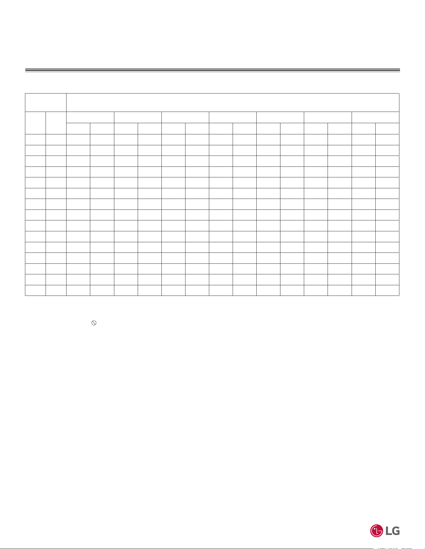
'XHWRRXUSROLF\RIFRQWLQXRXVSURGXFWLQQRYDWLRQVRPHVSHFL¿FDWLRQVPD\FKDQJHZLWKRXWQRWL¿FDWLRQ
©
/*(OHFWURQLFV86$,QF(QJOHZRRG&OLIIV1-$OOULJKWVUHVHUYHG³/*´LVDUHJLVWHUHGWUDGHPDUNRI/*&RUS
80
56LQJOH=RQH6WDQGDUG(ႈFLHQF\0HJDDQG0HJD9:DOO0RXQWHG(QJLQHHULQJ0DQXDO
MAXIMUM HEATING CAPACITY
Outdoor Air
Temp.
Indoor Air Temperature (°F DB)
°F DB °F WB
60 64 68 70 72 75 86
TC PI TC PI TC PI TC PI TC PI TC PI TC PI
6 5 8.60 1.33 8.51 1.35 8.44 1.36 8.40 1.37 8.31 1.36 8.12 1.35 7.25 1.29
10 9 9.42 1.37 9.31 1.39 9.23 1.40 9.18 1.41 9.06 1.40 8.80 1.38 7.68 1.31
16 14 10.37 1.42 10.25 1.43 10.15 1.45 10.09 1.46 9.93 1.44 9.55 1.42 8.42 1.31
17 15 10.57 1.42 10.44 1.44 10.34 1.46 10.28 1.47 10.10 1.45 9.70 1.42 8.49 1.29
19 17 10.85 1.44 10.72 1.46 10.62 1.47 10.56 1.48 10.36 1.45 9.90 1.41 8.54 1.24
24 23 11.44 1.48 11.31 1.48 11.20 1.49 11.14 1.49 10.86 1.46 10.25 1.40 8.43 1.22
32 30 12.38 1.50 12.24 1.50 12.12 1.51 12.06 1.51 11.69 1.46 10.87 1.40 8.40 1.16
41 38 13.44 1.46 13.29 1.49 13.16 1.51 13.09 1.53 12.65 1.47 11.67 1.38 8.71 1.04
43 40 13.68 1.46 13.52 1.49 13.39 1.52 13.32 1.53 12.86 1.47 11.81 1.37 8.67 1.01
47 43 14.16 1.43 13.99 1.48 13.86 1.53 13.78 1.55 13.27 1.48 12.13 1.36 8.70 0.96
53 50 14.52 1.46 14.34 1.50 14.20 1.55 14.11 1.57 13.56 1.48 12.31 1.36 8.55 0.89
59 53 14.71 1.43 14.69 1.48 14.68 1.54 14.68 1.56 14.07 1.48 12.71 1.35 8.63 0.89
64 57 14.82 1.40 14.61 1.42 14.43 1.44 14.33 1.45 13.75 1.38 12.45 1.27 8.54 0.87
70 61 14.87 1.34 14.62 1.33 14.41 1.33 14.29 1.33 13.72 1.27 12.43 1.17 8.58 0.80
75 65 14.84 1.22 14.54 1.25 14.29 1.29 14.16 1.30 13.57 1.23 12.26 1.13 8.33 0.75
Table 56: Mega 115V Wall-Mounted System KSSAC121B / KNSAC121B - KUSAC121B Maximum Heating Capacities.
0HJD9.66$&%.16$&%.86$&%
DB: Dry Bulb Temperature (°F) WB: Wet Bulb Temperature (°F) TC: Total Capacity (kBtu/h)
PI: Power Input (kW) (includes compressor, indoor fan motor and outdoor fan motor)
1. All capacities are net, evaporator fan motor heat is deducted.
2. Direct interpolation is permissible.
Do not extrapolate..
Capacity as rated: 0 ft. above sea level with 24.6 ft. of refrigerant piping. 0 ft. level difference between
outdoor and indoor units.
Heating capacity rating obtained with air entering the indoor unit at 70ºF dry bulb (DB) and 60ºF wet
bulb (WB), and outdoor ambient conditions of 47ºF dry bulb (DB) and 43ºF wet bulb (WB).
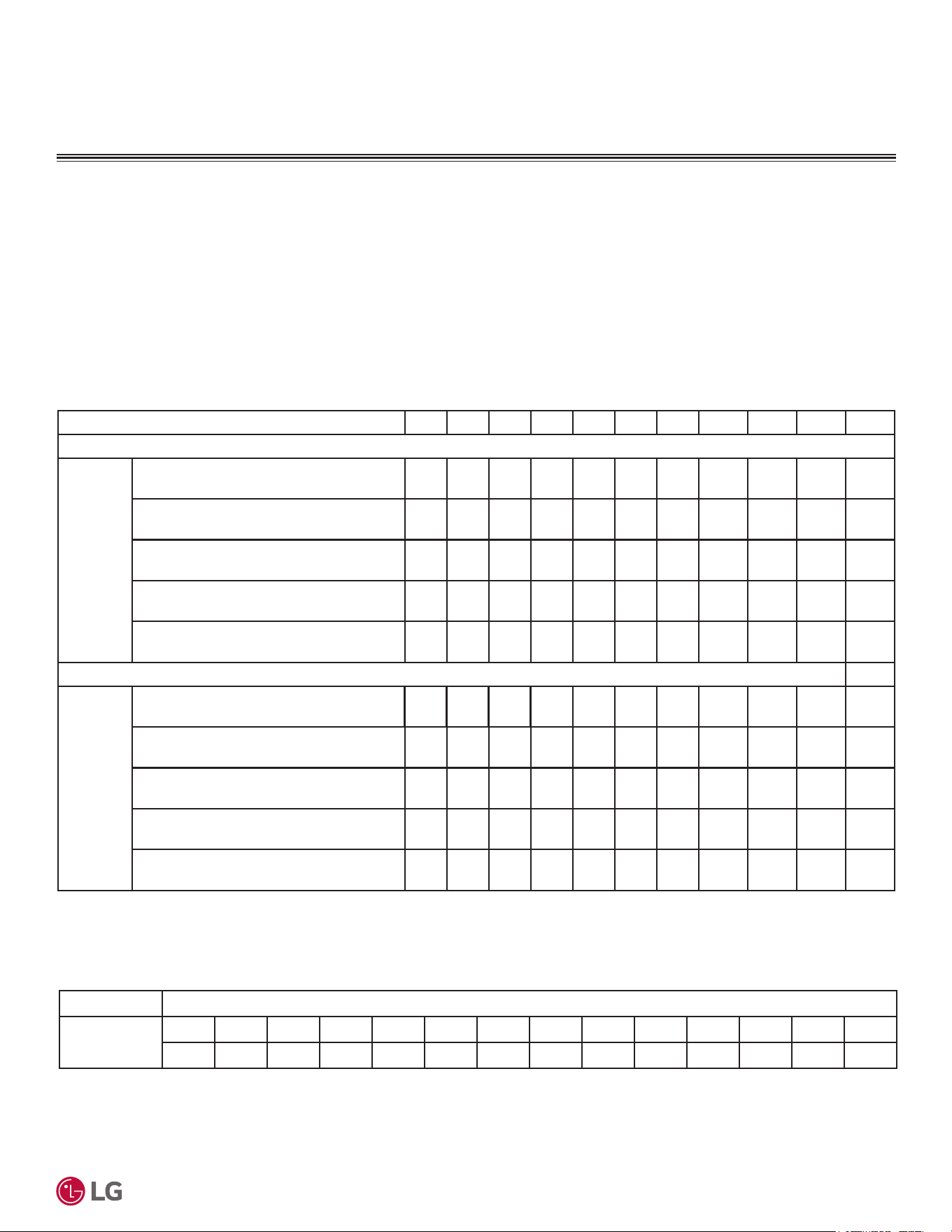
'XHWRRXUSROLF\RIFRQWLQXRXVSURGXFWLQQRYDWLRQVRPHVSHFL¿FDWLRQVPD\FKDQJHZLWKRXWQRWL¿FDWLRQ
©
/*(OHFWURQLFV86$,QF(QJOHZRRG&OLIIV1-$OOULJKWVUHVHUYHG³/*´LVDUHJLVWHUHGWUDGHPDUNRI/*&RUS
81
Performance Data
CORRECTION FACTORS
Table 57: 6WDQGDUG(I¿FLHQF\0HJDDQG0HJD96\VWHP&RROLQJDQG+HDWLQJ&DSDFLW\&RHI¿FLHQW)DFWRUV
&RROLQJ+HDWLQJ&RUUHFWLRQ)DFWRUV
For single zone systems, calculate the equivalent length of the liquid line from the outdoor unit to the indoor unit. Also, determine the eleva-
tion difference of the indoor unit above or below the outdoor unit. Find corresponding cooling or heating capacity correction factors as shown
below. Multiply the correction factors by the cooling or heating capacity obtained from the capacity table using design conditions. The resul-
tant is the NET cooling or heating capacity.
Refrigerant Line Length Derates
For air-cooled systems, a capacity correction factor will have to be applied to account for the length of the system’s refrigerant pipe. Rate of
change in capacity due to increased piping lengths is shown below.
Piping Length (ft.) 16.4 24.6 32.8 49.2 65.6 82.0 98.4 114.8 131.2 147.6 164.0
Cooling Capacity Coefficient Factor
Rate of
Capacity
Change
(%)
Standard Efficiency KSSAE091A (9,000
Btu/h), KSSAE121A (12,000 Btu/h)
100 100 97.7 93.0 - - - - - - -
Mega KSSAC091A (9,000 Btu/h),
KSSAC121A (12,000 Btu/h)
100 100 97.7 93.0 - - - - - - -
Mega 115V KSSAC091B (9,000 Btu/h),
KSSAC121B (12,000 Btu/h)
100 100 97.7 93.0 - - - - - - -
Standard Efficiency KSSAE181A (18,000
Btu/h), KSSAE241A (24,000 Btu/h)
100 100 99.0 97.0 95.0 - - - - - -
Mega KSSAC181A (18,000 Btu/h),
KSSAC241A (24,000 Btu/h)
100 100 99.0 97.0 95.0 - - - - - -
Heating Capacity Coefficient Factor
Rate of
Capacity
Change
(%)
Standard Efficiency KSSAE091A (9,000
Btu/h), KSSAE121A (12,000 Btu/h)
100 100 98.3 95.0 - - - - - - -
Mega KSSAC091A (9,000 Btu/h),
KSSAC121A (12,000 Btu/h)
100 100 98.3 95.0 - - - - - - -
Mega 115V KSSAC091B (9,000 Btu/h),
KSSAC121B (12,000 Btu/h)
100 100 98.3 95.0 - - - - - - -
Standard Efficiency KSSAE181A (18,000
Btu/h), KSSAE241A (24,000 Btu/h)
100 100 99.2 97.6 96.0 - - - - - -
Mega KSSAC181A (18,000 Btu/h),
KSSAC241A (24,000 Btu/h)
100 100 99.2 97.6 96.0 - - - - - -
(TXLYDOHQW3LSLQJ/HQJWKIRU3LSLQJ&RPSRQHQWV
Component Size (Inches)
(OERZIW
1/4 3/8 1/2 5/8 3/4 7/8 1 1-1/8 1-1/4 1-3/8 1-1/2 1-5/8 1-3/4 2-1/8
0.5 0.6 0.7 0.8 1.2 1.3 1.5 1.6 1.8 2.0 2.1 2.3 2.5 2.8
Table 58: Equivalent Piping Length for Elbows.
Altitude Correction Factor
The impact of air density must be considered on systems installed at a significant altitude above sea level, therefore, locally accepted alti-
tude correction factors must be applied.
'XHWRRXUSROLF\RIFRQWLQXRXVSURGXFWLQQRYDWLRQVRPHVSHFL¿FDWLRQVPD\FKDQJHZLWKRXWQRWL¿FDWLRQ
©
/*(OHFWURQLFV86$,QF(QJOHZRRG&OLIIV1-$OOULJKWVUHVHUYHG³/*´LVDUHJLVWHUHGWUDGHPDUNRI/*&RUS
82
56LQJOH=RQH6WDQGDUG(ႈFLHQF\0HJDDQG0HJD9:DOO0RXQWHG(QJLQHHULQJ0DQXDO
Table 59: Outdoor Unit Frost Accumulation Factor (Heating)1.
There will be a temporary reduction in capacity when frost / ice accumulates on the outside surface of the outdoor unit heat exchanger. The level of
FDSDFLW\UHGXFWLRQGHSHQGVRQDQXPEHURIIDFWRUVIRUH[DPSOHRXWGRRUWHPSHUDWXUH)'%UHODWLYHKXPLGLW\5+DQGWKHDPRXQWRIIURVWSUHV-
ent.
Entering DB (ºF) 19.4 23.0 26.6 32.0 37.4 41.0 44.6
Derate Factor 0.98 0.95 0.93 0.86 0.93 0.96 1.0
1
At 85% outdoor air relative humidity.
The frost accumulation factor does not account for effects of snow accumulation restricting airflow
through the outdoor unit coil.
Defrost Correction Factor for Heating Operation
The outdoor unit heating capacity will need to be adjusted for frost accumulation on air-cooled systems. If design day conditions are below
the dewpoint of the surrounding air, frost will not be a problem and no correction factor is needed. In certain weather conditions, however,
frost will form and accumulate on the air-cooled outdoor unit coil and impact the coils ability to transfer heat. If significant frost accumulates
on the outdoor unit coil, a defrost algorithm will start automatically. The timing between defrost periods is determined by the system’s ability
to achieve a target head pressure value.
Capacity and AHRI ratings tables do not factor in capacity reduction when frost has accumulated on the condenser coil, nor during defrost
operation.
Integrated heating capacity values can be obtained using the formula:
A = B x C
Where:
A = Integrated Heating Capacity.
B = Value found in the Capacity Table.
C = Correction Factor for Frost Accumulation Factor (from table at right).
&KHFNWKH,QGRRUDQG2XWGRRU8QLW6HOHFWLRQV
Compare the corrected cooling and heating capacities to the load calculations. Is each capacity sufficient for the zone it serves?
For each indoor unit, the corrected capacity must be at least equal to the total of the cooling design load (plus ventilation load, if applicable)
for the space(s) served by the indoor unit. For each indoor unit, the corrected capacity also must be at least equal to the total of the heating
design load (plus ventilation load, if applicable) for the space(s) and / or thermal zones served by the indoor unit.
The outdoor unit selected must be large enough to offset the total cooling load for all spaces it serves (account for ventilation air cooling load
if the ventilation air has not been pretreated to room neutral conditions). The outdoor unit must also be large enough to offset the total heat-
ing load for all spaces it serves.
If the corrected heating capacity ratio exceeds 100%, reselect the equipment, or change the system design by moving some of the load to
another system.
• Understand the design safety factors.
• Reference load calculations for actual cooling and heating capacities (applies in 99% of applications – consider total load when latent load
is greater than 30%).
• Verify that the sensible load of the zone is satisfied.
• Use caution when sizing to meet listed capacity specifications for the scheduled manufacturer’s equipment.
If further system design assistance is needed, or you have a unique application you would like to discuss, contact an LG sales rep.
1. Outdoor Unit Rated Capacity.
Q
odu(rated)
(From capacity tables).
2. Outdoor Unit Capacity at Ti, To Temperature.
Q
odu(Ti, To)
(From capacity tables).
3. Outdoor Unit Capacity Coefficient Factor.
F
(Ti, To)
= Q
odu(Ti, To)
/ Q
odu(rated)
4. Piping Correction Factor (From Capacity Coefficient
Factor Tables).
F
(length)
for each piping length
5. Individual Indoor Unit Combination Capacity.
Q
idu (combi)
= Q
odu(rated)
x Q
idu(rated)
/ Q
idu(rated-total)
6. Individual Indoor Unit Actual Capacity.
Q
idu (actual)
= Q
odu(combi)
x F
(Ti, To)
x F
(length, altitude)
6\VWHP6L]LQJ&KHFN)RUPXODV
Conclusions and Recommendations
&255(&7,21)$&7256&+(&.6(/(&7,21

3ODFHPHQW&OHDUDQFH&RQVLGHUDWLRQVIRU,QGRRU8QLWVRQSDJH
3ODFHPHQW&OHDUDQFH&RQVLGHUDWLRQVIRU2XWGRRU8QLWVRQSDJH
Installing Outdoor Units Indoors on page 89
APPLICATION
GUIDELINES
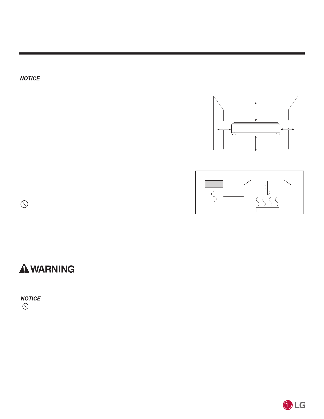
'XHWRRXUSROLF\RIFRQWLQXRXVSURGXFWLQQRYDWLRQVRPHVSHFL¿FDWLRQVPD\FKDQJHZLWKRXWQRWL¿FDWLRQ
©
/*(OHFWURQLFV86$,QF(QJOHZRRG&OLIIV1-$OOULJKWVUHVHUYHG³/*´LVDUHJLVWHUHGWUDGHPDUNRI/*&RUS
84
56LQJOH=RQH6WDQGDUG(ႈFLHQF\0HJDDQG0HJD9:DOO0RXQWHG(QJLQHHULQJ0DQXDO
3/$&(0(17&/($5$1&(&216,'(5$7,216
Selecting the Best Location for the Indoor Unit
7KHXQLWZLOOEHGDPDJHGZLOOPDOIXQFWLRQDQGRUZLOOQRWRSHUDWHDVGHVLJQHGLILQVWDOOHGLQDQ\RIWKHFRQGLWLRQVOLVWHG
• ,QGRRUXQLWV,'8VPXVWQRWEHSODFHGLQDQHQYLURQPHQWZKHUHWKH,'8VZLOOEHH[SRVHGWRKDUPIXOYRODWLOHRUJDQLFFRPSRXQGV
92&VRULQHQYLURQPHQWVZKHUHWKHUHLVLPSURSHUDLUPDNHXSRUVXSSO\RULQDGHTXDWHYHQWLODWLRQ,IWKHUHDUHFRQFHUQVDERXW92&VLQWKH
environment where the IDUs are installed, proper air make up or supply and / or adequate ventilation should be provided. Additionally, in
EXLOGLQJVZKHUH,'8VZLOOEHH[SRVHGWR92&VFRQVLGHUDIDFWRU\DSSOLHGHSR[\FRDWLQJWRWKHIDQFRLOVIRUHDFK,'8
• If the unit is installed near a body of water, the installation parts are at risk of corroding. Appropriate anti-corrosion methods must be taken
for the unit and all installation parts.
Installing in an Area Exposed to Unconditioned Air
In some installation applications, areas (floors, walls) in some rooms will be exposed to unconditioned air (room will be above or next to an
unheated garage or storeroom). To countermeasure:
• Verify that carpet is or will be installed (carpet will increase the temperature by three degrees).
• Add insulation between the floor joists.
• Install radiant heat or another type of heating system to the floor.
,QGRRU8QLWV
Figure 27: Installing Near a Heat or Steam Source.
Install a ventilation fan
with sufficient capacity
Heat or steam source
Include enough
distance
Indoor Unit
7KHXQLWPXVWQRWEHLQVWDOOHGZKHUHRLOVXOIXULFDFLGDQGÀDPPDEOHRUFRUURVLYHJDVHVDUHJHQHUDWHGYHQWHGLQWRRUVWRUHG7KHUHLVULVNRI¿UH
explosion, and physical injury or death.
Follow recommended best practices when choosing an indoor location for the single zone
indoor unit.
Dos
6HOHFWDORFDWLRQIRULQVWDOOLQJWKHLQGRRUXQLWVWKDWZLOOPHHWWKHIROORZLQJFRQGLWLRQV
• Follow the diagram at right for minimum clearance of indoor unit from the top of the unit
to the ceiling.
• Clearance gap between any wall or enclosure and the left or right side of the unit must be
greater than 4 inches. Ensure there is sufficient maintenance space.
• Unit must be at least 6-1/2 feet from the floor for adequate clearance.
• Place the unit where drainage can be obtained easily and to minimize the length of the
condensate drain piping. Condensation drain must be conveniently routed away from the
unit.
• Locate the indoor unit in a location where it can be easily connected to the outdoor
unit within allowable limits.
• Use a metal detector to locate studs in the walls. Anchor unit following stud location
to prevent damage to the wall.
• Place the unit where air circulation will not be blocked.
Do Nots
• Do not install the unit near a heat or steam source, or where considerable amounts
RIRLOLURQSRZGHURUIORXUDUHXVHG7KHVHPDWHULDOVZLOOJHQHUDWHFRQGHQVDWH
cause a reduction in heat exchanger efficiency, or the drain to malfunction. If this is a potential problem, install a ventilation fan large
HQRXJKWRYHQWRXWWKHVHPDWHULDOV
• Ensure there are no obstacles to air circulation around the unit; keep proper distances from ceilings, doorways, floor, walls, etc.
• Do not install in an area where operation sound will disturb occupants--place the unit where noise prevention is taken into consideration.
• Do not install near doorway.
• Avoid installing the unit near high-frequency generators.
Figure 26: Wall-Mounted Indoor Unit Clearance
Requirements.
>4 (100)
Unit: Inch (mm)
>4 (100)
>8 (200)
At least 6-1/2 feet from the floor
'XHWRRXUSROLF\RIFRQWLQXRXVSURGXFWLQQRYDWLRQVRPHVSHFL¿FDWLRQVPD\FKDQJHZLWKRXWQRWL¿FDWLRQ
©
/*(OHFWURQLFV86$,QF(QJOHZRRG&OLIIV1-$OOULJKWVUHVHUYHG³/*´LVDUHJLVWHUHGWUDGHPDUNRI/*&RUS
Application Guidelines
85
Selecting the Best Location for the Indoor Unit, continued.
,QVWDOOLQJ,QGRRU8QLWVLQDQ$UHDZLWK+LJK+XPLGLW\/HYHOV
If the environment is prone to humidity levels of 80% or more (near the ocean, lakes, etc.) or where steam could collect.
• Install additional insulation to the indoor unit (glass wool insulation >13/32 inches thick).
• Install additional insulation to the refrigerant piping (insulation >13/16 inches thick).
• Seal all gaps between the indoor unit and the wall (make the area air tight) so that humidity does not transfer to the conditioned space.
3/$&(0(17&/($5$1&(&216,'(5$7,216
,QGRRU8QLWV2XWGRRU8QLWV
Selecting the Best Location for the Outdoor Unit
DANGER
• Do not install the unit in an area where combustible gas will generate, flow, stagnate, or leak. These conditions can cause a fire, result-
ing in bodily injury or death.
• 'RQRWLQVWDOOWKHXQLWLQDORFDWLRQZKHUHDFLGLFVROXWLRQDQGVSUD\VXOIXUDUHRIWHQXVHGDVLWFDQFDXVHERGLO\LQMXU\RUGHDWK
•
Do not use the unit in environments where oil, steam, or sulfuric gas are present as it can cause bodily injury or death.
When deciding on a location to place the outdoor unit, be sure to choose an area where run-off from defrost will not accumulate and freeze on
sidewalks or driveways, which will create unsafe conditions. Properly install and insulate any drain hoses to prevent the hose from freezing, cracking,
leaking, and causing unsafe conditions from frozen condensate.
Install a fence to prevent pests from crawling into the unit or unauthorized individuals from accessing it. Pests and unauthorized individuals can
GDPDJHLQWHUQDOFRPSRQHQWVZKLFKFDQFDXVHD¿UHHOHFWULFVKRFNSK\VLFDOLQMXU\RUGHDWK)ROORZWKHSODFHPHQWJXLGHOLQHVVHWIRUWKLQ³&OHDUDQFH
Requirements”.
Select a location for installing the outdoor unit that will meet the following conditions:
Dos
• Where there is enough strength to bear the weight of the unit.
• A location that allows for optimum air flow and is easily accessible for inspection, maintenance, and service.
• Where piping between the outdoor unit and indoor unit is within allowable limits.
• Include space for drainage to ensure condensate flows properly out of the unit when it is in heating mode.
Avoid placing the outdoor
unit in a low-lying area where water could accumulate.
• ,IWKHRXWGRRUXQLWLVLQVWDOOHGLQDKLJKO\KXPLGHQYLURQPHQWQHDUDQRFHDQODNHHWFHQVXUHWKDWWKHVLWHLVZHOOYHQWLODWHGDQGKDVDORW
RIQDWXUDOOLJKW([DPSOH,QVWDOORQDURRIWRS
Do Nots
• Where it will be subjected to direct thermal radiation from other heat sources, or an area that would expose the outdoor unit to heat or
steam like discharge from boiler stacks, chimneys, steam relief ports, other air conditioning units, kitchen vents, plumbing vents, and other
sources of extreme temperatures.
• Where high-frequency electrical noise / electromagnetic waves will affect operation.
• Where operating sound from the unit will disturb inhabitants of surrounding buildings.
• Where the unit will be exposed to direct, strong winds.
• :KHUHWKHGLVFKDUJHRIRQHRXWGRRUXQLWZLOOEORZLQWRWKHLQOHWVLGHRIDQDGMDFHQWXQLWZKHQLQVWDOOLQJPXOWLSOHRXWGRRUXQLWV
Outdoor Unit Condensate Drain Piping
Outdoor unit requires condensate drain piping. Condensate drain pipe is constructed with materials approved by local code. See pages 86-88
for information in reference to outdoor unit placement.
7KHLQGRRUXQLWPD\WDNHORQJHUWRSURYLGHKHDWRUKHDWLQJSHUIRUPDQFHZLOOEHUHGXFHGLQZLQWHULIWKHRXWGRRUXQLWLVLQVWDOOHG
1. In a narrow, shady location.
2. Near a location that has a lot of ground moisture.
3. In a highly humid environment.
4. In an area in which condensate does not drain properly.
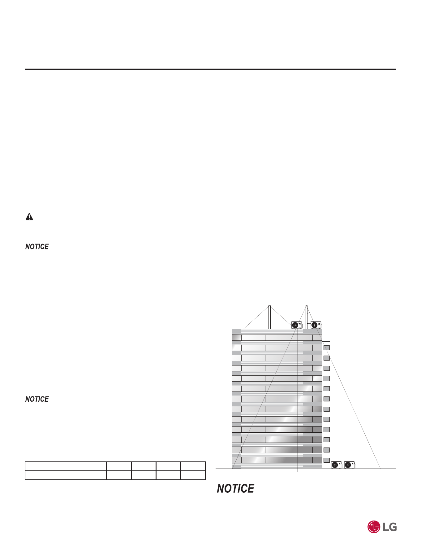
'XHWRRXUSROLF\RIFRQWLQXRXVSURGXFWLQQRYDWLRQVRPHVSHFL¿FDWLRQVPD\FKDQJHZLWKRXWQRWL¿FDWLRQ
©
/*(OHFWURQLFV86$,QF(QJOHZRRG&OLIIV1-$OOULJKWVUHVHUYHG³/*´LVDUHJLVWHUHGWUDGHPDUNRI/*&RUS
86
56LQJOH=RQH6WDQGDUG(ႈFLHQF\0HJDDQG0HJD9:DOO0RXQWHG(QJLQHHULQJ0DQXDO
Planning for Snow and Ice
To ensure the outdoor unit operates properly, certain measures are required in locations where there is a possibility of heavy snowfall or
severe windchill or cold:
1. Prepare for severe winter wind chills and heavy snowfall, even in areas of the country where these are unusual phenomena.
2. Position the outdoor unit so that its airflow fans are not buried by direct, heavy snowfall. If snow piles up and blocks the airflow, the sys-
tem will malfunction.
3. Remove any snow that has accumulated four (4) inches or more on the top of the outdoor unit.
4. In climates that will experience significant snow buildup, mount the outdoor unit on a raised, field-provided platform or stand. The raised
support platform must be high enough to allow the unit to remain above possible snow drifts, and must be higher than the maximum antici-
pated snowfall for the location.
5. Design the mounting base to prevent snow accumulation on the platform in front or back of the unit frame.
6. Provide a field fabricated snow protection hood to keep snow and ice and/or drifting snow from accumulating on the coil surfaces.
7. To prevent snow and heavy rain from entering the outdoor unit, install the condenser air inlets and outlets facing away from direct
winds.
8. Consider tie-down requirements in case of high winds or where required by local codes.
CAUTION
When deciding on a location to place the outdoor unit, be sure to choose an area where run-off from defrost will not accumulate and freeze on side-
walks or driveways, which will create unsafe conditions.
Choose an area where run-off from defrost mode will not accumulate and freeze on sidewalks or driveways. Properly install and insulate any drain
hoses to prevent the hose from freezing, cracking, leaking, and damaging the outdoor unit.
Tie-Downs, Lightning Protection, and
Wind Protection
7LH'RZQV
• The strength of the roof must be checked before installing the
outdoor units.
• The strength of the outdoor unit frames is adequate to be used with
field-provided wind restraint tie-downs.
• If the installation site is prone to high winds or earthquakes, when
installing on the wall or roof, securely anchor the mounting base
using a field-provided tie-down configuration approved by a local
professional engineer.
• The overall tie-down configuration must be approved by a local
professional engineer.
Always refer to local code when using a wind restraint system.
Lightning Protection
• To protect the outdoor unit from lightning, it must be placed within
the specified lightning safety zone.
• Power cable and communication cable must be installed five (5)
feet away from lightning rod.
• A high-resistance ground system must be included to protect
against induced lightning or indirect strike.
Building Height (feet) 66 98 148 197
3URWHFWLRQ$QJOHÜ 55 45 35 25
If the building does not include lightning protection, the outdoor unit will
be damaged from a lightning strike. Inform the customer of this possibil-
ity in advance.
Ground
Safe zone
Lightning rod
3URWHFWLRQ$QJOHÛaÛ
5 feet
Lightning rod
Table 60: 6DIHW\=RQH6SHFL¿FDWLRQV
3/$&(0(17&/($5$1&(&216,'(5$7,216
2XWGRRU8QLWV
Figure 28: Lightning Protection Diagram (Outdoor Unit Appearances
Differ According to Model).
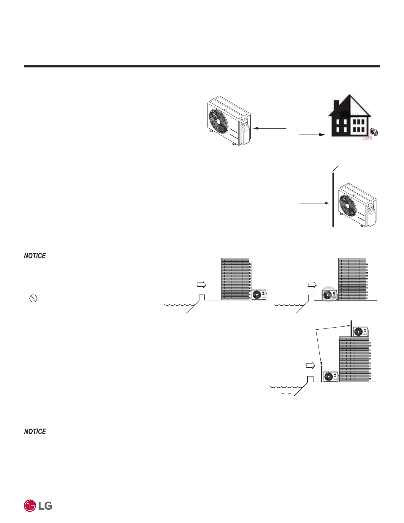
'XHWRRXUSROLF\RIFRQWLQXRXVSURGXFWLQQRYDWLRQVRPHVSHFL¿FDWLRQVPD\FKDQJHZLWKRXWQRWL¿FDWLRQ
©
/*(OHFWURQLFV86$,QF(QJOHZRRG&OLIIV1-$OOULJKWVUHVHUYHG³/*´LVDUHJLVWHUHGWUDGHPDUNRI/*&RUS
Application Guidelines
87
• Avoid installing the outdoor unit where it
would be directly exposed to ocean winds.
• Install the outdoor unit on the side of the building
opposite from direct ocean winds.
• Select a location with good drainage.
• Periodically clean dust or salt particles off of the
heat exchanger with water.
If the outdoor unit must be placed in a location
where it would be subjected to direct ocean winds,
install a concrete windbreak strong enough to
block any winds. Windbreaker height and width
must be more than 150% of the outdoor unit, and
be installed at least 14 to 28 inches away from the
outdoor unit to allow for airflow (depending on the
location and outdoor unit size).
Additional anti-corrosion treatment may need to be applied to the outdoor unit at oceanside locations.
Ocean winds will cause corrosion, particularly on the
FRQGHQVHUDQGHYDSRUDWRU¿QVZKLFKLQWXUQFRXOG
FDXVHSURGXFWPDOIXQFWLRQRULQHI¿FLHQWSHUIRUPDQFH
Oceanside Application Precautions
Oceanside Applications
Wind Protection
If the outdoor unit is placed on a roof, position it with the compressor
end (no coil surface) in the direction of the prevailing wind as shown
in the figure at right. In cooler climates, it may be beneficial to posi-
tion the unit in direct sunlight to assist with defrost operations.
If the outdoor unit is not placed on a roof, place it on the leeward
side of the building or in a location where the unit will not be ex-
posed to constant wind.
If placement exposes the unit to constant wind activity, construct a
wind break in front of the unit. Follow the placement guidelines set
forth in “Clearance Requirements”.
Figure 29: Prevailing Wind Direc-
tion.
Prevailing
Winds
Figure 30: Leeward Side of the
Building.
Prevailing Winds
Wall or Other Wind Break
Figure 31: Wind Break.
Ocean winds
Ocean winds
Sea wind
Windbreak
Figure 32: Oceanside Placement Using a Building as Shield, and Placement Using a
Windbreak.
3/$&(0(17&/($5$1&(&216,'(5$7,216
2XWGRRU8QLWV
Prevailing Winds
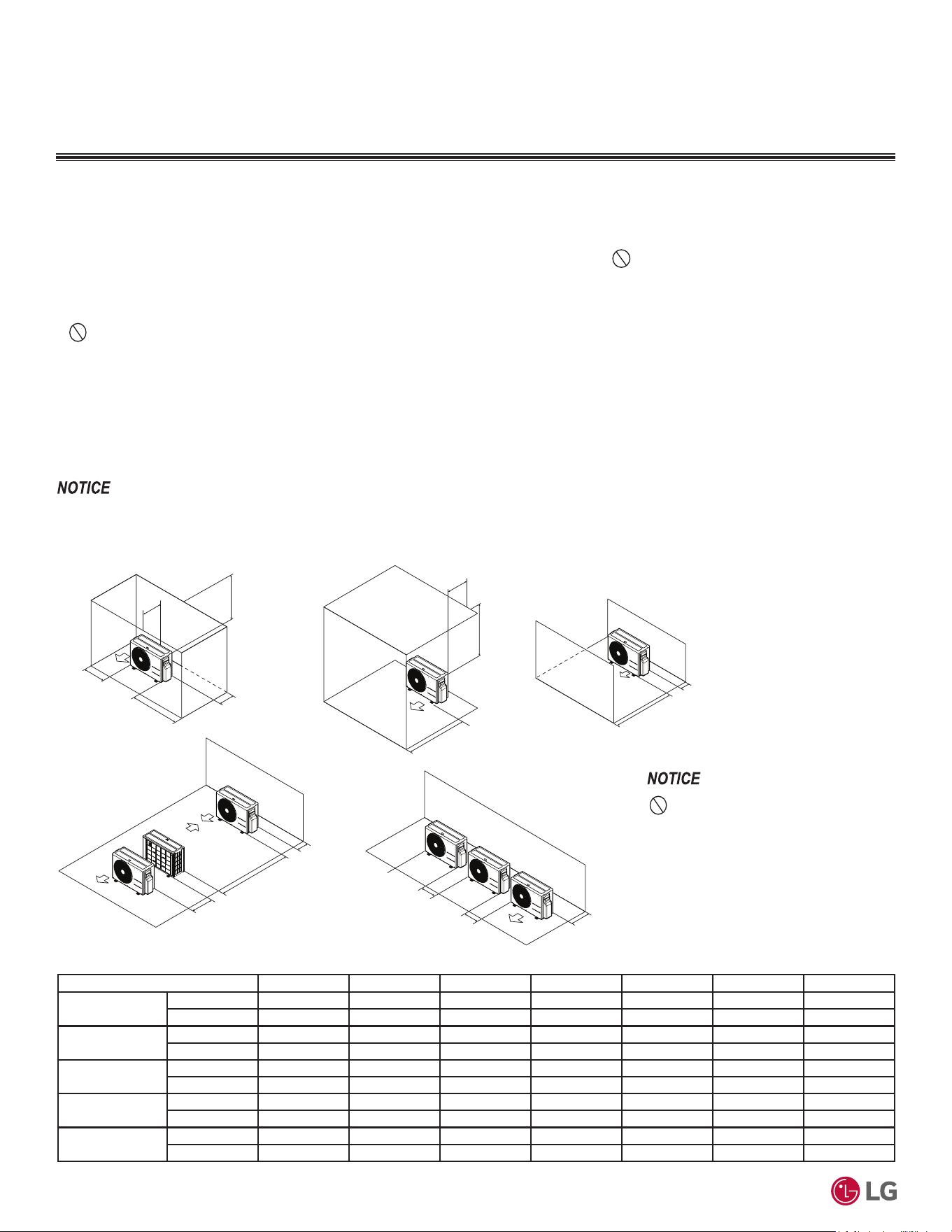
'XHWRRXUSROLF\RIFRQWLQXRXVSURGXFWLQQRYDWLRQVRPHVSHFL¿FDWLRQVPD\FKDQJHZLWKRXWQRWL¿FDWLRQ
©
/*(OHFWURQLFV86$,QF(QJOHZRRG&OLIIV1-$OOULJKWVUHVHUYHG³/*´LVDUHJLVWHUHGWUDGHPDUNRI/*&RUS
88
56LQJOH=RQH6WDQGDUG(ႈFLHQF\0HJDDQG0HJD9:DOO0RXQWHG(QJLQHHULQJ0DQXDO
3/$&(0(17&/($5$1&(&216,'(5$7,216
Figure 33: Single Fan Outdoor Unit Service Access and Allowable Clearances Diagram.
Unit: Inch A B C D E F G
Case 1
Standard 12 24 - 12 - - -
Minimum 4 10 - 4 - - 40
Case 2
Standard - - 20 - - - -
Minimum - - 14 - - - 40
Case 3
Standard - - 20 12 - - -
Minimum - - 14 4 - - -
Case 4
Standard - - - 12 24 - -
Minimum - - - 4 8 79 -
Case 5
Standard - 24 - 12 - - -
Minimum - 10 - 4 - - -
Table 61: Single Fan Outdoor Unit Service Access and Allowable Clearances Diagram Legend.
Do not place the unit where animals
and/or plants will be in the path of the warm
air, or where the warm air and/or noise will
disturb neighbors.
If the outdoor unit is installed between standard and minimum clearances, capacity decreases approximately 10%.
0LQLPXP$OORZDEOH&OHDUDQFHDQG6HUYLFH$FFHVV5HTXLUHPHQWV
Proper clearance for the outdoor unit coil is critical for proper unit operation. When installing the outdoor unit, consider service, inlet and
outlet and minimum allowable space requirements as illustrated in the diagrams on the page below.
• Include enough space for airflow and for service access. If installing multiple outdoor units, avoid placing the units where the discharge
of one unit will blow into the inlet side of an adjacent unit.
• If an awning is built over the unit to prevent direct sunlight or rain exposure, make sure that the discharge air of the outdoor unit isn’t
restricted.
•
No obstacles to air circulation around the unit; keep proper distances from ceilings, fences, floor, walls, etc. (Install a fence to prevent
pests from damaging the unit or unauthorized individuals from accessing it.)
A
B
D
G
C
G
C
D
E
D
D
B
B
F
1/16 inch
20 inches or less
Case 1
Case 4
Case 2 Case 3
Case 5
20 inches or less
2XWGRRU8QLWV
Minimum Clearance Requirements for Single Fan Outdoor Units
Specific clearance requirements in the diagram below are for single fan outdoor units. The figure below shows the overall minimum clear-
ances that must be observed for safe operation and adequate airflow around the outdoor unit.
When placing the outdoor unit under an overhang, awning, sunroof or other “roof-like structure”, observe the clearance requirements (as
shown in Cases 1 and 2) for height in relation to the unit. To have successful service access to the outdoor unit, see the figure below for
minimum spacing. When installing multiple outdoor units, see Cases 4 and 5 for correct spacing requirements.

'XHWRRXUSROLF\RIFRQWLQXRXVSURGXFWLQQRYDWLRQVRPHVSHFL¿FDWLRQVPD\FKDQJHZLWKRXWQRWL¿FDWLRQ
©
/*(OHFWURQLFV86$,QF(QJOHZRRG&OLIIV1-$OOULJKWVUHVHUYHG³/*´LVDUHJLVWHUHGWUDGHPDUNRI/*&RUS
Application Guidelines
89
INSTALLING OUTDOOR UNITS INDOORS
Installing Outdoor Units Indoors
Single Zone outdoor units are engineered to be mounted outdoors and include technology designed to minimize the negative effects of winter
weather’s freezing rain, sleet, and snow. Some building projects, however, necessitate placing the HVAC outdoor units indoors:
• Lack of ground space.
• Lack of an appropriate outdoor location that meets system design requirements.
• When mounting on the roof is not an option due to a lack of roof space.
• Roof warranty will be voided if mechanical equipment is placed on the membrane.
• On retrofit projects, a former chiller / boiler / air handler equipment room, mechanical area, or penthouse already exists.
• To curtail the potential need for redundant zone heating devices such as wall-fin radiators or duct heaters.
• In extremely cold environments where there is a significant amount of run-time at temperatures well below freezing outside the outdoor unit
ambient air temperature range published in this engineering manual.
Benefits of Installing Outdoor Units Indoors
• Shelters the outdoor unit from direct exposure to prevailing winds that decrease the heating capability of the outdoor unit.
• Protects equipment from freezing precipitation and / or potential ice build-up that could hinder unit operation.
• Maintains coil heat transfer efficiency by reducing the number of and shortening the cycle time for defrost operation.
• Easier maintenance and servicing during inclement weather.
• When mounted in a fully enclosed space, limiting the ambient air temperature will allow the Single Zone system designer to eliminate over-
sizing.
• The outdoor unit to compensate for loss of capacity at low ambient temperatures.
• Will also curtail the need to provide inefficient redundant zone heating devices such as wall-fin radiators and second-stage ancillary heating
devices.
Design Considerations Include:
• Enclosure types and elements such as louvers (see next page), rain hoods, dampers and controls, heating methods and sizing of heating
devices.
• Heating strategies.
• Duct design.
• Condensate handling.
General Guidelines
• Follow ASHRAE 62.1 design guidelines.
• Depending on the project / application, a roof over the outdoor units in combination with a wind break will be all that is necessary.
• Consider the potential for snow accumulation near louvers / roof openings. Outside air intakes and discharge ducts / louvers must be engi-
neered to clear anticipated snow accumulation levels by at least one (1) foot.
• In situations where operation is anticipated at temperatures lower than the product’s minimum operating temperature, ancillary heat must
be provided to heat the outdoor unit coils to ensure continuous compressor operation and heating.
It may be necessary to use a field-fabricated air guide to prevent discharge air from short-cycling back to the coil inlet.
• Consider the direction of prevailing winds and opening placement. If possible, locate inlet openings upwind of discharge openings and other
exhaust outlets.
• When inlet and outlet openings are placed on the same wall, minimum distance between the two openings must be approximately three (3)
feet (minimum distance varies significantly with variations in outlet opening face velocity).
• If roof-mounted ventilation openings are used, strategically locate the inlet ventilation opening(s) upwind of the outlet opening(s).
• Discharge and supply ductwork must be designed to avoid weather related long periods of water entrainment.
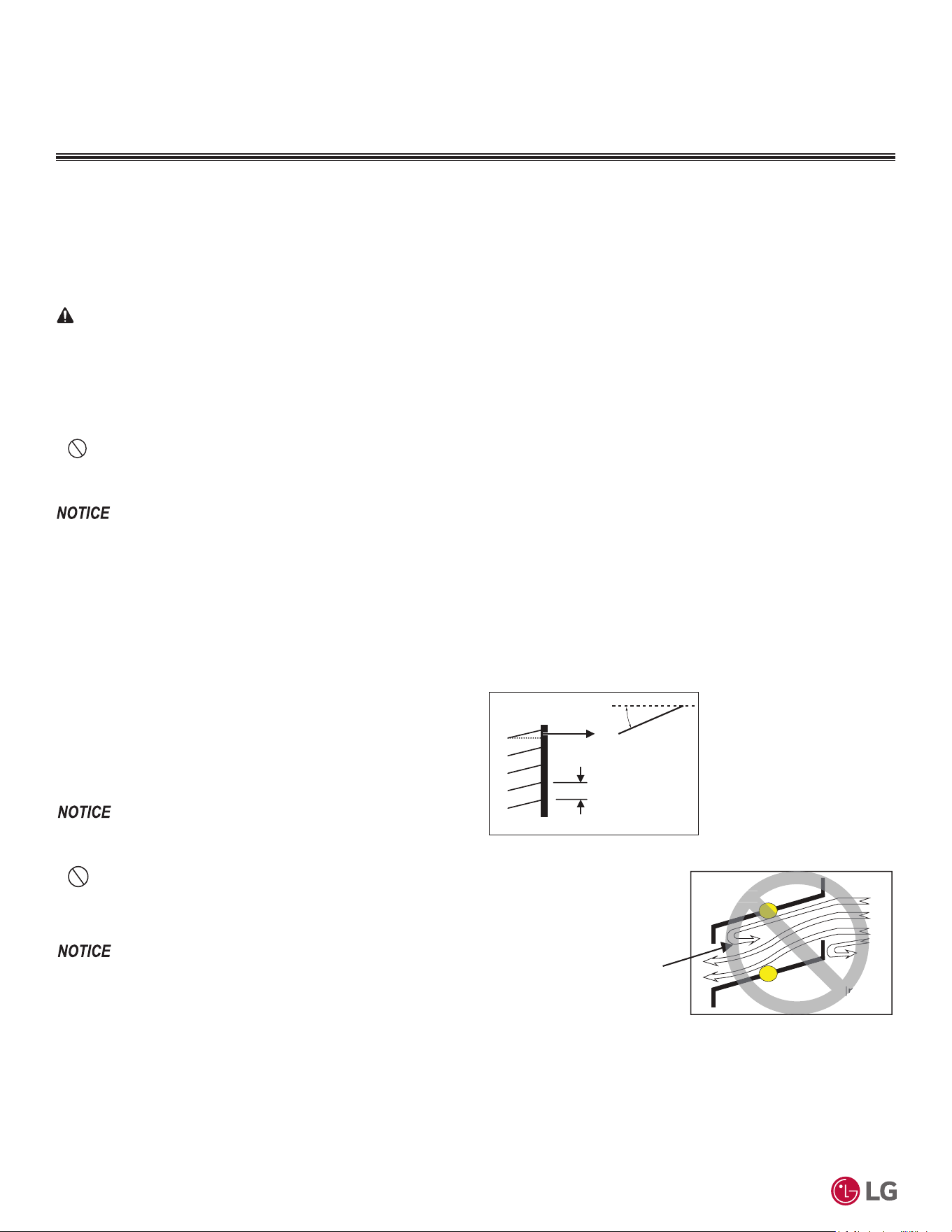
'XHWRRXUSROLF\RIFRQWLQXRXVSURGXFWLQQRYDWLRQVRPHVSHFL¿FDWLRQVPD\FKDQJHZLWKRXWQRWL¿FDWLRQ
©
/*(OHFWURQLFV86$,QF(QJOHZRRG&OLIIV1-$OOULJKWVUHVHUYHG³/*´LVDUHJLVWHUHGWUDGHPDUNRI/*&RUS
90
56LQJOH=RQH6WDQGDUG(ႈFLHQF\0HJDDQG0HJD9:DOO0RXQWHG(QJLQHHULQJ0DQXDO
INSTALLING OUTDOOR UNITS INDOORS
1. Outdoor Unit Enclosure: Manual Door Open Type.
2. Louver Angle: No More Than 15° Horizontally.
3. Space Between Louvers: More than four (4) inches (Recom-
mend).
4. Louver Shape: Wing or Plane Type.
Inside
Outside
Air flow passing through
the louver blade backwards
can generate noise.
In
side
Maximum 15°
(Recommended)
More than 4 in.
(Recommended)
Louver
• Open Rate and Inlet must be taken into consideration when de-
signing the louvered outdoor unit enclosure.
• Do not use “S” type louvers.
If the Louver Open Rate is Too Small
1. Noise can occur because of the increased air velocity passing through
the louver blade.
2. Noise can occur from louver blade vibrations.
3. $GURSLQRXWGRRUXQLWIDQSHUIRUPDQFHH[FHVVVWDWLFSUHVVXUHFDQ
FDXVHDGURSLQRXWGRRUXQLWSHUIRUPDQFHDQGKHDWH[FKDQJHUHI¿-
FLHQF\
4. ,IWKHORXYHURSHQUDWHLVWRRVPDOORUWKHUHLVLQVXI¿FLHQWDLUÀRZ
exchange, the air conditioner might stop operating.
Figure 34: Louver Recommendations.
Table 62: Using “S” Type Louvers.
Provide a means to drain the condensate generated during heating mode and defrost cycle in addition to rainwater that infiltrates the inlet
louver enclosed area.
• Install a field-provided drain pan under the outdoor units and provide a path to a nearby floor drain.
• If the ambient air temperature is expected to drop below 32°F in the enclosure, heat the bottom surface of the pan, drain line, and floor
drain so that the condensate does not freeze before reaching the drain.
Louver Recommendations for Outdoor Unit Enclosure
Allow for ventilation intake and exhaust air based on maximum outdoor unit fan capacity.
• Select the size, type and orientation of architectural louvers with adequate “net free area” face velocity to ensure the total external static
pressure from the outdoor unit fan does not exceed design limitations (see specification data tables).
•
No obstructions must be placed in front of the louver that could hamper the free flow (throw) of air.
• Roof top openings and / or discharge and supply louvers must be equipped with screens to prevent bird and insect infiltration.
For louver recommendations, see below and on the next page.
As always, the best solution for each project balances acceptable heating performance (considering local weather conditions), capital costs,
life cycle energy consumption, and limitations set forth by local building codes.
When deciding on a location to place the outdoor unit, be sure to choose an area where run-off from defrost will not accumulate and freeze on walk-
ways, which will create unsafe conditions.
CAUTION
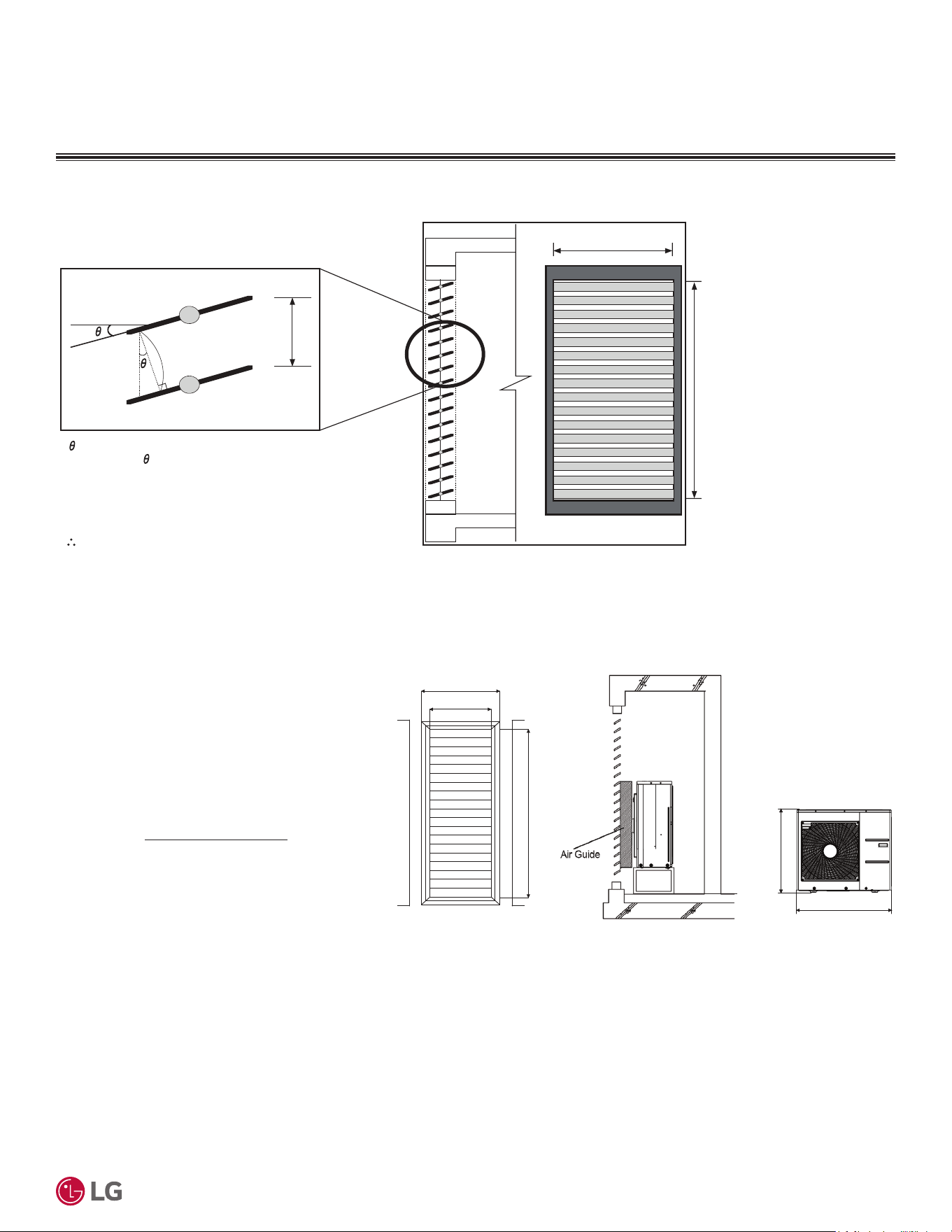
'XHWRRXUSROLF\RIFRQWLQXRXVSURGXFWLQQRYDWLRQVRPHVSHFL¿FDWLRQVPD\FKDQJHZLWKRXWQRWL¿FDWLRQ
©
/*(OHFWURQLFV86$,QF(QJOHZRRG&OLIIV1-$OOULJKWVUHVHUYHG³/*´LVDUHJLVWHUHGWUDGHPDUNRI/*&RUS
Application Guidelines
91
INSTALLING OUTDOOR UNITS INDOORS
Figure 35: Open Rate by Louver Radian Formula.
Side View
ho = h * COS
Total Area (A) = H * W
Number of Open Spaces (N) = (Number of Louvers - 1)
Effective Area (Af) = ho * W * N
Louver Open Rate (n) = Af / A
Af = A * n
Effective Cross Section Area
ho
h
W
Front View
H
Open Rate by Louver Radian
Figure 36: Example of Installing Outdoor Unit Indoors.
Formula
• Total Louver Dimension (Excluding Frame) (A) = 3.9 feet x 6.2 feet = 24.2 ft.
2
• Area Blocked by Outdoor Unit (Discharge) (B) = 2.6 feet x 2.8 feet = 7.41 ft.
2
• Inlet Louver Dimension (A - B) = 16.8 ft.
2
• Equivalent Inlet Dimension (Open Rate 80%) = 16.8 ft.
2
x 0.8 = 13.44 ft.
2
• Equivalent Inlet Airflow = 13.44 ft.
2
x 8.2 ft./s x 60 sec./min. = 6,612 ft.
3
/min.
• Equivalent Inlet Airflow / Discharge Airflow = 6,612 ft.
3
/min. / 2,119 ft.
3
/min. = 312% (Within Allowable Limits)
&RQILUPLQJ$LU)ORZ5DWH7RWDO2SHQLQJ5DWH
• Example: KUSAB181A (For illustrative purposes
only).
• Discharge Airflow Rate: 2,119 ft.
3
/min.
• Velocity of Outlet Air: 16.4 ft./s
• Velocity of Inlet Air: 8.2 ft./s
• Open Rate = 80% or More
• Inlet airflow must match or exceed discharge airflow.
• Separate inlet airflow from discharge airflow to
prevent recirculation.
Open Rate = Effective Face Area (Af)
Total Face Area (A)
55-1/8
47-1/4
34-1/4
74-13/16
31-1/2
Unit: Inch
Louver Dimensions Air Guide Duct on
Outdoor Unit
Outdoor Unit
Dimensions

REFRIGERANT PIPING
DESIGN
Refrigerant Flow Diagrams on page 93
Connection Limitations and System Layout on page 94
Additional Refrigerant Charge on page 95
Refrigerant Piping System Engineering on page 96
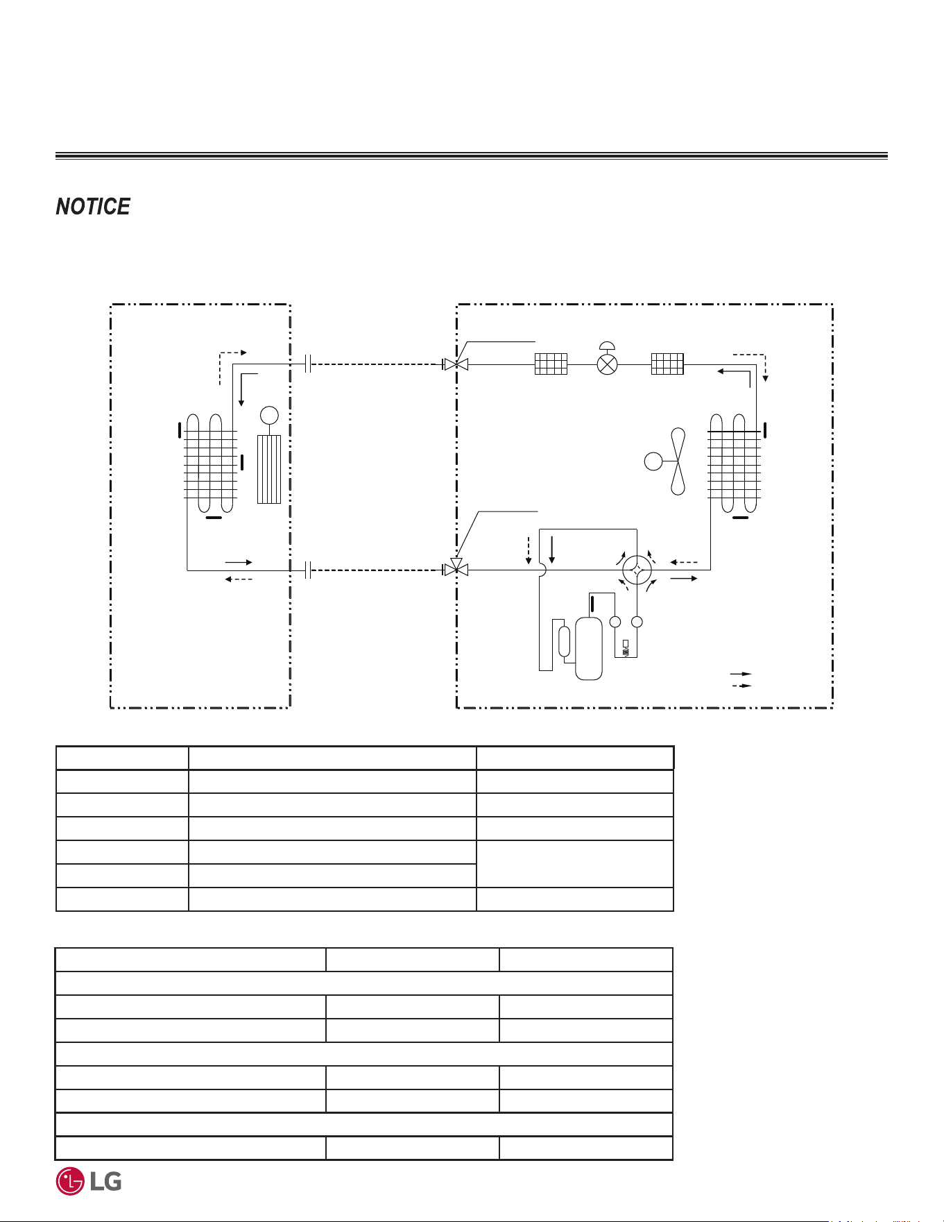
'XHWRRXUSROLF\RIFRQWLQXRXVSURGXFWLQQRYDWLRQVRPHVSHFL¿FDWLRQVPD\FKDQJHZLWKRXWQRWL¿FDWLRQ
©
/*(OHFWURQLFV86$,QF(QJOHZRRG&OLIIV1-$OOULJKWVUHVHUYHG³/*´LVDUHJLVWHUHGWUDGHPDUNRI/*&RUS
Refrigerant Piping Design
93
REFRIGERANT FLOW DIAGRAMS
Figure 37: 5HIULJHUDQW)ORZ'LDJUDPIRU$OO6WDQGDUG(I¿FLHQF\0HJDDQG0HJD90RGHOV
Table 63: 7KHUPLVWRU'HWDLOVIRU$OO6WDQGDUG(I¿FLHQF\0HJDDQG0HJD90RGHOV
$OO6WDQGDUG(ႈFLHQF\0HJDDQG0HJD90RGHOV
Field Piping
(Copper Tubing)
Field Piping
(Copper Tubing)
M
M
Heat
Exchanger
(Evaporator)
Heat
Exchanger
(Condenser)
Compressor
2-Way Valve
Reversing
Valve
Indoor Unit
O
utdoor Unit
: Cooling
: Heating
EEV
Th1
Th3
Th4
Th5
Th6
Liquid Side
Vapor Side
3-Way Valve
Th2
Pressure
Switch
Table 64: 5HIULJHUDQW3LSLQJ&RQQHFWLRQ6L]HVIRU$OO6WDQGDUG(I¿FLHQF\0HJDDQG0HJD90RGHOV
Thermistor Description PCB Connector
Th1 Thermistor for indoor air temperature CN-TH1 (Indoor)
Th2 Thermistor for evaporator temperature CN-TH2 (Indoor)
Th3 Thermistor for evaporator middle temperature CN-TH3 (Indoor)
Th4 Thermistor for outdoor air temperature
CN-TH1 (Outdoor)
Th5 Thermistor for condenser temperature
Th6 Thermistor for discharge pipe temperature CN-TH2 (Outdoor)
Model Vapor (in.) Liquid (in.)
Standard Efficiency
KSSAE091A, KSSAE121A Ø3/8 Ø1/4
KSSAE181A, KSSAE241A Ø1/2 Ø1/4
Mega
KSSAC091A, KSSAC121A Ø3/8 Ø1/4
KSSAC181A, KSSAC241A Ø1/2 Ø1/4
0HJD9
KSSAC091B, KSSAC121B Ø3/8 Ø1/4
9DULRXVWRROVDUHDYDLODEOHWRDVVLVWLQSURSHUO\GHVLJQLQJ/*5VSOLWV\VWHPV5HIHUWRWKH³5$SSOLFDWLRQ*XLGH´WKH³6LPSOH&DOFXODWRUIRU&D-
SDFLW\5HIULJHUDQW&KDUJHDQG(63´WKH³/*$LU&RQGLWLRQHU7HFKQLFDO6ROXWLRQV´/$76VRIWZDUHSURJUDPDQGWKHORFDO/*6DOHV5HSUHVHQWDWLYH
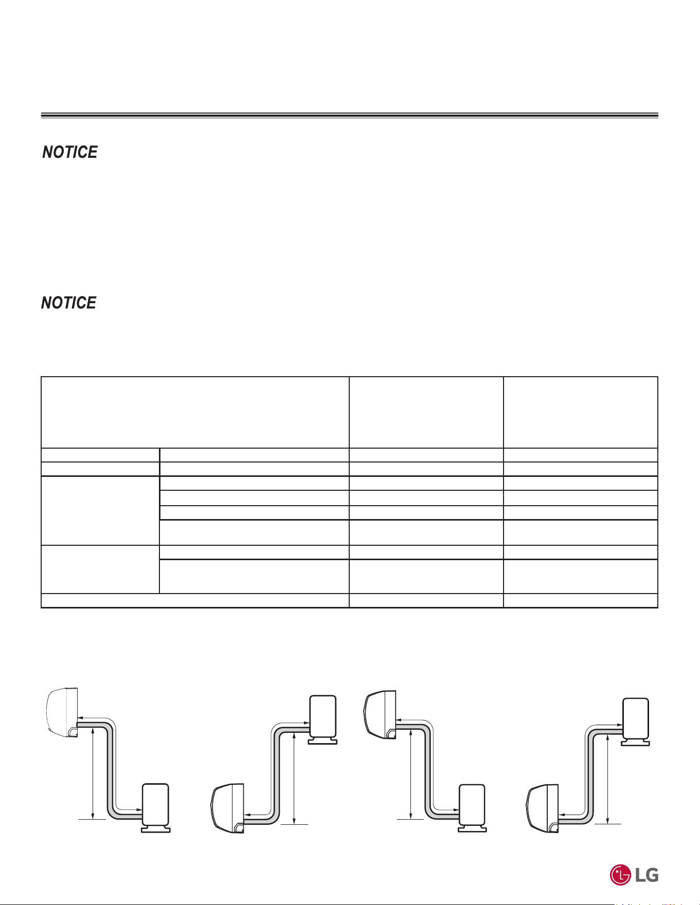
'XHWRRXUSROLF\RIFRQWLQXRXVSURGXFWLQQRYDWLRQVRPHVSHFL¿FDWLRQVPD\FKDQJHZLWKRXWQRWL¿FDWLRQ
©
/*(OHFWURQLFV86$,QF(QJOHZRRG&OLIIV1-$OOULJKWVUHVHUYHG³/*´LVDUHJLVWHUHGWUDGHPDUNRI/*&RUS
94
56LQJOH=RQH6WDQGDUG(ႈFLHQF\0HJDDQG0HJD9:DOO0RXQWHG(QJLQHHULQJ0DQXDO
&211(&7,21/,0,7$7,2166<67(0/$<287
Connection Limitations
Single-zone systems consist of one outdoor unit and one indoor unit. One of the most critical elements of a single zone system is the refrig-
erant piping. If the connection piping is not within allowable limits, there will be reliability, performance, noise, and vibration issues. The table
below lists pipe length limits that must be followed in the design of a Single Zone Standard Efficiency, Mega, and Mega 115V refrigerant pipe
system. Refer to the figure(s) for maximum length and elevation of piping.
System Model No.
6WDQGDUG(IÀFLHQF\
KSSAE091A and KSSAE121A;
Mega KSSAC091A and
KSSAC121A;
Mega 115V KSSAC091B and
KSSAC121B
6WDQGDUG(IÀFLHQF\
KSSAE181A and KSSAE241A;
Mega KSSAC181A and
KSSAC241A
Liquid Piping (in.) Connection / Pipe Size 1/4 / 1/4 1/4 / 1/4
Vapor Piping (in.) Connection / Pipe Size Vapor 3/8 / 3/8 1/2 / 1/2
Pipe Length
(ELF = Equivalent
Length of Pipe)
Standard length (no add’l refrigerant) 24.6 feet 24.6 feet
Longest total equivalent piping length 49.2 feet 65.6 feet
Shortest total equivalent piping length 9.8 9.8
Distance between fittings and indoor or
outdoor units
LQFKHV LQFKHV
Elevation
(All Elevation Limitations
are Measured in Actual
Feet)
If outdoor unit is above indoor unit 23 feet 32.8 feet
If outdoor unit is below indoor unit 23 feet 32.8 feet
Additional Refrigerant Needed (oz. /ft.) 0.16 0.22
Figure 38: 7\SLFDO6WDQGDUG(I¿FLHQF\0HJDDQG0HJD9
Btu/h and 12,000 Btu/h System Layout.
Table 65: 6LQJOH=RQH6WDQGDUG(I¿FLHQF\0HJDDQG0HJD95HIULJHUDQW3LSLQJ6\VWHP/LPLWDWLRQV
System Layout
Depending on system and proposed / installed pipe length, it may be required to calculate maximum refrigerant charge to determine if the system
complies with applicable regulations / standards. For residential applications, a refrigerant charge less than 4.1 lbs. complies with ASHRAE 15.2
and does not require additional calculation/consideration of maximum refrigerant charge for release in a space.
Figure 39: 7\SLFDO6WDQGDUG(I¿FLHQF\DQG0HJD%WXKDQG
24,000 Btu/h System Layout.
Outdoor unit
Indoor unit
Outdoor unit
Indoor unit
65.6 feet 65.6 feet
32.8 feet
32.8 feet
Outdoor unit
Indoor unit
Outdoor unit
Indoor unit
49.2 feet
49.2 feet
23 feet
23 feet
9DULRXVWRROVDUHDYDLODEOHWRDVVLVWLQSURSHUO\GHVLJQLQJ/*5VSOLWV\VWHPV5HIHUWRWKH³5$SSOLFDWLRQ*XLGH´WKH³6LPSOH&DOFXODWRUIRU&D-
SDFLW\5HIULJHUDQW&KDUJHDQG(63´WKH³/*$LU&RQGLWLRQHU7HFKQLFDO6ROXWLRQV´/$76VRIWZDUHSURJUDPDQGWKHORFDO/*6DOHV5HSUHVHQWDWLYH
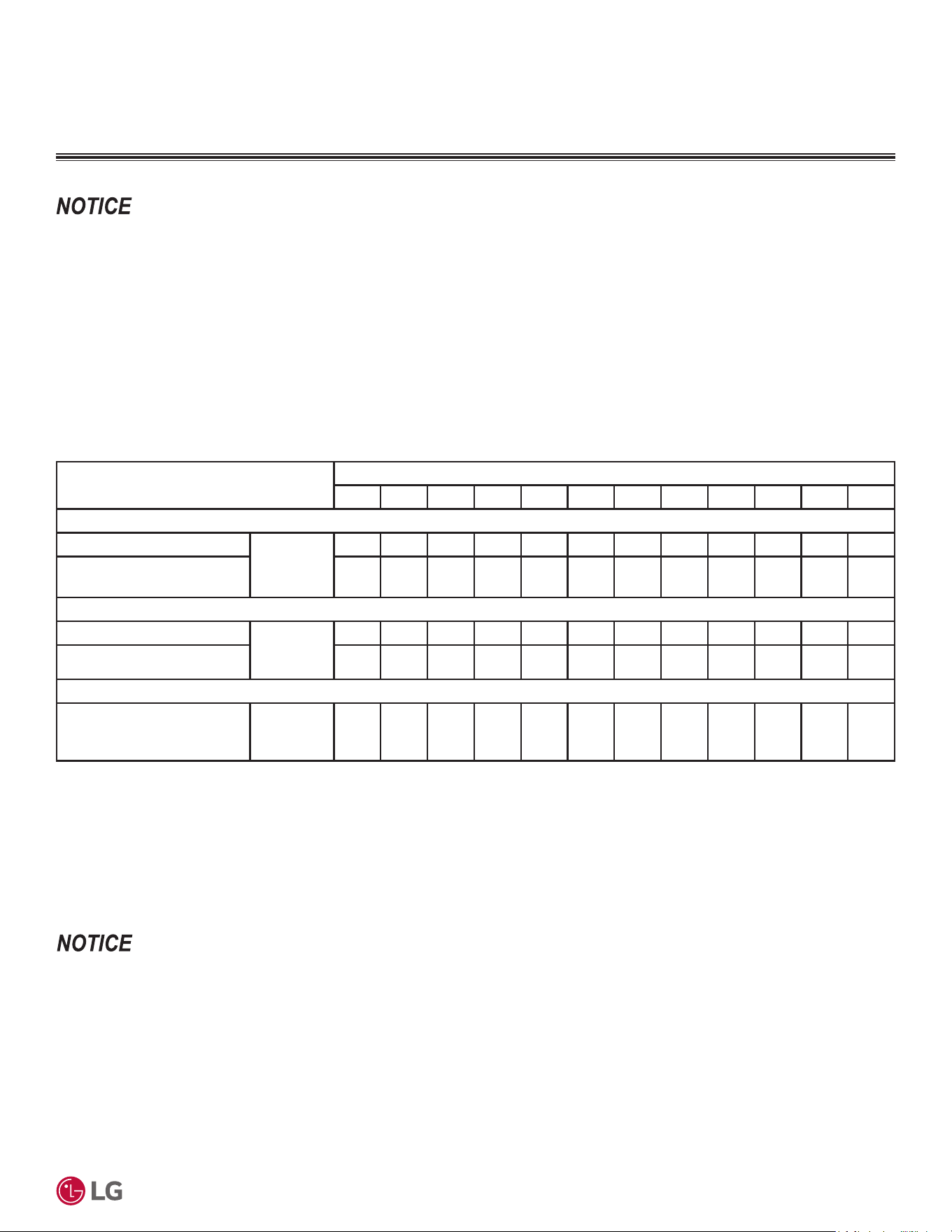
'XHWRRXUSROLF\RIFRQWLQXRXVSURGXFWLQQRYDWLRQVRPHVSHFL¿FDWLRQVPD\FKDQJHZLWKRXWQRWL¿FDWLRQ
©
/*(OHFWURQLFV86$,QF(QJOHZRRG&OLIIV1-$OOULJKWVUHVHUYHG³/*´LVDUHJLVWHUHGWUDGHPDUNRI/*&RUS
Refrigerant Piping Design
95
• 9DOXHVDUHLQRXQFHVR]
• Capacity is based on standard length; maximum allowance length is based on reliability.
• (TXLYDOHQW3LSH/HQJWK $FWXDO3LSH/HQJWK1XPEHURI%HQGV[
• &DOFXODWLRQ;R] >5HIULJHUDQW3LSLQJ/HQJWK@>&KDUJHOHVV/HQJWK@î$GGLWLRQDO5HIULJHUDQW
Table 66: 6LQJOH=RQH6WDQGDUG(I¿FLHQF\0HJDDQG0HJD9$GGLWLRQDO5HIULJHUDQWE\3LSLQJ/HQJWKR]
ADDITIONAL REFRIGERANT CHARGE
System Model No.
Refrigerant Piping Length (feet)
16.4 24.6 32.8 41.0 49.2 65.6 82.0 98.4 114.8 131.2 147.6 164.0
Standard Efficiency
KSSAE091A and KSSAE121A
Additional
Refrigerant
Charge (oz.)
001.32.63.9-------
KSSAE181A and KSSAE241A 0 0 1.8 3.6 5.4 9.0 - -----
Mega
KSSAC091A and KSSAC121A Additional
Refrigerant
Charge (oz.)
001.32.63.9-------
KSSAC181A and KSSAC241A 0 0 1.8 3.6 5.4 9.0 - -----
0HJD9
KSSAC091B and KSSAC121B
Additional
Refrigerant
Charge (oz.)
001.32.63.9-------
,IWKHXQLWFKDUJHLVXQNQRZQUHFODLPHYDFXDWHDQGZHLJKLQWKHFRUUHFWFKDUJHXVLQJWKHXQLWQDPHSODWHFDSDFLW\FKDUJHDGMXVWLQJIRUOLQHVHWV
ORQJHUWKDQWKH³FKDUJHOHVV´DPRXQW7KLVZLOOSUHYHQWDQ\LQWHUUXSWLRQVWRXQLWRSHUDWLRQDQGSRVVLEOHGDPDJH
Example for KSSAC181A:
$IRRWOLQHVHWLVXVHG$GGLWLRQDOIHHW[R]SHUIRRW $GGR]RIUHIULJHUDQW
Additional Refrigerant Charge
Each outdoor unit is factory charged (nameplate charge) for the evaporator as well as having a standard foot line (for each single zone
system; listed in the specification tables). Any time a line set is used longer then the standard foot line set length for the single zone system,
the refrigerant charge has to be adjusted.
The charge must be adjusted on the ounces of R32 (listed in the specification tables) per foot based on how many feet of piping are added.
The factory charge accommodates pipe lengths up to the standard (no additional refrigerant) length without requiring refrigerant removal.
See table below for information on the additional refrigerant charges necessary for longer piping lengths. Refer to the previous page for
maximum piping length and additional charge amount per additional foot of pipe length.
9DULRXVWRROVDUHDYDLODEOHWRDVVLVWLQSURSHUO\GHVLJQLQJ/*5VSOLWV\VWHPV5HIHUWRWKH³5$SSOLFDWLRQ*XLGH´WKH³6LPSOH&DOFXODWRUIRU&D-
SDFLW\5HIULJHUDQW&KDUJHDQG(63´WKH³/*$LU&RQGLWLRQHU7HFKQLFDO6ROXWLRQV´/$76VRIWZDUHSURJUDPDQGWKHORFDO/*6DOHV5HSUHVHQWDWLYH
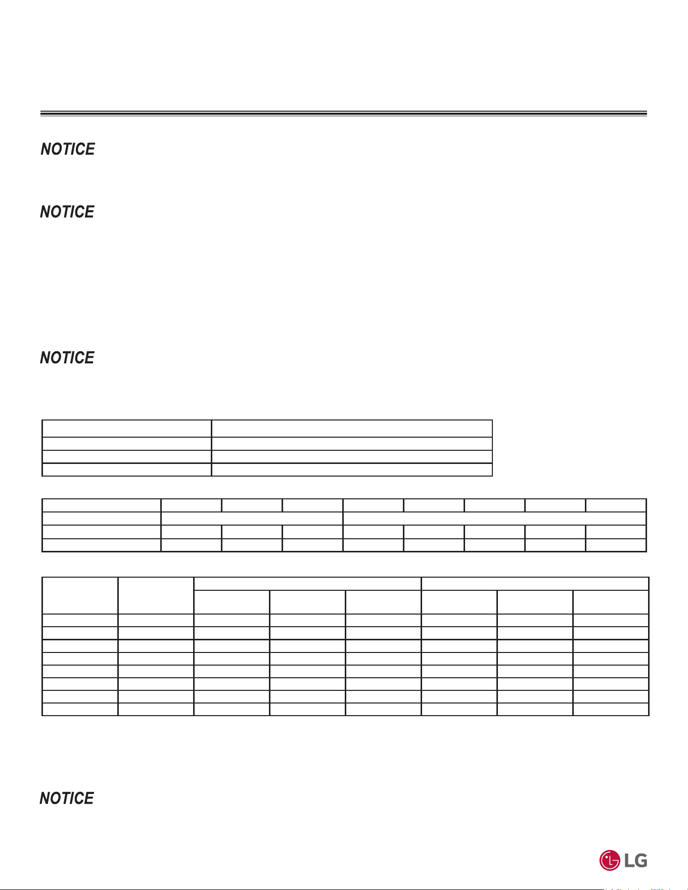
'XHWRRXUSROLF\RIFRQWLQXRXVSURGXFWLQQRYDWLRQVRPHVSHFL¿FDWLRQVPD\FKDQJHZLWKRXWQRWL¿FDWLRQ
©
/*(OHFWURQLFV86$,QF(QJOHZRRG&OLIIV1-$OOULJKWVUHVHUYHG³/*´LVDUHJLVWHUHGWUDGHPDUNRI/*&RUS
96
56LQJOH=RQH6WDQGDUG(ႈFLHQF\0HJDDQG0HJD9:DOO0RXQWHG(QJLQHHULQJ0DQXDO
REFRIGERANT PIPING SYSTEM ENGINEERING
Selecting Field-Supplied Copper Piping
Always follow local codes when selecting and installing copper pipe and piping system components.
Approved piping for use with LG Single Zone products will be marked “R32 RATED” along the length of the pipe. Piping wall thickness must
meet local code requirements and be approved for a maximum operating pressure of 626 psi. When bending piping, try to keep the number
of bends to a minimum, and use the largest radii possible to reduce the equivalent length of installed piping; also, bending radii greater than
ten (10) piping diameters can minimize pressure drop. Be sure no traps or sags are present.
For Single Zone Systems
LG prefers the use of ACR copper piping rated at the system working pressure was used.
Always properly support the piping as per the instructions on page 100.
Table 67: ACR Rated Copper Tubing Material.
Type Seamless Phosphorous Deoxidized
Class UNS C12200 DHP
Straight Lengths H58 Temper
Coils O60 Temper
Table 68: Piping Tube Thicknesses.
OD (in.) 1/4 3/8 1/2 5/8 3/4 7/8 1-1/8 1-3/8
Material Rigid or Soft ACR Rated for R32 Rigid or Soft ACR Rated for R32
Min. Bend Radius (in.) 0.563 0.9375 1.5 2.25 3.0 3.0 3.5 4.0
Min. Wall Thickness (in.) 0.030 0.030 0.030 0.030 0.030 0.030 0.030 0.040
Table 69: ACR Copper Tubing Dimensions and Physical Characteristics
1-3
.
Nominal Pipe
Outside
Diameter (in.)
Actual Outside
Diameter (in.)
'UDZQ7HPSHUHG+DUG Annealed Temper (Soft)
Nominal Wall
Thickness (in.)
Weight (lb. / ft.)
Cubic ft. per
Linear ft.
Nominal Wall
Thickness (in.)
Weight (lb. / ft.)
Cubic ft. per
Linear ft.
1/4 0.250 - - - 0.030 0.0804 0.00020
3/8 0.375 0.030 0.126 0.00054 0.032 0.134 0.00053
1/2 0.500 0.035 0.198 0.00101 0.032 0.182 0.00103
5/8 0.625 0.040 0.285 0.00162 0.035 0.251 0.00168
3/4 0.750 0.042 0.362 0.00242 0.035 0.305 0.00252
7/8 0.875 0.045 0.455 0.00336 0.045 0.455 0.00336
1-1/8 1.125 0.050 0.655 0.00573 0.050 0.655 0.00573
1-3/8 1.375 0.055 0.884 0.00875 0.055 0.884 0.00875
1
$OOGLPHQVLRQVSURYLGHGDUHLQDFFRUGDQFHZLWK$670%±6WDQGDUG
2
Design pressure = 626 psig.
3
7KH&RSSHU7XEH+DQGERRN,QGXVWU\6WDQGDUG*XLGHIRUWKH'HVLJQDQG,QVWDOODWLRQRI&RSSHU3LSLQJ6\VWHPV&RSSHU'HYHORSPHQW$VVRFLDWLRQ
,QF&RSSHU$OOLDQFHKWWSVZZZFRSSHURUJSXEOLFDWLRQVSXEBOLVWSGIFRSSHUBWXEHBKDQGERRNSGI
• Commercially available piping often contains dust and other materials. Always blow it clean with a dry inert gas.
• Prevent dust, water or other contaminants from entering the piping during installation.
9DULRXVWRROVDUHDYDLODEOHWRDVVLVWLQSURSHUO\GHVLJQLQJ/*5VSOLWV\VWHPV5HIHUWRWKH³5$SSOLFDWLRQ*XLGH´WKH³6LPSOH&DOFXODWRUIRU&D-
SDFLW\5HIULJHUDQW&KDUJHDQG(63´WKH³/*$LU&RQGLWLRQHU7HFKQLFDO6ROXWLRQV´/$76VRIWZDUHSURJUDPDQGWKHORFDO/*6DOHV5HSUHVHQWDWLYH
'XHWRRXUSROLF\RIFRQWLQXRXVSURGXFWLQQRYDWLRQVRPHVSHFL¿FDWLRQVPD\FKDQJHZLWKRXWQRWL¿FDWLRQ
©
/*(OHFWURQLFV86$,QF(QJOHZRRG&OLIIV1-$OOULJKWVUHVHUYHG³/*´LVDUHJLVWHUHGWUDGHPDUNRI/*&RUS
Refrigerant Piping Design
97
Under normal operating conditions, the vapor pipe temperature of
a Single Zone System can vary as much as 280°F. With this large
variance in pipe temperature, the designer must consider pipe
expansion and contraction to avoid pipe and fitting fatigue failures.
Refrigerant pipe along with the insulation jacket form a cohesive
unit that expands and contracts together. During system operation,
thermal heat transfer occurs between the pipe and the surrounding
insulation.
If the pipe is mounted in free air space, no natural restriction to
movement is present if mounting clamps are properly spaced and
installed. In extreme cases, the restrictive force of surface friction
between insulating jackets could become so great that natural
expansion ceases and the pipe is “fixed” in place. In this situation,
opposing force caused by change in refrigerant fluid / vapor tem-
perature can lead to pipe/fitting stress failure.
The refrigerant pipe support system must be engineered to allow free
expansion to occur. When a segment of pipe is mounted between
two fixed points, provisions must be provided to allow pipe expan-
sion to naturally occur. The most common method is the inclusion
of expansion Loop or U-bends. Each segment of pipe has a natural
fixed point where no movement occurs. This fixed point is located at
the center point of the segment assuming the entire pipe is insulated
in a similar fashion. The natural fixed point of the pipe segment is
typically where the expansion Loop or U-bend must be.
Linear pipe expansion can be calculated using the following formula:
1. From the “Linear Thermal Expansion of Copper Tubing in Inches”
Table on the next page, find the row corresponding with the actual
length of the straight pipe segment.
2. Estimate the minimum and maximum temperature of the pipe.
In the column showing the minimum pipe temperature, look up the
anticipated expansion distance. Do the same for the maximum
pipe temperature.
3. Calculate the difference in the two expansion distance values.
The result will be the anticipated change in pipe length.
General Example:
A system is installed and the design shows that there is a 100 foot
straight segment of tubing between an indoor unit and the outdoor
unit. In heating, this pipe transports hot gas vapor to the indoor units
at 120°F. In cooling, the same tube is a suction line returning refrig-
erant vapor to the outdoor unit at 40°F. Look up the copper tubing
expansion at each temperature and calculate the difference.
Vapor Line
Transporting Hot Vapor: 100 ft. pipe at 120°F = 1.40 in.
Transporting Suction Vapor: 100 ft. pipe at 40°F = 0.40 in.
Anticipated Change in Length: 1.40 in. – 0.40 in. = 1.00 in.
Liquid Line
The liquid temperature remains relatively the same temperature; only
the direction of flow will reverse. Therefore, no significant change in
length of the liquid line is anticipated.
When creating an expansion joint, the joint height must be a
minimum of two times the joint width. Although different types of
expansion arrangements are available, the data for correctly sizing
an Expansion Loop is provided in the “Radii of Coiled Expansion
Loops and Developed Lengths of Expansion Offsets” Table on the
next page. Use soft copper with long radius bends on longer runs or
long radius elbows for shorter pipe segments. Using the anticipated
linear expansion (LE) distance calculated, look up the Expansion
Loop or U-bend minimum design dimensions. If other types of expan-
sion joints are chosen, design per ASTM B-88 Standards.
LE = C x L x (T
r
– T
a
) x 12
LE = Anticipated linear tubing expansion (in.)
C = Constant (For copper = 9.2 x 10
-6
in./in.°F)
L = Length of pipe (ft.)
T
R
= Refrigerant pipe temperature (°F)
T
a
= Ambient air temperature (°F)
12 = Inches to feet conversion (12 in./ft.)
Copper Expansion and Contraction
See table on next page for precalculated anticipated expansion for various pipe sizes and lengths of refrigerant tubing.
To find the anticipated expansion value:
1. From the table on the next page, find the row corresponding with the actual feet of the straight pipe segment.
2. Estimate the minimum and maximum temperature of the pipe.
3. In the column showing the minimum pipe temperature, look up the anticipated expansion distance corresponding to the segment length.
Do the same for the maximum pipe temperature.
4. Calculate the difference in the two expansion distance values. The result will be the change in pipe length.
REFRIGERANT PIPING SYSTEM ENGINEERING
9DULRXVWRROVDUHDYDLODEOHWRDVVLVWLQSURSHUO\GHVLJQLQJ/*5VSOLWV\VWHPV5HIHUWRWKH³5$SSOLFDWLRQ*XLGH´WKH³6LPSOH&DOFXODWRUIRU&D-
SDFLW\5HIULJHUDQW&KDUJHDQG(63´WKH³/*$LU&RQGLWLRQHU7HFKQLFDO6ROXWLRQV´/$76VRIWZDUHSURJUDPDQGWKHORFDO/*6DOHV5HSUHVHQWDWLYH
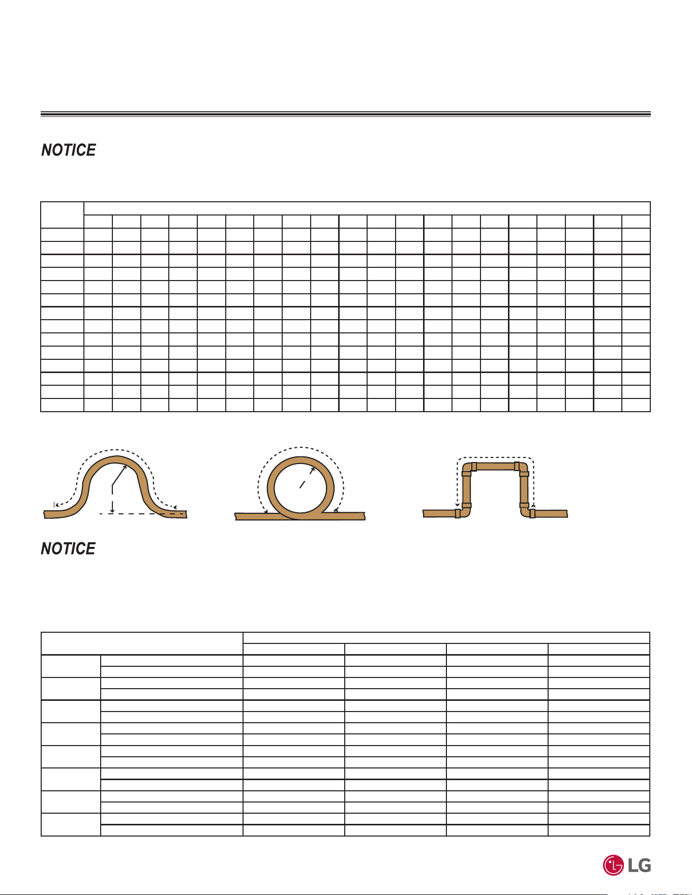
'XHWRRXUSROLF\RIFRQWLQXRXVSURGXFWLQQRYDWLRQVRPHVSHFL¿FDWLRQVPD\FKDQJHZLWKRXWQRWL¿FDWLRQ
©
/*(OHFWURQLFV86$,QF(QJOHZRRG&OLIIV1-$OOULJKWVUHVHUYHG³/*´LVDUHJLVWHUHGWUDGHPDUNRI/*&RUS
98
56LQJOH=RQH6WDQGDUG(ႈFLHQF\0HJDDQG0HJD9:DOO0RXQWHG(QJLQHHULQJ0DQXDO
Pipe
Length
1
Fluid Temperature °F
35° 40° 45° 50° 55° 60° 65° 70° 75° 80° 85° 90° 95° 100° 105° 110° 115° 120° 125° 130°
10 0.04 0.04 0.05 0.06 0.06 0.07 0.08 0.08 0.09 0.09 0.10 0.10 0.11 0.11 0.11 0.12 0.13 0.14 0.15 0.15
20 0.08 0.08 0.10 0.12 0.13 0.14 0.15 0.16 0.17 0.18 0.19 0.20 0.21 0.22 0.22 0.23 0.26 0.28 0.29 0.30
30 0.12 0.12 0.15 0.18 0.20 0.21 0.23 0.24 0.26 0.27 0.29 0.30 0.32 0.33 0.32 0.35 0.39 0.42 0.44 0.45
40 0.16 0.16 0.20 0.24 0.26 0.28 0.30 0.32 0.34 0.36 0.38 0.40 0.42 0.44 0.43 0.46 0.52 0.56 0.58 0.60
50 0.20 0.20 0.25 0.30 0.33 0.35 0.38 0.40 0.43 0.45 0.48 0.50 0.53 0.55 0.54 0.58 0.65 0.70 0.73 0.75
60 0.24 0.24 0.30 0.36 0.39 0.42 0.45 0.48 0.51 0.54 0.57 0.60 0.63 0.66 0.65 0.69 0.78 0.84 0.87 0.90
70 0.28 0.28 0.35 0.42 0.46 0.49 0.53 0.56 0.60 0.63 0.67 0.70 0.74 0.77 0.76 0.81 0.91 0.98 1.02 1.05
80 0.32 0.32 0.40 0.48 0.52 0.56 0.60 0.64 0.68 0.72 0.76 0.80 0.84 0.88 0.86 0.92 1.04 1.12 1.16 1.20
90 0.36 0.36 0.45 0.54 0.59 0.63 0.68 0.72 0.77 0.81 0.86 0.90 0.95 0.99 0.97 1.04 1.17 1.26 1.31 1.35
100 0.40 0.40 0.50 0.60 0.65 0.70 0.75 0.80 0.85 0.90 0.95 1.00 1.05 1.10 1.08 1.15 1.30 1.40 1.45 1.50
120 0.48 0.48 0.60 0.72 0.78 0.84 0.90 0.96 1.02 1.08 1.14 1.20 1.26 1.32 1.30 1.38 1.56 1.68 1.74 1.80
140 0.56 0.56 0.70 0.84 0.91 0.98 1.05 1.12 1.19 1.26 1.33 1.40 1.47 1.54 1.51 1.61 1.82 1.96 2.03 2.10
160 0.64 0.64 0.80 0.96 1.04 1.12 1.20 1.28 1.36 1.44 1.52 1.60 1.68 1.76 1.73 1.84 2.08 2.24 2.32 2.40
180 0.72 0.72 0.90 1.08 1.17 1.26 1.35 1.44 1.53 1.62 1.71 1.80 1.89 1.98 1.94 2.07 2.34 2.52 2.61 2.70
Table 70: Linear Thermal Expansion of Copper Tubing in Inches.
1
Pipe length baseline temperature = 0°F. "Expansion of Carbon, Copper and Stainless Steel Pipe," The Engineers' Toolbox, www.engineeringtoolbox.com.
Anticipated Linear
Expansion (LE) (inches)
Nominal Tube Size (OD) inches
1/4 3/8 1/2 3/4
1/2
R
1
6789
L
2
38 44 50 59
1
R
1
9 101113
L
2
54 63 70 83
1-1/2
R
1
11 12 14 16
L
2
66 77 86 101
2
R
1
12 14 16 19
L
2
77 89 99 117
2-1/2
R
1
14 16 18 21
L
2
86 99 111 131
3
R
1
15 17 19 23
L
2
94 109 122 143
3-1/2
R
1
16 19 21 25
L
2
102 117 131 155
4
R
1
17 20 22 26
L
2
109 126 140 166
Table 71: Radii of Coiled Expansion Loops and Developed Lengths of Expansion Offsets. (See 7KH&RSSHU7XEH+DQGERRN,QGXVWU\6WDQGDUG*XLGH
IRUWKH'HVLJQDQG,QVWDOODWLRQRI&RSSHU3LSLQJ6\VWHPV&RSSHU'HYHORSPHQW$VVRFLDWLRQ,QF&RSSHU$OOLDQFHKWWSVZZZFRSSHURUJSXEOLFD-
WLRQVSXEBOLVWSGIFRSSHUBWXEHBKDQGERRNSGIfor additional information.)
Figure 40: Coiled Expansion Loops and Offsets (Plan View).
Large Tubing U-bend (>3/4 in.) Loop Small Tubing U-bend (<3/4 in.)
R
L
R
L
L
1
R = Centerline Length of Pipe.
2
L = Centerline Minimum Radius (inches).
All expansion loops and offsets must be installed in the horizontal plane to prevent the possibility of trapping oil. Loops and offsets in vertical risers
must also be installed in a horizontal plane.
REFRIGERANT PIPING SYSTEM ENGINEERING
9DULRXVWRROVDUHDYDLODEOHWRDVVLVWLQSURSHUO\GHVLJQLQJ/*5VSOLWV\VWHPV5HIHUWRWKH³5$SSOLFDWLRQ*XLGH´WKH³6LPSOH&DOFXODWRUIRU&D-
SDFLW\5HIULJHUDQW&KDUJHDQG(63´WKH³/*$LU&RQGLWLRQHU7HFKQLFDO6ROXWLRQV´/$76VRIWZDUHSURJUDPDQGWKHORFDO/*6DOHV5HSUHVHQWDWLYH
'XHWRRXUSROLF\RIFRQWLQXRXVSURGXFWLQQRYDWLRQVRPHVSHFL¿FDWLRQVPD\FKDQJHZLWKRXWQRWL¿FDWLRQ
©
/*(OHFWURQLFV86$,QF(QJOHZRRG&OLIIV1-$OOULJKWVUHVHUYHG³/*´LVDUHJLVWHUHGWUDGHPDUNRI/*&RUS
Refrigerant Piping Design
99
REFRIGERANT PIPING SYSTEM ENGINEERING
No Pipe Size Substitutions
Use only the pipe size selected by the information in this manual. Using a different size is prohibited and will result in a system malfunction or
failure to work at all.
No In-line Refrigeration Components
Components such as oil traps, solenoid valves, filter-driers, sight glasses, tee fittings, and other after-market accessories are not
permitted on the refrigerant piping system between the outdoor units and the indoor units. LG Single Zone systems are provided with
redundant systems that make sure oil is properly returned to the compressor. Sight-glasses and solenoid valves will cause vapor to form in
the liquid stream. Over time, driers will deteriorate and introduce debris into the system. The designer and installer must verify the refrigerant
piping system is free of traps, sagging pipes, sight glasses, filter driers, etc.
Field-Provided Isolation Ball Valves
LG maintains a neutral position on using isolation valves in LG HVAC refrigerant piping systems. LG does not endorse any manufacturer of
isolation valves. It is recognized that installing isolation valves will simplify future maintenance requirements, and, if used, considerations
must be taken including, but not limited to, the following:
• Pressure drops for any component used, including isolation valves, must be known in equivalent pipe length and calculated into the total
and segment equivalent piping lengths and compared to product design limitations.
• In all cases, materials must be suitable for the application and any applicable codes, including, but not limited to, diameter and wall thick-
ness continuity per ACR standards.
Failure to do so will cause significant performance degradation. Proper leak checks must be performed. Using isolation valves does not
automatically void any LG product warranty, however, a limited warranty will be voided in whole or part if any field supplied accessory fail in
any way that causes product failure.
Using Elbows
Field-supplied elbows are allowed if they are long radius and designed for use with R32 refrigerant. The designer and installer, however,
must be cautious with the quantity and size of fittings used, and must account for the additional pressure losses in equivalent pipe length
calculation for each branch. The equivalent pipe length of each elbow must be added to each pipe segment in the LATS program.
Pipe Bends
When bending soft copper, use long radius bends. Refer to the “Radii of Coiled Expansion Loops and Developed Lengths of Expansion
Offsets” table on the previous page for minimum radius specifications.
Proper system operation depends on the installer using utmost care while assembling the piping system. The following pages are an over-
view of best practices when installing the refrigerant piping system.
LG Electronics U.S.A.,Inc., is not responsible for any piping calculations, refrigerant leaks, degradation of performance, any other potential problems
or damages caused by the interconnecting piping, their joint connections, isolation valves, or introduced debris inside the piping system.
9DULRXVWRROVDUHDYDLODEOHWRDVVLVWLQSURSHUO\GHVLJQLQJ/*5VSOLWV\VWHPV5HIHUWRWKH³5$SSOLFDWLRQ*XLGH´WKH³6LPSOH&DOFXODWRUIRU&D-
SDFLW\5HIULJHUDQW&KDUJHDQG(63´WKH³/*$LU&RQGLWLRQHU7HFKQLFDO6ROXWLRQV´/$76VRIWZDUHSURJUDPDQGWKHORFDO/*6DOHV5HSUHVHQWDWLYH
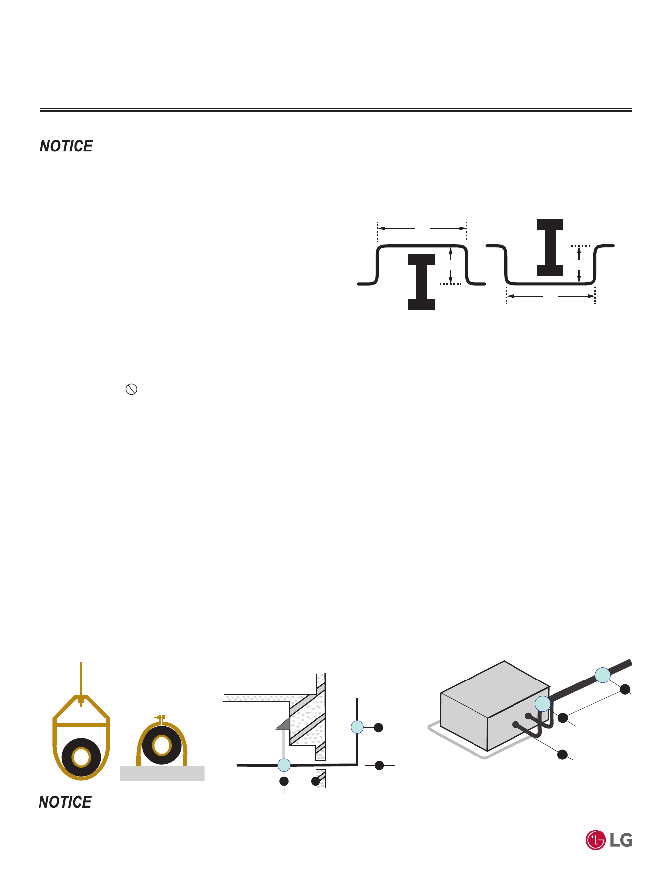
'XHWRRXUSROLF\RIFRQWLQXRXVSURGXFWLQQRYDWLRQVRPHVSHFL¿FDWLRQVPD\FKDQJHZLWKRXWQRWL¿FDWLRQ
©
/*(OHFWURQLFV86$,QF(QJOHZRRG&OLIIV1-$OOULJKWVUHVHUYHG³/*´LVDUHJLVWHUHGWUDGHPDUNRI/*&RUS
100
56LQJOH=RQH6WDQGDUG(ႈFLHQF\0HJDDQG0HJD9:DOO0RXQWHG(QJLQHHULQJ0DQXDO
REFRIGERANT PIPING SYSTEM ENGINEERING
Figure 41: Installing Piping Above and Below an Obstacle.
Obstacles
When an obstacle, such as an I-beam or concrete T, is in the path
of the planned refrigerant pipe run, it is best practice to route the
pipe over the obstacle. If adequate space is not available to route
the insulated pipe over the obstacle, then route the pipe under the
obstacle. In either case, it is imperative the length of the horizontal
section of pipe above or below the obstacle be a minimum of three
(3) times the longest vertical rise (or fall) at either end of the
segment.
MINIMUM
Above an obstacle
MINIMUM
Below an obstacle
3X
X
3X
X
Pipe Supports
A properly installed pipe system must be adequately supported to avoid pipe sagging. Sagging pipes become oil traps that lead to equipment
malfunction.
Pipe supports must never touch the pipe wall; supports must be installed outside (around) the primary pipe insulation jacket. Insulate
the pipe first because pipe supports must be installed outside (around) the primary pipe insulation jacket. Clevis hangers must be used with
shields between the hangers and insulation. Field provided pipe supports must be designed to meet local codes. If allowed by code, use fiber
straps or split-ring hangers suspended from the ceiling on all-thread rods (fiber straps or split ring hangers can be used as long as they do
not compress the pipe insulation). Place a second layer of insulation over the pipe insulation jacket to prevent chafing and compression of
the primary insulation within the confines of the support pipe clamp.
A properly installed pipe system will have sufficient supports to avoid pipes from sagging during the life of the system. As necessary, place
supports closer for segments where potential sagging could occur. Maximum spacing of pipe supports must meet local codes. If local codes
do not specify pipe support spacing, pipe must be supported:
• Maximum of five (5) feet on center for straight segments of pipe up to 3/4 inches outside diameter size.
• Maximum of six (6) feet on center for pipe up to one (1) inch outside diameter size.
• Maximum of eight (8) feet on center for pipe up to two (2) inches outside diameter size.
Wherever the pipe changes direction, place a hanger within twelve (12) inches on one side and within twelve (12) to nineteen (19) inches of
the bend on the other side.
Support piping at indoor unit(s) as shown.
Figure 42: Pipe Hanger Details.
Use a 4" + long sheet curved sheet metal saddles between hanger bracket and insulation to promote linear expansion/contraction.
Figure 43: Typical Pipe Support Location—
Change in Pipe Direction.
Max. 12"
~ 12" – 19"
Figure 44: Pipe Support at Indoor Unit.
Max. 12"
~12" - 19"
9DULRXVWRROVDUHDYDLODEOHWRDVVLVWLQSURSHUO\GHVLJQLQJ/*5VSOLWV\VWHPV5HIHUWRWKH³5$SSOLFDWLRQ*XLGH´WKH³6LPSOH&DOFXODWRUIRU&D-
SDFLW\5HIULJHUDQW&KDUJHDQG(63´WKH³/*$LU&RQGLWLRQHU7HFKQLFDO6ROXWLRQV´/$76VRIWZDUHSURJUDPDQGWKHORFDO/*6DOHV5HSUHVHQWDWLYH

'XHWRRXUSROLF\RIFRQWLQXRXVSURGXFWLQQRYDWLRQVRPHVSHFL¿FDWLRQVPD\FKDQJHZLWKRXWQRWL¿FDWLRQ
©
/*(OHFWURQLFV86$,QF(QJOHZRRG&OLIIV1-$OOULJKWVUHVHUYHG³/*´LVDUHJLVWHUHGWUDGHPDUNRI/*&RUS
Refrigerant Piping Design
101
REFRIGERANT PIPING SYSTEM ENGINEERING
Pipe Sleeves at Penetrations
LG recommends that all pipe penetrations through walls, floors, and pipes buried underground be properly insulated and routed through an
appropriate wall sleeve of sufficient size to prevent compression of refrigerant pipe insulation and free movement of the pipe within the
sleeve. Use 4”+ curved sheet metal saddles between the bottom surface of the pipe and the bottom surface of the penetration.
Figure 45: Pipe Sleeve Options.
Diameter of penetrations must be determined by pipe diameter plus the thickness of the insulation.
9DULRXVWRROVDUHDYDLODEOHWRDVVLVWLQSURSHUO\GHVLJQLQJ/*5VSOLWV\VWHPV5HIHUWRWKH³5$SSOLFDWLRQ*XLGH´WKH³6LPSOH&DOFXODWRUIRU&D-
SDFLW\5HIULJHUDQW&KDUJHDQG(63´WKH³/*$LU&RQGLWLRQHU7HFKQLFDO6ROXWLRQV´/$76VRIWZDUHSURJUDPDQGWKHORFDO/*6DOHV5HSUHVHQWDWLYH

General Guidelines on page 103
Wiring Diagrams on page 104
3RZHU6XSSO\3RZHU:LULQJRQSDJH
&RPPXQLFDWLRQ&RQQHFWLRQ&DEOHRQSDJH
Controllers on page 110
ELECTRICAL
'XHWRRXUSROLF\RIFRQWLQXRXVSURGXFWLQQRYDWLRQVRPHVSHFL¿FDWLRQVPD\FKDQJHZLWKRXWQRWL¿FDWLRQ
©
/*(OHFWURQLFV86$,QF(QJOHZRRG&OLIIV1-$OOULJKWVUHVHUYHG³/*´LVDUHJLVWHUHGWUDGHPDUNRI/*&RUS
103
Electrical
GENERAL GUIDELINES
• Separately wire the high and low voltage lines. There is a risk of electric shock, physical injury, or death.
• 8VHKHDWSURRIHOHFWULFDOZLUHFDSDEOHRIZLWKVWDQGLQJWHPSHUDWXUHVXSWR)WRDYRLGZLULQJPDOIXQFWLRQDQGHOHFWULFDOVKRFNZKLFK
may cause physical injury or death.
• Power wiring and communication cables must be firmly attached to the terminals; connect the wiring so that the wires cannot be easily
pulled out. Loose wiring may cause unit malfunction, the wires to burnout or the terminal to overheat and catch fire. There is a risk of elec-
tric shock, physical injury or death.
• Terminal screws will become loose during transport. Properly tighten the terminal connections during installation or risk electric shock, phys-
ical injury, or death.
• 8VHRXWGRRUDQGZDWHUSURRIFRQQHFWLRQFDEOHUDWHGXSWR9IRUWKHFRQQHFWLRQEHWZHHQWKHLQGRRUDQGRXWGRRUXQLWWRDYRLGHOHFWULFDO
shock, which may cause physical injury or death.
• Separately wire the high and low voltage lines to avoid damage to units.
•
'RQRWLQVWDOOSRZHUZLULQJWRWKHRXWGRRUXQLWDQGWKHFRPPXQLFDWLRQFRQQHFWLRQSRZHUFDEOHWRWKHLQGRRUXQLWLQWKHVDPHFRQGXLW
Use separate conduits.
• Local codes may require field-installed disconnect switches from outdoor unit to indoor unit.
• 8VHKHDWSURRIHOHFWULFDOZLUHFDSDEOHRIZLWKVWDQGLQJWHPSHUDWXUHVXSWR)WRDYRLGGDPDJHWRXQLW
• Always use a circuit breaker or time delay fuse when connecting electrical wiring to the unit.
• Power wiring and communication cables must be firmly attached to the terminals. Loose wiring may cause unit malfunction, the wires to
burnout or the terminal to overheat and catch fire. There is a risk of equipment malfunction or property damage.
• Terminal screws will become loose during transport. Properly tighten the terminal connections during installation or risk equipment malfunc-
tion or property damage. There is a risk of equipment malfunction or property damage.
• 8VHRXWGRRUDQGZDWHUSURRIFRQQHFWLRQFDEOHUDWHGXSWR9IRUWKHFRQQHFWLRQEHWZHHQWKHLQGRRUDQGRXWGRRUXQLWWRDYRLGGDPDJHWR
the unit.
• Comply with local codes while running wire from the indoor unit to the outdoor unit.
•
Do not allow wire to touch refrigerant piping, the compressor or any moving parts since it can lead to mechanical failure.
General Electrical Guidelines
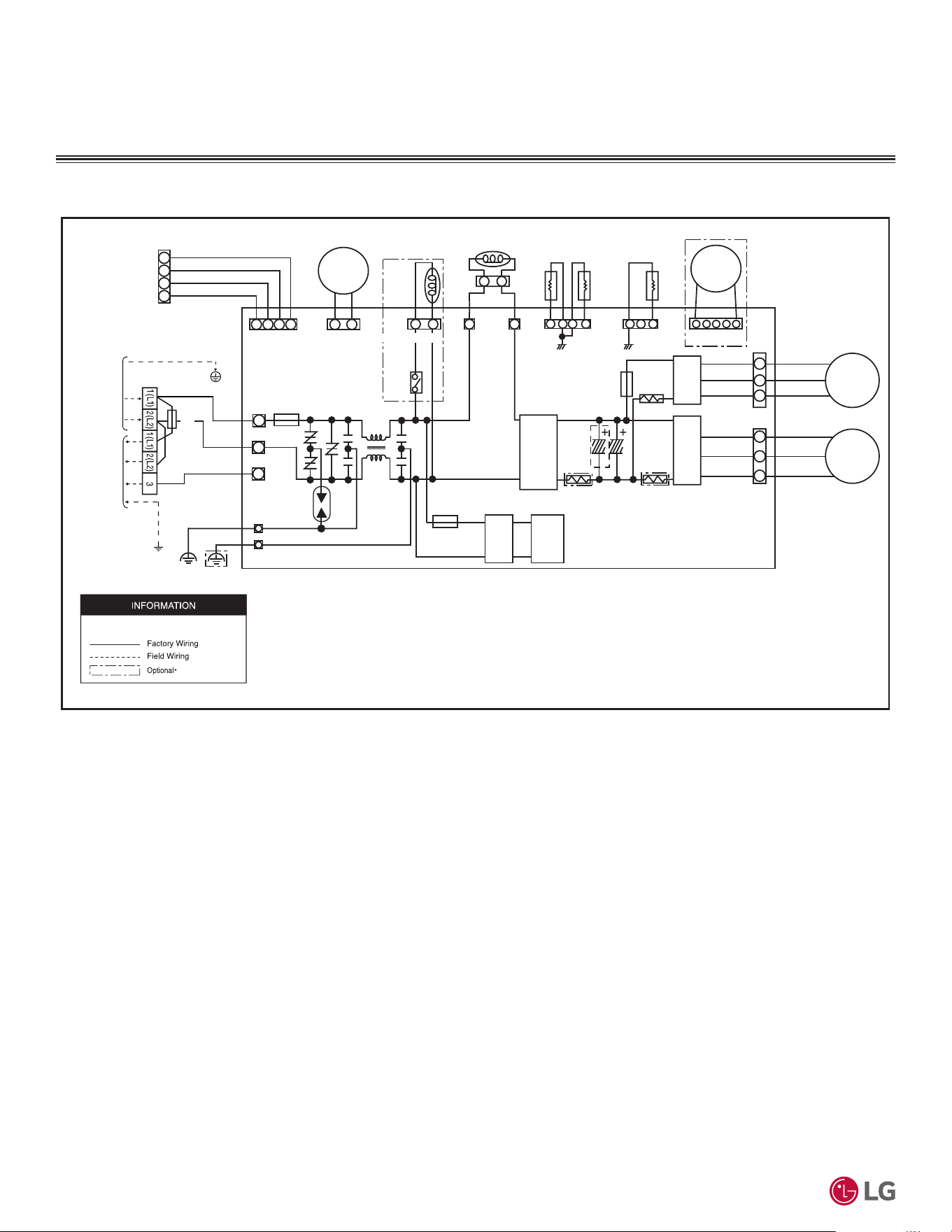
'XHWRRXUSROLF\RIFRQWLQXRXVSURGXFWLQQRYDWLRQVRPHVSHFL¿FDWLRQVPD\FKDQJHZLWKRXWQRWL¿FDWLRQ
©
/*(OHFWURQLFV86$,QF(QJOHZRRG&OLIIV1-$OOULJKWVUHVHUYHG³/*´LVDUHJLVWHUHGWUDGHPDUNRI/*&RUS
104
56LQJOH=RQH6WDQGDUG(ႈFLHQF\0HJDDQG0HJD9:DOO0RXQWHG(QJLQHHULQJ0DQXDO
WIRING DIAGRAMS
Figure 46: 6WDQGDUG(I¿FLHQF\.86$($DQG.86$($0HJD.86$&$DQG.86$&$2XWGRRU8QLW:LULQJ'LDJUDP
6WDQGDUG(ႈFLHQF\.86$($DQG.86$($
0HJD.86$&$DQG.86$&$2XWGRRU8QLWV
MEZ68728116 Rev.01_031224
CN_FAN(WH)
WCN_P_L
COM_RD
BR
BL
RD
RD
YL
BL
CN_UVW(WH)
Outdoor PWB ASSY
REVERSING VALVE
CN_LGMV(BL)
BK
BK
CN2
CN3
SURGE
ABSORBER
250V / T15A
WCN_P_N
CN_COIL1
CN_COIL2
CN_TH1(WH)
CN_TH2(YL)
CN_EEV(WH)
D-PIPE
BK BK
SPFC
PARTS
BD
SMPS
CN_4WAY(WH)
FUSE
250V / T3.15A
FUSE
N/F
MV Jig
REACTOR
OUTDOOR
TH.
PIPE TH.
EEV
MOTOR
COMP
CU-U(R)
CU-V(S)
CU-W(C)
IPM
IPM
250V / T3.15A
FUSE
RY_4WAY
CN_PRESS(GY)
PRESSURE
SWITCH
USE COPPER CONDUCTORS ONLY
BL
RD
BR
BL
250V/T3.15A
BR
GN/YL
TERMINAL BLOCK
GN/YL
POWER SUPPLY TO INDOOR UNIT
* This function can be optional or factory installed depending on the model.
Dedicated circuit is field supplied.
7 / 24
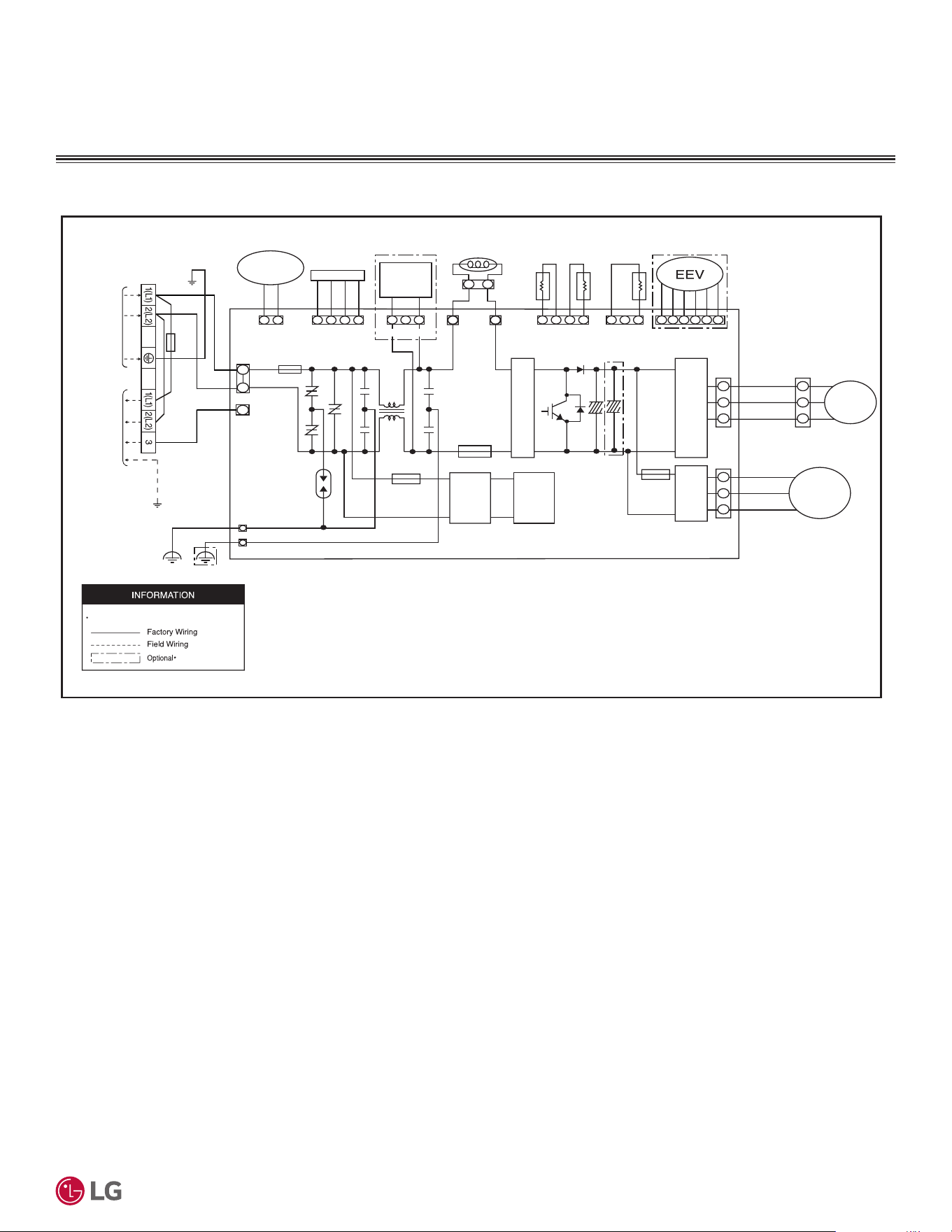
'XHWRRXUSROLF\RIFRQWLQXRXVSURGXFWLQQRYDWLRQVRPHVSHFL¿FDWLRQVPD\FKDQJHZLWKRXWQRWL¿FDWLRQ
©
/*(OHFWURQLFV86$,QF(QJOHZRRG&OLIIV1-$OOULJKWVUHVHUYHG³/*´LVDUHJLVWHUHGWUDGHPDUNRI/*&RUS
105
Electrical
WIRING DIAGRAMS
6WDQGDUG(ႈFLHQF\.86$($DQG.86$($
0HJD.86$&$DQG.86$&$2XWGRRU8QLWV
Figure 47: 6WDQGDUG(I¿FLHQF\.86$($DQG.86$($0HJD.86$&$DQG.86$&$2XWGRRU8QLW:LULQJ'LDJUDP
BK
BK
CN_AC_
REACT
_IN
CN_AC_
REACT
_OUT
Outdoor PWB ASSY
BK
BK
RD
BL
YL
RD
BL
YL
REVERSING
VALVE
250V / T25A
SURGE
ABSORBER
CN_COM1
CN_POWER
WCN_GND1
WCN_GND2
FUSE
250V / T3.15A
FUSE
B/D
SMPS
250V / T25A
FUSE
B/D
250V /
T3.15A
FUSE
FAN
IPM
IPM
CN_COMP
CN_FAN_DC
U
V
W
CN_LGMV CN_TH2CN_TH1
REACTOR
OUTDOOR
TH
.
PIPE TH.
COMP TH.
LGMV JIG
WIRE
CN_EEV1
CN_4WAY_AC
COMP
FAN
MOTOR
MEZ68728115 Rev.01_031224
TERMINAL BLOCK
GN/YL
POWER SUPPLY
TO INDOOR UNIT
BL
RD
BR
BL
250V /T5A
BR
GN/YL
CN_PRESS
PRESSURE
SWITCH
USE COPPER CONDUCTORS ONLY
Dedicated circuit is field supplied.
* This function can be optional or factory installed depending on the model.
7 / 24
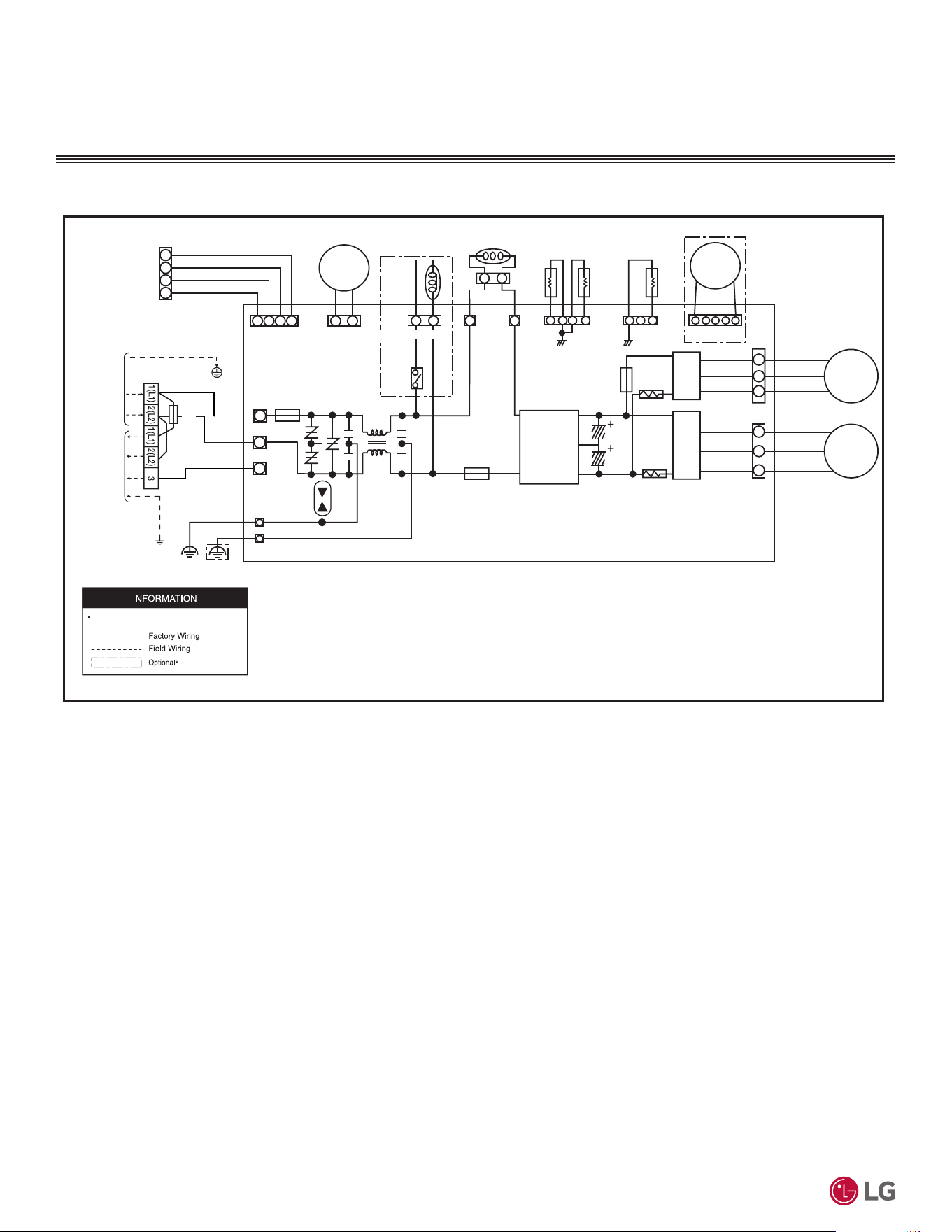
'XHWRRXUSROLF\RIFRQWLQXRXVSURGXFWLQQRYDWLRQVRPHVSHFL¿FDWLRQVPD\FKDQJHZLWKRXWQRWL¿FDWLRQ
©
/*(OHFWURQLFV86$,QF(QJOHZRRG&OLIIV1-$OOULJKWVUHVHUYHG³/*´LVDUHJLVWHUHGWUDGHPDUNRI/*&RUS
106
56LQJOH=RQH6WDQGDUG(ႈFLHQF\0HJDDQG0HJD9:DOO0RXQWHG(QJLQHHULQJ0DQXDO
WIRING DIAGRAMS
Figure 48: Mega 115V KUSAC091B and KUSAC121B Outdoor Unit Wiring Diagram.
0HJD9.86$&%DQG.86$&%2XWGRRU8QLWV
MEZ68728120 Rev.00_051324
CN_FAN_DC(WH)
WCN_P(L)
CN_COM
BR
BL
RD
RD
YL
BL
CN_COMP(BK)
Outdoor PWB ASSY
REVERSING VALVE
CN_LGMV(BL)
BK
BK
CN2
CN3
SURGE
ABSORBER
250V / T20A
WCN_P(N)
CN_COIL1
CN_COIL2
CN_TH1(WH)
CN_TH2(YL)
CN_EEV1(WH)
D-PIPE
BK BK
CONVERTER
CN_4WAY_AC(WH)
FUSE
250V / T20A
FUSE
N/F
MV Jig
REACTOR
OUTDOOR TH. PIPE TH.
EEV
MOTOR
COMP
CU-U(R)
CU-V(S)
CU-W(C)
IPM
IPM
250V / T3.15A
FUSE
RY_4WAY
CN_PRESS(GY)
PRESSURE
SWITCH
USE COPPER CONDUCTORS ONLY
BL
RD
BR
BL
250V/T3.15A
BR
GN/YL
TERMINAL BLOCK
GN/YL
POWER SUPPLY TO INDOOR UNIT
7 / 24
* This function can be optional or factory installed depending on the model.
Dedicated circuit is field supplied.
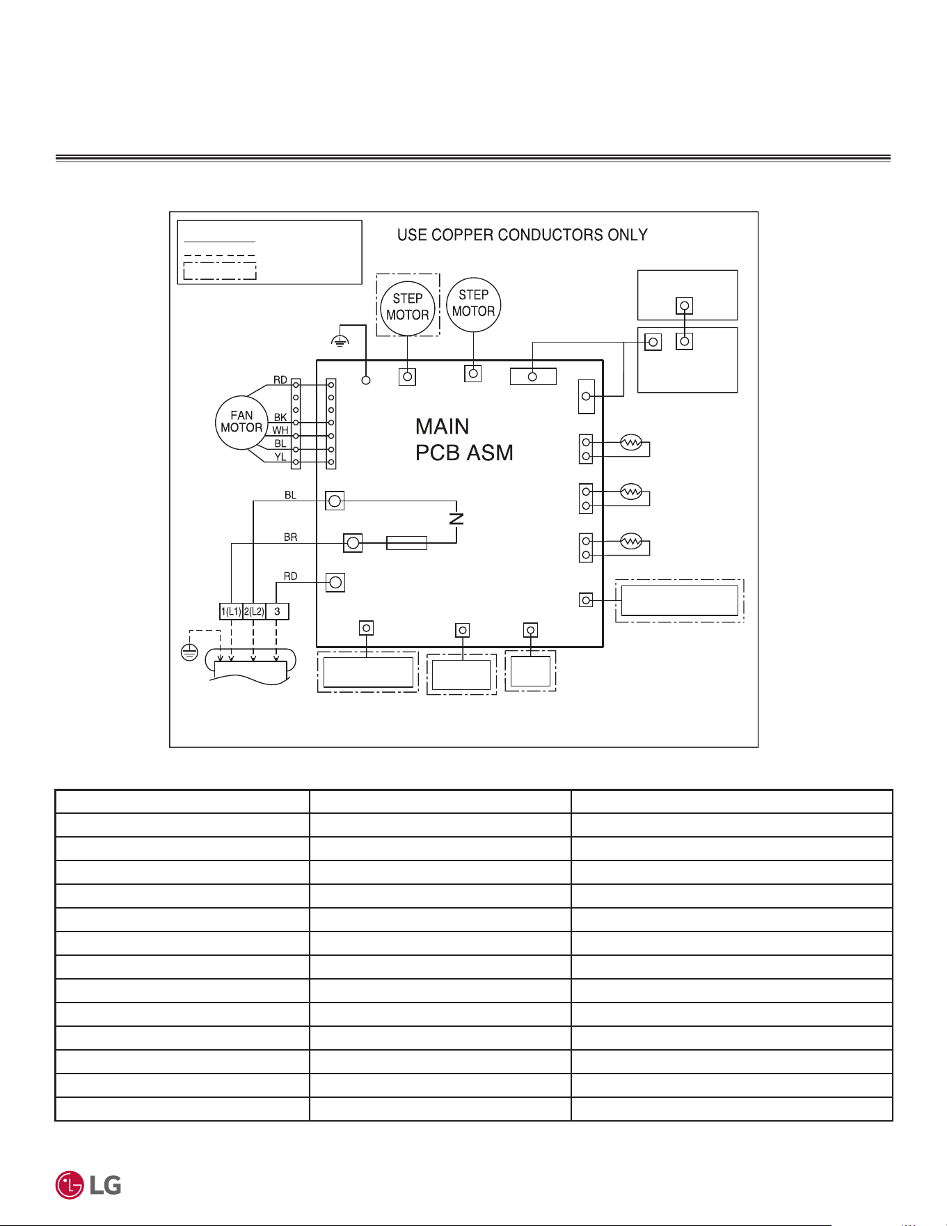
'XHWRRXUSROLF\RIFRQWLQXRXVSURGXFWLQQRYDWLRQVRPHVSHFL¿FDWLRQVPD\FKDQJHZLWKRXWQRWL¿FDWLRQ
©
/*(OHFWURQLFV86$,QF(QJOHZRRG&OLIIV1-$OOULJKWVUHVHUYHG³/*´LVDUHJLVWHUHGWUDGHPDUNRI/*&RUS
107
Electrical
WIRING DIAGRAMS
Figure 49: :LULQJ'LDJUDPIRU$OO6WDQGDUG(I¿FLHQF\0HJDDQG0HJD9,QGRRU8QLWV
$OO6WDQGDUG(ႈFLHQF\0HJDDQG0HJD9,QGRRU8QLWV
Table 72: :LULQJ'LDJUDP/HJHQGIRU$OO6WDQGDUG(I¿FLHQF\0HJDDQG0HJD9,QGRRU8QLWV
Terminal Purpose Function
CN_MOTOR1 Fan motor output Motor Output of BLDC
CN_L_R Step Motor Step Motor Connection
CN_U_D Step Motor Step Motor Connection
CN-DISP3 Display Indoor Status Display Connection
CN-DISP1 Display Indoor Status Display Connection
CN_TH1 Air Thermistor Air Thermistor Connection
CN_TH3 Mid Pipe Thermistor Mid Pipe Thermistor
CN_TH2 N / A N / A
CN_SUB Auxiliary Heater Relay Kit Auxiliary Heater Relay Kit Connection
CN_LINK Wifi Wifi Module Connection
CN_CC Dry Contact Dry Contact Connection
CN_REMO Wired Remote Controller Wired Remote Controller Connection
CN_COM2 Communication Outdoor Unit Communication Connection
CN_TH2
CN_TH3 CN_TH1
CN_DISP1
CN_SUB
CN_CC
CN_LINK
* This function can be optional or factory installed
depending on the model.
Field Wiring
Factory Wiring
Optional *
.
TO OUTDOOR UNIT
CN_L1
CN_IN_N1
CN_COM2
FUSE
250V / T3.15A
MEZ64135655 Rev.00_030424
CN1
CN_MOTOR1
CN_L_R
CN_DISP3
DRY
CONTACT
CONTROLLER
THERMISTOR
(AIR)
THERMISTOR
(MIDDLE PIPE)
DISPLAY
PWB ASM
FORCE S/W
BK
AUXILIARY HEATER
RELAY KIT
CN_U_D
Wi-Fi
CN_REMO
WIRED REMOTE
7 / 24
Dedicated circuit is field supplied.
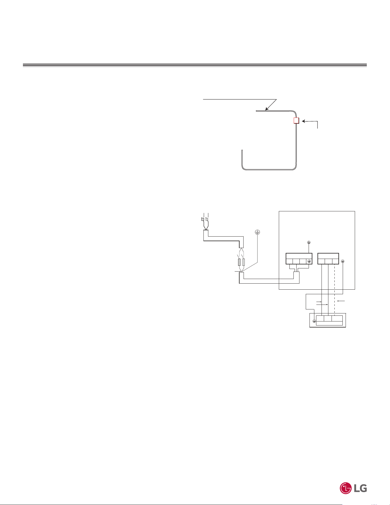
'XHWRRXUSROLF\RIFRQWLQXRXVSURGXFWLQQRYDWLRQVRPHVSHFL¿FDWLRQVPD\FKDQJHZLWKRXWQRWL¿FDWLRQ
©
/*(OHFWURQLFV86$,QF(QJOHZRRG&OLIIV1-$OOULJKWVUHVHUYHG³/*´LVDUHJLVWHUHGWUDGHPDUNRI/*&RUS
108
56LQJOH=RQH6WDQGDUG(ႈFLHQF\0HJDDQG0HJD9:DOO0RXQWHG(QJLQHHULQJ0DQXDO
3RZHU6XSSO\3RZHU:LULQJ
• LG Standard Efficiency and Mega single zone systems operate at
1Ø, 208-230V, 60Hz; confirm power source specifications
• LG Mega 115V single zone systems operate at 1Ø, 115V, 60Hz;
confirm power source specifications.
• Follow manufacturer’s circuit diagrams displayed on the inside of
the control box cover.
• It is recommended that a circuit breaker is installed, especially if
conditions could become wet or moist.
• Include a disconnect in the power wiring system. Add an air gap
contact separation of at least 1/8 inch in each active (phase)
conductor.
• Power wiring to the outdoor unit(s) must be solid or stranded, and
must comply with all National Electrical Code (NEC), UL, and local
electrical codes.
• Power supply to the outdoor unit must be selected based on NEC
and local codes. Maximum allowable voltage fluctuation ±10%
or nameplate rated value. Confirm that the electrical capacity is
sufficient.
A voltage drop will cause the following problems:
• Magnetic switch vibration, fuse breaks, or disturbance to the nor-
mal function of an overload protection device.
• Compressor will not receive the proper starting current.
• Any openings where the field wiring enters the cabinet must be
completely sealed.
• Properly ground the outdoor unit and the indoor unit per National
Electrical Code (NEC) and local codes.
• The indoor unit is powered by the outdoor unit. See the next page
for communication / connection (power) cable specifications from
the outdoor unit to the indoor unit.
• Ground wire must be longer than the common power / communica-
tion wires.
• Always match color codes of each wire and follow wiring diagram.
Figure 51: Circuit Breaker.
Figure 50: *HQHUDO6WDQGDUG(I¿FLHQF\0HJDDQG0HJD96LQJOH
Zone System Power / Communications System Schematic (Appearanc-
es May Vary).
Air
Conditioner
Main Power Source
Circuit Breaker
Use a circuit breaker
or time delay fuse
32:(56833/<32:(5:,5,1*
L
L
N
N
G
Power Supply
Main Switch
Circuit Breaker
Fuse
Power Wiring
(Including Ground)
Outdoor Unit
1(L1) 2(L2)
Terminal Block Outdoor
1(L1) 2(L2) 3
Terminal Block Outdoor
Communication
Cable
1(L1) 2(L2)
Terminal Block Indoor
3
Indoor Unit
Power
Wiring
Power Supply
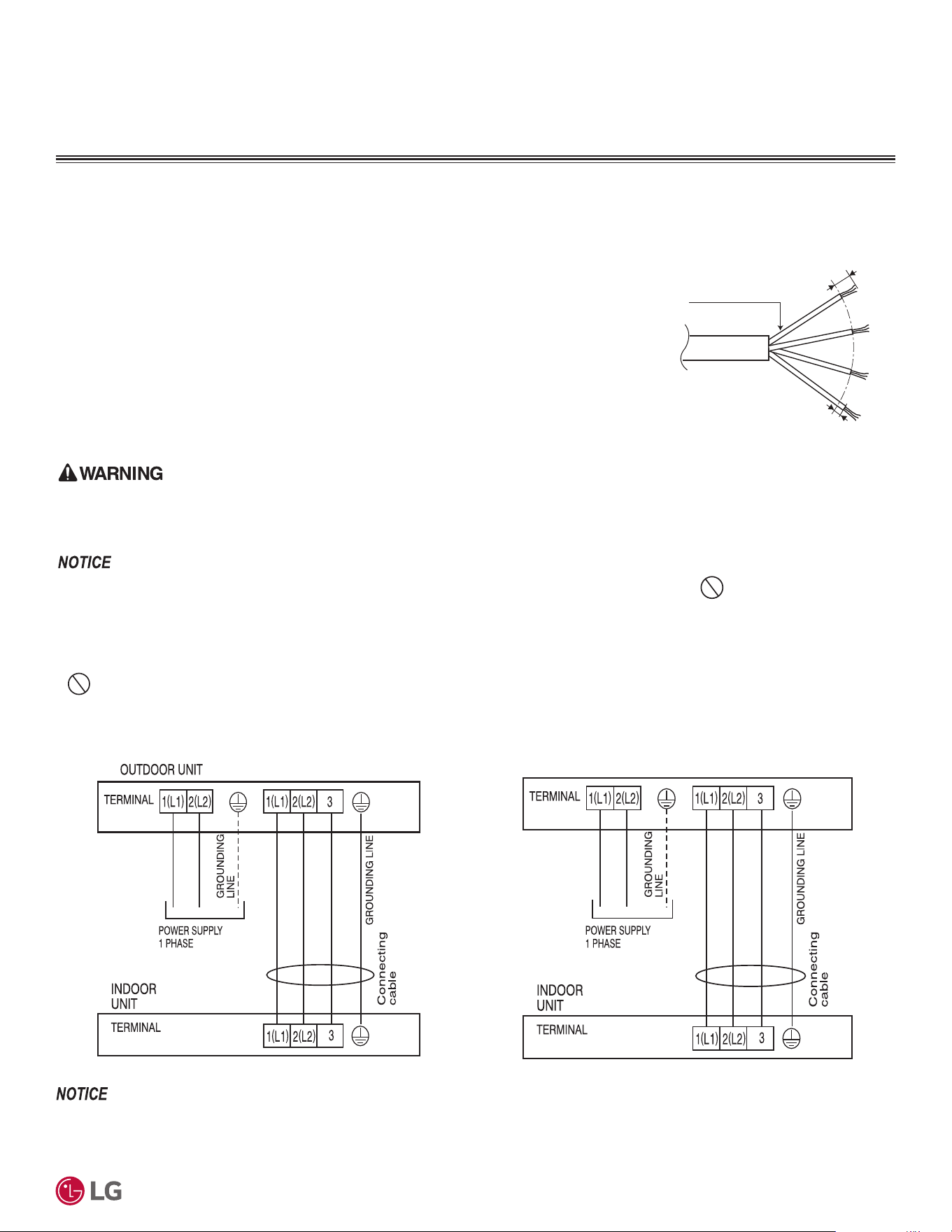
'XHWRRXUSROLF\RIFRQWLQXRXVSURGXFWLQQRYDWLRQVRPHVSHFL¿FDWLRQVPD\FKDQJHZLWKRXWQRWL¿FDWLRQ
©
/*(OHFWURQLFV86$,QF(QJOHZRRG&OLIIV1-$OOULJKWVUHVHUYHG³/*´LVDUHJLVWHUHGWUDGHPDUNRI/*&RUS
109
Electrical
• Make sure the communications cable / power wiring from the outdoor unit to the indoor unit and the power wiring to the outdoor unit are
separate, otherwise, the outdoor unit operation will be affected by electrical noise and will malfunction or fail.
• Use a conduit for the communications cable / power wiring from the outdoor unit to the indoor units.
Figure 52: Single Zone Outdoor Unit to Indoor Unit Wiring and Communi-
cations Cable Diagram.
• Always verify the communication cable is connected to a communications terminal on the single zone unit. Never apply line voltage
SRZHUWRWKHFRPPXQLFDWLRQFDEOHFRQQHFWLRQ,IFRQWDFWLVPDGHWKH3&%VZLOOEHGDPDJHG
• The shield of the communications cable connecting the outdoor unit to the indoor unit must be grounded only to the outdoor unit frame.
• Tie the shield of each cable segment together using a wire nut at the indoor unit. Maintain polarity throughout the communication network.
• Position the incoming power to the outdoor unit away from the power / communications cables from the outdoor unit to the indoor unit.
•
Never use a common multiple-core communications cable.
Communication / Connection
(Power), Ground Cable
From Outdoor Unit
To Indoor Unit
13/16"
GN/YL
GN/YL = (Green, Yellow)
7/16" ± 1/8"
208/230 VAC
Figure 53: 6LQJOH=RQH6WDQGDUG(I¿FLHQF\DQG0HJD:DOO0RXQWHG
Power / Communication System Diagram (Appearances May Vary
Slightly).
&RPPXQLFDWLRQ&RQQHFWLRQ3RZHU&DEOH6SHFLILFDWLRQVIURP2XWGRRU
Unit to Indoor Unit
• Communication / connection (power) cable from the single zone
outdoor unit to the indoor unit must use a minimum of 14 AWG,
four (4) conductor, stranded, shielded or unshielded (if shielded,
it must be grounded to the chassis of the outdoor unit only), and
must comply with applicable local and national codes.
• Use of 14 AWG, four (4) conductor, stranded, shielded or unshield-
ed wire is allowed for lengths up to the published maximum pipe
length, plus recommended slack at both ends.
• Insulation material as required by local code.
• Firmly attach the cable; provide slack but secure in a way to pre-
vent external forces from being imparted on the terminal block.
• Wiring must be completed without splices.
All power wiring and communication cable installation must be performed by trained service providers working in accordance with local, state, and
1DWLRQDO(OHFWULFDO&RGH1(&8/(7/IHGHUDOUHJXODWLRQVUHODWHGWRHOHFWULFDOHTXLSPHQWDQGZLULQJDQGIROORZLQJWKHPDQXIDFWXUHUSURGXFW
diagrams, requirements, and instructions in this manual. Failure to do so will lead to electric shock which can cause physical injury or death.
&20081,&$7,21&211(&7,21&$%/(
Figure 54: Single Zone Mega 115V Wall-Mounted Power / Communica-
tion System Diagram.
115V AC
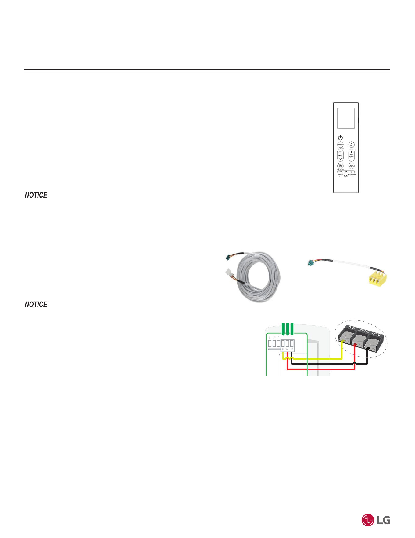
'XHWRRXUSROLF\RIFRQWLQXRXVSURGXFWLQQRYDWLRQVRPHVSHFL¿FDWLRQVPD\FKDQJHZLWKRXWQRWL¿FDWLRQ
©
/*(OHFWURQLFV86$,QF(QJOHZRRG&OLIIV1-$OOULJKWVUHVHUYHG³/*´LVDUHJLVWHUHGWUDGHPDUNRI/*&RUS
110
56LQJOH=RQH6WDQGDUG(ႈFLHQF\0HJDDQG0HJD9:DOO0RXQWHG(QJLQHHULQJ0DQXDO
Figure 55: AKB76044207 Wire-
less Handheld Remote Controller.
Figure 56: PZCWRC1 LG Wired
Remote Extension Cable.
Wired Controller Connection
Standard Efficiency, Mega, and Mega 115V wall-mounted indoor
units have a Molex plug on the PCB for wired controller connection
(CN-REMO). To connect the wall-mounted indoor units to the
wired controllers, choose from either a 30-foot LG Wired Remote
Extension Cable (PZCWRC1), or an LG Multi-Harness Cable
(EAD63886215) and field-supplied wiring. The cables are separate
purchases.
Controller Options
Single-Zone Standard Efficiency, Mega, and Mega 115V wall-mounted systems include a wireless hand-
held remote controller (Part No. AKB76044207. Optional LG-suppled wired controllers are available. See
“Functions, Controls, Options”, or contact an LG representative for more information.
Wireless Handheld Remote Controller features:
• Display Panel: Displays operation conditions.
• On / Off Button: Turns system operation on and off.
• 0RGH%XWWRQ6HOHFWVWKHRSHUDWLRQPRGH&RROLQJĺ$XWRĺ'HKXPLGLILFDWLRQĺ+HDWLQJĺ)DQ
• Temp. (Temperature) Up / Down Buttons: Adjusts the desired room temperature in the different modes.
• Fan Speed Button (+ / -): Sets desired fan speed.
• Reset: Resets / Initializes the handheld remote control settings.
Figure 57: EAD63886215 LG
Multi-Harness Cable.
(DFKIXQFWLRQZLOOGLVSOD\RQWKH/('IRUDERXWWKUHHVHFRQGVZKHQWKHSRZHULV¿UVWF\FOHGRQ
CONTROLLERS
Figure 58: Example of Wired Controller Terminals.
Common
456
Signal
12VDC
YL
RD
BK
:KHQXVLQJ¿HOGVXSSOLHGZLULQJPDNHVXUHWRFRQQHFWWKH\HOORZWR\HOORZFRPPXQLFDWLRQV
ZLUHUHGWRUHG9SRZHUZLUHDQGEODFNWREODFNJURXQGZLUHWHUPLQDOVRQWKHUHPRWH
controller.
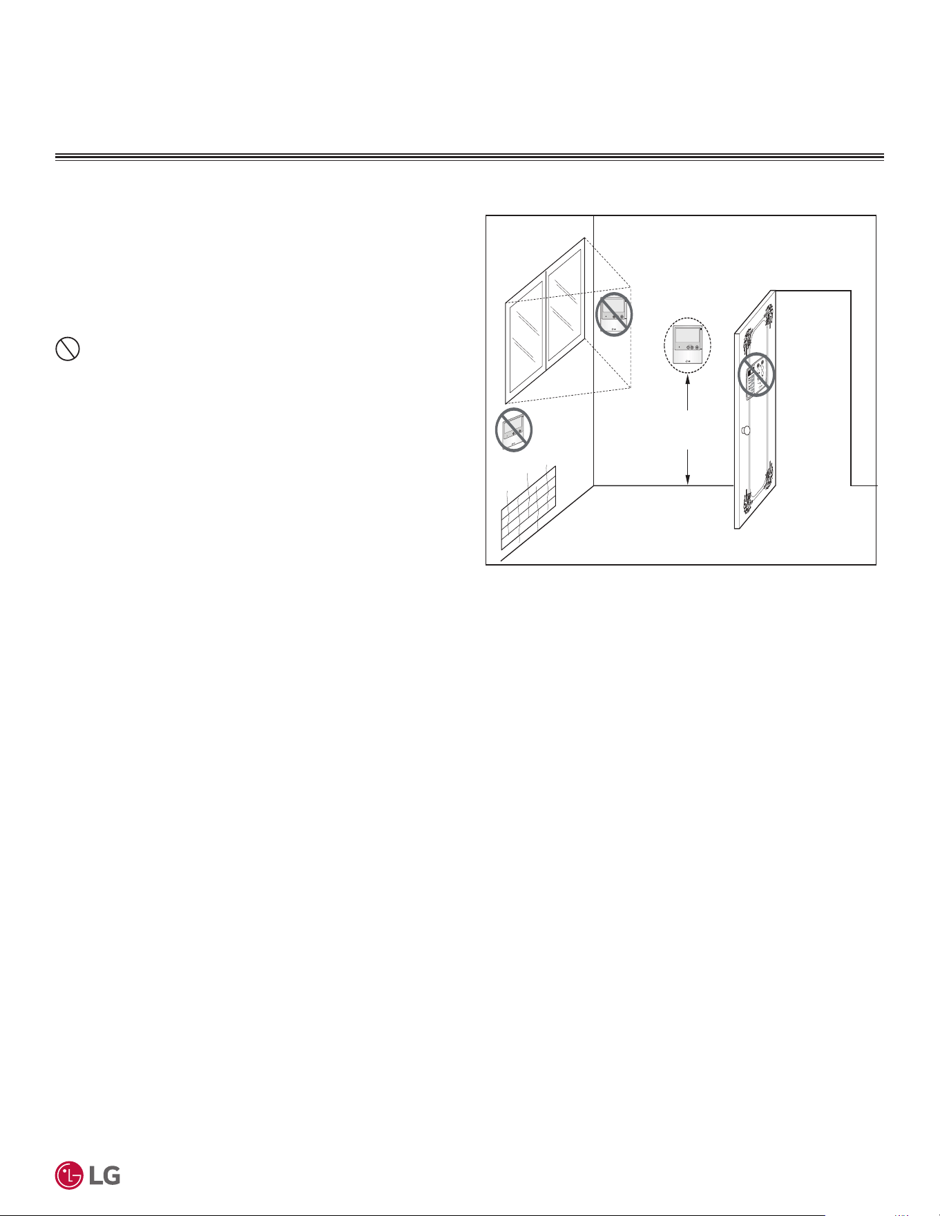
'XHWRRXUSROLF\RIFRQWLQXRXVSURGXFWLQQRYDWLRQVRPHVSHFL¿FDWLRQVPD\FKDQJHZLWKRXWQRWL¿FDWLRQ
©
/*(OHFWURQLFV86$,QF(QJOHZRRG&OLIIV1-$OOULJKWVUHVHUYHG³/*´LVDUHJLVWHUHGWUDGHPDUNRI/*&RUS
111
Electrical
Assigning the Thermistor for Temperature Detection
Each indoor unit includes a return air thermistor assigned to sense the temperature. If a wired controller is installed, there is a choice of
sensing temperature with either the indoor unit return air thermistor or the thermistor in the wired controller. It is also an option to set both
thermistors to sense temperature so that indoor unit bases its operation on the first thermistor to reach the designated temperature differen-
tial. For applicable indoor units, an optional Remote Temperature Sensor can be used in lieu of the return air thermistor—either alone or in
conjunction with a wired controller thermistor as previously described.
Wired Controller Placement
Wired controllers include a sensor to detect room temperature. To
maintain comfort levels in the conditioned space, the wired control-
ler must be installed in a location away from direct sunlight, high
humidity, and where it could be directly exposed to cold air. Control-
ler must be installed four (4) to five (5) feet above the floor where its
LED display can be read easily, in an area with good air circulation,
and where it can detect an average room temperature.
Do not install the wired controller near or in:
• Drafts or dead spots behind doors and in corners.
• Hot or cold air from ducts.
• Radiant heat from the sun or appliances.
• Concealed pipes and chimneys.
• An area where temperatures are uncontrolled, such as an outside
wall.
4 to 5 feet
above the floor
NO
NO
NO
YES
Remote Controlle r
TEMP
Remote Controlle r
TEMP
R
e
m
o
t
e
C
o
n
t
r
ol
l
er
TEM
P
Figure 59: Proper Location for the Wired Controller.
CONTROLLERS

'XHWRRXUSROLF\RIFRQWLQXRXVSURGXFWLQQRYDWLRQVRPHVSHFL¿FDWLRQVPD\FKDQJHZLWKRXWQRWL¿FDWLRQ
©
/*(OHFWURQLFV86$,QF(QJOHZRRG&OLIIV1-$OOULJKWVUHVHUYHG³/*´LVDUHJLVWHUHGWUDGHPDUNRI/*&RUS
112
56LQJOH=RQH6WDQGDUG(ႈFLHQF\0HJDDQG0HJD9:DOO0RXQWHG(QJLQHHULQJ0DQXDO
LIMITED WARRANTY (USA)
The product’s full Limited Warranty terms and conditions and arbitration
UHTXLUHPHQWVDUHDYDLODEOHDWKWWSVZZZOJKYDFFRP
LG Electronics, U.S.A., Inc.
Air Conditioning Technologies
4300 North Point Parkway
Alpharetta, Georgia 30022
www.lghvac.com
EM_SZ_StdEff_Mega_Mega115_R32_11_24
Supersedes: EM_SZ_StdEff_Mega_Mega115_R32_10_24
