
Loading ...
Loading ...
Loading ...
EN - 15
A
B
C
D
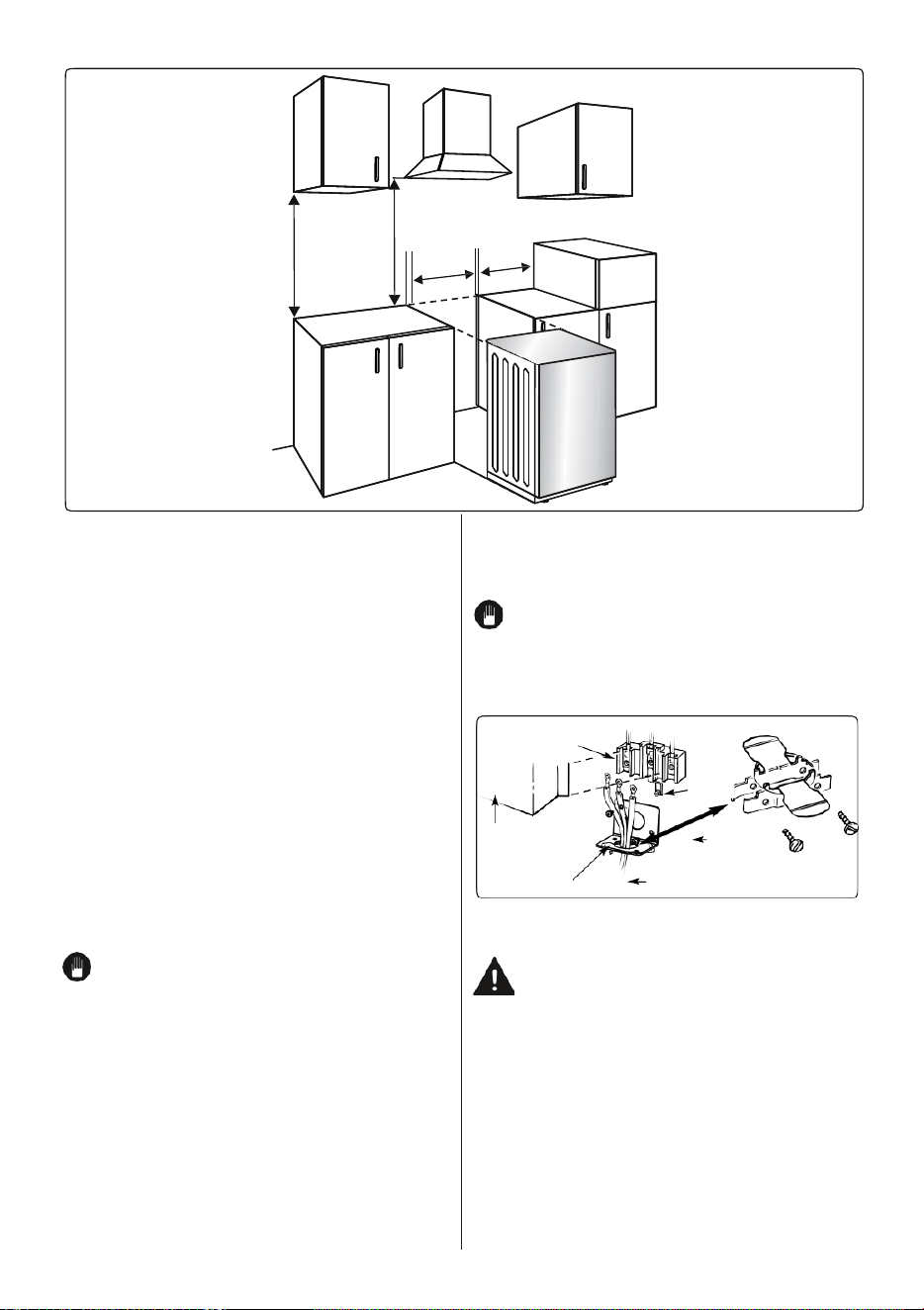
Preparing for Electrical Connection
Effective January 1, 1996,
the National Electric Code requires that
new construction (not existing) utilize a
4-conductor connection to an electric range.
When installing an electric range in new
construction follow Steps 3 and 5 for 4-wire
connection.
Use only a 3-conductor or a 4-conductor
UL-listed range cord. These cords may be
provided with ring terminals on wire and a
strain relief device.
A range cord rated at 40 amps with
125/250 minimum volt range is required.
A 50 amp range cord is not recommended
the cord terminals to the connector block.
If tabs are present at the end of the winged
strain relief, they can be removed for better
fit.
NOTE: Do not install the power
cord without a strain relief. The strain
relief bracket should be installed before
reinstalling the rear range wiring cover.
Connector box
Ground
strap
but if used, it should be marked for use
with nominal 13⁄8″ diameter connection
openings. Care should be taken to
center the cable and strain relief within
the knockout hole to keep the edge from
Wiring cover
(Shown
removed)
Strain relief
Power cord
Bracket
Strain relief bracket
(Provided with range
cord. Not part of range.)
damaging the cable.
NOTE: A 4-conductor cord is to be used
when the appliance is installed in a mobile
home or when local codes do not permit
grounding through the neutral. If conduit is
being used, go to
Step 6 or 7.
Power Cord Strain Relief Installation
Only a 4-conductor power-supply cord kit
rated 240 volts, 40 amperes and marked
for use with ranges must be used.
Assemble th
e strain relief in the hole. Insert
the power cord through the strain relief and
tighten. Allow enough slack to easily attach
3-Wire Power Cord Installation
WARNING: The neutral or ground wire
of the power cord must be connected
to the neutral terminal located in the
center of the connector block. The power
leads must be connected to the outside
(brass colored) terminals.
Remove the 3 wire terminal screws from
the connector block. Insert screws through
each power cord terminal ring and into the
connector block until the screws engage
the nuts. Be certain that the center wire
is connected to the center screw of the
connector block. Tighten screws securely.
Do NOT remove ground strap connection.
Loading ...
Loading ...
Loading ...