Loading ...
Loading ...
Loading ...

AXISM2014–ENetworkCamera
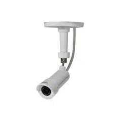
HardwareOverview
NOTICE NOTICE
NOTICE
Theproductshallbeconnectedusingashieldednetworkcable(STP).Allcablesconnectingtheproducttothenetworkswitch
shallbeshielded(STP)andintendedfortheirspecicuse.Makesurethatthenetworkswitchisproperlygrounded.For
informationaboutregulatoryrequirements,seeRegulatoryInformation,onpage2.
SDcardslot-Astandardorhigh-capacitymicroSDcard(notincluded)canbeusedforlocalrecordingwithremovablestorage.
NOTICE NOTICE
NOTICE
Topreventcorruptionofrecordings,theSDcardshouldbeunmountedbeforeremoval.Tounmount,gotoSetup>System
Options>Storage>SDCardandclickUnmount.
Controlbutton-Thecontrolbuttonisusedfor:
•Resettingtheproducttofactorydefaultsettings.Seepage42.
•ConnectingtoanAXISVideoHostingSystemservice.Seepage35.Toconnect,pressandholdthebuttonfor
about1seconduntiltheStatusLEDashesgreen.
•ConnectingtoAXISInternetDynamicDNSService.Seepage35.Toconnect,pressandholdthebuttonfor
about3seconds.
Powerconnector-2-pinterminalblockforpowerinput.Usealimitedpowersource(LPS)witheitheraratedoutputpower
limitedto≤100Woraratedoutputcurrentlimitedto≤5A.
I/Oterminalconnector-Useinapplicationsfore.g.motiondetection,eventtriggering,timelapserecordingandalarmnotications.
InadditiontoanauxiliarypowerandaGNDpin,theI/Oterminalconnectorprovidestheinterfaceto:
•Digitaloutput–ForconnectingexternaldevicessuchasrelaysandLEDs.Connecteddevicescanbeactivatedby
theVAPIX®ApplicationProgrammingInterface,outputbuttonsontheLiveViewpageorbyanActionRule.The
outputwillshowasactive(shownunderSystemOptions>Ports&Devices)ifthealarmdeviceisactivated.
•Digitalinput–Analarminputforconnectingdevicesthatcantogglebetweenanopenandclosedcircuit,for
example:PIRs,door/windowcontacts,glassbreakdetectors,etc.Whenasignalisreceivedthestatechangesand
theinputbecomesactive(shownunderSystemOptions>Ports&Devices).
LEDIndicators
LED
Color
Indication
Green
Steadyforconnectiontoa100MBit/snetwork.Flashesfornetworkactivity.
Amber
Steadyforconnectiontoa10MBit/snetwork.Flashesfornetworkactivity.
Network
UnlitNonetworkconnection.
GreenSteadygreenfornormaloperation.
Amber
Steadyduringstartupandwhenrestoringsettings.
Red
Slowashforfailedupgrade.
Status
UnlitNoconnectionbetweencameraunitandmainunit.
Green
Normaloperation. Power
Amber
Flashesgreen/amberduringrmwareupgrade.
6
Loading ...
Loading ...
Loading ...