NOTE:
Please read all instructions
carefully before using this
product
Table of Contents
Safety Notice
Hardware Pack
Assembly Instruction
Parts List
Warranty
Ordering Parts
Model
AMZ-986RW
Retain This
Manual for
Reference
190613
ASSEMBLY &
OWNER'S
MANUAL
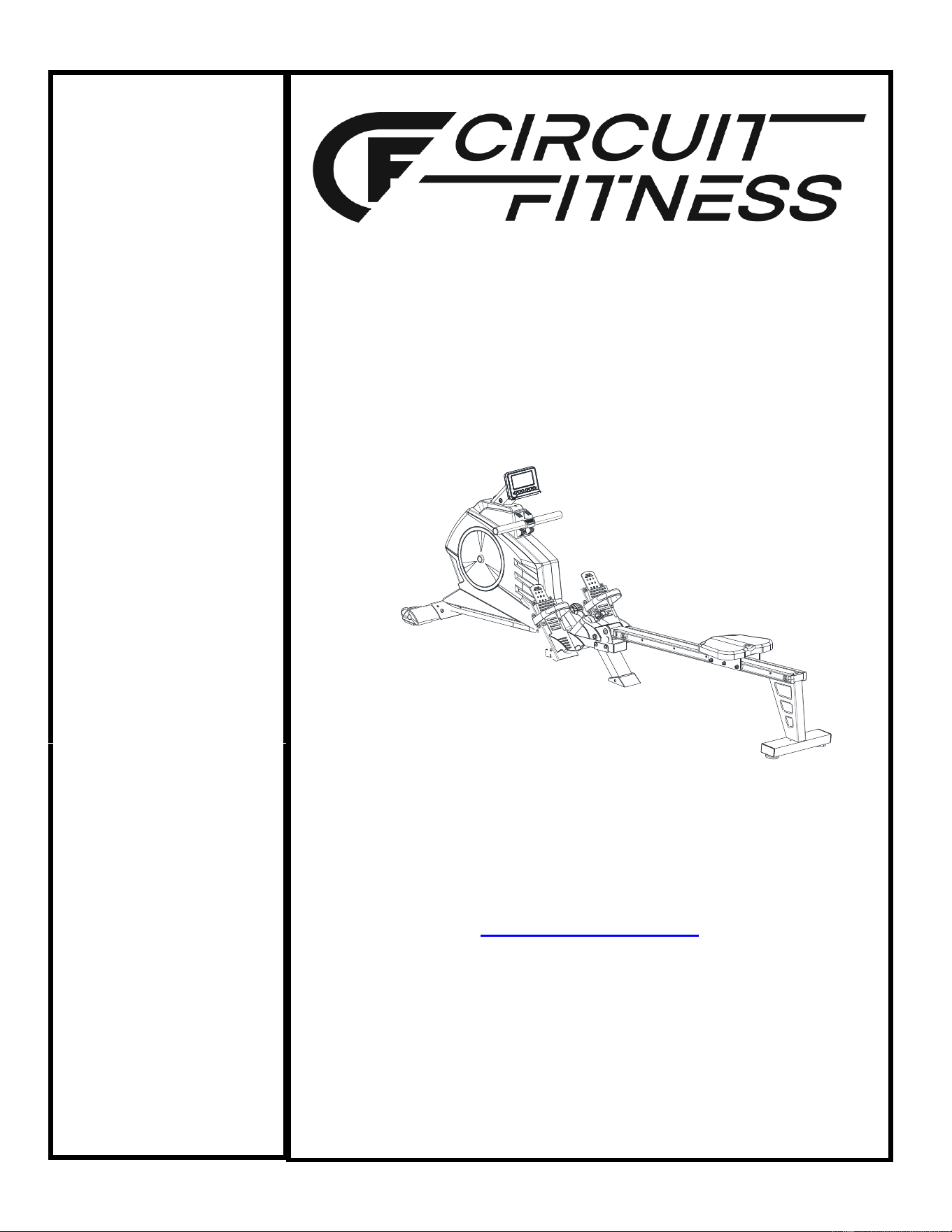
Magnetic-Resistance
Deluxe Rowing Machine
AMZ-986RW
IMPEX
®
INC.
2801 S. Towne Ave, Pomona, CA 91766
Tel: (800) 999-8899 Fax: (626) 961-9966
www.marcypro.com
support@impex-fitness.com

© IMPEX INC. www.marcypro.com
1
TABLE OF CONTENTS
BEFORE YOU BEGIN
Thank you for selecting the CIRCUIT FITNESS Magnetic-Resistance Deluxe Rowing
Machine AMZ-986RW by IMPEX
®
INC. For your safety and benefit, read this manual
carefully before using the bike. As a manufacturer, we are committed to provide you
complete customer satisfaction. If you have any questions, or find there are missing or
damaged parts, we guarantee you complete satisfaction through direct assistance
from our factory. To avoid unnecessary delays, please call our TOLL-FREE customer
service number. Our Customer Service Agents will provide immediate assistance to
you.
BEFORE YOU BEGIN
1
IMPORTANT SAFETY NOTICES
2
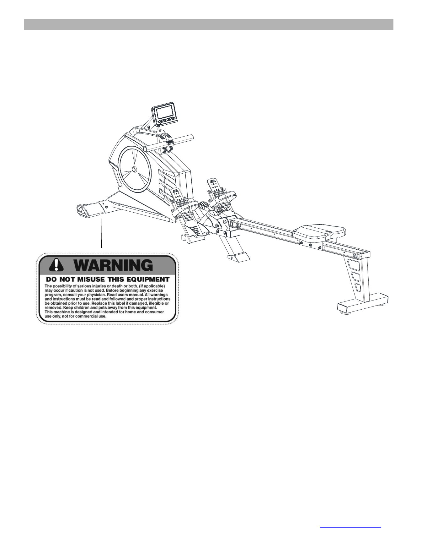
WARNING LABEL PLACEMENT
3
HARDWARE PACK
4
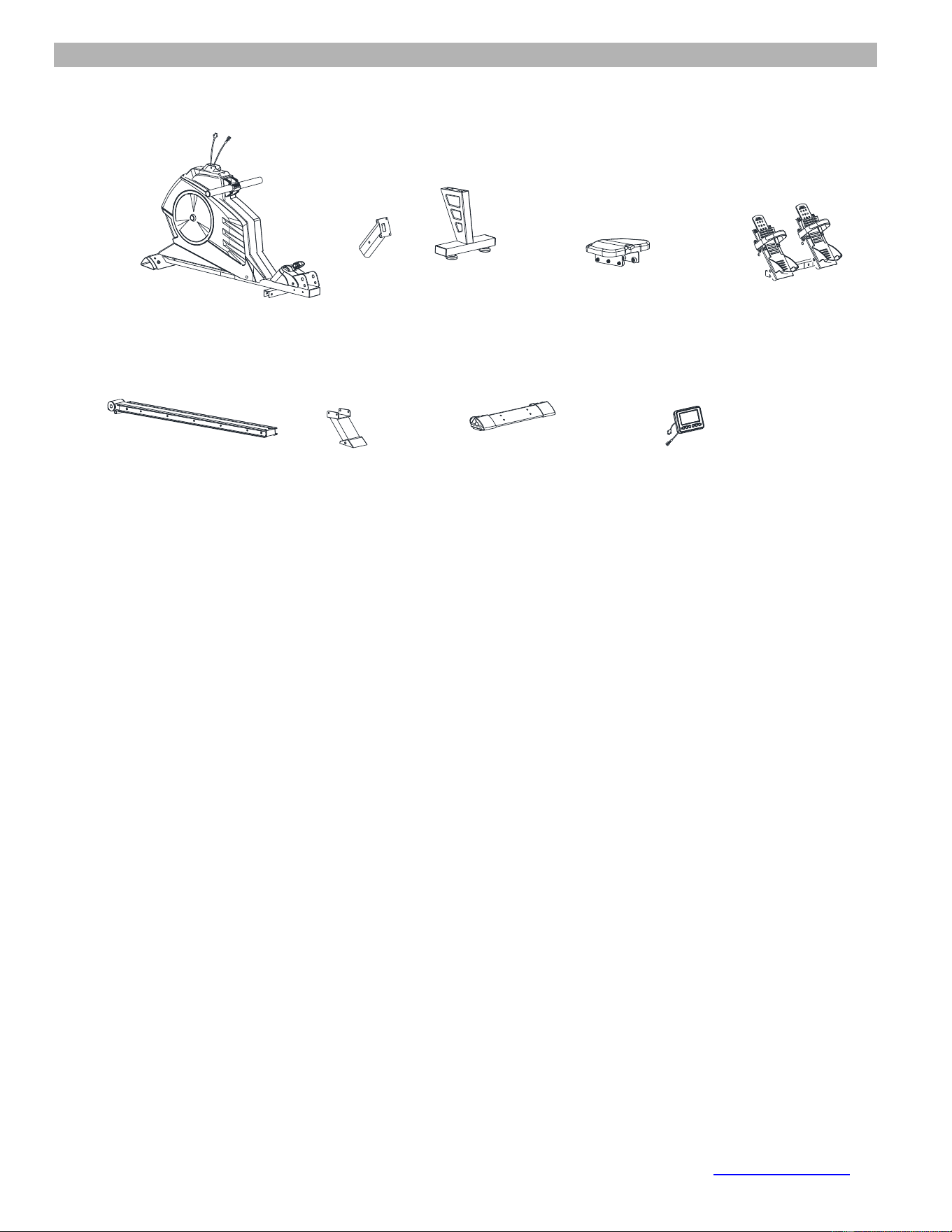
COMPONENT FOR ASSEMBLY
5
IMPORTANT ASSEMBLY INSTRUCTION
6
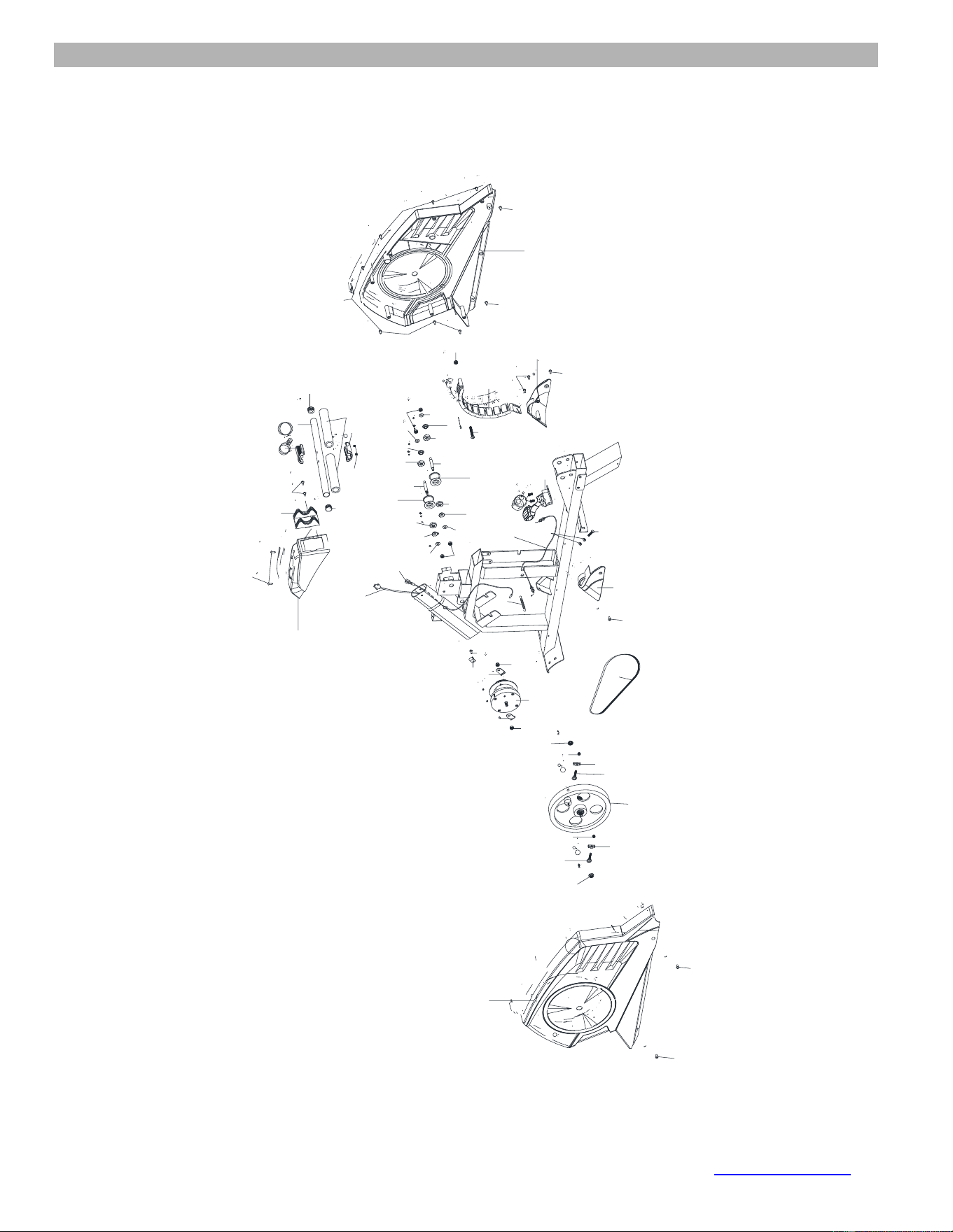
EXPLODED DIAGRAM
12
PARTS LIST
14
CARE AND MAINTENANCE, WEIGHT CAPACITY & DIMS.
16
COMPUTER
17
EXERCISE GUIDELINES
20
WARRANTY
22
ORDERING PARTS
22
Toll-Free Customer Service Number
1-800-999-8899
Mon. - Fri. 9 a.m. - 5 p.m. PST
www.marcypro.com

© IMPEX INC. www.marcypro.com
2
IMPORTANT SAFETY NOTICE
PRECAUTIONS
This exercise machine is built for optimum safety. However, certain precautions apply
whenever you operate a piece of exercise equipment. Be sure to read the entire manual
before you assemble or operate your machine. In particular, note the following safety
precautions:
1. Keep children and pets away from the machine at all times. DO NOT leave
children unattended in the same room with the machine.
2. Only one person at a time should use the machine.
3. If the user experiences dizziness, nausea, chest pain, or any other abnormal symptoms,
STOP the workout at once. CONSULT A PHYSICIAN IMMEDIATELY.
4. Position the machine on a clear, leveled surface. DO NOT use the machine near water
or outdoors.
5. Keep hands away from all moving parts.
6. Always wear appropriate workout clothing when exercising. DO NOT wear robes or
other clothing that could become caught in the machine. Running or aerobic shoes are
also required when using the machine.
7. Use the machine only for its intended use as described in this manual. DO NOT use
attachments not recommended by the manufacturer.
8. Do not place any sharp object around the machine.
9. Disabled person should not use the machine without a qualified person or physician in
attendance.
10. Before using the machine to exercise, always do stretching exercises to properly warm
up.
11. Never operate the machine if the machine is not functioning properly.
12. Read all warnings posted on the exercise bike.
13. Inspect the exercise bike for worn or loose component prior to use. Tighten/replace any
loose or wore components prior to use.
14. Care should be taken in mounting or dismounting the exercise bike.
15. This exercise bike is for consumer and home use only.
WARNING: BEFORE BEGINNING ANY EXERCISE PROGRAM, CONSULT YOUR
PHYSICIAN. THIS IS ESPECIALLY IMPORTANT FOR INDIVIDUALS OVER THE AGE
OF 35 OR PERSONS WITH PRE-EXISTING HEALTH PROBLEMS. READ ALL
INSTRUCTIONS BEFORE USING ANY FITNESS EQUIPMENT. IMPEX INC. ASSUMES
NO RESPONSIBILITY FOR PERSONAL INJURY OR PROPERTY DAMAGE
SUSTAINED BY OR THROUGH THE USE OF THIS PRODUCT.
SAVE THESE INSTRUCTIONS.
© IMPEX INC. www.marcypro.com
4
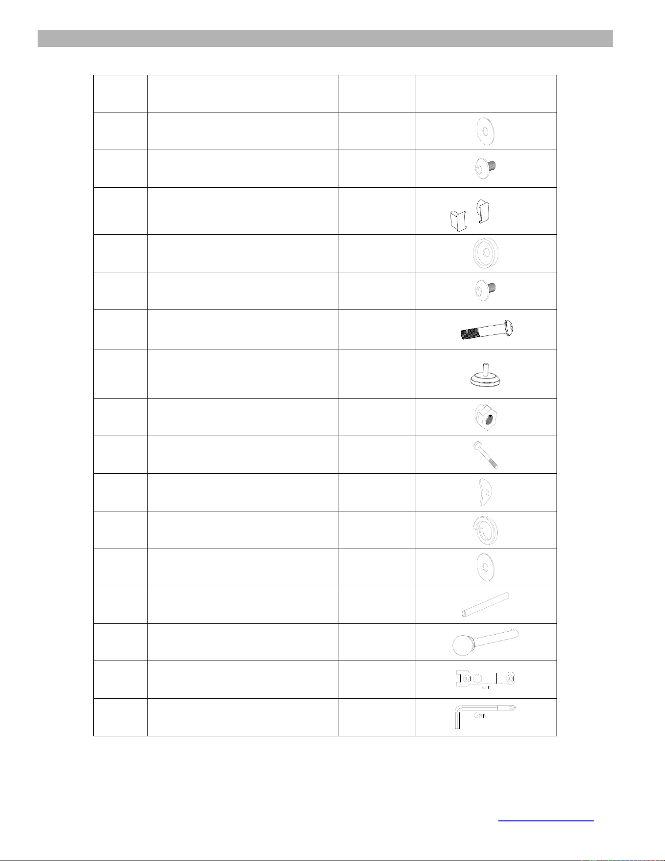
HARDWARE PACK
NOTE: The following parts are not drawn to scale. Please use your own ruler to measure the size.
NO.
Description
QTY
Drawings
3
Flat washer
11
11
Allen Bolt
12
14
End cap for slide rail L/R
1/1
16
Collar
2
17
Allen Bolt M8x ¾”
4
24
Allen Bolt M8x1⅝”
2
27
Stopper
2
35
Acorn nut M8
2
36
Carriage bolt M8*1¾
2
10
Curve washer
5
67
Lock Washer
2
68
Flat washer
2
69
Axle for slide rail
1
8
Knob
1
Allen Wrench
1
Allen Key 6MM
2
© IMPEX INC. www.marcypro.com
6
ASSEMBLY INSTRUCTION
• Tools Required for Assembling the Machine: One Crossing Wrench and Allen Wrench,
provided by manufacturer.
• NOTE: It is strongly recommended that two or more people assemble this machine to
avoid possible injury.
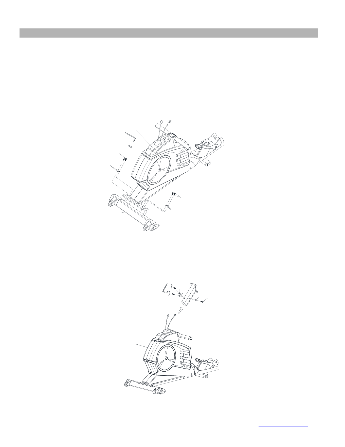
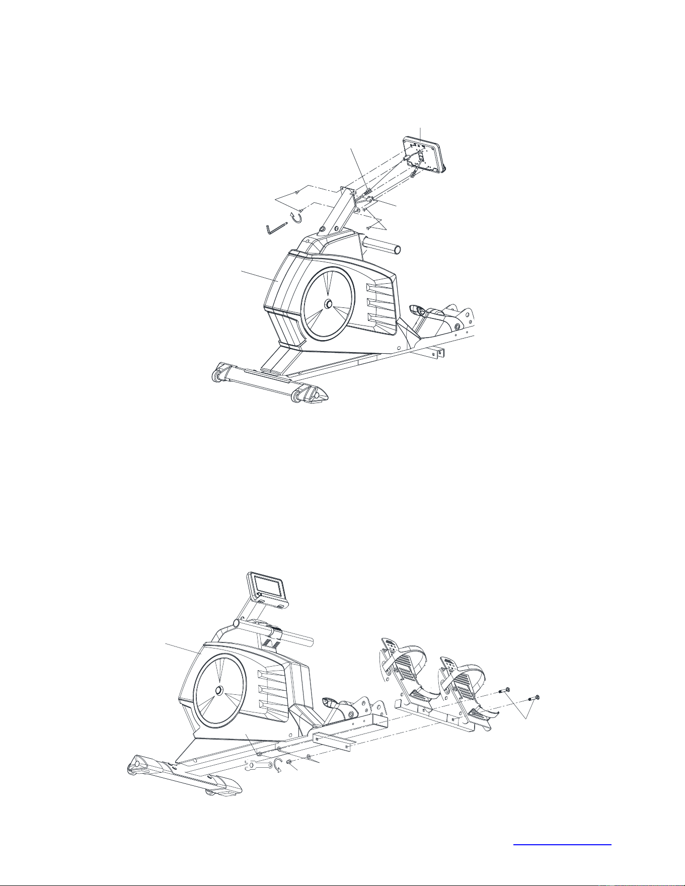
STEP 1
Attach the front stabilizer (2) to the main frame (5). Secure using four allen bolts (11), Four curve
washers (10).
STEP 2
Insert sensor wire (7) and computer wire (33) into and pull out through the top of the front post (51).
Attach front post (51) to Main frame (5) and secure with one set of allen bolts (11) & curved
washers (10) and from the sides with two sets of allen bolts (11) and flat washers (3).
11
3
11
3
10
5
11
10
11
10
2
5
© IMPEX INC. www.marcypro.com
7
STEP 3
Connect sensor wire (7) and computer wire (33) to the computer (9). Secure with four screws (6)
on the front post.
6
6
7
9
5
33
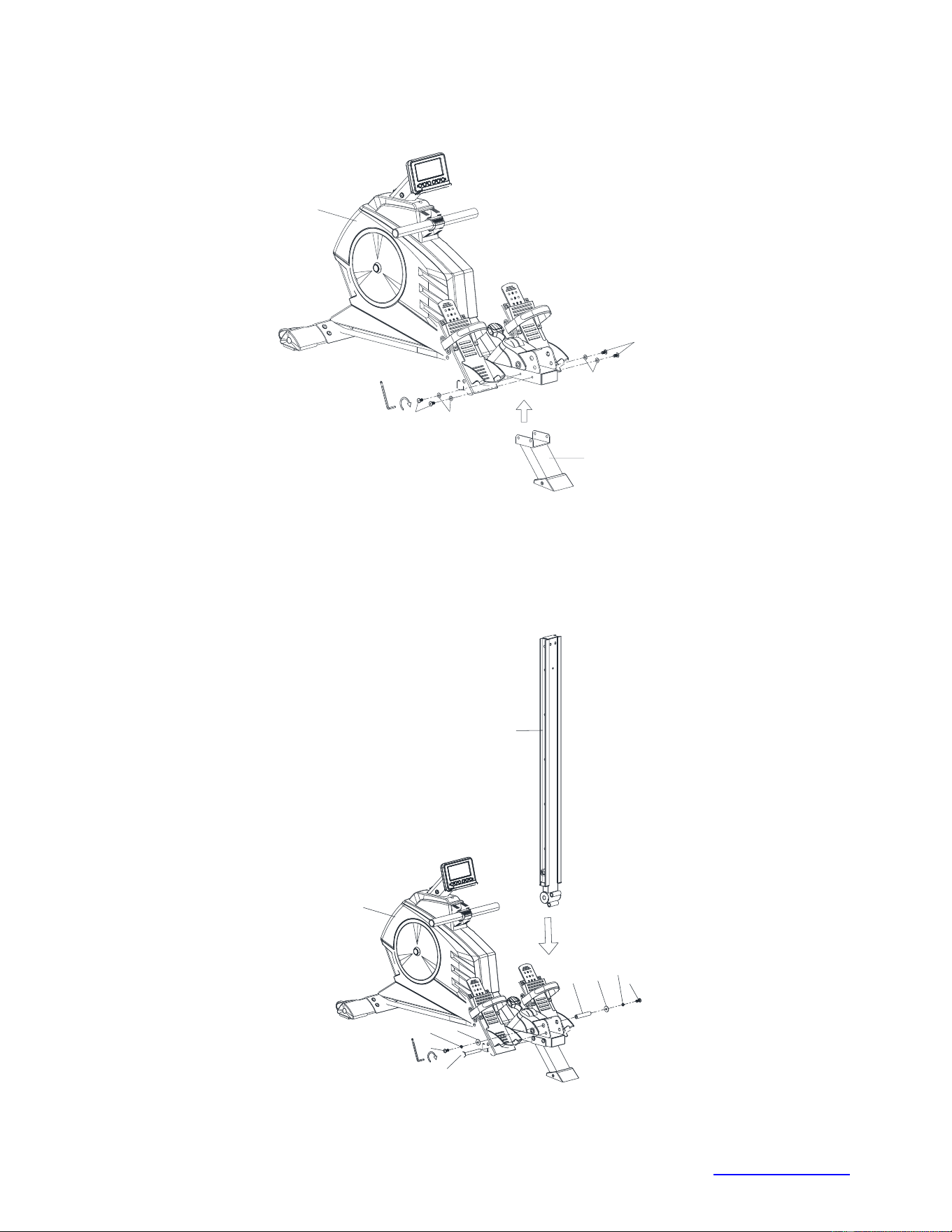
STEP 4
Attach the pedal support tube (31) to bottom of the main frame (5). Secure using two carriage bolts
(36), two flat washers (3) and two acorn nuts (35).
5
36
3
35
35
© IMPEX INC. www.marcypro.com
8
STEP 5
Attach middle stabilizer (28) to main frame (5), secure with 4 sets of allen bolts (11) and flat
washers (3).
3
11
3
11
28
5
STEP 6
Attach the slide rail (15) to the main frame (5). Secure using one axle for slide rail (69), two Allen
bolts (17), two spring washers (67), and two flat washers (68)
Fold the slide rail (15) Then insert the knob (8).
15
17
67
68
69
8
17
67
68
5
© IMPEX INC. www.marcypro.com
9
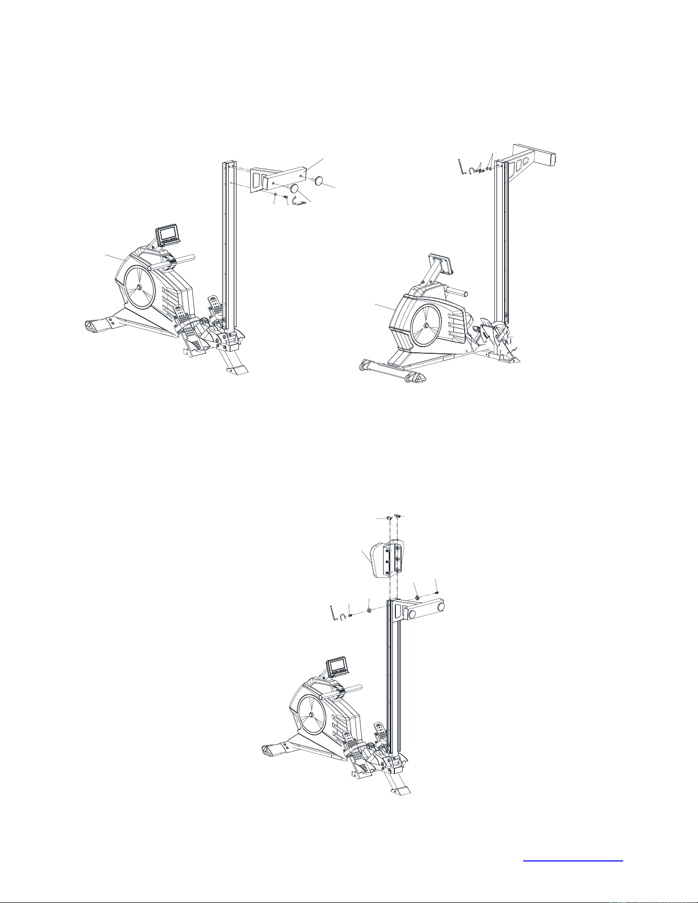
STEP 7
Attach the rear stabilizer (26) to the back of the slide rail (15). Secure one allen bolt (11) and one
flat washer (3) on the front of the rear stabilizer, then secure two allen bolts (24) and two flat
washers (3) on the rear of the stabilizer.
Thread two stoppers (27) into rear stabilizer (26).
26
27
27
11
3
5
24
3
5
STEP 8
Slide the seat (23) into the slide rail (15). Attach two collars (16) to the back of the slide rail (15)
and securing with two allen bolts (17).
Attach the end caps (14L & 14R) to the end of the slide rail (15).
14R
14L
16
16
17
17
23
© IMPEX INC. www.marcypro.com
10
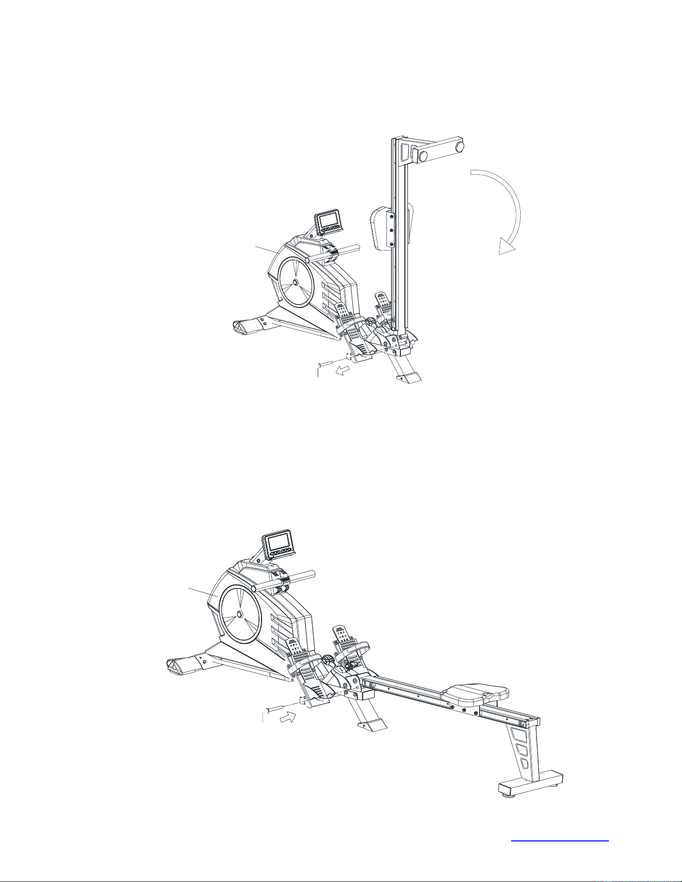
STEP 9
Pull out the locking pin (8) from the main frame and unfold the slide rail (15) slowly.
8
5
STEP 10
Set rear stabilizer to the floor and insert locking pin (8) to lock the frame into place.
Note: if there is resistance when inserting the locking pin, slightly lift the middle stabilizer, and it will
make inserting the pin easier.
5
8


© IMPEX INC. www.marcypro.com
13
AMZ-986RW PARTS LIST
NO.
Description
Qty
1L/R
End cap for front stabilizer L/R
1/1
2
Front stabilizer
1
3
Flat washer Ф8*Ф ⅝
21
4
Allen bolt M6x¾”
4
5
Main frame
1
6
Screw M5x ½”
4
7
Sensor wire
1
8
Locking Pin
1
9
Computer
1
10
Curve washer Ф8*Ф¾
5
11
Allen Bolt M8x⅝”
12
12
End cap
2
13
Sleeve
2
14L/R
End cap for slide rail L/R
2/2
15
Slide rail
1
16
Collar
4
17
Allen Bolt M8x¾”
6
18
Nylon nut M8
13
19
Axle for Wheel
6
20
Wheel
6
21
Screw M5*9/16
6
22
Seat support plate
1
23
Seat
1
24
Allen bolt M8x1 9/16
2
25
End cap for slide rail
1
26
Rear stabilizer
1
27
Stopper
2
28
Middle stabilizer
1
29
Self-tapping screw ST5*15
12
30
End cap for middle stabilizer
1
31
Pedal L/R
1
32
Allen bolt M6x½”
2
33
Computer sensor wire
1
34
Hex Head bolt M6*1”
1
35
Hex nut M8
2
36
Carriage bolt M8*1 ¾
2

© IMPEX INC. www.marcypro.com
14
37
Cable
1
38L/R
Chain cover L/R
1/1
39
Flange nut
2
40
Screw for clip
2
41
Clip
2
42
Aircraft nut
2
43
Flywheel
1
44
Rope pulley w/rope
1
45
Hex nut M6
2
46
Bracket for spring clutch
2
47
Sensor bracket
1
48
Self-tapping screw ST15*9/16
10
49
Spring
1
50
Belt
1
51
Front post
1
52
Decorative cover
1
53
Fix rubber pad
1
54
Upper cover for handlebar
1
55
Handlebar
1
56
End cap for handlebar
2
57
Foam grip for handlebar
2
58
Lower cover for handlebar
1
59
Self-tapping screw 5*9/16
2
60
Powder bushing
4
61
Bearing
4
62
Wheel
2
63
Axle for wheel
2
64
Allen bolt M8x2 3/16”
1
65
Magnetic assembly
1
66L/R
Decorative cover L/R
1/1
67
Lock washer Ф8
2
68
Flat Washer Ф8*Ф1
2
69
Axle for slide rail
1
70
8-level tension gear
1

© IMPEX INC. www.marcypro.com
15
CARE, MAINTENANCE AND STORAGE
1. Inspect and tighten all parts each time you use the machine. Replace any worn parts
immediately.
2. This machine can be cleaned using a damp cloth and mild non-abrasive detergent. Do not use
solvents.
3. Store the rower IN-DOOR. Excess moisture and water would cause rust on the frame.
4. The rower shall be placed at least 24 inches away from the wall or/and any other object such as
furniture to provide safe access to and passage around the machine.
5. To avoid possible injury, the help of two or more people are needed when moving the machine
around.
6. Disposal Instructions – The equipment can be safely disassembled and disposed without
unreasonable hazards. Call your local recycle agency regarding details of recycling.
7. The maximum user weight is 300 lbs.
8. Assembled Dimension (L x W x H): 91”x20.5”x31.5”
9. Folded Dimension (L x W x H): 49”x20.5”x51”
OPERATING NOTES
TRANSPORT
The Rower has a pair of roller wheels on Front Stabilizer End Cap.
To move, fold up the Rower; carefully hold and tilt the Rower, and then roll.

© IMPEX INC. www.marcypro.com
16
COMPUTER
Our computerized display console on the Water Rower allows the user to tailor a personalized
workout by monitoring their progress. During a workout, the display console will alternately and
repeatedly display the Time, Time/500M, SPM, Distance, Strokes, Total Strokes, Calories Burned
and Pulse.
BUTTONS
UP▲/ DOWN▼:Press either buttons to cycle through available selections, and to adjust the
function value upward or downward.
ENTER: To confirm your selection.
During training, press the button to scan through each display function.
START / STOP: To start and stop your selected workout program.
RESET: Press to go back to the main menu.
Long press (3-5 seconds) will reset all values back to zero.
RECOVERY: To activate the RECOVERY PROGRAM that will automatically evaluate your fitness
immediately after your work out.
DISPLAY FUNCTIONS
TIME: Set target time by pressing UP or DOWN buttons (1min ~ 99 min), in 1-min. increments.
TIME/500M: Your average 500-meter time will automatically be displayed and continuously
updated.
SPM: Strokes per minute.
DISTANCE: Set target value by pressing UP or DOWN buttons (0 ~ 99900 meters) in 100-meter
increments.
STROKES: Preset target value by pressing UP or DOWN buttons (0~9990 strokes) in
10-stroke increments.
TOTAL STROKES: Accumulates total strokes from 0 up to 9999.
CALORIES: Set target CALORIES by pressing UP or DOWN buttons
(10Cal ~9990Cal) in 10-Cal. increments.
PULSE: In Manual Mode, set target value by pressing up or down button to set from 30 to 240, in 1
BPM increments. The computer will display user’s heart rate during training. When target
value is reached, computer will beep until you change to another mode or take off Chest
belt. Also, the Pulse ICON will blink. The pulse function will only work if it is connected to
a chest strap system (not included).
CALENDAR: The computer will display year, month, and day when computer is in sleep mode.
TEMPERATURE: The computer will display the current room temperature when the computer is in
sleep mode.
CLOCK: The computer will display current time when the computer is in sleep mode.
OPERATION
1. Install 2 AA batteries (included) and computer will beep for 2 seconds (Fig.1).
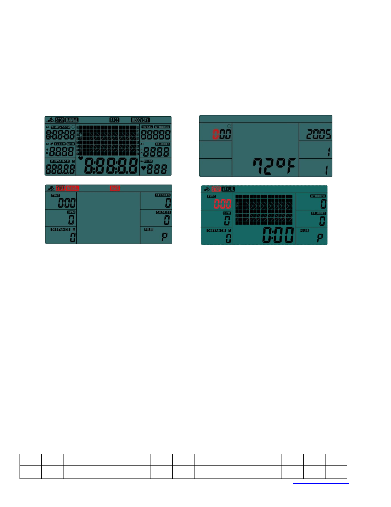
© IMPEX INC. www.marcypro.com
17
The computer will enter into the CLOCK & CALENDAR MODE (Fig.2).
2. The CLOCK will flash. Press UP/DOWN to set the hour. Press ENTER to confirm.
Press UP/DOWN to set the minutes. Press ENTER to confirm. Continue to set up YEAR
(displays in the STROKES window); MONTH (displays in the CALORIES window); DAY
(displays in the PULSE window) by pressing UP or DOWN. Each time, press ENTER to confirm.
After setting the CLOCK, the ALARM icon will blink for you to set up an alarm. To skip setting
up an alarm, press ENTER.
To set up an alarm, press UP KEY to turn on ALARM. An arrow will appear next to ALARM.
Press ENTER. CLOCK window will flash. Press UP or DOWN to set the alarm time. Press
ENTER to confirm. Computer will go into the SPORT screen (Fig.3).
Fig.1 Fig.2
Fig.3 Fig.4
3. When you enter into the SPORT screen, MANUAL and RACE will blink. Press UP or DOWN to
select MANUAL or RACE. Press ENTER to confirm your selection.
(1) MANUAL (Fig.4): There are 2 options in MANUAL mode.
A. The computer can be set to countdown.
i. When you select MANUAL, the value of TIME will start to flash. Press UP/DOWN
to set the value of TIME to countdown. Press ENTER to confirm it. If you do not
want to set the value of time to COUNTDOWN, press ENTER to go to the next
function.
ii. You can set the values for DISTANCE, STROKES, CALORIES, or PULSE. (You
can only set the value for one function to countdown. For example, if you have set
the target value for TIME, then DISTANCE can’t be set.)
iii. Press START button to start. The STOP icon will disappear.
iv. When the function you have selected counts down to zero or you press STOP
button, the computer will stop and display the average value.
B. The computer counts the value of your workout. Press START to start.
(2) RACE (Fig.5) :
A. Select RACE mode and L9 will flash. The TIME/500M will display 4:00. Then, press UP
or DOWN to select L1 ~ L15. Press ENTER to confirm. Then, you can set the distance
of the race (500M~10000M) while the value of DISTANCE is blinking.
L1
L2
L3
L4
L5
L6
L7
L8
L9
L10
L11
L12
L13
L14
L15
8:00
7:30
7:00
6:30
6:00
5:30
5:00
4:30
4:00
3:30
3:00
2:30
2:00
1:30
1:00

© IMPEX INC. www.marcypro.com
18
B. Press ENTER and the picture of the race will display on the screen.
The TIME/500M of the programs are as follows:
Fig.5 Fig.6
C. Press START button to start and STOP will disappear. USER and PC will be displayed
in the center window (Fig.6). The computer will stop when either the user or the
computer has reached the race distance that was set. Then the matrix displays “PC
WIN” or “USER WIN” (Fig.7).
Fig.7
D. When the race is over, you can press START to start a race once again. Press RESET
to leave the RACE screen.
(3) RECOVERY:
1. This computer works with a 5.3 KHz chest strap heart rate monitor (not included). After
exercising for a period of time, continue wearing chest strap monitor and press
“RECOVERY” button. All function displays will stop except “TIME”, it will start to counting
down from 00:60 to 00:00.
2. Screen will display your heart rate recovery status with the F1, F2….to F6.
3. F1 is outstanding. F6 is poor. User may keep exercising to improve the heart rate recovery
status. (Press the RECOVERY button again to return the main display.)
ALARM
Alarm only works while the computer is in sleep mode. Alarm will not sound during exercise.
Press and hold RESET to go to clock screen to set up ALARM.
SLEEP MODE
The computer will go into sleep mode after about 4 minutes of inactivity.
BATTERY
This meter uses 2 AA batteries, which are included. Changing the batteries will reset all values. If
there is a problem with the display, try changing the batteries first. When changing the batteries,
change both of them. Do not mix battery types. Do not mix old and new batteries. Dispose of old
batteries according to your regional guidelines. For optimal performance, the manufacturer recommends
the use of Generic alkaline AA batteries with an expiration date of 5-8 years from the current year.
High output/high drain and rechargeable batteries often produce too much initial surge and may not
© IMPEX INC. www.marcypro.com
19
activate the computer correctly
EXERCISE GUIDELINES
Using your MAGNETIC ROWER
will provide you with several benefits, it will improve your physical
fitness, tone muscle and in conjunction with calorie controlled diet help you lose weight.
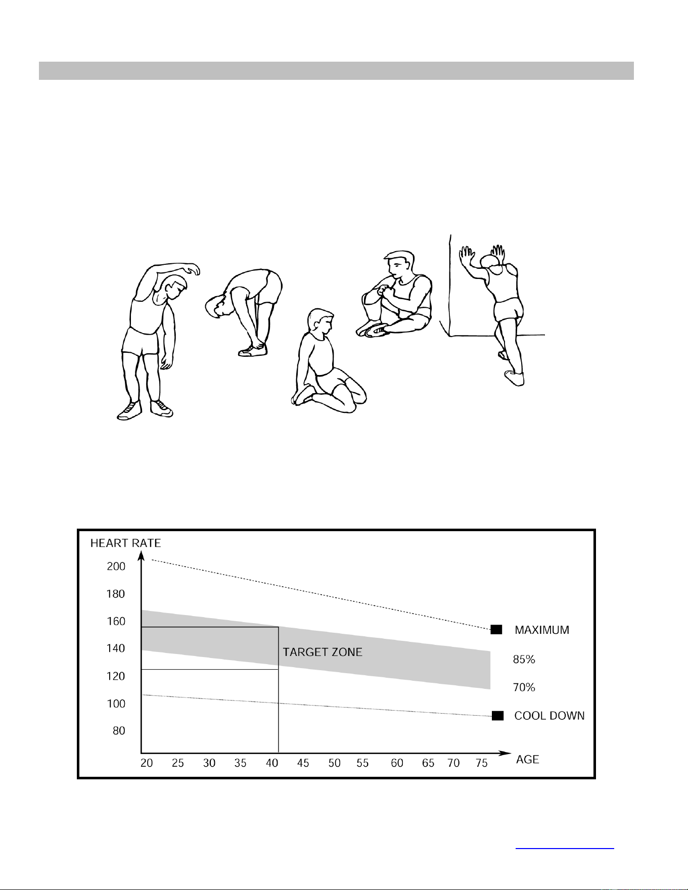
1. The Warm Up Phase
This stage helps get the blood flowing around the body and the muscles working properly. It will
also reduce the risk of cramp and muscle injury. It is advisable to do a few stretching exercises as
shown below. Each stretch should be held for approximately 30 seconds, do not force or jerk your
muscles into a stretch - if it hurts, STOP.
2. The Exercise Phase
This is the stage where you put the effort in. After regular use, the muscles in your legs will become
more flexible. Work to your targeted heart rate but it is very important to maintain a steady tempo
throughout. The rate of work should be sufficient to raise your heartbeat into the target zone shown
on the graph below.
SIDE BENDS OUTER THIGH
INNER THIGH
FORWARD
BENDS
CALF / ACHILLES

© IMPEX INC. www.marcypro.com
20
This stage should last for a minimum of 12 minutes though most people start at about 15-20
minutes
3. The Cool Down Phase
This stage is to let your Cardio-vascular System and muscles wind down. This is a repeat of the
warm up exercise e.g. reduce your tempo, continue for approximately 5 minutes. The stretching
exercises should now be repeated, again remembering not to force or jerk your muscles into the
stretch.
As you get fitter you may need to train longer and harder. It is advisable to train at least three times
a week, and if possible space your workouts evenly throughout the week.
MUSCLE TONING
To tone muscle while on your MAGNETIC BIKE you will need to have the resistance set quite high.
This will put more strain on our leg muscles and may mean you cannot train for as long as you
would like. If you are also trying to improve your fitness you need to alter your training program.
You should train as normal during the warm up and cool down phases, but towards the end of the
exercise phase you should increase resistance making your legs work harder. You will have to
reduce your speed to keep your heart rate in the target zone.
WEIGHT LOSS
The important factor here is the amount of effort you put in. The harder and longer you work
the more calories you will burn. Effectively this is the same as if you were training to
improve your fitness, the difference is the goal.

© IMPEX INC. www.marcypro.com
21
IMPEX
®
INC.
LIMITED WARRANTY
IMPEX Inc. ("IMPEX
®
") warrants this product to be free from defects in workmanship and material, under normal use
and service conditions, for a period of two years on the Frame from the date of purchase. This warranty extends only
to the original purchaser. IMPEX's obligation under this Warranty is limited to replacing or repairing, at IMPEX's option.
All returns must be pre-authorized by IMPEX. Pre-authorization may be obtained by calling IMPEX Customer Service
Department at 1-800-999-8899. All freights for products return to IMPEX must be prepaid by the customer. This
warranty does not extend to any product or damage to a product caused by or attributable to freight damage, abuse,
misuse, improper or abnormal usage or repairs not provided by an IMPEX authorized service center or for products
used for commercial or rental purposes. No other warranty beyond that specifically set forth above is authorized by
IMPEX.
IMPEX is not responsible or liable for indirect, special or consequential damages arising out of or in connection with the
use or performance of the product or other damages with respect to any economic loss, loss of property, loss of
revenues or profits, loss of enjoyments or use, costs of removal, installation or other consequential damages or
whatsoever natures. Some states do not allow the exclusion or limitation of incidental or consequential damages.
Accordingly, the above limitation may not apply to you.
The warranty extended hereunder is in lieu of any and all other warranties and any implied warranties of
merchantability or fitness for a particular purpose is limited in its scope and duration to the terms set forth herein.
Some states do not allow limitations on how long an implied warranty lasts. Accordingly, the above limitation may not
apply to you.
This warranty gives you specific legal right. You may also have other rights which vary from state to state.
Register on-line www.marcypro.com
IMPEX
®
INC.
2801 S. Towne Ave.
Pomona, CA 91766
ORDERING REPLACEMENT PARTS
Replacement parts can be ordered by calling our Customer Service Department toll-free at 1-800-999-8899 during our
regular business hours: Monday through Friday, 9 am until 5 pm Pacific standard time.
When ordering replacement part, always give the following information.
1. Model
2. Description of Parts
3. Part Number
4. Date of Purchase