
i
© 2024 GeoVision, Inc. All rights reserved.
Under the copyright laws, this manual may not be copied, in whole or in part, without
the written consent of GeoVision.
Every effort has been made to ensure that the information in this manual is accurate.
GeoVision, Inc. makes no expressed or implied warranty of any kind and assumes no
responsibility for errors or omissions. No liability is assumed for incidental or
consequential damages arising from the use of the information or products contained
herein. Features and specifications are subject to change without notice.
GeoVision, Inc.
9F, No. 246, Sec. 1, Neihu Rd.,
Neihu District, Taipei, Taiwan
Tel: +886-2-8797-8377
Fax: +886-2-8797-8335
http://www.geovision.com.tw
Trademarks used in this manual: GeoVision, the GeoVision logo and GV series
products are trademarks of GeoVision, Inc. Windows is the registered trademark of
Microsoft Corporation.
May 2024
Scan the following QR codes for product warranty and technical support
policy:
[Warranty] [Technical Support Policy]
ii
Preface
Welcome to the GV-PoE Switch User’s Manual.
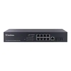
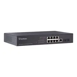
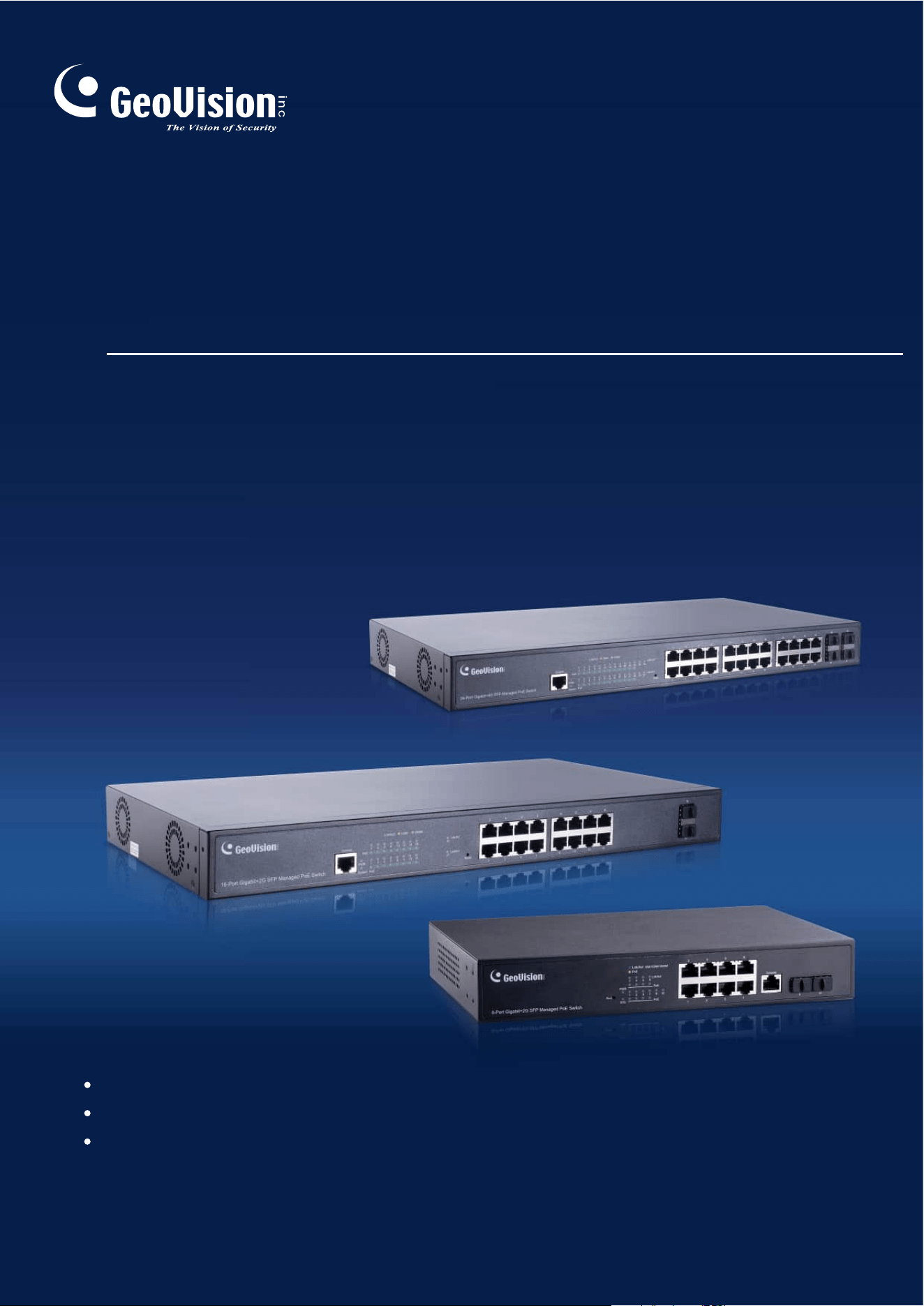
This Manual applies to the following GV-PoE Switch:
Product
GV-APOE0811
GV-APOE0811-V2
GV-APOE1611
GV-APOE1611-V2
GV-APOE2411
GV-APOE2411-V2

iii
PREFACE ............................................................................................................................................................................................ II
1. GETTING STARTED....................................................................................................................................................................... 1
1.1.
Power .................................................................................................................................................................................. 1
1.1.1. Connecting to Power ................................................................................................................................................................. 1
1.1.2. Connecting to the Network ...................................................................................................................................................... 2
1.1.3. Starting the Web-based Configuration Utility ..................................................................................................................... 2
1.1.4. Logging In .................................................................................................................................................................................... 4
2. WEB-BASED SWITCH CONFIGURATION ........................................................................................................................................ 5
2.1. Status .................................................................................................................................................................................. 6
2.1.1. System Information .................................................................................................................................................................... 6
2.1.2. Logging Message ....................................................................................................................................................................... 8
2.1.3. Port ................................................................................................................................................................................................. 8
2.1.3.1. Statistics ....................................................................................................................................................................................... 8
2.1.3.2. Error Disabled ........................................................................................................................................................................... 11
2.1.3.3. Bandwidth Utilization .............................................................................................................................................................. 12
2.1.4. Link Aggregation ...................................................................................................................................................................... 12
2.1.5. MAC Address Table ................................................................................................................................................................. 13
2.2. Network ............................................................................................................................................................................ 14
2.2.1. IP Address .................................................................................................................................................................................. 14
2.2.2. System Time .............................................................................................................................................................................. 16
2.3. Port .................................................................................................................................................................................... 18
2.3.1. Port Setting ................................................................................................................................................................................ 18
2.3.2. Error Disable .............................................................................................................................................................................. 20
2.3.3. Link Aggregation ...................................................................................................................................................................... 21
2.3.3.1. Group ........................................................................................................................................................................................... 21
2.3.3.2. Port Setting ................................................................................................................................................................................ 22
2.3.3.3. LACP ............................................................................................................................................................................................ 24
2.3.4. EEE ............................................................................................................................................................................................... 25
2.3.5. Jumbo Frame ............................................................................................................................................................................. 26
2.4. VLAN ................................................................................................................................................................................. 27
2.4.1. VLAN ............................................................................................................................................................................................ 27
2.4.1.1. Create VLAN .............................................................................................................................................................................. 27
2.4.1.2. VLAN Configuration ................................................................................................................................................................. 28
2.4.1.3. Membership ............................................................................................................................................................................... 29
2.4.1.4. Port Setting ................................................................................................................................................................................ 30
2.4.2. Voice VLAN ................................................................................................................................................................................ 32
2.4.2.1. Property ...................................................................................................................................................................................... 32
2.4.2.2. Voice OUI .................................................................................................................................................................................... 34
2.4.3. Protocol VLAN ........................................................................................................................................................................... 35
2.4.3.1. Protocol Group .......................................................................................................................................................................... 35
2.4.3.2. Group Binding ........................................................................................................................................................................... 36
2.4.4. MAC VLAN .................................................................................................................................................................................. 38
2.4.4.1. MAC Group ................................................................................................................................................................................. 38
2.4.4.2. Group Binding ........................................................................................................................................................................... 39
2.4.5. Surveillance VLAN ................................................................................................................................................................... 40
2.4.5.1. Property ...................................................................................................................................................................................... 40
2.4.5.2. Surveillance OUI ....................................................................................................................................................................... 42
2.4.6. GVRP ........................................................................................................................................................................................... 43
2.4.6.1. Property ...................................................................................................................................................................................... 43
2.4.6.2. Membership ............................................................................................................................................................................... 45
2.4.6.3. Statistics ..................................................................................................................................................................................... 46
2.4.7. QinQ ............................................................................................................................................................................................. 47
2.4 MAC Address Table ...................................................................................................................................................... 49
2.4.8. Dynamic Address ..................................................................................................................................................................... 49
2.4.9. Static Address ........................................................................................................................................................................... 50
2.4.10. Filtering Address ...................................................................................................................................................................... 51
2.5. Spanning Tree ................................................................................................................................................................ 52
2.5.1. Property ...................................................................................................................................................................................... 52
2.5.2. Port Setting ................................................................................................................................................................................ 54
2.5.3. MST Instance ............................................................................................................................................................................. 56
2.5.4. MST Port Setting ....................................................................................................................................................................... 58

iv
2.5.5. Statistics ..................................................................................................................................................................................... 60
2.6. Discovery ......................................................................................................................................................................... 62
2.6.1. LLDP ............................................................................................................................................................................................ 62
2.6.1.1. Property ...................................................................................................................................................................................... 62
2.6.1.2. Port Setting ................................................................................................................................................................................ 63
2.6.1.3. MED Network Policy ................................................................................................................................................................ 65
2.6.1.4. MED Port Setting ...................................................................................................................................................................... 66
2.6.1.5. Packet View ................................................................................................................................................................................ 68
2.6.1.6. Local Information ..................................................................................................................................................................... 70
2.6.1.7. Neighbor ..................................................................................................................................................................................... 72
2.6.1.8. Statistics ..................................................................................................................................................................................... 74
2.7. Multicast ........................................................................................................................................................................... 75
2.7.1. General ........................................................................................................................................................................................ 75
2.7.1.1. Property ...................................................................................................................................................................................... 75
2.7.1.2. Group Address .......................................................................................................................................................................... 76
2.7.1.3. Router Port ................................................................................................................................................................................. 77
2.7.1.4. Forward All ................................................................................................................................................................................. 79
2.7.1.5. Throttling .................................................................................................................................................................................... 82
2.7.1.6. Filtering Profile .......................................................................................................................................................................... 83
2.7.1.7. Filtering Binding ....................................................................................................................................................................... 84
2.7.2. IGMP Snooping ......................................................................................................................................................................... 85
2.7.2.1. Property ...................................................................................................................................................................................... 85
2.7.2.2. Querier......................................................................................................................................................................................... 89
2.7.2.3. Statistics ..................................................................................................................................................................................... 90
2.7.3. MLD Snooping ........................................................................................................................................................................... 92
2.7.3.1. Property ...................................................................................................................................................................................... 92
2.7.3.2. Statistics ..................................................................................................................................................................................... 94
2.7.4. MVR .............................................................................................................................................................................................. 96
2.7.4.1. Property ...................................................................................................................................................................................... 96
2.7.4.2. Port Setting ................................................................................................................................................................................ 97
2.7.4.3. Group Address .......................................................................................................................................................................... 98
2.8. Security ............................................................................................................................................................................ 99
2.8.1. RADIUS ....................................................................................................................................................................................... 99
2.8.2. TACACS+ .................................................................................................................................................................................. 101
2.8.3. AAA ............................................................................................................................................................................................ 104
2.8.3.1. Method List .............................................................................................................................................................................. 104
2.8.3.2. Login Authentication ............................................................................................................................................................. 105
2.8.4. Management Access.............................................................................................................................................................. 106
2.8.4.1. Management VLAN ................................................................................................................................................................. 106
2.8.4.2. Management Service ............................................................................................................................................................. 107
2.8.4.3. Management ACL ................................................................................................................................................................... 108
2.8.4.4. Management ACE ................................................................................................................................................................... 108
2.8.5. Authentication Manager ........................................................................................................................................................ 111
2.8.5.1. Property .................................................................................................................................................................................... 111
2.8.5.2. Port Setting .............................................................................................................................................................................. 115
2.8.5.3. MAC-Based Local Account .................................................................................................................................................. 119
2.8.5.4. WEB-Based Local Account .................................................................................................................................................. 120
2.8.5.5. Sessions ................................................................................................................................................................................... 122
2.8.6. Port Security ............................................................................................................................................................................ 123
2.8.7. Protected Port ......................................................................................................................................................................... 125
2.8.8. Storm Control .......................................................................................................................................................................... 126
2.8.9. DoS ............................................................................................................................................................................................. 128
2.8.9.1. Property .................................................................................................................................................................................... 128
2.8.9.2. Port Setting .............................................................................................................................................................................. 130
2.8.10. Dynamic ARP Inspection ...................................................................................................................................................... 131
2.8.10.1. Property .................................................................................................................................................................................... 131
2.8.10.2. Statistics ................................................................................................................................................................................... 133
2.8.11. DHCP Snooping ...................................................................................................................................................................... 134
2.8.11.1. Property .................................................................................................................................................................................... 134
2.8.11.2. Statistics ................................................................................................................................................................................... 135
2.8.11.3. Binding ...................................................................................................................................................................................... 136
2.8.11.4. Option82 Property .................................................................................................................................................................. 137
2.8.11.5. Option82 Circuit ID ................................................................................................................................................................. 138

v
2.8.12. IP Source Guard ...................................................................................................................................................................... 140
2.8.12.1. Port Setting .............................................................................................................................................................................. 140
2.8.12.2. IMPV Binding ........................................................................................................................................................................... 141
2.8.12.3. Save Database ......................................................................................................................................................................... 142
2.9. PoE .................................................................................................................................................................................. 144
2.9.1. PoE Global information ......................................................................................................................................................... 144
2.9.2. PoE Port .................................................................................................................................................................................... 145
2.9.3. PoE PD Alive Check ............................................................................................................................................................... 147
2.9.4. MCU Upgrade .......................................................................................................................................................................... 147
2.9.5. PoE Schedule .......................................................................................................................................................................... 147
2.10. ONVIF .............................................................................................................................................................................. 149
2.11.1. ONVIF Server ........................................................................................................................................................................... 149
2.11.2. ONVIF Discover ....................................................................................................................................................................... 149
2.12. ACL .................................................................................................................................................................................. 150
2.12.1. MAC ACL .................................................................................................................................................................................. 150
2.12.2. MAC ACE .................................................................................................................................................................................. 150
2.12.3. IPv4 ACL ................................................................................................................................................................................... 152
2.12.4. IPv4 ACE ................................................................................................................................................................................... 153
2.12.5. IPv6 ACL ................................................................................................................................................................................... 158
2.12.6. Ipv6 ACE ................................................................................................................................................................................... 158
2.12.7. ACL Binding ............................................................................................................................................................................. 163
2.13. QoS .................................................................................................................................................................................. 165
2.13.1. General ...................................................................................................................................................................................... 165
2.13.1.1. Property .................................................................................................................................................................................... 165
2.13.1.2. Queue Scheduling .................................................................................................................................................................. 167
2.13.1.3. CoS Mapping ........................................................................................................................................................................... 169
2.13.1.4. DSCP Mapping ........................................................................................................................................................................ 170
2.13.1.5. IP Precedence Mapping ........................................................................................................................................................ 171
2.13.2. Rate Limit ................................................................................................................................................................................. 171
2.13.2.1. Ingress/Egress Port ............................................................................................................................................................... 171
2.13.2.2. Egress Queue .......................................................................................................................................................................... 173
2.14. Diagnostics ................................................................................................................................................................... 176
2.14.1. Logging ..................................................................................................................................................................................... 176
2.14.1.1. Property .................................................................................................................................................................................... 176
2.14.1.2. Remote Server ......................................................................................................................................................................... 177
2.14.2. Mirroring ................................................................................................................................................................................... 163
2.14.3. Ping ............................................................................................................................................................................................ 165
2.14.4. Traceroute ................................................................................................................................................................................ 166
2.14.5. Copper Test.............................................................................................................................................................................. 167
2.14.6. Fiber Module ............................................................................................................................................................................ 167
2.14.7. UDLD .......................................................................................................................................................................................... 169
2.14.7.1. Property .................................................................................................................................................................................... 169
2.14.7.2. Neighbor ................................................................................................................................................................................... 170
2.15. Management .................................................................................................................................................................. 171
2.15.1. User Account ........................................................................................................................................................................... 171
2.15.2. Firmware ................................................................................................................................................................................... 172
2.15.2.1. Upgrade / Backup ................................................................................................................................................................... 172
2.15.3. Configuration ........................................................................................................................................................................... 176
2.15.3.1. Upgrade / Backup ................................................................................................................................................................... 176
2.15.3.2. Save Configuration ................................................................................................................................................................ 180
2.15.4. SNMP ......................................................................................................................................................................................... 181
2.15.4.1. Status......................................................................................................................................................................................... 181
2.15.4.2. View ............................................................................................................................................................................................ 181
2.15.4.3. Group ......................................................................................................................................................................................... 181
2.15.4.4. Community ............................................................................................................................................................................... 183
2.15.4.5. User ............................................................................................................................................................................................ 184
2.15.4.6. Engine ID .................................................................................................................................................................................. 186
2.15.4.7. Trap Event ................................................................................................................................................................................ 188
2.15.4.8. Notification ............................................................................................................................................................................... 188
2.15.5. RMON......................................................................................................................................................................................... 191
2.15.5.1. Statistics ................................................................................................................................................................................... 191
2.15.5.2. History ....................................................................................................................................................................................... 193
2.15.5.3. Event .......................................................................................................................................................................................... 196

vi
2.15.5.4. Alarm ......................................................................................................................................................................................... 198
2.15.6. Open Source Software Licenses ........................................................................................................................................ 200
Introduction
1
1
1. Getting Started
This section provides an introduction to the web-based configuration utility, and covers the
following topics:
•
Powering on the device
•
Connecting to the network
•
Starting the web-based configuration utility
1.1. Power
1.1.1. Connecting to Power
Power down and disconnect the power cord before servicing or wiring a switch.
Do not disconnect modules or cabling unless the power is first switched off. The
device only supports the voltage outlined in the type plate. Do not use any other
power components except those specifically designated for the switch.
Disconnect the power cord before installation or cable wiring.
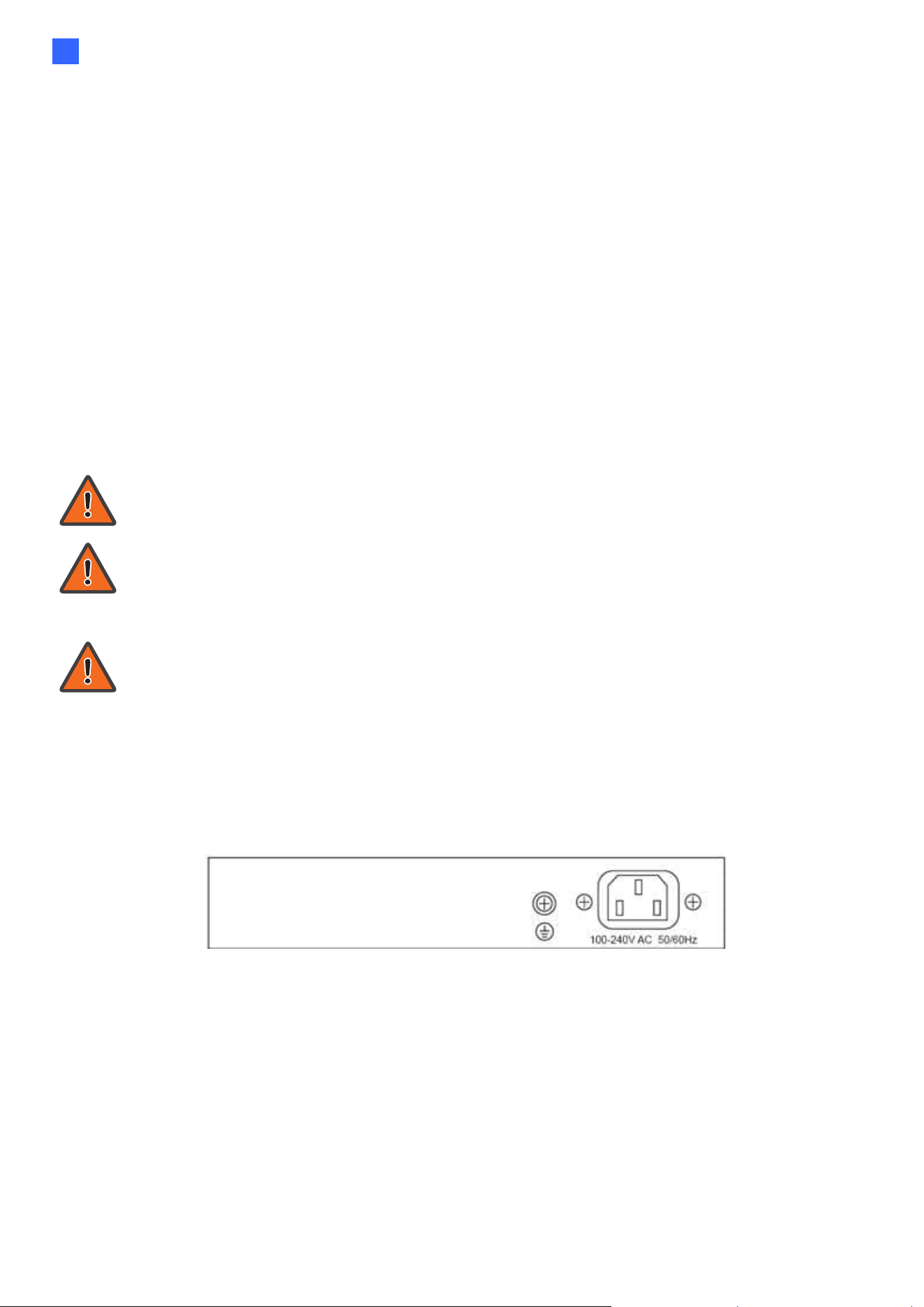
The switch is powered by the AC 100-240 V 50/60Hz internal high-performance power supply. It is
recommended to connect the switch with a single-phase three-wire power source with a neutral
outlet, or a multifunctional computer professional source.
Connect the AC power connector on the back panel of the switch to the external power
source with the included power cord, and check the power LED is on.
Figure 1 - Rear View AC Power Socket

2
1.1.2. Connecting to the Network
To connect the switch to the network:
1. Connect an Ethernet cable to the Ethernet port of a computer
2. Connect the other end of the Ethernet cable to one of the numbered Ethernet ports of
the switch. The LED of the port lights if the device connected is active.
3. Repeat Step 1 and Step 2 for each device to connect to the switch.
We strongly recommend using CAT-5E or better cable to connect network devices.
When connecting network devices, do not exceed the maximum cabling distance of
100 meters (328 feet). It can take up to one minute for attached devices or the LAN
to be operational after it is connected. This is normal behavior.
Connect the switch to end nodes using a standard Cat 5/5e Ethernet cable (UTP/STP) to
connect the switch to end nodes as shown in the illustration below.
Switch ports will automatically adjust to the characteristics (MDI/MDI-X, speed, duplex) of
the device to which the switch is connected.
1.1.3. Starting the Web-based Configuration Utility
This section describes how to navigate the web-based switch configuration utility. Be sure to
disable any pop-up blocker.
Browser Restrictions
•
If you are using older versions of Internet Explorer, you cannot directly use an IPv6
address to access the device. You can, however, use the DNS (Domain Name System)
server to create a domain name that contains the IPv6 address, and then use that domain
name in the address bar in place of the IPv6 address.
•
If you have multiple IPv6 interfaces on your management station, use the IPv6 global
address instead of the IPv6 link local address to access the device from your browser.

Introduction
3
1
Launching the Configuration Utility
To open the web-based configuration utility:
1. Open a Web browser.
2. Enter the factory default IP address of 192.168.0.250 in the address bar on the browser
and then press Enter.
When the device is using the factory default IP address, its power LED flashes
continuously. When the device is using a DHCP assigned IP address or an
administrator-configured static IP address, the power LED is lit a solid color. Your
computer’s IP address must be in the same subnet as the switch. For example, if the
switch is using the factory default IP address, your computer’s IP address can be in
the following range: 192.168.0.x (whereas x is a number from 2 to 254).
After a successful connection, the login window displays.
Figure 2 - Login Window
4
1.1.4. Logging In
The default username is admin and the default password is admin. The first time that you log in
with the default username and password, you are required to enter a new password.
To log in to the device configuration utility:
1. Enter the default user ID (admin) and the default password (admin).
2. If this is the first time that you logged on with the default user ID (admin) and the default
password (admin) it is recommended that you change your password immediately.
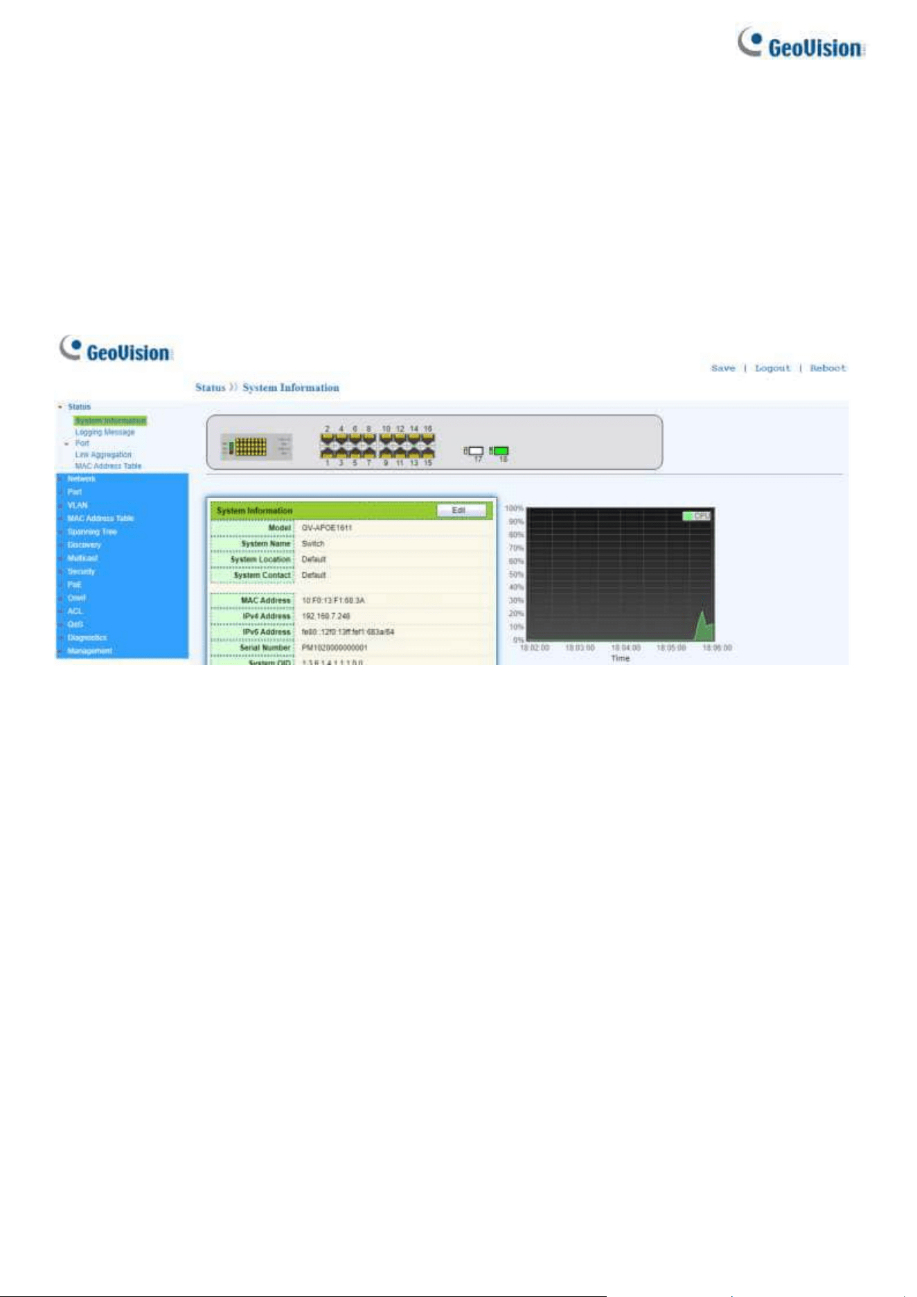
3. When the login attempt is successful, the System Information window displays.
Figure 3 - System Information
If you entered an incorrect username or password, an error message appears and the Login
page remains displayed on the window. If you are having problems logging in, please see the
Launching the Configuration Utility section in the Administration Guide for additional information.
Logging Out
By default, the application logs out after ten minutes of inactivity.
To logout, click Logout in the top right corner of any page. The system logs out of the device.
When a timeout occurs or you intentionally log out of the system, a message appears and the
Login page appears, with a message indicating the logged-out state. After you log in, the
application returns to the initial page.
Web-based Switch Configuration
5
2
2. Web-based Switch Configuration
The PoE smart switch software provides rich Layer 2 functionality for switches in your
networks. This chapter describes how to use the web-based management interface (Web
UI) to configure the switch’s features.
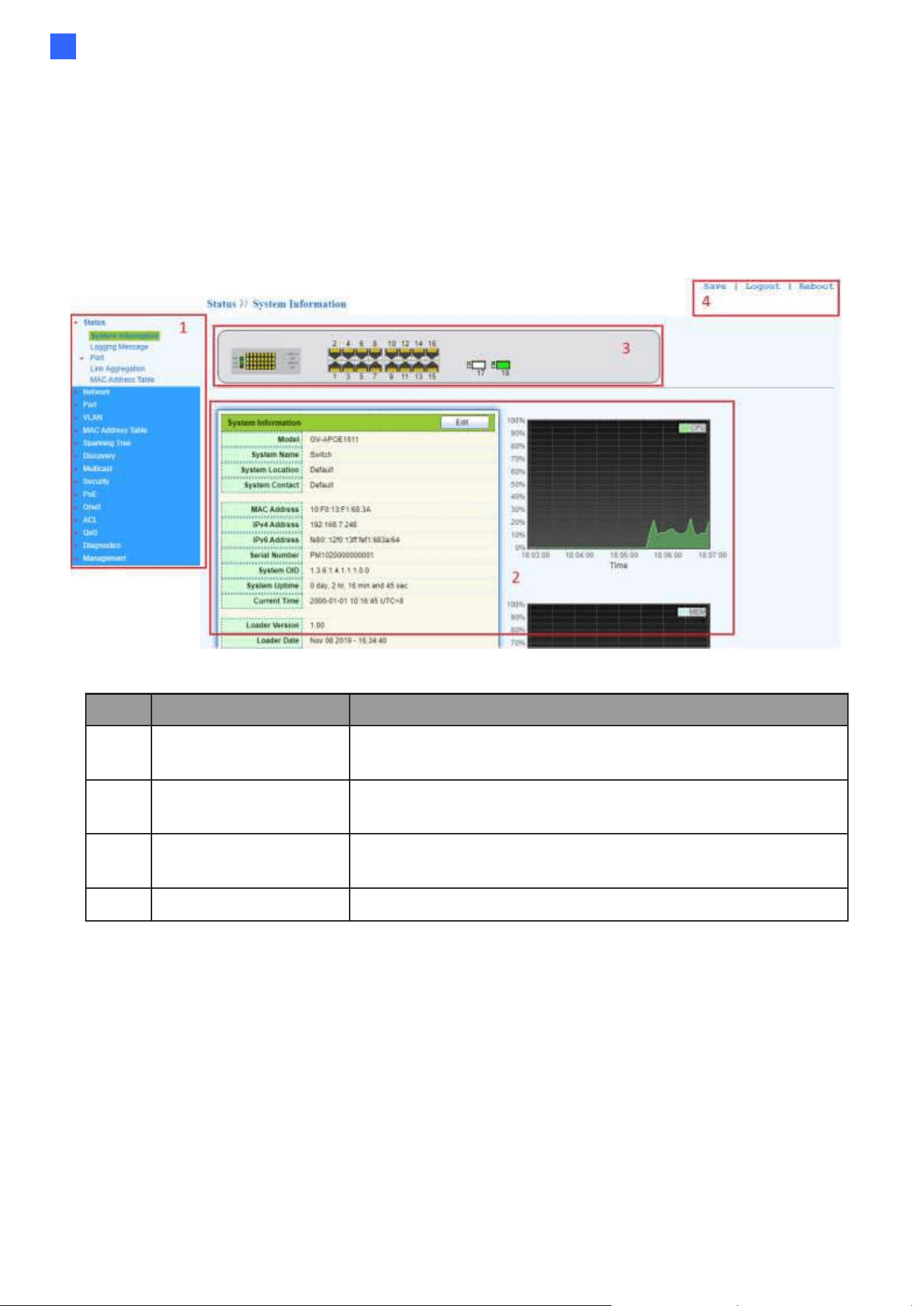
For the purposes of this manual, the user interface is separated into four sections, as
shown in the following figure:
Figure 4 - User Interface
No.
Name
Description
1
Configuration
menu
Navigate to locate specific switch functions.
2
Configuration
settings
Edit specific function settings.
3
Switch’s current
link status
Green squares indicate the port link is up, while black
squares indicate the port link is down.
4
Common toolbar
Provides access to frequently used settings.
6
2.1. Status
Use the Status pages to view system information and status.
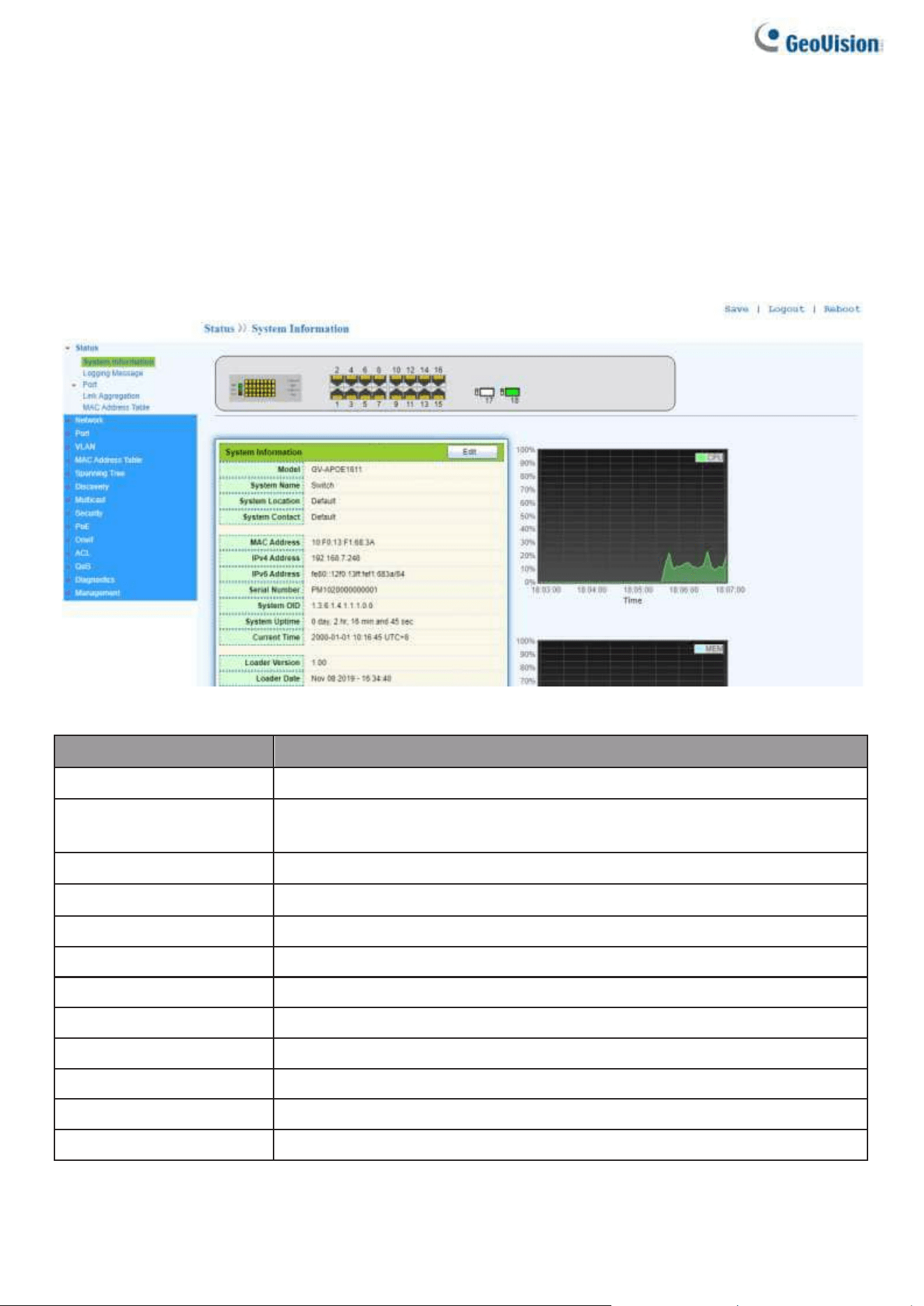
2.1.1. System Information
This page shows switch panel, CPU utilization, Memory utilization and other system current
information. It also allows user to edit some system information.
To display the Device Information web page, click Status > System Information.
Figure 5 - Status > System Information
Item
Description
Model
Model name of the switch.
System Name
System name of the switch. This name will also use as CLI prefix
of each line. (“Switch>” or “Switch#”).
System Location
Location information of the switch.
System Contact
Contact information of the switch.
MAC Address
Base MAC address of the switch.
IPv4 Address
Current system IPv4 address.
IPv6 Address
Current system IPv6 address.
System OID
SNMP system object ID.
System Uptime
Total elapsed time from booting.
Current Time
Current system time.
Loader Version
Boot loader image version.
Loader Date
Boot loader image build date.
Web-based Switch Configuration
7
2
Firmware Version
Current running firmware image version.
Firmware Date
Current running firmware image build date.
Telnet
Current Telnet service enable/disable state.
SSH
Current SSH service enable/disable state.
HTTP
Current HTTP service enable/disable state.
HTTPS
Current HTTPS service enable/disable state.
SNMP
Current SNMP service enable/disable state.
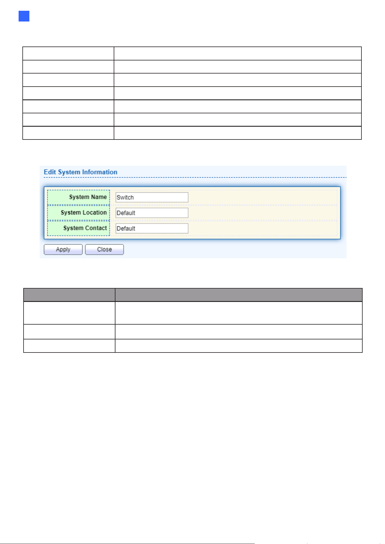
Click “Edit” button on the table title to edit following system information.
Figure 6 - Status > System Information > Edit System Information
Item
Description
System Name
System name of the switch. This name will also use as CLI prefix
of each line. (“Switch>” or “Switch#”).
System Location
Location information of the switch.
System Contact
Contact information of the switch.
8
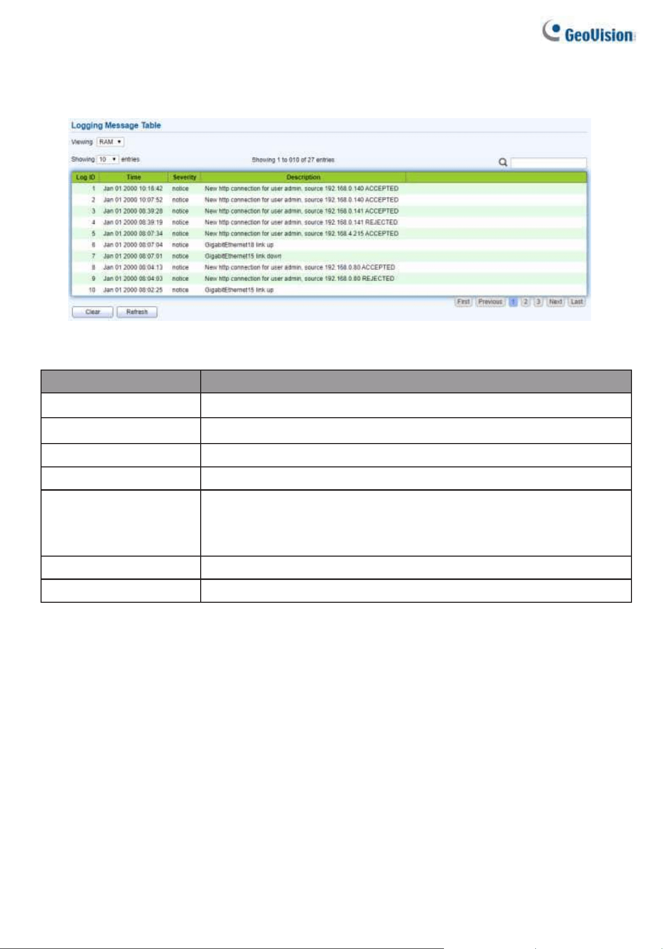
2.1.2. Logging Message
To view the logging messages stored on the RAM and Flash, click Status > Logging Message.
Figure 7 - Status > Logging Message
Item
Description
Log ID
The log identifier.
Time
The time stamp for the logging message.
Severity
The severity for the logging message.
Description
The description of logging message.
Viewing
The logging view including:
●
RAM: Show the logging messages stored on the RAM.
●
Flash: Show the logging messages stored on the Flash.
Clear
Clear the logging messages.
Refresh
Refresh the logging messages.
2.1.3. Port
The Port configuration page displays port summary and status information.
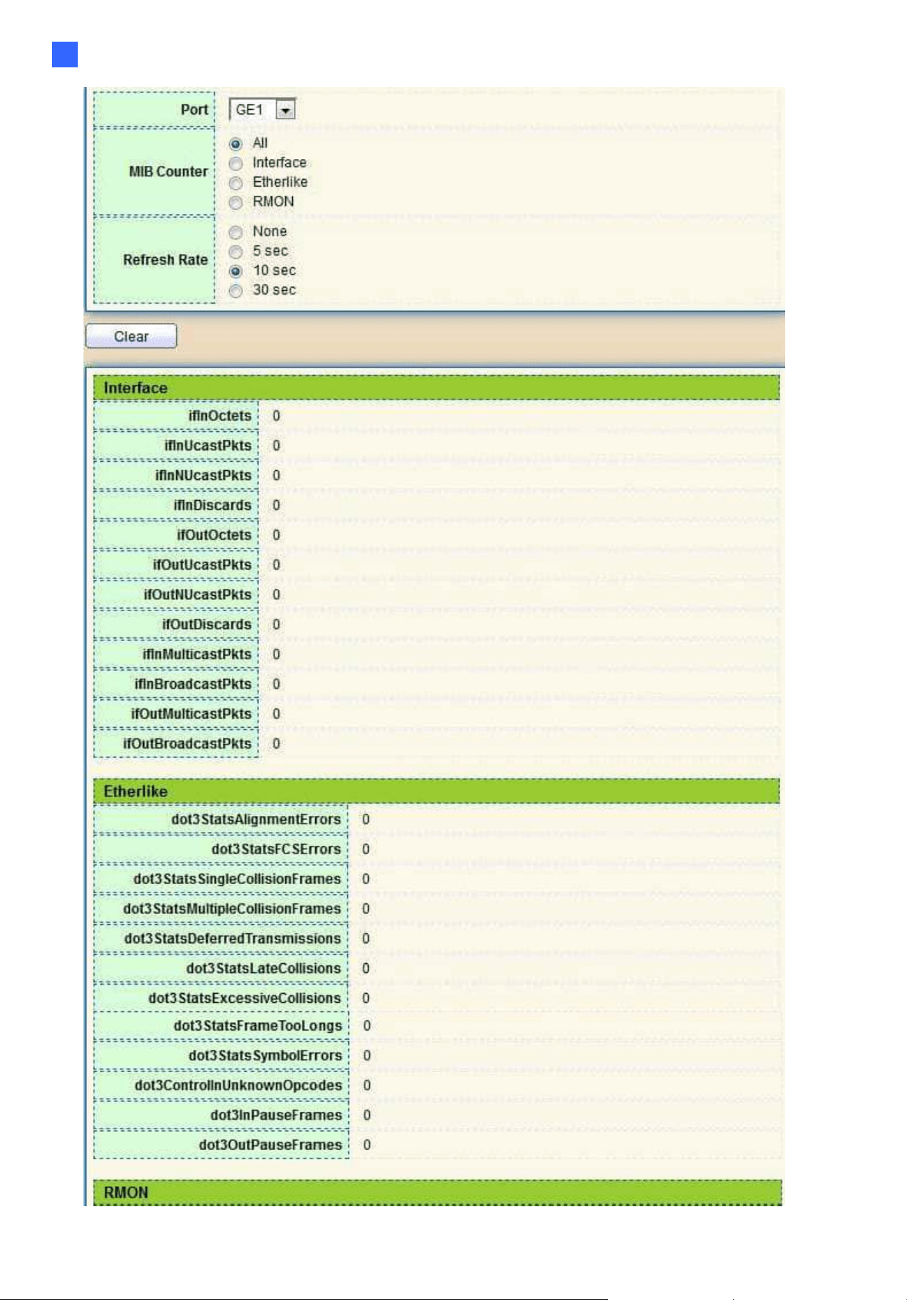
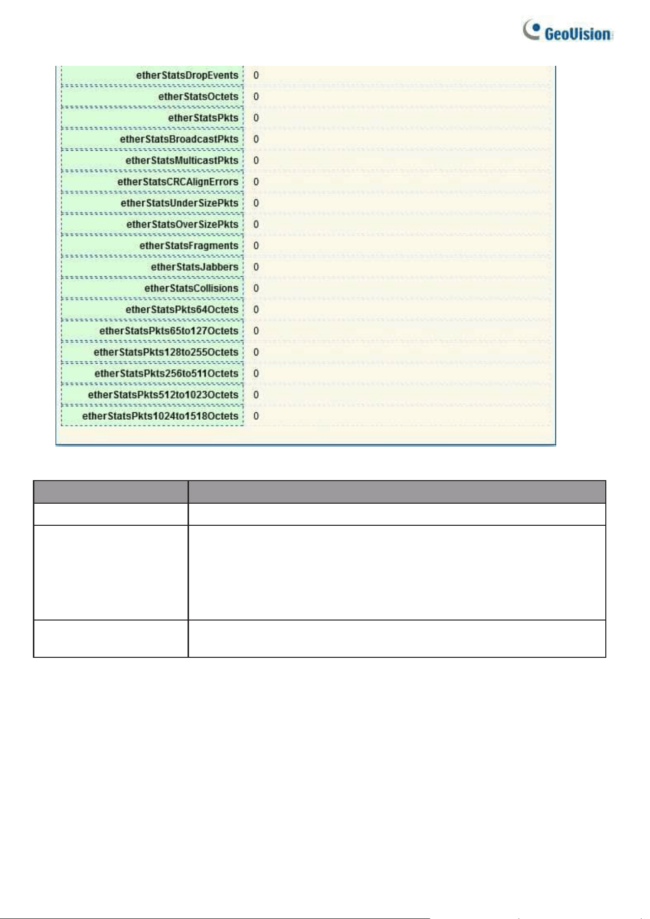
2.1.3.1. Statistics
This page displays standard counters on network traffic form the Interfaces, Ethernet
-like and RMONMIB. Interfaces and Ethernet-like counters display errors on the traffic passing
through each port. RMON counters provide a total count of different frame types and sizes
passing through each port. The “Clear” button will clear MIB counter of current selected port.
To display the Port Flow Chart webpage, click Status > Port > Statistics.
Web-based Switch Configuration
9
2
10
Figure 8 - Status > Port > Statistics
Item
Description
Port
Select one port to show counter statistics.
MIB Counter
Select the MIB counter to show different counter type
•
All: All counters.
•
Interface: Interface related MIB counters.
•
Etherlike: Ethernet-like related MIB counters.
•
RMON: RMON related MIB counters.
Refresh Rate
Refresh the web page every period of seconds to get new
counter of specified port.
Web-based Switch Configuration
11
2
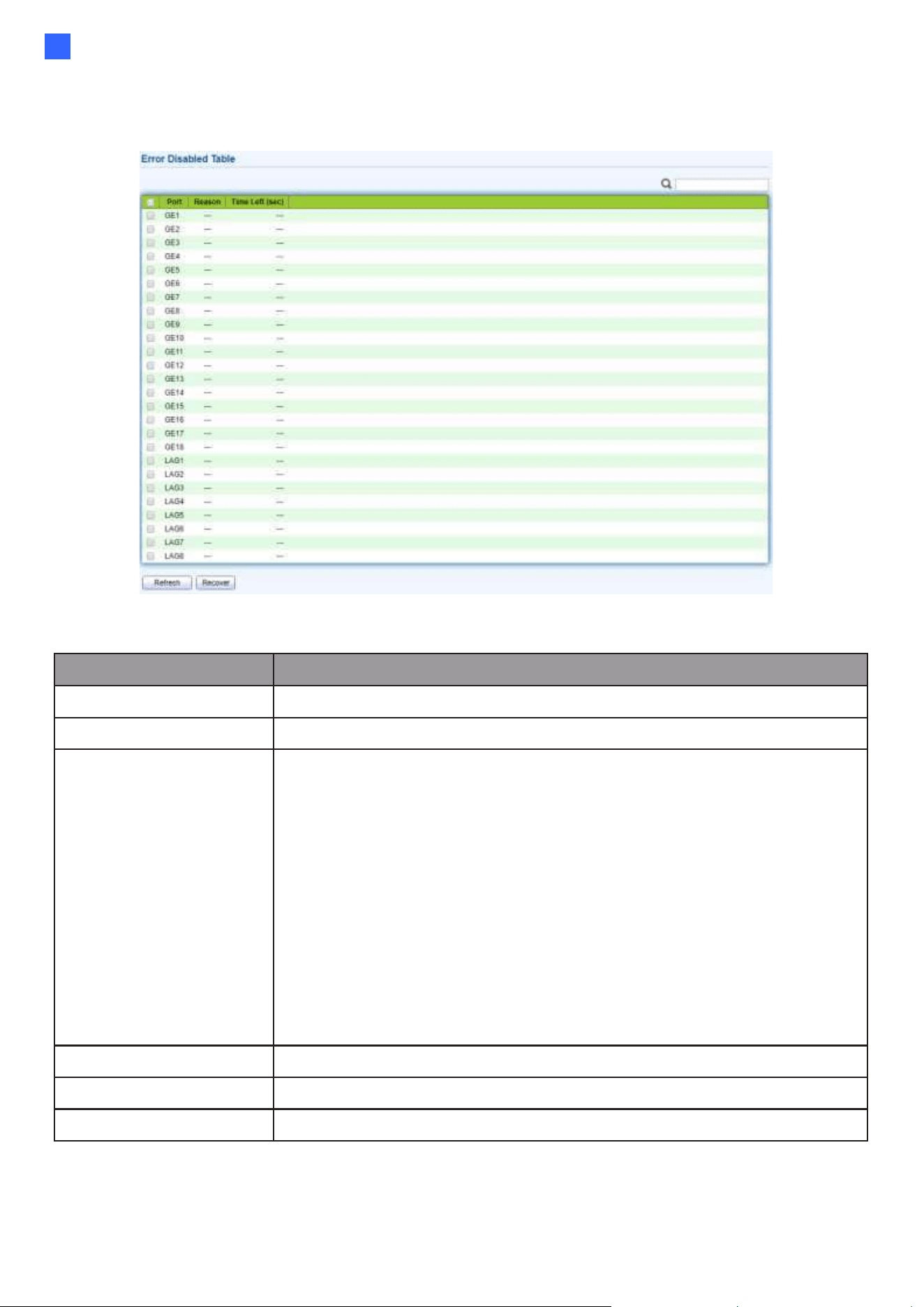
2.1.3.2. Error Disabled
To display the Error Disabled webpage, click Status > Port > Error Disabled.
Figure 9 - Status > Port > Error Disabled
Item
Description
□
Select one or more port to operate.
Port
Interface or port number.
Reason
Port will be disabled by one of the following error reasons:
•
BPDU Guard
•
UDLD
•
Self Loop
•
Broadcast Flood
•
Unknown Multicast Flood
•
Unicast Flood
•
ACL
•
Port Security Violation
•
DHCP rate limit
•
ARP rate limit
Time Left (sec)
The time left in second for the error recovery.
Refresh
Refresh the current page.
Recover
Recover the selected port status.
12
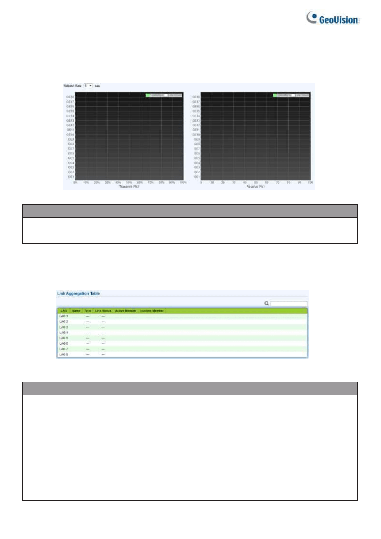
2.1.3.3. Bandwidth Utilization
This page allows users to browse ports’ bandwidth utilization in real time. This page will
refresh automatically in every refresh period.
To display Bandwidth Utilization webpage, click Status > Port > Bandwidth Utilization.
Figure 10 - Status > Port > Bandwidth Utilization
Item
Description
Refresh Rate
Refresh the web page every period of seconds to get new
bandwidth utilization data.
2.1.4. Link Aggregation
To display the Link Aggregation web page, click Status > Link Aggregation.
Figure 11 - Status > Link Aggregation
Item
Description
LAG
LAG Name.
Name
LAG port description.
Type
•
The type of the LAG.
•
Static: The group of ports assigned to a static LAG are always
active members.
•
LACP: The group of ports assigned to dynamic LAG are
candidate ports. LACP determines which candidate ports are
active member ports.
Link Status
LAG port link status.
Web-based Switch Configuration
13
2
Active Member
Active member ports of the LAG.
Inactive Member
Inactive member ports of the LAG.
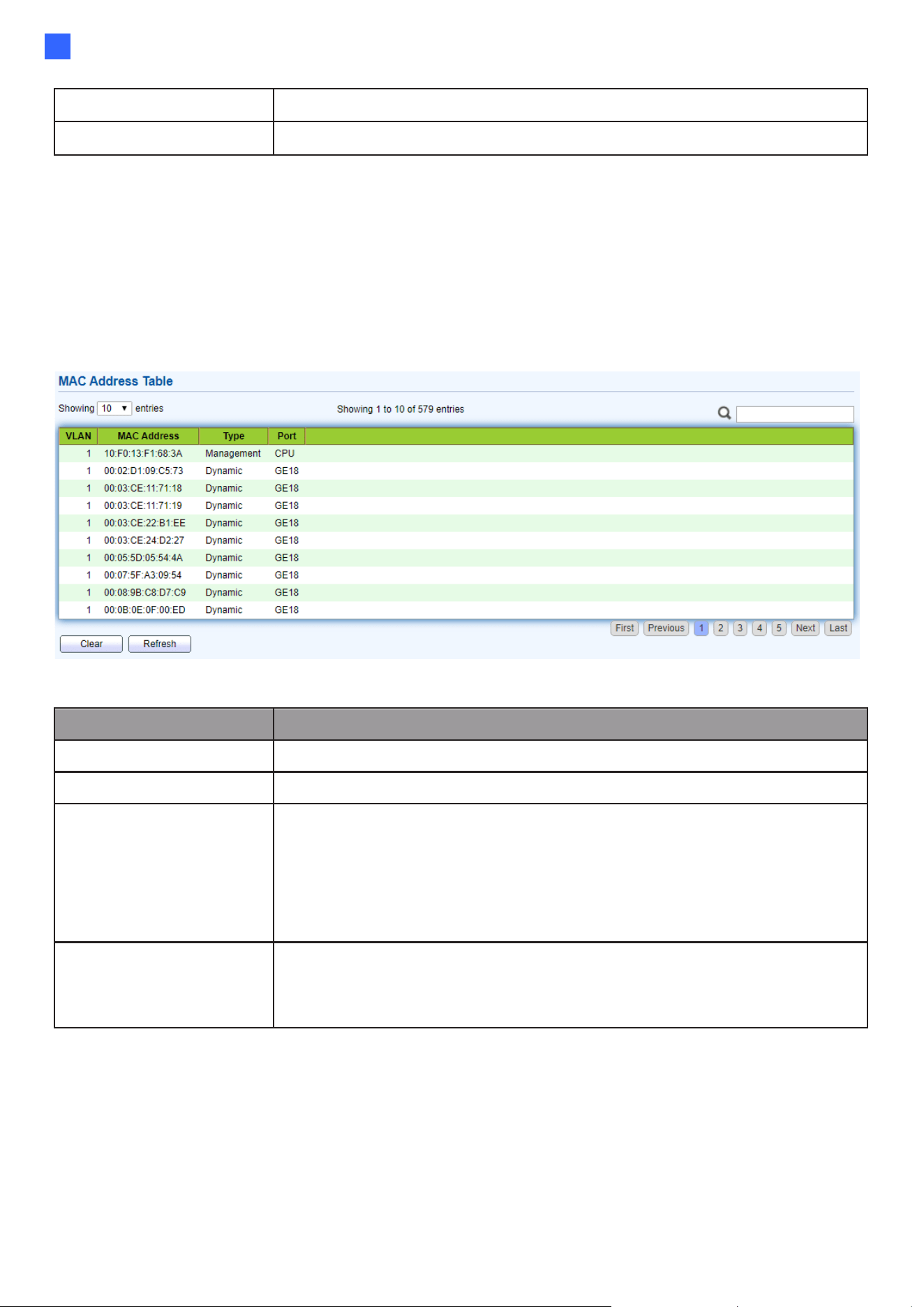
2.1.5. MAC Address Table
The MAC address table page displays all MAC address entries on the switch including static
MAC address created by administrator or auto learned from hardware. The “Clear” button will
clear all dynamic entries and “Refresh” button will retrieve latest MAC address entries and show
them on page.
To display the MAC Address Table web page, click Status > MAC Address Table.
Figure 12 - Status > MAC Address Table
Item
Description
VLAN
VLAN ID of the mac address.
MAC Address
MAC address.
Type
The type of MAC address
•
Management: DUT’s base mac address for
management Purpose.
•
Static: Manually configured by administrator
•
Dynamic: Auto learned by hardware.
Port
The type of Port
•
CPU: DUT’s CPU port for management purpose.
•
Other: Normal switch port.
14
2.2. Network
Use the Network pages to configure settings for the switch network interface and how the
switch connects to a remote server to get services.
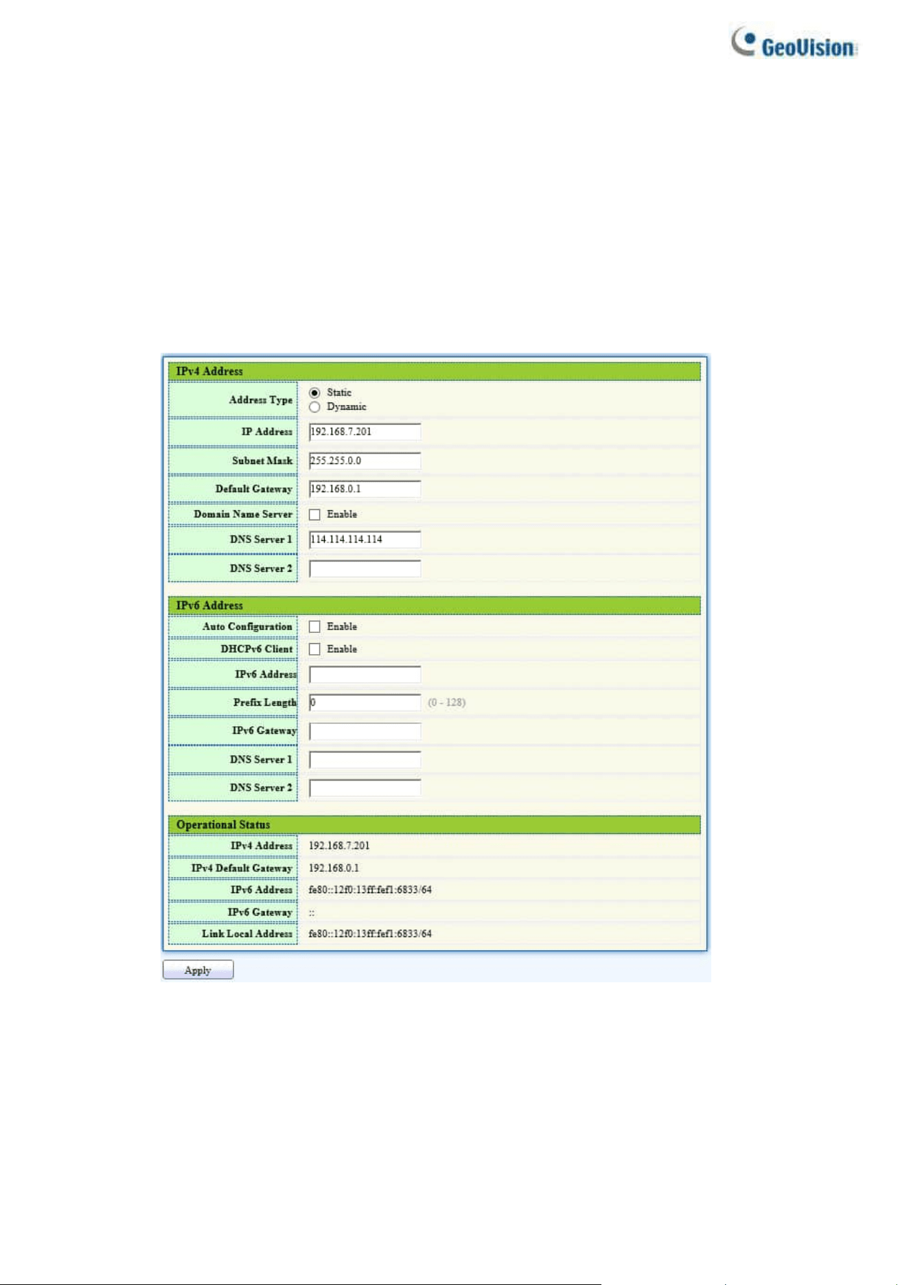
2.2.1. IP Address
This section allows you to edit the IP address, Netmask, Gateway and DNS server of the
switch.
To view the IP Address menu, navigate to Network > IP Address.
Figure 13 - Network > IP Address

Web-based Switch Configuration
15
2
Item
Description
Address Type
The address type of switch IP configuration including
•
Static: Static IP configured by users will be used.
•
Dynamic: Enable the DHCP to obtain the IP address from a DHCP
server.
IP Address
Specify the switch static IP address on the static configuration.
Subnet Mask
Specify the switch subnet mask on the static configuration.
Default Gateway
Specify the default gateway on the static configuration. The default
gateway must be in the same subnet with switch IP address
configuration.
Domain Name Server
Enable the domain name service. To specify a hostname pointing to a
dynamic IP address, see 2.14.3 Ping and 2.14.4 Traceroute.
DNS Server 1
Specify the primary user-defined IPv4 DNS server configuration.
DNS Server 2
Specify the secondary user-defined IPv4 DNS server configuration.
Ibid, IPv6 Address fields
IPv4 Address
The operational IPv4 address of the switch.
IPv4 Gateway
The operational IPv4 gateway of the switch.
IPv6 Address v6
The operational IPv6 address of the switch.
IPv6 Gateway
The operational IPv6 gateway of the switch.
Link Local Address
The IPv6 link local address for the switch.
16
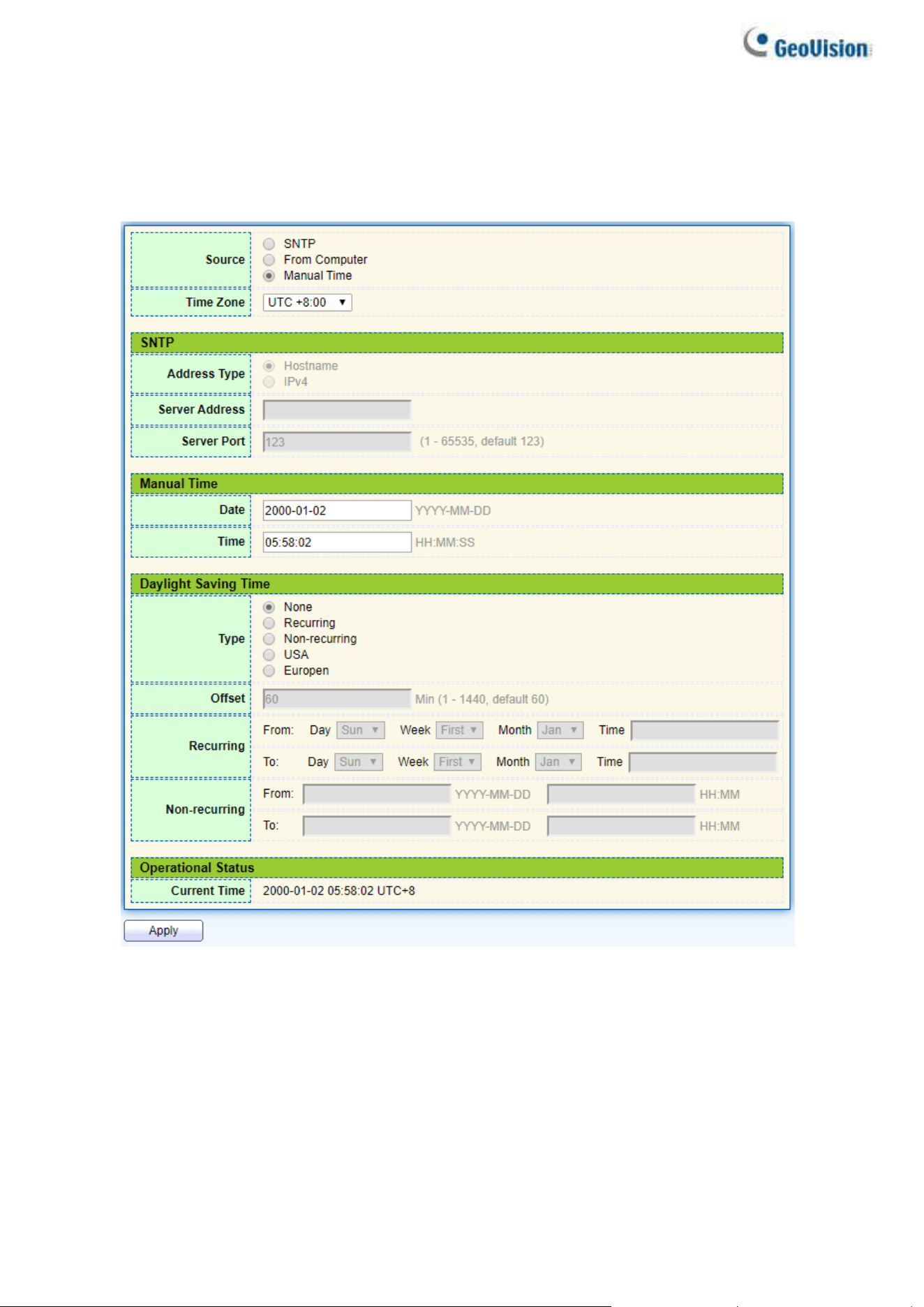
2.2.2. System Time
This page allows users to set time source, static time, time zone and daylight-saving settings. Time
zone and daylight saving takes effect both static time or time from SNTP server.
To display System Time page, click Network > System Time
Figure 14 - Network > System Time

Web-based Switch Configuration
17
2
Item
Description
Source
Select the time source.
•
SNTP: Time sync from NTP server.
•
From Computer: Time set from browser host.
•
Manual Time: Time set by manually configure.
Time Zone
Select a time zone difference from listing district.
SNTP
Address Type
Select the address type of NTP server. This is enabled when
time source is SNTP.
Server Address
Input IPv4 address or hostname for NTP server. This is
enabled when time source is SNTP.
Server Port
Input NTP port for NTP server. Default is 123. This is
enabled when time source is SNTP.
Manual Time
Date
Input manual date. This is enabled when time source is
manual.
Time
Input manual time. This is enabled when time source is
manual.
Daylight Saving Time
Type
Select the mode of daylight saving time.
•
None: Disable daylight saving time.
•
Recurring: Using recurring mode of daylight saving time.
•
Non-Recurring: Using non-recurring mode of daylight saving
time.
•
USA: Using daylight saving time in the United States that starts
on the second Sunday of March and ends on the first Sunday
of November.
•
European: Using daylight saving time in the Europe that starts
on the last Sunday in March and ending on the last Sunday in
October.
Offset
Specify the adjust offset of daylight saving time.
Recurring From
Specify the starting time of recurring daylight saving time. This
field available when selecting “Recurring” mode.
Recurring To
Specify the ending time of recurring daylight saving time. This
field available when selecting “Recurring” mode.
Non-recurring
From
Specify the starting time of non-recurring daylight saving time. This
field available when selecting “Non-Recurring” mode.
Non-recurring To
Specify the ending time of recurring daylight saving time. This
field available when selecting “Non-Recurring”
Operational Status
Current Time
Display current time
18
2.3. Port
Use the Port pages to configure settings for switch port related features.
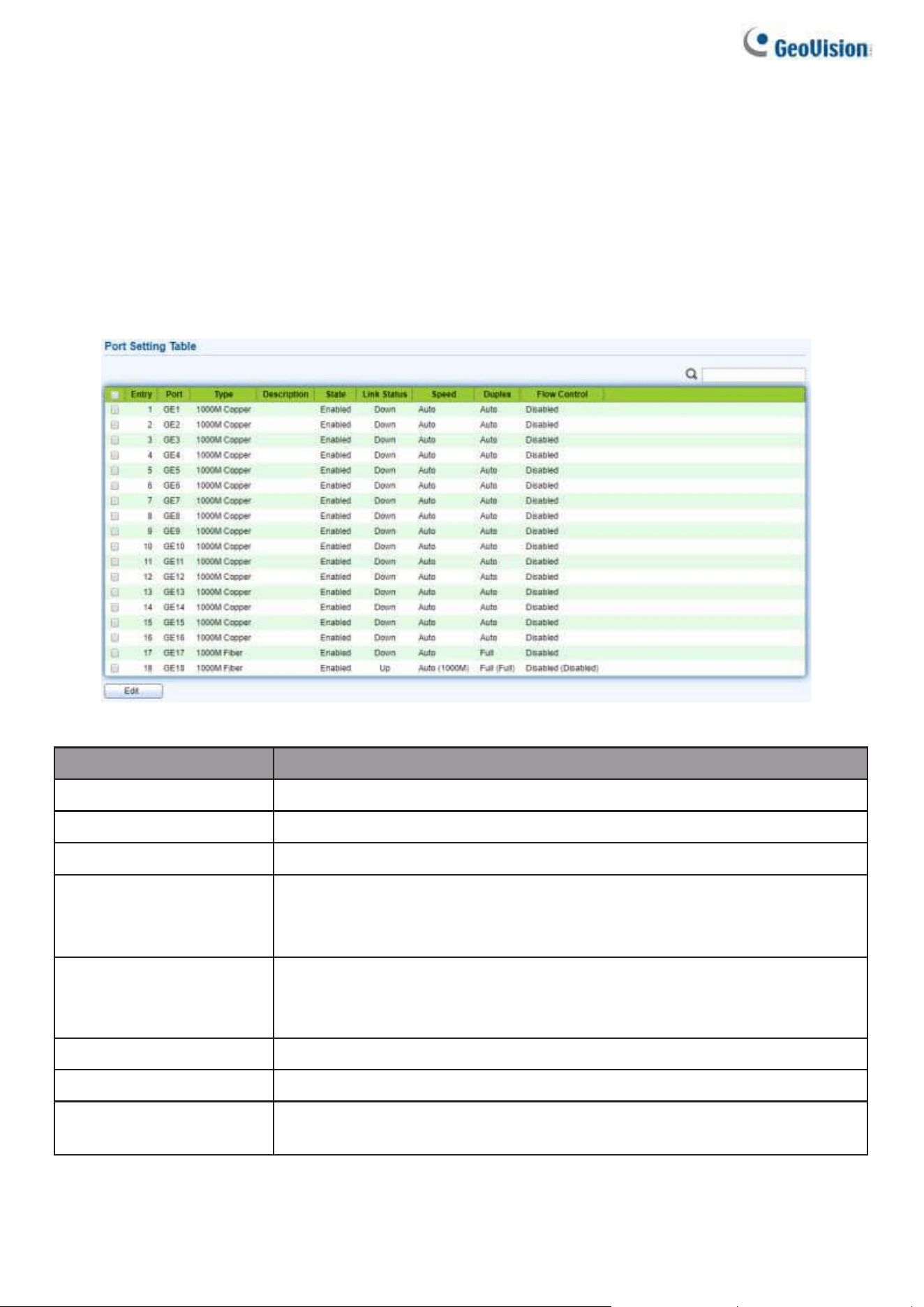
2.3.1. Port Setting
This page shows port current status and allow users to edit port configurations. Select
port entry and click “Edit” button to edit port configurations.
To display Port Setting web page, click Port > Port Setting
Figure 15 - Port > Port Setting
Item
Description
Port
Port Name.
Type
Port media type.
Description
Port Description.
State
Port admin state
•
Enabled: Enable the port.
•
Disabled: Disable the port.
Link Status
Current port link status
•
Up: Port is link up.
•
Down: Port is link down.
Speed
Current port speed configuration and link speed status.
Duplex
Current port duplex configuration and link duplex status.
Flow Control
Current port flow control configuration and link flow control
status.
Web-based Switch Configuration
19
2
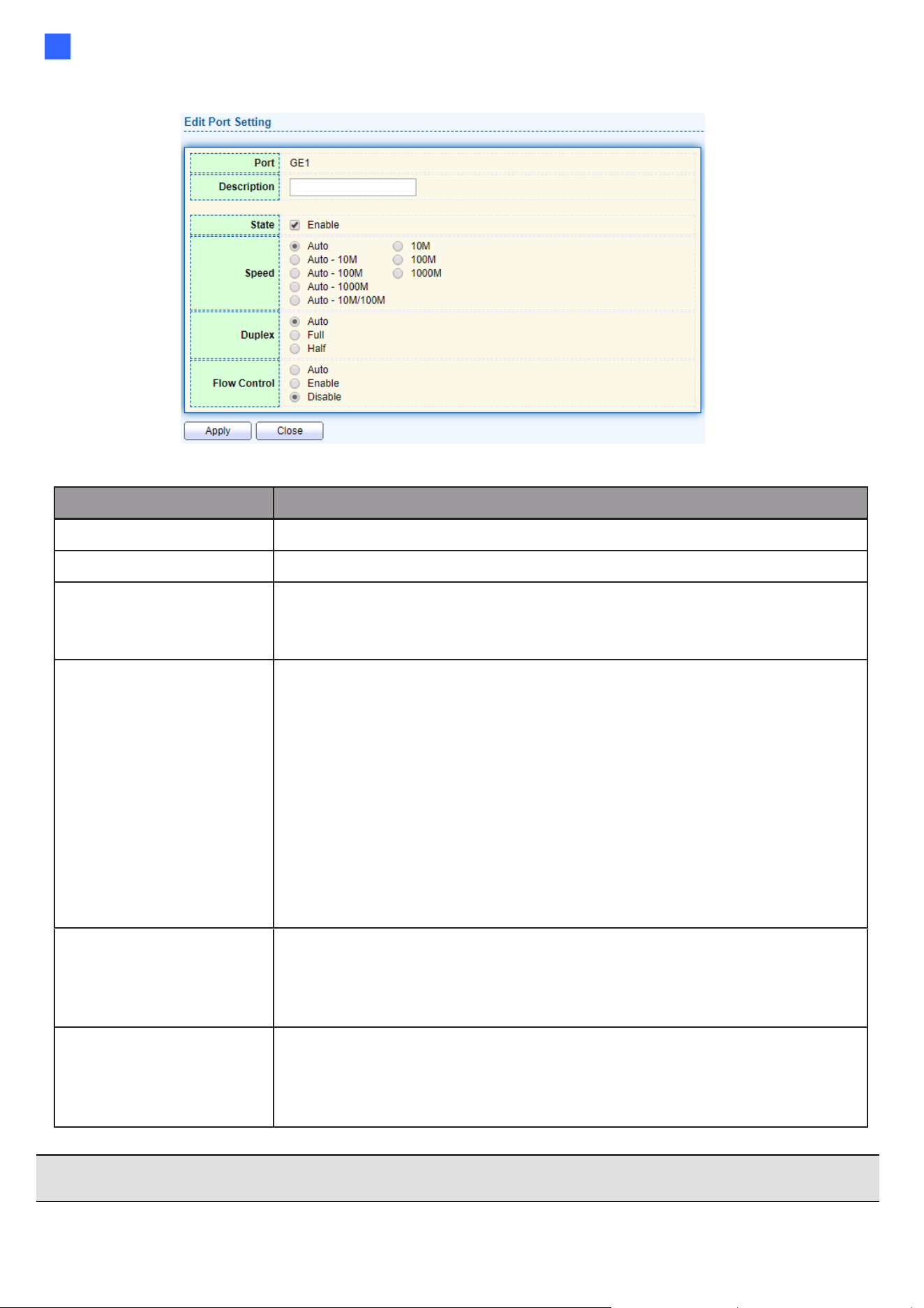
Click “Edit” button to edit Port Setting menu.
Figure 16 - Port > Port Setting > Edit Port Setting
Item
Description
Port
Selected Port list.
Description
Port media type.
State
Port admin state.
•
Enabled: Enable the port.
•
Disabled: Disable the port.
Speed
Port speed capabilities.
•
Auto: Auto speed with all capabilities.
•
Auto-10M: Auto speed with 10M ability only. Power supply is
supported up to 250 m (820 ft) over network cables.
•
Auto-100M: Auto speed with 100M ability only.
•
Auto-1000M: Auto speed with 1000M ability only.
•
Auto-10M/100M: Auto speed with 10M/100M abilities.
•
10M: Force speed with 10M ability. Power supply is supported up
to 250 m (820 ft) over network cables.
•
100M: Force speed with 100M ability.
•
1000M: Force speed with 1000M ability.
Duplex
Port duplex capabilities.
•
Auto: Auto duplex with all capabilities.
•
Half: Auto speed with 10M and 100M ability only.
•
Full: Auto speed with 10M/100M/1000M ability only.
Flow Control
Port flow control.
•
Auto: Auto flow control by negotiation.
•
Enabled: Enable flow control ability.
•
Disabled: Disable flow control ability.
Note: The maximum cable length for Gigabit RJ-45 (Cat.5e, 6) can achieve 250 m (820 ft) by
selecting Auto-10M or 10M for Speed.
20
2.3.2. Error Disable
To display Error Disabled web page, click Port > Error Disabled
Figure 17 - Port > Error disable
Item
Description
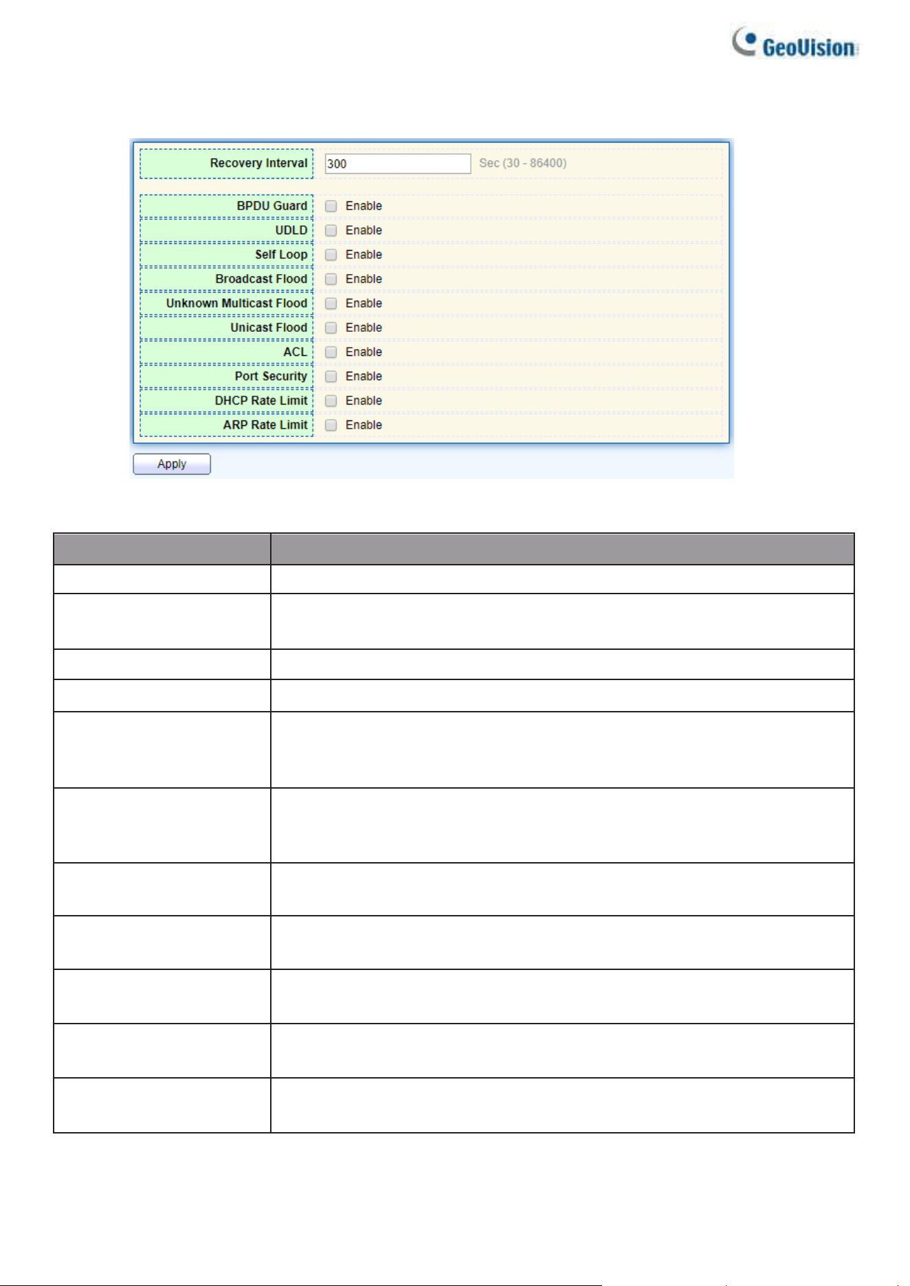
Recover Interval
Auto recovery after this interval for error disabled port.
BPDU Guard
Enabled to auto shutdown port when BPDU Guard reason occur. This
reason caused by STP BPDU Guard mechanism.
UDLD
Enabled to auto shutdown port when UDLD violation occur.
Self Loop
Enabled to auto shutdown port when Self Loop reason occur.
Broadcast Flood
Enabled to auto shutdown port when Broadcast Flood reason occur.
This reason caused by broadcast rate exceed broadcast storm control
rate.
Unknown Multicast Flood
Enabled to auto shutdown port when Unknown Multicast Flood reason
occur. This reason caused by unknown multicast rate exceed unknown
multicast storm control rate.
Unicast Flood
Enabled to auto shutdown port when Unicast Flood reason occur. This
reason caused by unicast rate exceed unicast storm control rate.
ACL
Enabled to auto shutdown port when ACL shutdown port reason occur.
This reason caused packet match the ACL shutdown port action.
Port Security
Enabled to auto shutdown port when Port Security Violation reason
occur. This reason caused by violation port security rules.
DHCP rate limit
Enabled to auto shutdown port when DHCP rate limit reason occur.
This reason caused by DHCP packet rate exceed DHCP rate limit.
ARP rate limit
Enabled to auto shutdown port when ARP rate limit reason occur. This
reason caused by DHCP packet rate exceed ARP rate limit.
Web-based Switch Configuration
21
2
2.3.3. Link Aggregation
2.3.3.1. Group
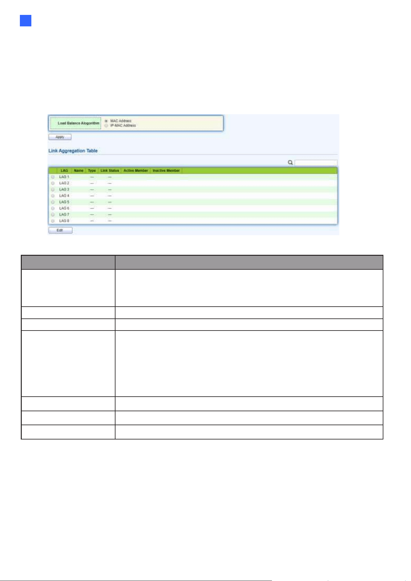
This page allows users to configure link aggregation group load balance algorithm and group
member.
To view the Group menu, navigate to Port > Link Aggregation > Group.
Figure 18 - Port > Link Aggregation > Group
Item
Description
Load Balance
Algorithm
LAG load balance distribution algorithm
•
src-dst-mac: Based on MAC address.
•
src-dst-mac-ip: Based on MAC address and IP address.
LAG
LAG Name.
Name
LAG port description.
Type
The type of the LAG
•
Static: The group of ports assigned to a static LAG are always
active members.
•
LACP: The group of ports assigned to dynamic LAG are
candidate ports. LACP determines which candidate ports are
active member ports.
Link Status
LAG port link status
Active Member
Active member ports of the LAG.
Inactive Member
Inactive member ports of the LAG.
22
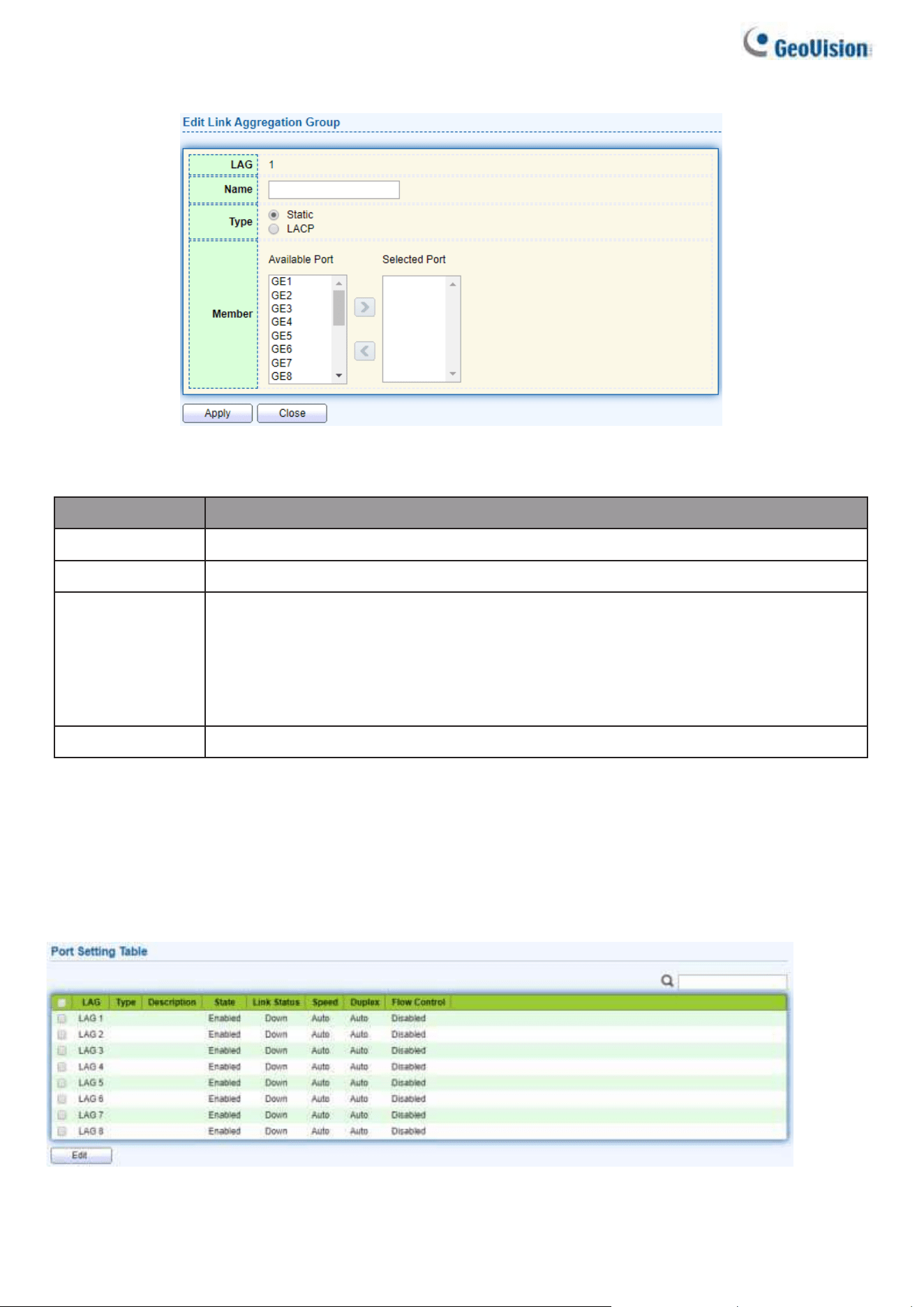
Click “Edit” to edit Link Aggregation Group menu.
Figure 19 - Port > Link Aggregation > Group > Edit Link Aggregation Group
Item
Description
LAG
Selected LAG group ID.
Name
LAG port description.
Type
The type of the LAG
•
Static: The group of ports assigned to a static LAG are always active
members.
•
LACP: The group of ports assigned to dynamic LAG are candidate ports.
LACP determines which candidate ports are active member ports.
Member
Select available port to be LAG group member port.
2.3.3.2. Port Setting
This page shows LAG port current status and allow users to edit LAG port
configurations. Select LAG entry and click “Edit” button to edit LAG port
configurations.
To display LAG Port Setting webpage, click Port > Link Aggregation > Port Setting.
Figure 20 - Port > Link Aggregation > Port Setting
Web-based Switch Configuration
23
2
Item
Description
LAG
LAG Port Name.
Type
LAG Port media type.
Description
LAG Port description.
State
LAG Port admin state
•
Enabled: Enable the port.
•
Disabled: Disable the port.
Link Status
Current LAG port link status
•
Up: Port is link up.
•
Down: Port is link down.
Speed
Current LAG port speed configuration and link speed
status.
Duplex
Current LAG port duplex configuration and link duplex status.
Flow Control
Current LAG port flow control configuration and link flow control
status.
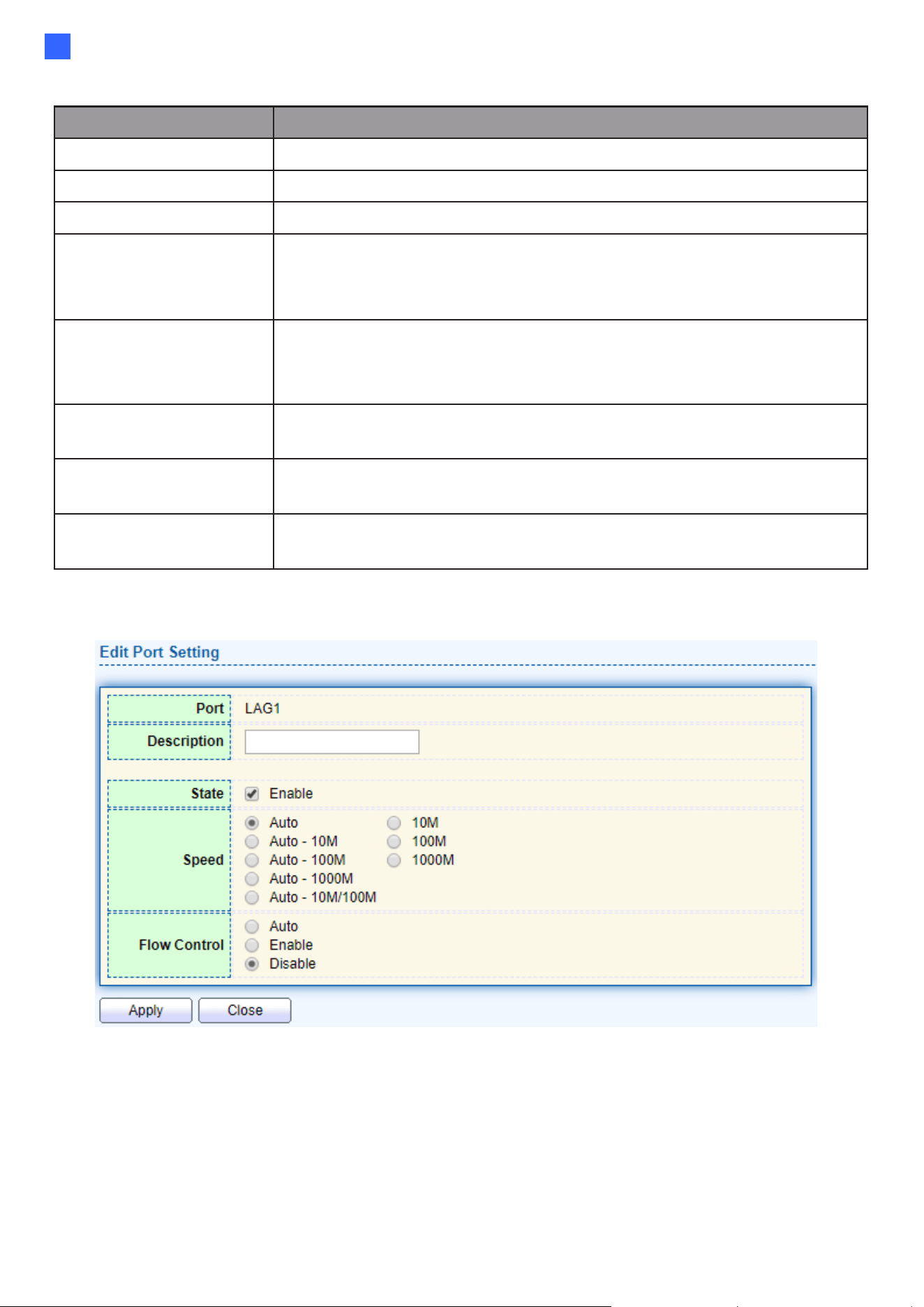
Click “Edit” to view Edit Port Setting menu.
Figure 21 - Port > Link Aggregation > Port Setting > Edit Port Setting
24
Item
Description
Port
Selected Port list.
Description
Port description.
State
Port admin state
•
Enabled: Enable the port.
•
Disabled: Disable the port.
Speed
Port speed capabilities
•
Auto: Auto speed with all capabilities.
•
Auto-10M: Auto speed with 10M ability only.
•
Auto-100M: Auto speed with 100M ability only.
•
Auto-1000M: Auto speed with 1000M ability only.
•
Auto-10M/100M: Auto speed with 10M/100M abilities.
•
10M: Force speed with 10M ability.
•
100M: Force speed with 100M ability.
•
1000M: Force speed with 1000M ability.
Flow Control
Port flow control
•
Auto: Auto flow control by negotiation.
•
Enabled: Enable flow control ability.
•
Disabled: Disable flow control ability.
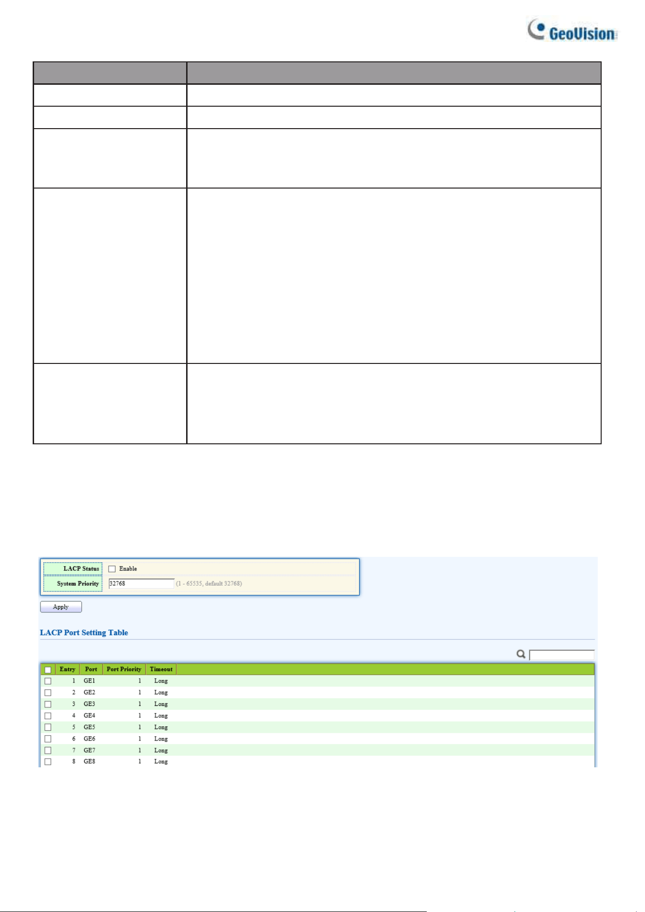
2.3.3.3. LACP
This page allows users to configure LACP global and port configurations. Enable the LACP
Status, select ports, and click “Edit” button to edit port configuration.
To display the LACP Setting webpage, click Port > Link Aggregation > LACP.
Figure 22 - Port > Link Aggregation > LACP
Web-based Switch Configuration
25
2
Item
Description
System Priority
Configure the system priority of LACP. This decides the
system priority field in LACP PDU.
Port
Port Name.
Port Priority
LACP priority value of the port.
Timeout
The periodic transmissions type of LACP PDUs.
•
Long: Transmit LACP PDU with slow periodic (30s).
•
Short: Transmit LACP PDU with fast periodic (1s).
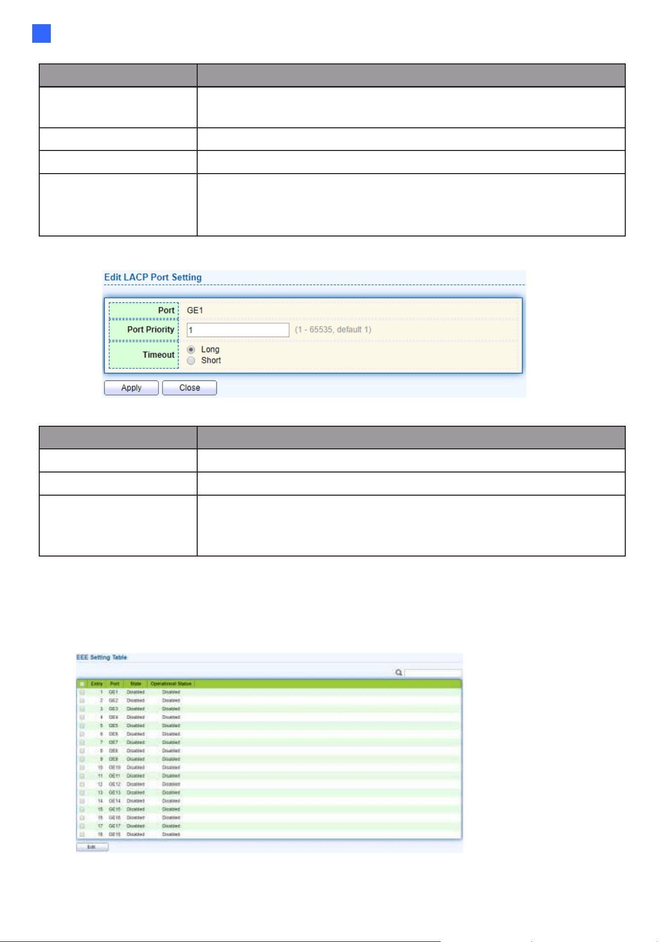
Click "Edit" button to view Edit LACP Port Setting menu.
Figure 23 - Port > Link Aggregation > LACP > Edit LACP Port Setting
Item
Description
Port
Selected port list.
Port Priority
Enter the LACP priority value of the port
Timeout
The periodic transmissions type of LACP PDUs.
•
Long: Transmit LACP PDU with slow periodic (30s).
•
Short: Transmit LACP PDU with fast periodic (1s).
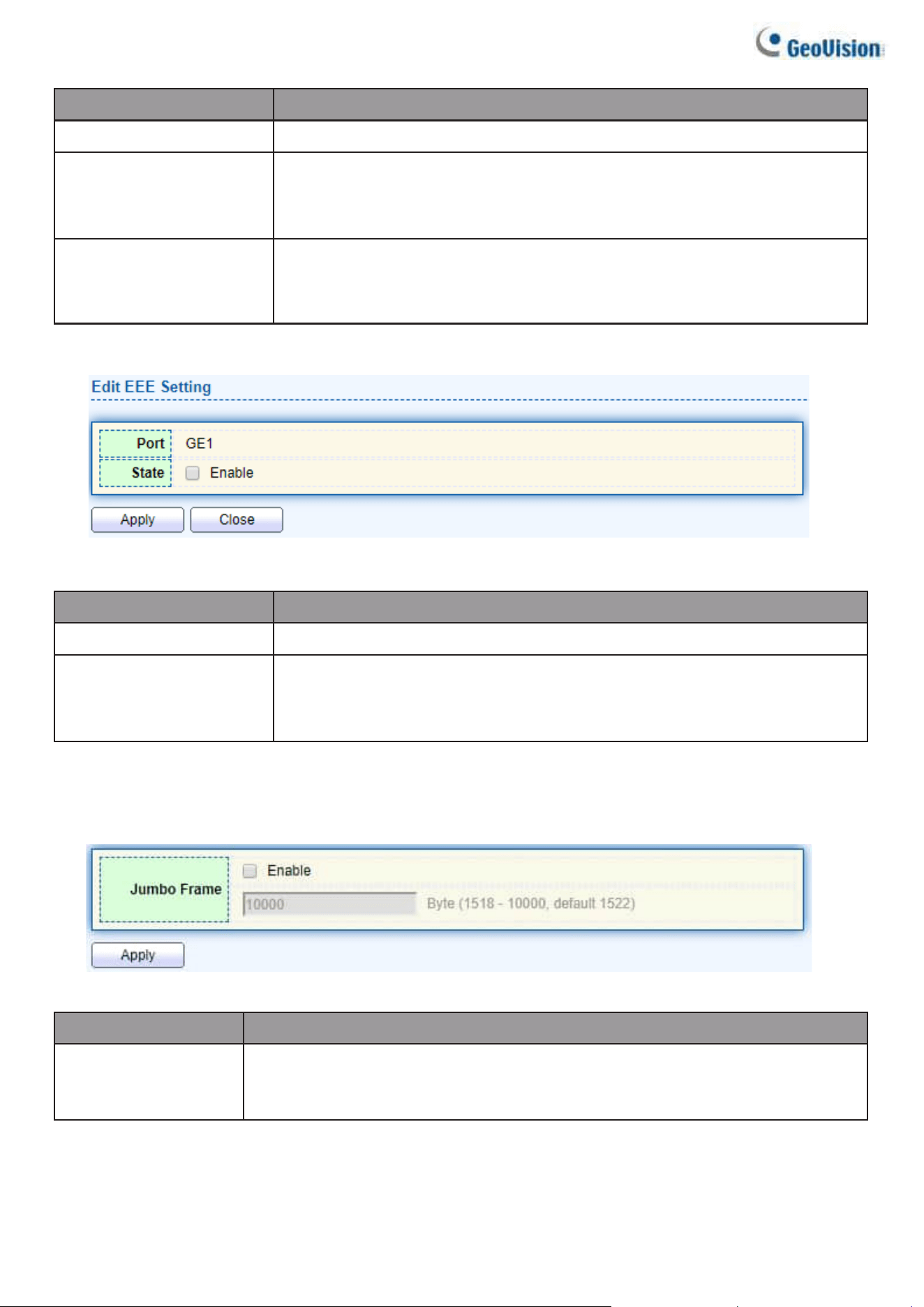
2.3.4. EEE
This page allows users to configure Energy Efficient Ethernet settings. To
display the EEE web page, click Port > EEE.
Figure 24 - Port > EEE
26
Item
Description
Port
Port Name.
State
Port EEE admin state
•
Enabled: EEE is enabled.
•
Disabled: EEE is disabled.
Operational Status
Port EEE operational status
•
Enabled: EEE is operating.
•
Disabled: EEE is no operating.
Click “Edit” to edit the EEE menu.
Figure 25 - Port > EEE > Edit EEE Setting
Item
Description
Port
Port Name
State
Port EEE admin state
•
Enabled: EEE is enabled.
•
Disabled: EEE is disabled.
2.3.5. Jumbo Frame
This page allows users to configure switch jumbo frame size.
To display Jumbo Frame web page, click Port > Jumbo Frame
Figure 26 - Port > Jumbo Frame
Item
Description
Jumbo Frame
Enable or disable jumbo frame. When jumbo frame is enabled, switch
max frame size is allowed to configure. When
jumbo frame is disabled, default frame size 1522 will be used.
Web-based Switch Configuration
27
2
2.4. VLAN
A virtual local area network, virtual LAN or VLAN, is a group of hosts with a common set of
requirements that communicate as if they were attached to the same broadcast domain, regardless
of their physical location. A VLAN has the same attributes as a physical local area network (LAN),
but it allows for end stations to be grouped together even if they are not located on the same
network switch. VLAN membership can be configured through software instead of physically
relocating devices or connections.
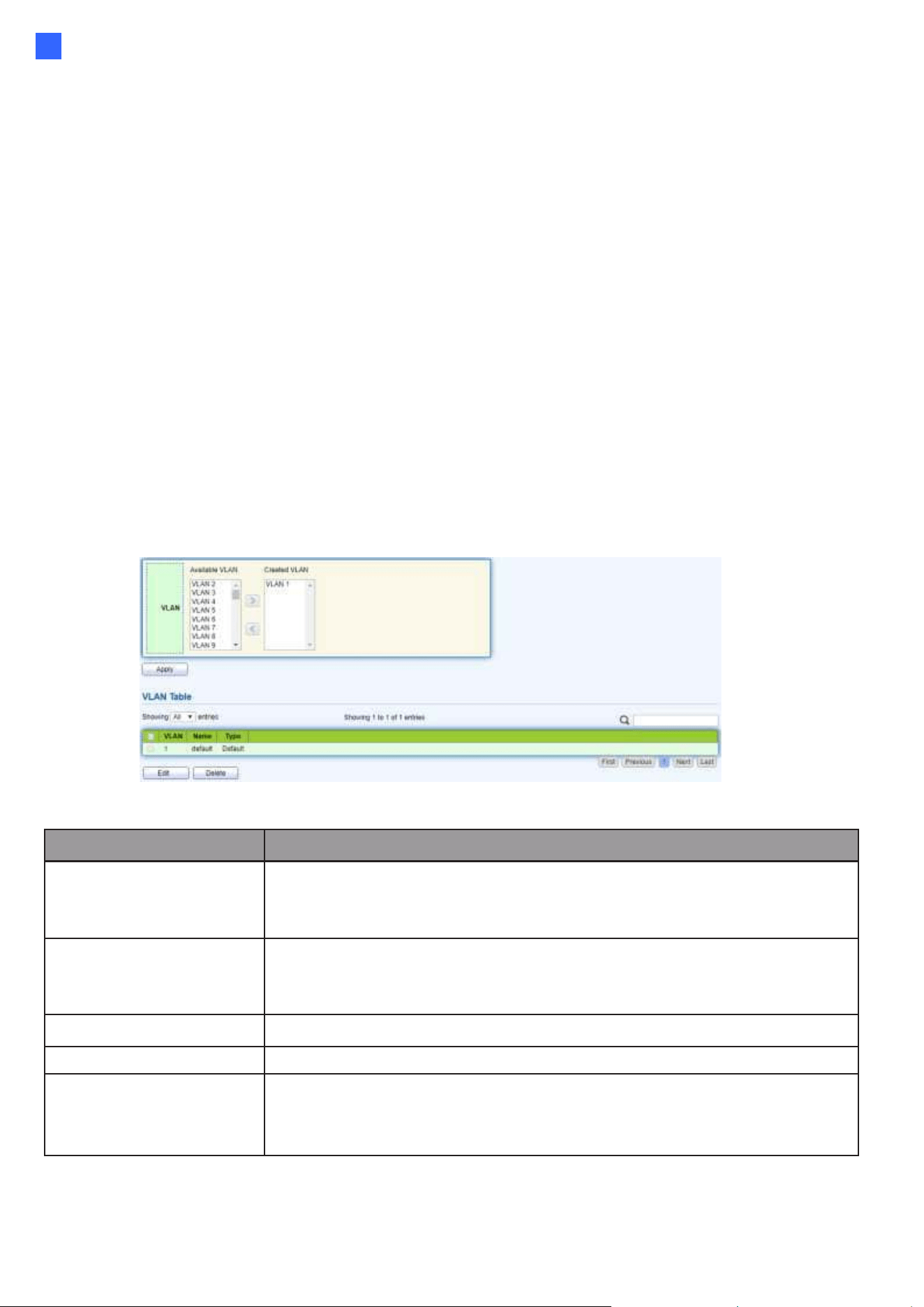
2.4.1. VLAN
Use the VLAN pages to configure settings of VLAN.
2.4.1.1. Create VLAN
This page allows users to add or delete VLAN ID entries and browser all VLAN entries
that add statically or dynamic learned by GVRP. Each VLAN entry has a unique name;
users can edit VLAN name in edit page.
To display Create VLAN page, click VLAN > VLAN > Create VLAN
Figure 27 - VLAN > VLAN > Create VLAN
Item
Description
Available VLAN
VLAN has not created yet.
Select available VLANs from left box then move to right box to
add.
Created VLAN
VLAN had been created.
Select created VLANs from right box then move to left box to
delete.
VLAN
The VLAN ID.
Name
The VLAN Name.
Type
The VLAN Type.
Static: Port base VLAN.
Dynamic: 802.1q VLAN.
28
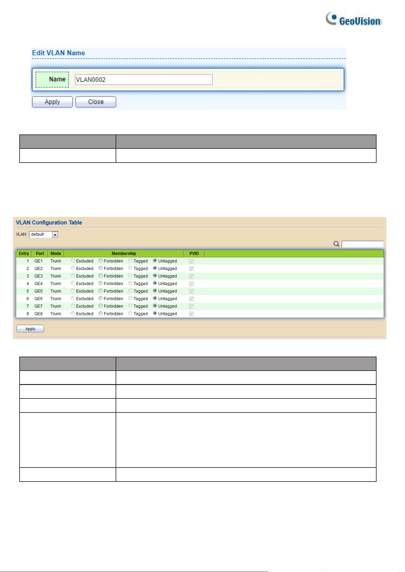
Click “Edit” button to view Edit VLAN Name menu.
Figure 28 - VLAN > VLAN > Create VLAN > Edit VLAN Name
Item
Description
Name
Input VLAN name.
2.4.1.2. VLAN Configuration
This page allows users to configure the membership for each port of selected VLAN. To
display VLAN Configuration page, click VLAN > VLAN > VLAN Configuration.
Figure 29 - VLAN > VLAN > VLAN Configuration
Item
Description
VLAN
Select specified VLAN ID to configure VLAN configuration.
Port
Display the interface of port entry.
Mode
Display the interface VLAN mode of port.
Membership
Select the membership for this port of the specified VLAN ID.
•
Forbidden: Specify the port is forbidden in the VLAN.
•
Excluded: Specify the port is excluded in the VLAN.
•
Tagged: Specify the port is tagged member in the VLAN.
•
Untagged: Specify the port is untagged member in the VLAN.
PVID
Display if it is PVID of interface.
Web-based Switch Configuration
29
2
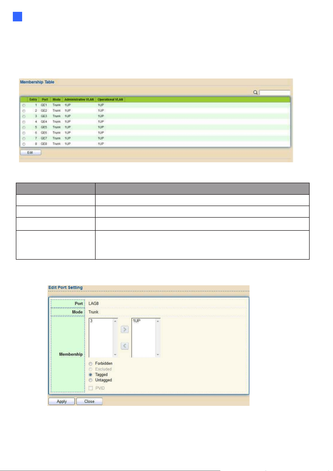
2.4.1.3. Membership
This page allows users to view membership information for each port and edit membership for
specified interface.
To display Membership page, click VLAN > VLAN > Membership
Figure 30 - VLAN > VLAN > Membership
Item
Description
Port
Display the interface of port entry.
Mode
Display the interface VLAN mode of port.
Administrative VLAN
Display the administrative VLAN list of this port.
Operational VLAN
Display the operational VLAN list of this port. Operational VLAN
means the VLAN status that really runs in device. It may different
to administrative VLAN.
Click "Edit" button to view the Edit Port Setting menu
Figure 31 - VLAN > VLAN > Membership > Edit Port Setting
30
Item
Description
Port
Display the interface.
Mode
Display the VLAN mode of interface.
Membership
Select VLANs of left box and select one of following membership
then move to right box to add membership. Select VLANs of right box
then move to left box to remove membership. Tagging membership
may not choose in differ VLAN port mode. Select the time source.
•
Forbidden: Set VLAN as forbidden VLAN.
•
Excluded: This option is always disabled.
•
Tagged: Set VLAN as tagged VLAN.
•
Untagged: Set VLAN as untagged VLAN.
•
PVID: Check this checkbox to select the VLAN ID to be the
port-based VLAN ID for this port. PVID may auto select or can’t
select in differ settings.
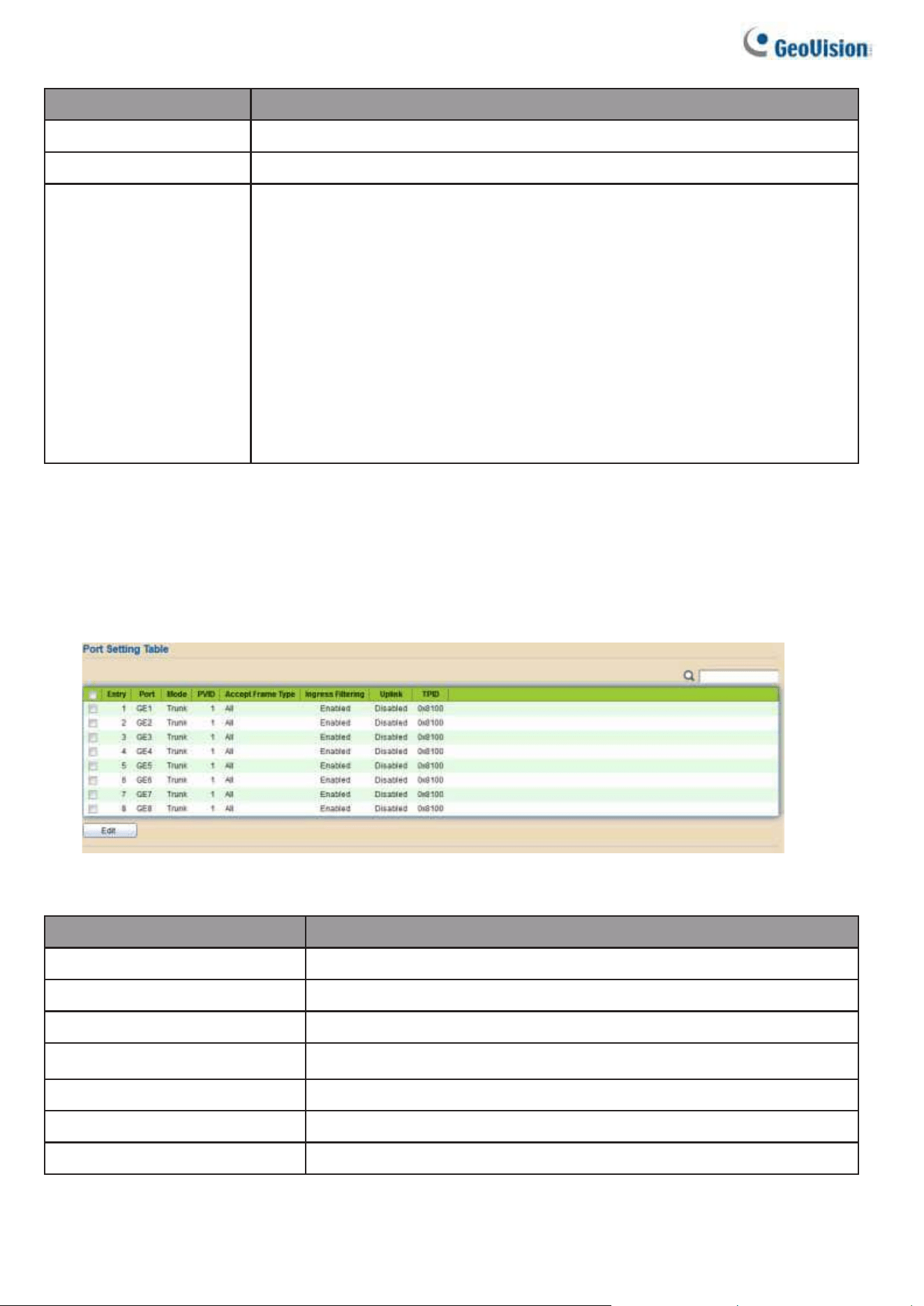
2.4.1.4. Port Setting
This page allows users to configure ports VLAN settings such as VLAN port mode, PVID
etc. The attributes depend on different VLAN port mode.
To display Port Setting page, click VLAN > VLAN > Port Setting
Figure 32 - VLAN > VLAN > Port Setting
Item
Description
Port
Display the interface.
Mode
Display the VLAN mode of interface.
PVID
Display the Port-based VLAN ID of port.
Accept Frame Type
Display accept frame type of port.
Ingress Filtering
Display ingress filter status of port.
Uplink
Display uplink status.
TPID
Display TPID used of interface.

Web-based Switch Configuration
31
2
Click “Edit” button to Edit Port Setting menu.
Figure 33 - VLAN > VLAN > Port Setting > Edit Port Setting
Item
Description
Port
Display selected port to be edited.
Mode
Select the VLAN mode of the interface.
•
Hybrid: Support all functions as defined in IEEE 802.1Q
specification.
•
Access: Accepts only untagged frames and join an
untagged VLAN.
•
Trunk: An untagged member of one VLAN at most, and is a
tagged member of zero or more VLANs.
PVID
Specify the port-based VLAN ID (1-4094). It’s only available
with Hybrid and Trunk mode.
Accepted Type
Specify the acceptable-frame-type of the specified
interfaces. It’s only available with Hybrid mode.
Ingress Filtering
Set checkbox to enable/disable ingress filtering. It’s only available
with Hybrid mode.
Uplink
Set checkbox to enable/disable uplink mode. It’s only available
with trunk mode.
TPID
Select TPID used of interface. It’s only available with trunk
mode.
32
2.4.2. Voice VLAN
Use the Voice VLAN pages to configure settings of Voice VLAN.
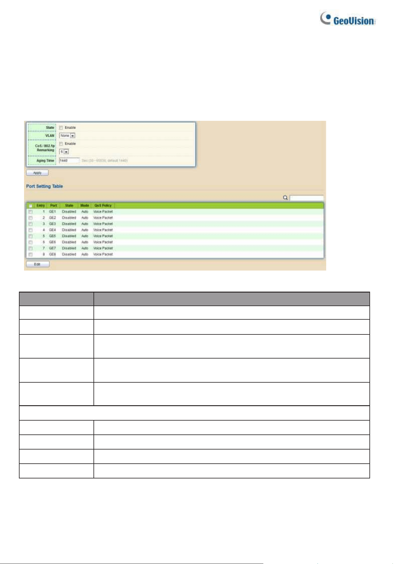
2.4.2.1. Property
This page allows users to configure global and per interface settings of voice VLAN.
To display Property Web page, click VLAN> Voice VLAN> Property
Figure 34 - VLAN > Voice VLAN > Property
Item
Description
State
Set checkbox to enable or disable voice VLAN function.
VLAN
Select Voice VLAN ID. Voice VLAN ID cannot be default VLAN.
Cos/802.1p
Select a value of VPT. Qualified packets will use this VPT value as
inner priority.
Remarking
Set checkbox to enable or disable 1p remarking. If enabled,
qualified packets will be remark by this value.
Aging Time
Input value of aging time. Default is 1440 minutes. A voice VLAN entry
will be age out after this time if without any packet pass through.
Port Setting Table
Port
Display port entry.
State
Display enable/disabled status of interface.
Mode
Display voice VLAN mode.
QoS Policy
Display voice VLAN remark will affect which kind of packet.
Web-based Switch Configuration
33
2
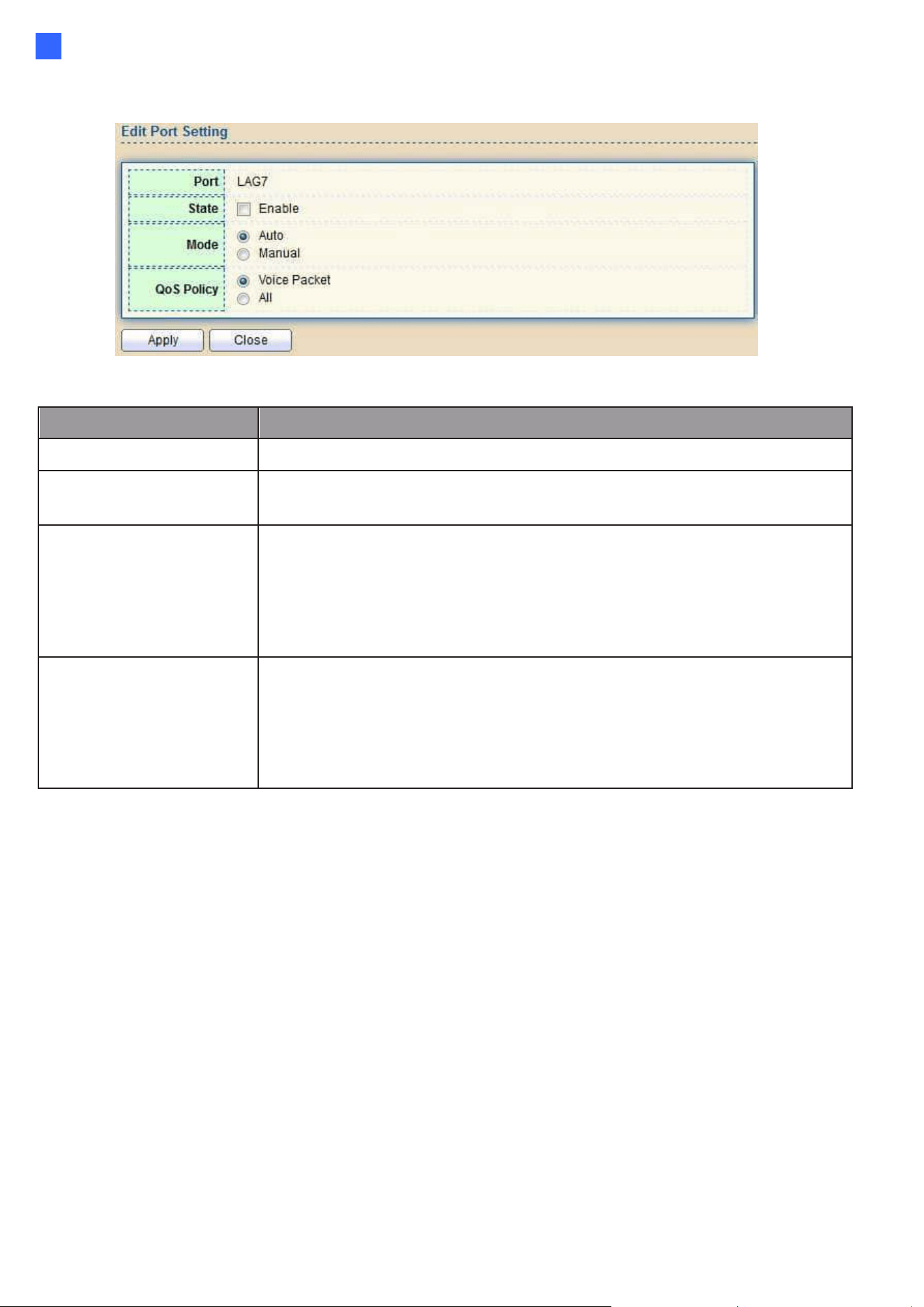
Click “Edit” button to view Edit Port Setting menu.
Figure 35 - VLAN > Voice VLAN > Property > Edit Port Setting
Item
Description
Port
Display selected port to be edited.
State
Set checkbox to enable/disabled voice VLAN function of
interface.
Mode
Select port voice VLAN mode
•
Auto: Voice VLAN auto detect packets that match OUI table
and add received port into voice VLAN ID tagged member.
•
Manual: Users need add interface to VLAN ID tagged
member manually.
QoS Policy
Select port QoS Policy mode
•
Voice Packet: QoS attributes are applied to packets with OUIs
in the source MAC address.
•
All: QoS attributes are applied to packets that are
classified to the Voice VLAN.
34
2.4.2.2. Voice OUI
This page allows users to add, edit or delete OUI MAC addresses. Default has 8 pre- defined OUI
MAC.
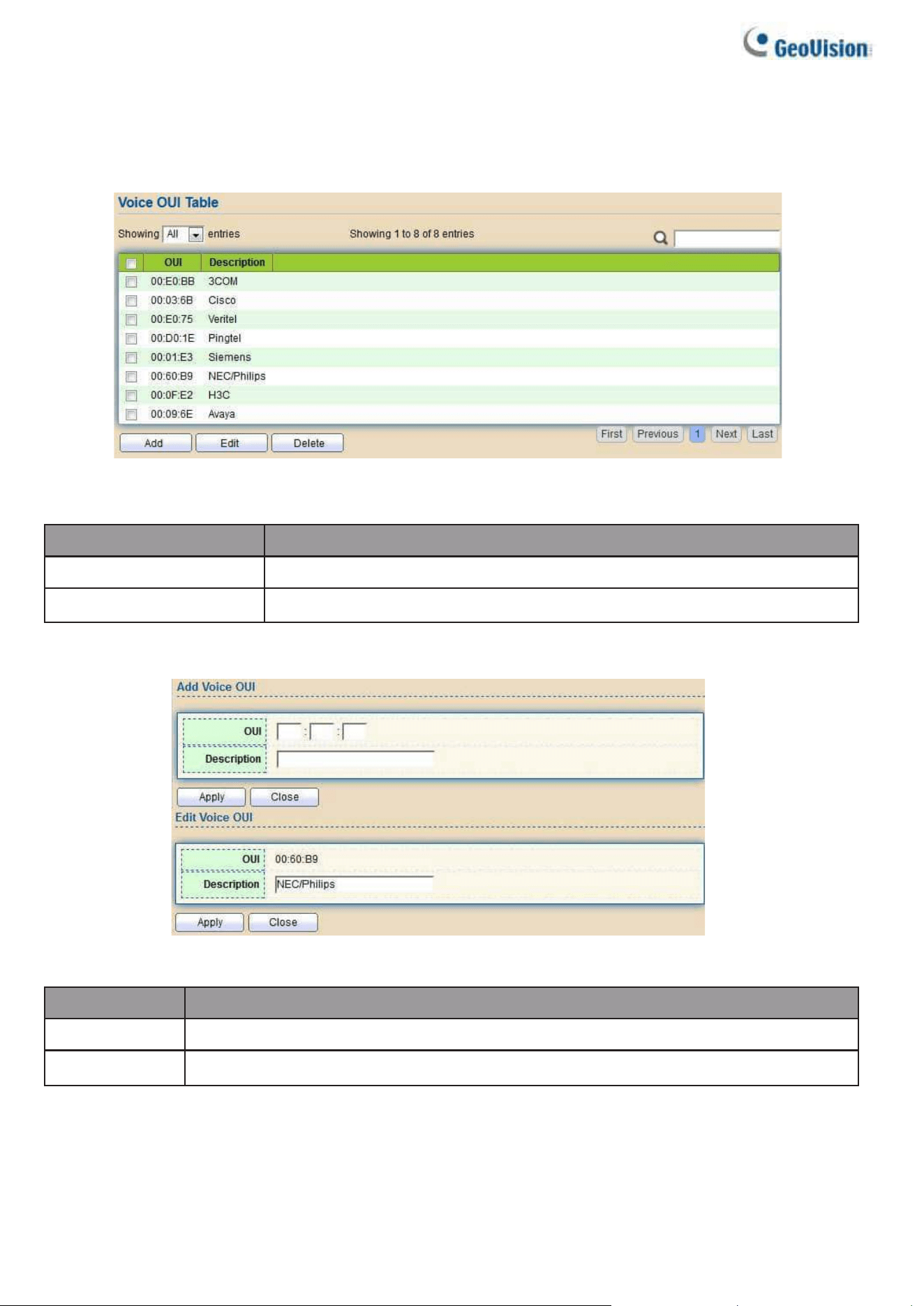
To display the Voice OUI Web page, click VLAN > Voice VLAN > Voice OUI.
Figure 36 - VLAN > Voice VLAN > Voice OUI
Item
Description
OUI
Display OUI MAC address.
Description
Display description of OUI entry.
Click “Add” or “Edit” button to Add/Edit Voice OUI menu.
Figure 37 - VLAN > Voice VLAN > Voice OUI > Add/Edit Voice OUI
Item
Description
OUI
Input OUI MAC address. Can’t be edited in edit dialog.
Description
Input description of the specified MAC address to the voice VLAN OUI table.
Web-based Switch Configuration
35
2
2.4.3. Protocol VLAN
Use the Protocol VLAN pages to configure settings of Protocol VLAN.
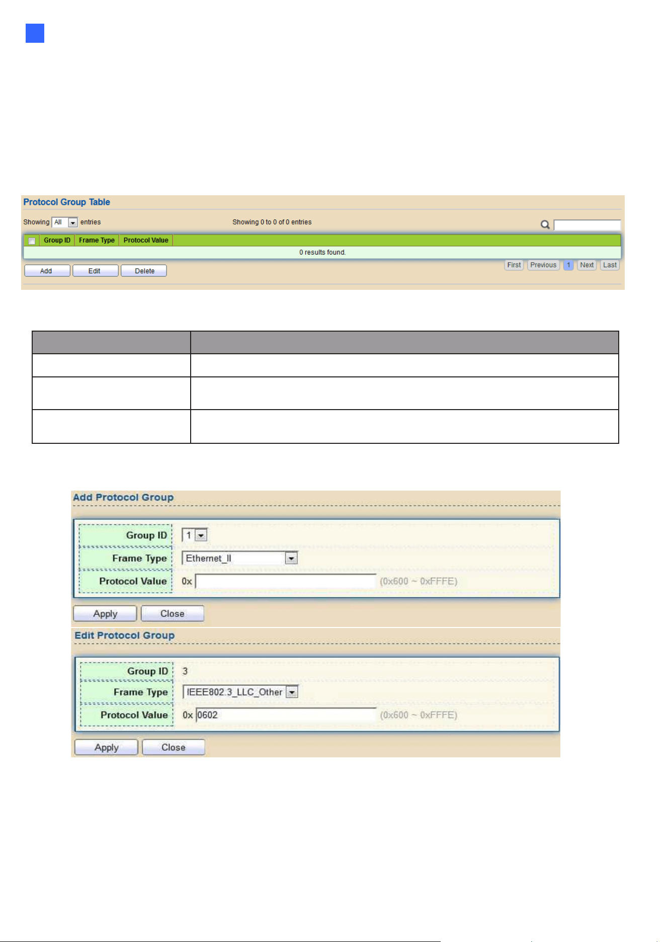
2.4.3.1. Protocol Group
To display Protocol Group page, click VLAN > Protocol VLAN > Protocol Group. This page
allows users to add or edit groups settings of protocol VLAN.
Figure 38 - VLAN > Protocol VLAN > Protocol Group
Item
Description
Group ID
Display group ID of entry.
Frame Type
Display frame type of entry.
Protocol Value
Display protocol value of entry.
Click “Add” or “Edit” button to Add/Edit Protocol Group menu.
Figure 39 - VLAN > Protocol VLAN > Add/Edit Protocol Group
36
Item
Description
Group ID
Select group ID of list. The range from 1 to 8.
Frame Type
Select frame type of list that maps packets to protocol- defined
VLANs by examining the type octet within the packet header to
discover the type of protocol associated with it.
⚫
Ethernet_II: packet type is Ethernet version 2.
⚫
IEEE802.3_LLC_Other: packet type is 802.3 packet with LLC
other header.
⚫
RFC_1042: packet type is rfc 1042 packet
Protocol Value
Input protocol value of the target protocol. Packets match this
protocol value classified to specified VLAN ID.
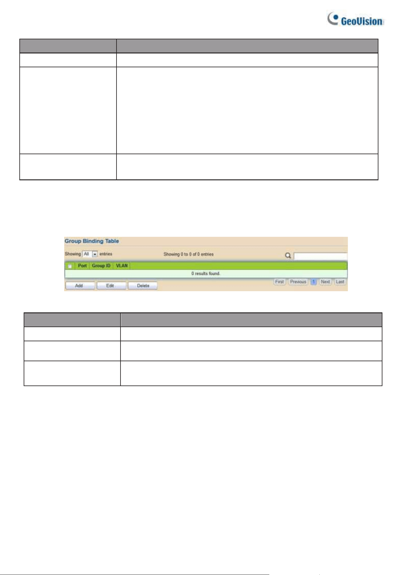
2.4.3.2. Group Binding
This page allows users to bind protocol VLAN group to each port with VLAN ID.
To display Group Binding page, click VLAN> Protocol VLAN > Group Binding
Figure 40 - VLAN > Protocol VLAN > Group Binding
Item
Description
Port
Display port ID that binding with protocol group entry
Group ID
Display group ID that port binding with
VLAN
Display VLAN ID that assign to packets which match
protocol group
Web-based Switch Configuration
37
2
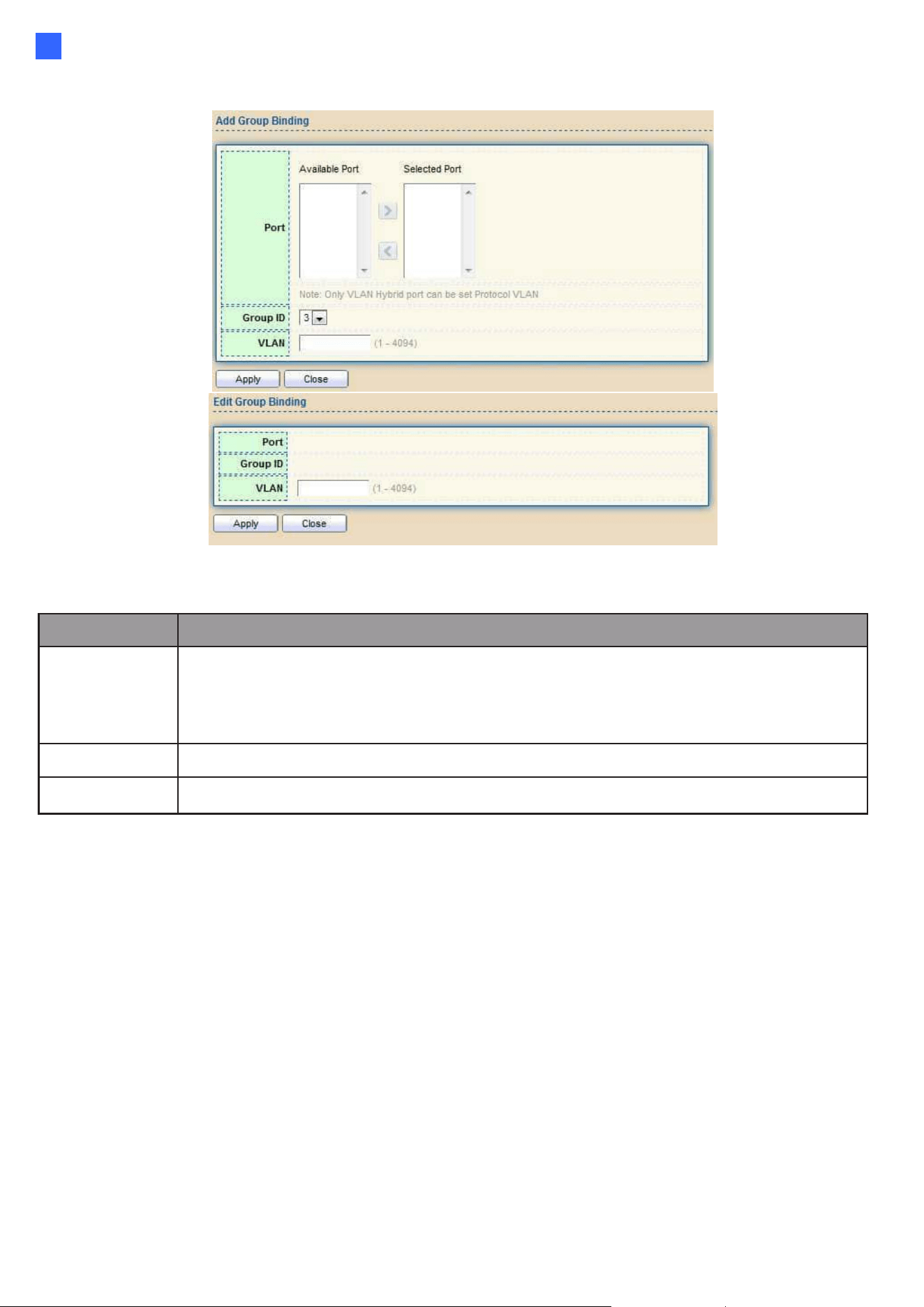
Click “Add” or “Edit” button to Add/Edit Group Binding menu.
Figure 41 - VLAN > Protocol VLAN > Add/Edit Group Binding
Item
Description
Port
Select ports in left box then move to right to binding with protocol group. Or
select ports in right box then move to left to unbind with protocol group. Only
interface has hybrid VLAN mode can be selected and bound with protocol
group. Only available on Add dialog.
Group ID
Select a Group ID to associate with port. Only available on Add dialog.
VLAN
Input VLAN ID that will assign to packets which match protocol group
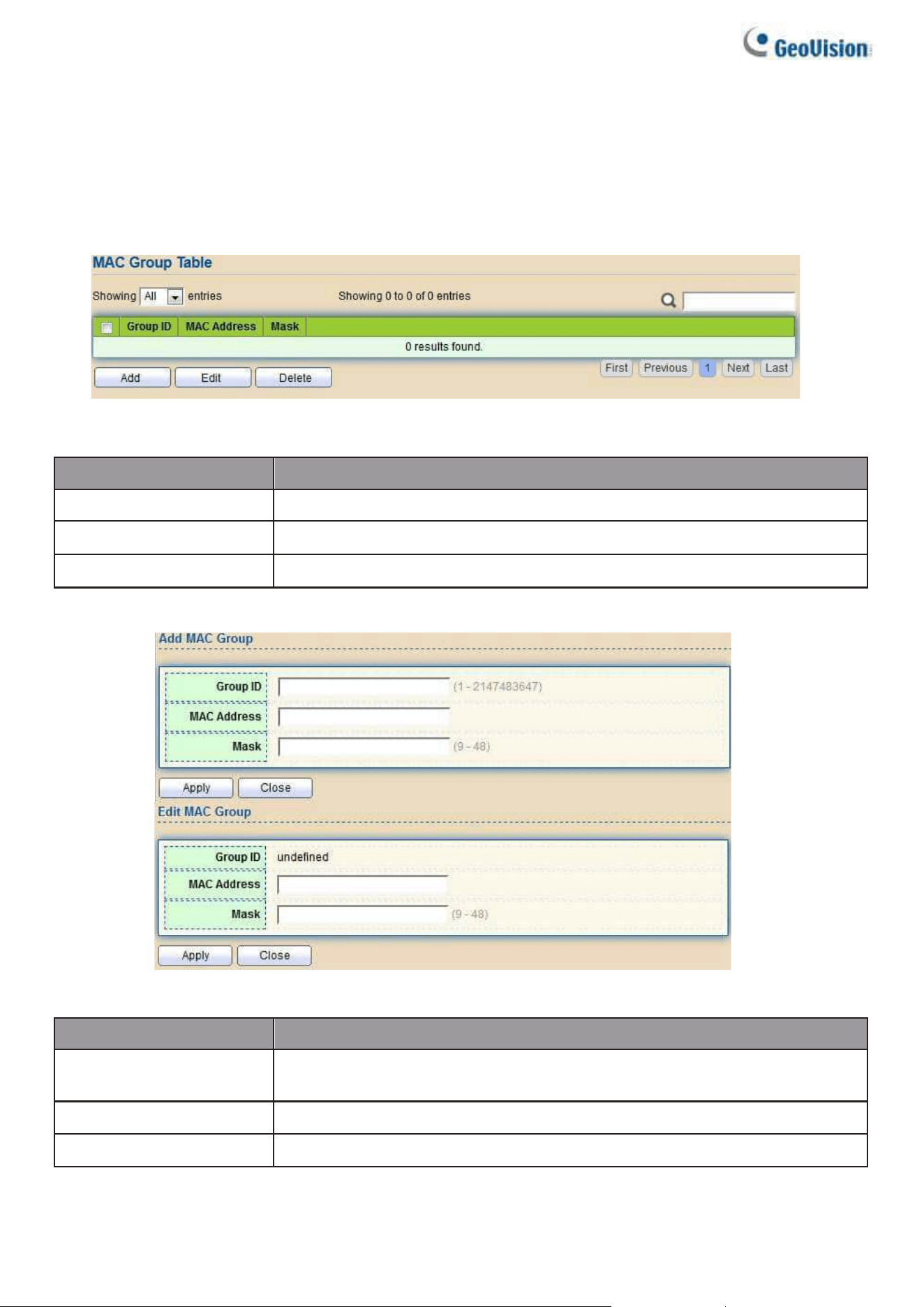
38
2.4.4. MAC VLAN
Use the MAC VLAN pages to configure settings of MAC VLAN.
2.4.4.1. MAC Group
This page allows users to add or edit groups settings of MAC VLAN.
To display the MAC page, click VLAN > MAC VLAN > MAC Group.
Figure 42 - VLAN > MAC VLAN > MAC Group
Item
Description
Group ID
Display group ID of entry.
MAC Address
Display mac address of entry.
Mask
Display mask of mac address for classified packet.
Click “Add” button or "Edit" button to view Add/Edit MAC menu.
Figure 43 - VLAN > MAC VLAN > MAC Group > Add/Edit MAC
Item
Description
Group ID
Input group ID that is a unique ID of mac group entry. The range
from 1 to 2147483647. Only available on Add Dialog.
MAC Address
Input mac address for classifying packets.
Mask
Input mask of mac address.
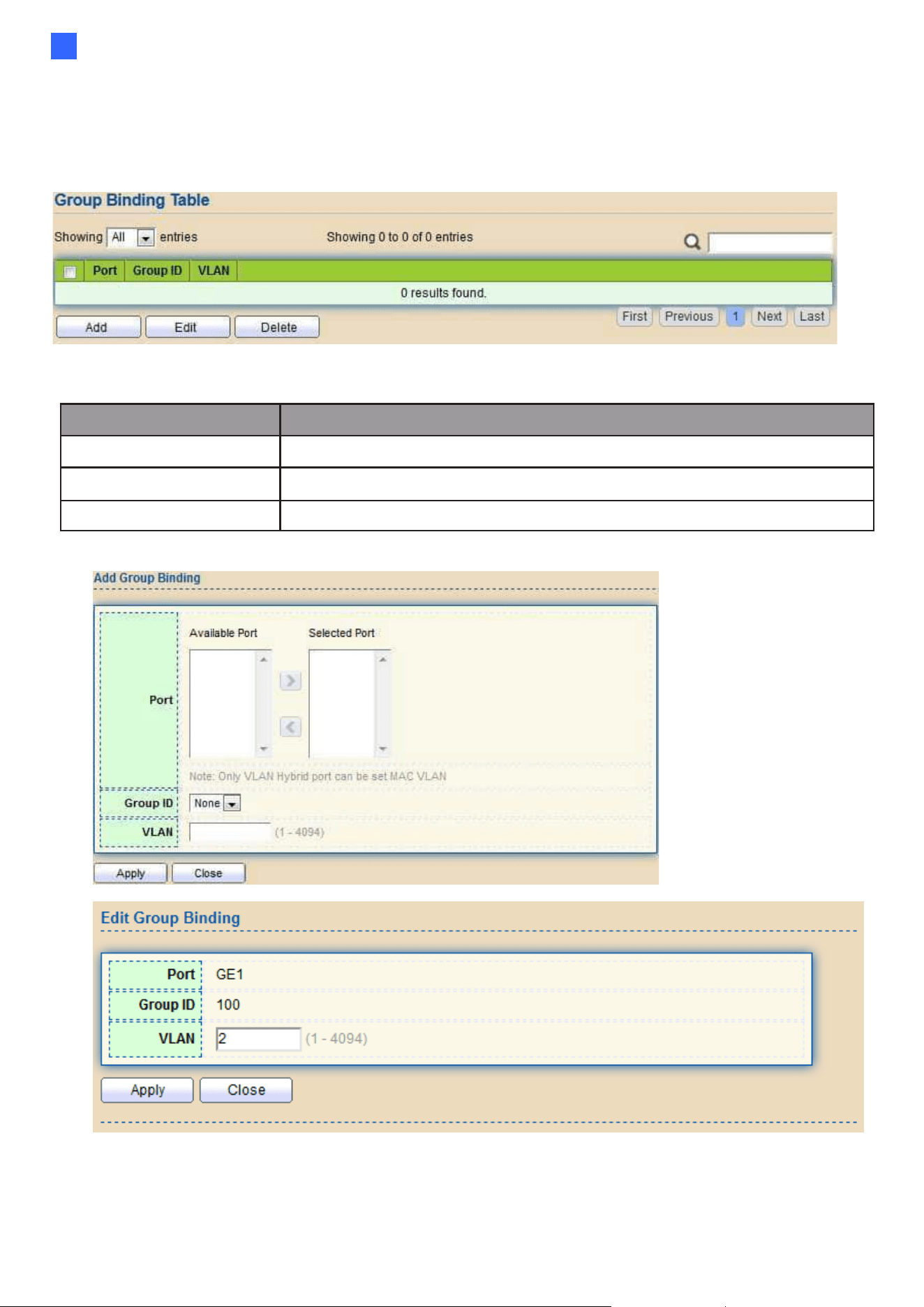
Web-based Switch Configuration
39
2
2.4.4.2. Group Binding
This page allows users to bind MAC VLAN group to each port with VLAN ID.
To display Group Binding page, click VLAN> MAC VLAN > Group Binding
Figure 44 - VLAN > MAC VLAN > Group Binding
Item
Description
Port
Display port ID that binding with MAC group entry.
Group ID
Display group ID that port binding with.
VLAN
Display VLAN ID that assign to packets which match MAC group.
Click “Add” button or "Edit" button to view the Add Group Binding menu.
Figure 45 - VLAN > MAC VLAN > Group Binding
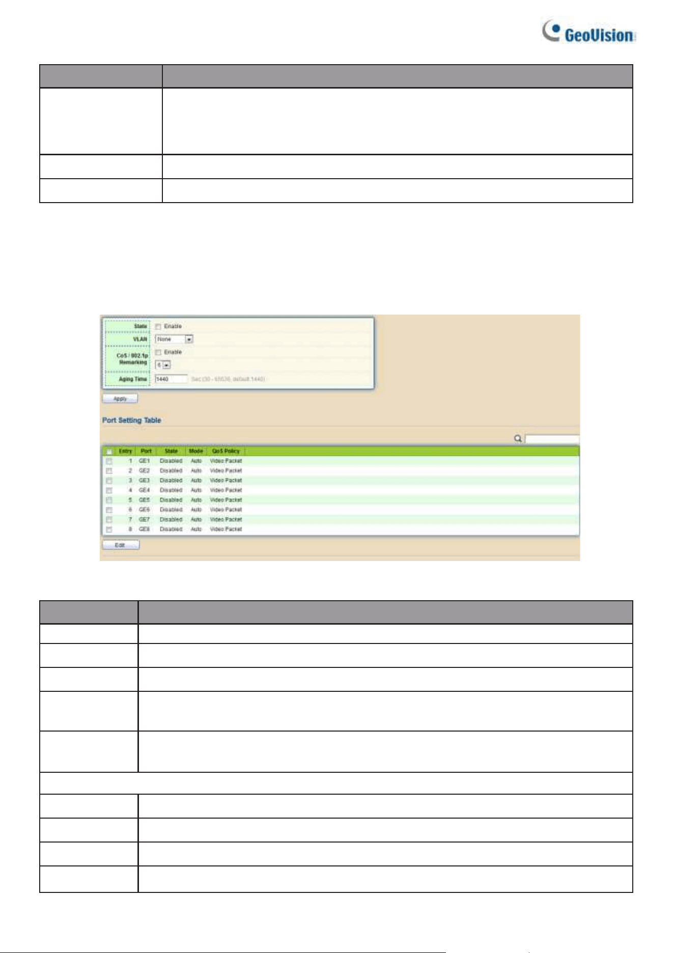
40
Item
Description
Port
Select ports in left box then move to right to binding with MAC group. Or
select ports in right box then move to left to unbind with MAC group. Only
interface has hybrid VLAN mode can be selected and bound with protocol
group. Only available on Add dialog.
Group ID
Select a Group ID to associate with port. Only available on Add dialog.
VLAN
Input VLAN ID that will assign to packets which match MAC group.
2.4.5. Surveillance VLAN
Use the Surveillance VLAN pages to configure settings of Surveillance VLAN.
2.4.5.1. Property
To display Property page, click VLAN> Surveillance VLAN> Property
Figure 46 - VLAN > Surveillance VLAN > Property
Item
Description
State
Set checkbox to enable or disable Surveillance VLAN function.
VLAN
Select Surveillance VLAN ID. Surveillance VLAN ID cannot be default VLAN.
COS/802.1P
Select a value of VPT. Qualified packets will use this VPT value as inner priority.
Remarking
Set checkbox to enable or disable 1p remarking. If enabled, qualified packets will
be remark by this value.
Aging Time
Input value of aging time. Default is 1440 minutes. A video VLAN entry will be age
out after this time if without any packet pass through.
Port Setting Table
Port
Display port entry.
State
Display enable/disabled status of interface.
Mode
Display Surveillance VLAN mode.
Qos Policy
Display Surveillance VLAN remark will affect which kind of packet.
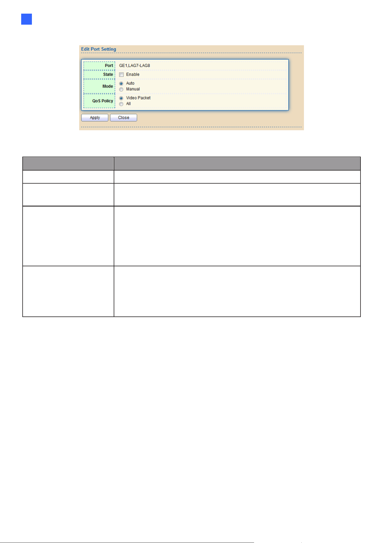
Web-based Switch Configuration
41
2
Click “Add” button or "Edit" button to view the Add Group Binding menu.
Figure 47 - VLAN > Surveillance VLAN > Property
Item
Description
Port
Display selected port to be edited.
State
Set checkbox to enable/disabled Surveillance VLAN function of
interface.
Mode
Select port voice VLAN mode
•
Auto: Surveillance VLAN auto detect packets that match OUI
table and add received port into Surveillance VLAN ID tagged
member.
•
Manual: Users need add interface to Surveillance VLAN ID
tagged member manually.
QoS Policy
Select port QoS Policy mode
•
Video Packet: QoS attributes are applied to packets with OUIs
in the source MAC address.
•
All: QoS attributes are applied to packets that are
classified to the Surveillance VLAN.
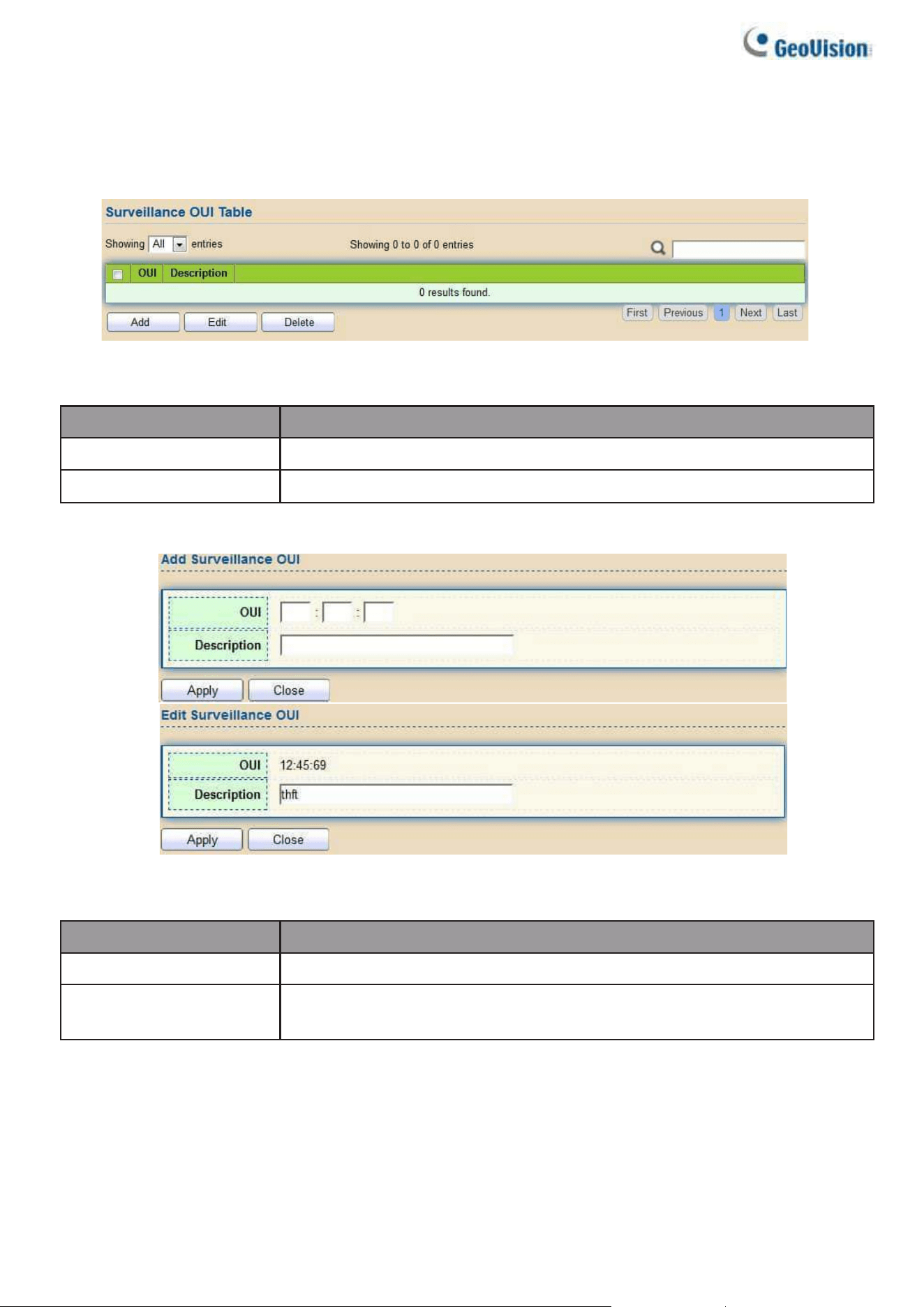
42
2.4.5.2. Surveillance OUI
This page allows users to add, edit or delete OUI MAC addresses.
To display Surveillance OUI web page, click VLAN> Surveillance VLAN>
Surveillance OUI.
Figure 48 - VLAN > Surveillance VLAN > Surveillance OUI
Item
Description
OUI
Display OUI MAC address.
Description
Display description of OUI entry.
Click “Add” or “Edit” button to view the Add/Edit Surveillance OUI menu.
Figure 49 - VLAN >Surveillance VLAN >Surveillance OUI
Item
Description
OUI
Input OUI MAC address. Can’t be edited in edit dialog.
Descripiton
Input description of the specified MAC address to the
Surveillance VLAN OUI table.
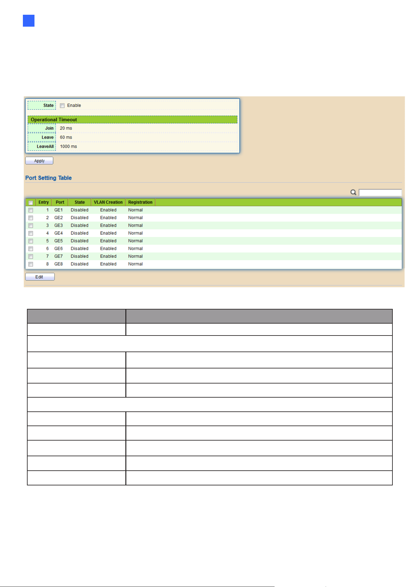
Web-based Switch Configuration
43
2
2.4.6. GVRP
2.4.6.1. Property
This page allows users to enable or disable GVRP function and GVRP port setting.
To display GVRP Global and Port Setting web page, click VLAN> GVRP > Property.
Figure 50 - VLAN > GVRP > Property
Item
Description
State
Set the enabling status of GVRP functionality.
Operational Timeout
Join
GVRP Join time out.
Leave
GVRP leave time out.
Leave All
GVRP leave all time out.
Port Setting Table
Entry
Entry Entry of number
Port
Port Name
State
Display port GVRP state
VLAN Creation
Display port GVRP creation vlan state
Registration
Display port GVRP registration mode
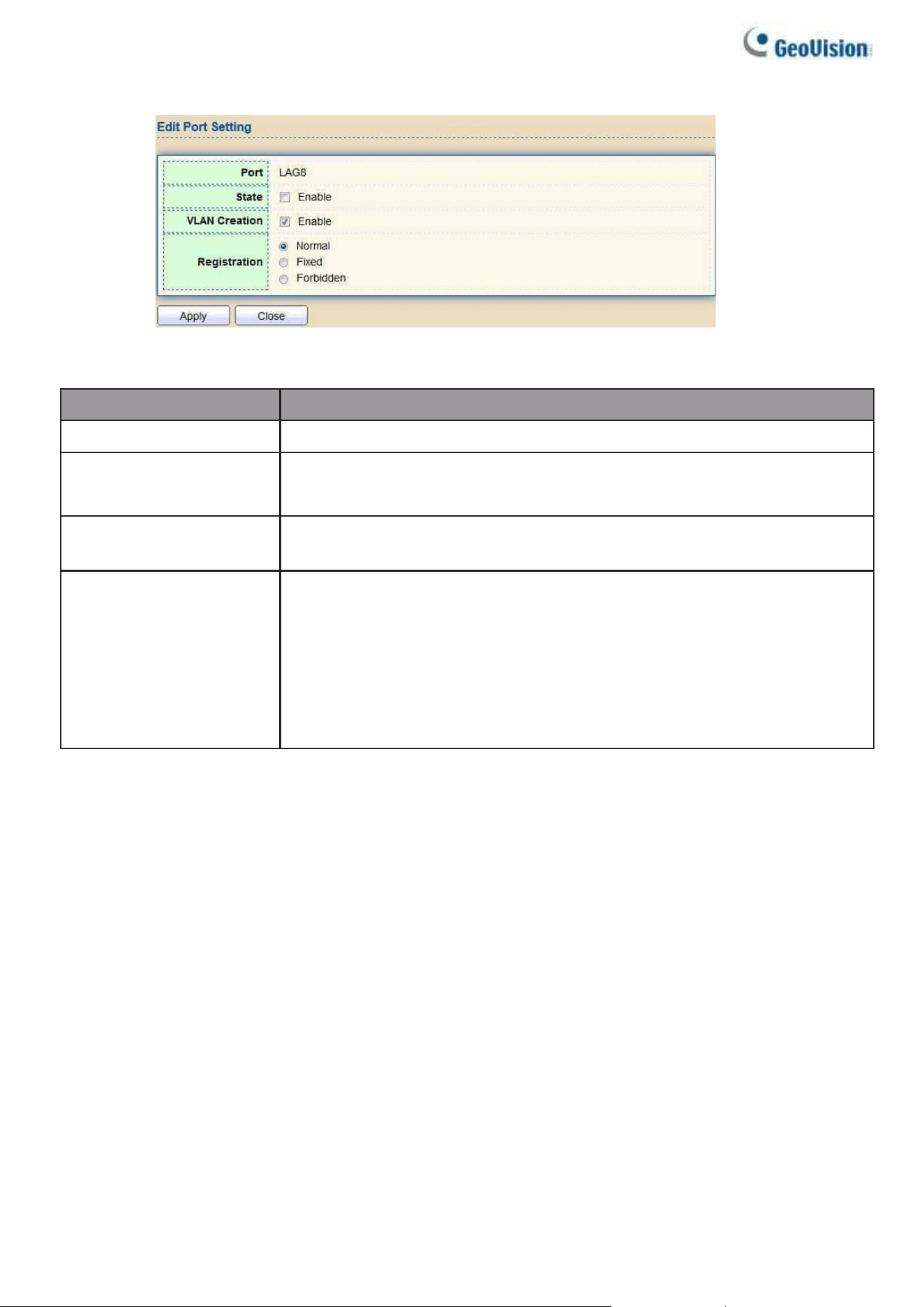
44
Click “Edit” button to view the Edit Port Setting menu.
Figure 51 - VLAN > GVRP > Property> Edit Port Setting
Item
Description
Port
Port Display the selected port list
State
Set the enabling status of GVRP port
●
Enable: Enable/Disable port of GVRP state
VLAN Creation
Set the enabling status of GVRP port create VLAN
●
Enable: Enable/Disable port create dynamic VLAN.
Register Mode
Set the register mode of GVRP port
●
Normal: Normal mode.
●
Fixed: The port will not learn any dynamic VLAN. Only send
static VLAN information to neighbor and allow static VLAN
packet pass.
●
Forbidden: The port will not learn any dynamic VLAN and
only allow default VLAN packet pass.
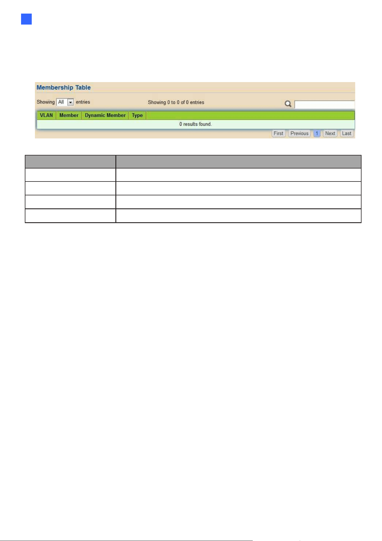
Web-based Switch Configuration
45
2
2.4.6.2. Membership
This page allows users to browser all VLAN member settings that are learned by GVRP
protocol or configured by users.
To display GVRP VLAN database web page, click VLAN> GVRP> Membership
Figure 52 - VLAN > GVRP > Membership
Item
Description
VLAN
VLAN ID
Member
VLAN port members include static and dynamic member
Dynamic Member
GVRP learned dynamic ports
Type
The type of VLAN is static or dynamic.
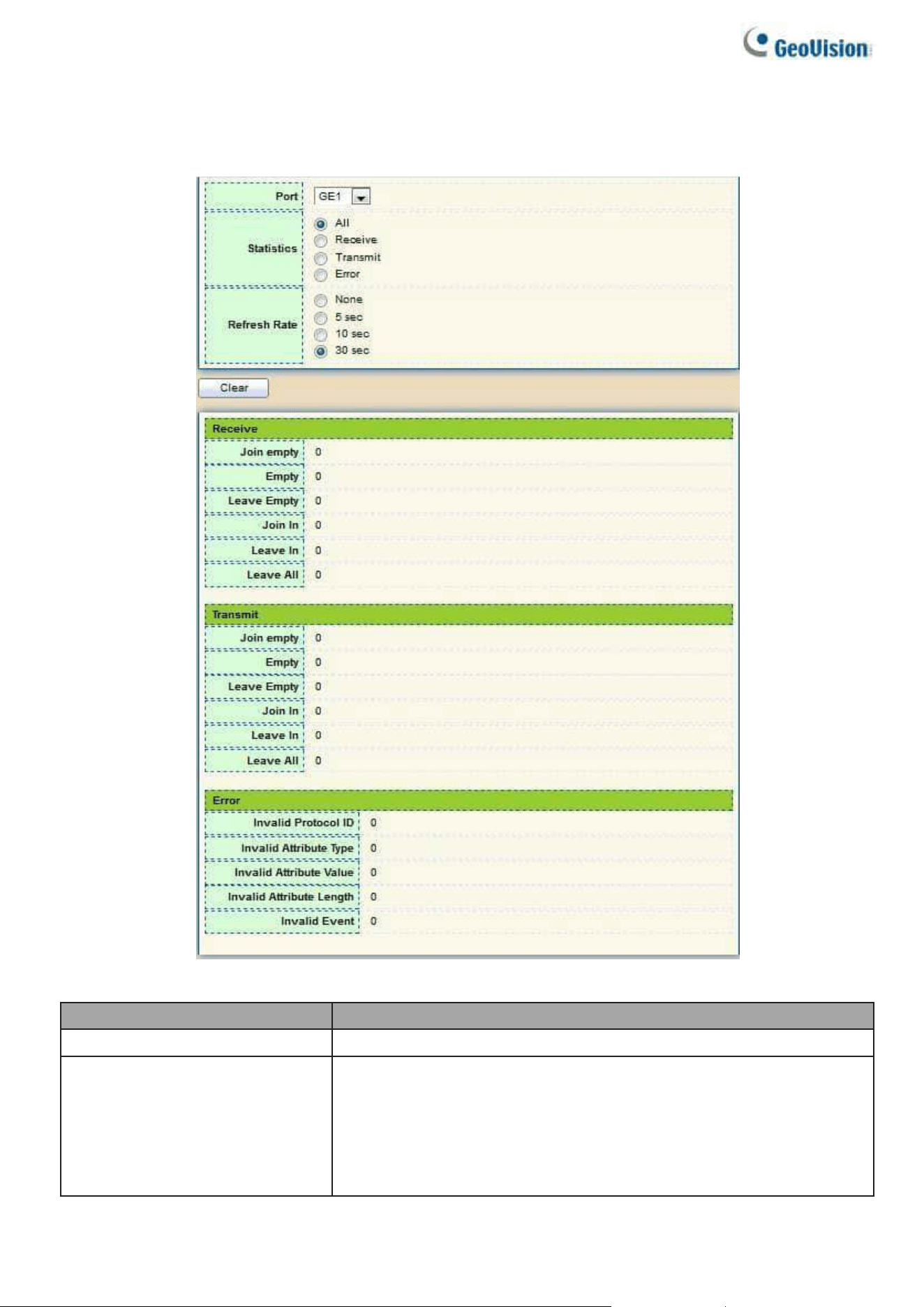
46
2.4.6.3. Statistics
This page allows users to display GVRP port statics by type and clear GVRP port statistics by port.
To display GVRP port statistics web page, click VLAN > GVRP > Statistics
Figure 53 - VLAN > GVRP > Statistics
Item
Description
Port
Port ID
Statistics
Type of statistics
⚫
All: Display Receiver, Transmit and Error port statistics
⚫
Receive: Display Receive port statistics
⚫
Transmit: Display Transmit port statistics
⚫
Error: Display Error port statistics
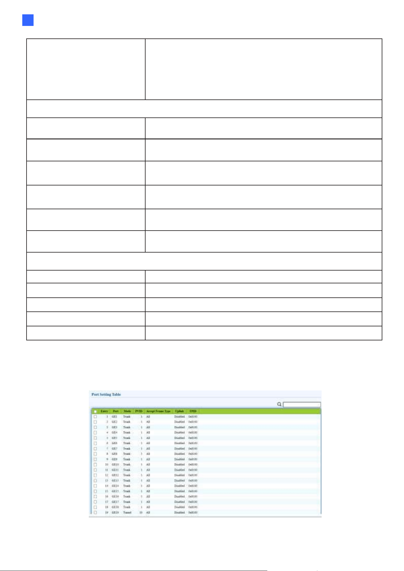
Web-based Switch Configuration
47
2
Refresh Rate
Web refresh rate
⚫
None: Not auto refresh display port statistics
⚫
5 sec: Refresh display port statistics per 5 seconds
⚫
10 sec: Refresh display port statistics per 10 seconds
⚫
30 sec: Refresh display port statistics per 30 seconds
Receive and Transmit
Join empty
The number of Receive or Transmit Join empty attribute
value.
Empty
Empty The number of Receive or Transmit Empty
attribute value.
Leave Empty
Leave Empty The number of Receive or Transmit Leave
Empty attribute value.
Join in
Join In The number of Receive or Transmit Join In
attribute value.
Leave in
The number of Receive or Transmit Leave In empty
attribute value.
Leave All
Leave All The number of Receive or Transmit Leave All
attribute value.
Error
Invalid Protocol ID
The number of Receive Invalid Protocol ID
Invalid Attribute Type
The number of Receive Invalid Attribute Type
Invalid Attribute Value
The number of Receive Invalid Attribute value
Invalid Attribute Length
The number of Receive Invalid Attribute Length.
Invalid Event
The number of Receive Invalid Event.
2.4.7. QinQ
This page allows users to configure Tunnel Mode port settings.
To display QinQ web page, click Port > VLAN > QinQ.
Figure 54 – Port > VLAN > QinQ
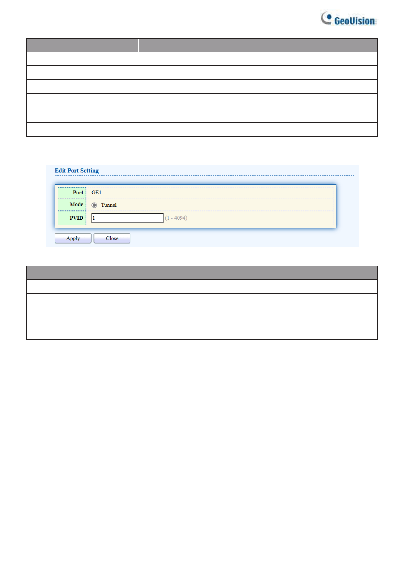
48
Item
Description
Port
Display the interface.
Mode
Display the VLAN mode of interface.
PVID
Display the Port-based VLAN ID of port.
Accept Frame Type
Display accept frame type of port.
Uplink
Display uplink status.
TPID
Display TPID used of interface.
Click “Edit” button to Edit Port Setting menu.
Figure 56 – Port > VLAN > QinQ > Edit Port Setting
Item
Description
Port
Display selected port to be edited.
Mode
Tunnel Mode is a technique often used by Metro Ethernet providers
as a layer 2 VPN for customers.
PVID
Specify the port-based VLAN ID (1-4094).
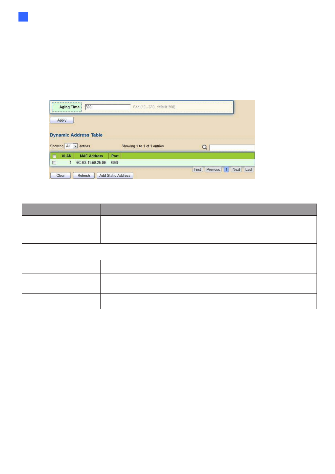
Web-based Switch Configuration
49
2
2.4 MAC Address Table
Use the MAC Address Table pages to show dynamic MAC table and configure settings for static
MAC entries.
2.4.8. Dynamic Address
To display the Dynamic Address web page, click MAC Address Table > Dynamic Address.
Figure 54 - MAC Address Table > Dynamic Address
Item
Description
Aging Time
The time in seconds that an entry remains in the MAC address
table. Its valid range is from 10 to 630 seconds, and the default
value is 300 seconds.
Dynamic Address Table
VLAN
Specify the VLAN to show or clear MAC entries.
MAC Address
The MAC address to which packets will be statically
forwarded.
Port
Interface or port number.
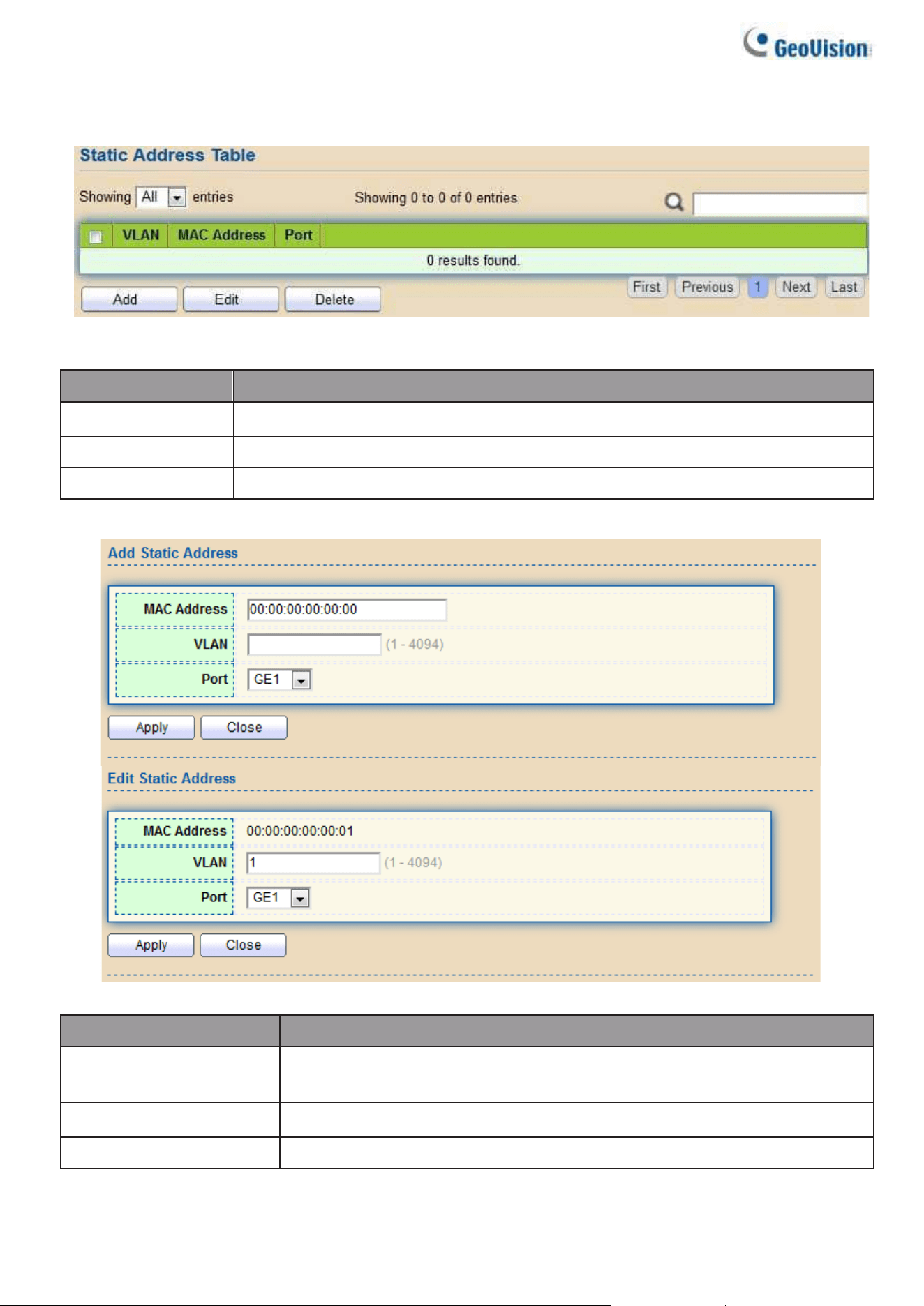
50
2.4.9. Static Address
To display the Static Address web page, click MAC Address Table > Static Address.
Figure 55 - MAC Address Table > Static Address.
Item
Description
VLAN
Specify the VLAN to show or clear MAC entries.
MAC Address
The MAC address to which packets will be statically forwarded.
Port
Interface or port number.
Click “Add” or “Edit” button to view the Add/Edit Static Address menu.
Figure 56 - MAC Address Table > Static Address > Add/Edit Static Address.
Item
Description
MAC Address
The MAC address to which packets will be statically
forwarded.
VLAN
Specify the VLAN to edit MAC entries.
Port
Interface or port number.
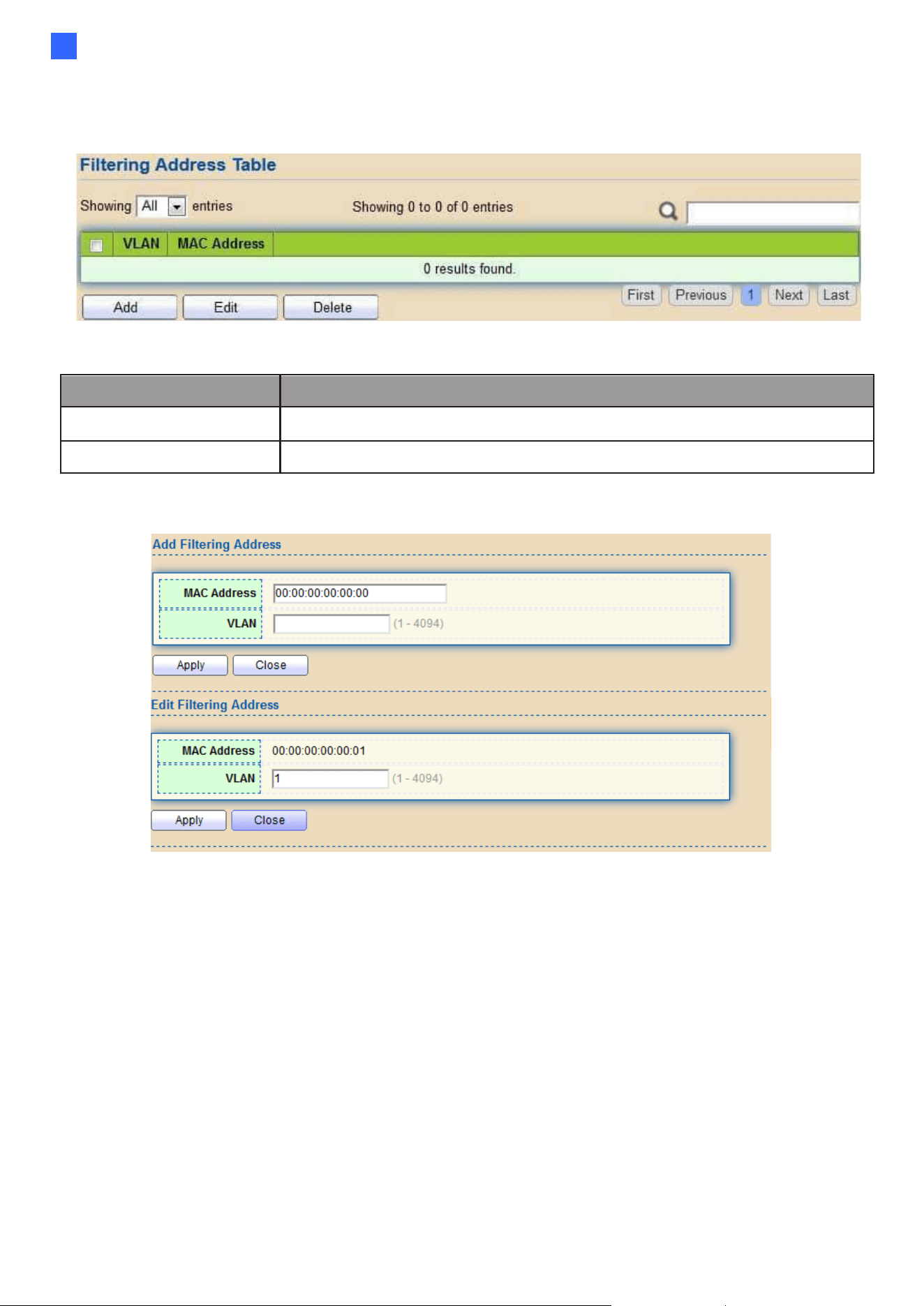
Web-based Switch Configuration
51
2
2.4.10. Filtering Address
To display the Filtering Address web page, click MAC Address Table > Filtering Address.
Figure 57 - MAC Address Table > Filtering Address.
Item
Description
MAC Address
Specify unicast MAC address in the packets to be dropped.
VLAN
Specify the VLAN to show or clear MAC entries.
Click “Add” or “Edit” button to view the Add/Edit Filtering Address menu.
Figure 58 - MAC Address Table > Filtering Address > Add/Edit Filtering Address.
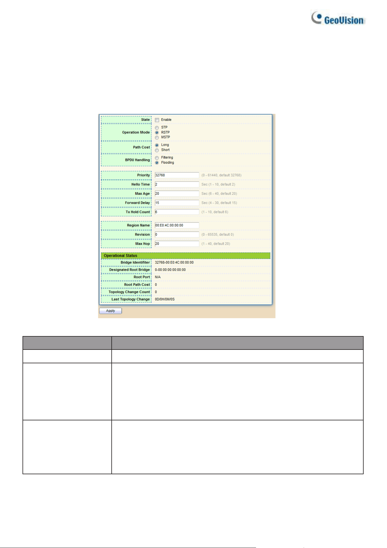
52
2.5. Spanning Tree
The Spanning Tree Protocol (STP) is a network protocol that ensures a loop-free topology
for any bridged Ethernet local area network.
2.5.1. Property
To display the Property web page, click Spanning Tree > Property.
Figure 59 - Spanning Tree > Property
Item
Description
State
Enable/disable the STP on the switch.
Operation Mode
Specify the STP operation mode.
•
STP: Enable the Spanning Tree (STP) operation.
•
RSTP: Enable the Rapid Spanning Tree (RSTP) operation.
•
MSTP: Enable the Multiple Spanning Tree (MSTP)
operation.
Path Cost
Specify the path cost method.
•
Long: Specifies that the default port path costs are within
the range:1-200,000,000.
•
Short: Specifies that the default port path costs are within
the range:1-65,535.

Web-based Switch Configuration
53
2
BPDU Handling
Specify the BPDU forward method when the STP is
disabled.
•
Filtering: Filter the BPDU when STP is disabled.
•
Flooding: Flood the BPDU when STP is disabled.
Priority
Specify the bridge priority. The valid range is from 0 to 61440, and
the value should be the multiple of 4096. It ensures the probability
that the switch is selected as the root bridge, and the lower value
has the higher priority for the switch to be selected as the root
bridge of the topology.
Hello Time
Specify the STP hello time in second to broadcast its hello
message to other bridges by Designated Ports. Its valid range is
from 1 to 10 seconds.
Max Age
Specify the time interval in seconds for a switch to wait the
configuration messages, without attempting to redefine its own
configuration.
Forward Delay
Specify the STP forward delay time, which is the amount of time
that a port remains in the Listening and Learning states before it
enters the Forwarding state. Its valid range is from 4 to 10
seconds.
TX Hold Count
Specify the tx-hold-count used to limit the maximum numbers of
packets transmission per second. The valid range is from 1 to
10.
Region Name
The MSTP instance name. Its maximum length is 32
characters. The default value is the MAC address of the switch.
Revision
The MSTP revision number. Its valid rage is from 0 to 65535.
Max Hop
Specify the number of hops in an MSTP region before the BPDU
is discarded. The valid range is 1 to 40.
Operational Status
Bridge Identifier
Bridge identifier of the switch.
Designated Root
Identifier
Bridge identifier of the designated root bridge.
Root Port
Operational root port of the switch.
Root Path Cost
Operational root path cost.
Topology Change
Count
Numbers of the topology changes.
Last Topology
Change
The last time for the topology change.
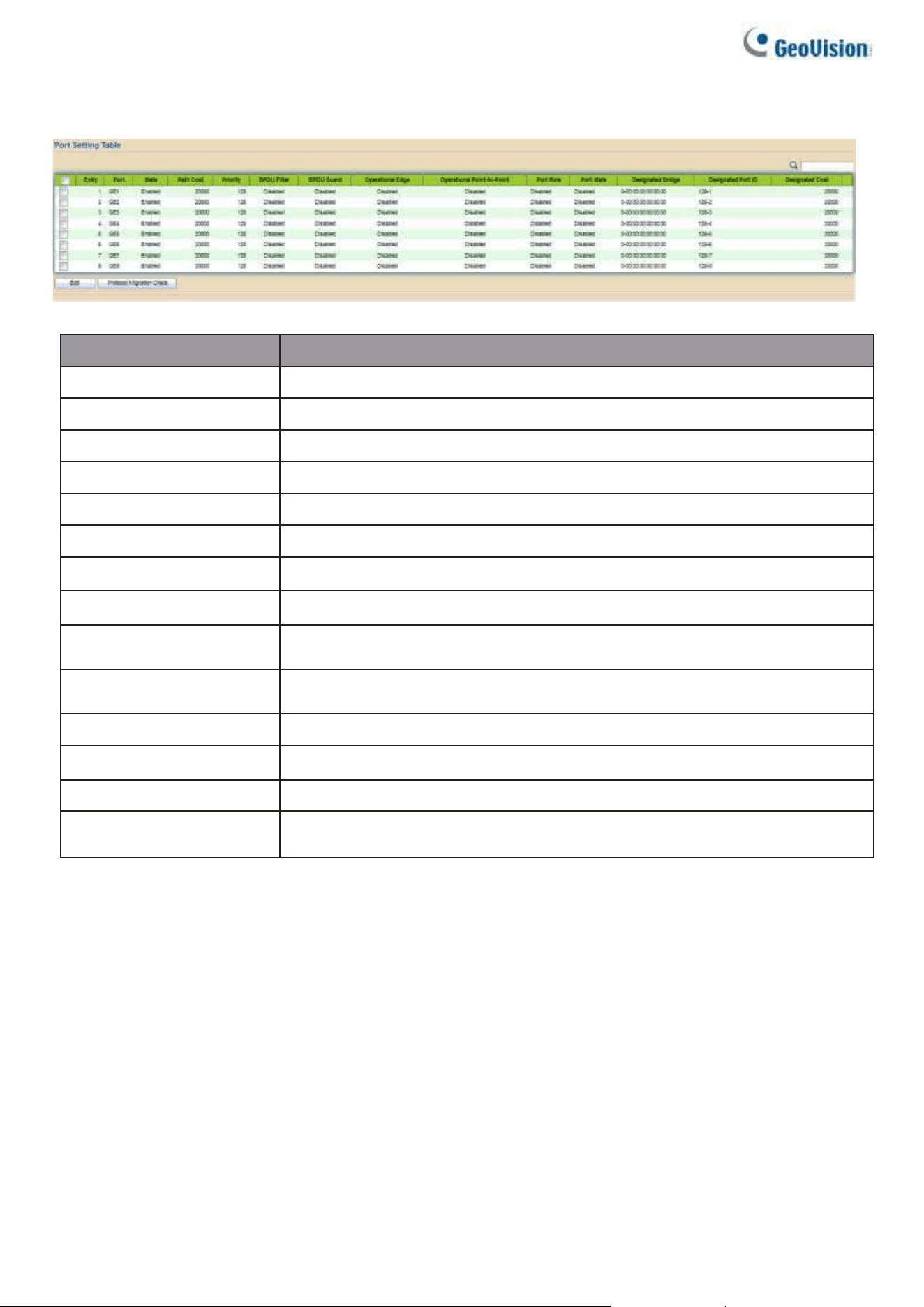
54
2.5.2. Port Setting
To configure and display the STP port settings, click STP > Port Setting.
Figure 60 - Spanning Tree > Port Setting
Item
Description
Port
Specify the interface ID or the list of interface IDs.
State
The operational state on the specified port.
Path Cost
STP path cost on the specified port.
Priority
STP priority on the specified port.
BPDU Filter
The states of BPDU filter on the specified port.
BPDU Guard
The states of BPDU guard on the specified port.
Operational Edge
The operational edge port status on the specified port.
Operational Point-to-Point
The operational point-to-point status on the specified port.
Port Role
The current port role on the specified port. The possible values are:
“Disabled”, “Master”, “Root”, “Designated”, “Alternative”, and “Backup”.
Port State
The current port state on the specified port. The possible values are:
“Disabled”, “Discarding”, “Learning”, and “Forwarding”.
Designated Bridge
The bridge ID of the designated bridge.
Designated Port ID
The designated port ID on the switch.
Designated Cost
The path cost of the designated port on the switch.
Protocol Migration Check
Restart the Spanning Tree Protocol (STP) migration process (re-
negotiate with its neighborhood) on the specific interface.
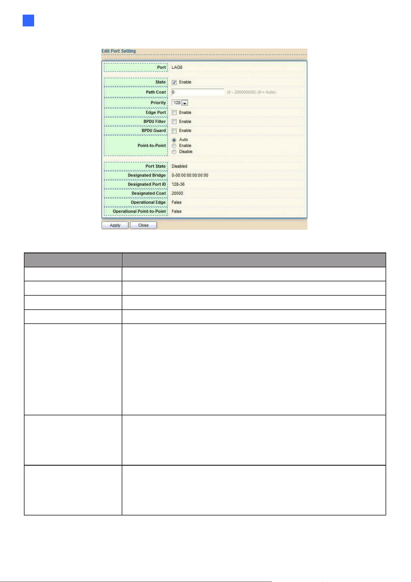
Web-based Switch Configuration
55
2
Click "Edit" button to view Edit Port Setting menu.
Figure 61 - Spanning Tree > Port Setting > Edit Port Setting
Item
Description
Port
Selected port ID.
State
Enable/Disable the STP on the specified port.
Path Cost
Specify the STP path cost on the specified port.
Priority
Specify the STP path cost on the specified port.
Edge Port
Specify the edge mode.
•
Enable: Force to true state (as link to a host).
•
Disable: Force to false state (as link to a bridge). In the
edge mode, the interface would be put into the
Forwarding state immediately upon link up. If the edge
mode is enabled for the interface and there are BPDUs
received on the interface, the loop might be occurred in the
short time before the STP state change.
BPDU Filter
The BPDU Filter configuration avoids receiving /
transmitting BPDU from the specified ports.
•
Enable: Enable BPDU filter function.
•
Disable: Disable BPDU filter function.
BPDU Guard
The BPDU Guard configuration to drop the received BPDU
directly.
•
Enable: Enable BPDU guard function.
•
Disable: Disable BPDU guard function.
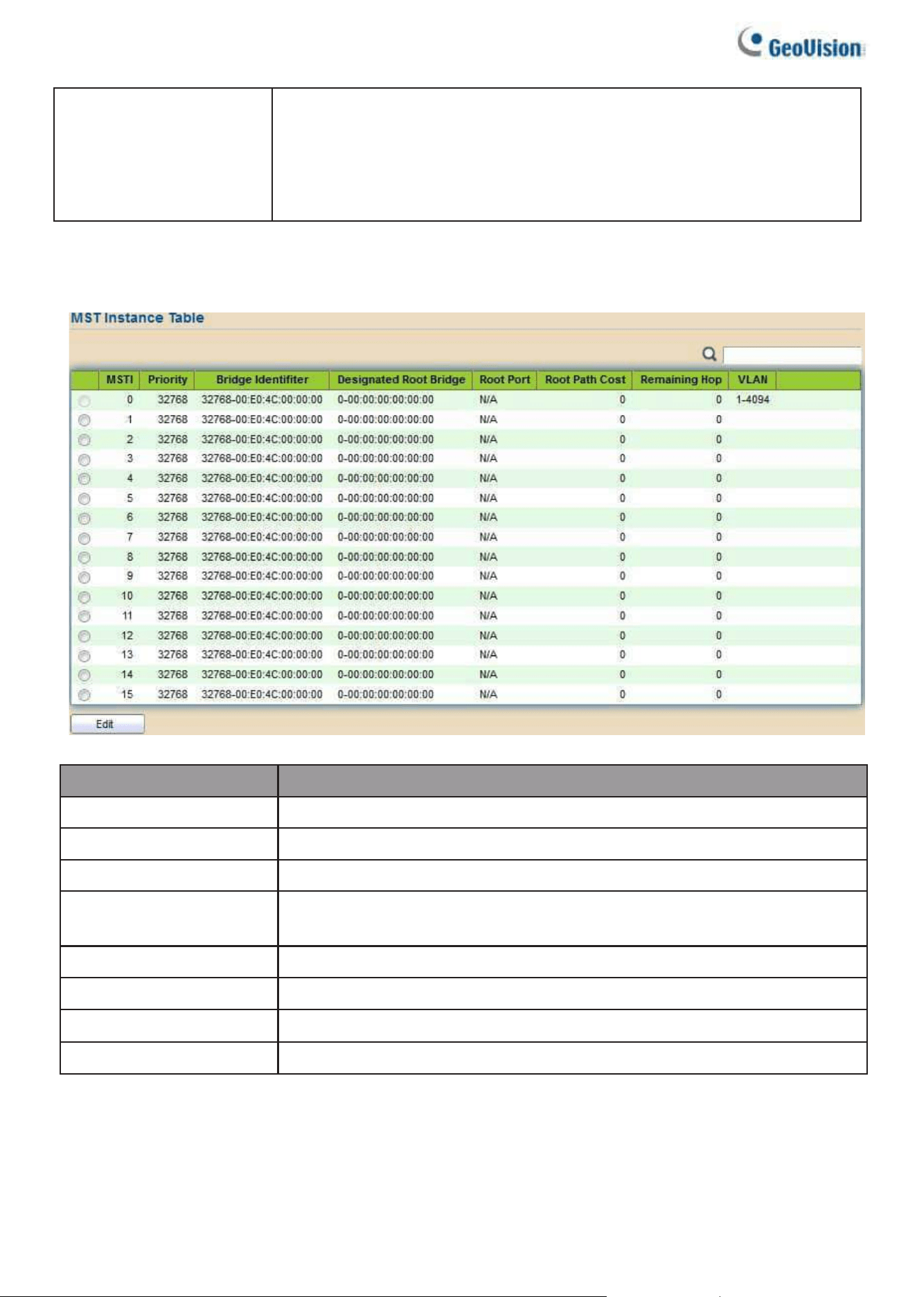
56
Point-to-Point
Specify the Point-to-Point port configuration:
•
Auto: The state is depended on the duplex setting of the port
•
Enable: Force to true state.
•
Disable: Force to false state
2.5.3. MST Instance
To configure MST instance setting, click STP > MST Instance.
Figure 62 - Spanning Tree > MST Instance
Item
Description
MSTI
Designated port number.
Priority
The bridge priority on the specified MSTI.
Bridge Identifier
The bridge identifier on the specified MSTI.
Designated Root
Bridge
The designated root bridge identifier on the specified MSTI.
Root Port
The designated root port on the specified MSTI.
Root Path Cost
The designated root path cost on the specified MSTI.
Remaining Hop
The configuration of remaining hop on the specified MSTI.
VLAN
The VLAN configuration on the specified MSTI.
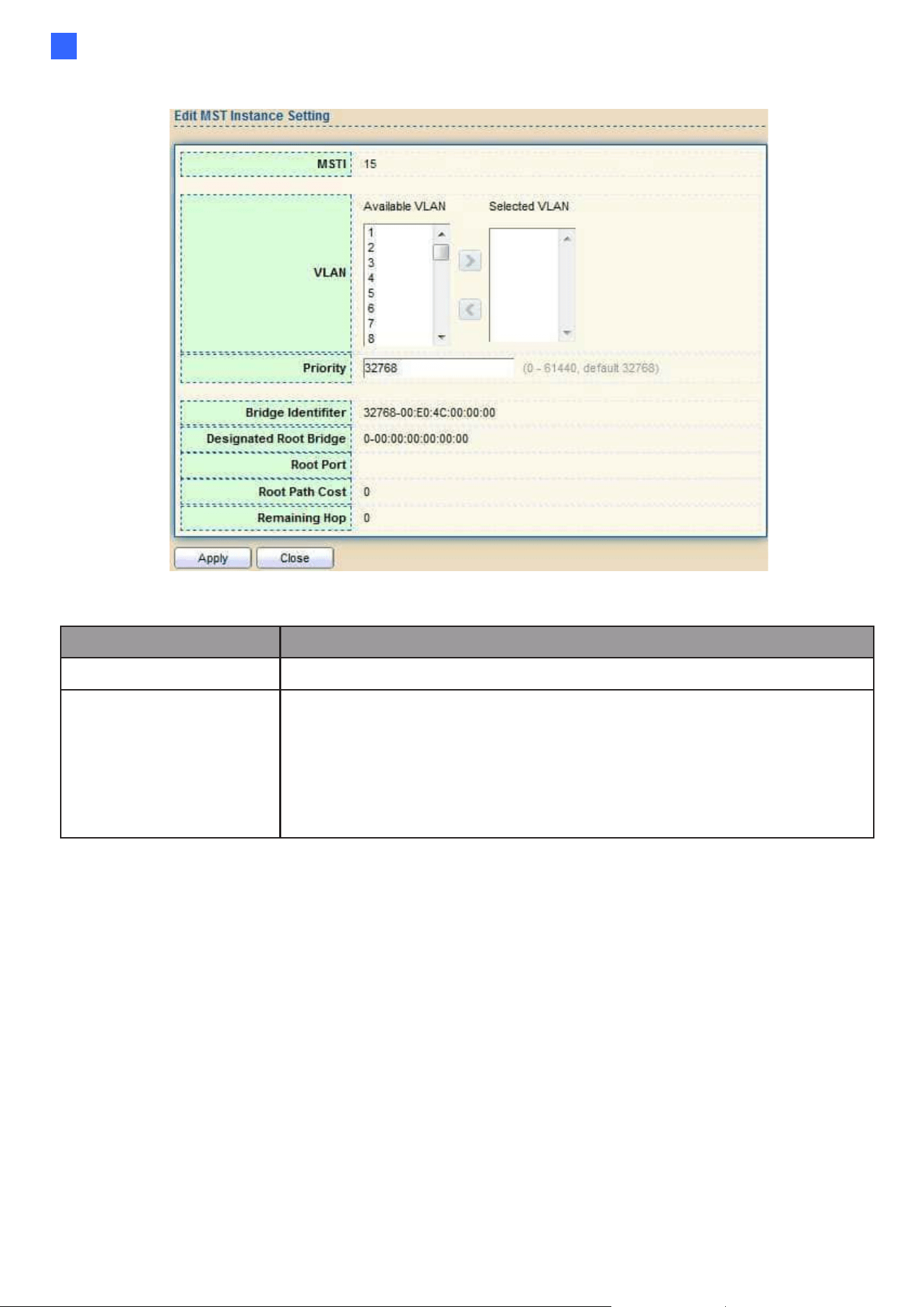
Web-based Switch Configuration
57
2
Click "Edit" button to view Edit MST Instance menu.
Figure 63 - Spanning Tree > MST Instance > Edit MST Instance Setting
Item
Description
VLAN
Select the VLAN list for the specified MSTI.
Priority
Specify the bridge priority on the specified MSTI. The valid range
is from 0 to 61440, and the value must be the multiple of 4096. It
ensures the probability that the switch is selected as the root
bridge, and the lower values has
the higher priority for the switch to be selected as the root bridge of
the STP topology.
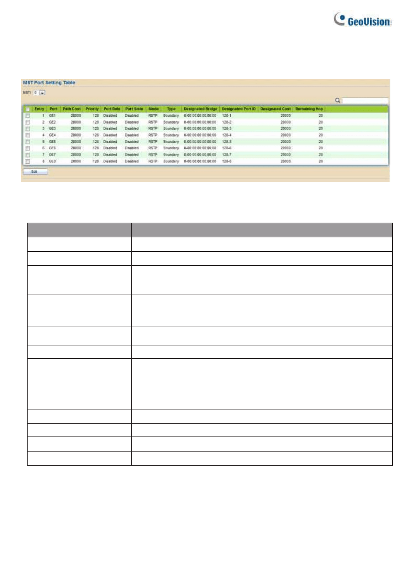
58
2.5.4. MST Port Setting
To configure and display MST port setting, click STP > MST Port Setting.
Figure 64 - Spanning Tree > MST Port Setting
Item
Description
MSTI
Specify the port setting on the specified MSTI.
Port
Specify the interface ID or the list of interface IDs.
Path Cost
The port path cost on the specified MSTI.
Priority
The port priority on the specified MSTI.
Port Role
The current port role on the specified port. The possible values are:
“Disabled”, “Master”, “Root”, “Designated”, “Alternative”, and
“Backup”.
Port State
The current port state on the specified port. The possible values are:
“Disabled”, “Discarding”, “Learning”, and “Forwarding”.
Mode
The operational STP mode on the specified port.
Type
The possible value for the port type are:
•
Boundary: The port attaching an MST Bridge to a LAN that is not
in the same region.
•
Internal: The port attaching an MST Bridge to a LAN that is not in
the same region.
Designated Bridge
The bridge ID of the designated bridge.
Designated Port ID
The designated port ID on the switch.
Designated Cost
The path cost of the designated port on the switch.
Remaining Hop
The remaining hops count on the specified port.
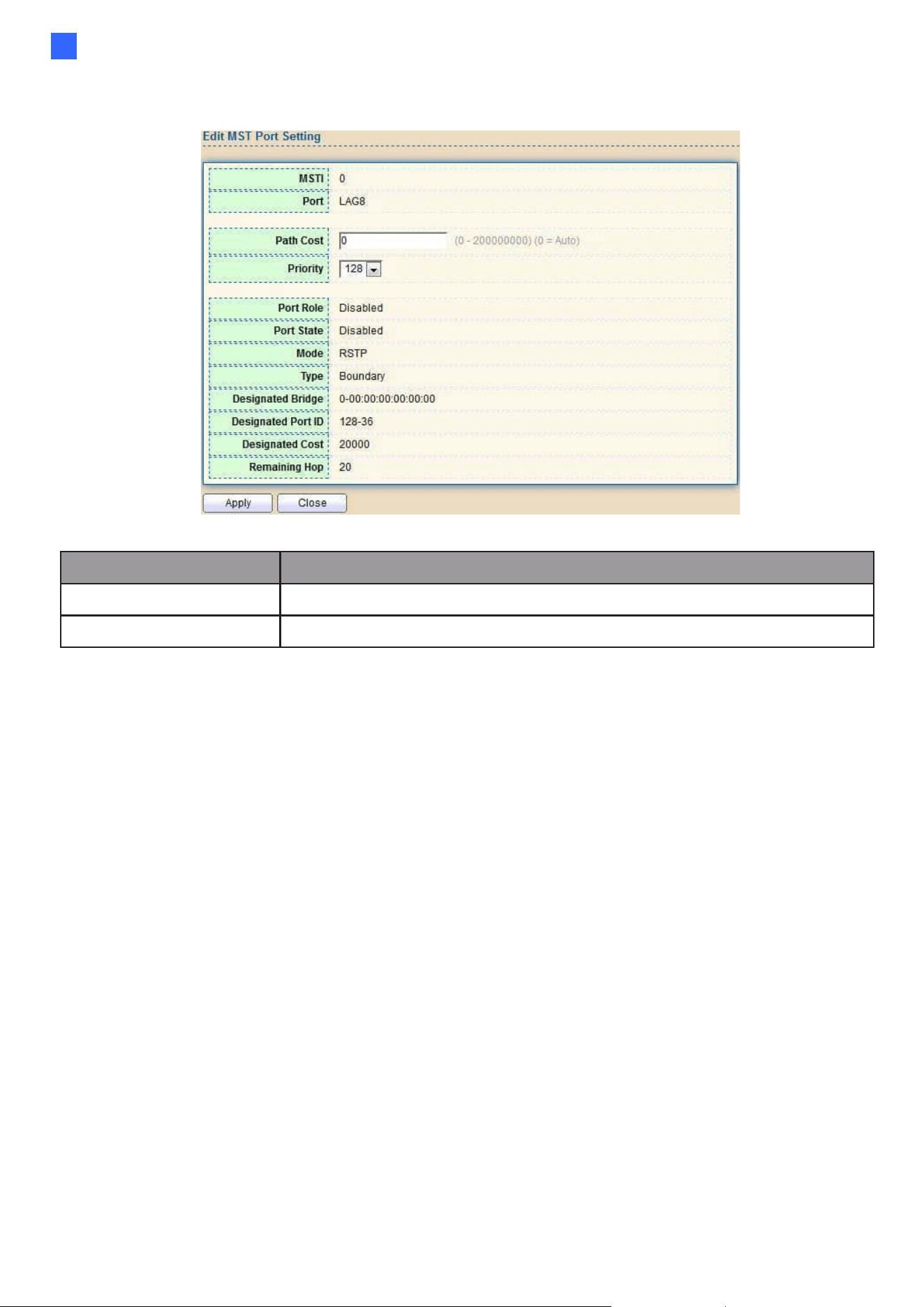
Web-based Switch Configuration
59
2
Click "Edit" button to view Edit MST Port Setting menu.
Figure 65 - Spanning Tree > MST Port Setting > Edit MST Port Setting
Item
Description
Path Cost
Specify the STP port path cost on the specified MSTI.
Priority
Specify the STP port priority on the specified MSTI.
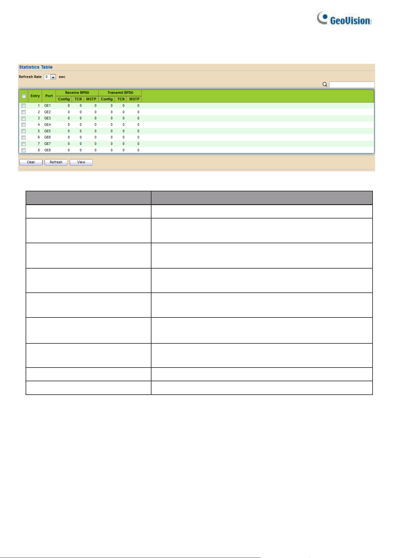
60
2.5.5. Statistics
To display the STP statistics, click STP > Statistics.
Figure 66 - Spanning Tree > Statistics
Item
Description
Refresh Rate
The option to refresh the statistics automatically.
Receive BPDU (Config)
The counts of the received CONFIG BPDU.
Receive BPDU (TCN)
The counts of the received TCN BPDU.
Receive BPDU (MSTP)
The counts of the received MSTP BPDU.
Transmit BPDU (Config)
The counts of the transmitted CONFIG BPDU.
Transmit BPDU (TCN)
The counts of the transmitted TCN BPDU.
Transmit BPDU (MSTP)
The counts of the transmitted MSTP BPDU.
Clear
Clear the statistics for the selected interfaces
View
View the statistics for the interface.
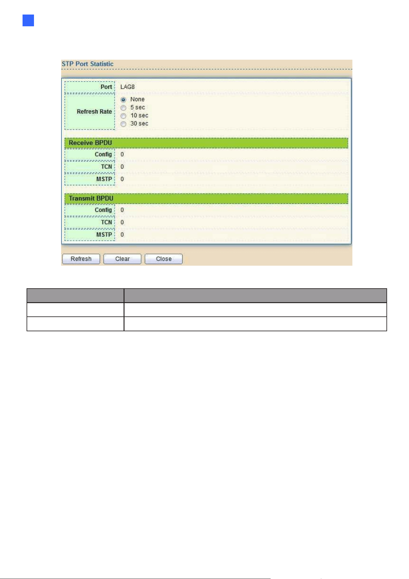
Web-based Switch Configuration
61
2
Click "View" button to view the STP Port Statistic menu.
Figure 67 - Spanning Tree > Statistics > STP Port Statistic
Item
Description
Refresh Rate
The option to refresh the statistics automatically.
Clear
Clear the statistics for the selected interfaces.
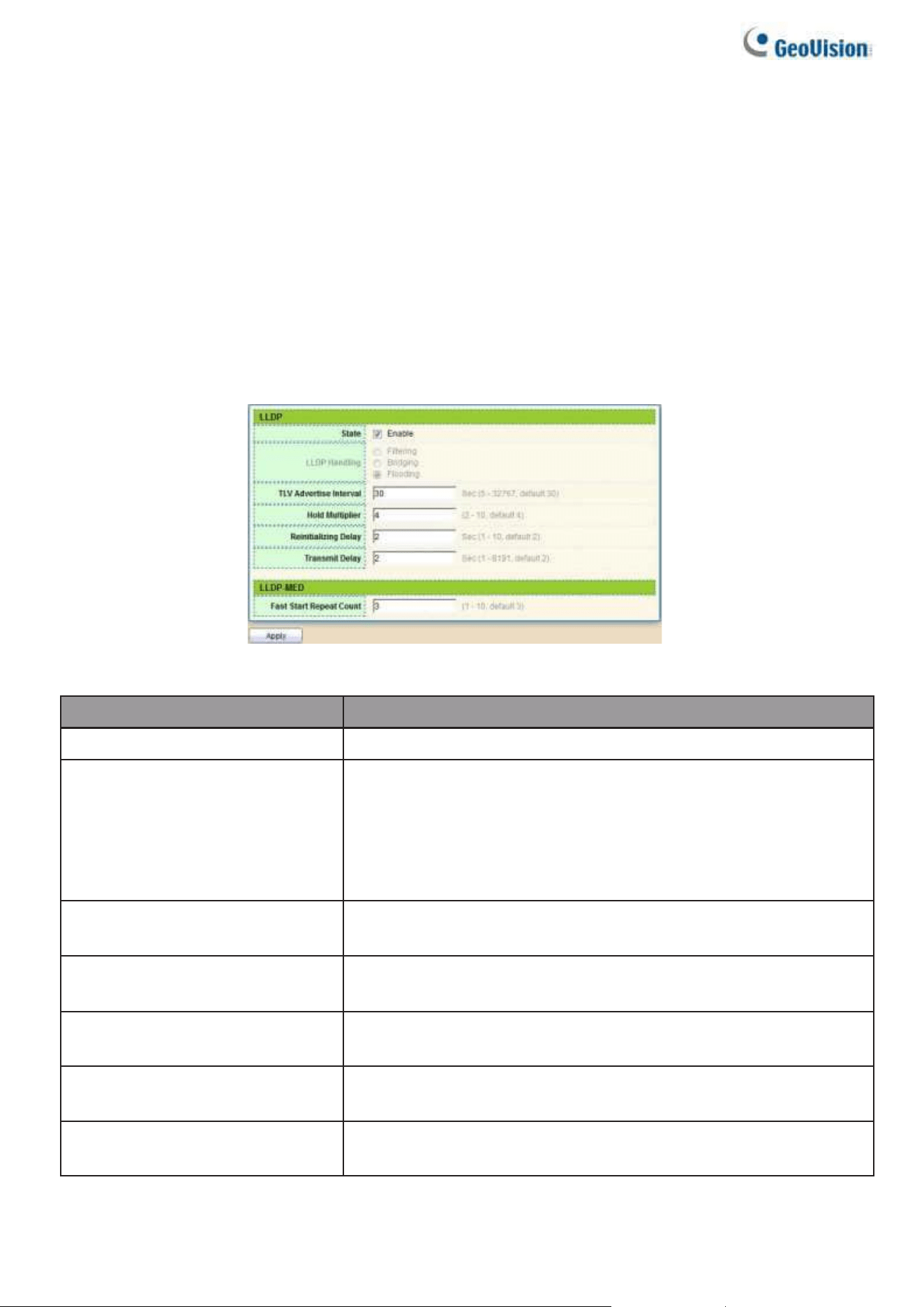
62
2.6. Discovery
Use this section to configure LLDP.
2.6.1. LLDP
LLDP is a one-way protocol; there are no request/response sequences. Information is
advertised by stations implementing the transmit function, and is received and processed by
stations implementing the receive function. The LLDP category contains LLDP and LLDP-
MED pages.
2.6.1.1. Property
To display LLDP Property Setting web page, click Discovery > LLDP > Property.
Figure 68 - Discovery > LLDP > Property
Item
Description
State
Enable/ Disable LLDP protocol on this switch.
LLDP Handling
Select LLDP PDU handling action to be filtered, bridging or
flooded when LLDP is globally disabled.
⚫ Filtering: Deletes the packet.
⚫ Bridging: (VLAN-aware flooding) Forwards the packet to all VLAN
members
⚫ Flooding: Forwards the packet to all ports
TLV Advertise Interval
Select the interval at which frames are transmitted. The default is
30 seconds, and the valid range is 5–32767 seconds.
Hold Multiplier
Select the multiplier on the transmit interval to assign to TTL
(range 2–10, default = 4).
Reinitializing Delay
Select the delay before a re-initialization (range 1–10 seconds,
default = 2).
Transmit Delay
Select the delay after an LLDP frame is sent (range 1– 8191
seconds, default = 3).
Fast Start Repeat Count
Select fast start repeat count when port link up (range 1–10,
default = 3).
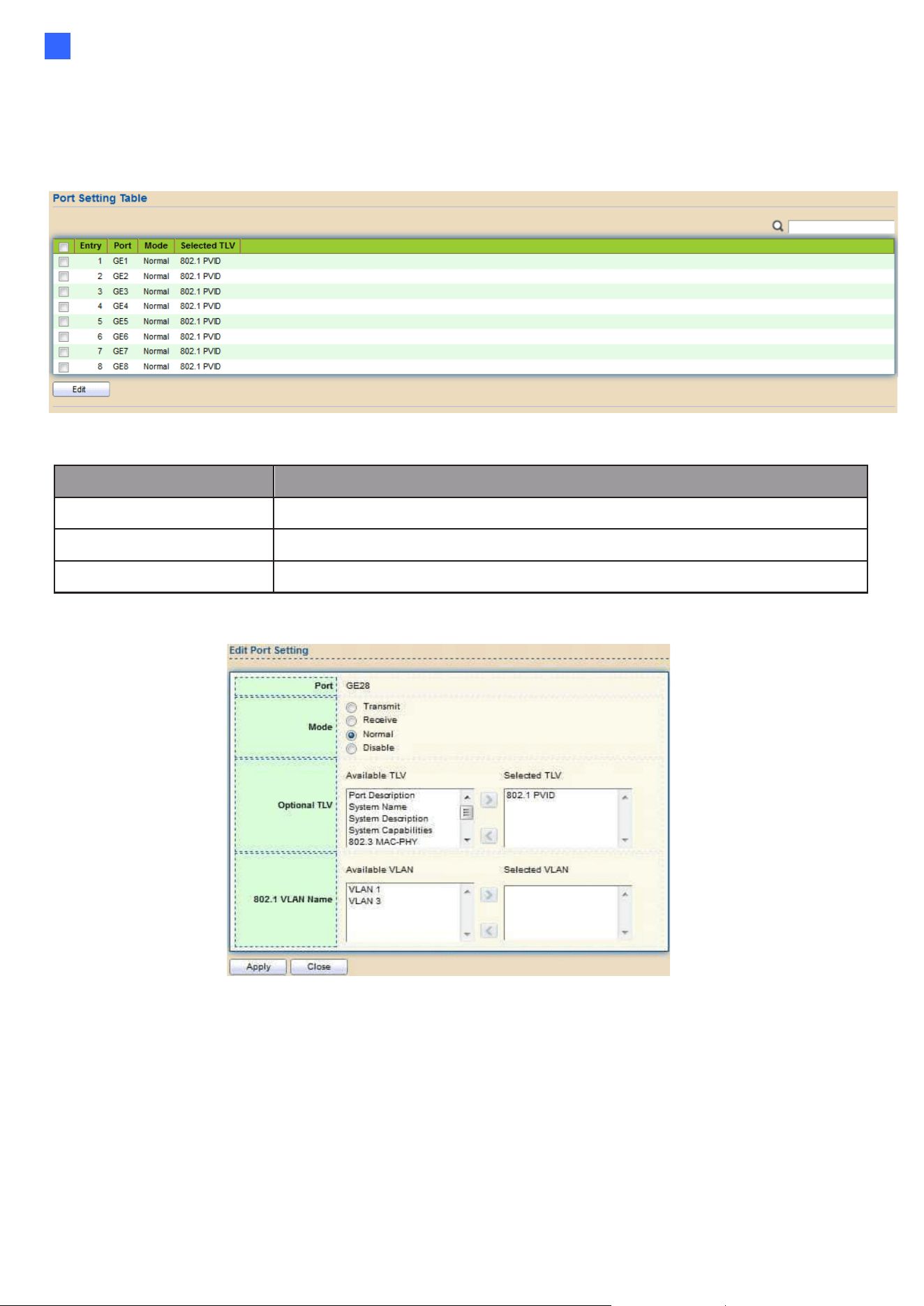
Web-based Switch Configuration
63
2
2.6.1.2. Port Setting
To display LLDP Port Setting, click Discovery > LLDP > Port Setting.
Figure 69 - Discovery > LLDP > Port Setting
Item
Description
Port
Port Name.
Mode
The port LLDP mode.
Selected TLV
The Selected LLDP TLV.
Click "Edit" button to view Edit Port Setting menu.
Figure 70 - Discovery > LLDP > Port Setting > Edit Port Setting

64
Item
Description
Port
Select specified port or all ports to configure LLDP state.
Mode
Select the transmission state of LLDP port interface.
•
Disable: Disable the transmission of LLDP PDUs.
•
Receive: RX Only LLDP PDUs only.
•
Transmit: Transmit and receive LLDP PDUs only.
•
Normal: Transmit and receive LLDP PDUs both.
Optional TLV
Select the LLDP optional TLVs to be carried (multiple
selection is allowed).
•
System Name
•
Port Description
•
System Description
•
System Capability
•
802.3 MAC-PHY
•
802.3 Link Aggregation
•
802.3 Maximum Frame Size
•
Management Address
• 802.1 PVID.
802.1 VLAN Name
Select the VLAN Name ID to be carried (multiple selection is
allowed).
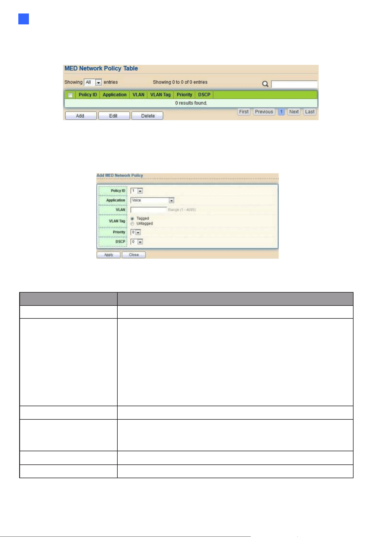
Web-based Switch Configuration
65
2
2.6.1.3. MED Network Policy
To display LLDP MED Network Policy Setting, click Discovery > LLDP > MED Network Policy.
Figure 71 - Discovery > LLDP > MED Network Policy
Click "Add" button or “Edit” button to view Edit Add MED Network Policy menu.
Figure 72 - Discovery > LLDP > MED Network Policy
Item
Description
Policy ID
Select specified network policy ID to configure.
Application
Select the network policy application type.
●
Voice
●
Voice Signaling
●
Guest Voice
●
Guest Voice Signaling
●
Softphone Voice
●
Video Conferencing
●
Streaming Video
●
Video Signaling
VLAN
Set the VLAN ID, range from 1 to 4094.
VLAN Tag
Set the VLAN tag status.
●
Tagged: Traffic is tagged.
●
Untagged: Traffic is untagged
Priority
Set the L2 priority, range from 0 to 7.
DSCP
Set the DSCP value, range from 0 to 63.
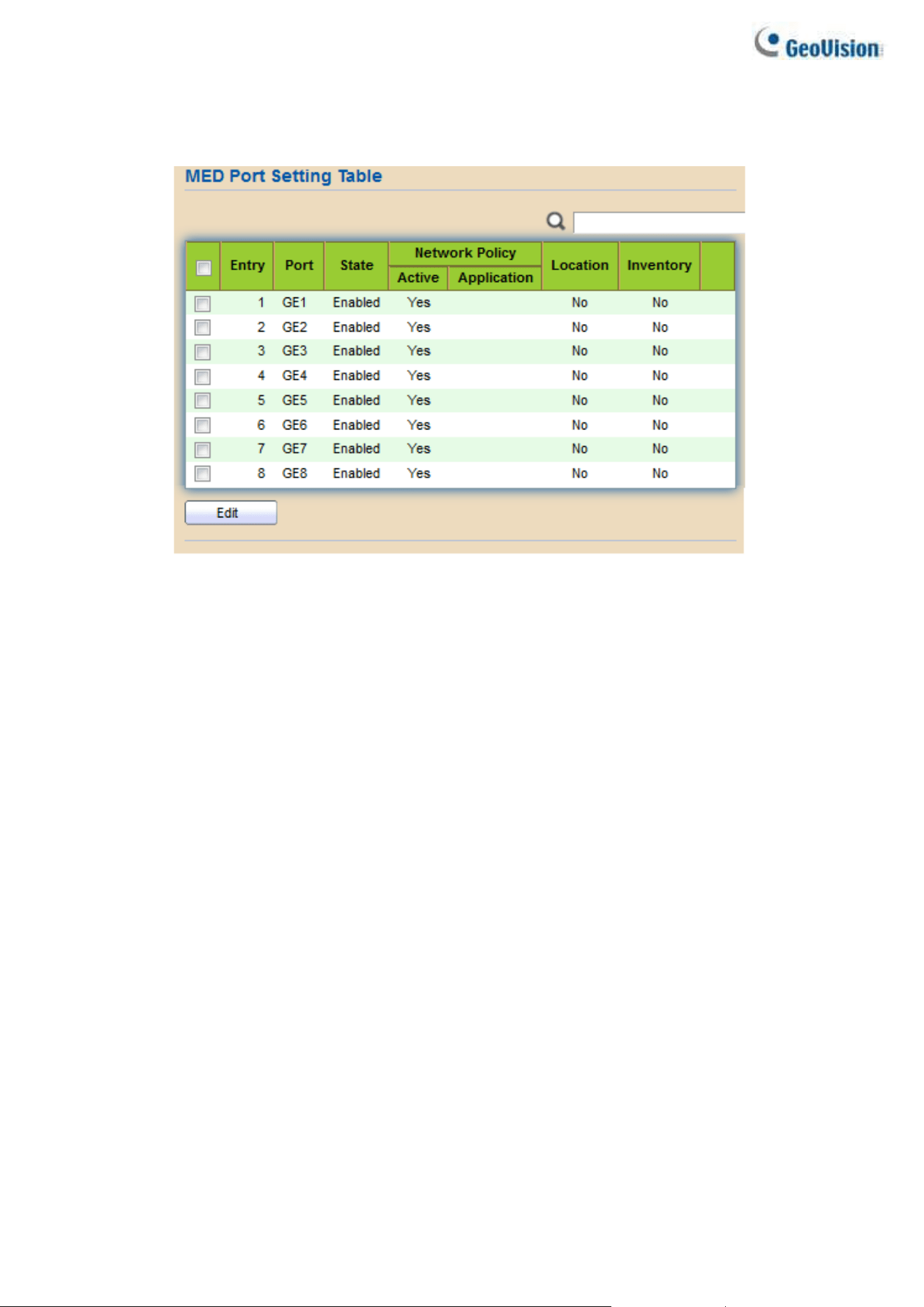
66
2.6.1.4. MED Port Setting
To display LLDP MED Port Setting, click Discovery > LLDP > MED Port Setting.
Figure 73 - Discovery > LLDP > MED Port Setting
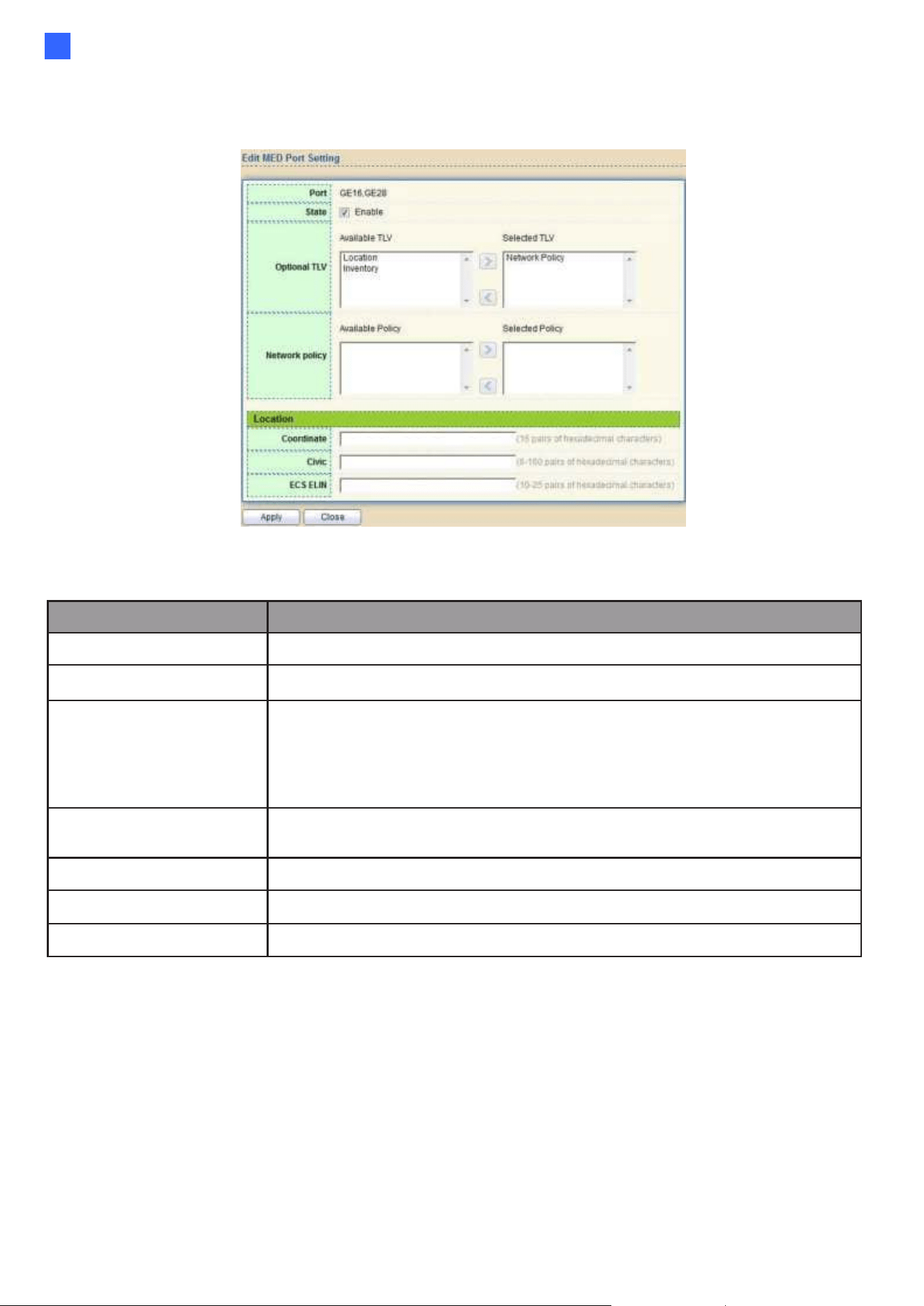
Web-based Switch Configuration
67
2
Click "Edit" button to view Edit Add MED Port Setting menu.
Figure 74 - Discovery > LLDP > Add MED Port Setting
Item
Description
Port
Select specified port or all ports to configure LLDP MED.
State
Select LLDP MED enable status.
Optional TLV
Select LLDP MED optional TLVs (multiple selection is allowed)
⚫ Network Policy
⚫ Location
⚫ Inventory
Network Policy
Select the network policy IDs to be bound to ports. The network
policy should be created in MED Network Policy page at first.
Coordinate
Set Coordinate
Civic
Set Civic
ECS ELIN
Set ECS ELIN
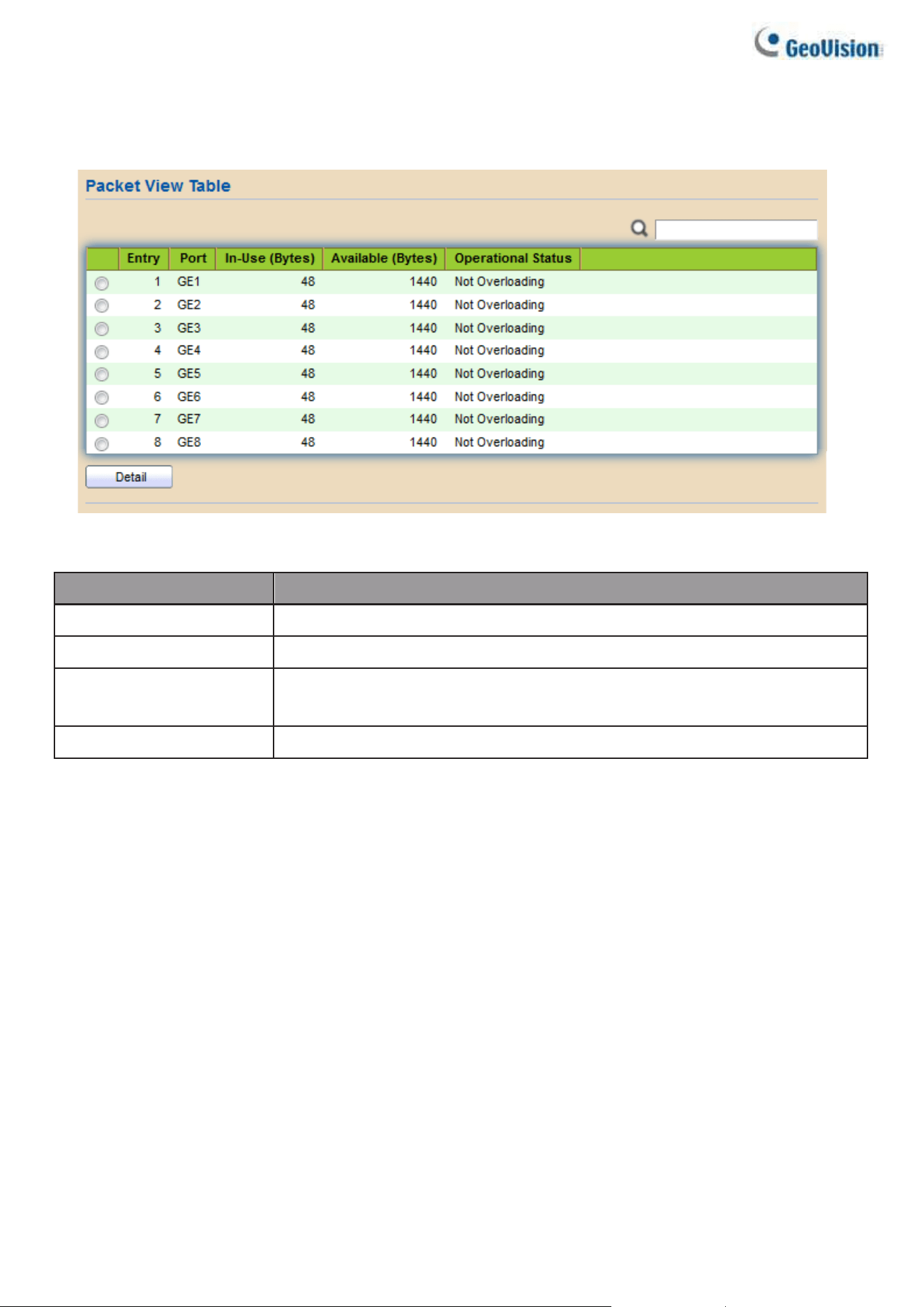
68
2.6.1.5. Packet View
To display LLDP Overloading, click Discovery > LLDP > Packet View.
Figure 75 - Discovery > LLDP > Packet View
Item
Description
Port
Port Name.
In-Use (Bytes)
Total number of bytes of LLDP information in each packet.
Available (Bytes)
Total number of available bytes left for additional LLDP
information in each packet.
Operational Status
Overloading or not.
Click "Detail" button to view Packet View Detail menu.
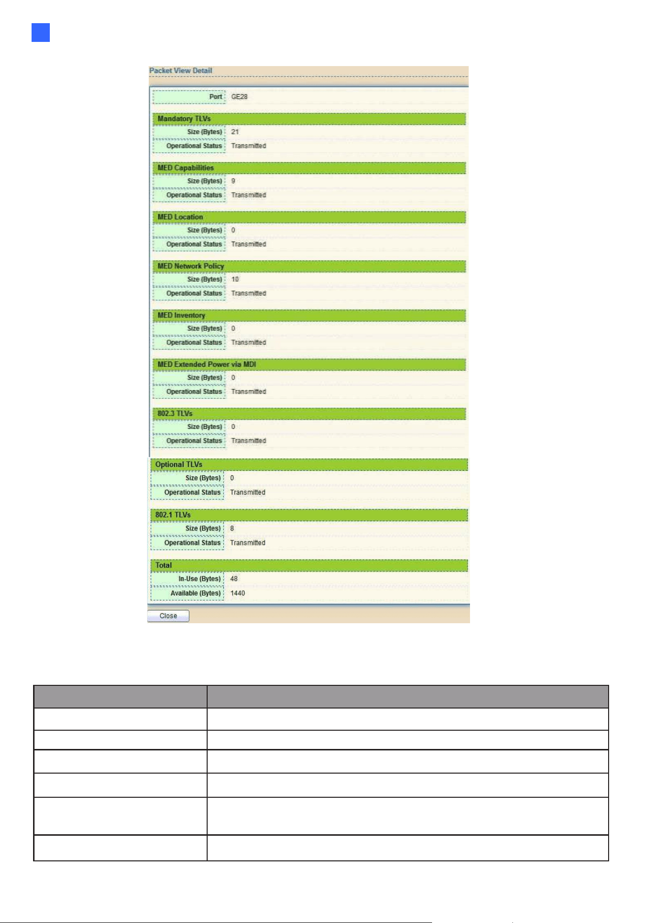
Web-based Switch Configuration
69
2
Figure 76 - Discovery > LLDP > Packet View > Packet View Detail
Item
Description
Port
Port Name
Mandatory TLVs
Total mandatory TLV byte size. Status is sent or overloading.
MED Capabilities
Total MED Capabilities TLV byte size. Status is sent or overloading.
MED Location
Total MED Location byte size. Status is sent or overloading.
MED Network Policy
Total MED Network Policy byte size. Status is sent or
overloading.
MED Inventory
Total MED Inventory byte size. Status is sent or overloading
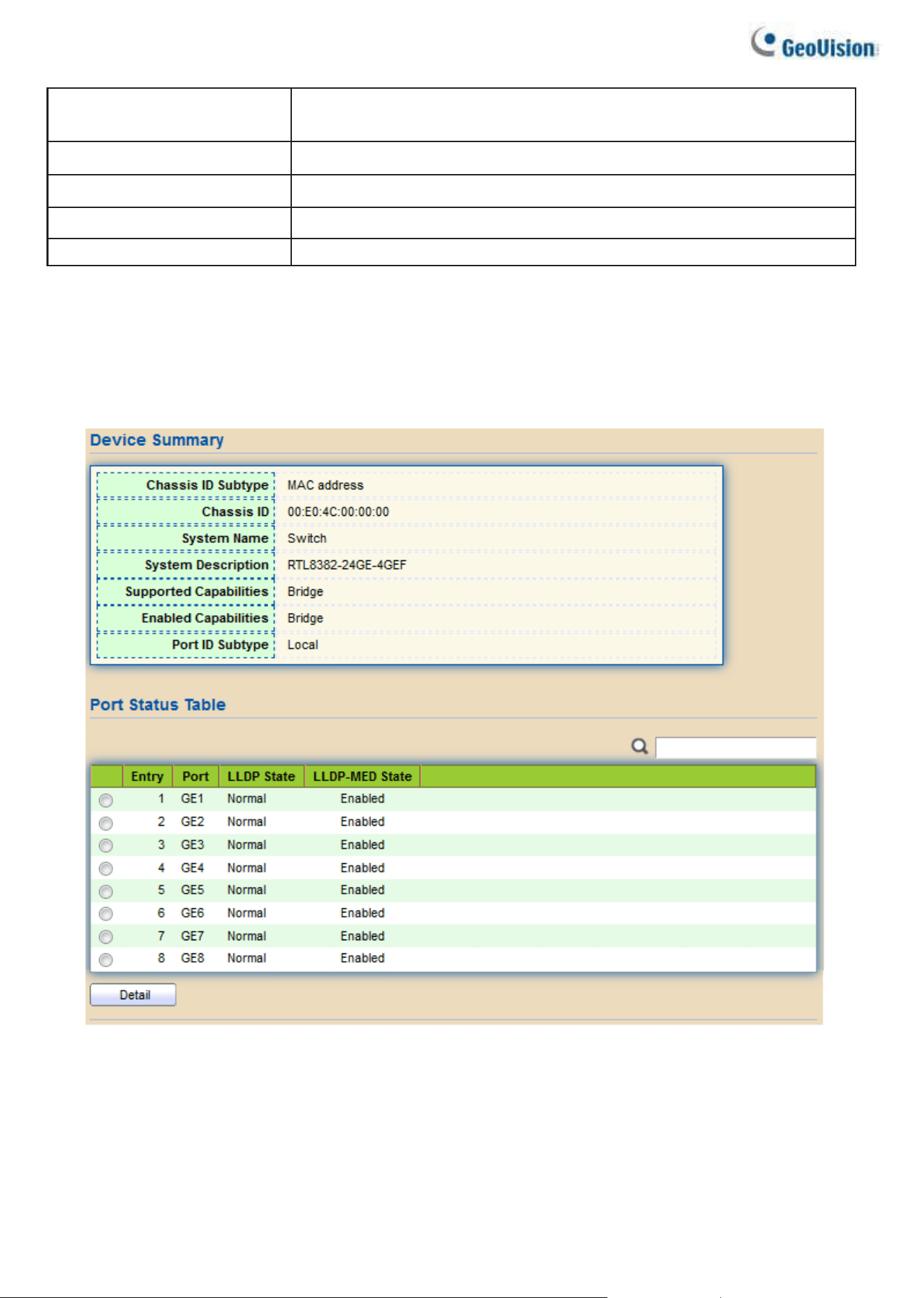
70
MED Extended
Power via MDI
Total MED Extended Power via MDI byte size. Status is sent
or overloading.
802.3 TLVs
Total 802.3 TLVs byte size. Status is sent or overloading.
Optional TLVs
Total Optional TLV byte size. Status is sent or overloading.
802.1 TLVs
Total 802.1 TLVs byte size. Status is sent or overloading.
Total
Total number of bytes of LLDP information in each packet.
2.6.1.6. Local Information
Use the LLDP Local Information to view LLDP local device information.
To display LLDP Local Device, click Discovery > LLDP > Local Information.
Figure 77 - Discovery > LLDP > Local Information
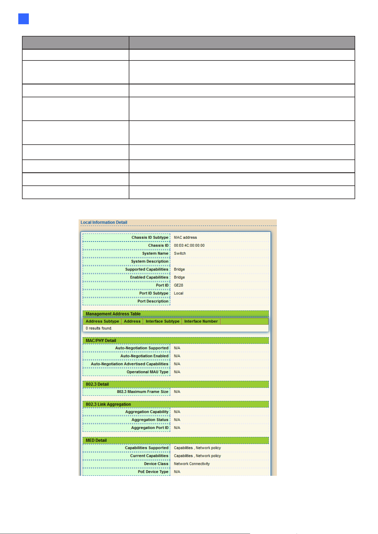
Web-based Switch Configuration
71
2
Item
Description
Chassis ID Subtype
Type of chassis ID, such as the MAC address.
Chassis ID
Identifier of chassis. Where the chassis ID subtype is a MAC
address, the MAC address of the switch is displayed.
System Name
Name of switch.
System
Description
Description of the switch.
Capabilities
Supported
Primary functions of the device, such as Bridge, WLAN
AP, or Router.
Capabilities Enabled
Primary enabled functions of the device.
Port ID Subtype
Type of the port identifier that is shown.
LLDP Status
LLDP Tx and Rx abilities.
LLDP Med Status
LLDP MED enable state.
Click “Detail” button on the page to view detail information of the selected port.
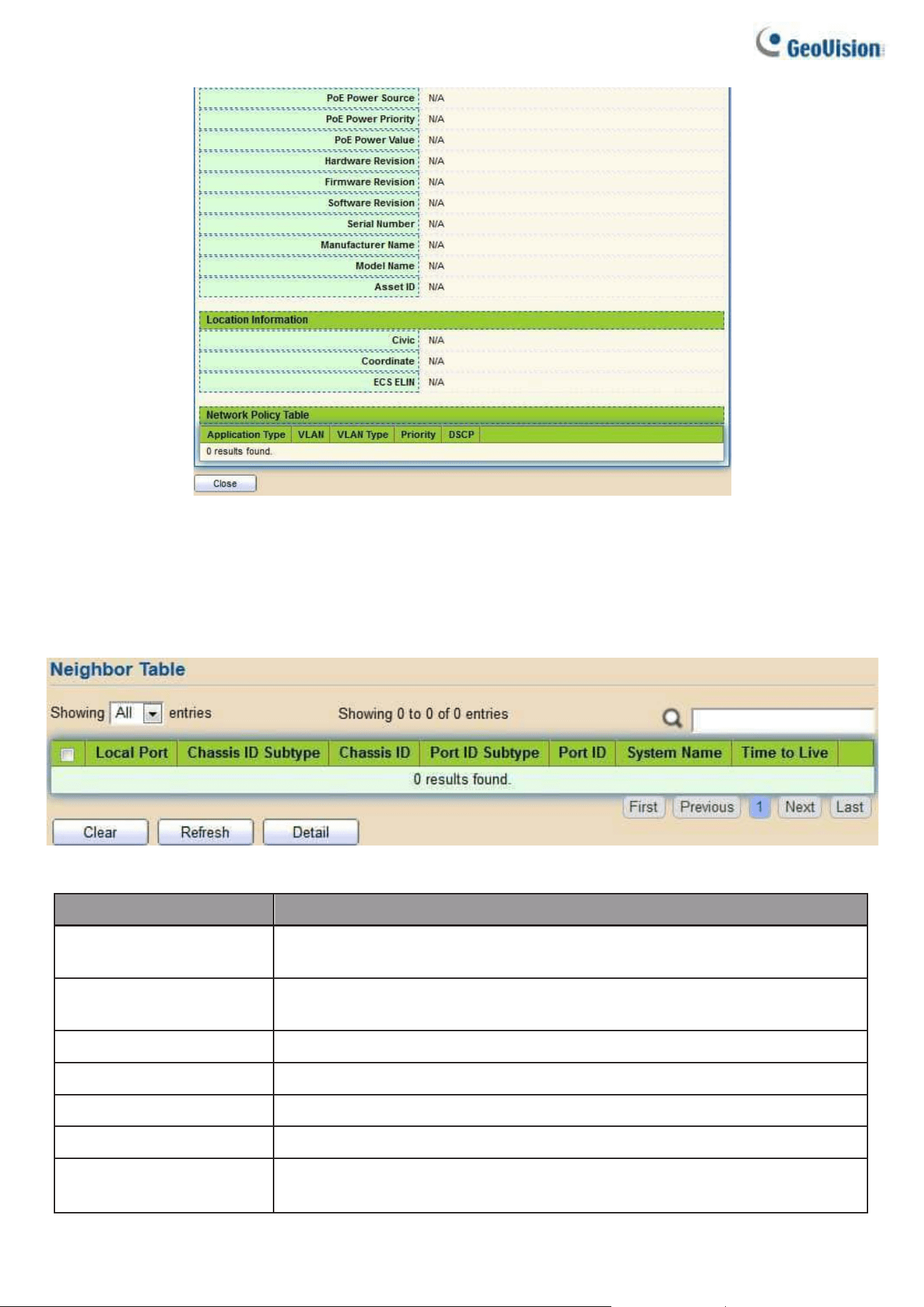
72
Figure 78 - Discovery > LLDP > Local Information > Detail
2.6.1.7. Neighbor
Use the LLDP Neighbor page to view LLDP neighbors information.
To display LLDP Remote Device, click Discovery > LLDP > Neighbor.
Figure 79 - Discovery > LLDP > Neighbor
Item
Description
Local Port
Number of the local port to which the neighbor is
connected.
Chassis ID Subtype
Type of chassis ID (for example, MAC address).
Chassis ID
chassis ID.
Port ID Subtype
Type of the port identifier that is shown.
Port ID
Identifier of port.
System Name
Published name of the switch.
Time to Live
Time interval in seconds after which the information for this
neighbor is deleted.
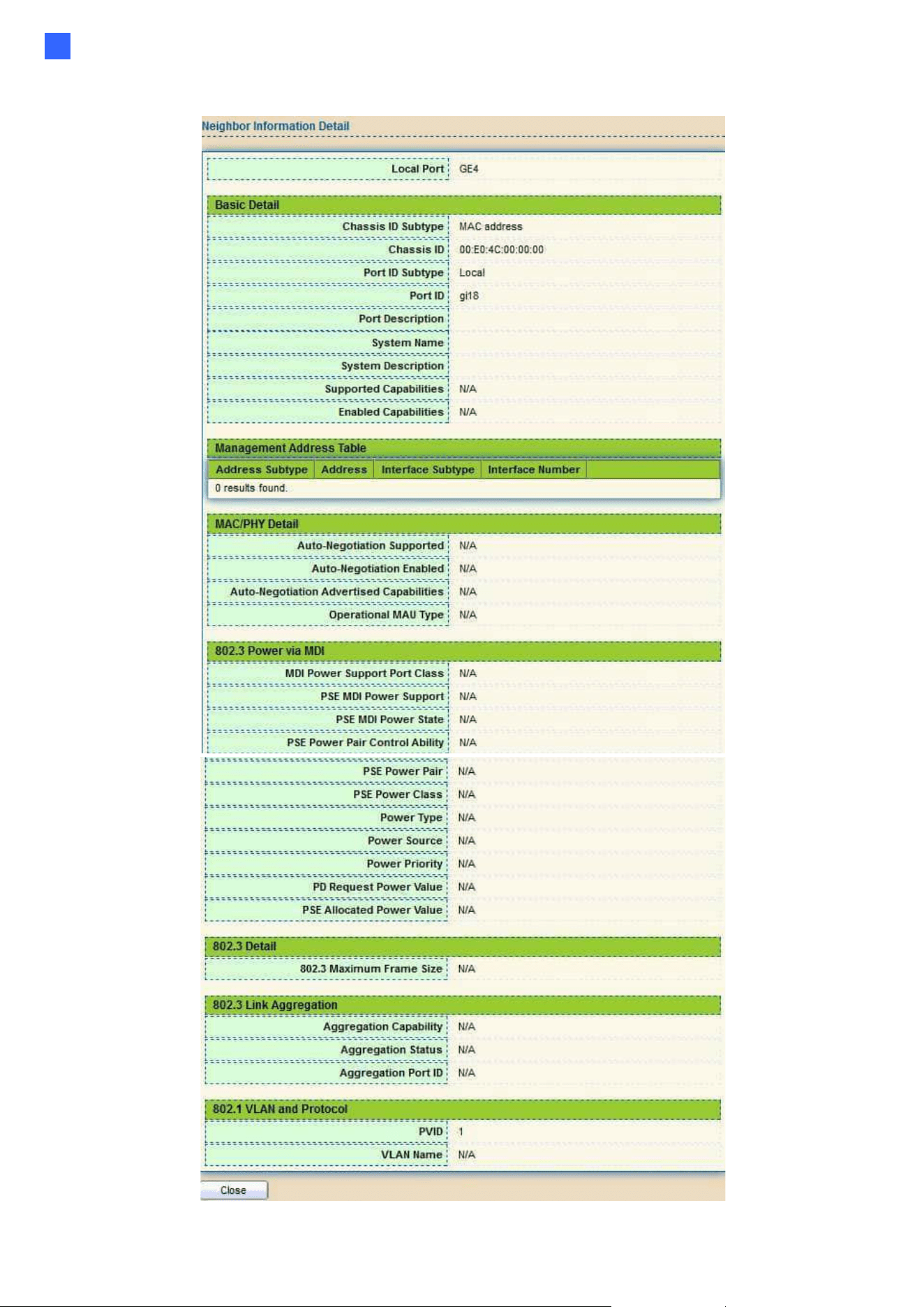
Web-based Switch Configuration
73
2
Click “detail” to view selected neighbor detail information
Figure 80 LLDP Neighbor Detail Page
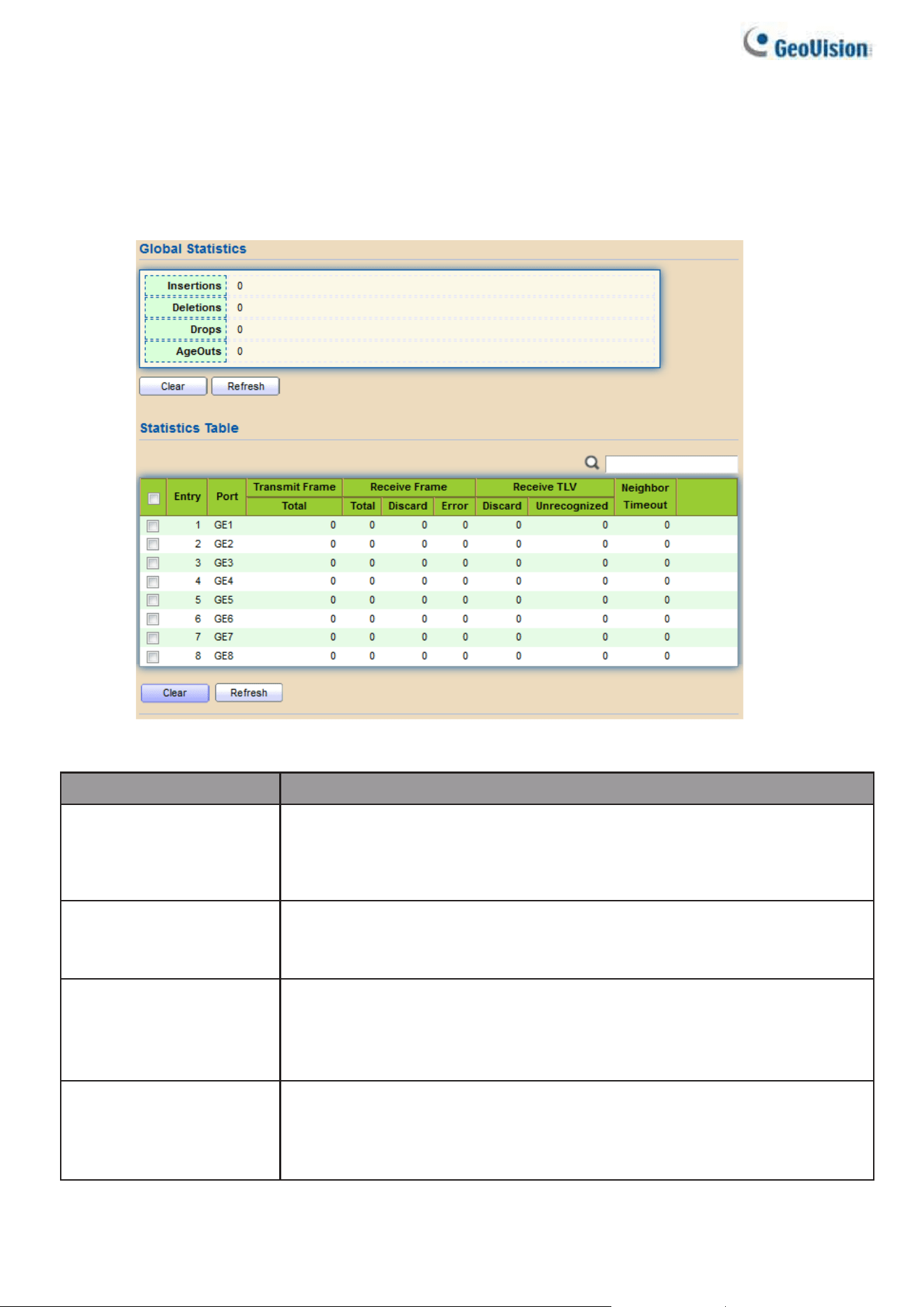
74
2.6.1.8. Statistics
The Link Layer Discovery Protocol (LLDP) Statistics page displays summary and per-
port information for LLDP frames transmitted and received on the switch.
To display LLDP Statistics status, click Discovery > LLDP > Statistics.
Figure 81 - Discovery > LLDP > Statistics
Item
Description
Insertions
The number of times the complete set of information advertised
by a particular MAC Service Access Point (MSAP) has been
inserted into tables associated with the remote systems.
Deletions
The number of times the complete set of information
advertised by MSAP has been deleted from tables
associated with the remote systems.
Drops
The number of times the complete set of information advertised by
MSAP could not be entered into tables associated with the remote
systems because of insufficient resources.
Age Outs
The number of times the complete set of information
advertised by MSAP has been deleted from tables
associated with the remote systems because the
information timeliness interval has expired.
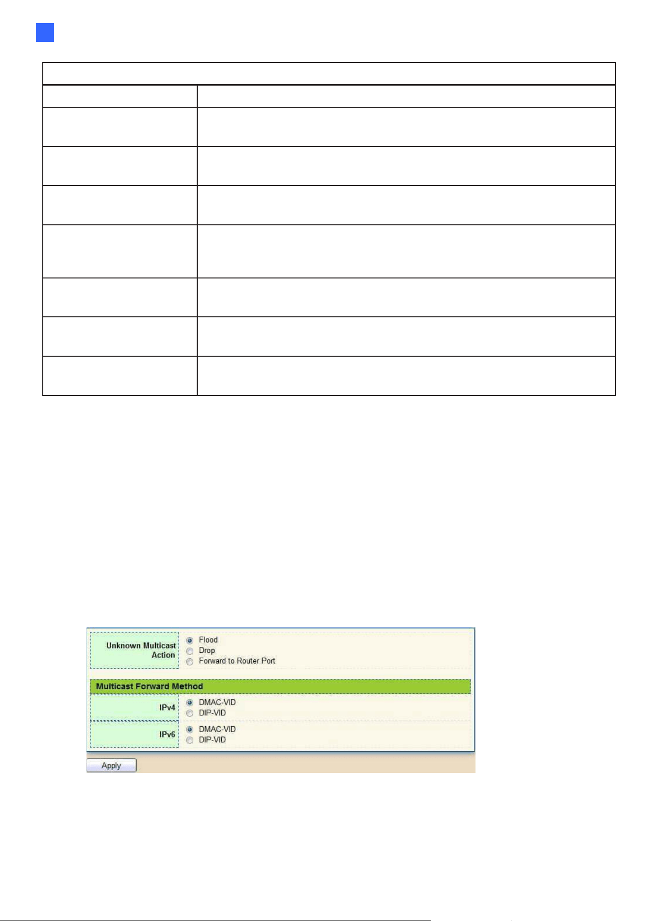
Web-based Switch Configuration
75
2
Statistics Table
Port
Interface or port number.
Transmit Frame
Total
Number of LLDP frames transmitted on the corresponding port.
Receive Frame
Total
Number of LLDP frames received by this LLDP agent on the
corresponding port, while the LLDP agent is enabled.
Receive Frame
Discard
Number of LLDP frames discarded for any reason by the LLDP
agent on the corresponding port.
Receive Frame
Error
Number of invalid LLDP frames received by the LLDP agent on the
corresponding port, while the LLDP agent is enabled.
Receive TLV
Discard
Number of TLVs of LLDP frames discarded for any reason by the
LLDP agent on the corresponding port.
Receive TLV
Unrecognized
Number of TLVs of LLDP frames that are unrecognized while the
LLDP agent is enabled.
Neighbor Timeout
Number of age out LLDP frames.
2.7. Multicast
Use this section to configure Multicast.
2.7.1. General
Use the General pages to configure settings of IGMP and MLD common function.
2.7.1.1. Property
To display multicast general property Setting web page, click Multicast> General>
Property
Figure 82 - Multicast > General > Property
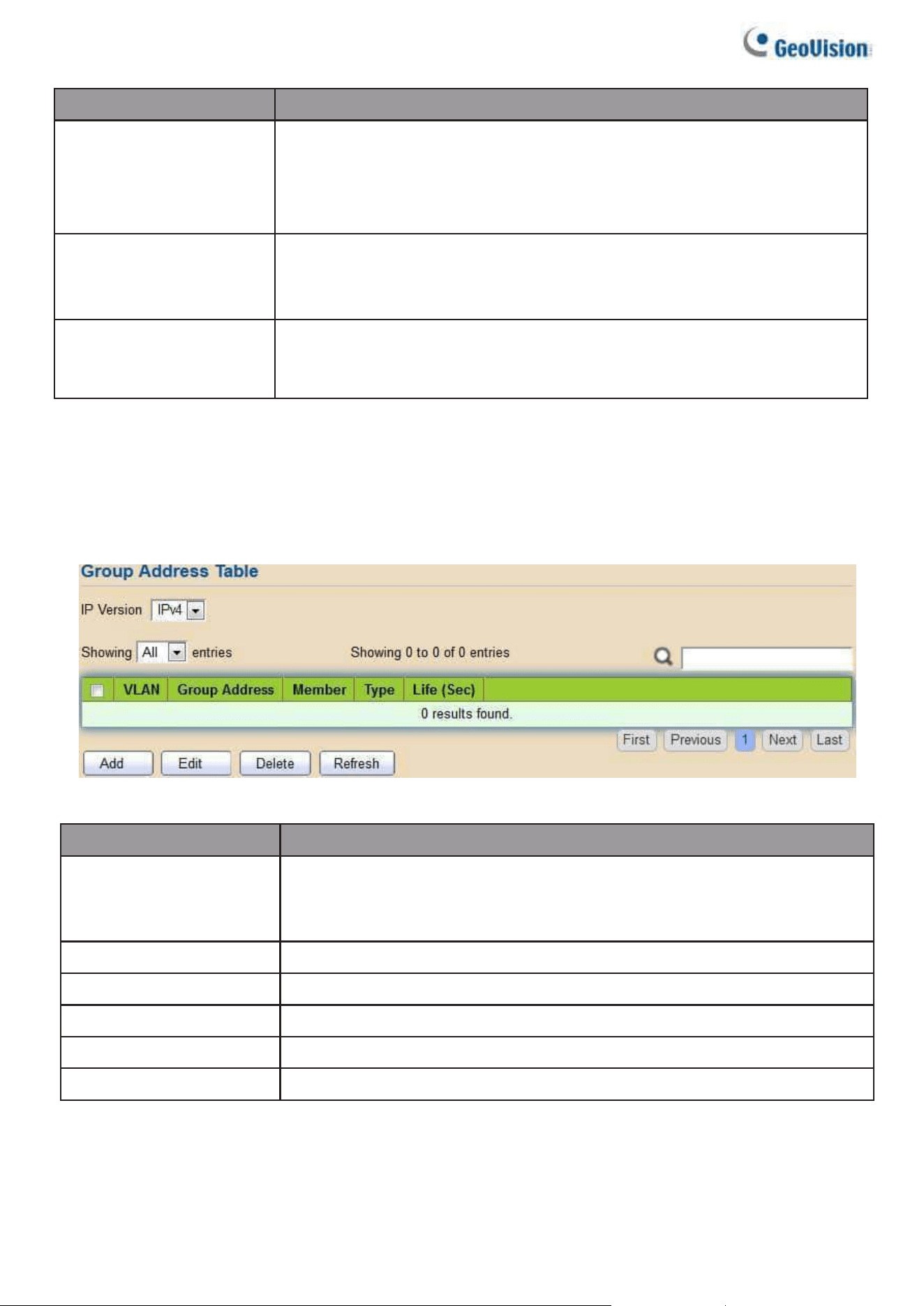
76
Item
Description
Unknown Multicast
Action
Set the unknown multicast action
•
Flood: flood the unknown multicast data.
•
Drop: drop the unknown multicast data.
•
Router port: forward the unknown multicast data to router port.
IPv4
Set the ipv4 multicast forward method.
•
MAC-VID: forward method dmac+vid.
•
DIP-VID: forward method dip+vid.
IPv6
Set the ipv6 multicast forward method.
•
MAC-VID: forward method dmac+vid.
•
DIP-VID: forward method dip+vid(dip is ipv6 low 32 bit).
2.7.1.2. Group Address
This page allows users to browse all multicast groups that dynamic learned or
statically added.
To display Multicast General Group web page, click Multicast> General> Group Address
Figure 83 - Multicast > General > Group Address
Item
Description
IP Version
IP Version
•
IPv4: ipv4 multicast group
•
IPv6: ipv6 multicast group
VLAN
The VLAN ID of group.
Group Address
The group IP address.
Member
The member ports of group.
Type
The type of group. Static or Dynamic.
Life(Sec)
The life time of this dynamic group.
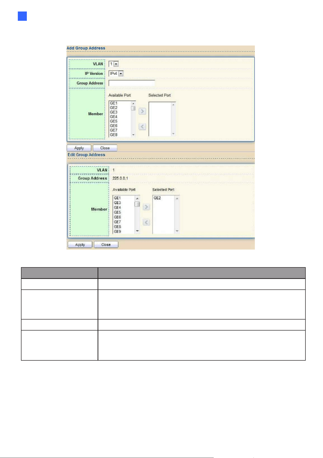
Web-based Switch Configuration
77
2
Click “Add” or “Edit” button to view Add or Edit Group Address menu.
Figure 84 - Multicast > General > Group Address > Add/Edit Group Address
Item
Description
VLAN
The VLAN ID of group.
IP Version
IP Version
•
IPv4: ipv4 multicast group
•
IPv6: ipv6 multicast group
Group Address
The group IP address.
Member
The member ports of group.
•
Available Port: Optional port member
•
Selected Port: Selected port member
2.7.1.3. Router Port
This page allows users to browse all router port information. The static and forbidden
router port can be set by users.
To display multicast router port table web page, click Multicast> General> Router Port.
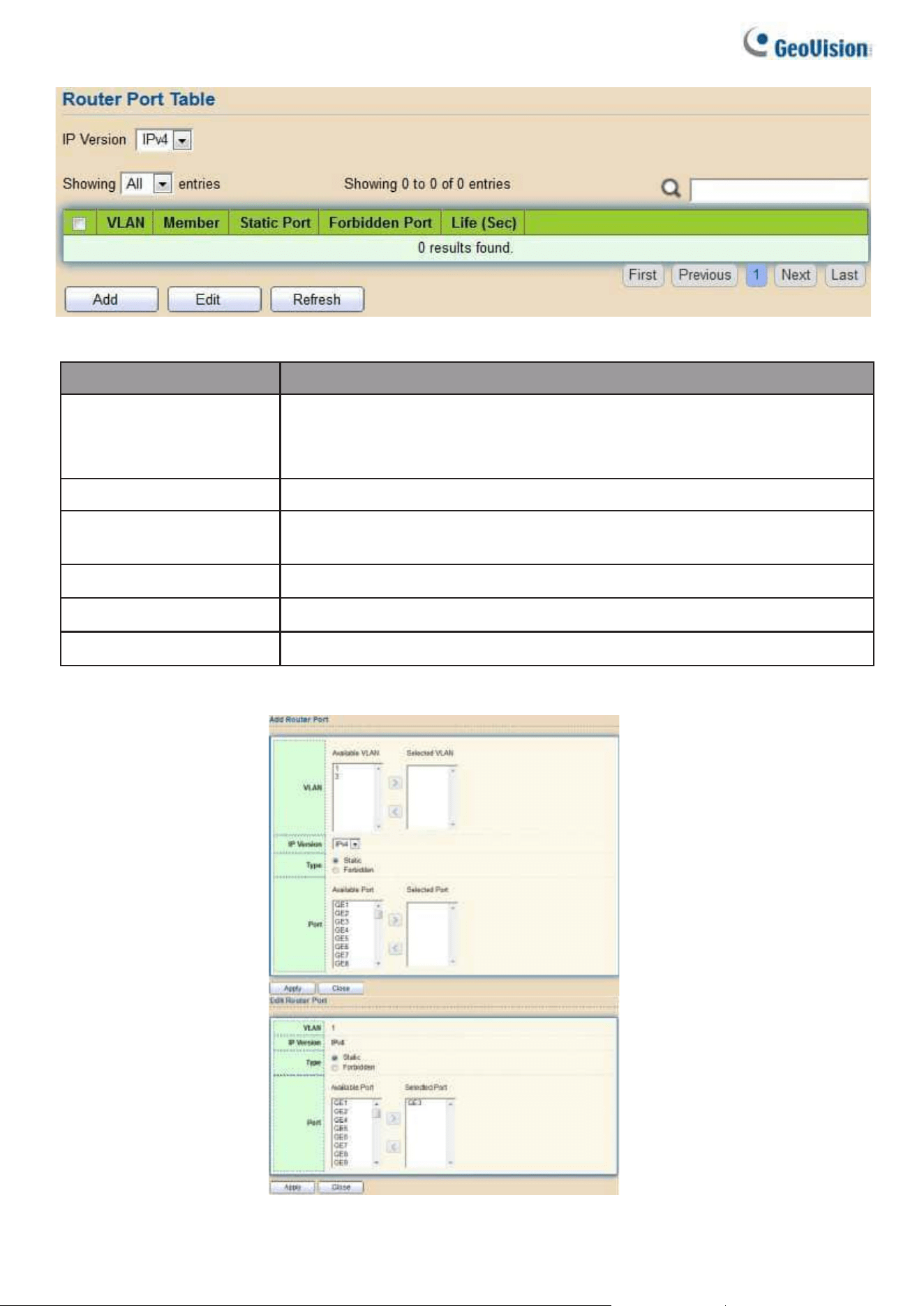
78
Figure 85 - Multicast > General > Router Port
Item
Description
IP Version
IP Version
•
IPv4: ipv4 multicast router
•
IPv6: ipv6 multicast router
VLAN
The VLAN ID router entry.
Member
Router Port member (include static and learned port
member).
Static Port
Static router port member.
Forbidden Port
Forbidden router port member.
Life (Sec)
The expiry time of the router entry.
Click "Add" or “Edit” button to view Add/Edit Router Port menu.
Figure 86 - Multicast > General > Router Port > Add/Edit Router Port
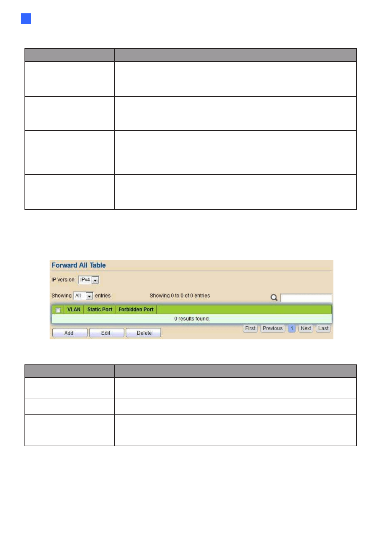
Web-based Switch Configuration
79
2
Item
Description
VLAN
The VLAN ID for router entry
•
Available VLAN: Optional VLAN member
•
Selected VLAN: Selected VLAN member.
IP Version
IP Version
•
IPv4: ipv4 multicast router
•
IPv6: ipv6 multicast router
Type
The router port type
•
Static: static router port
•
Forbidden: forbidden router port, can’t learn dynamic router
port member
Port
The member ports of router entry.
•
Available Port: Optional router port member
•
Selected Port: Selected router port member
2.7.1.4. Forward All
This page allows users to add and edit forward all entry.
To display multicast Forward All web page, click Multicast> General> Forward All
Figure 87 - Multicast > General > Forward All
Item
Description
IP Version
⚫ IPv4: ipv4 multicast forward all
⚫ IPv6: ipv6 multicast forward all
VLAN
VLAN ID of forward all entry
Static Port
Known multicast group always forward port member
Forbidden Port
Known multicast group always not forward port member
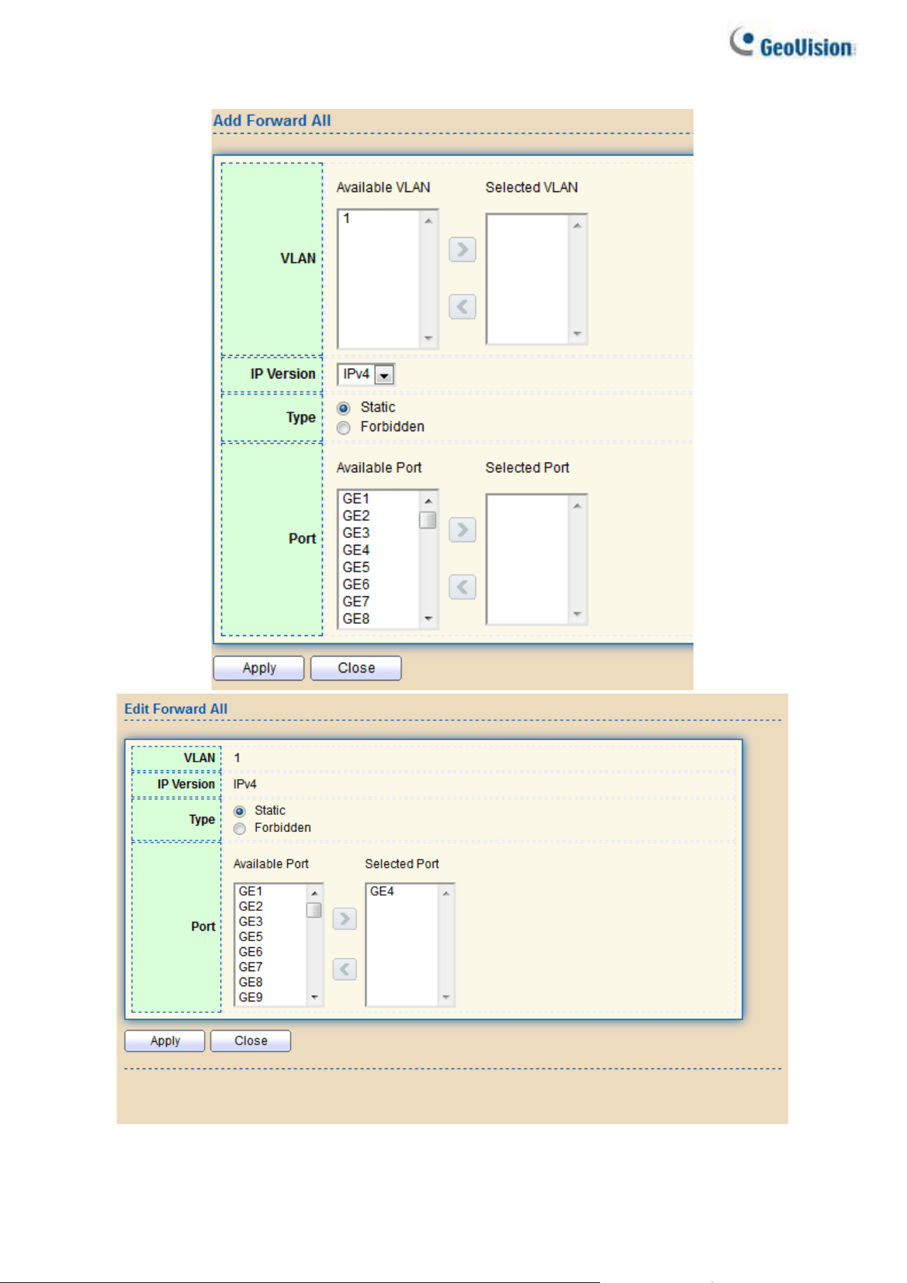
80
Click "Add" or “Edit” button to view Add/Edit Forward All menu.
Figure 88 - Multicast > General > Add/Edit Forward All

Web-based Switch Configuration
81
2
Item
Description
VLAN
The VLAN ID for forward all entry
⚫
Available VLAN: Optional VLAN member
⚫
Selected VLAN: Selected VLAN member
IP Version
⚫
IPv4: ipv4 multicast forward all
⚫
IPv6: ipv6 multicast forward all
Type
The forward all port type
⚫
Static: static forward all port
⚫
Forbidden: forbidden forward all port
Port
The member ports of router entry
⚫
Available Port: Optional router port member
⚫
Selected Port: Selected router port member
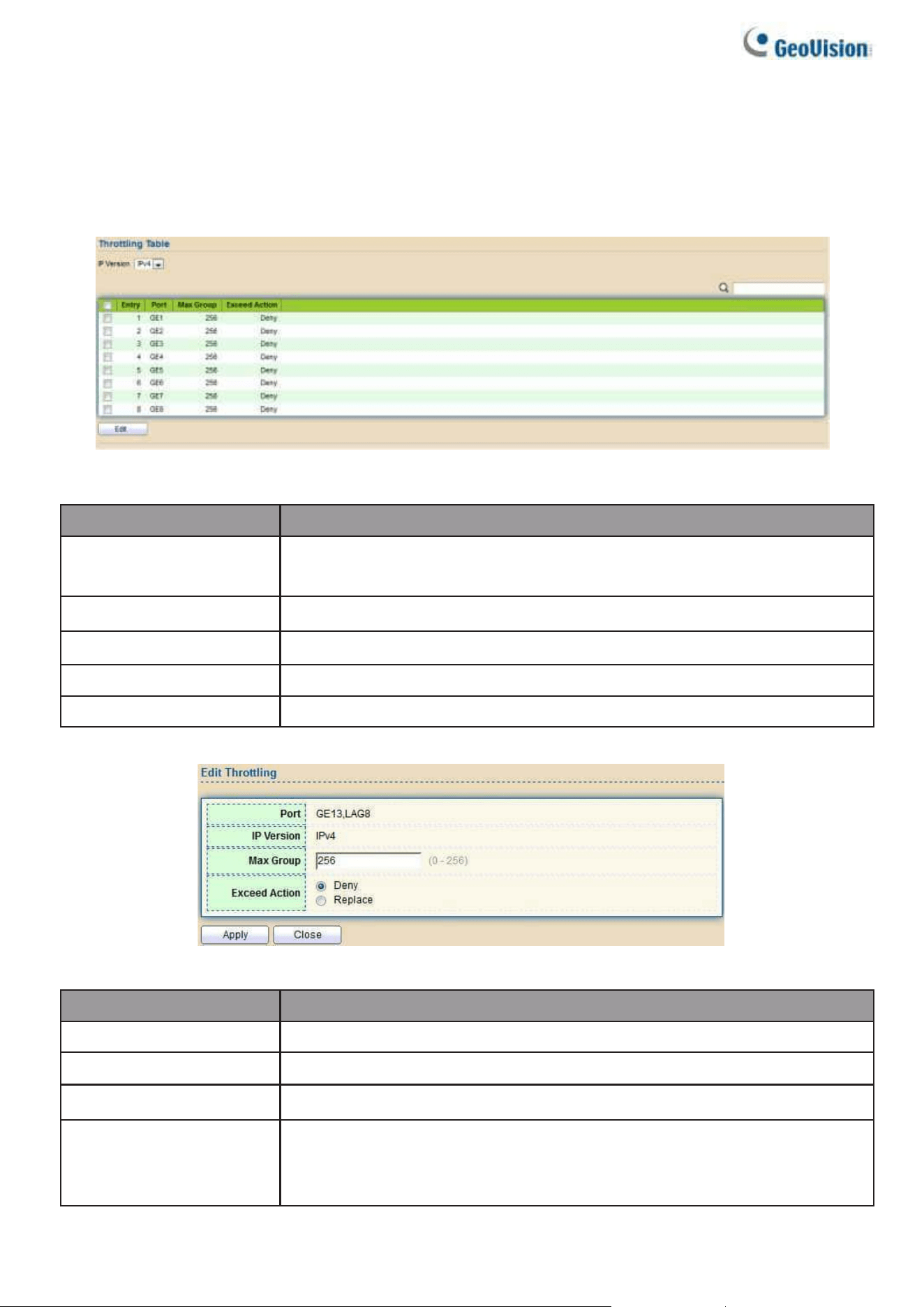
82
2.7.1.5. Throttling
This page allows users to configure port can learned max group number and if port group
number arrived max group number action.
To display multicast max-group number and action setting web page, click
Multicast> General> Throttling
Figure 89 - Multicast > General > Throttling
Item
Description
IP Version
⚫ IPv4: ipv4 for igmp snooping throttling
⚫ IPv6: ipv6 for mld snooping throttling
Entry
Entry of number
Port
Port Name
Max Group
Max number of group for port
Exceed Action
Display the port exceed max number group learning group action
Click “Edit” button to view Edit Throttling menu.
Figure 90 - Multicast > General > Edit Throttling
Item
Description
Port
Display the selected port list
IP Version
Display the selected IP version
Max Group
Max number of group for port
Exceed Action
Excess Max number of port learning group action
⚫
Deny: do not learning group.
⚫
Replace: random replace one exist group
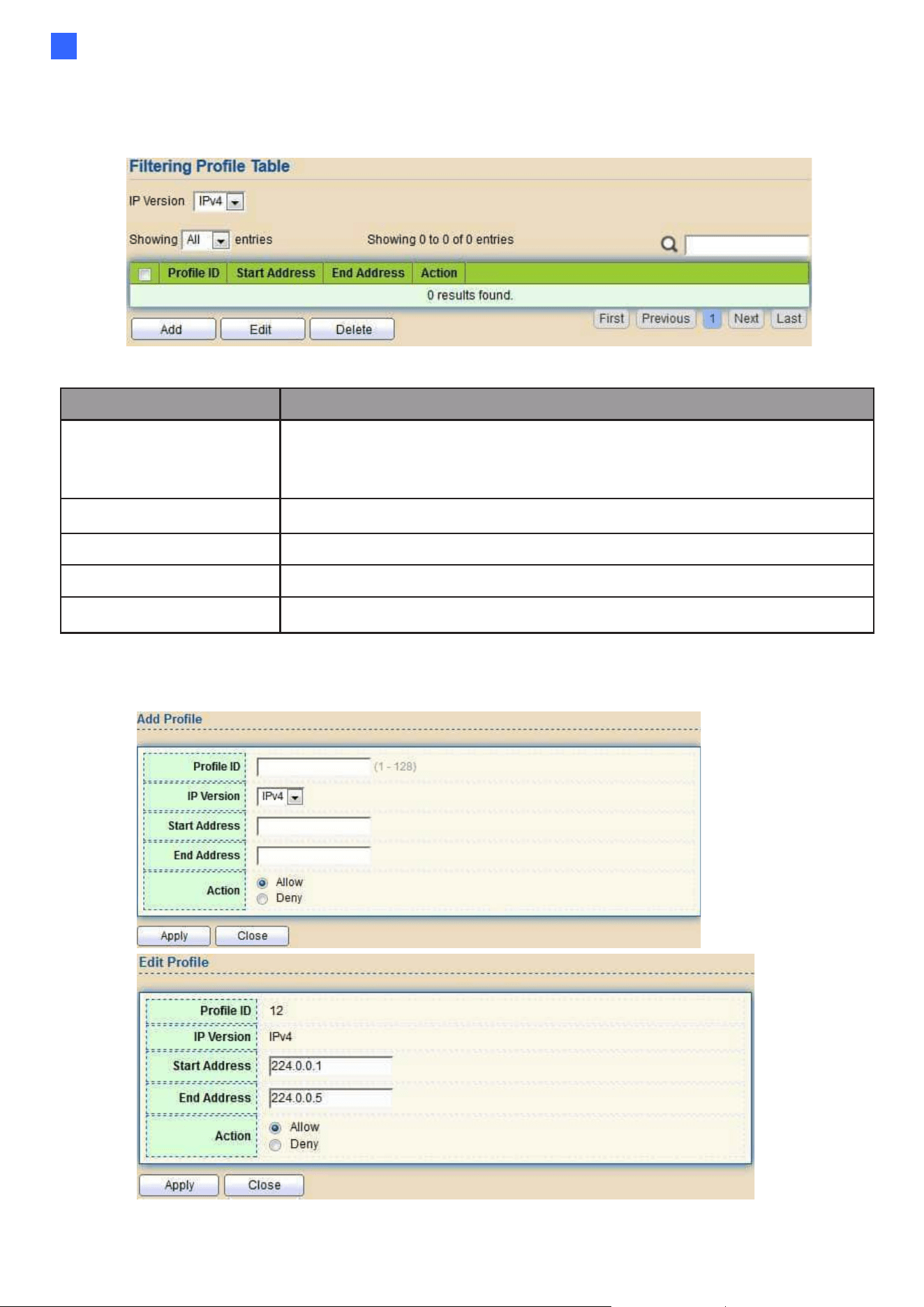
Web-based Switch Configuration
83
2
2.7.1.6. Filtering Profile
This page allows users to add, edit or delete profile for IGMP or MLD snooping.
To display Multicast Profile Setting web page, click Multicast> General> Filtering Profile
Figure 91 - Multicast > General > Filtering Profile
Item
Description
IP Version
IP version:
⚫
IPv4: IGMP snooping profile
⚫
IPv6: MLD snooping profile
Profile ID
Profile ID
Start Address
The start group address of profile Display
End Address
The end group address of profile
Action
Display profile action
Click "Add" or “Edit” button to view Add/Edit profile menu.
Figure 92 - Multicast > General > Add/Edit Filtering Profile
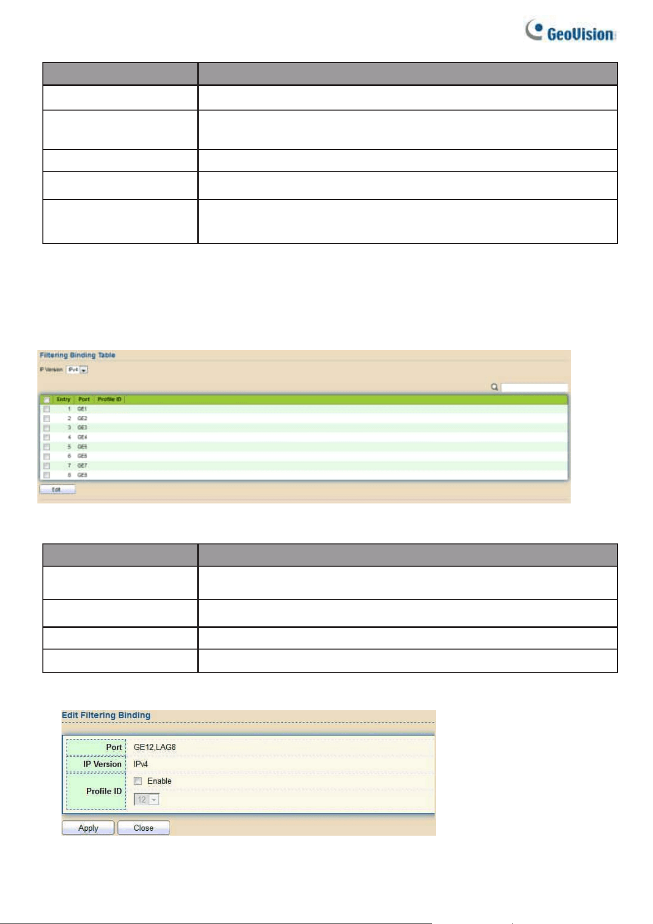
84
Item
Description
Profile ID
Profile ID
IP Version
⚫ IPv4: IGMP snooping profile
⚫ IPv6: MLD snooping profile
Start Address
The start group address of profile Display
End Address
The end group address of profile
Action
⚫
Allow: permit all packets that match the profile.
⚫
Deny: deny all packets that match the profile.
2.7.1.7. Filtering Binding
This page allows users to bind/remove profile for each port.
To display Multicast port filter binding profile web page, click Multicast> General> Filtering
Binding
Figure 93 - Multicast > General > Filtering Profile Binding
Item
Description
IP Version
⚫ IPv4: IGMP snooping profile
⚫ IPv6: MLD snooping profile
Entry
Entry of number
Port
Port Name
Profile ID
Port binding Profile ID
Click “Edit” button to view Edit profile Binding menu.
Figure 94 - Multicast > General > Edit Filtering Profile Binding
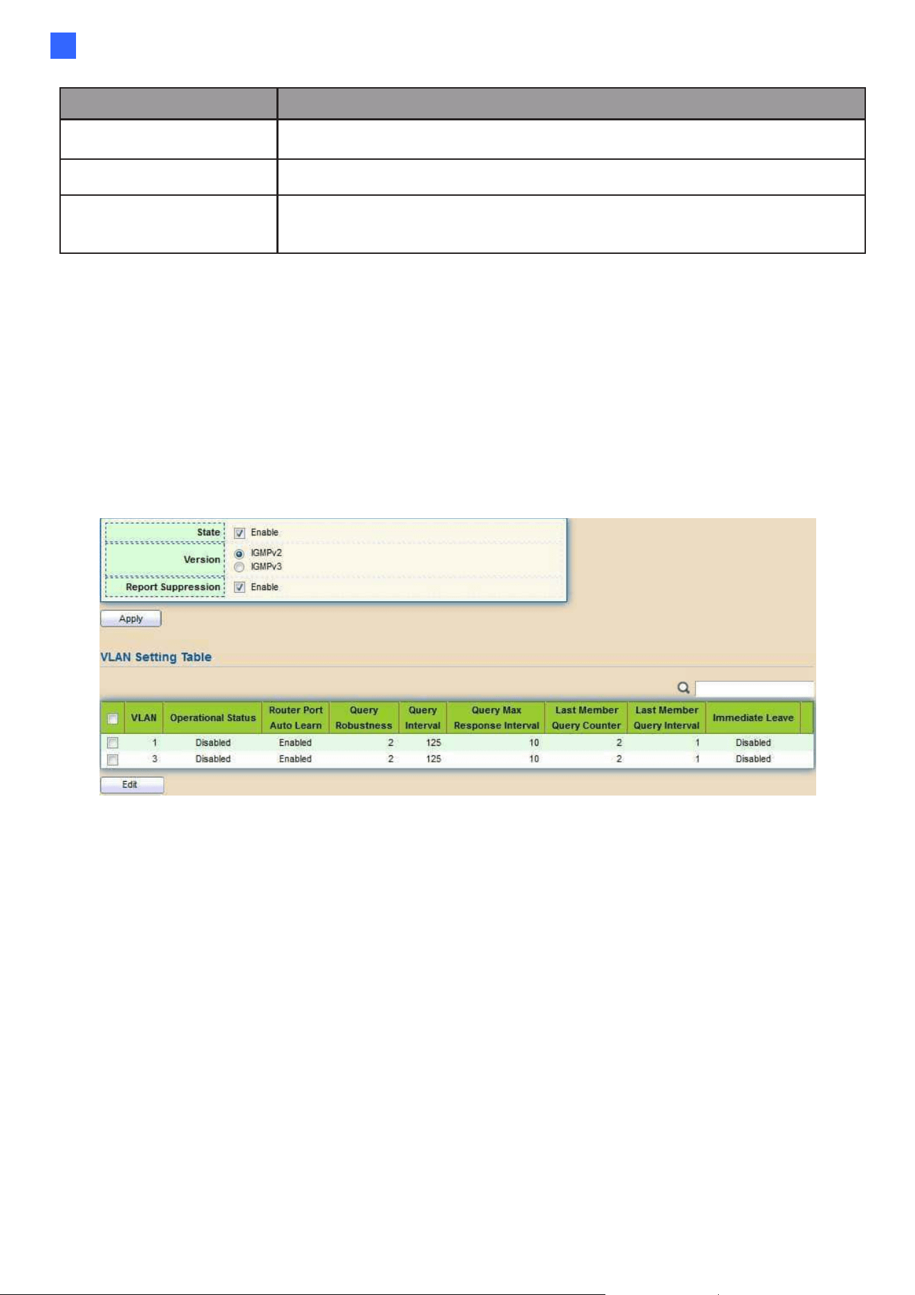
Web-based Switch Configuration
85
2
Item
Description
Port
Selected Port List
IP Version
Display Selected Port filtering IP version
Profile ID
If check Enable, can select or change profile ID, Else it will delete
port filter profile binding
2.7.2. IGMP Snooping
Use the IGMP Snooping pages to configure settings of IGMP snooping function.
2.7.2.1. Property
This page allows users to configure global settings of IGMP snooping and configure specific
VLAN settings of IGMP Snooping.
To display IGMP Snooping global setting and VLAN Setting web page, click
Multicast> IGMP Snooping> Property
Figure 95 - Multicast > IGMP Snooping > Property

86
Item
Description
State
Set the enabling status of IGMP Snooping functionality
•
Enable: If Checked Enable IGMP Snooping, else is Disabled IGMP
Snooping.
Version
Set the igmp snooping version
•
IGMPv2: Only support process igmp v2 packet.
•
IGMPv3: Support v3 basic and v2.
Report Suppression
Set the enabling status of IGMP v2 report suppression
•
Enable: If Checked Enable IGMP Snooping v2 report
suppression, else Disable the report suppression function.
VLAN
The IGMP entry VLAN ID.
Operation Status
The enable status of IGMP snooping VLAN functionality.
Router Port Auto
Learn
The enabling status of IGMP snooping router port auto
learning.
Query Robustness
The Query Robustness allows tuning for the expected
packet loss on a subnet.
Query Interval
The interval of querier to send general query.
Query Max
Response
Interval
In Membership Query Messages, it specifies the maximum
allowed time before sending a responding report in units of 1/10
second.
Last Member
Query count
The count that Querier-switch sends Group-Specific Queries
when it receives a Leave Group message for a group.
Last Member
Query Interval
The interval that Querier-switch sends Group-Specific
Queries when it receives a Leave Group message for a
group.
Immediate leave
The immediate leave status of the group will immediate leave
when receive IGMP Leave message.
Click "Edit" button to Edit VLAN Setting menu.
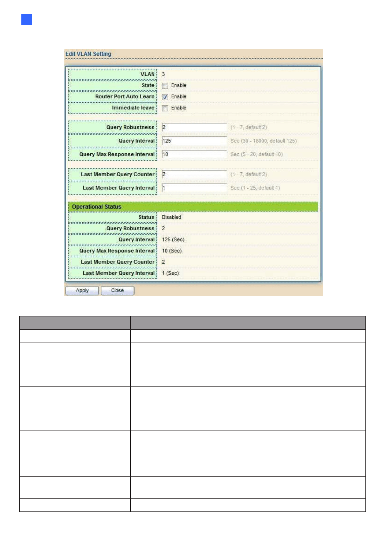
Web-based Switch Configuration
87
2
Figure 96 - Multicast > IGMP Snooping > Property >Edit VLAN Setting
Item
Description
VLAN
The selected VLAN List.
State
Set the enabling status of IGMP Snooping VLAN
functionality
•
Enable: If Checked Enable IGMP Snooping VLAN, else is
Disabled IGMP Snooping VLAN.
Router Port Auto Learn
Set the enabling status of IGMP Snooping router port
learning
•
Enable: If checked Enable learning router port by query
and PIM, DVRMP, else Disable the learning router port.
Immediate leave
Immediate Leave the group when receive IGMP Leave
message.
•
Enable: If checked Enable immediate leave, else disable
immediate leave.
Query Robustness
The Admin Query Robustness allows tuning for the
expected packet loss on a subnet.
Query Interval
The Admin interval of querier to send general query.

88
Query Max Response
Interval
The Admin query max response interval, In Membership
Query Messages, it specifies the maximum allowed time
before sending a responding report in units of 1/10 second.
Last Member Query
Counter
The Admin last member query count that Querier-switch
sends Group-Specific Queries when it receives a Leave
Group message for a group.
Last Member Query
Interval
The Admin last member query interval that Querier-switch
sends Group-Specific Queries when it receives a Leave Group
message for a group.
Operational Status
Status
Operational IGMP snooping status must both IGMP snooping
global and IGMP snooping enable the status will be enable.
Query Robustness
Operational Query Robustness.
Query Interval
Operational Query Interval.
Query Max
Response
Interval
Operational Query Max Response Interval
Last Member Query
Counter
Operational Last Member Query Count.
Last Member Query
Interval
Operational Last Member Query Interval
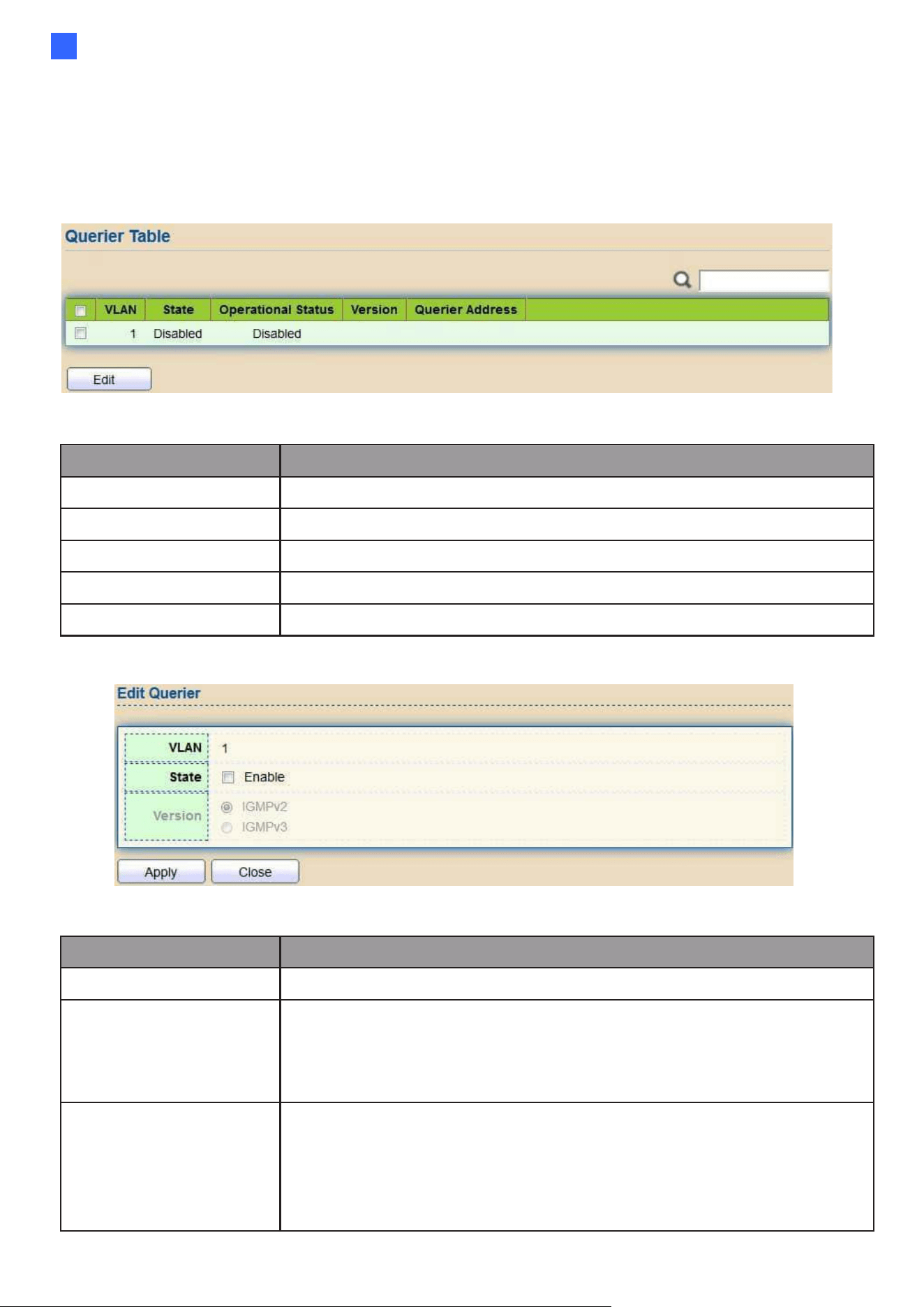
Web-based Switch Configuration
89
2
2.7.2.2. Querier
This page allows users to configure querier settings on specific VLAN of IGMP
Snooping.
To display IGMP Snooping Querier Setting web page, click Multicast> IGMP Snooping
> Querier
Figure 97 - Multicast > IGMP Snooping > Querier
Item
Description
VLAN
IGMP Snooping querier entry VLAN ID.
State
The IGMP Snooping querier Admin State.
Operational Status
The IGMP Snooping querier operational status.
Version
The IGMP Snooping querier operational version.
Querier IP
The operational Querier IP address on the VLAN.
Click "Edit" button to view Edit Querier menu.
Figure 98 - Multicast > IGMP Snooping > Querier > Edit Querier
Item
Description
VLAN
The Selected Edit IGMP Snooping querier VLAN List.
State
Set the enabling status of IGMP Querier Election on the chose
VLANs
•
Enabled: if checked Enable IGMP Querier else Disable
IGMP Querier.
Version
Set the query version of IGMP Querier Election on the chose
VLANs
•
IGMPv2: Querier version 2.
•
IGMPv3: Querier version 3. (IGMP Snooping version should be
IGMPv3)
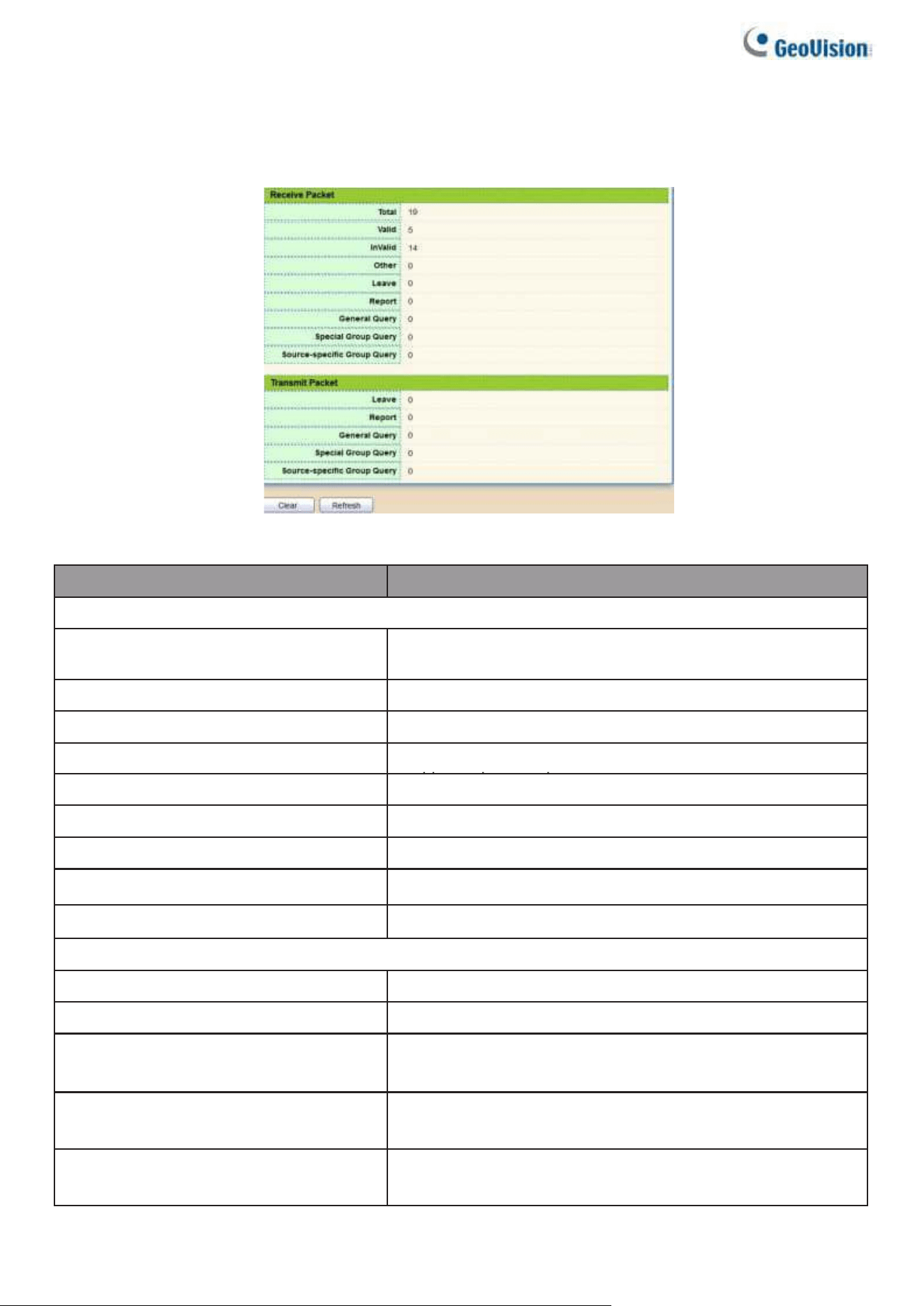
90
2.7.2.3. Statistics
This page allows users to clear IGMP snooping statics.
To display IGMP Snooping Statistics, click Multicast> IGMP Snooping> Statistic
Figure 99 - Multicast > IGMP Snooping > Statistics
Item
Description
Receive Packet
Total
Total RX igmp packet, include ipv4 multicast data to
CPU.
Valid
The valid igmp snooping process packet.
InValid
The invalid igmp snooping process packet.
Other
The ICMP protocol is not 2, and is not ipv4
multicast data packet.
Leave
IGMP leave packet.
Report
IGMP join and report packet.
General Query
IGMP General Query packet.
Special Group Query
IGMP Special Group General Query packet.
Source-specific Group Query
IGMP Special Source and Group General Query packet.
Transmit Packet
Leave
IGMP leave packet
Report
IGMP join and report packet
General Query
IGMP general query packet include querier
transmit general query packet.
Special Group Query
IGMP special group query packet include querier
transmit special group query packet.
Source-specific Group Query
IGMP Special Source and Group General Query
packet.

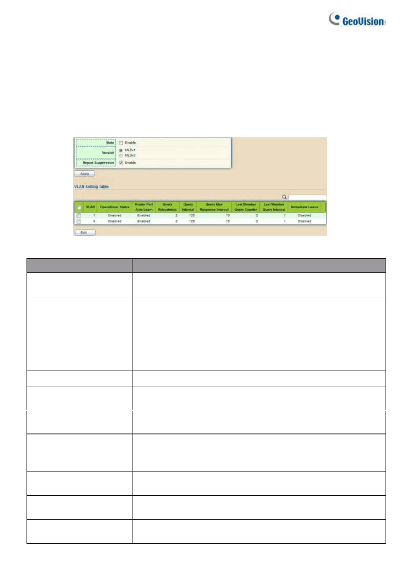
92
2.7.3. MLD Snooping
Use the MLD Snooping pages to configure settings of MLD snooping function.
2.7.3.1. Property
This page allows users to configure global settings of MLD snooping and configure specific VLAN
settings of MLD Snooping.
To display MLD Snooping global setting and VLAN Setting webpage, click Multicast > MLD
Snooping > Property
Figure 100 - Multicast > MLD snooping > Property
Item
Description
State
⚫
Enable: If Checked Enable IGMP Snooping, else is
Disabled IGMP Snooping.
Version
⚫
MLDv1: Only support process MLD v1 packet.
⚫
MLDv2: Support v2 basic and v1
Report
Suppression
Set the enabling status of MLD v1 report suppression
⚫
Enable: If Checked Enable MLD Snooping v1 report
suppression, else Disable the report suppression function
VLAN
The MLD entry VLAN ID
Operation Status
The enable status of MLD snooping VLAN functionality
Router Port Auto
Learn
The enabling status of MLD snooping router port auto
learning.
Query Robustness
The Query Robustness allows tuning for the expected packet loss
on a subnet.
Query Interval
The interval of querier to send general query.
Query Max Response
Interval
In Membership Query Messages, it specifies the maximum allowed
time before sending a responding report in units of 1/10 second.
Last Member Query count
The count that Querier-switch sends Group-Specific Queries when it
receives a Leave Group message for a group.
Last Member Query Interval
The interval that Querier-switch sends Group-Specific Queries when
it receives a Leave Group message for a group.
Immediate leave
The immediate leave status of the group will immediately leave when
receive MLD Leave message.
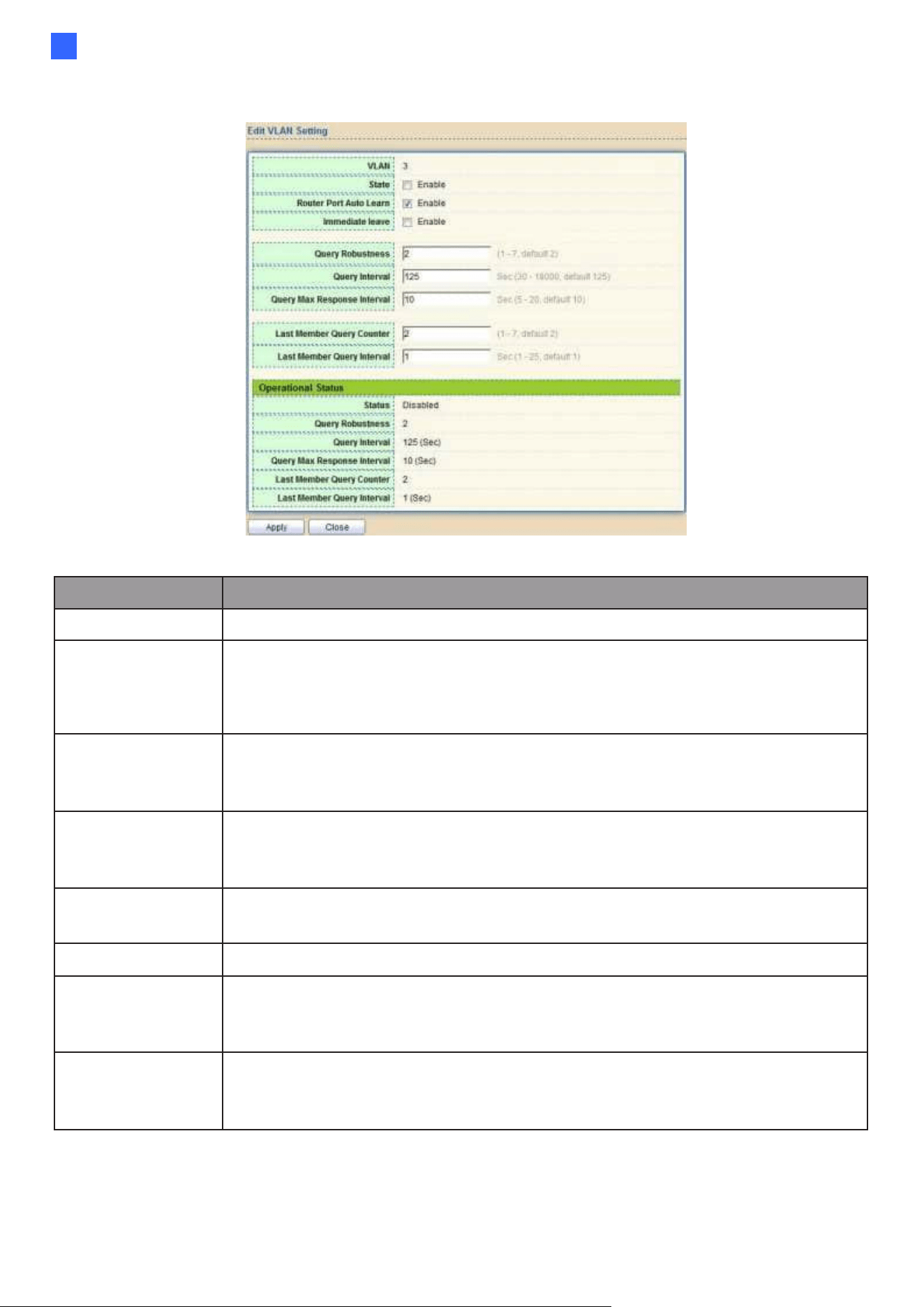
Web-based Switch Configuration
93
2
Click "Edit" button to view Edit VLAN Setting menu.
Figure 101 - Multicast > MLD snooping > Edit VLAN Setting
Item
Description
VLAN
The selected VLAN List
State
Set the enabling status of MLD Snooping VLAN
functionality
⚫
Enable: If Checked Enable MLD Snooping VLAN, else is Disabled
MLD Snooping VLAN.
Router Port Auto
Learn
Set the enabling status of MLD Snooping router port learning
⚫
Enable: If checked Enable learning router port by query
and PIM, DVRMP, else Disable the learning router port.
Immediate leave
Immediate Leave the group when receive MLD Leave message.
Enable: If checked Enable immediate leave, else disable
immediate leave Immediate leave.
Query Robustness
The Admin Query Robustness allows tuning for the
expected packet loss on a subnet.
Query Interval
The Admin interval of querier to send general query.
Query Max
Response Interval
The Admin query max response interval, In Membership
Query Messages, it specifies the maximum allowed time
before sending a responding report in units of 1/10 second.
Last Member Query
Counter
The Admin last member query count that Querier-switch
sends Group-Specific Queries when it receives a Leave
Group message for a group.
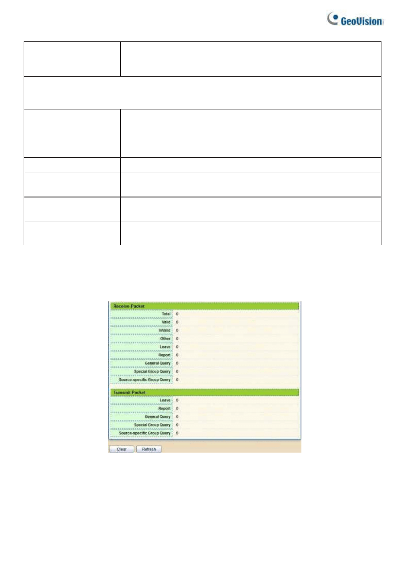
94
Last Member
Query Interval
The Admin last member query interval that Querier-switch sends
Group-Specific Queries when it receives a Leave Group message
for a group.
Operational Status
Status
Operational MLD snooping status,must both MLD snooping
global and MLD snooping enable the status will be enable.
Query Robustness
Operational Query Robustness.
Query Interval
Operational Query Interval.
Query Max
Response Interval
Operational Query Max Response Interval.
Last Member
Query Counter
Operational Last Member Query Count.
Last Member
Query Interval
Operational Last Member Query Interval.
2.7.3.2. Statistics
This page allows users to clear MLD snooping statics.
To display MLD Snooping Statistics, click Multicast> MLD Snooping> Statistics
Figure 102 - Multicast > MLD snooping > Statistics

Web-based Switch Configuration
95
2
Item
Description
Receive Packet
Total
Total RX MLD packet, include ipv4 multicast data to CPU.
Valid
The valid MLD snooping process packet.
In Valid
The invalid MLD snooping process packet.
Other
The ICMPV6 type is not MLD, and is not ipv6 multicast data
packet, and is not IPV6 router protocol.
Leave
MLD leave packet.
Report
MLD join and report packet.
General Query
MLD General Query packet.
Special Group
Query
MLD Special Group General Query packet
Source-specific
Group Query
MLD Special Source and Group General Query packet
Transmit Packet
Leave
MLD leave packet.
Report
MLD join and report packet.
General Query
MLD general query packet.
Special Group Query
MLD special group query packet.
Source-specific Group
Query
MLD Special Source and Group General Query packet.
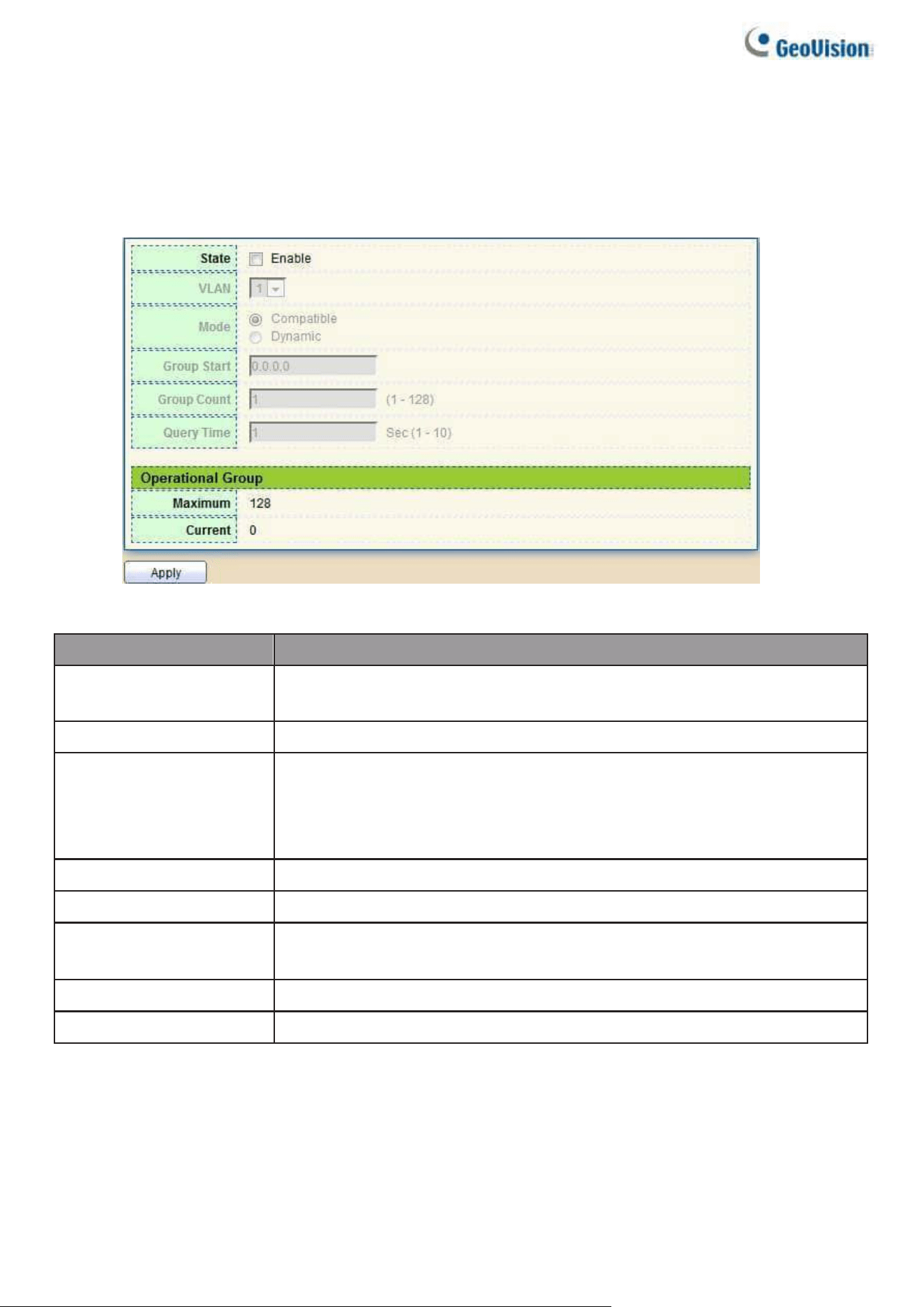
96
2.7.4. MVR
Use the MVR pages to configure settings of MVR function.
2.7.4.1. Property
To display multicast MVR property Setting web page, click Multicast> MVR> Property
Figure 103 - Multicast > MVR > Property
Item
Description
State
•
Enable: if checked enable the MVR state, else disable the MVR
state.
VLAN
The MVR VLAN ID.
Mode
Set the MVR mode
•
Compatible: compatible mode.
•
Dynamic: dynamic mode, will learn group member on source
port.
Group Start
MVR group range start.
Group Count
MVR group continue count.
Query Time
MVR query time when receive MVR leave MVR group
packet.
Maximum
The max number of MVR group database.
Current
The learned MVR group current time
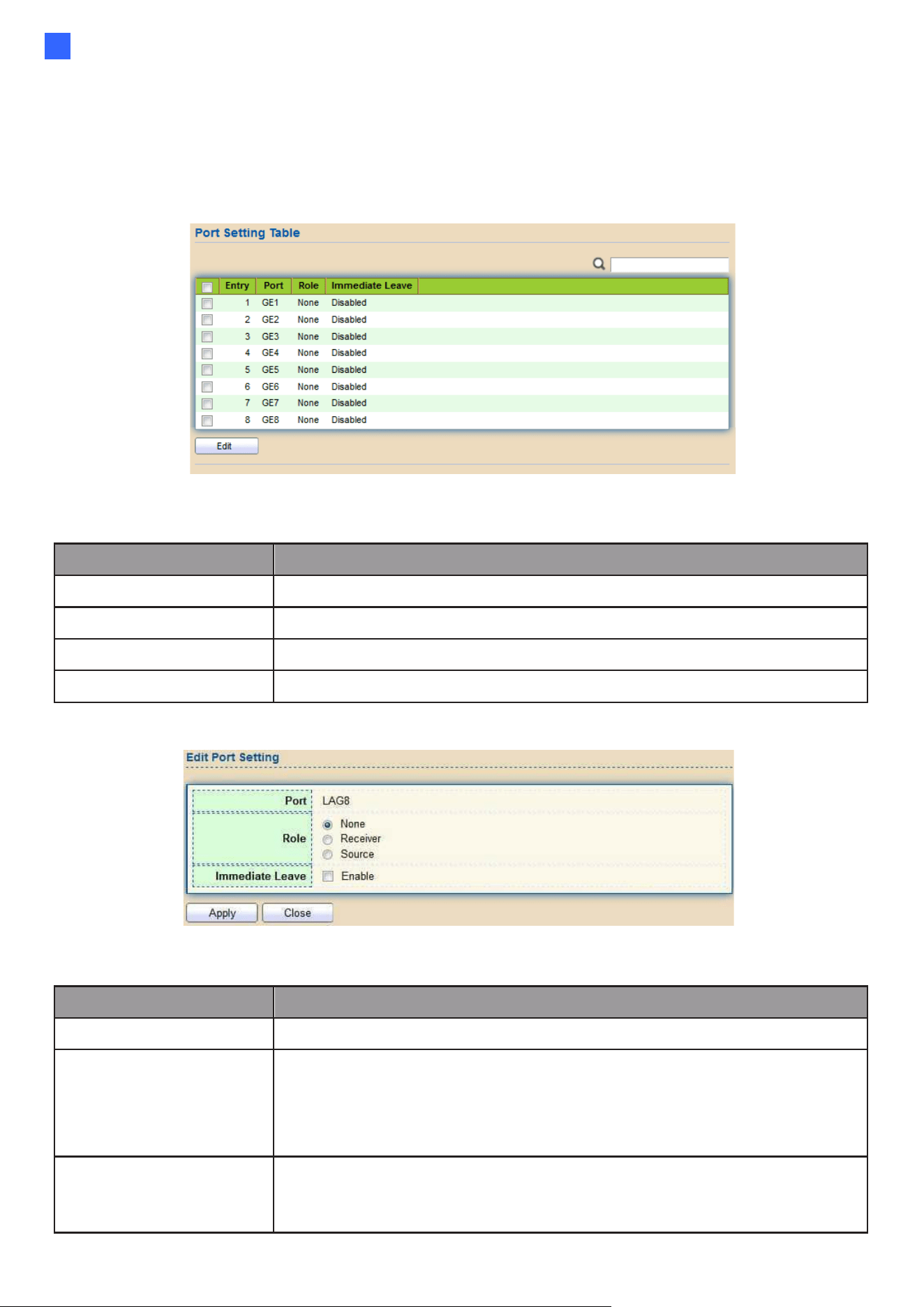
Web-based Switch Configuration
97
2
2.7.4.2. Port Setting
This page allows users to configure port role and port immediate leave.
To display MVR port role and immediate leave state setting web page, click
Multicast> MVR> Port Setting
Figure 104 - Multicast > MVR > Port Setting
Item
Description
Entry
Entry of number.
Port
Port Name.
Role
Port Role for MVR, the type is None/Receiver/Source.
Immediate Leave
Status of immediate leave.
Click "Edit" button to view Edit Port Setting menu.
Figure 105 - Multicast > MVR > Port Setting > Edit Port Setting
Item
Description
Port
Display the selected port list.
Role
MVR port role
•
None: port role is none.
•
Receiver: port role is receiver.
•
Source: port role is source.
Immediate Leave
MVR Port immediate leave
•
Enable: if checked is enable immediate leave, else disable
immediate leave.
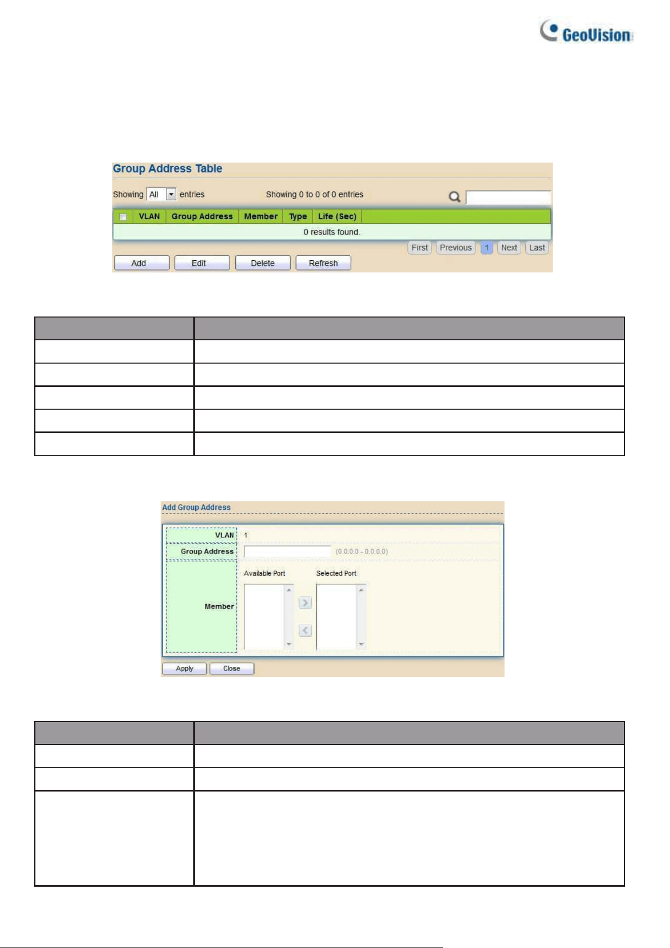
98
2.7.4.3. Group Address
This page allows users to browse all multicast MVR groups that dynamic learned or statically
added.
To display Multicast MVR Group web page, click Multicast> MVR> Group Address
Figure 106 - Multicast > MVR > Group Address
Item
Description
VLAN
The VLAN ID of MVR group.
Group Address
The MVR group IP address.
Member
The member ports of MVR group.
Type
The type of MVR group. Static or Dynamic.
Life(Sec)
The life time of this dynamic MVR group.
Click "Add" button or “Edit” to view Add/Edit Group Address Table menu.
Figure 107 - Multicast > MVR > Group Address > Add Group Address
Item
Description
VLAN
The VLAN ID of MVR group.
Group Address
The MVR group IP address.
Member
The member ports of MVR group.
•
Available Port: Optional port member, it is only receiver port
when MVR mode is compatible, it includes source port when
mode is dynamic.
•
Selected Port: Selected port member
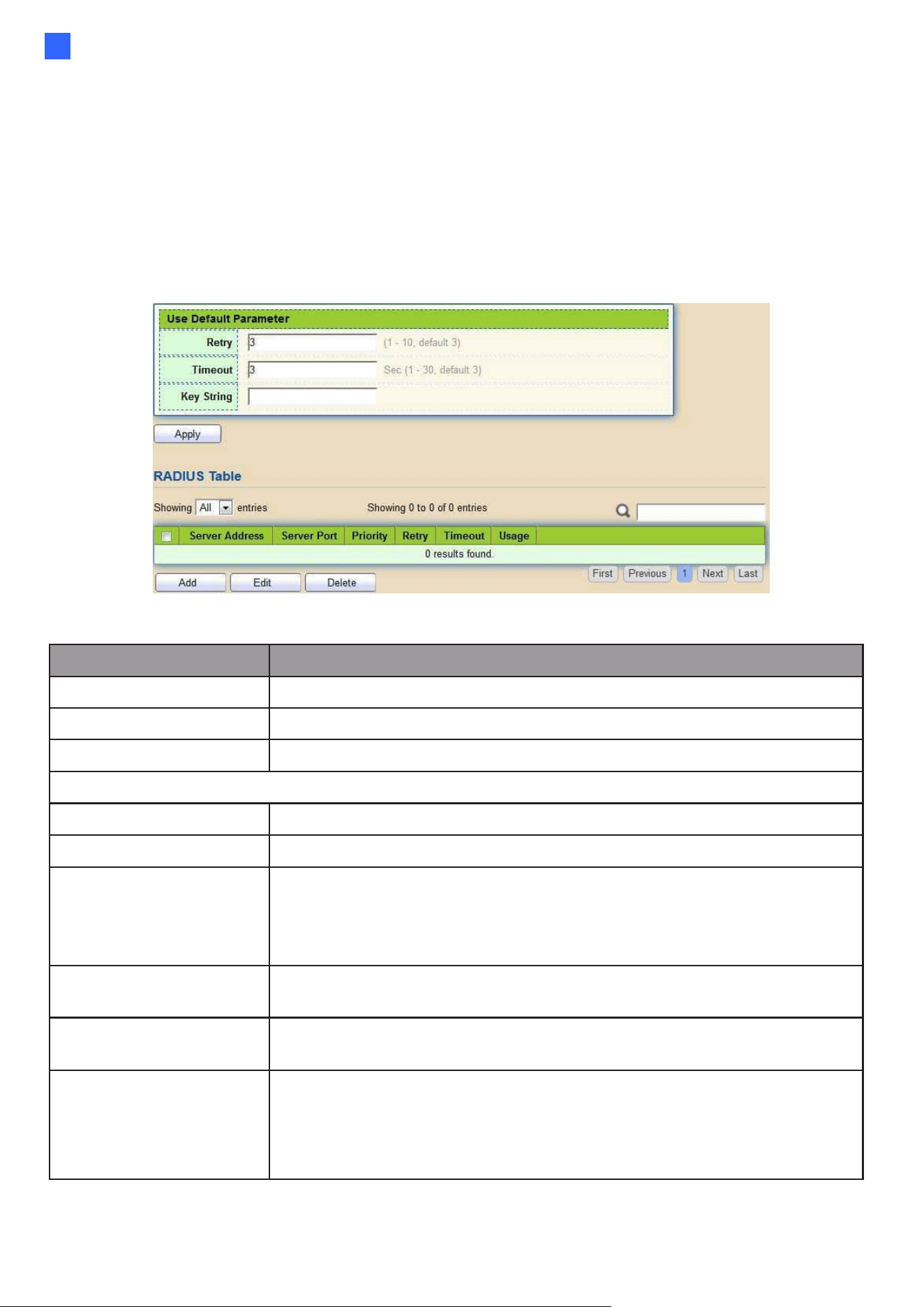
Web-based Switch Configuration
99
2
2.8. Security
Use the Security pages to configure settings for the switch security features.
2.8.1. RADIUS
This page allows users to add, edit or delete RADIUS server settings and modify default
parameter of RADIUS server.
To display RADIUS web page, click Security > RADIUS
Figure 108 - Security > RADIUS
Item
Description
Retry
Set default retry number.
Timeout
Set default timeout value.
Key String
Set default RADIUS key string
RADIUS Table
Server Address
RADIUS server address.
Server Port
RADIUS server port.
Priority
RADIUS server priority (smaller value has higher priority). RADIUS
session will try to establish with the server setting which has highest
priority. If failed, it will try to connect to the server with next higher
priority.
Retry
RADIUS server retry value. If it fails to connect to the server, it will
keep trying until timeout with retry times.
Timeout
RADIUS server timeout value. If it fails to connect to the
server, it will keep trying until timeout.
Usage
RADIUS server usage type
•
Login: For login authentication.
•
802.1x: For 802.1x authentication.
•
All: For all types.
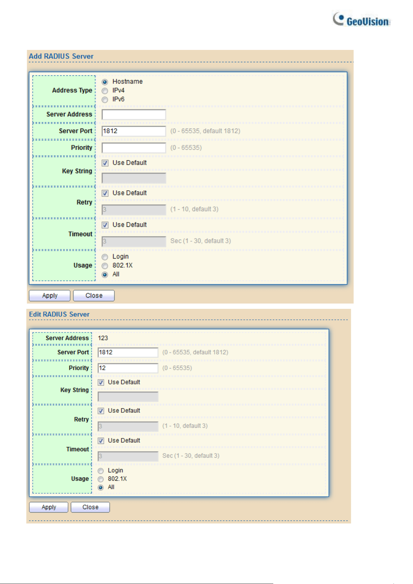
100
Click "Add" or “Edit” button to view Add/Edit RADIUS Server menu.
Figure 109 - Security > RADIUS > Add/Edit RADIUS Server
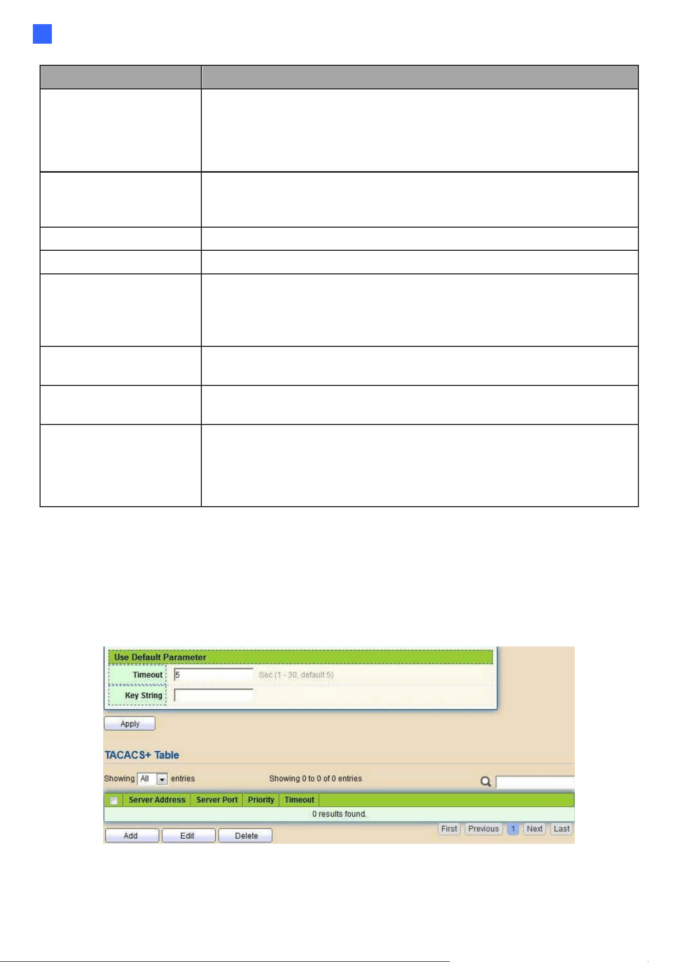
Web-based Switch Configuration
101
2
Item
Description
Address Type
In add dialog, users need to specify server Address Type
•
Hostname: Use a domain name as server address.
•
IPv4: Use IPv4 as server address.
•
IPv6: Use IPv6 as server address.
Server Address
In add dialog, users need to input server address based on
address type. In edit dialog, it shows current edit server address.
Server Port
Set RADIUS server port.
Key String
Set RADIUS key string
Priority
Set RADIUS server priority (smaller value has higher priority).
RADIUS session will try to establish with the server setting
which has highest priority. If failed, it will try to connect to the
server with next higher priority.
Retry
Set RADIUS server retry value. If it fails to connect to the
server, it will keep trying until timeout with retry times.
Timeout
Set RADIUS server timeout value. If it fails to connect to the
server, it will keep trying until timeout.
Usage
Set RADIUS server usage type
•
Login: For login authentication.
•
802.1x: For 802.1x authentication.
•
All: For all types.
2.8.2. TACACS+
This page allows users to add, edit or delete TACACS+ server settings and modify default
parameter of TACACS+ server.
To display TACACS+ web page, click Security > TACACS+
Figure 110 - Security > TACACS+

102
Item
Description
Timeout
Set default timeout value.
Key String
Set default TACACS+ key string.
Server Address
TACACS+ server address.
Server Port
TACACS+ server port.
Priority
TACACS+ server priority (smaller value has higher priority).
TACACS+ session will try to establish with the server setting
which has highest priority. If failed, it will try to connect to the
server with next higher priority.
Timeout
TACACS+ server timeout value. If it fails to connect to the server,
it will keep trying until timeout.
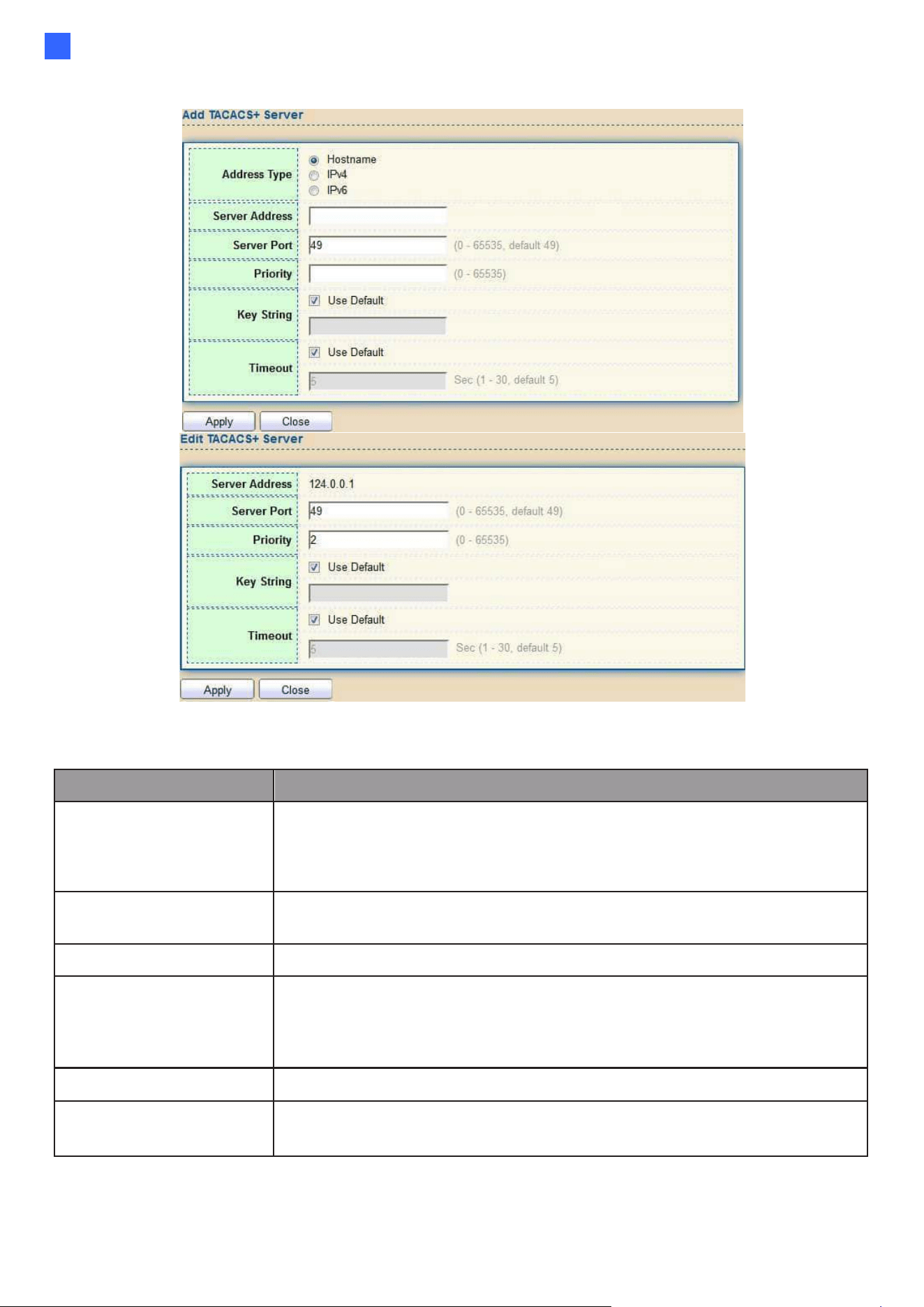
Web-based Switch Configuration
103
2
Click "Add" or “Edit” button to view Add/Edit TACAS+ Server menu.
Figure 111 - Security > TACACS+>Add/Edit TACACS Server
Item
Description
Address Type
In add dialog, users need to specify server Address Type
⚫
Hostname: Use domain name as server address
⚫
IPv4: Use IPv4 as server address
⚫
IPv6: Use IPv6 as server address
Server Address
In add dialog, users need to input server address based on
address type. In edit dialog, it shows current edit server address.
Server Port
Set TACACS+ server port
Priority
Set TACACS+ server priority (smaller value has higher priority).
TACACS+ session will try to establish with the server setting
which has highest priority. If failed, it will try to connect to the
server with next higher priority
Key String
Set default TACACS+ key string.
Timeout
Set TACACS+ server timeout value. If it fails to connect to the
server, it will keep trying until timeout.
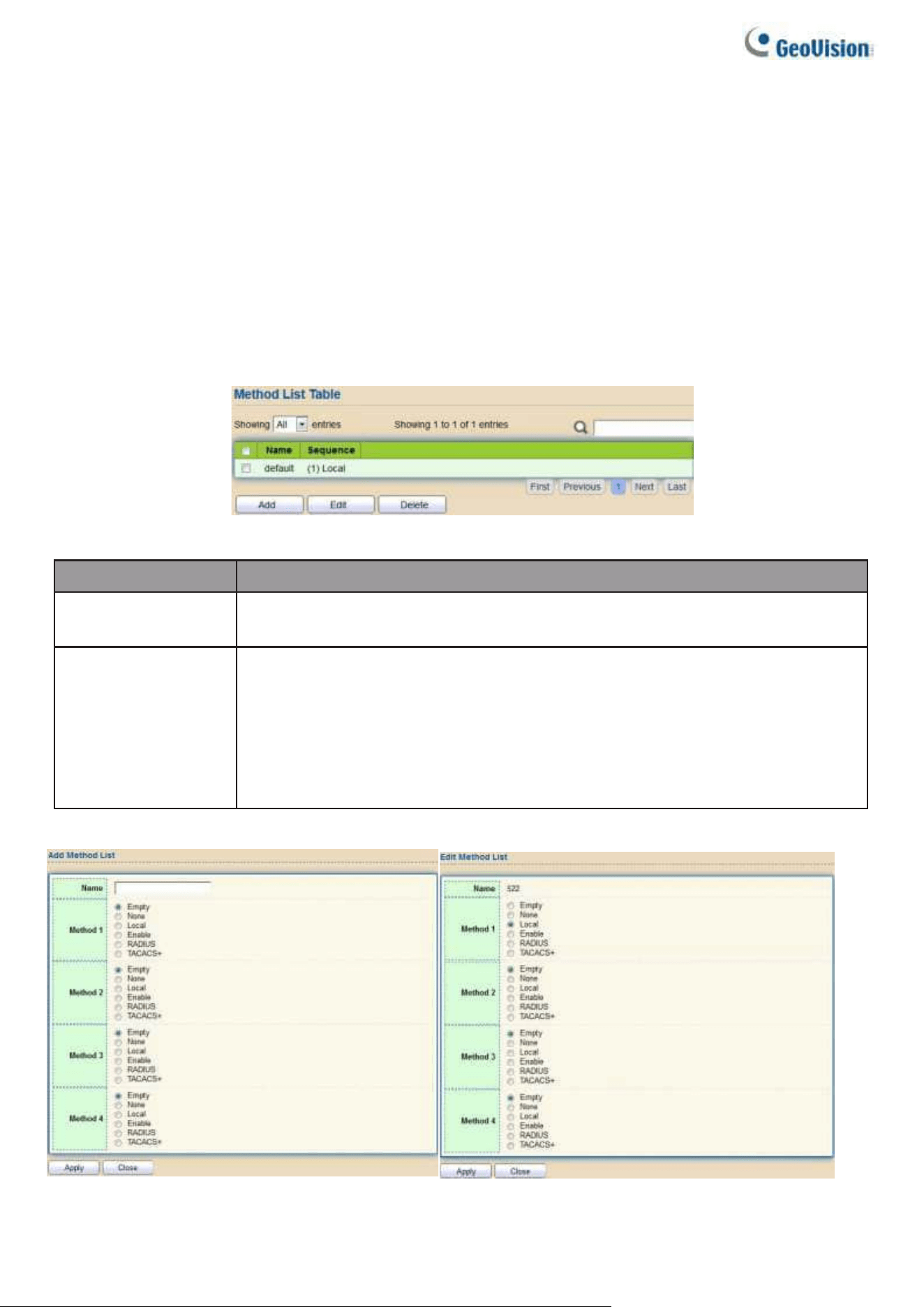
104
2.8.3. AAA
2.8.3.1. Method List
This page allows users to add, edit or delete login authentication list settings (The
“default” list cannot be deleted.). The line combined to this list will authenticate login
users by methods in this list. If the first method is failed, it will try to use the next priority
method to authenticate if it exists.
With RADIUS and TACACS+ methods, the failed means connecting to server fail. With Local
method, the failed means cannot find the users in local database.
To display Method List web page, click Security > AAA > Method List
Figure 112 - Security > TACACS+>AAA> Method List
Item
Description
Name
Login authentication list name. This name should be different from
other existing lists.
Sequence
Priority of login authentication method.
□
None: Authenticated with any condition.
□
Local: Use local accounts database to authenticate
□
TACACS+: Use remote TACACS+ server to authenticate.
□
RADIUS: Use remote Radius server to authenticate.
□
Enable: Use local enable password to authenticate.
Click "Add" or “Edit” button to view Add/Edit Method List menu.
Figure 113 - Security > TACACS+>AAA> Add/Edit Method List

Web-based Switch Configuration
105
2
Item
Description
Name
Login authentication list name. This name should be different from
other existing lists.
Method 1
Select first priority of login authentication method.
⚫
None: Authenticated with any condition.
⚫
Local: Use local accounts database to authenticate
⚫
TACACS+: Use remote TACACS+ server to authenticate.
⚫
RADIUS: Use remote Radius server to authenticate.
⚫
Enable: Use local enable password to authenticate
Method 2
Select second priority of login authentication method
⚫
None: Authenticated with any condition
⚫
Local: Use local accounts database to authenticate
⚫
TACACS+: Use remote TACACS+ server to authenticate.
⚫
RADIUS: Use remote Radius server to authenticate
⚫
Enable: Use local enable password to authenticate
Method 3
Select third priority of login authentication method.
⚫
None: Authenticated with any condition.
⚫
Local: Use local accounts database to authenticate
⚫
TACACS+: Use remote TACACS+ server to authenticate.
⚫
RADIUS: Use remote Radius server to authenticate.
⚫
Enable: Use local enable password to authenticate
Method 4
Select fourth priority of login authentication method.
⚫
None: Authenticated with any condition.
⚫
Local: Use local accounts database to authenticate
⚫
TACACS+: Use remote TACACS+ server to authenticate.
⚫
RADIUS: Use remote Radius server to authenticate.
⚫
Enable: Use local enable password to authenticate
2.8.3.2. Login Authentication
This page allows users to combine AAA login authentication list to all management
interfaces.
To display the login authentication combined web page, click Security > AAA > Login
Authentication.
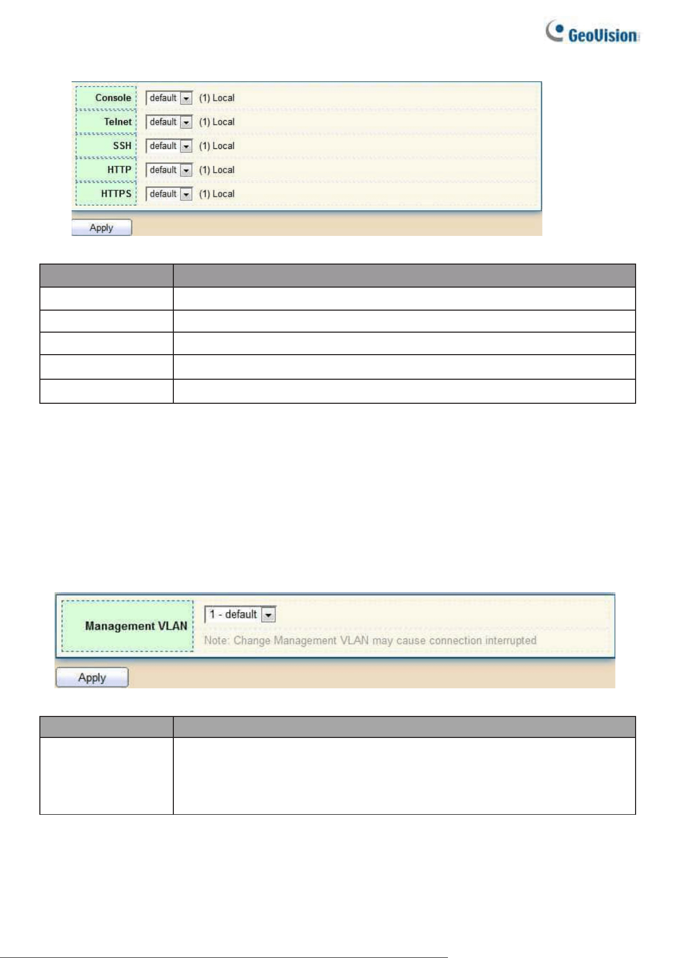
106
Figure 114 - Security > TACACS+>AAA> login authentication
Item
Description
Console
Specify login authentication list combined on console.
Telnet
Specify login authentication list combined on Telnet.
SSH
Specify login authentication list combined on SSH.
HTTP
Specify login authentication list combined on HTTP.
HTTPS
Specify login authentication list combined on HTTPS.
2.8.4. Management Access
Use the Management Access pages to configure settings of management access.
2.8.4.1. Management VLAN
This page allows users to change management VLAN.
To display Management VLAN page, click Security > Management Access >
Management VLAN
Figure 115 - Security > Management Access > Management VLAN
Item
Description
Management
VLAN
Select a specific VLAN in option list to allow connections to the device
through http, https, SNMP and etc. Connections to other VLANs will be
dropped.
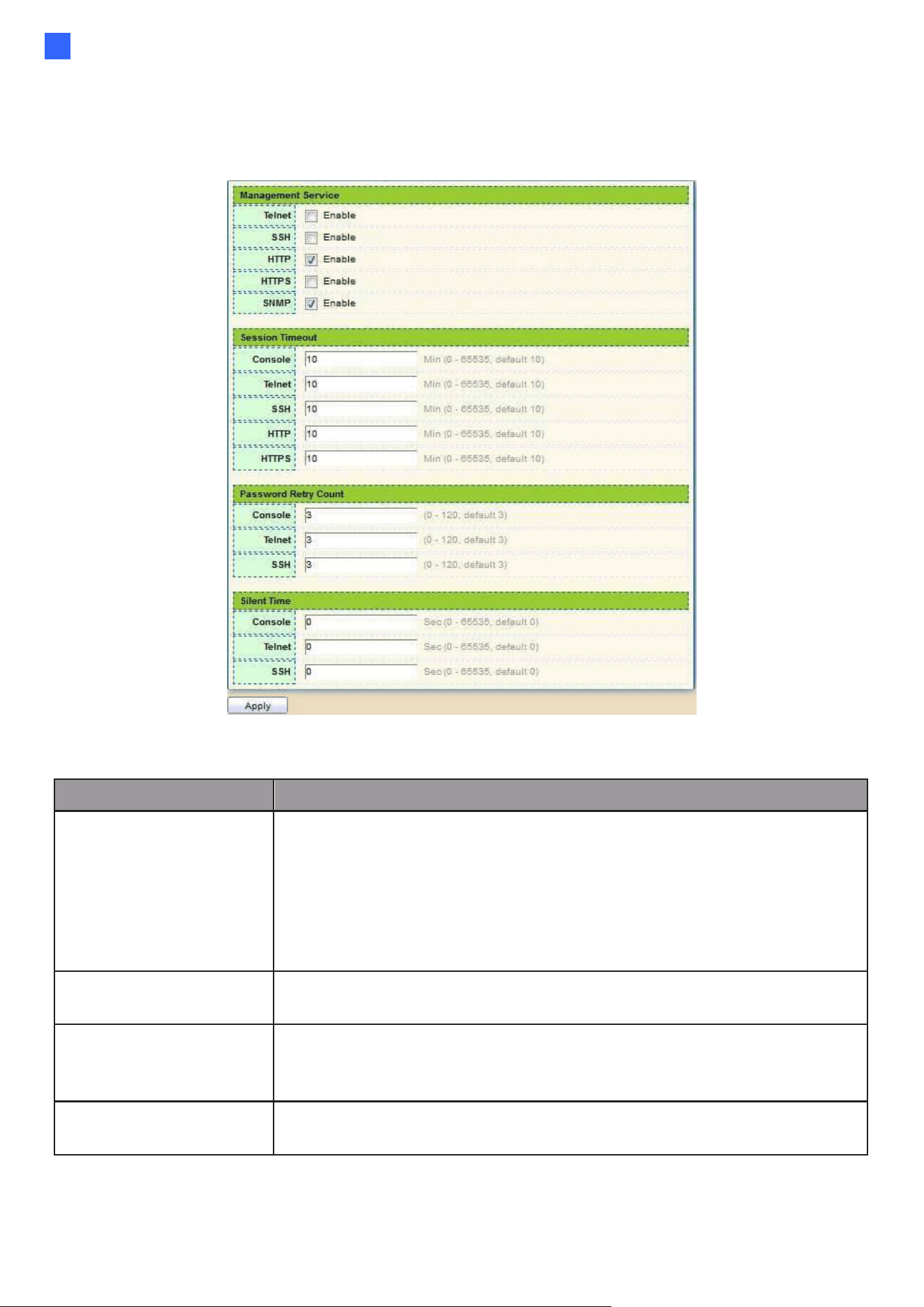
Web-based Switch Configuration
107
2
2.8.4.2. Management Service
This page allows users to change management services related configurations.
To display Management Service click Security > Management Access > Management Service
Figure 116 - Security > Management Access > Management Service
Item
Description
Management Service
Management service admin state.
•
Telnet: Connect CLI through telnet.
•
SSH: Connect CLI through SSH.
•
HTTP: Connect WEBUI through HTTP.
•
HTTPS: Connect WEBUI through HTTPS.
•
SNMP: Manage switch trough SNMP.
Session Timeout
Set session timeout minutes for users to access the user
interface. 0 minutes means never timeout.
Password Retry Count
Retry count is the number which CLI password input error
tolerance count. After input error password exceeds this
count, the CLI will freeze after silent time.
Silent Time
After input error password exceeds password retry count,
the CLI will freeze after silent time.
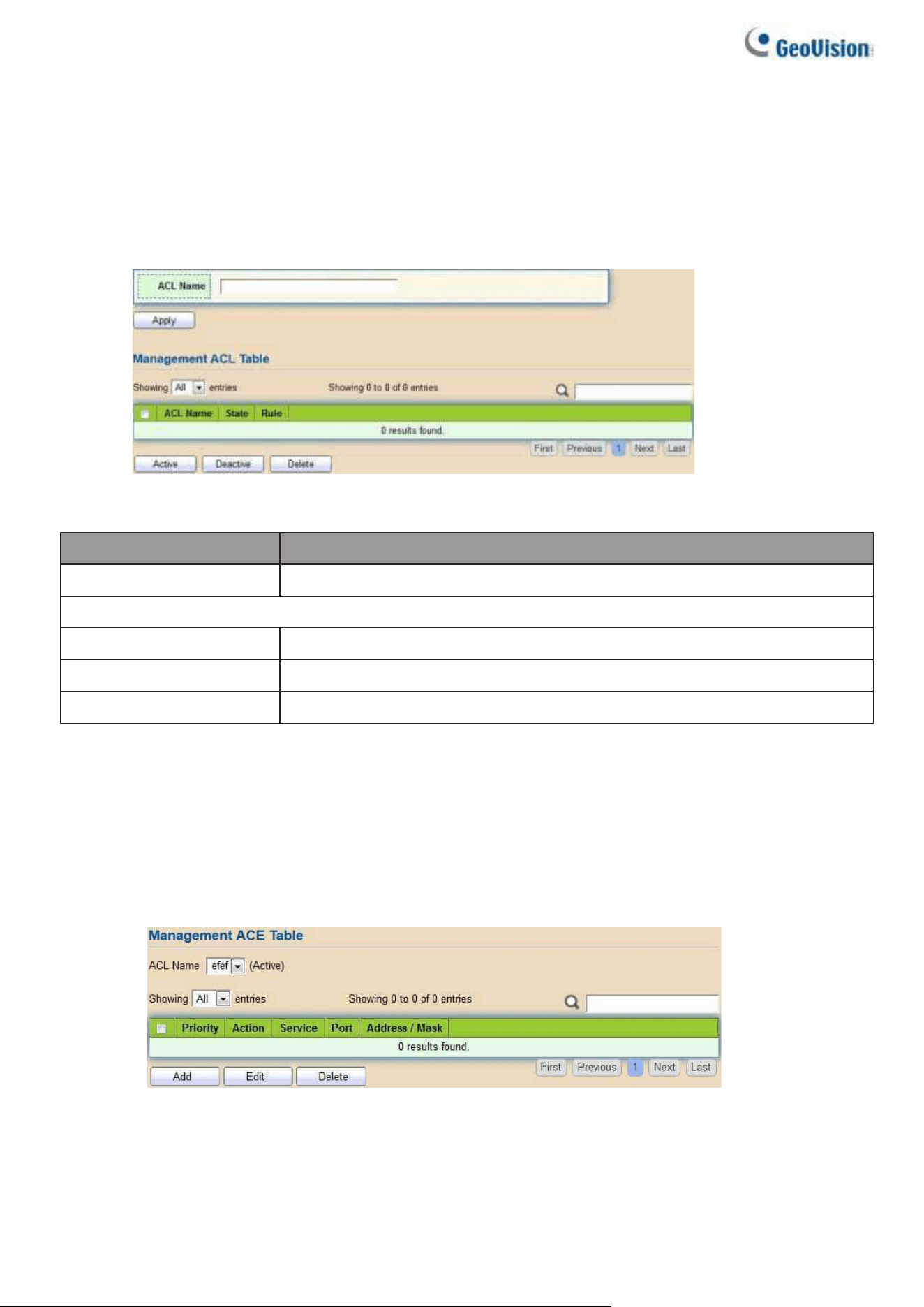
108
2.8.4.3. Management ACL
This page allows users to add or delete management ACL rule. A rule cannot be deleted if under
active.
To display Management ACL page, click Security > Management Access >
Management ACL
Figure 117 - Security > Management Access > Management ACL
Item
Description
ACL Name
Input MAC ACL name.
Management ACL
ACL Name
Display Management ACL name.
State
Display Management ACL whether active.
Rule
Display the number Management ACE rule of ACL.
2.8.4.4. Management ACE
This page allows users to add, edit or delete ACE rule. An ACE rule cannot be edited or deleted if
ACL under active. New ACE cannot be added if ACL under active
To display Management ACE page, click Security > Management Access >
Management ACE
Figure 118 - Security > Management Access > Management ACE
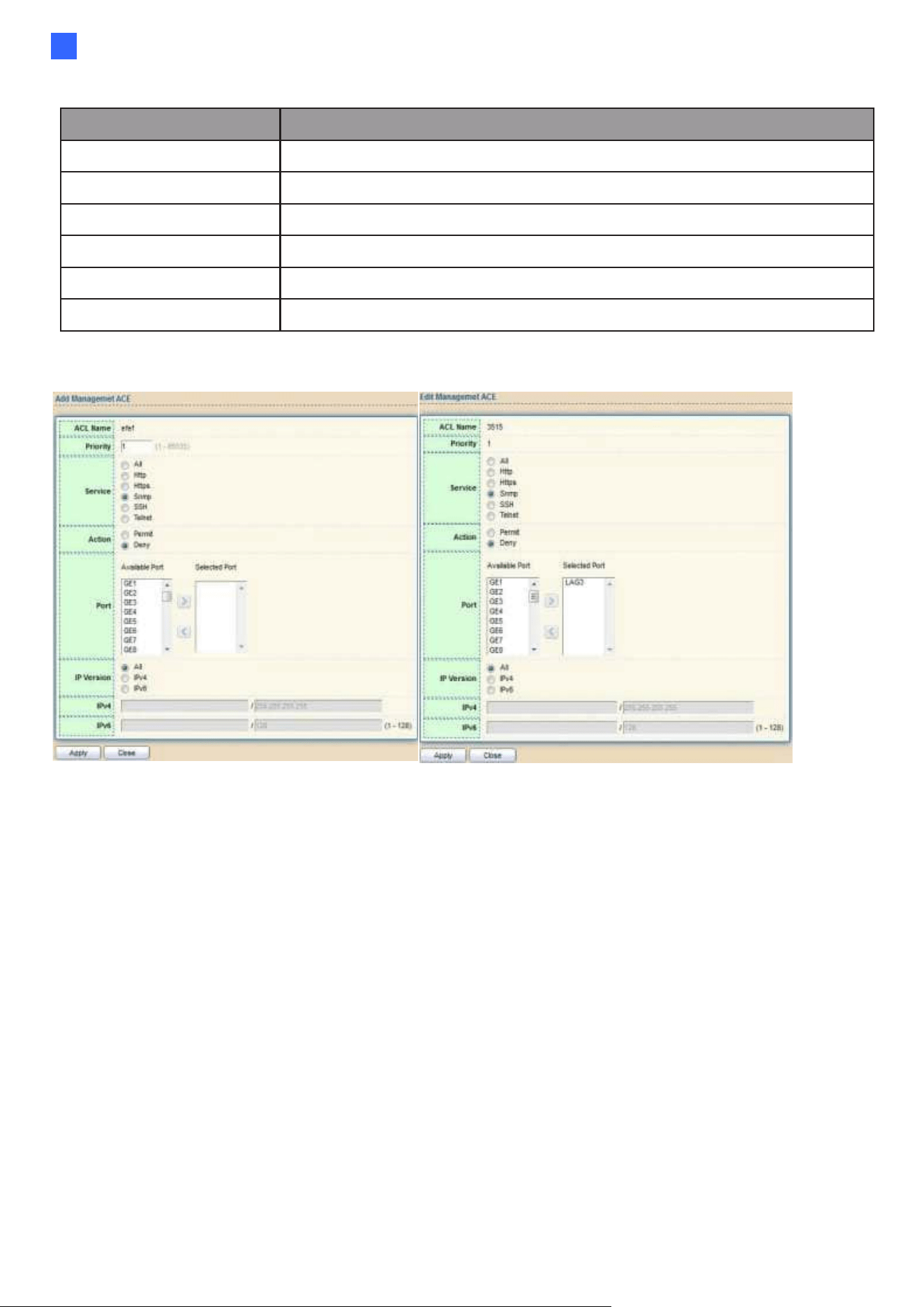
Web-based Switch Configuration
109
2
Item
Description
ACL Name
Select the ACL name to which an ACE is being added.
Priority
Display the priority of ACE.
Action
Display the action of ACE.
Service
Display the service ACE
Port
Display the port list of ACE
Address / Mask
Display the source IP address and mask of ACE.
Click "Add" or “Edit” button to view Add/Edit Management ACE menu.
Figure 119 - Security > Management Access > Add/Edit Management ACE

110
Item
Description
ACL Name
Display the ACL name to which an ACE is being added.
Priority
Specify the priority of the ACE. ACE with higher sequence are
processed first (1 is the highest priority). Only available on Add
Dialog.
Service
Select the type service of rule
●
All: All services
●
Http: Only Http service
●
Https: Only Https service
●
Snmp: Only Snmp service
●
SSH: Only SSH service
●
Telnet: Only Telnet service
Action
Select the action after ACE match packet.
●
Permit: Forward packets that meet the ACE criteria.
●
Deny: Drop packets that meet the ACE criteria.
Port
Select ports which will be matched.
IP Version
●
All: All IP addresses can access.
●
IPv4: Specify IPv4 address ca access.
●
IPv6: Specify IPv6 address ca access.
IPv4
Enter the source IPv4 address value and mask to which will be
matched.
IPv6
Enter the source IPv6 address value and mask to which will be
matched.
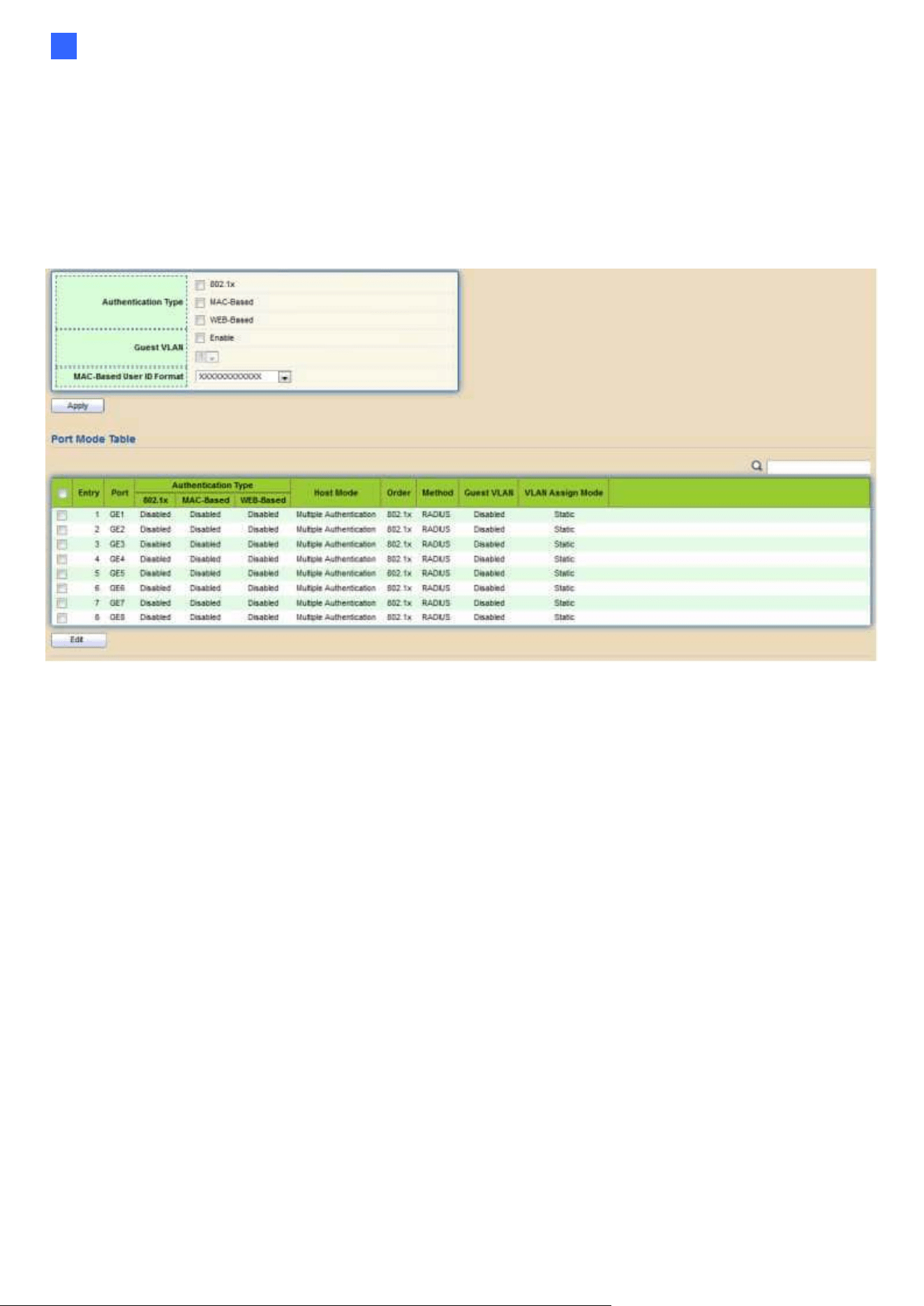
Web-based Switch Configuration
111
2
2.8.5. Authentication Manager
2.8.5.1. Property
This page allows users to edit authentication global settings and some port mods’ configurations.
To display authentication manager Property web page, click Security >
Authentication Manager > Property.
Figure 120 - Security > Authentication Manager > Property

112
Item
Description
Authentication
Type
Set checkbox to enable/disable following authentication types
•
802.1x: Use IEEE 802.1x to do authentication
•
MAC-Based: Use MAC address to do authentication
•
WEB-Based: Prompt authentication web page for users to do
authentication
Guest VLAN
Set checkbox to enable/disable guest VLAN, if guest VLAN is
enabled, you need to select one available VLAN ID to be guest
VID.
MAC-Based User
ID Format
Select mac-based authentication RADIUS
username/password ID format.
•
XXXXXXXXXXXX
•
Xxxxxxxxxxxx
•
XX:XX:XX:XX:XX:XX
•
xx:xx:xx:xx:xx:xx
•
XX-XX-XX-XX-XX-XX
•
xx-xx-xx-xx-xx-xx
•
XX.XX.XX.XX.XX.XX
•
xx.xx.xx.xx.xx.xx
•
XXXX:XXXX:XXXX
•
xxxx:xxxx:xxxx
Port Mode Table
Port
Port Name.
Authentication
Type
(802.1X)
802.1X authentication type state
•
Enabled: 802.1X is enabled.
•
Disabled: 802.1X is disabled.
Authentication
Type
(MAC-Based)
MAC-Based authentication type state
•
Enabled: MAC-Based authentication is enabled
•
Disabled: MAC-Based authentication is disabled
Authentication
Type
(WEB-Based)
WEB-Based authentication type state
•
Enabled: WEB-Based authentication is enabled
•
Disabled: WEB-Based authentication is disabled
Host Mode
Authenticating host mode
•
Multiple Authentication: In this mode, every client need to pass
authenticate procedure individually.
•
Multiple Hosts: In this mode, only one client need to be
authenticated and other clients will get the same access
accessibility. Web-auth cannot be enabled in this mode.
•
Single Host: In this mode, only one host is allowed to be
authenticated. It is the same as Multi-auth mode with max hosts
number configure to be 1.

Web-based Switch Configuration
113
2
Order
Support following authentication type order combinations. Web
Authentication should always be the last type. The authentication
manager will go to next type if current type is not enabled or
authenticated fail.
● 802.1x
●
MAC-Based
●
WEB-Based
●
802.1x MAC-Based
●
802.1x WEB-Based
●
MAC-Based 802.1x
●
WEB-Based 802.1x
●
802.1x MAC-Based WEB-Based
●
802.1x WEB-Based MAC-Based
Method
Support following authentication method order
combinations.
These orders only available on MAC-Based authentication and
WEB-Based authentication. 802.1x only support Radius method.
•
Local: Use DUT’s local database to do authentication
•
Radius: Use remote RADIUS server to do authentication
•
Local Radius
•
Radius Local
Guest VLAN
Port guest VLAN enable state
•
Enabled: Guest VLAN is enabled on port.
•
Disabled: Guest VLAN is disabled on port.
VLAN Assign Mode
Support following VLAN assign mode and only apply when source
is RADIUS
•
Disable: Ignore the VLAN authorization result and keep
original VLAN of host.
•
Reject: If get VLAN authorized information, just use it. However, if
there is no VLAN authorized information, reject the host and make
it unauthorized.
Static: If get VLAN authorized information, just use it. If there is no
VLAN authorized information, keep original VLAN of host.
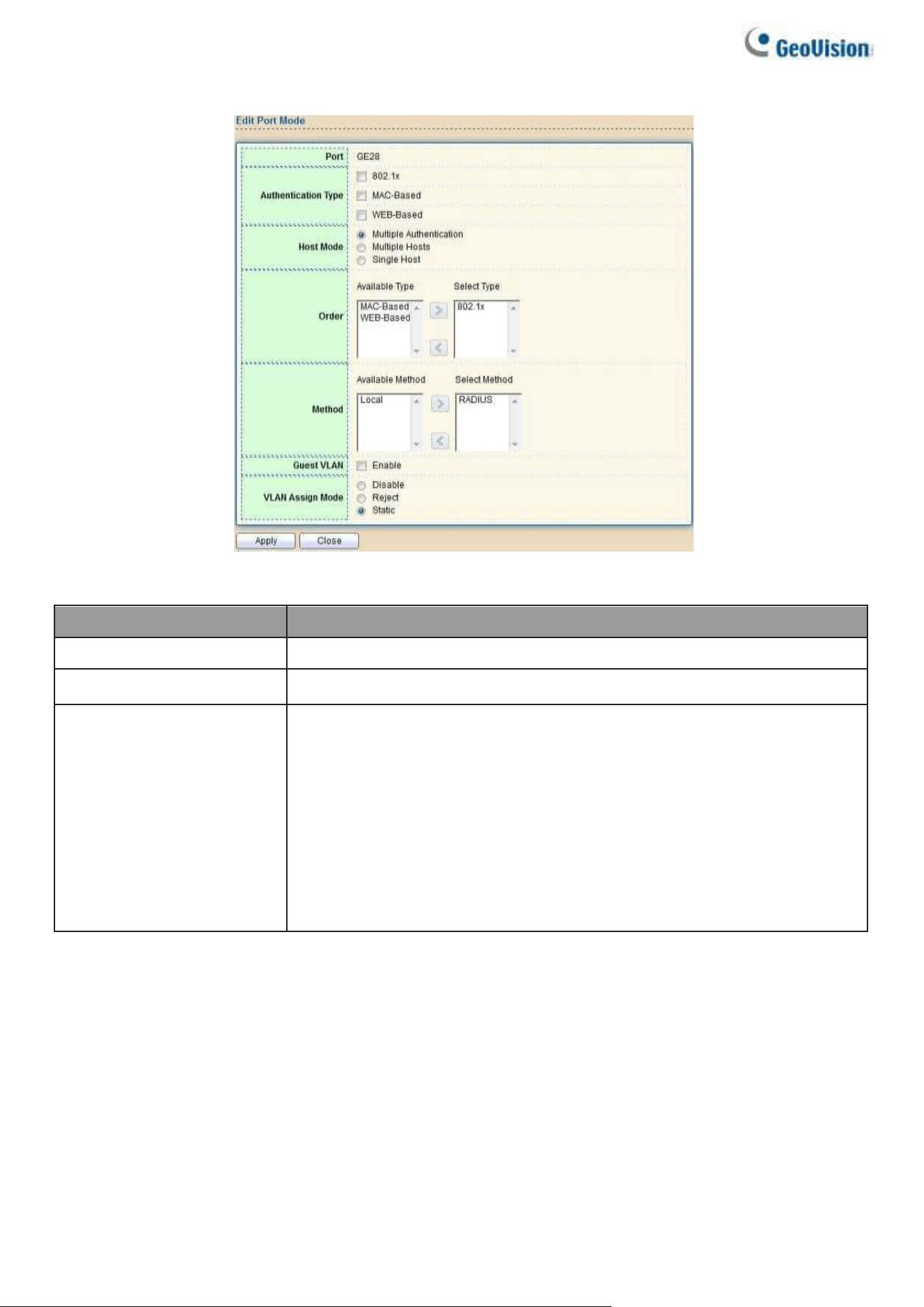
114
Click “Edit” button to view the Edit Port Mode menu.
Figure 121 - Security > Authentication Manager > Property > Edit Port Mode
Item
Description
Port
Selected port list.
Authentication Type
Set checkbox to enable/disable authentication types.
Host Mode
Select authenticating host mode
•
Multiple Authentication: In this mode, every client needs to
pass authenticate procedure individually.
•
Multiple Hosts: In this mode, only one client need to be
authenticated and other clients will get the same access
accessibility. Web-auth cannot be enabled in this mode.
•
Single Host: In this mode, only one host is allowed to be
authenticated. It is the same as Multi-auth mode with max hosts
number configure to be 1.

Web-based Switch Configuration
115
2
Order
Support following authentication type order combinations. Web
Authentication should always be the last type. The authentication
manager will go to next type if current type is not enabled or
authenticated fail.
● 802.1x
●
MAC-Based
●
WEB-Based
●
802.1x MAC-Based
●
802.1x WEB-Based
●
MAC-Based 802.1x
●
WEB-Based 802.1x
●
802.1x MAC-Based WEB-Based
●
802.1x WEB-Based MAC-Based
Method
Support following authentication method order
combinations.
•
These orders only available on MAC-Based authentication and
WEB-Based authentication. 802.1x only support Radius method.
•
Local: Use DUT’s local database to do authentication.
•
Radius: Use remote RADIUS server to do authentication.
•
Local Radius.
•
Radius Local.
Guest VLAN
Set checkbox to enable/disable guest VLAN.
VLAN Assign
Mode
Support following VLAN assign mode and only apply when source
is RADIUS
•
Disable: Ignore the VLAN authorization result and keep
original VLAN of host.
•
Reject: If get VLAN authorized information, just use it.
However, if there is no VLAN authorized information, reject
the host and make it unauthorized.
•
Static: If get VLAN authorized information, just use it. If there is
no VLAN authorized information, keep original VLAN of host.
2.8.5.2. Port Setting
This page allows users to configure authentication manger port settings
To display the authentication manager Port Setting web page, click Security >
Authentication Manager > Port Setting.
Figure 122 - Security > Authentication Manager > Port Setting

116
Item
Description
Port
Port
Port Control
Support following authentication port control types.
•
Disable: Disable authentication function and all clients have
network accessibility.
•
Force Authorized: Port is force authorized and all clients have
network accessibility.
•
Force Unauthorized: Port is force unauthorized and all clients
have no network accessibility.
•
Auto: Need passing authentication procedure to get
network accessibility.
Reauthentication
Reauthenticate state
•
Enabled: Host will be reauthenticated after
reauthentication period.
•
Disabled: Host will not be authenticated after
reauthentication period.
Max Hosts
In Multiple Authentication mode, total host number cannot
not exceed max hosts number.
Common Timer
(Reauthentication)
After re-authenticate period, host will return to initial state and
need to pass authentication procedure again.
Common Timer
(Inactive)
If no packet from the authenticated host, the inactive timer will
increase. After inactive timeout, the host will be unauthorized and
corresponding session will be deleted. In multi-host mode, the
packet is counting on the authorized host only.
Common Timer
(Quiet)
When port is in Locked state after authenticating fail several times,
the host will be locked in quiet period. After this quiet period, the
host is allowed to authenticate again.
802.1X Params
(TX Period)
Number of seconds that the device waits for a response to an
Extensible Authentication Protocol (EAP) request/identity frame
from the supplicant (client) before resending the request.
802.1X Params
(Supplicant
Timeout)
The maximum number of EAP requests that can be sent. If a
response is not received after the defined period (supplicant
timeout), the authentication process is restarted.
802.1X Params
(Server Timeout)
Number of seconds that lapses before EAP requests are
resent to the supplicant.
802.1X Params
(Max Request)
Number of seconds that lapses before the device resends a
request to the authentication server.
Web-Based Param
(Max Login)
Number of failed login allowed. After failed login number
exceeds, the host will enter Lock state and is not able to
authenticate until the quiet period exceeds.
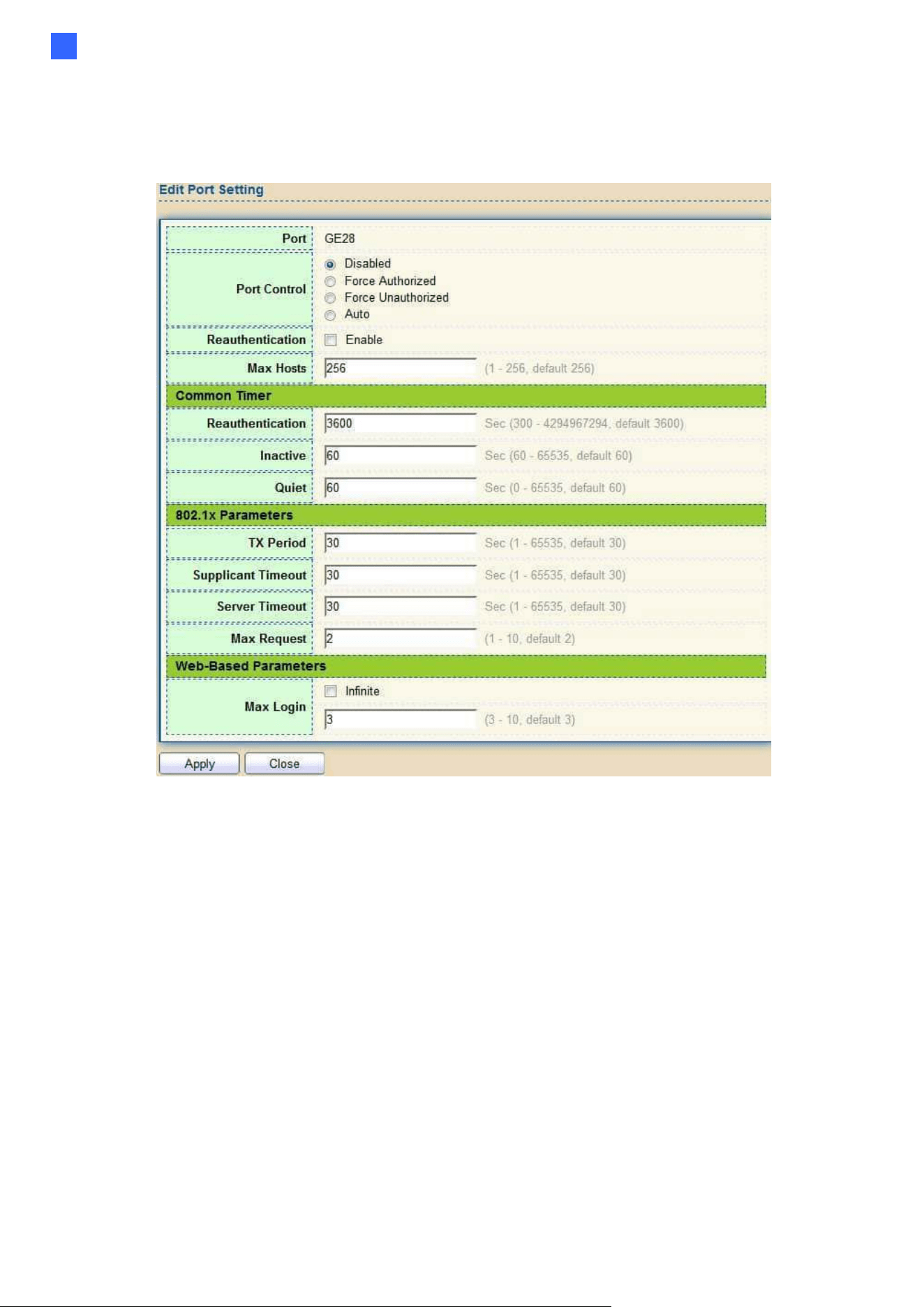
Web-based Switch Configuration
117
2
Click "Edit" button to view Edit Port Setting menu.
Figure 123 - Security > Authentication Manager > Port Setting > Edit Port Setting

118
Item
Description
Port
Port Name.
Port Control
Support following authentication port control types.
•
Disable: Disable authentication function and all clients have
network accessibility. Force Authorized: Port is force authorized
and all clients have network accessibility.
•
Force Unauthorized: Port is force unauthorized and all clients
have no network accessibility.
•
Auto: Need passing authentication procedure to get
network accessibility.
Reauthentication
Set checkbox to enable/disable reauthentication.
Max Hosts
In Multiple Authentication mode, total host number cannot not
exceed max hosts number.
Common Timer
Reauthentication
After re-authenticate period, host will return to initial state and need
to pass authentication procedure again.
Inactive
If no packet from the authenticated host, the inactive timer will
increase. After inactive timeout, the host will be unauthorized and
corresponding session will be deleted. In multi-host mode, the
packet is counting on the authorized host only and not all packets
on the port.
Quiet
When port is in Locked state after authenticating fail several times,
the host will be locked in quiet period. After this quiet period, the
host is allowed to authenticate again.
802.1X Params
TX Period
Number of seconds that the device waits for a response to an
Extensible Authentication Protocol (EAP) request/identity frame
from the supplicant (client)
before resending the request.
Supplicant
Timeout
The maximum number of EAP requests that can be sent. If a
response is not received after the defined period (supplicant
timeout), the authentication
process is restarted.
Server Timeout
Number of seconds that lapses before EAP requests are resent
to the supplicant.
Max Request
Number of seconds that lapses before the device resends a
request to the authentication server.
Web-Based Params
Max Login
Set checkbox to set max login number to be infinite or specify
max login number.
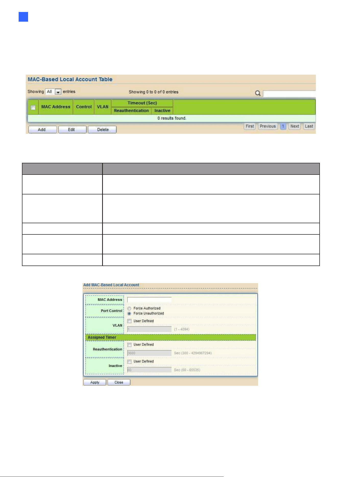
Web-based Switch Configuration
119
2
2.8.5.3. MAC-Based Local Account
This page allows users to add/edit/delete MAC-Based authentication local accounts.
To display MAC-Based Local Account web page, click Security > Authentication Manger > MAC-
Based Local Account
Figure 124 - Security > Authentication Manager > MAC-Based Local Account
Item
Description
MAC Address
Authenticated host MAC address, and each MAC allow only one
entry in local database.
Control
Control Type
●
Force Authorized: Host will be force authorized
●
Force Unauthorized: Host will be force unauthorized
VLAN
Assigned VLAN ID for the authenticated host.
Timeout
(Reauthentication)
Assigned reauthentication period for the authenticated
host.the service ACE.
Timeout (Inactive)
Assigned inactive timeout for the authenticated host.
Click “Add" or “Edit” button to view Add MAC-Base Local Account menu.
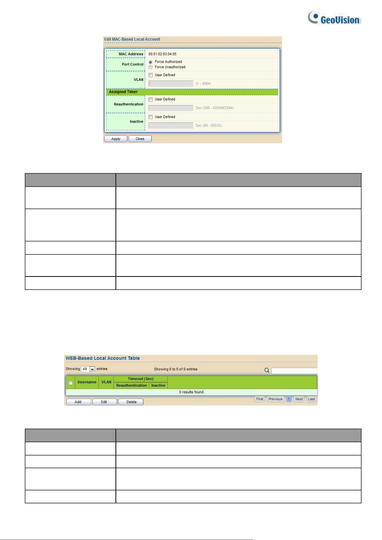
120
Figure 125 - Security > Authentication Manager > Add MAC-Based Local Account
Item
Description
MAC Address
Authenticated host MAC address, and each MAC allow only one
entry in local database.
Control
Control Type
●
Force Authorized: Host will be force authorized
●
Force Unauthorized: Host will be force unauthorized
VLAN
Assigned VLAN ID for the authenticated host.
Timeout
(Reauthentication)
Assigned reauthentication period for the authenticated host.
Timeout (Inactive)
Assigned inactive timeout for the authenticated host.
2.8.5.4. WEB-Based Local Account
This page allows users to add/edit/delete WEB-Based authentication local accounts.
To display WEB-Based Local Account web page, click Security > Authentication Manger >
WEB-Based Local Account
Figure 126 - Security > Authentication Manager > WEB-Based Local Account
Item
Description
Username
Authenticating account username
VLAN
Assigned VLAN ID for the authenticated host
Timeout
(Reauthentication)
Assigned reauthentication period for the authenticated host.
Timeout (Inactive)
Assigned inactive timeout for the authenticated host.
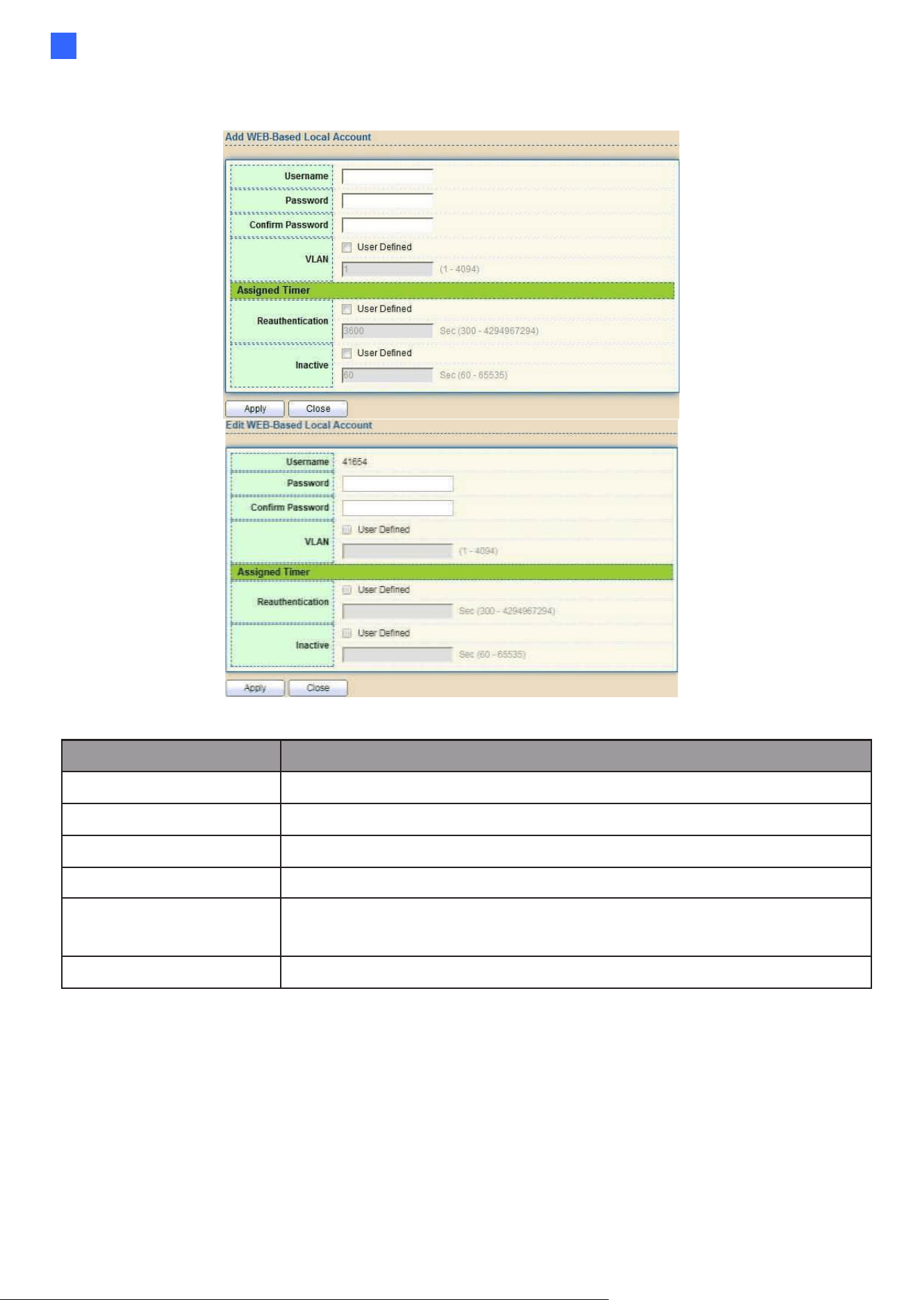
Web-based Switch Configuration
121
2
Click “Add" or “Edit” button to view Add/Edit WEB-Base Local Account menu.
Figure 127 - Security > Authentication Manager > Add/Edit WEB-Based Local Account
Item
Description
Username
Authenticating account username.
Password
Authenticating account password.
Confirm Password
Confirm authenticating account password.
VLAN
Assigned VLAN ID for the authenticated host.
Timeout
(Reauthentication)
Assigned reauthentication period for the authenticated host.
Timeout (Inactive)
Assigned inactive timeout for the authenticated host.
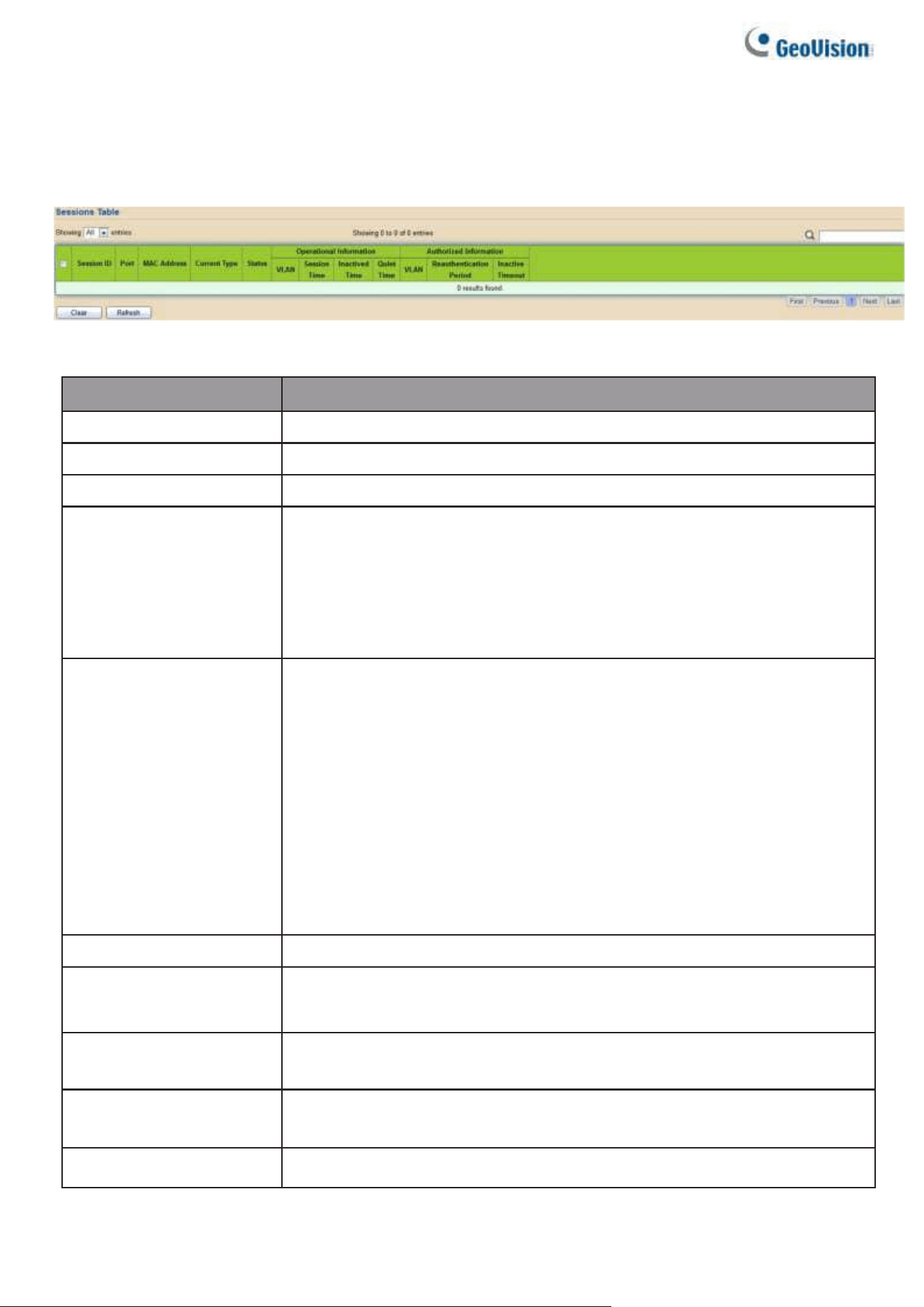
122
2.8.5.5. Sessions
This page shows all detail information of authentication sessions and allow users to select
specific session to delete by clicking “Clear” button.
To display Sessions web page, click Security > Authentication Manger > Sessions
Figure 128 - Security > Authentication Manager > Sessions
Item
Description
Session ID
Session ID is unique of each session.
Port
Port name which the host located.
MAC Address
Host MAC address.
Current Type
Show current authenticating type
•
802.1x: Use IEEE 802.1X to do authenticating
•
MAC-Based: Use MAC-Based authentication to do
authenticating.
•
WEB-Based: Use WEB-Based authentication to do
authenticating.
Status
Show host authentication session status
•
IP version (IPv4, IPv6)
•
Disable: This session is ready to be deleted
•
Running: Authentication process is running
•
Authorized: Authentication is passed and getting network
accessibility.
•
Unauthorized: Authentication is not passed and not getting network
accessibility.
•
Locked: Host is locked and do not allow to do authenticating until
quiet period.
•
Guest: Host is in the guest VLAN.
Operational(VLAN)
Shows host operational VLAN ID.
Operational
(Session Time)
In “Authorized” state, it shows total time after
authorized.
Operational (Inactived
Time)
In “Authorized” state, it shows how long the host do not send any
packet.
Operational (Quiet Time)
In “Locked” state, it shows total time after locked.
Authorized (VLAN)
Shows VLAN ID given from authorized procedure.
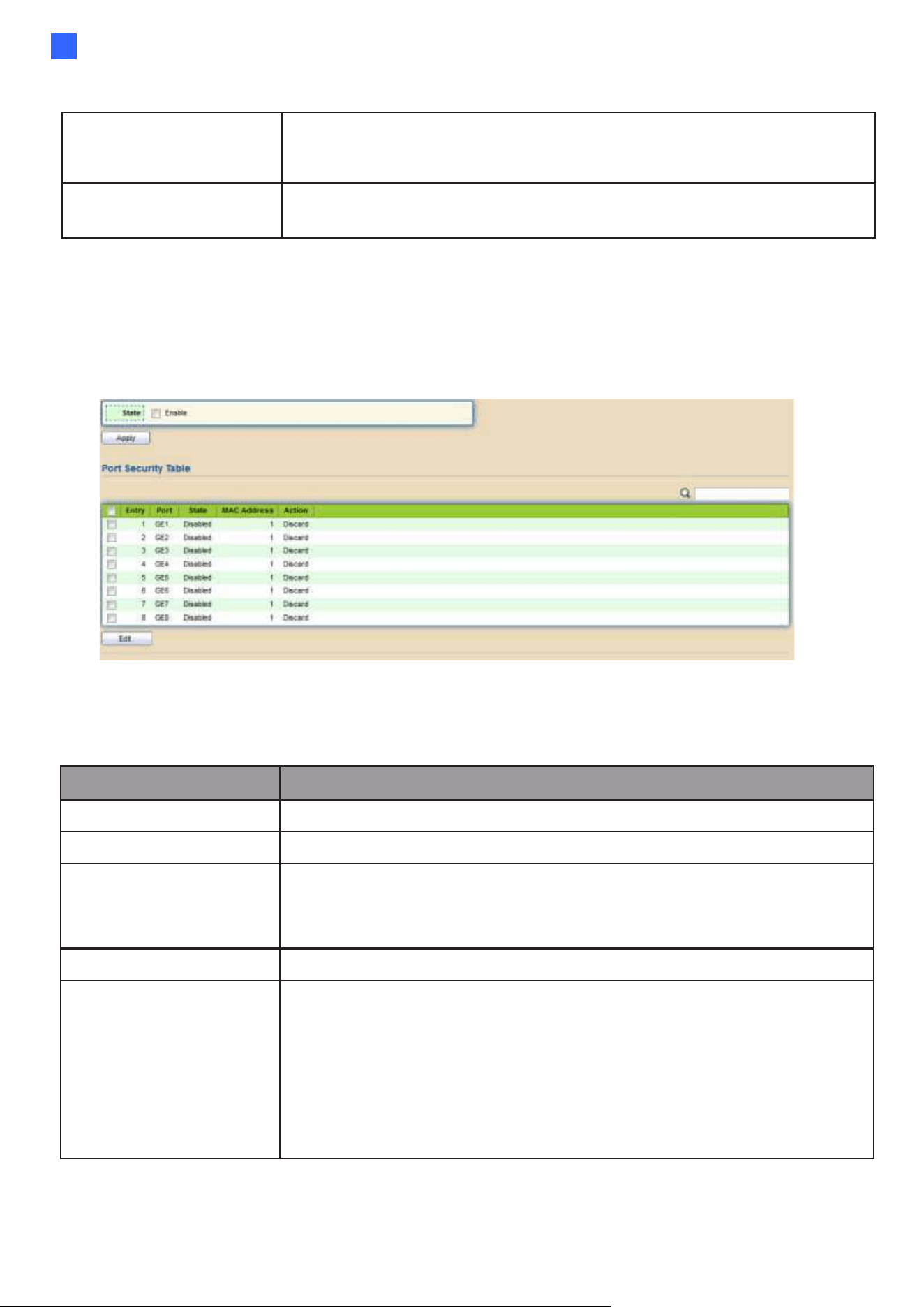
Web-based Switch Configuration
123
2
Authorized
(Reauthentication
Period)
Shows reauthentication period given from authorized
procedure.
Authorized (Inactive
Timeouts)
Shows inactive timeout given from authorized procedure.
2.8.6. Port Security
This page allows users to configure port security settings for each interface. When port
security is enabled on interface, action will be perform once learned MAC address over
limitation.
Figure 129 - Security > Port Security
To display Port Security web page, click Security > Port Security
Item
Description
State
Enable/Disable the port security function.
Port
Select one or multiple ports to configure.
State
Select the status of port security
•
Disable: Disable port security function.
•
Enable: Enable port security function.
MAC Address
Specify the number of how many mac addresses can be learned.
Action
Select the action if learned mac addresses
•
Forward: Forward this packet whose SMAC is new to
system and exceed the learning-limit number.
•
Discard: Discard this packet whose SMAC is new to system and
exceed the learning-limit number.
•
Shutdown: Shutdown this port when receives a packet whose
SMAC is new to system and exceed the learning limit number.
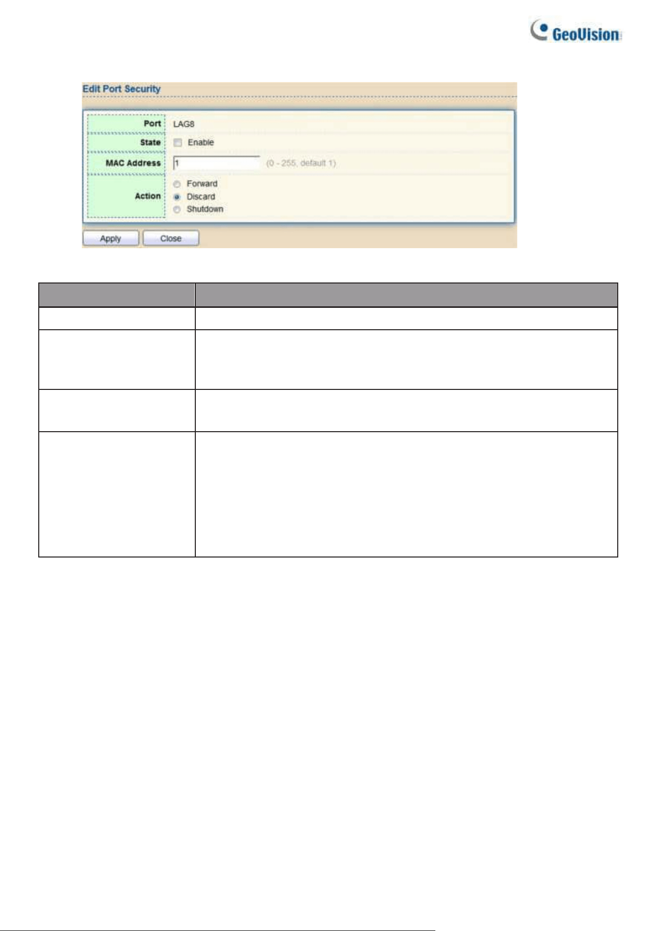
124
Click "Edit" button to view Edit Port Security menu.
Figure 130 - Security > Port Security > Add Port Security
Item
Description
Port
Select one or multiple ports to configure.
State
Select the status of port security
•
Disable: Disable port security function.
•
Enable: Enable port security function.
MAC Address
Specify the number of how many mac addresses can be
learned.
Action
Select the action if learned mac addresses
•
Forward: Forward this packet whose SMAC is new to
system and exceed the learning-limit number.
•
Discard: Discard this packet whose SMAC is new to system and
exceed the learning-limit number.
•
Shutdown: Shutdown this port when receives a packet whose
SMAC is new to system and exceed the learning limit number.
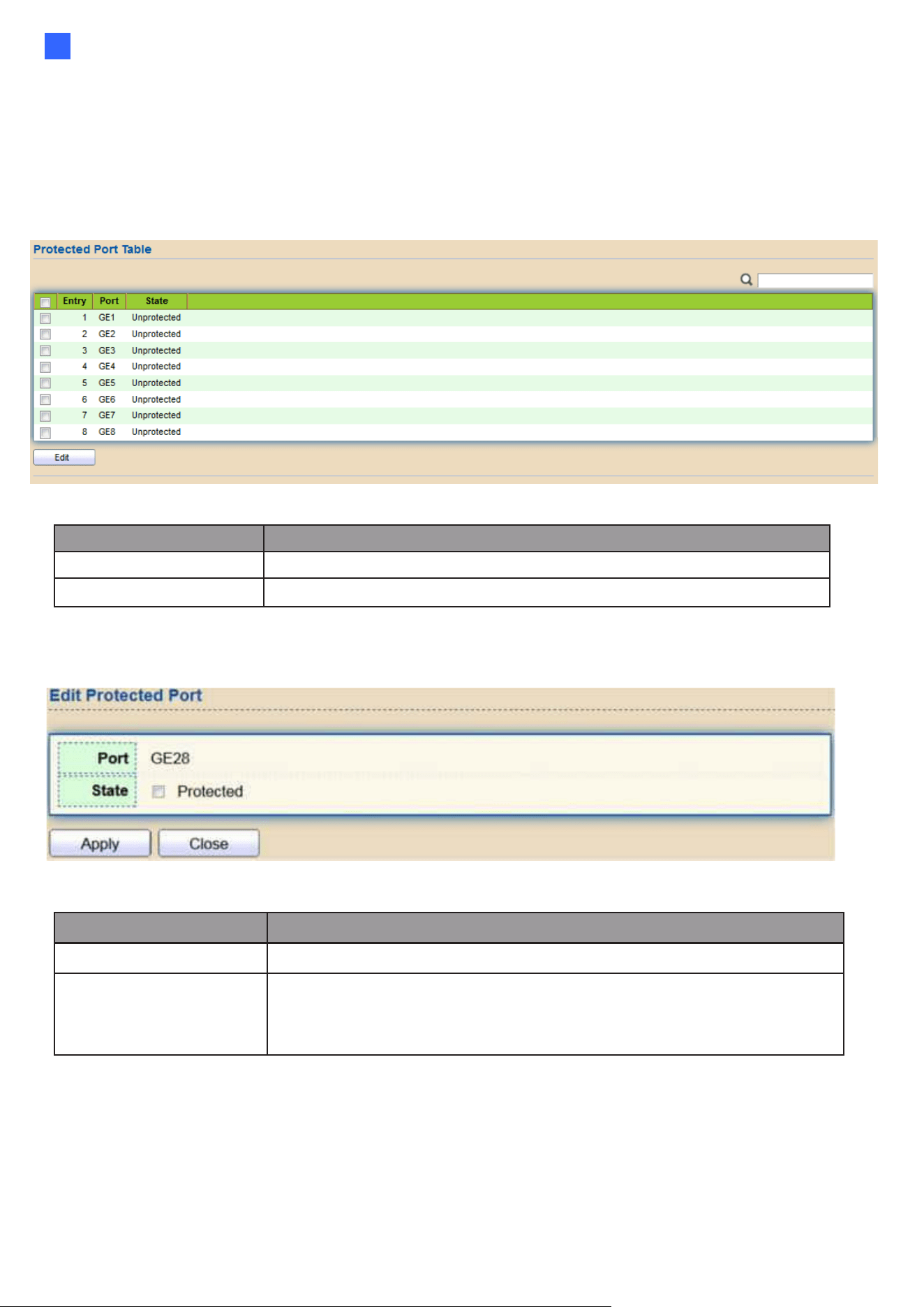
Web-based Switch Configuration
125
2
2.8.7. Protected Port
This page allows users to configure protected port setting to prevent the selected ports from
communication with each other. Protected port is only allowed to communicate with unprotected
port. In other words, protected port is not allowed to communicate with another protected port.
To display Protected Port web page, click Security > Protected Port
Figure 131 - Security > Protected Port
Item
Description
Port
Port Name.
State
Port protected admin state.
Click "Edit" button to view Edit Protected Port menu.
Figure 132 - Security > Protected Port > Edit Protected Port
Item
Description
Port
Selected port list.
State
Port protected admin state.
•
Protected: Enable protecting function.
•
Unprotected: Disable protecting function.
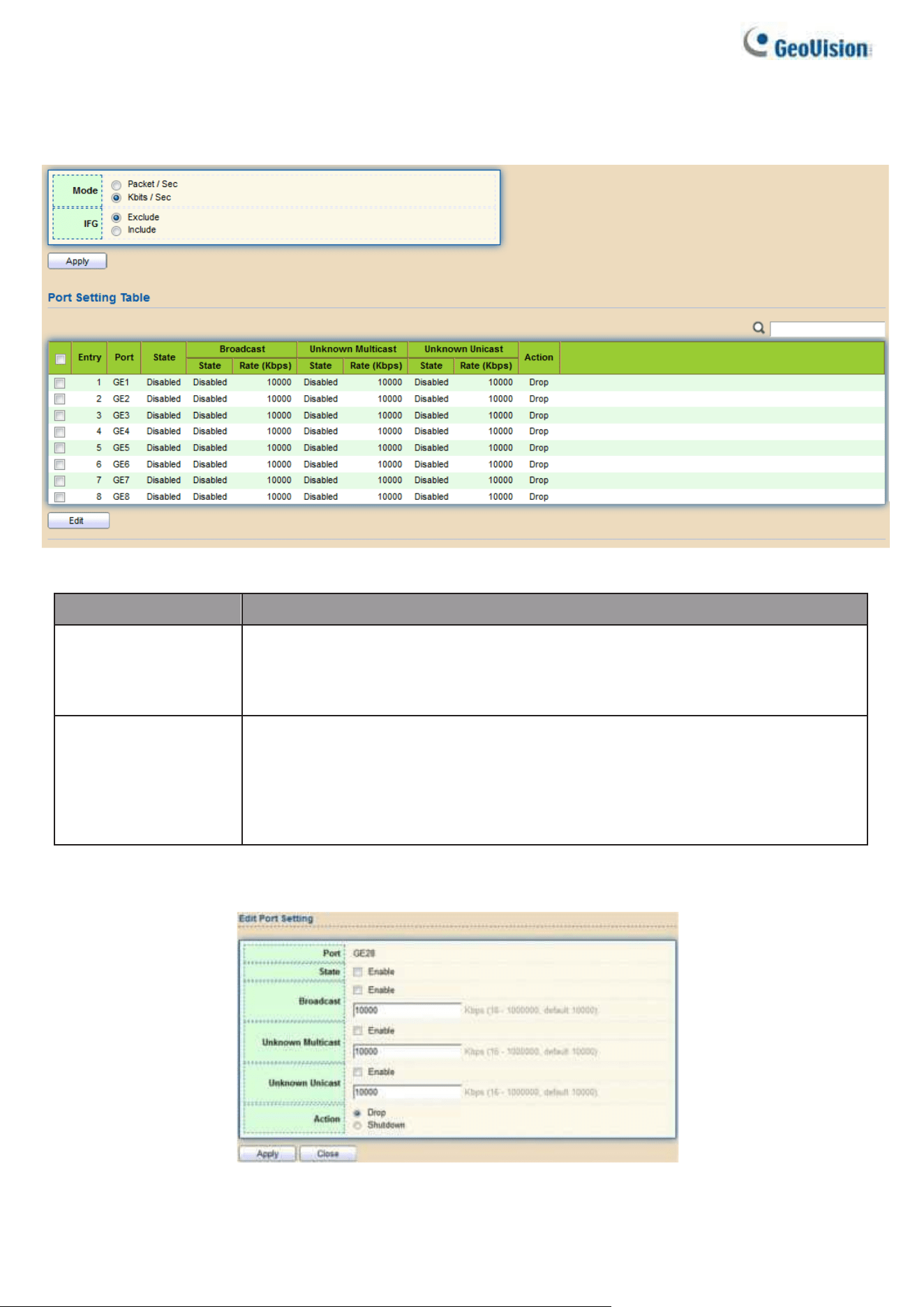
126
2.8.8. Storm Control
To display Storm Control global setting web page, click Security > Storm Control
Figure 133 - Security > Storm Control
Item
Description
Mode(Unit)
Select the unit of storm control
•
Packet / Sec: storm control rate calculates by packet-based
•
Kbits / Sec: storm control rate calculates by octet-based.
IFG
Select the rate calculates w/o preamble & IFG (20 bytes)
•
Excluded: exclude preamble & IFG (20 bytes) when count ingress
storm control rate.
•
Included: include preamble & IFG (20 bytes) when count ingress
storm control rate.
Click "Edit" button to view Edit Port Setting menu.
Figure 134 - Security > Storm Control > Edit Port Setting

Web-based Switch Configuration
127
2
Item
Description
Port
Select the setting ports.
State
Select the state of setting
•
Enable: Enable the storm control function.
Broadcast
Enable: Enable the storm control function of Broadcast packet.
Value of storm control rate, Unit: pps (packet per- second, range
1- 262143) or Kbps (Kbits per-second, range16 - 1000000)
depends on global mode setting.
Unknown
Multicast
Enable: Enable the storm control function of Unknown multicast
packet. Value of storm control rate, Unit: pps (packet per-second,
range 1- 262143) or Kbps (Kbits per- second, range16 - 1000000)
depends on global mode setting.
Unknown Unicast
Enable: Enable the storm control function of Unknown unicast
packet. Value of storm control rate, Unit: pps (packet per-second,
range 1 - 262143) or Kbps (Kbits per- second, range16 - 1000000)
depends on global mode setting.
Action
Select the state of setting
•
Drop: Packets exceed storm control rate will be dropped.
•
Shutdown: Port will be shutdown when packets exceed storm
control rate.
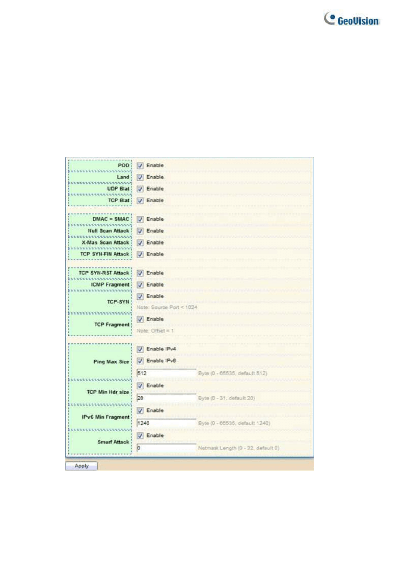
128
2.8.9. DoS
A Denial of Service (DoS) attack is a hacker attempt to make a device unavailable to its users.
DoS attacks saturate the device with external communication requests, so that it cannot respond
to legitimate traffic. These attacks usually lead to a device CPU overload.
The DoS protection feature is a set of predefined rules that protect the network from malicious
attacks. The DoS Security Suite Settings enables activating the security suite.
2.8.9.1. Property
To display Dos Global Setting web page, click Security > Dos > Property
Figure 135 - Security > DoS > Property

Web-based Switch Configuration
129
2
Item
Description
POD
Avoids ping of death attack.
Land
Drops the packets if the source IP address is equal to the
destination IP address.
UDP Blat
Drops the packets if the UDP source port equals to the
UDP destination port.
TCP Blat
Drops the packages if the TCP source port is equal to the
TCP destination port.
DMAC = SMAC
Drops the packets if the destination MAC address is equal to
the source MAC address.
Null Scan Attach
Drops the packets with NULL scan.
X-Mas
Scan Attack
Drops the packets if the sequence number is zero, and the FIN,
URG and PSH bits are set.
TCP
SYN-FIN Attack
Drops the packets with SYN and FIN bits set.
TCP
SYN-RST Attack
Drops the packets with SYN and RST bits set
ICMP Flagment
Drops the fragmented ICMP packets.
TCP SYN (SPORT<1024)
Drops SYN packets with sport less than 1024.
TCP Fragment (Offset = 1)
Drops the TCP fragment packets with offset equals to one.
Ping Max Size
Specify the maximum size of the ICMPv4/ICMPv6 ping packets.
The valid range is from 0 to 65535 bytes, and the default value
is 512 bytes.
IPv6 Min Flagment
Checks the minimum size of IPv6 fragments, and drops the
packets smaller than the minimum size. The valid range is
from 0 to 65535 bytes, and default value is 1240 bytes.
Smurf Attack
Avoids smurf attack. The length range of the netmask is from
0 to 323 bytes, and default length is 0 bytes.
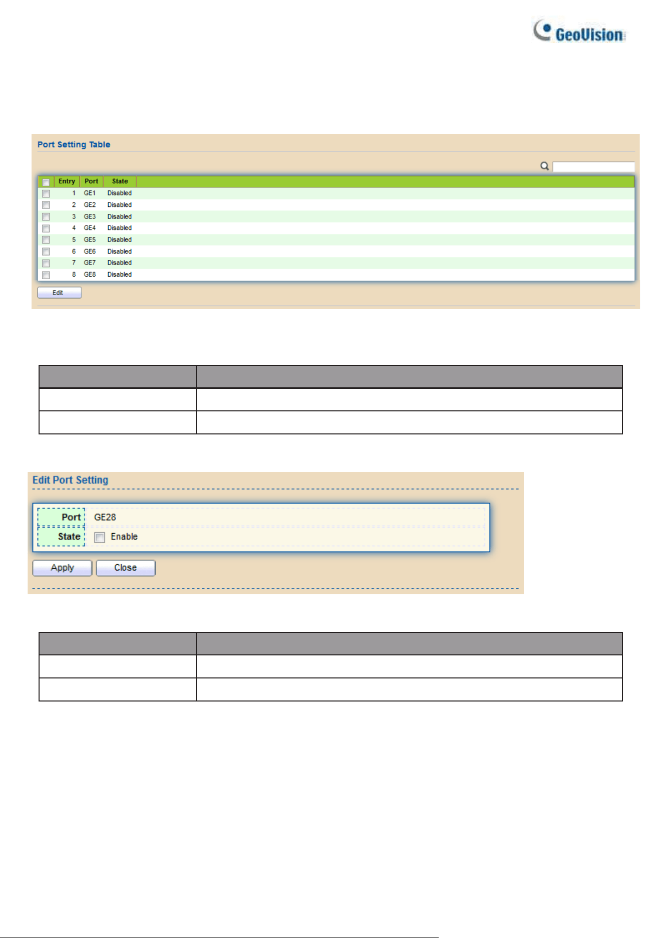
130
2.8.9.2. Port Setting
To configure and display the state of DoS protection for interfaces, click Security > DoS > Port
Setting.
Figure 136 - Security > DoS > Port Setting
Item
Description
Port
Interface or port number.
State
Enable/Disable the DoS protection on the interface.
Click "Edit" button to view Edit Port Setting menu.
Figure 137 - Security > DoS > Port Setting
Item
Description
Port
Interface or port number.
State
Enable/Disable the DoS protection on the interface.
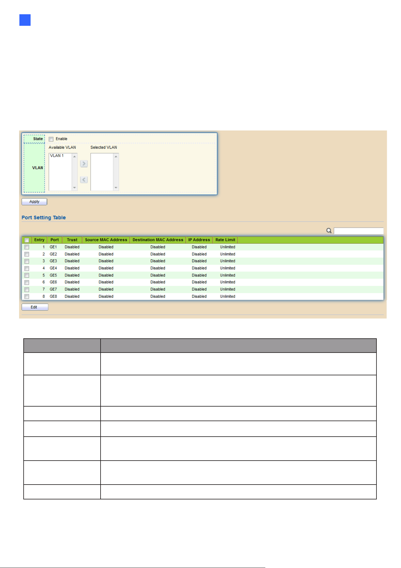
Web-based Switch Configuration
131
2
2.8.10. Dynamic ARP Inspection
Use the Dynamic ARP Inspection pages to configure settings of Dynamic ARP Inspection
2.8.10.1. Property
This page allows users to configure global and per interface settings of Dynamic ARP
Inspection.
To display property page, click Security > Dynamic ARP Inspection > Property
Figure 138 - Security > Dynamic ARP Inspection > Property
Item
Description
State
Set checkbox to enable/disable Dynamic ARP Inspection
function.
VLAN
Select VLANs in left box then move to right to enable Dynamic ARP
Inspection. Or select VLANs in right box then move to left to disable
Dynamic ARP Inspection.
Port
Display port ID.
Trust
Display enable/disabled trust attribute of interface.
Source MAC
Address
Display enable/disabled destination mac address validation
attribute of interface.
IP Address
Display enable/disabled IP address validation attribute of interface.
Allow zero which means allow 0.0.0.0 IP address.
Rate Limit
Display rate limitation value of interface.
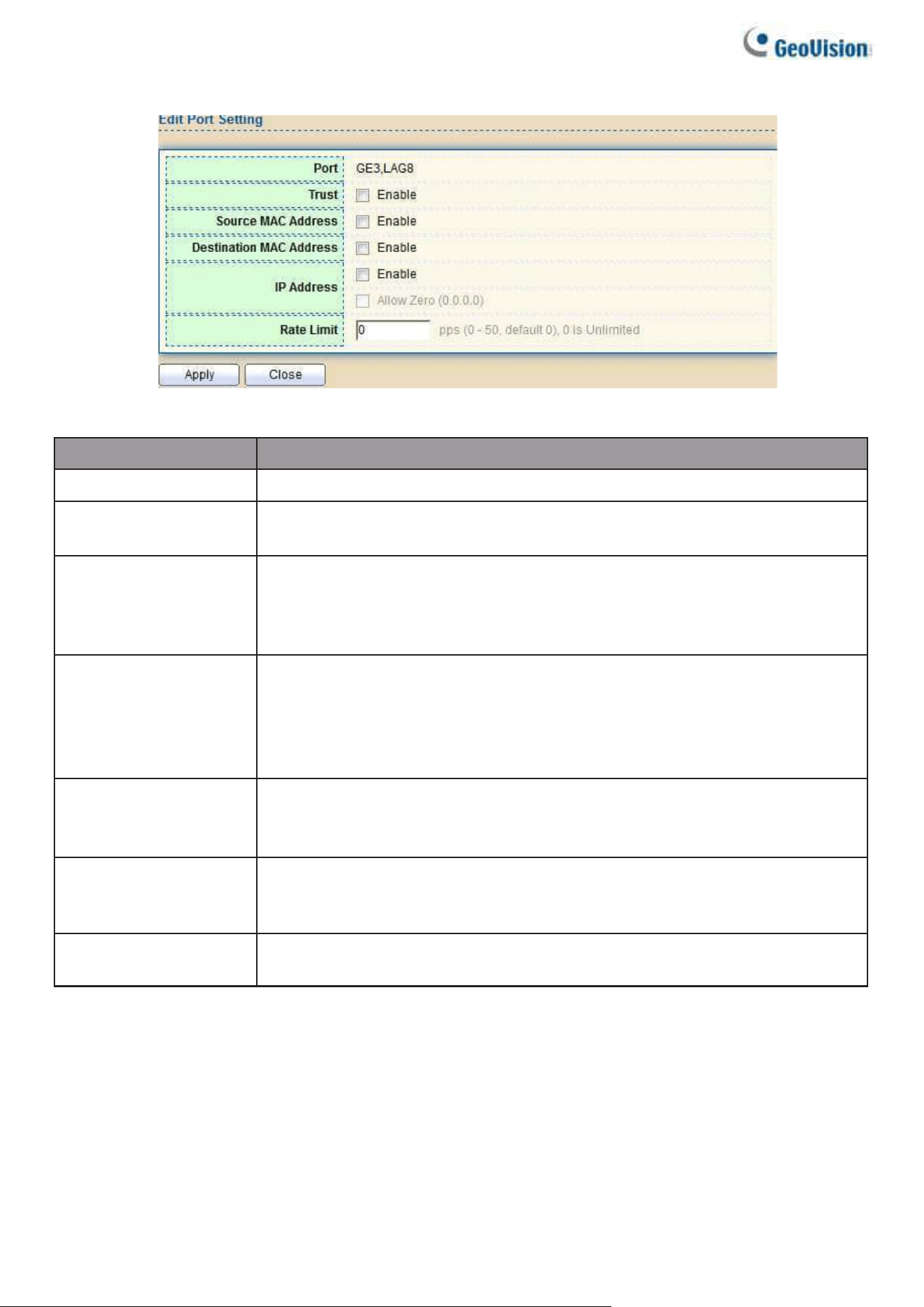
132
Click "Edit" button to view Edit Port Setting menu.
Figure 139 - Security > Dynamic ARP Inspection > Property>Edit Port Setting
Item
Description
Port
Display selected port to be edited.
Trust
Set checkbox to enable/disabled trust of interface. All ARP packet will
be forward directly if enable trust. Default is disabled.
Source MAC
Address
Set checkbox to enable or disable source mac address validation of
interface. All ARP packets will be checked whether sender mac is
same as source mac in Ethernet header if enable source mac address
validation. Default is disabled.
Destination MAC
Address
Set checkbox to enable or disable destination mac address validation
of interface. All ARP packets will be checked whether target mac is
same as destination mac in Ethernet header if enable destination mac
address validation. Default is disabled.
IP Address
Set checkbox to enable or disable IP address validation of interface.
All ARP packets will be checked whether IP address is 0.0.0.0,
255.255.255.255 or multicast address. Default is disabled.
IP Address –
Allow Zero
Set checkbox to enable or disable allow zero of IP address validation.
0.0.0.0 IP address is valid if allow zero enable. Default is disabled.
Rate Limit
Input rate limitation of ARP packets. The unit is pps. 0 means
unlimited. Default is unlimited.
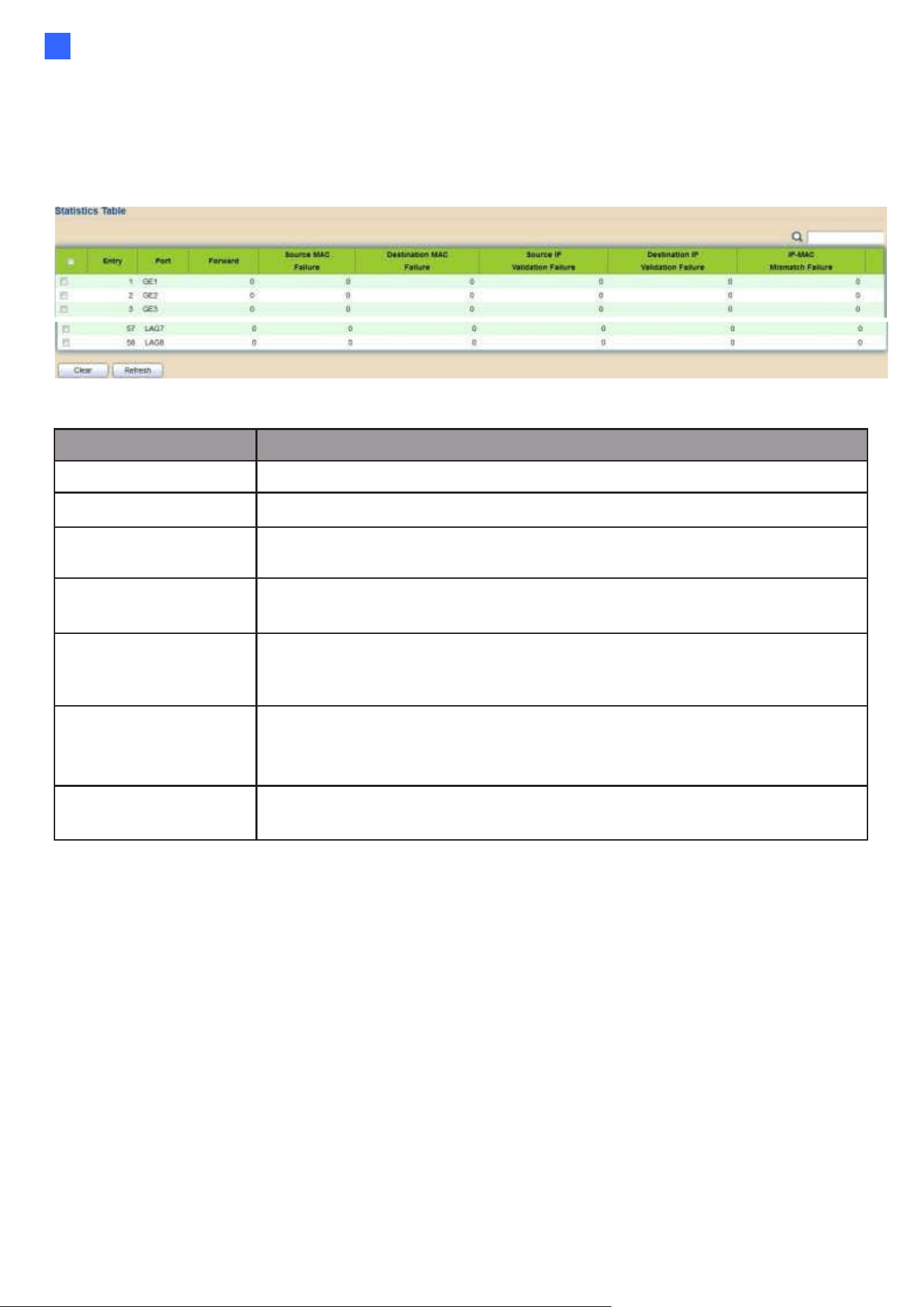
Web-based Switch Configuration
133
2
2.8.10.2. Statistics
This page allows users to browse all statistics that recorded by Dynamic ARP Inspection function.
To display Statistics page, click Security > Dynamic ARP Inspection > Statistics
Figure 140 - Security > Dynamic ARP Inspection > statistics
Item
Description
Port
Display port ID.
Forwarded
Display how many packets forwarded normally.
Source MAC
Failures
Display how many packets dropped by source MAC validation.
Destination MAC
Failures
Display how many packets dropped by destination MAC validation.
Source IP
Validation
Failures
Display how many packets dropped by source IP validation.
Destination IP
Validation
Failures
Display how many packets dropped by destination IP validation.
IP-MAC
Mismatch
Display how many packets dropped by IP-MAC doesn’ t match in IP
Source Guard binding table.
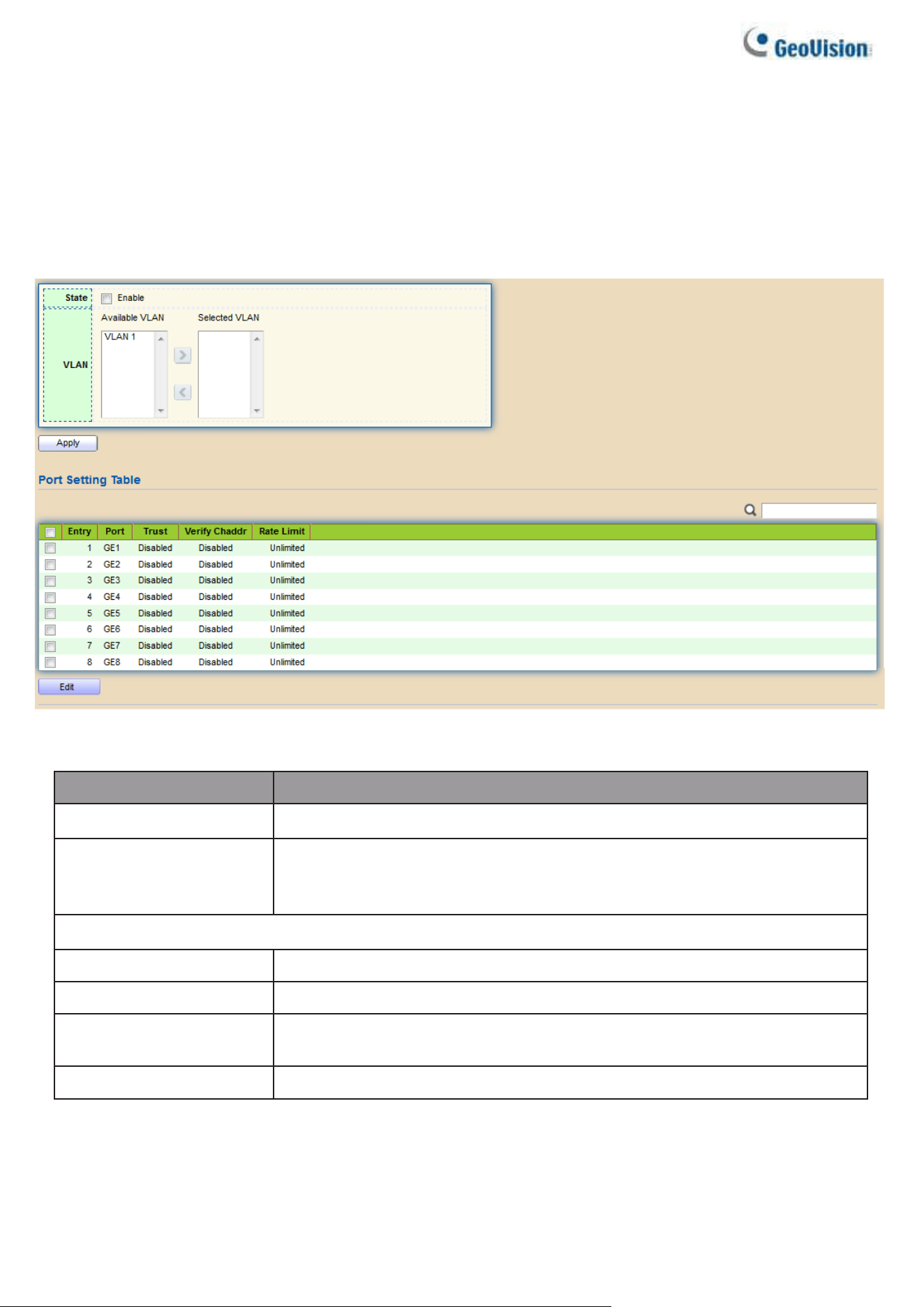
134
2.8.11. DHCP Snooping
Use the DHCP Snooping pages to configure settings of DHCP Snooping
2.8.11.1. Property
This page allows users to configure global and per interface settings of DHCP Snooping.
To display property page, click Security > DHCP Snooping > Property
Figure 141 - Security > DHCP Snooping > Property
Item
Description
State
Set checkbox to enable/disable DHCP Snooping function.
VLAN
Select VLANs in left box then move to right to enable
DHCP Snooping. Or select VLANs in right box then move to left to
disable DHCP Snooping.
Port Setting Table
Port
Display port ID.
Trust
Display enable/disabled trust attribute of interface.
Verify Chaddr
Display enable/disabled chaddr validation attribute of
interface.
Rate Limit
Display rate limitation value of interface.
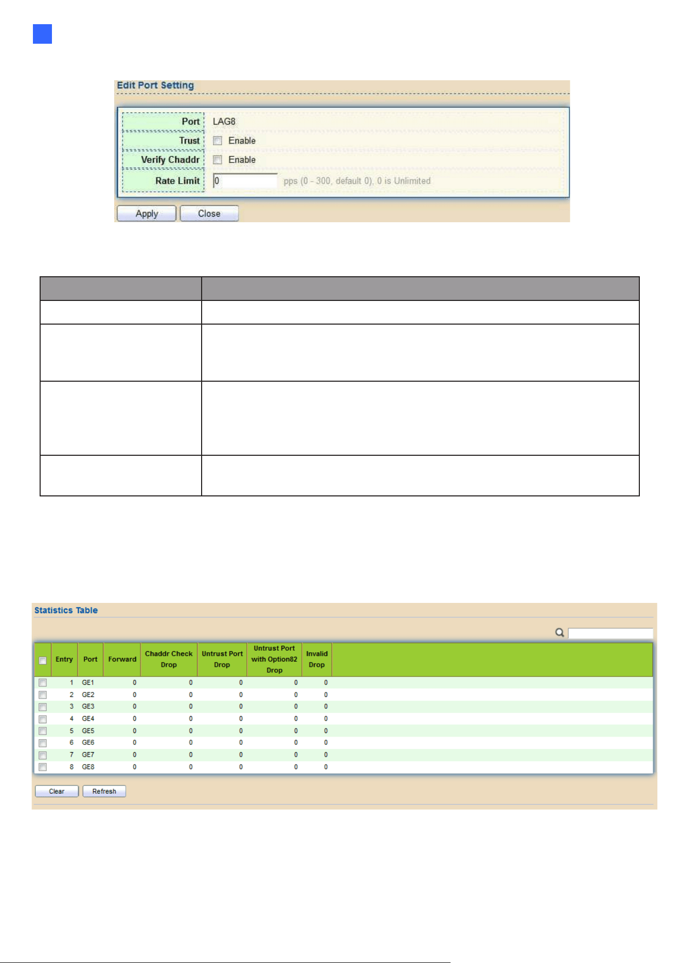
Web-based Switch Configuration
135
2
Click "Edit" button to view Edit Port Setting menu.
Figure 142 - Security > DHCP Snooping > Property > Edit Port Setting
Item
Description
Port
Display selected port to be edited
Trust
Set checkbox to enable/disabled trust of interface. All DHCP
packet will be forward directly if enable trust.
Default is disabled.
Verify Chaddr
Set checkbox to enable or disable chaddr validation of interface.
All DHCP packets will be checked whether client hardware mac
address is same as source mac in Ethernet header if enable
chaddr validation. Default is disabled.
Rate Limit
Input rate limitation of DHCP packets. The unit is pps. 0 means
unlimited. Default is unlimited.
2.8.11.2. Statistics
This page allows users to browse all statistics that recorded by DHCP snooping function.
To view the Statistics menu, navigate to Security > DHCP Snooping > Statistics.
Figure 143 - Security > DHCP Snooping > Statistics
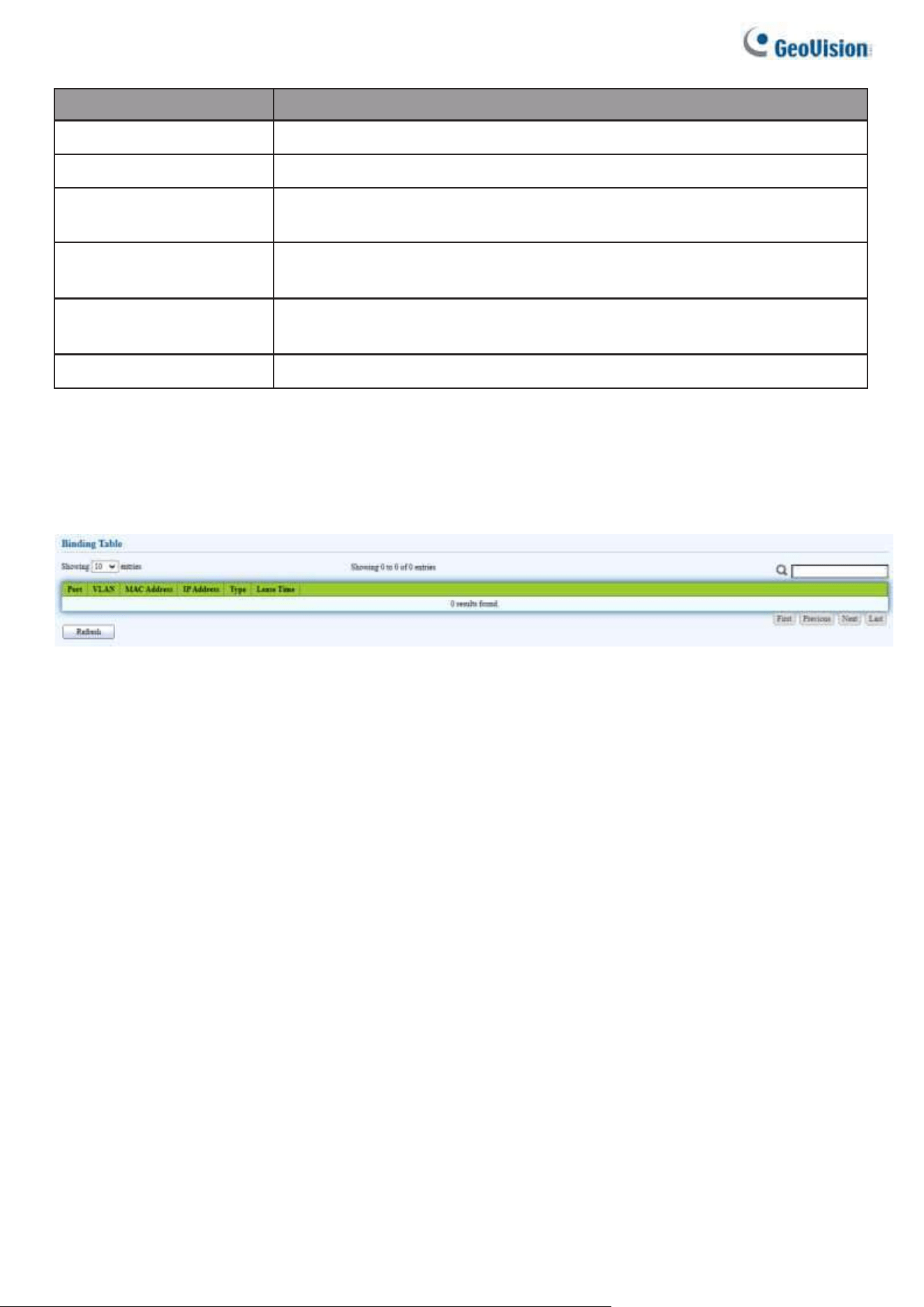
136
Item
Description
Port
Display port ID.
Forwarded
Display how many packets forwarded normally.
Chaddr Check
Drop
Display how many packets dropped by chaddr validation.
Untrusted Port
Drop
Display how many DHCP server packets that are received by
untrusted port dropped.
Untrusted Port
with Option82
Display how many packets dropped by untrusted port with
option82 checking.
Invalid Drop
Display how many packets dropped by invalid checking.
2.8.11.3. Binding
This page allows users to browse the DHCP status, including the port, VLAN, Mac address, IP
address, etc.
To view the Binding menu, navigate to Security > DHCP Snooping > Binding.
Figure 144 - Security > DHCP Snooping > Binding
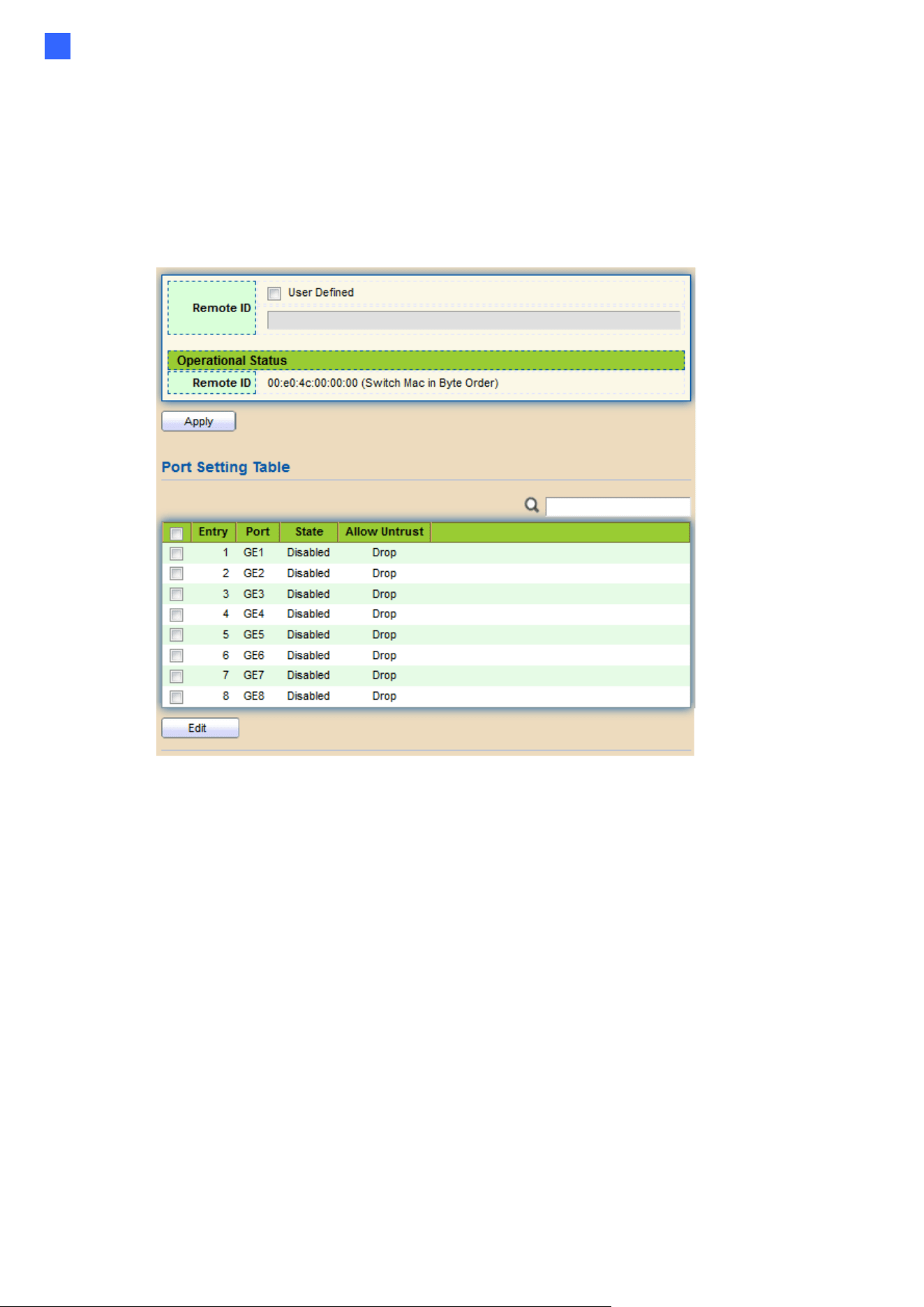
Web-based Switch Configuration
137
2
2.8.11.4. Option82 Property
This page allows users to set string of DHCP option82 remote ID filed. The string will attach
in option82 if option inserted.
To display Option82 Property page, click Security > DHCP Snooping > Option82 Property
Figure 144 - Security > DHCP Snooping > Option82 Property
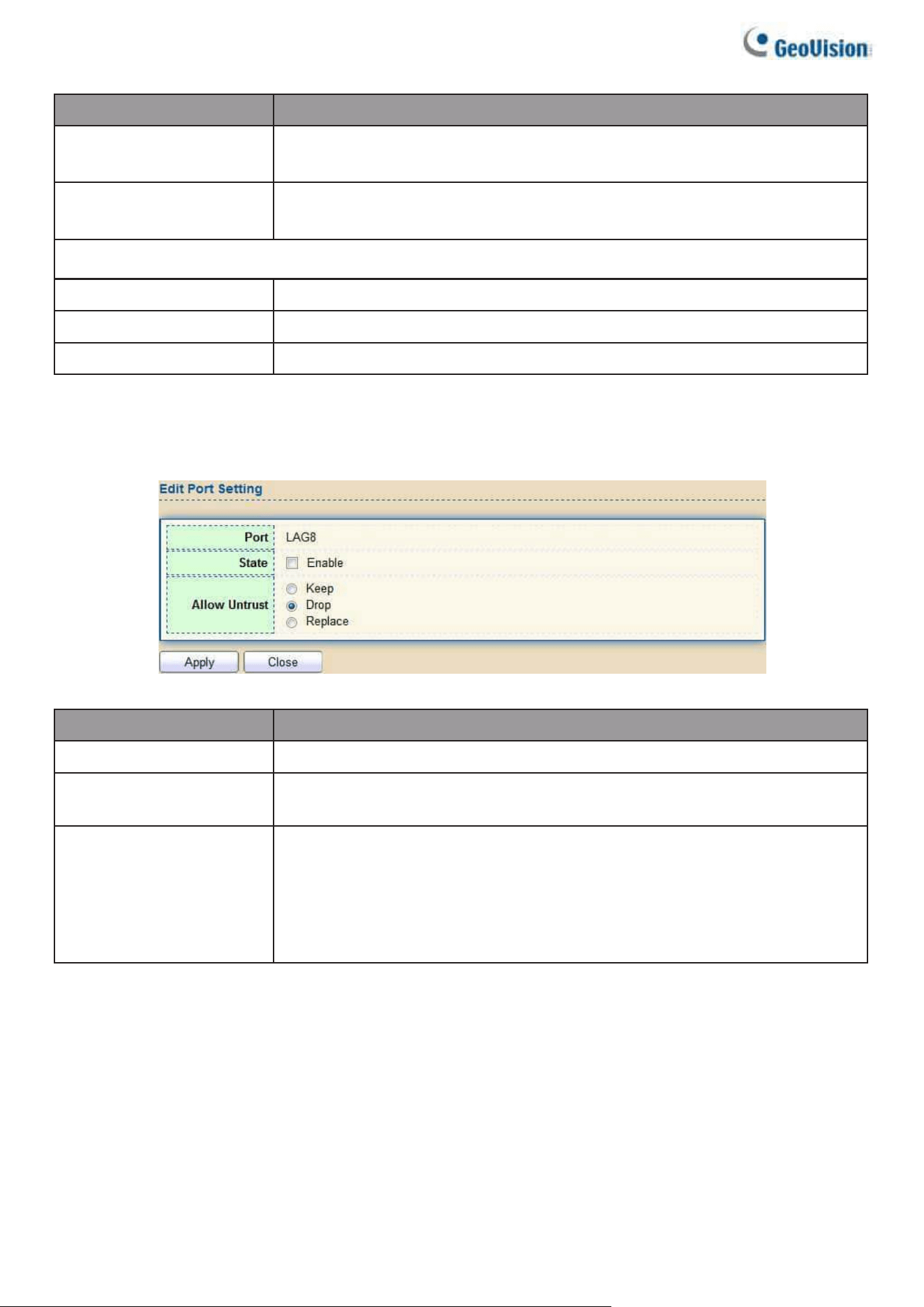
138
Item
Description
User-defined
Set checkbox to enable user-defined remote-ID. By
default, remote ID is switch mac in byte order.
Remote ID
Input user-defined remote ID. Only available when enable user-
define remote ID.
Port Setting Table
Port
Display port ID.
State
Display option82 enable/disable status of interface.
Allow untrusted
Display allow untrusted action of interface.
Click "Edit" button to view Edit Port Setting menu.
Figure 145 - Security > DHCP Snooping > Option82 Property > Edit Port Setting
Item
Description
Port
Display selected port to be edited
State
Set checkbox to enable/disable option82 function of
interface.
Allow untrusted
Select the action perform when untrusted port receive DHCP
packet has option82 filed. Default is drop.
•
Keep: Keep original option82 content.
•
Replace: Replace option82 content by switch setting
•
Drop: Drop packets with option82
2.8.11.5. Option82 Circuit ID
This page allows users to set string of DHCP option82 circuit ID filed. The string will attach in
option82 if option inserted.
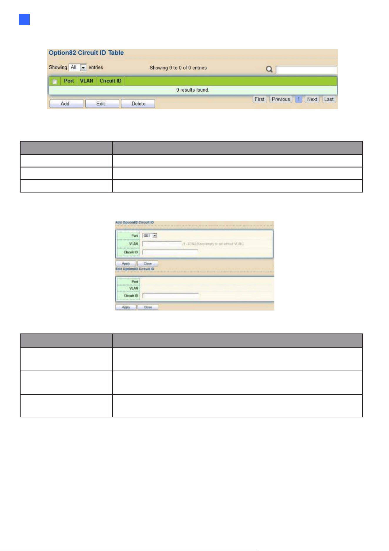
Web-based Switch Configuration
139
2
To display Option82 Circuit ID page, click Security > DHCP Snooping > Option82 Circuit ID.
Figure 146 - Security > DHCP Snooping > Option82 Circuit ID
Item
Description
Port
Display port ID of entry.
VLAN
Display associate VLAN of entry.
Circuit ID
Display circuit ID string of entry.
Click “Add” button or "Edit" button to view the Add/Edit Option82 Circuit ID menu.
Figure 147 - Security > DHCP Snooping > Option82 Circuit ID> Add/Edit Option82 Circuit ID
Item
Description
Port
Select port from list to associate to CID entry. Only
available on Add dialog.
VLAN
Input VLAN ID to associate to circuit ID entry. VLAN ID is not
mandatory. Only available on Add dialog.
Circuit ID
Input String as circuit ID. Packets match port and VLAN will be
inserted circuit ID.
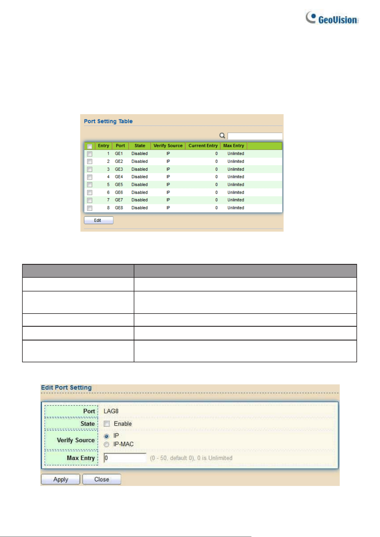
140
2.8.12. IP Source Guard
Use the IP Source Guard pages to configure settings of IP Source Guard.
2.8.12.1. Port Setting
Use the IP Source Guard pages to configure settings of IP Source Guard.
To display Port Setting page, click Security > IP Source Guard > Port Setting.
Figure 148 - Security > IP Source Guard > Port Setting
Item
Description
Port
Display port ID.
State
Display IP Source Guard enable/disable status of
interface.
Verify Source
Display mode of IP Source Guard verification
Current Binding Entry
Display current binding entries of a interface.
Max Binding Entry
Display the number of maximum binding entry of
interface.
Click "Edit" button to view the Edit Port Setting menu.
Figure 149 - Security > IP Source Guard > Port Setting > Edit Port Setting
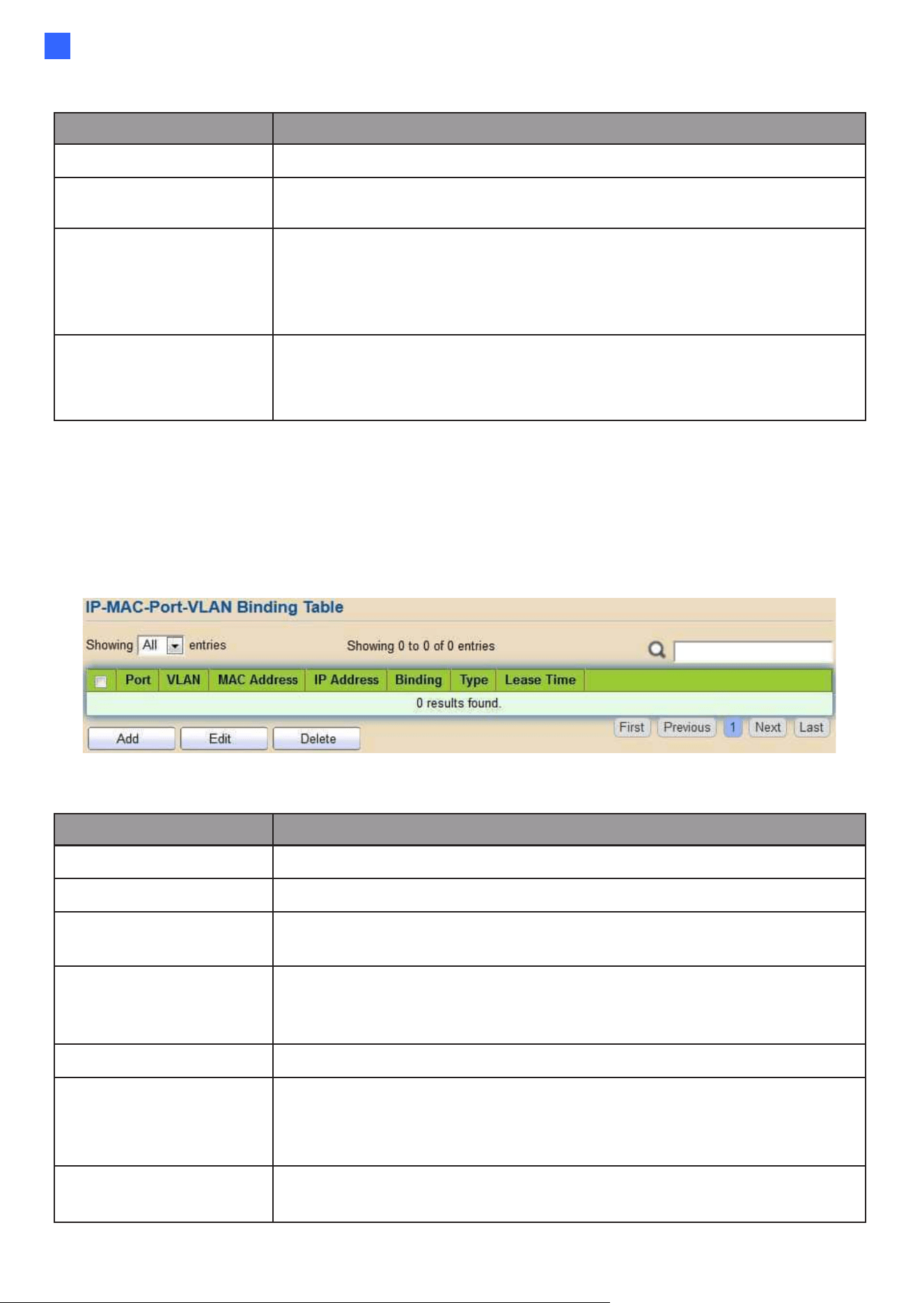
Web-based Switch Configuration
141
2
Item
Description
Port
Display selected port to be edited.
Status
Set checkbox to enable or disable IP Source Guard
function. Default is disabled.
Verify Source
Select the mode of IP Source Guard verification
•
IP: Only verify source IP address of packet.
•
IP-MAC: Verify source IP and source MAC address of
packet.
Max Entry
Input the maximum number of entries that a port can be
bounded. Default is un-limited on all ports. No entry will be
bound if limitation reached.
2.8.12.2. IMPV Binding
This page allows users to add static IP source guard entry and browse all IP source guard
entries that learned by DHCP snooping or statically create by users.
To display IPMV Binding page, click Security > IP Source Guard > IMPV Binding
Figure 150 - Security > IP Source Guard > IMPV Binding
Item
Description
Port
Display port ID of entry.
VLAN
Display VLAN ID of entry.
MAC Address
Display MAC address of entry. Only available of IP-MAC
binding entry.
IP Address
Display IP address of entry. Mask always to be
255.255.255.255 for IP-MAC binding. IP binding entry display
user input.
Binding
Display binding type of entry.
Type
Type of existing binding entry
•
Static: Entry added by users.
•
Dynamic: Entry learned by DHCP snooping.
Lease Time
Lease time of DHCP Snooping learned entry. After lease time entry
will be deleted. Only available of dynamic entry.
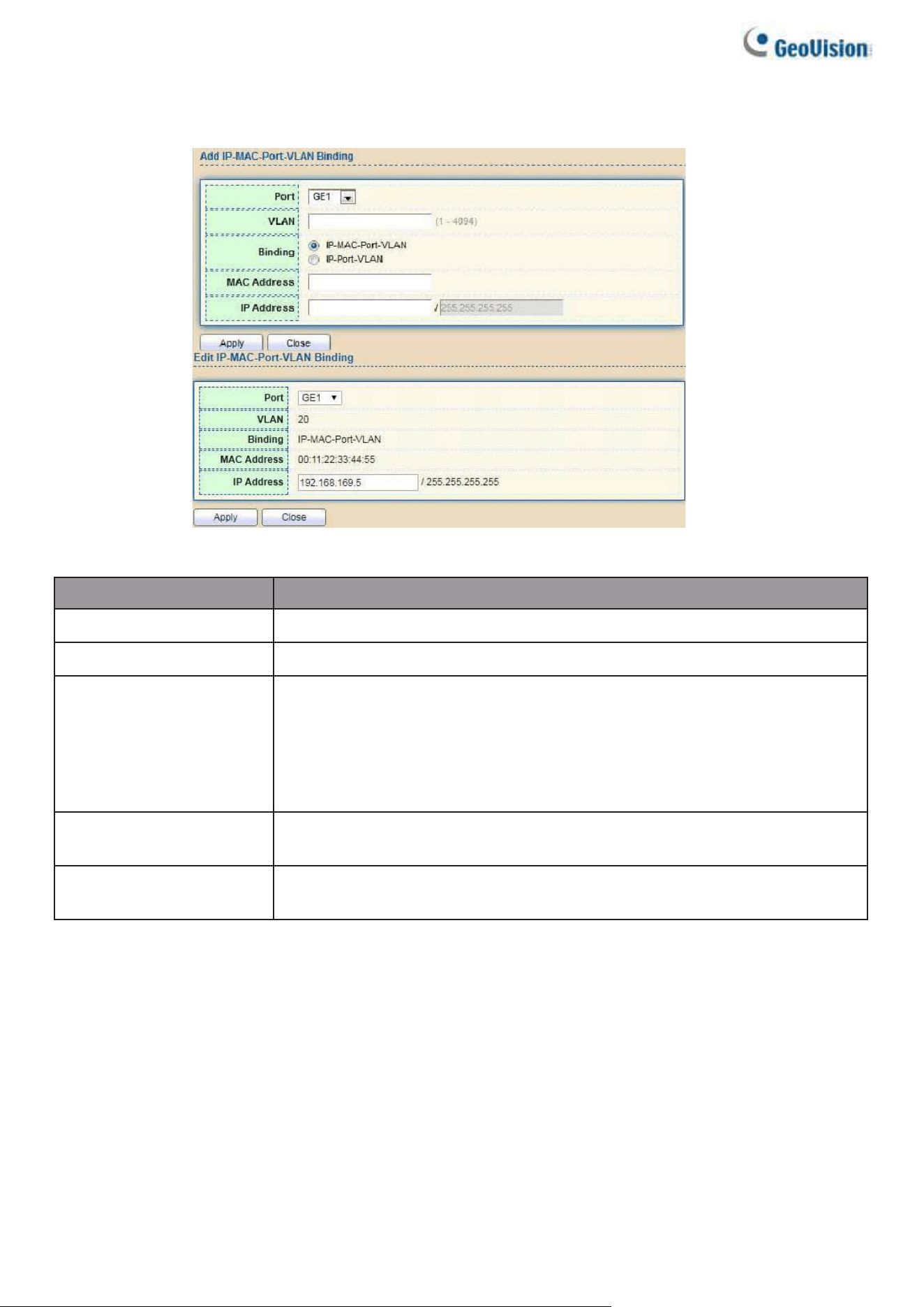
142
Click "Add" or “Edit” button to view the Add/Edit IP-MAC-Port-VLAN Binding menu.
Figure 151 - Security > IP Source Guard > Add/Edit IP-MAC-Port-VLAN Binding
Item
Description
Port
Select port from list of a binding entry.
VLAN
Specify a VLAN ID of a binding entry.
Binding
Select matching mode of binding entry
•
IP-MAC-Port-VLAN: packet must match IP address, MAC
address, Port, and VLAN ID.
•
IP-Port-VLAN: packet must match IP address or subnet, Port,
and VLAN ID.
MAC Address
Input MAC address. Only available on IP-MAC-Port-VLAN
mode.
IP Address
Input IP address and mask. Mask only available on IP- MAC-
Port mode.
2.8.12.3. Save Database
This page allows users to configure DHCP snooping database which can backup and
restore dynamic DHCP snooping entries.
To display Save Database page, click Security > DHCP Snooping > Save Database.
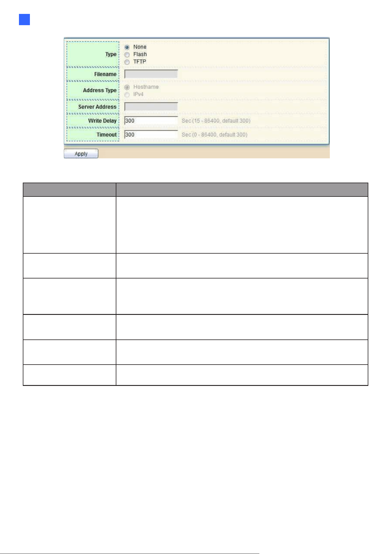
Web-based Switch Configuration
143
2
Figure 152 - Security > IP Source Guard > Save Database
Item
Description
Type
Select the type of database agent.
•
None: Disable database agent service.
•
Flash: Save DHCP dynamic binding entries to flash.
•
TFTP: Save DHCP dynamic binding entries to remote TFTP
server.
Filename
Input filename for backup file. Only available when
selecting type “flash” and “TFTP”.
Address Type
Select the type of TFTP server.
•
Hostname: TFTP server address is hostname.
•
IPv4: TFTP server address is IPv4 address
Server Address
Input remote TFTP server hostname or IP address. Only
available when selecting type “TFTP”
Write Delay
Input delay timer for doing backup after change
happened. Default is 300 seconds.
Timeout
Input aborts timeout for doing backup failure. Default is 300
seconds.
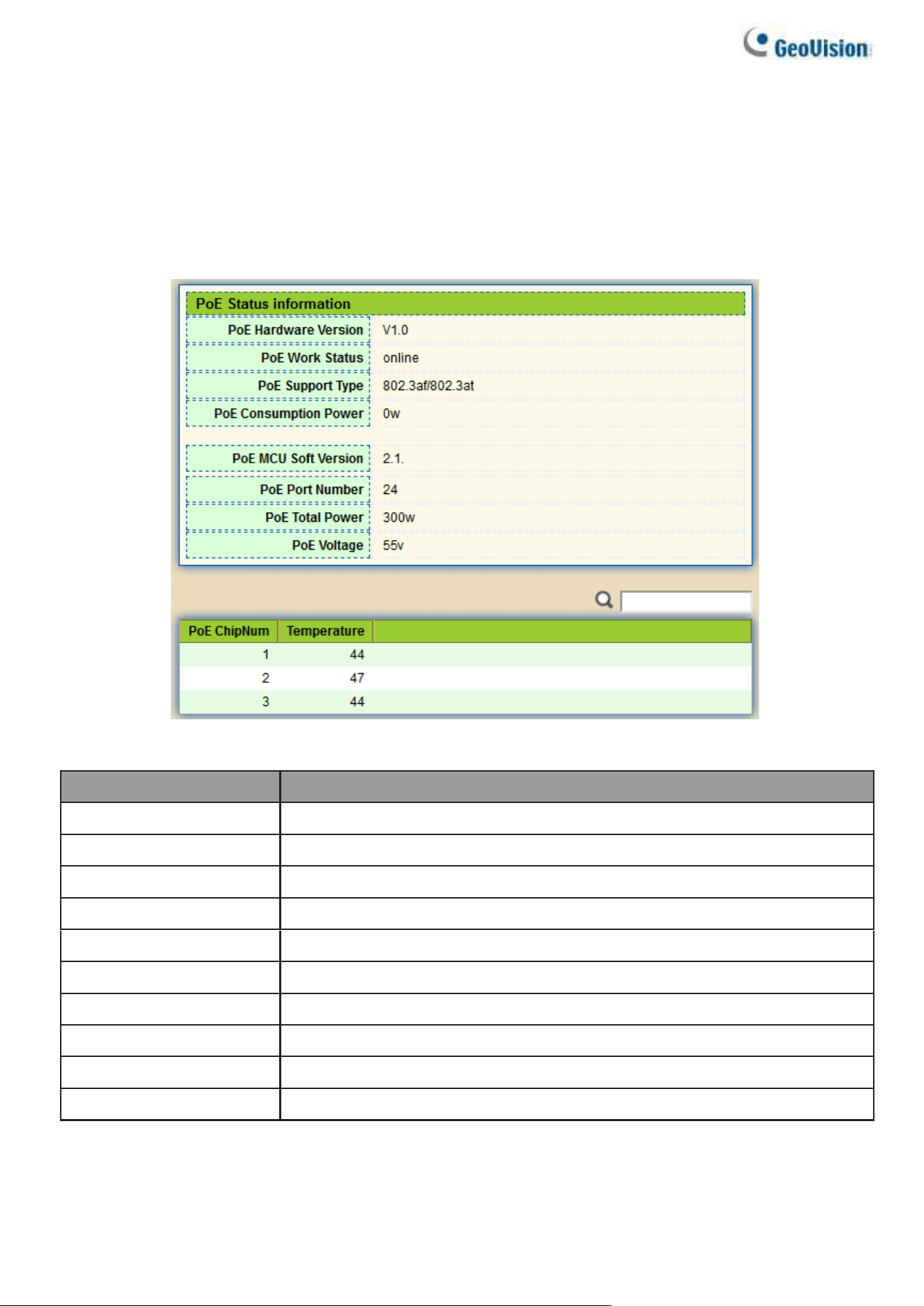
144
2.9. PoE
Manage global PoE information and ports.
2.9.1. PoE Global information
This page allows users to configure PoE global configurations.
To display the Global web page, click PoE > PoE Global Information.
Figure 153 - PoE > PoE Global information
Item
Description
PoE Hardware Version
Hardware version of the PoE module.
PoE Work Status
Working status of the current PoE module.
PoE Support Type
The type of PoE protocol supported by this PoE module.
PoE Consuming Power
Current consumed power.
PoE MCU Soft Version
MCU software version of this PoE module.
PoE Port Number
The number of PoE ports supported by this PoE module.
PoE Total Power
Maximum supply power.
PoE Voltage
Input voltage of the PoE module.
PoE Chipnum
Chip serial number.
Temperature
Chip temperature.
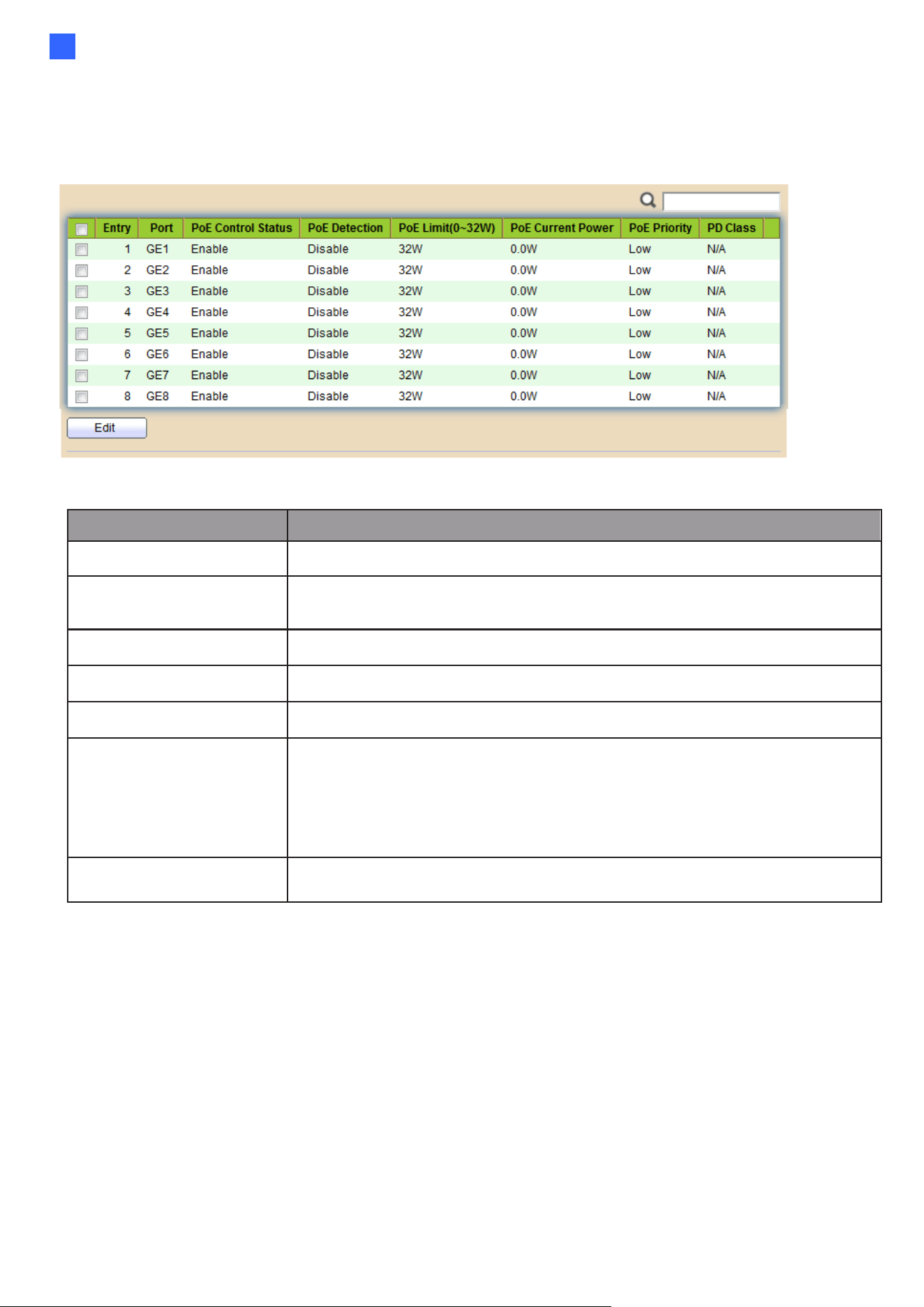
Web-based Switch Configuration
145
2
2.9.2. PoE Port
Use this page to set the status, power priority, and power limit of the PoE port.
To display the Priority Setting web page, click PoE > PoE Port.
Figure 154-1 - PoE > PoE Port
Item
Description
Port
Display port ID of entry.
Control Status
Displays the enabled/disabled status of the PoE interface or PoE
Forcepower.
Detection
Display PoE detection results.
PoE Limit
Display the maximum usable power of the port.
Current Power
Display the current power used by the port.
PoE Priority
Display port power priority.
“Low” is lower priority;
“High” is high priority;
“Critical” is Critical priority.
PD Class
Display the type of PD.
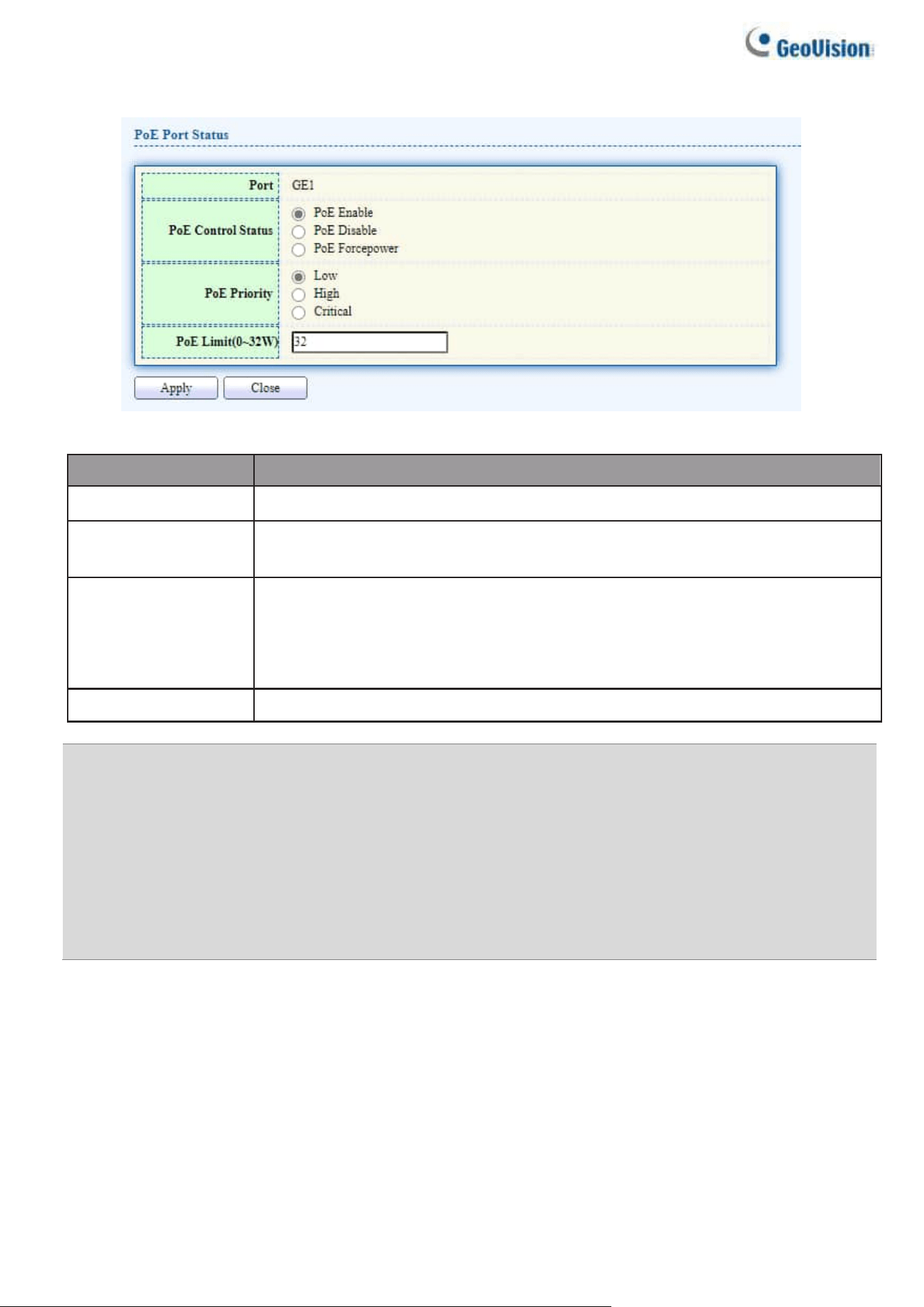
146
Select the port ID(s) and click the “Edit” button to view the edit page.
Figure 154-2 - PoE > PoE Port > Edit PoE Port
Item
Description
Port
Display port ID of entry.
Control Status
select the enabled/disabled status of the PoE interface or PoE
Forcepower.
PoE Priority
select port power priority.
“Low” is lower priority;
“High” is high priority;
“Critical” is Critical priority.
PoE Limit
Enter max supply power value for the selected port list. The default is 32.
Note: Take extra care when using the PoE Forcepower mode, since no PD detection is
performed and power is automatically injected.
Use this mode only after you have made sure that either the PoE unit is connected to a
valid PD capable of receiving PoE power, or during the manufacturers testing.
If a port is disabled and then forced on, the port remains off until the port is enabled, and
only then is the port connected.
If a port was forced on and then disabled, the PoE system ignores the disable command
and returns an error report.
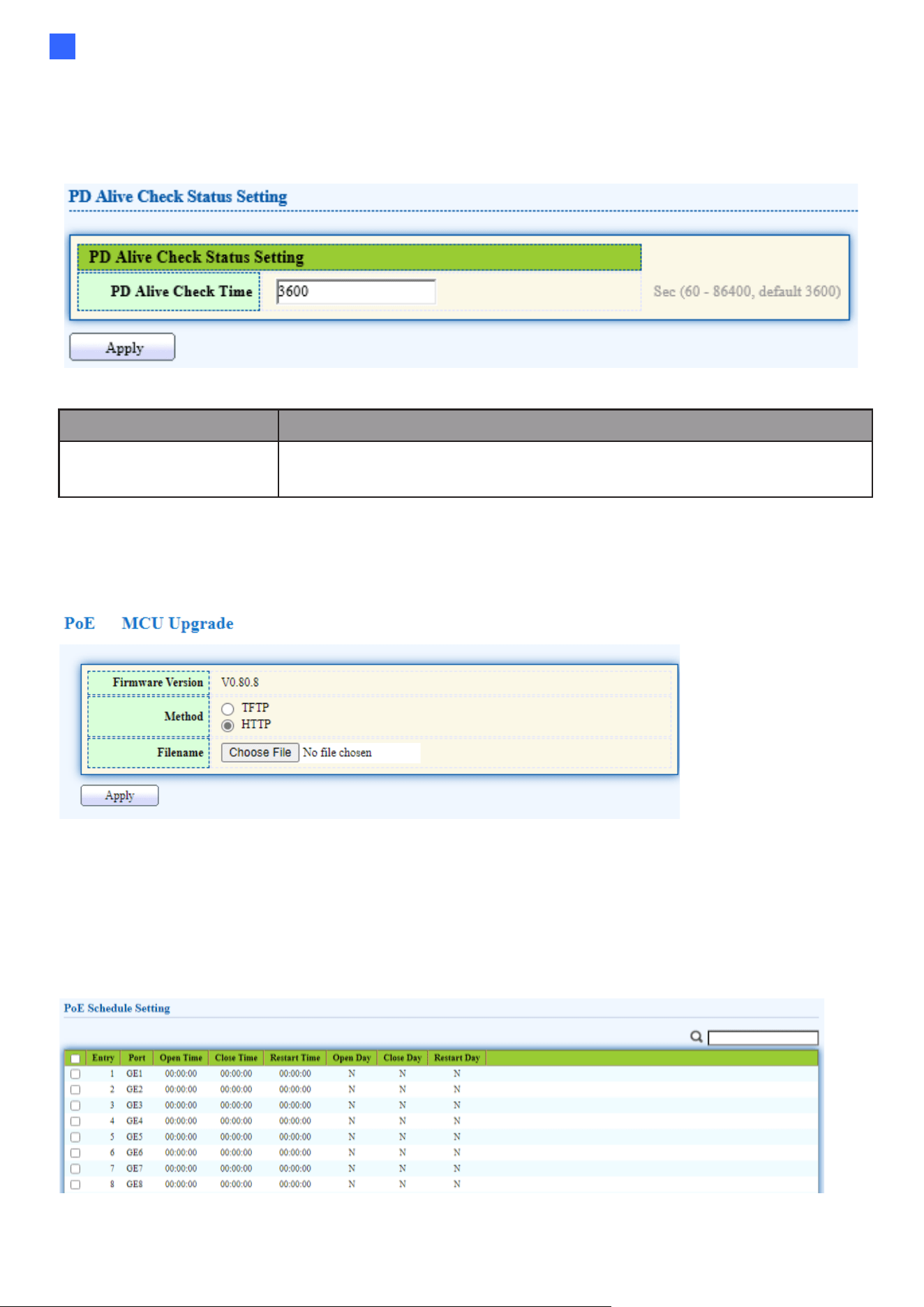
Web-based Switch Configuration
147
2
2.9.3. PoE PD Alive Check
Use this page to power down the PoE interface restart.
To display the PoE PD Alive Check web page, click PoE > PoE PD Alive Check.
Figure 155 - PoE > PoE PD Alive Check
Item
Description
PD Alive Check Time
Set time value to get one data flow. Determine whether to restart
based on the data traffic of the two periods.
2.9.4. MCU Upgrade
Use this page to upgrade MCU.
To display the MCU Upgrade web page, click PoE > MCU Upgrade.
Figure 156 - PoE > MCU Upgrade
2.9.5. PoE Schedule
Use this page to set the open time, close time, restart time, open day, close day, and restart
day of the PoE schedule.
To display the Priority Setting web page, click PoE > PoE Schedule.
Figure 156-1 - PoE > PoE Schedule
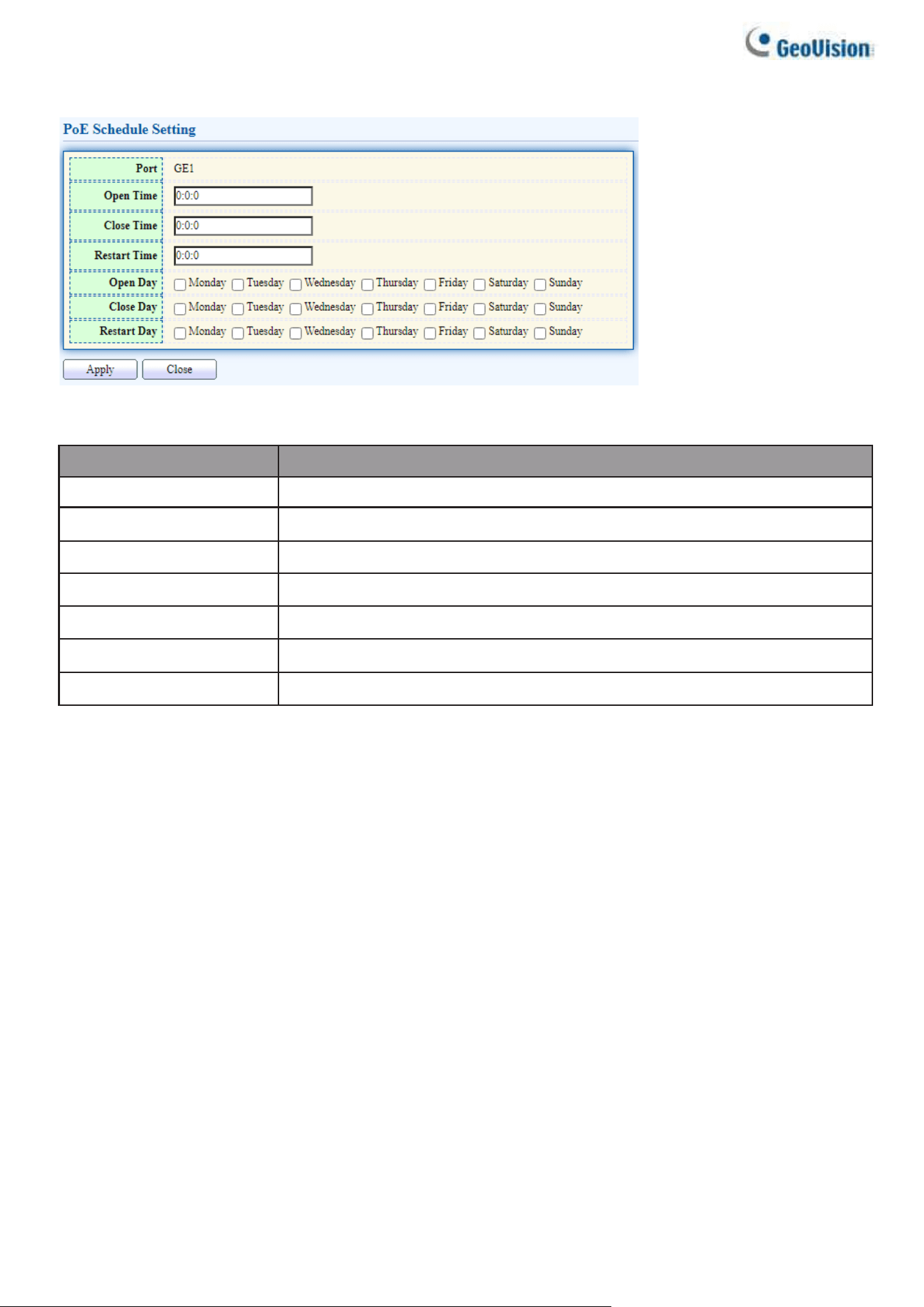
148
Select the port ID(s) and click the “Edit” button to view the edit page.
Figure 156-2 - PoE > PoE Schedule > Edit PoE Schedule
Item
Description
Port
Display port ID of entry.
Open Time
Displays the opening time of the port.
Close Time
Displays the closing time of the port.
Restart Time
Displays the restarting time of the port.
Open Day
Displays the opening date of the port.
Close Day
Displays the closing date of the port.
Restart Day
Displays the restarting date of the port.
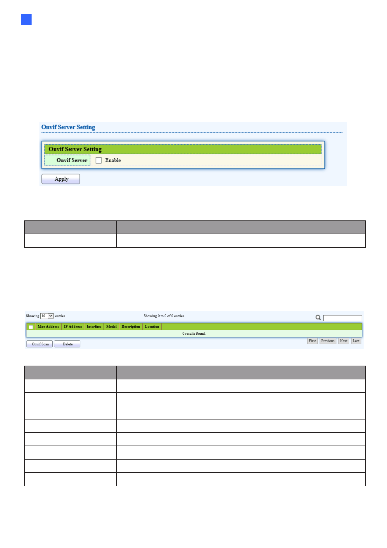
Web-based Switch Configuration
149
2
2.10. ONVIF
Manage ONVIF device.
2.11.1. ONVIF Server
This page allows users to use the switch as a server.
To display the ONVIF Server page, click ONVIF > ONVIF Server.
Figure 157 - ONVIF > ONVIF Server
Item
Description
ONVIF Server
Setting up the switch as an ONVIF server
2.11.2. ONVIF Discover
This page shows a list of ONVIF devices.
To display the ONVIF Discover page, click ONVIF > ONVIF Discover.
Figure 158 - ONVIF > ONVIF Discover
Item
Description
Mac Address
Show mac address of ONVIF device
IP Address
Show IP address of ONVIF device
Interface
Display the port ID of the switch connected to the device
Model
Display the model of the ONVIF device
Description
Show description of ONVIF device
Location
Show production origin of ONVIF equipment
ONVIF Scan
Detect ONVIF devices in the network
Delete
Clear selected entry device
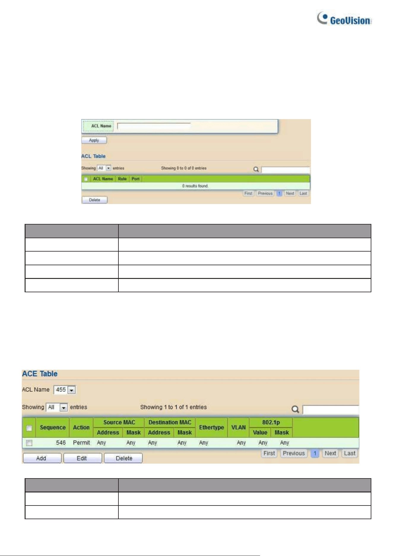
150
2.12. ACL
Use the ACL pages to configure settings for the switch ACL features.
2.12.1. MAC ACL
This page allows users to add or delete ACL rule. A rule cannot be deleted if under binding.
To display MAC ACL page, click ACL > MAC ACL
Figure 159 - ACL > MAC ACL
Item
Description
ACL Name
Input MAC ACL name.
ACL Name
Display MAC ACL name.
Rule
Display the number ACE rule of ACL.
Port
Display the port list that bind this ACL.
2.12.2. MAC ACE
This page allows users to add, edit or delete ACE rule. An ACE rule cannot be edited or
deleted if ACL under binding. New ACE cannot be added if ACL under binding.
To display MAC ACE page, click ACL > MAC ACE
Figure 160 - ACL > MAC ACE
Item
Description
ACL Name
Select the ACL name to which an ACE is being added.
Sequence
Display the sequence of ACE.
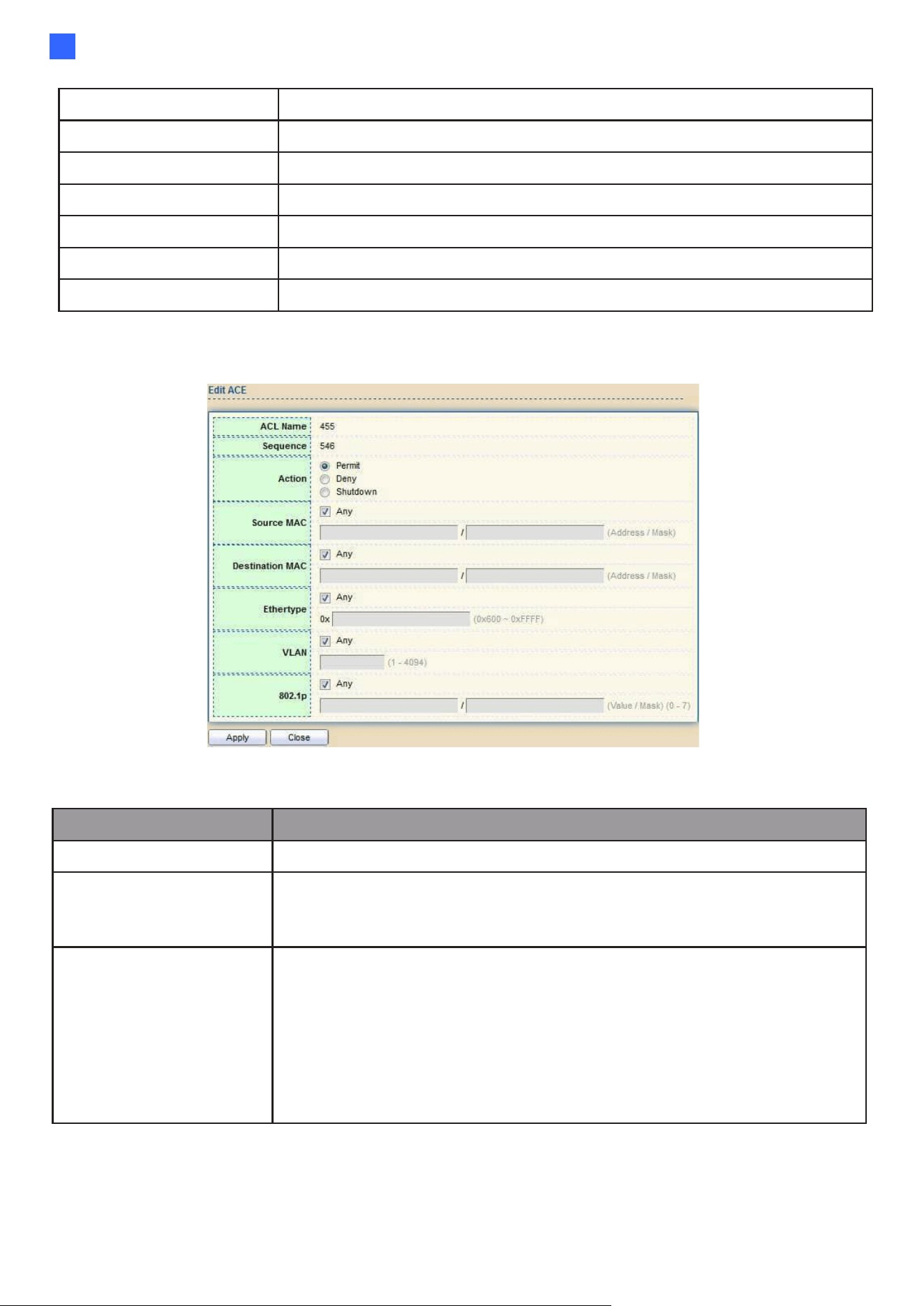
Web-based Switch Configuration
151
2
Action
Display the action of ACE.
Source MAC
Display the source MAC address and mask of ACE.
Destination MAC
Display the destination MAC address and mask of ACE.
Ethertype
Display the Ethernet frame type of ACE.
VLAN ID
Display the VLAN ID of ACE.
802.1p Value
Display the 802.1p value of ACE.
802.1p Mask
Display the 802.1p mask of ACE.
Click “Edit” button to view the Edit ACE menu.
Figure 161 - ACL > Edit ACE
Item
Description
ACL Name
Display the ACL name to which an ACE is being added.
Sequence
Specify the sequence of the ACE. ACEs with higher sequence
are processed first (1 is the highest priority). Only available on
Add Dialog.
Action
Select the action after ACE match packet.
●
Permit: Forward packets that meet the ACE criteria.
●
Deny: Drop packets that meet the ACE criteria.
●
Shutdown: Drop packets that meet the ACE criteria, and
disable the port from where the packets were received. Such
ports can be reactivated from the Port Settings page.
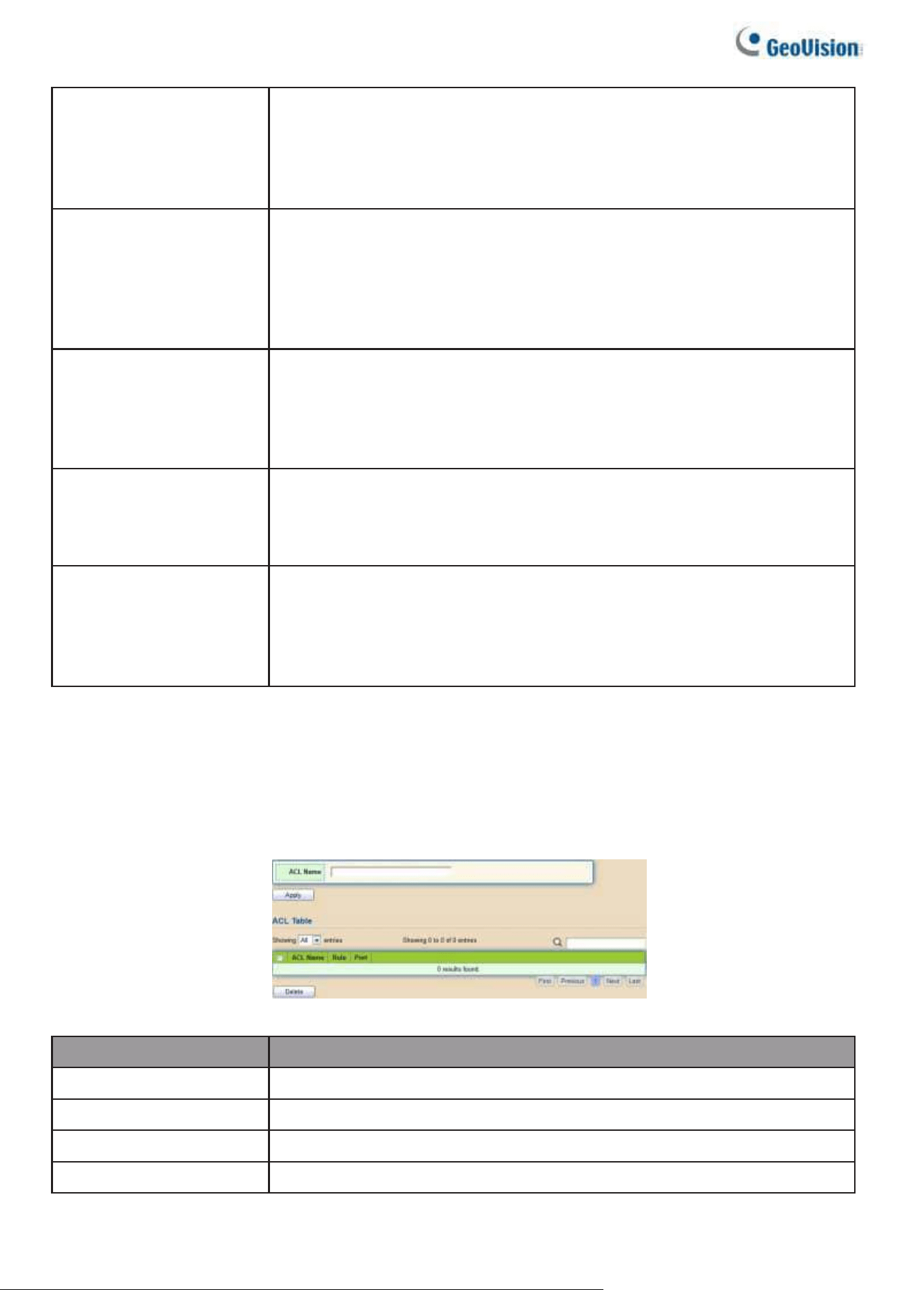
152
Source MAC
Select the type for source MAC address.
●
Any: All source addresses are acceptable.
●
User-defined: Only a source address or a range of source
addresses which users define are acceptable. Enter the
source MAC address and mask to which will be matched.
Destination MAC
Select the type for Destination MAC address.
●
Any: All destination addresses are acceptable.
●
User-defined: Only a destination address or a range of
destination addresses which users define are acceptable.
Enter the destination MAC address and mask to which will be
matched.
Ethertype
Select the type for Ethernet frame type.
●
Any: All Ethernet frame type is acceptable.
●
User-defined: Only an Ethernet frame type which users define
is acceptable. Enter the Ethernet frame type value to which will
be matched.
VLAN
Select the type for VLAN ID.
●
Any: All VLAN ID is acceptable.
●
User-defined: Only a VLAN ID which users define is
acceptable. Enter the VLAN ID to which will be matched.
802.1p
Select the type for 802.1p value.
●
Any: All 802.1p value is acceptable.
●
User-defined: Only an 802.1p value or a range of 802.1p
value which users define is acceptable. Enter the 802.1p
value and mask to which will be matched.
2.12.3. IPv4 ACL
This page allows users to add or delete IPv4 ACL rule. A rule cannot be deleted if under
binding.
To display IPv4 ACL page, click ACL > IPv4 ACL
Figure 162 - ACL > IPv4 ACL
Item
Description
ACL Name
Input IPv4 ACL name.
ACL Name
Display IPv4 ACL name.
Rule
Display the number ACE rule of ACL.
Port
Display the port list that bind this ACL.
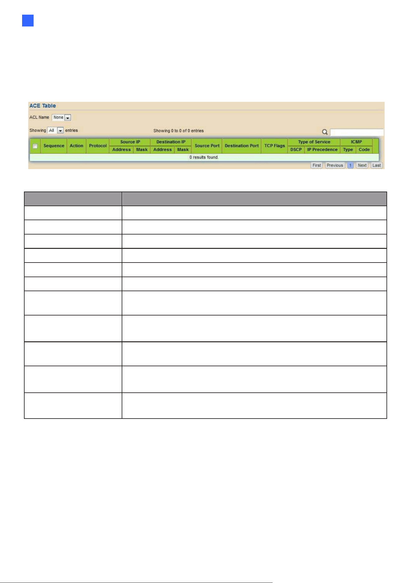
Web-based Switch Configuration
153
2
2.12.4. IPv4 ACE
This page allows users to add, edit or delete ACE rule. An ACE rule cannot be edited or
deleted if ACL under binding. New ACE cannot be added if ACL under binding.
To display IPv4 ACE page, click ACL > IPv4 ACE
Figure 169 - ACL > IPv4 ACE
Item
Description
ACL Name
Select the ACL name to which an ACE is being added.
Sequence
Display the sequence of ACE.
Action
Display the action of ACE.
Protocol
Display the protocol value of ACE.
Source IP
Display the source IP address and mask of ACE.
Destination IP
Display the destination IP address and mask of ACE.
Source Port
Display single source port or a range of source ports of ACE.
Only available when protocol is TCP or UDP.
Destination Port
Display single destination port or a range of destination ports of
ACE. Only available when protocol is TCP or UDP.
TCP Flags
Display the TCP flag value if ACE. Only available when
protocol is TCP.
Type of Service
Display the ToS value of ACE which could be DSCP or IP
Precedence.
ICMP
Display the ICMP type and code of ACE. Only available when
protocol is ICMP.
Click "Add" or “Edit” button to view the Add/Edit ACE menu.
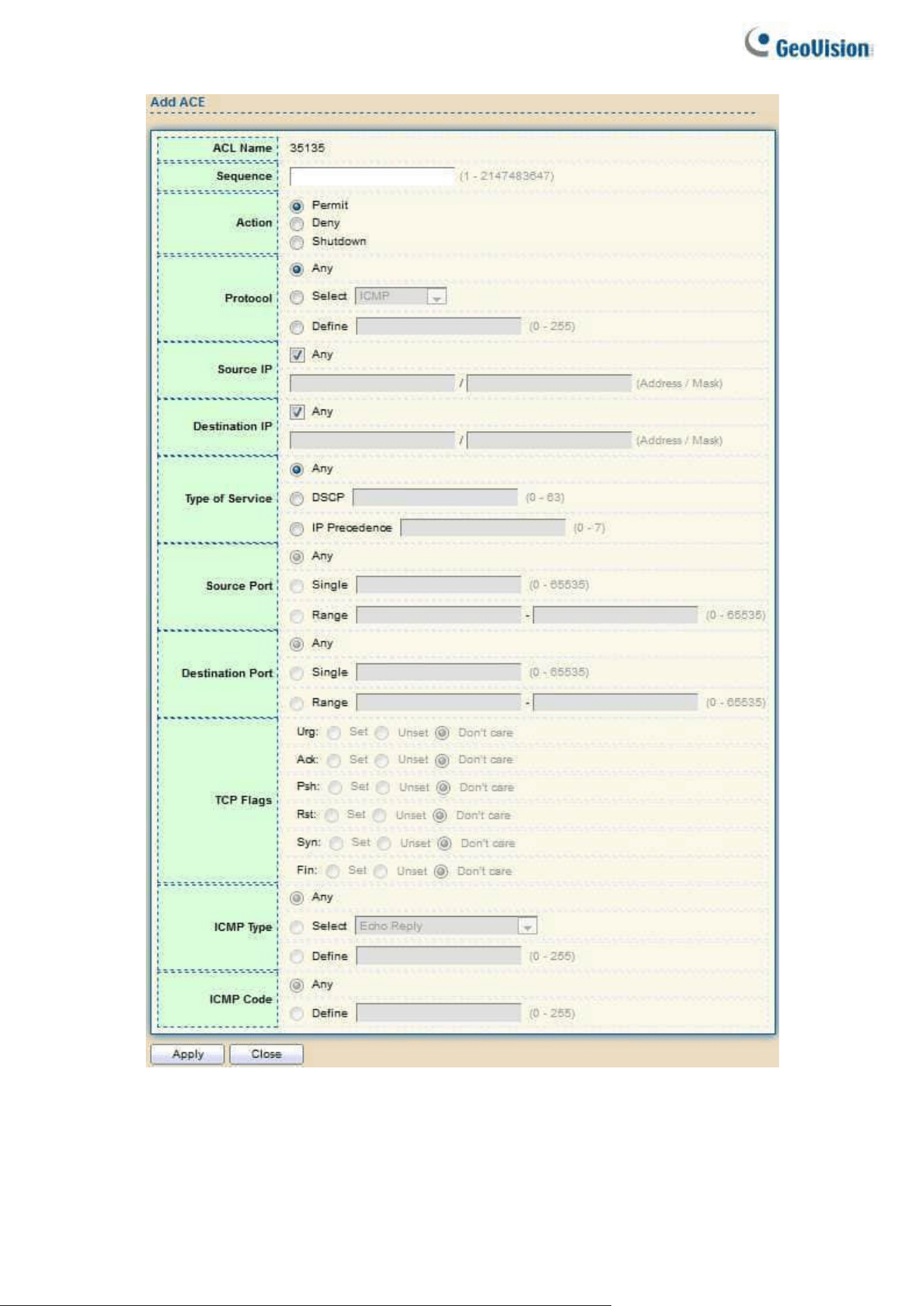
154
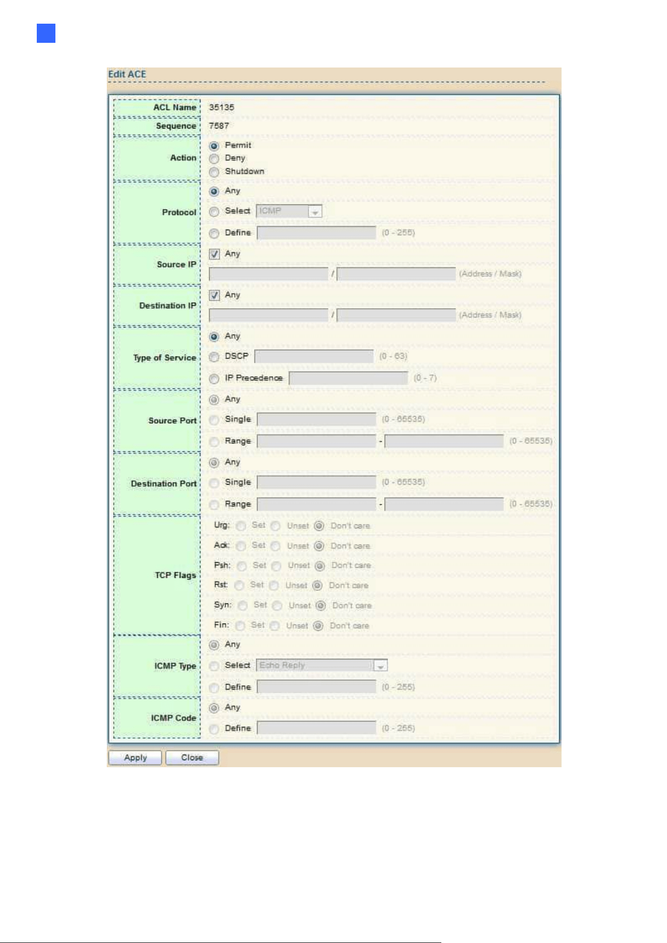
Web-based Switch Configuration
155
2
Figure 170 - ACL > Add/Edit ACE

156
Item
Description
ACL Name
Display the ACL name to which an ACE is being added.
Sequence
Specify the sequence of the ACE. ACEs with higher sequence are
processed first (1 is the highest sequence). Only available on Add
dialog.
Action
Select the action for a match.
●
Permit: Forward packets that meet the ACE criteria.
●
Deny: Drop packets that meet the ACE criteria.
●
Shutdown: Drop packets that meet the ACE criteria, and disable
the port from where the packets were received. Such ports can be
reactivated from the Port Settings page.
Protocol
Select the type of protocol for a match.
●
Any (IP): All IP protocols are acceptable.
●
Select from list: Select one of the following protocols from the drop-
down list.
(ICMP/IPinIP/TCP/EGP/IGP/UDP/HMP/RDP/IPV6/IPV6:ROUT
/IPV6:FRAG/ RSVP/IPV6:ICMP/OSPF/PIM/L2TP)
●
Protocol ID to match: Enter the protocol ID.
Source IP
Select the type for source IP address.
●
Any: All source addresses are acceptable.
●
User-defined: Only a source address or a range of source
addresses which users define are acceptable. Enter the source
IP address value and mask to which will be matched.
Destination IP
Select the type for destination IP address.
●
Any: All destination addresses are acceptable.
●
User-defined: Only a destination address or a range of
destination addresses which users define are acceptable. Enter
the destination IP address value and mask to which will be
matched.
Source Port
Select the type of protocol for a match. Only available when protocol
is TCP or UDP.
●
Any: All source ports are acceptable.
●
Single: Enter a single TCP/UDP source port to which
packets are matched.
●
Range: Select a range of TCP/UDP source ports to which the
packet is matched. There are eight different port ranges that can
be configured (shared between source and destination ports). TCP
and UDP protocols each have eight port ranges.

Web-based Switch Configuration
157
2
Destination
Port
Select the type of protocol for a match. Only available when protocol
is TCP or UDP.
●
Any: All source ports are acceptable.
●
Single: Enter a single TCP/UDP source port to which
packets are matched.
Range: Select a range of TCP/UDP source ports to which the packet
is matched. There are eight different port ranges that can be
configured (shared between source and destination ports). TCP and
UDP protocols each have eight port ranges.
Destination
Port
Select the type of protocol for a match. Only available when protocol
is TCP or UDP.
●
Any: All source ports are acceptable.
●
Single: Enter a single TCP/UDP source port to which
packets are matched.
●
Range: Select a range of TCP/UDP source ports to which the
packet is matched. There are eight different port ranges that can
be configured (shared between source and destination ports). TCP
and UDP protocols each have eight port ranges.
TCP Flags
Select one or more TCP flags with which to filter packets. Filtered
packets are either forwarded or dropped. Filtering packets by TCP
flags increases packet control, which increases network security.
Only available when protocol is TCP.
Type of
Service
Select the type of service for a match.
●
Any: All types of service are acceptable.
●
DSCP to match: Enter a Differentiated Serves Code Point
(DSCP) to match.
●
IP Precedence to match: Enter a IP Precedence to match.
ICMP Type
Either select the message type by name or enter the message type
number. Only available when protocol is ICMP.
●
Any: All message types are acceptable.
●
Select from list: Select message type by name.
●
Protocol ID to match: Enter the number of message type.
ICMP Code
Select the type for ICMP code. Only available when protocol is ICMP.
●
Any: All codes are acceptable.
●
User-defined: Enter an ICMP code to match.
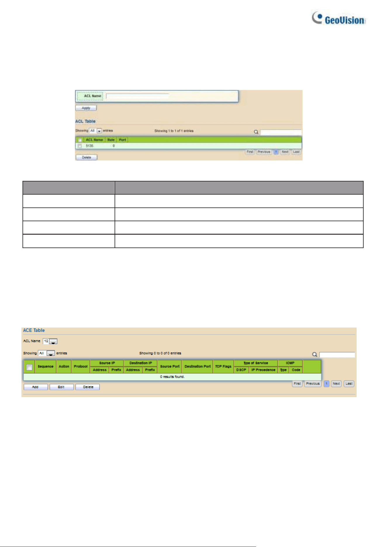
158
2.12.5. IPv6 ACL
This page allows users to add or delete Ipv6 ACL rule. A rule cannot be deleted if under
binding.
To display Ipv6 ACL page, click ACL > Ipv6 ACL
Figure 171 – ACL > Ipv6 ACL
Item
Description
ACL Name
Input Ipv6 ACL name.
ACL Name
Display Ipv6 ACL name.
Rule
Display the number ACE rule of ACL.
Port
Display the port list that bind this ACL.
2.12.6. Ipv6 ACE
This page allows users to add, edit or delete ACE rule. An ACE rule cannot be edited or deleted if
ACL under binding. New ACE cannot be added if ACL under binding.
To display Ipv6 ACE page, click ACL > Ipv6 ACE
Figure 172 – ACL > Ipv6 ACE

Web-based Switch Configuration
159
2
Item
Description
ACL Name
Select the ACL name to which an ACE is being added.
Sequence
Display the sequence of ACE.
Action
Display the action of ACE.
Protocol
Display the protocol value of ACE.
Source IP
Display the source IP address and mask of ACE.
Destination IP
Display the destination IP address and mask of ACE.
Source Port
Display single source port or a range of source ports of ACE.
Only available when protocol is TCP or UDP.
Destination Port
Display single destination port or a range of destination ports of
ACE. Only available when protocol is TCP or UDP.
TCP Flags
Display the TCP flag value if ACE. Only available when
protocol is TCP.
Type of Service
Display the ToS value of ACE which could be DSCP or IP
Precedence.
ICMP
Display the ICMP type and code of ACE. Only available when
protocol is ICMP.
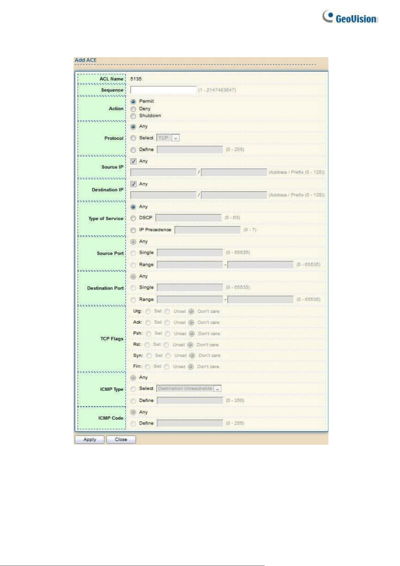
160
Click “Add” or “Edit” button to view the Add/Edit ACE menu.
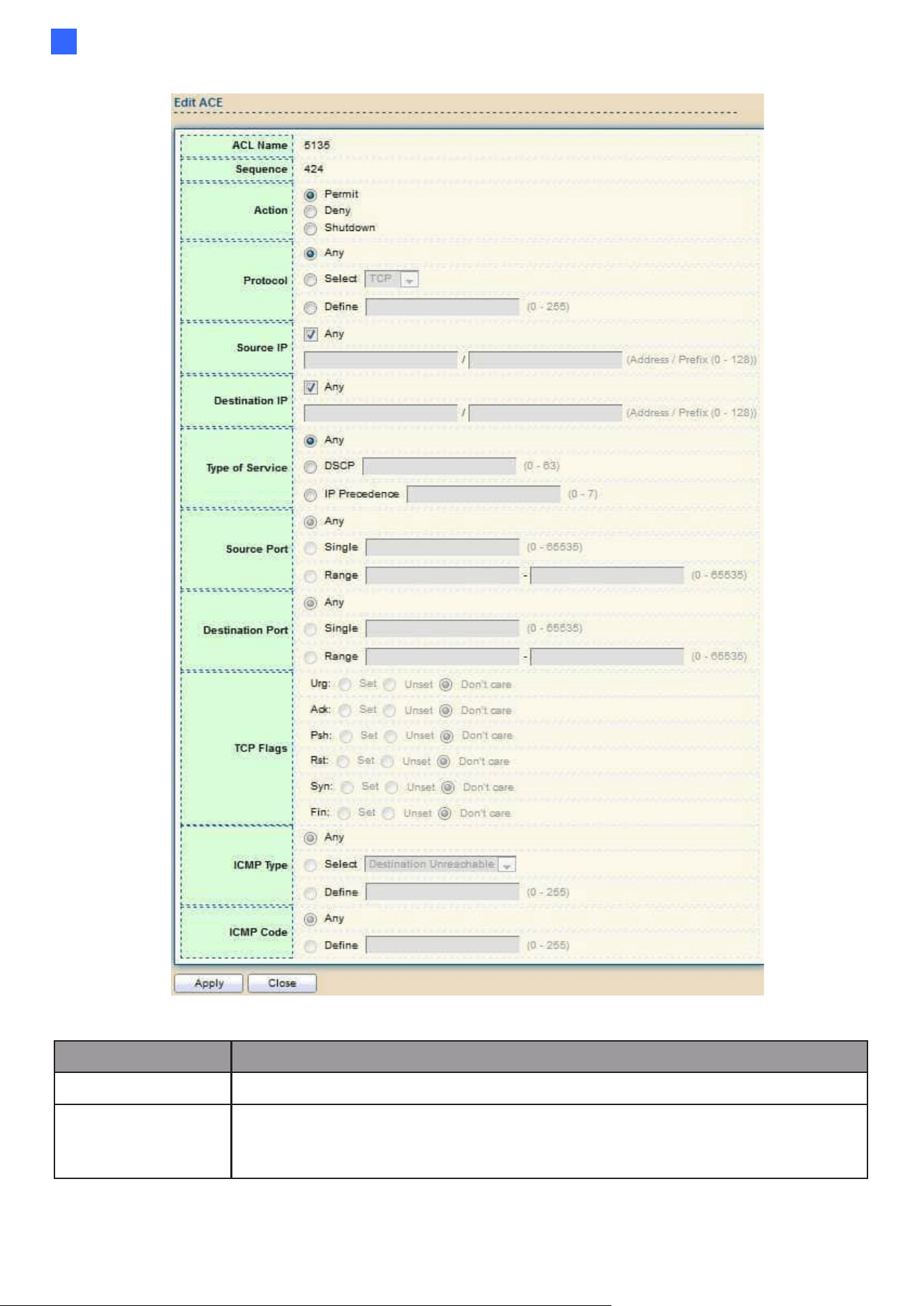
Web-based Switch Configuration
161
2
Figure 173 – ACL > Add/Edit ACE
Item
Description
ACL Name
Display the ACL name to which an ACE is being added.
Sequence
Specify the sequence of the ACE. ACEs with higher sequence are
processed first (1 is the highest sequence). Only available on Add
dialog.

162
Action
Select the action for a match.
●
Permit: Forward packets that meet the ACE criteria.
●
Deny: Drop packets that meet the ACE criteria.
●
Shutdown: Drop packets that meet the ACE criteria, and disable
the port from where the packets were received. Such ports can be
reactivated from the Port Settings page.
Protocol
Select the type of protocol for a match.
●
Any (IP): All IP protocols are acceptable.
●
Select from list: Select one of the following protocols from the
dropdown list. (TCP / UDP / ICMP)
●
Protocol ID to match: Enter the protocol ID.
Source IP
Select the type for source IP address.
●
Any: All source addresses are acceptable.
●
User-defined: Only a source address or a range of source addresses
which users define are acceptable. Enter the source IP address
value and mask to which will be matched.
Destination IP
Select the type for destination IP address.
●
Any: All destination addresses are acceptable.
●
User-defined: Only a destination address or a range of
destination addresses which users define are acceptable. Enter
the destination IP address value and mask to which will be
matched.
Source Port
Select the type of protocol for a match. Only available when protocol
is TCP or UDP.
●
Any: All source ports are acceptable.
●
Single: Enter a single TCP/UDP source port to which packets are
matched.
●
Range: Select a range of TCP/UDP source ports to which the packet
is matched. There are eight different port ranges
that can be configured (shared between source and destination
ports). TCP and UDP protocols each have eight port ranges.
Destination
Port
Select the type of protocol for a match. Only available when protocol
is TCP or UDP.
●
Any: All source ports are acceptable.
●
Single: Enter a single TCP/UDP source port to which packets are
matched.
●
Range: Select a range of TCP/UDP source ports to which the packet
is matched. There are eight different port ranges
that can be configured (shared between source and destination
ports). TCP and UDP protocols each have eight port ranges.
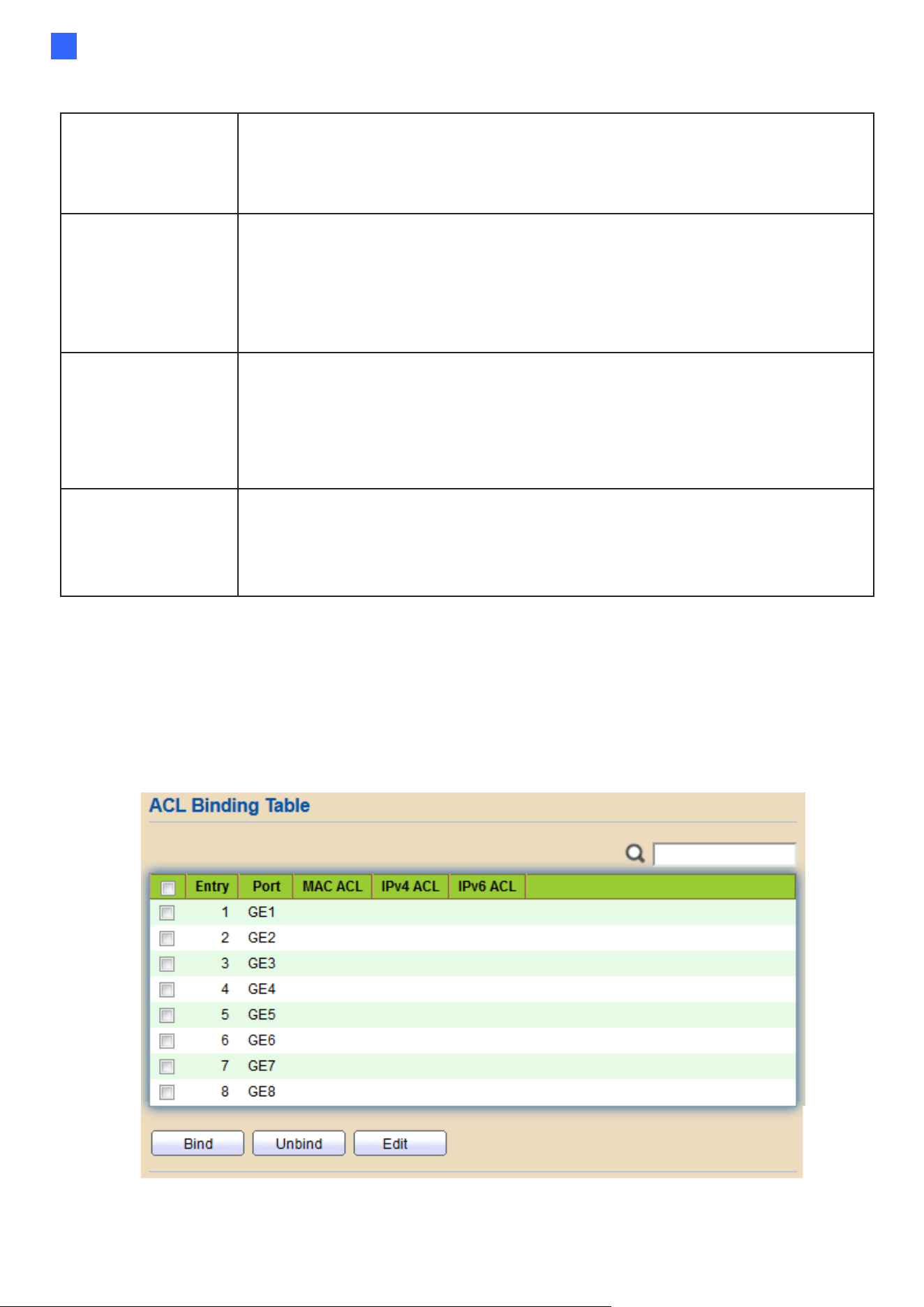
Web-based Switch Configuration
163
2
TCP Flags
Select one or more TCP flags with which to filter packets. Filtered
packets are either forwarded or dropped. Filtering packets by TCP
flags increases packet control, which increases network security. Only
available when protocol is TCP.
Type of
Service
Select the type of service for a match.
●
Any: All types of service are acceptable.
●
DSCP to match: Enter a Differentiated Serves Code Point
(DSCP) to match.
●
IP Precedence to match: Enter a IP Precedence to match.
ICMP Type
Either select the message type by name or enter the message type
number. Only available when protocol is ICMP.
●
Any: All message types are acceptable.
●
Select from list: Select message type by name.
●
Protocol ID to match: Enter the number of message type.
ICMP Code
Select the type for ICMP code. Only available when protocol is ICMP.
●
Any: All codes are acceptable.
●
User-defined: Enter an ICMP code to match.
2.12.7. ACL Binding
This page allows users to bind or unbind ACL rule to or from interface. IPv4 and Ipv6 ACL
cannot be bound to the same port simultaneously.
To display ACL Binding page, click ACL > ACL Binding
Figure 174 - ACL > ACL Binding
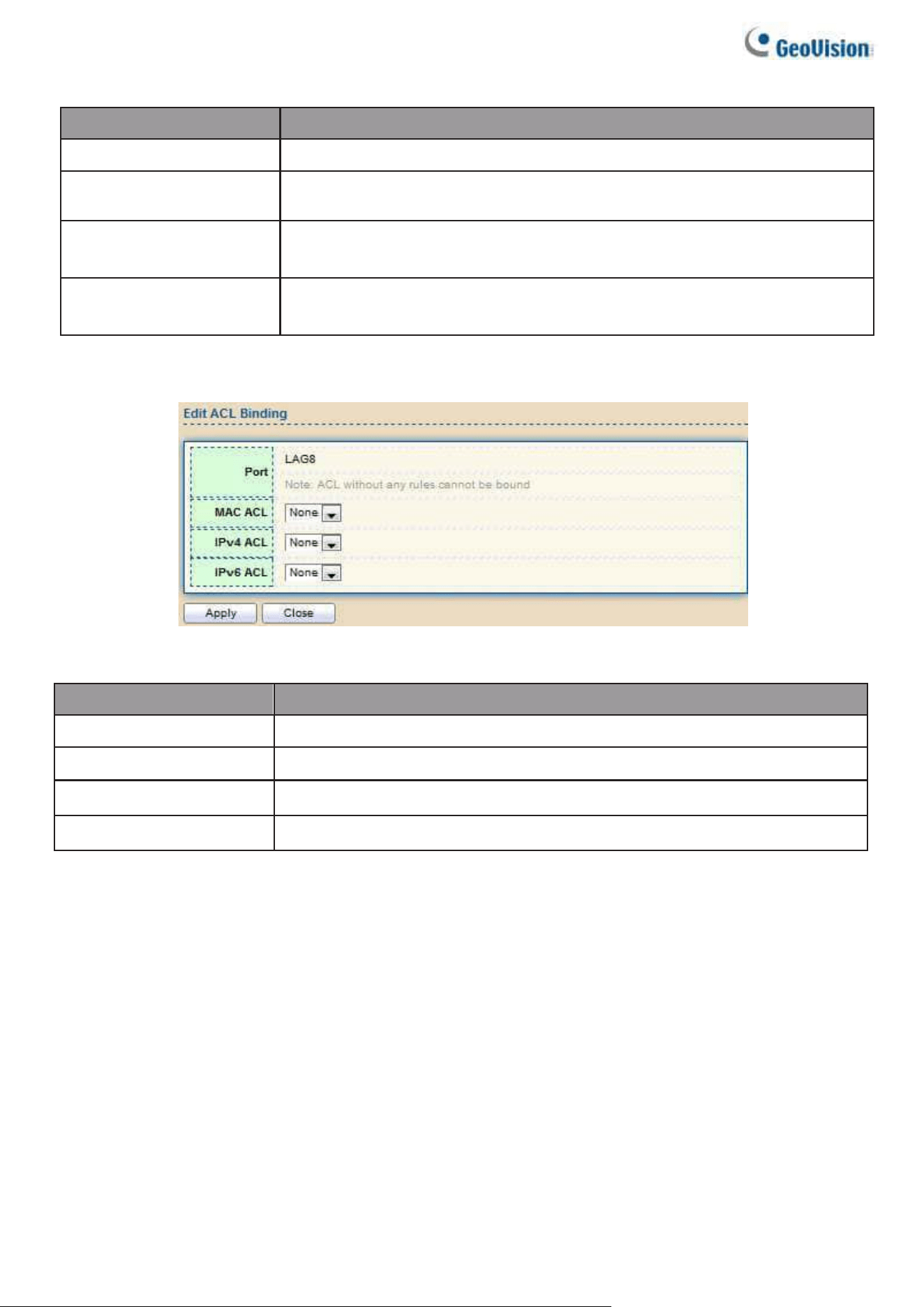
164
Item
Description
Port
Display port entry ID.
MAC ACL
Display mac ACL name that bound of interface. Empty means
no rule bound.
IPv4 ACL
Display ipv4 ACL name that bound of interface. Empty means
no rule bound.
IPv6 ACL
Display ipv6 ACL name that bound of interface. Empty means
no rule bound.
Click “Edit” button to view the Edit ACL Binding menu.
Figure 175 - ACL > Edit ACL Binding
Item
Description
Port
Display port entry ID.
MAC ACL
Select mac ACL name from list to bind.
IPv4 ACL
Select IPv4 ACL name from list to bind.
IPv6 ACL
Select IPv6 ACL name from list to bind.
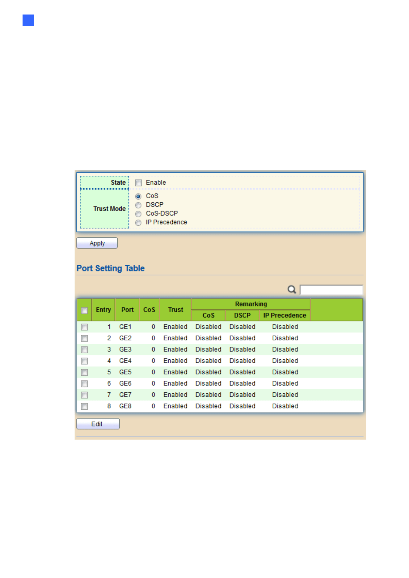
Web-based Switch Configuration
165
2
2.13. QoS
Use the QoS pages to configure settings for the switch QoS interface.
2.13.1. General
Use the QoS general pages to configure settings for general purpose.
2.13.1.1. Property
To display Property web page, click QoS > General > Property
Figure 176 - QoS > General > Property

166
Item
Description
State
Set checkbox to enable/disable QoS.
Trust
Select QoS trust mode
•
CoS: Traffic is mapped to queues based on the CoS field in the
VLAN tag, or based on the per-port default CoS value (if there is
no VLAN tag on the incoming packet), the
actual mapping of the CoS to queue can be configured on port
setting dialog.
•
CoS-DSCP: Uses the trust CoS mode for non-IP traffic and trust
DSCP mode for IP traffic.
•
IP Precedence: Traffic is mapped to queues based on the
IP precedence. The actual mapping of the IP precedence to queue
can be configured on the IP Precedence mapping page.
Port Setting Table
Port
Port name
CoS
Port default CoS priority value for the selected ports.
Trust
Port trust state
•
Enabled: Traffic will follow trust mode in global setting
•
Disabled: Traffic will always use best efforts
Remarking (CoS)
Set checkbox to enable/disable port CoS remarking.
•
Enabled: CoS remarking is enabled
•
Disabled: CoS remarking is disabled
Remarking
(DSCP)
Set checkbox to enable/disable port DSCP remarking.
•
Enabled: DSCP remarking is enabled
•
Disabled: DSCP remarking is disabled
Remarking
(IP Precedence)
Set checkbox to enable/disable port IP Precedence
remarking.
•
Enabled: IP Precedence remarking is enabled
•
Disabled: IP Precedence remarking is disabled
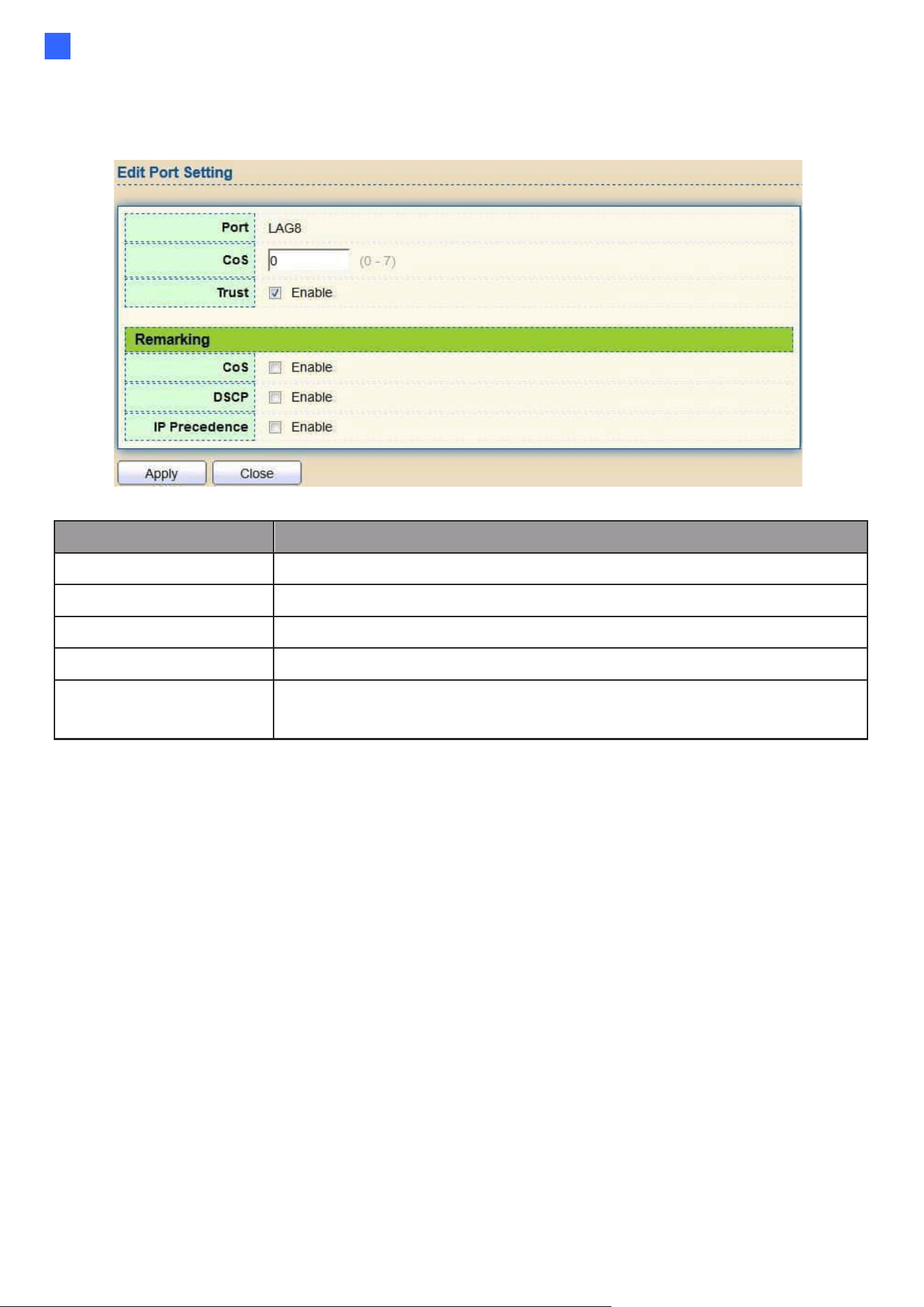
Web-based Switch Configuration
167
2
Click "Edit" button to view the Edit Port Setting menu.
Figure 177 - Qos > General > Property
Item
Description
Port
Selected port list.
CoS
Set default CoS/802.1p priority value for the selected
Trust
Set checkbox to enable/disable port trust state.
Remarking (CoS)
Set checkbox to enable/disable port CoS remarking.
Remarking
(IP PRecedence)
Set checkbox to enable/disable port IP Precedence
remarking.
2.13.1.2. Queue Scheduling
The switch supports eight queues for each interface. Queue number 8 is the highest
priority queue.
Queue number 1 is the lowest priority queue. There are two ways of determining how traffic in
queues is handled, Strict Priority (SP) and Weighted Round Robin (WRR).
‧ Strict Priority (SP)—Egress traffic from the highest priority queue is transmitted first. Traffic
from the lower queues is processed only after the highest queue has been transmitted, which
provide the highest level of priority of traffic to the
highest numbered queue.
‧ Weighted Round Robin (WRR)—In WRR mode the number of packets sent from the queue is
proportional to the weight of the queue (the higher the weight, the more frames are sent).
The queuing modes can be selected on the Queue page. When the queuing mode is by Strict
Priority, the priority sets the order in which queues are serviced, starting with queue_8 (the
highest priority queue) and going to the next lower queue when each queue is completed.
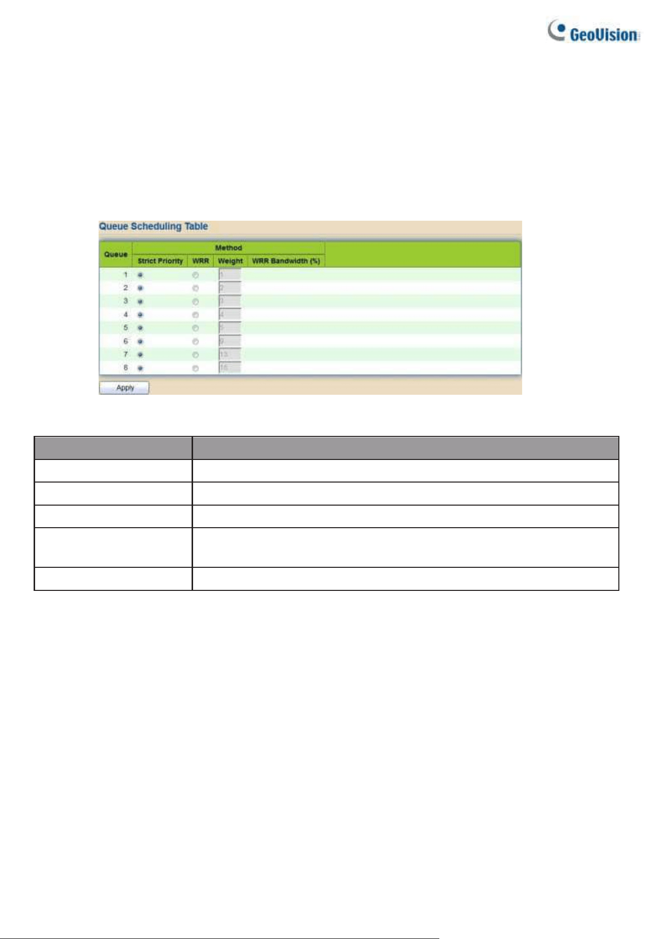
168
When the queuing mode is Weighted Round Robin, queues are serviced until their quota has
been used up and then another queue is serviced. It is also possible to assign some of the
lower queues to WRR, while keeping some of the higher queues in Strict Priority.
In this case traffic for the SP queues is always sent before traffic from the WRR queues. After
the SP queues have been emptied, traffic from the WRR queues is forwarded. (The relative
portion from each WRR queue depends on its weight).
To display Queue Scheduling web page, click QoS > General > Queue Scheduling
Figure 178 - QoS > General > Queue Scheduling
Item
Description
Queue
Queue ID to configure.
Strict Priority
Set queue to strict priority type.
WRR
Set queue to Weight round robin type.
Weight
If the queue type is WRR, set the queue weight for the queue.
WRR Bandwidth
Percentage of WRR queue bandwidth.
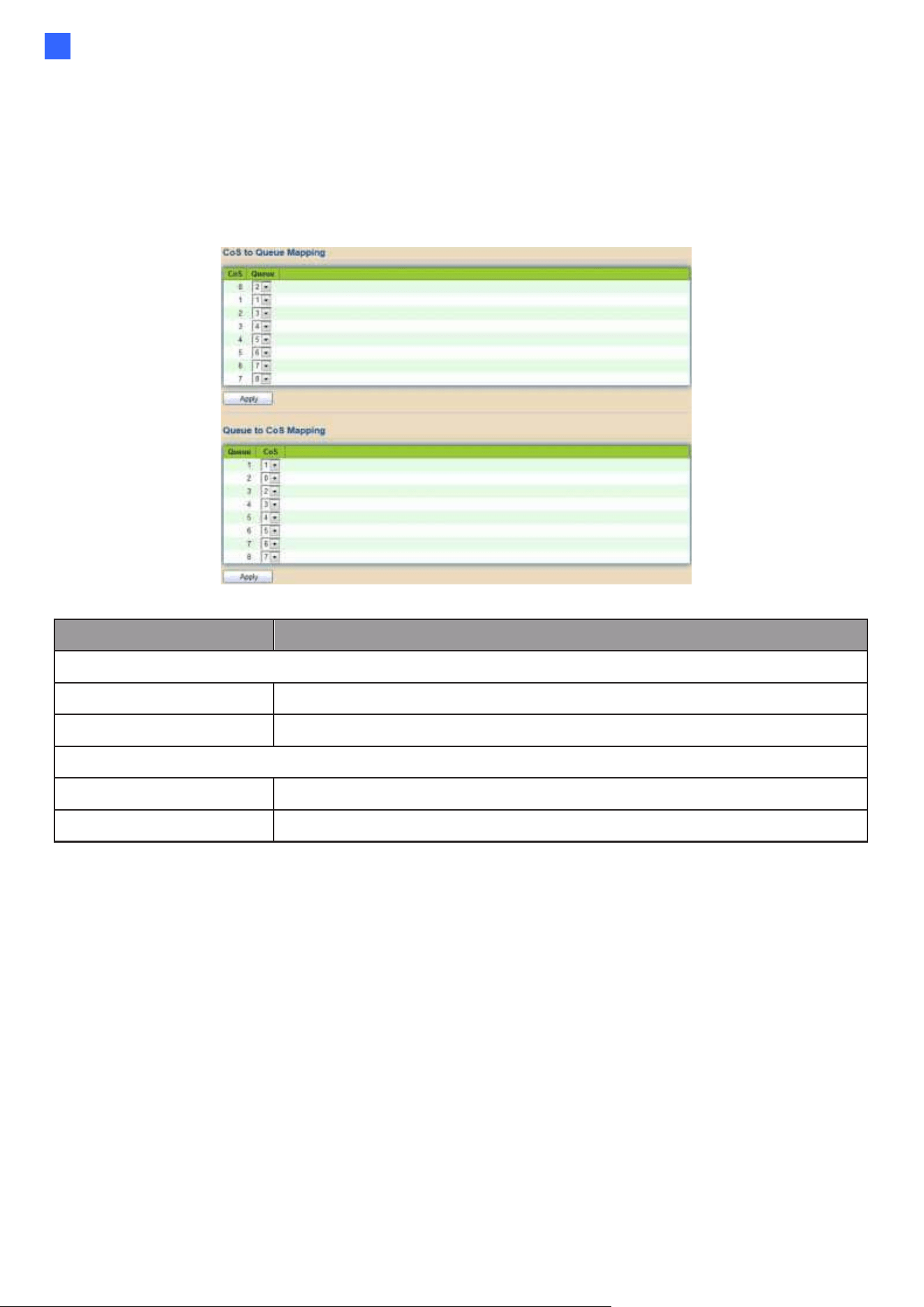
Web-based Switch Configuration
169
2
2.13.1.3. CoS Mapping
The CoS to Queue table determines the egress queues of the incoming packets based on the
802.1p priority in their VLAN tags. For incoming untagged packets, the 802.1p priority will be the
default CoS/802.1p priority assigned to the ingress ports. Use the Queues to CoS table to remark
the CoS/802.1p priority for egress traffic from each queue.
To display CoS Mapping web page, click QoS > General > CoS Mapping
Figure 179 - QoS > General > Cos Mapping
Item
Description
CoS to Queue Mapping
CoS
CoS value.
Queue
Select queue id for the CoS value.
Queue to CoS Mapping
Queue
Queue ID
CoS
Select CoS value for the queue id.
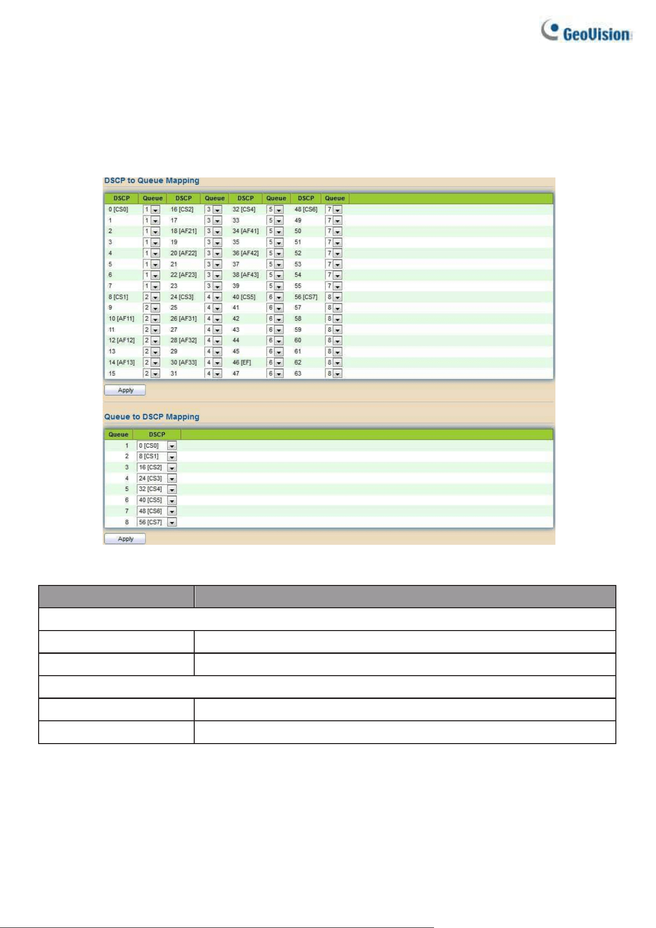
170
2.13.1.4. DSCP Mapping
The DSCP to Queue table determines the egress queues of the incoming IP packets based on their
DSCP values. The original VLAN Priority Tag (VPT) of the packet is unchanged. Use the Queues to
DSCP page to remark DSCP value for egress traffic from each queue.
To display DSCP Mapping web page, click QoS > General > DSCP Mapping
Figure 180 - QoS > General > DSCP Mapping
Item
Description
DSCP to Queue Mapping
DSCP
DSCP value
Queue
Select queue id for DSCP value
Queue to DSCP Mapping
Queue
Queue ID.
DSCP
Select DSCP value for queue ID.
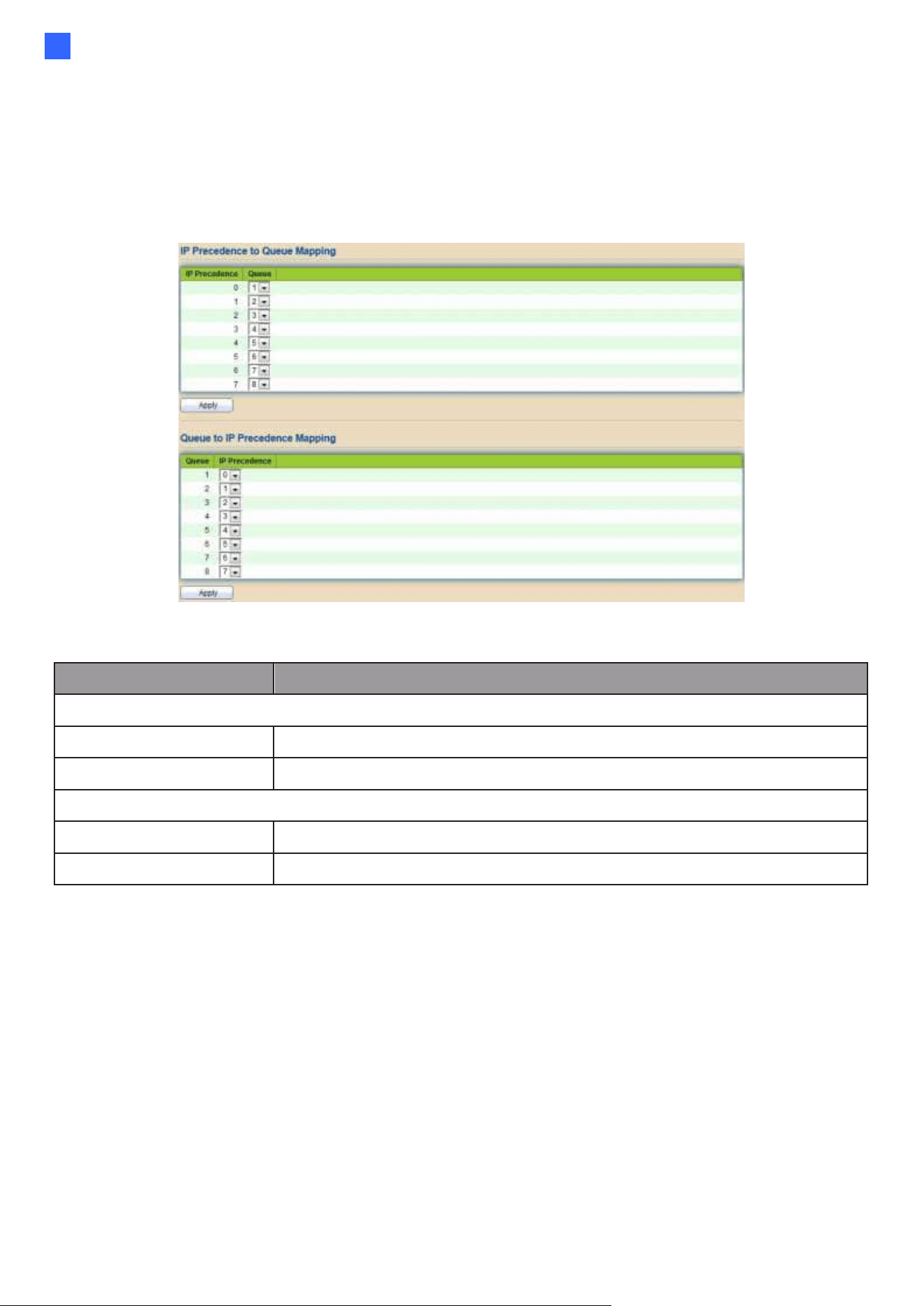
Web-based Switch Configuration
171
2
2.13.1.5. IP Precedence Mapping
This page allows users to configure IP Precedence to Queue mapping and Queue to IP
Precedence mapping.
To display IP Precedence Mapping web page, click QoS > General > IP Precedence Mapping
Figure 181 - QoS > General > IP Precedence Mapping
Item
Description
IP Precedence to Queue Mapping
IP Precedence
IP Precedence value.
Queue
Queue value which IP Precedence is mapped.
Queue to IP Precedence Mapping
Queue
Queue ID.
IP Precedence
IP Precedence value which queue is mapped.
2.13.2. Rate Limit
Use the Rate Limit pages to define values that determine how much traffic the switch can
receive and send on specific port or queue.
2.13.2.1. Ingress/Egress Port
This page allows users to configure ingress port rate limit and egress port rate limit. The ingress
rate limit is the number of bits per second that can be received from the ingress interface. Excess
bandwidth above this limit is discarded.
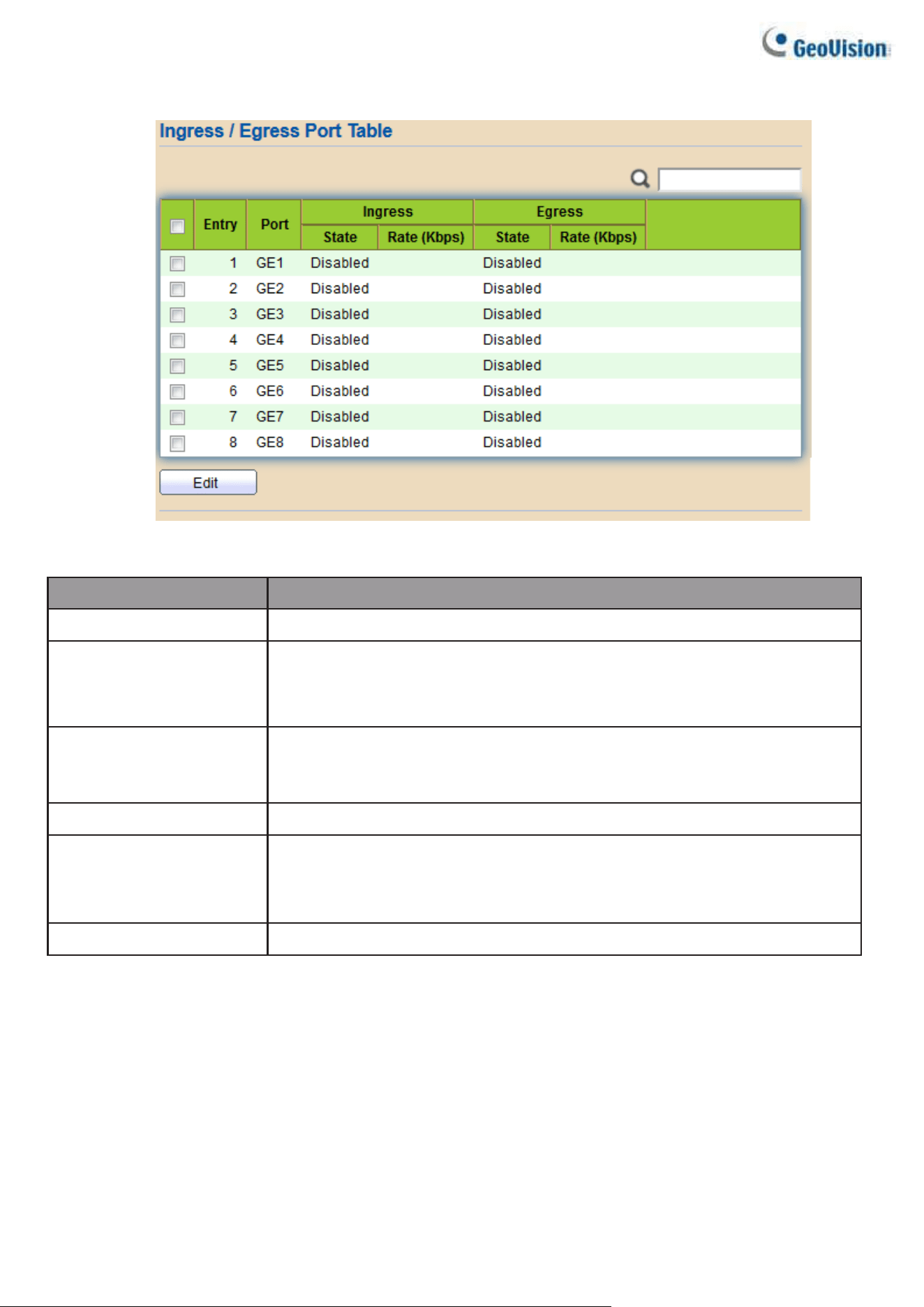
172
To display Ingress / Egress Port web page, click QoS > Rate Limit > Ingress / Egress Port
Figure
182 - QoS > Rate Limit > Ingress / Egress Port
Item
Description
Port
Port name.
Ingress (State)
Port ingress rate limit state
•
Enabled: Ingress rate limit is enabled
•
Disabled: Ingress rate limit is disabled
Ingress (Rate)
Port ingress rate limit value if ingress rate state is
enabled.
IP Precedence
IP Precedence value which queue is mapped.
Egress (State)
Port egress rate limit state
•
Enabled: Egress rate limit is enabled
•
Disabled: Egress rate limit is disabled
Egress (Rate)
Port egress rate limit value if egress rate state is enabled.
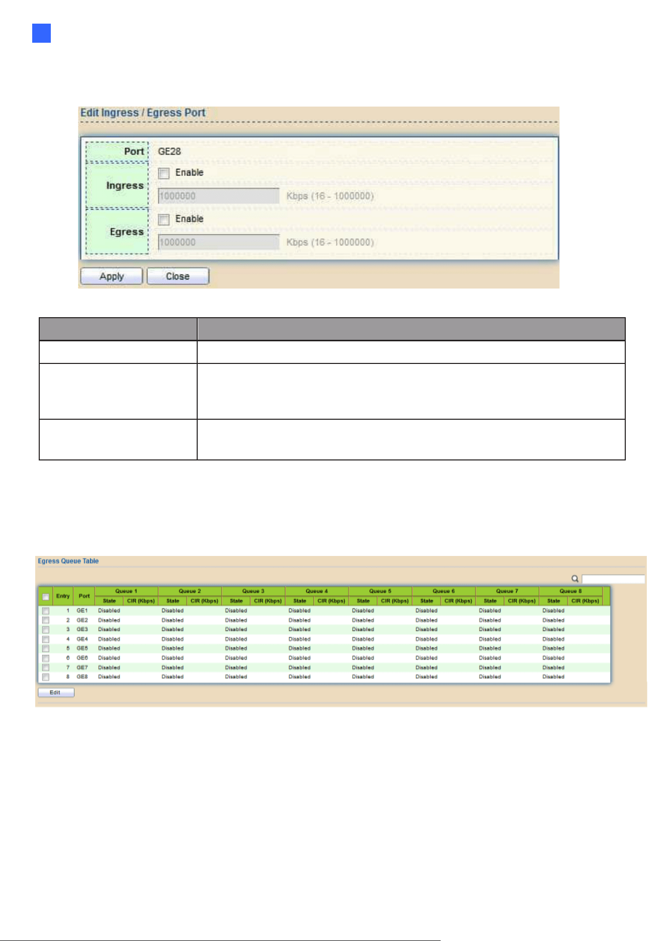
Web-based Switch Configuration
173
2
Click "Edit" button to view the Ingress / Egress Port menu.
Figure 183 - QoS > Rate Limit > Ingress / Egress Port
Item
Description
Port
Select port list.
Ingress
Set checkbox to enable/disable ingress rate limit. If ingress
rate limit is enabled, rate limit value need to be assigned.
Egress
Set checkbox to enable/disable egress rate limit. If egress rate
limit is enabled, rate limit value need to be assigned.
2.13.2.2. Egress Queue
Egress rate limiting is performed by shaping the output load.
To display Egress Queue web page, click QoS > Rate Limit > Egress Queue.
Figure 184 - QoS > Rate Limit > Egress Queue

174
Item
Description
Port
Port name.
Queue 1 (State)
Port egress queue 1 rate limit state.
●
Enabled: Egress queue rate limit is enabled.
●
Disabled: Egress queue rate limit is disabled.
Queue 1 (CIR)
Queue 1 egress committed information rate.
Queue 2 (State)
Port egress queue 2 rate limit state.
●
Enabled: Egress queue rate limit is enabled.
●
Disabled: Egress queue rate limit is disabled.
Queue 2 (CIR)
Queue 2 egress committed information rate
Queue 3 (State)
Port egress queue 3 rate limit state.
●
Enabled: Egress queue rate limit is enabled.
●
Disabled: Egress queue rate limit is disabled.
Queue 3 (CIR)
Queue 3 egress committed information rate.
Queue 4 (State)
Port egress queue 4 rate limit state.
●
Enabled: Egress queue rate limit is enabled.
●
Disabled: Egress queue rate limit is disabled.
Queue 4 (CIR)
Queue 4 egress committed information rate.
Queue 5 (State)
Port egress queue 5 rate limit state.
●
Enabled: Egress queue rate limit is enabled.
Disabled: Egress queue rate limit is disabled.
Queue 5 (CIR)
Queue 5 egress committed information rate.
Queue 6 (State)
Port egress queue 6 rate limit state.
●
Enabled: Egress queue rate limit is enabled.
●
Disabled: Egress queue rate limit is disabled.
Queue 6 (CIR)
Queue 6 egress committed information rate.
Queue 7 (State)
Port egress queue 7 rate limit state.
●
Enabled: Egress queue rate limit is enabled.
●
Disabled: Egress queue rate limit is disabled.
Queue 7 (CIR)
Queue 7 egress committed information rate.
Queue 8 (State)
Port egress queue 8 rate limit state.
●
Enabled: Egress queue rate limit is enabled.
●
Disabled: Egress queue rate limit is disabled.
Queue 8 (CIR)
Queue 8 egress committed information rate.
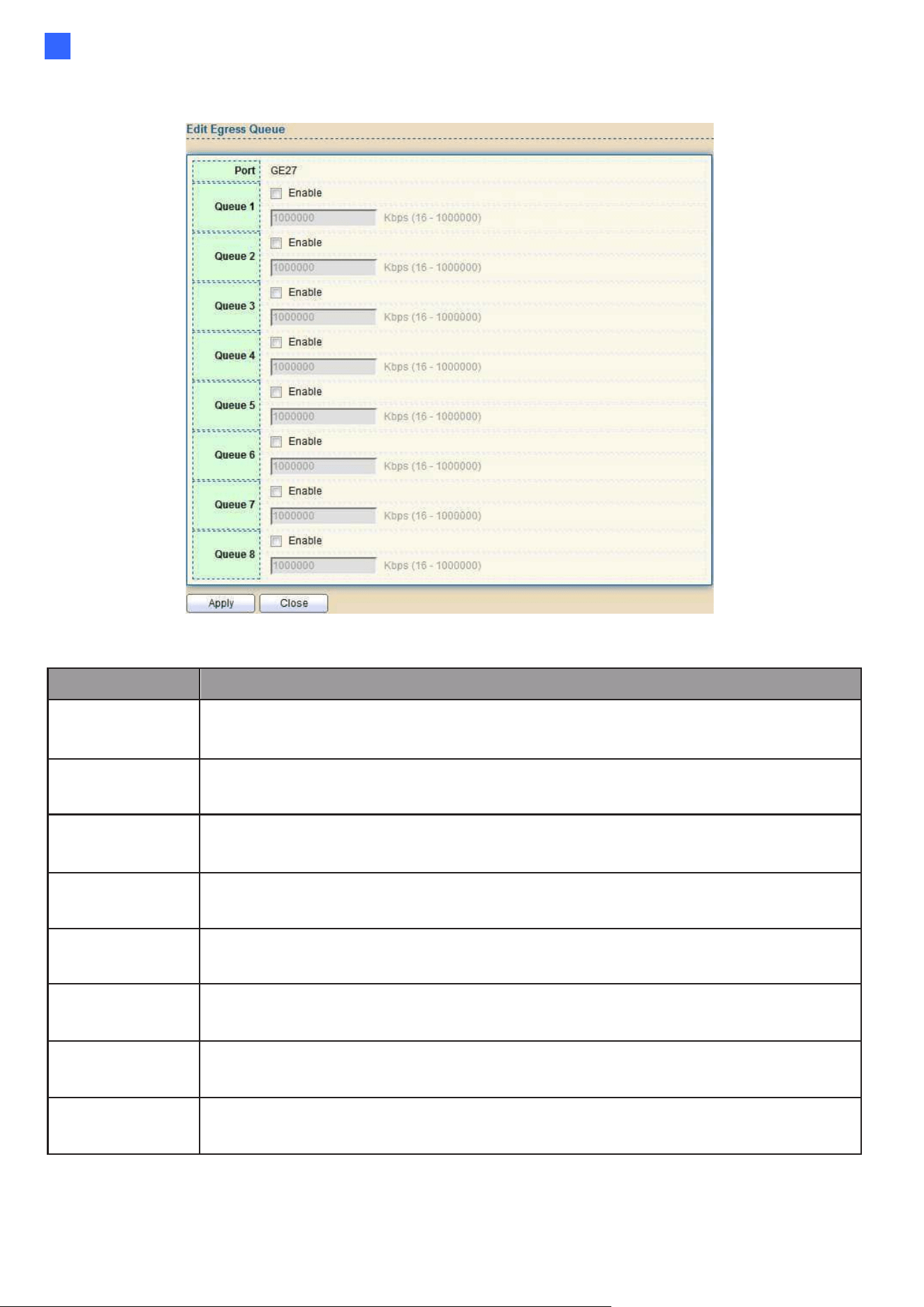
Web-based Switch Configuration
175
2
Click "Edit" button to view the Edit Egress Queue menu.
Figure 185 - QoS > Rate Limit > Edit Egress Queue
Item
Description
Queue 1
Set checkbox to enable/disable egress queue 1 rate limit. If egress rate
limit is enabled, rate limit value need to be assigned.
Queue 2
Set checkbox to enable/disable egress queue 2 rate limit. If egress rate
limit is enabled, rate limit value need to be assigned.
Queue 3
Set checkbox to enable/disable egress queue 3 rate limit. If egress rate
limit is enabled, rate limit value need to be assigned.
Queue 4
Set checkbox to enable/disable egress queue 4 rate limit. If egress rate
limit is enabled, rate limit value need to be assigned.
Queue 5
Set checkbox to enable/disable egress queue 5 rate limit. If egress rate
limit is enabled, rate limit value need to be assigned.
Queue 6
Set checkbox to enable/disable egress queue 6 rate limit. If egress rate
limit is enabled, rate limit value need to be assigned.
Queue 7
Set checkbox to enable/disable egress queue 7 rate limit. If egress rate
limit is enabled, rate limit value need to be assigned.
Queue 8
Set checkbox to enable/disable egress queue 8 rate limit. If egress rate
limit is enabled, rate limit value need to be assigned.
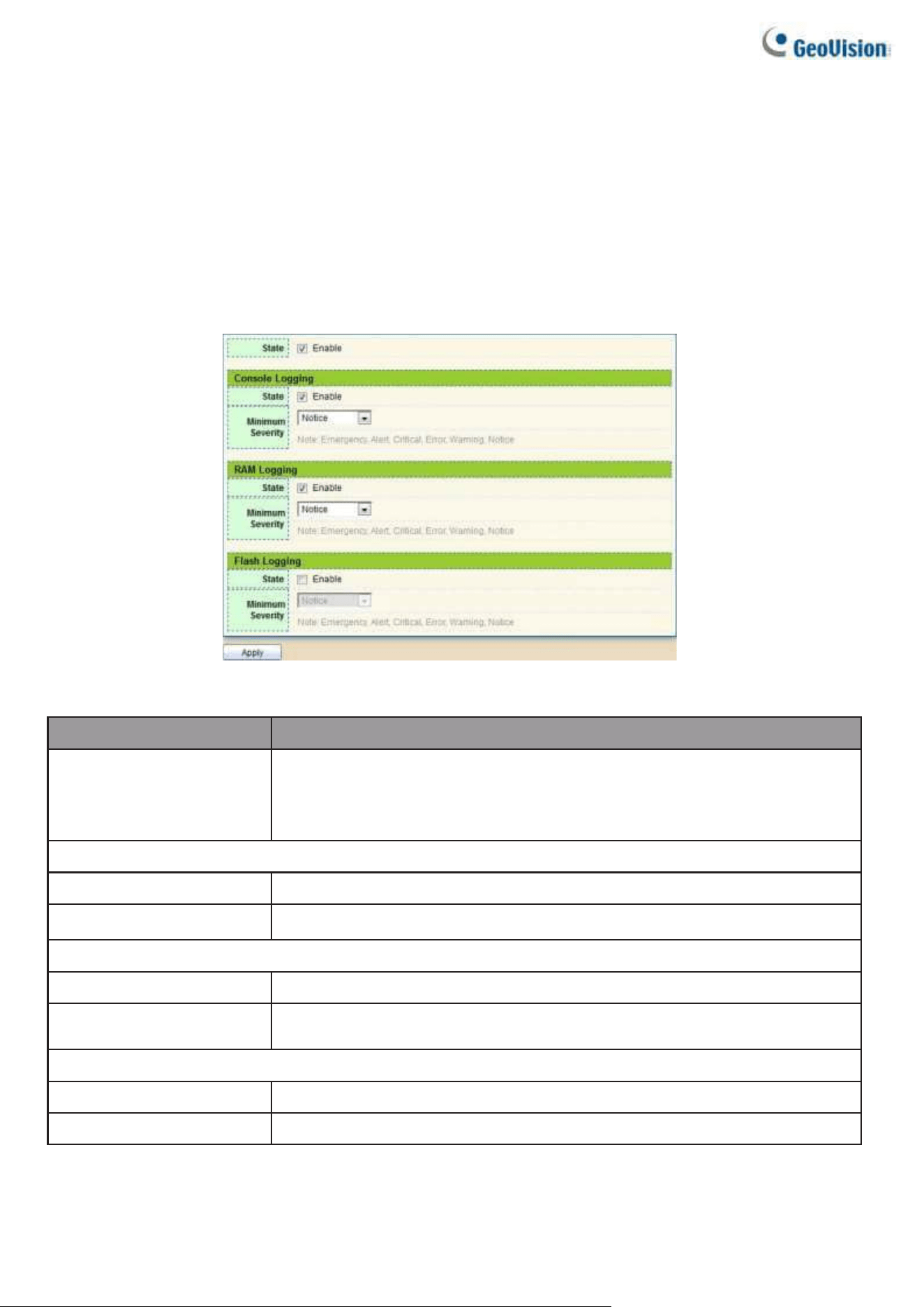
176
2.14. Diagnostics
Use the Diagnostics pages to configure settings for the switch diagnostics feature or operating
diagnostic utilities.
2.14.1. Logging
2.14.1.1. Property
To enable/disable the logging service, click Diagnostic > Logging > Property.
Figure 186 - Diagnostics > Logging > Property
Item
Description
State
Enable/Disable the global logging services. When the logging
service is enabled, logging configuration of each destination
rule can be individually configured. If the logging service is
disabled, no messages will be sent to these destinations.
Console Logging
State
Enable/Disable the console logging service
Minimum Severity
The minimum severity for the console logging.
RAM Logging
State
Enable/Disable the RAM logging service.
Minimum
Severity
The minimum severity for the RAM logging.
Flash Logging
State
Enable/Disable the flash logging service.
Minimum Severity
The minimum severity for the flash logging.
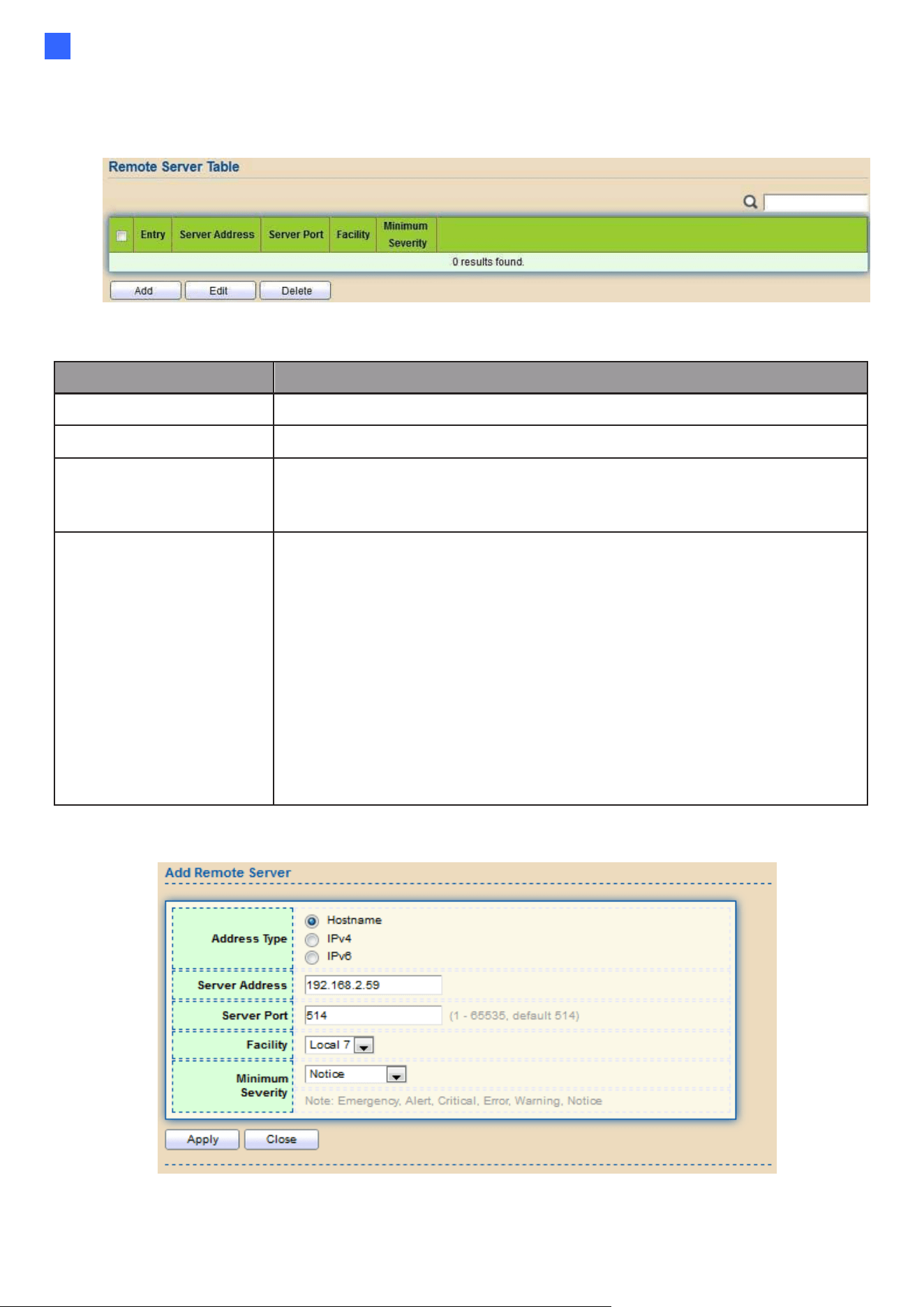
Web-based Switch Configuration
177
2
2.14.1.2. Remote Server
To configure the remote logging server, click Diagnostic > Logging > Remote Server.
Figure 187 - Diagnostics > Logging > Remote Server
Item
Description
Server Address
The IP address of the remote logging server.
Server Ports
The port number of the remote logging server.
Facility
The facility of the logging messages. It can be one of the
following values: local0, local1, local2, local3, local4, local5,
local6, and local7.
Severity
The minimum severity.
•
Emergence: System is not usable.
•
Alert: Immediate action is needed.
•
Critical: System is in the critical condition.
•
Error: System is in error condition
•
Warning: System warning has occurred
•
Notice: System is functioning properly, but a system notice has
occurred.
•
Informational: Device information.
•
Debug: Provides detailed information about an event.
Click “Add” or "Edit" button to view the Remote Server menu.
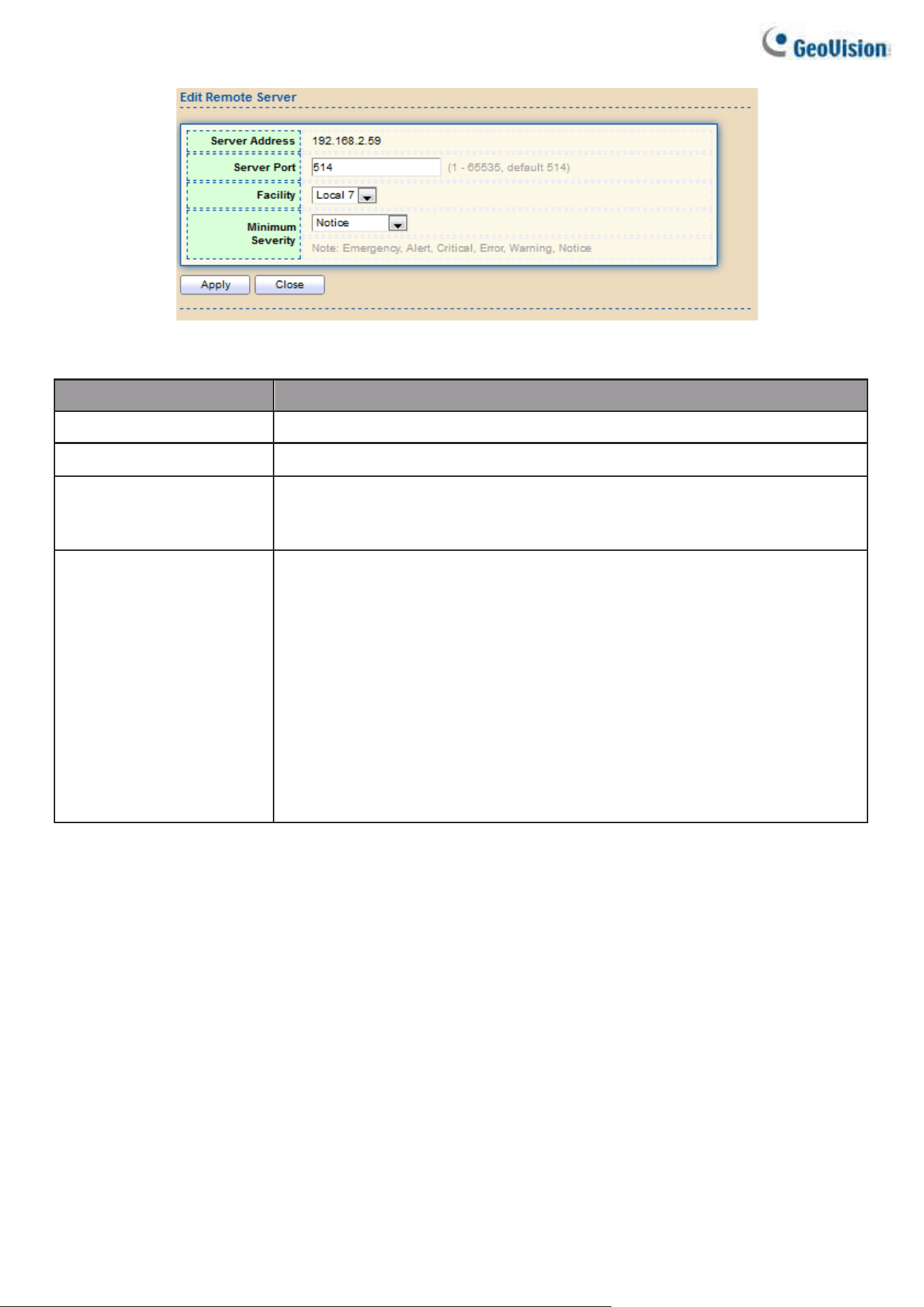
178
Figure 188 - Diagnostics > Logging > Remote Server
Item
Description
Server Address
The IP address of the remote logging server.
Server Ports
The port number of the remote logging server.
Facility
The facility of the logging messages. It can be one of the
following values: local0,local1, local2, local3, local4, local5,
local6, and local7.
Severity
The minimum severity.
•
Emergence: System is not usable.
•
Alert: Immediate action is needed.
•
Critical: System is in the critical condition.
•
Error: System is in error condition
•
Warning: System warning has occurred
•
Notice: System is functioning properly, but a system notice has
occurred.
•
Informational: Device information.
•
Debug: Provides detailed information about an event.
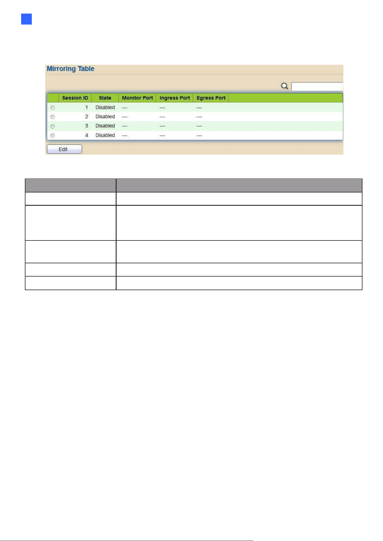
Web-based Switch Configuration
163
2
2.14.2. Mirroring
To display Port Mirroring web page, click Diagnostics > Mirroring
Figure 189 - Diagnostics > Mirroring
Item
Description
Session ID
Select mirror session ID.
State
Select mirror session state : port-base mirror or disable
•
Enabled: Enable port based mirror
•
Disabled: Disable mirror.
Monitor Port
Select mirror session monitor port, and select whether normal
packet could be sent or received by monitor port.
Ingress port
Select mirror session source rx ports.
Egress port
Select mirror session source tx ports.
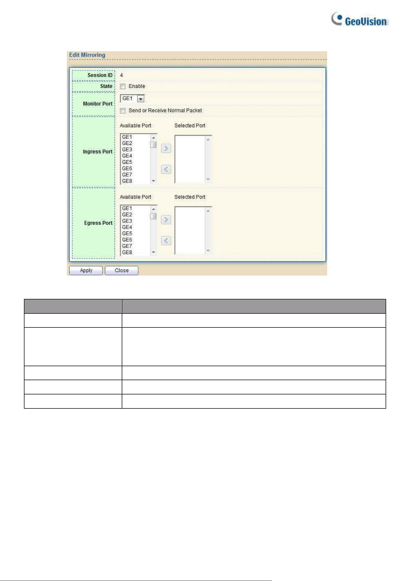
164
Click "Edit" button to view the Edit Mirroring menu.
Figure 190 - Diagnostics > Mirroring > Edit Mirroring
Item
Description
Session ID
Selected mirror session ID.
State
Select mirror session state : port-base mirror or disable
•
Enabled: Enable port based mirror
•
Disabled: Disable mirror.
Monitor Port
Select mirror session monitor port, and select whether
Ingress port
Select mirror session source rx ports.
Egress port
Select mirror session source tx ports.
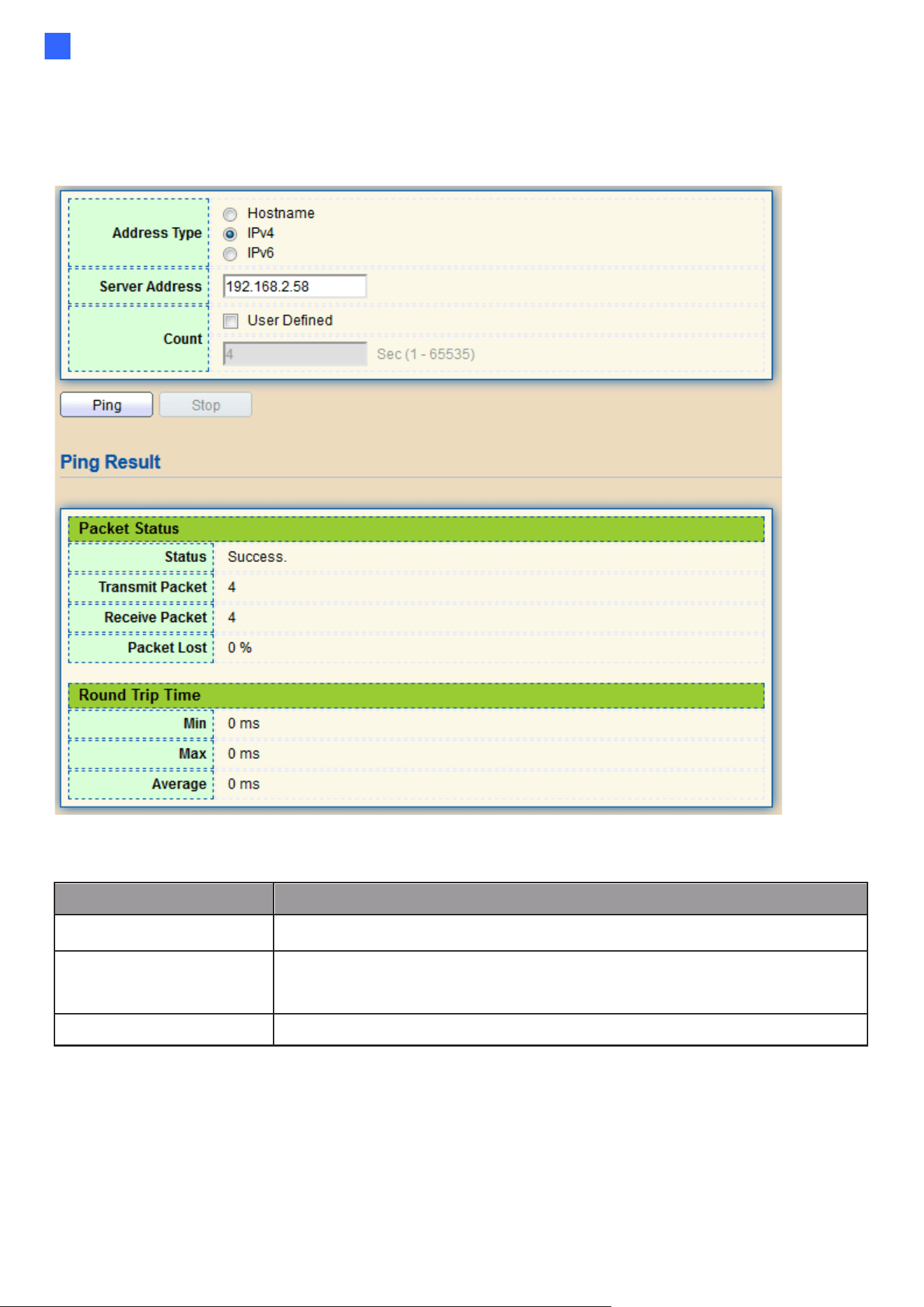
Web-based Switch Configuration
165
2
2.14.3. Ping
For the ping functionality, click Diagnostic > Ping
Figure 191 - Diagnostics > Ping
Item
Description
Address Type
Specify the address type to “Hostname” or “IPv4”.
Server Address
Specify the Hostname/IPv4 address for the remote logging server.
Count
Specify the numbers of each ICMP ping request.
Note to apply a specified hostname in the Server Address field, you must enable Domain Name
Server in 2.2.1 IP Address.
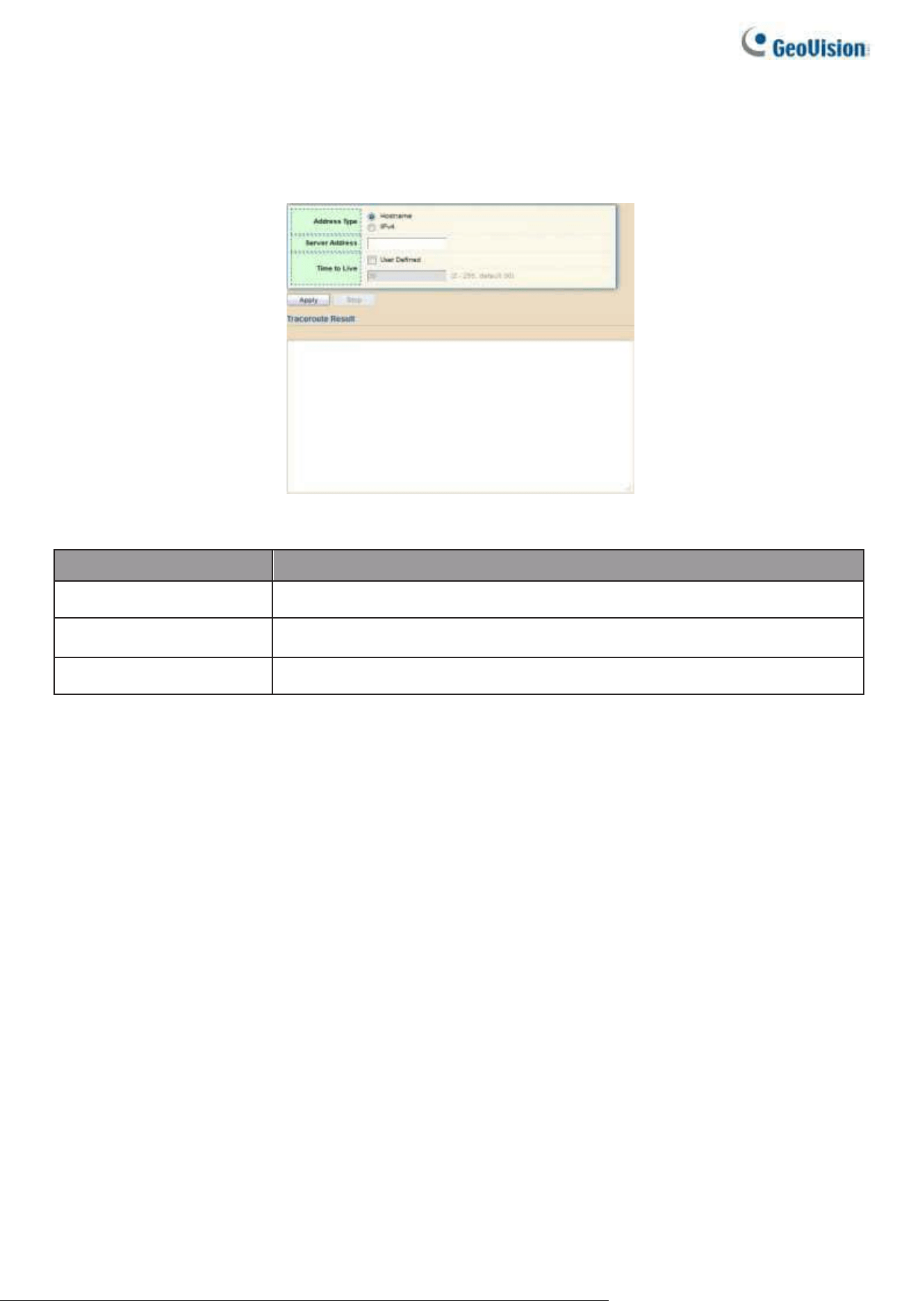
166
2.14.4. Traceroute
For trace route functionality, click Diagnostic > Traceroute.
Figure 192 - Diagnostics > Traceroute
Item
Description
Address Type
Specify the address type to “Hostname” or “IPv4”.
Server Address
Specify the Hostname/IPv4 address for the remote logging server.
Time to Live
Specify the max hops of hosts for traceroute.
Note to apply a specified hostname in the Server Address field, you must enable Domain Name
Server in 2.2.1 IP Address.
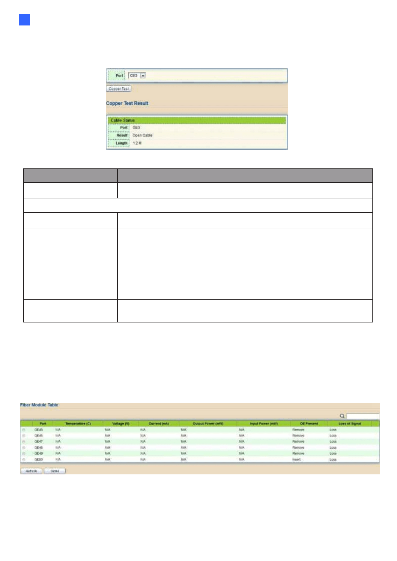
Web-based Switch Configuration
167
2
2.14.5. Copper Test
For copper length diagnostic, click Diagnostic > Copper Test.
Figure 193 - Diagnostics > Logging > Copper Test
Item
Description
Port
Specify the interface for the copper test.
Copper Test Result
Port
The interface for the copper test.
Result
The status of copper test. Including:
●
OK: Correctly terminated pair.
●
Short Cable: Shorted pair.
●
Open Cable: Open pair, no link partner.
●
Impedance Mismatch: Terminating impedance is not in the
reference range.
●
Line Drive
Length
Distance in meter from the port to the location on the cable
where the fault was discovered.
2.14.6. Fiber Module
The Optical Module Status page displays the operational information reported by the Small Form-
factor Pluggable (SFP) transceiver. Some information may not be available for SFPs without the
supports of digital diagnostic monitoring standard SFF-8472.
To display the Optical Module Diagnostic page, click Diagnostic > Fiber Module.
Figure 194 - Diagnostics > Logging>Fiber Module
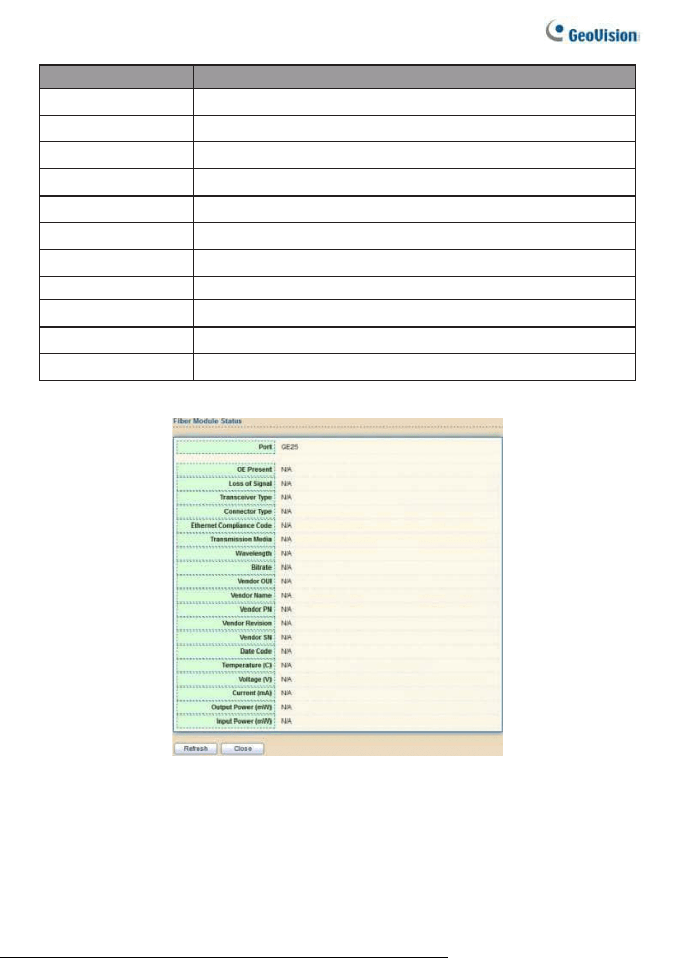
168
Item
Description
Port
Interface or port number.
Temperature
Internally measured transceiver temperature.
Voltage
Internally measured supply voltage.
Current
Measured TX bias current.
Output Power
Measured TX output power in milliwatts.
Input Power
Measured RX received power in milliwatts.
Transmitter Fault
State of TX fault.
OE Present
Indicate transceiver has achieved power up and data is
Loss of Signal
Loss of signal.
Refresh
Refresh the page.
Detail
The detail information on the specified port.
Click "Detail" button to view the Fiber Module Status menu
Figure 195 - Diagnostics > Logging>Fiber Module>Fiber Module Status
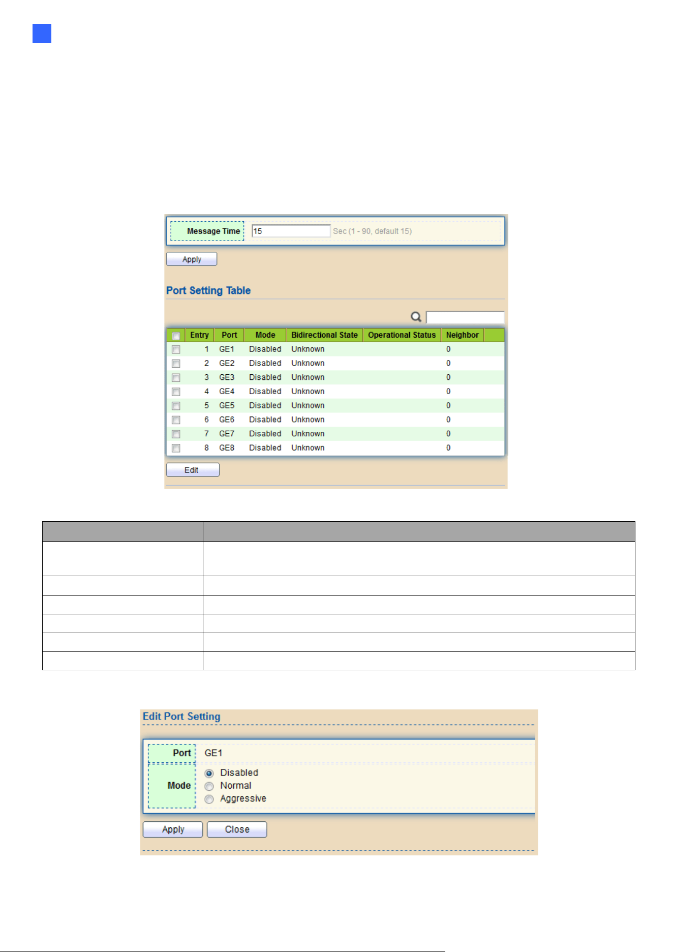
Web-based Switch Configuration
169
2
2.14.7. UDLD
Use the UDLD pages to configure settings of UDLD function.
2.14.7.1. Property
This page allows users to configure global and per interface settings of UDLD.
To display Property page, click Diagnostics > UDLD > Property.
Figure 196 - Diagnostics > UDLD>Property
Item
Description
Message Time
Input the interval for sending message. Range is 1 -90
seconds.
Port
Display port ID of entry.
Mode
Display UDLD running mode of interface.
Bidirectional State
Display bidirectional state of interface.
Operational Status
Display operational status of interface.
Neighbor
Display the number of neighbor of interface.
Click "Edit" button to view the Fiber Module Status menu.
Figure 197 - Diagnostics > UDLD>Property>Edit
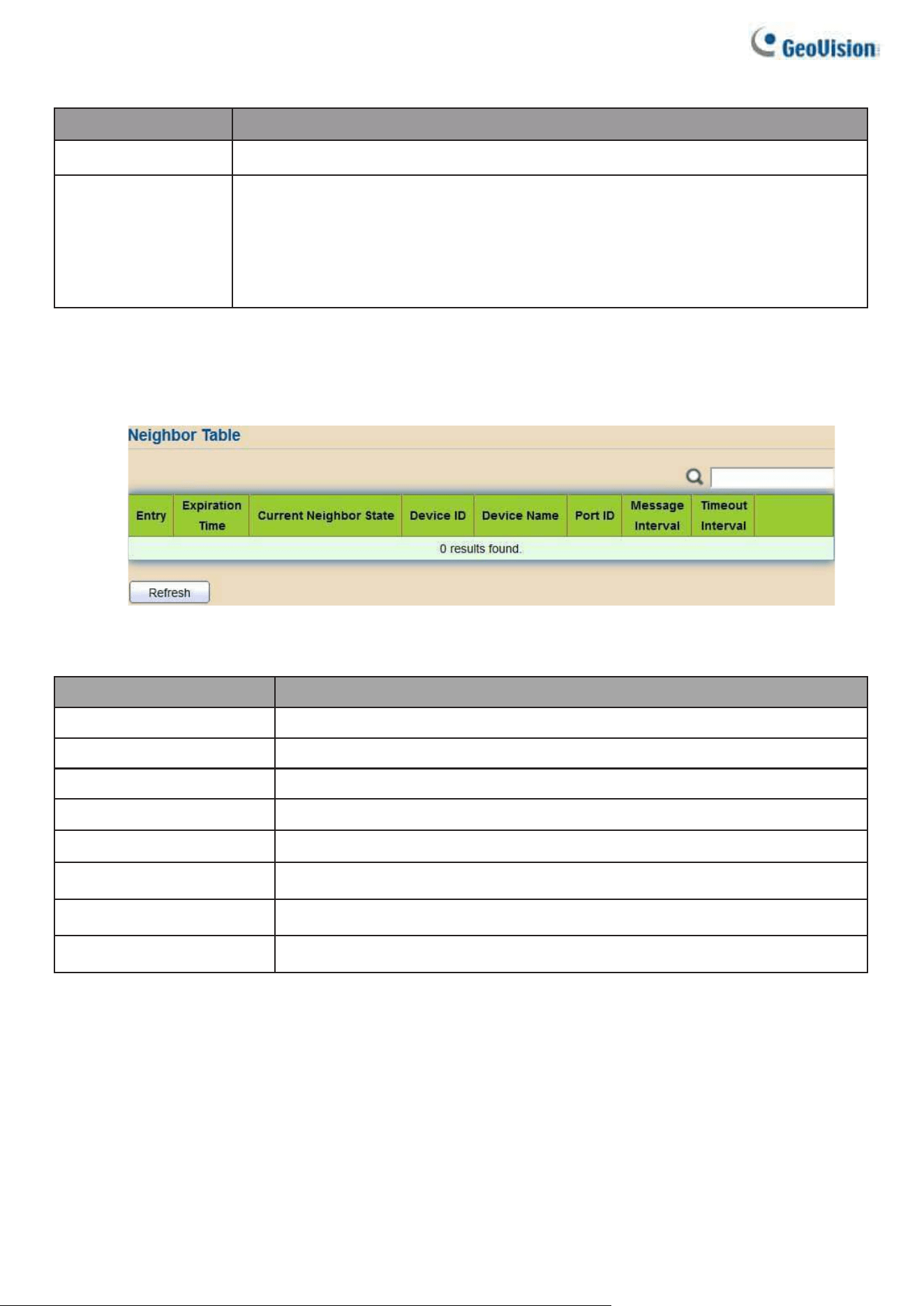
170
Item
Description
Port
Display selected port to be edited.
Mode
Select UDLD running mode of interface.
● Disabled: Disable UDLD function.
● Normal: Running on normal mode that port goes to Link Up One
phase after last neighbor ages out.
● Aggressive: Running on aggressive mode that port goes to
Re- Establish phase after last neighbor ages out.
2.14.7.2. Neighbor
To display Neighbor page, click Diagnostics > UDLD > Neighbor
Figure 198- Diagnostics > UDLD> Neighbor
Item
Description
Entry
Display entry index.
Expiration Time
Display expiration time before age out.
Current Neighbor
Display neighbor current state.
Device ID
Display neighbor device ID.
Device Name
Display neighbor device name.
Port ID
Display neighbor port ID that connected.
Message Interval
Display neighbor message interval.
Timeout Interval
Display neighbor timeout interval.
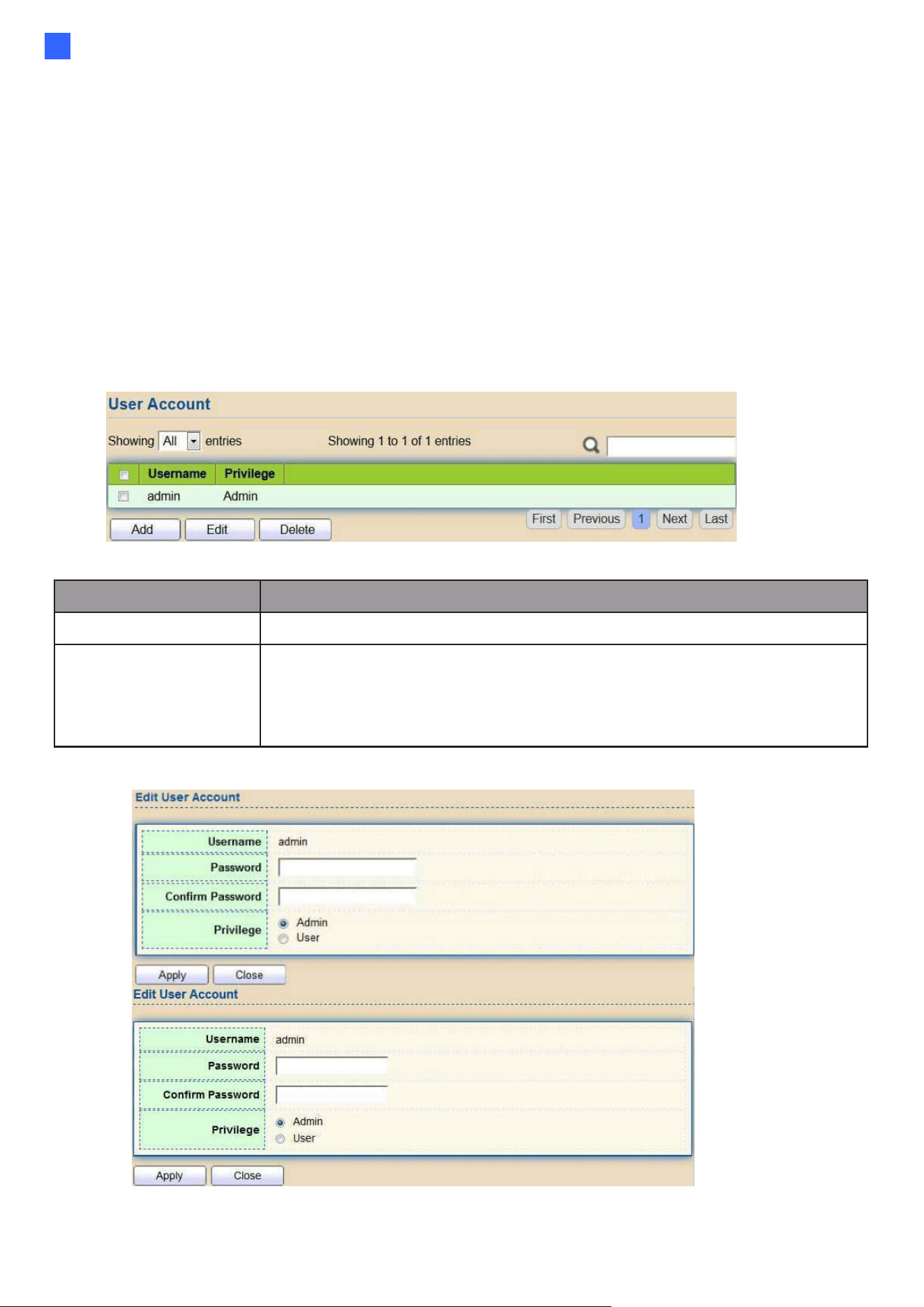
Web-based Switch Configuration
171
2
2.15. Management
Use the Management pages to configure settings for the switch management features.
2.15.1. User Account
The default username/password is admin/admin. And default account is not able to be
deleted.
Use this page to add additional users that are permitted to manage the switch or to change
the passwords of existing users.
To display User Account web page, click Management > User Account
Figure 199 - Management > User Account
Item
Description
Username
Username of the account.
Privilege
Select privilege level for new account.
•
Admin: Allow to change switch settings. Privilege value equals to 15.
•
User: See switch settings only. Not allow to change it.
Privilege level equals to 1.
Click "Add" or “Edit” button to view the Add/Edit User Account menu.
Figure 200 - Management > User Account > Add/Edit User Account
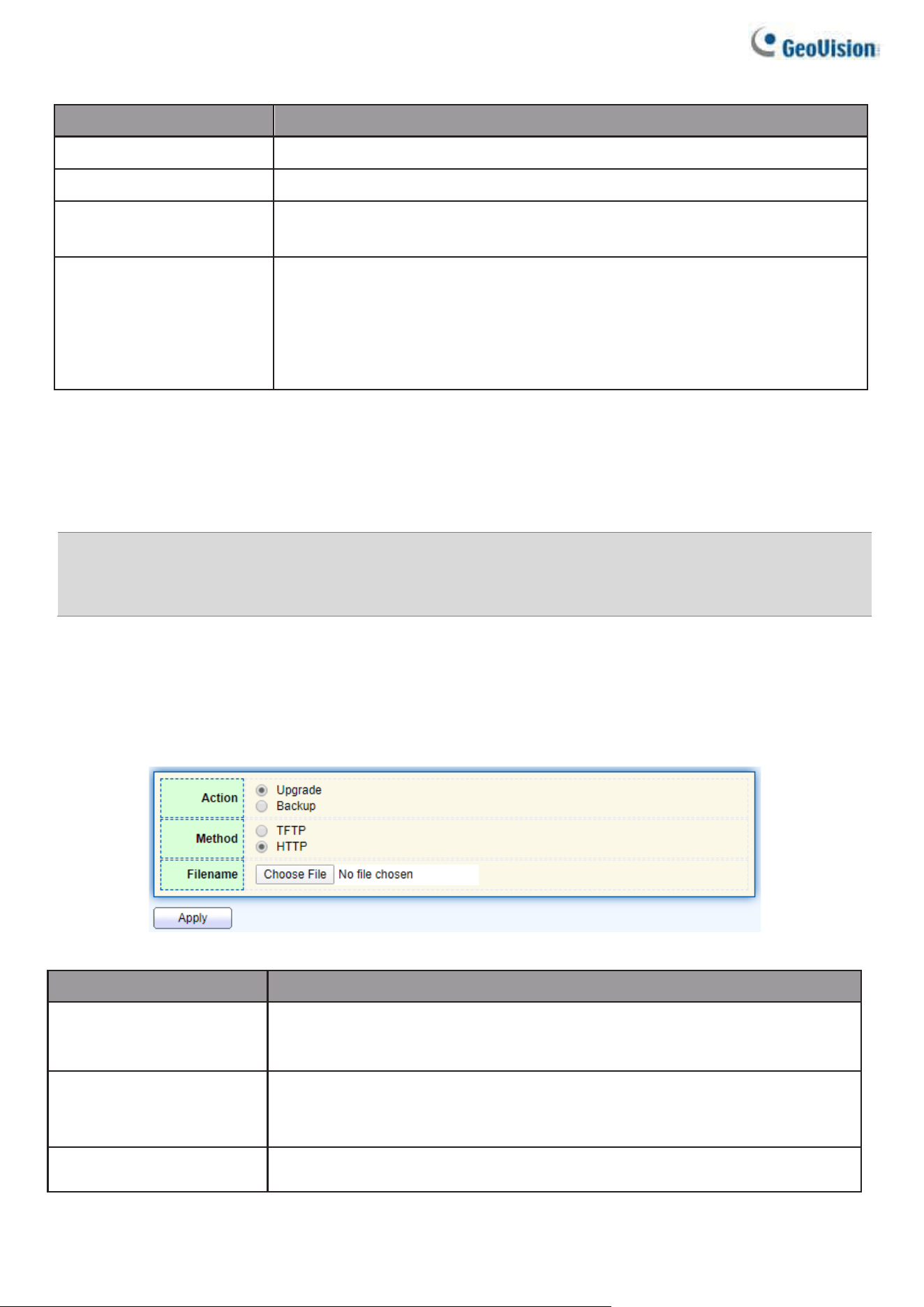
172
Item
Description
Username
Username of the account.
Password
Set password of the account.
Confirm Password
Set the same password of the account as in “Password”
field.
Privilege
Select privilege level for new account.
•
Admin: Allow to change switch settings. Privilege value equals
to 15.
•
User: See switch settings only. Not allow to change it.
Privilege level equals to 1.
2.15.2. Firmware
2.15.2.1. Upgrade / Backup
Note: For browser compatibility improvements, it is required for users of Internet Explorer or
Microsoft Edge to clear all cookies and site data, and then reopen the browser after upgrading to
firmware V1.01 or later.
This page allows users to upgrade or backup firmware image through HTTP or TFTP server.
To display firmware upgrade or backup web page, click Management > Firmware >
Upgrade/Backup
Figure 201 - Management > Firmware > Upgrade/Backup
Item
Description
Action
Firmware operations
•
Upgrade: Upgrade firmware from remote host to DUT.
•
Backup: Backup firmware image from DUT to remote host.
Method
Firmware upgrade / backup method.
•
TFTP: Using TFTP to upgrade/backup firmware.
•
HTTP: Using WEB browser to upgrade/backup firmware.
Filename
Use browser to upgrade firmware, you should select firmware image
file on your host PC.
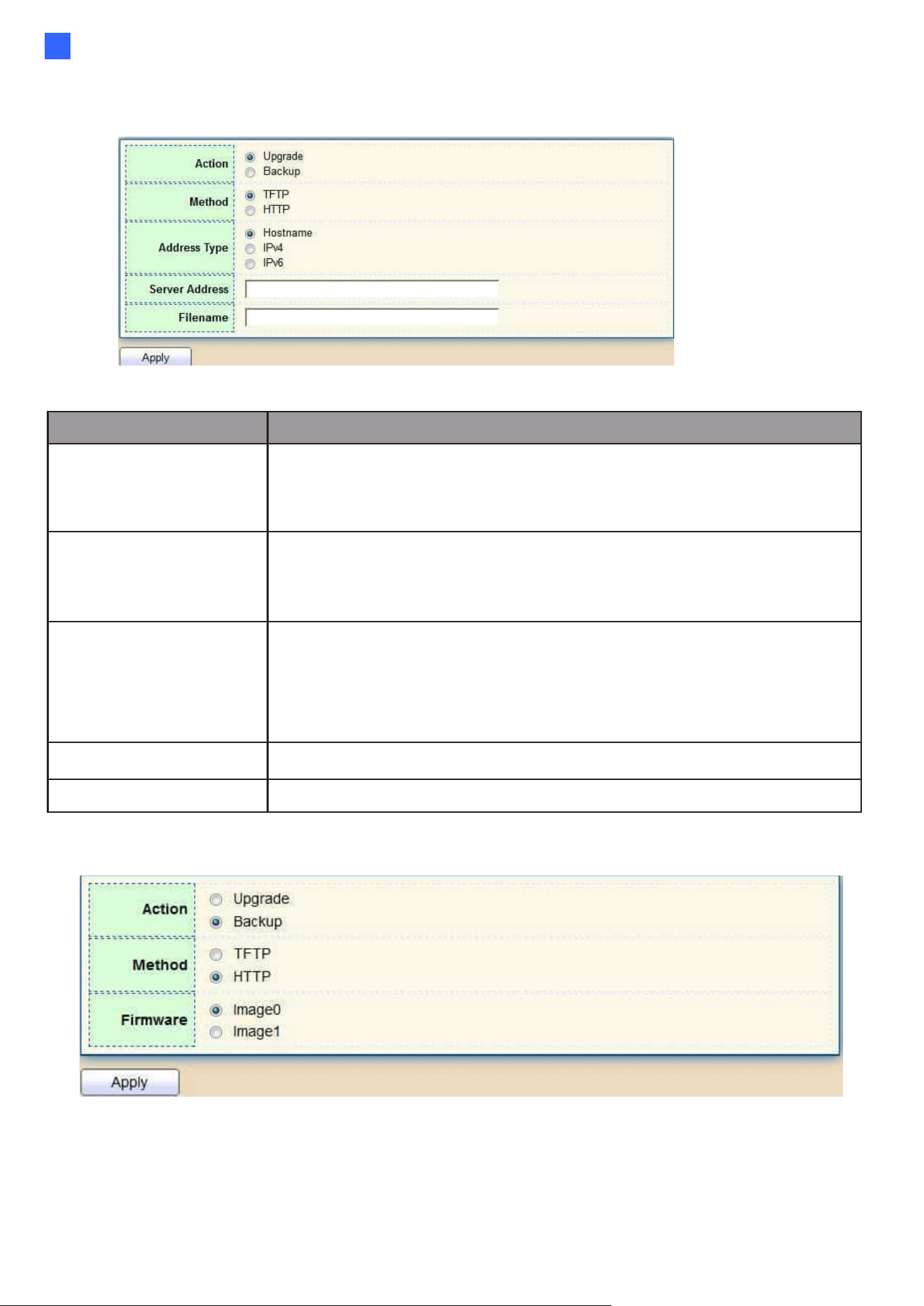
Web-based Switch Configuration
173
2
To display firmware upgrade or backup web page, click Management > Firmware >
Upgrade/Backup
Figure 202 - Management > Firmware > Upgrade/Backup
Item
Description
Action
Firmware operations
•
Upgrade: Upgrade firmware from remote host to DUT
•
Backup: Backup firmware image from DUT to remote host
Method
Firmware upgrade / backup method
•
TFTP: Using TFTP to upgrade/backup firmware.
•
HTTP: Using WEB browser to upgrade/backup firmware.
Address Type
Specify TFTP server address type
•
Hostname: Use a domain name as server address
•
IPv4: Use IPv4 as server address
•
IPv6: Use IPv6 as server address
Server Address
Specify TFTP server address.
Filename
Firmware image file name on remote TFTP server
To display firmware upgrade or backup web page, click Management > Firmware > Upgrade/Backup
Figure 203 - Management > Firmware > Upgrade/Backup
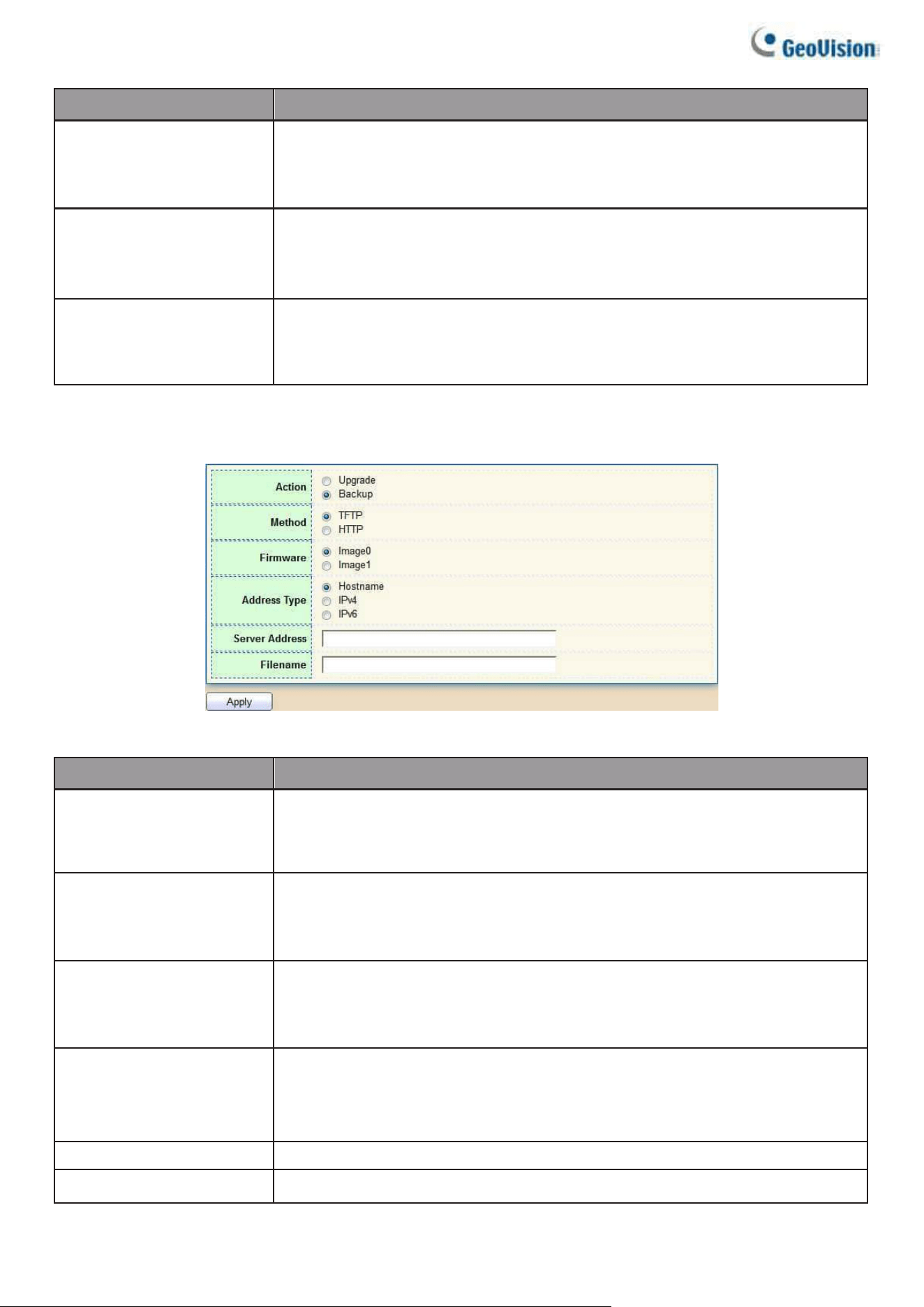
174
Item
Description
Action
Firmware operations
•
Upgrade: Upgrade firmware from remote host to DUT
•
Backup: Backup firmware image from DUT to remote host
Method
Firmware upgrade / backup method
•
TFTP: Using TFTP to upgrade/backup firmware.
•
HTTP: Using WEB browser to upgrade/backup firmware.
Firmware
Firmware partition need to backup
•
Image0: Firmware image in flash partition 0
•
Image1: Firmware image in flash partition 1
To view the Firmware Upgrade/Backup menu, navigate to Management > Firmware
> Upgrade/Backup.
Figure 204 - Management > Firmware >Upgrade/Backup
Item
Description
Action
Firmware operations
•
Upgrade: Upgrade firmware from remote host to DUT
•
Backup: Backup firmware image from DUT to remote host
Method
Firmware upgrade / backup method
•
TFTP: Using TFTP to upgrade/backup firmware.
•
HTTP: Using WEB browser to upgrade/backup firmware.
Firmware
Firmware partition need to backup
•
Image0: Firmware image in flash partition 0.
•
Image1: Firmware image in flash partition 1.
Address Type
Specify TFTP server address type
•
Hostname: Use domain name as server address.
•
IPv4: Use IPv4 as server address.
•
IPv6: Use IPv6 as server address.
Server Address
Specify TFTP server address.
Filename
File name saved on remote TFTP server.
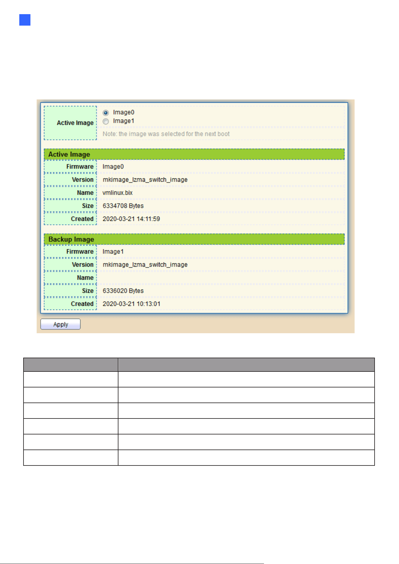
Web-based Switch Configuration
175
2
Active Image
This page allows users to select firmware image on next booting and show firmware
information on both flash partitions.
To display the Active Image web page, click Management > Firmware > Active Image.
Figure 205 - Management > Firmware > Active Image
Item
Description
Active Image
Select firmware image to use on next booting
Firmware
Firmware flash partition name.
Version
Firmware version.
Name
Firmware name.
Size
Firmware image size.
Created
Firmware image created date.
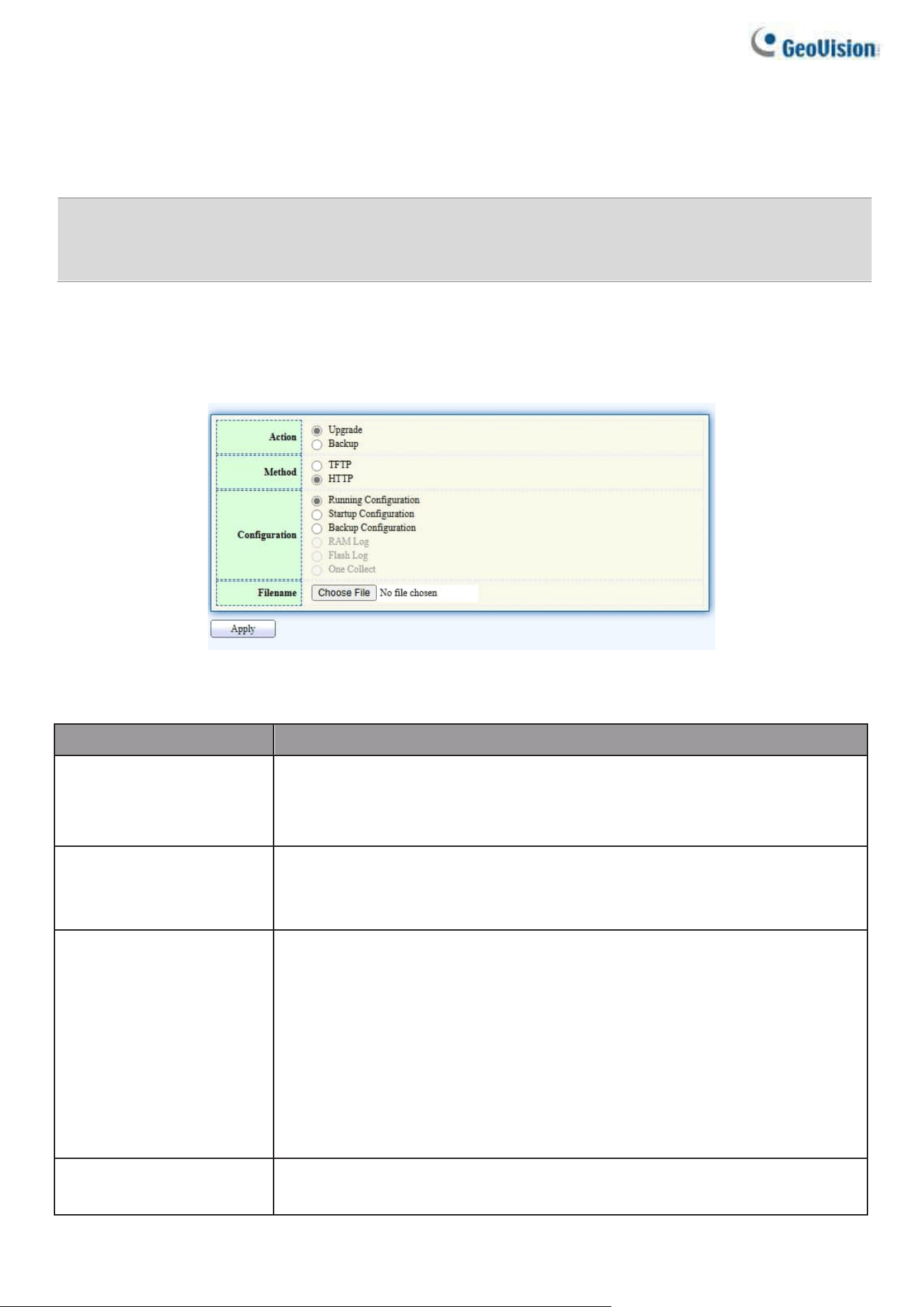
176
2.15.3. Configuration
2.15.3.1. Upgrade / Backup
Note: For browser compatibility improvements, it is required for users of Internet Explorer or
Microsoft Edge to clear all cookies and site data, and then reopen the browser after upgrading to
firmware V1.01 or later.
This page allows users to upgrade or backup configuration file through HTTP or TFTP server.
To display firmware upgrade or backup web page, click Management > Configuration >
Upgrade/Backup
Figure 206 - Management > Configuration > Upgrade/Backup
Item
Description
Action
Configuration operations
•
Upgrade: Upgrade firmware from remote host to DUT
•
Backup: Backup firmware image from DUT to remote host
Method
Configuration upgrade / backup method
•
TFTP: Using TFTP to upgrade/backup firmware
•
HTTP: Using WEB browser to upgrade/backup firmware
Configuration
Configuration types
•
Running Configuration: Merge to current running
configuration file
•
Startup Configuration: Replace startup configuration file
•
Backup Configuration: Replace backup configuration file
•
RAM Log: Backup log file stored in RAM.
•
Flash Log: Backup log files store in Flash.
•
One Collect: Export system info, config, and error log at once
Filename
Use browser to upgrade configuration, you should select
configuration file on your host PC.
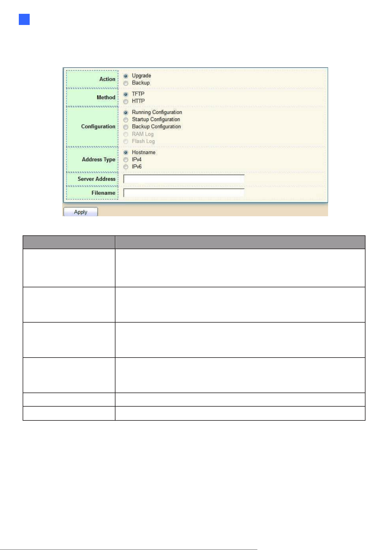
Web-based Switch Configuration
177
2
To display firmware upgrade or backup web page, click Management >
Configuration > Upgrade/Backup
Figure 207 - Management > Configuration > Upgrade/Backup
Item
Description
Action
Configuration operations
•
Upgrade: Upgrade firmware from remote host to DUT
•
Backup: Backup firmware image from DUT to remote host
Method
Configuration upgrade / backup method
•
TFTP: Using TFTP to upgrade/backup firmware
•
HTTP: Using WEB browser to upgrade/backup firmware
Configuration
Configuration types
•
Running Configuration: Merge to current running
configuration file
•
Startup Configuration: Replace startup configuration file
•
Backup Configuration: Replace backup configuration file
Address Type
Specify TFTP server address type
•
Hostname: Use a domain name as server address
•
IPv4: Use IPv4 as server address
•
IPv6: Use IPv6 as server address
Server Address
Specify TFTP server address
Filename
File name saved on remote TFTP server
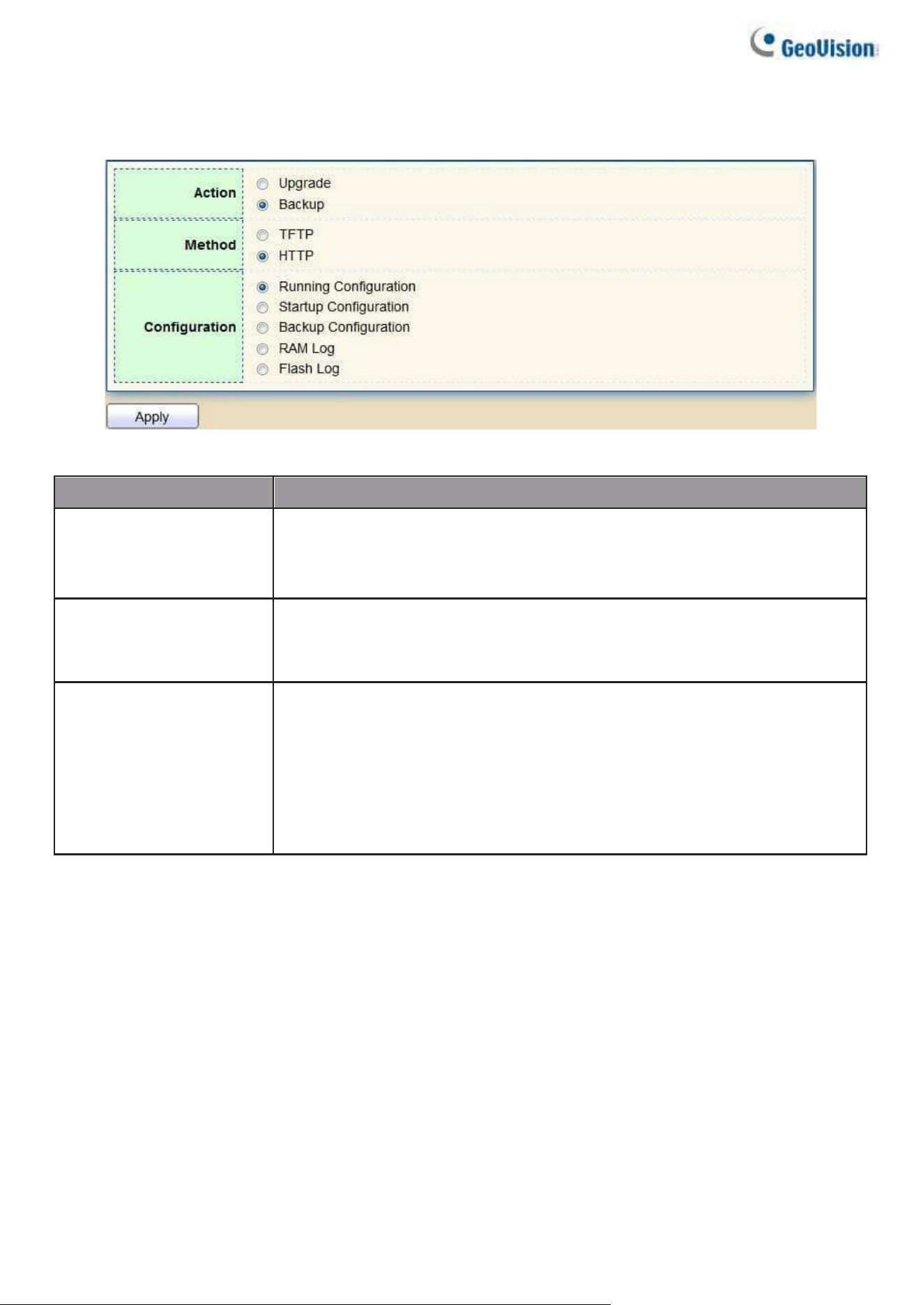
178
“To display firmware upgrade or backup web page, click Management >
Configuration > Upgrade/Backup
Figure 208 - Management > Configuration > Upgrade/Backup
Item
Description
Action
Configuration operations
•
Upgrade: Upgrade firmware from remote host to DUT
•
Backup: Backup firmware image from DUT to remote host
Method
Configuration upgrade / backup method
•
TFTP: Using TFTP to upgrade/backup firmware
•
HTTP: Using WEB browser to upgrade/backup firmware
Configuration
Configuration types
•
Running Configuration: Backup running configuration file.
•
Startup Configuration: Backup start configuration file.
•
Backup Configuration: Backup backup configuration file.
•
RAM Log: Backup log file stored in RAM.
•
Flash Log: Backup log files store in Flash.
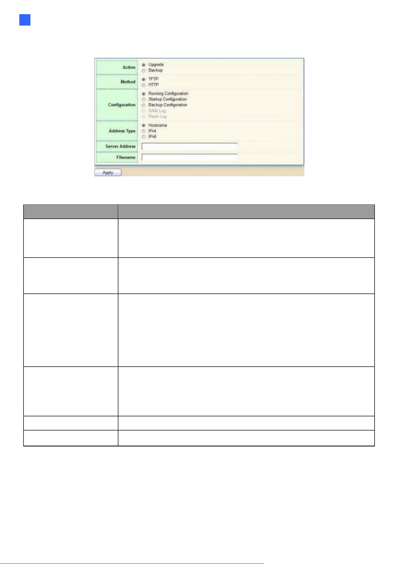
Web-based Switch Configuration
179
2
To display firmware upgrade or backup web page, click Management >
Configuration > Upgrade/Backup
Figure 209 - Management > Configuration > Upgrade/Backup
Item
Description
Action
Configuration operations
•
Upgrade: Upgrade firmware from remote host to DUT
•
Backup: Backup firmware image from DUT to remote host
Method
Configuration upgrade / backup method
•
TFTP: Using TFTP to upgrade/backup firmware
•
HTTP: Using WEB browser to upgrade/backup firmware
Configuration
Configuration types
•
Running Configuration: Backup running configuration file.
•
Startup Configuration: Backup start configuration file.
•
Backup Configuration: Backup backup configuration file.
•
RAM Log: Backup log file stored in RAM.
•
Flash Log: Backup log files store in Flash.
Address Type
Specify TFTP server address type
•
Hostname: Use a domain name as server address
•
IPv4: Use IPv4 as server address
•
IPv6: Use IPv6 as server address
Server Address
Specify TFTP server address
Filename
File name saved on remote TFTP server.
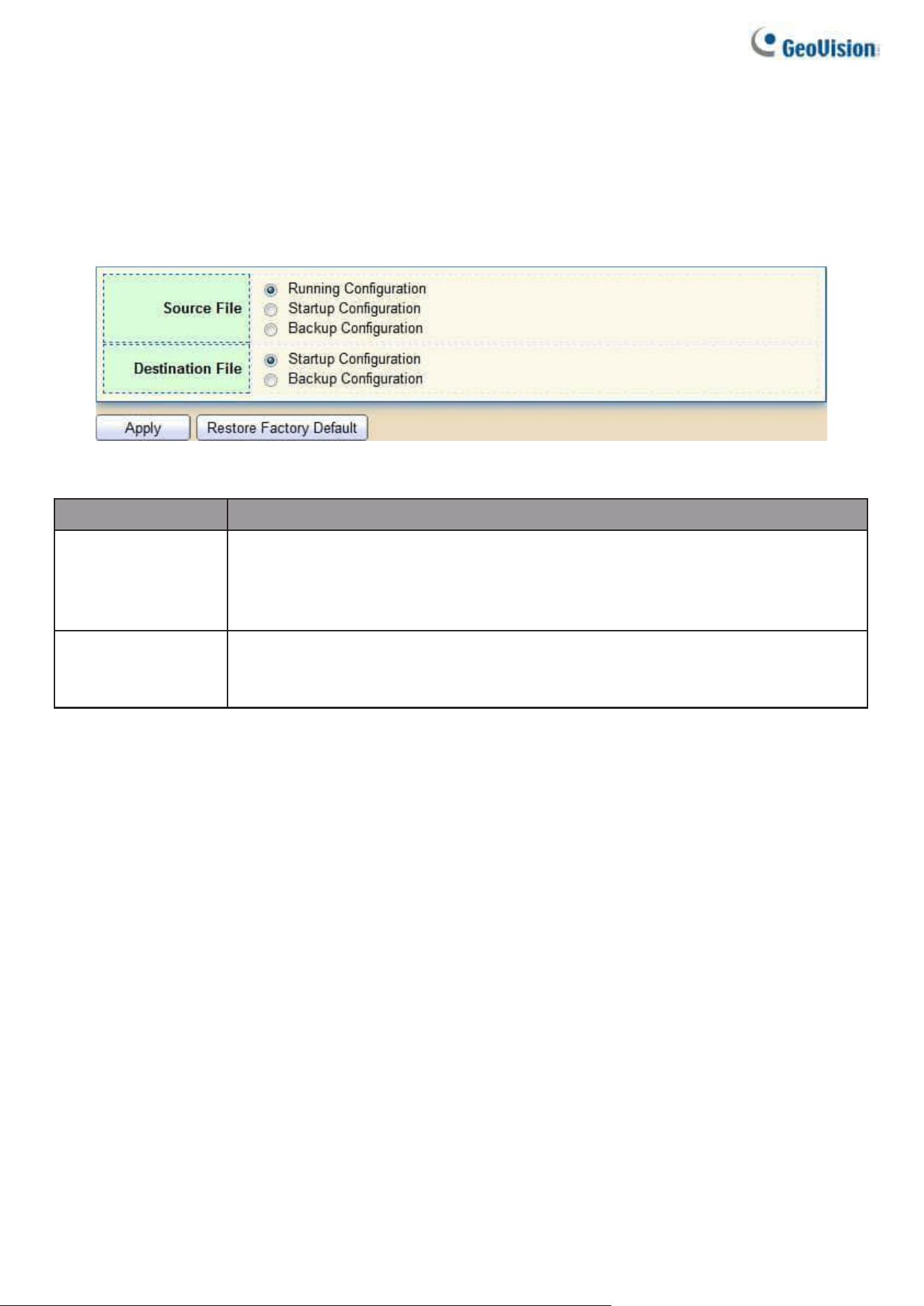
180
2.15.3.2. Save Configuration
This page allows users to manage configuration file saved on DUT and click
“Restore Factory Default” button to restore factory defaults.
To display the Save Configuration web page, click Management > Configuration > Save
Configuration.
Figure 210 - Management > Configuration > Save Configuration
Item
Description
Source File
Source file types
•
Running Configuration: Copy running configuration file to
destination.
•
Startup Configuration: Copy startup configuration file to destination.
Destination File
Destination file
•
Startup Configuration: Save file as startup configuration.
•
Backup Configuration: Save file as backup configuration.
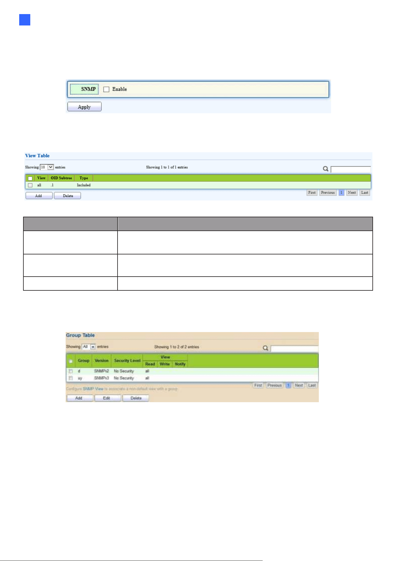
Web-based Switch Configuration
181
2
2.15.4. SNMP
2.15.4.1. Status
Enable the SNMP function.
Figure 211 - Management > SNMP > Status
2.15.4.2. View
To configure and display the SNMP view table, click Management > SNMP > View.
Figure 212 - Management > SNMP > View
Item
Description
View
The SNMP view name. Its maximum length is 30
characters
OID Subtree
Specify the ASN.1 subtree object identifier (OID) to be
included or excluded from the SNMP view
Type
Include or exclude the selected MIBs in the view
2.15.4.3. Group
To configure and display the SNMP group settings, click Management > SNMP > Group.
Figure 213 - Management > SNMP > Group
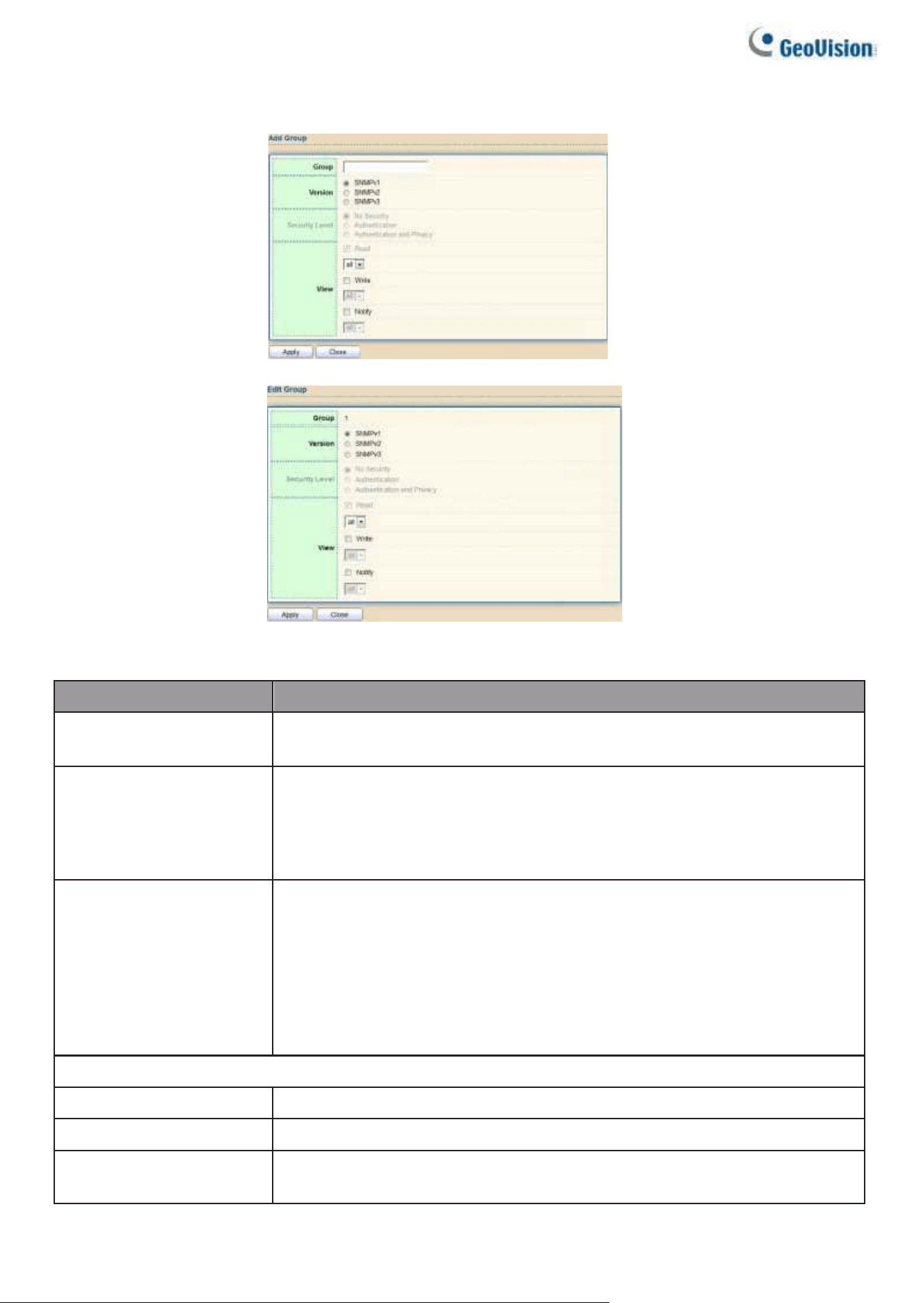
182
Click "Add" or “Edit” button to view the Add/Edit Group menu.
Figure 214 - Management > SNMP > Group > Add/Edit Group
Item
Description
Group
Specify SNMP group name, and the maximum length is 30
characters.
Version
Specify SNMP version
•
SNMPv1: SNMP Version 1.
•
SNMPv2: Community-based SNMP Version 2.
•
SNMPv3: User security model SNMP version 3.
Security Level
Specify SNMP security level
•
No Security: Specify that no packet authentication is
performed.
•
Authentication: Specify that no packet authentication without
encryption is performed.
•
Authentication and Privacy: Specify that no packet
authentication with encryption is performed.
View
Read
Group read view name.
Write
Group write view name.
Notify
The view name that sends only traps with contents that is
included in SNMP view selected for notification.
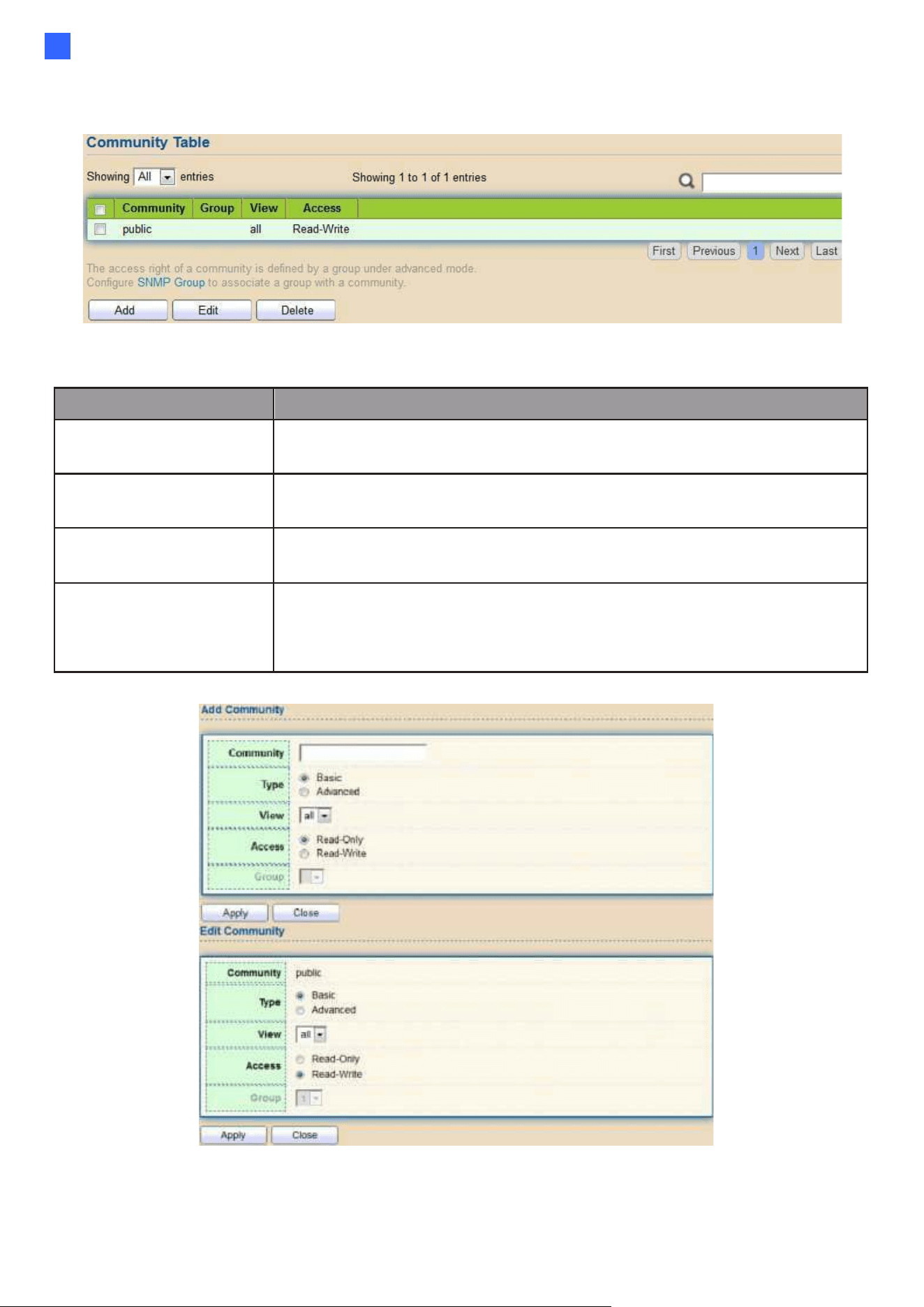
Web-based Switch Configuration
183
2
2.15.4.4. Community
To configure and display the SNMP community settings, click Management > SNMP > Community.
Figure 215 - Management > SNMP > Community
Item
Description
Community
The SNMP community name. Its maximum length is 20
characters.
Group
Specify the SNMP group configured by the command snmp group
to define the object available to the community.
View
Specify the SNMP view to define the object available to the
community.
Access
SNMP access mode
•
Read-Only: Read only.
•
Read-Write: Read and write.
Click "Add" or “Edit” button to view the Add/Edit Community menu.
Figure 216 - Management > SNMP > Group > Add/Edit Community
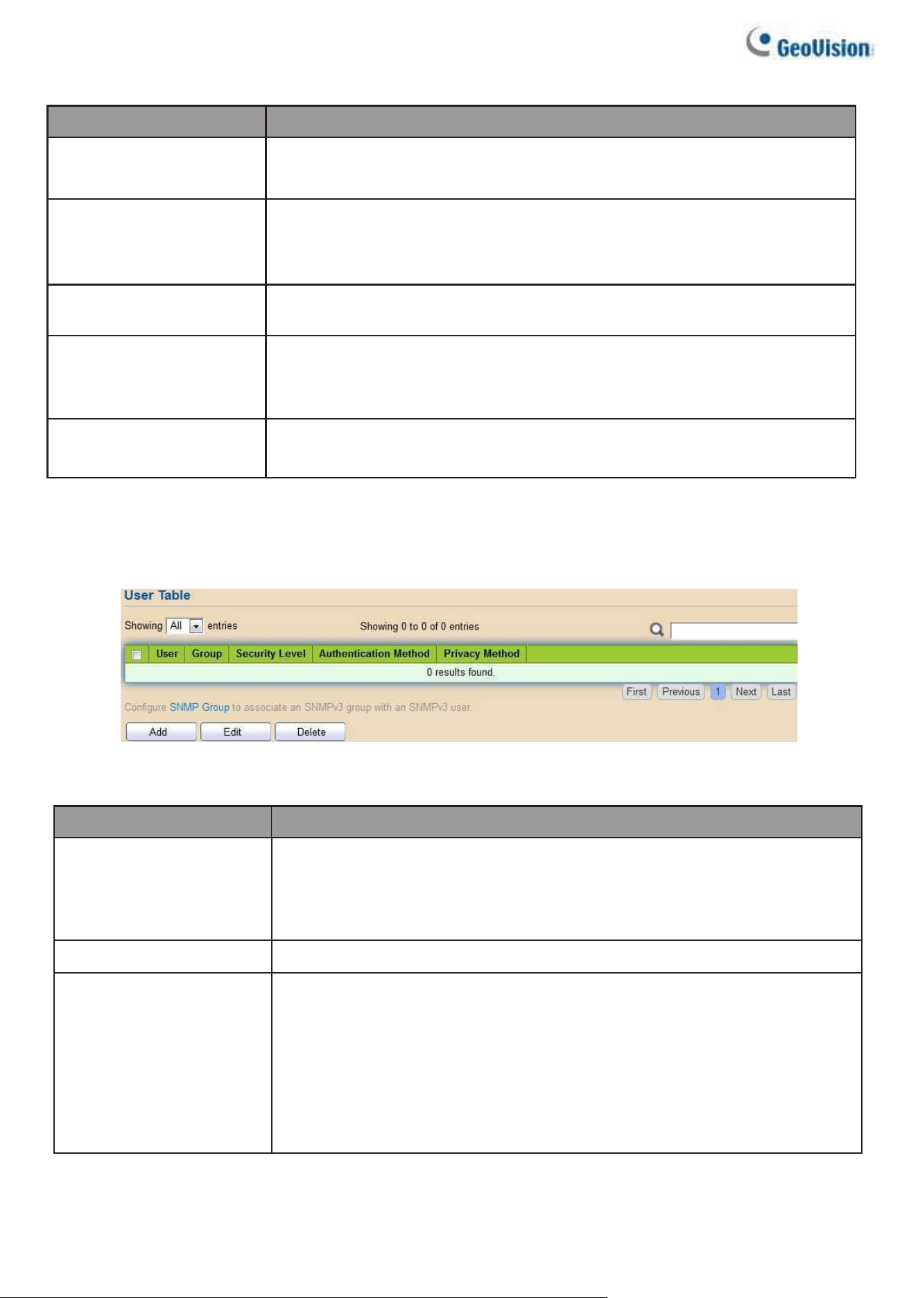
184
Item
Description
Community
The SNMP community name. Its maximum length is 20
characters.
Type
SNMP Community mode
•
Basic: SNMP community specifies view and access right.
•
Advanced: SNMP community specifies group.
View
Specify the SNMP view to define the object available to the
community.
Access
SNMP access mode
•
Read-Only: Read only.
•
Read-Write: Read and write.
Group
Specify the SNMP group configured by the command snmp group
to define the object available to the community.
2.15.4.5. User
To configure and display the SNMP users, click Management > SNMP > User.
Figure 217 - Management > SNMP > User
Item
Description
User
Specify the SNMP username on the host that connects to the
SNMP agent. The max character is 30 characters. For the SNMP
v1 or v2c, the username must match the community name.
Group
Specify the SNMP group to which the SNMP user belongs.
Security Level
SNMP privilege mode
•
No Security: Specify that no packet authentication is
performed.
•
Authentication: Specify that no packet authentication without
encryption is performed.
•
Authentication and Privacy: Specify that no packet
authentication with encryption is performed.
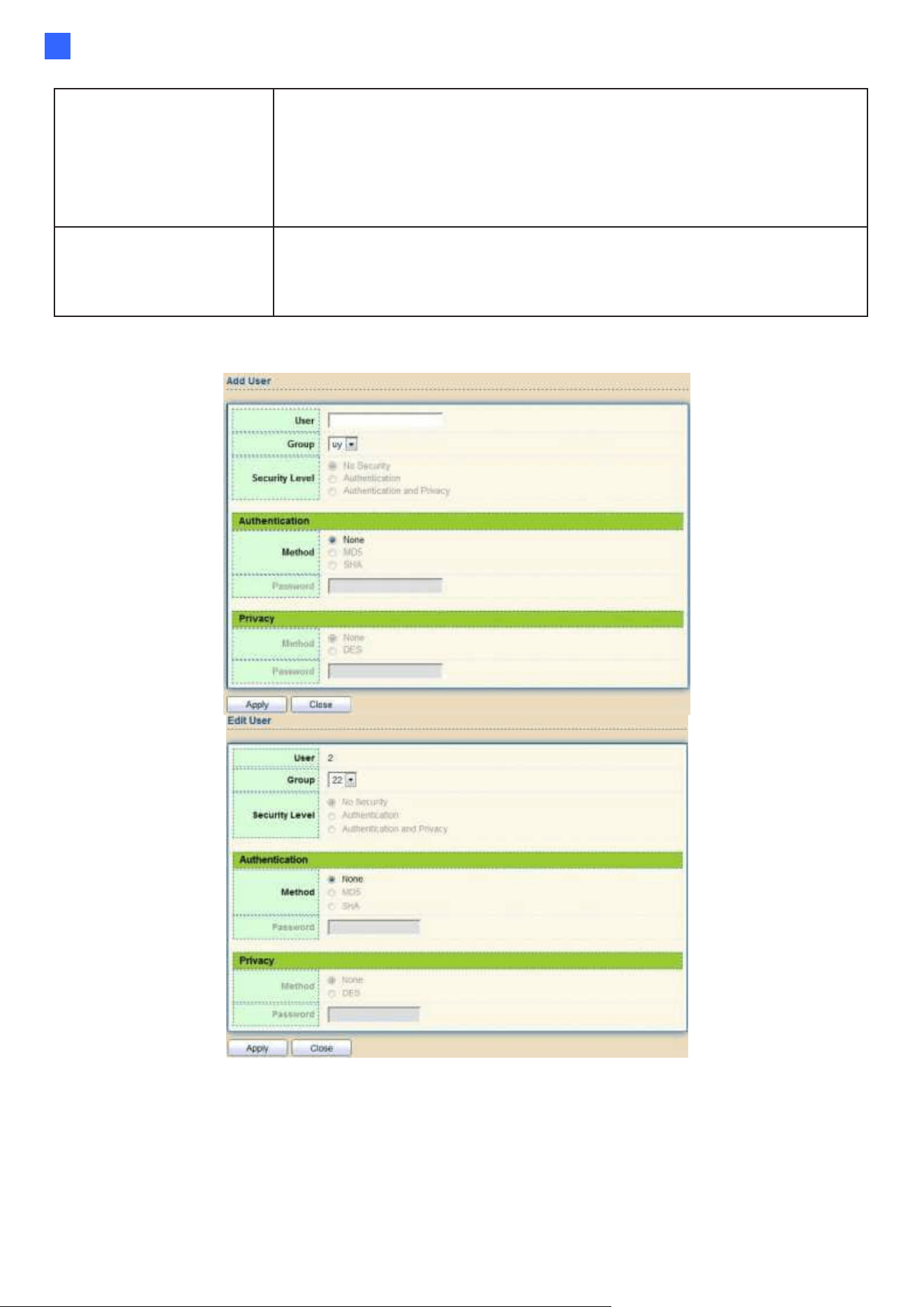
Web-based Switch Configuration
185
2
Authentication
Method
Authentication Protocol which is available when Privilege Mode
is Authentication or Authentication and Privacy.
•
None: No authentication required.
•
MD5: Specify the HMAC-MD5-96 authentication protocol.
•
SHA: Specify the HMAC-SHA-96 authentication protocol
Privacy Method
Encryption Protocol
•
None: No privacy required.
•
DES: DES algorithm
Click "Add" or “Edit” button to view Add/Edit User menu.
Figure 218 - Management > SNMP > User > Add/Edit User
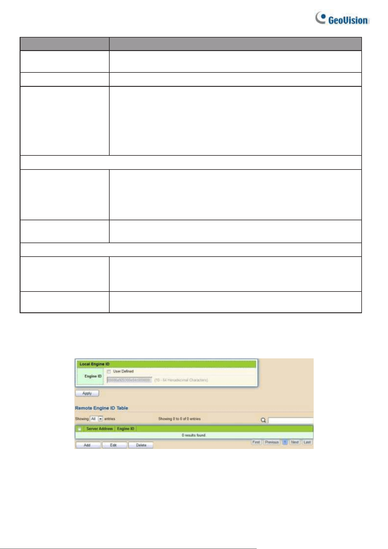
186
Item
Description
User
Specify the SNMP username on the host that connects to the
SNMP agent. The max character is 30 characters.
Group
Specify the SNMP group to which the SNMP user belongs.
Security Level
SNMP privilege mode
•
No Security: Specify that no packet authentication is
performed.
•
Authentication: Specify that no packet authentication without
encryption is performed.
•
Authentication and Privacy: Specify that no packet authentication
with encryption is performed.
Authentication
Method
Authentication Protocol which is available when Privilege Mode
is Authentication or Authentication and Privacy.
•
None: No authentication required.
•
MD5: Specify the HMAC-MD5-96 authentication protocol.
•
SHA: Specify the HMAC-SHA-96 authentication protocol.
Password
The authentication password. The number of character range
is 8 to 32 characters.
Privacy
Method
Encryption Protocol
•
None: No privacy required.
•
DES: DES algorithm
Password
The privacy password, the number of character range is 8 to 64
characters.
2.15.4.6. Engine ID
To configure and display SNMP local and remote engine ID, click Management > SNMP >
Engine ID.
Figure 219 - Management > SNMP > Engine ID
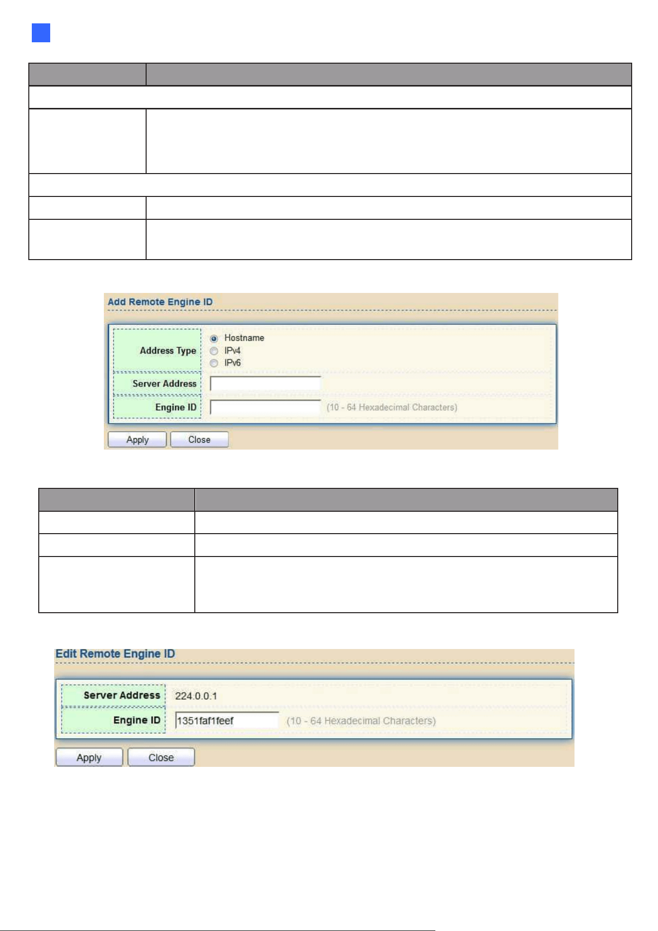
Web-based Switch Configuration
187
2
Item
Description
Local Engine ID
Engine ID
If checked “User-defined”, the local engine ID is configured by the user, else use
the default Engine ID which is made up of MAC and Enterprise ID.
The User-defined engine ID is range 10 to 64 hexadecimal characters, and
the hexadecimal number must be divided by 2.
Remote Engine ID Table
Server Address
Remote host.
Engine ID
Specify Remote SNMP engine ID. The engine ID is range10 to 64
hexadecimal characters, and the hexadecimal number must be divided by 2.
Click "Add" button to view Add Remote Engine ID menu.
Figure 220 - Management > SNMP > Add Engine ID
Item
Description
Address Type
Remote host address type for Hostname/IPv4/IPv6.
Server Address
Remote host.
Engine ID
Specify Remote SNMP engine ID. The engine ID is range10 to 64
hexadecimal characters, and the hexadecimal number must be
divided by 2.
Click “Edit” button to view Edit Remote Engine ID menu.
Figure 221 - Management > SNMP > Edit Engine ID
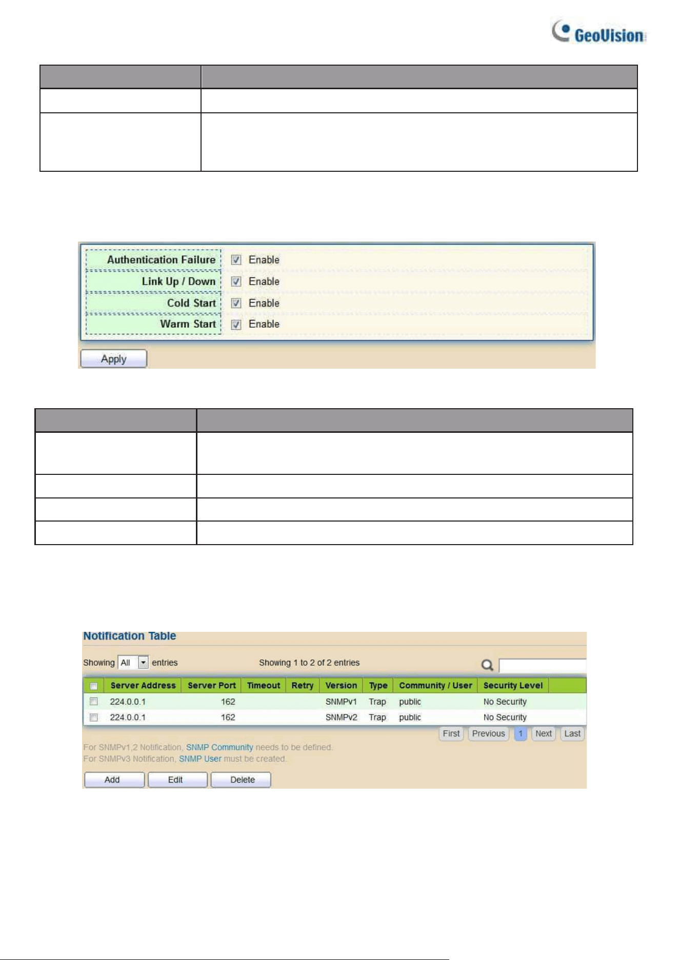
188
Item
Description
Server Address
Edit Remote host address
Engine ID
Specify Remote SNMP engine ID. The engine ID is range10 to 64
hexadecimal characters, and the hexadecimal number must be
divided by 2.
2.15.4.7. Trap Event
To configure and display SNMP trap event, click Management > SNMP > Trap Event.
Figure 222 - Management > SNMP > Trap Event
Item
Description
Authentication
Failure
SNMP authentication failure trap, when community not match
or user authentication password not match.
Link Up/Down
Port link up or down trap.
Cold Start
Device reboot configure by user trap.
Warm Start
Device reboot by power down trap.
2.15.4.8. Notification
To configure the hosts to receive SNMPv1/v2/v3 notification, click
Management > SNMP > Notification.
Figure 223 - Management > SNMP > Notification
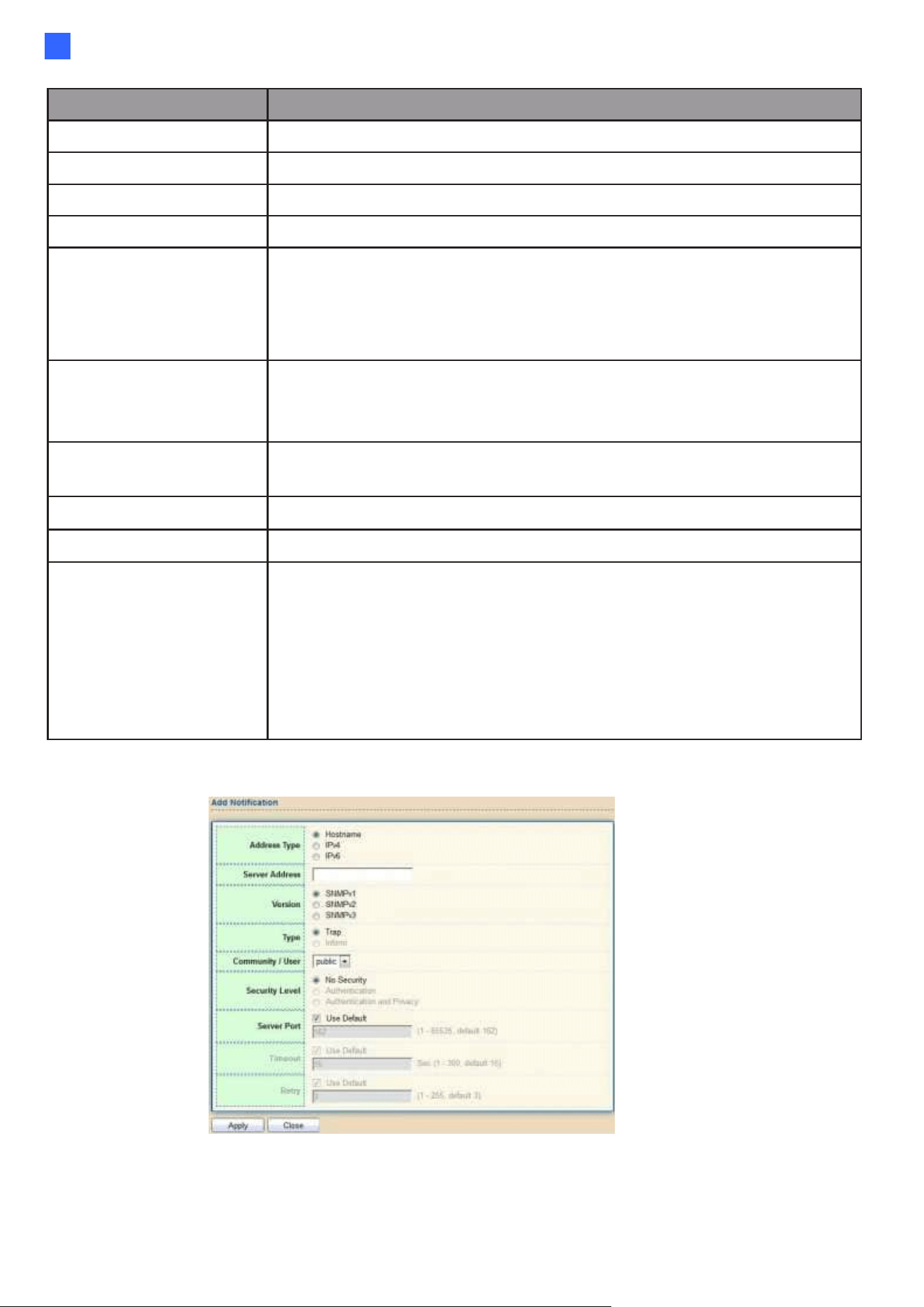
Web-based Switch Configuration
189
2
Item
Description
Server Address
IP address or the hostname of the SNMP trap recipients.
Server Port
Recipients server UDP port number.
Timeout
Specify the SNMP informs timeout.
Retry
Specify the retry counter of the SNMP informs.
Version
Specify SNMP notification version
•
SNMPv1: SNMP Version 1 notification.
•
SNMPv2: SNMP Version 2 notification.
•
SNMPv3: SNMP Version 3 notification.
Type
Notification Type
•
Trap: Send SNMP traps to the host.
•
Inform: Send SNMP informs to the host.
Community/User
SNMP community/username for notification. If version is SNMPv3
the name is username, else is community name.
UDP Port
Specify the UDP port number.
Timeout
Specify the SNMP informs timeout.
Security Level
SNMP trap packet security level
•
No Security: Specify that no packet authentication is
performed.
•
Authentication: Specify that no packet authentication without
encryption is performed.
•
Authentication and Privacy: Specify that no packet
authentication with encryption is performed.
Click "Add" button to view the Notification menu.
Figure 224 - Management > SNMP > Notification > Add Notification
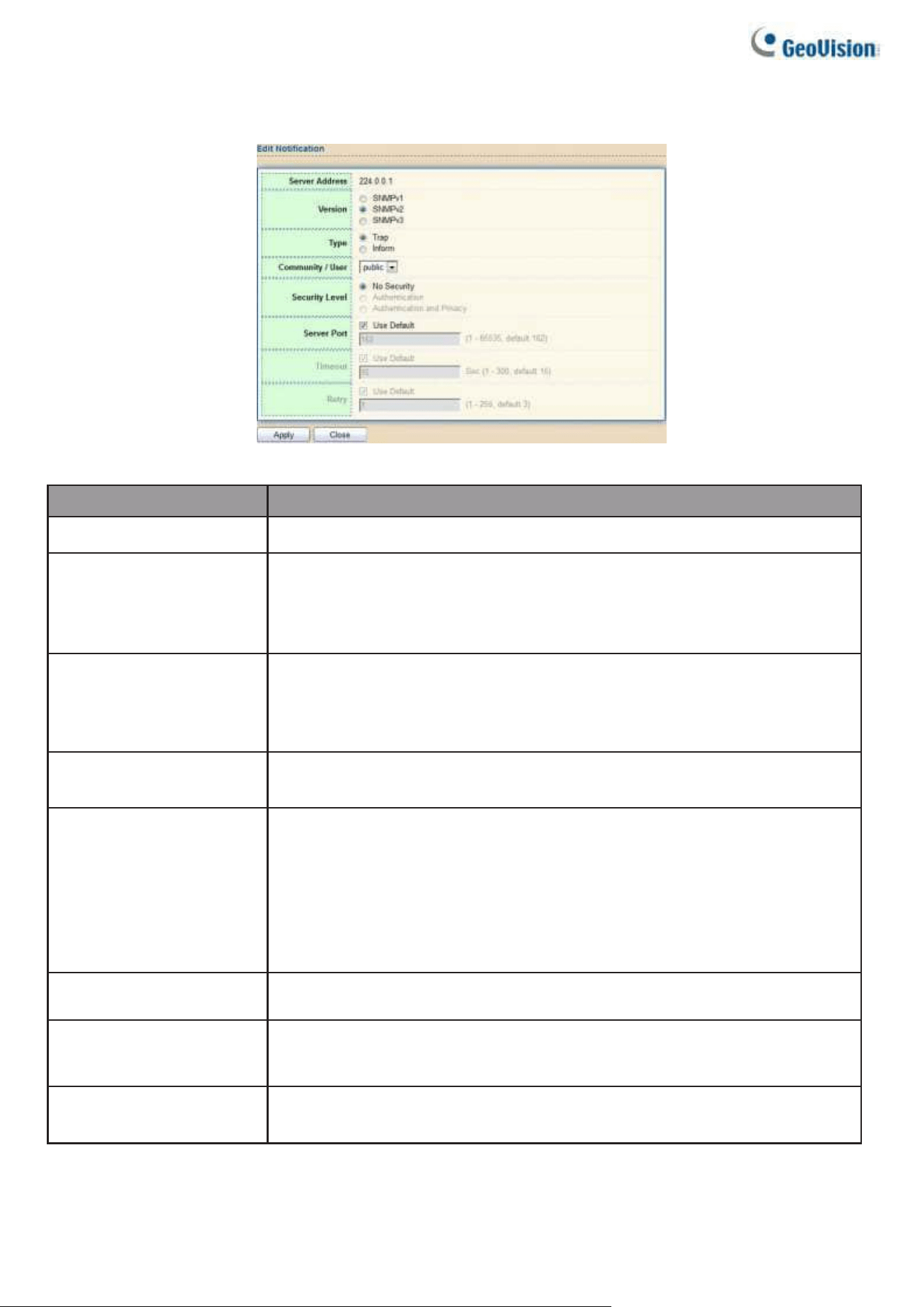
190
Click "Edit" button to view the Edit Notification menu.
Figure 225 - Management > SNMP > Notification > Edit Notification
Item
Description
Server Address
Edit SNMP notify recipients address
Version
Specify SNMP notification version
•
SNMPv1: SNMP Version 1 notification.
•
SNMPv2: SNMP Version 2 notification.
•
SNMPv3: SNMP Version 3 notification.
Type
Notification Type
•
Trap: Send SNMP traps to the host.
•
Inform: Send SNMP informs to the host. (This function is not
applicable to SNMPv1)
Community/User
SNMP community/username for notification. If version is SNMPv3 the
name is username, else is community name.
Community Level
SNMP notification packet security level, the security level must less than
or equal to the community/username
•
No Security: Specify that no packet authentication is performed.
•
Authentication: Specify that no packet authentication without
encryption is performed.
•
Authentication and Privacy: Specify that no packet authentication
with encryption is performed.
Server Port
Specify the UDP port number. If “Use Default” checked, the default
value is 162.
Timeout
Specify the time length for notifying the hosts after timeout. If “Use
Default” is checked, the default value is 15.
Retry
Specify the number of retry allowed before notifying the hosts. If “Use
Default” is checked, the default value is 3.

Web-based Switch Configuration
191
2
2.15.5. RMON
2.15.5.1. Statistics
To display RMON Statistics, click Management > RMON > Statistics.
Figure 226 - Management > RMON > Statistics
Item
Description
Port
The port for the RMON statistics.
Bytes Received
Number of octets received, including bad packets and FCS octets,
but excluding framing bits.
Drop Events
Number of packets that were dropped.
Packets Received
Number of packets received, including bad packets, Multicast
packets, and Broadcast packets.
Broadcast Packets
Number of good Broadcast packets received. This number does not
include Multicast packets.
Multicast Packets
Number of good Multicast packets received.
CRC &Align Errors
Number of CRC and Align errors that have occurred.
Undersize Packets
Number of undersized packets (les than 64 octets) received.
Oversize Packets
Number of oversized packets (over 1518 octets) received.
Fragments
Number of fragments (packets with less than 64 octets, excluding
framing bits, but including FCS octets) received.
Jabbers
Number of received packets that were longer than 1632 octets. This
number excludes frame bits, but includes FCS octets that had either
a bad FCS (Frame Check Sequence) with an integral number of
octets (FCS Error) or a bad FCS with a non-integral octet (Alignment
Error) number. A Jabber packet is defined as an Ethernet frame that
satisfies the following criteria:
•
Packet data length is greater than MRU.
•
Packet has an invalid CRC.
•
RX error event has not been detected.
Collisions
Number of collisions received. If Jumbo Frames are enabled, the
threshold of Jabber Frames is raised to the maximum size of Jumbo
Frames.
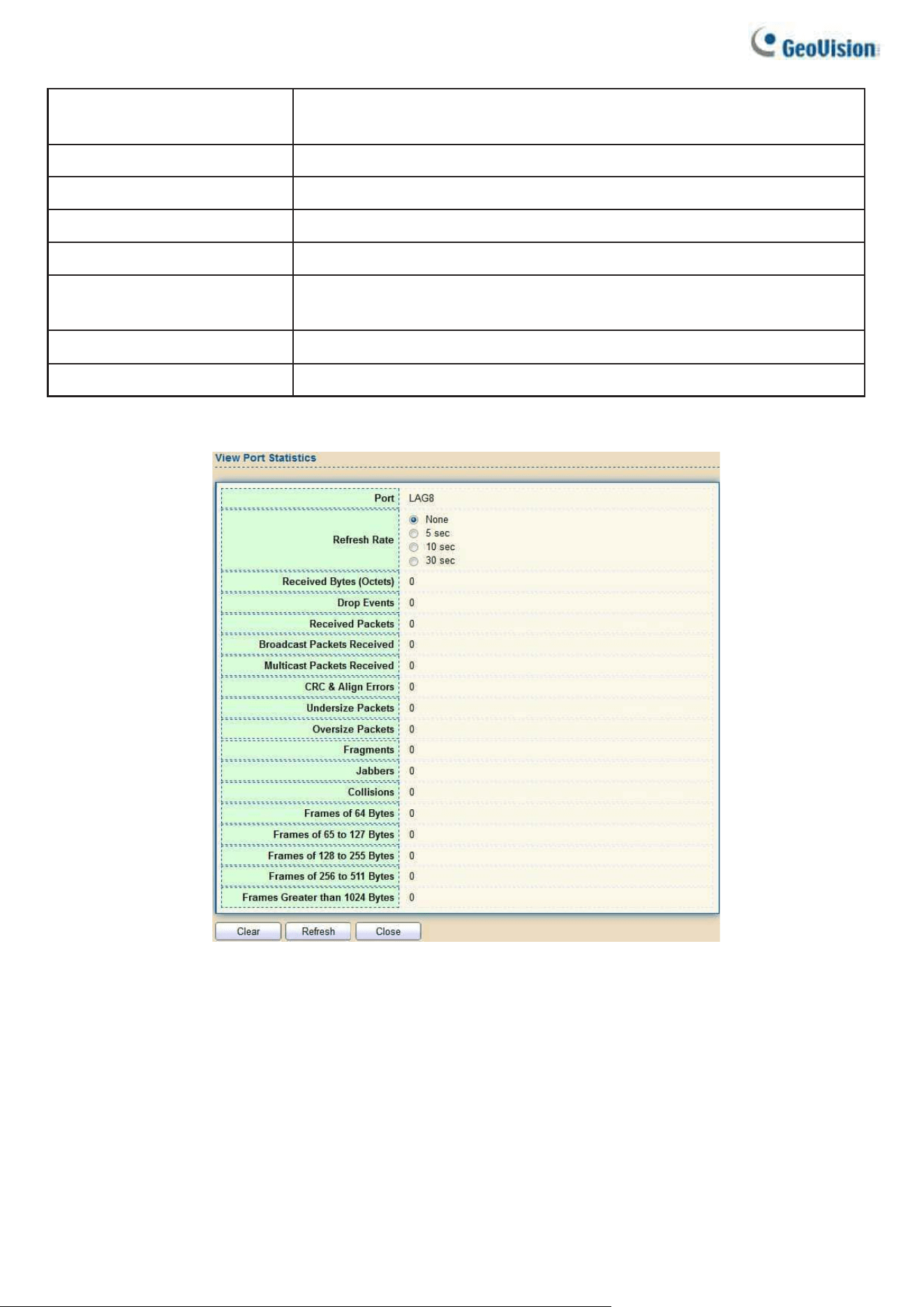
192
Frames of 64 Bytes
Number of frames, containing less than 64 bytes that were received.
Frames of 65 to 127 Bytes
Number of frames, containing 65 to 127 bytes that were received.
Frames of 128 to 225 Bytes
Number of frames, containing 128 to 255 bytes that were received.
Frames of 256 to 511 Bytes
Number of frames, containing 256 to 511 bytes that were received.
Frames of 512 to 1023 Bytes
Number of frames, containing 512 to 1023 bytes that were received.
Frames Greater than 1024
Bytes
Number of frames, containing 1024 to 1518 bytes that were received.
Clear
Clear the statistics for the selected ports.
View
View the statistics on the specified port.
Click "View" button to view the view Port Statistics menu.
Figure 227 - Management > RMON > Statistics
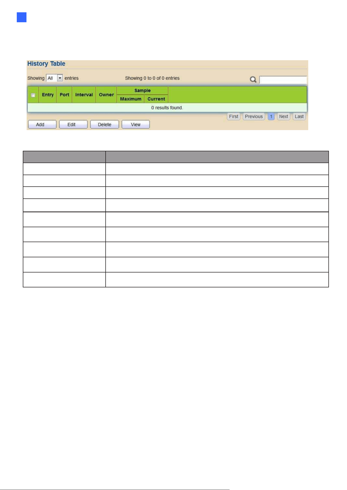
Web-based Switch Configuration
193
2
2.15.5.2. History
For the RMON history, click Management > RMON > History.
Figure 228 - Management > RMON > History
Item
Description
Port
The port for the RMON history.
Interval
The number of seconds for each sample.
Owner
The owner name of event (0~31 characters).
Sample Maximum
The maximum number of buckets.
Sample Current
The current number of buckets.
Add
Add the new RMON history entries
Edit
Edit the RMON history
Delete
Delete the RMON histories
View
View the history log.
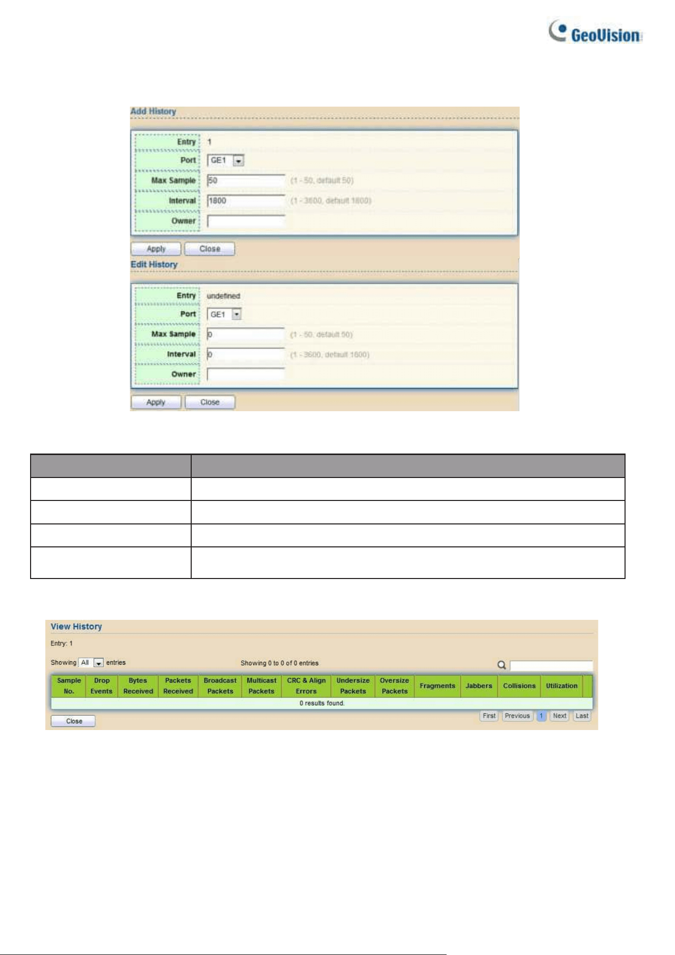
194
Click "Add/Edit" button to Add/Edit the History menu.
Figure 229 - Management > RMON > Add /Edit History
Item
Description
Port
Specify port for the RMON history.
Max Sample
Specify the maximum number of buckets.
Interval
Specify the number of seconds for each sample.
Owner
Specify the owner name of event (0~31 characters).
Click "View" button to view the History menu.
Figure 230 - Management > RMON > View History

Web-based Switch Configuration
195
2
Item
Description
Port
The port for the RMON statistics.
Bytes Received
Number of octets received, including bad packets and
Drop Events
Number of packets that were dropped.
Packets Received
Number of packets received, including bad packets,
Multicast packets, and Broadcast packets.
Broadcast Packets
Number of good Broadcast packets received. This number does
not include Multicast packets.
Multicast Packets
Number of good Multicast packets received.
CRC & Align
Errors
Number of CRC and Align errors that have occurred.
Undersize
Packages
Number of undersized packets (less than 64 octets)
received.
Oversize
Packages
Number of oversized packets (over 1518 octets) received.
Fragments
Number of fragments (packets with less than 64 octets, excluding
framing bits, but including FCS octets) received.
Jabbers
Number of received packets that were longer than 1632 octets.
This number excludes frame bits, but includes FCS octets that
had either a bad FCS (Frame Check Sequence) with an integral
number of octets (FCS Error) or a bad
FCS with a non-integral octet (Alignment Error) number. A Jabber
packet is defined as an Ethernet frame that satisfies the following
criteria:
⚫
Packet data length is greater than MRU.
⚫
Packet has an invalid CRC.
⚫
RX error event has not been detected.
Collision
Number of collisions received. If Jumbo Frames are enabled,
the threshold of Jabber Frames is raised to the maximum size
of Jumbo Frames.
Utilization
Percentage of current interface traffic compared to the
maximum traffic that the interface can handle.
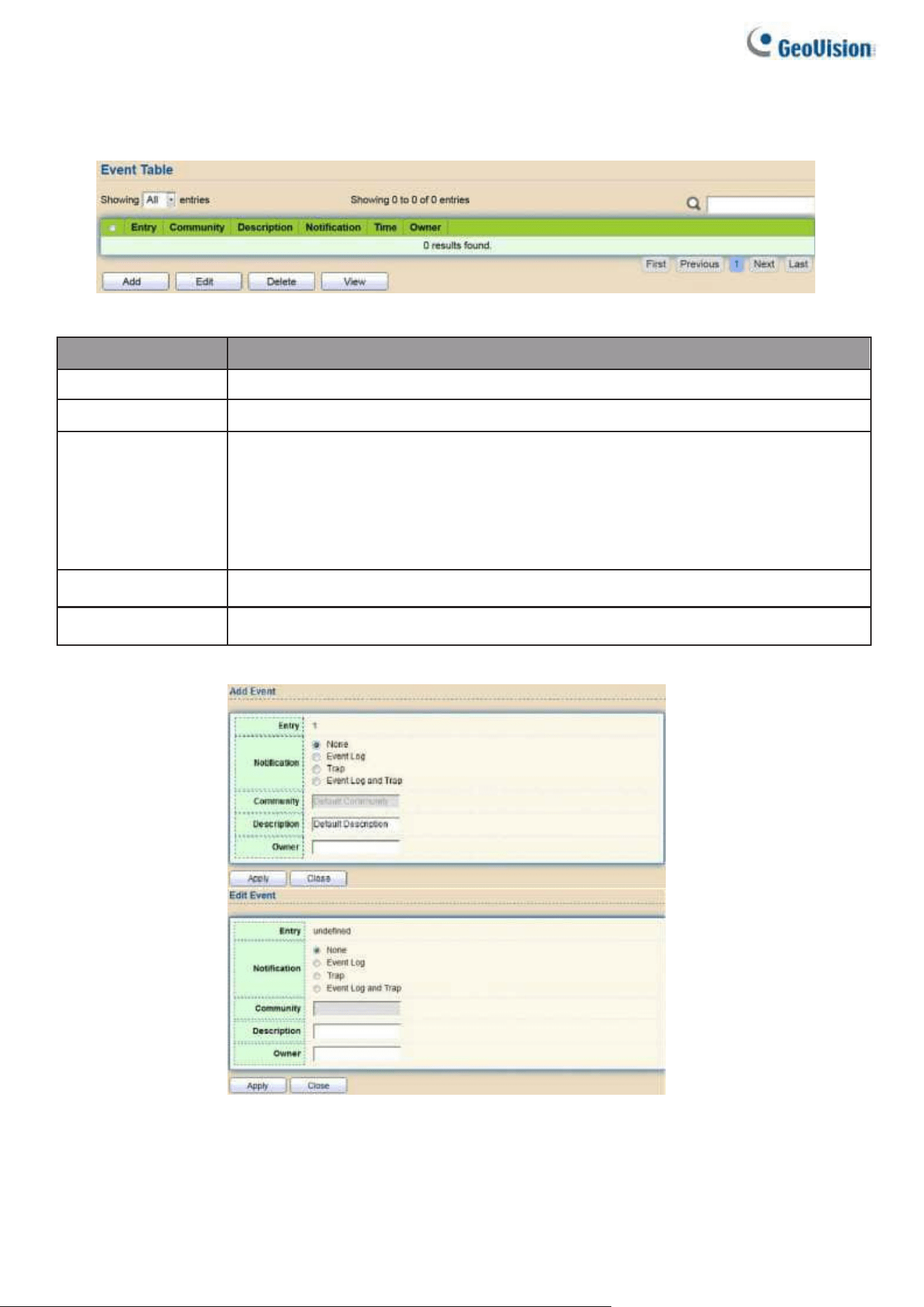
196
2.15.5.3. Event
For the RMON event, click Management > RMON > Event.
Figure 231 - Management > RMON > Event
Item
Description
Community
The SNMP community when the notification type is specified as
Description
The description for the event
Notification
The notification type for the event, and the possible value are:
•
None: Nothing for notification.
•
Event Log: Logging the event in the RMON Event Log table.
•
Trap: Send a SNMP trap.
•
Event Log and Trap: Logging the event and send the SNMP trap.
Time
The time that the event was triggered.
Owner
The owner for the event.
Click "Add/Edit" button to view the Add/Edit Event menu.
Figure 232 - Management > RMON > Add/Edit Event
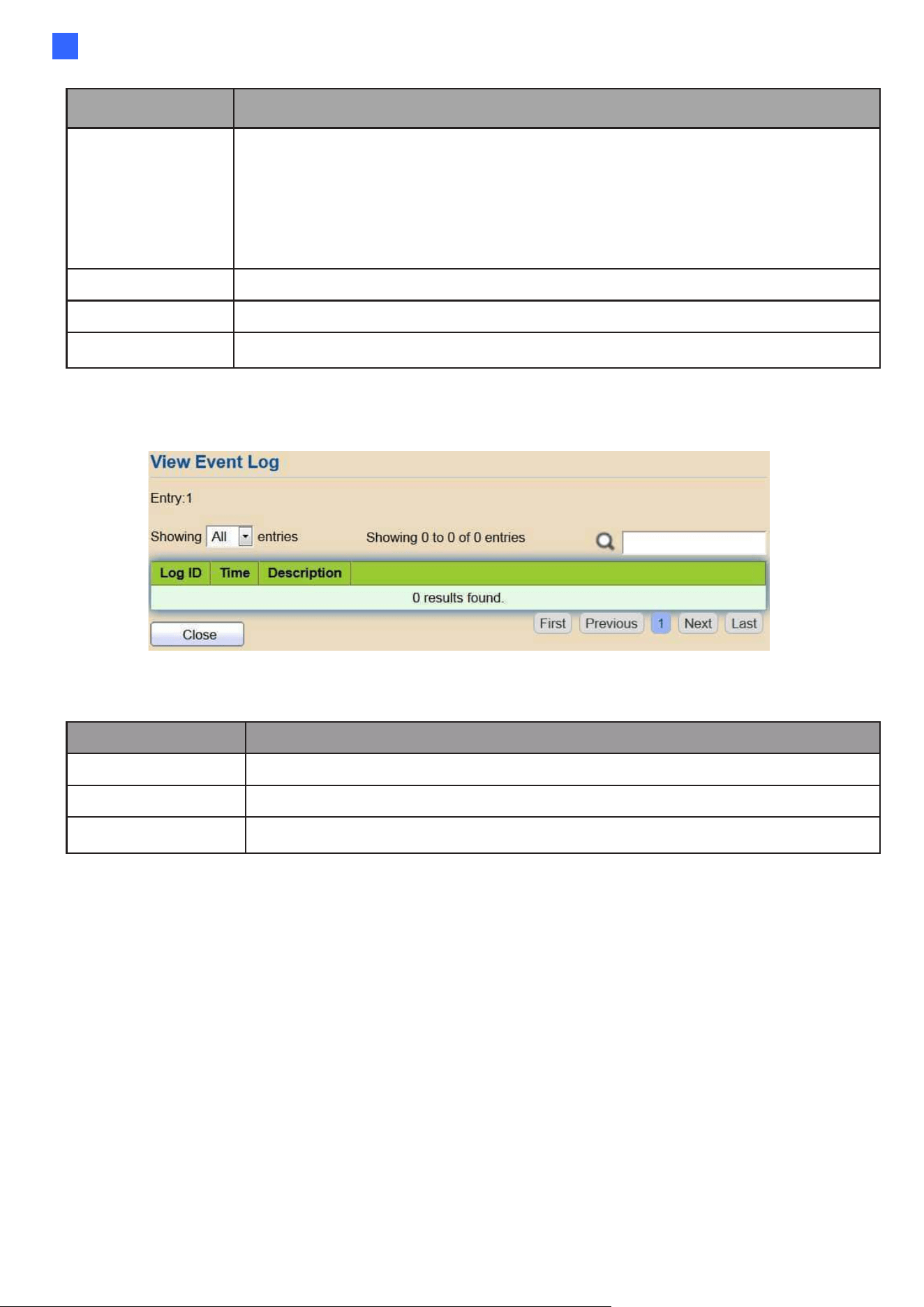
Web-based Switch Configuration
197
2
Item
Description
Notification
Specify the notification type for the event, and the possible value are:
•
None: Nothing for notification.
•
Event Log: Logging the event in the RMON Event Log table
•
Trap: Send a SNMP trap.
•
Event Log and Trap: Logging the event and send the SNMP trap
Community
Specify the SNMP community when the notification type is
Description
Specify the description for the event.
Owner
Specify owner for the event.
Click "View" button to view the View Event Log menu.
Figure 233 - Management > RMON > View Event Log
Item
Description
Log ID
The log identifier.
Time
The time that the event was triggered.
Description
The description for the event.
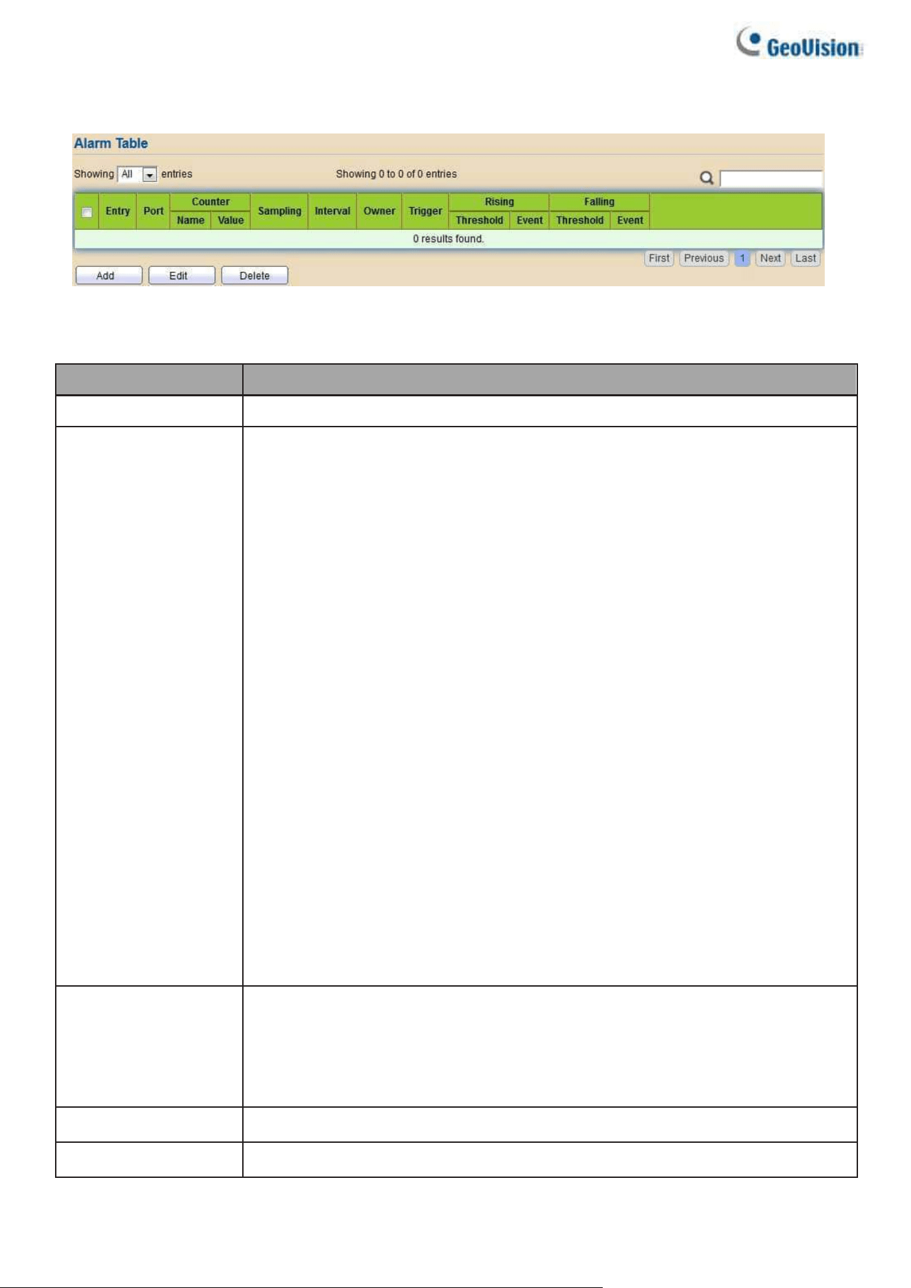
198
2.15.5.4. Alarm
For the RMON Alarm menu, click Management > RMON > Alarm.
Figure 234 - Management > RMON > Alarm
Item
Description
Port
The port configuration for the RMON alarm.
Counter
The counter for sampling
•
DropEvents (Drop Event): Total number of events received in which
the packets were dropped.
•
Octes (Received Bytes): Octets.
•
Pkts (Received Packets): Number of packets.
•
BroadcastPkts (Broadcast Packets Received): Broadcast packets.
•
MulticastPkts (Multicast Packets Received): Multicast packets.
•
CRCAlignError (CRC and Align Error): CRC alignment error.
•
UndersizePkts (Undersize Packets): Number of undersized packets
•
OversizePkts (Oversize Packets): Number of oversized packets.
•
Fragments (Fragments): Total number of packet fragment.
•
Jabbers (Jabbers): Total number of packet jabber.
•
Collisions (Collisions): Collision.
•
Pkts64Octetes (Frames of 64 Bytes): Number of packets size 64
octets.
•
Pkts65to127Octetes (Frames of 65 to 127 Bytes): Number of packets
size 65 to 127 octets.
•
Pkts128to255Octetes (Frames of 128 to 255 Bytes): Number of
packets size 128 to 255 octets.
•
Pkts256to511Octetes (Frames of 256 to 511 Bytes): Number of
packets size 256 to 511 octets.
•
Pkts512to1023Octetes (Frames of 512 to 1023 Bytes): Number of
packets size 512 to 1023 octets.
•
Pkts1024to1518Octets (Frames Greater than 1024 Bytes): Number of
packets size 1024 to 1518 octets.
Sampling
The sampling type including:
•
Absolute: The selected variable value is compared directly with the
thresholds at the end of the sampling interval.
•
Delta: The selected variable value of the last sample is subtracted
from the current value and the difference is compared with the thresholds.
Interval
The number of seconds for each sample.
Owner
The owner for the alarm entry.
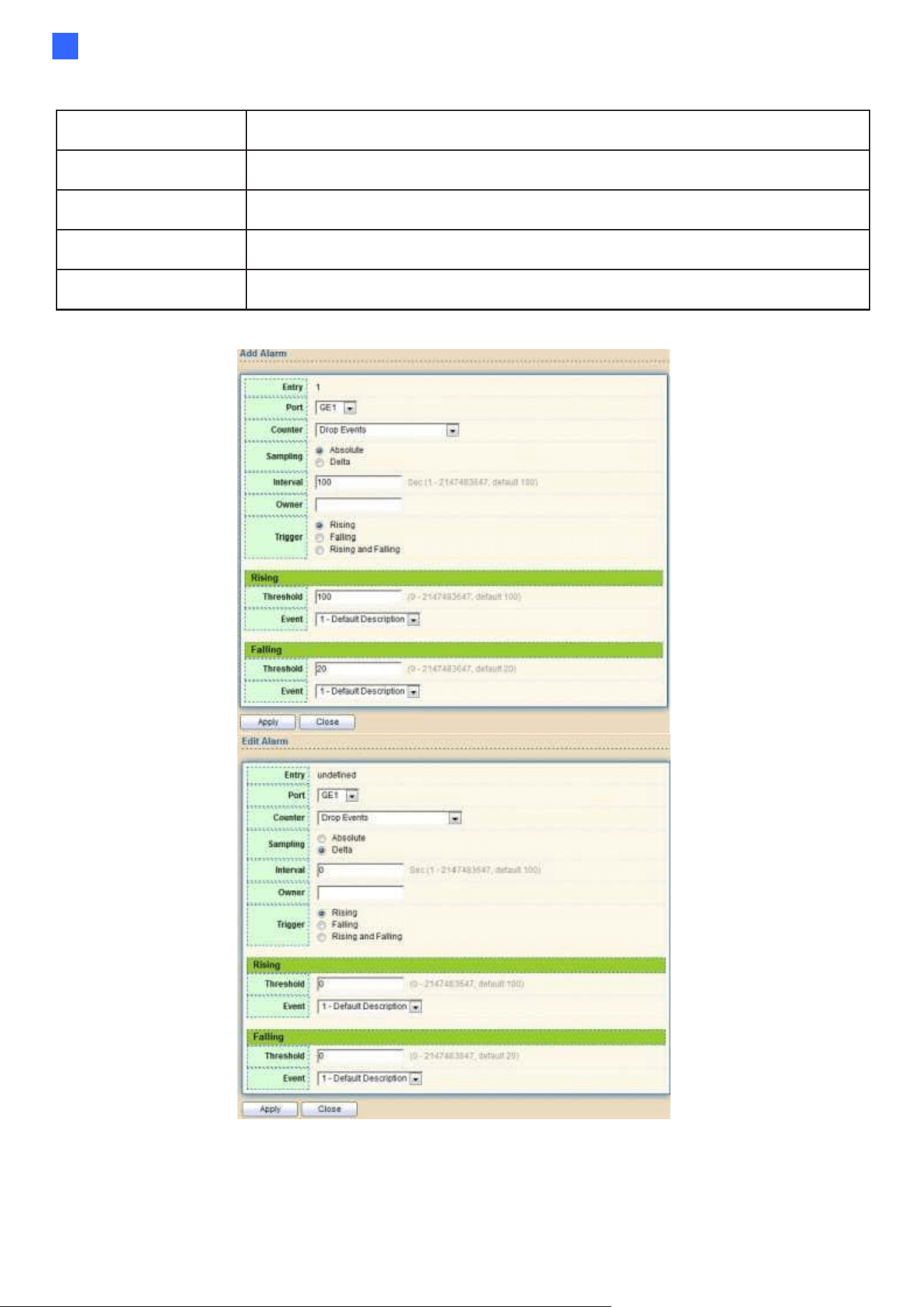
Web-based Switch Configuration
199
2
Trigger
The type of event triggering.
Rising Threshold
The threshold for firing rising event.
Rising Event
The rising event when alarm was fired.
Falling Threshold
The threshold for firing falling event.
Falling Event
The falling event when alarm was fired.
Click "Add/Edit" button to view the Add/Edit menu.
Figure 235 - Management > RMON > Add/Edit Alarm

200
2.15.6. Open Source Software Licenses
To access the copyright notices, select Management > Open Source Software Licenses. Click
Open Source Software Licenses.
Figure 236 - Management > Open Source Software Licenses