Visit our website at: http://www.harborfreight.com
Email our technical support at: [email protected]
Find the most recent manual
and software updates at
harborfreight.com
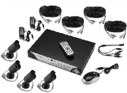
Owner’s Manual & Safety Instructions
Save This Manual Keep this manual for the safety warnings and precautions, assembly,
operating, inspection, maintenance and cleaning procedures. Write the product’s serial number in the
back of the manual near the assembly diagram (or month and year of purchase if product has no number).
Keep this manual and the receipt in a safe and dry place for future reference.
When unpacking, make sure that the product is intact
and undamaged. If any parts are missing or broken,
please call 1-888-866-5797 as soon as possible.
Copyright
©
2014 by Harbor Freight Tools
®
. All rights reserved.
No portion of this manual or any artwork contained herein may be reproduced in
any shape or form without the express written consent of Harbor Freight Tools.
Diagrams within this manual may not be drawn proportionally. Due to continuing
improvements, actual product may differ slightly from the product described herein.
Tools required for assembly and service may not be included.
Read this material before using this product.
Failure to do so can result in serious injury.
SAVE THIS MANUAL.
REV 15h
Downloaded from www.ManualsFile.com manuals search engine
Page 2 For technical questions, please call 1-888-866-5797. Item 62463
SAFETy
ADVANCED
OPERATION
SETUP
BASIC
MAINTENANCE
TROUBLESHOOTING
Table of Contents
Safety .............................................................................2
Specifications ...............................................................5
Components and Controls .......................................... 6
Setup ..............................................................................8
Default Settings .......................................................... 12
Basic Menu..................................................................13
Basic Settings .............................................................14
Date, Time, Language, and Menu Settings ................ 14
Password Settings ......................................................15
Monitor Settings..........................................................15
Recording Settings .....................................................16
Operation ..................................................................... 18
Playback and Backup Recordings .............................. 18
View DVR's Activity..................................................... 19
Maintain Hard Drive .................................................... 20
Format Hard Drive and USB Flash Drive ................... 20
Advanced Menu .......................................................... 21
Monitor Settings..........................................................21
Clock Settings.............................................................22
User Management Settings ........................................ 22
Privacy Zone............................................................... 23
Motion Detection Settings........................................... 23
PTZ Camera ............................................................... 24
System Information..................................................... 24
Maintenance Instructions ..........................................25
Troubleshooting .........................................................26
Advanced Network Configuration, Software and
Notification Settings ..................................................27
Computer and Smartphone Access ............................ 28
Software ..................................................................... 32
Notifications ................................................................ 34
Warranty ......................................................................36
WARNING SyMBOLS AND DEFINITIONS
This is the safety alert symbol. It is used to alert you to potential
personal injury hazards. Obey all safety messages that
follow this symbol to avoid possible injury or death.
Indicates a hazardous situation which, if not avoided,
will result in death or serious injury.
Indicates a hazardous situation which, if not avoided,
could result in death or serious injury.
Indicates a hazardous situation which, if not avoided,
could result in minor or moderate injury.
Addresses practices not related to personal injury.
IMPORTANT SAFETy INFORMATION
Read all safety warnings and instructions.
Failure to follow the warnings and instructions may result in electric shock, fire and/or serious injury.
Save all warnings and instructions for future reference.
Downloaded from www.ManualsFile.com manuals search engine

Page 3For technical questions, please call 1-888-866-5797.Item 62463
SAFETy
ADVANCED
MAINTENANCE
TROUBLESHOOTING
OPERATION SETUPBASIC
Installation Precautions
1. Check federal, state and local surveillance laws
before installing video
and/or audio surveillance equipment.
2. Install only according to these instructions.
Improper installation can create hazards.
3. Do not overreach when installing this product.
Keep proper footing and balance at all times.
This enables better control in unexpected situations.
4. Wear ANSI-approved safety goggles
during installation.
5. Keep installation area clean and well lit.
6. Keep children and bystanders out of
the area during installation.
7. Do not install when tired or when under the
influence of alcohol, drugs or medication.
Use Precautions
1. This product is not a toy. Do not allow
children to play with or near this item.
2. Use as intended only.
3. Do not modify.
4. Maintain product labels and nameplates.
These carry important safety information.
If unreadable or missing, contact
Harbor Freight Tools for a replacement.
Service
Have your DVR equipment serviced by a qualified repair person using only identical replacement parts.
This will ensure that the safety of the equipment is maintained.
Camera Safety Warnings
1. To prevent electric shock, do not attempt
to disassemble Camera. There are
no serviceable parts inside.
2. Do not expose the Power Adapter to rain
or wet conditions. Water entering the Power
Adapter will increase the risk of electric shock.
3. Do not abuse the Power Adapter cord. Never
use the cord for unplugging the plug from the
outlet. Keep cord away from heat, oil, sharp
edges or moving parts. Damaged or entangled
cords increase the risk of electric shock.
4. Handle Camera with care. Camera could be
damaged by improper handling or storage.
DVR Safety Warnings
1. Maintain adequate airflow around DVR.
2. Use supplied Power Adapter only.
3. To prevent electric shock, do not
attempt to disassemble DVR. There
are no serviceable parts inside.
4. Do not expose the Power Adapter or DVR
console to rain or wet conditions. Water
entering the Power Adapter or DVR console
will increase the risk of electric shock.
5. Do not abuse the Power Adapter cord. Never
use the cord for unplugging the plug from the
outlet. Keep cord away from heat, oil, sharp
edges or moving parts. Damaged or entangled
cords increase the risk of electric shock.
6. Maintain labels and nameplates on the unit.
These carry important safety information.
If unreadable or missing, contact
Harbor Freight Tools for a replacement.
7. WARNING: The cord of this product contains
lead and/or di (2-ethylhexyl) phthalate (DEHP),
chemicals known to the State of California
to cause cancer, and birth defects or other
reproductive harm. Wash hands after handling.
(California Health & Safety Code § 25249.5, et seq.)
8. The warnings, precautions, and instructions
discussed in this instruction manual cannot
cover all possible conditions and situations
that may occur. It must be understood by the
operator that common sense and caution are
factors which cannot be built into this product,
but must be supplied by the operator.
SAVE THESE INSTRUCTIONS.
Downloaded from www.ManualsFile.com manuals search engine
Page 4 For technical questions, please call 1-888-866-5797. Item 62463
SAFETy
ADVANCED
OPERATION
SETUP
BASIC
MAINTENANCE
TROUBLESHOOTING
Grounding
TO PREVENT ELECTRIC SHOCK AND DEATH FROM
INCORRECT GROUNDING WIRE CONNECTION:
Check with a qualified electrician if you are in doubt as to whether the outlet
is properly grounded. Do not modify the power cord plug provided with the tool. Never
remove the grounding prong from the plug. Do not use the tool if the power cord or plug
is damaged. If damaged, have it repaired by a service facility before use. If the plug
will not fit the outlet, have a proper outlet installed by a qualified electrician.
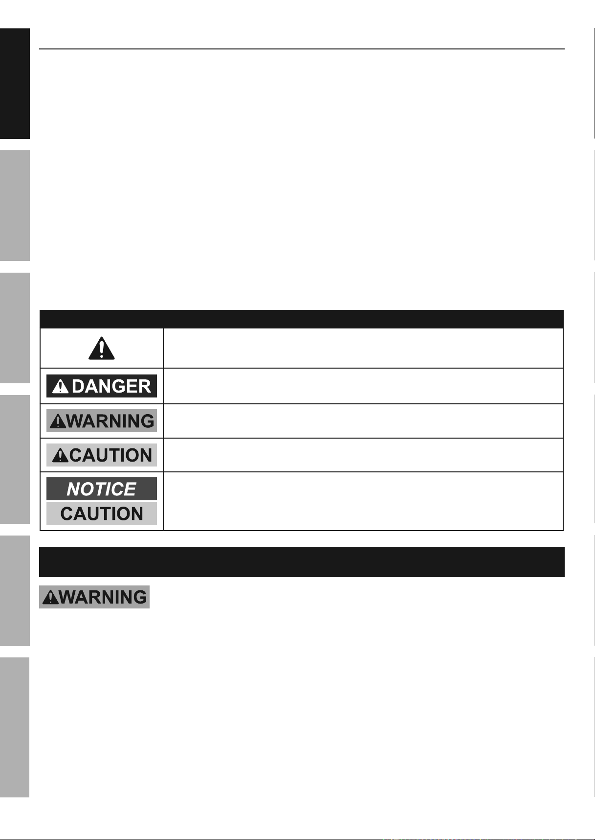
Figure A: Outlets for 2-Prong Plug
1. The included Power Adapters do
not require grounding.
2. The Power Adapters may be used in
either of the 120 volt outlets shown in the
preceding illustration. (See Figure A.)
Extension Cords
Note: Do not use an extension cord with the Power Adapters.
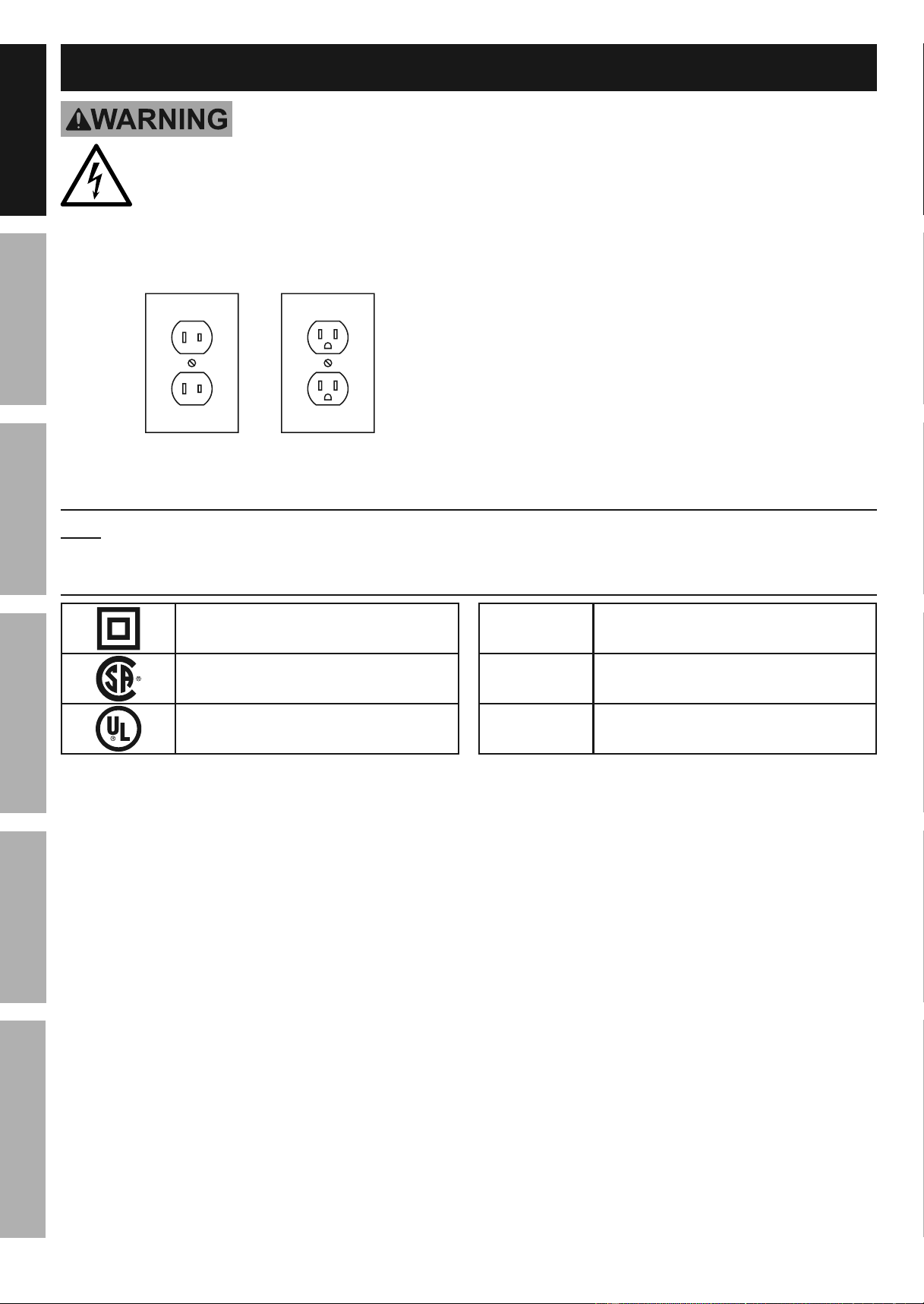
Symbology
Double Insulated
Canadian Standards Association
Underwriters Laboratories, Inc.
V
Volts
~
Alternating Current
A
Amperes
Downloaded from www.ManualsFile.com manuals search engine
Page 5For technical questions, please call 1-888-866-5797.Item 62463
SAFETy
ADVANCED
MAINTENANCE
TROUBLESHOOTING
OPERATION SETUPBASIC
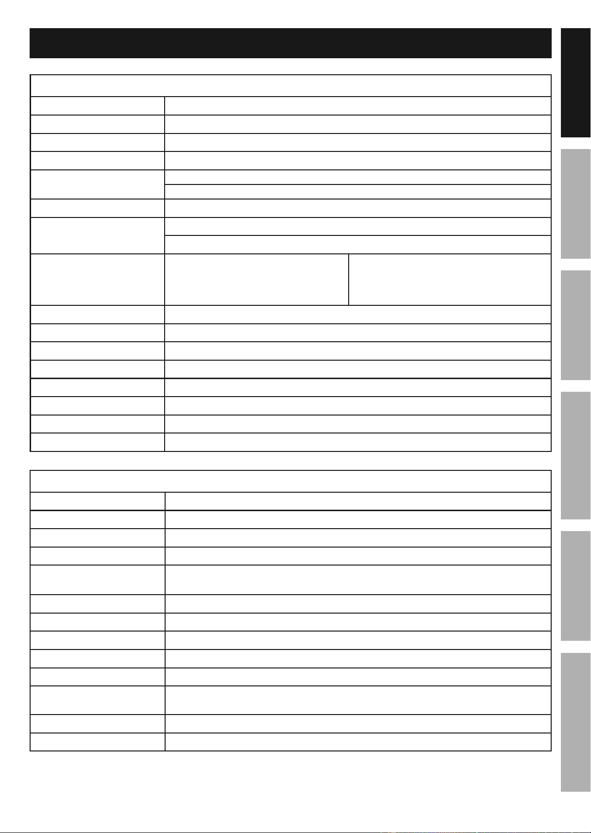
Specifications
DVR
Hard Drive 500 GB
Video Standard NTSC (United States, default) / PAL (Europe)
Video Codec H.264
Operating System Linux
Video I/O
Input: 8 BNC
Output: 1 HDMI / 1 BNC / 1 VGA
Audio Codec G.711
Audio I/O
Input: 2 RCA
Output: 1 RCA
Recording Resolution
16:9 Screen
WD1: 960 x 480
WHD1: 960 x 240
WCIF: 480 x 240
4:3 Screen
D1: 720 x 480
HD1:720 x 240
CIF: 360 x 240
Recording Mode Manual / Schedule / Motion Detection
Motion Detection Selectable Area and Sensitivity Detection
PTZ Interface RS485 - Supports Pelco-D/P camera (sold separately)
Network Interface RJ-45 10m/100m Ethernet Interface
USB Interface USB 2.0
DVR Input Rating 12VDC / 2A
Power Adapter Rating 12VDC / 2A
Operating Temperature 32º - 131ºF
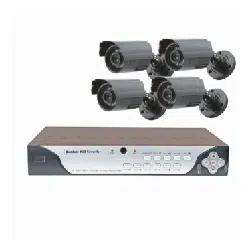
Cameras
Lens Type Fixed 6 mm
Horizontal Resolution 550 TVL
Effective Pixels 648H x 488V
Night Vision Type Infrared LEDs with Low Light Sensor
Image Type
Daylight: Color
Infrared: Black & White
Infrared Wavelength 940nm
Infrared Distance 30 ft. (indoors)
Ingress Protection Rating IP65 - Protected from low pressure water jets
Video Connector BNC
Camera Input Rating 12VDC / 250 mA
Power Adapter Rating
12VDC / 1A - To power included 4 cameras. Additional cameras or longer
cables will require a higher amperage Power Adapter (all sold separately)
Cable Length 60 ft.
Operating Temperature 14° - 122°F
Downloaded from www.ManualsFile.com manuals search engine
Page 6 For technical questions, please call 1-888-866-5797. Item 62463
SAFETy
ADVANCED
OPERATION
SETUP
BASIC
MAINTENANCE
TROUBLESHOOTING
Components and Controls
Read the ENTIRE IMPORTANT SAFETy INFORMATION section at the beginning of this
manual including all text under subheadings therein before set up or use of this product.
IMPORTANT: If Mouse, Remote, and DVR buttons won't work,
press and hold REW button on front of DVR until unit beeps.
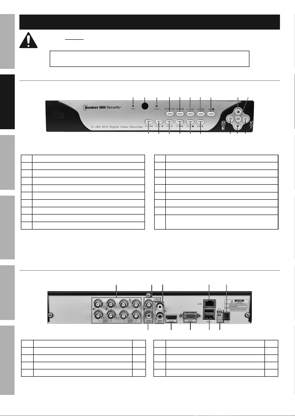
DVR Front Panel
9
10
1
181711
12
13 14 15
16 19
2
3
4 5
6 7
8
1 Green Power Indicator - glows when power is on
2 Remote Control IR Receiver
3 Red Hard Drive Light - flashes when recording
4 Search Recordings
5 Mute
6 Previous Channel
7 Next Channel
8 Toggle between single, 4 and 8 Screen Displays
9 Menu Up / PTZ Up*
10 PTZ Control Mode*
11 Rewind / Lock and Unlock Controls
12 Pause
13 Play
14 Fast Forward
15 Stop
16 Start Manual Recording
17 Open Menu / Escape / PTZ Left*
18 Menu Down / PTZ Down*
19
Conrm Selection / Edit Selected Setting / PTZ
Right*
*Controls for PTZ mode are italicized. PTZ is optional Pan/Tilt/Zoom camera (sold separately).
Figure B
DVR Back Panel
2
6
8
1 3
4 5
9
107
1 BNC Video Input 8
2 BNC Video Output 1
3 RCA Audio Input 2
4 RJ45 LAN Ethernet Port 1
5 12VDC Power Input 1
6 RCA Audio Output 1
7 HDMI Video Output 1
8 VGA Video Output 1
9 USB 2.0 Port 2
10 RS485 PTZ Connector 1
Figure C
Downloaded from www.ManualsFile.com manuals search engine
Page 7For technical questions, please call 1-888-866-5797.Item 62463
SAFETy
ADVANCED
MAINTENANCE
TROUBLESHOOTING
OPERATION SETUPBASIC
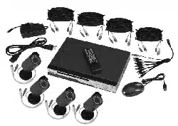
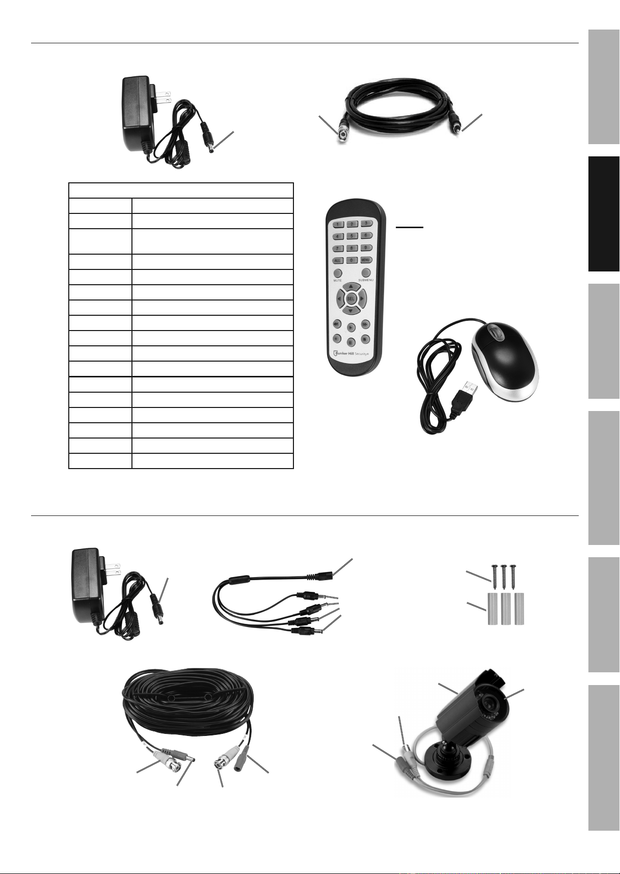
DVR Accessories
12VDC/2A Power Adapter
Power
(to DVR)
BNC to RCA Cable
BNC
(to DVR)
RCA (to
Monitor)
Use the Mouse to
navigate the DVR
Mouse
Note: 2 AAA
batteries included
Remote
Remote Control Functions
1 - 8 Select Channel
0 Lock and Unlock Controls
ALL
Toggle between single, 4
and 8 Screen Displays
MENU Open Menu
MUTE Mute
SUBMENU Open Pop-Up Menu
▲ Menu Up
▼ Menu Down
◄ Menu Left
► Menu Right
SEL Confirm Selected Operation
◄◄ Rewind
► Play / Search Records
►► Fast Forward
● Record
ll Pause
■
Stop
Figure D
Camera and Accessories
Video
(from Camera)
Video
(to DVR)
Power
(to Camera)
Power
(from Splitter)
Cable - 60 ft.
Screws
Anchors
Mounting Hardware
Power
(from Cable)
Video
(to Cable)
Camera
Hood
Lens
12VDC/1A Power Adapter
Power
(to Splitter)
Power Splitter
Power
(from Adapter)
Power
(to Cables)
Figure E
Downloaded from www.ManualsFile.com manuals search engine
Page 8 For technical questions, please call 1-888-866-5797. Item 62463
SAFETy
ADVANCED
OPERATION
SETUP
BASIC
MAINTENANCE
TROUBLESHOOTING
Setup
Read the ENTIRE IMPORTANT SAFETy INFORMATION section at the beginning of this manual
including all text under subheadings therein before set up or use of this product.
NOTICE: CHECK FEDERAL, STATE AND LOCAL SURVEILLANCE LAWS BEFORE
INSTALLING VIDEO AND/OR AUDIO SURVEILLANCE EQUIPMENT.
IMPORTANT: If Mouse, Remote, and DVR buttons won't work,
press and hold REW button on front of DVR until unit beeps.
Downloaded from www.ManualsFile.com manuals search engine
Page 9For technical questions, please call 1-888-866-5797.Item 62463
SAFETy
ADVANCED
MAINTENANCE
TROUBLESHOOTING
OPERATION SETUPBASIC
CONNECT AND TEST ALL EQUIPMENT AND CAMERA LOCATIONS
BEFORE MOUNTING CAMERAS.
Designate Location for DVR and Monitor
When planning location for DVR and Monitor:
1. Choose a clean, dry, well ventilated, dust-free
location indoors with a 120V outlet nearby.
2. If setting up Network access, make sure
the DVR is located close to a router.
3. Take into consideration the length
of the Camera Cables.
CAUTION! Route the Cables so as
to avoid a tripping hazard.
4. Make sure location will remain within
Operating Temperature.
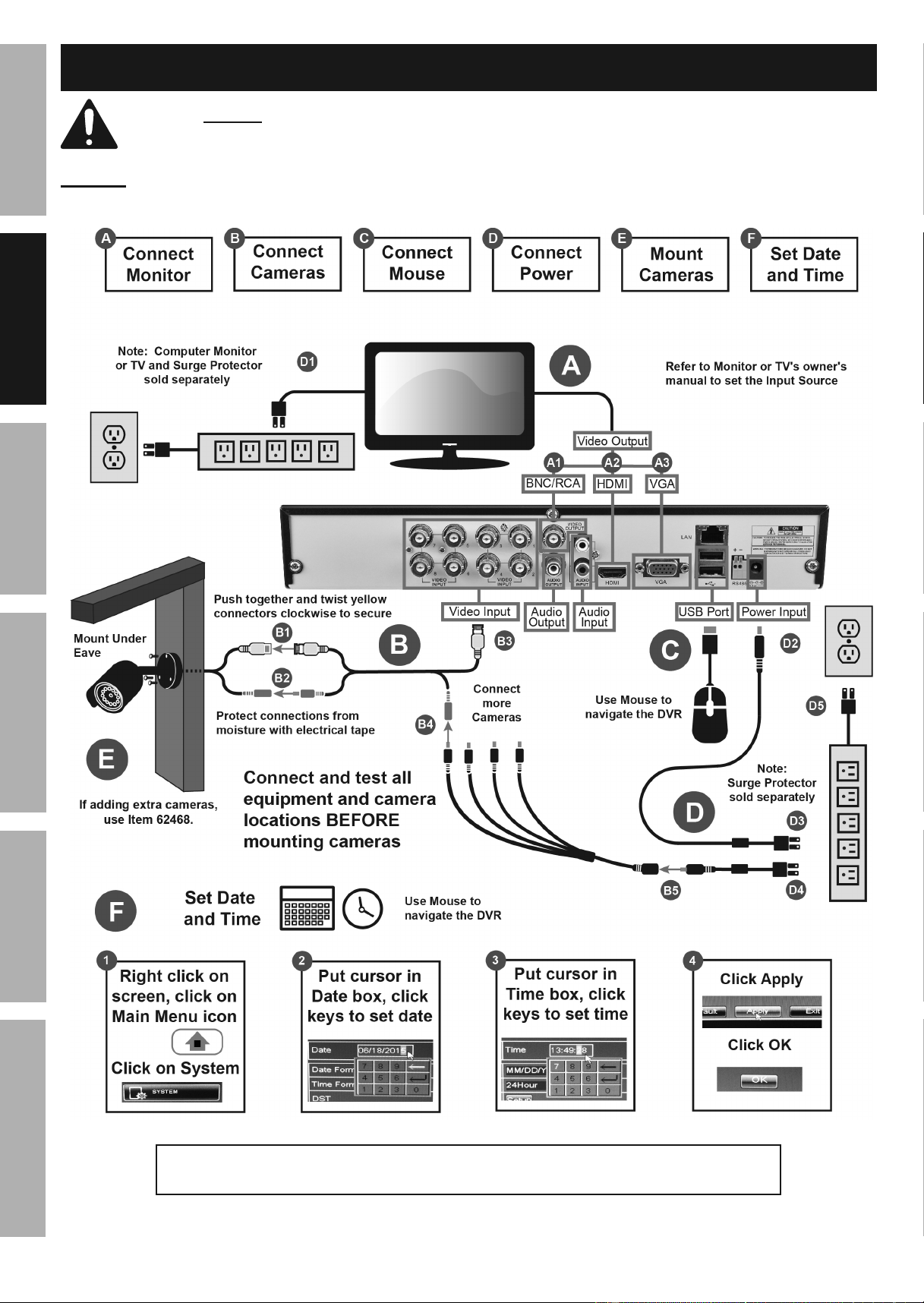
A. Connect Monitor
Connect monitor or TV (sold separately) to DVR using:
BNC to RCA cable (included), HDMI cable (sold separately) or VGA cable (sold separately).
B. Connect Cameras and Audio
NOTICE: Do not join cables together end-to-end. Video loss may occur. If extra length is needed,
longer cables (sold separately) and a higher amperage power adapter (sold separately) should be used.
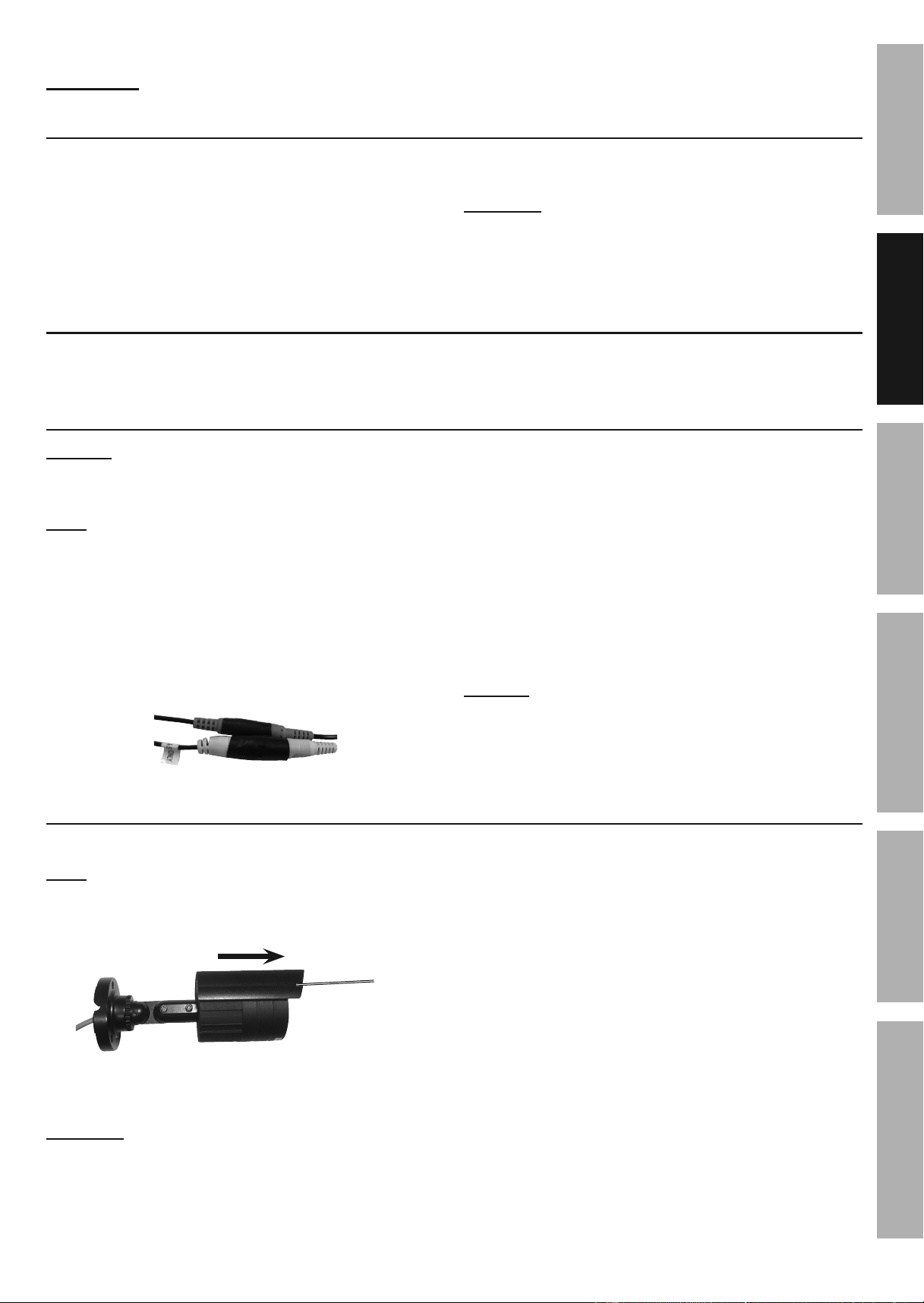
1. Connect Video (Yellow) from Cameras to Cables.
Note: Route Cables so that the end marked
TO CAMERA is at the Camera end.
2. Connect Power (Red) from Cameras to Cables.
3. Connect Video (Yellow) from Cables to DVR.
4. Connect Power from Cables to Splitter.
5. Connect Splitter to Camera Power Adapter.
6. Protect connections from moisture
with electrical tape.
7. Audio: Connect audio surveillance microphone
(sold separately) to Audio Input and
speaker (sold separately) to Audio Output.
• Go to Record > MainStream - Set
Resolution, FPS, Bitrate and Audio
on page 17 to enable audio.
• Go to Network > SubStream - Set Resolution,
FPS, Bitrate and Audio on page 31 to
enable audio during remote access.
NOTICE: CHECK FEDERAL, STATE AND
LOCAL AUDIO SURVEILLANCE LAWS
BEFORE INSTALLING MICROPHONE.
Plan Mounting Locations for Cameras
DO NOT MOUNT CAMERAS yET!
Note: If adding extra cameras, use Item 62468.
1. Camera comes with Hood in storage
position. Pull Hood out to protect lens.
Hood
2. When planning mounting locations and angles:
a. Take into consideration the length of the Cables.
CAUTION! Route the Cables so as
to avoid a tripping hazard.
b. Choose locations under eaves to shelter
Cameras from rain and direct sunlight.
c. Choose locations high enough so that
Cameras are visible, but out of reach.
d. Verify that installation surfaces have no hidden
utility lines before drilling or driving screws.
e. Make sure no strong light will shine
directly into Camera Lenses.
f. To avoid mounting the Cameras upside down,
make sure the Hood is above the Lens.
g. Do not point Camera through a window, glaring
may occur, resulting in poor quality images.
Downloaded from www.ManualsFile.com manuals search engine
Page 10 For technical questions, please call 1-888-866-5797. Item 62463
SAFETy
ADVANCED
OPERATION
SETUP
BASIC
MAINTENANCE
TROUBLESHOOTING
C. Connect Mouse
Plug Mouse into either USB port on back of DVR. The Mouse will be used to navigate the DVR.
D. Connect Power
Note: Connect power using a surge
protector (sold separately).
1. Plug Monitor into surge protector.
2. Plug DVR Power Adapter into Power Input on DVR.
3. Plug DVR Power Adapter plug into surge protector.
4. Plug Camera Power Adapter into surge protector.
5. Plug surge protector into 120V outlet.
CAUTION! The Power Adapters MUST be
plugged in indoors in a clean, dry location.
6. System will boot up and green
PWR (power) light will glow.
7. After boot up, system will initialize.
Note: It may take up to a minute for
initialization to complete.
8. After initialization is complete, system
will beep, then display Live View.
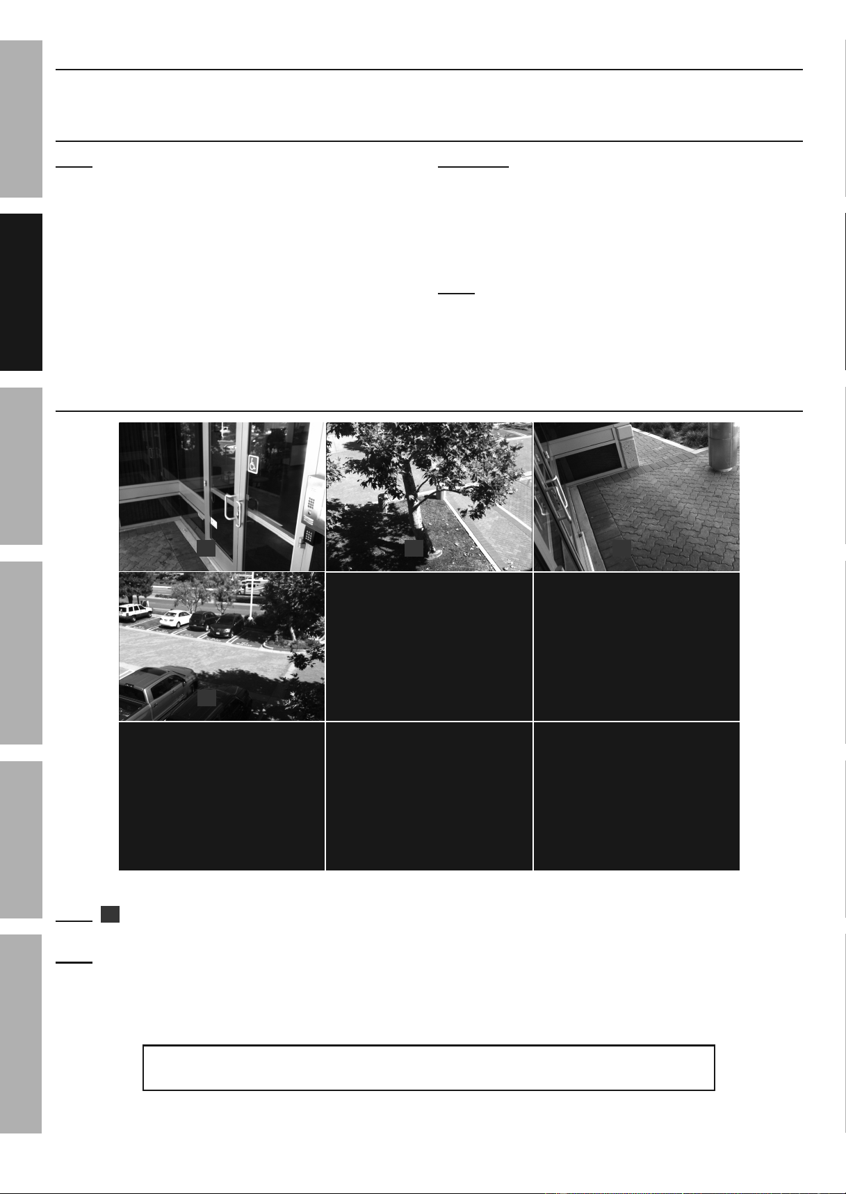
Live View
VIDEO LOSS VIDEO LOSS
VIDEO LOSS
VIDEO LOSS
CH7
CH5
CH8
CH6
R
R
R
R
06/17/2015 09:23:14
CH3CH2
CH1
CH4
Figure F: Live View
Note:
R
will display on Live View and red HDD light on DVR's front panel will flash to indicate DVR is
recording. (Go to Default Settings on page 12 for a list of what the DVR will automatically do.)
Note: The DVR may beep if disconnecting and reconnecting cameras because video loss will trigger
a notification. Go to Advanced > Events - Notifications on page 14 to change settings.
Double click on image to view in full screen. Double click again to return to previous view.
IMPORTANT: If Mouse, Remote, and DVR buttons won't work,
press and hold REW button on front of DVR until unit beeps.
Downloaded from www.ManualsFile.com manuals search engine
Page 11For technical questions, please call 1-888-866-5797.Item 62463
SAFETy
ADVANCED
MAINTENANCE
TROUBLESHOOTING
OPERATION SETUPBASIC
E. Mount Cameras
CONNECT AND TEST ALL EQUIPMENT AND CAMERA LOCATIONS
BEFORE MOUNTING CAMERAS.
Place Cameras under eaves and cable connections
inside walls to shelter them from rain and direct
sunlight.
Using the Base as a template, mark locations
of mounting holes on mounting surface.
Note: Route Cable through slot on Base to keep Base
flush with mounting surface while marking holes.
Solid Surface
1. Using a drill bit slightly smaller than the Screws,
drill pilot holes into the marked locations.
2. Position Camera so that mounting
holes align with pilot holes.
Note: Route Cable through slot on Base to
keep Base flush with mounting surface.
3. Drive Screws through mounting holes in
Base and into pilot holes until the Camera is
securely attached to the mounting surface.
Hollow Surface
1. Using a drill bit slightly smaller than the
Anchors, drill holes in the marked locations.
2. Tap Anchors into the holes until they are
almost flush with mounting surface.
3. Position Camera so that mounting
holes align with anchors.
Note: Route Cable through slot on Base to
keep Base flush with mounting surface.
4. Drive Screws through mounting holes in
Base and into anchors until the Camera is
securely attached to the mounting surface.
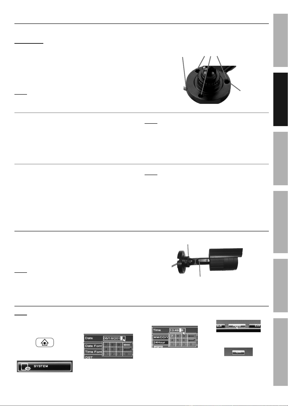
Camera Adjustment
1. Loosen Adjustment Wheel, rotate Camera as
needed, then tighten Adjustment Wheel.
2. Loosen Adjustment Screw, tilt Camera as
needed, then tighten Adjustment Screw.
Note: Only loosen Adjustment Screw
slightly, do not remove it.
Adjustment
Wheel
Adjustment
Screw
F. Set Date and Time
Note: Use Mouse to navigate the DVR.
1. Right click on
screen, click on
Main Menu icon.
2. Click on System.
3. Put cursor in Date box,
click keys to set date.
4. Put cursor in Time box,
click keys to set time.
5. Click Apply.
6. Click OK.
Mounting
Holes
Cable
Slot
Base
Downloaded from www.ManualsFile.com manuals search engine
Page 12 For technical questions, please call 1-888-866-5797. Item 62463
SAFETy
ADVANCED
OPERATION
SETUP
BASIC
MAINTENANCE
TROUBLESHOOTING
Default Settings
After Date and Time are set, the DVR will automatically perform the following functions.
Default Settings (after setting Date and Time) To Change Default Settings
Menus • Will time out after 1 minute • Go to page 14
Notification • Will beep when camera is unplugged • Go to page 14
Password • Off • Go to page 15
Recording
• Date and recording time will be visible on recordings
• All Channels with a camera hooked up will record 24/7
• Red HDD light on front panel flashes
• Go to page 15
• Go to page 16
• Cannot change
Motion Detection • Off • Go to page 16
Video
• 16:9 Wide Screen aspect ratio
• WD1 Resolution (960 x 480)
• 11 Frames per Second (FPS)
• 768 Bitrate
• Go to page 17
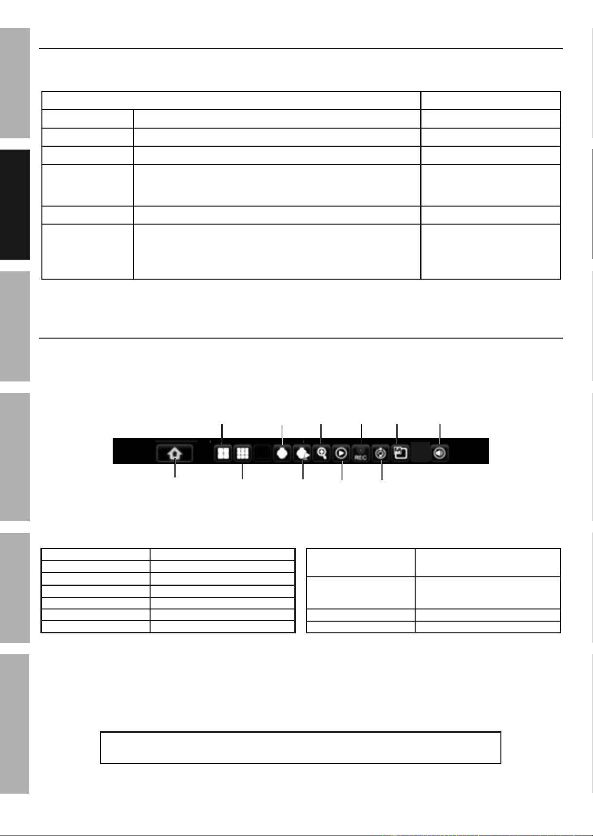
Pop-Up Menu
To access Pop-Up Menu, right-click anywhere on screen or hover over bottom of screen.
*Controls for PTZ mode are italicized. PTZ is optional Pan/Tilt/Zoom camera (sold separately).
Main
Menu
4-way
Split
Screen
Start
PTZ
Cruise
PTZ
9-way
Split
Screen
Record
Search
Zoom
Record/
Stop
Record
Start
SEQ
PIP
x1
Mute
Figure G
Main Menu Main Menu
4-way Split Screen Display Up To 4 Live Images
8-way Split Screen Display Up To 8 Live Images
PTZ Go To PTZ Controls*
Start Cruise Start PTZ Program*
Zoom Click and drag to zoom
Record Search Go To Record Search
Record/Stop Record
Start Recording/
Stop Recording
Start SEQ/Stop SEQ
(Sequence)
Rotate Through Live
Images/Stop Rotation
PIPx1 Picture in Picture
Mute (if audio hooked up)
IMPORTANT: If Mouse, Remote, and DVR buttons won't work,
press and hold REW button on front of DVR until unit beeps.
Downloaded from www.ManualsFile.com manuals search engine
Page 13For technical questions, please call 1-888-866-5797.Item 62463
SAFETy
ADVANCED
MAINTENANCE
TROUBLESHOOTING
OPERATION SETUPBASIC
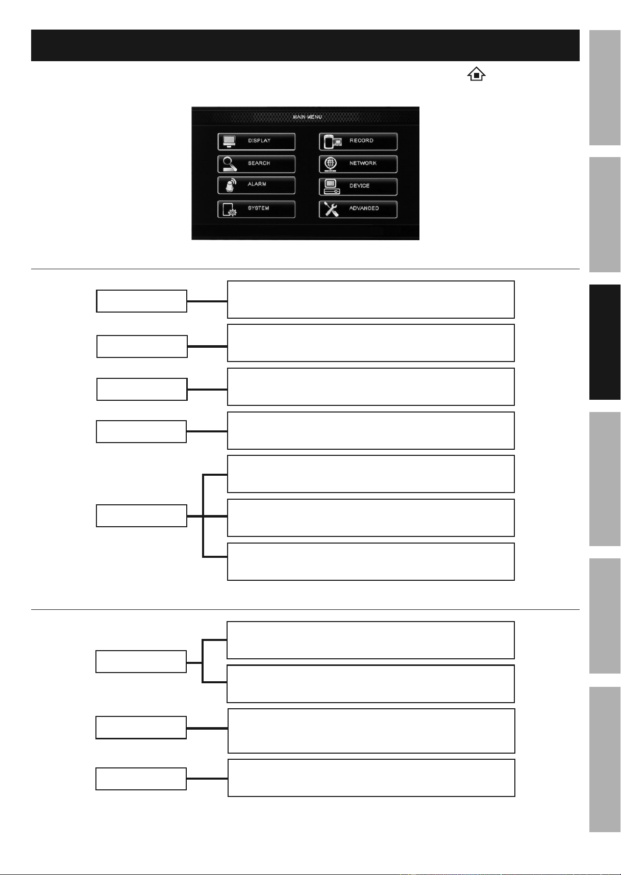
Basic Menu
To access Main Menu, bring up Pop-Up menu and click Main Menu icon
Exit from any menu by right clicking on screen
Basic Settings
ADVANCED
Events
Set up Notifications p. 14
DISPLAy
Live
Monitor Settings p.15
RECORD
Main Stream
Set Resolution, FPS, Bitrate and Audio p. 17
Schedule
Recording Settings p. 16
REC Para
Recording Parameters p. 17
General
Date, Time, Language, and Menu Settings p. 14
Users
Password Settings p. 15
SySTEM
SySTEM
Operation
ADVANCED
DEVICE
SEARCH
Log
View DVR's Activity p. 19
Event Search
Playback and Backup Recordings p. 18
Maintain
Maintain Hard Drive, Update Software & Firmware,
Restore Default Settings, Reboot And Shut Down p. 20
HDD
Format Hard Drive and USB Flash Drive p. 20
For Advanced Menu, go to page 21.
Downloaded from www.ManualsFile.com manuals search engine
Page 14 For technical questions, please call 1-888-866-5797. Item 62463
SAFETy
ADVANCED
OPERATION
SETUP
BASIC
MAINTENANCE
TROUBLESHOOTING
Basic Settings
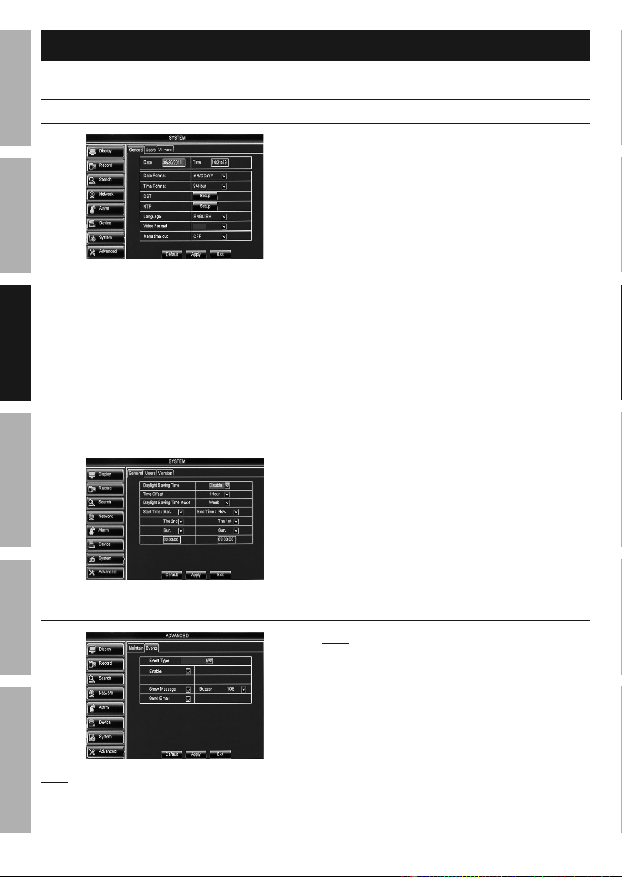
Date, Time, Language, and Menu Settings
System > General
NTSC
Figure H
1. Date and Time:
a. Date: Enter current date.
b. Time: Enter current time.
c. Date Format: 24Hour is selected by
default. Change to 12Hour if desired.
d. Time Format: MM/DD/yy is selected by
default. Change to other format if desired.
e. Click Apply then OK to save
date and time settings.
2. DST (Daylight Saving Time) Setup:
a. Click Setup.
Figure I
b. Daylight Saving Time: Disable is selected
by default. Change to Enable to manually
enter when time change will happen.
c. Time Offset: 1Hour is selected by
default. Change to 2Hour if necessary.
d. Daylight Saving Time Mode:
Week: Set month, week, day of week
and time for change to occur.
Date: Set date and time for change to occur.
3. NTP (Network Time Protocol) Setup:
The DVR must be connected to your Network for
this feature to work.
(Go to Time Settings on page 22)
4. Language: English is selected by
default. Change if desired.
• System needs to restart before Language
changes will apply. Click Apply and OK,
then Exit. Right click on screen and
DVR will prompt restart. Click OK.
5. Video Format: Default is NTSC,
which is the standard in the United
States. LEAVE IT SET TO NTSC.
6. Menu Time Out: Select how long menus will
display or set to OFF so menus will always display.
Changes will be saved when you
click Apply then OK.
Changes will not be saved if you click
Exit or right click on screen.
Click Default to restore default settings.
Advanced > Events - Notifications
Disk Full
Note: By default, all events will trigger
on screen messages, email being sent
(if email is set up) and beeping sound.
Note: To set up email, the DVR must be connected
to your Network. (Go to Network > Email - Set
up Email Notifications on page 34)
1. Event Type: Choose Disc Full,
Disc Error, or Video Loss.
2. Change settings if desired.
Changes will be saved when you
click Apply then OK.
Changes will not be saved if you click
Exit or right click on screen.
Click Default to restore default settings.
Downloaded from www.ManualsFile.com manuals search engine
Page 15For technical questions, please call 1-888-866-5797.Item 62463
SAFETy
ADVANCED
MAINTENANCE
TROUBLESHOOTING
OPERATION SETUPBASIC
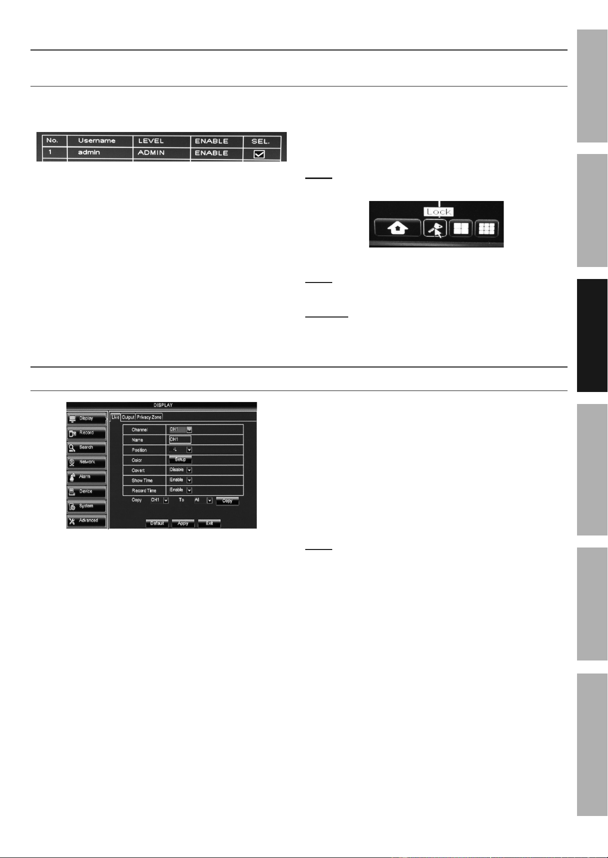
Password Settings
System > Users - Set Password for main user.
(To add other users, go to User Management Settings on page 22)
1. admin is selected by default. Click
Edit at bottom of screen.
Figure J
2. User Name: Leave as admin or enter
another name (up to 8 characters).
3. Password Enable: Select Enable.
a. Password: Enter Password
(must be 6 characters).
b. Confirm: Enter Password again.
Changes will be saved when you
click Apply then OK.
Changes will not be saved if you click
Exit or right click on screen.
Note: When Password is Enabled, a key
icon will appear on Pop-Up Menu.
Figure K
Note: To add other users, go to User
Management Settings on page 22.
NOTICE: If you are locked out of the DVR because
of a password problem, call 1-888-866-5797.
Monitor Settings
Display > Live - Set camera names, viewing positions, color and information to display on monitor
U
Figure L
1. Channel: Select which Channel to set up.
2. Name: Enter Channel name (up to 8 characters).
For example, "Garage" or "Backyard".
3. Position: Select where Channel Name
will appear on the monitor.
a. U-L: Upper Left
b. D-L: Lower Left.
c. U-R: Upper Right.
d. D-R: Lower Right.
e. Disable: No name will appear.
4. Color: Click Setup to adjust Hue,
Brightness, Contrast, and Saturation.
Changes will be saved when you
click Apply > OK > Exit.
Changes will not be saved if you click
Exit or right click on screen.
5. Covert: Disable is selected by default.
Select Enable to hide live image on monitor.
Note: Camera will still record even if the
image can't be seen on monitor.
6. Show Time: Enable is selected by default
to show date and time on monitor.
7. Record Time: Enable is selected by default
to show date and time on recordings.
8. Copy: Copy settings from one
Channel to other Channels.
a. Select Channel to copy from.
b. Select Channel to copy to or select ALL.
c. Click Copy, then click OK.
Changes will be saved when you
click Apply then OK.
Changes will not be saved if you click
Exit or right click on screen.
Click Default to restore default settings.
Downloaded from www.ManualsFile.com manuals search engine
Page 16 For technical questions, please call 1-888-866-5797. Item 62463
SAFETy
ADVANCED
OPERATION
SETUP
BASIC
MAINTENANCE
TROUBLESHOOTING
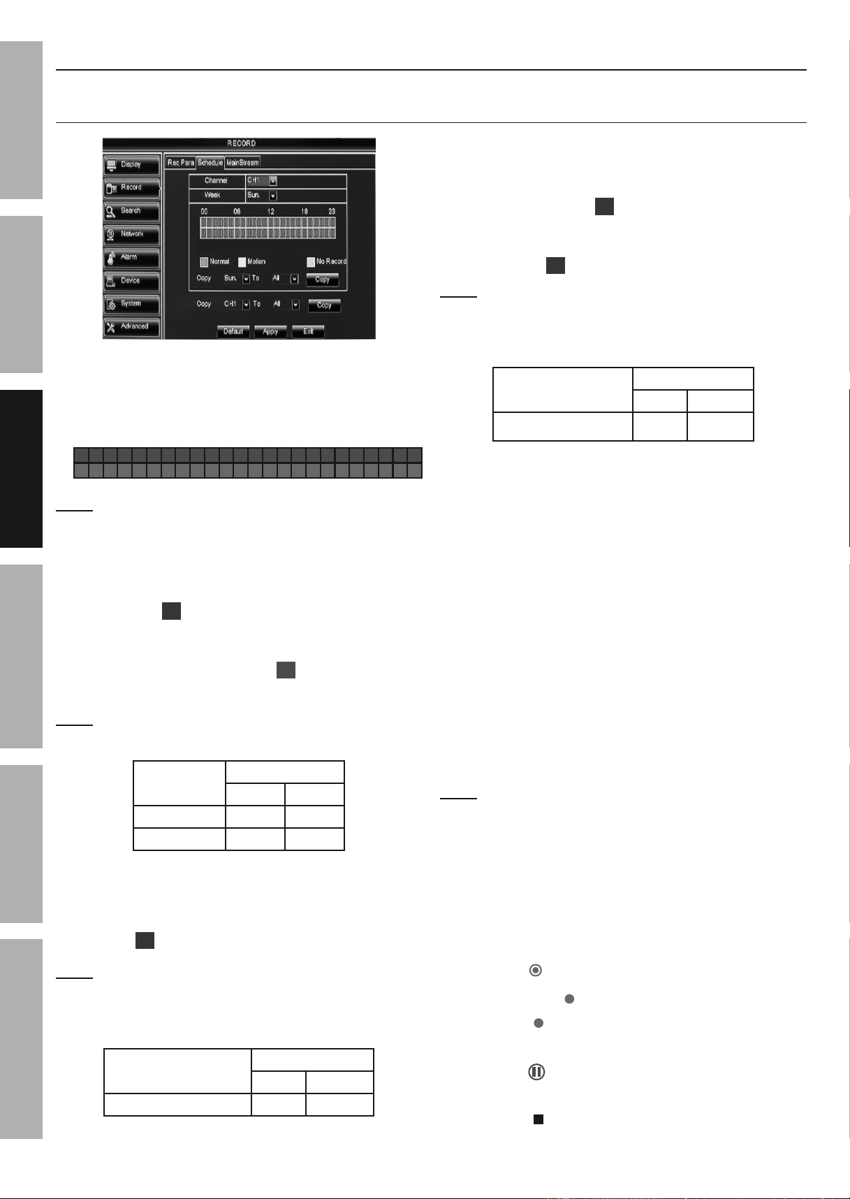
Recording Settings
Record > Schedule - Normal, Motion Detection and Manual Settings
(To set advanced Motion Detection settings, go to Motion Detection Settings on page 23)
N
M
Figure M
1. Schedule Table:
N
00
06
18
23
12
M
12 AM
Midnight
6 AM
12 PM
Noon
6 PM
11 PM
Note: Click or click and drag to
select or deselect boxes.
2. N - Normal:
• When green boxes are selected, DVR
will record during selected time frames
and red
R
will display on Live View.
• When gray boxes are selected, DVR will not
record and red HDD light will stop flashing. If
motion is detected, green
M
will display on
Live View, but no recording will be made.
Note: If HDD light continues to flash after selecting
gray boxes, press STOP on DVR's front panel.
Normal
Schedule Table
Green Gray
Record X
Not Record X
Figure N
3. M - Motion: When yellow boxes are
selected, DVR will record during selected
time frames when a camera detects motion
and red
M
will display on Live View.
Note: To start recording several seconds BEFORE
motion is detected, ensure that Pre-record is set
to ENABLE according to Record > Rec Para -
Recording Parameters on page 17, step 3.
Motion
Schedule Table
Green yellow
Motion Only X
Figure O
4. N & M: Normal with Motion - When both
green and yellow boxes are selected:
• DVR will record constantly during selected time
frames and red
R
will display on Live View.
• DVR will record separate event during selected
time frames when a camera detects motion
and red
M
will display on Live View.
Note: To start motion event recording several seconds
BEFORE motion is detected, ensure that Pre-record
is set to ENABLE according to Record > Rec Para
- Recording Parameters on page 17, step 3.
Motion
Schedule Table
Green yellow
Normal with Motion X X
5. Copy (Day of week): Copy settings from one
Day to other Days for this channel only.
a. Select Day to copy from.
b. Select Day to copy to or select ALL.
c. Click Copy, then click OK.
6. Copy (Channel): Copy settings from one Channel
to other Channels for all the days of the week.
a. Select Channel to copy from.
b. Select Channel to copy to or select ALL.
c. Click Copy, then click OK.
Changes will be saved when you
click Apply then OK.
Changes will not be saved if you click
Exit or right click on screen.
Note: To set advanced Motion Detection settings,
go to Motion Detection Settings on page 23.
7. Manual Recording:
a. Click or click and drag all green and
yellow boxes until all boxes are gray.
b. Click Apply then OK. If HDD light continues
to flash, press STOP on DVR's front panel.
c. To record manually:
• Click
REC
on Pop-Up Menu,
• Press REC on DVR's front panel, or
• Press on remote.
d. To stop recording manually:
• Click on Pop-Up Menu,
• Press STOP on DVR's front panel, or
• Press on remote.
Downloaded from www.ManualsFile.com manuals search engine
Page 17For technical questions, please call 1-888-866-5797.Item 62463
SAFETy
ADVANCED
MAINTENANCE
TROUBLESHOOTING
OPERATION SETUPBASIC
Recording Settings (continued)
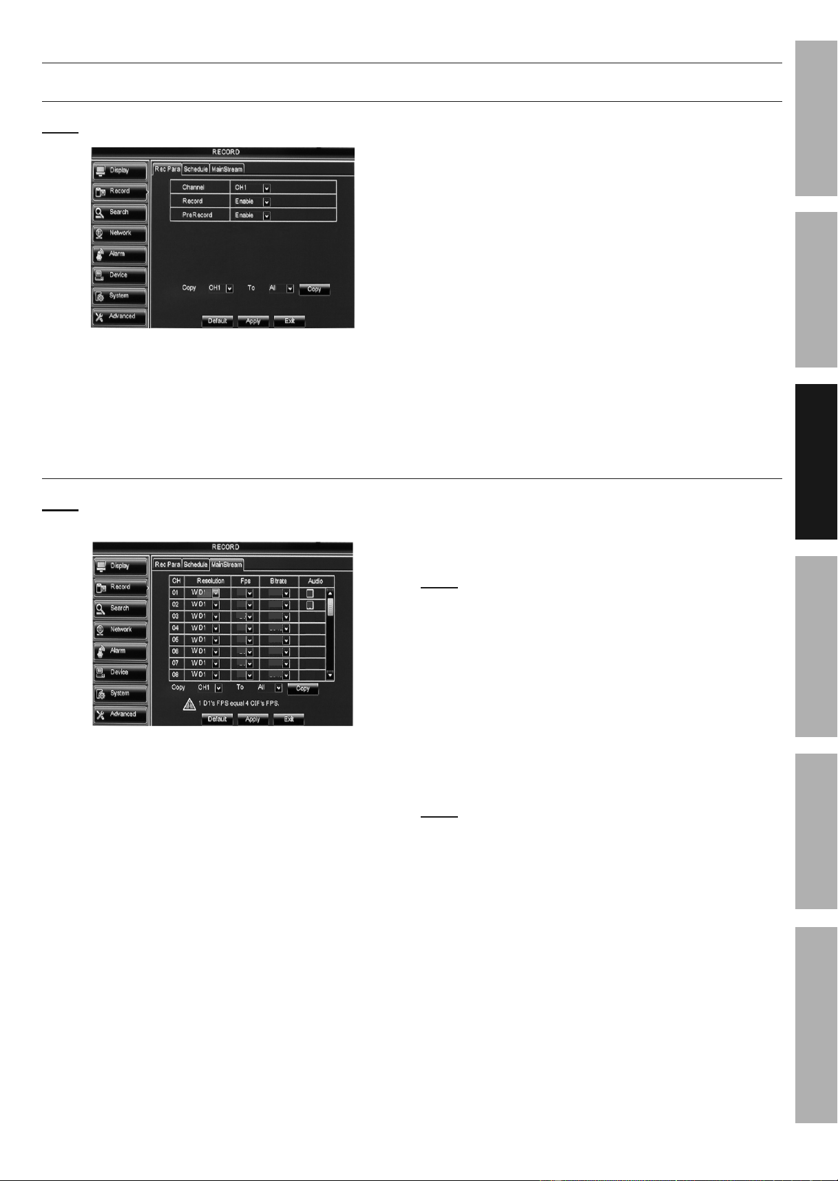
Record > Rec Para - Recording Parameters
Note: All channels are set to record and pre-record by default.
Figure P
1. Channel: Select Channel.
2. Record: Enable is selected by default to
record on all channels. Change if desired.
3. Pre-record: Enable is selected by default
to start motion event recordings several
seconds BEFORE motion is detected.
4. Copy: Copy settings from one
Channel to other Channels.
a. Select Channel to copy from.
b. Select Channel to copy to or select ALL.
c. Click Copy, then click OK.
Changes will be saved when you
click Apply then OK.
Changes will not be saved if you click
Exit or right click on screen.
Click Default to restore default settings.
Record > MainStream - Set Resolution, FPS, Bitrate and Audio
Note: The hard drive will fill up faster when the Frames Per Second (FPS) and Bitrate are
set higher than default settings. Resolution is set by default to the highest setting.
11
768
768
768
768
768
768
768
768
11
11
11
11
11
11
11
Figure Q
1. Mode and Resolution:
a. Select Mode 960H for 16:9 wide screen view.
Resolution Choices:
• WD1: 960 x 480 (default)
• WHD1: 960 x 240
• WCIF: 480 x 240
b. Select Mode D1 for 4:3 standard screen view.
Resolution Choices:
• D1: 720 x 480 (default)
• HD1: 720 x 240
• CIF: 360 x 240
c. System needs to restart before Mode
changes will apply. Click Apply and OK,
then Exit. Right click on screen and
DVR will prompt restart. Click OK.
2. FPS (Frames per second): Change if desired.
Note: The higher the FPS, the smoother the recording
will be.
In Mode D1 all Channels may be set to
the maximum of 30 FPS each.
In Mode 960H there is an FPS counter that shows
total and remaining FPS. You can adjust FPS up
and down between cameras to use all of the FPS.
3. Bitrate (Kbps): Change if desired.
4. Audio: Check box to record audio
if audio surveillance microphone
(sold separately) is being used.
Note: Audio is available on Channel
1 and Channel 2 only.
5. Copy: Copy settings from one
Channel to other Channels.
a. Select Channel to copy from.
b. Select Channel to copy to or select ALL.
c. Click Copy, then click OK.
Changes will be saved when you
click Apply then OK.
Changes will not be saved if you click
Exit or right click on screen.
Click Default to restore default settings.
Downloaded from www.ManualsFile.com manuals search engine
Page 18 For technical questions, please call 1-888-866-5797. Item 62463
SAFETy
ADVANCED
OPERATION
SETUP
BASIC
MAINTENANCE
TROUBLESHOOTING
Operation
Playback and Backup Recordings
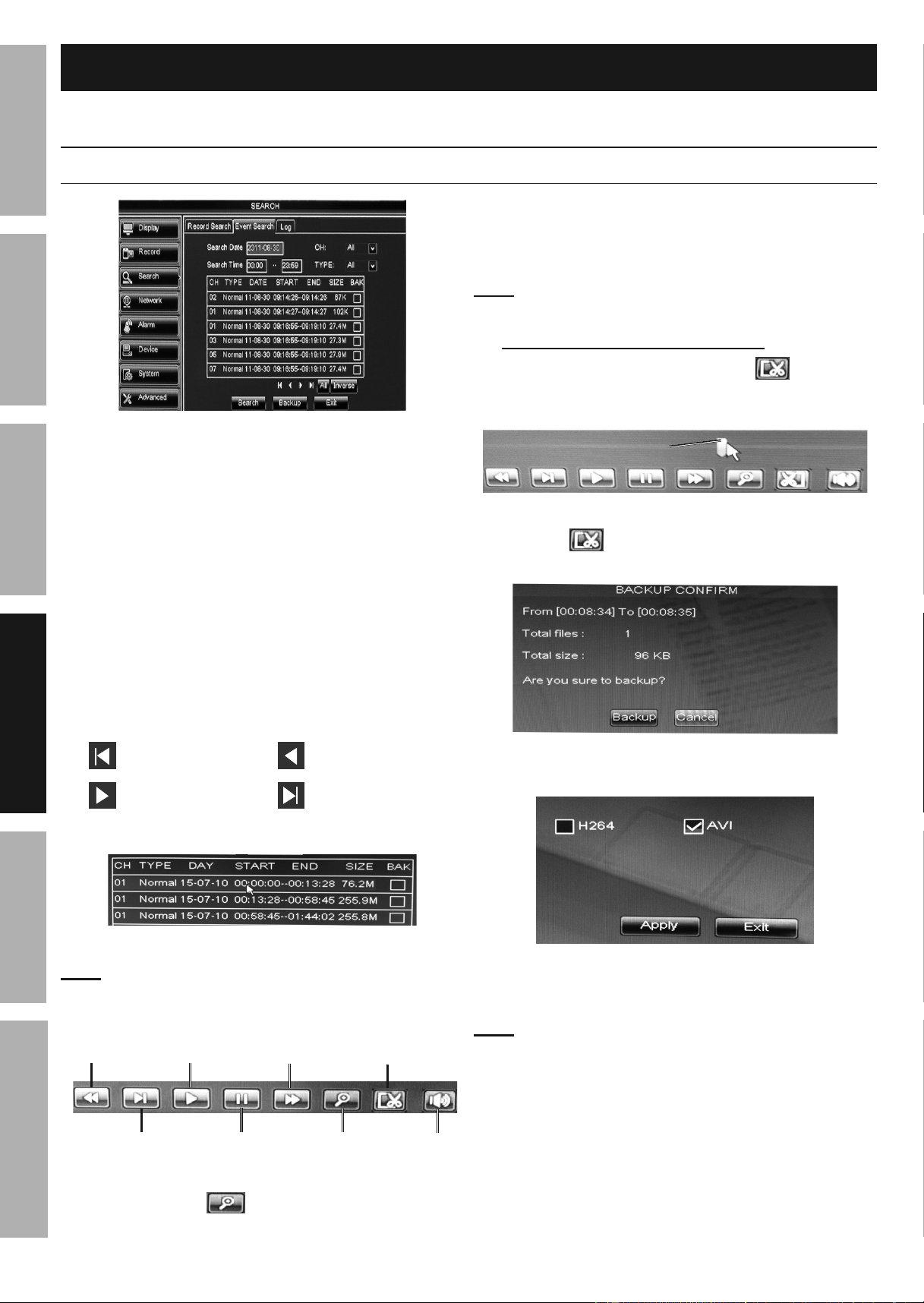
Search > Event Search
Figure R
1. Search Date: Today's date is selected by
default. Change date to search a different day.
2. CH: All is selected by default. Change if desired.
3. Search Time: Default is set to search entire day.
To search a different time frame, enter beginning
time in first box and ending time in second box.
4. TyPE: Select All, Normal, or Alarm recordings.
a. Normal - Scheduled or manual recordings.
b. Alarm - Motion event recordings.
5. Click Search to populate table with list of
recordings. Use buttons below table to navigate:
Go to first recording Go to previous page
Go to next page Go to last recording
6. Click on individual recording to playback.
Figure S
Note: Playback will start automatically.
a. Playback Bar will appear at bottom of
screen. Functions are shown below.
Rewind Play Fast Forward Backup
Slow Motion Pause Zoom Mute
Figure T: Playback Bar
b. Zoom: Click then drag a box over
area to zoom in on. Right click to exit.
7. Backup Recordings
Insert a USB flash drive into either
USB port on back of DVR.
Note: Some flash drives include special file
handling software and may not be compatible.
Backup Segment During Playback:
• While viewing a recording, click once, then
click and drag the Time Marker from beginning
to end of desired time segment to backup.
Time
Marker
Figure U
• Click again to bring up
BACKUP CONFIRM box.
Figure V
• Click Backup to save the file to the flash drive.
• You will be prompted to choose
between H264 and AVI file.
AVI should be chosen in most cases.
Note: AVI is a common media file and will
work with most computer's media players.
H264 is an uncommon media file.
• Click Apply and wait until Backup Completed
box pops up, then click OK.
• The USB flash drive can be plugged into
another device to view or transfer recordings.
Downloaded from www.ManualsFile.com manuals search engine
Page 19For technical questions, please call 1-888-866-5797.Item 62463
SAFETy
ADVANCED
MAINTENANCE
TROUBLESHOOTING
OPERATION SETUPBASIC
Backup Entire Recording:
• Follow steps 1 to 5 on page 18.
• To select recordings for backup, click
in BAK box for each selection.
BAK
Figure W
• To select all recordings for backup, click All.
To deselect all recordings, click Inverse.
• Click Backup.
• You will be prompted to choose
between H264 and AVI file.
AVI should be chosen in most cases.
Note: AVI is a common media file and will
work with most computer's media players.
H264 is an uncommon media file.
• Click Apply and wait until Backup Completed
box pops up, then click OK.
• The USB flash drive can be plugged into
another device to view or transfer recordings.
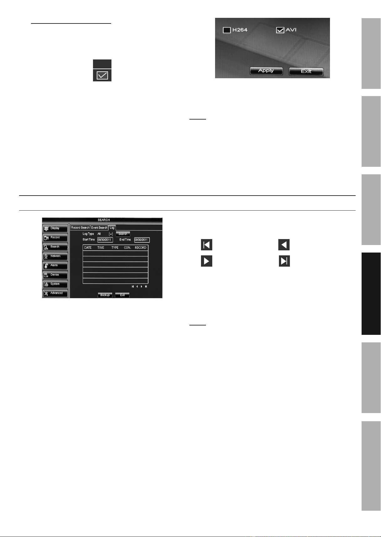
View DVR's Activity
Search > Log
Figure X
1. Start Time (Date): Today's date is selected by
default. Change date to search a different day.
2. End Time (Date): Today's date is selected by
default. Change date to search a different day.
3. Log Type: All is selected by default.
Change to search for specific type:
a. System - Logs when DVR starts up, shuts
down, reboots or time settings are changed.
b. Config - Logs when settings are changed.
c. Alarm - Logs when motion events start
and end; and when there is video loss.
d. Account - Logs when users login and logout.
e. Record - Logs when manual recordings
start and stop; and when records are
searched, played back and backed up.
f. Storage - Logs when the hard
drive has been formatted.
4. Click Search to populate table with list of log
entries. Use buttons below table to navigate:
Go to first log Go to previous page
Go to next page Go to last log.
5. Double-click any log entry for more details.
6. Backup Log
Insert a USB flash drive into either
USB port on back of DVR.
Note: Some flash drives include special file
handling software and may not be compatible.
• Click Backup to backup log file, then
click OK when backup finished.
• The USB flash drive can be plugged into
another device to view or transfer log file(s).
Downloaded from www.ManualsFile.com manuals search engine
Page 20 For technical questions, please call 1-888-866-5797. Item 62463
SAFETy
ADVANCED
OPERATION
SETUP
BASIC
MAINTENANCE
TROUBLESHOOTING
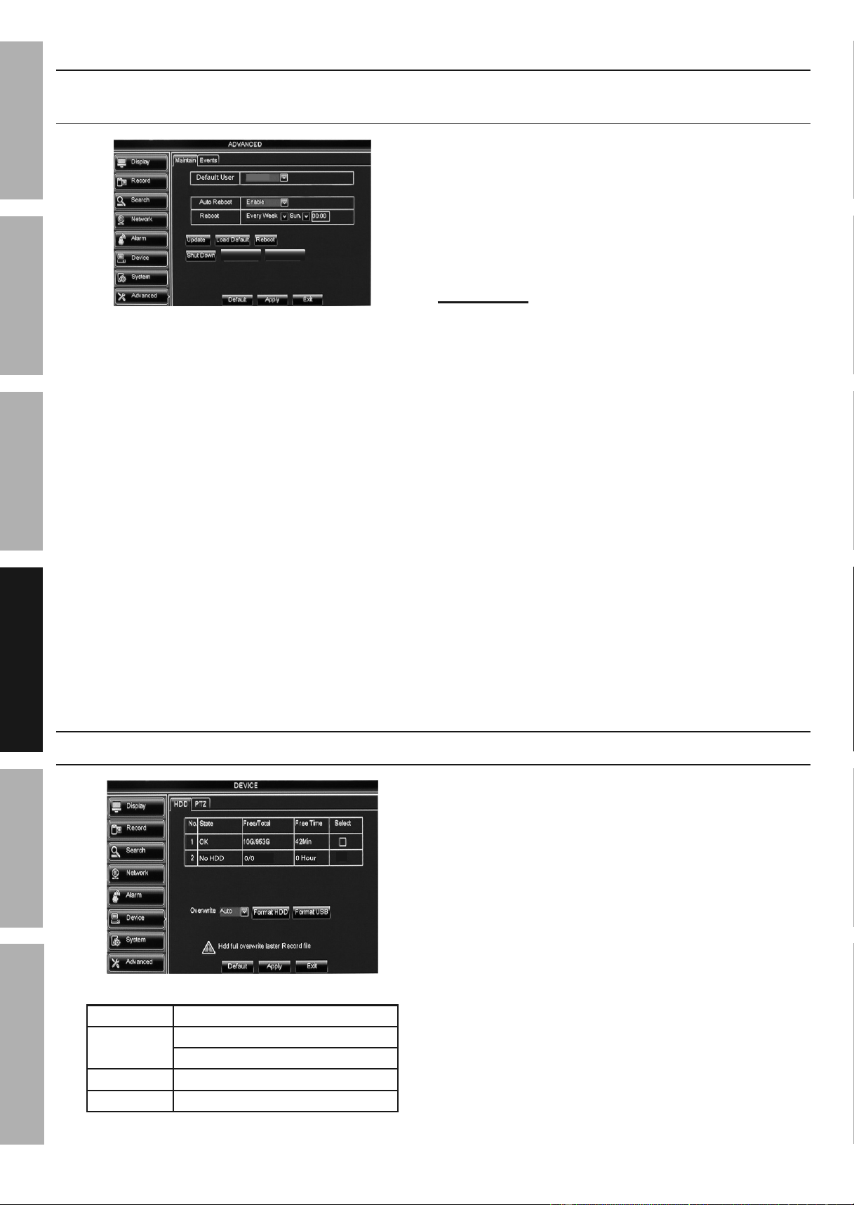
Maintain Hard Drive
Advanced > Maintain - Set up Reboot Cycle, Update Software &
Firmware, Restore Default Settings, Reboot And Shut Down
Load Settings Save Settings
OFF
Figure y
1. Default User:
a. OFF is selected by default so that any
user can access this function.
b. Select Admin so that only the main
user can access this function.
2. Auto Reboot: Enable is selected by default.
3. Reboot: By default DVR will Reboot every
Sunday at midnight. To change:
a. Select when to Auto Reboot.
• Everyday
• Every Week
• Every Month
b. Enter time according to which time format you are
using. For example, to auto reboot at 9:00 PM:
• 24 Hour = 21:00
• 12 Hour = 09:00 PM
4. Update: For updating firmware using a
USB flash drive. (Find the most recent
firmware updates at harborfreight.com.)
5. Load Default:
a. Click to restore system default settings.
b. Check the settings to restore,
click APPLy then OK.
IMPORTANT! Clicking OK will delete
custom settings you have made.
c. System needs to restart before changes will apply.
Click Apply and OK, then Exit. Right click on
screen and DVR will prompt restart. Click OK.
6. Reboot: Click to manually reboot system.
7. Shut Down: Click to manually shut down system.
Unplug DVR and plug back in to restart.
8. Load Settings: Import settings
using a USB flash drive.
9. Save Settings: Export settings
using a USB flash drive.
Changes will be saved when you click Apply then OK.
Changes will not be saved if you click
Exit or right click on screen.
Format Hard Drive and USB Flash Drive
Device > HDD
Figure Z
No. ID number of drives
State
OK - Hard drive installed
No HDD - No hard drive installed
Free/total Free Space/Total Space
Free Time Recording time available
Figure AA
1. Overwrite: Auto is selected by default.
The Hard Disk Drive will overwrite itself
when full. Change if desired.
2. Format Hard Drive:
a. Click Select box.
b. Click Format HDD.
c. Click OK.
d. When formatting is finished, click OK.
3. Format USB Flash Drive:
a. Install USB flash drive into back of DVR.
b. Click Format USB.
c. Click OK.
d. When formatting is finished, click OK.
Changes will be saved when you click Apply then OK.
Changes will not be saved if you click
Exit or right click on screen.
Downloaded from www.ManualsFile.com manuals search engine
Page 21For technical questions, please call 1-888-866-5797.Item 62463
SAFETy
ADVANCED
MAINTENANCE
TROUBLESHOOTING
OPERATION SETUPBASIC
Advanced Menu
DEVICE
ALARM
SySTEM
SySTEM
Motion - Motion Detection Settings p.23
PTZ - Set up PTZ Camera p.24
DISPLAy
DISPLAy
Privacy Zone - Block areas from Live View p. 23
Users - Set up Users p. 22
General - Clock Settings p. 22
Output - Monitor Settings p. 21
Info - Device Information & Software Versions p. 24
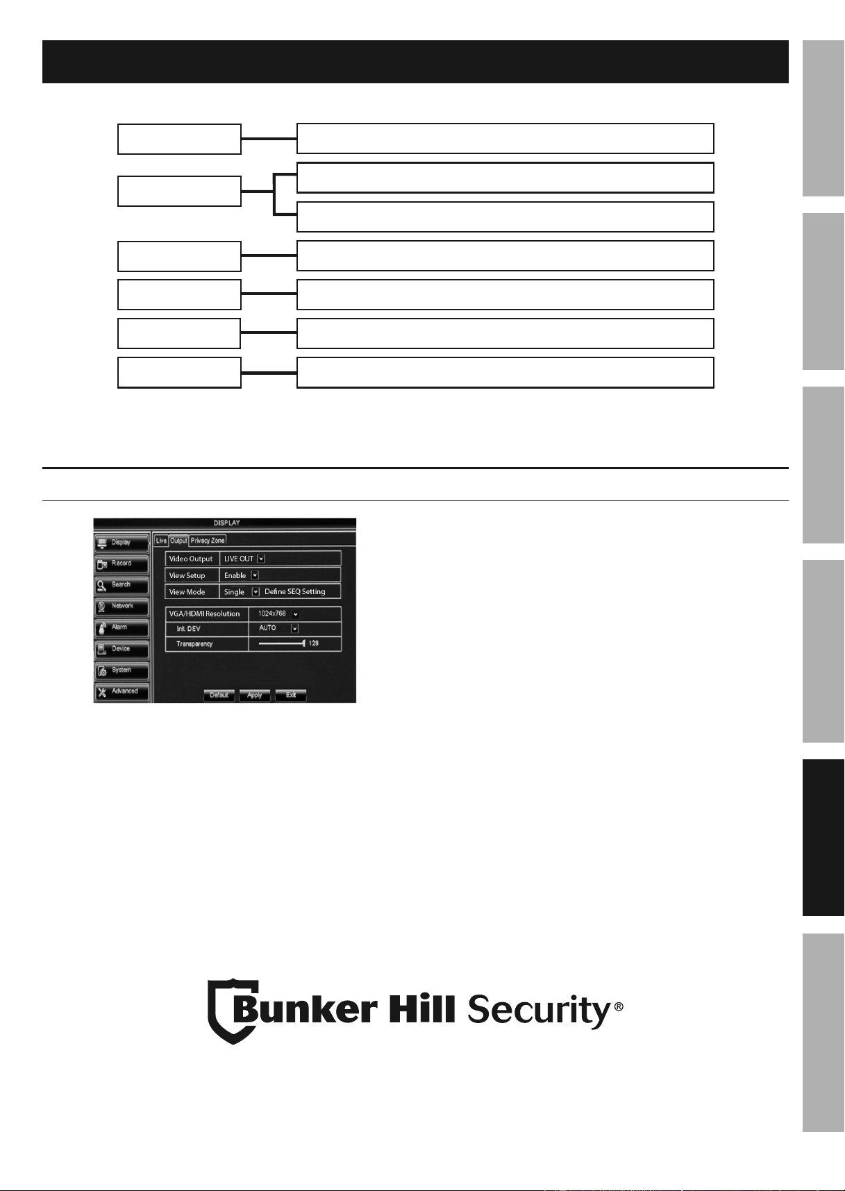
Monitor Settings
Display > Output
Figure AB
1. Video Output: Cannot modify.
2. View Setup: Disable is set by default.
Choose Enable to modify View Mode.
3. SEQ (Sequence) Time: Amount of time, in
seconds, that each Channel will display in Live View
when Start SEQ is activated from the Pop-Up Menu.
4. VGA/HDMI Resolution: Select resolution for
monitor or TV (see monitor's or TV's user manual).
5. Init. DEV: Sets output. Auto is set as default.
6. Transparency: Set transparency of Menus.
Changes will be saved when you
click Apply then OK.
Changes will not be saved if you click
Exit or right click on screen.
Downloaded from www.ManualsFile.com manuals search engine
Page 22 For technical questions, please call 1-888-866-5797. Item 62463
SAFETy
ADVANCED
OPERATION
SETUP
BASIC
MAINTENANCE
TROUBLESHOOTING
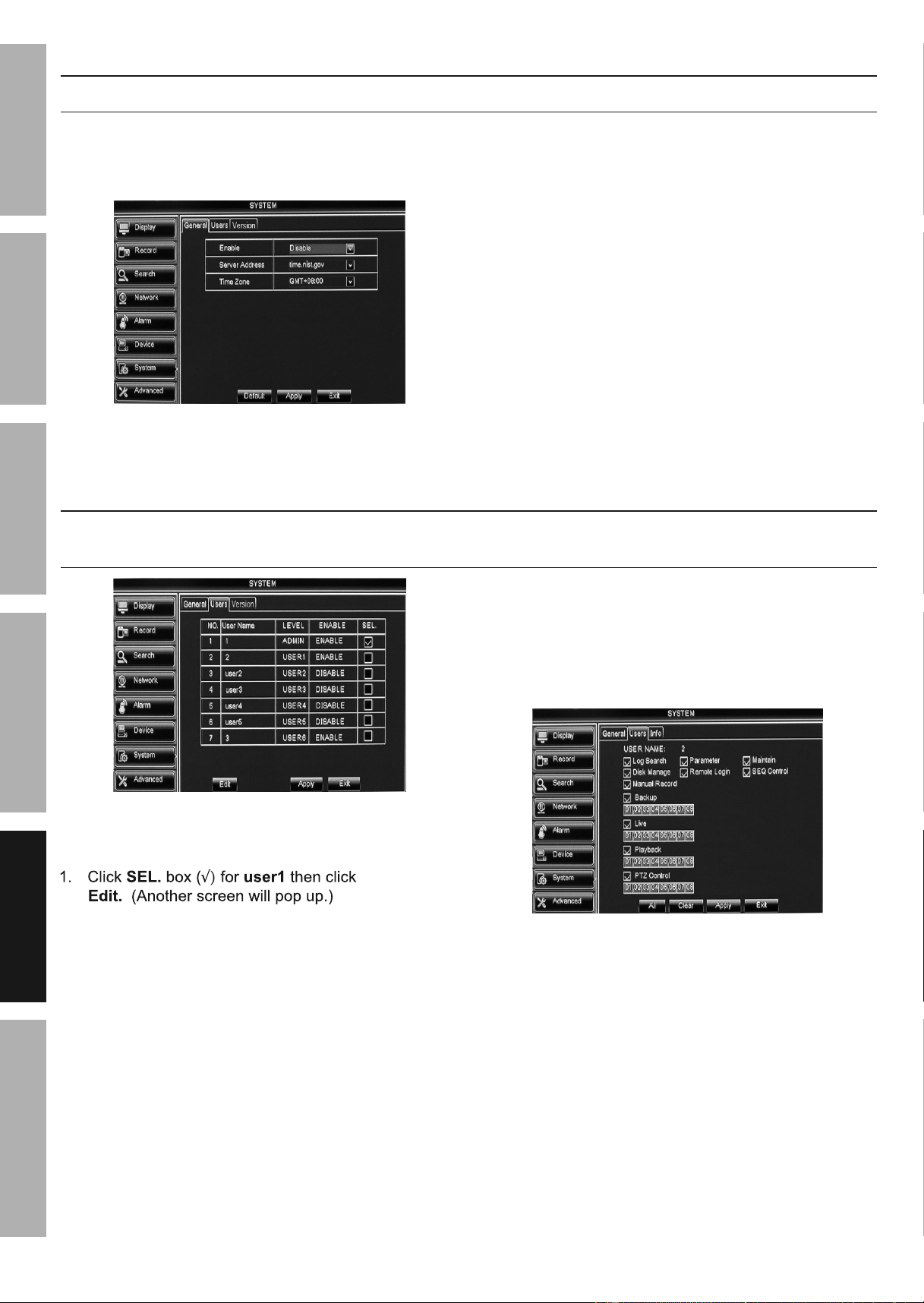
Clock Settings
System > General - NTP (Network Time Protocol)
1. The DVR must be connected to your network
for this feature to work. (Go to Connect
DVR to Network on page 28)
Figure AC
2. After network connection is set up:
a. Click NTP Setup.
b. Select Enable.
c. Choose Server Address.
d. Choose Time Zone.
e. Click Apply then OK.
f. Click Update Now.
The DVR's clock will be synchronized to
Coordinated Universal Time (UTC).
Changes will be saved when you
click Apply then OK.
Changes will not be saved if you click
Exit or right click on screen.
User Management Settings
System > Users - Set up additional users' passwords and permissions.
To set password for main user, go to Password Settings on page 15.
Figure AD
Set up Additional Users
1. User Enable: Select Enable.
2. User Name: Enter User Name (up to 8 characters).
3. Password Enable: Select Enable or Disable.
a. Password: Enter Password (up to 6 characters).
b. Confirm: Enter Password again to confirm.
Changes will be saved when you
click Apply then OK.
Changes will not be saved if you click
Exit or right click on screen.
4. Select User that was just named
and click Permission.
a. Click in boxes to select specific permissions.
b. Click All to select all permissions.
c. Click Clear to remove all permissions.
Figure AE
Changes will be saved when you
click Apply then OK.
Changes will not be saved if you click
Exit or right click on screen.
5. Repeat steps above for other users.
Downloaded from www.ManualsFile.com manuals search engine
Page 23For technical questions, please call 1-888-866-5797.Item 62463
SAFETy
ADVANCED
MAINTENANCE
TROUBLESHOOTING
OPERATION SETUPBASIC
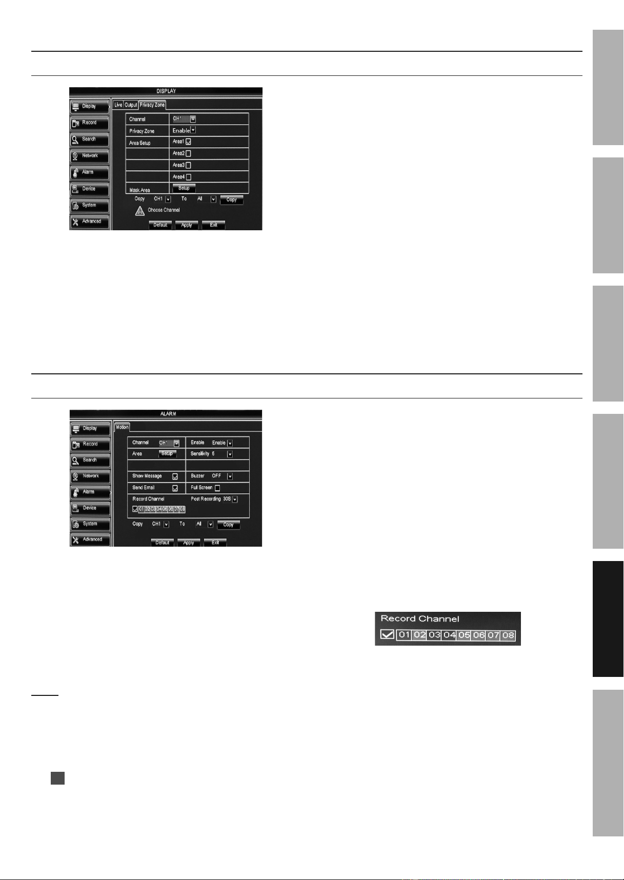
Privacy Zone
Display > Privacy Zone - Block areas from being viewed or recorded
Figure AF
1. Channel: Select Channel.
2. Privacy Zone: Select Enable.
3. Area Setup: Select up to 4 areas to block.
4. Mask Area: Select Setup, you will see
green outlined square(s). They can
be moved and resized, by clicking and
dragging, to cover areas to be blocked.
5. Right click anywhere to return to Privacy Zone.
Click Apply then OK to save changes.
6. Repeat steps above for other Channels.
7. Copy: Copy settings from one
Channel to other Channels.
a. Select Channel to copy from.
b. Select Channel to copy to or select ALL.
c. Click Copy, then click OK.
Changes will be saved when you
click Apply then OK.
Changes will not be saved if you click
Exit or right click on screen.
Motion Detection Settings
Alarm > Motion
Figure AG
1. Channel: Select Camera.
2. Enable: Enable is set by default so that when
motion detection is scheduled, the selected
camera will record. (Go to Recording Settings
on page 16 to schedule motion detection)
3. Area: Click and drag green outlined boxes
to set desired area(s) where motion detection
will trigger an event. Right click to exit.
Note: If no areas are set, the entire
camera view will trigger an event.
4. Sensitivity: Set sensitivity level,
1 is lowest and 10 is highest.
5. Show Message: Set to ON by default. When
motion is detected by a camera,
M
will appear on Live View for that camera.
6. Buzzer: Set to OFF by default. To turn
on, click drop-down box and choose
length of time for beeping to sound.
7. Send Email: Set to ON by default. The DVR
must be connected to your Network for this
feature to work. (Go to Network > Email - Set
up Email Notifications on page 34)
8. Full Screen: Check box so that when motion is
detected by the selected camera, Live View will
display in full screen mode for that camera.
9. Record Channel: By default, when selected
camera detects motion, that camera will record.
This setting allows you to choose which other
cameras will record when the selected camera
detects motion. For example, if you want motion
detection for camera 1 to also record from
cameras 3 and 4, make the following settings:
10. Post Recording: Select how long recording
will continue after motion is detected.
11. Copy: Copy settings from one
Channel to other Channels.
a. Select Channel to copy from.
b. Select Channel to copy to or select ALL.
c. Click Copy, then click OK.
Changes will be saved when you
click Apply then OK.
Changes will not be saved if you click
Exit or right click on screen.
Downloaded from www.ManualsFile.com manuals search engine
Page 24 For technical questions, please call 1-888-866-5797. Item 62463
SAFETy
ADVANCED
OPERATION
SETUP
BASIC
MAINTENANCE
TROUBLESHOOTING
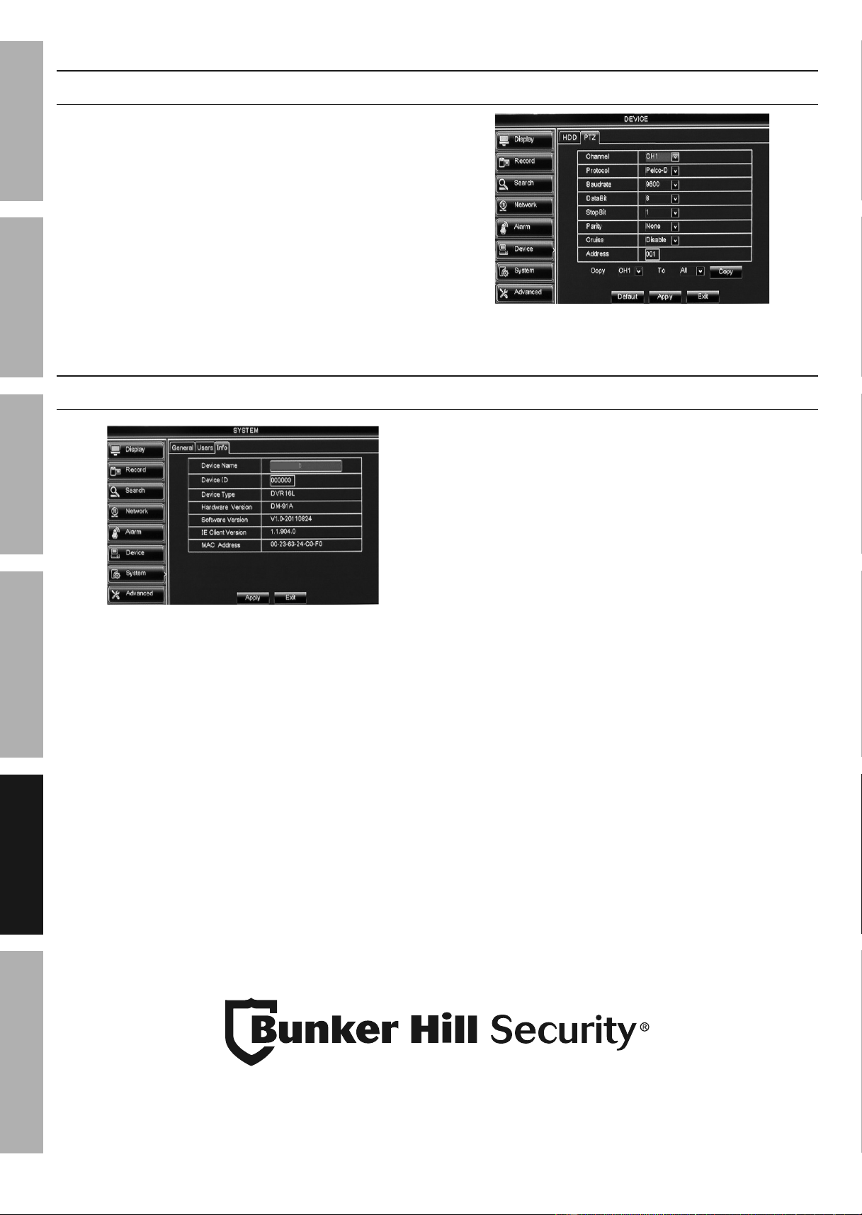
PTZ Camera
Device > PTZ Settings for PTZ (Pan, Tilt, Zoom) camera (sold separately).
Input information according to PTZ
camera manufacturer instructions.
Figure AH
System Information
System > Info
DVR-08D1
Figure AI
1. Device Name: Set to DVR-08D1 by default.
Change if desired (up to 21 characters).
2. Device ID: Set to 000000 by default.
Change if desired (up to 6 numbers).
3. The rest of settings are informational
and cannot be changed.
Changes will be saved when you
click Apply then OK.
Changes will not be saved if you click
Exit or right click on screen.
Downloaded from www.ManualsFile.com manuals search engine
Page 25For technical questions, please call 1-888-866-5797.Item 62463
SAFETy
ADVANCED
MAINTENANCE
TROUBLESHOOTING
BASIC SETUPOPERATION
Maintenance Instructions
Procedures not specifically explained in this manual must be performed only by a qualified
technician.
DVR Maintenance
TO PREVENT SERIOUS INJURy FROM ELECTRIC SHOCK:
Shut down the DVR and unplug the Power Adapter from its electrical outlet
before inspection, maintenance, or cleaning.
1. PERIODICALLy, inspect the general
condition of the DVR. Check for:
• loose hardware,
• damaged cord/electrical wiring,
• cracked or broken parts, and
• any other condition that may
affect its safe operation.
2. PERIODICALLy, wipe external
surfaces of DVR with clean cloth.
3. ONCE A MONTH, blow compressed air
into vents to remove dust buildup.
Camera Maintenance
TO PREVENT SERIOUS INJURy FROM ELECTRIC SHOCK:
Unplug the Power Adapter from its electrical outlet
before inspection, maintenance, or cleaning.
1. PERIODICALLy, inspect the general
condition of the Camera. Check for:
• loose hardware,
• damaged cord/electrical wiring,
• cracked or broken parts, and
• any other condition that may
affect its safe operation.
2. PERIODICALLy:
• Wipe external surfaces of
Camera with clean cloth.
• Clean Camera lenses by applying lens cleaning
solution to scratch-free cloth, then wiping lens.
Do not apply solution directly to lens.
3. Maintain area surrounding Camera,
making sure obstacles don’t interfere with
visibility, such as overgrown bushes.
Downloaded from www.ManualsFile.com manuals search engine

Page 26 For technical questions, please call 1-888-866-5797. Item 62463
SAFETy
ADVANCED
OPERATION
SETUP
BASIC
MAINTENANCE
TROUBLESHOOTING
Troubleshooting
Problem Possible Causes Likely Solutions
DVR makes
beeping sound
1. Camera is unplugged.
2. Hard drive is full.
3. Hard drive is damaged.
1. Check Camera connection at DVR and at Camera.
2. Go to Device > HDD on page 20
and set Overwrite to Auto.
3. Have a qualified technician repair DVR.
No image(s)
in Live View
1. Covert is enabled.
2. Loose or incorrect
connections.
3. Longer cables used
without sufficient amperage
from power adapter.
4. Monitor needs adjustment.
1. Go to Monitor Settings on page
15 and disable Covert.
2. Check that all connections are secure
and in the correct locations.
3. Use power adapter with proper amperage rating.
4. Adjust the image settings on the monitor.
DVR freezes Hard Drive crash. Unplug DVR, wait 30 seconds, then plug back in.
Remote won't work
1. Batteries need replacing.
2. Controls are locked.
1. Replace batteries.
2. Press and hold REW button on front of
DVR until unit beeps or press 0 button on
Remote Control to unlock controls.
Mouse won't work Controls are locked.
Press and hold REW button on front of DVR until unit beeps
or press 0 button on Remote Control to unlock controls.
DVR buttons
won't work
Controls are locked.
Press and hold REW button on front of DVR until unit beeps
or press 0 button on Remote Control to unlock controls.
Password Problem Forgot Password Call 1-888-866-5797
Error codes
when trying to
install software
1. Interference from antivirus
or firewall programs.
2. Incompatibility with
Operating System.
1. Follow antivirus or firewall program's
instructions to resolve interference.
2. Check System Requirements on page 27 to
make sure your Operating System is supported.
Record Product’s Serial Number Here:
Note: If product has no serial number, record month and year of purchase instead.
Note: Some parts are listed and shown for illustration purposes only,
and are not available individually as replacement parts.
Downloaded from www.ManualsFile.com manuals search engine
Page 27
For technical questions, please call your Internet Service Provider.
Item 62463
Advanced Network Configuration, Software and Notification Settings
DISCLAIMER: The following pages contain instructions for using a specific
equipment setup. your equipment setup may be different, therefore we cannot offer
any more instruction than is contained in the following pages. If you cannot achieve
network configuration with these instructions, you will need to contact your Router
Manufacturer or Internet Service Provider. you may also need to hire an IT Specialist.
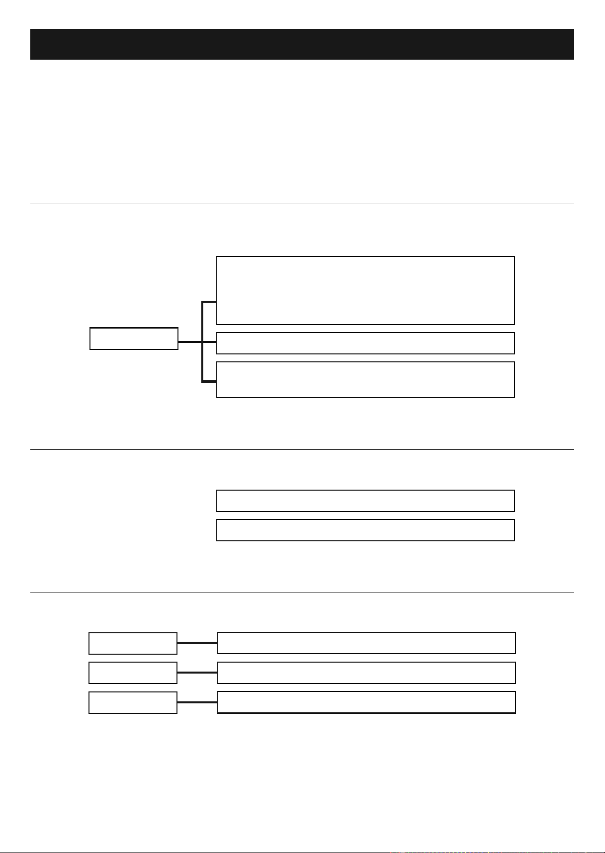
Computer and Smartphone Access
NETWORK
Network
Connect DVR to Network p. 28
Set up DDNS p. 28
Access DVR with Smartphone p. 29
Access DVR with computer p. 30
SubStream - Set Network Resolution,
FPS, Bitrate and Audio p. 31
RTSP - Set up RTSP p. 31
Software
Video Player - Playback Recordings p.
Surveillance Client - Access DVR p. 32
Notifications
ADVANCED
DEVICE
FTP - Set up FTP Notifications p. 34
Cloud Storage - Set up Dropbox Notifications p. 34
Email - Set up Email Notifications p. 34
NETWORK
Downloaded from www.ManualsFile.com manuals search engine
Page 28
For technical questions, please call your Internet Service Provider.
Item 62463
Computer and Smartphone Access
Read the ENTIRE IMPORTANT SAFETy INFORMATION section at the beginning of this
manual including all text under subheadings therein before set up or use of this product.
IMPORTANT! YOU MAY NEED TO HIRE AN IT SPECIALIST TO SET UP THE FUNCTIONS IN THIS SECTION.
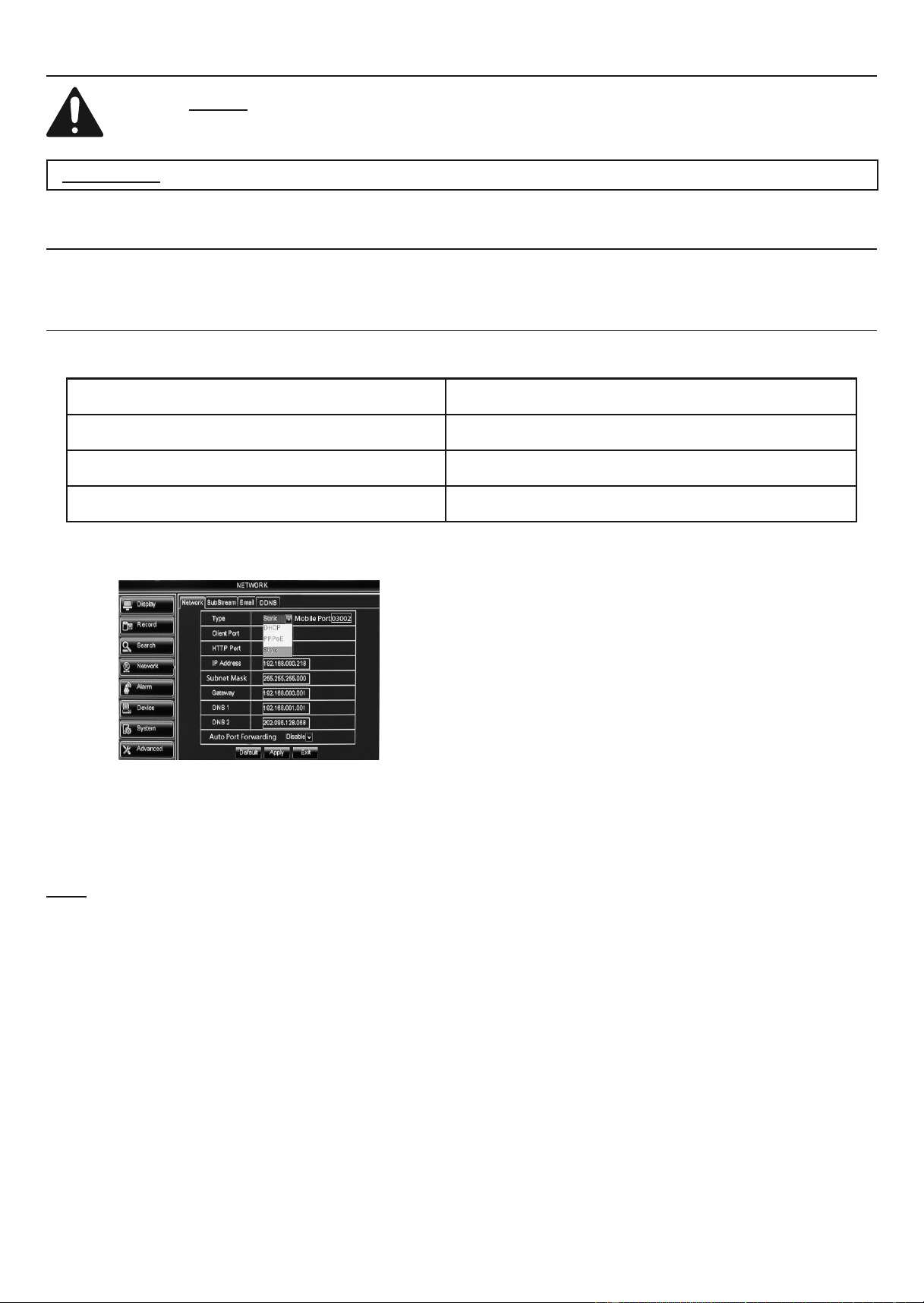
Network > Network
yOU MUST HAVE HIGH SPEED INTERNET, A ROUTER AND AN ETHERNET CABLE (SOLD SEPARATELy).
yOU MAy NEED TO CONTACT yOUR ROUTER'S MANUFACTURER OR INTERNET SERVICE PROVIDER.
Connect DVR to Network
Use the chart below to record the information you will need in the following instructions.
Static IP Address or DDNS Host Name (External)
IP(v4) Address (Internal)
Subnet Mask
Default Gateway or Router
Figure AJ
Figure AK
1. Set up user name and password according
to Password Settings on page 15.
2. Connect DVR to Router via Ethernet
Cable (sold separately).
Note: If you are not familiar with your
router, contact your Router’s Manufacturer
or Internet Service Provider.
3. Find out if you have a Static or
Dynamic external IP Address.
a. If Static, get external IP address (It can
usually be found on the router's WAN
settings page, but your router may differ),
fill in the chart, then go to step 4.
b. If Dynamic, set up DDNS Service.
Set up DDNS
• Go to Network > DDNS
• DDNS: Set to Enable.
• Server: Sign up online with one of the
services on the drop-down list.
• Follow instructions on DDNS service's
website to finish setup.
• Click DDNS Test button to check the connection.
• Fill in the chart with DDNS Host Name.
Changes will be saved when you
click Apply then OK.
Changes will not be saved if you click
Exit or right click on screen.
Click Default to restore default settings.
Downloaded from www.ManualsFile.com manuals search engine
Page 29
For technical questions, please call your Internet Service Provider.
Item 62463
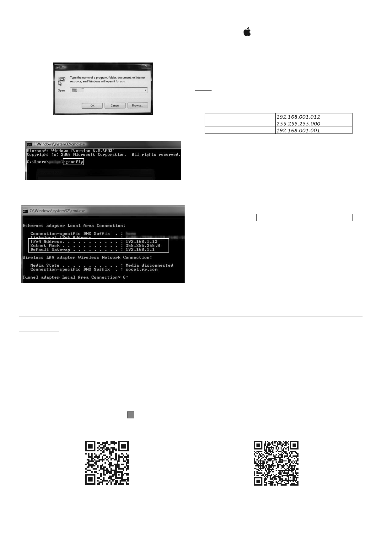
4. View Network information:
a. On PC:
• Click on Start menu, then click Run.
• Type “cmd” then click OK.
Figure AL
• Type “ipconfig” then press Enter.
Figure AM: cmd
• You will see the router's Local Area Connection.
FIGURE AN: IPCONFIG
b. On MAC:
• Click on .
• Go to System Preferences.
• Click on Network.
5. Fill in the Chart with information from
ipconfig (PC) or Network (MAC).
Note: If any address has single digit
sets (Example, 192.168.1.12), change to
triple digits (Example, 192.168.001.012).
IP(v4) Address
Subnet Mask
Default Gateway or Router
Example
6. On DVR, go to Network > Network:
a. Leave Type set to Static.
b. Set Client Port to 03000.
c. Set HTTP Port to 03001.
d. Set IP(v4) Address to one from Chart,
change last 3 digits to 200.
IP(v4) Address
192.168.001.012 200
Example
e. Set Subnet Mask and Gateway
to ones from Chart.
f. Set DNS1 to the same as Gateway.
g. Enable Auto Port Forwarding.
h. Click Apply and OK, then Exit.
i. Right click on screen and DVR will
prompt restart. Click OK.
Access DVR with Smartphone
IMPORTANT: Set up network access first according to Connect DVR to Network on
page 28. Keep the Ethernet Cable connected to the DVR at all times.
1. Using your phone's QR code scanning app, scan
the code for your Smartphone's operating system:
a. IOS will open ITunes app store to RXCamLink.
b. ANDROID will open Google Play
app store to RXCamLink.
2. Install and open RXCamLink app.
3. Go To Device Manager and click
+
to add DVR.
4. Give DVR any Device Name.
5. Set Login Type to IP/DOMAIN.
6. Click into Address box to the right of
QR Code and type in Static IP Address
or DDNS Host Name from chart.
7. Set Client Port to 3000.
8. Enter User Name and Password for DVR.
9. Click Save and you will see cameras in Live View.
IOS
ANDROID
Downloaded from www.ManualsFile.com manuals search engine
Page 30
For technical questions, please call your Internet Service Provider.
Item 62463
Access DVR with computer
IMPORTANT: Set up network access first according to Connect DVR to Network on
page 28. Keep the Ethernet Cable connected to the DVR at all times.
1. Install Surveillance Client. (Go to page 32), or
2. Use the Internet:
Note: Internet Explorer
® is the preferred browser.
a. Open Internet Explorer.
b. Type Static IP Address or DDNS Host
Name and HTTP Port into address bar
(NOT search bar) and press ENTER.
Example, http://xxx.xxx.xxx.xxx:3001.
c. Allow ActiveX control to install.
Note: If Internet Explorer will not allow
ActiveX to install change Download
unsigned ActiveX controls to Prompt.
d. Repeat Step b, then allow
ActiveX Control to install.
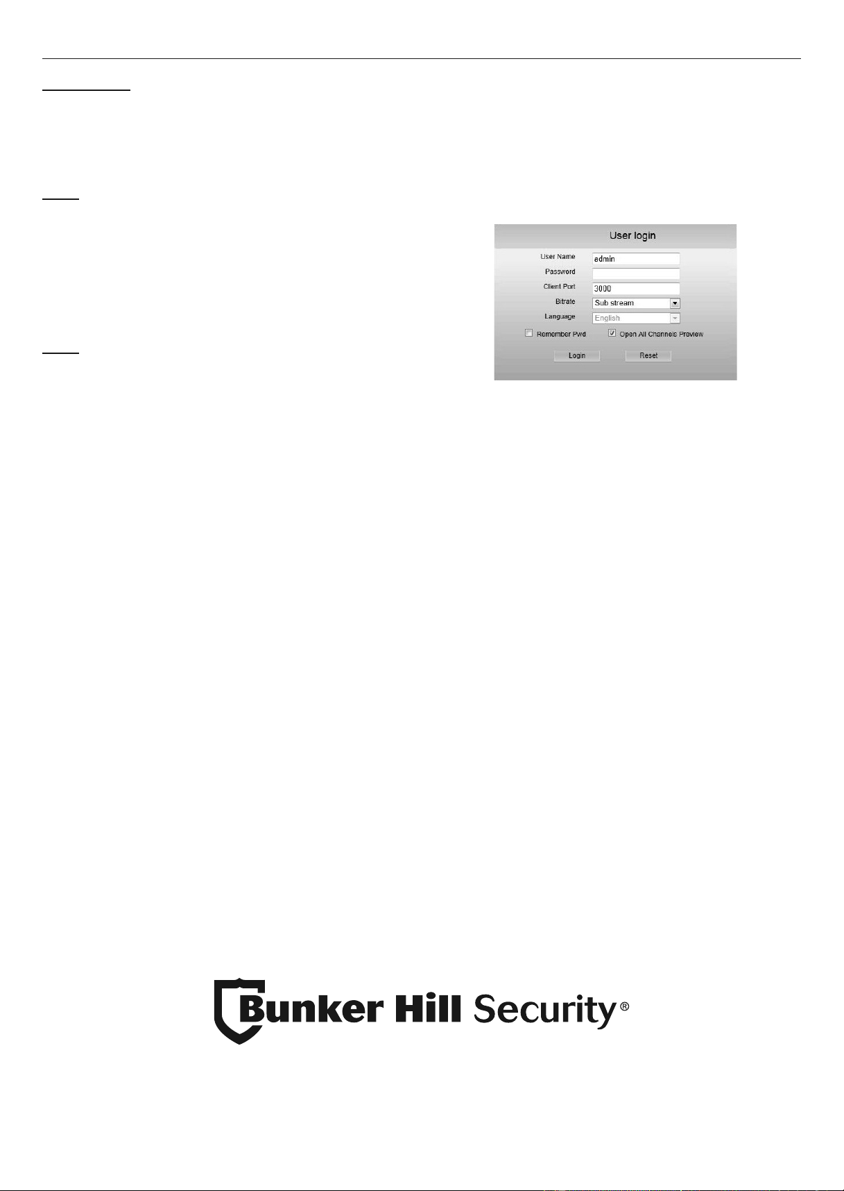
e. Login to DVR:
• Enter User Name and Password for DVR.
• Set Client Port to 3000.
• Choose Sub stream for Bitrate.
Figure AO
f. Click Login and you will see
cameras in Live View.
Downloaded from www.ManualsFile.com manuals search engine
Page 31
For technical questions, please call your Internet Service Provider.
Item 62463
Network > RTSP
Access DVR using VLC Media Player with RTSP (Real Time Streaming Protocol).
Note: Set up this function only if you
have advanced networking skill.
Changes will be saved when you
click Apply then OK.
Changes will not be saved if you click
Exit or right click on screen.
Click Default to restore default settings.
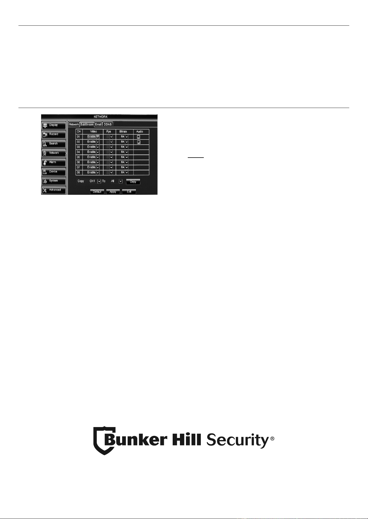
Network > SubStream - Set Resolution, FPS, Bitrate and Audio
4
4
4
4
4
4
4
4
Figure AP
1. Video: Enable is set as default.
2. FPS (Frames per second): Change if desired.
3. Bitrate (Kbps): Change if desired.
4. Audio - Check box to record audio if audio
surveillance microphone (sold separately) is hooked
up. (To hook up audio equipment, go to B.
Connect Cameras and Audio on page 9)
Note: Audio is available on Channel
1 and Channel 2 only.
5. Copy: Copy settings from one
Channel to other Channels.
a. Select Channel to copy from.
b. Select Channel to copy to or select ALL.
c. Click Copy, then click OK.
Changes will be saved when you
click Apply then OK.
Changes will not be saved if you click
Exit or right click on screen.
Click Default to restore default settings.
Downloaded from www.ManualsFile.com manuals search engine
Page 32
For technical questions, please call your Internet Service Provider.
Item 62463
Software
Read the ENTIRE IMPORTANT SAFETy INFORMATION section at the beginning of this manual
including all text under subheadings therein before set up or use of this product.
IMPORTANT: Set up Network access first according to Connect DVR to Network on
page 28. Keep the Ethernet Cable connected to the DVR at all times.
System Requirements
CPU Intel Pentium 4 or higher, 3GHz
RAM Min. 2GB
Operating
System
Windows XP Professional
®
, Windows Vista
®
,
Windows 7
®
, Windows 8
®, Windows
10
®
Disk Space Min. 10GB
Surveillance Client
Note: Some antivirus programs or firewalls may prevent full installation.
1. Insert Software CD into computer.
2. Open Software for PC or Software for Mac folder.
3. Open Surveillance client folder.
4. Install Surveillance Client.
5. A wizard will open, click Next.
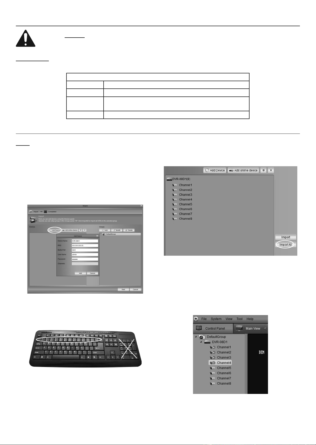
6. Click Add Device.
Figure AQ
7. Fill in Device Name: Find Device Name on
DVR in System>Info. For inputting numbers,
use regular keyboard numbers, NOT keypad.
8. Use Static IP Address or DDNS
Host Name for IP/ID.
9. Change Media Port to 3000.
10. Enter User Name and Password for DVR.
11. Click Add, then click Import All. Your
DVR and all Channels will be visible.
Figure AR
12. Go to Main View.
13. Open the Channels by double-clicking
Default Group, then double-clicking DVR.
14. Double-click each Channel to see
cameras in Live View.
15. Consult PC Surveillance Client
Instructions for further instructions.
Downloaded from www.ManualsFile.com manuals search engine
Page 33
For technical questions, please call your Internet Service Provider.
Item 62463
Video Player
Playback H.264 or AVI files and save .bmp snapshots on a computer.
Note: Some antivirus programs or firewalls may prevent full installation.
1. Insert Software CD into computer.
2. Open Software for PC or Software for Mac folder.
3. Open Video player folder.
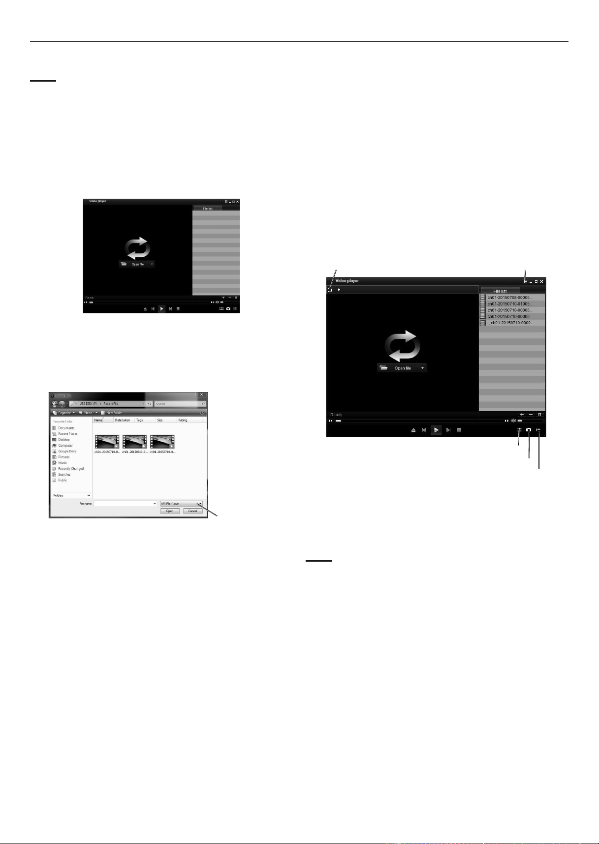
4. Install and open PC Video Player.
5. Click Open file.
Figure AS
6. Choose file type.
7. Find recordings saved on USB flash
drive, select them, then click Open.
Choose
File Type
Figure AT
8. Recordings will show on File list.
• Full Screen - Click for full screen, Press
Esc button to return to normal view.
• Advanced Config - Advanced configurations.
• Watermark - The word “Watermark”
will appear on recordings. Click to
remove watermark from recordings.
• Snapshot - Saves .bmp image to
VideoPlayer Picture folder.
• Open and close List - Show or hide File list.
Watermark
Snapshot
Open and
Close List
Full
Screen
Advanced
Config
Figure AU
9. Double click on recording to start playback.
10. Click Snapshot to save a .bmp image.
Note: You may have to search for *.bmp to
find the VideoPlayer Picture folder.
Downloaded from www.ManualsFile.com manuals search engine

Page 34
For technical questions, please call your Internet Service Provider.
Item 62463
Notifications
IMPORTANT! YOU MAY NEED TO HIRE AN IT SPECIALIST TO SET UP THE FUNCTIONS IN THIS SECTION.
Network > Email - Set up Email Notifications
IMPORTANT: Set up Network access first according to Connect DVR to Network on
page 28. Keep the Ethernet Cable connected to the DVR at all times.
Note: If you are not familiar with your email settings, contact your Email Provider.
1. Make sure Send E-Mail is checked
in Alarm > Motion on page 23.
2. E-Mail: Set to Enable.
3. Enter email settings.
4. Click Schedule.
00
06
18
23
12
12 AM
Midnight
6 AM
12 PM
Noon
6 PM
11 PM
Figure AV: Default Settings
Note: Default settings will send email alerts 24/7 for both
Motion events (green boxes) and DVR events (red boxes)
for Video Loss, Hard Drive Full or Hard Drive Error.
5. Change settings if desired.
Changes will be saved when you
click Apply then OK.
Changes will not be saved if you click
Exit or right click on screen.
Click Default to restore default settings.
Device > Cloud Storage - Set up Cloud Notifications
IMPORTANT: Set up Network access first according to Connect DVR to Network on
page 28. Keep the Ethernet Cable connected to the DVR at all times.
Note: you will need a Dropbox account and be familiar with the Cloud to set up this feature.
1. Cloud Storage: Set to Enable.
2. Enter appropriate information.
Changes will be saved when you
click Apply then OK.
Changes will not be saved if you click
Exit or right click on screen.
Click Default to restore default settings.
Advanced > FTP - Set up FTP Notifications
IMPORTANT: Set up Network access first according to Connect DVR to Network on
page 28. Keep the Ethernet Cable connected to the DVR at all times.
Note: you will need to have an FTP site to set up this feature.
1. Enable: Set to Enable.
2. Enter appropriate information.
Changes will be saved when you
click Apply then OK.
Changes will not be saved if you click
Exit or right click on screen.
Click Default to restore default settings.
Downloaded from www.ManualsFile.com manuals search engine

Page 35
For technical questions, please call your Internet Service Provider.
Item 62463
FCC STATEMENT
Note: This equipment has been tested and found to comply with the limits for a Class B
digital device, pursuant to part 15 of the FCC Rules. These limits are designed to provide
reasonable protection against harmful interference in a residential installation. This equipment
generates, uses and can radiate radio frequency energy and, if not installed and used in
accordance with the instructions, may cause harmful interference to radio communications.
However, there is no guarantee that interference will not occur in a particular installation.
If this equipment does cause harmful interference to radio or television reception,
which can be determined by turning the equipment off and on, the user is encouraged
to try to correct the interference by one or more of the following measures:
• Reorient or relocate the receiving antenna.
• Increase the separation between the equipment and receiver.
• Connect the equipment into an outlet on a circuit different
from that to which the receiver is connected.
• Consult the dealer or an experienced radio/TV technician for help.
Downloaded from www.ManualsFile.com manuals search engine

3491 Mission Oaks Blvd. • PO Box 6009 • Camarillo, CA 93011 • 1-888-866-5797
Limited 90 Day Warranty
Harbor Freight Tools Co. makes every effort to assure that its products meet high quality and durability
standards, and warrants to the original purchaser that this product is free from defects in materials and
workmanship for the period of 90 days from the date of purchase. This warranty does not apply to damage
due directly or indirectly, to misuse, abuse, negligence or accidents, repairs or alterations outside our facilities,
criminal activity, improper installation, normal wear and tear, or to lack of maintenance. We shall in no event
be liable for death, injuries to persons or property, or for incidental, contingent, special or consequential
damages arising from the use of our product. To the extent that this product is used with software other than
what is provided, we shall in no event be liable for any damage to your computer or loss of data. Some states
do not allow the exclusion or limitation of incidental or consequential damages, so the above limitation of
exclusion may not apply to you. THIS WARRANTY IS EXPRESSLY IN LIEU OF ALL OTHER WARRANTIES,
EXPRESS OR IMPLIED, INCLUDING THE WARRANTIES OF MERCHANTABILITY AND FITNESS.
To take advantage of this warranty, the product or part must be returned to us with transportation charges
prepaid. Proof of purchase date and an explanation of the complaint must accompany the merchandise.
If our inspection verifies the defect, we will either repair or replace the product at our election or we may
elect to refund the purchase price if we cannot readily and quickly provide you with a replacement. We will
return repaired products at our expense, but if we determine there is no defect, or that the defect resulted
from causes not within the scope of our warranty, then you must bear the cost of returning the product.
This warranty gives you specific legal rights and you may also have other rights which vary from state to state.
Downloaded from www.ManualsFile.com manuals search engine