www.autooltech.com
Auto Diagnostic Scanner
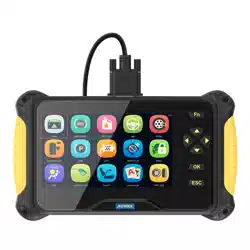
AUTOOL CS603 / CS605 / CS606
User Manual


COPYRIGHT INFORMATION
Copyright
Trademark
Manual are either trademarks, registered trademarks, service
marks, domain names, logos, company names or are otherwise
the property of AUTOOL or its affiliates. In countries where any of
the AUTOOL trademarks, service marks, domain names, logos
and company names are not registered, AUTOOL claims other
rights associated with unregistered trademarks, service marks,
domain names, logos, and company names. Other products or
company names referred to in this manual may be trademarks of
their respective owners. You may not use any trademark, service
mark, domain name, logo, or company name of AUTOOL or any
third party without permission from the owner of the applicable
trademark, service mark, domain name, logo, or company name.
You may contact AUTOOL by visiting AUTOOL at https://www.au-
tooltech.com, or writing to aftersale@autooltech.com, to request
written permission to use materials on this manual for purposes or
for all other questions relating to this manual.
●
●
●
●
All rights reserved by AUTOOL TECH. CO., LTD. No part of this
publication may be reproduced, stored in a retrieval system, or
transmitted in any form or by any means, electronic, mechanical,
photocopying, recording or otherwise, without the prior written
permission of AUTOOL. The information contained herein is
designed only for the use of this unit. AUTOOL is not responsi-
ble for any use of this information as applied to other units.
Neither AUTOOL nor its affiliates shall be liable to the purchaser
of this unit or third parties for damages, losses, costs, or
expenses incurred by the purchaser or third parties as a result
of: accident, misuse, or abuse of this unit, or unauthorized modi-
fications, repairs, or alterations to this unit, or failure to strictly
comply with AUTOOL operating and maintenance instructions.
AUTOOL shall not be liable for any damages or problems
arising from the use of any options or any consumable products
other than those designated as original AUTOOL products or
AUTOOL approved products by AUTOOL.
Other product names used herein are for identification purpos-
es only and may be trademarks of their respective owners.
AUTOOL disclaims any and all rights in those marks.

1
TABLE OF CONTENTS
Product Introduction.......................................................................................... 3
Technical specifications................................................................................... 3
Cable connection for on-board diagnosis........................................................ 3
Product Structure............................................................................................... 4
Structure diagram............................................................................................ 4
Operations Instruction....................................................................................... 5
FN Key ( 3-in-1 Functions defined) ................................................................. 5
Main menu ...................................................................................................... 6
Diagnose - Region selection ........................................................................... 7
Diagnose - Vehicle coverage .......................................................................... 7
Diagnose - Vehicle identification ..................................................................... 8
Diagnose - Control unit ................................................................................... 9
Diagnose - Function selection......................................................................... 9
Diagnose - ECU information ........................................................................... 10
Diagnose - Read fault code............................................................................. 11
Diagnose - Clear fault code............................................................................. 11
Diagnose - Data stream .................................................................................. 12
Special function............................................................................................... 12
Definition of special function ........................................................................... 12
About............................................................................................................... 14
OBDII function................................................................................................. 14
DTC library...................................................................................................... 15
Log upload function......................................................................................... 15
Setting ............................................................................................................. 16
FAQ ................................................................................................................. 16
Warranty.......................................................................................................... 18
Update instructions and procedures ............................................................... 19
Description Of Accessories............................................................................... 22
Maintenance Service.......................................................................................... 23
Maintenance.................................................................................................... 23

2
Warranty .............................................................................................................. 24
Warranty access.............................................................................................. 24
Disclaimer ....................................................................................................... 24
Return & Exchange Service .............................................................................. 25
Return & Exchange ......................................................................................... 25
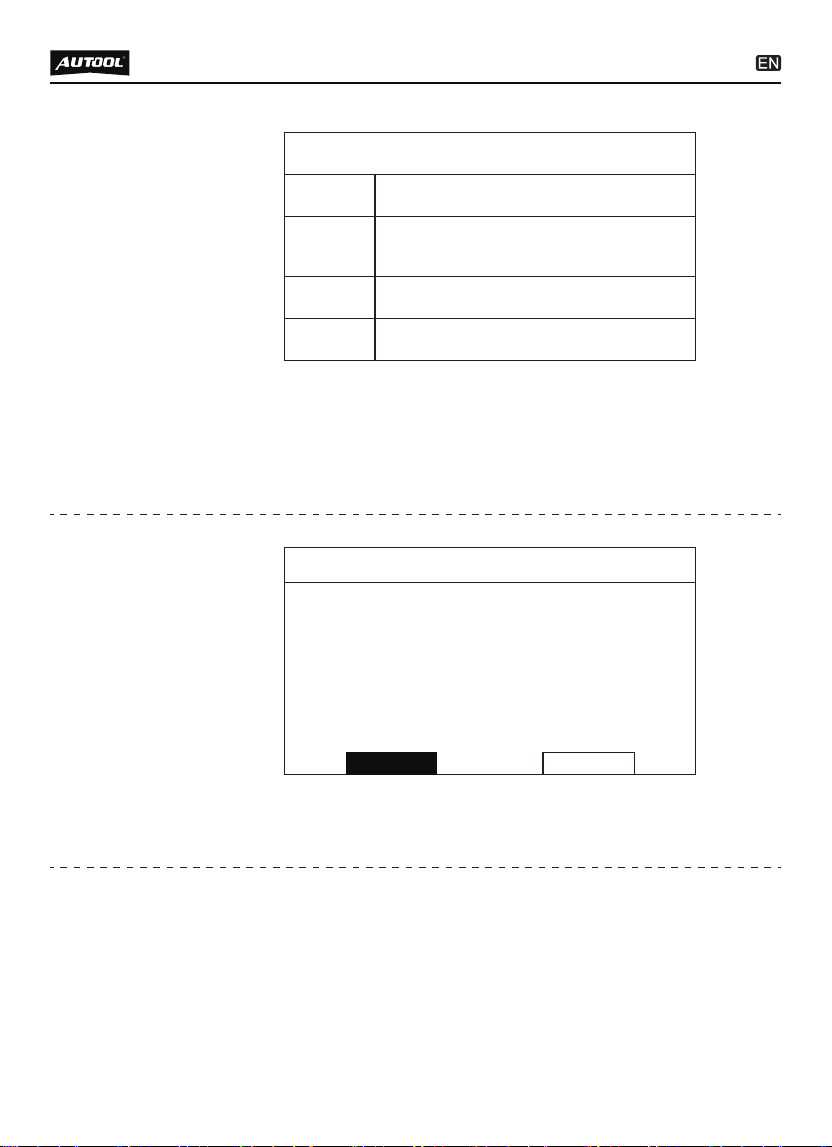
Screen Display
Dimension (LxWxH)
OS Platform
Card Memory
Gross Weight
Input Voltage
7’Color
240x160x110mm
Linux
16G
0.85kg
DC 12V
3
PRODUCT INTRODUCTION
Technical
specifications
Cable
connection
for on-board
diagnosis
To connect the CS603 / CS605 / CS606 main unit with the
main cable to get power supply from the car via OBDII-16
connector.
Connection
4
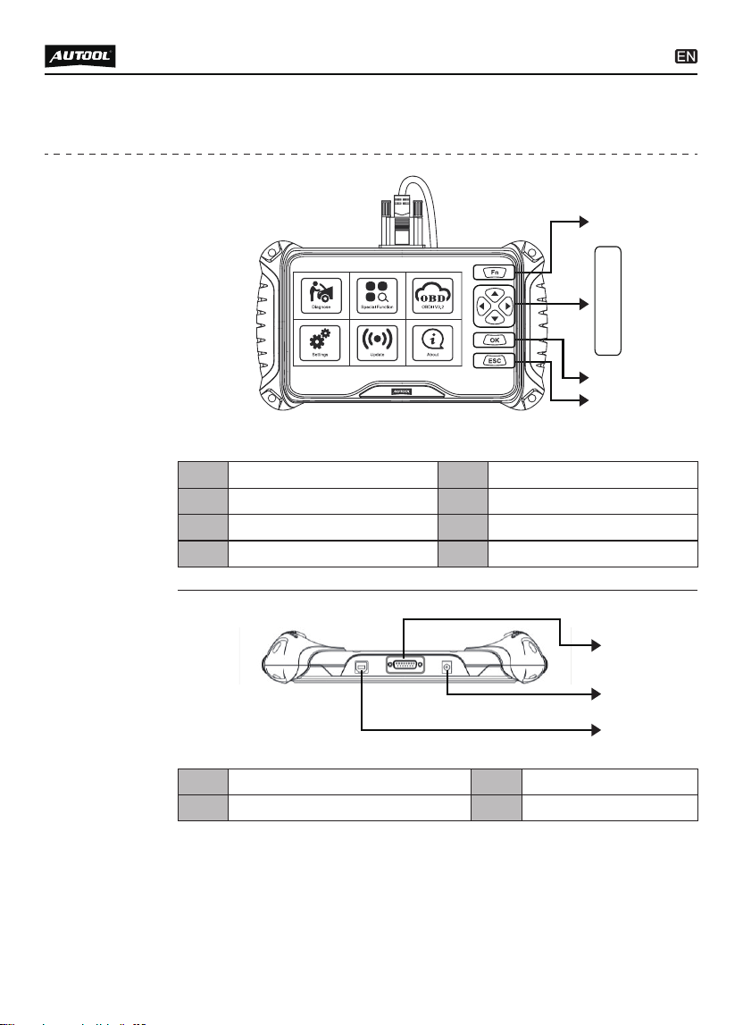
PRODUCT STRUCTURE
Structure
diagram
FN Key Up buttonA B
Down button Left button
C D
Right button OK button
E F
ESC button
G
For main cable connection Power portH I
For USB connection
J
H
I
J
G
A
B
C
D
E
F
5
OPERATIONS INSTRUCTION
Press FN key to select the items in live data function.
After pressing OK, the live data will be displayed in graphic.
●
●
FN Key
( 3-in-1 Func-
tions defined)
FN #1 : Selection
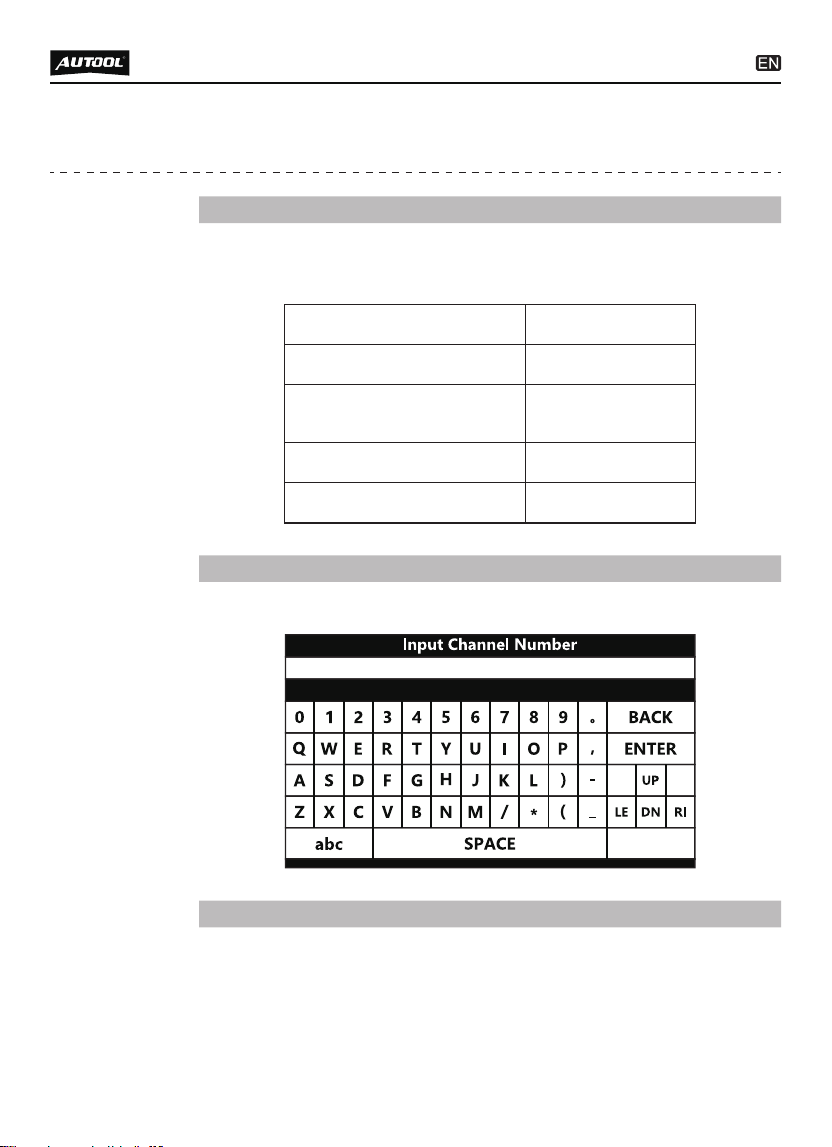
Press FN key to show or hide the keyboard.
●
FN #2 : Show/Hide keyboard
Different operation areas can be switched among each other
by pressing the FN key during the special testing.
●
FN #3: Shift operation area
IGN RUN START SW
IGN STSRT SW
Ignition Start Switch
Filter Switch State
√ MAP Vacuum
√ Map Volts
ON
OFF
OFF
0.00 (in Hg)
4.92 (Volts)
6
Press FN key, the display area will be highlighted as above.
Press the up and down button to view more information.
●
●
Press FN key, the function area will be highlighted as above.
Press the left and right button to actuate more test.
●
●
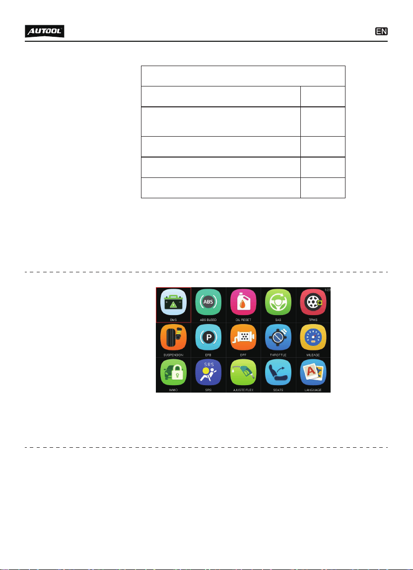
Diagnose:
To access specific diagnosis function directly base on selec-
tion of the areas as well as the car makes.
●
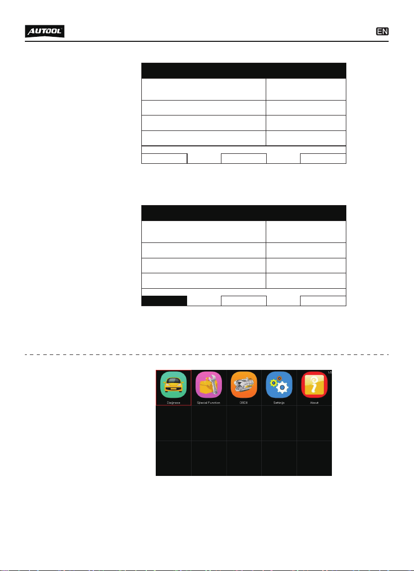
Main menu
Auto Shutdown (ASD) Relay
Auto Shutdown (ASD)
Relay Control State
Off
On
Toggle
F1
F2
F3
BACK F1 F2
Auto Shutdown (ASD) Relay
Auto Shutdown (ASD)
Relay Control State
Off
On
Toggle
F1
F2
F3
BACK F1 F2
7
Special Functions:
To provide 5 common use service resets for the professional
workshop repairs.
OBDII V3.0:
10 modes of OBDII test for cars after 1996 and newer including
read / erase codes, view live data, view freeze frame data, view
I / M readiness, O2 monitor test etc.
Settings:
To provide the system setting, including Language , logging,
unit setting and Bluetooth setting.
Update:
To access online software update for full coverage. Internet
update via WI-FI.
About:
To provide the system information menu.
●
●
●
●
●
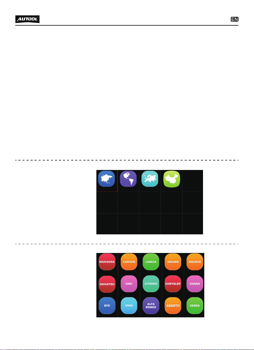
Diagnose -
Region
selection
Diagnose -
Vehicle
coverage

8
Automatic selection
The diagnostic system features the latest VIN-based Auto VIN
Scan function to identify CAN vehicles in just one touch, which
allows the technician to quickly detect vehicles, scan all the
diagnosable ECUs on every vehicle and run diagnostics on the
selected system.
●
Please note that the VT100 is a vehicle-specific car diagnostic
tool. Therefore, it only supports vehicles of a specific car group,
which depends on the pre-installed car brand software. For the
blank version machine, please contact us to install your selected
car brand software.
Diagnose -
Vehicle
identification
American
Vehicle coverage:
GM, FORD, CHRYSLER.
Asian
Vehicle coverage:
TOYOTA, LEXUS, HONDA, ACURA, NISSAN,
INFINITI, HYUNDAI, KIA, SUBARU, ISUZU,
SUZUKI, MAZDA, MITSUBISHI,etc.
European
Vehicle coverage:
BMW, MERCEDES-BENZ, CITROEN, VOLVO,
PEUGEOT, FIAT, OPEL, LANDROVER, AUDI,
JAGUAR, VAUXHALL, VOLKSWAGEN,
REN AULT, etc.
Chinese
Vehicle coverage:
BYD, CHANA, CHEYR, G EELY, GWM, LIFAN, etc.
CHRYSLE
1
2
Automatic selection
Manual selection

9
Manual selection
This mode of vehicle selection is menu driven; you can make a
series of choices, Each selection you make advances you to
the next screen. A Back button returns you to the previous
screen. Exact procedures may vary somewhat by various
vehicles being serviced.
●
This option allows you to manually locate a required control
system for testing through a series of choices. Follow the menu
driven procedures and make proper selections; the application
will guide you to the diagnostic function menu after a few
choices you’re made.
●
Diagnose -
Control unit
Diagnose -
Function
selection
Control Unit
1
2
Powertrain Control Module
Transmission Control Module
3 Anti Lock Brakes
4 AirBag
Powertrain Control Module
1
2
Computer identification
Read fault code
3 Clear fault code
4 Read data stream

Computer identification:
Provides the retrieved ECU information in detail. An informa-
tion screen opens upon selection.
Read fault code:
Displays detailed information of DTC records retrieved from
the vehicle control module.
Clear fault code:
Erases DTC records and other data from the test vehicle’s
ECU.
Read data stream:
Retrieves and displays data stream and parameters from the
vehicle’s ECU.
●
●
●
●
10
The function retrieves and displays the specific information for
the tested control unit, including unit type, version numbers
and other specifications. The sample Vehicle Information
screen displays as above.
During an active test, the tester outputs commands to the ECU
in order todrive the actuators. This test determines the integrity
of the system or parts by reading the engine ECU data, or by
monitoring the operation of the actuators, such as switching a
solenoid, relay, or switch, between two operating states.
●
●
The Function Menu options vary slightly for different vehicles.
The function menu may include:
Diagnose - ECU
information
Vehicle Information
Model Year
ECU Part No.
2010.00
68045613AE
Body Style Station Wagon
Vehicle Line RT
VIN-Original
2D4RN4DE0AR
473865
11
After reading the retrieved codes and making appropriate
vehicle repairs, use this function to clear fault code.
●
This function retrieves and displays the DTCs from the
vehicle’s control system. The Fault code list screen varies for
each vehicle being tested. On some vehicles, freeze frame
data can also be retrieved for viewing. The sample Read
Codes screen displays as above.
●
Diagnose -
Read fault
code
Diagnose -
Clear fault
code
Fault code list
P0522
U0141
Engine Oil Pressure Sensor
Low Communication with IPM
(FCM/TIPM) [Active]
P0685 ASD/Main Control Circuit [Active]
P0627 Fuel Pump Control Circuit/Open
Information
Do you want to erase all the fault
code (s)?
Yes No
12
These functions perform various component adaptations,
allowing you to recalibrate or configure certain components
after some maintenance or replacement.
●
Oil Light Reset
This function allows you to perform reset for the Engine Oil Life
system, which calculations An optional oil life change interval
depending on the vehicle driving conditions and climates. The
Oil Life Reminder must be reset every time the oil is changed,
●
When this function is selected, the screen displays the data list
for the selected module. The items available for any control
module vary by vehicle. The parameters display in the order
that they are transmitted by the ECM, so expect variation
between vehicles.
●
Diagnose -
Data stream
Special
function
Definition
of special
function
CHRYSLER
Current Fuel Shutoff
SKIM VTA Invalid Key
Received Fault Posted
ASD
False
NGC Should Shut Off Fuel Fuel On
SKIM/VATA Has Completed False
IGN RUN START SW On

13
so the system can calculate when the next oil change is
required.
EPB Reset
This function has a multitude of usages to maintain the
electronic braking system safely and effectively. The applica-
tions include deactivating and activating the brake control
system, assisting with brake fluid control, opening and closing
brake pads, and setting brakes after disc or pad replacement,
etc
ABS Bleeding
This function allows you to perform various bi-directional tests
to check the operating conditions of Anti-lock Braking System
(ABS).
(1) When the ABS contains air, the ABS bleeding function
must be performed to bleed the brake system to restore ABS
brake sensitivity.
(2) If the ABS computer, ABS pump, brake master cylinder,
brake cylinder, brake line, or brake fluid is replaced, the ABS
bleeding function must be performed to bleed the ABS.
Throttle Relearn
This function enables you to make initial settings to throttle
actuators and returns the “learned” values stored on ECU to
the default state. Doing so can accurately control the actions of
regulating throttle (or idle engine) to adjust the amount of air
intake.
SAS Reset
To reset the steering angle, first find the relative zero point
position for the car to drive in straight line. Taking this position
as reference, the ECU can calculate the accurate angle for left
and right steering. After replacing the steering angle position
sensor, replacing steering mechanical parts (such as steering
gearbox, steering column, end tie rod, steering knuckle),
performing four-wheel alignment, or recovering car body, you
must reset the steering angle.
●
●
●
●
This section describes the various functions of each option:
14
Stored codes are the current emission-related DTCs from the
ECM of the vehicle. OBD II/EOBD Codes have a priority
according to their emission severity, with higher priority codes
overwriting lower priority codes.
This option is used to clear all emission-related diagnostic data
●
●
About :
Display the system information including the register
password, firmware version, system software version and
company information.
●
About
OBDII
function
Product Serial Number: VT1000002
Register Password: VTTXCN02
Firmware Version: 7001.7048
System Software Version: 5.72
(NOT SUPPORT USB MODE)
Please Select the Nameplate:
[1]
[2]
Read Current Trouble Code
Clear Trouble Code
[3] Read Current Data
[4] Read Pending Trouble Code
[5]
[6]
Read Freeze Frame Data
Readiness Tests
[7] On-Board Monitoring Test
[8] Read System Information

15
●
●
●
●
such as, DTCs, Freeze frame data and manufacturer-specific
enhanced data from the vehicle’s ECM, and reset the I/M
Readiness Monitor Status for all vehicle’s ECM.
This function displays the real time PID data from ECU.
Displayed data includes analog inputs and outputs, digital
inputs and outputs, and system status information broadcast
on the vehicle data stream.
These are codes that were generated during the last drive
cycle, but before the DTC actually sets, two or more consecu-
tive drive cycles are needed. The service is to assist the
service technician after a vehicle repair and after clearing
diagnostic information, by expect or see differences between
makes.
Typically, the stored frame is the last DTC that occurred.
Certain DTCs that have a greater impact on vehicle emission,
have a higher priority. The top prioritized DTC is the one for
which the freeze frame records are retained.
This function is used to check the readiness of the monitoring
system. It is an excellent function to use prior to having a
vehicle inspected for state emissions compliance. Select I/M
readiness to display a sub menu with two choice.
Use this option to view the result of On-Board Monitor tests.
The tests are useful after servicing or after erasing a vehicle’s
control module memory.
The option displays the vehicle identification number (VIN), the
and other information of the test vehicle.
●
DTC search function
●
●
DTC library
●
“Feedback” (log upload function)
Log upload
function

Setting
Why cannot install AUTOOL update client correctly?
16
After installing the AUTOOL Update Client software, the
system won’t accept the serial number for the auto scanner.
●
FAQ
Language
Display multi-languages function menu.
Total 18 languages optional.
Only 2 languages loaded before delivery:
English + local language
Unit
Display unit setting menu.
Unit includes: Metric and English units.
Press OK to change the unit setting selection.
Record
Display record setting menu.
Record includes: On and Off.
Press OK to change the record setting selection.
This function allows data recording during the car testing.
Button Test
Display button function menu.
Press the FN key for 2 seconds to quit the button test.
LCD Test
Display LCD test function menu.
Press ESC to quit the LCD test.
Beep
Display beep setting menu.
Beep includes: On and Off.
Press OK to change the beep setting selection.

You need to connect auto scanner to PC with the USB cable
before software download.
NOTE
Why the vehicle linking error?
A communication error occurs if the auto scanner fails to
communicate with the vehicle ECU. Follow the steps to check
the connections:
(1) Verify the ignition is ON.
(2) Check the cable or connector is securely connected to the
vehicle DLC.
●
17
Why the device doesn’t power up?
If the auto scanner won’t power up or operate correctly in any
other way, follow the steps to check the connections:
(1) Check the connector properly inserted to the socket seat.
(2) Check the DLC pins bent or broken.
(3) Clean the DLC pins if necessary.
(3) Turn the ignition off and wait for about 10 seconds and turn
the ignition back to ON and continue the testing.
(4) Verify the control module is not defective.
●
Why the device have no permission to update?
Please contact the local distributor to get authorization.
●
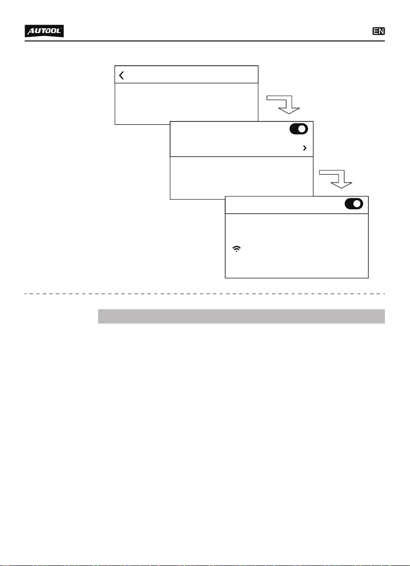
Why cannot find the WIFI name?
The device can only display the Wifi name consisting of
English character or numbers.
●
How to set Wifi if the mobile is iPhone 11 or higher
version?
Click the Settings from the iPhone mobile to access Personal
Hotspot. Click Allow Others to Join and input Wi-Fi Password
and meanwhile switch on Maximize Compatibility.
●
12 - Month Limited Warranty
18
AUTOOL warrants to the original retail purchaser of this
AUTOOL auto scanner, that should this product or any part
thereof during normal consumer usage and conditions, be
proven defective in material or workmanship that results in
product failure within twelve (12) months period from the date
of delivery, such defects will be repaired, or replaced (with new
or rebuilt parts) with Proof of Purchase, at the Company’s
option, without charge for parts or labor directly related to the
defects.
The Company shall not be liable for any incidental or conse-
quential damages arising from the use, misuse, or mounting of
the auto scanner. Some states do not allow limitation on how
long an implied warranty lasts, so the above limitations may
not apply to you.
●
●
Warranty
Personal Hotspot on your iPhone can provide
lnternet access to other devices signed into your
iCloud account without requiring you to enter the
password.
Settings
Personal Hotspot
Allow other users or devices not signed into
iCloud to look for your shared network "Oliver "
when you are in Personal Hotspot settings or
when you turn it on in Control Center.
TO CONNECT USING WI-FI
1. Choose "Oliver" from the Wi-Fi settings
on your computer or other device.
2. Enter the password when prompted.
Internet performance may be reduced for
devices connected to your hotspot when
turned on.
Allow Others to Join
Wi-Fi Password 12345678
Maximize Compatibility
19
Product subject to abnormal use or conditions, accident,
mishandling, neglect, unauthorized alternation, misuse,
improper installation or repair or improper storage;
Products whose mechanical serial number or electronic serial
number has been removed, altered or defected;
Damage from expose to excessive temperatures or extreme
environmental conditions;
Damage resulting from connection to, or use of any accessory
or other product not approved or authorized by the Company;
Defects in appearance, cosmetic, decorative or structural
items such as framing and non operative parts;
Product damaged from external causes such as fire, dirt, sand,
battery leakage, blown fuse, theft or improper usage of any
electrical source.
●
●
●
●
●
●
Update
instructions
and proce-
dures
All contents of the product may be deleted during the process
of repair. You should create a back-up copy of any contents of
your product before delivering the product for warranty
service.
IMPORTANT
This warranty does not apply to:
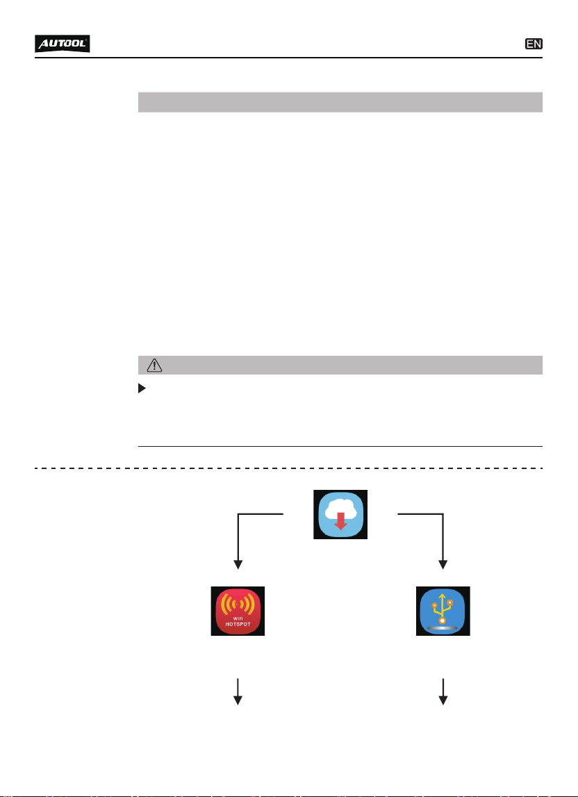
Update
Via WIFI
Update via WIFI mode
Via USB
Update via USB mode
20
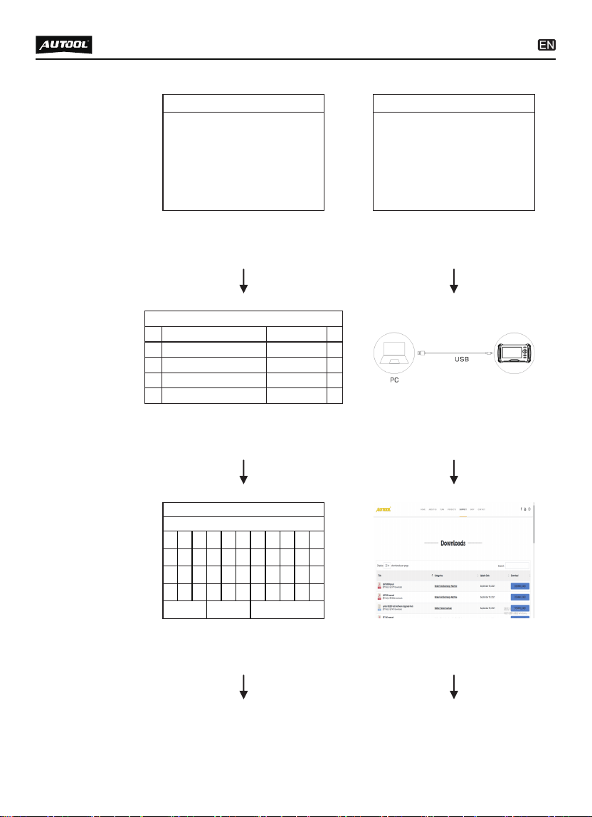
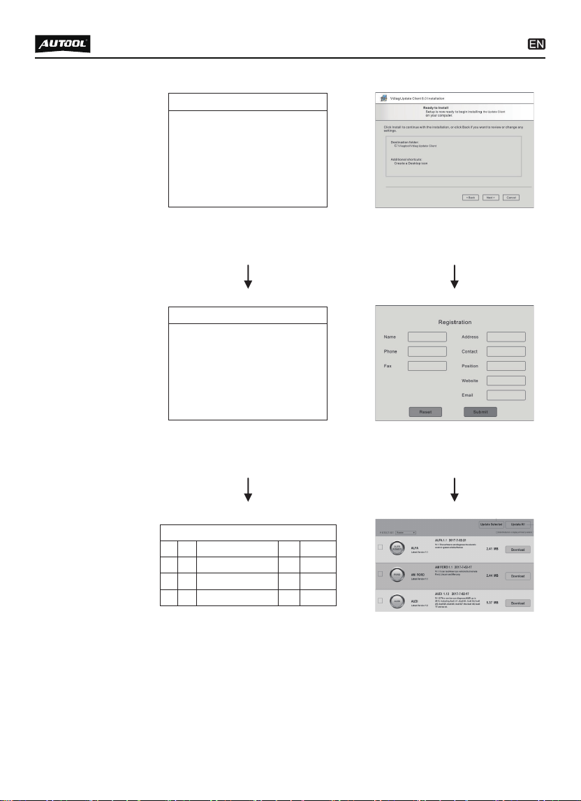
Step 1
Searching WIFI signal
after selecting the WIFI icon.
Step 1
The information mentioned above
will be displayed during the update.
UPDATE
Searching Wifi ...
INFORMATION
1. Make sure the update client has been
installed in your PC (Windows 7/8/10 only).
2. Make sure the device and your PC connect
with USB cable.
3. Press “OK”, the device will restart and
enter the update mode.
4. Run the update client in your PC,
Step 2
The system will list all
HOTSPOT on site.
Step 2
Connect the PC to CS603 / CS605 /
CS606 main unit with USB cable.
Please Select the Nameplate:
[1]
[2]
Internet Telcel HH41NH_BE7B
PRD
[3] PRD_Wi-Fi5
[4]
AUTOOL 5G
[5]
FEIKEYY
e4:e1:30:82:8e:7b
c0:b4:7d:63:ae:94
80
88
c0:b4:7d:f3:ae:99 78
f4:2a:7d:50:a6:88 77
64:6e:97:a4:71:b8 76
Step 3
Input the password if necessary.
Step 3
Visit the website
www.autooltech.com
0
q
a
z
ABC
1
w
s
x
2
e
d
c
3
r
f
v
4
t
g
b
5
y
h
n
6
u
j
m
7
i
k
/
8
o
l
*
9
SPACE Backspace
p
)
(
。
,
-
_
PASSWORD
1a2345
21
Step 5
Connect the Server as above.
Step 5
Input the necessary information
during the first registration.
Step 4
Connecting the WIFI
during the testing.
Step 4
Download AUTOOL Update Client
to PC according to the instructions.
UPDATE
Connecting Wifi ...
UPDATE
Connecting Server...
Step 6
Select the car makes for update
according to the demands.
Step 6
Select the car makes for update
according to the demands.
UPDATE
[1]
[2]
AMFORD, EUR FORD
BENZ
[3] BMW
[4]
√
√
CHANA
5.82
4.22
37.81MB
19.54MB
3.7 7.01MB
3.14 4.29MB

22
DESCRIPTION OF ACCESSORIES
Name
Nylon tool bag
Main cable with OBDII-16
User Manual
Name
Main unit
USB cable

23
Be careful not to rub the product against rough surfaces or
wear the product, especially the sheet metal housing.
Please regularly check the product parts that need to be
tightened and connected. If found loose, please tighten it in
time to ensure the safe operation of the equipment. The exter-
nal and internal parts of the equipment in contact with various
chemical media should be frequently treated with anti-corrosion
treatment such as rust removal and painting to improve the
corrosion resistance of the equipment and extend its service
life.
Comply with the safe operating procedures and do not
overload the equipment. The safety guards of the products
are complete and reliable.
Unsafe factors are to be eliminated in time. The circuit part
should be checked thoroughly and the aging wires should be
replaced in time.
Adjust the clearance of various parts and replace worn
(broken) parts. Avoid contact with corrosive liquids.
When not in use, please store the product in a dry place. Do
not store the product in hot, humid, or non-ventilated places.
Our products are made of long-lasting and durable materials, and
we insist on perfect production process. Each product leaves the
factory after 35 procedures and 12 times of testing and inspec-
tion work, which ensures that each product has excellent quality
and performance.
To maintain the performance and appearance of the product, it is
recommended that the following product care guidelines be read
carefully:
●
●
●
●
●
●
MAINTENANCE SERVICE
Maintenance

24
WARRANTY
The repair or replacement of products is determined by the
actual breakdown situation of product.
It is guaranteed that AUTOOL will use brand new component,
accessory or device in terms of repair or replacement.
If the product fails within 90 days after the customer receives
it, the buyer should provide both video and picture, and we will
bear the shipping cost and provide the accessories for the
customer to replace it free of charge. While the product is
received for more than 90 days, the customer will bear the
appropriate cost and we will provide the parts to the customer
for replacement free of charge.
The product is not purchased through official or authorized
channels.
The product breakdown because the user does not follow
product instructions to use or maintain the product.
From the date of receipt, we provide a three-year warranty for the
main unit and all the accessories included are covered by a
one-year warranty.
We AUTOOL pride ourselves on superb design and excellent
service. It would be our pleasure to provide you with any further
support or services.
All information, illustrations, and specifications contained in this
manual, AUTOOL resumes the right of modify this manual and the
machine itself with no prior notice. The physical appearance and
color may differ from what is shown in the manual, please refer to
the actual product. Every effort has been made to make all
descriptions in the book accurate, but inevitably there are still
inaccuracies, if in doubt, please contact your dealer or AUTOOL
after-service centre, we are not responsible for any consequences
arising from misunderstandings.
●
●
●
●
●
These conditions below shall not be in warranty range
Warranty
access
Disclaimer

25
If you are an AUTOOL user and are not satisfied with the
AUTOOL products purchased from the online authorized
shopping platform and offline authorized dealers, you can
return the products within seven days from the date of receipt;
or you may exchange it for another product of the same value
within 30 days from the date of delivery.
Returned and exchanged products must be in fully saleable
condition with documentation of the relevant bill of sale, all
relevant accessories and original packaging.
AUTOOL will inspect the returned items to ensure that they
are in good condition and eligible. Any item that does not pass
inspection will be returned to you and you will not receive a
refund for the item.
You can exchange the product through the customer service
center or AUTOOL authorized distributors; the policy of return
and exchange is to return the product from where it was
purchased. If there are difficulties or problems with your return
or exchange, please contact AUTOOL Customer Service.
●
●
●
●
RETURN & EXCHANGE SERVICE
Return &
Exchange
China
Oversea Zone
E-mail
Facebook
YouTube
400-032-0988
+86 0755 23304822
aftersale@autooltech.com
https://www.facebook.com/autool.vip
https://www.youtube.com/c/autooltech