Loading ...
Loading ...
Loading ...
14
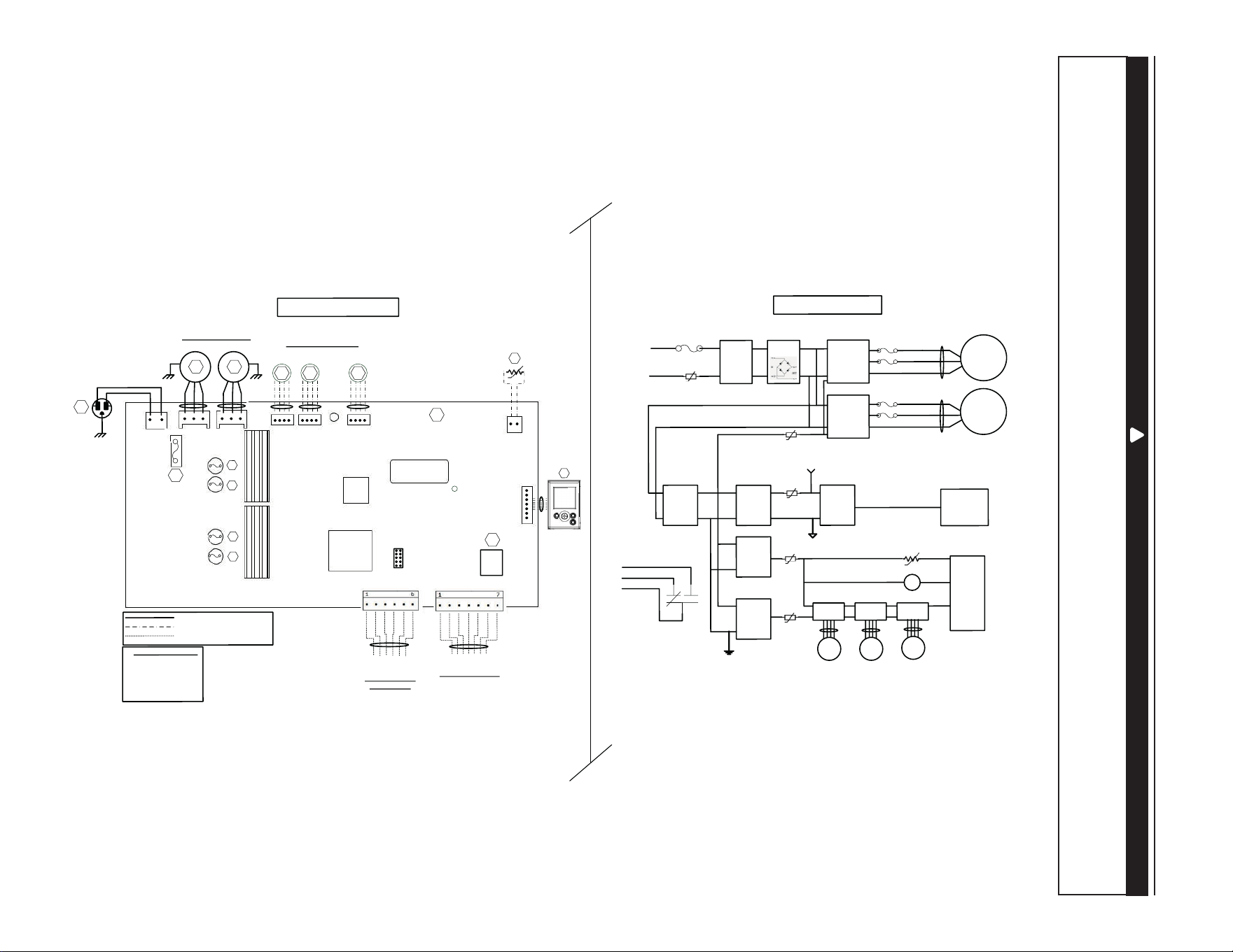
4. WIRING DIAGRAM
BLK
B
L
K
GRN
LOGIC DIAGRAM
W
IRING COL
O
R CODE
BLK BLA
C
K
BLU BLUE
GR
NGREE
N
RED RED
WHT
W
HITE
Line voltage factory
wiring
Low vol
t
age factory wiring
Low vol
t
age field wir
in
g
(Exhaust
)
B
LU
R
E
D
120VAC
60Hz
W1
GRN
F1
1
P
ower
LED
J1
M2
Damper
Stepper M
otors
Y
M1
W
HT
B
LK
A1
MAIN EL
E
CTRO
NIC
A
SSEMBLY
M1
Po
wer
Supply
(15V
DC
)
Line
N
eutral
K1
G
Gf
AC
Line
Filter
J1-2
F1
High Voltage
(120VAC
)
J1-1
To J
2
MCU
K1
M3
St
epper
Driver
To J
5
WIRING DIAGRAM
BDM
1
5A
/125VAC
J
2J
3
J5 J6
J7
1
11
1
1
J7a
J
15a
1
A2
L
C
D
ASSEM
B
L
Y
GR
N
Ve
ntilatio
n Fan Motors
BLU
RED
M2
M3
M4
(Supply
)
(Suppl
y
)
* Op
tional
(Recir
c
)
(E
x
haust
)
MCU
Serial
N
um
ber
Isolation
Tr
a
nsformer
M
otor Fuses
F2
F3
F4
F5
V
W
Gf
C
G
R
* Optio
nal Cen
tral Forced-A
ir
S
yste
m Wi
r
ing
(Isolate
d 2
4VAC
)
OV
R
LED
12V
D-
D+
G
N
D
Main and A
uxil
liar
y
C
o
ntrols Wiring
Thermisto
r
R1
RT1
(NTC
)
Bridge
IPM
Motor 1
IPM
Motor 1
F3
F2
M2
To J
3
F5
F4
Cent
r
al
Forc
e
d-
Air
System
Relay
K1
PTC
3
I
solat
e
d
S
upply
(12VDC
)
Isolat
ed
Supply
(3.3
VDC
)
J9
J1 3
L
ogic
Suppl
y
(3.3
VDC
)
P
TC
2
To J
9
L
ogic
Supply
(12VDC
)
M4
Stepper
D
river
To
J
6
M5
Stepper
Dr
iver
T
o J
7
PTC
6
PTC
4
T
o J13
R
TH
1
To
J
7a
(R1)
LCD
Assembly
I
solated GND
Digital GN
D
T
o
J15
a
(A2)
Recirc
ulation
Damper (J6
) i
s
not present for
al
l
models
J1 4
VE0452A
WARNING
• Risk of electric shocks. Before performing any maintenance or servicing, always disconnect the unit from its power source.
• This product is equipped with an overload protection (fuse). A blown fuse indicates an overload or a short-circuit situation.
If the fuse blows, unplug the product from the outlet. Discontinue using the unit and contact technical support.
!
Loading ...
Loading ...
Loading ...