IP Surveillance
Installation Guide
Using
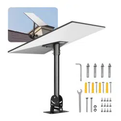
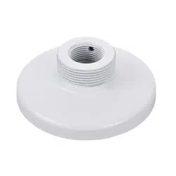
AM-52E Mounting Adapter,
AM-118 Pendant Head (indoor),
AM-114 Pendant Head (outdoor)
AM-116 and AM-117 Pendant Pipes,
AM-522 NPT adaptor
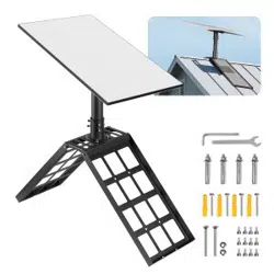
AM-218 Wall Mount,
AM-312 Pole Mount,
AM-412 Corner Mount
VIVOTEK Fixed Dome Series
Mounting kit
Rev. 1.0
Corresponding part number:
AM-52E: 100217700G
AM-116: 900014301G
AM-117: 900014401G
AM-118: 900014601G
AM-312: 900034802G
AM-412: 900034902G
AM-522: 900020202G
AM-218: 100146100G
AM-114: 900004101G
3
English
WARNING:
1. Select a suitable location where the camera is free from accidental damage, tampering,
or harsh environmental conditions.
2. Locate a place for the installation where the camera can not be intentionally or
unintentionally interfered.
3. Select a solid and at mounting surface that can support the combined weight of the
camera and associated hardware. Vibration and temperature range should also be taken
into consideration.
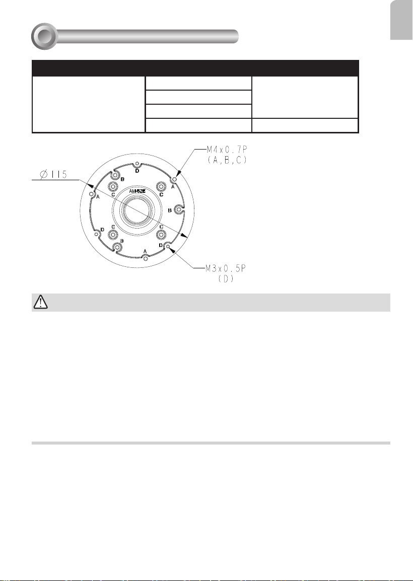
Compatible VIVOTEK Cameras
1
Combination
Compatible Models Screw
Direct installation:
AM-118/114 + AM-117/116
+ AM-52E
A: FD9360-H, FD9380-H M4x8
B: IT9388-HT
C: IT9360-H, IT9380-H
D: IT9389-H, IT9389-HT M3x8
4
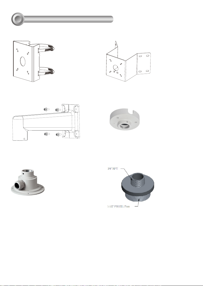
Compatible Accessories (5-1): AM-118
Pendant Head
Compatible Accessories (1): AM-312 Pole
Mount Bracket
Compatible Accessories (2): AM-412
Corner Mount Bracket
Compatible Accessories
2
Compatible Accessories: AM-522
Pendant NPT Adaptor
Compatible Accessories (4-3): AM-218
Wall-mount Bracket
Compatible Accessories (5-2): AM-114
Pendant Head
5
English
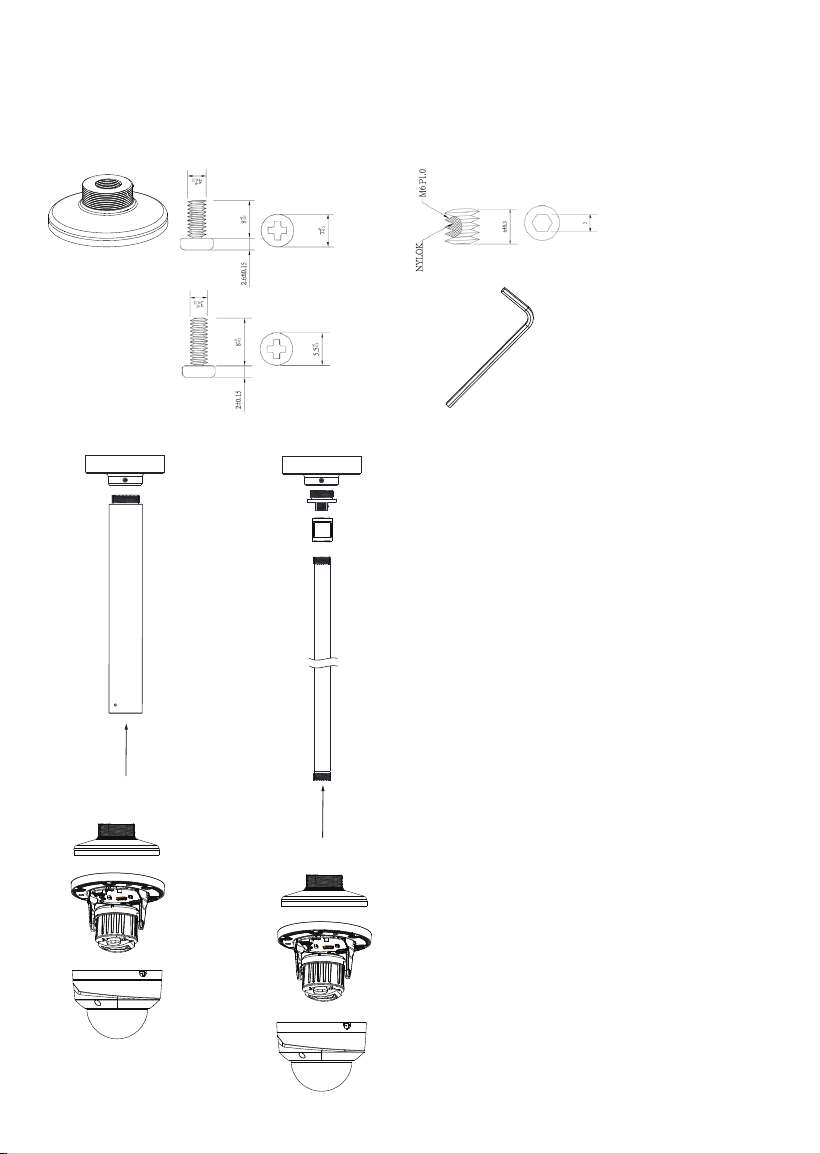
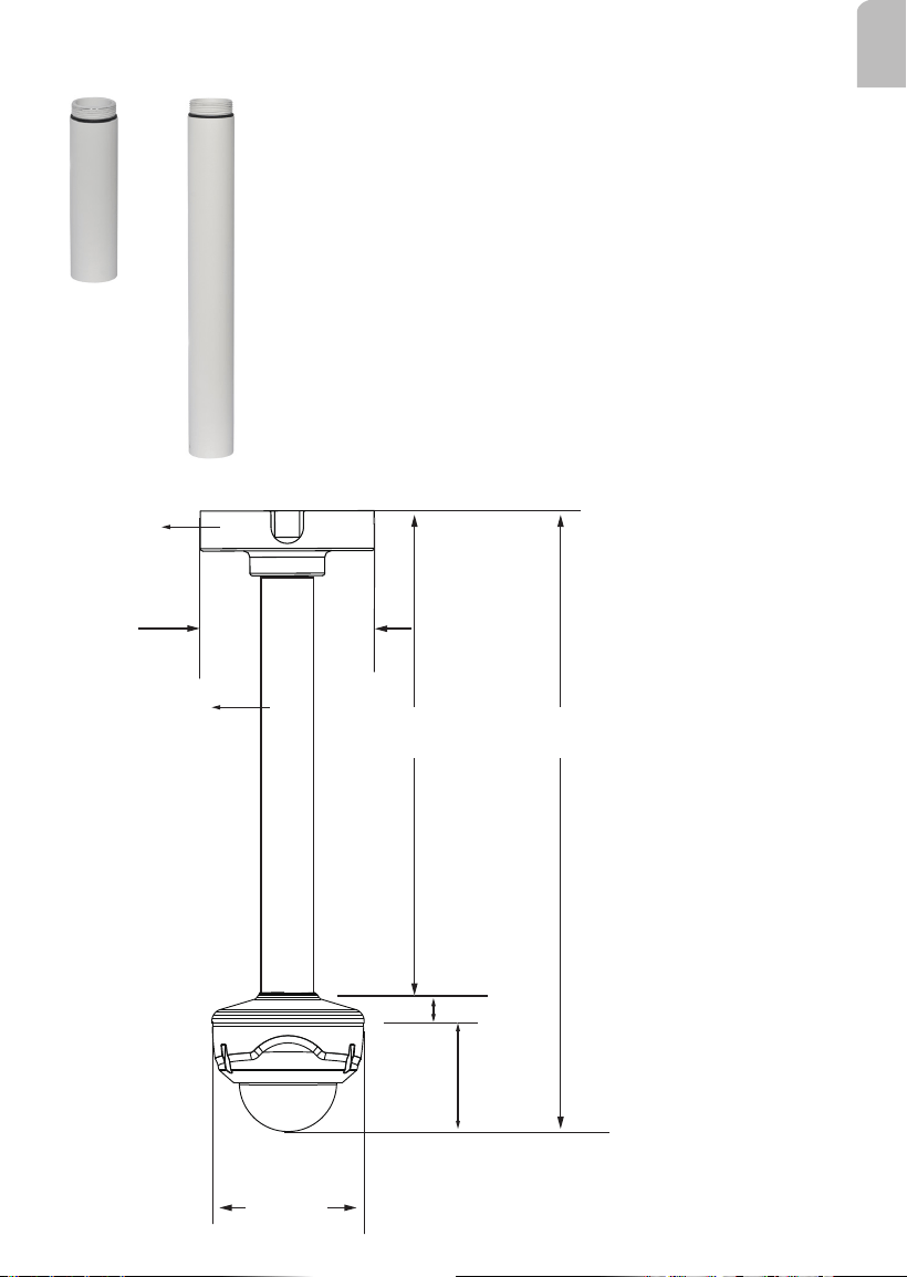
Compatible Accessories (5-2): AM-116 and AM-117 Pendant Pipe
307 mm
117.1 mm
438.2 mm
AM-118
AM-117
24.5mm
140 mm
552.2mm
FD9380
89.5 mm
Shown below are the mounting dimensions using a 40cm pendant pipe (AM-117).
6
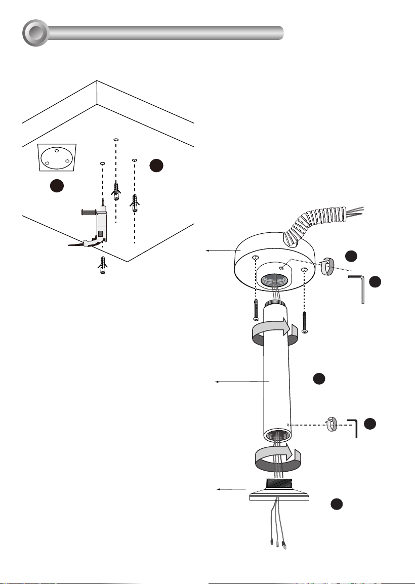
Direct Installation
3
2
1
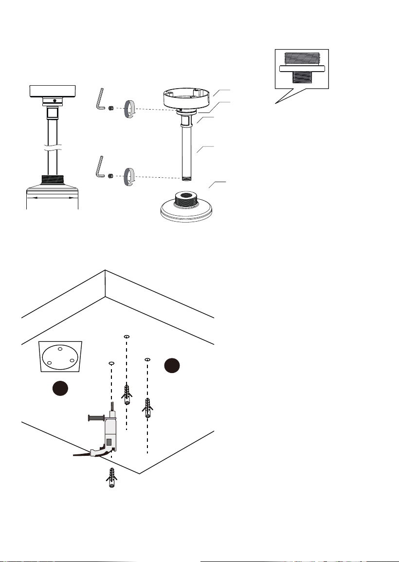
1. Determine a hard surface ceiling
location, and use the included alignment
sticker for marking three mounting holes
as where holes will be drilled to secure
the pendant head.
2. Hammer in the plastic anchors.
3
4
5
7
6
AM-118
AM-116/
AM-117
AM-52E
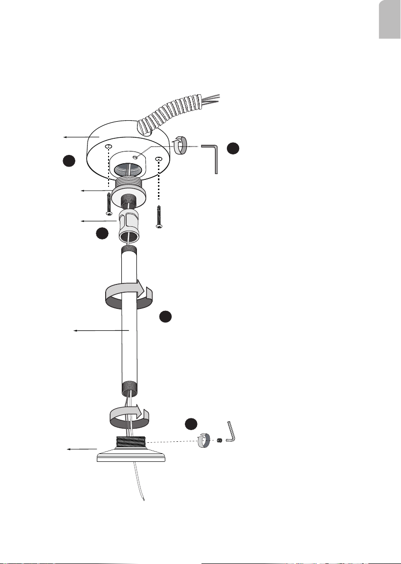
3. Secure pandant head using the included
screws.
4. Install the pendant pipe.
5. Tighten the retention screw using the hex
wrench.
6. Install the AM-52E.
7. Tighten the retention screw using the
included hex wrench.
3-1. Using the Pendant Pipe
7
English
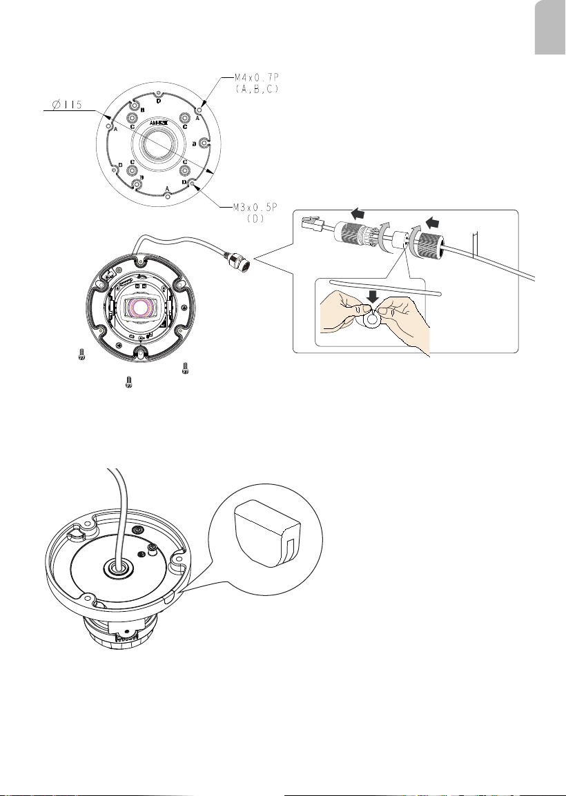
8. Pull the cables through the pendant pipe, and install the waterproof cable gland. Install
the camera using the corresponding mounting holes.
5.5 ~ 6.4mm
Some cameras come with a side-routing cutout. Use the included side lid to seal the
cutout.
8
2
1
1. Determine a hard surface ceiling location, and use the included alignment sticker for
marking three mounting holes as where holes will be drilled to secure the pendant head.
2. Hammer in the plastic anchors.
3-2. Using the 3/4" NPT Pipe
AM-118
3/4" Female adapter
3/4" pendent pipe
AM-52E
AM-522
115 mm
9
English
3
4
5
AM-118
AM-522
NPT female-
female coupler
7
6
3/4” NPT pipe
AM-52E
3. Secure the pandant head using the included screws.
4. Install the AM-522 adaptor and the NPT female-female coupler (user-supplied)
5. Tighten the hex socket screw using the hex wrench.
6. Install the 3/4" NPT pipe of a preferred length.
7. Install the AM-52E.
10
8. Pull the cables through the NPT pipe and the camera base. Align the camera's
mounting holes with the associated holes on the bracket. It is recommended to install
the waterproof cable gland.
11
English
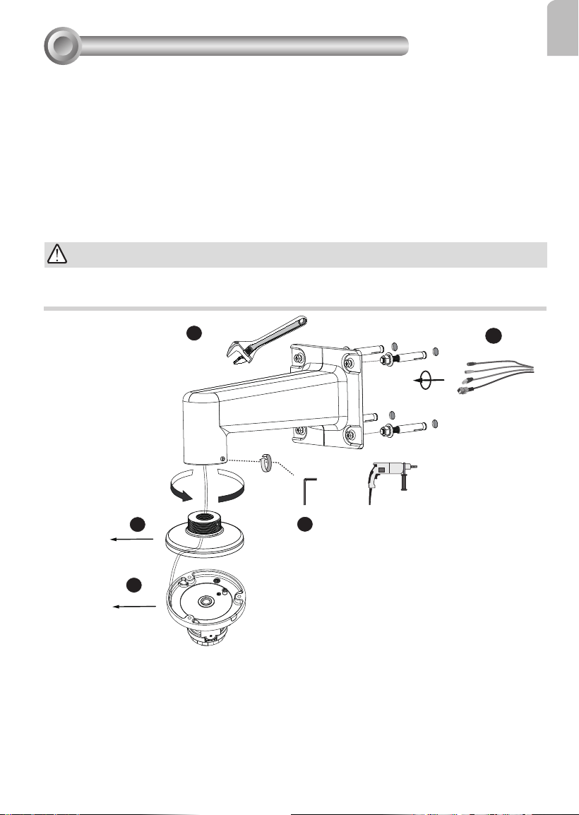
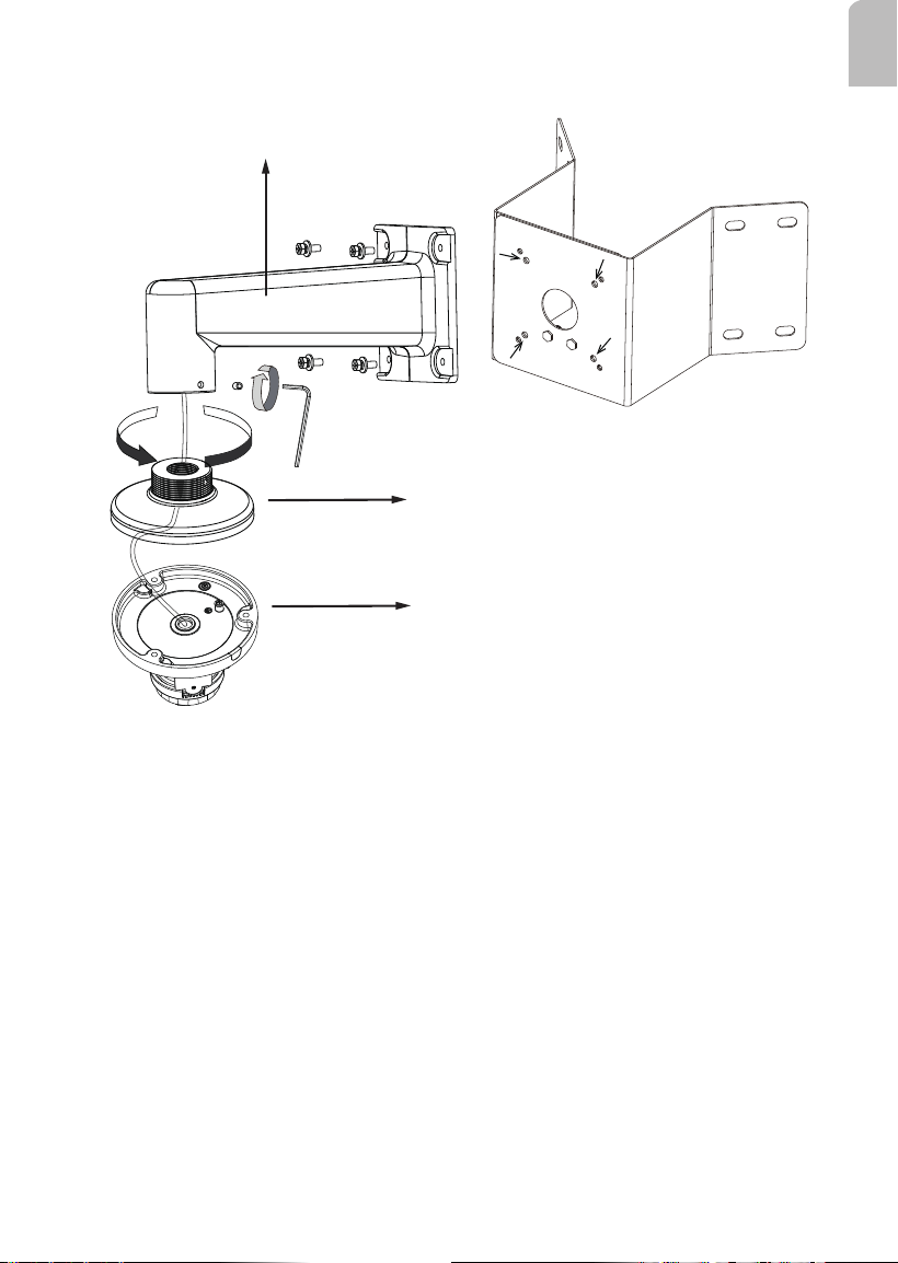
Below is a general, sample procedure using a gooseneck bracket:
1. Route the Ethernet and/or other cables through the wall and the bracket.
2. Locate the position where you want to install the wall-mount bracket and camera. Drill
holes on the wall for securing the bracket and for routing the cables.
Secure the bracket by hammering anchors into the wall and then fasten screws through
it. Drill 10mm holes in diameter and 60mm deep.
3. Attach the mounting adapter to the bracket by rotating it clockwise until it is tightly
fastened.
1
2
3
4
55
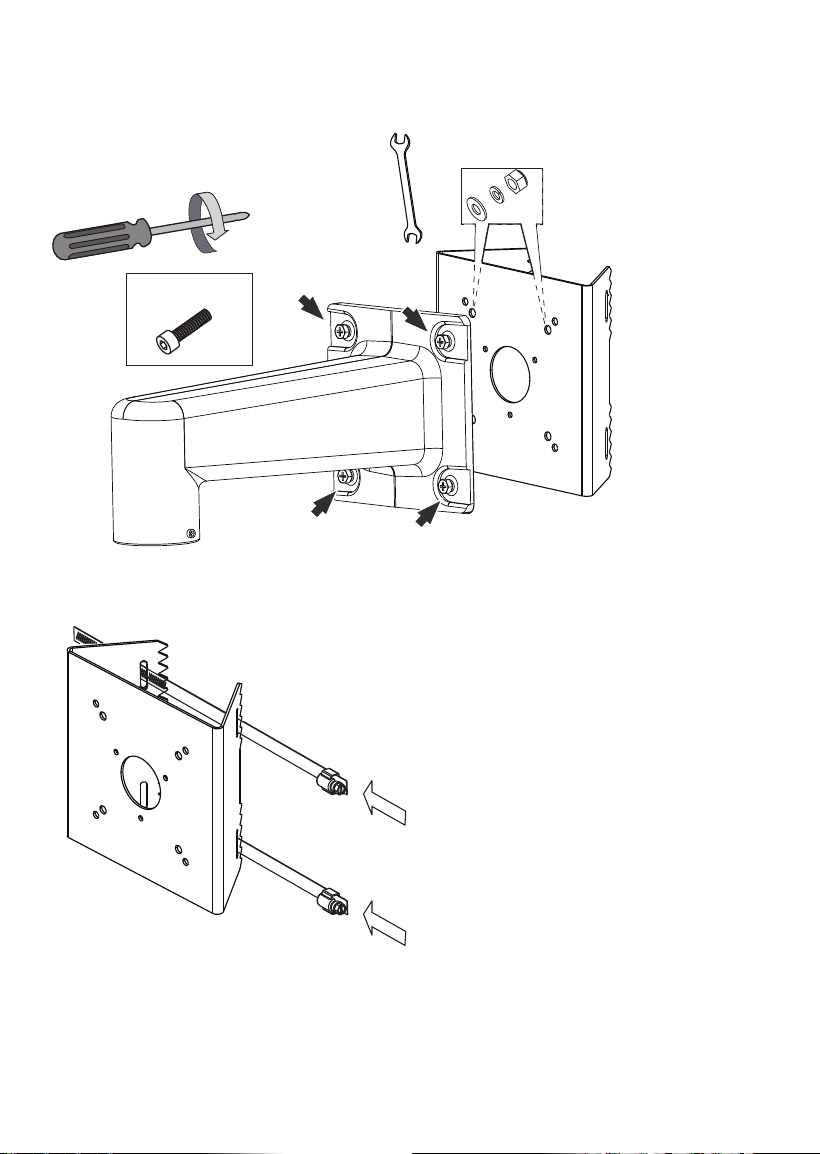
4. Use a hex wrench to secure the mounting adaptor to the wall-mount bracket.
5. When cabling is done, proceed with initial setup such as enabling network access, focus
tuning, or zooming. When done, secure the outer dome cover.
Cables
Mounting adapter
Dome camera
4-1. Wall-mount Installation - AM-218
Using Other Accessories
4
WARNING:
When you hammer the threaded anchors into wall, keep the nuts and washers on them in
case the top of threaded poles can be deformed during the process.
12
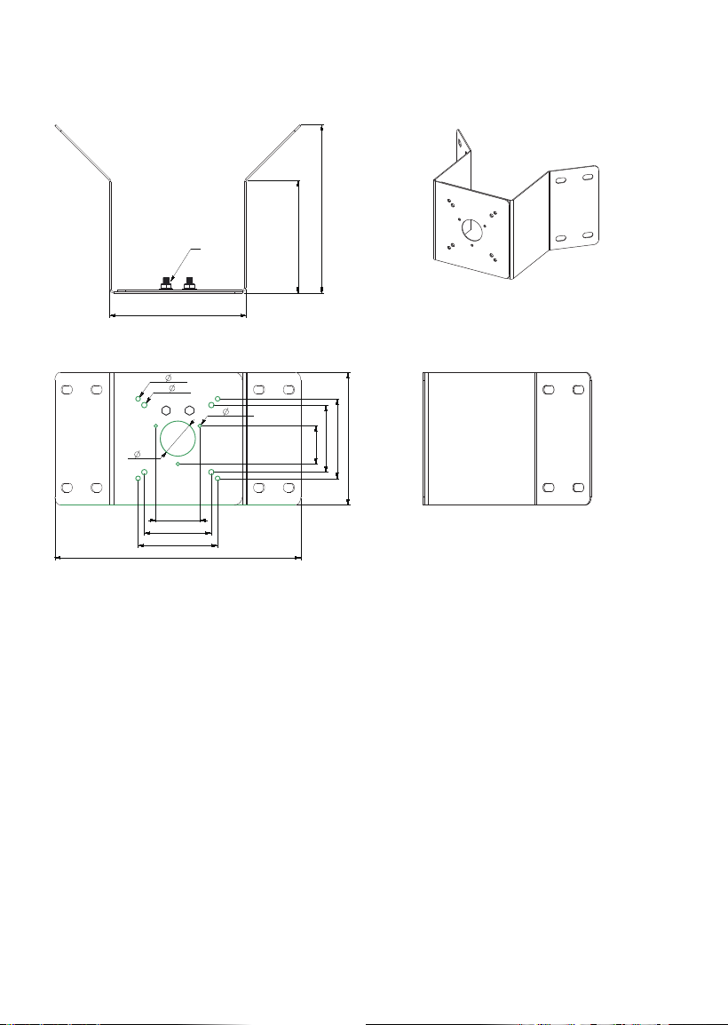
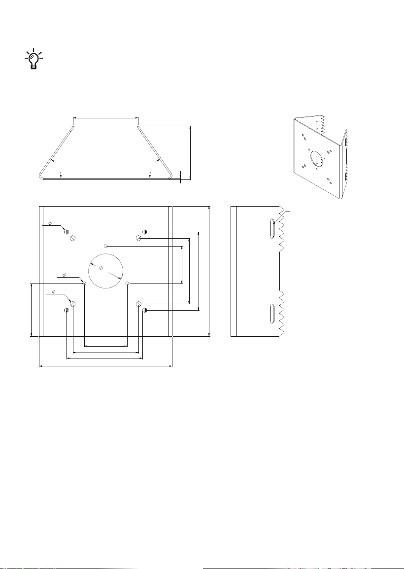
4-2. Corner Mount Installation
Dimension drawing:
170
315,25
45
4-6
4-7
86
102
86
102
56,29
48,75
3-4,5
175
215,71
144,17
M8X20mm
SUS 302
13
English
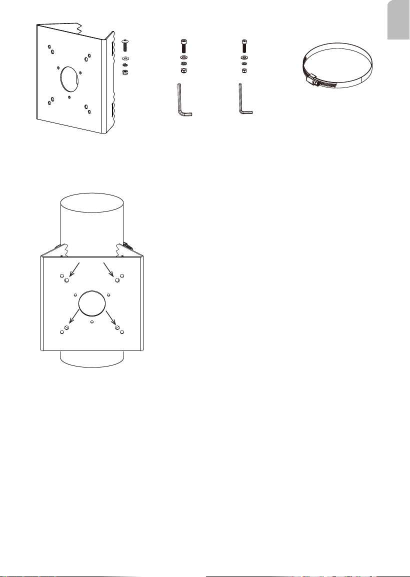
M6X20
X4
M4X15
X4
5mm X1
M5X20
X4
4mm X1
M8
X2
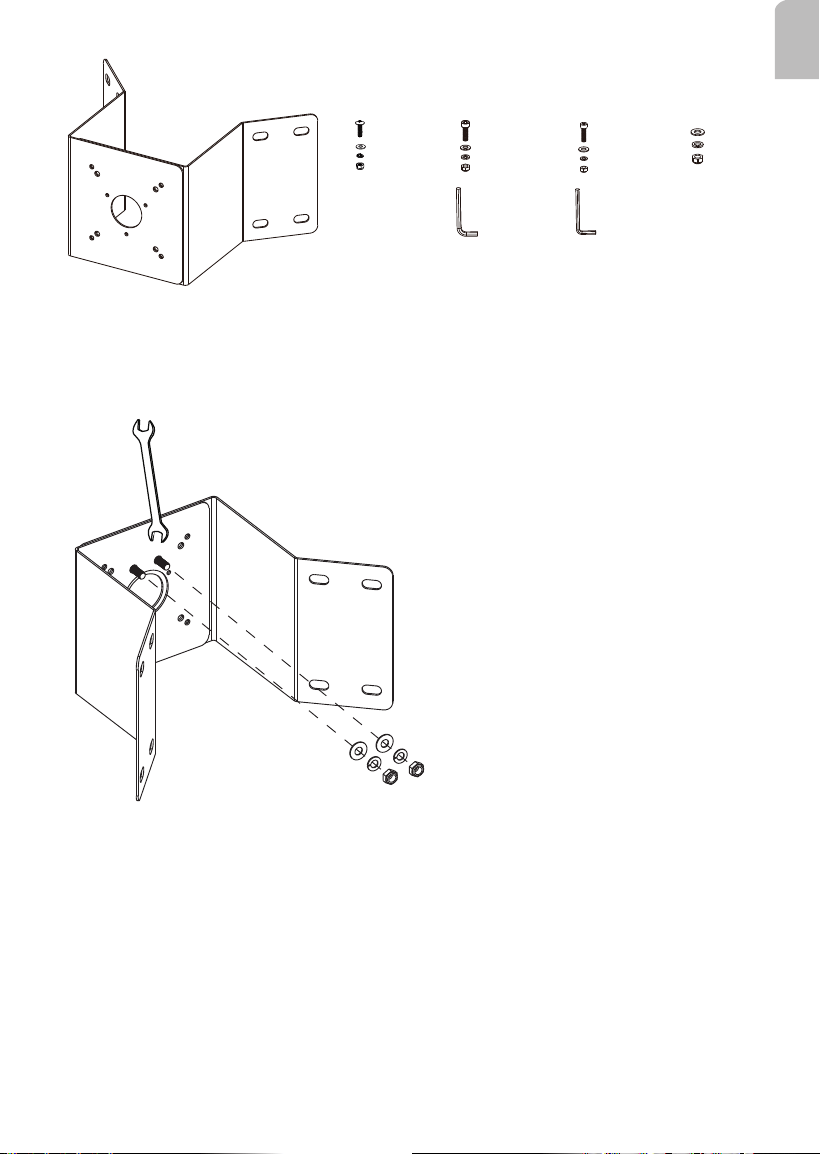
Below is a general, sample procedure using a Corner mount bracket:
1. Combine the two metal pieces together using the M8 hex nuts and washers.
14
x8
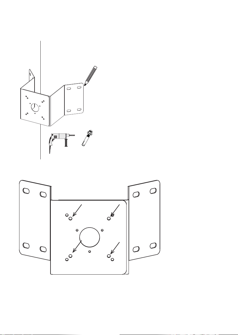
The 4 screw holes marked below are used for mounting the bracket (using the M4 screws).
2. Align the assembled brackets with the desired position. Align screw holes on the
brackets against the wall. Drill holes on the wall for securing the bracket and for routing
the cables. Hammer the anchors into the wall. Note that these screws and wall anchors
are user-supplied.
15
English
AM-218
Dome camera
AM-52E
3. Install the AM-218 bracket to the top of AM-312. Install the AM-52E to the bracket and
tighten the retention hex screw.
16
4-3. Pole Mount Installation
173,79
170
45
4-6
102
2
55°
55°
70,05
86
4-7
84,9
86
99
56,29
48,75
3-4,5
68,75
4-OB 25.5X5.5mm
The pole mount bracket is designed to accommodate a pole in a diameter ranging from 90
~ 152mm (3.5 ~ 6 inches)
17
English
M6X20
X4
5mm
X1
M5X20
X4
4mm
X1
Stainless steeel strap
X2
M4X15
X4
Below is a general, sample procedure using a Pole mount bracket:
Use the mounting holes indicated below for the conduit box.
18
1. Secure the AM-719 conduit box to bracket using the M4 screws, washers, and hex
heads. A hex crescent wrench is required. You can do this before you install the pole-
mount bracket.
M4
2. Pass the stainless steel straps through the bracket and around the pole.
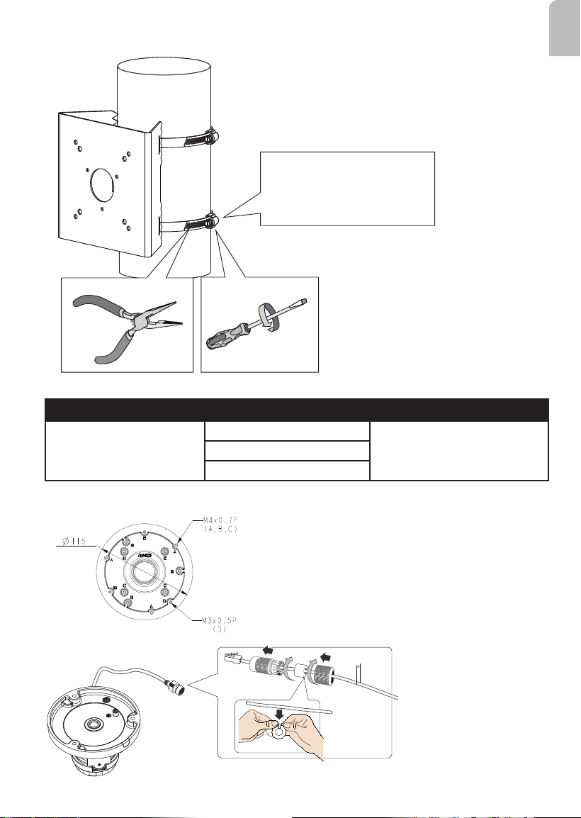
19
English
Installation Torque:
35 lb-in(40kg-cm)
4. Tighten the straps using a pincer plier and a at blade screwdriver.
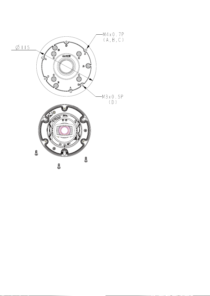
The corresponding mounting holes and cameras are shown below:
Combination
Compatible Models Screw
Direct installation:
AM-52E
A: FD9360-H, FD9380-H M4x8L
B: IT9388-HT
C: IT9360-H, IT9380-H
5.5 ~ 6.4mm
6. Install the AM-52E to the bracket and install your camera to the AM-52E adapter
bracket.

20
This page is intentionally left blank.