
Technical Support and E-Warranty Certificate www.vevor.com/support
STEAM GENERATOR
MODEL:DO-45/DO-60/DO-70/DO-80/DO-90
DO-105/DO-120/DO-150/DO-180
We continue to be committed to provide you tools with competitive price.
"Save Half", "Half Price" or any other similar expressions used by us only represents an
estimate of savings you might benefit from buying certain tools with us compared to the major
top brands and doses not necessarily mean to cover all categories of tools offered by us. You
are kindly reminded to verify carefully when you are placing an order with us if you are
actually saving half in comparison with the top major brands.
- 1 -
MODEL:DO-45/DO-60/DO-70/DO-80/DO-90/DO-105/DO-120/DO-150/DO
-180
Have product questions? Need technical support? Please feel free to
contact us:
CustomerService@vevor.com
NEED HELP? CONTACT US!
This is the original instruction, please read all manual instructions
carefully before operating. VEVOR reserves a clear interpretation of our
user manual. The appearance of the product shall be subject to the
product you received. Please forgive us that we won't inform you again if
there are any technology or software updates on our product.
STEAM GENERATOR
- 2 -
Preface
Welcome to use VEVOR (automatic) series steam generator, which operates
internationally with advanced technology, sound design, stable performance, and
beautiful appearance. It is a complete set of steam bath equipment with a unique
room body. It can relax human muscles, eliminate fatigue, excrete toxins from the
body, refresh people after the steam bath, and has specific health effects.
Please read this manual carefully and keep it for safe and proper installation,
operation, and maintenance.
Note for Steam Bath:
● The device should not be used temporarily by the elderly, pregnant women or
patients with heart disease, high blood pressure, diabetes or for other adverse
health reasons. It should only be used under the supervision of a physician.
● Smoking, exercising or drinking alcoholic beverages are strictly prohibited during
the steam bath.
● If you feel sick, nauseous, or sleepy, please immediately withdraw from the
steam room.
● Take care of your children at all times during the steam bath.
● Installing an exhaust fan outside the steam room is necessary to allow air
circulation.
I Basic Parameters of Machine and Controller
1. Basic parameters of the model, external dimensions are shown in Table1.
Model
Power (kw)
Voltage(AC V)
Dimensions/mm
DO-45
4.5kw
200-240V(1PH/2PH)
450*185*380
208V/3PH
380-415V/3PH
DO-60
6kw
200-240V(1PH/2PH)
208V/3PH
380-415V/3PH
DO-70
7kw
200-240V(1PH/2PH)
208V/3PH
380-415V/3PH
- 3 -
DO-80
8kw
200-240V(1PH/2PH)
208V/3PH
380-415V/3PH
DO-90
9kw
200-240V(1PH/2PH)
208V/3PH
380-415V/3PH
DO-105
10.5kw
200-240V(1PH/2PH)
500*185*390
208V/3PH
380-415V/3PH
DO-120
12kw
200-240V(1PH/2PH)
208V/3PH
380-415V/3PH
DO-150
15kw
200-240V(1PH/2PH)
208V/3PH
380-415V/3PH
DO-180
18kw
200-240V(1PH/2PH)
208V/3PH
380-415V/3PH
II Steam Generator and Piping Installation Operation Instruction
Installation and Operation of DO Series Steam Generator:
When installing steam generators, note that the steam generators manufactured
by our company are carefully assembled and tested, and piping must be installed
following national codes. A professional with a local or national plumber's license
will perform the work. Turn off all power at the time of steam generator installation.
And confirm that the purchased model can be suitable for your steam room.
Please refer to Table 3.
- 4 -
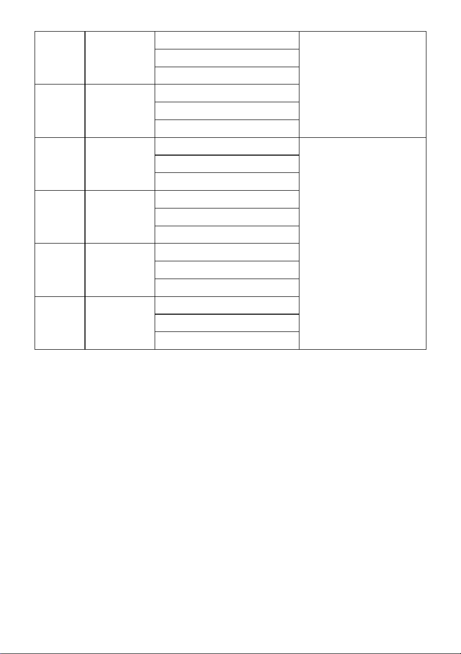
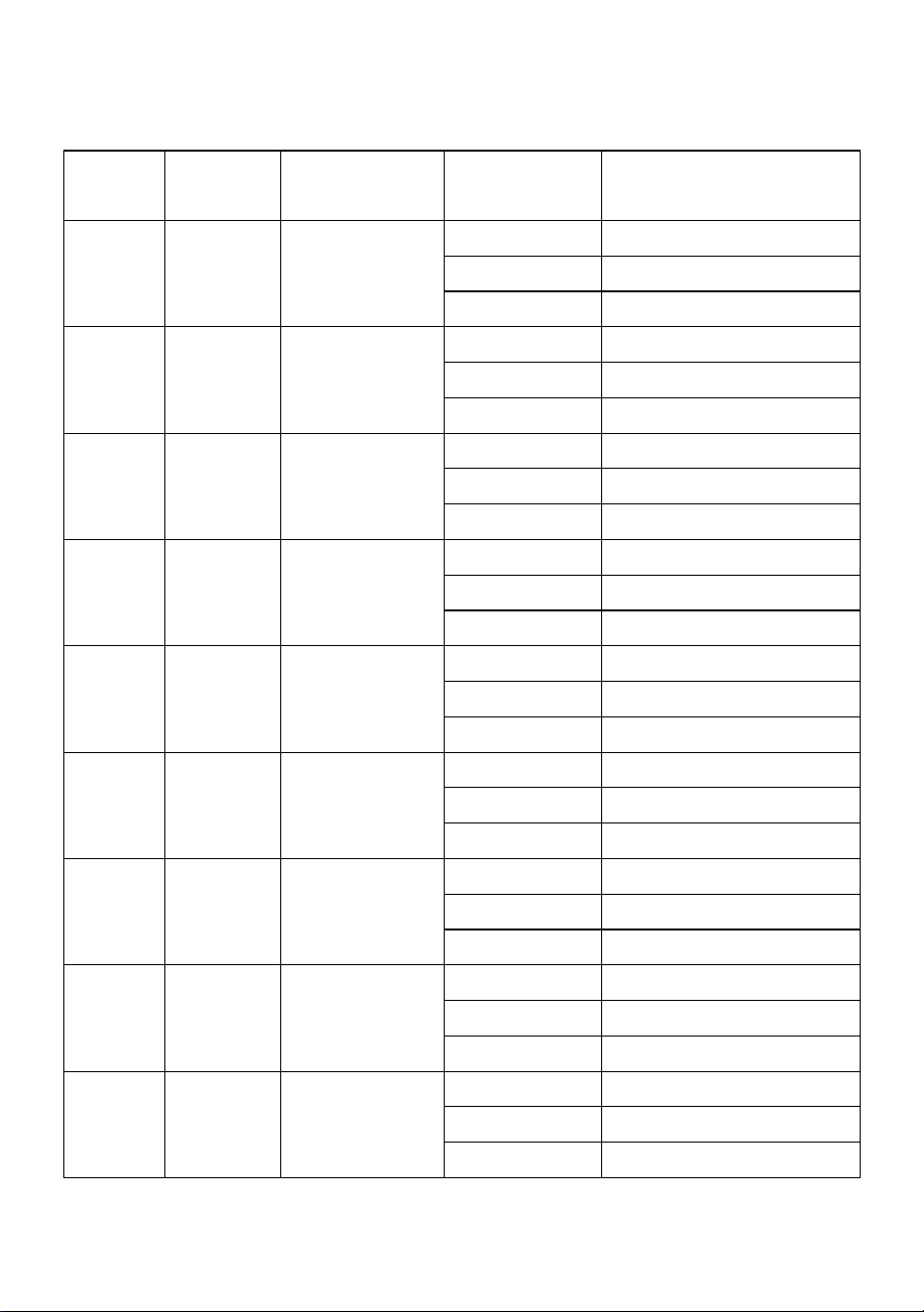
Table 3 Technical Parameters
Model
Power
(kw)
Room(M3)*
Current(A)
Specifications for power
wire
DO-45
4.5kw
3-6
21
10AWG or 4.0mm2
13
11AWG or 2.5mm2
7
14AWG or 1.5mm2
DO-60
6kw
5-7
28
9AWG or 6.0mm2
17
11AWG or 4.0mm2
9
13AWG or 2.5mm2
DO-70
7kw
6-8
34
8AWG or 6.0mm2
20
10AWG or 4mm2
11
12AWG or 2.5mm2
DO-80
8kw
7-9
37
7AWG or 10.0mm2
22
10AWG or 4.0mm2
12
12AWG or 2.5mm2
DO-90
9kw
8-11
41
7AWG or 10.0mm2
25
9AWG or 6.0mm2
14
12AWG or 2.5mm2
DO-105
10.5kw
9-13
48
7AWG or 10.0mm2
29
8AWG or 6.0mm2
16
11AWG or 4.0mm2
DO-120
12kw
11-15
55
6AWG or 10.0mm2
33
8AWG or 6.0mm2
18
11AWG or 4.0mm2
DO-150
15kw
13-18
68
5AWG or 16.0mm2
42
7AWG or 10.0mm2
23
10AWG or 4.0mm2
DO-180
18kw
15-20
82
5AWG or 16.0mm2
50
6AWG or 10.0mm2
27
9AWG or 6.0mm2
- 5 -
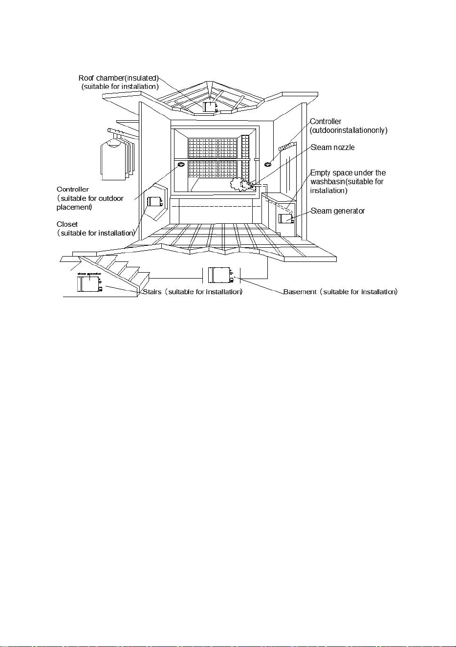
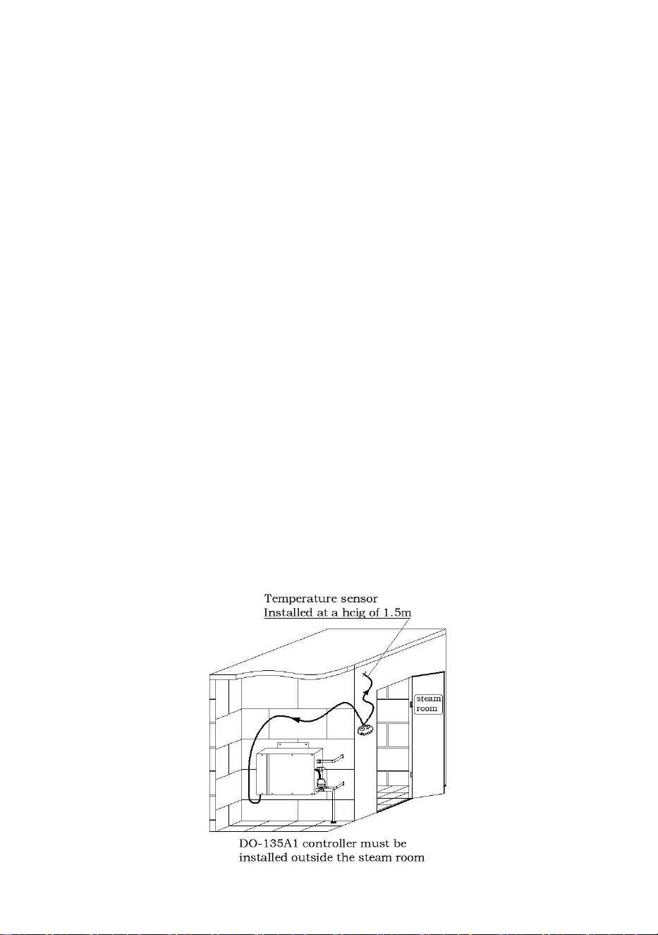
Installation of Steam Generator:
Fig.1
1. The steam generator can be installed on the wall or the ground, but it must be
firm. The steam generator should be installed far from the bathtub or bathroom. Fix
the machine on a vertical wall. First loosen the two screws on the machine cover
and remove the outer cover. There are two holes on the machine cover's upper left
and upper right for fixing the machine on the wall. Next, fix the rear cover and
install the outer cover. In order to provide good maintenance services, the
nameplate must be placed in a visible place, and the machine must also be
installed in a place convenient for maintenance. Please refer to the installation
recommendations (Figure 1).
2. It is strictly forbidden to install the machine in outdoor, humid, high temperature
places or places where it may be frozen or corroded. At the same time, it is
forbidden to place it near flammable and explosive places such as paint, thinner,
gasoline, etc. It should be placed in a dry and ventilated place.
3. The steam generator can only be installed horizontally.
- 6 -
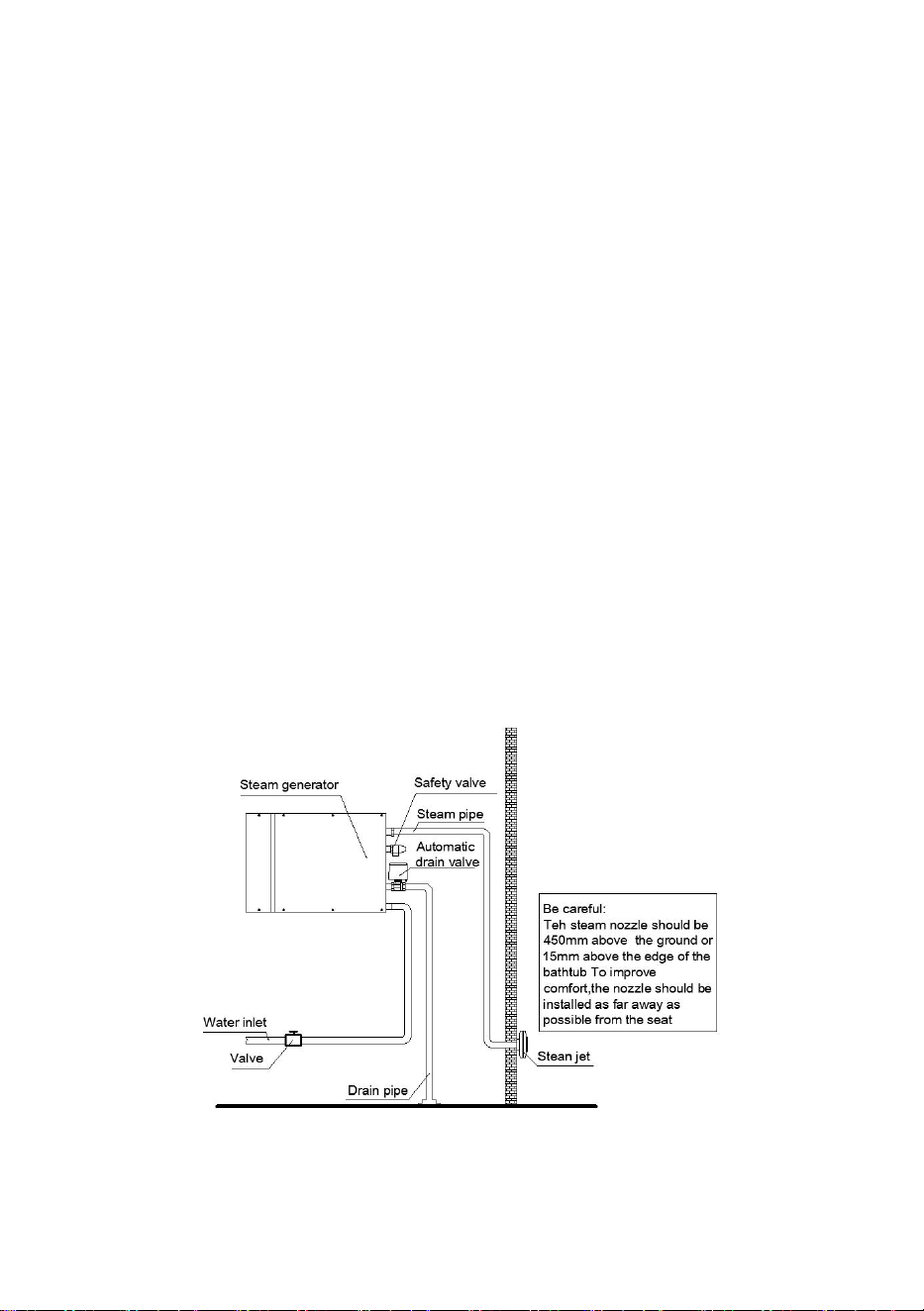
Pipe Installation:
1. The water supply and steam pipes shall be installed according to national
standards. The installation shall be completed before the wall is sealed.
2. Water inlet pipe - The water inlet pipe is introduced by the existing 4 branch
pipes, and connected to the valve of the water inlet and water supply pipe of the
machine respectively with a 4 branch metal hose (please refer to Figure 2).
3. Steam outlet - the steam pipe shall be made of copper pipe with a diameter of
no less than 4 cm (it is forbidden to use because the black metal or galvanized
pipe will rust and discolor the wall of the steam room). The steam pipe's length
shall be at least 3 meters at most. If the length of the steam pipe exceeds 3 meters,
it shall be insulated (please refer to Figure 1)
4. Drainage pipe - to prevent damage to the house during drainage, a water pipe
with a length of not less than 4 points shall be connected to guide drainage.
5. Steam nozzle - in the steam room, cover the decorative cover on the steam
nozzle, apply sealant and screw on the nozzle. Avoid damaging the decorative
cover and nozzle due to excessive force. Ensure that the nozzle's steam outlet is
downward (pointing to the ground).
After the pipe installation, the electrician can carry out the machine wiring
work.
Fig.2

- 7 -
Warning:
● If the machine is installed in a place where it is difficult for users to operate, the
water supply valve must be installed in a place where it is easy to operate in case
of emergency.
● The withstand pressure of the solenoid valve is 2kg/m
2
. If the water pressure is
too high, in order to avoid damage to the solenoid valve, it is appropriate to turn
down the inlet valve or add an inlet pressure reducing valve.
● The saddle or needle valve cannot be installed on the water inlet pipe. The water
pipe shall be dredged and flushed before the final connection.
● It is forbidden to install blocking valves in steam pipes. It is strictly forbidden to
block or bend the "U" channel. Otherwise, condensed water will be produced to
block the flow of steam. The steam pipe shall be inclined to a certain extent when it
is laid horizontally so that the condensate can flow back to the steam generator or
to the steam nozzle.
● The steam generator cannot be installed outdoors to prevent icing inside. It must
be installed in a place convenient for maintenance. The machine should be
installed horizontally and the arrow direction should be upward, otherwise it cannot
be started.
● The pipe installation must be made of copper pipe. It is forbidden to use plastic,
acrylic, aluminum-plastic pipe or other similar materials as steam pipes because
the allowable temperature of these materials cannot reach 150 ℃ or higher.
● The steam pipe inlet, all other inlets and gaps shall be sealed to prevent steam
leakage from damaging the machine and other objects.
● Draining the water in the water tank into the steam room may cause scald
accidents and damage the building materials used in the steam room.
III Steam Generator Circuit Installation Guide
When installing and operating the steam generator, it should be noted that the
machines manufactured by our company have been carefully assembled and
tested. The line installation must be carried out following the national regulations
and by professionals with local or national professional electrician qualification
certificates. The power supply must be turned off before making any line
connection.
- 8 -
Steam Generator Power Supply Installation:
1. To confirm the correct power supply voltage (220V or 380V, see the label),
please refer to the label on the machine or Table 1 in the manual.
2. Requirements for installing circuit breakers in the line: the circuit breaker must
be installed in strict accordance with Table 3. The machine must be grounded
reliably. Install CFI (Ground Drain) (International Electrical Technical Code 210-8).
3. Select the power line matching the local requirements. If the socket needs to be
installed, please install it near the steam generator. Note that the plug and socket
shall exceed 250V and the required current load (please refer to Table 3). After the
wall is sealed, the wiring between the machine and the controller can be carried
out.
4. Loosen the cover screws and remove the cover. Open the blind hole for the
incoming power line on the right side of the machine (see Figure 4). Connect the
three-core cable (220V connection) (two power supplies and one ground wire) or
five-core cable (380V connection) (four power supplies and one ground wire) of
the machine, and strip off the 5cm long insulation layer. Connect the ground wire
with the yellow-green multi-core wire in the machine, connect two power lines with
the terminals marked with "L" and "N" (220V) or four power lines with the terminals
marked with "N", "L1", "L2" and "L3" (380V).
After the controller is installed, the machine can be started.
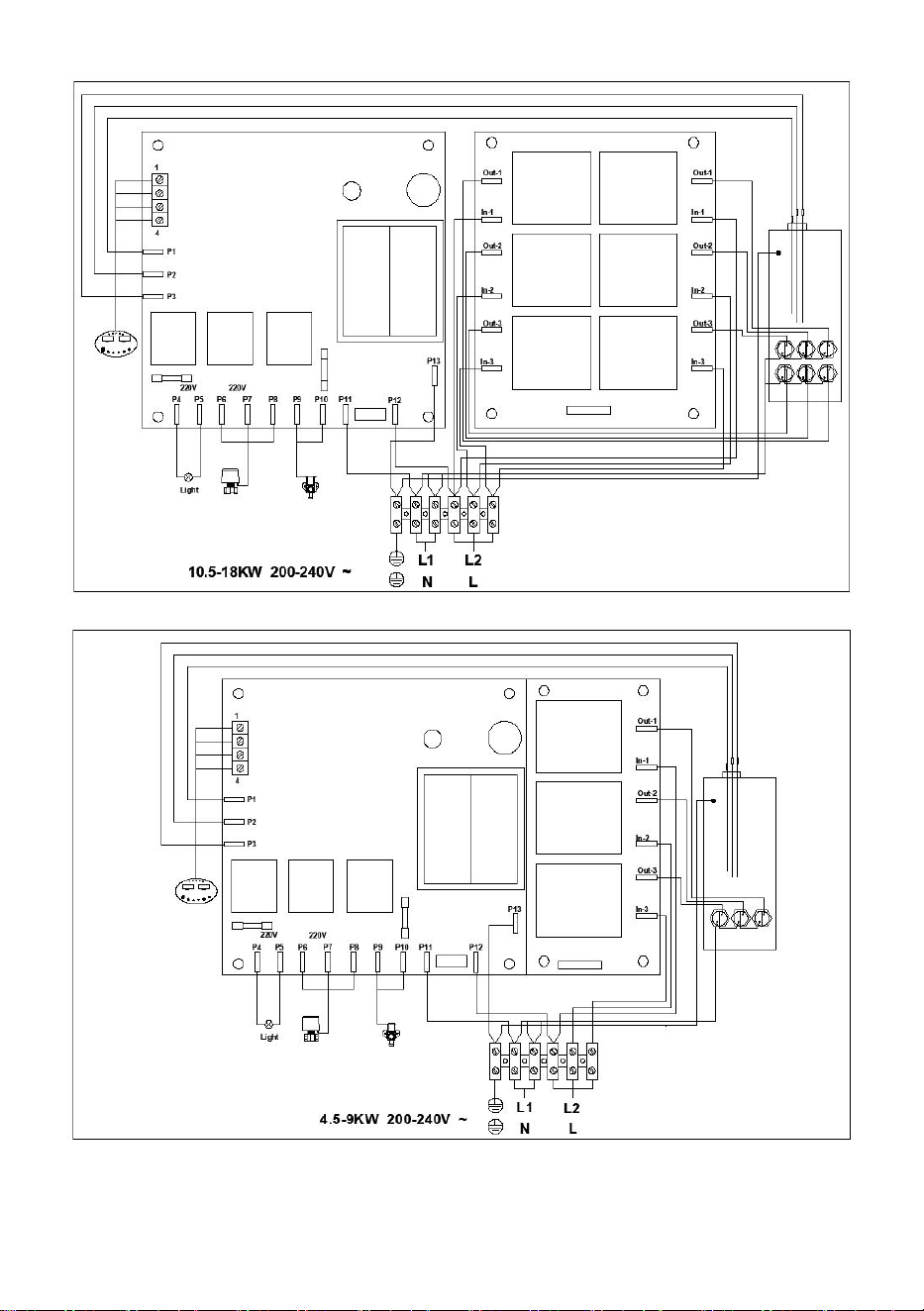
The following figure shows the wiring diagram of DO series controller. (Figure 2)
- 9 -
Fig.2 Steam Generator Wiring Diagram

- 10 -
Inspection Clause:
Before use, please check according to the following terms:
1. The machine is grounded correctly, and the diameter of the grounding wire
should be greater than 4mm
2
.
2. Whether the machine model is properly selected. If not, the matching steam
room may not reach the preset temperature.
3. The voltage connected to the steam generator is well selected (i.e. 220V or
380V). If 220V steam generator is connected with 380V voltage, the electric
heating tube and circuit board will be damaged. If 380V steam generator is
connected with 220V voltage, the power of the machine will be reduced by 25%.
The connection of the zero line of the 380V steam generator cannot be wrong, that
is, the zero line cannot be connected to the phase line. Otherwise, the circuit board
and electric heating tube will be damaged.
4. The steam generator must be installed vertically and horizontally.
5. Select the correct cable number and circuit breaker.
Warning:
● All power switches must be disconnected before installing, maintaining and
maintaining the machine.
● Connecting any additional wires or providing power to the machine and
controller is forbidden. Confirm that the ground wire is not connected to the
energized wire. In installation, operation, maintenance, and repair, to use the
machine for continuous and safe operation, please only use the components
authorized to be replaced by the original manufacturer.
IV DO-135A1 Operating Instructions
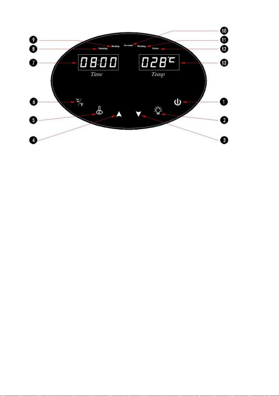
1. Controller Shape (Fig. 1)
- 11 -
Fig. 1
1: On/Off
2: Lighting On/Off
3: Digital Decrease
4: Digital Increase
5: Temperature / Time setting key
6: Celsius / Fahrenheit Display Switch
7: Time Display
8: Automatic Drain Indication
9: Heating Indication
10: Water Shortage Indication
11: Working Indication
12: Power Indication
13: Temperature Display
2. Operation Instruction
● After the installation of the steam generator and controller is completed and
checked for accuracy, the power is turned on and energized.
● On/Off: On/Off: When the steam generator is in standby mode, touch the key to
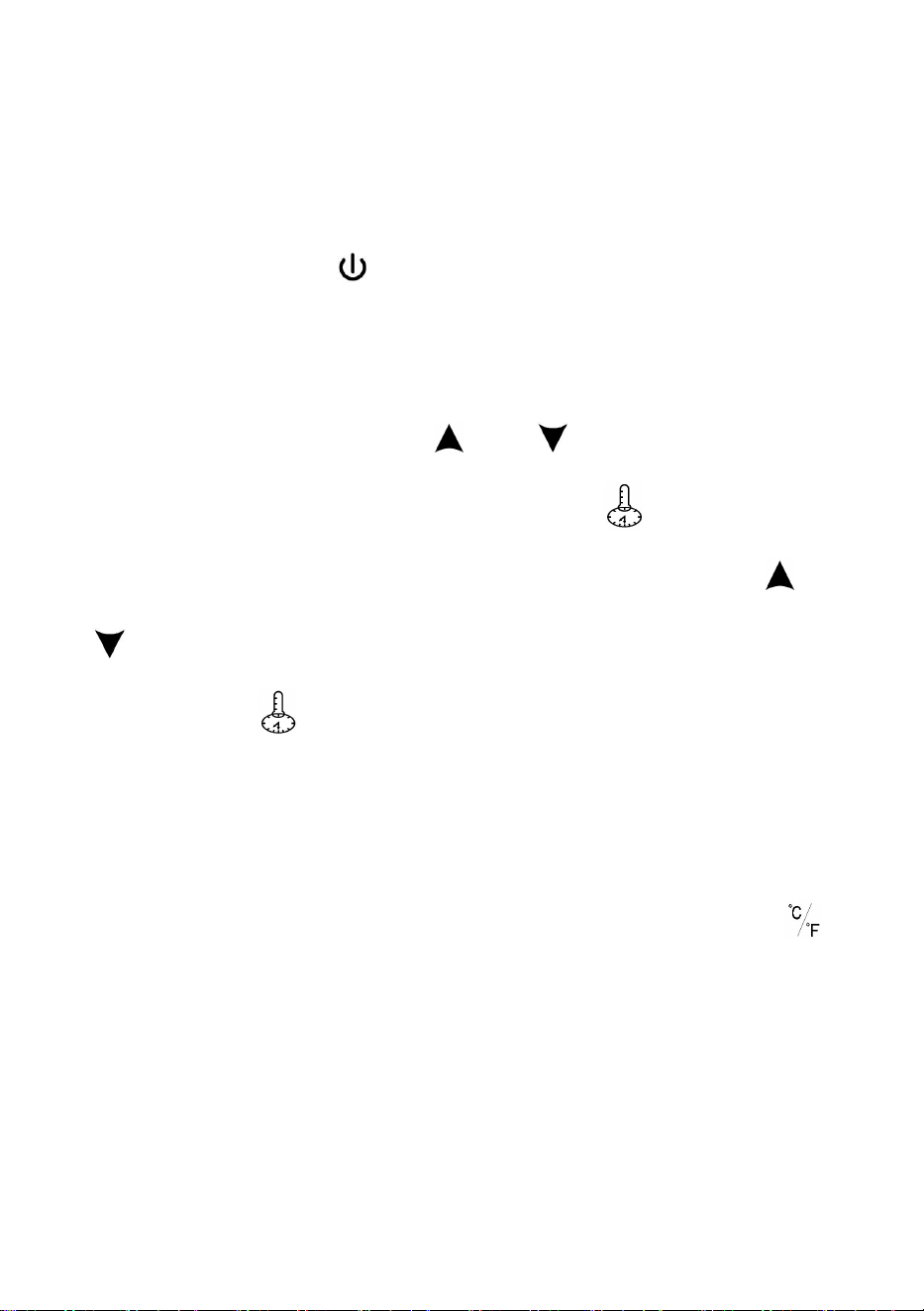
- 12 -
start the steam generator. The controller will then display the working time of the
steam generator and the temperature in the steam room, and the icon bar will
show the steam generator's operational state. If you touch this key again during
the countdown period, the controller will turn off the display, and the steam
generator will stop working.
● Lighting on / off: touch the key to turn on the lighting, touch this key again to
turn off the lighting. Lighting voltage is 220V, the maximum power is 100W.
● Temperature and time setting: Touch the key to set the temperature and time
during the machine opening time, the first time you touch this key to set the time,
the time display flashes. Touch the key or key to modify the value, the
adjustment range is 10 minutes - 24 hours. Touch the key again to enter the
temperature setting, while the temperature display flashes. Touch the key or
the key to modify the value, the temperature adjustment range is 25-55 degrees
Celsius. Touch the key or controller again after 15 seconds of no operation,
the system automatically exits the setting and returns to the countdown display
and the normal temperature display of the steam room. The modified value has
only a memory function, and the last value will be read automatically after the next
power is on.
● Switching between Celsius and Fahrenheit display: With the touch of key,
the customer can switch the display between Celsius and Fahrenheit.
Controller Installation Guidance
1. Hole diameter of 35MM in the wall where the controller is installed (Fig.2).
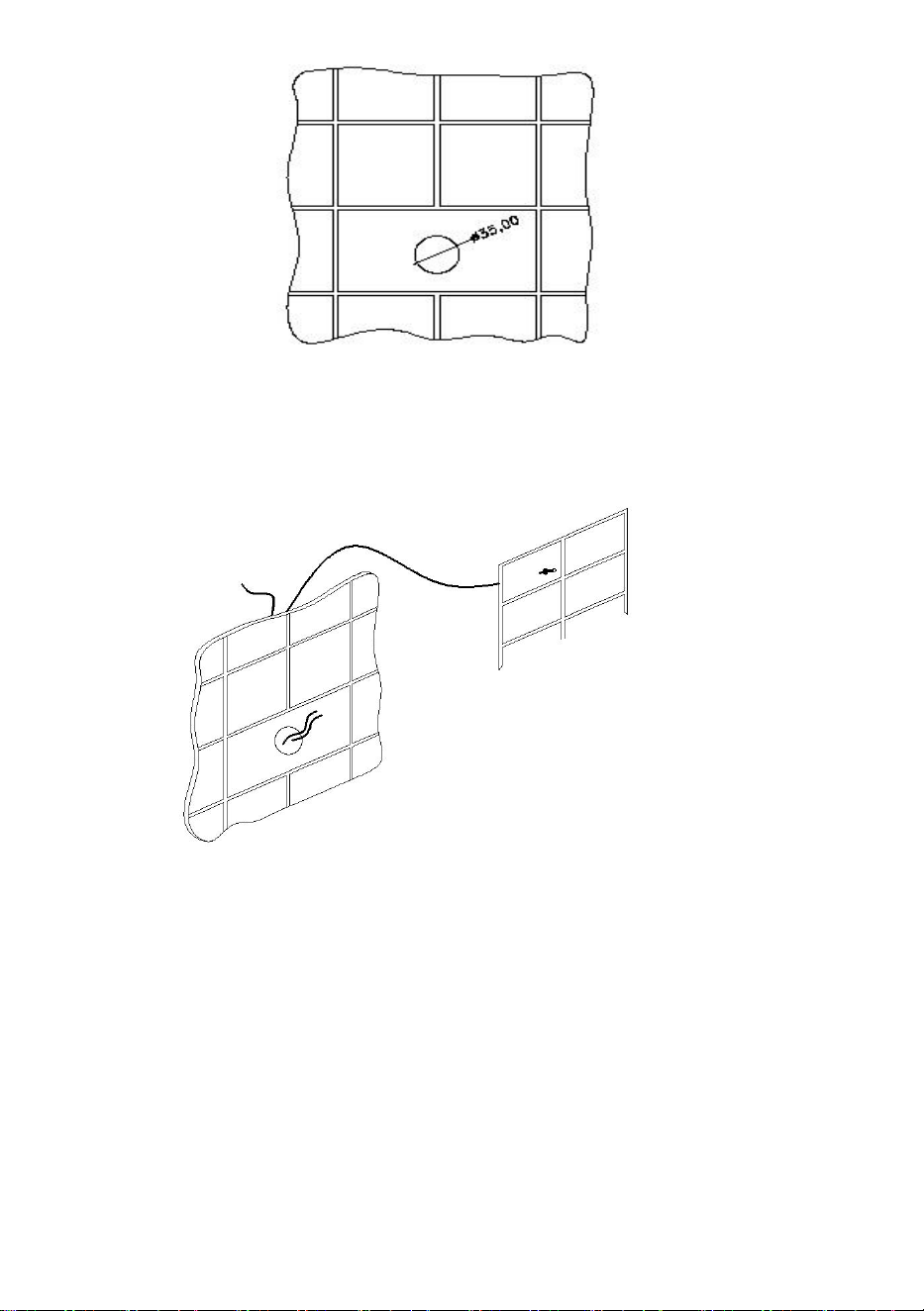
- 13 -
Fig.2
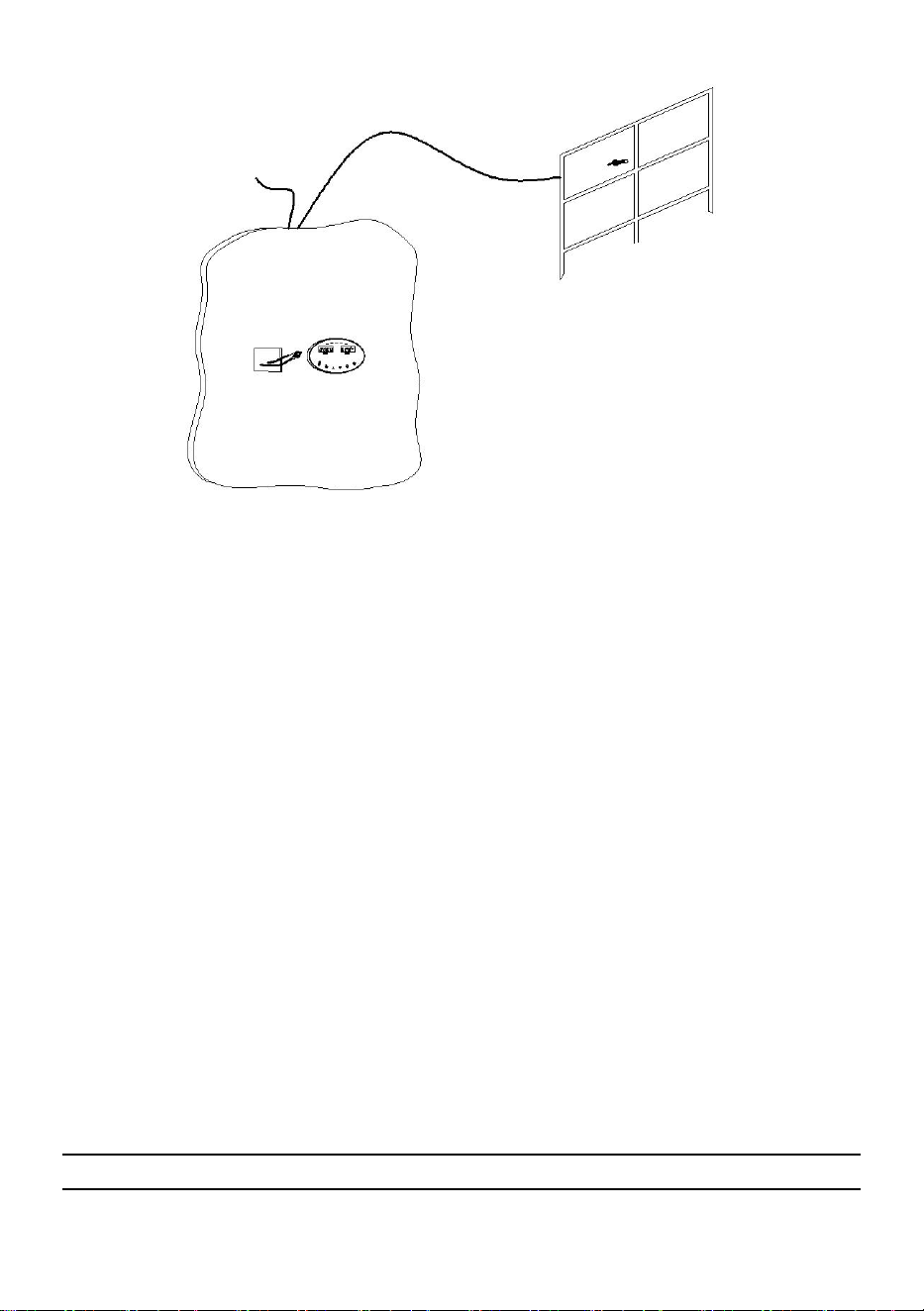
2. Pre-buried steam generator control line wire and temperature sensor
connection line (Fig.3).
Fig.3
3. After completing the interior sauna decoration, insert the steam generator
control line and the temperature sensor connection line into the plug according to
the color instructions and tighten the set screws. Then turn on the power and test
whether the buttons are usually working. After the detection is correct, tear off the
double-sided adhesive protection film on the back of the controller. Finally, paste
the controller on the wall. (Fig.4)
- 14 -
Fig.4
Warning:
● This machine must be grounded.
● Installing the machine and controller in places susceptible to moisture is strictly
forbidden. The installation site shall be dry and ventilated. The company's
after-sales service guarantee liability for damage to the machine due to dampness
shall not take effect.
V Maintenance and Repair Instructions for Steam Generator
Maintenance of Steam Generator:
1. To prevent the machine from being damaged by steam or water leakage, the
steam generator, steam nozzle, parts and pipes shall be inspected regularly.
2. This machine is equipped with a drain valve to clean and discharge the
sediment in the steam generator case. This work is carried out monthly or more
frequently according to the local water quality and the use of steam generators.
Cleaning Process: When the machine is cooled, open the drain valve, let the water
flow for about 10 minutes, and then close the water valve (the machine does not

- 15 -
heat the water).
When the machine is running, check the signs of excessive heating. Also, check
the security of all electronic interfaces.
Maintenance and Operation Instructions:
Replace the electric heating tube:
● Turn off the power supply.
● Drain the water in the water tank.
● Open the front and outer cover of the electric heating tube channel.
● Mark the wired interface.
● Remove the wire.
● Take out the electric heating tube.
It is necessary to replace a new electric heating pipe, clean the scale in the water
tank, put the electric heating pipe into the pipe mouth, and tighten the electric
heating pipe. Then, reconnect the wire, check whether the electric heating pipe
orifice leaks and cover the front and outer cover of the electric heating pipe
channel.
1.Replace the circuit board: turn off the power supply, open the front cover, pay
attention to the water level probe corresponding to the blue and white water level
probes, and remove the probe and the three wires on the circuit board. Note and
mark all wiring interfaces, and remove the circuit board. Installation is the reverse
of the above steps.
2.Replace the solenoid valve: turn off the power and water source, and open the
front cover. Remove two blue wires from the solenoid valve. Remove the hose on
the solenoid valve, loosen two screws, and remove the valve. Install the solenoid
valve and hose in reverse order.
3.Replace the water level probe: turn off the power supply, open the front cover,
pay attention to the water level probe of the blue and white wires, unplug the three
wires on the probe, install a new water level probe, and tighten the bottom of the
plastic nut to the original height of the nozzle. Just plug in three wires.
Warning:
● The power must be turned off before operation for all maintenance and repair
work. Live operation is not allowed.
- 16 -
● After maintenance, conduct a test according to regular operation..
VI Common Faults and Troubleshooting Instructions
There are no parts in the machine that the user can operate. Qualified
professionals must carry out the maintenance. If you need more services or the
help of the manufacturer's authorized service personnel, please get in touch with
the seller.
Symptoms
Reasons
Method
Start the
controller,
the
controller
has display
but no
steam is
generated.
No Water
Supply;
Temperature
Sensor
Fault;
Circuit
Board Fault;
Electric
Heating
Tube Failure
1. Start the steam generator and wait for at least 5
minutes.
2. Check whether the water supply valve is open
and whether there is water in the water pipe.
3. Check whether there are impurities in front of
the solenoid valve.
4. Whether the heating indicator on the controller
is on.
5. Replace the circuit board.
6. Replace the electric heating pipe.
If none of the above methods can be solved,
please turn off the power supply and contact the
seller.
Close the
controller
and
continue to
generate
steam.
Control
Circuit Fault;
Equipment
Problems
1. Check whether there is moisture or water on the
circuit board.
2. Replace the circuit board.
Turn off the power and call the seller.
Water from
steam
nozzle.
Solenoid
Valve Fault;
Circuit
Board Fault;
1. Check whether there is moisture or water on the
circuit board.
2. Replace the circuit board.
3. Replace the solenoid valve.
- 17 -
Water Level
Probe Is
Broken
4. Replace the water level probe.
5. If none of the above methods can be solved,
please turn off the power supply and contact the
seller.
The
controller
has no
response
and no
display.
Controller
Failure,
Circuit
Board Fault;
Control
Connection
Line Fault
1. Check whether the red indicator on the circuit
board is on.
2. Replace the circuit board.
3. Replace the controller.
4. Replace the control connecting wire.
If none of the above methods can be solved,
please turn off the power supply and contact the
seller.
The
controller
displays
"00".
Temperature
Sensor Fault
1. Check the temperature sensor connecting wire.
2. Replace the temperature sensor.
The lamp
does not
work.
Safety Tube
The fuse is broken.
(Some models do not have this function.)
Note:
● Refer to the four indicator lights on the circuit board for troubleshooting. Red
indicator light - power supply, green indicator light - start steam generator, yellow
indicator light - heating, orange indicator light - water inlet.
● The power supply must be turned off when replacing components.
● If the fault cannot be eliminated according to the above methods or the machine
cannot work normally for other reasons, please notify the seller or manufacturer to
contact for maintenance.
VII Guarantee Conditions for After-sales Service
The company gives a conditional guarantee to the Vevor steam generator
purchaser. Free guarantee shall be provided for the damage caused by the

- 18 -
material and product quality problems of the electrical components of the machine
within one year or 18 months after delivery (whichever occurs first). All accessories,
accessory parts and parts are not guaranteed under any circumstances.
● The electric heating pipe warranty period is 90 days from the installation date or
within half a year after delivery (whichever occurs first).
● The company has the right to choose whether to repair or replace parts. As long
as it is within the scope of the company's commitment, the parts listed in the
guarantee will be replaced with old ones. It must be approved by the company
before returning to the company. (The freight shall be paid by itself) The
replacement parts shall be paid in advance and the freight shall be prepaid.
● The terms and items mentioned in this manual are not included in the guarantee.
● This warranty does not cover damage caused by incorrect use, negligence,
accidental rupture, improper power supply connection during use, failure to follow
the instructions, and modification or maintenance by technical personnel not
recognized by the company.
● After the warranty period expires, the company will continue to provide paid
services for users. The material cost and personnel travel expenses shall be paid if
the parts need to be repaired or replaced.
● The guarantee is only for the company's products.
● The company will not be responsible for any damage, loss, or damage of other
things and any loss caused by human factors.
● For specific after-sales service matters, please get in touch with the seller.
Thank you!
Made In China