VIVOTEK - A Leading Provider of Multimedia Communication Solutions
User's Manual - 1
Rev. 1.6.1.11
Rev. 1.0
User’s Manual
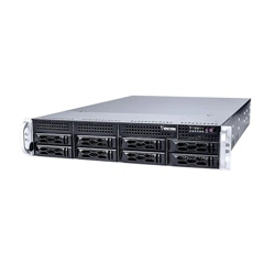
NR9681-v2
Network Video Recorder
Rack-mount Enclosure • 32-/64-channel Recording • 8x Hot-swappable H.D.D.
RAID storage • Full Integration with VIVOTEK Cameras
NR9581-v2
Rev. 1.0
for VAST rev. 2.9

VIVOTEK - A Leading Provider of Multimedia Communication Solutions
2 - User's Manual
Table of Contents
Revision History ..................................................................................................................................................... 4
Chapter One Hardware Installation and Initial Conguration ...................................................................................... 6
Introduction ............................................................................................................................................................. 6
Special Features ............................................................................................................................................. 6
Safety .............................................................................................................................................................. 7
Installation Instructions .......................................................................................................................................... 8
Power Supply .................................................................................................................................................. 9
Environmental Specications .......................................................................................................................... 9
Grounding Requirements .............................................................................................................................. 10
Physical Description ........................................................................................................................................... 11
Drive Bay Numbering Sequence .......................................................................................................................... 11
Front View ............................................................................................................................................................ 11
Rear View ............................................................................................................................................................. 14
Display .......................................................................................................................................................... 15
Chassis Dimensions ...................................................................................................................................... 16
Rack-mounting ..................................................................................................................................................... 17
Installing Hard Disk Drives ................................................................................................................................... 23
Connecting Interfaces .......................................................................................................................................... 26
Initial Conguration ............................................................................................................................................... 26
RAID Basics ......................................................................................................................................................... 44
Chapter Two VAST2 Software Conguration and Management ............................................................................... 61
Log in .................................................................................................................................................................... 61
Introducing VAST2 ............................................................................................................................................... 62
Charged Add-on Features .................................................................................................................................... 64
Installation Option - OpenVPN ............................................................................................................................. 68
Chapter 2-1 Basics: Control and Elements .......................................................................................................... 71
Hot Keys ............................................................................................................................................................. 89
View Cell Elements .............................................................................................................................................. 92
VAST Server and Client Components .................................................................................................................. 96
Minimum System Requirements .......................................................................................................................... 98
Chapter 2-2 Starting Up ..................................................................................................................................... 100
2-2-1. Selecting Devices .................................................................................................................................... 101
2-2-2. Recording Options ................................................................................................................................... 102
Seamless Recording ................................................................................................................................... 106
Activity Adaptive Stream ............................................................................................................................. 107
Adding NAS (Network Attached Storage) as a Storage Option .................................................................. 108
2-2-3. Storage .................................................................................................................................................... 112
2-2-4. Starting Up - Main Page ........................................................................................................................... 113
2-2-5. Saving a View .......................................................................................................................................... 116
2-2-6. Add More Live Views ............................................................................................................................... 117
2-2-7. Save Your Preferences ............................................................................................................................ 118
2-2-8. Customizable Layout ............................................................................................................................... 119
2-2-9. Dashboard ............................................................................................................................................... 121

VIVOTEK - A Leading Provider of Multimedia Communication Solutions
User's Manual - 3
2-2-10. E-Map .................................................................................................................................................... 123
Placing DI/DO Devices ............................................................................................................................................ 126
Conguring Google Map and GPS .......................................................................................................................... 127
2-2-11. Event Search .......................................................................................................................................... 133
2-2-12. PTZ Control ............................................................................................................................................ 136
2-2-13. Playback ................................................................................................................................................ 138
2-2-14. Alarm .................................................................................................................................................... 145
Group Alarm ................................................................................................................................................ 154
2-2-15. Search Panel ......................................................................................................................................... 158
2-2-16. Smart search .......................................................................................................................................... 161
2-2-17. Tour ..................................................................................................................................................... 171
2-2-18. Thumbnail search .................................................................................................................................. 173
Chapter 3 Applications: ..................................................................................................................................... 175
3-1. I/O DI/DO Devices: IO Box and Related Conguration ............................................................................... 175
Conguring I/O Box DI/DO as a Trigger or Action in Alarm ................................................................................ 177
3-2. Conguring Redundant Servers - Failover .................................................................................................. 181
Failover Conguration Process .......................................................................................................................... 188
3-3. VCA (Video Content Analysis) .................................................................................................................... 192
3-4. VAST Software License ............................................................................................................................... 205
Updating Licenses for VAST on Virtual Machines .............................................................................................. 209
Reminders for VAST Software License .............................................................................................................. 215
Chapter 4 Settings: ............................................................................................................................................ 216
4-1. Settings > System > Preferences ................................................................................................................ 216
4-2. Settings > Device > Cameras ..................................................................................................................... 222
Streaming URL ............................................................................................................................................ 223
4-3. Logical Folders ............................................................................................................................................ 225
4-4. Settings > Recording > Recording Options ................................................................................................. 228
4-5. Settings > Recording > Backup .................................................................................................................. 230
Storage ............................................................................................................................................................... 233
4-6. Settings > Device > Sites ............................................................................................................................ 234
Multicasting ........................................................................................................................................................ 237
4-7. Settings > Device > POS ............................................................................................................................ 241
4-8. Settings > Device > Local DB ..................................................................................................................... 242
4-9. Settings > System > SMTP ......................................................................................................................... 246
4-10. Settings > IO Box and Related Conguration ........................................................................................... 246
4-11. Settings > User Management .................................................................................................................... 247
Add a New User Account - Windows AD Account ................................................................................ 249
Appendix A: VAST Service Control Tool ............................................................................................................. 251
Appendix B: Matrix ........................................................................................................................................... 252
Appendix C: Joystick Support .......................................................................................................................... 257
Appendix D: Upload Device Pack .................................................................................................................... 263
Appendix E: Using LPR Related Functions w/ Data Magnet .............................................................................. 265
Appendix F: Enable Smart Tracking for Speed Dome Cameras ........................................................................ 282
Appendix G: Database Merge Function ............................................................................................................. 284
VIVOTEK - A Leading Provider of Multimedia Communication Solutions
4 - User's Manual
Revision History
Rev. 1.0: Initial release. The description for the software functionality is based on VAST rev. 2.9.
1. Do not format or initialize the
Disk 0: drive on your NVR. The Disk 0: drive contains the
operating system. Doing so will disable the system.
2. No storage system is completely fail-safe. Damage to data might occur due to le system
corruption, operating system malfunction, virus infection, HDD component failures, and so on.
Therefore, it is highly recommended to regularly back up your data, and VIVOTEK disclaims
responsibilities of data loss or recovery.
3. Always power off the system using the power down button on system desktop. Do not
disconnect the power cord while the system is still operating. Doing so will result in data
inconsistencies. The normal power-off procedure allows cached data to be written to disks.
WARNING:
Technology License Notice
Notices from HEVC Advance:
THIS PRODUCT IS SOLD WITH A LIMITED LICENSE AND IS AUTHORIZED TO BE USED ONLY
IN CONNECTION WITH HEVC CONTENT THAT MEETS EACH OF THE THREE FOLLOWING
QUALIFICATIONS: (1) HEVC CONTENT ONLY FOR PERSONAL USE; (2) HEVC CONTENT THAT
IS NOT OFFERED FOR SALE; AND (3) HEVC CONTENT THAT IS CREATED BY THE OWNER OF
THE PRODUCT. THIS PRODUCT MAY NOT BE USED IN CONNECTION WITH HEVC ENCODED
CONTENT CREATED BY A THIRD PARTY, WHICH THE USER HAS ORDERED OR PURCHASED
FROM A THIRD PARTY, UNLESS THE USER IS SEPARATELY GRANTED RIGHTS TO USE THE
PRODUCT WITH SUCH CONTENT BY A LICENSED SELLER OF THE CONTENT. YOUR USE OF
THIS PRODUCT IN CONNECTION WITH HEVC ENCODED CONTENT IS DEEMED ACCEPTANCE
OF THE LIMITED AUTHORITY TO USE AS NOTED ABOVE.
Some low quality Ethernet cables with smaller core diameter can seriously reduce the
transmission rate. Use CAT5e or CAT6 cables with a wire gauge of 24AWG for NVR’s uplink
port. A thicker core 24 AWG network cable can offer less resistance than a 26 AWG or 28 AWG
network cable.
Use shielded cables in high noise environments where cross talk and EMI can occur.
IMPORTANT:
VIVOTEK - A Leading Provider of Multimedia Communication Solutions
User's Manual - 5
Symbols and Statements in this Document
i
INFORMATION: provides important messages or advices that might help prevent inconvenient
or problem situations.
NOTE: Notices provide guidance or advices that are related to the functional integrity of the
machine.
Tips: Tips are useful information that helps enhance or facilitae an installation, function, or
process.
WARNING! or IMPORTANT: These statements indicate situations that can be dangerous or
hazardous to the machine or you.
Electrical Hazard: This statement appears when high voltage electrical hazards might occur
to an operator.
Read Before Use
The use of surveillance devices may be prohibited by law in your country. The Network Camera
is not only a high-performance web-ready camera but can also be part of a exible surveillance
system. It is the user’s responsibility to ensure that the operation of such devices is legal before
installing this unit for its intended use.
It is important to first verify that all contents received are complete according to the Package
Contents listed below. Take note of the warnings in the Quick Installation Guide before the
Network Camera is installed; then carefully read and follow the instructions in the Installation
chapter to avoid damage due to faulty assembly and installation. This also ensures the product is
used properly as intended.
The Network Camera is a network device and its use should be straightforward for those who
have basic networking knowledge. It is designed for various applications including video sharing,
general security/surveillance, etc. The Configuration chapter suggests ways to best utilize the
Network Camera and ensure proper operations. For creative and professional developers, the
URL Commands of the Network Camera section serves as a helpful reference to customizing
existing homepages or integrating with the current web server.
The operating system and management software are installed on a ash memory mounted on
the main board. Except for the plug-ins for onscreen display, there is no need to install software.
NOTE:
セキュリティ基準(新規則第 34 条の 10)
「本製品は 電気通信事業者(移動通信会社、固定通信会社、インターネットプロバイダ等)
の通信回線(公衆無線 LAN を含む )
に直接接続することができません。本製品をインターネットに接続する場合は、必ずルータ等
を経由し接続してください。」

VIVOTEK - A Leading Provider of Multimedia Communication Solutions
6 - User's Manual
Chapter One Hardware Installation and Initial
Conguration
Introduction
NR9581/9681-v2 is the latest 64- or 32-channel H.265, RAID-protected NVR from VIVOTEK,
bringing stable and efficient system operation under a wide range of recording/network man-
agement/system settings. The unit supports all VIVOTEK camera models, including the latest
5-Megapixel and fisheye cameras. The support for RAID 1/5/6/10 provides data security in the
event of disk drive failure.
The unit is equipped with two gigabit Ethernet RJ45 ports which provide network failover func-
tionality to avoid the risk of recording loss. When one network line is disconnected, the system
will shift to the other network automatically, providing continuous access for video data. Up to 8
HDDs can be installed in the NR9581/9681 for a total storage capacity of up to 48TB (6TB max.
each). Eight removable HDD trays are available in the front of the unit, with hot-swap functional-
ity for easy replacement.
A VAST2 CMS server runs on the machine that manages surveillance recording and playback.
The compatibility with the iViewer application allows for remote access to the NR9581-v2/
NR9681-v2 on handheld devices. By integrating all of the components together using VIVOT-
EK’s NVR, network cameras, VAST2, and iViewer software, users can realize a fully-featured
and robust next-generation surveillance system. This ingenious NVR also features the remote
management capability with a full range of server/client structures and thus is capable for robust
and diverse applications.
Special Features
● Runs on embedded Windows
● 2U Rack Mount Design
● RAID 0, 1, 5, 6, 10, 50, 60 in virtual drive storage configurations
● 8 x HDD Tray, for a max. capacity of 48TB
● 2 x Gigabit RJ45 Ethernet ports
● 6 x USB Port (2 x Front / 4 x in Back)
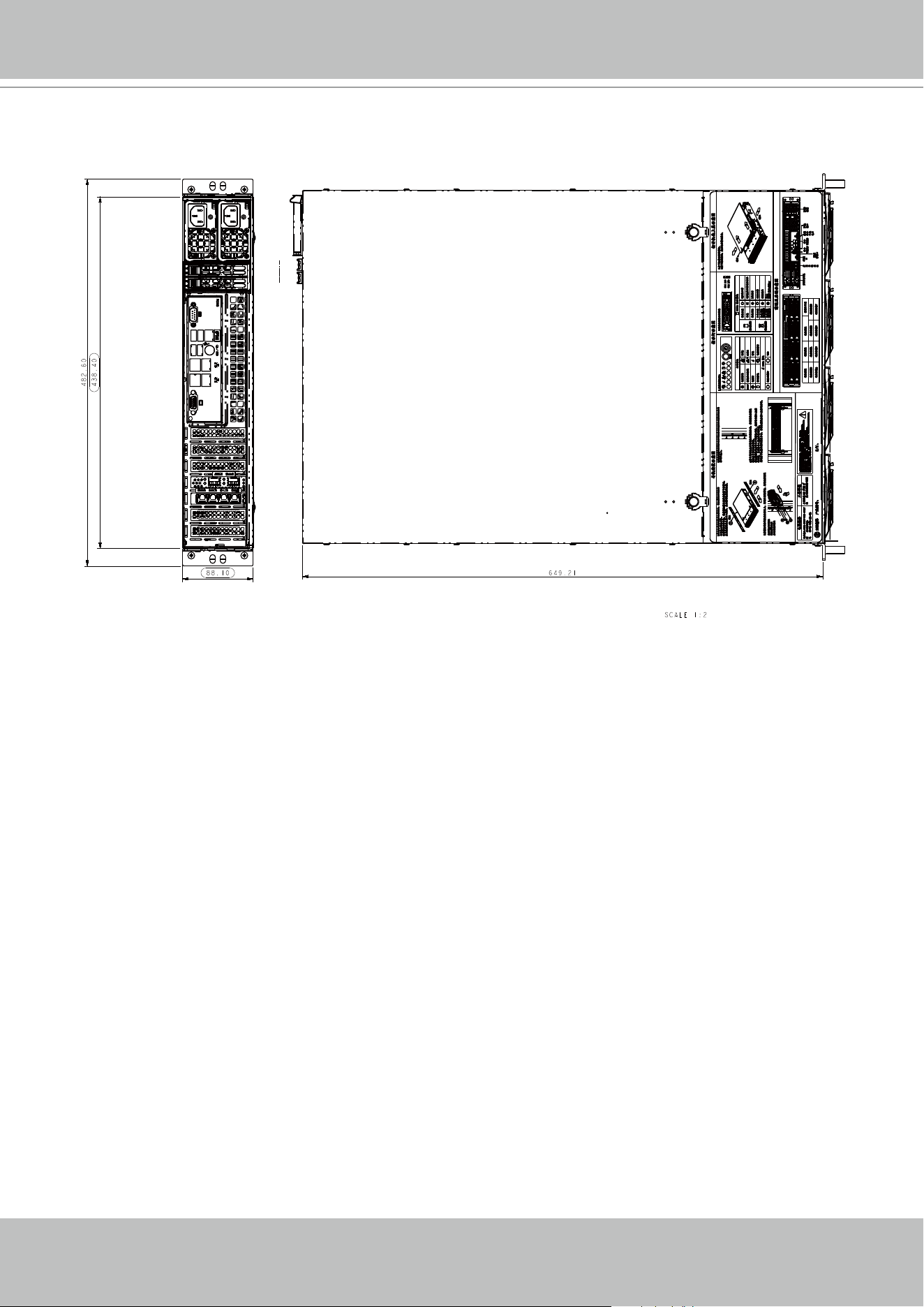
● Size: 17.2” (437 mm) (W) x 25.5” (647 mm) (D) x 3.5” (89 mm) (H)
● Gross Weight: 33 lbs (14.97 kg)
● 64-CH Live View & 16-CH Synchronous Playback
● H.265/H.264/ MPEG-4
● PTZ Support
● Snapshot / Export Media
● PiP Video Control
● Bookmark Design
● Fast Configuration Backup / Restore
● Pre-installed VIVOTEK VAST Central Management Software*
● Full Integration with VIVOTEK Network Cameras
● VIVOTEK iViewer Support (iOS/Android)

VIVOTEK - A Leading Provider of Multimedia Communication Solutions
User's Manual - 7
Safety
1. Read these safety instructions carefully.
2. Keep this User Manual for later reference.
3. Disconnect this equipment from any AC outlet before cleaning. Use a damp cloth. Do not use
liquid or spray detergents for cleaning.
4. For plug-in equipment, the power outlet socket must be located near the equip-ment and
must be easily accessible.
5. Keep this equipment away from humidity.
6. Put this equipment on a reliable surface during installation. Dropping it or letting it fall may
cause damage.
7. For rack-mount equipment, please firmly install the device with pallets or sliding rails in the
rack.
8. Do not leave this equipment in an environment unconditioned where the storage temperature
under 0° C (32° F) or above 40° C (104° F), it may damage the equipment.
9. The openings on the enclosure are for air convection. Protect the equipment from overheat-
ing. DO NOT COVER THE OPENINGS.
10. Make sure the voltage of the power source is correct before connecting the equipment to the
power outlet.
11. Position the power cord so that people cannot step on it. Do not place anything over the
power cord.
12. All cautions and warnings on the equipment should be noted.
13. If the equipment is not used for a long time, disconnect it from the power source to avoid
damage by transient overvoltage.
14. Never pour any liquid into an opening. This may cause fire or electrical shock.
15. Never open the equipment. For safety reasons, the equipment should be opened only by
qualified service personnel.
16. If one of the following situations arises, get the equipment checked by service personnel:
The power cord or plug is damaged.
Liquid has penetrated into the equipment.
The equipment has been exposed to moisture.
The equipment does not work well, or you cannot get it to work according to the user's
manual.
The equipment has been dropped and damaged.
The equipment has obvious signs of breakage.
17. CAUTION: The computer is provided with a battery-powered real-time clock circuit. There is
a danger of explosion if battery is incorrectly replaced. Replace only with same or equivalent
type recommended by the manufacturer. Discard used batteries according to the manufac-
turer’s instructions.
18. This device complies with Part 15 of the FCC rules. Operation is subject to the following
two conditions: (1) this device may not cause harmful interference, and (2) this device must
accept any interference received, including interferencethat may cause undesired operation.
VIVOTEK - A Leading Provider of Multimedia Communication Solutions
8 - User's Manual
Installation Instructions
Warning:
Read the installation instructions before connecting the system to the power source.
Warning:
This product relies on the building’s installation for short-circuit (overcurrent) protection.
Ensure that the protective device is rated not greater than: 250V, 20 A.
Warning:
The system must be disconnected from all sources of power and the power cord.re-
moved from the power supply module(s) before accessing the chassis interior to install or
remove system components.
Warning:
Only trained and qualifiedpersonnel should be allowed to install, replace, or service this
equipment.
Warning:
This unit is intended for installation in restricted access areas. A restricted access area
can be accessed only through the use of a special tool, lock and key, or other means of
security. (This warning does not apply to workstations).
Warning:
There is the danger of explosion if the battery is replaced incorrectly. Replace the bat-
tery only with the same or equivalent type recommended by the manufacturer. Dispose of
used batteries according to the manufacturer’s instructions.
Warning:
This unit might have more than one power supply connection. All connections must be re-
moved to de-energize the unit.
19. CAUTION: Always completely disconnect the power cord from your chassis whenever you
work with the hardware. Do not make connections while the power is on. Sensitive electronic
components can be damaged by sudden power surges.
20. CAUTION: Always ground yourself to remove any static charge before touching the
motherboard, backplane, or add-on cards. Modern electronic devices are very sensitive to
static electric charges. As a safety precaution, use a grounding wrist strap at all times. Place
all electronic components on a static-dissipative surface or in a static-shielded bag when
they are not in the chassis.
21. CAUTION: Any unveried component could cause unexpected damage. To ensure the
correct installation, please always use the components (e.g., screws) provided with the
accessory box.
VIVOTEK - A Leading Provider of Multimedia Communication Solutions
User's Manual - 9
Warning:
Hazardous voltage or energy is present on the backplane when the system is operating.
Use caution when servicing.
Warning:
Installation of the equipment must comply with local and national electrical codes.
Warning:
Ultimate disposal of this product should be handled according to all national laws and
regulations.
Warning:
The fans might still be turning when you remove the fan assembly from the chassis. Keep
fingers,screwdrivers, and other objects away from the openings in the fan assembly’s
housing.
Warning:
When installing the product, use the provided or designated connection cables, power
cables and AC adaptors. Using any other cables and adaptors could cause a malfunction
or a fire.Electrical Appliance and Material Safety Law prohibits the use of UL or CSA -cer-
tified cables (that have UL/CSA shown on the code) for any other electrical devices than
products designated by the manufacturer only.
Power Supply
Watt 600W max. (94+ Gold, PFC) (1+1 Redundant 2U)
Input rating 600W with Input 100 - 127Vac, 50-60Hz
Output voltage +12 V: Max: 50A (100Vac - 127Vac); Max: 54.16A (200Vac - 240Vac); Max: 54.16A (200 -
240) @ 45A. +5Vsb: Max: 4A / Min: 0A
Power distributor PDB-PT826-L8824 - O/P: 12V/75, +5V Max: 30, +3.3V Max: 24, -12V Max: 0.6
Safety BSMI/CCC/CE/EMC/FCC
Environmental Specications
Environment Operating Non-operating
Temperature
5 ~ 35°C (32 ~ 104°F) --40 ~ 70°C (-40 ~ 158°F)
Humidity 8 ~ 90% @ 40°C, non-condensing 5 ~ 95% @ 60°C, non-condensing
VIVOTEK - A Leading Provider of Multimedia Communication Solutions
10 - User's Manual
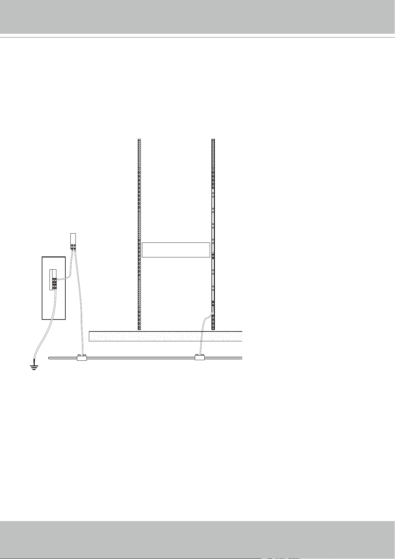
Grounding Requirements
1. The enclosure is designed to be rack-mounted, in an equipment room which has limited hu-
man access.
2. In addition to the grounding via the power cords, make sure your equipment rack is properly
grounded.
3. Use a ground wire of a copper cross section of at least 16AWG.
Main grounding bus
bar
Rack ground bar
Earth
ground
Mesh common bonding
VIVOTEK - A Leading Provider of Multimedia Communication Solutions
User's Manual - 11
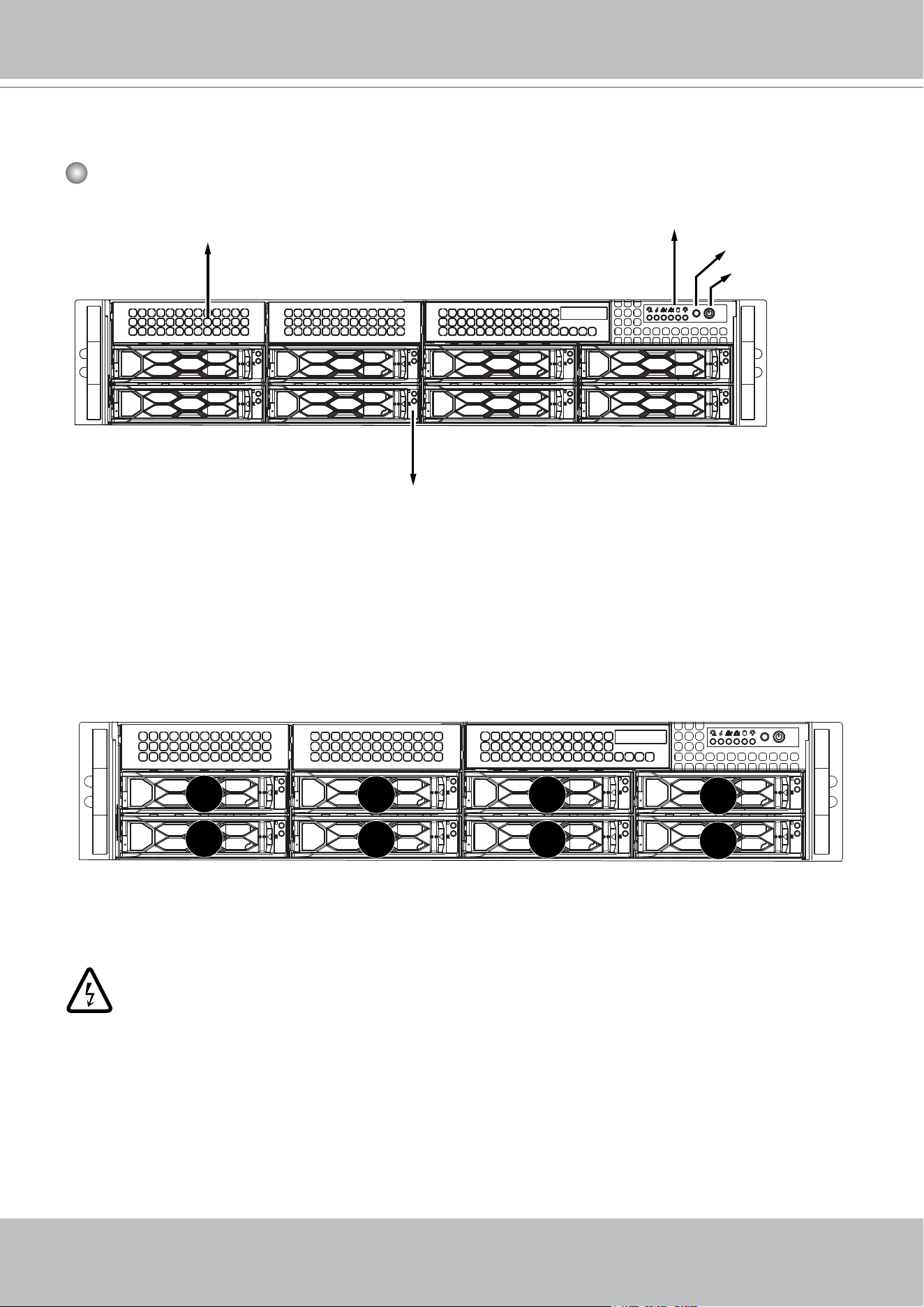
Physical Description
Front View
2
Hot-swappable 2.5”/3.5” HDD trays
Bays for optional
drives
Reset button
Power button
Control panel
Drive Bay Numbering Sequence
Warning:
Knowing the correct positions of hard drives is very important. For example, if a hard
drive fails in a RAID5 Virtual Drive, you can initialize a rebuild by locating and replacing
the failed drive. If you replace the wrong drive, it means that you have 1 failed drive and
another mistakenly failed drive. Having 2 failed drives in a RAID5 configuration renders
all data inaccessible. All data in the RAID5 Virtual Drive will be lost.
1
0
2
3
5
4
6
7
VIVOTEK - A Leading Provider of Multimedia Communication Solutions
12 - User's Manual
Control Panel buttons and LEDs
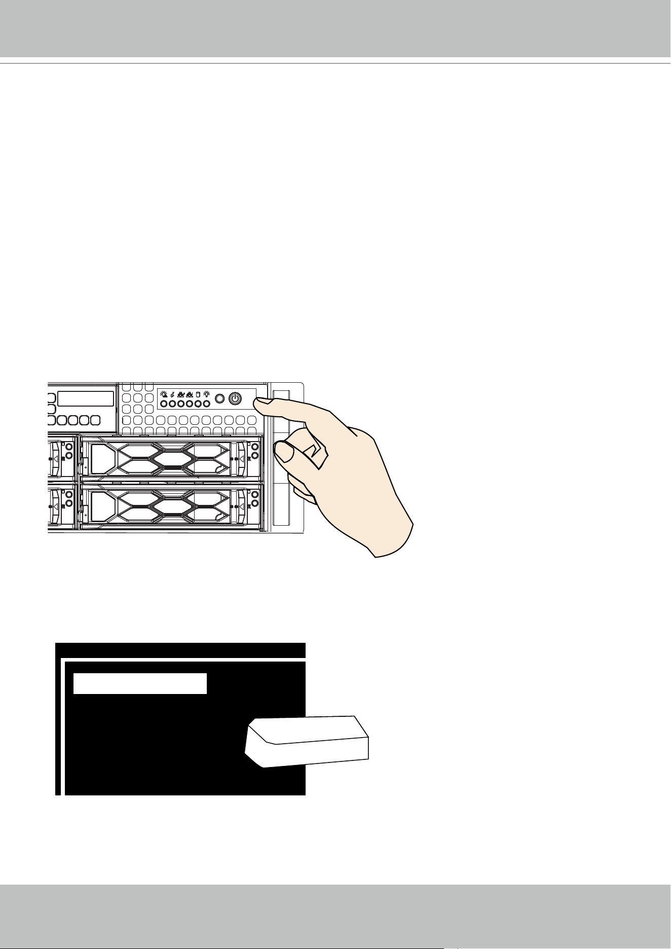
1 Power switch Press this switch to turn the system power on or off. Please use
system shutdown or press this switch for a few seconds to turn
off the system ATX power.
The main power switch is used to apply or remove power from
the power supplies to the server. Turning off system power
using this button removes the main power but keeps standby
power supplied to the system. You must unplug the system
before servicing components inside the chassis.
2 Reset button Press this button to reboot the system.
3 Power LED Indicates power is being supplied to the system power supply
units. This LED is illuminated when the system is operating
normally.
4 HDD LED Indicates hard disk drive activities
5 LAN status LED Indicates network activity on LAN1 when ashing.
6 LAN status LED Indicates network activity on LAN2 when ashing.
7 Information LED* Alerts operator to several states, as noted in the table below.
8 Power failed LED Indicates a power supply module has failed.
* The HDD LED here only displays the status for those attached to the motherboard. They do not display
the status for the hard disks in the 16 drive bays
1
3 28 7 6 5 4
Information LED
Continuously on and red An overheat condition has occurred.
(This may be caused by cable congestion.)
Blinking red (1Hz) Fan failure, check for an inoperative fan.
Blinking red (0.25Hz) Power failure, check for a non-operational power supply.
Solid blue UID has been activated locally to locate the server in a
rack environment.
Blinking blue UID has been activated using IPMI to locate the server
in a rack environment.
VIVOTEK - A Leading Provider of Multimedia Communication Solutions
User's Manual - 13
Information LED
Continuously on and red An overheat condition has occurred.
(This may be caused by cable congestion.)
Blinking red (1Hz) Fan failure, check for an inoperative fan.
Blinking red (0.25Hz) Power failure, check for a non-operational power supply.
Solid blue UID has been activated locally to locate the server in a
rack environment.
Blinking blue UID has been activated using IPMI to locate the server
in a rack environment.
Drive Tray LED Denitions
Color Blinking pattern Device Behavior
Activity LED Blue Solid ON SAS drive installed
Blinking I/O activity
Status LED Red Solid ON Failure of drive with RSTe
support
Blinking at 1 Hz Rebuild drive with RSTe
support
Blinking with two blinks and
one stop at 1 Hz
Hot spare for drive
with RSTe support (not
supported in VMD mode)
On for ve seconds, then
off
Power on for drive with
RSTe support
Blinking at 4 Hz Identify drive with RSTe
support
Each drive carrier has two LED indicators: an activity indicator and a status indicator. For RAID congurations
using a controller, the meaning of the status indicator is described in the table below. For OS RAID or non-RAID
congurations, some LED indications are not supported, such as hot spare.
VIVOTEK - A Leading Provider of Multimedia Communication Solutions
14 - User's Manual
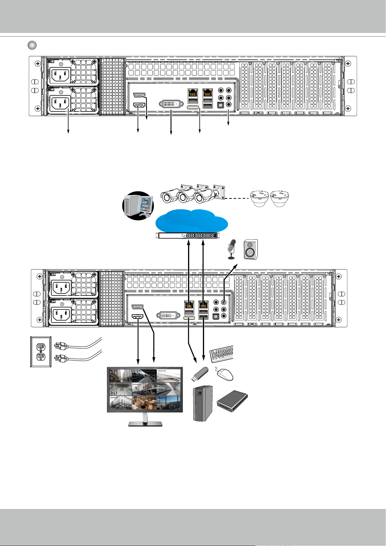
Rear View
DVI-D
LAN & USB
ports
HDMI
Display
port
Audio In/Out
Redundant power
supplies
Camera 01
Camera 02
Camera 03
Camera 04
Camera 06
Camera 05
Camera 07
Camera 08
Camera 09
LAN/WAN
AC100~240V
50/60Hz, 600W
LAN1
LAN2
VIVOTEK - A Leading Provider of Multimedia Communication Solutions
User's Manual - 15
IMPORTANT:
It is important to leave a clearance of 76cm to the rear side of the chassis. The clearance is re-
quired to ensure an adequate airow through the chassis to ventilate heat. A 64cm clearance is
also required on the front of the chassis.
To ensure normal operation, maintain ambient airow. Do not block the airow around chassis
such as placing the system in a closed cabinet.
30”
76cm
25”
64cm
Display
Interface Resolution
HDMI
Supports max resolution HDMI 1.2 1920 x 1200 @ 60 Hz
DVI-D Currently not supported. Supports max. resolution 1920 x 1200 @ 60 Hz
Display port Supports max resolution 4096 x 2304 @ 60 Hz
eDP Internal pin header, supports max. resolution 3840 x 2160 @ 60 Hz (on board)
VIVOTEK - A Leading Provider of Multimedia Communication Solutions
16 - User's Manual
Chassis Dimensions
VIVOTEK - A Leading Provider of Multimedia Communication Solutions
User's Manual - 17
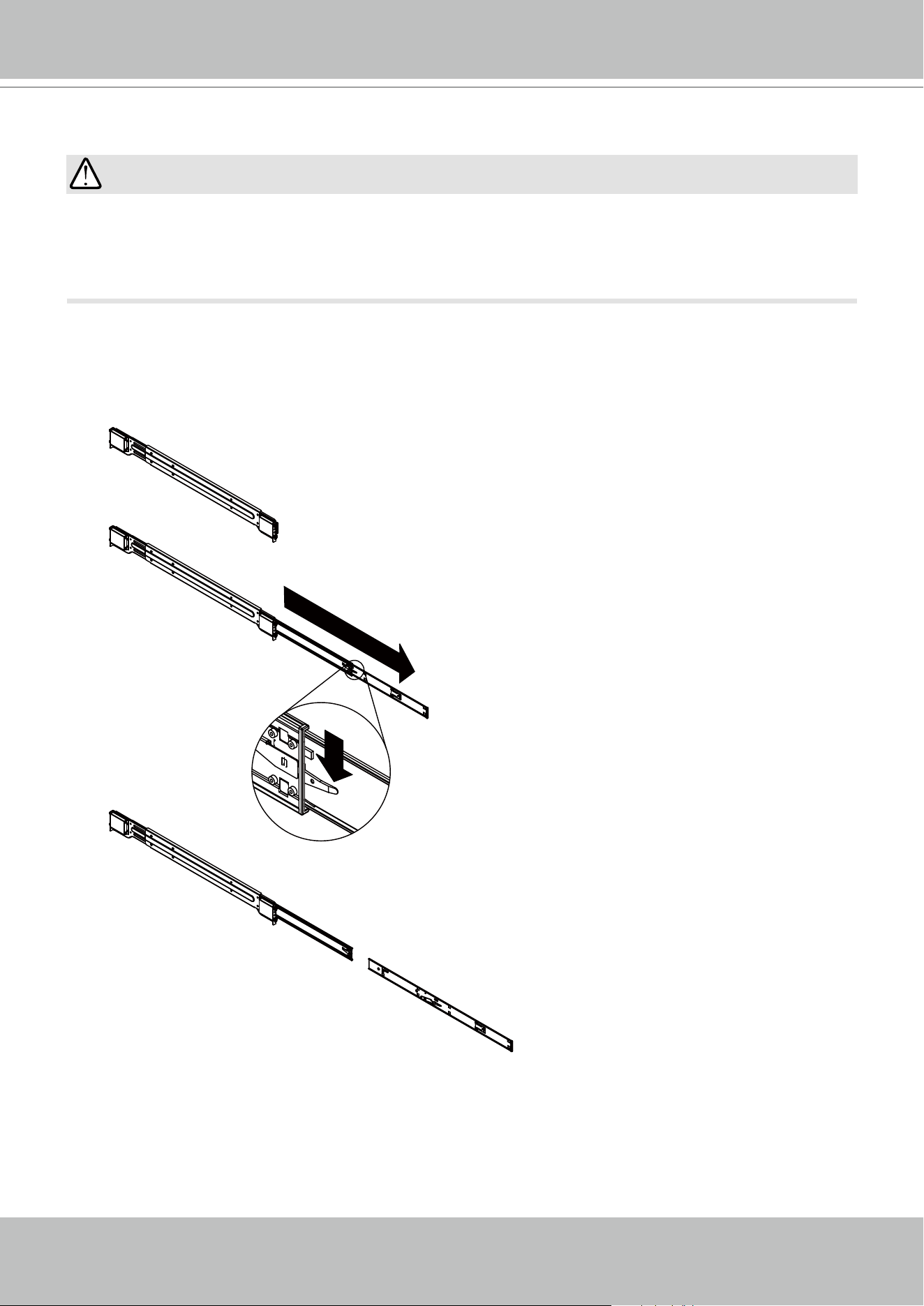
Rack-mounting
If you have either a round-holed or square-holed rack, install cage nuts or clip nuts to the
desired positions on the rack posts.
The instructions below are based on the installation to a 4-post equipment rack.
IMPORTANT:
PULL
Outer Rail
Middle Rail
Inner Rail
This Side Faces
Outward
1. Remove the inner rail from the slide rail assembly. There is a locking tab at the tip of the inner
rail.
VIVOTEK - A Leading Provider of Multimedia Communication Solutions
18 - User's Manual
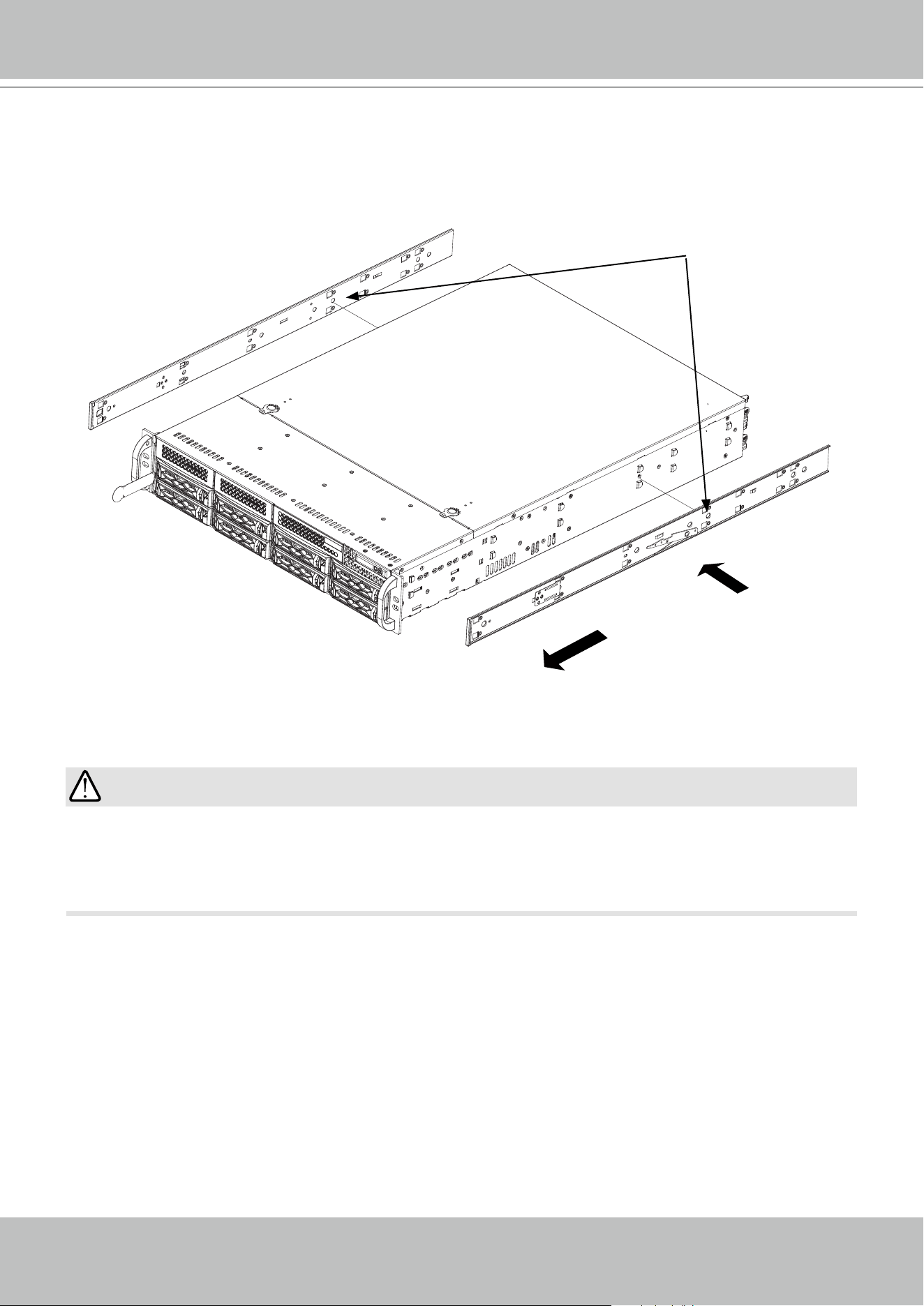
2. Remove the inner rail from the slide rail assembly.
2. Secure the inner rails to the sides of the chassis using the included screws. Place the inner
rail rmly against the side of the chassis, aligning the hooks on the side of the chassis with
the holes in the inner rail. Slide the inner rail forward toward the front of the chassis and under
the hooks until the quick release bracket snaps into place, securing the rail to the chassis.
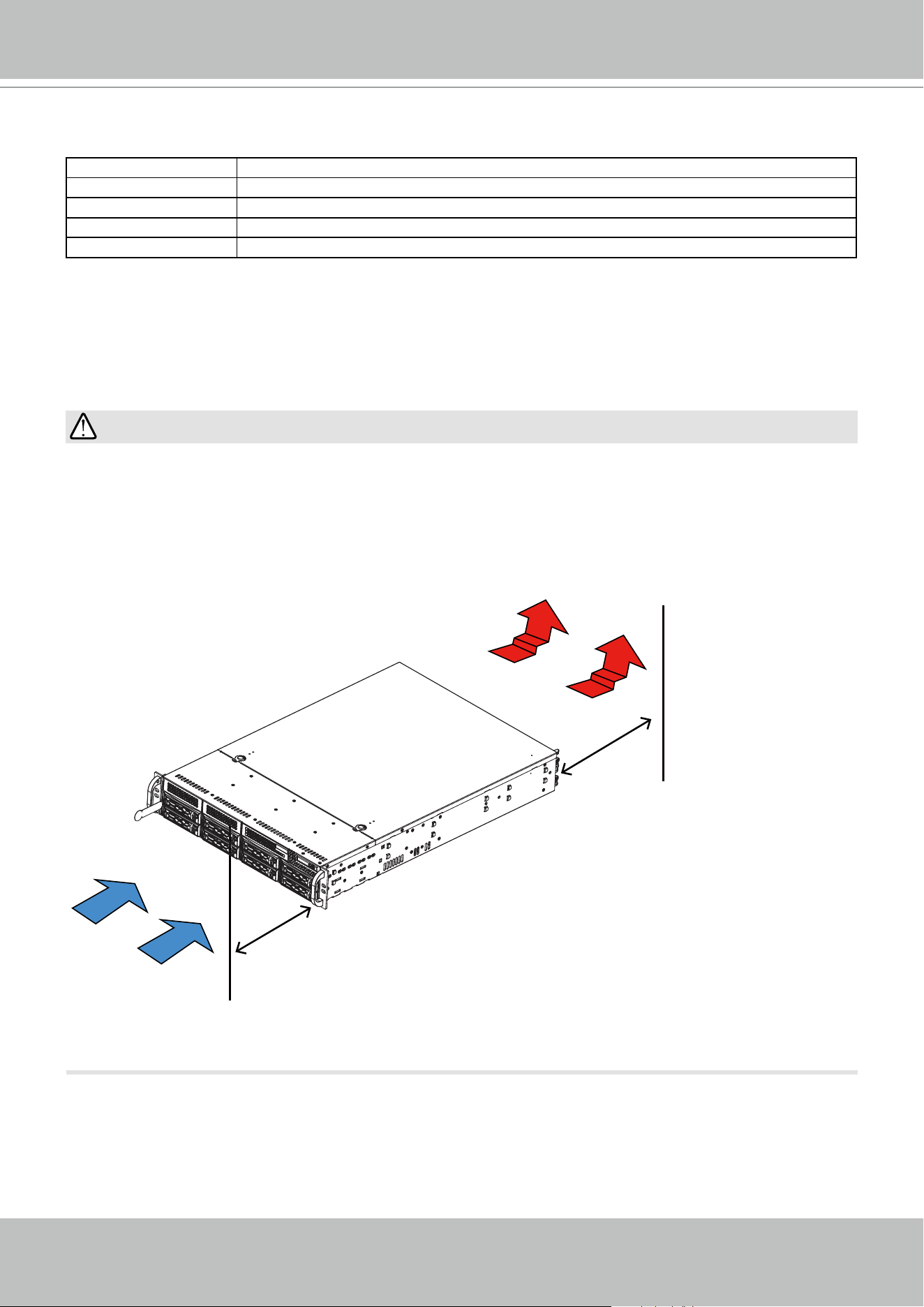
Do not pick up the server with the front handles. They are designed to pull the system from a
rack only.
WARNING:
VIVOTEK - A Leading Provider of Multimedia Communication Solutions
User's Manual - 19
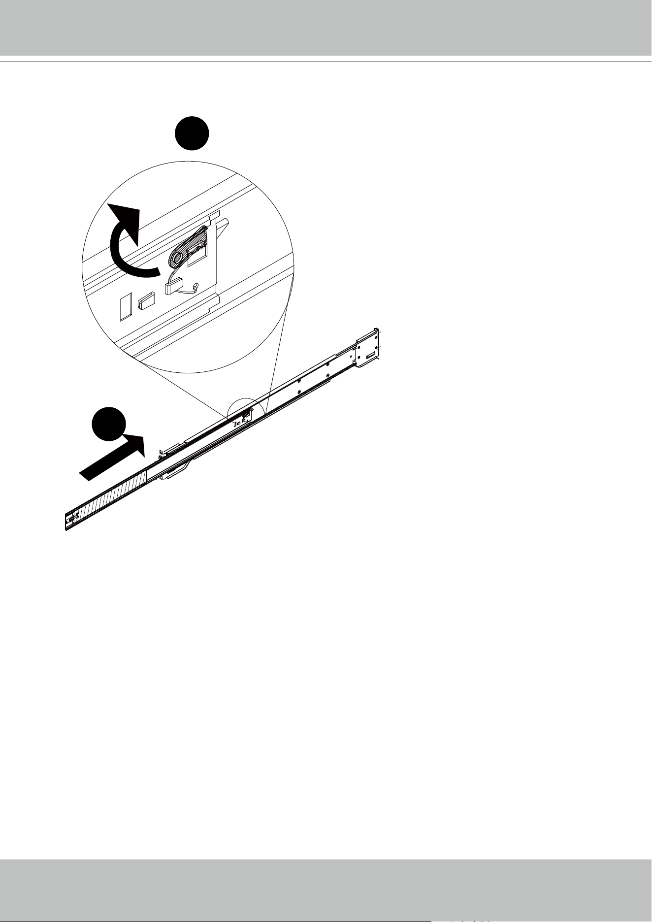
3. Pull upward on the locking tab at the rear end of the middle rail.
Push the middle rail back into the outer rail.
2
1
VIVOTEK - A Leading Provider of Multimedia Communication Solutions
20 - User's Manual
It is important to check if the safety lock is in the unlocked position before mounting the brackets.
Optional
Screws
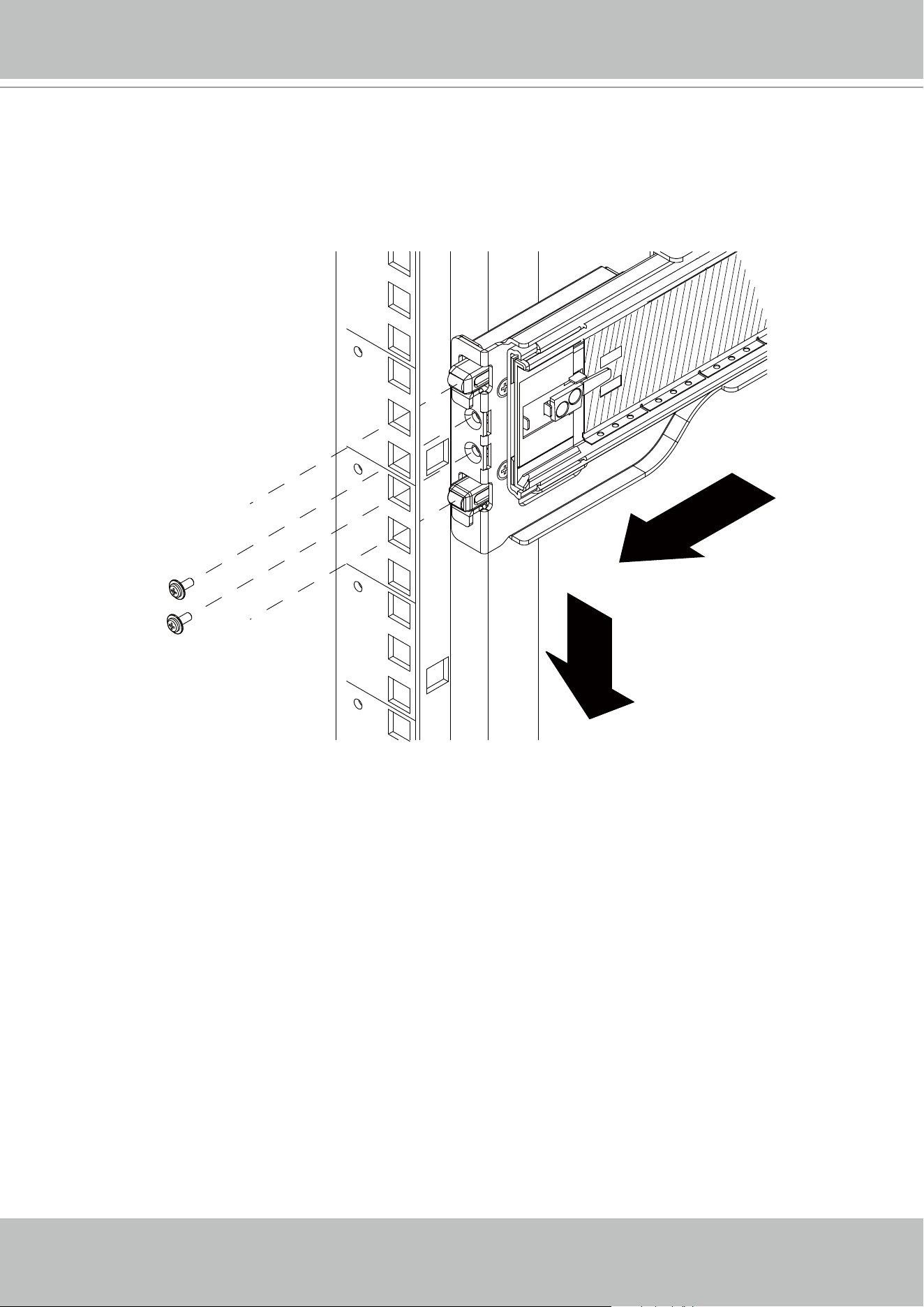
4. Hang the hooks on the front of the outer rail onto the square holes on the front of the rack. If
desired, use screws to secure the outer rails to the rack.
VIVOTEK - A Leading Provider of Multimedia Communication Solutions
User's Manual - 21
5. Pull out the rear of the outer rail, adjusting the length until it just ts within the posts of the
rack.
Hang the hooks of the rear section of the outer rail onto the square holes on the rear of the
rack. Take care that the proper holes are used so the rails are level. If desired, use screws to
secure the rear of the outer rail to the rear of the rack.
VIVOTEK - A Leading Provider of Multimedia Communication Solutions
22 - User's Manual
Ball Bearing
Shuttle
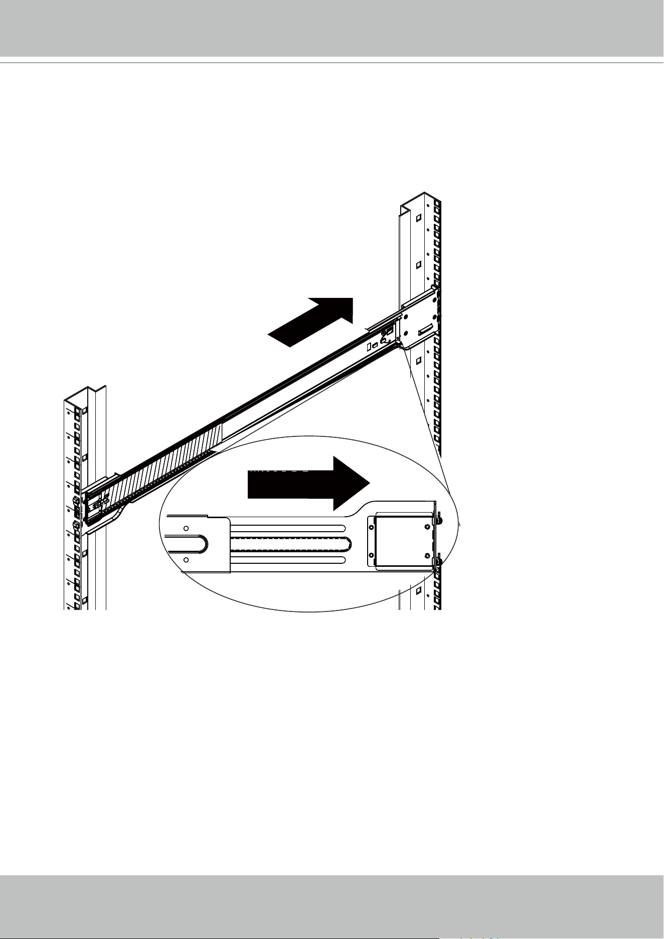
6. Pull the middle rail out of the front of the outer rail and make sure that the ball bearing shuttle
is locked at the front of the middle rail.
Align the rear of the chassis rails with the middle rails and then push evenly on both sides of
the chassis until it clicks into the fully extended position.
Depress the locking tabs on both sides of the chassis and push the it fully into the rack. The
locking tabs should "click".
Note: Keep the ball bearing shuttle locked at the front of the middle rail during installation. Note: Figure is for
illustrative purposes only. Always install servers to the bottom of a rack rst.
VIVOTEK - A Leading Provider of Multimedia Communication Solutions
User's Manual - 23
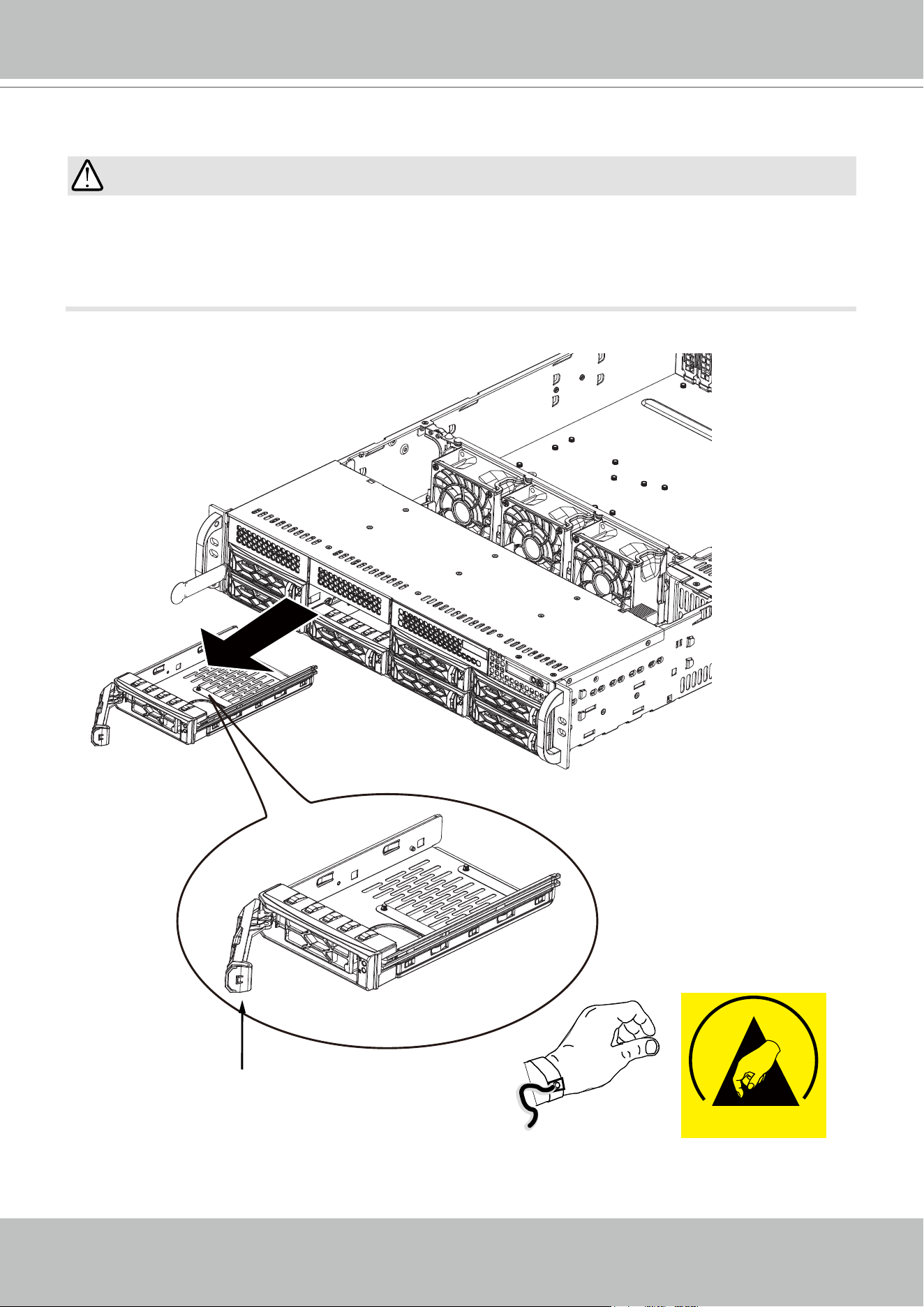
Release Button
Lever
ESD
• Refer to VIVOTEK's website for the hard disk compatibility information.
• Avoid touching the hard drive's circuit board or connector pins. Doing so can damage the
hard drive by electro-static discharge.
IMPORTANT:
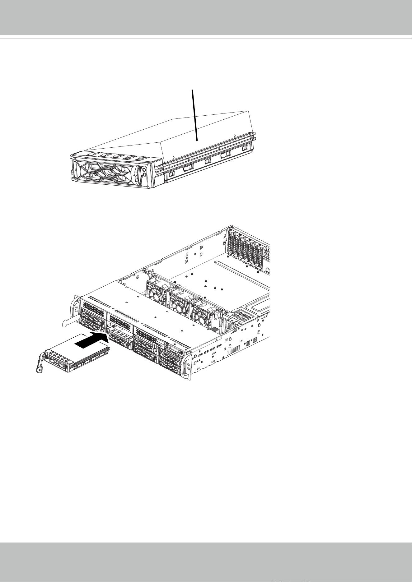
Installing Hard Disk Drives
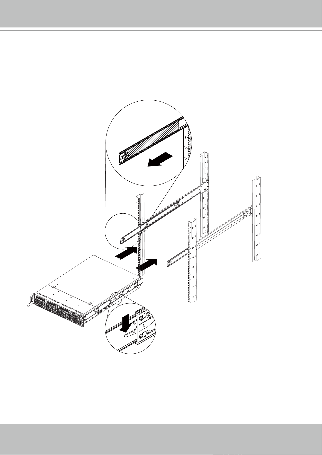
1. Press the release button on the drive carrier. This extends the drive carrier lever.
2.Use the lever to pull the carrier out of the chassis.
It is recommended to
wear an anti-static wrist
strap when handling hard
drives.
VIVOTEK - A Leading Provider of Multimedia Communication Solutions
24 - User's Manual
2
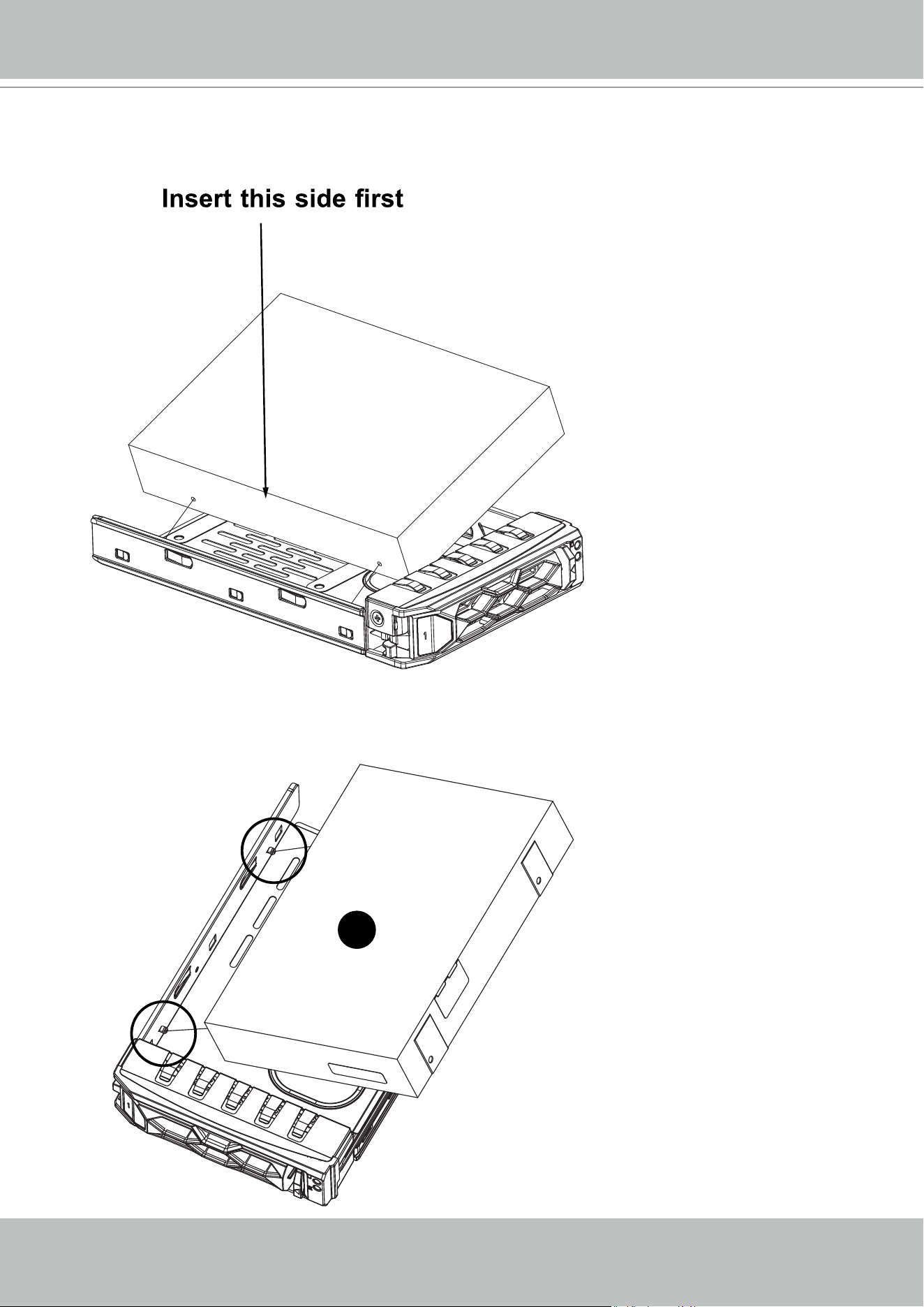
3. Insert a 3.5" hard drive in an angle into the carrier, so that the mounting holes on the right
side of the drive align with the two stubs in the drive carrier. Insert this side into the drive
carrier rst, then push the other side into the drive carrier completely.
3.5" Drive
Stub
Stub
2
VIVOTEK - A Leading Provider of Multimedia Communication Solutions
User's Manual - 25
3. Install hard drives by driving screws from the sides. When done, gently install the drive trays
into the chassis.
X8
Insert this side later
4. Press down on the other side for the hard drive to snap into place.
If using 2.5" hard drives, the 4 screws necessary for installation are user-supplied.
VIVOTEK - A Leading Provider of Multimedia Communication Solutions
26 - User's Manual
Connecting Interfaces
Refer to page 14 for the interface connections.
1. Make sure all cameras have been properly installed, either they are powered by 12V
power lines or using one or several PoE switches or mid-spans. Refer to the cameras'
documentation for details.
2. Connect all other interfaces to USB mouse/keyboard, one or two monitors, and audio input/
output devices.
3. Make sure you connect both power supplies to power mains. An alarm will be sounded if you
connect only 1 of the power supplies.
Initial Conguration
1. Power up the system by pressing the power on button.
2. Skip the BIOS screens and select Enter NVR at the selection screen. The system will start.
Wait for the start-up process to complete.
0 Enter NVR
1 Restore to default
2 Reboot
3 Shutdown
Enter
VIVOTEK - A Leading Provider of Multimedia Communication Solutions
User's Manual - 27
RAID5/6/10
Drive Group
Virtual Drive
Our default recommendation is to combine 4 hard drives into 1 drive group. The capacities of
these drives will be utilized to form 1 Virtual Drive. If all 16 drive bays are populated, you can
create 4 Virtual Drives. A 4-member Virtual Drive can receive the video feeds from 32 cameras.
You can also create two 8-member Virtual Drives to receive the video feeds from 64 cameras (CH,
or channels.)
Recording will not take place unless you create a Virtual Drive rst. Select RAID5 as the RAID
level during the conguration process.
Virtual Drive
Drive Group
LUN - Volume
x1
8 members (RAID5)
64 CH,
each LUN
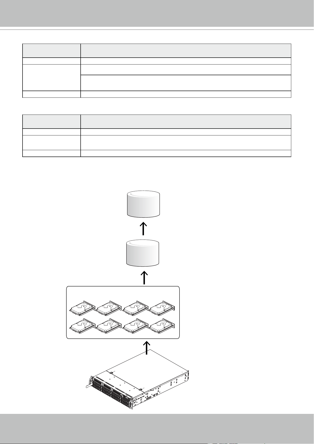
VIVOTEK - A Leading Provider of Multimedia Communication Solutions
28 - User's Manual
The default conguration for a conguration of 64 cameras should look like the following:
Physical & Logical
components
Conguration
Hard drive 8
Virtual Drive 1, each has 8 members. Congured in RAID5.
If using 6TB drives, the available capacity in each Virtual Drive will be,
8 x 6TB-1 x 6TB(parity drive)= 42TB.
Volume 2, each created from 1 Virtual Drive.
The camera conguration should look like this,
Physical & Logical
components
Conguration
Cameras 64
Recording Group 1, each responds to 32 or 64 cameras, and each Recording Group is associated with 1
Virtual Drive volume.
Volume 1, each created from 1 Virtual Drive, and associated with 1 Recording Group. .
Virtual Drive
Drive Group
LUN - Volume
x1
x1
x1
8 members (RAID5)
A Virtual Drive appears to the host system (Windows) as a logical disk partition. The logical
parition, when formatted, becomes a disk volume.
VIVOTEK - A Leading Provider of Multimedia Communication Solutions
User's Manual - 29
X2
1. The system will boot up to the system main screen. Double-click on the RAID Cong shortcut
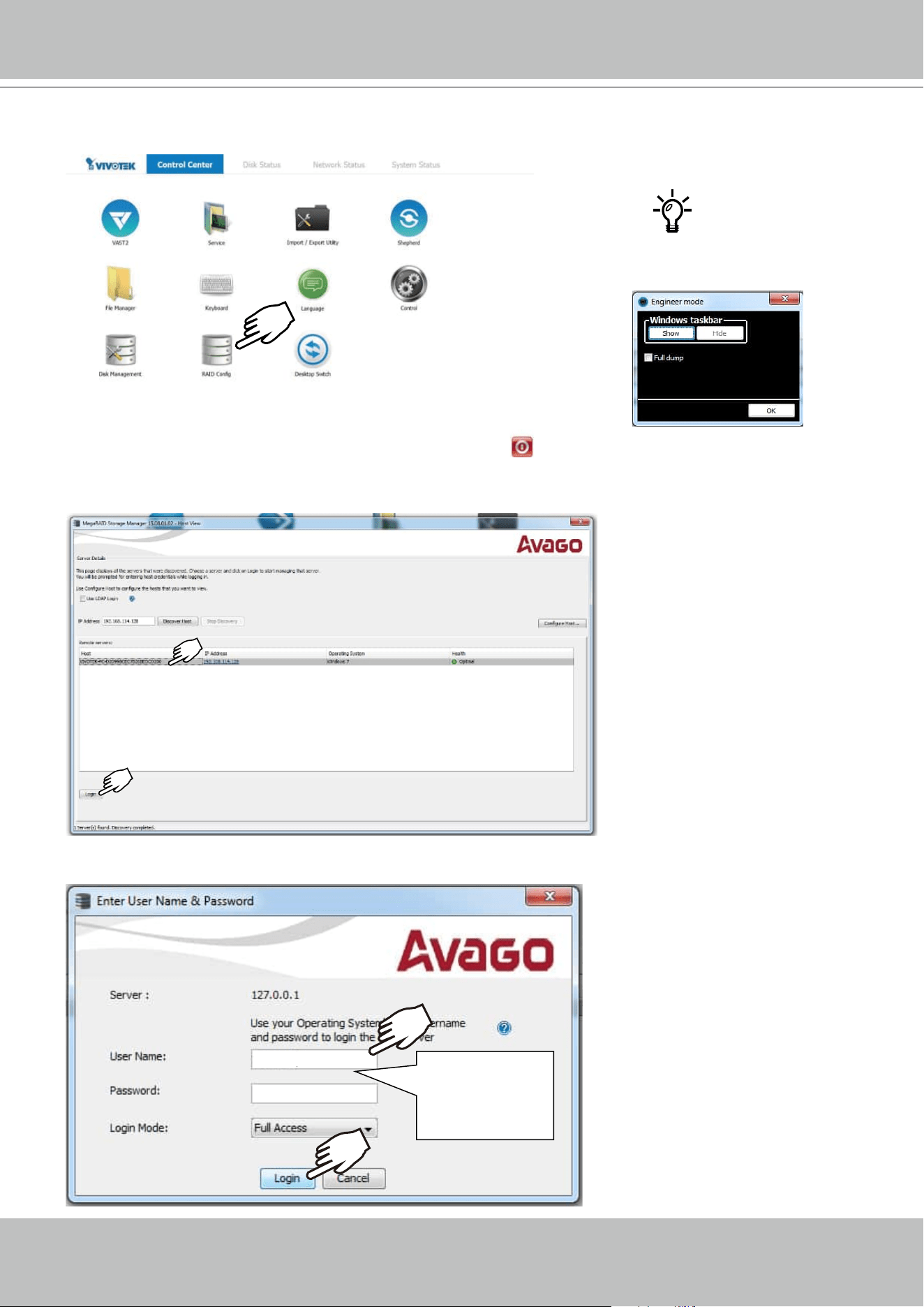
to start the MegaRAID storage conguration utility.
2. Select the default server, namely, the Windows 7 server running on this machine. Click Login
to begin your conguration.
3. Enter vivotek/vivotek as the User Name and Password. Click Login to proceed.
vivotek
vivotek
Default:
vivotek
vivotek
Ctrl + Alt + F12 ->
X2
VIVOTEK - A Leading Provider of Multimedia Communication Solutions
30 - User's Manual
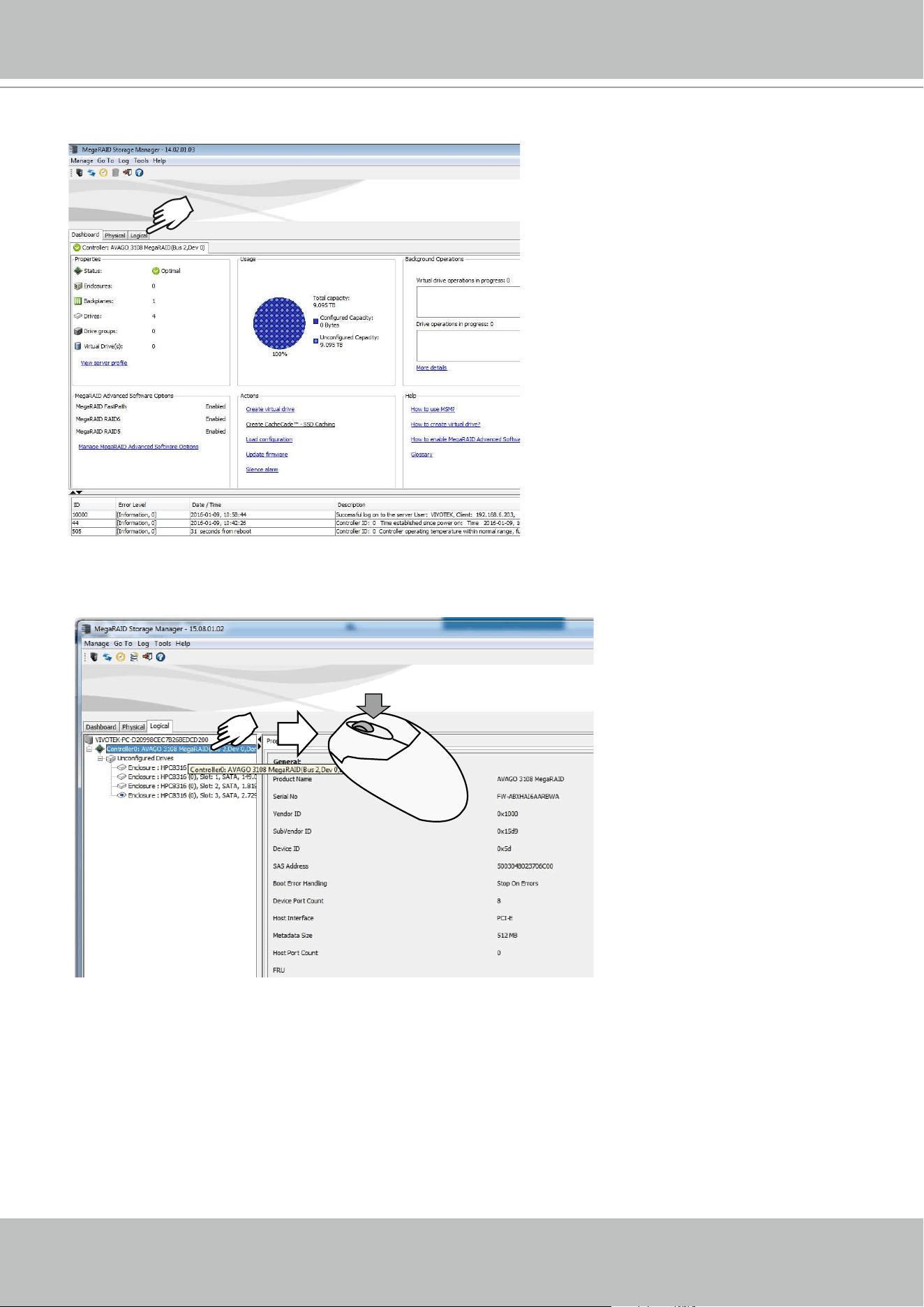
4. A Dashboard view will appear. Click the Logical tab.
5. Left-click to select the AVAGO MegaRAID controller, and then right-click to display a
command menu.
VIVOTEK - A Leading Provider of Multimedia Communication Solutions
User's Manual - 31
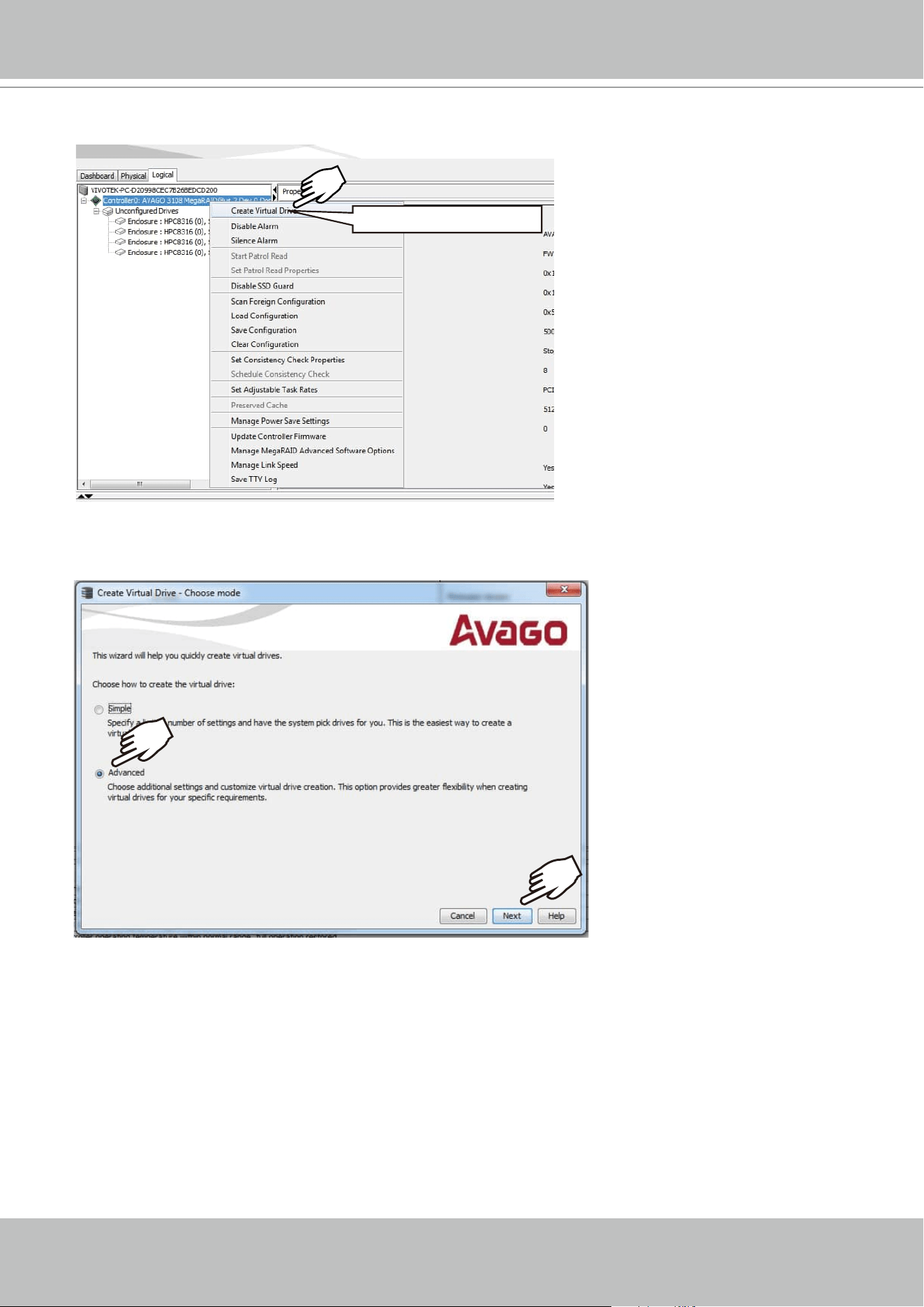
6. Click on Create Virtual Drive.
Create Virtual Drive
7. The Create Virtual Drive wizard will start. Click to select the Advanced mode. Then click the
Next button to proceed.

VIVOTEK - A Leading Provider of Multimedia Communication Solutions
32 - User's Manual
8. Select a RAID level, and then select multiple disk drives as the members of your drive group.
Left-click to select a disk drive, and click Add to add it to group. You do not need to select the
Data protection option.
9. Click on the Drive Group 0 entry you have just congured. The Create Drive Group button
will become available. Click Next to proceed.
Refer to the next section: RAID Basics on page 44, for details about RAID levels.
VIVOTEK - A Leading Provider of Multimedia Communication Solutions
User's Manual - 33
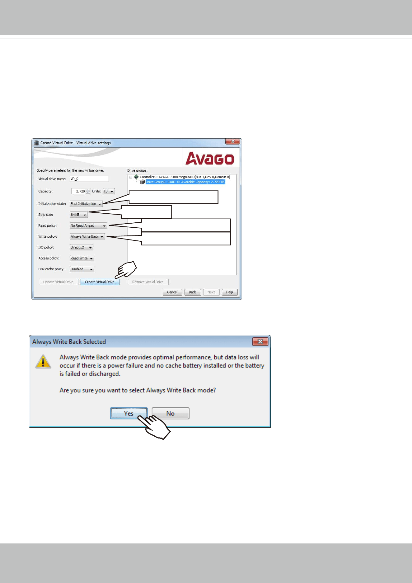
9. Select the following key parameters:
Initialization State: Fast Initialization,
Strip size: 64KB,
RAID policy: No Read Ahead,
Write policy: Always Write Back.
These are important parameters to the disk array performance, and have to be correctly
congured. Click Create Virtual Drive.
10. Click Yes to leave the Write Back concern message.
64 KB
No Read Ahead
Always Write Back
Fast Initialization
VIVOTEK - A Leading Provider of Multimedia Communication Solutions
34 - User's Manual
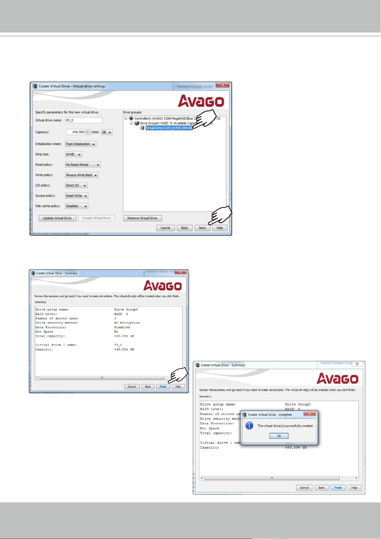
11. The wizard may prompt for another virtual drive. Multiple virtual drives can be created from
a physical drive group. Repeat the process to create more 4-member Virtual Drives. When
done, click to select the Virtual Drive 0,VD_0, and then click Next to proceed.
12. The Virtual Drive is instantly created. Click OK, and then click Finish to close the wizard.
You can then terminate the MegaRAID utility.
VIVOTEK - A Leading Provider of Multimedia Communication Solutions
User's Manual - 35
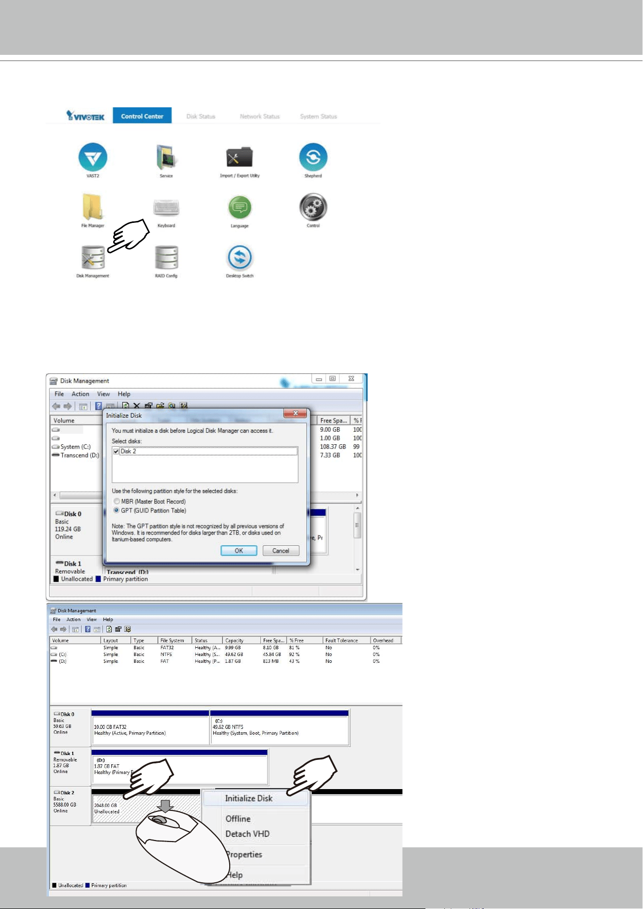
13. Double-click on the Disk Management shortcut on the desktop to open the utility.
14. The virtual drive you created should appear as a new disk partition. You need to initialize
and format the partition before using the disk capacity. Left-click to select and then right-click
to display the command menu. Click Initialize Disk to proceed.
X2
VIVOTEK - A Leading Provider of Multimedia Communication Solutions
36 - User's Manual
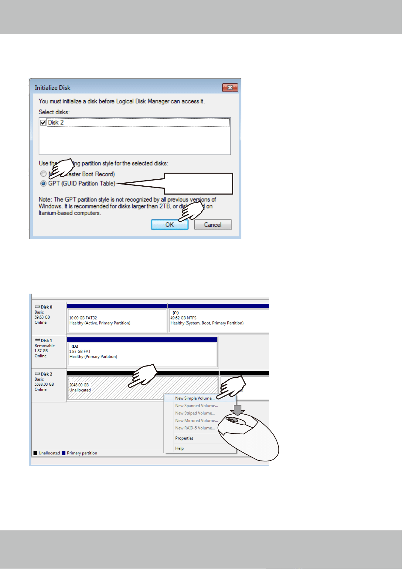
15. Select GPT (GUID Partition Table), and then click OK to proceed. This window may
automatically pop up when Disk Management is started.
GPT
16. Once initialized, you can create a new volume. Right-click to display the New Simple
Volume command. Click to proceed.
Please do not format drive C:. Doing so will disable the system.
VIVOTEK - A Leading Provider of Multimedia Communication Solutions
User's Manual - 37
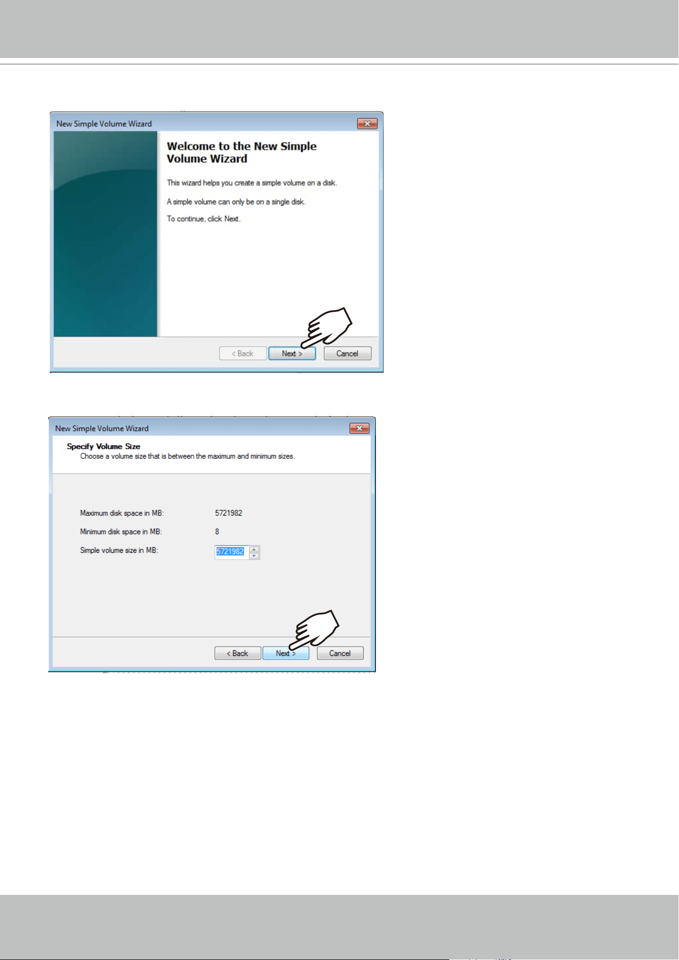
17. The New Simple Volume Wizard will prompt. Click Next to proceed.
18. Leave the volume size unchanged. Click Next to proceed.
VIVOTEK - A Leading Provider of Multimedia Communication Solutions
38 - User's Manual
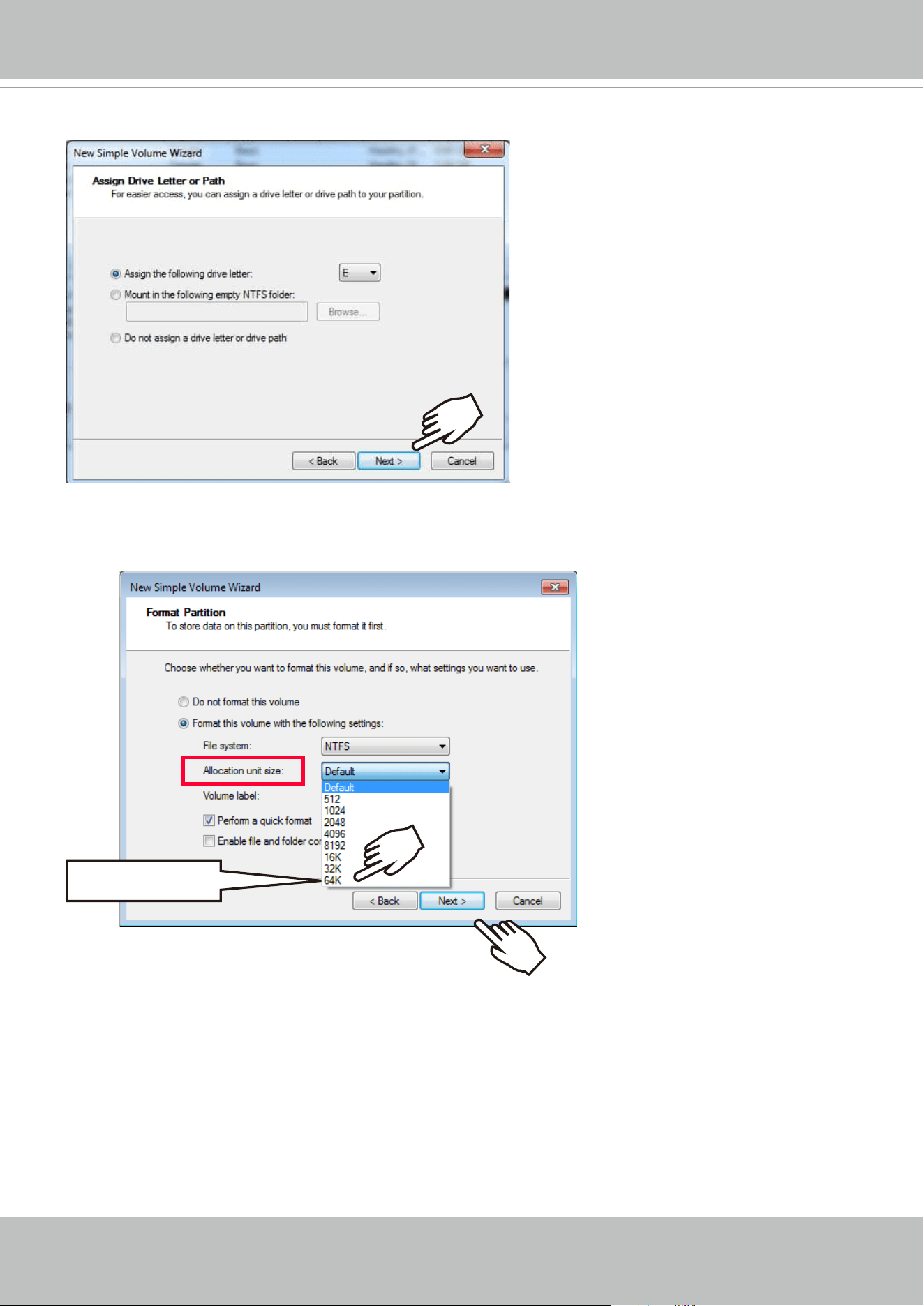
20. On the Format Partition page, select the Allocation unit size as 64KB. When done, click
Next to proceed.
64 KB
19. When prompted to assign a drive letter, click Next to proceed.
VIVOTEK - A Leading Provider of Multimedia Communication Solutions
User's Manual - 39
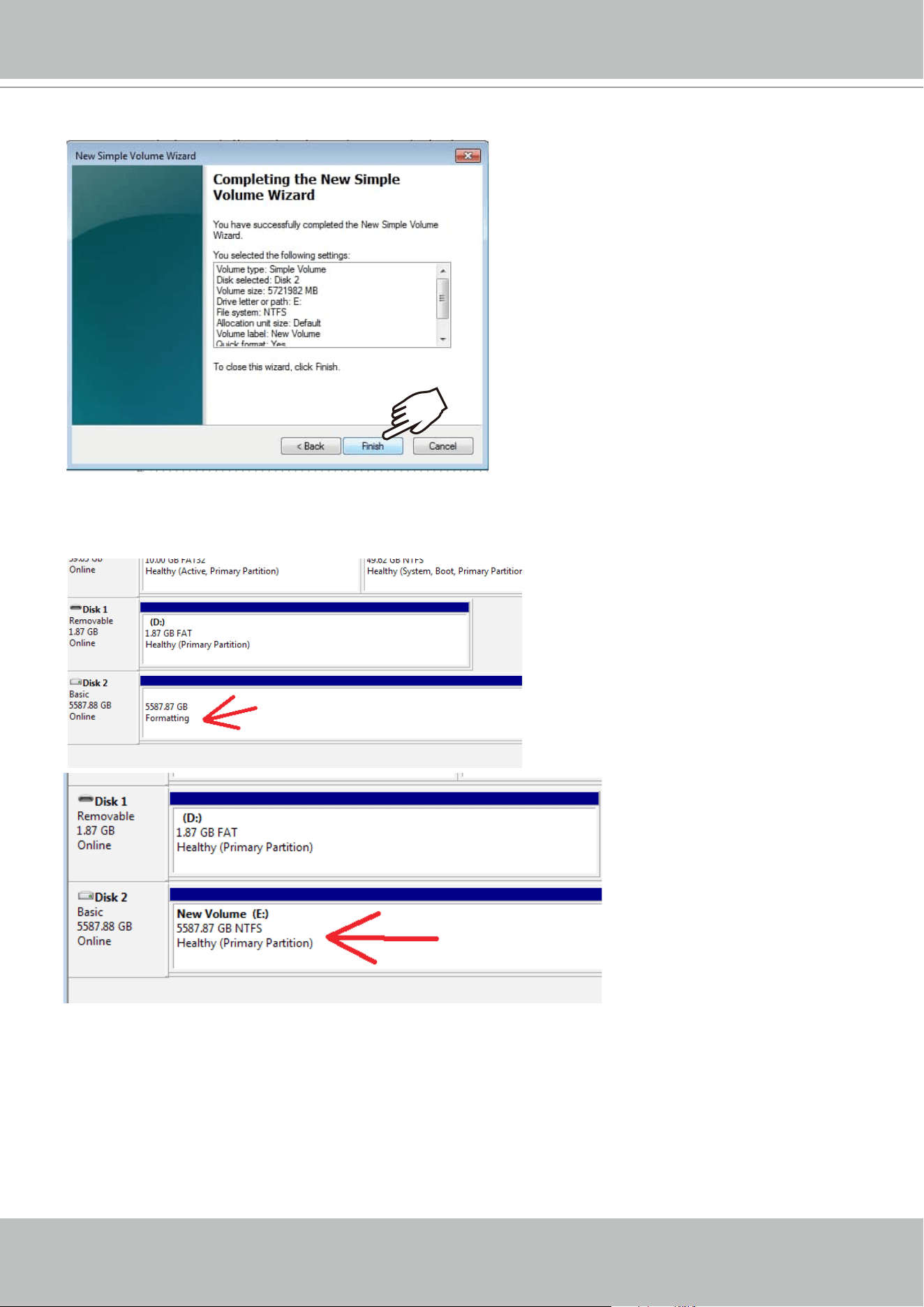
21. Click Finish to end the wizard.
22. The formatting process will run in the background. When done, the new volume shall be
indicated as a healthy new volume. Close the Disk Management window.
VIVOTEK - A Leading Provider of Multimedia Communication Solutions
40 - User's Manual
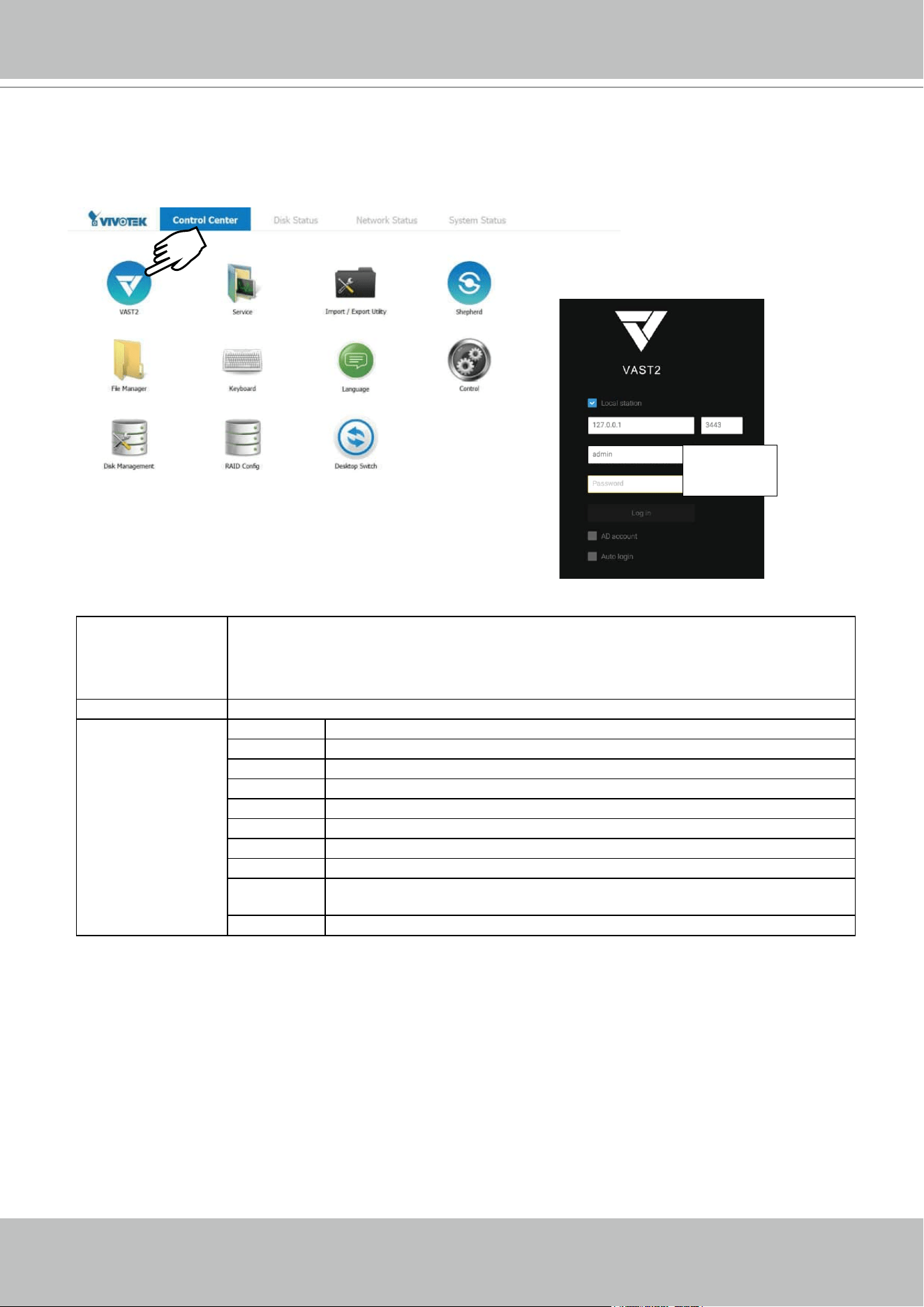
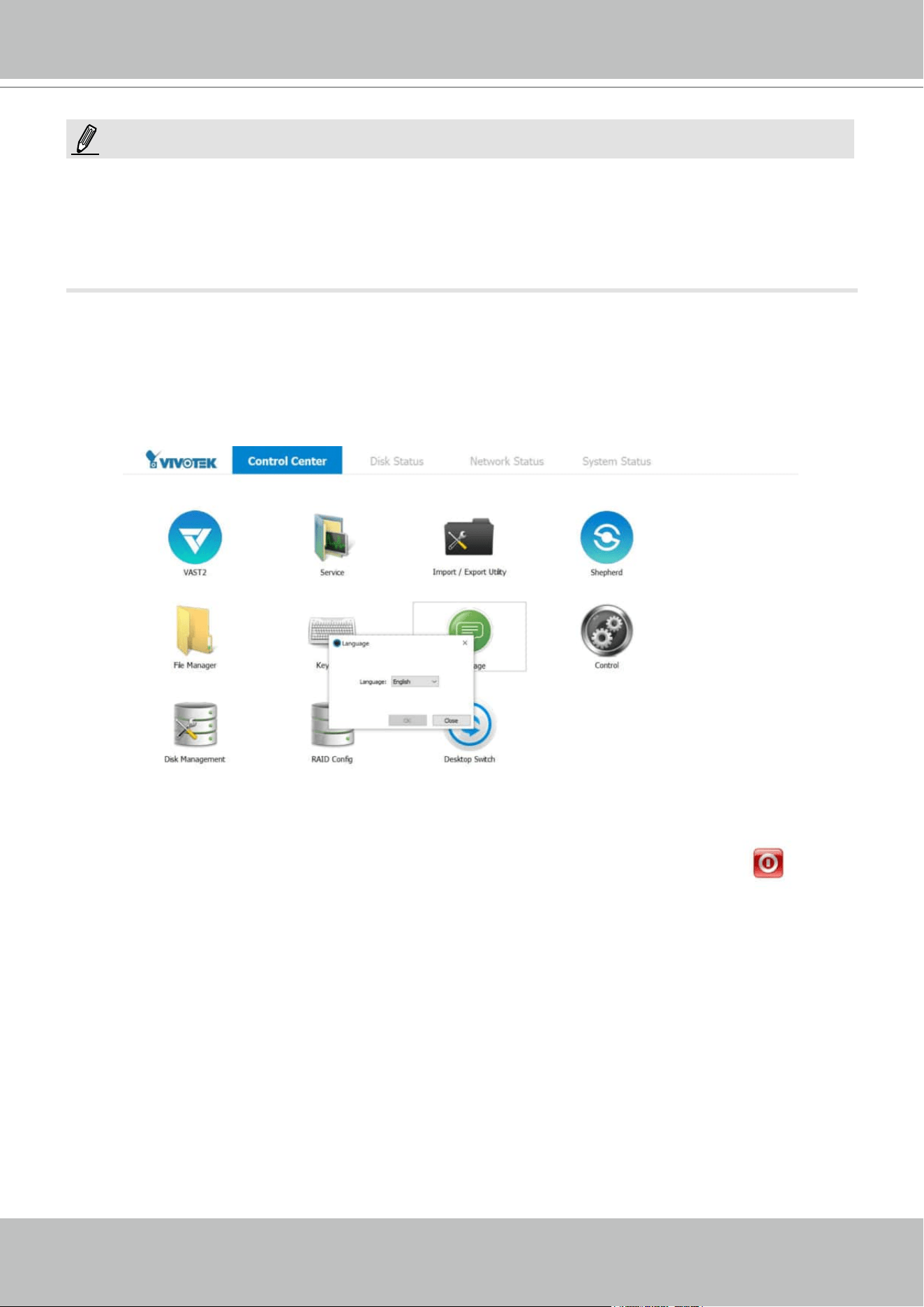
23. Start VIVOTEK VAST management software by double-clicking its shortbut. Enter admin
and admin as the User Name and default Password. You can change the password later in
the utility. Click Log in to proceed.
Top row Control Center: the default desktop.
Disk Status: Displays the current storage volume status (system drive and RAID volumes).
Network Status: Displays the information for the current network connections.
System Status: Displays the current system status, license information, and VAST service.
Desktop Shortcuts
VAST2
Starts the VAST2 recording and management software.
Service Enables you to start, stop, or restart the VAST server instance.
Import/Export Allows you to import or export VAST congurations.
Shepherd Use the Shepherd utility to locate cameras within your network.
File Manager Provides access to the les in system disk drive volumes.
Keyboard Toggles the virtual keyboard in case you do not have a physical keyboard.
Language Changes the UI language. .
Control Opens the operating system's control panel.
Disk
Managment
Starts the Disk Management utility in Windows.
RAID Cong. Starts the RAID card storage conguration utility.
X2
admin
admin
VIVOTEK - A Leading Provider of Multimedia Communication Solutions
User's Manual - 41
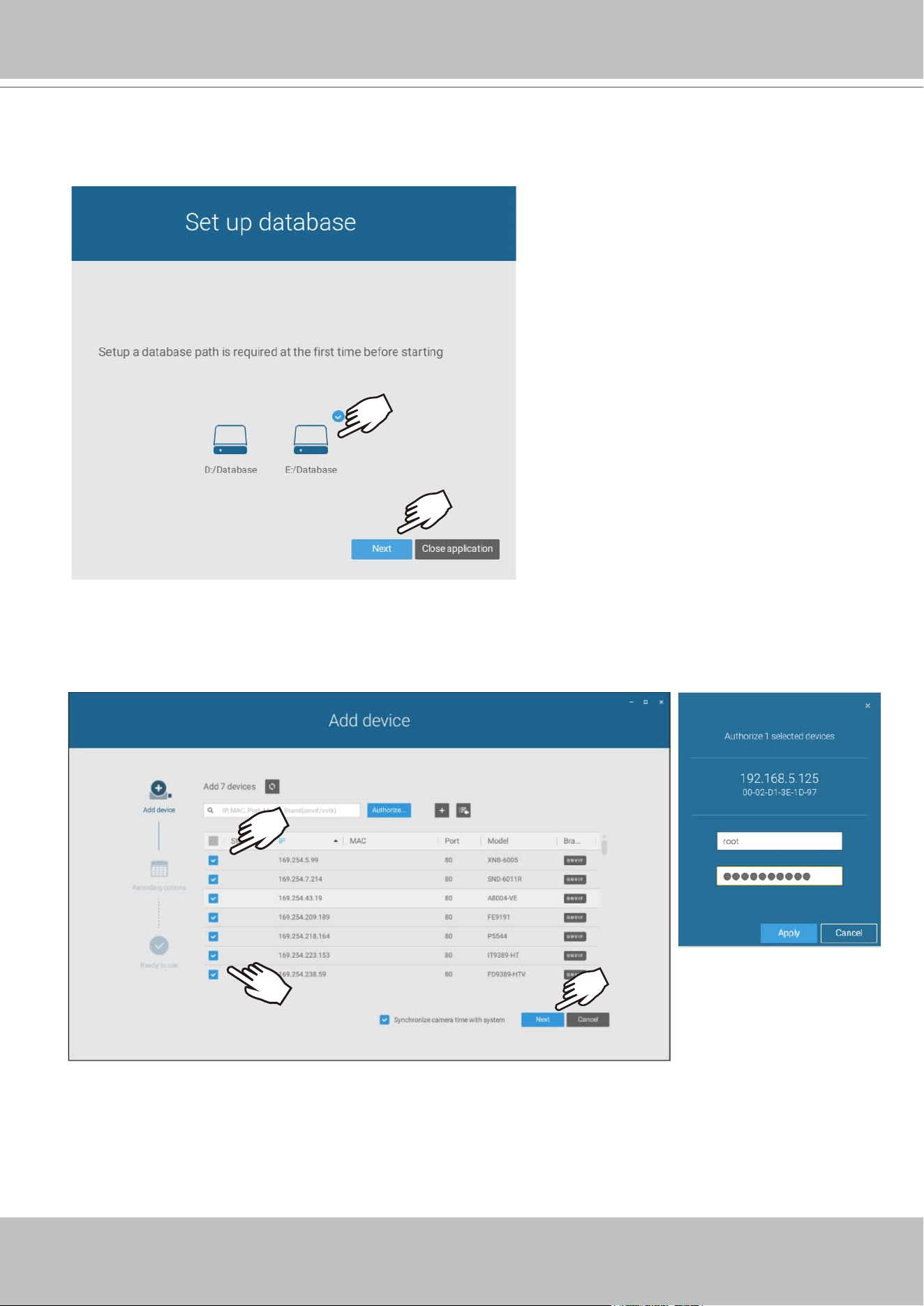
24. The rst time the VAST2 server is started, a conguration wizard will prompt to guide
you through the basic conguration. Select drive
E:/ as the default location for the server
database.
25. The next screen provides a list of all cameras in the local network. Select the cameras of
your choice. Enter the credentials for making the connection with the network cameras. When
done, click the Next button to proceed.
VIVOTEK - A Leading Provider of Multimedia Communication Solutions
42 - User's Manual
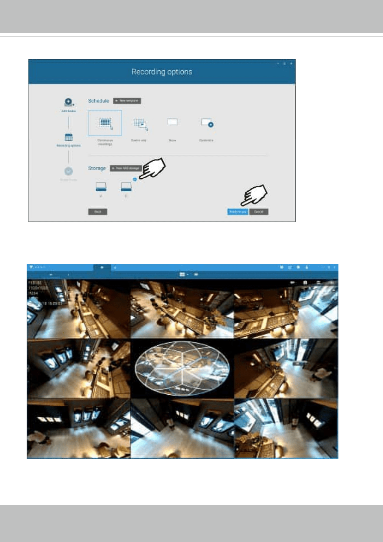
26. Select the recording volumes, such as the E:/ volume you just created. When done, click the
Ready to use button.
27. You should then enter the Liveview of the VAST2 software. Follow the discussions in later
sections for how to congure your VAST2 deployment.
VIVOTEK - A Leading Provider of Multimedia Communication Solutions
User's Manual - 43
1. Cameras and the NVR must reside in the same subnet. Otherwise, the NVR will not be able
to recruit them into a recording conguration.
2. It is recommended all network cameras use static IPs. If you let a DHCP server assign IPs to
these cameras, IPs may be changed later and the NVR may not recognize them.
NOTE:
If preferred, change the language of UI text using the Language shortcut on the desktop.

VIVOTEK - A Leading Provider of Multimedia Communication Solutions
44 - User's Manual
RAID Basics
A Redundant Array of Independent Disks is an array, or group, of multiple independent physical
drives that provide high performance and fault tolerance. A RAID drive group improves I/O
performance and reliability. The RAID drive group appears to the host computer as a single
storage volume or as multiple virtual units. An I/O transaction is expedited because several
drives can be accessed simultaneously.
A RAID drive group improves data storage reliability and fault tolerance compared to single drive
storage. Data loss resulting from a drive failure can be prevented by reconstructing missing data
from the remaining drives. The benets of RAID come from the improvement of I/O performance
and the increased reliability.
What are the Virtual drives?
Virtual drives are drive groups that are available to the operating systems. The storage space in
a virrtual drive comes from all the members in the drive group.
The RAID functions available for virtual drives include:
Hot spare drives.
Drive group and virtual drive congurations.
Initializing one or more virtual drives.
Individual access to controllers, virtual drives, and disk drives.
Failed drive rebuild.
Verication of redundancy data in virtual drives using RAID levels 1, 5, 6, 10, 50, and 60.
Reconstructing virtual drives after the RAID levels or adding a drive to a drive group.
Indepently selecting a host controller to work for.
RAID conguration components
Drive group: a group of physical drives. These drives will be managed in partitions known as
virtual drives.
Virtual drive: a partition in a drive group made of continguous data segments from the
individual disk drives. A virtual drive can consist of the following components:
An entire drive group.
More than one entire drive group.
A part of drive group.
Parts of more than one drive group.
A combination of any two of the conditions above.
For a RAID volume conguration, it is recommended you use hard drives of the same model
featuring the same capacity and rotation speed. It is also preferred that these drives are running
the same version of rmware.
IMPORTANT:
VIVOTEK - A Leading Provider of Multimedia Communication Solutions
User's Manual - 45
RAID Fault Tolerance
RAID Level Number of Tolerable Drive Failures
0 No fault tolerance
1 1, each drive group
5 1
6 2
10 multiple, as long as each failure is in a separate drive group
50 1 in each drive group
60 2 in each drive group
RAID10
Mirror
Mirror
Mirror
Mirror
Mirror
Mirror
RAID0
RAID1 RAID1 RAID1 RAID1 RAID1 RAID1
For example, if disk failure occurs in different drive groups, a RAID10 conguration can
tolerate multiple drive failures. In each RAID1 drive group, data is mirrored to a counterpart
disk drive. Data remains intact if one disk drive should fail in each drive group.
Consistency Check
The consistency check operation veries the correctness of the data in virtual drives that use
RAID levels 1, 5, 6, 10, 50, and 60. RAID0 does not provide data redundancy. In a system with
parity, check consistency means calculating the data on one drive and comparing the results to
the contents of the parity drive.
VIVOTEK - A Leading Provider of Multimedia Communication Solutions
46 - User's Manual
Background Initialization
Background initialization is a check for media errors on the drives when you create a virtual
drive. It is an automatic operation that starts ve minutes after you create a virtual drive. This
check ensures that striped data segments are the same on all of the drives in the drive group.
Background initialization is similar to a consistency check. The difference between the two is
that a background initialization is forced on new virtual drives and a consistency check is not.
New RAID 5 virtual drives and new RAID 6 virtual drives require a minimum number of drives
for a background initialization to start. If fewer drives exist, the background initialization does not
start. The background initialization needs to be started manually. The following number of drives
are required:
New RAID 5 virtual drives must have at least ve drives for background initialization to start.
New RAID 6 virtual drives must have at least seven drives for background initialization to
start.
The default and recommended background initialization rate is 30 percent. Before you change
the rebuild rate, you must stop the background initialization or the rate change will not affect the
background initialization rate. After you stop background initialization and change the rebuild
rate, the rate change takes effect when you restart background initialization.2.1.7Patrol Read
Disk Striping
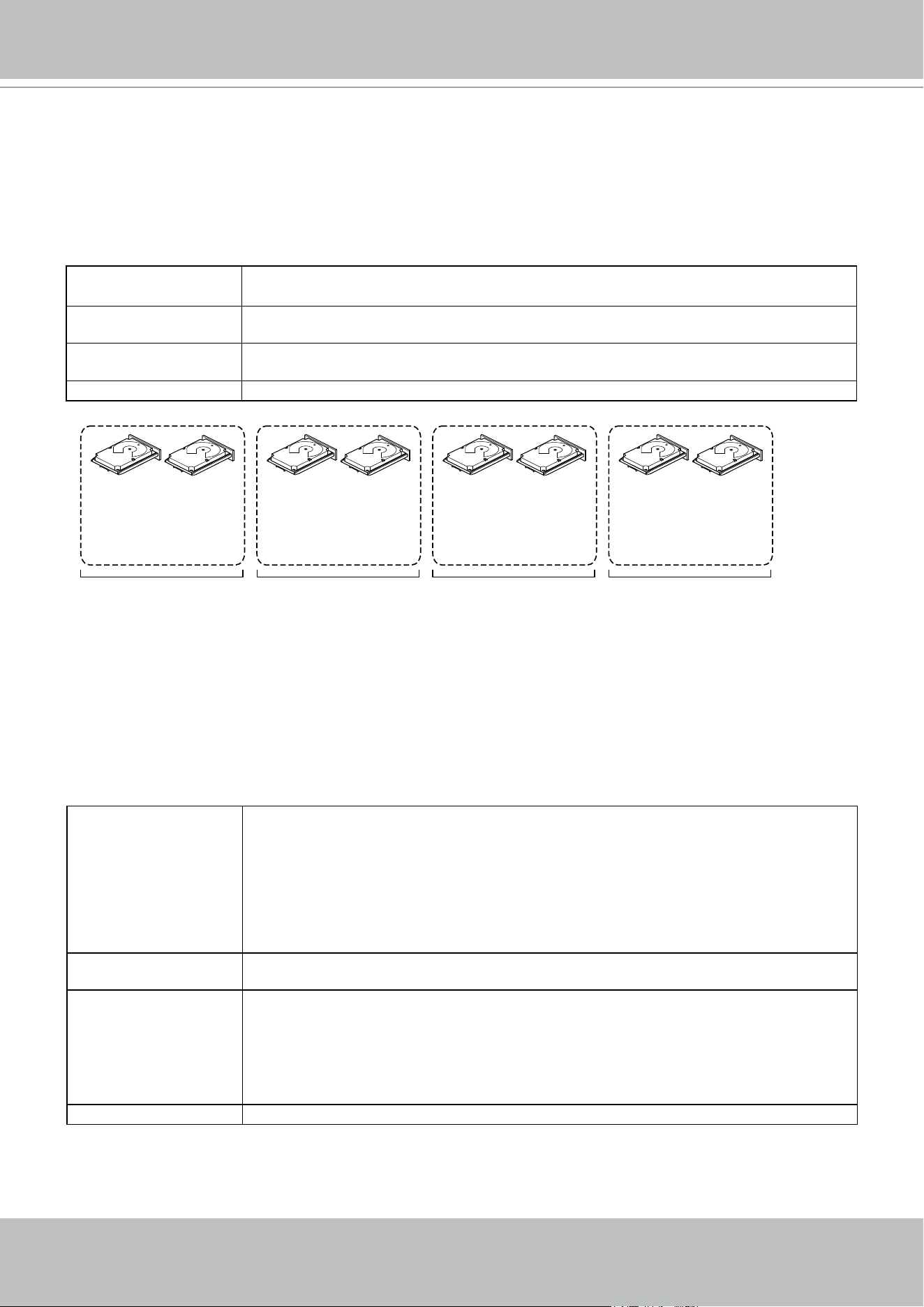
Disk striping lets you write data across multiple drives instead of just one drive. Disk striping
involves partitioning each drive storage space into stripes that can vary in size from a minimum
of 64 KB to 1 MB for MegaRAID controllers and 64 KB for Integrated MegaRAID controllers. The
LSISAS2108 controller allows stripe size from 8 KB to 1 MB. These stripes are interleaved in
a repeated sequential manner. The combined storage space is composed of stripes from each
drive. It is recommended that you keep stripe sizes the same across RAID drive groups.
For example, in a four-disk system using only disk striping (used in RAID level 0), segment 1 is
written to disk 1, segment 2 is written to disk 2, and so on. Disk striping enhances performance
because multiple drives are accessed simultaneously, but disk striping does not provide data
redundancy.
Segment 1
Segment 5
Segment 9
Segment 2
Segment 6
Segment 10
Segment 3
Segment 7
Segment 11
Segment 4
Segment 8
Segment 12
VIVOTEK - A Leading Provider of Multimedia Communication Solutions
User's Manual - 47
Disk Mirroring
With disk mirroring (used in RAID 1 and RAID 10), data written to one drive is simultaneously
written to another drive. The primary advantage of disk mirroring is that it provides 100 percent
data redundancy. Because the contents of the disk are completely written to a second disk, data
is not lost if one disk fails. In addition, both drives contain the same data at all times, so either
disk can act as the operational disk. If one disk fails, the contents of the other disk can run the
system and reconstruct the failed disk.
Disk mirroring provides 100 percent redundancy, but it is expensive because each drive in the
system must be duplicated. The following gure shows an example of disk mirroring.
Stripe Width
Stripe width is the number of drives involved in a drive group where striping is implemented. For
example, a four-disk drive group with disk striping has a stripe width of four.
Stripe Size
The stripe size is the length of the interleaved data segments that the RAID controller writes
across multiple drives, not including parity drives. For example, consider a stripe that contains
1 MB of drive space and has 64 KB of data residing on each drive in the stripe. In this case, the
stripe size is 1 MB and the strip size is 64 KB.
Strip Size
The strip size is the portion of a stripe that resides on a single drive.
Parity
Parity generates a set of redundancy data from two or more parent data sets. The redundancy
data can be used to reconstruct one of the parent data sets in the event of a drive failure. Parity
data does not fully duplicate the parent data sets, but parity generation can slow the write
process. In a RAID drive group, this method is applied to entire drives or stripes across all of the
drives in a drive group. The types of parity are described in the following table.
VIVOTEK - A Leading Provider of Multimedia Communication Solutions
48 - User's Manual
A RAID 5 drive group combines distributed parity with disk striping. If a single drive fails, it can
be rebuilt from the parity and the data on the remaining drives. An example of a RAID 5 drive
group is shown in the following gure. A RAID 5 drive group uses parity to provide redundancy
for one drive failure without duplicating the contents of entire drives. A RAID 6 drive group also
uses distributed parity and disk striping, but adds a second set of parity data so that it can
survive up to two drive failures.
Parity Type Description
Dedicated The parity data on two or more drives is stored on an additional disk.
Distributed The parity data is distributed across more than one drive in the system.
Segment 1
Segment 7
Segment 13
Segment 2
Segment 8
Segment 14
Segment 3
Segment 9
Segment 15
Segment 4
Segment 10
Parity (11 to 15)
Segment 5
Parity (6 to 10)
Segment 11
Parity (1 to 5)
Segment 6
Segment 12
Segment 19
Segment 25
Parity (26 to 30)
Segment 20
Parity (21 to 25)
Segment 26
Parity (16 to 20)
Segment 21
Segment 27
Segment 16
Segment 22
Segment 28
Segment 17
Segment 23
Segment 29
Segment 18
Segment 24
Segment 30
Disk Spanning
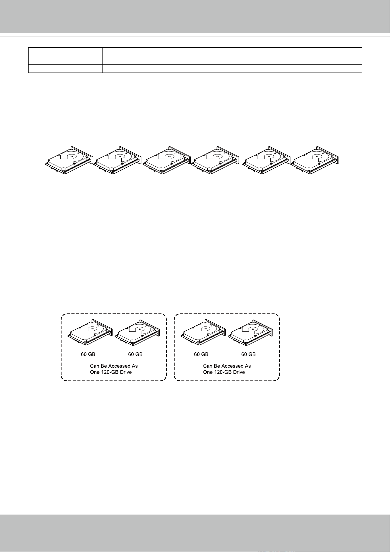
Disk spanning allows multiple drives to function like one big drive. Spanning overcomes lack
of disk space and simplies storage management by combining existing resources or adding
relatively inexpensive resources. For example, four 20-GB drives can be combined to appear
to the operating system as a single 80-GB drive.Spanning alone does not provide reliability or
performance enhancements. Spanned virtual drives must have the same stripe size and must
be contiguous. In the following gure, RAID 1 drive groups are turned into a RAID 10 drive
group.
Spanning two contiguous RAID 0 virtual drives does not produce a new RAID level or add
fault tolerance. It does increase the capacity of the virtual drive and improves performance by
doubling the number of spindles.
Spanning for RAID 00, RAID 10, RAID 50, and RAID 60 Drive Groups
The following table describes how to congure RAID 00, RAID 10, RAID 50, and RAID 60
drive groups by spanning. The virtual drives must have the same stripe size and the maximum
number of spans is 8. The full drive capacity is used when you span virtual drives; you cannot
specify a smaller drive capacity.

VIVOTEK - A Leading Provider of Multimedia Communication Solutions
User's Manual - 49
Level Description
00 Congure a RAID 00 by spanning two or more contiguous RAID 0 virtual drives, up to the
maximum number of supported devices for the controller.
10 Congure RAID 10 by spanning two or more contiguous RAID 1 virtual drives, up to
the maximum number of supported devices for the controller. A RAID 10 drive group
supports a maximum of 8 spans. You must use an even number of drives in each RAID
virtual drive in the span. The RAID 1 virtual drives must have the same stripe size.
50 Congure a RAID 50 drive group by spanning two or more contiguous RAID 5 virtual
drives. The RAID 5 virtual drives must have the same stripe size.
60 Congure a RAID 60 drive group by spanning two or more contiguous RAID 6 virtual
drives. The RAID 6 virtual drives must have the same stripe size.
Hot Spares
A hot spare is an extra, unused drive that is part of the disk subsystem. It is usually in Standby
mode, ready for service if a drive fails. Hot spares let you replace failed drives without system
shutdown or user intervention. The MegaRAID SAS RAID controllers can implement automatic
and transparent rebuilds of failed drives using hot spare drives, which provide a high degree of
fault tolerance and zero downtime.
The RAID management software lets you specify drives as hot spares. When a hot spare is
needed, the RAID controller assigns the hot spare that has a capacity closest to and at least as
great as that of the failed drive to take the place of the failed drive. The failed drive is removed
from the virtual drive and marked ready awaiting removal after the rebuild to a hot spare begins.
You can make hot spares of the drives that are not in a RAID virtual drive.
You can use the RAID management software to designate the hot spare to have enclosure
afnity, which means that if drive failures are present on a split backplane conguration, the hot
spare will be used rst on the backplane side in which it resides.If the hot spare is designated as
having enclosure afnity, it tries to rebuild any failed drives on the backplane in which it resides
before rebuilding any other drives on other backplanes.
The hot spare can be of two types:
• Global hot spare
• Dedicated hot spare
Global Hot Spare
Use a global hot spare drive to replace any failed drive in a redundant drive group as long as
its capacity is equal to or larger than the coerced capacity of the failed drive. A global hot spare
dened on any channel should be available to replace a failed drive on both channels.
Dedicated Hot Spare
Use a dedicated hot spare to replace a failed drive only in a selected drive group. One or more
drives can be designated as a member of a spare drive pool. The most suitable drive from the
pool is selected for failover. A dedicated hot spare is used before one from the global hot spare
pool.

VIVOTEK - A Leading Provider of Multimedia Communication Solutions
50 - User's Manual
Hot spare drives can be located on any RAID channel. Standby hot spares (not being used in
RAID drive group) are polled every 60 seconds at a minimum, and their status made available
in the drive group management software. RAID controllers offer the ability to rebuild with a disk
that is in a system but not initially set to be a hot spare.
Observe the following parameters when using hot spares:
• Hot spares are used only in drive groups with redundancy: RAID levels 1, 5, 6, 10, 50, and
60.
• A hot spare connected to a specic RAID controller can be used to rebuild a drive that is
connected only to the same controller.
• You must assign the hot spare to one or more drives through the controller BIOS or use drive
group management software to place it in the hot spare pool.
• A hot spare must have free space equal to or greater than the drive it replaces. For example,
to replace a 500-GB drive, the hot spare must be 500-GB or larger.
Disk Rebuilds
When a drive in a RAID drive group fails, you can rebuild the drive by re-creating the data that
was stored on the drive before it failed. The RAID controller re-creates the data using the data
stored on the other drives in the drive group. Rebuilding can be performed only in drive groups
with data redundancy, which includes RAID 1, 5, 6, 10, 50, and 60 drive groups.
The RAID controller uses hot spares to rebuild failed drives automatically and transparently,
at user-dened rebuild rates. If a hot spare is available, the Rebuild operation can start
automatically when a drive fails. If a hot spare is not available, the failed drive must be replaced
with a new drive so that the data on the failed drive can be rebuilt.
The failed drive is removed from the virtual drive and marked ready awaiting removal when the
Rebuild operation to a hot spare begins. If the system goes down during a Rebuild operation,
the RAID controller automatically resumes the rebuild after the system reboots.
NOTE:
When the Rebuild operation to a hot spare begins, the failed drive is often removed from
the virtual drive before management applications detect the failed drive. When this removal
occurs, the event logs show the drive rebuilding to the hot spare without showing the failed
drive. The formerly failed drive will be marked as ready after a Rebuild operation begins to a
hot spare. If a source drive fails during a rebuild to a hot spare, the Rebuild operation fails,
and the failed source drive is marked as ofine. In addition, the rebuilding hot spare drive
is changed back to a hot spare. After a Rebuild operation fails because of a source drive
failure, the dedicated hot spare is still dedicated and assigned to the correct drive group, and
the global hot spare is still global.
An automatic drive Rebuild operation will not start if you replace a drive during a RAID-level
migration. The Rebuild operation must be started manually after the expansion or migration
procedure is complete. (RAID-level migration changes a virtual drive from one RAID level to
another.)

VIVOTEK - A Leading Provider of Multimedia Communication Solutions
User's Manual - 51
Hot Swap
A hot swap is the manual replacement of a defective drive unit while the computer is still
running. When a new drive has been installed, a Rebuild operation occurs automatically if these
situation occurs:
• The newly inserted drive is the same capacity as or larger than the failed drive.
• The newly inserted drive is placed in the same drive bay as the failed drive it is replacing.
The RAID controller can be congured to detect the new drives and rebuild the contents of the
drive automatically.
Parity Type Description
Online A drive that can be accessed by the RAID controller and is part of the virtual drive.
Uncongured Good A drive that is functioning normally but is not congured as a part of a virtual drive or as a
hot spare.
Hot Spare A drive that is powered up and ready for use as a spare in case an online drive fails.
Failed A drive that was originally congured as Online or Hot Spare, but on which the rmware
detects an unrecoverable error.
Rebuild A drive to which data is being written to restore full redundancy for a virtual drive.
Uncongured Bad A drive on which the rmware detects an unrecoverable error; the drive was Uncongured
Good or the drive could not be initialized.
Missing A drive that was Online but which has been removed from its location.
Ofine A drive that is part of a virtual drive but which has invalid data as far as the RAID
conguration is concerned.
Shield State An interim state of physical drive for diagnostic operations.
Copyback A drive that has replaced the failed drive in the RAID conguration.
Drive States
A drive state is a property indicating the status of the drive. The drive states are described in the
following table.

VIVOTEK - A Leading Provider of Multimedia Communication Solutions
52 - User's Manual
Parity Type Description
Online The virtual drive operating condition is good. All congured drives are online.
Degraded The virtual drive operating condition is not optimal. One of the congured drives has
failed or is ofine.
Partial Degraded The operating condition in a RAID 6 virtual drive is not optimal. One of the congured
drives has failed or is ofine. A RAID 6 drive group can tolerate up to two drive failures.
Failed The virtual drive has failed.
Ofine The virtual drive is not available to the RAID controller.
Virtual Drive States
The virtual drive states are described in the following table.
Parity Type Virtual Drive State Beep Code
RAID 0 virtual drive loses a virtual drive Ofine 3 seconds on and 1 second off
RAID 1 virtual drive loses a mirror drive Degraded 1 second on and 1 second off
RAID 1 virtual drive loses both drives Ofine 3 seconds on and 1 second off
RAID 5 virtual drive loses one drive Degraded 1 second on and 1 second off
RAID 5 virtual drive loses two or more
drives
Ofine 3 seconds on and 1 second off
RAID 6 virtual drive loses one drive Partially degraded 1 second on and 1 second off
RAID 6 virtual drive loses two drives Degraded 1 second on and 1 second off
RAID 6 virtual drive loses more than two
drives
Ofine 3 seconds on and 1 second off
A hot spare completes the Rebuild
process and is brought into a drive group
B/A 1 second on and 3 seconds off
A copy back occurs after a Rebuild
operation completes
Optimal 1 second on and 3 seconds off
Beep Codes
An alarm sounds on the MegaRAID controller when a virtual drive changes from an optimal
state to another state, when a hot spare rebuilds, and for test purposes.
RAID Levels
The RAID controller supports RAID levels 0, 00, 1, 5, 6, 10, 50, and 60. The supported RAID
levels are summarized in the following section.
In addition, the RAID controller supports independent drives (congured as RAID 0 and RAID 00
drive groups) The following sections describe the RAID levels in detail.
Summary of RAID Levels
A RAID 0 drive group uses striping to provide high data throughput, especially for large les in
an environment that does not require fault tolerance.
A RAID 1 drive group uses mirroring so that data written to one drive is simultaneously written
to another drive. The RAID 1 drive group is good for small databases or other applications that
require small capacity but complete data redundancy.

VIVOTEK - A Leading Provider of Multimedia Communication Solutions
User's Manual - 53
A RAID 5 drive group uses disk striping and parity data across all drives (distributed parity) to
provide high data throughput, especially for small random access.A RAID 6 drive group uses
distributed parity, with two independent parity blocks per stripe, and disk striping.
A RAID 6 virtual drive can survive the loss of any two drives without losing data. A RAID 6 drive
group, which requires a minimum of three drives, is similar to a RAID 5 drive group. Blocks of
data and parity information are written across all drives. The parity information is used to recover
the data if one or two drives fail in the drive group.
A RAID 00 drive group is a spanned drive group that creates a striped set from a series of
RAID 0 drive groups.A RAID 10 drive group, a combination of RAID 0 and RAID 1 drive groups,
consists of striped data across mirrored spans.
A RAID 10 drive group is a spanned drive group that creates a striped set from a series of
mirrored drives. A RAID 10 drive group allows a maximum of 8 spans. You must use an even
number of drives in each RAID virtual drive in the span. The RAID 1 virtual drives must have
the same stripe size. A RAID 10 drive group provides high data throughput and complete data
redundancy but uses a larger number of spans.
A RAID 50 drive group, a combination of RAID 0 and RAID 5 drive groups, uses distributed
parity and disk striping. A RAID 50 drive group is a spanned drive group in which data is striped
across multiple RAID 5 drive groups. A RAID 50 drive group works best with data that requires
high reliability, high request rates, high data transfers, and medium-to-large capacity.
NOTE
Having virtual drives of different RAID levels, such as RAID Level0 and RAID Level5, in the
same drive group is not allowed. For example, if an existing RAID5 virtual drive is created out
of partial space in an array, the next virtual drive in the array has to be RAID Level 5 only.
A RAID 60 drive group, a combination of RAID level 0 and RAID Level 6, uses distributed parity,
with two independent parity blocks per stripe in each RAID set, and disk striping. A RAID 60
virtual drive can survive the loss of two drives in each of the RAID 6 sets without losing data. A
RAID 60 drive group works best with data that requires high reliability, high request rates, high
data transfers, and medium-to-large capacity.
NOTE
The MegaSR controller supports the standard RAID levels – RAID0, RAID1, RAID5, and
RAID10. The MegaSR controller comes in two variants, SCU and AHCI, both supporting a
maximum of eight physical drives. A maximum of eight virtual drives can be created (using
RAID0, RAID 1, RAID5, and RAID10 only) and controlled by the MegaSR controller. One
virtual drive can be created on an array (a maximum of eight if no other virtual drives are
already created on the MegaSR controller), or you can create eight arrays with one virtual
drive each. However, on a RAID10 drive group, you can create only one virtual drive on a
particular array.
VIVOTEK - A Leading Provider of Multimedia Communication Solutions
54 - User's Manual
Uses Provides high data throughput, especially for large les.Any environment that does not
require fault tolerance.
Strong points Provides increased data throughput for large les.
No capacity loss penalty for parity.
Weak points Does not provide fault tolerance or high bandwidth.All data is lost if any drive fails.
Drives 1 to 32
RAID 0 Drive Groups
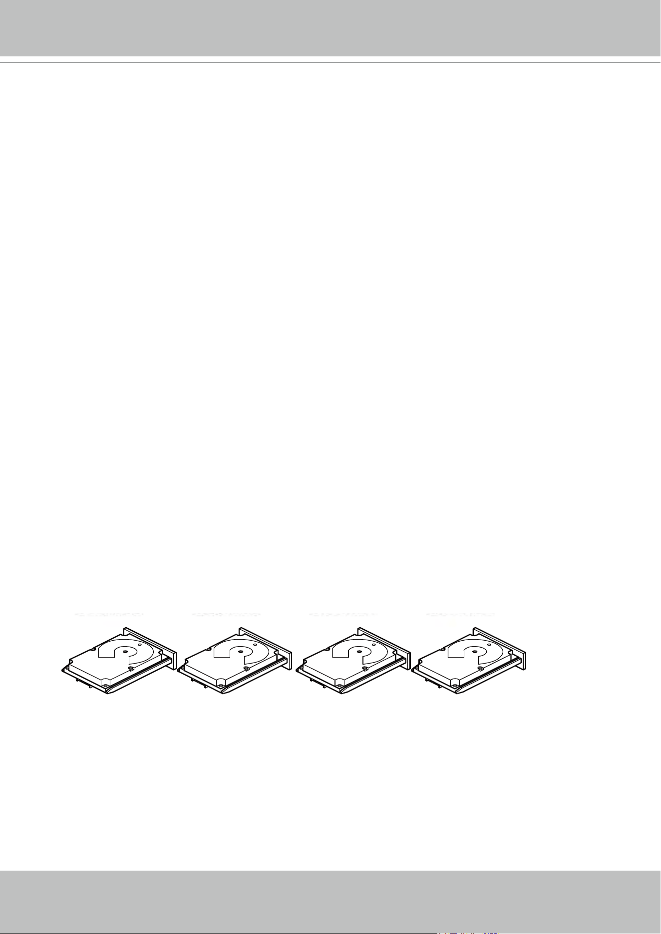
A RAID 0 drive group provides disk striping across all drives in the RAID drive group. A RAID0
drive group does not provide any data redundancy, but the RAID 0 drive group offers the best
performance of any RAID level. The RAID 0 drive group breaks up data into smaller segments,
and then stripes the data segments across each drive in the drive group. The size of each data
segment is determined by the stripe size. A RAID 0 drive group offers high bandwidth.
By breaking up a large le into smaller segments, the RAID controller can use both SAS
drives and SATA drives to read or write the le faster. A RAID 0 drive group involves no parity
calculations to complicate the write operation. This situation makes the RAID 0 drive group ideal
for applications that require high bandwidth but do not require fault tolerance. The following
table provides an overview of the RAID 0 drive group. The following gure provides a graphic
example of a RAID 0 drive group.
NOTE
RAID level 0 is not fault tolerant. If a drive in a RAID 0 drive group fails, the entire virtual drive (all drives
associated with the virtual drive) fails.
Segment 1
Segment 3
Segment 5
Segment 2
Segment 4
Segment 6
Segment 7 Segment 8
VIVOTEK - A Leading Provider of Multimedia Communication Solutions
User's Manual - 55
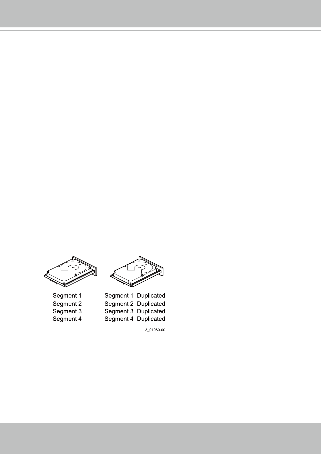
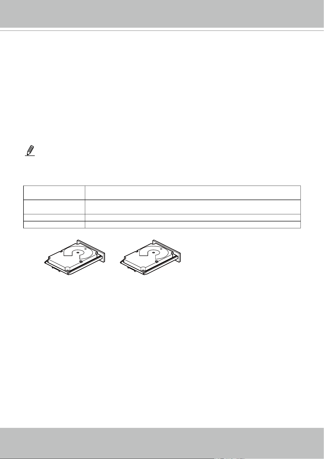
RAID 1 Drive Groups
In RAID 1 drive groups, the RAID controller duplicates all data from one drive to a second drive
in the drive group. A RAID 1 drive group supports an even number of drives from 2 through 32
in a single span. The RAID1 drive group provides complete data redundancy, but at the cost
of doubling the required data storage capacity. The following table provides an overview of a
RAID1 drive group. The following gure provides a graphic example of a RAID1 drive group.
Uses Use RAID 1 drive groups for small databases or any other environment that requires fault
tolerance but small capacity.
Strong points Provides complete data redundancy.A RAID 1 drive group is ideal for any application that
requires fault tolerance and minimal capacity.
Weak points Requires twice as many drives.
Performance is impaired during drive rebuilds.
Drives 2 through 32 (must be an even number of drives)
Segment 1
RAID 1
Segment 1
Duplicate
Segment 5 Segment 5
Duplicate
...
Segment 2 Segment 2
Duplicate
Segment 6 Segment 6
Duplicate
...
Segment 3
Segment 3
Duplicate
Segment 7 Segment 7
Duplicate
...
Segment 4 Segment 4
Duplicate
Segment 8 Segment 8
Duplicate
...
RAID 1 RAID 1 RAID 1
RAID 5 Drive Groups
A RAID 5 drive group includes disk striping at the block level and parity. Parity is the data’s
property of being odd or even, and parity checking is used to detect errors in the data. In RAID5
drive groups, the parity information is written to all drives. A RAID5 drive group is best suited for
networks that perform a lot of small input/output (I/O) transactions simultaneously.The following
table provides an overview of a RAID5 drive group. The following gure provides a graphic
example of a RAID5 drive group.
Uses Provides high data throughput, especially for large les.
Use RAID 5 drive groups for transaction processing applications because each drive can
read and write independently.
If a drive fails, the RAID controller uses the parity drive to re-create all missing
information.Use also for online customer service that requires fault tolerance.Use for any
application that has high read request rates but random write request rates.
Strong points Provides data redundancy, high read rates, and good performance in most environments.
Provides redundancy with lowest loss of capacity.
Weak points Not well suited to tasks requiring lots of small writes or small block write operations.
Suffers more impact if no cache is used.
Drive performance is reduced if a drive is being rebuilt.
Environments with few processes do not perform as well because the RAID drive group
overhead is not offset by the performance gains in handling simultaneous processes.
Drives 3 through 32
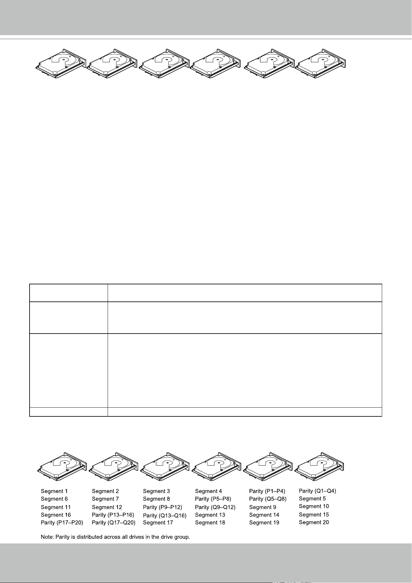
VIVOTEK - A Leading Provider of Multimedia Communication Solutions
56 - User's Manual
Segment 1
Segment 7
Segment 13
Segment 2
Segment 8
Segment 14
Segment 3
Segment 9
Segment 15
Segment 4
Segment 10
Parity (11 to 15)
Segment 5
Parity (6 to 10)
Segment 11
Parity (1 to 5)
Segment 6
Segment 12
Segment 19
Segment 25
Parity (26 to 30)
Segment 20
Parity (21 to 25)
Segment 26
Parity (16 to 20)
Segment 21
Segment 27
Segment 16
Segment 22
Segment 28
Segment 17
Segment 23
Segment 29
Segment 18
Segment 24
Segment 30
RAID 6 Drive Groups
A RAID6 drive group is similar to a RAID5 drive group (disk striping and parity), except that
instead of one parity block per stripe, there are two. With two independent parity blocks, A
RAID6 drive group can survive the loss of any two drives in a virtual drive without losing data.
A RAID6 drive group provides a high level of data protection through the use of a second
parity block in each stripe. Use a RAID6 drive group for data that requires a very high level of
protection from loss.
In the case of a failure of one drive or two drives in a virtual drive, the RAID controller uses the
parity blocks to re-create all of the missing information. If two drives in a RAID6 virtual drive fail,
two drive rebuilds are required, one for each drive. These rebuilds do not occur at the same
time. The controller rebuilds one failed drive, and then the other failed drive.The following table
provides an overview of a RAID6 drive group.
Uses Use for any application that has high read request rates but low random or small block
write rates.
Strong points Provides data redundancy, high read rates, and good performance in most environments.
Can survive the loss of two drives or the loss of a drive while another drive is being
rebuilt.Provides the highest level of protection against drive failures of all of the RAID
levels.Performance is similar to that of a RAID5 drive group.
Weak points Not well-suited to tasks requiring a lot of small and/or random write operations.A RAID 6
virtual drive must generate two sets of parity data for each write operation, which results
in a signicant decrease in performance during write operations.
Drive performance is reduced during a drive Rebuild operation.Environments with
few processes do not perform as well because the RAID overhead is not offset by the
performance gains in handling simultaneous processes.
A RAID6 drive group costs more because of the extra capacity required by using two
parity blocks per stripe.
Drives 3 through 32
The following gure shows a RAID6 drive group data layout. The second set of parity drives is
denoted by Q. The P drives follow the RAID5 drive group parity scheme.
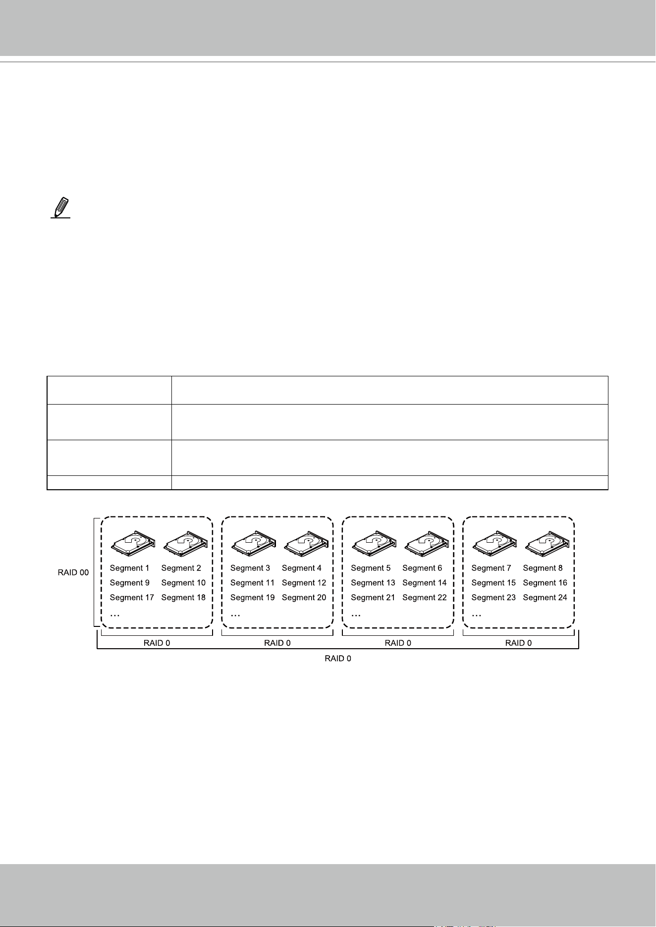
VIVOTEK - A Leading Provider of Multimedia Communication Solutions
User's Manual - 57
RAID 00 Drive Groups
A RAID 00 drive group is a spanned drive group that creates a striped set from a series of
RAID0 drive groups. A RAID00 drive group does not provide any data redundancy, but, along
with the RAID0 drive group, does offer the best performance of any RAID level. A RAID00 drive
group breaks up data into smaller segments and then stripes the data segments across each
drive in the drive groups. The size of each data segment is determined by the stripe size. A
RAID00 drive group offers high bandwidth.
Uses Provides high data throughput, especially for large les.Any environment that does not
require fault tolerance.
Strong points Provides increased data throughput for large les.
No capacity loss penalty for parity.
Weak points Does not provide fault tolerance or high bandwidth.
All data lost if any drive fails.
Drives 2 through 256
NOTE
RAID level 00 is not fault tolerant. If a drive in a RAID 0 drive group fails, the entire virtual drive (all drives
associated with the virtual drive) fails.
By breaking up a large le into smaller segments, the controller can use both SAS drives and
SATA drives to read or write the le faster. A RAID00 drive group involves no parity calculations
to complicate the write operation. This situation makes the RAID00 drive group ideal for
applications that require high bandwidth but do not require fault tolerance. The following table
provides an overview of the RAID00 drive group. The following gure provides a graphic
example of a RAID 00 drive group.
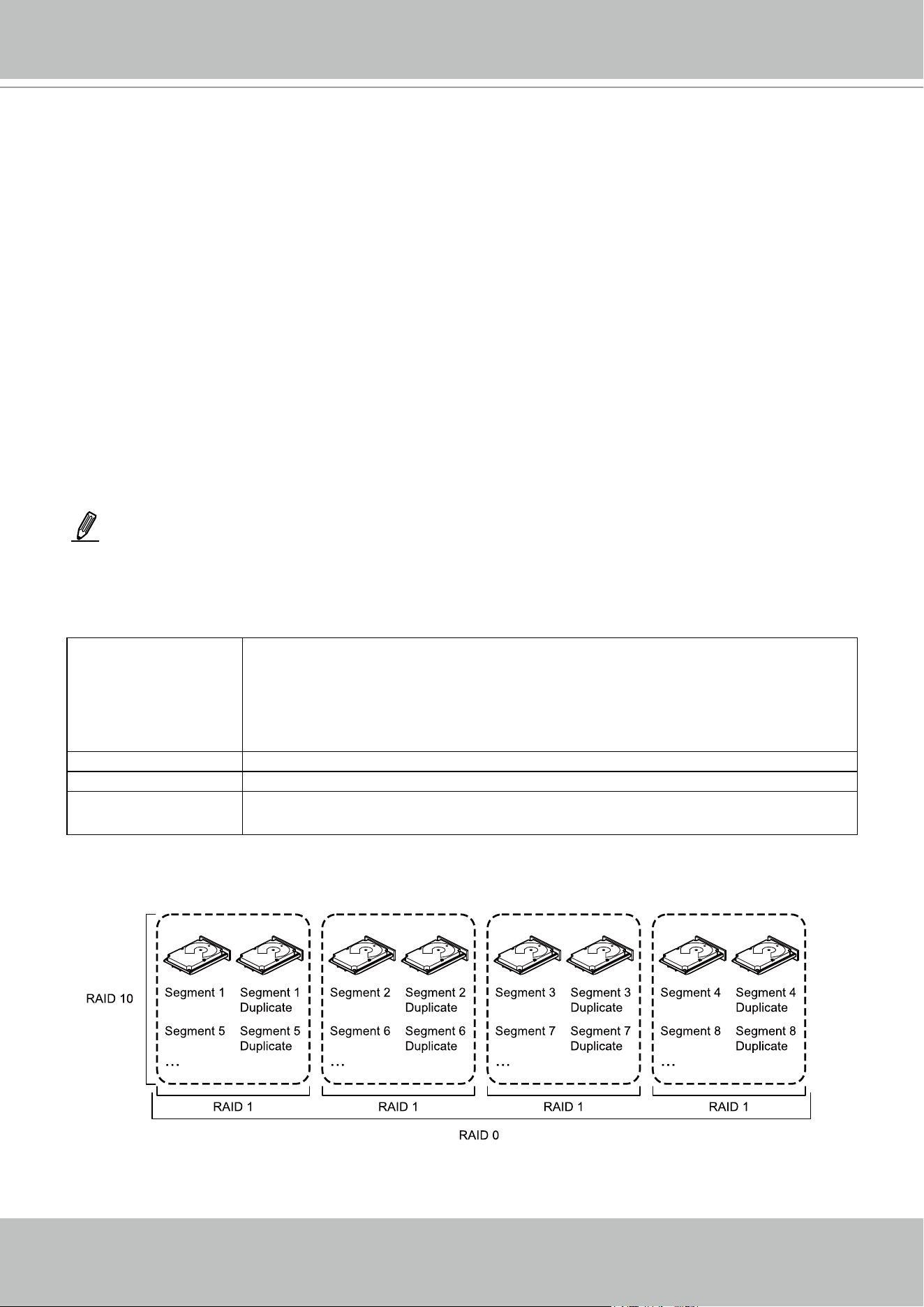
VIVOTEK - A Leading Provider of Multimedia Communication Solutions
58 - User's Manual
RAID 10
A RAID10 drive group is a combination of RAID level 0 and RAID level 1, and it consists of
stripes across mirrored drives. A RAID10 drive group breaks up data into smaller blocks and
then mirrors the blocks of data to each RAID1 drive group. The rst RAID1 drive in each drive
group then duplicates its data to the second drive. The size of each block is determined by the
stripe size parameter, which is set during the creation of the RAID set. The RAID 1 virtual drives
must have the same stripe size.
Spanning is used because one virtual drive is dened across more than one drive group. Virtual
drives dened across multiple RAIDlevel 1 drive groups are referred to as RAID level 10, (1+0).
Data is striped across drive groups to increase performance by enabling access to multiple drive
groups simultaneously.
Each spanned RAID 10 virtual drive can tolerate multiple drive failures, as long as each failure
is in a separate drive group. If drive failures occur, less than total drive capacity is available.
Congure RAID 10 drive groups by spanning two contiguous RAID1 virtual drives, up to the
maximum number of supported devices for the controller. A RAID10 drive group supports a
maximum of 8spans, with a maximum of 32drives per span. You must use an even number of
drives in each RAID10 virtual drive in the span.
Uses Appropriate when used with data storage that needs 100 percent redundancy of mirrored
drive groups and that also needs the enhanced I/O performance of RAID 0 (striped drive
groups.)
A RAID10 drive group works well for medium-sized databases or any environment that
requires a higher degree of fault tolerance and moderate-to-medium capacity.
Strong points Provides both high data transfer rates and complete data redundancy.
Weak points Requires twice as many drives as all other RAID levels except in RAID 1 drive groups.
Drives 4 to 32 in multiples of 4 — The maximum number of drives supported by the controller
(using an even number of drives in each RAID 10 virtual drive in the span).
NOTE
Other factors, such as the type of controller, can restrict the number of drives supported by RAID 10 virtual drives.
The following table provides an overview of a RAID10 drive group.
In the following gure, virtual drive 0 is created by distributing data across four drive groups (drive groups 0
through3).
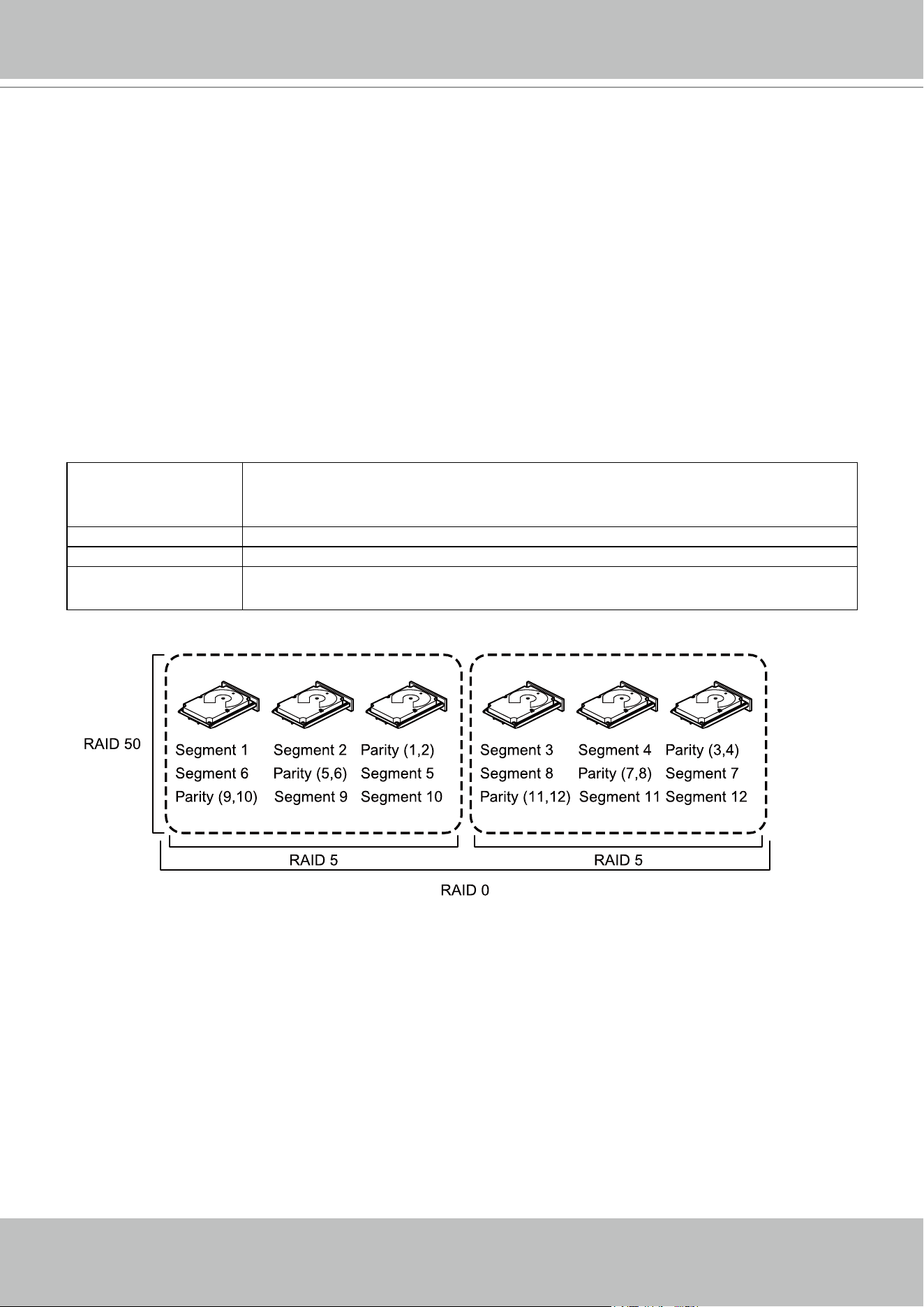
VIVOTEK - A Leading Provider of Multimedia Communication Solutions
User's Manual - 59
RAID 50
A RAID50 drive group provides the features of both RAID0 and RAID5 drive groups. A RAID50
drive group includes both distributed parity and drive striping across multiple drive groups. A
RAID50 drive group is best implemented on two RAID5 drive groups with data striped across
both drive groups.
A RAID50 drive group breaks up data into smaller blocks and then stripes the blocks of data to
each RAID5 disk set. A RAID5 drive group breaks up data into smaller blocks, calculates parity
by performing an exclusive OR operation on the blocks, and then performs write operations
to the blocks of data and parity to each drive in the drive group. The size of each block is
determined by the stripe size parameter, which is set during the creation of the RAID set.
A RAID level 50 drive group can support up to eight spans and tolerate up to eight drive failures,
though less than total drive capacity is available. Though multiple drive failures can be tolerated,
only one drive failure can be tolerated in each RAID 5 level drive group.
The following table provides an overview of a RAID50 drive group.
Uses Appropriate when used with data that requires high reliability, high request rates, high
data transfer, and medium-to-large capacity.
Also used when a virtual drive of greater than 32 drives is needed.
Strong points Provides high data throughput, data redundancy, and very good performance.
Weak points Requires two times to eight times as many parity drives as a RAID 5 drive group.
Drives Eight spans of RAID 5 drive groups that contain 3 to 32 drives each (limited by the
maximum number of devices supported by the controller)
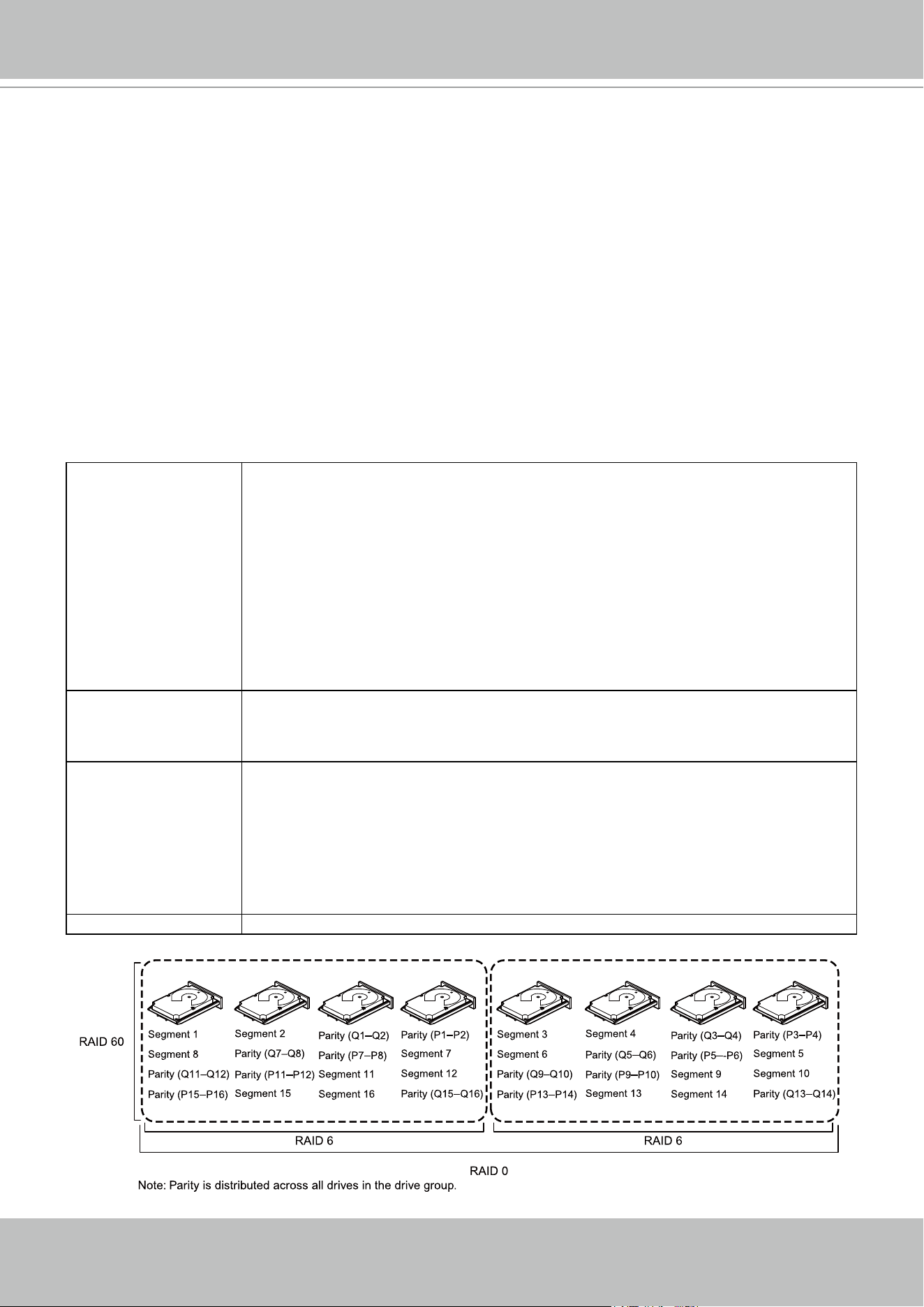
VIVOTEK - A Leading Provider of Multimedia Communication Solutions
60 - User's Manual
RAID 60
A RAID 60 drive group provides the features of both RAID 0 and RAID 6 drive groups, and
includes both parity and disk striping across multiple drive groups. A RAID6 drive group supports
two independent parity blocks per stripe. A RAID 60 virtual drive can survive the loss of two
drives in each of the RAID6 drive group sets without losing data. A RAID60 drive group is best
implemented on two RAID6 drive groups with data striped across both drive groups.
A RAID60 drive group breaks up data into smaller blocks and then stripes the blocks of data to
each RAID6 disk set. A RAID6 drive group breaks up data into smaller blocks, calculates parity
by performing an exclusive-OR operation on the blocks, and then performs write operations to
the blocks of data and writes the parity to each drive in the drive group. The size of each block is
determined by the stripe size parameter, which is set during the creation of the RAID set.
A RAID60 drive group can support up to 8spans and tolerate up to 16 drive failures, though less
than total drive capacity is available. Two drive failures can be tolerated in each RAID 6 level
drive group.
Uses Provides a high level of data protection through the use of a second parity block in each
stripe. Use a RAID60 drive group for data that requires a very high level of protection
from loss.
In the case of a failure of one drive or two drives in a RAID set in a virtual drive, the RAID
controller uses the parity blocks to re-create all of the missing information. If two drives in
a RAID 6 set in a RAID60 virtual drive fail, two drive Rebuild operations are required, one
for each drive. These Rebuild operations can occur at the same time.
Use for online customer service that requires fault tolerance. Use for any application that
has high read request rates but low write request rates. Also used when a virtual drive of
greater than 32 drives is needed.
Strong points Provides data redundancy, high read rates, and good performance in most environments.
Each RAID6 set can survive the loss of two drives or the loss of a drive while another
drive is being rebuilt.Provides the highest level of protection against drive failures of all of
the RAID levels.
Weak points Not well-suited for small block write or random write operations. A RAID 60 virtual
drive must generate two sets of parity data for each write operation, which results in
a signicant decrease in performance during write operations.Drive performance is
reduced during a drive Rebuild operation. Environments with few processes do not
perform as well because the RAID overhead is not offset by the performance gains in
handling simultaneous processes.
A RAID6 drive group costs more because of the extra capacity required by using two
parity blocks per stripe.
Drives A minimum of 6.
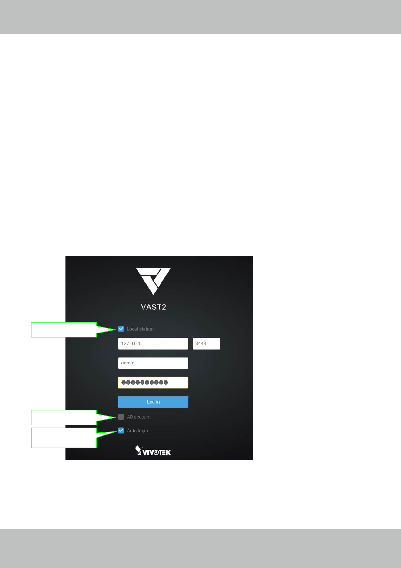
VIVOTEK - A Leading Provider of Multimedia Communication Solutions
User's Manual - 61
Log in
To log in,
1. Enter the server's IP address and TCP port number (3443 as the default). If logging in from
the server itself, you can select the Local station checkbox.
2. Enter the credentials for login. The credentials were created during the installation.
3. You can use an existing AD ccount for login. See page 247 for user management and AD
account configuration.
4. Auto login: After you enter the credentials for the first time, the server will not prompt for
credentials the next time you start the VAST software.
Login from the local machine
using a loop-back address
login using an existing AD
account
Automatically login after the
first time you entered the cre-
dentials
Chapter Two VAST2 Software Conguration and
Management

VIVOTEK - A Leading Provider of Multimedia Communication Solutions
62 - User's Manual
Introducing VAST2
VIVOTEK VAST2 is the professional video / central management software designed for
managing all VIVOTEK IP surveillance products with intuitive functions and numerous features.
It supports hundreds of cameras and stations in a hierarchical structure of system for
monitoring, recording, playback and event trigger management with ease-of-use and efficient
control.
VAST2 integrates VIVOTEK network cameras to provide diverse solutions and applications, with
the cameras for uninterrupted video recording, Smart Search II, Smart VCA, and Cybersecurity
management solution. VAST2 performs remote management with full range of the server & client
structure and constitutes a robust system for various applications, such as stores, banking and the
public space.
New Features
• Smart Search II
• Event Search: General, Smart VCA, and Trend Micro IoT Security events.
• Alarm management with Smart VCA, Trend Micro IoT Security and new general events.
• Alarm list enhancement: Thumbnail view, Status, and Comment.
• Manually export alarm clips.
• Automaticallly locks video clips when triggered by alarms.
• Sends HTTP requests to all selected cameras, incuding those under sub-stations, via one alarm
configuration.
• Manually refresh selected devices to obtain the latest VADP configuration settings.
• View cells with embedded E-maps.
• Standalone player improvements for displaying VCA rules/metadata, VIVOTEK MP4/3GP, and drag
and play feature.
Key Features
•
Multiple monitors support on tabbed windows, configurable as live view, tour, E-map,
dashboard, or alarm views.
•
Supports Windows Active Directory.
•
Automatic Problem Feedback mechanism.
•
Add-on solutions: Failover (VAST server redundancy), Transportation, Transaction, and Data
Magnet.
•
Auto Streaming Size for Clients, saving decode and streaming bandwidth.
•
Multiple Fisheye Dewarp modes.
•
Customizable Layouts for unique camera types, e.g., corridor or panoramic.

VIVOTEK - A Leading Provider of Multimedia Communication Solutions
User's Manual - 63
* The number of linked devices will depend on the number of licenses you purchased.
* The ability to extend devices is also subject to the network bandwidth and computer performance.
•
New Matrix for Video Wall Solution.
•
Counting Solution with the display of VCA/Counting reports from cameras.
•
Device Packs for instant support for new cameras.
•
Panoramic PTZ Support.
•
Cybersecurity support.
•
Supports various view settings: time, bandwidth, codec, VCA rules, etc.
•
Bookmarks on the occurrence of video events with Evidence Lock.
•
Customized layouts, e.g., a dewarped fisheye view, can also be displayed on standalone
player.
•
Log / Alarm Search & Export
•
System overview Dashboard.
•
VAST client on MAC machines.

VIVOTEK - A Leading Provider of Multimedia Communication Solutions
64 - User's Manual
Charged Add-on Features
The following are the charged add-on features. These features will not be available unless
you purchase and enable their individual licenses:
Transportation License:
• Users have the need to show their mobile server on the Google map.
• Users can use generic GPS device or VIVOTEK's mobile NVR (w/ a built-in GPS)
• We only support IP-based generic GPS.
POS Implementation:
• We provide the following for POS integration:
• Live view with transaction data.
• Playback with transaction data.
• Search using keyword.
• Highlights specific product item name.
Data Magnet License:
• Data Magnet is used for integration with 3rd party data source. For example, POS data,
access control, ATM data, LPR data, etc.
• We provide the following for Data Magnet integration:
• Map the data to specific cameras.
• Searching 3rd party data using keywords.
• Show data with live view.
• Set up alarms using 3rd party data.
• Highlight specific keyword or value.
Failover License (substations):
• We support M x N structure.
• The CMS station will be the main station for controlling and monitoring all of the active
and redundant servers.
• The Failover license (substations) needs to be imported on the CMS server.
Failover License (CMS):
• We support 1 x 1 redundancy for the CMS station.
• The failover license (CMS) needs to be imported on a CMS server.
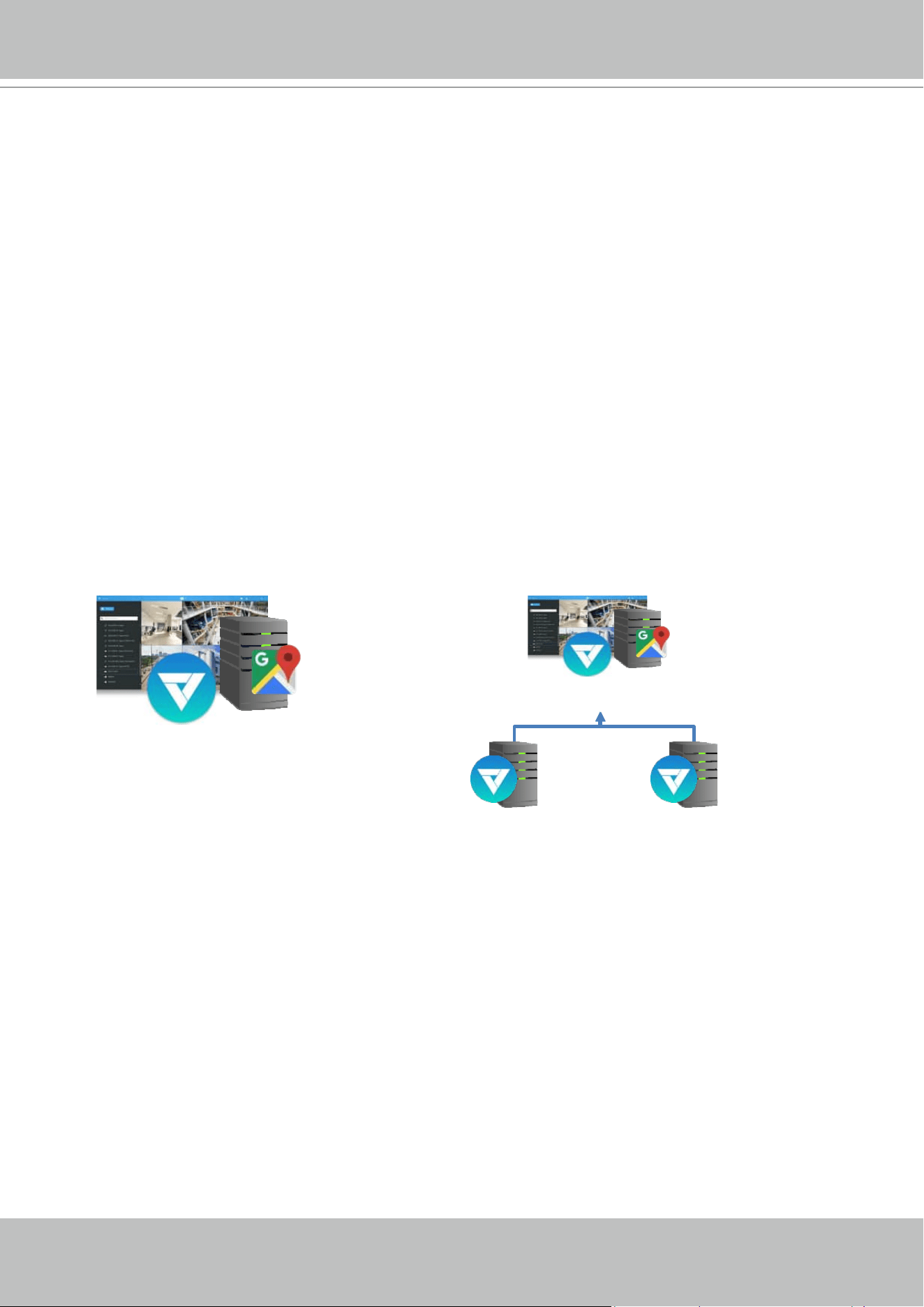
VIVOTEK - A Leading Provider of Multimedia Communication Solutions
User's Manual - 65
Advanced Feature License:
• Advanced License list:
• Transportation package: Google map / GPS.
• POS terminal.
• Failover (Substations)
• Failover (CMS)
• TCP message
• Data Magnet license.
NOTE:
1. Failover license cannot be used on hardware dongle.
2. The related configuration pages/menus will still be available even the license has not
been activated.
Calculation - Transportation Package: Google map + GPS
Single Server (50)
Substa�on
(46)
Substa�on
(32)
CMS
(50)
Total no. of cameras: 50
Needs 50 packages.
NOTE: camera normal usage
licenses are included.
Total no. of cameras: 50 + 32 + 46 = 128
Needs 128 packages.
NOTE: camera normal usage licenses are
included.
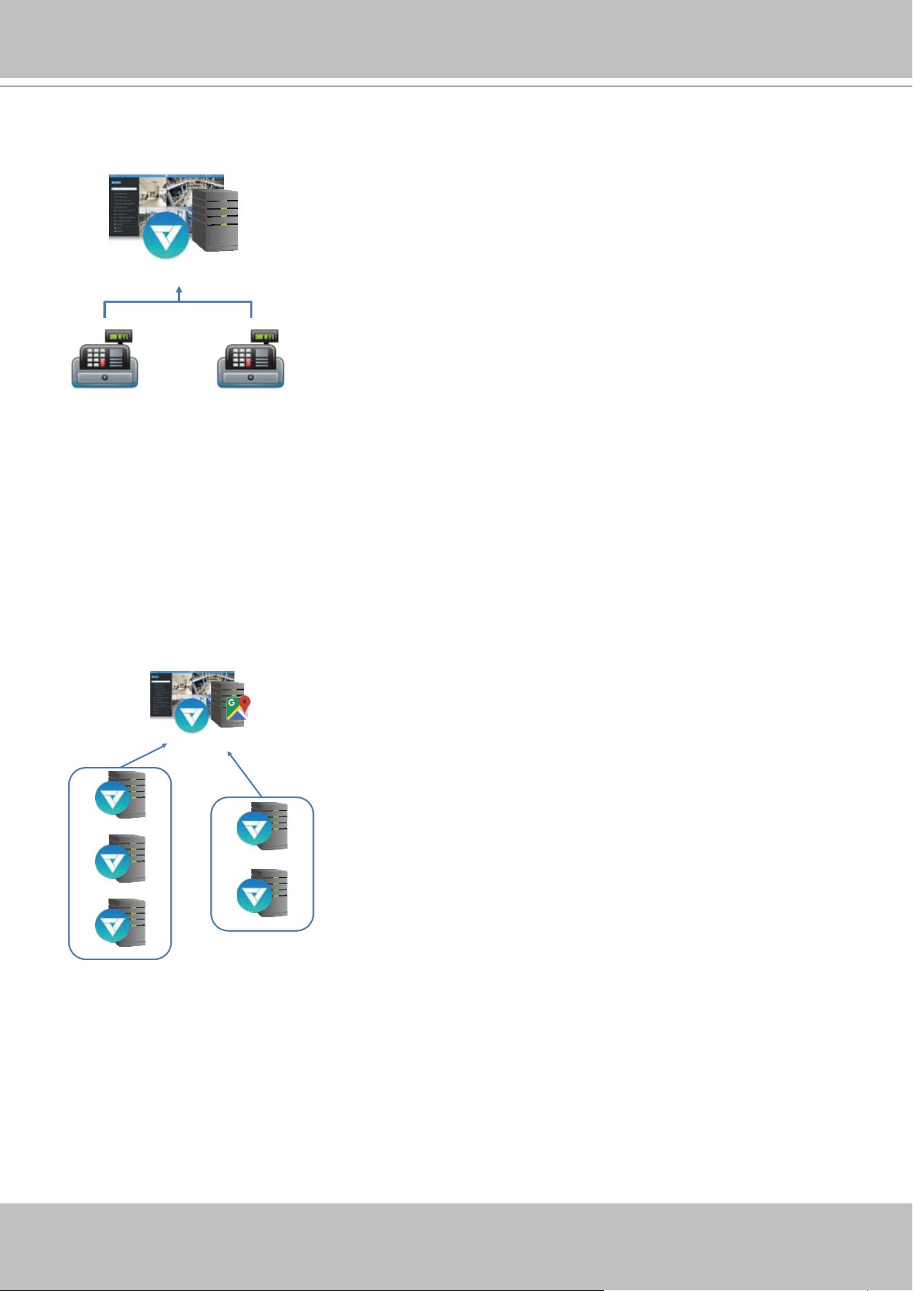
VIVOTEK - A Leading Provider of Multimedia Communication Solutions
66 - User's Manual
Calculation - POS License
Single Server (50)
POS 1 POS 2
Total no. of POS terminals: 2
Total no. of cameras: 50
Needs 2 POS licenses and 18 [50 - 32(free)] camera licenses.
NOTE: 32 camera channels are for free.
Calculation - Failover License
CMS
Acve Server
(32)
Acve Server
(40)
Acve Server (50)
Redundant Server
Redundant Server
Channels on each active server: 32, 40, 50
No. of redundant servers: 2
Total no. of cameras: 122 (32 + 40 + 50)
Needs 100 Failover licenses (50 x 2), and 90 normal camera licenses (122 - 32).
NOTE: 32 camera channels are for free. These licenses do not come with hardware dongle.
Rule:
No. of channels on the active server hosting the
largest no. of cameras x the no. of redundant servers.
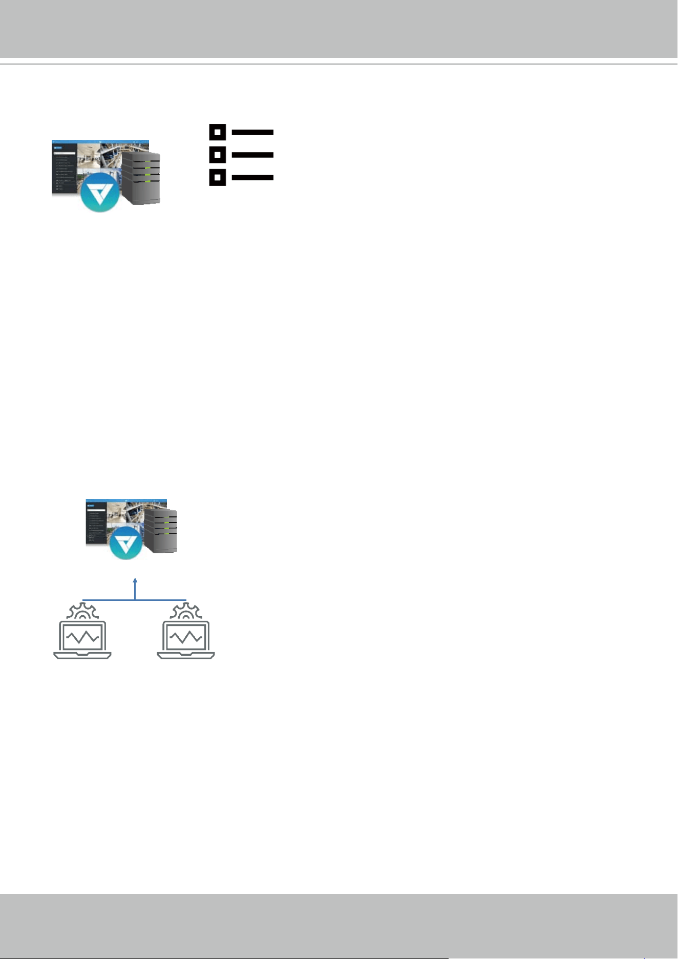
VIVOTEK - A Leading Provider of Multimedia Communication Solutions
User's Manual - 67
Calculation - TCP Message License
Single Server
(32)
Alarm list (50)
• 10 TCP messages
• 20 camera moon
• 20 DI trigger
Total no. of cameras: 32
Total instances of Alarm: 50
The no. of other triggering sources: 40
Needs 10 TCP Message licenses, and 0 for normal camera licenses (32 - 32).
NOTE: 32 camera channels are for free.
Rule:
The no. of licenses depends on how many alarm
rules are using TCP Message as the triggering
source.
Calculation - Data Magnet License
Single Server
(50)
3
rd
party SW 3
rd
party SW
Total no. of Data Magnet sources: 2
Total no. of cameras: 50
Needs 2 Data Magnet licenses, and 18 normal camera licenses (50 - 32).
NOTE: 32 camera channels are for free.
Rule:
The no. of licenses depends on how many Data
Magnet sources are implemented.
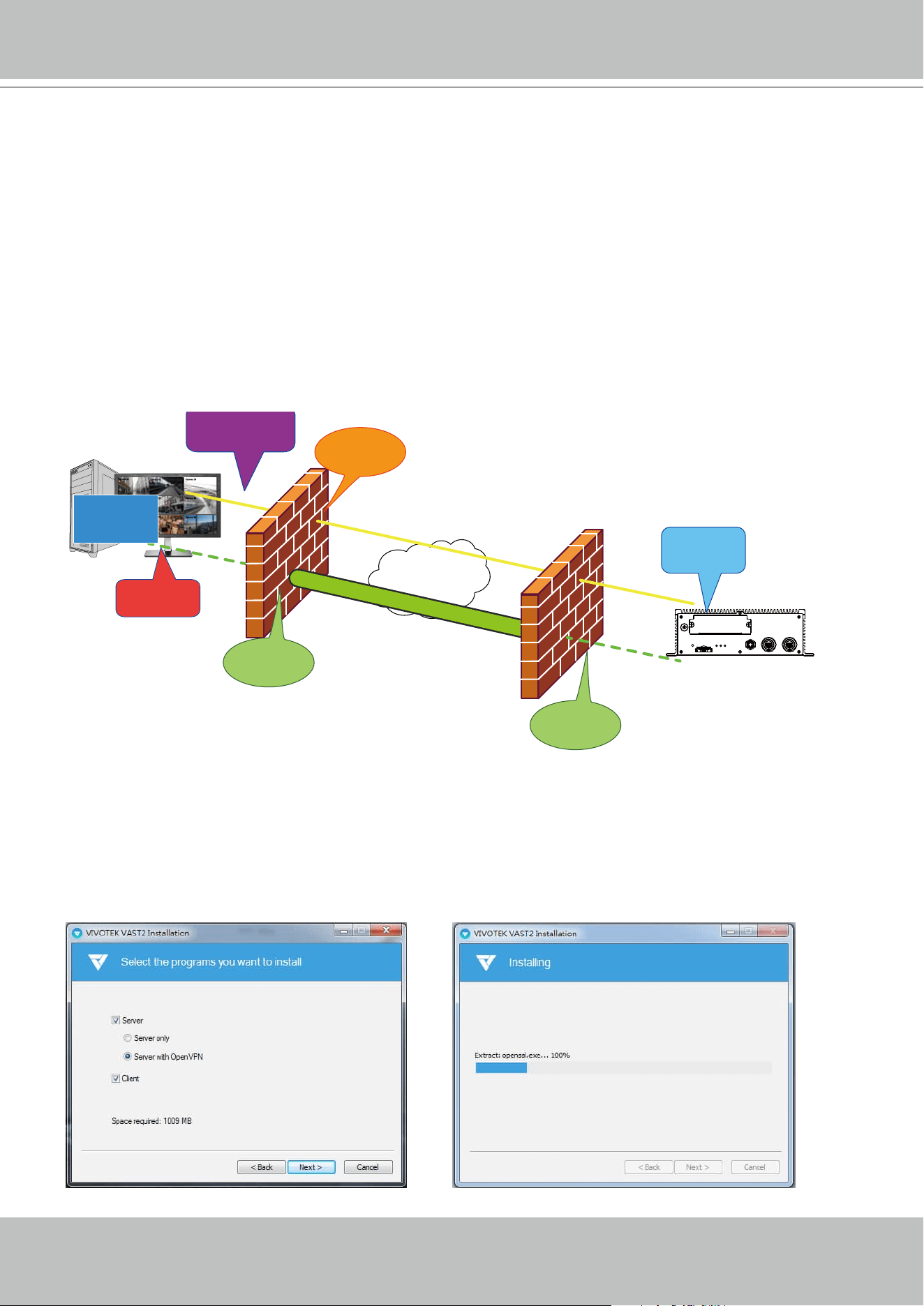
VIVOTEK - A Leading Provider of Multimedia Communication Solutions
68 - User's Manual
Installation Option - OpenVPN
NAT-traversal with OpenVPN
You can select the "VAST Server with OpenVPN" option when installing the VAST server. A
remote connection from NVR via a 3G/4G/LTE network can be made through an OpenVPN
tunnel. When the OpenVPN option is selected, an OpenVPN server will be installed with the
VAST server.
HMAC authentication and TLS encryption over an encrypted UDP connection are made effort-
lessly using the traversal methodology.
The sample installation screens are shown below:
VAST
Camera 01
Camera 02
Camera 03
Camera 04
Camera 06
Camera 05
Camera 07
Camera 08
Camera 09
Internet
HTTPS connection
OpenVPN tunnel
Port
Forwarding
Establish
VPN tunnel
Port
Forwarding
Register
Substation
Fetch CA/
Cert/Key
RESTful
API Server
Tunnel
message
NVR

VIVOTEK - A Leading Provider of Multimedia Communication Solutions
User's Manual - 69
The NVR runs an OpenVPN client that makes remote connection via the RESTful (Repretational
State Transfer) API (Application Programming Interface) service to a VPN-enabled VAST server
running on the remote site. The applicable service port number ranges from 1 to 65534. The
default is port #3443. The NVR automatically registers with CA cert key and becomes a VAST
sub-station over a VPN tunnel. Once set, the VAST2 can automatically connect the NVR.
Note that on the side of the VAST server making connection via the OpenVPN, the server/client
conguration should be properly congured. On the mobile NVR, a proper gateway setting
should be made for VPN connection.
For the server conguration, the conguration le is placed in:
C:\Program Files (x86)\VIVOTEK Inc\VAST\Server\OpenVPN\cong\server\server.ovpn
You can edit your VPN IP subnet parameters according to your network configuration. The
contents of the editable text file looks like this:
port 3939
proto udp
dev tun
ca ca.crt
cert server.crt
key server.key
dh dh.pem
server 10.6.0.0 255.255.0.0
topology subnet
client-to-client
client-config-dir "C:\\Program Files (x86)\\VIVOTEK Inc\\VAST\\Server\\OpenVPN\\ccd"
keepalive 10 30
cipher AES-256-CBC
max-clients 50000
persist-key
persist-tun
status openvpn-status.log
log-append openvpn.log
verb 3
mute 20
sndbuf 262144
rcvbuf 262144
tls-server
Note that the NVR and VAST server should have a similar time setting when exchanging
certicate information. Otherwise, the mutual handshake authentication process may fail.
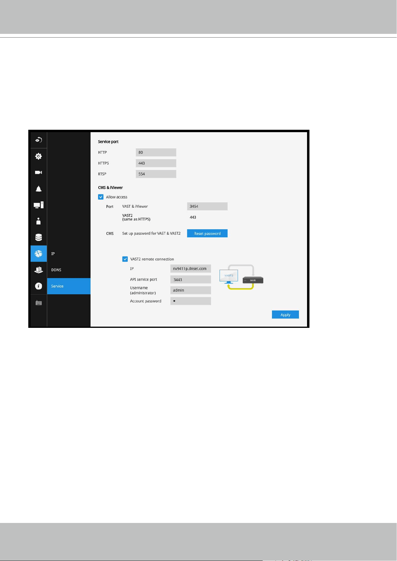
VIVOTEK - A Leading Provider of Multimedia Communication Solutions
70 - User's Manual
Enter the OpenVPN DNS domain name and the credentials on the NVR network service
configuration page.
A public IP or domain name must be configured on the VAST server for the access through the
Internet. The IP or domain name can contain alpha-numeric characters [0-9][a-z][A-Z][-]. [-] can
not be the beginning or the ending character.
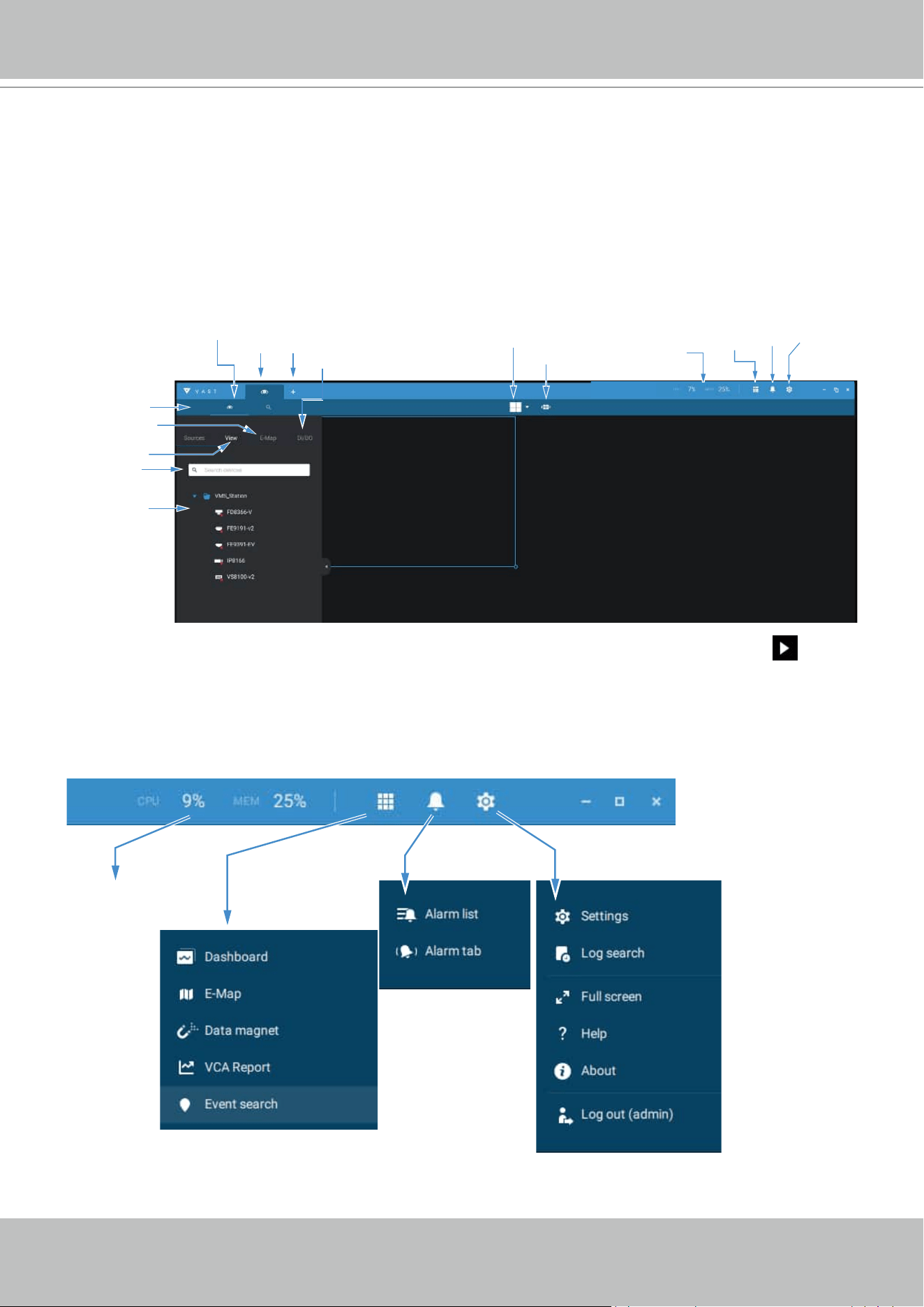
VIVOTEK - A Leading Provider of Multimedia Communication Solutions
User's Manual - 71
Chapter 2-1 Basics: Control and Elements
The basic screen elements of VAST live view, playback, and search pane are shown below:
Live view
DI/DO
LiveView
Layout
Tabs
Camera tour
Hide Pane
Buon
View
View Cell
Device Tree
Search
View
configuraon
Sengs
System
resources
Applicaons
Alarm
list
New
Tab
E-Map
Playback is evoked when a view cell is selected, and you click the Palyback button on the
upper right of the view cell.
Top Tool Bar
Sengs
Applicaons
Alarm
System
Resources
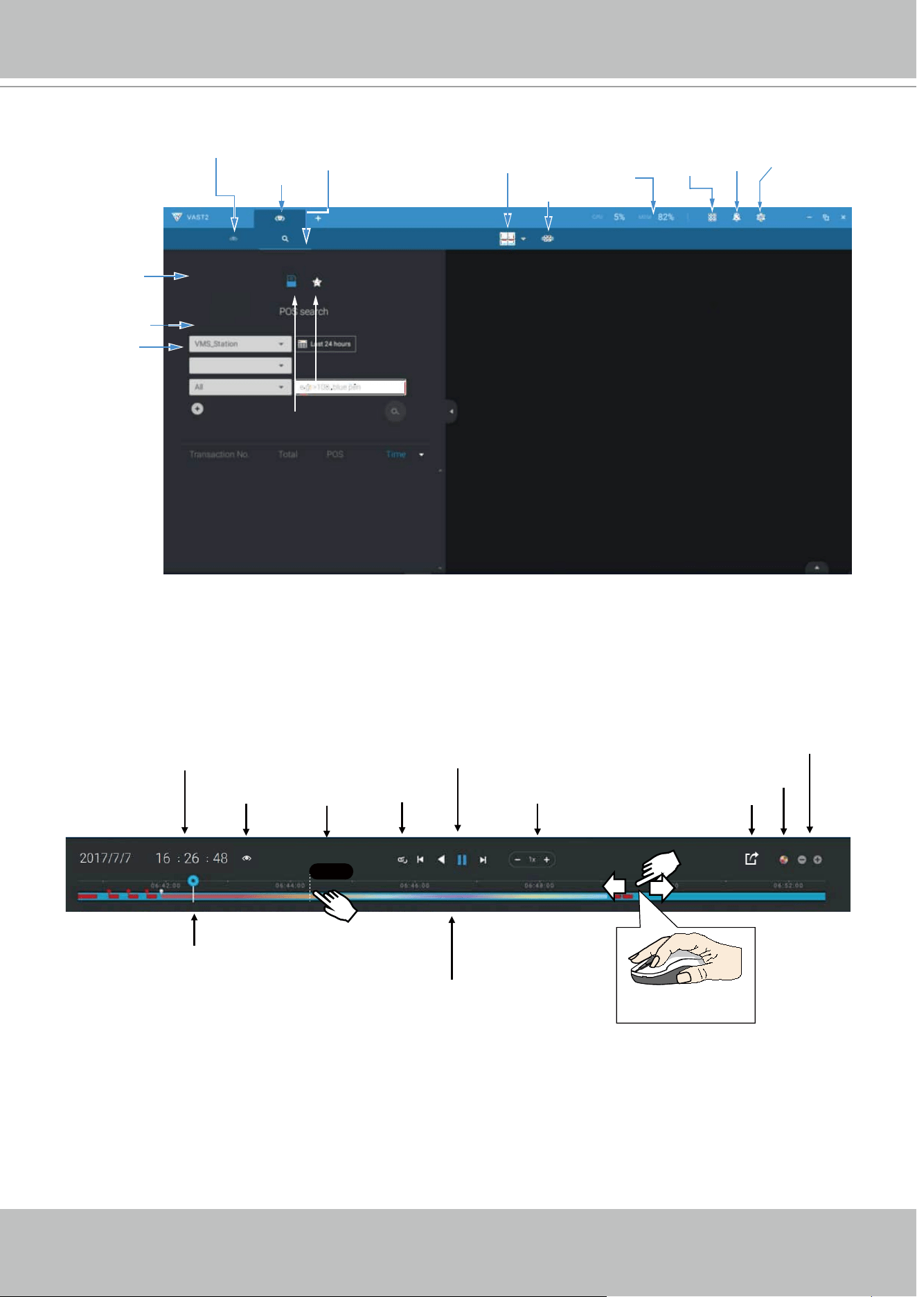
VIVOTEK - A Leading Provider of Multimedia Communication Solutions
72 - User's Manual
Search Pane
Playback Control
Hide Pane
Buon
Search pane
LiveView
Layout
Tabs
View
Search
POS
Bookmark
Camera tour
Time selector
Sengs
System
resources
Applicaons
Alarm
list
Histogram
Adjustment
Export
Speed Control
Playback Timeline & Histogram
Playhead
Synchronous
Playback Control Buon
Time Search
Events
Highlights
06:44:23
Mouse-over
indicator
Return to Live
Drag to move along
meline
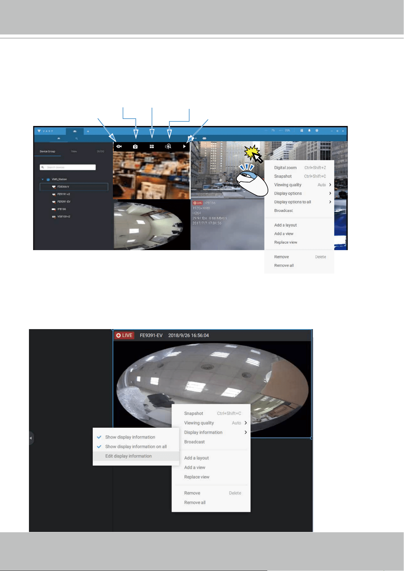
VIVOTEK - A Leading Provider of Multimedia Communication Solutions
User's Manual - 73
View cell control
Some controls and functions are available when a view cell is selected or via the right-click
menus.
Smart
Search II
Snapshot
Thumbnail
Search
Camera-specific
Playback
Text overlay
Single-click to select a view cell, right-click and select Display information. The Edit display
information tab will appear.
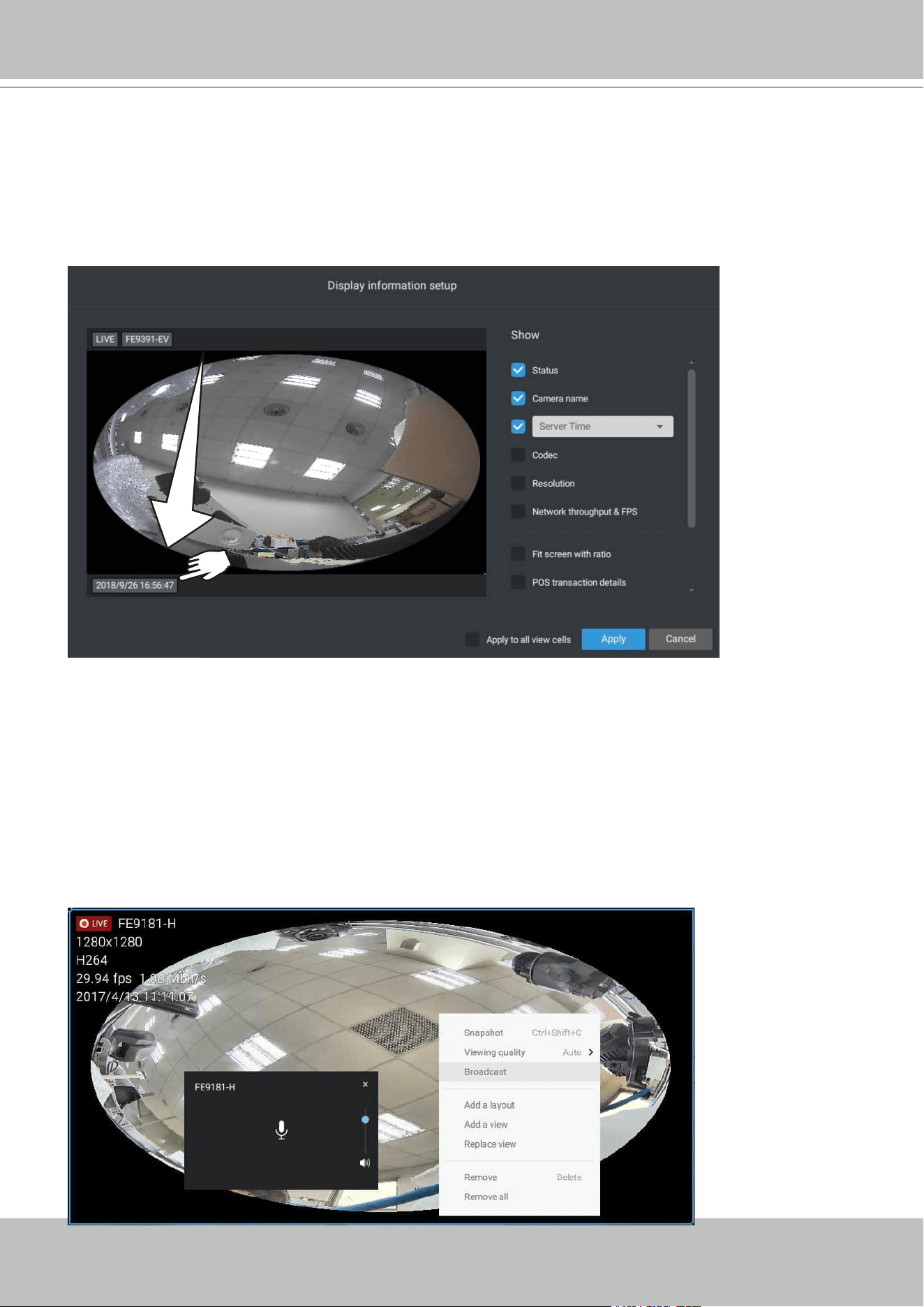
VIVOTEK - A Leading Provider of Multimedia Communication Solutions
74 - User's Manual
Two Way Audio
If your cameras support the Two Way Audio feature and the microphone and audio output to
an amplified speakers have been connected, you can right-click on the camera to display the
Broadcast function. Click on the Microphone icon in the middle to start speaking. Click again to
stop the Two Way Audio.
Note that the Broadcast option only appears when you select a camera that supports the Two
Way Audio feature. Currently the VAST2 software supports 1 to 1 broadcast.
Select the checkboxes to determine what kind of text overlay will display on view cells. Note that
you can place the overlay either on top or at the lower screen. Simply click and drag an overlay
item to a preferred location. When done, click the Apply button.
You can apply your current configuration to all view cells by selecting the Apply to all view cells
checkbox. Note that you can also display the VCA rules and areas on screen.
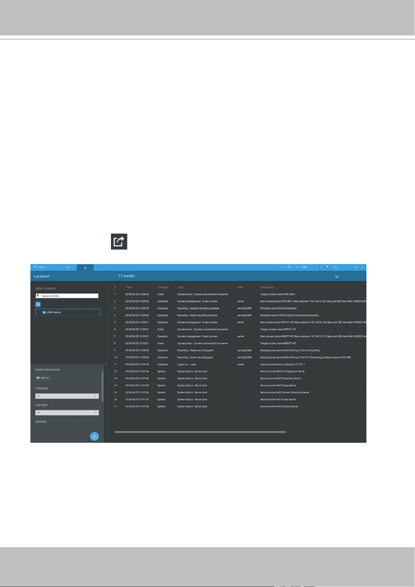
VIVOTEK - A Leading Provider of Multimedia Communication Solutions
User's Manual - 75
Log Search
System logs can be found via the tool bar tab. All system events will be listed in the Log search
panel. If you have multiple server, substations, select a server. You can search specific events by
the event types (All triggers, camera, system/site, external devices), or by the time of occurrence
using the calendar tool.
Use the Export button
to export the system log as an individual log file.
Full Screen
The full screen function maximizes the display of view cells, concealing all other tool bar or
navigation panels. To return to the normal view, press the ESC key on keyboard.

VIVOTEK - A Leading Provider of Multimedia Communication Solutions
76 - User's Manual
Log Level
Minor:
:
Level 6~
~
8
Normal:
:
Level 3~
~
5
Major:
:
Level 1~
~
2
Operation
V
V
A
A
S
S
T
T
2
2
T
T
y
y
p
p
e
e
L
L
o
o
g
g
T
T
y
y
p
p
e
e
I
I
D
D
L
L
e
e
v
v
e
e
l
l
S
S
a
a
m
m
p
p
l
l
e
e
E
E
x
x
t
t
r
r
a
a
P
P
a
a
r
r
a
a
m
m
e
e
t
t
e
e
r
r
s
s
L
L
o
o
g
g
i
i
n
n
/
/
o
o
u
u
t
t
Login
1
3
User Account=admin, Address=127.0.0.1 User account Address
Logout
2
3
User Account=admin, Address=127.0.0.1 User account Address
U
U
s
s
e
e
r
r
Insert user 101
4
New User Name=guest, New Role=PowerUser, New
Permission=000F01013F0201070307FFF6F77EFD4E00
New User Name New Role New
Permission
Update user
password
104
5
Target User Name=guest Target User Name
Update user
privilege
105
5
Target User Name=guest, Target Role=PowerUser, Target
Permission=000F01013F0201070307FFF6F77EFD4E00,
New User Name=guest, New Role=PowerUser, New
Permission=000F01013F0201070307FFF6F77EFD4E00
Target User Name Target
Role
Target
Permission
New User
Name
New Role New
Permission
Delete user 106
3
Target User Name=guest Target User Name
Update user
expiration
107
5
Target User Name=guest Target User Name
S
S
i
i
t
t
e
e
Insert station 201
4
New Station Name=VMS_Station, New
Address=172.18.60.31, New Port=3454, New UseSSL=0,
New RTSP Port=3454, New Station
ID=S_{6312FAC9-FCF4-4573-964D-5F03D083BE54}
New Station Name New
Address
New Port New
UseSSL
New RTSP
Port
New Station
ID
Update
station
information
202
5
Target Station
Name={6312FAC9-FCF4-4573-964D-5F03D083BE54},
Target Address=172.18.60.31, Target Port=3454, Target
UseSSL=0, Target RTSP Port=3454, New Station
Name={6312FAC9-FCF4-4573-964D-5F03D083BE54},
New Address=172.18.60.31, New Port=3443, New
UseSSL=1, New RTSP Port=3443
Target Station
Name
Target
Address
Target Port Target
UseSSL
Target
RTSP Port
New Station
Name
New
Address
New Port
New
UseSS
L
New
RTSP
Port
Update
station name
203
5
Target Station Name=VMS_Station, New Station
Name=CMS
Target Station
Name
New
Station
Name
Delete station
204
3
Target Station Name=VMS_Station, Target Station
ID=S_{6312FAC9-FCF4-4573-964D-5F03D083BE54}
Target Station
Name
Target
Station ID
Set relay
settings
1716
5
Enable=true Enable
Station
enable
multicast
2416
5
Station name=VMS_Station Station name
Station
disable
multicast
2417
5
Station name=VMS_Station Station name
CC
a
a
m
m
e
e
r
r
a
a
Insert camera
205
4
New Camera Name=Door, New Address=172.18.1.129,
New Port=80, New MAC=0002D11CC24E, New HTTPS
Port=443, New Recording Stream=1
New Camera Name New
Address
New Port New MAC New
HTTPS
Port
New
Recording
Stream
Update
camera
information
206
5
Target Camera Name=Door, Target Address=172.18.1.129,
Target Port=80, Target MAC=0002D11CC24E, Target
HTTPS Port=443, Target Recording Stream=1, New Camera
Name=IP8362, New Address=172.18.1.129, New Port=80,
Target Camera
Name
Target
Address
Target Port Target
MAC
Target
HTTPS
Port
Target
Recording
Stream
New
Camera
Name
New
Address
New
Port
New
MAC
New
HTTP
S Port
New
Reco
rding
Strea

VIVOTEK - A Leading Provider of Multimedia Communication Solutions
User's Manual - 77
New MAC=0002D11CC24E, New HTTPS Port=443, New
Recording Stream=1
m
Delete
camera
208
3
Target Camera Name=IP8362 Target Camera
Name
Set digital
output
701
4
Target Camera Name=IP8362 Target Camera
Name
Set DI/DO
name
1715
5
Target Camera Name=IP8362, Target Device=, Reference
Name=Alarm
Target Camera
Name
Target
Device
Reference
Name
Enable
multicast
2414
5
Camera name=SD8362 Camera name
Disable
multicast
2415
5
Camera name=SD8362 Camera name
I
I
/
/
O
O
d
d
e
e
v
v
i
i
c
c
e
e
Insert
External
Device
1151
4
Device Name=ADAM-6052, Device Host=172.18.60.70,
Device Port=502
Device Name Device
Host
Device Port
Remove
External
Device
1152
3
Device Name=ADAM-6052, Device Host=172.18.60.70,
Device Port=502
Device Name Device
Host
Device Port
Update
External
Device
1153
5
Device Name=ADAM-6052, Device Host=172.18.60.70,
Device Port=502
Device Name Device
Host
Device Port
Set digital
output
1154
2
Device Name=ADAM-6052, DO Index=8, Status=Trigger Device Name DO Index Status
R
R
e
e
c
c
o
o
r
r
d
d
i
i
n
n
g
g
Manually
begin
recording
301
2
Target Camera Name=IP8362 Target Camera
Name
Manually
302
2
Target Camera Name=IP8362 Target Camera
stop
recording
Name
Set recording
storage
401
4
Storage Group Name=Office Storage Group
Name
Insert
recording
schedule
402
4
Schedule Name=Working Time Schedule Name
Update
recording
schedule
403
5
Schedule Name=Working Time Schedule Name
Delete
recording
schedule
404
3
Schedule Name=Working Time Schedule Name
Insert storage
group
411
4
Storage Group Name=Office, Cycle=True Storage Group
Name
Cycle
Update
storage group
412
5
Storage Group Name=Office, Cycle=True Storage Group
Name
Cycle
Delete
storage group
413
3
Storage Group Name=Office Storage Group
Name
Insert
recording
path
414
4
Storage Group Name=Office, Path=E:\recording, Reserve
Space=90112 MB
Storage Group
Name
Path Reserve
Space
Update
recording
path
415
5
Storage Group Name=Office, Path=E:\recording, Reserve
Space=102400 MB
Storage Group
Name
Path Reserve
Space
Delete
recording
416
3
Storage Group Name=Office, Path=E:\recording Storage Group
Name
Path
VIVOTEK - A Leading Provider of Multimedia Communication Solutions
78 - User's Manual
path
Insert camera
to the storage
group
417
4
Storage Group Name=Office, Camera Name=IP8362 Storage Group
Name
Camera
Name
Delete
camera from
the storage
group
419
3
Storage Group Name=Office, Camera Name=IP8371E Storage Group
Name
Camera
Name
NN
e
e
t
t
w
w
o
o
r
r
k
k
Update server
port
1701
5
Server Name=Web, Port=3455 Server Name Port
Set proxy
server
1702
5
Enable=True, Address=172.18.60.13, Port=80 Enable Address Port
Set UPnP 1703
5
UPnP Port Forwarding Enable=False, UPnP Presentation
Enable=True
UPnP Port
Forwarding Enable
UPnP
Presentatio
n Enable
Set DDNS
server
1704
5
Enable=True, Provider=Dyndns.org(Dynamic) Enable Provider
AA
l
l
a
a
r
r
m
m
Insert alarm
management
408
4
Alarm name=alarm, Trigger list=Motion detection - Motion
window 1 of Network Camera, Action list=Set DO status -
DO-1 of Network Camera
Alarm name Trigger list
Action list
Update alarm
management
409
5
Alarm name=alarm, Trigger list=Motion detection - Motion
window 1 of Network Camera, Action list=Set DO status -
DO-1 of Network Camera
Alarm name Trigger list
Action list
Delete alarm
management
410
3
Alarm name=alarm Alarm name
Stop alarm
sound
2408
7
Alarm name=alarm Alarm name
Close alarm
notification
panel
2409
7
Alarm name=alarm Alarm name
Mute alarm 2411
7
Alarm name=alarm, Duration=10mins, Alarm name
PP
T
T
Z
Z
Camera PTZ,
Iris, Focus,
Pan, Patrol
control
702
7
Target Camera Name=SD9361-EH Target Camera
Name
Click on
image
703
7
Target Camera Name=SD9361-EH Target Camera
Name
Select preset
location
704
7
Target Camera Name=SD9361-EH, Preset Name=Door Target Camera
Name
Preset
Name
BB
a
a
c
c
k
k
u
u
p
p
Update
scheduled
backup
1503
5
Enable=true Enable
LL
i
i
c
c
e
e
n
n
s
s
e
e
Update
license
information
1717
5
(Empty)
SS
y
y
s
s
t
t
e
e
m
m
Create
directory
1705
4
Target Path=E:\test Target Path
Rename
directory
1706
5
Source Path=E:\test, Target Path=E:\recording Source Path Target Path
Delete
directory
1707
3
Target Path=E:\recording Target Path
Update server
database path
3401
3
Old path=E:\clientlogs, Target Path=E:\test
Insert SMTP 1708
4
Target Address=mail.vivotek.tw, Target Port=25, Target Target Address Target Port
Target Order
VIVOTEK - A Leading Provider of Multimedia Communication Solutions
User's Manual - 79
server Order=0
Update
SMTP server
1709
5
Target Address=mail.vivotek.tw, Target Port=25, Target
Order=0, New Address=mail.vivotek.com, New Port=25,
New Order=0
Target Address Target Port
Target Order New
Address
New Port New Order
Delete SMTP
server
1710
3
Target Address=mail.vivotek.tw, Target Port=25, Target
Order=0
Target Address Target Port
Target Order
Insert
network
storage
1711
4
Target Host=rd2fs, Target Domain=vivotek Target Host Target
Domain
Update
network
storage
1712
5
New Host=rd2fs, New Domain=vivotek, Target Host=rd2fs,
Target Domain=vivotek
New Host New
Domain
Target Host Target
Domain
Delete
network
storage
1713
3
Target Host=rd2fs, Target Domain=vivotek Target Host Target
Domain
Watermark
settings
2418
5
Status=Disable
Status=Enable
Status
Import device
pack
1721
4
Original version=xxxx, New version=ooo Original version New
version
Import device
pack failed
1722
4
Reason=Invalid device pack
Reason=Failed to import device pack
Reason
L
L
i
i
v
v
e
e
Add camera 2402
7
New Camera(s) = C1, Total Camera(s) in View= C1,C2 New Camera(s) Total
Camera(s)
in View
Remove
camera
2403
7
Removed Camera(s) = C1, Total Camera(s) in View= C2 Removed
Camera(s)
Total
Camera(s)
in View
Replace
camera
2404
7
Removed Camera(s) = C1, New Camera(s) = C2,C3 Total
Camera(s) in View= C2,C3
Removed
Camera(s)
New
Camera(s)
Total
Camera(s) in
View
V
V
i
i
e
e
w
w
Add view 2401
5
View Name = View001, Add Camera(s) = C_1 View Name Add
Camera(s)
Delete view 2405
5
View Name = View001, Removed Camera(s) = C_1, C_3 View Name Removed
Camera(s)
Update view 2406
5
View Name = View001, Removed Camera(s) = C_3, Add
Camera(s) = C_1, Total Camera(s) in View= C_1, C_2
View Name Removed
Camera(s)
Add
Camera(s)
Total
Camera(s)
in View
Rename view
2407
5
Old View Name = View001, New View Name = View002,
Total Camera(s) in View= C1, C_2
Old View Name New View
Name
Total
Camera(s) in
View
D
D
a
a
t
t
a
a
m
m
a
a
g
g
n
n
e
e
t
t
Add data
source
2601
4
Name=Lane, Port=1234, Camera name=FE8173 Name Port Camera
name
Update data
source
2602
5
Target name=Lane, Targe port=1234, Target camera
name=FE8173, New name=Lane, New port=4321, New
camera name=IP8362
Target name Targer port
Target
camera name
New name New port New camera
name
Delete data
source
2603
3
Name=Lane Name
Show data 2604
7
Enable=True, Camera name=FE8173 Enable Camera
name
E
E
M
M
a
a
p
p
Add EMap 3201
7
New EMap(s) = /Dessert, Total EMap(s) in View=
/Dessert,/Penguin
New EMap(s) Total
EMap(s) in
View
Delete EMap 3202
7
Removed EMap(s) = /Dessert, Total EMap(s) in View= Removed EMap(s) Total

VIVOTEK - A Leading Provider of Multimedia Communication Solutions
80 - User's Manual
/Penguin EMap(s) i
n
View
Replace
EMap
3203
7
Removed EMaps(s) = /Dessert, New EMap(s) =
/Flower,/Lion Total EMap(s) in View= /Flower,/Lion
Removed EMap(s) New
EMap(s)
Total
EMap(s) in
View
VV
C
C
A
A
R
R
e
e
p
p
o
o
r
r
t
t
Auto update
report
2801
5
VCA Chart Auto Update=true VCA Chart Auto
Update
Auto update
frequency
2802
5
VCA Chart Update Frequency=999 VCA Chart Update
Frequency
MM
a
a
t
t
r
r
i
i
x
x
Assign
component
3001
7
User=admin, assign component=Google map, to
client=WIN-458HOD557IM, screen=1
User name Component
Client name Screen ID
Reset all 3002
7
User=admin, reset all screen to client=WIN-458HOD557IM User name Client
name
PP
P
P
T
T
Z
Z
PPTZ
Control
2410
7
Enable=True, Camera name=FE8173
Event
VV
A
A
S
S
T
T
2
2
T
T
y
y
p
p
e
e
L
L
o
o
g
g
T
T
y
y
p
p
e
e
I
I
D
D
LL
e
e
v
v
e
e
l
l
S
S
a
a
m
m
p
p
l
l
e
e
E
E
x
x
t
t
r
r
a
a
P
P
a
a
r
r
a
a
m
m
e
e
t
t
e
e
r
r
s
s
CC
a
a
m
m
e
e
r
r
a
a
Camera disconnected from
server
1101
2
Target Camera Name=SC8131 Target Camera Name
Camera connected to the
server
1102
2
Target Camera Name=SC8131 Target Camera Name
SS
y
y
s
s
t
t
e
e
m
m
Parent station disconnected 1201
2
Target Station Name=VMS_Station Target Station Name
Parent station connected 1202
2
Target Station Name=VMS_Station Target Station Name
Parent station connection lost 1203
2
Target Station Name=VMS_Station Target Station Name
Parent station connection
restored
1204
2
Target Station Name=VMS_Station Target Station Name
Substation disconnected 1205
2
Target Station Name=NV9411P Target Station Name
Substation connected 1206
2
Target Station Name=NV9411P Target Station Name
Substation connection lost 1207
2
Target Station Name=NV9411P Target Station Name
Substation connection restore 1208
2
Target Station Name=NV9411P Target Station Name
Start scheduled backup 1501
2
Backup Path=E:\backup, Backup
Interval=2018/02/05 00:00:01-2018/02/06
23:58:40
Backup Path Backup Interval
Stop scheduled backup 1502
2
Backup Result Desc=Backup Finish, Backup
Interval=2018/02/05 00:00:01-2018/02/06
23:58:40, Backup Latest End
Time=2018-02-06 23:58:40.506
Backup Result Desc Backup Interval Backup Latest End Time
Schedule backup error 1504
2
Media File Source
Path=D:\recording\2018-02-04\2-SC8131\1_
2018-02-04_000001.3gp, Backup
Destination Path=E:\backup, Reason=source
is not exist
Media File Source Path
Backup Destination
Path
Reason
A
A
l
l
a
a
r
r
m
m
Alarm trigger 1601
2
Alarm Name=Test, Trigger Type=DO,
Action Type=Start to record on
Alarm Name Trigger Type Action Type
System
V
V
A
A
S
S
T
T
2
2
T
T
y
y
p
p
e
e
L
L
o
o
g
g
T
T
y
y
p
p
e
e
I
I
D
D
L
L
e
e
v
v
e
e
l
l
S
S
a
a
m
m
p
p
l
l
e
e
E
E
x
x
t
t
r
r
a
a
P
P
a
a
r
r
a
a
m
m
e
e
t
t
e
e
r
r
s
s
S
S
y
y
s
s
t
t
e
e
m
m
Server start 1001
1
Service Name=VAST Configuration Server Service Name

VIVOTEK - A Leading Provider of Multimedia Communication Solutions
User's Manual - 81
Server stop 1002
1
Service Name=VAST Configuration Server Service Name
Trial expired 1003
1
(Empty)
Key dongle lost 1004
1
(Empty)
Virtual memory low 1005
1
(Empty)
Network lost 1006
1
(Empty)
Camera MAC invalid 1007
1
(Empty)
License invalid 1008
1
Invalid Item=Number of VIVOTEK camera(s) exceeded Invalid Item
Storage lost 1602
2
Path=Volume1 Path
Failover start 2301
1
Active Station Name=CMS, Active Station ID=S_{f2725102-d790-4bbb-9f27-ab10356b55bd},
Redundant Station Name=NVR, Redundant Station ID=S_{50ef2623-7143-50d2-9e09-7552798e0e2b}
Active Station Name Active Station ID
Failover stop 2302
1
Active Station Name=CMS, Active Station ID=S_{f2725102-d790-4bbb-9f27-ab10356b55bd},
Redundant Station Name=NVR, Redundant Station ID=S_{50ef2623-7143-50d2-9e09-7552798e0e2b}
Active Station Name Active Station ID
Start NVR backup 2412
2
Station name=NVR, Reason=Backup triggered Station name Reason
Stop NVR backup 2413
2
Station name=NVR, Reason=Backup Finished Station name Reason
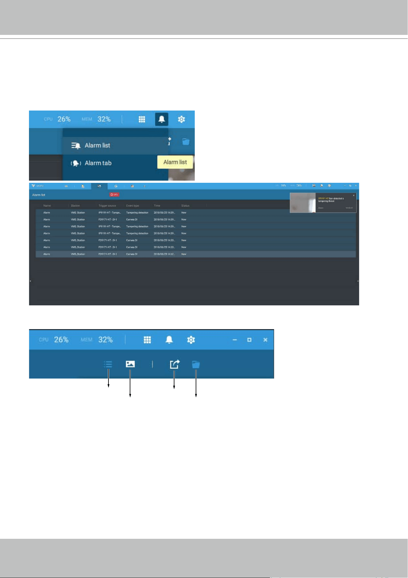
VIVOTEK - A Leading Provider of Multimedia Communication Solutions
82 - User's Manual
Alarm list
The Alarm list is accessed from the top tool bar. The Alarm list provides easy access to all
triggered alarms, such as tampering alarms, alarms reported by VCA analytics, external devices
connected via a camera's DI pin, etc.
The Alarm list can be displayed in either the List view or Thumbnail view.
List view
Thumbnail view
Export
Export target folder
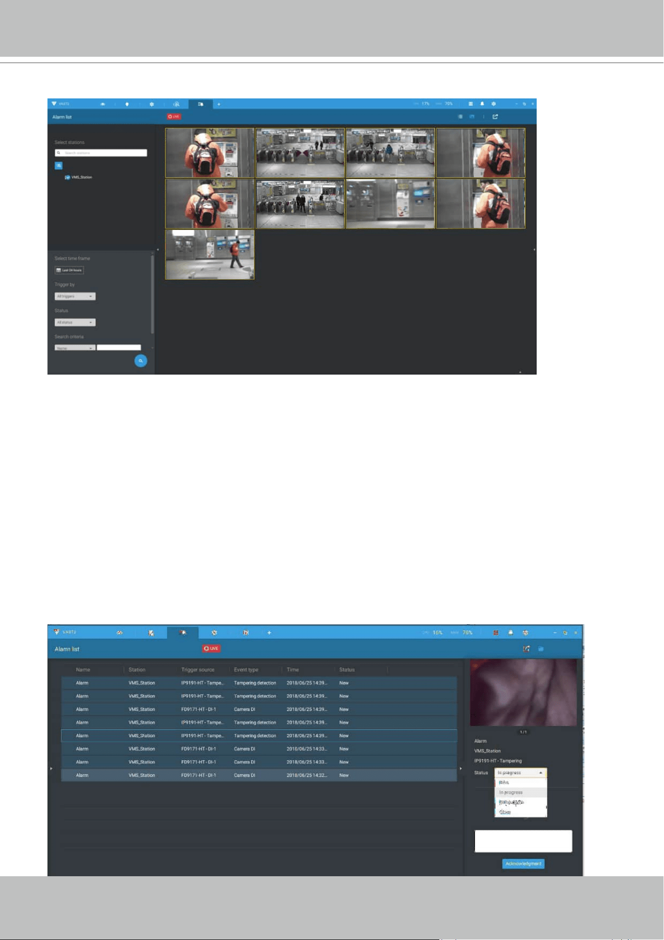
VIVOTEK - A Leading Provider of Multimedia Communication Solutions
User's Manual - 83
On the Alarm list, you can double-click to select a triggered alarm. A related snapshot and
configuration panel will appear. An operator can select the Status menu to change the event
management status. The configurable statuses can be:
1.
New: An event that has not been handled.
2.
In progress: Select to indicate that the event is being handled, e.g., a security personnel has
been sent to verify the cause of the event.
3.
False alarm: Used to indicate the event has been verified as a false alarm.
4.
Close: A closed case event will be erased from the event list.
When done with designating event status, click the
Acknowledegment button.
Below is an example of a Thumbnail view.
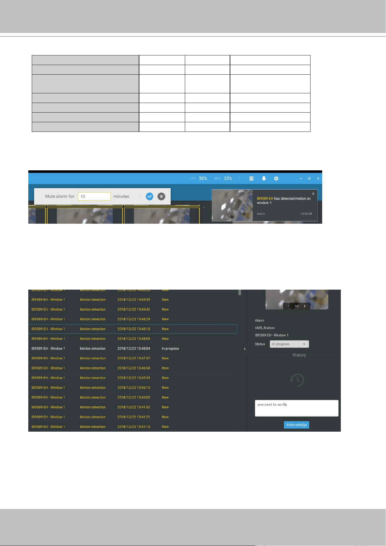
VIVOTEK - A Leading Provider of Multimedia Communication Solutions
84 - User's Manual
The Alarm list also supports Hot keys.
Alarm list window
Mute the current alarm Ctrl m
Designate the selected alarms
as false alarms
Ctrl f
Select all alarms Ctrl a
Select one or multiple alarms Ctrl left mouse button
Select multiple alarms Shift left mouse button
Select different alarms Up/Down/Left/Right
When an alarm is muted, a message will prompt asking for how long the alarm will be muted.
Enter a number, and the alarm will disappear from the list temporarily.
When an alarm is designated as a false alarm, it is immediately removed from the list.
When an alarm is designated as In progress, you can add a comment on the current condition,
and click Acknowledge to change its status.
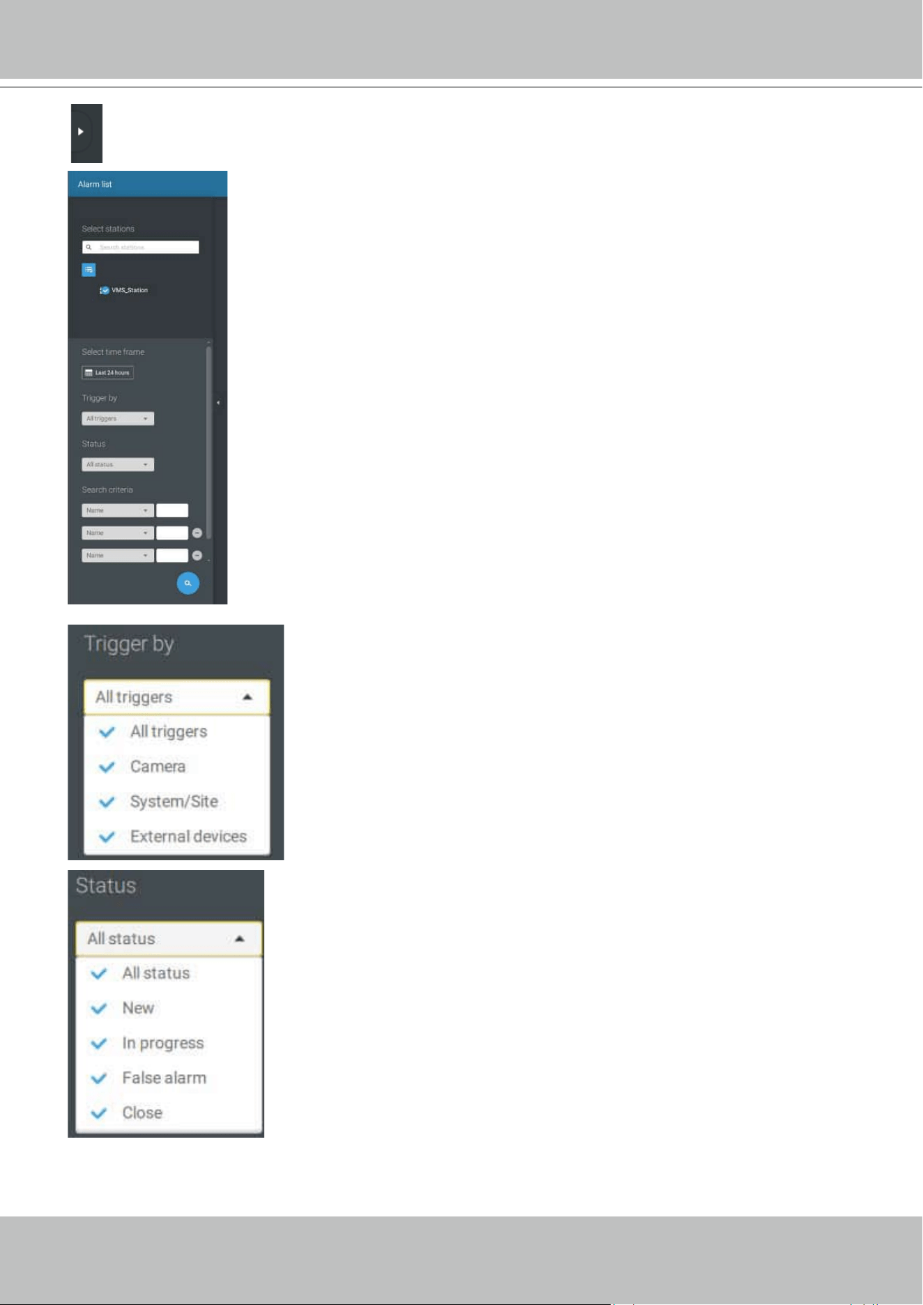
VIVOTEK - A Leading Provider of Multimedia Communication Solutions
User's Manual - 85
To find alarms of specific types, time of occurrences, and alarm status,
click the side tab to reveal the search panel.
You can select the trigger source, e.g., when you need to see
camera alarms only.
You can check to see alarms of a specific status. For example, you
can select to search for the "In progress" alarms only.
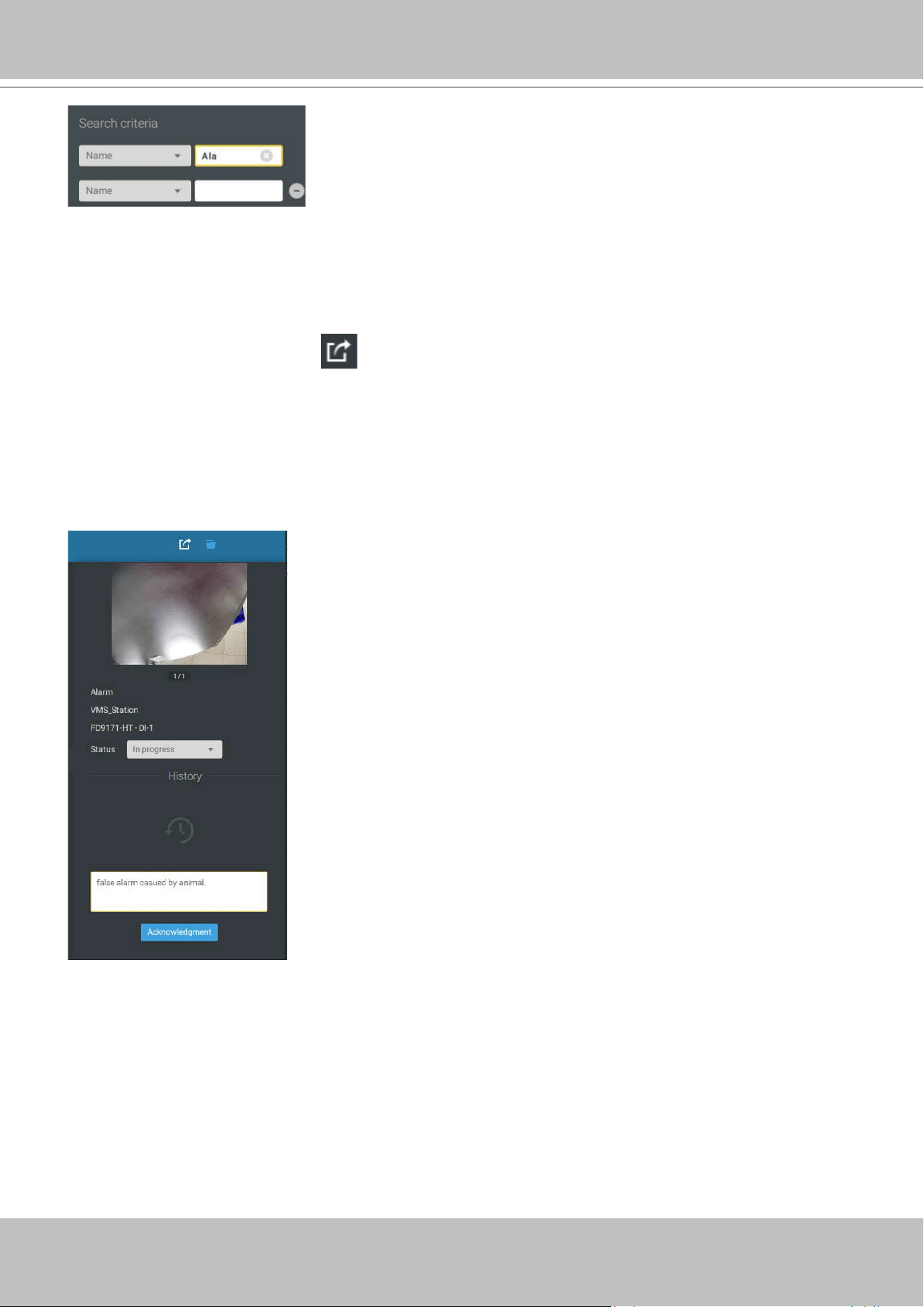
VIVOTEK - A Leading Provider of Multimedia Communication Solutions
86 - User's Manual
You can use the Export button to export a full list of all triggered events into a CSV file. The
event type, receiving station, triggering device, time of occurrence, and event status will all be
listed. You can also export alarm-triggered videos.
You can also add a comment for an event by entering the description in the comment entry field.
You can enter one or multiple keywords as the search criteria.
For example, if you have an alarm named as "Alarm3-sidewalk,"
use the name as the keyword to search for the related alarms.
VIVOTEK - A Leading Provider of Multimedia Communication Solutions
User's Manual - 87
To review the alarm-related video, click to select an alarm, double-click to playback. The Playback
window will appear on the upper right of the screen.
< 1/2 >
Double-click on the small playback screen again to bring it to the full view. The playback control,
time line, export, and alarm tags will be available on screen.
VIVOTEK - A Leading Provider of Multimedia Communication Solutions
88 - User's Manual
Alarm tab
The Alarm tab is an automated streaming window displaying live videos by the triggered alarms.
If you configure an alarm action as "
Send live streaming," the alarm streaming will be displayed in
this window. Note that this window does not display other alarms.
When a live streaming is sent with an alarm, an orange ringing bell icon will displays.
An alarm prompt will also display on the screen.
You can click on the ringing bell icon to open the Alarm tab window. The alarm-trigged streamings
will be available on screen.

VIVOTEK - A Leading Provider of Multimedia Communication Solutions
User's Manual - 89
Hot Keys
Open online document F1
Close current tab Ctrl (Win) /
Command (MacOS)
W
Open new Live / Playback tab Ctrl (Win) /
Command (MacOS)
T
Full screen
Ctrl (Win) /
Command (MacOS)
Shift F
Exit full screen Ctrl (Win) /
Command (MacOS)
Shift F
Exit full screen Esc
View cell
Select view cell Arrow keys
Digital zoom Ctrl (Win) /
Command (MacOS)
Shift Z
Snapshot Ctrl (Win) /
Command (MacOS)
Shift C
Instant bookmark Ctrl (Win) /
Command (MacOS)
Shift B
Remove camera from cell Del
Move to preset position Ctrl (Win) /
Command (MacOS)
Digits (1,2,3,...)
PTZ model up, down, left, right Arrow keys
Save current layout as a
customized layout
Ctrl (Win) /
Command (MacOS)
S
Undo layout modication Ctrl (Win) /
Command (MacOS)
Z
Redo layout modication Ctrl (Win) /
Command (MacOS)
Y
Timeline
Sync Playback mode Ctrl (Win) /
Command (MacOS)
Shift S
Pause (Play/Rewind) Space
Play Ctrl (Win) /
Command (MacOS)
Arrow right
Rewind Ctrl (Win) /
Command (MacOS)
Arrow left
Speed up Ctrl (Win) /
Command (MacOS)
Up
Speed down Ctrl (Win) /
Command (MacOS)
Down
Next frame Shift Arrow right
Previous frame Shift Arrow left
Reset speed to 1x Ctrl (Win) /
Command (MacOS)
1 (one)

VIVOTEK - A Leading Provider of Multimedia Communication Solutions
90 - User's Manual
Bookmark search
Select more bookmarks Ctrl (Win) /
Command (MacOS)
Click
Select more bookmarks Shift Click
Back to bookmark page Esc
Next bookmark Arrow right
Previous bookmark Arrow left
Thumbnail search
Select thumbnail Arrow keys
Play a selected thumnail Enter
Back to Thumbnail page Esc
Next Thumbnail Arrow right
Previous Thumbnail Arrow left
Emap Setup
- Google map
Remove selected GPS Del
DI/DO Device Settings
Remove selected external I/O
device
Del
SMTP Settings
Remove selected SMTP
server
Del
Camera Management
Rename selected camera F2
Rename selected folder F2
Remove selected camera
from system
Del
Sites Management
Rename selected site F2
Remove selected site from
system
Del
Users Settings
Remove selected user Del
Schedule Settings
Remove scheduled time frame Del
Smart search II
- Conguration page
Delete detection range Esc
VIVOTEK - A Leading Provider of Multimedia Communication Solutions
User's Manual - 91
Data Magnet
Move selected row Up / Down
Show detail of selected row Enter
View management
Rename selected view F2
Delete selected view Del
Alarm management
Delete selected alarm Del
Alarm list window
Mute the current alarm Ctrl (Win) /
Command (MacOS)
m
Designate the selected alarms
as false alarms
Ctrl (Win) /
Command (MacOS)
f
Select all alarms Ctrl (Win) /
Command (MacOS)
a
Select one or multiple alarms Ctrl (Win) /
Command (MacOS)
left mouse button
Select multiple alarms Shift left mouse button
Select different alarms Up/Down/Left/Right
VIVOTEK - A Leading Provider of Multimedia Communication Solutions
92 - User's Manual
View Cell Elements
On a view cell, the control elements are different with different types of network cameras. 3
major types are listed below with applicable screen elements:
1. Fixed cameras:
Snapshot - Thumbnail search - Smart search -
Replay.
2. Fisheye cameras:
Fisheye display mode - Snapshot -
Thumbnail search - Smart search - Replay.
Zoom In
Zoom Out
The Auto pan function applies only to the Regional views. Select a regional view, and click the
Auto pan button. The Regional view will pan from side to side to cover more viewable regions.
If a fisheye is mounted on wall, a regional view with auto pan can cover a panoramic view
region.
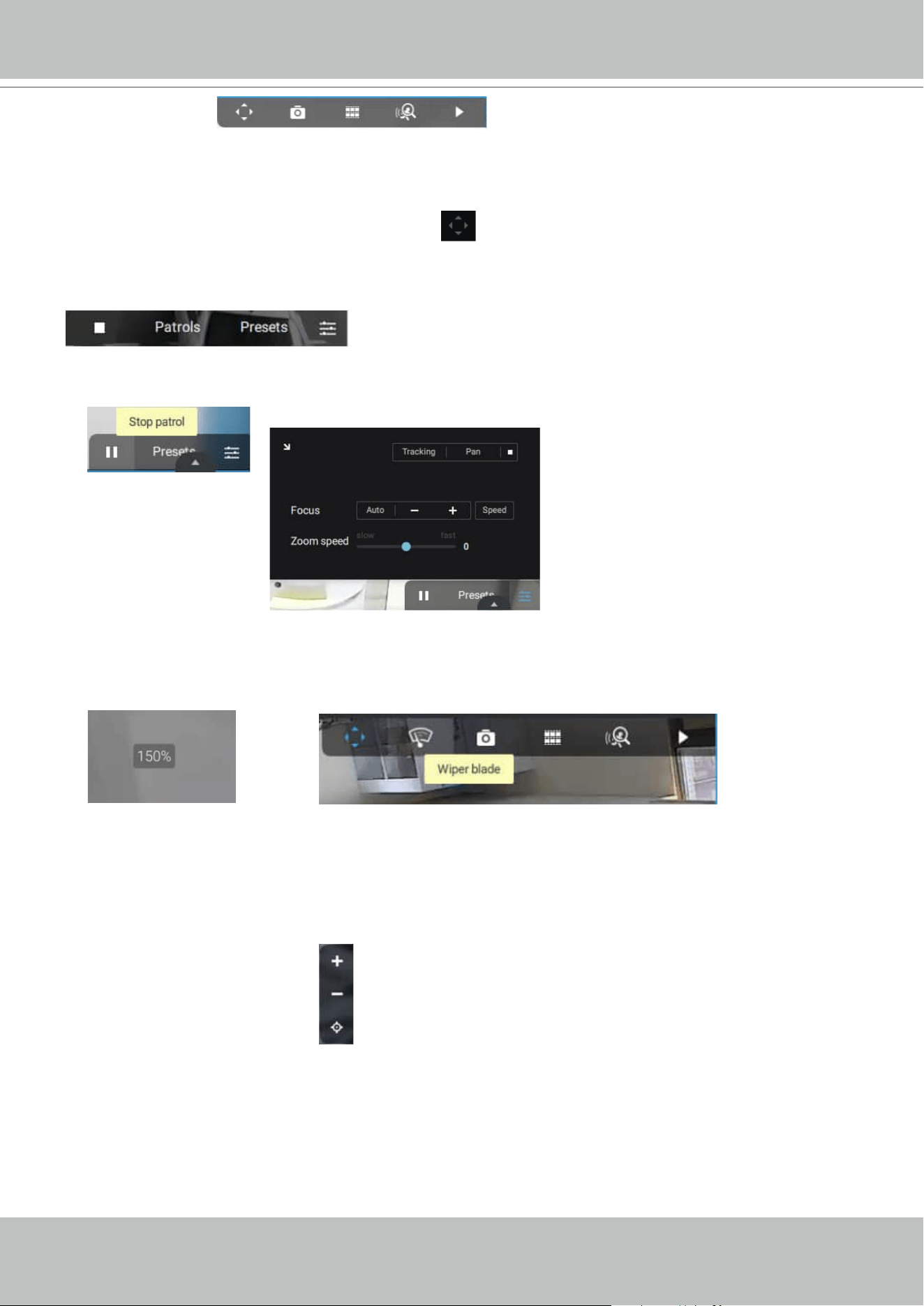
VIVOTEK - A Leading Provider of Multimedia Communication Solutions
User's Manual - 93
You can use the mouse wheel to zoom in or zoom out on the screen. The zoom ratio is shown
on screen for half a second.
When PTZ is enabled, the zoom buttons and a home button are displayed on the right hand side
of the view cell.
For more information about Snapshot, Thumbnail search, and the Replay functions, please refer
to their specific help pages.
3. PTZ cameras:
PTZ - Snapshot - Thumbnail search - Smart
search - Replay. For information about PTZ control, refer to the discussion on PTZ on page
136.
To exert PTZ control, first click on this button
to enable PTZ control.
When PTZ control is enabled, the following controls are available on screen:
Click Patrols or Presets if these have been configured on the PTZ camera. You will need to open
a web console with the camera to do so.
The PTZ settings tab allows you to enable PTZ Tracking and the Pan functions. You can also
adjust the Zoom and Focus speed, or manually adjust the focus. Please refer to the camera User
Manual for more information about these functions.
For speed dome cameras that comes with wiper blade, the wiper blade control button will be
available on the tool bar.
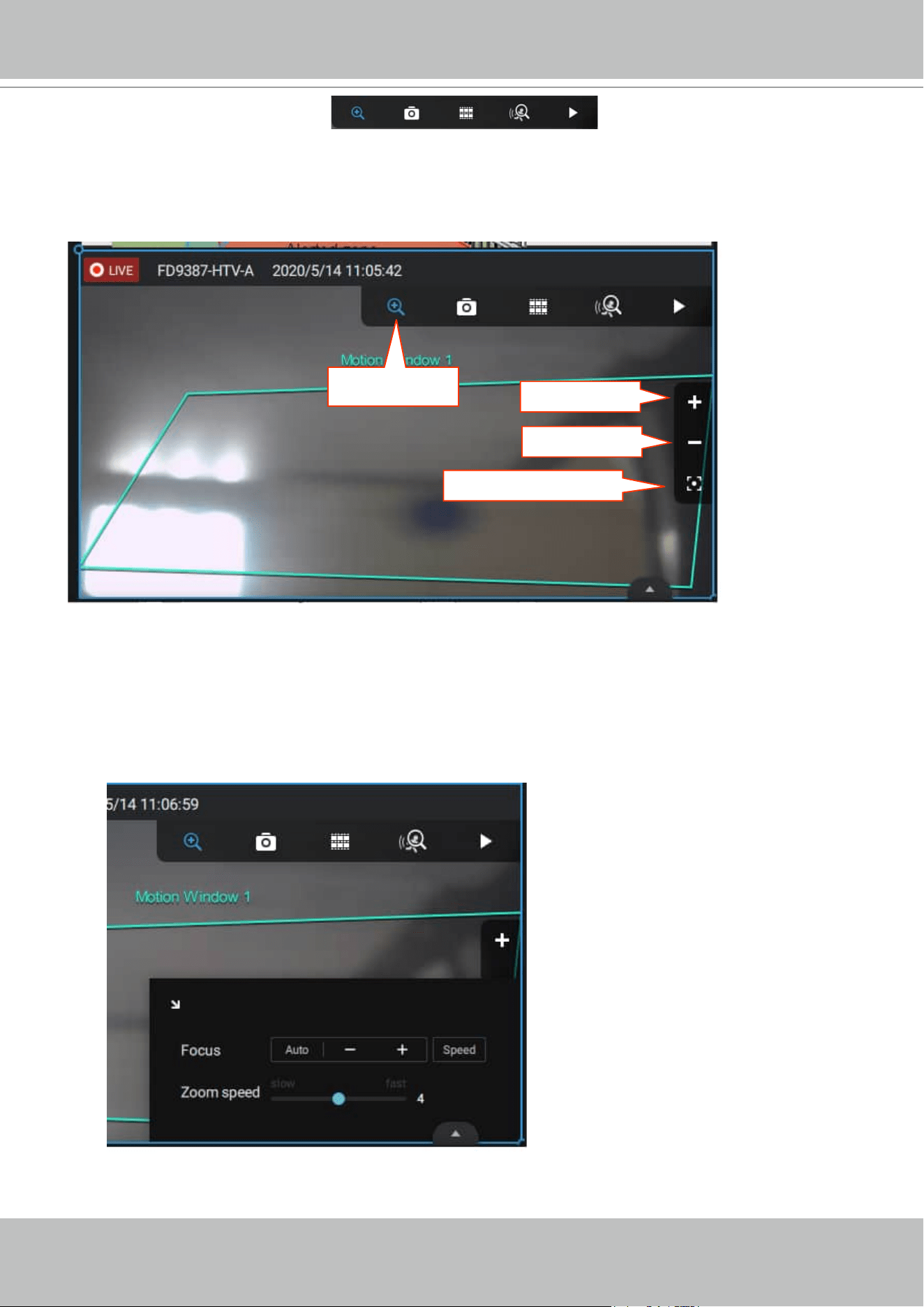
VIVOTEK - A Leading Provider of Multimedia Communication Solutions
94 - User's Manual
3. Motorized lens cameras: Enable Optical - Snapshot -
Thumbnail search - Smart search - Replay.
For cameras that come with motorized zoom lens, click on the Enable Optical button. You can
zoom in or zoom out on the scene.
Click on the Focus adjustment button to bring out the focus panel. If you find the image is out of
focus, you can use the +, -, or Auto buttons to regain the best image focus.
You can use the Auto scan function to let the camera automatically find the best focus. The
process may take up to 20 seconds.
Enable Optical
Zoom in
Zoom out
Focus adjustment
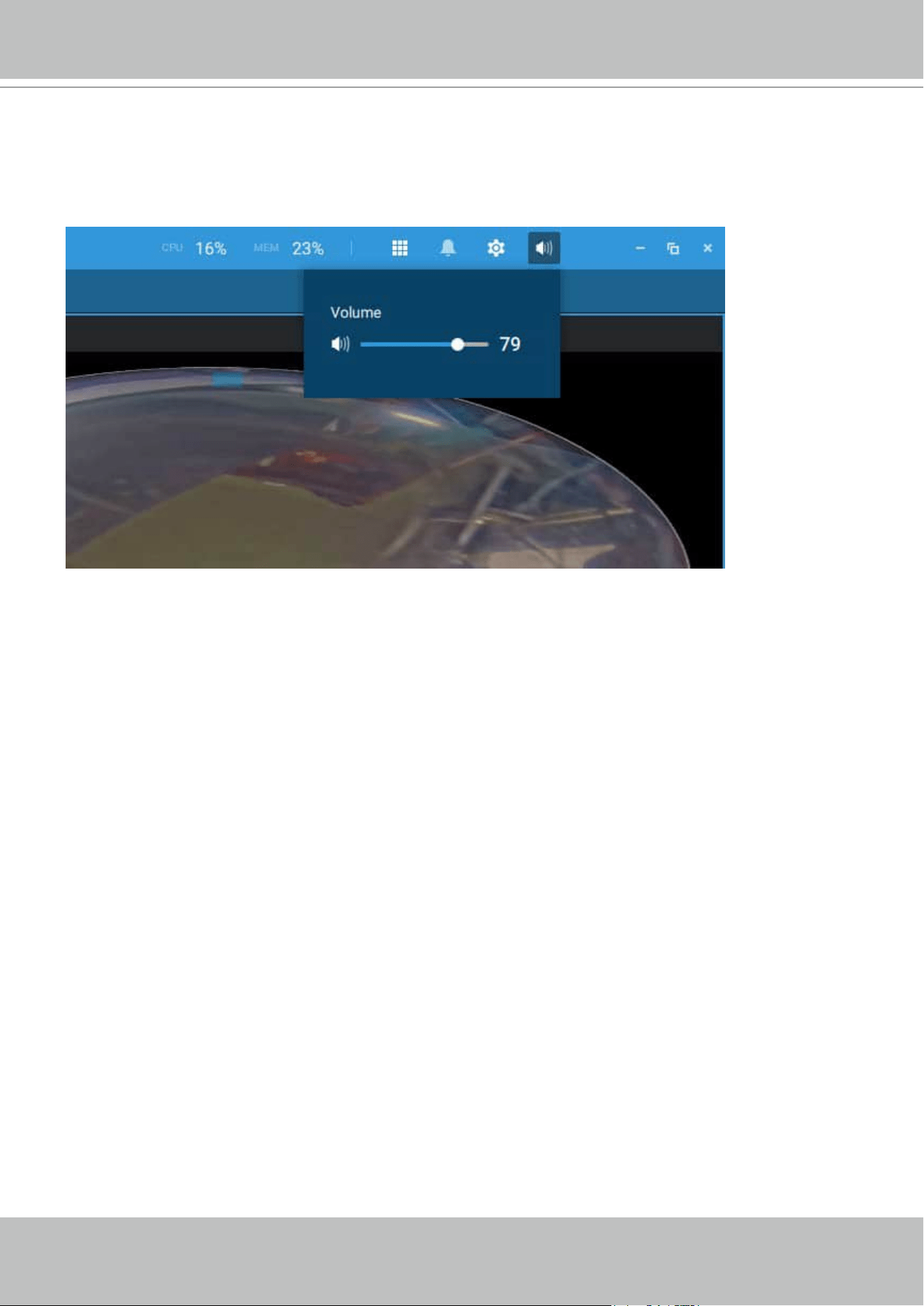
VIVOTEK - A Leading Provider of Multimedia Communication Solutions
User's Manual - 95
Audio
For a view cell housing a camera with an audio input, you can tune its volume using the slide bar
on the tab panel.
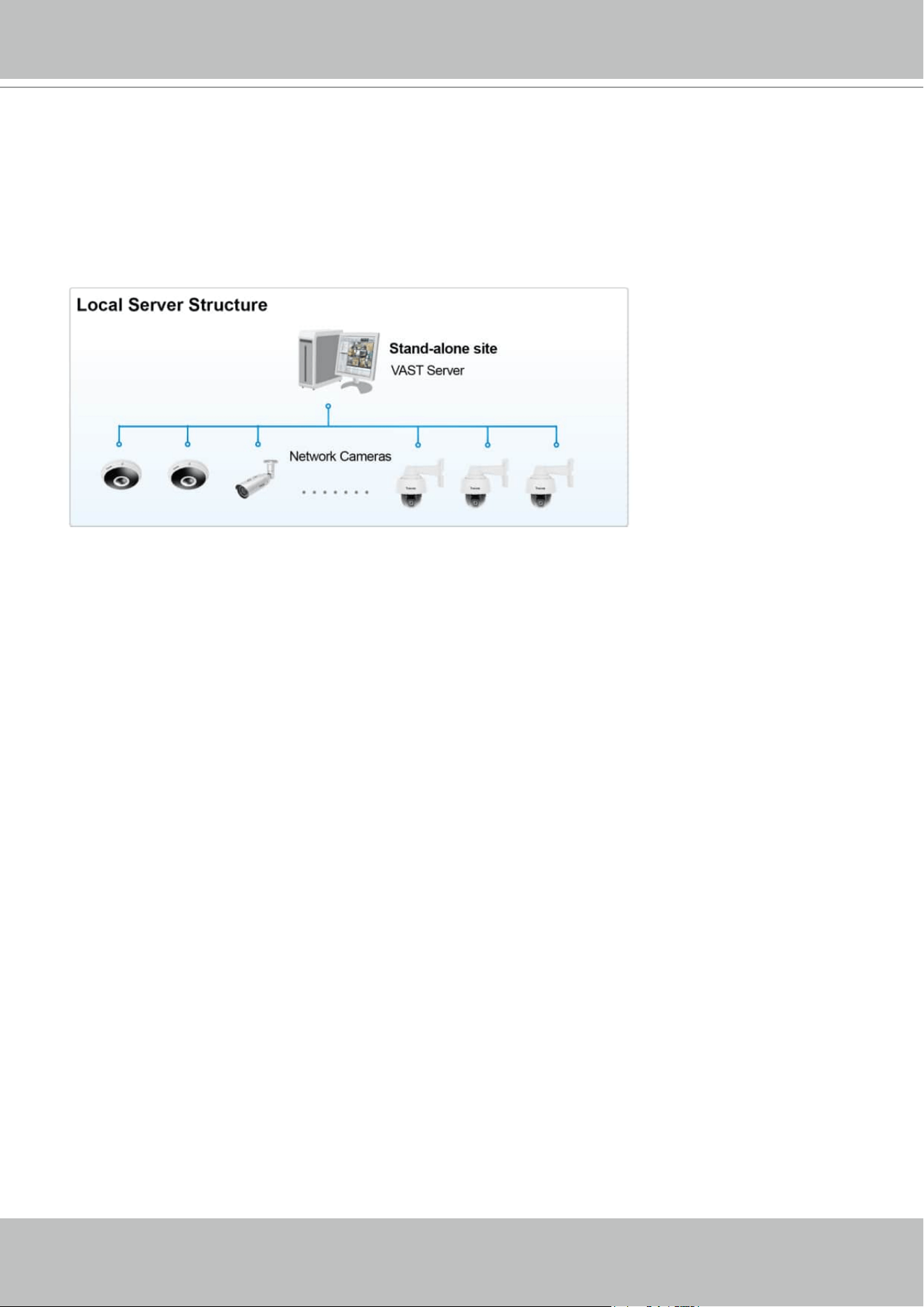
VIVOTEK - A Leading Provider of Multimedia Communication Solutions
96 - User's Manual
VAST Server and Client Components
VAST2 Server provides a centralized management site for video recording. Users can login and
modify the server's configuration, edit the server's recording storage, configure schedules and
many other functions. You can browse the recorded video database and video clips related to
specific events on the server.
For users who manage large-scale surveillance deployments, please plan the hierarchical
structure first. Then you can start to add cameras to each station and connect these sub-
stations to the root station. The whole hierarchical management system is thus constructed.
VIVOTEK's NVR stations can also be included as sub-stations. The Logical Tree view becomes
the default.
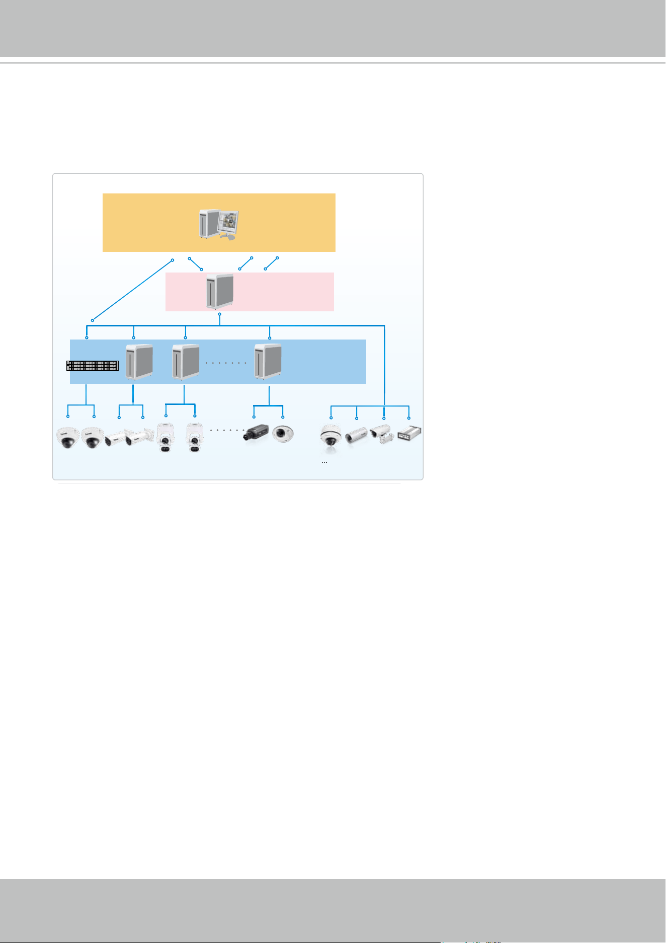
VIVOTEK - A Leading Provider of Multimedia Communication Solutions
User's Manual - 97
Please refer to the Sites page for how to enlist VAST sub-stations.
Unlimited No. of Network Cameras , Video Servers...
Remote Server Structure
Login
Login
Client VAST
(Root station)
VAST CMS Server
VAST Server
(Sub-stations)
NVR
Multiple Server Applications
A host with the VAST2 installed is recognized as a stand-alone site. All the functions can be
simultaneously performed on one single site.
VIVOTEK - A Leading Provider of Multimedia Communication Solutions
98 - User's Manual
Minimum System Requirements
Before installing the VAST software, please make sure your system meets the following
recommended minimum system requirements.
VAST 2 Liveview & Playback
Operating System
Windows Server 2012, 2016 / Windows 10, 7 / MacOS 10.15
Catalina (Server core installation type is not supported.)
Clients
(Display
Channels)
720P,2Mbps,
H.264,* each CH
8 CH 16 CH 32 CH
1080P,4Mbps,
H.264**, each CH
6 CH 10 CH 18 CH
1080P,4Mbps,
H.265, each CH
3 CH 5 CH 9 CH
CPU
6th Generation Intel
®
Core™ i3 Processors
6th Generation Intel
®
Core™ i5 Processors
6th Generation Intel
®
Core™ i7 Processors
RAM*** 8GB or above 8GB or above 16GB or above
Network Interface Card Ethernet, 1Gbit recommended
Graphics Card****
Direct3D acceleration with 1GB RAM graphics card
VAST2 Server
Operating System
Windows 10, 7, Windows Server 2012, 2016 (Server core installation
type is not supported.)
Server (Recording
Channels)
Up to 64 CH Up to 128 CH Up to 256 CH
CPU
6th Generation Intel
®
Core™ i3 Processors
or above
6th Generation Intel
®
Core™ i5 Processors or
above
RAM**** 4 GB or above 8GB or above 8GB or above
Hard Drive (Enterprise
model only), suggestion
1 Volume Group* 2 Volume Group* 4 Volume Group*
Recording throughput 1 Volume Group: Max. 200Mbps (Max.)**
Network Interface Card Ethernet, 1Gbit recommended***
* The size of volume group depends on the total recording server throughput.
** The maximum combined bit rate of cameras cannot exceed the total recording throughput.
*** Please consider the combined throughput of viewing, recording, and server's network
bandwidth when designing your surveillance deployments.
**** Please use a dual-channel memory configuration.

VIVOTEK - A Leading Provider of Multimedia Communication Solutions
User's Manual - 99
The required hard disk space will depend on the video settings, the number of network cameras
and recording group settings. Please add more hard disks if you want to extend the system.
Below are the approximate numbers for a week-long recording. The actual storage space
required also depends on imaging parameters, e.g., a complex retail environment that involves
many moving objects requires more pixel data to be transmitted over network than a simple
environment such as a parking lot. The following numbers are based on H.264 recording.
32-CH, VGA, about 1 week recording: 750 GB
64-CH, VGA, about 1 week recording: 1TB x 2
32-CH, 2-megapixel, about 1 week recording: 2TB x 2
64-CH, 2-megapixel, about 1 week recording: 2TB x 4
**** Please update to the lastest GPU driver.
* Display requirements of the 3MP fisheye camera is equal to a 720P camera.
** Display requirements of the 5MP fisheye camera is equal to a 1080P camera.
*** Please use a dual-channel memory configuration.
* Each recording group can receive recordings for 60 channels.
If you plan to install both VAST2 server and client on the same computer, please remember to
consider the combined load on computing, encode/decode effort, and bandwidth.
The 60-day trial includes 256 channel license and all advanced license features.
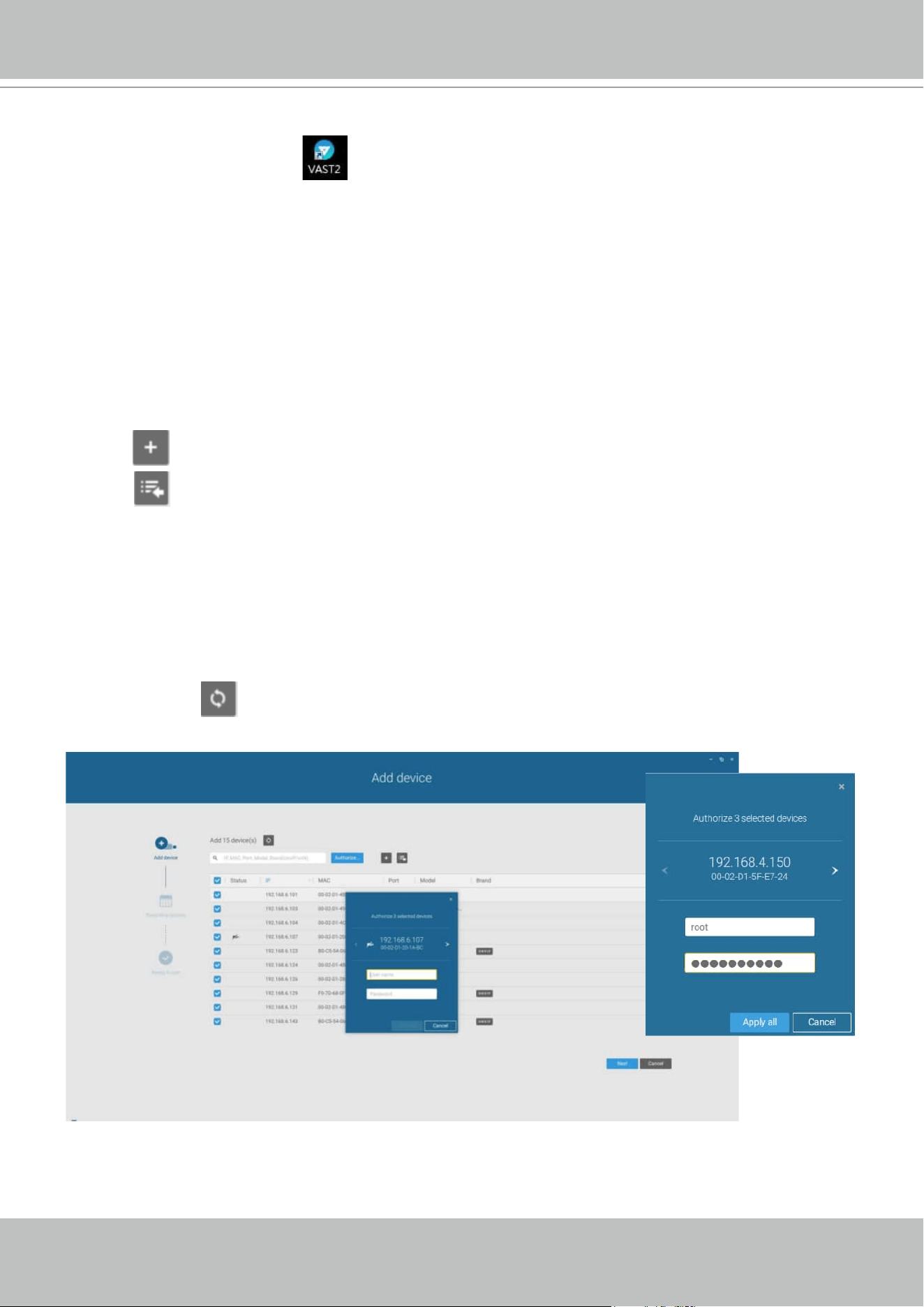
VIVOTEK - A Leading Provider of Multimedia Communication Solutions
100 - User's Manual
Chapter 2-2 Starting Up
Double-click the VAST2 icon on the desktop to start the VAST2 main page.
When started the first time, the server automaticallly polls the local network for reacheable
network cameras. For cameras that come with pre-configured User Name and Passwords, the
server prompts for entering credentials for the access to cameras. Check out the cameras' MAC
addresses to identify the cameras.
The cameras found within the network will be listed. If the need should arise, you can use the
Search panel on top to locate specific cameras using their IP, MAC, Port, Model name, or brand
name (ONVIF/VIVOTEK).
Use the Add device button to manually add a camera with its known IP or domain name.
Use the Import Device List button to recruit cameras in a previously-saved device list (CSV
files).
Use the Authorize button if the camera found in the Search panel needs credentials.
When search is done, delete the alpha-numeric characters in the search field to return to the
device list.
Use the Refresh
button to search the local network again.
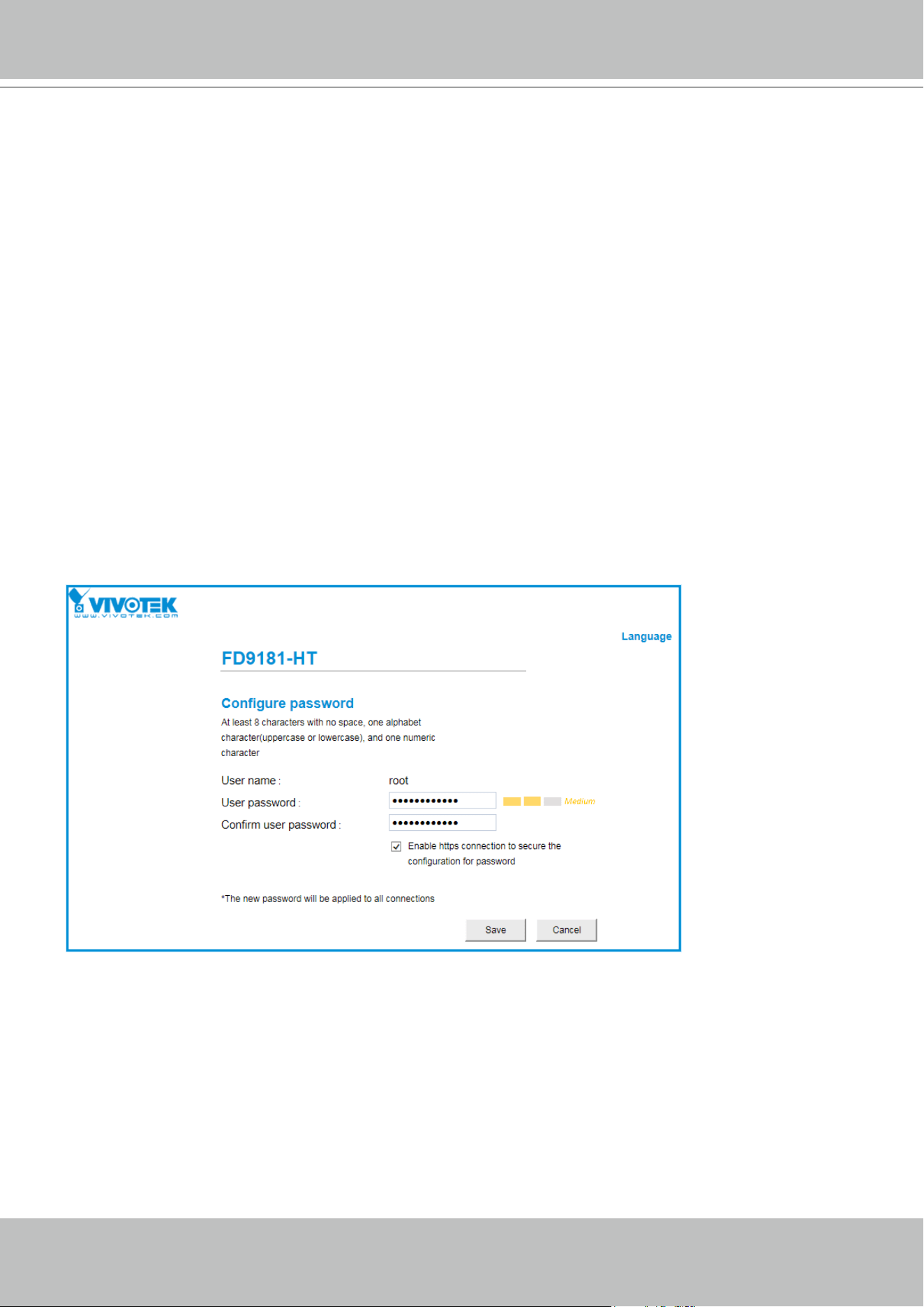
VIVOTEK - A Leading Provider of Multimedia Communication Solutions
User's Manual - 101
NOTE:
For cameras that come without a password protection, you should open the Shepherd utility
to locate and open a web console, and congure a password for protecting the access to the
camera. If a brand new camera (with no password) is selected for your VAST conguration, it
will join your conguration without the password protection.
2-2-1. Selecting Devices
Use the checkboxes in front of the listed devices to determine which devices will be recruited to
your configuration. By default, all cameras are selected. When the selection is done, click on the
Next button at the lower right screen.
If any of the selected devices requires credentials, the authorization window will prompt.
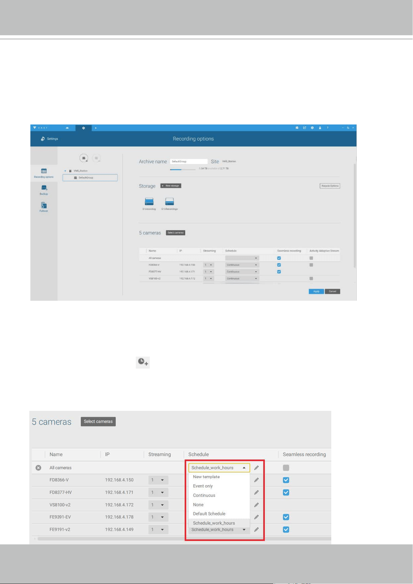
VIVOTEK - A Leading Provider of Multimedia Communication Solutions
102 - User's Manual
2-2-2. Recording Options
Click Settings > Recording > Recording options. The Recording options window will prompt.
You can congure recording schedules or select the storage options, including the conguration
of an external NAS storage.
Click on the Schedule column on the Camera list for a recording option: Continuous recordings,
Events only, None, or Default Schedule, or New template. You can apply a schedule template
for all cameras or congure individual schedules for different cameras. When using the Event-
triggered recording, a pre-event and post-event time can be configured. An Edit pane is
available by clicking the Edit button.
You can manually create a recording template using the New template option. When done,
each congured template will be listed below.
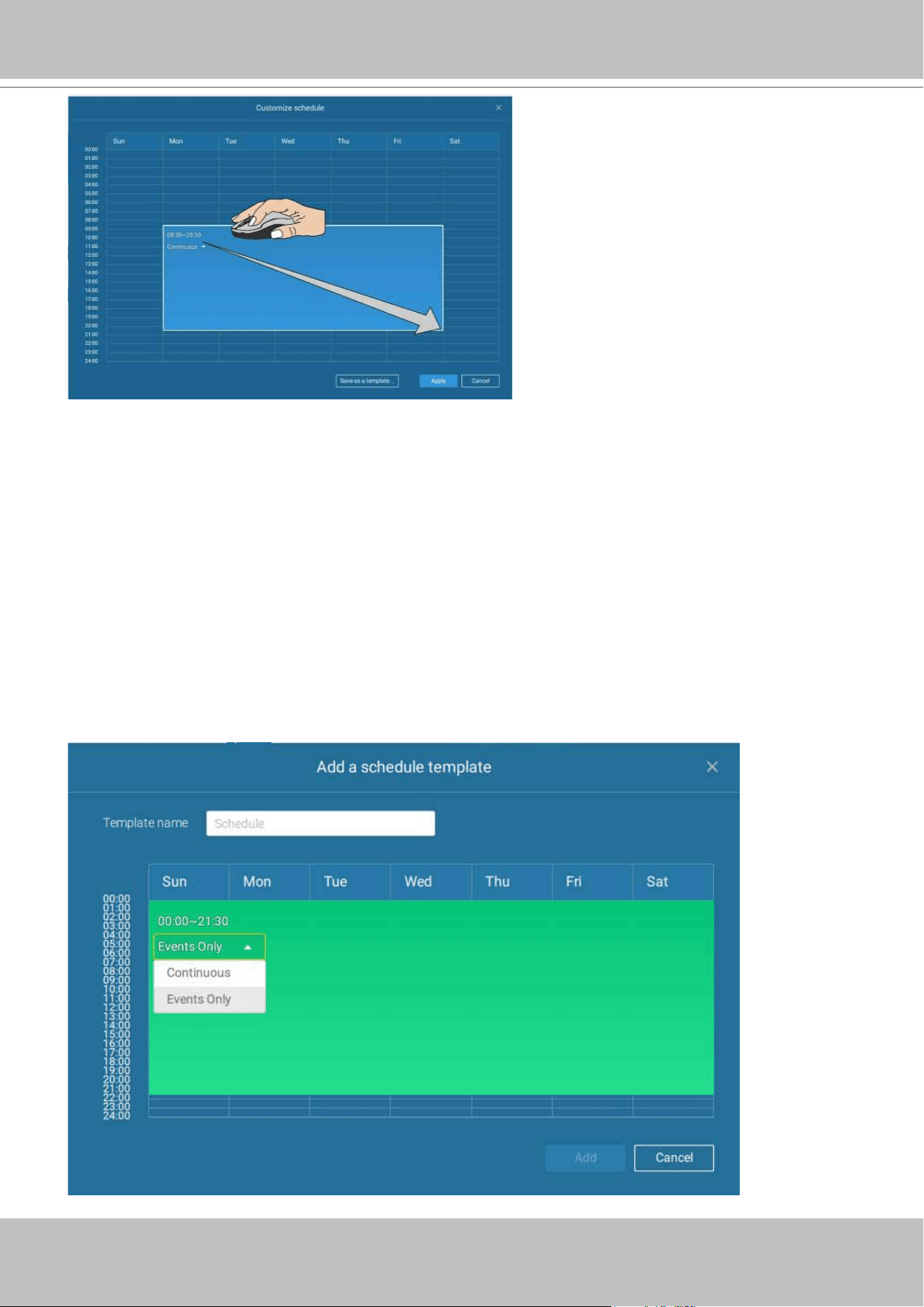
VIVOTEK - A Leading Provider of Multimedia Communication Solutions
User's Manual - 103
Click and hold down on the time cells, and drag the mouse to include the time span of your
preferrence. The minimum selectable unit is half an hour. You can select separate and multiple
time spans on the template.
Enter a name for the template, and click Add to save your template.
Event types can be selected when
The same conguraion window apply to both the Schedule template and the customize
schedule windows.
If the Events only option is selected for the new template, you can determine what kinds of
events will trigger the recording. Use the pull-down menu to select Events only.
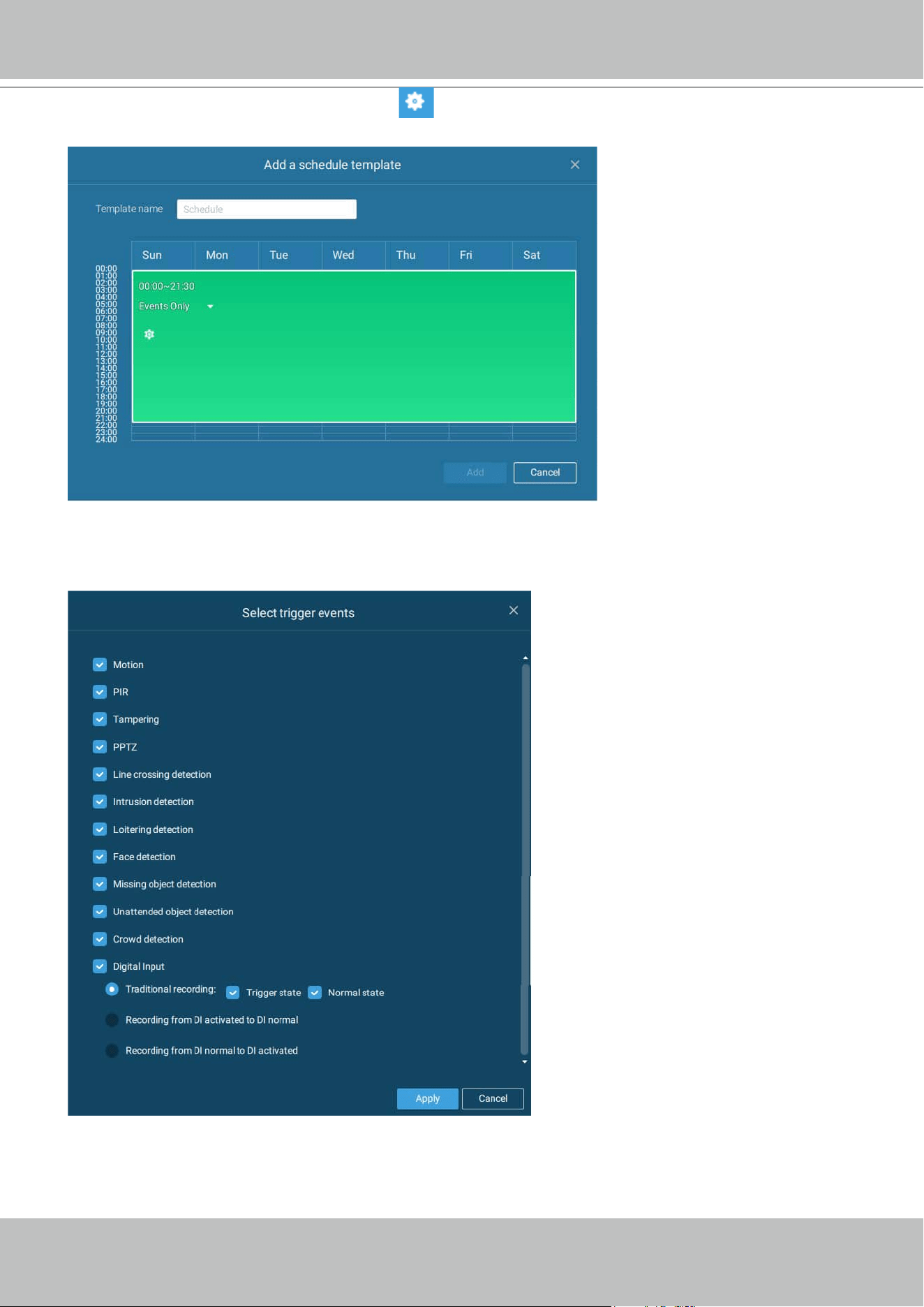
VIVOTEK - A Leading Provider of Multimedia Communication Solutions
104 - User's Manual
When Events only is select, click on the Settings button to proceed.
The applicable event types will be listed. Select the types of event triggers that you prefer. Click
Apply to leave this page. By deault, all applicable event triggers will be selected.
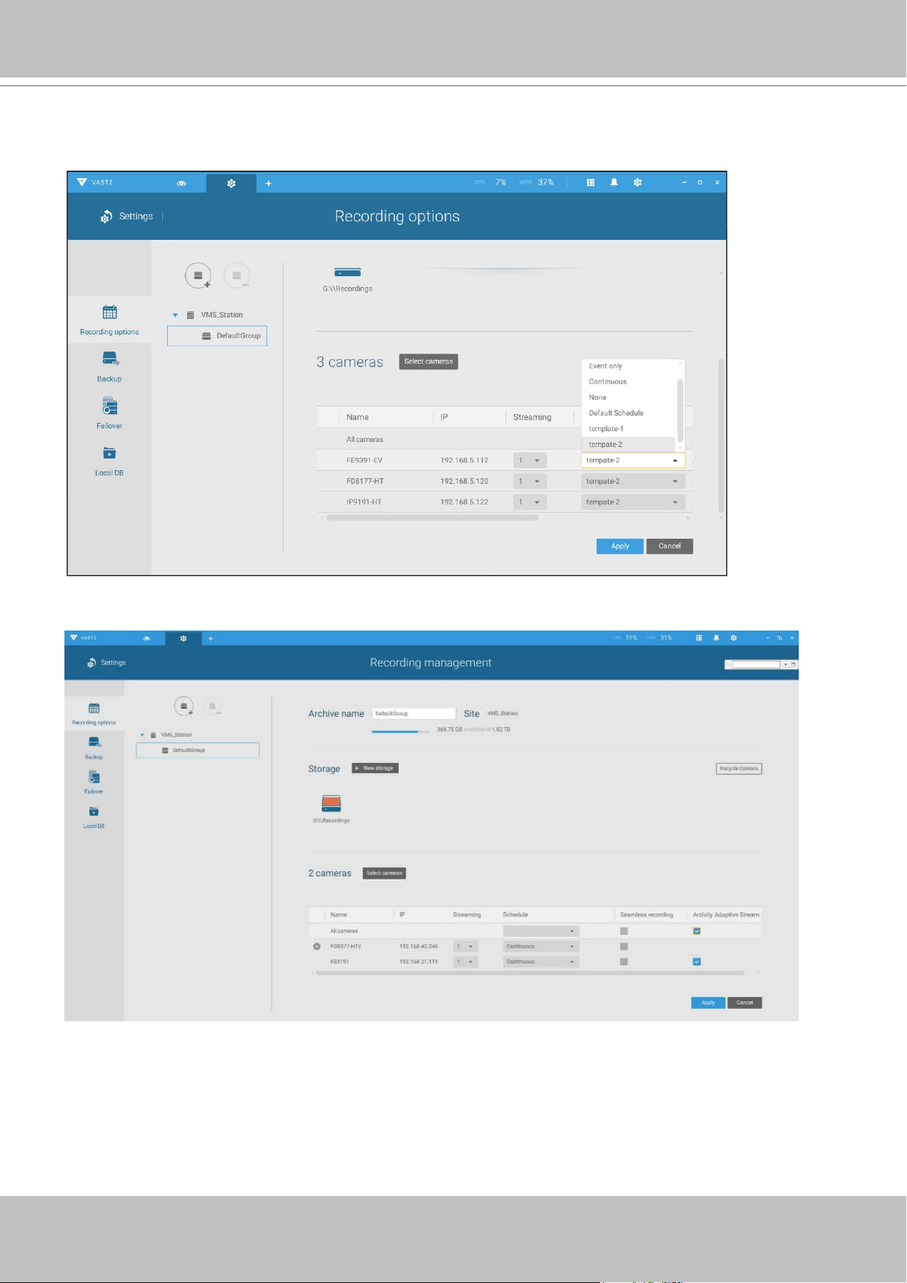
VIVOTEK - A Leading Provider of Multimedia Communication Solutions
User's Manual - 105
Back on the Recording options page, select the new template as a scheduling option. Use the
menu on the top to select a scheduling template for all cameras.
Make sure a Schedule mode is selected when you leave this conguration step.
VIVOTEK - A Leading Provider of Multimedia Communication Solutions
106 - User's Manual
Seamless Recording
Seamless Recording safeguards critical videos in the occurences of network disconnection.
In the event of temporary disconnection, video is stored in individual cameras' SD/SDHC/
SDXC card; and once the connection is restored, a VAST server can automatically resume the
recording. More remarkable is that, a VAST server can simultaneously retrieve the time-tagged
videos that were temporarily stored on SD/SDHC/SDXC cards. For information about the latest
rmware/software revisions that support this feature, please contact your sales representatives
or technical support.
VAST
Server Station
14:30 14:50
Disconnect Restored
Timeline
LAN/WAN
VAST
Server Station
LAN/WAN
1
4
:
3
0
~
1
4
:
5
0
Seamless Recording
SD/SDHC/SDXC
Normal recording
Retrieval
The Seamless Recording feature is enabled when inserting, updating, or batch inserting
cameras in the Camera Management window. The rmware/hardware compatibility of this
feature is automatically detected, i.e., this feature is not available when a non-compliant camera
is attached. If a compatible camera is attached, a checkbox will be available as shown below.
The video data retrieved from SD/SDHC/SDXC card also include event-triggered recordings such
as pre- or post-event footages, if events were detected during the network outage.
VIVOTEK - A Leading Provider of Multimedia Communication Solutions
User's Manual - 107
Activity Adaptive Stream
■ Activity Adaptive Stream: (Note that this feature may not be available for some older models)
This option will activate the frame rate control according to alarm trigger.
The frame control means that when there is a triggered alarm, the frame rate will raise up to the value
you’ve congured on the Video quality page.
If you enable adaptive recording on a camera, only when an event is triggered on a camera will the
server record the full frame rate streaming data; otherwise, it will only request the I frame data during
normal monitoring, thus effectively saves bandwidth and storage space.
The alarm trigger includes: motion detection and DI detection. Please refer to Alarm Settings on page
145.
On individual cameras, you can congure the following:
■ Pre-event recording and post-event recording
The Network Camera has a buffer that temporarily holds data for a period of time. Therefore, when an
event occurs, the camera can restrieve image frames taken several seconds ago. Enter a number to
dene the duration of recording before and after a trigger is activated.
■ Priority: Select the relative importance of this recording (High, Normal, or Low). Recording with a
higher priority setting will be executed rst.
■ Source: Select a video stream as the recording source.
Time
Bandwidth
Bandwidth
Activity Adaptive Streaming
for Dynamic Frame Rate Control
I frame ---> Full frame rate ---> I frame
Continuous recording
NOTE:
* To enable adaptive recording, please make sure you have congured the trigger sources such
as Motion Detection, DI input, or Manual trigger.
* When there is no alarm trigger:
- JPEG mode: record 1 frame per second.
- H.264 mode: record the I frame only.
* When the I frame period is > 1 second on the Video settings page, rmware will force decrease
the I frame period to 1 second when the Activity Adaptive Recording feature is enabled.
VIVOTEK - A Leading Provider of Multimedia Communication Solutions
108 - User's Manual
Adding NAS (Network Attached Storage) as a Storage Option
You can also record videos to a networked storage.
1. Click the Add archive
button.
2. Enter a name for the conguration.
3. Click the Add storage
button.
4. Click the + New NAS button.
VIVOTEK - A Leading Provider of Multimedia Communication Solutions
User's Manual - 109
5. Enter the NAS storage's address and the credentials for access to the networked storage.
When done, click the Connect button.
6. The NAS storage should appear on screen. The connection may take several seconds.
Single-click on the NAS storage to select its network shares.
VIVOTEK - A Leading Provider of Multimedia Communication Solutions
110 - User's Manual
7. The NAS storage's network shares should be listed. Single-click to select a network share.
8. Click Select when done. Note that you can repeat the previous process to select multiple
network shares from a single NAS storage.
VIVOTEK - A Leading Provider of Multimedia Communication Solutions
User's Manual - 111
9. The selected shares should be listed. Enter a name and select cameras. When done, click
the Add button at the lower right to complete your conguration.
VIVOTEK - A Leading Provider of Multimedia Communication Solutions
112 - User's Manual
2-2-3. Storage
By default, VAST will check if the D: drive is available. If no other disk drives can be specified,
the system drive C: will still be defined as a storage option. Other disk drives in the system, and
the default storage volume (configured in the initial setup) will be listed.
You can add a NAS storage's share volume as the additional storage option. Enter the necessary
information for access to a network share. Enter and select a NAS path. The share will then be
available for video recording.
Select storage volumes each by a single click.
Click Ready to use to continue. The server will take several minutes synchronizing configuration
between server and cameras, and time settings between them.
VIVOTEK - A Leading Provider of Multimedia Communication Solutions
User's Manual - 113
2-2-4. Starting Up - Main Page
You will be defaulted to the Live view once the main page displays. Another tab window is the
Search panel where you can search recorded events and recorded videos.
On the initial start up, the server should fill the live camera feed to the available 2x2 view cells (4).
You should then select a preferred layout, e.g., 3x3 or others, using the Layout pull-down menu.
The available layouts are categorized into 4 types: Equal, Panorama, Focus, and Vertical.
Equal: 1x1, 2x2, 3x3, 4x4, 5x5, 6x6, 7x7, 8x8.
Panorama: 1P(Panoramic)+6, 2P, 2P+3, 3P. (applies to fisheye cameras)
Focus: 1+12, 1+16, 1+3, 1+5, 1+7, 1+9, 2+8.
Vertical: 1V+6, 2V+2, 2V+3, 3V, 3V+4, 4V, 4V+4, 5V. (applies to corridor view)
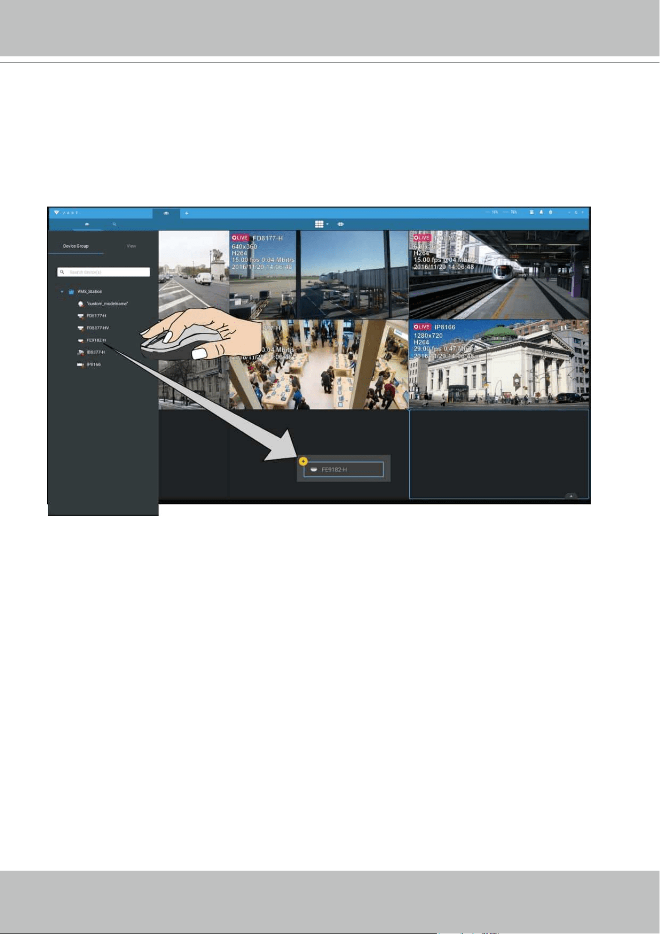
VIVOTEK - A Leading Provider of Multimedia Communication Solutions
114 - User's Manual
To design and customize a layout, please refer to the Customizable Layout page.
You can then fill in the view cells by dragging and dropping cameras into the view cells. While
dragging, a name tag displays. All cameras should be listed under the VMS_Station Device
Group.
You can swap two view cells by dragging one on top of another.
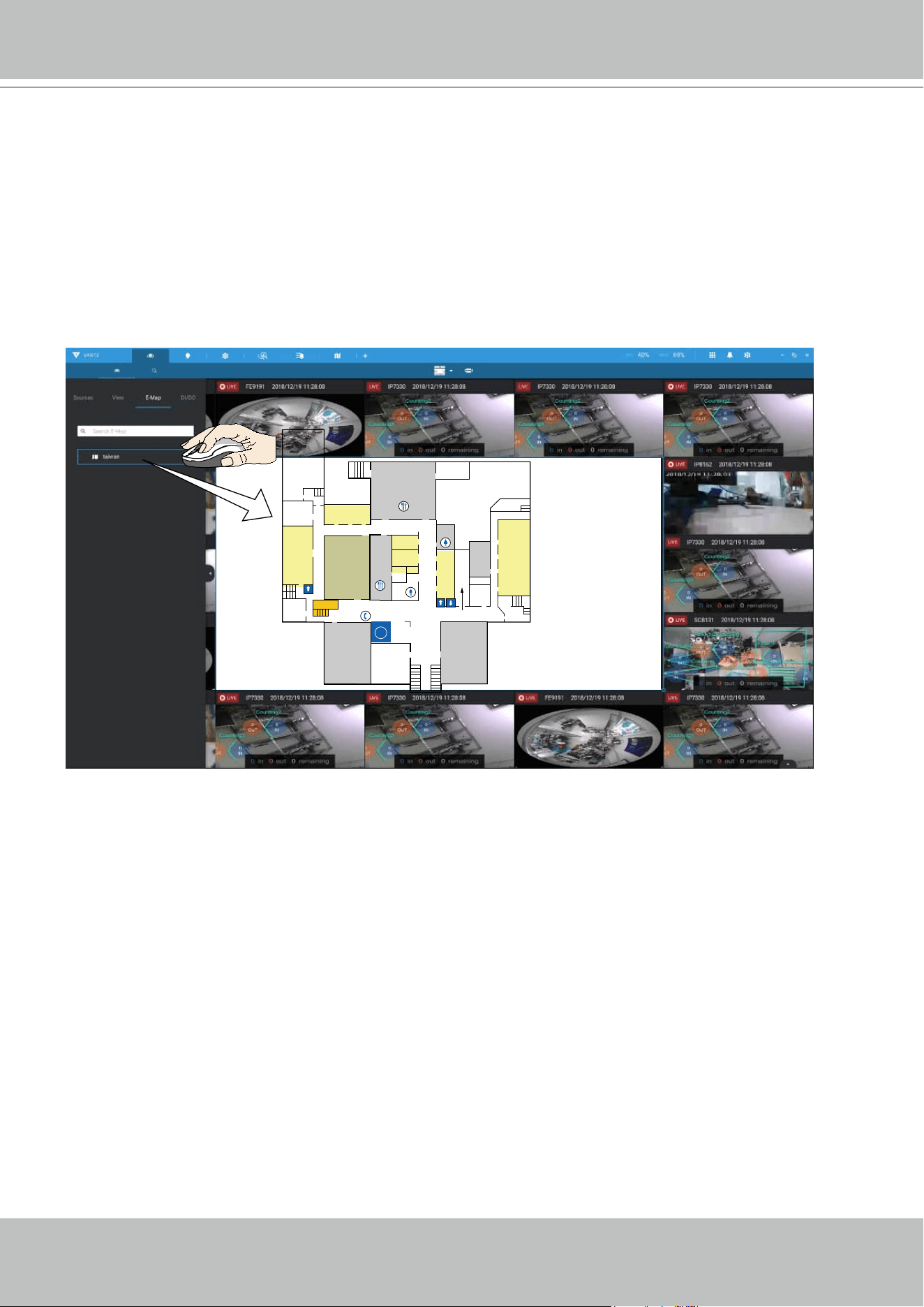
VIVOTEK - A Leading Provider of Multimedia Communication Solutions
User's Manual - 115
You can also fill in an Emap by dragging and dropping a pre-configured Emap into a specific
view cell. Click on the E-Map tab to select a pre-configured E-Map. Note that an E-Map should be
placed into a larger view cell.
Depending on the resolution of your monitor, a view cell can be too small for an E-Map.
For example, for an HD monitor (1920x1080), a single view cell from a 3x3 layout will have a
resolution of 640x360. View cells larger than 330 (width) x 300 (height) pixels can contain an
E-Map.
i
EXIT
EXIT
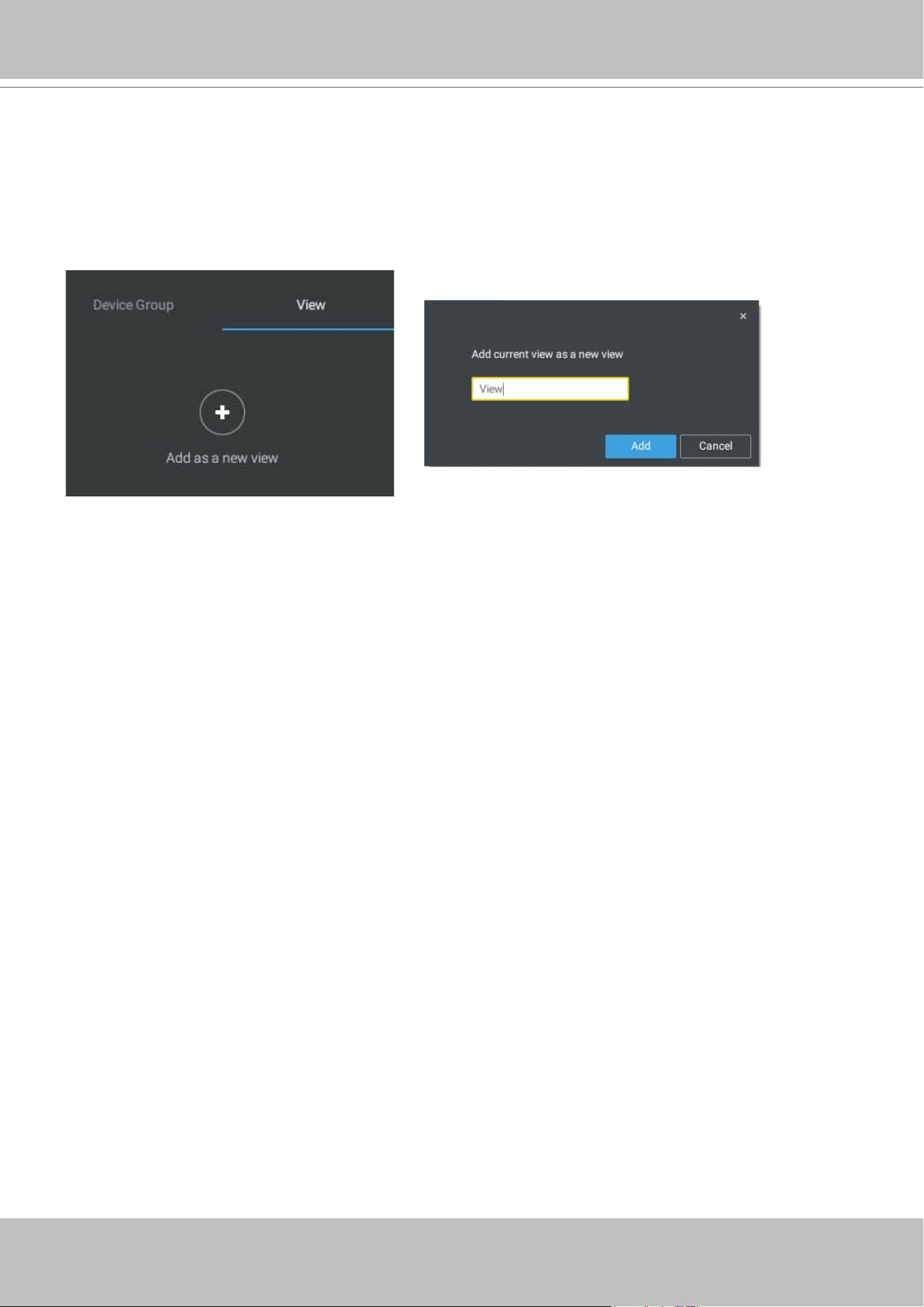
VIVOTEK - A Leading Provider of Multimedia Communication Solutions
116 - User's Manual
2-2-5. Saving a View
When done with arranging view cells, click the View tag.
Save your current layout and view cell arrangement as a new view.
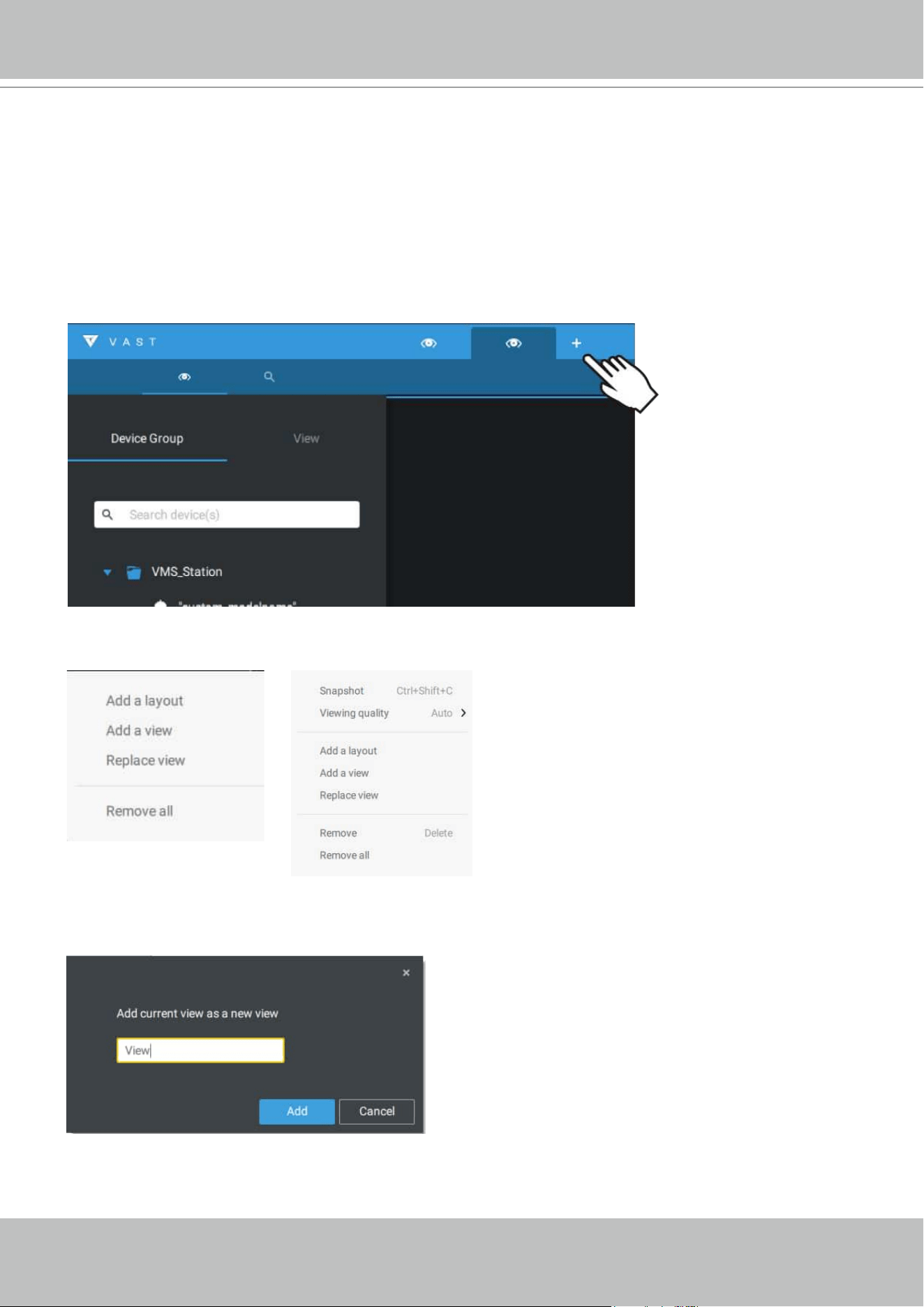
VIVOTEK - A Leading Provider of Multimedia Communication Solutions
User's Manual - 117
2-2-6. Add More Live Views
With many cameras in your deployments, you can click the New Tab "+" button to add more Live
views.
An empty live view will display, and you should repeat the above process to select a layout, and
fill in the view cells. When done, save the view.
Right-click on the screen to display the right-click menu. Select Add a view.
Enter a name for the new view and click Add to proceed. The new view will be listed in the View
panel.
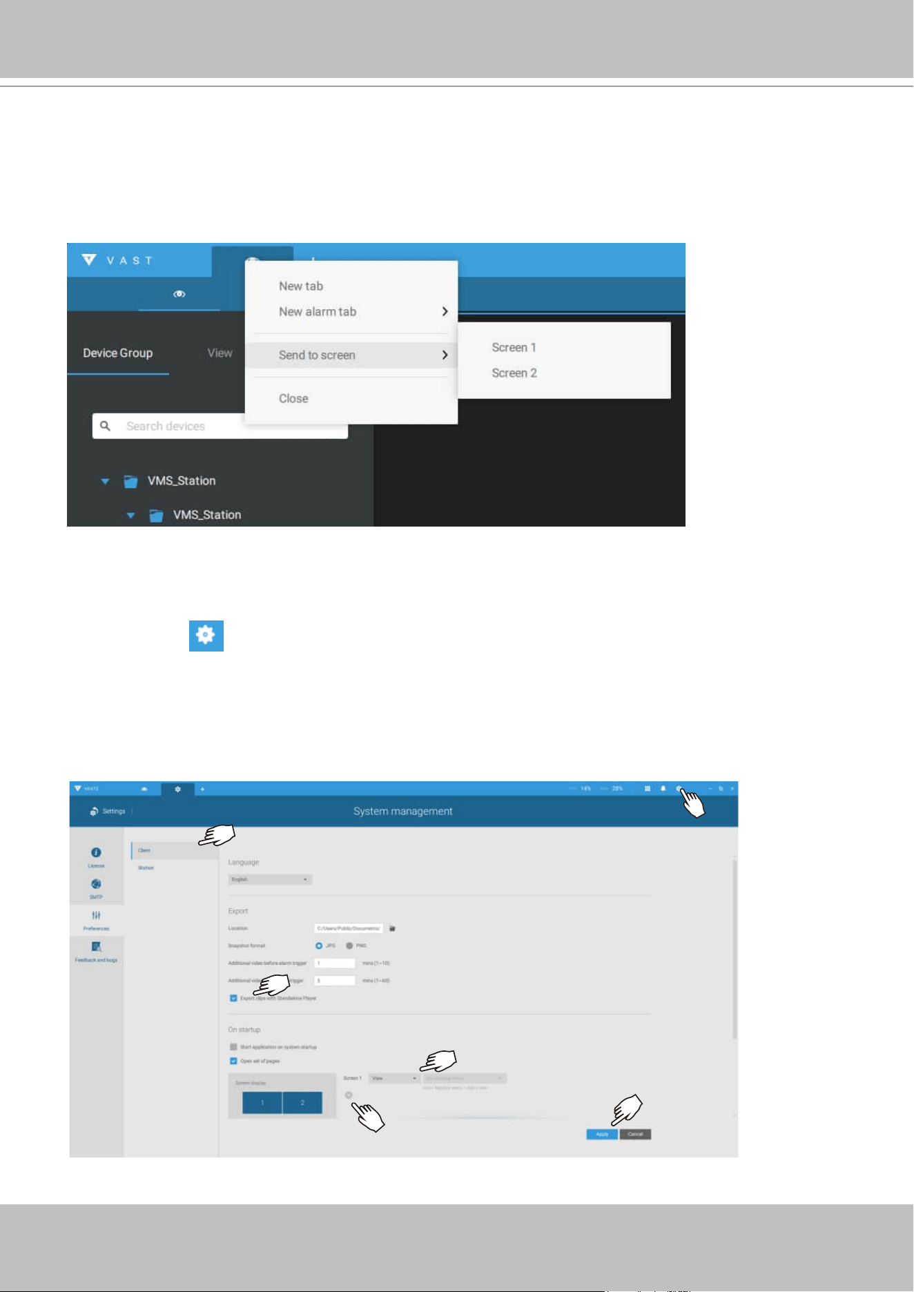
VIVOTEK - A Leading Provider of Multimedia Communication Solutions
118 - User's Manual
If you have multiple monitors attached to your server station, you can drag a live tab to a
different screen. In this way, you can display live views simultaneously on multiple screens.
Live views can be placed on up to 8 monitors. Please note that this is determined by the
capability of your graphics card chipset.
2-2-7. Save Your Preferences
Go to Settings > Preferences to save your current layout and display configurations.
Select the options in the startup choices menu to decide what to display whenever your VAST2
client starts. You can display Live view, Tour, Dashboard, E-Map, or Alarm tab simultaneously on
multiple screens.
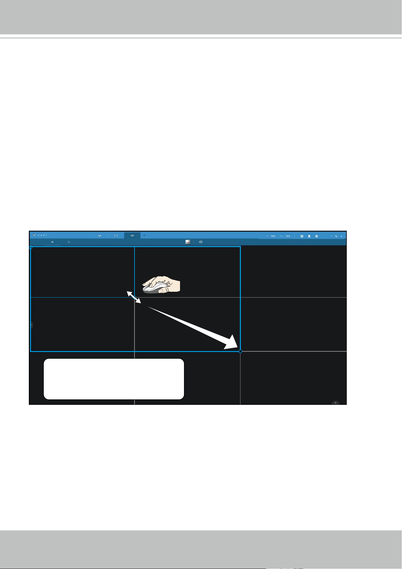
VIVOTEK - A Leading Provider of Multimedia Communication Solutions
User's Manual - 119
2-2-8. Customizable Layout
The standard layouts can be manually configured to form layouts of your choice. Depending on
the complexity of your design, you should start with a multi-cell layout.
Click and drag the corner mark on a view cell. Drag across the screen and release the mouse
button to enlarge the view cell. Choose a standard layout of many view cells, e.g., 7x7 or 8x8,
if you want to design a complex customized layout. You can create a special layout, e.g., an
especially wide view cell for a multi-sensor camera, such as the panoramic MS-8392.
To abandon a customized layout, simply select a new layout from the layout window. You can
also use the Ctrl + Z keys to undo your changes on the layout.
Use “Ctrl + Z” to undo
layout change
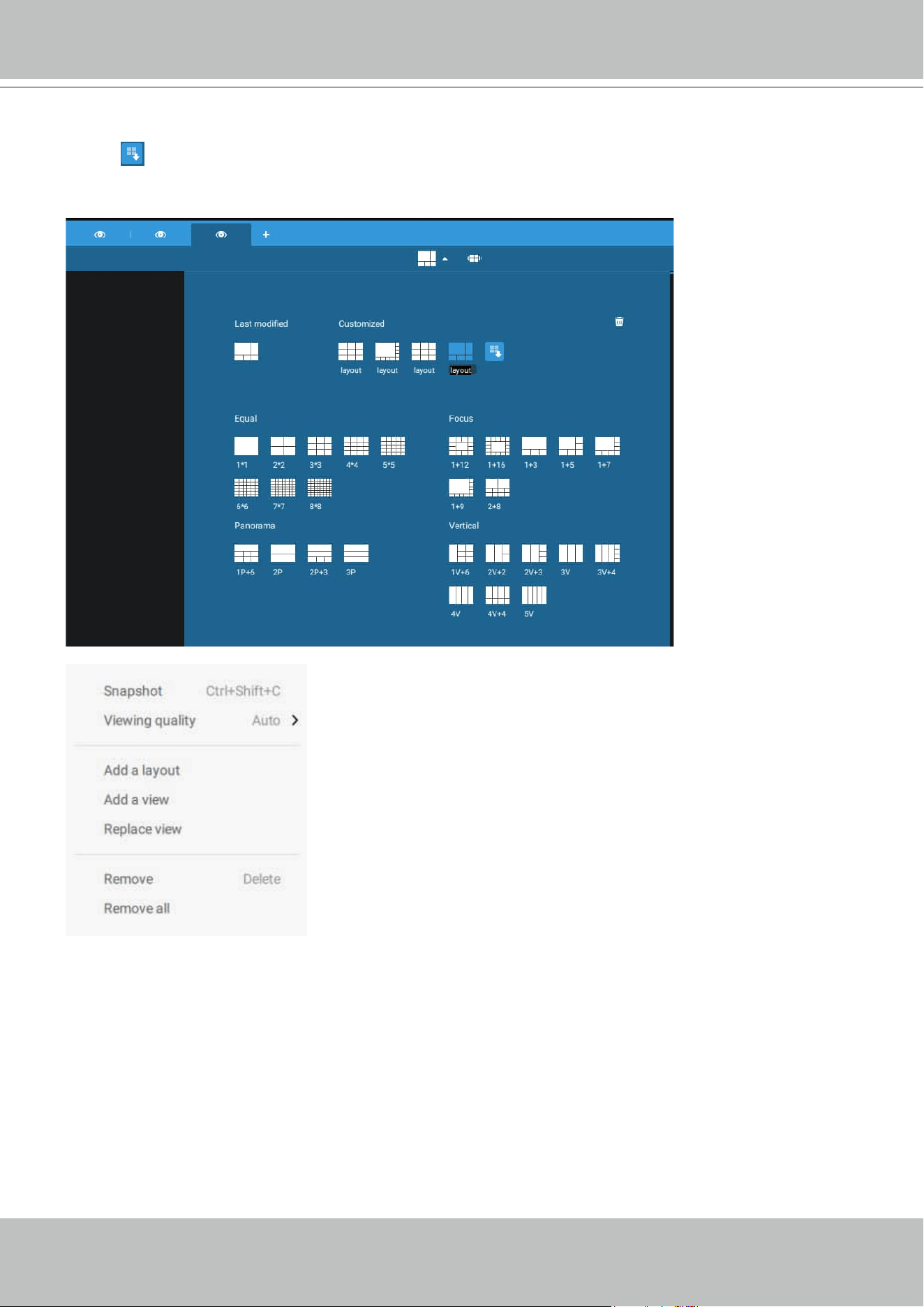
VIVOTEK - A Leading Provider of Multimedia Communication Solutions
120 - User's Manual
To preserve your customized layout, click to open the layout window. Click on the Add current
layout
button. You may then change the name of your layout by a double-click on its name.
To remove a configured layout, drag it to the garbage can icon on the upper right.
You can also right-click on the screen to display the Add layout option.
You can then click Device Group, and start filling your customized layout with camera views.
When done, click Add a view.
Also remember to save the current layout as a view, and save your configuration in Settings >
Preferences.
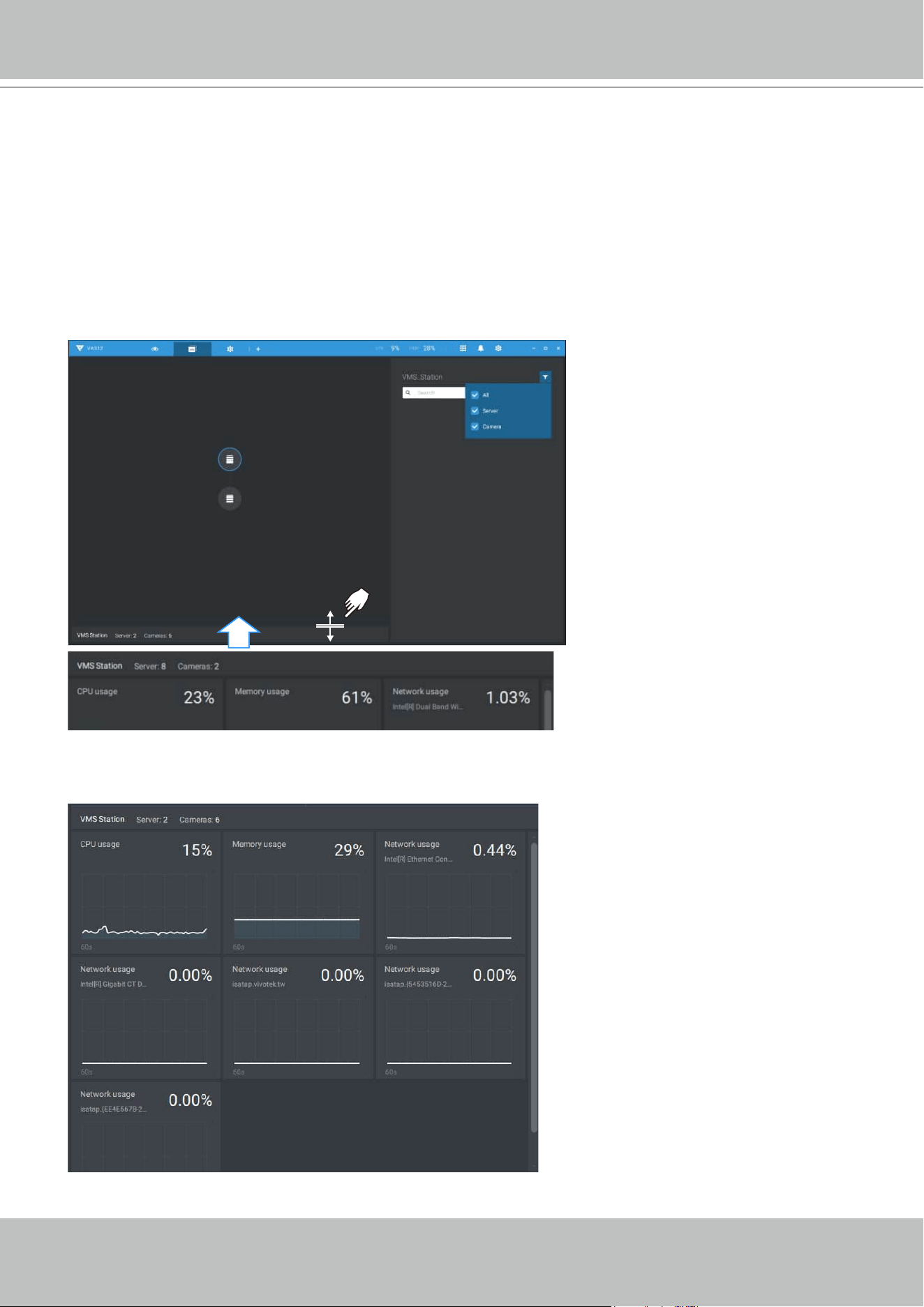
VIVOTEK - A Leading Provider of Multimedia Communication Solutions
User's Manual - 121
2-2-9. Dashboard
Select to open the Dashboard utility from the tool bar. The Dashboard displays the system
resources of a CMS server along with those of its sub-stations. This provides a glimpse of the
load on machines when performing the recording and monitoring tasks.
Mouse over the edge of the bottom row to reveal the expansion mark. Pull the status row up to
display the system resource statuses.
If you have multiple LAN cards or virtual HBAs, the status row can be pulled to reveal all of their
statuses.
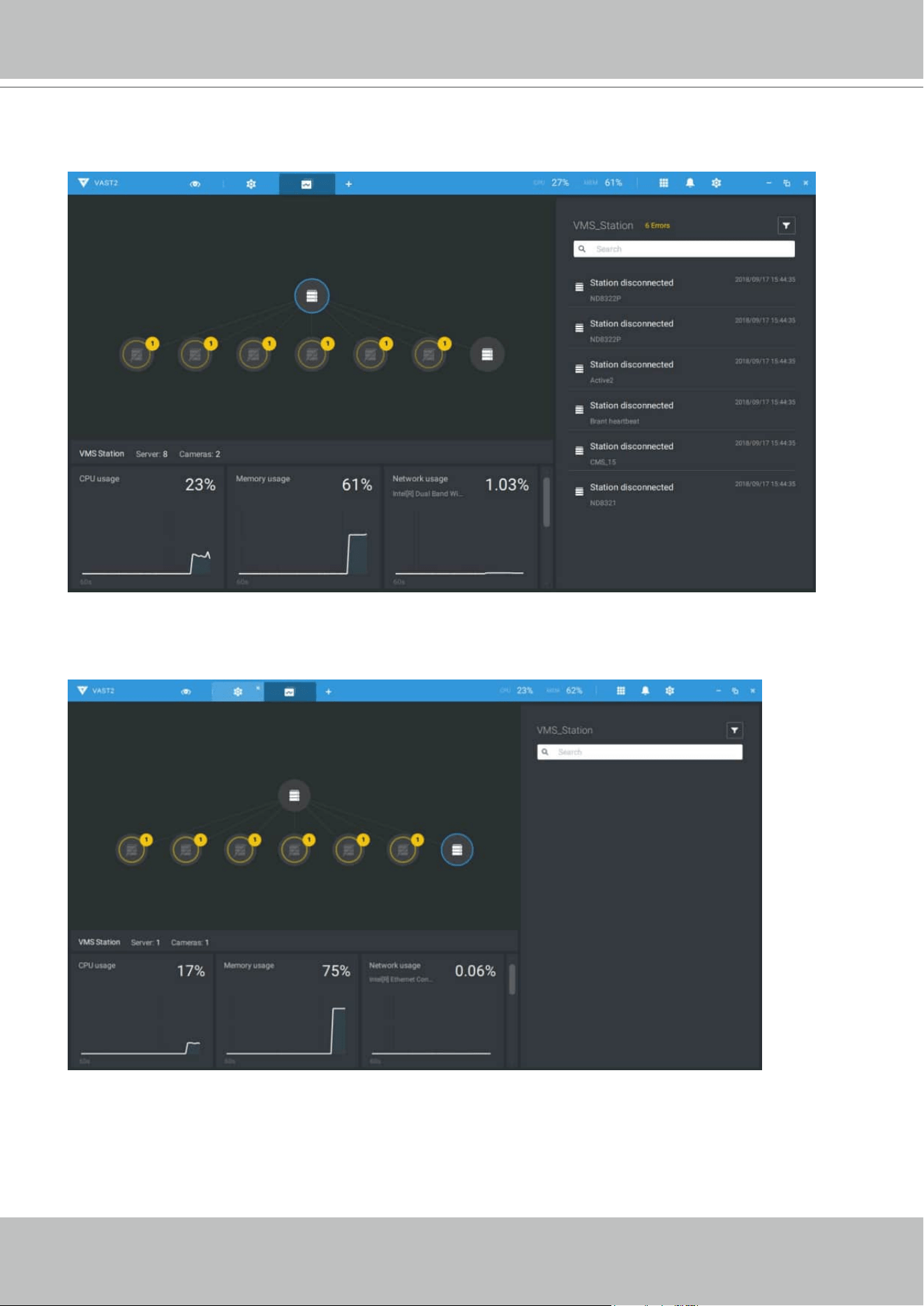
VIVOTEK - A Leading Provider of Multimedia Communication Solutions
122 - User's Manual
If you have multiple sub-stations, single-click to select and reveal their individual status,
including CPU usage, memory usage, and network usage.
Note that VAST servers of the earlier revisions and NVRs running older firmware do not deliver
their statuses to your Dashboard.
VIVOTEK - A Leading Provider of Multimedia Communication Solutions
User's Manual - 123
2-2-10. E-Map
To create your E-Map, click Settings . Click Import & Setup. Click E-Map.
Click Import file or Import folder . An entire folder can be imported.
When done, double-click on the snaphot of E-Map image to configure the E-Map.
Your cameras will be listed on the left. Drag and drop the cameras to the corresponding
locations on the map.
VIVOTEK - A Leading Provider of Multimedia Communication Solutions
124 - User's Manual
When the camera is in place, drag the FOV indicators on the edge to change the shooting angle
and the coverage range.
Drag the FOV to change the shooting direction to match the actual installation.
Click on the camera icon. You can also change the color of camera icon and the FOV type.
Fisheye cameras, when ceiling mounted, have a round shape coverage.
VIVOTEK - A Leading Provider of Multimedia Communication Solutions
User's Manual - 125
If you have a larger regional map that covers a geographical area, say, a street block, you can
drag one or many E-Maps into it. For example, you can place another E-Map that is used to
indicate the camera deployment inside a building that is located on the street.
To see live streams from cameras, click on the camera icons in the E-Map.
When configuring an E-Map, you can use the tilt bar on the right to tilt the E-Map image. Doing
so creates a sense of distance and depth of view.
VIVOTEK - A Leading Provider of Multimedia Communication Solutions
126 - User's Manual
Placing DI/DO Devices
I/O devices can also be planted into an Emap, such as alarm or various kinds of detectors. The
I/O boxes (such as Advantech's Adam series) or the DI/DO connections on an NVR also apply.
1. Select a floor map from the pull-down menu.
2. Unfold the sub-trees beneath the network camera, (taking camera DI/DO devices as an
example).
3. Select a DI/DO device. Click and drag to a preferred location on map.
2
1
3
4. When a DI/DO device is selected, you can select the display colors of its icons. Configure
different colors for the device status when it is normal or triggered.
5. When done with placing all DI/DO devices, click the Done button on the lower right of the
configuration screen.
VIVOTEK - A Leading Provider of Multimedia Communication Solutions
User's Manual - 127
Conguring Google Map and GPS
Since Google Map changed its access policy, using the Google Maps feature requires user
entering a billing API key. Using Maps, Routes, and Places APIs requires an API key.
For applying a Google API key,
https://cloud.google.com/maps-platform/maps/
Visit Settings > Emap > All Maps.
Enter the Google API key you previously registered (if using Google Map).
VIVOTEK - A Leading Provider of Multimedia Communication Solutions
128 - User's Manual
NOTE: In this revision, Google Map only supports installation on a GPS-enabled vehicles. Placing
cameras on a static location on Google Map is currently not supported.
Before configuration on a Google Map, you should prepare an E-map drawing for special
installations, such as that on a vehicle. The vehicle, e.g., a train, should come with a GPS-GSM/
GPRS module to collect the position information and passes this information to a web-server.
As new data is constantly inserted to the database, the VAST server will update the location
information containing coordinates, speed, distance, time, etc.; and when video recording is
required, the location information and time tags will be available.
This applies to a mobile NVR that comes with GPS.
Open the E-Map Import & Setup window.
VIVOTEK - A Leading Provider of Multimedia Communication Solutions
User's Manual - 129
Click to enter the GIS (Geographic Information System) Map and then Google Map window.
Click on the GPS tab. Select a VMS station or mobile NVR to apply the configuration, and then
select the GPS Add button .
Click on either the Google map or the OpenStreetMap.
VIVOTEK - A Leading Provider of Multimedia Communication Solutions
130 - User's Manual
Enter a name for the GPS/GNSS server on the vehicle, its IP address, and server port number.
You can select an E-map that will display when you click on the GPS location icon. Select the
checkbox and an E-Map that corresponds to the deployment on the vehicle. When done, click
the Apply button.
You can skip this setting for the mobile NVR
that comes with a built-in GPS module.
VIVOTEK - A Leading Provider of Multimedia Communication Solutions
User's Manual - 131
You can click on the location icon to bring up the E-Map. The coordinates, speed, and time
information also display on the map.
You can click on any cameras on the E-map to search through past recordings. One click
displays the live view. A live stream window will display.
To search and review recordings when an event occurs,
1. Click on the Playback button.
2. Click the Pane button to display the Playback control panel.
3. To search for the video of past events, pull the Playhead to a point in time on the timeline.
4. The GPS coordinates and time will change to those corresponding to the time you selected.
You can then acquire the corresponding location information while tracing the occurrence of
an event.
29.91 fps 0.97 Mbit/s
2017/4/11 17:46:10
PLAYBACK
FE9181-H
1280x1280
H264
2
1
3
4
VIVOTEK - A Leading Provider of Multimedia Communication Solutions
132 - User's Manual
Click on the Setting button on the map to bring up the Map update frequency option. Your
GPS target may travel to the outside of the map through time without the map being updated.
The map will update by the interval you configure here.
VIVOTEK - A Leading Provider of Multimedia Communication Solutions
User's Manual - 133
2-2-11. Event Search
The Event Search window is accessed from the top tool bar.
Below is the comparison between the Alarm list and the Event search windows:
Alarm List Event Search
Reports alarms triggered by user-
congurable events, such as DI/DOs,
Motion Detection, tampering, VCA analytics,
cybersecurity, and so on.
The events on the Event Search window require
no user congurations. The Event Search window
displays system events and provides a glimpse of
all general events.
The event types include: General events, Smart
VCA events, and Trend Micro IoT Security events.
The sample screen for VCA-related events is shown below:
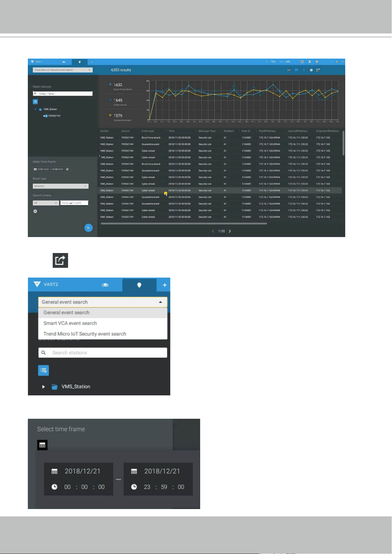
VIVOTEK - A Leading Provider of Multimedia Communication Solutions
134 - User's Manual
From the Search Event window, you can view and search events by its event types, and use the
Export button to save a record of these events (in the CSV format).
The sample screen for network security-related events is shown below:
Use the calendar tool to specify the span of time as the search range.
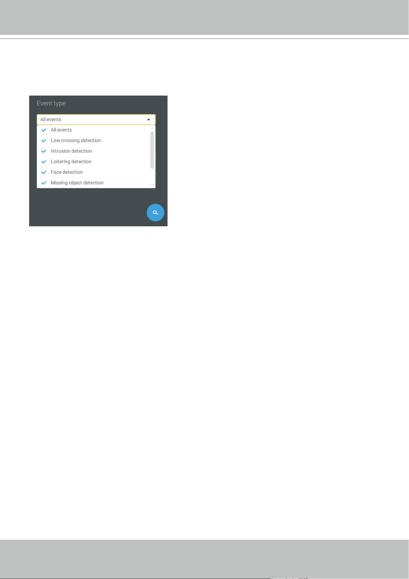
VIVOTEK - A Leading Provider of Multimedia Communication Solutions
User's Manual - 135
Use the Event type menu to narrow down the types of events. Select or deselect the event types
for search. You may also enter one or several keywords as the search criteria in the following
menus.
Click the search button to generate search results.
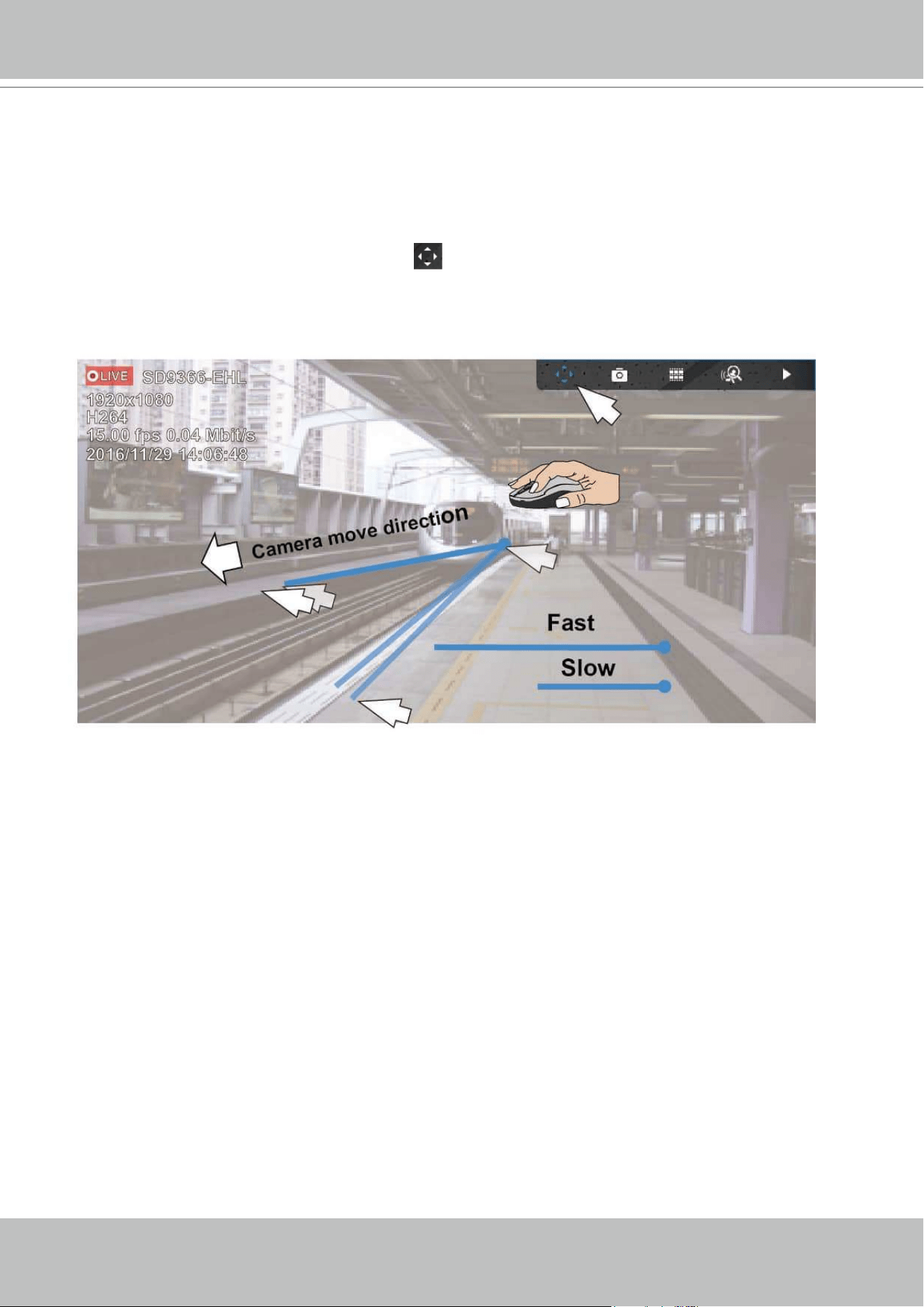
VIVOTEK - A Leading Provider of Multimedia Communication Solutions
136 - User's Manual
2-2-12. PTZ Control
PTZ on this page refers to the mechanical PTZ. The discussion on this page applies to cameras
that come with PTZ mechanisms that are capable of directional and zoom control.
To begin the PTZ control, click on the PTZ
button.
Click and drag your left mouse button across the screen, towards the direction you wish to
move. A light blue trace will appear. The longer the trace, the faster the move.
Note that while the camera is moving, you can change the move direction keeping the mouse
button hold down. Release the button to stop moving.
See Appendix C Joystick support if you use VIVOTEK's joystick.
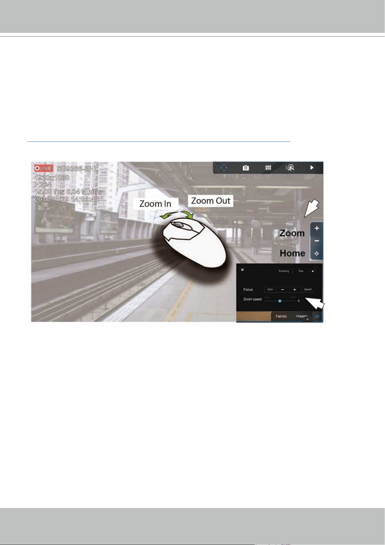
VIVOTEK - A Leading Provider of Multimedia Communication Solutions
User's Manual - 137
You can also use the mouse wheel to zoom in or zoom out. You can also mouse over the right
side of the screen to display the zoom button. A home button is also provided.
The Patrol, Presets, and PTZ control panel is located at the lower right of the screen. You can
click to begin a pre-configured patrol, preset points, or enable a Tracking or Pan action.
You can also adjust the Zoom speed, and/or manually adjust the Focus and the Focus speed.
See Appendix F Smart Tracking for how to enable the Smart Tracking feature.
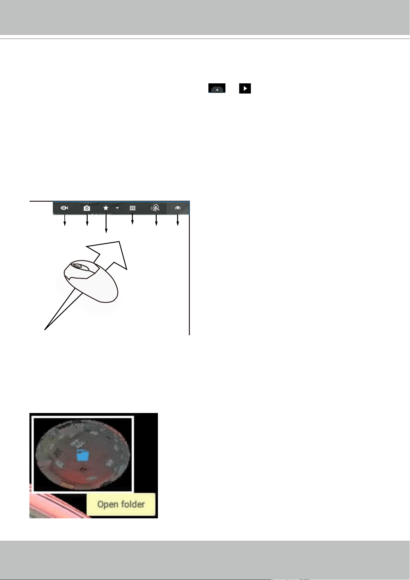
VIVOTEK - A Leading Provider of Multimedia Communication Solutions
138 - User's Manual
2-2-13. Playback
To start the playback function, select a camera's view cell (whether in full view or ordinary cell
size), then click the playback initiative button (
or ). The button can be found on the
upper right of the view cell or at the lower right corner of the view cell in the full view.
Default Time: When started, system normally rolls back to the start of the hour, e.g., your current
time is 10:30:00, and the default playback position on the timeline is 10:00:00.
Playback control can be found in 3 places:
1. Float Panel: When Playback is started, swipe your mouse to the upper-right of the view cell to
display the Playback float panel.
Fisheye
Dewarp
Snapshot
Bookmark
Thumbnail
search
Smart
search
Liveview
Fisheye Dewarp: For a fisheye camera, you can select different dewarped views during a
playback. Click to select an option.
Snapshot: Click to take a snapshot. A small floating window will stay for 2 seconds. You can
click the folder icon to access the snapshot files.
Note that a dewarped, regional view allows producing a snapshot of the regional view.
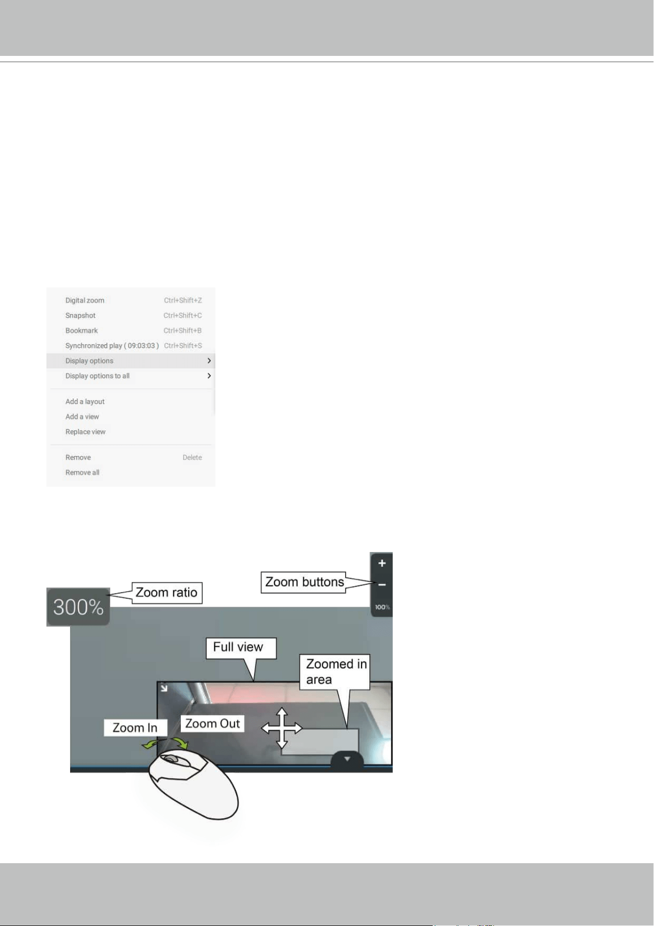
VIVOTEK - A Leading Provider of Multimedia Communication Solutions
User's Manual - 139
Bookmark: If you find anything of your interest when viewing the playback, click this button
to create a bookmark. It helps when you need to return to the point in time after you review
all through the recorded videos. Note that the bookmarked video clips are free from storage
recycles. They will not be erased when storage space runs short and needs to be recycled.
Smart search II: Smart search II is an independent function. See page 168 for details.
Liveview: Click to return to Live view.
2. Right-click Menu: Right-click on the Playback screen to display this menu.
Digital zoom: If you find anything of your interest when viewing the playback, click this button
to create a bookmark. It helps when you need to return to the point in time after you review all
through the recorded videos.
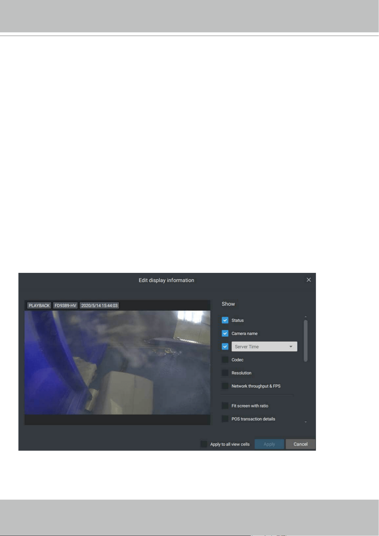
VIVOTEK - A Leading Provider of Multimedia Communication Solutions
140 - User's Manual
Synchronized play: When enabled, all cameras in the same view will be playing the video of the
same point in time.
The following commands are general purpose commands.
Snapshot: Click to take a snapshot. A small floating window will stay for 2 seconds. You can
click the folder icon to access the snapshot files.
Bookmark: If you find anything of your interest when viewing the playback, click this button
to create a bookmark. It helps when you need to return to the point in time after you review all
through the recorded videos.
Display information: By default, all display elements will appear on screen for all playback
windows. You can use the Edit display information to select more display elements.
They include:
Status, Camera name, Server time, Codec, Resolution, Network throughput & FPS, Fit screen
with ratio, POS transaction details (for POS), Data magnet data (Data overlay on screen / Hide
data after idle), Motion detection, Rules (VCA), Rule name, Motion cells, Tracking block, Tracking
dot, Exclusive area, People detection area.
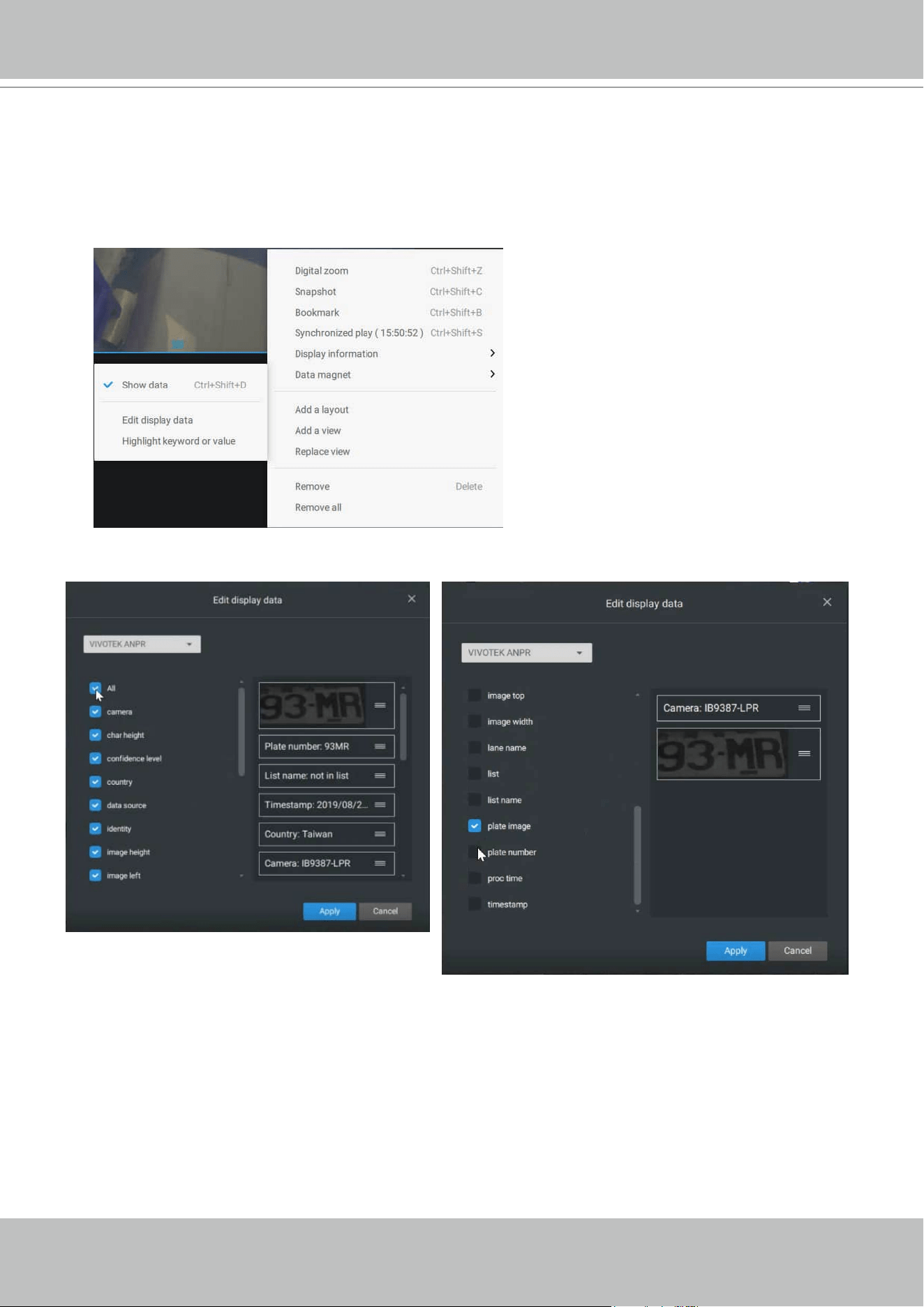
VIVOTEK - A Leading Provider of Multimedia Communication Solutions
User's Manual - 141
Data magnet: For 3rd-party applicatioins, such as VIVOTEK's license plate recognition software,
you can select to display different types of information. You can use the Edit display data to
select or deselect the display elements.
Please note that the display elements can vary for different applications.
Below are the sample screens for applications implemented via the Data magnet.
VIVOTEK - A Leading Provider of Multimedia Communication Solutions
142 - User's Manual
3. Timeline Panel: This panel appears when Playback is initiated.
Starting from left to right, timeline control functions will be described as follolws:
1. Time Search: Click on the current date to open a calendar. If you want to review videos
recorded in another day, select it from the calendar.
Timescale is adjustable (minutes, hours, days, to a max. of 3 days) so you can easily find the
required time period and begin playback from that point.
Histogram
Adjustment
Export
Speed Control
Playback Timeline & Histogram
Playhead
Synchronous
Playback Control Buon
Time Search
Events
Highlights
06:44:23
Mouse-over
indicator
Return to Live
Drag to move along
meline
Blue: days with recordings.
Orange bottom line: Today.
White: days with no recordings.
VIVOTEK - A Leading Provider of Multimedia Communication Solutions
User's Manual - 143
Click on the current time. You can use the arrow buttons to change the time you wish to
playback, or simply enter a preferred number. You can also pull the playhead along the timeline.
Timeline magnification levels: The default time span is 6 hours. You can change the
magnification level for easier browsing. Click the Zoom in and Zoom out buttons to change the
timeline time span. The configurable time spans are shown below:
3 days, 1 day, 12hr, 6hr, 3hr, 1hr, 12mins, 1 min
2. Playback control:
From left to right,
2-1. Synchronous play: This lets all cameras in the same view to playback video of the same
point in time. If you perform synchronous playback on a multi-cell view, your computer can
be stressed. It is recommended you create a new view with a 2x2 layout, select and insert
camera views into it, and begin the Synchronous playback.
2-2. Frame by frame buttons: Click to move forward or backward to flick through the video
frames. This may only display the I-frames.
2-3. Forward playback and reverse playback: Click to view the video in the forward or reverse
playback manner.
VIVOTEK - A Leading Provider of Multimedia Communication Solutions
144 - User's Manual
2-4. Speed selector: The selectable speed ranges from 1/64x to 64x.
3. Export Clips: Click the Export Clips button
. A range selector will appear. Pull the ends to
include the time span you want to export. Note that each end of the selector, when clicked and
selected, will turn white, and its location on the timescale is shown on the time line. When done,
click the Start to export
button.
Depending on the length of video clips to export, it may take minutes to export. When the export
is completed, a shortcut to the exported clips is shown. You may then open the folder where the
clips are located.
VIVOTEK - A Leading Provider of Multimedia Communication Solutions
User's Manual - 145
2-2-14. Alarm
The Alarms can be configured to perform a series of actions when different events occur.
Alarms can be used to automatically react to possible threats. For example, the VAST server can
start a recording or send an Email notification when Motion detection is triggered.
A wide variety of triggering conditions can be applied, including:
1. Camera triggers
General
Motion detection IR (Infrared)
Camera DI PIR (Passive Infrared)
Camera DO Tampering detection
Temperature Stop recording
Recording error Audio detection
Video loss (Video server only) Shock detection
SD card life expectancy detection
Video Content Analysis
Line crossing (VCA) Intrusion detection
Loitering detection Face detection
Missing object detection Unattended object detection
Crowd detection Smart tracking
Zone detection
Trend Micro IoT Security
Brute force attack Cyber attack
Quarantine event
Note that some of the triggers require that you open a web console to individual cameras. For example,
VCA and Motion detection windows have to be manually configured on each camera before they can be
configured in the Alarm settings.
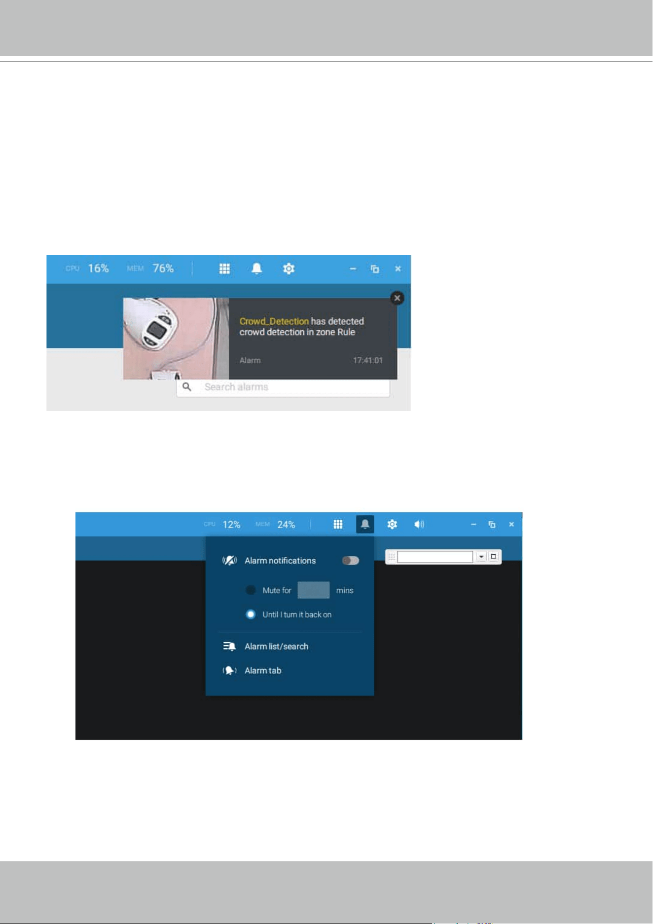
VIVOTEK - A Leading Provider of Multimedia Communication Solutions
146 - User's Manual
If a triggering condition is associated with event recording, an event prompt will pop up on the
screen when a triggering condition is met. For example, the number of people exceeds a preset
threshold in a Crowd Detection configuration. The sample prompt is shown below. The related
footage can be played back by clicking on the event entry.
If you select a trigger and you cannot find a corresponding device, you need to open a web
console to that device. Make sure the corresponding VADP is running. Open the VAST2 device
tree, right-click on the device to perform a manual refresh "Update device" to acquire the lastest
conguration update.
On the Alarm tab, you can select to mute all alarms for a configurable period of time. Enter the
number of minutes or select to mute until you manually turn it back on.
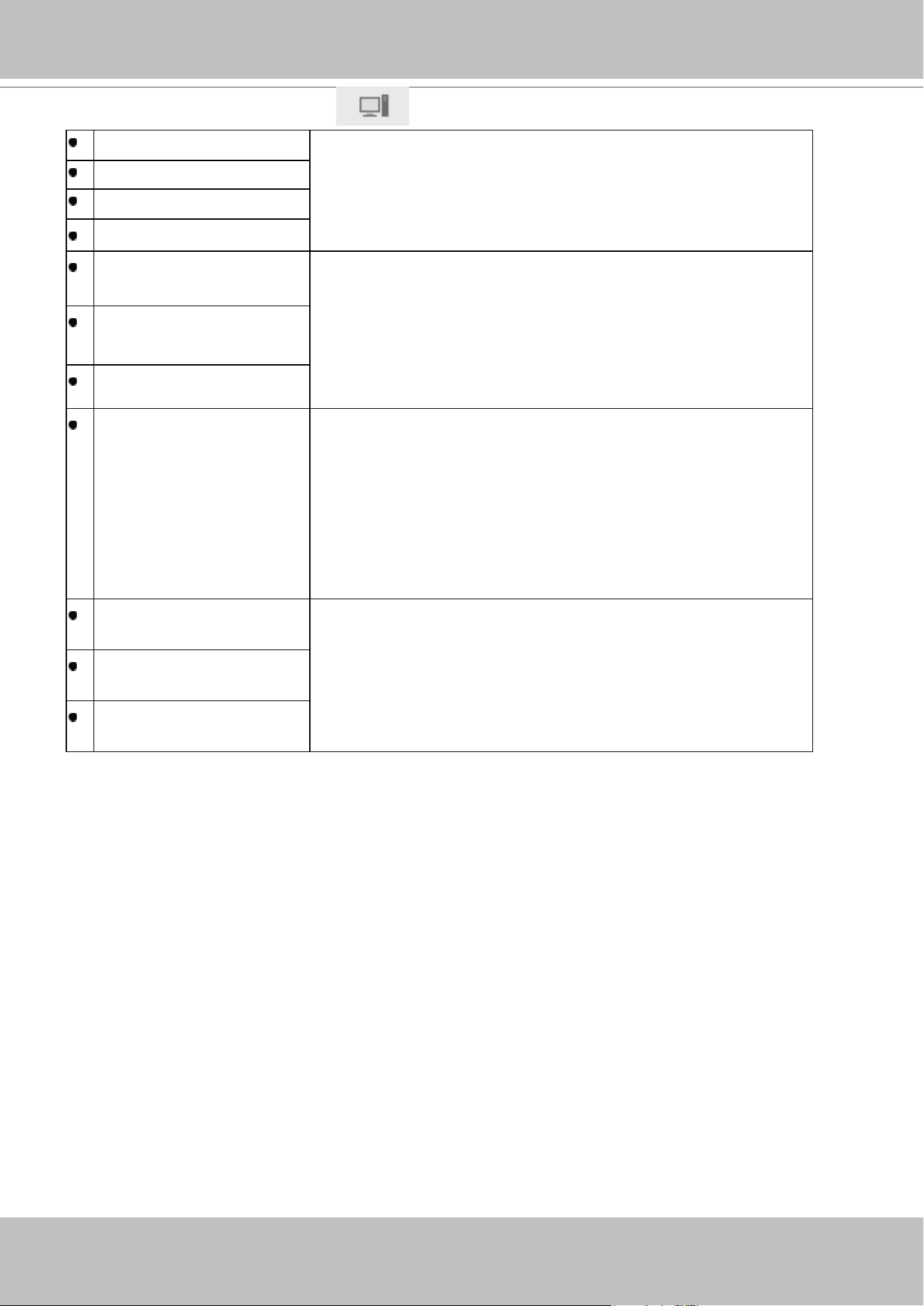
VIVOTEK - A Leading Provider of Multimedia Communication Solutions
User's Manual - 147
2. VAST server and NVR triggers
Network disconnected These can be used to send maintenance notifications.
Storage failure
Storage full
Fan status
GPS disconnected
(Mobile NVR)
The GPS and G-sensor related options apply to the Mobile
NVR that comes with the GPS and G-sensor. GPS can be
used to track the speed and location of a vehicle, while the
G-sensor can be used to detect abnormal impact.
Abnormal G-sensor
motion (Mobile NVR)
Speeding (Mobile NVR)
Number of remaining
people
For VCA-capable cameras, the alarm can be triggered when
the number of people staying within a specific area has
exceeded the preset threshold. For example, when too many
people are waiting in line in front of a cashier.
This function requires appropriate configuration on the
counting camera(s).
Brute force attack (Trend
Micro IoT)
These can be configured as alarm triggers to notify the
administrator that malicious attacks have occurred. Note
that these triggers are available with NVRs that come with
the protection of Trend Micro IoT packages.
Cyber attack (Trend Micro
IoT)
Quarantine event (Trend
Micro IoT)
* Note that you should use the pull-down menu to select a triggering condition, and then click to
select a mobile NVR.
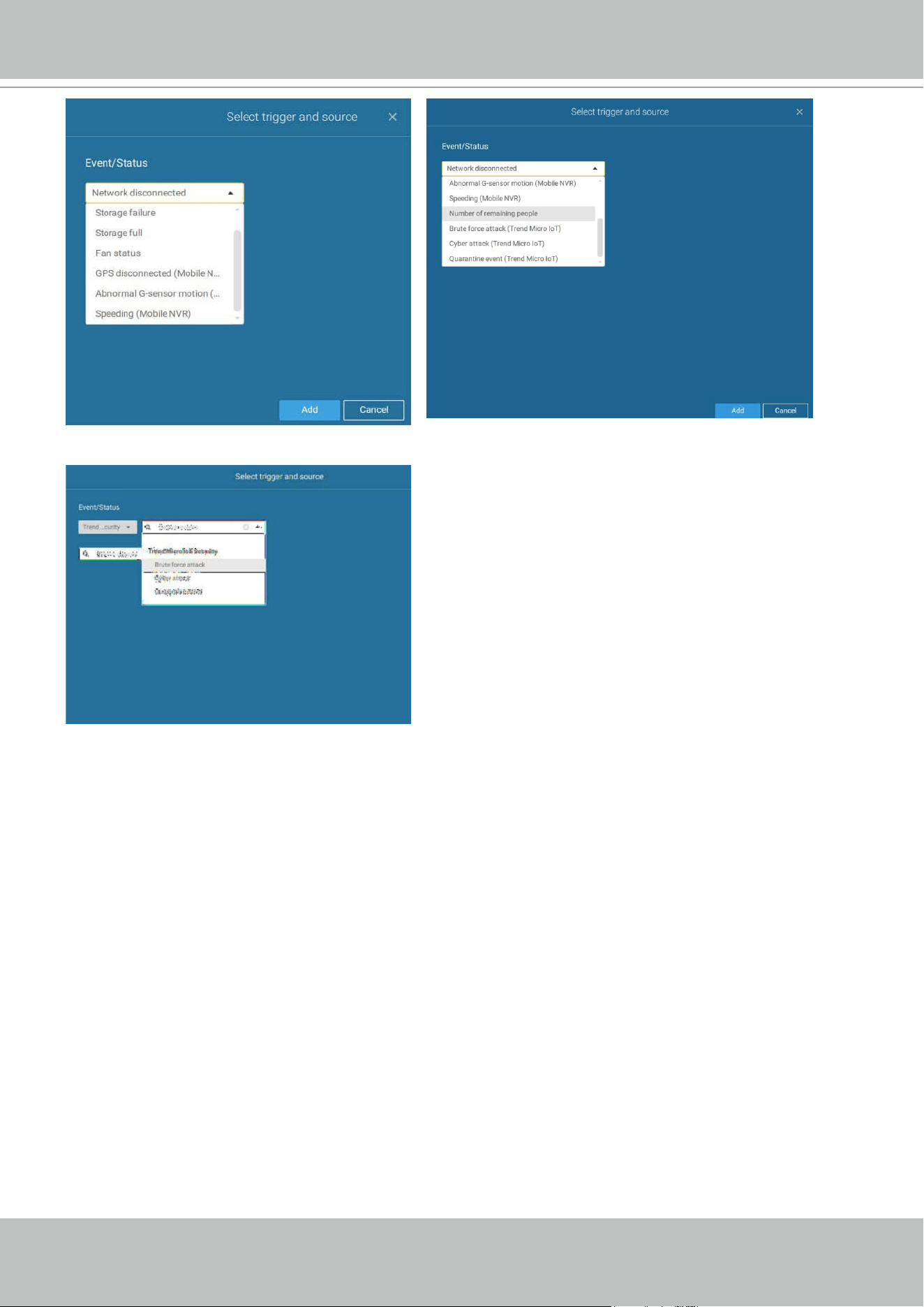
VIVOTEK - A Leading Provider of Multimedia Communication Solutions
148 - User's Manual
Note that the alarms will be received into the Alarm list window. The previous Alarm Search
window is replaced by the Alarm list function.
The Alarm tab window is used to display the live video stream when an alarm is triggered, and
its responding action is configured as "Send live streaming."
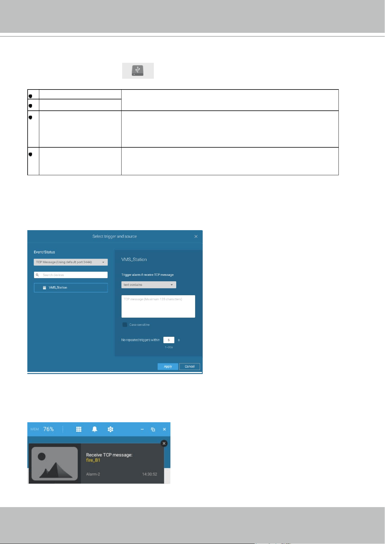
VIVOTEK - A Leading Provider of Multimedia Communication Solutions
User's Manual - 149
For I/O box configuration, please refer to the I/O Box page.
3. I/O box and TCP triggers
DI/DO Device DI This applies when an external I/O box is applied, e.g.,
Advantech's ADAM I/O box.
DI/DO Device DO
TCP Message
TCP message comes from the peer VAST servers or external
sources (such as an access control system) via the analysis
of received TCP message over the 3444 port. This is a paid
feature.
Data Magnet
Triggering conditions can be acquiring data from 3rd-party
software, such as the character height, image width, list, list
name, country, from an LPR software, etc.
To congure a TCP message trigger,
Select TCP message as a trigger type, and enter a description, such as a short term, for VAST
to listen and analyze data packages.
You can use Telnet to send a small amount of data matching the term you entered in the TCP
message conguration window. A TCP message event will be triggered, and you should see the
event prompt as follows.
Below are the messaging parameters:
1.
text contains: Messages will be
received if some of the textual
messages match the keywords.
2.
text matches: Textual messages must
be exactly identical.
3.
Case sensitive: The upper or lower
cases letters used in the messages
must match within the messages.
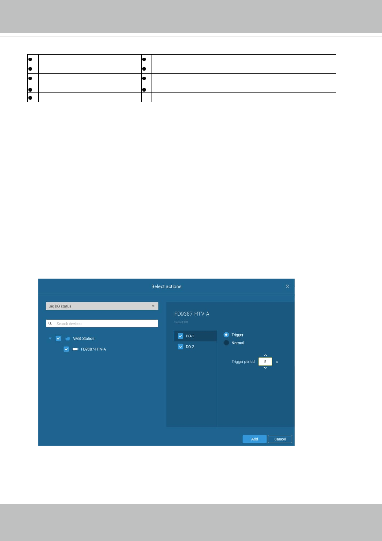
VIVOTEK - A Leading Provider of Multimedia Communication Solutions
150 - User's Manual
The available actions include:
Start to record video Send HTTP requests
Set DO status Send live streaming
Go to camera presets Send email
Go to E-map Sound the alarm
Add bookmark
The
Start to record video will record a video clip of the length of 10 seconds (default) on the
occurrence of an event. The event recording pre / post event time is configurable. Except for
Stop recording, all the other triggering conditions can be associated with this action.
The Set DO status will activate a DO connection. For example, to light an illuminator or sound an
alarm.
You can select a camera, and its DO pins will appear on the right. You can configure the duration
of the DO trigger, e.g., 15 seconds.
If no Trigger period is configured and when there are multiple instances of DO trigger,
administration troubles may occur. Use the arrow marks to configure a trigger period. You may
also manually enter a number.
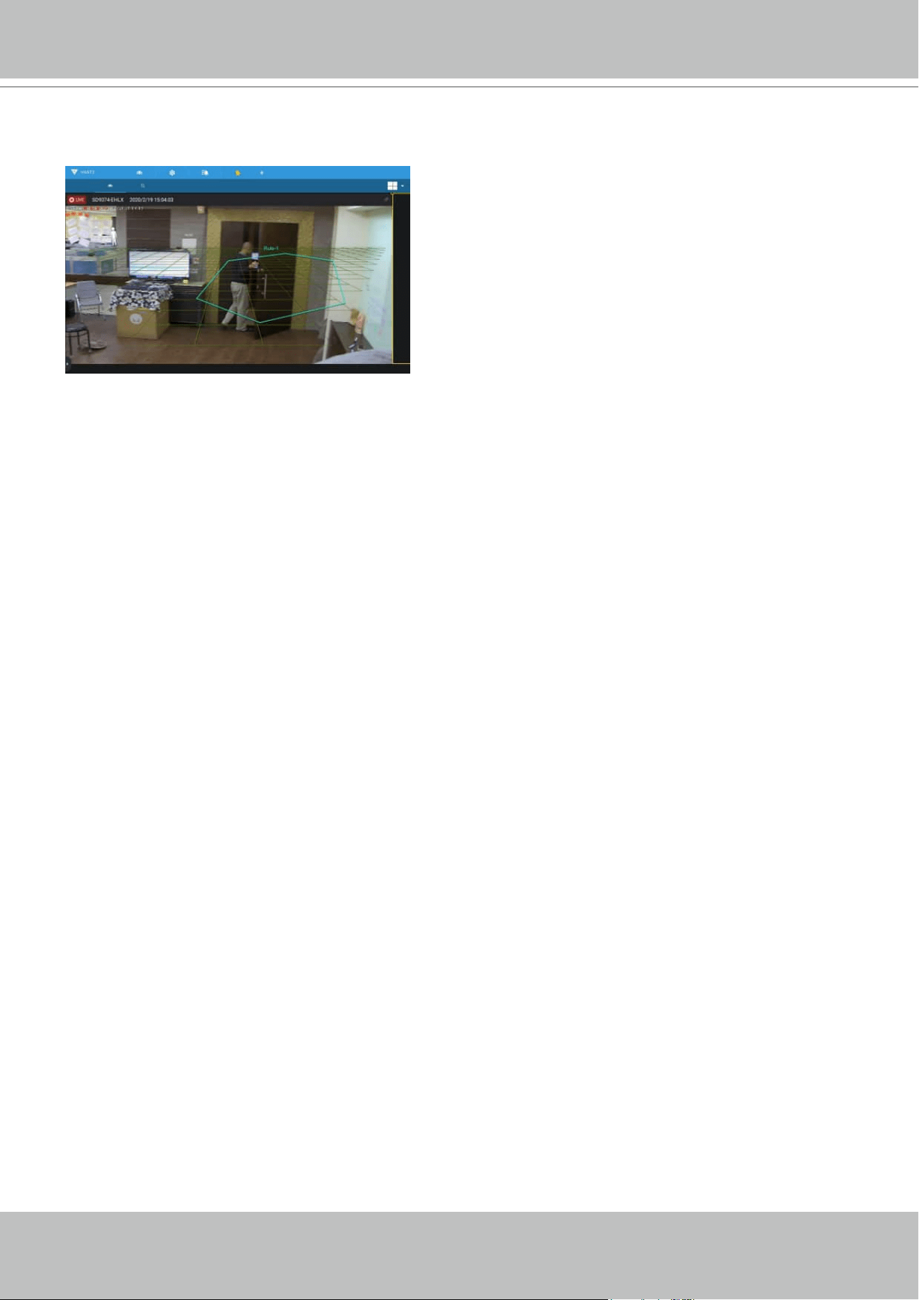
VIVOTEK - A Leading Provider of Multimedia Communication Solutions
User's Manual - 151
The Send live streaming action will bring up a video prompt to the Alarm tab window, showing
the realtime video feed from a specific camera.
The Go to camera presets requires you to configure preset points on a PTZ camera before the
Alarm configuration, such as a speed dome. Once triggered, the PTZ camera lens will move to a
preset position.
The VAST server automatically disables unavailable options. For example, when the DO option is
selected, the cameras that do not support DO connections will be hidden.
The Send email opens a configuration page where you should enter valid email addresses
as sender and recipients. It is required that you configure an SMTP server for mail delivery in
Settings > SMTP. Enter Subject and contents. Select the checkbox for including a snapshot of
the event. When done, click Add to enable the action.
The Go to E-map opens a pre-configured E-map of where the triggering condition occurs. The
user can then click on the camera icon on the E-map for an instant viewing.
The Add bookmark function saves a video clip of a 10-seconds length. Once triggered, you
can open a new view tab > Search > Bookmark search to find the existing bookmarks. The
bookmarked video clips will not be recycled during the storage cleaning cycles.
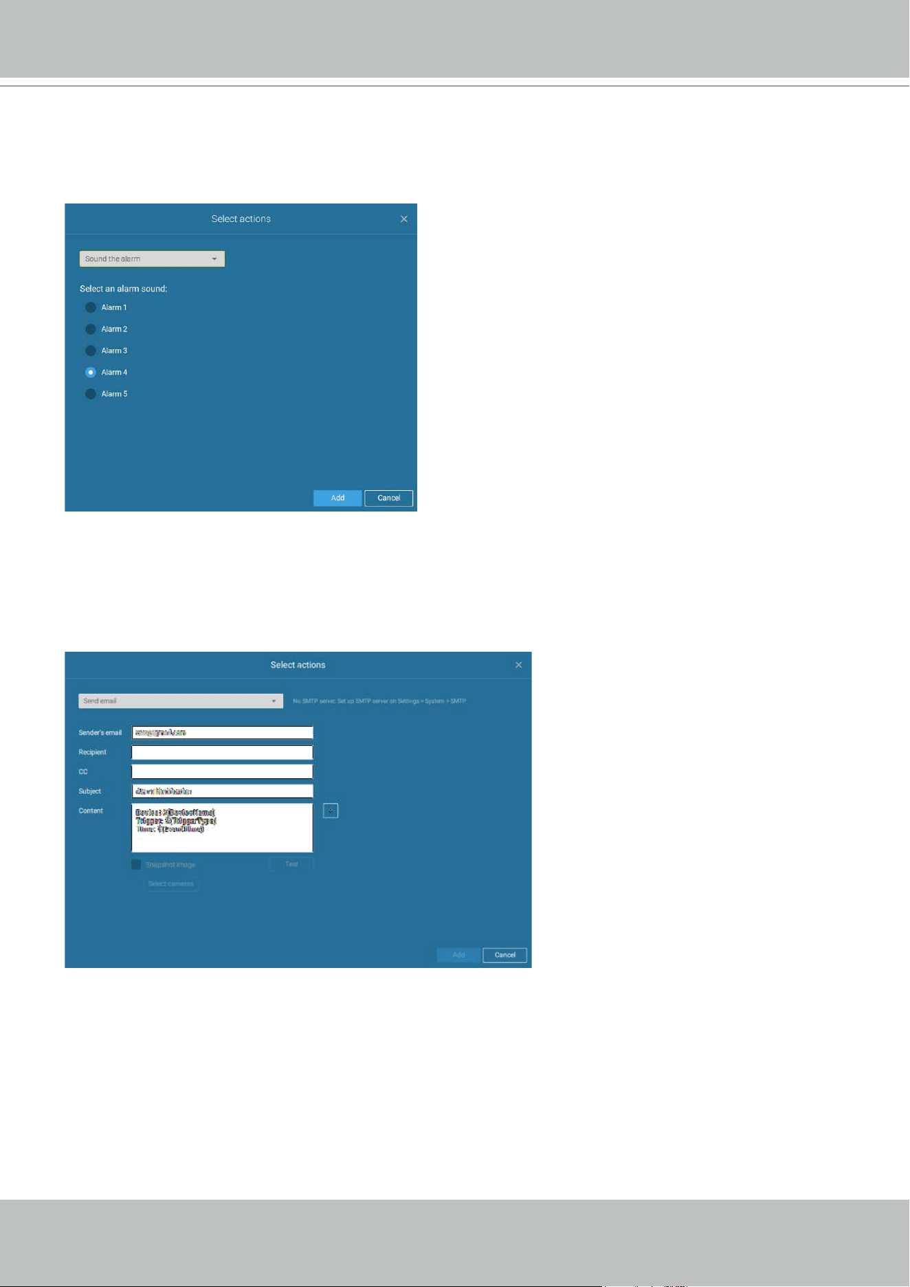
VIVOTEK - A Leading Provider of Multimedia Communication Solutions
152 - User's Manual
The Sound the alarm action provides 5 alarm sounds that will be sounded on the VAST client or
server. Your VAST client or server should have speakers for playing the audible alarm.
A reacheable Mail server and Email accounts must be provided before you can apply the
settings.
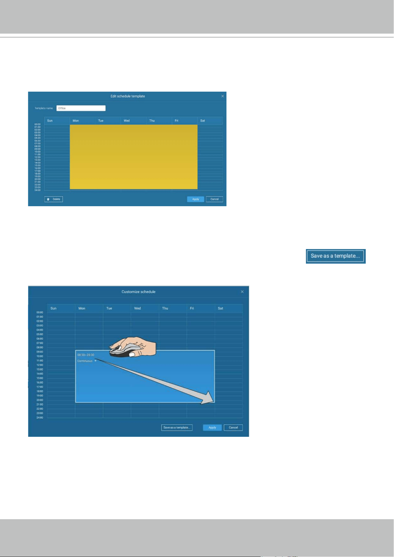
VIVOTEK - A Leading Provider of Multimedia Communication Solutions
User's Manual - 153
On the Schedule page, you can select to activate or de-activate alarm triggers throughout a
specific timeline. For example, in some situations you can disable the alarm triggers during the
office hours, and choose to enable the triggers only during the off-office hours.
Click on any of the options on the Schedule panel for the alarm to take effect: Customize,
Always, or Add a schedule.
You can manually create a effective time template using the New template
button.
VIVOTEK - A Leading Provider of Multimedia Communication Solutions
154 - User's Manual
Click and hold down on the time cells, and drag the mouse to include the time span of your
preferrence. The minimum selectable unit is half an hour. You can select multiple time spans on
the template. Enter a name for the template, and click Add to save your template.
The same configuraion window apply to both the Schedule template and the customize
schedule windows.
Make sure a Schedule mode is selected when you leave this configuration step.
Enter a name and instructions for users to follow, and then click Add to complete the Alarm
setting.
All configured alarms will be listed on the Alarm settings page.
Group Alarm
Multiple triggered alarms can be presented as group alarms. Alarms triggered by the same event
type, and by the same camera can be grouped together. In this way, multiple similar alarms can
be listed under one entry.
On the alarm list, click the
button to display the alarm group.
Click to reveal the video viewing panel.
In the list mode, you can expand the right-hand-side panel. The video of the latest alarm will
display.
VIVOTEK - A Leading Provider of Multimedia Communication Solutions
User's Manual - 155
The same applies to the thumbnail view. To leave the group alarm view, click the Group alarm
button again.
When the alarm-triggered action is configured as sounded alarm, you can mute all alarms in the
group by clicking the alarm sound icon.
VIVOTEK - A Leading Provider of Multimedia Communication Solutions
156 - User's Manual
When the alarm action is set to "Send live streaming," the videos coming from the same camera
will occupy only one view cell.
In the Alarm tab window, use the thumbtack
button to freeze the current screen. If
thumbtacked, the other incoming alarms will not affect the current screen.
On arrival, the latest alarm will display with a blinking red frame. A selected view cell will display
with a yellow frame.
VIVOTEK - A Leading Provider of Multimedia Communication Solutions
User's Manual - 157
The alarm notification can be turned off by clicking on the Alarm tab. Use the slide toggle to do
so. You can also select to let the notification automatically turn on after a configurable span of
time. Enter the number in the mins field. The max. time span is 9,999 minutes.
The notification configuration is kept on the client computer.
When the Alarm notification is turned off, the Alarm tab icon is greyed out .
Note that the default for the alarm notification is "Until I turn it back on." If you turn off the alarm
notification, you need to re-activate it after you turn off the notification the first time.
VIVOTEK - A Leading Provider of Multimedia Communication Solutions
158 - User's Manual
2-2-15. Search Panel
The Search panel is accessed via the Search button. 2 key functions are provided:
Search by POS transaction, and Search by Bookmark.
1. Search by POS transaction:
The VAST station can collect coordinated database
information from a POS machine. This function provides access to the video clips associated
with the sales record on the POS machine. Details of transaction can be listed on screen so
that a manager can see the live view when controversial events occur.
To search the POS-related recordings,
2-1. Select the VAST station which the POS machine is connected to (via the Settings > POS
configuration).
2-2. If you know the approximate time of occurrence (bill void, content adjusted, shortage of
products, and other frauds), use the calendar to select a time span.
2-3. Select a POS machine, if there are many.
2-4. Select a search condition, such as item name, subtotal, or the transaction number.
You can use the >, <, or = signs to specify the amount you are searching for. For example, key
in >100 for amounts larger than $100.
2-5. You can click the add button below to append more search conditions.
2-6. When done, click the search button.
NOTE:
The Alarm search panel is
replaced by the Alarm list function. The
Alarm list is accessed from the top tool
bar.
VIVOTEK - A Leading Provider of Multimedia Communication Solutions
User's Manual - 159
2-7. Click on any of the search results. Details of the transaction will display along with the
recording of the time of occurrence.
VIVOTEK - A Leading Provider of Multimedia Communication Solutions
160 - User's Manual
2. Search by Bookmark:
Bookmarks are manually created when users review recorded videos
in the Playback mode. Each bookmark comes as a 10-second video clip.
In the Bookmark search panel,
Click the Bookmark search
button. The Bookmark Management window will prompt.
All existing bookmarks will be listed with thumbnails.
a. On this window, you can specify a range of time during which the video streams were
recorded and its points in time were bookmarked.
b. You can then click on a bookmark to display the short video clip extracted from within the
recorded video. The default is 10 seconds.
c. To remove an existing bookmark, left-click to select an entry, and then click the Delete
bookmark(s) button. Bookmarks will be indicated as "Invalid" if the videos where the
bookmarks were appended were erased, e.g., when the original recording was erased by
cyclic recording.
d. Currently you can search for bookmarks using the name of the camera.
e. You can also select the display types for the bookmark search in either the thumbnails or list
mode.

VIVOTEK - A Leading Provider of Multimedia Communication Solutions
User's Manual - 161
2-2-16. Smart search
The Smart search function enables a quick glimpse of activities occurred within a user-
configurable detection area from the recorded videos. Smart search is available in both the
Liveview and Playback mode.
Click to select a camera view cell. Click on the
Smart search button
to enter the Smart
search window.
There are two Smart Search modes: Smart search II and Smart search I. The Smart search
II applies to the recordings of the cameras that come with the Smart Motion, and other VCA
capabilities. There are two kinds of metadata polled from camera VCA packages:
1. Motion cell: Pixel-based information. The search results will include all moving objects in
the scene.
2.
Object information: Human-based information. If People detection is selected, only objects
detected as human will be displayed as the search results.
Please refer to VIVOTEK's website pages that are related to the Smart motion and Smart VCA
features for the supported cameras.
VIVOTEK - A Leading Provider of Multimedia Communication Solutions
162 - User's Manual
Line Crossing Detection
The Line Crossing detection detects one or multiple persons crossing a virtual trip-wire. The
trafc direction can be assigned on screen for persons passing the line in one specic direction
or in both directions.
Out
In
Detection line
The applicable scenarios of this feature can be:
* Detects someone who enters a drive way, entrance, or exit through the virtual line.
* Detects and triggers an alarm in a predetermined direction.
* The detection line can be used as a fence boundary to know if someone has crossed the
articulated line around a perimeter.
Below are short description for the Line Crossing, Loitering, and Intrusion detection functionality:
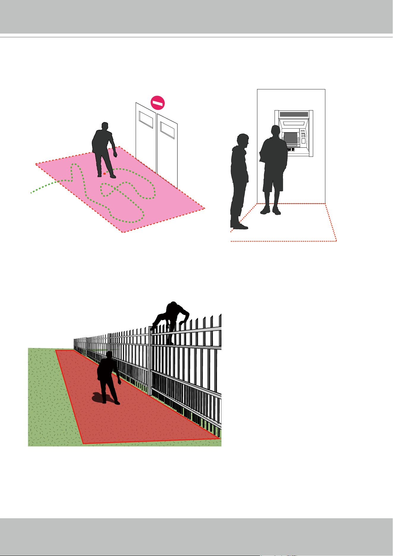
VIVOTEK - A Leading Provider of Multimedia Communication Solutions
User's Manual - 163
Loitering Detection
The Loitering detection can be used to detect a person or a group of people lingering in an area
for longer than a preset time threshold.
ATM
Intrusion Detection
VIVOTEK Intrusion Detection can be used to detect people entering or leaving a virtual area in
the camera eld of view.
Alerted zone
The applicable scenarios of this feature can be:
* Detects when a person enters a bank vault or school after the ofce hours.
* Detects when a person leaves an emergency exit or re escape, or any place that is normally
forbidden from access.
VIVOTEK - A Leading Provider of Multimedia Communication Solutions
164 - User's Manual
1
2
3
To use Smart search,
1. Use the date and time selectors to specify a time span on which to perform the Smart search.
2. Select a Type (Smart motion, Line crossing, Loitering, or Intrusion). Selecting Line crossing
detection may require you to adjust the position of the detection line.
3. There are different parameters for each detection Type. Refer to each VCA feature's
documentation for details. You can tune the parameters for each VCA feature. See next page
for the configurable parameters.
4. You can draw one polygon with multiple mouse clicks to include areas where activities of
your interest have occurred. You can draw one or more cross lines for Cross line detection.
Double-click to close a polygon.
5. Click the Search button.
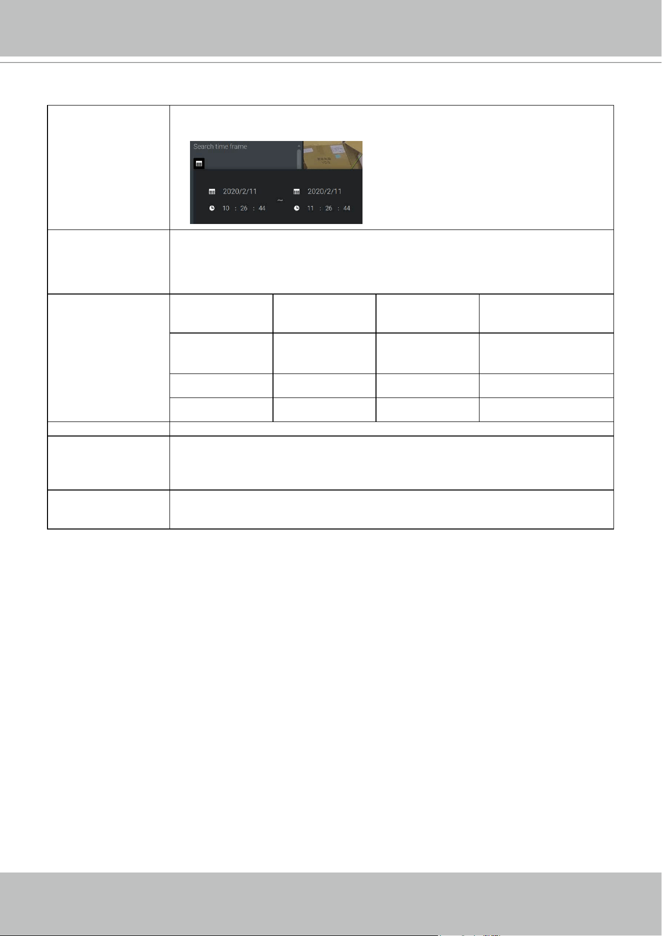
VIVOTEK - A Leading Provider of Multimedia Communication Solutions
User's Manual - 165
Search parameters:
Search time frame Use the calendar tool pane to specify the time span within which the activities in
scene will be searched.
Type If the selected camera supports multiple Smart VCA detection features, the
supported types will be listed:
Smart motion, Line crossing, Loitering, or Intrusion.
Parameters
(determined by Type)
Smart motion Line crossing Loitering Intrusion
People detection* People walking
direction
Stay time Direction:
Into the zone /
Leaving the zone
Sensitivity**
Time lter
* People detection People detection enables the display of the alarms detected via the human silhouettes
algorithm. This can be used to lter out video analytics alarms that are not related to
human activities, such as swaying vegetation, or small animals.
** Sensitivity Congure the sensitivity for the detection of the activities in scene. Low for near scene,
high sensitivity for long distance scenes.
Note that different cameras support different VCA functions. Please refer to the documentation
for Smart VCA or Smart tracking features, such as the Smart VCA User Guide.
IMPORTANT:
Running Smart Search II requires cameras that support the following:
1. Smart motion.
2. Firmware version above 0113d, 0117b or 0100i (Authwebsocket support is needed)
3. VCA package version above 6.1.3a.
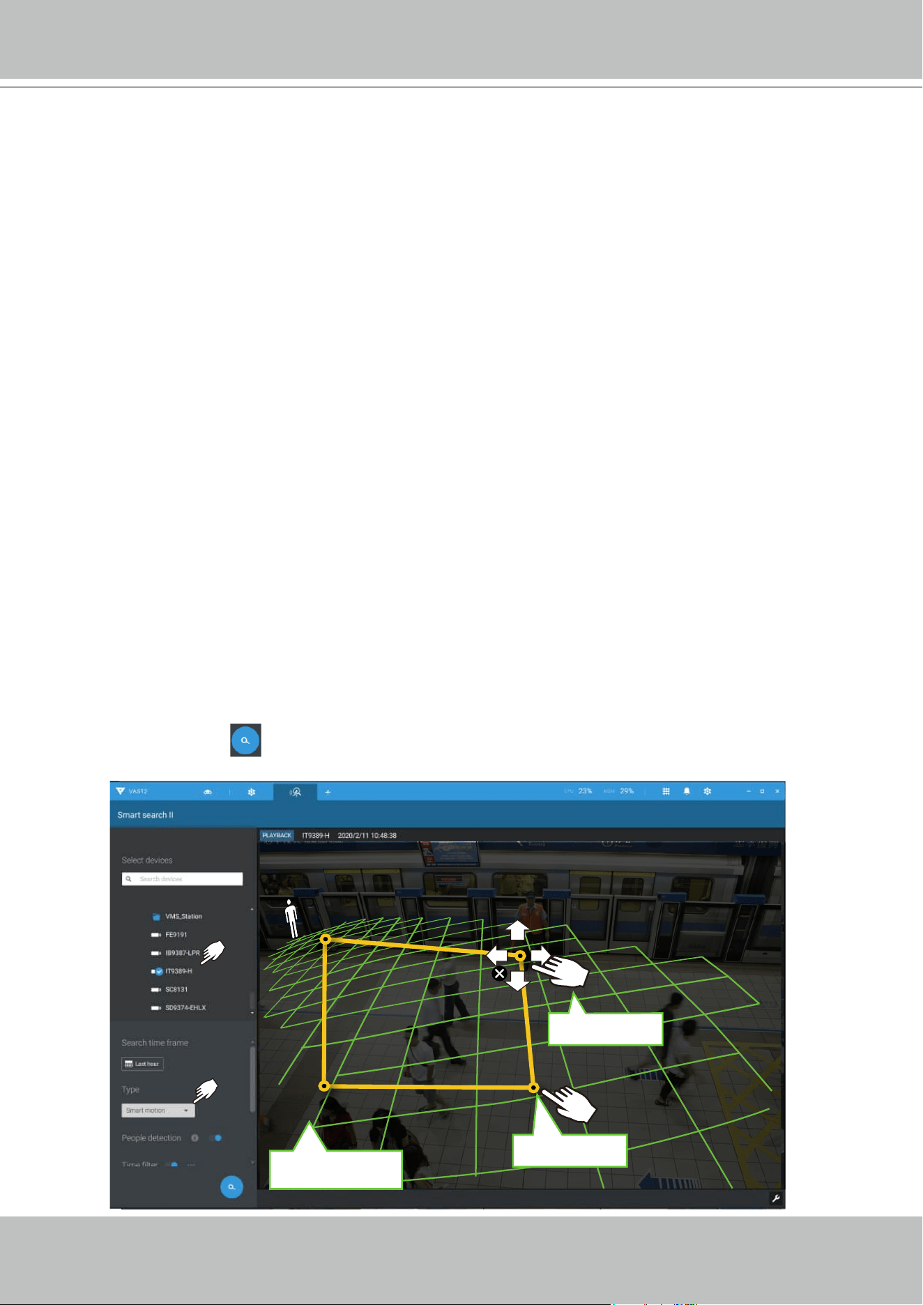
VIVOTEK - A Leading Provider of Multimedia Communication Solutions
166 - User's Manual
Green horizontal grid
as People detection area
Click to create.
Drag to change shape
If your camera supports Smart VCA features, you can manually create detection rules on the
configuration screen. Note that you may not need to do this if you have already configured
detection rules on the camera.
1. Select a VCA camera.
2. Select a VCA type from the pull-down list: Smart Motion, Line crossing, Loitering, or Intrusion.
For a camera that supports only one VCA feature, such as Smart tracking on a speed dome,
there is no "type" option.
3. You can then draw a detection zone, or detection line on the screen.
4. Select a time frame using the calendar tool.
5. Select to enable or disable the People detection feature and configure the Time filter, or other
parameters.
6. Click the Search button.
In most cases, it is presumed that you have configured VCA detection zones and detection rules
such as lines to detect people crossing. You can also configure a detection zone or lines on the
VAST server and then search for the detection results from the recorded videos.
NOTE:
* Smart search II supports people detection whether the camera comes with a Smart motion
license or not. However, the Line crossing, Loitering, Intrusion features will not be available.
* With a valid VCA package and license, the abovementioned features will be available in the
Smart search II.
VIVOTEK - A Leading Provider of Multimedia Communication Solutions
User's Manual - 167
4. The search results display as the snapshots of the associated video clips. Click to playback
the video clips with activities in the detection zones.
Hover the screen with your mouse, and the length of each video clip is displayed.
Note that unless interrupted, the playback continues with all detection zone clips, by continuing
to the successive clips.
VIVOTEK - A Leading Provider of Multimedia Communication Solutions
168 - User's Manual
Smart search II is available only for newer line of cameras that come with Smart Motion
detection and other Smart VCA features. Smart search II has the following benefits:
1. Faster search: Metadata is saved with videos coming from the cameras running Smart
VCA detection. With the help of the metadata, the search focuses on the effective alerted
vectors and the adverse effects, e.g., headlights causing dramatic contrast or small
animals passing through, have already been eliminated by the camera. The search can be
more rapidly completed.
2. People detection: The search can be conducted for human activities only. Activities
matching the silhouettes of human will be considered as effective results.
3. Multiple-point polygon: Users can select a region of interest by drawing a easily-configured
polygon. In addition to the pre-configured detection rules on VCA cameras, users can
create their own Smart VCA Detection rules on the VAST search panel screen.
You can specify the time span, People detection,
Sensitivity level, and time filter parameters in a Smart
Search II panel.
VIVOTEK - A Leading Provider of Multimedia Communication Solutions
User's Manual - 169
5. You can then click to open any clip of your interest. Each marked event clip will be indicated
by a lighter color on the time line. Select and double-click on a video clip, and then right-click
or select the bookmark or snapshot functions from the upper-right.
Move your cursor to the upper right corner of the playback window to display the Snapshot
and Bookmark buttons. Use them to congure the current play time as a bookmark or take a
snapshot.
While in the full-screen Playback window, you can right-click to select or deselect the display
elements including motion cells, tracking block, and tracking dot.
VIVOTEK - A Leading Provider of Multimedia Communication Solutions
170 - User's Manual
6. If you nd important events, use the Export function to mark the start and end points on the
timeline to export a video clip. Use the pull tabs on time line to determine the export length.
By default, the export length is 2 minutes long.
The playback control in the Smart search window is identical to that on the Playback window.
PLAYBACK
FE9391-EV
2992x2992
H264
15.00 fps 0.04 Mbit/s
2017/11/29 14:06:48
Different events on the timeline are indicated by tags of different colors. Click on the event
highlights button to verify their colors.
VIVOTEK - A Leading Provider of Multimedia Communication Solutions
User's Manual - 171
2-2-17. Tour
A tour can be configured to consecutively display multiple views. A tour allows users to quickly
glimpse through many view cells in a timed pattern. As a tour can contain multiple views, you
should design and configure camera views before configuring a tour.
To configure a tour,
1. Click on the Add a camera tour
button.
2. Click the Add button.
1
2
3. Enter a name for the tour.
4. Single-click to select a view. Select multiple views each by a single click.
5. Click the Add Tour button.
3
4
5
VIVOTEK - A Leading Provider of Multimedia Communication Solutions
172 - User's Manual
The default for the duration of the display of each view is 5 seconds. You can right-click on each
view to display the Duration of each view. You can apply the same duration of all views, or allow
each view to display on screen for a different span of time.
Mouse over a configured tour, and then click to start a tour.
When playing a tour, and you want to stop the tour, you can left-click or right-click on the screen.
Click the Tour icon
again to return to the singular live view.
You can enable the Audio tour option which plays the audio inputs from each view cell for a
specific period of time.
VIVOTEK - A Leading Provider of Multimedia Communication Solutions
User's Manual - 173
2-2-18. Thumbnail search
The Thumbnail search function is like doing a post-production editing in film making. Screens
from across different time spans are shown to facilitate the search for evidence.
Click on the Thumbnail serach button to enter the Thumbnail search window.
The default time span is 100 minutes, starting an hour earlier of the current system time.
To use Thumbnail search,
1. Use the date and time selectors to specify a time span during which you suspect the event of
your interest has occurred.
2. If preferred, tune the interval and clip size. The default length for each clip is 10 seconds.
3. If you find a clip might contain an event of your interest, you can click to select, and then slide
left and right to watch the activities within.
4. Hover your cursor to the lower center of a clip to display the Play and the More snapshots
options. If you click More snapshots, another window will prompt to display all frames
within the clip.
When you select to display the clip details (specific time span), the time span and the interval
information will change accordingly.
VIVOTEK - A Leading Provider of Multimedia Communication Solutions
174 - User's Manual
When you find an event of your interest, you can play that video clip and use the export function
on screen to output the evidence. You may also place a bookmark on the timeline.
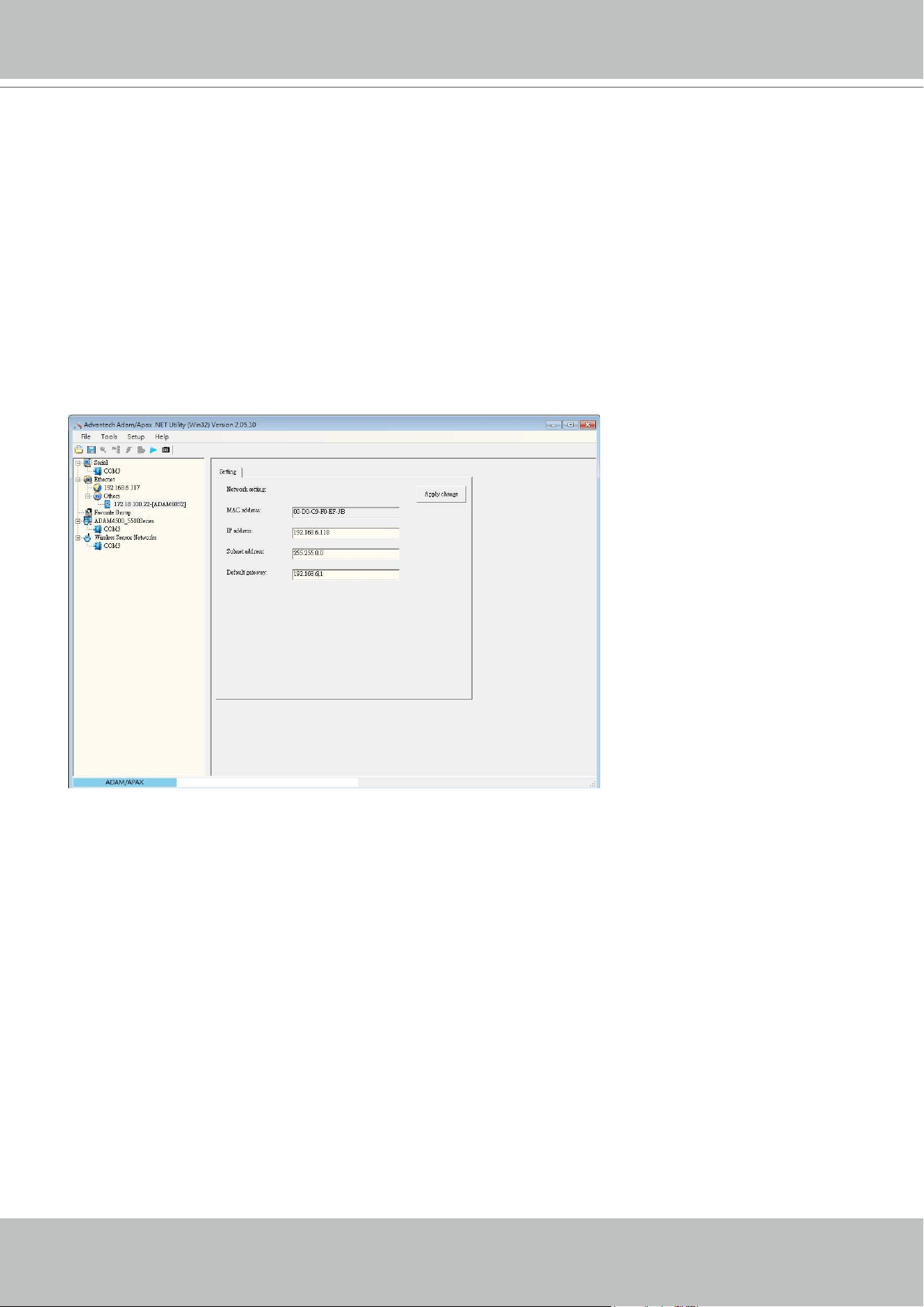
VIVOTEK - A Leading Provider of Multimedia Communication Solutions
User's Manual - 175
Chapter 3 Applications:
3-1. I/O DI/DO Devices: IO Box and Related Conguration
Use the software utility that comes with the IO box, e.g., Advantech's Adam/Apax.NET utility,
to configure IP address, and test the DI/DO connectivity. The connections to external devices
should be completed before configuration on the software.
VIVOTEK - A Leading Provider of Multimedia Communication Solutions
176 - User's Manual
Enter the I/O box's IP addess and credentials, and select the correct model name from the pull-
down list on the right. Click the Apply button to proceed. The current I/O connections are also
displayed on screen, such that the status is displayed when DI pins are connected to detection
devices.
Enter Settings > Device > DI/DO Device. Click the add I/O button on top.
VIVOTEK - A Leading Provider of Multimedia Communication Solutions
User's Manual - 177
The Select trigger and source window will prompt.
Select either the I/O Box DI or DO as the triggering source.
Conguring I/O Box DI/DO as a Trigger or Action in Alarm
Enter the Settings > Alarm window. Click the Add alarm button on top.
Select the External Device event , and then click the Add trigger button.
VIVOTEK - A Leading Provider of Multimedia Communication Solutions
178 - User's Manual
Select one or multiple DIs as the triggering source and click the Apply button.
Click Add action , and select a corresponding action, such as sending live streaming,
record videos, trigger a DO, sending an HTTP request, or sending an Email. When done, click the
Add button.
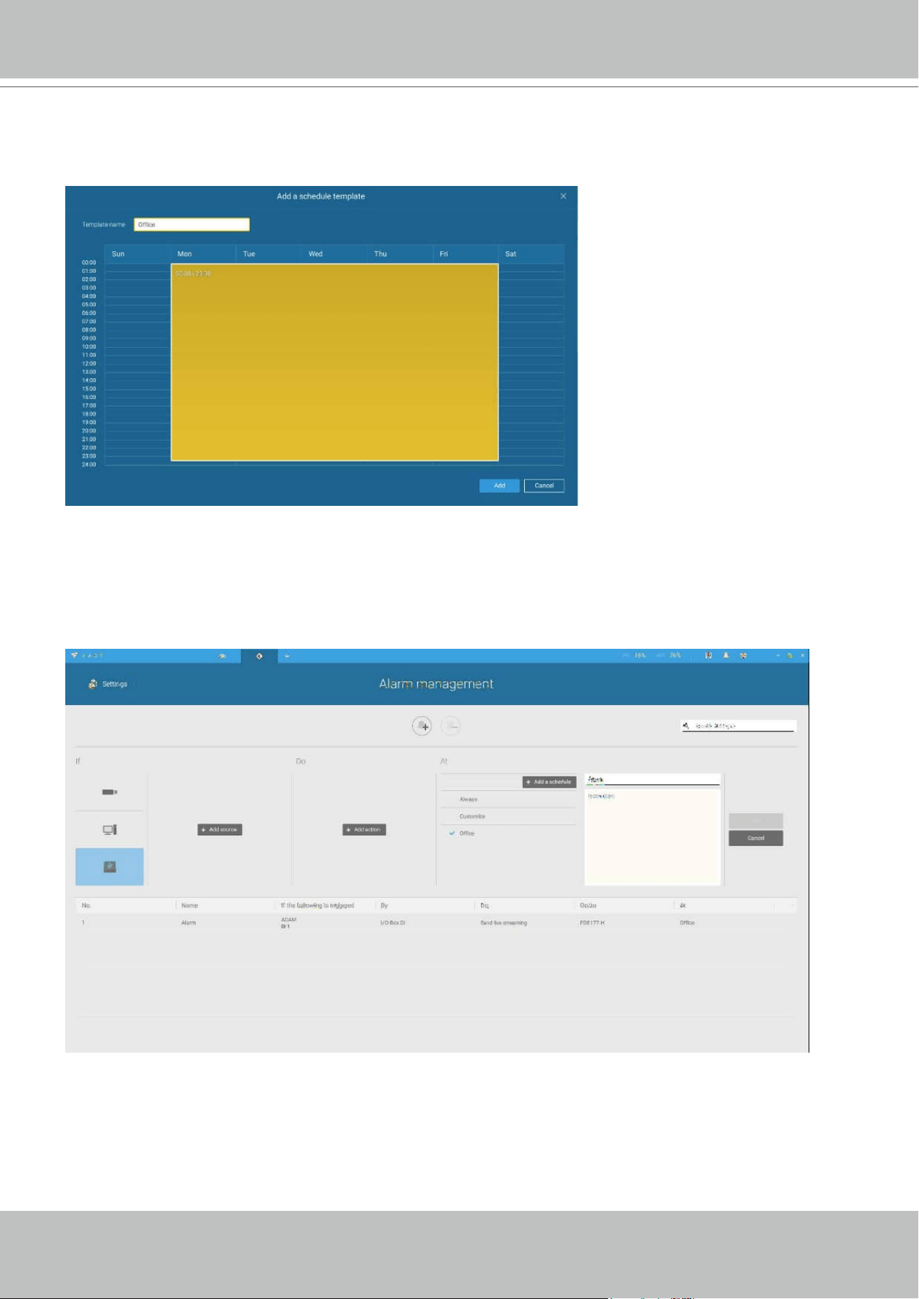
VIVOTEK - A Leading Provider of Multimedia Communication Solutions
User's Manual - 179
Enter a name for your Alarm, and add description for your configuration, e.g., "intrusion detected
on the front door." When done, click the Add button. The Alarm configuration takes effect
immediately.
Configure a schedule during which the Alarm configuration will take effect. If no special time
span is needed, you can simply select Always.
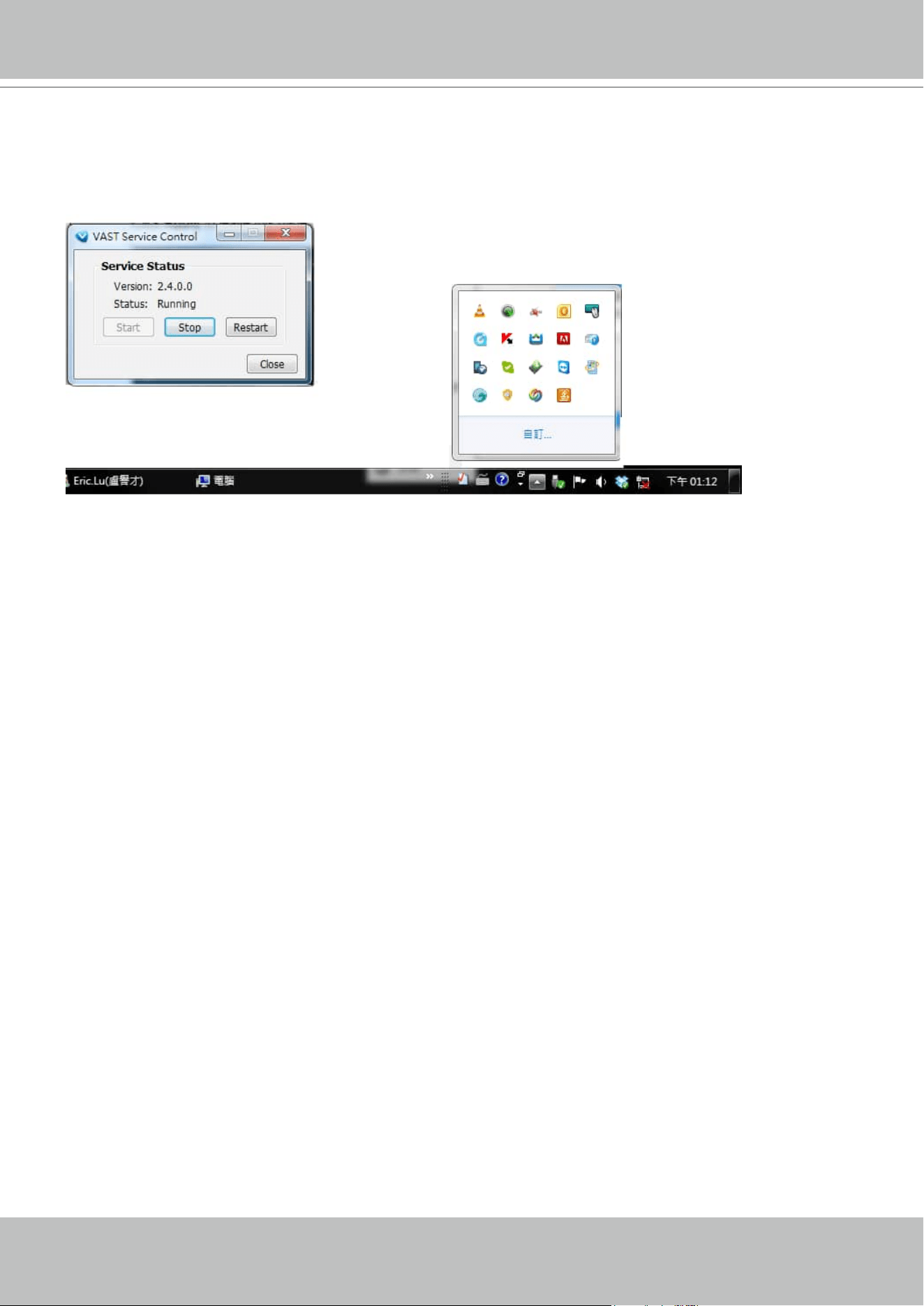
VIVOTEK - A Leading Provider of Multimedia Communication Solutions
180 - User's Manual
NOTE:
If an I/O module is started later than the VAST server, you may not be able to access the I/O
module. You should then re-start the VAST service.
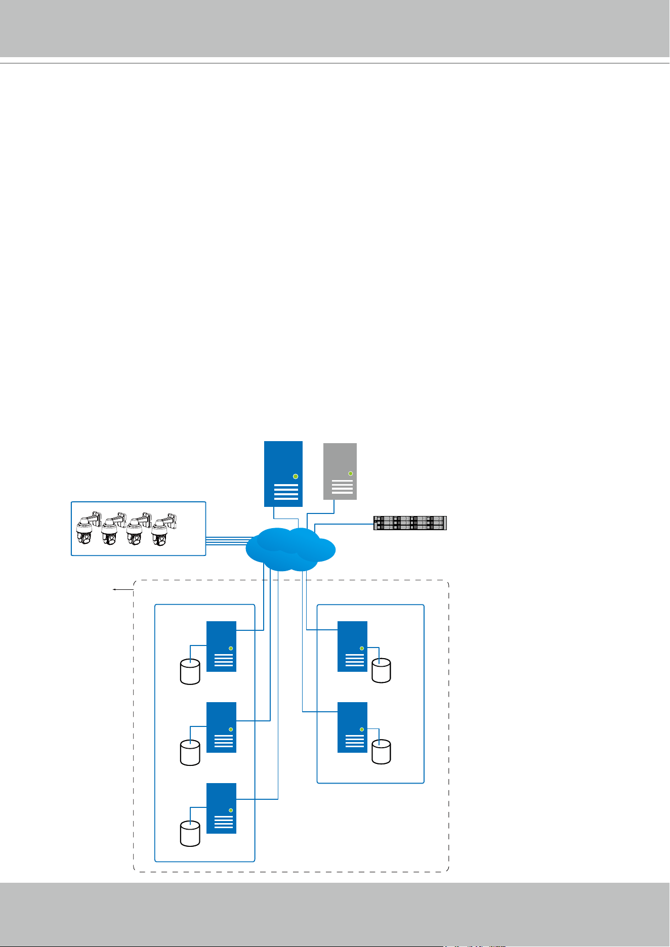
VIVOTEK - A Leading Provider of Multimedia Communication Solutions
User's Manual - 181
3-2. Conguring Redundant Servers - Failover
VAST2 servers can be congured into two groups: Active and Redundant. The Active group
performs daily recording and monitoring tasks, while the Redundant group acts as the standby
servers. In the event of server failures, the Redundant group becomes active, and takes over
the recording task.
The Redundant server group conguration consists of the following:
1. One VAST2 server designated as the CMS (Central Management server) VAST central
management server. Another VAST server can serve as a CMS failover server.
2. At least one VAST2 server in the Active group.
3. At least one VAST2 server in the Redundant group.
4. Gb/s network or higher-speed connections among the servers. All Active and Redundant
groups can reside in different subnets, provided that static IPs are congured for these
servers.
Active VAST servers Redundant VAST servers
CMS VAST
Active Group Redundant Group
Node 1
Node 2
Node 1
Node 2
Node 3
External storage /
NAS
Network Cameras
. . . . .
Server Group
CMS Failover
LAN
IMPORTANT:
For a Redundant server conguration, you must rst enlist VAST servers in the Sites
conguration page before conguring the Redundant server groups. See the Sites
conguration page.
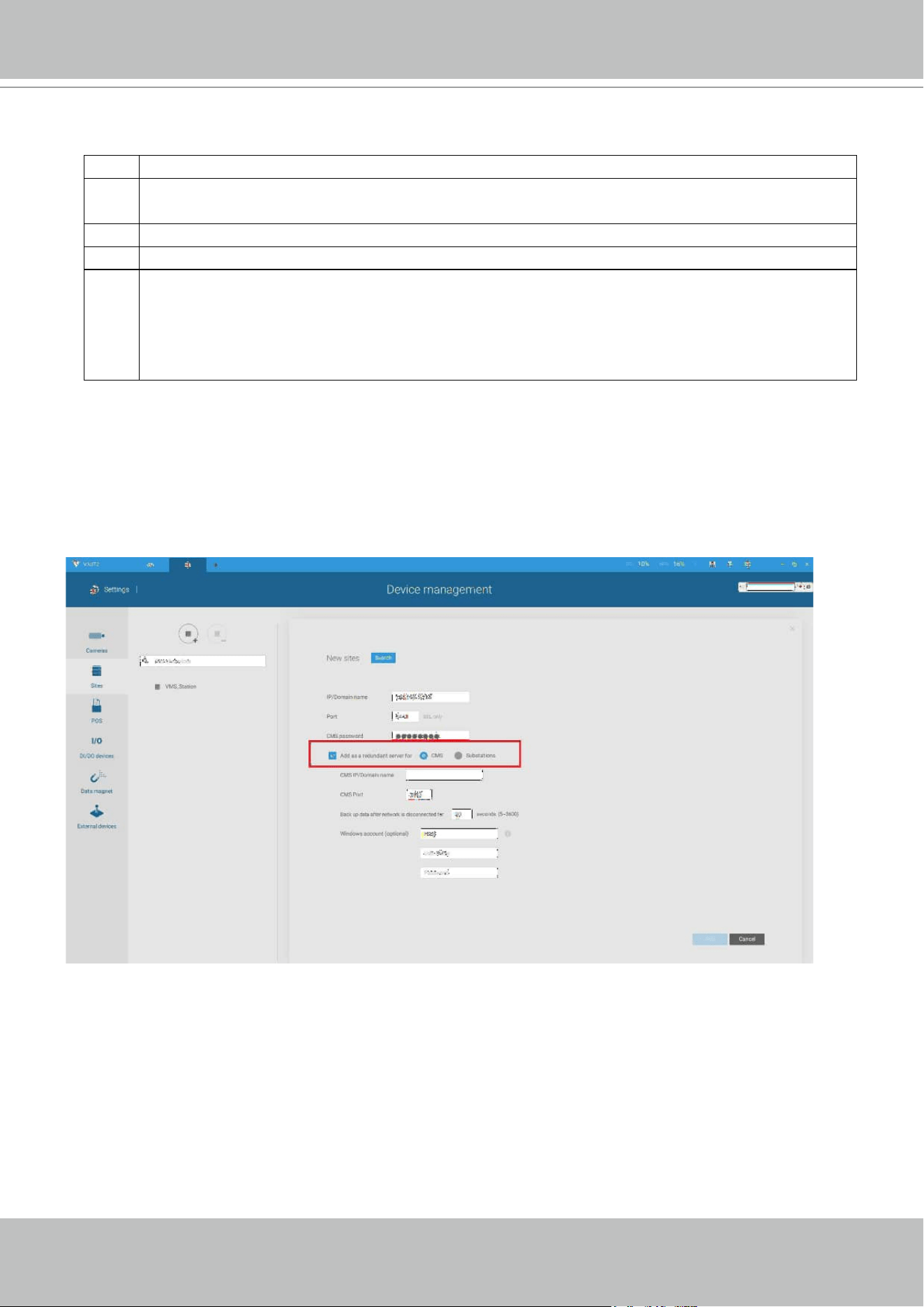
VIVOTEK - A Leading Provider of Multimedia Communication Solutions
182 - User's Manual
Below are the denitions of server roles:
1. CMS VAST server: The main access portal for the conguration.
1-1. CMS server is where the Failover conguration takes place.
1-2. CMS continuously polls to check the hearbeats to monitor the statuses of all Active
and Redundant servers.
1-3. CMS regularly backs up the congurations on Active servers.
1-4. CMS assigns redundant server(s) to the takeover of a failed Active server.
1-5. In a Redundant server conguration, the CMS is supposed to be up and running at
all time. If the CMS server fails, the server failover and failback operation will not take
place. It is therefore preferrable to congure a CMS redundant server, and install the
CMS server at a high up-time environment, such as on a VMWare conguration.
3. Active servers: Active VAST servers are the work horses that perform recording and
monitoring tasks.
4. Redundant servers: The Redundant servers are actually active-standbys. They participate
to continue video recording in the event of active server failures. It is recommended for the
Redundant servers to have an equivalent or higher processing power than the Active servers.
The same applies to the size of storage volumes and the disk drives' write performance.
Note that you cannot congure a Redundant server by opening a local console.
2. CMS Redundant server: This is a failover server that serves as the backup for the CMS
server.
Note that this redundant server is congured in Settings > Devices > Sites. Click Add Sites,
and select "
Add as a redundant server for" "CMS." See next section for the conguration
procedure.
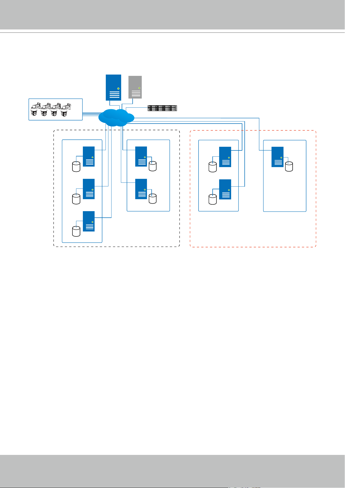
VIVOTEK - A Leading Provider of Multimedia Communication Solutions
User's Manual - 183
Multiple Active and Redundant groups can be created.
Active VAST servers Redundant VAST servers
CMS VAST
Active Group Redundant Group
Node 1
Node 2
Node 1
Node 2
Node 3
External storage /
NAS
Network Cameras
. . . . .
Server Group 1
Active VAST servers Redundant VAST servers
Active Group Redundant Group
Node 1
Node 1
Node 2
Server Group 2
CMS Failover
LAN
Each Redundant server can serve as the backup for ONE Active server. Depending on the
number of the Active and Redundant servers, if the number of failed servers exceeds the
number of Redundant servers, the failover will be abandoned. For example, if 2 Active servers
failed, and there is only 1 Redundant server available, the second Active server that failed will
be abandoned.
The conditions during the failover process are illustrated below:
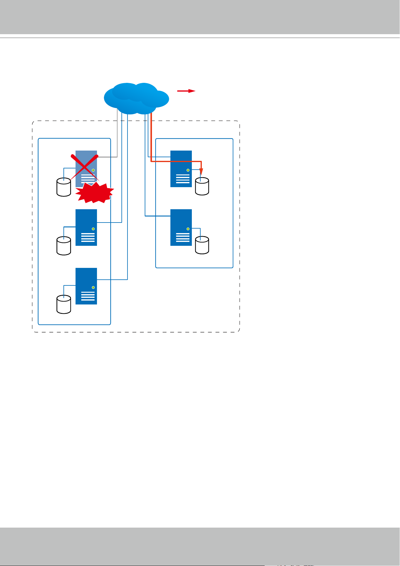
VIVOTEK - A Leading Provider of Multimedia Communication Solutions
184 - User's Manual
In the event of a server failover, a VAST2 server in the Redundant group takes over the
recording task. Note that depending on the network environment, the takeover can take up to 5
minutes.
Active VAST servers Redundant VAST servers
Active Group Redundant Group
Node 1
Node 2
Node 1
Node 2
Node 3
Server Group
Recording
LAN
Failed!
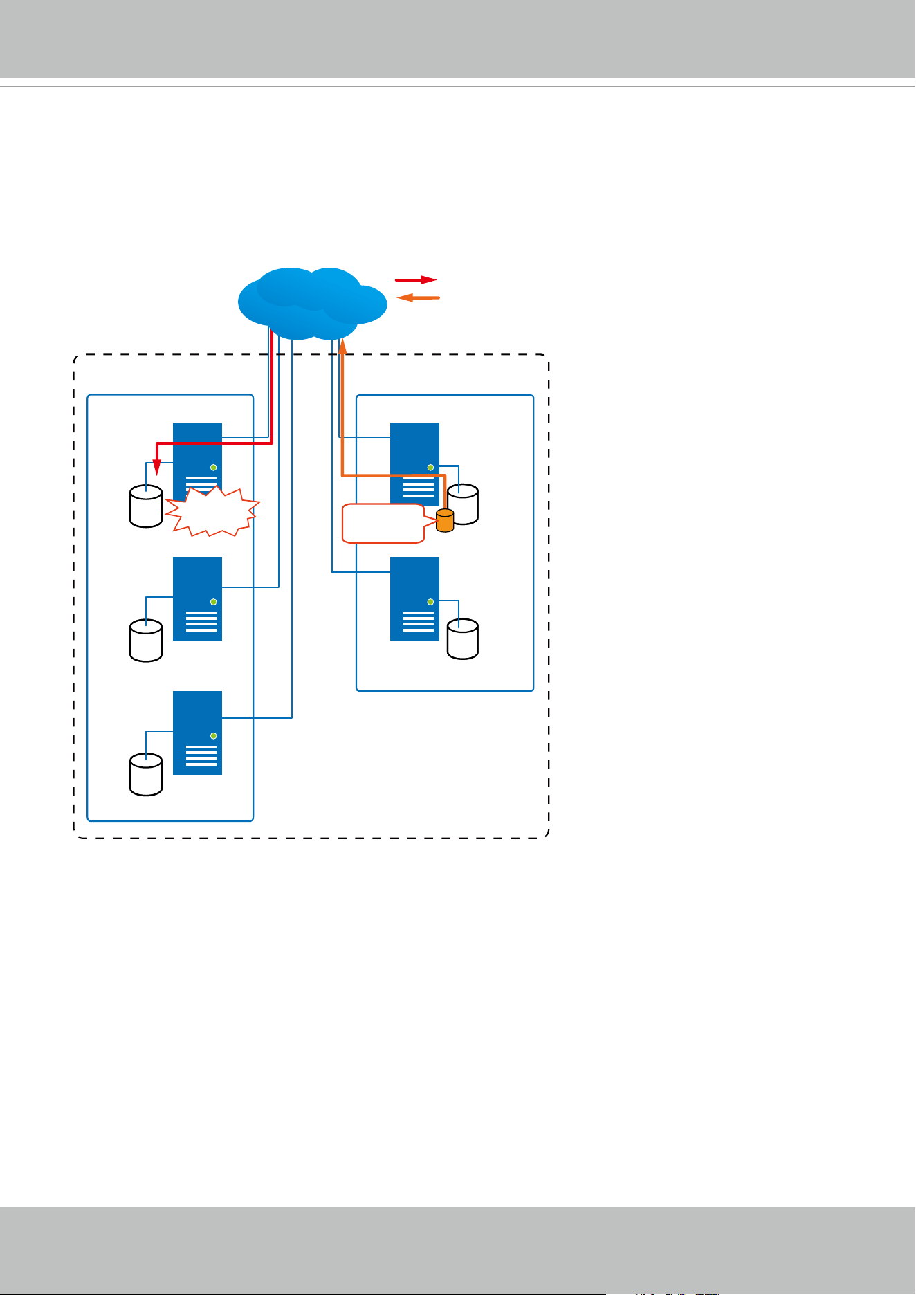
VIVOTEK - A Leading Provider of Multimedia Communication Solutions
User's Manual - 185
Once the server in the Active group is restored to normal operation, and a CMS server requests
for the recordings and data occurred during the time the active server failed, the requests will
be fullled by a shared volume on the redundant server. Due to the concerns with network
bandwidth and processing power, the restored active server does not synchronize its recording
pool with that on the redundant server after the failover and failback process.
Active VAST servers Redundant VAST servers
Active Group Redundant Group
Node 1
Node 2
Node 1
Node 2
Node 3
Server Group
Recovered!
Shared
Volume
LAN
Recording
Playback & Search
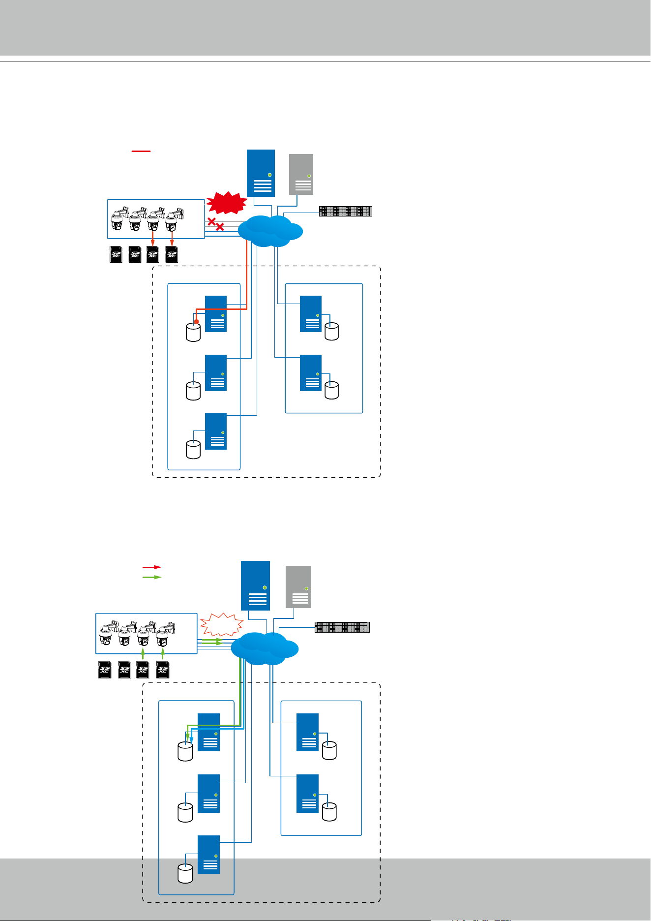
VIVOTEK - A Leading Provider of Multimedia Communication Solutions
186 - User's Manual
In terms of network failure, the VAST2 conguration supports Seamless Recording. For cameras
equipped with an SD card, video is recorded to the SD cards in the event of network failure. Of
course, the cameras must have a backup power source, such as a DC 12V input. In cases such
as the only PoE switch or PoE mid-span fails, power is lost.
Active VAST servers Redundant VAST servers
CMS VAST
Active Group Redundant Group
Node 1
Node 2
Node 1
Node 2
Node 3
External storage /
NAS
Network Cameras
. . . . .
Server Group 1
Network
Failure
Recording
CMS Failover
LAN
Once the network connection is restored, the VAST2 servers resume the recording task and also
retrieve video segments from the SD cards. The video segments recorded during the network
failure will be stitched up with those occurred before and after the network failure. The retrieval
speed varies depending on the available network bandwidth and CPU resources.
Active VAST servers Redundant VAST servers
CMS VAST
Active Group Redundant Group
Node 1
Node 2
Node 1
Node 2
Node 3
External storage /
NAS
Network Cameras
. . . . .
Server Group 1
Recording
Retrieval
LAN
Recovered!
CMS Failover
VIVOTEK - A Leading Provider of Multimedia Communication Solutions
User's Manual - 187
To enable Seamless recording, nd the associated option in Settings > Recording options,
and select the Seamless recording checkboxes. Camera models that support the Seamless
recording option will have it listed.
VIVOTEK - A Leading Provider of Multimedia Communication Solutions
188 - User's Manual
Failover Conguration Process
Before Failover conguration, you need to add other servers to your Failover conguration.
Below is a screen from the Sites management window.
• If you are adding a Redundant server, select the "Add as a redundant server" checkbox,
for either a CMS server or VAST Substations.
• If you are adding a server without selecting this checkbox, it will be considered as an Active
server.
• When adding a Redundant server, you can provide a Windows account 802.1x domain user
name and password. A Redundant server requires this because a full access to the recorded
data is required during the failover and failback process.
VIVOTEK - A Leading Provider of Multimedia Communication Solutions
User's Manual - 189
When the "Add as a redundant server" checkbox is selected, enter the name of your Windows
domain and the user credentials for a full access to the Redundant server.
Note that it is a must for the Redundant server to be installed differently by selecting a
"Redundant server" checkbox during the installation process.
VIVOTEK - A Leading Provider of Multimedia Communication Solutions
190 - User's Manual
Note that on the Active servers, you should congure them as the subordinates to your CMS
VAST server. On a web console to these servers, open the Site management page, and select
"Allow CMS to access this site." Create a common password for the CMS hierarchy.
When a Redundant server is successfully added, the server will be listed under your VMS
station.
A Redundant server comes with an associated icon, .
An Active server must have a CMS password congured for the hierarchical conguration.
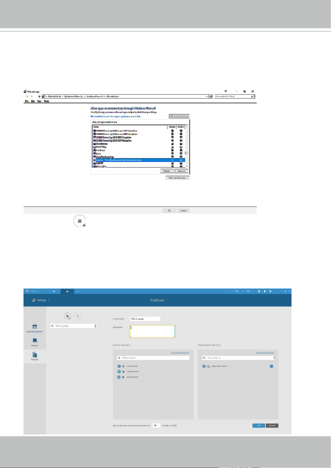
VIVOTEK - A Leading Provider of Multimedia Communication Solutions
User's Manual - 191
Two agents will be running on the Active and Redundant servers, "stunnel" and
"VMSWebServer." Make sure they are not blocked out by your rewall. These agents can be
found in the default folders below:
C:\Program Files (x86)\VIVOTEK Inc\sTunnel\stunnel.exe
C:\Program Files (x86)\VIVOTEK Inc\VAST\Server\VMSWebServer.exe
Click on the Add button to create a Redundant server group. The Active and Redundant
servers you enlisted on the Sites page should all be listed below. Select the members of the
Redundant group, and click Add to complete.
The default for the network disconnection timeout is 30 seconds. It is not recommended to
congure a very short timeout, e.g., 5 seconds, because if doing so, a temporary network
disorder can make servers consider the Active server(s) have failed.
1
2
3
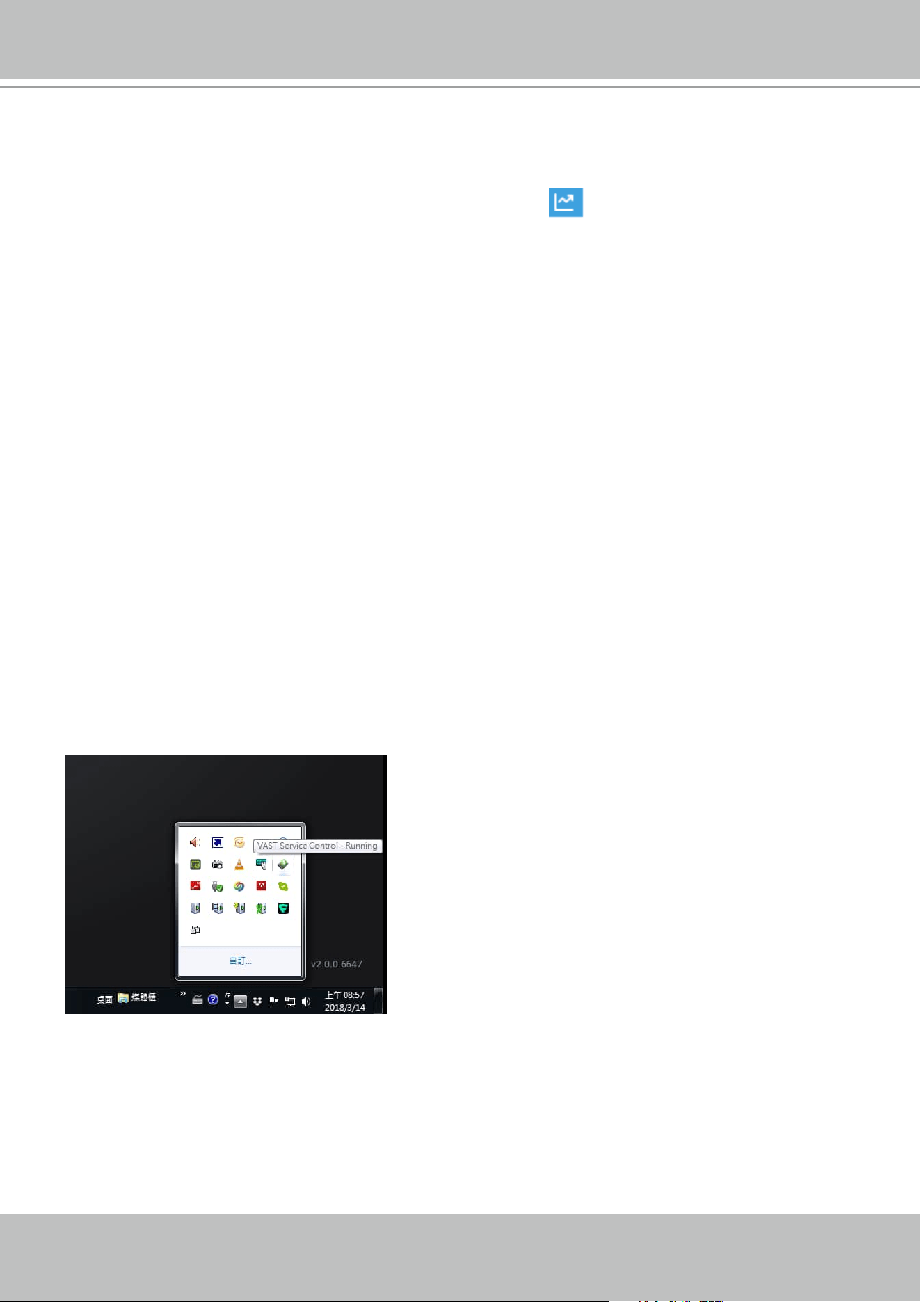
VIVOTEK - A Leading Provider of Multimedia Communication Solutions
192 - User's Manual
3-3. VCA (Video Content Analysis)
The VCA Report utility is started from the tool bar on top, . The VCA Report utility provides
comprehensive graphs and line charts for quick access to the data collected through VIVOTEK's
People Counting modules, such as the SC8131 stereo camera. Statistical results is refreshed
by hour or minutes, and you can compare the results acquired through different time periods or
among different surveillance areas. These data help figuring the customer flow in retails so that
shop owners can optimize the arrangement of store layout, or mange queues more efficiently.
Note that the conguration of detection methods in People Counting still occur on a web console
to individual cameras. It is not congurable through the VAST LiveClient.
Prerequisites:
The prerequisites for using the VCA Report are:
1. The monitoring server running the VCA Report utility must be up and running during the
time the counting VCA is taking place. If you power off the server, the counting metadata
generated during the server down time will not be available for analysis.
The VAST2 server instance runs in the background. The VAST2 management console needs
not be started during the VCA Report data collection process.
2. Cameras running the VCA utilities have been configured and added into the VAST deployment.
The instances of available VCA rules will be listed in the Area panel.
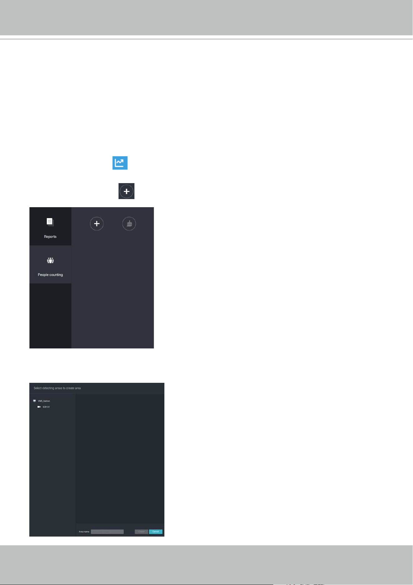
VIVOTEK - A Leading Provider of Multimedia Communication Solutions
User's Manual - 193
4. Select a camera that is VCA-enabled, and then click the Create button.
To start VCA report:
1. Click on VCA report
button on the tool bar.
2. Select People Counting.
3. Click on the Add area
button.
3. The life expectancy of VCA records is 5 years.
4. Currently the utility supports Windows XP, 7, 8, and 10.
5. The latest revision VAST supports Seamless Recording, in order to retrieve collected data
and recording during Ethernet disconnection. Provided that an SD card is installed on the
VCA-enabled cameras, the VAST station gradually retrieves data from the SD card after the
connection is restored.
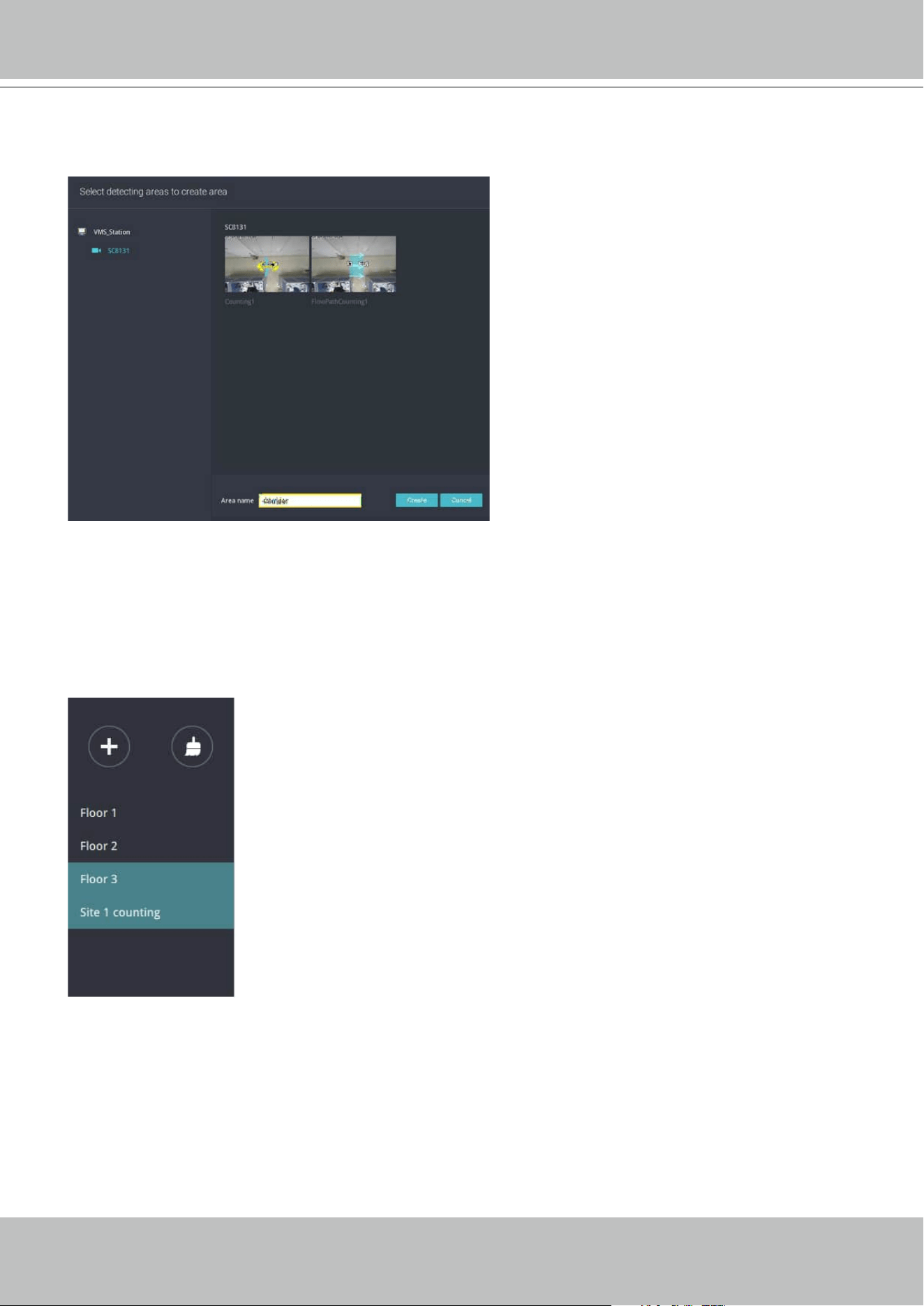
VIVOTEK - A Leading Provider of Multimedia Communication Solutions
194 - User's Manual
5. The pre-configured counting rules (areas) will automatically display. Select a counting rule
and enter a name for the area. When done, click the Create button.
If only one camera is selected, its name will apply as the Area name. If not, enter a name for the
area.
6. Click to select one or multiple areas. Those selected will be highlighted in a different color.
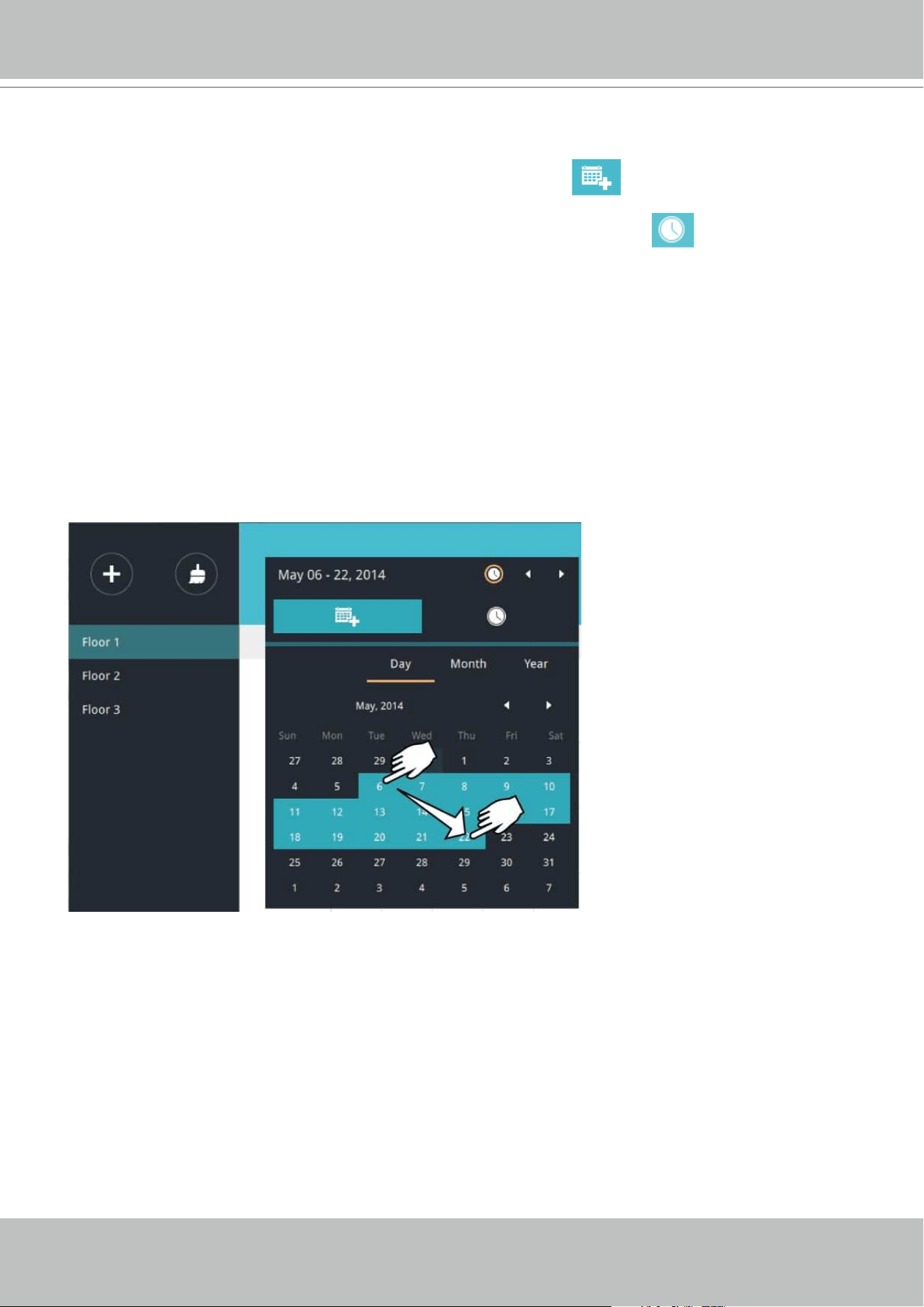
VIVOTEK - A Leading Provider of Multimedia Communication Solutions
User's Manual - 195
7. Select Date & Time
7-1. By default, the time displayed on the calendar is the current system time on the client
computer running the utility. Select from the Date selector
on top.
7-2. Select a date or span of time from the calendar or use the Time
selector to select a
span of time.
> Single-click to select a date or click and drag to select multiple dates.
> You can select a month or a year using a single click. If you select a month, the timeline unit
will be days within the month. If you select a year, the timeline units will be the months in a
year.
> In the Month or Year panel, single click to select the entire month or an entire year. Double-
click to select sub-units, e.g., days within a month. If you double-click on a Month panel, you
will enter the Day panel.
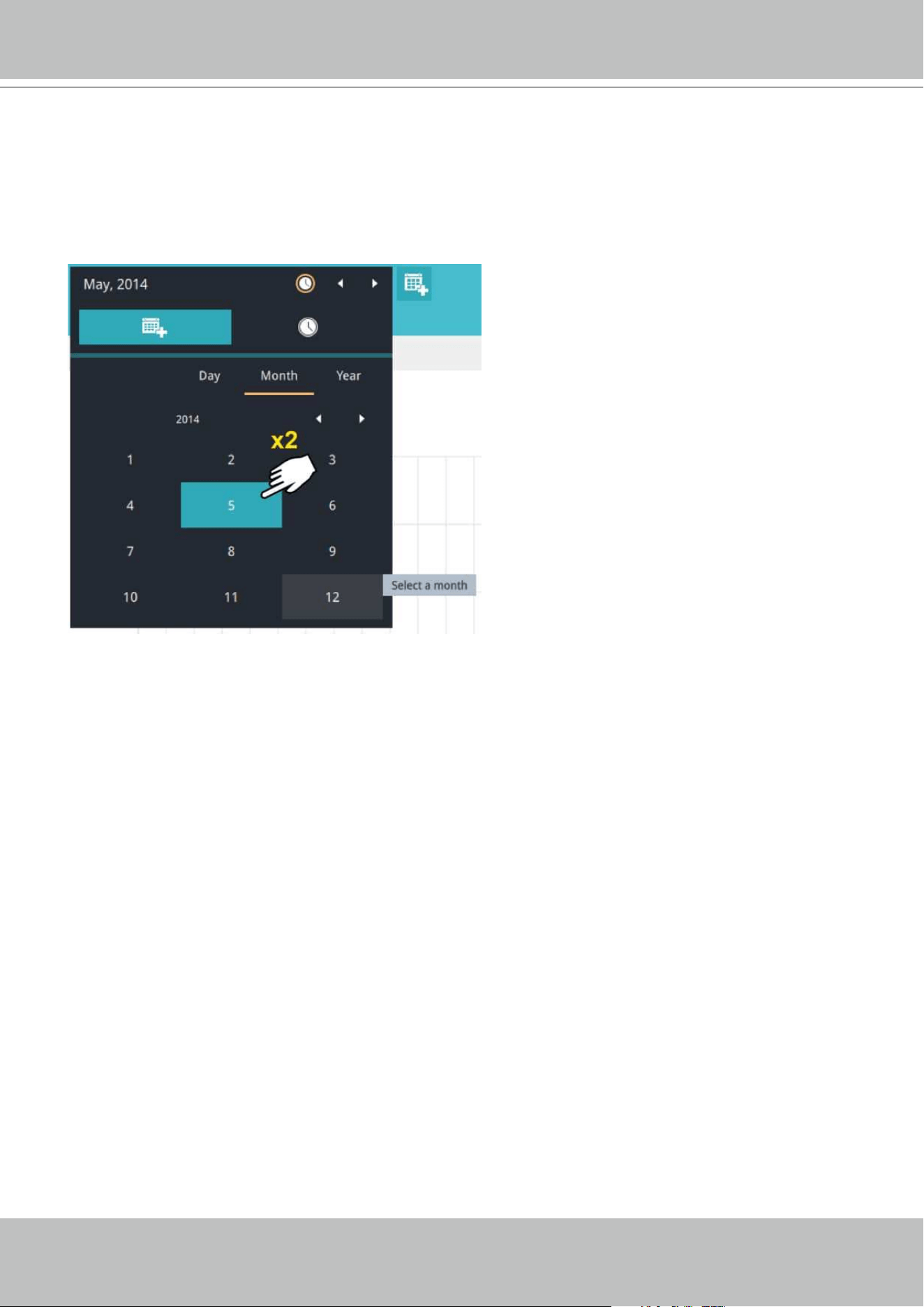
VIVOTEK - A Leading Provider of Multimedia Communication Solutions
196 - User's Manual
You can select a different month in the Month or Year panels. The Calendar panel disappears
if left unattended for 2 seconds.
On a Month panel, double-click to select a month, and the Day panel for that particular month
will display.
Note the following when making the configuration:
• When a date is selected, the Date and Time panel will not automatically close, and the
configuration changes will not take effect until it is closed. You can click on the outside of
the panel to leave the panel.
• You can select multiple days to form a span of time. Select one date with a single click and
select multiple dates by draging your cursor across the screen to a preferred end date.
• To select a year, click to open the Year panel. Single click to select a year. Multiple years can
be selected using the click and drag method.
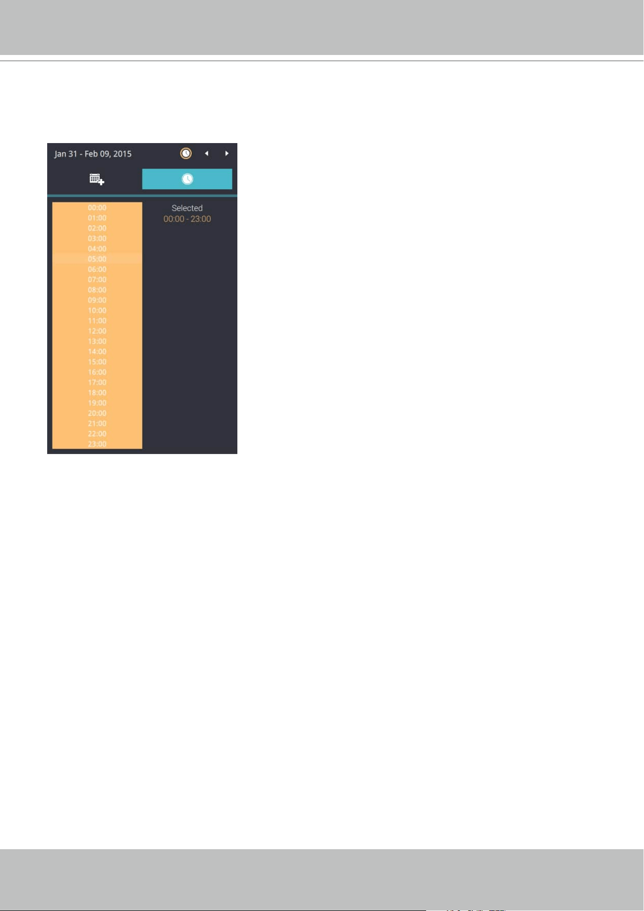
VIVOTEK - A Leading Provider of Multimedia Communication Solutions
User's Manual - 197
7-3. Select the hours to be included in the statistical poll using multiple clicks on the chart.
Single-click to select an hour or click and drag to select multiple hours.
Note that you can only compare the counting results from two spans of time if you select only
one Area. If you selected multiple Areas, you can not compare the results from multiple time
spans.
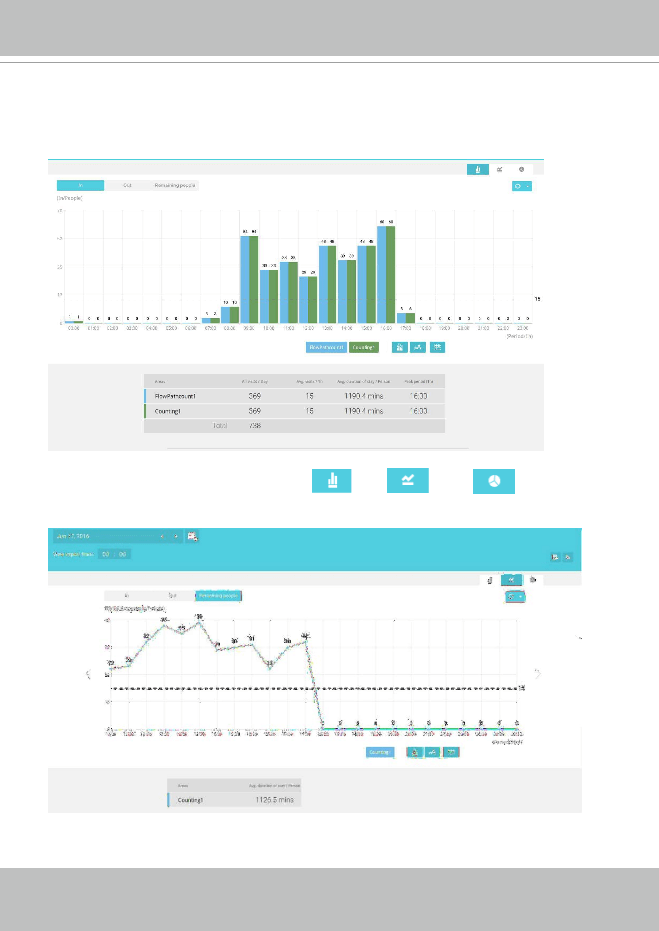
VIVOTEK - A Leading Provider of Multimedia Communication Solutions
198 - User's Manual
7-4. Click outside the Calendar panel. The statistical results will display. The default display
is the bar chart. Below is a sample screen showing the results polled from 3 areas. Up to 8
areas can be selected in one view.
Select different display modes using the Bar , Line , or Pie chart buttons.
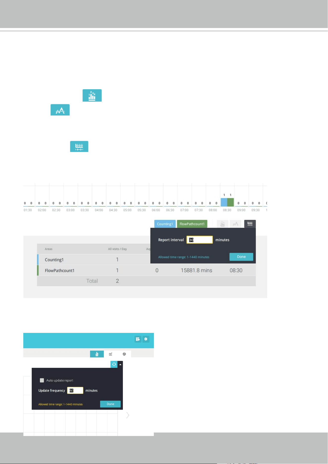
VIVOTEK - A Leading Provider of Multimedia Communication Solutions
User's Manual - 199
Note that the timeline units can vary depending on the span of time you selected on the
Calendar panel. If a date was selected, hourly data will display in chart. If a year was selected,
monthly data will display in chart.
Use the following functional buttons to change the display parameters
Show data on chart
: Displays the collected numbers on chart.
Average
: Displays the average number per time span unit (e.g., per hour). If the interval
is changed to 30 mins, the average number will be halved comparing to the number acquired by
every hour.
Report Interval : Configure the intervals for polling data from the camera. The default for
displaying results is by every hour. If you enter 30 minutes as the display interval, all data will be
listed on the basis of the 30 minutes time span. The configurable range is 1 to 1440 mins.
You can use the update menu on the side of the Refresh button to determine an automatic
update schedule. You can let the statistic chart update itself by a regular interval.
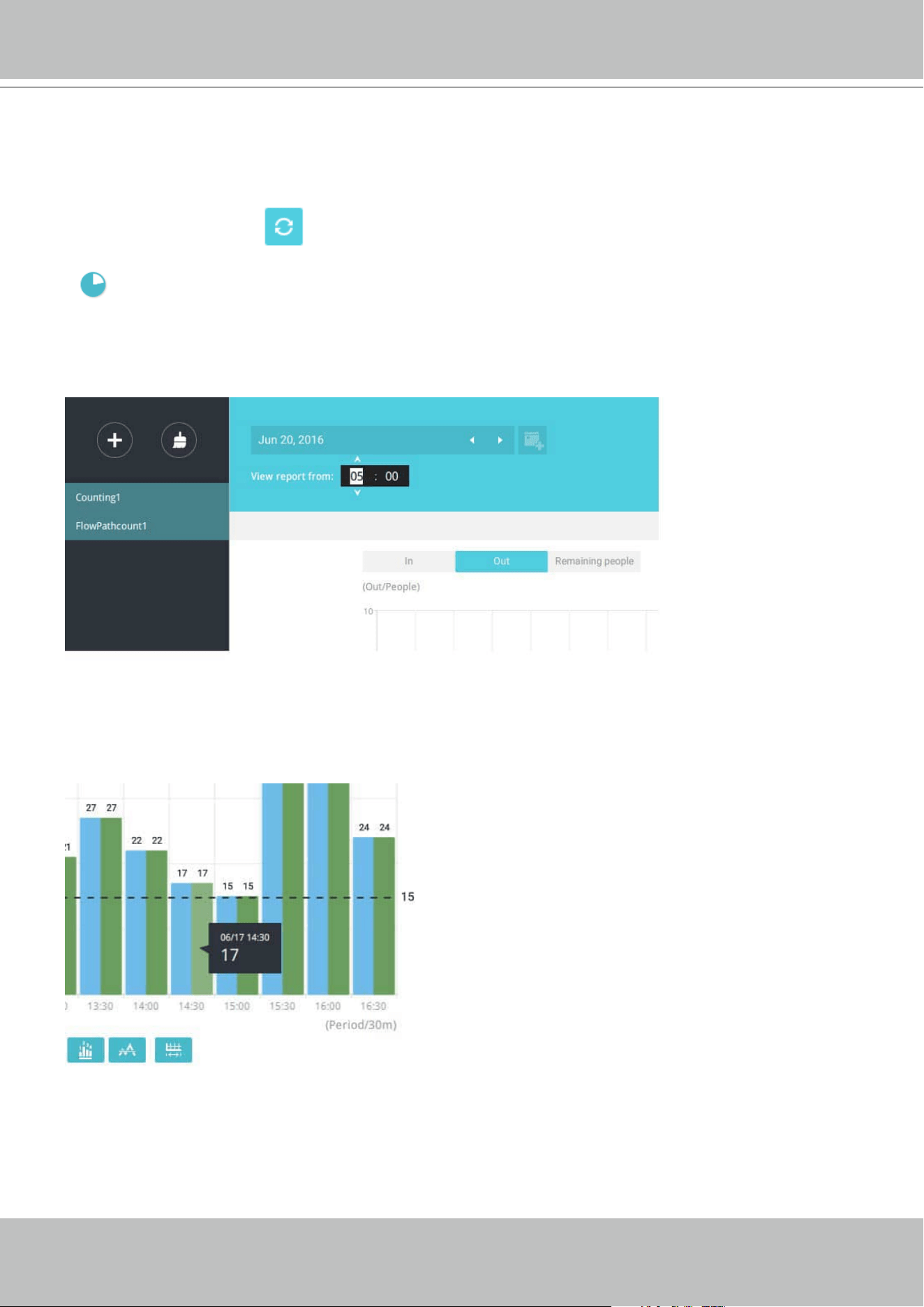
VIVOTEK - A Leading Provider of Multimedia Communication Solutions
200 - User's Manual
Use the Refresh button to poll the latest data from camera.
Use the time selector on the View Report from pane to select the start time of your statistics
view window. Data collected before that time will not be displayed.
A number is displayed when you mouse over an area on the chart. Move your cursor to an area
on chart, and the number is displayed.
If you selected only one area, you can use the Shift key to select multiple areas (or two spans of
time). You can select multiple dates in the Calendar panel.
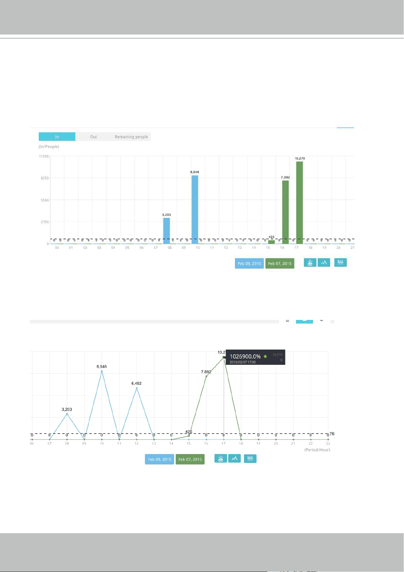
VIVOTEK - A Leading Provider of Multimedia Communication Solutions
User's Manual - 201
Data on a time line will be generated. To close the window, use the close button on the second
date information. Equivalent spans of time can also be used for comparison. For example, you
can compare the data in a span of 4 days against another span of 4 days.
Note that the Compare function only applies when you select to display only one area on screen.
In a comparison result displayed in a line chart, mouse over to the peak value to display the
percentage of an increase or decrease rate.
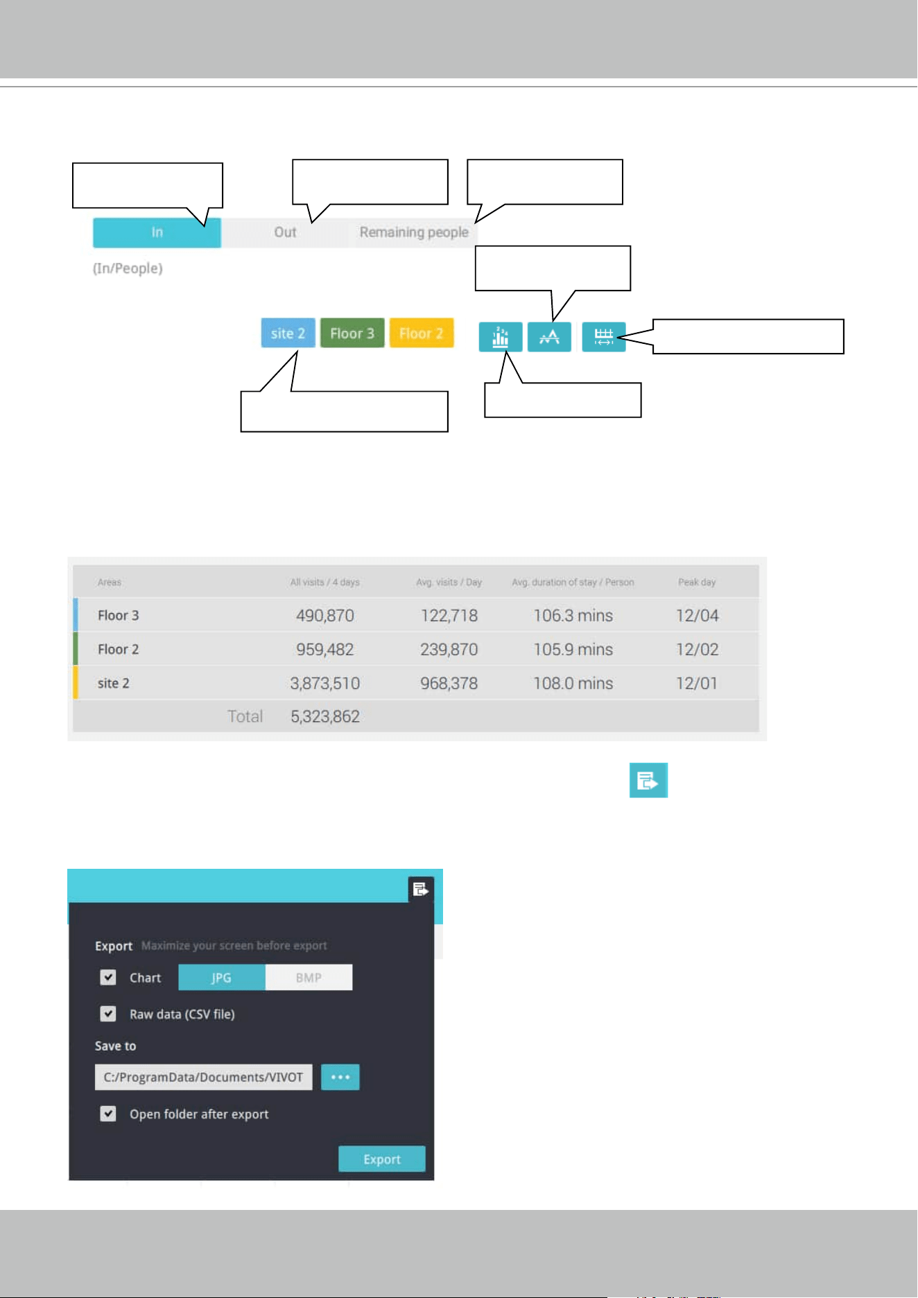
VIVOTEK - A Leading Provider of Multimedia Communication Solutions
202 - User's Manual
See below for the functions of buttons on screen.
Click to display or
hide the results for an area
No. of people who
entered the area
No. of people who
left the area
No. of people who
remain in the area
Show an average
number
Show data on chart
Change the report interval
In addition to the charts, a summary of displayed data will be listed below showing the areas
involved, visits/Day or Month, Average visits / Hours / Days, Average duration of stay / person,
and the Peak hour.
8. When done with displaying the results, you can use the Export button to produce an
image file to preserve the current results. Both a spreadsheet and a graphic chart will be
produced.
By default, the exported report is placed in:
C:\ProgramData\Documents\VIVOTEK Inc\
VAST\Client\VCAReport
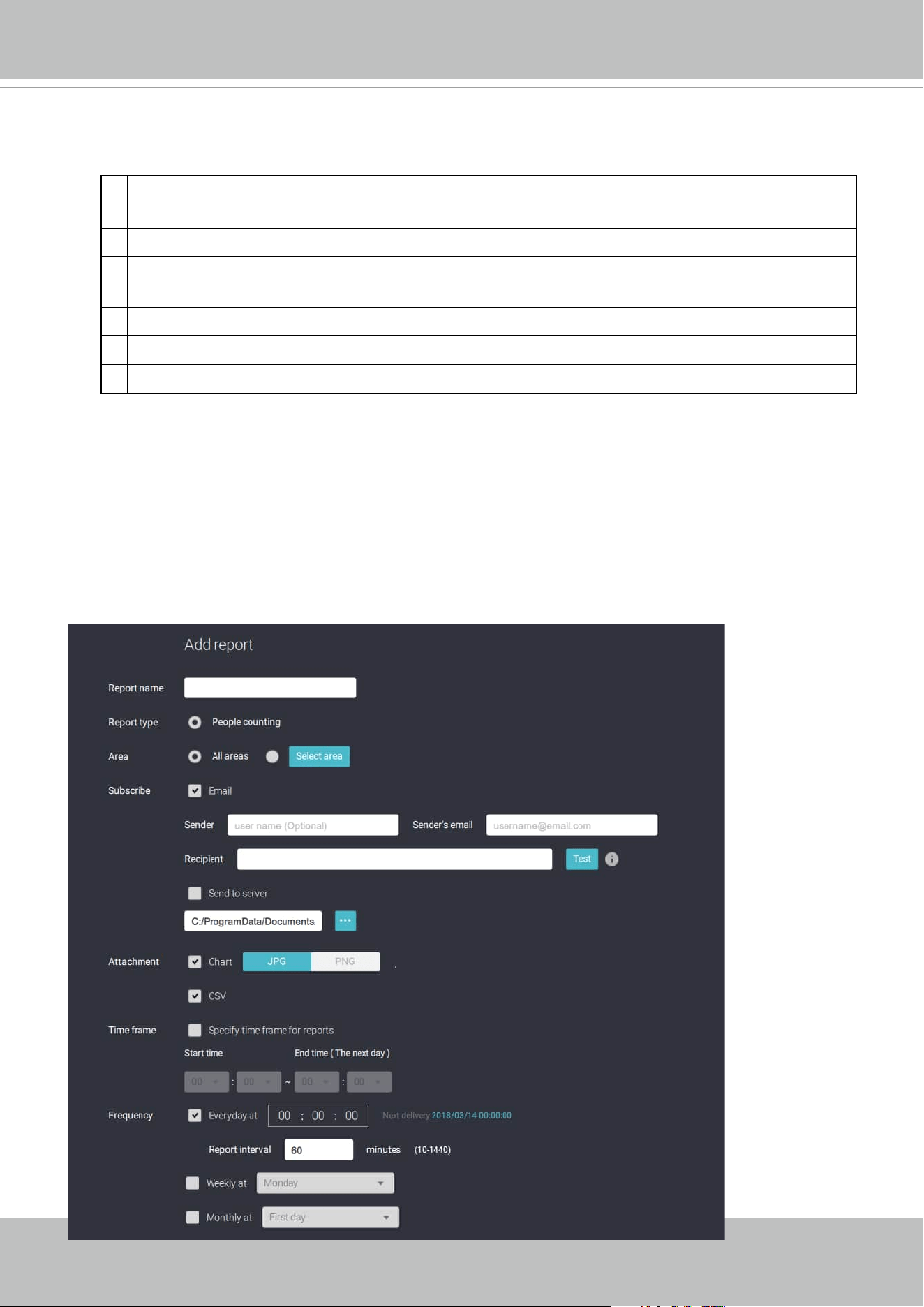
VIVOTEK - A Leading Provider of Multimedia Communication Solutions
User's Manual - 203
9. Click the Reports Subscription button to configure the regular report sent to your Email
account or a specific location on the server itself.
Select the following:
1.
Report type: People counting results, or Heatmap (Heatmap does not produce CSV file)
2.
Area: All areas or a preconfigured area.
3.
Subscribe: Enter the sender and recipient Email addresses. You can also configure to
send the report to a specific location on the server.
4. Attachment: Select to attach graph Charts in JPG or PNG, and the CSV
data files
.
5. Time frame: Select the time coverage of the report, during which data is collected.
6. Frequency: Species when and how frequently to deliver the reports.
Select the time to deliver your mail notification. Enter valid Email addresses as the sender
and receiver addresses and make sure the SMTP mail server configuration has been properly
configured on your VAST server. This VCA mail notification utilizes the mail service on VAST
for regular notification. You can then receive Email notification every day on your Email
account. You can enter up to 5 recipient addresses.
Select the report interval to determine how often you receive an aggregated report.
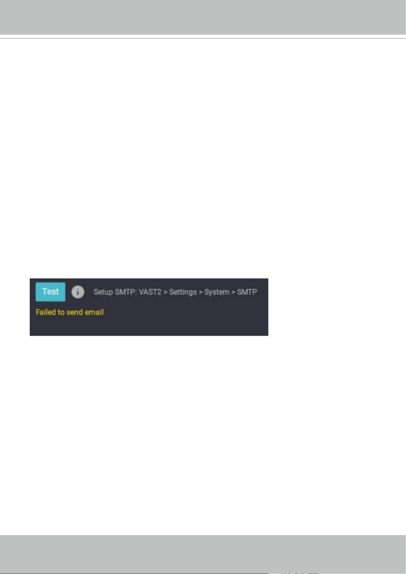
VIVOTEK - A Leading Provider of Multimedia Communication Solutions
204 - User's Manual
Note that the notification contents is your current field of view, including a Bar, Line, and Pie
chart combined into one image file. The In/Out/Remaining results will be generated into
3 charts. Each Area will generate one CSV file, and each CSV data file will contain In/Out/
Remaining/Summary information.
The generated file names will look like this: 20160226_test02_Remain.jpg for charts
and 20160226_Summary.csv for CSV files. The Email subject will be "VCA Daily Report -
2016/02/26."
Note that if you manually export a report, the default is sending the data collected until one
hour before the manual export. For example, if you generate the report at 14:07, the report
will only cover the data collected until 13:59. You may use the Refresh button to manually
generate immediate data inputs (those occurred between 14:00 and 14:07).
You may configure to receive regular VCA report as Weekly or Monthly using the associated
menus.
Below are the messages with the Email test function.
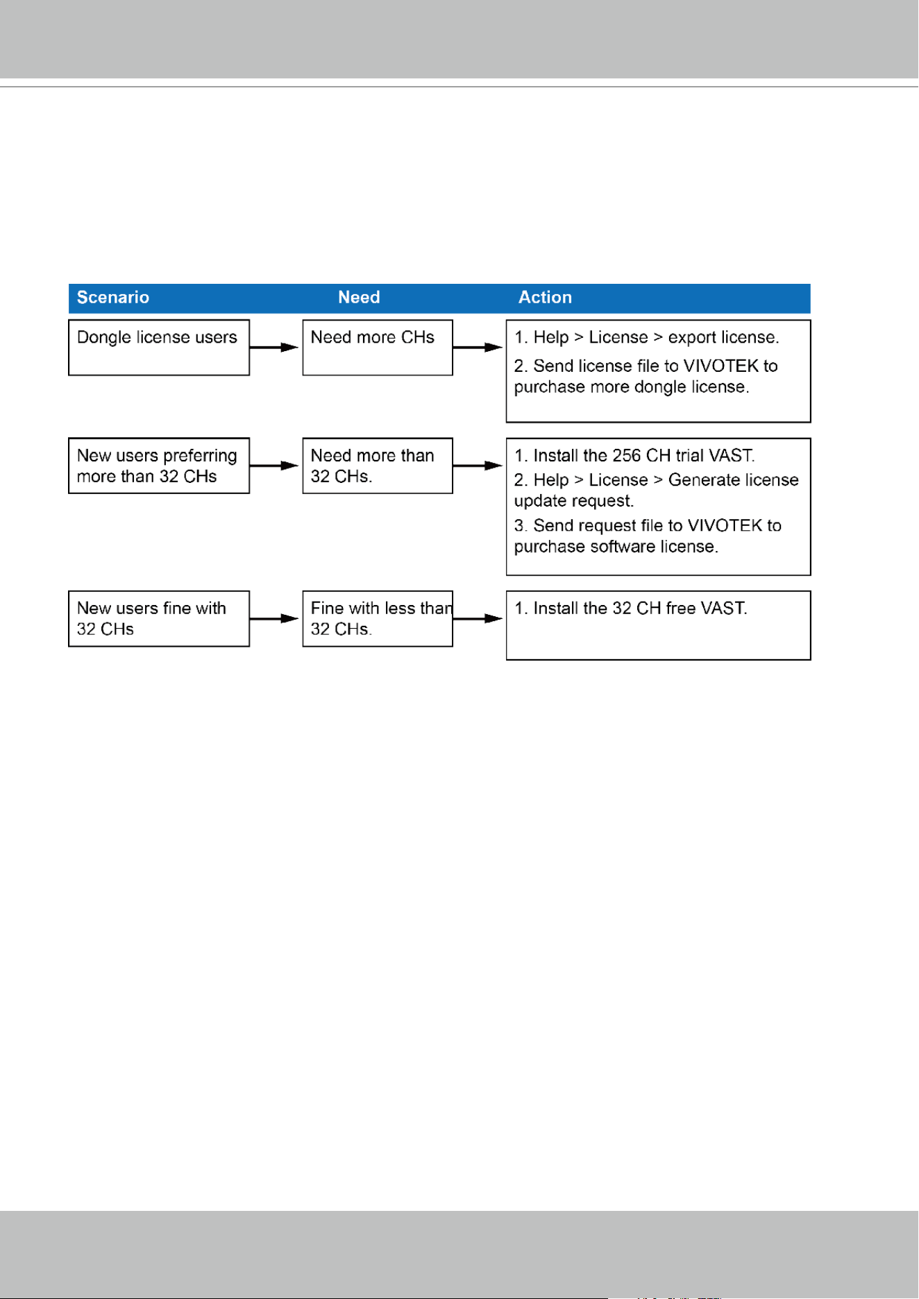
VIVOTEK - A Leading Provider of Multimedia Communication Solutions
User's Manual - 205
3-4. VAST Software License
To activate the software, refer to the flow chart below:
The VAST software provides 32 free channels. Since revision 1.11, the VAST software is
activated using a software license instead of the original hardware dongle.
For users running the previous dongle version, there is no need to upgrade their original license.
If they need the license for more channels, They can export their license file, and purchase more
dongle licenses.
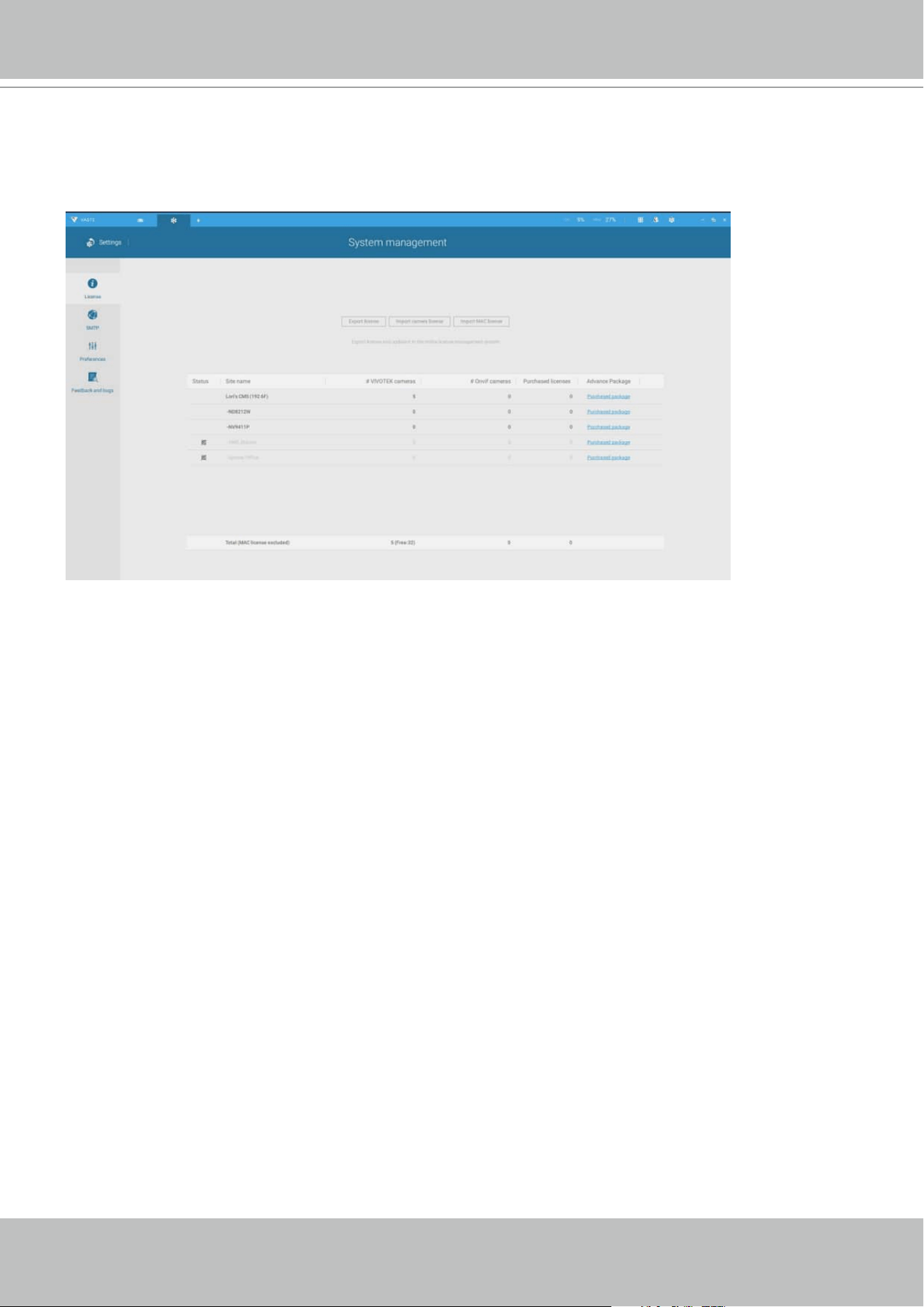
VIVOTEK - A Leading Provider of Multimedia Communication Solutions
206 - User's Manual
For users who require more than 32 channels, they can install the 256 channel trial version first,
and go to Settings > System > License page, and click on the Export License button. Send the
request back to VIVOTEK to purchase more channel licenses.
When you purchased and received the official software license, use the Import License function
to activate the official license.
When importing purchased licenses,
1. System will dispatch licenses to VAST stations according to hardware information,
2. If licenses do not match the VAST stations, you can manually select which license will be
dispatched to which station.
Since VAST rev. 2.6, there is an Import MAC license option. You can select a MAC license file
and manually deliver the file to one or multiple substations.
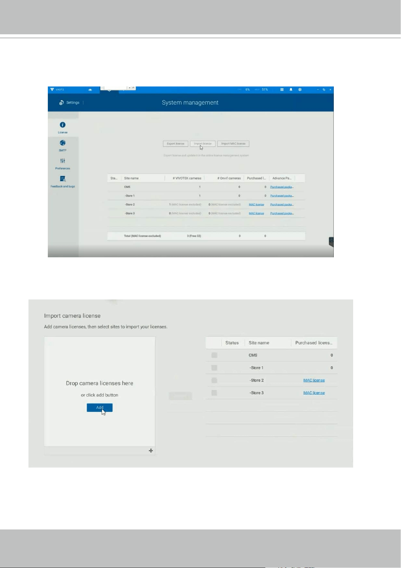
VIVOTEK - A Leading Provider of Multimedia Communication Solutions
User's Manual - 207
1. Continue to import the camera licenses.
2. When in the Import page, click the Add button to select camera licenses.
Below is a sample procedure for importing the camera licenses:
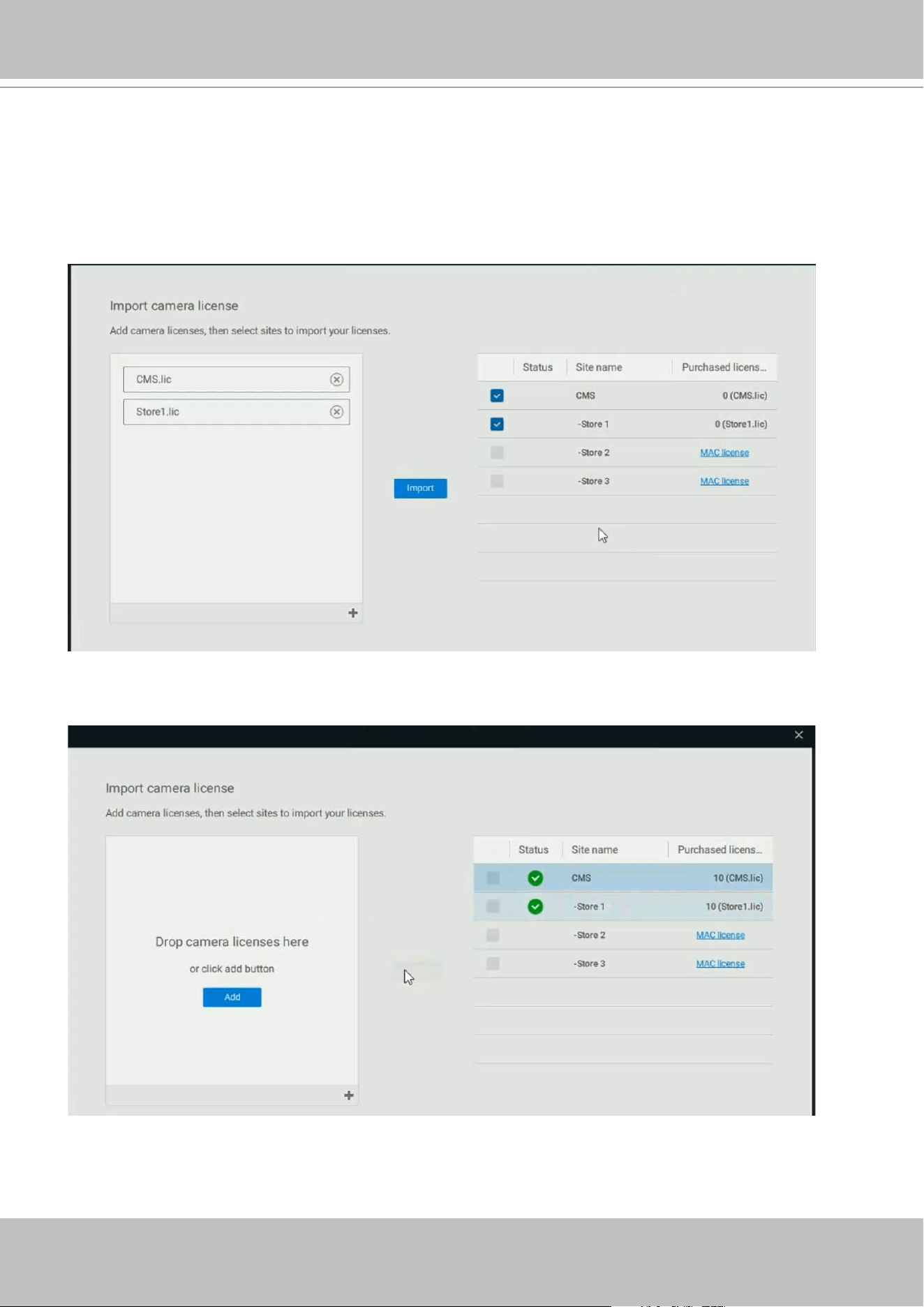
VIVOTEK - A Leading Provider of Multimedia Communication Solutions
208 - User's Manual
3. Select the target servers, click Import.
4. When done, a successful import will be indicated.
Camera licenses are bundled with hardware information. When import camera licenses, the
software will automatically match the licenses with corresponding servers.

VIVOTEK - A Leading Provider of Multimedia Communication Solutions
User's Manual - 209
Updating Licenses for VAST on Virtual Machines
NOTE:
1. The VAST server supports the installation on VMWare, Virtual Box, Parallel, and Hyper V.
2. A MAC address authentication mechanism is implemented for VAST running on virtual
machines.
3. The license requests have to be generated from the VAST2 installed on a Virtual Machine. If
your conguration consists of multiple VAST servers, and one of them is installed on a virtual
machine, exporting license information will generate a MAClist le. The MAClist le will be
used for the VAST instances running on virtual machines.
This instruction includes:
1.How to Export a license request from VAST2 on a virtual machine.
2.How to acquire the MAC addresses of the inserted or non-inserted cameras?
3.Send us request les & MAC addresses (If you have multiple sites, please remember to
designate grouping information, such as which MAC addresses belong to which camera
deployments).
4.How to Import MAC licenses to VAST2?
5.How to buy more MAC licenses for future distribution?
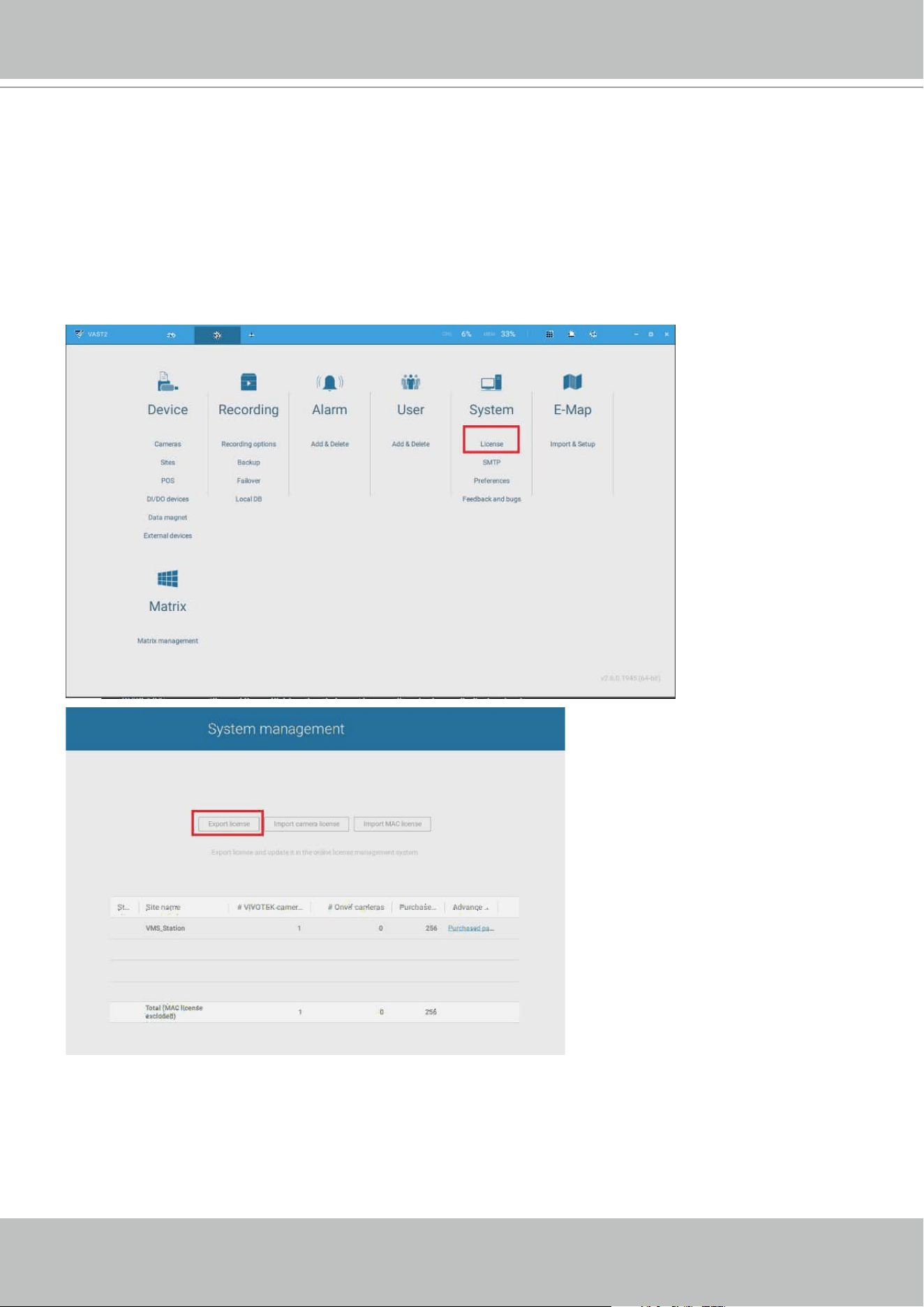
VIVOTEK - A Leading Provider of Multimedia Communication Solutions
210 - User's Manual
1.How to export request from VAST2 on VM?
1-1. Install VAST2 server on a Virtual machine (usually VMware workstation - full - 12.1.1), or
download VAST2 from VIVOTEK website.
1-2. Insert cameras for the VAST station(optional).
Go to virtual machine, Open VAST2 > Settings > Insert cameras (You may already have
more than 32 cameras inserted if you are using the trial version).
1-3. Go to VAST2 > Settings > License > Export license.
1-4. Click the Export license button and select your Windows desktop as the destination folder. A
VAST2 license folder will display on the desktop, zip the folder and send the request le back
to your sales representative, distributor, or VIVOTEK.
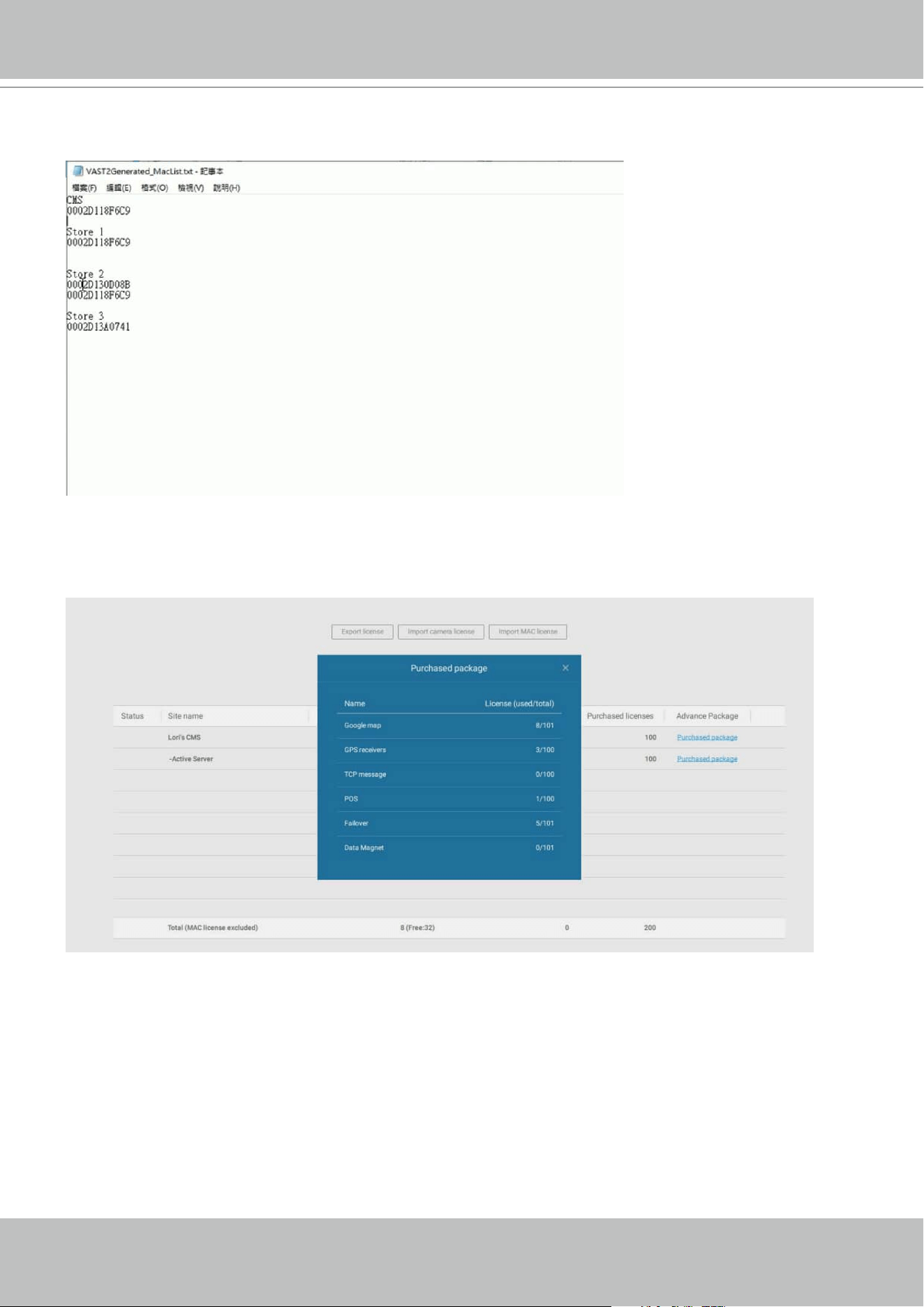
VIVOTEK - A Leading Provider of Multimedia Communication Solutions
User's Manual - 211
You can examine your current license status. Click on Purchased package. The licenses cur-
rently in use will appear.
The generated MAC list should look like this.
VIVOTEK - A Leading Provider of Multimedia Communication Solutions
212 - User's Manual
1-5. Once you acquired the MAC licenses from VIVOTEK, click Import MAC license button. You
will enter the import page. Use the Add button and locate your license les.
To use the MAC license import function, both the CMS and its substation servers should both
be running VAST revision 2.6 or above.
1-6. Select the license le.
VIVOTEK - A Leading Provider of Multimedia Communication Solutions
User's Manual - 213
1-7. The selected le appears on screen.
1-8. Select the target server sites to import the license le. When done, click the Import button.
MAC licenses are not bundled with server hardware. You can import licenses from the CMS
server to one or multiple virtual machines running the VAST software.
VIVOTEK - A Leading Provider of Multimedia Communication Solutions
214 - User's Manual
1-9. Select the virtual machines (sites) running the VAST server to import the license le. When
done, click the Import button.
1-10. When done, the MAC licenses display on the license page as shown below.

VIVOTEK - A Leading Provider of Multimedia Communication Solutions
User's Manual - 215
Limitations:
1. The Batch import/export function applies when a managing VAST server needs to collect and
update the licensing information from subordinate VAST substations and itself. An enterprise
may have a central management server and several VAST instances running in branch of-
fices. In that case, the substations will be listed on the device list, and may not be displayed
on a hierarchical structure.
Reminders for VAST Software License
2. The batch download/import function only takes effect on a VAST instance running on server,
not on the Linux-based NVR.
3. The trial channels on VAST substations will not be available for use on a managing VAST
server (one that manages multiple substations).
4. If you access a VAST deployment via a web console, the license related information will not
be available.
5. In this revision, an identical software license applies to both VIVOTEK and other-brand
cameras (ONVIF). You do not need to activate two different kinds of software licenses.
6. The Batch export update of the current license profile is supported.
7. If the VAST server is removed and then re-installed, the number of licensed channels remains
intact.
8. If users plan to integrate the software licenses from previous dongle licenses, problems may
occur if users changed the exported license file name.
VIVOTEK - A Leading Provider of Multimedia Communication Solutions
216 - User's Manual
Chapter 4 Settings:
4-1. Settings > System > Preferences
The Preferences page for VAST client and Station sides allows you to configure the
following:
Client Setting:
1. Select the UI text language.
2. Configure a default destination for exporting video, snapshots, or configuration backups.
The default is "
C:\Users\Public\Documents\VIVOTEK Inc\VAST\Downloads". You can
change the media format via the checkboxes.
3. Select the format for the snapshot as either JPG or PNG.
4. You can select the length of the Alarm-triggered videos by specifying pre- and post-
alarm recordings.
5. You can designate the VAST client interface to automatically start once the client
computer is started.
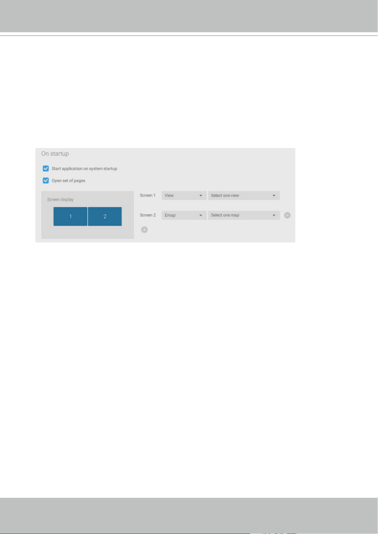
VIVOTEK - A Leading Provider of Multimedia Communication Solutions
User's Manual - 217
5. The default Live view, which may span across multiple monitor screens and display Live view,
Tour, Dashboard, E-Map, or Alarm prompts. The precondition is that you should configure one
or many views before making the Startup configuration.
Below is a server/client with dual monitors, you can select one view to be displayed on one
monitor, or place an E-Map on another. Up to 8 monitors can be configured.
Click the Apply button for the configuration to take effect.
Station Setting:
1. Display Watermark over video - Administrators can select to display watermarks on the video
feeds of the VAST clients. The opacity and display frequency can be adjusted.
Encrypted watermark for authentication:
To ensure your video is authentic and has not forgerized, adding an encrypted watermark on
the data stream can be achieved with a customized password. You can use the Standalone
Player to verify which frames in the video footage have been tampered with.
If enabled, the following will be displayed:
camera name + substation name + VAST2 user
name + user computer current time
. The purpose of watermark is to preserve evidence if the
video screen is recorded using cell phones or other devices.
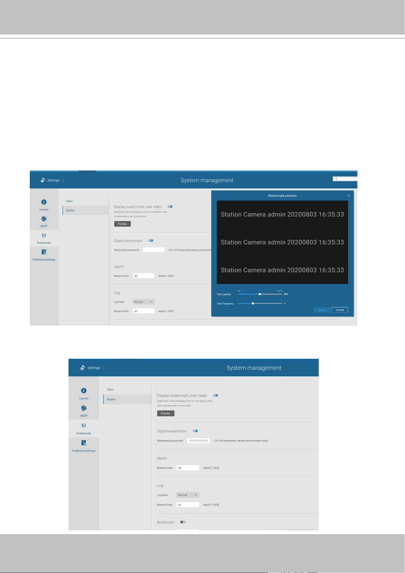
VIVOTEK - A Leading Provider of Multimedia Communication Solutions
218 - User's Manual
Station Setting:
2. Digital watermark - To prevent forgery of recorded or exported video clips, and to prove the
validity of surveillance evidence, digital watermark can be appened to recorded video.
Note that only non-administrator users will see watermarks.
To enable text watermark, use the slide button. Use the Preview function to tune the text
opacity and text frequency display on screen.
To enable Digital watermark, enter a password that is at least 16 characters long. Once a
valid password is available, you can click the Apply button to preserve your setting.
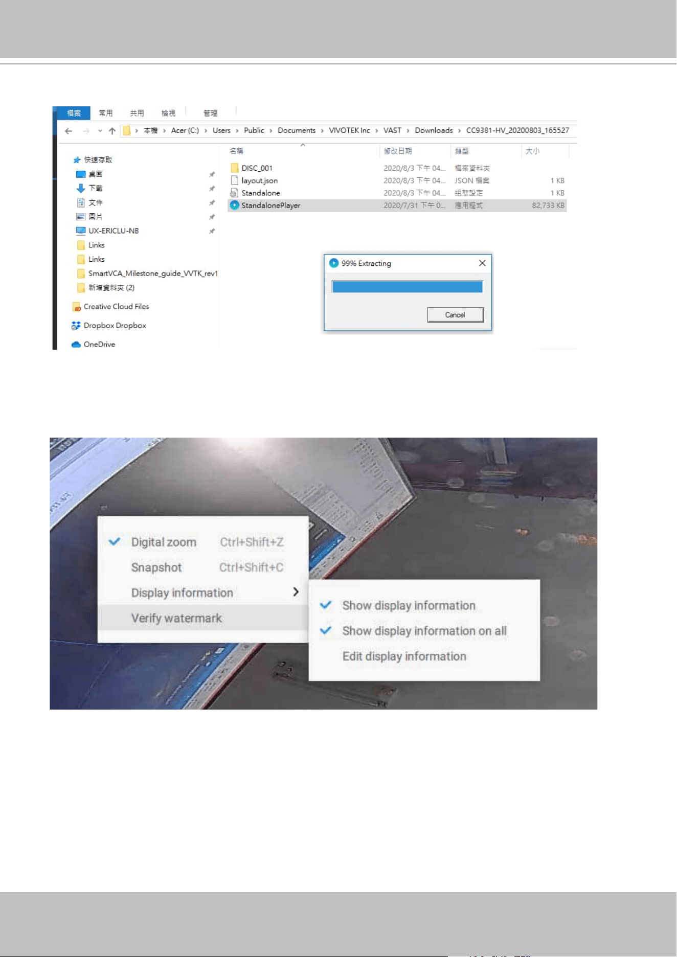
VIVOTEK - A Leading Provider of Multimedia Communication Solutions
User's Manual - 219
When you export a video clip, a StandalonePlayer is generated with the exported files.
Right-click on the StandalonePlayer screen to display the "Verify watermark" function.
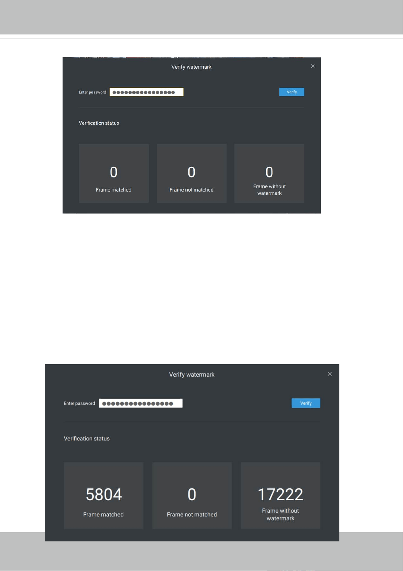
VIVOTEK - A Leading Provider of Multimedia Communication Solutions
220 - User's Manual
The Verify screen will display. Enter the pre-configured password. Click Verify.
The below result shows that the video is authentic and has not been forgerized.
Frame matched: Your video was exported with the digital password, and you entered the
correct password.
Frame not matched: Your video was exported with the digital password, and you entered the
incorrect password.
Frame without watermark: a. If your video wasn't exported with the digital password.
b. If your video was exported with the digital password, and your video has been tampered.
If the numbers in the "Frame not matched" or "Frame without watermark" are not zero, it
means your video is probably not correct.

VIVOTEK - A Leading Provider of Multimedia Communication Solutions
User's Manual - 221
3. Alarm - Reservation time: Configure the preservation time of the alarms and logs. Note that
some alarms can be triggered with recorded videos. Configuring a preservation time can help
reduce the use of storage space on server.
4. Log: Use the menu to configure the preservation time of the Major, Normal, or Minor logs.
5. Bookmark: Configure the days of preservation for bookmarks.
6. Data magnet: Configure the days of preservation for data related to Data Magnet.
7. Trend Micro events: Configure the days of preservation for events related to cyber security.
8. Database: Configure the destination of the database folder. The database contains
information for system log, alarms, Bookmarks, data magnet, VCA reports, POS transaction
data, snapshots, and Trend Micro IoT security information.
VIVOTEK - A Leading Provider of Multimedia Communication Solutions
222 - User's Manual
4-2. Settings > Device > Cameras
In addition to the add device process during the initial setup, you can add more cameras or
arrange the device list in Settings > Cameras.
Below are the locations of the functions for adding devices to the VAST server.
Start Scanning
Import CSV
Manual Add
Refresh
Authorize...
Click to select or deselect
Password protected
Edit device list &
Logical folders
Final confirm
Sync time w/ VAST
- or -
Sync w/ another NTP server
Note that you must know the credentials for password-protected cameras. You will not be
allowed to enlist cameras that come with unknown credentials.
For cameras outside the local network, you can manually enter its IP address, or use a pre-
configured device list to automatically introduce new devices.
If all devices come with the same credentials, you can select these devices and click Authorize
to enter the credentials.
VIVOTEK - A Leading Provider of Multimedia Communication Solutions
User's Manual - 223
Streaming URL
This is an optional feature. You can enter a camera's IP address to add a camera's RTSP
streaming for live view and recording, and playback.
To insert a camera using the URL-like command,
1. Select the camera Brand as "RTSP."
2. Enter the camera's IP address.
3. Enter the camera's MAC address as printed on the camera label, or one found by the
Shepherd utility.
4. Enter "554" in the Conguration port.
5. Enter "live.sdp" in the URL field, as this is part of the original RTSP streaming command:
"
rtsp://172.18.204.58:554/live.sdp". If streaming stream #2, enter live2.sdp.
6. Select a preferred protocol.
Note that the free 32 channel licenses does not apply when inserting a camera using the
URL command. Only the live view, recording, and playback functions are supported if thus
connected. All other functions are not supported, such as auto streaming size or changing to
another video stream. Neither are camera DI/DO supported.
Retrieve RTSP streaming on specific port: The default port for RTSP streaming is 554. If you
want to change this port, please check this item and fill in a desired port number.
VIVOTEK - A Leading Provider of Multimedia Communication Solutions
224 - User's Manual
6. For administrators who need to synchronize device time with a NTP server, he can deselect
the "Synchronize camera time with system" checkbox.
When adding cameras via ONVIP or RTSP protocol, you can select to synchronize its time
setting with your VAST server or to keep the camera setting. The default is using the camera
time setting.
VIVOTEK - A Leading Provider of Multimedia Communication Solutions
User's Manual - 225
4-3. Logical Folders
The Logical Folders allow you to re-define the logical relationships between the real-world
deployment and the physical devices (cameras). For example, according to your deployments,
you can designate several cameras to be listed under a logical sub-directory named as "Building
A," and the other cameras into "Building B." In this way, you can re-arrange your cameras and
devices on a tree view that is geographically more accurate.
1. On the Settings > Cameras page, click the Edit button.
2. Click on the Add a folder button.
3. Enter a name for the folder, e.g., 1st floor, 2nd floor,... according to your needs as shown
below.
4. Repeat the process to create more folders.
5. Make sure you enlisted all cameras in your deployment. You can start moving cameras to
specific folders. Click on the Move Selected Items button.
To create logical folders,
VIVOTEK - A Leading Provider of Multimedia Communication Solutions
226 - User's Manual
6. Select a logical folder to move the devices to. The selected devices will be listed under the
logical folder you selected. Repeat the process to move cameras to each logical folder.
VIVOTEK - A Leading Provider of Multimedia Communication Solutions
User's Manual - 227
You can also use the add device button to select devices from the list and move them to a
specific folder.
Return to live view, and you can see the configuration change takes effect.
VIVOTEK - A Leading Provider of Multimedia Communication Solutions
228 - User's Manual
4-4. Settings > Recording > Recording Options
Click Settings > Recording options. The Recording options window will prompt.
You can configure recording schedules or select the storage options, including the configuration
of an external NAS storage.
VIVOTEK - A Leading Provider of Multimedia Communication Solutions
User's Manual - 229
Click and hold down on the time cells, and drag the mouse to include the time span of your
preferrence. The minimum selectable unit is half an hour. You can select multiple time spans on
the template. Enter a name for the template, and click Add to save your template.
The same configuraion window apply to both the Schedule template and the customize
schedule windows.
Make sure a Schedule mode is selected when you leave this configuration step.
Click on any of the options on the Schedule panel for a recording option: Continuous recordings,
Events only, None, or Customize.
You can manually create a recording template using the New template
button.
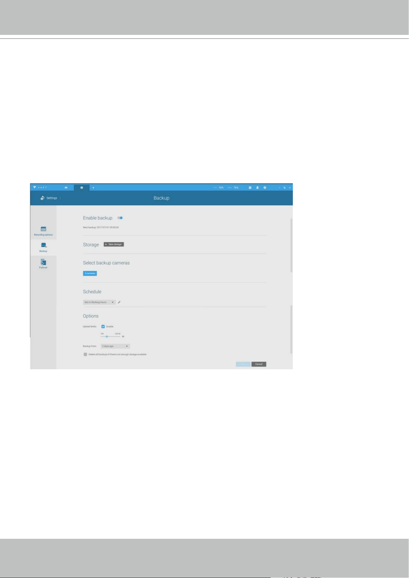
VIVOTEK - A Leading Provider of Multimedia Communication Solutions
230 - User's Manual
4-5. Settings > Recording > Backup
The Backup function allows you to regularly back up the video recordings of one or multiple
cameras to local hard disks or a Network Attached Storage device. Currently, the VAST2 server
does not support backup to external storage devices such as a storage devices connected
via Fibre Channel. VAST supports backup to an external storage attached through a USB 3.0
connection.
Note that the alarms associated with individual cameras will not be backed up.
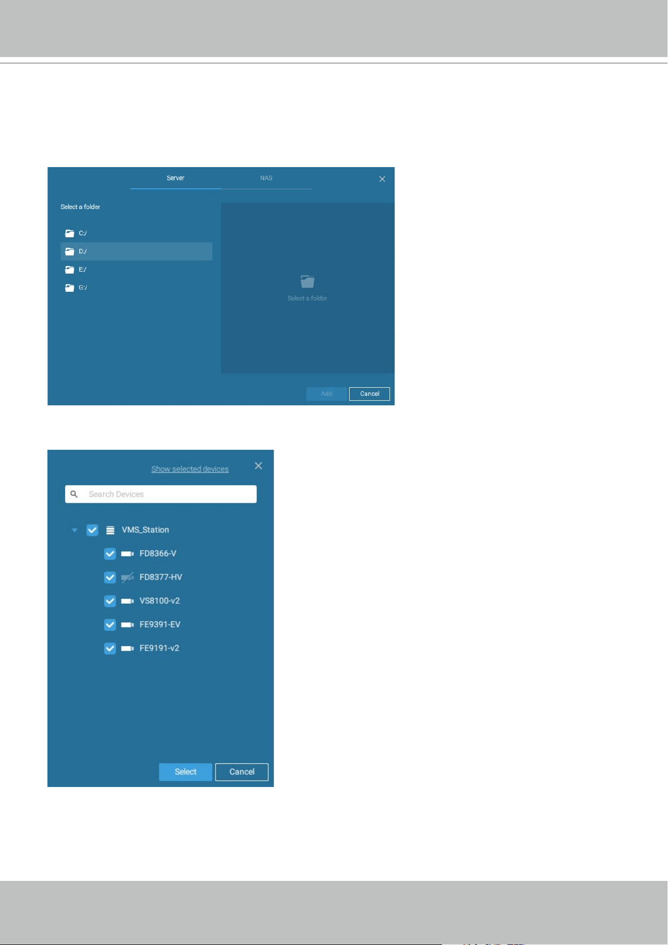
VIVOTEK - A Leading Provider of Multimedia Communication Solutions
User's Manual - 231
To enable a backup schedule,
1. Enable the backup by selecting the "Enable backup" slide switch.
2. Click to add New storage. A conguration window will prompt showing all accessible storage.
Click the NAS tab to enable access to a network share.
3. Select the cameras whose videos will be backed up.
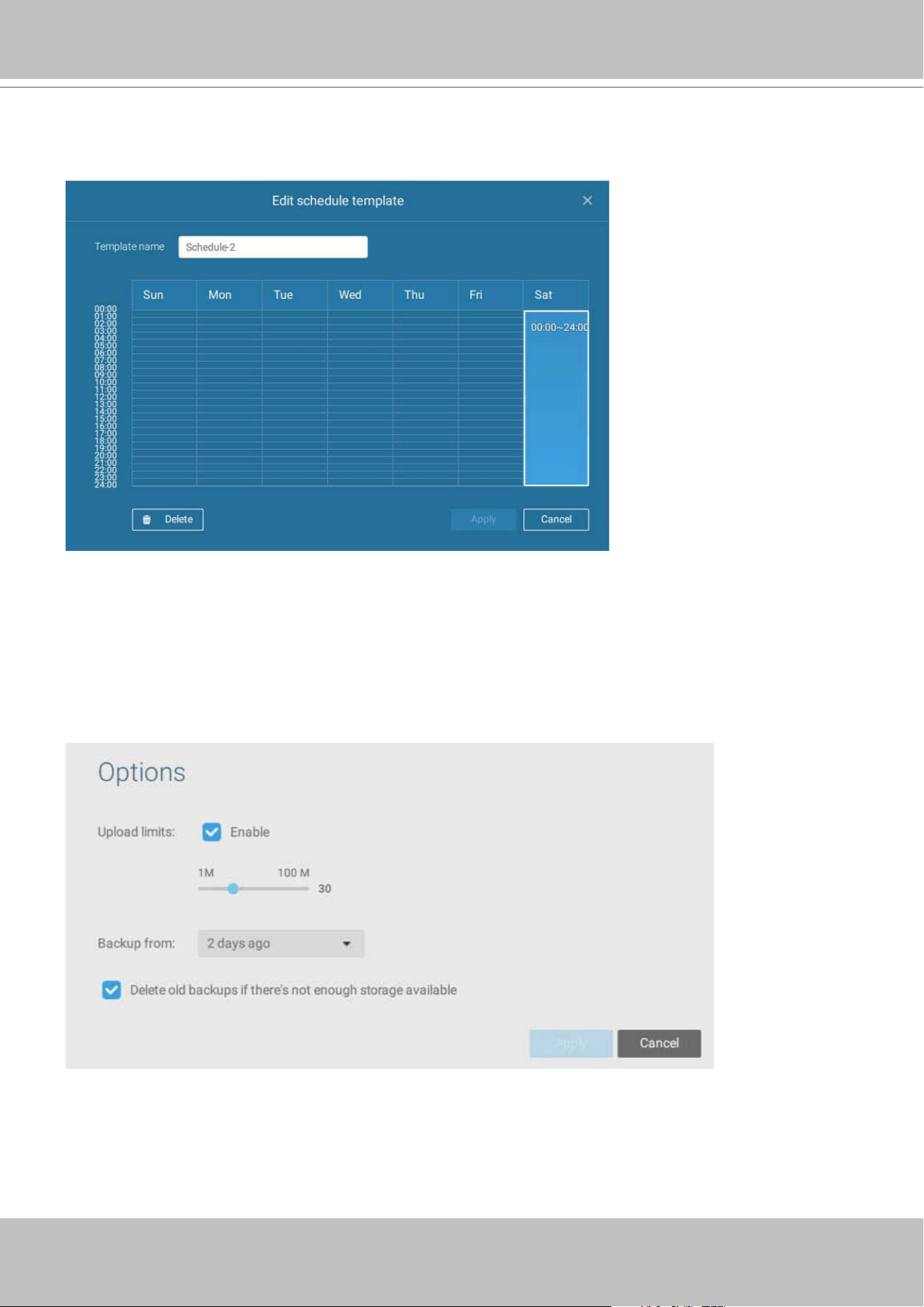
VIVOTEK - A Leading Provider of Multimedia Communication Solutions
232 - User's Manual
4. Select or congure a new schedule template for the backup process to take place. You can
select a time when the network load is low, such as the off-ofce hours, to avoid network
congestions.
5. On the Options pane, you can congure an upper bandwidth threshold (in Megabytes) for the
backup operation (for all selected cameras/channels).
You can select the extension of time, such as starting from how many days ago, of your
backup task. You can select to remove old backups when you run short of storage volume.
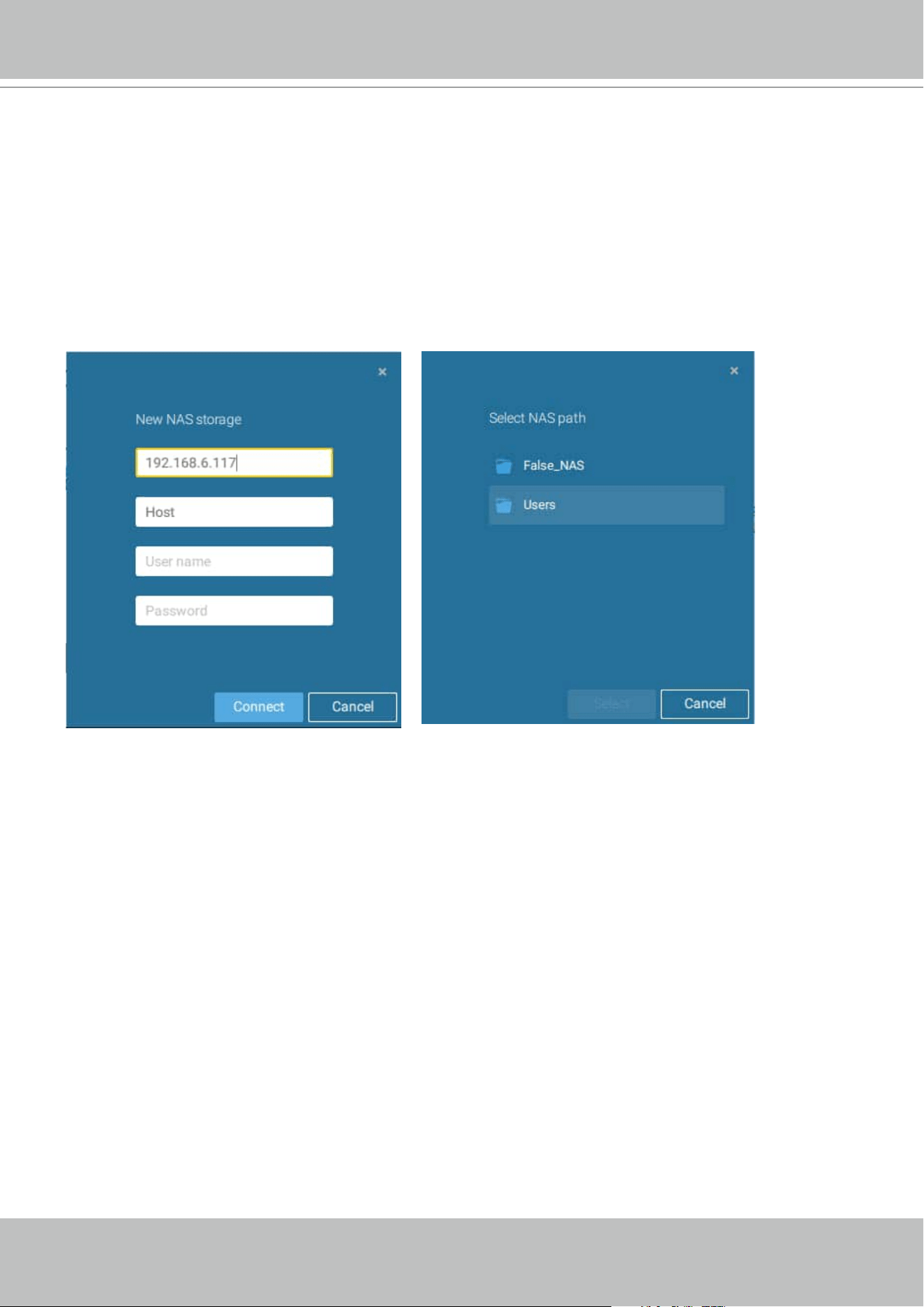
VIVOTEK - A Leading Provider of Multimedia Communication Solutions
User's Manual - 233
Storage
By default, VAST will check there is a D: drive. If not system drive C: will still be defined as the
first storage option. Other disk drives in the system, and the default storage volume (configured
in the initial setup) will be listed.
You can add a NAS storage's share volume as the additional storage option. Enter the necessary
information for access to a network share. Enter and select a NAS path. The share will then be
available for video recording.
Select storage volumes each by a single click.
Click Ready to use to continue.
VIVOTEK - A Leading Provider of Multimedia Communication Solutions
234 - User's Manual
4-6. Settings > Device > Sites
The VAST2 allows a deployment consisting of multiple VAST instances at different sites. A
VAST server can be selected as the CMS (Central Management Server) to manage sub-stations
in a hierarchical structure.
Each individual VAST station manages its own surveillance deployments. To build a hierarchy,
proceed with the following:
1. Open the VAST 2 client on a sub-station.
2. Enter Settings > Sites.
3. Enter a TCP Port number if your network configuration requires a different port.
4. Select Allow CMS to access this site.
5. Click Change password. This password will be used to authenticate the connection between a
CMS VAST server and sub-stations.
6. Click the Apply button.
7. Open the VAST 2 client on the server chosen as the CMS.
8. Click the Add sites
button.
VIVOTEK - A Leading Provider of Multimedia Communication Solutions
User's Manual - 235
9. You can click the Search button if the sub-station is reacheable in a local network, or manually
enter the IP address, and password for making the connection.
10. Enter the password you configured for the Sites configuration, and then click the Authorize
button.
Click the Apply button for the configuration to take effect.
VIVOTEK - A Leading Provider of Multimedia Communication Solutions
236 - User's Manual
The sub-stations and its subordinate devices should be immediately listed under the CMS
station. You can create separate views to place the sub-stations' cameras.
When you want to enlist an NVR into your conguration, please remember to enable the
access from VAST server in the NVR's Service page.
The connection between VAST and NVR is made via encrypted https.
If the connection port is changed to a non-SSL port, the access from VAST to NVR will fail.
For adding the ND series NVR, use port 443.
VIVOTEK - A Leading Provider of Multimedia Communication Solutions
User's Manual - 237
Multicasting
The VAST2 supports multicasting of live streams from server to clients. If multiple VAST2
clients demand live videos from the same camera, multicasting cna help save considerable
system resources.
Multicasting should be enabled on a VAST server and also on individual cameras.
There are prerequisites:
1. Both the VAST2 server and clients have to be revision 2.7 or above. If any of them is running
revisions before 2.7, client connections will crash.
2. Multicasting is not supported under the following conditions:
* A CMS local client can only access the live stream from the cameras managed by the CMS
server using unicast connections.
* If the need arises for access to cameras managed by VAST sub-stations, the multicasting
configuration should take place on the sub-stations instead of on the CMS server.
CMS VAST2
LAN
Video streaming
Camera 01
Camera 02
Camera 03
Camera 04
Camera 06
Camera 05
Camera 07
Camera 08
Camera 09
VAST2 Client
Camera 01
Camera 02
Camera 03
Camera 04
Camera 06
Camera 05
Camera 07
Camera 08
Camera 09
VAST2 Client
VAST2 Substation
VAST2 Substation
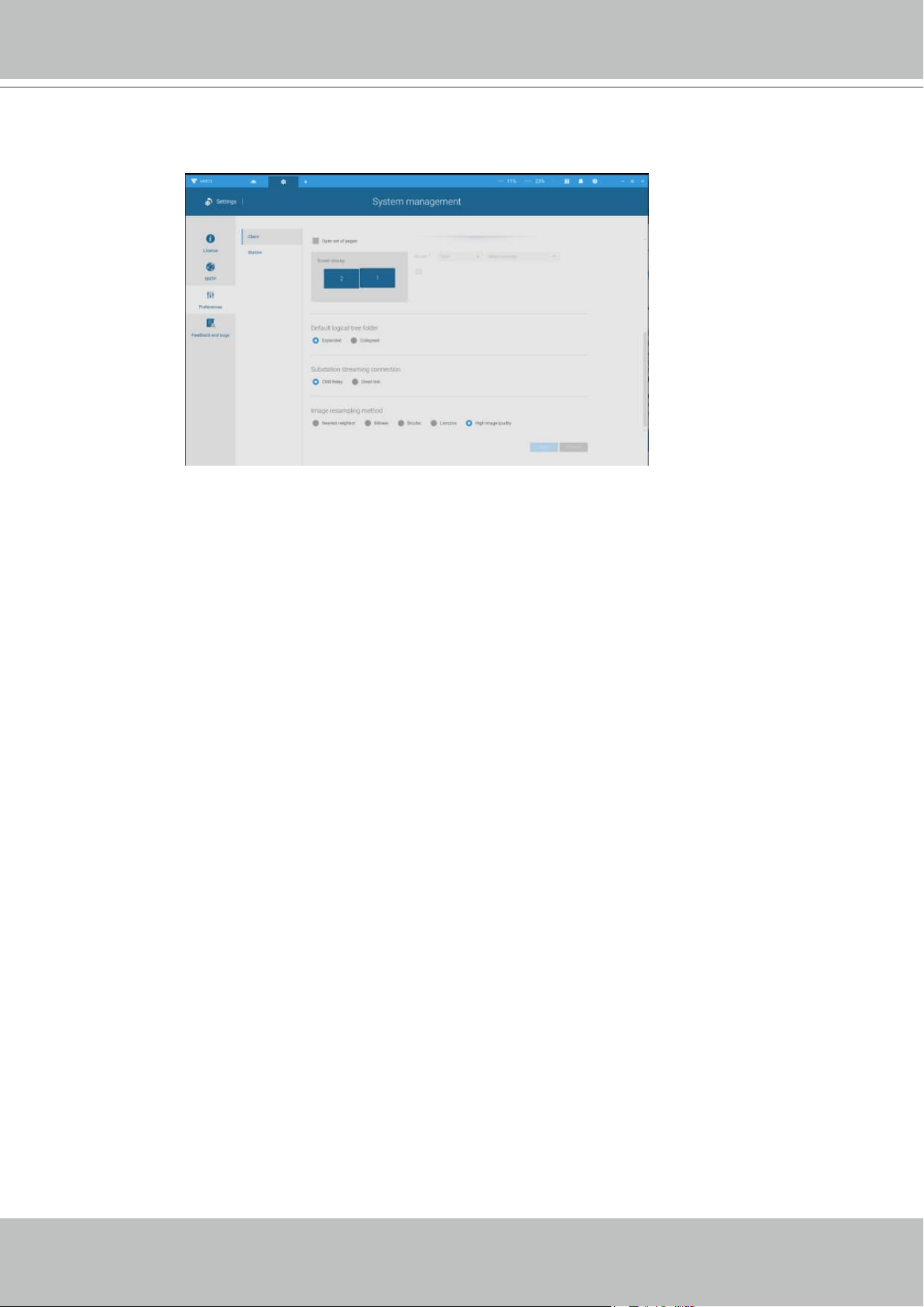
VIVOTEK - A Leading Provider of Multimedia Communication Solutions
238 - User's Manual
* To enable multicasting, your network infrastructure must support the IP multicasting
standard IGMP (Internet Group Management Protocol). Your server and clients should be
on the the same network segment.
* Multicasting is only possible for live streams, not applicable to the recorded video or audio.
* Multicast streams are not encrypted, even if the the recording server uses encryption.
* The IPv4 multicast address range is: 224.0.0.0 to 239.255.255.255.
* A layer 2 network switch that supports IGMP is required in the configuration.
* If the streaming connection for a sub-station is configured as CMS Relay, you should
configure the multicasting settings on the CMS server.
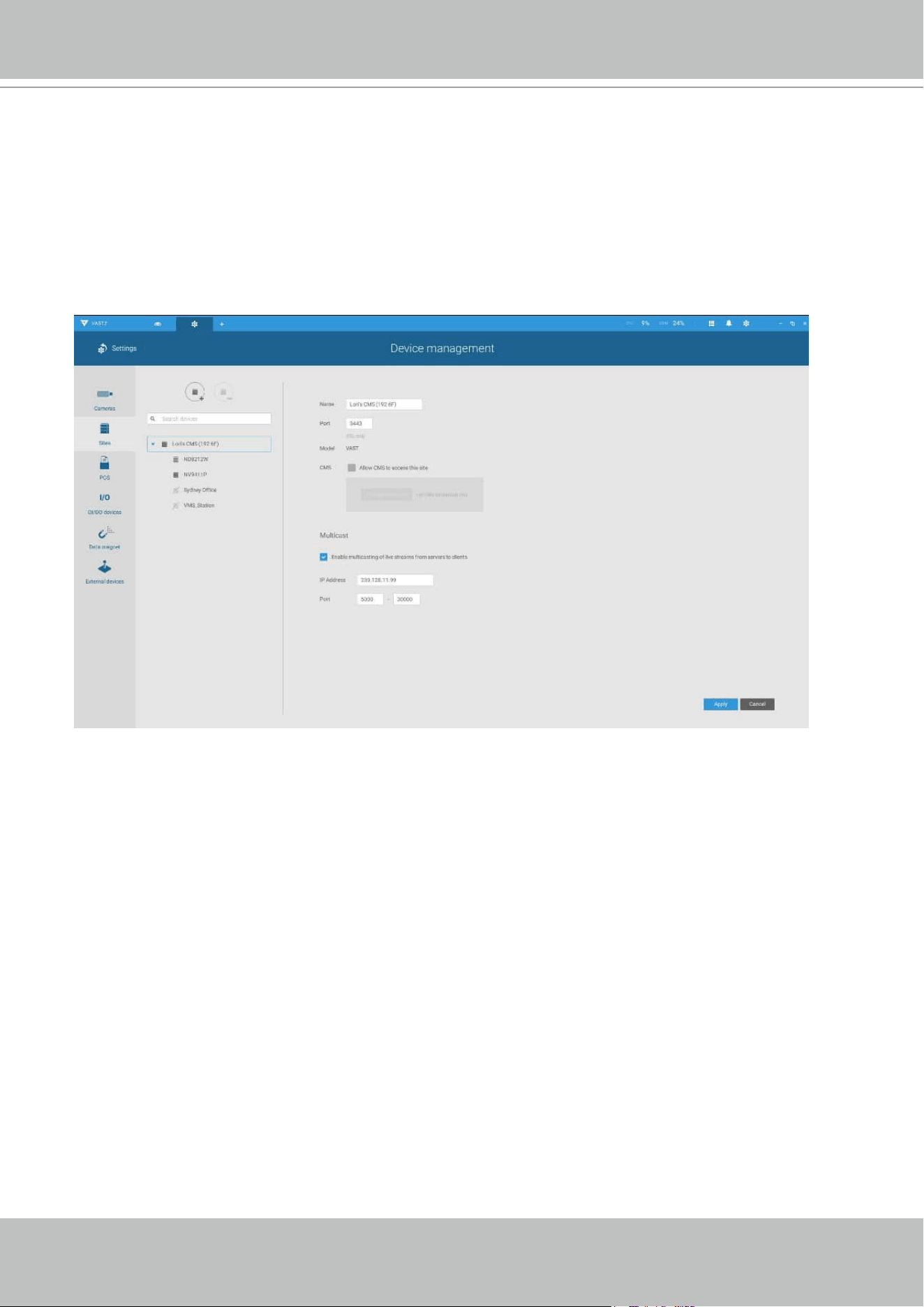
VIVOTEK - A Leading Provider of Multimedia Communication Solutions
User's Manual - 239
To enable Multicasting on a VAST server:
1. Enter Settings > Device > Sites.
2. Single-click to select a server for which you want to enable the Multicasting.
3. Click the checkbox to enable the configuration and enter the multicast address.
4. Click the Apply button.
Starting the Multicasting service will restart the VAST server.
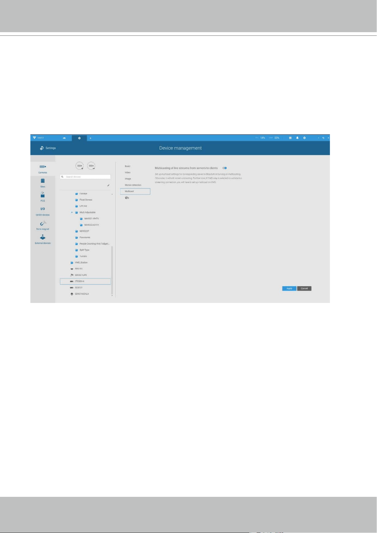
VIVOTEK - A Leading Provider of Multimedia Communication Solutions
240 - User's Manual
To enable Multicasting on a camera:
1. Enter Settings > Device > Cameras.
2. Single-click to select a camera for which you want to enable the Multicasting.
3. Click to select the Multicast tab.
4. Click the Multicasting slide button.
5. Click the Apply button.
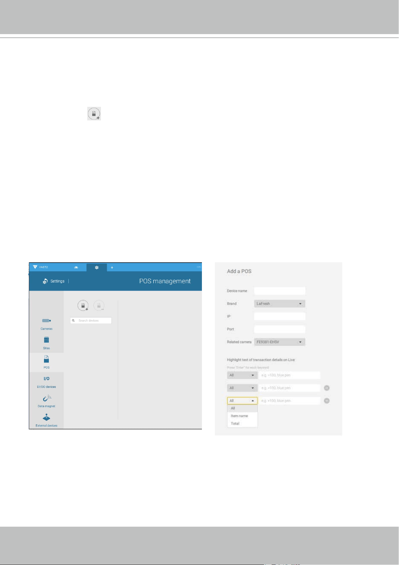
VIVOTEK - A Leading Provider of Multimedia Communication Solutions
User's Manual - 241
4-7. Settings > Device > POS
To connect a POS machine, make sure the POS machine is connected to the local network. Click
on the Add POS
button.
1. Enter a device name, such as POS on the 1st floor counter.
2. Select the POS brand name. Currently VAST2 supports Lafresh, POSNET, Gulfcoast(POS
Gateway).
3. Enter the IP address assigned to the machine.
4. Enter the TCP port number utilized by the POS machine for network connection
5. Select a related camera whose video feed will be used to display POS transaction data. This
is the camera which covers the customers and cashier.
6. Enter specific item name or a total amount exceeding a high threshold, such as using >100
as a threshold. You can enter multiple highlight conditions using the add button below. The
highlighted entries will be displayed in bright font colors on screen.
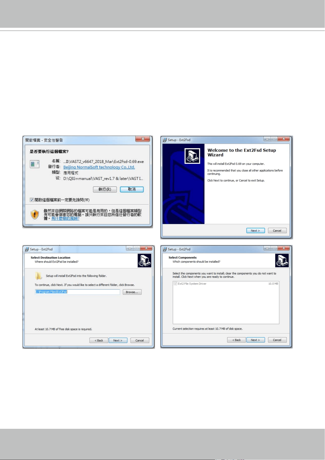
VIVOTEK - A Leading Provider of Multimedia Communication Solutions
242 - User's Manual
4-8. Settings > Device > Local DB
Since some of VIVOTEK's NVRs runs on Linux, you have to install the Ext2 File System Driver for
Windows to access the recording files from a NVR hard disk.
The file system driver can be found here: https://sourceforge.net/projects/ext2fsd/?source=typ_
redirect
Run and install the Ext2fsd-0.xx.exe. Follow the onscreen instructions to complete the
installation.
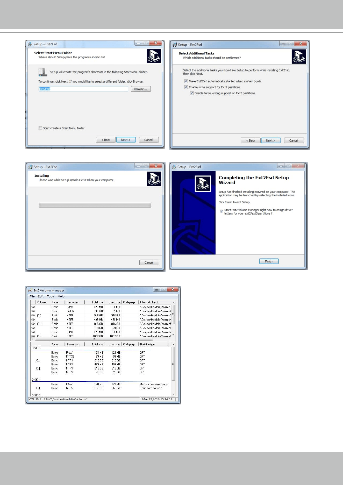
VIVOTEK - A Leading Provider of Multimedia Communication Solutions
User's Manual - 243
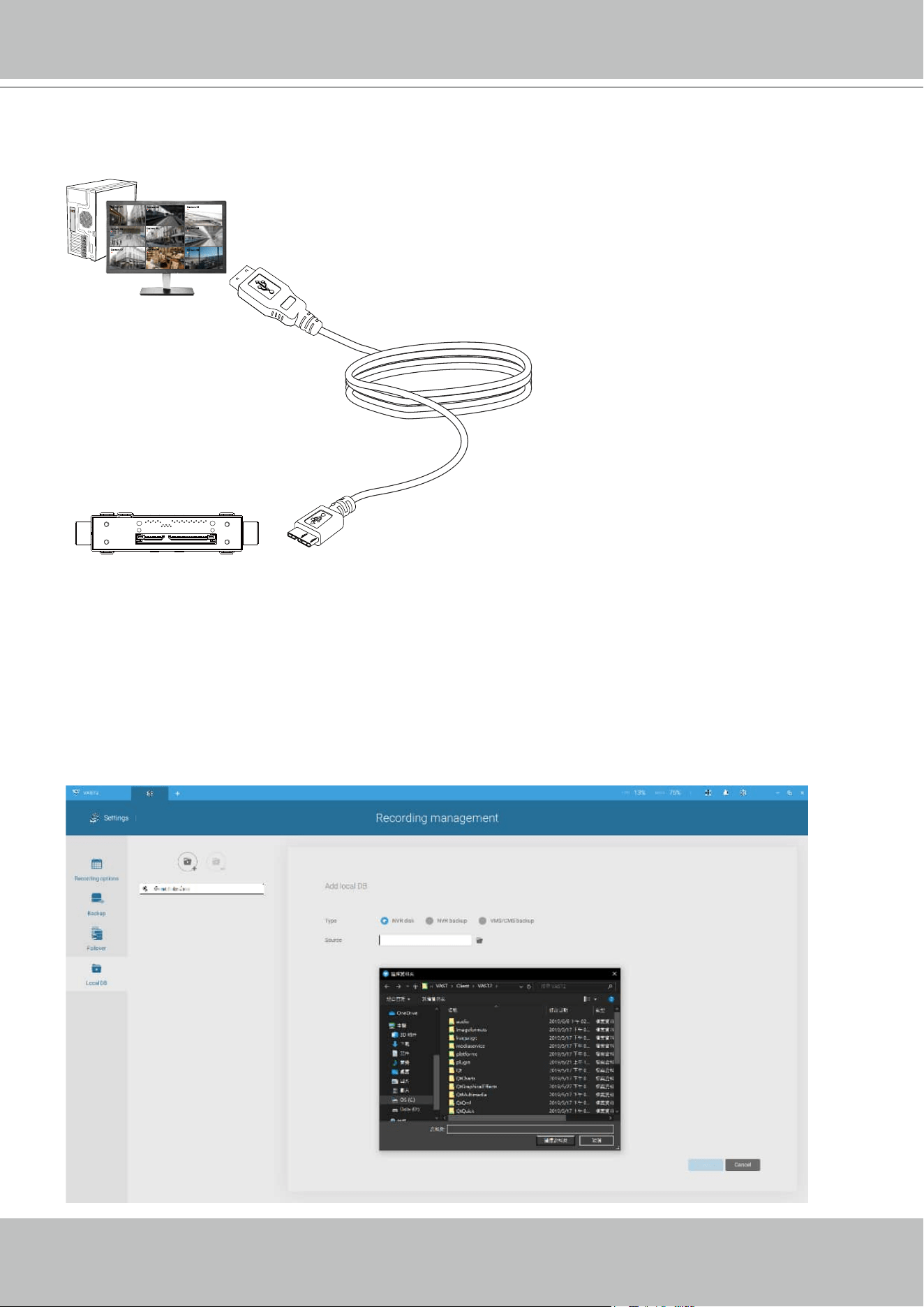
VIVOTEK - A Leading Provider of Multimedia Communication Solutions
244 - User's Manual
1. Remove the disk tray box from a mobile NVR.
2. Connect the disk tray box to your VAST server using a USB 3.0 type A to Micro B cable.
Camera 01
Camera 02
Camera 03
Camera 04
Camera 06
Camera 05
Camera 07
Camera 08
Camera 09
VAST
USB Micro BMobile NVR
Disk Tray
3. From VAST, enter Settings > Device > Locabl DB.
4. There are 3 import types:
1.
NVR disk: the drive tray box removed from a mobile NVR.
2.
NVR backup: the recorded videos exported from an NVR using a USB thumb disk or
portable drive.
3.
VAST backup: scheduled backup from the local machine. They include: VAST backups
from previous software releases, and scheduled backups.
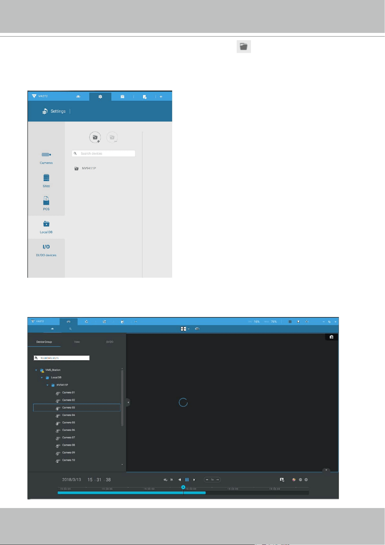
VIVOTEK - A Leading Provider of Multimedia Communication Solutions
User's Manual - 245
5. Taking a mobile NVR's disk drive as an example, click the Source select button to locate
the disk drive.
6. The NVR will be mounted as a local DB.
7. A Local DB sub-tree will be listed under your server, and you can view the existing recordings
on the NVR's disk drive.

VIVOTEK - A Leading Provider of Multimedia Communication Solutions
246 - User's Manual
4-9. Settings > System > SMTP
Configure a mail server via which the system alarms or notifications can be delivered to a
receiver.
Enter the Settings page, select . Click on the Add SMTP button.
Enter your mail server's domain name or IP address. Enter credentials for access to the mail
service.
If SSL encrypted transmission is preferred, select its checkbox.
Click Add to complete the configuration.
4-10. Settings > IO Box and Related Conguration
Please refer to page 175 for information.
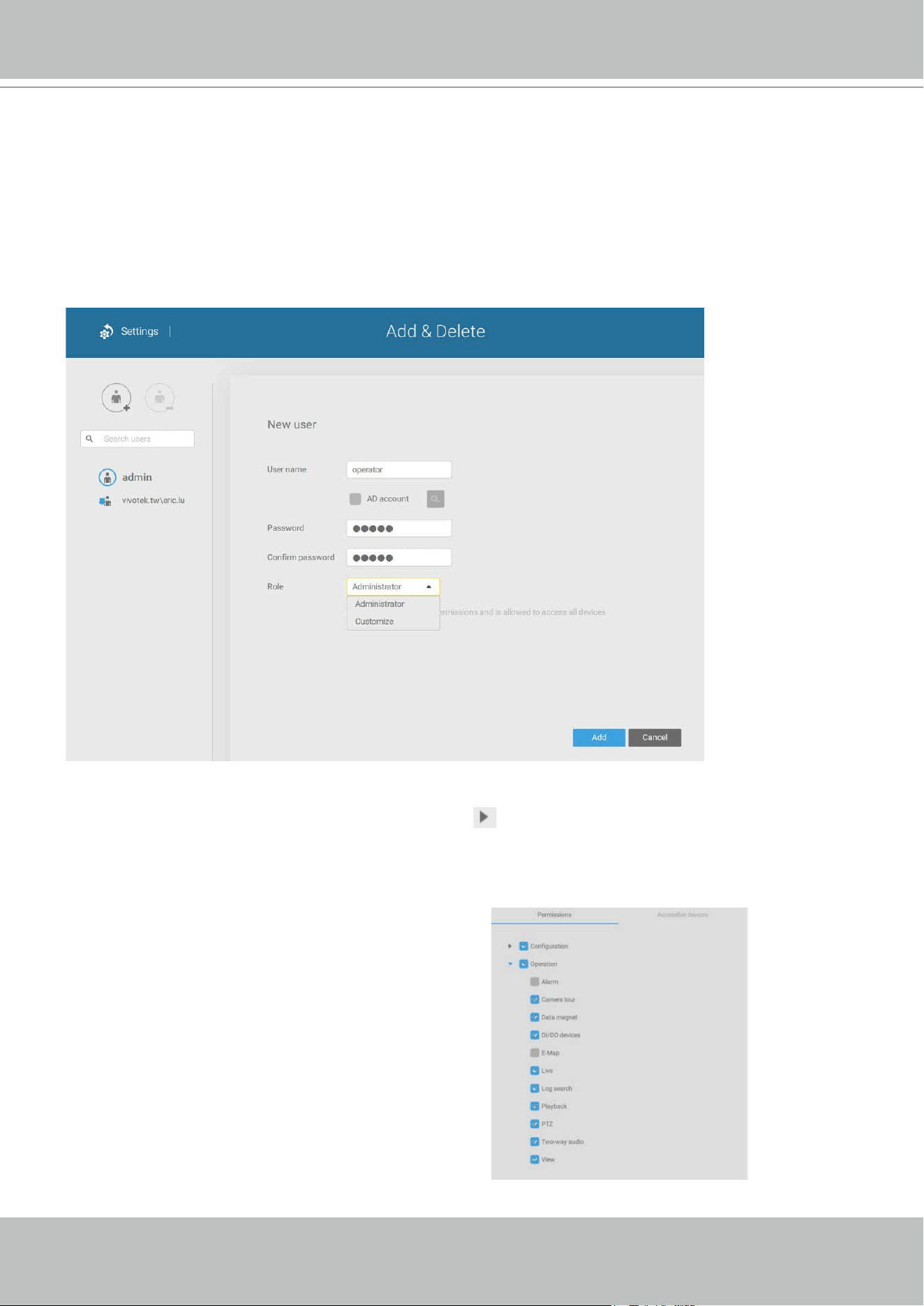
VIVOTEK - A Leading Provider of Multimedia Communication Solutions
User's Manual - 247
4-11. Settings > User Management
The User Add & Delete page allows you to create users with the permissions for different
operational capabilities.
To specify the authorized privileges, select Customize in the Role menu, then select the
Permissions and/or the Accessible devices tabbed menus.
Use the Customize option to limit the authorized actions of a user.
In the Permissions tab, click the expand button
to unfold the Operation and Configuration
menus. Select or deselect the checkboxes to
configure the user privileges. For example, you may not want
a user to operate Alarm and E-Map. If so,
deselect these checkboxes.
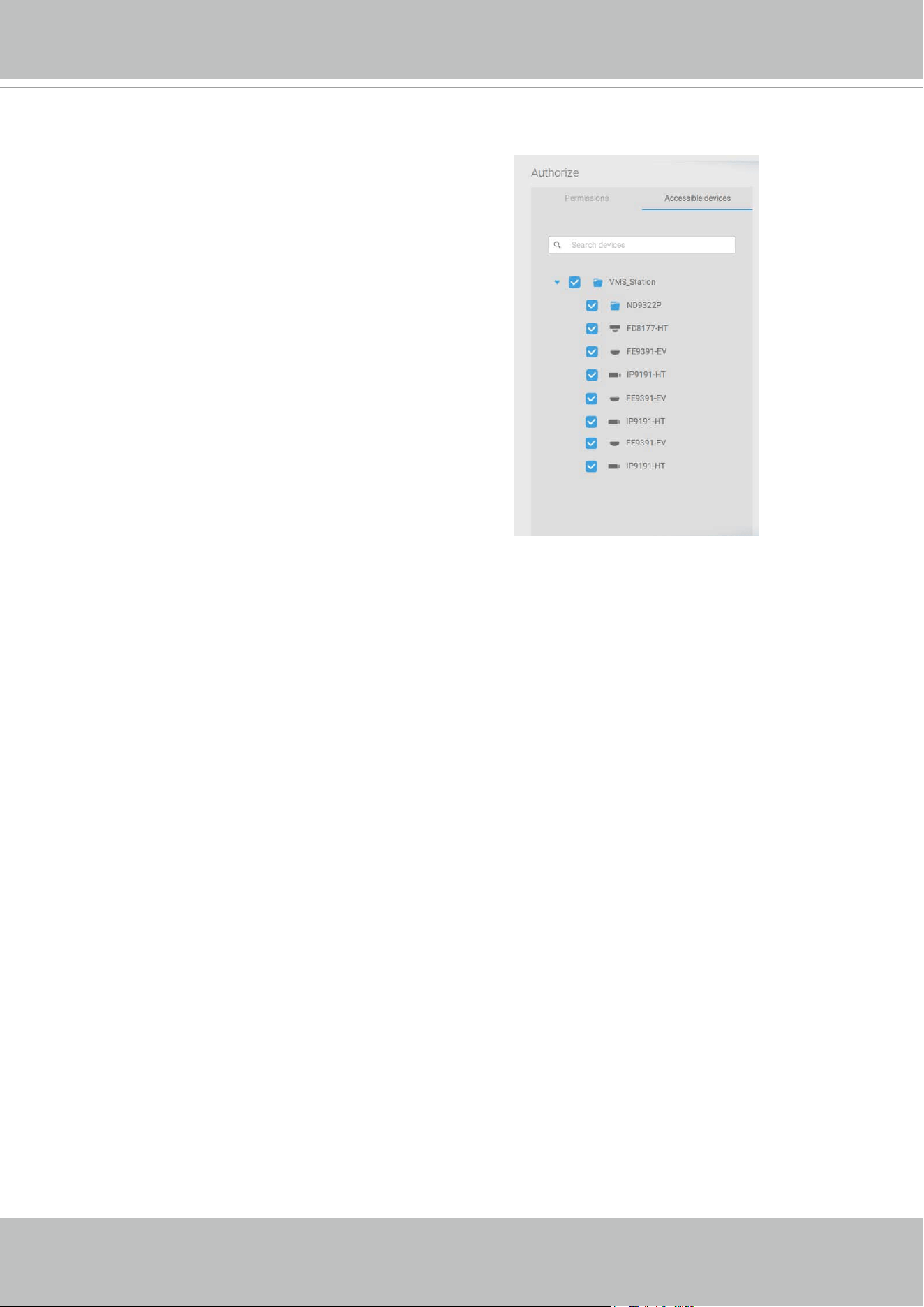
VIVOTEK - A Leading Provider of Multimedia Communication Solutions
248 - User's Manual
When done with the privilege settings, click Add to create a new user.
The new users will be listed under the Administrator's icon. Repeat the process to create more
users.
In the Accessible devices tab, click to select the cameras that a user can access. Some users
may only need to access specific devices.
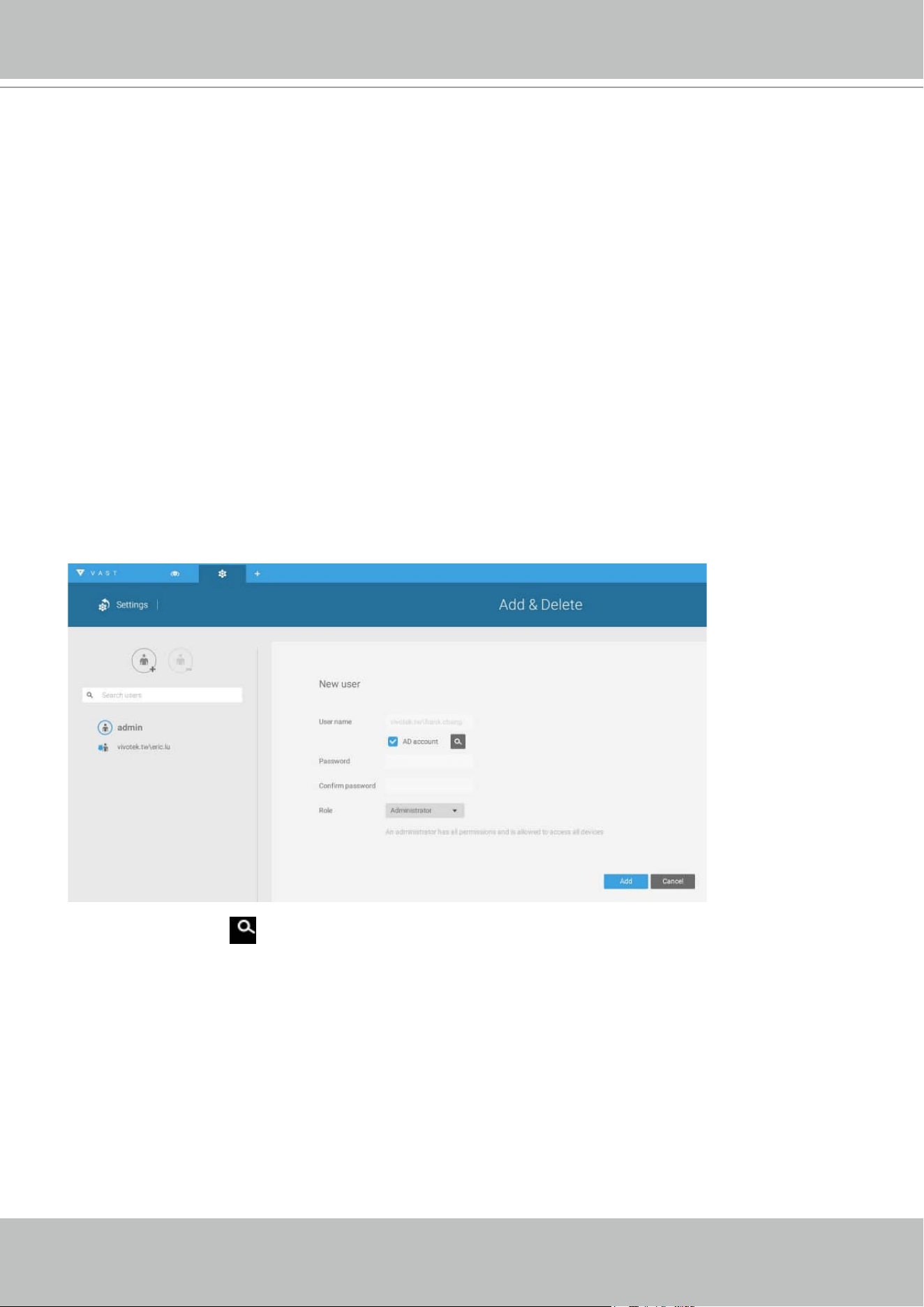
VIVOTEK - A Leading Provider of Multimedia Communication Solutions
User's Manual - 249
Add a New User Account - Windows AD Account
In an established, enterprise network environment, the support for Windows AD (Active Directory)
infrastructure enables ease of integration using the credentials of existing users. Using the same AD
authentication methodologies, you can congure the clients or users in an established network to access
the VAST server conguration.
Note the following with Windows AD support:
1. If you install VAST server on a Windows XP machine with Postqre SQL server, the login using a
Windows AD account will not work.
2. The VAST server must reside in a domain managed by the AD server.
3. This function does not support the environment that spans across multiple AD domains.
4. A user account hosted by an AD server cannot be modied in VAST.
5. A User Group and its members congured in AD cannot be managed in VAST.
6. You cannot add an account having the same name as one you used to log in VAST.
7. There are 3 types of account for VAST: VIVOTEK account, AD single user, AD group.
To add an existing AD user,
1. Select the AD account checkbox.
2. Click the Search button.
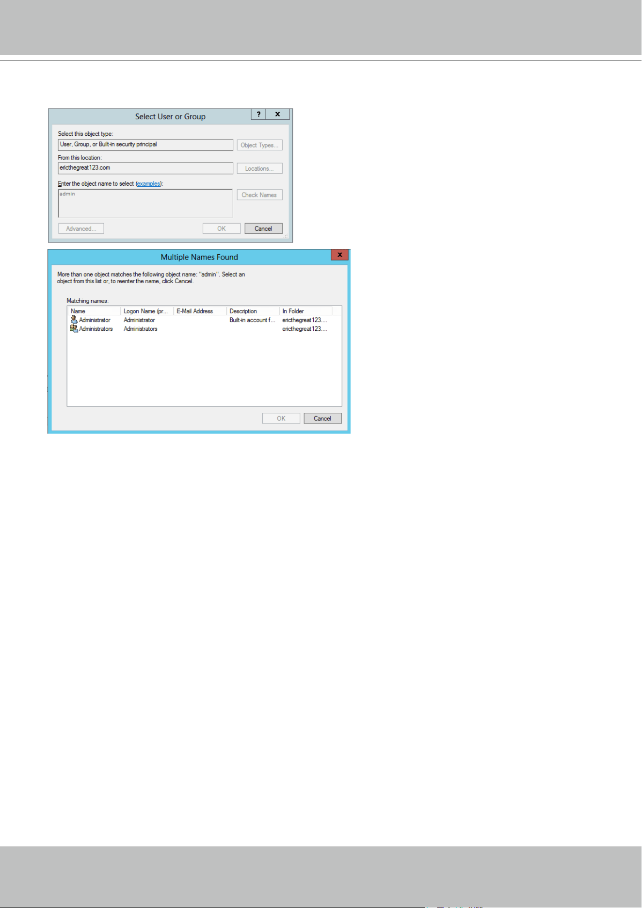
VIVOTEK - A Leading Provider of Multimedia Communication Solutions
250 - User's Manual
3. Enter a user name or group name to search, e.g., Frank. Click OK when done.
4. Enter the password twice for the AD user.
5. Select the privilege role for the user, congure his/her privilege settings as described above
and then click Add.
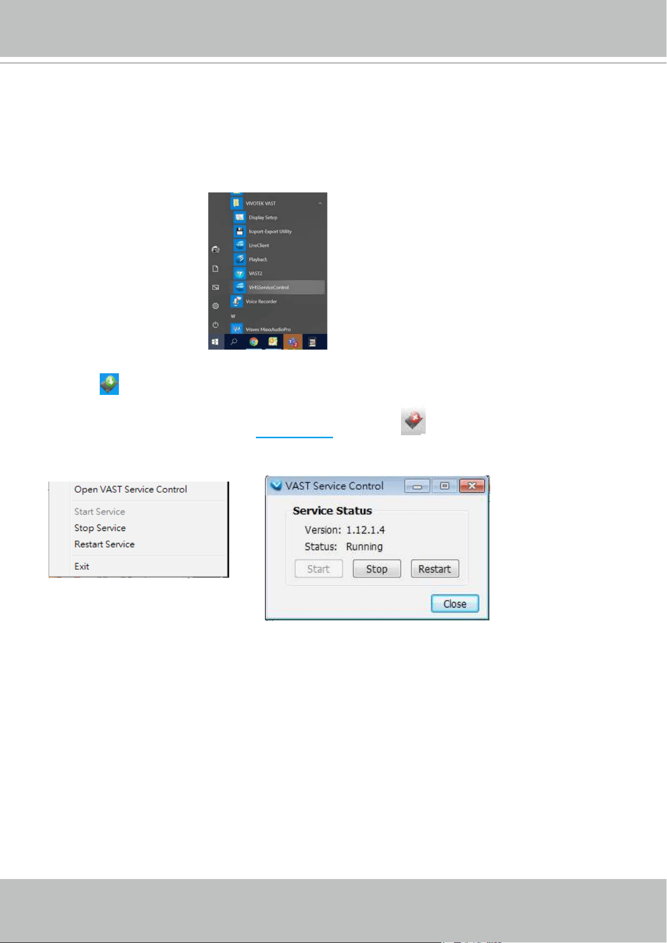
VIVOTEK - A Leading Provider of Multimedia Communication Solutions
User's Manual - 251
Appendix A: VAST Service Control Tool
VAST service control tool is a tool for server control and for user to be aware of the VAST Server
status. It starts up as Windows OS startup.
Under Microsoft Windows, choose "Start > VIVOTEK Inc VAST > VMServiceControl."
You may also find it in the system tray icon of the tool bar, which indicates that the service is
running:
It shows a disconnection icon when the service is stopped:
A menu for the service control tool will pop up when you right-click on the icon:
Here you can manually start, stop and restart the service.
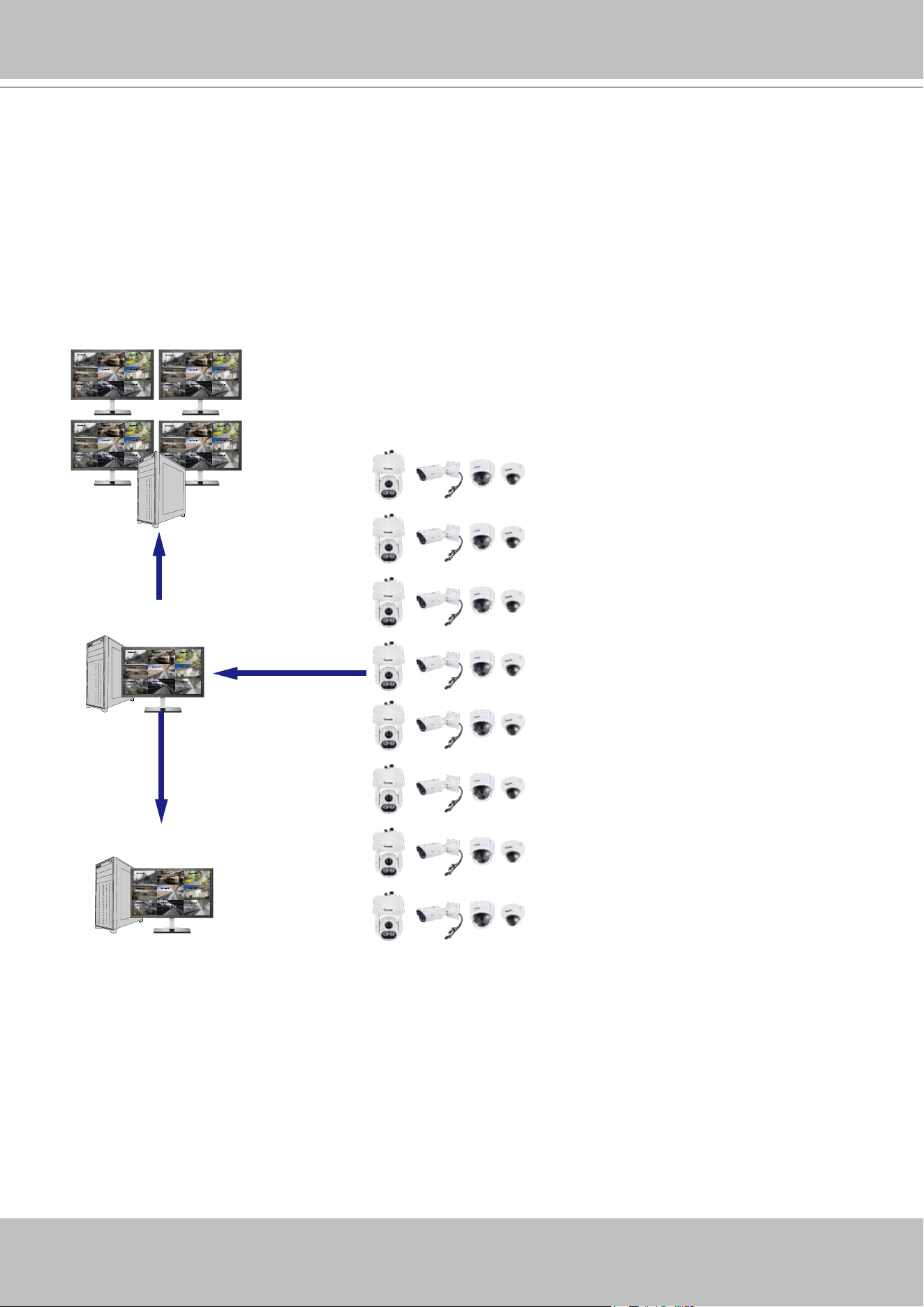
VIVOTEK - A Leading Provider of Multimedia Communication Solutions
252 - User's Manual
Appendix B: Matrix
Camera 01
Camera 02
Camera 03
Camera 04
Camera 06
Camera 05
Camera 07
Camera 08
Camera 09
VAST2 Server
Camera 01
Camera 02
Camera 03
Camera 04
Camera 06
Camera 05
Camera 07
Camera 08
Camera 09
Camera 01
Camera 02
Camera 03
Camera 04
Camera 06
Camera 05
Camera 07
Camera 08
Camera 09
Camera 01
Camera 02
Camera 03
Camera 04
Camera 06
Camera 05
Camera 07
Camera 08
Camera 09
Camera 01
Camera 02
Camera 03
Camera 04
Camera 06
Camera 05
Camera 07
Camera 08
Camera 09
VAST2 Matrix
Camera 01
Camera 02
Camera 03
Camera 04
Camera 06
Camera 05
Camera 07
Camera 08
Camera 09
VAST2 Client
The virtual matrix feature enables the display of any cameras on any monitors in an IP
surveillance network. Combinations of live or playback streams can be displayed simultaneously.
In addition of pre-congured live views, E-maps, Google maps, and Alarm panes can all be
placed on a remote matrix. Users gain realtime awareness of scenes and access to past events.
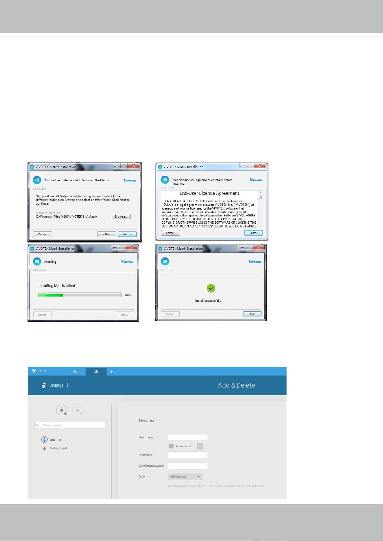
VIVOTEK - A Leading Provider of Multimedia Communication Solutions
User's Manual - 253
Prerequisites:
1. One VAST2 server and another computer running the Matrix client utility.
2. The rst 2 digits of software revision numbers of VAST server and Matrix client must be the
same: e.g., 2.3.x.x and 2.3.x.x.
3. Sufcient network bandwidth among network cameras, VAST servers, and Matrix clients.
Conguration procedure:
1. Install the Matrix client utility on a computer equipped with multiple monitors. Follow the
onscreen instructions to install the utility.
2. On the VAST server, create a user account for the Matrix client. Depending on the operation
on the client computer, assign the client user with adequate operation privileges.
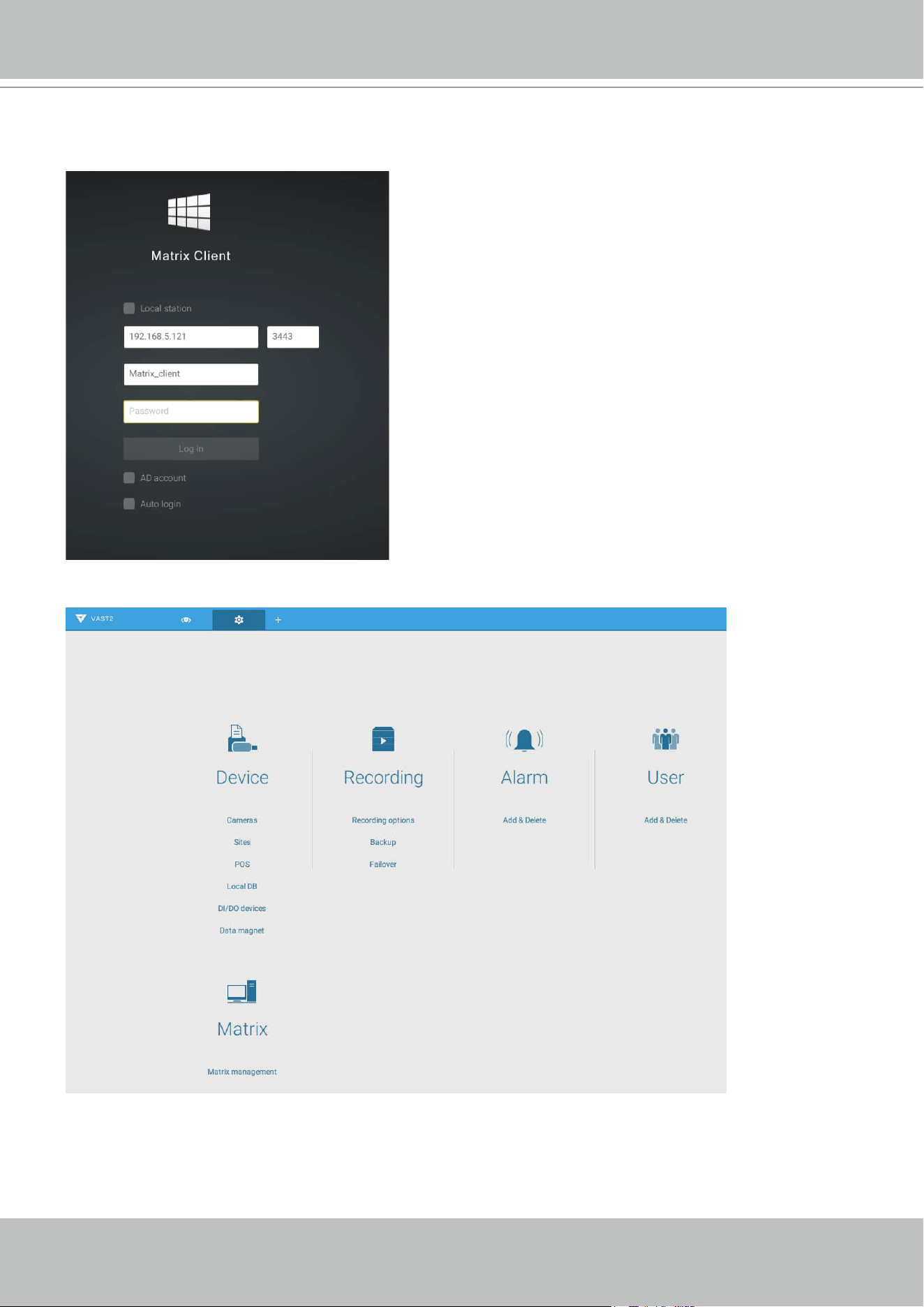
VIVOTEK - A Leading Provider of Multimedia Communication Solutions
254 - User's Manual
3. Open the Matrix utility, log in to the VAST server address, using the Matrix client account
credentials.
4. From the VAST server, open the Settings > Matrix Management window.
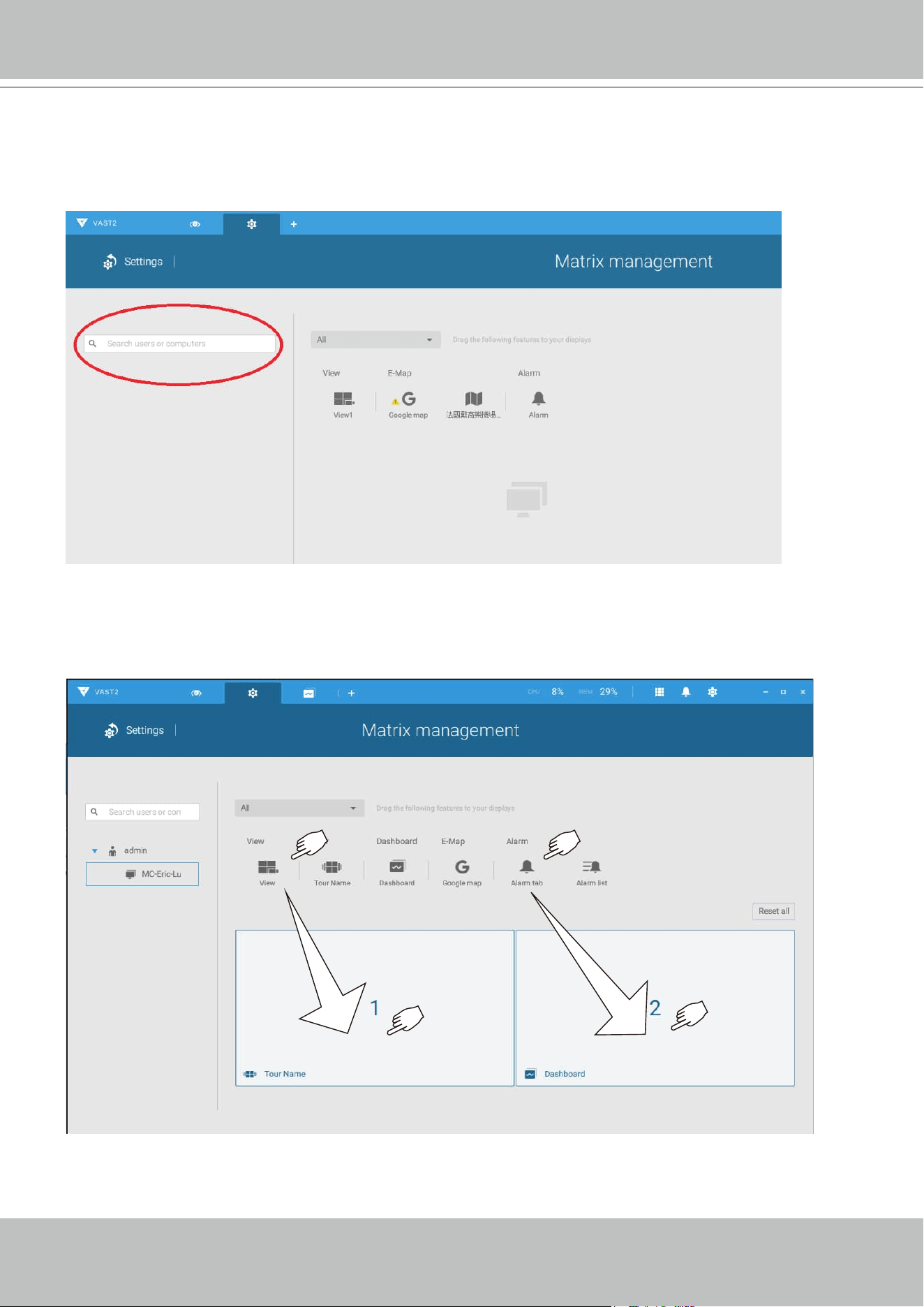
VIVOTEK - A Leading Provider of Multimedia Communication Solutions
User's Manual - 255
5. Enter the name of your Matrix client, e.g., Matrix_client in the search pane of the Matrix
Management window. Note that the Matrix client must have logged in to establish the
connection before the VAST server can nd it (as previously described).
6. Once the VAST server found the Matrix client, the available monitors will be listed. Click
and drag the pre-congured Views, Tour, Dashboard, E-maps, or Alarm panel to any of the
monitors.
7. The views should immediately appear on the Matrix monitors.
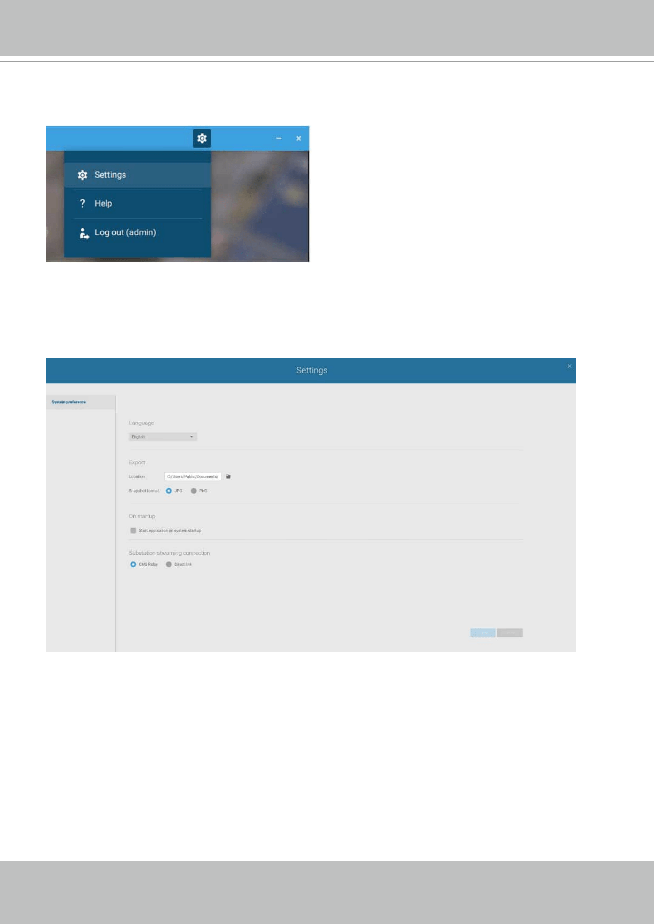
VIVOTEK - A Leading Provider of Multimedia Communication Solutions
256 - User's Manual
8. If you need to log out, move your mouse cursor to the top of the Matrix client screen to end
the session.
If necessary, change your client settings. Here you can change the displayed language,
Export target folder, Start-up option, and the streaming connection options.
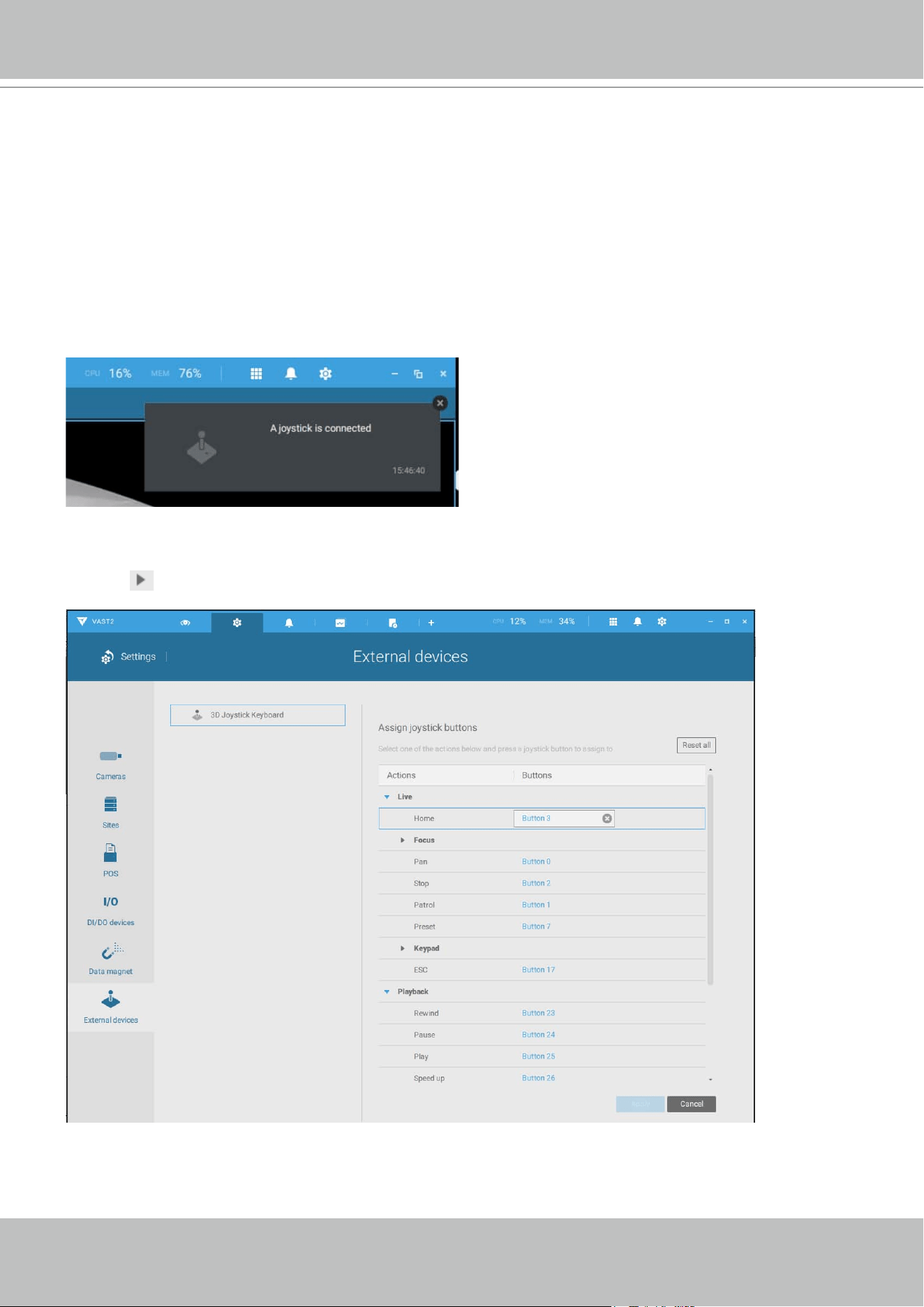
VIVOTEK - A Leading Provider of Multimedia Communication Solutions
User's Manual - 257
Appendix C: Joystick Support
Congurable joystick buttons
1. Connect the joystick's USB cable between the USB ports on the joystick and a VAST server/
client.
2. Once connected, you should be prompted by a connection message.
3. Enter Settings > Device > External devices.
4. Single-click to select the detected joystick. The congurable buttons will be listed.
Click
to expand the Live, Playback and Common menus.
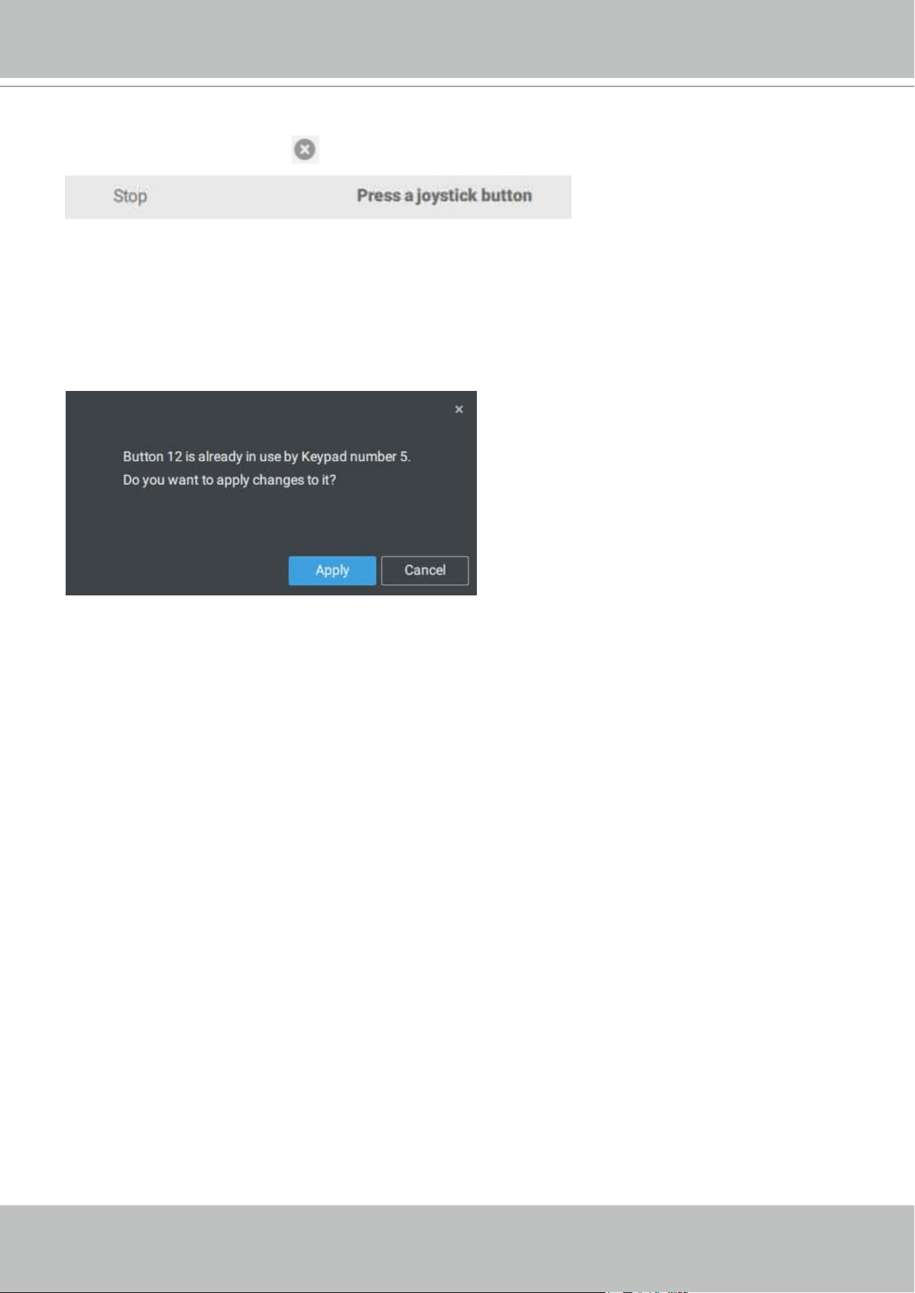
VIVOTEK - A Leading Provider of Multimedia Communication Solutions
258 - User's Manual
5. To assign or re-assign a button's function, single-click on the button number besides a
function. Click the Delete
button. The below message will display.
Press a preferred button on your joystick to complete the setting.
If a button conict occurs, (another function has already been assigned to the same button),
the below message will prompt. You can Cancel or click Apply to change the assignment.
Repeat the above process and click the Apply button to preserve your settings.
VIVOTEK - A Leading Provider of Multimedia Communication Solutions
User's Manual - 259
Camera 01
Camera 02
Camera 03
Camera 04
Camera 06
Camera 05
Camera 07
Camera 08
Camera 09
X2
VAST
12V DC
The AJ-002 is a USB joystick with HID 3-axis PTZ control, a twist wheel for zoom in/zoom out,
and 29 congurable function buttons for use on a VAST server station.
Following are the conditions for making the connection:
1. The joystick can either be powered by a DC 12V adaptor or via the USB. If powered by USB,
plug the USB cable twice to the USB port to enable USB power.
2. Connect the included USB cable between the USB ports on the joystick and a VAST server.
1. Avoid spilling water onto the device. Avoid using this device in a high-moisture
environment.
2. This device should be operated in the indoor environment.
3. When the temperature is lower than -10ºC, the LCD panel may not function normally.
4. If the included power adapter should be replaced, use a 9-15V/1000mA alternative.
5. Avoid impact to the device.
6. This product is manufactured to comply with the requirements of the following directives:
89/336/EEC, 92/31/EEC, 93/68/EEC.
NOTE:
VIVOTEK's joysticks
VIVOTEK - A Leading Provider of Multimedia Communication Solutions
260 - User's Manual
KEYPAD DEFINITION
1 2
3 4
5 6
8
28
21 22
24 25
23 7
26 27
9 10
12 13
11
14
15 16
18 19
17
20
Below is the keypad numbering sequence:
The following keypad functions will be available as the defaults for the joystick.
1 Pan 9 #1 17 #9 25 Pause
2 Patrol 10 #2 18 Cancel/Clear/Esc 26 Play (Playback)
3 Stop 11 #3 19 #0 27 Speed Up
4 Home 12 #4 20 Enter 28 Speed Down
5 Focus Near 13 #5 21 Full Screen
6 Focus Far 14 #6 22 Manual recording
7 Snapshot 15 #7 23 Change Layout
8 Preset 16 #8 24 Rewind
When a joystick is connected, the VAST server should automatically detect the connection.
The following controls are available:
* PTZ control – Basic PTZ control: Direction, Home, Zoom in/out, and Focus near/far.
* Playback control – Play, Pause, Stop, Rewind, Speed up and Slow down.
* View switch – Switch to existing View (Users need to create views first).
VIVOTEK - A Leading Provider of Multimedia Communication Solutions
User's Manual - 261
Left-click to select your server on the device tree, and right-click to display and select the "Show
joystick key number." The camera key numbers are determined by the sequence when the
cameras were added to the VAST conguration, and cannot be changed. By default, the key
numbers are not shown.
Press the key number on the joystick keypad and the Enter key
, e.g., 5 + . The full
view of the selected camera will display.
Press the ESC key to leave the full view.
To move to a preset position, press the number key + Preset, and the Enter key . The
number key corresponds to the sequence number for the preset position regardless of the name
of the preset.
Note that the RS232/485 terminal connection is currently not supported.
Note that the Manual Recording button is currently not effective.
VIVOTEK - A Leading Provider of Multimedia Communication Solutions
262 - User's Manual
If you have multiple views, press the number key and the Change Layout, and the Enter key
to switch to a different view. The number key corresponds to the sequence number for the
view you congured regardless of the name of the view (layout).
The Play button toggles the playback window. From here you can trace back the past
recordings. You can use speed up, slow down, and rewind buttons here. Once the Playback
mode is toggled, the point-in-time defaults to the start of the current hour.
VIVOTEK - A Leading Provider of Multimedia Communication Solutions
User's Manual - 263
Appendix D: Upload Device Pack
A device pack is contantly updated for the latest proles of VIVOTEK's new camera/NVR
models. If you install new cameras/NVRs to your conguration, you can visit VIVOTEK's website
for the latest device pack updates, and upload the pack le to your VAST server. New functional
parameters and functions in the new cameras are available through the device pack.
Enter Settings > About to see the upload button.
VIVOTEK - A Leading Provider of Multimedia Communication Solutions
264 - User's Manual
A device pack le looks like the following.
VIVOTEK - A Leading Provider of Multimedia Communication Solutions
User's Manual - 265
Appendix E: Using LPR Related Functions w/ Data Magnet
Acquiring data sources from 3rd-party software:
1. Select a camera that comes with the LPR (License Plate Recognition) functionality, e.g.,
IB9387-LPR as shown below. Click "More settings on Web" to open a web console to
the camera.
VIVOTEK - A Leading Provider of Multimedia Communication Solutions
266 - User's Manual
2. On the web console, enter Conguration > Applications > Package management. Click on
ANPR to open a web console to the license plate recognition software.
3. Click on the Lists tab.
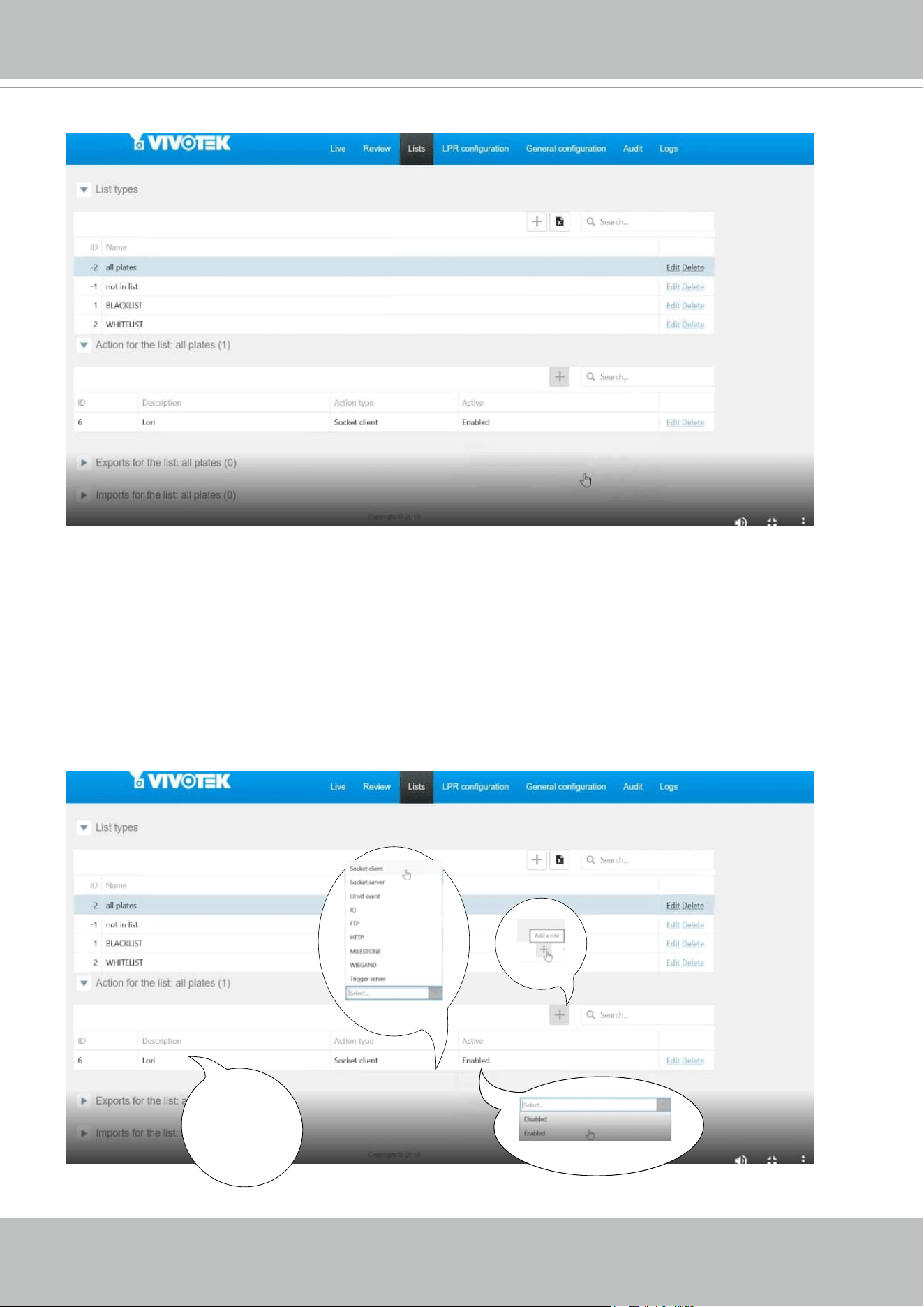
VIVOTEK - A Leading Provider of Multimedia Communication Solutions
User's Manual - 267
4. Select a list whose data will be transmitted to the VAST server.
5. 5-1. Find the "Action for the list" pane. Click the "+" Add a row button.
5-2. Enter a short description for the row.
5-3. Select "Socket client" as the action type.
5-4. Click to select Enabled.
5-5. Click the Save button.
1
2
enter a
short description
3
4
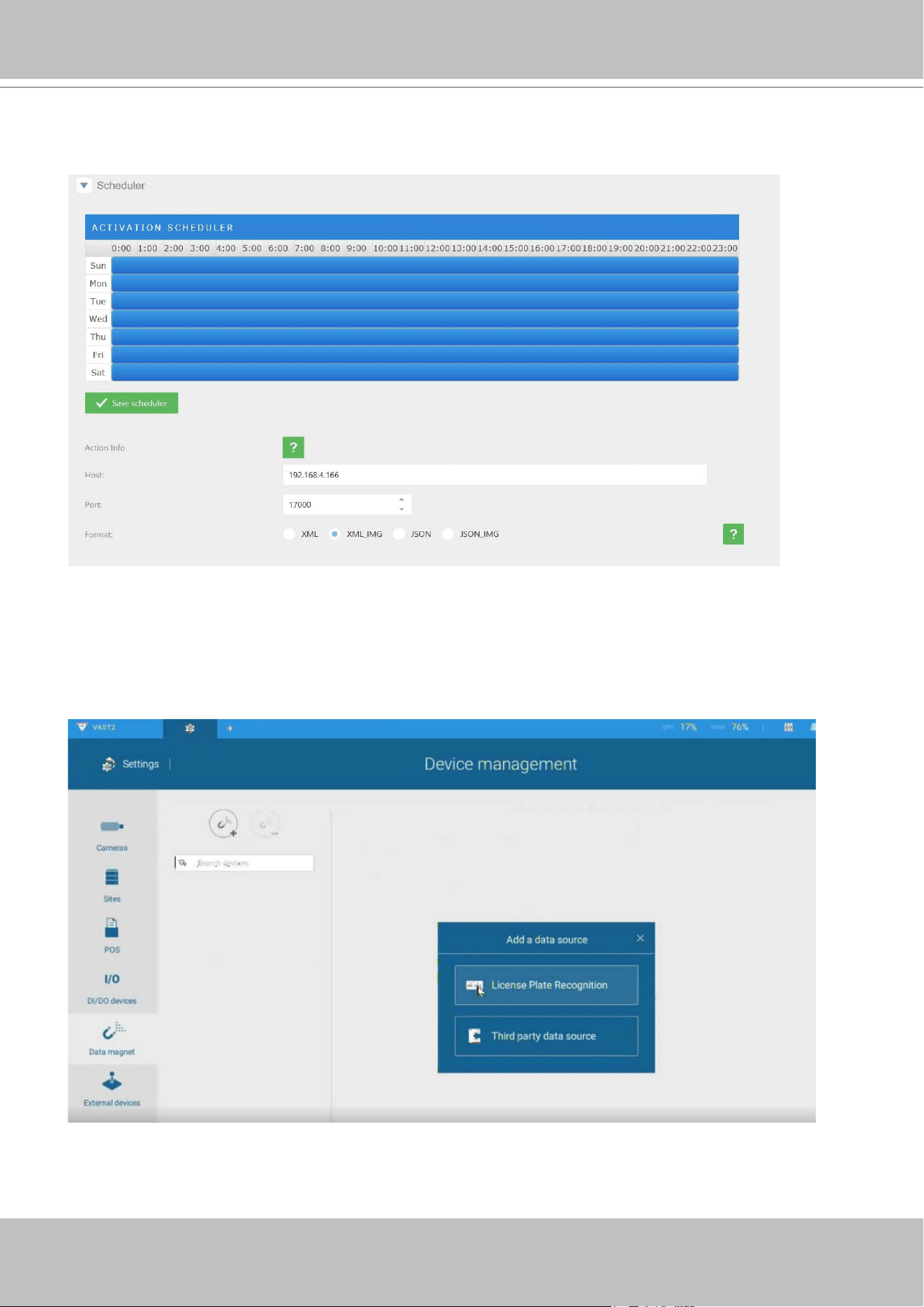
VIVOTEK - A Leading Provider of Multimedia Communication Solutions
268 - User's Manual
6. Roll down to enter your VAST server's IP address. If necessary, select XML_IMG as the le
format for your data that will be collected on VAST.
7. Close the web console and return to the VAST Settings > Device management > Data
magnet page.
Click the Add button, and click the License Plate Recognition button.
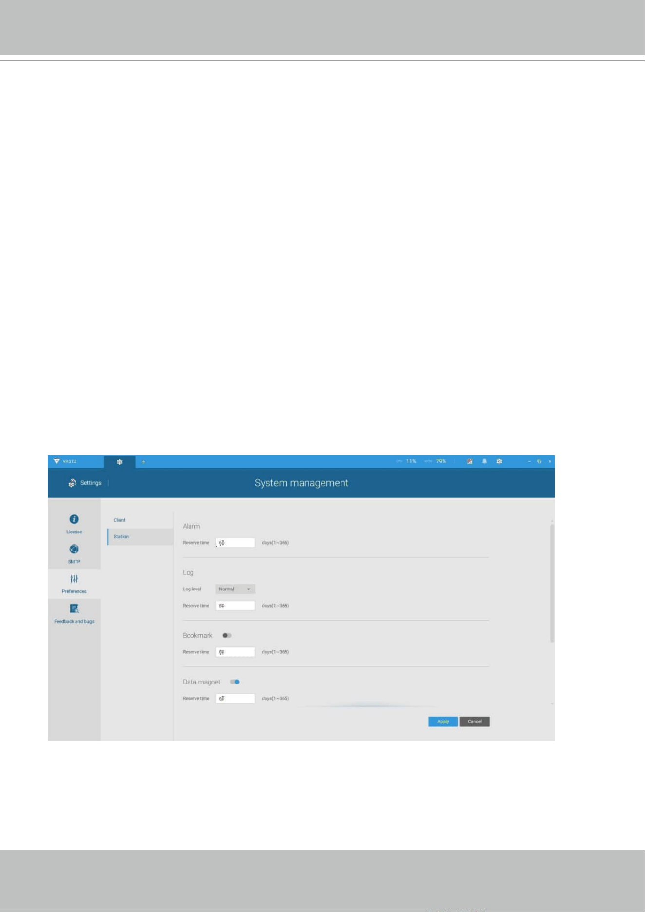
VIVOTEK - A Leading Provider of Multimedia Communication Solutions
User's Manual - 269
If you need the development document for integrating 3rd-party software, please contact
VIVOTEK's technical support.
You can designate how many days the data from the data sources is retained on server in
Settings > System management > Preferences.
NOTE
:
1. The License Plate Recognition data source will not be charged with a Data Magnet license
fee.
2. The VAST server port for License Plate Recognition data source can be customized; It is not
limited to 17000.
3. If you have more than one VIVOTEK LPR camera, you only need to (and can only) add a
License Plate Recognition data source.
4. If you add a 3rd-party data source but you name it as "VIVOTEK ANPR", it will be recognized
as a VIVOTEK ANPR (License Plate Recognition) data source.
5. Different Data sources cannot have the same name.
6. Different 3rd-party data sources can share the same server port, but they cannot use the
same port the License Plate Recognition is using.
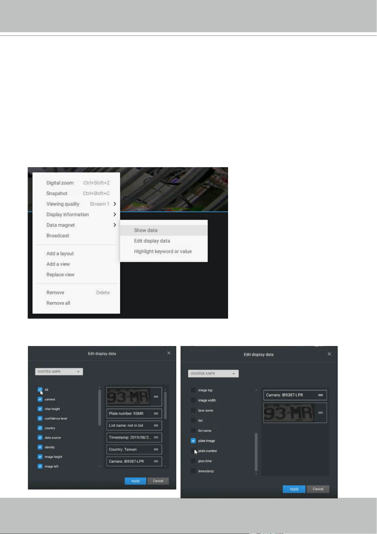
VIVOTEK - A Leading Provider of Multimedia Communication Solutions
270 - User's Manual
Selecting data display options:
1. On the VAST live view, right-click on screen to display Data Magnet > Edit display data.
If Show data is selected, a portion of the view cell will be used to display the captured data.
2. On the Edit pane, select all or manually select multiple display elements.
There are two different ways to show data:
1. Right-click: Data Magnet > Show data.
2. Right-click: Display information > Edit display information > Data magnet data.
The display options are: with or without Data overlay on screen. If the overlay is not enabled,
the data will display on the right pane of the view cell.
The data on the overlay can
be congured to automatically
disappear after a congurable
time, when no new data is
received (Hide data after idle _
s).
VIVOTEK - A Leading Provider of Multimedia Communication Solutions
User's Manual - 271
3. Click and drag individual elements to change their top-down positions on the screen. When
done, click the Apply button.
4. Click Highlight keyword or value. You can display information of unusual data, such as
the specic numbers or characters of forbidden license plates. When such data is met, the
occurrence will be highlighted in a bright yellow color.
VIVOTEK - A Leading Provider of Multimedia Communication Solutions
272 - User's Manual
Searching for data and linked recordings:
1. On the VAST live view, click on the Applications tab.
VIVOTEK - A Leading Provider of Multimedia Communication Solutions
User's Manual - 273
2. On the Data Magnet window, select the LPR camera, and then begin with conguring the
search conditions. Select the time span from the calendar. Select to display character height,
country, data source, identity, image height, lane name, list name, or enter a plate number.
You can select multiple ltering conditions.
VIVOTEK - A Leading Provider of Multimedia Communication Solutions
274 - User's Manual
3. Click the Search button. The search results will display. Single-click to display the related
video. You can also review the video in a full-screen mode.
You can click and drag the display names of individual columns to switch their positions on
the screen. The changes to layout are stored on the client computer. After you re-arrange the
order of columns in search results, the display order will also be applied to the exported CSV
le.
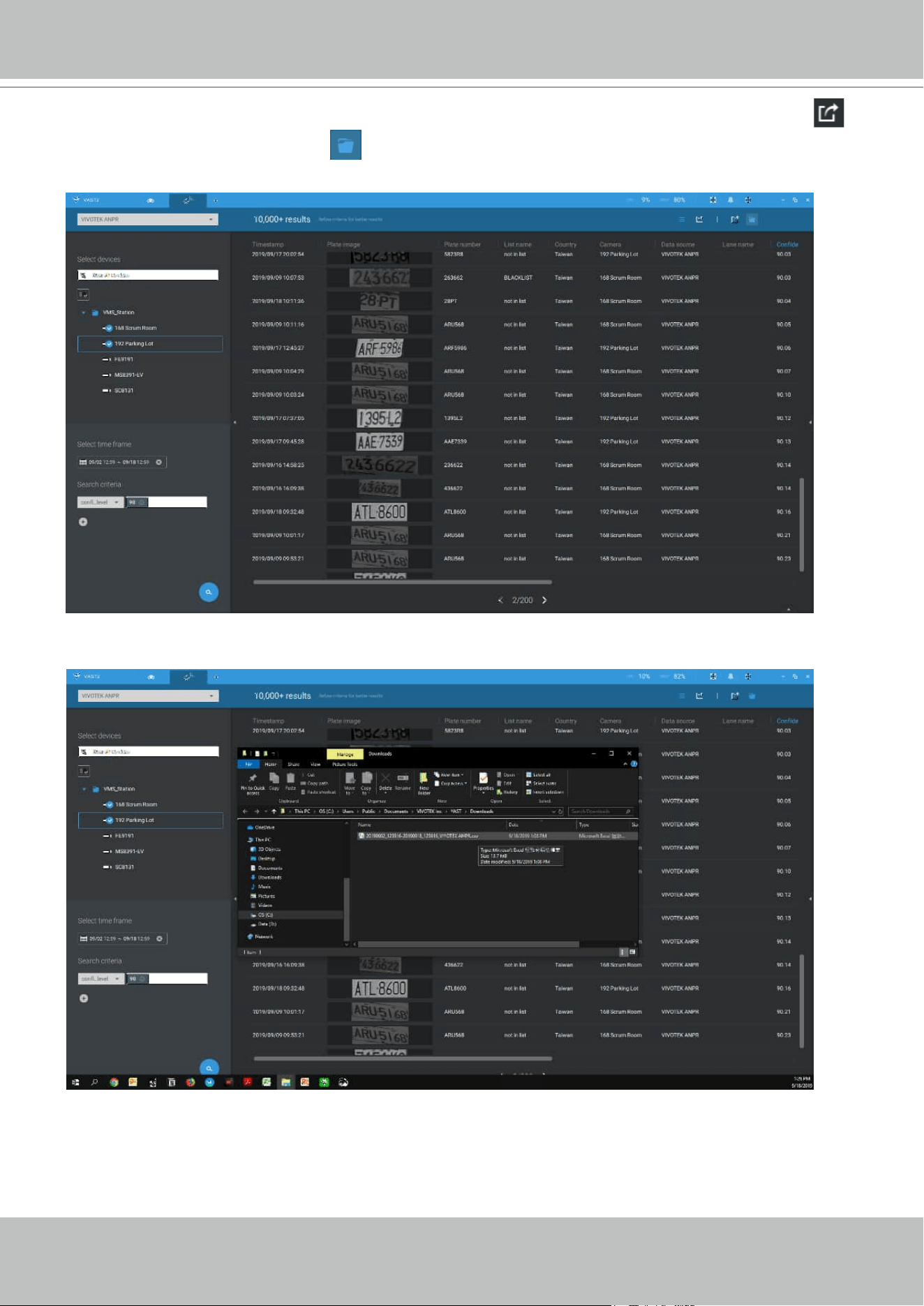
VIVOTEK - A Leading Provider of Multimedia Communication Solutions
User's Manual - 275
4. You can select and export a license plate capture using the Export function. Click on the
export button. A folder button will display. Click on it to access the exported le.
The target directory will open. Open the exported CSV le to view the search results.
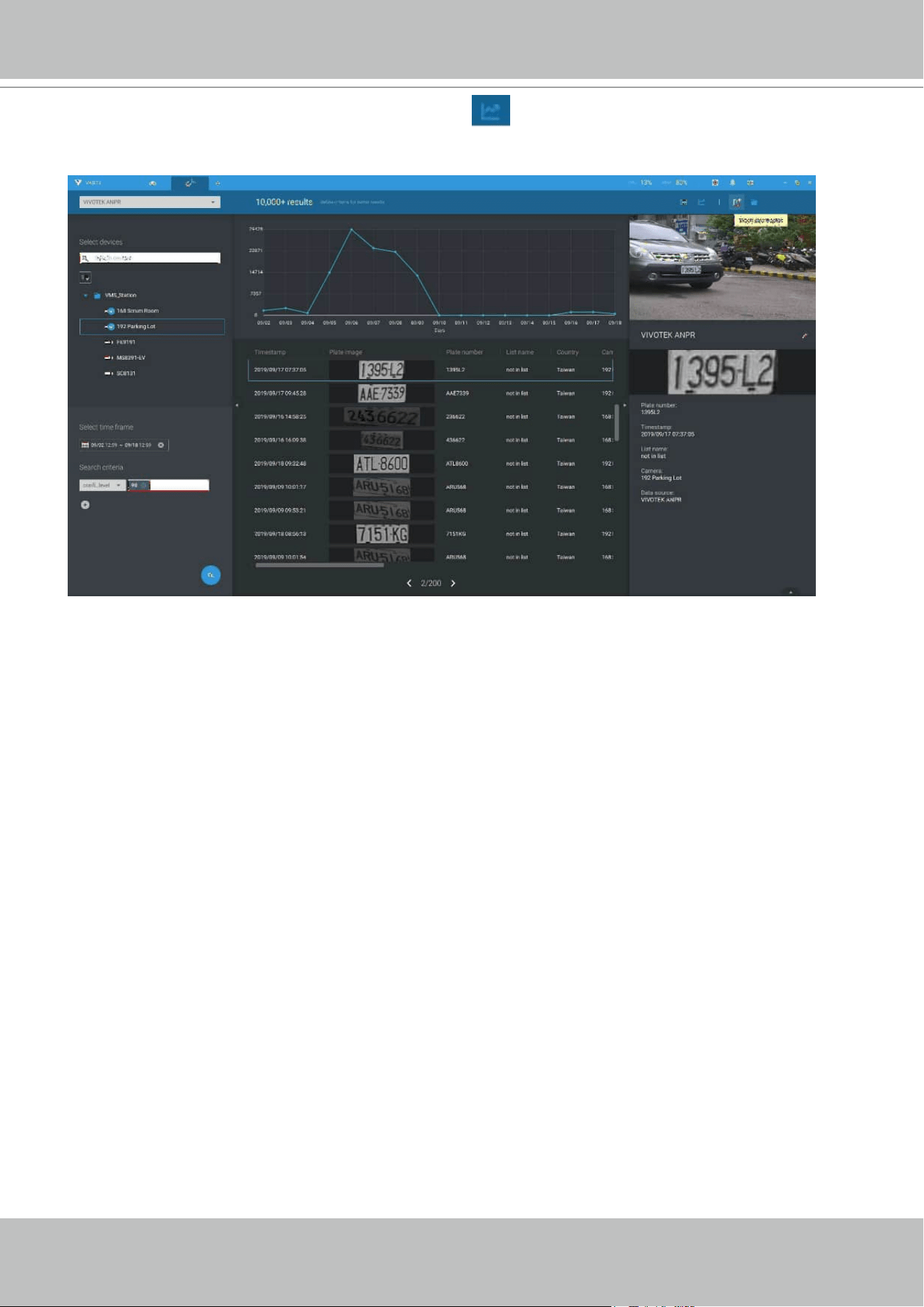
VIVOTEK - A Leading Provider of Multimedia Communication Solutions
276 - User's Manual
You can also open a chart view by clicking the Chart view button. The chart view can
also be exported as a png le.
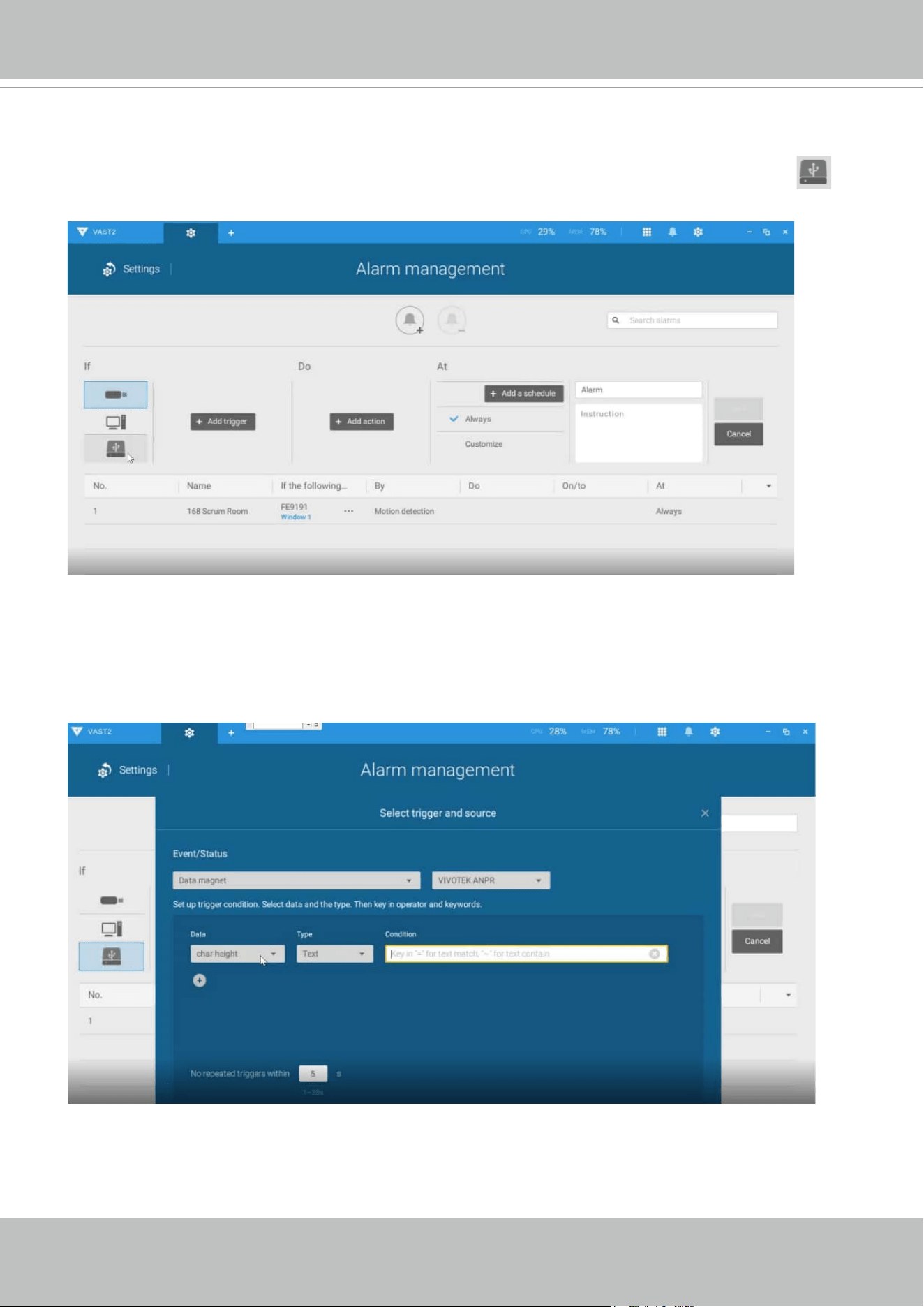
VIVOTEK - A Leading Provider of Multimedia Communication Solutions
User's Manual - 277
Conguring Data Magnet alarms:
1. Enter Settings > Alarm > Add & Delete to create a new alarm setting. Click to select
External devices.
2. Select VIVOTEK ANPR as your triggering source. Select and create triggering conditions
such as character height, image width, list, list name, country, etc. Use "=" for text matching, "~"
for text containing, or approximately matching specic characters, and also ">," "<," ">=," "<="
for numbers larger or smaller than a preset value.
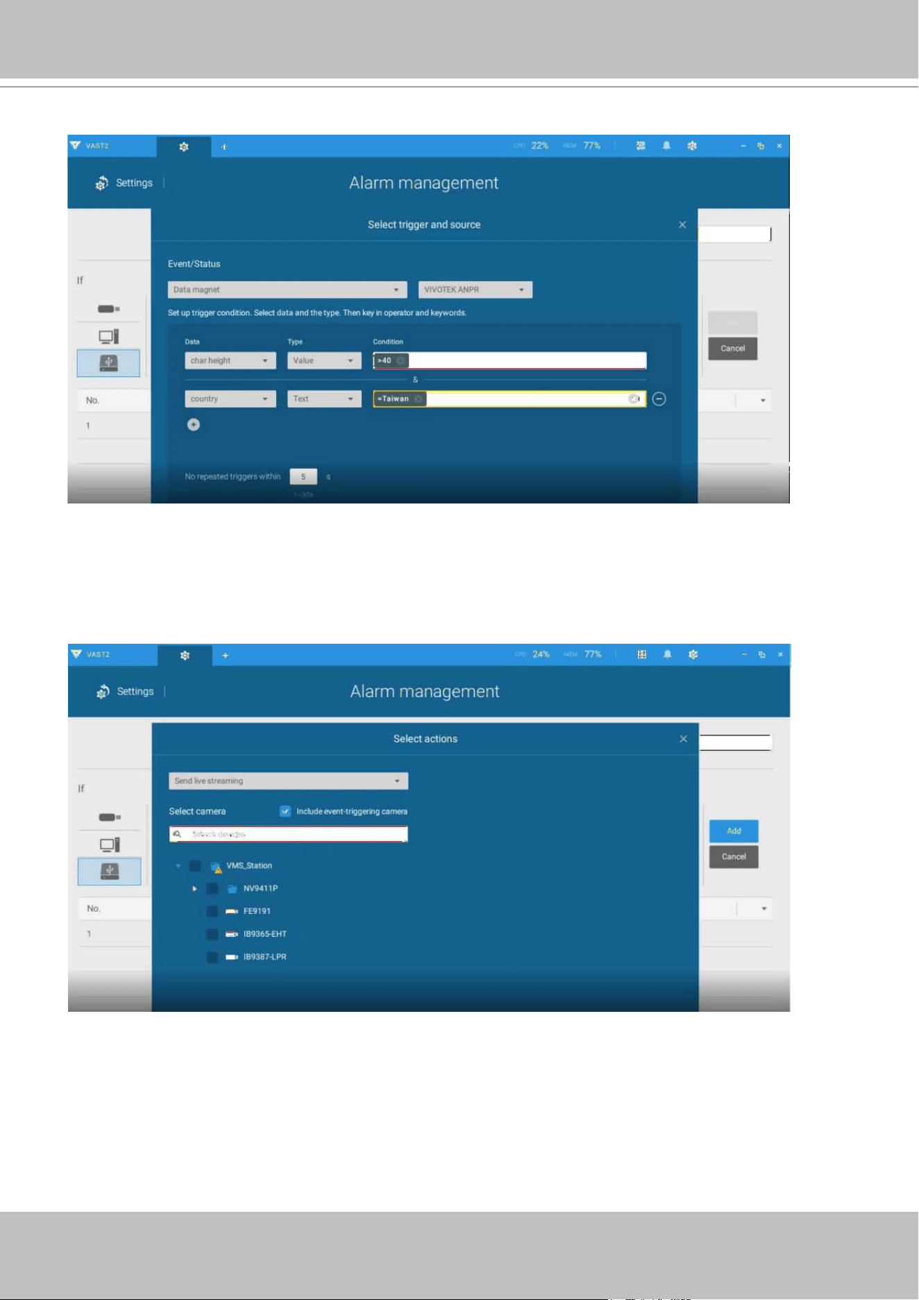
VIVOTEK - A Leading Provider of Multimedia Communication Solutions
278 - User's Manual
3. Continue to congure your triggering conditions. You can create multiple conditions.
4. Continue to congure the actions for a triggered alarm, such as sending live streaming.
VIVOTEK - A Leading Provider of Multimedia Communication Solutions
User's Manual - 279
5. When done, enter a name for the alarm and click the Add button to complete.
6. You can now receive alarm notications triggered by license plate recognition via the Data
Magnet.
VIVOTEK - A Leading Provider of Multimedia Communication Solutions
280 - User's Manual
Note that if you select "Include event-triggering camera" during the alarm conguration stage,
the camera delivering the data source will be automatically selected.
VIVOTEK - A Leading Provider of Multimedia Communication Solutions
User's Manual - 281
Conguring Data Source macro via Send email and Send HTTP requests:
In Settings > Alarm > Add & Delete, Email and HTTP requests can be used to send data
source macro to receivers. Use "<br>" as the line break command. Note that an SMTP server
should have been congured before the Email settings in Alarm.
You can specify multiple lines of information in your alarm
notication message.
VIVOTEK - A Leading Provider of Multimedia Communication Solutions
282 - User's Manual
Appendix F: Enable Smart Tracking for Speed Dome Cameras
The Smart tracking function is available on speed dome cameras, such as SD9374-EHLX.
The Smart tracking feature is separately congured on the camera side. Please refer to Smart
Tracking User Guide for conguration details.
To display Smart tracking on VAST,
1. Enter Settings > Devices > Cameras.
2. Select the speed dome camera that supports this feature.
3. Select PTZ Settings, and the Track mode menu. Select Smart tracking as the tracking
display mode. A hyperlink is provided for the Smart tracking conguration page.
It is recommended to always enable "Enable track if the camera idles for xx seconds." Manual
PTZ control always has a higher priority and will interrupt tracking.
4. Click the Apply button.
VIVOTEK - A Leading Provider of Multimedia Communication Solutions
User's Manual - 283
5. On the view cell of the speed dome, click PTZ settings, and then click the Tracking button.
VIVOTEK - A Leading Provider of Multimedia Communication Solutions
284 - User's Manual
Appendix G Database Merge Function
The Database Merge function applies in the following scenario:
1. A VAST server A failed or was intentionally depleted. The precondition is that the disk drives
containing the recordings remain intact. Server B must also have the conguration prole of
the Server A.
VAST server B
VAST Server A
Network Cameras
LAN
DB
Recorded
videos (default path)
DB
Recorded
videos
Failed
Taken over
Recovery path
2. The VAST server B is used to continue video recording. The previous recordings on server A
can be retrieved by attaching the hard disk(s) to server B or manually copying to a storage
device on server B. You can then designate the location of these files as the "Recovery
path" from server B. An administrator can then use the VAST software to access the past
recordings.
• It is
IMPORTANT
to move or copy the entire storage group folder, e.g.,
D:/recording/2016-
06-17/1-FE9181-H..., which is a root directory congured by VAST server as the recording
folder. The default recording folder contains file folder structure, video files, and database
metadata. If you copy the video les only, the database data will not be synchronized, and
you will not be able to access the recordings.
• The video streams received from cameras will not be recorded on to the Recovery path
folder. It is designed to maintain previous recordings. The Recovery path folder becomes
static.
VIVOTEK - A Leading Provider of Multimedia Communication Solutions
User's Manual - 285
D:/Record
2016-06-17 2016-06-18 2016-06-19 2016-06-20 2016-06-21
2016-06-22
Recording Doc
1-FE9181-H 2-FD9381 3-Outdoor
Speed Dome
4-Outdor
Speed Dome
5-IB9381 6-IP8166
2016-06-17
. . . .
. . . .
• It is also a good habit to export and preserve your VAST system configuration to prevent
losses in the event of system failure. In case you want to migrate or upgrade your VAST
server, you can use the Import-Export utility to duplicate your VAST configuration to
another server. Copy the conguration le and import the conguration from another VAST
server.
VIVOTEK - A Leading Provider of Multimedia Communication Solutions
286 - User's Manual
When the file folder is ready for server B, designate the location of recovered files from
another VAST server, go to Settings > Recording management > Recording options.
Select the recording folder that contains the recordings from the counterpart VAST server.
Select the Restore recordings from this path checkbox and click Add.

VIVOTEK - A Leading Provider of Multimedia Communication Solutions
User's Manual - 287
The Local Database you incorporated will be listed on the device tree, which is separated
from your current deployment. There are two different scenarios"
1. Using Recovery path:
Server B incorporated Server A conguration le, selected Recording options and the
"Restore recordings from this path" option. The device tree will look similar to the original
VAST server A conguration.
2. Using Local DB:
A Local DB sub-folder will appear on the device tree. Click to select the cameras in the
sub-folder to access the past recordings. The recordings in the Local DB is only
accessible from the computer which has a copy of the Local DB.
For system backup options, refer to page 284.
