Loading ...
Loading ...
Loading ...

16 49-1000491 Rev. 3
Installation Instructions
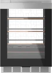
INSTALLING THE BEVERAGE CENTER (Cont.)
METHOD 2
FREESTANDING INSTALLATION
Attach the protective guard over the hinge
1. Pry hole cover from the top of the beverage center
cabinet on the hinge side to reveal the holes used
to install the protective guard.
2 Remove the protective guard and screws from the
accessory bag.
3. Using Screw A (Qty 2),
install the protective guard
onto the hinge side of the
cabinet as shown.
Level the Beverage Center
Adjust the height of the leveling
legs so that the product is level
and so that the left rear leveling
leg will slide in to the anti-tip
bracket. Tilt the unit to adjust
the height of the
four leveling legs.
Anti-tip Bracket
1. Determine the final location of the cabinet before
attempting to install the bracket. The bracket will
capture the left rear leveling leg.
2. The bracket must be secured to either the FLOOR
or REAR WALL. 2 screws must enter the floor or
wall at Loc A, B, or C.
FREESTANDING INSTALLATION (Cont.)
FLOOR Installation:
WOOD FLOOR: Use Screw D (qty 2) to secure the
bracket using the pair of marked holes (either Loc A or B).
CONCRETE FLOOR: Use a screw that is appropriate
for concrete applications and secure the bracket to
the floor using the pair of marked holes (either Loc
A or B). Screws for concrete application are not
provided with the unit.
REAR WALL Installation:
Use screw D (Qty 2) to secure the bracket using the
pair of marked holes at Loc C. The screws MUST enter
into a wood sill plate. If the wall contains any metal
studs or similar materials, then the floor must be used.
Install Toe Kick
1. Using Screw B (qty 4), attach the toe kick brackets
to each side of the bottom of the cabinet as shown
in the picture.
2. Install the toe kick.
Use Screw B or
Screw E depending
on the color of your
toe kick.
Protective
Guard
Screw must enter
wood or concrete
Wall Sill Plate
Screw must enter wood
Bracket
Bracket
Bracket
Screw
CONNECT TO POWER
Ŷ3OXJLQWRDJURXQGHGSURQJRXWOHW
WARNING
ELECTRICAL SHOCK
HAZARD
Plug into a grounded 3 prong outlet.
Do not remove the ground prong from the
power cord plug.
Do not use an adapter.
Do not use an extension cord.
Failure to do so can result in death, fire or
electrical shock.
COMPLETE INSTALLATION
Slide the beverage center into its final location. The rear
leveling leg must be fully inserted into the anti-tip bracket.
Loc A
Loc B
Loc C
Left Rear Leveling Leg
´PP
Distance between the
edge of bracket and
the side of the cabinet
in its final location
WARNING
Door Hinge Pinch Point
Hazard
Improper installation can lead to a finger pinch
point hazard near the hinge when operating
the door. For installations that are not under a
counter, follow the installation instructions. A
protective guard is provided for limiting access
to the door hinge.
INSTALLATION INSTRUCTIONS
Loading ...
Loading ...
Loading ...