
100 Mbps PoE Switch
Quick Start Guide
100 Mbps PoE Switch Quick Start Guide
i
Preface
Applicable Models
This manual is applicable to 100 Mbps PoE switches.
Symbol Conventions
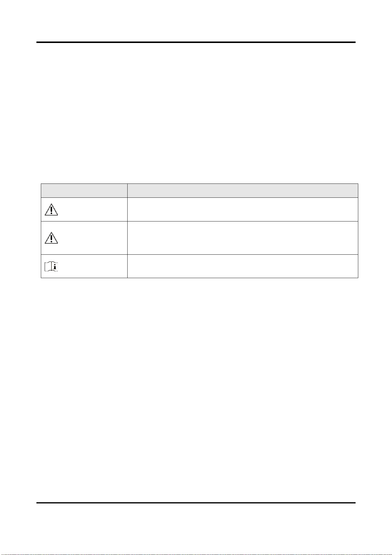
The symbols that may be found in this document are defined as follows.
Symbol
Description
Danger
Indicates a hazardous situation which, if not avoided, will or could
result in death or serious injury.
Caution
Indicates a potentially hazardous situation which, if not avoided,
could result in equipment damage, data loss, performance
degradation, or unexpected results.
Note
Provides additional information to emphasize or supplement
important points of the main text.

100 Mbps PoE Switch Quick Start Guide
1
Chapter 1 Introduction
1.1 Product Introduction
DS-3E1300P series switches (hereinafter referred to as "the device") are layer 2 PoE switches,
providing advanced PoE power supply technology on the basis of Internet access. The switches
support client management, network topology management, link aggregation, port management
and so on. The switches are suitable for small-scale LAN device access.
1.2 Packing List
Item
Quantity
Switch
× 1
Power Adapter
× 1
AC Power Cord
× 1
Quick Start Guide
× 2
1.3 Appearance
Different models of devices may have different appearances. The following pictures are only for
illustration.

100 Mbps PoE Switch Quick Start Guide
2
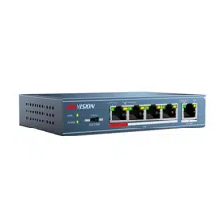
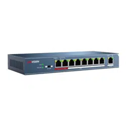
1.3.1 Front Panel
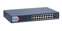
Figure 1-1 1309P Series
No.
Indicator/Port
Description
1
PWR Indicator
● Solid: The switch is powered on normally.
● Unlit: No power supply connected or power supply is
abnormal.
2
PoE-MAX Indicator
● Solid /Flashing: The output power of the switch will reach the
upper limit. The power supply may be abnormal if more
devices are connected.
● Unlit: The switch provides power supply to PD normally.
3
100 Mbps PoE RJ45 Port
Used for PD devices connection via network cables.
4
1000 Mbps RJ45 Port
(G1)
Used for other devices connection via network cables.
5
LINK/ACT Indicator
● Solid: The port is connected.
● Flashing: The port is transmitting data.
● Unlit: The port is disconnected or connection is abnormal.
6
PoE Indicator
● Solid: The switch provides power supply to PD normally.
● Unlit: The switch is disconnected to PD, or provides power
supply to PD abnormally.
100 Mbps PoE Switch Quick Start Guide
3
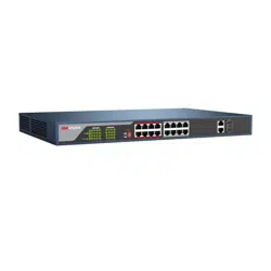
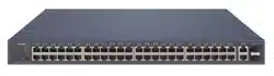
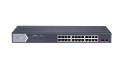
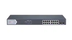
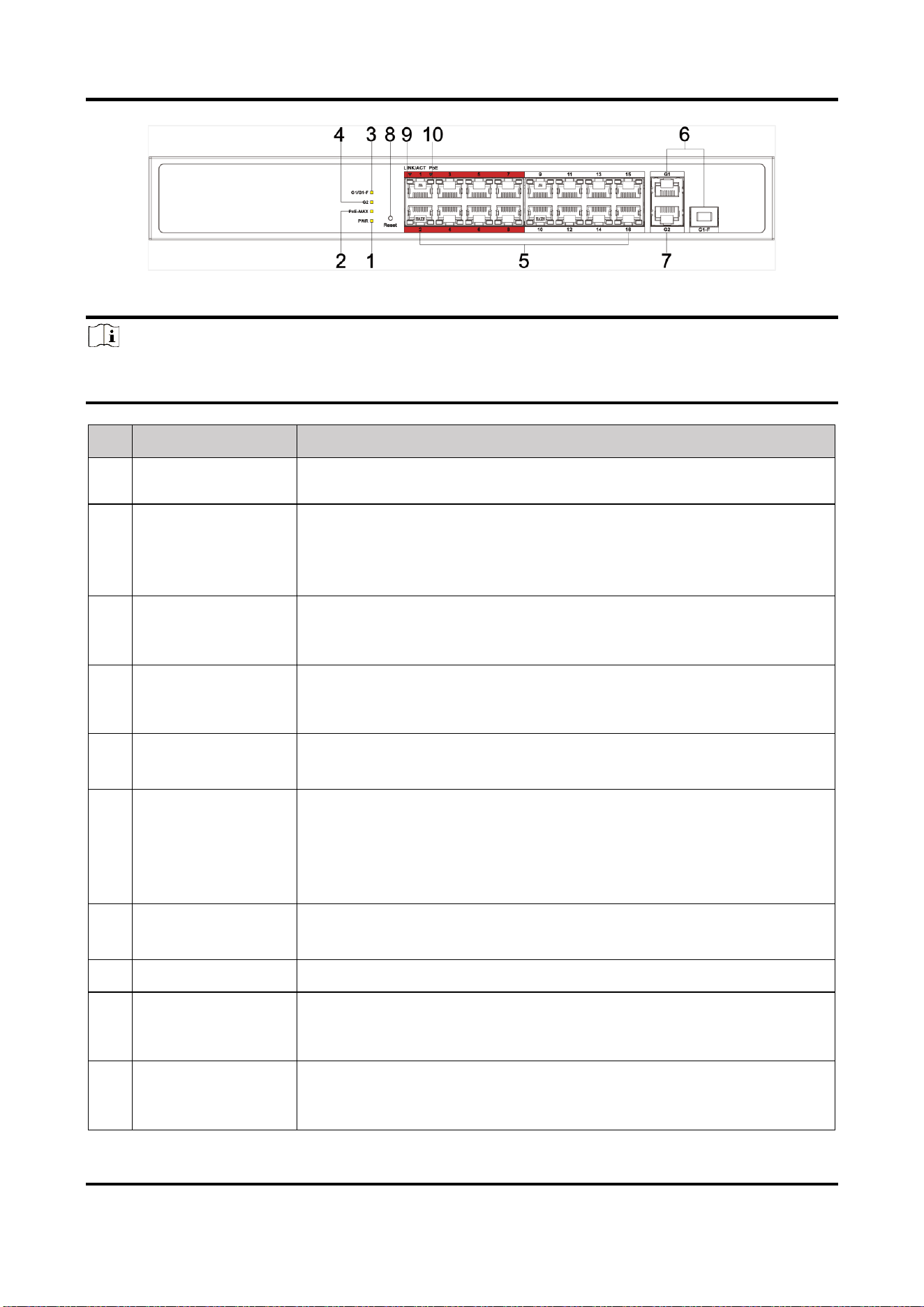
Figure 1-2 1318P Series
Note
The front panel of 1326P switch is similar to that of 1318P, with differences on 24 100Mbps PoE
RJ45 ports, 24 LINK/ACT, and 24 PoE indicators.
No.
Indicator/Port
Description
1
PWR Indicator
● Solid: The switch is powered on normally.
● Unlit: No power supply connected or power supply is abnormal.
2
PoE-MAX Indicator
● Solid/Flashing: The output power of the switch will reach the upper
limit. The power supply may be abnormal if more devices are
connected.
● Unlit: The switch provides power supply to PD normally.
3
G1/G1-F Indicator
● Solid: The port is connected.
● Flashing: The port is transmitting data.
● Unlit: The port is disconnected or connection is abnormal.
4
G2 Indicator
● Solid: The port is connected.
● Flashing: The port is transmitting data.
● Unlit: The port is disconnected or connection is abnormal.
5
100 Mbps PoE RJ45
Port
Used for PD devices connection via network cables.
6
1000 Mbps Gigabit
Combo (G1/G1-F)
● When connected to a network cable, the combo is a RJ45 port.
When plugged into with an optical module and connected to an
optical fiber, the combo functions as a fiber optic port.
● When connected to both the network cable and optical fiber at the
same time, the port works as a fiber optic port.
7
1000 Mbps RJ45
Port (G2)
Used for other devices connection via network cables.
8
Reset
Restore device to the defaults.
9
LINK/ACT Indicator
● Solid: The port is connected.
● Flashing: The port is transmitting data.
● Unlit: The port is disconnected or connection is abnormal.
10
PoE Indicator
● Solid: The switch provides power supply to PD normally.
● Unlit: The switch is disconnected to PD, or provides power supply
to PD abnormally.
100 Mbps PoE Switch Quick Start Guide
4
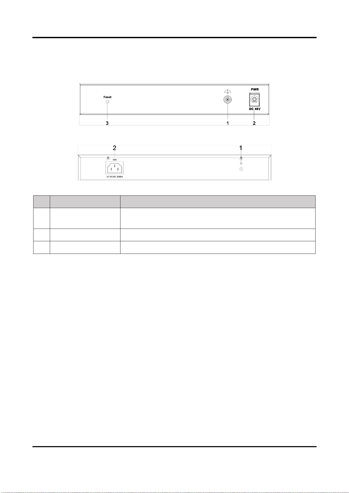
1.3.2 Rear Panel
Figure 1-3 1309P Series
Figure 1-4 1318P/1326P Series
No.
Indicator/Port
Description
1
Grounding Terminal
Used for connecting to the grounding cable to protect the switch
from lightning.
2
Power Supply
Use the attached power cord to connect the switch to socket.
3
Reset
Restore to the defaults.
100 Mbps PoE Switch Quick Start Guide
5
Chapter 2 Installation
Please select the appropriate installation method according to the actual needs.
Before You Start
● Ensure that the desktop or rack is stable and firm enough.
● Keep the room well-ventilated. Keep at least 10 cm distance around the device for heat
dissipation.
● Keep at least 1.5 cm vertical distance between two adjacent devices for rack-mount installation.
2.1 Desk-Mounted Installation
Place the device on the desk.
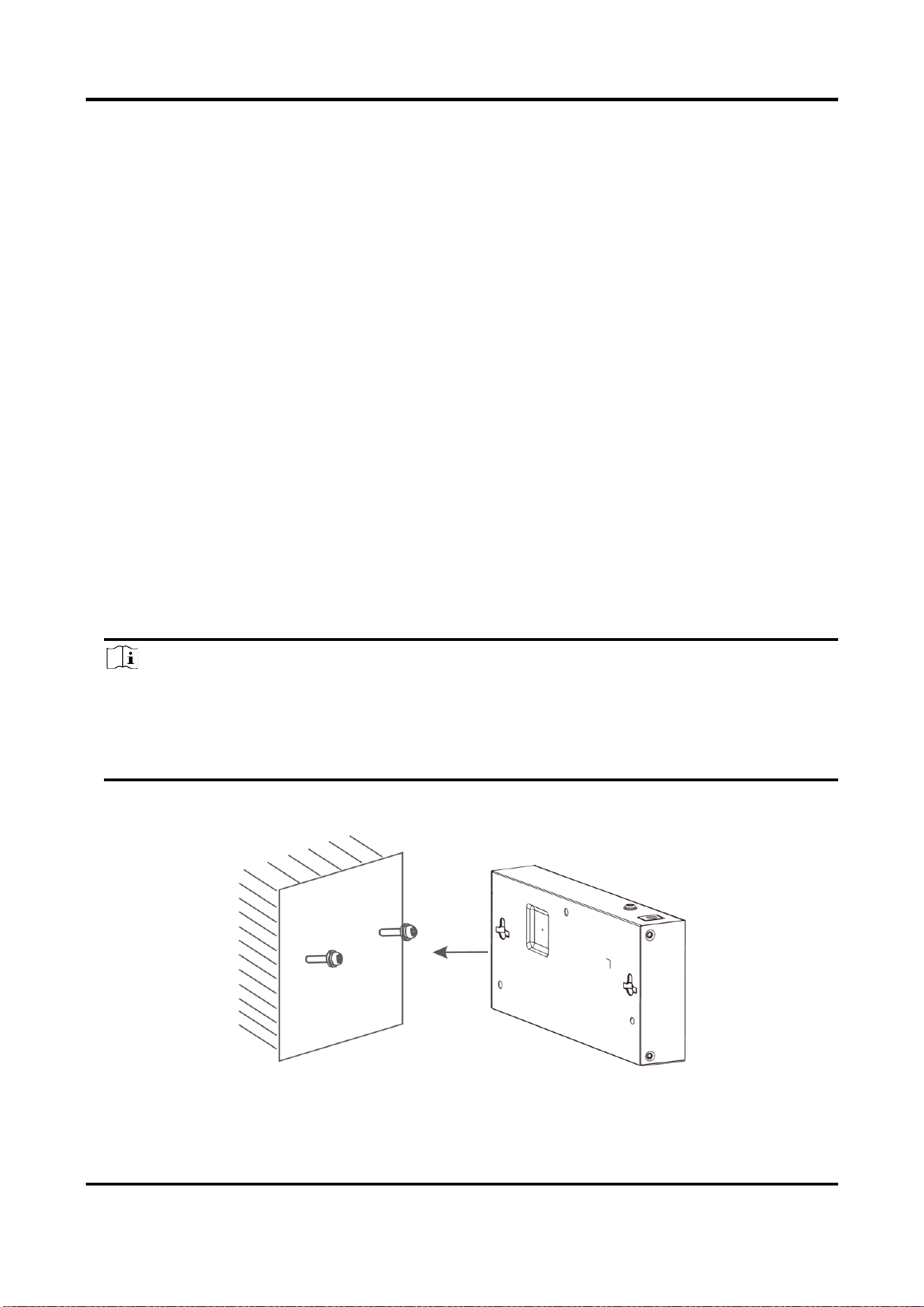
2.2 Wall-Mounted Installation
Steps
1. Check the distance between the two hanging holes on the rear cover of the device.
2. Insert two M4 screws into the wall.
Note
● Please prepare two M4 screws.
● Ensure that the distance between the two screws equals that between the two hanging
holes.
● Set aside at least 4 mm screws outside the wall.
3. Align the hanging holes with screws, and hang the device on the screws.
Figure 2-1 Wall-Mounted Installation
100 Mbps PoE Switch Quick Start Guide
6
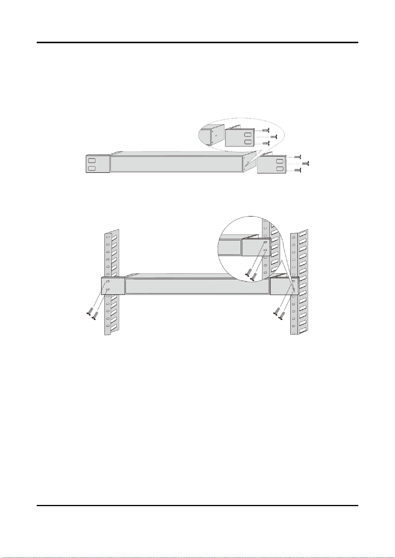
2.3 Rack-Mounted Installation
Steps
1. Check the grounding and stability of the rack.
2. Use the attached screws to fix the two L-shaped brackets to the sides of the switch.
Figure 2-2 Fix L-Shaped Brackets
3. Place your switch on the rack, fix it to the rack with self-prepared screws to stably install your
switch.
Figure 2-3 Fix to the Rack
100 Mbps PoE Switch Quick Start Guide
7
Chapter 3 Grounding
3.1 Connecting the Grounding Cable
Grounding is used to quickly release overvoltage and overcurrent induced by lightening for switch,
and to protect personal safety. Select the appropriate grounding method according to your needs.
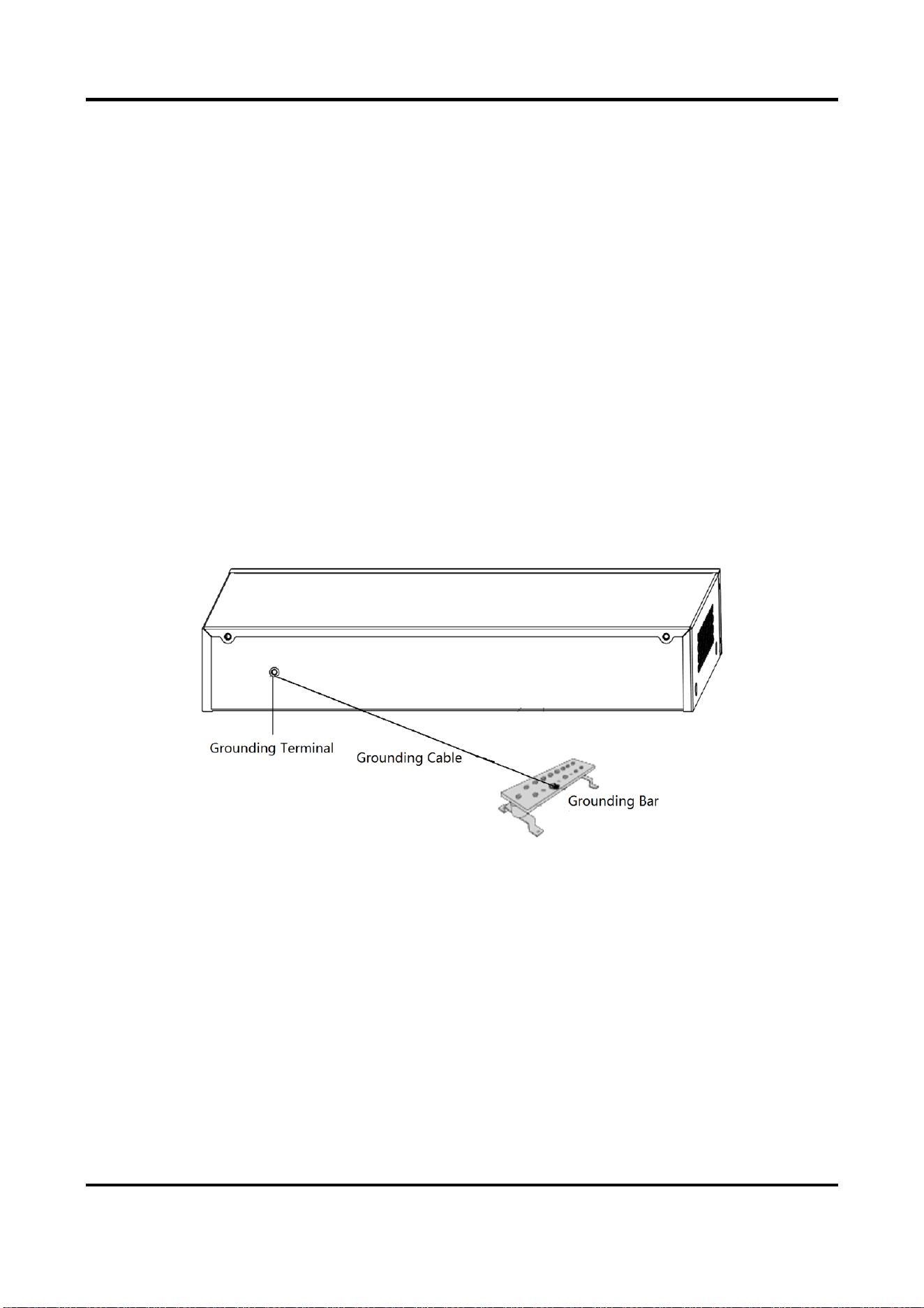
3.1.1 With Grounding Bar
If a grounding bar is available at the installation site, follow the steps below.
Steps
1. Connect one end of the grounding cable to the binding post on the grounding bar.
2. Connect the other end of the grounding cable to the grounding terminal of the device and fix
the screw.
Figure 3-1 Grounding with Grounding Bar
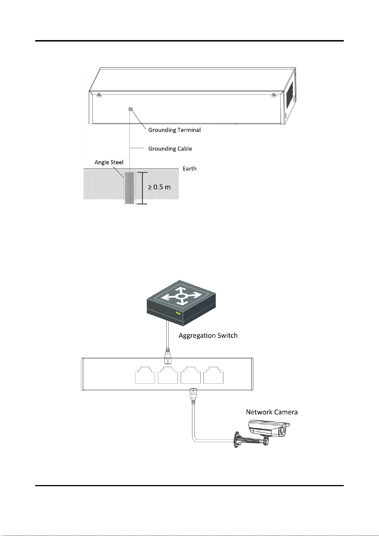
3.1.2 Without Grounding Bar
If there is no grounding bar but the earth is nearby and the grounding body is allowed to be
buried, follow the steps below.
Steps
1. Bury an angle steel or steel pipe (≥ 0.5 m) into the mud land.
2. Weld one end of the grounding cable to the angle steel or steel pipe and embalm the welding
point via electroplating or coating.
100 Mbps PoE Switch Quick Start Guide
8
3. Connect the other end of the grounding cable to the grounding terminal.
Figure 3-2 Grounding with Angle Steel
3.2 Connecting RJ45 Port
Use a network cable to connect the device to the RJ45 port of a peer device such as network
camera, NVR, switch, etc.
Figure 3-3 RJ45 Port Connection

100 Mbps PoE Switch Quick Start Guide
9
3.3 Connecting SFP Optical Module
Connecting SFP optical module is supported when the device has a fiber optic port or a combo.
When connected to a network cable, the combo is a RJ45 port. When plugged into with an optical
module and connected to an optical fiber, the combo functions as a fiber optic port.
When connected to both the network cable and optical fiber at the same time, the port works as a
fiber optic port.
Steps
Caution
● Single-Mode optical module needs to be paired.
● Do not bend fiber optic (curvature radius ≥ 10 cm) overly.
● Do not look directly at fiber optic connector because the laser is harmful to eyes.
1. Connect the two paired SFP optical modules with an optical fiber.
2. Hold the SFP optical module from one side, and smoothly plug it into the device along with the
SFP port slot until the optical module and the device are closely attached.
3. After powering on the device, check the status of LINK/ACT indicator. If the indicator is lit, the
link is connected. If the indicator is unlit, the link is disconnected. Check the line, and make sure
peer devices have been started.

100 Mbps PoE Switch Quick Start Guide
10
Chapter 4 Powering on the Device
Please use the attached power cord in package to power on the device.
Before powering your switch, make sure that:
● The operating power supply is compliant with rated input standard.
● Port cables and grounding cables are correctly connected.
● If there is outdoor cabling, connect a lightning rod and lightening arrester to the cable.
Caution
PoE power supply line and strong wire cannot be wired together, otherwise PD equipment or
switch ports will be burnt.

100 Mbps PoE Switch Quick Start Guide
11
Chapter 5 Device Management
The device can be configured and managed through iVMS-4200 software, mainly including
network parameter configuration, port configuration, link aggregation configuration, network
topology display and so on.
Note
● This chapter will briefly introduce device management through iVMS-4200 software. For other
functions, please refer to user manual of iVMS-4200 software.
● All pictures in this manual are for illustration only, and the specific interface is subject to the
actual interface.
5.1 Activating Devices
For the inactive devices, you are required to create a password to activate them before they can
be added to the software and work properly.
Before You Start
Make sure the device to be activated is connected to the network and is in the same subnet with
the PC running the client.
Steps
Note
This function should be supported by the device.
1. Enter the Device Management page.
2. Click Device tab on the top of the right panel.
3. Click Online Device to show the online device area at the bottom of the page.
The searched online devices are displayed in the list.
4. Check the device status (shown on Security Level column) and select an inactive device.
Figure 5-1 Online Inactive Device
5. Click Activate to open the Activation dialog.
6. Create a password in the password field, and confirm the password.

100 Mbps PoE Switch Quick Start Guide
12
Caution
The password strength of the device can be automatically checked. We highly recommend you
change the password of your own choosing (using a minimum of 8 characters, including at least
three kinds of following categories: upper case letters, lower case letters, numbers, and special
characters) in order to increase the security of your product. And we recommend you change
your password regularly, especially in the high security system, changing the password monthly
or weekly can better protect your product.
Proper configuration of all passwords and other security settings is the responsibility of the
installer and/or end-user.
7. Click OK to activate the device.
5.2 Adding Devices
The client provides various device adding modes including IP/domain, IP segment, cloud P2P, ISUP
protocol, and HiDDNS. The client also supports importing multiple devices in a batch when there
are large amount of devices to be added. The section only introduces one mode, namely, adding a
detected online device.
Steps
1. Enter the Device Management module.
2. Click Device tab on the top of the right panel.
3. Click Online Device to show the online device area.
The searched online devices are displayed in the list.
4. Select an online device in the Online Device area, and click Add to open the device adding
window.
Note
For the inactive device, you need to create the password for it before you can add the device
properly. For detailed steps, refer to Activating Devices.
5. Enter the required information.
Name
Enter a descriptive name for the device.
IP Address
Enter the device's IP address. The IP address of the device is obtained automatically in this
adding mode.
Port
You can customize the port number. The port number of the device is obtained automatically
in this adding mode.

100 Mbps PoE Switch Quick Start Guide
13
User Name
By default, the user name is admin.
Password
Enter the device password.
Caution
The password strength of the device can be automatically checked. We highly recommend
you change the password of your own choosing (using a minimum of 8 characters, including
at least three kinds of following categories: upper case letters, lower case letters, numbers,
and special characters) in order to increase the security of your product. And we recommend
you change your password regularly, especially in the high security system, changing the
password monthly or weekly can better protect your product.
Proper configuration of all passwords and other security settings is the responsibility of the
installer and/or end-user.
6. Check Synchronize Time to synchronize the device time with the PC running the client after
adding the device to the client.
7. Click Add.

100 Mbps PoE Switch Quick Start Guide
14
Chapter 6 Get More Information
Scan the QR code below for iVMS-4200 software operations.

UD32039B