Air conditioner
User manual
AM***NN1PEH*** / AM***NN1DEH*** / AM***NN1DKH***
• Thank you for purchasing this Samsung air conditioner.
• Before operating this unit, please read this manual carefully and retain it for future reference.
DB68-07559A-05_IBIM_DVM Wind-Free 1way_EU_EN_.indb 1 2024-01-09 오후 4:31:30
2
English
Contents
Correct Disposal of This Product
(Waste Electrical & Electronic Equipment)
(Applicable in countries with separate collection systems)
This marking on the product, accessories or literature indicates that the product and its electronic accessories (e.g.
charger, headset, USB cable) should not be disposed of with other household waste at the end of their working life. To
prevent possible harm to the environment or human health from uncontrolled waste disposal, please separate these
items from other types of waste and recycle them responsibly to promote the sustainable reuse of material resources.
Household users should contact either the retailer where they purchased this product, or their local government office, for
details of where and how they can take these items for environmentally safe recycling.
Business users should contact their supplier and check the terms and conditions of the purchase contract. This product
and its electronic accessories should not be mixed with other commercial wastes for disposal.
For information on Samsung’s environmental commitments and product regulatory obligations, e.g. REACH, visit our
sustainability page available via www.samsung.com
Safety Information 3
Safety Information 3
At a Glance 10
Indoor Unit Overview 10
Main parts 10
Operation Features 12
Operating temperature and humidity • Pairing an indoor unit with a remote control 12
Cleaning and Maintenance 13
Cleaning and Maintaining 13
Cleaning the indoor unit exterior • Cleaning the outdoor unit heat exchanger 13
Cleaning the air filter 14
Periodical maintenance 18
Troubleshooting 19
Technical specifications 22
Information about refrigerant 22
Important information: regulation regarding the refrigerant used 22
Installation Procedure 23
Installation Procedure 23
DB68-07559A-05_IBIM_DVM Wind-Free 1way_EU_EN_.indb 2 2024-01-09 오후 4:31:30
3
English
Safety Information
Before using your new air conditioner, please read this manual thoroughly
to ensure that you know how to safely and efficiently operate the extensive
features and functions of your new appliance.
Because the following operating instructions cover various models, the
characteristics of your air conditioner may differ slightly from those described in
this manual. If you have any questions, call your nearest contact centre or find
help and information online at www.samsung.com.
WARNING
Hazards or unsafe practices that may result in severe personal injury or death.
CAUTION
Hazards or unsafe practices that may result in minor personal injury or property
damage.
Follow directions.
Do NOT attempt.
Make sure the machine is grounded to prevent electric shock.
Cut-off the power supply.
Do NOT disassemble.
FOR INSTALLATION
WARNING
Use the power line with the power specifications of the product or higher
and use the power line for this appliance only. In addition, do not use an
extension line.
• Extending the power line may result in electric shock or fire.
• Do not use an electric transformer. This may result in electric shock or
fire.
• If the voltage/frequency/rated current condition is different, it may cause
fire.
Safety Information
Safety Information
DB68-07559A-05_IBIM_DVM Wind-Free 1way_EU_EN_.indb 3 2024-01-09 오후 4:31:31
4
English
Safety InformationSafety Information
Safety Information
The installation of this appliance must be performed by a qualified
technician or service company.
• Failing to do so may result in electric shock, fire, explosion, problems with
the product, or injury.
Install a switch and circuit breaker dedicated to the air conditioner.
• Failing to do so may result in electric shock or fire.
Fix the outdoor unit firmly so that the electric part of the outdoor unit is
not exposed.
• Failing to do so may result in electric shock or fire.
Do not install this appliance near a heater, inflammable material. Do
not install this appliance in a humid, oily or dusty location, in a location
exposed to direct sunlight and water (rain drops). Do not install this
appliance in a location where gas may leak.
• This may result in electric shock or fire.
Never install the outdoor unit in a location such as on a high external wall
where it could fall.
• If the outdoor unit falls, it may result in injury, death or property damage.
This appliance must be properly grounded. Do not ground the appliance to
a gas pipe, plastic water pipe, or telephone line.
• Failure to do so may result in electric shock, fire, an explosion, or other
problems with the product.
• Make sure that it is in accordance with local and national codes.
CAUTION
Install your appliance on a level and hard floor that can support its weight.
• Failing to do so may result in abnormal vibrations, noise, or problems with
the product.
Install the drain hose properly so that water is drained correctly.
• Failing to do so may result in water overflowing and property damage.
Avoid adding drain to waste pipes as odours may arise in the future.
DB68-07559A-05_IBIM_DVM Wind-Free 1way_EU_EN_.indb 4 2024-01-09 오후 4:31:31
5
English
Safety Information
When installing the outdoor unit, make sure to connect the drain hose so
that draining is performed correctly.
• The water generated during the heating operation in the outdoor unit
may overflow and result in property damage.
In particular, in winter, if a block of ice falls, it may result in injury, death
or property damage.
Do not install the product in a place where thermo-hygrostat is needed
(such as server room, machinery room, computer room, etc.)
• Those places do not provide guaranteed operation condition of the
product therefore performance can be poor in these places.
FOR POWER SUPPLY
WARNING
When the circuit breaker is damaged, contact your nearest service centre.
Do not pull or excessively bend the power line. Do not twist or tie the
power line. Do not hook the power line over a metal object, place a heavy
object on the power line, insert the power line between objects, or push
the power line into the space behind the appliance.
• This may result in electric shock or fire.
CAUTION
When not using the air conditioner for a long period of time or during a
thunder/lightning storm, cut the power at the circuit breaker.
• Failing to do so may result in electric shock or fire.
FOR USING
WARNING
If the appliance is flooded, please contact your nearest service centre.
• Failing to do so may result in electric shock or fire.
If the appliance generates a strange noise, a burning smell or smoke, cut-
off the power supply immediately and contact the nearest service centre.
• Failing to do so may result in electric shock or fire.
DB68-07559A-05_IBIM_DVM Wind-Free 1way_EU_EN_.indb 5 2024-01-09 오후 4:31:31
6
English
Safety InformationSafety Information
Safety Information
In the event of a gas leak (such as propane gas, LP gas, etc.), ventilate
immediately without touching the power line. Do not touch the appliance
or power line.
• Do not use a ventilating fan.
• A spark may result in an explosion or fire.
To reinstall the air conditioner, please contact your nearest service centre.
• Failing to do so may result in problems with the product, water leakage,
electric shock, or fire.
• A delivery service for the product is not provided. If you reinstall the
product in another location, additional construction expenses and an
installation fee will be charged.
• Especially, when you wish to install the product in an unusual location
such as in an industrial area or near the seaside where it is exposed to salt
in the air, please contact your nearest service centre.
Do not touch the circuit breaker with wet hands.
• This may result in electric shock.
Do not turn the air conditioner off with the circuit breaker while it is
operating.
• Turning the air conditioner off and then on again with the circuit breaker
may cause a spark and result in electric shock or fire.
After unpacking the air conditioner, keep all packaging materials well
out of the reach of children, as packaging materials can be dangerous to
children.
• If a child places a bag over its head, it may result in suffocation.
Do not touch the front panel with your hands or fingers during the heating
operation.
• This may result in electric shock or burns.
Do not insert your fingers or foreign substances into the outlet when the
air conditioner is operating or the front panel is closing.
• Take special care that children do not injure themselves by inserting their
fingers into the product.
DB68-07559A-05_IBIM_DVM Wind-Free 1way_EU_EN_.indb 6 2024-01-09 오후 4:31:31

7
English
Safety Information
Do not insert your fingers or foreign substances into the air inlet/outlet of
the air conditioner.
• Take special care that children do not injure themselves by inserting their
fingers into the product.
Do not strike or pull the air conditioner with excessive force.
• This may result in fire, injury, or problems with the product.
Do not place an object near the outdoor unit that allows children to climb
onto the machine.
• This may result in children seriously injuring themselves.
Do not use this air conditioner for long periods of time in badly ventilated
locations or near infirm people.
• Since this may be dangerous due to a lack of oxygen, open a window at
least once an hour.
If any foreign substance such as water has entered the appliance, cut-off
the power supply and contact the nearest service centre.
• Failing to do so may result in electric shock or fire.
Do not attempt to repair, disassemble, or modify the appliance yourself.
• Do not use any fuse (such as copper, steel wire, etc.)other than the
standard fuse.
• Failing to do so may result in electric shock, fire, problems with the
product, or injury.
CAUTION
Do not place objects or devices under the indoor unit.
• Water dripping from the indoor unit may result in fire or property damage.
Check that the installation frame of the outdoor unit is not broken at least
once a year.
• Failing to do so may result in injury, death or property damage.
Max current is measured according to IEC standard for safety and current
is measured according to ISO standard for energy efficiency.
Do not install the product in a ship or a vehicle (such as a campervan).
• Salt, vibration or other environmental factor may cause the product
malfunction, electric shock or fire.
DB68-07559A-05_IBIM_DVM Wind-Free 1way_EU_EN_.indb 7 2024-01-09 오후 4:31:32

8
English
Safety InformationSafety Information
Safety Information
Do not stand on top of the appliance or place objects (such as laundry,
lighted candles, lighted cigarettes, dishes, chemicals, metal objects, etc.)
on the appliance.
• This may result in electric shock, fire, problems with the product, or injury.
Do not operate the appliance with wet hands.
• This may result in electric shock.
Do not spray volatile material such as insecticide onto the surface of the
appliance.
• As well as being harmful to humans, it may also result in electric shock,
fire or problems with the product.
Do not drink the water from the air conditioner.
• The water may be harmful to humans.
Do not apply a strong impact to the remote controller and do not
disassemble the remote controller.
Do not touch the pipes connected with the product.
• This may result in burns or injury.
Do not use this air conditioner to preserve precision equipment, food,
animals, plants or cosmetics, or for any other unusual purposes.
• This may result in property damage.
Avoid directly exposing humans, animals or plants to the air flow from the
air conditioner for long periods of time.
• This may result in harm to humans, animals or plants.
This appliance is not intended for use by persons (including children) with
reduced physical, sensory or mental capabilities, or lack of experience and
knowledge, unless they have been given supervision or instruction concerning
use of the appliance by a person responsible for their safety. Children should
be supervised to ensure that they do not play with the appliance.
DB68-07559A-05_IBIM_DVM Wind-Free 1way_EU_EN_.indb 8 2024-01-09 오후 4:31:32
9
English
Safety Information
For use in Europe: This appliance can be used by children aged from 8 years
and above and persons with reduced physical, sensory or mental capabilities
or lack of experience and knowledge if they have been given supervision or
instruction concerning use of the appliance in a safe way and understand the
hazards involved. Children shall not play with the appliance. Cleaning and user
maintenance shall not be made by children without supervision.
FOR CLEANING
WARNING
Do not clean the appliance by spraying water directly onto it. Do not use
benzene, thinner, alcohol or acetone to clean the appliance.
• This may result in discoloration, deformation, damage, electric shock or
fire.
Before cleaning or performing maintenance, cut-off the power supply and
wait until the fan stops.
• Failing to do so may result in electric shock or fire.
CAUTION
Take care when cleaning the surface of the heat exchanger of the outdoor
unit since it has sharp edges.
• To avoid cutting your fingers, wear thick cotton gloves when cleaning it.
• This should be done by a qualified technician please contact your installer
or service centre.
Do not clean the inside of the air conditioner by yourself.
• For cleaning inside the appliance, contact your nearest service centre.
• When cleaning the internal filter, refer to the descriptions in the ‘Cleaning
and Maintaining’ section.
• Failure to do may result in damage, electric shock or fire.
• Make sure to prevent any injury from sharp edges of the surface when
handling the heat exchanger.
DB68-07559A-05_IBIM_DVM Wind-Free 1way_EU_EN_.indb 9 2024-01-09 오후 4:31:32
10
English
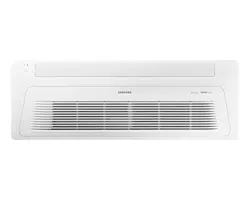
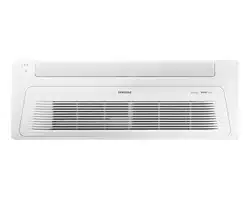
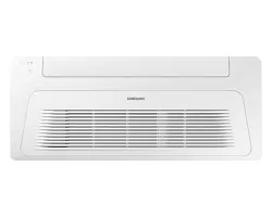
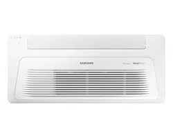
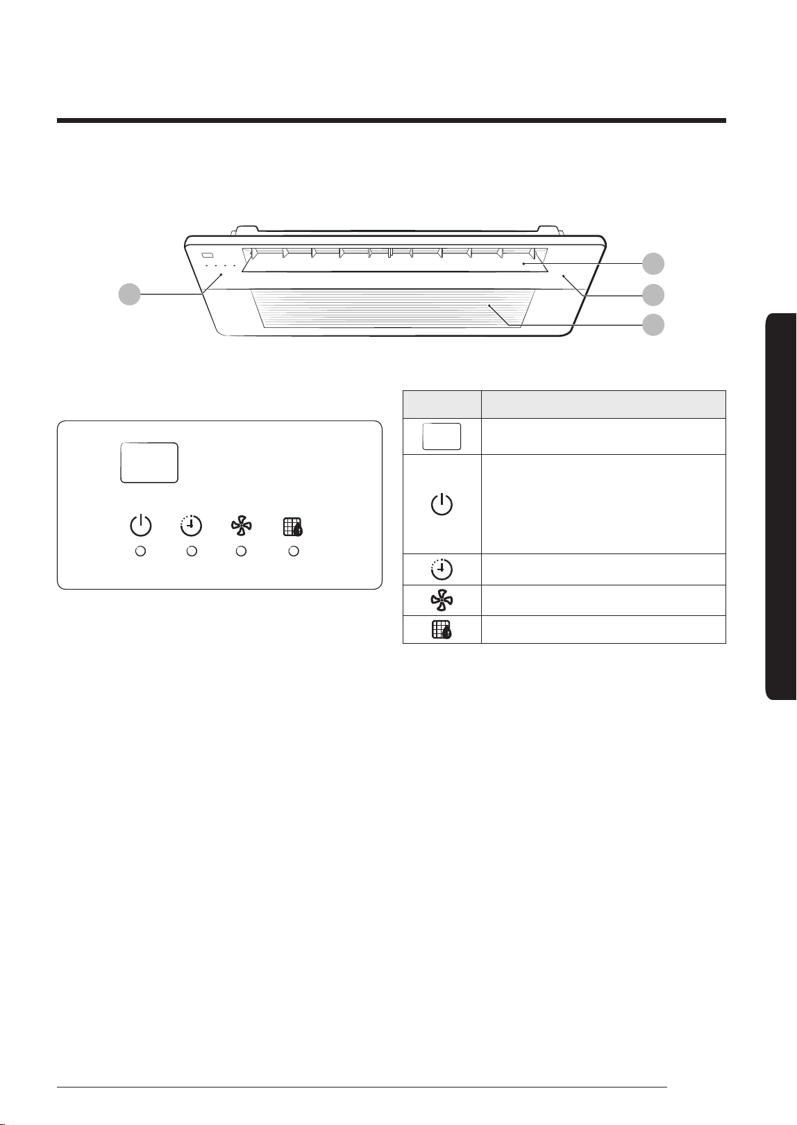
Indoor Unit Overview
At a Glance
Indoor Unit Overview
At a Glance
Main parts
The indoor unit and its display may look slightly different from the illustration shown below,
depending on the model and the panel type.
PC1*WFMAN / PC1*WCMAN
02
01
04
05
03
01 Display
02 Remote control sensor
03 Airflow blade
04 Wind-Free panel
(You can use the Wind-Free Cooling function
when the Cool, Dry, or Fan mode is running.)
(Refer to the remote control manual for
product operation)
05 Air intake
Indication Function
Operation indicator
• Heating and cooling model:
Operation(Blue) / Defrost(Yellow)
• Cooling only model: Operation
indicator
Timer indicator
Fan indicator
Filter cleaning indicator
DB68-07559A-05_IBIM_DVM Wind-Free 1way_EU_EN_.indb 10 2024-01-09 오후 4:31:34
11
English
At a Glance
PC1NUSMAN/PC1NUPMAN/PC1MWSKAN/PC1NWSMAN/PC1BWSMAN
02
03
04
01
01 Display
02 Air flow blade
03 Panel
04 Air intake
Indication Function
Remote control sensor
Operation indicator
• Heating and cooling model:
Operation(Blue) / Defrost(Yellow)
• Cooling only model: Operation
indicator
Timer indicator
Fan indicator
Filter cleaning indicator
DB68-07559A-05_IBIM_DVM Wind-Free 1way_EU_EN_.indb 11 2024-01-09 오후 4:31:34
12
English
Operation Features
At a Glance
Operation Features
Operating temperature and humidity
When using the air conditioner follow the operating temperature and humidity ranges.
Mode Outdoor temperature Indoor temperature Indoor humidity
Cool mode
Depending on the outdoor
unit specifications
18°C to 32°C 80% or less
Heat mode 30°C or less
-
Dry mode 18°C to 32°C
CAUTION
• If you use the air conditioner at a relative humidity above 80%, it may cause a formation of
condensation and a leakage of water on the floor.
• The rated heating capacity is based on an outdoor temperature of 7°C. If the outdoor temperature
goes down below 0°C, heating efficiencies may decrease depending on the temperature
conditions.
• If the indoor unit is out of the operating temperature and humidity range, the safery device may
operate and the air conditioner may stops.
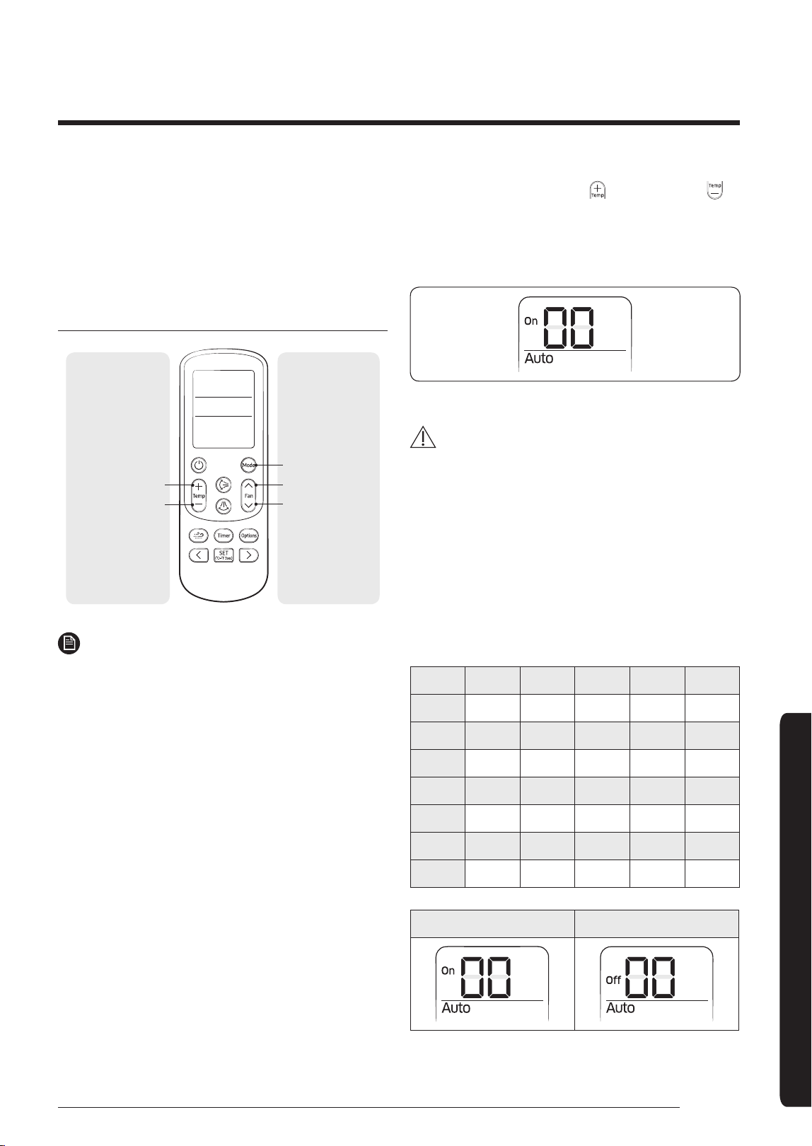
Pairing an indoor unit with a remote control
When using multiple indoor unit, you can control individually pairing remote control and indoor unit.
Set by remote control when the indoor unit is off.
▶ Zone 1~4 ▶ ▶ (5sec)
NOTE
• After push the
, have to push within 60 seconds.
• Each indoor unit number setting must be set by the installer when installing. Contact service
centre to reset indoor unit number.
DB68-07559A-05_IBIM_DVM Wind-Free 1way_EU_EN_.indb 12 2024-01-09 오후 4:31:34
13
English
Cleaning and Maintenance
Cleaning and Maintaining
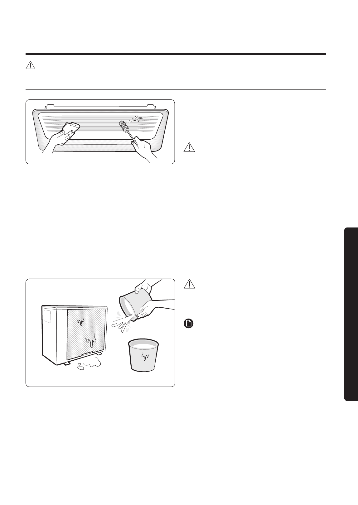
Cleaning the indoor unit exterior
Wipe the surface of the indoor unit with a tepid
damp cloth.
Remove the dust accumulated in the narrow
gaps of the product with a soft brush.
CAUTION
• Do not use alkaline detergent, sulphuric
acid, hydrochloric acid, or organic solvents
(such as thinner, kerosene, and acetone) to
clean the surfaces.
• Do not attach any stickers on the surfaces
because this may cause damage.
• When you clean the heat exchanger on the
indoor unit, you need to disassemble the
indoor unit. Therefore, you must contact the
local service Centre for help.
Cleaning the outdoor unit heat exchanger
Spray water to clean the dust.
CAUTION
• The heat exchanger of the outdoor unit has
sharp edges. Take care when cleaning its
surface.
NOTE
• If it is difficult to clean the heat exchanger
of the outdoor unit, contact the local service
Centre.
Cleaning and Maintenance
Before cleaning the indoor unit, be sure to turn off the auxiliary power switch.
DB68-07559A-05_IBIM_DVM Wind-Free 1way_EU_EN_.indb 13 2024-01-09 오후 4:31:35
14
English
Cleaning and MaintainingCleaning and Maintaining
Cleaning and Maintenance
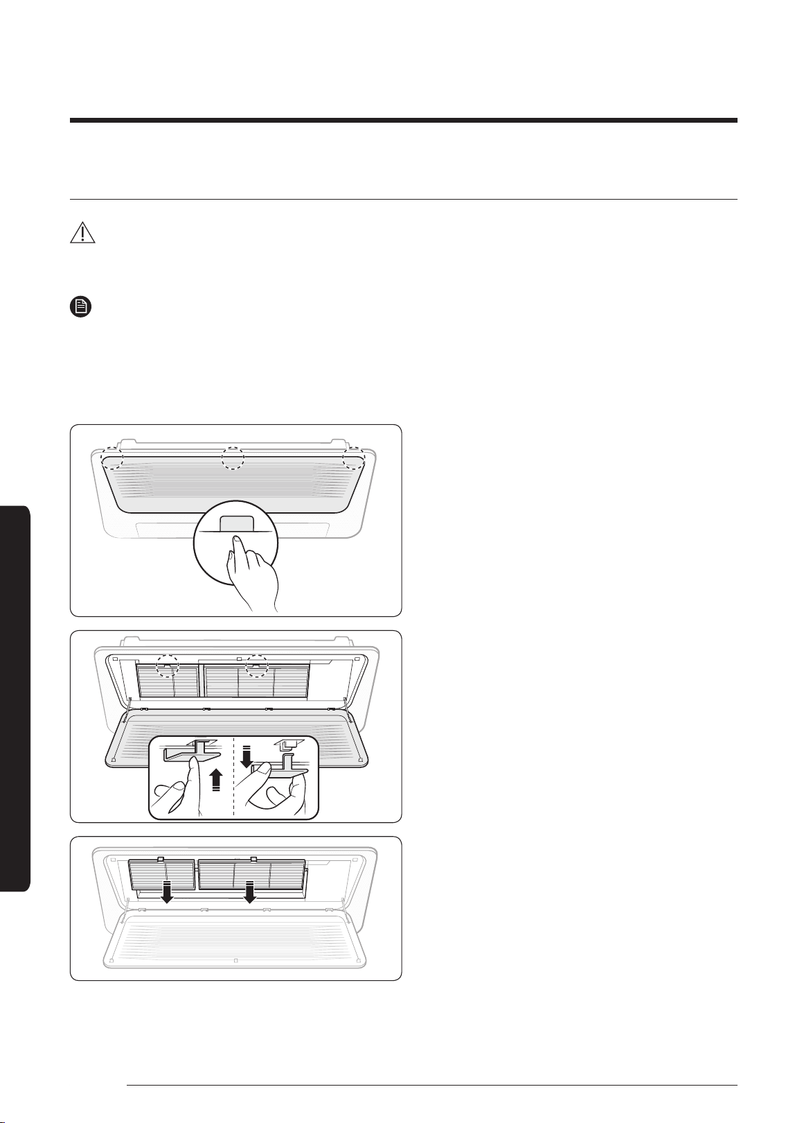
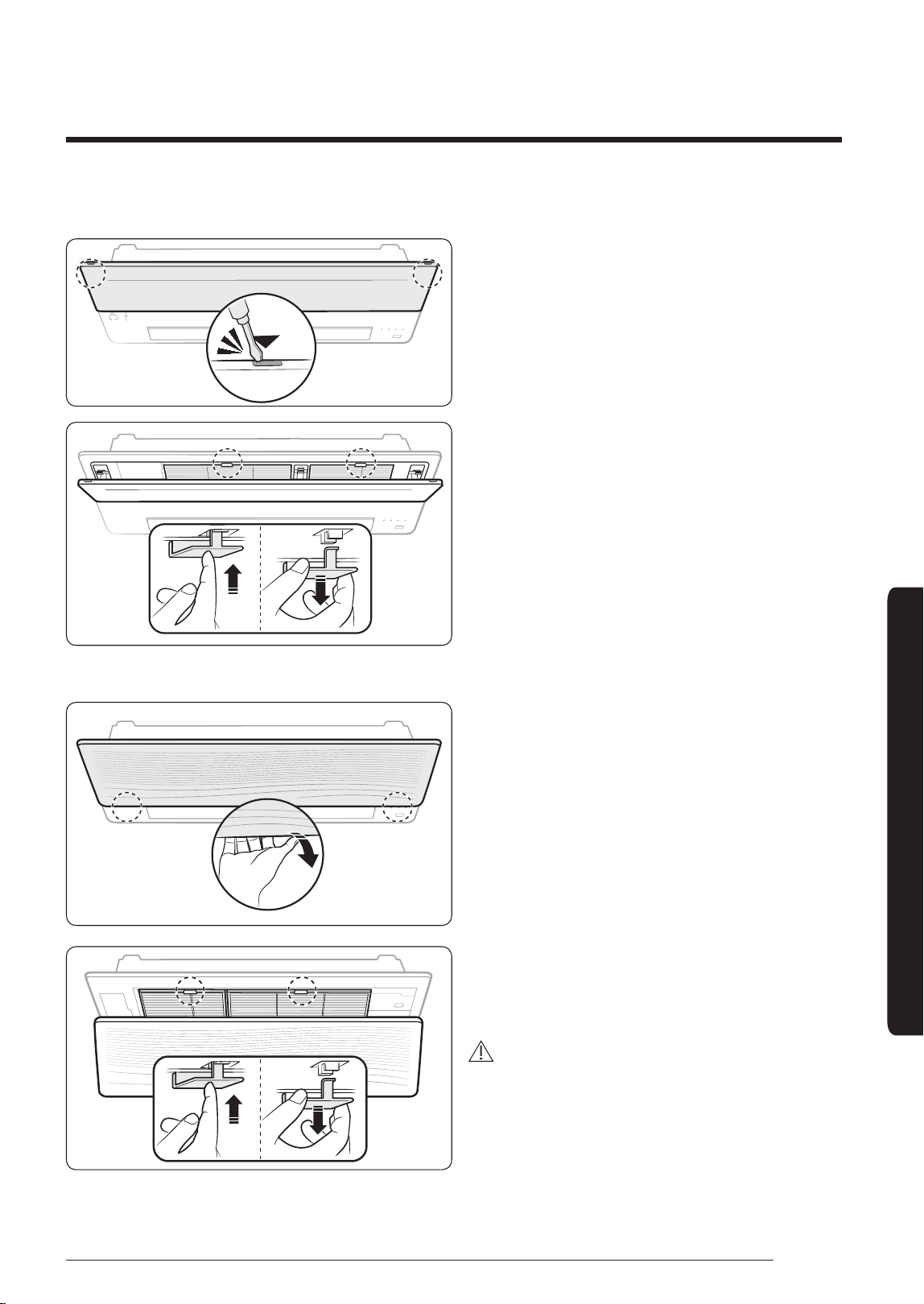
Cleaning the air filter
CAUTION
• Before cleaning the indoor unit, be sure to turn off the auxiliary power switch.
• Be sure to hold the grille with a hand to prevent dropping from the opening of the front grille.
NOTE
• When removing the grill completely, unhook the safety hooks on both sides of the grill.
PC1*WFMAN / PC1*WCMAN / PC1NUSMAN
1 Detaching the air filter
PUSH
Press the Push signs on the front panel, then
open the grille.
Press the Push signs (▽) on the air filter.
Grab the handle of the air filter and pull it out
from the indoor unit with your hand.
Pull the air filter out of the indoor unit.
DB68-07559A-05_IBIM_DVM Wind-Free 1way_EU_EN_.indb 14 2024-01-09 오후 4:31:38
15
English
Cleaning and Maintenance
PC1NUPMAN
Insert a driver at the marked points and open
the front grille.
Press the Push signs on the air filter.
Grab the handle of the air filter and pull it out
from the indoor unit.
PC1MWSKAN/PC1NWSMAN/PC1BWSMAN
Insert your hand into the front grille and pull
out the front grille to open it.
Press the Push signs on the air filter.
Grab the handle of the air filter and pull it out
from the indoor unit.
CAUTION
• The grille is connected to the panel. Do not
forcibly detach the grille. If the connection
structure is broken, the grille may fall down,
which may cause an injury.
DB68-07559A-05_IBIM_DVM Wind-Free 1way_EU_EN_.indb 15 2024-01-09 오후 4:31:39
16
English
Cleaning and MaintainingCleaning and Maintaining
Cleaning and Maintenance
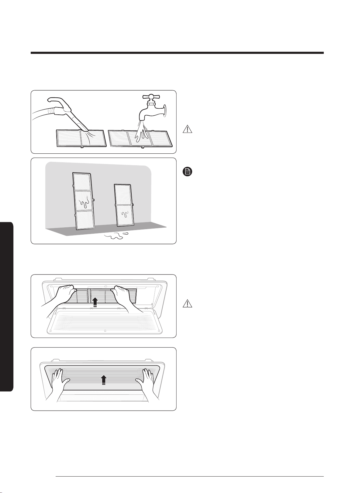
2 Cleaning the air filter
Clean the air filter with a vacuum cleaner or soft
brush. If dust is too heavy, then rinse it with
running water and dry it in a ventilated area.
CAUTION
• Do not scrub the air filter with a brush or
other cleaning utensil. This may damage the
filter.
NOTE
• If the air filter dries in a humid area, it may
produce offensive odours. Clean it again and
dry it in a well-ventilated area.
• The cleaning period may differ depending
on the usage and environmental conditions,
so clean the air filter every week if the air
conditioner is in the dusty area.
• You can request a filter cleaning service.
Note that it is a charged service.
3 Reassembling the air filter
To assemble the air filter, proceed in reverse
order of detaching.
CAUTION
• If the indoor unit is used without the air filter,
it may be damaged due to dust.
DB68-07559A-05_IBIM_DVM Wind-Free 1way_EU_EN_.indb 16 2024-01-09 오후 4:31:41
17
English
Cleaning and Maintenance
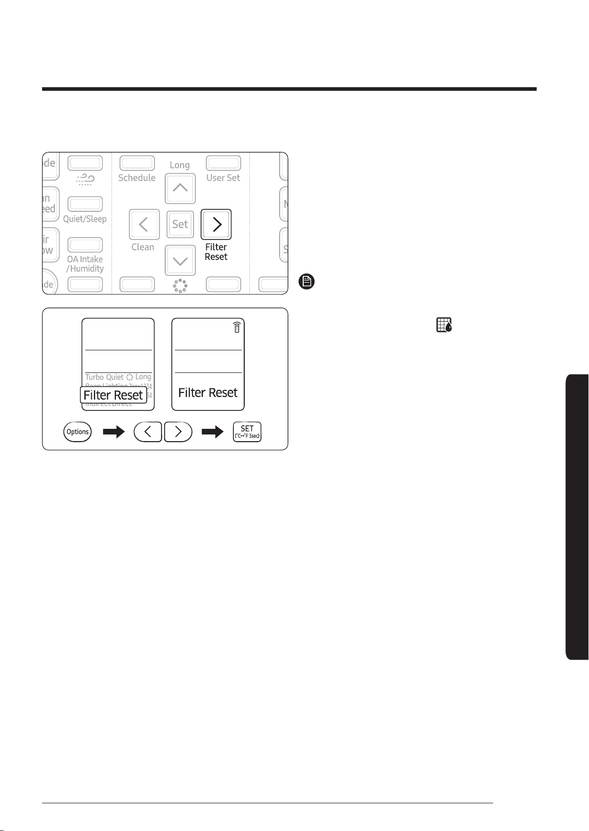
4 Resetting the air filter
After cleaning and reassembling the air filter,
be sure to reset the filter-cleaning reminder as
follows:
• Indoor unit with the wired remote control:
Press the Filter Reset button.
• Indoor unit with the wireless remote control:
Press the Options button → < or > → (Filter
Reset) Blinking → press the SET button.
NOTE
• Be sure to reset the filter-cleaning reminder
every time you clean the air filter although
the filter reset indicator (
) does not blink.
DB68-07559A-05_IBIM_DVM Wind-Free 1way_EU_EN_.indb 17 2024-01-09 오후 4:31:41
18
English
Cleaning and MaintainingCleaning and Maintaining
Cleaning and Maintenance
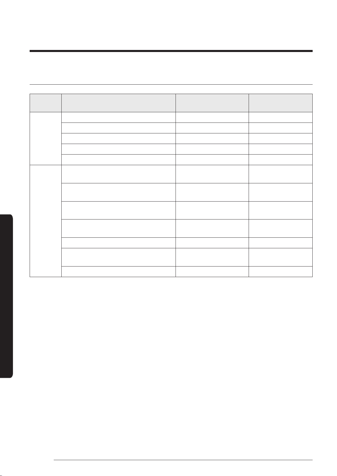
Periodical maintenance
Unit Maintenance item Interval
Requires qualified
technicians
Indoor
unit
Clean the air filter. At least once a month
Clean the condensate drain pan. Once a year Required
Clean the heat exchanger. Once a year Required
Clean the condensate drain pipe. Once every 4 months Required
Replace the remote control batteries. At least once a year
Outdoor
unit
Clean the heat exchanger on the
outside of the unit.
Once every 4 months Required
Clean the heat exchanger on the
inside of the unit.
Once a year Required
Clean the electric components with
jets of air.
Once a year Required
Verify that all the electric
components are firmly tightened.
Once a year Required
Clean the fan. Once a year Required
Verify that the fan assemblies are
firmly tightened.
Once a year Required
Clean the condensate drain pan. Once a year Required
DB68-07559A-05_IBIM_DVM Wind-Free 1way_EU_EN_.indb 18 2024-01-09 오후 4:31:41
19
English
Cleaning and Maintenance
Troubleshooting
Refer to the following chart if the air conditioner operates abnormally. This may save time and
unnecessary expense.
Problem Solution
The air conditioner
does not operate
immediately after it
has been restarted.
• Because of the protective mechanism, the appliance does not start
operating immediately to keep the unit from overloading. The air
conditioner will start in 3 minutes.
The air conditioner
does not operate
at all.
• Check whether the power is turned on, and then operate the air
conditioner again.
• Check whether the auxiliary power switch (MCCB, ELB) is turned on.
• If the auxiliary power switch (MCCB, ELB) is turned off, the air
conditioner does not work although you press the
(Power) button.
• When you clean the air conditioner or do not use it for an extended
period of time, turn off the auxiliary power switch (MCCB, ELB).
• After the air conditioner is not used for an extended period of time, be
sure to turn on the auxiliary power switch (MCCB, ELB) 6 hours before
starting operation.
NOTE
• The auxiliary power switch (MCCB, ELB) is sold separately.
• Make sure that auxiliary power switch (MCCB, ELB) is installed in
the distribution box inside the building.
• If the air conditioner is turned off by the Timed off function, turn on the
air conditioner again by pressing the
(Power) button.
The temperature
does not change.
• Check whether the Fan mode is running. In the Fan mode, the air
conditioner controls the set temperature automatically, and you cannot
change the set temperature.
Warm air does not
come out of the air
conditioner.
• Check whether the outdoor unit is designed for cooling only. In this case,
warm air does not come out although you select the Heat mode.
• Check whether the remote control is designed only for cooling only. Use
a remote control that supports both cooling and heating.
The fan speed does
not change.
• Check whether the Auto or Dry mode is running. In these modes, the
air conditioner controls the fan speed automatically, and you cannot
change the fan speed.
The wireless
remote control
does not operate.
• Check whether the batteries are discharged. Replace the batteries with
new ones.
• Make sure that nothing is blocking the remote control sensor.
• Check whether any strong lighting sources are near the air conditioner.
Strong light which comes from fluorescent bulbs or neon signs may
interfere with the remote control.
DB68-07559A-05_IBIM_DVM Wind-Free 1way_EU_EN_.indb 19 2024-01-09 오후 4:31:41
20
English
Cleaning and MaintainingCleaning and Maintaining
Cleaning and Maintenance
Problem Solution
The wired remote
control does not
operate.
• Check whether the
indicator is displayed at the bottom right of the
remote control display. In this case, turn off both the air conditioner and
the auxiliary power switch, and then contact a service centre.
The air conditioner
is not turned on or
off immediately
with the wired
remote control.
• Check whether the wired remote control is set for group control. In this
case, the air conditioners connected to the wired remote control are
turned on or off sequentially. This operation takes up to 32 seconds.
The Timed on/off
function does not
operate.
• Check whether you pressed the
(SET) button on the remote control
after setting the on/off time. Set the on/off time.
The indoor unit
display blinks
continuously.
• Turn on the air conditioner again by pressing the
(Power) button.
• Turn off and then turn on the auxiliary power switch, and then turn on
the conditioner.
• If the indoor unit display is still blinking, contact a service centre.
The air is not cool or
warm enough.
• In the Cool mode, cool air does not come out if the set temperature is
higher than the current temperature.
– Remote control: Press the Temperature button repeatedly until the
set temperature (minimum: 18°C) is set to lower than the current
temperature.
• In the Heat mode, warm air does not come out if the set temperature is
lower than the current temperature.
– Remote control: Press the Temperature button repeatedly until the
set temperature (maximum: 30°C) is set to higher than the current
temperature.
• Both cooling and heating do not operate in the Fan mode. Select the
Cool, Heat, Auto, or Dry mode.
• Check whether the air filter is blocked with dirt. A dusty filter may
decrease the cooling and heating efficiencies. Clean the air filter
frequently.
• If a cover is on the outdoor unit or any obstacle is present near the
outdoor unit, remove them.
• Install the outdoor unit in a well-ventilated place. Avoiding places
exposed to direct sunlight or close to a heating appliance.
• Place a sunscreen over the outdoor unit to protect it from direct sunlight.
• If the indoor unit is installed in a place exposed to direct sunlight, pull
the curtains on the windows.
DB68-07559A-05_IBIM_DVM Wind-Free 1way_EU_EN_.indb 20 2024-01-09 오후 4:31:41
21
English
Cleaning and Maintenance
Problem Solution
The air is not cool or
warm enough.
• Close the windows and doors to maximize the cooling and heating
efficiencies.
• If the Cool mode is stopped and then started immediately, cool air comes
out after about 3 minutes to protect the compressor of the outdoor unit.
• When the Heat mode is started, warm air does not come out
immediately to prevent cool air from coming out at the beginning.
• If the refrigerant pipe is too long, the cooling and heating efficiencies
may be decreased. Avoid exceeding the maximum pipe length.
The air conditioner
makes strange
noises.
• In certain conditions (especially, when the outdoor temperature is
lower than 20°C), a hissing, rumbling, or splashing sound may be heard
while the refrigerant is circulating through the air conditioner. This is a
normal operation.
• When you press the
(Power) button on the remote control, noise
may be heard from the drain pump inside the air conditioner. This noise
is a normal sound.
Unpleasant odours
permeate the room.
• If the air conditioner is running in a smoky area or if there is a smell
entering from outside, ventilate the room properly.
• If both indoor temperature and indoor humidity are high, operate the air
conditioner in the Clean or Fan mode for 1 to 2 hours.
• If the air conditioner has not been operated for an extended period of
time, clean the indoor unit and then operate the air conditioner in the
Fan mode for 3 to 4 hours to dry the inside of the indoor unit for removal
of unpleasant odours.
• If the air filter blocked with dirt, clean the air filter.
Steam is produced
on the indoor unit.
• In winter, if the indoor humidity is high, steam may be produced around
the air outlet while the defrost function is running. This is a normal
operation.
The outdoor unit
fan continues to
operate when the
air conditioner is
turned off.
• When the air conditioner is turned off, the outdoor unit fan may
continue to operate to reduce noise of the refrigerant gas. This is a
normal operation.
Water drops
from the piping
connections of the
outdoor unit.
• Condensation may develop due to the difference in temperature. This is
a normal condition.
Steam is produced
on the outdoor unit.
• In winter, when the air conditioner runs in the Heat mode, the frost on
the heat exchanger melts and steam may be produced. This is a normal
operation, neither product malfunction nor a fire.
DB68-07559A-05_IBIM_DVM Wind-Free 1way_EU_EN_.indb 21 2024-01-09 오후 4:31:41
22
English
Technical specifications
Cleaning and Maintenance
Type Model New weight Net dimension(W x D x H)
Indoor unit
AM017NN1PEH 8.0 kg 740 mm x 360 mm x 135 mm
AM022NN1PEH 8.0 kg 740 mm x 360 mm x 135 mm
AM022NN1DEH 10.0 kg 970 mm x 410 mm x 135 mm
AM028NN1DEH 10.0 kg 970 mm x 410 mm x 135 mm
AM036NN1DEH 10.0 kg 970 mm x 410 mm x 135 mm
AM056NN1DEH 13.5 kg 1,200 mm x 450 mm x 138 mm
AM071NN1DEH 13.5 kg 1,200 mm x 450 mm x 138 mm
AM022NN1DKH 10.0 kg 970 mm x 410 mm x 135 mm
AM028NN1DKH 10.0 kg 970 mm x 410 mm x 135 mm
AM036NN1DKH 10.0 kg 970 mm x 410 mm x 135 mm
Information about refrigerant
Important information: regulation regarding the refrigerant used
This product contains fluorinated greenhouse gases. Do not vent gases into the atmosphere.
CAUTION
• If the system contains 5 tCO₂e or more of fluorinated greenhouse gases, it must be checked
for leakage at least once every 12 months, according to regulation No. 517/2014. This activity
must be covered by qualified personnel only. In the case of the situation above, the installer (or
authorized person with responsibility for final check) must provide a maintenance book, with
all the information recorded, according to REGULATION (EU) No. 517/2014 OF THE EUROPEAN
PARLIAMENT AND OF THE COUNCIL of 16 April 2014 on fluorinated greenhouse gases.
Refrigenat type GWP value
R-410A 2088
• GWP: Global Warming Potential
• Calculating tCO₂e: kg x GWP/1000
Technical specifications
DB68-07559A-05_IBIM_DVM Wind-Free 1way_EU_EN_.indb 22 2024-01-09 오후 4:31:42
23
English
Installation Procedure
Step 1 Installing the indoor unit
When deciding on the location of the air conditioner the
following restrictions must be taken into account.
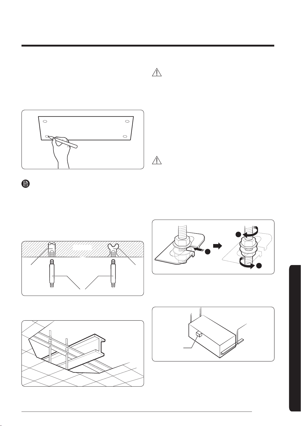
1 Place the pattern sheet on the ceiling at the spot
where you want to install the indoor unit.
NOTE
• Since the diagram is made of paper, it may shrink
or stretch slightly due to temperature or humidity.
For this reason, before drilling the holes, be sure
to maintain the correct dimensions between the
markings.
2 Insert bolt anchors, use existing ceiling supports or
construct a suitable support as shown in figure.
Concrete
Hole in anchor
Hole in plug
Suspension bolt (ø9.52 or M10)
Insert
3 Install the suspension bolts, depending on the ceiling
type.
Ceiling support
CAUTION
• Make sure that the ceiling is strong enough to support
the weight of the indoor unit. Before hanging the unit,
test the strength of each attached suspension bolt.
• If the length of the suspension bolt is more than 1.5 m,
you are required to prevent vibration.
• If this is not possible, create an opening on the false
ceiling in order to be able to use it to perform the
required operations on the indoor unit.
4 Screw eight nuts and washers to the suspension bolts,
making space for hanging the indoor unit.
CAUTION
• You must install all of the suspension rods.
• It is important to leave sufficient space in the false
ceiling to allow access for maintenance or repairs to
the drainage pipe connection, the refrigerant pipe
connection, or to remove the unit if necessary.
5 Hang the indoor unit to the suspension bolts between
two nuts. Screw the nuts to suspend the unit.
1
2
2
6 Check the level of the indoor unit by using a leveler.
• A tilt of the indoor unit may cause malfunction of a
built-in float switch and water leaks.
Level
Installation Procedure
Installation Procedure
DB68-07559A-05_IBIM_DVM Wind-Free 1way_EU_EN_.indb 23 2024-01-09 오후 4:31:42
24
English
Installation Procedure
Installation Procedure
7 Adjust the unit to the appropriate position, taking into
account the installation area for the front panel.
• Place the pattern sheet on the indoor unit.
• Adjust the space between the ceiling and the
indoor unit by using a dimension gauge.
• Fix the indoor unit securely after adjusting the level
of the unit by using a leveller.
• Remove the pattern sheet and install the front
panel.
(Unit: mm)
Slim 1way cassette
(Small, Wind-Free)
Indoor unit
Slim 1way cassette
(Medium, Wind-Free)
Slim 1way cassette
(Large, Wind-Free)
Air outlet side
Jig
6.0
8.0
Ceiling
Air inlet side
Indoor unit
Air outlet side
Jig
10
10
Ceiling
Air inlet side
Indoor unit
Air outlet side
Jig
10
10
Ceiling
Air inlet side
Slim 1way cassette
(Small)
Indoor unit
Slim 1way cassette
(Medium)
Slim 1way cassette
(Large)
Air outlet side
Jig
16
18
Ceiling
Air inlet side
Indoor unit
Air outlet side
Jig
15
15
Ceiling
Air inlet side
Indoor unit
Air outlet side
Jig
15
15
Ceiling
Air inlet side
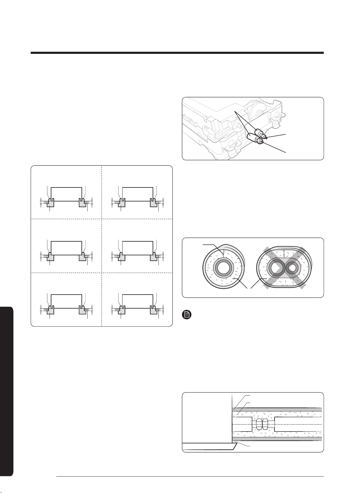
Step 2 Performing the gas leak test
To identify potential gas leaks on the indoor unit, inspect
the connection area of each refrigerant pipe using a leak
detector for R-410A.
Before recreating the vacuum and recirculating the
refrigerant gas, pressurize the whole system with
nitrogen (using a cylinder with a pressure reducer) at a
pressure above 4.1 MPa in order to immediately detect
leaks on the refrigerant fittings.
Made vacuum for 15 minutes and pressurizing system
with nitrogen.
Liquid side
Gas side
Insulator
Step 3 Insulating the refrigerant pipes
Once you have checked that there are no leaks in the
system, you can insulate the piping and hose.
1 To avoid condensation problems, place Acrylonitrile
Butadien Rubber separately around each refrigerant
pipe.
No gap
NBR (T13.0 or thicker)
NOTE
• Always make the seam of pipes face upwards.
2 Wind insulating tape around the pipes and drain hose
avoiding compressing the insulation too much.
3 Finish wrapping insulating tape around the rest of the
pipes leading to the outdoor unit.
4 The pipes and electrical cables connecting the indoor
unit with the outdoor unit must be fixed to the wall
with suitable ducts.
Insulation cover pipe
Insulation pipe
Be sure to overlap the insulation.
Indoor unit
DB68-07559A-05_IBIM_DVM Wind-Free 1way_EU_EN_.indb 24 2024-01-09 오후 4:31:42
25
English
Installation Procedure
CAUTION
• Must fit tightly against body without any gap.
• Install the insulation not to get wider and use the
adhesives on the connection part of it to prevent
moisture from entering.
• Wind the refrigerant pipe with insulation tape if it is
exposed to outside sunlight.
• Install the refrigerant pipe respecting that the
insulation does not get thinner on the bent part or
hanger of pipe.
• Add the additional insulation if the insulation plate
gets thinner.
Refrigerant pipe insulation
Hanger
Additional
insulation
a
a x 3
• Must fit tightly against body without any gap.
• All refrigerant connection must be accessible, in order
to permit either unit maintenance or removal.
5 Select the insulation of the refrigerant pipe.
• Insulate the gas side and liquid side pipe, noting the
insulation thickness that must differ according to the
pipe size.
• Standard: Less than an indoor temperature of 30°C,
with humidity at 85%. If installing in a high humidity
environment, use one grade thicker insulator by
referring to the table below. If installing in an
unfavourable environment, use thicker one.
• The heat-resistance temperature of the insulator must
be more than 120°C.
Pipe
Pipe size
(mm)
Insulation Type (Heating/Cooling)
Remarks
Standard
[30°C, 85%]
High humidity
[30°C, over 85%]
EPDM, NBR
(mm)
Liquid
pipe
Ø6.35 to Ø9.52 9t
←
Internal temperature
is higher than 120°C
Ø12.7 to Ø50.80 13t
←
Gas pipe
Ø6.35 13t 19t
Ø9.52 to Ø25.40
19t
25t
Ø28.58 to Ø44.45 32t
Ø50.80 25t 38t
DB68-07559A-05_IBIM_DVM Wind-Free 1way_EU_EN_.indb 25 2024-01-09 오후 4:31:43
26
English
Installation Procedure
Installation Procedure
• When installing insulation in the places and conditions
below, use the same insulation that is used for high
humidity conditions.
<Geological condition>
High humidity locations such as shorelines, hot springs,
lake or riversides, and ridges (when part of the building is
covered by earth and sand)
<Operation purpose condition>
Restaurant ceiling, sauna, swimming pool etc.
<Building construction condition>
Ceilings frequently exposed to moisture and cooling are
not covered. For example, pipes installed at a corridor of a
dormitory and studio or near an exit that opens and closes
frequently.
Places (where the pipes are installed) that are highly
humid due to a lack of ventilation.
• Refrigerant pipe before EEV kit and MCU or without
EEV kit and MCU
‐ You can contact the gas side and liquid side pipes
but the pipes should not be pressed.
‐ When contacting the gas side and liquid side pipe,
use 1 grade thicker insulator.
• Refrigerant pipe after EEV kit and MCU
‐ Install the gas side and liquid side pipes, leave
10mm of space.
‐ When contacting the gas side and liquid side pipe,
use 1 grade thicker insulator.
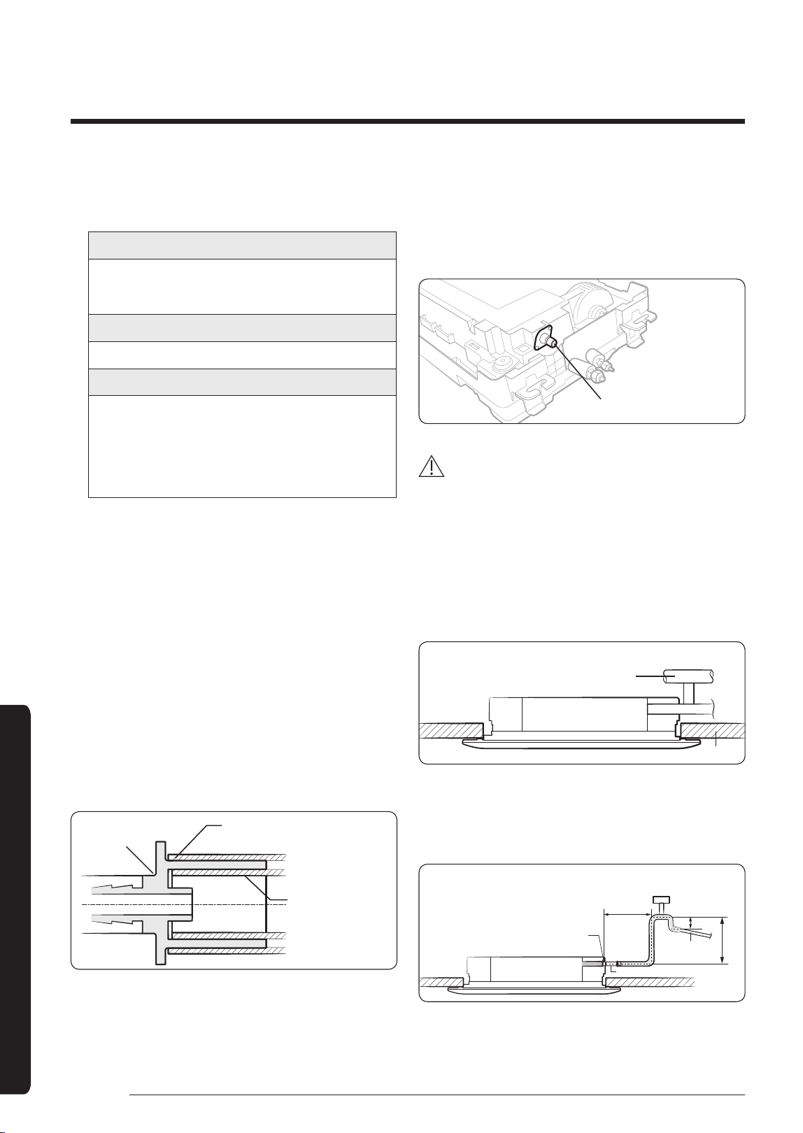
6 Fix the flexible hose to the drain pipe.
• The connection port of the flexible hose and PVC drain
pipe must be fixed with PVC adhesives.
Check out that the connected part doesn’t leak.
Drain hose
PVC Tube Joint
+ VP25 (OD: 32 mm, ID: 25 mm)
VP 20 (Drain pipe)
(OD: 26mm, ID: 20mm)
7 Connect the flexible hose to the drain hose port.
• Make sure that a rubber ring is installed on the drain
hose port.
• The drain hose port location differs depending on the
unit types.
Drain hose port
CAUTION
Check that the indoor unit is level with the ceiling by
using the leveller.
• If the slope of the drain pipe is less than 1/100, be sure
to install an air vent at the top of each indoor unit to
prevent water from flowing back to the unit.
‐ If the slope of the drain pipe is 1/100 or more and it
is free from backward flow to the indoor unit, you
are not required to install an air vent.
Ceiling
Air ventilation
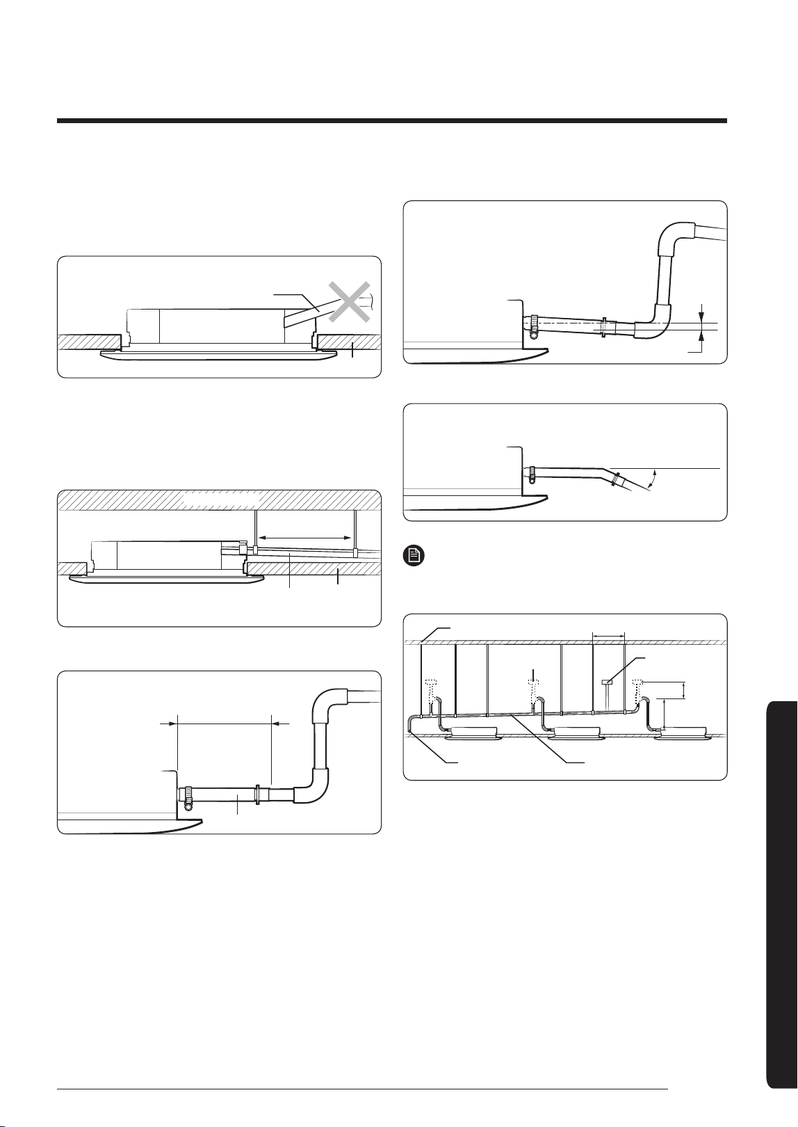
• If it is necessary to increase the height of the drain
pipe, install the drain pipe straight within 300 mm
from the drain hose port. If it is raised higher than 550
mm, there may be water leaks.
Band joint
300 mm
or less
20 mm
or more
Ceiling
1/100 or more
550 mm or less
Drain hose
DB68-07559A-05_IBIM_DVM Wind-Free 1way_EU_EN_.indb 26 2024-01-09 오후 4:31:43
27
English
Installation Procedure
• Do not give the hose an upward gradient beyond
the connection port. This will cause water to flow
backwards when the unit is stopped, resulting in water
leaks.
Ceiling
Under gradient
• Do not apply force to the piping on the unit side when
connecting the drain hose. The hose should not be
allowed to hang loose from its connection to the unit.
Fasten the hose to a wall, frame or other support as
close to the unit as possible.
Ceiling
Support pieces
1 to 1.5 m
Slope of the horizontal drain pipe:
1/100 or more
• Install horizontally.
Indoor unit
Be horizontal
Flexible hose
• Max. allowable aixs gap
Max. 20 mm
Indoor unit
• Max. allowable bending angle
Max. 30˚
Indoor unit
NOTE
• If a concentrated drain pipe is installed, refer to the
figure below.
Centralized horizontal drain pipe
(more than 1/100 slope)
Main drain pipe
Full thread bolt hanger
1000 to 1500 mm
300 to
550 mm
200 mm
or more
Individual
air vent
Main air vent
(must be installed)
• If 3 or more units are installed, install the main air vent
at the front of the farthest indoor unit from the main
drain pipe.
• To prevent water from flowing back to indoor units, install
an individual air vent at the top of each indoor unit.
‐ The air vents should be T or 7 shaped to prevent
dust or foreign substances from entering.
‐ You may not need to install air vent if the
horizontal drain pipe is in proper slope.
DB68-07559A-05_IBIM_DVM Wind-Free 1way_EU_EN_.indb 27 2024-01-09 오후 4:31:44
28
English
Installation Procedure
Installation Procedure
Step 4 Connecting the power and
communication cables
Power and communication cable connection
• Before wiring work, you must turn off all power source.
• Connect the power and communication cable among
the units within maximum length to set the voltage
drop under 10%.
• The auxiliary circuit breaker (ELCB, MCCB, ELB) should
be considered more capacity if many indoor units are
connected from one breaker.
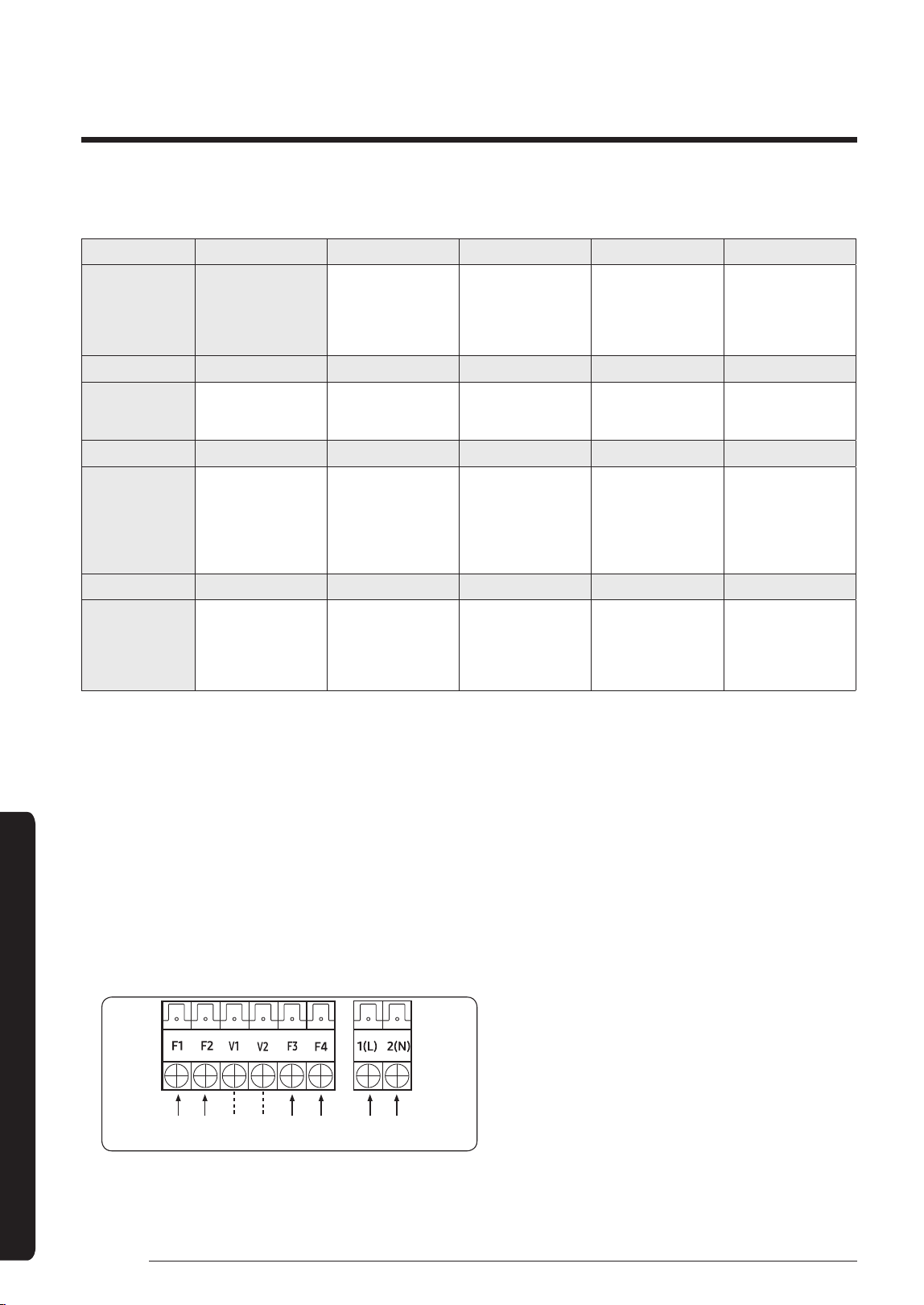
• Connect F3, F4(for communication) to the
communication cable of the wired remote control.
• Tighten the electric wires with a proper tool within the
torque limit to connect and fix them firmly, and then
organize the wires to prevent outside pressure being
exerted on the covers and other parts. Failure to do so
may result in overheating, electric shock, and fire.
• To protect the product from water and possible shock,
you should keep the power and the communication
cables of the indoor and outdoor units in the iron pipe.
• Connect the power cable to the auxiliary circuit
breaker (ELCB, MCCB, ELB).
• Keep distances of 50mm or more between power cable
and communication cables.
• Power supply cords of parts of appliances for outdoor
use shall not be lighter than polychloroprene sheathed
flexible cord. (Code designation IEC:60245 IEC 57 /
CENELEC: H05RN-F or IEC:60245 IEC 66 / CENELEC:
H07RN-F)
• Screws on terminal block must not be unscrewed with
thetorquelessthan12kgf•cm.
• When installing the indoor unit in a computer room,
use the double shielded (tape aluminum / polyester
braid + copper) cable of FROHH2R type.
220~240V~
Outdoor Unit
ELB
MCCB
Indoor Unit 1 Indoor Unit 2 Indoor Unit 3
Indoor Unit 4
Indoor Unit 5 Indoor Unit 6
※ ELB : Essential Installation
※ Ceiling, wall-mounted indoor unit.
EEV kit
Wired Remote
Control
DB68-07559A-05_IBIM_DVM Wind-Free 1way_EU_EN_.indb 28 2024-01-09 오후 4:31:44
29
English
Installation Procedure
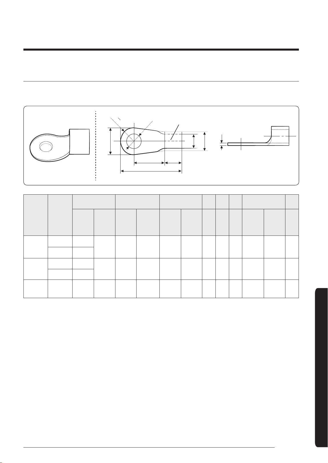
Selecting the crimping terminal lug
1 Select the crimping terminal lug based on the norminal dimension of the power cable.
2 Cover the connection part of the power cable and crimping terminal lug to insulate it.
Silver solder
F E
L
D
d1
B
d2
t
B
2
R
Norminal
dimensions
for cable
(mm²)
Norminal
dimensions
for screw
(mm)
B D d1 E F L d2 t
Standard
dimension
(mm)
Allowance
(mm)
Standard
dimension
(mm)
Allowance
(mm)
Standard
dimension
(mm)
Allowance
(mm)
Min. Min. Max.
Standard
dimension
(mm)
Allowance
(mm)
Min.
1.5
4 6.6
± 0.2 3.4
+0.3
-0.2
1.7 ± 0.2 4.1 6 16 4.3
+0.2
0
0.7
4 8
2.5
4 6.6
± 0.2 4.2
+0.3
-0.2
2.3 ± 0.2 6 6 17. 5 4.3
+0.2
0
0.8
4 8.5
4 4 9.5 ± 0.2 5.6
+0.3
-0.2
3.4 ± 0.2 6 5 20 4.3
+0.2
0
0.9
DB68-07559A-05_IBIM_DVM Wind-Free 1way_EU_EN_.indb 29 2024-01-09 오후 4:31:44
30
English
Installation Procedure
Installation Procedure
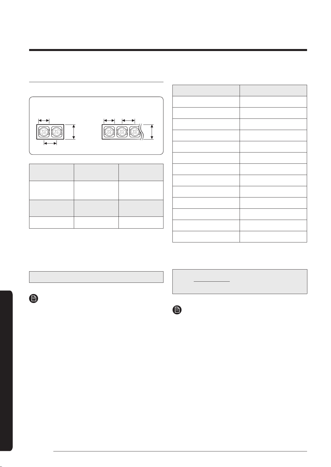
Specifications of the terminal blocks
(Unit: mm)
AC power: M4 screw
Communication: M3.5 screw
11
13
7. 5
9.0
18
13.8
Power supply
(single phase)
MCCB ELB
Min : 198V
Max : 242V
XA
XA, 30 mA
0.1 s
Power cable Earth cable
Communication
cable
2.5 mm² or more 2.5 mm² 0.75 to 1.5 mm²
Decide the power cable specification and maximum
length by formula 2.
1 Decide the capacity of ELB and MCCB by below
formula.
The capacity of ELB, MCCB X[A] = 1.25 X 1.1 X ΣAi
NOTE
• X : The capacity of ELB, MCCB
• ΣAi:Sumofratingcurrentsofeachindoorunit.
Rated currents
Model Rating current(A)
AM017NN1PEH* 0.14
AM022NN1PEH* 0.15
AM022NN1DEH* 0.20
AM028NN1DEH* 0.23
AM036NN1DEH* 0.25
AM056NN1DEH* 0.28
AM071NN1DEH* 0.40
AM022NN1DKH* 0.16
AM028NN1DKH* 0.17
AM036NN1DKH* 0.20
AM022NN1DEH2* 0.16
AM028NN1DEH2* 0.17
AM036NN1DEH2* 0.20
2 Decide the power cable specification and maximum
length within 10% voltage drop among indoor units.
n
Coef×35.6×Lk
× ik) < 10% of input voltage[V]
∑ (
1000×Ak
k=1
NOTE
• Coef: 1.55
• Lk: Distance among each indoor unit[m],
Ak: Power cable specification[mm
2
]
• ik: Running current of each unit[A]
DB68-07559A-05_IBIM_DVM Wind-Free 1way_EU_EN_.indb 30 2024-01-09 오후 4:31:44
31
English
Installation Procedure
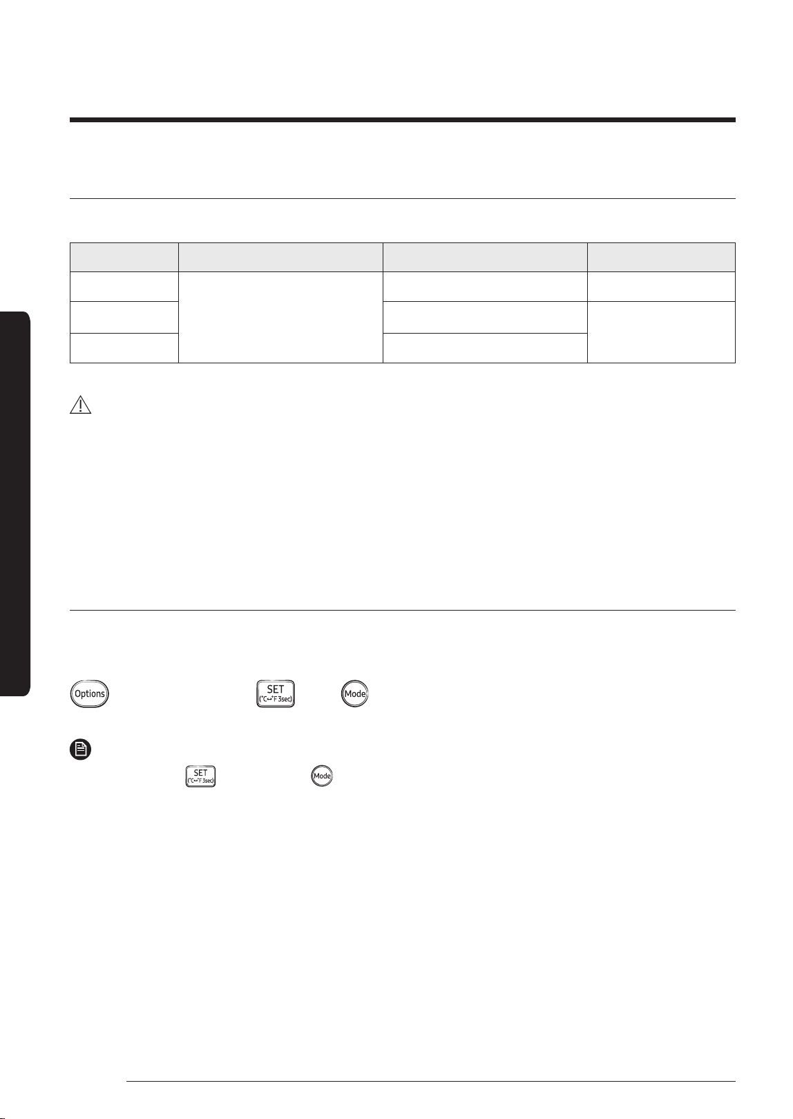
Step 5 Setting the indoor unit
addresses and the installation options
You cannot set both of the indoor unit addresses and the
installation options in a batch: set both of them respectively.
Common steps for setting the addresses and
options
Low Temp button
High Temp button
Mode button
Low Fan button
High Fan button
Setting the
option values
Entering the
mode for setting
the options
NOTE
• The remote control display and buttons may vary
depending on the model.
1 Enter the mode for setting the options:
a Remove the batteries from the remote control,
and then insert them again.
b While holding down the
(High Temp) and
(Low Temp) buttons simultaneously, insert the
batteries into the remote control.
c Make sure that you are entered to the mode for
setting the options:
2 Set the option values.
CAUTION
• The total number of available options are 24: SEG1 to
SEG24.
• Because SEG1, SEG7, SEG13, and SEG19 are the page
options used by the previous remote control models,
the modes to set values for these options are skipped
automatically.
• Set a 2-digit value for each option pair in the following
order: SEG2 and SEG3
→ SEG4 and SEG5 → SEG6 and
SEG8
→ SEG9 and SEG10 → SEG11 and SEG12 → SEG14
and SEG15
→ SEG16 and SEG17 → SEG18 and SEG20 →
SEG21 and SEG22
→ SEG23 and SEG24
SEG1 SEG2 SEG3 SEG4 SEG5 SEG6
0 X X X X X
SEG7 SEG8 SEG9 SEG10 SEG11 SEG12
1 X X X X X
SEG13 SEG14 SEG15 SEG16 SEG17 SEG18
2 X X X X X
SEG19 SEG20 SEG21 SEG22 SEG23 SEG24
3 X X X X X
On (SEG1 to SEG12) Off (SEG13 to SEG24)
DB68-07559A-05_IBIM_DVM Wind-Free 1way_EU_EN_.indb 31 2024-01-09 오후 4:31:45
32
English
Installation Procedure
Installation Procedure
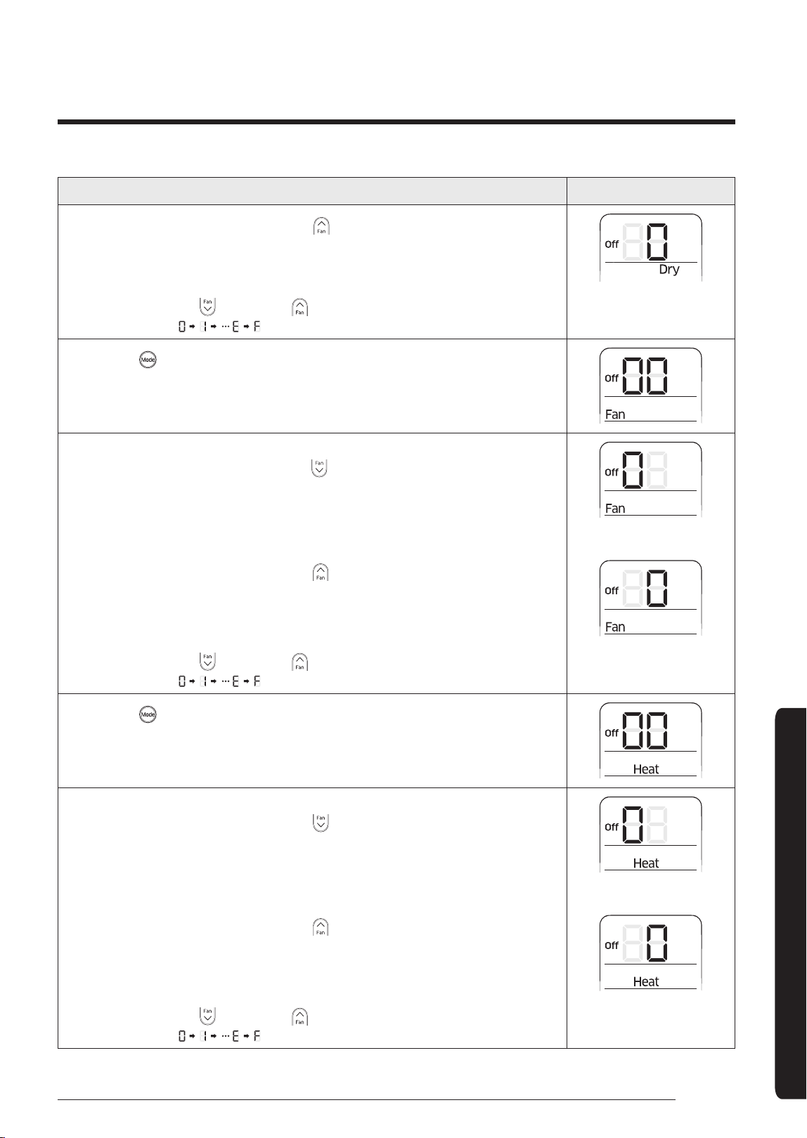
Take the steps presented in the following table:
Steps Remote control display
1 Set the SEG2 and SEG3 values:
a Set the SEG2 value by pressing the
(Low Fan) button repeatedly until the
value you want to set appears on the remote control display.
SEG2
b Set the SEG3 value by pressing the (High Fan) button repeatedly until the
value you want to set appears on the remote control display.
When you press the (Low Fan) or (High Fan) button, values appear in the
following order:
SEG3
2 Press the (Mode) button. Cool and On appear on the remote control display.
3 Set the SEG4 and SEG5 values:
a Set the SEG4 value by pressing the
(Low Fan) button repeatedly until the
value you want to set appears on the remote control display.
SEG4
b Set the SEG5 value by pressing the (High Fan) button repeatedly until the
value you want to set appears on the remote control display.
When you press the (Low Fan) or (High Fan) button, values appear in the
following order:
SEG5
4 Press the (Mode) button. Dry and On appear on the remote control display.
5 Set the SEG6 and SEG8 values:
a Set the SEG6 value by pressing the
(Low Fan) button repeatedly until the
value you want to set appears on the remote control display.
SEG6
DB68-07559A-05_IBIM_DVM Wind-Free 1way_EU_EN_.indb 32 2024-01-09 오후 4:31:45
33
English
Installation Procedure
Steps Remote control display
b Set the SEG8 value by pressing the (High Fan) button repeatedly until the
value you want to set appears on the remote control display.
SEG8
When you press the (Low Fan) or (High Fan) button, values appear in the
following order:
6 Press the (Mode) button. Fan and On appear on the remote control display.
7 Set the SEG9 and SEG10 values:
a Set the SEG9 value by pressing the
(Low Fan) button repeatedly until the
value you want to set appears on the remote control display.
SEG9
b Set the SEG10 value by pressing the (High Fan) button repeatedly until the
value you want to set appears on the remote control display.
When you press the (Low Fan) or (High Fan) button, values appear in the
following order:
SEG10
8 Press the (Mode) button. Heat and On appear on the remote control display.
9 Set the SEG11 and SEG12 values:
a Set the SEG11 value by pressing the
(Low Fan) button repeatedly until the
value you want to set appears on the remote control display.
SEG11
b Set the SEG12 value by pressing the (High Fan) button repeatedly until the
value you want to set appears on the remote control display.
When you press the (Low Fan) or (High Fan) button, values appear in the
following order:
SEG12
DB68-07559A-05_IBIM_DVM Wind-Free 1way_EU_EN_.indb 33 2024-01-09 오후 4:31:46
34
English
Installation Procedure
Installation Procedure
Steps Remote control display
10 Press the (Mode) button. Auto and Off appear on the remote control display.
11 Set the SEG14 and SEG15 values:
a Set the SEG14 value by pressing the
(Low Fan) button repeatedly until the
value you want to set appears on the remote control display.
SEG14
b Set the SEG15 value by pressing the (High Fan) button repeatedly until the
value you want to set appears on the remote control display.
When you press the (Low Fan) or (High Fan) button, values appear in the
following order:
SEG15
12 Press the (Mode) button. Cool and Off appear on the remote control display.
13 Set the SEG16 and SEG17 values:
a Set the SEG16 value by pressing the
(Low Fan) button repeatedly until the
value you want to set appears on the remote control display.
SEG16
b Set the SEG17 value by pressing the (High Fan) button repeatedly until the
value you want to set appears on the remote control display.
When you press the (Low Fan) or (High Fan) button, values appear in the
following order:
SEG17
14 Press the (Mode) button. Dry and Off appear on the remote control display.
15 Set the SEG18 and SEG20 values:
a Set the SEG18 value by pressing the
(Low Fan) button repeatedly until the
value you want to set appears on the remote control display.
SEG18
DB68-07559A-05_IBIM_DVM Wind-Free 1way_EU_EN_.indb 34 2024-01-09 오후 4:31:47
35
English
Installation Procedure
Steps Remote control display
b Set the SEG20 value by pressing the (High Fan) button repeatedly until the
value you want to set appears on the remote control display.
When you press the (Low Fan) or (High Fan) button, values appear in the
following order:
SEG20
16 Press the (Mode) button. Fan and Off appear on the remote control display.
17 Set the SEG21 and SEG22 values:
a Set the SEG21 value by pressing the
(Low Fan) button repeatedly until the
value you want to set appears on the remote control display.
SEG21
b Set the SEG22 value by pressing the (High Fan) button repeatedly until the
value you want to set appears on the remote control display.
When you press the (Low Fan) or (High Fan) button, values appear in the
following order:
SEG22
18 Press the (Mode) button. Heat and Off appear on the remote control display.
19 Set the SEG23 and SEG24 values:
a Set the SEG23 value by pressing the
(Low Fan) button repeatedly until the
value you want to set appears on the remote control display.
SEG23
b Set the SEG24 value by pressing the (High Fan) button repeatedly until the
value you want to set appears on the remote control display.
When you press the (Low Fan) or (High Fan) button, values appear in the
following order:
SEG24
DB68-07559A-05_IBIM_DVM Wind-Free 1way_EU_EN_.indb 35 2024-01-09 오후 4:31:47
36
English
Installation Procedure
Installation Procedure
3 Check whether the option values that you have set are
correct by pressing the
(Mode) button repeatedly
[SEG2, SEG3]
[SEG11 , SEG12 ]
[SEG21 , SEG22 ]
[SEG4, SEG5]
[SEG14 , SEG15 ]
[SEG23, SEG24]
[SEG6, SEG8]
[SEG16 , SEG17 ]
[SEG9, SEG10 ]
[SEG18 , SEG20]
4 Save the option values into the indoor unit:
Point the remote control to the remote control sensor
on the indoor unit and then press the
(Power)
button on the remote control twice. Make sure that
this command is received by the indoor unit. When it is
successfully received, you can hear a short sound from
the indoor unit. If the command is not received, press
the
(Power) button again.
5 Check whether the air conditioner operates in
accordance with the option values you have set:
a Reset the indoor unit by disconnecting and then
reconnecting the power cable of the indoor unit or
by pressing the RESET button on the outdoor unit.
b Remove the batteries from the remote control,
insert them again, and then press the
(Power)
button on the remote control.
Setting the indoor unit addresses (MAIN/RMC/MCU)
1 Make sure that the power is supplied to the indoor
unit.
• If the indoor unit is not plugged in, it must include a
power supply.
2 Make sure that the panel or display is connected to the
indoor unit so that it can receive options.
Indoor unit
3 Set an address (MAIN/RMC/MCU port) for each indoor
unit using the remote control, according to your air
conditioning system plan.
• The indoor unit addresses (MAIN/RMC/MCU port)
are set to 0A0000-100000-200000-300000 by
default.
NOTE
• Also set the MCU and Indoor units address by using
Add-on
→
Change address on S-NET Pro 2.
(For more information, see the S-NET Pro 2 Help.)
• From SEG13 to SEG18 is for setting MCU address.
‐ MCU models that can set address: MCU-S*NEK2N,
MCU-S4NEK3N, MCU-S1NEK1N
Option No. for an indoor unit address: 0AXXXX-1XXXXX-2XXXXX-3XXXXX
Option SEG1 SEG2 SEG3 SEG4 SEG5 SEG6
Function Page Mode
Setting main
address
100-digit of an
indoor unit address
10-digit of an
indoor unit address
The single digit of
an indoor unit
Indication
and details
Indication
Details
Indication
Details
Indication
Details
Indication
Details
Indication
Details
Indication
Details
0 A
0
No main
address
0 to 9 10-digit 0 to 9
A single
digit
0 to 3
A single
digit
1
Main
address
setting
mode
DB68-07559A-05_IBIM_DVM Wind-Free 1way_EU_EN_.indb 36 2024-01-09 오후 4:31:48
37
English
Installation Procedure
Option SEG7 SEG8 SEG9 SEG10 SEG11 SEG12
Function Page -
Setting RMC
address
-
Group channel
(x16)
Group address
Indication
and details
Indication
Details
-
Indication
Details
-
Indication
Details
Indication
Details
1
0
No RMC
address
RMC1 0 to F RMC2 0 to F
1
RMC
address
setting
mode
Option SEG13 SEG14 SEG15 SEG16 SEG17 SEG18
Function Page -
Setting MCU PORT
address
10-digit of MCU
address
1-digit of MCU MCU PORT address
Indication
and details
Indication
Details
-
Indication
Details
Indication
Details
Indication
Details
Indication
Details
2
0
No MCU
PORT
0~1 10-digit 0~9 1-digit A~F
PORT
Location
1
MCU
PORT
address
setting
mode
CAUTION
• If you enter A to F to the SEG5 or SEG6, the indoor unit
main address is not changed.
• If you enter 0 to the SEG 3, the indoor unit maintains
the previous main address although you enter the
option value for the SEG5 or SEG 6.
• If you enter 0 to the SEG 9, the indoor unit maintains
previous RMC address although you enter the option
value for the SEG11 or SEG12.
• You cannot set the SEG11 or SEG12 to F value at the
same time.
• If the indoor unit is connected to the MCU, you can set
the SEG 15~18.
Ex.) If you want to set the indoor unit to ‘A’ port of MCU #1.
(0A0000 – 100000 – 20101A -30000)
Setting the indoor unit installation option
(suitable for the condition of each installation
location)
1 Make sure that the power is supplied to the indoor unit.
• If the indoor unit is not plugged in, it must include a
power supply.
2 Make sure that the panel or display is connected to the
indoor unit so that it can receive options
Indoor unit
3 Set an address for each indoor unit using the remote
control, according to your air conditioning system plan.
• The indoor unit addresses are set to 020010-
100000-200000-300000 by default.
• The SEG20 option, Individual control with remote
control, allows you to control multiple indoor units
individually by using the remote control.
DB68-07559A-05_IBIM_DVM Wind-Free 1way_EU_EN_.indb 37 2024-01-09 오후 4:31:48
38
English
Installation Procedure
Installation Procedure
Installation options for the 02 series
SEG1 SEG2 SEG3 SEG4 SEG5 SEG6
0 2 Evaporator Drying
Use of external
room temperature
sensor / Minimizing
fan operation when
thermostat is off
Use of central control
FAN RPM
compensation
SEG7 SEG8 SEG9 SEG10 SEG11 SEG12
1 Use of drain pump
Use of hot water
heater
-
EEV Step when
heating stops
Dew removal
operation in wind
free mode
SEG13 SEG14 SEG15 SEG16 SEG17 SEG18
2
Use of external
control
Setting the output
of external control /
External heater signal
/ Cooling operation
signal / Free Cooling
control signal
S-Plasma ion Buzzer control Hours of filter usage
SEG19 SEG20 SEG21 SEG22 SEG23 SEG24
3
Individual control of a
remote controller
Heating setting
compensation
/ Removing
condensate water in
heating mode
Adjusted EEV step of
stopped unit during
oil return /defrost
mode.
Motion detect sensor
-
• Even if you set the Use of drain pump (SEG8) option to 0, it is automatically set to 2 (the drain pump is used with 3
minute delay).
• If you set the Maximum filter usage time (SEG18) option to a value other than 2 and 6, it is automatically set to 2
(1000 hours).
• If you set an option to a value that is out of range specified above, the option is automatically set to 0 by default.
• The SEG5 option (Use of central control) is set to 1 (Use) by default. Therefore, you don't need to set the SEG5 option
additionally. Note that even if the central control system is not connected, no errors occur. If you want a specific
indoor unit not to be controlled by the central control system, set the SEG option of that indoor unit to 0 (Disuse).
• The external output of SEG15 is generated via MIM-B14 connection. (Refer to the manual of MIM-B14.)
• If you set the Individual control with remote control (SEG20) option to a value other than 0 to 4, it is automatically set
to 0 (Indoor 1).
• The output of hot water heater in SEG9 is generated from the hot coil part of the terminal board in duct models.
Outdoor
Communication
(+) (-) COM2
DC 12 V
Wire Remote
Controller
AC
POWER
L NCOM1
DB68-07559A-05_IBIM_DVM Wind-Free 1way_EU_EN_.indb 38 2024-01-09 오후 4:31:49
39
English
Installation Procedure
02 series installation option (Detailed)
Option No. : 02XXXX-1XXXXX-2XXXXX-3XXXXX
Option SEG1 SEG2 SEG3 SEG4 SEG5 SEG6
Explanation PAGE MODE Evaporator Drying
Use of external room temperature sensor /
Minimizing fan operation when thermostat is off
Use of central
control
FAN RPM compensation
Indication
and Details
Indication Details Indication Details Indication Details
Indication
Details
Indication Details Indication Details
Use of
External room
temperature
sensor
Minimizing fan
operation when
thermostat is off
0 2
0 Disuse
0 Default Default
0 Disuse
0 Disuse
1 Use Disuse
2 Disuse Use (Heating) (*2)
2 Use (5min) (*1)
3 Use Use (Heating) (*2)
4 Disuse Use (Cooling) (*2)
1
RPM
compensation
5 Use Use (Cooling) (*2)
4 Use (10min) (*1)
6 Disuse
Use (Heating /
Cooling) (*2)
1 Use
7 Use
Use (Heating /
Cooling) (*2)
8 Disuse
Use (Cooling Ultra
Low Fan ) (*2)
2
High ceiling
KIT (4way
model only)
6 Use (30min) (*1)
9 Use
Use (Cooling Ultra
Low Fan ) (*2)
A Disuse
Use (Heating / Cooling
Ultra Low Fan ) (*2)
B Use
Use (Heating / Cooling
Ultra Low Fan ) (*2)
Option SEG7 SEG8 SEG9 SEG10 SEG11 SEG12
Explanation PAGE Use of drain pump Use of hot water heater -
EEV Step when
heating stops
Dew removal operation in
wind free mode
Indication
and Details
Indication Details Indication Details Indication Details
-
Indication Details Indication Details
1
0 Disuse 0 Disuse 0 Default 0
(Default)
Maintain
blade status
in wind free
mode
1 Use 1 Use (*3)
1
Adjusted
EEV Step
setting
1
Cooling
operation by
opening the
blade
2
When an
indoor unit
stops, drain
pump will
operate for
3min
3 Use (*3)
DB68-07559A-05_IBIM_DVM Wind-Free 1way_EU_EN_.indb 39 2024-01-09 오후 4:31:49
40
English
Installation Procedure
Installation Procedure
Option SEG13 SEG14 SEG15 SEG16 SEG17 SEG18
Explanation PAGE Use of external control
Setting the output of external
control / External heater signal /
Cooling operation signal /
Free Cooling control signal
S-Plasma ion Buzzer control Hours of filter usage
Indication
and Details
Indication Details Indication Details Indication Details Indication Details Indication Details Indication Details
2
0 Disuse
Normal
Signal
Control
(*4)
0
External control
(Thermo On)
0 Disuse 0
Use
buzzer
2
1000
Hour
1
ON/OFF
Control
2
OFF
Control
1
External control
(Operation On)
3
Window
ON/OFF
Control
2
External heater
signal (*5)
8 Disuse
Reverse
Signal
Control
(*4)
3
External heater
signal (*5)
9
ON/OFF
Control
4
Cooling operation
signal (*6)
1 Use 1
Disuse
buzzer
6
2000
Hour
A
OFF
Control
5
Free Cooling control
(Cooling Thermo On) (*7)
B
Window
ON/OFF
Control
6
Free Cooling control
(Cooling/Dry Thermo
On) (*7)
Option SEG19 SEG20 SEG21 SEG22 SEG23 SEG24
Explanation PAGE
Individual control of a remote
controller
Heating setting compensation / Removing condensate
water in heating mode
Adjusted EEV step of
stopped unit during
oil return /defrost
mode.
Motion detect sensor -
Indication and
Details
Indication
Details
Indication Details Indication
Details
Indication Details Indication Details
-
Heating Setting
Compensation
Removing Condensate
Water in Heating Mode
3
0 or 1 channel 1
0 Default Disuse
0 Default
0 Disuse
1 2 °C Disuse 1
Turn out in 30min.
without motion
2 channel 2
2 5 °C Disuse 2
Turn out in 60min.
without motion
3 Default Use (*8)
3
Turn out in 120min.
without motion
3 channel 3
4
Turn out in 180min.
without motion
4 2 °C Use (*8)
1
Adjusted
EEV
positon
5
Turn out in 30min.
without motion or
*advanced function
4 channel 4
6
Turn out in 60min.
without motion &
*advanced function
5 5 °C Use (*8)
7
Turn out in 120min.
without motion &
*advanced function
8
Turn out in 180min.
without motion &
*advanced function
DB68-07559A-05_IBIM_DVM Wind-Free 1way_EU_EN_.indb 40 2024-01-09 오후 4:31:49

41
English
Installation Procedure
* Advanced function: Controlling cooling/heating current or power saving with motion detect.
(*1) When Cooling or dry mode is off. The indoor fan operate in setting minutes.
(*2) Minimizing fan operation when thermostat is off
- Fan operates for 20 seconds at an interval of 5 minutes in heat mode.
- Fan stops or operates Ultra low in Cooling when thermostat is off.
(*3) 1: Fan is turned on continually when the hot water heater is turned on,
3: Fan is turned off when the hot water heater is turned on with cooling only indoor unit
Cooling only indoor unit: To use this option, install the Mode Select switch(MCM-C200) on the outdoor unit and fix
it as cool mode.
If the "Cooling Priority" option is set in the Heat Pump outdoor unit, the indoor unit can operate in the Heat mode
owing to the water heater even if the outdoor unit is running in the Cool mode.
(*4) When Normal Signal Control is enabled, the external control is turned on by the short-circuit signal and off by the
open-circuit signal.
When Reverse Signal Control is enabled, the external control is turned off by the short-circuit signal and on by the
open-circuit signal.
(*5) When the following 2 or 3 is used as external heater On/Off signal, the signal for monitoring external contact
control will not be output.
2: Fan is turned on continually when the external heater is turned on,
3: Fan is turned off when the external heater is turned on with cooling only indoor unit
Cooling only indoor unit: To use this option, install the Mode Select switch(MCM-C200) on the outdoor unit and fix
it as cool mode.
- If Fan is set to off for cooling only indoor unit by setting the SEG9=3 or SEG15=3, you need to use an external
sensor or wired remote controller sensor to detect indoor temperature exactly.
- If the "Cooling Priority" option is set in the Heat Pump outdoor unit, the indoor unit can operate in the Heat mode
owing to the external heater even if the outdoor unit is running in the Cool mode.
(*6) When indoor unit is in cooling or Dry mode, The output signal is “ON”
(*7) For free cooling control, Economizer controller is required.
(*8) If the air conditioner operates the heating mode immediately after finishing the cooling mode, the condensate
water in the drain pan becomes water vapor by the heat of the indoor unit heat exchanger. Since the water vapor
might be condensed on the indoor unit, which may fall into a living space, use this function to get rid of the water
vapor out of the indoor unit by operating the fan (for maximum 20 minutes) even when the indoor unit is turned off
after cooling mode is turned to heating mode.
DB68-07559A-05_IBIM_DVM Wind-Free 1way_EU_EN_.indb 41 2024-01-09 오후 4:31:49
42
English
Installation Procedure
Installation Procedure
05 series installation option
SEG1 SEG2 SEG3 SEG4 SEG5 SEG6
0 5
Use of Auto Change
Over for HR only in
Auto mode / Use of
Cooling only indoor
unit of HR
(When setting SEG3)
Standard heating temp.
Offset
(When setting SEG3)
Standard cooling
temp. Offset
(When setting SEG3)
Standard for mode
change Heating
→
Cooling
SEG7 SEG8 SEG9 SEG10 SEG11 SEG12
1
(When setting SEG3)
Standard for mode
change Cooling
→
Heating
(When setting SEG3)
Time required for
mode change (*1)
Compensation option
for Long pipe or height
difference between
indoor units
MTFC (*4) -
SEG13 SEG14 SEG15 SEG16 SEG17 SEG18
2 - - - -
Control variables when
using hot water /
external heater (*5)
SEG19 SEG20 SEG21 SEG22 SEG23 SEG24
3 - - -
Forced FAN Operation
for Heating and
Cooling
-
DB68-07559A-05_IBIM_DVM Wind-Free 1way_EU_EN_.indb 42 2024-01-09 오후 4:31:50
43
English
Installation Procedure
05 series installation option (Detailed)
Option No. : 05XXXX-1XXXXX-2XXXXX-3XXXXX
Option SEG1 SEG2 SEG3 SEG4 SEG5 SEG6
Explanation PAGE MODE
Use of Auto Change Over
for HR only in Auto mode /
Use of Cooling only indoor
unit of HR
(When setting SEG3)
Standard heating temp.
Offset
(When setting SEG3)
Standard cooling temp.
Offset
(When setting SEG3)
Standard for mode change
Heating→Cooling
Indication
and Details
Indication Details Indication Details Indication Details Indication Details Indication Details Indication Details
0 5
0
Follow
product
option
0 0 °C 0 0 °C 0 1 °C
1 0.5 °C 1 0.5 °C 1 1.5 °C
1
Use Auto
Change Over
for HR only
2 1 °C 2 1 °C 2 2 °C
3 1.5 °C 3 1.5 °C 3 2.5 °C
4 2 °C 4 2 °C 4 3 °C
2
Use Cooling
only indoor
unit for HR
5 2.5 °C 5 2.5 °C 5 3.5 °C
6 3 °C 6 3 °C 6 4 °C
7 3.5 °C 7 3.5 °C 7 4.5 °C
Option SEG7 SEG8 SEG9 SEG10 SEG11 SEG12
Explanation PAGE
(When setting SEG3)
Standard for mode
changeCooling→
Heating
(When setting SEG3)
Time required for mode
change (*1)
Compensation option
for Long pipe or height
difference between indoor
units
MTFC (*4) -
Indication
and Details
Indication Details Indication Details Indication Details Indication Details Indication Details
-
1
0 1 °C 0 5min 0 Default
0 Default
1 1.5 °C 1 7min
1
(*2) Height
difference is
more than
30m or
(*3) Distance
is longer than
110m
2 2 °C 2 9min
3 2.5 °C 3 11min
4 3 °C 4 13min
2
(*2) Height
difference is
15~30m or
(*3) Distance
is 50~110m
2 Use
5 3.5 °C 5 15min
6 4 °C 6 20min
7 4.5 °C 7 30min
DB68-07559A-05_IBIM_DVM Wind-Free 1way_EU_EN_.indb 43 2024-01-09 오후 4:31:50

44
English
Installation Procedure
Installation Procedure
Option SEG13 SEG14 SEG15 SEG16 SEG17 SEG18
Explanation - - - - - Control variables when using hot water / external heater (*5)
Indication
and Details
Indication Details
- - - -
Indication
Details
Set temp. for heater On/Off
Delay time for heater On
2
0 At the same time as thermo on No delay
1 At the same time as thermo on 10 minutes
2 At the same time as thermo on 20 minutes
3 1.5 °C No delay
4 1.5 °C 10 minutes
5 1.5 °C 20 minutes
6 3.0 °C No delay
7 3.0 °C 10 minutes
8 3.0 °C 20 minutes
9 4.5 °C No delay
A 4.5 °C 10 minutes
B 4.5 °C 20 minutes
C 6.0 °C No delay
D 6.0 °C 10 minutes
E 6.0 °C 20 minutes
Option SEG19 SEG20 SEG21 SEG22 SEG23 SEG24
Explanation PAGE - - - Forcing FAN Operation for Heating and Cooling -
Indication
and Details
Indication Details
- - -
Indication
Details
-
Cooling Fan
Setting
Heating Fan
Setting
3
0 Disuse Disuse
1 Disuse
Use (Fan: User
setting)
2 Disuse Use (Fan: High)
3 Disuse Use (Fan: Low)
4
Use (Fan: User
setting)
Disuse
5
Use (Fan: User
setting)
Use (Fan: User
setting)
6
Use (Fan: User
setting)
Use (Fan: High)
7
Use (Fan: User
setting)
Use (Fan: Low)
8 Use (Fan: High) Disuse
9 Use (Fan: High)
Use (Fan: User
setting)
A Use (Fan: High) Use (Fan: High)
B Use (Fan: High) Use (Fan: Low)
C Use (Fan: Low) Disuse
D Use (Fan: Low)
Use (Fan: User
setting)
E Use (Fan: Low) Use (Fan: High)
F Use (Fan: Low) Use (Fan: Low)
DB68-07559A-05_IBIM_DVM Wind-Free 1way_EU_EN_.indb 44 2024-01-09 오후 4:31:50
45
English
Installation Procedure
(* 1) Duration for Auto Change Over triggered when you set dual set points in the Auto mode using the wired remote
control MWR-WG00*N.
During the automatic heating operation, if the specified time has elapsed in the state of "the room temperature >
the cooling temperature in the Auto mode + the primary cooling temperature (set in the Auto Change Over screen
after entering the User mode by pressing the
button on the wired remote control)" the air conditioner changes
into the automatic cooling operation.
During the automatic cooling operation, if the specified time has elapsed in the state of "the room temperature <
the heating temperature in the Auto mode - the primary heating temperature (set in the Auto Change Over screen
after entering the User mode by pressing the
button on the wired remote control)" the air conditioner changes
into the automatic heating mode.
(*2) Height difference : The difference of the height between the corresponding indoor unit and the indoor unit
installed at the lowest place. For example, When the indoor unit is installed 40m higher than the indoor unit
installed at the lowest place, select the option “1”.
(*3) The difference between the pipe length of the indoor unit installed at farthest place from an outdoor unit and the
pipe length of the corresponding indoor unit from an outdoor unit.
For example, when the farthest pipe length is 100 m and the corresponding indoor unit is 40 m away from an
outdoor unit, select the option “2”. (100 - 40 = 60m)
(*4) For MTFC option, MTFC(Multi Tenant Function Controller) kit is required.
(*5) Heater operation when the SEG9 of 02 series installation option is set to using hot water heater or when SEG15 is
set to using external heater.
Example 1) Setting 02 series SEG9 =”1” / Setting 05 series SEG18 = “0”: The hot water heater is turned on at the
same time as the heating thermostat is on, and turned off when the heating thermostat is off.
Example2)Setting02seriesSEG15=”2”/Setting05seriesSEG18=”A”:Roomtemp.≤settemp.+f(heating
compensation temp.)
‐ External heater is turned on when the temperature is maintained as 4.5 °C for 10 minutes. Room temp. >
set temp. + f(heating compensation temp.)
‐ External heater is turned off when the temperature is maintained as 4.5 °C + 1 °C (1 °C is the Hysteresis for On/
Off selection.)
DB68-07559A-05_IBIM_DVM Wind-Free 1way_EU_EN_.indb 45 2024-01-09 오후 4:31:51
46
English
Installation Procedure
Installation Procedure
Additional information on SEG 3, 4, 5, 6, 8, 9
When SEG 3 is set to 1 and the HR-specific auto changeover function is run, the indoor unit operates as shown in the
following figure:
C
Temperature
b
d
c
A
D
B
a
Ts
Set temperature
for Auto mode
Reference
temperature for
cooling
Reference temperature for heating
Reference temperature for change from
heating to cooling
Reference temperature for
cooling
Cooling thermo off
Cooling thermo on
Heating thermo off
Heating thermo on
A: Set with SEG4 (˚C)
B: Set with SEG5 (˚C)
C: Set with SEG6 (˚C)
D: Set with SEG8 (˚C)
The mode change between the Cool and Heat modes is made only when the thermo off state is maintained for the
period of time set with SEG9.
DB68-07559A-05_IBIM_DVM Wind-Free 1way_EU_EN_.indb 46 2024-01-09 오후 4:31:51
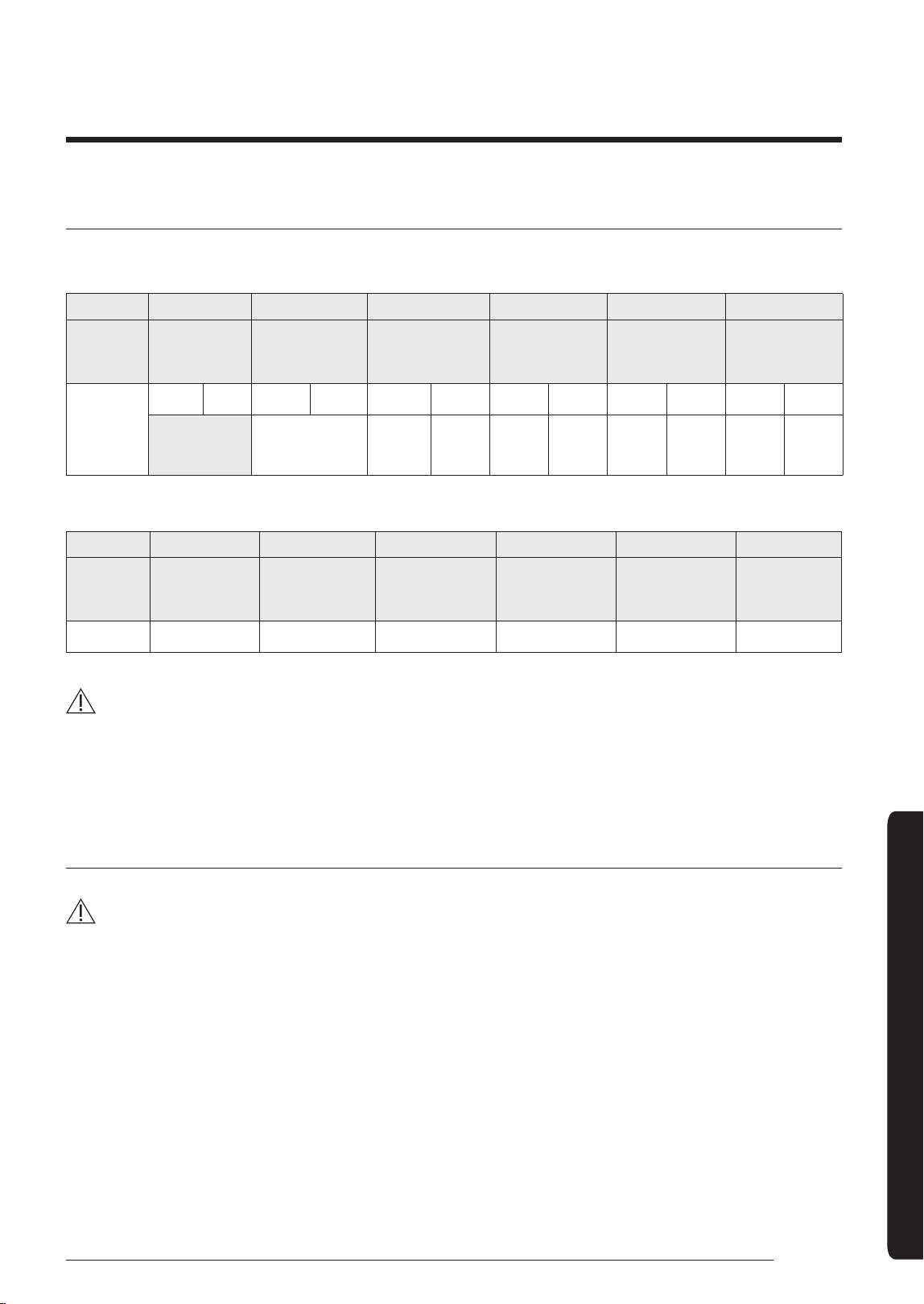
47
English
Installation Procedure
Changing the addresses and options individually
When you want to change the value of a specific option, refer to the following table and follow the steps in Common
steps for setting the addresses and options on page 31.
Option SEG1 SEG2 SEG3 SEG4 SEG5 SEG6
Function Page Mode
Type of the
option to change
Tens position
of the option
number
Units position
of the option
number
New value
Indication
and details
Indication
Details
Indication
Details
Indication
Details
Indication
Details
Indication
Details
Indication
Details
0 D
Option
type
0 to F
Tens
position
value
0 to 9
Units
position
value
0 to 9
New
value
0 to F
Example: Changing the Buzzer control (SEG17) option of the installation options to 1 disuse.
Option SEG1 SEG2 SEG3 SEG4 SEG5 SEG6
Function Page Mode
Type of the
option to change
Tens position
of the option
number
Units position
of the option
number
New value
Indication
0 D 2 1 7 1
CAUTION
• If your indoor units support both cooling and heating, the mixed operation (two or more indoor units operate in
different modes simultaneously) is not available when the indoor units are connected to the same outdoor unit. If
you set an indoor unit as the master indoor unit by using the remote control, the outdoor unit automatically operate
in the current mode of the master indoor unit.
Emergency Temperature Output (ETO) function
CAUTION
• In order to deploy the ETO function, the MIM-B14, an external contact interface module, must be installed in each
indoor unit.
‐ The ETO is a concept of emergency operation of indoor units. If the indoor unit 1 (main indoor unit) stops because
of an error, the indoor unit 2 (sub indoor unit) starts to operate.
‐ Basically, the indoor unit 2 operates in the previous mode. [For the first time operation, it starts in 24 °C Auto
mode.]
‐ To set more detailed operation conditions for the indoor unit 2, use the S-net Pro.
DB68-07559A-05_IBIM_DVM Wind-Free 1way_EU_EN_.indb 47 2024-01-09 오후 4:31:51
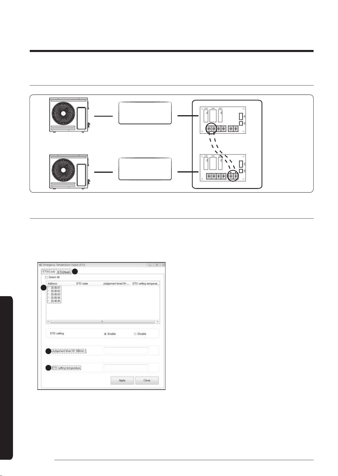
48
English
Installation Procedure
Installation Procedure
Setting up the ETO
Communication between
indoor and outdoor units
(F1 and F2)
Error output port (1, 2)
Contact input port (5, 6)
Main indoor unit
Sub indoor unit
External contact
interface module
MIM-B14
Main indoor unit
1 Disable the external contact control (Default).
2 Connect the S-net pro2 to F1 and F2.
3 Enable the ETO function and set the temperature and time in the S-net pro2.
• Setting the main indoor unit in the S-net pro2
a
b
c
d
a Select an emergency temperature output(ETO)
mode.
b Select the main indoor unit.
c Set the duration used as a reference for generating
emergency output.
d Set the reference temperature at which emergency
output is generated.
• In the Cool mode, emergency output is generated
when the room temperature becomes higher
than the lower of the set temperature and ETO
setting temperature.
• In the Heat mode, emergency output is generated
when the room temperature becomes lower than
the higher of the set temperature and ETO setting
temperature.
DB68-07559A-05_IBIM_DVM Wind-Free 1way_EU_EN_.indb 48 2024-01-09 오후 4:31:51
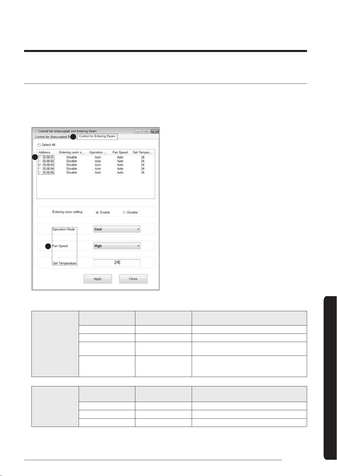
49
English
Installation Procedure
Sub indoor unit (BackUp Unit)
1 (Required) Enable the external contact control (with the installation option 02 series SEG14 - Reverse Control).
2 Connect the S-net pro2 to F1 and F2.
3 Enable the entrance control and set the mode, set temperature, and fan speed in the S-net pro2.
• Setting the sub indoor unit in the S-net pro2
a
b
c
a Select Control for Entering Room.
b Select the sub indoor unit.
c Set the operation mode, fan speed, and set
temperature.
• Operation when the external contact settings and the ETO settings overlap
Main indoor unit
Enable of ETO
Enable of external
contact
Error port output
X X N/A
X O Output due to an error
O X
Output by ETO entrance conditions
(temperature / time / error occurrence)
O O
Output by ETO entrance conditions
(temperature / time / error occurrence)
※Readytocontrolthemaincontactinput
Sub indoor unit
Enable of entrance
control
Enable of external
contact
Operation when outputting Main
X X N/A
X O On with the previous operation conditions
O O On with the entrance control enabled
DB68-07559A-05_IBIM_DVM Wind-Free 1way_EU_EN_.indb 49 2024-01-09 오후 4:31:52
COUNTRY CALL OR VISIT US ONLINE AT
UK 0333 000 0333 www.samsung.com/uk/support
IRELAND (EIRE) 0818 717100 www.samsung.com/ie/support
GERMANY 06196 77 555 77 www.samsung.com/de/support
FRANCE 01 48 63 00 00 www.samsung.com/fr/support
SPAIN 91 175 00 15 www.samsung.com/es/support
PORTUGAL
210 608 098
Chamada para a rede fixa nacional
Dias úteis das 9h às 20h
www.samsung.com/pt/support
LUXEMBURG 261 03 710 www.samsung.com/be_fr/support
NETHERLANDS 088 90 90 100 www.samsung.com/nl/support
BELGIUM 02-201-24-18
www.samsung.com/be/support (Dutch)
www.samsung.com/be_fr/support (French)
NORWAY 21629099 www.samsung.com/no/support
DENMARK 707 019 70 www.samsung.com/dk/support
FINLAND 030-6227 515 www.samsung.com/fi/support
SWEDEN 0771-400 300 www.samsung.com/se/support
AUSTRIA 0800 72 67 864 (0800-SAMSUNG) www.samsung.com/at/support
SWITZERLAND 0800 726 786
www.samsung.com/ch/support (German)
www.samsung.com/ch_fr/support (French)
HUNGARY 0680SAMSUNG (0680-726-7864) www.samsung.com/hu/support
CZECH 800 - SAMSUNG (800-726786) www.samsung.com/cz/support
SLOVAKIA 0800 - SAMSUNG (0800-726 786) www.samsung.com/sk/support
CROATIA 072 726 786 www.samsung.com/hr/support
BOSNIA 055 233 999 www.samsung.com/ba/support
North Macedonia 023 207 777 www.samsung.com/mk/support
MONTENEGRO 020 405 888 www.samsung.com/support
SLOVENIA 080697267(brezplačnaštevilka) www.samsung.com/si/support
SERBIA 011 321 6899 www.samsung.com/rs/support
Kosovo 038 40 30 90 www.samsung.com/support
ALBANIA 045 620 202 www.samsung.com/al/support
BULGARIA
080011131-Безплатензавсичкиоператори
*3000-Ценанаединградскиразговорилиспоредтарифатанамобилниятоператор
09:00до18:00-ПонеделникдоПетък
www.samsung.com/bg/support
ROMANIA
0800872678 - Apel gratuit
*8000-Apeltarifatînreţea
Program Call Centre
Luni - Vineri: 9 AM - 6 PM
www.samsung.com/ro/support
ITALIA 800-SAMSUNG (800.7267864) www.samsung.com/it/support
CYPRUS 8009 4000 only from landline, toll free
www.samsung.com/gr/support
GREECE
80111-SAMSUNG (80111 726 7864) from mobile and land line
(+30) 210 6897691 from mobile and land line
POLAND
801-172-678*
*(opłatawedługtaryfyoperatora)
http://www.samsung.com/pl/support/
LITHUANIA 8-800-77777 www.samsung.com/lt/support
LATVIA 8000-7267 www.samsung.com/lv/support
ESTONIA 800-7267 www.samsung.com/ee/support
UKRAINE 0-800-502-000 www.samsung.com/ua/support
MOLDOVA +373-22-667-400 www.samsung.com/ua/support/moldova
QUESTIONS OR COMMENTS?
Samsung, PO Box 12987, Blackrock, Co. Dublin. IE
or Euro QA Lab. Saxony Way, Yateley, Hampshire GU46 6GG, UK
DB68-07559A-05_IBIM_DVM Wind-Free 1way_EU_EN_.indb 50 2024-01-09 오후 4:31:52