Loading ...
Loading ...
Loading ...
Instrument tour
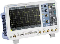
R&S
®
RTB2000
27Getting Started 1333.1605.02 ─ 08
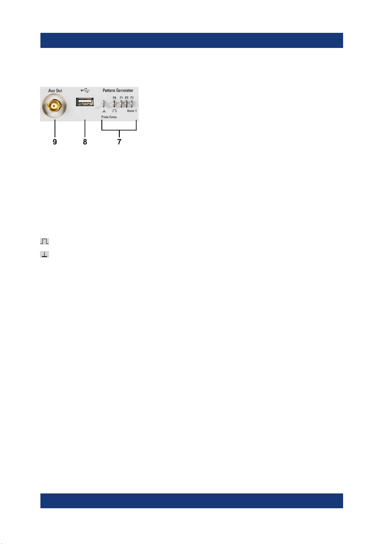
4.1.2 Other connectors on the front panel
[Pattern Generator] (7)
Connectors for the pattern generator P0, P1, P2, P3.
The "Demo 1" signal is intended for demonstration purposes.
[Probe Comp.] (7)
Probe compensation terminal to support adjustment of passive probes to the
oscilloscope channel.
Square wave signal for probe compensation.
Ground connector for probes.
[USB] type A (8)
USB 2.0 type A interface to connect a mouse or a keyboard, or a USB flash drive
for storing and reloading instrument settings and measurement data, and to
update the firmware.
[Aux Out] (9)
Multi-purpose BNC output that can function as pass/fail and trigger output, output
of 10 MHz reference frequency, and as waveform generator (with option
R&S RTB-B6).
4.2 Rear panel
Figure 4-2 shows the rear panel of the R&S RTB2000 with its connectors.
Rear panel
Loading ...
Loading ...