R&S
®
RTC1000
Digital Oscilloscope
User Manual
User Manual
Version 04
1335735202
(=S×Â2)

This document describes the following R&S RTC1000 models:
●
R&S
®
RTC1000 (1335.7500K02)
© 2018 Rohde & Schwarz GmbH & Co. KG
Mühldorfstr. 15, 81671 München, Germany
Phone: +49 89 41 29 - 0
Fax: +49 89 41 29 12 164
Email:
Internet: www.rohde-schwarz.com
Subject to change – Data without tolerance limits is not binding.
R&S
®
is a registered trademark of Rohde & Schwarz GmbH & Co. KG.
Trade names are trademarks of the owners.
1335.7352.02 | Version 04 | R&S
®
RTC1000
Throughout this manual, products from Rohde & Schwarz are indicated without the ® symbol, e.g. R&S
®
RTC1000 is indicated as
R&S RTC1000.

Contents
R&S
®
RTC1000
3User Manual 1335.7352.02 ─ 04
Contents
1 Preface.................................................................................................... 7
1.1 Safety Instructions........................................................................................................7
1.2 Documentation Overview............................................................................................. 8
2 Getting Started..................................................................................... 11
2.1 Preparing for Use........................................................................................................ 11
2.2 Instrument Tour...........................................................................................................15
3 Operating Basics..................................................................................19
3.1 Control Panel...............................................................................................................19
3.2 Display......................................................................................................................... 22
3.3 Operating Concept......................................................................................................23
3.4 Integrated Help............................................................................................................ 24
3.5 Signal Display..............................................................................................................24
3.6 General Instrument Settings...................................................................................... 28
3.7 Self-Alignment.............................................................................................................29
3.8 Firmware Update......................................................................................................... 30
3.9 Options.........................................................................................................................31
4 Waveform Setup...................................................................................34
4.1 Vertical Setup.............................................................................................................. 34
4.2 Horizontal Setup..........................................................................................................39
4.3 Acquisition Setup........................................................................................................40
5 Trigger ..................................................................................................47
5.1 Setting Up the Trigger.................................................................................................47
5.2 General Trigger Settings............................................................................................ 48
5.3 Edge Trigger................................................................................................................ 49
5.4 Pulse Trigger............................................................................................................... 51
5.5 Logic Trigger............................................................................................................... 52
5.6 Video Trigger............................................................................................................... 55
5.7 Trigger Out Pulses...................................................................................................... 56
5.8 External Trigger Input................................................................................................. 56
6 Analysis................................................................................................ 58

Contents
R&S
®
RTC1000
4User Manual 1335.7352.02 ─ 04
6.1 Zoom Function............................................................................................................ 58
6.2 Marker Function.......................................................................................................... 60
6.3 XY-Display....................................................................................................................62
6.4 Mathematics................................................................................................................ 63
6.5 Frequency Analysis (FFT).......................................................................................... 71
6.6 Pass/Fail Test Based on Masks................................................................................. 75
6.7 Component Test.......................................................................................................... 77
6.8 Digital Voltmeter..........................................................................................................81
7 Measurements......................................................................................83
7.1 Quick View................................................................................................................... 83
7.2 Cursor Measurements................................................................................................ 84
7.3 Automatic Measurements.......................................................................................... 87
8 Documenting Results.......................................................................... 94
8.1 Saving and Loading Instrument Settings................................................................. 94
8.2 Reference Waveforms.................................................................................................97
8.3 Waveforms (Traces).................................................................................................... 99
8.4 Screenshots...............................................................................................................103
8.5 Quick Access with FILE/PRINT Key ....................................................................... 105
9 Mixed Signal Operation (Option R&S
RTC-B1)............................... 107
9.1 Using Logic Channels.............................................................................................. 107
9.2 Logic Trigger for Digital Input.................................................................................. 110
9.3 Cursor Measurements for Logic Channels.............................................................110
9.4 Automatic Measurements for Logic Channels....................................................... 111
9.5 Using Logic Channels in Buses...............................................................................111
10 Signal Generation (Option R&S
RTC-B6).........................................114
10.1 Function Generator................................................................................................... 114
10.2 Pattern Generator......................................................................................................115
11 Serial Bus Analysis............................................................................120
11.1 Bus Configuration.....................................................................................................120
11.2 Bus Table: Decode Results...................................................................................... 122
11.3
I
2
C Bus (Option R&S
RTC-K1)..................................................................................124
11.4 SPI / SSPI BUS (Option R&S
RTC-K1).....................................................................130

Contents
R&S
®
RTC1000
5User Manual 1335.7352.02 ─ 04
11.5 UART/RS-232 BUS (Option R&S
RTC-K2)...............................................................135
11.6 CAN Bus (Option R&S
RTC-K3)...............................................................................141
11.7 LIN Bus (Option R&S
RTC-K3).................................................................................147
12 Network Connections and Remote Operation.................................154
12.1 LAN Connection........................................................................................................ 154
12.2 Remote Access Using a Web Browser....................................................................157
12.3 USB Connection........................................................................................................162
12.4 Switching to Remote Control...................................................................................166
13 Remote Commands Reference.........................................................167
13.1 Conventions Used in Remote Command Description...........................................167
13.2 Common Commands................................................................................................ 167
13.3 Acquisition and Setup.............................................................................................. 171
13.4 Trigger........................................................................................................................ 198
13.5 Display....................................................................................................................... 208
13.6 Measurements........................................................................................................... 215
13.7 Quickmath and Reference Waveforms....................................................................229
13.8 FFT..............................................................................................................................237
13.9 Masks......................................................................................................................... 242
13.10 Function Generator...................................................................................................248
13.11 Pattern Generator......................................................................................................250
13.12 Digital Voltmeter........................................................................................................256
13.13 Counter...................................................................................................................... 259
13.14 Component Tester.....................................................................................................260
13.15 External input............................................................................................................ 260
13.16 Protocol Analysis......................................................................................................264
13.17 Data and File Management.......................................................................................318
13.18 General Instrument Setup........................................................................................ 327
13.19 Status Reporting....................................................................................................... 331
Annex.................................................................................................. 337
A SCPI Command Structure................................................................. 337
A.1 Syntax for Common Commands............................................................................. 337
A.2 Syntax for Device-Specific Commands.................................................................. 338

Contents
R&S
®
RTC1000
6User Manual 1335.7352.02 ─ 04
A.3 SCPI Parameters....................................................................................................... 340
A.4 Overview of Syntax Elements.................................................................................. 342
A.5 Structure of a Command Line..................................................................................343
A.6 Responses to Queries.............................................................................................. 344
B Command Sequence and Synchronization..................................... 346
B.1 Preventing Overlapping Execution......................................................................... 346
C Status Reporting System.................................................................. 348
C.1 Structure of a SCPI Status Register........................................................................ 348
C.2 Hierarchy of status registers................................................................................... 349
C.3 Contents of the Status Registers............................................................................ 351
C.4 Application of the Status Reporting System.......................................................... 356
C.5 Reset Values of the Status Reporting System....................................................... 358
D General Programming Recommendations...................................... 359
List of Commands..............................................................................360

Preface
R&S
®
RTC1000
7User Manual 1335.7352.02 ─ 04
1 Preface
1.1 Safety Instructions
The R&S RTC1000 digital oscilloscope is designed for measurements on circuits that
are only indirectly connected to the mains or not connected at all. It is not rated for any
measurement category.
The instrument is rated for pollution degree 2 - for indoor, dry location use where only
non-conductive pollution occurs. Temporary conductivity caused by condensation is
possible.
The instrument is intended for use in industrial areas. When used in residential areas,
radio disturbances caused by the instrument can exceed given limits. Additional shield-
ing can be required.
The instrument must be controlled by personnel familiar with the potential risks of mea-
suring electrical quantities. Observe applicable local or national safety regulations and
rules for the prevention of accidents.
Safety information is part of the product documentation. It warns you about the poten-
tial dangers and gives instructions how to prevent personal injury or damage caused
by dangerous situations. Safety information is provided as follows:
●
The "Basic Safety Instructions" in different languages are delivered as a printed
brochure with the instrument.
●
Throughout the documentation, safety instructions are provided when you need to
take care during setup or operation.
Risk of injury
The instrument must be used in an appropriate manner to prevent electric shock, per-
sonal injury, or fire:
●
Do not open the instrument casing.
●
Do not use the instrument if you detect or suspect any damage of the instrument or
accessories.
●
Do not operate the instrument in wet, damp or explosive atmospheres.
●
Do not use the instrument to ascertain volt-free state.
●
Do not exceed the voltage limits given in
Chapter 2.2.1.1, "Input Connectors",
on page 16.
Safety Instructions

Preface
R&S
®
RTC1000
8User Manual 1335.7352.02 ─ 04
Risk of instrument damage
An unsuitable operating site or test setup can damage the instrument and connected
devices. Ensure the following operating conditions before you switch on the instrument:
●
Read and observe the "Basic Safety Instructions" brochure and the safety instruc-
tions in the manuals.
●
Observe the operating conditions specified in the data sheet. Note that the general
safety instructions also contain information on operating conditions.
●
Position the instrument as described in the following sections.
Make sure that all fan openings are unobstructed and the airflow perforations are
unimpeded. The minimum distance from the wall is 10 cm.
●
Signal levels at the input connectors are all within the specified ranges.
●
Signal outputs are correctly connected and are not overloaded.
Instrument damage caused by electrostatic discharge
Electrostatic discharge (ESD) can damage the electronic components of the instrument
and the device under test (DUT). Electrostatic discharge is most likely to occur when
you connect or disconnect a DUT or test fixture to the instrument's test ports. To pre-
vent electrostatic discharge, use a wrist strap and cord and connect yourself to the
ground, or use a conductive floor mat and heel strap combination.
Electromagnetic interference (EMI) may affect the measurement results.
To suppress generated electromagnetic interference (EMI):
●
Use suitable shielded cables of high quality. For example, use double-shielded RF
and LAN cables.
●
Always terminate open cable ends.
●
Note the EMC classification in the data sheet.
1.2 Documentation Overview
This section provides an overview of the R&S RTC1000 user documentation.
1.2.1 Manuals and Instrument Help
You find the manuals on the product page at:
www.rohde-schwarz.com/manual/rtc1000
Documentation Overview

Preface
R&S
®
RTC1000
9User Manual 1335.7352.02 ─ 04
Getting started manual
Introduces the R&S RTC1000 and describes how to set up the product. A printed Eng-
lish version is included in the delivery.
User manual
Contains the description of all instrument modes and functions. It also provides an
introduction to remote control, a complete description of the remote control commands
with programming examples, and information on maintenance and instrument interfa-
ces. Includes the contents of the getting started manual.
The online version of the user manual provides the complete contents for immediate
display on the internet.
Instrument help
The help offers quick, context-sensitive access to the functional description directly on
the instrument.
Basic safety instructions
Contains safety instructions, operating conditions and further important information.
The printed document is delivered with the instrument.
Instrument security procedures manual
Deals with security issues when working with the R&S RTC1000 in secure areas.
Service manual
Describes the performance test for checking the rated specifications, module replace-
ment and repair, firmware update, troubleshooting and fault elimination, and contains
mechanical drawings and spare part lists. The service manual is available for regis-
tered users on the global Rohde & Schwarz information system (GLORIS,
https://
gloris.rohde-schwarz.com
).
1.2.2 Data Sheet and Brochure
The data sheet contains the technical specifications of the R&S RTC1000. It also lists
the options with their order numbers and optional accessories. The brochure provides
an overview of the instrument and deals with the specific characteristics.
See
www.rohde-schwarz.com/brochure-datasheet/rtc1000
1.2.3 Calibration Certificate
The document is available on
https://gloris.rohde-schwarz.com/calcert. You need the
device ID of your instrument, which you can find on a label on the rear panel.
Documentation Overview

Preface
R&S
®
RTC1000
10User Manual 1335.7352.02 ─ 04
1.2.4 Release Notes, Open Source Acknowledgment
The release notes list new features, improvements and known issues of the current
firmware version, and describe the firmware installation. The open source acknowledg-
ment document provides verbatim license texts of the used open source software. It
can also be read directly on the instrument.
See
www.rohde-schwarz.com/firmware/rtc1000.
Documentation Overview

Getting Started
R&S
®
RTC1000
11User Manual 1335.7352.02 ─ 04
2 Getting Started
2.1 Preparing for Use
2.1.1 Unpacking and Checking the Instrument
1. Inspect the package for damage.
If the packaging material shows any signs of stress, notify the carrier who delivered
the instrument.
2. Carefully unpack the instrument and the accessories.
3. Check the equipment for completeness. See section
"Delivery contents"
on page 11.
4. Check the equipment for damage.
If there is damage, or anything is missing, immediately contact the carrier as well
as your distributor. Make sure not to discard the box and packing material.
Packing material
Retain the original packing material. If the instrument needs to be transported or ship-
ped later, you can use the material to protect the control elements and connectors.
Delivery contents
The delivery package contains the following items:
●
R&S RTC1000 digital oscilloscope
●
R&S RT-ZP03 probe probes (2x)
●
Country-specific power cable
●
Printed "Getting Started" manual
●
Printed "Basic Safety Instructions" brochure
2.1.2 Positioning the Instrument
The instrument is designed for use under laboratory conditions. It can be used in
standalone operation on a bench top or can be installed in a rack.
For standalone operation, place the instrument on a horizontal bench with even, flat
surface. The instrument can be used in horizontal position, or with the support feet on
the bottom extended.
Preparing for Use

Getting Started
R&S
®
RTC1000
12User Manual 1335.7352.02 ─ 04
The instrument can be installed in a 19" rack mount using a rack mount kit. The order
number of the rack mount kit is given in the data sheet. The installation instructions are
part of the rack mount kit.
Risk of injury if feet are folded out
The feet can fold in if they are not folded out completely or if the instrument is shifted.
This can cause damage or injury.
●
Fold the feet completely in or out to ensure stability of the instrument. Never shift
the instrument when the feet are folded out.
●
When the feet are folded out, do not work under the instrument or place anything
underneath.
●
The feet can break if they are overloaded. The overall load on the folded-out feet
must not exceed 200 N.
F
max
Risk of instrument damage due to overheating
An insufficient airflow can cause the R&S RTC1000 to overheat, which can impair the
measurement results, disturb the operation, and even cause damage.
●
Ensure that all fan openings are unobstructed and that the airflow perforations are
unimpeded. The minimum distance to a wall is 10 cm.
●
When placing several instruments side by side, keep a minimum distance of 20 cm
between the instruments. Ensure that the instruments do not draw in the preheated
air from their neighbors.
●
When mounting the instrument in a rack, observe the instructions of the rack man-
ufacturer to ensure sufficient airflow and avoid overheating.
2.1.3 Starting the Instrument
2.1.3.1 Powering On
The R&S RTC1000 can be used with different AC power voltages and adapts itself
automatically to it.
Preparing for Use

Getting Started
R&S
®
RTC1000
13User Manual 1335.7352.02 ─ 04
The nominal ranges are:
●
100 V to 240 V AC at 50 Hz to 60 Hz, or 100 V to 120 V at 400 Hz
●
max. 25 W
Risk of injury
Connect the instrument only to an outlet that has a ground contact.
Do not use an isolating transformer to connect the instrument to the AC power supply.
1. Connect the power cable to the AC power connector on the rear panel of the
R&S RTC1000.
2. Connect the power cable to the socket outlet.
3. Switch the main power switch at the rear of the instrument to position I.
The [ON/OFF] key lights up when the instrument is in standby mode. The key is
located next to the upper right corner of the screen.
You can leave the main power switch on to preserve your last instrument settings. To
disconnect from power supply, power off the instrument.
2.1.3.2 Starting Up and Shutting Down
To start up the instrument
1. Make sure that the R&S RTC1000 is connected to the AC power supply and the
main power switch on the rear panel is in position I.
2. Press the [ON/OFF] key. The key is located next to the upper right corner of the
screen.
The instrument performs a system check and starts the firmware. If the previous
session was terminated regularly, the oscilloscope uses the last settings.
Table 2-1: Colors of the [ON/OFF] key
Unlit Instrument is on: firmware is working
Red Standby: instrument is off, main power switch is on
Warm-up and prepare the instrument
Make sure that the instrument has been running and warming up before you start the
self-alignment and the measurements. The minimum warm-up time is about 20 min.
To shut down the instrument to standby state
► Press the [ON/OFF] key.
Preparing for Use

Getting Started
R&S
®
RTC1000
14User Manual 1335.7352.02 ─ 04
All current settings are saved, and the software shuts down. Now it is safe to power
off the instrument.
2.1.3.3 Powering Off
Powering off is required only if the instrument must be disconnected from all power
supplies.
1. If the instrument is running, press the [ON/OFF] key on the front panel to shut
down the instrument.
2. Switch the main power switch at the rear of the instrument to position 0.
3. Disconnect the AC power cable from the AC power supply.
Risk of losing data
If you switch off the running instrument using the rear panel switch or by disconnecting
the power cord, the instrument loses its current settings. Furthermore, program data
can be lost.
Press the ON/OFF key first to shut down the application properly.
2.1.4 Replacing the Fuse
The instrument is protected by a fuse. You can find it on the rear panel between the
main power switch and AC power supply.
Type of fuse: Size 5x20 mm, 250V~, T2.5H (slow-blow), IEC60127-2/5
Risk of electric shock
The fuse is part of the main power supply. Therefore, handling the fuse while power is
on can lead to electric shock. Before opening the fuse holder, make sure that the
instrument is switched off and disconnected from all power supplies.
Always use fuses supplied by Rohde & Schwarz as spare parts, or fuses of the same
type and rating.
1. Pull the fuse holder out of its slot on the rear panel.
2. Exchange the fuse.
3. Insert the fuse holder carefully back in its slot until it latches.
Preparing for Use
Getting Started
R&S
®
RTC1000
15User Manual 1335.7352.02 ─ 04
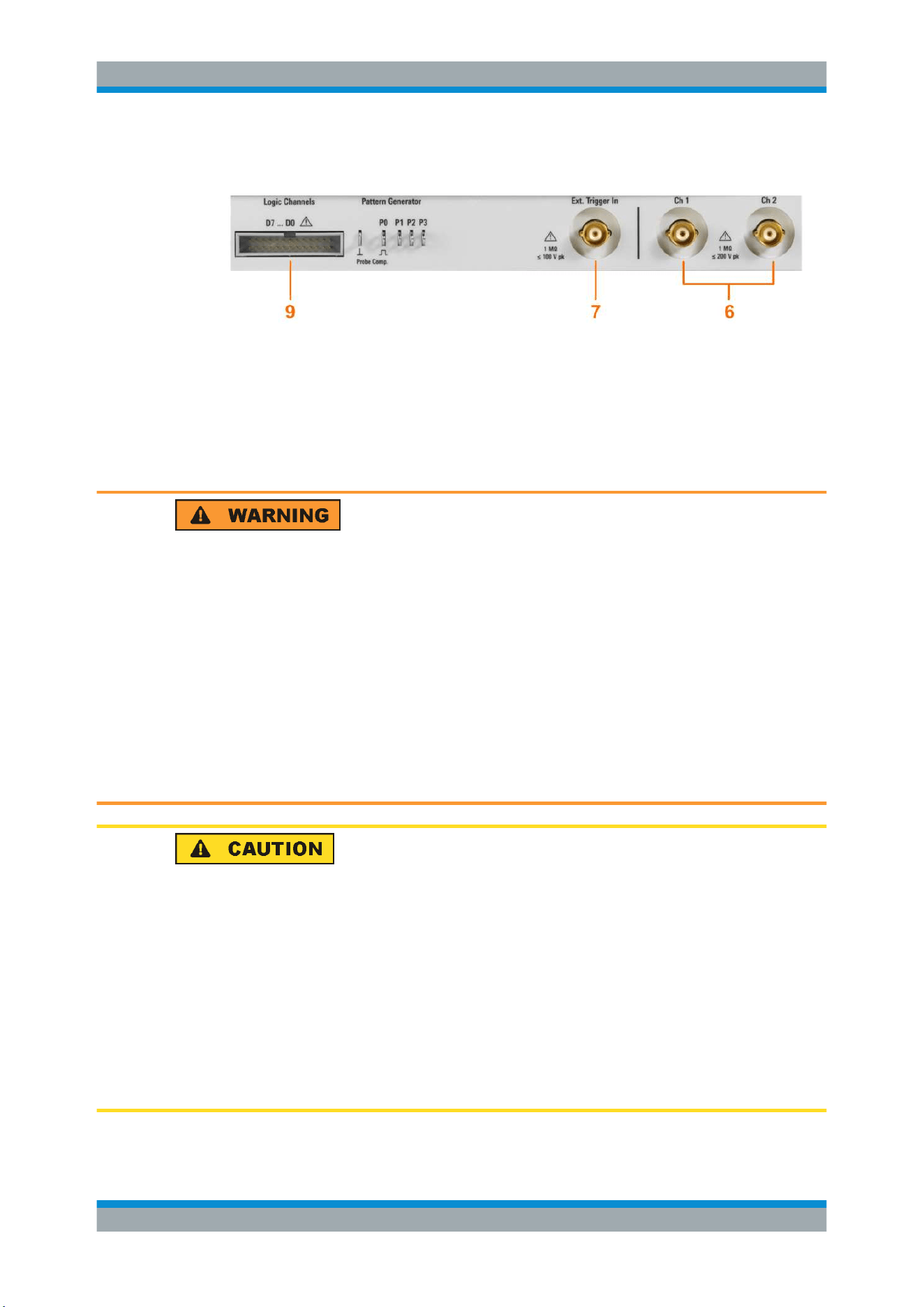
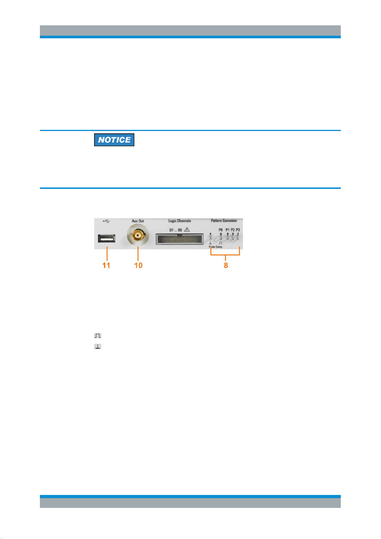
2.2 Instrument Tour
2.2.1 Front Panel
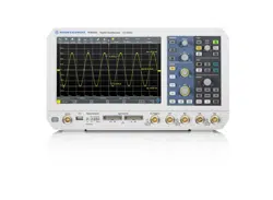
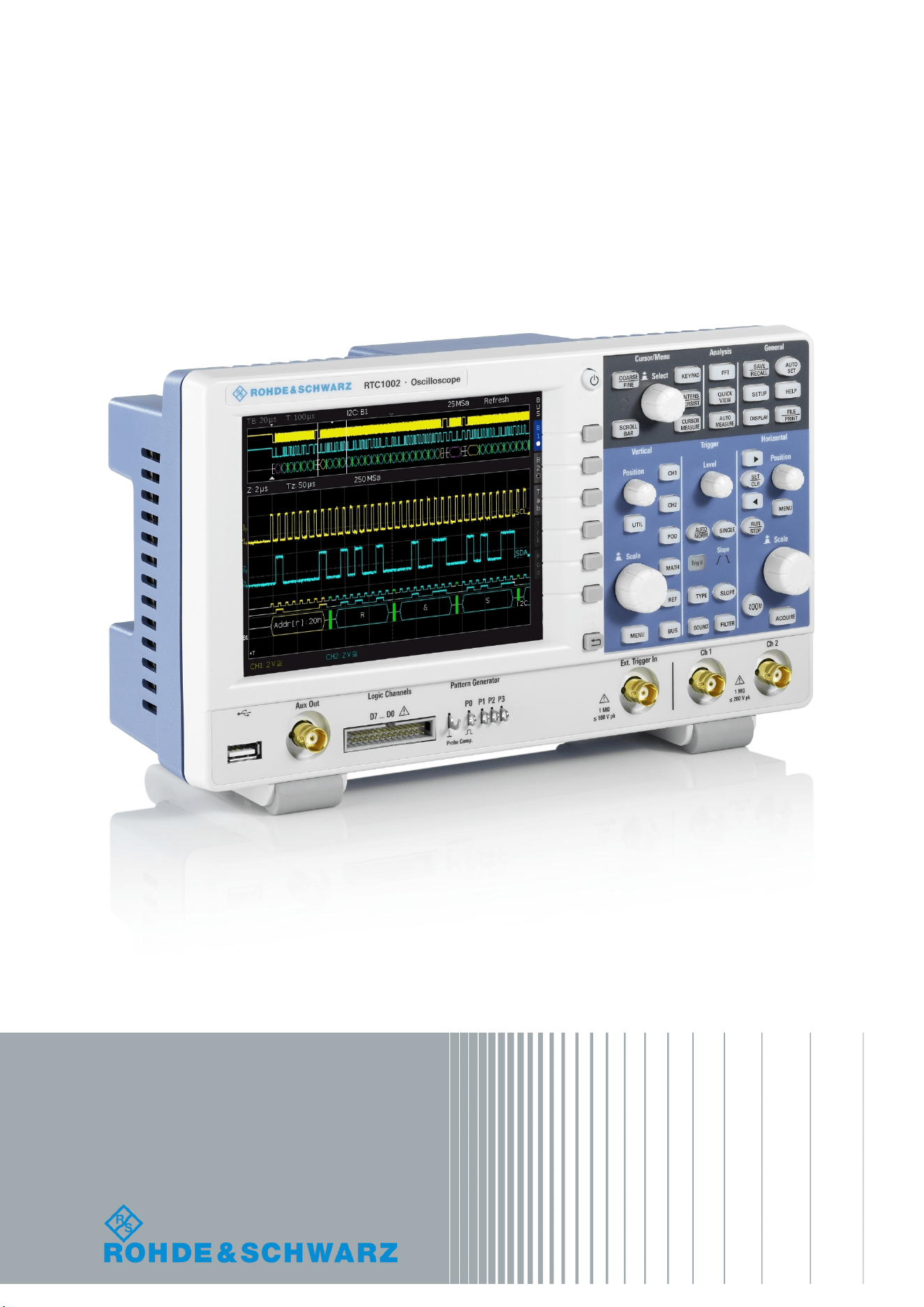
Figure 2-1 shows the front panel of the R&S RTC1000. The function keys are grouped
in functional blocks to the right of the display.
Figure 2-1: Front view of the R&S
RTC1000
1 = Display
2 = Softkeys and menu
3 = [ON/OFF] key
4 = Cursor/Menu, Analyze and General sections
5 = Vertical, Trigger and Horizontal sections
6 = BNC connectors of the analog channel inputs
7 = BNC connector of the external trigger input
8 = Pattern generator output (option R&S RTC-B6) and probe adjustment output
9 = Connector for the logic probe (option R&S RTC-B1)
10 = Multi-purpose BNC connector [Aux Out]
11 = USB connector
Instrument Tour
Getting Started
R&S
®
RTC1000
16User Manual 1335.7352.02 ─ 04
2.2.1.1 Input Connectors
BNC inputs (6, 7)
The R&S RTC1000 has two channel inputs (6) to connect the input signals. The exter-
nal trigger input (7) is used to control the measurement by an external signal. The trig-
ger level can be set from -5 V to 5 V.
The input impedance of all BNC inputs is 1 MΩ.
Risk of electrical shock - maximum input voltages
The maximum input voltage on channel inputs must not exceed 200 V (peak) and
150 V (RMS).
For the external trigger input, the maximum input voltage is 100 V (peak) and
70 V (RMS).
Transient overvoltages must not exceed 200 V (peak).
Voltages higher than 30 V (RMS) or 42 V (peak) or 60 V DC are regarded as hazard-
ous contact voltages. When working with hazardous contact voltages, use appropriate
protective measures to preclude direct contact with the measurement setup:
●
Use only insulated voltage probes, test leads and adapters.
●
Do not touch voltages higher than 30 V (RMS) or 42 V (peak) or 60 V DC.
Risk of injury and instrument damage
The instrument is not rated for any measurement category. When measuring in circuits
with transient overvoltages of category II, III or IV circuits, make sure that no such
overvoltages reach the R&S RTC1000 input. Therefore, use only probes that comply
with DIN EN 61010-031. When measuring in category II, III or IV circuits, always insert
a probe that appropriately reduces the voltage so that no transient overvoltages higher
than 200 V (peak) are applied to the instrument. For detailed information, refer to the
documentation and safety information of the probe manufacturer.
Explanation: According to section AA.2.4 of EN 61010-2-030, measuring circuits with-
out any measurement category are intended for measurements on circuits which are
not directly connected to the mains.
Instrument Tour
Getting Started
R&S
®
RTC1000
17User Manual 1335.7352.02 ─ 04
Logic probe (9)
The connector for logic channels can be used if the Mixed Signal Option R&S RTC-B1
is installed. The option provides a logical probe with 8 digital channels (D0 to D7).
The maximum input voltage is 40 V (peak) at 100 kΩ input impedance. The maximum
input frequency for a signal with the minimum input voltage swing and medium hystere-
sis of 800 mV (Vpp) is 300 MHz.
Risk of instrument damage
Use the connector for the active logic probe exclusively for the logic probe R&S RT-
ZL03, which is delivered with option R&S RTC-B1. Connecting other probe types can
demolish the input.
2.2.1.2 Other Connectors on the Front Panel
[Pattern Generator] (8)
Connectors for the pattern generator P0, P1, P2, P3.
[Probe Comp.] (8)
Probe compensation terminal to support adjustment of passive probes to the oscillo-
scope channel.
Square wave signal for probe compensation.
Ground connector for probes.
[Aux Out] (10)
Multi-purpose BNC output that can function as pass/fail and trigger output, output for
component testing, and as function generator output (with option R&S RTC-B6).
[USB] type A (11)
USB 2.0 type A interface to connect a USB flash drive for storing and reloading instru-
ment settings and measurement data, and to update the firmware.
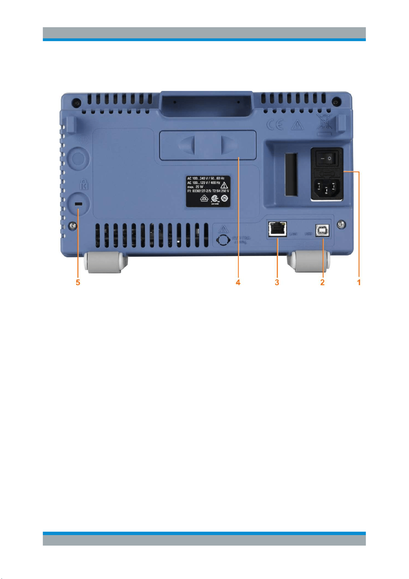
2.2.2 Rear Panel
Figure 2-2 shows the rear panel of the R&S RTC1000 with its connectors.
Instrument Tour
Getting Started
R&S
®
RTC1000
18User Manual 1335.7352.02 ─ 04
On the back panel of the instrument, you find Ethernet and USB interfaces. Optional
interfaces are not available.
Figure 2-2: Rear panel view of R&S
RTC1000
1 = AC power supply connector and main power switch
2 = USB connector, type B
3 = LAN connector
4 = not used
5 = Kensington lock slot to secure the instrument against theft
AC supply: mains connector and main power switch (1)
The instrument supports a wide range power supply. It automatically adjusts to the cor-
rect range for the applied voltage. There is no line voltage selector.
The AC main power switch disconnects the instrument from the AC power line.
[USB] type B (2)
USB 2.0 interface of type B (device USB) to connect a printer, or for remote control of
the instrument.
Note: Electromagnetic interference (EMI) can affect the measurement results. To avoid
any impact, use only USB connecting cables with a maximum length of 1 m.
[LAN] (3)
8-pin connector RJ-45 used to connect the instrument to a Local Area Network (LAN).
It supports up to 100 Mbit/s.
Instrument Tour
Operating Basics
R&S
®
RTC1000
19User Manual 1335.7352.02 ─ 04
3 Operating Basics
3.1 Control Panel
The controls on the front panel allow access to all basic functions. Advanced settings
are easily accessible using the menu structure and gray softkeys. The [ON/OFF] but-
ton is clearly set apart by its design. The most important controls have colored LEDs,
indicating the current setting.
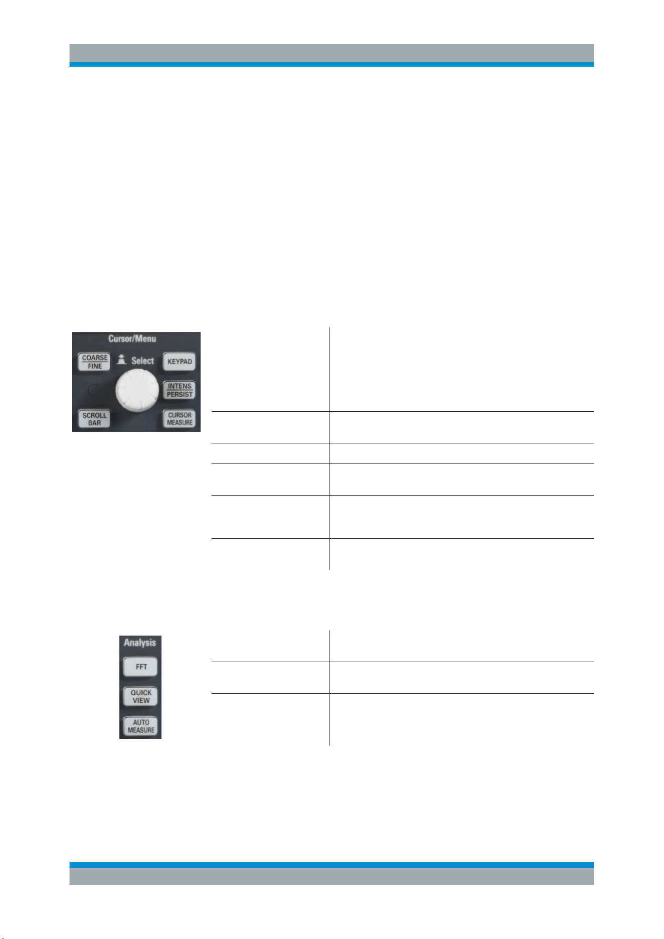
3.1.1 Cursor/Menu Section
Universal rotary knob
The action of the universal knob depends on the selection in the
menu:
●
Set a numeric value
●
Select a value in a list
●
Navigate through the menus
●
Select a highlighted value by pressing the knob, for exam-
ple, in the keypad.
[COARSE/FINE] Toggles between coarse and fine resolution of the universal
rotary knob. The key lights up if fine resolution is active.
[SCROLLBAR] Activates or deactivates the virtual screen.
KEYPAD Opens the on-screen keypad. The key is illuminated if the key-
pad can be used.
INTENS/PERSIST The first keypress sets the rotary knob to adjust the intensity of
the waveforms (key is illuminated). The second keypress opens
the menu to adjust all intensities and the persistence.
[CURSOR MEASURE] Activates the cursors and opens the menu to set up cursor mea-
surements.
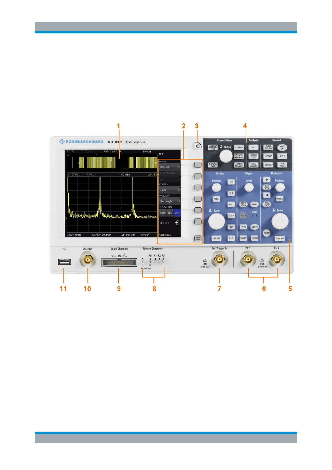
3.1.2 Analysis Section
[FFT] Starts a Fast Fourier Transformation and switches to frequency
domain.
[QUICK VIEW] Starts the quick measurements and shows the typical character-
istics of the signal.
[AUTO MEASURE] Opens a menu to set up automatic measurements. Up to 6 mea-
surements can be performed at the same time.
Control Panel
Operating Basics
R&S
®
RTC1000
20User Manual 1335.7352.02 ─ 04
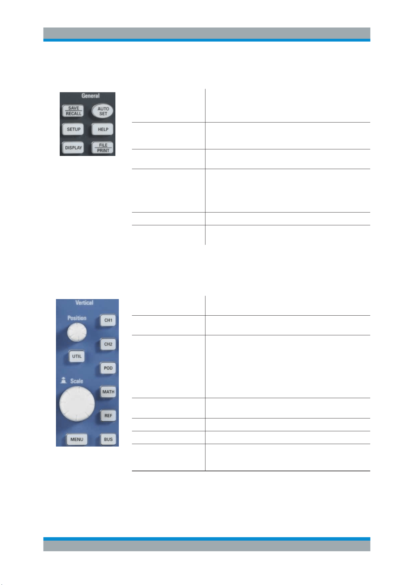
3.1.3 General Section
[SAVE/RECALL] Opens a menu to load and save instrument settings, reference
signals, waveforms, screenshots of the display, and formularies.
In the menu, you can also assign the function of the [FILE/
PRINT] key.
[SETUP] Opens the menu of general instrument settings, such as lan-
guage, interfaces, date, time, firmware update, options, printer,
and more.
[DISPLAY] Opens a menu to activate the virtual screen, and to adjust the
display settings.
[AUTOSET] Press shortly to perform automatic setup. The instrument ana-
lyzes the active signals, and adjusts the horizontal, vertical, and
trigger settings to display stable waveforms.
Press and hold the key until you hear a beep. The most impor-
tant settings of the scope are reset to their defaults.
[HELP] Opens a window with the integrated help.
[FILE/PRINT] Depending on the assigned function, [FILE/PRINT] can save
instrument settings, signals, screenshots, or start a printout.
3.1.4 Vertical Section
The Vertical section features all controls for analog channels.
[Position] knob Sets the vertical position of the selected waveform. To switch to
fine tuning of the value, press the knob.
[Scale] knob Sets the vertical scale (vertical gain) of the selected waveform.
The scale value is shown below the grid.
[CH1], [CH2] Activate the channel if the channel is off.
Selects the channel if the channel is on and the other channel is
selected.
Switches off the channel if it is selected.
If a channel is selected, its key is illuminated. If a channel is on
but not selected, you see the signal on the display, and its key
does not light up.
[POD] Activates the logic channels if optional logic probe R&S RT-ZL03
is connected. Requires option R&S RTC-B1.
[REF] Opens the menu to create, save and load reference waveforms.
[MATH] Opens a menu to create, save and load calculated waveforms.
[BUS] Activates the serial and parallel bus analysis. Requires at least
one of the options R&S RTC-B1, R&S RTC-K1, R&S RTC-K2, or
R&S RTC-K3.
Control Panel
Operating Basics
R&S
®
RTC1000
21User Manual 1335.7352.02 ─ 04
[MENU] Opens the advanced menu for the selected waveform, bus or
pod.
[UTIL] Opens a menu with more applications: digital voltmeter, function
and pattern generator (requires option R&S RTC-B6), compo-
nent tester, and trigger counter.
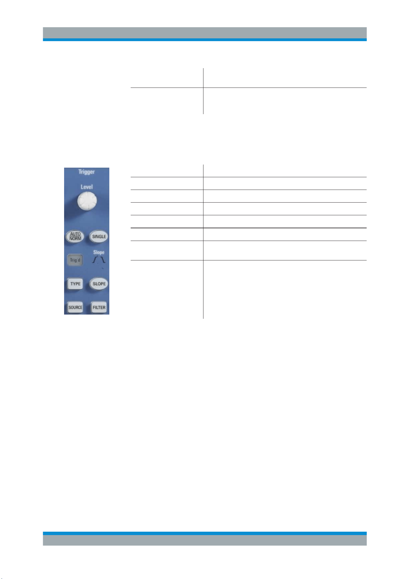
3.1.5 Trigger Section
The Trigger section provides all controls to adjust the trigger.
[LEVEL] knob Sets the trigger level.
[AUTO/NORM] Toggles between auto and normal trigger mode.
Trigg'd The LED lights up if the instrument found a trigger event.
[TYPE] Opens a menu to select the trigger type.
[SOURCE] Opens a menu to select the trigger source.
[SINGLE] Starts a single acquisition.
[SLOPE] Selects the slope for the edge trigger, or the polarity for the pulse
trigger. The selection is indicated by the Slope LEDs.
[FILTER] Opens a menu to set up the trigger condition for the selected trig-
ger type.
3.1.6 Horizontal Section
In the Horizontal section, you set the horizontal and acquisition settings, zoom, and
markers.
Control Panel
Operating Basics
R&S
®
RTC1000
22User Manual 1335.7352.02 ─ 04
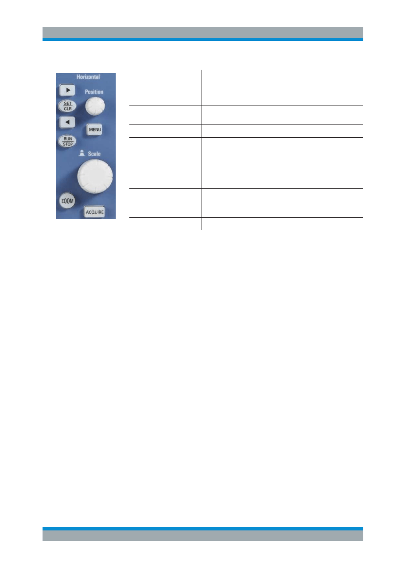
[Left Arrow ], [Right Arrow] /
[SET/CLR]
Set and deletes markers, and navigate markers.
If no markers are set, the arrow keys move the trigger position by
5 division to the left or right. [SET/CLR] resets the value to the
time reference point.
[RUN/STOP] Starts and stops continuous data acquisition. The key lights up in
red if acquisition is stopped.
[ZOOM] Activates and deactivates the zoom display.
[Position] knob Sets the trigger position (horizontal position). The maximum
value depends on the time base.
If a zoom window is active, the knob sets the zoom position.
If markers are set, the knob sets the marker position.
[MENU] Opens a menu to set the trigger position.
[Time base] knob Sets the horizontal scale (time base) for all waveforms. The
scale value is shown above the grid on the left.
If a zoom window is active, the knob sets the zoom size.
[ACQUIRE] Opens a menu to select the acquisition mode and record mode.
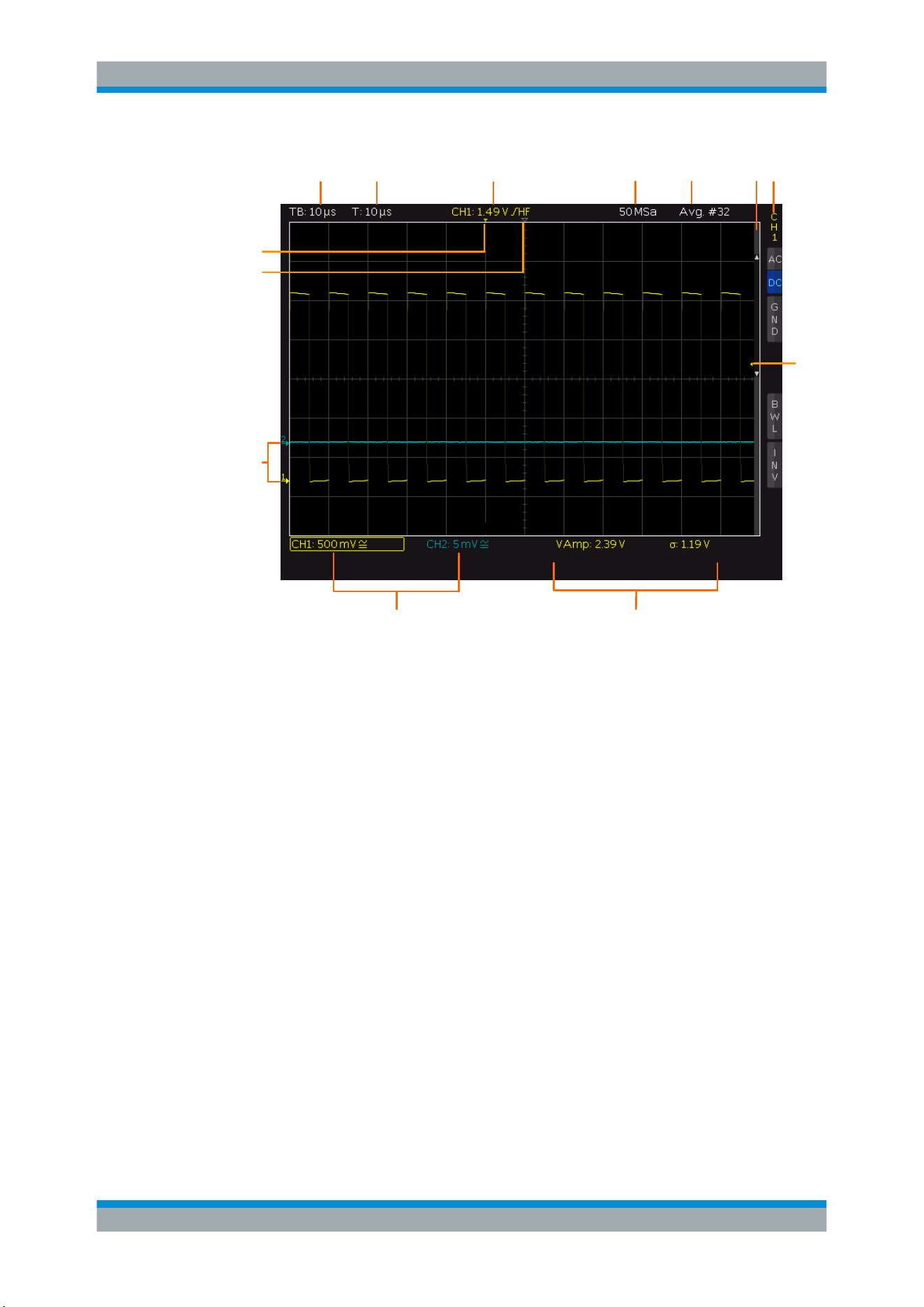
3.2 Display
The R&S RTC1000 is equipped with a TFT color monitor with LED backlight and VGA
resolution (640x480 pixels). If the soft menu is closed, the display has 12 scale divi-
sions on the time axis. If the menu is shown, 10 divisions are shown. In vertical direc-
tion, the display has 8 divisions.
Display
Operating Basics
R&S
®
RTC1000
23User Manual 1335.7352.02 ─ 04
9 10
1 2 4 5 6 7 8
2
3
11
12
1 = Horizontal scale (time base), in s/div
2 = Trigger position
3 = Time reference, zero point of the time axis
4 = Trigger settings: source, level, type, and filter conditions
5 = Sample rate
6 = Acquisition mode
7 = Vertical scrollbar, visible if virtual screen with 20 vertical divisions is on
8 = Short menu with most important settings of the selected channel
9 = Vertical settings of active waveforms: vertical scale in V/div, coupling, and bandwidth limit (if set). Chan-
nel 1 is selected.
10 = Measurement results
11 = Reference potentials of the channels
12 = Trigger level
3.3 Operating Concept
The general operating concept is based on a few key principals, recurring with various
settings and functions:
●
Keys work in one of these ways:
– The key opens a soft menu when pressed once. It closes the soft menu when
pressed a second time.
– The key activates a specific function. Pressing this key a second time deacti-
vates the function.
Operating Concept

Operating Basics
R&S
®
RTC1000
24User Manual 1335.7352.02 ─ 04
●
Depending on the requirements, the [Universal] knob in the Cursor/Menu section
either selects a value, or navigates through menus. The COARSE/FINE key tog-
gles between fine and coarse resolution of the [Universal] knob.
●
The "MENU OFF" key below the softkeys closes the current menu, or switches to
the next higher level.
●
The effect of channel keys depends on the state of the selected waveform:
– Activate the channel if the channel is off.
– Selects the channel if the channel is on and the other channel is selected.
– Switches off the channel if it is selected.
– If a channel is selected, its key is illuminated. If a channel is on but not
selected, you see the signal on the display, and its key does not light up.
The menus include some navigation elements and usage principles.
●
Press the softkey to select or toggle a value. The selected value is marked in blue.
●
Some functions must be activated and require value selection. Pressing the softkey
toggles between "OFF" and the last set value. Use the [Universal] knob to change
the value.
●
A round arrow in the softkey indicates that the value is set with the [Universal]
knob.
●
A small triangle on the bottom right of a softkey indicates an additional menu level.
●
If additional menu pages are available, the lowest softkey navigates through the
menu pages. The current page is shown in the soft menu.
3.4 Integrated Help
The integrated help shows explanatory text about the selected function. The text in the
help window is dynamically updated when you select another function.
1. To activate the integrated help, press the [HELP] key in the General section.
The help window opens, and the [HELP] key lights up.
2. If you no longer need help, press [HELP] again.
3.5 Signal Display
This chapter describes the display of signals and the available display modes.
3.5.1 Display Settings
► To adjust the display, press the [DISPLAY] key.
Signal Display
Operating Basics
R&S
®
RTC1000
25User Manual 1335.7352.02 ─ 04
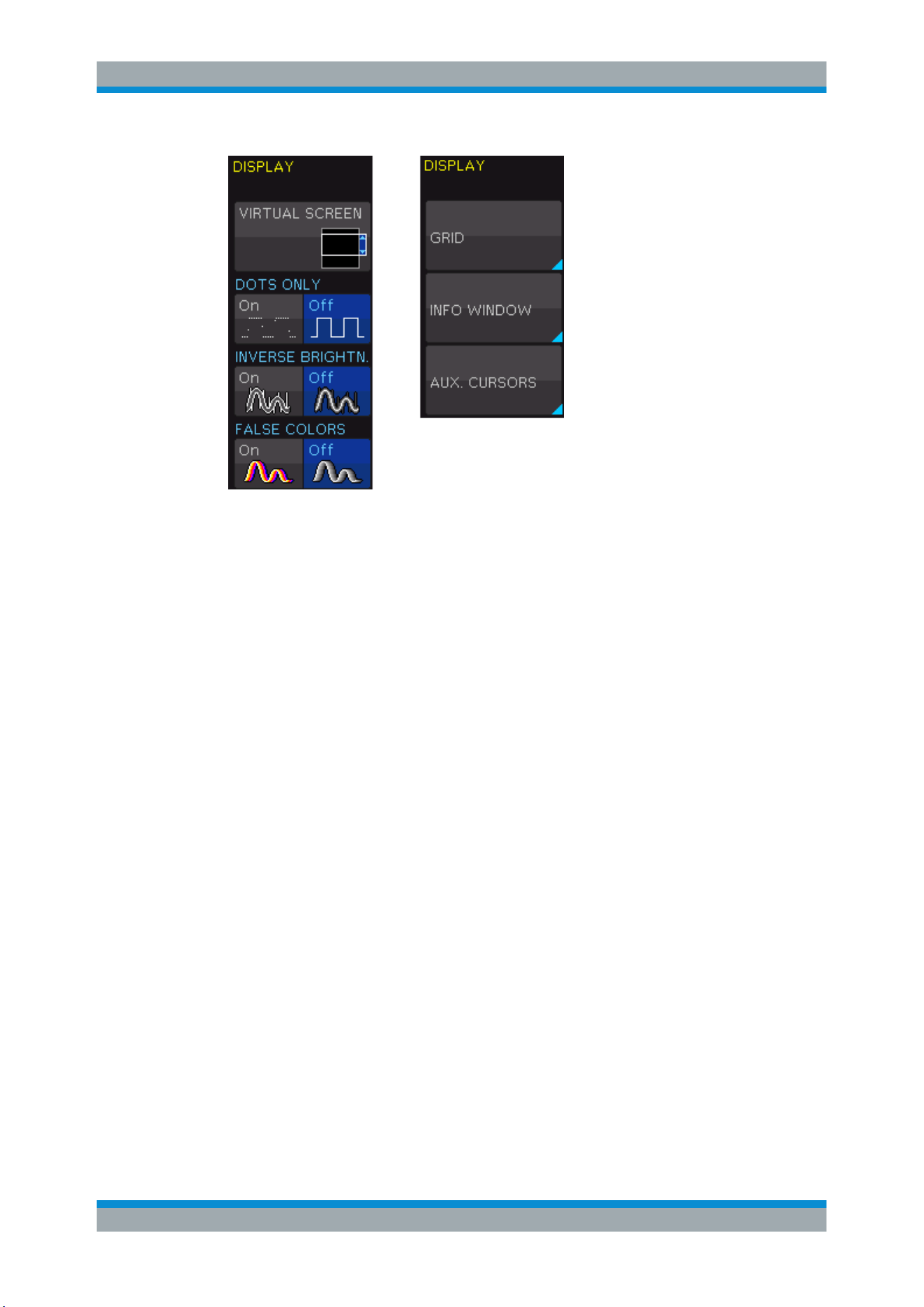
Figure 3-1: Display menu, page 1/2 (left) and page 2/2 (right)
VIRTUAL SCREEN
See
Chapter 3.5.2, "Virtual Screen", on page 26.
DOTS ONLY
If enabled, only the acquired data points are shown. The data points are not connected
by lines. If disabled, interpolated data points are also shown, and the waveform is a
continuous line.
INVERSE BRIGHTN.
Iinverts the brightness of the displayed signals points. Normally, frequently captured
dots are displayed more brightly than rare dots. If inverted, rare events are displayed
with higher brightness. To capture rare events in a signal, this setting can be used in
combination with persistence.
FALSE COLORS
Converts the brightness level of the displayed signal points to a color scale, ranging
from blue, magenta, red and yellow to white. Due to the higher contrast, you can see
signal details easily. This setting applies to all signals.
GRID
Sets the display of the grid: "LINES", "RETICLE", or "OFF".
INFO WINDOW
Info windows are small windows that appear on the screen depending on the current
application. You can change the format of information windows:
"TRANSPARENCY"
Use the Universal knob to or the [KEYPAD] to change the value from
0% to 100%.
Signal Display

Operating Basics
R&S
®
RTC1000
26User Manual 1335.7352.02 ─ 04
"POSITION"
If activated and the vertical position is changed, the value of the verti-
cal position is shown at the zero line.
"ACQ.STA-
TUS"
If activated, the information on the acquisition status is shown. In nor-
mal trigger mode, if the trigger condition is fulfilled, the information
window shows a progress display for the post-trigger and pre-trigger.
If the trigger condition is not met, the information window shows the
time since the last trigger event ("Trig?"). In automatic trigger mode,
no information is shown.
AUX. CURSORS
You can enable or disable the cursor and channel markers on the display. Select
"DEFAULTS" to rest the settings.
3.5.2 Virtual Screen
Normally, the grid of the R&S RTC1000 has 8 vertical divisions. It has also a virtual
range of 20 divisions. These virtual divisions can be used entirely by the optional digital
channels D0 to D7, the mathematical channels and the references signals. The analog
channels can use up to ±10 divisions from the center. This allows a simple and clear
display of many waveforms
Figure 3-2 illustrates the functionality of the virtual screen. The scroll bar next to the
grid indicates the position of the 8 visible divisions within the available 20 divisions. .
1. Press the [DISPLAY] key in the General section.
2. Activate "VIRTUAL SCREEN".
A scrollbar is shown to the right of the grid.
3. To activate or deactivate the scrollbar, press the [SCROLL BAR] key.
The scrollbar is shown in blue if it is active.
4. If the scrollbar is active, use the Universal knob to move the display window within
the 20 divisions of the virtual screen.
Signal Display
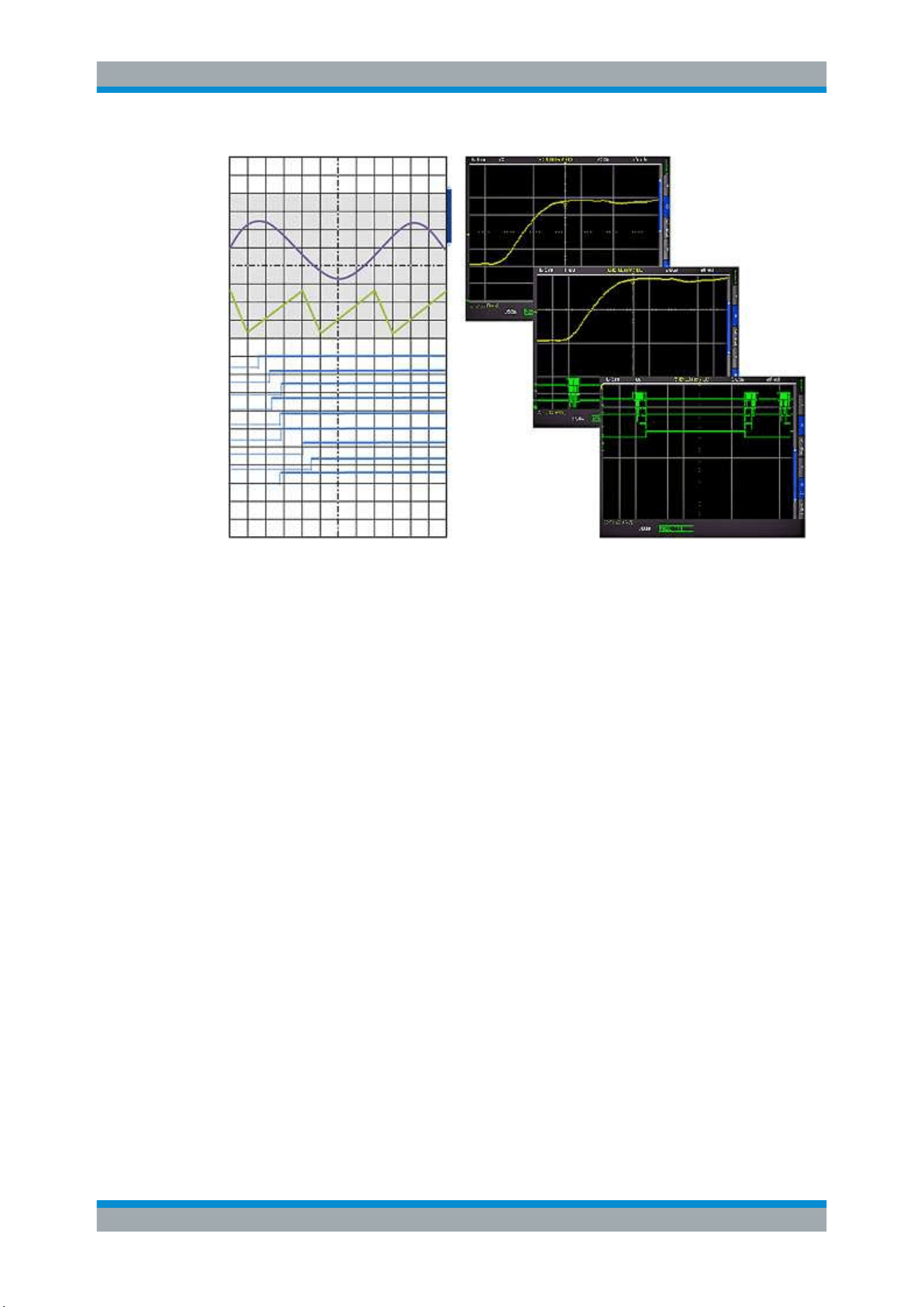
Operating Basics
R&S
®
RTC1000
27User Manual 1335.7352.02 ─ 04
Figure 3-2: Drawing of the virtual screen area
3.5.3 Signal Intensity and Persistence
To change the intensity of the waveforms:
1. Press the [INTENS/PERSIST] key in the Cursor/Menu section until it lights up in
white.
2. Turn the Universal knob to change the intensity of the signal display from 0% to
100%.
To access further intensity and persistence settings:
1. If the [INTENS/PERSIST] key is illuminated in white, press this key again.
2. Use the menu functions to adjust the settings.
The following settings are available:
TRACE, GRID, BACKLIGHT
Use the Universal knob to adjust the waveform intensities, grid intensity, and the back-
lighting.
PERSISTENCE
Persistence defines how subsequent captured waveforms are shown simultaneously.
Older waveforms are displayed in darker color (they fade), and newer waveforms are
displayed in lighter color. Thus, signals points occurring more frequently are displayed
in lighter color. The display is similar to that of an analog oscilloscope
Signal Display
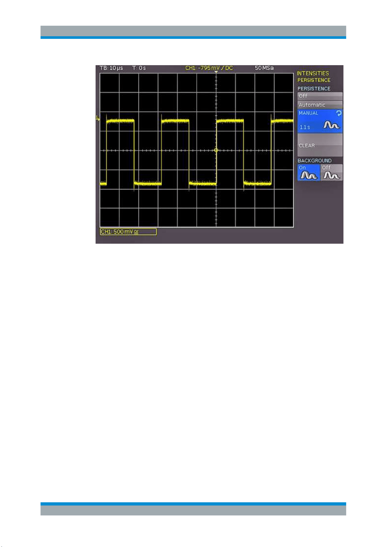
Operating Basics
R&S
®
RTC1000
28User Manual 1335.7352.02 ─ 04
Figure 3-3: Persistence function
"MANUAL"
You can set a duration of 50 ms to infinite by using the [universal]
knob or the [KEYPAD] key. If a finite duration is selected, new signals
are written on top of one another. The most recent captures are dis-
played more brightly than older signals. For example, if 300 ms is
selected, the display of the waveform becomes darker in 50 ms inter-
vals and is erased after 300 ms.
"AUTOMATIC"
The instrument sets the optimal persistence time.
"OFF"
Persistence is deactivated.
"BACK-
GROUND"
When enabled, older waveforms do not disappear entirely after the
set persistence time. Instead, waveforms are displayed in the back-
ground with low brightness. This display is useful for the analysis of
peak values in signals, for example.
3.6 General Instrument Settings
The instrument settings are provided in the "SETUP" menu.
► Press the [SETUP] key in the General section.
General Instrument Settings

Operating Basics
R&S
®
RTC1000
29User Manual 1335.7352.02 ─ 04
"LANGUAGE" Selects the language for user interface and help.
"SELF ALIGNMENT" The instrument adjusts vertical accuracy, time base and several
trigger settings and saves the identified correction data internally.
See also:
Chapter 3.7, "Self-Alignment", on page 29.
"PROBE ADJUST" Aligns the probe. A wizard explains all steps on the display.
"INTERFACE" Configures the USB and Ethernet (LAN) interfaces.
See also: .
"DEVICE INFORMATION" Shows detailed information on hardware and software of the
instrument.
"UPDATE" Firmware update, see Chapter 3.8, "Firmware Update",
on page 30.
"OPTIONS" Activation of options, see Chapter 3.9, "Options", on page 31.
"DATE & TIME" Sets the date and time.
"SOUND" You can activate a control beep to get information on the instru-
ment's activities, error beep, and trigger beep.
"DEVICE NAME" You can define a name with up to 19 characters, which is listed
when screenshots are printed.
"MENU OFF" Selects whether you close the menus manually, or they are closed
automatically after a specified time.
"DEVICE LOGO IN SCREENSHOT" If activated, the R&S logo is printed in the upper right corner of
screenshots and printouts.
"EDUCATION MODE" Activates and deactivates the education mode. You can set a
password to prevent unwanted deactivation.
In education mode, the AUTOSET, QUICK VIEW and automatic
measuring functions are disabled. This information is also shown
in the device information window.
"PRINTER" Configures the printer, see .
3.7 Self-Alignment
The R&S RTC1000 features an integrated self-alignment procedure to achieve the
highest possible accuracy. During the standard self-alignment, the instrument adjusts
vertical accuracy, offset, time base and several trigger settings and saves the identified
correction data internally.
Make sure that the instrument has been running and warming up for at least 20
minutes before you start the self-alignment.
Remove all probes and connected lines from the inputs.
1. Press the [SETUP] key.
2. Press "SELF ALIGNMENT".
Self-Alignment
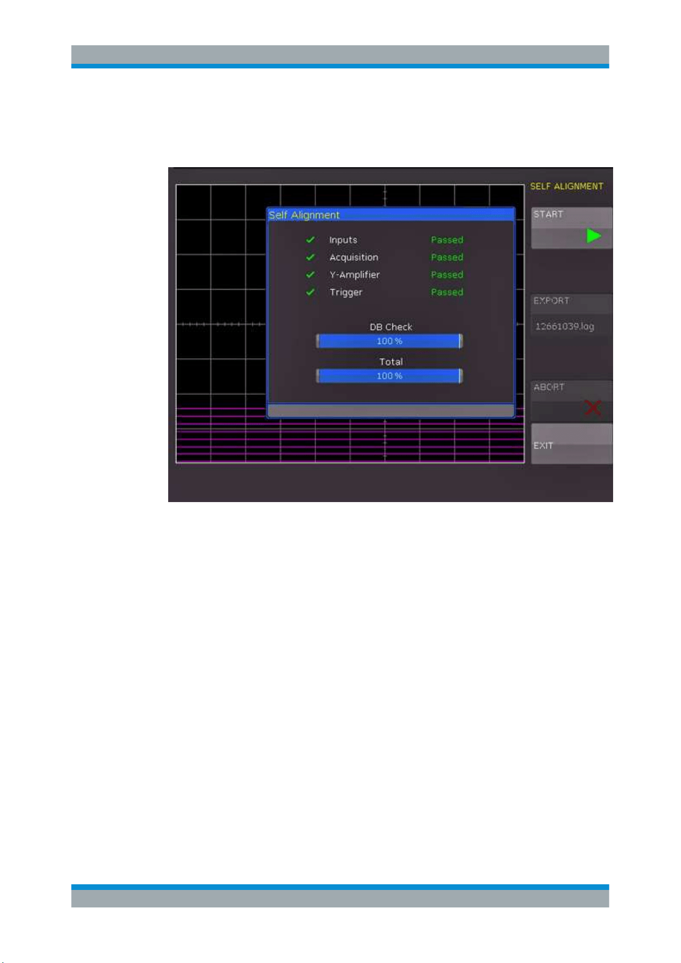
Operating Basics
R&S
®
RTC1000
30User Manual 1335.7352.02 ─ 04
3. Press "START".
The procedure can take up to 16 minutes.
Figure 3-4: Self-alignment successful
If an error occurs during the self-alignment although it has been carried out as descri-
bed, export the .log file in the "SELF ALIGNMENT" menu and send it to
customer-
. You can save the .log file to a USB flash drive.
3.8 Firmware Update
Your instrument is delivered with the latest firmware version. Firmware updates are
provided on the Internet at
www.rohde-schwarz.com/firmware/rtc1000. Along with the
firmware file, you find the Release Notes describing the improvements and modifica-
tions.
Make sure to update the firmware if a new version is available.
1. Download the firmware installation file RTC1002.FWU to a USB flash drive.
2. Connect the USB flash drive to the USB connector at the front of the instrument.
3. Press the [SETUP] key.
4. Go to menu page 2/3.
Firmware Update

Operating Basics
R&S
®
RTC1000
31User Manual 1335.7352.02 ─ 04
5. Select "UPDATE".
A window with information about the installed firmware and front controller firmware
is shown.
6. Select "FIRMWARE".
The information on the new firmware is added in the window. If you have no newer
firmware than the installed one, a message appears.
7. Wait until the firmware file is loaded.
8. To start the firmware update, select "EXECUTE".
Wait until the update has finished. The instrument restarts automatically.
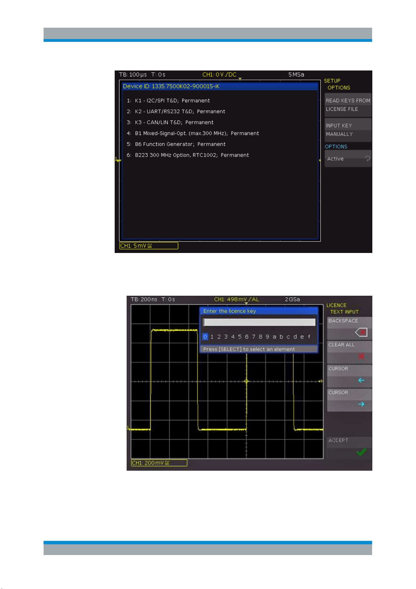
3.9 Options
All options are activated by license keys. No additional installation or hardware change
is required.
Consult your sales representative and provide the material number, serial number, and
the device ID of your instrument to get a license key. You find this information on the
bar code sticker at the rear panel, and in "SETUP" menu > "DEVICE INFORMATION".
The license key is provided in written form or in a file. Unregistered licenses must be
registered in the R&S License Manager before they can be activated on the instru-
ment.
Unregistered licenses
Unregistered licenses are not assigned to a particular instrument. The instrument
accepts only registered licenses. If your license is delivered unregistered, use the
online tool R&S License Manager to register the license for your instrument. The regis-
tration of a permanent license is irreversible, so ensure that you register it for the cor-
rect instrument. The address of the tool is
https://extranet.rohde-schwarz.com/service.
1. If you received the option key in a file, save the file to a USB flash drive.
2. Connect the USB flash drive to the R&S RTC1000.
3. Press the [SETUP] key.
4. Go to menu page 2/3.
5. Select "Options".
A window with information on the active options is shown.
Options
Operating Basics
R&S
®
RTC1000
32User Manual 1335.7352.02 ─ 04
6. If you received a key in written form:
a) Select "INPUT KEY MANUALLY".
b) Enter the key.
7. If you received a key in digital form as a file:
a) Select "READ KEYS FROM LICENSE FILE".
b) Select the "Front" storage and change directory if necessary.
c) Turn the [Universal] knob to select the license file.
Options

Operating Basics
R&S
®
RTC1000
33User Manual 1335.7352.02 ─ 04
d) Select "LOAD".
8. If you want to activate several options, repeat step 6 or 7 for each option.
9. Restart the instrument.
Options

Waveform Setup
R&S
®
RTC1000
34User Manual 1335.7352.02 ─ 04
4 Waveform Setup
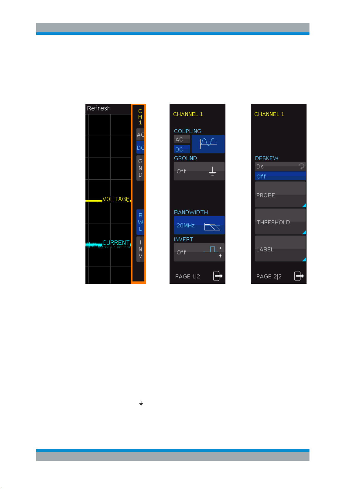
4.1 Vertical Setup
The most important vertical settings are permanently available for adjustment:
●
Channel keys to switch on or off and to select a channel
●
Rotary knobs to adjust vertical scale and position
●
Short menu to adjust coupling, ground, bandwidth filter and to invert the waveform.
Advanced settings are provided in the "Vertical" menu.
The channel labels show the current vertical settings of each channel.
Figure 4-1: Channel labels: Channel 1 is selected, is DC coupled and bandwidth limited. Channel 2 is
AC couples and inverted.
Make sure to check and adjust the probe attenuation value in the channel menu.
●
Vertical Controls...................................................................................................... 34
●
Vertical Settings in the Channel Menus.................................................................. 34
●
Probe Compensation.............................................................................................. 37
4.1.1 Vertical Controls
In the Vertical section of the front panel, you select the channel, set scale and position,
and open the vertical menu. The key of the selected channel lights up.
Vertical scale (sensitivity) and vertical position (Y-position or offset) are the basic verti-
cal settings. Each channel has its individual vertical values.
1. To select the desired channel, press its channel key.
2. To set the vertical scale of the selected channel, turn the [Scale] knob in the Verti-
cal section. You can select the sensitivity in 1-2-5 steps of 1mV/div to 10V/div.
Press the knob once to switch to a continuous value setting.
3. To set the vertical position of the selected channel, turn the [Position] knob in the
Vertical section.
For a complete description of the Vertical section of the frontpanel, see
Chap-
ter 3.1.4, "Vertical Section"
, on page 20.
4.1.2 Vertical Settings in the Channel Menus
To open the vertical menu for a channel:
Vertical Setup
Waveform Setup
R&S
®
RTC1000
35User Manual 1335.7352.02 ─ 04
1. Select the channel using its [CH] key.
2. Press the [MENU] key in the Vertical section.
Page 1 of the menu shows the settings of the short menu, page 2 provides further set-
tings.
Figure 4-2: Vertical menus: short menu (left), page 1 and page 2 of the advanced menu
COUPLING
The analog channels have an input impedance of 1 MΩ. The input coupling influences
the signal path between input connector and the following internal signal stage. The
current coupling of each channel is shown in the channel labels below the grid.
"AC"
AC coupling blocks the DC component of the signal so that the wave-
form is centered on zero volts. AC coupling is useful if the DC compo-
nent of a signal is of no interest.
"DC"
With DC coupling, the input signal passes unchanged, all signal com-
ponents are shown.
GROUND (GND)
Connects the input to a virtual ground. All channel data is set to 0 V. Ground connec-
tion is indicated with
in the waveform labels. The coupling is not affected by the
ground setting.
Vertical Setup

Waveform Setup
R&S
®
RTC1000
36User Manual 1335.7352.02 ─ 04
BANDWIDTH (BWL)
Inserts an analog 20 MHz low-pass filter to the signal path. Higher frequencies are
removed to reduce noise.
Limited bandwidth is indicated by "B
W
" in the waveform label.
INVERT (INV)
Turns the inversion of the signal amplitude on or off. To invert means to reflect the volt-
age values of all signal components against the ground level. Inversion affects only the
display of the signal but not the trigger.
For example: if the oscilloscope triggers on the rising edge, the trigger is not changed
by inversion, but the actually rising edge is displayed as falling edge.
Inversion is indicated in the waveform labels by line above the channel name.
DESKEW
Each analog channel can be shifted in time by ± 32 ns. The deskew setting is used to
compensate different signal delays when different cable lengths or probes are used.
To activate this offset, press the softkey. Turn the [Universal] knob to set the value, or
use the [KEYPAD].
PROBE
The attenuation of the delivered probes R&S RT-ZP03 probe can be switched: 10:1 or
1:1. The instrument does not detect the probe attenuation automatically. Therefore,
make sure to set up the correct attenuation factor manually.
You can select a predefined value "x1", "x10", "x100", "x1000". If predefined values do
not fit, select "USER" and enter a value between x0.001 and x1000.
"UNIT" defines the measurement unit:
●
V - for voltage measurements
●
A - for current measurements if a current probe is connected, or current is mea-
sured using a shunt. The menu shows the most common factors "1V/A",
"100mV/A", "10mV/A" and "1mV/A".
All measurements are always displayed with the correct unit and scale.
THRESHOLD menu
The "THRESHOLD" key on page 2/2 opens the threshold menu.
The threshold defines the level to detect a high or low signal state if analog channels
are used as source for the serial bus analysis or logic trigger.
"THRESH-
OLD"
Sets the threshold value.
"HYSTERE-
SIS"
Sets a range around the threshold level to avoid the change of signal
states due to noise. If the signal oscillates only inside the hysteresis
range and crosses the threshold, no state transition occurs.
"FIND LEVEL"
The instrument analyzes the channel and sets the appropriate thresh-
old.
Vertical Setup
Waveform Setup
R&S
®
RTC1000
37User Manual 1335.7352.02 ─ 04
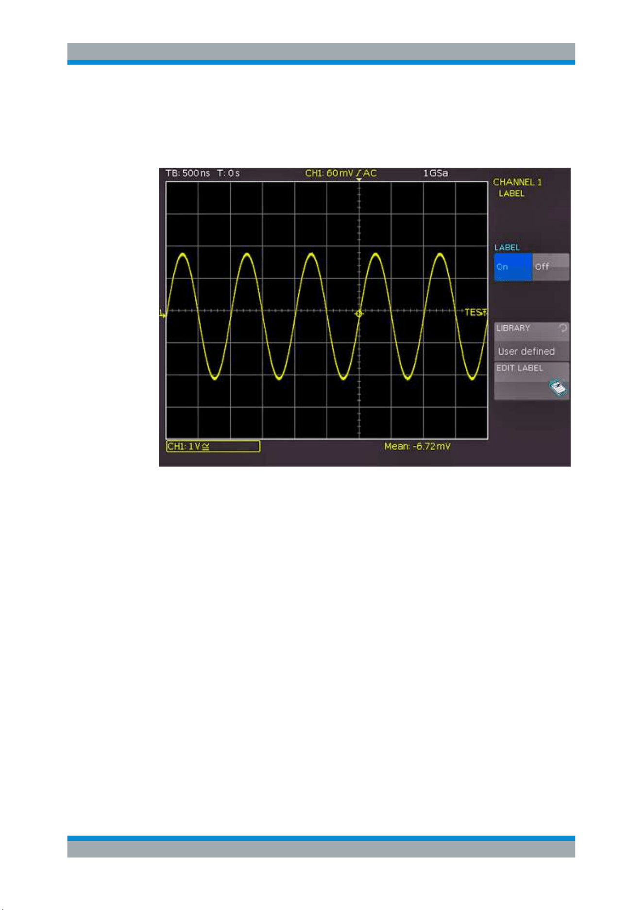
LABEL
The "LABEL" key on page 2/2 opens the label menu to define a name label for the
selected waveform. The label is shown and printed at the waveform on the right edge
of the display. It moves with the waveform if vertical position is changed.
Figure 4-3: Label menu
"LABEL"
Activates or deactivates the label display.
"LIBRARY"
Selects a predefined label text. You can edit the text with "EDIT
LABEL"
"EDIT LABEL"
Opens on-screen keypad to enter a label text. The maximum name
length is 8 characters, and only ASCII characters provided on the on-
screen keypad can be used.
If you previously have selected a text from the library, it is already
written in the entry line, and you can modify it.
4.1.3 Probe Compensation
Compensation matches the probe cable capacitance to the oscilloscope input capaci-
tance to assure good amplitude accuracy from DC to upper bandwidth limit frequen-
cies. A poorly compensated probe reduces the performance of the probe-oscilloscope
system and introduces measurement errors resulting in distorted waveforms and inac-
curate results.
Vertical Setup
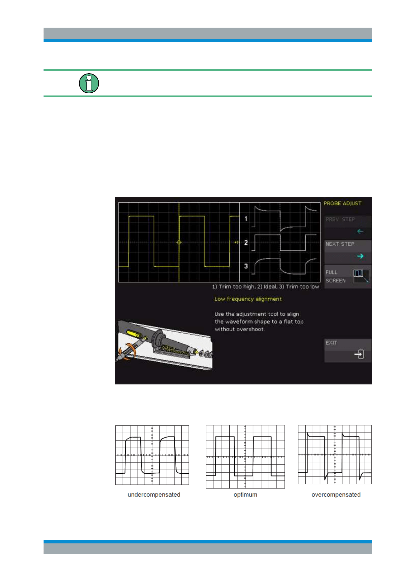
Waveform Setup
R&S
®
RTC1000
38User Manual 1335.7352.02 ─ 04
Make sure to align passive probes before their first use, after an extended measure-
ment break, or when switching instruments or channels.
Two connector pins for compensation are located at the front panel. The left pin is on
ground level. The next pin supplies a square wave signal for the adjustment.
To perform probe compensation using the wizard
1. Press the [SETUP] key in the General section.
2. Press the "PROBE ADJUST" softkey.
3. Follow the instructions of the wizard. It guides you through the compensation proc-
ess.
4. Use the compensation trimmer of the probe to get optimum square wave response.
For details, refer to the documentation of your probe.
The compensation is performed at 1 kHz (LF) and 1 MHz (HF).
Vertical Setup

Waveform Setup
R&S
®
RTC1000
39User Manual 1335.7352.02 ─ 04
To perform probe compensation manually
1. Press the [UTIL] menu in the Vertical section.
2. Select the "PATTERN GEN." softkey.
3. Select "SQUARE WAVE" (see
Chapter 10.2.1, "Square Wave", on page 115).
4. Use the compensation trimmer of the probe to get optimum square wave response.
For details, refer to the documentation of your probe.
4.2 Horizontal Setup
Horizontal settings, also known as timebase settings, adjust the waveforms in horizon-
tal direction.
Typically, the trigger is the determining point of the waveform record. In many scenar-
ios, you want to analyze the waveform some time before or after the trigger. To adjust
the horizontal acquisition window to the waveform section of interest, you can use the
following parameters:
●
The trigger position (horizontal position) defines the time distance of the trigger
point to the reference point. Changing the trigger position, you can move the trigger
point, even outside the screen.
●
The reference point is the zero point of the diagram and the rescaling center of
the time scale on the screen. If you modify the time scale, the reference point
remains fixed on the screen, and the scale is stretched or compressed to both
sides of the reference point.
In the HORIZONTAL section of the front panel, you can:
●
Adjust the timebase, trigger position, and acquisition settings, see
"To adjust time-
base and trigger position"
on page 39.
●
Activate the zoom, see
Chapter 6.1, "Zoom Function", on page 58.
●
Set markers, see
Chapter 6.2, "Marker Function", on page 60.
To adjust timebase and trigger position
1. To set the timebase (horizontal scale), turn the [Scale] knob in the Horizontal sec-
tion.
The current timebase setting, e.g."TB: 500 ns", is displayed in the upper left above
the grid. The default setting shows the trigger in the center of the display, with 50%
of the signal display before and 50% after this trigger position.
2. To set the trigger position, use one of these methods:
● Turn the [Position] knob.
● Use the arrow keys.
● Press the [MENU] key.
In the submenu, you can:
– Set an exact value: "NUMERIC INPUT"
Horizontal Setup

Waveform Setup
R&S
®
RTC1000
40User Manual 1335.7352.02 ─ 04
– Set the trigger position to minimum or maximum value: "MINIMUM" or
"MAXIMUM".
– Set the trigger position to zero.
3. To set the time reference point:
a) Press the [MENU] key.
b) Press the "TIME REF." softkey.
c) Use the universal knob in the Cursour/Menu section to adjust the value.
You can set the reference point from -6 divisions to +6 divisions with 0 being the
center and default setting.
4.3 Acquisition Setup
During an acquisition, the R&S RTC1000 captures the signal and converts it to digital
samples. The digital samples are processed according to the acquisition settings. The
result is a waveform record that is displayed on the screen and stored in memory.
The rate of recording waveform samples - the number of waveform samples per sec-
ond - is the sampling rate. The higher the sampling rate, the better the resolution and
the more details of the waveform are visible.
A sufficient resolution is essential for correct reconstruction of the waveform. If the sig-
nal is undersampled, aliasing occurs - a false waveform is displayed. To avoid aliasing
and accurately reconstruct a signal, the sampling rate must be at least 3 to 5 times the
fastest frequency component of the signal.
4.3.1 RUN/STOP and SINGLE
In run mode, signals are shown on the screen according to the selected acquisition
and trigger conditions. Previously captured signals are discarded with each new acqui-
sition.
► To stop the acquisition, press the [RUN/STOP] key.
Now the captured signal remains on the screen and you can analyze it. The key is
illuminated in red.
► To capture and display exactly one waveform record, press the [SINGLE] key in the
Trigger section.
4.3.2 Acquisition Settings
Acquisition settings define the processing of the captured samples in the instrument.
The current sampling rate is shown on top of the grid.
► To adjust acquisition settings, press the [ACQUIRE] key.
Acquisition Setup
Waveform Setup
R&S
®
RTC1000
41User Manual 1335.7352.02 ─ 04
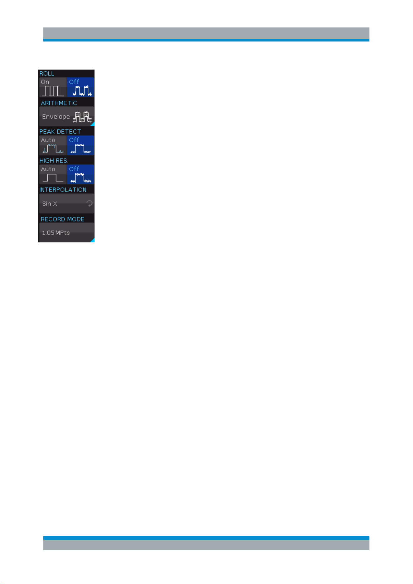
ROLL
Enables the roll mode.
The roll mode displays the untriggered, continuous signal. The roll mode moves the
captured input data on the display from the right to the left. The instrument shows the
waveform immediately, without waiting for the complete acquisition of the waveform
record.
The roll mode is intended for slow signals and requires signals slower than 200 kHz.
If roll mode is active, zoom is not available.
ARITHMETIC
Opens a menu to define how the waveform is built from the captured samples.
"REFRESH"
Captures and displays of the samples of the signal.
Usually, signals are displayed optimally with this acquisition mode but
very short glitches can remain undiscovered by this method.
"ENVELOPE"
Displays the normal sample of the signal, and also the maximum and
minimum values of each sampling interval. Over time, these values
create an envelope surrounding the signal.
"AVERAGE"
The average is calculated from the data of the current acquisition and
some consecutive acquisitions before. The method reduces random
noise. It requires a stable, triggered and repetitive signal.
Turn the universal knob to set the number of acquisitions for average
calculation (2 to 1024 in powers of 2).
"SMOOTH"
Calculates the mean value from several adjacent sampling points.
The result is a smooth waveform. This function is used for non-peri-
odic signals.
"FILTER"
Activates a low pass filter with adjustable cut-off frequency to sup-
press unwanted high frequency interferences. The cut-off frequency
depends on the sampling rate.
Turn the universal knob to adjust the cut-off frequency. The minimum
setting is 1/100 of the sampling rate and the maximum value is 1/4 of
the sampling rate.
PEAK DETECT
Peak detection is used for large time base settings to detect even short signal
changes.
The following conditions must be met to activate the peak detect mode:
●
Function "HIGH RES." is deactivated.
Acquisition Setup

Waveform Setup
R&S
®
RTC1000
42User Manual 1335.7352.02 ─ 04
●
No serial or parallel bus is active.
If "PEAK DETECT" is set to "Auto", the instrument selects the best peak detection
mode depending on the time base and sampling rate. The minimum and the maximum
of each sampling interval are recorded as data pairs, and the other samples are discar-
ded. Thus the instrument can detect fast signal peaks at slow time scale settings that
would be missed with other acquisition modes.
HIGH RES.
The average of n captured sample points is recorded as one waveform sample. High
resolution reduces the noise, the result is a more precise waveform with higher vertical
resolution.
The following requirements must be met to activate the high-resolution mode:
●
Sampling rate is smaller than the maximum sampling rate (no interlace mode)
●
Peak detection is deactivated
●
No active logic probe
●
No serial or parallel bus is active
INTERPOLATION
Selects the interpolation method to display the acquired data points:
"Sin x"
Two adjacent waveform points are connected by a sin(x)/x curve, and
also the adjoining sample points are considered by this curve. This
interpolation method is the default method. It is precise and shows
the best signal curve.
"Linear"
Uses a line to connect acquired data points.
"Sample-Hold"
Allows a more precise assessment of the position for the acquired
data points. For each sampling interval, the Y-value of the sample
point is considered as constant, and the intervals are connected with
vertical lines. Thus, you see the discrete values of the ADC.
RECORD MODE
See
Chapter 4.3.3, "Record Modes", on page 42.
4.3.3 Record Modes
The R&S RTC1000 provides several record modes, which combine the setting of the
sampling rate, the memory depth, and the waveform rate.
MAX. WFM. RATE
Memory depth and sampling rate are adjusted to obtain the maximum trigger repeat
rate. The oscilloscope displays the maximum number of acquisitions per second in the
signal window. Each column in the signal window displays a captured date. When peak
detection is activated, each column displays a pair of min/max values. The
R&S RTC1000 displays a signal window of 600x400 pixels (without zoom), which
translates into 600 data points per acquisition. When peak detection is activated, 600
pairs of min/max values or 1,200 data values are displayed.
Acquisition Setup
Waveform Setup
R&S
®
RTC1000
43User Manual 1335.7352.02 ─ 04
The memory depth corresponds to the displayed time window (time base x 10 grid sec-
tions in horizontal direction) multiplied by the current sampling rate. The minimum
value is determined by the maximum sampling rate and the maximum signal repeat
rate of the oscilloscope. The displayed sampling rate corresponds to the current sam-
pling rate divided by the amount of data skipped while reading out from the acquisition
memory. If peak detection is activated, the displayed sampling rate corresponds to the
current sampling rate.
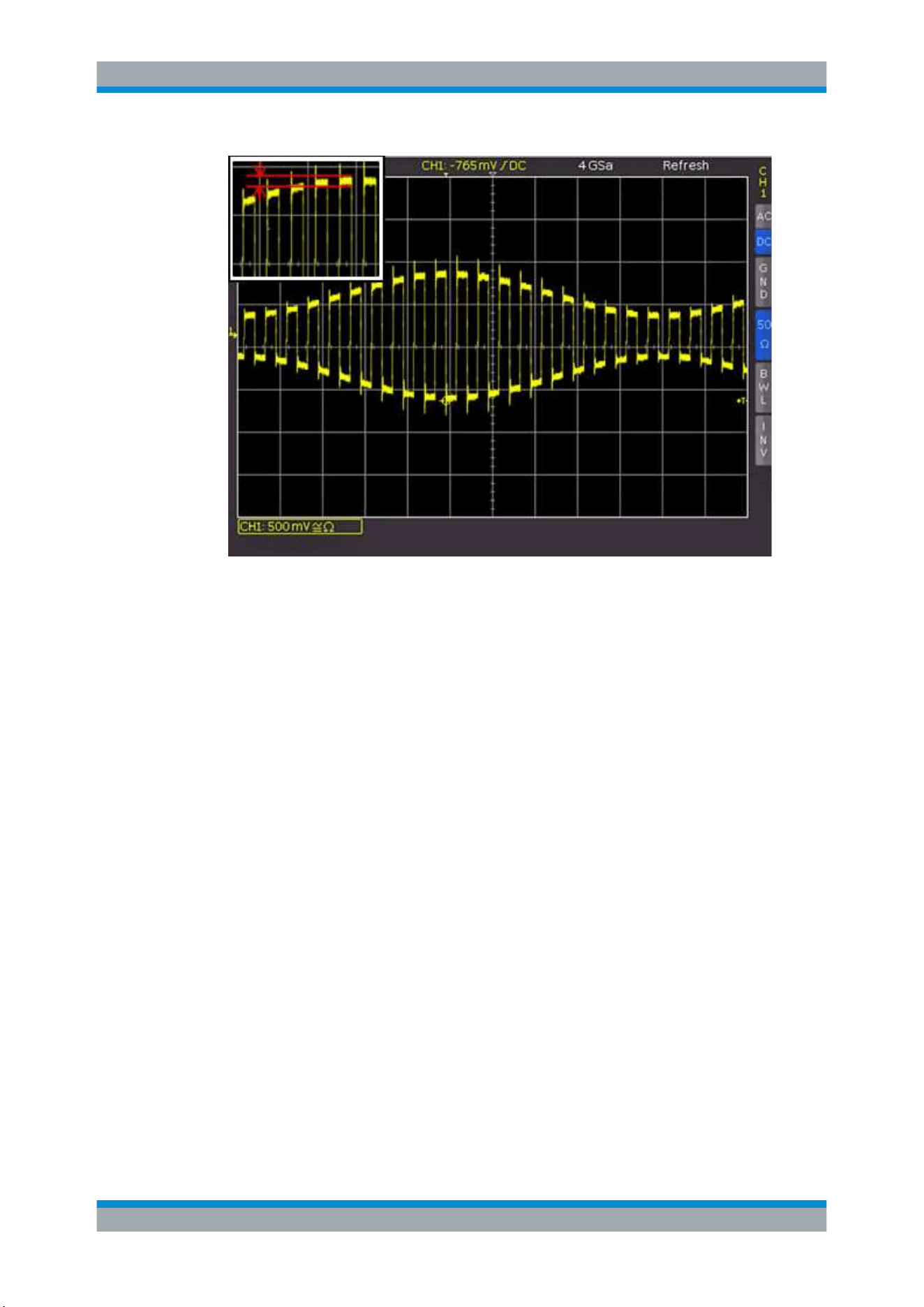
Figure 4-4: AM modulated signal with maximum repeat rate
MAX. SA. RATE
The instrument sets the maximum sampling rate while using the maximum memory
available. Thus, it displays the maximum amount of data. Each column in the signal
window displays up to 40 detected data values (limited by processor performance).
How much data is displayed depends on the displayed time window and the current
sampling rate. If peak detection is activated, each column displays up to 20 pairs of
min/max values. The memory depth always corresponds to the maximum acquisition
memory. The displayed sampling rate is identical with the current sampling rate. Peak
detection is used if the displayed time window contains more data than 40 * signal win-
dow columns in the acquisition memory or min/max data in the acquisition memory.
If the maximum sampling rate is selected, the entire oscilloscope memory can only be
read out in "STOP" mode.
Acquisition Setup
Waveform Setup
R&S
®
RTC1000
44User Manual 1335.7352.02 ─ 04
Figure 4-5: Example figure of AM modulated signal with max. sampling rate
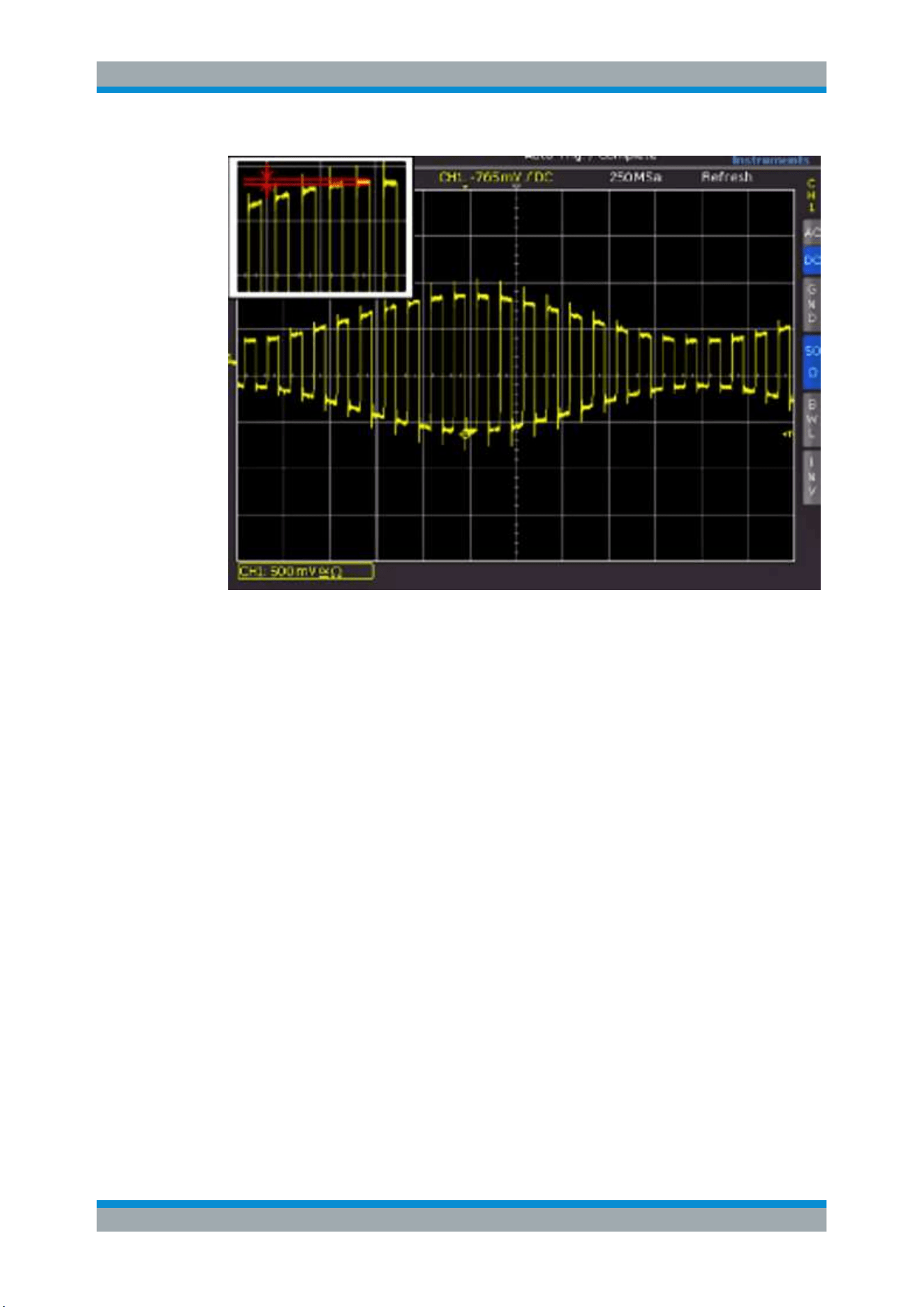
AUTOMATIC
"AUTOMATIC" is the default setting and offers the best compromise between maxi-
mum repeat rate and maximum sampling rate (selection of memory depth). Each col-
umn in the signal window displays up to 10 captured data values. How much data is
displayed depends on the displayed time window and the current sampling rate. When
peak detection is activated, each column displays up to 5 pairs of min/max values. The
memory depth is at least twice as much as the storage capacity set for the maximum
repeat rate (limited by the maximum acquisition memory). The displayed sampling rate
corresponds to the current sampling rate divided by the amount of data skipped while
loading from the acquisition memory. If peak detection is activated, the displayed sam-
pling rate corresponds to the current sampling rate.
Acquisition Setup
Waveform Setup
R&S
®
RTC1000
45User Manual 1335.7352.02 ─ 04
Figure 4-6: Example figure of AM modulated signal with automatic setting
4.3.3.1 Comparison of Record Modes
In all record modes, the sampling rate used to write to the acquisition memory is the
same. In "STOP" mode, it is also possible to change menu items. Changing the record
mode does not impact the current memory depth but the amount of displayed data is
adjusted. Peak detection is also activated in "STOP" mode. If the time base allows of
the display of each sample point, all three settings behave identically (except used
memory depth and signal update rate). Advantages and disadvantages of the record
modes are listed in
Table 4-1.
The record mode menu replaces the adjustable memory depth, a standard for other
oscilloscopes. An adjustable memory depth requires that users understand the relation
between memory depth, time base and sampling rate and to evaluate advantages and
disadvantages. With the record mode menu, the oscilloscope always captures signals
with the maximum sampling rate. Zoom in and zoom out in stop mode is always possi-
ble.
Acquisition Setup

Waveform Setup
R&S
®
RTC1000
46User Manual 1335.7352.02 ─ 04
Table 4-1: Advantages and disadvantages of record modes
Setting Advantages Disadvantages Application
Maximum
waveform
rate
●
Many captures in one image
●
Rare events can be detected more
quickly in connection with persis-
tence
●
Quick response to operation or
change in signal
●
Low noise band
●
High aliasing risk
●
Low accuracy of details
●
Low accuracy of measurements due
to reduced amount of data
●
Search for rare events
●
Displaying modulated
signals
Maximum
sample rate
●
Maximum accuracy of details
●
Lowest aliasing risk
●
High accuracy of measurements
●
Slow response to operation or
change in signal
●
Low signal update rate
●
Higher visibility of noise
●
For signals with high
frequency parts
●
Assessment of small
signal details
Automatic
●
Average signal update rate
●
Reasonable smooth operation
●
Good accuracy of measurements
●
Low noise band
●
Aliasing is possible
●
Default application
4.3.4 Interlace Mode
In interlace mode, only one channel is active, and the ADC and storage of two chan-
nels are connected. This connection doubles the sampling rate and the acquisition
memory. A channel is also considered active if it is deactivated but serving as the trig-
ger source.
The interlace mode is activated automatically if the following conditions are met:
●
No logic probe is active
●
No serial or parallel bus is active
●
Logic trigger is not used
Acquisition Setup

Trigger
R&S
®
RTC1000
47User Manual 1335.7352.02 ─ 04
5 Trigger
Triggering means to capture the interesting part of the relevant waveforms. Choosing
the right trigger type and configuring all trigger settings correctly allows you to detect
various incidents in signals.
A trigger occurs if the trigger conditions are fulfilled. The instrument acquires continu-
ously and keeps the sample points to fill the pretrigger part of the waveform record.
When the trigger occurs, the instrument continues acquisition until the posttrigger part
of the waveform record is filled. Then it stops acquiring and displays the waveform.
When a trigger is recognized, the instrument does not accept another trigger until the
acquisition is complete.
Trigger conditions include:
●
Source of the trigger signal (channel)
●
Trigger type and its filter setup
●
Trigger mode
In addition, the trigger position and the reference point are important to display the
interesting part of the signal. See
Chapter 4.2, "Horizontal Setup", on page 39.
The trigger level and position are marked in the grid. The markers have the color of the
trigger source. Information on the most important trigger settings is shown above the
grid, in the middle of the information bar.
5.1 Setting Up the Trigger
1. To activate the normal trigger mode, press the [AUTO/NORM] key.
A red LED highlights the key if normal mode is active.
2. To select the trigger source:
a) Press the [SOURCE] key.
b) Select the trigger source in the menu.
3. To configure the trigger type:
a) Press the [TYPE] key.
b) Select the trigger type.
c) Press the [FILTER] key.
d) Define the trigger condition.
4. To define the hold-off time:
a) Press the [TYPE] key.
b) Press the "HOLD OFF" softkey to enable the hold-off.
c) Turn the universal knob in the Cursour/Menu section to adjust the value.
Setting Up the Trigger

Trigger
R&S
®
RTC1000
48User Manual 1335.7352.02 ─ 04
5.2 General Trigger Settings
The keys in the Trigger section provide all functions to set up the trigger.
[AUTO/NORM] trigger modes
Sets the trigger mode. The Trigg'd LED lights up if the instrument found a trigger event.
"AUTO"
In "AUTO" mode, the screen always displays a signal. If a signal ful-
fills the trigger conditions, the oscilloscope synchronizes with this
event and triggers when the condition is met. If a signal that does not
fulfill the trigger condition, the oscilloscope generates a trigger event.
With auto mode, you can see the input signals at any time, regardless
of the trigger condition.
"NORMAL"
In "NORMAL" mode, the signal is displayed if the trigger condition is
met. The instrument shows the signal that was triggered last. If no
trigger occurs, no waveform is acquired and the last triggered wave-
form is displayed. If no waveform was captured before, nothing is dis-
played.
[SINGLE]
To ensure that only a signal that meets the trigger condition is detected and displayed,
press the [SINGLE] key. The key is highlighted in white when the SINGLE mode is
active. In normal trigger mode, the trigger system is now activated, and the [RUN/
STOP] key is blinking. If the trigger condition is fulfilled, the instrument triggers, data is
stored and displayed, and the oscilloscope switches to "STOP" mode (red [RUN/
STOP] key.
[Type]
Opens a menu to select the trigger type, and to set the hold-off time.
The following trigger types are available:
●
Chapter 5.3, "Edge Trigger", on page 49
●
Chapter 5.4, "Pulse Trigger", on page 51
●
Chapter 5.5, "Logic Trigger", on page 52
●
Chapter 5.6, "Video Trigger", on page 55
●
Serial trigger if at least one of the protocol options R&S RTC-K1, R&S RTC-K2, or
R&S RTC-K3 is installed.
HOLD OFF
The trigger hold-off time indicates how long the oscilloscope waits after a trigger event
until the trigger system is ready again. The next trigger occurs only after the hold-off
time has passed. Hold-off helps to obtain stable triggering when the oscilloscope is
triggering on unwanted events. Changing the time base does not impact the selected
hold-off time.
The hold-off time is set in the "Trigger Type" menu.
[SOURCE]
Opens a menu to set the trigger source. You can trigger on:
General Trigger Settings

Trigger
R&S
®
RTC1000
49User Manual 1335.7352.02 ─ 04
●
An analog channel.
●
A digital channel if option R&S RTC-B1 is installed.
●
The power supply frequency ("AC LINE"). The trigger signal is extracted internally
from the power supply.
●
An external signal that is connected to the external trigger input. Select the cou-
pling of the trigger signal: AC or DC.
[SLOPE]
Selects the slope for the edge trigger, or the polarity for the pulse trigger. The selection
is indicated by the Slope LEDs.
[FILTER]
Opens a menu to set up the trigger condition for the selected trigger type.
5.3 Edge Trigger
The edge trigger is the most common trigger type. The trigger occurs when the signal
of the trigger source passes the trigger level in the specified direction (slope).
1. Select [TYPE] > "EDGE".
2. To set the slope, press the [SLOPE] key repeatedly.
The selected slope is shown above the key, and on top of the grid in the display.
3. To set the trigger level, turn the [Level] knob.
4. Select [FILTER].
The [FILTER] settings select how to couple the signal for the trigger circuit.
Edge Trigger
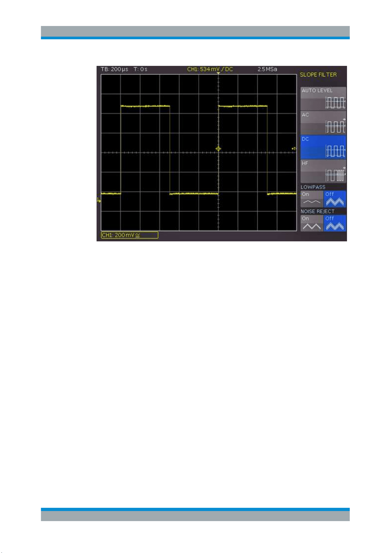
Trigger
R&S
®
RTC1000
50User Manual 1335.7352.02 ─ 04
AUTO LEVEL
Automatic filter setting (default setting).
AC
The trigger signal is coupled through a 5 Hz high-pass filter which suppresses the DC
portion of the trigger signal. With a changing DC portion, the trigger level remains at
the set point in the AC signal.
DC
The trigger signal is coupled to the trigger circuit with all signal portions (AC and DC
voltage).
HF
The trigger signal is coupled through a high-pass filter with a minimum cut-off fre-
quency (-3 dB) of 30 kHz. Use this coupling type only with high frequency signals.
LOWPASS
The trigger signal is coupled through a low-pass filter with an upper cut-off frequency of
5 kHz. This filter removes higher frequencies and is available with AC and DC cou-
pling.
NOISE REJECT
A low-pass filter with a cut-off frequency of 100 MHz improves the noise performance
for the trigger amplifier. This filter removes higher frequencies and is available with AC
and DC coupling.
Note: The coupling types "LOWPASS" and "NOISE REJECT" cannot be activated
simultaneously.
Edge Trigger
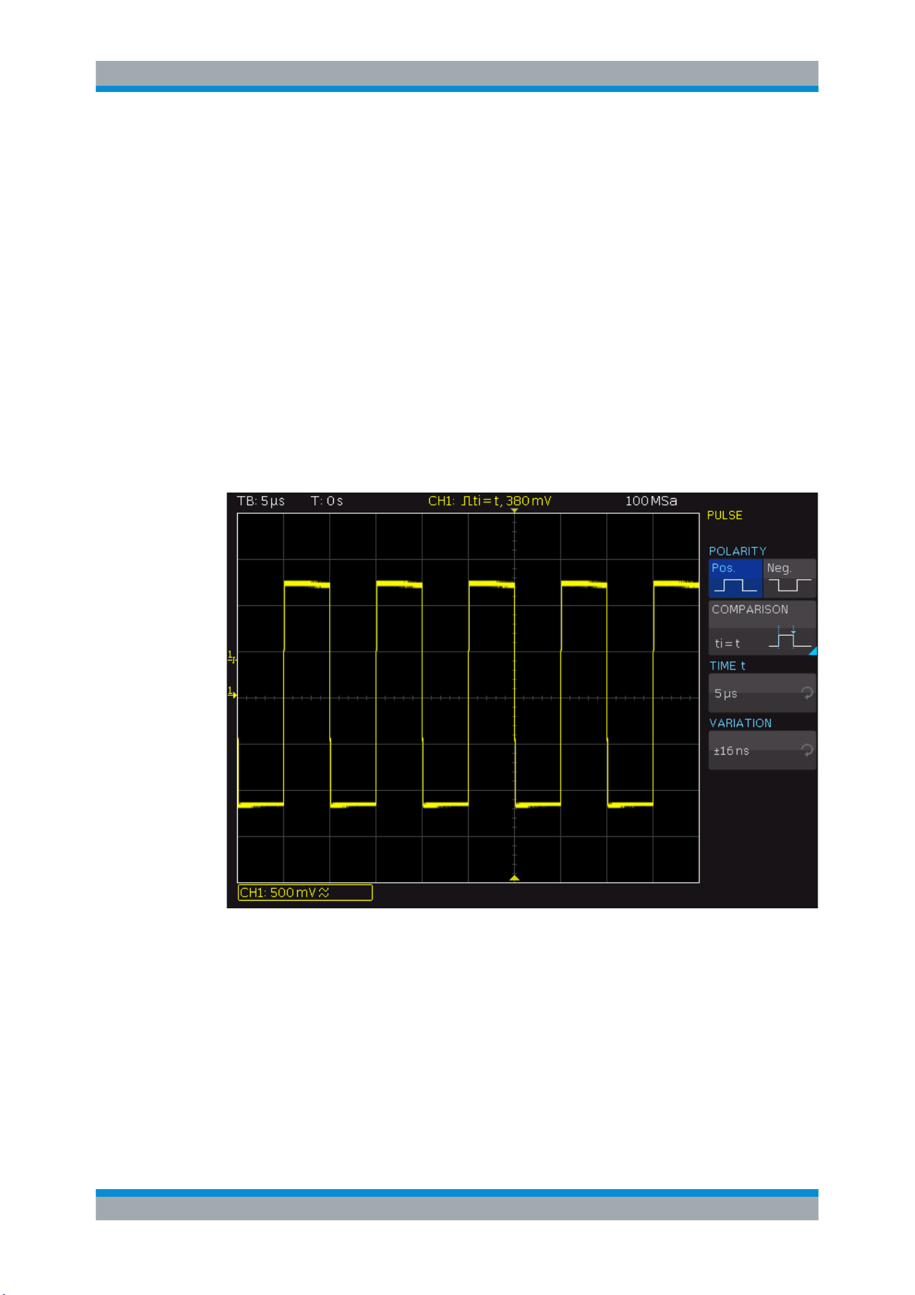
Trigger
R&S
®
RTC1000
51User Manual 1335.7352.02 ─ 04
5.4 Pulse Trigger
The pulse trigger finds specific pulse widths of positive or negative pulses or on pulse
width ranges. If a pulse on the trigger source fulfills the trigger condition, the oscillo-
scope triggers on the trailing slope. For a positive pulse, it triggers on the falling slope,
and for a negative pulse on a rising slope.
1. Select [TYPE] > "PULSE".
2. To set the polarity, press the [SLOPE] key repeatedly.
The selected polarity is shown above the key, and on top of the grid in the display.
3. To set the trigger level, turn the [Level] knob.
4. Select [FILTER].
The filter settings define the pulse direction and length for the pulse trigger:
TIME t, TIME t
1
,TIME t
2
, VARIATION
Set the reference pulse length depending on the selected comparison.
The comparison time can be set between 16 ns to 10s. For values up to 1 ms, the res-
olution is 2 ns. and for any value greater than 1 ms the resolution is 1 μs.
The deviation can be set from ±8 ns up to 657.5 μs with a resolution of 8 ns.
Pulse Trigger

Trigger
R&S
®
RTC1000
52User Manual 1335.7352.02 ─ 04
POLARITY
Sets the polarity, alternatively to the [SLOPE] key. For positive pulses, you define the
width from rising to falling slopes, and accordingly for negative pulses from falling to
rising slopes. Consequently, the trigger always occurs on the second slope of the
pulse.
COMPARISON
Sets how the measured pulse width is compared with the given limits.
"t
i
> t"
Triggers on pulses longer than the reference time t.
"t
i
< t"
Triggers on pulses shorter than the reference time t.
"t
i
= t"
Triggers on pulses equal to the reference time t. The reference time is
a combination of time t plus the deviation.
"t
i
≠ t"
Triggers on pulses unequal to the reference time t. The reference
time is a combination of time t plus the deviation.
"t
1
< t
i
< t
2
"
Triggers on pulses shorter than the reference time t
2
and longer than
the reference time t
1
.
"Not(t
1
< t
i
<
t
2
)"
Triggers on pulses longer than the reference time t
2
and shorter than
the reference time t
1
.
5.5 Logic Trigger
Using the logic trigger (also known as pattern trigger), you can trigger on any logic
combination of active input channels. The logic trigger supports you in verifying the
operation of digital logic when MSO option R&S RTC-B1 is installed.
You can also set a time limitation to the pattern. Thus you can trigger on bus patterns
of parallel buses.
You can test all settings in the logic trigger without connecting the logic probe.
Before you set up the logic trigger, make sure that the thresholds are set correctly.
●
Analog channels: in the "Channel" > "Threshold" menu, see
"THRESHOLD menu"
on page 36.
●
Logic channels: in the "LOGIC POD" menu, see
The pattern is configured in the "SOURCE" menu. The time limitation is configured in
the "FILTER" menu.
5.5.1 Logic Pattern
In the "SOURCE" menu, you define the logic pattern. The configuration is shown in a
window.
1. Select [TYPE] > "LOGIC".
2. Press the [SOURCE] key.
Logic Trigger
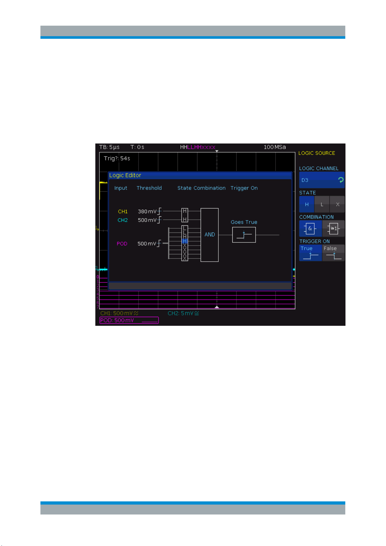
Trigger
R&S
®
RTC1000
53User Manual 1335.7352.02 ─ 04
3. Turn the Universal knob to select the "LOGIC CHANNEL" for which you want to set
the logic state.
4. Press "STATE" repeatedly until the required state is selected.
5. Repeat steps 3 and 4 for each channel of the pattern.
6. Select the logic "COMBINATION" of the channels.
7. Select whether you want to trigger on the true or false pattern: "TRIGGER ON".
Figure 5-1: Logic trigger pattern setup
LOGIC CHANNEL
Selects the channel for which you want to set the logic state. The setting is always
active.
STATE
Selects the channel state: high ("H"), low ("L") or don't care ("X").
COMBINATION
Sets the logic combination of the channels:
"AND"
The states of all channels must be met simultaneously to produce a
logic high ("H", true) as a result.
"OR"
At least one of the defined states must be met to produce a logic high
("H", true) as a result.
Logic Trigger
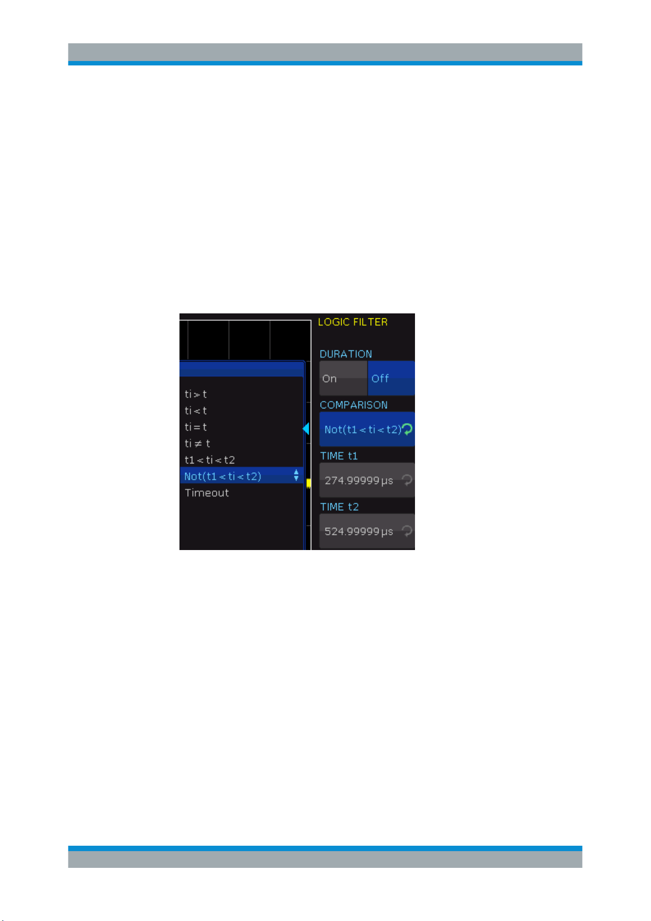
Trigger
R&S
®
RTC1000
54User Manual 1335.7352.02 ─ 04
TRIGGER ON
Selects whether the trigger is generated at the beginning ("TRUE") or the end of the
fulfilled logic condition ("FALSE").
5.5.2 Time Limitation
To set a time limitation for the pattern, you have several possibilities. They are similar
to the setting of a pulse width, see
Chapter 5.4, "Pulse Trigger", on page 51.
1. Select [TYPE] > "LOGIC".
2. Press the [FILTER] key.
3. To enable the time limit, press "DURATION".
4. Set the "COMPARISON" and the reference "TIME t".
The following settings are possible:
● "Timeout" and "TIME t".
Define a minimum time during which the signals match the pattern condition.
● "ti > t" or "ti < t" and "TIME t"
Triggers if the pattern condition changes before or after the specified time.
● "ti = t", "TIME t" and "Variation":
Triggers if the pattern condition is fulfilled for a duration time t ± variation.
● "ti ≠ t", "TIME t" and "Variation":
Triggers if the pattern condition is fulfilled for a duration shorter than time t -
variation, or longer than time t + variation.
● "t1 < ti < t2", "TIME t1" and "TIME t2"
Triggers if the pattern condition is fulfilled for a duration between time t1 and
time t2. These settings are an alternative setting to the definition with "Width ="
and variation. The time values are interdependent and adjusted accordingly.
● "Not(t1 < ti < t2)", "TIME t1" and "TIME t2"
Logic Trigger
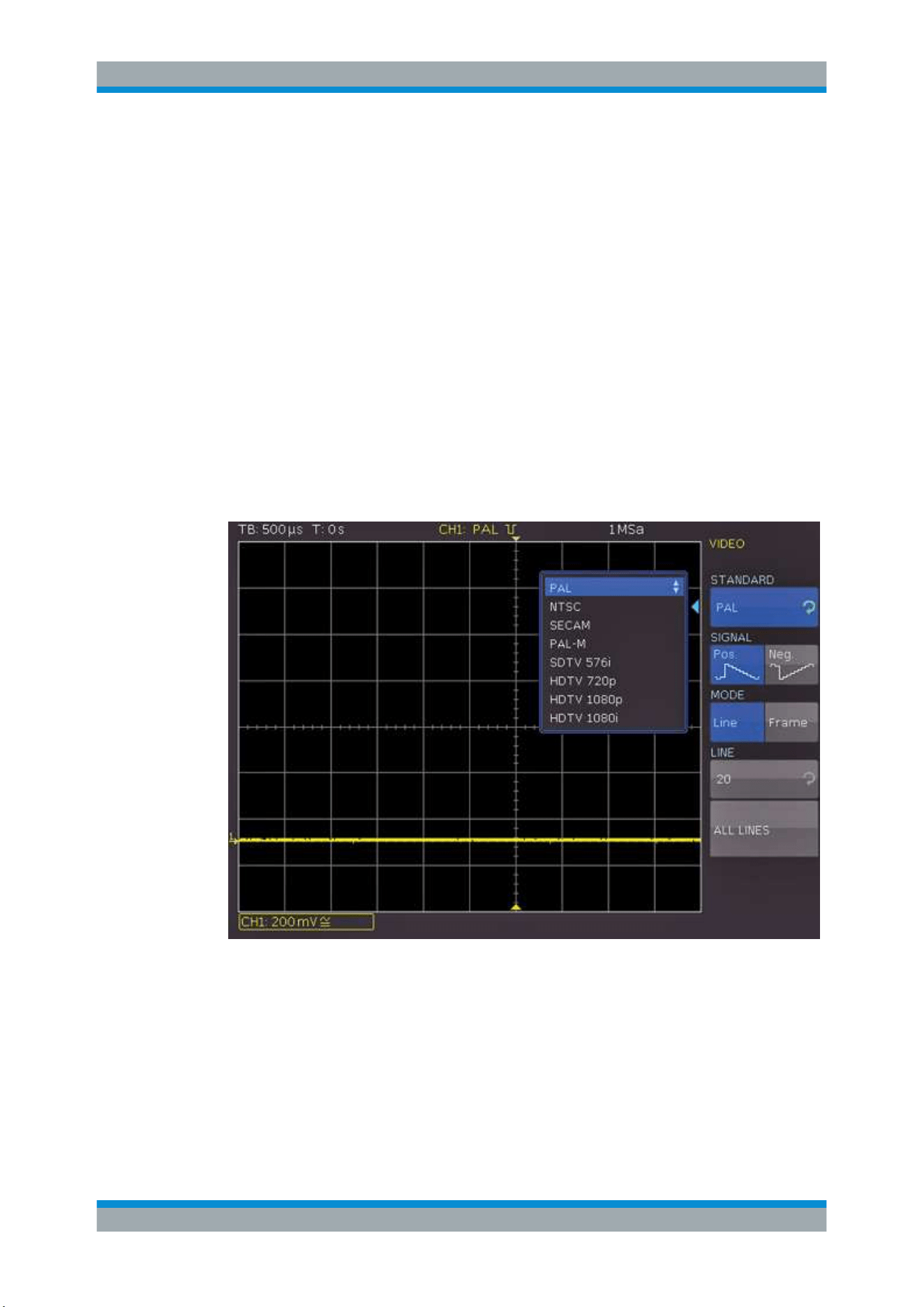
Trigger
R&S
®
RTC1000
55User Manual 1335.7352.02 ─ 04
Triggers if the pattern condition is fulfilled for a duration shorter than time t1 t1",
or longer than time t2. These settings are an alternative setting to the definition
with "Width =" and variation. The time values are interdependent and adjusted
accordingly.
5.6 Video Trigger
The video or TV trigger is used to analyze analog baseband video signals. You can
trigger on baseband video signals from standard definition and high definition stand-
ards connected to an analog channel input.
1. Select [TYPE] > "VIDEO".
2. Select [FILTER].
The following settings can be selected in the video filter menu:
Figure 5-2: Video trigger menu
STANDARD
Selects the television standard.
●
PAL
●
NTCS
●
SECAM
●
PAL-M
●
SDTV 576i Interlaced
Video Trigger

Trigger
R&S
®
RTC1000
56User Manual 1335.7352.02 ─ 04
●
HDTV 720p Progressive
●
HDTV 1080p Progressive
●
HDTV 1080i Interlaced
SIGNAL
Selects the polarity of the sync pulse (positive or negative). With positive video modu-
lation, when the highest brightness is represented by the maximum signal voltage in
the image ), the synchronization pulses are negative. If the modulation is negative,
sync pulses are positive. The edges of the sync pulses are used for triggering, there-
fore incorrect polarity setting causes a sporadic triggering by the video information.
MODE
Selects line or frame triggering.
"LINE"
Triggers on the start of video lines. You can define the exact line
between 1 and 625, or trigger on all lines.
"FRAME"
Triggers on the start of half frames, either on odd or on even half
frames.
5.7 Trigger Out Pulses
You can output a pulse for each trigger event at the [AUX OUT] connector for each trig-
ger event, thus issuing the trigger frequency.
1. Press the [UTIL] key in the Vertical section of the control panel.
2. On page 2|2, select "ACQ. TRIGGER EV.".
5.8 External Trigger Input
You can use an external trigger signal, for example, for CS (chip select) of a SPI BUS.
The external trigger signal is displayed as green line.
1. Press the [POD] key.
2. To activate the external trigger, press the "EXT" softkey.
3. Press the [MENU] key in the Vertical section.
4. Press the "EXT. THRESHOLD" softkey and adjust the threshold for the external
trigger signal
External Trigger Input
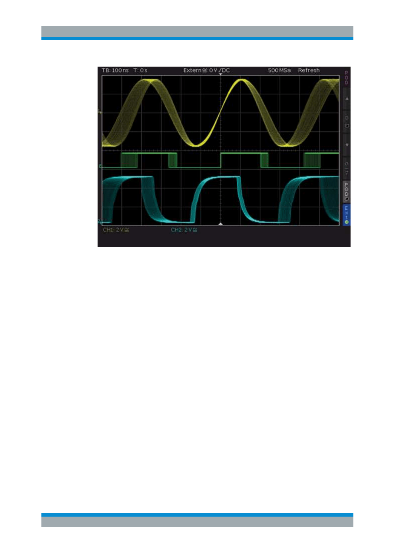
Trigger
R&S
®
RTC1000
57User Manual 1335.7352.02 ─ 04
Figure 5-3: External trigger signal
External Trigger Input

Analysis
R&S
®
RTC1000
58User Manual 1335.7352.02 ─ 04
6 Analysis
The R&S RTC1000 features various functions to analyze waveforms on the display.
●
Zoom Function........................................................................................................ 58
●
Marker Function...................................................................................................... 60
●
XY-Display...............................................................................................................62
●
Mathematics............................................................................................................63
●
Frequency Analysis (FFT).......................................................................................71
●
Pass/Fail Test Based on Masks.............................................................................. 75
●
Component Test......................................................................................................77
●
Digital Voltmeter...................................................................................................... 81
6.1 Zoom Function
The R&S RTC1000 features a memory depth of 1 MSa (2 MSa in interlaced mode).
Thus, the instrument can record long and complex signals. To analyze these records in
detail, use the zoom function.
► Press the [ZOOM] key in the Horizontal section.
The screen is divided into two windows. The upper window displays the entire time
base window. The lower window is the zoom window, it shows an enlarged section of
the upper window. The enlarged section is marked by two cursors in the upper window.
If several channels are active, all displayed channels are zoomed simultaneously by
the same factor and at the identical position.
Zoom Function
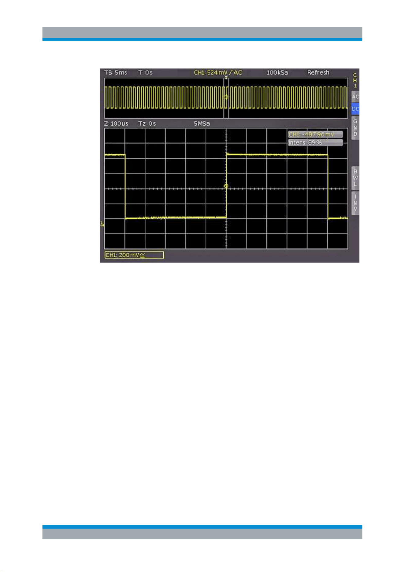
Analysis
R&S
®
RTC1000
59User Manual 1335.7352.02 ─ 04
Figure 6-1: Zoom window with 100
μ
s per division, the zoomed time window is 12
ms
Above the zoom window, you see the zoom time base "Z" (zoom factor), which deter-
mines the width of the zoom area (12 divisions x scaling per division). "Tz" indicates
the zoom time and determines the position of the zoom area. The time base setting of
the upper window is shown in gray, while the zoom time base is marked in white.
To adjust the zoom settings
1. If the zoom time base is marked in white, the zoom window is active. Turn the
[Scale] knob in the Horizontal section to change the zoom time base "Z".
2. To move the position of the zoomed section "Tz", turn the [Position] knob in the
Horizontal area.
To set the time base in the upper window
1. Press the [Scale] knob in the Horizontal section.
Now, the time base setting is highlighted in white and the zoom time base in gray.
The upper window is active.
2. Turn the [Scale] knob in the Horizontal section to change the time base of the origi-
nal waveform "TB".
3. To move the trigger position, turn the [Position] knob in the Horizontal area.
The zoom function is not available in roll mode because the signal values of the X axis
are always captured with the maximum memory depth. The acquisition mode "NOR-
Zoom Function

Analysis
R&S
®
RTC1000
60User Manual 1335.7352.02 ─ 04
MAL" always stores more samples in the memory than what can be shown in the dis-
play. That explains that you can zoom in the signal using the memory data. The values
in the Y axis (amplitude) can be scaled also in roll mode because they apply to a speci-
fied axis.
6.2 Marker Function
Markers allow you to highlight specific positions on the screen, e.g. a rising or falling
slope, an unexpected signal value, or a search result. You can use the markers to iden-
tify areas of interest you want to zoom into, and quickly move through the data. You
can set up to 8 time markers.
To set markers:
1. Press the [MENU] key in the Horizontal section.
2. Press the upper softkey to select "Marker".
The "Marker" menu is shown.
3. Press the [SET/CLR] key to set a time marker at the 6th division. This position is
the center of the grid if menus are closed.
The time markers is a vertical line in gray-blue.
4. To move the signal including the set marker, turn the [Position] knob in the Horizon-
tal section.
5. Identify an important signal position and set it to the center of the screen.
6. Press the [SET/CLR] key to set the marker to the identified position.
Marker Function
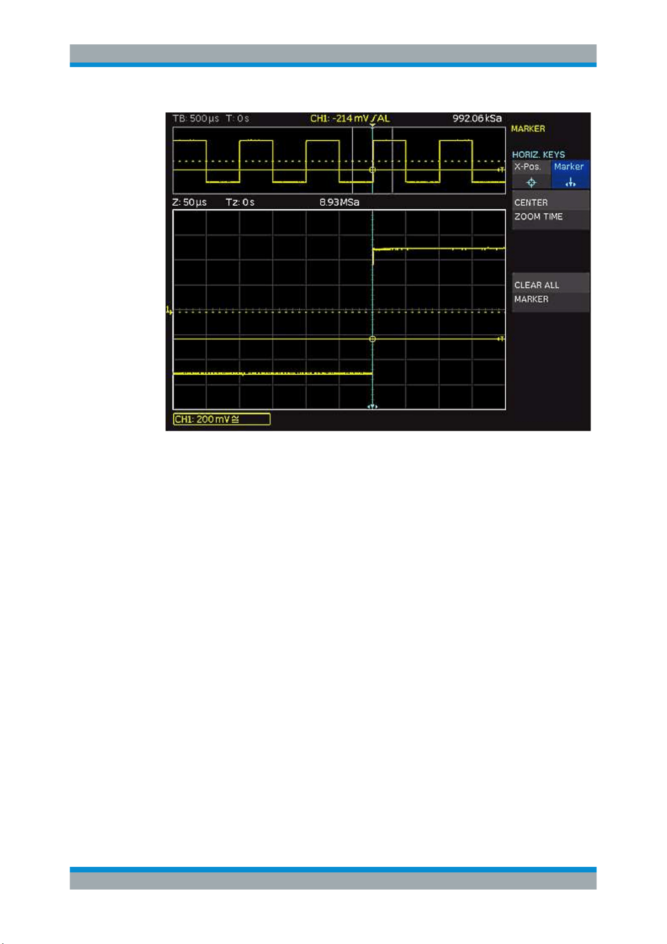
Analysis
R&S
®
RTC1000
61User Manual 1335.7352.02 ─ 04
Figure 6-2: Marker in zoom mode
1. To toggle markers, use the [ARROW] keys. The selected marker is set to the cen-
ter of the screen.
Thus, you can quickly compare marked signal sections in zoom mode.
2. To delete a marker, set it to the center of the screen. Press [SET/CLR].
The marker menu provides more functions.
Marker Function
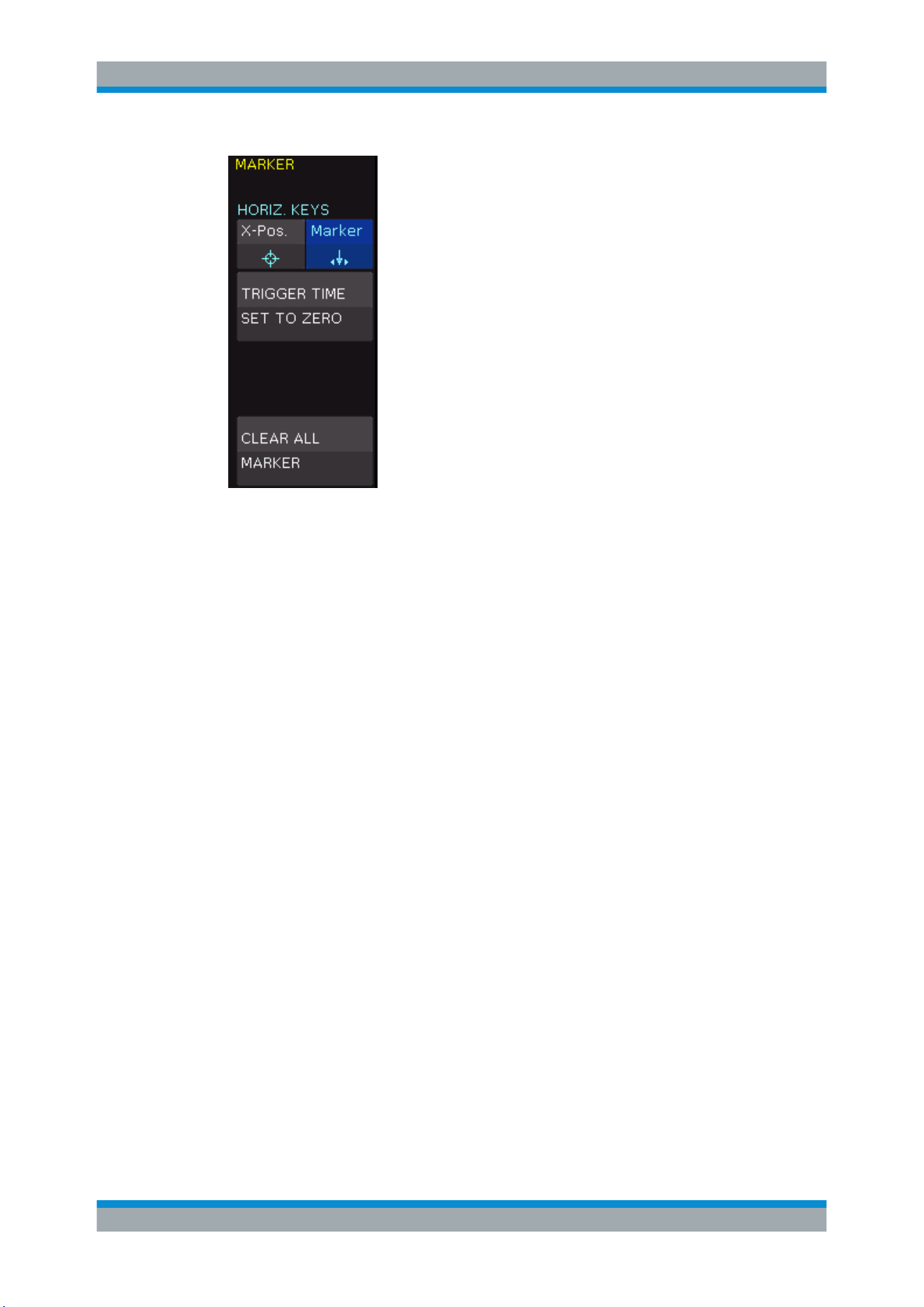
Analysis
R&S
®
RTC1000
62User Manual 1335.7352.02 ─ 04
Figure 6-3: Marker menu
TRIGGER TIME SET TO ZERO
Sets the trigger time to 0 s.
CLEAR ALL MARKER
Deletes all defined time markers.
6.3 XY-Display
The XY-display combines the voltage levels of two waveforms in one diagram. The
voltage level of the first signal is displayed in y-direction, and the voltage level of a sec-
ond signal in x-direction. In other words, the time base x is replaced by amplitude val-
ues of a second source.
The resulting XY-display for harmonic signals is known as Lissajous figures. They are
used to analyze frequency and phase position for the two signals, and to measure the
phase shift. If the frequencies are nearly identical, the figure rotates. If the frequencies
are identical, the figure stands still and the phase position can be deduced from its
shape.
1. Activate both analog channels.
2. Press the [UTIL] key in the Vertical section.
3. On menu page 2|2, press "XY".
4. Assign the channels to the axis.
XY-Display
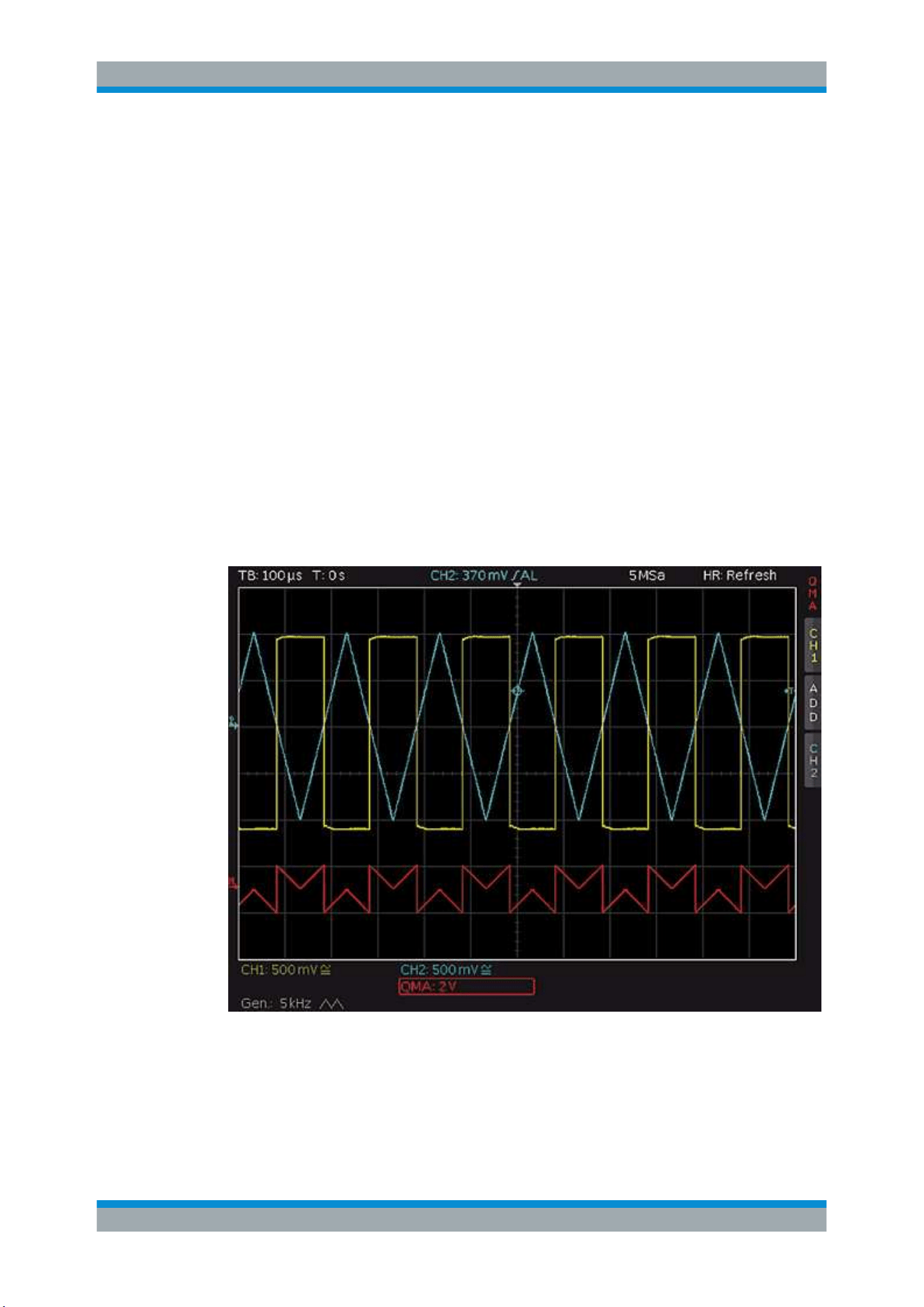
Analysis
R&S
®
RTC1000
63User Manual 1335.7352.02 ─ 04
The display shows one large and two small diagrams. The large diagram shows
the XY-display. The small diagrams show the sources for X and Y, the normal sig-
nal display as Y vs. time.
6.4 Mathematics
Math waveforms are calculated waveforms. The R&S RTC1000 provides two methods
to use mathematics:
●
With the Quick Mathematics (QM) function, you can create one math waveform
with basic mathematical operators on channel 1 and channel 2.
●
Using the advanced mathematics (MA), you can create up to five formulary sets.
Each formulary set can include up to five equations. Equations provide more oper-
ators and more sources than the Quick Mathematics. Formulary sets can be saved
and loaded for further use.
Mathematical functions track the changes of the source signals. They apply to the visi-
ble area of the screen. If a signal is cut off at the edge of the screen, the corresponding
mathematical curve can also be truncated.
Figure 6-4: Example of a mathematical waveform
► To scale a mathematic waveform:
a) Select the math waveform.
Mathematics
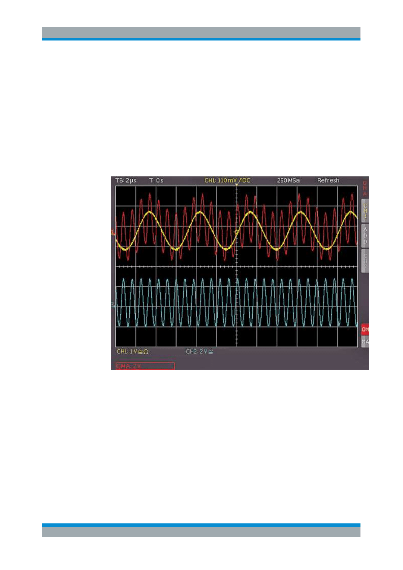
Analysis
R&S
®
RTC1000
64User Manual 1335.7352.02 ─ 04
b) Turn the [Scale] knob in the Vertical section.
6.4.1 Quick Mathematics (QM)
Quick mathematics create one math waveform with basic mathematical operators on
analog channels 1 and 2.
1. Press the [MATH] key in the Vertical section.
The short math menu opens.
2. Press the lowest softkey until "QM" is illuminated in red.
Figure 6-5: Quick Mathematics short menu
3. Configure the math function:
a) Press the upper softkey to choose the first operand (channel).
b) Press the second softkey to set the mathematical operation.
c) Press the third softkey to select the second operand (channel).
Tip: If you press the MENU key in the Vertical section, you see the complete menu.
The following mathematical operations can be selected:
Mathematics
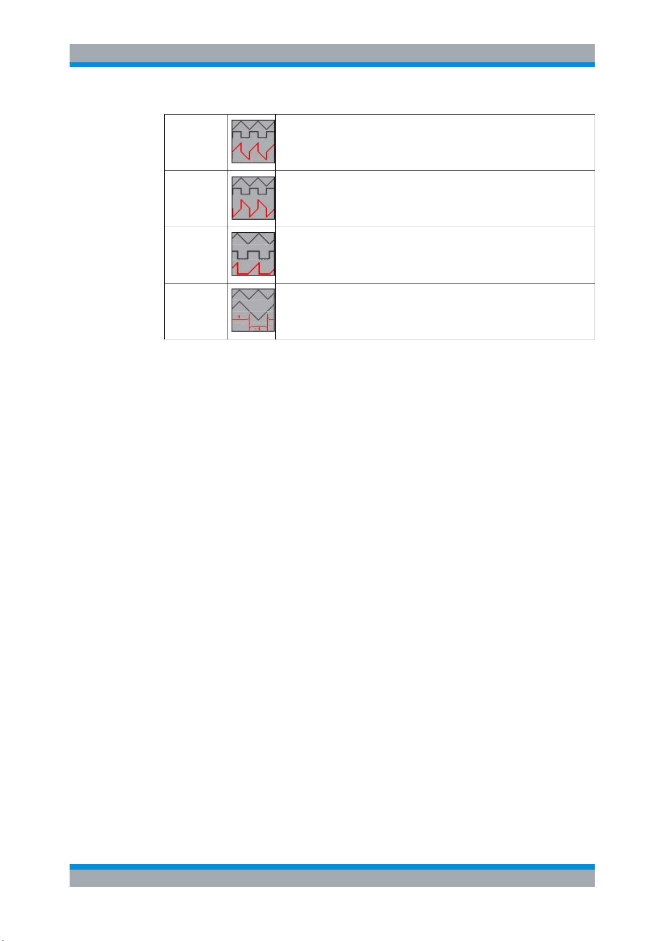
Analysis
R&S
®
RTC1000
65User Manual 1335.7352.02 ─ 04
ADD
Addition
SUB
Subtraction
MUL
Multiplication
DIV
Division
6.4.2 Advanced Mathematics
Using the advanced mathematics (MA), you can create up to five formulary sets. Each
formulary set can include up to five equations. Equations provide more operators and
more sources than the Quick Mathematics. Formulary sets can be saved and loaded
for further use.
6.4.2.1 To Create a Formulary Set and Its Equations
1. Press the [MATH] key in the VERTICAL section.
The math short menu opens.
2. Press the lowest softkey until "MA" is illuminated in red.
3. Press the [MENU] key in the Vertical control panel.
The mathematics menu opens to select the formulary set and edit the equations.
Mathematics
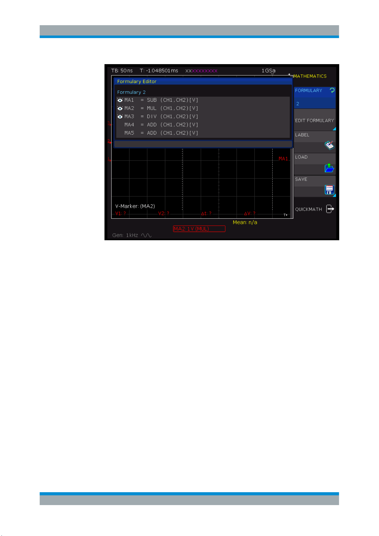
Analysis
R&S
®
RTC1000
66User Manual 1335.7352.02 ─ 04
Figure 6-6: Mathematics menu
4. To select a formulary set, turn the Universal knob in the Cursor/Menu section.
5. To open the equation menu, press "EDIT FORMULARY".
6. To select an equation, turn the Universal knob in the Cursor/Menu section.
7. To add an equation:
a) Use the Universal knob to select "new..." in the editor.
b) Press "ADD".
The new equation is added and can be edited.
8. To delete an equation from the formula set, press "DELETE".
6.4.2.2 To Edit Equations
If the equations are created, you define the mathematical calculation and the display
options.
1. In the "EDIT FORMULARY" menu, select the equation.
2. Press the "EDIT" softkey until "Display" is selected.
Mathematics
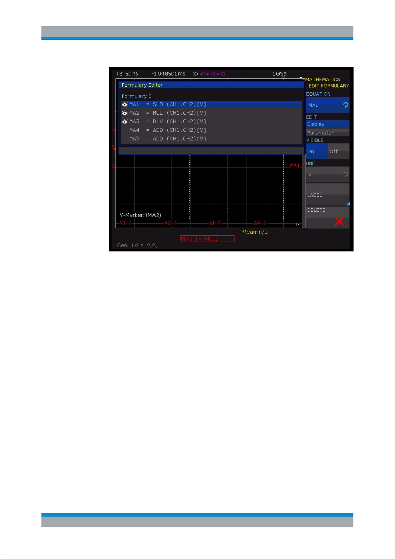
Analysis
R&S
®
RTC1000
67User Manual 1335.7352.02 ─ 04
Figure 6-7: Display settings for equations
3. To activate the equation, press "VISIBLE" until "On" is selected.
An active visible equation is marked by an eye symbol in the formula editor, and it
is listed in the short menu.
4. Press the "UNIT" softkey. Select the unit by using the Universal knob.
Various units for all usual calculations are available. The selected equation unit is
applied to the channel description, cursor types and automatic measurement types.
5. To change the equation name:
a) Press the "LABEL" softkey.
b) To select a predefined label, press "LIBRARY".
c) To define a label, press the "EDIT LABEL" softkey. Enter the label on the key-
pad.
The equation name is listed in the formula set editor. It is also shown in the dia-
gram instead of the generic labels "MA1" to "MA5".
6. Press the "EDIT" softkey until "Parameter" is selected.
Mathematics
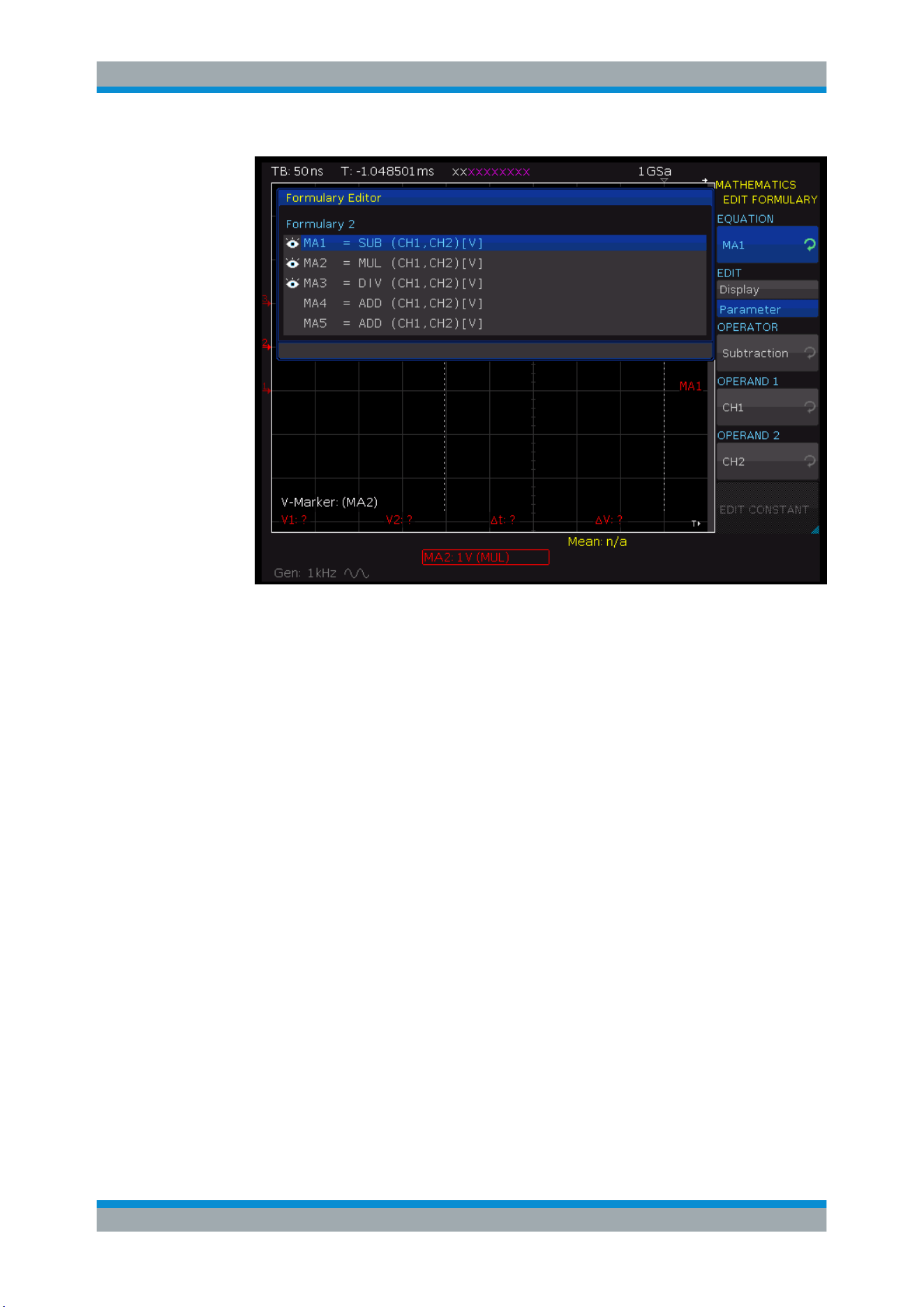
Analysis
R&S
®
RTC1000
68User Manual 1335.7352.02 ─ 04
Figure 6-8: Equation parameters (edit equation)
7. Press OPERATOR. Turn the Universal knob to select the operator.
8. To select the operands, press the "OPERAND" softkeys.
For each equation, the input channels CH1, CH2 and a constant are available as
operands (sources). For the formula MA2, MA1 is added as source, for MA3 the
additional sources are MA1 and MA2, for MA4 it is MA1, MA2 and MA3 and so on.
9. To set a constant, press "EDIT CONSTANT" and the [universal] knob in the CUR-
SOR/MENU section to choose one of the following constants:
You can:
● Select a predefined constant (π, 2*π, 0.5*π).
● Customize a constant:
– Select one of the constants "User: 1" to "User: 10".
– Press NUMERIC INPUT
– Press "VALUE". Use the Universal knob to select a numeric value.
– Press "DECIMAL POINT". Set the position of the decimal point.
– To enter an additional SI prefix, press "PREFIX".
– Select a "UNIT".
Mathematics
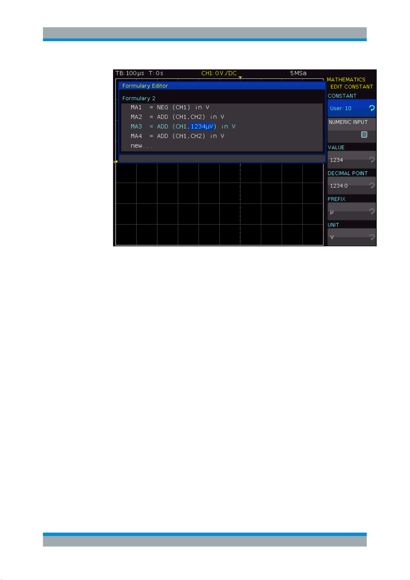
Analysis
R&S
®
RTC1000
69User Manual 1335.7352.02 ─ 04
Figure 6-9: Customize a constant
6.4.2.3 To Save and Load a Formulary Set
If all equations of a formulary set are defined, you can save the set.
1. Navigate to the "MATHEMATICS" menu.
2. Press "SAVE".
3. Save the formulary set:
a) Select the storage location with "STORAGE".
b) Enter the "FILE NAME".
c) Optionally, add a "COMMENT".
4. To use a saved formulary set, press "LOAD".
6.4.2.4 Example
This example shows the analysis of an electrical energy waveform. The voltage across
the load is measured with differential probe and applied to channel 2. The current is
measured with a current probe and applied to channel 1. Voltage is measured with an
active differential probe and applied to channel 2.
To define the equation CURRENT
1. Press "EDIT FORMULARY" to open formulary set 1.
2. Select equation "MA1".
Mathematics
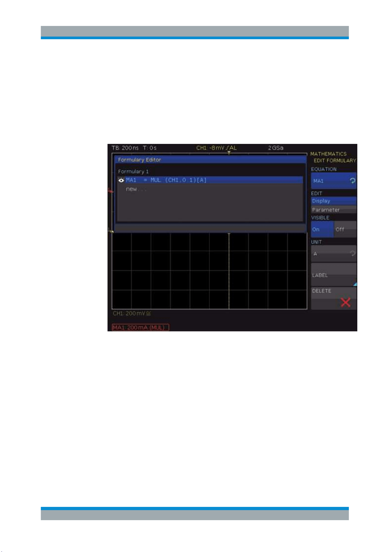
Analysis
R&S
®
RTC1000
70User Manual 1335.7352.02 ─ 04
3. Select "EDIT" = "Display".
4. Assign the unit "A" (Ampere) to the equation by pressing "UNIT".
5. Press "LABEL" and enter CURRENT.
6. Select "EDIT" = "Parameter".
7. Select "CH1" as "OPERAND 1" and "Const." as "OPERAND 2".
8. Press "EDIT CONSTANT" to define the constant: "NUMERIC INPUT" = 0.1.
Figure 6-10: Definition of the current equation
The correct scaling and the units for cursors and automatic measurements are
defined.
To define the POWER equation
1. Add a new equation "MA2" to formulary set 1.
2. Select "EDIT" = "Parameter".
3. Select "Multiplication" as "OPERATOR", "CURRENT" as "OPERAND 1" and "CH2"
as "OPERAND 2".
4. Select "EDIT" = "Display".
5. Assign the unit "W" (Watt) to the equation.
6. Press t"LABEL" and enter POWER.
Mathematics
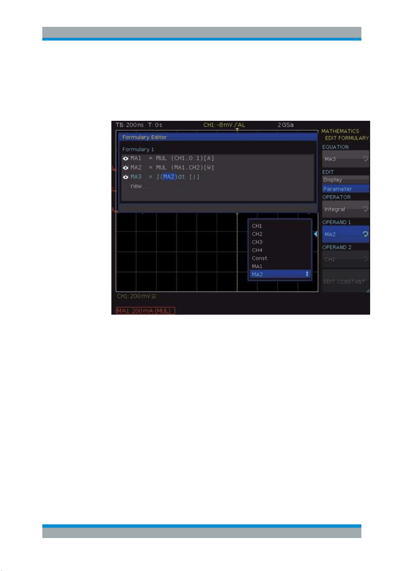
Analysis
R&S
®
RTC1000
71User Manual 1335.7352.02 ─ 04
To define the ENERGY equation
1. Add a third equation "MA3" to formulary set 1.
2. Select "EDIT" = "Parameter".
3. Choose "Integral" as "OPERATOR" and "POWER" as "OPERATOR 1".
Figure 6-11: Definition of the power equation
4. Select "EDIT" = "Display".
5. Assign the unit "J" (Joule) to the equation.
6. Press the softkey "LABEL" and enter ENERGY.
Now, all definitions are completed and the results can be displayed and analyzed. The
math analysis can be performed with cursor or automatic measurement functions. All
measurement results are correctly shown with correct units: Ampere, Watt, and Joule.
6.5 Frequency Analysis (FFT)
The fast Fourier transformation (FFT) in an oscilloscope works differently than in a
spectrum analyzer. The FFT calculation is affected by the time base setting, and by the
available number of used acquired data points. You can include up to 128k point in the
FFT. The FFT is not suitable for the analysis of slow signals (Hz-range).
Frequency Analysis (FFT)
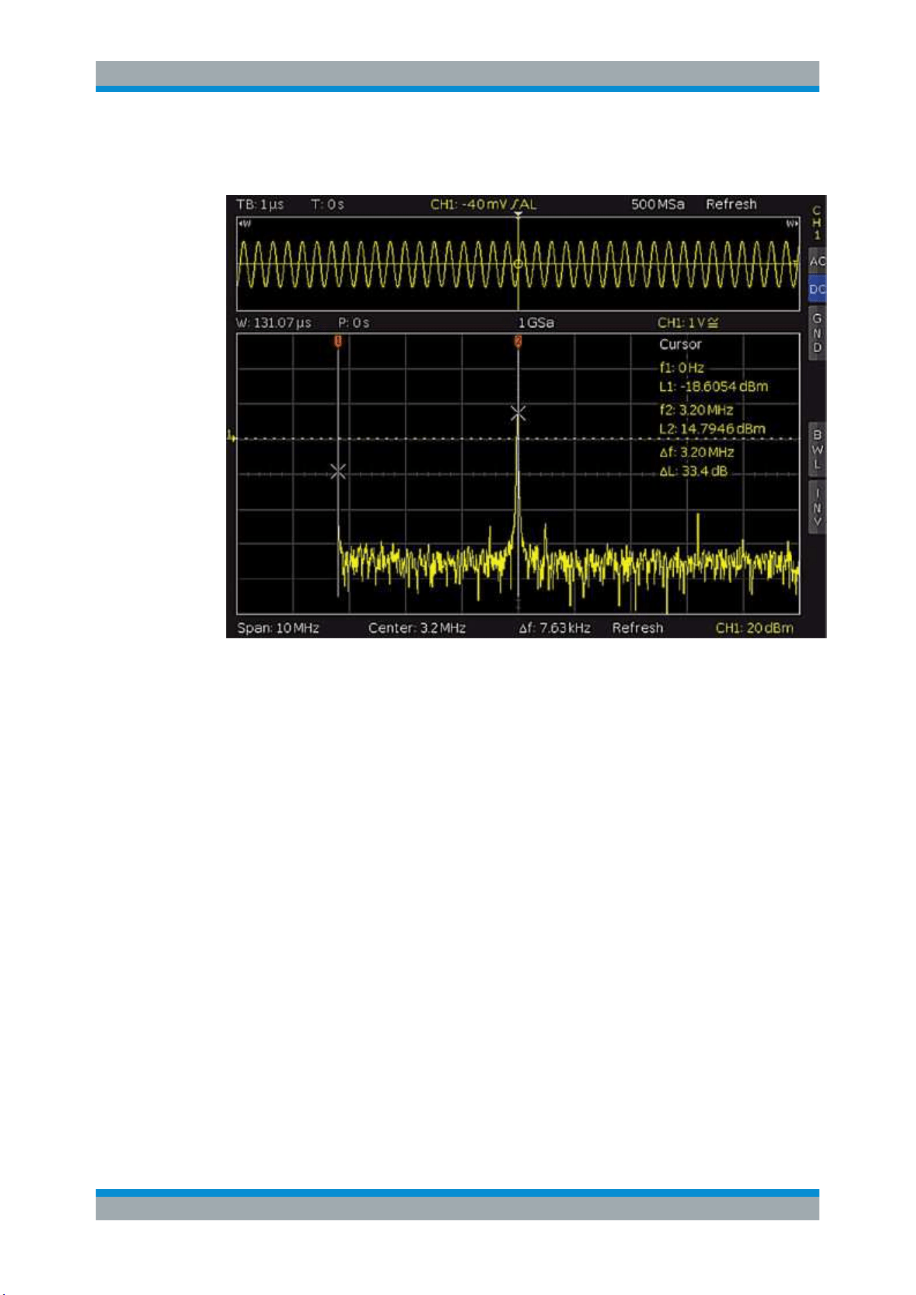
Analysis
R&S
®
RTC1000
72User Manual 1335.7352.02 ─ 04
► To start the FFT, press the [FFT] key in the Analysis section
Figure 6-12: FFT
In FFT mode, the screen is divided into two grids:
●
The upper grid shows the voltage vs time waveform. The time domain settings are
shown above the grid, on the left.
●
The area between the upper and the lower grid shows details about zoom and
position.
●
The lower, large grid shows the frequency domain with the most frequent frequen-
cies in the signal and the corresponding amplitudes.
●
The line below the FFT grid indicates the frequency domain settings (span and
center).
If the FFT grid is active, it is outlined in white, and the [Scale] knob in the Horizontal
section changes the span of the FFT. The span is specified in Hz (Hertz) and identifies
the width of the displayed frequency range. The span position is determined by the
center value, which is set using the [Position] knob in the Horizontal section. The dis-
played frequency range is (Center - Span/2) to (Center + Span/2).
The minimum frequency increment depends on the time base. The greater the time
base, the smaller the span. Another important element for the FFT is the setting "Max.
Sampling Rate" in the "ACQUIRE" menu.
► To toggle the settings between time domain, zoom, and frequency domain, press
the [Scale] knob in the Horizontal section.
Frequency Analysis (FFT)
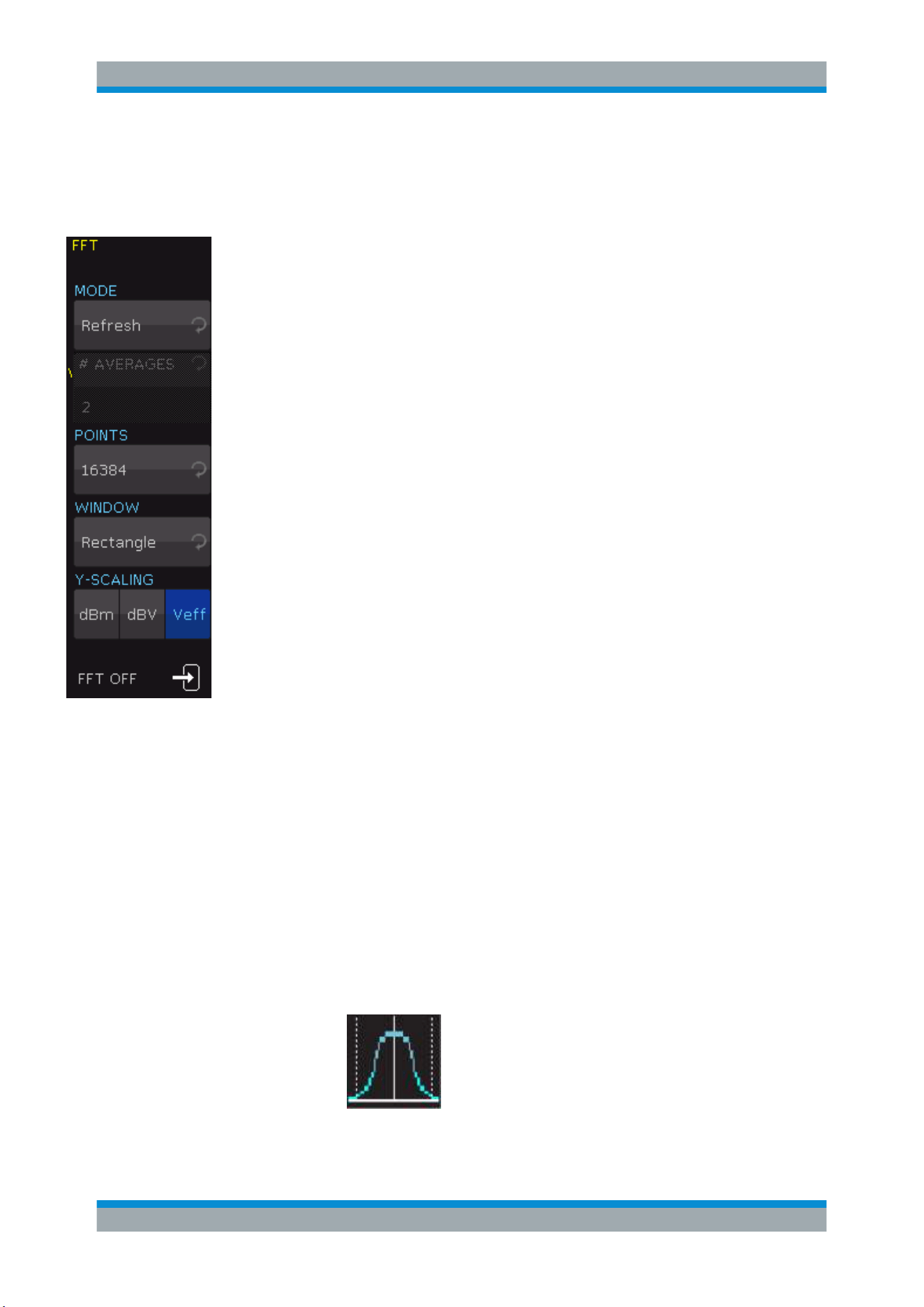
Analysis
R&S
®
RTC1000
73User Manual 1335.7352.02 ─ 04
Active settings are highlighted in white, inactive settings are gray.
The FFT menu provides further settings.
MODE
Sets the display type:
"REFRESH"
Calculates and displays the FFT without additional evaluation or edit-
ing of the captured data. The new input data is captured, displayed
and overwrites previously stored and displayed values.
"ENVELOPE"
The maximum deflections of all spectra are stored separately in addi-
tion to the current spectrum. They are updated with each new spec-
trum. The maximum values are displayed with the input data and cre-
ate an envelope curve. The spectrum is located within the envelope
limits. The envelope forms an area or a sleeve including all occurren-
ces of FFT signal values. If a signal parameter is changed, the enve-
lope curve is reset.
"AVERAGE"
Calculates the mean value from several spectra to reduce noise. The
softkey "AVERAGES" selects the number of spectra used to calculate
the mean value.
POINTS
Selects the maximum number of capture points to be included in the calculation. Possi-
ble values are 2048, 4096, 8192, 16384, 32768, 65536, 131072 points.
WINDOWS
Sets the window type to improve the FFT display. Various window functions are provi-
ded in the R&S RTC1000 to suit different input signals. Each of the window functions
has specific characteristics, including some advantages and some trade-offs. Consider
these characteristics carefully to find the optimum solution for the measurement task.
"Hanning"
The Hann window is bell shaped. Unlike the Hamming window, its
value is zero at the borders of the measuring interval. Thus, the noise
level within the spectrum is reduced and the width of the spectral
lines enlarges.
Use this window to measure amplitudes of a periodical signal pre-
cisely.
Frequency Analysis (FFT)
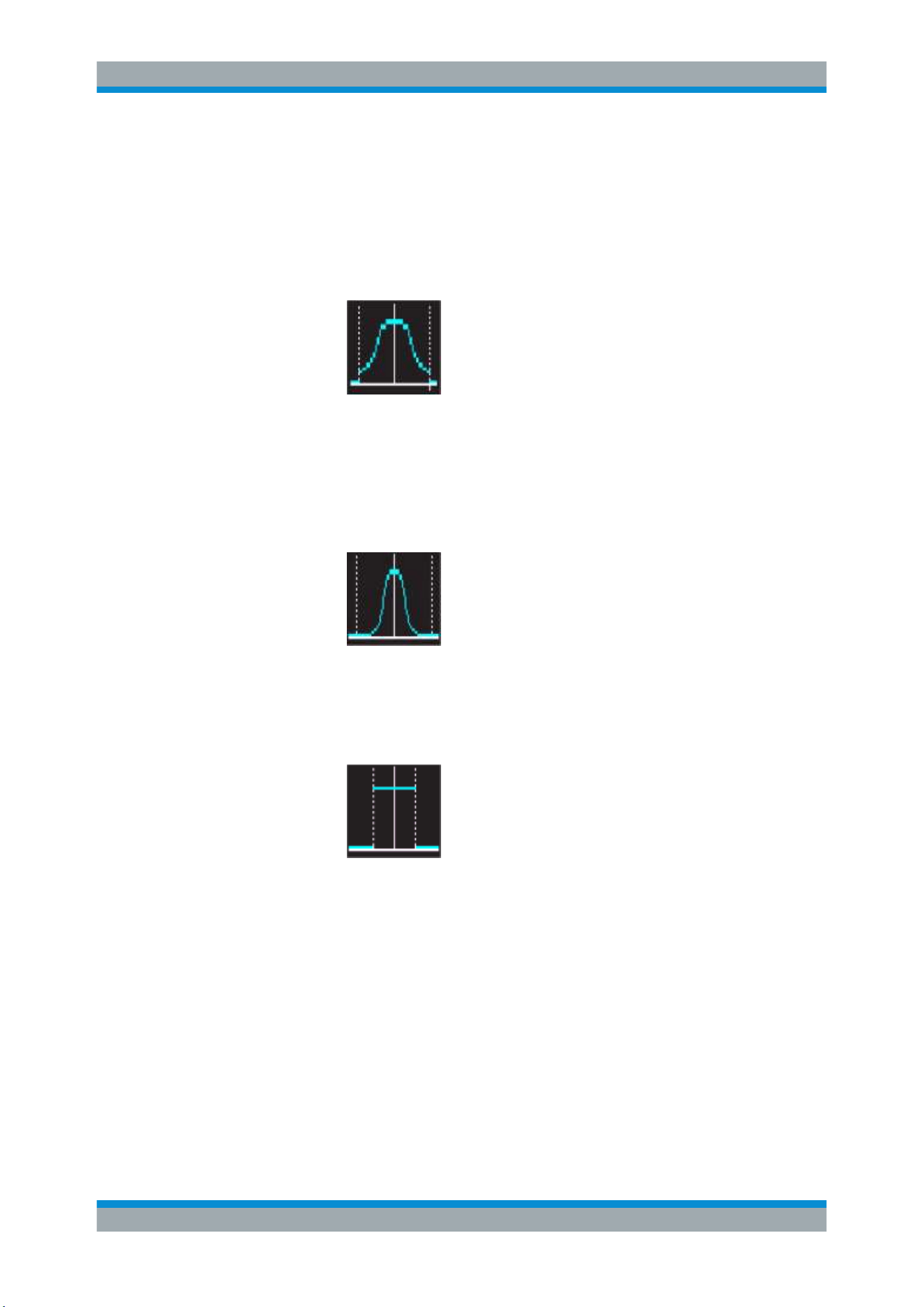
Analysis
R&S
®
RTC1000
74User Manual 1335.7352.02 ─ 04
"Hamming"
The Hamming window is bell shaped. Its value is not zero at the bor-
ders of the measuring interval. Thus, the noise level inside the spec-
trum is higher than Hanning or Blackman, but smaller than the rectan-
gular window. The width of the spectral lines is thinner than the other
bell-shaped functions.
Use this window to measure amplitudes of a periodical signal pre-
cisely.
"Blackman"
The Blackman window is bell shaped and has the steepest fall in its
wave shape of all other available functions. Its value is zero at both
borders of the measuring interval. In the Blackman window, the ampli-
tudes can be measured precisely. However, determining the fre-
quency is more difficult.
Use this window to measure signals with single frequencies to detect
harmonics and accurate single-tone measurements.
"Rectangle"
The rectangular window multiplies all points by one. The result is a
high frequency accuracy with thin spectral lines, but also with
increased noise.
Use this function for measurements of separation of two tones with
almost equal amplitudes and a small frequency distance.
Y-SCALING
Sets the scale of the amplitude in FFT: logarithmically ("dBm" / "dBV") or linear ("Veff").
The unit dBm (Decibel-Milliwatt) refers to 1 mW. The unit dBV (Decibel-Volt) refers to
1 V
eff
.
FFT OFF
Deactivates the FFT function. Alternatively, you can press the [FFT] key on the control
panel again.
Frequency Analysis (FFT)
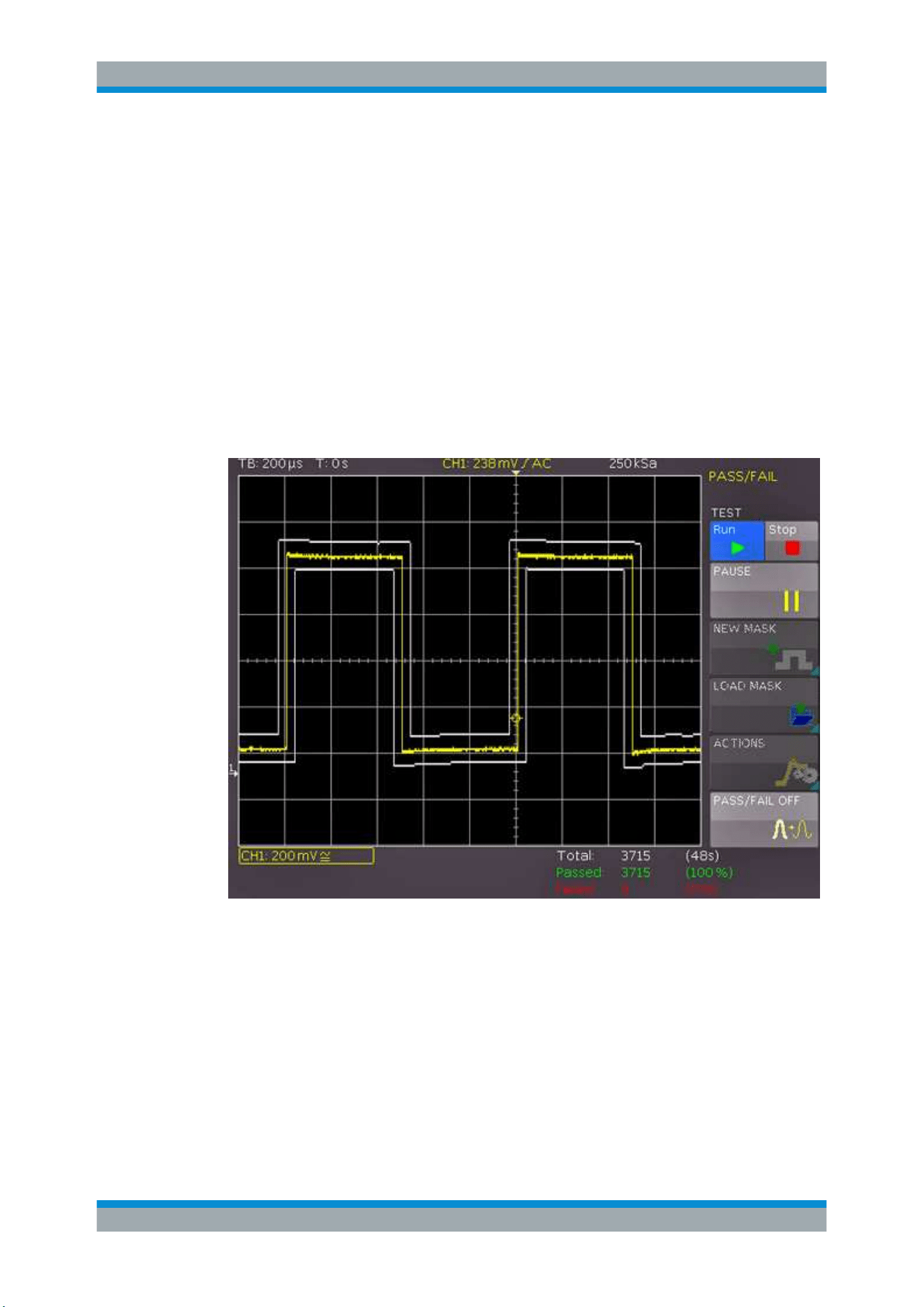
Analysis
R&S
®
RTC1000
75User Manual 1335.7352.02 ─ 04
6.6 Pass/Fail Test Based on Masks
The Pass/Fail test evaluates whether a signal is located within defined limits. The limits
are set by a mask. If the signal exceeds the mask limits, an error (fail) is counted. The
number of errors, the number of successful acquisitions, and the total acquisition count
are displayed at the bottom of the display. You can also start certain actions if an error
is discovered.
To access the Pass/Fail test menu
1. Press the [UTIL] key in the Vertical section.
2. On menu page 2|2, press "PASS/FAIL".
3. To open the menu, press [UTIL] and "PASS/FAIL" again.
Figure 6-13: PASS/FAIL mask test
Before you can start the mask test, generate or load a mask and select an action.
To generate new mask
1. In the "PASS/FAIL" menu, press "NEW MASK".
2. To copy the current signal into a mask, press "COPY CHANNEL".
The mask is displayed in white and appears as an overlay of the output signal.
Pass/Fail Test Based on Masks

Analysis
R&S
®
RTC1000
76User Manual 1335.7352.02 ─ 04
3. To shift the mask vertically, or to enlarge it, press "Y-POSITION" and "STRETCH
Y", and use the Universal knob
4. To set the tolerance for the mask test, press "WIDTH Y" and "WIDTH X". Use the
Universal knob or the [KEYPAD] to enter values with a resolution of 1/100 division.
A mask has a minimum and a maximum value for each captured data value. The
minimum and maximum value for a source waveform with only one value per data
are identical. The width indicates the distance between the mask points and the
original point. The greater the selected value is, the greater are the potential wave-
form deviations in the amplitude.
The generated and edited mask can be used immediately for the test, however, it is
only saved temporarily in the instrument storage.
Masks are displayed as light white waveforms on the screen. If a mask was copied
or loaded, you can use the menu to change the limits for the test.
5. To store the mask permanently to a USB flash drive or in the internal memory,
press "SAVE".
6. To return to the "PASS/FAIL" menu, press the "Back" key.
To load a mask
1. In the "PASS/FAIL" menu, press "LOAD MASK" to open a file browser which allows
you to load previously stored masks for the test ).
2. In the file browser, select the mask file (file extension .MSK).
3. Load the selected file.
4. To change a loaded mask, access the "NEW MASK" menu.
A loaded mask is adjusted in the same way as a created mask. You can save the
changed mask.
To select an action:
1. In the "PASS/FAIL" menu, press "ACTIONS"
2. Select the actions:
● Audio signal if the tolerance limits are exceeded
● Stop at failure, the number of failures is adjustable
● Pulse at the [Aux Out] output in case of failure
● Screenshot at first failure, saved on USB flash drive
● Print on connected printer
● Waveform data saved to file
An action is performed if the condition is met, for example, a given number of mask
failures.
3. To return to the "PASS/FAIL" menu, press the "Back" key.
Pass/Fail Test Based on Masks
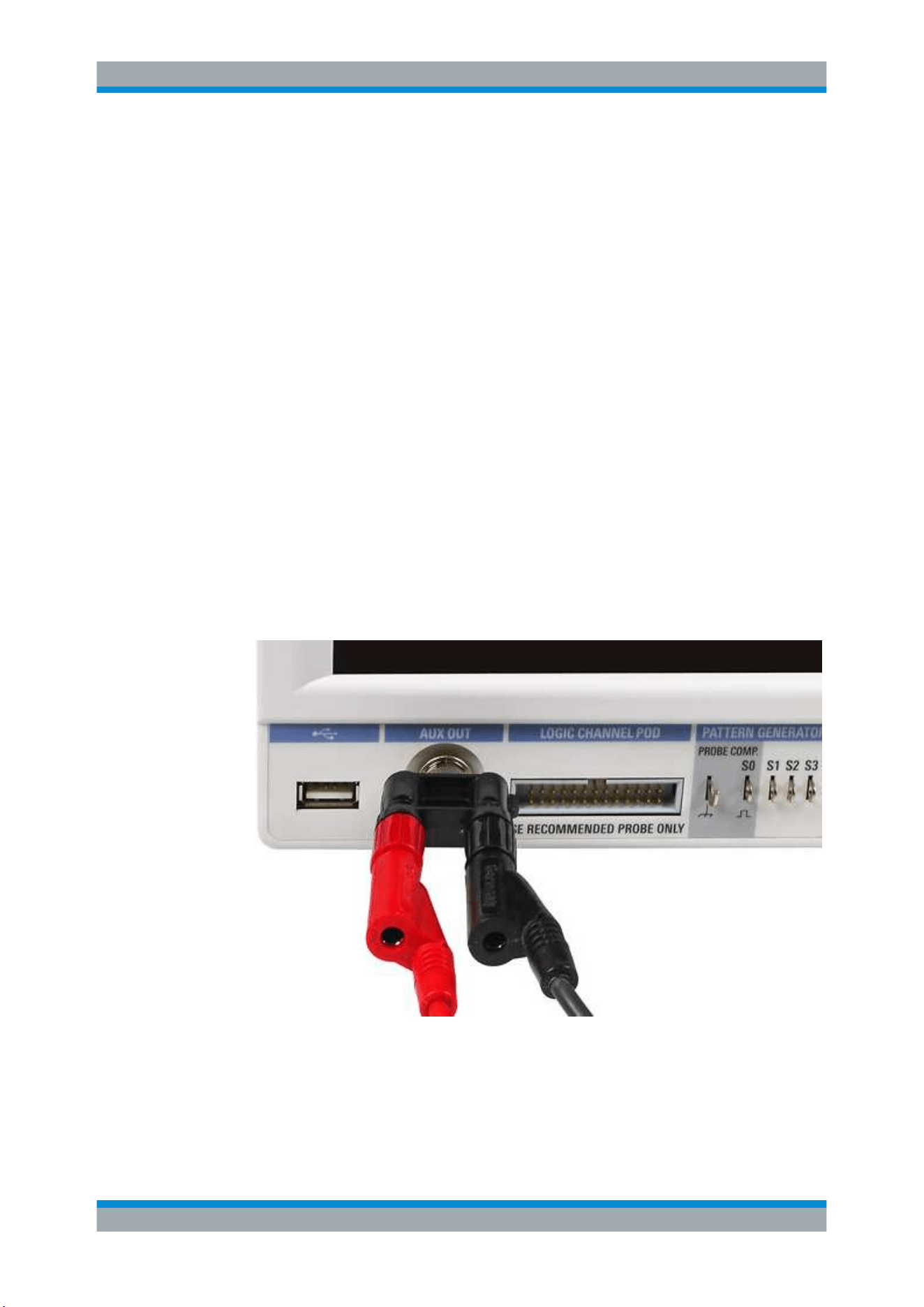
Analysis
R&S
®
RTC1000
77User Manual 1335.7352.02 ─ 04
To perform a pass/fail test
1. In the "PASS/FAIL" menu, press "TEST Run/Stop" to start the test.
Below the grid, you see the total number and the total duration of the tests in white.
The number of successful tests and their percentage is displayed in green, and the
number of failures and their percentage are displayed in red.
2. To interrupt the test while the acquisition of signals is continued, press "PAUSE".
3. To resume the test and to continue all event counters, press "PAUSE" again.
4. To finish the test, press "TEST Stop".
The event and time counters are stopped.
If you start a new test with "TEST Run", all counters are reset to zero.
5. To deactivate the "PASS/FAIL" mode, press "PASS/FAIL OFF".
6.7 Component Test
The R&S RTC1000 has a built-in component tester.
1. Connect the unit under test to the [Aux Out] connector using a BNC/Banana
adapter.
Figure 6-14: BNC/banana adapter connected to [Aux Out]
2. Press the [UTIL] key in the Vertical section.
3. Press "COMP. TEST".
Component Test
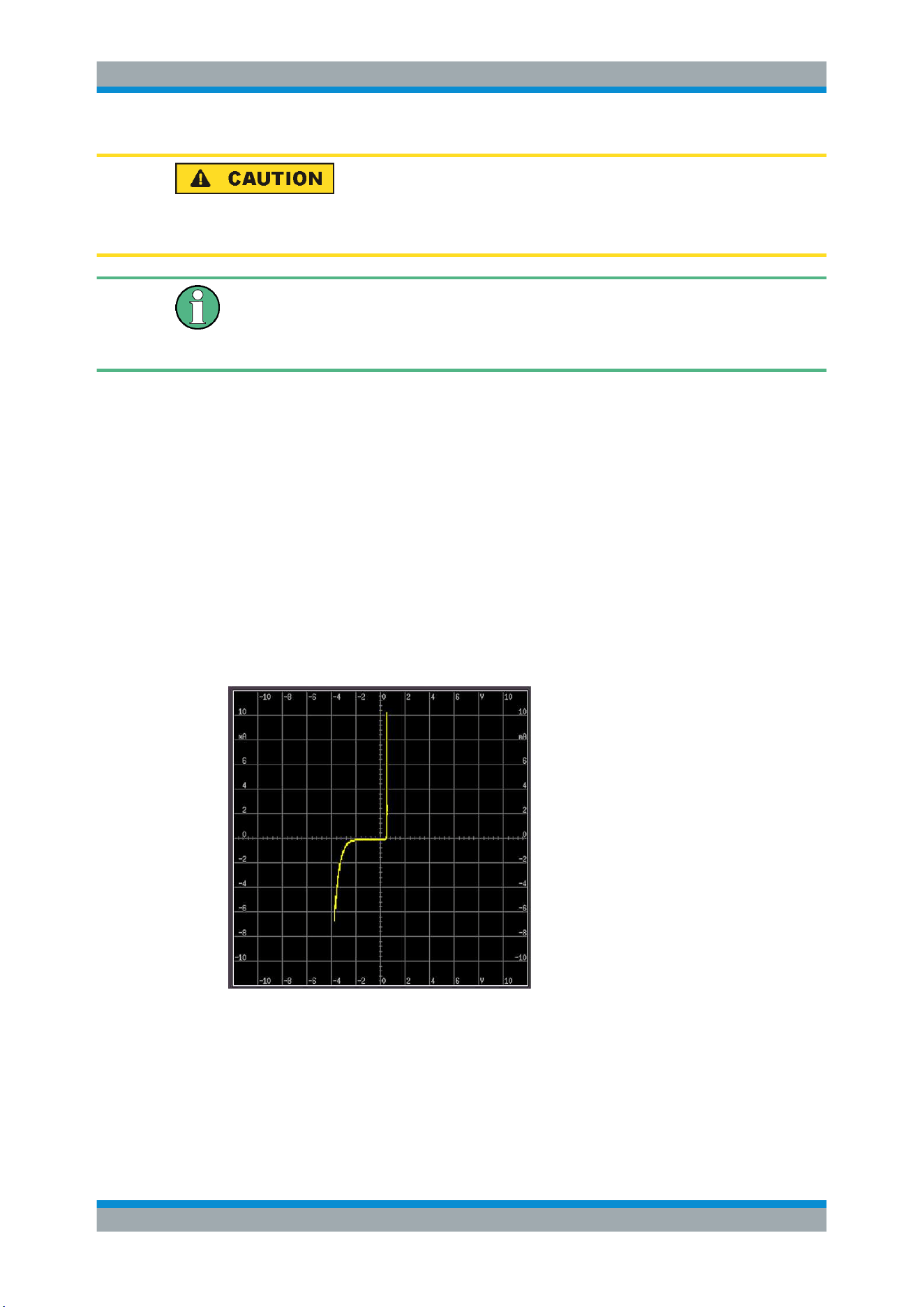
Analysis
R&S
®
RTC1000
78User Manual 1335.7352.02 ─ 04
Risk of electric shock
Make sure to discharge capacitors before test.
If components are tested which are located in circuits or instruments, make sure to set
the circuits or instruments currentless. If they are operated from the mains, also pull
out the mains plug of the test object. Thus, loops between the scope and the test
object via the safety earth are avoided, which can cause false results.
In component tester mode, the Y-preamplifiers and the timebase are disconnected.
Signals can be present at the inputs as long as the unit under test is not connected to
any circuit. It is possible to test components remaining in their circuits, but in such
cases all signals must be disconnected from the front panel BNC connectors (see
Chapter 6.7.1, "In-circuit Tests", on page 81).
The test principle is a generator within the R&S RTC1000 which generates a 50 Hz or
200 Hz (±10 %) sine wave. The sine wave feeds the series connection of the test
object and a sense resistor.
●
Is the test object short-circuited, the line is vertical (no voltage, current maximum).
●
If the test object is open-circuited or missing, a horizontal line appears (voltage, but
no current).
●
If the test object has only a real part such as a resistor, both voltages are in phase;
the display is a straight line, more or less slanted.
Figure 6-15: Component test example
The angle of the line is a measure of the resistance value. Resistor measurements
between Ω and kΩ are possible. Capacitors can be measured between μF and mF.
Capacitors and inductors cause phase shift between voltage and current and hence
between the voltages. The phase shift causes displays of ellipses. The location and the
Component Test

Analysis
R&S
®
RTC1000
79User Manual 1335.7352.02 ─ 04
form factor of the ellipse are determined by the apparent impedance at 50 Hz (resp.
200 Hz).
●
An ellipse with horizontal long axis indicates a high impedance (small capacitance
or large inductance).
●
An ellipse with vertical long axis indicates a low impedance (large capacitance or
small inductance).
●
An ellipse with slanted long axis indicates a relatively large resistive loss in series
with the impedance of the capacitor or inductor.
When testing semiconductors, the transition from the non-conducting to the conducting
state is indicated in their characteristic. As far as is possible, with the available vol-
tages and currents, the forward and backward characteristics are displayed (e.g. with
zener diodes up to 9 V). Because this is a two-pole measurement, the gain of a transis-
tor cannot be determined, however, the B-C, B-E, C-E diodes can be measured. With
this exception, the diodes can be measured without fear of destruction as the maxi-
mum voltage is limited to 9 V and the current to a few mA. This implies, however, that a
measurement of breakdown voltages > 9 V is not possible. This is no disadvantage
because, if there is a defect in a circuit, gross deviations are to be expected which
point to the defective component. Rather exact results can be achieved if the measure-
ments are compared to those of intact components. This is especially true for semicon-
ductors. The polarity of diodes or transistors can thus be identified if the lettering or
marking is missing. Please note that with semiconductors changing the polarity causes
the display to rotate 180 degrees around the screen center. More important in practice
is the quick determination of plain shorts and opens which are the most common cau-
ses of requiring service.
Component Test
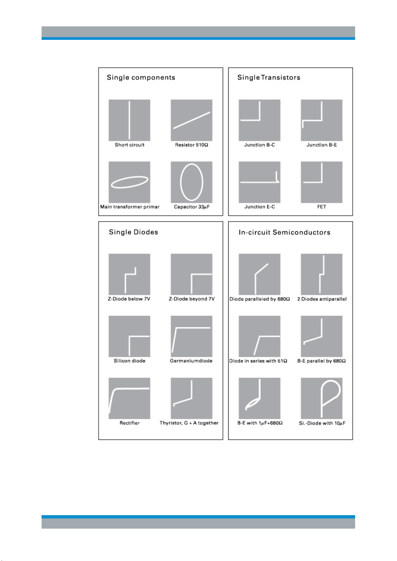
Analysis
R&S
®
RTC1000
80User Manual 1335.7352.02 ─ 04
Figure 6-16: Exmaple results of component tests
Component Test

Analysis
R&S
®
RTC1000
81User Manual 1335.7352.02 ─ 04
Risk of instrument damage
Observe the necessary precautions when handling MOS components. They can be
destroyed by static charges or tribo electricity.
6.7.1 In-circuit Tests
In-circuit tests are possible but often do not deliver clear results. By paralleling of real
or complex impedances – especially if those are of fairly low impedance at 50 Hz/200
Hz – there are mostly great differences compared to individual components. If circuits
of the same type have to be tested often (service), comparisons with intact circuits can
help again. This is also quickly done because the intact circuit has not to be functional,
also it must not be energized.
To test circuits of the same type
1. Probe the various test points of the unit under test with the cables of the compo-
nent tester.
2. Probe the various test points of the intact unit with the cables of the component
tester.
3. Compare the screen displays.
Sometimes the unit under test can already contain an intact portion of the same
type, for example, with stereo circuits, push-pull circuits or symmetrical bridge cir-
cuits.
4. In cases of doubt, unsolder one side of the dubious component.
6.8 Digital Voltmeter
The digital voltmeter captures all input data with the selected vertical sensitivity and the
basic accuracy of the ADC. The digital voltmeter is independent from the capture set-
tings and the post processing of the transformer values. Measurement values are
determined using the measurement interval to ensure the defined frequency range of
20 Hz to 100 kHz. The measurement interval of the digital voltmeter is not the acquisi-
tion time interval. Therefore, the measurement values of the digital voltmeter cannot be
the same as the measurement values of the AUTO MEASURE values.
1. Press the [UTIL] key in the Vertical section.
2. Press "DIG. VOLTMETER".
The digital voltmeter has a 3-digit voltage display.
3. You can set four configurable measuring displays. For each channel, you can mea-
sure and display two values:
Digital Voltmeter
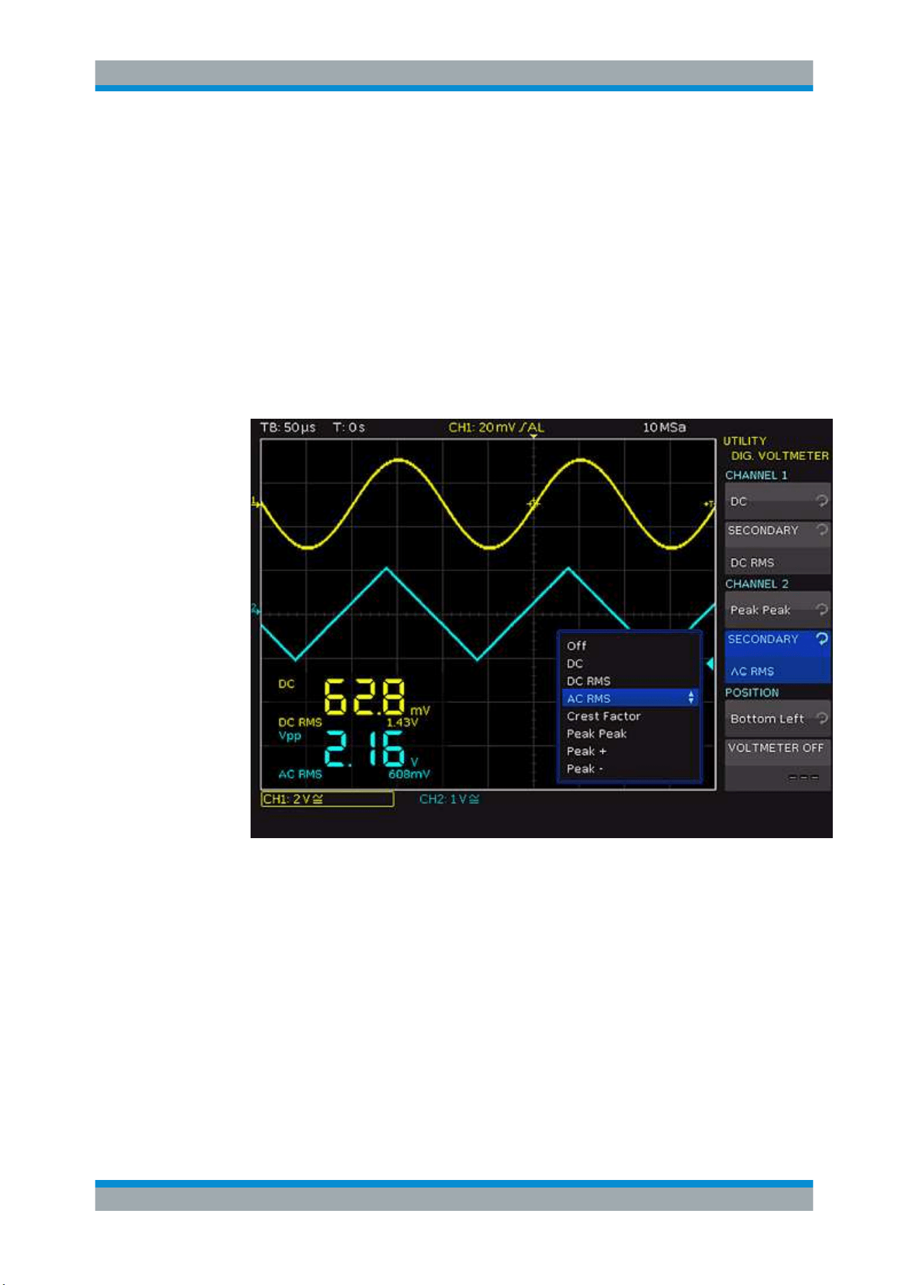
Analysis
R&S
®
RTC1000
82User Manual 1335.7352.02 ─ 04
a) Select the primary measurement for channel 1 and channel 2.
b) Press"SECONDARY" for the corresponding channel to select the secondary
measurement.
The following primary and secondary measurements are available:
● OFF: Measurement off
● DC: Mean
● DC RMS: RMS
● AC RMS: Standard deviation
● CREST FACTOR: Crest factor (|X|max/XRMS)
● PEAK PEAK: Maximum - Minimum
● PEAK +: Maximum
● PEAK -: Minimum
Figure 6-17: Digital Voltmeter
The primary measurement is shown in a large font, and the secondary measure-
ment in a small font. All measurements can be configured separately.
4. To define the position of the measurement display, use "POSITION".
Note: When the "XY" mode is active, the display position of the digital voltmeter is
predefined and cannot be modified.
5. To deactivate the digital voltmeter function and to close the menu, press "VOLTME-
TER OFF".
Digital Voltmeter
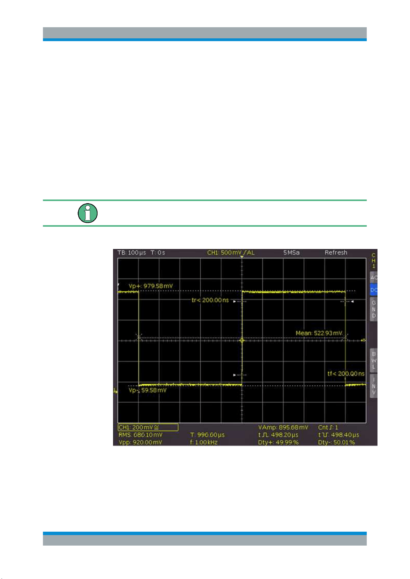
Measurements
R&S
®
RTC1000
83User Manual 1335.7352.02 ─ 04
7 Measurements
There are several methods to measure on signals: quick view, cursor measurements
and automatic measurements. All measurements are stored in a buffer memory that is
larger than the display memory.
7.1 Quick View
The quick view function provides a quick overview of the typical signal characteristics.
Measurement results are displayed at the bottom of the screen and with a cursor on
the signal.
Only one channel can be active in the Quick View mode. All measurements are per-
formed on the active channel.
1. Press the [QUICK VIEW] key in the Analysis section.
2. The following measurement values are displayed directly in the signal:
● Maximum voltage (V
p+
)
● Mean voltage (Mean)
● Minimum voltage (V
p-
)
● Rise time (t
r
)
Quick View

Measurements
R&S
®
RTC1000
84User Manual 1335.7352.02 ─ 04
● Fall time (t
f
)
The following measurement values are displayed at the bottom of the screen:
● RMS value
● Peak to peak voltage
● Amplitude
● Pos. pulse width
● Pos. duty ratio
● Period
● Frequency
● Number of positive /slopes
● Neg. pulse width
● Neg. duty ratio
3. Press the [QUICK VIEW] key again to switch off the function.
The six measurement parameters on the bottom right can be changed using the
[AUTO MEASURE] key, see
Chapter 7.3, "Automatic Measurements", on page 87.
7.2 Cursor Measurements
Cursor measurements are often used with an oscilloscope. Depending on the mea-
surement type, up to three cursor lines are available.
To move cursors:
1. To select the cursor line, press the Universal knob in the Cursor/Menu section.
2. To position the cursor line, turn the Universal knob.
The measurement results are displayed at the bottom of the screen.
If "n/a" is displayed, the measurement is not applicable to the signal. For instance, this
can be the case for a voltage measurement on a "POD" because only logic states with-
out voltage reference are displayed.
If "?" is displayed, the display does not show a complete measurement result. For
instance, the period to be measured is not completely displayed and cannot be identi-
fied.
7.2.1 Cursor Measurement Settings
► Press the [CURSOR MEASURE] key in the Cursor/Menu section.
Cursor Measurements
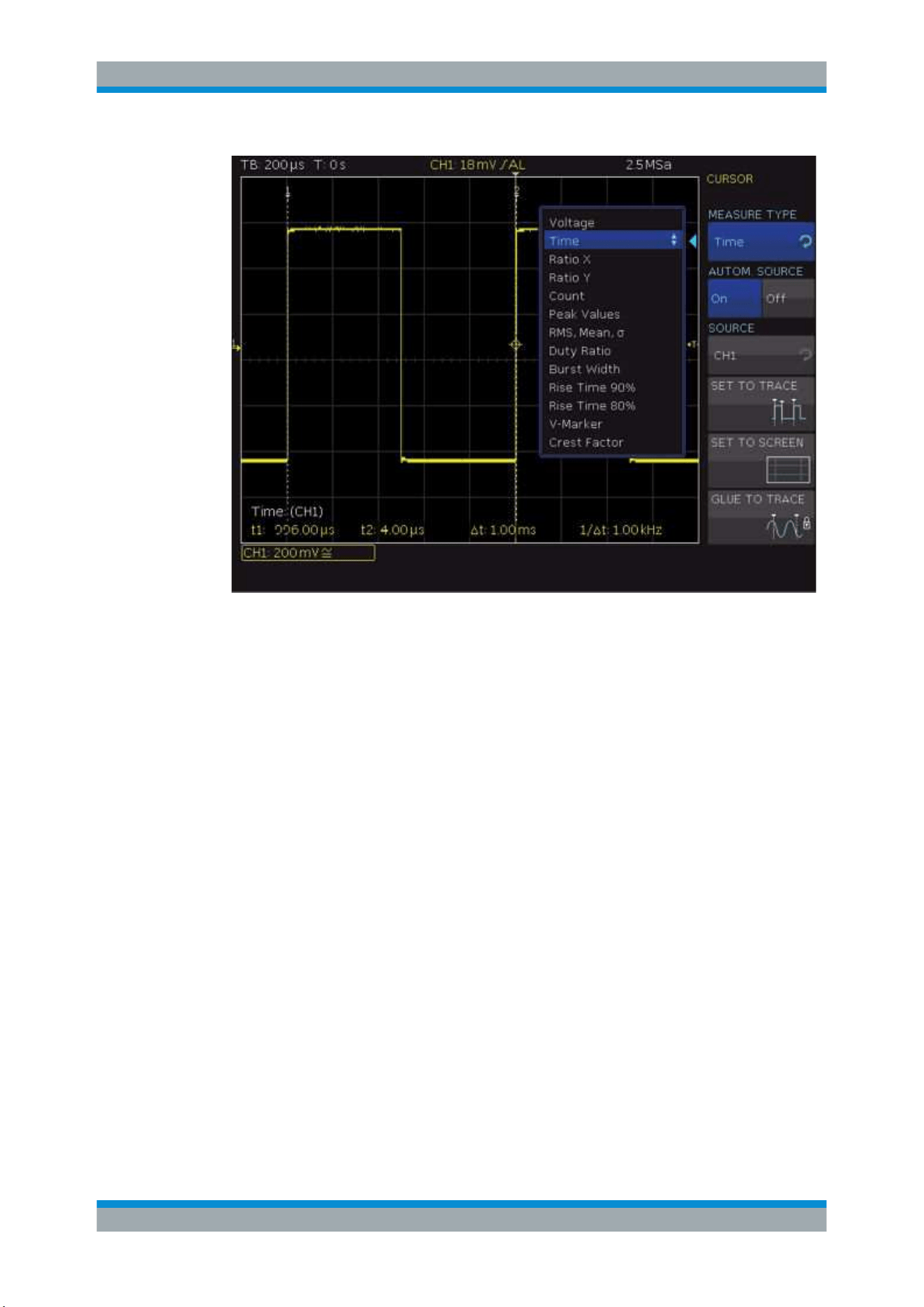
Measurements
R&S
®
RTC1000
85User Manual 1335.7352.02 ─ 04
Figure 7-1: Cursor measurement menu
MEASURE TYPE
Defines the measurement type. To learn about the individual types, see
Chapter 7.2.2,
"Measurement Types"
, on page 86.
AUTOM. SOURCE, SOURCE
If "AUTOM. SOURCE" is activated ("On"), the selected channel is used as source for
the measurement. If the "AUTOM. SOURCE" is deactivated ("Off"), set the channel
with "SOURCE".
SET TO TRACE
Places the cursors in their optimal position on the waveform and allows fast and typi-
cally optimal automatic positioning of the cursors. Mostly, only fine-tuning is required. If
"SET TO TRACE" does not provide the anticipated results due to complex signals, use
the key "SET TO TRACE" to position the cursors in a predefined starting position, and
to return distant cursors to the screen.
SET TO SCREEN
Sets the cursors to their default position. Use this function to return distant cursors to
the screen.
GLUE TO TRACE
If active, the cursors stay on the selected data point without changing the position in
the measurement signal if the scaling is modified (cursors are "glued" to the signal).
The measured value remains unmodified.
Cursor Measurements
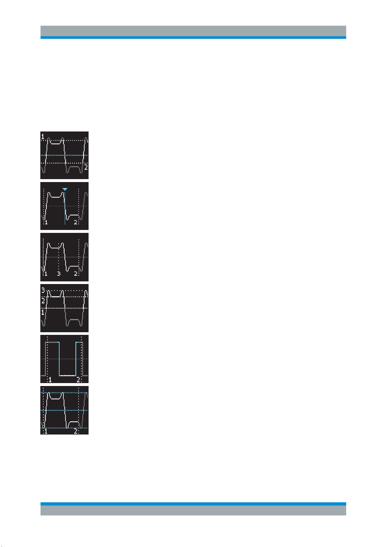
Measurements
R&S
®
RTC1000
86User Manual 1335.7352.02 ─ 04
If deactivated, the cursors stay in position on the screen if the waveform is scaled, and
the measured value changes.
7.2.2 Measurement Types
The following cursor measurement types are available:
Voltage
"Voltage" provides two cursors and measures three voltages. The values V1 and V2
correspond to the voltage between the zero base line of the selected signal and the
current position of the first or second cursor. The value ΔV is voltage difference
between the two cursors.
Time
"Time" provides two cursors and measures three times and an equivalent frequency.
The values t1 and t2 correspond to the time between the trigger and the current posi-
tion of the first or second cursor. The value Δt corresponds to the time between the two
cursors.
Ratio X
"Ratio X" provides three cursors and measures a ratio in X direction (e.g. a duty ratio)
between the first two cursors and the first and the third cursor. The measurement val-
ues are displayed in four formats (floating point, percent, degrees and radians).
Ratio Y
"Ratio Y" provides three cursors and measures a ratio in Y direction (e.g. an over-
shoot) between the first two cursors and the first and the third cursor. The measure-
ment values are displayed in two formats (floating point and percent).
Count
"Count" provides three cursors to count signal changes that exceed the threshold
within a specific interval. The interval is set by the first two cursors and the threshold is
the third cursor. The measurement values are displayed in four formats (number of ris-
ing and falling slopes and number of positive and negative pulses).
Peak Values
"Peak Values" provides two cursors and measures the minimum and the maximum
voltage of a signal within the interval that is set by both cursors. The values Vp- and Vp
+ correspond to the minimum and the maximum voltage. The peak value (Vpp) corre-
sponds to the voltage difference between the minimum and maximum value.
Cursor Measurements
Measurements
R&S
®
RTC1000
87User Manual 1335.7352.02 ─ 04
RMS, Mean, σ
This measurement type provides two cursors and measures the effective value (RMS –
root mean square), the mean value and the standard deviation within the interval set
by both cursors.
Duty Ratio
"Duty Ratio" provides three cursors to determine the duty ratio between the two hori-
zontal cursors. The third cursor specifies the threshold at which the duty ratio is mea-
sured.
Burst Width
"Burst Width" determines the duration of a burst from the first edge to the last edge
(Bst).
Freq. & Period
"Freq. & Period" provides three cursors and measures the frequency and the period.
Rise Time 90%, Rise Time 80%
These measurement types provide two cursors and measure the rise and fall time of
the first rising slope in the display within the time span set by the cursors. The rise time
identifies the time in which the signal rises or falls from 10% to 90% of its amplitude, or
from 20% to 80%.
V-Marker
"V-Marker" provides two cursors and measures three voltages and a time. The values
V1 and V2 correspond to the voltage between the zero base line of the selected curve
and the current position of the first or second cursor. The value ΔV corresponds to the
voltage difference between the two cursors. The value Δt corresponds to the time
between the two cursors.
Crest Factor
The crest factor (peak-to-average ratio) is calculated from the maximum value divided
by the RMS value of the waveform (Crest).
7.3 Automatic Measurements
The R&S RTC1000 also features various automatic measurements. Up to 6 measure-
ments can run in parallel.
The results of automatic measurements are displayed at the bottom of the screen. The
results of the automatic measurements are also shown in the quick view, they are the 6
results on the right.
Automatic Measurements
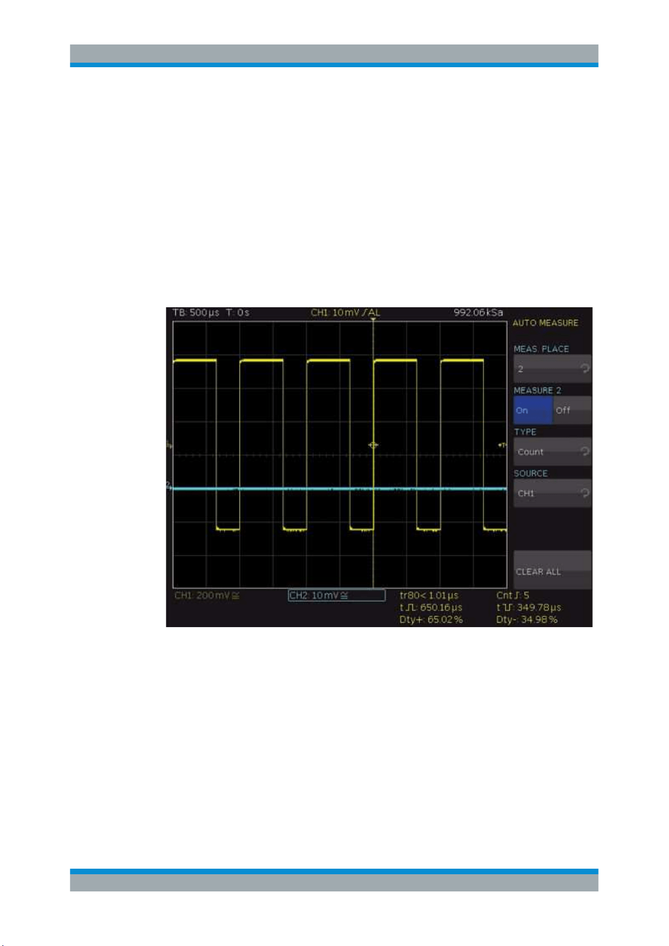
Measurements
R&S
®
RTC1000
88User Manual 1335.7352.02 ─ 04
If "n/a" is displayed, the measurement is not applicable to the signal. For instance, if
you measure a voltage on a POD, no result is displayed because only logic states with-
out voltage reference are displayed.
If "?" is displayed, the display does not show a complete measurement result. For
instance, the period to be measured is not completely displayed and cannot be identi-
fied.
7.3.1 Settings for Automatic Measurements
► Press the [AUTO MEASURE] key in the Analysis section.
Figure 7-2: Auto measurement settings and results
MEAS. PLACE
Selects the measurement place. To each measurement place, an automatic measure-
ment function is assigned.
MEASURE
Switches the selected measurement place on or off.
TYPE
Defines the measurement type. To learn about the types, see
Chapter 7.3.2, "Auto-
matic Measurement Types"
, on page 89).
Automatic Measurements
Measurements
R&S
®
RTC1000
89User Manual 1335.7352.02 ─ 04
SOURCE
Selects the waveform to be measured. The list only includes displayed channels. Pos-
sible sources are analog, digital and mathematical channels.
CLEAR ALL
Switches off the activated automatic measurements.
7.3.2 Automatic Measurement Types
The following types of automatic measurements are available:
Mean Value
Measures the mean value of the signal amplitude (Mean). If the signal is periodic, the
first period on the left of the screen is used for the measurement.
RMS Value
"RMS Value" measures the effective value of the displayed signal. If the signal is peri-
odic, the first period on the left of the screen is used for the measurement. The effec-
tive value is not based on a sine signal but is calculated directly (TrueRMS).
Peak Peak
"Peak Peak" measures the voltage difference between the maximum and the minimum
peak value of the displayed signal (V
pp
).
Peak +
"Peak +" measures the maximum voltage value in the display (V
p+
).
Peak –
"Peak –" measures the minimum voltage value in the display (V
p-
).
Frequency
Measures the frequency of the signal from the reciprocal value of the first signal period
T (f).
Automatic Measurements
Measurements
R&S
®
RTC1000
90User Manual 1335.7352.02 ─ 04
Period
"Period" measures the duration of the signal period T. The period identifies the duration
between two equal values of one periodically repeated signal.
Amplitude
Measures the amplitude of a square wave signal (V
Amp
). The measurement calculates
the difference in voltage between the upper and the lower level (V
base
and V
top
). The
measurement requires at least one complete period of a triggered signal.
Crest Factor
The crest factor (peak-to-average ratio) is calculated from the maximum value divided
by the RMS value of the waveform (Crest).
Top Level
"Top Level" measures the mean voltage level of an upper square wave (V
Top
). The
measurement calculates the mean value of the roof slope without overshoot. The mea-
surement requires at least one complete period of a triggered signal.
Base Level
"Base Level" measures the mean voltage level of the lower square wave (V
Base
). The
measurement calculates the mean value of the roof slope (without overshoot). The
measurement requires at least one complete period of a triggered signal.
Pos. Overshoot
"Pos. Overshoot" measures the positive overshoot of a square wave which is calcula-
ted from top level, peak + and amplitude value (+Ovr).
Neg. Overshoot
"Neg. Overshoot" measures the negative overshoot of a square wave which is calcula-
ted from base level, peak - and amplitude value (-Ovr).
Pulse Width +
"Pulse Width +" measures the width of the positive pulse. A positive pulse consists of a
rising slope followed by a falling slope. The measurement identifies the two slopes and
calculates the pulse width from their time difference. The measurement requires at
least one complete period of a triggered signal.
Automatic Measurements
Measurements
R&S
®
RTC1000
91User Manual 1335.7352.02 ─ 04
Pulse Width –
"Pulse Width –" measures the width of the negative pulse. A negative pulse consists of
a falling slope followed by a rising slope. The measurement identifies the two slopes
and calculates the pulse width from their time difference (t). The measurement requires
at least one complete period of a triggered signal.
Duty Cycle +
"Duty Cycle +" measures the positive duty ratio. Positive signal portions are identified
over a period and set in relation to the signal period. The measurement requires at
least one complete period of a triggered signal. The measured value Dty
+
is displayed
as a percentage of the signal period.
Duty Cycle –
"Duty Cycle –" measures the negative duty ratio. Negative signal portions are identified
over a period and set in relation to the signal period. The measurement requires at
least one complete period of a triggered signal. The measured value Dty
+
is displayed
as a percentage of the signal period.
Rise Time 90%, Rise Time 80%
Measures the rise time of the first rising slope in the display (t
r
, t
r80
). The rise time is the
time in which the signal rises from 10% to 90% or from 20% to 80% of its amplitude.
Fall Time 90%, Fall Time 80%
Measures the fall time of the first falling slope in the display (t
f
, t
f80
). The fall time is the
time in which the signal falls from 90% to 10% or from 80% to 20% of its amplitude.
σ-Std. Deviation
Measures the standard deviation of the signal amplitude in the display. The standard
deviation is deviation of a signal from its mean value. A low result indicates that the
values are close to the mean value. A higher result illustrates that the difference
between the values is greater.
Delay
"Delay" measures the time delay between the measurement source and the reference
source. The instrument searches for the slope of the measurement source that is clos-
est to the time reference. Then, beginning from this point, it searches for the nearest
slope of the reference source. This time difference is the measurement result. Press
"DELAY SETUP" to select measurement source, reference source and slopes.
Automatic Measurements
Measurements
R&S
®
RTC1000
92User Manual 1335.7352.02 ─ 04
Phase
Measures the phase between two slopes of two channels in the display (Phs). It meas-
ures the relation of the time delay between the sources to the signal period of the mea-
surement source. The instrument searches for the slope of the measurement source
that is closest to the time reference. Then, beginning from this point, it searches for the
nearest slope of the reference source. The time difference and the signal period indi-
cate the measurement result in degrees. Select the "MEAS. SOURCE" and the "REF.
SOURCE".
Burst Width
Measures the duration of burst from the first edge to the last edge (Bst).
Count P+
"Count P+" counts positive pulses in the display. A negative pulse consists of a falling
slope followed by a rising slope. The mean value is calculated from the amplitude of
the measurement signal. A slope is counted if the signal crosses the mean value. A
pulse that passes the mean value only once is not calculated..
Count P–
"Count P–" counts negative pulses in the display. A negative pulse consists of a falling
slope followed by a rising slope. The mean value is calculated from the amplitude of
the measurement signal. A slope is counted if the signal crosses the mean value. A
pulse that passes the mean value only once is not calculated.
Count S+
"Count S+" counts signal changes (slopes) from low level to high level in the display.
The mean value is calculated from the amplitude of the measurement signal. A slope is
counted if the signal crosses the mean value.
Count S-
"Count S-" counts signal changes (slopes) from high level to low level in the display.
The mean value is calculated from the amplitude of the measurement signal. A slope is
counted if the signal crosses the mean value.
Trigger Freq.
"Trigger Freq." measures the frequency of the trigger signal f
Tr
based on the period
duration. The source for the measurement is the current trigger source. The frequency
is determined with a hardware counter with high accuracy of 5 digits.
Automatic Measurements

Measurements
R&S
®
RTC1000
93User Manual 1335.7352.02 ─ 04
Trigger Period
"Trigger Period" measures the duration of periods of the trigger signal T
Tr
with a hard-
ware counter. The source for the measurement is the current trigger source.
Automatic Measurements
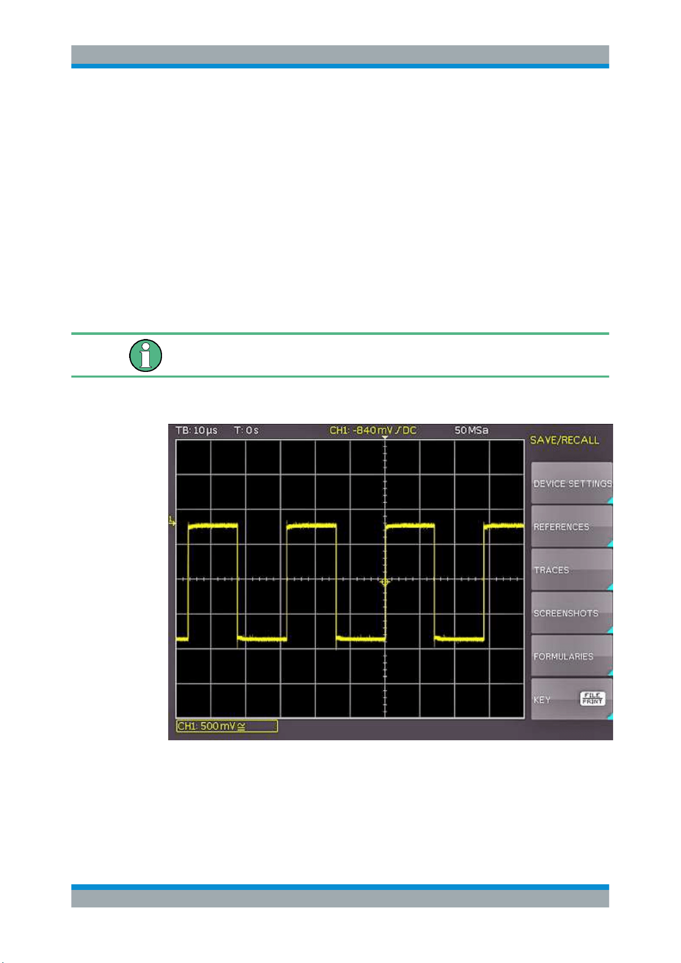
Documenting Results
R&S
®
RTC1000
94User Manual 1335.7352.02 ─ 04
8 Documenting Results
The R&S RTC1000 can store various data to files for further usage, analysis and
reporting.
Waveform data and screenshots, which are intended for analysis outside the oscillo-
scope, are always saved to a USB flash drive. The USB flash drive is the external stor-
age location (FRONT USB). This location is only available if the USB flash drive is con-
nected.
Reference waveforms and instrument settings, which are intended for further use on
the instrument, are usually saved to the internal storage (/INT). You can also store
them to the external storage, or move them to the other location using the export and
import function.
The supported file system in all storage locations is FAT (FAT16/32). Prefer to use USB
flash drive up to 4 GB.
► To save and load data, press the [SAVE/RECALL] key in the General section.
8.1 Saving and Loading Instrument Settings
To repeat measurements or tests at different times or perform similar measurements
with different test data, you can save the used configuration settings. Furthermore, it
Saving and Loading Instrument Settings
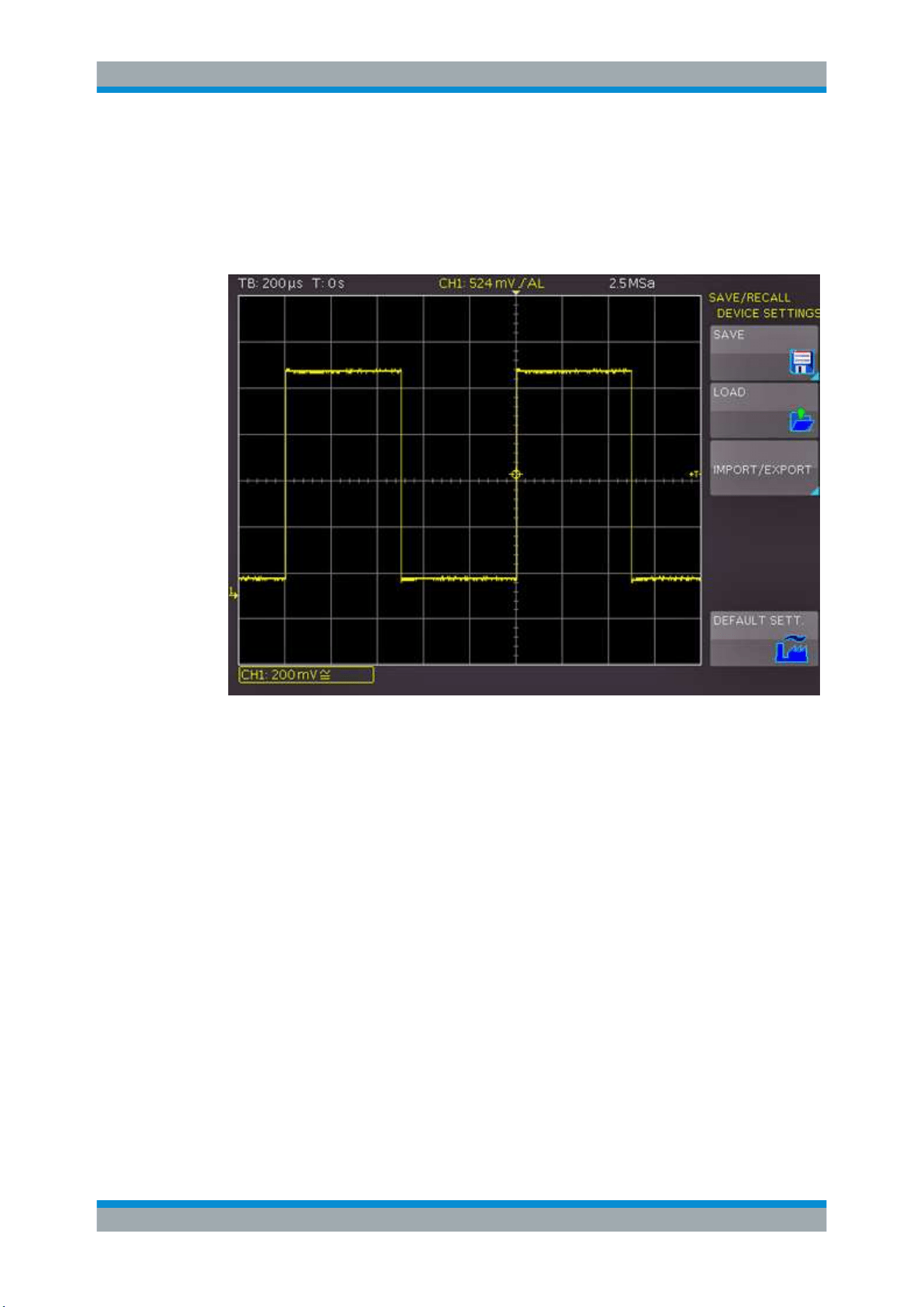
Documenting Results
R&S
®
RTC1000
95User Manual 1335.7352.02 ─ 04
can be helpful to refer to the configuration settings of a particular measurement when
analyzing the results. Therefore, you can easily save the complete measurement con-
figuration.
The softkey "DEVICE SETTINGS" allows you to save current instrument settings, load
saved settings and import or export instrument settings to USB flash drive.
Figure 8-1: SAVE/RECALL menu for instrument settings
To save current instrument settings
1. In the "SAVE/RECALL" > "DEVICE SETTINGS" menu, press the softkey "SAVE" to
open the "Save" menu.
Saving and Loading Instrument Settings
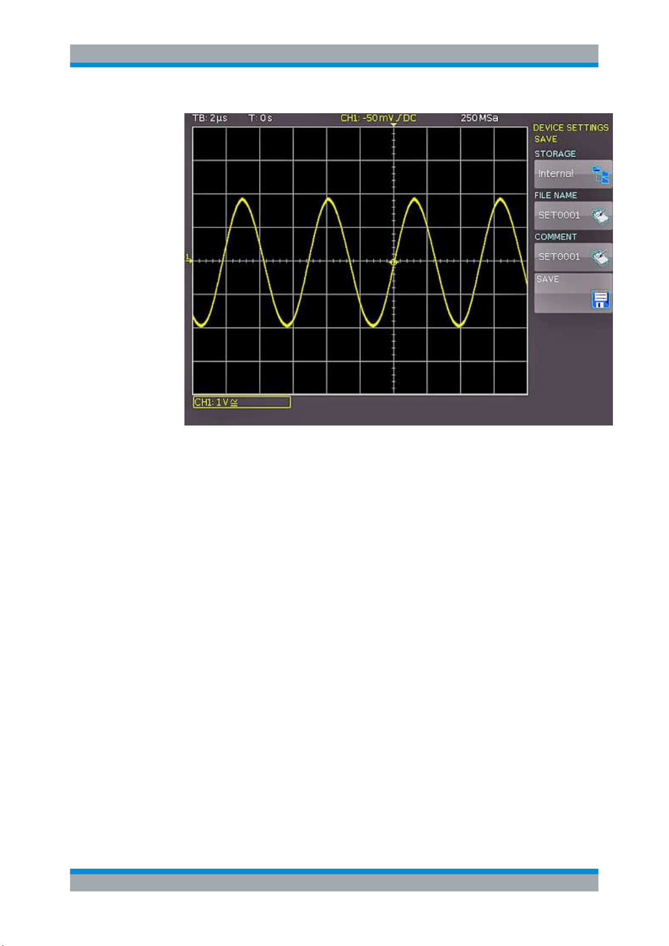
Documenting Results
R&S
®
RTC1000
96User Manual 1335.7352.02 ─ 04
Figure 8-2: SAVE menu for instrument settings
2. Press the "STORAGE" softkey.
The file manager window opens.
3. Select the location: internal memory or front USB connection, where you want to
save the instrument settings.
On a USB flash drive, you can also create, change and delete directories.
4. Press "ACCEPT DIR."
5. Press "FILE NAME". Change the file name if necessary. "SET01" is the default
name.
6. To enter an optional comment, press "COMMENT".
The comment is displayed in the file manager footer if the file is selected.
7. Select the file format: "SET" or "SCP".
Device settings of an older firmware version in SCP format can be loaded with a
newer firmware version.
8. Press "SAVE" to store the settings.
To reload stored settings
1. In the "SAVE/RECALL" > "DEVICE SETTINGS" menu, press the "LOAD" softkey.
2. Press "STORAGE".
Saving and Loading Instrument Settings

Documenting Results
R&S
®
RTC1000
97User Manual 1335.7352.02 ─ 04
3. Use the softkey "SORT ENTRIES" to sort the settings files by name, type, size or
date.
4. Use the [Universal] knob to select the settings file.
5. Press "LOAD".
The settings are read an applied on the instrument.
6. To remove files that are no longer required:
a) Use the [Universal] knob to select the settings file.
b) Press "REMOVE FILE".
To import or export instrument settings
You can copy data between the instrument's internal storage "/INT/ SETTINGS" and a
USB flash drive. Make sure that the USB flash drive is connected.
1. In the "SAVE/RECALL" > "DEVICE SETTINGS" menu, press "IMPORT/EXPORT".
2. Press "SOURCE FILE" and select a source file using the [Universal] knob.
3. Press "DEST. PATH" and select a storage location using the [Universal] knob.
4. To change the file name, press "DEST. NAME".
5. Press "IMPORT/EXPORT" to copy the selected settings file.
To restore default instrument settings
► In the "SAVE/RECALL" > "DEVICE SETTINGS" menu, press "DEFAULT SETT.".
8.2 Reference Waveforms
References or reference waveforms are data sets that consist of settings information
and waveform data sampled by the A/D converter. References can be stored and
reloaded in internal or external storage. You can reload the data into one of the 4 refer-
ence memories RE1 to RE4, and display the references. All information (e.g. vertical
gain, time base setting, A/D converter data) is included when saving or reloading, ena-
bling a comparison between the original signal and its corresponding values.
To save and load references, a specific reference menu is available. If you want to
copy data between the instrument's internal storage and a USB flash drive, use the
"SAVE/RECALL" > "REFERENCES" menu.
To create, store and load references
1. Press the [REF] key in the Vertical section.
2. Press the [MENU] key in the Vertical section.
Reference Waveforms
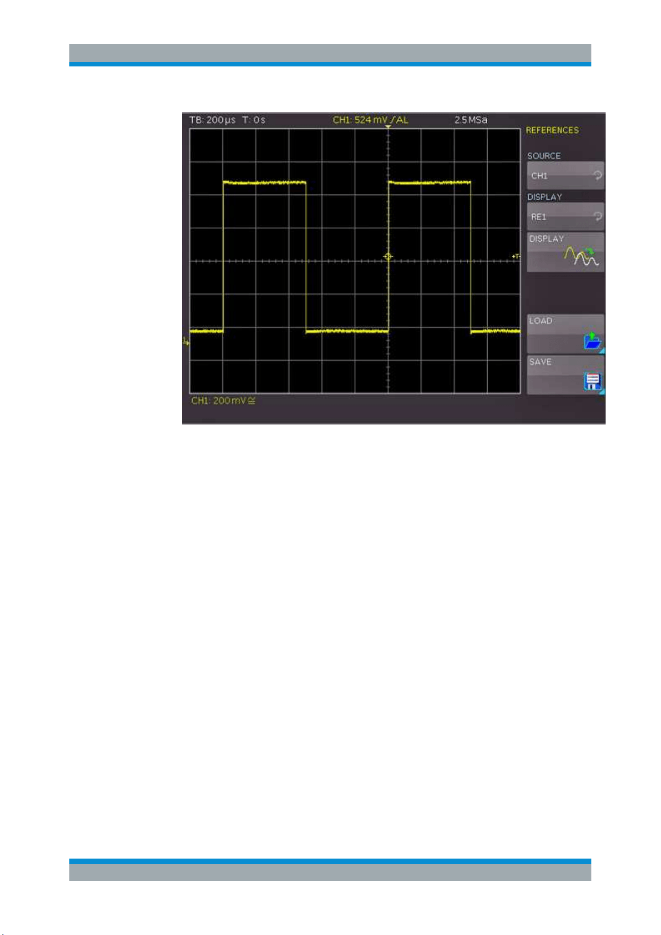
Documenting Results
R&S
®
RTC1000
98User Manual 1335.7352.02 ─ 04
Figure 8-3: Menu for references
3. To create and display a reference waveform:
a) Press "SOURCE". Use the [Universal] knob to select the waveform that you
want to store as reference.
You can select from active channels, other reference waveforms, pod and
mathematical waveforms.
b) Press the upper "DISPLAY" softkey. Select one of the references "RE1" to
"RE4".
c) Press the lower "DISPLAY" softkey.
The data is written to the reference storage, and the reference waveform is dis-
played.
4. To save a reference:
a) Press "SAVE".
b) Press "TRACE". Select the waveform that you want to save as reference wave-
form.
c) Select the "STORAGE": internal or USB flash drive.
d) Enter the "FILE NAME".
e) Press "SAVE".
The reference file is saved in TRF format.
5. To load a reference from a USB flash drive or the internal memory:
a) In the "REFERENCES" menu, press "LOAD".
Reference Waveforms

Documenting Results
R&S
®
RTC1000
99User Manual 1335.7352.02 ─ 04
b) Press "DISPLAY". Use the [Universal] knob to select the target reference wave-
form.
c) Press "LOAD".
d) In the file manager menu, select the storage, the directory, and the file.
e) Press "LOAD" to read and display the reference.
To import or export references
1. In the "SAVE/RECALL" menu, press "REFERENCES".
2. Press "SOURCE FILE" to select the source file using the [Universal] knob.
3. Press "DEST. PATH" to set the storage location using the [Universal] knob.
4. To change the file name, press "DEST. NAME". Enter the file name.
5. To change the file format, press "DEST. FORMAT".
6. Select the target format. See also
Chapter 8.3.1, "Waveform File Formats",
on page 101.
7. Press "IMPORT/EXPORT".
8.3 Waveforms (Traces)
You can store also waveform data without settings to external storage for analysis.
Depending on the selected timebase and the record mode in the "ACQUIRE" menu
(AUTOMATIC, MAX. SAMPLE RATE or MAX. WAVEFORM RATE), the maximum
read-out measurement points varies. To read out the full memory, save the waveform
in stop mode with the maximum sampling rate setting.
To store waveform data to file
1. Connect a USB flash drive.
2. In the "SAVE/RECALL" menu, press "TRACES".
Waveforms (Traces)
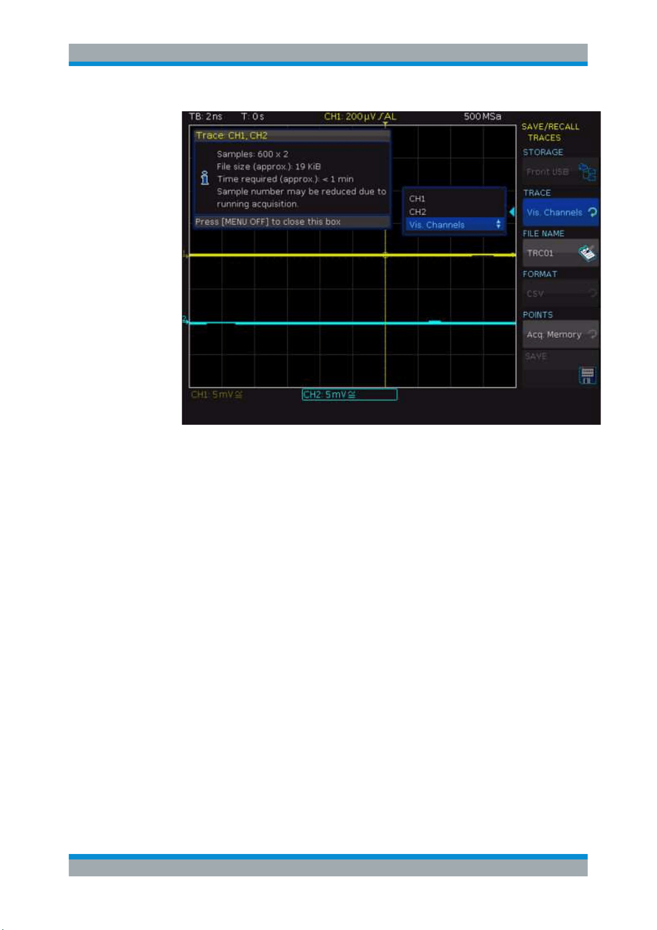
Documenting Results
R&S
®
RTC1000
100User Manual 1335.7352.02 ─ 04
Figure 8-4: Trace storage menu
3. To select the target directory, press "STORAGE".
a) Use the softkey "SORT ENTRIES" to sort the files by name, type, size or date.
b) Change, create or delete directories.
c) Select the target directory.
d) Press "ACCEPT DIR." to confirm the target directory and you return automati-
cally to the curve main menu.
4. Press "TRACE". Use the [universal] knob to select the channel, math waveform,
reference, or pod.
You can select only active waveforms. You can also save all visible channels to
one file.
5. Press "FILE NAME". Enter the file name.
6. Press "FORMAT". Select the target format, see
Chapter 8.3.1, "Waveform File For-
mats", on page 101.
Note: If "Max. Sampling Rate" is set in the "ACQUIRE" menu, two rows are affixed
with a time stamp during the CSV export because a minimum and a maximum
value must be assigned to this time value. To acquire an amplitude value per time
stamp, activate "Automatic" in the "ACQUIRE" menu.
7. Press "POINTS". Select whether you want to read out the display memory ("Dis-
play Data") or the entire acquisition memory ("Acq. Memory").
8. Press "SAVE".
Waveforms (Traces)

Documenting Results
R&S
®
RTC1000
101User Manual 1335.7352.02 ─ 04
The file is written according to the settings.
8.3.1 Waveform File Formats
Data of all waveforms is saved as a succession of values or pairs of values. Pairs of
values are written as two consecutive single values. Depending on the file format, only
amplitude values are stored, or the amplitude values are stored together with their time
value, or frequency value in FFT mode.
With export/import, you can change the target file format and convert the data.
To reload waveform data as a reference waveform, it must be stored in TRF or CSV
format.
8.3.1.1 CSV Format
In a Comma Separated Values text file, the waveform is stored in a two-columned
table. Columns are separated by a comma, and the lines are separated by line breaks
\r\n (0x0D 0x0A). Values are listed in scientific notation.
The first column contains the time values of the samples in relation to the trigger point,
and the second column contains the associated amplitude values. The first line indi-
cates the units of the values in each column, and the name of the waveform. Pairs of
values are listed as two single values with the same time value (minimum and maxi-
mum).
The data can be loaded back to the instrument for further use.
Example CSV1: Waveform of channel 1, single values
in s,CH1 in V
-1.1996E-02,1.000E-02
-1.1992E-02,1.000E-02
-1.1988E-02,1.000E-02
-1.1984E-02,1.000E-02
Example CSV2: Waveform of channel 1, pairs of values
in s,CH1 in V
-2.9980E+00,2.000E-05
-2.9980E+00,1.400E-04
-2.9960E+00,-1.800E-04
-2.9960E+00,1.400E-04
-2.9940E+00,-1.800E-04
-2.9940E+00,1.400E-04
Example CSV3: FFT
in Hz,FFT in dBm
0.000000E+00,1.03746E+01
1.525879E+02,7.49460E+00
Waveforms (Traces)

Documenting Results
R&S
®
RTC1000
102User Manual 1335.7352.02 ─ 04
3.051758E+02,-1.19854E+01
4.577637E+02,-1.56854E+01
Import of CSV files: If you import a CSV file as reference waveform from a USB flash
drive to the instrument, the import converts the data to TRF format. The instrument
reads the first and the last time value and calculates the total time of the waveform,
and it counts the number of values. Then all amplitude values are read one by one and
written with an equidistant time distribution to the TRF file. If the first two time values
are identical, the waveform is considered to consist of pairs of values.
8.3.1.2 TXT Format
TXT files are ASCII files that contain only amplitude values but no time values. Ampli-
tude values are separated by commas. Pairs of values are listed as two subsequent
single values, without any identification. Amplitude values are given in scientific nota-
tion. There is no comma at the end of the file.
Amplitude values are given in scientific notation.
Example: TXT file
1.000E-02,1.000E-02,1.000E-02,1.000E-02,3.000E-02
8.3.1.3 BIN Format
BIN files contain only binary amplitude values but no time values. Each value has a
word size of 8, or 16, or 32 bit, the word size is the same throughout the file.
You can set the word order: BIN MSBF saves data in Big Endian order - beginning with
the MSB (Most Significant Byte) and ending with the LSB (Least Significant Byte). BIN
LSBF saves data beginning with the LSB and ending with the MSB. Pairs of values are
listed as two subsequent single values, without any identification.
8.3.1.4 FLT Format
FLT files contain amplitude values in float format, where 4 successive bytes are saved
in a 32-bit float value.
You can set the word order: FLT MSBF saves data in Big Endian order - beginning with
the MSB (Most Significant Byte) and ending with the LSB (Least Significant Byte). FLT
LSBF saves data beginning with the LSB and ending with the MSB.
8.3.1.5 TRF Format
TRF is the specific binary format for reference waveforms of the R&S RTC1000. It con-
tains the amplitude value of each sample that is displayed on the screen (8 bit or 16 bit
long). For peak-detect waveforms, 2 values per sample are saved. The file contains
also time information (time of the first sample and the sample interval) and current
instrument settings.
Waveforms (Traces)

Documenting Results
R&S
®
RTC1000
103User Manual 1335.7352.02 ─ 04
The data can be loaded as reference waveform for further use on the instrument. It is
not intended for analysis outside the R&S RTC1000.
8.4 Screenshots
You can create a screenshot of the current display of your waveforms and measure-
ment results and save it to a file, or print it on a connected printer. To optimize the out-
put, you can configure different color modes and formats.
Press the [RUN/STOP] key to stop acquisition before printing to get a correct printout.
8.4.1 Saving Screenshots
You can create a screenshot of the current display of your waveforms and measure-
ment results and save it to a file. Before you can save the screenshot, you have to con-
figure the storage location and file format.
1. Connect a USB flash drive.
2. In the "SAVE/RECALL" menu, press "SCREENSHOTS".
3. Press "STORAGE". Select the target directory for the file. Screenshots are always
saved to USB flash drive ("FRONT").
a) To sort several settings files by name, type, size or date, use "SORT
ENTRIES".
b) To open a selected directory, press "CHANGE DIR". You can also create and
delete directories.
c) Press "ACCEPT DIR." to confirm the target directory.
4. Press "FILE NAME". Use the [Universal] knob or the [KEYPAD] key to enter a
name.
5. Press "FORMAT" to select the file format, see
"FORMAT" on page 103.
6. Press "COLOR MODE". Use the Universal knob to select the color mode, see
"COLOR MODE" on page 104.
7. Press "SAVE" to save the current screen to the selected storage location with the
selected name and format.
FORMAT
Selects the file format. The file format determines the color depth and the type of com-
pression.
"BMP"
Windows Bitmap Format is an uncompressed format, files are large
and saving can take some time.
"GIF"
Graphics Interchange Format
Screenshots

Documenting Results
R&S
®
RTC1000
104User Manual 1335.7352.02 ─ 04
"PNG"
Portable Network Graphic is a graphic format with lossless data com-
pression.
COLOR MODE
Selects the color settings for the screenshot.
"Grayscale"
Colors are converted to gray scales when the waveform is stored.
"Color"
The waveform is stored as it is displayed.
"Inverted (BG)"
The waveform is stored in color with an inverted background.
"Inverted (BG,
gray)"
The waveform is stored in gray with an inverted background.
"Inverted (all)"
The waveform and background are stored inverted.
"Inverted (all,
gray)"
The waveform and background are stored in gray.
SAVE
Saves a screenshot immediately according to the settings in the "SCREENSHOTS"
menu.
PRINT
Prints a screenshot immediately to a connected printer. The function is only available if
a printer is connected to the rear USB port and identified by the instrument.
See also:
Chapter 8.4.2, "Printing Screenshots", on page 104.
8.4.2 Printing Screenshots
You can create a screenshot of the current display of your waveforms and measure-
ment results and print it on a printer. To optimize the output, you can configure different
color modes. Connect the printer to the rear USB Type B port. Alternatively, you can
save screenshots to files, see also:
Chapter 8.4.1, "Saving Screenshots", on page 103.
If you want to print many screenshots, you can assign the printout function to the
[FILE/PRINT] key. This key is a shortcut key that initiates the assigned action at a sin-
gle keypress. Infrequent printouts can be started from the "SAVE/RECALL" menu.
To configure the printer output
1. Connect the printer to the USB port on the rear panel of the instrument.
2. Press [SETUP] > "PAGE 3|3" > "PRINTER".
If the instrument can identify the printer and its supported languages, the "Printer
information" window shows a message:
Figure 8-5: Supported printer example
Screenshots

Documenting Results
R&S
®
RTC1000
105User Manual 1335.7352.02 ─ 04
3. Press "PAPER FORMAT". Select the required format using the [Universal] knob.
4. Press "COLOR MODE".
5. Select the colors, see
"COLOR MODE" on page 104.
6. To select the printer language that is used by your printer, press "COMMAND
SET".
The following printer languages are supported:
● PCL-5
● PCL-XL (= PCL-6)
● Postscript
To start the printout
Infrequent printouts can be started from the "File" menu.
1. Make sure that the printer is configured correctly.
See:
"To configure the printer output" on page 104.
2. Press the [SAVE/RECALL] key.
3. Press "SCREENSHOTS" > "PRINT".
To use quick print with the [FILE/PRINT] key
If you assign the print function to the [FILE/PRINT] key, a screenshot is printed on the
connected printer when you press the [FILE/PRINT] key.
1. Configure the [FILE/PRINT] key:
a) Press [SAVE/RECALL] > "KEY".
b) Press "SCREENSHOTS".
2. Make sure that the printer is configured correctly.
See:
"To configure the printer output" on page 104
3. Press the [FILE/PRINT] key.
8.5 Quick Access with FILE/PRINT Key
The [FILE/PRINT] key is a shortcut key that initiates the associated action. With this
key, it is easy to print screenshots to a connected printer, or to save data to a specified
storage location just by pressing a single key.
1. Press the [SAVE/RECALL] key.
2. Press the "KEY" softkey.
3. Press the softkey of the required operation:
● "DEVICE SETTINGS": Stores instrument settings
● "TRACES": Stores waveforms
Quick Access with FILE/PRINT Key
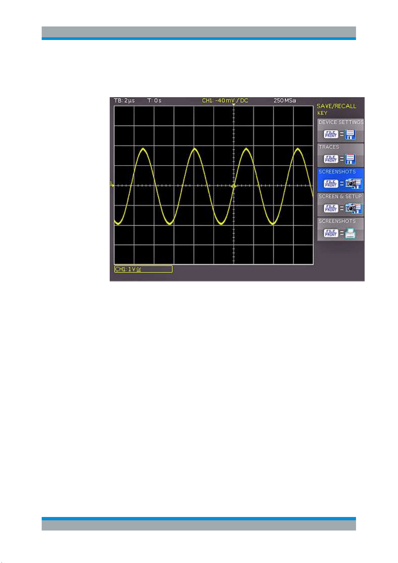
Documenting Results
R&S
®
RTC1000
106User Manual 1335.7352.02 ─ 04
● "SCREENSHOTS": Stores screenshots
● "SCREEN & SETUP": Stores screenshots and settings
● "PRINT": Prints directly to a connected printer
Figure 8-6: Definition of FILE/PRINT key
4. Configure the settings for the selected action as described in the previous sections.
If you press the [FILE/PRINT] key, the selected function is performed.
Quick Access with FILE/PRINT Key
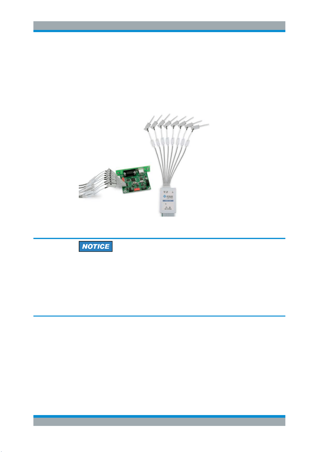
Mixed Signal Operation (Option R&S RTC-B1)
R&S
®
RTC1000
107User Manual 1335.7352.02 ─ 04
9 Mixed Signal Operation (Option R&S RTC-
B1)
The R&S RTC1000 has a connector for the R&S RT-ZL03 logic probe to add 8 digital
logic inputs. To use the logic analysis, you need the option R&S RTC-B1. The logic
probe comes with the option.
Figure 9-1: Optional logic probe R&S
RT-ZL03
Ensuring accurate measurement results
The logic analyzer option R&S RTC-B1 with connected probe leads is considered as a
test probe, according to EN 61326-2-1, clause 5.2.4.101. Therefore, the measure-
ments are sensitive to electromagnetic interference. Consider additional shielding
methods to avoid interference.
To ensure accurate measurements, attach the ground lead from the pod to the ground
of the device under test if any logic channel of the pod is used for data capture. The
ground lead improves signal fidelity to the oscilloscope.
9.1 Using Logic Channels
You can display and adjust logic channels in various ways. Make sure to set the
threshold to identify the logic states (high and low) .
●
"To set the threshold for logic states" on page 108
●
"To activate and scale logic channels" on page 108
●
"To reset the position and size of logic channels" on page 109
Using Logic Channels
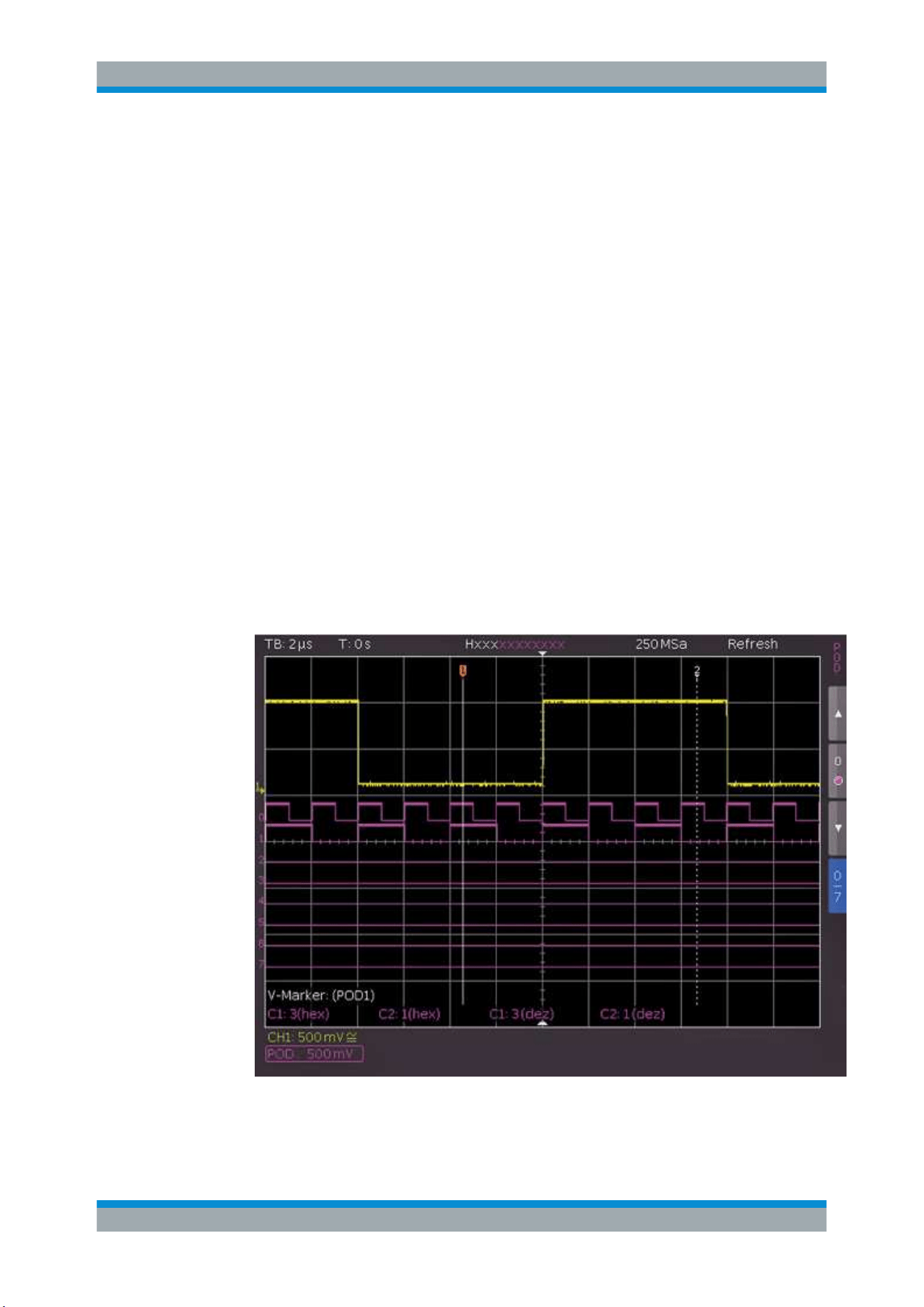
Mixed Signal Operation (Option R&S RTC-B1)
R&S
®
RTC1000
108User Manual 1335.7352.02 ─ 04
●
"To label the individual bits of the logic probe" on page 109
To set the threshold for logic states
1. Press the [POD] key.
2. Press the [MENU] key in the Vertical section.
3. Set "SETUP" = "POD".
4. Press "THRESHOLD".
5. Set the threshold:
● Select the predefined level for "TTL", "CMOS" or "ECL".
● To set a user-defined level, select "User1" or "User2".
Adjust the logic level from –2 V to 8 V with the universal knob or the [KEYPAD]
key.
To activate and scale logic channels
1. To switch on the digital channels, press the [POD] key in the Vertical section.
The digital channels 0 to 7 are shown on the screen. A logic "1" is indicated by a
bar that is two pixels wide, and a logic "0" is indicated by a bar that is one pixel
wide. The logic threshold and a figure which shows the logical states are shown
next to the name "POD" in the information field in the bottom left of the display.
Figure 9-2: Logic channels: display settings
Using Logic Channels

Mixed Signal Operation (Option R&S RTC-B1)
R&S
®
RTC1000
109User Manual 1335.7352.02 ─ 04
2. Choose the Y-position and the size of the logic channel display as you do for the
analog channels:
a) Press the softkey "0/7" in the short menu until it highlights blue.
b) To adjust size and position of all logic channels on the screen, use the vertical
[Position] and [Scale] knobs.
3. To resize and position a single channel individually:
a) Press the arrow softkeys in the short menu to choose a logic channel.
b) Press the softkey between the arrow keys to activate the channel.
c) Use the vertical [Position] and [Scale] knobs to adjust size and position of the
selected logic channel.
To reset the position and size of logic channels
1. Press the [POD] key in the Vertical section until it lights up.
2. Press the [MENU] key in the Vertical section to open the "POD" menu.
3. Press "SET TO DEFAULT POS. & SIZE" to reset the position and size of the logic
channels.
To label the individual bits of the logic probe
1. Press the [POD] key in the Vertical section until it lights up.
2. Press the [MENU] key in the Vertical section to open the "POD" menu.
3. Press "LABEL".
4. Press "BIT" and use the universal knob to select a bit.
5. To switch the display of the label on or off, press the "LABEL" softkey.
6. Press "LIBRARY" to choose a name from the list.
7. Press "EDIT LABEL" to enter a new name or to change the suggested name. You
can enter up to 8 characters.
8. Press "ACCEPT" to confirm the name in the editor.
The name is displayed on the grid and the printout. It is assigned to the signal and
moves with the waveform.
Using Logic Channels
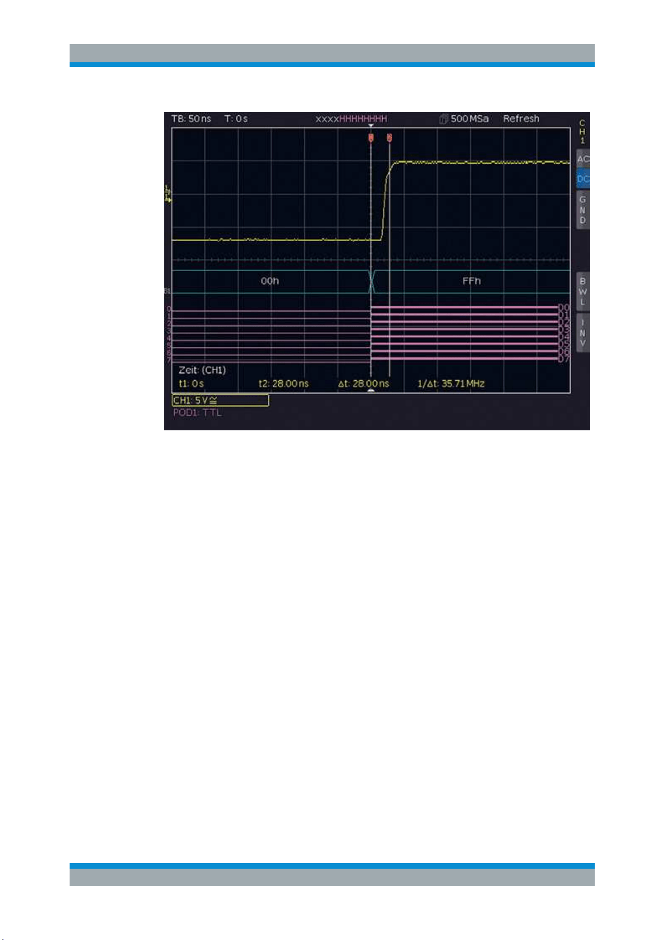
Mixed Signal Operation (Option R&S RTC-B1)
R&S
®
RTC1000
110User Manual 1335.7352.02 ─ 04
Figure 9-3: Bit DAC signal change
9.2 Logic Trigger for Digital Input
To trigger on logic channels, you can use the logic trigger, see
Chapter 5.5, "Logic Trig-
ger"
, on page 52.
9.3 Cursor Measurements for Logic Channels
If the logic channels active, you can determine several parameters using cursor mea-
surements ([CURSOR MEASURE] key).
The following measurement types are available:
●
TIME:
The display shows the time position of both cursors relative to the trigger time, the
time difference between the two positions and the resulting frequency.
●
RATIO X:
Three cursors are used to display a time ratio between the first two cursors plus the
first and third cursor. The results are shown in floating point format, in percent, in
degrees and in radians.
●
V-MARKER:
Cursor Measurements for Logic Channels

Mixed Signal Operation (Option R&S RTC-B1)
R&S
®
RTC1000
111User Manual 1335.7352.02 ─ 04
For logic channels, the logic value of the selected POD is measured at the cursor
position and shown in hexadecimal and decimal format.
9.4 Automatic Measurements for Logic Channels
If the logic channels active, you can use the automatic measurement functions to
determine several parameters ([AUTO MEASURE] key).
The following measurement types are available:
●
FREQUENCY
●
PERIOD
●
PULSE WIDTH +/–
●
DUTY CYCLE+/–
●
DELAY
●
PHASE
●
BURST WIDTH
●
COUNT PULSE +/–
●
COUNT (pos./neg.)
9.5 Using Logic Channels in Buses
You can use logic channels as input sources of various buses. Parallel buses are dedi-
cated for analysis of logic channels. Serial buses accept analog and digital channels as
input.
The general usage of buses is described in the following chapters:
●
Chapter 11.1, "Bus Configuration", on page 120
●
Chapter 11.2, "Bus Table: Decode Results", on page 122
9.5.1 Parallel / Parallel Clocked Bus
The R&S RTC1000 has a parallel and parallel bus analysis by default. No option is
required. You can analyze up to 7 lines (7 bit).
To select the parallel or parallel bus
1. Press the [BUS] key in the Vertical section.
2. In the short menu, select the bus: "B1" or "B2".
3. In the "BUS" menu, press the softkey "BUS TYPE"
4. Use the [Universal] knob to select "PARALLEL" or "PARALLEL CLOCKED".
Using Logic Channels in Buses
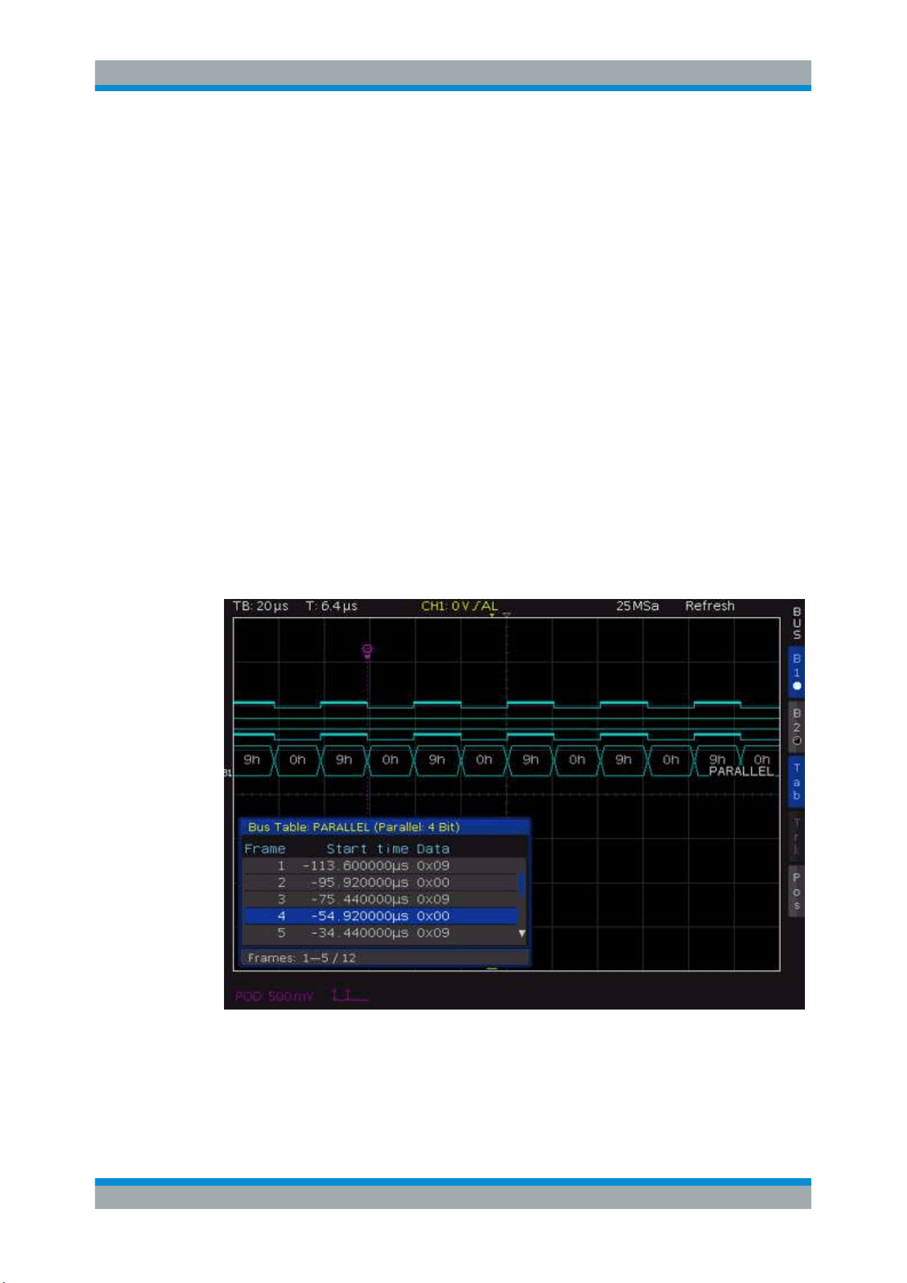
Mixed Signal Operation (Option R&S RTC-B1)
R&S
®
RTC1000
112User Manual 1335.7352.02 ─ 04
To configure the parallel or parallel bus
1. In the "BUS" menu, press "CONFIGURATION".
2. Press "BUS WIDTH". Use the [Universal] knob to select the number of bit lines.
3. Press "SOURCE".
4. Set the source lines of the individual bits:
a) Press "PREVIOUS BIT" or "NEXT BIT" repeatedly to select a bit. The selected
bit is highlighted in blue.
b) Turn the [universal] knob to assign a logic channel to the selected bit. Alterna-
tively, you can press the "SOURCE" repeatedly.
5. If you have selected "PARALLEL CLOCKED" as bus type, press the bottom softkey
"CONTROL WIRES" to set the following:
a) Press "CHIP SELECT" and select the CS source.
b) Press "ACTIVE" to determine whether the chip select signal is active high
("High") or active low ("Low").
c) Press "CLOCK" and select the clock source.
d) Press "SLOPE" to toggle between rising, falling and both slopes.
6. Press the Back softkey to return to the "BUS" main menu.
Figure 9-4: Example of a bus table for parallel bus
Using Logic Channels in Buses

Mixed Signal Operation (Option R&S RTC-B1)
R&S
®
RTC1000
113User Manual 1335.7352.02 ─ 04
Table 9-1: Content of the parallel bus table
Column Description
"Start Time" Time of frame start in relation to the trigger point
"Data" Values of the data bytes
To trigger on parallel buses, you can use the logic trigger (see Chapter 5.5, "Logic Trig-
ger"
, on page 52).
Using Logic Channels in Buses

Signal Generation (Option R&S RTC-B6)
R&S
®
RTC1000
114User Manual 1335.7352.02 ─ 04
10 Signal Generation (Option R&S RTC-B6)
The signal generation option R&S RTC-B6 provides a function generator and a pattern
generator. You can find the generator settings in the [UTIL] menu.
To load a predefined function or pattern
The instrument provides a predefined pattern files for the important functions and pat-
terns.
1. Press the [SAVE/RECALL] key.
2. Press "DEVICE SETTINGS".
3. Press "LOAD".
4. Use the Universak knob to select one of the predefined patterns (*. SCP files) from
the internal memory.
5. Press "LOAD".
10.1 Function Generator
Using the function generator, you can generate input signals for circuits testing and
other purposes. The generated signal is output at the [Aux Out] connector.
1. Press the [UTIL] key in the Vertical section.
2. Press "FUNCTION GEN".
3. Select the parameters of the generated waveform. The parameters are described
below.
An information box shows a preview of the generated waveform with the selected
parameters.
4. To deactivate the function generator, press "OFF".
FUNCTION
Selects the waveform. The following waveforms can be generated and output at the
[Aux Out] connector:
●
DC
●
Sine: Frequency range from 0.1 Hz to 50 kHz
●
Rectangle: Frequency range from 0.1 Hz to 50 kHz
●
Pulse: Frequency range from 0.1 Hz to 10 kHz
●
Triangle: Frequency range from 0.1 Hz to 10 kHz
●
Ramp: Frequency range from 0.1 Hz to 10 kHz
FREQUENCY
Selects the signal frequency. The available range depends on the selected function.
Function Generator

Signal Generation (Option R&S RTC-B6)
R&S
®
RTC1000
115User Manual 1335.7352.02 ─ 04
AMPLITUDE
Selects the signal amplitude.
OFFSET
Selects a DC offset.
10.2 Pattern Generator
The pattern generator outputs parallel patterns on the four pins P0 to P3 on the front
panel of the instrument. It is based on a 2048-bit wide memory (samples). The pattern
can be issued cyclically or individually. It is not possible to issue multiple patterns
simultaneously.
To activate the pattern generator
1. Press the [UTIL] key in the Vertical section.
2. Press "PATTERN GEN.".
3. Select the pattern.
An information box shows which pins to use.
4. Adjust the settings for the selected pattern.
Table 10-1: Settings for the pattern generator
Pattern Settings
Square wave Frequency, polarity, duty cycle
Counter Frequency, counting direction
Arbitrary Timing, pattern input
Manual Manual switching of the 4 individual connectors
UART Polarity, bit rate
SPI / I
2
C / CAN / LIN
Bit rate
10.2.1 Square Wave
You can use "SQUARE WAVE" to perform a manual probe compensation without com-
pensation wizard. The square wave function uses a 100-sample wide pattern (100 con-
ditions). Also, you can change the polarity and the duty cycle (1% to 99%).
10.2.2 Counter
A 4-bit wide counter-pattern is issued. You can determine the counting direction and
the frequency. The frequency always refers to the switching of the pattern condition.
This results in square waveforms at the individual pins, as described in
Table 10-2.
Pattern Generator
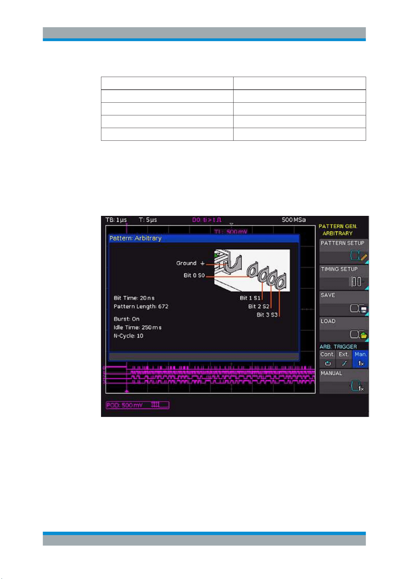
Signal Generation (Option R&S RTC-B6)
R&S
®
RTC1000
116User Manual 1335.7352.02 ─ 04
Table 10-2: Counter frequencies
Pin Frequency
P0 f/2
P1 f/4
P2 f/8
P3 f/16
10.2.3 Arbitrary
You can define a 4 bit wide and a 2048 sample deep arbitrary pattern. The created pat-
tern can be stored and loaded. If a pattern is generated when you call the arbitrary
function, the pattern is retained. Thus, you can can adapt and analyze the pattern as
necessary.
Figure 10-1: Arbitrary menu
The following settings are available:
PATTERN SETUP
Defines the pattern length and bit values.
Pattern Generator
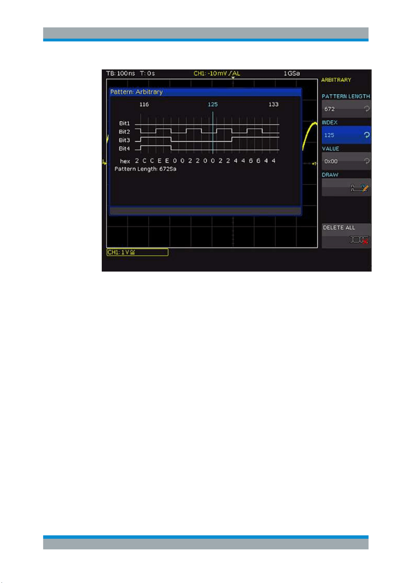
Signal Generation (Option R&S RTC-B6)
R&S
®
RTC1000
117User Manual 1335.7352.02 ─ 04
Figure 10-2: Arbitrary pattern setup
"PATTERN
LENGTH"
Determines the pattern depth.
"INDEX"
Selects the sample, for which the value is set. The selected sample is
marked in the information box by a blue line. Around the index, ±8
bits are displayed.
"VALUE"
Sets the value of the selected sample.
"DRAW"
Ccopies the value of the selected sample to the samples before or
after by turning the [Universal] knob.
"DELETE ALL"
Ddeletes the pattern. The pattern length is reset to 1. All values are
set to 0.
TIMING SETUP
Defines the time characteristics of the pattern.
"BIT TIME"
Sets length of a bit, how long a sample is applied. The time is identi-
cal for all samples.
"PERIOD"
Sets the time of the entire pattern: Period = Pattern length * Bit time.
If you change the value, the instrument adjusts the bit time.
"BURST"
If "On", the instrument pauses after each pattern for the duration of
the "IDLE TIME". Then the pattern is issued again.
"IDLE TIME"
Sets the waiting time between two patterns from 20 ns to 42 s in
increments of 10 ns.
Pattern Generator

Signal Generation (Option R&S RTC-B6)
R&S
®
RTC1000
118User Manual 1335.7352.02 ─ 04
"N-CYCLE"
Defines how often a pattern is issued if "BURST" = "On". If the burst
is disabled, the setting is not available.
SAVE/LOAD
Saves the created pattern, or loads and apllies a previously saved pattern. The pattern
can be stored internally or externally on a connected USB flash drive. The pattern set-
tings and the time settings are saved.
ARB. TRIGGER
Defines when the instrument issues the pattern.
"CONT."
Issues the pattern continuously. If the burst is enabled, the idle time is
applied between the patterns, but the "N-CYCLE" is ignored.
"EXT."
The pattern is issued by an edge at the external trigger input of the
oscilloscope ([Ext. Trigger In]). You can select the direction of the trig-
gering edge. If "BOTH" is selected, both edges are of equal value.
The first edge triggers the pattern. The edges do not alternate.
If the burst is enabled, the idle time is applied between the patterns,
and the pattern is issued <n> times.
"MAN."
The pattern is issued manually by pressing the "MANUAL" key. If the
burst is enabled, the idle time number of cycles are applied
10.2.4 Manual
In the manual pattern mode, each pin is assigned to a softkey and the condition High
("H") or Low ("L") is selected.
10.2.5 Serial Buses
On the second page of the PATTERN GEN. menu, you find the settings to generate
bus signals for measurements without measurement object. The generated bus signals
are pseudo random patterns and are not adaptable. Only the bus type and the data
rate can be selected.
The following bus signals can be generated:
●
SPI: Data rate 100 kBit/s, 250 kBit/s or 1 MBit/s
●
I2C: Data rate 100 kBit/s, 400 kBit/s, 1 MBit/s or 3.4 MBit/s
●
UART: Data rate 9600 Bit/s, 115.2 kBit/s and 1 MBit/s
●
CAN: up to 50 MBit/s
●
LIN: up to 50 MBit/s
The left contact is always ground, the signal levels are about 1 V. The following table
shows how the outputs P0, P1, P2 and P3 are used.
Pattern Generator

Signal Generation (Option R&S RTC-B6)
R&S
®
RTC1000
119User Manual 1335.7352.02 ─ 04
Table 10-3: Pin assignment of the bus signal source
Signal P1 P2 P3
P0 /
SPI Clock MOSI MISO Chip Select
I
2
C
Data SDA no signal no signal Clock SCL
UART RX no signal no signal TX
CAN CAN L no signal no signal CAN H
LIN Low no signal no signal High
An information box is displayed for each bus, displaying the connector assignment.
Adjust the bitrate of the selected bus.
Pattern Generator

Serial Bus Analysis
R&S
®
RTC1000
120User Manual 1335.7352.02 ─ 04
11 Serial Bus Analysis
To trigger and decode serial buses on the digital channels and on the analog inputs,
the following options are available:
●
R&S RTC-K1: I
2
C and SPI buses
●
R&S RTC-K2: UART/RS-232 buses
●
R&S RTC-K3: CAN and LIN buses
The serial bus analysis is performed with 1/8 of the sampling rate.
The usage of digital channels requires the logic probe R&S RT-ZL03 and option
R&S RTC-B1.
In the "BUS" menu, you find also the settings for parallel buses. Parallel buses are
dedicated for analysis of logic channels and described in
Chapter 9, "Mixed Signal
Operation (Option R&S RTC-B1)"
, on page 107.
The analysis of parallel and serial data consists of the following three basic steps:
●
Protocol configuration (bus type / protocol-specific settings)
●
Decoding (Display of decoded data / zoom / bus table)
●
Trigger (Start / stop / serial pattern)
11.1 Bus Configuration
Before you can adjust the settings for the trigger and decoding functions, you must
define a bus. Two buses, B1 and B2, can be defined.
Before you configure the bus, set the correct logic level (threshold).
●
For analog channels, see
"THRESHOLD menu" on page 36.
●
For digital channels, see
"To set the threshold for logic states" on page 108. The
default value is 500 mV.
To define a bus
1. Press the [BUS] key in the Vertical section until it lights up in white.
2. In the short menu, press the softkey "B1" or "B2" until a menu opens.
Alternatively, press the [MENU] button in the Vertical section and press the top soft-
key to define the bus.
3. Press "BUS TYPE" and use the [Universal] knob to select one of the following bus
types:
● "PARALLEL" and "PARALLEL CLOCKED": analysis of logic channels, see
Chapter 9.5.1, "Parallel / Parallel Clocked Bus", on page 111.
Bus Configuration
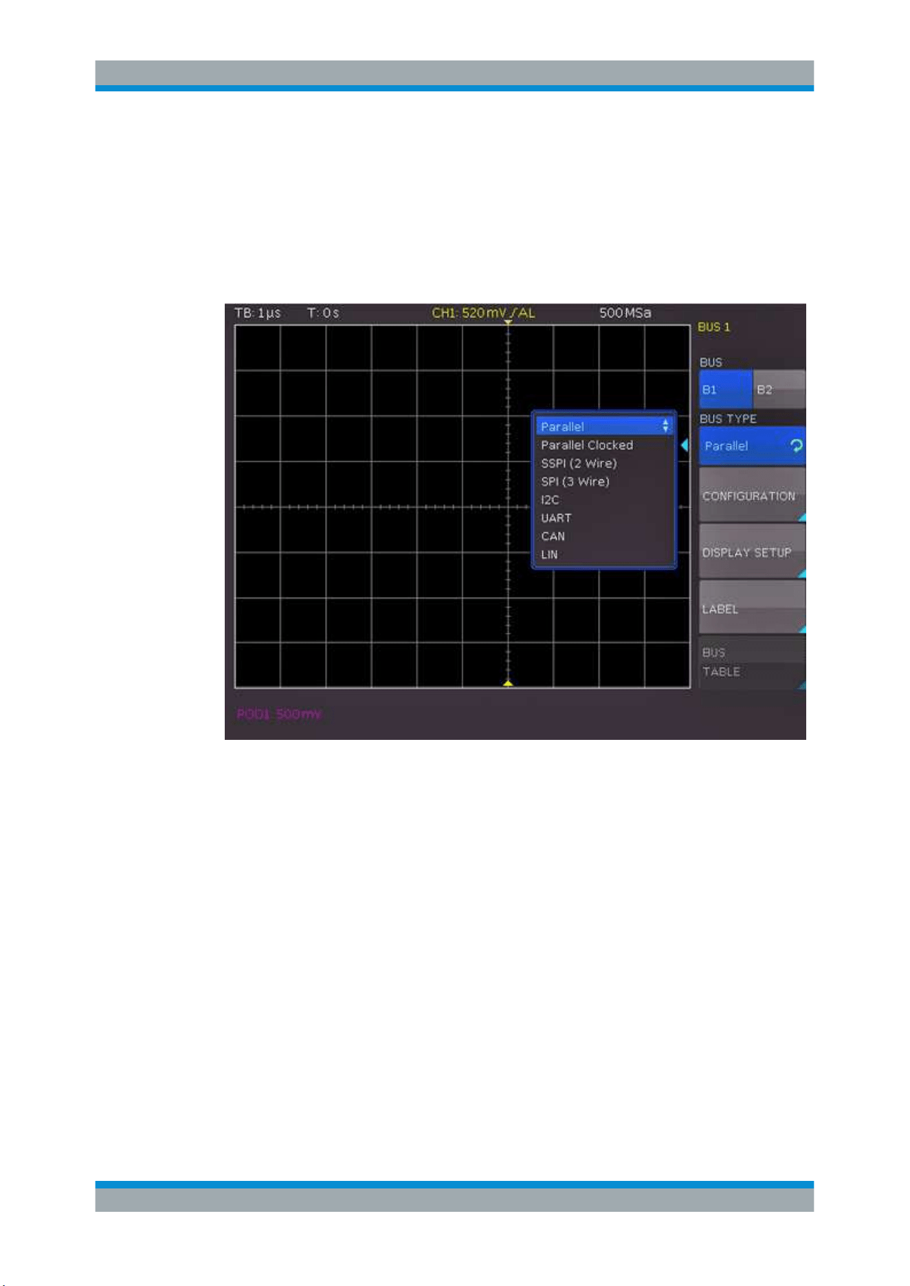
Serial Bus Analysis
R&S
®
RTC1000
121User Manual 1335.7352.02 ─ 04
● "SSPI" (available with R&S RTC-K1)
● "SPI" (available with R&S RTC-K1)
●
"I
2
C" (available with R&S RTC-K1)
● "UART" (available with R&S RTC-K2)
● "CAN" (available with R&S RTC-K3)
● "LIN" (available with R&S RTC-K3)
Figure 11-1: Menu for bus definition
To configure the selected bus type
► Press "CONFIGURATION".
The configuration menu for the selected bus type opens. A menu description can
be found in the chapters describing the bus types.
To define the display settings:
1. Press "DISPLAY SETUP".
2. Press "DISPLAY" repeatedly to select one of the following decoding formats:
● Binary
● Hexadecimal
● Decimal
● ASCII
Bus Configuration

Serial Bus Analysis
R&S
®
RTC1000
122User Manual 1335.7352.02 ─ 04
3. Press "BITS" to activate or deactivate the display of individual bit lines above the
table display.
To enter a bus name
1. Press "LABEL".
2. To switch on or off the label display, press "LABEL".
3. To choose a name from a predefined list, press "LIBRARY"
4. To enter a new name or to customize the suggested name, press "EDIT LABEL".
You can enter up to 8 characters.
Press "ACCEPT" to confirm the name in the editor.
The name is displayed on the grid and the printout.
11.2 Bus Table: Decode Results
The bus table shows the decode results of the bus. You can adjust the content of the
table, and export the decode data to a file.
The table content is protocol-specific. You can activate the table display for each bus
type.
To activate the bus table
1. In the "BUS" menu, press "BUS TABLE" to open the menu.
2. To activate the bus table, press "BUS TABLE".
Make sure that a complete message of a serial protocol is displayed on the screen to
ensure that decoding can function properly. Use the zoom function to see details of the
message.
Bus Table: Decode Results
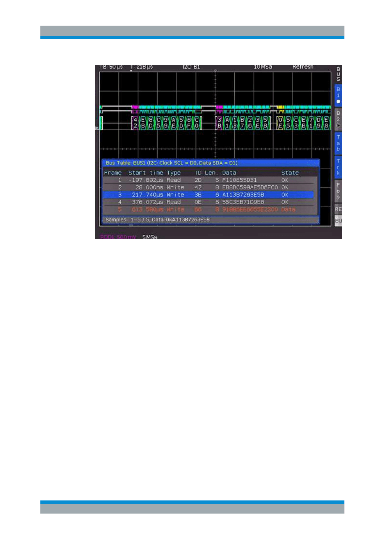
Serial Bus Analysis
R&S
®
RTC1000
123User Manual 1335.7352.02 ─ 04
Figure 11-2: Example of I2C BUS with bus table
To export the decode results
1. Stop the acquisition.
2. In the "BUS TABLE" menu, press "SAVE".
3. Connect a USB flash drive to the instrument.
4. Save the bus table.
For each frame, one line is written to the file, for example:
"Bus table: BUS1 (I2C: Clock SCL = D0, Dates SDA = D1)“
Frame,Mark,Start time[s],Type,ID,Length,Date,Condition
1,,-197.89200e-6,Read,0x2D,5,0xF110E55D31,OK
2,,28.00000e-9,Write,0x42,8,0xEB8DC599AE5D6FC0,OK
3,,217.74000e-6,Write,0x3B,6,0xA113B7263E5B,OK
4,,376.07200e-6,Read,0x0E,6,0x55C3EB71D9E8,
OK
5,,613.58000e-6,Write,0x66,8,0x91B86EE6655E2300,Data Error
The "BUS TABLE" menu provides the following settings:
Bus Table: Decode Results

Serial Bus Analysis
R&S
®
RTC1000
124User Manual 1335.7352.02 ─ 04
BUS TABLE
Activates or deactivates the list view. Generally, a complete message (frame) of a pro-
tocol is displayed in a row. The columns contain time information, data, and address
message if applicable. The number of rows in the table is identical to the number of
complete message frames in the instrument memory. The softkey "TAB" in the "BUS"
short menu activates or deactivates the bus table without opening a menu.
TRACK FRAME
Enables scrolling the bus table and simultaneously jump to the selected position in the
memory using the [Universal] knob. Tracking is only possible if acquisition has been
stopped. This function is also available in the short "BUS" menu: "TRK" (= Track).
FRAME TIME DIFFERENCE
If activated, the bus table shows the time difference to the previous frame (data
packet). This column is labeled as "TIME DIFF".
If deactivated, the absolute time in relation to the trigger point is displayed in the col-
umn "START TIME".
POSITION
Moves the bus table to the top or bottom of the screen, or displays the bus table in full
screen. You can also use the softkey "POS" in the "BUS" short menu to toggle the
position.
SAVE
Saves the decoding results in a CSV file on USB flash drive.
11.3
I
2
C Bus (Option R&S
RTC-K1)
For I
2
C bus trigger and decoding, you need the R&S RTC-K1 option.
The I
2
C bus is a two-wire bus, which was developed by Philips (today known as NXP
Semiconductor).
An I
2
C bus has the following properties:
●
Two wires: clock (SCL) and data (SDA).
●
Master-slave communication: the master provides the clock pulse and selects the
slave.
●
Addressing: Each slave can be addressed with a unique address. Multiple slaves
can be linked with each other and can be addressed by the same master.
●
Read/Write bit: Master reads data (= 1) or writes data (= 0).
●
Acknowledge bit: issued after each byte
I
2
C Bus (Option R&S RTC-K1)
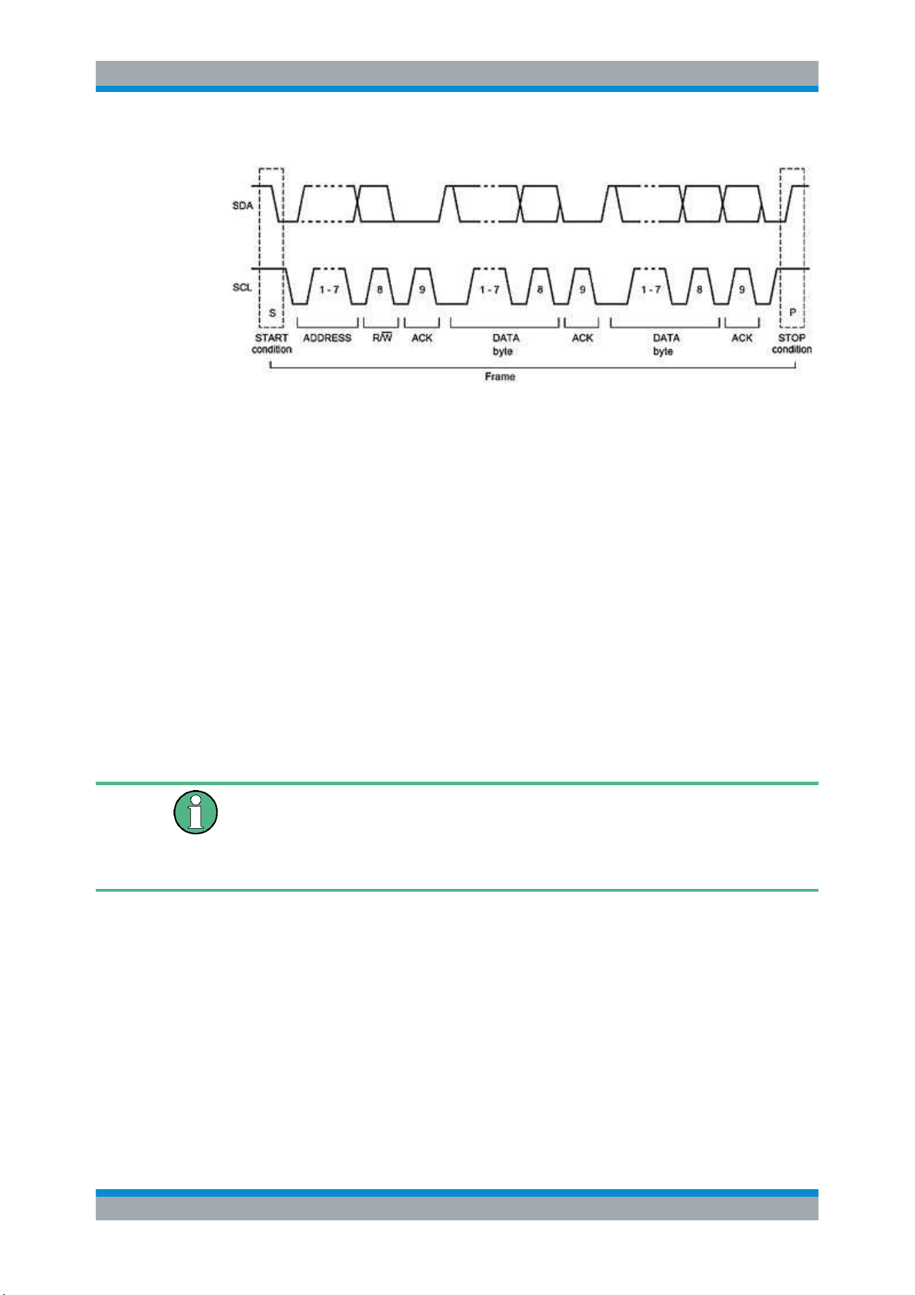
Serial Bus Analysis
R&S
®
RTC1000
125User Manual 1335.7352.02 ─ 04
Figure 11-3: I2C 7-bit address
The format of a simple I
2
C message (frame) with an address length of 7 bit has the
following structure:
●
Start condition: falling slope on SDA (serial data), while SCL (serial clock) is high
●
7-bit address (write or read slave)
●
Read/Write bit (R/W): indicates if the data is to be written or read out from the slave
●
Acknowledge bit (ACK): is issued by the recipient of the previous byte if transmis-
sion was successful. Exception: for read access, the master terminates the data
transmission with a NACK bit after the last byte.
●
Data: a series of data bytes with an ACK bit after each byte
●
Stop condition: rising slope on SDA (serial data), while SCL (serial clock) is high
11.3.1
I
2
C Bus Configuration
Before you configure the bus, set the correct logic level (threshold).
●
For analog channels, see
"THRESHOLD menu" on page 36.
●
For digital channels, see
"To set the threshold for logic states" on page 108. The
default value is 500 mV.
To select the I
2
C bus
1. Press the [BUS] key in the Vertical section.
2. In the short menu, select the bus: "B1" or "B2".
3. In the "BUS" menu, press the softkey "BUS TYPE"
4. Use the [Universal] knob to select "I2C".
To decode the I
2
C bus, the instrument needs information which logic channel is con-
nected to the clock (SCL) and which is connected to the data line (SDA).
I
2
C Bus (Option R&S RTC-K1)
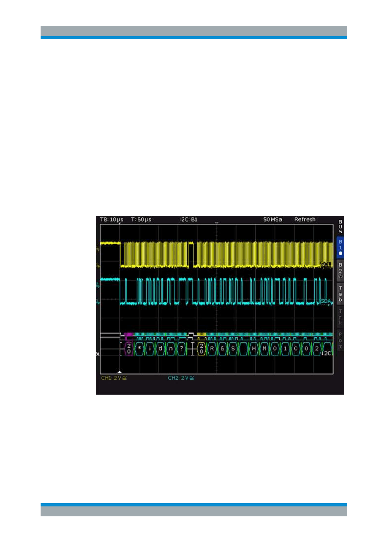
Serial Bus Analysis
R&S
®
RTC1000
126User Manual 1335.7352.02 ─ 04
To configure the I
2
C bus
1. In the "BUS" menu, press "CONFIGURATION".
2. To select the source channel, press "CLOCK SCL". Use the [Universal] knob to
select.
3. To define the data channel, press "DATA SDA" and use the [universal] knob.
4. Press "7BIT ADDRESS" to choose whether the address is interpreted inclusive
("ADR.+ RW") or without the Read/Write bit ("ADDR. ONLY").
A small window provides information about the current settings.
5. Press the Back softkey twice to close all menus.
11.3.2
I
2
C Bus Triggering
After the bus configuration is completed, you can trigger on various events.
Figure 11-4: I2C bus
To trigger on events
1. In the Trigger section, press the [TYPE] key.
2. Select "SERIAL BUS".
3. Press the [SOURCE] key in the Trigger section.
4.
Choose the "I
2
C" bus by pressing the respective softkey.
I
2
C Bus (Option R&S RTC-K1)

Serial Bus Analysis
R&S
®
RTC1000
127User Manual 1335.7352.02 ─ 04
The bus is only available if it is configured correctly.
5.
Press the [FILTER] key in the Trigger section to list all available I
2
C trigger condi-
tions.
6. Configure the trigger condition. Possible conditions are described below.
7. Press the Back softkey until all menus are closed.
The oscilloscope triggers on the condition. For measurements without measuring
object, refer to chapter
Chapter 10.2.5, "Serial Buses", on page 118.
START
Triggers on the frame start sequence. The start sequence is the falling slope on SDA
when SCL is high.
STOP
Triggers on the frame stop sequence. The stop signal is the rising slope on SDA when
SCL is high.
RESTART
Triggers if a new start sequence occurs before the stop condition. The new start signal
is a repeated start signal.
NOT-ACKNOWLEDGE
The NOT-ACKNOWLEDGE bit is the 9th bit in a data or address pattern of the SDA
line. For NOT-ACKNOWLEDGE, the acknowledge bit is high on SDA, although it
should be low.
READ/WRITE
Sets the following additional trigger options:
I
2
C Bus (Option R&S RTC-K1)
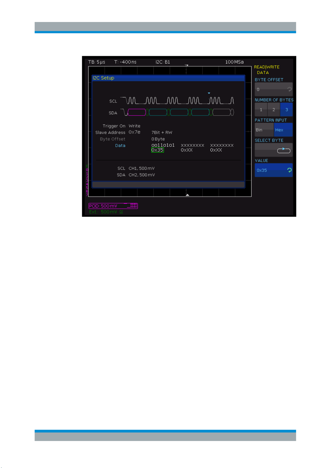
Serial Bus Analysis
R&S
®
RTC1000
128User Manual 1335.7352.02 ─ 04
Figure 11-5: Read/Write trigger menu
"MASTER"
Toggles the trigger condition between read and write access. The 8th
bit of the first data unit (depending on the address length) is used to
distinguish between read and write access. The selected condition is
displayed in the I
2
C settings window.
"ADDRESS
LENGTH"
Defines the address length, and thus the maximum number of slave
addresses. For a 7-bit address length, the maximum number of avail-
able addresses is 112. The 10-bit addressing mode is downward
compatible with the 7-bit addressing mode by using 4 of 16 reserved
addresses and can be used simultaneously. For a 10-bit address
length, a total of 1136 addresses (1024 + 128 - 16) is available. The
highest 10-bit address is 1023 (0x3FF). The selected address length
is displayed in the I
2
C settings window.
"SLAVE
ADDRESS"
Sets the address of the slave the master communicates with. Use the
[Universal] knob to select the address to be triggered.
"DATA"
Trigger on a specific address and/or data pattern. See
"DATA"
on page 128.
DATA
"DATA" triggers on specific data in addition to the address. You can trigger on clearly
defined data bytes (color cyan) within the transmission, allowing you to filter out irrele-
vant transmissions. You can trigger on up to 24 bit (3 bytes) of data. An offset of 0 to
4095 to the address is allowed.
I
2
C Bus (Option R&S RTC-K1)

Serial Bus Analysis
R&S
®
RTC1000
129User Manual 1335.7352.02 ─ 04
BYTE OFFSET ← DATA
Defines the number of bytes to be ignored before the relevant bytes of the trigger con-
dition. Usually, the byte offset is zero if the trigger is to occur on the maximum first 24
bits after the address.
NUMBER OF BYTES ← DATA
Defines how many bytes are to be analyzed for the trigger condition.
PATTERN INPUT ← DATA
You can define the bit pattern in binary or hexadecimal format.
If binary input is selected, use "SELECT BIT" and the [Universal] knob to select the bit.
Then press "STATE" to set the state H (=1), L (=0) or X (do not care) for the selected
bit. The state X defines any state. Repeat until all bits are set.
If hexadecimal input is selected, only the entire byte can be set to X. Use the softkey
"SELECT BYTE" to choose one of the bytes, depending on the available number of
bytes. Use the softkey "VALUE" and the [universal] knob to set the byte value. The
active byte is marked with a green border in the display window of the trigger condition
(see
Figure 11-5).
11.3.3
I
2
C Decode Results
Certain portions of the I
2
C messages are displayed in color to distinguish between the
different parts. If the data lines are selected in the bus table, the respective sections
are also displayed in color.
●
Read address: Yellow
●
Write address: Magenta
●
Data: Cyan
●
Start: White
●
Stop: White
●
No acknowledge: Red
●
Acknowledge: Green
The bus table lists the decode results. See also:
Chapter 11.2, "Bus Table: Decode
Results"
, on page 122.
I
2
C Bus (Option R&S RTC-K1)
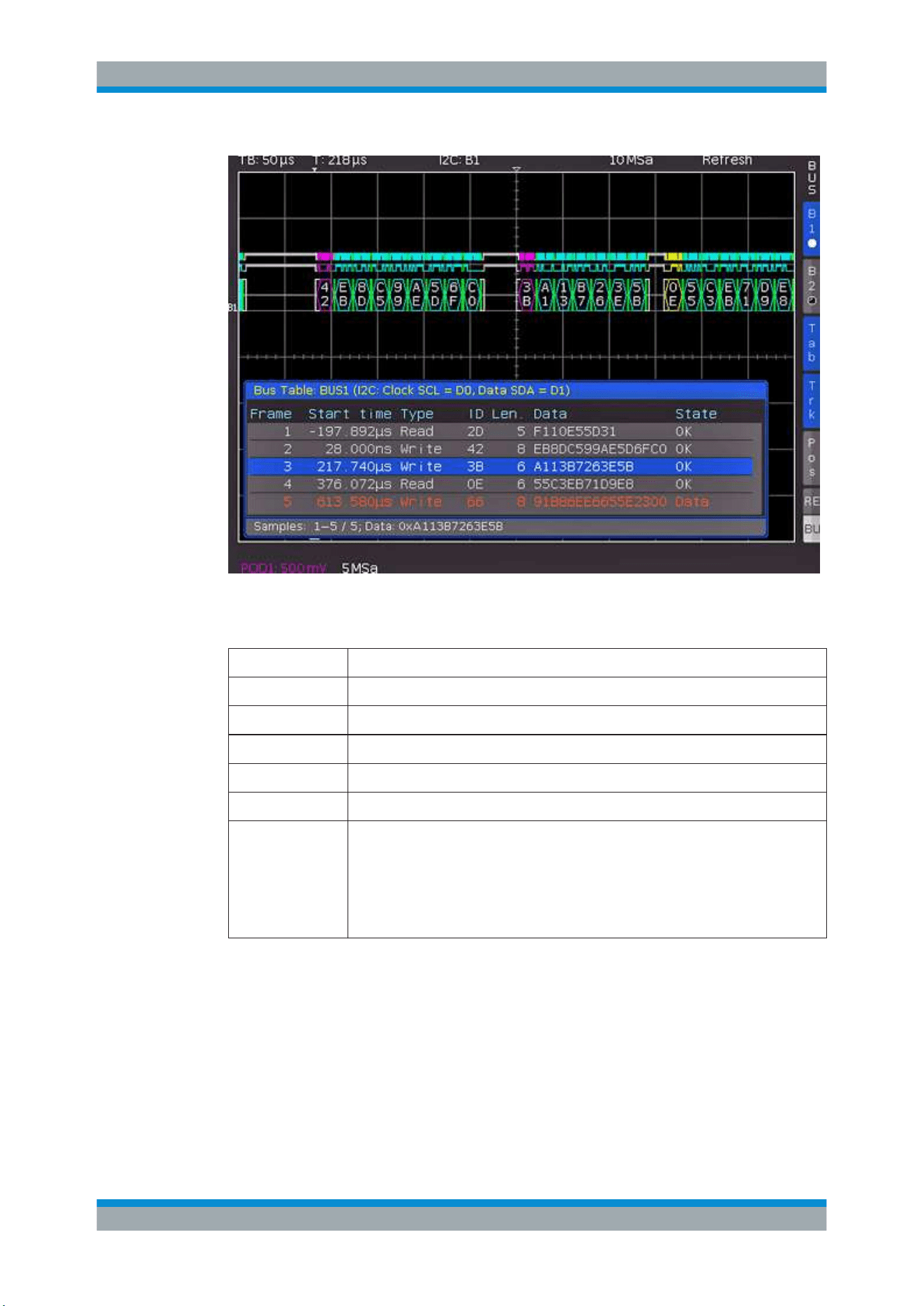
Serial Bus Analysis
R&S
®
RTC1000
130User Manual 1335.7352.02 ─ 04
Figure 11-6: I2C bus table
Table 11-1: Content of the I
2
C bus table
Column Description
"Start Time" Time of frame start in relation to the trigger point
"Type" Value of the R/W bit (Read/Write)
"ID" Value of address
"Length" Number of words in the frame
"Data" Values of the data words
"State"
Frame state:
●
"OK" = frame is valid
●
"DATA" = during acquisition start/end only the frame start / frame end has been
decoded; currently no data available
●
"ADDR. ERR." = incomplete frame decoding
●
"INS" = the frame is not contained in the acquisition; the acquired part of the
frame is valid.
11.4 SPI / SSPI BUS (Option R&S RTC-K1)
For SPI/SSPI bus trigger and decoding, you need the R&S RTC-K1 option.
The Serial Peripheral Interface SPI is used to communicate with slow peripheral devi-
ces, in particular for the transfer of data streams. The SPI bus was developed by
Motorola; however, it has not been formally standardized. Generally, it is a bus with
clock and data lines and a select line (3-wire). If only one master and one slave are
SPI / SSPI BUS (Option R&S RTC-K1)
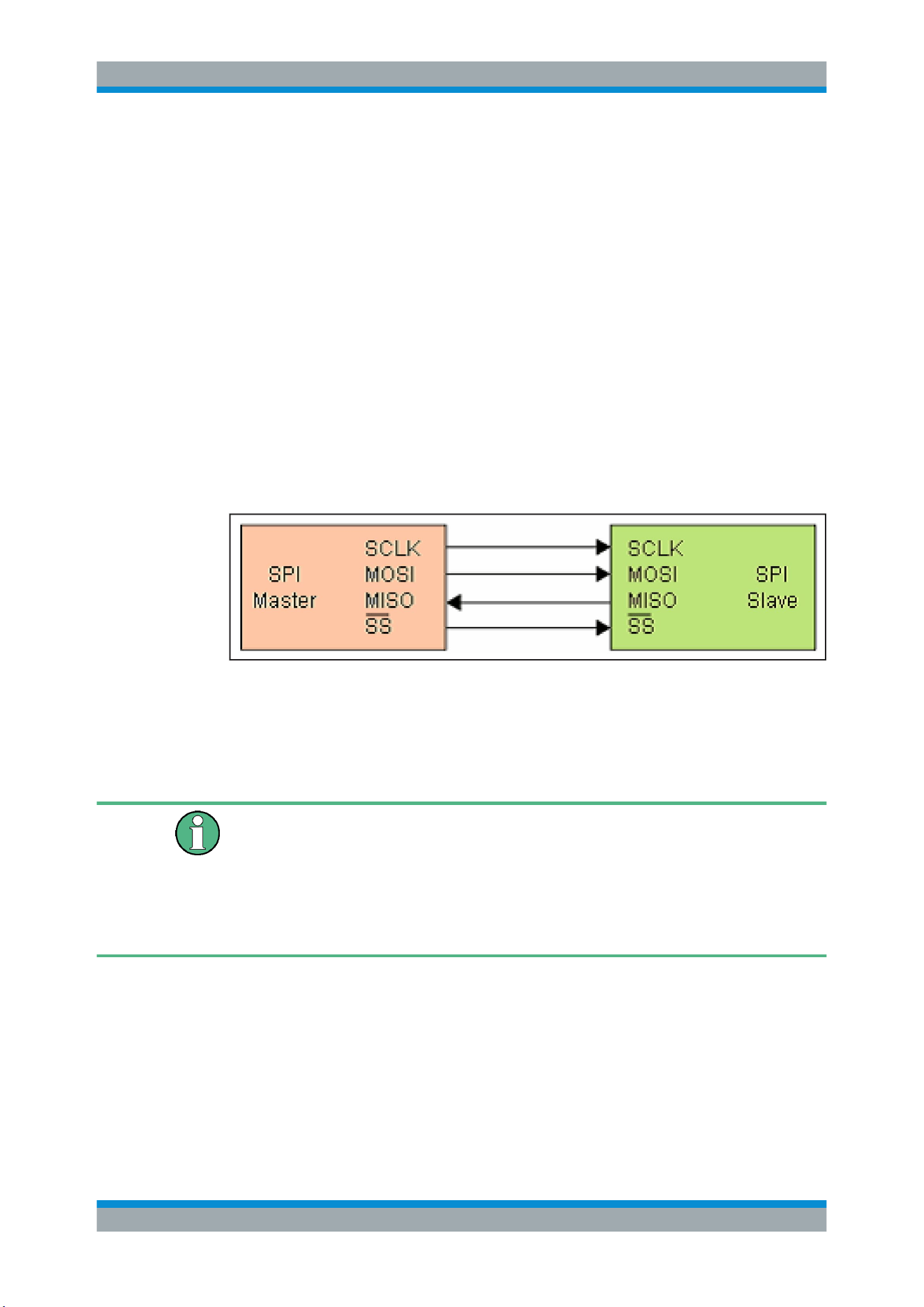
Serial Bus Analysis
R&S
®
RTC1000
131User Manual 1335.7352.02 ─ 04
present, the select line can be deleted. This type of line is also called SSPI (Simple
SPI) (2-wire).
An SPI bus has the following properties:
●
Master-slave communication
●
No instrument addressing
●
No acknowledge to confirm data reception
●
Duplex capability
Most SPI buses have four common lines, two data lines and two control lines:
●
Clock to all slaves (SCLK)
●
Slave select or chip select lines (SS or CS)
●
Master-Out-Slave-In, Slave-Data-Input (MOSI or SDI)
●
Master-In-Slave-Out, Slave-Data-Output (MISO or SDO)
If the master generates a clock pulse and selects a slave, data can be transmitted in
either one direction or simultaneously in both directions.
Figure 11-7: Simple configuration of SPI bus
11.4.1 SPI / SSPI Bus Configuration
Before you configure the bus, set the correct logic level (threshold).
●
For analog channels, see
"THRESHOLD menu" on page 36.
●
For digital channels, see
"To set the threshold for logic states" on page 108. The
default value is 500 mV.
For 3-wire SPI, the external trigger input is used as CS (Chip Select). The threshold
can be set in the bus configuration menu.
To select the SPI or SSPI bus
1. Press the [BUS] key in the Vertical section.
2. In the short menu, select the bus: "B1" or "B2".
3. In the "BUS" menu, press the "BUS TYPE" softkey.
4. Use the [Universal] knob to select:
● "SSPI" for a 2-wire SPI system.
SPI / SSPI BUS (Option R&S RTC-K1)
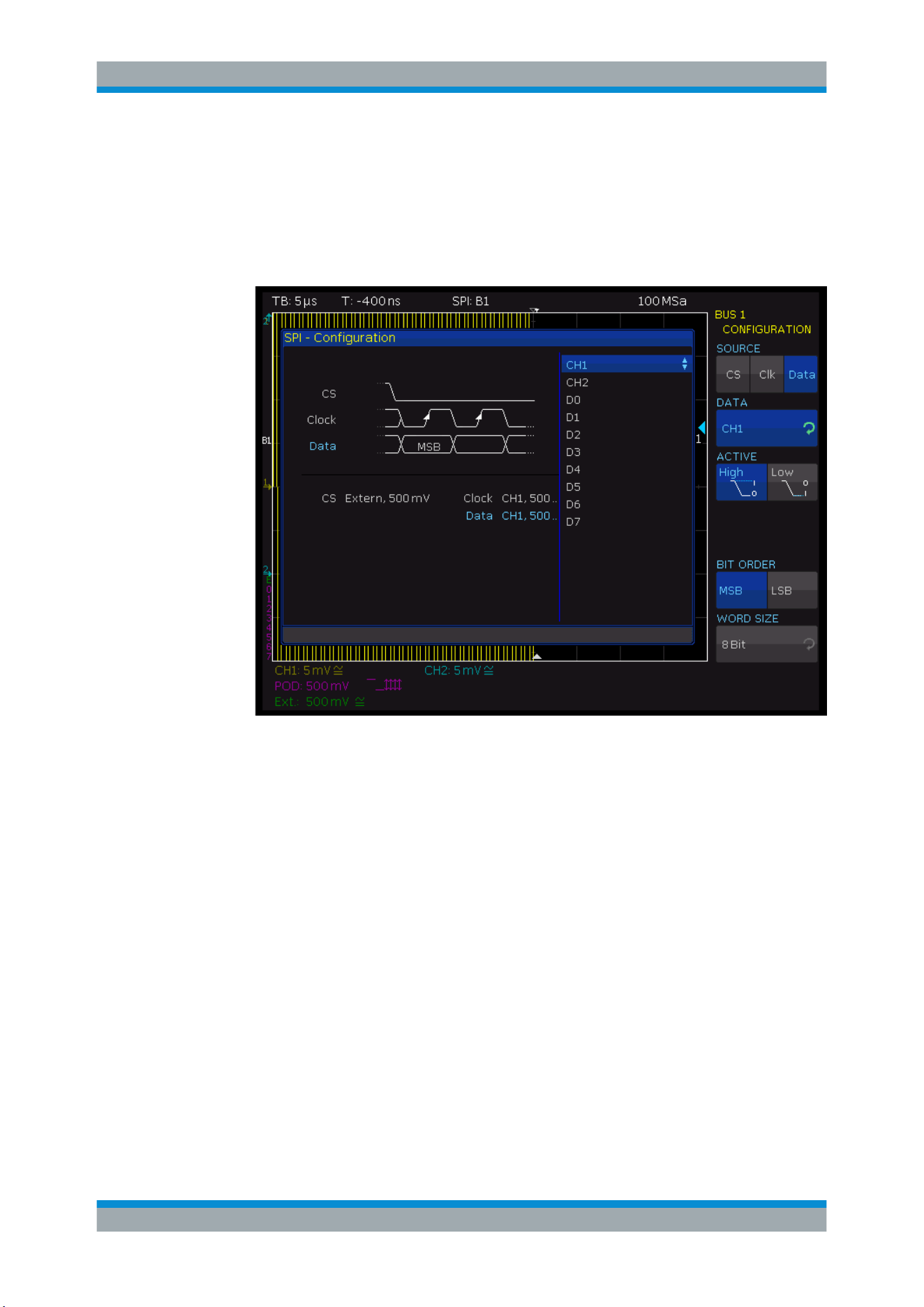
Serial Bus Analysis
R&S
®
RTC1000
132User Manual 1335.7352.02 ─ 04
● "SPI" for a 3-wire SPI system.
To configure the SPI bus
1. In the "BUS" menu, press "CONFIGURATION".
2. Press "SOURCE" to select the chip select ("CS"), clock ("Clk") or data line ("Data").
Figure 11-8: Menu for the definition of an SPI bus
3. Press the second softkey ("CHIP SELECT", "CLOCK", or "DATA". Use the
[Universal] knob to select the source channel.
4. If "CS" is selected, press "ACTIVE" to set high or low active (low active is the
default setting).
5. If "Clk" is selected, press "SLOPE" to decide whether the data is stored with rising
or falling slope (rising slope is the default setting).
6. If "Data" is selected, press "ACTIVE" to assign whether data is high or low active
(high active is the default setting).
7. Press "BIT ORDER" to determine if the data of each message starts with the
"MSB" (most significant bit) or the "LSB" (least significant bit).
8. Press "WORD SIZE" to select with the [Universal] knob how many bits are included
in each message. You can select a value between 1 bit and 32 bits.
To configure the SSPI bus
1. In the "BUS" menu, press "CONFIGURATION".
SPI / SSPI BUS (Option R&S RTC-K1)

Serial Bus Analysis
R&S
®
RTC1000
133User Manual 1335.7352.02 ─ 04
2. Press "SOURCE" to select the clock ("Clk"), data line ("Data"), and the timeout
("Time").
3. If "Clk" is selected:
a) Press "CLOCK".
b) Select the input channel of the clock line.
c) Press "SLOPE" to decide whether the data is stored with rising or falling slope
(rising slope is the default setting).
4. If "Data" is selected:
a) Press "DATA".
b) Select the input channel of the data line.
c) Press "ACTIVE" to assign whether data is high or low active (high active is the
default setting).
5. If "Time" is selected, press "TIME OUT". Use the [Universal] knob to set the idle
time.
6. Use the top softkey "SOURCE" to select the respective channel for clock ("Clk")
and data ("Data") or to select the time-out time ("Time").
During the time-out, data and clock line are at Low. When the time-out has been
reached, a new frame begins. If the time intervals between the data packets are
shorter than the time-out, these packets belong to the same frame. A small window
provides information about the current settings.
7. Press "BIT ORDER" to determine if the data of each message starts with the
"MSB" (most significant bit) or the "LSB" (least significant bit).
8. Press "WORD SIZE" to select with the [Universal] knob how many bits are included
in each message. You can select a value between 1 bit and 32 bits.
11.4.2 SPI / SSPI Bus Triggering
After the bus configuration is completed, you can trigger on various events.
To trigger on events
1. In the Trigger section, press the [TYPE] key.
2. Select "SERIAL BUS".
3. Press the [SOURCE] key in the Trigger section.
4. Choose "SPI" or "SSPI" by pressing the respective softkey.
The bus is only available if it is configured correctly.
5. Press the [FILTER] key in the Trigger section to list the trigger conditions of the
bus.
6. Configure the trigger condition. Possible conditions are described below.
7. Press the Back softkey until all menus are closed.
SPI / SSPI BUS (Option R&S RTC-K1)

Serial Bus Analysis
R&S
®
RTC1000
134User Manual 1335.7352.02 ─ 04
The oscilloscope triggers on the condition. For measurements without measuring
object, refer to chapter
Chapter 10.2.5, "Serial Buses", on page 118.
FRAME START
Triggers on the start of the frame. The frame starts when the chip select ("CS") signal
switches to the selected active mode, or when the time-out exceeded, at the next clock
edge.
FRAME END
Triggers on the end of the frame. The frame ends when the chip select ("CS") signal
switches from the selected active to the inactive mode, or when the time-out exceeded.
BIT
Triggers on the selected bit within the bit sequence. Use the [Universal] knob or the
[KEYPAD] to set the bit number.
SER. PATTERN
Triggers on a specific bit pattern at a given position in the frame.
BIT OFFSET ← SER. PATTERN
Defines the position of the first bit of the configured bit sequence within the frame. The
bits in front of it have no impact on the trigger event. For example, if the bit offset = 2,
bit 0 and bit 1 after CS are ignored and the pattern begins with bit 2. You can select a
value between 0 and 4095 using the [Universal] knob or the [KEYPAD].
NUMBER OF BITS ← SER. PATTERN
Sets the number of bits are analyzed for the trigger condition. You can select a value
between 1 bit and 32 bit.
PATTERN INPUT ← SER. PATTERN
See
"PATTERN INPUT" on page 129.
11.4.3 SPI / SSPI Decode Results
Certain parts of the SPI/SSPI messages are displayed in color to distinguish between
the different elements:
●
White: Start / End of complete frame
●
Red: Incomplete word that is not contained in the acquisition; change the horizontal
scale or move the "Time Reference" to get a longer acquisition
●
Cyan: Decoded words
SPI / SSPI BUS (Option R&S RTC-K1)
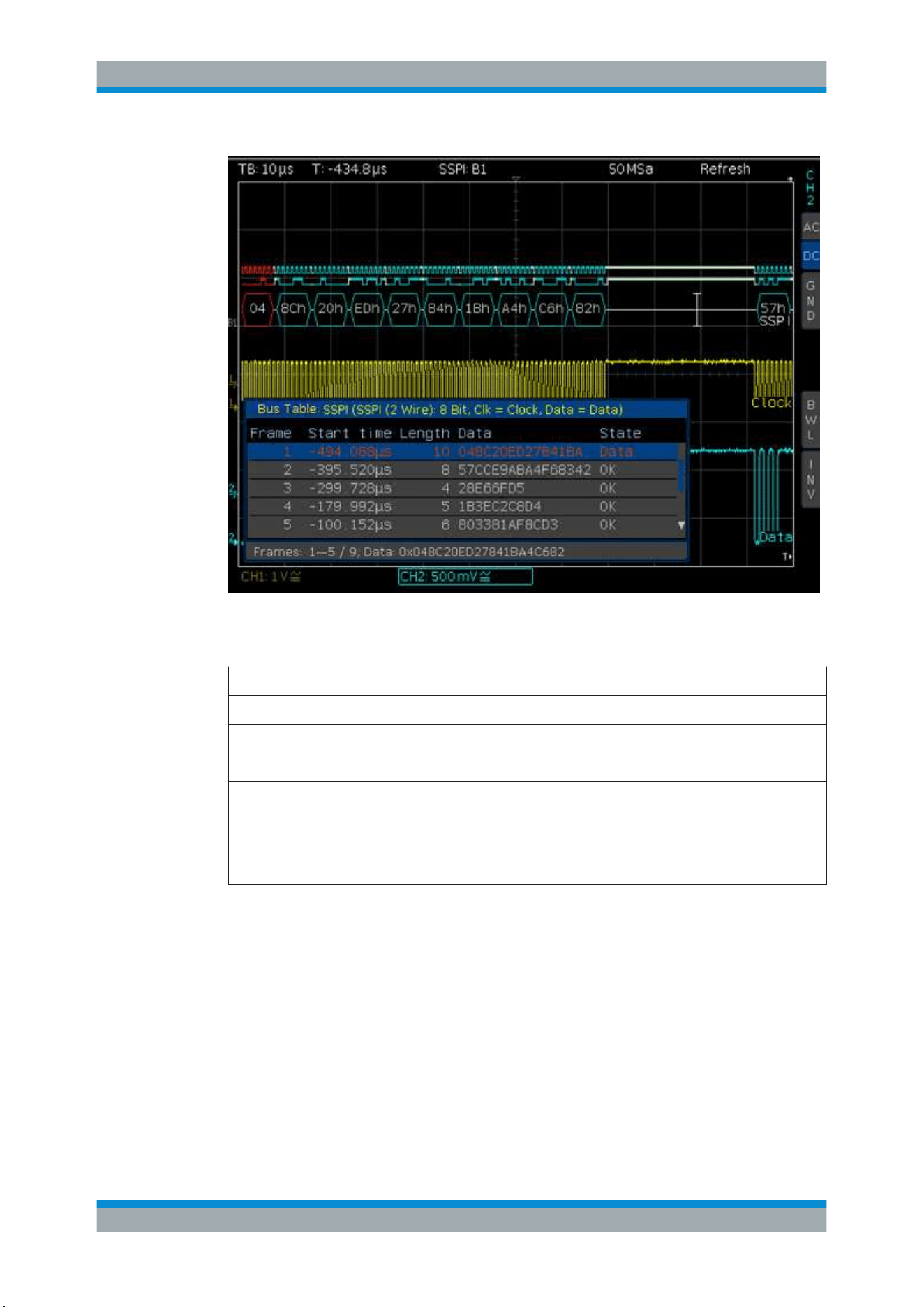
Serial Bus Analysis
R&S
®
RTC1000
135User Manual 1335.7352.02 ─ 04
Figure 11-9: Example of an SSPI bus table
Table 11-2: Content of the SPI/SSPI bus table
Column Description
"Start Time" Time of frame start in relation to the trigger point
"Length" Number of words in the frame
"Data" Values of the data words
"State"
Frame Status:
●
"OK" = frame is valid
●
"DATA" = during acquisition start/end only the frame start / frame end has been
decoded; currently no data available
●
"INS" = the frame is not contained in the acquisition; the acquired part of the
frame is valid.
11.5 UART/RS-232 BUS (Option R&S RTC-K2)
For UART/RS-232 bus trigger and decoding, you need the R&S RTC-K2 option.
The UART bus (Universal Asynchronous Receiver Transmitter) is a general bus sys-
tem and the base for many protocols. One example is the RS-232 protocol. It consists
of a frame with a start bit, 5 to 9 data bits, one parity bit and a stop bit. The stop bit can
assume the single length, or 1.5 or twice the length of a normal bit.
UART/RS-232 BUS (Option R&S RTC-K2)

Serial Bus Analysis
R&S
®
RTC1000
136User Manual 1335.7352.02 ─ 04
Figure 11-10: UART bit sequence
11.5.1 UART/RS-232 Bus Configuration
Before you configure the bus, set the correct logic level (threshold).
●
For analog channels, see
"THRESHOLD menu" on page 36.
●
For digital channels, see
"To set the threshold for logic states" on page 108. The
default value is 500 mV.
To select the UART bus
1. Press the [BUS] key in the Vertical section.
2. In the short menu, select the bus: "B1" or "B2".
3. In the "BUS" menu, press the "BUS TYPE" softkey.
4. Use the [Universal] knob to select "UART":
To configure the UART bus
1. In the "BUS" menu, press "CONFIGURATION".
2. Configure the bus. The settings are located on two menu pages. They are descri-
bed below.
UART/RS-232 BUS (Option R&S RTC-K2)
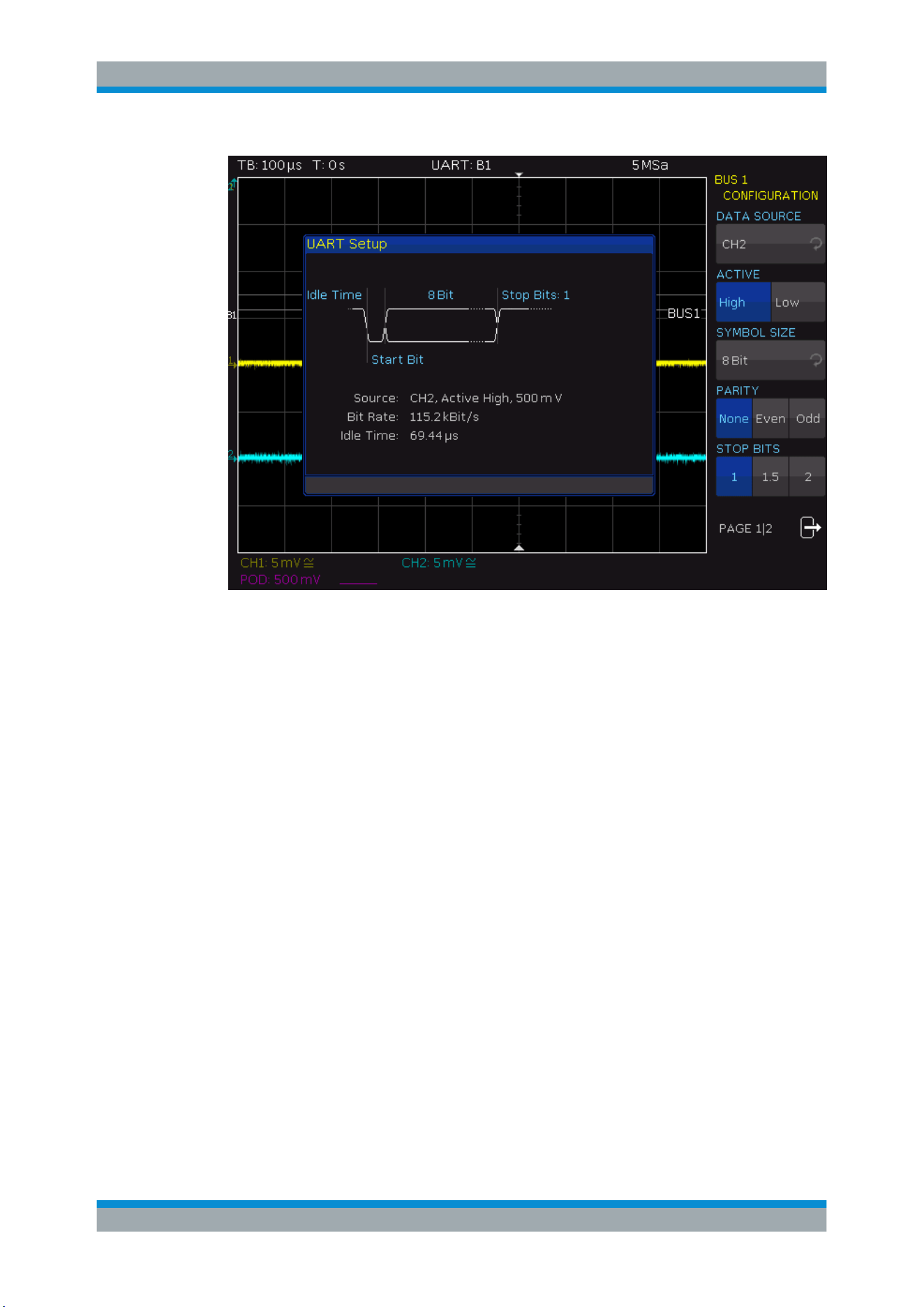
Serial Bus Analysis
R&S
®
RTC1000
137User Manual 1335.7352.02 ─ 04
Figure 11-11: Page 1|2 UART bus setup menu
DATA SOURCE
Selects the channel which is connected to the data line.
ACTIVE
Determines if the data transferred are active high (high = 1) or active low (low = 1). For
RS-232, choose active low.
SYMBOL SIZE
Selects a value between 5 bit to 9 bit for the bits that form a symbol.
PARITY
Parity bits are used to detect errors during a transmission:
"None"
No parity bits
"Even"
If the number of ones in a specific set of bits is uneven (without parity
bit), the parity bit is set to "1".
"Odd"
If the number of ones in a specific set of bits is uneven (without parity
bit), the parity bit is set to "1".
STOP BITS
Sets the number of stop bits: 1 or 1.5 or 2 stop bits are possible.
BIT RATE, USER
The bit rate defines how many bits are sent per second. To select a standard bit rate,
use "BIT RATE". To define a customized rate, use "USER".
UART/RS-232 BUS (Option R&S RTC-K2)

Serial Bus Analysis
R&S
®
RTC1000
138User Manual 1335.7352.02 ─ 04
IDLE TIME
Sets the minimum time between the stop bit of the last data and the start bit of the new
data. The idle time defines the start of a transmission and the exact start of a frame
(one or more symbols, most commonly bytes). The idle time is important for correct
decoding and triggering, regardless of the trigger type. A start bit within the idle time is
not recognized. You can enter the value using the [Universal] knob or the [KEYPAD].
11.5.2 UART/RS-232 BUS Triggering
After the bus configuration is completed, you can trigger on various events.
To trigger on events
1. In the Trigger section, press the [TYPE] key.
2. Select "SERIAL BUS".
3. Press the [SOURCE] key in the Trigger section.
4. Choose "UART" by pressing the respective softkey.
The bus is only available if it was configured earlier.
5. Press the [FILTER] key in the Trigger section to list the trigger conditions of the
bus.
6. Configure the trigger condition. Possible conditions are described below.
7. Press the Back softkey until all menus are closed.
The oscilloscope triggers on the condition. For measurements without measuring
object, refer to chapter
Chapter 10.2.5, "Serial Buses", on page 118.
UART/RS-232 BUS (Option R&S RTC-K2)
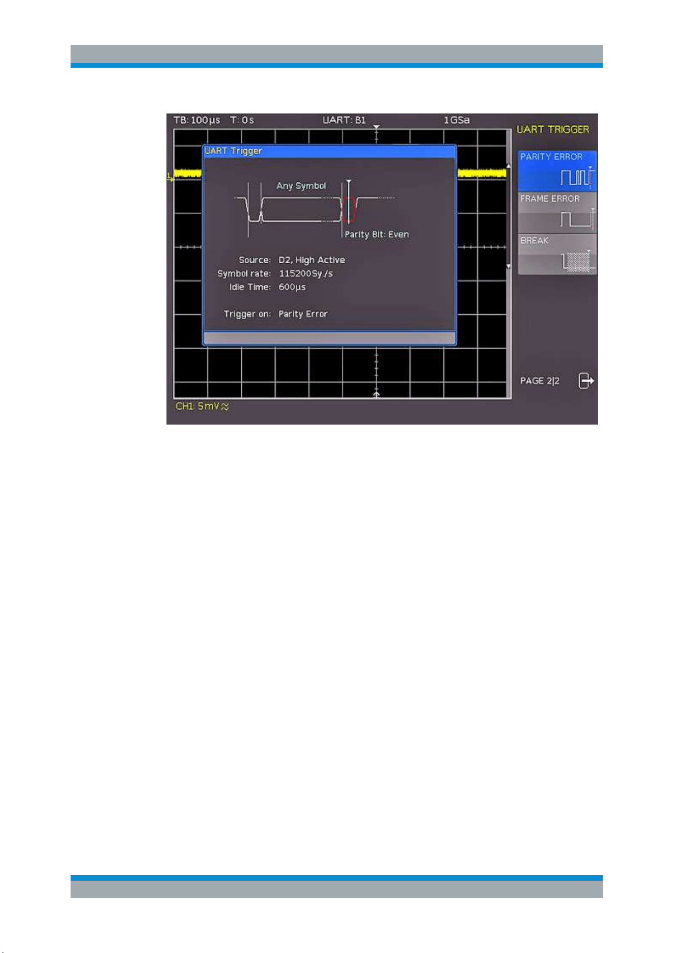
Serial Bus Analysis
R&S
®
RTC1000
139User Manual 1335.7352.02 ─ 04
Figure 11-12: UART trigger menu page 2
START BIT
Sets the start bit as trigger event. The start bit is the first low bit after a stop bit.
FRAME START
Defines the first start bit after idle time (= frame start) as trigger condition.
SYMBOL <N>
Triggers on the Nth symbol in a frame.
ANY SYMBOL
Triggers on a symbol pattern anywhere within a frame. See
"PATTERN INPUT"
on page 129.
PATTERN
Configures a data pattern of one or more symbols as trigger condition.
UART/RS-232 BUS (Option R&S RTC-K2)
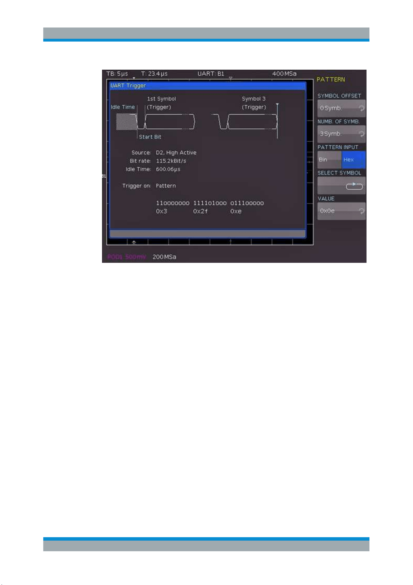
Serial Bus Analysis
R&S
®
RTC1000
140User Manual 1335.7352.02 ─ 04
Figure 11-13: Trigger menu to trigger on a data pattern
"SYMBOL
OFFSET"
Selects the number of irrelevant symbols that proceed the pattern.
Any value between 0 to 4095 symbols after the start bit can be
entered.
"NUMB. OF
SYMB."
Selects the number of symbols included in the pattern, the pattern
size. The symbol length is configured in the bus configuration.
"PATTERN
INPUT"
See
"PATTERN INPUT" on page 129.
PARITY ERROR
Triggers on a parity error.
FRAME ERROR
Triggers on a frame error.
BREAK
Triggers on a break. The condition is fulfilled if a stop bit does not succeed a start bit
within a specified time period.
11.5.3 UART Decode Results
Certain portions of the UART messages are displayed in color to distinguish between
the different elements:
●
White: Start / End of complete frame
UART/RS-232 BUS (Option R&S RTC-K2)
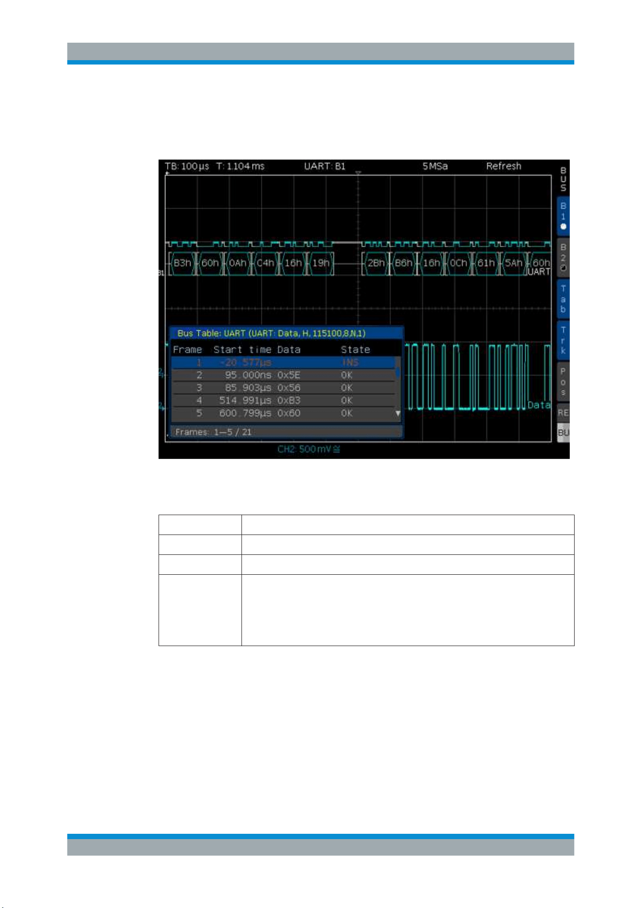
Serial Bus Analysis
R&S
®
RTC1000
141User Manual 1335.7352.02 ─ 04
●
Red: Incomplete word that is not contained in the acquisition; change the horizontal
scale or move the "Time Reference" to get a longer acquisition
●
Cyan: Decoded words
Figure 11-14: Example of an UART BUS table
Table 11-3: Content of the UART BUS table
Column Description
"Start Time" Time of frame start in relation to the trigger point
"Data" Values of the data words
"State"
Frame Status:
●
"OK" = Frame is valid
●
"DATA" = during acquisition start/end only the frame start / frame end has been
decoded; currently no data available
●
"INS" = the frame is not contained in the acquisition; the acquired part of the
frame is valid.
11.6 CAN Bus (Option R&S RTC-K3)
For CAN BUS trigger and decoding, you need the R&S RTC-K3 option.
The CAN bus (Controller Area Network) is a bus system primarily developed for auto-
motive applications and is used for the data exchange between controller units and
sensors. It can be found in aviation, healthcare, and general automation industries.
CAN Bus (Option R&S RTC-K3)

Serial Bus Analysis
R&S
®
RTC1000
142User Manual 1335.7352.02 ─ 04
At the physical level, CAN is a differential signal, therefore a differential probe is rec-
ommended for decoding. Nevertheless, standard probes are also suitable to capture
the signals. The standard data rates range between 10 kBit/s and 1 MBit/s.
A CAN message primarily consists of a start bit, the frame ID (11 bit or 29 bit), the data
length code DLC, the data, a CRC, acknowledge bit, and an end bit.
11.6.1 CAN Bus Configuration
Before you configure the bus, set the correct logic level (threshold).
●
For analog channels, see
"THRESHOLD menu" on page 36.
●
For digital channels, see
"To set the threshold for logic states" on page 108. The
default value is 500 mV.
To select the CAN bus
1. Press the [BUS] key in the Vertical section.
2. In the short menu, select the bus: "B1" or "B2".
3. In the "BUS" menu, press the "BUS TYPE" softkey.
4. Use the [Universal] knob to select "CAN":
To configure the CAN bus
1. In the "BUS" menu, press "CONFIGURATION".
2. Configure the bus. The settings are described below.
CAN Bus (Option R&S RTC-K3)
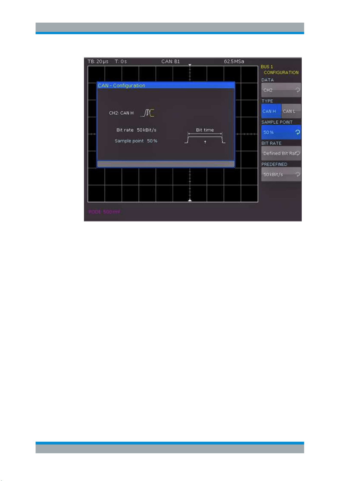
Serial Bus Analysis
R&S
®
RTC1000
143User Manual 1335.7352.02 ─ 04
Figure 11-15: CAN bus configuration
DATA
Selects the channel of the data line.
TYPE
Selects the CAN-High or CAN-Low line. CAN uses both lines for differential signal
transmission.
When using a differential probe, select "CAN H" if the positive input of the probe is con-
nected to CAN-High and the negative input to CAN Low. If the probe is connected with
reversed polarity, select "CAN L".
SAMPLE POINT
Sets the position of the sample point within the bit in percent of the nominal bit time.
You can select a value between 25% and 90%.
BIT RATE, USER
The bit rate defines how many bits are sent per second. To select a standard bit rate,
use "BIT RATE". To define a customized rate, use "USER".
11.6.2 CAN Bus Triggering
After the bus configuration is completed, you can trigger on various events.
CAN Bus (Option R&S RTC-K3)

Serial Bus Analysis
R&S
®
RTC1000
144User Manual 1335.7352.02 ─ 04
To trigger on events
1. In the Trigger section, press the [TYPE] key.
2. Select "SERIAL BUS".
3. Press the [SOURCE] key in the Trigger section.
4. Choose "CAN" by pressing the respective softkey.
The bus is only available if it is configured correctly.
5. Press the [FILTER] key in the Trigger section to list the trigger conditions of the
bus.
6. Configure the trigger condition. Possible conditions are described below.
7. Press the Back softkey until all menus are closed.
The oscilloscope triggers on the condition. For measurements without measuring
object, refer to chapter
Chapter 10.2.5, "Serial Buses", on page 118.
START OF FRAME
Triggers on the first slope of the SOF bit (synchronizing bit).
END OF FRAME
Triggers on the end of the frame.
FRAME
Triggers on the selected frame type. For data and remote frames, also select the iden-
tifier type (11 bit, 29 bit or any).
"ERROR"
Triggers on general frame error.
"OVERLOAD"
Triggers on CAN overload frames.
"DATA"
Triggers on data frames.
"REMOTE"
Triggers on remote frames.
"DATA OR
REMOTE"
Triggers on either data frames or remote frames.
ERROR
Identifies various errors in a frame. Select one or several error message types as trig-
ger condition.
"STUFF BIT"
Frame segments (e.g. frame start) are coded during the bit stuffing
procedure. The transmitter automatically adds a complimentary bit to
the bit stream if it detects 5 consecutive bits with identical value in the
bit stream. An error occurs if the 6th identical bit level is detected in
the specified sections.
"FORM"
A form error occurs if a fixed-form bit field contains one or more inva-
lid bits.
"ACKNOWL-
EDGE"
An authentication error occurs if the transmitter receives no acknowl-
edgment - a dominant bit during the Ack Slot.
CAN Bus (Option R&S RTC-K3)

Serial Bus Analysis
R&S
®
RTC1000
145User Manual 1335.7352.02 ─ 04
"CRC"
CAN uses a complex checksum calculation called Cyclic Redundancy
Check. The transmitter calculates the CRC and transmits the result in
a CRC sequence. The receiver calculates the CRC in the same way.
A CRC error occurs if the calculated result differs from the received
CRC sequence.
IDENTIFIER
Triggers on an address or address range. Configure the following:
●
"FRAME TYPE" on page 145
●
"IDENTIFIER SETUP" on page 145
IDENTIFIER AND DATA
Triggers on a combination of identifier and data pattern. Configure the following:
●
"FRAME TYPE" on page 145
●
"IDENTIFIER SETUP" on page 145
●
"DATA SETUP" on page 145
FRAME TYPE
Selects the frame type: remote or data frame, or both.
IDENTIFIER SETUP
Defines the address of the data pattern:
●
"ID TYPE", the length of the identifier (11 bit for CAN base frame format, or 29 bit
for extended CAN frames).
●
Compare function:
"COMPARE" on page 145.
●
Address pattern:
"PATTERN INPUT" on page 129.
DATA SETUP
Specify the data pattern for up to 8 bytes.
●
"DATA LENGTH", the number of data bytes to be compared.
●
"COMPARE" on page 145 function.
●
Data pattern:
"PATTERN INPUT" on page 129.
COMPARE
Defines the comparison function for data and address patterns. If the pattern includes
at least one X (do not care), you can trigger on a value equal or not equal to the speci-
fied value. If the pattern includes only 0 or 1, you can trigger on an area greater than or
less than the specified value.
11.6.3 CAN Decode Results
Certain portions of the CAN messages are displayed in color to recognize the different
elements:
●
White: Data length code, number of data bytes
●
Cyan: Data words
●
Magenta: Identifier
●
Red: Frame error
CAN Bus (Option R&S RTC-K3)
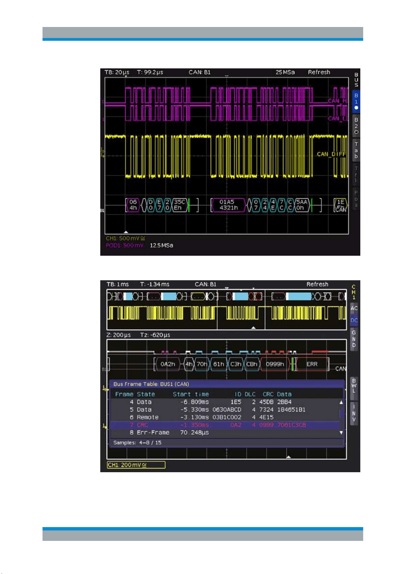
Serial Bus Analysis
R&S
®
RTC1000
146User Manual 1335.7352.02 ─ 04
Figure 11-16: Decoded CAN bus
Figure 11-17: Example of a CAN bus table
CAN Bus (Option R&S RTC-K3)

Serial Bus Analysis
R&S
®
RTC1000
147User Manual 1335.7352.02 ─ 04
Table 11-4: Content of the CAN bus table
Column Description
"Start Time" Time of frame start in relation to the trigger point
"Type"
Frame type:
●
"DATA" = Data frame
●
"REMOTE" = Remote frame
●
"ERR-F." = Transmission error (error frame)
●
"OVL-F." = Overload frame
"ID" Frame ID
"DLC" Data length code, number of data bytes
"Data" Values of the data bytes
"CRC" Cyclic Redundancy Check
"State"
Frame state:
●
"OK" = frame is valid
●
"CRC" = the calculated result deviates from the received CRC sequence (cyclic
redundancy check failed)
●
"NACK" = no acknowledge
●
"CRC+NACK" = cyclic redundancy check failed followed by "not acknowledge"
●
"STUFF" = Bit stuffing error
●
"INS" = the frame is not contained in the acquisition; the acquired part of the
frame is valid.
11.7 LIN Bus (Option R&S RTC-K3)
For CAN bus trigger and decoding, you need the R&S RTC-K3 option.
The LIN bus (Local Interconnect Network) is a simple master/slave bus system for
automotive applications and is used for the data exchange between controller units
and sensors or actuators. The signal is transmitted on one line with ground reference
to the vehicle mass.
A LIN bus has the following properties:
●
Serial single-wire communication protocol (byte-oriented)
●
Master-slave communication (up to 12 knots)
●
Master-controlled communication (master initiates / coordinates communication)
The data is transmitted in bytes without parity (based on UART). Each byte consists of
a start bit, 8 data bits, and a stop bit.
Figure 11-18: LIN byte structure
LIN Bus (Option R&S RTC-K3)

Serial Bus Analysis
R&S
®
RTC1000
148User Manual 1335.7352.02 ─ 04
11.7.1 LIN Bus Configuration
Before you configure the bus, set the correct logic level (threshold).
●
For analog channels, see
"THRESHOLD menu" on page 36.
●
For digital channels, see
"To set the threshold for logic states" on page 108. The
default value is 500 mV.
To select the LIN bus
1. Press the [BUS] key in the Vertical section.
2. In the short menu, select the bus: "B1" or "B2".
3. In the "BUS" menu, press the "BUS TYPE" softkey.
4. Use the [Universal] knob to select "LIN":
To configure the CAN bus
1. In the "BUS" menu, press "CONFIGURATION".
2. Configure the bus. The settings are described below.
Figure 11-19: LIN bus configuration
LIN Bus (Option R&S RTC-K3)

Serial Bus Analysis
R&S
®
RTC1000
149User Manual 1335.7352.02 ─ 04
DATA
Selects the channel of the data line.
POLARITY
Defines the idle state of the bus. The idle state is the recessive state and corresponds
to a logic 1.
VERSION
Select the version of the LIN standard (version 1x, version 2x, J2602 or any).
BIT RATE
Specifies the number of transmitted bits per second.
USER
Changes a selected standard data rate. The highest possible data rate is 4 MBit/s. Use
the universal knob or the [KEYPAD] to adjust the value.
11.7.2 LIN Bus Triggering
After the bus configuration is completed, you can trigger on various events.
To trigger on events
1. In the Trigger section, press the [TYPE] key.
2. Select "SERIAL BUS".
3. Press the [SOURCE] key in the Trigger section.
4. Choose "LIN" by pressing the respective softkey.
The bus is only available if it is configured correctly.
5. Press the [FILTER] key in the Trigger section to list the trigger conditions of the
bus.
6. Configure the trigger condition. Possible conditions are described below.
7. Press the Back softkey until all menus are closed.
The oscilloscope triggers on the condition. For measurements without measuring
object, refer to chapter
Chapter 10.2.5, "Serial Buses", on page 118.
LIN Bus (Option R&S RTC-K3)
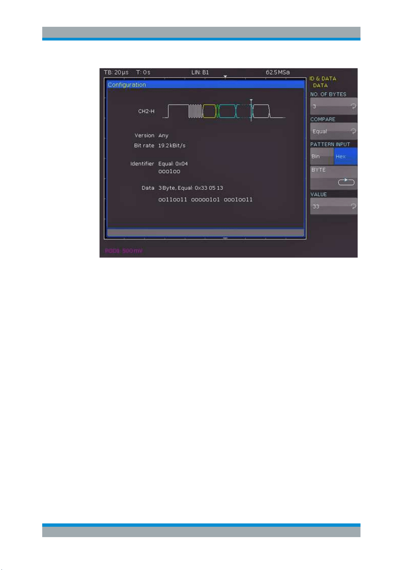
Serial Bus Analysis
R&S
®
RTC1000
150User Manual 1335.7352.02 ─ 04
Figure 11-20: LIN data trigger menu
START OF FRAME
Triggers on the stop bit of the synchronizing field.
WAKE UP
Triggers after a wake-up frame.
ERROR
Identifies various errors in a frame. Select one or more error types as trigger condition.
"CRC"
LIN uses a complex checksum calculation (Cyclic Redundancy
Check). The transmitter calculates the CRC and transmits the result
in a CRC sequence. The receiver calculates the CRC in the same
way. An error occurs if the calculated result differs from the received
CRC sequence.
"PARITY"
Triggers on a parity error. Parity bits are bit 6 and bit 7 of the identi-
fier. The correct transfer of the identifier is verified.
"SYNCHRO-
NIZ."
Triggers if the synchronizing field indicates an error.
IDENTIFIER
Triggers on an identifier or identifier range. Configure the following:
●
Compare function:
"COMPARE" on page 151.
●
Identifier pattern:
"PATTERN INPUT" on page 129.
LIN Bus (Option R&S RTC-K3)

Serial Bus Analysis
R&S
®
RTC1000
151User Manual 1335.7352.02 ─ 04
IDENTIFIER AND DATA
You define the "IDENTIFIER SETUP" in the same way as for the identifier trigger
("COMPARE" and "PATTERN INPUT").
In addition, define the "DATA SETUP" to specify the data bit pattern or HEX values for
up to 8 bytes.
Triggers on a combination of identifier and data condition:
●
Identifier setup:
"IDENTIFIER" on page 150
●
"DATA SETUP" on page 151
DATA SETUP
Specify the data pattern for up to 8 bytes.
●
"NO. OF BYTES", the number of data bytes to be compared.
●
Compare function:
"COMPARE" on page 151.
●
Data pattern:
"PATTERN INPUT" on page 129.
COMPARE
Defines the comparison function. If the pattern includes at least one X (do not care), it
is possible to trigger on a value equal or not equal to the specified value. If the pattern
includes only 0 or 1, it is possible to trigger on an area greater than or less than the
specified value.
11.7.3 LIN Decode Results
Certain portions of the messages are displayed in color to identify the different ele-
ments:
●
White: Synchronization byte / correct checksum
●
Cyan: Data words
●
Yellow: Identifier
●
Green: Parity bit
●
Red: Frame error
LIN Bus (Option R&S RTC-K3)
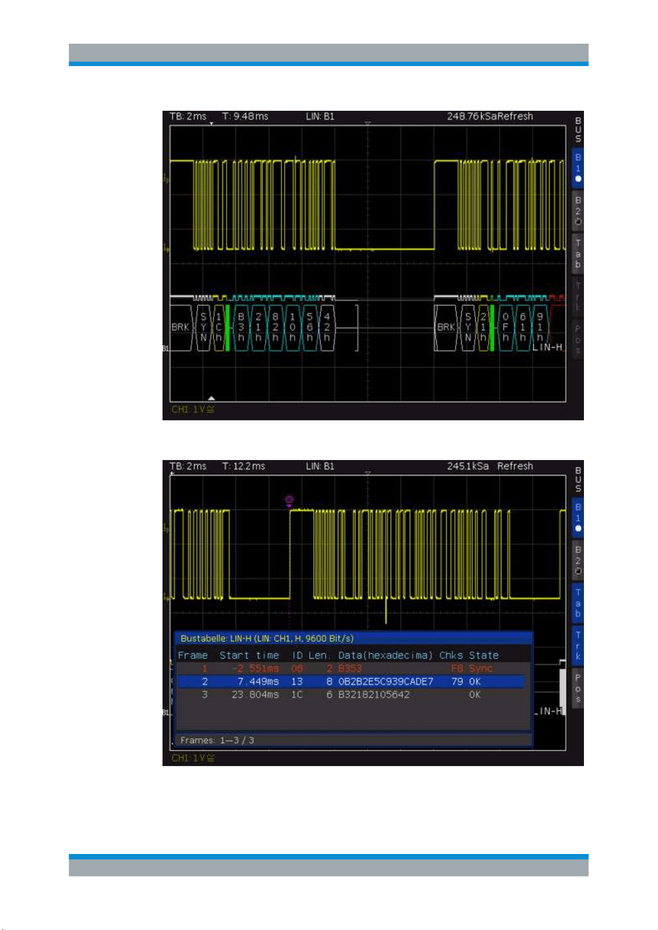
Serial Bus Analysis
R&S
®
RTC1000
152User Manual 1335.7352.02 ─ 04
Figure 11-21: LIN bus
Figure 11-22: Example of a LIN bus table
LIN Bus (Option R&S RTC-K3)

Serial Bus Analysis
R&S
®
RTC1000
153User Manual 1335.7352.02 ─ 04
Column Description
"Start Time" Time of frame start in relation to the trigger point
"ID" Frame identifier
"Length" Number of data bytes
"Data" Values of the data bytes
"Chks" Checksum value
"State"
Frame state:
●
"OK" = Frame is valid
●
"DATA" = during acquisition start/end only the frame start / frame end has been
decoded; currently no data available
●
"SYNC" = Synchronization error
●
"CHKS" = Checksum error
●
"PARI" = Parity error
●
"WAKEUP" = Wakeup frame
●
"INS" = the last frame is not contained in the acquisition. The frame end was not
decoded.
LIN Bus (Option R&S RTC-K3)

Network Connections and Remote Operation
R&S
®
RTC1000
154User Manual 1335.7352.02 ─ 04
12 Network Connections and Remote Opera-
tion
The R&S RTC1000 has a LAN interface and a USB type B port for remote control and
remote operation.
12.1 LAN Connection
A LAN connection is necessary for remote control of the instrument, and for access
from a computer using a web browser. You can connect the instrument to a local area
network (LAN), usually the company network, or directly to a computer. To identify the
instrument in the network, you need the IP address of the R&S RTC1000.
The network card can be operated with a 10 Mbps Ethernet IEEE 802.3 or a 100 Mbps
Ethernet IEEE 802.3u interface. To establish a network connection, connect a commer-
cial RJ-45 cable to one of the LAN ports of the instrument and to a PC.
Depending on the network capacities, the TCP/IP address of the instrument can be
obtained in different ways:
●
Automatically using DHCP. All address information is assigned automatically. Auto-
matic private IP addressing (APIPA) is not supported.
●
Manually: the address must be set manually.
By default, the instrument is configured to use automatic configuration and obtain all
address information automatically. Thus, it is safe to establish a physical connection to
the LAN without any previous instrument configuration.
Risk of network errors
Connection errors can affect the entire network. If your network does not support
DHCP, or if you choose to disable dynamic TCP/IP configuration, you must assign valid
address information before connecting the instrument to the LAN. Contact your net-
work administrator to obtain a valid IP address.
Connect computer and instrument to the same network. Otherwise a remote connec-
tion is not possible.
If DHCP is set and the system cannot assign an IP address to the R&S RTC1000, it
can take a while until you can reconfigure the interface. Possible reasons are: no
Ethernet cable is connected, or the network does not support DHCP.
Connecting the instrument to the LAN
1. Connect the LAN cable to the LAN connector at the rear panel of the instrument,
and to the LAN connector of the network or computer.
2. Press the [SETUP] key.
LAN Connection
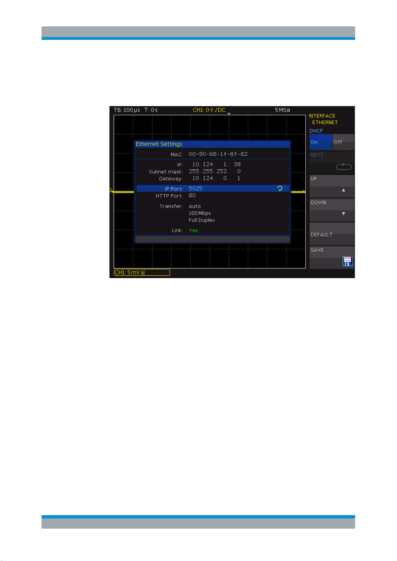
Network Connections and Remote Operation
R&S
®
RTC1000
155User Manual 1335.7352.02 ─ 04
3. Press the "INTERFACE" softkey.
4. To activate the LAN interface, press "ETHERNET".
5. Press "PARAMETER".
Figure 12-1: Ethernet settings
The MAC address (physical address) and the "Link" status information is displayed
for information only and cannot be edited. The IP address can be changed if DHCP
is off.
6. Switch DHCP on or off:
● "On" enables DHCP for automatic network parameter distribution and shows
the values of these parameters. Note that refreshing the values (for example
after disconnecting the LAN cable and reconnecting it) can take a while,
depending on the network responsiveness.
● "Off": Use this setting if the network does not support dynamic host configura-
tion protocol (DHCP).
7. If DHCP is off, define the IP address of the instrument. Set up each address block
individually:
a) Select "IP" by pressing "Up" or "Down".
b) Define the first block number using the [Universal] knob.
c) Press "Next" to move to the next block.
d) Define the number of the second block.
e) Repeat steps c) and d) for the remaining blocks.
f) When the IP address is complete, press "Down" to continue with the next set-
ting.
LAN Connection

Network Connections and Remote Operation
R&S
®
RTC1000
156User Manual 1335.7352.02 ─ 04
8. Define the "Subnetmask" and "Gateway" in the same way.
9. Select the "IP Port", the port number for SCPI socket communication. The default
port number for SCPI socket communication is 5025.
10. Select the "HTTP Port" used by the instrument.
11. Select the "Transfer" mode. The mode can either be determined automatically
("Auto"), or you can select a combination of a transfer rate and half or full duplex
manually.
12. Press "SAVE" to save the LAN parameters.
The "Link" information at the bottom of the dialog box indicates whether a LAN con-
nection was established successfully.
Check the LAN connection using the ping command in a command window on the
computer: ping <IP address>.
Using the IP address in remote control
The IP address of the instrument is part of the resource string to identify and control
the instrument. The resource string has the form:
TCPIP::‹IP_address›::‹IP_port›::SOCKET
The VISA resource string of the instrument is shown in the [SETUP] > "DEVICE
INFORMATION" window.
Example:
If the instrument has the IP address 192.1.2.3; the valid resource string is:
TCPIP::192.1.2.3::5025::SOCKET
If the LAN is supported by a DNS server, the host name can be used instead of the IP
address. The DNS server (Domain Name System server) translates the host name to
the IP address. The resource string has the form:
TCPIP::‹host_name›::‹IP_port›::SOCKET
To assign a host name to the R&S RTC1000, select [SETUP] key › "Page 2|3" ›
"DEVICE NAME".
Example:
If the host name is TEST1; the valid resource string is:
TCPIP::TEST1::5025::SOCKET
The end character must be set to linefeed (LF).
LAN Connection

Network Connections and Remote Operation
R&S
®
RTC1000
157User Manual 1335.7352.02 ─ 04
12.2 Remote Access Using a Web Browser
The R&S RTC1000 firmware contains a web server. If a LAN connection is estab-
lished, you can access the instrument remotely using a web browser on the control
computer.
The browser access allows you to:
●
Check instrument data
●
Control the instrument remotely
●
Print screenshots
●
Send remote commands
●
Save waveform and instrument data
●
Check network settings
12.2.1 Accessing the Instrument Using a Web Browser
To access the R&S RTC1000, you need a LAN connection and the IP address of the
instrument.
1. Set up a LAN connection, see
"Connecting the instrument to the LAN"
on page 154.
2. Obtain the IP address of the R&S RTC1000: [SETUP] > "DEVICE INFORMATION".
3. Open an Internet browser on the control computer.
4. Enter the IP address of the R&S RTC1000 in the address line:
http//:xxx.yyy.zzz.xxx.
The "Instrument Home" page opens.
12.2.2 Instrument Home
The "Instrument Home" page provides information on the instrument and the LAN con-
nection.
Remote Access Using a Web Browser

Network Connections and Remote Operation
R&S
®
RTC1000
158User Manual 1335.7352.02 ─ 04
12.2.3 Screenshot
The "Screenshot" page shows a copy of the instrument's display. It also provides
instrument control functions and screenshot settings.
Instrument control
●
"Run" and "Stop" = start and stop continuous acquisition, same as [RUN/STOP]
key on the instrument.
●
"Single" = [SINGLE] key on the instrument
●
"Autoset" = [AUTOSET] key on the instrument
●
"Preset" = Press and hold the [AUTOSET] key on the instrument until you hear a
beep.
Remote Access Using a Web Browser
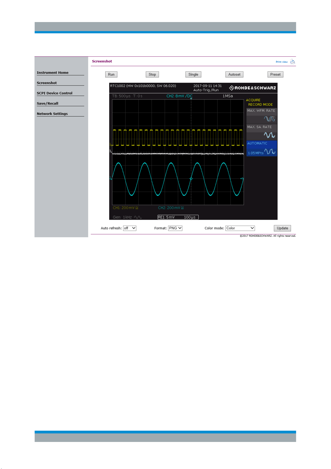
Network Connections and Remote Operation
R&S
®
RTC1000
159User Manual 1335.7352.02 ─ 04
Screenshots
●
"Auto refresh" and "Update"
Get the current screen content from the instrument. With "Auto refresh", you can
set the interval of automatic updates.
●
"Format" and "Color mode":
Set the file format and color mode of the screenshot.
► To save the screenshot, right-click the picture and select "Save image as".
12.2.4 SCPI Device Control
On the "SCPI Device Control" page, you can check how the transfer of remote com-
mands is working.
You can enter a single command, for example; *IDN?, and transmit it with "Send". Do
not press the [Enter] key.
If the sent command has an error, an error message is created in the background, and
you do not get any response. You can see the error messages using "Last Error Mes-
sage" and "All Error Messages"
Remote Access Using a Web Browser

Network Connections and Remote Operation
R&S
®
RTC1000
160User Manual 1335.7352.02 ─ 04
12.2.5 Save/Recall
On the "Save/Recall" page, you can save waveform data and instrument settings to a
file - either on the computer (local file) or on the instrument (remote device). On the
computer, the default storage directory is the download folder, but you can change the
directory using the download functions of your browser. On the instrument, the files are
saved in the internal storage.
You can also load reference waveforms and instrument settings from file to the instru-
ment.
To save data to a file on the computer
1. Select the waveform or the device settings in the "Source" list.
2. Select the file "Format".
See also:
●
Chapter 8.3.1, "Waveform File Formats", on page 101
● Chapter 8.2, "Reference Waveforms", on page 97
3. For analog and digital channels, select whether you want to read out the display
memory ("Display Data") or the entire acquisition memory ("Acq. Memory").
4. Click "Save".
Remote Access Using a Web Browser
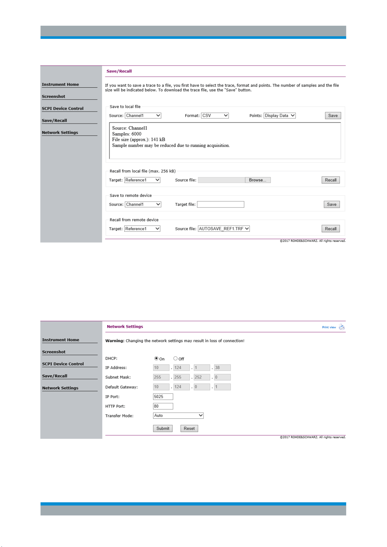
Network Connections and Remote Operation
R&S
®
RTC1000
161User Manual 1335.7352.02 ─ 04
12.2.6 Network Settings
On the "Network Setting" page, you can change the port settings, switch off DHCP
address and enter an IP address in a more comfortable way than directly on the instru-
ment. To take effect of the changes, "Submit" them to the instrument.
"Reset" removes all modified values that were not yet sent to the instrument.
Remote Access Using a Web Browser
Network Connections and Remote Operation
R&S
®
RTC1000
162User Manual 1335.7352.02 ─ 04
12.3 USB Connection
In addition to a LAN connection, you can use the USB connector at the rear panel to
access the instrument via USB.
Connecting the instrument using USB
1. Connect the USB cable to the USB type B connector at the rear panel of the instru-
ment, and to the computer.
2. Press the [SETUP] key.
3. Press "INTERFACE".
4. Press "USB" to select USB connection.
5. Press "PARAMETER".
6. Select the USB mode:
● USB TMC (Test & Measurement Class)
● USB VCP (Virtual Com Port)
● USB MTP (Media Transfer Protocol)
USB Connection

Network Connections and Remote Operation
R&S
®
RTC1000
163User Manual 1335.7352.02 ─ 04
12.3.1 USB TMC
USB TMC means USB Test & Measurement Class. You can use this interface for
remote control of the instrument using SCPI commands. USB TMC does not need a
driver installation but requires a VISA installation on the controlling computer. VISA is
used to access the instrument, to send remote commands, and to read status informa-
tion.
Rohde & Schwarz provides the standardized I/O software library R&S VISA for com-
munication via TCP/IP (LAN: HiSlip, VXI-11) or USB (USBTMC) interfaces. R&S VISA
is available for download at the Rohde & Schwarz website
www.rohde-schwarz.com/
rsvisa
.
12.3.2 USB VCP
USB VCP uses the virtual COM port (VCP) to communicate with the measuring instru-
ment. You can use any terminal program to send SCPI commands. USB VCP requires
a USB VCP driver on the controlling computer. If the computer requests a driver instal-
lation, you can download the driver at the Rohde & Schwarz website (
www.rohde-
schwarz.com/de/treiber/hmo/
, HO732). You need administrator rights to install the
driver.
12.3.3 USM MTP
USB MTP is the USB media transfer protocol. It is a solution to load data from the
oscilloscope to the computer. Remote control using SCPI commands is not possible.
USB MTP does not need a driver installation. If the instrument and the computer are
connected with a USB cable and USB MTP is selected as interface, you can access
the oscilloscope data from the computer. You see the oscilloscope in the computer's
Device Manager and in the file explorer as portable instrument.
USB Connection
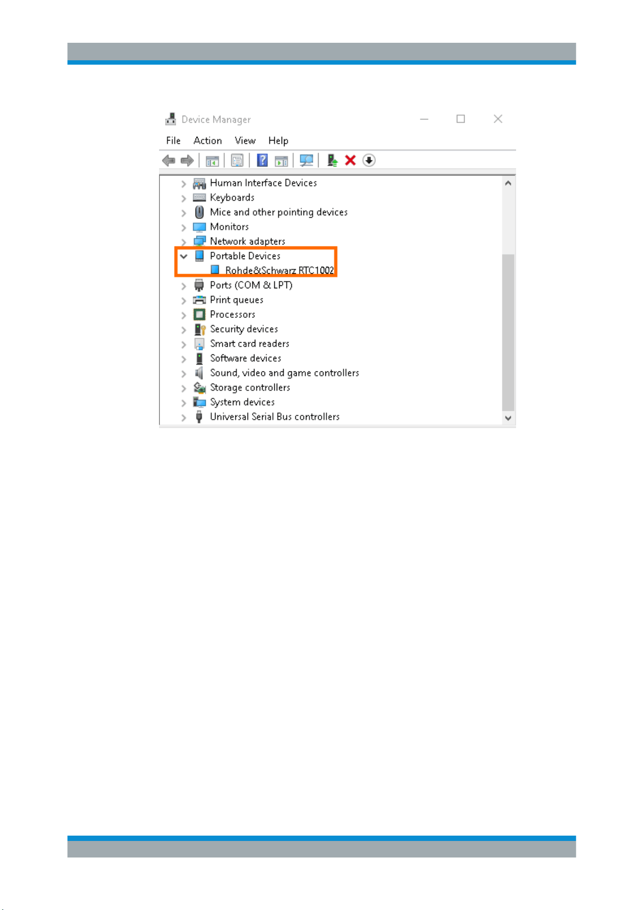
Network Connections and Remote Operation
R&S
®
RTC1000
164User Manual 1335.7352.02 ─ 04
Figure 12-2: R&S
RTC1000 in the Device Manager of the computer
The following instrument folders are visible:
●
Internal Storage:
Read-only folder, provides access to the files stored on the instrument, for exam-
ple, instrument settings, references, and formula sets.
●
Live Data:
Read-only folder, provides access to multiple subfolders and current instrument
data. Files are created on demand. See
"Live Data" on page 165.
●
Upload:
Read-write folder to send instrument settings files, firmware update files, and
license key files to the oscilloscope. The content is deleted when you turn off or
restart the instrument. The oscilloscope checks the data and loads it automatically
if possible. The firmware update must be started manually.
●
USB Front
If a USB flash drive is connected to the oscilloscope, an additional USB Front
folder is available. You can view the files and copy files to and from the computer to
the USB flash drive. The indicated file size is the actual file size.
USB Connection
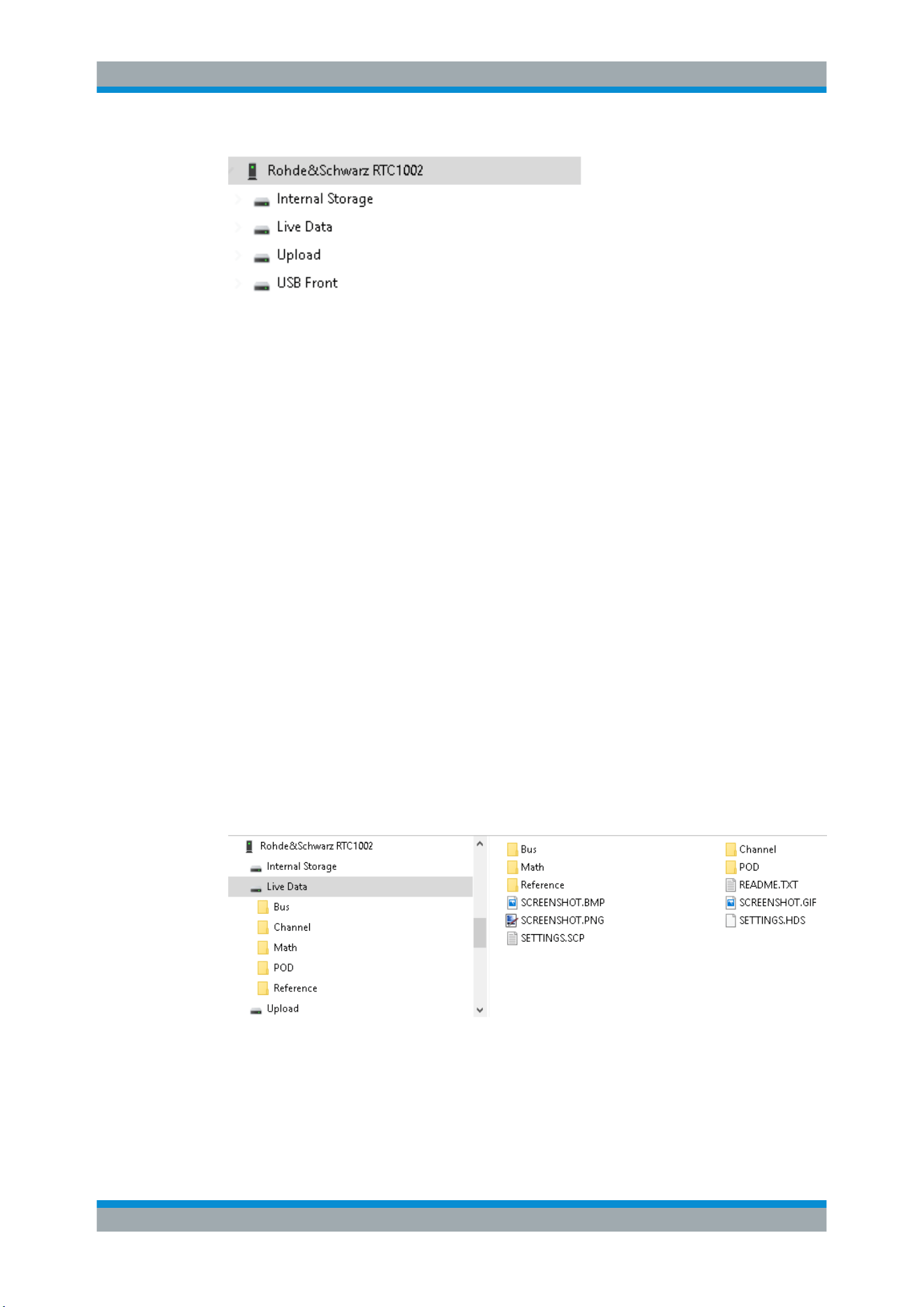
Network Connections and Remote Operation
R&S
®
RTC1000
165User Manual 1335.7352.02 ─ 04
Figure 12-3: Folders in the file explorer, with USB flash drive
Live Data
The Live Data folder contains several subfolders and files:
●
Screenshot.*
The screenshot is created when you open the file. To open it, right-click the file and
select "Open". Double-clicking the file can cause an error because the indicated file
size is an estimation and can differ from the actual file size.
●
SETTINGS.*
Contain the current instrument settings.
●
Channel, Bus and POD
Contain two subfolders and a README.TXT. The files in the
Acquisition Memory folder provide data from the acquisition memory, and the
files in the DISPLAY DATA folder provide the visible waveform data in various for-
mats. The file content is generated when the file transfer to the PC is started.
●
Math and Reference
Contain visible waveform data. The INFO.TXT file provides information on the
waveforms, such as name, units, samples. The file content is generated when the
file transfer to the PC is started.
To get accurate waveform data and to read the acquisition memory, make sure to stop
the acquisition before you access the files. If acquisition is running, reading the data
results in waveform data from different acquisitions, and the acquisition memory can-
not be read.
Figure 12-4: Folder structure of Live Data folder
USB Connection

Network Connections and Remote Operation
R&S
®
RTC1000
166User Manual 1335.7352.02 ─ 04
12.4 Switching to Remote Control
When you switch on the instrument, it is always in manual operation state
(„local“ state) and can be operated using the front panel. When you send a command
from the control computer, it is received and executed by the instrument. The display
remains on, manual operation is always possible.
Switching to Remote Control

Remote Commands Reference
R&S
®
RTC1000
167User Manual 1335.7352.02 ─ 04
13 Remote Commands Reference
This chapter provides the description of all remote commands available for the
R&S RTC1000. The commands are sorted according to the menu structure of the
instrument. A list of commands in alphabetical order ist given in the „List of Com-
mands“ at the end of this chapter.
General information on remote control is given in the "Annex" of this manual.
13.1 Conventions Used in Remote Command Description
Note the following conventions used in the remote command descriptions:
●
Command usage
If not specified otherwise, commands can be used both for setting and for querying
parameters.
If a command can be used for setting or querying only, or if it initiates an event, the
usage is stated explicitly.
●
Parameter usage
If not specified otherwise, a parameter can be used to set a value and it is the
result of a query.
Parameters required only for setting are indicated as Setting parameters.
Parameters required only to refine a query are indicated as Query parameters.
Parameters that are only returned as the result of a query are indicated as Return
values.
●
Conformity
Commands that are taken from the SCPI standard are indicated as SCPI con-
firmed. All commands used by the R&S RTC1000 follow the SCPI syntax rules.
●
Asynchronous commands
A command which does not automatically finish executing before the next com-
mand starts executing (overlapping command) is indicated as an Asynchronous
command.
●
Reset values (*RST)
Default parameter values that are used directly after resetting the instrument (*RST
command) are indicated as *RST values, if available.
●
Default unit
This is the unit used for numeric values if no other unit is provided with the parame-
ter.
13.2 Common Commands
Common commands are described in the IEEE 488.2 (IEC 625-2) standard. These
commands have the same effect and are employed in the same way on different devi-
ces. The headers of these commands consist of "*" followed by three letters. Many
common commands are related to the Status Reporting System.
Common Commands

Remote Commands Reference
R&S
®
RTC1000
168User Manual 1335.7352.02 ─ 04
Available common commands:
*CAL?...........................................................................................................................168
*CLS.............................................................................................................................168
*ESE.............................................................................................................................168
*ESR?...........................................................................................................................168
*IDN?............................................................................................................................169
*OPC............................................................................................................................169
*OPT?...........................................................................................................................169
*PSC............................................................................................................................ 169
*RST.............................................................................................................................170
*SRE............................................................................................................................ 170
*STB?...........................................................................................................................170
*TRG............................................................................................................................ 170
*TST?........................................................................................................................... 170
*WAI............................................................................................................................. 171
*CAL?
Performs a self-alignment of the instrument and then generates a status response.
Return values ≠ 0 indicate an error.
Usage: Query only
*CLS
Clear status
Sets the status byte (STB), the standard event register (ESR) and the EVENt part of
the QUEStionable and the OPERation registers to zero. The command does not
alter the mask and transition parts of the registers. It clears the output buffer.
Usage: Setting only
*ESE <Value>
Event status enable
Sets the event status enable register to the specified value. The query returns the con-
tents of the event status enable register in decimal form.
Parameters:
<Value> Range: 0 to 255
*ESR?
Event status read
Returns the contents of the event status register in decimal form and subsequently
sets the register to zero.
Common Commands

Remote Commands Reference
R&S
®
RTC1000
169User Manual 1335.7352.02 ─ 04
Return values:
<Contents> Range: 0 to 255
Usage: Query only
*IDN?
Identification
Returns the instrument identification.
Return values:
<ID> "Rohde&Schwarz,<device type>,<serial number>,<firmware ver-
sion>"
Example:
Rohde&Schwarz,RTC1002,1335.7500k02/120012,
01.203
Usage: Query only
*OPC
Operation complete
Sets bit 0 in the event status register when all preceding commands have been execu-
ted. This bit can be used to initiate a service request. The query form writes a "1" into
the output buffer as soon as all preceding commands have been executed. This is
used for command synchronization.
*OPT?
Option identification query
Queries the options included in the instrument. For a list of all available options and
their description refer to the data sheet.
Return values:
<Options> The query returns a list of options. The options are returned at
fixed positions in a comma-separated string. A zero is returned
for options that are not installed.
Usage: Query only
*PSC <Action>
Power on status clear
Determines whether the contents of the ENABle registers are preserved or reset when
the instrument is switched on. Thus a service request can be triggered when the instru-
ment is switched on, if the status registers ESE and SRE are suitably configured. The
query reads out the contents of the "power-on-status-clear" flag.
Common Commands

Remote Commands Reference
R&S
®
RTC1000
170User Manual 1335.7352.02 ─ 04
Parameters:
<Action> 0 | 1
0
The contents of the status registers are preserved.
1
Resets the status registers.
*RST
Reset
Sets the instrument to a defined default status. The default settings are indicated in the
description of commands.
Usage: Setting only
*SRE <Contents>
Service request enable
Sets the service request enable register to the indicated value. This command deter-
mines under which conditions a service request is triggered.
Parameters:
<Contents> Contents of the service request enable register in decimal form.
Bit 6 (MSS mask bit) is always 0.
Range: 0 to 255
*STB?
Status byte query
Reads the contents of the status byte in decimal form.
Usage: Query only
*TRG
Trigger
Triggers all actions waiting for a trigger event. In particular, *TRG generates a manual
trigger signal. This common command complements the commands of the TRIGger
subsystem.
Usage: Event
*TST?
Self-test query
Initiates self-tests of the instrument and returns an error code
Common Commands

Remote Commands Reference
R&S
®
RTC1000
171User Manual 1335.7352.02 ─ 04
Return values:
<ErrorCode> integer > 0 (in decimal format)
An error occurred.
(For details see the Service Manual supplied with the instru-
ment).
0
No errors occurred.
Usage: Query only
*WAI
Wait to continue
Prevents servicing of the subsequent commands until all preceding commands have
been executed and all signals have settled (see also command synchronization and
*OPC).
Usage: Event
13.3 Acquisition and Setup
●
Starting and Stopping Acquisition......................................................................... 171
●
Time Base............................................................................................................. 172
●
Acquisition.............................................................................................................174
●
Vertical.................................................................................................................. 180
●
Waveform Data..................................................................................................... 184
●
Waveform Data Export to File............................................................................... 191
●
Logic Channel....................................................................................................... 192
●
Probes...................................................................................................................197
13.3.1 Starting and Stopping Acquisition
RUN............................................................................................................................. 171
RUNContinous...............................................................................................................172
SINGle..........................................................................................................................172
RUNSingle.................................................................................................................... 172
STOP........................................................................................................................... 172
RUN
Starts the continuous acquisition.
Usage: Event
Asynchronous command
Acquisition and Setup

Remote Commands Reference
R&S
®
RTC1000
172User Manual 1335.7352.02 ─ 04
RUNContinous
Same as RUN.
Usage: Event
Asynchronous command
SINGle
Performs a single acquisition and returns to stop mode.
Usage: Event
Asynchronous command
RUNSingle
Same as SINGle.
Usage: Event
Asynchronous command
STOP
Stops the running acquistion.
Usage: Event
Asynchronous command
13.3.2 Time Base
TIMebase:SCALe...........................................................................................................172
TIMebase:RATime?........................................................................................................173
TIMebase:ACQTime.......................................................................................................173
TIMebase:RANGe..........................................................................................................173
TIMebase:DIVisions?......................................................................................................173
TIMebase:POSition........................................................................................................ 173
TIMebase:REFerence.....................................................................................................174
TIMebase:SCALe <TimeScale>
Sets the horizontal scale for all channel and math waveforms.
Parameters:
<TimeScale> Range: 1e-9 to 50
*RST: 100e-6
Default unit: s/div
Acquisition and Setup

Remote Commands Reference
R&S
®
RTC1000
173User Manual 1335.7352.02 ─ 04
TIMebase:RATime?
Queries the real acquisition time used in the hardware. If FFT analysis is performed,
the value can differ from the adjusted acquisition time (
TIMebase:ACQTime).
Return values:
<HWAcqTime> Range: Depends on various settings
Default unit: s
Usage: Query only
TIMebase:ACQTime <AcquisitionTime>
Defines the time of one acquisition, that is the time across the 12 divisions of the dia-
gram: Timebase Scale*12.
Parameters:
<AcquisitionTime> Range: 12 ns to 600 s
Default unit: s
TIMebase:RANGe <AcquisitionTime>
Defines the time of one acquisition, that is the time across the 12 divisions of the dia-
gram: Timebase Scale*12.
Parameters:
<AcquisitionTime> Range: 12 ns to 600 s
Default unit: s
TIMebase:DIVisions?
Queries the number of horizontal divisions on the screen.
Return values:
<HorizDivCount> Range: 12
Usage: Query only
TIMebase:POSition <Offset>
Defines the trigger position (trigger offset) - the time interval between trigger point and
reference point to analyze the signal some time before or after the trigger event. If the
trigger position is zero, the trigger point matches the reference point.
See also:
TIMebase:REFerence
Parameters:
<Offset> Range: -500 to 500
*RST: 0
Default unit: s
Acquisition and Setup

Remote Commands Reference
R&S
®
RTC1000
174User Manual 1335.7352.02 ─ 04
TIMebase:REFerence <ReferencePoint>
Sets the reference point of the time scale (Time Reference) in % of the display. The
reference point defines which part of the waveform is shown.
See also:
TIMebase:POSition
Parameters:
<ReferencePoint> Range: 10 to 90
*RST: 50
Default unit: %
13.3.3 Acquisition
AUToscale.....................................................................................................................174
ACQuire:MODE............................................................................................................. 174
ACQuire:INTerpolate...................................................................................................... 175
ACQuire:AVERage:COUNt..............................................................................................175
ACQuire:AVERage:COMPlete?....................................................................................... 175
ACQuire:WRATe............................................................................................................ 176
ACQuire:POINts[:VALue]?...............................................................................................176
CHANnel<m>:TYPE.......................................................................................................176
CHANnel<m>:ARIThmetics.............................................................................................177
TIMebase:ROLL:ENABle................................................................................................ 177
ACQuire:FILTer:FREQuency........................................................................................... 178
ACQuire:POINts:ARATe?................................................................................................ 178
ACQuire:SRATe?........................................................................................................... 178
ACQuire:STATe..............................................................................................................178
ACQuire:TYPE.............................................................................................................. 179
ACQuire:PEAKdetect..................................................................................................... 179
ACQuire:HRESolution.................................................................................................... 180
AUToscale
Performs an autoset process: analyzes the enabled channel signals, and obtains
appropriate horizontal, vertical, and trigger settings to display stable waveforms.
Usage: Event
Asynchronous command
ACQuire:MODE <AcquisitionMode>
Selects the method of adding waveform points to the samples of the ADC in order to fill
the record length.
Acquisition and Setup

Remote Commands Reference
R&S
®
RTC1000
175User Manual 1335.7352.02 ─ 04
Parameters:
<AcquisitionMode> RTIMe | ETIMe
RTIMe (Real Time Mode)
At slow time base settings the sampled points of the input signal
are used to build the waveform, no waveform points are added.
With fast time base settings, the sample rate is higher than the
ADC sample rate. Waveform samples are added to the ADC
samples with sin(x)/x interpolation.
ETIMe (Equivalent time)
The waveform points are taken from several acquisitions of a
repetive signal at a different time in relation to the trigger point.
*RST: RTIM
ACQuire:INTerpolate <Interpolation>
Defines the interpolation mode.
Parameters:
<Interpolation> LINear | SINX | SMHD
LINear
Linear interpolation between two adjacent sample points.
SINX
Interpolation by means of a sin(x)/x curve.
SMHD
Sample & Hold causes a histogram-like interpolation.
*RST: SINX
ACQuire:AVERage:COUNt <AverageCount>
Defines the number of waveforms used to calculate the average waveform. The higher
the number, the better the noise is reduced.
Parameters:
<AverageCount>
Only numbers from the 2
n
progression are permitted (2, 4, 8, ...)
Range: 2 to 1024
*RST: 2
ACQuire:AVERage:COMPlete?
Returns the state of averaging.
Acquisition and Setup

Remote Commands Reference
R&S
®
RTC1000
176User Manual 1335.7352.02 ─ 04
Return values:
<AverageComplete> 0 | 1
0
The number of acquired waveforms is less than the number
required for average calculation. See
ACQuire:AVERage:
COUNt
.
1
The instrument acquired a sufficient number of waveforms to
determine the average.
Usage: Query only
ACQuire:WRATe <WaveformRate>
Defines the mode to set the sample rate (samples per second saved in the memory)
and the waveform acquisition rate (waveforms per second).
Parameters:
<WaveformRate> AUTO | MWAVeform | MSAMples
AUTO
To display the best waveform, the instrument selects the opti-
mum combination of waveform acquisition rate and sample rate
using the full memory depth (maximum record length).
MWAVeform
Maximum waveform rate: The instrument combines sample rate
and memory depth to acquire at maximum waveform acquisition
rate. In connection with persistence, the mode can display rare
signal anomalies.
MSAMples
Maximum sample rate: The instrument acquires the signal at
maximum sample rate and uses the full memory depth. The
result is a waveform with maximum number of waveform sam-
ples, high degree of accuracy, and low risk of aliasing.
*RST: AUTO
ACQuire:POINts[:VALue]?
The query returns the record length, the number of recorded waveform points.
Return values:
<RecordLength> Record length in Sa
*RST: 960000
Usage: Query only
CHANnel<m>:TYPE <DecimationMode>
Selects the method to reduce the data stream of the ADC to a stream of waveform
points with lower sample rate.
Acquisition and Setup

Remote Commands Reference
R&S
®
RTC1000
177User Manual 1335.7352.02 ─ 04
Suffix:
<m>
.
The command affects all channels regardless of the indicated
channel number. The suffix can be omitted.
Parameters:
<DecimationMode> SAMPle | PDETect | HRESolution
SAMPle
Input data is acquired with a sample rate which is aligned to the
time base (horizontal scale) and the record length.
PDETect (Peak Detect)
Tthe minimum and the maximum of n samples in a sample inter-
val are recorded as waveform points.
HRESolution (High Resolution)
The average of n sample points is recorded as waveform point.
*RST: SAMPle
CHANnel<m>:ARIThmetics <TrArithmetic>
Selects the method to build the resulting waveform from several consecutive acquisi-
tions of the signal.
Suffix:
<m>
.
The command affects all channels regardless of the indicated
channel number. The suffix can be omitted.
Parameters:
<TrArithmetic> OFF | ENVelope | AVERage | FILTer
OFF
The data of the current acquisition is recorded according to the
decimation settings.
ENVelope
Detects the minimum and maximum values in an sample interval
over a number of acquisitions.
AVERage
Calculates the average from the data of the current acquisition
and a number of acquisitions before. The number of used
acquisitions is set with
ACQuire:AVERage:COUNt.
FILTer
Sets a low-pass filter with 3 dB attenuation at a configurable limit
frequency set with
ACQuire:FILTer:FREQuency. The filter
removes higher frequencies from the channel signals.
*RST: OFF
TIMebase:ROLL:ENABle <Roll>
Enables the roll mode.
Acquisition and Setup

Remote Commands Reference
R&S
®
RTC1000
178User Manual 1335.7352.02 ─ 04
Parameters:
<Roll> ON | OFF
*RST: OFF
ACQuire:FILTer:FREQuency <FilterFrequency>
Sets the limit frequency if
CHANnel<m>:ARIThmetics is set to FILTer.
Parameters:
<FilterFrequency> Limit frequency with 3 dB attenuation.
Default unit: Hz
ACQuire:POINts:ARATe?
Retrieves the sample rate of the ADC, that is the number of points that are sampled by
the ADC in one second.
Return values:
<AcquisitionRate> ADC sample rate in Hz.
Usage: Query only
ACQuire:SRATe?
Returns the sample rate, that is the number of recorded waveform samples per sec-
ond.
Return values:
<SampleRate> Waveform samples per second (Sa/s)
Usage: Query only
ACQuire:STATe <Aquisition State>
Sets or queries the acquisition state of the instrument.
Acquisition and Setup

Remote Commands Reference
R&S
®
RTC1000
179User Manual 1335.7352.02 ─ 04
Parameters:
<Aquisition State> RUN | STOP | COMPlete | BREak
RUN
Set: Starts the acquisition.
Read: The acquisition is running.
STOP
Set: Stops the acquisition when it is finished.
Read: Acquisition is stopped.
COMPlete
Set: Not available.
Read: The current acquisition is finished and completed.
BREak
Set: Immediate interrupt of current acquisition.
Read: acquisition is finished but interrupted.
*RST: RUN
ACQuire:TYPE <Aquisition Type>
Sets the type of the aquisition mode.
Parameters:
<Aquisition Type> REFresh | SMOoth | AVERage | ENVelope | FILTer
REFresh
The aquisitions are displayed as they are done.
SMOoth
Calculates a mean value of several adjacent sample points.
Thus, smoothing is a moving average that uses the full data and
can be used for non-periodic signals. It works like a low-pass,
and increases the vertical resolution at the expense of band-
width reduction.
AVERage
The aquisitions are averaged.
Detects the minimum and maximum values in an sample interval
over a number of acquisitions, and displays the envelope wave-
forms.
FILTer
Sets a low-pass filter with 3 dB attenuation at a configurable limit
frequency
*RST: OFF
ACQuire:PEAKdetect <PeakDetect>
Enables the peak detection.
Parameters:
<PeakDetect> AUTO | OFF
*RST: OFF
Acquisition and Setup

Remote Commands Reference
R&S
®
RTC1000
180User Manual 1335.7352.02 ─ 04
ACQuire:HRESolution <HighRes>
Enables the high resolution mode.
Parameters:
<HighRes> AUTO | OFF
*RST: OFF
13.3.4 Vertical
CHANnel<m>:STATe...................................................................................................... 180
CHANnel<m>:COUPling.................................................................................................180
CHANnel<m>:SCALe..................................................................................................... 181
CHANnel<m>:RANGe.................................................................................................... 181
CHANnel<m>:POSition...................................................................................................181
CHANnel<m>:OFFSet.................................................................................................... 182
CHANnel<m>:BANDwidth...............................................................................................182
CHANnel<m>:POLarity...................................................................................................182
CHANnel<m>:OVERload................................................................................................ 182
CHANnel<m>:SKEW......................................................................................................183
CHANnel<m>:THReshold............................................................................................... 183
CHANnel<m>:THReshold:FINDlevel................................................................................ 183
CHANnel<m>:THReshold:HYSTeresis............................................................................. 183
CHANnel<m>:LABel.......................................................................................................184
CHANnel<m>:LABel:STATe.............................................................................................184
CHANnel<m>:STATe <State>
Switches the channel signal on or off.
Suffix:
<m>
.
Selects the input channel (1, 2).
Parameters:
<State> ON | OFF
CHANnel<m>:COUPling <Coupling>
Selects the connection of the indicated channel signal.
Suffix:
<m>
.
Selects the input channel (1, 2).
Acquisition and Setup

Remote Commands Reference
R&S
®
RTC1000
181User Manual 1335.7352.02 ─ 04
Parameters:
<Coupling> DCLimit | ACLimit | GND
DCLimit
DC coupling
ACLimit
AC coupling
GND
Ground
*RST: DCL
CHANnel<m>:SCALe <Scale>
Sets the vertical scale for the indicated channel.
Suffix:
<m>
.
Selects the input channel (1, 2).
Parameters:
<Scale> Scale value, given in Volts per division.
Range: 1e-3 to 10
*RST: 5e-3
CHANnel<m>:RANGe <Range>
Sets the voltage range across the 8 vertical divisions of the diagram. Use the com-
mand alternativly instead of CHANnel<m>:SCALe.
Suffix:
<m>
.
Selects the input channel (1, 2).
Parameters:
<Range> Voltage range value
Range: 8e-3 to 80
*RST: 40e-3
CHANnel<m>:POSition <Position>
Sets the vertical position of the indicated channel and its horizontal axis in the window.
Suffix:
<m>
.
Selects the input channel (1, 2).
Parameters:
<Position> Position value, given in divisions.
Range: -4 to 4
*RST: 0
Acquisition and Setup

Remote Commands Reference
R&S
®
RTC1000
182User Manual 1335.7352.02 ─ 04
CHANnel<m>:OFFSet <Offset>
The offset voltage is subtracted to correct an offset-affected signal.
Suffix:
<m>
.
Selects the input channel (1, 2).
Parameters:
<Offset> Offset value in V
Range: Values depend on vertical scale and probe attenua-
tion.
*RST: 0
CHANnel<m>:BANDwidth <BandwidthLimit>
Selects the bandwidth limit for the indicated channel.
Suffix:
<m>
.
Selects the input channel (1, 2).
Parameters:
<BandwidthLimit> FULL | B20
FULL
Use full bandwidth.
B20
Bandwidth limit 20 MHz.
*RST: FULL
CHANnel<m>:POLarity <Polarity>
Turns the inversion of the signal amplitude on or off. To invert means to reflect the volt-
age values of all signal components against the ground level. Inversion affects only the
display of the signal but not the trigger.
Suffix:
<m>
.
Selects the input channel (1, 2).
Parameters:
<Polarity> NORMal | INVerted
*RST: NORM
CHANnel<m>:OVERload <Overload>
Retrieves the overload status of the specified channel from the status bit. When the
overload problem is solved, the command resets the status bit.
Suffix:
<m>
.
Selects the input channel (1, 2).
Acquisition and Setup

Remote Commands Reference
R&S
®
RTC1000
183User Manual 1335.7352.02 ─ 04
Parameters:
<Overload> ON | OFF
Use OFF to reset the overload status bit.
*RST: OFF
Example:
CHANnel2:OVERload?
Queries the overload status of channel 2.
CHANnel2:OVERload OFF
Resets the overload status bit.
CHANnel<m>:SKEW <Skew>
Skew or deskew compensates delay differences between channels caused by the dif-
ferent length of cables, probes, and other sources. Correct deskew values are impor-
tant for accurate triggering.
Suffix:
<m>
.
Selects the input channel (1, 2).
Parameters:
<Skew> Deskew value in s.
CHANnel<m>:THReshold <Threshold>
Threshold value for digitization of analog signals. If the signal value is higher than the
threshold, the signal state is high (1 or true for the boolean logic). Otherwise, the signal
state is considered low (0 or false) if the signal value is below the threshold.
Suffix:
<m>
.
Selects the input channel (1, 2).
Parameters:
<Threshold> Default values are:
TTL: 1.4 V
ECL: -1.3 V
CMOS: 2.5 V
*RST: 5.00E-01
CHANnel<m>:THReshold:FINDlevel
Sets the appropriate threshold level automatically.
Suffix:
<m>
.
Selects the input channel (1, 2).
Usage: Event
CHANnel<m>:THReshold:HYSTeresis <ThresholdHyst>
Defines the size of the hysteresis to avoid the change of signal states due to noise.
Acquisition and Setup

Remote Commands Reference
R&S
®
RTC1000
184User Manual 1335.7352.02 ─ 04
Suffix:
<m>
.
Selects the input channel (1, 2).
Parameters:
<ThresholdHyst> SMALl | MEDium | LARGe
*RST: SMAL
CHANnel<m>:LABel <Label>
Set the label for the input channel.
Suffix:
<m>
.
Selects the input channel (1, 2).
Parameters:
<Label> String value “xxxxxxxx“ with maximum 8 ASCII characters.
CHANnel<m>:LABel:STATe <State>
Switches the label of the channel on or off.
Suffix:
<m>
.
Selects the input channel (1, 2).
Parameters:
<State> ON | OFF
*RST: OFF
13.3.5 Waveform Data
FORMat[:DATA]............................................................................................................. 185
FORMat:BORDer...........................................................................................................185
CHANnel<m>:DATA?..................................................................................................... 186
CHANnel<m>:DATA:HEADer?.........................................................................................186
CHANnel<m>:DATA:POINts............................................................................................187
CHANnel<m>:DATA:XINCrement?...................................................................................188
CHANnel<m>:DATA:XORigin?........................................................................................ 188
CHANnel<m>:DATA:YINCrement?...................................................................................188
CHANnel<m>:DATA:YORigin?........................................................................................ 188
CHANnel<m>:DATA:YRESolution?.................................................................................. 189
CHANnel<m>:DATA:ENVelope?...................................................................................... 189
CHANnel<m>:DATA:ENVelope:HEADer?......................................................................... 189
CHANnel<m>:DATA:ENVelope:XINCrement?................................................................... 190
CHANnel<m>:DATA:ENVelope:XORigin?......................................................................... 190
CHANnel<m>:DATA:ENVelope:YINCrement?................................................................... 190
CHANnel<m>:DATA:ENVelope:YORigin?......................................................................... 190
CHANnel<m>:DATA:ENVelope:YRESolution?...................................................................191
Acquisition and Setup

Remote Commands Reference
R&S
®
RTC1000
185User Manual 1335.7352.02 ─ 04
FORMat[:DATA] <DataFormat>,<Accuracy>
Defines the format for data export with
●
CHANnel<m>:DATA?
●
CHANnel<m>:DATA:ENVelope?
●
REFCurve<m>:DATA?
●
CALCulate:QMATh:DATA?
Parameters:
<DataFormat> ASCii | REAL | UINTeger | CSV
ASCii
List of values, for example, 1.23,1.22,1.24,..
<Accuracy> is 0 which means that the instrument selects the
number of digits to be returned. The query returns ASC,0.
REAL
Block data, 32 bit float values in 4 byte blocks.
<Accuracy> is always 32. The query returns REAL,32.
UINTeger
Unsigned integer format, binary values with length 8 or 16 bit
(UINT,8 or UINT,16). The data range for UINT,8 is 0 to 255, the
data range for UINT,16 is 0 to 65.535.
For data conversion, you need the results of following com-
mands:
...:DATA:XORigin?; ...:DATA:XINCrement?; ..:DATA:
Yorigin?; ...:DATA:YINCrement?; ...:DATA:
YRESolution?. .
CSV
Comma separated value list.
*RST: ASC
<Accuracy> 0 | 8 | 16 | 32
Length of a data value in bit
*RST: 0
Example: Set the ASCII data format:
FORM ASC
Example: Query the data format:
FORM?
-> ASC,0
FORMat:BORDer <ByteOrder>
Defines the byte order for binary data export if
FORMat[:DATA] is set to REAL or
UINT.
Acquisition and Setup

Remote Commands Reference
R&S
®
RTC1000
186User Manual 1335.7352.02 ─ 04
Parameters:
<ByteOrder> MSBFirst | LSBFirst
MSBFirst
Big endian, most significant byte first, for example:
abcd,acbe,abcf, ...
LSBFirst
Little endian, least significant byte first, for example:
dcba,ebca,fcba, ...
*RST: MSBF
CHANnel<m>:DATA?
Returns the data of the channel waveform points. The waveforms data can be used in
MATLAB, for example.
For envelope waveforms, use the
CHANnel<m>:DATA:ENVelope? command.
Suffix:
<m>
.
Selects the input channel (1, 2).
Return values:
<Data> Comma-separated list of vertical values (voltages of recorded
waveform samples).
Example:
CHAN1:DATA?
-0.125000,-0.123016,-0.123016,-0.123016,
-0.123016,-0.123016,...
Usage: Query only
CHANnel<m>:DATA:HEADer?
Returns information on the channel waveform. For envelope waveforms, use the
CHANnel<m>:DATA:ENVelope:HEADer? command.
Table 13-1: Header data
Position Meaning Example
1 XStart in s -9.477E-008 = - 94,77 ns
2 XStop in s 9.477E-008 = 94,77 ns
3 Record length of the waveform in samples 200000
4 Number of values per sample interval, usually 1. 1
Suffix:
<m>
.
Selects the input channel (1, 2).
Return values:
<DataHeader> Comma-separated value list.
Example: -9.477E-008,9.477E-008,200000,1
Usage: Query only
Acquisition and Setup

Remote Commands Reference
R&S
®
RTC1000
187User Manual 1335.7352.02 ─ 04
CHANnel<m>:DATA:POINts <Points>
As a setting, the command selects a range of samples. As a query, it returns the num-
ber of samples for the selected range. To get correct results with settings MAX and
DMAX, the acquisition must not run when the command is used. To acquire consistent
and valid data, use the SINGle command before. Do not cancel a running acquisition
with STOP because the waveform data might be incomplete or incorrect.
Suffix:
<m>
.
Selects the input channel (1, 2).a
Setting parameters:
<Points> DEFault | MAXimum | DMAXimum
Sets the range for the queries.
DEFault
Waveform samples displayed on the screen.
MAXimum
Range is the complete memory.
Note: Reading the complete memory is only possible in STOP
mode, and if maximum sample rate is set (
ACQuire:WRATe
ACQ:WRAT MSAM
)
DMAXimum (Display Maximum)
Number of samples in the current waveform record.
Return values:
<Points> Number of data points in the selected range (samples). The
number of data points is depending on the timebase and chan-
nel settings.
Example: The instrument recorded 10000 samples. 6000 of these samples
apply to the screen. To create the display points, every 6 points
are combined to a MIN-MAX pair, and 1000 of these data pairs
are displayed on the screen. For DEFault, 2000 is returned
(1000 data pairs). DMAX returns 6000, and MAX 10000 (the
complete memory).
Record mode „AUTOMATIC“ (ACQUIRE menu) in STOP
mode
CHAN1:DATA:POIN MAX
CHAN1:DATA:POIN?
Response: 240000
Record mode „MAX.SA.RATE“ (ACQUIRE menu) in STOP
mode
CHAN1:DATA:POIN MAX
CHAN1:DATA:POIN?
Response: 1048560
Acquisition and Setup

Remote Commands Reference
R&S
®
RTC1000
188User Manual 1335.7352.02 ─ 04
CHANnel<m>:DATA:XINCrement?
Returns the time difference between two adjacent samples of the indicated waveform.
The command is relevant for data conversion, if binary data format is defined (FORM
UINT,8|16|32).
Suffix:
<m>
.
Selects the input channel (1, 2).
Return values:
<Xincrement> Time in s.
Usage: Query only
CHANnel<m>:DATA:XORigin?
Returns the time of the first sample of the indicated waveform. The command is rele-
vant for data conversion, if binary data format is defined (FORM UINT,8|16|32).
Suffix:
<m>
.
Selects the input channel (1, 2).
Return values:
<Xorigin> Time in s.
Usage: Query only
CHANnel<m>:DATA:YINCrement?
Returns the voltage value per bit of the indicated waveform. The command is relevant
for data conversion, if binary data format is defined (FORM UINT,8|16|32).
Suffix:
<m>
.
Selects the input channel (1, 2).
Return values:
<Yincrement> Voltage in V.
Usage: Query only
CHANnel<m>:DATA:YORigin?
Returns the voltage value for binary value 0 of the indicated waveform. The command
is relevant for data conversion, if binary data format is defined (FORM UINT,8|16|32).
Suffix:
<m>
.
Selects the input channel (1, 2).
Return values:
<Yorigin> Voltage in V.
Usage: Query only
Acquisition and Setup

Remote Commands Reference
R&S
®
RTC1000
189User Manual 1335.7352.02 ─ 04
CHANnel<m>:DATA:YRESolution?
Return the vertical bit resolution of the indicated waveform. The command is relevant
for data conversion, if binary data format is defined (FORM UINT,8|16|32).
Suffix:
<m>
.
Selects the input channel (1, 2).
Return values:
<Yresolution> For default waveforms, the resolution is 8 bit.
If high resolution, average or filter are set, the resolution is
16 bit.
Usage: Query only
CHANnel<m>:DATA:ENVelope?
Returns the data of the envelope. The envelope consists of two waveforms. The wave-
forms data can be used in MATLAB, for example.
Use this command only for envelope waveforms. For other channel waveforms use
CHANnel<m>:DATA?.
Suffix:
<m>
.
Selects the input channel (1, 2).
Return values:
<Data> Comma-separated list of vertical values (voltages of envelope
points). The list contains two values for each sample interval.
Usage: Query only
CHANnel<m>:DATA:ENVelope:HEADer?
Returns information on the envelope waveform.
Use this command only for envelope waveforms. for all other channel waveforms use
CHANnel<m>:DATA:HEADer?.
Position Meaning Example
1 XStart in s -9.477E-008 = - 94,77 ns
2 XStop in s 9.477E-008 = 94,77 ns
3 Number of samples 1200
4
Number of values per sample interval. For envelope
waveforms the value is 2.
2
Suffix:
<m>
.
Selects the input channel (1, 2).
Acquisition and Setup

Remote Commands Reference
R&S
®
RTC1000
190User Manual 1335.7352.02 ─ 04
Return values:
<DataHeader> Comma-separated value list.
Example: -9.477E-008,9.477E-008,1200,2
Usage: Query only
CHANnel<m>:DATA:ENVelope:XINCrement?
Returns the time difference between two adjacent samples of the indicated waveform.
The command is relevant for data conversion, if binary data format is defined (FORM
UINT,8|16|32).
Suffix:
<m>
.
Selects the input channel (1, 2).
Return values:
<Xincrement> Time in s.
Usage: Query only
CHANnel<m>:DATA:ENVelope:XORigin?
Returns the time of the first sample of the indicated waveform. The command is rele-
vant for data conversion, if binary data format is defined (FORM UINT,8|16|32).
Suffix:
<m>
.
Selects the input channel (1, 2).
Return values:
<Xorigin> Time in s.
Usage: Query only
CHANnel<m>:DATA:ENVelope:YINCrement?
Returns the voltage value per bit of the indicated waveform. The command is relevant
for data conversion, if binary data format is defined (FORM UINT,8|16|32).
Suffix:
<m>
.
Selects the input channel (1, 2).
Return values:
<Yincrement> Voltage in V.
Usage: Query only
CHANnel<m>:DATA:ENVelope:YORigin?
Returns the voltage value for binary value 0 of the indicated waveform. The command
is relevant for data conversion, if binary data format is defined (FORM UINT,8|16|32).
Suffix:
<m>
.
Selects the input channel (1, 2).
Acquisition and Setup

Remote Commands Reference
R&S
®
RTC1000
191User Manual 1335.7352.02 ─ 04
Return values:
<Yorigin> Voltage in V.
Usage: Query only
CHANnel<m>:DATA:ENVelope:YRESolution?
Return the vertical bit resolution of the indicated waveform. The command is relevant
for data conversion, if binary data format is defined (FORM UINT,8|16|32).
Suffix:
<m>
.
Selects the input channel (1, 2).
Return values:
<Yresolution> For default waveforms, the resolution is 8 bit.
If high resolution, average or filter are set, the resolution is
16 bit.
Usage: Query only
13.3.6 Waveform Data Export to File
EXPort:WAVeform:SOURce............................................................................................ 191
EXPort:WAVeform:NAME................................................................................................191
EXPort:WAVeform:SAVE.................................................................................................192
EXPort:WAVeform:SOURce <WaveformSource>
Defines the waveform to be exported.
Parameters:
<WaveformSource> CH1 | CH2 | D0...7 | QMA | RE1..4
CH1 | CH2
Analog channels CH1 | CH2.
D0...7
Pod, digital channels D0 to D7 are exported together
QMA
Quick Mathematics waveform
RE1..4
Reference waveforms RE1 | RE2 | RE3 | RE4.
EXPort:WAVeform:NAME <FileName>
Defines the path and file name for a waveform data file that will be saved with
EXPort:WAVeform:SAVE. Depending on which USB port the flash drive is connected
to, you either choose “/USB_FRONT” or “/USB_REAR” to specify the correct location.
Additionally, the format type via FORM {ASC, REAL, UINT, CSV} and the number of
points to export via
CHANnel<m>:DATA:POINts should be defined.
Existing files will be overwritten.
Acquisition and Setup

Remote Commands Reference
R&S
®
RTC1000
192User Manual 1335.7352.02 ─ 04
Existing files will be overwritten. You can change the storage location, file name and/or
file format manually in the menu. Remote control uses the recent settings.
Parameters:
<FileName> String parameter
Example:
FORM CSV
EXP:WAV:SOUR CH1
EXP:WAV:NAME “/USB_FRONT/CHANNEL1.CSV“
EXP:WAV:SAVE
The waveform data is saved to CHANNEL1.CSV.
EXPort:WAVeform:SAVE
Saves the waveform and starts the export to USB drive.
Usage: Event
13.3.7 Logic Channel
LOGic<l>:POSition.........................................................................................................192
LOGic<l>:SIZE.............................................................................................................. 193
LOGic<l>:STATe............................................................................................................ 193
LOGic<l>:LABel............................................................................................................. 193
LOGic<l>:LABel:State.....................................................................................................193
POD:THReshold............................................................................................................ 193
POD:THReshold:UDLevel<u>......................................................................................... 194
POD:State.....................................................................................................................194
POD:DATA?.................................................................................................................. 194
POD:DATA:HEADer?......................................................................................................195
POD:DATA:POINts.........................................................................................................195
POD:DATA:XINCrement?................................................................................................196
POD:DATA:XORigin?..................................................................................................... 196
POD:DATA:YINCrement?................................................................................................196
POD:DATA:YORigin?..................................................................................................... 196
POD:DATA:YRESolution?............................................................................................... 196
POD:CURRent:STATe:MINimum?....................................................................................197
POD:CURRent:STATe:MAXimum?...................................................................................197
LOGic<l>:POSition <Position>
Set the position of a logic channel.
Suffix:
<l>
.
Selects the logic channel (0...7).
Parameters:
<Position> Position value in divisions.
Acquisition and Setup

Remote Commands Reference
R&S
®
RTC1000
193User Manual 1335.7352.02 ─ 04
LOGic<l>:SIZE <Size>
Set the size of the display of the logic channel.
Suffix:
<l>
.
Selects the logic channel (0...7).
Parameters:
<Size> SMALl | MEDium | LARGe
*RST: SMAL
LOGic<l>:STATe <State>
Switches the channel signal on or off.
Suffix:
<l>
.
Selects the logic channel (0...7).
Parameters:
<State> ON | OFF
LOGic<l>:LABel <Label>
Set the label for the logic channel.
Suffix:
<l>
.
Selects the logic channel (0...7).
Parameters:
<Label> String value “xxxxxxxx“ with maximum 8 ASCII characters.
LOGic<l>:LABel:State <Label>
Switches the label of the logic channel on or off.
Suffix:
<l>
.
Selects the logic channel (0...7).
Parameters:
<Label> ON | OFF
POD:THReshold <Threshold Mode>
Threshold Mode for Logic Pod. If the signal value is higher than the threshold, the sig-
nal state is high (1 or true for the boolean logic). Otherwise, the signal state is consid-
ered low (0 or false) if the signal value is below the threshold.
Acquisition and Setup

Remote Commands Reference
R&S
®
RTC1000
194User Manual 1335.7352.02 ─ 04
Parameters:
<Threshold Mode> TTL | ECL | CMOS | USER1 | USER2
TTL
TTL level, set to 1.4V
ECL
ECL level, set to -1.3V
CMOS
CMOS level, set to 2.5V
USER1
USER1 level, can be set with
POD:THReshold:UDLevel<u>.
USER2
USER1 level, can be set with
POD:THReshold:UDLevel<u>.
POD:THReshold:UDLevel<u> <Threshold Level>
Set the user-defined threshold for the pod.
Suffix:
<u>
.
Select the user setting. (USER1, USER2)
Parameters:
<Threshold Level> Threshold level in V.
Range: -2 to 8 V
POD:State <State>
Switches the Pod on or off.
Parameters:
<State> ON | OFF
*RST: OFF
POD:DATA?
Returns the data of the specified digital channel. To set the export format, use
FORMat[:DATA]. To set the range of samples to be returned, use POD:DATA:
POINts
.
Return values:
<WaveformData> List of values according to the format settings.
Example:
FORM ASC,0
POD:DATA?
1,1,1,1,1,1,0,0,0,0,0,0,...
Usage: Query only
Acquisition and Setup

Remote Commands Reference
R&S
®
RTC1000
195User Manual 1335.7352.02 ─ 04
POD:DATA:HEADer?
Returns information on the digital channel waveform.
Position Meaning Example
1 XStart in s -9.477E-008 = - 94,77 ns
2 XStop in s 9.477E-008 = 94,77 ns
3 Record length of the waveform in samples 200000
4 Number of values per sample interval, usually 1. 1
Return values:
<Header> Comma-separated value list.
Example:
-9.477E-008,9.477E-008,200000,1
Usage: Query only
POD:DATA:POINts <PointSelection>
As a setting, the command selects a range of samples that will be returned with
POD:
DATA?
. As a query, the command returns the number of returned samples for the
selected range. If
ACQuire:WRATe is set to MSAMples (maximum sample rate), the
memory usually contains more data samples than the screen can display. In this case,
you can decide which data will be saved: samples stored in the memory or only the
displayed samples.
Parameters:
<PointSelection> DEFault | MAXimum | DMAXimum
Sets the range for data queries.
DEFault
Waveform samples displayed on the screen.
MAXimum
Range is the complete memory
Note: Reading the complete memory is only possible in STOP
mode, and if maximum sample rate is set (
ACQuire:WRATe
ACQ:WRAT MSAM
)
DMAXimum (Display Maximum)
Number of samples in the current waveform record.
*RST: DEFault
Return values:
<Points> Number of data points in the selected range.
Default unit: Samples
See also:
CHANnel<m>:DATA:POINts
Acquisition and Setup

Remote Commands Reference
R&S
®
RTC1000
196User Manual 1335.7352.02 ─ 04
POD:DATA:XINCrement?
Returns the time difference between two adjacent samples of the indicated waveform.
The command is relevant for data conversion, if binary data format is defined (FORM
UINT,8|16|32).
Return values:
<Xincrement> Time in s.
Usage: Query only
POD:DATA:XORigin?
Returns the time of the first sample of the indicated waveform. The command is rele-
vant for data conversion, if binary data format is defined (FORM UINT,8|16|32).
Return values:
<Xorigin> Time in s.
Usage: Query only
POD:DATA:YINCrement?
Returns the voltage value per bit of the indicated waveform. The command is relevant
for data conversion, if binary data format is defined (FORM UINT,8|16|32).
Return values:
<Yincrement> Voltage in V.
Usage: Query only
POD:DATA:YORigin?
Returns the voltage value for binary value 0 of the indicated waveform. The command
is relevant for data conversion, if binary data format is defined (FORM UINT,8|16|32).
Return values:
<Yorigin> Voltage in V.
Usage: Query only
POD:DATA:YRESolution?
Return the vertical bit resolution of the indicated waveform. The command is relevant
for data conversion, if binary data format is defined (FORM UINT,8|16|32).
Return values:
<Yresolution> For default waveforms, the resolution is 8 bit.
If high resolution, average or filter are set, the resolution is
16 bit.
Usage: Query only
Acquisition and Setup

Remote Commands Reference
R&S
®
RTC1000
197User Manual 1335.7352.02 ─ 04
POD:CURRent:STATe:MINimum?
POD:CURRent:STATe:MAXimum?
Both commands together return the current status of the digital channel regardless of
the trigger settings and even without any acquisition.
POD:CURR:STAT:MIN returns POD:CURR:STAT:MAX returns Signal
0 0 Low
1 1 High
0 1 Toggle
Return values:
<CurrentState> Range: 0 | 1
Usage: Query only
13.3.8 Probes
PROBe<m>:SETup:TYPE?............................................................................................. 197
PROBe<m>:SETup:ATTenuation:UNIT.............................................................................197
PROBe<m>:SETup:ATTenuation:MANual.........................................................................198
PROBe<m>:SETup:ATTenuation[:AUTO]?........................................................................198
PROBe<m>:SETup:TYPE?
Queries the type of the probe.
Suffix:
<m>
.
Selects the input channel (1, 2).
Return values:
<Type> NONE | ACTive | PASSive
NONE
Not detected
ACTive
Active probe
PASSive
Passive probe
Usage: Query only
PROBe<m>:SETup:ATTenuation:UNIT <Unit>
Selects the unit that the probe can measure.
Suffix:
<m>
.
Selects the input channel (1, 2).
Acquisition and Setup

Remote Commands Reference
R&S
®
RTC1000
198User Manual 1335.7352.02 ─ 04
Parameters:
<Unit> V | A
PROBe<m>:SETup:ATTenuation:MANual <ManualAttenuation>
Sets the attenuation or gain of the probe if the probe was not detected by the instru-
ment.
Suffix:
<m>
.
Selects the input channel (1, 2).
Parameters:
<ManualAttenuation> Range: 0.001 to 10000
*RST: 1
PROBe<m>:SETup:ATTenuation[:AUTO]?
Returns the attenuation of an automatically detected probe.
Suffix:
<m>
.
Selects the input channel (1, 2).
Return values:
<ProbeAttenuation> Range: 0.001 to 1000
Usage: Query only
13.4 Trigger
●
General A Trigger Settings....................................................................................198
●
Edge Trigger......................................................................................................... 201
●
Width (Pulse) Trigger............................................................................................ 203
●
Video/TV Trigger................................................................................................... 204
●
Pattern (Logic) Trigger.......................................................................................... 205
13.4.1 General A Trigger Settings
TRIGger:A:MODE.......................................................................................................... 199
TRIGger:A:LEVel<n>[:VALue]..........................................................................................199
TRIGger:A:SOURce....................................................................................................... 199
TRIGger:A:TYPE........................................................................................................... 200
TRIGger:A:HOLDoff:MODE.............................................................................................200
TRIGger:A:HOLDoff:TIME...............................................................................................200
TRIGger:OUT:MODE......................................................................................................200
TRIGger:EXTern:COUPling............................................................................................. 201
TRIGger:OUT:POLarity................................................................................................... 201
TRIGger:OUT:PLENgth...................................................................................................201
Trigger

Remote Commands Reference
R&S
®
RTC1000
199User Manual 1335.7352.02 ─ 04
TRIGger:A:MODE <TriggerMode>
Sets the trigger mode. The trigger mode determines the behaviour of the instrument if
no trigger occurs.
Parameters:
<TriggerMode> AUTO | NORMal
AUTO
The instrument triggers repeatedly after a time interval if the trig-
ger conditions are not fulfilled. If a real trigger occurs, it takes
precedence.
NORMal
The instrument acquires a waveform only if a trigger occurs.
*RST: AUTO
TRIGger:A:LEVel<n>[:VALue] <Level>
Sets the trigger treshold voltage for edge and width trigger.
Suffix:
<n>
.
Selects the trigger input. 1, 2 selects the corresponding channel,
5 selects the external trigger input.
Parameters:
<Level> Trigger level in V.
Range: Depends on vertical scale.
TRIGger:A:SOURce <Source>
Sets the trigger source.
Parameters:
<Source> CH1 | CH2 | D0...D7 | EXTernanalog | LINE | PATTern | NONE
CH1 | CH2:
Analog channels
D0...D7:
Digital channels
EXTernanalog:
External TRIG IN connector on the front panel
LINE:
AC line for the edge trigger
PATTern:
Pattern
NONE:
No trigger source selected
*RST: CH1
Trigger

Remote Commands Reference
R&S
®
RTC1000
200User Manual 1335.7352.02 ─ 04
TRIGger:A:TYPE <Type>
Sets the trigger type.
Parameters:
<Type> EDGE | WIDTh | TV | LOGic | BUS
EDGE:
Edge trigger
WIDTh:
Pulse trigger
TV:
Video trigger
LOGic:
Logic trigger
BUS:
BUS trigger requires that at least one serial protocol option is
installed.
*RST: EDGE
TRIGger:A:HOLDoff:MODE <HoldOffMode>
Enables or disables the holdoff time.
Parameters:
<HoldOffMode> TIME | OFF
*RST: Off
TRIGger:A:HOLDoff:TIME <HoldOffTime>
Defines the holdoff time. The next trigger occurs only after the holdoff time has passed.
Parameters:
<HoldOffTime> Range: 5.00000E-08 to 1.00000E+01
Default unit: s
TRIGger:OUT:MODE <OutputMode>
Sets the trigger output mode. Defines the trigger output mode wether and when a trig-
ger out pulse is generated.
Trigger

Remote Commands Reference
R&S
®
RTC1000
201User Manual 1335.7352.02 ─ 04
Parameters:
<OutputMode> OFF | TRIGger | MASK | GENerator
TRIGger:
Trigger event
MASK:
Mask violation
GENerator:
Generator signal
*RST: OFF
TRIGger:EXTern:COUPling <ExternCoupling>
Sets the coupling for the external trigger input. The command is relevant if
TRIGger:
A:SOURce
is set to EXTernanalog.
Parameters:
<ExternCoupling> AC | DC
*RST: AC
TRIGger:OUT:POLarity <Polarity>
Sets the polarity of the trigger out pulse.
Parameters:
<Polarity> POSitive | NEGative
*RST: POS
TRIGger:OUT:PLENgth <PulseLength>
Sets the trigger output pulse length.
Parameters:
<PulseLength> *RST: 1E-6
Default unit: s
13.4.2 Edge Trigger
TRIGger:A:EDGE:SLOPe............................................................................................... 201
TRIGger:A:EDGE:COUPling........................................................................................... 202
TRIGger:A:EDGE:FILTer:LPASs...................................................................................... 202
TRIGger:A:EDGE:FILTer:NREJect................................................................................... 202
TRIGger:A:EDGE:SLOPe <Slope>
Sets the slope for the edge trigger (A trigger).
Trigger

Remote Commands Reference
R&S
®
RTC1000
202User Manual 1335.7352.02 ─ 04
Parameters:
<Slope> POSitive | NEGative | EITHer
POSitive
Rising edge, a positive voltage change
NEGative
Falling edge, a negative voltage change
EITHer
Rising as well as the falling edge
*RST: POSitive
TRIGger:A:EDGE:COUPling <Coupling>
Sets the coupling for the trigger source.
Parameters:
<Coupling> DC | AC | HF | ALEVel
DC
Direct Current coupling. The trigger signal remains unchanged.
AC
Alternating Current coupling. A 5 Hz high pass filter removes the
DC offset voltage from the trigger signal.
HF
High frequency coupling. A 15 kHz high-pass filter removes
lower frequencies from the trigger signal. Use this mode only
with very high frequency signals.
ALEVel
Auto Level
*RST: DC
TRIGger:A:EDGE:FILTer:LPASs <State>
Turns an additional 5 kHz low-pass filter in the trigger path on or off. This filter removes
higher frequencies and is available with AC and DC coupling.
Parameters:
<State> ON | OFF
*RST: OFF
TRIGger:A:EDGE:FILTer:NREJect <State>
Turns an additional 100 MHz low-pass filter in the trigger path on or off. This filter
removes higher frequencies and is available with AC and DC coupling.
Parameters:
<State> ON | OFF
*RST: OFF
Trigger

Remote Commands Reference
R&S
®
RTC1000
203User Manual 1335.7352.02 ─ 04
13.4.3 Width (Pulse) Trigger
TRIGger:A:WIDTh:POLarity............................................................................................ 203
TRIGger:A:WIDTh:RANGe..............................................................................................203
TRIGger:A:WIDTh:WIDTh...............................................................................................203
TRIGger:A:WIDTh:DELTa............................................................................................... 204
TRIGger:A:WIDTh:POLarity <Polarity>
Sets the polarity of the pulse trigger function.
Parameters:
<Polarity> POSitive | NEGative
POSitive
Positive going pulse, the width is defined from the rising to the
falling slopes.
NEGative
Negative going pulse, the width is defined from the falling to the
rising slopes.
*RST: POSitive
TRIGger:A:WIDTh:RANGe <RangeMode>
Defines how the measured pulse width is compared with the given limit(s) .
Parameters:
<RangeMode> WITHin | OUTSide | SHORter | LONGer
WITHin | OUTSide
Triggers on pulses inside or outside a range defined by time ±
delta. The time is specified with
TRIGger:A:WIDTh:WIDTh,
the range around is defined with
TRIGger:A:WIDTh:DELTa.
SHORter | LONGer
Triggers on pulses shorter or longer than a time set with
TRIGger:A:WIDTh:WIDTh.
*RST: LONGer
TRIGger:A:WIDTh:WIDTh <Time1>
For the ranges WITHin and OUTSide (defined using
TRIGger:A:WIDTh:RANGe), the
<Time1> defines the center of a range which is defined by the limits ±<Delta> (set with
TRIGger:A:WIDTh:DELTa).
For the ranges SHORter and LONGer, the width defines the maximum and minimum
pulse width, respectively.
Parameters:
<Time1> Center value, maximum value or minimum value depending on
the defined range type.
Range: 1.6E-08 to 3.435974E+01
Trigger

Remote Commands Reference
R&S
®
RTC1000
204User Manual 1335.7352.02 ─ 04
TRIGger:A:WIDTh:DELTa <Delta>
Defines a range around the width value specified using
TRIGger:A:WIDTh:WIDTh.
Parameters:
<Delta> ±Δt ("Variation" softkey)
Range: Depends on the defined pulse width
(TRIG:A:WIDTH:WITDH)
*RST: 3.2E-9
13.4.4 Video/TV Trigger
TRIGger:A:TV:STANdard................................................................................................ 204
TRIGger:A:TV:POLarity.................................................................................................. 204
TRIGger:A:TV:FIELd...................................................................................................... 204
TRIGger:A:TV:LINE........................................................................................................205
TRIGger:A:TV:STANdard <Standard>
Selects the color television standard.
Parameters:
<Standard> PAL | NTSC | SECam | PALM | I576 | P720 | P1080 | I1080
*RST: PAL
TRIGger:A:TV:POLarity <Polarity>
Sets the polarity of the sync pulses. The edges of the sync pulses are used for trigger-
ing.
Parameters:
<Polarity> POSitive | NEGative
POSitive
If the video modulation is positive, the sync pulses are negative.
NEGative
If the modulation is negative, sync pulses are positive.
*RST: NEGative
TRIGger:A:TV:FIELd <Field>
Sets the trigger on the beginning of the video signal fields, or on the beginning of video
signal lines.
Trigger

Remote Commands Reference
R&S
®
RTC1000
205User Manual 1335.7352.02 ─ 04
Parameters:
<Field> EVEN | ODD | ALL | LINE | ALINe
EVEN
Triggers only on even half frames.
ODD
Triggers only on odd half frames.
ALL
Triggers on all frames.
LINE
Triggers on the beginning of a specified line in any field.
The line number is set with
TRIGger:A:TV:LINE
ALINe
Triggers on the beginning of all video signal lines.
*RST: ALL
TRIGger:A:TV:LINE <Line>
Sets an exact line number if
TRIGger:A:TV:FIELd is set to LINE.
Parameters:
<Line> Range: 1 to 525, 625, ..., 1080 depending on the TV stan-
dard
*RST: 1
13.4.5 Pattern (Logic) Trigger
TRIGger:A:PATTern:SOURce.......................................................................................... 205
TRIGger:A:PATTern:FUNCtion.........................................................................................206
TRIGger:A:PATTern:CONDition....................................................................................... 206
TRIGger:A:PATTern:MODE............................................................................................. 206
TRIGger:A:PATTern:WIDTh[:WIDTh]................................................................................ 207
TRIGger:A:PATTern:WIDTh:DELTa.................................................................................. 207
TRIGger:A:PATTern:WIDTh:RANGe.................................................................................207
TRIGger:A:PATTern:SOURce <SourceString>
Selects the state for each digital channel. The respective channel (CH1, CH2 or logic
channels 0...7) has to be activated before state selecting.
Parameters:
<SourceString> String containing 0, 1, or X for each channel.
1
High, the signal voltage is higher than the trigger level.
0
Low, the signal voltage is lower than the trigger level.
X
Don‘t care. The channel does not affect the trigger.
Trigger

Remote Commands Reference
R&S
®
RTC1000
206User Manual 1335.7352.02 ─ 04
Example:
TRIG:A:PATT:SOUR „1X“
CH1 = High, CH2 = Don‘t care (POD deactivated)
TRIG:A:PATT:SOUR „00101X1X1X“
POD: 0 = High, 1 = Low, ... , 7 = Don‘t care (CH1 / CH2 deacti-
vated)
TRIGger:A:PATTern:FUNCtion <Function>
Sets the logical combination of the trigger states of the channels.
Parameters:
<Function> AND | OR
AND
The required states of all channels must appear in the input sig-
nal at the same time.
OR
At least one of the channels must have the required state.
*RST: AND
TRIGger:A:PATTern:CONDition <ConditionString>
Sets the trigger point depending on the result of the logical combination of the channel
states.
Parameters:
<ConditionString> „TRUE“ | „FALSE“
*RST: „TRUE“
TRIGger:A:PATTern:MODE <PatternMode>
Sets the duration function of the pattern trigger.
Parameters:
<PatternMode> OFF | TIMeout | WIDTh
OFF
Pattern trigger without duration.
TIMeout
Defines how long at least the result of the state pattern condition
must be true or false.
WIDTh
Width duration and comparision of the logical combined chan-
nels. The range is defined using
TRIGger:A:PATTern:
WIDTh:RANGe
*RST: OFF
Trigger

Remote Commands Reference
R&S
®
RTC1000
207User Manual 1335.7352.02 ─ 04
TRIGger:A:PATTern:WIDTh[:WIDTh] <PatternWidth>
For the ranges WITHin and OUTSide (defined using
TRIGger:A:PATTern:WIDTh:
RANGe
), the <PatternWidth> defines the center of a range which is defined by the limits
±<Delta> (set with
TRIGger:A:PATTern:WIDTh:DELTa).
For the ranges SHORter and LONGer, the pattern width defines the maximum and
minimum values, respectively.
Parameters:
<PatternWidth> Center value, maximum value or minimum value depending on
the defined range type.
Range: 1.600E-08 to 3.435974E+01
*RST: 3.9999999E-04
Default unit: s
TRIGger:A:PATTern:WIDTh:DELTa <PatternDelta>
Defines a range around the pattern width value specified using
TRIGger:A:
PATTern:WIDTh[:WIDTh]
.
Parameters:
<PatternDelta> ±Δt ("Variation")
Range: 8.00E-09 to maximum value, which depends on
the defined pulse width
*RST: 1.5000000E-04
TRIGger:A:PATTern:WIDTh:RANGe <PatternRange>
Defines a range around the width value specified using
TRIGger:A:PATTern:
WIDTh[:WIDTh]
.
Parameters:
<PatternRange> WITHin | OUTSide | SHORter | LONGer
WITHin | OUTSide
Triggers on pulses inside or outside a range defined by time ±
delta. The time is specified with
TRIGger:A:PATTern:
WIDTh[:WIDTh]
, the range around is defined with TRIGger:
A:PATTern:WIDTh:DELTa
SHORter | LONGer
Triggers on pulses shorter or longer than a time set with
TRIGger:A:PATTern:WIDTh[:WIDTh]
*RST: LONGer
Trigger

Remote Commands Reference
R&S
®
RTC1000
208User Manual 1335.7352.02 ─ 04
13.5 Display
●
Basic Display Settings...........................................................................................208
●
Zoom.....................................................................................................................214
●
Markers (Timestamps).......................................................................................... 214
13.5.1 Basic Display Settings
This chapter describes commands that configure the screen display.
13.5.1.1 General Display Settings
DISPlay:MODE
..............................................................................................................208
DISPlay:PALette............................................................................................................ 208
DISPlay:VSCReen:ENABle............................................................................................. 209
DISPlay:VSCReen:POSition............................................................................................209
DISPlay:DIALog:CLOSe................................................................................................. 209
DISPlay:DIALog:MESSage............................................................................................. 209
DISPlay:DIALog:TRANsparency...................................................................................... 210
DISPlay:LANGuage........................................................................................................210
DISPlay:LANGuage:REMove.......................................................................................... 210
DISPlay:LANGuage:ADD................................................................................................210
DISPlay:LANGuage:CATalog?......................................................................................... 210
DISPlay:MODE <Mode>
Sets the diagram mode.
Parameters:
<Mode> YT | XY
YT
Default time diagram with a time axis in x-direction and the sig-
nal amplitudes displayed in y-direction.
XY
XY-diagram, combines the voltage levels of two waveforms in
one diagram.
*RST: YT
DISPlay:PALette <Palette>
Sets the color and brightness of the displayed waveform samples depending on their
cumulative occurance.
Display

Remote Commands Reference
R&S
®
RTC1000
209User Manual 1335.7352.02 ─ 04
Parameters:
<Palette> NORMal | INVerse | FCOLor | IFColor
NORMal
Values that occur frequently are brighter than rare values.
INVerse
Rare values are brighter than frequent values, inverse to the
NORMal brightness.
FColor
Rare values are displayed in blue, while more frequent values
are red and very frequent values are displayed in yellow or
white, with various colors inbetween.
IFColor
Inverses the FColor setting: rare values are yellow or white while
frequent values are blue.
*RST: NORMal
DISPlay:VSCReen:ENABle <Enable>
Switches the virtual screen on or off.
Parameters:
<Enable> ON | OFF
*RST: OFF
DISPlay:VSCReen:POSition <Position>
Set the position of the virtual screen window.
Parameters:
<Position> Range: 2 to -10
*RST: 0
DISPlay:DIALog:CLOSe
Closes and opens dialog box.
Usage: Event
DISPlay:DIALog:MESSage <MessageText>
Sends a message text to the instrument and displays it in a message box.
To close the message box, use
DISPlay:DIALog:CLOSe.
Setting parameters:
<MessageText> String that contains the message.
Example:
DISP:DIAL:MESS 'My message'
DISP:DIAL:CLOS
Display

Remote Commands Reference
R&S
®
RTC1000
210User Manual 1335.7352.02 ─ 04
Usage: Setting only
DISPlay:DIALog:TRANsparency <Transparency>
Sets the transparency of result boxes that overlay the waveforms, for example, boxes
with statistical results or digital voltmeter results.
Parameters:
<Transparency> Range: 0 to 100
Default unit: %
DISPlay:LANGuage <Language>
Sets the menu language. The *RST command does not reset the language setting.
Parameters:
<Language> ENGLish | GERMan | FRENch | SPANish | RUSSian |
SCHinese | TCHinese | JAPanese | KORean
Supported languages are listed in the "Specifications" data
sheet.
DISPlay:LANGuage:REMove <Language>
Removes an installed menu language file from internal memory.
Setting parameters:
<Language> ENGLish | GERMan | FRENch | SPANish | RUSSian |
SCHinese | TCHinese | JAPanese | KORean
Example:
DISP:LANG:REM GERM
Usage: Setting only
DISPlay:LANGuage:ADD <Language>,<SourcePath>
Adds a saved menu language file from USB stick to internal memory.
Setting parameters:
<Language> ENGLish | GERMan | FRENch | SPANish | RUSSian |
SCHinese | TCHinese | JAPanese | KORean
<SourcePath> String parameter containing source path and language file.
Example:
DISP:LANG:ADD GERM,"/USB_FRONT/RTC_LN00.HLU"
Usage: Setting only
DISPlay:LANGuage:CATalog?
Returns all installed menu language files.
Display

Remote Commands Reference
R&S
®
RTC1000
211User Manual 1335.7352.02 ─ 04
Return values:
<Catalog> ENGLish | GERMan | FRENch | SPANish | RUSSian |
SCHinese | TCHinese | JAPanese | KORean
Usage: Query only
13.5.1.2 XY-Setup
DISPlay:XY:XSOurce
......................................................................................................211
DISPlay:XY:Y1Source.....................................................................................................211
DISPlay:XY:XSOurce <Source>
Defines the source to be displayed in x direction in an XY-diagram, replacing the usual
time base.
Parameters:
<Source> CH1 | CH2
*RST: CH1
DISPlay:XY:Y1Source <Source>
Defines the (first) source to be displayed in y direction in an XY-diagram.
Parameters:
<Source> CH1 | CH2
*RST: CH2
13.5.1.3 Intensities
DISPlay:INTensity:WAVeform
...........................................................................................211
DISPlay:INTensity:BACKlight...........................................................................................212
DISPlay:INTensity:GRID................................................................................................. 212
DISPlay:PERSistence:STATe.......................................................................................... 212
DISPlay:PERSistence:TIME............................................................................................212
DISPlay:PERSistence:INFinite.........................................................................................212
DISPlay:PERSistence:TIME:AUTO.................................................................................. 213
DISPlay:PERSistence:CLEar.......................................................................................... 213
DISPlay:INTensity:WAVeform <Intensity>
Defines the strength of the waveform line in the diagram. *RST does not change the
intensity.
Parameters:
<Intensity> Value in percent
Range: 0 to 100
Display

Remote Commands Reference
R&S
®
RTC1000
212User Manual 1335.7352.02 ─ 04
DISPlay:INTensity:BACKlight <Intensity>
Defines the intensity of the background lighting of the display. *RST does not change
the intensity.
Parameters:
<Intensity> Value in percent
Range: 10 to 100
DISPlay:INTensity:GRID <Intensity>
Defines the intensity of the grid on the screen. *RST does not change the intensity.
Parameters:
<Intensity> Value in percent
Range: 0 to 100
DISPlay:PERSistence:STATe <State>
Defines whether the waveform persists on the screen or whether the screen is
refreshed continuously.
Parameters:
<State> ON | OFF
ON
The waveform persists for the time defined using
DISPlay:
PERSistence:TIME
.
OFF
The waveform does not persist on the screen. Only the currently
measured values are displayed at any time.
*RST: OFF
DISPlay:PERSistence:TIME <Time>
Persistence time if persistence is active (see
DISPlay:PERSistence:STATe).
Each new data point in the diagram area remains on the screen for the duration
defined here. To set infinite persistence, use
DISPlay:PERSistence:INFinite.
Parameters:
<Time> Range: 50E-3 to infinite
*RST: 50E-3
Default unit: s
DISPlay:PERSistence:INFinite <InfPersistence>
Sets the persistence time to infinite if
DISPlay:PERSistence:STATe is ON. Each
new data point remains on the screen infinitely until this setting is changed or the per-
sistence is cleared.
Display

Remote Commands Reference
R&S
®
RTC1000
213User Manual 1335.7352.02 ─ 04
Parameters:
<InfPersistence> ON | OFF
*RST: OFF
DISPlay:PERSistence:TIME:AUTO <Auto>
The optimal persistence time is determined automatically by the instrument.
Parameters:
<Auto> ON | OFF
*RST: OFF
DISPlay:PERSistence:CLEar
Removes the displayed persistent waveform from the screen.
Usage: Event
13.5.1.4 Waveform and Grid Settings
DISPlay:STYLe
..............................................................................................................213
DISPlay:GRID:STYLe.....................................................................................................213
DISPlay:STYLe <Style>
Defines how the waveform data is displayed
Parameters:
<Style> VECTors | DOTS
VECTors
Individual data points are connected by a line.
DOTS
Only the data points are displayed.
*RST: VECT
DISPlay:GRID:STYLe <Style>
Defines how the grid is displayed.
Parameters:
<Style> LINes | RETicle | NONE
LINes
Displays the grid as horizontal and vertical lines.
RETicle
Displays crosshairs instead of a grid.
NONE
No grid is displayed.
*RST: LIN
Display

Remote Commands Reference
R&S
®
RTC1000
214User Manual 1335.7352.02 ─ 04
13.5.2 Zoom
TIMebase:ZOOM:STATe................................................................................................. 214
TIMebase:ZOOM:SCALe................................................................................................ 214
TIMebase:ZOOM:TIME...................................................................................................214
TIMebase:ZOOM:POSition..............................................................................................214
TIMebase:ZOOM:STATe <ZoomState>
Switches the zoom window on or off.
Parameters:
<ZoomState> ON | OFF
*RST: OFF
TIMebase:ZOOM:SCALe <ZoomScale>
Defines the time base in the zoom diagram in seconds per division.
Parameters:
<ZoomScale> Scaling of the zoom time base in s/div depending on time base
and channel settings.
TIMebase:ZOOM:TIME <Time>
Defines the offset of the trigger point to the reference point of the zoom diagram.
Parameters:
<Time> *RST: 0
Default unit: s
TIMebase:ZOOM:POSition <Position>
Defines the position of the zoom reference point (the reference point of the zoom win-
dow) in relation to the reference point of original time base.
Parameters:
<Position> Value in %
Range: 0 to 100, depending on the zoom time base
*RST: 50
13.5.3 Markers (Timestamps)
TSTamp:SET................................................................................................................. 215
TSTamp:NEXT...............................................................................................................215
TSTamp:PREVious.........................................................................................................215
TSTamp:CLEar.............................................................................................................. 215
TSTamp:ACLear............................................................................................................ 215
Display

Remote Commands Reference
R&S
®
RTC1000
215User Manual 1335.7352.02 ─ 04
TSTamp:SET
Sets a new marker (timestamp) at the reference point of the display, unless an existing
marker is already set there. The reference point is set with
TIMebase:REFerence.
Usage: Event
TSTamp:NEXT
Usage: Event
Moves the next marker (timestamp, to the right) to the reference point of the display or
zoom area.
TSTamp:PREVious
Moves the previous marker (timestamp, to the left) to the reference point of the display
or zoom area.
Usage: Event
TSTamp:CLEar
Deletes the marker (timestamp) at the reference point. The reference point is set with
TIMebase:REFerence.
Usage: Event
TSTamp:ACLear
Deletes all markers (timestamps).
Usage: Event
13.6 Measurements
This chapter describes functions that configure or perform cursor and automatic mea-
surements.
●
Cursor................................................................................................................... 215
●
Quick View............................................................................................................ 222
●
Automatic Measurements..................................................................................... 223
13.6.1 Cursor
In all CURSor commands, the numeric suffix <m> is irrelevant. You can omit it.
Measurements

Remote Commands Reference
R&S
®
RTC1000
216User Manual 1335.7352.02 ─ 04
CURSor<m>:AOFF........................................................................................................ 216
CURSor<m>:STATe........................................................................................................216
CURSor<m>:FUNCtion...................................................................................................217
CURSor<m>:SOURce.................................................................................................... 217
CURSor<m>:SWAVe...................................................................................................... 218
CURSor<m>:SSCReen.................................................................................................. 218
CURSor<m>:SNPeak.....................................................................................................218
CURSor<m>:SPPeak..................................................................................................... 218
CURSor<m>:TRACking[:STATe]...................................................................................... 218
CURSor<m>:X1Position................................................................................................. 219
CURSor<m>:X2Position................................................................................................. 219
CURSor<m>:X3Position................................................................................................. 219
CURSor<m>:Y1Position................................................................................................. 219
CURSor<m>:Y2Position................................................................................................. 219
CURSor<m>:Y3Position................................................................................................. 219
CURSor<m>:TRACking:SCALe[:STATe]...........................................................................220
CURSor<m>:YCOupling................................................................................................. 220
CURSor<m>:XCOupling................................................................................................. 220
CURSor<m>:RESult?.....................................................................................................220
CURSor<m>:XDELta:INVerse?....................................................................................... 220
CURSor<m>:XDELta[:VALue]?........................................................................................221
CURSor<m>:YDELta:SLOPe?.........................................................................................221
CURSor<m>:YDELta[:VALue]?........................................................................................221
CURsor<m>:XRATio:UNIT.............................................................................................. 221
CURSor<m>:XRATio[:VALue]?........................................................................................ 222
CURSor<m>:YRATio:UNIT..............................................................................................222
CURSor<m>:YRATio[:VALue]?........................................................................................ 222
CURSor<m>:AOFF
Switches the cursor off.
Suffix:
<m>
.
1
The numeric suffix is irrelevant.
Usage: Event
CURSor<m>:STATe <State>
Activates or deactivates the cursor measurement.
Suffix:
<m>
.
1
The numeric suffix is irrelevant.
Parameters:
<State> ON | OFF
*RST: OFF
Measurements

Remote Commands Reference
R&S
®
RTC1000
217User Manual 1335.7352.02 ─ 04
CURSor<m>:FUNCtion <Type>
Defines the cursor measurement type.
Parameters:
<Type> HORizontal | VERTical | PAIRed | HRATio | VRATio | PPCount |
NPCount | RECount | FECount | MEAN | RMS | RTIMe | FTIMe |
PEAK | UPEakvalue | LPEakvalue
*RST: PAIR
HORizontal Sets two horizontal cursor lines and measures the voltages at the two cursor
positions and the delta of the two values.
VERTical Sets two vertical cursor lines and measures the time from the trigger point to
each cursor, the time between the two cursors and the frequency calculated
from that time.
PAIRed V-Marker
HRATio Ratio of the x-values (e.g. a duty cycle) between the first and second cursors
and the first and third cursors.
VRATio Ratio of the y-values (e.g. overshooting) between the first and second cursors
and the first and third cursors.
PPCount
NPCount
RECount
FECount
Count positive pulses
Count negative pulses
Count rising edges
Count falling edges
Sets two vertical and one horizontal cursor line. The time base is defined by
the vertical cursors, the horizontal cursor defines the threshold value.
MEAN
RMS
Mean value
Root mean square
Values are measured between two vertical cursor lines.
RTIMe
FTIMe
Rise time, t
r
Fall time, t
f
The reference level for rise and fall time measurement is set with
REFLevel<m>:RELative:MODE
PEAK
UPEakvalue
LPEakvalue
Vpp, absolute difference between the two peak values
V
p+
, upper peak value
V
p-
, lower peak value
Values are measured between two vertical cursor lines.
CURSor<m>:SOURce <Source>
Defines the cursor measurement source as one of the active signal, reference or math
channel.
Measurements

Remote Commands Reference
R&S
®
RTC1000
218User Manual 1335.7352.02 ─ 04
Parameters:
<Source> NONE | CH1 | CH2 | QMA | RE1...RE4 | XY
CH1 | CH2
Active signal channels CH1 to CH2.
QMA
Active quick math channel.
RE1...RE4
Active reference channels RE1 to RE4.
XY
Active XY-waveform.
*RST: CH1
CURSor<m>:SWAVe
Autoset for cursor lines, sets the cursor lines to typical points of the waveform depend-
ing on the selected measurement type. For example, for voltage measurement, the
cursor lines are set to the upper and lower peaks of the waveform. For time measure-
ment, the cursor lines are set to the edges of two consecutive positive or two consecu-
tive negative pulses.
Usage: Event
CURSor<m>:SSCReen
Resets the cursors to their initial positions. This is helpful if the cursors have disap-
peared from the display or need to be moved for a larger distance.
Usage: Event
CURSor<m>:SNPeak
For FFT analysis only: sets the selected cursor to the next (right) level peak.
Usage: Event
CURSor<m>:SPPeak
For FFT analysis only: sets the selected cursor to the previous (left) level peak.
Usage: Event
CURSor<m>:TRACking[:STATe] <State>
If set to ON, the V-Marker cursor measurement is enabled.
Suffix:
<m>
.
1
The numeric suffix is irrelevant.
Measurements

Remote Commands Reference
R&S
®
RTC1000
219User Manual 1335.7352.02 ─ 04
Parameters:
<State> ON | OFF
*RST: OFF
CURSor<m>:X1Position <Xposition1>
Specifies the position of the first cursor on the time axis.
Parameters:
<Xposition1> Default unit: s
CURSor<m>:X2Position <Xposition2>
Specifies the position of the second cursor on the time axis.
Parameters:
<Xposition2> Default unit: s
CURSor<m>:X3Position <Xposition3>
Specifies the position of the third cursor on the time axis for the Ratio X measurement.
Parameters:
<Position> Default unit: s
CURSor<m>:Y1Position <Yposition1>
Specifies the position of the first horizontal cursor on the y-axis.
Parameters:
<Yposition1> Default unit: V
CURSor<m>:Y2Position <Yposition2>
Specifies the position of the second horizontal cursor on the y-axis.
Parameters:
<Yposition2> *RST: V
CURSor<m>:Y3Position <Yposition3>
Specifies the position of the third horizontal cursor on the y-axis for Ratio Y measure-
ments.
Parameters:
<Position> Default unit: V
Measurements

Remote Commands Reference
R&S
®
RTC1000
220User Manual 1335.7352.02 ─ 04
CURSor<m>:TRACking:SCALe[:STATe] <State>
Enables the adjustment of cursor lines if the vertical or horizontal scales are changed.
Parameters:
<State> ON | OFF
ON
Cursor lines keep their relative position to the waveform.
OFF
Cursor lines remain on their position on the display if the scaling
is changed.
*RST: OFF
CURSor<m>:YCOupling <Coupling>
CURSor<m>:XCOupling <Coupling>
If enabled, the cursors of a set are coupled so that the distance between the two
remains the same if one cursor is moved.
Suffix:
<m>
.
1
The numeric suffix is irrelevant.
Parameters:
<Coupling> ON | OFF
*RST: OFF
CURSor<m>:RESult?
Returns the cursor positions.
Return values:
<Value> Comma-separated list
Usage: Query only
CURSor<m>:XDELta:INVerse?
Returns the inverse time difference between the two cursors (1/Δt).
Suffix:
<m>
.
1
The numeric suffix is irrelevant.
Return values:
<DeltaInverse> Default unit: 1/s
Usage: Query only
Measurements

Remote Commands Reference
R&S
®
RTC1000
221User Manual 1335.7352.02 ─ 04
CURSor<m>:XDELta[:VALue]?
Returns the time difference between the two cursors (Δt).
Return values:
<Delta> Default unit: s
Usage: Query only
CURSor<m>:YDELta:SLOPe?
Returns the inverse value of the voltage difference - the reciprocal of the vertical dis-
tance of two horizontal cursor lines: 1/
Δ
V.
Suffix:
<m>
.
1
The numeric suffix is irrelevant.
Return values:
<DeltyYslope> Inverse value
Usage: Query only
CURSor<m>:YDELta[:VALue]?
Queries the delta of the values in y-direction at the two cursors.
Suffix:
<m>
.
1
The numeric suffix is irrelevant.
Return values:
<DeltaY> Delta value in V
Usage: Query only
CURsor<m>:XRATio:UNIT <Unit>
Sets the unit for X Ratio measurements with
CURSor<m>:XRATio[:VALue]?.
Parameters:
<Unit> RATio | PCT | GRD | PI
RATio
floating value
PCT
percent
GRD
degree
PI
radian
*RST: RAT
Measurements

Remote Commands Reference
R&S
®
RTC1000
222User Manual 1335.7352.02 ─ 04
CURSor<m>:XRATio[:VALue]?
Returns the ratio of the x-values (e.g. a duty cycle) between the first and second cur-
sors and the first and third cursors: (x2-x1)/(x3-x1).
Set the unit of the result with
CURsor<m>:XRATio:UNIT.
Return values:
<Ratio> Numeric value corresponding to the specified unit.
Usage: Query only
CURSor<m>:YRATio:UNIT <Unit>
Sets the unit for Y Ratio measurements with
CURSor<m>:YRATio[:VALue]?.
Parameters:
<Unit> RATio | PCT
RATio
floating value
PCT
percent
*RST: RAT
CURSor<m>:YRATio[:VALue]?
Provides three cursors and measures the ratio of the y-values (e.g. overshooting)
between the first and second cursors and the first and third cursors: (y2-y1)/(y3-y1).
Set the unit of the result with
CURSor<m>:YRATio:UNIT.
Return values:
<Ratio> Numeric value corresponding to the specified unit.
Usage: Query only
13.6.2 Quick View
MEASurement<m>:AOFF............................................................................................... 222
MEASurement<m>:AON.................................................................................................223
MEASurement<m>:ARESult?..........................................................................................223
MEASurement<m>:AOFF
Stops the quick measurement.
Suffix:
<m>
.
1 (the suffix is irrelevant)
Usage: Event
Measurements

Remote Commands Reference
R&S
®
RTC1000
223User Manual 1335.7352.02 ─ 04
MEASurement<m>:AON
Starts the quick measurement.
Suffix:
<m>
.
1 (the suffix is irrelevant)
Usage: Event
MEASurement<m>:ARESult?
Returns the results of the quick measurement.
Suffix:
<m>
.
1 (the suffix is irrelevant)
Return values:
<QuickMeasData> List of values
Quick measurement results are listed in the following order:
PEAK, UPE, LPE, CYCR, CYCM, PER, FREQ, RTIM , FTIM
Usage: Query only
13.6.3 Automatic Measurements
MEASurement<m>[:ENABle]...........................................................................................223
MEASurement<m>:SOURce........................................................................................... 223
MEASurement<m>:CATegory?........................................................................................ 224
MEASurement<m>:MAIN................................................................................................224
MEASurement<m>:RESult?............................................................................................227
MEASurement<m>:DELay:SLOPe...................................................................................228
REFLevel<m>:RELative:MODE.......................................................................................228
MEASurement<m>[:ENABle] <State>
Activates or deactivates the selected measurement (1-6). Only the results of active
measurements are displayed in the result table.
Suffix:
<m>
.
1..6
Selects the measurement.
Parameters:
<State> ON | OFF
*RST: OFF
MEASurement<m>:SOURce <SignalSource>[,<ReferenceSource>]
Selects one of the active signal, reference or math channels as the source(s) of the
selected measurement. Available sources depend on the selected measurement type.
Measurements

Remote Commands Reference
R&S
®
RTC1000
224User Manual 1335.7352.02 ─ 04
Suffix:
<m>
.
1..6
Selects the measurement place.
Parameters:
<SignalSource> NONE | CH1...CH2 | QMA | RE1...RE4 | POD | D0..7 | TRIGger |
EXTern
*RST: CH1
<ReferenceSource> NONE | CH1...CH2 | QMA | RE1...RE4 | POD | D0..7 | TRIGger |
EXTern
CH1 | CH2
Active signal channels 1 to 2.
QMA
Active quick math channel QMA.
RE1...RE4
Active reference channels RE1 to RE4.
POD
Active logic POD.
D0...D7
Active digital channels D0 to D7.
TRIGger
TRIG is returned, if the measurement type is a trigger measure-
ment source (TFRequency, TPERiode).
EXTern
Active external signal.
MEASurement<m>:CATegory?
Returns the measurement category.
Suffix:
<m>
.
1..6
Selects the measurement.
Return values:
<Category> AMPTime | SPECtrum
AMPtime
Yt-measurements
SPECtrum
Spectrum measurements
*RST: AMPT
Usage: Query only
MEASurement<m>:MAIN <MeasType>
Defines the measurement type to be performed on the selected source. To query the
results, use MEASurement<m>:RESult?.
Measurements

Remote Commands Reference
R&S
®
RTC1000
225User Manual 1335.7352.02 ─ 04
Suffix:
<m>
.
1..6
Selects the measurement.
Measurements

Remote Commands Reference
R&S
®
RTC1000
226User Manual 1335.7352.02 ─ 04
Parameters:
<MeasType> FREQuency | PERiod | PEAK | UPEakvalue | LPEakvalue |
PPCount | NPCount | RECount | FECount | HIGH | LOW |
AMPLitude | CRESt | MEAN | RMS | RTIMe | FTIMe | PDCYcle |
NDCYcle | PPWidth | NPWidth | CYCMean | CYCRms |
STDDev | TFRequency | TPERiode | DELay | PHASe | BWIDth |
POVershoot | NOVershoot
FREQuency
Frequency of the signal. The result is based on the length of the
leftmost signal period within the displayed section of the wave-
form of the selected channel.
PERiod
Length of the left-most signal period within the displayed section
of the waveform of the selected channel.
PEAK
Peak-to-peak value within the displayed section of the waveform
of the selected channel.
UPEakvalue
Maximum value within the displayed section of the waveform of
the selected channel.
LPEakvalue
Minimum value within the displayed section of the waveform of
the selected channel.
PPCount
Counts positive pulses.
NPCount
Counts negative pulses.
RECount
Counts the number of rising edges.
FECount
Counts the number of falling edges.
HIGH
Mean value of the high level of a square wave.
LOW
Mean value of the low level of a square wave.
AMPLitude
Amplitude of a square wave.
CRESt
The crest factor (peak-to-average ratio) is calculated from the
maximum value divided by the RMS value of the waveform
(Crest).
MEAN
Mean value of the complete displayed waveform of the selected
channel.
RMS
Measurements

Remote Commands Reference
R&S
®
RTC1000
227User Manual 1335.7352.02 ─ 04
RMS (Root Mean Square) value of the voltage of the complete
displayed waveform of the selected channel.
RTIMe | FTIMe
Rise or falling time of the left-most rising edge within the dis-
played section of the waveform of the selected channel. The ref-
erence level for this mesurement is set with
REFLevel<m>:
RELative:MODE
.
PDCycle | NDCycle
Measure the positive or negative duty cycle.
PPWidth | NPWidth
Measure the width of positive or negative pulses.
CYCMean
Mean value of the left-most signal period of the waveform of the
selected channel.
CYCRms
RMS (Root Mean Square) value of the voltage of the left-most
signal period of the waveform of the selected channel.
STDDev
Measures the standard deviation of the waveform.
CYCStddev
Measures the standard deviation of one cycle, usually of the
first, left-most signal period.
TFRequency | TPERiode
Measure the frequency of the trigger signal and the length of the
its periods (hardware counter).
DELay
Time difference between two edges of the same or different
waveforms. The waveforms are selected with
MEASurement<m>:SOURce, and the edges with
MEASurement<m>:DELay:SLOPe.
PHASe
Phase difference between two waveforms (time difference/
period * 360).
BWIDth
Duration of one burst, measured from the first edge to the last.
POVershoot | NOVershoot
Positive and negative overshoot of a square wave.
*RST: NONE (measurement is off)
The waveforms are selected with
MEASurement<m>:SOURce
MEASurement<m>:RESult? [<MeasType>]
Returns the result of the specified measurement type.
Measurements

Remote Commands Reference
R&S
®
RTC1000
228User Manual 1335.7352.02 ─ 04
Suffix:
<m>
.
1..6
Selects the measurement place.
Query parameters:
<MeasType> FREQuency | PERiod | PEAK | UPEakvalue | LPEakvalue |
PPCount | NPCount | RECount | FECount | HIGH | LOW |
AMPLitude | CRESt | MEAN | RMS | RTIMe | FTIMe | PDCYcle |
NDCYcle | PPWidth | NPWidth | CYCMean | CYCRms |
STDDev | TFRequency | TPERiode | DELay | PHASe | BWIDth |
POVershoot | NOVershoot
Specifies the measurement type. See
MEASurement<m>:MAIN.
Return values:
<Value> Measurement result
Usage: Query only
MEASurement<m>:DELay:SLOPe <SignalSlope>,<ReferenceSlope>
Sets the edges to be used for delay measurement. The associated waveforms are
defined with
MEASurement<m>:SOURce
Parameters:
<SignalSlope> POSitive | NEGative
Slope of source 1 ( first waveform)
*RST: POS
<ReferenceSlope> POSitive | NEGative
Slope of source 2 (second waveform)
*RST: POS
REFLevel<m>:RELative:MODE <RelativeMode>
Sets the lower and upper reference levels for rise and fall time mesurements (cursor
and automatic mesurements), defined as percentages of the high signal level.
Suffix:
<m>
.
1..5
Measurement to which the reference level belongs.
Suffix 1...4 assign the measurement places 1 to 4 (auto mea-
sure).
Suffix 5 assigns the cursor mesurement.
Measurements

Remote Commands Reference
R&S
®
RTC1000
229User Manual 1335.7352.02 ─ 04
Parameters:
<RelativeMode> TEN | TWENty
TEN
10/90%
TWENty
20/80%
*RST: TEN
Example:
REFL2:REL:MODE TWENty
MEAS2:MAIN RTIM
Sets the reference level for measurement place 2 and measures
the rise time between these levels:
Lower reference level = 20% of high signal level
Upper reference level = 80% of high signal level
13.7 Quickmath and Reference Waveforms
●
Quickmath.............................................................................................................229
●
Reference Waveforms.......................................................................................... 232
13.7.1 Quickmath
This chapter describes commands that configure or perform basic math functions using
Quickmath.
CALCulate:QMATh:STATe...............................................................................................229
CALCulate:QMATh:SOURce........................................................................................... 230
CALCulate:QMATh:OPERation........................................................................................230
CALCulate:QMATh:SCALe..............................................................................................230
CALCulate:QMATh:POSition........................................................................................... 230
CALCulate:QMATh:DATA?.............................................................................................. 230
CALCulate:QMATh:DATA:HEADer?................................................................................. 231
CALCulate:QMATh:DATA:XINCrement?........................................................................... 231
CALCulate:QMATh:DATA:XORigin?................................................................................. 231
CALCulate:QMATh:DATA:YINCrement?........................................................................... 231
CALCulate:QMATh:DATA:YORigin?................................................................................. 232
CALCulate:QMATh:DATA:YRESolutiont?..........................................................................232
CALCulate:QMATh:STATe <State>
Defines whether the Quickmath waveform is active or not. Only if a channel is active it
is visible on the screen and can be selected as a source for analysis and display func-
tions. Quickmath is only available in YT and Zoom mode.
Parameters:
<State> ON | OFF
*RST: OFF
Quickmath and Reference Waveforms

Remote Commands Reference
R&S
®
RTC1000
230User Manual 1335.7352.02 ─ 04
CALCulate:QMATh:SOURce <Source>
Defines the source of the Quickmath waveform.
Parameters:
<Source> CH1 | CH2
*RST: 1
CALCulate:QMATh:OPERation <Operation>
Defines the operation of the Quickmath waveform.
Parameters:
<Operation> ADD | SUB | MUL | DIV
*RST: ADD
Example:
CALC:QMAT:OPER ADD
CALC:QMAT:OPER SUB
CALC:QMAT:OPER MUL
CALC:QMAT:OPER DIV
CALCulate:QMATh:SCALe <Scale>
Sets the vertical scale for the Quickmath waveform.
Parameters:
<Scale> Scale value, given in Volts per division.
Range: -1.0E-24 to 5.0E+25
*RST: 1
CALCulate:QMATh:POSition <Position>
Sets the vertical position of the Quickmath waveform in the window.
Parameters:
<Position> Position value, given in divisions.
*RST: 0
CALCulate:QMATh:DATA?
Returns the data of the quick math waveform. The waveform data can be used in MAT-
LAB, for example. To set the export format, use
FORMat[:DATA]
Return values:
<Data> List of values according to the format settings.
Usage: Query only
Quickmath and Reference Waveforms

Remote Commands Reference
R&S
®
RTC1000
231User Manual 1335.7352.02 ─ 04
CALCulate:QMATh:DATA:HEADer?
Returns information on the quick math waveform.
Table 13-2: Header data
Position Meaning Example
1 XStart in s -9.477E-008 = - 94,77 ns
2 XStop in s 9.477E-008 = 94,77 ns
3 Record length of the waveform in Samples 200000
4 Number of values per sample interval, usually 1. 1
Return values:
<DataHeader> Comma-separated value list.
Example: -9.477E-008,9.477E-008,200000,1
Usage: Query only
CALCulate:QMATh:DATA:XINCrement?
Returns the time difference between two adjacent samples of the indicated waveform.
The command is relevant for data conversion, if binary data format is defined (FORM
UINT,8|16|32).
Return values:
<Xincrement> Time in s
Usage: Query only
CALCulate:QMATh:DATA:XORigin?
Returns the time of the first sample of the indicated waveform. The command is rele-
vant for data conversion, if binary data format is defined (FORM UINT,8|16|32).
Return values:
<Xorigin> Time in s
Usage: Query only
CALCulate:QMATh:DATA:YINCrement?
Returns the voltage value per bit of the indicated waveform. The command is relevant
for data conversion, if binary data format is defined (FORM UINT,8|16|32).
Return values:
<Yincrement> Voltage in V
Usage: Query only
Quickmath and Reference Waveforms

Remote Commands Reference
R&S
®
RTC1000
232User Manual 1335.7352.02 ─ 04
CALCulate:QMATh:DATA:YORigin?
Returns the voltage value for binary value 0 of the indicated waveform. The command
is relevant for data conversion, if binary data format is defined (FORM UINT,8|16|32).
Return values:
<Yorigin> Voltage in V
Usage: Query only
CALCulate:QMATh:DATA:YRESolutiont?
Return the vertical bit resolution of the indicated waveform. The command is relevant
for data conversion, if binary data format is defined (FORM UINT,8|16|32).
Return values:
<Yresolution> For default waveforms, the resolution is 8 bit.
If high resolution, average or filter are set, the resolution is
16 bit.
Usage: Query only
13.7.2 Reference Waveforms
REFCurve<m>:STATe.....................................................................................................232
REFCurve<m>:SOURce.................................................................................................233
REFCurve<m>:SOURce:CATalog?.................................................................................. 233
REFCurve<m>:UPDate.................................................................................................. 233
REFCurve<m>:SAVE..................................................................................................... 233
REFCurve<m>:LOAD.....................................................................................................234
REFCurve<m>:LOAD:STATe...........................................................................................234
REFCurve<m>:HORizontal:SCALe.................................................................................. 234
REFCurve<m>:HORizontal:POSition................................................................................235
REFCurve<m>:VERTical:SCALe..................................................................................... 235
REFCurve<m>:VERTical:POSition...................................................................................235
REFCurve<m>:DATA?....................................................................................................235
REFCurve<m>:DATA:HEADer?....................................................................................... 235
REFCurve<m>:DATA:XINCrement?................................................................................. 236
REFCurve<m>:DATA:XORigin?.......................................................................................236
REFCurve<m>:DATA:YINCrement?................................................................................. 236
REFCurve<m>:DATA:YORigin?.......................................................................................237
REFCurve<m>:DATA:YRESolution?.................................................................................237
REFCurve<m>:STATe <State>
Displays or hides the selected reference waveform.
Suffix:
<m>
.
1..4
Selects the reference waveform, the internal reference storage.
Quickmath and Reference Waveforms

Remote Commands Reference
R&S
®
RTC1000
233User Manual 1335.7352.02 ─ 04
Parameters:
<State> ON | OFF
*RST: OFF
REFCurve<m>:SOURce <Source>
Defines the source of the reference waveform.
Suffix:
<m>
.
1..4
Selects the reference waveform, the internal reference storage.
Parameters:
<Source> CH1 | CH2 | POD | QMA | RE1...RE4
CH1 | CH2
Signal channels 1 to 2.
POD
Logic POD.
QMA
Quick math channel.
RE1...RE4
Reference channels 1 to 4.
*RST: CH1
REFCurve<m>:SOURce:CATalog?
Returns the source waveform - channel, math or reference waveform.
Suffix:
<m>
.
1..4
Selects the reference waveform, the internal reference storage.
Return values:
<Catalog> CH1 | CH2 | POD | QMA | RE1...RE4
Usage: Query only
REFCurve<m>:UPDate
Updates the selected reference by the waveform defined with
REFCurve<m>:SOURce.
Suffix:
<m>
.
1..4
Selects the reference waveform, the internal reference storage.
Usage: Event
REFCurve<m>:SAVE <FileName>
Stores the reference waveform the specified file.
Quickmath and Reference Waveforms

Remote Commands Reference
R&S
®
RTC1000
234User Manual 1335.7352.02 ─ 04
Suffix:
<m>
.
1..4
Selects the reference waveform, the internal reference storage.
Setting parameters:
<FileName> String with path and file name
Usage: Setting only
REFCurve<m>:LOAD <FileName>
Loads the waveform data from the indicated reference file to the reference storage.
To load the instrument settings, use
REFCurve<m>:LOAD:STATe.
Suffix:
<m>
.
1..4
Selects the reference waveform, the internal reference storage.
Setting parameters:
<FileName> String with path and file name
Usage: Setting only
REFCurve<m>:LOAD:STATe
Loads the instrument settings in addition to the reference waveform data. The wave-
form data must be loaded before the settings, see REFCurve<m>:LOAD.
The settings are only available if the file was stored to the internal storage /INT/
REFERENCE and never written to an external storage (USB stick).
Suffix:
<m>
.
1..4
Selects the reference waveform.
Usage: Event
REFCurve<m>:HORizontal:SCALe <Scale>
Changes the horizontal scale (timebase) of the reference waveform independent of the
channel waveform settings.
Suffix:
<m>
.
1..4
Selects the reference waveform, the internal reference storage.
Parameters:
<Scale> Default unit: s/div
Quickmath and Reference Waveforms

Remote Commands Reference
R&S
®
RTC1000
235User Manual 1335.7352.02 ─ 04
REFCurve<m>:HORizontal:POSition <Position>
Changes the horizontal position of the reference waveform independent of the channel
waveform settings.
Suffix:
<m>
.
1..4
Selects the reference waveform, the internal reference storage.
Parameters:
<Position> Default unit: s
REFCurve<m>:VERTical:SCALe <Scale>
Changes the vertical scale of the reference waveform.
Suffix:
<m>
.
1..4
Selects the reference waveform, the internal reference storage.
Parameters:
<Scale> Default unit: V/div
REFCurve<m>:VERTical:POSition <Position>
Changes the vertical position of the reference waveform.
Suffix:
<m>
.
1..4
Selects the reference waveform, the internal reference storage.
Parameters:
<Position> Default unit: div
REFCurve<m>:DATA?
Returns the data of the reference waveform.
Suffix:
<m>
.
1..4
Selects the reference waveform, the internal reference storage.
Return values:
<Data> Comma-separated value list
Usage: Query only
REFCurve<m>:DATA:HEADer?
Returns information on the reference waveform.
Quickmath and Reference Waveforms

Remote Commands Reference
R&S
®
RTC1000
236User Manual 1335.7352.02 ─ 04
Table 13-3: Header data
Position Meaning Example
1 XStart in s -9.477E-008 = - 94,77 ns
2 XStop in s 9.477E-008 = 94,77 ns
3 Record length of the waveform in samples 200000
4 Number of values per sample interval, usually 1. 1
Suffix:
<m>
.
1..4
Selects the reference waveform, the internal reference storage.
Parameters:
<Header> Comma-separated value list
Example: -9.477E-008,9.477E-008,200000,1
Usage: Query only
REFCurve<m>:DATA:XINCrement?
Returns the time difference between two adjacent samples of the indicated waveform.
The commands are relevant for data conversion if binary data format is defined (FORM
UINT, 8 | 16).
Suffix:
<m>
.
1..4
Selects the reference waveform, the internal reference storage.
Return values:
<Xincrement> Time in s
Usage: Query only
REFCurve<m>:DATA:XORigin?
Returns the time of the first sample of the indicated waveform. The commands are rel-
evant for data conversion if binary data format is defined (FORM UINT, 8 | 16).
Suffix:
<m>
.
1..4
Selects the reference waveform, the internal reference storage.
Return values:
<Xorigin> Time in s
Usage: Query only
REFCurve<m>:DATA:YINCrement?
Returns the voltage value per bit of the indicated waveform. The commands are rele-
vant for data conversion, if binary data format is defined (FORM UINT, 8 | 16).
Quickmath and Reference Waveforms

Remote Commands Reference
R&S
®
RTC1000
237User Manual 1335.7352.02 ─ 04
Suffix:
<m>
.
1..4
Selects the reference waveform, the internal reference storage.
Return values:
<Yincrement> Voltage in V
Usage: Query only
REFCurve<m>:DATA:YORigin?
Returns the voltage value for binary value 0 of the indicated waveform. The commands
are relevant for data conversion, if binary data format is defined (FORM UINT, 8 | 16).
Suffix:
<m>
.
1..4
Selects the reference waveform, the internal reference storage.
Return values:
<Yorigin> Voltage in V
Usage: Query only
REFCurve<m>:DATA:YRESolution?
Returns the vertical bit resolution of the indicated waveform. The commands are rele-
vant for data conversion, if binary data format is defined (FORM UINT, 8 | 16).
Suffix:
<m>
.
1..4
Selects the reference waveform, the internal reference storage.
Return values:
<Yresolution> For default waveforms, the resolution is 8 bit. Its resolution is
depending on the source waveform. The maximum is 16 bit.
Usage: Query only
13.8 FFT
In all CALCulate:MATH<m> commands, the numeric suffix <m> is irrelevant. You can
omit it.
CALCulate:MATH<m>:ARIThmetics.................................................................................238
CALCulate:MATH<m>:FFT:WINDow:TYPE.......................................................................238
CALCulate:MATH<m>:FFT:AVERage:COUNt....................................................................239
CALCulate:MATH<m>:FFT:MAGNitude:SCALe................................................................. 239
CALCulate:MATH<m>:FFT:BANDwidth[:RESolution]:ADJusted?.........................................240
CALCulate:MATH<m>:FFT:BANDwidth[:RESolution]:AUTO................................................240
CALCulate:MATH<m>:FFT:BANDwidth[:RESolution]:RATio................................................240
CALCulate:MATH<m>:FFT:BANDwidth[:RESolution][:VALue]............................................. 240
FFT

Remote Commands Reference
R&S
®
RTC1000
238User Manual 1335.7352.02 ─ 04
CALCulate:MATH<m>:FFT:CFRequency.......................................................................... 240
CALCulate:MATH<m>:FFT:FULLspan.............................................................................. 241
CALCulate:MATH<m>:FFT:SPAN.................................................................................... 241
CALCulate:MATH<m>:FFT:STARt....................................................................................241
CALCulate:MATH<m>:FFT:STOP.................................................................................... 241
CALCulate:MATH<m>:FFT:TIME:RANGe......................................................................... 241
CALCulate:MATH<m>:FFT:TIME:POSition....................................................................... 242
CALCulate:MATH<m>:FFT:SRATe?................................................................................. 242
CALCulate:MATH<m>:ARIThmetics <Arithmetics>
Defines the mode for FFT calculation and display.
Parameters:
<Arithmetics> OFF | ENVelope | AVERage
OFF
The FFT is performed without any additional weighting or post-
proces sing of the acquired data. The new input data is acquired
and displayed, and thus overwrites the previously saved and dis-
played data.
ENVelope
In addition to the normal spectrum, the maximal oscillations are
saved separately and updated for each new spectrum. The max-
imum values are displayed together with the newly acquired val-
ues and form an envelope. This envelope indicates the range of
all FFT trace values that occurred.
AVERage
The average of several spectrums is calculated. The number of
spectrums used for the averaging is defined using the com-
mand. This mode is useful for noise rejection.
*RST: OFF
CALCulate:MATH<m>:FFT:WINDow:TYPE <WindowType>
Window functions are multiplied with the input values and thus can improve the FFT
display.
FFT

Remote Commands Reference
R&S
®
RTC1000
239User Manual 1335.7352.02 ─ 04
Parameters:
<WindowType> RECTangular | HAMMing | HANN | BLACkharris | FLATtop2
RECTangular
The rectangular window multiplies all points by one. The result is
a high frequency accuracy with thin spectral lines, but also with
increased noise. Use this function preferably with pulse
response tests where start and end values are zero.
HAMMing
The Hamming window is bell shaped. Its value is not zero at the
borders of the measuring interval. Thus, the noise level inside
the spectrum is higher than Hanning or Blackman, but smaller
than the rectangular window. The width of the spectral lines is
thinner than the other bellshaped functions. Use this window to
measure amplitudes of a periodical signal precisely.
HANN
The Hann window is bell shaped. Unlike the Hamming window,
its value is zero at the borders of the measuring interval. Thus,
the noise level within the spectrum is reduced and the width of
the spectral lines enlarges. Use this window to measure ampli-
tudes of a periodical signal precisely.
BLACkmanharris
The Blackman window is bell shaped and has the steepest fall in
its wave shape of all other available functions. Its value is zero
at both borders of the measuring interval. In the Blackman win-
dow the amplitudes can be measured very precisely. However,
determining the frequency is more difficult. Use this window to
measure amplitudes of a periodical signal precisely.
FLATtop2
The flattop window has a poor frequency resolution, but the best
amplitude accuracy and the sharpest side lobe. It is recommen-
ded for accurate single-tone amplitude measurements.
*RST: HANN
CALCulate:MATH<m>:FFT:AVERage:COUNt <AverageCount>
Defines the number of spectrums used for averaging if
CALCulate:MATH<m>:
ARIThmetics
is set to AVERage.
Parameters:
<AverageCount> Integer value
Range: 2 to 512
*RST: 2
CALCulate:MATH<m>:FFT:MAGNitude:SCALe <Magnitude Scale>
Defines the scaling unit of the y-axis.
FFT

Remote Commands Reference
R&S
®
RTC1000
240User Manual 1335.7352.02 ─ 04
Parameters:
<Magnitude Scale> LINear | DBM | DBV
LINear
Linear scaling; displays the RMS value of the voltage.
DBM
logarithmic scaling; related to 1 mW
DBV
logarithmic scaling; related to 1 Veff
*RST: DBM
CALCulate:MATH<m>:FFT:BANDwidth[:RESolution]:ADJusted?
Returns the effective resolution bandwidth.
Return values:
<AdjResBW> Range: -100E+24 to 100E+24
Default unit: Hz
Usage: Query only
CALCulate:MATH<m>:FFT:BANDwidth[:RESolution]:AUTO <SpanRBWCoupl>
Couples the frequency span to the RBW.
Parameters:
<SpanRBWCoupl> ON | OFF
CALCulate:MATH<m>:FFT:BANDwidth[:RESolution]:RATio <SpanRBWRatio>
Defines the ratio of resolution bandwidth (Hz) to span (Hz).
Parameters:
<SpanRBWRatio> Range: 2048 to 131072
*RST: 4096
CALCulate:MATH<m>:FFT:BANDwidth[:RESolution][:VALue] <ResolutionBW>
Defines the resolution bandwidth.
Parameters:
<ResolutionBW> Default unit: Hz
CALCulate:MATH<m>:FFT:CFRequency <CenterFreq>
Defines the position of the displayed frequency domain, which is (Center - Span/2) to
(Center + Span/2). The width of the domain is defined using the CALCulate:
MATH<m>:FFT:SPAN
command.
FFT

Remote Commands Reference
R&S
®
RTC1000
241User Manual 1335.7352.02 ─ 04
Parameters:
<CenterFreq> Default unit: Hz
CALCulate:MATH<m>:FFT:FULLspan
Performs FFT calculation for the full frequency span.
Usage: Event
CALCulate:MATH<m>:FFT:SPAN <FreqSpan>
The span is specified in Hertz and defines the width of the displayed frequency range,
which is (Center - Span/2) to (Center + Span/2). The position of the span is defined
using the
CALCulate:MATH<m>:FFT:CFRequency command.
Parameters:
<FreqSpan> Range: Depends on various other settings, mainly on time
base and span/RBW ratio.
Increment: Only 1 | 2 | 5 in first digit
Default unit: Hz
CALCulate:MATH<m>:FFT:STARt <StartFreq>
Defines the start frequency of the displayed frequency domain (instead of defining a
center frequency and span).
Parameters:
<StartFreq> Default unit: Hz
CALCulate:MATH<m>:FFT:STOP <StopFreq>
Defines the stop frequency of the displayed frequency domain (instead of defining a
center frequency and span).
Parameters:
<StopFreq> Default unit: Hz
CALCulate:MATH<m>:FFT:TIME:RANGe <WindowWidth>
Defines the width of the time base extract from the Y(t)-window for which the FFT is
calculated.
Parameters:
<WindowWidth> Range: depends on the time base
Default unit: s
FFT

Remote Commands Reference
R&S
®
RTC1000
242User Manual 1335.7352.02 ─ 04
CALCulate:MATH<m>:FFT:TIME:POSition <WindowPosition>
Defines the position of the time base extract in the Y(t)-window for which the FFT is
calculated.
Parameters:
<WindowPosition> Range: depends on the time base and the width of the FFT
time base
Default unit: s
CALCulate:MATH<m>:FFT:SRATe?
Returns the sample rate of data used in an FFT analysis.
Return values:
<SampleRate> Default unit: Sa/s
Usage: Query only
13.9 Masks
MASK:STATe................................................................................................................. 243
MASK:TEST..................................................................................................................243
MASK:LOAD................................................................................................................. 243
MASK:SAVE..................................................................................................................243
MASK:SOURce............................................................................................................. 243
MASK:CHCopy..............................................................................................................244
MASK:YPOSition........................................................................................................... 244
MASK:YSCale............................................................................................................... 244
MASK:YWIDth............................................................................................................... 244
MASK:XWIDth............................................................................................................... 244
MASK:COUNt?..............................................................................................................245
MASK:VCOunt?.............................................................................................................245
MASK:DATA?................................................................................................................ 245
MASK:DATA:HEADer?................................................................................................... 245
MASK:DATA:XINCrement?............................................................................................. 246
MASK:DATA:XORigin?................................................................................................... 246
MASK:DATA:YINCrement?............................................................................................. 246
MASK:DATA:YORigin?................................................................................................... 246
MASK:DATA:YRESolution?............................................................................................. 246
MASK:ACTion:YOUT:ENABle..........................................................................................246
MASK:ACTion:SOUNd:EVENt:MODE.............................................................................. 247
MASK:ACTion:STOP:EVENt:MODE.................................................................................247
MASK:ACTion:PULSe:EVENt:MODE............................................................................... 247
MASK:ACTion:SCRSave:EVENt:MODE........................................................................... 247
MASK:ACTion:PRINt:EVENt:MODE.................................................................................247
MASK:ACTion:WFMSave:EVENt:MODE.......................................................................... 247
MASK:ACTion:STOP:EVENt:COUNt................................................................................247
Masks

Remote Commands Reference
R&S
®
RTC1000
243User Manual 1335.7352.02 ─ 04
MASK:ACTion:SCRSave:DESTination............................................................................. 247
MASK:ACTion:WFMSave:DESTination.............................................................................248
MASK:RESet:COUNter...................................................................................................248
MASK:STATe <State>
Turns the mask test mode on or off. When turning off, any temporarily stored new
masks are deleted.
Parameters:
<State> ON | OFF
*RST: OFF
MASK:TEST <Test>
Starts, finishes or interrupts a mask test.
Parameters:
<Test> RUN | STOP | PAUSe
*RST: STOP
MASK:LOAD <FileName>
Loads a stored mask from the specified file.
Setting parameters:
<FileName> String parameter
Path and file name
Usage: Setting only
MASK:SAVE <FileName>
Saves the current mask in the specified file.
Setting parameters:
<FileName> String parameter
Path and file name
Usage: Setting only
MASK:SOURce <Source>
Defines the channel to be compared with the mask.
Parameters:
<Source> CH1 | CH2
*RST: CH1
Masks

Remote Commands Reference
R&S
®
RTC1000
244User Manual 1335.7352.02 ─ 04
MASK:CHCopy
Creates a mask from the envelope waveform of the test source set with
MASK:SOURce
.
Usage: Event
MASK:YPOSition <Yposition>
Moves the mask vertically within the display.
Parameters:
<Yposition> Mask offset from the vertical center
Range: -200 to 200
*RST: 0
Default unit: div
MASK:YSCale <Yscale>
Changes the vertical scaling to stretch or compress the mask in y-direction.
Parameters:
<Yscale> A value over 100 % stretches the amplitudes; a value less than
100 % compresses the amplitudes.
Range: 10 to 1000
*RST: 100
Default unit: %
MASK:YWIDth <Yaddition>
Changes the width of the mask in vertical direction.
Parameters:
<Yaddition> The value is added to the y-values of the upper mask limit and
subtracted from the y-values of the lower mask limit.
Range: 0 to 5.12
*RST: 0
Default unit: div
MASK:XWIDth <Xaddition>
Changes the width of the mask in horizontal direction.
Masks

Remote Commands Reference
R&S
®
RTC1000
245User Manual 1335.7352.02 ─ 04
Parameters:
<Xaddition> The value is added to the positive x-values and subtracted from
the negative x-values of the mask limits in relation to the mask
center.
Range: 0 to 10
*RST: 0
Default unit: div
MASK:COUNt?
Returns the number of tested acquisitions.
Return values:
<TotalCount> Total number of tested acquisitions
Usage: Query only
MASK:VCOunt?
Returns the number of acquistions that hit the mask.
Return values:
<ViolationCount> Acquisition count
Usage: Query only
MASK:DATA?
Returns the data of the mask.
Return values:
<Data> List of values
Usage: Query only
MASK:DATA:HEADer?
Returns information on the mask waveform.
Table 13-4: Header data
Position Meaning Example
1 XStart in s 0.000E+00
2 XStop in s 5.990E+02
3 Number of samples 600
4 Number of values per sample interval. For masks
the value is 2.
2
Return values:
<DataHeader> Comma-separated value list
Masks

Remote Commands Reference
R&S
®
RTC1000
246User Manual 1335.7352.02 ─ 04
Example: 0.000E+00,5.990E+02,600,2
Usage: Query only
MASK:DATA:XINCrement?
Return the time difference between two adjacent samples of the mask waveform.
Return values:
<Xincrement> Time in s
Usage: Query only
MASK:DATA:XORigin?
Return the time of the first sample of the indicated mask waveform.
Return values:
<Xorigin> Time in s
Usage: Query only
MASK:DATA:YINCrement?
Return the voltage value per bit of the indicated mask waveform.
Return values:
<Yincrement> Voltage in V
Usage: Query only
MASK:DATA:YORigin?
Return the voltage value for binary value 0 of the indicated mask waveform.
Return values:
<Yorigin> Voltage in V
Usage: Query only
MASK:DATA:YRESolution?
Return the vertical bit resolution of the indicated waveform.
Return values:
<Yresolution> For default waveforms, the resolution is 8 bit.
Usage: Query only
MASK:ACTion:YOUT:ENABle <Yout>
Enable or disable of pulses at the AUX-OUTput if mask is violated.
Masks

Remote Commands Reference
R&S
®
RTC1000
247User Manual 1335.7352.02 ─ 04
Parameters:
<Yout> ON | OFF
*RST: OFF
MASK:ACTion:SOUNd:EVENt:MODE <EventMode>
MASK:ACTion:STOP:EVENt:MODE <EventMode>
MASK:ACTion:PULSe:EVENt:MODE <EventMode>
MASK:ACTion:SCRSave:EVENt:MODE <EventMode>
MASK:ACTion:PRINt:EVENt:MODE <EventMode>
MASK:ACTion:WFMSave:EVENt:MODE <EventMode>
Defines when and how often the action will be executed.
●
SOUNd: Generates a beep sound on mask violation.
●
STOP: Stops the waveform acquisition on mask violation.
●
PULSe: Emits an impulse.
●
SCRSave: Saves a screenshot according to printer output settings.
●
PRINt: Prints a screenshot to a printer connected to the USB connector on the
front panel.
●
WFMSave: Saves the waveform data according to the screenshot output settings.
Parameters:
<EventMode> OFF | EACH
OFF
No action is executed.
EACH
The selected action is executed on each violation of the mask.
*RST: OFF
MASK:ACTion:STOP:EVENt:COUNt <EventCount>
Sets the number of mask violations after which the action is executed.
Parameters:
<EventCount> Integer value, number of mask violations
MASK:ACTion:SCRSave:DESTination <File>
Defines the path and filename for a screenshot that will be saved on mask violation.
The file format is PNG, the filename is incremented automatically
Parameters:
<File> String parameter
Example:
MASK:ACT:SCRS:DEST "/USB_FRONT/MASKS/VIOL"
On first violation, the screeenshot is saved to VIOL.PNG, on
second violation to VIOL01.PNG, the third to VIOL02.PNG ...
Masks

Remote Commands Reference
R&S
®
RTC1000
248User Manual 1335.7352.02 ─ 04
MASK:ACTion:WFMSave:DESTination <File>
Defines the path and filename for a waveform data that will be saved on mask viola-
tion. The file format is CSV, the filename is incremented automatically
You can change the storage location, file name and/or file format manually in the [File]
> "Waveforms" menu. Remote control uses the recent settings.
Parameters:
<File> String parameter
Example:
MASK:ACT:WFMS:DEST "/USB_FRONT/MASKS/VIOL"
On first violation, the waveform data is saved to VIOL.CSV, on
second violation to VIOL01.CSV, the third to VIOL02.CSV ...
MASK:RESet:COUNter
Sets the counters of passed and failed acquisitions to zero.
Usage: Event
13.10 Function Generator
GENerator:FUNCtion......................................................................................................248
GENerator:VOLTage.......................................................................................................248
GENerator:VOLTage:OFFSet.......................................................................................... 249
GENerator:FREQuency.................................................................................................. 249
GENerator:FUNCtion:RAMP:POLarity..............................................................................249
GENerator:FUNCtion:PULSe:DCYCle..............................................................................249
GENerator:OUTPut[:ENABle].......................................................................................... 249
GENerator:FUNCtion <Function>
Selects the generator function.
Parameters:
<Function> DC | SINusoid | SQUare | PULSe | TRIangle | RAMP
*RST: SIN
GENerator:VOLTage <Amplitude>
Defines the amplitude value (peak-peak value) of the selected generator function.
Parameters:
<Amplitude> Range: 6.0000E-02 to 6.00000E+00
*RST: 5.0000E-01
Default unit: Vpp
Function Generator

Remote Commands Reference
R&S
®
RTC1000
249User Manual 1335.7352.02 ─ 04
GENerator:VOLTage:OFFSet <Offset>
Sets the DC offset of the selected generator function.
Parameters:
<Offset> Range: -3.00000E+00 to 3.00000E+00
*RST: 0.00E+00
Default unit: V
GENerator:FREQuency <Frequency>
Defines the frequency value of the selected generator function.
Parameters:
<Frequency> Numeric value depending on the selected generator function.
Range: 1.000E-01 to 5.000000000E+04 (sine / square)
1.000E-01 to 1.000000000E+04 (triangle / ramp /
pulse)
*RST: 1.00000000E+03
Default unit: Hz
GENerator:FUNCtion:RAMP:POLarity <Polarity>
Sets the polarity of the generator function ramp.
Parameters:
<Polarity> POSitive | NEGative
*RST: NEG
GENerator:FUNCtion:PULSe:DCYCle <DutyCycle>
Defines the duty cycle value of the generator function pulse.
Parameters:
<DutyCycle> Range: 1.000E+01 to 9.000E+01
*RST: 2.500E+01
Default unit: %
GENerator:OUTPut[:ENABle] <OutputEnable>
Activates or deactivates the function generator output.
Parameters:
<OutputEnable> ON | OFF
*RST: OFF
Function Generator

Remote Commands Reference
R&S
®
RTC1000
250User Manual 1335.7352.02 ─ 04
13.11 Pattern Generator
PGENerator:FUNCtion................................................................................................... 250
PGENerator:PATTern:STATe ...........................................................................................251
PGENerator:PATTern:STIMe .......................................................................................... 251
PGENerator:PATTern:PERiod .........................................................................................251
PGENerator:PATTern:FREQuency .................................................................................. 252
PGENerator:PATTern:ITIMe ............................................................................................252
PGENerator:PATTern:BURSt:STATe.................................................................................252
PGENerator:PATTern:BURSt:NCYCle.............................................................................. 252
PGENerator:PATTern:TRIGger:MODE..............................................................................252
PGENerator:PATTern:TRIGger:SINGle............................................................................. 253
PGENerator:PATTern:TRIGger:EXTern:SLOPe................................................................. 253
PGENerator:PATTern:ARBitrary:DATA[:SET].....................................................................253
PGENerator:PATTern:ARBitrary:DATA:APPend................................................................. 253
PGENerator:PATTern:ARBitrary:DATA:APPend:BOR......................................................... 254
PGENerator:PATTern:ARBitrary:DATA:APPend:BAND....................................................... 254
PGENerator:PATTern:ARBitrary:DATA:APPend:INDex....................................................... 254
PGENerator:PATTern:ARBitrary:DATA:LENGth................................................................. 254
PGENerator:PATTern:COUNter:FREQuency.....................................................................254
PGENerator:PATTern:COUNter:DIRection........................................................................ 255
PGENerator:PATTern:SQUarewave:POLarity....................................................................255
PGENerator:PATTern:SQUarewave:DCYCle.....................................................................255
PGENerator:MANual:STATe<s>.......................................................................................255
PGENerator:FUNCtion <Function>
Selects the pattern generator function.
Pattern Generator

Remote Commands Reference
R&S
®
RTC1000
251User Manual 1335.7352.02 ─ 04
Parameters:
<Function> SQUarewave | COUNter | ARBitrary | SPI | I2C | UART | CAN |
LIN | MANual
SQUarewave
Square wave function (e.g. for manual probe compensation).
COUNter
Definition of a 4 bit wide counter pattern.
ARBitrary
Definition of a 4 bit wide and 2048 samples deep pattern.
SPI
SPI BUS signals for measurements without measurement
object. Data rate 100 kBit/s, 250 kBit/s or 1 MBit/s.
I2C
I
2
C BUS signals for measurements without measurement object.
Data rate 100 kBit/s, 400 kBit/s, 1 MBit/s or 3.4 MBit/s.
UART
UART BUS signals for measurements without measurement
object. Data rate 9600 Bit/s, 115.2 kBit/s and 1 MBit/s.
CAN
CAN BUS signals for measurements without measurement
object up to 50 MBit/s.
LIN
LIN BUS signals for measurements without measurement object
up to 50 MBit/s.
MANual
Manual pattern mode.
PGENerator:PATTern:STATe <State>
Activates or deactivates the pattern.
Parameters:
<State> ON | OFF
*RST: OFF
PGENerator:PATTern:STIMe <SampleTime>
Defines the sample time of the pattern generator function.
Parameters:
<SampleTime> Range: 2.000E-08 to 4.200E+01
*RST: 2.000E-08
Default unit: s
PGENerator:PATTern:PERiod <PatternPeriod>
Defines the period of the pattern generator function.
Pattern Generator

Remote Commands Reference
R&S
®
RTC1000
252User Manual 1335.7352.02 ─ 04
Parameters:
<PatternPeriod> Numeric value (Period = Pattern length * Bit time)
Range: MIN: 1 Sample * 20ns = 20ns to MAX: 2048 Sam-
ples * 42s = 10416s (approx. 2.89h)
*RST: 2.000E-06
Default unit: s
PGENerator:PATTern:FREQuency <PatternFrequency>
Defines the frequency (period) value of the pattern generator function.
Parameters:
<PatternFrequency> Numeric value
PGENerator:PATTern:ITIMe <IdleTime>
Defines the idle time of the pattern generator function. The idle time can be only
defined with activated BURST function.
Parameters:
<IdleTime> Numeric value
Range: 2.000E-08 to 4.200E+01
*RST: 2.500E-01
PGENerator:PATTern:BURSt:STATe <BurstState>
Turns the BURST function on or off.
Parameters:
<BurstState> ON | OFF
*RST: OFF
PGENerator:PATTern:BURSt:NCYCle <PatternCycles>
Defines the BURST pattern cycles. The cycles can be only defined with activated
BURST function.
Parameters:
<PatternCycles> Numeric value
Range: 1 to 4096
*RST: 1
PGENerator:PATTern:TRIGger:MODE <TriggerMode>
Defines the arbitrary trigger mode of the pattern generator function.
Pattern Generator

Remote Commands Reference
R&S
®
RTC1000
253User Manual 1335.7352.02 ─ 04
Parameters:
<TriggerMode> CONTinuous | SINGle | EXTern
CONTinuous
The CONT function (continuous trigger) issues the pattern con-
tinuously.
SINGle
If the SING setting is activated, the pattern is issued manually.
EXTern
For the EXT (external trigger) setting the pattern is issued by an
edge at the external input of the oscilloscope (TRIG.EXT.).
*RST: CONT
PGENerator:PATTern:TRIGger:SINGle
Manual output of a pattern (single trigger).
Usage: Event
PGENerator:PATTern:TRIGger:EXTern:SLOPe <Slope>
Defines the slope of the external arbitrary pattern trigger.
Parameters:
<Slope> POSitive | NEGative | EITHer
POSitive
Rising edge (rise).
NEGative
Falling edge (fall).
EITHer
Rising as well as the falling edge (both).
*RST: POS
PGENerator:PATTern:ARBitrary:DATA[:SET] <ArbitraryData>
Defines the arbitrary pattern.
Parameters:
<ArbitraryData> List of values
Example:
PGEN:PATT:ARB:DATA 0,1,1,1,2,0,3,1,4,0
PGENerator:PATTern:ARBitrary:DATA:APPend <AppendData>
Defines the arbitrary pattern.
Parameters:
<AppendData> List of Values
Pattern Generator

Remote Commands Reference
R&S
®
RTC1000
254User Manual 1335.7352.02 ─ 04
Example:
PGEN:PATT:ARB:DATA:APP 4
From index = n the oscilloscope appends a 4 in HEX to the pat-
tern.
Usage: Setting only
PGENerator:PATTern:ARBitrary:DATA:APPend:BOR <AppendData>
Parameters:
<AppendData> List of values
From index = n data will be integrated in existing pattern via OR
combination.
PGENerator:PATTern:ARBitrary:DATA:APPend:BAND <AppendData>
Selects the pattern generator function.
Parameters:
<AppendData> List of values
From index = n data will be integrated in existing pattern via
AND combination.
PGENerator:PATTern:ARBitrary:DATA:APPend:INDex <AppendIndex>
Defines the index of the arbitrary pattern.
Parameters:
<Function> Numeric value
Example:
PGEN:PATT:ARB:DATA:APP:IND 5
PGEN:PATT:ARB:DATA:APP 4
From index = n a pattern length of 6 will be defined with last high
bit 4.
PGENerator:PATTern:ARBitrary:DATA:LENGth <PatternLength>
Defines the arbitrary pattern length.
Parameters:
<PatternLength> Numeric value
Range: 1 to 2048
*RST: 1
PGENerator:PATTern:COUNter:FREQuency <Period>
Defines the frequency value of the pattern generator counter function. The user fre-
quency always refers to the switching of the pattern condition. This results in square
waveforms for individual pins.
Pattern Generator

Remote Commands Reference
R&S
®
RTC1000
255User Manual 1335.7352.02 ─ 04
Pin Frequency
S0 f/2
S1 f/4
S2 f/8
S3 f/16
Parameters:
<Period> Numeric value
Range: 2.380952425301E-02 to 2.500000000000E+07
*RST: 1.000000000000E+05
PGENerator:PATTern:COUNter:DIRection <CountDirection>
Sets the pattern generator counter direction.
Parameters:
<CountDirection> UPWard | DOWNward
*RST: UPW
PGENerator:PATTern:SQUarewave:POLarity <Polarity>
Defines the polarity of the pattern generator square wave function.
Parameters:
<Polarity> NORMal | INVerted
*RST: NORM
PGENerator:PATTern:SQUarewave:DCYCle <DutyCycle>
Selects the pattern generator function.
Parameters:
<DutyCycle> Numeric value
Range: 1.00E+00 to 9.900E+01
*RST: 5.000E+01
Default unit: %
Example:
PGEN:PATT:SQU:DCYC 20
Sets the duty cycle of the square wave function to 20 %.
PGENerator:MANual:STATe<s> <State>
Suffix:
<s>
.
0...3
Selects the pins S0 to S3 manually.
Pattern Generator

Remote Commands Reference
R&S
®
RTC1000
256User Manual 1335.7352.02 ─ 04
Parameters:
<Function> ON | OFF
ON
Pin state is set to high (H).
OFF
Pin state is set to low (L).
*RST: OFF
Example:
PGEN:MAN:STAT2 ON
Pin state of s2 is set to high (H).
13.12 Digital Voltmeter
DVM<m>:TYPE............................................................................................................. 256
DVM<m>:SOURce.........................................................................................................257
DVM:ENABle.................................................................................................................257
DVM<m>:RESult[:ACTual]?............................................................................................ 258
DVM<m>:RESult[:ACTual]:STATus?................................................................................ 258
DVM<m>:RESult:RESet................................................................................................. 258
DVM:POSition............................................................................................................... 259
DVM<m>:TYPE <MeasurementType>
Selects the measurement type of the digital voltmeter function.
Suffix:
<m>
.
1..2
Selects the channel resp. the secondary measurement type.
Digital Voltmeter

Remote Commands Reference
R&S
®
RTC1000
257User Manual 1335.7352.02 ─ 04
Parameters:
<MeasurementType> MEAN | DCRMs | STDD | UPEakvalue | LPEakvalue | PEAK |
CRESt | OFF
MEAN
DC
DCRMs
RMS
STDD
Standard deviation
UPEakvalue
Peak +
LPEakvalue
Peak -
PEAK
Peak peak value (Maximum-Minimum)
CRESt
Crest factor (|X|
max
/X
RMS
)
OFF
Measurement display deactivated
Example:
DVM1:TYPE PEAK
Selects the DVM type PEAK for channel 1 (CH1).
DVM<m>:SOURce <Source>
Selects the source for the digital voltmeter function.
●
DVM1 = primary measurement value CH1
●
DVM2 = secondary measurement value CH1
●
DVM3 = primary measurement value CH2
●
DVM4 = secondary measurement value CH2
Suffix:
<m>
.
1..2
Selects the channel resp. the secondary measurement type.
Parameters:
<Source> CH1 | CH2
Example:
DVM2:SOUR CH2
DVM:ENABle <VoltmeterEnable>
Activates or deactivates the digital voltmeter function.
Parameters:
<VoltmeterEnable> ON | OFF
*RST: OFF
Digital Voltmeter

Remote Commands Reference
R&S
®
RTC1000
258User Manual 1335.7352.02 ─ 04
DVM<m>:RESult[:ACTual]?
Returns the current value of the indicated measurement.
Return values:
<CurrentValue> Numeric value
Example:
DVM2:SOUR CH2
DVM2:TYPE DCRM
DVM2:RES?
<-- 7.089E-01
A RMS measurement is performed on measurement place 2, on
channel 2. The result is 708,9 mV.
Usage: Query only
DVM<m>:RESult[:ACTual]:STATus?
Returns the result value and the status of the result.
The status is the decimal representation of a 4-bit register value:
●
Bit 0 = 1: result is valid
●
Bit 1 = 1: no result available
●
Bit 2 = 1: clipping occurs
●
Bit 3 = 1: no period found
Return values:
<ResultAndStatus> <Value>,Status
Example:
DVM:SOUR CH1
DVM:TYPE MEAN
DVM:RES:STAT?
<-- 4.968E-01,5
The result value of the mean measurement on channel 1 is
496.1 mV. The result status is 5 (decimal) = 0101 (binary). That
means, the result is valid (bit 0 = 1), and the signal is clipped by
the limits of the ADC range (bit 3 = 1).
Usage: Query only
DVM<m>:RESult:RESet
Resets the digital voltmeter function.
Suffix:
<m>
.
1..2
Selects the channel resp. the secondary measurement type.
Usage: Event
Digital Voltmeter

Remote Commands Reference
R&S
®
RTC1000
259User Manual 1335.7352.02 ─ 04
DVM:POSition <Position>
Selects the display position of the digital voltmeter values.
Parameters:
<Position> TLEFt | TRIGht | BLEFt | BRIGht
TLEFt
Display position top left.
TRIGht
Display position top right.
BLEFt
Display position bottom left.
BRIGht
Display position bottom right.
*RST: TLEF
13.13 Counter
TCOunter:ENAB............................................................................................................ 259
TCOunter:RESult[:ACTual]:FREQuency?......................................................................... 259
TCOunter:RESult[:ACTual]:PERiod?................................................................................ 259
TCOunter:ENAB <Enable>
Enables or disables the trigger counter measurements.
Parameters:
<Enable> ON | OFF
*RST: OFF
TCOunter:RESult[:ACTual]:FREQuency?
Returns the frequency of the trigger source.
Return values:
<FrequencyValue> Default unit: Hz
Usage: Query only
TCOunter:RESult[:ACTual]:PERiod?
Returns the period of the trigger source.
Return values:
<PeriodValue> Default unit: s
Usage: Query only
Counter

Remote Commands Reference
R&S
®
RTC1000
260User Manual 1335.7352.02 ─ 04
13.14 Component Tester
COMPonenttest:STATe................................................................................................... 260
COMPonenttest:FREQuency...........................................................................................260
COMPonenttest:STATe <State>
Switches the component tester mode on or off.
Parameters:
<State> ON | OFF
*RST: OFF
COMPonenttest:FREQuency <Frequency>
Sets the frequency of the component tester source.
Parameters:
<Frequency> F50 | F200
F50
50 Hz
F200
200 Hz
13.15 External input
EXTern[:STATe]..............................................................................................................260
EXTern:POSition............................................................................................................261
EXTern:COUPling.......................................................................................................... 261
EXTern:SIZE..................................................................................................................261
EXTern:THReshold.........................................................................................................261
EXTern:TYPE................................................................................................................ 261
EXTern:DATA?...............................................................................................................262
EXTern:DATA:POINts..................................................................................................... 262
EXTern:DATA:HEADer?.................................................................................................. 263
EXTern:DATA:XINCrement?............................................................................................ 263
EXTern:DATA:XORigin?..................................................................................................263
EXTern:DATA:YINCrement?............................................................................................ 263
EXTern:DATA:YORigin?..................................................................................................264
EXTern:DATA:YRESolution?............................................................................................264
EXTern[:STATe] <State>
Activates or deactivates the external input functionality.
External input

Remote Commands Reference
R&S
®
RTC1000
261User Manual 1335.7352.02 ─ 04
Parameters:
<State> ON | OFF
Default unit: OFF
EXTern:POSition <Position>
Sets the vertical position of the external input signal and its horizontal axis in the win-
dow.
Parameters:
<Position> Position value, given in divisions.
Range: -4 to 4
Default unit: div
EXTern:COUPling <Coupling>
Selects the connection of the external input signal.
Parameters:
<Coupling> DC | AC
*RST: DC
EXTern:SIZE <Size>
Defines the display size of the external input signal.
Parameters:
<Size> SMALl | MEDium | LARGe
Default unit: SMAL
EXTern:THReshold <Threshold>
Defines the threshold level. If the signal value is higher than the threshold, the signal
state is high (1 or true for the boolean logic). Otherwise, the signal state is considered
low (0 or false), if the signal value is below the threshold.
Parameters:
<Threshold> Range: -5.49 to 5.49
*RST: V
Default unit: 4.90E-01
EXTern:TYPE <DecimationMode>
Selects the method to reduce the data stream of the ADC to a stream of waveform
points with lower sample rate.
External input

Remote Commands Reference
R&S
®
RTC1000
262User Manual 1335.7352.02 ─ 04
Parameters:
<DecimationMode> SAMPle | PDETect | HRESolution
SAMPle
Input data is acquired with a sample rate which is aligned to the
time base (horizontal scale) and the record length.
PDETect
The minimum and the maximum of n samples in a sample inter-
val are recorded as waveform points (Peak Detect).
HRESolution
The average of n sample points is recorded as waveform point
(High Resolution).
*RST: SAMP
EXTern:DATA?
Returns the data of the external input signal waveform. To set the export format, use
FORMat[:DATA]. To set the range of samples to be returned, use EXTern:DATA:
POINts
Return values:
<Data> List of values according to the format settings - the voltages of
recorded waveform samples.
Usage: Query only
EXTern:DATA:POINts <Points>
As a setting, the command selects a range of samples. As a query, it returns the num-
ber of samples for the selected range. To get correct results with settings MAX and
DMAX, the acquisition must not run when the command is used. To acquire consistent
and valid data, use the SINGle command before. Do not cancel a running acquisition
with STOP because the waveform data might be incomplete or incorrect.
Setting parameters:
<Points> DEFault | MAXimum | DMAXimum
Sets the range for the query.
DEFault
Waveform samples displayed on the screen.
MAXimum
Range is the complete memory.
Note: Reading the complete memory is only possible in STOP
mode, and if maximum sample rate is set (
ACQuire:WRATe
ACQ:WRAT MSAM
)
DMAXimum (Display Maximum)
Number of samples in the current waveform record.
Return values:
<Points> Number of data points in the selected range (samples).
External input

Remote Commands Reference
R&S
®
RTC1000
263User Manual 1335.7352.02 ─ 04
Example:
EXT:DATA:POIN MAX
EXT:DATA:POIN?
Suffix: 20000
EXTern:DATA:HEADer?
Returns information on the external input signal waveform.
Table 13-5: Header data
Position Meaning Example
1 XStart in s -9.477E-008 = - 94,77 ns
2 XStop in s 9.477E-008 = 94,77 ns
3 Record length of the waveform in Samples 20000
4 Number of values per sample interval, usually 1. 1
Return values:
<Header> Comma-separated value list.
Example: -9.477E-008,9.477E-008,20000,1
Usage: Query only
EXTern:DATA:XINCrement? <Xincrement>
Returns the time difference between two adjacent samples of the indicated waveform.
The command is relevant for data conversion, if binary data format is defined (FORM
UINT,8|16|32).
Parameters:
<Xincrement> Time in s
Usage: Query only
EXTern:DATA:XORigin? <Xorigin>
Returns the time of the first sample of the indicated waveform. The command is rele-
vant for data conversion, if binary data format is defined (FORM UINT,8|16|32).
Parameters:
<Xorigin> Time in s
Usage: Query only
EXTern:DATA:YINCrement? <Yincrement>
Returns the voltage value per bit of the indicated waveform. The command is relevant
for data conversion, if binary data format is defined (FORM UINT,8|16|32).
Parameters:
<Yincrement> Voltage in V
External input

Remote Commands Reference
R&S
®
RTC1000
264User Manual 1335.7352.02 ─ 04
Usage: Query only
EXTern:DATA:YORigin? <Yorigin>
Returns the voltage value for binary value 0 of the indicated waveform. The command
is relevant for data conversion, if binary data format is defined (FORM UINT,8|16|32).
Parameters:
<Yorigin> Voltage in V
Usage: Query only
EXTern:DATA:YRESolution? <Yresolution>
Returns the voltage value for binary value 0 of the indicated waveform. The command
is relevant for data conversion, if binary data format is defined (FORM UINT,8|16|32).
Parameters:
<Yresolution> For default waveforms, the resolution is 8 bit.
If high resolution, average or filter are set, the resolution is
16 bit.
Usage: Query only
13.16 Protocol Analysis
●
General................................................................................................................. 264
●
Parallel / Parallel Clocked Bus..............................................................................267
●
SPI Bus................................................................................................................. 269
●
SSPI Bus...............................................................................................................276
●
I
2
C Bus..................................................................................................................279
●
UART.................................................................................................................... 290
●
CAN.......................................................................................................................296
●
LIN.........................................................................................................................308
13.16.1 General
BUS<b>:STATe..............................................................................................................265
BUS<b>:TYPE...............................................................................................................265
BUS<b>:FORMat...........................................................................................................265
BUS<b>:DSIZe..............................................................................................................265
BUS<b>:DSIGnals......................................................................................................... 266
BUS<b>:POSition.......................................................................................................... 266
BUS<b>:LABel.............................................................................................................. 266
BUS<b>:LABel:STATe.................................................................................................... 266
Protocol Analysis

Remote Commands Reference
R&S
®
RTC1000
265User Manual 1335.7352.02 ─ 04
BUS<b>:STATe <State>
Switches the protocol display on or off.
Suffix:
<b>
.
1, 2
Selects the bus.
Parameters:
<State> ON | OFF
*RST: OFF
BUS<b>:TYPE <Type>
Defines the bus or interface type for analysis. For most types, a special option to the
instrument is required.
Suffix:
<b>
.
1, 2
Selects the bus.
Parameters:
<Type> PARallel | CPARallel | I2C | SPI | SSPI | UART | CAN | LIN
*RST: PARallel
BUS<b>:FORMat <Format>
Sets the decoding format for the display on the screen.
Suffix:
<b>
.
1, 2
Selects the bus.
Parameters:
<Format> ASCii | HEXadecimal | BINary | DECimal
*RST: HEX
BUS<b>:DSIZe <DisplaySize>
Sets the height of the decoded bus signal on the sreen.
Suffix:
<b>
.
1..4
Selects the bus.
Parameters:
<DisplaySize> SMALl | MEDium | LARGe
*RST: MEDium
Protocol Analysis

Remote Commands Reference
R&S
®
RTC1000
266User Manual 1335.7352.02 ─ 04
BUS<b>:DSIGnals <BitsSignals>
Displays the individual bit lines above the decoded bus line.
Suffix:
<b>
.
1, 2
Selects the bus.
Parameters:
<BitsSignals> ON | OFF
*RST: ON
BUS<b>:POSition <Position>
Sets the vertical position of the decoded bus signal in divisions on the sreen.
Suffix:
<b>
.
1, 2
Selects the bus.
Parameters:
<Position> Range: -4 to 4
*RST: 1
Default unit: div
BUS<b>:LABel <Label>
Defines an additional name label for the selected bus.
Suffix:
<b>
.
1, 2
Selects the bus.
Parameters:
<Label> String value
The maximum name length is 8 characters, and only ASCII
characters provided on the on-screen keyboard can be used.
BUS<b>:LABel:STATe <State>
Displays or hides the bus label. The bus label is shown on the the right side of the dis-
play.
Suffix:
<b>
.
1, 2
Selects the bus.
Parameters:
<State> ON | OFF
*RST: ON
Protocol Analysis

Remote Commands Reference
R&S
®
RTC1000
267User Manual 1335.7352.02 ─ 04
13.16.2 Parallel / Parallel Clocked Bus
BUS<b>:PARallel:DATA<m>:SOURce..............................................................................267
BUS<b>:PARallel:WIDTh................................................................................................267
BUS<b>:CPARallel:DATA<m>:SOURce........................................................................... 267
BUS<b>:CPARallel:CLOCk:SOURce............................................................................... 268
BUS<b>:CPARallel:CLOCK:SLOPe................................................................................. 268
BUS<b>:CPARallel:CS:SOURce......................................................................................268
BUS<b>:CPARallel:CS:POLarity......................................................................................269
BUS<b>:CPARallel:WIDTh..............................................................................................269
BUS<b>:PARallel:DATA<m>:SOURce <DataSource>
Defines the digital channel that is assigned to the selected bit. Use the command for
each bit of the bus.
Suffix:
<b>
.
1, 2
Selects the bus.
<m> Selects the bit line
Parameters:
<DataSource> D0 .... D7
*RST: D0
Example:
BUS:PAR:WIDT 4
BUS:PAR:DATA0:SOUR D2
BUS:PAR:DATA1:SOUR D3
BUS:PAR:DATA2:SOUR D4
BUS:PAR:DATA3:SOUR D5
BUS<b>:PARallel:WIDTh <BusWidth>
Sets the number of lines to be analyzed.
Suffix:
<b>
.
1, 2
Selects the bus.
Parameters:
<BusWidth> Range: 1 to 6
Increment: 1
*RST: 6
Default unit: Bit
BUS<b>:CPARallel:DATA<m>:SOURce <DataSource>
Defines the digital channel that is assigned to the selected bit.
Use the command for each bit of the bus.
Protocol Analysis

Remote Commands Reference
R&S
®
RTC1000
268User Manual 1335.7352.02 ─ 04
Suffix:
<b>
.
1, 2
Selects the bus.
<m> Selects the bit line
Parameters:
<Source> D0 .... D7
*RST: D0
Example:
BUS:CPAR:WIDT 4
BUS:CPAR:DATA0:SOUR D2
BUS:CPAR:DATA1:SOUR D3
BUS:CPAR:DATA2:SOUR D4
BUS:CPAR:DATA3:SOUR D5
BUS<b>:CPARallel:CLOCk:SOURce <ClockSource>
Selects the digital channel that is used as clock line.
Suffix:
<b>
.
1, 2
Selects the bus.
Parameters:
<ClockSource> D0...D7
*RST: D7
BUS<b>:CPARallel:CLOCK:SLOPe <ClockSlope>
Selects if the data is sampled on the rising or falling slope of the clock, or on both
edges (EITHer). The clock slope marks the begin of a new bit.
Suffix:
<b>
.
1, 2
Selects the bus.
Parameters:
<ClockSlope> POSitive | NEGative | EITHer
BUS<b>:CPARallel:CS:SOURce <ChipSelectSource>
Selects the digital channel that is used as chip select line.
Suffix:
<b>
.
1, 2
Selects the parallel bus.
Parameters:
<ChipSelectSource> D0...D7
*RST: D6
Protocol Analysis

Remote Commands Reference
R&S
®
RTC1000
269User Manual 1335.7352.02 ─ 04
BUS<b>:CPARallel:CS:POLarity <Polarity>
Selects wether the chip select signal is high active (high = 1) or low active (low = 1).
Suffix:
<b>
.
1, 2
Selects the bus.
Parameters:
<Polarity> POSitive | NEGative
POSitive
high active
NEGative
low active
BUS<b>:CPARallel:WIDTh <BusWidth>
Sets the number of lines to be analyzed.
Suffix:
<b>
.
1, 2
Selects the bus.
Parameters:
<BusWidth> Range: 1 to 6
Increment: 1
*RST: 6
Default unit: Bit
13.16.3 SPI Bus
●
SPI - Configuration................................................................................................269
●
Trigger...................................................................................................................272
●
Decode..................................................................................................................273
13.16.3.1 SPI - Configuration
BUS<b>:SPI:CS:SOURce
...............................................................................................269
BUS<b>:SPI:CS:POLarity............................................................................................... 270
BUS<b>:SPI:CLOCk:SOURce.........................................................................................270
BUS<b>:SPI:CLOCk:POLarity.........................................................................................270
BUS<b>:SPI:DATA:SOURce........................................................................................... 271
BUS<b>:SPI:DATA:POLarity........................................................................................... 271
BUS<b>:SPI:BORDer.....................................................................................................271
BUS<b>:SPI:SSIZe........................................................................................................272
BUS<b>:SPI:CS:SOURce <Source>
Selects the input channel of the chip select line.
Protocol Analysis

Remote Commands Reference
R&S
®
RTC1000
270User Manual 1335.7352.02 ─ 04
Suffix:
<b>
.
1, 2
Selects the bus.
Parameters:
<Source> CH1 | CH2 | D0 .... D7 | EXTern
*RST: EXT
BUS<b>:SPI:CS:POLarity <Polarity>
Selects whether the chip select signal is high active (high = 1) or low active (low = 1).
Suffix:
<b>
.
1, 2
Selects the bus.
Parameters:
<Polarity> POSitive | NEGative
POSitive
High active
NEGative
Low active
*RST: POSitive
BUS<b>:SPI:CLOCk:SOURce <Source>
Selects the input channel of the clock line.
Suffix:
<b>
.
1, 2
Selects the bus.
Parameters:
<Source> CH1 | CH2 | D0 .... D7
*RST: CH1
BUS<b>:SPI:CLOCk:POLarity <Polarity>
Selects if data is stored with the rising or falling slope of the clock. The slope marks the
begin of a new bit.
Suffix:
<b>
.
1, 2
Selects the bus.
Protocol Analysis

Remote Commands Reference
R&S
®
RTC1000
271User Manual 1335.7352.02 ─ 04
Parameters:
<Polarity> POSitive | NEGative
POSitive
Rising slope
NEGative
Falling slope
*RST: NEGative
BUS<b>:SPI:DATA:SOURce <Source>
Selects the input channel of the data line.
Suffix:
<b>
.
1, 2
Selects the bus.
Parameters:
<Source> CH1 | CH2 | D0 .... D7
*RST: CH1
BUS<b>:SPI:DATA:POLarity <Polarity>
Selects whether transmitted data is high active (high = 1) or low active (low = 1) on the
data line.
Suffix:
<b>
.
1, 2
Selects the bus.
Parameters:
<Polarity> POSitive | NEGative
POSitive
High active
NEGative
Low active
*RST: POSitive
BUS<b>:SPI:BORDer <BitOrder>
Defines if the data of the messages starts with MSB (most significant bit) or LSB (least
significant bit).
Suffix:
<b>
.
1, 2
Selects the bus.
Parameters:
<BitOrder> MSBFirst | LSBFirst
*RST: MSBFirst
Protocol Analysis

Remote Commands Reference
R&S
®
RTC1000
272User Manual 1335.7352.02 ─ 04
BUS<b>:SPI:SSIZe <SymbolSize>
Sets the word length, the number of bits in a message.
Suffix:
<b>
.
1, 2
Selects the bus.
Parameters:
<SymbolSize> Range: 4 to 32
Increment: 1
*RST: 8
Default unit: Bit
13.16.3.2 Trigger
TRIGger:A:SPI:MODE
.................................................................................................... 272
TRIGger:A:SPI:PATTern..................................................................................................272
TRIGger:A:SPI:PLENgth.................................................................................................273
TRIGger:A:SPI:POFFset.................................................................................................273
TRIGger:A:SPI:MODE <Mode>
Specifies the trigger mode for SPI/SSPI protocols.
Parameters:
<Mode> BSTart | BEND | NTHBit | PATTern
BSTart
Burst start, sets the trigger event to the start of the frame. The
frame starts when the chip select signal CS changes to the
active state.
BEND
Burst end, sets the trigger event to the end of the message.
NTHBit
Sets the trigger event to the specified bit number. To define the
bit number, use
TRIGger:A:SPI:POFFset.
PATTern
Sets the trigger event to a serial pattern. To define the pattern,
use TRIGger:A:SPI:PATTern.
For a complete configuration of the pattern mode, you also have
to set
TRIGger:A:SPI:PLENgth and TRIGger:A:SPI:
POFFset
.
*RST: BSTart
TRIGger:A:SPI:PATTern <DataPattern>
Defines the bit pattern as trigger condition. The pattern length is limited, see
TRIGger:A:SPI:PLENgth on page 273.
Protocol Analysis

Remote Commands Reference
R&S
®
RTC1000
273User Manual 1335.7352.02 ─ 04
Parameters:
<DataPattern> String with max. 32 bit. Characters 0, 1, and X are allowed.
Example:
TRIG:A:SPI:PATT "0011XXXX0110"
Sets a 12-bit pattern.
TRIGger:A:SPI:PLENgth <PatternLength>
Defines how many bits build up the serial pattern.
Parameters:
<PatternLength> Range: 1 to 32
Increment: 1
*RST: 4
Example:
TRIG:A:SPI:PATT "0011XXXX0110"
TRIG:A:SPI:PLEN?
12
TRIG:A:SPI:PLEN 4
TRIG:A:SPI:PATT?
"0011"
TRIGger:A:SPI:POFFset <PatternBitOffset>
Sets the number of bits before the first bit of the pattern.
Parameters:
<PatternBitOffset> Number of ignored bits.
Range: 0 to 4095
Increment: 1
*RST: 0
13.16.3.3 Decode
BUS<b>:SPI:FCOunt?
....................................................................................................273
BUS<b>:SPI:FRAME<n>:STATus?.................................................................................. 274
BUS<b>:SPI:FRAME<n>:STARt?.................................................................................... 274
BUS<b>:SPI:FRAME<n>:STOP?.....................................................................................274
BUS<b>:SPI:FRAME<n>:DATA?..................................................................................... 275
BUS<b>:SPI:FRAME<n>:WCOunt?.................................................................................275
BUS<b>:SPI:FRAME<n>:WORD<o>:STARt?................................................................... 275
BUS<b>:SPI:FRAME<n>:WORD<o>:STOP?....................................................................276
BUS<b>:SPI:FRAME<n>:WORD<o>:MISO?.................................................................... 276
BUS<b>:SPI:FRAME<n>:WORD<o>:MOSI?.................................................................... 276
BUS<b>:SPI:FCOunt?
Returns the number of frames.
Protocol Analysis

Remote Commands Reference
R&S
®
RTC1000
274User Manual 1335.7352.02 ─ 04
Suffix:
<b>
.
1, 2
Selects the bus.
Return values:
<FrameCount> Total number of decoded frames.
Usage: Query only
BUS<b>:SPI:FRAME<n>:STATus?
Returns the status of frames.
Suffix:
<b>
.
1, 2
Selects the bus.
<n> Selects the frame.
Return values:
<Status> OK | INCFirst | INCLast | INSufficient
OK
Frame is o.k.
INCFirst
First frame is incomplete
INCLast
Last frame is incomplete
INSufficient
Frame is insufficient
Usage: Query only
BUS<b>:SPI:FRAME<n>:STARt?
Returns the start time of the specified frame.
Suffix:
<b>
.
1, 2
Selects the bus.
<n> Selects the frame.
Return values:
<StartTime> Range: depends on sample rate and time base
Default unit: s
Usage: Query only
BUS<b>:SPI:FRAME<n>:STOP?
Returns the end time of the specified frame.
Protocol Analysis

Remote Commands Reference
R&S
®
RTC1000
275User Manual 1335.7352.02 ─ 04
Suffix:
<b>
.
1, 2
Selects the bus.
<n> Selects the frame.
Return values:
<StopTime> Range: depends on sample rate and time base
Default unit: s
Usage: Query only
BUS<b>:SPI:FRAME<n>:DATA?
Returns the comma separeted frame data.
Suffix:
<b>
.
1, 2
Selects the bus.
<n> Selects the frame.
Return values:
<Data> List of decimal values of data bytes
Example:
BUS:SPI:FRAM3:DATA?
Usage: Query only
BUS<b>:SPI:FRAME<n>:WCOunt?
Returns the number of words in the specified frame.
Suffix:
<b>
.
1, 2
Selects the bus.
<n> Selects the frame.
Return values:
<WordCount> Number of words
Usage: Query only
BUS<b>:SPI:FRAME<n>:WORD<o>:STARt?
Returns the start time of the specified data word.
Suffix:
<b>
.
1, 2
Selects the bus.
<n> Selects the frame.
<o> Selects the word number.
Protocol Analysis

Remote Commands Reference
R&S
®
RTC1000
276User Manual 1335.7352.02 ─ 04
Return values:
<StartTime> Range: depends on sample rate and time base
Default unit: s
Usage: Query only
BUS<b>:SPI:FRAME<n>:WORD<o>:STOP?
Returns the end time of the specified data word.
Suffix:
<b>
.
1, 2
Selects the bus.
<n> Selects the frame.
<o> Selects the word number.
Return values:
<StopTime> Range: depends on sample rate and time base
Default unit: s
Usage: Query only
BUS<b>:SPI:FRAME<n>:WORD<o>:MISO?
BUS<b>:SPI:FRAME<n>:WORD<o>:MOSI?
Returns the data value of the specified word.
Suffix:
<b>
.
1, 2
Selects the bus.
<n> Selects the frame (1...n)
<o> Selects the word number (1...m)
Return values:
<Data> Decimal value of the data word
Usage: Query only
13.16.4 SSPI Bus
BUS<b>:SSPI:CLOCk:SOURce.......................................................................................277
BUS<b>:SSPI:CLOCk:POLarity.......................................................................................277
BUS<b>:SSPI:DATA:SOURce......................................................................................... 277
BUS<b>:SSPI:DATA:POLarity......................................................................................... 277
BUS<b>:SSPI:BITime.....................................................................................................278
BUS<b>:SSPI:BORDer...................................................................................................278
BUS<b>:SSPI:SSIZe......................................................................................................278
Protocol Analysis

Remote Commands Reference
R&S
®
RTC1000
277User Manual 1335.7352.02 ─ 04
BUS<b>:SSPI:CLOCk:SOURce <Source>
Selects the input channel of the clock line.
Suffix:
<b>
.
1, 2
Selects the bus.
Parameters:
<Source> CH1 | CH2 | D0 .... D7
*RST: CH1
BUS<b>:SSPI:CLOCk:POLarity <Polarity>
Selects if data is stored with the rising or falling slope of the clock. The slope marks the
begin of a new bit.
Suffix:
<b>
.
1, 2
Selects the bus.
Parameters:
<Polarity> POSitive | NEGative
POSitive
Rising slope
NEGative
Falling slope
*RST: POSitive
BUS<b>:SSPI:DATA:SOURce <Source>
Selects the input channel of the data line.
Suffix:
<b>
.
1, 2
Selects the bus.
Parameters:
<Source> CH1 | CH2 | D0 .... D7
*RST: CH1
BUS<b>:SSPI:DATA:POLarity <Polarity>
Selects whether transmitted data is high active (high = 1) or low active (low = 1) on the
data line.
Suffix:
<b>
.
1, 2
Selects the bus.
Protocol Analysis

Remote Commands Reference
R&S
®
RTC1000
278User Manual 1335.7352.02 ─ 04
Parameters:
<Polarity> POSitive | NEGative
POSitive
High active
NEGative
Low active
*RST: POSitive
BUS<b>:SSPI:BITime <BurstIdleTime>
Within the idle time the data and clock lines are low. A new frame begins when the idle
time has expired and the clock line has been inactive during that time. If the time inter-
val between the data words is shorter than the idle time, the words are part of the
same frame.
Suffix:
<b>
.
1, 2
Selects the bus.
Parameters:
<BurstIdleTime> Range: 16E-9 to 1E-3
*RST: 100e-6
Default unit: s
BUS<b>:SSPI:BORDer <BitOrder>
Defines if the data of the messages starts with MSB (most significant bit) or LSB (least
significant bit).
Suffix:
<b>
.
1, 2
Selects the bus.
Parameters:
<BitOrder> MSBFirst | LSBFirst
*RST: MSBFirst
BUS<b>:SSPI:SSIZe <SymbolSize>
Sets the word length, the number of bits in a message.
Suffix:
<b>
.
1, 2
Selects the bus.
Parameters:
<SymbolSize> Range: 4 to 32
*RST: 8
Default unit: Bit
Protocol Analysis

Remote Commands Reference
R&S
®
RTC1000
279User Manual 1335.7352.02 ─ 04
13.16.5
I
2
C Bus
●
I
2
C - Configuration.................................................................................................279
●
Trigger...................................................................................................................280
●
Decode..................................................................................................................283
13.16.5.1
I
2
C - Configuration
BUS<b>:I2C:CLOCk:SOURce
.........................................................................................279
BUS<b>:I2C:DATA:SOURce........................................................................................... 279
BUS<b>:I2C:AMODe......................................................................................................279
BUS<b>:I2C:CLOCk:SOURce <Source>
Sets the input channel to which the clock line is connected.
Suffix:
<b>
.
1, 2
Selects the bus.
Parameters:
<Source> CH1 | CH2 | D0 .... D7
*RST: CH1
BUS<b>:I2C:DATA:SOURce <Source>
Sets the input channel to which the data line is connected.
Suffix:
<b>
.
1, 2
Selects the bus.
Parameters:
<Source> CH1 | CH2 | D0 .... D7
*RST: CH1
BUS<b>:I2C:AMODe <BusConfig>
Defines if the R/W bit of a 7-bit address is considered separately or as part of the
address. The setting defines which address lengths are available with
TRIGger:A:
I2C:MODE
Suffix:
<b>
.
1, 2
Selects the bus.
Protocol Analysis

Remote Commands Reference
R&S
®
RTC1000
280User Manual 1335.7352.02 ─ 04
Parameters:
<BusConfig> ARWRite | AONLy
ARWRite
Address + R/W bit
AONLy
Address only
*RST: AONL
13.16.5.2 Trigger
TRIGger:A:I2C:MODE
.................................................................................................... 280
TRIGger:A:I2C:ACCess.................................................................................................. 281
TRIGger:A:I2C:AMODe.................................................................................................. 281
TRIGger:A:I2C:ADDRess................................................................................................282
TRIGger:A:I2C:PATTern..................................................................................................282
TRIGger:A:I2C:PLENgth.................................................................................................282
TRIGger:A:I2C:POFFset.................................................................................................282
TRIGger:A:I2C:MODE <Mode>
Specifies the trigger mode for I²C.
Protocol Analysis

Remote Commands Reference
R&S
®
RTC1000
281User Manual 1335.7352.02 ─ 04
Parameters:
<Mode> STARt | RESTart | STOP | MACKnowledge | PATTern
STARt
Start of the message. The start condition is a falling slope on
SDA while SCL is high.
RESTart
Restarted message. The restart is a repeated start condition.
STOP
End of the message. The stop condition is a rising slope on SDA
while SCL is high.
MACKnowledge
Missing acknowledge. If the transfer failed, at the moment of the
acknowledge bit the SCL and the SDA lines are both on high
level.
PATTern
Triggers on a set of trigger conditions: read or write access of
the master, to an address, or/and to a bit pattern in the mes-
sage.
For a complete configuration of the pattern mode, you have to
set:
TRIGger:A:I2C:ACCess (read/write access), and
TRIGger:A:I2C:AMODe and TRIGger:A:I2C:ADDRess
(address), and/or
TRIGger:A:I2C:POFFset and TRIGger:A:I2C:PLENgth
and TRIGger:A:I2C:PATTern (pattern)
*RST: STARt
TRIGger:A:I2C:ACCess <Access>
Toggles the trigger condition between Read and Write access of the master.
Parameters:
<Access> READ | WRITe
*RST: READ
TRIGger:A:I2C:AMODe <AdrMode>
Sets the lenght of the slave address.
Parameters:
<AdrMode> NORMal | EXTended
NORMal: 7 bit address
EXTended: 10 bit address
*RST: NORMal
Protocol Analysis

Remote Commands Reference
R&S
®
RTC1000
282User Manual 1335.7352.02 ─ 04
TRIGger:A:I2C:ADDRess <AddressString>
Sets the address of the slave device. The address can have 7 bits or 10 bits.
Parameters:
<AddressString> String with max. 7 or 10 characters, depending on the address
length. Characters 0, 1, and X are allowed.
Example:
TRIG:A:I2C:ADDR "10X1"
TRIGger:A:I2C:PATTern <DataPattern>
Defines the bit pattern as trigger condition.
Parameters:
<DataPattern> String with max. 24 characters (3 byte) . Characters 0, 1, and X
are allowed. If you define a pattern shorter than the pattern
length, the missing LSB are filled with X. If you define a pattern
longer than the pattern length, the pattern string is not valid.
Example:
TRIG:A:I2C:PLEN 2
TRIG:A:I2C:PATT "10X10000XXXX1111"
TRIG:A:I2C:PATT?
Return value (2 bytes): "10X10000XXXX1111"
Example:
TRIG:A:I2C:PLEN 1
TRIG:A:I2C:PATT "110"
TRIG:A:I2C:PATT?
Return value (1 byte): "110XXXXX"
TRIGger:A:I2C:PLENgth <PatternLength>
Defines how many bytes are considered in the trigger condition. To set the pattern for
these bytes, use TRIGger:A:I2C:PATTern.
Parameters:
<PatternLength> Number of bytes
Range: 1 to 3
Increment: 1
*RST: 1
TRIGger:A:I2C:POFFset <PatternByteOffset>
Sets the number of bytes before the first byte of interest, relating to the end of the
address bytes.
Parameters:
<PatternByteOffset> Number of ignored bytes
Range: 0 to 4095
Increment: 1
*RST: 0
Protocol Analysis

Remote Commands Reference
R&S
®
RTC1000
283User Manual 1335.7352.02 ─ 04
13.16.5.3 Decode
BUS<b>:I2C:FCOunt?
.................................................................................................... 283
BUS<b>:I2C:FRAMe<n>:STATus?...................................................................................283
BUS<b>:I2C:FRAMe<n>:STARt?.....................................................................................284
BUS<b>:I2C:FRAMe<n>:STOP?..................................................................................... 284
BUS<b>:I2C:FRAMe<n>:ACCess?.................................................................................. 284
BUS<b>:I2C:FRAMe<n>:AMODe?.................................................................................. 285
BUS<b>:I2C:FRAMe<n>:AACCess?................................................................................285
BUS<b>:I2C:FRAMe<n>:ADDRess?................................................................................286
BUS<b>:I2C:FRAMe<n>:ADEVice?.................................................................................286
BUS<b>:I2C:FRAMe<n>:ASTart?.................................................................................... 286
BUS<b>:I2C:FRAMe<n>:ADBStart?................................................................................ 287
BUS<b>:I2C:FRAMe<n>:ACOMplete?............................................................................. 287
BUS<b>:I2C:FRAMe<n>:BCOunt?.................................................................................. 287
BUS<b>:I2C:FRAMe<n>:DATA?......................................................................................288
BUS<b>:I2C:FRAMe<n>:BYTE<o>:VALue?..................................................................... 288
BUS<b>:I2C:FRAMe<n>:BYTE<o>:STARt?......................................................................289
BUS<b>:I2C:FRAMe<n>:BYTE<o>:ACKStart?................................................................. 289
BUS<b>:I2C:FRAMe<n>:BYTE<o>:ACCess?................................................................... 289
BUS<b>:I2C:FRAMe<n>:BYTE<o>:COMPlete?................................................................ 290
BUS<b>:I2C:FCOunt?
Returns the number of received frames.
Suffix:
<b>
.
1, 2
Selects the bus.
Return values:
<FrameCount> Total number of decoded frames.
Usage: Query only
BUS<b>:I2C:FRAMe<n>:STATus?
Returns the overall state of the frame.
Suffix:
<b>
.
1, 2
Selects the bus.
<n> Selects the frame.
Protocol Analysis

Remote Commands Reference
R&S
®
RTC1000
284User Manual 1335.7352.02 ─ 04
Return values:
<State> INComplete | OK | UNEXpstop | INSufficient | ADDifferent
INComplete
The frame is not completely contained in the acquisition.
OK
The frame is o.k.
UNEXpstop
The frame stop is unexpected.
INSufficient
The frame is insufficient.
ADDifferent
The frame is different.
Usage: Query only
BUS<b>:I2C:FRAMe<n>:STARt?
Returns the start time of the specified frame.
Suffix:
<b>
.
1, 2
Selects the bus.
<n> Selects the frame.
Return values:
<StartTime> Range: depends on sample rate and time base
Default unit: s
Usage: Query only
BUS<b>:I2C:FRAMe<n>:STOP?
Returns the end time of the specified frame.
Suffix:
<b>
.
1, 2
Selects the bus.
<n> Selects the frame.
Return values:
<EndTime> Range: depends on sample rate and time base
Default unit: s
Usage: Query only
BUS<b>:I2C:FRAMe<n>:ACCess?
Returns the transfer direction - read or write access from master to slave.
Protocol Analysis

Remote Commands Reference
R&S
®
RTC1000
285User Manual 1335.7352.02 ─ 04
Suffix:
<b>
.
1, 2
Selects the bus.
<n> Selects the frame.
Return values:
<Access> INComplete | READ | WRITE | EITHer | UNDF
INComplete
The frame is incomplete.
READ
read frame
WRITE
write frame
EITHer
Either write or read frame.
UNDF
The frame is undefined.
Usage: Query only
BUS<b>:I2C:FRAMe<n>:AMODe?
Returns the address mode.
Suffix:
<b>
.
1, 2
Selects the bus.
<n> Selects the frame.
Return values:
<AddressMode> BIT7 | BIT10
BIT7
7 Bit address
BIT10
10 Bit address
Usage: Query only
BUS<b>:I2C:FRAMe<n>:AACCess?
Returns the address acknowledge bit value for the indicated frame.
Suffix:
<b>
.
1, 2
Selects the bus.
<n> Selects the frame.
Protocol Analysis

Remote Commands Reference
R&S
®
RTC1000
286User Manual 1335.7352.02 ─ 04
Return values:
<Acknowledge> INComplete | ACK | NACK | EITHer
INComplete
Acknowledge is incomplete
ACK
Acknowledge
NACK
No Acknowledge
EITHer
ACK or NACK
Usage: Query only
BUS<b>:I2C:FRAMe<n>:ADDRess?
Returns the decimal address value of the indicated frame including the R/W bit.
Suffix:
<b>
.
1, 2
Selects the bus.
<n> Selects the frame.
Return values:
<AddressValue> Decimal value
Range: 0 to 2047
Increment: 1
Usage: Query only
BUS<b>:I2C:FRAMe<n>:ADEVice?
Returns the decimal address value of the indicated frame without R/W bit.
Suffix:
<b>
.
1, 2
Selects the bus.
<n> Selects the frame.
Return values:
<SlaveAddress> Decimal value
Range: 0 to 1023
Increment: 1
Usage: Query only
BUS<b>:I2C:FRAMe<n>:ASTart?
Returns the start time of the address for the indicated frame.
Protocol Analysis

Remote Commands Reference
R&S
®
RTC1000
287User Manual 1335.7352.02 ─ 04
Suffix:
<b>
.
1, 2
Selects the bus.
<n> *
Selects the frame.
Return values:
<StartTime> Range: depends on sample rate, and time base
Default unit: s
Usage: Query only
BUS<b>:I2C:FRAMe<n>:ADBStart?
Returns the start time of the address acknowledge bit.
Suffix:
<b>
.
1, 2
Selects the bus.
<n> Selects the frame.
Return values:
<AckStartTime> Range: depends on sample rate, and time base
Default unit: s
Usage: Query only
BUS<b>:I2C:FRAMe<n>:ACOMplete?
Returns the state of the address.
Suffix:
<b>
.
1, 2
Selects the bus.
<n> Selects the frame.
Return values:
<AddressComplete> ON | OFF
ON
Address was received completely.
OFF
Address was not received completely.
Usage: Query only
BUS<b>:I2C:FRAMe<n>:BCOunt?
Returns the number of data bytes of a frame.
Protocol Analysis

Remote Commands Reference
R&S
®
RTC1000
288User Manual 1335.7352.02 ─ 04
Suffix:
<b>
.
1, 2
Selects the bus.
<n> Selects the frame.
Return values:
<ByteCountInFrame> Number of words (bytes)
Example:
BUS:I2C:FRAM2:BCO?
-> 4
Usage: Query only
BUS<b>:I2C:FRAMe<n>:DATA?
Returns the data words of the specified frame.
Suffix:
<b>
.
1, 2
Selects the bus.
<n> Selects the frame.
Return values:
<DataWordsInFrame>Comma-separated list of decimal values of the data bytes.
Example:
BUS:I2C:FRAM2:DATA?
returns four data bytes:
-> 69,158,174,161
Usage: Query only
BUS<b>:I2C:FRAMe<n>:BYTE<o>:VALue?
Returns the decimal value of the specified byte.
Suffix:
<b>
.
1, 2
Selects the bus.
<n> Selects the frame.
<o> Selects the byte number.
Return values:
<ByteValue> Decimal value
Range: 0 to 255
Increment: 1
Example:
BUS:I2C:FRAM2:BYTE2:VAL?
-> 158
Usage: Query only
Protocol Analysis

Remote Commands Reference
R&S
®
RTC1000
289User Manual 1335.7352.02 ─ 04
BUS<b>:I2C:FRAMe<n>:BYTE<o>:STARt?
Returns the start time of the specified data byte.
Suffix:
<b>
.
1, 2
Selects the bus.
<n> Selects the frame.
<o> Selects the byte number.
Return values:
<StartTime> Range: depends on sample rate, and time base
Default unit: s
Usage: Query only
BUS<b>:I2C:FRAMe<n>:BYTE<o>:ACKStart?
Returns the start time of the acknowledge bit of the specified byte.
Suffix:
<b>
.
1, 2
Selects the bus.
<n> Selects the frame.
<o> Selects the byte number.
Return values:
<AckStartTime> Range: depends on sample rate, and time base
Default unit: s
Usage: Query only
BUS<b>:I2C:FRAMe<n>:BYTE<o>:ACCess?
Returns the acknowledge bit value of the specified data byte.
Suffix:
<b>
.
1, 2
Selects the bus.
<n> Selects the frame.
<o> Selects the byte number.
Protocol Analysis

Remote Commands Reference
R&S
®
RTC1000
290User Manual 1335.7352.02 ─ 04
Return values:
<Acknowledge> INComplete | ACK | NACK | EITHer
INComplete
Acknowledge is incomplete
ACK
Acknowledge
NACK
No Acknowledge
EITHer
ACK or NACK
Usage: Query only
BUS<b>:I2C:FRAMe<n>:BYTE<o>:COMPlete?
Returns the information whethera data byte of a frame is received complete.
Suffix:
<b>
.
1, 2
Selects the bus.
<n> Selects the frame.
<o> Selects the byte number.
Return values:
<ByteComplete> ON | OFF
ON
Data byte was received completely.
OFF
Data byte was not received completely.
Usage: Query only
13.16.6 UART
● UART - Configuration............................................................................................290
●
Trigger...................................................................................................................292
●
Decode..................................................................................................................294
13.16.6.1 UART - Configuration
BUS<b>:UART:DATA:SOURce
........................................................................................291
BUS<b>:UART:DATA:POLarity........................................................................................ 291
BUS<b>:UART:SSIZe.....................................................................................................291
BUS<b>:UART:PARity.................................................................................................... 291
BUS<b>:UART:SBIT.......................................................................................................292
BUS<b>:UART:BAUDrate............................................................................................... 292
BUS<b>:UART:BITime....................................................................................................292
Protocol Analysis

Remote Commands Reference
R&S
®
RTC1000
291User Manual 1335.7352.02 ─ 04
BUS<b>:UART:DATA:SOURce <Source>
Selects the input channel of the UART signal.
Suffix:
<b>
.
1, 2
Selects the bus.
Note: SPI/SSPI and UART protocols occupy two bus lines.
Parameters:
<Source> CH1 | CH2 | D0 .... D7
*RST: CH1
BUS<b>:UART:DATA:POLarity <Polarity>
Defines if the transmitted data on the bus is high (high = 1) or low (low = 1) active.
Suffix:
<b>
.
1, 2
Selects the bus.
Parameters:
<Polarity> POSitive | NEGative
POSitive
High active
NEGative
Low active
*RST: POS
BUS<b>:UART:SSIZe <SymbolSize>
Sets the number of data bits in a message.
Suffix:
<b>
.
1, 2
Selects the bus.
Parameters:
<SymbolSize> Range: 5 to 9
Increment: 1
*RST: 8
Default unit: Bit
BUS<b>:UART:PARity <Parity>
Defines the optional parity bit that is used for error detection.
Suffix:
<b>
.
1, 2
Selects the bus.
Protocol Analysis

Remote Commands Reference
R&S
®
RTC1000
292User Manual 1335.7352.02 ─ 04
Parameters:
<Parity> ODD | EVEN | NONE
*RST: NONE
BUS<b>:UART:SBIT <StopBitNumber>
Sets the stop bits.
Suffix:
<b>
.
1, 2
Selects the bus.
Parameters:
<StopBitNumber> B1 | B1_5 | B2
1; 1.5 or 2 stop bits are possible.
*RST: B1
BUS<b>:UART:BAUDrate <Baudrate>
Sets the number of transmitted bits per second.
Suffix:
<b>
.
1, 2
Selects the bus.
Parameters:
<Baudrate> Range: 6.0E+01 to 1.56E+07
*RST: 1.15200E+05
Default unit: Bit
BUS<b>:UART:BITime <BurstIdleTime>
Sets the minimal time between two data frames (packets), that is, between the last
stop bit and the start bit of the next frame.
Suffix:
<b>
.
1, 2
Selects the bus.
Parameters:
<BurstIdleTime> Range: 9.54880E-05 to 2.6843137E-01
*RST: 1.1458333E-03
Default unit: s
13.16.6.2 Trigger
TRIGger:A:UART:MODE
.................................................................................................293
TRIGger:A:UART:PATTern.............................................................................................. 293
TRIGger:A:UART:PLENgth..............................................................................................293
TRIGger:A:UART:POFFset..............................................................................................294
Protocol Analysis

Remote Commands Reference
R&S
®
RTC1000
293User Manual 1335.7352.02 ─ 04
TRIGger:A:UART:MODE <Mode>
Specifies the trigger mode for UART/RS-232 interfaces.
Parameters:
<Mode> BSTart | SBIT | NTHSymbol | SYMBol | PATTern | PERRor |
FERRor | BREak
BSTart
Burst start. Sets the trigger to the begin of a data frame. The
frame start is the first start bit after the idle time.
SBIT
Start bit. The start bit is the first low bit after a stop bit.
NTHSymbol
Sets the trigger to the n-th symbol of a burst.
SYMBol
Triggers if a pattern occurs in a symbol at any position in a burst.
PATTern
Triggers on a serial pattern at a defined position in the burst.
To define the pattern, use
TRIGger:A:UART:PLENgth and
TRIGger:A:UART:PATTern.
To define the position, use
TRIGger:A:UART:POFFset
on page 294.
PRERror
Parity Error: Triggers if a bit error occured in transmission.
FERRor
Triggers on frame error.
BREak
Triggers if a start bit is not followed by a stop bit within a defined
time. During the break the stop bits are at low state.
*RST: SBIT
TRIGger:A:UART:PATTern <DataPattern>
Defines the bit pattern as trigger condition.
Parameters:
<DataPattern> Binary pattern with max. 32 bit. Characters 0, 1, and X are
allowed.
*RST: 1 = "00000001"
TRIGger:A:UART:PLENgth <PatternLength>
Defines how many symbols build up the serial pattern.
Protocol Analysis

Remote Commands Reference
R&S
®
RTC1000
294User Manual 1335.7352.02 ─ 04
Parameters:
<PatternLength> Number of symbols
Range: 1 to 3
Increment: 1
*RST: 1
TRIGger:A:UART:POFFset <PatternByteOffset>
Sets the number of symbols before the first symbol of the pattern.
Parameters:
<PatternByteOffset> Number of ignored symbols
Range: 0 to 4095
Increment: 1
*RST: 0
13.16.6.3 Decode
BUS<b>:UART:FCOunt?
.................................................................................................294
BUS<b>:UART:FRAMe<n>:WCOunt?.............................................................................. 294
BUS<b>:UART:FRAMe<n>:WORD<o>:VALue?................................................................ 295
BUS<b>:UART:FRAMe<n>:WORD<o>:STARt?.................................................................295
BUS<b>:UART:FRAMe<n>:WORD<o>:STOP?................................................................. 295
BUS<b>:UART:FRAMe<n>:WORD<o>:STATe?.................................................................295
BUS<b>:UART:FCOunt?
Returns the number of frames.
Suffix:
<b>
.
1, 2
Selects the bus.
Return values:
<FrameCount> Total number of decoded frames.
Usage: Query only
BUS<b>:UART:FRAMe<n>:WCOunt?
Returns the number of words of a frame.
Suffix:
<b>
.
1, 2
Selects the bus.
<n> Selects the frame.
Return values:
<WordCount> Number of words (symbols, characters)
Usage: Query only
Protocol Analysis

Remote Commands Reference
R&S
®
RTC1000
295User Manual 1335.7352.02 ─ 04
BUS<b>:UART:FRAMe<n>:WORD<o>:VALue?
Suffix:
<b>
.
1, 2
Selects the bus.
<n> Selects the frame.
<o> Selects the word number.
Return values:
<Value> Decimal value
Range: 0 to 511
Increment: 1
Usage: Query only
BUS<b>:UART:FRAMe<n>:WORD<o>:STARt?
Suffix:
<b>
.
1, 2
Selects the bus.
<n> Selects the frame.
<o> Selects the word number.
Return values:
<StartTime> Range: depends on sample rate and time base
Default unit: s
Usage: Query only
BUS<b>:UART:FRAMe<n>:WORD<o>:STOP?
Suffix:
<b>
.
1, 2
Selects the bus.
<n> Selects the frame.
<o> Selects the word number.
Return values:
<StopTime> Range: depends on sample rate and time base
Default unit: s
Usage: Query only
BUS<b>:UART:FRAMe<n>:WORD<o>:STATe?
Suffix:
<b>
.
1, 2
Selects the bus.
Protocol Analysis

Remote Commands Reference
R&S
®
RTC1000
296User Manual 1335.7352.02 ─ 04
<n> Selects the frame.
<o> Selects the word number.
Return values:
<Status> OK | FRSTart | FRENd | FRMError | STERror | SPERror |
PRERror | INSufficient
OK
Frame is o.k.
FRSTart
Frame start
FRENd
Frame end
FRMError
Frame error
STERror
Startbit error
SPERror
Stopbit error
PRERror
Parity error
INSufficient
Frame is insufficient
*RST: OK
Usage: Query only
13.16.7 CAN
●
CAN - Configuration..............................................................................................296
●
Trigger...................................................................................................................298
●
Decode..................................................................................................................301
13.16.7.1 CAN - Configuration
BUS<b>:CAN:DATA:SOURce
..........................................................................................296
BUS<b>:CAN:TYPE.......................................................................................................297
BUS<b>:CAN:SAMPlepoint.............................................................................................297
BUS<b>:CAN:BITRate................................................................................................... 297
BUS<b>:CAN:DATA:SOURce <Source>
Sets the input channel to which the data line is connected.
Suffix:
<b>
.
1, 2
Selects the bus.
Protocol Analysis

Remote Commands Reference
R&S
®
RTC1000
297User Manual 1335.7352.02 ─ 04
Parameters:
<Source> CH1 | CH2 | D0 .... D7
*RST: CH1
BUS<b>:CAN:TYPE <SignalType>
Sets the signal type of the CAN.
Suffix:
<b>
.
1, 2
Selects the bus.
Parameters:
<SignalType> CANH | CANL
CANH
CAN High
CANL
CAN Low
*RST: CANH
BUS<b>:CAN:SAMPlepoint <SamplePoint>
Sets the sample point for the CAN Decoder within the bit period.
Suffix:
<b>
.
1, 2
Selects the bus.
Parameters:
<SamplePoint> Range: 25 to 90
Increment: 1
*RST: 50
Default unit: %
BUS<b>:CAN:BITRate <BitRate>
Sets the user defined bit rate for the CAN Decoder.
Suffix:
<b>
.
1, 2
Selects the bus.
Parameters:
<BitRate> Range: 1.00E+02 to 1.0081E+06
*RST: 5.0000E+04
Default unit: Bit/s
Protocol Analysis

Remote Commands Reference
R&S
®
RTC1000
298User Manual 1335.7352.02 ─ 04
13.16.7.2 Trigger
TRIGger:A:CAN:TYPE
....................................................................................................298
TRIGger:A:CAN:FTYPe.................................................................................................. 298
TRIGger:A:CAN:ITYPe................................................................................................... 299
TRIGger:A:CAN:ICONdition............................................................................................ 299
TRIGger:A:CAN:IDENtifier.............................................................................................. 300
TRIGger:A:CAN:DCONdition...........................................................................................300
TRIGger:A:CAN:DATA.................................................................................................... 300
TRIGger:A:CAN:DLENgth............................................................................................... 300
TRIGger:A:CAN:ACKerror...............................................................................................301
TRIGger:A:CAN:CRCerror.............................................................................................. 301
TRIGger:A:CAN:FORMerror............................................................................................301
TRIGger:A:CAN:BITSterror............................................................................................. 301
TRIGger:A:CAN:TYPE <TriggerType>
Specifies the trigger mode for CAN.
Parameters:
<TriggerType> STOFrame | EOFrame | ID | IDDT | FTYPe | ERRCondition
STOFrame
Sets the trigger to the start of a frame.
EOFrame
Sets the trigger to the end of a frame.
ID
Sets the trigger to the ID of a frame.
IDDT
Sets the trigger to the ID and data of a frame.
FTYPe
Sets the trigger to the frame type.
ERRCondition
Sets the trigger to the error condition of a frame.
*RST: STOF
TRIGger:A:CAN:FTYPe <FrameType>
Specifies the frame type for CAN.
Protocol Analysis

Remote Commands Reference
R&S
®
RTC1000
299User Manual 1335.7352.02 ─ 04
Parameters:
<FrameType> DATA | REMote | ERRor | OVERload | ANY
DATA
Sets the frame type to data.
REMote
Sets the frame type to remote.
ERRor
Sets the frame type to error.
OVERload
Sets the frame type to overload.
ANY
Sets the frame type to any.
*RST: ERR
TRIGger:A:CAN:ITYPe <IdentifierType>
Selects the length of the identifier: 11 bit for CAN base frames, or 29 bits for CAN
extended frames. The command is relevant ifTRIGger:A:CAN:TYPE is set to ID or
IDDT.
Parameters:
<IdentifierType> B11 | B29
B11
Sets the identifier type 11Bit.
B29
Sets the identifier type 29Bit.
*RST: B11
TRIGger:A:CAN:ICONdition <IdentifierCondition>
Specifies the condition for the identifier.
Parameters:
<IdentifierCondition> EQUual | NEQual | GTHan | LTHan
EQUual
Sets the condition for identifier to equal.
NEQual
Sets the condition for identifier to not equal.
GTHan
Sets the condition for identifier to greater than.
LTHan
Sets the condition for identifier to less than.
*RST: EQU
Protocol Analysis

Remote Commands Reference
R&S
®
RTC1000
300User Manual 1335.7352.02 ─ 04
TRIGger:A:CAN:IDENtifier <Identifier>
Specifies the identifier, depending of
TRIGger:A:CAN:ITYPe setting only string with
11 or 29 characters is possible.
Parameters:
<Identifier> String containing binary pattern with max. 29 bit. Characters 0,
1, and X are allowed.
TRIGger:A:CAN:DCONdition <DataCondition>
Specifies the condition for the data.
Parameters:
<DataCondition> EQUal | NEQual | GTHan | LTHan
EQUal
Sets the condition for identifier to equal.
NEQual
Sets the condition for identifier to not equal.
GTHan
Sets the condition for identifier to greater than.
LTHan
Sets the condition for identifier to less than.
*RST: EQU
TRIGger:A:CAN:DATA <Data>
Specifies the data for CAN trigger. Depending of
TRIGger:A:CAN:DLENgth setting
the number of characters is fixed, all bytes need to be complete.
Parameters:
<Data> String containing binary pattern with max. 64 bit. Characters 0,
1, and X are allowed. Make sure to enter complete bytes.
Example:
TRIG:A:CAN:DATA "10010110"
TRIGger:A:CAN:DLENgth <DataLength>
Specifies the data length for the CAN trigger.
Parameters:
<DataLength> Range: 0 to 8
Increment: 1
*RST: 1
Default unit: Byte
Protocol Analysis

Remote Commands Reference
R&S
®
RTC1000
301User Manual 1335.7352.02 ─ 04
TRIGger:A:CAN:ACKerror <AcknowledgeError>
Specifies the trigger on acknowledge error when trigger type is set to error, using
TRIGger:A:CAN:TYPE. An acknowledgement error occurs when the transmitter does
not receive an acknowledgment - a dominant bit during the Ack Slot.
Parameters:
<AcknowledgeError> ON | OFF
*RST: OFF
TRIGger:A:CAN:CRCerror <CRCerror>
Specifies the trigger on checksum error when trigger type is set to error, using
TRIGger:A:CAN:TYPE.
Parameters:
<CRCerror> ON | OFF
*RST: OFF
TRIGger:A:CAN:FORMerror <FormError>
Specifies the trigger on form error when trigger type is set to error, using
TRIGger:A:
CAN:TYPE
. A form error occurs when a fixed-form bit field contains one or more illegal
bits.
Parameters:
<FormError> ON | OFF
*RST: OFF
TRIGger:A:CAN:BITSterror <BitStuffingError>
Specifies the trigger on stuff bit error when trigger type is set to error, using
TRIGger:
A:CAN:TYPE
.
Parameters:
<BitStuffingError> ON | OFF
*RST: ON
13.16.7.3 Decode
BUS<b>:CAN:FCOunt?
.................................................................................................. 302
BUS<b>:CAN:FRAMe<n>:STATus?.................................................................................302
BUS<b>:CAN:FRAMe<n>:STARt?...................................................................................303
BUS<b>:CAN:FRAMe<n>:STOP?................................................................................... 303
BUS<b>:CAN:FRAMe<n>:TYPE?....................................................................................303
BUS<b>:CAN:FRAMe<n>:DATA?.................................................................................... 304
BUS<b>:CAN:FRAMe<n>:ACKState?..............................................................................304
BUS<b>:CAN:FRAMe<n>:CSSTate?............................................................................... 304
BUS<b>:CAN:FRAMe<n>:DLCState?.............................................................................. 305
Protocol Analysis

Remote Commands Reference
R&S
®
RTC1000
302User Manual 1335.7352.02 ─ 04
BUS<b>:CAN:FRAMe<n>:IDSTate?.................................................................................305
BUS<b>:CAN:FRAMe<n>:ACKValue?............................................................................. 305
BUS<b>:CAN:FRAMe<n>:CSValue?................................................................................306
BUS<b>:CAN:FRAMe<n>:DLCValue?..............................................................................306
BUS<b>:CAN:FRAMe<n>:IDTYpe?................................................................................. 306
BUS<b>:CAN:FRAMe<n>:IDValue?.................................................................................306
BUS<b>:CAN:FRAMe<n>:BSEPosition?.......................................................................... 307
BUS<b>:CAN:FRAMe<n>:BCOunt?.................................................................................307
BUS<b>:CAN:FRAMe<n>:BYTE<o>:STATe?.................................................................... 307
BUS<b>:CAN:FRAMe<n>:BYTE<o>:VALue?....................................................................308
BUS<b>:CAN:FCOunt?
Returns the number of received frames.
Suffix:
<b>
.
1, 2
Selects the bus.
Return values:
<FrameCount> Total number of decoded frames.
Usage: Query only
BUS<b>:CAN:FRAMe<n>:STATus?
Returns the overall state of the specified frame.
Suffix:
<b>
.
1, 2
Selects the bus.
<n> Selects the frame (1...n).
Return values:
<FrameStatus> OK | BTST | CRC | FORM | NACK | INSufficient
OK
Frame is valid.
BTST
Bit stuff error occured.
CRC
Cyclic redundancy check failed.
FORM
Wrong CRC, ACK delimiter or end of frame occured.
NACK
Acknowledge is missing.
INSufficient
Frame is incomplete.
Usage: Query only
Protocol Analysis

Remote Commands Reference
R&S
®
RTC1000
303User Manual 1335.7352.02 ─ 04
BUS<b>:CAN:FRAMe<n>:STARt?
Returns the start time of the specified frame.
Suffix:
<b>
.
1, 2
Selects the bus.
<n> Selects the frame (1...n).
Return values:
<StartTime> Range: depends on sample rate, and time base
Default unit: s
Usage: Query only
BUS<b>:CAN:FRAMe<n>:STOP?
Returns the end time of the specified frame.
Suffix:
<b>
.
1, 2
Selects the bus.
<n> Selects the frame (1...n).
Return values:
<StopTime> Range: depends on sample rate, and time base
Default unit: s
Usage: Query only
BUS<b>:CAN:FRAMe<n>:TYPE?
Returns the type of the specified frame.
Suffix:
<b>
.
1, 2
Selects the bus.
<n> Selects the frame (1...n).
Return values:
<FrameType> DATA | REMote | ERR | OVLD
DATA
Frame type is data.
REMote
Frame type is remote.
ERR
Frame type is error.
OVLD
Frame type is overload.
Usage: Query only
Protocol Analysis

Remote Commands Reference
R&S
®
RTC1000
304User Manual 1335.7352.02 ─ 04
BUS<b>:CAN:FRAMe<n>:DATA?
Returns a comma separated list of decimal values.
Suffix:
<b>
.
1, 2
Selects the bus.
<n> Selects the frame (1...n).
Return values:
<FrameData> Comma-separated list of decimal values of the data bytes.
Usage: Query only
BUS<b>:CAN:FRAMe<n>:ACKState?
Returns the state of the acknowledge field.
Suffix:
<b>
.
1, 2
Selects the bus.
<n> Selects the frame (1...n).
Return values:
<AcknowledgeState> OK | UNDF
OK
Acknowledge state is o.k.
UNDF
Acknowledge state is undefined.
Usage: Query only
BUS<b>:CAN:FRAMe<n>:CSSTate?
Returns the state of the checksum.
Suffix:
<b>
.
1, 2
Selects the bus.
<n> Selects the frame (1...n).
Return values:
<ChecksumState> OK | UNDF
OK
Checksum state is o.k.
UNDF
Checksum is undefined.
Usage: Query only
Protocol Analysis

Remote Commands Reference
R&S
®
RTC1000
305User Manual 1335.7352.02 ─ 04
BUS<b>:CAN:FRAMe<n>:DLCState?
Returns the state of the data length code.
Suffix:
<b>
.
1, 2
Selects the bus.
<n> Selects the frame (1...n).
Return values:
<DLCState> OK | UNDF
OK
Data length code state is o.k.
UNDF
Data length code state is undefined.
Usage: Query only
BUS<b>:CAN:FRAMe<n>:IDSTate?
Returns the state of the identifier.
Suffix:
<b>
.
1, 2
Selects the bus.
<n> Selects the frame (1...n).
Return values:
<IdentifierState> OK | UNDF
OK
Identifier state is o.k.
UNDF
Identifier state is undefined.
Usage: Query only
BUS<b>:CAN:FRAMe<n>:ACKValue?
Returns the value of the acknowledge field.
Suffix:
<b>
.
1, 2
Selects the bus.
<n> Selects the frame (1...n).
Return values:
<AcknowledgeValue> Decimal value
Usage: Query only
Protocol Analysis

Remote Commands Reference
R&S
®
RTC1000
306User Manual 1335.7352.02 ─ 04
BUS<b>:CAN:FRAMe<n>:CSValue?
Returns the checksum value.
Suffix:
<b>
.
1, 2
Selects the bus.
<n> Selects the frame (1...n).
Return values:
<ChecksumValue> Decimal value
Usage: Query only
BUS<b>:CAN:FRAMe<n>:DLCValue?
Returns the value of the data length code field of a frame.
Suffix:
<b>
.
1, 2
Selects the bus.
<n> Selects the frame (1...n).
Return values:
<DLCValue> Non-negative integer
Usage: Query only
BUS<b>:CAN:FRAMe<n>:IDTYpe?
Returns the length of the identifier: 11 bit for CAN base frames, or 29 bits for CAN
extended frames.
Suffix:
<b>
.
1, 2
Selects the bus.
<n> Selects the frame (1...n).
Return values:
<IdentifierType> B11 | B29
B11
Identifier type is 11 bit
B29
Identifier type is 29 bit
Usage: Query only
BUS<b>:CAN:FRAMe<n>:IDValue?
Returns the decimal address value of the specified frame.
Protocol Analysis

Remote Commands Reference
R&S
®
RTC1000
307User Manual 1335.7352.02 ─ 04
Suffix:
<b>
.
1, 2
Selects the bus.
<n> Selects the frame (1...n).
Return values:
<IdentifierValue> Decimal value
Usage: Query only
BUS<b>:CAN:FRAMe<n>:BSEPosition?
Returns the position of the bit stuffing error in the specified frame (if available).
Suffix:
<b>
.
1, 2
Selects the bus.
<n> Selects the frame (1...n).
Return values:
<ErrorPosition> *RST: 0
Default unit: s
Usage: Query only
BUS<b>:CAN:FRAMe<n>:BCOunt?
Returns the number of data bytes in the specified frame.
Suffix:
<b>
.
1, 2
Selects the bus.
<n> Selects the frame (1...n).
Return values:
<ByteCount> Number of words (bytes)
Usage: Query only
BUS<b>:CAN:FRAMe<n>:BYTE<o>:STATe?
Returns the state of the specified data byte.
Suffix:
<b>
.
1, 2
Selects the bus.
<n> Selects the frame (1...n).
<o> Selects the byte number (1...n).
Protocol Analysis

Remote Commands Reference
R&S
®
RTC1000
308User Manual 1335.7352.02 ─ 04
Return values:
<ByteStatus> OK | UNDF
OK
Data byte state is o.k.
UNDF
Data byte state is undefined.
Usage: Query only
BUS<b>:CAN:FRAMe<n>:BYTE<o>:VALue?
Returns the decimal value of the specified byte.
Suffix:
<b>
.
1, 2
Selects the bus.
<n> Selects the frame (1...n).
<o> Selects the byte number (1...n).
Return values:
<ByteValue> Decimal value
Usage: Query only
13.16.8 LIN
● LIN - Configuration................................................................................................308
●
Trigger...................................................................................................................310
●
Decode..................................................................................................................312
13.16.8.1 LIN - Configuration
BUS<b>:LIN:DATA:SOURce
........................................................................................... 308
BUS<b>:LIN:POLarity.....................................................................................................309
BUS<b>:LIN:STANdard.................................................................................................. 309
BUS<b>:LIN:BITRate..................................................................................................... 309
BUS<b>:LIN:DATA:SOURce <Source>
Sets the input channel to which the data line is connected.
Suffix:
<b>
.
1, 2
Selects the bus.
Parameters:
<Source> CH1 | CH2 | D0 .... D7
*RST: CH1
Protocol Analysis

Remote Commands Reference
R&S
®
RTC1000
309User Manual 1335.7352.02 ─ 04
BUS<b>:LIN:POLarity <Polarity>
Sets the polarity of the LIN.
Suffix:
<b>
.
1, 2
Selects the bus.
Parameters:
<Polarity> POSitive | NEGative
*RST: POS
BUS<b>:LIN:STANdard <Standard>
Selects the version of the LIN standard that is used in the DUT. The setting mainly
defines the checksum version used during decoding. The most common version is LIN
2.x. For mixed networks, or if the standard is unknown, set the LIN standard to AUTO.
Suffix:
<b>
.
1, 2
Selects the bus.
Parameters:
<Standard> V1X | V2X | J2602 | AUTO
V1X
LIN Standard V1.x
V2X
LIN Standard V2.x
J2602
LIN Standard J206 (sets also BitRate to 10.417 KBit/s)
AUTO
Any standard
*RST: V1X
BUS<b>:LIN:BITRate <BitRate>
Sets the user defined bit rate for the CAN Decoder.
Suffix:
<b>
.
1, 2
Selects the bus.
Parameters:
<BitRate> Range: 1.00E+02 to 1.0081E+06
*RST: 9.6E+03
Default unit: Bit/s
Protocol Analysis

Remote Commands Reference
R&S
®
RTC1000
310User Manual 1335.7352.02 ─ 04
13.16.8.2 Trigger
TRIGger:A:LIN:TYPE
..................................................................................................... 310
TRIGger:A:LIN:ICONdition.............................................................................................. 310
TRIGger:A:LIN:IDENtifier................................................................................................ 311
TRIGger:A:LIN:DCONdition.............................................................................................311
TRIGger:A:LIN:DATA...................................................................................................... 311
TRIGger:A:LIN:DLENgth................................................................................................. 311
TRIGger:A:LIN:CHKSerror.............................................................................................. 312
TRIGger:A:LIN:IPERror.................................................................................................. 312
TRIGger:A:LIN:SYERror................................................................................................. 312
TRIGger:A:LIN:TYPE <TriggerType>
Specifies the trigger type for LIN.
Parameters:
<TriggerType> SYNC | WKFRame | ID | IDDT | ERRCondition
SYNC
Sets the trigger to the synchronisation.
WKFRame
Sets the trigger to the wake up frame.
ID
Sets the trigger to the ID of a frame.
IDDT
Sets the trigger to the ID and data of a frame.
ERRCondition
Sets the trigger to the error condition of a frame.
*RST: SYNC
TRIGger:A:LIN:ICONdition <IdentifierCondition>
Specifies the condition for the identifier.
Parameters:
<IdentifierCondition> EQUal | NEQual | GTHan | LTHan
EQUal
Sets the condition for identifier to equal.
NEQual
Sets the condition for identifier to not equal.
GTHan
Sets the condition for identifier to greater than.
LTHan
Sets the condition for identifier to less than.
*RST: EQU
Protocol Analysis

Remote Commands Reference
R&S
®
RTC1000
311User Manual 1335.7352.02 ─ 04
TRIGger:A:LIN:IDENtifier <Identifier>
Specifies the identifier, only 6 character are allowed.
Parameters:
<Identifier> String containing binary pattern. Characters 0, 1, and X are
allowed. Enter the 6 bit identifier without parity bits, not the pro-
tected identifier.
Example:
TRIG:A:LIN:IDEN "100001"
TRIGger:A:LIN:DCONdition <DataCondition>
Specifies the condition for the data.
Parameters:
<DataCondition> EQUal | NEQual | GTHan | LTHan
EQUal
Sets the condition for identifier to equal.
NEQual
Sets the condition for identifier to not equal.
GTHan
Sets the condition for identifier to greater than.
LTHan
Sets the condition for identifier to less than.
*RST: EQU
TRIGger:A:LIN:DATA <Data>
Specifies the data for LIN trigger. Depending of
TRIGger:A:LIN:DLENgth setting
the number of characters is fixed, all bytes need to be complete.
Parameters:
<Data> String containing binary pattern with max. 64 bit. Characters 0,
1, and X are allowed. Make sure to enter complete bytes.
Example:
TRIG:A:LIN:DATA "10100101"
TRIGger:A:LIN:DLENgth <DataLength>
Defines the length of the data pattern - the number of bytes in the pattern.
Parameters:
<DataLength> Range: 1 to 8
Increment: 1
*RST: 1
Default unit: Byte
Protocol Analysis

Remote Commands Reference
R&S
®
RTC1000
312User Manual 1335.7352.02 ─ 04
TRIGger:A:LIN:CHKSerror <ChecksumError>
Triggers on a checksum error when trigger type is set to error condition, using
TRIGger:A:LIN:TYPE. The checksum verifies the correct data transmission. It is the
last byte of the frame response.
Parameters:
<ChecksumError> ON | OFF
*RST: ON
TRIGger:A:LIN:IPERror <IdParityError>
Triggers on a parity error when trigger type is set to error condition, using
TRIGger:A:
LIN:TYPE
. Parity bits are the bits 6 and 7 of the identifier. They verify the correct
transmission of the identifier.
Parameters:
<IdParityError> ON | OFF
*RST: OFF
TRIGger:A:LIN:SYERror <SyncError>
Specifies the trigger on synchronisation error when trigger type is set to error, using
TRIGger:A:LIN:TYPE.
Parameters:
<SyncError> ON | OFF
*RST: OFF
13.16.8.3 Decode
BUS<b>:LIN:FCOunt?
.................................................................................................... 313
BUS<b>:LIN:FRAMe<n>:BCOunt?.................................................................................. 313
BUS<b>:LIN:FRAMe<n>:STATus?...................................................................................313
BUS<b>:LIN:FRAMe<n>:STARt?.....................................................................................314
BUS<b>:LIN:FRAMe<n>:STOP?..................................................................................... 314
BUS<b>:LIN:FRAMe<n>:VERSion?.................................................................................315
BUS<b>:LIN:FRAMe<n>:DATA?......................................................................................315
BUS<b>:LIN:FRAMe<n>:IDSTate?.................................................................................. 315
BUS<b>:LIN:FRAMe<n>:IDValue?...................................................................................316
BUS<b>:LIN:FRAMe<n>:IDPValue?................................................................................ 316
BUS<b>:LIN:FRAMe<n>:SYSTate?................................................................................. 316
BUS<b>:LIN:FRAMe<n>:CSSTate?................................................................................. 317
BUS<b>:LIN:FRAMe<n>:CSValue?................................................................................. 317
BUS<b>:LIN:FRAMe<n>:BYTE<o>:STATe?......................................................................317
BUS<b>:LIN:FRAMe<n>:BYTE<o>:VALue?..................................................................... 318
Protocol Analysis

Remote Commands Reference
R&S
®
RTC1000
313User Manual 1335.7352.02 ─ 04
BUS<b>:LIN:FCOunt?
Returns the number of received frames of the active LIN bus.
Suffix:
<b>
.
1, 2
Selects the bus.
Return values:
<FrameCount> Total number of decoded frames.
Usage: Query only
BUS<b>:LIN:FRAMe<n>:BCOunt?
Returns the number of data bytes in the specified frame.
Suffix:
<b>
.
1, 2
Selects the bus.
<n> Selects the frame (1...n).
Return values:
<ByteCount> Number of words (bytes)
Usage: Query only
BUS<b>:LIN:FRAMe<n>:STATus?
Suffix:
<b>
.
1, 2
Selects the bus.
<n> Selects the frame (1...n).
Protocol Analysis

Remote Commands Reference
R&S
®
RTC1000
314User Manual 1335.7352.02 ─ 04
Return values:
<FrameStatus> OK | CHKS | WAKeup | SYER | INS | ERR | UNDF | IPER
OK
Frame is valid.
CHKS
Checksum error occured.
WAKeup
Wake up occured.
SYER
Synchronisation
INS
Identifier is insufficient.
ERR
Error
UNDF
Undefined
IPER
ID parity error
Usage: Query only
BUS<b>:LIN:FRAMe<n>:STARt?
Returns the start time of the specified frame.
Suffix:
<b>
.
1, 2
Selects the bus.
<n> Selects the frame (1...n).
Return values:
<StartTime> Range: depends on sample rate, and time base
Default unit: s
Usage: Query only
BUS<b>:LIN:FRAMe<n>:STOP?
Returns the end time of the specified frame.
Suffix:
<b>
.
1, 2
Selects the bus.
<n> Selects the frame (1...n).
Return values:
<StopTime> Range: depends on sample rate, and time base
Default unit: s
Protocol Analysis

Remote Commands Reference
R&S
®
RTC1000
315User Manual 1335.7352.02 ─ 04
Usage: Query only
BUS<b>:LIN:FRAMe<n>:VERSion?
Returns the version of the LIN standard for the specified frame.
Suffix:
<b>
.
1, 2
Selects the bus.
<n> Selects the frame (1...n).
Return values:
<FrameVersion> V1X | V2X | J2602 | UNK
V1X
LIN version is 1.x
V2X
LIN version is 2.x
J2602
LIN version is J2602
UNK
LIN version is unknown
Usage: Query only
BUS<b>:LIN:FRAMe<n>:DATA?
Returns the data bytes of the specified frame.
Suffix:
<b>
.
1, 2
Selects the bus.
<n> Selects the frame (1...n).
Return values:
<FrameData> Comma-separated list of decimal values of the data bytes.
Usage: Query only
BUS<b>:LIN:FRAMe<n>:IDSTate?
Returns the identifier state of the selected frame.
Suffix:
<b>
.
1, 2
Selects the bus.
<n> Selects the frame (1...n).
Protocol Analysis

Remote Commands Reference
R&S
®
RTC1000
316User Manual 1335.7352.02 ─ 04
Return values:
<IdentifierState> OK | PRERror | UNDF | INSufficient
OK
Identifier state is o.k.
PRERror
Parity error at the identifier.
UNDF
Address is undefined.
INSufficient
Identifier is insufficient.
Usage: Query only
BUS<b>:LIN:FRAMe<n>:IDValue?
Returns the identifier value (address)
Suffix:
<b>
.
1, 2
Selects the bus.
<n> Selects the frame (1...n).
Return values:
<IdentifierValue> Decimal value
Usage: Query only
BUS<b>:LIN:FRAMe<n>:IDPValue?
Returns the parity value.
Suffix:
<b>
.
1, 2
Selects the bus.
<n> Selects the frame (1...n).
Return values:
<IdentifierParityValue>Decimal value
Usage: Query only
BUS<b>:LIN:FRAMe<n>:SYSTate?
Returns the state of the sync field for the specified frame.
Suffix:
<b>
.
1, 2
Selects the bus.
<n> Selects the frame (1...n).
Protocol Analysis

Remote Commands Reference
R&S
®
RTC1000
317User Manual 1335.7352.02 ─ 04
Return values:
<SyncFieldState> OK | ERR | UNDF
OK
Sync field state is o.k.
ERR
Sync error.
UNDF
Sync field state is undefined.
Usage: Query only
BUS<b>:LIN:FRAMe<n>:CSSTate?
Returns the checksum state of the specified frame.
Suffix:
<b>
.
1, 2
Selects the bus.
<n> Selects the frame (1...n).
Return values:
<ChecksumState> OK | ERR | UNDF
OK
Checksum field state is o.k.
ERR
Checksum error.
UNDF
Checksum state is undefined.
Usage: Query only
BUS<b>:LIN:FRAMe<n>:CSValue?
Returns the checksum value.
Suffix:
<b>
.
1, 2
Selects the bus.
<n> Selects the frame (1...n).
Return values:
<ChecksumValue> Decimal value
Usage: Query only
BUS<b>:LIN:FRAMe<n>:BYTE<o>:STATe?
Returns the state of the specified data byte.
Protocol Analysis

Remote Commands Reference
R&S
®
RTC1000
318User Manual 1335.7352.02 ─ 04
Suffix:
<b>
.
1, 2
Selects the bus.
<n> Selects the frame (1...n).
<o> Selects the byte number (1...n).
Return values:
<ByteStatus> OK | INS | UART
OK
Byte status is o.k.
INS
Byte status is insufficient.
UART
Error within the byte.
Usage: Query only
BUS<b>:LIN:FRAMe<n>:BYTE<o>:VALue?
Returns the decimal value of the specified byte.
Suffix:
<b>
.
1, 2
Selects the bus.
<n> Selects the frame (1...n).
<o> Selects the byte number (1...n).
Return values:
<ByteValue> Decimal value
Usage: Query only
13.17 Data and File Management
This chapter describes commands that store or restore data and measurement results.
13.17.1 Output Control
HCOPy:DATA?.............................................................................................................. 319
HCOPy:FORMat............................................................................................................ 319
HCOPy:SIZE:X?............................................................................................................ 319
HCOPy:SIZE:Y?............................................................................................................ 319
HCOPy:DESTination...................................................................................................... 320
MMEMory:NAME........................................................................................................... 320
HCOPy[:IMMediate]....................................................................................................... 320
HCOPy:LANGuage........................................................................................................ 320
Data and File Management

Remote Commands Reference
R&S
®
RTC1000
319User Manual 1335.7352.02 ─ 04
HCOPy:PAGE:SIZE........................................................................................................321
HCOPy:PAGE:ORIentation............................................................................................. 321
HCOPy:COLor:SCHeme.................................................................................................321
SYSTem:COMMunicate:PRINter:SELect.......................................................................... 321
SYSTem:COMMunicate:PRINter:ENUMerate:FIRSt?.........................................................321
SYSTem:COMMunicate:PRINter:ENUMerate[:NEXT]?.......................................................322
SYSTem:COMMunicate:PRINter:CSET............................................................................ 322
HCOPy:DATA?
Returns the actual display content (screenshot) in binary format.
Return values:
<ScreenData> Block data
Example: • Stopping the waveform acquisition and send HCOP:DATA?
• Reading the screenshot data bytes until the whole capture is
received
• Removing the specific header and saving the data stream
#47609PNG
#4 = 4 letters following
7609 = number of bytes to be transmitted
PNG = PNG file format
In order to get a valid PNG which can be opened by any stan-
dard image viewer, the header information must be stripped
down and removed until the file starts with „PNG“.
Usage: Query only
HCOPy:FORMat <Format>
Defines the data format of the screenshot.
Parameters:
<Format> BMP | PNG
BMP
Windows Bitmap Format
PNG
Portable Network Graphic
HCOPy:SIZE:X?
Returns the horizontal expansion of the screenshots.
Usage: Query only
HCOPy:SIZE:Y?
Returns the vertical expansion of the screenshots.
Usage: Query only
Data and File Management

Remote Commands Reference
R&S
®
RTC1000
320User Manual 1335.7352.02 ─ 04
HCOPy:DESTination <Medium>
Defines whether the screenshot is saved or printed.
Parameters:
<Medium> „MMEM“ | „SYST:COMM:PRIN“
String parameter
„MMEM“
Saves the screenshot to a file. Specify the file name and location
with
MMEMory:NAME.
„SYST:COMM:PRIN“
Prints on the printer specified with
SYSTem:COMMunicate:
PRINter:SELect
. The printer must be specified before the
HCOPy:DESTination is sent.
*RST: MMEM
MMEMory:NAME <FileName>
Defines the file name to store an image of the display with
HCOPy[:IMMediate].
Parameters:
<FileName> String parameter
HCOPy[:IMMediate]
Prints an image of the display to the printer or saves an image to a file or the clipboard,
depending on the HCOPy:DESTination setting.
Before starting the printout, make sure that:
●
The printer is defined by
SYSTem:COMMunicate:PRINter:SELect.
●
The file name for storage is defined by
MMEMory:NAME.
Usage: Event
HCOPy:LANGuage <Format>
Defines the format of the printed or saved screenshot.
Parameters:
<Format> GDI | BMP | PNG | GIF
GDI
For output on printer
BMP | PNG | GIF
File formats for saved screenshots.
*RST: PNG
Data and File Management

Remote Commands Reference
R&S
®
RTC1000
321User Manual 1335.7352.02 ─ 04
HCOPy:PAGE:SIZE <Size>
Defines the page size to be used.
Parameters:
<Size> A4 | A5 | B5 | B6 | EXECutive
HCOPy:PAGE:ORIentation <Orientation>
Defines the page orientation.
Parameters:
<Orientation> LANDscape | PORTrait
HCOPy:COLor:SCHeme <ColorScheme>
Defines the color mode for saved and printed screenshots.
Parameters:
<ColorScheme> COLor | GRAYscale | INVerted
INVerted inverts the colors of the output, i.e. a dark waveform is
printed on a white background.
*RST: COLor
SYSTem:COMMunicate:PRINter:SELect <PrinterName>
Selects a configured printer.
Parameters:
<PrinterName> String parameter
Enter the string as it is returned with
SYSTem:COMMunicate:
PRINter:ENUMerate:FIRSt?
or SYSTem:COMMunicate:
PRINter:ENUMerate[:NEXT]?
.
SYSTem:COMMunicate:PRINter:ENUMerate:FIRSt?
Queries the name of the first printer in the list of printers. The names of other installed
printers can be queried with the SYSTem:COMMunicate:PRINter:ENUMerate[:
NEXT]?
command.
Return values:
<PrinterName> String parameter
If no printer is configured an empty string is returned.
Usage: Query only
Data and File Management

Remote Commands Reference
R&S
®
RTC1000
322User Manual 1335.7352.02 ─ 04
SYSTem:COMMunicate:PRINter:ENUMerate[:NEXT]?
Queries the name of the next printer installed. The
SYSTem:COMMunicate:
PRINter:ENUMerate:FIRSt?
command should be sent previously to return to the
beginning of the printer list and query the name of the first printer.
Return values:
<PrinterName> String parameter
After all available printer names have been returned, an empty
string enclosed by quotation marks (") is returned for the next
query. Further queries are answered by a query error.
Usage: Query only
SYSTem:COMMunicate:PRINter:CSET <CommandSet>
Sets the printer language that is supported by the printer.
Parameters:
<CommandSet> PCL5 | PCLXl | PS
PCLXl
PCL XL
PS
Postscript
13.17.2 MMEMory Commands
The Mass MEMomory subsystem provides commands to access the storage media
and to save and reload instrument settings and data.
The R&S RTC1000 has two storage devices indicated as drives:
●
/INT: internal storage with default directories for each data type
●
/USB_FRONT: USB connector on the front panel
Common computer and network drives like C:, D:, \\server\share are not availa-
ble.
Name conventions
The names of files and directories have to meet the following rules:
●
Only the 8.3 format with ASCI characters is supported.
●
No special characters are allowed.
●
Use / (slash) instead of \ (backslash).
MMEMory:DRIVes?........................................................................................................323
MMEMory:MSIS.............................................................................................................323
MMEMory:DCATalog?.................................................................................................... 323
MMEMory:DCATalog:LENGth?........................................................................................ 324
MMEMory:MDIRectory................................................................................................... 324
MMEMory:CDIRectory....................................................................................................324
Data and File Management

Remote Commands Reference
R&S
®
RTC1000
323User Manual 1335.7352.02 ─ 04
MMEMory:RDIRectory....................................................................................................324
MMEMory:CATalog?.......................................................................................................325
MMEMory:CATalog:LENGth?.......................................................................................... 325
MMEMory:COPY........................................................................................................... 325
MMEMory:MOVE........................................................................................................... 326
MMEMory:DELete..........................................................................................................326
MMEMory:DATA............................................................................................................ 326
MMEMory:STORe:STATe................................................................................................327
MMEMory:LOAD:STATe..................................................................................................327
MMEMory:DRIVes?
Returns the storage devices available on the R&S RTC1000.
Return values:
<Drive> List of strings
/INT:
Internal storage
/USB_FRONT:
USB connector on the front panel
Usage: Query only
MMEMory:MSIS [<MassStorageIS>]
Changes the storage device (drive).
Parameters:
<MassStorageIS> One of the available drives: /INT or /USB_FRONT
Example:
MMEM:MSIS '/USB_FRONT'
Sets the USB flash drive connected to the front panel as storage
device to be used.
MMEMory:DCATalog? <DirectoryName>
Returns the subdirectories of the specified directory. The result corresponds to the
number of strings returned by the MMEMory:DCATalog:LENgth? command.
Query parameters:
<DirectoryName> String parameter
Specifies the directory.
Return values:
<FileEntry> String parameter
List of subdirectories separated by commas.
Example: Query for directories using absolute path:
MMEM:DCAT? "/USB_FRONT"
received "screenshots","data"
Usage: Query only
Data and File Management

Remote Commands Reference
R&S
®
RTC1000
324User Manual 1335.7352.02 ─ 04
MMEMory:DCATalog:LENGth? <DirectoryName>
Returns the number of directories in specified directory. The result corresponds to the
number of strings returned by the MMEMory:DCATalog? command.
Query parameters:
<DirectoryName> String parameter
Specifies the directory.
Return values:
<FileEntryCount> Number of directories.
Usage: Query only
MMEMory:MDIRectory <DirectoryName>
Creates a new directory with the specified name.
Setting parameters:
<DirectoryName> String parameter
Complete path including the storage device.
Example: Create directory DATA on the front USB flash device, with abso-
lute path:
MMEM:MDIR "/USB_FRONT/DATA"
Usage: Setting only
MMEMory:CDIRectory <DirectoryName>
Specifies the current directory for file access.
Setting parameters:
<DirectoryName> String parameter to specify the directory.
If the string also contains the storage device, the command
MMEM:MSIS is executed implicitely.
Example:
MMEM:CDIR "/USB_FRONT/DATA"
MMEMory:RDIRectory <DirectoryName>
Deletes the specified directory.
Note: All subdirectories and all files in the specified directory and in the subdirectories
are deleted!
You cannot delete the current directory or a superior directory. In this case, the instru-
ment returns an execution error.
Setting parameters:
<DirectoryName> String parameter, absolute path or relative to the current direc-
tory
Usage: Setting only
Data and File Management

Remote Commands Reference
R&S
®
RTC1000
325User Manual 1335.7352.02 ─ 04
MMEMory:CATalog? <DirectoryName>[,<Format>]
Returns the a list of files contained in the specified directory. The result corresponds to
the number of files returned by the MMEMory:CATalog:LENgth? command.
The list of return values has the following order:
<UsedMemory>,<FreeMemory>,<FileEntry1>,<FileEntry2>,...
Query parameters:
<DirectoryName> String parameter
Specifies the directory. A filter can be used to list, for example,
only files of a given file type.
<Format> ALL | WTIMe
ALL: Extended result including file, date, time and attributes
WTIMe: Result including file, date, time
Return values:
<UsedMemory> Total amount of storage currently used in the directory, in bytes.
<FreeMemory> Total amount of storage available in the directory, in bytes.
<FileEntry> String parameter
All files of the directory are listed with their file name, format and
size in bytes.
Usage: Query only
MMEMory:CATalog:LENGth? <DirectoryName>
Returns the number of files in the specified directory. The result corresponds to the
number of files returned by the MMEMory:CATalog? command.
Query parameters:
<PathName> String parameter
Directory to be queried, absolute or relative path
Return values:
<Count> Number of files.
Usage: Query only
MMEMory:COPY <FileSource>,<FileDestination>
Copies data to another directory on the same or different storage device. The file name
can be changed, too.
Setting parameters:
<FileSource> String parameter
Name and path of the file to be copied
Data and File Management

Remote Commands Reference
R&S
®
RTC1000
326User Manual 1335.7352.02 ─ 04
<FileDestination> String parameter
Name and path of the new file. If the file already exists, it is over-
written without notice.
Example:
MMEM:COPY "/INT/SETTINGS/SET001.SET",
"/USB_FRONT/SETTINGS/TESTSET1.SET"
Usage: Setting only
MMEMory:MOVE <FileSource>, <FileDestination>
Moves an existing file to a new location.
Setting parameters:
<FileSource> String parameter
Path and name of the file to be moved.
<FileDestination> String parameter
Path and name of the new file.
Example:
MMEM:MOVE "/INT/SETTINGS/SET001.SET",
"/USB_FRONT/SETTINGS/SET001.SET"
Usage: Setting only
MMEMory:DELete <FileSource>
Deletes a file from the specified directory.
Setting parameters:
<FileSource> String parameter
Name and directory of the file to be deleted.
Usage: Setting only
MMEMory:DATA <FileName>,<Data>
Writes data to the specified file in the current directory (MMEMory:CDIRectory), or
reads the data.
Parameters:
<Data> 488.2 block data
The block begins with character '#'. The next digit is the length of
the length information. Then the length information digits provide
the number of bytes in the binary data.
Parameters for setting and query:
<FileName> String parameter containing the file name
Data and File Management

Remote Commands Reference
R&S
®
RTC1000
327User Manual 1335.7352.02 ─ 04
Example:
MMEM:DATA "abc.txt", #216This is the file
#2: the length infomation has two digits
16: the binary data has 16 bytes.
MMEM:DATA? "abc.txt"
received: This is the file
MMEMory:STORe:STATe <StateNumber>,<FileName>
Saves the current device settings to the specified file in the current directory.
Setting parameters:
<StateNumber> State 0 (low) or 1 (high)1
<FileName> String parameter
Path and file name
Example:
MMEM:CDIR "/USB_FRONT/DATA"'
MMEM:STOR:STAT 1,"MORNING.SET"
Usage: Setting only
MMEMory:LOAD:STATe <StateNumber>,<FileName>
Loads the device settings from the specified file in the current directory.
Setting parameters:
<StateNumber> State 0 (low) or 1 (high)1
<FileName> String parameter
Path and file name
Example:
MMEM:CDIR "/USB_FRONT/DATA"'
MMEM:LOAD:STAT 1,"MORNING"
Usage: Setting only
13.18 General Instrument Setup
For printer settings, see
Chapter 13.17.1, "Output Control", on page 318.
CALibration................................................................................................................... 328
CALibration:STATe?....................................................................................................... 328
DISPlay:LANGuage........................................................................................................328
SYSTem:NAME............................................................................................................. 329
SYSTem:DATE.............................................................................................................. 329
SYSTem:TIME............................................................................................................... 329
SYSTem:TREE?............................................................................................................ 329
SYSTem:SET................................................................................................................ 329
SYSTem:ERRor[:NEXT]?................................................................................................330
SYSTem:ERRor:ALL?.....................................................................................................330
SYST:PRESet................................................................................................................330
General Instrument Setup

Remote Commands Reference
R&S
®
RTC1000
328User Manual 1335.7352.02 ─ 04
SYSTem:BEEPer[:IMMediate]......................................................................................... 330
SYSTem:BEEPer:TRIG:STATe........................................................................................ 331
SYSTem:BEEPer:CONTrol:STATe....................................................................................331
SYSTem:BEEPer:ERRor:STATe...................................................................................... 331
SYSTem:EDUCation:PRESet.......................................................................................... 331
CALibration
Calibration starts the self-alignment process. It can take several minutes. Consider
your timeout settings.
Calibration? returns information on the state of the self-alignment. Return values ≠
0 indicate an error.
Same as *CAL?.
Return values:
<SelfAlignment> Numeric status indicator
CALibration:STATe?
Returns the overall state of the self-alignment.
Return values:
<SelfAlignmentState> NOALignment | RUN | ERRor | OK | ABORt
NOALignment
No self-aligment was performed.
RUN
Self-aligment is running.
ERRor
Error occured.
OK
Self-aligment has been performed successfully.
ABORt
Self-aligment has been cancelled.
Usage: Query only
DISPlay:LANGuage <Language>
Sets the language in which the softkey labels, help and other screen information can
be displayed. Supported languages are listed in the „Specifications“ data sheet.
Parameters:
<Language> ENGLish | GERMan | FRENch | SPANish | RUSSian |
SCHinese | TCHinese
*RST: Reset does not change the language
General Instrument Setup

Remote Commands Reference
R&S
®
RTC1000
329User Manual 1335.7352.02 ─ 04
SYSTem:NAME <Name>
Defines an instrument name.
Parameters:
<Name> String with max. 20 characters
SYSTem:DATE <Year>,<Month>,<Day>
Specifies the internal date for the instrument.
Parameters:
<Year> Increment: 1
Default unit: a
<Month> Range: 1 to 12
Increment: 1
<Day> Range: 1 to 31
Increment: 1
Default unit: d
Usage: SCPI confirmed
SYSTem:TIME <Hour>,<Minute>,<Second>
Specifies the internal time for the instrument.
Parameters:
<Hour> Range: 0 to 23
Increment: 1
Default unit: h
<Minute> Range: 0 to 59
Increment: 1
Default unit: min
<Second> Range: 0 to 59
Increment: 1
Default unit: s
Usage: SCPI confirmed
SYSTem:TREE?
Returns a list of implemented remote commands.
Usage: Query only
SYSTem:SET <Setup>
Defines or queries the device settings that can be saved and load manually with
[SAVE/RECALL] > "Device Settings".
General Instrument Setup

Remote Commands Reference
R&S
®
RTC1000
330User Manual 1335.7352.02 ─ 04
Parameters:
<Setup> 488.2 block data
Usage: SCPI confirmed
SYSTem:ERRor[:NEXT]?
Queries the error/event queue for the oldest item and removes it from the queue. The
response consists of an error number and a short description of the error. Positive error
numbers are instrument-dependent. Negative error numbers are reserved by the SCPI
standard..
Return values:
<Error> List of:
<Error/event_number>,"<Error/event_description>[;<Device-
dependent info>]"
If the queue is empty, the response is 0,“No error“
Usage: Query only
SCPI confirmed
SYSTem:ERRor:ALL?
Queries the error/event queue for all unread items and removes them from the queue.
The response is a comma separated list of error number and a short description of the
error in FIFO order. Positive error numbers are instrument-dependent. Negative error
numbers are reserved by the SCPI standard.
Return values:
<Error> List of:
<Error/event_number>,"<Error/event_description>[;<Device-
dependent info>]"
If the queue is empty, the response is 0,“No error“
Usage: Query only
SCPI confirmed
SYST:PRESet
Resets the instrument to the default state, has the same effect as *RST.
Usage: Event
SYSTem:BEEPer[:IMMediate]
Generates an immediate beep.
Usage: Event
General Instrument Setup

Remote Commands Reference
R&S
®
RTC1000
331User Manual 1335.7352.02 ─ 04
SYSTem:BEEPer:TRIG:STATe <TriggerBeep>
Enables or disables the beep if a trigger occurs.
Parameters:
<TriggerBeep> ON | OFF
SYSTem:BEEPer:CONTrol:STATe <ControlBeep>
Enables or diables a sound for general control events, e.g. reaching the rotary encoder
end or changing the measuring mode in the "Automeasure" menu.
Parameters:
<ControlBeep> ON | OFF
SYSTem:BEEPer:ERRor:STATe <ErrorBeep>
Enables or disables the beep if an error occurs.
Parameters:
<ErrorBeep> ON | OFF
SYSTem:EDUCation:PRESet
Deletes the password of the education mode.
Usage: Event
13.19 Status Reporting
13.19.1 STATus:OPERation Register
The commands of the STATus:OPERation subsystem control the status reporting
structures of the STATus:OPERation register:
See also:
●
Chapter C.1, "Structure of a SCPI Status Register", on page 348
●
STATus:OPERation Register
The following commands are available:
STATus:OPERation:CONDition?......................................................................................332
STATus:OPERation:ENABle............................................................................................332
STATus:OPERation:NTRansition..................................................................................... 332
STATus:OPERation:PTRansition......................................................................................332
STATus:OPERation[:EVENt]?..........................................................................................332
Status Reporting

Remote Commands Reference
R&S
®
RTC1000
332User Manual 1335.7352.02 ─ 04
STATus:OPERation:CONDition?
Returns the of the CONDition part of the operational status register.
Return values:
<Condition> Condition bits in decimal representation. ALIGnment (bit 0) ,
SELFtest (bit 1) , AUToset (bit 2), WTRigger (bit 3).
Range: 1 to 65535
Increment: 1
Usage: Query only
STATus:OPERation:ENABle <Enable>
Controls the ENABle part of the STATus:OPERation register. The ENABle defines
which events in the EVENt part of the status register are forwarded to the OPERation
summary bit (bit 7) of the status byte. The status byte can be used to create a service
request.
Parameters:
<Enable> Range: 1 to 65535
Increment: 1
Example:
STATus:OPERation:ENABle 5
The ALIGnment event (bit 0) and AUToset event (bit 2) are for-
warded to the OPERation summary bit of the status byte.
STATus:OPERation:NTRansition <NegativeTransition>
Parameters:
<NegativeTransition> Range: 1 to 65535
Increment: 1
STATus:OPERation:PTRansition <PositiveTransition>
Parameters:
<PositiveTransition> Range: 1 to 65535
Increment: 1
STATus:OPERation[:EVENt]?
Return values:
<Event> Range: 1 to 65535
Increment: 1
Usage: Query only
Status Reporting
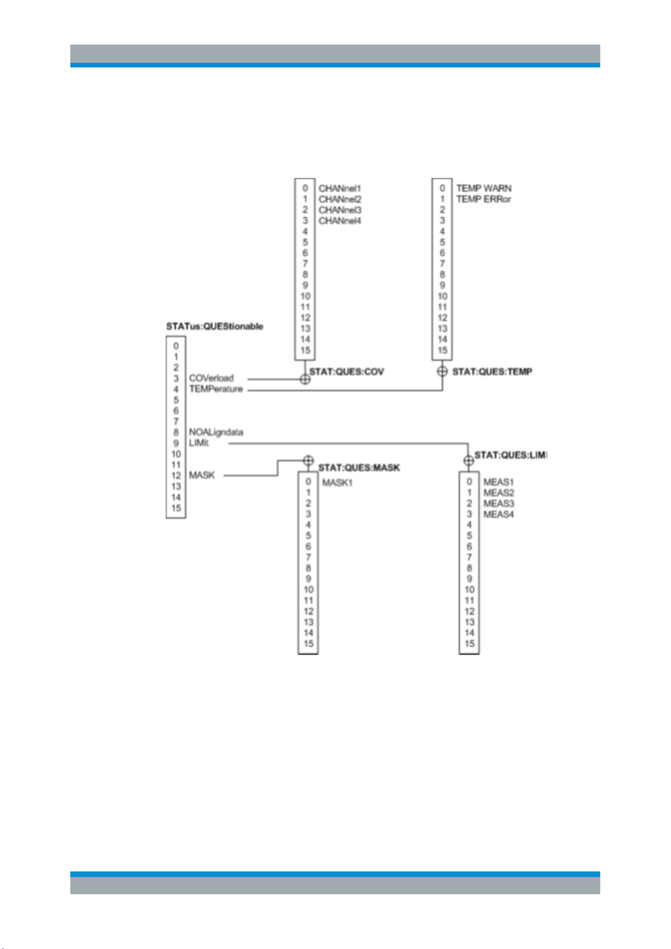
Remote Commands Reference
R&S
®
RTC1000
333User Manual 1335.7352.02 ─ 04
13.19.2 STATus:QUEStionable Registers
The commands of the STATus:QUEStionable subsystem control the status reporting
structures of the STATus:QUEStionable registers:
Figure 13-1: Structure of the STATus:QUEStionable register
See also:
●
Chapter C.1, "Structure of a SCPI Status Register", on page 348
●
STATus:QUEStionable Registers
The following commands are available:
STATus:PRESet.............................................................................................................334
STATus:QUEStionable:CONDition?..................................................................................334
STATus:QUEStionable:COVerload:CONDition?.................................................................334
STATus:QUEStionable:LIMit:CONDition?..........................................................................334
Status Reporting

Remote Commands Reference
R&S
®
RTC1000
334User Manual 1335.7352.02 ─ 04
STATus:QUEStionable:MASK:CONDition?....................................................................... 334
STATus:QUEStionable:ENABle....................................................................................... 334
STATus:QUEStionable:COVerload:ENABle.......................................................................334
STATus:QUEStionable:LIMit:ENABle................................................................................334
STATus:QUEStionable:MASK:ENABle............................................................................. 334
STATus:QUEStionable[:EVENt]?......................................................................................335
STATus:QUEStionable:COVerload[:EVENt]?.....................................................................335
STATus:QUEStionable:LIMit[:EVENt]?..............................................................................335
STATus:QUEStionable:MASK[:EVENt]?........................................................................... 335
STATus:QUEStionable:NTRansition.................................................................................335
STATus:QUEStionable:COVerload:NTRansition................................................................ 335
STATus:QUEStionable:LIMit:NTRansition......................................................................... 335
STATus:QUEStionable:MASK:NTRansition.......................................................................335
STATus:QUEStionable:PTRansition................................................................................. 335
STATus:QUEStionable:COVerload:PTRansition................................................................ 335
STATus:QUEStionable:LIMit:PTRansition......................................................................... 335
STATus:QUEStionable:MASK:PTRansition....................................................................... 335
STATus:PRESet
Resets all STATUS:QUESTIONALBLE registers.
Usage: Event
STATus:QUEStionable:CONDition?
STATus:QUEStionable:COVerload:CONDition?
STATus:QUEStionable:LIMit:CONDition?
STATus:QUEStionable:MASK:CONDition?
Returns the contents of the CONDition part of the status register to check for question-
able instrument or measurement states. Reading the CONDition registers does not
delete the contents.
Return values:
<Condition> Condition bits in decimal representation
Range: 1 to 65535
Increment: 1
Usage: Query only
STATus:QUEStionable:ENABle <Enable>
STATus:QUEStionable:COVerload:ENABle <Enable>
STATus:QUEStionable:LIMit:ENABle <Enable>
STATus:QUEStionable:MASK:ENABle <Enable>
Sets the ENABle part that allows true conditions in the EVENt part to be reported in the
summary bit. If a bit is set to 1 in the enable part and its associated event bit transitions
to true, a positive transition occurs in the summary bit and is reported to the next
higher level.
Status Reporting

Remote Commands Reference
R&S
®
RTC1000
335User Manual 1335.7352.02 ─ 04
Parameters:
<Enable> Bit mask in decimal representation
Range: 1 to 65535
Increment: 1
Example:
STATus:QUEStionable:MASK:ENABle 24
Set bits no. 3 and 4 of the STATus:QUEStionable:MASK:ENABle
register part: 24 = 8 + 16 = 2
3
+ 2
4
STATus:QUEStionable[:EVENt]?
STATus:QUEStionable:COVerload[:EVENt]?
STATus:QUEStionable:LIMit[:EVENt]?
STATus:QUEStionable:MASK[:EVENt]?
Returns the contents of the EVENt part of the status register to check whether an
event has occurred since the last reading. Reading an EVENt register deletes its con-
tents.
Return values:
<Event> Event bits in decimal representation
Range: 1 to 65535
Increment: 1
Usage: Query only
STATus:QUEStionable:NTRansition <NegativeTransition>
STATus:QUEStionable:COVerload:NTRansition <NegativeTransition>
STATus:QUEStionable:LIMit:NTRansition <NegativeTransition>
STATus:QUEStionable:MASK:NTRansition <NegativeTransition>
Sets the negative transition filter. If a bit is set, a 1 to 0 transition in the corresponding
bit of the condition register causes a 1 to be written in the corresponding bit of the
event register.
Parameters:
<NegativeTransition> Bit mask in decimal representation
Range: 1 to 65535
Increment: 1
Example:
STATus:QUEStionable:MASK:NTRansition 24
Set bits no. 3 and 4 of the STATus:QUEStionable:MASK:NTRan-
sition register part: 24 = 8 + 16 = 2
3
+ 2
4
STATus:QUEStionable:PTRansition <PositiveTransition>
STATus:QUEStionable:COVerload:PTRansition <PositiveTransition>
STATus:QUEStionable:LIMit:PTRansition <PositiveTransition>
STATus:QUEStionable:MASK:PTRansition <PositiveTransition>
Sets the positive transition filter. If a bit is set, a 0 to 1 transition in the corresponding
bit of the condition register causes a 1 to be written in the corresponding bit of the
event register.
Status Reporting

Remote Commands Reference
R&S
®
RTC1000
336User Manual 1335.7352.02 ─ 04
Parameters:
<PositiveTransition> Bit mask in decimal representation
Range: 1 to 65535
Increment: 1
Example:
STATus:QUEStionable:MASK:PTRansition 24
Set bits no. 3 and 4 of the STATus:QUEStionable:MASK:PTRan-
sition register part: 24 = 8 + 16 = 2
3
+ 2
4
Status Reporting

SCPI Command Structure
R&S
®
RTC1000
337User Manual 1335.7352.02 ─ 04
Annex
A SCPI Command Structure
SCPI commands consist of a header and, in most cases, one or more parameters. The
header and the parameters are separated by a "white space" (ASCII code 0 to 9, 11 to
32 decimal, e.g. blank). The headers may consist of several mnemonics (keywords).
Queries are formed by appending a question mark directly to the header.
The commands can be either device-specific or device-independent (common com-
mands). Common and device-specific commands differ in their syntax.
A.1 Syntax for Common Commands
Common (= device-independent) commands consist of a header preceded by an aster-
isk (*), and possibly one or more parameters.
Table A-1: Examples of common commands
*RST RESET Resets the instrument.
*ESE EVENT STATUS ENABLE Sets the bits of the event status enable registers.
*ESR? EVENT STATUS QUERY Queries the contents of the event status register.
*IDN? IDENTIFICATION QUERY Queries the instrument identification string.
Syntax for Common Commands

SCPI Command Structure
R&S
®
RTC1000
338User Manual 1335.7352.02 ─ 04
A.2 Syntax for Device-Specific Commands
Not all commands used in the following examples are necessarily implemented in the
instrument. For demonstration purposes only, assume the existence of the following
commands for this section:
●
DISPlay[:WINDow<1...4>]:MAXimize <Boolean>
●
FORMat:READings:DATA <type>[,<length>]
●
HCOPy:DEVice:COLor <Boolean>
●
HCOPy:DEVice:CMAP:COLor:RGB <red>,<green>,<blue>
●
HCOPy[:IMMediate]
●
HCOPy:ITEM:ALL
●
HCOPy:ITEM:LABel <string>
●
HCOPy:PAGE:DIMensions:QUADrant[<N>]
●
HCOPy:PAGE:ORIentation LANDscape | PORTrait
●
HCOPy:PAGE:SCALe <numeric value>
●
MMEMory:COPY <file_source>,<file_destination>
●
SENSE:BANDwidth|BWIDth[:RESolution] <numeric_value>
●
SENSe:FREQuency:STOP <numeric value>
●
SENSe:LIST:FREQuency <numeric_value>{,<numeric_value>}
● Long and short form..............................................................................................338
●
Numeric Suffixes...................................................................................................339
●
Optional Mnemonics............................................................................................. 339
A.2.1 Long and short form
The mnemonics feature a long form and a short form. The short form is marked by
upper case letters, the long form corresponds to the complete word. Either the short
form or the long form can be entered; other abbreviations are not permitted.
Example:
HCOPy:DEVice:COLor ON is equivalent to HCOP:DEV:COL ON.
Case-insensitivity
Upper case and lower case notation only serves to distinguish the two forms in the
manual, the instrument itself is case-insensitive.
Syntax for Device-Specific Commands

SCPI Command Structure
R&S
®
RTC1000
339User Manual 1335.7352.02 ─ 04
A.2.2 Numeric Suffixes
If a command can be applied to multiple instances of an object, e.g. specific channels
or sources, the required instances can be specified by a suffix added to the command.
Numeric suffixes are indicated by angular brackets (<1...4>, <n>, <i>) and are replaced
by a single value in the command. Entries without a suffix are interpreted as having the
suffix 1.
Example:
Definition: HCOPy:PAGE:DIMensions:QUADrant[<N>]
Command: HCOP:PAGE:DIM:QUAD2
This command refers to the quadrant 2.
Different numbering in remote control
For remote control, the suffix may differ from the number of the corresponding selec-
tion used in manual operation. SCPI prescribes that suffix counting starts with 1. Suffix
1 is the default state and used when no specific suffix is specified.
Some standards define a fixed numbering, starting with 0. If the numbering differs in
manual operation and remote control, it is indicated for the corresponding command.
A.2.3 Optional Mnemonics
Some command systems permit certain mnemonics to be inserted into the header or
omitted. These mnemonics are marked by square brackets in the description. The
instrument must recognize the long command to comply with the SCPI standard. Some
commands are considerably shortened by these optional mnemonics.
Example:
Definition: HCOPy[:IMMediate]
Command: HCOP:IMM is equivalent to HCOP
Optional mnemonics with numeric suffixes
Do not omit an optional mnemonic if it includes a numeric suffix that is relevant for the
effect of the command.
Example:
Definition:DISPlay[:WINDow<1...4>]:MAXimize <Boolean>
Command: DISP:MAX ON refers to window 1.
In order to refer to a window other than 1, you must include the optional WINDow
parameter with the suffix for the required window.
DISP:WIND2:MAX ON refers to window 2.
Syntax for Device-Specific Commands

SCPI Command Structure
R&S
®
RTC1000
340User Manual 1335.7352.02 ─ 04
A.3 SCPI Parameters
Many commands are supplemented by a parameter or a list of parameters. The
parameters must be separated from the header by a "white space" (ASCII code 0 to 9,
11 to 32 decimal, e.g. blank).
The parameters required for each command and the allowed range of values are
specified in the command description.
Allowed parameters are:
● Numeric Values..................................................................................................... 340
●
Special Numeric Values........................................................................................ 341
●
Boolean Parameters............................................................................................. 341
●
Text Parameters....................................................................................................341
●
Character Strings.................................................................................................. 342
●
Block Data.............................................................................................................342
A.3.1 Numeric Values
Numeric values can be entered in any form, i.e. with sign, decimal point and exponent.
Values exceeding the resolution of the instrument are rounded up or down. The man-
tissa may comprise up to 255 characters, the exponent must lie inside the value range
-32000 to 32000. The exponent is introduced by an "E" or "e". Entry of the exponent
alone is not allowed.
Example:
SENS:FREQ:STOP 1500000 = SENS:FREQ:STOP 1.5E6
Units
For physical quantities, the unit can be entered. If the unit is missing, the basic unit is
used. Allowed unit prefixes are:
●
G (giga)
●
MA (mega), MOHM, MHZ
●
K (kilo)
●
M (milli)
●
U (micro)
●
N (nano)
Example:
SENSe:FREQ:STOP 1.5GHz = SENSe:FREQ:STOP 1.5E9
Some settings allow relative values to be stated in percent. According to SCPI, this unit
is represented by the PCT string.
SCPI Parameters

SCPI Command Structure
R&S
®
RTC1000
341User Manual 1335.7352.02 ─ 04
Example:
HCOP:PAGE:SCAL 90PCT
A.3.2 Special Numeric Values
The following mnemonics are special numeric values. In the response to a query, the
numeric value is provided.
●
MIN and MAX: denote the minimum and maximum value.
●
DEF: denotes a preset value which has been stored in the EPROM. This value
conforms to the default setting, as it is called by the *RST command.
●
NAN: Not A Number (NAN) represents the value 9.91E37. NAN is only sent as a
instrument response. This value is not defined. Possible causes are the division of
zero by zero, the subtraction of infinite from infinite and the representation of miss-
ing values.
Example:
Setting command: SENSe:LIST:FREQ MAXimum
Query: SENS:LIST:FREQ?
Response: 3.5E9
Queries for special numeric values
The numeric values associated to MAXimum/MINimum/DEFault can be queried by
adding the corresponding mnemonic after the quotation mark.
Example: SENSe:LIST:FREQ? MAXimum
Returns the maximum numeric value as a result.
A.3.3 Boolean Parameters
Boolean parameters represent two states. The "ON" state (logically true) is represen-
ted by "ON" or a numeric value 1. The "OFF" state (logically untrue) is represented by
"OFF" or the numeric value 0. The numeric values are provided as the response for a
query.
Example:
Setting command: HCOPy:DEV:COL ON
Query: HCOPy:DEV:COL?
Response: 1
A.3.4 Text Parameters
Text parameters observe the syntactic rules for mnemonics, i.e. they can be entered
using a short or long form. Like any parameter, they have to be separated from the
SCPI Parameters

SCPI Command Structure
R&S
®
RTC1000
342User Manual 1335.7352.02 ─ 04
header by a white space. In the response to a query, the short form of the text is provi-
ded.
Example:
Setting command: HCOPy:PAGE:ORIentation LANDscape
Query: HCOP:PAGE:ORI?
Response: LAND
A.3.5 Character Strings
Strings must always be entered in quotation marks (' or ").
Example:
HCOP:ITEM:LABel "Test1"
HCOP:ITEM:LABel 'Test1'
A.3.6 Block Data
Block data is a format which is suitable for the transmission of large amounts of data.
For example, a command using a block data parameter has the following structure:
FORMat:READings:DATA #45168xxxxxxxx
The ASCII character # introduces the data block. The next number indicates how many
of the following digits describe the length of the data block. In the example the 4 follow-
ing digits indicate the length to be 5168 bytes. The data bytes follow. During the trans-
mission of these data bytes all end or other control signs are ignored until all bytes are
transmitted.
#0 specifies a data block of indefinite length. The use of the indefinite format requires a
NL^END message to terminate the data block. This format is useful when the length of
the transmission is not known or if speed or other considerations prevent segmentation
of the data into blocks of definite length.
A.4 Overview of Syntax Elements
The following tables provide an overview of the syntax elements and special charac-
ters.
Table A-2: Syntax elements
: The colon separates the mnemonics of a command.
; The semicolon separates two commands of a command line. It does not alter the path.
, The comma separates several parameters of a command.
? The question mark forms a query.
Overview of Syntax Elements

SCPI Command Structure
R&S
®
RTC1000
343User Manual 1335.7352.02 ─ 04
* The asterisk marks a common command.
' '
"
Quotation marks introduce a string and terminate it (both single and double quotation marks are
possible).
# The hash symbol introduces binary, octal, hexadecimal and block data.
●
Binary: #B10110
●
Octal: #O7612
●
Hexa: #HF3A7
●
Block: #21312
A "white space" (ASCII-Code 0 to 9, 11 to 32 decimal, e.g. blank) separates the header from the
parameters.
Table A-3: Special characters
|
Parameters
A vertical stroke in parameter definitions indicates alternative possibilities in the sense of "or". The
effect of the command differs, depending on which parameter is used.
Example:
Definition:HCOPy:PAGE:ORIentation LANDscape | PORTrait
Command HCOP:PAGE:ORI LAND specifies landscape orientation
Command HCOP:PAGE:ORI PORT specifies portrait orientation
Mnemonics
A selection of mnemonics with an identical effect exists for several commands. These mnemonics are
indicated in the same line; they are separated by a vertical stroke. Only one of these mnemonics
needs to be included in the header of the command. The effect of the command is independent of
which of the mnemonics is used.
Example:
DefinitionSENSE:BANDwidth|BWIDth[:RESolution] <numeric_value>
The two following commands with identical meaning can be created:
SENS:BAND:RES 1
SENS:BWID:RES 1
[ ] Mnemonics in square brackets are optional and may be inserted into the header or omitted.
Example: HCOPy[:IMMediate]
HCOP:IMM is equivalent to HCOP
{ } Parameters in curly brackets are optional and can be inserted once or several times, or omitted.
Example: SENSe:LIST:FREQuency <numeric_value>{,<numeric_value>}
The following are valid commands:
SENS:LIST:FREQ 10
SENS:LIST:FREQ 10,20
SENS:LIST:FREQ 10,20,30,40
A.5 Structure of a Command Line
A command line may consist of one or several commands. It is terminated by one of
the following:
●
<New Line>
Structure of a Command Line

SCPI Command Structure
R&S
®
RTC1000
344User Manual 1335.7352.02 ─ 04
●
<New Line> with EOI
●
EOI together with the last data byte
Several commands in a command line must be separated by a semicolon ";".
Example:
MMEM:COPY "Test1","MeasurementXY";:HCOP:ITEM ALL
This command line contains two commands. The first command belongs to the MMEM
system, the second command belongs to the HCOP system. If the next command
belongs to a different command system, the semicolon is followed by a colon.
Example:
HCOP:ITEM ALL;:HCOP:IMM
This command line contains two commands. Both commands are part of the HCOP
command system, i.e. they have one level in common.
If the successive commands belong to the same system, having one or several levels
in common, the command line can be abbreviated. When abbreviating the command
line, the second command begins with the level below HCOP. The colon after the semi-
colon is omitted. The abbreviated form of the command line reads as follows:
HCOP:ITEM ALL;IMM
Example:
HCOP:ITEM ALL
HCOP:IMM
A new command line always begins with the complete path.
A.6 Responses to Queries
A query is defined for each setting command unless explicitly specified otherwise. It is
formed by adding a question mark to the associated setting command. According to
SCPI, the responses to queries are partly subject to stricter rules than in standard
IEEE 488.2.
●
The requested parameter is transmitted without a header.
Example: HCOP:PAGE:ORI?, Response: LAND
●
Maximum values, minimum values and all other quantities that are requested via a
special text parameter are returned as numeric values.
Example: SENSe:FREQuency:STOP? MAX, Response: 3.5E9
●
Numeric values are output without a unit. Physical quantities are referred to the
basic units or to the units set using the Unit command. The response 3.5E9 in
the previous example stands for 3.5 GHz.
●
Truth values (Boolean values) are returned as 0 (for OFF) and 1 (for ON).
Example:
Setting command: HCOPy:DEV:COL ON
Query: HCOPy:DEV:COL?
Responses to Queries

SCPI Command Structure
R&S
®
RTC1000
345User Manual 1335.7352.02 ─ 04
Response: 1
●
Text (character data) is returned in a short form.
Example:
Setting command: HCOPy:PAGE:ORIentation LANDscape
Query: HCOP:PAGE:ORI?
Response: LAND
●
Invalid numerical results
In some cases, particularly when a result consists of multiple numeric values, inva-
lid values are returned as 9.91E37 (not a number).
Responses to Queries

Command Sequence and Synchronization
R&S
®
RTC1000
346User Manual 1335.7352.02 ─ 04
B Command Sequence and Synchronization
IEEE 488.2 defines a distinction between overlapped (asynchronous) and sequential
commands:
●
A sequential command finishes executing before the next command starts execut-
ing. Commands that are processed quickly are usually implemented as sequential
commands.
●
An overlapping or asynchronous command does not automatically finish executing
before the next command starts executing. Usually, overlapping commands take
longer to process and allow the program to do other tasks while being executed. If
overlapping commands must be executed in a defined order, e.g. to avoid wrong
measurement results, they must be serviced sequentially. This method is called
synchronization between the controller and the instrument.
As a rule, send commands and queries in different program messages, i.e. in separate
command lines.
Do not combine queries with commands that affect the queried value in one program
message because the response to the query is not predictable.
The following messages always return correct results:
:CHAN:SCAL 0.01;POS 1
:CHAN:SCAL?
Result: 0.01 (10 mV/div)
Reason: Setting commands within one command line, even though they are implemen-
ted as sequential commands, are not necessarily serviced in the order in which they
have been received.
For further information, refer to:
●
rohde-schwarz.com/rckb: Rohde & Schwarz web page that provides information on
instrument drivers and remote control.
●
"Automatic Measurement Control - A tutorial on SCPI and IEEE 488.2" from John
M. Pieper (R&S order number 0002.3536.00). The book offers detailed information
on concepts and definitions of SCPI.
B.1 Preventing Overlapping Execution
To prevent an overlapping execution of commands, one of the commands *OPC,
*OPC? or *WAI can be used. All three commands cause a certain action only to be
carried out after the hardware has been set. The controller can be forced to wait for the
corresponding action to occur.
Preventing Overlapping Execution

Command Sequence and Synchronization
R&S
®
RTC1000
347User Manual 1335.7352.02 ─ 04
Table B-1: Synchronization using *OPC, *OPC? and *WAI
Com-
mand
Action Programming the controller
*OPC Sets the Operation Complete bit in the ESR
after all previous commands have been exe-
cuted.
●
Setting bit 0 in the ESE
●
Setting bit 5 in the SRE
●
Waiting for service request (SRQ)
*OPC? Stops command processing until 1 is
returned. This occurs when all pending opera-
tions are completed.
Send *OPC? directly after the command
whose processing must be terminated before
other commands can be executed.
*WAI Stops further command processing until all
commands sent before *WAI have been exe-
cuted.
Send *WAI directly after the command whose
processing must be terminated before other
commands are executed.
Command synchronization using *WAI or *OPC? is a good choice if the overlapped
command takes only little time to process. The two synchronization commands simply
block overlapped execution of the command. Append the synchronization command to
the overlapping command, for example:
SINGle; *OPC?
For time consuming overlapped commands, you can allow the controller or the instru-
ment to do other useful work while waiting for command execution. Use one of the fol-
lowing methods:
*OPC with a service request
1. Set the OPC mask bit (bit no. 0) in the ESE: *ESE 1
2. Set bit no. 5 in the SRE: *SRE 32 to enable ESB service request.
3. Send the overlapped command with *OPC .
4. Wait for a service request.
The service request indicates that the overlapped command has finished.
*OPC? with a service request
1. Set bit no. 4 in the SRE: *SRE 16 to enable MAV service request.
2. Send the overlapped command with *OPC?.
3. Wait for a service request.
The service request indicates that the overlapped command has finished.
Event status register (ESE)
1. Set the OPC mask bit (bit no. 0) in the ESE: *ESE 1
2. Send the overlapped command without *OPC, *OPC? or *WAI.
3. Poll the operation complete state periodically (with a timer) using the sequence:
*OPC; *ESR?
A return value (LSB) of 1 indicates that the overlapped command has finished.
Preventing Overlapping Execution
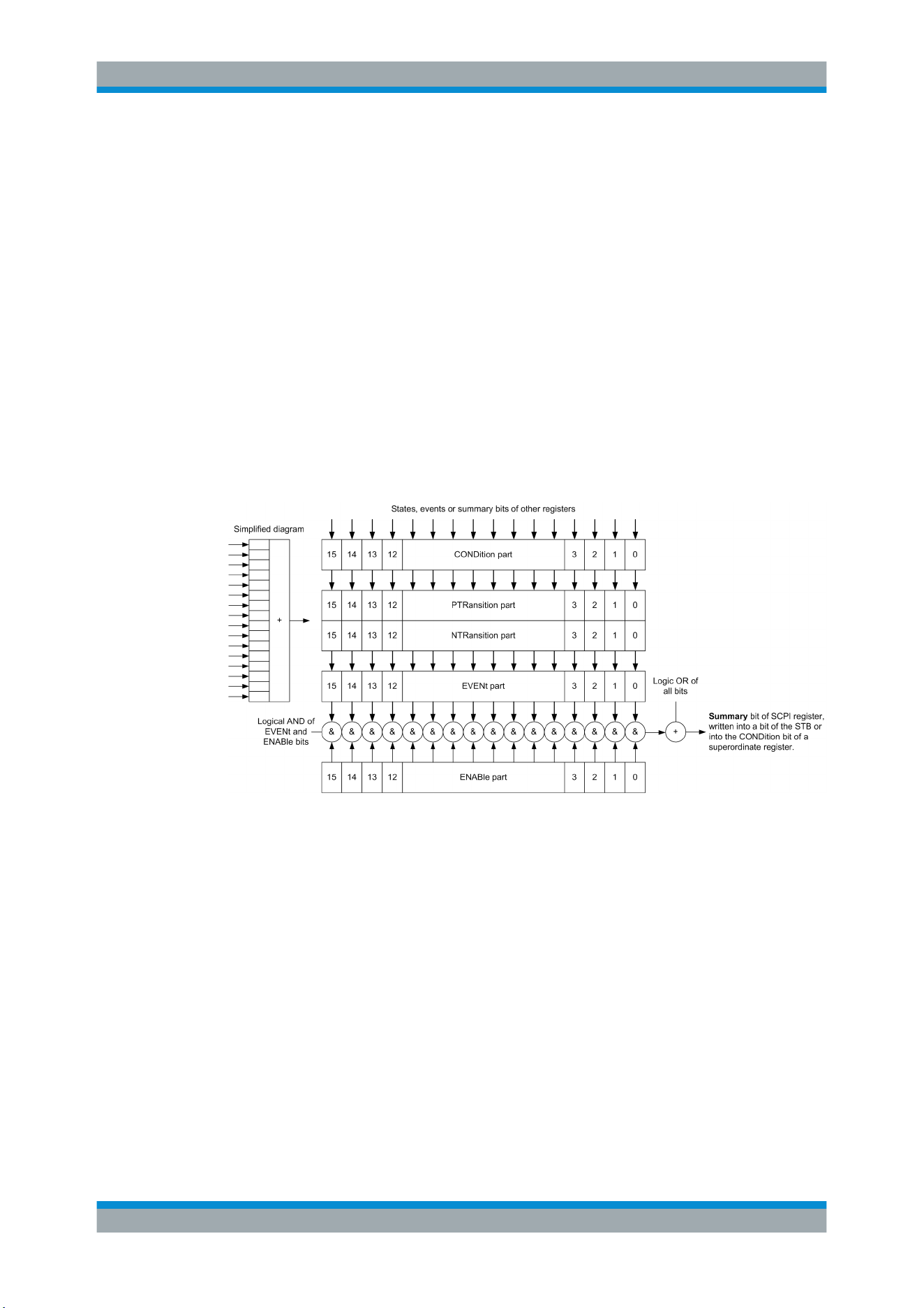
Status Reporting System
R&S
®
RTC1000
348User Manual 1335.7352.02 ─ 04
C Status Reporting System
The status reporting system stores all information on the current operating state of the
instrument, and on errors which have occurred. This information is stored in the status
registers and in the error queue. Both can be queried via LAN interface (STATus...
commands).
C.1 Structure of a SCPI Status Register
Each standard SCPI register consists of 5 parts. Each part has a width of 16 bits and
has different functions. The individual bits are independent of each other, i.e. each
hardware status is assigned a bit number which is valid for all five parts. Bit 15 (the
most significant bit) is set to zero for all parts. Thus the contents of the register parts
can be processed by the controller as positive integers.
Figure C-1: The status-register model
Description of the five status register parts
The five parts of a SCPI register have different properties and functions:
●
CONDition
The CONDition part is written into directly by the hardware or the sum bit of the
next lower register. Its contents reflect the current instrument status. This register
part can only be read, but not written into or cleared. Its contents are not affected
by reading.
●
PTRansition / NTRansition
The two transition register parts define which state transition of the CONDition
part (none, 0 to 1, 1 to 0 or both) is stored in the EVENt part.
The Positive-TRansition part acts as a transition filter. When a bit of the
CONDition part is changed from 0 to 1, the associated PTR bit decides whether
the EVENt bit is set to 1.
Structure of a SCPI Status Register

Status Reporting System
R&S
®
RTC1000
349User Manual 1335.7352.02 ─ 04
– PTR bit =1: the EVENt bit is set.
– PTR bit =0: the EVENt bit is not set.
This part can be written into and read as required. Its contents are not affected by
reading.
The Negative-TRansition part also acts as a transition filter. When a bit of the
CONDition part is changed from 1 to 0, the associated NTR bit decides whether
the EVENt bit is set to 1.
– NTR bit =1: the EVENt bit is set.
– NTR bit =0: the EVENt bit is not set.
This part can be written into and read as required. Its contents are not affected by
reading.
●
EVENt
The EVENt part indicates whether an event has occurred since the last reading, it
is the "memory" of the condition part. It only indicates events passed on by the
transition filters. It is permanently updated by the instrument. This part can only be
read by the user. Reading the register clears it. This part is often equated with the
entire register.
●
ENABle
The ENABle part determines whether the associated EVENt bit contributes to the
sum bit (see below). Each bit of the EVENt part is "ANDed" with the associated
ENABle bit (symbol '&'). The results of all logical operations of this part are passed
on to the sum bit via an "OR" function (symbol '+').
ENABle bit = 0: the associated EVENt bit does not contribute to the sum bit
ENABle bit = 1: if the associated EVENt bit is "1", the sum bit is set to "1" as well.
This part can be written into and read by the user as required. Its contents are not
affected by reading.
Sum bit
The sum bit is obtained from the EVENt and ENABle part for each register. The result
is then entered into a bit of the CONDition part of the higher-order register.
The instrument automatically generates the sum bit for each register. Thus an event
can lead to a service request throughout all levels of the hierarchy.
C.2 Hierarchy of status registers
●
STB, SRE
The STatus Byte (STB) register and its associated mask register Service Request
Enable (SRE) form the highest level of the status reporting system. The STB pro-
vides a rough overview of the instrument status, collecting the information of the
lower-level registers.
●
ESR, SCPI registers
The STB receives its information from the following registers:
Hierarchy of status registers
Status Reporting System
R&S
®
RTC1000
350User Manual 1335.7352.02 ─ 04
– The Event Status Register (ESR) with the associated mask register standard
Event Status Enable (ESE).
– The STATus:OPERation and STATus:QUEStionable registers which are
defined by SCPI and contain detailed information on the instrument.
●
Output buffer
The output buffer contains the messages the instrument returns to the controller. It
is not part of the status reporting system but determines the value of the MAV bit in
the STB and thus is represented in the overview.
All status registers have the same internal structure.
As shown in the following figure, the status information has a hierarchical structure.
Figure C-2: Overview of the status registers hierarchy
Hierarchy of status registers

Status Reporting System
R&S
®
RTC1000
351User Manual 1335.7352.02 ─ 04
C.3 Contents of the Status Registers
In the following sections, the contents of the status registers are described in more
detail.
C.3.1 Status Byte (STB) and Service Request Enable Register (SRE)
The STatus Byte (STB) is already defined in IEEE 488.2. It provides a rough over-
view of the instrument status by collecting the pieces of information of the lower regis-
ters. A special feature is that bit 6 acts as the sum bit of the remaining bits of the status
byte.
The STB can thus be compared with the CONDition part of an SCPI register and
assumes the highest level within the SCPI hierarchy.
The STB is read using the command
*STB? or a serial poll.
The STatus Byte (STB) is linked to the Service Request Enable (SRE) register.
Each bit of the STB is assigned a bit in the SRE. Bit 6 of the SRE is ignored. If a bit is
set in the SRE and the associated bit in the STB changes from 0 to 1, a service
request (SRQ) is generated. The SRE can be set using the command
*SRE and read
using the command *SRE?.
Table C-1: Meaning of the bits used in the status byte
Bit No. Meaning
0...1 Not used
2 Error Queue not empty
The bit is set when an entry is made in the error queue. If this bit is enabled by the SRE, each
entry of the error queue generates a service request. Thus an error can be recognized and
specified in greater detail by polling the error queue. The poll provides an informative error mes-
sage. This procedure is to be recommended since it considerably reduces the problems
involved with remote control.
3 QUEStionable status register summary bit
The bit is set if an EVENt bit is set in the QUEStionable status register and the associated
ENABle bit is set to 1. A set bit indicates a questionable instrument status, which can be speci-
fied in greater detail by querying the STATus:QUEStionable status register.
4 MAV bit (message available)
The bit is set if a message is available in the output queue which can be read. This bit can be
used to enable data to be automatically read from the instrument to the controller.
5 ESB bit
Sum bit of the event status register. It is set if one of the bits in the event status register is set
and enabled in the event status enable register. Setting of this bit indicates a serious error which
can be specified in greater detail by polling the event status register.
Contents of the Status Registers

Status Reporting System
R&S
®
RTC1000
352User Manual 1335.7352.02 ─ 04
Bit No. Meaning
6 MSS bit (master status summary bit)
The bit is set if the instrument triggers a service request. This is the case if one of the other bits
of this registers is set together with its mask bit in the service request enable register SRE.
7 STATus:OPERation status register summary bit
The bit is set if an EVENt bit is set in the OPERation status register and the associated
ENABle bit is set to 1. A set bit indicates that the instrument is just performing an action. The
type of action can be determined by querying the STATus:OPERation status register.
C.3.2 Event Status Register (ESR) and Event Status Enable Register
(ESE)
The ESR is defined in IEEE 488.2. It can be compared with the EVENt part of a SCPI
register. The event status register can be read out using command
*ESR?.
The ESE corresponds to the ENABle part of a SCPI register. If a bit is set in the ESE
and the associated bit in the ESR changes from 0 to 1, the ESB bit in the STB is set.
The ESE register can be set using the command
*ESE and read using the command
*ESE?.
Table C-2: Meaning of the bits used in the event status register
Bit No. Meaning
0 Operation Complete
This bit is set on receipt of the command *OPC exactly when all previous commands have been
executed.
1 Not used
2 Query Error
This bit is set if either the controller wants to read data from the instrument without having sent a
query, or if it does not fetch requested data and sends new instructions to the instrument
instead. The cause is often a query which is faulty and hence cannot be executed.
3 Device-dependent Error
This bit is set if a device-dependent error occurs. An error message with a number between
-300 and -399 or a positive error number, which denotes the error in greater detail, is entered
into the error queue.
4 Execution Error
This bit is set if a received command is syntactically correct but cannot be performed for other
reasons. An error message with a number between -200 and -300, which denotes the error in
greater detail, is entered into the error queue.
5 Command Error
This bit is set if a command is received, which is undefined or syntactically incorrect. An error
message with a number between -100 and -200, which denotes the error in greater detail, is
entered into the error queue.
Contents of the Status Registers

Status Reporting System
R&S
®
RTC1000
353User Manual 1335.7352.02 ─ 04
Bit No. Meaning
6 User Request
This bit is set when the instrument is switched over to manual control.
7 Power On (supply voltage on)
This bit is set on switching on the instrument.
C.3.3 STATus:OPERation Register
In the CONDition part, this register contains information on which actions the instru-
ment is executing. In the EVENt part, it contains information on which actions the
instrument has executed since the last reading.
It can be read using the commands STATus:OPERation:CONDition? or
STATus:OPERation[:EVENt]?, see also
Chapter 13.19.1, "STATus:OPERation
Register"
, on page 331.
Table C-3: Bits in the STATus:OPERation register
Bit No. Meaning
0
ALIGnment
This bit is set as long as the instrument is performing a self-alignment.
1
SELFtest
This bit is set while a selftest is running.
2
AUToset
This bit is set while the instrument is performing an auto setup.
3
WTRIgger
This bit is set while the instrument is waiting for the trigger.
4 to 14 Not used
15 This bit is always 0.
C.3.4 STATus:QUEStionable Register
This register contains information about indefinite states which may occur if the unit is
operated without meeting the specifications. It can be read using the commands
STATus:QUEStionable:CONDition? and STATus:QUEStionable[:EVENt]?
The remote commands for the STATus:QUEStionable register are described in Chap-
ter 13.19.2, "STATus:QUEStionable Registers"
, on page 333.
Contents of the Status Registers
Status Reporting System
R&S
®
RTC1000
354User Manual 1335.7352.02 ─ 04
Figure C-3: Overview of the STATus:QUEStionable register
Table C-4: Bits in the STATus:QUEStionable register
Bit No. Meaning
0 to 2 not used
3
COVerload
This bit is set if a questionable channel overload occurs (see
Chapter C.3.4.1, "STATus:QUES-
tionable:COVerload register", on page 355).
4
TEMPerature
This bit is set if a questionable temperature occurs (see
Chapter C.3.4.2, "STATus:QUEStiona-
ble:TEMPerature register", on page 355).
5 and 7 Not used
Contents of the Status Registers

Status Reporting System
R&S
®
RTC1000
355User Manual 1335.7352.02 ─ 04
Bit No. Meaning
8
NOALigndata
This bit is set if no alignment data is available - the instrument is uncalibrated.
9
LIMit
This bit is set if a limit value is violated (see
Chapter C.3.4.3, "STATus:QUEStionable:LIMit reg-
ister", on page 355).
10 and
11
Not used
12
MASK
This bit is set if a mask value is violated (see
Chapter C.3.4.4, "STATus:QUEStionable:MASK
register", on page 356).
13 and
14
Not used
15 This bit is always 0.
C.3.4.1 STATus:QUEStionable:COVerload register
This register contains all information about overload of the channels. The bit is set if
the assigned channel is overloaded, or if an overload risk occured (overload warning).
Table C-5: Bits in the STATus:QUEStionable:COVerload register
Bit No. Meaning
0 Overload on CHANnel1
1 Overload on CHANnel2
C.3.4.2 STATus:QUEStionable:TEMPerature register
This register contains information about the instrument's temperature.
Table C-6: Bits in the STATus:QUEStionable:TEMPerature register
Bit No. Meaning
0
TEMP WARN
This bit is set if a temperature warning on channel 1 or 2 occured.
1
TEMP ERRor
This bit is set if a temperature error on channel 1or 2 occured.
C.3.4.3 STATus:QUEStionable:LIMit register
These registers contain information about the observance of the limits of measure-
ments. The LIMit bit is set if the limit of the assigned measurement is violated.
Contents of the Status Registers

Status Reporting System
R&S
®
RTC1000
356User Manual 1335.7352.02 ─ 04
Table C-7: Bits in the STATus:QUEStionable:LIMit register
Bit No. Meaning
0
MEAS1
1
MEAS2
C.3.4.4 STATus:QUEStionable:MASK register
This register contains information about the violation of masks. This bit is set if the
assigned mask is violated.
Table C-8: Bits in the STATus:QUEStionable:MASK register
Bit No. Meaning
0
MASK1
C.4 Application of the Status Reporting System
The purpose of the status reporting system is to monitor the status of one or several
devices in a measuring system. To do this and react appropriately, the controller must
receive and evaluate the information of all devices. The following standard methods
are used:
●
Service request (SRQ) initiated by the instrument
●
Serial poll of all devices in the bus system, initiated by the controller in order to
find out who sent a SRQ and why
●
Parallel poll of all devices
●
Query of a specific instrument status by means of commands
●
Query of the error queue
C.4.1 Service Request
Under certain circumstances, the instrument can send a service request (SRQ) to the
controller. Usually this service request initiates an interrupt at the controller, to which
the control program can react appropriately. As evident from
Figure C-3, an SRQ is
always initiated if one or several of bits 2, 3, 4, 5 or 7 of the status byte are set and
enabled in the SRE. Each of these bits combines the information of a further register,
the error queue or the output buffer. The ENABle parts of the status registers can be
set such that arbitrary bits in an arbitrary status register initiate an SRQ. In order to
make use of the possibilities of the service request effectively, all bits should be set to
"1" in enable registers SRE and ESE.
The SRQ is the only possibility for the instrument to become active on its own. Each
controller program should cause the instrument to initiate a service request if errors
occur. The program should react appropriately to the service request.
Application of the Status Reporting System
Status Reporting System
R&S
®
RTC1000
357User Manual 1335.7352.02 ─ 04
C.4.2 Serial Poll
In a serial poll, just as with command *STB, the status byte of an instrument is queried.
However, the query is realized via interface messages and is thus clearly faster.
The serial poll method is defined in IEEE 488.1 and used to be the only standard pos-
sibility for different instruments to poll the status byte. The method also works for
instruments which do not adhere to SCPI or IEEE 488.2.
The serial poll is mainly used to obtain a fast overview of the state of several instru-
ments connected to the controller.
C.4.3 Query of an instrument status
Each part of any status register can be read using queries. There are two types of
commands:
●
The common commands *ESR?, *IDN?, *IST?, *STB? query the higher-level
registers.
●
The commands of the STATus system query the SCPI registers
(STATus:QUEStionable...)
The returned value is always a decimal number that represents the bit pattern of the
queried register. This number is evaluated by the controller program.
Queries are usually used after an SRQ in order to obtain more detailed information on
the cause of the SRQ.
C.4.3.1 Decimal representation of a bit pattern
The STB and ESR registers contain 8 bits, the SCPI registers 16 bits. The contents of
a status register are specified and transferred as a single decimal number. To make
this possible, each bit is assigned a weighted value. The decimal number is calculated
as the sum of the weighted values of all bits in the register that are set to 1.
Example:
The decimal value 40 = 32 + 8 indicates that bits no. 3 and 5 in the status register (e.g.
the QUEStionable status summary bit and the ESB bit in the STatus Byte ) are set.
Application of the Status Reporting System

Status Reporting System
R&S
®
RTC1000
358User Manual 1335.7352.02 ─ 04
C.4.4 Error Queue
Each error state in the instrument leads to an entry in the error queue. The entries of
the error queue are detailed plain text error messages that can be looked up in the
Error Log or queried via remote control using SYSTem:ERRor[:NEXT]?. Each call of
SYSTem:ERRor[:NEXT]? provides one entry from the error queue. If no error mes-
sages are stored there any more, the instrument responds with 0, "No error".
The error queue should be queried after every SRQ in the controller program as the
entries describe the cause of an error more precisely than the status registers. Espe-
cially in the test phase of a controller program the error queue should be queried regu-
larly since faulty commands from the controller to the instrument are recorded there as
well.
C.5 Reset Values of the Status Reporting System
The following table contains the different commands and events causing the status
reporting system to be reset. None of the commands, except *RST and
SYSTem:PRESet, influence the functional instrument settings. In particular, DCL does
not change the instrument settings.
Table C-9: Resest of the status reporting system
Event Switching on supply
voltage
Power-On-Status-
Clear
DCL,
SDC
(Device
Clear,
Selected
Device
Clear)
*RST or
SYS-
Tem:PRE
Set
STA-
Tus:PRE-
Set
*CLS
Effect 0 1
Clear STB, ESR - yes - - - yes
Clear SRE, ESE - yes - - - -
Clear EVENt parts of the regis-
ters
- yes - - - yes
Clear ENABle parts of all
OPERation and QUEStionable
registers;
Fill ENABle parts of all other
registers with "1".
- yes - - yes -
Fill PTRansition parts with "1";
Clear NTRansition parts
- yes - - yes -
Clear error queue yes yes - - - yes
Clear output buffer yes yes yes 1) 1) 1)
Clear command processing
and input buffer
yes yes yes - - -
1) The first command in a command line that immediately follows a <PROGRAM MESSAGE TERMINA-
TOR> clears the output buffer.
Reset Values of the Status Reporting System

General Programming Recommendations
R&S
®
RTC1000
359User Manual 1335.7352.02 ─ 04
D General Programming Recommendations
Initial instrument status before changing settings
Manual operation is designed for maximum possible operating convenience. In con-
trast, the priority of remote control is the "predictability" of the instrument status. Thus,
when a command attempts to define incompatible settings, the command is ignored
and the instrument status remains unchanged, i.e. other settings are not automatically
adapted. Therefore, control programs should always define an initial instrument status
(e.g. using the *RST command) and then implement the required settings.
Command sequence
As a general rule, send commands and queries in different program messages. Other-
wise, the result of the query may vary depending on which operation is performed first
(see also Preventing Overlapping Execution).
Reacting to malfunctions
The service request is the only possibility for the instrument to become active on its
own. Each controller program should instruct the instrument to initiate a service
request in case of malfunction. The program should react appropriately to the service
request.
Error queues
The error queue should be queried after every service request in the controller pro-
gram as the entries describe the cause of an error more precisely than the status regis-
ters. Especially in the test phase of a controller program the error queue should be
queried regularly since faulty commands from the controller to the instrument are
recorded there as well.

List of Commands
R&S
®
RTC1000
360User Manual 1335.7352.02 ─ 04
List of Commands
*CAL?.............................................................................................................................................................168
*CLS...............................................................................................................................................................168
*ESE.............................................................................................................................................................. 168
*ESR?............................................................................................................................................................ 168
*IDN?............................................................................................................................................................. 169
*OPC..............................................................................................................................................................169
*OPT?............................................................................................................................................................ 169
*PSC.............................................................................................................................................................. 169
*RST.............................................................................................................................................................. 170
*SRE.............................................................................................................................................................. 170
*STB?.............................................................................................................................................................170
*TRG..............................................................................................................................................................170
*TST?.............................................................................................................................................................170
*WAI...............................................................................................................................................................171
ACQuire:AVERage:COMPlete?..................................................................................................................... 175
ACQuire:AVERage:COUNt............................................................................................................................ 175
ACQuire:FILTer:FREQuency..........................................................................................................................178
ACQuire:HRESolution....................................................................................................................................180
ACQuire:INTerpolate......................................................................................................................................175
ACQuire:MODE............................................................................................................................................. 174
ACQuire:PEAKdetect.....................................................................................................................................179
ACQuire:POINts:ARATe?...............................................................................................................................178
ACQuire:POINts[:VALue]?............................................................................................................................. 176
ACQuire:SRATe?........................................................................................................................................... 178
ACQuire:STATe..............................................................................................................................................178
ACQuire:TYPE...............................................................................................................................................179
ACQuire:WRATe............................................................................................................................................ 176
AUToscale......................................................................................................................................................174
BUS<b>:CAN:BITRate...................................................................................................................................297
BUS<b>:CAN:DATA:SOURce....................................................................................................................... 296
BUS<b>:CAN:FCOunt?................................................................................................................................. 302
BUS<b>:CAN:FRAMe<n>:ACKState?...........................................................................................................304
BUS<b>:CAN:FRAMe<n>:ACKValue?.......................................................................................................... 305
BUS<b>:CAN:FRAMe<n>:BCOunt?..............................................................................................................307
BUS<b>:CAN:FRAMe<n>:BSEPosition?...................................................................................................... 307
BUS<b>:CAN:FRAMe<n>:BYTE<o>:STATe?............................................................................................... 307
BUS<b>:CAN:FRAMe<n>:BYTE<o>:VALue?............................................................................................... 308
BUS<b>:CAN:FRAMe<n>:CSSTate?............................................................................................................ 304
BUS<b>:CAN:FRAMe<n>:CSValue?............................................................................................................ 306
BUS<b>:CAN:FRAMe<n>:DATA?................................................................................................................. 304
BUS<b>:CAN:FRAMe<n>:DLCState?...........................................................................................................305
BUS<b>:CAN:FRAMe<n>:DLCValue?.......................................................................................................... 306
BUS<b>:CAN:FRAMe<n>:IDSTate?..............................................................................................................305
BUS<b>:CAN:FRAMe<n>:IDTYpe?.............................................................................................................. 306
BUS<b>:CAN:FRAMe<n>:IDValue?..............................................................................................................306
BUS<b>:CAN:FRAMe<n>:STARt?................................................................................................................ 303
BUS<b>:CAN:FRAMe<n>:STATus?.............................................................................................................. 302

List of Commands
R&S
®
RTC1000
361User Manual 1335.7352.02 ─ 04
BUS<b>:CAN:FRAMe<n>:STOP?.................................................................................................................303
BUS<b>:CAN:FRAMe<n>:TYPE?.................................................................................................................303
BUS<b>:CAN:SAMPlepoint...........................................................................................................................297
BUS<b>:CAN:TYPE...................................................................................................................................... 297
BUS<b>:CPARallel:CLOCK:SLOPe.............................................................................................................. 268
BUS<b>:CPARallel:CLOCk:SOURce............................................................................................................ 268
BUS<b>:CPARallel:CS:POLarity................................................................................................................... 269
BUS<b>:CPARallel:CS:SOURce................................................................................................................... 268
BUS<b>:CPARallel:DATA<m>:SOURce........................................................................................................267
BUS<b>:CPARallel:WIDTh............................................................................................................................ 269
BUS<b>:DSIGnals.........................................................................................................................................266
BUS<b>:DSIZe.............................................................................................................................................. 265
BUS<b>:FORMat...........................................................................................................................................265
BUS<b>:I2C:AMODe.....................................................................................................................................279
BUS<b>:I2C:CLOCk:SOURce.......................................................................................................................279
BUS<b>:I2C:DATA:SOURce......................................................................................................................... 279
BUS<b>:I2C:FCOunt?................................................................................................................................... 283
BUS<b>:I2C:FRAMe<n>:AACCess?.............................................................................................................285
BUS<b>:I2C:FRAMe<n>:ACCess?............................................................................................................... 284
BUS<b>:I2C:FRAMe<n>:ACOMplete?..........................................................................................................287
BUS<b>:I2C:FRAMe<n>:ADBStart?............................................................................................................. 287
BUS<b>:I2C:FRAMe<n>:ADDRess?.............................................................................................................286
BUS<b>:I2C:FRAMe<n>:ADEVice?..............................................................................................................286
BUS<b>:I2C:FRAMe<n>:AMODe?................................................................................................................285
BUS<b>:I2C:FRAMe<n>:ASTart?..................................................................................................................286
BUS<b>:I2C:FRAMe<n>:BCOunt?................................................................................................................287
BUS<b>:I2C:FRAMe<n>:BYTE<o>:ACCess?...............................................................................................289
BUS<b>:I2C:FRAMe<n>:BYTE<o>:ACKStart?.............................................................................................289
BUS<b>:I2C:FRAMe<n>:BYTE<o>:COMPlete?........................................................................................... 290
BUS<b>:I2C:FRAMe<n>:BYTE<o>:STARt?................................................................................................. 289
BUS<b>:I2C:FRAMe<n>:BYTE<o>:VALue?................................................................................................. 288
BUS<b>:I2C:FRAMe<n>:DATA?................................................................................................................... 288
BUS<b>:I2C:FRAMe<n>:STARt?.................................................................................................................. 284
BUS<b>:I2C:FRAMe<n>:STATus?................................................................................................................ 283
BUS<b>:I2C:FRAMe<n>:STOP?...................................................................................................................284
BUS<b>:LABel...............................................................................................................................................266
BUS<b>:LABel:STATe................................................................................................................................... 266
BUS<b>:LIN:BITRate.....................................................................................................................................309
BUS<b>:LIN:DATA:SOURce......................................................................................................................... 308
BUS<b>:LIN:FCOunt?................................................................................................................................... 313
BUS<b>:LIN:FRAMe<n>:BCOunt?................................................................................................................313
BUS<b>:LIN:FRAMe<n>:BYTE<o>:STATe?................................................................................................. 317
BUS<b>:LIN:FRAMe<n>:BYTE<o>:VALue?................................................................................................. 318
BUS<b>:LIN:FRAMe<n>:CSSTate?.............................................................................................................. 317
BUS<b>:LIN:FRAMe<n>:CSValue?.............................................................................................................. 317
BUS<b>:LIN:FRAMe<n>:DATA?................................................................................................................... 315
BUS<b>:LIN:FRAMe<n>:IDPValue?............................................................................................................. 316
BUS<b>:LIN:FRAMe<n>:IDSTate?................................................................................................................315
BUS<b>:LIN:FRAMe<n>:IDValue?................................................................................................................316
BUS<b>:LIN:FRAMe<n>:STARt?.................................................................................................................. 314

List of Commands
R&S
®
RTC1000
362User Manual 1335.7352.02 ─ 04
BUS<b>:LIN:FRAMe<n>:STATus?................................................................................................................ 313
BUS<b>:LIN:FRAMe<n>:STOP?...................................................................................................................314
BUS<b>:LIN:FRAMe<n>:SYSTate?.............................................................................................................. 316
BUS<b>:LIN:FRAMe<n>:VERSion?..............................................................................................................315
BUS<b>:LIN:POLarity....................................................................................................................................309
BUS<b>:LIN:STANdard................................................................................................................................. 309
BUS<b>:PARallel:DATA<m>:SOURce.......................................................................................................... 267
BUS<b>:PARallel:WIDTh...............................................................................................................................267
BUS<b>:POSition.......................................................................................................................................... 266
BUS<b>:SPI:BORDer....................................................................................................................................271
BUS<b>:SPI:CLOCk:POLarity.......................................................................................................................270
BUS<b>:SPI:CLOCk:SOURce.......................................................................................................................270
BUS<b>:SPI:CS:POLarity..............................................................................................................................270
BUS<b>:SPI:CS:SOURce............................................................................................................................. 269
BUS<b>:SPI:DATA:POLarity......................................................................................................................... 271
BUS<b>:SPI:DATA:SOURce......................................................................................................................... 271
BUS<b>:SPI:FCOunt?...................................................................................................................................273
BUS<b>:SPI:FRAME<n>:DATA?...................................................................................................................275
BUS<b>:SPI:FRAME<n>:STARt?................................................................................................................. 274
BUS<b>:SPI:FRAME<n>:STATus?............................................................................................................... 274
BUS<b>:SPI:FRAME<n>:STOP?..................................................................................................................274
BUS<b>:SPI:FRAME<n>:WCOunt?..............................................................................................................275
BUS<b>:SPI:FRAME<n>:WORD<o>:MISO?................................................................................................276
BUS<b>:SPI:FRAME<n>:WORD<o>:MOSI?................................................................................................276
BUS<b>:SPI:FRAME<n>:WORD<o>:STARt?...............................................................................................275
BUS<b>:SPI:FRAME<n>:WORD<o>:STOP?............................................................................................... 276
BUS<b>:SPI:SSIZe........................................................................................................................................272
BUS<b>:SSPI:BITime....................................................................................................................................278
BUS<b>:SSPI:BORDer..................................................................................................................................278
BUS<b>:SSPI:CLOCk:POLarity.................................................................................................................... 277
BUS<b>:SSPI:CLOCk:SOURce.................................................................................................................... 277
BUS<b>:SSPI:DATA:POLarity....................................................................................................................... 277
BUS<b>:SSPI:DATA:SOURce.......................................................................................................................277
BUS<b>:SSPI:SSIZe..................................................................................................................................... 278
BUS<b>:STATe.............................................................................................................................................. 265
BUS<b>:TYPE...............................................................................................................................................265
BUS<b>:UART:BAUDrate..............................................................................................................................292
BUS<b>:UART:BITime...................................................................................................................................292
BUS<b>:UART:DATA:POLarity......................................................................................................................291
BUS<b>:UART:DATA:SOURce......................................................................................................................291
BUS<b>:UART:FCOunt?............................................................................................................................... 294
BUS<b>:UART:FRAMe<n>:WCOunt?...........................................................................................................294
BUS<b>:UART:FRAMe<n>:WORD<o>:STARt?............................................................................................295
BUS<b>:UART:FRAMe<n>:WORD<o>:STATe?............................................................................................295
BUS<b>:UART:FRAMe<n>:WORD<o>:STOP?............................................................................................ 295
BUS<b>:UART:FRAMe<n>:WORD<o>:VALue?........................................................................................... 295
BUS<b>:UART:PARity................................................................................................................................... 291
BUS<b>:UART:SBIT...................................................................................................................................... 292
BUS<b>:UART:SSIZe.................................................................................................................................... 291
CALCulate:MATH<m>:ARIThmetics..............................................................................................................238

List of Commands
R&S
®
RTC1000
363User Manual 1335.7352.02 ─ 04
CALCulate:MATH<m>:FFT:AVERage:COUNt............................................................................................... 239
CALCulate:MATH<m>:FFT:BANDwidth[:RESolution]:ADJusted?................................................................. 240
CALCulate:MATH<m>:FFT:BANDwidth[:RESolution]:AUTO.........................................................................240
CALCulate:MATH<m>:FFT:BANDwidth[:RESolution]:RATio......................................................................... 240
CALCulate:MATH<m>:FFT:BANDwidth[:RESolution][:VALue]...................................................................... 240
CALCulate:MATH<m>:FFT:CFRequency...................................................................................................... 240
CALCulate:MATH<m>:FFT:FULLspan...........................................................................................................241
CALCulate:MATH<m>:FFT:MAGNitude:SCALe............................................................................................ 239
CALCulate:MATH<m>:FFT:SPAN..................................................................................................................241
CALCulate:MATH<m>:FFT:SRATe?.............................................................................................................. 242
CALCulate:MATH<m>:FFT:STARt.................................................................................................................241
CALCulate:MATH<m>:FFT:STOP................................................................................................................. 241
CALCulate:MATH<m>:FFT:TIME:POSition................................................................................................... 242
CALCulate:MATH<m>:FFT:TIME:RANGe..................................................................................................... 241
CALCulate:MATH<m>:FFT:WINDow:TYPE...................................................................................................238
CALCulate:QMATh:DATA:HEADer?.............................................................................................................. 231
CALCulate:QMATh:DATA:XINCrement?........................................................................................................231
CALCulate:QMATh:DATA:XORigin?.............................................................................................................. 231
CALCulate:QMATh:DATA:YINCrement?........................................................................................................231
CALCulate:QMATh:DATA:YORigin?.............................................................................................................. 232
CALCulate:QMATh:DATA:YRESolutiont?...................................................................................................... 232
CALCulate:QMATh:DATA?............................................................................................................................ 230
CALCulate:QMATh:OPERation..................................................................................................................... 230
CALCulate:QMATh:POSition......................................................................................................................... 230
CALCulate:QMATh:SCALe............................................................................................................................ 230
CALCulate:QMATh:SOURce......................................................................................................................... 230
CALCulate:QMATh:STATe............................................................................................................................. 229
CALibration.................................................................................................................................................... 328
CALibration:STATe?.......................................................................................................................................328
CHANnel<m>:ARIThmetics........................................................................................................................... 177
CHANnel<m>:BANDwidth............................................................................................................................. 182
CHANnel<m>:COUPling................................................................................................................................180
CHANnel<m>:DATA:ENVelope:HEADer?..................................................................................................... 189
CHANnel<m>:DATA:ENVelope:XINCrement?...............................................................................................190
CHANnel<m>:DATA:ENVelope:XORigin?..................................................................................................... 190
CHANnel<m>:DATA:ENVelope:YINCrement?...............................................................................................190
CHANnel<m>:DATA:ENVelope:YORigin?..................................................................................................... 190
CHANnel<m>:DATA:ENVelope:YRESolution?.............................................................................................. 191
CHANnel<m>:DATA:ENVelope?....................................................................................................................189
CHANnel<m>:DATA:HEADer?...................................................................................................................... 186
CHANnel<m>:DATA:POINts.......................................................................................................................... 187
CHANnel<m>:DATA:XINCrement?................................................................................................................188
CHANnel<m>:DATA:XORigin?...................................................................................................................... 188
CHANnel<m>:DATA:YINCrement?................................................................................................................188
CHANnel<m>:DATA:YORigin?...................................................................................................................... 188
CHANnel<m>:DATA:YRESolution?............................................................................................................... 189
CHANnel<m>:DATA?.....................................................................................................................................186
CHANnel<m>:LABel...................................................................................................................................... 184
CHANnel<m>:LABel:STATe...........................................................................................................................184
CHANnel<m>:OFFSet................................................................................................................................... 182

List of Commands
R&S
®
RTC1000
364User Manual 1335.7352.02 ─ 04
CHANnel<m>:OVERload...............................................................................................................................182
CHANnel<m>:POLarity..................................................................................................................................182
CHANnel<m>:POSition..................................................................................................................................181
CHANnel<m>:RANGe................................................................................................................................... 181
CHANnel<m>:SCALe.................................................................................................................................... 181
CHANnel<m>:SKEW..................................................................................................................................... 183
CHANnel<m>:STATe..................................................................................................................................... 180
CHANnel<m>:THReshold..............................................................................................................................183
CHANnel<m>:THReshold:FINDlevel.............................................................................................................183
CHANnel<m>:THReshold:HYSTeresis.......................................................................................................... 183
CHANnel<m>:TYPE...................................................................................................................................... 176
COMPonenttest:FREQuency.........................................................................................................................260
COMPonenttest:STATe.................................................................................................................................. 260
CURSor<m>:AOFF........................................................................................................................................216
CURSor<m>:FUNCtion..................................................................................................................................217
CURSor<m>:RESult?.................................................................................................................................... 220
CURSor<m>:SNPeak.................................................................................................................................... 218
CURSor<m>:SOURce................................................................................................................................... 217
CURSor<m>:SPPeak.................................................................................................................................... 218
CURSor<m>:SSCReen................................................................................................................................. 218
CURSor<m>:STATe....................................................................................................................................... 216
CURSor<m>:SWAVe..................................................................................................................................... 218
CURSor<m>:TRACking:SCALe[:STATe]....................................................................................................... 220
CURSor<m>:TRACking[:STATe]....................................................................................................................218
CURSor<m>:X1Position................................................................................................................................ 219
CURSor<m>:X2Position................................................................................................................................ 219
CURSor<m>:X3Position................................................................................................................................ 219
CURSor<m>:XCOupling................................................................................................................................220
CURSor<m>:XDELta:INVerse?..................................................................................................................... 220
CURSor<m>:XDELta[:VALue]?..................................................................................................................... 221
CURsor<m>:XRATio:UNIT.............................................................................................................................221
CURSor<m>:XRATio[:VALue]?......................................................................................................................222
CURSor<m>:Y1Position................................................................................................................................ 219
CURSor<m>:Y2Position................................................................................................................................ 219
CURSor<m>:Y3Position................................................................................................................................ 219
CURSor<m>:YCOupling................................................................................................................................220
CURSor<m>:YDELta:SLOPe?...................................................................................................................... 221
CURSor<m>:YDELta[:VALue]?..................................................................................................................... 221
CURSor<m>:YRATio:UNIT............................................................................................................................222
CURSor<m>:YRATio[:VALue]?......................................................................................................................222
DISPlay:DIALog:CLOSe................................................................................................................................ 209
DISPlay:DIALog:MESSage............................................................................................................................209
DISPlay:DIALog:TRANsparency....................................................................................................................210
DISPlay:GRID:STYLe....................................................................................................................................213
DISPlay:INTensity:BACKlight.........................................................................................................................212
DISPlay:INTensity:GRID................................................................................................................................ 212
DISPlay:INTensity:WAVeform.........................................................................................................................211
DISPlay:LANGuage....................................................................................................................................... 210
DISPlay:LANGuage....................................................................................................................................... 328
DISPlay:LANGuage:ADD...............................................................................................................................210

List of Commands
R&S
®
RTC1000
365User Manual 1335.7352.02 ─ 04
DISPlay:LANGuage:CATalog?.......................................................................................................................210
DISPlay:LANGuage:REMove........................................................................................................................ 210
DISPlay:MODE.............................................................................................................................................. 208
DISPlay:PALette............................................................................................................................................ 208
DISPlay:PERSistence:CLEar.........................................................................................................................213
DISPlay:PERSistence:INFinite...................................................................................................................... 212
DISPlay:PERSistence:STATe........................................................................................................................ 212
DISPlay:PERSistence:TIME.......................................................................................................................... 212
DISPlay:PERSistence:TIME:AUTO............................................................................................................... 213
DISPlay:STYLe..............................................................................................................................................213
DISPlay:VSCReen:ENABle........................................................................................................................... 209
DISPlay:VSCReen:POSition..........................................................................................................................209
DISPlay:XY:XSOurce..................................................................................................................................... 211
DISPlay:XY:Y1Source....................................................................................................................................211
DVM:ENABle................................................................................................................................................. 257
DVM:POSition................................................................................................................................................259
DVM<m>:RESult:RESet................................................................................................................................ 258
DVM<m>:RESult[:ACTual]:STATus?............................................................................................................. 258
DVM<m>:RESult[:ACTual]?...........................................................................................................................258
DVM<m>:SOURce.........................................................................................................................................257
DVM<m>:TYPE............................................................................................................................................. 256
EXPort:WAVeform:NAME.............................................................................................................................. 191
EXPort:WAVeform:SAVE............................................................................................................................... 192
EXPort:WAVeform:SOURce...........................................................................................................................191
EXTern:COUPling.......................................................................................................................................... 261
EXTern:DATA:HEADer?.................................................................................................................................263
EXTern:DATA:POINts.................................................................................................................................... 262
EXTern:DATA:XINCrement?.......................................................................................................................... 263
EXTern:DATA:XORigin?.................................................................................................................................263
EXTern:DATA:YINCrement?.......................................................................................................................... 263
EXTern:DATA:YORigin?.................................................................................................................................264
EXTern:DATA:YRESolution?..........................................................................................................................264
EXTern:DATA?............................................................................................................................................... 262
EXTern:POSition............................................................................................................................................ 261
EXTern:SIZE.................................................................................................................................................. 261
EXTern:THReshold........................................................................................................................................ 261
EXTern:TYPE.................................................................................................................................................261
EXTern[:STATe]..............................................................................................................................................260
FORMat:BORDer...........................................................................................................................................185
FORMat[:DATA]............................................................................................................................................. 185
GENerator:FREQuency................................................................................................................................. 249
GENerator:FUNCtion.....................................................................................................................................248
GENerator:FUNCtion:PULSe:DCYCle...........................................................................................................249
GENerator:FUNCtion:RAMP:POLarity...........................................................................................................249
GENerator:OUTPut[:ENABle]........................................................................................................................ 249
GENerator:VOLTage......................................................................................................................................248
GENerator:VOLTage:OFFSet........................................................................................................................ 249
HCOPy:COLor:SCHeme................................................................................................................................321
HCOPy:DATA?...............................................................................................................................................319
HCOPy:DESTination......................................................................................................................................320

List of Commands
R&S
®
RTC1000
366User Manual 1335.7352.02 ─ 04
HCOPy:FORMat............................................................................................................................................ 319
HCOPy:LANGuage........................................................................................................................................320
HCOPy:PAGE:ORIentation............................................................................................................................321
HCOPy:PAGE:SIZE....................................................................................................................................... 321
HCOPy:SIZE:X?............................................................................................................................................ 319
HCOPy:SIZE:Y?............................................................................................................................................ 319
HCOPy[:IMMediate].......................................................................................................................................320
LOGic<l>:LABel............................................................................................................................................. 193
LOGic<l>:LABel:State....................................................................................................................................193
LOGic<l>:POSition.........................................................................................................................................192
LOGic<l>:SIZE...............................................................................................................................................193
LOGic<l>:STATe............................................................................................................................................ 193
MASK:ACTion:PRINt:EVENt:MODE..............................................................................................................247
MASK:ACTion:PULSe:EVENt:MODE............................................................................................................247
MASK:ACTion:SCRSave:DESTination..........................................................................................................247
MASK:ACTion:SCRSave:EVENt:MODE....................................................................................................... 247
MASK:ACTion:SOUNd:EVENt:MODE...........................................................................................................247
MASK:ACTion:STOP:EVENt:COUNt.............................................................................................................247
MASK:ACTion:STOP:EVENt:MODE..............................................................................................................247
MASK:ACTion:WFMSave:DESTination.........................................................................................................248
MASK:ACTion:WFMSave:EVENt:MODE...................................................................................................... 247
MASK:ACTion:YOUT:ENABle........................................................................................................................246
MASK:CHCopy.............................................................................................................................................. 244
MASK:COUNt?.............................................................................................................................................. 245
MASK:DATA:HEADer?.................................................................................................................................. 245
MASK:DATA:XINCrement?............................................................................................................................246
MASK:DATA:XORigin?.................................................................................................................................. 246
MASK:DATA:YINCrement?............................................................................................................................246
MASK:DATA:YORigin?.................................................................................................................................. 246
MASK:DATA:YRESolution?........................................................................................................................... 246
MASK:DATA?.................................................................................................................................................245
MASK:LOAD..................................................................................................................................................243
MASK:RESet:COUNter..................................................................................................................................248
MASK:SAVE.................................................................................................................................................. 243
MASK:SOURce..............................................................................................................................................243
MASK:STATe................................................................................................................................................. 243
MASK:TEST...................................................................................................................................................243
MASK:VCOunt?.............................................................................................................................................245
MASK:XWIDth............................................................................................................................................... 244
MASK:YPOSition........................................................................................................................................... 244
MASK:YSCale................................................................................................................................................244
MASK:YWIDth............................................................................................................................................... 244
MEASurement<m>:AOFF..............................................................................................................................222
MEASurement<m>:AON................................................................................................................................223
MEASurement<m>:ARESult?........................................................................................................................223
MEASurement<m>:CATegory?......................................................................................................................224
MEASurement<m>:DELay:SLOPe................................................................................................................228
MEASurement<m>:MAIN.............................................................................................................................. 224
MEASurement<m>:RESult?.......................................................................................................................... 227
MEASurement<m>:SOURce......................................................................................................................... 223

List of Commands
R&S
®
RTC1000
367User Manual 1335.7352.02 ─ 04
MEASurement<m>[:ENABle].........................................................................................................................223
MMEMory:CATalog:LENGth?........................................................................................................................ 325
MMEMory:CATalog?...................................................................................................................................... 325
MMEMory:CDIRectory...................................................................................................................................324
MMEMory:COPY........................................................................................................................................... 325
MMEMory:DATA............................................................................................................................................ 326
MMEMory:DCATalog:LENGth?......................................................................................................................324
MMEMory:DCATalog?....................................................................................................................................323
MMEMory:DELete..........................................................................................................................................326
MMEMory:DRIVes?....................................................................................................................................... 323
MMEMory:LOAD:STATe................................................................................................................................ 327
MMEMory:MDIRectory...................................................................................................................................324
MMEMory:MOVE...........................................................................................................................................326
MMEMory:MSIS.............................................................................................................................................323
MMEMory:NAME........................................................................................................................................... 320
MMEMory:RDIRectory...................................................................................................................................324
MMEMory:STORe:STATe.............................................................................................................................. 327
PGENerator:FUNCtion...................................................................................................................................250
PGENerator:MANual:STATe<s>.................................................................................................................... 255
PGENerator:PATTern:ARBitrary:DATA:APPend............................................................................................ 253
PGENerator:PATTern:ARBitrary:DATA:APPend:BAND................................................................................. 254
PGENerator:PATTern:ARBitrary:DATA:APPend:BOR................................................................................... 254
PGENerator:PATTern:ARBitrary:DATA:APPend:INDex................................................................................. 254
PGENerator:PATTern:ARBitrary:DATA:LENGth.............................................................................................254
PGENerator:PATTern:ARBitrary:DATA[:SET]................................................................................................ 253
PGENerator:PATTern:BURSt:NCYCle...........................................................................................................252
PGENerator:PATTern:BURSt:STATe..............................................................................................................252
PGENerator:PATTern:COUNter:DIRection.................................................................................................... 255
PGENerator:PATTern:COUNter:FREQuency................................................................................................ 254
PGENerator:PATTern:FREQuency ............................................................................................................... 252
PGENerator:PATTern:ITIMe ..........................................................................................................................252
PGENerator:PATTern:PERiod .......................................................................................................................251
PGENerator:PATTern:SQUarewave:DCYCle................................................................................................ 255
PGENerator:PATTern:SQUarewave:POLarity............................................................................................... 255
PGENerator:PATTern:STATe .........................................................................................................................251
PGENerator:PATTern:STIMe ........................................................................................................................ 251
PGENerator:PATTern:TRIGger:EXTern:SLOPe.............................................................................................253
PGENerator:PATTern:TRIGger:MODE.......................................................................................................... 252
PGENerator:PATTern:TRIGger:SINGle......................................................................................................... 253
POD:CURRent:STATe:MAXimum?................................................................................................................197
POD:CURRent:STATe:MINimum?................................................................................................................. 197
POD:DATA:HEADer?.....................................................................................................................................195
POD:DATA:POINts........................................................................................................................................ 195
POD:DATA:XINCrement?.............................................................................................................................. 196
POD:DATA:XORigin?.....................................................................................................................................196
POD:DATA:YINCrement?.............................................................................................................................. 196
POD:DATA:YORigin?.....................................................................................................................................196
POD:DATA:YRESolution?..............................................................................................................................196
POD:DATA?................................................................................................................................................... 194
POD:State......................................................................................................................................................194

List of Commands
R&S
®
RTC1000
368User Manual 1335.7352.02 ─ 04
POD:THReshold............................................................................................................................................ 193
POD:THReshold:UDLevel<u>....................................................................................................................... 194
PROBe<m>:SETup:ATTenuation:MANual.....................................................................................................198
PROBe<m>:SETup:ATTenuation:UNIT......................................................................................................... 197
PROBe<m>:SETup:ATTenuation[:AUTO]?....................................................................................................198
PROBe<m>:SETup:TYPE?........................................................................................................................... 197
REFCurve<m>:DATA:HEADer?.....................................................................................................................235
REFCurve<m>:DATA:XINCrement?.............................................................................................................. 236
REFCurve<m>:DATA:XORigin?.................................................................................................................... 236
REFCurve<m>:DATA:YINCrement?.............................................................................................................. 236
REFCurve<m>:DATA:YORigin?.................................................................................................................... 237
REFCurve<m>:DATA:YRESolution?............................................................................................................. 237
REFCurve<m>:DATA?...................................................................................................................................235
REFCurve<m>:HORizontal:POSition............................................................................................................ 235
REFCurve<m>:HORizontal:SCALe............................................................................................................... 234
REFCurve<m>:LOAD.................................................................................................................................... 234
REFCurve<m>:LOAD:STATe.........................................................................................................................234
REFCurve<m>:SAVE.....................................................................................................................................233
REFCurve<m>:SOURce................................................................................................................................233
REFCurve<m>:SOURce:CATalog?............................................................................................................... 233
REFCurve<m>:STATe....................................................................................................................................232
REFCurve<m>:UPDate................................................................................................................................. 233
REFCurve<m>:VERTical:POSition................................................................................................................235
REFCurve<m>:VERTical:SCALe...................................................................................................................235
REFLevel<m>:RELative:MODE.....................................................................................................................228
RUN............................................................................................................................................................... 171
RUNContinous...............................................................................................................................................172
RUNSingle..................................................................................................................................................... 172
SINGle........................................................................................................................................................... 172
STATus:OPERation:CONDition?................................................................................................................... 332
STATus:OPERation:ENABle.......................................................................................................................... 332
STATus:OPERation:NTRansition...................................................................................................................332
STATus:OPERation:PTRansition................................................................................................................... 332
STATus:OPERation[:EVENt]?........................................................................................................................332
STATus:PRESet.............................................................................................................................................334
STATus:QUEStionable:CONDition?...............................................................................................................334
STATus:QUEStionable:COVerload:CONDition?............................................................................................334
STATus:QUEStionable:COVerload:ENABle...................................................................................................334
STATus:QUEStionable:COVerload:NTRansition........................................................................................... 335
STATus:QUEStionable:COVerload:PTRansition............................................................................................335
STATus:QUEStionable:COVerload[:EVENt]?................................................................................................ 335
STATus:QUEStionable:ENABle..................................................................................................................... 334
STATus:QUEStionable:LIMit:CONDition?......................................................................................................334
STATus:QUEStionable:LIMit:ENABle............................................................................................................ 334
STATus:QUEStionable:LIMit:NTRansition..................................................................................................... 335
STATus:QUEStionable:LIMit:PTRansition..................................................................................................... 335
STATus:QUEStionable:LIMit[:EVENt]?.......................................................................................................... 335
STATus:QUEStionable:MASK:CONDition?................................................................................................... 334
STATus:QUEStionable:MASK:ENABle.......................................................................................................... 334
STATus:QUEStionable:MASK:NTRansition...................................................................................................335

List of Commands
R&S
®
RTC1000
369User Manual 1335.7352.02 ─ 04
STATus:QUEStionable:MASK:PTRansition................................................................................................... 335
STATus:QUEStionable:MASK[:EVENt]?........................................................................................................335
STATus:QUEStionable:NTRansition.............................................................................................................. 335
STATus:QUEStionable:PTRansition.............................................................................................................. 335
STATus:QUEStionable[:EVENt]?................................................................................................................... 335
STOP............................................................................................................................................................. 172
SYST:PRESet................................................................................................................................................ 330
SYSTem:BEEPer:CONTrol:STATe.................................................................................................................331
SYSTem:BEEPer:ERRor:STATe.................................................................................................................... 331
SYSTem:BEEPer:TRIG:STATe...................................................................................................................... 331
SYSTem:BEEPer[:IMMediate]....................................................................................................................... 330
SYSTem:COMMunicate:PRINter:CSET.........................................................................................................322
SYSTem:COMMunicate:PRINter:ENUMerate:FIRSt?................................................................................... 321
SYSTem:COMMunicate:PRINter:ENUMerate[:NEXT]?.................................................................................322
SYSTem:COMMunicate:PRINter:SELect.......................................................................................................321
SYSTem:DATE...............................................................................................................................................329
SYSTem:EDUCation:PRESet........................................................................................................................ 331
SYSTem:ERRor:ALL?....................................................................................................................................330
SYSTem:ERRor[:NEXT]?...............................................................................................................................330
SYSTem:NAME..............................................................................................................................................329
SYSTem:SET................................................................................................................................................. 329
SYSTem:TIME............................................................................................................................................... 329
SYSTem:TREE?............................................................................................................................................ 329
TCOunter:ENAB............................................................................................................................................ 259
TCOunter:RESult[:ACTual]:FREQuency?..................................................................................................... 259
TCOunter:RESult[:ACTual]:PERiod?.............................................................................................................259
TIMebase:ACQTime...................................................................................................................................... 173
TIMebase:DIVisions?.....................................................................................................................................173
TIMebase:POSition........................................................................................................................................173
TIMebase:RANGe..........................................................................................................................................173
TIMebase:RATime?....................................................................................................................................... 173
TIMebase:REFerence....................................................................................................................................174
TIMebase:ROLL:ENABle...............................................................................................................................177
TIMebase:SCALe...........................................................................................................................................172
TIMebase:ZOOM:POSition............................................................................................................................214
TIMebase:ZOOM:SCALe...............................................................................................................................214
TIMebase:ZOOM:STATe................................................................................................................................214
TIMebase:ZOOM:TIME..................................................................................................................................214
TRIGger:A:CAN:ACKerror............................................................................................................................. 301
TRIGger:A:CAN:BITSterror............................................................................................................................301
TRIGger:A:CAN:CRCerror.............................................................................................................................301
TRIGger:A:CAN:DATA................................................................................................................................... 300
TRIGger:A:CAN:DCONdition.........................................................................................................................300
TRIGger:A:CAN:DLENgth..............................................................................................................................300
TRIGger:A:CAN:FORMerror..........................................................................................................................301
TRIGger:A:CAN:FTYPe.................................................................................................................................298
TRIGger:A:CAN:ICONdition...........................................................................................................................299
TRIGger:A:CAN:IDENtifier.............................................................................................................................300
TRIGger:A:CAN:ITYPe.................................................................................................................................. 299
TRIGger:A:CAN:TYPE...................................................................................................................................298

List of Commands
R&S
®
RTC1000
370User Manual 1335.7352.02 ─ 04
TRIGger:A:EDGE:COUPling..........................................................................................................................202
TRIGger:A:EDGE:FILTer:LPASs....................................................................................................................202
TRIGger:A:EDGE:FILTer:NREJect................................................................................................................ 202
TRIGger:A:EDGE:SLOPe..............................................................................................................................201
TRIGger:A:HOLDoff:MODE...........................................................................................................................200
TRIGger:A:HOLDoff:TIME............................................................................................................................. 200
TRIGger:A:I2C:ACCess.................................................................................................................................281
TRIGger:A:I2C:ADDRess.............................................................................................................................. 282
TRIGger:A:I2C:AMODe................................................................................................................................. 281
TRIGger:A:I2C:MODE................................................................................................................................... 280
TRIGger:A:I2C:PATTern.................................................................................................................................282
TRIGger:A:I2C:PLENgth................................................................................................................................282
TRIGger:A:I2C:POFFset................................................................................................................................282
TRIGger:A:LEVel<n>[:VALue]........................................................................................................................199
TRIGger:A:LIN:CHKSerror.............................................................................................................................312
TRIGger:A:LIN:DATA..................................................................................................................................... 311
TRIGger:A:LIN:DCONdition........................................................................................................................... 311
TRIGger:A:LIN:DLENgth................................................................................................................................311
TRIGger:A:LIN:ICONdition.............................................................................................................................310
TRIGger:A:LIN:IDENtifier............................................................................................................................... 311
TRIGger:A:LIN:IPERror................................................................................................................................. 312
TRIGger:A:LIN:SYERror................................................................................................................................312
TRIGger:A:LIN:TYPE.....................................................................................................................................310
TRIGger:A:MODE..........................................................................................................................................199
TRIGger:A:PATTern:CONDition..................................................................................................................... 206
TRIGger:A:PATTern:FUNCtion...................................................................................................................... 206
TRIGger:A:PATTern:MODE........................................................................................................................... 206
TRIGger:A:PATTern:SOURce........................................................................................................................ 205
TRIGger:A:PATTern:WIDTh:DELTa................................................................................................................207
TRIGger:A:PATTern:WIDTh:RANGe..............................................................................................................207
TRIGger:A:PATTern:WIDTh[:WIDTh].............................................................................................................207
TRIGger:A:SOURce.......................................................................................................................................199
TRIGger:A:SPI:MODE................................................................................................................................... 272
TRIGger:A:SPI:PATTern................................................................................................................................ 272
TRIGger:A:SPI:PLENgth................................................................................................................................273
TRIGger:A:SPI:POFFset................................................................................................................................273
TRIGger:A:TV:FIELd......................................................................................................................................204
TRIGger:A:TV:LINE....................................................................................................................................... 205
TRIGger:A:TV:POLarity................................................................................................................................. 204
TRIGger:A:TV:STANdard...............................................................................................................................204
TRIGger:A:TYPE........................................................................................................................................... 200
TRIGger:A:UART:MODE................................................................................................................................293
TRIGger:A:UART:PATTern.............................................................................................................................293
TRIGger:A:UART:PLENgth............................................................................................................................ 293
TRIGger:A:UART:POFFset............................................................................................................................ 294
TRIGger:A:WIDTh:DELTa.............................................................................................................................. 204
TRIGger:A:WIDTh:POLarity...........................................................................................................................203
TRIGger:A:WIDTh:RANGe............................................................................................................................ 203
TRIGger:A:WIDTh:WIDTh............................................................................................................................. 203
TRIGger:EXTern:COUPling........................................................................................................................... 201

List of Commands
R&S
®
RTC1000
371User Manual 1335.7352.02 ─ 04
TRIGger:OUT:MODE..................................................................................................................................... 200
TRIGger:OUT:PLENgth..................................................................................................................................201
TRIGger:OUT:POLarity.................................................................................................................................. 201
TSTamp:ACLear............................................................................................................................................ 215
TSTamp:CLEar.............................................................................................................................................. 215
TSTamp:NEXT............................................................................................................................................... 215
TSTamp:PREVious........................................................................................................................................ 215
TSTamp:SET..................................................................................................................................................215