Loading ...
Loading ...
Loading ...
ADVANCED CONFIGURATION
125
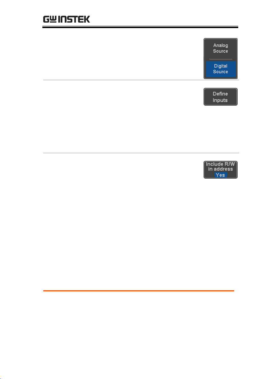
4. Press Analog Source to choose the
sources for the I
2
C bus is.
Define Inputs
5. Press Define Inputs from the bottom
menu.
6. From the side menu choose the
SCLK input and the SDA Input.
SCLK
CH1~CH4
SDA
CH1~CH4
Include R/W in
address
To configure whether you want the
R/W bit to be included in the
address, press Include R/W in
address and set to Yes or No in the
side menu.
R/W Bit
Yes, No
SPI Serial Bus Interface
The serial peripheral interface (SPI) is a full duplex 4 wire
synchronous serial interface. The 4 signals lines: Serial clock line
(SCLK), slave select (SS), Master output/slave input (MOSI, or
SIMO) and the Master input/slave output (MISO, or SOMI). The
word size is configurable from 4 to 32 bits. The SPI triggers on the
data pattern at the start of each framing period. Note: The SPI bus
with analog source is only available for 4 channel models.
Panel operation
1. Connect each of the bus signals (SCLK, SS,
MOSI, MISO) to the oscilloscope’s 4 analog
channels. Connect the ground potential to one
of the probes’ ground clip if you are using the
analog channels.
Loading ...
Loading ...
Loading ...